considerations for selecting and using multimode fiber
TRANSCRIPT
892019 Considerations for Selecting and Using Multimode Fiber
httpslidepdfcomreaderfullconsiderations-for-selecting-and-using-multimode-fiber 132
SPONSORED BY
EDITORIAL GUIDE
Considerationsfor Selectingand UsingMultimode FiberA network managerrsquos choice to use
multimode fiber-optic cable does not
end the decision-making process Next
come considerations including cabling-system architecture compatibility
issues connector styles and the type
of multimode to usemdashincluding core
size bandwidth and bend sensitivity
This Cabling Installation amp Maintenance
editorial guide presents information that
will help network managers choose the
specific type of fiber-optic cabling system
that best suits their needs
2 Optical fiber cablingand componentspecification
considerations
13Making the switchfrom 625- to50-micron fiber
20Compatibility issuewith bend-insensitand standard
multimode
892019 Considerations for Selecting and Using Multimode Fiber
httpslidepdfcomreaderfullconsiderations-for-selecting-and-using-multimode-fiber 232Cabling Installation amp Maintenance EDITORIAL GUIDE
2
Optical fiber cabling and
component specificationconsiderations
Put optical theory into practice for
optimal network performance
by Valerie Maguire
UNLIKE BALANCED TWISTED-
PAIR media optical fiber cabling
can be considered application-
dependent media This means that
considerations such as distance application
and equipment cost play a role in the media
selection process
The Telecommunications Industry Association
(TIA) and the International Organization
for Standardization (ISO) through reference
to specifications from the International Electrotechnical Commission (IEC)
and the International Telecommunication Union (ITU-T) recognize six grades
of multimode and singlemode optical fiber as shown in the table on page 3
Physical dimensions related to the optical fiber eg diameter non-circularityand mechanical requirements as well as optical specifications such as
attenuation and bandwidth are specified It is important to keep in mind that
these specifications are for the ldquorawrdquo optical fiber before it is subjected to the
cabling process TIA and ISO use these optical fiber requirements to then specify
requirements for OM1 OM2 OM3 OM4 OS1 and OS2 optical fiber cables and
cabling
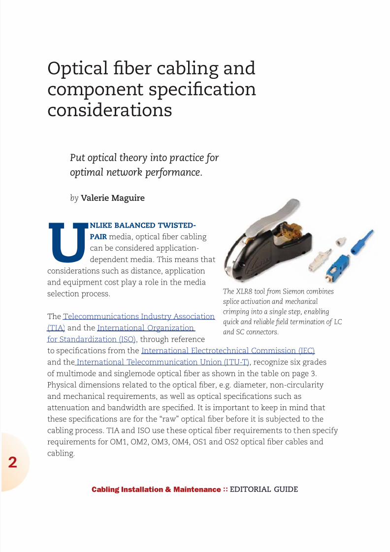
The XLR8 tool from Siemon combinessplice activation and mechanical
crimping into a single step enabling
quick and reliable field termination of LC
and SC connectors
892019 Considerations for Selecting and Using Multimode Fiber
httpslidepdfcomreaderfullconsiderations-for-selecting-and-using-multimode-fiber 332
Optical fiber cabling and component specification considerations
Cabling Installation amp Maintenance EDITORIAL GUIDE
While media selection may seem onerous comparing the throughput and
distance needs in your target environment against performance parameters is
a good way to initiate the selection process Although such comparisons may
lead to the conclusion that singlemode fiber is the optimum medium under all
scenarios there are tradeoffs to consider related to the cost of optoelectronics
and application implementation
In particular singlemode optoelectronics rely on much more powerful and precise
light sources and can cost 2 to 4 times more than multimode optoelectronics
Also multimode media is typically easier to terminate and install in the field
than singlemode Additionally it is always more cost-effective to transmit at
850 nm for multimode applications and at 1310 nm for singlemode applicationsFinally optoelectronics that use multiple transmit lasers (eg 10GBase-LX4 uses
four separate laser sources per fiber) or other multiplexing techniques cost
significantly more than optoelectronics that transmit over one wavelength
A good rule of thumb is to consider multimode fiber to be the most cost-effective
choice for applications up to 550 meters in length
Supportable application distances by fiber type (meters)
Application OM 1 OM2 OM3 OM4 OS1 OS2
Wavelength 850 1300 850 1300 850 1300 850 1300 1310 1550
FDDI PMD 2000 2000 2000 2000
FDDI SMF-PMD 10000
10100Base-SX 300 300 300 300
100Base-FX 2000 2000 2000 2000
1000Base-SX 275 550 800 800
1000Base-LX 550 550 800 800 5000
10GBase-S 33 82 300 550
10GBase-LX4 300 300 300 300 10000
10GBase-L 10000
10GBase-LRM 220 220 220 220
10GBase-E 40000
40GBase-SR4 100 125
40GBase-LR4 10000
100GBase-SR10 100 125
100GBase-LR4 10000
100GBase-ER4 30000
892019 Considerations for Selecting and Using Multimode Fiber
httpslidepdfcomreaderfullconsiderations-for-selecting-and-using-multimode-fiber 432
Optical fiber cabling and component specification considerations
4
Cabling Installation amp Maintenance EDITORIAL GUIDE
Optical fiber cabling configurations
Optical fiber cabling is typically deployed in pairs one fiber is used to transmit
and the other is used to receive Due to its extended distance support of
applications compared to balanced twisted-pair cabling optical fiber cabling
is the perfect media for use in customer-owned outside plant (OSP) backbone
cabling and centralized cabling applications
Customer-owned OSP cabling is deployed between buildings in a campus
environment and includes the terminating connecting hardware at or within the
structures Interestingly customer-owned OSP cabling is typically intended to
have a useful life in excess of 30 years so great care should be taken to specify
robust cabling media Requirements pertaining to customer-owned outside plantcabling and pathways can be found in ANSITIA-758-A and BS EN 50174-3
Backbone cabling is deployed between entrance facilities access-provider
spaces service-provider spaces common equipment rooms common
telecommunications rooms equipment rooms telecommunications rooms and
telecommunications enclosures within a commercial building Backbone cabling
must be configured in a star topology and may contain one (main) or two (main
and intermediate) levels of crossconnects Backbone cabling requirements are
specified in ANSITIA-568-C0 ANSITIA-568-C1 and ISOIEC 11801 Ed20
Centralized optical fiber cabling may be deployed as an alternative to the optical
crossconnect to support centralized electronics deployment in single-tenant
buildings Centralized optical fiber cabling supports direct connections from the
work area to the centralized crossconnect via a pull-through cable and the use
of an interconnect or splice in the telecommunications room or enclosure Note
that the maximum allowed distance of the pull-through cable between the work
area and the centralized crossconnect is 90 meters (295 feet) Centralized cablingrequirements are specified in ANSITIA-568-C0 ANSITIA-568-C1 and ISOIEC
11801 Ed20
Optical fiber cabling may also be used in the horizontal cabling infrastructure
although there are no provisions allowing extended distance in the TIA and ISO
standards
892019 Considerations for Selecting and Using Multimode Fiber
httpslidepdfcomreaderfullconsiderations-for-selecting-and-using-multimode-fiber 532
Optical fiber cabling and component specification considerations
Cabling Installation amp Maintenance EDITORIAL GUIDE
Horizontal cabling is deployed between the work area and the telecommunications
room or enclosure Horizontal cabling includes the connector and cords at the
work area and the optical fiber patch panel A full crossconnect or interconnect
may be deployed along with an optional multi-user telecommunications outlet
assembly (MUTOA) or consolidation point (CP) for a total of four connectors in the
channel The maximum horizontal cable length shall be 90 meters (295 feet) and
the total length of work area cords patch cords or jumpers and equipment cords
shall be 10 meters (32 feet) for both optical fiber and balanced twisted-pair cabling
channels Horizontal cabling requirements are specified in ANSITIA-568-C0
ANSITIA-568-C1 and ISOIEC 11801 Ed20
Optical fiber cableThe optical fiber that enables light transmission is actually an assembly of three
subcomponents the core the cladding and the coating The core is made of
glass (or more accurately silica) and is the medium through which the light
propagates The core may have an overall diameter of 9 microm for singlemode or 50
microm or 625 microm for multimode transmission Surrounding the glass is a second
layer of glass with a vastly different index of refraction that focuses and contains
the light by reflecting it back into the core This second layer is called the
cladding and regardless of the glass core construction has an overall diameter
of 125 microm Combining the core and cladding diameters is the source of optical
fiber descriptors such as 50125 microm or 625125 microm that are applied to optical
fibers commonly used for telecommunications applications The purpose of the
outermost layer called the coating is to add strength and build up the outer
diameter to a manageable 250-microm diameter (about three times the diameter of
a human hair) The coating is not glass but rather a protective polymer such as
urethane acrylate that may be optionally colored for identification purposes
Cabling optical fibers makes them easier to handle facilitates connectortermination provides protection and increases strength and durability The
cabling process differs depending upon whether the optical fibers are intended for
use in indoor outdoor or indooroutdoor environments
Indoor optical fiber cables are suitable for inside (including riser and plenum)
building applications To facilitate connector terminations a 900microm plastic
buffer is applied over the optical fiber core cladding and coating subassembly
892019 Considerations for Selecting and Using Multimode Fiber
httpslidepdfcomreaderfullconsiderations-for-selecting-and-using-multimode-fiber 632
Optical fiber cabling and component specification considerations
6
Cabling Installation amp Maintenance EDITORIAL GUIDE
to create a tight buffered fiber Up to 12 tight buffered fibers are then encircled
with aramid yarns for strength and then enclosed by an overall flame-retardant
thermoplastic jacket to form a finished optical fiber cable For indoor cables with
higher than 12-fiber counts groups of jacketed optical fiber cables (typically 6- or
12-fiber count) are bundled together with a central strength member (for support
and to maintain cable geometry) and are enclosed by an overall flame-retardant
thermoplastic jacket Supported fiber counts are typically between 2 and 144
Outdoor (also known as outside plant or OSP) optical fiber cables are used
outside of the building and are suitable for lashed aerial duct and underground
conduit applications To protect the optical fiber core from water and freezing
up to 12 250-microm optical fiber cores are enclosed in a loose buffer tube that isfilled with water-blocking gel For up to 12-fiber applications the gel-filled loose
tube is encircled with water-blocking tapes and aramid yarns and enclosed
within an overall ultraviolet and
water-resistant black polyolefin
jacket For outdoor cables with
higher than 12-fiber counts groups
of loose buffer tubes (typically 6- or
12-fiber count) are bundled together
with a central strength member and
water-blocking tapes and aramid
yarns and then enclosed within
an overall ultraviolet and water-
resistant black polyolefin jacket
Corrugated aluminum interlocking
steel armor or dual jackets may be
applied for additional protection
against crushing and rodent damageSupported fiber counts are typically
between 12 and 144
Indooroutdoor optical fiber cables offer the ultraviolet and water resistance
benefits of outdoor optical fiber cables combined with a fire-retardant jacket that
allows the cable to be deployed inside the building entrance facility beyond the
maximum 152-meter (50-foot) distance that is specified for OSP cables Note that
Several of the optical interconnection technologies
described in this article are shown here Clockwise
from upper left are MTPMPO-style trunking
cable assemblies duplex LC-connected optical fiber
cables plug-and-play array modules (one with
MPOMTP-style connectors showing and the otherwith LC connectors showing) and a pass-through
adapter plate
892019 Considerations for Selecting and Using Multimode Fiber
httpslidepdfcomreaderfullconsiderations-for-selecting-and-using-multimode-fiber 732
Optical fiber cabling and component specification considerations
7
Cabling Installation amp Maintenance EDITORIAL GUIDE
there is no length limitation in
countries outside of the United
States that do not specify riser-
or plenum-rated cabling The
advantage of using indoor
outdoor optical fiber cables
in this scenario is that the
number of transition splices
and hardware connections is
reduced Indooroutdoor optical
fiber cables are similar in
construction to outdoor opticalfiber cables except that the 250-
microm optical fiber cores may be
either tight buffered or enclosed
within loose buffer tubes Loose
tube indooroutdoor optical fiber
cables have a smaller overall
diameter than tight buffered
indooroutdoor optical fiber cables however tight buffered indooroutdoor cables
are typically more convenient to terminate because they do not contain water-
blocking gel or require the use of breakout kits (described later)
Optical fiber interconnections
Unlike the plug-and-jack combination that makes up a mated balanced
twisted-pair connection an interconnection is used to mate two tight-buffered
optical fibers An optical fiber interconnection typically consists of two plugs
(connectors) that are aligned in a nose-to-nose orientation and held in place with
an adapter (also called a coupler or bulkhead) The performance of the opticalfiber interconnection is highly reliant upon the connectorrsquos internal ferrule and
the adapterrsquos alignment sleeve These components work in tandem to retain
and properly align the optical fibers in the plug-adapter-plug configuration The
internal connector ferrule is fabricated using a high-precision manufacturing
process to ensure that the optical fiber is properly seated and its position is tightly
controlled The high tolerances of the alignment sleeve ensure that the optical
fibers held in place by the ferrule are aligned as perfectly as possible Although
Equipment cord connected tocentralized equipment
Horizontal cable90 m (295 ft max)
Telecommunications
room (TR)
Work area (WA)
Work areaequipment
cord
Work area outlet
Centralized optical fiber cabling usingan interconnection
Equipmentroom
Shown here is a typical schematic for centralized optical
fiber cabling using an interconnection the centralized
system supports direct connections from the work area to
the centralized crossconnect via a pull-through cable and
the interconnect
892019 Considerations for Selecting and Using Multimode Fiber
httpslidepdfcomreaderfullconsiderations-for-selecting-and-using-multimode-fiber 832
Optical fiber cabling and component specification considerations
8
Cabling Installation amp Maintenance EDITORIAL GUIDE
more expensive ceramic alignment sleeves maintain slightly tighter tolerances
than metal or plastic alignment sleeves are not as susceptible to performance
variations due to temperature fluctuations and may be specified for extremely
low-loss applications
Accurate plug-adapter-plug alignment minimizes light energy lost at the optical
fiber interconnection and maintaining precision tolerances becomes especially
critical as the optical fiber diameter decreases For example if two 625-microm
optical fibers are off-center by 4 microm in opposite directions then 13 of the light
energy escapes or is lost at the interconnection point This same misalignment
in a 9-microm singlemode fiber would result in almost a total loss of light energy
The critical nature of the core alignment is the reason why different optical fibertypes including 625-microm and 50-microm multimode fiber should never be mixed in
the same link or channel
Optical fiber breakout kits are used to facilitate termination of loose-tube optical
fibers used in indooroutdoor and outdoor applications Once the water-blocking
gel is thoroughly removed from the optical fibers the breakout kit allows furcation
tubes (typically 12mm to 30mm in diameter) to be installed over the 250-microm
optical fibers increasing the diameter and forming a short ldquojacketrdquo so that the
optical fibers may be terminated to the desired optical fiber connector Selection of
the correct furcation tube ensures compatibility with all optical fiber connectors
Users can choose from many optical fiber connector options
Traditional optical fiber connectors are represented by the SC and ST connector
styles These two types of optical fiber connectors were recognized when optical
fiber cabling was described in
the first published TIA and ISOIEC telecommunications cabling
standards The ST connector
Cladding
Core
Optical fiber cross-section
Core
Diameter
9m 50m or 625m
125m
Coating
250m
Cladding
Coating
Singlemode fiber cores are 9 microm in
diameter while multimode fiber cores may
be 50 or 625 microm Regardless of core size
the cladding is 125 microm and the coating
250 microm
892019 Considerations for Selecting and Using Multimode Fiber
httpslidepdfcomreaderfullconsiderations-for-selecting-and-using-multimode-fiber 932
892019 Considerations for Selecting and Using Multimode Fiber
httpslidepdfcomreaderfullconsiderations-for-selecting-and-using-multimode-fiber 1032
Optical fiber cabling and component specification considerations
0
Cabling Installation amp Maintenance EDITORIAL GUIDE
12-fiber MPOMTP interfaces with 24 LC connections or one 12-fiber MPOMTP
interface with 12 SC or LC connections
Optical fiber cabling deployment
The most common optical fiber cabling deployment approach is to field terminate
the optical fiber connectors to the optical fiber cable using the appropriate epoxy
polish or no-epoxyno-polish mechanical termination method However the
new MPOMTP plug-and-play modules and MPOMTP array connectors are not
supported by field termination and there are considerations such as installer
expertise and the IT construction
upgrade schedule that may favor the
use of factory-terminated pigtailsor trunking assemblies over field
termination methods
The pros and cons of these termination
methods are described here
Field termination supports the lowest
raw material cost for SC ST LC and
MT-RJ optical fiber cabling systems
However the time needed for field
termination is the longest of the three
deployment options and installer
skill-level requirements are higher
which may increase the project
installation costs No-epoxyno-polish
and certain mechanical-splice-style
termination methods require lessinstallation skill than the epoxypolish method however the connectors used in
conjunction with mechanical termination methods are more expensive and the
performance (especially using the no-epoxyno-polish method) may be lower
and more variable
Optical fiber pigtails feature a factory preterminated and tested SC ST LC or MT-
RJ optical fiber connector and a 1-meter stub of 625125-microm multimode 50125-
Tight-buffered
Loose-tube
Sample optical fiber cable constructions
Jacket
Rip cord
Central strength member
Aramid yarns
Color coded tight-bufferedfibers and jackets
Water-blocking swellabletape
Gel-filled tubes
Water-blocking aramid yarn
Central strength memberRip cord
Aramid yarns
Color-coded fibers and tubes
Jacket
The environment in which the fiber cable will be
used eg indoor or outdoor will determine the
cablersquos construction and the treatment of the
fibers within that cable
892019 Considerations for Selecting and Using Multimode Fiber
httpslidepdfcomreaderfullconsiderations-for-selecting-and-using-multimode-fiber 1132
Optical fiber cabling and component specification considerations
1
Cabling Installation amp Maintenance EDITORIAL GUIDE
microm multimode or singlemode optical fiber The stub end of the pigtail is then
fusion-spliced to the optical fiber Fusion splicing provides a consistent nearly
loss-free termination and can be fast with proper technicians and equipment
The main benefits to this approach are the assurance of low-loss performance at
the interconnection and the elimination of the need for endface inspections and
possible connector reterminations
Trunking cable assemblies provide an efficient alternative to field-terminated
components or splice connections and allow up to 75 faster field deployment
times Trunking cable assemblies are custom factory preterminated and tested
lengths of optical fiber cable terminated on both ends with SC ST LC MT-RJ or
MPOMTP optical fiber connectors that are simply pulled and plugged in Whendeploying trunking cable assemblies cable-length specification is critical and
precise planning is required up front Trunking cable assemblies that have an
MPOMTP connector on one or both ends are commonly referred to as ldquoplug-
and-playrdquo cable assemblies MPOMTP plug-and-play cable assemblies have the
smallest connector profile and therefore have the smallest pathway cabinet and
rack-space requirements of all trunking cable assembly options
Always maintain the fibersrsquo polarity to ensure the transmit fiber is matched to
the receive port on each end of the link or channel
Valerie Maguire is a Global Sales Engineer with Siemon
892019 Considerations for Selecting and Using Multimode Fiber
httpslidepdfcomreaderfullconsiderations-for-selecting-and-using-multimode-fiber 1232
1010100000001111011111100101010101001010
1010000001110101010101000101010001010101
0101001010101010010100101010101000000011
1101111110010101010100101010100000011101
0101010100010101000101010101010010101010
1001010010101010100000001111011111100101
0101010010101010000001110101010101000101
010001010101010100101010101001010010101
0101000000011110111111001010101010010101
0100101010000000111101111110010101010100
1010101000000111010101010100010101000101
010101010010101010100101001010101010000
0001111011111100101010101001010101000000
1110101010101000101010001010101010100101
0101010010100101010101000000011110111111
0010101010100101010100000011101010101010
0010101000101010101010010101010100101001
0101010100000001111011111100101010101001
01010100101010000000111101111110010101010
Is there a hole in your
fiberrsquos performance
If itrsquos not OFS multimode fiber there could be OFSrsquo
manufacturing process virtually eliminates defects in the
fiber core with a DMD specified in the 0-5 micron range
That means double the bandwidth for lasers that launch
power in the fiberrsquos center while providing fast reliable
transmission and easier connectivity To learn more ask
your cabler about OFS or visit wwwofsopticscomfiber
892019 Considerations for Selecting and Using Multimode Fiber
httpslidepdfcomreaderfullconsiderations-for-selecting-and-using-multimode-fiber 1332Cabling Installation amp Maintenance EDITORIAL GUIDE
3
Making the switch from
625- to 50-micron fiber
What to do and what not to do when opting
for higher-bandwidth 50-micron multimode
By John Kamino
MULTIMODE FIBER SYSTEMS continue to provide the most cost-
effective cabling solution for data centers local area networks
(LANs) and other enterprise applications Compared to singlemode
fiber multimode systems offer significantly lower costs for
transceivers connectors and connector installation while meeting and exceeding
the bandwidth and reliability requirements of the most demanding networks
If you are designing a new short-reach installation you will probably choose laser-
optimized 50-micron (microm) OM3 or OM4 multimode fiber These fibers preserve the
systems-cost benefits over singlemode fiber by using low-cost 850-nm vertical-
cavity surface-emitting laser (VCSEL) technology are capable of 10-Mbitsec
through 10-Gbitsec operation and will support upcoming 40- and 100-Gbitsec
transmission speeds
But if you are upgrading an existing system many of which have 625-microm
multimode already installed should you stick with 625-microm Or can you go with
the higher performance of 50-microm OM3 or OM4 fiber This article highlights thethings you must consider when upgrading an existing 625-microm system
Why two fiber sizes
The numbers under discussionmdash50-microm and 625-micrommdashrefer to the diameter of
the fiberrsquos core through which light signals are transmitted The first optical
fibers deployed in the 1970s for both short- and long-reach applications were
50-microm multimode fibers In the early 1980s singlemode fiber replaced 50-microm
892019 Considerations for Selecting and Using Multimode Fiber
httpslidepdfcomreaderfullconsiderations-for-selecting-and-using-multimode-fiber 1432
Making the switch from 625- to 50-micron fiber
4
Cabling Installation amp Maintenance EDITORIAL GUIDE
fiber in longer-distance installations However 50-microm multimode continued to be
more cost-effective for short-reach interconnects such as building and campus
backbones up to 2000-meter distances
But as data rates increased 50-microm fiber could not support 10-Mbitsec rates overthe 2-kilometer distances required by some campus installations Not enough
power could be coupled from the light-emitting diode (LED) sources in use at that
time into the 50-microm core to support these link distances
625-microm multimode fiber was introduced in 1985 to solve this problem It could
capture more light from a LED in its larger core and 2-km campus links operating
at 10 Mbitssec were easily supported Also the larger-core fiber was easier to
cable and connectorize It became the most commonly used fiber for short-reach
enterprise applications in North America
Today as data rates surpass 10-Gbitssec and lasers have replaced LEDs 625-microm
fiber has reached its performance limit 50-microm fiber offers as much as 10 times
the bandwidth of the 625-microm fiber Whatrsquos more improvements in technology
have made 50-microm fiber easier to use
Multimode fiber choices today
To consider making the switch from 625-microm to 50-microm multimode it is importantto first understand the terminology used to designate the various performance
grades of multimode fiber In each of these designations ldquoOMrdquo stands for ldquooptical
multimoderdquo For example OM1 is the designation for fiber with 200500 MHz-
km overfilled launch (OFL) bandwidth at 8501300 nm this typically is 625microm
fiber OM2 is used for fiber with 500500 MHz-km OFL bandwidth at 8501300 nm
(typically 50-microm fiber)
Fiberdesignation
EMB (in MHz∙km) 850 nm
OFL (in MHz∙km) 850 nm
OFL (in MHz∙km) 1300 nm
OM1 (625) NA 200 500
OM2 (50) NA 500 500
OM3 (laser-
optimized 50) 2000 1500 500
OM4 (laser-
optimized 50) 4700 3500 500
892019 Considerations for Selecting and Using Multimode Fiber
httpslidepdfcomreaderfullconsiderations-for-selecting-and-using-multimode-fiber 1532
Making the switch from 625- to 50-micron fiber
5
Cabling Installation amp Maintenance EDITORIAL GUIDE
More-recent additions are OM3 for laser-optimized 50-microm fiber having 2000
MHz-km effective modal bandwidth (EMB also known as laser bandwidth) at 850
nm (designed for 10-Gbitsec transmission) and most recently OM4 for laser-
optimized 50-microm fiber having 4700 MHz-km EMB at 850 nm designed for 10-Gbit
sec transmission over longer distances
OM4 with its extended bandwidth can be used to enhance the system-cost
benefits enabled by 850 nm lasers for 10-Gbitsec applications as well as new
40- and 100-Gbitsec systems With its 150 m reach capability at 40 and 100
Gbitsec OM4 will support an additional 10 percent of link lengths in large data
centers that are not covered by OM3rsquos 100 m reach It is especially well-suited
for short reach data center and high-performance computing applications whereoptical loss budgets are tight at 10-Gbitsec and higher The additional bandwidth
provided when OM4 fiber is deployed at less than its rated distance offers extra
headroom for channel insertion loss
Itrsquos also important to note that for next-generation 40- and 100-Gbitsec
Ethernet only OM3 and OM4 fibers are included in the IEEE 8023ba standard
as supported (multimode optical fiber) media OM1 and OM2 fibers are not
supported media types
The latest offerings in multimode fiber are 50 microm bend insensitive multimode
fibers (BIMMF) These fibers have been promoted as offering all the advantages
of high bandwidth laser-optimized multimode fiber with the added advantage
of lower bend sensitivity However recent work has shown that some of these
fibers may have significant performance issues A paper presented at the 2010
International Wire and Cable Symposium (IWCS) showed that mating (connector)
loss of BIMMFs with standard fibers is higher than standard fiber connected to
standard fiber This additional loss adds to the total link loss possibly causing itto exceed the link loss budget
Another recent study examined issues with the system performance of bend
insensitive fibers and questioned whether current requirements are adequate
It has been proposed that standards organizations perform a thorough review of
BIMMFs and incorporate them into industry standards Until this work is done
caution is advised before widespread adoption takes place
892019 Considerations for Selecting and Using Multimode Fiber
httpslidepdfcomreaderfullconsiderations-for-selecting-and-using-multimode-fiber 1632
Making the switch from 625- to 50-micron fiber
6
Cabling Installation amp Maintenance EDITORIAL GUIDE
Upgrading a 625-microm network
The primary considerations for an upgrade or extension of an existing 625-microm
network are
the required transmission speed (now and especially in the future)
link distance
ease of cable replacement and
cost of cable replacement
If you are running Gigabit Ethernet (1-Gbitsec) then legacy 625-microm fiber will
transmit a distance of 220 to 275 meters depending on its bandwidth ratingBut at 10-Gigabit Ethernet (10-GbE 10-Gbitssec) they will only support 26 to
33 meters If your network will not need to support 10-GbE at distances greater
than 25 meters then you may be able to stick with 625-microm fiber It is important
to note however that most 625-microm fiber has not been measured for laser
bandwidth and some legacy fiber may have difficulty supporting even this short
distance
And if you want to transmit longer distances over 625-microm fiber you will be
forced to use much-more-expensive 1300-nm transceivers that will operate over
multimode or singlemode fiber These transceivers cost significantly more than
850-nm multimode devices because the 1300-nm optoelectronics package is the
far more complex of the two
If you are considering extending your network by installing additional 625-microm
fiber you need to carefully review your future network plans If you plan to
upgrade your network speed to 10-Gbitssec in the future recabling with laser-
optimized OM3 or OM4 fiber would be a wiser choice
Measuring laser bandwidth
As previously stated 625-microm fiber provides limited support for 10-Gbitsec
transmission so it generally is not measured for laser bandwidth (EMB) Typically
only 50-microm fibers are measured for EMB To verify bandwidth of 625-microm fiber
the traditional OFL bandwidth measurement method is used
892019 Considerations for Selecting and Using Multimode Fiber
httpslidepdfcomreaderfullconsiderations-for-selecting-and-using-multimode-fiber 1732
Making the switch from 625- to 50-micron fiber
7
Cabling Installation amp Maintenance EDITORIAL GUIDE
For 50-microm fibers EMB is ensured by using a method called Differential Mode
Delay (DMD) This DMD test is required by standards to verify 10-Gbitsec
performance and involves scanning the fiberrsquos core in small increments to see
how the signal travels in various regions of the core
Once the DMD test is conducted and a DMD ldquoprofilerdquo is obtained the standards
allow two methods to disposition the fiber One is the DMD Mask method and the
other is the Effective Modal Bandwidth Calculated (EMBc) method
The DMD Mask method provides direct verification of the fiberrsquos DMD
performance using a set of clearly defined DMD masks and templates that are
overlaid on the DMD profile This technique provides flexibility in applying more-stringent DMD performance criteria in certain regions of the fiber including the
0-5microm center region
The EMBc method involves complex calculations involving 10 weighting
functions to represent the wide variety of 10-Gbitsec VCSELs available on the
market Theoretical in nature this technique does not in our opinion provide
the scrutiny on fiber quality and performance that the DMD Mask technique
does The EMBc method puts little emphasis on the 0-5microm region of a fiberrsquos
core Though standards allow both testing methods we advocate the DMD
Mask method
Mixing 50- and 625-microm
If you decide to add 50-microm fiber to an existing 625-microm infrastructure connecting
50-microm directly to 625-microm is generally not recommended The difference in core
sizes could cause high loss when transmitting from the 625-microm into the 50-
microm fiber Also the bandwidth of 625-microm fibers is typically much lower further
degrading system performance Even if a low-speed application operates over alink made up of mixed fiber types upgradeability will be severely compromised
This elevated-loss problem occurs when transmitting from the larger (625-microm) to
the smaller (50-microm) core It is comparable to a 4-inch water pipe connecting to a
3-inch pipe there is no problem going from the smaller pipe to the larger one but
going in the opposite direction can lead to a lot of lost water (or in this case light)
892019 Considerations for Selecting and Using Multimode Fiber
httpslidepdfcomreaderfullconsiderations-for-selecting-and-using-multimode-fiber 1832
Making the switch from 625- to 50-micron fiber
8
Cabling Installation amp Maintenance EDITORIAL GUIDE
The amount of connection loss you could experience is about 4 dB for a LED-
based system which fills the entire core of a 625-microm fiber and anywhere from 0
to 4 dB for a VCSEL-based system which only fills a portion of the core
Because most optical-loss test sets use LEDs you should plan for the worst and
assume you will see a 4-dB loss in one direction If your link budget can tolerate
this additional 4-dB loss then you can get away with connecting 50-microm directly
to 625-microm
The better scenario is to separate 50-microm from 625-microm with active electronics
such as a switch router or simple media converter
Mixing of 625-microm and 50-microm fiber is not recommended unless an electronics
interface is inserted into the link If 10-Gbitsec speeds are being installed 625-
microm fiber will only be able to support extremely short links and replacement is
recommended
John Kamino is Product Manager Multimode Fiber with OFS
892019 Considerations for Selecting and Using Multimode Fiber
httpslidepdfcomreaderfullconsiderations-for-selecting-and-using-multimode-fiber 1932
OFSrsquo LaserWave fiber exceeds the OM4 standard for
todayrsquos high-speed networks mdash and tomorrowrsquos Andsince LaserWave fiber delivers DMD specified in the
0 ndash 5 micron range you get up to twice the bandwidth for
lasers that launch power in the fiberrsquos center Enjoy fast
reliable transmission and easier connectivity To learn more
ask your cabler about OFS or visit ofsopticscomfiber
Get your network up tospeed with LaserWavereg fiber
892019 Considerations for Selecting and Using Multimode Fiber
httpslidepdfcomreaderfullconsiderations-for-selecting-and-using-multimode-fiber 2032Cabling Installation amp Maintenance EDITORIAL GUIDE
20
Compatibility issues with
bend-insensitive andstandard multimode
Lab testing indicates risks associated with mixing
bend-insensitive and standard multimode fiber
By Rick Pimpinella Bulent Kose and Brett Lane
THE INCREASING DEMAND for higher-speed data transmission
within the data center and premises networks has led to the wide
deployment of multimode optical connectivity To meet performance
and reliability requirements the optical specifications on the
components have also become more stringent For high-speed optical networks
using laser-optimized OM3 and OM4 multimode fiber it is more critical than ever
for network operators and designers to understand the attributes of the various
performance grades of passive fiber-
optic components that make up the
network so that they may employ the
most cost-efficient solutions that meet
their needs today and in the future
In order to ensure that optical networks
operate effectively and reliably it isfundamental that the optical fiber
meets the necessary bandwidth
requirements and that the total optical
loss or insertion loss (IL) is below
the allowable limit required by the
application The two sources of IL
within optical networks are 1) loss at
892019 Considerations for Selecting and Using Multimode Fiber
httpslidepdfcomreaderfullconsiderations-for-selecting-and-using-multimode-fiber 2132
Compatibility issues with bend-insensitive and standard multimode
21
Cabling Installation amp Maintenance EDITORIAL GUIDE
connector interfaces and 2) loss or attenuation within the fiber itself The IL
limits for 10- 40- and 100-Gbitsec Ethernet are in the table below
The combination of
eroding insertion loss
budgets and increased
demands for complex
network architectures
with many
connector interfaces
has triggered several fiber and connectivity suppliers to develop improved
connectivity and fiber products that allow network architectures to cope withthese trends Specifically several connectivity suppliers now offer low-loss or
optimized passive fiber-optic components such as connectors cassettes and
patch cords that allow them to implement complex networks with numerous
connector interfaces while still meeting the maximum connector loss budget
Moreover although the intrinsic fiber attenuation has not been reduced
significantly over the past many years recent advancements in fiber production
have delivered extra headroom by significantly improving attenuation levels
under tightly bent conditions even in those cases in which the fiber is
unintentionally subjected to bends smaller than that allowed with the ANSI
TIA-568-C0 premises cabling standard This article reviews how this new type of
laser-optimized multimode fiber often called bend-insensitive or bend-optimized
integrates into todayrsquos data center and premises network
Achieving bend-optimization
It is well known that in order to produce a fiber with improved bend performance
it must be made to more tightly confine the light within its core region Thismodification allows more of the light to meet the conditions necessary for
total internal reflection as the fiber is bent Enhanced optical confinement
is accomplished by simply increasing the effective difference in the index of
refraction between the core and cladding regions This is typically accomplished
by introducing an index depression or trench in the cladding region close to the
fiber core
Applicationstandard
Minoperatingdistance
(m)
Maxconnectorloss (dB)
Max fiberattenuation
(dB)
Max totalIL budget
(dB)
0-Gbitsec Ethernet 300 15 11 26
40- and 100-Gbit
sec Ethernet (OM3)
100 15 04 19
40- and 100-Gbit
sec Ethernet (OM4)
150 1 05 15
892019 Considerations for Selecting and Using Multimode Fiber
httpslidepdfcomreaderfullconsiderations-for-selecting-and-using-multimode-fiber 2232
892019 Considerations for Selecting and Using Multimode Fiber
httpslidepdfcomreaderfullconsiderations-for-selecting-and-using-multimode-fiber 2332
Compatibility issues with bend-insensitive and standard multimode
23
Cabling Installation amp Maintenance EDITORIAL GUIDE
conditions necessary for total internal reflection (ie rays with larger angles)
light emerging from bend-optimized multimode fiber will have a larger angle on
average than light emerging from standard multimode fiber The parameter that
characterizes the maximum divergence or acceptance angle of light from or to
a fiber is called numerical aperture (NA) Therefore the NA of bend-optimized
multimode is generally expected to be greater on average than the NA of
standard multimode A thorough sampling across multiple fiber manufacturers
revealed that the average NA increased
from 0199 for standard multimode fiber to
0207 for bend-optimized multimode fiber
Although this moderate increase in NAappears insignificant in some situations
the optical loss across an optical fiber
interface (eg connector) is dependent on
the differences in NAs of the fibers In the
case that light fully populates the fiber
core such as when illuminated with an
LED and is coupled from a fiber with a
higher NA into a receiver with a lower NA
the light will diverge at an angle larger
than the acceptance angle of the receive
fiber This will result in some light being
lost (into the cladding) and the interface will have loss proportional to the NA
difference (ratio) between the two fibers
Consequently increased loss may be realized when light travels from bend-
optimized multimode fiber into standard multimode fiber In fact the expected
loss across a bend-optimized fiber with an NA of 0207 and a standard fiber withan NA of 0199 is 034 dB which is a significant portion of the overall IL budget
In the case that light travels from a fiber with a lower NA into a receiver with a
higher NA or light does not fully illuminate the fiber core no loss resulting from
the difference in fiber NAs is expected
NA loss measurements
To predict the NA loss that would be realized during link certification
2 4 6
MMF LED
MMF VCSEL
8 10
3
25
2
15
1
05
0
Bend loss (1 m) (dB)
Mandrel radius (mm)
BO-MMF LED
BO-MMF VCSEL
Measured bend loss at 850 nm
representative of bend-optimized and
standard multimode fiber using both
LED and VCSEL light source Fibers were
wrapped one turn around 10 different
mandrels with radii ranging from 25mm to
10 mm
892019 Considerations for Selecting and Using Multimode Fiber
httpslidepdfcomreaderfullconsiderations-for-selecting-and-using-multimode-fiber 2432
Compatibility issues with bend-insensitive and standard multimode
24
Cabling Installation amp Maintenance EDITORIAL GUIDE
measurements of an optical
channel with bend-optimized
and standard fiber interfaces
a series of standard IL
measurements were performed
on selected bend-optimized
and standard fibers Fiber
samples from several fiber
manufacturers were selected
with a wide range of NAs in
order to provide not only a
typical NA loss from fibers withaverage NA but also provide
an upper and lower limit of
NA loss that may be expected
when connecting dissimilar
multimode fiber types without knowledge of NA differences Several fibers were
selected of each fiber typendashsome with an average NA some with a low NA and
some with a high NA The table on page 25 summarizes the samples used for this
experiment and the theoretically expected NA loss from each connection
For these measurements the various bend-optimized fiber samples were
fusion spliced to the various standard multimode fiber samples A fusion
splicer was used to connect dissimilar fiber types instead of connectors in
order to minimize other loss contributors such as lateral offset and connector
termination processing The insertion loss of the connection was calculated by
injecting light meeting the new TIAEIA-526-14-B encircled flux specification
into the bend-optimized fiber and then measuring the power coupled out of
the standard fiber Subtracting this power level from the reference power levelmeasured previously as the amount of power coupled into the bend-optimized
fiber resulted in the IL or NA loss of the connection All aspects of these
measurements were in compliance with TIAEIA-45-171A (eg diameter and
placement of cladding mode strippers)
The measurement data is shown in the chart on page 25 Each data point
represents the average of the NA losses for a set of fibers for each NA
Bend-optimizedMMF core
NA = sinq1
MMF coreα
NABO-MMF gt NAstd-MMF
This illustration shows a mismatch in NA when connecting
a fiber with a large NA (left) to a fiber with a small NA(right) Because the receive fiber on the right has a smaller
NA some light is not coupled and instead is lost into the
cladding This loss is referred to as NA loss
892019 Considerations for Selecting and Using Multimode Fiber
httpslidepdfcomreaderfullconsiderations-for-selecting-and-using-multimode-fiber 2532
Compatibility issues with bend-insensitive and standard multimode
25
Cabling Installation amp Maintenance EDITORIAL GUIDE
combination From this data
connecting dissimilar fiber types
with average NAs confirms the
theoretically predicted NA loss of
approximately 040 dB Additionally
the upper and lower limits of NA
loss were measured to be 028
dB and 106 dB Although these
average and extreme NA losses
are fairly well correlated with the
theoretically predicted NA loss
other measured values deviatesignificantly from the theoretically
predicted value This suggests that
factors other than NA such as core
diameter index profile and mode structure also significantly influence the loss
when connecting bend-optimized and standard multimode fiber As a result the
light does not couple with 100 percent efficiency between fibers and therefore an
additional mode coupling loss must exist
In fact in the case that bend-optimized fiber samples with the identical NA but
manufactured from different suppliers were connected to standard fibers with
NA equal to 0200 the NA loss differs significantly from vendor to vendor The
average NA loss from Vendor A bend-optimized interfaces nearly exactly matched
the theoretical NA loss of 030 dB while the average NA loss from Vendor B
bend-optimized interfaces was much higher at 051 dB (see graph on page 26) As
expected the bend-optimized fibers from Vendor B were found to be more bend-
tolerant than those from Vendor A
In addition to realizing
unidirectional NA
loss an increase in the
modal noise penalty
may also result
when connecting
bend-optimized and
1000 0975 0950 0925 0900 0875 0850
14
12
10
08
06
04
02
00
NA ratio
NA loss (dB)
The black line shows the theoretical loss of connected
fibers with different NA and the dots represent
actual measured loss The results suggest factorsother than NA also influence loss when connecting
bend-optimized and standard multimode fiber
NA (BO-MMF)to NA (MMF)combination
NA (BO-MMF) NA (MMF) NA ratio Theoreticalloss (dB)
Average to Average 0207 0199 0961 034
Large to Average 0215 0199 0926 067
Large to Small 0215 0185 086 131
Average to Small 0207 0185 0894 098
Small to Small 0199 0185 0928 063
Large to Large 0215 0212 0986 012
892019 Considerations for Selecting and Using Multimode Fiber
httpslidepdfcomreaderfullconsiderations-for-selecting-and-using-multimode-fiber 2632
Compatibility issues with bend-insensitive and standard multimode
26
Cabling Installation amp Maintenance EDITORIAL GUIDE
standard multimode fiber Modal noise is a power penalty related to the reduction
in the signal-to-noise ratio (SNR) of the optical signal For high-speed networks
employing VCSELs if a connector selectively attenuates higher-order modes as a
result of NA mismatch or a lateral offset between fiber cores then fluctuations in
the power distribution (spatial speckle pattern) result in fluctuations in connector
insertion loss This fluctuation is seen by the detector as an increase in noise
thereby reducing the SNR and therefore signal quality
The maximum allowed power penalty for modal noise is currently specified
in 10GBase-SR to be 03 dB Both NA loss and mode coupling loss can increase
the mode-selective loss (filter aperture) at a connector interface resulting in an
increase in modal noise Considering the overall power budget for 10G40G100GEthernet is 15 dB (or 10 dB for OM4) any
increase in modal noise may compromise
system reliability
In conclusion inconclusive
As part of our review of how bend-
optimized multimode fiber is integrating
in todayrsquos data center and premises
networks we measured the loss between
bend-insensitive and standard multimode
fibers to quantify the expected additional
loss during certification of mixed-fiber
links These additional losses were
measured to be as high as 1 dB and can
be a significant portion ofndashor even actually
exceedndashthe total optical power budget
for todayrsquos high-speed networks For a channel link that contains several bend-optimized fiber and multimode fiber interfaces which have large NA differences
the NA losses may be additive and further inhibit system certification
Furthermore although NA loss alone is unlikely to detrimentally influence
system performance it may be very difficult if not impossible to determine if
excessive channel loss is due to NA differences or other conventional sources
of loss such as macrobending or dirtydamaged components One strategy to
BO-MMF1
to MMF2
BO-MMF1
to MMF2
BO-MMF1
to MMF2
Vendor A BO-MMF
Vendor B BO-MMF
BO-MMF1
to MMF2
07
06
05
04
03
02
01
00
Measured NA loss (dB)
Bend-optimized fibers from Vendor B shown
here as the blue bars were found to be more
bend-tolerant than the bend-optimized fibers
from Vendor A shown as the green bars
The more-optimized fibers exhibited higher
NA loss
892019 Considerations for Selecting and Using Multimode Fiber
httpslidepdfcomreaderfullconsiderations-for-selecting-and-using-multimode-fiber 2732
Compatibility issues with bend-insensitive and standard multimode
27
Cabling Installation amp Maintenance EDITORIAL GUIDE
account for this loss would be to require bidirectional loss measurements of
individual optical interfaces
During the most recent meeting of the TIA TR-4212 Optical Fibers and Cable
Subcommittee a vigorous debate included many of the topics discussed in this
article and others including increased NA loss mode coupling loss modal
noise (which may negatively impact system performance) the validity of other
standardized fiber test procedures for fiber core diameter fiber bandwidth and
link attenuation (encircled flux) The subcommittee authorized the formation of
a task group to study the technical compatibility of bend-insensitive multimode
fiber with current multimode fiber standards
Based on our internal analysis and the present uncertain position within the
standards community we have concluded that the performance risks of mixing
bend-optimized and standard multimode fiber types in high-speed optical
channel links exceeds any benefit To ensure that total optical loss across data
center and premises networks remains below the allowable limit we recommend
adhering to standards-based radius-control methods and the use of one fiber
type throughout the channel link which includes cabling and patch cords This
approach enables network stakeholders to reliably deploy complex network
architectures meet stringent IL budgets and ensure optimal system performance
within current standards-based network architectures and testing methods
Some manufacturers support this effort others minimize its importance Until
the TIA subcommittee work on these issues is complete we recommend that
these two fiber types should not presently be mixed
Dr Rick Pimpinella is a Distinguished Engineer Bulent Kose is a ResearchEngineer and Dr Brett Lane is a Fiber Research Manager with Panduit
892019 Considerations for Selecting and Using Multimode Fiber
httpslidepdfcomreaderfullconsiderations-for-selecting-and-using-multimode-fiber 2832
As the demand for bandwidth in
enterprise applications such as
data centers continues to
boom new transmission media
must be developed continually
to meet end user requirementsThe latest in optical transmis-
sion media for the enterprise is
called OM4 fiber
OM4 fiber is a 50 micron (microm)
laser-optimized multimode fiber
with extended bandwidth It is
designed to enhance the sys-
tem cost benefits enabled by
850 nm Vertical Cavity Surface
Emitting Lasers (VCSELs) for existing 1 and 10 Gbs applica-
tions as well as future 40 and
100 Gbs systems
Supporting Ethernet Fibre
Channel and OIF applications
OM4 fiber allows extended
reach upwards of 550 meters at
10 Gbs for ultra long building
backbones and medium lengthcampus backbones It offers an
Effective Modal Bandwidth
(EMB) of 4700 MHz-km more
than double the IEEE require-
ment for 10 Gbs 300 meter
support
To help you use this advanced
fiber to its greatest advantage
this paper describes the tech-
nology behind OM4 fiber high-
lights the key differences with
other fiber types and explains
how its high bandwidth is
ensured through stringentmeasurement methods
Multimode Fiber Basics
Compared to single-mode
fibers multimode fibers have
larger cores that as their name
implies guide multiple ldquomodesrdquo
or rays of light simultaneously
Modes that travel at the outside
edge of the core have a longer
distance to go than modes thattravel near the center
The corersquos graded index profile
is designed to slow down
modes that have a shorter dis-
tance to travel so that all modes
arrive at the end of the fiber as
close in time as possible This
minimizes modal dispersion
also known as differential mode
delay (DMD) and maximizes
bandwidth which is the amount
of information that can travel
through the fiber per unit of
time
In addition to their large core
multimode fibers have a large
Numerical Aperture (NA) the
maximum angle at which a fiber
can accept the light that will be
transmitted through it This
allows them to work with rela-
tively low-cost optical compo-
nents and light sources such as
light-emitting diodes (LEDs)and VCSELs
Multimode Fiber Options
Multimode products are identi-
fied by the OM (ldquooptical multi-
moderdquo) designation as outlined
in the ISOIEC 11801 interna-
tional cabling standard (see
table 1)
OM4 - The Next Generation
of Multimode Fiber Tony Irujo
Sales Engineer
OPTICAL FIBER IN ENTERPRISE APPLICATIONS
Table 1 ISOIEC 11801 OM designations
892019 Considerations for Selecting and Using Multimode Fiber
httpslidepdfcomreaderfullconsiderations-for-selecting-and-using-multimode-fiber 2932
OM4 fiber is the latest develop-
ment in this series It is espe-
cially well suited for shorter
reach data center and high per-
formance computing applica-
tions where optical loss budg-
ets are tight at 10 Gbs (and
are expected to get even tighter
at 40 Gbs and 100 Gbs) Thehigh bandwidth provided by
OM4 fiber when deployed at
less than its rated distance
offers extra ldquoheadroomrdquo for
channel insertion loss
OM4 is backward compatible
with applications calling for OFL
bandwidth of at least 500 MHz-
km at 1300 nm (eg FDDI
IEEE 100BASE-FX
1000BASE-LX 10GBASE-LX4
and 10GBASE-LRM)
The latest offerings in multi-
mode fiber are 50 983221m bend
insensitive multimode fibers
(BIMMF) These fibers have
been promoted as offering all
the advantages of high band-
width laser-optimized multi-mode fiber with the added
advantage of lower bend sensi-
tivity
However recent work has
pointed to some areas of con-
cern with these fibers Studies
have identified issues with the
characterization of bend insen-
sitive fibers and questioned
whether current requirements
are adequate to guarantee sys-
tem performance Additional
studies have shown that mating
(connector) loss of BIMMFs
with standard fibers is higher
than with standard fibers con-
nected to each other This addi-
tional loss adds to the total link
loss
It has been proposed that stan-
dards organizations perform a
thorough review of BIMMFs
and incorporate them into
industry standards Until this
work is done some caution is
advised before widespread
adoption takes place
What Makes OM4 Different
Like OM3 multimode fiber OM4
fiber is considered to be ldquolaser-
optimizedrdquo or optimized for use
with VCSEL light sources OM3
and OM4 fibers are designed
and manufactured in such a
way as to get the most perform-
ance out of VCSELs compared
to LEDs That is why laser-opti-
mized fibers are specified using
Laser Bandwidth or EMB
OM2 fiber although compatible
with VCSELs is not considered
to be laser-optimized OM2
fiber is intended for use with
LED sources at speeds of 10 or
100 Mbs or for shorter reach 1
Gbs networks You can use
OM2 fiber with VCSELs but itsperformance is limited to 550
meters at 1 Gbs and only 82
meters at 10 Gbs compared to
OM4 fiberrsquos
reach of over
1000 meters
at 1 Gbs and
550 meters at
10 Gbs
As discussed
the speed at
which each
mode travels
down a multi-
mode fiberrsquos
core depends
on its refrac-
tive index
which is gov-
erned by the amount of chemi-
cal dopant Germanium at that
location in the core Because
modes traveling down the cen-
ter of the core have shorter dis-
tance to travel than those trav-
eling along the edge the refrac-
tive index profile in a multimode
fiber must be ldquogradedrdquo in a par-abolic manner across the core
This slows down the modes
that have a shorter distance to
travel equalizing the arrival
time of all the modes
The better the modes are
equalized the higher the band-
width of the fiber Mode equal-
ization depends on how well
the graded index profile is con-
structed during fiber manufac-
turing The more precise the
refractive index profile is in
terms of shape curvature and
smoothness (free of dips
spikes or defects) the better
the modes will be equalized
(see Figure 2)
OM4 fiber with its higher band-width has an extremely precise
refractive index profile virtually
free of perturbations or defects
Figure 2 A refractive index profile optimized for shape curvature
and smoothness maximizes bandwidth
892019 Considerations for Selecting and Using Multimode Fiber
httpslidepdfcomreaderfullconsiderations-for-selecting-and-using-multimode-fiber 3032
In order to make such a precise
fiber one needs to use a pre-
form manufacturing process
that has exceptional control
over the amount of Germanium
that is incorporated at particular
sub-micron positions within the
fiberrsquos core An example of a
process that lends itself to this
level of control is OFSrsquo propri-
etary MCVD process in which
each layer of the core is
deposited and sintered individu-
ally providing the utmost in
refractive index precision and
uniformity
OM4 Fiber Standards
Two standards define the useof OM4 fiber in high-speed net-
works TIA document TIA-
492AAAD which contains the
OM4 fiber performance specifi-
cations and the IEC 60793-2-
10 international standard which
provides equivalent OM4 speci-
fications under fiber type A1a3
ISOIEC 11801 will add OM4
fiber as an industry-recognized
fiber type and IEEE 8023bafor 40G and 100G Ethernet will
include OM4 fiber as an option
that provides a reach of 150
meters (50 percent greater than
OM3)
There was discussion and
debate within the standards
groups about a minimum OFL
bandwidth requirement at 850nm Although current applica-
tions primarily use 850 nm
VCSEL lasers with fibers that
are specified to a minimum
EMB there was good reason to
also establish a minimum 850
nm OFL bandwidth specifica-
tion It has been shown that
fibers with higher OFL band-
width will perform better with
VCSELs that launch more
power into outer modes That is
why the existing OM3 fiber
standards require a minimum
1500 MHz-km OFL bandwidthat 850 nm
For OM4 fiber OFS and others
in the standards group strongly
recommended at least 3500
MHz-km OFL bandwidth in
order to ensure the utmost per-
formance and reliability ulti-
mately that is the specification
that was agreed upon
Measuring Laser Bandwidth
Bandwidth performance of OM4
fiber is ensured using the same
criteria as OM3 but to much
tighter specifications Due to a
challenge posed when the now-
familiar VCSEL was first intro-
duced new measurement
methods had to be developed
to verify laser bandwidth of OM3 and OM4 fibers
Unlike an LED laser VCSELs
produce an energy output that
is not uniform it can change
sharply across the face of the
output Whatrsquos more each laser
fills a different set of light paths
in each fiber and does so with
differing amounts of power in
each path Overfilled bandwidth
measurements used to meas-
ure LED bandwidth could not
emulate the operation of aVCSEL
The standards allow two ways
to measure and verify laser
bandwidth the DMD Mask
Method and the EMBc Method
Both methods require DMD
testing -- the difference lies in
how the DMD data is used and
interpreted
In DMD testing small high-
powered laser pulses are trans-
mitted through the fiber in tiny
steps across the entire core of
the fiber Only a few modes are
excited at each step and their
arrival times are recorded The
DMD of the fiber is the differ-
ence between the earliest and
the latest arrival times of allmodes at all steps
DMD measurement is currently
the only reliable method for ver-
ifying bandwidth required for 10
Gbs performance because it is
the only method that checks all
modes across the fiber core
independently For that reason
Figure 3 DMD testing measures how different VCSELs fill different modes in each
fiber
892019 Considerations for Selecting and Using Multimode Fiber
httpslidepdfcomreaderfullconsiderations-for-selecting-and-using-multimode-fiber 3132
industry associations such as
TIAEIA and ISOIEC have pub-
lished standards for DMD
measurement and DMD specifi-
cations for laser-optimized mul-
timode fiber
The DMD Mask Method is a
simple process that directlycompares DMD test results
against a set of specifications
(called templates or masks) to
see if the fiber has the neces-
sary performance
This is a straightforward graphi-
cal approach to ensuring the
data pulses do not spread
excessively beyond therequired 10 Gbs bit period If
the fiber passes these DMD
specs then you are assured of
at least 2000 MHz-km EMB no
matter which VCSEL you use
(as long as the VCSEL is com-
pliant)
The EMBc Method is an indi-
rect and more complex
process It takes the DMD
results and matches them
against a set of theoretical
weighting functions that are
intended to represent the
launch distributions of all com-
pliant VCSELs
The DMD results are combined
mathematically with each of the
10 weighting functions This
produces 10 different EMBc
values the lowest of which is
called minEMBc The minEMBc
value is then multiplied by a
factor of 113 to obtain the
fiberrsquos EMB value If this EMB
value is gt 2000 MHz-km thefiber is deemed compliant with
OM3 requirements and there-
fore should support 300 meters
at 10 Gbs
Due to all the complex calcula-
tions required by the EMBc
method and the fact that the
weighting functions only repre-
sent a sampling of the launch
characteristics of the many
VCSELs that could actually be
used in a real system the
EMBc method does not provide
the same scrutiny on fiber qual-
ity and performance as the
DMD Mask technique Whatrsquos
more the EMBc method virtual-ly ignores the center 0 ndash 5 983221m
(radial) region of a fiberrsquos core
because the weighting func-
tions put little emphasis in this
region
Conclusion
OM4 fiber provides next-gener-
ation multimode fiber perform-
ance for today and tomorrowrsquoshigh speed applications With
its significantly higher band-
width network designers and
operators can be assured that
multimode fiber will continue to
provide the most cost effective
solutions for short reach appli-
cations in data centers and
LANs
Copyright copy 2011 Furukawa Electric North America All rights reserved printed in USA
For additional information visit our website at wwwofsopticscomofs-fiber or call 1-888-fiber-
help For regional assistance contact
North America Asia Pacific
Telephone 508-347-8590 Telephone +852 2836 7102
Toll Free 800-799-7732 Fax +852 2836 7101
Fax 508-347-1211 E-mail fibersalesapofsopticscomE-mail fibersalesnarofsopticscom
Caribbean Latin America Japan
Telephone 508-347-8590 Telephone +81-3-3286-3424
Fax 508-347-1211 Fax +81-3-3286-3708 or 3190
E-mail fibersalescalaofsopticscom E-mail fibersalesjapanofsopticscom
Europe Middle East Africa China
Telephone +45-43 48 3736 Telephone +86 10 6505 3660
Fax +45 4348 3444 Fax +86 10 65059515
E-mail ofssalesdkofsopticscom E-mail fibersaleschinaofsopticscom
OFS reserves the right to make changes to the prices
and product(s) described in this document in the
interest of improving internal design operational
function andor reliability
This document is for informational purposes only
and is not intended to modify or supplement any
OFS warranties or specifications relating to any of
its products or services
892019 Considerations for Selecting and Using Multimode Fiber
httpslidepdfcomreaderfullconsiderations-for-selecting-and-using-multimode-fiber 3232
About OFSOFS is a world-leading designer manufacturer and provider of optical fiber
optical fiber cable FTTX optical connectivity and specialty photonics products
Our manufacturing and research divisions work together to provide innovative
products and solutions that traverse many different applications as they linkpeople and machines worldwide Between continents between cities around
neighborhoods and into homes and businesses of digital consumers we provide
the right optical fiber optical cable and components for efficient cost-effective
transmission
OFSrsquo corporate lineage dates back to 1876 and includes technology powerhouses
such as ATampT (NYSE T) and Lucent Technologies (now Alcatel-Lucent NYSE
ALU) Today OFS is owned by Furukawa Electric a multi-billion dollar global
leader in optical communications Headquartered in Norcross (near Atlanta)Georgia US OFS is a global provider with facilities in Avon Connecticut
Carrollton Georgia Somerset New Jersey and Sturbridge Massachusetts as well
as in Denmark Germany and Russia
wwwofsopticscom
LINKS
LaserWavereg Laser-Optimized OM4OM3 Fibers
Multimode or Single-Mode Fiber
Measuring Bandwidth of 10G Laser-optimized Multimode Fiber
892019 Considerations for Selecting and Using Multimode Fiber
httpslidepdfcomreaderfullconsiderations-for-selecting-and-using-multimode-fiber 232Cabling Installation amp Maintenance EDITORIAL GUIDE
2
Optical fiber cabling and
component specificationconsiderations
Put optical theory into practice for
optimal network performance
by Valerie Maguire
UNLIKE BALANCED TWISTED-
PAIR media optical fiber cabling
can be considered application-
dependent media This means that
considerations such as distance application
and equipment cost play a role in the media
selection process
The Telecommunications Industry Association
(TIA) and the International Organization
for Standardization (ISO) through reference
to specifications from the International Electrotechnical Commission (IEC)
and the International Telecommunication Union (ITU-T) recognize six grades
of multimode and singlemode optical fiber as shown in the table on page 3
Physical dimensions related to the optical fiber eg diameter non-circularityand mechanical requirements as well as optical specifications such as
attenuation and bandwidth are specified It is important to keep in mind that
these specifications are for the ldquorawrdquo optical fiber before it is subjected to the
cabling process TIA and ISO use these optical fiber requirements to then specify
requirements for OM1 OM2 OM3 OM4 OS1 and OS2 optical fiber cables and
cabling
The XLR8 tool from Siemon combinessplice activation and mechanical
crimping into a single step enabling
quick and reliable field termination of LC
and SC connectors
892019 Considerations for Selecting and Using Multimode Fiber
httpslidepdfcomreaderfullconsiderations-for-selecting-and-using-multimode-fiber 332
Optical fiber cabling and component specification considerations
Cabling Installation amp Maintenance EDITORIAL GUIDE
While media selection may seem onerous comparing the throughput and
distance needs in your target environment against performance parameters is
a good way to initiate the selection process Although such comparisons may
lead to the conclusion that singlemode fiber is the optimum medium under all
scenarios there are tradeoffs to consider related to the cost of optoelectronics
and application implementation
In particular singlemode optoelectronics rely on much more powerful and precise
light sources and can cost 2 to 4 times more than multimode optoelectronics
Also multimode media is typically easier to terminate and install in the field
than singlemode Additionally it is always more cost-effective to transmit at
850 nm for multimode applications and at 1310 nm for singlemode applicationsFinally optoelectronics that use multiple transmit lasers (eg 10GBase-LX4 uses
four separate laser sources per fiber) or other multiplexing techniques cost
significantly more than optoelectronics that transmit over one wavelength
A good rule of thumb is to consider multimode fiber to be the most cost-effective
choice for applications up to 550 meters in length
Supportable application distances by fiber type (meters)
Application OM 1 OM2 OM3 OM4 OS1 OS2
Wavelength 850 1300 850 1300 850 1300 850 1300 1310 1550
FDDI PMD 2000 2000 2000 2000
FDDI SMF-PMD 10000
10100Base-SX 300 300 300 300
100Base-FX 2000 2000 2000 2000
1000Base-SX 275 550 800 800
1000Base-LX 550 550 800 800 5000
10GBase-S 33 82 300 550
10GBase-LX4 300 300 300 300 10000
10GBase-L 10000
10GBase-LRM 220 220 220 220
10GBase-E 40000
40GBase-SR4 100 125
40GBase-LR4 10000
100GBase-SR10 100 125
100GBase-LR4 10000
100GBase-ER4 30000
892019 Considerations for Selecting and Using Multimode Fiber
httpslidepdfcomreaderfullconsiderations-for-selecting-and-using-multimode-fiber 432
Optical fiber cabling and component specification considerations
4
Cabling Installation amp Maintenance EDITORIAL GUIDE
Optical fiber cabling configurations
Optical fiber cabling is typically deployed in pairs one fiber is used to transmit
and the other is used to receive Due to its extended distance support of
applications compared to balanced twisted-pair cabling optical fiber cabling
is the perfect media for use in customer-owned outside plant (OSP) backbone
cabling and centralized cabling applications
Customer-owned OSP cabling is deployed between buildings in a campus
environment and includes the terminating connecting hardware at or within the
structures Interestingly customer-owned OSP cabling is typically intended to
have a useful life in excess of 30 years so great care should be taken to specify
robust cabling media Requirements pertaining to customer-owned outside plantcabling and pathways can be found in ANSITIA-758-A and BS EN 50174-3
Backbone cabling is deployed between entrance facilities access-provider
spaces service-provider spaces common equipment rooms common
telecommunications rooms equipment rooms telecommunications rooms and
telecommunications enclosures within a commercial building Backbone cabling
must be configured in a star topology and may contain one (main) or two (main
and intermediate) levels of crossconnects Backbone cabling requirements are
specified in ANSITIA-568-C0 ANSITIA-568-C1 and ISOIEC 11801 Ed20
Centralized optical fiber cabling may be deployed as an alternative to the optical
crossconnect to support centralized electronics deployment in single-tenant
buildings Centralized optical fiber cabling supports direct connections from the
work area to the centralized crossconnect via a pull-through cable and the use
of an interconnect or splice in the telecommunications room or enclosure Note
that the maximum allowed distance of the pull-through cable between the work
area and the centralized crossconnect is 90 meters (295 feet) Centralized cablingrequirements are specified in ANSITIA-568-C0 ANSITIA-568-C1 and ISOIEC
11801 Ed20
Optical fiber cabling may also be used in the horizontal cabling infrastructure
although there are no provisions allowing extended distance in the TIA and ISO
standards
892019 Considerations for Selecting and Using Multimode Fiber
httpslidepdfcomreaderfullconsiderations-for-selecting-and-using-multimode-fiber 532
Optical fiber cabling and component specification considerations
Cabling Installation amp Maintenance EDITORIAL GUIDE
Horizontal cabling is deployed between the work area and the telecommunications
room or enclosure Horizontal cabling includes the connector and cords at the
work area and the optical fiber patch panel A full crossconnect or interconnect
may be deployed along with an optional multi-user telecommunications outlet
assembly (MUTOA) or consolidation point (CP) for a total of four connectors in the
channel The maximum horizontal cable length shall be 90 meters (295 feet) and
the total length of work area cords patch cords or jumpers and equipment cords
shall be 10 meters (32 feet) for both optical fiber and balanced twisted-pair cabling
channels Horizontal cabling requirements are specified in ANSITIA-568-C0
ANSITIA-568-C1 and ISOIEC 11801 Ed20
Optical fiber cableThe optical fiber that enables light transmission is actually an assembly of three
subcomponents the core the cladding and the coating The core is made of
glass (or more accurately silica) and is the medium through which the light
propagates The core may have an overall diameter of 9 microm for singlemode or 50
microm or 625 microm for multimode transmission Surrounding the glass is a second
layer of glass with a vastly different index of refraction that focuses and contains
the light by reflecting it back into the core This second layer is called the
cladding and regardless of the glass core construction has an overall diameter
of 125 microm Combining the core and cladding diameters is the source of optical
fiber descriptors such as 50125 microm or 625125 microm that are applied to optical
fibers commonly used for telecommunications applications The purpose of the
outermost layer called the coating is to add strength and build up the outer
diameter to a manageable 250-microm diameter (about three times the diameter of
a human hair) The coating is not glass but rather a protective polymer such as
urethane acrylate that may be optionally colored for identification purposes
Cabling optical fibers makes them easier to handle facilitates connectortermination provides protection and increases strength and durability The
cabling process differs depending upon whether the optical fibers are intended for
use in indoor outdoor or indooroutdoor environments
Indoor optical fiber cables are suitable for inside (including riser and plenum)
building applications To facilitate connector terminations a 900microm plastic
buffer is applied over the optical fiber core cladding and coating subassembly
892019 Considerations for Selecting and Using Multimode Fiber
httpslidepdfcomreaderfullconsiderations-for-selecting-and-using-multimode-fiber 632
Optical fiber cabling and component specification considerations
6
Cabling Installation amp Maintenance EDITORIAL GUIDE
to create a tight buffered fiber Up to 12 tight buffered fibers are then encircled
with aramid yarns for strength and then enclosed by an overall flame-retardant
thermoplastic jacket to form a finished optical fiber cable For indoor cables with
higher than 12-fiber counts groups of jacketed optical fiber cables (typically 6- or
12-fiber count) are bundled together with a central strength member (for support
and to maintain cable geometry) and are enclosed by an overall flame-retardant
thermoplastic jacket Supported fiber counts are typically between 2 and 144
Outdoor (also known as outside plant or OSP) optical fiber cables are used
outside of the building and are suitable for lashed aerial duct and underground
conduit applications To protect the optical fiber core from water and freezing
up to 12 250-microm optical fiber cores are enclosed in a loose buffer tube that isfilled with water-blocking gel For up to 12-fiber applications the gel-filled loose
tube is encircled with water-blocking tapes and aramid yarns and enclosed
within an overall ultraviolet and
water-resistant black polyolefin
jacket For outdoor cables with
higher than 12-fiber counts groups
of loose buffer tubes (typically 6- or
12-fiber count) are bundled together
with a central strength member and
water-blocking tapes and aramid
yarns and then enclosed within
an overall ultraviolet and water-
resistant black polyolefin jacket
Corrugated aluminum interlocking
steel armor or dual jackets may be
applied for additional protection
against crushing and rodent damageSupported fiber counts are typically
between 12 and 144
Indooroutdoor optical fiber cables offer the ultraviolet and water resistance
benefits of outdoor optical fiber cables combined with a fire-retardant jacket that
allows the cable to be deployed inside the building entrance facility beyond the
maximum 152-meter (50-foot) distance that is specified for OSP cables Note that
Several of the optical interconnection technologies
described in this article are shown here Clockwise
from upper left are MTPMPO-style trunking
cable assemblies duplex LC-connected optical fiber
cables plug-and-play array modules (one with
MPOMTP-style connectors showing and the otherwith LC connectors showing) and a pass-through
adapter plate
892019 Considerations for Selecting and Using Multimode Fiber
httpslidepdfcomreaderfullconsiderations-for-selecting-and-using-multimode-fiber 732
Optical fiber cabling and component specification considerations
7
Cabling Installation amp Maintenance EDITORIAL GUIDE
there is no length limitation in
countries outside of the United
States that do not specify riser-
or plenum-rated cabling The
advantage of using indoor
outdoor optical fiber cables
in this scenario is that the
number of transition splices
and hardware connections is
reduced Indooroutdoor optical
fiber cables are similar in
construction to outdoor opticalfiber cables except that the 250-
microm optical fiber cores may be
either tight buffered or enclosed
within loose buffer tubes Loose
tube indooroutdoor optical fiber
cables have a smaller overall
diameter than tight buffered
indooroutdoor optical fiber cables however tight buffered indooroutdoor cables
are typically more convenient to terminate because they do not contain water-
blocking gel or require the use of breakout kits (described later)
Optical fiber interconnections
Unlike the plug-and-jack combination that makes up a mated balanced
twisted-pair connection an interconnection is used to mate two tight-buffered
optical fibers An optical fiber interconnection typically consists of two plugs
(connectors) that are aligned in a nose-to-nose orientation and held in place with
an adapter (also called a coupler or bulkhead) The performance of the opticalfiber interconnection is highly reliant upon the connectorrsquos internal ferrule and
the adapterrsquos alignment sleeve These components work in tandem to retain
and properly align the optical fibers in the plug-adapter-plug configuration The
internal connector ferrule is fabricated using a high-precision manufacturing
process to ensure that the optical fiber is properly seated and its position is tightly
controlled The high tolerances of the alignment sleeve ensure that the optical
fibers held in place by the ferrule are aligned as perfectly as possible Although
Equipment cord connected tocentralized equipment
Horizontal cable90 m (295 ft max)
Telecommunications
room (TR)
Work area (WA)
Work areaequipment
cord
Work area outlet
Centralized optical fiber cabling usingan interconnection
Equipmentroom
Shown here is a typical schematic for centralized optical
fiber cabling using an interconnection the centralized
system supports direct connections from the work area to
the centralized crossconnect via a pull-through cable and
the interconnect
892019 Considerations for Selecting and Using Multimode Fiber
httpslidepdfcomreaderfullconsiderations-for-selecting-and-using-multimode-fiber 832
Optical fiber cabling and component specification considerations
8
Cabling Installation amp Maintenance EDITORIAL GUIDE
more expensive ceramic alignment sleeves maintain slightly tighter tolerances
than metal or plastic alignment sleeves are not as susceptible to performance
variations due to temperature fluctuations and may be specified for extremely
low-loss applications
Accurate plug-adapter-plug alignment minimizes light energy lost at the optical
fiber interconnection and maintaining precision tolerances becomes especially
critical as the optical fiber diameter decreases For example if two 625-microm
optical fibers are off-center by 4 microm in opposite directions then 13 of the light
energy escapes or is lost at the interconnection point This same misalignment
in a 9-microm singlemode fiber would result in almost a total loss of light energy
The critical nature of the core alignment is the reason why different optical fibertypes including 625-microm and 50-microm multimode fiber should never be mixed in
the same link or channel
Optical fiber breakout kits are used to facilitate termination of loose-tube optical
fibers used in indooroutdoor and outdoor applications Once the water-blocking
gel is thoroughly removed from the optical fibers the breakout kit allows furcation
tubes (typically 12mm to 30mm in diameter) to be installed over the 250-microm
optical fibers increasing the diameter and forming a short ldquojacketrdquo so that the
optical fibers may be terminated to the desired optical fiber connector Selection of
the correct furcation tube ensures compatibility with all optical fiber connectors
Users can choose from many optical fiber connector options
Traditional optical fiber connectors are represented by the SC and ST connector
styles These two types of optical fiber connectors were recognized when optical
fiber cabling was described in
the first published TIA and ISOIEC telecommunications cabling
standards The ST connector
Cladding
Core
Optical fiber cross-section
Core
Diameter
9m 50m or 625m
125m
Coating
250m
Cladding
Coating
Singlemode fiber cores are 9 microm in
diameter while multimode fiber cores may
be 50 or 625 microm Regardless of core size
the cladding is 125 microm and the coating
250 microm
892019 Considerations for Selecting and Using Multimode Fiber
httpslidepdfcomreaderfullconsiderations-for-selecting-and-using-multimode-fiber 932
892019 Considerations for Selecting and Using Multimode Fiber
httpslidepdfcomreaderfullconsiderations-for-selecting-and-using-multimode-fiber 1032
Optical fiber cabling and component specification considerations
0
Cabling Installation amp Maintenance EDITORIAL GUIDE
12-fiber MPOMTP interfaces with 24 LC connections or one 12-fiber MPOMTP
interface with 12 SC or LC connections
Optical fiber cabling deployment
The most common optical fiber cabling deployment approach is to field terminate
the optical fiber connectors to the optical fiber cable using the appropriate epoxy
polish or no-epoxyno-polish mechanical termination method However the
new MPOMTP plug-and-play modules and MPOMTP array connectors are not
supported by field termination and there are considerations such as installer
expertise and the IT construction
upgrade schedule that may favor the
use of factory-terminated pigtailsor trunking assemblies over field
termination methods
The pros and cons of these termination
methods are described here
Field termination supports the lowest
raw material cost for SC ST LC and
MT-RJ optical fiber cabling systems
However the time needed for field
termination is the longest of the three
deployment options and installer
skill-level requirements are higher
which may increase the project
installation costs No-epoxyno-polish
and certain mechanical-splice-style
termination methods require lessinstallation skill than the epoxypolish method however the connectors used in
conjunction with mechanical termination methods are more expensive and the
performance (especially using the no-epoxyno-polish method) may be lower
and more variable
Optical fiber pigtails feature a factory preterminated and tested SC ST LC or MT-
RJ optical fiber connector and a 1-meter stub of 625125-microm multimode 50125-
Tight-buffered
Loose-tube
Sample optical fiber cable constructions
Jacket
Rip cord
Central strength member
Aramid yarns
Color coded tight-bufferedfibers and jackets
Water-blocking swellabletape
Gel-filled tubes
Water-blocking aramid yarn
Central strength memberRip cord
Aramid yarns
Color-coded fibers and tubes
Jacket
The environment in which the fiber cable will be
used eg indoor or outdoor will determine the
cablersquos construction and the treatment of the
fibers within that cable
892019 Considerations for Selecting and Using Multimode Fiber
httpslidepdfcomreaderfullconsiderations-for-selecting-and-using-multimode-fiber 1132
Optical fiber cabling and component specification considerations
1
Cabling Installation amp Maintenance EDITORIAL GUIDE
microm multimode or singlemode optical fiber The stub end of the pigtail is then
fusion-spliced to the optical fiber Fusion splicing provides a consistent nearly
loss-free termination and can be fast with proper technicians and equipment
The main benefits to this approach are the assurance of low-loss performance at
the interconnection and the elimination of the need for endface inspections and
possible connector reterminations
Trunking cable assemblies provide an efficient alternative to field-terminated
components or splice connections and allow up to 75 faster field deployment
times Trunking cable assemblies are custom factory preterminated and tested
lengths of optical fiber cable terminated on both ends with SC ST LC MT-RJ or
MPOMTP optical fiber connectors that are simply pulled and plugged in Whendeploying trunking cable assemblies cable-length specification is critical and
precise planning is required up front Trunking cable assemblies that have an
MPOMTP connector on one or both ends are commonly referred to as ldquoplug-
and-playrdquo cable assemblies MPOMTP plug-and-play cable assemblies have the
smallest connector profile and therefore have the smallest pathway cabinet and
rack-space requirements of all trunking cable assembly options
Always maintain the fibersrsquo polarity to ensure the transmit fiber is matched to
the receive port on each end of the link or channel
Valerie Maguire is a Global Sales Engineer with Siemon
892019 Considerations for Selecting and Using Multimode Fiber
httpslidepdfcomreaderfullconsiderations-for-selecting-and-using-multimode-fiber 1232
1010100000001111011111100101010101001010
1010000001110101010101000101010001010101
0101001010101010010100101010101000000011
1101111110010101010100101010100000011101
0101010100010101000101010101010010101010
1001010010101010100000001111011111100101
0101010010101010000001110101010101000101
010001010101010100101010101001010010101
0101000000011110111111001010101010010101
0100101010000000111101111110010101010100
1010101000000111010101010100010101000101
010101010010101010100101001010101010000
0001111011111100101010101001010101000000
1110101010101000101010001010101010100101
0101010010100101010101000000011110111111
0010101010100101010100000011101010101010
0010101000101010101010010101010100101001
0101010100000001111011111100101010101001
01010100101010000000111101111110010101010
Is there a hole in your
fiberrsquos performance
If itrsquos not OFS multimode fiber there could be OFSrsquo
manufacturing process virtually eliminates defects in the
fiber core with a DMD specified in the 0-5 micron range
That means double the bandwidth for lasers that launch
power in the fiberrsquos center while providing fast reliable
transmission and easier connectivity To learn more ask
your cabler about OFS or visit wwwofsopticscomfiber
892019 Considerations for Selecting and Using Multimode Fiber
httpslidepdfcomreaderfullconsiderations-for-selecting-and-using-multimode-fiber 1332Cabling Installation amp Maintenance EDITORIAL GUIDE
3
Making the switch from
625- to 50-micron fiber
What to do and what not to do when opting
for higher-bandwidth 50-micron multimode
By John Kamino
MULTIMODE FIBER SYSTEMS continue to provide the most cost-
effective cabling solution for data centers local area networks
(LANs) and other enterprise applications Compared to singlemode
fiber multimode systems offer significantly lower costs for
transceivers connectors and connector installation while meeting and exceeding
the bandwidth and reliability requirements of the most demanding networks
If you are designing a new short-reach installation you will probably choose laser-
optimized 50-micron (microm) OM3 or OM4 multimode fiber These fibers preserve the
systems-cost benefits over singlemode fiber by using low-cost 850-nm vertical-
cavity surface-emitting laser (VCSEL) technology are capable of 10-Mbitsec
through 10-Gbitsec operation and will support upcoming 40- and 100-Gbitsec
transmission speeds
But if you are upgrading an existing system many of which have 625-microm
multimode already installed should you stick with 625-microm Or can you go with
the higher performance of 50-microm OM3 or OM4 fiber This article highlights thethings you must consider when upgrading an existing 625-microm system
Why two fiber sizes
The numbers under discussionmdash50-microm and 625-micrommdashrefer to the diameter of
the fiberrsquos core through which light signals are transmitted The first optical
fibers deployed in the 1970s for both short- and long-reach applications were
50-microm multimode fibers In the early 1980s singlemode fiber replaced 50-microm
892019 Considerations for Selecting and Using Multimode Fiber
httpslidepdfcomreaderfullconsiderations-for-selecting-and-using-multimode-fiber 1432
Making the switch from 625- to 50-micron fiber
4
Cabling Installation amp Maintenance EDITORIAL GUIDE
fiber in longer-distance installations However 50-microm multimode continued to be
more cost-effective for short-reach interconnects such as building and campus
backbones up to 2000-meter distances
But as data rates increased 50-microm fiber could not support 10-Mbitsec rates overthe 2-kilometer distances required by some campus installations Not enough
power could be coupled from the light-emitting diode (LED) sources in use at that
time into the 50-microm core to support these link distances
625-microm multimode fiber was introduced in 1985 to solve this problem It could
capture more light from a LED in its larger core and 2-km campus links operating
at 10 Mbitssec were easily supported Also the larger-core fiber was easier to
cable and connectorize It became the most commonly used fiber for short-reach
enterprise applications in North America
Today as data rates surpass 10-Gbitssec and lasers have replaced LEDs 625-microm
fiber has reached its performance limit 50-microm fiber offers as much as 10 times
the bandwidth of the 625-microm fiber Whatrsquos more improvements in technology
have made 50-microm fiber easier to use
Multimode fiber choices today
To consider making the switch from 625-microm to 50-microm multimode it is importantto first understand the terminology used to designate the various performance
grades of multimode fiber In each of these designations ldquoOMrdquo stands for ldquooptical
multimoderdquo For example OM1 is the designation for fiber with 200500 MHz-
km overfilled launch (OFL) bandwidth at 8501300 nm this typically is 625microm
fiber OM2 is used for fiber with 500500 MHz-km OFL bandwidth at 8501300 nm
(typically 50-microm fiber)
Fiberdesignation
EMB (in MHz∙km) 850 nm
OFL (in MHz∙km) 850 nm
OFL (in MHz∙km) 1300 nm
OM1 (625) NA 200 500
OM2 (50) NA 500 500
OM3 (laser-
optimized 50) 2000 1500 500
OM4 (laser-
optimized 50) 4700 3500 500
892019 Considerations for Selecting and Using Multimode Fiber
httpslidepdfcomreaderfullconsiderations-for-selecting-and-using-multimode-fiber 1532
Making the switch from 625- to 50-micron fiber
5
Cabling Installation amp Maintenance EDITORIAL GUIDE
More-recent additions are OM3 for laser-optimized 50-microm fiber having 2000
MHz-km effective modal bandwidth (EMB also known as laser bandwidth) at 850
nm (designed for 10-Gbitsec transmission) and most recently OM4 for laser-
optimized 50-microm fiber having 4700 MHz-km EMB at 850 nm designed for 10-Gbit
sec transmission over longer distances
OM4 with its extended bandwidth can be used to enhance the system-cost
benefits enabled by 850 nm lasers for 10-Gbitsec applications as well as new
40- and 100-Gbitsec systems With its 150 m reach capability at 40 and 100
Gbitsec OM4 will support an additional 10 percent of link lengths in large data
centers that are not covered by OM3rsquos 100 m reach It is especially well-suited
for short reach data center and high-performance computing applications whereoptical loss budgets are tight at 10-Gbitsec and higher The additional bandwidth
provided when OM4 fiber is deployed at less than its rated distance offers extra
headroom for channel insertion loss
Itrsquos also important to note that for next-generation 40- and 100-Gbitsec
Ethernet only OM3 and OM4 fibers are included in the IEEE 8023ba standard
as supported (multimode optical fiber) media OM1 and OM2 fibers are not
supported media types
The latest offerings in multimode fiber are 50 microm bend insensitive multimode
fibers (BIMMF) These fibers have been promoted as offering all the advantages
of high bandwidth laser-optimized multimode fiber with the added advantage
of lower bend sensitivity However recent work has shown that some of these
fibers may have significant performance issues A paper presented at the 2010
International Wire and Cable Symposium (IWCS) showed that mating (connector)
loss of BIMMFs with standard fibers is higher than standard fiber connected to
standard fiber This additional loss adds to the total link loss possibly causing itto exceed the link loss budget
Another recent study examined issues with the system performance of bend
insensitive fibers and questioned whether current requirements are adequate
It has been proposed that standards organizations perform a thorough review of
BIMMFs and incorporate them into industry standards Until this work is done
caution is advised before widespread adoption takes place
892019 Considerations for Selecting and Using Multimode Fiber
httpslidepdfcomreaderfullconsiderations-for-selecting-and-using-multimode-fiber 1632
Making the switch from 625- to 50-micron fiber
6
Cabling Installation amp Maintenance EDITORIAL GUIDE
Upgrading a 625-microm network
The primary considerations for an upgrade or extension of an existing 625-microm
network are
the required transmission speed (now and especially in the future)
link distance
ease of cable replacement and
cost of cable replacement
If you are running Gigabit Ethernet (1-Gbitsec) then legacy 625-microm fiber will
transmit a distance of 220 to 275 meters depending on its bandwidth ratingBut at 10-Gigabit Ethernet (10-GbE 10-Gbitssec) they will only support 26 to
33 meters If your network will not need to support 10-GbE at distances greater
than 25 meters then you may be able to stick with 625-microm fiber It is important
to note however that most 625-microm fiber has not been measured for laser
bandwidth and some legacy fiber may have difficulty supporting even this short
distance
And if you want to transmit longer distances over 625-microm fiber you will be
forced to use much-more-expensive 1300-nm transceivers that will operate over
multimode or singlemode fiber These transceivers cost significantly more than
850-nm multimode devices because the 1300-nm optoelectronics package is the
far more complex of the two
If you are considering extending your network by installing additional 625-microm
fiber you need to carefully review your future network plans If you plan to
upgrade your network speed to 10-Gbitssec in the future recabling with laser-
optimized OM3 or OM4 fiber would be a wiser choice
Measuring laser bandwidth
As previously stated 625-microm fiber provides limited support for 10-Gbitsec
transmission so it generally is not measured for laser bandwidth (EMB) Typically
only 50-microm fibers are measured for EMB To verify bandwidth of 625-microm fiber
the traditional OFL bandwidth measurement method is used
892019 Considerations for Selecting and Using Multimode Fiber
httpslidepdfcomreaderfullconsiderations-for-selecting-and-using-multimode-fiber 1732
Making the switch from 625- to 50-micron fiber
7
Cabling Installation amp Maintenance EDITORIAL GUIDE
For 50-microm fibers EMB is ensured by using a method called Differential Mode
Delay (DMD) This DMD test is required by standards to verify 10-Gbitsec
performance and involves scanning the fiberrsquos core in small increments to see
how the signal travels in various regions of the core
Once the DMD test is conducted and a DMD ldquoprofilerdquo is obtained the standards
allow two methods to disposition the fiber One is the DMD Mask method and the
other is the Effective Modal Bandwidth Calculated (EMBc) method
The DMD Mask method provides direct verification of the fiberrsquos DMD
performance using a set of clearly defined DMD masks and templates that are
overlaid on the DMD profile This technique provides flexibility in applying more-stringent DMD performance criteria in certain regions of the fiber including the
0-5microm center region
The EMBc method involves complex calculations involving 10 weighting
functions to represent the wide variety of 10-Gbitsec VCSELs available on the
market Theoretical in nature this technique does not in our opinion provide
the scrutiny on fiber quality and performance that the DMD Mask technique
does The EMBc method puts little emphasis on the 0-5microm region of a fiberrsquos
core Though standards allow both testing methods we advocate the DMD
Mask method
Mixing 50- and 625-microm
If you decide to add 50-microm fiber to an existing 625-microm infrastructure connecting
50-microm directly to 625-microm is generally not recommended The difference in core
sizes could cause high loss when transmitting from the 625-microm into the 50-
microm fiber Also the bandwidth of 625-microm fibers is typically much lower further
degrading system performance Even if a low-speed application operates over alink made up of mixed fiber types upgradeability will be severely compromised
This elevated-loss problem occurs when transmitting from the larger (625-microm) to
the smaller (50-microm) core It is comparable to a 4-inch water pipe connecting to a
3-inch pipe there is no problem going from the smaller pipe to the larger one but
going in the opposite direction can lead to a lot of lost water (or in this case light)
892019 Considerations for Selecting and Using Multimode Fiber
httpslidepdfcomreaderfullconsiderations-for-selecting-and-using-multimode-fiber 1832
Making the switch from 625- to 50-micron fiber
8
Cabling Installation amp Maintenance EDITORIAL GUIDE
The amount of connection loss you could experience is about 4 dB for a LED-
based system which fills the entire core of a 625-microm fiber and anywhere from 0
to 4 dB for a VCSEL-based system which only fills a portion of the core
Because most optical-loss test sets use LEDs you should plan for the worst and
assume you will see a 4-dB loss in one direction If your link budget can tolerate
this additional 4-dB loss then you can get away with connecting 50-microm directly
to 625-microm
The better scenario is to separate 50-microm from 625-microm with active electronics
such as a switch router or simple media converter
Mixing of 625-microm and 50-microm fiber is not recommended unless an electronics
interface is inserted into the link If 10-Gbitsec speeds are being installed 625-
microm fiber will only be able to support extremely short links and replacement is
recommended
John Kamino is Product Manager Multimode Fiber with OFS
892019 Considerations for Selecting and Using Multimode Fiber
httpslidepdfcomreaderfullconsiderations-for-selecting-and-using-multimode-fiber 1932
OFSrsquo LaserWave fiber exceeds the OM4 standard for
todayrsquos high-speed networks mdash and tomorrowrsquos Andsince LaserWave fiber delivers DMD specified in the
0 ndash 5 micron range you get up to twice the bandwidth for
lasers that launch power in the fiberrsquos center Enjoy fast
reliable transmission and easier connectivity To learn more
ask your cabler about OFS or visit ofsopticscomfiber
Get your network up tospeed with LaserWavereg fiber
892019 Considerations for Selecting and Using Multimode Fiber
httpslidepdfcomreaderfullconsiderations-for-selecting-and-using-multimode-fiber 2032Cabling Installation amp Maintenance EDITORIAL GUIDE
20
Compatibility issues with
bend-insensitive andstandard multimode
Lab testing indicates risks associated with mixing
bend-insensitive and standard multimode fiber
By Rick Pimpinella Bulent Kose and Brett Lane
THE INCREASING DEMAND for higher-speed data transmission
within the data center and premises networks has led to the wide
deployment of multimode optical connectivity To meet performance
and reliability requirements the optical specifications on the
components have also become more stringent For high-speed optical networks
using laser-optimized OM3 and OM4 multimode fiber it is more critical than ever
for network operators and designers to understand the attributes of the various
performance grades of passive fiber-
optic components that make up the
network so that they may employ the
most cost-efficient solutions that meet
their needs today and in the future
In order to ensure that optical networks
operate effectively and reliably it isfundamental that the optical fiber
meets the necessary bandwidth
requirements and that the total optical
loss or insertion loss (IL) is below
the allowable limit required by the
application The two sources of IL
within optical networks are 1) loss at
892019 Considerations for Selecting and Using Multimode Fiber
httpslidepdfcomreaderfullconsiderations-for-selecting-and-using-multimode-fiber 2132
Compatibility issues with bend-insensitive and standard multimode
21
Cabling Installation amp Maintenance EDITORIAL GUIDE
connector interfaces and 2) loss or attenuation within the fiber itself The IL
limits for 10- 40- and 100-Gbitsec Ethernet are in the table below
The combination of
eroding insertion loss
budgets and increased
demands for complex
network architectures
with many
connector interfaces
has triggered several fiber and connectivity suppliers to develop improved
connectivity and fiber products that allow network architectures to cope withthese trends Specifically several connectivity suppliers now offer low-loss or
optimized passive fiber-optic components such as connectors cassettes and
patch cords that allow them to implement complex networks with numerous
connector interfaces while still meeting the maximum connector loss budget
Moreover although the intrinsic fiber attenuation has not been reduced
significantly over the past many years recent advancements in fiber production
have delivered extra headroom by significantly improving attenuation levels
under tightly bent conditions even in those cases in which the fiber is
unintentionally subjected to bends smaller than that allowed with the ANSI
TIA-568-C0 premises cabling standard This article reviews how this new type of
laser-optimized multimode fiber often called bend-insensitive or bend-optimized
integrates into todayrsquos data center and premises network
Achieving bend-optimization
It is well known that in order to produce a fiber with improved bend performance
it must be made to more tightly confine the light within its core region Thismodification allows more of the light to meet the conditions necessary for
total internal reflection as the fiber is bent Enhanced optical confinement
is accomplished by simply increasing the effective difference in the index of
refraction between the core and cladding regions This is typically accomplished
by introducing an index depression or trench in the cladding region close to the
fiber core
Applicationstandard
Minoperatingdistance
(m)
Maxconnectorloss (dB)
Max fiberattenuation
(dB)
Max totalIL budget
(dB)
0-Gbitsec Ethernet 300 15 11 26
40- and 100-Gbit
sec Ethernet (OM3)
100 15 04 19
40- and 100-Gbit
sec Ethernet (OM4)
150 1 05 15
892019 Considerations for Selecting and Using Multimode Fiber
httpslidepdfcomreaderfullconsiderations-for-selecting-and-using-multimode-fiber 2232
892019 Considerations for Selecting and Using Multimode Fiber
httpslidepdfcomreaderfullconsiderations-for-selecting-and-using-multimode-fiber 2332
Compatibility issues with bend-insensitive and standard multimode
23
Cabling Installation amp Maintenance EDITORIAL GUIDE
conditions necessary for total internal reflection (ie rays with larger angles)
light emerging from bend-optimized multimode fiber will have a larger angle on
average than light emerging from standard multimode fiber The parameter that
characterizes the maximum divergence or acceptance angle of light from or to
a fiber is called numerical aperture (NA) Therefore the NA of bend-optimized
multimode is generally expected to be greater on average than the NA of
standard multimode A thorough sampling across multiple fiber manufacturers
revealed that the average NA increased
from 0199 for standard multimode fiber to
0207 for bend-optimized multimode fiber
Although this moderate increase in NAappears insignificant in some situations
the optical loss across an optical fiber
interface (eg connector) is dependent on
the differences in NAs of the fibers In the
case that light fully populates the fiber
core such as when illuminated with an
LED and is coupled from a fiber with a
higher NA into a receiver with a lower NA
the light will diverge at an angle larger
than the acceptance angle of the receive
fiber This will result in some light being
lost (into the cladding) and the interface will have loss proportional to the NA
difference (ratio) between the two fibers
Consequently increased loss may be realized when light travels from bend-
optimized multimode fiber into standard multimode fiber In fact the expected
loss across a bend-optimized fiber with an NA of 0207 and a standard fiber withan NA of 0199 is 034 dB which is a significant portion of the overall IL budget
In the case that light travels from a fiber with a lower NA into a receiver with a
higher NA or light does not fully illuminate the fiber core no loss resulting from
the difference in fiber NAs is expected
NA loss measurements
To predict the NA loss that would be realized during link certification
2 4 6
MMF LED
MMF VCSEL
8 10
3
25
2
15
1
05
0
Bend loss (1 m) (dB)
Mandrel radius (mm)
BO-MMF LED
BO-MMF VCSEL
Measured bend loss at 850 nm
representative of bend-optimized and
standard multimode fiber using both
LED and VCSEL light source Fibers were
wrapped one turn around 10 different
mandrels with radii ranging from 25mm to
10 mm
892019 Considerations for Selecting and Using Multimode Fiber
httpslidepdfcomreaderfullconsiderations-for-selecting-and-using-multimode-fiber 2432
Compatibility issues with bend-insensitive and standard multimode
24
Cabling Installation amp Maintenance EDITORIAL GUIDE
measurements of an optical
channel with bend-optimized
and standard fiber interfaces
a series of standard IL
measurements were performed
on selected bend-optimized
and standard fibers Fiber
samples from several fiber
manufacturers were selected
with a wide range of NAs in
order to provide not only a
typical NA loss from fibers withaverage NA but also provide
an upper and lower limit of
NA loss that may be expected
when connecting dissimilar
multimode fiber types without knowledge of NA differences Several fibers were
selected of each fiber typendashsome with an average NA some with a low NA and
some with a high NA The table on page 25 summarizes the samples used for this
experiment and the theoretically expected NA loss from each connection
For these measurements the various bend-optimized fiber samples were
fusion spliced to the various standard multimode fiber samples A fusion
splicer was used to connect dissimilar fiber types instead of connectors in
order to minimize other loss contributors such as lateral offset and connector
termination processing The insertion loss of the connection was calculated by
injecting light meeting the new TIAEIA-526-14-B encircled flux specification
into the bend-optimized fiber and then measuring the power coupled out of
the standard fiber Subtracting this power level from the reference power levelmeasured previously as the amount of power coupled into the bend-optimized
fiber resulted in the IL or NA loss of the connection All aspects of these
measurements were in compliance with TIAEIA-45-171A (eg diameter and
placement of cladding mode strippers)
The measurement data is shown in the chart on page 25 Each data point
represents the average of the NA losses for a set of fibers for each NA
Bend-optimizedMMF core
NA = sinq1
MMF coreα
NABO-MMF gt NAstd-MMF
This illustration shows a mismatch in NA when connecting
a fiber with a large NA (left) to a fiber with a small NA(right) Because the receive fiber on the right has a smaller
NA some light is not coupled and instead is lost into the
cladding This loss is referred to as NA loss
892019 Considerations for Selecting and Using Multimode Fiber
httpslidepdfcomreaderfullconsiderations-for-selecting-and-using-multimode-fiber 2532
Compatibility issues with bend-insensitive and standard multimode
25
Cabling Installation amp Maintenance EDITORIAL GUIDE
combination From this data
connecting dissimilar fiber types
with average NAs confirms the
theoretically predicted NA loss of
approximately 040 dB Additionally
the upper and lower limits of NA
loss were measured to be 028
dB and 106 dB Although these
average and extreme NA losses
are fairly well correlated with the
theoretically predicted NA loss
other measured values deviatesignificantly from the theoretically
predicted value This suggests that
factors other than NA such as core
diameter index profile and mode structure also significantly influence the loss
when connecting bend-optimized and standard multimode fiber As a result the
light does not couple with 100 percent efficiency between fibers and therefore an
additional mode coupling loss must exist
In fact in the case that bend-optimized fiber samples with the identical NA but
manufactured from different suppliers were connected to standard fibers with
NA equal to 0200 the NA loss differs significantly from vendor to vendor The
average NA loss from Vendor A bend-optimized interfaces nearly exactly matched
the theoretical NA loss of 030 dB while the average NA loss from Vendor B
bend-optimized interfaces was much higher at 051 dB (see graph on page 26) As
expected the bend-optimized fibers from Vendor B were found to be more bend-
tolerant than those from Vendor A
In addition to realizing
unidirectional NA
loss an increase in the
modal noise penalty
may also result
when connecting
bend-optimized and
1000 0975 0950 0925 0900 0875 0850
14
12
10
08
06
04
02
00
NA ratio
NA loss (dB)
The black line shows the theoretical loss of connected
fibers with different NA and the dots represent
actual measured loss The results suggest factorsother than NA also influence loss when connecting
bend-optimized and standard multimode fiber
NA (BO-MMF)to NA (MMF)combination
NA (BO-MMF) NA (MMF) NA ratio Theoreticalloss (dB)
Average to Average 0207 0199 0961 034
Large to Average 0215 0199 0926 067
Large to Small 0215 0185 086 131
Average to Small 0207 0185 0894 098
Small to Small 0199 0185 0928 063
Large to Large 0215 0212 0986 012
892019 Considerations for Selecting and Using Multimode Fiber
httpslidepdfcomreaderfullconsiderations-for-selecting-and-using-multimode-fiber 2632
Compatibility issues with bend-insensitive and standard multimode
26
Cabling Installation amp Maintenance EDITORIAL GUIDE
standard multimode fiber Modal noise is a power penalty related to the reduction
in the signal-to-noise ratio (SNR) of the optical signal For high-speed networks
employing VCSELs if a connector selectively attenuates higher-order modes as a
result of NA mismatch or a lateral offset between fiber cores then fluctuations in
the power distribution (spatial speckle pattern) result in fluctuations in connector
insertion loss This fluctuation is seen by the detector as an increase in noise
thereby reducing the SNR and therefore signal quality
The maximum allowed power penalty for modal noise is currently specified
in 10GBase-SR to be 03 dB Both NA loss and mode coupling loss can increase
the mode-selective loss (filter aperture) at a connector interface resulting in an
increase in modal noise Considering the overall power budget for 10G40G100GEthernet is 15 dB (or 10 dB for OM4) any
increase in modal noise may compromise
system reliability
In conclusion inconclusive
As part of our review of how bend-
optimized multimode fiber is integrating
in todayrsquos data center and premises
networks we measured the loss between
bend-insensitive and standard multimode
fibers to quantify the expected additional
loss during certification of mixed-fiber
links These additional losses were
measured to be as high as 1 dB and can
be a significant portion ofndashor even actually
exceedndashthe total optical power budget
for todayrsquos high-speed networks For a channel link that contains several bend-optimized fiber and multimode fiber interfaces which have large NA differences
the NA losses may be additive and further inhibit system certification
Furthermore although NA loss alone is unlikely to detrimentally influence
system performance it may be very difficult if not impossible to determine if
excessive channel loss is due to NA differences or other conventional sources
of loss such as macrobending or dirtydamaged components One strategy to
BO-MMF1
to MMF2
BO-MMF1
to MMF2
BO-MMF1
to MMF2
Vendor A BO-MMF
Vendor B BO-MMF
BO-MMF1
to MMF2
07
06
05
04
03
02
01
00
Measured NA loss (dB)
Bend-optimized fibers from Vendor B shown
here as the blue bars were found to be more
bend-tolerant than the bend-optimized fibers
from Vendor A shown as the green bars
The more-optimized fibers exhibited higher
NA loss
892019 Considerations for Selecting and Using Multimode Fiber
httpslidepdfcomreaderfullconsiderations-for-selecting-and-using-multimode-fiber 2732
Compatibility issues with bend-insensitive and standard multimode
27
Cabling Installation amp Maintenance EDITORIAL GUIDE
account for this loss would be to require bidirectional loss measurements of
individual optical interfaces
During the most recent meeting of the TIA TR-4212 Optical Fibers and Cable
Subcommittee a vigorous debate included many of the topics discussed in this
article and others including increased NA loss mode coupling loss modal
noise (which may negatively impact system performance) the validity of other
standardized fiber test procedures for fiber core diameter fiber bandwidth and
link attenuation (encircled flux) The subcommittee authorized the formation of
a task group to study the technical compatibility of bend-insensitive multimode
fiber with current multimode fiber standards
Based on our internal analysis and the present uncertain position within the
standards community we have concluded that the performance risks of mixing
bend-optimized and standard multimode fiber types in high-speed optical
channel links exceeds any benefit To ensure that total optical loss across data
center and premises networks remains below the allowable limit we recommend
adhering to standards-based radius-control methods and the use of one fiber
type throughout the channel link which includes cabling and patch cords This
approach enables network stakeholders to reliably deploy complex network
architectures meet stringent IL budgets and ensure optimal system performance
within current standards-based network architectures and testing methods
Some manufacturers support this effort others minimize its importance Until
the TIA subcommittee work on these issues is complete we recommend that
these two fiber types should not presently be mixed
Dr Rick Pimpinella is a Distinguished Engineer Bulent Kose is a ResearchEngineer and Dr Brett Lane is a Fiber Research Manager with Panduit
892019 Considerations for Selecting and Using Multimode Fiber
httpslidepdfcomreaderfullconsiderations-for-selecting-and-using-multimode-fiber 2832
As the demand for bandwidth in
enterprise applications such as
data centers continues to
boom new transmission media
must be developed continually
to meet end user requirementsThe latest in optical transmis-
sion media for the enterprise is
called OM4 fiber
OM4 fiber is a 50 micron (microm)
laser-optimized multimode fiber
with extended bandwidth It is
designed to enhance the sys-
tem cost benefits enabled by
850 nm Vertical Cavity Surface
Emitting Lasers (VCSELs) for existing 1 and 10 Gbs applica-
tions as well as future 40 and
100 Gbs systems
Supporting Ethernet Fibre
Channel and OIF applications
OM4 fiber allows extended
reach upwards of 550 meters at
10 Gbs for ultra long building
backbones and medium lengthcampus backbones It offers an
Effective Modal Bandwidth
(EMB) of 4700 MHz-km more
than double the IEEE require-
ment for 10 Gbs 300 meter
support
To help you use this advanced
fiber to its greatest advantage
this paper describes the tech-
nology behind OM4 fiber high-
lights the key differences with
other fiber types and explains
how its high bandwidth is
ensured through stringentmeasurement methods
Multimode Fiber Basics
Compared to single-mode
fibers multimode fibers have
larger cores that as their name
implies guide multiple ldquomodesrdquo
or rays of light simultaneously
Modes that travel at the outside
edge of the core have a longer
distance to go than modes thattravel near the center
The corersquos graded index profile
is designed to slow down
modes that have a shorter dis-
tance to travel so that all modes
arrive at the end of the fiber as
close in time as possible This
minimizes modal dispersion
also known as differential mode
delay (DMD) and maximizes
bandwidth which is the amount
of information that can travel
through the fiber per unit of
time
In addition to their large core
multimode fibers have a large
Numerical Aperture (NA) the
maximum angle at which a fiber
can accept the light that will be
transmitted through it This
allows them to work with rela-
tively low-cost optical compo-
nents and light sources such as
light-emitting diodes (LEDs)and VCSELs
Multimode Fiber Options
Multimode products are identi-
fied by the OM (ldquooptical multi-
moderdquo) designation as outlined
in the ISOIEC 11801 interna-
tional cabling standard (see
table 1)
OM4 - The Next Generation
of Multimode Fiber Tony Irujo
Sales Engineer
OPTICAL FIBER IN ENTERPRISE APPLICATIONS
Table 1 ISOIEC 11801 OM designations
892019 Considerations for Selecting and Using Multimode Fiber
httpslidepdfcomreaderfullconsiderations-for-selecting-and-using-multimode-fiber 2932
OM4 fiber is the latest develop-
ment in this series It is espe-
cially well suited for shorter
reach data center and high per-
formance computing applica-
tions where optical loss budg-
ets are tight at 10 Gbs (and
are expected to get even tighter
at 40 Gbs and 100 Gbs) Thehigh bandwidth provided by
OM4 fiber when deployed at
less than its rated distance
offers extra ldquoheadroomrdquo for
channel insertion loss
OM4 is backward compatible
with applications calling for OFL
bandwidth of at least 500 MHz-
km at 1300 nm (eg FDDI
IEEE 100BASE-FX
1000BASE-LX 10GBASE-LX4
and 10GBASE-LRM)
The latest offerings in multi-
mode fiber are 50 983221m bend
insensitive multimode fibers
(BIMMF) These fibers have
been promoted as offering all
the advantages of high band-
width laser-optimized multi-mode fiber with the added
advantage of lower bend sensi-
tivity
However recent work has
pointed to some areas of con-
cern with these fibers Studies
have identified issues with the
characterization of bend insen-
sitive fibers and questioned
whether current requirements
are adequate to guarantee sys-
tem performance Additional
studies have shown that mating
(connector) loss of BIMMFs
with standard fibers is higher
than with standard fibers con-
nected to each other This addi-
tional loss adds to the total link
loss
It has been proposed that stan-
dards organizations perform a
thorough review of BIMMFs
and incorporate them into
industry standards Until this
work is done some caution is
advised before widespread
adoption takes place
What Makes OM4 Different
Like OM3 multimode fiber OM4
fiber is considered to be ldquolaser-
optimizedrdquo or optimized for use
with VCSEL light sources OM3
and OM4 fibers are designed
and manufactured in such a
way as to get the most perform-
ance out of VCSELs compared
to LEDs That is why laser-opti-
mized fibers are specified using
Laser Bandwidth or EMB
OM2 fiber although compatible
with VCSELs is not considered
to be laser-optimized OM2
fiber is intended for use with
LED sources at speeds of 10 or
100 Mbs or for shorter reach 1
Gbs networks You can use
OM2 fiber with VCSELs but itsperformance is limited to 550
meters at 1 Gbs and only 82
meters at 10 Gbs compared to
OM4 fiberrsquos
reach of over
1000 meters
at 1 Gbs and
550 meters at
10 Gbs
As discussed
the speed at
which each
mode travels
down a multi-
mode fiberrsquos
core depends
on its refrac-
tive index
which is gov-
erned by the amount of chemi-
cal dopant Germanium at that
location in the core Because
modes traveling down the cen-
ter of the core have shorter dis-
tance to travel than those trav-
eling along the edge the refrac-
tive index profile in a multimode
fiber must be ldquogradedrdquo in a par-abolic manner across the core
This slows down the modes
that have a shorter distance to
travel equalizing the arrival
time of all the modes
The better the modes are
equalized the higher the band-
width of the fiber Mode equal-
ization depends on how well
the graded index profile is con-
structed during fiber manufac-
turing The more precise the
refractive index profile is in
terms of shape curvature and
smoothness (free of dips
spikes or defects) the better
the modes will be equalized
(see Figure 2)
OM4 fiber with its higher band-width has an extremely precise
refractive index profile virtually
free of perturbations or defects
Figure 2 A refractive index profile optimized for shape curvature
and smoothness maximizes bandwidth
892019 Considerations for Selecting and Using Multimode Fiber
httpslidepdfcomreaderfullconsiderations-for-selecting-and-using-multimode-fiber 3032
In order to make such a precise
fiber one needs to use a pre-
form manufacturing process
that has exceptional control
over the amount of Germanium
that is incorporated at particular
sub-micron positions within the
fiberrsquos core An example of a
process that lends itself to this
level of control is OFSrsquo propri-
etary MCVD process in which
each layer of the core is
deposited and sintered individu-
ally providing the utmost in
refractive index precision and
uniformity
OM4 Fiber Standards
Two standards define the useof OM4 fiber in high-speed net-
works TIA document TIA-
492AAAD which contains the
OM4 fiber performance specifi-
cations and the IEC 60793-2-
10 international standard which
provides equivalent OM4 speci-
fications under fiber type A1a3
ISOIEC 11801 will add OM4
fiber as an industry-recognized
fiber type and IEEE 8023bafor 40G and 100G Ethernet will
include OM4 fiber as an option
that provides a reach of 150
meters (50 percent greater than
OM3)
There was discussion and
debate within the standards
groups about a minimum OFL
bandwidth requirement at 850nm Although current applica-
tions primarily use 850 nm
VCSEL lasers with fibers that
are specified to a minimum
EMB there was good reason to
also establish a minimum 850
nm OFL bandwidth specifica-
tion It has been shown that
fibers with higher OFL band-
width will perform better with
VCSELs that launch more
power into outer modes That is
why the existing OM3 fiber
standards require a minimum
1500 MHz-km OFL bandwidthat 850 nm
For OM4 fiber OFS and others
in the standards group strongly
recommended at least 3500
MHz-km OFL bandwidth in
order to ensure the utmost per-
formance and reliability ulti-
mately that is the specification
that was agreed upon
Measuring Laser Bandwidth
Bandwidth performance of OM4
fiber is ensured using the same
criteria as OM3 but to much
tighter specifications Due to a
challenge posed when the now-
familiar VCSEL was first intro-
duced new measurement
methods had to be developed
to verify laser bandwidth of OM3 and OM4 fibers
Unlike an LED laser VCSELs
produce an energy output that
is not uniform it can change
sharply across the face of the
output Whatrsquos more each laser
fills a different set of light paths
in each fiber and does so with
differing amounts of power in
each path Overfilled bandwidth
measurements used to meas-
ure LED bandwidth could not
emulate the operation of aVCSEL
The standards allow two ways
to measure and verify laser
bandwidth the DMD Mask
Method and the EMBc Method
Both methods require DMD
testing -- the difference lies in
how the DMD data is used and
interpreted
In DMD testing small high-
powered laser pulses are trans-
mitted through the fiber in tiny
steps across the entire core of
the fiber Only a few modes are
excited at each step and their
arrival times are recorded The
DMD of the fiber is the differ-
ence between the earliest and
the latest arrival times of allmodes at all steps
DMD measurement is currently
the only reliable method for ver-
ifying bandwidth required for 10
Gbs performance because it is
the only method that checks all
modes across the fiber core
independently For that reason
Figure 3 DMD testing measures how different VCSELs fill different modes in each
fiber
892019 Considerations for Selecting and Using Multimode Fiber
httpslidepdfcomreaderfullconsiderations-for-selecting-and-using-multimode-fiber 3132
industry associations such as
TIAEIA and ISOIEC have pub-
lished standards for DMD
measurement and DMD specifi-
cations for laser-optimized mul-
timode fiber
The DMD Mask Method is a
simple process that directlycompares DMD test results
against a set of specifications
(called templates or masks) to
see if the fiber has the neces-
sary performance
This is a straightforward graphi-
cal approach to ensuring the
data pulses do not spread
excessively beyond therequired 10 Gbs bit period If
the fiber passes these DMD
specs then you are assured of
at least 2000 MHz-km EMB no
matter which VCSEL you use
(as long as the VCSEL is com-
pliant)
The EMBc Method is an indi-
rect and more complex
process It takes the DMD
results and matches them
against a set of theoretical
weighting functions that are
intended to represent the
launch distributions of all com-
pliant VCSELs
The DMD results are combined
mathematically with each of the
10 weighting functions This
produces 10 different EMBc
values the lowest of which is
called minEMBc The minEMBc
value is then multiplied by a
factor of 113 to obtain the
fiberrsquos EMB value If this EMB
value is gt 2000 MHz-km thefiber is deemed compliant with
OM3 requirements and there-
fore should support 300 meters
at 10 Gbs
Due to all the complex calcula-
tions required by the EMBc
method and the fact that the
weighting functions only repre-
sent a sampling of the launch
characteristics of the many
VCSELs that could actually be
used in a real system the
EMBc method does not provide
the same scrutiny on fiber qual-
ity and performance as the
DMD Mask technique Whatrsquos
more the EMBc method virtual-ly ignores the center 0 ndash 5 983221m
(radial) region of a fiberrsquos core
because the weighting func-
tions put little emphasis in this
region
Conclusion
OM4 fiber provides next-gener-
ation multimode fiber perform-
ance for today and tomorrowrsquoshigh speed applications With
its significantly higher band-
width network designers and
operators can be assured that
multimode fiber will continue to
provide the most cost effective
solutions for short reach appli-
cations in data centers and
LANs
Copyright copy 2011 Furukawa Electric North America All rights reserved printed in USA
For additional information visit our website at wwwofsopticscomofs-fiber or call 1-888-fiber-
help For regional assistance contact
North America Asia Pacific
Telephone 508-347-8590 Telephone +852 2836 7102
Toll Free 800-799-7732 Fax +852 2836 7101
Fax 508-347-1211 E-mail fibersalesapofsopticscomE-mail fibersalesnarofsopticscom
Caribbean Latin America Japan
Telephone 508-347-8590 Telephone +81-3-3286-3424
Fax 508-347-1211 Fax +81-3-3286-3708 or 3190
E-mail fibersalescalaofsopticscom E-mail fibersalesjapanofsopticscom
Europe Middle East Africa China
Telephone +45-43 48 3736 Telephone +86 10 6505 3660
Fax +45 4348 3444 Fax +86 10 65059515
E-mail ofssalesdkofsopticscom E-mail fibersaleschinaofsopticscom
OFS reserves the right to make changes to the prices
and product(s) described in this document in the
interest of improving internal design operational
function andor reliability
This document is for informational purposes only
and is not intended to modify or supplement any
OFS warranties or specifications relating to any of
its products or services
892019 Considerations for Selecting and Using Multimode Fiber
httpslidepdfcomreaderfullconsiderations-for-selecting-and-using-multimode-fiber 3232
About OFSOFS is a world-leading designer manufacturer and provider of optical fiber
optical fiber cable FTTX optical connectivity and specialty photonics products
Our manufacturing and research divisions work together to provide innovative
products and solutions that traverse many different applications as they linkpeople and machines worldwide Between continents between cities around
neighborhoods and into homes and businesses of digital consumers we provide
the right optical fiber optical cable and components for efficient cost-effective
transmission
OFSrsquo corporate lineage dates back to 1876 and includes technology powerhouses
such as ATampT (NYSE T) and Lucent Technologies (now Alcatel-Lucent NYSE
ALU) Today OFS is owned by Furukawa Electric a multi-billion dollar global
leader in optical communications Headquartered in Norcross (near Atlanta)Georgia US OFS is a global provider with facilities in Avon Connecticut
Carrollton Georgia Somerset New Jersey and Sturbridge Massachusetts as well
as in Denmark Germany and Russia
wwwofsopticscom
LINKS
LaserWavereg Laser-Optimized OM4OM3 Fibers
Multimode or Single-Mode Fiber
Measuring Bandwidth of 10G Laser-optimized Multimode Fiber
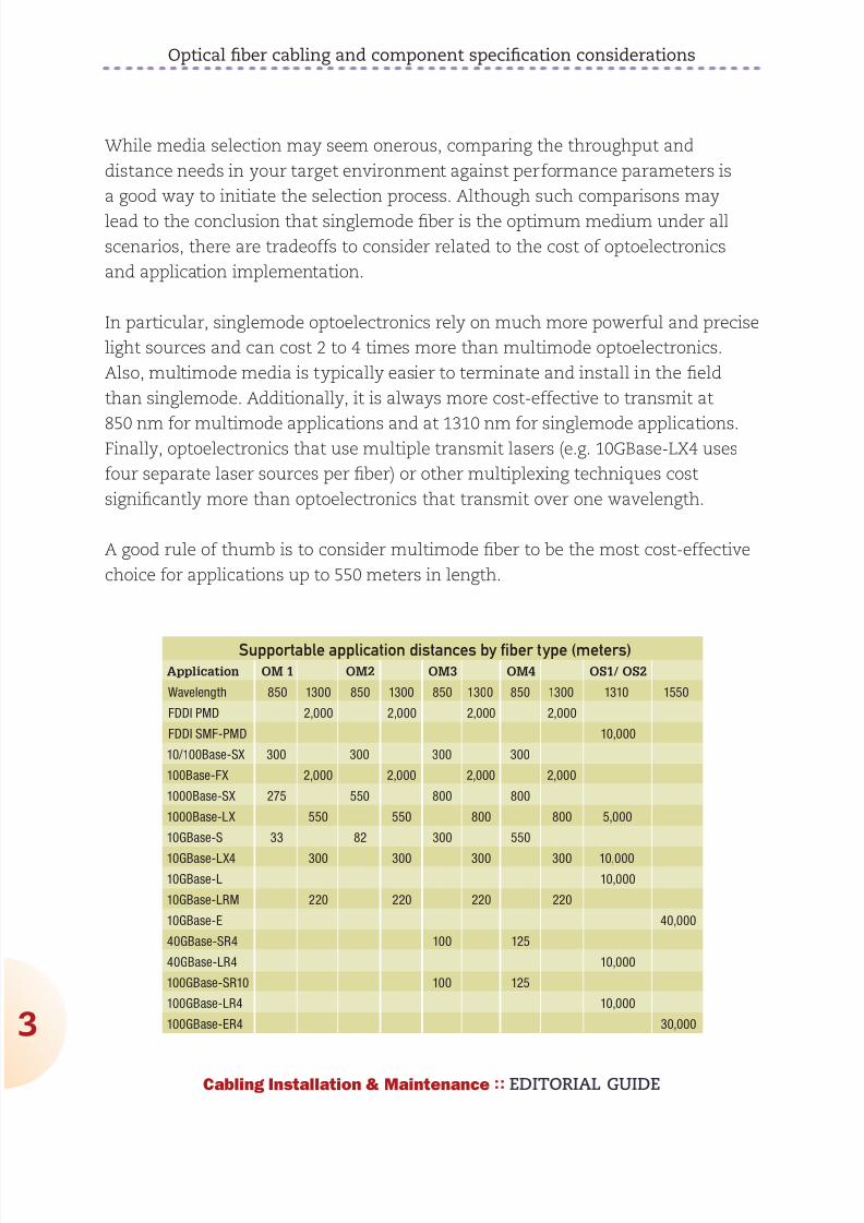
892019 Considerations for Selecting and Using Multimode Fiber
httpslidepdfcomreaderfullconsiderations-for-selecting-and-using-multimode-fiber 432
Optical fiber cabling and component specification considerations
4
Cabling Installation amp Maintenance EDITORIAL GUIDE
Optical fiber cabling configurations
Optical fiber cabling is typically deployed in pairs one fiber is used to transmit
and the other is used to receive Due to its extended distance support of
applications compared to balanced twisted-pair cabling optical fiber cabling
is the perfect media for use in customer-owned outside plant (OSP) backbone
cabling and centralized cabling applications
Customer-owned OSP cabling is deployed between buildings in a campus
environment and includes the terminating connecting hardware at or within the
structures Interestingly customer-owned OSP cabling is typically intended to
have a useful life in excess of 30 years so great care should be taken to specify
robust cabling media Requirements pertaining to customer-owned outside plantcabling and pathways can be found in ANSITIA-758-A and BS EN 50174-3
Backbone cabling is deployed between entrance facilities access-provider
spaces service-provider spaces common equipment rooms common
telecommunications rooms equipment rooms telecommunications rooms and
telecommunications enclosures within a commercial building Backbone cabling
must be configured in a star topology and may contain one (main) or two (main
and intermediate) levels of crossconnects Backbone cabling requirements are
specified in ANSITIA-568-C0 ANSITIA-568-C1 and ISOIEC 11801 Ed20
Centralized optical fiber cabling may be deployed as an alternative to the optical
crossconnect to support centralized electronics deployment in single-tenant
buildings Centralized optical fiber cabling supports direct connections from the
work area to the centralized crossconnect via a pull-through cable and the use
of an interconnect or splice in the telecommunications room or enclosure Note
that the maximum allowed distance of the pull-through cable between the work
area and the centralized crossconnect is 90 meters (295 feet) Centralized cablingrequirements are specified in ANSITIA-568-C0 ANSITIA-568-C1 and ISOIEC
11801 Ed20
Optical fiber cabling may also be used in the horizontal cabling infrastructure
although there are no provisions allowing extended distance in the TIA and ISO
standards
892019 Considerations for Selecting and Using Multimode Fiber
httpslidepdfcomreaderfullconsiderations-for-selecting-and-using-multimode-fiber 532
Optical fiber cabling and component specification considerations
Cabling Installation amp Maintenance EDITORIAL GUIDE
Horizontal cabling is deployed between the work area and the telecommunications
room or enclosure Horizontal cabling includes the connector and cords at the
work area and the optical fiber patch panel A full crossconnect or interconnect
may be deployed along with an optional multi-user telecommunications outlet
assembly (MUTOA) or consolidation point (CP) for a total of four connectors in the
channel The maximum horizontal cable length shall be 90 meters (295 feet) and
the total length of work area cords patch cords or jumpers and equipment cords
shall be 10 meters (32 feet) for both optical fiber and balanced twisted-pair cabling
channels Horizontal cabling requirements are specified in ANSITIA-568-C0
ANSITIA-568-C1 and ISOIEC 11801 Ed20
Optical fiber cableThe optical fiber that enables light transmission is actually an assembly of three
subcomponents the core the cladding and the coating The core is made of
glass (or more accurately silica) and is the medium through which the light
propagates The core may have an overall diameter of 9 microm for singlemode or 50
microm or 625 microm for multimode transmission Surrounding the glass is a second
layer of glass with a vastly different index of refraction that focuses and contains
the light by reflecting it back into the core This second layer is called the
cladding and regardless of the glass core construction has an overall diameter
of 125 microm Combining the core and cladding diameters is the source of optical
fiber descriptors such as 50125 microm or 625125 microm that are applied to optical
fibers commonly used for telecommunications applications The purpose of the
outermost layer called the coating is to add strength and build up the outer
diameter to a manageable 250-microm diameter (about three times the diameter of
a human hair) The coating is not glass but rather a protective polymer such as
urethane acrylate that may be optionally colored for identification purposes
Cabling optical fibers makes them easier to handle facilitates connectortermination provides protection and increases strength and durability The
cabling process differs depending upon whether the optical fibers are intended for
use in indoor outdoor or indooroutdoor environments
Indoor optical fiber cables are suitable for inside (including riser and plenum)
building applications To facilitate connector terminations a 900microm plastic
buffer is applied over the optical fiber core cladding and coating subassembly
892019 Considerations for Selecting and Using Multimode Fiber
httpslidepdfcomreaderfullconsiderations-for-selecting-and-using-multimode-fiber 632
Optical fiber cabling and component specification considerations
6
Cabling Installation amp Maintenance EDITORIAL GUIDE
to create a tight buffered fiber Up to 12 tight buffered fibers are then encircled
with aramid yarns for strength and then enclosed by an overall flame-retardant
thermoplastic jacket to form a finished optical fiber cable For indoor cables with
higher than 12-fiber counts groups of jacketed optical fiber cables (typically 6- or
12-fiber count) are bundled together with a central strength member (for support
and to maintain cable geometry) and are enclosed by an overall flame-retardant
thermoplastic jacket Supported fiber counts are typically between 2 and 144
Outdoor (also known as outside plant or OSP) optical fiber cables are used
outside of the building and are suitable for lashed aerial duct and underground
conduit applications To protect the optical fiber core from water and freezing
up to 12 250-microm optical fiber cores are enclosed in a loose buffer tube that isfilled with water-blocking gel For up to 12-fiber applications the gel-filled loose
tube is encircled with water-blocking tapes and aramid yarns and enclosed
within an overall ultraviolet and
water-resistant black polyolefin
jacket For outdoor cables with
higher than 12-fiber counts groups
of loose buffer tubes (typically 6- or
12-fiber count) are bundled together
with a central strength member and
water-blocking tapes and aramid
yarns and then enclosed within
an overall ultraviolet and water-
resistant black polyolefin jacket
Corrugated aluminum interlocking
steel armor or dual jackets may be
applied for additional protection
against crushing and rodent damageSupported fiber counts are typically
between 12 and 144
Indooroutdoor optical fiber cables offer the ultraviolet and water resistance
benefits of outdoor optical fiber cables combined with a fire-retardant jacket that
allows the cable to be deployed inside the building entrance facility beyond the
maximum 152-meter (50-foot) distance that is specified for OSP cables Note that
Several of the optical interconnection technologies
described in this article are shown here Clockwise
from upper left are MTPMPO-style trunking
cable assemblies duplex LC-connected optical fiber
cables plug-and-play array modules (one with
MPOMTP-style connectors showing and the otherwith LC connectors showing) and a pass-through
adapter plate
892019 Considerations for Selecting and Using Multimode Fiber
httpslidepdfcomreaderfullconsiderations-for-selecting-and-using-multimode-fiber 732
Optical fiber cabling and component specification considerations
7
Cabling Installation amp Maintenance EDITORIAL GUIDE
there is no length limitation in
countries outside of the United
States that do not specify riser-
or plenum-rated cabling The
advantage of using indoor
outdoor optical fiber cables
in this scenario is that the
number of transition splices
and hardware connections is
reduced Indooroutdoor optical
fiber cables are similar in
construction to outdoor opticalfiber cables except that the 250-
microm optical fiber cores may be
either tight buffered or enclosed
within loose buffer tubes Loose
tube indooroutdoor optical fiber
cables have a smaller overall
diameter than tight buffered
indooroutdoor optical fiber cables however tight buffered indooroutdoor cables
are typically more convenient to terminate because they do not contain water-
blocking gel or require the use of breakout kits (described later)
Optical fiber interconnections
Unlike the plug-and-jack combination that makes up a mated balanced
twisted-pair connection an interconnection is used to mate two tight-buffered
optical fibers An optical fiber interconnection typically consists of two plugs
(connectors) that are aligned in a nose-to-nose orientation and held in place with
an adapter (also called a coupler or bulkhead) The performance of the opticalfiber interconnection is highly reliant upon the connectorrsquos internal ferrule and
the adapterrsquos alignment sleeve These components work in tandem to retain
and properly align the optical fibers in the plug-adapter-plug configuration The
internal connector ferrule is fabricated using a high-precision manufacturing
process to ensure that the optical fiber is properly seated and its position is tightly
controlled The high tolerances of the alignment sleeve ensure that the optical
fibers held in place by the ferrule are aligned as perfectly as possible Although
Equipment cord connected tocentralized equipment
Horizontal cable90 m (295 ft max)
Telecommunications
room (TR)
Work area (WA)
Work areaequipment
cord
Work area outlet
Centralized optical fiber cabling usingan interconnection
Equipmentroom
Shown here is a typical schematic for centralized optical
fiber cabling using an interconnection the centralized
system supports direct connections from the work area to
the centralized crossconnect via a pull-through cable and
the interconnect
892019 Considerations for Selecting and Using Multimode Fiber
httpslidepdfcomreaderfullconsiderations-for-selecting-and-using-multimode-fiber 832
Optical fiber cabling and component specification considerations
8
Cabling Installation amp Maintenance EDITORIAL GUIDE
more expensive ceramic alignment sleeves maintain slightly tighter tolerances
than metal or plastic alignment sleeves are not as susceptible to performance
variations due to temperature fluctuations and may be specified for extremely
low-loss applications
Accurate plug-adapter-plug alignment minimizes light energy lost at the optical
fiber interconnection and maintaining precision tolerances becomes especially
critical as the optical fiber diameter decreases For example if two 625-microm
optical fibers are off-center by 4 microm in opposite directions then 13 of the light
energy escapes or is lost at the interconnection point This same misalignment
in a 9-microm singlemode fiber would result in almost a total loss of light energy
The critical nature of the core alignment is the reason why different optical fibertypes including 625-microm and 50-microm multimode fiber should never be mixed in
the same link or channel
Optical fiber breakout kits are used to facilitate termination of loose-tube optical
fibers used in indooroutdoor and outdoor applications Once the water-blocking
gel is thoroughly removed from the optical fibers the breakout kit allows furcation
tubes (typically 12mm to 30mm in diameter) to be installed over the 250-microm
optical fibers increasing the diameter and forming a short ldquojacketrdquo so that the
optical fibers may be terminated to the desired optical fiber connector Selection of
the correct furcation tube ensures compatibility with all optical fiber connectors
Users can choose from many optical fiber connector options
Traditional optical fiber connectors are represented by the SC and ST connector
styles These two types of optical fiber connectors were recognized when optical
fiber cabling was described in
the first published TIA and ISOIEC telecommunications cabling
standards The ST connector
Cladding
Core
Optical fiber cross-section
Core
Diameter
9m 50m or 625m
125m
Coating
250m
Cladding
Coating
Singlemode fiber cores are 9 microm in
diameter while multimode fiber cores may
be 50 or 625 microm Regardless of core size
the cladding is 125 microm and the coating
250 microm
892019 Considerations for Selecting and Using Multimode Fiber
httpslidepdfcomreaderfullconsiderations-for-selecting-and-using-multimode-fiber 932
892019 Considerations for Selecting and Using Multimode Fiber
httpslidepdfcomreaderfullconsiderations-for-selecting-and-using-multimode-fiber 1032
Optical fiber cabling and component specification considerations
0
Cabling Installation amp Maintenance EDITORIAL GUIDE
12-fiber MPOMTP interfaces with 24 LC connections or one 12-fiber MPOMTP
interface with 12 SC or LC connections
Optical fiber cabling deployment
The most common optical fiber cabling deployment approach is to field terminate
the optical fiber connectors to the optical fiber cable using the appropriate epoxy
polish or no-epoxyno-polish mechanical termination method However the
new MPOMTP plug-and-play modules and MPOMTP array connectors are not
supported by field termination and there are considerations such as installer
expertise and the IT construction
upgrade schedule that may favor the
use of factory-terminated pigtailsor trunking assemblies over field
termination methods
The pros and cons of these termination
methods are described here
Field termination supports the lowest
raw material cost for SC ST LC and
MT-RJ optical fiber cabling systems
However the time needed for field
termination is the longest of the three
deployment options and installer
skill-level requirements are higher
which may increase the project
installation costs No-epoxyno-polish
and certain mechanical-splice-style
termination methods require lessinstallation skill than the epoxypolish method however the connectors used in
conjunction with mechanical termination methods are more expensive and the
performance (especially using the no-epoxyno-polish method) may be lower
and more variable
Optical fiber pigtails feature a factory preterminated and tested SC ST LC or MT-
RJ optical fiber connector and a 1-meter stub of 625125-microm multimode 50125-
Tight-buffered
Loose-tube
Sample optical fiber cable constructions
Jacket
Rip cord
Central strength member
Aramid yarns
Color coded tight-bufferedfibers and jackets
Water-blocking swellabletape
Gel-filled tubes
Water-blocking aramid yarn
Central strength memberRip cord
Aramid yarns
Color-coded fibers and tubes
Jacket
The environment in which the fiber cable will be
used eg indoor or outdoor will determine the
cablersquos construction and the treatment of the
fibers within that cable
892019 Considerations for Selecting and Using Multimode Fiber
httpslidepdfcomreaderfullconsiderations-for-selecting-and-using-multimode-fiber 1132
Optical fiber cabling and component specification considerations
1
Cabling Installation amp Maintenance EDITORIAL GUIDE
microm multimode or singlemode optical fiber The stub end of the pigtail is then
fusion-spliced to the optical fiber Fusion splicing provides a consistent nearly
loss-free termination and can be fast with proper technicians and equipment
The main benefits to this approach are the assurance of low-loss performance at
the interconnection and the elimination of the need for endface inspections and
possible connector reterminations
Trunking cable assemblies provide an efficient alternative to field-terminated
components or splice connections and allow up to 75 faster field deployment
times Trunking cable assemblies are custom factory preterminated and tested
lengths of optical fiber cable terminated on both ends with SC ST LC MT-RJ or
MPOMTP optical fiber connectors that are simply pulled and plugged in Whendeploying trunking cable assemblies cable-length specification is critical and
precise planning is required up front Trunking cable assemblies that have an
MPOMTP connector on one or both ends are commonly referred to as ldquoplug-
and-playrdquo cable assemblies MPOMTP plug-and-play cable assemblies have the
smallest connector profile and therefore have the smallest pathway cabinet and
rack-space requirements of all trunking cable assembly options
Always maintain the fibersrsquo polarity to ensure the transmit fiber is matched to
the receive port on each end of the link or channel
Valerie Maguire is a Global Sales Engineer with Siemon
892019 Considerations for Selecting and Using Multimode Fiber
httpslidepdfcomreaderfullconsiderations-for-selecting-and-using-multimode-fiber 1232
1010100000001111011111100101010101001010
1010000001110101010101000101010001010101
0101001010101010010100101010101000000011
1101111110010101010100101010100000011101
0101010100010101000101010101010010101010
1001010010101010100000001111011111100101
0101010010101010000001110101010101000101
010001010101010100101010101001010010101
0101000000011110111111001010101010010101
0100101010000000111101111110010101010100
1010101000000111010101010100010101000101
010101010010101010100101001010101010000
0001111011111100101010101001010101000000
1110101010101000101010001010101010100101
0101010010100101010101000000011110111111
0010101010100101010100000011101010101010
0010101000101010101010010101010100101001
0101010100000001111011111100101010101001
01010100101010000000111101111110010101010
Is there a hole in your
fiberrsquos performance
If itrsquos not OFS multimode fiber there could be OFSrsquo
manufacturing process virtually eliminates defects in the
fiber core with a DMD specified in the 0-5 micron range
That means double the bandwidth for lasers that launch
power in the fiberrsquos center while providing fast reliable
transmission and easier connectivity To learn more ask
your cabler about OFS or visit wwwofsopticscomfiber
892019 Considerations for Selecting and Using Multimode Fiber
httpslidepdfcomreaderfullconsiderations-for-selecting-and-using-multimode-fiber 1332Cabling Installation amp Maintenance EDITORIAL GUIDE
3
Making the switch from
625- to 50-micron fiber
What to do and what not to do when opting
for higher-bandwidth 50-micron multimode
By John Kamino
MULTIMODE FIBER SYSTEMS continue to provide the most cost-
effective cabling solution for data centers local area networks
(LANs) and other enterprise applications Compared to singlemode
fiber multimode systems offer significantly lower costs for
transceivers connectors and connector installation while meeting and exceeding
the bandwidth and reliability requirements of the most demanding networks
If you are designing a new short-reach installation you will probably choose laser-
optimized 50-micron (microm) OM3 or OM4 multimode fiber These fibers preserve the
systems-cost benefits over singlemode fiber by using low-cost 850-nm vertical-
cavity surface-emitting laser (VCSEL) technology are capable of 10-Mbitsec
through 10-Gbitsec operation and will support upcoming 40- and 100-Gbitsec
transmission speeds
But if you are upgrading an existing system many of which have 625-microm
multimode already installed should you stick with 625-microm Or can you go with
the higher performance of 50-microm OM3 or OM4 fiber This article highlights thethings you must consider when upgrading an existing 625-microm system
Why two fiber sizes
The numbers under discussionmdash50-microm and 625-micrommdashrefer to the diameter of
the fiberrsquos core through which light signals are transmitted The first optical
fibers deployed in the 1970s for both short- and long-reach applications were
50-microm multimode fibers In the early 1980s singlemode fiber replaced 50-microm
892019 Considerations for Selecting and Using Multimode Fiber
httpslidepdfcomreaderfullconsiderations-for-selecting-and-using-multimode-fiber 1432
Making the switch from 625- to 50-micron fiber
4
Cabling Installation amp Maintenance EDITORIAL GUIDE
fiber in longer-distance installations However 50-microm multimode continued to be
more cost-effective for short-reach interconnects such as building and campus
backbones up to 2000-meter distances
But as data rates increased 50-microm fiber could not support 10-Mbitsec rates overthe 2-kilometer distances required by some campus installations Not enough
power could be coupled from the light-emitting diode (LED) sources in use at that
time into the 50-microm core to support these link distances
625-microm multimode fiber was introduced in 1985 to solve this problem It could
capture more light from a LED in its larger core and 2-km campus links operating
at 10 Mbitssec were easily supported Also the larger-core fiber was easier to
cable and connectorize It became the most commonly used fiber for short-reach
enterprise applications in North America
Today as data rates surpass 10-Gbitssec and lasers have replaced LEDs 625-microm
fiber has reached its performance limit 50-microm fiber offers as much as 10 times
the bandwidth of the 625-microm fiber Whatrsquos more improvements in technology
have made 50-microm fiber easier to use
Multimode fiber choices today
To consider making the switch from 625-microm to 50-microm multimode it is importantto first understand the terminology used to designate the various performance
grades of multimode fiber In each of these designations ldquoOMrdquo stands for ldquooptical
multimoderdquo For example OM1 is the designation for fiber with 200500 MHz-
km overfilled launch (OFL) bandwidth at 8501300 nm this typically is 625microm
fiber OM2 is used for fiber with 500500 MHz-km OFL bandwidth at 8501300 nm
(typically 50-microm fiber)
Fiberdesignation
EMB (in MHz∙km) 850 nm
OFL (in MHz∙km) 850 nm
OFL (in MHz∙km) 1300 nm
OM1 (625) NA 200 500
OM2 (50) NA 500 500
OM3 (laser-
optimized 50) 2000 1500 500
OM4 (laser-
optimized 50) 4700 3500 500
892019 Considerations for Selecting and Using Multimode Fiber
httpslidepdfcomreaderfullconsiderations-for-selecting-and-using-multimode-fiber 1532
Making the switch from 625- to 50-micron fiber
5
Cabling Installation amp Maintenance EDITORIAL GUIDE
More-recent additions are OM3 for laser-optimized 50-microm fiber having 2000
MHz-km effective modal bandwidth (EMB also known as laser bandwidth) at 850
nm (designed for 10-Gbitsec transmission) and most recently OM4 for laser-
optimized 50-microm fiber having 4700 MHz-km EMB at 850 nm designed for 10-Gbit
sec transmission over longer distances
OM4 with its extended bandwidth can be used to enhance the system-cost
benefits enabled by 850 nm lasers for 10-Gbitsec applications as well as new
40- and 100-Gbitsec systems With its 150 m reach capability at 40 and 100
Gbitsec OM4 will support an additional 10 percent of link lengths in large data
centers that are not covered by OM3rsquos 100 m reach It is especially well-suited
for short reach data center and high-performance computing applications whereoptical loss budgets are tight at 10-Gbitsec and higher The additional bandwidth
provided when OM4 fiber is deployed at less than its rated distance offers extra
headroom for channel insertion loss
Itrsquos also important to note that for next-generation 40- and 100-Gbitsec
Ethernet only OM3 and OM4 fibers are included in the IEEE 8023ba standard
as supported (multimode optical fiber) media OM1 and OM2 fibers are not
supported media types
The latest offerings in multimode fiber are 50 microm bend insensitive multimode
fibers (BIMMF) These fibers have been promoted as offering all the advantages
of high bandwidth laser-optimized multimode fiber with the added advantage
of lower bend sensitivity However recent work has shown that some of these
fibers may have significant performance issues A paper presented at the 2010
International Wire and Cable Symposium (IWCS) showed that mating (connector)
loss of BIMMFs with standard fibers is higher than standard fiber connected to
standard fiber This additional loss adds to the total link loss possibly causing itto exceed the link loss budget
Another recent study examined issues with the system performance of bend
insensitive fibers and questioned whether current requirements are adequate
It has been proposed that standards organizations perform a thorough review of
BIMMFs and incorporate them into industry standards Until this work is done
caution is advised before widespread adoption takes place
892019 Considerations for Selecting and Using Multimode Fiber
httpslidepdfcomreaderfullconsiderations-for-selecting-and-using-multimode-fiber 1632
Making the switch from 625- to 50-micron fiber
6
Cabling Installation amp Maintenance EDITORIAL GUIDE
Upgrading a 625-microm network
The primary considerations for an upgrade or extension of an existing 625-microm
network are
the required transmission speed (now and especially in the future)
link distance
ease of cable replacement and
cost of cable replacement
If you are running Gigabit Ethernet (1-Gbitsec) then legacy 625-microm fiber will
transmit a distance of 220 to 275 meters depending on its bandwidth ratingBut at 10-Gigabit Ethernet (10-GbE 10-Gbitssec) they will only support 26 to
33 meters If your network will not need to support 10-GbE at distances greater
than 25 meters then you may be able to stick with 625-microm fiber It is important
to note however that most 625-microm fiber has not been measured for laser
bandwidth and some legacy fiber may have difficulty supporting even this short
distance
And if you want to transmit longer distances over 625-microm fiber you will be
forced to use much-more-expensive 1300-nm transceivers that will operate over
multimode or singlemode fiber These transceivers cost significantly more than
850-nm multimode devices because the 1300-nm optoelectronics package is the
far more complex of the two
If you are considering extending your network by installing additional 625-microm
fiber you need to carefully review your future network plans If you plan to
upgrade your network speed to 10-Gbitssec in the future recabling with laser-
optimized OM3 or OM4 fiber would be a wiser choice
Measuring laser bandwidth
As previously stated 625-microm fiber provides limited support for 10-Gbitsec
transmission so it generally is not measured for laser bandwidth (EMB) Typically
only 50-microm fibers are measured for EMB To verify bandwidth of 625-microm fiber
the traditional OFL bandwidth measurement method is used
892019 Considerations for Selecting and Using Multimode Fiber
httpslidepdfcomreaderfullconsiderations-for-selecting-and-using-multimode-fiber 1732
Making the switch from 625- to 50-micron fiber
7
Cabling Installation amp Maintenance EDITORIAL GUIDE
For 50-microm fibers EMB is ensured by using a method called Differential Mode
Delay (DMD) This DMD test is required by standards to verify 10-Gbitsec
performance and involves scanning the fiberrsquos core in small increments to see
how the signal travels in various regions of the core
Once the DMD test is conducted and a DMD ldquoprofilerdquo is obtained the standards
allow two methods to disposition the fiber One is the DMD Mask method and the
other is the Effective Modal Bandwidth Calculated (EMBc) method
The DMD Mask method provides direct verification of the fiberrsquos DMD
performance using a set of clearly defined DMD masks and templates that are
overlaid on the DMD profile This technique provides flexibility in applying more-stringent DMD performance criteria in certain regions of the fiber including the
0-5microm center region
The EMBc method involves complex calculations involving 10 weighting
functions to represent the wide variety of 10-Gbitsec VCSELs available on the
market Theoretical in nature this technique does not in our opinion provide
the scrutiny on fiber quality and performance that the DMD Mask technique
does The EMBc method puts little emphasis on the 0-5microm region of a fiberrsquos
core Though standards allow both testing methods we advocate the DMD
Mask method
Mixing 50- and 625-microm
If you decide to add 50-microm fiber to an existing 625-microm infrastructure connecting
50-microm directly to 625-microm is generally not recommended The difference in core
sizes could cause high loss when transmitting from the 625-microm into the 50-
microm fiber Also the bandwidth of 625-microm fibers is typically much lower further
degrading system performance Even if a low-speed application operates over alink made up of mixed fiber types upgradeability will be severely compromised
This elevated-loss problem occurs when transmitting from the larger (625-microm) to
the smaller (50-microm) core It is comparable to a 4-inch water pipe connecting to a
3-inch pipe there is no problem going from the smaller pipe to the larger one but
going in the opposite direction can lead to a lot of lost water (or in this case light)
892019 Considerations for Selecting and Using Multimode Fiber
httpslidepdfcomreaderfullconsiderations-for-selecting-and-using-multimode-fiber 1832
Making the switch from 625- to 50-micron fiber
8
Cabling Installation amp Maintenance EDITORIAL GUIDE
The amount of connection loss you could experience is about 4 dB for a LED-
based system which fills the entire core of a 625-microm fiber and anywhere from 0
to 4 dB for a VCSEL-based system which only fills a portion of the core
Because most optical-loss test sets use LEDs you should plan for the worst and
assume you will see a 4-dB loss in one direction If your link budget can tolerate
this additional 4-dB loss then you can get away with connecting 50-microm directly
to 625-microm
The better scenario is to separate 50-microm from 625-microm with active electronics
such as a switch router or simple media converter
Mixing of 625-microm and 50-microm fiber is not recommended unless an electronics
interface is inserted into the link If 10-Gbitsec speeds are being installed 625-
microm fiber will only be able to support extremely short links and replacement is
recommended
John Kamino is Product Manager Multimode Fiber with OFS
892019 Considerations for Selecting and Using Multimode Fiber
httpslidepdfcomreaderfullconsiderations-for-selecting-and-using-multimode-fiber 1932
OFSrsquo LaserWave fiber exceeds the OM4 standard for
todayrsquos high-speed networks mdash and tomorrowrsquos Andsince LaserWave fiber delivers DMD specified in the
0 ndash 5 micron range you get up to twice the bandwidth for
lasers that launch power in the fiberrsquos center Enjoy fast
reliable transmission and easier connectivity To learn more
ask your cabler about OFS or visit ofsopticscomfiber
Get your network up tospeed with LaserWavereg fiber
892019 Considerations for Selecting and Using Multimode Fiber
httpslidepdfcomreaderfullconsiderations-for-selecting-and-using-multimode-fiber 2032Cabling Installation amp Maintenance EDITORIAL GUIDE
20
Compatibility issues with
bend-insensitive andstandard multimode
Lab testing indicates risks associated with mixing
bend-insensitive and standard multimode fiber
By Rick Pimpinella Bulent Kose and Brett Lane
THE INCREASING DEMAND for higher-speed data transmission
within the data center and premises networks has led to the wide
deployment of multimode optical connectivity To meet performance
and reliability requirements the optical specifications on the
components have also become more stringent For high-speed optical networks
using laser-optimized OM3 and OM4 multimode fiber it is more critical than ever
for network operators and designers to understand the attributes of the various
performance grades of passive fiber-
optic components that make up the
network so that they may employ the
most cost-efficient solutions that meet
their needs today and in the future
In order to ensure that optical networks
operate effectively and reliably it isfundamental that the optical fiber
meets the necessary bandwidth
requirements and that the total optical
loss or insertion loss (IL) is below
the allowable limit required by the
application The two sources of IL
within optical networks are 1) loss at
892019 Considerations for Selecting and Using Multimode Fiber
httpslidepdfcomreaderfullconsiderations-for-selecting-and-using-multimode-fiber 2132
Compatibility issues with bend-insensitive and standard multimode
21
Cabling Installation amp Maintenance EDITORIAL GUIDE
connector interfaces and 2) loss or attenuation within the fiber itself The IL
limits for 10- 40- and 100-Gbitsec Ethernet are in the table below
The combination of
eroding insertion loss
budgets and increased
demands for complex
network architectures
with many
connector interfaces
has triggered several fiber and connectivity suppliers to develop improved
connectivity and fiber products that allow network architectures to cope withthese trends Specifically several connectivity suppliers now offer low-loss or
optimized passive fiber-optic components such as connectors cassettes and
patch cords that allow them to implement complex networks with numerous
connector interfaces while still meeting the maximum connector loss budget
Moreover although the intrinsic fiber attenuation has not been reduced
significantly over the past many years recent advancements in fiber production
have delivered extra headroom by significantly improving attenuation levels
under tightly bent conditions even in those cases in which the fiber is
unintentionally subjected to bends smaller than that allowed with the ANSI
TIA-568-C0 premises cabling standard This article reviews how this new type of
laser-optimized multimode fiber often called bend-insensitive or bend-optimized
integrates into todayrsquos data center and premises network
Achieving bend-optimization
It is well known that in order to produce a fiber with improved bend performance
it must be made to more tightly confine the light within its core region Thismodification allows more of the light to meet the conditions necessary for
total internal reflection as the fiber is bent Enhanced optical confinement
is accomplished by simply increasing the effective difference in the index of
refraction between the core and cladding regions This is typically accomplished
by introducing an index depression or trench in the cladding region close to the
fiber core
Applicationstandard
Minoperatingdistance
(m)
Maxconnectorloss (dB)
Max fiberattenuation
(dB)
Max totalIL budget
(dB)
0-Gbitsec Ethernet 300 15 11 26
40- and 100-Gbit
sec Ethernet (OM3)
100 15 04 19
40- and 100-Gbit
sec Ethernet (OM4)
150 1 05 15
892019 Considerations for Selecting and Using Multimode Fiber
httpslidepdfcomreaderfullconsiderations-for-selecting-and-using-multimode-fiber 2232
892019 Considerations for Selecting and Using Multimode Fiber
httpslidepdfcomreaderfullconsiderations-for-selecting-and-using-multimode-fiber 2332
Compatibility issues with bend-insensitive and standard multimode
23
Cabling Installation amp Maintenance EDITORIAL GUIDE
conditions necessary for total internal reflection (ie rays with larger angles)
light emerging from bend-optimized multimode fiber will have a larger angle on
average than light emerging from standard multimode fiber The parameter that
characterizes the maximum divergence or acceptance angle of light from or to
a fiber is called numerical aperture (NA) Therefore the NA of bend-optimized
multimode is generally expected to be greater on average than the NA of
standard multimode A thorough sampling across multiple fiber manufacturers
revealed that the average NA increased
from 0199 for standard multimode fiber to
0207 for bend-optimized multimode fiber
Although this moderate increase in NAappears insignificant in some situations
the optical loss across an optical fiber
interface (eg connector) is dependent on
the differences in NAs of the fibers In the
case that light fully populates the fiber
core such as when illuminated with an
LED and is coupled from a fiber with a
higher NA into a receiver with a lower NA
the light will diverge at an angle larger
than the acceptance angle of the receive
fiber This will result in some light being
lost (into the cladding) and the interface will have loss proportional to the NA
difference (ratio) between the two fibers
Consequently increased loss may be realized when light travels from bend-
optimized multimode fiber into standard multimode fiber In fact the expected
loss across a bend-optimized fiber with an NA of 0207 and a standard fiber withan NA of 0199 is 034 dB which is a significant portion of the overall IL budget
In the case that light travels from a fiber with a lower NA into a receiver with a
higher NA or light does not fully illuminate the fiber core no loss resulting from
the difference in fiber NAs is expected
NA loss measurements
To predict the NA loss that would be realized during link certification
2 4 6
MMF LED
MMF VCSEL
8 10
3
25
2
15
1
05
0
Bend loss (1 m) (dB)
Mandrel radius (mm)
BO-MMF LED
BO-MMF VCSEL
Measured bend loss at 850 nm
representative of bend-optimized and
standard multimode fiber using both
LED and VCSEL light source Fibers were
wrapped one turn around 10 different
mandrels with radii ranging from 25mm to
10 mm
892019 Considerations for Selecting and Using Multimode Fiber
httpslidepdfcomreaderfullconsiderations-for-selecting-and-using-multimode-fiber 2432
Compatibility issues with bend-insensitive and standard multimode
24
Cabling Installation amp Maintenance EDITORIAL GUIDE
measurements of an optical
channel with bend-optimized
and standard fiber interfaces
a series of standard IL
measurements were performed
on selected bend-optimized
and standard fibers Fiber
samples from several fiber
manufacturers were selected
with a wide range of NAs in
order to provide not only a
typical NA loss from fibers withaverage NA but also provide
an upper and lower limit of
NA loss that may be expected
when connecting dissimilar
multimode fiber types without knowledge of NA differences Several fibers were
selected of each fiber typendashsome with an average NA some with a low NA and
some with a high NA The table on page 25 summarizes the samples used for this
experiment and the theoretically expected NA loss from each connection
For these measurements the various bend-optimized fiber samples were
fusion spliced to the various standard multimode fiber samples A fusion
splicer was used to connect dissimilar fiber types instead of connectors in
order to minimize other loss contributors such as lateral offset and connector
termination processing The insertion loss of the connection was calculated by
injecting light meeting the new TIAEIA-526-14-B encircled flux specification
into the bend-optimized fiber and then measuring the power coupled out of
the standard fiber Subtracting this power level from the reference power levelmeasured previously as the amount of power coupled into the bend-optimized
fiber resulted in the IL or NA loss of the connection All aspects of these
measurements were in compliance with TIAEIA-45-171A (eg diameter and
placement of cladding mode strippers)
The measurement data is shown in the chart on page 25 Each data point
represents the average of the NA losses for a set of fibers for each NA
Bend-optimizedMMF core
NA = sinq1
MMF coreα
NABO-MMF gt NAstd-MMF
This illustration shows a mismatch in NA when connecting
a fiber with a large NA (left) to a fiber with a small NA(right) Because the receive fiber on the right has a smaller
NA some light is not coupled and instead is lost into the
cladding This loss is referred to as NA loss
892019 Considerations for Selecting and Using Multimode Fiber
httpslidepdfcomreaderfullconsiderations-for-selecting-and-using-multimode-fiber 2532
Compatibility issues with bend-insensitive and standard multimode
25
Cabling Installation amp Maintenance EDITORIAL GUIDE
combination From this data
connecting dissimilar fiber types
with average NAs confirms the
theoretically predicted NA loss of
approximately 040 dB Additionally
the upper and lower limits of NA
loss were measured to be 028
dB and 106 dB Although these
average and extreme NA losses
are fairly well correlated with the
theoretically predicted NA loss
other measured values deviatesignificantly from the theoretically
predicted value This suggests that
factors other than NA such as core
diameter index profile and mode structure also significantly influence the loss
when connecting bend-optimized and standard multimode fiber As a result the
light does not couple with 100 percent efficiency between fibers and therefore an
additional mode coupling loss must exist
In fact in the case that bend-optimized fiber samples with the identical NA but
manufactured from different suppliers were connected to standard fibers with
NA equal to 0200 the NA loss differs significantly from vendor to vendor The
average NA loss from Vendor A bend-optimized interfaces nearly exactly matched
the theoretical NA loss of 030 dB while the average NA loss from Vendor B
bend-optimized interfaces was much higher at 051 dB (see graph on page 26) As
expected the bend-optimized fibers from Vendor B were found to be more bend-
tolerant than those from Vendor A
In addition to realizing
unidirectional NA
loss an increase in the
modal noise penalty
may also result
when connecting
bend-optimized and
1000 0975 0950 0925 0900 0875 0850
14
12
10
08
06
04
02
00
NA ratio
NA loss (dB)
The black line shows the theoretical loss of connected
fibers with different NA and the dots represent
actual measured loss The results suggest factorsother than NA also influence loss when connecting
bend-optimized and standard multimode fiber
NA (BO-MMF)to NA (MMF)combination
NA (BO-MMF) NA (MMF) NA ratio Theoreticalloss (dB)
Average to Average 0207 0199 0961 034
Large to Average 0215 0199 0926 067
Large to Small 0215 0185 086 131
Average to Small 0207 0185 0894 098
Small to Small 0199 0185 0928 063
Large to Large 0215 0212 0986 012
892019 Considerations for Selecting and Using Multimode Fiber
httpslidepdfcomreaderfullconsiderations-for-selecting-and-using-multimode-fiber 2632
Compatibility issues with bend-insensitive and standard multimode
26
Cabling Installation amp Maintenance EDITORIAL GUIDE
standard multimode fiber Modal noise is a power penalty related to the reduction
in the signal-to-noise ratio (SNR) of the optical signal For high-speed networks
employing VCSELs if a connector selectively attenuates higher-order modes as a
result of NA mismatch or a lateral offset between fiber cores then fluctuations in
the power distribution (spatial speckle pattern) result in fluctuations in connector
insertion loss This fluctuation is seen by the detector as an increase in noise
thereby reducing the SNR and therefore signal quality
The maximum allowed power penalty for modal noise is currently specified
in 10GBase-SR to be 03 dB Both NA loss and mode coupling loss can increase
the mode-selective loss (filter aperture) at a connector interface resulting in an
increase in modal noise Considering the overall power budget for 10G40G100GEthernet is 15 dB (or 10 dB for OM4) any
increase in modal noise may compromise
system reliability
In conclusion inconclusive
As part of our review of how bend-
optimized multimode fiber is integrating
in todayrsquos data center and premises
networks we measured the loss between
bend-insensitive and standard multimode
fibers to quantify the expected additional
loss during certification of mixed-fiber
links These additional losses were
measured to be as high as 1 dB and can
be a significant portion ofndashor even actually
exceedndashthe total optical power budget
for todayrsquos high-speed networks For a channel link that contains several bend-optimized fiber and multimode fiber interfaces which have large NA differences
the NA losses may be additive and further inhibit system certification
Furthermore although NA loss alone is unlikely to detrimentally influence
system performance it may be very difficult if not impossible to determine if
excessive channel loss is due to NA differences or other conventional sources
of loss such as macrobending or dirtydamaged components One strategy to
BO-MMF1
to MMF2
BO-MMF1
to MMF2
BO-MMF1
to MMF2
Vendor A BO-MMF
Vendor B BO-MMF
BO-MMF1
to MMF2
07
06
05
04
03
02
01
00
Measured NA loss (dB)
Bend-optimized fibers from Vendor B shown
here as the blue bars were found to be more
bend-tolerant than the bend-optimized fibers
from Vendor A shown as the green bars
The more-optimized fibers exhibited higher
NA loss
892019 Considerations for Selecting and Using Multimode Fiber
httpslidepdfcomreaderfullconsiderations-for-selecting-and-using-multimode-fiber 2732
Compatibility issues with bend-insensitive and standard multimode
27
Cabling Installation amp Maintenance EDITORIAL GUIDE
account for this loss would be to require bidirectional loss measurements of
individual optical interfaces
During the most recent meeting of the TIA TR-4212 Optical Fibers and Cable
Subcommittee a vigorous debate included many of the topics discussed in this
article and others including increased NA loss mode coupling loss modal
noise (which may negatively impact system performance) the validity of other
standardized fiber test procedures for fiber core diameter fiber bandwidth and
link attenuation (encircled flux) The subcommittee authorized the formation of
a task group to study the technical compatibility of bend-insensitive multimode
fiber with current multimode fiber standards
Based on our internal analysis and the present uncertain position within the
standards community we have concluded that the performance risks of mixing
bend-optimized and standard multimode fiber types in high-speed optical
channel links exceeds any benefit To ensure that total optical loss across data
center and premises networks remains below the allowable limit we recommend
adhering to standards-based radius-control methods and the use of one fiber
type throughout the channel link which includes cabling and patch cords This
approach enables network stakeholders to reliably deploy complex network
architectures meet stringent IL budgets and ensure optimal system performance
within current standards-based network architectures and testing methods
Some manufacturers support this effort others minimize its importance Until
the TIA subcommittee work on these issues is complete we recommend that
these two fiber types should not presently be mixed
Dr Rick Pimpinella is a Distinguished Engineer Bulent Kose is a ResearchEngineer and Dr Brett Lane is a Fiber Research Manager with Panduit
892019 Considerations for Selecting and Using Multimode Fiber
httpslidepdfcomreaderfullconsiderations-for-selecting-and-using-multimode-fiber 2832
As the demand for bandwidth in
enterprise applications such as
data centers continues to
boom new transmission media
must be developed continually
to meet end user requirementsThe latest in optical transmis-
sion media for the enterprise is
called OM4 fiber
OM4 fiber is a 50 micron (microm)
laser-optimized multimode fiber
with extended bandwidth It is
designed to enhance the sys-
tem cost benefits enabled by
850 nm Vertical Cavity Surface
Emitting Lasers (VCSELs) for existing 1 and 10 Gbs applica-
tions as well as future 40 and
100 Gbs systems
Supporting Ethernet Fibre
Channel and OIF applications
OM4 fiber allows extended
reach upwards of 550 meters at
10 Gbs for ultra long building
backbones and medium lengthcampus backbones It offers an
Effective Modal Bandwidth
(EMB) of 4700 MHz-km more
than double the IEEE require-
ment for 10 Gbs 300 meter
support
To help you use this advanced
fiber to its greatest advantage
this paper describes the tech-
nology behind OM4 fiber high-
lights the key differences with
other fiber types and explains
how its high bandwidth is
ensured through stringentmeasurement methods
Multimode Fiber Basics
Compared to single-mode
fibers multimode fibers have
larger cores that as their name
implies guide multiple ldquomodesrdquo
or rays of light simultaneously
Modes that travel at the outside
edge of the core have a longer
distance to go than modes thattravel near the center
The corersquos graded index profile
is designed to slow down
modes that have a shorter dis-
tance to travel so that all modes
arrive at the end of the fiber as
close in time as possible This
minimizes modal dispersion
also known as differential mode
delay (DMD) and maximizes
bandwidth which is the amount
of information that can travel
through the fiber per unit of
time
In addition to their large core
multimode fibers have a large
Numerical Aperture (NA) the
maximum angle at which a fiber
can accept the light that will be
transmitted through it This
allows them to work with rela-
tively low-cost optical compo-
nents and light sources such as
light-emitting diodes (LEDs)and VCSELs
Multimode Fiber Options
Multimode products are identi-
fied by the OM (ldquooptical multi-
moderdquo) designation as outlined
in the ISOIEC 11801 interna-
tional cabling standard (see
table 1)
OM4 - The Next Generation
of Multimode Fiber Tony Irujo
Sales Engineer
OPTICAL FIBER IN ENTERPRISE APPLICATIONS
Table 1 ISOIEC 11801 OM designations
892019 Considerations for Selecting and Using Multimode Fiber
httpslidepdfcomreaderfullconsiderations-for-selecting-and-using-multimode-fiber 2932
OM4 fiber is the latest develop-
ment in this series It is espe-
cially well suited for shorter
reach data center and high per-
formance computing applica-
tions where optical loss budg-
ets are tight at 10 Gbs (and
are expected to get even tighter
at 40 Gbs and 100 Gbs) Thehigh bandwidth provided by
OM4 fiber when deployed at
less than its rated distance
offers extra ldquoheadroomrdquo for
channel insertion loss
OM4 is backward compatible
with applications calling for OFL
bandwidth of at least 500 MHz-
km at 1300 nm (eg FDDI
IEEE 100BASE-FX
1000BASE-LX 10GBASE-LX4
and 10GBASE-LRM)
The latest offerings in multi-
mode fiber are 50 983221m bend
insensitive multimode fibers
(BIMMF) These fibers have
been promoted as offering all
the advantages of high band-
width laser-optimized multi-mode fiber with the added
advantage of lower bend sensi-
tivity
However recent work has
pointed to some areas of con-
cern with these fibers Studies
have identified issues with the
characterization of bend insen-
sitive fibers and questioned
whether current requirements
are adequate to guarantee sys-
tem performance Additional
studies have shown that mating
(connector) loss of BIMMFs
with standard fibers is higher
than with standard fibers con-
nected to each other This addi-
tional loss adds to the total link
loss
It has been proposed that stan-
dards organizations perform a
thorough review of BIMMFs
and incorporate them into
industry standards Until this
work is done some caution is
advised before widespread
adoption takes place
What Makes OM4 Different
Like OM3 multimode fiber OM4
fiber is considered to be ldquolaser-
optimizedrdquo or optimized for use
with VCSEL light sources OM3
and OM4 fibers are designed
and manufactured in such a
way as to get the most perform-
ance out of VCSELs compared
to LEDs That is why laser-opti-
mized fibers are specified using
Laser Bandwidth or EMB
OM2 fiber although compatible
with VCSELs is not considered
to be laser-optimized OM2
fiber is intended for use with
LED sources at speeds of 10 or
100 Mbs or for shorter reach 1
Gbs networks You can use
OM2 fiber with VCSELs but itsperformance is limited to 550
meters at 1 Gbs and only 82
meters at 10 Gbs compared to
OM4 fiberrsquos
reach of over
1000 meters
at 1 Gbs and
550 meters at
10 Gbs
As discussed
the speed at
which each
mode travels
down a multi-
mode fiberrsquos
core depends
on its refrac-
tive index
which is gov-
erned by the amount of chemi-
cal dopant Germanium at that
location in the core Because
modes traveling down the cen-
ter of the core have shorter dis-
tance to travel than those trav-
eling along the edge the refrac-
tive index profile in a multimode
fiber must be ldquogradedrdquo in a par-abolic manner across the core
This slows down the modes
that have a shorter distance to
travel equalizing the arrival
time of all the modes
The better the modes are
equalized the higher the band-
width of the fiber Mode equal-
ization depends on how well
the graded index profile is con-
structed during fiber manufac-
turing The more precise the
refractive index profile is in
terms of shape curvature and
smoothness (free of dips
spikes or defects) the better
the modes will be equalized
(see Figure 2)
OM4 fiber with its higher band-width has an extremely precise
refractive index profile virtually
free of perturbations or defects
Figure 2 A refractive index profile optimized for shape curvature
and smoothness maximizes bandwidth
892019 Considerations for Selecting and Using Multimode Fiber
httpslidepdfcomreaderfullconsiderations-for-selecting-and-using-multimode-fiber 3032
In order to make such a precise
fiber one needs to use a pre-
form manufacturing process
that has exceptional control
over the amount of Germanium
that is incorporated at particular
sub-micron positions within the
fiberrsquos core An example of a
process that lends itself to this
level of control is OFSrsquo propri-
etary MCVD process in which
each layer of the core is
deposited and sintered individu-
ally providing the utmost in
refractive index precision and
uniformity
OM4 Fiber Standards
Two standards define the useof OM4 fiber in high-speed net-
works TIA document TIA-
492AAAD which contains the
OM4 fiber performance specifi-
cations and the IEC 60793-2-
10 international standard which
provides equivalent OM4 speci-
fications under fiber type A1a3
ISOIEC 11801 will add OM4
fiber as an industry-recognized
fiber type and IEEE 8023bafor 40G and 100G Ethernet will
include OM4 fiber as an option
that provides a reach of 150
meters (50 percent greater than
OM3)
There was discussion and
debate within the standards
groups about a minimum OFL
bandwidth requirement at 850nm Although current applica-
tions primarily use 850 nm
VCSEL lasers with fibers that
are specified to a minimum
EMB there was good reason to
also establish a minimum 850
nm OFL bandwidth specifica-
tion It has been shown that
fibers with higher OFL band-
width will perform better with
VCSELs that launch more
power into outer modes That is
why the existing OM3 fiber
standards require a minimum
1500 MHz-km OFL bandwidthat 850 nm
For OM4 fiber OFS and others
in the standards group strongly
recommended at least 3500
MHz-km OFL bandwidth in
order to ensure the utmost per-
formance and reliability ulti-
mately that is the specification
that was agreed upon
Measuring Laser Bandwidth
Bandwidth performance of OM4
fiber is ensured using the same
criteria as OM3 but to much
tighter specifications Due to a
challenge posed when the now-
familiar VCSEL was first intro-
duced new measurement
methods had to be developed
to verify laser bandwidth of OM3 and OM4 fibers
Unlike an LED laser VCSELs
produce an energy output that
is not uniform it can change
sharply across the face of the
output Whatrsquos more each laser
fills a different set of light paths
in each fiber and does so with
differing amounts of power in
each path Overfilled bandwidth
measurements used to meas-
ure LED bandwidth could not
emulate the operation of aVCSEL
The standards allow two ways
to measure and verify laser
bandwidth the DMD Mask
Method and the EMBc Method
Both methods require DMD
testing -- the difference lies in
how the DMD data is used and
interpreted
In DMD testing small high-
powered laser pulses are trans-
mitted through the fiber in tiny
steps across the entire core of
the fiber Only a few modes are
excited at each step and their
arrival times are recorded The
DMD of the fiber is the differ-
ence between the earliest and
the latest arrival times of allmodes at all steps
DMD measurement is currently
the only reliable method for ver-
ifying bandwidth required for 10
Gbs performance because it is
the only method that checks all
modes across the fiber core
independently For that reason
Figure 3 DMD testing measures how different VCSELs fill different modes in each
fiber
892019 Considerations for Selecting and Using Multimode Fiber
httpslidepdfcomreaderfullconsiderations-for-selecting-and-using-multimode-fiber 3132
industry associations such as
TIAEIA and ISOIEC have pub-
lished standards for DMD
measurement and DMD specifi-
cations for laser-optimized mul-
timode fiber
The DMD Mask Method is a
simple process that directlycompares DMD test results
against a set of specifications
(called templates or masks) to
see if the fiber has the neces-
sary performance
This is a straightforward graphi-
cal approach to ensuring the
data pulses do not spread
excessively beyond therequired 10 Gbs bit period If
the fiber passes these DMD
specs then you are assured of
at least 2000 MHz-km EMB no
matter which VCSEL you use
(as long as the VCSEL is com-
pliant)
The EMBc Method is an indi-
rect and more complex
process It takes the DMD
results and matches them
against a set of theoretical
weighting functions that are
intended to represent the
launch distributions of all com-
pliant VCSELs
The DMD results are combined
mathematically with each of the
10 weighting functions This
produces 10 different EMBc
values the lowest of which is
called minEMBc The minEMBc
value is then multiplied by a
factor of 113 to obtain the
fiberrsquos EMB value If this EMB
value is gt 2000 MHz-km thefiber is deemed compliant with
OM3 requirements and there-
fore should support 300 meters
at 10 Gbs
Due to all the complex calcula-
tions required by the EMBc
method and the fact that the
weighting functions only repre-
sent a sampling of the launch
characteristics of the many
VCSELs that could actually be
used in a real system the
EMBc method does not provide
the same scrutiny on fiber qual-
ity and performance as the
DMD Mask technique Whatrsquos
more the EMBc method virtual-ly ignores the center 0 ndash 5 983221m
(radial) region of a fiberrsquos core
because the weighting func-
tions put little emphasis in this
region
Conclusion
OM4 fiber provides next-gener-
ation multimode fiber perform-
ance for today and tomorrowrsquoshigh speed applications With
its significantly higher band-
width network designers and
operators can be assured that
multimode fiber will continue to
provide the most cost effective
solutions for short reach appli-
cations in data centers and
LANs
Copyright copy 2011 Furukawa Electric North America All rights reserved printed in USA
For additional information visit our website at wwwofsopticscomofs-fiber or call 1-888-fiber-
help For regional assistance contact
North America Asia Pacific
Telephone 508-347-8590 Telephone +852 2836 7102
Toll Free 800-799-7732 Fax +852 2836 7101
Fax 508-347-1211 E-mail fibersalesapofsopticscomE-mail fibersalesnarofsopticscom
Caribbean Latin America Japan
Telephone 508-347-8590 Telephone +81-3-3286-3424
Fax 508-347-1211 Fax +81-3-3286-3708 or 3190
E-mail fibersalescalaofsopticscom E-mail fibersalesjapanofsopticscom
Europe Middle East Africa China
Telephone +45-43 48 3736 Telephone +86 10 6505 3660
Fax +45 4348 3444 Fax +86 10 65059515
E-mail ofssalesdkofsopticscom E-mail fibersaleschinaofsopticscom
OFS reserves the right to make changes to the prices
and product(s) described in this document in the
interest of improving internal design operational
function andor reliability
This document is for informational purposes only
and is not intended to modify or supplement any
OFS warranties or specifications relating to any of
its products or services
892019 Considerations for Selecting and Using Multimode Fiber
httpslidepdfcomreaderfullconsiderations-for-selecting-and-using-multimode-fiber 3232
About OFSOFS is a world-leading designer manufacturer and provider of optical fiber
optical fiber cable FTTX optical connectivity and specialty photonics products
Our manufacturing and research divisions work together to provide innovative
products and solutions that traverse many different applications as they linkpeople and machines worldwide Between continents between cities around
neighborhoods and into homes and businesses of digital consumers we provide
the right optical fiber optical cable and components for efficient cost-effective
transmission
OFSrsquo corporate lineage dates back to 1876 and includes technology powerhouses
such as ATampT (NYSE T) and Lucent Technologies (now Alcatel-Lucent NYSE
ALU) Today OFS is owned by Furukawa Electric a multi-billion dollar global
leader in optical communications Headquartered in Norcross (near Atlanta)Georgia US OFS is a global provider with facilities in Avon Connecticut
Carrollton Georgia Somerset New Jersey and Sturbridge Massachusetts as well
as in Denmark Germany and Russia
wwwofsopticscom
LINKS
LaserWavereg Laser-Optimized OM4OM3 Fibers
Multimode or Single-Mode Fiber
Measuring Bandwidth of 10G Laser-optimized Multimode Fiber
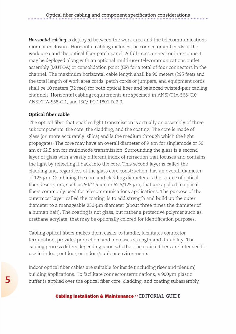
892019 Considerations for Selecting and Using Multimode Fiber
httpslidepdfcomreaderfullconsiderations-for-selecting-and-using-multimode-fiber 732
Optical fiber cabling and component specification considerations
7
Cabling Installation amp Maintenance EDITORIAL GUIDE
there is no length limitation in
countries outside of the United
States that do not specify riser-
or plenum-rated cabling The
advantage of using indoor
outdoor optical fiber cables
in this scenario is that the
number of transition splices
and hardware connections is
reduced Indooroutdoor optical
fiber cables are similar in
construction to outdoor opticalfiber cables except that the 250-
microm optical fiber cores may be
either tight buffered or enclosed
within loose buffer tubes Loose
tube indooroutdoor optical fiber
cables have a smaller overall
diameter than tight buffered
indooroutdoor optical fiber cables however tight buffered indooroutdoor cables
are typically more convenient to terminate because they do not contain water-
blocking gel or require the use of breakout kits (described later)
Optical fiber interconnections
Unlike the plug-and-jack combination that makes up a mated balanced
twisted-pair connection an interconnection is used to mate two tight-buffered
optical fibers An optical fiber interconnection typically consists of two plugs
(connectors) that are aligned in a nose-to-nose orientation and held in place with
an adapter (also called a coupler or bulkhead) The performance of the opticalfiber interconnection is highly reliant upon the connectorrsquos internal ferrule and
the adapterrsquos alignment sleeve These components work in tandem to retain
and properly align the optical fibers in the plug-adapter-plug configuration The
internal connector ferrule is fabricated using a high-precision manufacturing
process to ensure that the optical fiber is properly seated and its position is tightly
controlled The high tolerances of the alignment sleeve ensure that the optical
fibers held in place by the ferrule are aligned as perfectly as possible Although
Equipment cord connected tocentralized equipment
Horizontal cable90 m (295 ft max)
Telecommunications
room (TR)
Work area (WA)
Work areaequipment
cord
Work area outlet
Centralized optical fiber cabling usingan interconnection
Equipmentroom
Shown here is a typical schematic for centralized optical
fiber cabling using an interconnection the centralized
system supports direct connections from the work area to
the centralized crossconnect via a pull-through cable and
the interconnect
892019 Considerations for Selecting and Using Multimode Fiber
httpslidepdfcomreaderfullconsiderations-for-selecting-and-using-multimode-fiber 832
Optical fiber cabling and component specification considerations
8
Cabling Installation amp Maintenance EDITORIAL GUIDE
more expensive ceramic alignment sleeves maintain slightly tighter tolerances
than metal or plastic alignment sleeves are not as susceptible to performance
variations due to temperature fluctuations and may be specified for extremely
low-loss applications
Accurate plug-adapter-plug alignment minimizes light energy lost at the optical
fiber interconnection and maintaining precision tolerances becomes especially
critical as the optical fiber diameter decreases For example if two 625-microm
optical fibers are off-center by 4 microm in opposite directions then 13 of the light
energy escapes or is lost at the interconnection point This same misalignment
in a 9-microm singlemode fiber would result in almost a total loss of light energy
The critical nature of the core alignment is the reason why different optical fibertypes including 625-microm and 50-microm multimode fiber should never be mixed in
the same link or channel
Optical fiber breakout kits are used to facilitate termination of loose-tube optical
fibers used in indooroutdoor and outdoor applications Once the water-blocking
gel is thoroughly removed from the optical fibers the breakout kit allows furcation
tubes (typically 12mm to 30mm in diameter) to be installed over the 250-microm
optical fibers increasing the diameter and forming a short ldquojacketrdquo so that the
optical fibers may be terminated to the desired optical fiber connector Selection of
the correct furcation tube ensures compatibility with all optical fiber connectors
Users can choose from many optical fiber connector options
Traditional optical fiber connectors are represented by the SC and ST connector
styles These two types of optical fiber connectors were recognized when optical
fiber cabling was described in
the first published TIA and ISOIEC telecommunications cabling
standards The ST connector
Cladding
Core
Optical fiber cross-section
Core
Diameter
9m 50m or 625m
125m
Coating
250m
Cladding
Coating
Singlemode fiber cores are 9 microm in
diameter while multimode fiber cores may
be 50 or 625 microm Regardless of core size
the cladding is 125 microm and the coating
250 microm
892019 Considerations for Selecting and Using Multimode Fiber
httpslidepdfcomreaderfullconsiderations-for-selecting-and-using-multimode-fiber 932
892019 Considerations for Selecting and Using Multimode Fiber
httpslidepdfcomreaderfullconsiderations-for-selecting-and-using-multimode-fiber 1032
Optical fiber cabling and component specification considerations
0
Cabling Installation amp Maintenance EDITORIAL GUIDE
12-fiber MPOMTP interfaces with 24 LC connections or one 12-fiber MPOMTP
interface with 12 SC or LC connections
Optical fiber cabling deployment
The most common optical fiber cabling deployment approach is to field terminate
the optical fiber connectors to the optical fiber cable using the appropriate epoxy
polish or no-epoxyno-polish mechanical termination method However the
new MPOMTP plug-and-play modules and MPOMTP array connectors are not
supported by field termination and there are considerations such as installer
expertise and the IT construction
upgrade schedule that may favor the
use of factory-terminated pigtailsor trunking assemblies over field
termination methods
The pros and cons of these termination
methods are described here
Field termination supports the lowest
raw material cost for SC ST LC and
MT-RJ optical fiber cabling systems
However the time needed for field
termination is the longest of the three
deployment options and installer
skill-level requirements are higher
which may increase the project
installation costs No-epoxyno-polish
and certain mechanical-splice-style
termination methods require lessinstallation skill than the epoxypolish method however the connectors used in
conjunction with mechanical termination methods are more expensive and the
performance (especially using the no-epoxyno-polish method) may be lower
and more variable
Optical fiber pigtails feature a factory preterminated and tested SC ST LC or MT-
RJ optical fiber connector and a 1-meter stub of 625125-microm multimode 50125-
Tight-buffered
Loose-tube
Sample optical fiber cable constructions
Jacket
Rip cord
Central strength member
Aramid yarns
Color coded tight-bufferedfibers and jackets
Water-blocking swellabletape
Gel-filled tubes
Water-blocking aramid yarn
Central strength memberRip cord
Aramid yarns
Color-coded fibers and tubes
Jacket
The environment in which the fiber cable will be
used eg indoor or outdoor will determine the
cablersquos construction and the treatment of the
fibers within that cable
892019 Considerations for Selecting and Using Multimode Fiber
httpslidepdfcomreaderfullconsiderations-for-selecting-and-using-multimode-fiber 1132
Optical fiber cabling and component specification considerations
1
Cabling Installation amp Maintenance EDITORIAL GUIDE
microm multimode or singlemode optical fiber The stub end of the pigtail is then
fusion-spliced to the optical fiber Fusion splicing provides a consistent nearly
loss-free termination and can be fast with proper technicians and equipment
The main benefits to this approach are the assurance of low-loss performance at
the interconnection and the elimination of the need for endface inspections and
possible connector reterminations
Trunking cable assemblies provide an efficient alternative to field-terminated
components or splice connections and allow up to 75 faster field deployment
times Trunking cable assemblies are custom factory preterminated and tested
lengths of optical fiber cable terminated on both ends with SC ST LC MT-RJ or
MPOMTP optical fiber connectors that are simply pulled and plugged in Whendeploying trunking cable assemblies cable-length specification is critical and
precise planning is required up front Trunking cable assemblies that have an
MPOMTP connector on one or both ends are commonly referred to as ldquoplug-
and-playrdquo cable assemblies MPOMTP plug-and-play cable assemblies have the
smallest connector profile and therefore have the smallest pathway cabinet and
rack-space requirements of all trunking cable assembly options
Always maintain the fibersrsquo polarity to ensure the transmit fiber is matched to
the receive port on each end of the link or channel
Valerie Maguire is a Global Sales Engineer with Siemon
892019 Considerations for Selecting and Using Multimode Fiber
httpslidepdfcomreaderfullconsiderations-for-selecting-and-using-multimode-fiber 1232
1010100000001111011111100101010101001010
1010000001110101010101000101010001010101
0101001010101010010100101010101000000011
1101111110010101010100101010100000011101
0101010100010101000101010101010010101010
1001010010101010100000001111011111100101
0101010010101010000001110101010101000101
010001010101010100101010101001010010101
0101000000011110111111001010101010010101
0100101010000000111101111110010101010100
1010101000000111010101010100010101000101
010101010010101010100101001010101010000
0001111011111100101010101001010101000000
1110101010101000101010001010101010100101
0101010010100101010101000000011110111111
0010101010100101010100000011101010101010
0010101000101010101010010101010100101001
0101010100000001111011111100101010101001
01010100101010000000111101111110010101010
Is there a hole in your
fiberrsquos performance
If itrsquos not OFS multimode fiber there could be OFSrsquo
manufacturing process virtually eliminates defects in the
fiber core with a DMD specified in the 0-5 micron range
That means double the bandwidth for lasers that launch
power in the fiberrsquos center while providing fast reliable
transmission and easier connectivity To learn more ask
your cabler about OFS or visit wwwofsopticscomfiber
892019 Considerations for Selecting and Using Multimode Fiber
httpslidepdfcomreaderfullconsiderations-for-selecting-and-using-multimode-fiber 1332Cabling Installation amp Maintenance EDITORIAL GUIDE
3
Making the switch from
625- to 50-micron fiber
What to do and what not to do when opting
for higher-bandwidth 50-micron multimode
By John Kamino
MULTIMODE FIBER SYSTEMS continue to provide the most cost-
effective cabling solution for data centers local area networks
(LANs) and other enterprise applications Compared to singlemode
fiber multimode systems offer significantly lower costs for
transceivers connectors and connector installation while meeting and exceeding
the bandwidth and reliability requirements of the most demanding networks
If you are designing a new short-reach installation you will probably choose laser-
optimized 50-micron (microm) OM3 or OM4 multimode fiber These fibers preserve the
systems-cost benefits over singlemode fiber by using low-cost 850-nm vertical-
cavity surface-emitting laser (VCSEL) technology are capable of 10-Mbitsec
through 10-Gbitsec operation and will support upcoming 40- and 100-Gbitsec
transmission speeds
But if you are upgrading an existing system many of which have 625-microm
multimode already installed should you stick with 625-microm Or can you go with
the higher performance of 50-microm OM3 or OM4 fiber This article highlights thethings you must consider when upgrading an existing 625-microm system
Why two fiber sizes
The numbers under discussionmdash50-microm and 625-micrommdashrefer to the diameter of
the fiberrsquos core through which light signals are transmitted The first optical
fibers deployed in the 1970s for both short- and long-reach applications were
50-microm multimode fibers In the early 1980s singlemode fiber replaced 50-microm
892019 Considerations for Selecting and Using Multimode Fiber
httpslidepdfcomreaderfullconsiderations-for-selecting-and-using-multimode-fiber 1432
Making the switch from 625- to 50-micron fiber
4
Cabling Installation amp Maintenance EDITORIAL GUIDE
fiber in longer-distance installations However 50-microm multimode continued to be
more cost-effective for short-reach interconnects such as building and campus
backbones up to 2000-meter distances
But as data rates increased 50-microm fiber could not support 10-Mbitsec rates overthe 2-kilometer distances required by some campus installations Not enough
power could be coupled from the light-emitting diode (LED) sources in use at that
time into the 50-microm core to support these link distances
625-microm multimode fiber was introduced in 1985 to solve this problem It could
capture more light from a LED in its larger core and 2-km campus links operating
at 10 Mbitssec were easily supported Also the larger-core fiber was easier to
cable and connectorize It became the most commonly used fiber for short-reach
enterprise applications in North America
Today as data rates surpass 10-Gbitssec and lasers have replaced LEDs 625-microm
fiber has reached its performance limit 50-microm fiber offers as much as 10 times
the bandwidth of the 625-microm fiber Whatrsquos more improvements in technology
have made 50-microm fiber easier to use
Multimode fiber choices today
To consider making the switch from 625-microm to 50-microm multimode it is importantto first understand the terminology used to designate the various performance
grades of multimode fiber In each of these designations ldquoOMrdquo stands for ldquooptical
multimoderdquo For example OM1 is the designation for fiber with 200500 MHz-
km overfilled launch (OFL) bandwidth at 8501300 nm this typically is 625microm
fiber OM2 is used for fiber with 500500 MHz-km OFL bandwidth at 8501300 nm
(typically 50-microm fiber)
Fiberdesignation
EMB (in MHz∙km) 850 nm
OFL (in MHz∙km) 850 nm
OFL (in MHz∙km) 1300 nm
OM1 (625) NA 200 500
OM2 (50) NA 500 500
OM3 (laser-
optimized 50) 2000 1500 500
OM4 (laser-
optimized 50) 4700 3500 500
892019 Considerations for Selecting and Using Multimode Fiber
httpslidepdfcomreaderfullconsiderations-for-selecting-and-using-multimode-fiber 1532
Making the switch from 625- to 50-micron fiber
5
Cabling Installation amp Maintenance EDITORIAL GUIDE
More-recent additions are OM3 for laser-optimized 50-microm fiber having 2000
MHz-km effective modal bandwidth (EMB also known as laser bandwidth) at 850
nm (designed for 10-Gbitsec transmission) and most recently OM4 for laser-
optimized 50-microm fiber having 4700 MHz-km EMB at 850 nm designed for 10-Gbit
sec transmission over longer distances
OM4 with its extended bandwidth can be used to enhance the system-cost
benefits enabled by 850 nm lasers for 10-Gbitsec applications as well as new
40- and 100-Gbitsec systems With its 150 m reach capability at 40 and 100
Gbitsec OM4 will support an additional 10 percent of link lengths in large data
centers that are not covered by OM3rsquos 100 m reach It is especially well-suited
for short reach data center and high-performance computing applications whereoptical loss budgets are tight at 10-Gbitsec and higher The additional bandwidth
provided when OM4 fiber is deployed at less than its rated distance offers extra
headroom for channel insertion loss
Itrsquos also important to note that for next-generation 40- and 100-Gbitsec
Ethernet only OM3 and OM4 fibers are included in the IEEE 8023ba standard
as supported (multimode optical fiber) media OM1 and OM2 fibers are not
supported media types
The latest offerings in multimode fiber are 50 microm bend insensitive multimode
fibers (BIMMF) These fibers have been promoted as offering all the advantages
of high bandwidth laser-optimized multimode fiber with the added advantage
of lower bend sensitivity However recent work has shown that some of these
fibers may have significant performance issues A paper presented at the 2010
International Wire and Cable Symposium (IWCS) showed that mating (connector)
loss of BIMMFs with standard fibers is higher than standard fiber connected to
standard fiber This additional loss adds to the total link loss possibly causing itto exceed the link loss budget
Another recent study examined issues with the system performance of bend
insensitive fibers and questioned whether current requirements are adequate
It has been proposed that standards organizations perform a thorough review of
BIMMFs and incorporate them into industry standards Until this work is done
caution is advised before widespread adoption takes place
892019 Considerations for Selecting and Using Multimode Fiber
httpslidepdfcomreaderfullconsiderations-for-selecting-and-using-multimode-fiber 1632
Making the switch from 625- to 50-micron fiber
6
Cabling Installation amp Maintenance EDITORIAL GUIDE
Upgrading a 625-microm network
The primary considerations for an upgrade or extension of an existing 625-microm
network are
the required transmission speed (now and especially in the future)
link distance
ease of cable replacement and
cost of cable replacement
If you are running Gigabit Ethernet (1-Gbitsec) then legacy 625-microm fiber will
transmit a distance of 220 to 275 meters depending on its bandwidth ratingBut at 10-Gigabit Ethernet (10-GbE 10-Gbitssec) they will only support 26 to
33 meters If your network will not need to support 10-GbE at distances greater
than 25 meters then you may be able to stick with 625-microm fiber It is important
to note however that most 625-microm fiber has not been measured for laser
bandwidth and some legacy fiber may have difficulty supporting even this short
distance
And if you want to transmit longer distances over 625-microm fiber you will be
forced to use much-more-expensive 1300-nm transceivers that will operate over
multimode or singlemode fiber These transceivers cost significantly more than
850-nm multimode devices because the 1300-nm optoelectronics package is the
far more complex of the two
If you are considering extending your network by installing additional 625-microm
fiber you need to carefully review your future network plans If you plan to
upgrade your network speed to 10-Gbitssec in the future recabling with laser-
optimized OM3 or OM4 fiber would be a wiser choice
Measuring laser bandwidth
As previously stated 625-microm fiber provides limited support for 10-Gbitsec
transmission so it generally is not measured for laser bandwidth (EMB) Typically
only 50-microm fibers are measured for EMB To verify bandwidth of 625-microm fiber
the traditional OFL bandwidth measurement method is used
892019 Considerations for Selecting and Using Multimode Fiber
httpslidepdfcomreaderfullconsiderations-for-selecting-and-using-multimode-fiber 1732
Making the switch from 625- to 50-micron fiber
7
Cabling Installation amp Maintenance EDITORIAL GUIDE
For 50-microm fibers EMB is ensured by using a method called Differential Mode
Delay (DMD) This DMD test is required by standards to verify 10-Gbitsec
performance and involves scanning the fiberrsquos core in small increments to see
how the signal travels in various regions of the core
Once the DMD test is conducted and a DMD ldquoprofilerdquo is obtained the standards
allow two methods to disposition the fiber One is the DMD Mask method and the
other is the Effective Modal Bandwidth Calculated (EMBc) method
The DMD Mask method provides direct verification of the fiberrsquos DMD
performance using a set of clearly defined DMD masks and templates that are
overlaid on the DMD profile This technique provides flexibility in applying more-stringent DMD performance criteria in certain regions of the fiber including the
0-5microm center region
The EMBc method involves complex calculations involving 10 weighting
functions to represent the wide variety of 10-Gbitsec VCSELs available on the
market Theoretical in nature this technique does not in our opinion provide
the scrutiny on fiber quality and performance that the DMD Mask technique
does The EMBc method puts little emphasis on the 0-5microm region of a fiberrsquos
core Though standards allow both testing methods we advocate the DMD
Mask method
Mixing 50- and 625-microm
If you decide to add 50-microm fiber to an existing 625-microm infrastructure connecting
50-microm directly to 625-microm is generally not recommended The difference in core
sizes could cause high loss when transmitting from the 625-microm into the 50-
microm fiber Also the bandwidth of 625-microm fibers is typically much lower further
degrading system performance Even if a low-speed application operates over alink made up of mixed fiber types upgradeability will be severely compromised
This elevated-loss problem occurs when transmitting from the larger (625-microm) to
the smaller (50-microm) core It is comparable to a 4-inch water pipe connecting to a
3-inch pipe there is no problem going from the smaller pipe to the larger one but
going in the opposite direction can lead to a lot of lost water (or in this case light)
892019 Considerations for Selecting and Using Multimode Fiber
httpslidepdfcomreaderfullconsiderations-for-selecting-and-using-multimode-fiber 1832
Making the switch from 625- to 50-micron fiber
8
Cabling Installation amp Maintenance EDITORIAL GUIDE
The amount of connection loss you could experience is about 4 dB for a LED-
based system which fills the entire core of a 625-microm fiber and anywhere from 0
to 4 dB for a VCSEL-based system which only fills a portion of the core
Because most optical-loss test sets use LEDs you should plan for the worst and
assume you will see a 4-dB loss in one direction If your link budget can tolerate
this additional 4-dB loss then you can get away with connecting 50-microm directly
to 625-microm
The better scenario is to separate 50-microm from 625-microm with active electronics
such as a switch router or simple media converter
Mixing of 625-microm and 50-microm fiber is not recommended unless an electronics
interface is inserted into the link If 10-Gbitsec speeds are being installed 625-
microm fiber will only be able to support extremely short links and replacement is
recommended
John Kamino is Product Manager Multimode Fiber with OFS
892019 Considerations for Selecting and Using Multimode Fiber
httpslidepdfcomreaderfullconsiderations-for-selecting-and-using-multimode-fiber 1932
OFSrsquo LaserWave fiber exceeds the OM4 standard for
todayrsquos high-speed networks mdash and tomorrowrsquos Andsince LaserWave fiber delivers DMD specified in the
0 ndash 5 micron range you get up to twice the bandwidth for
lasers that launch power in the fiberrsquos center Enjoy fast
reliable transmission and easier connectivity To learn more
ask your cabler about OFS or visit ofsopticscomfiber
Get your network up tospeed with LaserWavereg fiber
892019 Considerations for Selecting and Using Multimode Fiber
httpslidepdfcomreaderfullconsiderations-for-selecting-and-using-multimode-fiber 2032Cabling Installation amp Maintenance EDITORIAL GUIDE
20
Compatibility issues with
bend-insensitive andstandard multimode
Lab testing indicates risks associated with mixing
bend-insensitive and standard multimode fiber
By Rick Pimpinella Bulent Kose and Brett Lane
THE INCREASING DEMAND for higher-speed data transmission
within the data center and premises networks has led to the wide
deployment of multimode optical connectivity To meet performance
and reliability requirements the optical specifications on the
components have also become more stringent For high-speed optical networks
using laser-optimized OM3 and OM4 multimode fiber it is more critical than ever
for network operators and designers to understand the attributes of the various
performance grades of passive fiber-
optic components that make up the
network so that they may employ the
most cost-efficient solutions that meet
their needs today and in the future
In order to ensure that optical networks
operate effectively and reliably it isfundamental that the optical fiber
meets the necessary bandwidth
requirements and that the total optical
loss or insertion loss (IL) is below
the allowable limit required by the
application The two sources of IL
within optical networks are 1) loss at
892019 Considerations for Selecting and Using Multimode Fiber
httpslidepdfcomreaderfullconsiderations-for-selecting-and-using-multimode-fiber 2132
Compatibility issues with bend-insensitive and standard multimode
21
Cabling Installation amp Maintenance EDITORIAL GUIDE
connector interfaces and 2) loss or attenuation within the fiber itself The IL
limits for 10- 40- and 100-Gbitsec Ethernet are in the table below
The combination of
eroding insertion loss
budgets and increased
demands for complex
network architectures
with many
connector interfaces
has triggered several fiber and connectivity suppliers to develop improved
connectivity and fiber products that allow network architectures to cope withthese trends Specifically several connectivity suppliers now offer low-loss or
optimized passive fiber-optic components such as connectors cassettes and
patch cords that allow them to implement complex networks with numerous
connector interfaces while still meeting the maximum connector loss budget
Moreover although the intrinsic fiber attenuation has not been reduced
significantly over the past many years recent advancements in fiber production
have delivered extra headroom by significantly improving attenuation levels
under tightly bent conditions even in those cases in which the fiber is
unintentionally subjected to bends smaller than that allowed with the ANSI
TIA-568-C0 premises cabling standard This article reviews how this new type of
laser-optimized multimode fiber often called bend-insensitive or bend-optimized
integrates into todayrsquos data center and premises network
Achieving bend-optimization
It is well known that in order to produce a fiber with improved bend performance
it must be made to more tightly confine the light within its core region Thismodification allows more of the light to meet the conditions necessary for
total internal reflection as the fiber is bent Enhanced optical confinement
is accomplished by simply increasing the effective difference in the index of
refraction between the core and cladding regions This is typically accomplished
by introducing an index depression or trench in the cladding region close to the
fiber core
Applicationstandard
Minoperatingdistance
(m)
Maxconnectorloss (dB)
Max fiberattenuation
(dB)
Max totalIL budget
(dB)
0-Gbitsec Ethernet 300 15 11 26
40- and 100-Gbit
sec Ethernet (OM3)
100 15 04 19
40- and 100-Gbit
sec Ethernet (OM4)
150 1 05 15
892019 Considerations for Selecting and Using Multimode Fiber
httpslidepdfcomreaderfullconsiderations-for-selecting-and-using-multimode-fiber 2232
892019 Considerations for Selecting and Using Multimode Fiber
httpslidepdfcomreaderfullconsiderations-for-selecting-and-using-multimode-fiber 2332
Compatibility issues with bend-insensitive and standard multimode
23
Cabling Installation amp Maintenance EDITORIAL GUIDE
conditions necessary for total internal reflection (ie rays with larger angles)
light emerging from bend-optimized multimode fiber will have a larger angle on
average than light emerging from standard multimode fiber The parameter that
characterizes the maximum divergence or acceptance angle of light from or to
a fiber is called numerical aperture (NA) Therefore the NA of bend-optimized
multimode is generally expected to be greater on average than the NA of
standard multimode A thorough sampling across multiple fiber manufacturers
revealed that the average NA increased
from 0199 for standard multimode fiber to
0207 for bend-optimized multimode fiber
Although this moderate increase in NAappears insignificant in some situations
the optical loss across an optical fiber
interface (eg connector) is dependent on
the differences in NAs of the fibers In the
case that light fully populates the fiber
core such as when illuminated with an
LED and is coupled from a fiber with a
higher NA into a receiver with a lower NA
the light will diverge at an angle larger
than the acceptance angle of the receive
fiber This will result in some light being
lost (into the cladding) and the interface will have loss proportional to the NA
difference (ratio) between the two fibers
Consequently increased loss may be realized when light travels from bend-
optimized multimode fiber into standard multimode fiber In fact the expected
loss across a bend-optimized fiber with an NA of 0207 and a standard fiber withan NA of 0199 is 034 dB which is a significant portion of the overall IL budget
In the case that light travels from a fiber with a lower NA into a receiver with a
higher NA or light does not fully illuminate the fiber core no loss resulting from
the difference in fiber NAs is expected
NA loss measurements
To predict the NA loss that would be realized during link certification
2 4 6
MMF LED
MMF VCSEL
8 10
3
25
2
15
1
05
0
Bend loss (1 m) (dB)
Mandrel radius (mm)
BO-MMF LED
BO-MMF VCSEL
Measured bend loss at 850 nm
representative of bend-optimized and
standard multimode fiber using both
LED and VCSEL light source Fibers were
wrapped one turn around 10 different
mandrels with radii ranging from 25mm to
10 mm
892019 Considerations for Selecting and Using Multimode Fiber
httpslidepdfcomreaderfullconsiderations-for-selecting-and-using-multimode-fiber 2432
Compatibility issues with bend-insensitive and standard multimode
24
Cabling Installation amp Maintenance EDITORIAL GUIDE
measurements of an optical
channel with bend-optimized
and standard fiber interfaces
a series of standard IL
measurements were performed
on selected bend-optimized
and standard fibers Fiber
samples from several fiber
manufacturers were selected
with a wide range of NAs in
order to provide not only a
typical NA loss from fibers withaverage NA but also provide
an upper and lower limit of
NA loss that may be expected
when connecting dissimilar
multimode fiber types without knowledge of NA differences Several fibers were
selected of each fiber typendashsome with an average NA some with a low NA and
some with a high NA The table on page 25 summarizes the samples used for this
experiment and the theoretically expected NA loss from each connection
For these measurements the various bend-optimized fiber samples were
fusion spliced to the various standard multimode fiber samples A fusion
splicer was used to connect dissimilar fiber types instead of connectors in
order to minimize other loss contributors such as lateral offset and connector
termination processing The insertion loss of the connection was calculated by
injecting light meeting the new TIAEIA-526-14-B encircled flux specification
into the bend-optimized fiber and then measuring the power coupled out of
the standard fiber Subtracting this power level from the reference power levelmeasured previously as the amount of power coupled into the bend-optimized
fiber resulted in the IL or NA loss of the connection All aspects of these
measurements were in compliance with TIAEIA-45-171A (eg diameter and
placement of cladding mode strippers)
The measurement data is shown in the chart on page 25 Each data point
represents the average of the NA losses for a set of fibers for each NA
Bend-optimizedMMF core
NA = sinq1
MMF coreα
NABO-MMF gt NAstd-MMF
This illustration shows a mismatch in NA when connecting
a fiber with a large NA (left) to a fiber with a small NA(right) Because the receive fiber on the right has a smaller
NA some light is not coupled and instead is lost into the
cladding This loss is referred to as NA loss
892019 Considerations for Selecting and Using Multimode Fiber
httpslidepdfcomreaderfullconsiderations-for-selecting-and-using-multimode-fiber 2532
Compatibility issues with bend-insensitive and standard multimode
25
Cabling Installation amp Maintenance EDITORIAL GUIDE
combination From this data
connecting dissimilar fiber types
with average NAs confirms the
theoretically predicted NA loss of
approximately 040 dB Additionally
the upper and lower limits of NA
loss were measured to be 028
dB and 106 dB Although these
average and extreme NA losses
are fairly well correlated with the
theoretically predicted NA loss
other measured values deviatesignificantly from the theoretically
predicted value This suggests that
factors other than NA such as core
diameter index profile and mode structure also significantly influence the loss
when connecting bend-optimized and standard multimode fiber As a result the
light does not couple with 100 percent efficiency between fibers and therefore an
additional mode coupling loss must exist
In fact in the case that bend-optimized fiber samples with the identical NA but
manufactured from different suppliers were connected to standard fibers with
NA equal to 0200 the NA loss differs significantly from vendor to vendor The
average NA loss from Vendor A bend-optimized interfaces nearly exactly matched
the theoretical NA loss of 030 dB while the average NA loss from Vendor B
bend-optimized interfaces was much higher at 051 dB (see graph on page 26) As
expected the bend-optimized fibers from Vendor B were found to be more bend-
tolerant than those from Vendor A
In addition to realizing
unidirectional NA
loss an increase in the
modal noise penalty
may also result
when connecting
bend-optimized and
1000 0975 0950 0925 0900 0875 0850
14
12
10
08
06
04
02
00
NA ratio
NA loss (dB)
The black line shows the theoretical loss of connected
fibers with different NA and the dots represent
actual measured loss The results suggest factorsother than NA also influence loss when connecting
bend-optimized and standard multimode fiber
NA (BO-MMF)to NA (MMF)combination
NA (BO-MMF) NA (MMF) NA ratio Theoreticalloss (dB)
Average to Average 0207 0199 0961 034
Large to Average 0215 0199 0926 067
Large to Small 0215 0185 086 131
Average to Small 0207 0185 0894 098
Small to Small 0199 0185 0928 063
Large to Large 0215 0212 0986 012
892019 Considerations for Selecting and Using Multimode Fiber
httpslidepdfcomreaderfullconsiderations-for-selecting-and-using-multimode-fiber 2632
Compatibility issues with bend-insensitive and standard multimode
26
Cabling Installation amp Maintenance EDITORIAL GUIDE
standard multimode fiber Modal noise is a power penalty related to the reduction
in the signal-to-noise ratio (SNR) of the optical signal For high-speed networks
employing VCSELs if a connector selectively attenuates higher-order modes as a
result of NA mismatch or a lateral offset between fiber cores then fluctuations in
the power distribution (spatial speckle pattern) result in fluctuations in connector
insertion loss This fluctuation is seen by the detector as an increase in noise
thereby reducing the SNR and therefore signal quality
The maximum allowed power penalty for modal noise is currently specified
in 10GBase-SR to be 03 dB Both NA loss and mode coupling loss can increase
the mode-selective loss (filter aperture) at a connector interface resulting in an
increase in modal noise Considering the overall power budget for 10G40G100GEthernet is 15 dB (or 10 dB for OM4) any
increase in modal noise may compromise
system reliability
In conclusion inconclusive
As part of our review of how bend-
optimized multimode fiber is integrating
in todayrsquos data center and premises
networks we measured the loss between
bend-insensitive and standard multimode
fibers to quantify the expected additional
loss during certification of mixed-fiber
links These additional losses were
measured to be as high as 1 dB and can
be a significant portion ofndashor even actually
exceedndashthe total optical power budget
for todayrsquos high-speed networks For a channel link that contains several bend-optimized fiber and multimode fiber interfaces which have large NA differences
the NA losses may be additive and further inhibit system certification
Furthermore although NA loss alone is unlikely to detrimentally influence
system performance it may be very difficult if not impossible to determine if
excessive channel loss is due to NA differences or other conventional sources
of loss such as macrobending or dirtydamaged components One strategy to
BO-MMF1
to MMF2
BO-MMF1
to MMF2
BO-MMF1
to MMF2
Vendor A BO-MMF
Vendor B BO-MMF
BO-MMF1
to MMF2
07
06
05
04
03
02
01
00
Measured NA loss (dB)
Bend-optimized fibers from Vendor B shown
here as the blue bars were found to be more
bend-tolerant than the bend-optimized fibers
from Vendor A shown as the green bars
The more-optimized fibers exhibited higher
NA loss
892019 Considerations for Selecting and Using Multimode Fiber
httpslidepdfcomreaderfullconsiderations-for-selecting-and-using-multimode-fiber 2732
Compatibility issues with bend-insensitive and standard multimode
27
Cabling Installation amp Maintenance EDITORIAL GUIDE
account for this loss would be to require bidirectional loss measurements of
individual optical interfaces
During the most recent meeting of the TIA TR-4212 Optical Fibers and Cable
Subcommittee a vigorous debate included many of the topics discussed in this
article and others including increased NA loss mode coupling loss modal
noise (which may negatively impact system performance) the validity of other
standardized fiber test procedures for fiber core diameter fiber bandwidth and
link attenuation (encircled flux) The subcommittee authorized the formation of
a task group to study the technical compatibility of bend-insensitive multimode
fiber with current multimode fiber standards
Based on our internal analysis and the present uncertain position within the
standards community we have concluded that the performance risks of mixing
bend-optimized and standard multimode fiber types in high-speed optical
channel links exceeds any benefit To ensure that total optical loss across data
center and premises networks remains below the allowable limit we recommend
adhering to standards-based radius-control methods and the use of one fiber
type throughout the channel link which includes cabling and patch cords This
approach enables network stakeholders to reliably deploy complex network
architectures meet stringent IL budgets and ensure optimal system performance
within current standards-based network architectures and testing methods
Some manufacturers support this effort others minimize its importance Until
the TIA subcommittee work on these issues is complete we recommend that
these two fiber types should not presently be mixed
Dr Rick Pimpinella is a Distinguished Engineer Bulent Kose is a ResearchEngineer and Dr Brett Lane is a Fiber Research Manager with Panduit
892019 Considerations for Selecting and Using Multimode Fiber
httpslidepdfcomreaderfullconsiderations-for-selecting-and-using-multimode-fiber 2832
As the demand for bandwidth in
enterprise applications such as
data centers continues to
boom new transmission media
must be developed continually
to meet end user requirementsThe latest in optical transmis-
sion media for the enterprise is
called OM4 fiber
OM4 fiber is a 50 micron (microm)
laser-optimized multimode fiber
with extended bandwidth It is
designed to enhance the sys-
tem cost benefits enabled by
850 nm Vertical Cavity Surface
Emitting Lasers (VCSELs) for existing 1 and 10 Gbs applica-
tions as well as future 40 and
100 Gbs systems
Supporting Ethernet Fibre
Channel and OIF applications
OM4 fiber allows extended
reach upwards of 550 meters at
10 Gbs for ultra long building
backbones and medium lengthcampus backbones It offers an
Effective Modal Bandwidth
(EMB) of 4700 MHz-km more
than double the IEEE require-
ment for 10 Gbs 300 meter
support
To help you use this advanced
fiber to its greatest advantage
this paper describes the tech-
nology behind OM4 fiber high-
lights the key differences with
other fiber types and explains
how its high bandwidth is
ensured through stringentmeasurement methods
Multimode Fiber Basics
Compared to single-mode
fibers multimode fibers have
larger cores that as their name
implies guide multiple ldquomodesrdquo
or rays of light simultaneously
Modes that travel at the outside
edge of the core have a longer
distance to go than modes thattravel near the center
The corersquos graded index profile
is designed to slow down
modes that have a shorter dis-
tance to travel so that all modes
arrive at the end of the fiber as
close in time as possible This
minimizes modal dispersion
also known as differential mode
delay (DMD) and maximizes
bandwidth which is the amount
of information that can travel
through the fiber per unit of
time
In addition to their large core
multimode fibers have a large
Numerical Aperture (NA) the
maximum angle at which a fiber
can accept the light that will be
transmitted through it This
allows them to work with rela-
tively low-cost optical compo-
nents and light sources such as
light-emitting diodes (LEDs)and VCSELs
Multimode Fiber Options
Multimode products are identi-
fied by the OM (ldquooptical multi-
moderdquo) designation as outlined
in the ISOIEC 11801 interna-
tional cabling standard (see
table 1)
OM4 - The Next Generation
of Multimode Fiber Tony Irujo
Sales Engineer
OPTICAL FIBER IN ENTERPRISE APPLICATIONS
Table 1 ISOIEC 11801 OM designations
892019 Considerations for Selecting and Using Multimode Fiber
httpslidepdfcomreaderfullconsiderations-for-selecting-and-using-multimode-fiber 2932
OM4 fiber is the latest develop-
ment in this series It is espe-
cially well suited for shorter
reach data center and high per-
formance computing applica-
tions where optical loss budg-
ets are tight at 10 Gbs (and
are expected to get even tighter
at 40 Gbs and 100 Gbs) Thehigh bandwidth provided by
OM4 fiber when deployed at
less than its rated distance
offers extra ldquoheadroomrdquo for
channel insertion loss
OM4 is backward compatible
with applications calling for OFL
bandwidth of at least 500 MHz-
km at 1300 nm (eg FDDI
IEEE 100BASE-FX
1000BASE-LX 10GBASE-LX4
and 10GBASE-LRM)
The latest offerings in multi-
mode fiber are 50 983221m bend
insensitive multimode fibers
(BIMMF) These fibers have
been promoted as offering all
the advantages of high band-
width laser-optimized multi-mode fiber with the added
advantage of lower bend sensi-
tivity
However recent work has
pointed to some areas of con-
cern with these fibers Studies
have identified issues with the
characterization of bend insen-
sitive fibers and questioned
whether current requirements
are adequate to guarantee sys-
tem performance Additional
studies have shown that mating
(connector) loss of BIMMFs
with standard fibers is higher
than with standard fibers con-
nected to each other This addi-
tional loss adds to the total link
loss
It has been proposed that stan-
dards organizations perform a
thorough review of BIMMFs
and incorporate them into
industry standards Until this
work is done some caution is
advised before widespread
adoption takes place
What Makes OM4 Different
Like OM3 multimode fiber OM4
fiber is considered to be ldquolaser-
optimizedrdquo or optimized for use
with VCSEL light sources OM3
and OM4 fibers are designed
and manufactured in such a
way as to get the most perform-
ance out of VCSELs compared
to LEDs That is why laser-opti-
mized fibers are specified using
Laser Bandwidth or EMB
OM2 fiber although compatible
with VCSELs is not considered
to be laser-optimized OM2
fiber is intended for use with
LED sources at speeds of 10 or
100 Mbs or for shorter reach 1
Gbs networks You can use
OM2 fiber with VCSELs but itsperformance is limited to 550
meters at 1 Gbs and only 82
meters at 10 Gbs compared to
OM4 fiberrsquos
reach of over
1000 meters
at 1 Gbs and
550 meters at
10 Gbs
As discussed
the speed at
which each
mode travels
down a multi-
mode fiberrsquos
core depends
on its refrac-
tive index
which is gov-
erned by the amount of chemi-
cal dopant Germanium at that
location in the core Because
modes traveling down the cen-
ter of the core have shorter dis-
tance to travel than those trav-
eling along the edge the refrac-
tive index profile in a multimode
fiber must be ldquogradedrdquo in a par-abolic manner across the core
This slows down the modes
that have a shorter distance to
travel equalizing the arrival
time of all the modes
The better the modes are
equalized the higher the band-
width of the fiber Mode equal-
ization depends on how well
the graded index profile is con-
structed during fiber manufac-
turing The more precise the
refractive index profile is in
terms of shape curvature and
smoothness (free of dips
spikes or defects) the better
the modes will be equalized
(see Figure 2)
OM4 fiber with its higher band-width has an extremely precise
refractive index profile virtually
free of perturbations or defects
Figure 2 A refractive index profile optimized for shape curvature
and smoothness maximizes bandwidth
892019 Considerations for Selecting and Using Multimode Fiber
httpslidepdfcomreaderfullconsiderations-for-selecting-and-using-multimode-fiber 3032
In order to make such a precise
fiber one needs to use a pre-
form manufacturing process
that has exceptional control
over the amount of Germanium
that is incorporated at particular
sub-micron positions within the
fiberrsquos core An example of a
process that lends itself to this
level of control is OFSrsquo propri-
etary MCVD process in which
each layer of the core is
deposited and sintered individu-
ally providing the utmost in
refractive index precision and
uniformity
OM4 Fiber Standards
Two standards define the useof OM4 fiber in high-speed net-
works TIA document TIA-
492AAAD which contains the
OM4 fiber performance specifi-
cations and the IEC 60793-2-
10 international standard which
provides equivalent OM4 speci-
fications under fiber type A1a3
ISOIEC 11801 will add OM4
fiber as an industry-recognized
fiber type and IEEE 8023bafor 40G and 100G Ethernet will
include OM4 fiber as an option
that provides a reach of 150
meters (50 percent greater than
OM3)
There was discussion and
debate within the standards
groups about a minimum OFL
bandwidth requirement at 850nm Although current applica-
tions primarily use 850 nm
VCSEL lasers with fibers that
are specified to a minimum
EMB there was good reason to
also establish a minimum 850
nm OFL bandwidth specifica-
tion It has been shown that
fibers with higher OFL band-
width will perform better with
VCSELs that launch more
power into outer modes That is
why the existing OM3 fiber
standards require a minimum
1500 MHz-km OFL bandwidthat 850 nm
For OM4 fiber OFS and others
in the standards group strongly
recommended at least 3500
MHz-km OFL bandwidth in
order to ensure the utmost per-
formance and reliability ulti-
mately that is the specification
that was agreed upon
Measuring Laser Bandwidth
Bandwidth performance of OM4
fiber is ensured using the same
criteria as OM3 but to much
tighter specifications Due to a
challenge posed when the now-
familiar VCSEL was first intro-
duced new measurement
methods had to be developed
to verify laser bandwidth of OM3 and OM4 fibers
Unlike an LED laser VCSELs
produce an energy output that
is not uniform it can change
sharply across the face of the
output Whatrsquos more each laser
fills a different set of light paths
in each fiber and does so with
differing amounts of power in
each path Overfilled bandwidth
measurements used to meas-
ure LED bandwidth could not
emulate the operation of aVCSEL
The standards allow two ways
to measure and verify laser
bandwidth the DMD Mask
Method and the EMBc Method
Both methods require DMD
testing -- the difference lies in
how the DMD data is used and
interpreted
In DMD testing small high-
powered laser pulses are trans-
mitted through the fiber in tiny
steps across the entire core of
the fiber Only a few modes are
excited at each step and their
arrival times are recorded The
DMD of the fiber is the differ-
ence between the earliest and
the latest arrival times of allmodes at all steps
DMD measurement is currently
the only reliable method for ver-
ifying bandwidth required for 10
Gbs performance because it is
the only method that checks all
modes across the fiber core
independently For that reason
Figure 3 DMD testing measures how different VCSELs fill different modes in each
fiber
892019 Considerations for Selecting and Using Multimode Fiber
httpslidepdfcomreaderfullconsiderations-for-selecting-and-using-multimode-fiber 3132
industry associations such as
TIAEIA and ISOIEC have pub-
lished standards for DMD
measurement and DMD specifi-
cations for laser-optimized mul-
timode fiber
The DMD Mask Method is a
simple process that directlycompares DMD test results
against a set of specifications
(called templates or masks) to
see if the fiber has the neces-
sary performance
This is a straightforward graphi-
cal approach to ensuring the
data pulses do not spread
excessively beyond therequired 10 Gbs bit period If
the fiber passes these DMD
specs then you are assured of
at least 2000 MHz-km EMB no
matter which VCSEL you use
(as long as the VCSEL is com-
pliant)
The EMBc Method is an indi-
rect and more complex
process It takes the DMD
results and matches them
against a set of theoretical
weighting functions that are
intended to represent the
launch distributions of all com-
pliant VCSELs
The DMD results are combined
mathematically with each of the
10 weighting functions This
produces 10 different EMBc
values the lowest of which is
called minEMBc The minEMBc
value is then multiplied by a
factor of 113 to obtain the
fiberrsquos EMB value If this EMB
value is gt 2000 MHz-km thefiber is deemed compliant with
OM3 requirements and there-
fore should support 300 meters
at 10 Gbs
Due to all the complex calcula-
tions required by the EMBc
method and the fact that the
weighting functions only repre-
sent a sampling of the launch
characteristics of the many
VCSELs that could actually be
used in a real system the
EMBc method does not provide
the same scrutiny on fiber qual-
ity and performance as the
DMD Mask technique Whatrsquos
more the EMBc method virtual-ly ignores the center 0 ndash 5 983221m
(radial) region of a fiberrsquos core
because the weighting func-
tions put little emphasis in this
region
Conclusion
OM4 fiber provides next-gener-
ation multimode fiber perform-
ance for today and tomorrowrsquoshigh speed applications With
its significantly higher band-
width network designers and
operators can be assured that
multimode fiber will continue to
provide the most cost effective
solutions for short reach appli-
cations in data centers and
LANs
Copyright copy 2011 Furukawa Electric North America All rights reserved printed in USA
For additional information visit our website at wwwofsopticscomofs-fiber or call 1-888-fiber-
help For regional assistance contact
North America Asia Pacific
Telephone 508-347-8590 Telephone +852 2836 7102
Toll Free 800-799-7732 Fax +852 2836 7101
Fax 508-347-1211 E-mail fibersalesapofsopticscomE-mail fibersalesnarofsopticscom
Caribbean Latin America Japan
Telephone 508-347-8590 Telephone +81-3-3286-3424
Fax 508-347-1211 Fax +81-3-3286-3708 or 3190
E-mail fibersalescalaofsopticscom E-mail fibersalesjapanofsopticscom
Europe Middle East Africa China
Telephone +45-43 48 3736 Telephone +86 10 6505 3660
Fax +45 4348 3444 Fax +86 10 65059515
E-mail ofssalesdkofsopticscom E-mail fibersaleschinaofsopticscom
OFS reserves the right to make changes to the prices
and product(s) described in this document in the
interest of improving internal design operational
function andor reliability
This document is for informational purposes only
and is not intended to modify or supplement any
OFS warranties or specifications relating to any of
its products or services
892019 Considerations for Selecting and Using Multimode Fiber
httpslidepdfcomreaderfullconsiderations-for-selecting-and-using-multimode-fiber 3232
About OFSOFS is a world-leading designer manufacturer and provider of optical fiber
optical fiber cable FTTX optical connectivity and specialty photonics products
Our manufacturing and research divisions work together to provide innovative
products and solutions that traverse many different applications as they linkpeople and machines worldwide Between continents between cities around
neighborhoods and into homes and businesses of digital consumers we provide
the right optical fiber optical cable and components for efficient cost-effective
transmission
OFSrsquo corporate lineage dates back to 1876 and includes technology powerhouses
such as ATampT (NYSE T) and Lucent Technologies (now Alcatel-Lucent NYSE
ALU) Today OFS is owned by Furukawa Electric a multi-billion dollar global
leader in optical communications Headquartered in Norcross (near Atlanta)Georgia US OFS is a global provider with facilities in Avon Connecticut
Carrollton Georgia Somerset New Jersey and Sturbridge Massachusetts as well
as in Denmark Germany and Russia
wwwofsopticscom
LINKS
LaserWavereg Laser-Optimized OM4OM3 Fibers
Multimode or Single-Mode Fiber
Measuring Bandwidth of 10G Laser-optimized Multimode Fiber
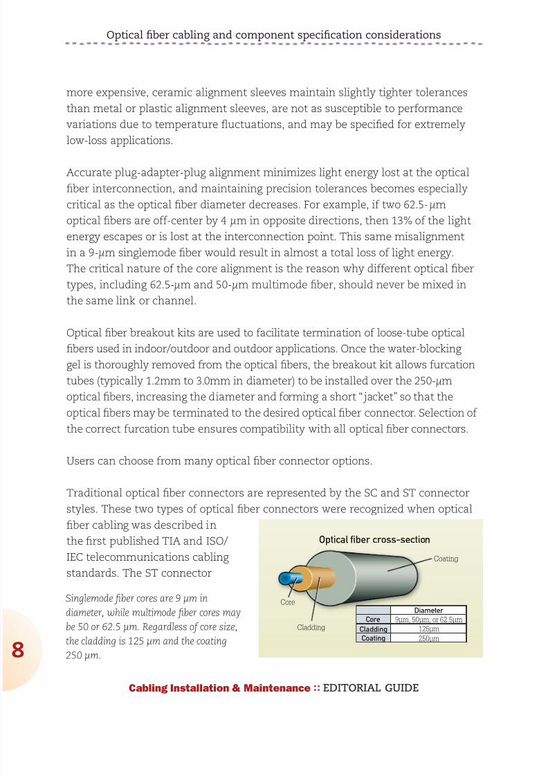
892019 Considerations for Selecting and Using Multimode Fiber
httpslidepdfcomreaderfullconsiderations-for-selecting-and-using-multimode-fiber 832
Optical fiber cabling and component specification considerations
8
Cabling Installation amp Maintenance EDITORIAL GUIDE
more expensive ceramic alignment sleeves maintain slightly tighter tolerances
than metal or plastic alignment sleeves are not as susceptible to performance
variations due to temperature fluctuations and may be specified for extremely
low-loss applications
Accurate plug-adapter-plug alignment minimizes light energy lost at the optical
fiber interconnection and maintaining precision tolerances becomes especially
critical as the optical fiber diameter decreases For example if two 625-microm
optical fibers are off-center by 4 microm in opposite directions then 13 of the light
energy escapes or is lost at the interconnection point This same misalignment
in a 9-microm singlemode fiber would result in almost a total loss of light energy
The critical nature of the core alignment is the reason why different optical fibertypes including 625-microm and 50-microm multimode fiber should never be mixed in
the same link or channel
Optical fiber breakout kits are used to facilitate termination of loose-tube optical
fibers used in indooroutdoor and outdoor applications Once the water-blocking
gel is thoroughly removed from the optical fibers the breakout kit allows furcation
tubes (typically 12mm to 30mm in diameter) to be installed over the 250-microm
optical fibers increasing the diameter and forming a short ldquojacketrdquo so that the
optical fibers may be terminated to the desired optical fiber connector Selection of
the correct furcation tube ensures compatibility with all optical fiber connectors
Users can choose from many optical fiber connector options
Traditional optical fiber connectors are represented by the SC and ST connector
styles These two types of optical fiber connectors were recognized when optical
fiber cabling was described in
the first published TIA and ISOIEC telecommunications cabling
standards The ST connector
Cladding
Core
Optical fiber cross-section
Core
Diameter
9m 50m or 625m
125m
Coating
250m
Cladding
Coating
Singlemode fiber cores are 9 microm in
diameter while multimode fiber cores may
be 50 or 625 microm Regardless of core size
the cladding is 125 microm and the coating
250 microm
892019 Considerations for Selecting and Using Multimode Fiber
httpslidepdfcomreaderfullconsiderations-for-selecting-and-using-multimode-fiber 932
892019 Considerations for Selecting and Using Multimode Fiber
httpslidepdfcomreaderfullconsiderations-for-selecting-and-using-multimode-fiber 1032
Optical fiber cabling and component specification considerations
0
Cabling Installation amp Maintenance EDITORIAL GUIDE
12-fiber MPOMTP interfaces with 24 LC connections or one 12-fiber MPOMTP
interface with 12 SC or LC connections
Optical fiber cabling deployment
The most common optical fiber cabling deployment approach is to field terminate
the optical fiber connectors to the optical fiber cable using the appropriate epoxy
polish or no-epoxyno-polish mechanical termination method However the
new MPOMTP plug-and-play modules and MPOMTP array connectors are not
supported by field termination and there are considerations such as installer
expertise and the IT construction
upgrade schedule that may favor the
use of factory-terminated pigtailsor trunking assemblies over field
termination methods
The pros and cons of these termination
methods are described here
Field termination supports the lowest
raw material cost for SC ST LC and
MT-RJ optical fiber cabling systems
However the time needed for field
termination is the longest of the three
deployment options and installer
skill-level requirements are higher
which may increase the project
installation costs No-epoxyno-polish
and certain mechanical-splice-style
termination methods require lessinstallation skill than the epoxypolish method however the connectors used in
conjunction with mechanical termination methods are more expensive and the
performance (especially using the no-epoxyno-polish method) may be lower
and more variable
Optical fiber pigtails feature a factory preterminated and tested SC ST LC or MT-
RJ optical fiber connector and a 1-meter stub of 625125-microm multimode 50125-
Tight-buffered
Loose-tube
Sample optical fiber cable constructions
Jacket
Rip cord
Central strength member
Aramid yarns
Color coded tight-bufferedfibers and jackets
Water-blocking swellabletape
Gel-filled tubes
Water-blocking aramid yarn
Central strength memberRip cord
Aramid yarns
Color-coded fibers and tubes
Jacket
The environment in which the fiber cable will be
used eg indoor or outdoor will determine the
cablersquos construction and the treatment of the
fibers within that cable
892019 Considerations for Selecting and Using Multimode Fiber
httpslidepdfcomreaderfullconsiderations-for-selecting-and-using-multimode-fiber 1132
Optical fiber cabling and component specification considerations
1
Cabling Installation amp Maintenance EDITORIAL GUIDE
microm multimode or singlemode optical fiber The stub end of the pigtail is then
fusion-spliced to the optical fiber Fusion splicing provides a consistent nearly
loss-free termination and can be fast with proper technicians and equipment
The main benefits to this approach are the assurance of low-loss performance at
the interconnection and the elimination of the need for endface inspections and
possible connector reterminations
Trunking cable assemblies provide an efficient alternative to field-terminated
components or splice connections and allow up to 75 faster field deployment
times Trunking cable assemblies are custom factory preterminated and tested
lengths of optical fiber cable terminated on both ends with SC ST LC MT-RJ or
MPOMTP optical fiber connectors that are simply pulled and plugged in Whendeploying trunking cable assemblies cable-length specification is critical and
precise planning is required up front Trunking cable assemblies that have an
MPOMTP connector on one or both ends are commonly referred to as ldquoplug-
and-playrdquo cable assemblies MPOMTP plug-and-play cable assemblies have the
smallest connector profile and therefore have the smallest pathway cabinet and
rack-space requirements of all trunking cable assembly options
Always maintain the fibersrsquo polarity to ensure the transmit fiber is matched to
the receive port on each end of the link or channel
Valerie Maguire is a Global Sales Engineer with Siemon
892019 Considerations for Selecting and Using Multimode Fiber
httpslidepdfcomreaderfullconsiderations-for-selecting-and-using-multimode-fiber 1232
1010100000001111011111100101010101001010
1010000001110101010101000101010001010101
0101001010101010010100101010101000000011
1101111110010101010100101010100000011101
0101010100010101000101010101010010101010
1001010010101010100000001111011111100101
0101010010101010000001110101010101000101
010001010101010100101010101001010010101
0101000000011110111111001010101010010101
0100101010000000111101111110010101010100
1010101000000111010101010100010101000101
010101010010101010100101001010101010000
0001111011111100101010101001010101000000
1110101010101000101010001010101010100101
0101010010100101010101000000011110111111
0010101010100101010100000011101010101010
0010101000101010101010010101010100101001
0101010100000001111011111100101010101001
01010100101010000000111101111110010101010
Is there a hole in your
fiberrsquos performance
If itrsquos not OFS multimode fiber there could be OFSrsquo
manufacturing process virtually eliminates defects in the
fiber core with a DMD specified in the 0-5 micron range
That means double the bandwidth for lasers that launch
power in the fiberrsquos center while providing fast reliable
transmission and easier connectivity To learn more ask
your cabler about OFS or visit wwwofsopticscomfiber
892019 Considerations for Selecting and Using Multimode Fiber
httpslidepdfcomreaderfullconsiderations-for-selecting-and-using-multimode-fiber 1332Cabling Installation amp Maintenance EDITORIAL GUIDE
3
Making the switch from
625- to 50-micron fiber
What to do and what not to do when opting
for higher-bandwidth 50-micron multimode
By John Kamino
MULTIMODE FIBER SYSTEMS continue to provide the most cost-
effective cabling solution for data centers local area networks
(LANs) and other enterprise applications Compared to singlemode
fiber multimode systems offer significantly lower costs for
transceivers connectors and connector installation while meeting and exceeding
the bandwidth and reliability requirements of the most demanding networks
If you are designing a new short-reach installation you will probably choose laser-
optimized 50-micron (microm) OM3 or OM4 multimode fiber These fibers preserve the
systems-cost benefits over singlemode fiber by using low-cost 850-nm vertical-
cavity surface-emitting laser (VCSEL) technology are capable of 10-Mbitsec
through 10-Gbitsec operation and will support upcoming 40- and 100-Gbitsec
transmission speeds
But if you are upgrading an existing system many of which have 625-microm
multimode already installed should you stick with 625-microm Or can you go with
the higher performance of 50-microm OM3 or OM4 fiber This article highlights thethings you must consider when upgrading an existing 625-microm system
Why two fiber sizes
The numbers under discussionmdash50-microm and 625-micrommdashrefer to the diameter of
the fiberrsquos core through which light signals are transmitted The first optical
fibers deployed in the 1970s for both short- and long-reach applications were
50-microm multimode fibers In the early 1980s singlemode fiber replaced 50-microm
892019 Considerations for Selecting and Using Multimode Fiber
httpslidepdfcomreaderfullconsiderations-for-selecting-and-using-multimode-fiber 1432
Making the switch from 625- to 50-micron fiber
4
Cabling Installation amp Maintenance EDITORIAL GUIDE
fiber in longer-distance installations However 50-microm multimode continued to be
more cost-effective for short-reach interconnects such as building and campus
backbones up to 2000-meter distances
But as data rates increased 50-microm fiber could not support 10-Mbitsec rates overthe 2-kilometer distances required by some campus installations Not enough
power could be coupled from the light-emitting diode (LED) sources in use at that
time into the 50-microm core to support these link distances
625-microm multimode fiber was introduced in 1985 to solve this problem It could
capture more light from a LED in its larger core and 2-km campus links operating
at 10 Mbitssec were easily supported Also the larger-core fiber was easier to
cable and connectorize It became the most commonly used fiber for short-reach
enterprise applications in North America
Today as data rates surpass 10-Gbitssec and lasers have replaced LEDs 625-microm
fiber has reached its performance limit 50-microm fiber offers as much as 10 times
the bandwidth of the 625-microm fiber Whatrsquos more improvements in technology
have made 50-microm fiber easier to use
Multimode fiber choices today
To consider making the switch from 625-microm to 50-microm multimode it is importantto first understand the terminology used to designate the various performance
grades of multimode fiber In each of these designations ldquoOMrdquo stands for ldquooptical
multimoderdquo For example OM1 is the designation for fiber with 200500 MHz-
km overfilled launch (OFL) bandwidth at 8501300 nm this typically is 625microm
fiber OM2 is used for fiber with 500500 MHz-km OFL bandwidth at 8501300 nm
(typically 50-microm fiber)
Fiberdesignation
EMB (in MHz∙km) 850 nm
OFL (in MHz∙km) 850 nm
OFL (in MHz∙km) 1300 nm
OM1 (625) NA 200 500
OM2 (50) NA 500 500
OM3 (laser-
optimized 50) 2000 1500 500
OM4 (laser-
optimized 50) 4700 3500 500
892019 Considerations for Selecting and Using Multimode Fiber
httpslidepdfcomreaderfullconsiderations-for-selecting-and-using-multimode-fiber 1532
Making the switch from 625- to 50-micron fiber
5
Cabling Installation amp Maintenance EDITORIAL GUIDE
More-recent additions are OM3 for laser-optimized 50-microm fiber having 2000
MHz-km effective modal bandwidth (EMB also known as laser bandwidth) at 850
nm (designed for 10-Gbitsec transmission) and most recently OM4 for laser-
optimized 50-microm fiber having 4700 MHz-km EMB at 850 nm designed for 10-Gbit
sec transmission over longer distances
OM4 with its extended bandwidth can be used to enhance the system-cost
benefits enabled by 850 nm lasers for 10-Gbitsec applications as well as new
40- and 100-Gbitsec systems With its 150 m reach capability at 40 and 100
Gbitsec OM4 will support an additional 10 percent of link lengths in large data
centers that are not covered by OM3rsquos 100 m reach It is especially well-suited
for short reach data center and high-performance computing applications whereoptical loss budgets are tight at 10-Gbitsec and higher The additional bandwidth
provided when OM4 fiber is deployed at less than its rated distance offers extra
headroom for channel insertion loss
Itrsquos also important to note that for next-generation 40- and 100-Gbitsec
Ethernet only OM3 and OM4 fibers are included in the IEEE 8023ba standard
as supported (multimode optical fiber) media OM1 and OM2 fibers are not
supported media types
The latest offerings in multimode fiber are 50 microm bend insensitive multimode
fibers (BIMMF) These fibers have been promoted as offering all the advantages
of high bandwidth laser-optimized multimode fiber with the added advantage
of lower bend sensitivity However recent work has shown that some of these
fibers may have significant performance issues A paper presented at the 2010
International Wire and Cable Symposium (IWCS) showed that mating (connector)
loss of BIMMFs with standard fibers is higher than standard fiber connected to
standard fiber This additional loss adds to the total link loss possibly causing itto exceed the link loss budget
Another recent study examined issues with the system performance of bend
insensitive fibers and questioned whether current requirements are adequate
It has been proposed that standards organizations perform a thorough review of
BIMMFs and incorporate them into industry standards Until this work is done
caution is advised before widespread adoption takes place
892019 Considerations for Selecting and Using Multimode Fiber
httpslidepdfcomreaderfullconsiderations-for-selecting-and-using-multimode-fiber 1632
Making the switch from 625- to 50-micron fiber
6
Cabling Installation amp Maintenance EDITORIAL GUIDE
Upgrading a 625-microm network
The primary considerations for an upgrade or extension of an existing 625-microm
network are
the required transmission speed (now and especially in the future)
link distance
ease of cable replacement and
cost of cable replacement
If you are running Gigabit Ethernet (1-Gbitsec) then legacy 625-microm fiber will
transmit a distance of 220 to 275 meters depending on its bandwidth ratingBut at 10-Gigabit Ethernet (10-GbE 10-Gbitssec) they will only support 26 to
33 meters If your network will not need to support 10-GbE at distances greater
than 25 meters then you may be able to stick with 625-microm fiber It is important
to note however that most 625-microm fiber has not been measured for laser
bandwidth and some legacy fiber may have difficulty supporting even this short
distance
And if you want to transmit longer distances over 625-microm fiber you will be
forced to use much-more-expensive 1300-nm transceivers that will operate over
multimode or singlemode fiber These transceivers cost significantly more than
850-nm multimode devices because the 1300-nm optoelectronics package is the
far more complex of the two
If you are considering extending your network by installing additional 625-microm
fiber you need to carefully review your future network plans If you plan to
upgrade your network speed to 10-Gbitssec in the future recabling with laser-
optimized OM3 or OM4 fiber would be a wiser choice
Measuring laser bandwidth
As previously stated 625-microm fiber provides limited support for 10-Gbitsec
transmission so it generally is not measured for laser bandwidth (EMB) Typically
only 50-microm fibers are measured for EMB To verify bandwidth of 625-microm fiber
the traditional OFL bandwidth measurement method is used
892019 Considerations for Selecting and Using Multimode Fiber
httpslidepdfcomreaderfullconsiderations-for-selecting-and-using-multimode-fiber 1732
Making the switch from 625- to 50-micron fiber
7
Cabling Installation amp Maintenance EDITORIAL GUIDE
For 50-microm fibers EMB is ensured by using a method called Differential Mode
Delay (DMD) This DMD test is required by standards to verify 10-Gbitsec
performance and involves scanning the fiberrsquos core in small increments to see
how the signal travels in various regions of the core
Once the DMD test is conducted and a DMD ldquoprofilerdquo is obtained the standards
allow two methods to disposition the fiber One is the DMD Mask method and the
other is the Effective Modal Bandwidth Calculated (EMBc) method
The DMD Mask method provides direct verification of the fiberrsquos DMD
performance using a set of clearly defined DMD masks and templates that are
overlaid on the DMD profile This technique provides flexibility in applying more-stringent DMD performance criteria in certain regions of the fiber including the
0-5microm center region
The EMBc method involves complex calculations involving 10 weighting
functions to represent the wide variety of 10-Gbitsec VCSELs available on the
market Theoretical in nature this technique does not in our opinion provide
the scrutiny on fiber quality and performance that the DMD Mask technique
does The EMBc method puts little emphasis on the 0-5microm region of a fiberrsquos
core Though standards allow both testing methods we advocate the DMD
Mask method
Mixing 50- and 625-microm
If you decide to add 50-microm fiber to an existing 625-microm infrastructure connecting
50-microm directly to 625-microm is generally not recommended The difference in core
sizes could cause high loss when transmitting from the 625-microm into the 50-
microm fiber Also the bandwidth of 625-microm fibers is typically much lower further
degrading system performance Even if a low-speed application operates over alink made up of mixed fiber types upgradeability will be severely compromised
This elevated-loss problem occurs when transmitting from the larger (625-microm) to
the smaller (50-microm) core It is comparable to a 4-inch water pipe connecting to a
3-inch pipe there is no problem going from the smaller pipe to the larger one but
going in the opposite direction can lead to a lot of lost water (or in this case light)
892019 Considerations for Selecting and Using Multimode Fiber
httpslidepdfcomreaderfullconsiderations-for-selecting-and-using-multimode-fiber 1832
Making the switch from 625- to 50-micron fiber
8
Cabling Installation amp Maintenance EDITORIAL GUIDE
The amount of connection loss you could experience is about 4 dB for a LED-
based system which fills the entire core of a 625-microm fiber and anywhere from 0
to 4 dB for a VCSEL-based system which only fills a portion of the core
Because most optical-loss test sets use LEDs you should plan for the worst and
assume you will see a 4-dB loss in one direction If your link budget can tolerate
this additional 4-dB loss then you can get away with connecting 50-microm directly
to 625-microm
The better scenario is to separate 50-microm from 625-microm with active electronics
such as a switch router or simple media converter
Mixing of 625-microm and 50-microm fiber is not recommended unless an electronics
interface is inserted into the link If 10-Gbitsec speeds are being installed 625-
microm fiber will only be able to support extremely short links and replacement is
recommended
John Kamino is Product Manager Multimode Fiber with OFS
892019 Considerations for Selecting and Using Multimode Fiber
httpslidepdfcomreaderfullconsiderations-for-selecting-and-using-multimode-fiber 1932
OFSrsquo LaserWave fiber exceeds the OM4 standard for
todayrsquos high-speed networks mdash and tomorrowrsquos Andsince LaserWave fiber delivers DMD specified in the
0 ndash 5 micron range you get up to twice the bandwidth for
lasers that launch power in the fiberrsquos center Enjoy fast
reliable transmission and easier connectivity To learn more
ask your cabler about OFS or visit ofsopticscomfiber
Get your network up tospeed with LaserWavereg fiber
892019 Considerations for Selecting and Using Multimode Fiber
httpslidepdfcomreaderfullconsiderations-for-selecting-and-using-multimode-fiber 2032Cabling Installation amp Maintenance EDITORIAL GUIDE
20
Compatibility issues with
bend-insensitive andstandard multimode
Lab testing indicates risks associated with mixing
bend-insensitive and standard multimode fiber
By Rick Pimpinella Bulent Kose and Brett Lane
THE INCREASING DEMAND for higher-speed data transmission
within the data center and premises networks has led to the wide
deployment of multimode optical connectivity To meet performance
and reliability requirements the optical specifications on the
components have also become more stringent For high-speed optical networks
using laser-optimized OM3 and OM4 multimode fiber it is more critical than ever
for network operators and designers to understand the attributes of the various
performance grades of passive fiber-
optic components that make up the
network so that they may employ the
most cost-efficient solutions that meet
their needs today and in the future
In order to ensure that optical networks
operate effectively and reliably it isfundamental that the optical fiber
meets the necessary bandwidth
requirements and that the total optical
loss or insertion loss (IL) is below
the allowable limit required by the
application The two sources of IL
within optical networks are 1) loss at
892019 Considerations for Selecting and Using Multimode Fiber
httpslidepdfcomreaderfullconsiderations-for-selecting-and-using-multimode-fiber 2132
Compatibility issues with bend-insensitive and standard multimode
21
Cabling Installation amp Maintenance EDITORIAL GUIDE
connector interfaces and 2) loss or attenuation within the fiber itself The IL
limits for 10- 40- and 100-Gbitsec Ethernet are in the table below
The combination of
eroding insertion loss
budgets and increased
demands for complex
network architectures
with many
connector interfaces
has triggered several fiber and connectivity suppliers to develop improved
connectivity and fiber products that allow network architectures to cope withthese trends Specifically several connectivity suppliers now offer low-loss or
optimized passive fiber-optic components such as connectors cassettes and
patch cords that allow them to implement complex networks with numerous
connector interfaces while still meeting the maximum connector loss budget
Moreover although the intrinsic fiber attenuation has not been reduced
significantly over the past many years recent advancements in fiber production
have delivered extra headroom by significantly improving attenuation levels
under tightly bent conditions even in those cases in which the fiber is
unintentionally subjected to bends smaller than that allowed with the ANSI
TIA-568-C0 premises cabling standard This article reviews how this new type of
laser-optimized multimode fiber often called bend-insensitive or bend-optimized
integrates into todayrsquos data center and premises network
Achieving bend-optimization
It is well known that in order to produce a fiber with improved bend performance
it must be made to more tightly confine the light within its core region Thismodification allows more of the light to meet the conditions necessary for
total internal reflection as the fiber is bent Enhanced optical confinement
is accomplished by simply increasing the effective difference in the index of
refraction between the core and cladding regions This is typically accomplished
by introducing an index depression or trench in the cladding region close to the
fiber core
Applicationstandard
Minoperatingdistance
(m)
Maxconnectorloss (dB)
Max fiberattenuation
(dB)
Max totalIL budget
(dB)
0-Gbitsec Ethernet 300 15 11 26
40- and 100-Gbit
sec Ethernet (OM3)
100 15 04 19
40- and 100-Gbit
sec Ethernet (OM4)
150 1 05 15
892019 Considerations for Selecting and Using Multimode Fiber
httpslidepdfcomreaderfullconsiderations-for-selecting-and-using-multimode-fiber 2232
892019 Considerations for Selecting and Using Multimode Fiber
httpslidepdfcomreaderfullconsiderations-for-selecting-and-using-multimode-fiber 2332
Compatibility issues with bend-insensitive and standard multimode
23
Cabling Installation amp Maintenance EDITORIAL GUIDE
conditions necessary for total internal reflection (ie rays with larger angles)
light emerging from bend-optimized multimode fiber will have a larger angle on
average than light emerging from standard multimode fiber The parameter that
characterizes the maximum divergence or acceptance angle of light from or to
a fiber is called numerical aperture (NA) Therefore the NA of bend-optimized
multimode is generally expected to be greater on average than the NA of
standard multimode A thorough sampling across multiple fiber manufacturers
revealed that the average NA increased
from 0199 for standard multimode fiber to
0207 for bend-optimized multimode fiber
Although this moderate increase in NAappears insignificant in some situations
the optical loss across an optical fiber
interface (eg connector) is dependent on
the differences in NAs of the fibers In the
case that light fully populates the fiber
core such as when illuminated with an
LED and is coupled from a fiber with a
higher NA into a receiver with a lower NA
the light will diverge at an angle larger
than the acceptance angle of the receive
fiber This will result in some light being
lost (into the cladding) and the interface will have loss proportional to the NA
difference (ratio) between the two fibers
Consequently increased loss may be realized when light travels from bend-
optimized multimode fiber into standard multimode fiber In fact the expected
loss across a bend-optimized fiber with an NA of 0207 and a standard fiber withan NA of 0199 is 034 dB which is a significant portion of the overall IL budget
In the case that light travels from a fiber with a lower NA into a receiver with a
higher NA or light does not fully illuminate the fiber core no loss resulting from
the difference in fiber NAs is expected
NA loss measurements
To predict the NA loss that would be realized during link certification
2 4 6
MMF LED
MMF VCSEL
8 10
3
25
2
15
1
05
0
Bend loss (1 m) (dB)
Mandrel radius (mm)
BO-MMF LED
BO-MMF VCSEL
Measured bend loss at 850 nm
representative of bend-optimized and
standard multimode fiber using both
LED and VCSEL light source Fibers were
wrapped one turn around 10 different
mandrels with radii ranging from 25mm to
10 mm
892019 Considerations for Selecting and Using Multimode Fiber
httpslidepdfcomreaderfullconsiderations-for-selecting-and-using-multimode-fiber 2432
Compatibility issues with bend-insensitive and standard multimode
24
Cabling Installation amp Maintenance EDITORIAL GUIDE
measurements of an optical
channel with bend-optimized
and standard fiber interfaces
a series of standard IL
measurements were performed
on selected bend-optimized
and standard fibers Fiber
samples from several fiber
manufacturers were selected
with a wide range of NAs in
order to provide not only a
typical NA loss from fibers withaverage NA but also provide
an upper and lower limit of
NA loss that may be expected
when connecting dissimilar
multimode fiber types without knowledge of NA differences Several fibers were
selected of each fiber typendashsome with an average NA some with a low NA and
some with a high NA The table on page 25 summarizes the samples used for this
experiment and the theoretically expected NA loss from each connection
For these measurements the various bend-optimized fiber samples were
fusion spliced to the various standard multimode fiber samples A fusion
splicer was used to connect dissimilar fiber types instead of connectors in
order to minimize other loss contributors such as lateral offset and connector
termination processing The insertion loss of the connection was calculated by
injecting light meeting the new TIAEIA-526-14-B encircled flux specification
into the bend-optimized fiber and then measuring the power coupled out of
the standard fiber Subtracting this power level from the reference power levelmeasured previously as the amount of power coupled into the bend-optimized
fiber resulted in the IL or NA loss of the connection All aspects of these
measurements were in compliance with TIAEIA-45-171A (eg diameter and
placement of cladding mode strippers)
The measurement data is shown in the chart on page 25 Each data point
represents the average of the NA losses for a set of fibers for each NA
Bend-optimizedMMF core
NA = sinq1
MMF coreα
NABO-MMF gt NAstd-MMF
This illustration shows a mismatch in NA when connecting
a fiber with a large NA (left) to a fiber with a small NA(right) Because the receive fiber on the right has a smaller
NA some light is not coupled and instead is lost into the
cladding This loss is referred to as NA loss
892019 Considerations for Selecting and Using Multimode Fiber
httpslidepdfcomreaderfullconsiderations-for-selecting-and-using-multimode-fiber 2532
Compatibility issues with bend-insensitive and standard multimode
25
Cabling Installation amp Maintenance EDITORIAL GUIDE
combination From this data
connecting dissimilar fiber types
with average NAs confirms the
theoretically predicted NA loss of
approximately 040 dB Additionally
the upper and lower limits of NA
loss were measured to be 028
dB and 106 dB Although these
average and extreme NA losses
are fairly well correlated with the
theoretically predicted NA loss
other measured values deviatesignificantly from the theoretically
predicted value This suggests that
factors other than NA such as core
diameter index profile and mode structure also significantly influence the loss
when connecting bend-optimized and standard multimode fiber As a result the
light does not couple with 100 percent efficiency between fibers and therefore an
additional mode coupling loss must exist
In fact in the case that bend-optimized fiber samples with the identical NA but
manufactured from different suppliers were connected to standard fibers with
NA equal to 0200 the NA loss differs significantly from vendor to vendor The
average NA loss from Vendor A bend-optimized interfaces nearly exactly matched
the theoretical NA loss of 030 dB while the average NA loss from Vendor B
bend-optimized interfaces was much higher at 051 dB (see graph on page 26) As
expected the bend-optimized fibers from Vendor B were found to be more bend-
tolerant than those from Vendor A
In addition to realizing
unidirectional NA
loss an increase in the
modal noise penalty
may also result
when connecting
bend-optimized and
1000 0975 0950 0925 0900 0875 0850
14
12
10
08
06
04
02
00
NA ratio
NA loss (dB)
The black line shows the theoretical loss of connected
fibers with different NA and the dots represent
actual measured loss The results suggest factorsother than NA also influence loss when connecting
bend-optimized and standard multimode fiber
NA (BO-MMF)to NA (MMF)combination
NA (BO-MMF) NA (MMF) NA ratio Theoreticalloss (dB)
Average to Average 0207 0199 0961 034
Large to Average 0215 0199 0926 067
Large to Small 0215 0185 086 131
Average to Small 0207 0185 0894 098
Small to Small 0199 0185 0928 063
Large to Large 0215 0212 0986 012
892019 Considerations for Selecting and Using Multimode Fiber
httpslidepdfcomreaderfullconsiderations-for-selecting-and-using-multimode-fiber 2632
Compatibility issues with bend-insensitive and standard multimode
26
Cabling Installation amp Maintenance EDITORIAL GUIDE
standard multimode fiber Modal noise is a power penalty related to the reduction
in the signal-to-noise ratio (SNR) of the optical signal For high-speed networks
employing VCSELs if a connector selectively attenuates higher-order modes as a
result of NA mismatch or a lateral offset between fiber cores then fluctuations in
the power distribution (spatial speckle pattern) result in fluctuations in connector
insertion loss This fluctuation is seen by the detector as an increase in noise
thereby reducing the SNR and therefore signal quality
The maximum allowed power penalty for modal noise is currently specified
in 10GBase-SR to be 03 dB Both NA loss and mode coupling loss can increase
the mode-selective loss (filter aperture) at a connector interface resulting in an
increase in modal noise Considering the overall power budget for 10G40G100GEthernet is 15 dB (or 10 dB for OM4) any
increase in modal noise may compromise
system reliability
In conclusion inconclusive
As part of our review of how bend-
optimized multimode fiber is integrating
in todayrsquos data center and premises
networks we measured the loss between
bend-insensitive and standard multimode
fibers to quantify the expected additional
loss during certification of mixed-fiber
links These additional losses were
measured to be as high as 1 dB and can
be a significant portion ofndashor even actually
exceedndashthe total optical power budget
for todayrsquos high-speed networks For a channel link that contains several bend-optimized fiber and multimode fiber interfaces which have large NA differences
the NA losses may be additive and further inhibit system certification
Furthermore although NA loss alone is unlikely to detrimentally influence
system performance it may be very difficult if not impossible to determine if
excessive channel loss is due to NA differences or other conventional sources
of loss such as macrobending or dirtydamaged components One strategy to
BO-MMF1
to MMF2
BO-MMF1
to MMF2
BO-MMF1
to MMF2
Vendor A BO-MMF
Vendor B BO-MMF
BO-MMF1
to MMF2
07
06
05
04
03
02
01
00
Measured NA loss (dB)
Bend-optimized fibers from Vendor B shown
here as the blue bars were found to be more
bend-tolerant than the bend-optimized fibers
from Vendor A shown as the green bars
The more-optimized fibers exhibited higher
NA loss
892019 Considerations for Selecting and Using Multimode Fiber
httpslidepdfcomreaderfullconsiderations-for-selecting-and-using-multimode-fiber 2732
Compatibility issues with bend-insensitive and standard multimode
27
Cabling Installation amp Maintenance EDITORIAL GUIDE
account for this loss would be to require bidirectional loss measurements of
individual optical interfaces
During the most recent meeting of the TIA TR-4212 Optical Fibers and Cable
Subcommittee a vigorous debate included many of the topics discussed in this
article and others including increased NA loss mode coupling loss modal
noise (which may negatively impact system performance) the validity of other
standardized fiber test procedures for fiber core diameter fiber bandwidth and
link attenuation (encircled flux) The subcommittee authorized the formation of
a task group to study the technical compatibility of bend-insensitive multimode
fiber with current multimode fiber standards
Based on our internal analysis and the present uncertain position within the
standards community we have concluded that the performance risks of mixing
bend-optimized and standard multimode fiber types in high-speed optical
channel links exceeds any benefit To ensure that total optical loss across data
center and premises networks remains below the allowable limit we recommend
adhering to standards-based radius-control methods and the use of one fiber
type throughout the channel link which includes cabling and patch cords This
approach enables network stakeholders to reliably deploy complex network
architectures meet stringent IL budgets and ensure optimal system performance
within current standards-based network architectures and testing methods
Some manufacturers support this effort others minimize its importance Until
the TIA subcommittee work on these issues is complete we recommend that
these two fiber types should not presently be mixed
Dr Rick Pimpinella is a Distinguished Engineer Bulent Kose is a ResearchEngineer and Dr Brett Lane is a Fiber Research Manager with Panduit
892019 Considerations for Selecting and Using Multimode Fiber
httpslidepdfcomreaderfullconsiderations-for-selecting-and-using-multimode-fiber 2832
As the demand for bandwidth in
enterprise applications such as
data centers continues to
boom new transmission media
must be developed continually
to meet end user requirementsThe latest in optical transmis-
sion media for the enterprise is
called OM4 fiber
OM4 fiber is a 50 micron (microm)
laser-optimized multimode fiber
with extended bandwidth It is
designed to enhance the sys-
tem cost benefits enabled by
850 nm Vertical Cavity Surface
Emitting Lasers (VCSELs) for existing 1 and 10 Gbs applica-
tions as well as future 40 and
100 Gbs systems
Supporting Ethernet Fibre
Channel and OIF applications
OM4 fiber allows extended
reach upwards of 550 meters at
10 Gbs for ultra long building
backbones and medium lengthcampus backbones It offers an
Effective Modal Bandwidth
(EMB) of 4700 MHz-km more
than double the IEEE require-
ment for 10 Gbs 300 meter
support
To help you use this advanced
fiber to its greatest advantage
this paper describes the tech-
nology behind OM4 fiber high-
lights the key differences with
other fiber types and explains
how its high bandwidth is
ensured through stringentmeasurement methods
Multimode Fiber Basics
Compared to single-mode
fibers multimode fibers have
larger cores that as their name
implies guide multiple ldquomodesrdquo
or rays of light simultaneously
Modes that travel at the outside
edge of the core have a longer
distance to go than modes thattravel near the center
The corersquos graded index profile
is designed to slow down
modes that have a shorter dis-
tance to travel so that all modes
arrive at the end of the fiber as
close in time as possible This
minimizes modal dispersion
also known as differential mode
delay (DMD) and maximizes
bandwidth which is the amount
of information that can travel
through the fiber per unit of
time
In addition to their large core
multimode fibers have a large
Numerical Aperture (NA) the
maximum angle at which a fiber
can accept the light that will be
transmitted through it This
allows them to work with rela-
tively low-cost optical compo-
nents and light sources such as
light-emitting diodes (LEDs)and VCSELs
Multimode Fiber Options
Multimode products are identi-
fied by the OM (ldquooptical multi-
moderdquo) designation as outlined
in the ISOIEC 11801 interna-
tional cabling standard (see
table 1)
OM4 - The Next Generation
of Multimode Fiber Tony Irujo
Sales Engineer
OPTICAL FIBER IN ENTERPRISE APPLICATIONS
Table 1 ISOIEC 11801 OM designations
892019 Considerations for Selecting and Using Multimode Fiber
httpslidepdfcomreaderfullconsiderations-for-selecting-and-using-multimode-fiber 2932
OM4 fiber is the latest develop-
ment in this series It is espe-
cially well suited for shorter
reach data center and high per-
formance computing applica-
tions where optical loss budg-
ets are tight at 10 Gbs (and
are expected to get even tighter
at 40 Gbs and 100 Gbs) Thehigh bandwidth provided by
OM4 fiber when deployed at
less than its rated distance
offers extra ldquoheadroomrdquo for
channel insertion loss
OM4 is backward compatible
with applications calling for OFL
bandwidth of at least 500 MHz-
km at 1300 nm (eg FDDI
IEEE 100BASE-FX
1000BASE-LX 10GBASE-LX4
and 10GBASE-LRM)
The latest offerings in multi-
mode fiber are 50 983221m bend
insensitive multimode fibers
(BIMMF) These fibers have
been promoted as offering all
the advantages of high band-
width laser-optimized multi-mode fiber with the added
advantage of lower bend sensi-
tivity
However recent work has
pointed to some areas of con-
cern with these fibers Studies
have identified issues with the
characterization of bend insen-
sitive fibers and questioned
whether current requirements
are adequate to guarantee sys-
tem performance Additional
studies have shown that mating
(connector) loss of BIMMFs
with standard fibers is higher
than with standard fibers con-
nected to each other This addi-
tional loss adds to the total link
loss
It has been proposed that stan-
dards organizations perform a
thorough review of BIMMFs
and incorporate them into
industry standards Until this
work is done some caution is
advised before widespread
adoption takes place
What Makes OM4 Different
Like OM3 multimode fiber OM4
fiber is considered to be ldquolaser-
optimizedrdquo or optimized for use
with VCSEL light sources OM3
and OM4 fibers are designed
and manufactured in such a
way as to get the most perform-
ance out of VCSELs compared
to LEDs That is why laser-opti-
mized fibers are specified using
Laser Bandwidth or EMB
OM2 fiber although compatible
with VCSELs is not considered
to be laser-optimized OM2
fiber is intended for use with
LED sources at speeds of 10 or
100 Mbs or for shorter reach 1
Gbs networks You can use
OM2 fiber with VCSELs but itsperformance is limited to 550
meters at 1 Gbs and only 82
meters at 10 Gbs compared to
OM4 fiberrsquos
reach of over
1000 meters
at 1 Gbs and
550 meters at
10 Gbs
As discussed
the speed at
which each
mode travels
down a multi-
mode fiberrsquos
core depends
on its refrac-
tive index
which is gov-
erned by the amount of chemi-
cal dopant Germanium at that
location in the core Because
modes traveling down the cen-
ter of the core have shorter dis-
tance to travel than those trav-
eling along the edge the refrac-
tive index profile in a multimode
fiber must be ldquogradedrdquo in a par-abolic manner across the core
This slows down the modes
that have a shorter distance to
travel equalizing the arrival
time of all the modes
The better the modes are
equalized the higher the band-
width of the fiber Mode equal-
ization depends on how well
the graded index profile is con-
structed during fiber manufac-
turing The more precise the
refractive index profile is in
terms of shape curvature and
smoothness (free of dips
spikes or defects) the better
the modes will be equalized
(see Figure 2)
OM4 fiber with its higher band-width has an extremely precise
refractive index profile virtually
free of perturbations or defects
Figure 2 A refractive index profile optimized for shape curvature
and smoothness maximizes bandwidth
892019 Considerations for Selecting and Using Multimode Fiber
httpslidepdfcomreaderfullconsiderations-for-selecting-and-using-multimode-fiber 3032
In order to make such a precise
fiber one needs to use a pre-
form manufacturing process
that has exceptional control
over the amount of Germanium
that is incorporated at particular
sub-micron positions within the
fiberrsquos core An example of a
process that lends itself to this
level of control is OFSrsquo propri-
etary MCVD process in which
each layer of the core is
deposited and sintered individu-
ally providing the utmost in
refractive index precision and
uniformity
OM4 Fiber Standards
Two standards define the useof OM4 fiber in high-speed net-
works TIA document TIA-
492AAAD which contains the
OM4 fiber performance specifi-
cations and the IEC 60793-2-
10 international standard which
provides equivalent OM4 speci-
fications under fiber type A1a3
ISOIEC 11801 will add OM4
fiber as an industry-recognized
fiber type and IEEE 8023bafor 40G and 100G Ethernet will
include OM4 fiber as an option
that provides a reach of 150
meters (50 percent greater than
OM3)
There was discussion and
debate within the standards
groups about a minimum OFL
bandwidth requirement at 850nm Although current applica-
tions primarily use 850 nm
VCSEL lasers with fibers that
are specified to a minimum
EMB there was good reason to
also establish a minimum 850
nm OFL bandwidth specifica-
tion It has been shown that
fibers with higher OFL band-
width will perform better with
VCSELs that launch more
power into outer modes That is
why the existing OM3 fiber
standards require a minimum
1500 MHz-km OFL bandwidthat 850 nm
For OM4 fiber OFS and others
in the standards group strongly
recommended at least 3500
MHz-km OFL bandwidth in
order to ensure the utmost per-
formance and reliability ulti-
mately that is the specification
that was agreed upon
Measuring Laser Bandwidth
Bandwidth performance of OM4
fiber is ensured using the same
criteria as OM3 but to much
tighter specifications Due to a
challenge posed when the now-
familiar VCSEL was first intro-
duced new measurement
methods had to be developed
to verify laser bandwidth of OM3 and OM4 fibers
Unlike an LED laser VCSELs
produce an energy output that
is not uniform it can change
sharply across the face of the
output Whatrsquos more each laser
fills a different set of light paths
in each fiber and does so with
differing amounts of power in
each path Overfilled bandwidth
measurements used to meas-
ure LED bandwidth could not
emulate the operation of aVCSEL
The standards allow two ways
to measure and verify laser
bandwidth the DMD Mask
Method and the EMBc Method
Both methods require DMD
testing -- the difference lies in
how the DMD data is used and
interpreted
In DMD testing small high-
powered laser pulses are trans-
mitted through the fiber in tiny
steps across the entire core of
the fiber Only a few modes are
excited at each step and their
arrival times are recorded The
DMD of the fiber is the differ-
ence between the earliest and
the latest arrival times of allmodes at all steps
DMD measurement is currently
the only reliable method for ver-
ifying bandwidth required for 10
Gbs performance because it is
the only method that checks all
modes across the fiber core
independently For that reason
Figure 3 DMD testing measures how different VCSELs fill different modes in each
fiber
892019 Considerations for Selecting and Using Multimode Fiber
httpslidepdfcomreaderfullconsiderations-for-selecting-and-using-multimode-fiber 3132
industry associations such as
TIAEIA and ISOIEC have pub-
lished standards for DMD
measurement and DMD specifi-
cations for laser-optimized mul-
timode fiber
The DMD Mask Method is a
simple process that directlycompares DMD test results
against a set of specifications
(called templates or masks) to
see if the fiber has the neces-
sary performance
This is a straightforward graphi-
cal approach to ensuring the
data pulses do not spread
excessively beyond therequired 10 Gbs bit period If
the fiber passes these DMD
specs then you are assured of
at least 2000 MHz-km EMB no
matter which VCSEL you use
(as long as the VCSEL is com-
pliant)
The EMBc Method is an indi-
rect and more complex
process It takes the DMD
results and matches them
against a set of theoretical
weighting functions that are
intended to represent the
launch distributions of all com-
pliant VCSELs
The DMD results are combined
mathematically with each of the
10 weighting functions This
produces 10 different EMBc
values the lowest of which is
called minEMBc The minEMBc
value is then multiplied by a
factor of 113 to obtain the
fiberrsquos EMB value If this EMB
value is gt 2000 MHz-km thefiber is deemed compliant with
OM3 requirements and there-
fore should support 300 meters
at 10 Gbs
Due to all the complex calcula-
tions required by the EMBc
method and the fact that the
weighting functions only repre-
sent a sampling of the launch
characteristics of the many
VCSELs that could actually be
used in a real system the
EMBc method does not provide
the same scrutiny on fiber qual-
ity and performance as the
DMD Mask technique Whatrsquos
more the EMBc method virtual-ly ignores the center 0 ndash 5 983221m
(radial) region of a fiberrsquos core
because the weighting func-
tions put little emphasis in this
region
Conclusion
OM4 fiber provides next-gener-
ation multimode fiber perform-
ance for today and tomorrowrsquoshigh speed applications With
its significantly higher band-
width network designers and
operators can be assured that
multimode fiber will continue to
provide the most cost effective
solutions for short reach appli-
cations in data centers and
LANs
Copyright copy 2011 Furukawa Electric North America All rights reserved printed in USA
For additional information visit our website at wwwofsopticscomofs-fiber or call 1-888-fiber-
help For regional assistance contact
North America Asia Pacific
Telephone 508-347-8590 Telephone +852 2836 7102
Toll Free 800-799-7732 Fax +852 2836 7101
Fax 508-347-1211 E-mail fibersalesapofsopticscomE-mail fibersalesnarofsopticscom
Caribbean Latin America Japan
Telephone 508-347-8590 Telephone +81-3-3286-3424
Fax 508-347-1211 Fax +81-3-3286-3708 or 3190
E-mail fibersalescalaofsopticscom E-mail fibersalesjapanofsopticscom
Europe Middle East Africa China
Telephone +45-43 48 3736 Telephone +86 10 6505 3660
Fax +45 4348 3444 Fax +86 10 65059515
E-mail ofssalesdkofsopticscom E-mail fibersaleschinaofsopticscom
OFS reserves the right to make changes to the prices
and product(s) described in this document in the
interest of improving internal design operational
function andor reliability
This document is for informational purposes only
and is not intended to modify or supplement any
OFS warranties or specifications relating to any of
its products or services
892019 Considerations for Selecting and Using Multimode Fiber
httpslidepdfcomreaderfullconsiderations-for-selecting-and-using-multimode-fiber 3232
About OFSOFS is a world-leading designer manufacturer and provider of optical fiber
optical fiber cable FTTX optical connectivity and specialty photonics products
Our manufacturing and research divisions work together to provide innovative
products and solutions that traverse many different applications as they linkpeople and machines worldwide Between continents between cities around
neighborhoods and into homes and businesses of digital consumers we provide
the right optical fiber optical cable and components for efficient cost-effective
transmission
OFSrsquo corporate lineage dates back to 1876 and includes technology powerhouses
such as ATampT (NYSE T) and Lucent Technologies (now Alcatel-Lucent NYSE
ALU) Today OFS is owned by Furukawa Electric a multi-billion dollar global
leader in optical communications Headquartered in Norcross (near Atlanta)Georgia US OFS is a global provider with facilities in Avon Connecticut
Carrollton Georgia Somerset New Jersey and Sturbridge Massachusetts as well
as in Denmark Germany and Russia
wwwofsopticscom
LINKS
LaserWavereg Laser-Optimized OM4OM3 Fibers
Multimode or Single-Mode Fiber
Measuring Bandwidth of 10G Laser-optimized Multimode Fiber
892019 Considerations for Selecting and Using Multimode Fiber
httpslidepdfcomreaderfullconsiderations-for-selecting-and-using-multimode-fiber 932
892019 Considerations for Selecting and Using Multimode Fiber
httpslidepdfcomreaderfullconsiderations-for-selecting-and-using-multimode-fiber 1032
Optical fiber cabling and component specification considerations
0
Cabling Installation amp Maintenance EDITORIAL GUIDE
12-fiber MPOMTP interfaces with 24 LC connections or one 12-fiber MPOMTP
interface with 12 SC or LC connections
Optical fiber cabling deployment
The most common optical fiber cabling deployment approach is to field terminate
the optical fiber connectors to the optical fiber cable using the appropriate epoxy
polish or no-epoxyno-polish mechanical termination method However the
new MPOMTP plug-and-play modules and MPOMTP array connectors are not
supported by field termination and there are considerations such as installer
expertise and the IT construction
upgrade schedule that may favor the
use of factory-terminated pigtailsor trunking assemblies over field
termination methods
The pros and cons of these termination
methods are described here
Field termination supports the lowest
raw material cost for SC ST LC and
MT-RJ optical fiber cabling systems
However the time needed for field
termination is the longest of the three
deployment options and installer
skill-level requirements are higher
which may increase the project
installation costs No-epoxyno-polish
and certain mechanical-splice-style
termination methods require lessinstallation skill than the epoxypolish method however the connectors used in
conjunction with mechanical termination methods are more expensive and the
performance (especially using the no-epoxyno-polish method) may be lower
and more variable
Optical fiber pigtails feature a factory preterminated and tested SC ST LC or MT-
RJ optical fiber connector and a 1-meter stub of 625125-microm multimode 50125-
Tight-buffered
Loose-tube
Sample optical fiber cable constructions
Jacket
Rip cord
Central strength member
Aramid yarns
Color coded tight-bufferedfibers and jackets
Water-blocking swellabletape
Gel-filled tubes
Water-blocking aramid yarn
Central strength memberRip cord
Aramid yarns
Color-coded fibers and tubes
Jacket
The environment in which the fiber cable will be
used eg indoor or outdoor will determine the
cablersquos construction and the treatment of the
fibers within that cable
892019 Considerations for Selecting and Using Multimode Fiber
httpslidepdfcomreaderfullconsiderations-for-selecting-and-using-multimode-fiber 1132
Optical fiber cabling and component specification considerations
1
Cabling Installation amp Maintenance EDITORIAL GUIDE
microm multimode or singlemode optical fiber The stub end of the pigtail is then
fusion-spliced to the optical fiber Fusion splicing provides a consistent nearly
loss-free termination and can be fast with proper technicians and equipment
The main benefits to this approach are the assurance of low-loss performance at
the interconnection and the elimination of the need for endface inspections and
possible connector reterminations
Trunking cable assemblies provide an efficient alternative to field-terminated
components or splice connections and allow up to 75 faster field deployment
times Trunking cable assemblies are custom factory preterminated and tested
lengths of optical fiber cable terminated on both ends with SC ST LC MT-RJ or
MPOMTP optical fiber connectors that are simply pulled and plugged in Whendeploying trunking cable assemblies cable-length specification is critical and
precise planning is required up front Trunking cable assemblies that have an
MPOMTP connector on one or both ends are commonly referred to as ldquoplug-
and-playrdquo cable assemblies MPOMTP plug-and-play cable assemblies have the
smallest connector profile and therefore have the smallest pathway cabinet and
rack-space requirements of all trunking cable assembly options
Always maintain the fibersrsquo polarity to ensure the transmit fiber is matched to
the receive port on each end of the link or channel
Valerie Maguire is a Global Sales Engineer with Siemon
892019 Considerations for Selecting and Using Multimode Fiber
httpslidepdfcomreaderfullconsiderations-for-selecting-and-using-multimode-fiber 1232
1010100000001111011111100101010101001010
1010000001110101010101000101010001010101
0101001010101010010100101010101000000011
1101111110010101010100101010100000011101
0101010100010101000101010101010010101010
1001010010101010100000001111011111100101
0101010010101010000001110101010101000101
010001010101010100101010101001010010101
0101000000011110111111001010101010010101
0100101010000000111101111110010101010100
1010101000000111010101010100010101000101
010101010010101010100101001010101010000
0001111011111100101010101001010101000000
1110101010101000101010001010101010100101
0101010010100101010101000000011110111111
0010101010100101010100000011101010101010
0010101000101010101010010101010100101001
0101010100000001111011111100101010101001
01010100101010000000111101111110010101010
Is there a hole in your
fiberrsquos performance
If itrsquos not OFS multimode fiber there could be OFSrsquo
manufacturing process virtually eliminates defects in the
fiber core with a DMD specified in the 0-5 micron range
That means double the bandwidth for lasers that launch
power in the fiberrsquos center while providing fast reliable
transmission and easier connectivity To learn more ask
your cabler about OFS or visit wwwofsopticscomfiber
892019 Considerations for Selecting and Using Multimode Fiber
httpslidepdfcomreaderfullconsiderations-for-selecting-and-using-multimode-fiber 1332Cabling Installation amp Maintenance EDITORIAL GUIDE
3
Making the switch from
625- to 50-micron fiber
What to do and what not to do when opting
for higher-bandwidth 50-micron multimode
By John Kamino
MULTIMODE FIBER SYSTEMS continue to provide the most cost-
effective cabling solution for data centers local area networks
(LANs) and other enterprise applications Compared to singlemode
fiber multimode systems offer significantly lower costs for
transceivers connectors and connector installation while meeting and exceeding
the bandwidth and reliability requirements of the most demanding networks
If you are designing a new short-reach installation you will probably choose laser-
optimized 50-micron (microm) OM3 or OM4 multimode fiber These fibers preserve the
systems-cost benefits over singlemode fiber by using low-cost 850-nm vertical-
cavity surface-emitting laser (VCSEL) technology are capable of 10-Mbitsec
through 10-Gbitsec operation and will support upcoming 40- and 100-Gbitsec
transmission speeds
But if you are upgrading an existing system many of which have 625-microm
multimode already installed should you stick with 625-microm Or can you go with
the higher performance of 50-microm OM3 or OM4 fiber This article highlights thethings you must consider when upgrading an existing 625-microm system
Why two fiber sizes
The numbers under discussionmdash50-microm and 625-micrommdashrefer to the diameter of
the fiberrsquos core through which light signals are transmitted The first optical
fibers deployed in the 1970s for both short- and long-reach applications were
50-microm multimode fibers In the early 1980s singlemode fiber replaced 50-microm
892019 Considerations for Selecting and Using Multimode Fiber
httpslidepdfcomreaderfullconsiderations-for-selecting-and-using-multimode-fiber 1432
Making the switch from 625- to 50-micron fiber
4
Cabling Installation amp Maintenance EDITORIAL GUIDE
fiber in longer-distance installations However 50-microm multimode continued to be
more cost-effective for short-reach interconnects such as building and campus
backbones up to 2000-meter distances
But as data rates increased 50-microm fiber could not support 10-Mbitsec rates overthe 2-kilometer distances required by some campus installations Not enough
power could be coupled from the light-emitting diode (LED) sources in use at that
time into the 50-microm core to support these link distances
625-microm multimode fiber was introduced in 1985 to solve this problem It could
capture more light from a LED in its larger core and 2-km campus links operating
at 10 Mbitssec were easily supported Also the larger-core fiber was easier to
cable and connectorize It became the most commonly used fiber for short-reach
enterprise applications in North America
Today as data rates surpass 10-Gbitssec and lasers have replaced LEDs 625-microm
fiber has reached its performance limit 50-microm fiber offers as much as 10 times
the bandwidth of the 625-microm fiber Whatrsquos more improvements in technology
have made 50-microm fiber easier to use
Multimode fiber choices today
To consider making the switch from 625-microm to 50-microm multimode it is importantto first understand the terminology used to designate the various performance
grades of multimode fiber In each of these designations ldquoOMrdquo stands for ldquooptical
multimoderdquo For example OM1 is the designation for fiber with 200500 MHz-
km overfilled launch (OFL) bandwidth at 8501300 nm this typically is 625microm
fiber OM2 is used for fiber with 500500 MHz-km OFL bandwidth at 8501300 nm
(typically 50-microm fiber)
Fiberdesignation
EMB (in MHz∙km) 850 nm
OFL (in MHz∙km) 850 nm
OFL (in MHz∙km) 1300 nm
OM1 (625) NA 200 500
OM2 (50) NA 500 500
OM3 (laser-
optimized 50) 2000 1500 500
OM4 (laser-
optimized 50) 4700 3500 500
892019 Considerations for Selecting and Using Multimode Fiber
httpslidepdfcomreaderfullconsiderations-for-selecting-and-using-multimode-fiber 1532
Making the switch from 625- to 50-micron fiber
5
Cabling Installation amp Maintenance EDITORIAL GUIDE
More-recent additions are OM3 for laser-optimized 50-microm fiber having 2000
MHz-km effective modal bandwidth (EMB also known as laser bandwidth) at 850
nm (designed for 10-Gbitsec transmission) and most recently OM4 for laser-
optimized 50-microm fiber having 4700 MHz-km EMB at 850 nm designed for 10-Gbit
sec transmission over longer distances
OM4 with its extended bandwidth can be used to enhance the system-cost
benefits enabled by 850 nm lasers for 10-Gbitsec applications as well as new
40- and 100-Gbitsec systems With its 150 m reach capability at 40 and 100
Gbitsec OM4 will support an additional 10 percent of link lengths in large data
centers that are not covered by OM3rsquos 100 m reach It is especially well-suited
for short reach data center and high-performance computing applications whereoptical loss budgets are tight at 10-Gbitsec and higher The additional bandwidth
provided when OM4 fiber is deployed at less than its rated distance offers extra
headroom for channel insertion loss
Itrsquos also important to note that for next-generation 40- and 100-Gbitsec
Ethernet only OM3 and OM4 fibers are included in the IEEE 8023ba standard
as supported (multimode optical fiber) media OM1 and OM2 fibers are not
supported media types
The latest offerings in multimode fiber are 50 microm bend insensitive multimode
fibers (BIMMF) These fibers have been promoted as offering all the advantages
of high bandwidth laser-optimized multimode fiber with the added advantage
of lower bend sensitivity However recent work has shown that some of these
fibers may have significant performance issues A paper presented at the 2010
International Wire and Cable Symposium (IWCS) showed that mating (connector)
loss of BIMMFs with standard fibers is higher than standard fiber connected to
standard fiber This additional loss adds to the total link loss possibly causing itto exceed the link loss budget
Another recent study examined issues with the system performance of bend
insensitive fibers and questioned whether current requirements are adequate
It has been proposed that standards organizations perform a thorough review of
BIMMFs and incorporate them into industry standards Until this work is done
caution is advised before widespread adoption takes place
892019 Considerations for Selecting and Using Multimode Fiber
httpslidepdfcomreaderfullconsiderations-for-selecting-and-using-multimode-fiber 1632
Making the switch from 625- to 50-micron fiber
6
Cabling Installation amp Maintenance EDITORIAL GUIDE
Upgrading a 625-microm network
The primary considerations for an upgrade or extension of an existing 625-microm
network are
the required transmission speed (now and especially in the future)
link distance
ease of cable replacement and
cost of cable replacement
If you are running Gigabit Ethernet (1-Gbitsec) then legacy 625-microm fiber will
transmit a distance of 220 to 275 meters depending on its bandwidth ratingBut at 10-Gigabit Ethernet (10-GbE 10-Gbitssec) they will only support 26 to
33 meters If your network will not need to support 10-GbE at distances greater
than 25 meters then you may be able to stick with 625-microm fiber It is important
to note however that most 625-microm fiber has not been measured for laser
bandwidth and some legacy fiber may have difficulty supporting even this short
distance
And if you want to transmit longer distances over 625-microm fiber you will be
forced to use much-more-expensive 1300-nm transceivers that will operate over
multimode or singlemode fiber These transceivers cost significantly more than
850-nm multimode devices because the 1300-nm optoelectronics package is the
far more complex of the two
If you are considering extending your network by installing additional 625-microm
fiber you need to carefully review your future network plans If you plan to
upgrade your network speed to 10-Gbitssec in the future recabling with laser-
optimized OM3 or OM4 fiber would be a wiser choice
Measuring laser bandwidth
As previously stated 625-microm fiber provides limited support for 10-Gbitsec
transmission so it generally is not measured for laser bandwidth (EMB) Typically
only 50-microm fibers are measured for EMB To verify bandwidth of 625-microm fiber
the traditional OFL bandwidth measurement method is used
892019 Considerations for Selecting and Using Multimode Fiber
httpslidepdfcomreaderfullconsiderations-for-selecting-and-using-multimode-fiber 1732
Making the switch from 625- to 50-micron fiber
7
Cabling Installation amp Maintenance EDITORIAL GUIDE
For 50-microm fibers EMB is ensured by using a method called Differential Mode
Delay (DMD) This DMD test is required by standards to verify 10-Gbitsec
performance and involves scanning the fiberrsquos core in small increments to see
how the signal travels in various regions of the core
Once the DMD test is conducted and a DMD ldquoprofilerdquo is obtained the standards
allow two methods to disposition the fiber One is the DMD Mask method and the
other is the Effective Modal Bandwidth Calculated (EMBc) method
The DMD Mask method provides direct verification of the fiberrsquos DMD
performance using a set of clearly defined DMD masks and templates that are
overlaid on the DMD profile This technique provides flexibility in applying more-stringent DMD performance criteria in certain regions of the fiber including the
0-5microm center region
The EMBc method involves complex calculations involving 10 weighting
functions to represent the wide variety of 10-Gbitsec VCSELs available on the
market Theoretical in nature this technique does not in our opinion provide
the scrutiny on fiber quality and performance that the DMD Mask technique
does The EMBc method puts little emphasis on the 0-5microm region of a fiberrsquos
core Though standards allow both testing methods we advocate the DMD
Mask method
Mixing 50- and 625-microm
If you decide to add 50-microm fiber to an existing 625-microm infrastructure connecting
50-microm directly to 625-microm is generally not recommended The difference in core
sizes could cause high loss when transmitting from the 625-microm into the 50-
microm fiber Also the bandwidth of 625-microm fibers is typically much lower further
degrading system performance Even if a low-speed application operates over alink made up of mixed fiber types upgradeability will be severely compromised
This elevated-loss problem occurs when transmitting from the larger (625-microm) to
the smaller (50-microm) core It is comparable to a 4-inch water pipe connecting to a
3-inch pipe there is no problem going from the smaller pipe to the larger one but
going in the opposite direction can lead to a lot of lost water (or in this case light)
892019 Considerations for Selecting and Using Multimode Fiber
httpslidepdfcomreaderfullconsiderations-for-selecting-and-using-multimode-fiber 1832
Making the switch from 625- to 50-micron fiber
8
Cabling Installation amp Maintenance EDITORIAL GUIDE
The amount of connection loss you could experience is about 4 dB for a LED-
based system which fills the entire core of a 625-microm fiber and anywhere from 0
to 4 dB for a VCSEL-based system which only fills a portion of the core
Because most optical-loss test sets use LEDs you should plan for the worst and
assume you will see a 4-dB loss in one direction If your link budget can tolerate
this additional 4-dB loss then you can get away with connecting 50-microm directly
to 625-microm
The better scenario is to separate 50-microm from 625-microm with active electronics
such as a switch router or simple media converter
Mixing of 625-microm and 50-microm fiber is not recommended unless an electronics
interface is inserted into the link If 10-Gbitsec speeds are being installed 625-
microm fiber will only be able to support extremely short links and replacement is
recommended
John Kamino is Product Manager Multimode Fiber with OFS
892019 Considerations for Selecting and Using Multimode Fiber
httpslidepdfcomreaderfullconsiderations-for-selecting-and-using-multimode-fiber 1932
OFSrsquo LaserWave fiber exceeds the OM4 standard for
todayrsquos high-speed networks mdash and tomorrowrsquos Andsince LaserWave fiber delivers DMD specified in the
0 ndash 5 micron range you get up to twice the bandwidth for
lasers that launch power in the fiberrsquos center Enjoy fast
reliable transmission and easier connectivity To learn more
ask your cabler about OFS or visit ofsopticscomfiber
Get your network up tospeed with LaserWavereg fiber
892019 Considerations for Selecting and Using Multimode Fiber
httpslidepdfcomreaderfullconsiderations-for-selecting-and-using-multimode-fiber 2032Cabling Installation amp Maintenance EDITORIAL GUIDE
20
Compatibility issues with
bend-insensitive andstandard multimode
Lab testing indicates risks associated with mixing
bend-insensitive and standard multimode fiber
By Rick Pimpinella Bulent Kose and Brett Lane
THE INCREASING DEMAND for higher-speed data transmission
within the data center and premises networks has led to the wide
deployment of multimode optical connectivity To meet performance
and reliability requirements the optical specifications on the
components have also become more stringent For high-speed optical networks
using laser-optimized OM3 and OM4 multimode fiber it is more critical than ever
for network operators and designers to understand the attributes of the various
performance grades of passive fiber-
optic components that make up the
network so that they may employ the
most cost-efficient solutions that meet
their needs today and in the future
In order to ensure that optical networks
operate effectively and reliably it isfundamental that the optical fiber
meets the necessary bandwidth
requirements and that the total optical
loss or insertion loss (IL) is below
the allowable limit required by the
application The two sources of IL
within optical networks are 1) loss at
892019 Considerations for Selecting and Using Multimode Fiber
httpslidepdfcomreaderfullconsiderations-for-selecting-and-using-multimode-fiber 2132
Compatibility issues with bend-insensitive and standard multimode
21
Cabling Installation amp Maintenance EDITORIAL GUIDE
connector interfaces and 2) loss or attenuation within the fiber itself The IL
limits for 10- 40- and 100-Gbitsec Ethernet are in the table below
The combination of
eroding insertion loss
budgets and increased
demands for complex
network architectures
with many
connector interfaces
has triggered several fiber and connectivity suppliers to develop improved
connectivity and fiber products that allow network architectures to cope withthese trends Specifically several connectivity suppliers now offer low-loss or
optimized passive fiber-optic components such as connectors cassettes and
patch cords that allow them to implement complex networks with numerous
connector interfaces while still meeting the maximum connector loss budget
Moreover although the intrinsic fiber attenuation has not been reduced
significantly over the past many years recent advancements in fiber production
have delivered extra headroom by significantly improving attenuation levels
under tightly bent conditions even in those cases in which the fiber is
unintentionally subjected to bends smaller than that allowed with the ANSI
TIA-568-C0 premises cabling standard This article reviews how this new type of
laser-optimized multimode fiber often called bend-insensitive or bend-optimized
integrates into todayrsquos data center and premises network
Achieving bend-optimization
It is well known that in order to produce a fiber with improved bend performance
it must be made to more tightly confine the light within its core region Thismodification allows more of the light to meet the conditions necessary for
total internal reflection as the fiber is bent Enhanced optical confinement
is accomplished by simply increasing the effective difference in the index of
refraction between the core and cladding regions This is typically accomplished
by introducing an index depression or trench in the cladding region close to the
fiber core
Applicationstandard
Minoperatingdistance
(m)
Maxconnectorloss (dB)
Max fiberattenuation
(dB)
Max totalIL budget
(dB)
0-Gbitsec Ethernet 300 15 11 26
40- and 100-Gbit
sec Ethernet (OM3)
100 15 04 19
40- and 100-Gbit
sec Ethernet (OM4)
150 1 05 15
892019 Considerations for Selecting and Using Multimode Fiber
httpslidepdfcomreaderfullconsiderations-for-selecting-and-using-multimode-fiber 2232
892019 Considerations for Selecting and Using Multimode Fiber
httpslidepdfcomreaderfullconsiderations-for-selecting-and-using-multimode-fiber 2332
Compatibility issues with bend-insensitive and standard multimode
23
Cabling Installation amp Maintenance EDITORIAL GUIDE
conditions necessary for total internal reflection (ie rays with larger angles)
light emerging from bend-optimized multimode fiber will have a larger angle on
average than light emerging from standard multimode fiber The parameter that
characterizes the maximum divergence or acceptance angle of light from or to
a fiber is called numerical aperture (NA) Therefore the NA of bend-optimized
multimode is generally expected to be greater on average than the NA of
standard multimode A thorough sampling across multiple fiber manufacturers
revealed that the average NA increased
from 0199 for standard multimode fiber to
0207 for bend-optimized multimode fiber
Although this moderate increase in NAappears insignificant in some situations
the optical loss across an optical fiber
interface (eg connector) is dependent on
the differences in NAs of the fibers In the
case that light fully populates the fiber
core such as when illuminated with an
LED and is coupled from a fiber with a
higher NA into a receiver with a lower NA
the light will diverge at an angle larger
than the acceptance angle of the receive
fiber This will result in some light being
lost (into the cladding) and the interface will have loss proportional to the NA
difference (ratio) between the two fibers
Consequently increased loss may be realized when light travels from bend-
optimized multimode fiber into standard multimode fiber In fact the expected
loss across a bend-optimized fiber with an NA of 0207 and a standard fiber withan NA of 0199 is 034 dB which is a significant portion of the overall IL budget
In the case that light travels from a fiber with a lower NA into a receiver with a
higher NA or light does not fully illuminate the fiber core no loss resulting from
the difference in fiber NAs is expected
NA loss measurements
To predict the NA loss that would be realized during link certification
2 4 6
MMF LED
MMF VCSEL
8 10
3
25
2
15
1
05
0
Bend loss (1 m) (dB)
Mandrel radius (mm)
BO-MMF LED
BO-MMF VCSEL
Measured bend loss at 850 nm
representative of bend-optimized and
standard multimode fiber using both
LED and VCSEL light source Fibers were
wrapped one turn around 10 different
mandrels with radii ranging from 25mm to
10 mm
892019 Considerations for Selecting and Using Multimode Fiber
httpslidepdfcomreaderfullconsiderations-for-selecting-and-using-multimode-fiber 2432
Compatibility issues with bend-insensitive and standard multimode
24
Cabling Installation amp Maintenance EDITORIAL GUIDE
measurements of an optical
channel with bend-optimized
and standard fiber interfaces
a series of standard IL
measurements were performed
on selected bend-optimized
and standard fibers Fiber
samples from several fiber
manufacturers were selected
with a wide range of NAs in
order to provide not only a
typical NA loss from fibers withaverage NA but also provide
an upper and lower limit of
NA loss that may be expected
when connecting dissimilar
multimode fiber types without knowledge of NA differences Several fibers were
selected of each fiber typendashsome with an average NA some with a low NA and
some with a high NA The table on page 25 summarizes the samples used for this
experiment and the theoretically expected NA loss from each connection
For these measurements the various bend-optimized fiber samples were
fusion spliced to the various standard multimode fiber samples A fusion
splicer was used to connect dissimilar fiber types instead of connectors in
order to minimize other loss contributors such as lateral offset and connector
termination processing The insertion loss of the connection was calculated by
injecting light meeting the new TIAEIA-526-14-B encircled flux specification
into the bend-optimized fiber and then measuring the power coupled out of
the standard fiber Subtracting this power level from the reference power levelmeasured previously as the amount of power coupled into the bend-optimized
fiber resulted in the IL or NA loss of the connection All aspects of these
measurements were in compliance with TIAEIA-45-171A (eg diameter and
placement of cladding mode strippers)
The measurement data is shown in the chart on page 25 Each data point
represents the average of the NA losses for a set of fibers for each NA
Bend-optimizedMMF core
NA = sinq1
MMF coreα
NABO-MMF gt NAstd-MMF
This illustration shows a mismatch in NA when connecting
a fiber with a large NA (left) to a fiber with a small NA(right) Because the receive fiber on the right has a smaller
NA some light is not coupled and instead is lost into the
cladding This loss is referred to as NA loss
892019 Considerations for Selecting and Using Multimode Fiber
httpslidepdfcomreaderfullconsiderations-for-selecting-and-using-multimode-fiber 2532
Compatibility issues with bend-insensitive and standard multimode
25
Cabling Installation amp Maintenance EDITORIAL GUIDE
combination From this data
connecting dissimilar fiber types
with average NAs confirms the
theoretically predicted NA loss of
approximately 040 dB Additionally
the upper and lower limits of NA
loss were measured to be 028
dB and 106 dB Although these
average and extreme NA losses
are fairly well correlated with the
theoretically predicted NA loss
other measured values deviatesignificantly from the theoretically
predicted value This suggests that
factors other than NA such as core
diameter index profile and mode structure also significantly influence the loss
when connecting bend-optimized and standard multimode fiber As a result the
light does not couple with 100 percent efficiency between fibers and therefore an
additional mode coupling loss must exist
In fact in the case that bend-optimized fiber samples with the identical NA but
manufactured from different suppliers were connected to standard fibers with
NA equal to 0200 the NA loss differs significantly from vendor to vendor The
average NA loss from Vendor A bend-optimized interfaces nearly exactly matched
the theoretical NA loss of 030 dB while the average NA loss from Vendor B
bend-optimized interfaces was much higher at 051 dB (see graph on page 26) As
expected the bend-optimized fibers from Vendor B were found to be more bend-
tolerant than those from Vendor A
In addition to realizing
unidirectional NA
loss an increase in the
modal noise penalty
may also result
when connecting
bend-optimized and
1000 0975 0950 0925 0900 0875 0850
14
12
10
08
06
04
02
00
NA ratio
NA loss (dB)
The black line shows the theoretical loss of connected
fibers with different NA and the dots represent
actual measured loss The results suggest factorsother than NA also influence loss when connecting
bend-optimized and standard multimode fiber
NA (BO-MMF)to NA (MMF)combination
NA (BO-MMF) NA (MMF) NA ratio Theoreticalloss (dB)
Average to Average 0207 0199 0961 034
Large to Average 0215 0199 0926 067
Large to Small 0215 0185 086 131
Average to Small 0207 0185 0894 098
Small to Small 0199 0185 0928 063
Large to Large 0215 0212 0986 012
892019 Considerations for Selecting and Using Multimode Fiber
httpslidepdfcomreaderfullconsiderations-for-selecting-and-using-multimode-fiber 2632
Compatibility issues with bend-insensitive and standard multimode
26
Cabling Installation amp Maintenance EDITORIAL GUIDE
standard multimode fiber Modal noise is a power penalty related to the reduction
in the signal-to-noise ratio (SNR) of the optical signal For high-speed networks
employing VCSELs if a connector selectively attenuates higher-order modes as a
result of NA mismatch or a lateral offset between fiber cores then fluctuations in
the power distribution (spatial speckle pattern) result in fluctuations in connector
insertion loss This fluctuation is seen by the detector as an increase in noise
thereby reducing the SNR and therefore signal quality
The maximum allowed power penalty for modal noise is currently specified
in 10GBase-SR to be 03 dB Both NA loss and mode coupling loss can increase
the mode-selective loss (filter aperture) at a connector interface resulting in an
increase in modal noise Considering the overall power budget for 10G40G100GEthernet is 15 dB (or 10 dB for OM4) any
increase in modal noise may compromise
system reliability
In conclusion inconclusive
As part of our review of how bend-
optimized multimode fiber is integrating
in todayrsquos data center and premises
networks we measured the loss between
bend-insensitive and standard multimode
fibers to quantify the expected additional
loss during certification of mixed-fiber
links These additional losses were
measured to be as high as 1 dB and can
be a significant portion ofndashor even actually
exceedndashthe total optical power budget
for todayrsquos high-speed networks For a channel link that contains several bend-optimized fiber and multimode fiber interfaces which have large NA differences
the NA losses may be additive and further inhibit system certification
Furthermore although NA loss alone is unlikely to detrimentally influence
system performance it may be very difficult if not impossible to determine if
excessive channel loss is due to NA differences or other conventional sources
of loss such as macrobending or dirtydamaged components One strategy to
BO-MMF1
to MMF2
BO-MMF1
to MMF2
BO-MMF1
to MMF2
Vendor A BO-MMF
Vendor B BO-MMF
BO-MMF1
to MMF2
07
06
05
04
03
02
01
00
Measured NA loss (dB)
Bend-optimized fibers from Vendor B shown
here as the blue bars were found to be more
bend-tolerant than the bend-optimized fibers
from Vendor A shown as the green bars
The more-optimized fibers exhibited higher
NA loss
892019 Considerations for Selecting and Using Multimode Fiber
httpslidepdfcomreaderfullconsiderations-for-selecting-and-using-multimode-fiber 2732
Compatibility issues with bend-insensitive and standard multimode
27
Cabling Installation amp Maintenance EDITORIAL GUIDE
account for this loss would be to require bidirectional loss measurements of
individual optical interfaces
During the most recent meeting of the TIA TR-4212 Optical Fibers and Cable
Subcommittee a vigorous debate included many of the topics discussed in this
article and others including increased NA loss mode coupling loss modal
noise (which may negatively impact system performance) the validity of other
standardized fiber test procedures for fiber core diameter fiber bandwidth and
link attenuation (encircled flux) The subcommittee authorized the formation of
a task group to study the technical compatibility of bend-insensitive multimode
fiber with current multimode fiber standards
Based on our internal analysis and the present uncertain position within the
standards community we have concluded that the performance risks of mixing
bend-optimized and standard multimode fiber types in high-speed optical
channel links exceeds any benefit To ensure that total optical loss across data
center and premises networks remains below the allowable limit we recommend
adhering to standards-based radius-control methods and the use of one fiber
type throughout the channel link which includes cabling and patch cords This
approach enables network stakeholders to reliably deploy complex network
architectures meet stringent IL budgets and ensure optimal system performance
within current standards-based network architectures and testing methods
Some manufacturers support this effort others minimize its importance Until
the TIA subcommittee work on these issues is complete we recommend that
these two fiber types should not presently be mixed
Dr Rick Pimpinella is a Distinguished Engineer Bulent Kose is a ResearchEngineer and Dr Brett Lane is a Fiber Research Manager with Panduit
892019 Considerations for Selecting and Using Multimode Fiber
httpslidepdfcomreaderfullconsiderations-for-selecting-and-using-multimode-fiber 2832
As the demand for bandwidth in
enterprise applications such as
data centers continues to
boom new transmission media
must be developed continually
to meet end user requirementsThe latest in optical transmis-
sion media for the enterprise is
called OM4 fiber
OM4 fiber is a 50 micron (microm)
laser-optimized multimode fiber
with extended bandwidth It is
designed to enhance the sys-
tem cost benefits enabled by
850 nm Vertical Cavity Surface
Emitting Lasers (VCSELs) for existing 1 and 10 Gbs applica-
tions as well as future 40 and
100 Gbs systems
Supporting Ethernet Fibre
Channel and OIF applications
OM4 fiber allows extended
reach upwards of 550 meters at
10 Gbs for ultra long building
backbones and medium lengthcampus backbones It offers an
Effective Modal Bandwidth
(EMB) of 4700 MHz-km more
than double the IEEE require-
ment for 10 Gbs 300 meter
support
To help you use this advanced
fiber to its greatest advantage
this paper describes the tech-
nology behind OM4 fiber high-
lights the key differences with
other fiber types and explains
how its high bandwidth is
ensured through stringentmeasurement methods
Multimode Fiber Basics
Compared to single-mode
fibers multimode fibers have
larger cores that as their name
implies guide multiple ldquomodesrdquo
or rays of light simultaneously
Modes that travel at the outside
edge of the core have a longer
distance to go than modes thattravel near the center
The corersquos graded index profile
is designed to slow down
modes that have a shorter dis-
tance to travel so that all modes
arrive at the end of the fiber as
close in time as possible This
minimizes modal dispersion
also known as differential mode
delay (DMD) and maximizes
bandwidth which is the amount
of information that can travel
through the fiber per unit of
time
In addition to their large core
multimode fibers have a large
Numerical Aperture (NA) the
maximum angle at which a fiber
can accept the light that will be
transmitted through it This
allows them to work with rela-
tively low-cost optical compo-
nents and light sources such as
light-emitting diodes (LEDs)and VCSELs
Multimode Fiber Options
Multimode products are identi-
fied by the OM (ldquooptical multi-
moderdquo) designation as outlined
in the ISOIEC 11801 interna-
tional cabling standard (see
table 1)
OM4 - The Next Generation
of Multimode Fiber Tony Irujo
Sales Engineer
OPTICAL FIBER IN ENTERPRISE APPLICATIONS
Table 1 ISOIEC 11801 OM designations
892019 Considerations for Selecting and Using Multimode Fiber
httpslidepdfcomreaderfullconsiderations-for-selecting-and-using-multimode-fiber 2932
OM4 fiber is the latest develop-
ment in this series It is espe-
cially well suited for shorter
reach data center and high per-
formance computing applica-
tions where optical loss budg-
ets are tight at 10 Gbs (and
are expected to get even tighter
at 40 Gbs and 100 Gbs) Thehigh bandwidth provided by
OM4 fiber when deployed at
less than its rated distance
offers extra ldquoheadroomrdquo for
channel insertion loss
OM4 is backward compatible
with applications calling for OFL
bandwidth of at least 500 MHz-
km at 1300 nm (eg FDDI
IEEE 100BASE-FX
1000BASE-LX 10GBASE-LX4
and 10GBASE-LRM)
The latest offerings in multi-
mode fiber are 50 983221m bend
insensitive multimode fibers
(BIMMF) These fibers have
been promoted as offering all
the advantages of high band-
width laser-optimized multi-mode fiber with the added
advantage of lower bend sensi-
tivity
However recent work has
pointed to some areas of con-
cern with these fibers Studies
have identified issues with the
characterization of bend insen-
sitive fibers and questioned
whether current requirements
are adequate to guarantee sys-
tem performance Additional
studies have shown that mating
(connector) loss of BIMMFs
with standard fibers is higher
than with standard fibers con-
nected to each other This addi-
tional loss adds to the total link
loss
It has been proposed that stan-
dards organizations perform a
thorough review of BIMMFs
and incorporate them into
industry standards Until this
work is done some caution is
advised before widespread
adoption takes place
What Makes OM4 Different
Like OM3 multimode fiber OM4
fiber is considered to be ldquolaser-
optimizedrdquo or optimized for use
with VCSEL light sources OM3
and OM4 fibers are designed
and manufactured in such a
way as to get the most perform-
ance out of VCSELs compared
to LEDs That is why laser-opti-
mized fibers are specified using
Laser Bandwidth or EMB
OM2 fiber although compatible
with VCSELs is not considered
to be laser-optimized OM2
fiber is intended for use with
LED sources at speeds of 10 or
100 Mbs or for shorter reach 1
Gbs networks You can use
OM2 fiber with VCSELs but itsperformance is limited to 550
meters at 1 Gbs and only 82
meters at 10 Gbs compared to
OM4 fiberrsquos
reach of over
1000 meters
at 1 Gbs and
550 meters at
10 Gbs
As discussed
the speed at
which each
mode travels
down a multi-
mode fiberrsquos
core depends
on its refrac-
tive index
which is gov-
erned by the amount of chemi-
cal dopant Germanium at that
location in the core Because
modes traveling down the cen-
ter of the core have shorter dis-
tance to travel than those trav-
eling along the edge the refrac-
tive index profile in a multimode
fiber must be ldquogradedrdquo in a par-abolic manner across the core
This slows down the modes
that have a shorter distance to
travel equalizing the arrival
time of all the modes
The better the modes are
equalized the higher the band-
width of the fiber Mode equal-
ization depends on how well
the graded index profile is con-
structed during fiber manufac-
turing The more precise the
refractive index profile is in
terms of shape curvature and
smoothness (free of dips
spikes or defects) the better
the modes will be equalized
(see Figure 2)
OM4 fiber with its higher band-width has an extremely precise
refractive index profile virtually
free of perturbations or defects
Figure 2 A refractive index profile optimized for shape curvature
and smoothness maximizes bandwidth
892019 Considerations for Selecting and Using Multimode Fiber
httpslidepdfcomreaderfullconsiderations-for-selecting-and-using-multimode-fiber 3032
In order to make such a precise
fiber one needs to use a pre-
form manufacturing process
that has exceptional control
over the amount of Germanium
that is incorporated at particular
sub-micron positions within the
fiberrsquos core An example of a
process that lends itself to this
level of control is OFSrsquo propri-
etary MCVD process in which
each layer of the core is
deposited and sintered individu-
ally providing the utmost in
refractive index precision and
uniformity
OM4 Fiber Standards
Two standards define the useof OM4 fiber in high-speed net-
works TIA document TIA-
492AAAD which contains the
OM4 fiber performance specifi-
cations and the IEC 60793-2-
10 international standard which
provides equivalent OM4 speci-
fications under fiber type A1a3
ISOIEC 11801 will add OM4
fiber as an industry-recognized
fiber type and IEEE 8023bafor 40G and 100G Ethernet will
include OM4 fiber as an option
that provides a reach of 150
meters (50 percent greater than
OM3)
There was discussion and
debate within the standards
groups about a minimum OFL
bandwidth requirement at 850nm Although current applica-
tions primarily use 850 nm
VCSEL lasers with fibers that
are specified to a minimum
EMB there was good reason to
also establish a minimum 850
nm OFL bandwidth specifica-
tion It has been shown that
fibers with higher OFL band-
width will perform better with
VCSELs that launch more
power into outer modes That is
why the existing OM3 fiber
standards require a minimum
1500 MHz-km OFL bandwidthat 850 nm
For OM4 fiber OFS and others
in the standards group strongly
recommended at least 3500
MHz-km OFL bandwidth in
order to ensure the utmost per-
formance and reliability ulti-
mately that is the specification
that was agreed upon
Measuring Laser Bandwidth
Bandwidth performance of OM4
fiber is ensured using the same
criteria as OM3 but to much
tighter specifications Due to a
challenge posed when the now-
familiar VCSEL was first intro-
duced new measurement
methods had to be developed
to verify laser bandwidth of OM3 and OM4 fibers
Unlike an LED laser VCSELs
produce an energy output that
is not uniform it can change
sharply across the face of the
output Whatrsquos more each laser
fills a different set of light paths
in each fiber and does so with
differing amounts of power in
each path Overfilled bandwidth
measurements used to meas-
ure LED bandwidth could not
emulate the operation of aVCSEL
The standards allow two ways
to measure and verify laser
bandwidth the DMD Mask
Method and the EMBc Method
Both methods require DMD
testing -- the difference lies in
how the DMD data is used and
interpreted
In DMD testing small high-
powered laser pulses are trans-
mitted through the fiber in tiny
steps across the entire core of
the fiber Only a few modes are
excited at each step and their
arrival times are recorded The
DMD of the fiber is the differ-
ence between the earliest and
the latest arrival times of allmodes at all steps
DMD measurement is currently
the only reliable method for ver-
ifying bandwidth required for 10
Gbs performance because it is
the only method that checks all
modes across the fiber core
independently For that reason
Figure 3 DMD testing measures how different VCSELs fill different modes in each
fiber
892019 Considerations for Selecting and Using Multimode Fiber
httpslidepdfcomreaderfullconsiderations-for-selecting-and-using-multimode-fiber 3132
industry associations such as
TIAEIA and ISOIEC have pub-
lished standards for DMD
measurement and DMD specifi-
cations for laser-optimized mul-
timode fiber
The DMD Mask Method is a
simple process that directlycompares DMD test results
against a set of specifications
(called templates or masks) to
see if the fiber has the neces-
sary performance
This is a straightforward graphi-
cal approach to ensuring the
data pulses do not spread
excessively beyond therequired 10 Gbs bit period If
the fiber passes these DMD
specs then you are assured of
at least 2000 MHz-km EMB no
matter which VCSEL you use
(as long as the VCSEL is com-
pliant)
The EMBc Method is an indi-
rect and more complex
process It takes the DMD
results and matches them
against a set of theoretical
weighting functions that are
intended to represent the
launch distributions of all com-
pliant VCSELs
The DMD results are combined
mathematically with each of the
10 weighting functions This
produces 10 different EMBc
values the lowest of which is
called minEMBc The minEMBc
value is then multiplied by a
factor of 113 to obtain the
fiberrsquos EMB value If this EMB
value is gt 2000 MHz-km thefiber is deemed compliant with
OM3 requirements and there-
fore should support 300 meters
at 10 Gbs
Due to all the complex calcula-
tions required by the EMBc
method and the fact that the
weighting functions only repre-
sent a sampling of the launch
characteristics of the many
VCSELs that could actually be
used in a real system the
EMBc method does not provide
the same scrutiny on fiber qual-
ity and performance as the
DMD Mask technique Whatrsquos
more the EMBc method virtual-ly ignores the center 0 ndash 5 983221m
(radial) region of a fiberrsquos core
because the weighting func-
tions put little emphasis in this
region
Conclusion
OM4 fiber provides next-gener-
ation multimode fiber perform-
ance for today and tomorrowrsquoshigh speed applications With
its significantly higher band-
width network designers and
operators can be assured that
multimode fiber will continue to
provide the most cost effective
solutions for short reach appli-
cations in data centers and
LANs
Copyright copy 2011 Furukawa Electric North America All rights reserved printed in USA
For additional information visit our website at wwwofsopticscomofs-fiber or call 1-888-fiber-
help For regional assistance contact
North America Asia Pacific
Telephone 508-347-8590 Telephone +852 2836 7102
Toll Free 800-799-7732 Fax +852 2836 7101
Fax 508-347-1211 E-mail fibersalesapofsopticscomE-mail fibersalesnarofsopticscom
Caribbean Latin America Japan
Telephone 508-347-8590 Telephone +81-3-3286-3424
Fax 508-347-1211 Fax +81-3-3286-3708 or 3190
E-mail fibersalescalaofsopticscom E-mail fibersalesjapanofsopticscom
Europe Middle East Africa China
Telephone +45-43 48 3736 Telephone +86 10 6505 3660
Fax +45 4348 3444 Fax +86 10 65059515
E-mail ofssalesdkofsopticscom E-mail fibersaleschinaofsopticscom
OFS reserves the right to make changes to the prices
and product(s) described in this document in the
interest of improving internal design operational
function andor reliability
This document is for informational purposes only
and is not intended to modify or supplement any
OFS warranties or specifications relating to any of
its products or services
892019 Considerations for Selecting and Using Multimode Fiber
httpslidepdfcomreaderfullconsiderations-for-selecting-and-using-multimode-fiber 3232
About OFSOFS is a world-leading designer manufacturer and provider of optical fiber
optical fiber cable FTTX optical connectivity and specialty photonics products
Our manufacturing and research divisions work together to provide innovative
products and solutions that traverse many different applications as they linkpeople and machines worldwide Between continents between cities around
neighborhoods and into homes and businesses of digital consumers we provide
the right optical fiber optical cable and components for efficient cost-effective
transmission
OFSrsquo corporate lineage dates back to 1876 and includes technology powerhouses
such as ATampT (NYSE T) and Lucent Technologies (now Alcatel-Lucent NYSE
ALU) Today OFS is owned by Furukawa Electric a multi-billion dollar global
leader in optical communications Headquartered in Norcross (near Atlanta)Georgia US OFS is a global provider with facilities in Avon Connecticut
Carrollton Georgia Somerset New Jersey and Sturbridge Massachusetts as well
as in Denmark Germany and Russia
wwwofsopticscom
LINKS
LaserWavereg Laser-Optimized OM4OM3 Fibers
Multimode or Single-Mode Fiber
Measuring Bandwidth of 10G Laser-optimized Multimode Fiber
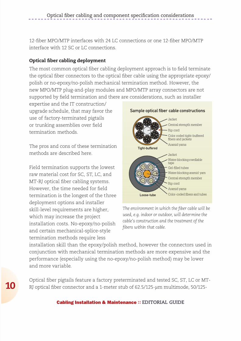
892019 Considerations for Selecting and Using Multimode Fiber
httpslidepdfcomreaderfullconsiderations-for-selecting-and-using-multimode-fiber 1032
Optical fiber cabling and component specification considerations
0
Cabling Installation amp Maintenance EDITORIAL GUIDE
12-fiber MPOMTP interfaces with 24 LC connections or one 12-fiber MPOMTP
interface with 12 SC or LC connections
Optical fiber cabling deployment
The most common optical fiber cabling deployment approach is to field terminate
the optical fiber connectors to the optical fiber cable using the appropriate epoxy
polish or no-epoxyno-polish mechanical termination method However the
new MPOMTP plug-and-play modules and MPOMTP array connectors are not
supported by field termination and there are considerations such as installer
expertise and the IT construction
upgrade schedule that may favor the
use of factory-terminated pigtailsor trunking assemblies over field
termination methods
The pros and cons of these termination
methods are described here
Field termination supports the lowest
raw material cost for SC ST LC and
MT-RJ optical fiber cabling systems
However the time needed for field
termination is the longest of the three
deployment options and installer
skill-level requirements are higher
which may increase the project
installation costs No-epoxyno-polish
and certain mechanical-splice-style
termination methods require lessinstallation skill than the epoxypolish method however the connectors used in
conjunction with mechanical termination methods are more expensive and the
performance (especially using the no-epoxyno-polish method) may be lower
and more variable
Optical fiber pigtails feature a factory preterminated and tested SC ST LC or MT-
RJ optical fiber connector and a 1-meter stub of 625125-microm multimode 50125-
Tight-buffered
Loose-tube
Sample optical fiber cable constructions
Jacket
Rip cord
Central strength member
Aramid yarns
Color coded tight-bufferedfibers and jackets
Water-blocking swellabletape
Gel-filled tubes
Water-blocking aramid yarn
Central strength memberRip cord
Aramid yarns
Color-coded fibers and tubes
Jacket
The environment in which the fiber cable will be
used eg indoor or outdoor will determine the
cablersquos construction and the treatment of the
fibers within that cable
892019 Considerations for Selecting and Using Multimode Fiber
httpslidepdfcomreaderfullconsiderations-for-selecting-and-using-multimode-fiber 1132
Optical fiber cabling and component specification considerations
1
Cabling Installation amp Maintenance EDITORIAL GUIDE
microm multimode or singlemode optical fiber The stub end of the pigtail is then
fusion-spliced to the optical fiber Fusion splicing provides a consistent nearly
loss-free termination and can be fast with proper technicians and equipment
The main benefits to this approach are the assurance of low-loss performance at
the interconnection and the elimination of the need for endface inspections and
possible connector reterminations
Trunking cable assemblies provide an efficient alternative to field-terminated
components or splice connections and allow up to 75 faster field deployment
times Trunking cable assemblies are custom factory preterminated and tested
lengths of optical fiber cable terminated on both ends with SC ST LC MT-RJ or
MPOMTP optical fiber connectors that are simply pulled and plugged in Whendeploying trunking cable assemblies cable-length specification is critical and
precise planning is required up front Trunking cable assemblies that have an
MPOMTP connector on one or both ends are commonly referred to as ldquoplug-
and-playrdquo cable assemblies MPOMTP plug-and-play cable assemblies have the
smallest connector profile and therefore have the smallest pathway cabinet and
rack-space requirements of all trunking cable assembly options
Always maintain the fibersrsquo polarity to ensure the transmit fiber is matched to
the receive port on each end of the link or channel
Valerie Maguire is a Global Sales Engineer with Siemon
892019 Considerations for Selecting and Using Multimode Fiber
httpslidepdfcomreaderfullconsiderations-for-selecting-and-using-multimode-fiber 1232
1010100000001111011111100101010101001010
1010000001110101010101000101010001010101
0101001010101010010100101010101000000011
1101111110010101010100101010100000011101
0101010100010101000101010101010010101010
1001010010101010100000001111011111100101
0101010010101010000001110101010101000101
010001010101010100101010101001010010101
0101000000011110111111001010101010010101
0100101010000000111101111110010101010100
1010101000000111010101010100010101000101
010101010010101010100101001010101010000
0001111011111100101010101001010101000000
1110101010101000101010001010101010100101
0101010010100101010101000000011110111111
0010101010100101010100000011101010101010
0010101000101010101010010101010100101001
0101010100000001111011111100101010101001
01010100101010000000111101111110010101010
Is there a hole in your
fiberrsquos performance
If itrsquos not OFS multimode fiber there could be OFSrsquo
manufacturing process virtually eliminates defects in the
fiber core with a DMD specified in the 0-5 micron range
That means double the bandwidth for lasers that launch
power in the fiberrsquos center while providing fast reliable
transmission and easier connectivity To learn more ask
your cabler about OFS or visit wwwofsopticscomfiber
892019 Considerations for Selecting and Using Multimode Fiber
httpslidepdfcomreaderfullconsiderations-for-selecting-and-using-multimode-fiber 1332Cabling Installation amp Maintenance EDITORIAL GUIDE
3
Making the switch from
625- to 50-micron fiber
What to do and what not to do when opting
for higher-bandwidth 50-micron multimode
By John Kamino
MULTIMODE FIBER SYSTEMS continue to provide the most cost-
effective cabling solution for data centers local area networks
(LANs) and other enterprise applications Compared to singlemode
fiber multimode systems offer significantly lower costs for
transceivers connectors and connector installation while meeting and exceeding
the bandwidth and reliability requirements of the most demanding networks
If you are designing a new short-reach installation you will probably choose laser-
optimized 50-micron (microm) OM3 or OM4 multimode fiber These fibers preserve the
systems-cost benefits over singlemode fiber by using low-cost 850-nm vertical-
cavity surface-emitting laser (VCSEL) technology are capable of 10-Mbitsec
through 10-Gbitsec operation and will support upcoming 40- and 100-Gbitsec
transmission speeds
But if you are upgrading an existing system many of which have 625-microm
multimode already installed should you stick with 625-microm Or can you go with
the higher performance of 50-microm OM3 or OM4 fiber This article highlights thethings you must consider when upgrading an existing 625-microm system
Why two fiber sizes
The numbers under discussionmdash50-microm and 625-micrommdashrefer to the diameter of
the fiberrsquos core through which light signals are transmitted The first optical
fibers deployed in the 1970s for both short- and long-reach applications were
50-microm multimode fibers In the early 1980s singlemode fiber replaced 50-microm
892019 Considerations for Selecting and Using Multimode Fiber
httpslidepdfcomreaderfullconsiderations-for-selecting-and-using-multimode-fiber 1432
Making the switch from 625- to 50-micron fiber
4
Cabling Installation amp Maintenance EDITORIAL GUIDE
fiber in longer-distance installations However 50-microm multimode continued to be
more cost-effective for short-reach interconnects such as building and campus
backbones up to 2000-meter distances
But as data rates increased 50-microm fiber could not support 10-Mbitsec rates overthe 2-kilometer distances required by some campus installations Not enough
power could be coupled from the light-emitting diode (LED) sources in use at that
time into the 50-microm core to support these link distances
625-microm multimode fiber was introduced in 1985 to solve this problem It could
capture more light from a LED in its larger core and 2-km campus links operating
at 10 Mbitssec were easily supported Also the larger-core fiber was easier to
cable and connectorize It became the most commonly used fiber for short-reach
enterprise applications in North America
Today as data rates surpass 10-Gbitssec and lasers have replaced LEDs 625-microm
fiber has reached its performance limit 50-microm fiber offers as much as 10 times
the bandwidth of the 625-microm fiber Whatrsquos more improvements in technology
have made 50-microm fiber easier to use
Multimode fiber choices today
To consider making the switch from 625-microm to 50-microm multimode it is importantto first understand the terminology used to designate the various performance
grades of multimode fiber In each of these designations ldquoOMrdquo stands for ldquooptical
multimoderdquo For example OM1 is the designation for fiber with 200500 MHz-
km overfilled launch (OFL) bandwidth at 8501300 nm this typically is 625microm
fiber OM2 is used for fiber with 500500 MHz-km OFL bandwidth at 8501300 nm
(typically 50-microm fiber)
Fiberdesignation
EMB (in MHz∙km) 850 nm
OFL (in MHz∙km) 850 nm
OFL (in MHz∙km) 1300 nm
OM1 (625) NA 200 500
OM2 (50) NA 500 500
OM3 (laser-
optimized 50) 2000 1500 500
OM4 (laser-
optimized 50) 4700 3500 500
892019 Considerations for Selecting and Using Multimode Fiber
httpslidepdfcomreaderfullconsiderations-for-selecting-and-using-multimode-fiber 1532
Making the switch from 625- to 50-micron fiber
5
Cabling Installation amp Maintenance EDITORIAL GUIDE
More-recent additions are OM3 for laser-optimized 50-microm fiber having 2000
MHz-km effective modal bandwidth (EMB also known as laser bandwidth) at 850
nm (designed for 10-Gbitsec transmission) and most recently OM4 for laser-
optimized 50-microm fiber having 4700 MHz-km EMB at 850 nm designed for 10-Gbit
sec transmission over longer distances
OM4 with its extended bandwidth can be used to enhance the system-cost
benefits enabled by 850 nm lasers for 10-Gbitsec applications as well as new
40- and 100-Gbitsec systems With its 150 m reach capability at 40 and 100
Gbitsec OM4 will support an additional 10 percent of link lengths in large data
centers that are not covered by OM3rsquos 100 m reach It is especially well-suited
for short reach data center and high-performance computing applications whereoptical loss budgets are tight at 10-Gbitsec and higher The additional bandwidth
provided when OM4 fiber is deployed at less than its rated distance offers extra
headroom for channel insertion loss
Itrsquos also important to note that for next-generation 40- and 100-Gbitsec
Ethernet only OM3 and OM4 fibers are included in the IEEE 8023ba standard
as supported (multimode optical fiber) media OM1 and OM2 fibers are not
supported media types
The latest offerings in multimode fiber are 50 microm bend insensitive multimode
fibers (BIMMF) These fibers have been promoted as offering all the advantages
of high bandwidth laser-optimized multimode fiber with the added advantage
of lower bend sensitivity However recent work has shown that some of these
fibers may have significant performance issues A paper presented at the 2010
International Wire and Cable Symposium (IWCS) showed that mating (connector)
loss of BIMMFs with standard fibers is higher than standard fiber connected to
standard fiber This additional loss adds to the total link loss possibly causing itto exceed the link loss budget
Another recent study examined issues with the system performance of bend
insensitive fibers and questioned whether current requirements are adequate
It has been proposed that standards organizations perform a thorough review of
BIMMFs and incorporate them into industry standards Until this work is done
caution is advised before widespread adoption takes place
892019 Considerations for Selecting and Using Multimode Fiber
httpslidepdfcomreaderfullconsiderations-for-selecting-and-using-multimode-fiber 1632
Making the switch from 625- to 50-micron fiber
6
Cabling Installation amp Maintenance EDITORIAL GUIDE
Upgrading a 625-microm network
The primary considerations for an upgrade or extension of an existing 625-microm
network are
the required transmission speed (now and especially in the future)
link distance
ease of cable replacement and
cost of cable replacement
If you are running Gigabit Ethernet (1-Gbitsec) then legacy 625-microm fiber will
transmit a distance of 220 to 275 meters depending on its bandwidth ratingBut at 10-Gigabit Ethernet (10-GbE 10-Gbitssec) they will only support 26 to
33 meters If your network will not need to support 10-GbE at distances greater
than 25 meters then you may be able to stick with 625-microm fiber It is important
to note however that most 625-microm fiber has not been measured for laser
bandwidth and some legacy fiber may have difficulty supporting even this short
distance
And if you want to transmit longer distances over 625-microm fiber you will be
forced to use much-more-expensive 1300-nm transceivers that will operate over
multimode or singlemode fiber These transceivers cost significantly more than
850-nm multimode devices because the 1300-nm optoelectronics package is the
far more complex of the two
If you are considering extending your network by installing additional 625-microm
fiber you need to carefully review your future network plans If you plan to
upgrade your network speed to 10-Gbitssec in the future recabling with laser-
optimized OM3 or OM4 fiber would be a wiser choice
Measuring laser bandwidth
As previously stated 625-microm fiber provides limited support for 10-Gbitsec
transmission so it generally is not measured for laser bandwidth (EMB) Typically
only 50-microm fibers are measured for EMB To verify bandwidth of 625-microm fiber
the traditional OFL bandwidth measurement method is used
892019 Considerations for Selecting and Using Multimode Fiber
httpslidepdfcomreaderfullconsiderations-for-selecting-and-using-multimode-fiber 1732
Making the switch from 625- to 50-micron fiber
7
Cabling Installation amp Maintenance EDITORIAL GUIDE
For 50-microm fibers EMB is ensured by using a method called Differential Mode
Delay (DMD) This DMD test is required by standards to verify 10-Gbitsec
performance and involves scanning the fiberrsquos core in small increments to see
how the signal travels in various regions of the core
Once the DMD test is conducted and a DMD ldquoprofilerdquo is obtained the standards
allow two methods to disposition the fiber One is the DMD Mask method and the
other is the Effective Modal Bandwidth Calculated (EMBc) method
The DMD Mask method provides direct verification of the fiberrsquos DMD
performance using a set of clearly defined DMD masks and templates that are
overlaid on the DMD profile This technique provides flexibility in applying more-stringent DMD performance criteria in certain regions of the fiber including the
0-5microm center region
The EMBc method involves complex calculations involving 10 weighting
functions to represent the wide variety of 10-Gbitsec VCSELs available on the
market Theoretical in nature this technique does not in our opinion provide
the scrutiny on fiber quality and performance that the DMD Mask technique
does The EMBc method puts little emphasis on the 0-5microm region of a fiberrsquos
core Though standards allow both testing methods we advocate the DMD
Mask method
Mixing 50- and 625-microm
If you decide to add 50-microm fiber to an existing 625-microm infrastructure connecting
50-microm directly to 625-microm is generally not recommended The difference in core
sizes could cause high loss when transmitting from the 625-microm into the 50-
microm fiber Also the bandwidth of 625-microm fibers is typically much lower further
degrading system performance Even if a low-speed application operates over alink made up of mixed fiber types upgradeability will be severely compromised
This elevated-loss problem occurs when transmitting from the larger (625-microm) to
the smaller (50-microm) core It is comparable to a 4-inch water pipe connecting to a
3-inch pipe there is no problem going from the smaller pipe to the larger one but
going in the opposite direction can lead to a lot of lost water (or in this case light)
892019 Considerations for Selecting and Using Multimode Fiber
httpslidepdfcomreaderfullconsiderations-for-selecting-and-using-multimode-fiber 1832
Making the switch from 625- to 50-micron fiber
8
Cabling Installation amp Maintenance EDITORIAL GUIDE
The amount of connection loss you could experience is about 4 dB for a LED-
based system which fills the entire core of a 625-microm fiber and anywhere from 0
to 4 dB for a VCSEL-based system which only fills a portion of the core
Because most optical-loss test sets use LEDs you should plan for the worst and
assume you will see a 4-dB loss in one direction If your link budget can tolerate
this additional 4-dB loss then you can get away with connecting 50-microm directly
to 625-microm
The better scenario is to separate 50-microm from 625-microm with active electronics
such as a switch router or simple media converter
Mixing of 625-microm and 50-microm fiber is not recommended unless an electronics
interface is inserted into the link If 10-Gbitsec speeds are being installed 625-
microm fiber will only be able to support extremely short links and replacement is
recommended
John Kamino is Product Manager Multimode Fiber with OFS
892019 Considerations for Selecting and Using Multimode Fiber
httpslidepdfcomreaderfullconsiderations-for-selecting-and-using-multimode-fiber 1932
OFSrsquo LaserWave fiber exceeds the OM4 standard for
todayrsquos high-speed networks mdash and tomorrowrsquos Andsince LaserWave fiber delivers DMD specified in the
0 ndash 5 micron range you get up to twice the bandwidth for
lasers that launch power in the fiberrsquos center Enjoy fast
reliable transmission and easier connectivity To learn more
ask your cabler about OFS or visit ofsopticscomfiber
Get your network up tospeed with LaserWavereg fiber
892019 Considerations for Selecting and Using Multimode Fiber
httpslidepdfcomreaderfullconsiderations-for-selecting-and-using-multimode-fiber 2032Cabling Installation amp Maintenance EDITORIAL GUIDE
20
Compatibility issues with
bend-insensitive andstandard multimode
Lab testing indicates risks associated with mixing
bend-insensitive and standard multimode fiber
By Rick Pimpinella Bulent Kose and Brett Lane
THE INCREASING DEMAND for higher-speed data transmission
within the data center and premises networks has led to the wide
deployment of multimode optical connectivity To meet performance
and reliability requirements the optical specifications on the
components have also become more stringent For high-speed optical networks
using laser-optimized OM3 and OM4 multimode fiber it is more critical than ever
for network operators and designers to understand the attributes of the various
performance grades of passive fiber-
optic components that make up the
network so that they may employ the
most cost-efficient solutions that meet
their needs today and in the future
In order to ensure that optical networks
operate effectively and reliably it isfundamental that the optical fiber
meets the necessary bandwidth
requirements and that the total optical
loss or insertion loss (IL) is below
the allowable limit required by the
application The two sources of IL
within optical networks are 1) loss at
892019 Considerations for Selecting and Using Multimode Fiber
httpslidepdfcomreaderfullconsiderations-for-selecting-and-using-multimode-fiber 2132
Compatibility issues with bend-insensitive and standard multimode
21
Cabling Installation amp Maintenance EDITORIAL GUIDE
connector interfaces and 2) loss or attenuation within the fiber itself The IL
limits for 10- 40- and 100-Gbitsec Ethernet are in the table below
The combination of
eroding insertion loss
budgets and increased
demands for complex
network architectures
with many
connector interfaces
has triggered several fiber and connectivity suppliers to develop improved
connectivity and fiber products that allow network architectures to cope withthese trends Specifically several connectivity suppliers now offer low-loss or
optimized passive fiber-optic components such as connectors cassettes and
patch cords that allow them to implement complex networks with numerous
connector interfaces while still meeting the maximum connector loss budget
Moreover although the intrinsic fiber attenuation has not been reduced
significantly over the past many years recent advancements in fiber production
have delivered extra headroom by significantly improving attenuation levels
under tightly bent conditions even in those cases in which the fiber is
unintentionally subjected to bends smaller than that allowed with the ANSI
TIA-568-C0 premises cabling standard This article reviews how this new type of
laser-optimized multimode fiber often called bend-insensitive or bend-optimized
integrates into todayrsquos data center and premises network
Achieving bend-optimization
It is well known that in order to produce a fiber with improved bend performance
it must be made to more tightly confine the light within its core region Thismodification allows more of the light to meet the conditions necessary for
total internal reflection as the fiber is bent Enhanced optical confinement
is accomplished by simply increasing the effective difference in the index of
refraction between the core and cladding regions This is typically accomplished
by introducing an index depression or trench in the cladding region close to the
fiber core
Applicationstandard
Minoperatingdistance
(m)
Maxconnectorloss (dB)
Max fiberattenuation
(dB)
Max totalIL budget
(dB)
0-Gbitsec Ethernet 300 15 11 26
40- and 100-Gbit
sec Ethernet (OM3)
100 15 04 19
40- and 100-Gbit
sec Ethernet (OM4)
150 1 05 15
892019 Considerations for Selecting and Using Multimode Fiber
httpslidepdfcomreaderfullconsiderations-for-selecting-and-using-multimode-fiber 2232
892019 Considerations for Selecting and Using Multimode Fiber
httpslidepdfcomreaderfullconsiderations-for-selecting-and-using-multimode-fiber 2332
Compatibility issues with bend-insensitive and standard multimode
23
Cabling Installation amp Maintenance EDITORIAL GUIDE
conditions necessary for total internal reflection (ie rays with larger angles)
light emerging from bend-optimized multimode fiber will have a larger angle on
average than light emerging from standard multimode fiber The parameter that
characterizes the maximum divergence or acceptance angle of light from or to
a fiber is called numerical aperture (NA) Therefore the NA of bend-optimized
multimode is generally expected to be greater on average than the NA of
standard multimode A thorough sampling across multiple fiber manufacturers
revealed that the average NA increased
from 0199 for standard multimode fiber to
0207 for bend-optimized multimode fiber
Although this moderate increase in NAappears insignificant in some situations
the optical loss across an optical fiber
interface (eg connector) is dependent on
the differences in NAs of the fibers In the
case that light fully populates the fiber
core such as when illuminated with an
LED and is coupled from a fiber with a
higher NA into a receiver with a lower NA
the light will diverge at an angle larger
than the acceptance angle of the receive
fiber This will result in some light being
lost (into the cladding) and the interface will have loss proportional to the NA
difference (ratio) between the two fibers
Consequently increased loss may be realized when light travels from bend-
optimized multimode fiber into standard multimode fiber In fact the expected
loss across a bend-optimized fiber with an NA of 0207 and a standard fiber withan NA of 0199 is 034 dB which is a significant portion of the overall IL budget
In the case that light travels from a fiber with a lower NA into a receiver with a
higher NA or light does not fully illuminate the fiber core no loss resulting from
the difference in fiber NAs is expected
NA loss measurements
To predict the NA loss that would be realized during link certification
2 4 6
MMF LED
MMF VCSEL
8 10
3
25
2
15
1
05
0
Bend loss (1 m) (dB)
Mandrel radius (mm)
BO-MMF LED
BO-MMF VCSEL
Measured bend loss at 850 nm
representative of bend-optimized and
standard multimode fiber using both
LED and VCSEL light source Fibers were
wrapped one turn around 10 different
mandrels with radii ranging from 25mm to
10 mm
892019 Considerations for Selecting and Using Multimode Fiber
httpslidepdfcomreaderfullconsiderations-for-selecting-and-using-multimode-fiber 2432
Compatibility issues with bend-insensitive and standard multimode
24
Cabling Installation amp Maintenance EDITORIAL GUIDE
measurements of an optical
channel with bend-optimized
and standard fiber interfaces
a series of standard IL
measurements were performed
on selected bend-optimized
and standard fibers Fiber
samples from several fiber
manufacturers were selected
with a wide range of NAs in
order to provide not only a
typical NA loss from fibers withaverage NA but also provide
an upper and lower limit of
NA loss that may be expected
when connecting dissimilar
multimode fiber types without knowledge of NA differences Several fibers were
selected of each fiber typendashsome with an average NA some with a low NA and
some with a high NA The table on page 25 summarizes the samples used for this
experiment and the theoretically expected NA loss from each connection
For these measurements the various bend-optimized fiber samples were
fusion spliced to the various standard multimode fiber samples A fusion
splicer was used to connect dissimilar fiber types instead of connectors in
order to minimize other loss contributors such as lateral offset and connector
termination processing The insertion loss of the connection was calculated by
injecting light meeting the new TIAEIA-526-14-B encircled flux specification
into the bend-optimized fiber and then measuring the power coupled out of
the standard fiber Subtracting this power level from the reference power levelmeasured previously as the amount of power coupled into the bend-optimized
fiber resulted in the IL or NA loss of the connection All aspects of these
measurements were in compliance with TIAEIA-45-171A (eg diameter and
placement of cladding mode strippers)
The measurement data is shown in the chart on page 25 Each data point
represents the average of the NA losses for a set of fibers for each NA
Bend-optimizedMMF core
NA = sinq1
MMF coreα
NABO-MMF gt NAstd-MMF
This illustration shows a mismatch in NA when connecting
a fiber with a large NA (left) to a fiber with a small NA(right) Because the receive fiber on the right has a smaller
NA some light is not coupled and instead is lost into the
cladding This loss is referred to as NA loss
892019 Considerations for Selecting and Using Multimode Fiber
httpslidepdfcomreaderfullconsiderations-for-selecting-and-using-multimode-fiber 2532
Compatibility issues with bend-insensitive and standard multimode
25
Cabling Installation amp Maintenance EDITORIAL GUIDE
combination From this data
connecting dissimilar fiber types
with average NAs confirms the
theoretically predicted NA loss of
approximately 040 dB Additionally
the upper and lower limits of NA
loss were measured to be 028
dB and 106 dB Although these
average and extreme NA losses
are fairly well correlated with the
theoretically predicted NA loss
other measured values deviatesignificantly from the theoretically
predicted value This suggests that
factors other than NA such as core
diameter index profile and mode structure also significantly influence the loss
when connecting bend-optimized and standard multimode fiber As a result the
light does not couple with 100 percent efficiency between fibers and therefore an
additional mode coupling loss must exist
In fact in the case that bend-optimized fiber samples with the identical NA but
manufactured from different suppliers were connected to standard fibers with
NA equal to 0200 the NA loss differs significantly from vendor to vendor The
average NA loss from Vendor A bend-optimized interfaces nearly exactly matched
the theoretical NA loss of 030 dB while the average NA loss from Vendor B
bend-optimized interfaces was much higher at 051 dB (see graph on page 26) As
expected the bend-optimized fibers from Vendor B were found to be more bend-
tolerant than those from Vendor A
In addition to realizing
unidirectional NA
loss an increase in the
modal noise penalty
may also result
when connecting
bend-optimized and
1000 0975 0950 0925 0900 0875 0850
14
12
10
08
06
04
02
00
NA ratio
NA loss (dB)
The black line shows the theoretical loss of connected
fibers with different NA and the dots represent
actual measured loss The results suggest factorsother than NA also influence loss when connecting
bend-optimized and standard multimode fiber
NA (BO-MMF)to NA (MMF)combination
NA (BO-MMF) NA (MMF) NA ratio Theoreticalloss (dB)
Average to Average 0207 0199 0961 034
Large to Average 0215 0199 0926 067
Large to Small 0215 0185 086 131
Average to Small 0207 0185 0894 098
Small to Small 0199 0185 0928 063
Large to Large 0215 0212 0986 012
892019 Considerations for Selecting and Using Multimode Fiber
httpslidepdfcomreaderfullconsiderations-for-selecting-and-using-multimode-fiber 2632
Compatibility issues with bend-insensitive and standard multimode
26
Cabling Installation amp Maintenance EDITORIAL GUIDE
standard multimode fiber Modal noise is a power penalty related to the reduction
in the signal-to-noise ratio (SNR) of the optical signal For high-speed networks
employing VCSELs if a connector selectively attenuates higher-order modes as a
result of NA mismatch or a lateral offset between fiber cores then fluctuations in
the power distribution (spatial speckle pattern) result in fluctuations in connector
insertion loss This fluctuation is seen by the detector as an increase in noise
thereby reducing the SNR and therefore signal quality
The maximum allowed power penalty for modal noise is currently specified
in 10GBase-SR to be 03 dB Both NA loss and mode coupling loss can increase
the mode-selective loss (filter aperture) at a connector interface resulting in an
increase in modal noise Considering the overall power budget for 10G40G100GEthernet is 15 dB (or 10 dB for OM4) any
increase in modal noise may compromise
system reliability
In conclusion inconclusive
As part of our review of how bend-
optimized multimode fiber is integrating
in todayrsquos data center and premises
networks we measured the loss between
bend-insensitive and standard multimode
fibers to quantify the expected additional
loss during certification of mixed-fiber
links These additional losses were
measured to be as high as 1 dB and can
be a significant portion ofndashor even actually
exceedndashthe total optical power budget
for todayrsquos high-speed networks For a channel link that contains several bend-optimized fiber and multimode fiber interfaces which have large NA differences
the NA losses may be additive and further inhibit system certification
Furthermore although NA loss alone is unlikely to detrimentally influence
system performance it may be very difficult if not impossible to determine if
excessive channel loss is due to NA differences or other conventional sources
of loss such as macrobending or dirtydamaged components One strategy to
BO-MMF1
to MMF2
BO-MMF1
to MMF2
BO-MMF1
to MMF2
Vendor A BO-MMF
Vendor B BO-MMF
BO-MMF1
to MMF2
07
06
05
04
03
02
01
00
Measured NA loss (dB)
Bend-optimized fibers from Vendor B shown
here as the blue bars were found to be more
bend-tolerant than the bend-optimized fibers
from Vendor A shown as the green bars
The more-optimized fibers exhibited higher
NA loss
892019 Considerations for Selecting and Using Multimode Fiber
httpslidepdfcomreaderfullconsiderations-for-selecting-and-using-multimode-fiber 2732
Compatibility issues with bend-insensitive and standard multimode
27
Cabling Installation amp Maintenance EDITORIAL GUIDE
account for this loss would be to require bidirectional loss measurements of
individual optical interfaces
During the most recent meeting of the TIA TR-4212 Optical Fibers and Cable
Subcommittee a vigorous debate included many of the topics discussed in this
article and others including increased NA loss mode coupling loss modal
noise (which may negatively impact system performance) the validity of other
standardized fiber test procedures for fiber core diameter fiber bandwidth and
link attenuation (encircled flux) The subcommittee authorized the formation of
a task group to study the technical compatibility of bend-insensitive multimode
fiber with current multimode fiber standards
Based on our internal analysis and the present uncertain position within the
standards community we have concluded that the performance risks of mixing
bend-optimized and standard multimode fiber types in high-speed optical
channel links exceeds any benefit To ensure that total optical loss across data
center and premises networks remains below the allowable limit we recommend
adhering to standards-based radius-control methods and the use of one fiber
type throughout the channel link which includes cabling and patch cords This
approach enables network stakeholders to reliably deploy complex network
architectures meet stringent IL budgets and ensure optimal system performance
within current standards-based network architectures and testing methods
Some manufacturers support this effort others minimize its importance Until
the TIA subcommittee work on these issues is complete we recommend that
these two fiber types should not presently be mixed
Dr Rick Pimpinella is a Distinguished Engineer Bulent Kose is a ResearchEngineer and Dr Brett Lane is a Fiber Research Manager with Panduit
892019 Considerations for Selecting and Using Multimode Fiber
httpslidepdfcomreaderfullconsiderations-for-selecting-and-using-multimode-fiber 2832
As the demand for bandwidth in
enterprise applications such as
data centers continues to
boom new transmission media
must be developed continually
to meet end user requirementsThe latest in optical transmis-
sion media for the enterprise is
called OM4 fiber
OM4 fiber is a 50 micron (microm)
laser-optimized multimode fiber
with extended bandwidth It is
designed to enhance the sys-
tem cost benefits enabled by
850 nm Vertical Cavity Surface
Emitting Lasers (VCSELs) for existing 1 and 10 Gbs applica-
tions as well as future 40 and
100 Gbs systems
Supporting Ethernet Fibre
Channel and OIF applications
OM4 fiber allows extended
reach upwards of 550 meters at
10 Gbs for ultra long building
backbones and medium lengthcampus backbones It offers an
Effective Modal Bandwidth
(EMB) of 4700 MHz-km more
than double the IEEE require-
ment for 10 Gbs 300 meter
support
To help you use this advanced
fiber to its greatest advantage
this paper describes the tech-
nology behind OM4 fiber high-
lights the key differences with
other fiber types and explains
how its high bandwidth is
ensured through stringentmeasurement methods
Multimode Fiber Basics
Compared to single-mode
fibers multimode fibers have
larger cores that as their name
implies guide multiple ldquomodesrdquo
or rays of light simultaneously
Modes that travel at the outside
edge of the core have a longer
distance to go than modes thattravel near the center
The corersquos graded index profile
is designed to slow down
modes that have a shorter dis-
tance to travel so that all modes
arrive at the end of the fiber as
close in time as possible This
minimizes modal dispersion
also known as differential mode
delay (DMD) and maximizes
bandwidth which is the amount
of information that can travel
through the fiber per unit of
time
In addition to their large core
multimode fibers have a large
Numerical Aperture (NA) the
maximum angle at which a fiber
can accept the light that will be
transmitted through it This
allows them to work with rela-
tively low-cost optical compo-
nents and light sources such as
light-emitting diodes (LEDs)and VCSELs
Multimode Fiber Options
Multimode products are identi-
fied by the OM (ldquooptical multi-
moderdquo) designation as outlined
in the ISOIEC 11801 interna-
tional cabling standard (see
table 1)
OM4 - The Next Generation
of Multimode Fiber Tony Irujo
Sales Engineer
OPTICAL FIBER IN ENTERPRISE APPLICATIONS
Table 1 ISOIEC 11801 OM designations
892019 Considerations for Selecting and Using Multimode Fiber
httpslidepdfcomreaderfullconsiderations-for-selecting-and-using-multimode-fiber 2932
OM4 fiber is the latest develop-
ment in this series It is espe-
cially well suited for shorter
reach data center and high per-
formance computing applica-
tions where optical loss budg-
ets are tight at 10 Gbs (and
are expected to get even tighter
at 40 Gbs and 100 Gbs) Thehigh bandwidth provided by
OM4 fiber when deployed at
less than its rated distance
offers extra ldquoheadroomrdquo for
channel insertion loss
OM4 is backward compatible
with applications calling for OFL
bandwidth of at least 500 MHz-
km at 1300 nm (eg FDDI
IEEE 100BASE-FX
1000BASE-LX 10GBASE-LX4
and 10GBASE-LRM)
The latest offerings in multi-
mode fiber are 50 983221m bend
insensitive multimode fibers
(BIMMF) These fibers have
been promoted as offering all
the advantages of high band-
width laser-optimized multi-mode fiber with the added
advantage of lower bend sensi-
tivity
However recent work has
pointed to some areas of con-
cern with these fibers Studies
have identified issues with the
characterization of bend insen-
sitive fibers and questioned
whether current requirements
are adequate to guarantee sys-
tem performance Additional
studies have shown that mating
(connector) loss of BIMMFs
with standard fibers is higher
than with standard fibers con-
nected to each other This addi-
tional loss adds to the total link
loss
It has been proposed that stan-
dards organizations perform a
thorough review of BIMMFs
and incorporate them into
industry standards Until this
work is done some caution is
advised before widespread
adoption takes place
What Makes OM4 Different
Like OM3 multimode fiber OM4
fiber is considered to be ldquolaser-
optimizedrdquo or optimized for use
with VCSEL light sources OM3
and OM4 fibers are designed
and manufactured in such a
way as to get the most perform-
ance out of VCSELs compared
to LEDs That is why laser-opti-
mized fibers are specified using
Laser Bandwidth or EMB
OM2 fiber although compatible
with VCSELs is not considered
to be laser-optimized OM2
fiber is intended for use with
LED sources at speeds of 10 or
100 Mbs or for shorter reach 1
Gbs networks You can use
OM2 fiber with VCSELs but itsperformance is limited to 550
meters at 1 Gbs and only 82
meters at 10 Gbs compared to
OM4 fiberrsquos
reach of over
1000 meters
at 1 Gbs and
550 meters at
10 Gbs
As discussed
the speed at
which each
mode travels
down a multi-
mode fiberrsquos
core depends
on its refrac-
tive index
which is gov-
erned by the amount of chemi-
cal dopant Germanium at that
location in the core Because
modes traveling down the cen-
ter of the core have shorter dis-
tance to travel than those trav-
eling along the edge the refrac-
tive index profile in a multimode
fiber must be ldquogradedrdquo in a par-abolic manner across the core
This slows down the modes
that have a shorter distance to
travel equalizing the arrival
time of all the modes
The better the modes are
equalized the higher the band-
width of the fiber Mode equal-
ization depends on how well
the graded index profile is con-
structed during fiber manufac-
turing The more precise the
refractive index profile is in
terms of shape curvature and
smoothness (free of dips
spikes or defects) the better
the modes will be equalized
(see Figure 2)
OM4 fiber with its higher band-width has an extremely precise
refractive index profile virtually
free of perturbations or defects
Figure 2 A refractive index profile optimized for shape curvature
and smoothness maximizes bandwidth
892019 Considerations for Selecting and Using Multimode Fiber
httpslidepdfcomreaderfullconsiderations-for-selecting-and-using-multimode-fiber 3032
In order to make such a precise
fiber one needs to use a pre-
form manufacturing process
that has exceptional control
over the amount of Germanium
that is incorporated at particular
sub-micron positions within the
fiberrsquos core An example of a
process that lends itself to this
level of control is OFSrsquo propri-
etary MCVD process in which
each layer of the core is
deposited and sintered individu-
ally providing the utmost in
refractive index precision and
uniformity
OM4 Fiber Standards
Two standards define the useof OM4 fiber in high-speed net-
works TIA document TIA-
492AAAD which contains the
OM4 fiber performance specifi-
cations and the IEC 60793-2-
10 international standard which
provides equivalent OM4 speci-
fications under fiber type A1a3
ISOIEC 11801 will add OM4
fiber as an industry-recognized
fiber type and IEEE 8023bafor 40G and 100G Ethernet will
include OM4 fiber as an option
that provides a reach of 150
meters (50 percent greater than
OM3)
There was discussion and
debate within the standards
groups about a minimum OFL
bandwidth requirement at 850nm Although current applica-
tions primarily use 850 nm
VCSEL lasers with fibers that
are specified to a minimum
EMB there was good reason to
also establish a minimum 850
nm OFL bandwidth specifica-
tion It has been shown that
fibers with higher OFL band-
width will perform better with
VCSELs that launch more
power into outer modes That is
why the existing OM3 fiber
standards require a minimum
1500 MHz-km OFL bandwidthat 850 nm
For OM4 fiber OFS and others
in the standards group strongly
recommended at least 3500
MHz-km OFL bandwidth in
order to ensure the utmost per-
formance and reliability ulti-
mately that is the specification
that was agreed upon
Measuring Laser Bandwidth
Bandwidth performance of OM4
fiber is ensured using the same
criteria as OM3 but to much
tighter specifications Due to a
challenge posed when the now-
familiar VCSEL was first intro-
duced new measurement
methods had to be developed
to verify laser bandwidth of OM3 and OM4 fibers
Unlike an LED laser VCSELs
produce an energy output that
is not uniform it can change
sharply across the face of the
output Whatrsquos more each laser
fills a different set of light paths
in each fiber and does so with
differing amounts of power in
each path Overfilled bandwidth
measurements used to meas-
ure LED bandwidth could not
emulate the operation of aVCSEL
The standards allow two ways
to measure and verify laser
bandwidth the DMD Mask
Method and the EMBc Method
Both methods require DMD
testing -- the difference lies in
how the DMD data is used and
interpreted
In DMD testing small high-
powered laser pulses are trans-
mitted through the fiber in tiny
steps across the entire core of
the fiber Only a few modes are
excited at each step and their
arrival times are recorded The
DMD of the fiber is the differ-
ence between the earliest and
the latest arrival times of allmodes at all steps
DMD measurement is currently
the only reliable method for ver-
ifying bandwidth required for 10
Gbs performance because it is
the only method that checks all
modes across the fiber core
independently For that reason
Figure 3 DMD testing measures how different VCSELs fill different modes in each
fiber
892019 Considerations for Selecting and Using Multimode Fiber
httpslidepdfcomreaderfullconsiderations-for-selecting-and-using-multimode-fiber 3132
industry associations such as
TIAEIA and ISOIEC have pub-
lished standards for DMD
measurement and DMD specifi-
cations for laser-optimized mul-
timode fiber
The DMD Mask Method is a
simple process that directlycompares DMD test results
against a set of specifications
(called templates or masks) to
see if the fiber has the neces-
sary performance
This is a straightforward graphi-
cal approach to ensuring the
data pulses do not spread
excessively beyond therequired 10 Gbs bit period If
the fiber passes these DMD
specs then you are assured of
at least 2000 MHz-km EMB no
matter which VCSEL you use
(as long as the VCSEL is com-
pliant)
The EMBc Method is an indi-
rect and more complex
process It takes the DMD
results and matches them
against a set of theoretical
weighting functions that are
intended to represent the
launch distributions of all com-
pliant VCSELs
The DMD results are combined
mathematically with each of the
10 weighting functions This
produces 10 different EMBc
values the lowest of which is
called minEMBc The minEMBc
value is then multiplied by a
factor of 113 to obtain the
fiberrsquos EMB value If this EMB
value is gt 2000 MHz-km thefiber is deemed compliant with
OM3 requirements and there-
fore should support 300 meters
at 10 Gbs
Due to all the complex calcula-
tions required by the EMBc
method and the fact that the
weighting functions only repre-
sent a sampling of the launch
characteristics of the many
VCSELs that could actually be
used in a real system the
EMBc method does not provide
the same scrutiny on fiber qual-
ity and performance as the
DMD Mask technique Whatrsquos
more the EMBc method virtual-ly ignores the center 0 ndash 5 983221m
(radial) region of a fiberrsquos core
because the weighting func-
tions put little emphasis in this
region
Conclusion
OM4 fiber provides next-gener-
ation multimode fiber perform-
ance for today and tomorrowrsquoshigh speed applications With
its significantly higher band-
width network designers and
operators can be assured that
multimode fiber will continue to
provide the most cost effective
solutions for short reach appli-
cations in data centers and
LANs
Copyright copy 2011 Furukawa Electric North America All rights reserved printed in USA
For additional information visit our website at wwwofsopticscomofs-fiber or call 1-888-fiber-
help For regional assistance contact
North America Asia Pacific
Telephone 508-347-8590 Telephone +852 2836 7102
Toll Free 800-799-7732 Fax +852 2836 7101
Fax 508-347-1211 E-mail fibersalesapofsopticscomE-mail fibersalesnarofsopticscom
Caribbean Latin America Japan
Telephone 508-347-8590 Telephone +81-3-3286-3424
Fax 508-347-1211 Fax +81-3-3286-3708 or 3190
E-mail fibersalescalaofsopticscom E-mail fibersalesjapanofsopticscom
Europe Middle East Africa China
Telephone +45-43 48 3736 Telephone +86 10 6505 3660
Fax +45 4348 3444 Fax +86 10 65059515
E-mail ofssalesdkofsopticscom E-mail fibersaleschinaofsopticscom
OFS reserves the right to make changes to the prices
and product(s) described in this document in the
interest of improving internal design operational
function andor reliability
This document is for informational purposes only
and is not intended to modify or supplement any
OFS warranties or specifications relating to any of
its products or services
892019 Considerations for Selecting and Using Multimode Fiber
httpslidepdfcomreaderfullconsiderations-for-selecting-and-using-multimode-fiber 3232
About OFSOFS is a world-leading designer manufacturer and provider of optical fiber
optical fiber cable FTTX optical connectivity and specialty photonics products
Our manufacturing and research divisions work together to provide innovative
products and solutions that traverse many different applications as they linkpeople and machines worldwide Between continents between cities around
neighborhoods and into homes and businesses of digital consumers we provide
the right optical fiber optical cable and components for efficient cost-effective
transmission
OFSrsquo corporate lineage dates back to 1876 and includes technology powerhouses
such as ATampT (NYSE T) and Lucent Technologies (now Alcatel-Lucent NYSE
ALU) Today OFS is owned by Furukawa Electric a multi-billion dollar global
leader in optical communications Headquartered in Norcross (near Atlanta)Georgia US OFS is a global provider with facilities in Avon Connecticut
Carrollton Georgia Somerset New Jersey and Sturbridge Massachusetts as well
as in Denmark Germany and Russia
wwwofsopticscom
LINKS
LaserWavereg Laser-Optimized OM4OM3 Fibers
Multimode or Single-Mode Fiber
Measuring Bandwidth of 10G Laser-optimized Multimode Fiber
892019 Considerations for Selecting and Using Multimode Fiber
httpslidepdfcomreaderfullconsiderations-for-selecting-and-using-multimode-fiber 1132
Optical fiber cabling and component specification considerations
1
Cabling Installation amp Maintenance EDITORIAL GUIDE
microm multimode or singlemode optical fiber The stub end of the pigtail is then
fusion-spliced to the optical fiber Fusion splicing provides a consistent nearly
loss-free termination and can be fast with proper technicians and equipment
The main benefits to this approach are the assurance of low-loss performance at
the interconnection and the elimination of the need for endface inspections and
possible connector reterminations
Trunking cable assemblies provide an efficient alternative to field-terminated
components or splice connections and allow up to 75 faster field deployment
times Trunking cable assemblies are custom factory preterminated and tested
lengths of optical fiber cable terminated on both ends with SC ST LC MT-RJ or
MPOMTP optical fiber connectors that are simply pulled and plugged in Whendeploying trunking cable assemblies cable-length specification is critical and
precise planning is required up front Trunking cable assemblies that have an
MPOMTP connector on one or both ends are commonly referred to as ldquoplug-
and-playrdquo cable assemblies MPOMTP plug-and-play cable assemblies have the
smallest connector profile and therefore have the smallest pathway cabinet and
rack-space requirements of all trunking cable assembly options
Always maintain the fibersrsquo polarity to ensure the transmit fiber is matched to
the receive port on each end of the link or channel
Valerie Maguire is a Global Sales Engineer with Siemon
892019 Considerations for Selecting and Using Multimode Fiber
httpslidepdfcomreaderfullconsiderations-for-selecting-and-using-multimode-fiber 1232
1010100000001111011111100101010101001010
1010000001110101010101000101010001010101
0101001010101010010100101010101000000011
1101111110010101010100101010100000011101
0101010100010101000101010101010010101010
1001010010101010100000001111011111100101
0101010010101010000001110101010101000101
010001010101010100101010101001010010101
0101000000011110111111001010101010010101
0100101010000000111101111110010101010100
1010101000000111010101010100010101000101
010101010010101010100101001010101010000
0001111011111100101010101001010101000000
1110101010101000101010001010101010100101
0101010010100101010101000000011110111111
0010101010100101010100000011101010101010
0010101000101010101010010101010100101001
0101010100000001111011111100101010101001
01010100101010000000111101111110010101010
Is there a hole in your
fiberrsquos performance
If itrsquos not OFS multimode fiber there could be OFSrsquo
manufacturing process virtually eliminates defects in the
fiber core with a DMD specified in the 0-5 micron range
That means double the bandwidth for lasers that launch
power in the fiberrsquos center while providing fast reliable
transmission and easier connectivity To learn more ask
your cabler about OFS or visit wwwofsopticscomfiber
892019 Considerations for Selecting and Using Multimode Fiber
httpslidepdfcomreaderfullconsiderations-for-selecting-and-using-multimode-fiber 1332Cabling Installation amp Maintenance EDITORIAL GUIDE
3
Making the switch from
625- to 50-micron fiber
What to do and what not to do when opting
for higher-bandwidth 50-micron multimode
By John Kamino
MULTIMODE FIBER SYSTEMS continue to provide the most cost-
effective cabling solution for data centers local area networks
(LANs) and other enterprise applications Compared to singlemode
fiber multimode systems offer significantly lower costs for
transceivers connectors and connector installation while meeting and exceeding
the bandwidth and reliability requirements of the most demanding networks
If you are designing a new short-reach installation you will probably choose laser-
optimized 50-micron (microm) OM3 or OM4 multimode fiber These fibers preserve the
systems-cost benefits over singlemode fiber by using low-cost 850-nm vertical-
cavity surface-emitting laser (VCSEL) technology are capable of 10-Mbitsec
through 10-Gbitsec operation and will support upcoming 40- and 100-Gbitsec
transmission speeds
But if you are upgrading an existing system many of which have 625-microm
multimode already installed should you stick with 625-microm Or can you go with
the higher performance of 50-microm OM3 or OM4 fiber This article highlights thethings you must consider when upgrading an existing 625-microm system
Why two fiber sizes
The numbers under discussionmdash50-microm and 625-micrommdashrefer to the diameter of
the fiberrsquos core through which light signals are transmitted The first optical
fibers deployed in the 1970s for both short- and long-reach applications were
50-microm multimode fibers In the early 1980s singlemode fiber replaced 50-microm
892019 Considerations for Selecting and Using Multimode Fiber
httpslidepdfcomreaderfullconsiderations-for-selecting-and-using-multimode-fiber 1432
Making the switch from 625- to 50-micron fiber
4
Cabling Installation amp Maintenance EDITORIAL GUIDE
fiber in longer-distance installations However 50-microm multimode continued to be
more cost-effective for short-reach interconnects such as building and campus
backbones up to 2000-meter distances
But as data rates increased 50-microm fiber could not support 10-Mbitsec rates overthe 2-kilometer distances required by some campus installations Not enough
power could be coupled from the light-emitting diode (LED) sources in use at that
time into the 50-microm core to support these link distances
625-microm multimode fiber was introduced in 1985 to solve this problem It could
capture more light from a LED in its larger core and 2-km campus links operating
at 10 Mbitssec were easily supported Also the larger-core fiber was easier to
cable and connectorize It became the most commonly used fiber for short-reach
enterprise applications in North America
Today as data rates surpass 10-Gbitssec and lasers have replaced LEDs 625-microm
fiber has reached its performance limit 50-microm fiber offers as much as 10 times
the bandwidth of the 625-microm fiber Whatrsquos more improvements in technology
have made 50-microm fiber easier to use
Multimode fiber choices today
To consider making the switch from 625-microm to 50-microm multimode it is importantto first understand the terminology used to designate the various performance
grades of multimode fiber In each of these designations ldquoOMrdquo stands for ldquooptical
multimoderdquo For example OM1 is the designation for fiber with 200500 MHz-
km overfilled launch (OFL) bandwidth at 8501300 nm this typically is 625microm
fiber OM2 is used for fiber with 500500 MHz-km OFL bandwidth at 8501300 nm
(typically 50-microm fiber)
Fiberdesignation
EMB (in MHz∙km) 850 nm
OFL (in MHz∙km) 850 nm
OFL (in MHz∙km) 1300 nm
OM1 (625) NA 200 500
OM2 (50) NA 500 500
OM3 (laser-
optimized 50) 2000 1500 500
OM4 (laser-
optimized 50) 4700 3500 500
892019 Considerations for Selecting and Using Multimode Fiber
httpslidepdfcomreaderfullconsiderations-for-selecting-and-using-multimode-fiber 1532
Making the switch from 625- to 50-micron fiber
5
Cabling Installation amp Maintenance EDITORIAL GUIDE
More-recent additions are OM3 for laser-optimized 50-microm fiber having 2000
MHz-km effective modal bandwidth (EMB also known as laser bandwidth) at 850
nm (designed for 10-Gbitsec transmission) and most recently OM4 for laser-
optimized 50-microm fiber having 4700 MHz-km EMB at 850 nm designed for 10-Gbit
sec transmission over longer distances
OM4 with its extended bandwidth can be used to enhance the system-cost
benefits enabled by 850 nm lasers for 10-Gbitsec applications as well as new
40- and 100-Gbitsec systems With its 150 m reach capability at 40 and 100
Gbitsec OM4 will support an additional 10 percent of link lengths in large data
centers that are not covered by OM3rsquos 100 m reach It is especially well-suited
for short reach data center and high-performance computing applications whereoptical loss budgets are tight at 10-Gbitsec and higher The additional bandwidth
provided when OM4 fiber is deployed at less than its rated distance offers extra
headroom for channel insertion loss
Itrsquos also important to note that for next-generation 40- and 100-Gbitsec
Ethernet only OM3 and OM4 fibers are included in the IEEE 8023ba standard
as supported (multimode optical fiber) media OM1 and OM2 fibers are not
supported media types
The latest offerings in multimode fiber are 50 microm bend insensitive multimode
fibers (BIMMF) These fibers have been promoted as offering all the advantages
of high bandwidth laser-optimized multimode fiber with the added advantage
of lower bend sensitivity However recent work has shown that some of these
fibers may have significant performance issues A paper presented at the 2010
International Wire and Cable Symposium (IWCS) showed that mating (connector)
loss of BIMMFs with standard fibers is higher than standard fiber connected to
standard fiber This additional loss adds to the total link loss possibly causing itto exceed the link loss budget
Another recent study examined issues with the system performance of bend
insensitive fibers and questioned whether current requirements are adequate
It has been proposed that standards organizations perform a thorough review of
BIMMFs and incorporate them into industry standards Until this work is done
caution is advised before widespread adoption takes place
892019 Considerations for Selecting and Using Multimode Fiber
httpslidepdfcomreaderfullconsiderations-for-selecting-and-using-multimode-fiber 1632
Making the switch from 625- to 50-micron fiber
6
Cabling Installation amp Maintenance EDITORIAL GUIDE
Upgrading a 625-microm network
The primary considerations for an upgrade or extension of an existing 625-microm
network are
the required transmission speed (now and especially in the future)
link distance
ease of cable replacement and
cost of cable replacement
If you are running Gigabit Ethernet (1-Gbitsec) then legacy 625-microm fiber will
transmit a distance of 220 to 275 meters depending on its bandwidth ratingBut at 10-Gigabit Ethernet (10-GbE 10-Gbitssec) they will only support 26 to
33 meters If your network will not need to support 10-GbE at distances greater
than 25 meters then you may be able to stick with 625-microm fiber It is important
to note however that most 625-microm fiber has not been measured for laser
bandwidth and some legacy fiber may have difficulty supporting even this short
distance
And if you want to transmit longer distances over 625-microm fiber you will be
forced to use much-more-expensive 1300-nm transceivers that will operate over
multimode or singlemode fiber These transceivers cost significantly more than
850-nm multimode devices because the 1300-nm optoelectronics package is the
far more complex of the two
If you are considering extending your network by installing additional 625-microm
fiber you need to carefully review your future network plans If you plan to
upgrade your network speed to 10-Gbitssec in the future recabling with laser-
optimized OM3 or OM4 fiber would be a wiser choice
Measuring laser bandwidth
As previously stated 625-microm fiber provides limited support for 10-Gbitsec
transmission so it generally is not measured for laser bandwidth (EMB) Typically
only 50-microm fibers are measured for EMB To verify bandwidth of 625-microm fiber
the traditional OFL bandwidth measurement method is used
892019 Considerations for Selecting and Using Multimode Fiber
httpslidepdfcomreaderfullconsiderations-for-selecting-and-using-multimode-fiber 1732
Making the switch from 625- to 50-micron fiber
7
Cabling Installation amp Maintenance EDITORIAL GUIDE
For 50-microm fibers EMB is ensured by using a method called Differential Mode
Delay (DMD) This DMD test is required by standards to verify 10-Gbitsec
performance and involves scanning the fiberrsquos core in small increments to see
how the signal travels in various regions of the core
Once the DMD test is conducted and a DMD ldquoprofilerdquo is obtained the standards
allow two methods to disposition the fiber One is the DMD Mask method and the
other is the Effective Modal Bandwidth Calculated (EMBc) method
The DMD Mask method provides direct verification of the fiberrsquos DMD
performance using a set of clearly defined DMD masks and templates that are
overlaid on the DMD profile This technique provides flexibility in applying more-stringent DMD performance criteria in certain regions of the fiber including the
0-5microm center region
The EMBc method involves complex calculations involving 10 weighting
functions to represent the wide variety of 10-Gbitsec VCSELs available on the
market Theoretical in nature this technique does not in our opinion provide
the scrutiny on fiber quality and performance that the DMD Mask technique
does The EMBc method puts little emphasis on the 0-5microm region of a fiberrsquos
core Though standards allow both testing methods we advocate the DMD
Mask method
Mixing 50- and 625-microm
If you decide to add 50-microm fiber to an existing 625-microm infrastructure connecting
50-microm directly to 625-microm is generally not recommended The difference in core
sizes could cause high loss when transmitting from the 625-microm into the 50-
microm fiber Also the bandwidth of 625-microm fibers is typically much lower further
degrading system performance Even if a low-speed application operates over alink made up of mixed fiber types upgradeability will be severely compromised
This elevated-loss problem occurs when transmitting from the larger (625-microm) to
the smaller (50-microm) core It is comparable to a 4-inch water pipe connecting to a
3-inch pipe there is no problem going from the smaller pipe to the larger one but
going in the opposite direction can lead to a lot of lost water (or in this case light)
892019 Considerations for Selecting and Using Multimode Fiber
httpslidepdfcomreaderfullconsiderations-for-selecting-and-using-multimode-fiber 1832
Making the switch from 625- to 50-micron fiber
8
Cabling Installation amp Maintenance EDITORIAL GUIDE
The amount of connection loss you could experience is about 4 dB for a LED-
based system which fills the entire core of a 625-microm fiber and anywhere from 0
to 4 dB for a VCSEL-based system which only fills a portion of the core
Because most optical-loss test sets use LEDs you should plan for the worst and
assume you will see a 4-dB loss in one direction If your link budget can tolerate
this additional 4-dB loss then you can get away with connecting 50-microm directly
to 625-microm
The better scenario is to separate 50-microm from 625-microm with active electronics
such as a switch router or simple media converter
Mixing of 625-microm and 50-microm fiber is not recommended unless an electronics
interface is inserted into the link If 10-Gbitsec speeds are being installed 625-
microm fiber will only be able to support extremely short links and replacement is
recommended
John Kamino is Product Manager Multimode Fiber with OFS
892019 Considerations for Selecting and Using Multimode Fiber
httpslidepdfcomreaderfullconsiderations-for-selecting-and-using-multimode-fiber 1932
OFSrsquo LaserWave fiber exceeds the OM4 standard for
todayrsquos high-speed networks mdash and tomorrowrsquos Andsince LaserWave fiber delivers DMD specified in the
0 ndash 5 micron range you get up to twice the bandwidth for
lasers that launch power in the fiberrsquos center Enjoy fast
reliable transmission and easier connectivity To learn more
ask your cabler about OFS or visit ofsopticscomfiber
Get your network up tospeed with LaserWavereg fiber
892019 Considerations for Selecting and Using Multimode Fiber
httpslidepdfcomreaderfullconsiderations-for-selecting-and-using-multimode-fiber 2032Cabling Installation amp Maintenance EDITORIAL GUIDE
20
Compatibility issues with
bend-insensitive andstandard multimode
Lab testing indicates risks associated with mixing
bend-insensitive and standard multimode fiber
By Rick Pimpinella Bulent Kose and Brett Lane
THE INCREASING DEMAND for higher-speed data transmission
within the data center and premises networks has led to the wide
deployment of multimode optical connectivity To meet performance
and reliability requirements the optical specifications on the
components have also become more stringent For high-speed optical networks
using laser-optimized OM3 and OM4 multimode fiber it is more critical than ever
for network operators and designers to understand the attributes of the various
performance grades of passive fiber-
optic components that make up the
network so that they may employ the
most cost-efficient solutions that meet
their needs today and in the future
In order to ensure that optical networks
operate effectively and reliably it isfundamental that the optical fiber
meets the necessary bandwidth
requirements and that the total optical
loss or insertion loss (IL) is below
the allowable limit required by the
application The two sources of IL
within optical networks are 1) loss at
892019 Considerations for Selecting and Using Multimode Fiber
httpslidepdfcomreaderfullconsiderations-for-selecting-and-using-multimode-fiber 2132
Compatibility issues with bend-insensitive and standard multimode
21
Cabling Installation amp Maintenance EDITORIAL GUIDE
connector interfaces and 2) loss or attenuation within the fiber itself The IL
limits for 10- 40- and 100-Gbitsec Ethernet are in the table below
The combination of
eroding insertion loss
budgets and increased
demands for complex
network architectures
with many
connector interfaces
has triggered several fiber and connectivity suppliers to develop improved
connectivity and fiber products that allow network architectures to cope withthese trends Specifically several connectivity suppliers now offer low-loss or
optimized passive fiber-optic components such as connectors cassettes and
patch cords that allow them to implement complex networks with numerous
connector interfaces while still meeting the maximum connector loss budget
Moreover although the intrinsic fiber attenuation has not been reduced
significantly over the past many years recent advancements in fiber production
have delivered extra headroom by significantly improving attenuation levels
under tightly bent conditions even in those cases in which the fiber is
unintentionally subjected to bends smaller than that allowed with the ANSI
TIA-568-C0 premises cabling standard This article reviews how this new type of
laser-optimized multimode fiber often called bend-insensitive or bend-optimized
integrates into todayrsquos data center and premises network
Achieving bend-optimization
It is well known that in order to produce a fiber with improved bend performance
it must be made to more tightly confine the light within its core region Thismodification allows more of the light to meet the conditions necessary for
total internal reflection as the fiber is bent Enhanced optical confinement
is accomplished by simply increasing the effective difference in the index of
refraction between the core and cladding regions This is typically accomplished
by introducing an index depression or trench in the cladding region close to the
fiber core
Applicationstandard
Minoperatingdistance
(m)
Maxconnectorloss (dB)
Max fiberattenuation
(dB)
Max totalIL budget
(dB)
0-Gbitsec Ethernet 300 15 11 26
40- and 100-Gbit
sec Ethernet (OM3)
100 15 04 19
40- and 100-Gbit
sec Ethernet (OM4)
150 1 05 15
892019 Considerations for Selecting and Using Multimode Fiber
httpslidepdfcomreaderfullconsiderations-for-selecting-and-using-multimode-fiber 2232
892019 Considerations for Selecting and Using Multimode Fiber
httpslidepdfcomreaderfullconsiderations-for-selecting-and-using-multimode-fiber 2332
Compatibility issues with bend-insensitive and standard multimode
23
Cabling Installation amp Maintenance EDITORIAL GUIDE
conditions necessary for total internal reflection (ie rays with larger angles)
light emerging from bend-optimized multimode fiber will have a larger angle on
average than light emerging from standard multimode fiber The parameter that
characterizes the maximum divergence or acceptance angle of light from or to
a fiber is called numerical aperture (NA) Therefore the NA of bend-optimized
multimode is generally expected to be greater on average than the NA of
standard multimode A thorough sampling across multiple fiber manufacturers
revealed that the average NA increased
from 0199 for standard multimode fiber to
0207 for bend-optimized multimode fiber
Although this moderate increase in NAappears insignificant in some situations
the optical loss across an optical fiber
interface (eg connector) is dependent on
the differences in NAs of the fibers In the
case that light fully populates the fiber
core such as when illuminated with an
LED and is coupled from a fiber with a
higher NA into a receiver with a lower NA
the light will diverge at an angle larger
than the acceptance angle of the receive
fiber This will result in some light being
lost (into the cladding) and the interface will have loss proportional to the NA
difference (ratio) between the two fibers
Consequently increased loss may be realized when light travels from bend-
optimized multimode fiber into standard multimode fiber In fact the expected
loss across a bend-optimized fiber with an NA of 0207 and a standard fiber withan NA of 0199 is 034 dB which is a significant portion of the overall IL budget
In the case that light travels from a fiber with a lower NA into a receiver with a
higher NA or light does not fully illuminate the fiber core no loss resulting from
the difference in fiber NAs is expected
NA loss measurements
To predict the NA loss that would be realized during link certification
2 4 6
MMF LED
MMF VCSEL
8 10
3
25
2
15
1
05
0
Bend loss (1 m) (dB)
Mandrel radius (mm)
BO-MMF LED
BO-MMF VCSEL
Measured bend loss at 850 nm
representative of bend-optimized and
standard multimode fiber using both
LED and VCSEL light source Fibers were
wrapped one turn around 10 different
mandrels with radii ranging from 25mm to
10 mm
892019 Considerations for Selecting and Using Multimode Fiber
httpslidepdfcomreaderfullconsiderations-for-selecting-and-using-multimode-fiber 2432
Compatibility issues with bend-insensitive and standard multimode
24
Cabling Installation amp Maintenance EDITORIAL GUIDE
measurements of an optical
channel with bend-optimized
and standard fiber interfaces
a series of standard IL
measurements were performed
on selected bend-optimized
and standard fibers Fiber
samples from several fiber
manufacturers were selected
with a wide range of NAs in
order to provide not only a
typical NA loss from fibers withaverage NA but also provide
an upper and lower limit of
NA loss that may be expected
when connecting dissimilar
multimode fiber types without knowledge of NA differences Several fibers were
selected of each fiber typendashsome with an average NA some with a low NA and
some with a high NA The table on page 25 summarizes the samples used for this
experiment and the theoretically expected NA loss from each connection
For these measurements the various bend-optimized fiber samples were
fusion spliced to the various standard multimode fiber samples A fusion
splicer was used to connect dissimilar fiber types instead of connectors in
order to minimize other loss contributors such as lateral offset and connector
termination processing The insertion loss of the connection was calculated by
injecting light meeting the new TIAEIA-526-14-B encircled flux specification
into the bend-optimized fiber and then measuring the power coupled out of
the standard fiber Subtracting this power level from the reference power levelmeasured previously as the amount of power coupled into the bend-optimized
fiber resulted in the IL or NA loss of the connection All aspects of these
measurements were in compliance with TIAEIA-45-171A (eg diameter and
placement of cladding mode strippers)
The measurement data is shown in the chart on page 25 Each data point
represents the average of the NA losses for a set of fibers for each NA
Bend-optimizedMMF core
NA = sinq1
MMF coreα
NABO-MMF gt NAstd-MMF
This illustration shows a mismatch in NA when connecting
a fiber with a large NA (left) to a fiber with a small NA(right) Because the receive fiber on the right has a smaller
NA some light is not coupled and instead is lost into the
cladding This loss is referred to as NA loss
892019 Considerations for Selecting and Using Multimode Fiber
httpslidepdfcomreaderfullconsiderations-for-selecting-and-using-multimode-fiber 2532
Compatibility issues with bend-insensitive and standard multimode
25
Cabling Installation amp Maintenance EDITORIAL GUIDE
combination From this data
connecting dissimilar fiber types
with average NAs confirms the
theoretically predicted NA loss of
approximately 040 dB Additionally
the upper and lower limits of NA
loss were measured to be 028
dB and 106 dB Although these
average and extreme NA losses
are fairly well correlated with the
theoretically predicted NA loss
other measured values deviatesignificantly from the theoretically
predicted value This suggests that
factors other than NA such as core
diameter index profile and mode structure also significantly influence the loss
when connecting bend-optimized and standard multimode fiber As a result the
light does not couple with 100 percent efficiency between fibers and therefore an
additional mode coupling loss must exist
In fact in the case that bend-optimized fiber samples with the identical NA but
manufactured from different suppliers were connected to standard fibers with
NA equal to 0200 the NA loss differs significantly from vendor to vendor The
average NA loss from Vendor A bend-optimized interfaces nearly exactly matched
the theoretical NA loss of 030 dB while the average NA loss from Vendor B
bend-optimized interfaces was much higher at 051 dB (see graph on page 26) As
expected the bend-optimized fibers from Vendor B were found to be more bend-
tolerant than those from Vendor A
In addition to realizing
unidirectional NA
loss an increase in the
modal noise penalty
may also result
when connecting
bend-optimized and
1000 0975 0950 0925 0900 0875 0850
14
12
10
08
06
04
02
00
NA ratio
NA loss (dB)
The black line shows the theoretical loss of connected
fibers with different NA and the dots represent
actual measured loss The results suggest factorsother than NA also influence loss when connecting
bend-optimized and standard multimode fiber
NA (BO-MMF)to NA (MMF)combination
NA (BO-MMF) NA (MMF) NA ratio Theoreticalloss (dB)
Average to Average 0207 0199 0961 034
Large to Average 0215 0199 0926 067
Large to Small 0215 0185 086 131
Average to Small 0207 0185 0894 098
Small to Small 0199 0185 0928 063
Large to Large 0215 0212 0986 012
892019 Considerations for Selecting and Using Multimode Fiber
httpslidepdfcomreaderfullconsiderations-for-selecting-and-using-multimode-fiber 2632
Compatibility issues with bend-insensitive and standard multimode
26
Cabling Installation amp Maintenance EDITORIAL GUIDE
standard multimode fiber Modal noise is a power penalty related to the reduction
in the signal-to-noise ratio (SNR) of the optical signal For high-speed networks
employing VCSELs if a connector selectively attenuates higher-order modes as a
result of NA mismatch or a lateral offset between fiber cores then fluctuations in
the power distribution (spatial speckle pattern) result in fluctuations in connector
insertion loss This fluctuation is seen by the detector as an increase in noise
thereby reducing the SNR and therefore signal quality
The maximum allowed power penalty for modal noise is currently specified
in 10GBase-SR to be 03 dB Both NA loss and mode coupling loss can increase
the mode-selective loss (filter aperture) at a connector interface resulting in an
increase in modal noise Considering the overall power budget for 10G40G100GEthernet is 15 dB (or 10 dB for OM4) any
increase in modal noise may compromise
system reliability
In conclusion inconclusive
As part of our review of how bend-
optimized multimode fiber is integrating
in todayrsquos data center and premises
networks we measured the loss between
bend-insensitive and standard multimode
fibers to quantify the expected additional
loss during certification of mixed-fiber
links These additional losses were
measured to be as high as 1 dB and can
be a significant portion ofndashor even actually
exceedndashthe total optical power budget
for todayrsquos high-speed networks For a channel link that contains several bend-optimized fiber and multimode fiber interfaces which have large NA differences
the NA losses may be additive and further inhibit system certification
Furthermore although NA loss alone is unlikely to detrimentally influence
system performance it may be very difficult if not impossible to determine if
excessive channel loss is due to NA differences or other conventional sources
of loss such as macrobending or dirtydamaged components One strategy to
BO-MMF1
to MMF2
BO-MMF1
to MMF2
BO-MMF1
to MMF2
Vendor A BO-MMF
Vendor B BO-MMF
BO-MMF1
to MMF2
07
06
05
04
03
02
01
00
Measured NA loss (dB)
Bend-optimized fibers from Vendor B shown
here as the blue bars were found to be more
bend-tolerant than the bend-optimized fibers
from Vendor A shown as the green bars
The more-optimized fibers exhibited higher
NA loss
892019 Considerations for Selecting and Using Multimode Fiber
httpslidepdfcomreaderfullconsiderations-for-selecting-and-using-multimode-fiber 2732
Compatibility issues with bend-insensitive and standard multimode
27
Cabling Installation amp Maintenance EDITORIAL GUIDE
account for this loss would be to require bidirectional loss measurements of
individual optical interfaces
During the most recent meeting of the TIA TR-4212 Optical Fibers and Cable
Subcommittee a vigorous debate included many of the topics discussed in this
article and others including increased NA loss mode coupling loss modal
noise (which may negatively impact system performance) the validity of other
standardized fiber test procedures for fiber core diameter fiber bandwidth and
link attenuation (encircled flux) The subcommittee authorized the formation of
a task group to study the technical compatibility of bend-insensitive multimode
fiber with current multimode fiber standards
Based on our internal analysis and the present uncertain position within the
standards community we have concluded that the performance risks of mixing
bend-optimized and standard multimode fiber types in high-speed optical
channel links exceeds any benefit To ensure that total optical loss across data
center and premises networks remains below the allowable limit we recommend
adhering to standards-based radius-control methods and the use of one fiber
type throughout the channel link which includes cabling and patch cords This
approach enables network stakeholders to reliably deploy complex network
architectures meet stringent IL budgets and ensure optimal system performance
within current standards-based network architectures and testing methods
Some manufacturers support this effort others minimize its importance Until
the TIA subcommittee work on these issues is complete we recommend that
these two fiber types should not presently be mixed
Dr Rick Pimpinella is a Distinguished Engineer Bulent Kose is a ResearchEngineer and Dr Brett Lane is a Fiber Research Manager with Panduit
892019 Considerations for Selecting and Using Multimode Fiber
httpslidepdfcomreaderfullconsiderations-for-selecting-and-using-multimode-fiber 2832
As the demand for bandwidth in
enterprise applications such as
data centers continues to
boom new transmission media
must be developed continually
to meet end user requirementsThe latest in optical transmis-
sion media for the enterprise is
called OM4 fiber
OM4 fiber is a 50 micron (microm)
laser-optimized multimode fiber
with extended bandwidth It is
designed to enhance the sys-
tem cost benefits enabled by
850 nm Vertical Cavity Surface
Emitting Lasers (VCSELs) for existing 1 and 10 Gbs applica-
tions as well as future 40 and
100 Gbs systems
Supporting Ethernet Fibre
Channel and OIF applications
OM4 fiber allows extended
reach upwards of 550 meters at
10 Gbs for ultra long building
backbones and medium lengthcampus backbones It offers an
Effective Modal Bandwidth
(EMB) of 4700 MHz-km more
than double the IEEE require-
ment for 10 Gbs 300 meter
support
To help you use this advanced
fiber to its greatest advantage
this paper describes the tech-
nology behind OM4 fiber high-
lights the key differences with
other fiber types and explains
how its high bandwidth is
ensured through stringentmeasurement methods
Multimode Fiber Basics
Compared to single-mode
fibers multimode fibers have
larger cores that as their name
implies guide multiple ldquomodesrdquo
or rays of light simultaneously
Modes that travel at the outside
edge of the core have a longer
distance to go than modes thattravel near the center
The corersquos graded index profile
is designed to slow down
modes that have a shorter dis-
tance to travel so that all modes
arrive at the end of the fiber as
close in time as possible This
minimizes modal dispersion
also known as differential mode
delay (DMD) and maximizes
bandwidth which is the amount
of information that can travel
through the fiber per unit of
time
In addition to their large core
multimode fibers have a large
Numerical Aperture (NA) the
maximum angle at which a fiber
can accept the light that will be
transmitted through it This
allows them to work with rela-
tively low-cost optical compo-
nents and light sources such as
light-emitting diodes (LEDs)and VCSELs
Multimode Fiber Options
Multimode products are identi-
fied by the OM (ldquooptical multi-
moderdquo) designation as outlined
in the ISOIEC 11801 interna-
tional cabling standard (see
table 1)
OM4 - The Next Generation
of Multimode Fiber Tony Irujo
Sales Engineer
OPTICAL FIBER IN ENTERPRISE APPLICATIONS
Table 1 ISOIEC 11801 OM designations
892019 Considerations for Selecting and Using Multimode Fiber
httpslidepdfcomreaderfullconsiderations-for-selecting-and-using-multimode-fiber 2932
OM4 fiber is the latest develop-
ment in this series It is espe-
cially well suited for shorter
reach data center and high per-
formance computing applica-
tions where optical loss budg-
ets are tight at 10 Gbs (and
are expected to get even tighter
at 40 Gbs and 100 Gbs) Thehigh bandwidth provided by
OM4 fiber when deployed at
less than its rated distance
offers extra ldquoheadroomrdquo for
channel insertion loss
OM4 is backward compatible
with applications calling for OFL
bandwidth of at least 500 MHz-
km at 1300 nm (eg FDDI
IEEE 100BASE-FX
1000BASE-LX 10GBASE-LX4
and 10GBASE-LRM)
The latest offerings in multi-
mode fiber are 50 983221m bend
insensitive multimode fibers
(BIMMF) These fibers have
been promoted as offering all
the advantages of high band-
width laser-optimized multi-mode fiber with the added
advantage of lower bend sensi-
tivity
However recent work has
pointed to some areas of con-
cern with these fibers Studies
have identified issues with the
characterization of bend insen-
sitive fibers and questioned
whether current requirements
are adequate to guarantee sys-
tem performance Additional
studies have shown that mating
(connector) loss of BIMMFs
with standard fibers is higher
than with standard fibers con-
nected to each other This addi-
tional loss adds to the total link
loss
It has been proposed that stan-
dards organizations perform a
thorough review of BIMMFs
and incorporate them into
industry standards Until this
work is done some caution is
advised before widespread
adoption takes place
What Makes OM4 Different
Like OM3 multimode fiber OM4
fiber is considered to be ldquolaser-
optimizedrdquo or optimized for use
with VCSEL light sources OM3
and OM4 fibers are designed
and manufactured in such a
way as to get the most perform-
ance out of VCSELs compared
to LEDs That is why laser-opti-
mized fibers are specified using
Laser Bandwidth or EMB
OM2 fiber although compatible
with VCSELs is not considered
to be laser-optimized OM2
fiber is intended for use with
LED sources at speeds of 10 or
100 Mbs or for shorter reach 1
Gbs networks You can use
OM2 fiber with VCSELs but itsperformance is limited to 550
meters at 1 Gbs and only 82
meters at 10 Gbs compared to
OM4 fiberrsquos
reach of over
1000 meters
at 1 Gbs and
550 meters at
10 Gbs
As discussed
the speed at
which each
mode travels
down a multi-
mode fiberrsquos
core depends
on its refrac-
tive index
which is gov-
erned by the amount of chemi-
cal dopant Germanium at that
location in the core Because
modes traveling down the cen-
ter of the core have shorter dis-
tance to travel than those trav-
eling along the edge the refrac-
tive index profile in a multimode
fiber must be ldquogradedrdquo in a par-abolic manner across the core
This slows down the modes
that have a shorter distance to
travel equalizing the arrival
time of all the modes
The better the modes are
equalized the higher the band-
width of the fiber Mode equal-
ization depends on how well
the graded index profile is con-
structed during fiber manufac-
turing The more precise the
refractive index profile is in
terms of shape curvature and
smoothness (free of dips
spikes or defects) the better
the modes will be equalized
(see Figure 2)
OM4 fiber with its higher band-width has an extremely precise
refractive index profile virtually
free of perturbations or defects
Figure 2 A refractive index profile optimized for shape curvature
and smoothness maximizes bandwidth
892019 Considerations for Selecting and Using Multimode Fiber
httpslidepdfcomreaderfullconsiderations-for-selecting-and-using-multimode-fiber 3032
In order to make such a precise
fiber one needs to use a pre-
form manufacturing process
that has exceptional control
over the amount of Germanium
that is incorporated at particular
sub-micron positions within the
fiberrsquos core An example of a
process that lends itself to this
level of control is OFSrsquo propri-
etary MCVD process in which
each layer of the core is
deposited and sintered individu-
ally providing the utmost in
refractive index precision and
uniformity
OM4 Fiber Standards
Two standards define the useof OM4 fiber in high-speed net-
works TIA document TIA-
492AAAD which contains the
OM4 fiber performance specifi-
cations and the IEC 60793-2-
10 international standard which
provides equivalent OM4 speci-
fications under fiber type A1a3
ISOIEC 11801 will add OM4
fiber as an industry-recognized
fiber type and IEEE 8023bafor 40G and 100G Ethernet will
include OM4 fiber as an option
that provides a reach of 150
meters (50 percent greater than
OM3)
There was discussion and
debate within the standards
groups about a minimum OFL
bandwidth requirement at 850nm Although current applica-
tions primarily use 850 nm
VCSEL lasers with fibers that
are specified to a minimum
EMB there was good reason to
also establish a minimum 850
nm OFL bandwidth specifica-
tion It has been shown that
fibers with higher OFL band-
width will perform better with
VCSELs that launch more
power into outer modes That is
why the existing OM3 fiber
standards require a minimum
1500 MHz-km OFL bandwidthat 850 nm
For OM4 fiber OFS and others
in the standards group strongly
recommended at least 3500
MHz-km OFL bandwidth in
order to ensure the utmost per-
formance and reliability ulti-
mately that is the specification
that was agreed upon
Measuring Laser Bandwidth
Bandwidth performance of OM4
fiber is ensured using the same
criteria as OM3 but to much
tighter specifications Due to a
challenge posed when the now-
familiar VCSEL was first intro-
duced new measurement
methods had to be developed
to verify laser bandwidth of OM3 and OM4 fibers
Unlike an LED laser VCSELs
produce an energy output that
is not uniform it can change
sharply across the face of the
output Whatrsquos more each laser
fills a different set of light paths
in each fiber and does so with
differing amounts of power in
each path Overfilled bandwidth
measurements used to meas-
ure LED bandwidth could not
emulate the operation of aVCSEL
The standards allow two ways
to measure and verify laser
bandwidth the DMD Mask
Method and the EMBc Method
Both methods require DMD
testing -- the difference lies in
how the DMD data is used and
interpreted
In DMD testing small high-
powered laser pulses are trans-
mitted through the fiber in tiny
steps across the entire core of
the fiber Only a few modes are
excited at each step and their
arrival times are recorded The
DMD of the fiber is the differ-
ence between the earliest and
the latest arrival times of allmodes at all steps
DMD measurement is currently
the only reliable method for ver-
ifying bandwidth required for 10
Gbs performance because it is
the only method that checks all
modes across the fiber core
independently For that reason
Figure 3 DMD testing measures how different VCSELs fill different modes in each
fiber
892019 Considerations for Selecting and Using Multimode Fiber
httpslidepdfcomreaderfullconsiderations-for-selecting-and-using-multimode-fiber 3132
industry associations such as
TIAEIA and ISOIEC have pub-
lished standards for DMD
measurement and DMD specifi-
cations for laser-optimized mul-
timode fiber
The DMD Mask Method is a
simple process that directlycompares DMD test results
against a set of specifications
(called templates or masks) to
see if the fiber has the neces-
sary performance
This is a straightforward graphi-
cal approach to ensuring the
data pulses do not spread
excessively beyond therequired 10 Gbs bit period If
the fiber passes these DMD
specs then you are assured of
at least 2000 MHz-km EMB no
matter which VCSEL you use
(as long as the VCSEL is com-
pliant)
The EMBc Method is an indi-
rect and more complex
process It takes the DMD
results and matches them
against a set of theoretical
weighting functions that are
intended to represent the
launch distributions of all com-
pliant VCSELs
The DMD results are combined
mathematically with each of the
10 weighting functions This
produces 10 different EMBc
values the lowest of which is
called minEMBc The minEMBc
value is then multiplied by a
factor of 113 to obtain the
fiberrsquos EMB value If this EMB
value is gt 2000 MHz-km thefiber is deemed compliant with
OM3 requirements and there-
fore should support 300 meters
at 10 Gbs
Due to all the complex calcula-
tions required by the EMBc
method and the fact that the
weighting functions only repre-
sent a sampling of the launch
characteristics of the many
VCSELs that could actually be
used in a real system the
EMBc method does not provide
the same scrutiny on fiber qual-
ity and performance as the
DMD Mask technique Whatrsquos
more the EMBc method virtual-ly ignores the center 0 ndash 5 983221m
(radial) region of a fiberrsquos core
because the weighting func-
tions put little emphasis in this
region
Conclusion
OM4 fiber provides next-gener-
ation multimode fiber perform-
ance for today and tomorrowrsquoshigh speed applications With
its significantly higher band-
width network designers and
operators can be assured that
multimode fiber will continue to
provide the most cost effective
solutions for short reach appli-
cations in data centers and
LANs
Copyright copy 2011 Furukawa Electric North America All rights reserved printed in USA
For additional information visit our website at wwwofsopticscomofs-fiber or call 1-888-fiber-
help For regional assistance contact
North America Asia Pacific
Telephone 508-347-8590 Telephone +852 2836 7102
Toll Free 800-799-7732 Fax +852 2836 7101
Fax 508-347-1211 E-mail fibersalesapofsopticscomE-mail fibersalesnarofsopticscom
Caribbean Latin America Japan
Telephone 508-347-8590 Telephone +81-3-3286-3424
Fax 508-347-1211 Fax +81-3-3286-3708 or 3190
E-mail fibersalescalaofsopticscom E-mail fibersalesjapanofsopticscom
Europe Middle East Africa China
Telephone +45-43 48 3736 Telephone +86 10 6505 3660
Fax +45 4348 3444 Fax +86 10 65059515
E-mail ofssalesdkofsopticscom E-mail fibersaleschinaofsopticscom
OFS reserves the right to make changes to the prices
and product(s) described in this document in the
interest of improving internal design operational
function andor reliability
This document is for informational purposes only
and is not intended to modify or supplement any
OFS warranties or specifications relating to any of
its products or services
892019 Considerations for Selecting and Using Multimode Fiber
httpslidepdfcomreaderfullconsiderations-for-selecting-and-using-multimode-fiber 3232
About OFSOFS is a world-leading designer manufacturer and provider of optical fiber
optical fiber cable FTTX optical connectivity and specialty photonics products
Our manufacturing and research divisions work together to provide innovative
products and solutions that traverse many different applications as they linkpeople and machines worldwide Between continents between cities around
neighborhoods and into homes and businesses of digital consumers we provide
the right optical fiber optical cable and components for efficient cost-effective
transmission
OFSrsquo corporate lineage dates back to 1876 and includes technology powerhouses
such as ATampT (NYSE T) and Lucent Technologies (now Alcatel-Lucent NYSE
ALU) Today OFS is owned by Furukawa Electric a multi-billion dollar global
leader in optical communications Headquartered in Norcross (near Atlanta)Georgia US OFS is a global provider with facilities in Avon Connecticut
Carrollton Georgia Somerset New Jersey and Sturbridge Massachusetts as well
as in Denmark Germany and Russia
wwwofsopticscom
LINKS
LaserWavereg Laser-Optimized OM4OM3 Fibers
Multimode or Single-Mode Fiber
Measuring Bandwidth of 10G Laser-optimized Multimode Fiber

892019 Considerations for Selecting and Using Multimode Fiber
httpslidepdfcomreaderfullconsiderations-for-selecting-and-using-multimode-fiber 1232
1010100000001111011111100101010101001010
1010000001110101010101000101010001010101
0101001010101010010100101010101000000011
1101111110010101010100101010100000011101
0101010100010101000101010101010010101010
1001010010101010100000001111011111100101
0101010010101010000001110101010101000101
010001010101010100101010101001010010101
0101000000011110111111001010101010010101
0100101010000000111101111110010101010100
1010101000000111010101010100010101000101
010101010010101010100101001010101010000
0001111011111100101010101001010101000000
1110101010101000101010001010101010100101
0101010010100101010101000000011110111111
0010101010100101010100000011101010101010
0010101000101010101010010101010100101001
0101010100000001111011111100101010101001
01010100101010000000111101111110010101010
Is there a hole in your
fiberrsquos performance
If itrsquos not OFS multimode fiber there could be OFSrsquo
manufacturing process virtually eliminates defects in the
fiber core with a DMD specified in the 0-5 micron range
That means double the bandwidth for lasers that launch
power in the fiberrsquos center while providing fast reliable
transmission and easier connectivity To learn more ask
your cabler about OFS or visit wwwofsopticscomfiber
892019 Considerations for Selecting and Using Multimode Fiber
httpslidepdfcomreaderfullconsiderations-for-selecting-and-using-multimode-fiber 1332Cabling Installation amp Maintenance EDITORIAL GUIDE
3
Making the switch from
625- to 50-micron fiber
What to do and what not to do when opting
for higher-bandwidth 50-micron multimode
By John Kamino
MULTIMODE FIBER SYSTEMS continue to provide the most cost-
effective cabling solution for data centers local area networks
(LANs) and other enterprise applications Compared to singlemode
fiber multimode systems offer significantly lower costs for
transceivers connectors and connector installation while meeting and exceeding
the bandwidth and reliability requirements of the most demanding networks
If you are designing a new short-reach installation you will probably choose laser-
optimized 50-micron (microm) OM3 or OM4 multimode fiber These fibers preserve the
systems-cost benefits over singlemode fiber by using low-cost 850-nm vertical-
cavity surface-emitting laser (VCSEL) technology are capable of 10-Mbitsec
through 10-Gbitsec operation and will support upcoming 40- and 100-Gbitsec
transmission speeds
But if you are upgrading an existing system many of which have 625-microm
multimode already installed should you stick with 625-microm Or can you go with
the higher performance of 50-microm OM3 or OM4 fiber This article highlights thethings you must consider when upgrading an existing 625-microm system
Why two fiber sizes
The numbers under discussionmdash50-microm and 625-micrommdashrefer to the diameter of
the fiberrsquos core through which light signals are transmitted The first optical
fibers deployed in the 1970s for both short- and long-reach applications were
50-microm multimode fibers In the early 1980s singlemode fiber replaced 50-microm
892019 Considerations for Selecting and Using Multimode Fiber
httpslidepdfcomreaderfullconsiderations-for-selecting-and-using-multimode-fiber 1432
Making the switch from 625- to 50-micron fiber
4
Cabling Installation amp Maintenance EDITORIAL GUIDE
fiber in longer-distance installations However 50-microm multimode continued to be
more cost-effective for short-reach interconnects such as building and campus
backbones up to 2000-meter distances
But as data rates increased 50-microm fiber could not support 10-Mbitsec rates overthe 2-kilometer distances required by some campus installations Not enough
power could be coupled from the light-emitting diode (LED) sources in use at that
time into the 50-microm core to support these link distances
625-microm multimode fiber was introduced in 1985 to solve this problem It could
capture more light from a LED in its larger core and 2-km campus links operating
at 10 Mbitssec were easily supported Also the larger-core fiber was easier to
cable and connectorize It became the most commonly used fiber for short-reach
enterprise applications in North America
Today as data rates surpass 10-Gbitssec and lasers have replaced LEDs 625-microm
fiber has reached its performance limit 50-microm fiber offers as much as 10 times
the bandwidth of the 625-microm fiber Whatrsquos more improvements in technology
have made 50-microm fiber easier to use
Multimode fiber choices today
To consider making the switch from 625-microm to 50-microm multimode it is importantto first understand the terminology used to designate the various performance
grades of multimode fiber In each of these designations ldquoOMrdquo stands for ldquooptical
multimoderdquo For example OM1 is the designation for fiber with 200500 MHz-
km overfilled launch (OFL) bandwidth at 8501300 nm this typically is 625microm
fiber OM2 is used for fiber with 500500 MHz-km OFL bandwidth at 8501300 nm
(typically 50-microm fiber)
Fiberdesignation
EMB (in MHz∙km) 850 nm
OFL (in MHz∙km) 850 nm
OFL (in MHz∙km) 1300 nm
OM1 (625) NA 200 500
OM2 (50) NA 500 500
OM3 (laser-
optimized 50) 2000 1500 500
OM4 (laser-
optimized 50) 4700 3500 500
892019 Considerations for Selecting and Using Multimode Fiber
httpslidepdfcomreaderfullconsiderations-for-selecting-and-using-multimode-fiber 1532
Making the switch from 625- to 50-micron fiber
5
Cabling Installation amp Maintenance EDITORIAL GUIDE
More-recent additions are OM3 for laser-optimized 50-microm fiber having 2000
MHz-km effective modal bandwidth (EMB also known as laser bandwidth) at 850
nm (designed for 10-Gbitsec transmission) and most recently OM4 for laser-
optimized 50-microm fiber having 4700 MHz-km EMB at 850 nm designed for 10-Gbit
sec transmission over longer distances
OM4 with its extended bandwidth can be used to enhance the system-cost
benefits enabled by 850 nm lasers for 10-Gbitsec applications as well as new
40- and 100-Gbitsec systems With its 150 m reach capability at 40 and 100
Gbitsec OM4 will support an additional 10 percent of link lengths in large data
centers that are not covered by OM3rsquos 100 m reach It is especially well-suited
for short reach data center and high-performance computing applications whereoptical loss budgets are tight at 10-Gbitsec and higher The additional bandwidth
provided when OM4 fiber is deployed at less than its rated distance offers extra
headroom for channel insertion loss
Itrsquos also important to note that for next-generation 40- and 100-Gbitsec
Ethernet only OM3 and OM4 fibers are included in the IEEE 8023ba standard
as supported (multimode optical fiber) media OM1 and OM2 fibers are not
supported media types
The latest offerings in multimode fiber are 50 microm bend insensitive multimode
fibers (BIMMF) These fibers have been promoted as offering all the advantages
of high bandwidth laser-optimized multimode fiber with the added advantage
of lower bend sensitivity However recent work has shown that some of these
fibers may have significant performance issues A paper presented at the 2010
International Wire and Cable Symposium (IWCS) showed that mating (connector)
loss of BIMMFs with standard fibers is higher than standard fiber connected to
standard fiber This additional loss adds to the total link loss possibly causing itto exceed the link loss budget
Another recent study examined issues with the system performance of bend
insensitive fibers and questioned whether current requirements are adequate
It has been proposed that standards organizations perform a thorough review of
BIMMFs and incorporate them into industry standards Until this work is done
caution is advised before widespread adoption takes place
892019 Considerations for Selecting and Using Multimode Fiber
httpslidepdfcomreaderfullconsiderations-for-selecting-and-using-multimode-fiber 1632
Making the switch from 625- to 50-micron fiber
6
Cabling Installation amp Maintenance EDITORIAL GUIDE
Upgrading a 625-microm network
The primary considerations for an upgrade or extension of an existing 625-microm
network are
the required transmission speed (now and especially in the future)
link distance
ease of cable replacement and
cost of cable replacement
If you are running Gigabit Ethernet (1-Gbitsec) then legacy 625-microm fiber will
transmit a distance of 220 to 275 meters depending on its bandwidth ratingBut at 10-Gigabit Ethernet (10-GbE 10-Gbitssec) they will only support 26 to
33 meters If your network will not need to support 10-GbE at distances greater
than 25 meters then you may be able to stick with 625-microm fiber It is important
to note however that most 625-microm fiber has not been measured for laser
bandwidth and some legacy fiber may have difficulty supporting even this short
distance
And if you want to transmit longer distances over 625-microm fiber you will be
forced to use much-more-expensive 1300-nm transceivers that will operate over
multimode or singlemode fiber These transceivers cost significantly more than
850-nm multimode devices because the 1300-nm optoelectronics package is the
far more complex of the two
If you are considering extending your network by installing additional 625-microm
fiber you need to carefully review your future network plans If you plan to
upgrade your network speed to 10-Gbitssec in the future recabling with laser-
optimized OM3 or OM4 fiber would be a wiser choice
Measuring laser bandwidth
As previously stated 625-microm fiber provides limited support for 10-Gbitsec
transmission so it generally is not measured for laser bandwidth (EMB) Typically
only 50-microm fibers are measured for EMB To verify bandwidth of 625-microm fiber
the traditional OFL bandwidth measurement method is used
892019 Considerations for Selecting and Using Multimode Fiber
httpslidepdfcomreaderfullconsiderations-for-selecting-and-using-multimode-fiber 1732
Making the switch from 625- to 50-micron fiber
7
Cabling Installation amp Maintenance EDITORIAL GUIDE
For 50-microm fibers EMB is ensured by using a method called Differential Mode
Delay (DMD) This DMD test is required by standards to verify 10-Gbitsec
performance and involves scanning the fiberrsquos core in small increments to see
how the signal travels in various regions of the core
Once the DMD test is conducted and a DMD ldquoprofilerdquo is obtained the standards
allow two methods to disposition the fiber One is the DMD Mask method and the
other is the Effective Modal Bandwidth Calculated (EMBc) method
The DMD Mask method provides direct verification of the fiberrsquos DMD
performance using a set of clearly defined DMD masks and templates that are
overlaid on the DMD profile This technique provides flexibility in applying more-stringent DMD performance criteria in certain regions of the fiber including the
0-5microm center region
The EMBc method involves complex calculations involving 10 weighting
functions to represent the wide variety of 10-Gbitsec VCSELs available on the
market Theoretical in nature this technique does not in our opinion provide
the scrutiny on fiber quality and performance that the DMD Mask technique
does The EMBc method puts little emphasis on the 0-5microm region of a fiberrsquos
core Though standards allow both testing methods we advocate the DMD
Mask method
Mixing 50- and 625-microm
If you decide to add 50-microm fiber to an existing 625-microm infrastructure connecting
50-microm directly to 625-microm is generally not recommended The difference in core
sizes could cause high loss when transmitting from the 625-microm into the 50-
microm fiber Also the bandwidth of 625-microm fibers is typically much lower further
degrading system performance Even if a low-speed application operates over alink made up of mixed fiber types upgradeability will be severely compromised
This elevated-loss problem occurs when transmitting from the larger (625-microm) to
the smaller (50-microm) core It is comparable to a 4-inch water pipe connecting to a
3-inch pipe there is no problem going from the smaller pipe to the larger one but
going in the opposite direction can lead to a lot of lost water (or in this case light)
892019 Considerations for Selecting and Using Multimode Fiber
httpslidepdfcomreaderfullconsiderations-for-selecting-and-using-multimode-fiber 1832
Making the switch from 625- to 50-micron fiber
8
Cabling Installation amp Maintenance EDITORIAL GUIDE
The amount of connection loss you could experience is about 4 dB for a LED-
based system which fills the entire core of a 625-microm fiber and anywhere from 0
to 4 dB for a VCSEL-based system which only fills a portion of the core
Because most optical-loss test sets use LEDs you should plan for the worst and
assume you will see a 4-dB loss in one direction If your link budget can tolerate
this additional 4-dB loss then you can get away with connecting 50-microm directly
to 625-microm
The better scenario is to separate 50-microm from 625-microm with active electronics
such as a switch router or simple media converter
Mixing of 625-microm and 50-microm fiber is not recommended unless an electronics
interface is inserted into the link If 10-Gbitsec speeds are being installed 625-
microm fiber will only be able to support extremely short links and replacement is
recommended
John Kamino is Product Manager Multimode Fiber with OFS
892019 Considerations for Selecting and Using Multimode Fiber
httpslidepdfcomreaderfullconsiderations-for-selecting-and-using-multimode-fiber 1932
OFSrsquo LaserWave fiber exceeds the OM4 standard for
todayrsquos high-speed networks mdash and tomorrowrsquos Andsince LaserWave fiber delivers DMD specified in the
0 ndash 5 micron range you get up to twice the bandwidth for
lasers that launch power in the fiberrsquos center Enjoy fast
reliable transmission and easier connectivity To learn more
ask your cabler about OFS or visit ofsopticscomfiber
Get your network up tospeed with LaserWavereg fiber
892019 Considerations for Selecting and Using Multimode Fiber
httpslidepdfcomreaderfullconsiderations-for-selecting-and-using-multimode-fiber 2032Cabling Installation amp Maintenance EDITORIAL GUIDE
20
Compatibility issues with
bend-insensitive andstandard multimode
Lab testing indicates risks associated with mixing
bend-insensitive and standard multimode fiber
By Rick Pimpinella Bulent Kose and Brett Lane
THE INCREASING DEMAND for higher-speed data transmission
within the data center and premises networks has led to the wide
deployment of multimode optical connectivity To meet performance
and reliability requirements the optical specifications on the
components have also become more stringent For high-speed optical networks
using laser-optimized OM3 and OM4 multimode fiber it is more critical than ever
for network operators and designers to understand the attributes of the various
performance grades of passive fiber-
optic components that make up the
network so that they may employ the
most cost-efficient solutions that meet
their needs today and in the future
In order to ensure that optical networks
operate effectively and reliably it isfundamental that the optical fiber
meets the necessary bandwidth
requirements and that the total optical
loss or insertion loss (IL) is below
the allowable limit required by the
application The two sources of IL
within optical networks are 1) loss at
892019 Considerations for Selecting and Using Multimode Fiber
httpslidepdfcomreaderfullconsiderations-for-selecting-and-using-multimode-fiber 2132
Compatibility issues with bend-insensitive and standard multimode
21
Cabling Installation amp Maintenance EDITORIAL GUIDE
connector interfaces and 2) loss or attenuation within the fiber itself The IL
limits for 10- 40- and 100-Gbitsec Ethernet are in the table below
The combination of
eroding insertion loss
budgets and increased
demands for complex
network architectures
with many
connector interfaces
has triggered several fiber and connectivity suppliers to develop improved
connectivity and fiber products that allow network architectures to cope withthese trends Specifically several connectivity suppliers now offer low-loss or
optimized passive fiber-optic components such as connectors cassettes and
patch cords that allow them to implement complex networks with numerous
connector interfaces while still meeting the maximum connector loss budget
Moreover although the intrinsic fiber attenuation has not been reduced
significantly over the past many years recent advancements in fiber production
have delivered extra headroom by significantly improving attenuation levels
under tightly bent conditions even in those cases in which the fiber is
unintentionally subjected to bends smaller than that allowed with the ANSI
TIA-568-C0 premises cabling standard This article reviews how this new type of
laser-optimized multimode fiber often called bend-insensitive or bend-optimized
integrates into todayrsquos data center and premises network
Achieving bend-optimization
It is well known that in order to produce a fiber with improved bend performance
it must be made to more tightly confine the light within its core region Thismodification allows more of the light to meet the conditions necessary for
total internal reflection as the fiber is bent Enhanced optical confinement
is accomplished by simply increasing the effective difference in the index of
refraction between the core and cladding regions This is typically accomplished
by introducing an index depression or trench in the cladding region close to the
fiber core
Applicationstandard
Minoperatingdistance
(m)
Maxconnectorloss (dB)
Max fiberattenuation
(dB)
Max totalIL budget
(dB)
0-Gbitsec Ethernet 300 15 11 26
40- and 100-Gbit
sec Ethernet (OM3)
100 15 04 19
40- and 100-Gbit
sec Ethernet (OM4)
150 1 05 15
892019 Considerations for Selecting and Using Multimode Fiber
httpslidepdfcomreaderfullconsiderations-for-selecting-and-using-multimode-fiber 2232
892019 Considerations for Selecting and Using Multimode Fiber
httpslidepdfcomreaderfullconsiderations-for-selecting-and-using-multimode-fiber 2332
Compatibility issues with bend-insensitive and standard multimode
23
Cabling Installation amp Maintenance EDITORIAL GUIDE
conditions necessary for total internal reflection (ie rays with larger angles)
light emerging from bend-optimized multimode fiber will have a larger angle on
average than light emerging from standard multimode fiber The parameter that
characterizes the maximum divergence or acceptance angle of light from or to
a fiber is called numerical aperture (NA) Therefore the NA of bend-optimized
multimode is generally expected to be greater on average than the NA of
standard multimode A thorough sampling across multiple fiber manufacturers
revealed that the average NA increased
from 0199 for standard multimode fiber to
0207 for bend-optimized multimode fiber
Although this moderate increase in NAappears insignificant in some situations
the optical loss across an optical fiber
interface (eg connector) is dependent on
the differences in NAs of the fibers In the
case that light fully populates the fiber
core such as when illuminated with an
LED and is coupled from a fiber with a
higher NA into a receiver with a lower NA
the light will diverge at an angle larger
than the acceptance angle of the receive
fiber This will result in some light being
lost (into the cladding) and the interface will have loss proportional to the NA
difference (ratio) between the two fibers
Consequently increased loss may be realized when light travels from bend-
optimized multimode fiber into standard multimode fiber In fact the expected
loss across a bend-optimized fiber with an NA of 0207 and a standard fiber withan NA of 0199 is 034 dB which is a significant portion of the overall IL budget
In the case that light travels from a fiber with a lower NA into a receiver with a
higher NA or light does not fully illuminate the fiber core no loss resulting from
the difference in fiber NAs is expected
NA loss measurements
To predict the NA loss that would be realized during link certification
2 4 6
MMF LED
MMF VCSEL
8 10
3
25
2
15
1
05
0
Bend loss (1 m) (dB)
Mandrel radius (mm)
BO-MMF LED
BO-MMF VCSEL
Measured bend loss at 850 nm
representative of bend-optimized and
standard multimode fiber using both
LED and VCSEL light source Fibers were
wrapped one turn around 10 different
mandrels with radii ranging from 25mm to
10 mm
892019 Considerations for Selecting and Using Multimode Fiber
httpslidepdfcomreaderfullconsiderations-for-selecting-and-using-multimode-fiber 2432
Compatibility issues with bend-insensitive and standard multimode
24
Cabling Installation amp Maintenance EDITORIAL GUIDE
measurements of an optical
channel with bend-optimized
and standard fiber interfaces
a series of standard IL
measurements were performed
on selected bend-optimized
and standard fibers Fiber
samples from several fiber
manufacturers were selected
with a wide range of NAs in
order to provide not only a
typical NA loss from fibers withaverage NA but also provide
an upper and lower limit of
NA loss that may be expected
when connecting dissimilar
multimode fiber types without knowledge of NA differences Several fibers were
selected of each fiber typendashsome with an average NA some with a low NA and
some with a high NA The table on page 25 summarizes the samples used for this
experiment and the theoretically expected NA loss from each connection
For these measurements the various bend-optimized fiber samples were
fusion spliced to the various standard multimode fiber samples A fusion
splicer was used to connect dissimilar fiber types instead of connectors in
order to minimize other loss contributors such as lateral offset and connector
termination processing The insertion loss of the connection was calculated by
injecting light meeting the new TIAEIA-526-14-B encircled flux specification
into the bend-optimized fiber and then measuring the power coupled out of
the standard fiber Subtracting this power level from the reference power levelmeasured previously as the amount of power coupled into the bend-optimized
fiber resulted in the IL or NA loss of the connection All aspects of these
measurements were in compliance with TIAEIA-45-171A (eg diameter and
placement of cladding mode strippers)
The measurement data is shown in the chart on page 25 Each data point
represents the average of the NA losses for a set of fibers for each NA
Bend-optimizedMMF core
NA = sinq1
MMF coreα
NABO-MMF gt NAstd-MMF
This illustration shows a mismatch in NA when connecting
a fiber with a large NA (left) to a fiber with a small NA(right) Because the receive fiber on the right has a smaller
NA some light is not coupled and instead is lost into the
cladding This loss is referred to as NA loss
892019 Considerations for Selecting and Using Multimode Fiber
httpslidepdfcomreaderfullconsiderations-for-selecting-and-using-multimode-fiber 2532
Compatibility issues with bend-insensitive and standard multimode
25
Cabling Installation amp Maintenance EDITORIAL GUIDE
combination From this data
connecting dissimilar fiber types
with average NAs confirms the
theoretically predicted NA loss of
approximately 040 dB Additionally
the upper and lower limits of NA
loss were measured to be 028
dB and 106 dB Although these
average and extreme NA losses
are fairly well correlated with the
theoretically predicted NA loss
other measured values deviatesignificantly from the theoretically
predicted value This suggests that
factors other than NA such as core
diameter index profile and mode structure also significantly influence the loss
when connecting bend-optimized and standard multimode fiber As a result the
light does not couple with 100 percent efficiency between fibers and therefore an
additional mode coupling loss must exist
In fact in the case that bend-optimized fiber samples with the identical NA but
manufactured from different suppliers were connected to standard fibers with
NA equal to 0200 the NA loss differs significantly from vendor to vendor The
average NA loss from Vendor A bend-optimized interfaces nearly exactly matched
the theoretical NA loss of 030 dB while the average NA loss from Vendor B
bend-optimized interfaces was much higher at 051 dB (see graph on page 26) As
expected the bend-optimized fibers from Vendor B were found to be more bend-
tolerant than those from Vendor A
In addition to realizing
unidirectional NA
loss an increase in the
modal noise penalty
may also result
when connecting
bend-optimized and
1000 0975 0950 0925 0900 0875 0850
14
12
10
08
06
04
02
00
NA ratio
NA loss (dB)
The black line shows the theoretical loss of connected
fibers with different NA and the dots represent
actual measured loss The results suggest factorsother than NA also influence loss when connecting
bend-optimized and standard multimode fiber
NA (BO-MMF)to NA (MMF)combination
NA (BO-MMF) NA (MMF) NA ratio Theoreticalloss (dB)
Average to Average 0207 0199 0961 034
Large to Average 0215 0199 0926 067
Large to Small 0215 0185 086 131
Average to Small 0207 0185 0894 098
Small to Small 0199 0185 0928 063
Large to Large 0215 0212 0986 012
892019 Considerations for Selecting and Using Multimode Fiber
httpslidepdfcomreaderfullconsiderations-for-selecting-and-using-multimode-fiber 2632
Compatibility issues with bend-insensitive and standard multimode
26
Cabling Installation amp Maintenance EDITORIAL GUIDE
standard multimode fiber Modal noise is a power penalty related to the reduction
in the signal-to-noise ratio (SNR) of the optical signal For high-speed networks
employing VCSELs if a connector selectively attenuates higher-order modes as a
result of NA mismatch or a lateral offset between fiber cores then fluctuations in
the power distribution (spatial speckle pattern) result in fluctuations in connector
insertion loss This fluctuation is seen by the detector as an increase in noise
thereby reducing the SNR and therefore signal quality
The maximum allowed power penalty for modal noise is currently specified
in 10GBase-SR to be 03 dB Both NA loss and mode coupling loss can increase
the mode-selective loss (filter aperture) at a connector interface resulting in an
increase in modal noise Considering the overall power budget for 10G40G100GEthernet is 15 dB (or 10 dB for OM4) any
increase in modal noise may compromise
system reliability
In conclusion inconclusive
As part of our review of how bend-
optimized multimode fiber is integrating
in todayrsquos data center and premises
networks we measured the loss between
bend-insensitive and standard multimode
fibers to quantify the expected additional
loss during certification of mixed-fiber
links These additional losses were
measured to be as high as 1 dB and can
be a significant portion ofndashor even actually
exceedndashthe total optical power budget
for todayrsquos high-speed networks For a channel link that contains several bend-optimized fiber and multimode fiber interfaces which have large NA differences
the NA losses may be additive and further inhibit system certification
Furthermore although NA loss alone is unlikely to detrimentally influence
system performance it may be very difficult if not impossible to determine if
excessive channel loss is due to NA differences or other conventional sources
of loss such as macrobending or dirtydamaged components One strategy to
BO-MMF1
to MMF2
BO-MMF1
to MMF2
BO-MMF1
to MMF2
Vendor A BO-MMF
Vendor B BO-MMF
BO-MMF1
to MMF2
07
06
05
04
03
02
01
00
Measured NA loss (dB)
Bend-optimized fibers from Vendor B shown
here as the blue bars were found to be more
bend-tolerant than the bend-optimized fibers
from Vendor A shown as the green bars
The more-optimized fibers exhibited higher
NA loss
892019 Considerations for Selecting and Using Multimode Fiber
httpslidepdfcomreaderfullconsiderations-for-selecting-and-using-multimode-fiber 2732
Compatibility issues with bend-insensitive and standard multimode
27
Cabling Installation amp Maintenance EDITORIAL GUIDE
account for this loss would be to require bidirectional loss measurements of
individual optical interfaces
During the most recent meeting of the TIA TR-4212 Optical Fibers and Cable
Subcommittee a vigorous debate included many of the topics discussed in this
article and others including increased NA loss mode coupling loss modal
noise (which may negatively impact system performance) the validity of other
standardized fiber test procedures for fiber core diameter fiber bandwidth and
link attenuation (encircled flux) The subcommittee authorized the formation of
a task group to study the technical compatibility of bend-insensitive multimode
fiber with current multimode fiber standards
Based on our internal analysis and the present uncertain position within the
standards community we have concluded that the performance risks of mixing
bend-optimized and standard multimode fiber types in high-speed optical
channel links exceeds any benefit To ensure that total optical loss across data
center and premises networks remains below the allowable limit we recommend
adhering to standards-based radius-control methods and the use of one fiber
type throughout the channel link which includes cabling and patch cords This
approach enables network stakeholders to reliably deploy complex network
architectures meet stringent IL budgets and ensure optimal system performance
within current standards-based network architectures and testing methods
Some manufacturers support this effort others minimize its importance Until
the TIA subcommittee work on these issues is complete we recommend that
these two fiber types should not presently be mixed
Dr Rick Pimpinella is a Distinguished Engineer Bulent Kose is a ResearchEngineer and Dr Brett Lane is a Fiber Research Manager with Panduit
892019 Considerations for Selecting and Using Multimode Fiber
httpslidepdfcomreaderfullconsiderations-for-selecting-and-using-multimode-fiber 2832
As the demand for bandwidth in
enterprise applications such as
data centers continues to
boom new transmission media
must be developed continually
to meet end user requirementsThe latest in optical transmis-
sion media for the enterprise is
called OM4 fiber
OM4 fiber is a 50 micron (microm)
laser-optimized multimode fiber
with extended bandwidth It is
designed to enhance the sys-
tem cost benefits enabled by
850 nm Vertical Cavity Surface
Emitting Lasers (VCSELs) for existing 1 and 10 Gbs applica-
tions as well as future 40 and
100 Gbs systems
Supporting Ethernet Fibre
Channel and OIF applications
OM4 fiber allows extended
reach upwards of 550 meters at
10 Gbs for ultra long building
backbones and medium lengthcampus backbones It offers an
Effective Modal Bandwidth
(EMB) of 4700 MHz-km more
than double the IEEE require-
ment for 10 Gbs 300 meter
support
To help you use this advanced
fiber to its greatest advantage
this paper describes the tech-
nology behind OM4 fiber high-
lights the key differences with
other fiber types and explains
how its high bandwidth is
ensured through stringentmeasurement methods
Multimode Fiber Basics
Compared to single-mode
fibers multimode fibers have
larger cores that as their name
implies guide multiple ldquomodesrdquo
or rays of light simultaneously
Modes that travel at the outside
edge of the core have a longer
distance to go than modes thattravel near the center
The corersquos graded index profile
is designed to slow down
modes that have a shorter dis-
tance to travel so that all modes
arrive at the end of the fiber as
close in time as possible This
minimizes modal dispersion
also known as differential mode
delay (DMD) and maximizes
bandwidth which is the amount
of information that can travel
through the fiber per unit of
time
In addition to their large core
multimode fibers have a large
Numerical Aperture (NA) the
maximum angle at which a fiber
can accept the light that will be
transmitted through it This
allows them to work with rela-
tively low-cost optical compo-
nents and light sources such as
light-emitting diodes (LEDs)and VCSELs
Multimode Fiber Options
Multimode products are identi-
fied by the OM (ldquooptical multi-
moderdquo) designation as outlined
in the ISOIEC 11801 interna-
tional cabling standard (see
table 1)
OM4 - The Next Generation
of Multimode Fiber Tony Irujo
Sales Engineer
OPTICAL FIBER IN ENTERPRISE APPLICATIONS
Table 1 ISOIEC 11801 OM designations
892019 Considerations for Selecting and Using Multimode Fiber
httpslidepdfcomreaderfullconsiderations-for-selecting-and-using-multimode-fiber 2932
OM4 fiber is the latest develop-
ment in this series It is espe-
cially well suited for shorter
reach data center and high per-
formance computing applica-
tions where optical loss budg-
ets are tight at 10 Gbs (and
are expected to get even tighter
at 40 Gbs and 100 Gbs) Thehigh bandwidth provided by
OM4 fiber when deployed at
less than its rated distance
offers extra ldquoheadroomrdquo for
channel insertion loss
OM4 is backward compatible
with applications calling for OFL
bandwidth of at least 500 MHz-
km at 1300 nm (eg FDDI
IEEE 100BASE-FX
1000BASE-LX 10GBASE-LX4
and 10GBASE-LRM)
The latest offerings in multi-
mode fiber are 50 983221m bend
insensitive multimode fibers
(BIMMF) These fibers have
been promoted as offering all
the advantages of high band-
width laser-optimized multi-mode fiber with the added
advantage of lower bend sensi-
tivity
However recent work has
pointed to some areas of con-
cern with these fibers Studies
have identified issues with the
characterization of bend insen-
sitive fibers and questioned
whether current requirements
are adequate to guarantee sys-
tem performance Additional
studies have shown that mating
(connector) loss of BIMMFs
with standard fibers is higher
than with standard fibers con-
nected to each other This addi-
tional loss adds to the total link
loss
It has been proposed that stan-
dards organizations perform a
thorough review of BIMMFs
and incorporate them into
industry standards Until this
work is done some caution is
advised before widespread
adoption takes place
What Makes OM4 Different
Like OM3 multimode fiber OM4
fiber is considered to be ldquolaser-
optimizedrdquo or optimized for use
with VCSEL light sources OM3
and OM4 fibers are designed
and manufactured in such a
way as to get the most perform-
ance out of VCSELs compared
to LEDs That is why laser-opti-
mized fibers are specified using
Laser Bandwidth or EMB
OM2 fiber although compatible
with VCSELs is not considered
to be laser-optimized OM2
fiber is intended for use with
LED sources at speeds of 10 or
100 Mbs or for shorter reach 1
Gbs networks You can use
OM2 fiber with VCSELs but itsperformance is limited to 550
meters at 1 Gbs and only 82
meters at 10 Gbs compared to
OM4 fiberrsquos
reach of over
1000 meters
at 1 Gbs and
550 meters at
10 Gbs
As discussed
the speed at
which each
mode travels
down a multi-
mode fiberrsquos
core depends
on its refrac-
tive index
which is gov-
erned by the amount of chemi-
cal dopant Germanium at that
location in the core Because
modes traveling down the cen-
ter of the core have shorter dis-
tance to travel than those trav-
eling along the edge the refrac-
tive index profile in a multimode
fiber must be ldquogradedrdquo in a par-abolic manner across the core
This slows down the modes
that have a shorter distance to
travel equalizing the arrival
time of all the modes
The better the modes are
equalized the higher the band-
width of the fiber Mode equal-
ization depends on how well
the graded index profile is con-
structed during fiber manufac-
turing The more precise the
refractive index profile is in
terms of shape curvature and
smoothness (free of dips
spikes or defects) the better
the modes will be equalized
(see Figure 2)
OM4 fiber with its higher band-width has an extremely precise
refractive index profile virtually
free of perturbations or defects
Figure 2 A refractive index profile optimized for shape curvature
and smoothness maximizes bandwidth
892019 Considerations for Selecting and Using Multimode Fiber
httpslidepdfcomreaderfullconsiderations-for-selecting-and-using-multimode-fiber 3032
In order to make such a precise
fiber one needs to use a pre-
form manufacturing process
that has exceptional control
over the amount of Germanium
that is incorporated at particular
sub-micron positions within the
fiberrsquos core An example of a
process that lends itself to this
level of control is OFSrsquo propri-
etary MCVD process in which
each layer of the core is
deposited and sintered individu-
ally providing the utmost in
refractive index precision and
uniformity
OM4 Fiber Standards
Two standards define the useof OM4 fiber in high-speed net-
works TIA document TIA-
492AAAD which contains the
OM4 fiber performance specifi-
cations and the IEC 60793-2-
10 international standard which
provides equivalent OM4 speci-
fications under fiber type A1a3
ISOIEC 11801 will add OM4
fiber as an industry-recognized
fiber type and IEEE 8023bafor 40G and 100G Ethernet will
include OM4 fiber as an option
that provides a reach of 150
meters (50 percent greater than
OM3)
There was discussion and
debate within the standards
groups about a minimum OFL
bandwidth requirement at 850nm Although current applica-
tions primarily use 850 nm
VCSEL lasers with fibers that
are specified to a minimum
EMB there was good reason to
also establish a minimum 850
nm OFL bandwidth specifica-
tion It has been shown that
fibers with higher OFL band-
width will perform better with
VCSELs that launch more
power into outer modes That is
why the existing OM3 fiber
standards require a minimum
1500 MHz-km OFL bandwidthat 850 nm
For OM4 fiber OFS and others
in the standards group strongly
recommended at least 3500
MHz-km OFL bandwidth in
order to ensure the utmost per-
formance and reliability ulti-
mately that is the specification
that was agreed upon
Measuring Laser Bandwidth
Bandwidth performance of OM4
fiber is ensured using the same
criteria as OM3 but to much
tighter specifications Due to a
challenge posed when the now-
familiar VCSEL was first intro-
duced new measurement
methods had to be developed
to verify laser bandwidth of OM3 and OM4 fibers
Unlike an LED laser VCSELs
produce an energy output that
is not uniform it can change
sharply across the face of the
output Whatrsquos more each laser
fills a different set of light paths
in each fiber and does so with
differing amounts of power in
each path Overfilled bandwidth
measurements used to meas-
ure LED bandwidth could not
emulate the operation of aVCSEL
The standards allow two ways
to measure and verify laser
bandwidth the DMD Mask
Method and the EMBc Method
Both methods require DMD
testing -- the difference lies in
how the DMD data is used and
interpreted
In DMD testing small high-
powered laser pulses are trans-
mitted through the fiber in tiny
steps across the entire core of
the fiber Only a few modes are
excited at each step and their
arrival times are recorded The
DMD of the fiber is the differ-
ence between the earliest and
the latest arrival times of allmodes at all steps
DMD measurement is currently
the only reliable method for ver-
ifying bandwidth required for 10
Gbs performance because it is
the only method that checks all
modes across the fiber core
independently For that reason
Figure 3 DMD testing measures how different VCSELs fill different modes in each
fiber
892019 Considerations for Selecting and Using Multimode Fiber
httpslidepdfcomreaderfullconsiderations-for-selecting-and-using-multimode-fiber 3132
industry associations such as
TIAEIA and ISOIEC have pub-
lished standards for DMD
measurement and DMD specifi-
cations for laser-optimized mul-
timode fiber
The DMD Mask Method is a
simple process that directlycompares DMD test results
against a set of specifications
(called templates or masks) to
see if the fiber has the neces-
sary performance
This is a straightforward graphi-
cal approach to ensuring the
data pulses do not spread
excessively beyond therequired 10 Gbs bit period If
the fiber passes these DMD
specs then you are assured of
at least 2000 MHz-km EMB no
matter which VCSEL you use
(as long as the VCSEL is com-
pliant)
The EMBc Method is an indi-
rect and more complex
process It takes the DMD
results and matches them
against a set of theoretical
weighting functions that are
intended to represent the
launch distributions of all com-
pliant VCSELs
The DMD results are combined
mathematically with each of the
10 weighting functions This
produces 10 different EMBc
values the lowest of which is
called minEMBc The minEMBc
value is then multiplied by a
factor of 113 to obtain the
fiberrsquos EMB value If this EMB
value is gt 2000 MHz-km thefiber is deemed compliant with
OM3 requirements and there-
fore should support 300 meters
at 10 Gbs
Due to all the complex calcula-
tions required by the EMBc
method and the fact that the
weighting functions only repre-
sent a sampling of the launch
characteristics of the many
VCSELs that could actually be
used in a real system the
EMBc method does not provide
the same scrutiny on fiber qual-
ity and performance as the
DMD Mask technique Whatrsquos
more the EMBc method virtual-ly ignores the center 0 ndash 5 983221m
(radial) region of a fiberrsquos core
because the weighting func-
tions put little emphasis in this
region
Conclusion
OM4 fiber provides next-gener-
ation multimode fiber perform-
ance for today and tomorrowrsquoshigh speed applications With
its significantly higher band-
width network designers and
operators can be assured that
multimode fiber will continue to
provide the most cost effective
solutions for short reach appli-
cations in data centers and
LANs
Copyright copy 2011 Furukawa Electric North America All rights reserved printed in USA
For additional information visit our website at wwwofsopticscomofs-fiber or call 1-888-fiber-
help For regional assistance contact
North America Asia Pacific
Telephone 508-347-8590 Telephone +852 2836 7102
Toll Free 800-799-7732 Fax +852 2836 7101
Fax 508-347-1211 E-mail fibersalesapofsopticscomE-mail fibersalesnarofsopticscom
Caribbean Latin America Japan
Telephone 508-347-8590 Telephone +81-3-3286-3424
Fax 508-347-1211 Fax +81-3-3286-3708 or 3190
E-mail fibersalescalaofsopticscom E-mail fibersalesjapanofsopticscom
Europe Middle East Africa China
Telephone +45-43 48 3736 Telephone +86 10 6505 3660
Fax +45 4348 3444 Fax +86 10 65059515
E-mail ofssalesdkofsopticscom E-mail fibersaleschinaofsopticscom
OFS reserves the right to make changes to the prices
and product(s) described in this document in the
interest of improving internal design operational
function andor reliability
This document is for informational purposes only
and is not intended to modify or supplement any
OFS warranties or specifications relating to any of
its products or services
892019 Considerations for Selecting and Using Multimode Fiber
httpslidepdfcomreaderfullconsiderations-for-selecting-and-using-multimode-fiber 3232
About OFSOFS is a world-leading designer manufacturer and provider of optical fiber
optical fiber cable FTTX optical connectivity and specialty photonics products
Our manufacturing and research divisions work together to provide innovative
products and solutions that traverse many different applications as they linkpeople and machines worldwide Between continents between cities around
neighborhoods and into homes and businesses of digital consumers we provide
the right optical fiber optical cable and components for efficient cost-effective
transmission
OFSrsquo corporate lineage dates back to 1876 and includes technology powerhouses
such as ATampT (NYSE T) and Lucent Technologies (now Alcatel-Lucent NYSE
ALU) Today OFS is owned by Furukawa Electric a multi-billion dollar global
leader in optical communications Headquartered in Norcross (near Atlanta)Georgia US OFS is a global provider with facilities in Avon Connecticut
Carrollton Georgia Somerset New Jersey and Sturbridge Massachusetts as well
as in Denmark Germany and Russia
wwwofsopticscom
LINKS
LaserWavereg Laser-Optimized OM4OM3 Fibers
Multimode or Single-Mode Fiber
Measuring Bandwidth of 10G Laser-optimized Multimode Fiber
892019 Considerations for Selecting and Using Multimode Fiber
httpslidepdfcomreaderfullconsiderations-for-selecting-and-using-multimode-fiber 1332Cabling Installation amp Maintenance EDITORIAL GUIDE
3
Making the switch from
625- to 50-micron fiber
What to do and what not to do when opting
for higher-bandwidth 50-micron multimode
By John Kamino
MULTIMODE FIBER SYSTEMS continue to provide the most cost-
effective cabling solution for data centers local area networks
(LANs) and other enterprise applications Compared to singlemode
fiber multimode systems offer significantly lower costs for
transceivers connectors and connector installation while meeting and exceeding
the bandwidth and reliability requirements of the most demanding networks
If you are designing a new short-reach installation you will probably choose laser-
optimized 50-micron (microm) OM3 or OM4 multimode fiber These fibers preserve the
systems-cost benefits over singlemode fiber by using low-cost 850-nm vertical-
cavity surface-emitting laser (VCSEL) technology are capable of 10-Mbitsec
through 10-Gbitsec operation and will support upcoming 40- and 100-Gbitsec
transmission speeds
But if you are upgrading an existing system many of which have 625-microm
multimode already installed should you stick with 625-microm Or can you go with
the higher performance of 50-microm OM3 or OM4 fiber This article highlights thethings you must consider when upgrading an existing 625-microm system
Why two fiber sizes
The numbers under discussionmdash50-microm and 625-micrommdashrefer to the diameter of
the fiberrsquos core through which light signals are transmitted The first optical
fibers deployed in the 1970s for both short- and long-reach applications were
50-microm multimode fibers In the early 1980s singlemode fiber replaced 50-microm
892019 Considerations for Selecting and Using Multimode Fiber
httpslidepdfcomreaderfullconsiderations-for-selecting-and-using-multimode-fiber 1432
Making the switch from 625- to 50-micron fiber
4
Cabling Installation amp Maintenance EDITORIAL GUIDE
fiber in longer-distance installations However 50-microm multimode continued to be
more cost-effective for short-reach interconnects such as building and campus
backbones up to 2000-meter distances
But as data rates increased 50-microm fiber could not support 10-Mbitsec rates overthe 2-kilometer distances required by some campus installations Not enough
power could be coupled from the light-emitting diode (LED) sources in use at that
time into the 50-microm core to support these link distances
625-microm multimode fiber was introduced in 1985 to solve this problem It could
capture more light from a LED in its larger core and 2-km campus links operating
at 10 Mbitssec were easily supported Also the larger-core fiber was easier to
cable and connectorize It became the most commonly used fiber for short-reach
enterprise applications in North America
Today as data rates surpass 10-Gbitssec and lasers have replaced LEDs 625-microm
fiber has reached its performance limit 50-microm fiber offers as much as 10 times
the bandwidth of the 625-microm fiber Whatrsquos more improvements in technology
have made 50-microm fiber easier to use
Multimode fiber choices today
To consider making the switch from 625-microm to 50-microm multimode it is importantto first understand the terminology used to designate the various performance
grades of multimode fiber In each of these designations ldquoOMrdquo stands for ldquooptical
multimoderdquo For example OM1 is the designation for fiber with 200500 MHz-
km overfilled launch (OFL) bandwidth at 8501300 nm this typically is 625microm
fiber OM2 is used for fiber with 500500 MHz-km OFL bandwidth at 8501300 nm
(typically 50-microm fiber)
Fiberdesignation
EMB (in MHz∙km) 850 nm
OFL (in MHz∙km) 850 nm
OFL (in MHz∙km) 1300 nm
OM1 (625) NA 200 500
OM2 (50) NA 500 500
OM3 (laser-
optimized 50) 2000 1500 500
OM4 (laser-
optimized 50) 4700 3500 500
892019 Considerations for Selecting and Using Multimode Fiber
httpslidepdfcomreaderfullconsiderations-for-selecting-and-using-multimode-fiber 1532
Making the switch from 625- to 50-micron fiber
5
Cabling Installation amp Maintenance EDITORIAL GUIDE
More-recent additions are OM3 for laser-optimized 50-microm fiber having 2000
MHz-km effective modal bandwidth (EMB also known as laser bandwidth) at 850
nm (designed for 10-Gbitsec transmission) and most recently OM4 for laser-
optimized 50-microm fiber having 4700 MHz-km EMB at 850 nm designed for 10-Gbit
sec transmission over longer distances
OM4 with its extended bandwidth can be used to enhance the system-cost
benefits enabled by 850 nm lasers for 10-Gbitsec applications as well as new
40- and 100-Gbitsec systems With its 150 m reach capability at 40 and 100
Gbitsec OM4 will support an additional 10 percent of link lengths in large data
centers that are not covered by OM3rsquos 100 m reach It is especially well-suited
for short reach data center and high-performance computing applications whereoptical loss budgets are tight at 10-Gbitsec and higher The additional bandwidth
provided when OM4 fiber is deployed at less than its rated distance offers extra
headroom for channel insertion loss
Itrsquos also important to note that for next-generation 40- and 100-Gbitsec
Ethernet only OM3 and OM4 fibers are included in the IEEE 8023ba standard
as supported (multimode optical fiber) media OM1 and OM2 fibers are not
supported media types
The latest offerings in multimode fiber are 50 microm bend insensitive multimode
fibers (BIMMF) These fibers have been promoted as offering all the advantages
of high bandwidth laser-optimized multimode fiber with the added advantage
of lower bend sensitivity However recent work has shown that some of these
fibers may have significant performance issues A paper presented at the 2010
International Wire and Cable Symposium (IWCS) showed that mating (connector)
loss of BIMMFs with standard fibers is higher than standard fiber connected to
standard fiber This additional loss adds to the total link loss possibly causing itto exceed the link loss budget
Another recent study examined issues with the system performance of bend
insensitive fibers and questioned whether current requirements are adequate
It has been proposed that standards organizations perform a thorough review of
BIMMFs and incorporate them into industry standards Until this work is done
caution is advised before widespread adoption takes place
892019 Considerations for Selecting and Using Multimode Fiber
httpslidepdfcomreaderfullconsiderations-for-selecting-and-using-multimode-fiber 1632
Making the switch from 625- to 50-micron fiber
6
Cabling Installation amp Maintenance EDITORIAL GUIDE
Upgrading a 625-microm network
The primary considerations for an upgrade or extension of an existing 625-microm
network are
the required transmission speed (now and especially in the future)
link distance
ease of cable replacement and
cost of cable replacement
If you are running Gigabit Ethernet (1-Gbitsec) then legacy 625-microm fiber will
transmit a distance of 220 to 275 meters depending on its bandwidth ratingBut at 10-Gigabit Ethernet (10-GbE 10-Gbitssec) they will only support 26 to
33 meters If your network will not need to support 10-GbE at distances greater
than 25 meters then you may be able to stick with 625-microm fiber It is important
to note however that most 625-microm fiber has not been measured for laser
bandwidth and some legacy fiber may have difficulty supporting even this short
distance
And if you want to transmit longer distances over 625-microm fiber you will be
forced to use much-more-expensive 1300-nm transceivers that will operate over
multimode or singlemode fiber These transceivers cost significantly more than
850-nm multimode devices because the 1300-nm optoelectronics package is the
far more complex of the two
If you are considering extending your network by installing additional 625-microm
fiber you need to carefully review your future network plans If you plan to
upgrade your network speed to 10-Gbitssec in the future recabling with laser-
optimized OM3 or OM4 fiber would be a wiser choice
Measuring laser bandwidth
As previously stated 625-microm fiber provides limited support for 10-Gbitsec
transmission so it generally is not measured for laser bandwidth (EMB) Typically
only 50-microm fibers are measured for EMB To verify bandwidth of 625-microm fiber
the traditional OFL bandwidth measurement method is used
892019 Considerations for Selecting and Using Multimode Fiber
httpslidepdfcomreaderfullconsiderations-for-selecting-and-using-multimode-fiber 1732
Making the switch from 625- to 50-micron fiber
7
Cabling Installation amp Maintenance EDITORIAL GUIDE
For 50-microm fibers EMB is ensured by using a method called Differential Mode
Delay (DMD) This DMD test is required by standards to verify 10-Gbitsec
performance and involves scanning the fiberrsquos core in small increments to see
how the signal travels in various regions of the core
Once the DMD test is conducted and a DMD ldquoprofilerdquo is obtained the standards
allow two methods to disposition the fiber One is the DMD Mask method and the
other is the Effective Modal Bandwidth Calculated (EMBc) method
The DMD Mask method provides direct verification of the fiberrsquos DMD
performance using a set of clearly defined DMD masks and templates that are
overlaid on the DMD profile This technique provides flexibility in applying more-stringent DMD performance criteria in certain regions of the fiber including the
0-5microm center region
The EMBc method involves complex calculations involving 10 weighting
functions to represent the wide variety of 10-Gbitsec VCSELs available on the
market Theoretical in nature this technique does not in our opinion provide
the scrutiny on fiber quality and performance that the DMD Mask technique
does The EMBc method puts little emphasis on the 0-5microm region of a fiberrsquos
core Though standards allow both testing methods we advocate the DMD
Mask method
Mixing 50- and 625-microm
If you decide to add 50-microm fiber to an existing 625-microm infrastructure connecting
50-microm directly to 625-microm is generally not recommended The difference in core
sizes could cause high loss when transmitting from the 625-microm into the 50-
microm fiber Also the bandwidth of 625-microm fibers is typically much lower further
degrading system performance Even if a low-speed application operates over alink made up of mixed fiber types upgradeability will be severely compromised
This elevated-loss problem occurs when transmitting from the larger (625-microm) to
the smaller (50-microm) core It is comparable to a 4-inch water pipe connecting to a
3-inch pipe there is no problem going from the smaller pipe to the larger one but
going in the opposite direction can lead to a lot of lost water (or in this case light)
892019 Considerations for Selecting and Using Multimode Fiber
httpslidepdfcomreaderfullconsiderations-for-selecting-and-using-multimode-fiber 1832
Making the switch from 625- to 50-micron fiber
8
Cabling Installation amp Maintenance EDITORIAL GUIDE
The amount of connection loss you could experience is about 4 dB for a LED-
based system which fills the entire core of a 625-microm fiber and anywhere from 0
to 4 dB for a VCSEL-based system which only fills a portion of the core
Because most optical-loss test sets use LEDs you should plan for the worst and
assume you will see a 4-dB loss in one direction If your link budget can tolerate
this additional 4-dB loss then you can get away with connecting 50-microm directly
to 625-microm
The better scenario is to separate 50-microm from 625-microm with active electronics
such as a switch router or simple media converter
Mixing of 625-microm and 50-microm fiber is not recommended unless an electronics
interface is inserted into the link If 10-Gbitsec speeds are being installed 625-
microm fiber will only be able to support extremely short links and replacement is
recommended
John Kamino is Product Manager Multimode Fiber with OFS
892019 Considerations for Selecting and Using Multimode Fiber
httpslidepdfcomreaderfullconsiderations-for-selecting-and-using-multimode-fiber 1932
OFSrsquo LaserWave fiber exceeds the OM4 standard for
todayrsquos high-speed networks mdash and tomorrowrsquos Andsince LaserWave fiber delivers DMD specified in the
0 ndash 5 micron range you get up to twice the bandwidth for
lasers that launch power in the fiberrsquos center Enjoy fast
reliable transmission and easier connectivity To learn more
ask your cabler about OFS or visit ofsopticscomfiber
Get your network up tospeed with LaserWavereg fiber
892019 Considerations for Selecting and Using Multimode Fiber
httpslidepdfcomreaderfullconsiderations-for-selecting-and-using-multimode-fiber 2032Cabling Installation amp Maintenance EDITORIAL GUIDE
20
Compatibility issues with
bend-insensitive andstandard multimode
Lab testing indicates risks associated with mixing
bend-insensitive and standard multimode fiber
By Rick Pimpinella Bulent Kose and Brett Lane
THE INCREASING DEMAND for higher-speed data transmission
within the data center and premises networks has led to the wide
deployment of multimode optical connectivity To meet performance
and reliability requirements the optical specifications on the
components have also become more stringent For high-speed optical networks
using laser-optimized OM3 and OM4 multimode fiber it is more critical than ever
for network operators and designers to understand the attributes of the various
performance grades of passive fiber-
optic components that make up the
network so that they may employ the
most cost-efficient solutions that meet
their needs today and in the future
In order to ensure that optical networks
operate effectively and reliably it isfundamental that the optical fiber
meets the necessary bandwidth
requirements and that the total optical
loss or insertion loss (IL) is below
the allowable limit required by the
application The two sources of IL
within optical networks are 1) loss at
892019 Considerations for Selecting and Using Multimode Fiber
httpslidepdfcomreaderfullconsiderations-for-selecting-and-using-multimode-fiber 2132
Compatibility issues with bend-insensitive and standard multimode
21
Cabling Installation amp Maintenance EDITORIAL GUIDE
connector interfaces and 2) loss or attenuation within the fiber itself The IL
limits for 10- 40- and 100-Gbitsec Ethernet are in the table below
The combination of
eroding insertion loss
budgets and increased
demands for complex
network architectures
with many
connector interfaces
has triggered several fiber and connectivity suppliers to develop improved
connectivity and fiber products that allow network architectures to cope withthese trends Specifically several connectivity suppliers now offer low-loss or
optimized passive fiber-optic components such as connectors cassettes and
patch cords that allow them to implement complex networks with numerous
connector interfaces while still meeting the maximum connector loss budget
Moreover although the intrinsic fiber attenuation has not been reduced
significantly over the past many years recent advancements in fiber production
have delivered extra headroom by significantly improving attenuation levels
under tightly bent conditions even in those cases in which the fiber is
unintentionally subjected to bends smaller than that allowed with the ANSI
TIA-568-C0 premises cabling standard This article reviews how this new type of
laser-optimized multimode fiber often called bend-insensitive or bend-optimized
integrates into todayrsquos data center and premises network
Achieving bend-optimization
It is well known that in order to produce a fiber with improved bend performance
it must be made to more tightly confine the light within its core region Thismodification allows more of the light to meet the conditions necessary for
total internal reflection as the fiber is bent Enhanced optical confinement
is accomplished by simply increasing the effective difference in the index of
refraction between the core and cladding regions This is typically accomplished
by introducing an index depression or trench in the cladding region close to the
fiber core
Applicationstandard
Minoperatingdistance
(m)
Maxconnectorloss (dB)
Max fiberattenuation
(dB)
Max totalIL budget
(dB)
0-Gbitsec Ethernet 300 15 11 26
40- and 100-Gbit
sec Ethernet (OM3)
100 15 04 19
40- and 100-Gbit
sec Ethernet (OM4)
150 1 05 15
892019 Considerations for Selecting and Using Multimode Fiber
httpslidepdfcomreaderfullconsiderations-for-selecting-and-using-multimode-fiber 2232
892019 Considerations for Selecting and Using Multimode Fiber
httpslidepdfcomreaderfullconsiderations-for-selecting-and-using-multimode-fiber 2332
Compatibility issues with bend-insensitive and standard multimode
23
Cabling Installation amp Maintenance EDITORIAL GUIDE
conditions necessary for total internal reflection (ie rays with larger angles)
light emerging from bend-optimized multimode fiber will have a larger angle on
average than light emerging from standard multimode fiber The parameter that
characterizes the maximum divergence or acceptance angle of light from or to
a fiber is called numerical aperture (NA) Therefore the NA of bend-optimized
multimode is generally expected to be greater on average than the NA of
standard multimode A thorough sampling across multiple fiber manufacturers
revealed that the average NA increased
from 0199 for standard multimode fiber to
0207 for bend-optimized multimode fiber
Although this moderate increase in NAappears insignificant in some situations
the optical loss across an optical fiber
interface (eg connector) is dependent on
the differences in NAs of the fibers In the
case that light fully populates the fiber
core such as when illuminated with an
LED and is coupled from a fiber with a
higher NA into a receiver with a lower NA
the light will diverge at an angle larger
than the acceptance angle of the receive
fiber This will result in some light being
lost (into the cladding) and the interface will have loss proportional to the NA
difference (ratio) between the two fibers
Consequently increased loss may be realized when light travels from bend-
optimized multimode fiber into standard multimode fiber In fact the expected
loss across a bend-optimized fiber with an NA of 0207 and a standard fiber withan NA of 0199 is 034 dB which is a significant portion of the overall IL budget
In the case that light travels from a fiber with a lower NA into a receiver with a
higher NA or light does not fully illuminate the fiber core no loss resulting from
the difference in fiber NAs is expected
NA loss measurements
To predict the NA loss that would be realized during link certification
2 4 6
MMF LED
MMF VCSEL
8 10
3
25
2
15
1
05
0
Bend loss (1 m) (dB)
Mandrel radius (mm)
BO-MMF LED
BO-MMF VCSEL
Measured bend loss at 850 nm
representative of bend-optimized and
standard multimode fiber using both
LED and VCSEL light source Fibers were
wrapped one turn around 10 different
mandrels with radii ranging from 25mm to
10 mm
892019 Considerations for Selecting and Using Multimode Fiber
httpslidepdfcomreaderfullconsiderations-for-selecting-and-using-multimode-fiber 2432
Compatibility issues with bend-insensitive and standard multimode
24
Cabling Installation amp Maintenance EDITORIAL GUIDE
measurements of an optical
channel with bend-optimized
and standard fiber interfaces
a series of standard IL
measurements were performed
on selected bend-optimized
and standard fibers Fiber
samples from several fiber
manufacturers were selected
with a wide range of NAs in
order to provide not only a
typical NA loss from fibers withaverage NA but also provide
an upper and lower limit of
NA loss that may be expected
when connecting dissimilar
multimode fiber types without knowledge of NA differences Several fibers were
selected of each fiber typendashsome with an average NA some with a low NA and
some with a high NA The table on page 25 summarizes the samples used for this
experiment and the theoretically expected NA loss from each connection
For these measurements the various bend-optimized fiber samples were
fusion spliced to the various standard multimode fiber samples A fusion
splicer was used to connect dissimilar fiber types instead of connectors in
order to minimize other loss contributors such as lateral offset and connector
termination processing The insertion loss of the connection was calculated by
injecting light meeting the new TIAEIA-526-14-B encircled flux specification
into the bend-optimized fiber and then measuring the power coupled out of
the standard fiber Subtracting this power level from the reference power levelmeasured previously as the amount of power coupled into the bend-optimized
fiber resulted in the IL or NA loss of the connection All aspects of these
measurements were in compliance with TIAEIA-45-171A (eg diameter and
placement of cladding mode strippers)
The measurement data is shown in the chart on page 25 Each data point
represents the average of the NA losses for a set of fibers for each NA
Bend-optimizedMMF core
NA = sinq1
MMF coreα
NABO-MMF gt NAstd-MMF
This illustration shows a mismatch in NA when connecting
a fiber with a large NA (left) to a fiber with a small NA(right) Because the receive fiber on the right has a smaller
NA some light is not coupled and instead is lost into the
cladding This loss is referred to as NA loss
892019 Considerations for Selecting and Using Multimode Fiber
httpslidepdfcomreaderfullconsiderations-for-selecting-and-using-multimode-fiber 2532
Compatibility issues with bend-insensitive and standard multimode
25
Cabling Installation amp Maintenance EDITORIAL GUIDE
combination From this data
connecting dissimilar fiber types
with average NAs confirms the
theoretically predicted NA loss of
approximately 040 dB Additionally
the upper and lower limits of NA
loss were measured to be 028
dB and 106 dB Although these
average and extreme NA losses
are fairly well correlated with the
theoretically predicted NA loss
other measured values deviatesignificantly from the theoretically
predicted value This suggests that
factors other than NA such as core
diameter index profile and mode structure also significantly influence the loss
when connecting bend-optimized and standard multimode fiber As a result the
light does not couple with 100 percent efficiency between fibers and therefore an
additional mode coupling loss must exist
In fact in the case that bend-optimized fiber samples with the identical NA but
manufactured from different suppliers were connected to standard fibers with
NA equal to 0200 the NA loss differs significantly from vendor to vendor The
average NA loss from Vendor A bend-optimized interfaces nearly exactly matched
the theoretical NA loss of 030 dB while the average NA loss from Vendor B
bend-optimized interfaces was much higher at 051 dB (see graph on page 26) As
expected the bend-optimized fibers from Vendor B were found to be more bend-
tolerant than those from Vendor A
In addition to realizing
unidirectional NA
loss an increase in the
modal noise penalty
may also result
when connecting
bend-optimized and
1000 0975 0950 0925 0900 0875 0850
14
12
10
08
06
04
02
00
NA ratio
NA loss (dB)
The black line shows the theoretical loss of connected
fibers with different NA and the dots represent
actual measured loss The results suggest factorsother than NA also influence loss when connecting
bend-optimized and standard multimode fiber
NA (BO-MMF)to NA (MMF)combination
NA (BO-MMF) NA (MMF) NA ratio Theoreticalloss (dB)
Average to Average 0207 0199 0961 034
Large to Average 0215 0199 0926 067
Large to Small 0215 0185 086 131
Average to Small 0207 0185 0894 098
Small to Small 0199 0185 0928 063
Large to Large 0215 0212 0986 012
892019 Considerations for Selecting and Using Multimode Fiber
httpslidepdfcomreaderfullconsiderations-for-selecting-and-using-multimode-fiber 2632
Compatibility issues with bend-insensitive and standard multimode
26
Cabling Installation amp Maintenance EDITORIAL GUIDE
standard multimode fiber Modal noise is a power penalty related to the reduction
in the signal-to-noise ratio (SNR) of the optical signal For high-speed networks
employing VCSELs if a connector selectively attenuates higher-order modes as a
result of NA mismatch or a lateral offset between fiber cores then fluctuations in
the power distribution (spatial speckle pattern) result in fluctuations in connector
insertion loss This fluctuation is seen by the detector as an increase in noise
thereby reducing the SNR and therefore signal quality
The maximum allowed power penalty for modal noise is currently specified
in 10GBase-SR to be 03 dB Both NA loss and mode coupling loss can increase
the mode-selective loss (filter aperture) at a connector interface resulting in an
increase in modal noise Considering the overall power budget for 10G40G100GEthernet is 15 dB (or 10 dB for OM4) any
increase in modal noise may compromise
system reliability
In conclusion inconclusive
As part of our review of how bend-
optimized multimode fiber is integrating
in todayrsquos data center and premises
networks we measured the loss between
bend-insensitive and standard multimode
fibers to quantify the expected additional
loss during certification of mixed-fiber
links These additional losses were
measured to be as high as 1 dB and can
be a significant portion ofndashor even actually
exceedndashthe total optical power budget
for todayrsquos high-speed networks For a channel link that contains several bend-optimized fiber and multimode fiber interfaces which have large NA differences
the NA losses may be additive and further inhibit system certification
Furthermore although NA loss alone is unlikely to detrimentally influence
system performance it may be very difficult if not impossible to determine if
excessive channel loss is due to NA differences or other conventional sources
of loss such as macrobending or dirtydamaged components One strategy to
BO-MMF1
to MMF2
BO-MMF1
to MMF2
BO-MMF1
to MMF2
Vendor A BO-MMF
Vendor B BO-MMF
BO-MMF1
to MMF2
07
06
05
04
03
02
01
00
Measured NA loss (dB)
Bend-optimized fibers from Vendor B shown
here as the blue bars were found to be more
bend-tolerant than the bend-optimized fibers
from Vendor A shown as the green bars
The more-optimized fibers exhibited higher
NA loss
892019 Considerations for Selecting and Using Multimode Fiber
httpslidepdfcomreaderfullconsiderations-for-selecting-and-using-multimode-fiber 2732
Compatibility issues with bend-insensitive and standard multimode
27
Cabling Installation amp Maintenance EDITORIAL GUIDE
account for this loss would be to require bidirectional loss measurements of
individual optical interfaces
During the most recent meeting of the TIA TR-4212 Optical Fibers and Cable
Subcommittee a vigorous debate included many of the topics discussed in this
article and others including increased NA loss mode coupling loss modal
noise (which may negatively impact system performance) the validity of other
standardized fiber test procedures for fiber core diameter fiber bandwidth and
link attenuation (encircled flux) The subcommittee authorized the formation of
a task group to study the technical compatibility of bend-insensitive multimode
fiber with current multimode fiber standards
Based on our internal analysis and the present uncertain position within the
standards community we have concluded that the performance risks of mixing
bend-optimized and standard multimode fiber types in high-speed optical
channel links exceeds any benefit To ensure that total optical loss across data
center and premises networks remains below the allowable limit we recommend
adhering to standards-based radius-control methods and the use of one fiber
type throughout the channel link which includes cabling and patch cords This
approach enables network stakeholders to reliably deploy complex network
architectures meet stringent IL budgets and ensure optimal system performance
within current standards-based network architectures and testing methods
Some manufacturers support this effort others minimize its importance Until
the TIA subcommittee work on these issues is complete we recommend that
these two fiber types should not presently be mixed
Dr Rick Pimpinella is a Distinguished Engineer Bulent Kose is a ResearchEngineer and Dr Brett Lane is a Fiber Research Manager with Panduit
892019 Considerations for Selecting and Using Multimode Fiber
httpslidepdfcomreaderfullconsiderations-for-selecting-and-using-multimode-fiber 2832
As the demand for bandwidth in
enterprise applications such as
data centers continues to
boom new transmission media
must be developed continually
to meet end user requirementsThe latest in optical transmis-
sion media for the enterprise is
called OM4 fiber
OM4 fiber is a 50 micron (microm)
laser-optimized multimode fiber
with extended bandwidth It is
designed to enhance the sys-
tem cost benefits enabled by
850 nm Vertical Cavity Surface
Emitting Lasers (VCSELs) for existing 1 and 10 Gbs applica-
tions as well as future 40 and
100 Gbs systems
Supporting Ethernet Fibre
Channel and OIF applications
OM4 fiber allows extended
reach upwards of 550 meters at
10 Gbs for ultra long building
backbones and medium lengthcampus backbones It offers an
Effective Modal Bandwidth
(EMB) of 4700 MHz-km more
than double the IEEE require-
ment for 10 Gbs 300 meter
support
To help you use this advanced
fiber to its greatest advantage
this paper describes the tech-
nology behind OM4 fiber high-
lights the key differences with
other fiber types and explains
how its high bandwidth is
ensured through stringentmeasurement methods
Multimode Fiber Basics
Compared to single-mode
fibers multimode fibers have
larger cores that as their name
implies guide multiple ldquomodesrdquo
or rays of light simultaneously
Modes that travel at the outside
edge of the core have a longer
distance to go than modes thattravel near the center
The corersquos graded index profile
is designed to slow down
modes that have a shorter dis-
tance to travel so that all modes
arrive at the end of the fiber as
close in time as possible This
minimizes modal dispersion
also known as differential mode
delay (DMD) and maximizes
bandwidth which is the amount
of information that can travel
through the fiber per unit of
time
In addition to their large core
multimode fibers have a large
Numerical Aperture (NA) the
maximum angle at which a fiber
can accept the light that will be
transmitted through it This
allows them to work with rela-
tively low-cost optical compo-
nents and light sources such as
light-emitting diodes (LEDs)and VCSELs
Multimode Fiber Options
Multimode products are identi-
fied by the OM (ldquooptical multi-
moderdquo) designation as outlined
in the ISOIEC 11801 interna-
tional cabling standard (see
table 1)
OM4 - The Next Generation
of Multimode Fiber Tony Irujo
Sales Engineer
OPTICAL FIBER IN ENTERPRISE APPLICATIONS
Table 1 ISOIEC 11801 OM designations
892019 Considerations for Selecting and Using Multimode Fiber
httpslidepdfcomreaderfullconsiderations-for-selecting-and-using-multimode-fiber 2932
OM4 fiber is the latest develop-
ment in this series It is espe-
cially well suited for shorter
reach data center and high per-
formance computing applica-
tions where optical loss budg-
ets are tight at 10 Gbs (and
are expected to get even tighter
at 40 Gbs and 100 Gbs) Thehigh bandwidth provided by
OM4 fiber when deployed at
less than its rated distance
offers extra ldquoheadroomrdquo for
channel insertion loss
OM4 is backward compatible
with applications calling for OFL
bandwidth of at least 500 MHz-
km at 1300 nm (eg FDDI
IEEE 100BASE-FX
1000BASE-LX 10GBASE-LX4
and 10GBASE-LRM)
The latest offerings in multi-
mode fiber are 50 983221m bend
insensitive multimode fibers
(BIMMF) These fibers have
been promoted as offering all
the advantages of high band-
width laser-optimized multi-mode fiber with the added
advantage of lower bend sensi-
tivity
However recent work has
pointed to some areas of con-
cern with these fibers Studies
have identified issues with the
characterization of bend insen-
sitive fibers and questioned
whether current requirements
are adequate to guarantee sys-
tem performance Additional
studies have shown that mating
(connector) loss of BIMMFs
with standard fibers is higher
than with standard fibers con-
nected to each other This addi-
tional loss adds to the total link
loss
It has been proposed that stan-
dards organizations perform a
thorough review of BIMMFs
and incorporate them into
industry standards Until this
work is done some caution is
advised before widespread
adoption takes place
What Makes OM4 Different
Like OM3 multimode fiber OM4
fiber is considered to be ldquolaser-
optimizedrdquo or optimized for use
with VCSEL light sources OM3
and OM4 fibers are designed
and manufactured in such a
way as to get the most perform-
ance out of VCSELs compared
to LEDs That is why laser-opti-
mized fibers are specified using
Laser Bandwidth or EMB
OM2 fiber although compatible
with VCSELs is not considered
to be laser-optimized OM2
fiber is intended for use with
LED sources at speeds of 10 or
100 Mbs or for shorter reach 1
Gbs networks You can use
OM2 fiber with VCSELs but itsperformance is limited to 550
meters at 1 Gbs and only 82
meters at 10 Gbs compared to
OM4 fiberrsquos
reach of over
1000 meters
at 1 Gbs and
550 meters at
10 Gbs
As discussed
the speed at
which each
mode travels
down a multi-
mode fiberrsquos
core depends
on its refrac-
tive index
which is gov-
erned by the amount of chemi-
cal dopant Germanium at that
location in the core Because
modes traveling down the cen-
ter of the core have shorter dis-
tance to travel than those trav-
eling along the edge the refrac-
tive index profile in a multimode
fiber must be ldquogradedrdquo in a par-abolic manner across the core
This slows down the modes
that have a shorter distance to
travel equalizing the arrival
time of all the modes
The better the modes are
equalized the higher the band-
width of the fiber Mode equal-
ization depends on how well
the graded index profile is con-
structed during fiber manufac-
turing The more precise the
refractive index profile is in
terms of shape curvature and
smoothness (free of dips
spikes or defects) the better
the modes will be equalized
(see Figure 2)
OM4 fiber with its higher band-width has an extremely precise
refractive index profile virtually
free of perturbations or defects
Figure 2 A refractive index profile optimized for shape curvature
and smoothness maximizes bandwidth
892019 Considerations for Selecting and Using Multimode Fiber
httpslidepdfcomreaderfullconsiderations-for-selecting-and-using-multimode-fiber 3032
In order to make such a precise
fiber one needs to use a pre-
form manufacturing process
that has exceptional control
over the amount of Germanium
that is incorporated at particular
sub-micron positions within the
fiberrsquos core An example of a
process that lends itself to this
level of control is OFSrsquo propri-
etary MCVD process in which
each layer of the core is
deposited and sintered individu-
ally providing the utmost in
refractive index precision and
uniformity
OM4 Fiber Standards
Two standards define the useof OM4 fiber in high-speed net-
works TIA document TIA-
492AAAD which contains the
OM4 fiber performance specifi-
cations and the IEC 60793-2-
10 international standard which
provides equivalent OM4 speci-
fications under fiber type A1a3
ISOIEC 11801 will add OM4
fiber as an industry-recognized
fiber type and IEEE 8023bafor 40G and 100G Ethernet will
include OM4 fiber as an option
that provides a reach of 150
meters (50 percent greater than
OM3)
There was discussion and
debate within the standards
groups about a minimum OFL
bandwidth requirement at 850nm Although current applica-
tions primarily use 850 nm
VCSEL lasers with fibers that
are specified to a minimum
EMB there was good reason to
also establish a minimum 850
nm OFL bandwidth specifica-
tion It has been shown that
fibers with higher OFL band-
width will perform better with
VCSELs that launch more
power into outer modes That is
why the existing OM3 fiber
standards require a minimum
1500 MHz-km OFL bandwidthat 850 nm
For OM4 fiber OFS and others
in the standards group strongly
recommended at least 3500
MHz-km OFL bandwidth in
order to ensure the utmost per-
formance and reliability ulti-
mately that is the specification
that was agreed upon
Measuring Laser Bandwidth
Bandwidth performance of OM4
fiber is ensured using the same
criteria as OM3 but to much
tighter specifications Due to a
challenge posed when the now-
familiar VCSEL was first intro-
duced new measurement
methods had to be developed
to verify laser bandwidth of OM3 and OM4 fibers
Unlike an LED laser VCSELs
produce an energy output that
is not uniform it can change
sharply across the face of the
output Whatrsquos more each laser
fills a different set of light paths
in each fiber and does so with
differing amounts of power in
each path Overfilled bandwidth
measurements used to meas-
ure LED bandwidth could not
emulate the operation of aVCSEL
The standards allow two ways
to measure and verify laser
bandwidth the DMD Mask
Method and the EMBc Method
Both methods require DMD
testing -- the difference lies in
how the DMD data is used and
interpreted
In DMD testing small high-
powered laser pulses are trans-
mitted through the fiber in tiny
steps across the entire core of
the fiber Only a few modes are
excited at each step and their
arrival times are recorded The
DMD of the fiber is the differ-
ence between the earliest and
the latest arrival times of allmodes at all steps
DMD measurement is currently
the only reliable method for ver-
ifying bandwidth required for 10
Gbs performance because it is
the only method that checks all
modes across the fiber core
independently For that reason
Figure 3 DMD testing measures how different VCSELs fill different modes in each
fiber
892019 Considerations for Selecting and Using Multimode Fiber
httpslidepdfcomreaderfullconsiderations-for-selecting-and-using-multimode-fiber 3132
industry associations such as
TIAEIA and ISOIEC have pub-
lished standards for DMD
measurement and DMD specifi-
cations for laser-optimized mul-
timode fiber
The DMD Mask Method is a
simple process that directlycompares DMD test results
against a set of specifications
(called templates or masks) to
see if the fiber has the neces-
sary performance
This is a straightforward graphi-
cal approach to ensuring the
data pulses do not spread
excessively beyond therequired 10 Gbs bit period If
the fiber passes these DMD
specs then you are assured of
at least 2000 MHz-km EMB no
matter which VCSEL you use
(as long as the VCSEL is com-
pliant)
The EMBc Method is an indi-
rect and more complex
process It takes the DMD
results and matches them
against a set of theoretical
weighting functions that are
intended to represent the
launch distributions of all com-
pliant VCSELs
The DMD results are combined
mathematically with each of the
10 weighting functions This
produces 10 different EMBc
values the lowest of which is
called minEMBc The minEMBc
value is then multiplied by a
factor of 113 to obtain the
fiberrsquos EMB value If this EMB
value is gt 2000 MHz-km thefiber is deemed compliant with
OM3 requirements and there-
fore should support 300 meters
at 10 Gbs
Due to all the complex calcula-
tions required by the EMBc
method and the fact that the
weighting functions only repre-
sent a sampling of the launch
characteristics of the many
VCSELs that could actually be
used in a real system the
EMBc method does not provide
the same scrutiny on fiber qual-
ity and performance as the
DMD Mask technique Whatrsquos
more the EMBc method virtual-ly ignores the center 0 ndash 5 983221m
(radial) region of a fiberrsquos core
because the weighting func-
tions put little emphasis in this
region
Conclusion
OM4 fiber provides next-gener-
ation multimode fiber perform-
ance for today and tomorrowrsquoshigh speed applications With
its significantly higher band-
width network designers and
operators can be assured that
multimode fiber will continue to
provide the most cost effective
solutions for short reach appli-
cations in data centers and
LANs
Copyright copy 2011 Furukawa Electric North America All rights reserved printed in USA
For additional information visit our website at wwwofsopticscomofs-fiber or call 1-888-fiber-
help For regional assistance contact
North America Asia Pacific
Telephone 508-347-8590 Telephone +852 2836 7102
Toll Free 800-799-7732 Fax +852 2836 7101
Fax 508-347-1211 E-mail fibersalesapofsopticscomE-mail fibersalesnarofsopticscom
Caribbean Latin America Japan
Telephone 508-347-8590 Telephone +81-3-3286-3424
Fax 508-347-1211 Fax +81-3-3286-3708 or 3190
E-mail fibersalescalaofsopticscom E-mail fibersalesjapanofsopticscom
Europe Middle East Africa China
Telephone +45-43 48 3736 Telephone +86 10 6505 3660
Fax +45 4348 3444 Fax +86 10 65059515
E-mail ofssalesdkofsopticscom E-mail fibersaleschinaofsopticscom
OFS reserves the right to make changes to the prices
and product(s) described in this document in the
interest of improving internal design operational
function andor reliability
This document is for informational purposes only
and is not intended to modify or supplement any
OFS warranties or specifications relating to any of
its products or services
892019 Considerations for Selecting and Using Multimode Fiber
httpslidepdfcomreaderfullconsiderations-for-selecting-and-using-multimode-fiber 3232
About OFSOFS is a world-leading designer manufacturer and provider of optical fiber
optical fiber cable FTTX optical connectivity and specialty photonics products
Our manufacturing and research divisions work together to provide innovative
products and solutions that traverse many different applications as they linkpeople and machines worldwide Between continents between cities around
neighborhoods and into homes and businesses of digital consumers we provide
the right optical fiber optical cable and components for efficient cost-effective
transmission
OFSrsquo corporate lineage dates back to 1876 and includes technology powerhouses
such as ATampT (NYSE T) and Lucent Technologies (now Alcatel-Lucent NYSE
ALU) Today OFS is owned by Furukawa Electric a multi-billion dollar global
leader in optical communications Headquartered in Norcross (near Atlanta)Georgia US OFS is a global provider with facilities in Avon Connecticut
Carrollton Georgia Somerset New Jersey and Sturbridge Massachusetts as well
as in Denmark Germany and Russia
wwwofsopticscom
LINKS
LaserWavereg Laser-Optimized OM4OM3 Fibers
Multimode or Single-Mode Fiber
Measuring Bandwidth of 10G Laser-optimized Multimode Fiber

892019 Considerations for Selecting and Using Multimode Fiber
httpslidepdfcomreaderfullconsiderations-for-selecting-and-using-multimode-fiber 1432
Making the switch from 625- to 50-micron fiber
4
Cabling Installation amp Maintenance EDITORIAL GUIDE
fiber in longer-distance installations However 50-microm multimode continued to be
more cost-effective for short-reach interconnects such as building and campus
backbones up to 2000-meter distances
But as data rates increased 50-microm fiber could not support 10-Mbitsec rates overthe 2-kilometer distances required by some campus installations Not enough
power could be coupled from the light-emitting diode (LED) sources in use at that
time into the 50-microm core to support these link distances
625-microm multimode fiber was introduced in 1985 to solve this problem It could
capture more light from a LED in its larger core and 2-km campus links operating
at 10 Mbitssec were easily supported Also the larger-core fiber was easier to
cable and connectorize It became the most commonly used fiber for short-reach
enterprise applications in North America
Today as data rates surpass 10-Gbitssec and lasers have replaced LEDs 625-microm
fiber has reached its performance limit 50-microm fiber offers as much as 10 times
the bandwidth of the 625-microm fiber Whatrsquos more improvements in technology
have made 50-microm fiber easier to use
Multimode fiber choices today
To consider making the switch from 625-microm to 50-microm multimode it is importantto first understand the terminology used to designate the various performance
grades of multimode fiber In each of these designations ldquoOMrdquo stands for ldquooptical
multimoderdquo For example OM1 is the designation for fiber with 200500 MHz-
km overfilled launch (OFL) bandwidth at 8501300 nm this typically is 625microm
fiber OM2 is used for fiber with 500500 MHz-km OFL bandwidth at 8501300 nm
(typically 50-microm fiber)
Fiberdesignation
EMB (in MHz∙km) 850 nm
OFL (in MHz∙km) 850 nm
OFL (in MHz∙km) 1300 nm
OM1 (625) NA 200 500
OM2 (50) NA 500 500
OM3 (laser-
optimized 50) 2000 1500 500
OM4 (laser-
optimized 50) 4700 3500 500
892019 Considerations for Selecting and Using Multimode Fiber
httpslidepdfcomreaderfullconsiderations-for-selecting-and-using-multimode-fiber 1532
Making the switch from 625- to 50-micron fiber
5
Cabling Installation amp Maintenance EDITORIAL GUIDE
More-recent additions are OM3 for laser-optimized 50-microm fiber having 2000
MHz-km effective modal bandwidth (EMB also known as laser bandwidth) at 850
nm (designed for 10-Gbitsec transmission) and most recently OM4 for laser-
optimized 50-microm fiber having 4700 MHz-km EMB at 850 nm designed for 10-Gbit
sec transmission over longer distances
OM4 with its extended bandwidth can be used to enhance the system-cost
benefits enabled by 850 nm lasers for 10-Gbitsec applications as well as new
40- and 100-Gbitsec systems With its 150 m reach capability at 40 and 100
Gbitsec OM4 will support an additional 10 percent of link lengths in large data
centers that are not covered by OM3rsquos 100 m reach It is especially well-suited
for short reach data center and high-performance computing applications whereoptical loss budgets are tight at 10-Gbitsec and higher The additional bandwidth
provided when OM4 fiber is deployed at less than its rated distance offers extra
headroom for channel insertion loss
Itrsquos also important to note that for next-generation 40- and 100-Gbitsec
Ethernet only OM3 and OM4 fibers are included in the IEEE 8023ba standard
as supported (multimode optical fiber) media OM1 and OM2 fibers are not
supported media types
The latest offerings in multimode fiber are 50 microm bend insensitive multimode
fibers (BIMMF) These fibers have been promoted as offering all the advantages
of high bandwidth laser-optimized multimode fiber with the added advantage
of lower bend sensitivity However recent work has shown that some of these
fibers may have significant performance issues A paper presented at the 2010
International Wire and Cable Symposium (IWCS) showed that mating (connector)
loss of BIMMFs with standard fibers is higher than standard fiber connected to
standard fiber This additional loss adds to the total link loss possibly causing itto exceed the link loss budget
Another recent study examined issues with the system performance of bend
insensitive fibers and questioned whether current requirements are adequate
It has been proposed that standards organizations perform a thorough review of
BIMMFs and incorporate them into industry standards Until this work is done
caution is advised before widespread adoption takes place
892019 Considerations for Selecting and Using Multimode Fiber
httpslidepdfcomreaderfullconsiderations-for-selecting-and-using-multimode-fiber 1632
Making the switch from 625- to 50-micron fiber
6
Cabling Installation amp Maintenance EDITORIAL GUIDE
Upgrading a 625-microm network
The primary considerations for an upgrade or extension of an existing 625-microm
network are
the required transmission speed (now and especially in the future)
link distance
ease of cable replacement and
cost of cable replacement
If you are running Gigabit Ethernet (1-Gbitsec) then legacy 625-microm fiber will
transmit a distance of 220 to 275 meters depending on its bandwidth ratingBut at 10-Gigabit Ethernet (10-GbE 10-Gbitssec) they will only support 26 to
33 meters If your network will not need to support 10-GbE at distances greater
than 25 meters then you may be able to stick with 625-microm fiber It is important
to note however that most 625-microm fiber has not been measured for laser
bandwidth and some legacy fiber may have difficulty supporting even this short
distance
And if you want to transmit longer distances over 625-microm fiber you will be
forced to use much-more-expensive 1300-nm transceivers that will operate over
multimode or singlemode fiber These transceivers cost significantly more than
850-nm multimode devices because the 1300-nm optoelectronics package is the
far more complex of the two
If you are considering extending your network by installing additional 625-microm
fiber you need to carefully review your future network plans If you plan to
upgrade your network speed to 10-Gbitssec in the future recabling with laser-
optimized OM3 or OM4 fiber would be a wiser choice
Measuring laser bandwidth
As previously stated 625-microm fiber provides limited support for 10-Gbitsec
transmission so it generally is not measured for laser bandwidth (EMB) Typically
only 50-microm fibers are measured for EMB To verify bandwidth of 625-microm fiber
the traditional OFL bandwidth measurement method is used
892019 Considerations for Selecting and Using Multimode Fiber
httpslidepdfcomreaderfullconsiderations-for-selecting-and-using-multimode-fiber 1732
Making the switch from 625- to 50-micron fiber
7
Cabling Installation amp Maintenance EDITORIAL GUIDE
For 50-microm fibers EMB is ensured by using a method called Differential Mode
Delay (DMD) This DMD test is required by standards to verify 10-Gbitsec
performance and involves scanning the fiberrsquos core in small increments to see
how the signal travels in various regions of the core
Once the DMD test is conducted and a DMD ldquoprofilerdquo is obtained the standards
allow two methods to disposition the fiber One is the DMD Mask method and the
other is the Effective Modal Bandwidth Calculated (EMBc) method
The DMD Mask method provides direct verification of the fiberrsquos DMD
performance using a set of clearly defined DMD masks and templates that are
overlaid on the DMD profile This technique provides flexibility in applying more-stringent DMD performance criteria in certain regions of the fiber including the
0-5microm center region
The EMBc method involves complex calculations involving 10 weighting
functions to represent the wide variety of 10-Gbitsec VCSELs available on the
market Theoretical in nature this technique does not in our opinion provide
the scrutiny on fiber quality and performance that the DMD Mask technique
does The EMBc method puts little emphasis on the 0-5microm region of a fiberrsquos
core Though standards allow both testing methods we advocate the DMD
Mask method
Mixing 50- and 625-microm
If you decide to add 50-microm fiber to an existing 625-microm infrastructure connecting
50-microm directly to 625-microm is generally not recommended The difference in core
sizes could cause high loss when transmitting from the 625-microm into the 50-
microm fiber Also the bandwidth of 625-microm fibers is typically much lower further
degrading system performance Even if a low-speed application operates over alink made up of mixed fiber types upgradeability will be severely compromised
This elevated-loss problem occurs when transmitting from the larger (625-microm) to
the smaller (50-microm) core It is comparable to a 4-inch water pipe connecting to a
3-inch pipe there is no problem going from the smaller pipe to the larger one but
going in the opposite direction can lead to a lot of lost water (or in this case light)
892019 Considerations for Selecting and Using Multimode Fiber
httpslidepdfcomreaderfullconsiderations-for-selecting-and-using-multimode-fiber 1832
Making the switch from 625- to 50-micron fiber
8
Cabling Installation amp Maintenance EDITORIAL GUIDE
The amount of connection loss you could experience is about 4 dB for a LED-
based system which fills the entire core of a 625-microm fiber and anywhere from 0
to 4 dB for a VCSEL-based system which only fills a portion of the core
Because most optical-loss test sets use LEDs you should plan for the worst and
assume you will see a 4-dB loss in one direction If your link budget can tolerate
this additional 4-dB loss then you can get away with connecting 50-microm directly
to 625-microm
The better scenario is to separate 50-microm from 625-microm with active electronics
such as a switch router or simple media converter
Mixing of 625-microm and 50-microm fiber is not recommended unless an electronics
interface is inserted into the link If 10-Gbitsec speeds are being installed 625-
microm fiber will only be able to support extremely short links and replacement is
recommended
John Kamino is Product Manager Multimode Fiber with OFS
892019 Considerations for Selecting and Using Multimode Fiber
httpslidepdfcomreaderfullconsiderations-for-selecting-and-using-multimode-fiber 1932
OFSrsquo LaserWave fiber exceeds the OM4 standard for
todayrsquos high-speed networks mdash and tomorrowrsquos Andsince LaserWave fiber delivers DMD specified in the
0 ndash 5 micron range you get up to twice the bandwidth for
lasers that launch power in the fiberrsquos center Enjoy fast
reliable transmission and easier connectivity To learn more
ask your cabler about OFS or visit ofsopticscomfiber
Get your network up tospeed with LaserWavereg fiber
892019 Considerations for Selecting and Using Multimode Fiber
httpslidepdfcomreaderfullconsiderations-for-selecting-and-using-multimode-fiber 2032Cabling Installation amp Maintenance EDITORIAL GUIDE
20
Compatibility issues with
bend-insensitive andstandard multimode
Lab testing indicates risks associated with mixing
bend-insensitive and standard multimode fiber
By Rick Pimpinella Bulent Kose and Brett Lane
THE INCREASING DEMAND for higher-speed data transmission
within the data center and premises networks has led to the wide
deployment of multimode optical connectivity To meet performance
and reliability requirements the optical specifications on the
components have also become more stringent For high-speed optical networks
using laser-optimized OM3 and OM4 multimode fiber it is more critical than ever
for network operators and designers to understand the attributes of the various
performance grades of passive fiber-
optic components that make up the
network so that they may employ the
most cost-efficient solutions that meet
their needs today and in the future
In order to ensure that optical networks
operate effectively and reliably it isfundamental that the optical fiber
meets the necessary bandwidth
requirements and that the total optical
loss or insertion loss (IL) is below
the allowable limit required by the
application The two sources of IL
within optical networks are 1) loss at
892019 Considerations for Selecting and Using Multimode Fiber
httpslidepdfcomreaderfullconsiderations-for-selecting-and-using-multimode-fiber 2132
Compatibility issues with bend-insensitive and standard multimode
21
Cabling Installation amp Maintenance EDITORIAL GUIDE
connector interfaces and 2) loss or attenuation within the fiber itself The IL
limits for 10- 40- and 100-Gbitsec Ethernet are in the table below
The combination of
eroding insertion loss
budgets and increased
demands for complex
network architectures
with many
connector interfaces
has triggered several fiber and connectivity suppliers to develop improved
connectivity and fiber products that allow network architectures to cope withthese trends Specifically several connectivity suppliers now offer low-loss or
optimized passive fiber-optic components such as connectors cassettes and
patch cords that allow them to implement complex networks with numerous
connector interfaces while still meeting the maximum connector loss budget
Moreover although the intrinsic fiber attenuation has not been reduced
significantly over the past many years recent advancements in fiber production
have delivered extra headroom by significantly improving attenuation levels
under tightly bent conditions even in those cases in which the fiber is
unintentionally subjected to bends smaller than that allowed with the ANSI
TIA-568-C0 premises cabling standard This article reviews how this new type of
laser-optimized multimode fiber often called bend-insensitive or bend-optimized
integrates into todayrsquos data center and premises network
Achieving bend-optimization
It is well known that in order to produce a fiber with improved bend performance
it must be made to more tightly confine the light within its core region Thismodification allows more of the light to meet the conditions necessary for
total internal reflection as the fiber is bent Enhanced optical confinement
is accomplished by simply increasing the effective difference in the index of
refraction between the core and cladding regions This is typically accomplished
by introducing an index depression or trench in the cladding region close to the
fiber core
Applicationstandard
Minoperatingdistance
(m)
Maxconnectorloss (dB)
Max fiberattenuation
(dB)
Max totalIL budget
(dB)
0-Gbitsec Ethernet 300 15 11 26
40- and 100-Gbit
sec Ethernet (OM3)
100 15 04 19
40- and 100-Gbit
sec Ethernet (OM4)
150 1 05 15
892019 Considerations for Selecting and Using Multimode Fiber
httpslidepdfcomreaderfullconsiderations-for-selecting-and-using-multimode-fiber 2232
892019 Considerations for Selecting and Using Multimode Fiber
httpslidepdfcomreaderfullconsiderations-for-selecting-and-using-multimode-fiber 2332
Compatibility issues with bend-insensitive and standard multimode
23
Cabling Installation amp Maintenance EDITORIAL GUIDE
conditions necessary for total internal reflection (ie rays with larger angles)
light emerging from bend-optimized multimode fiber will have a larger angle on
average than light emerging from standard multimode fiber The parameter that
characterizes the maximum divergence or acceptance angle of light from or to
a fiber is called numerical aperture (NA) Therefore the NA of bend-optimized
multimode is generally expected to be greater on average than the NA of
standard multimode A thorough sampling across multiple fiber manufacturers
revealed that the average NA increased
from 0199 for standard multimode fiber to
0207 for bend-optimized multimode fiber
Although this moderate increase in NAappears insignificant in some situations
the optical loss across an optical fiber
interface (eg connector) is dependent on
the differences in NAs of the fibers In the
case that light fully populates the fiber
core such as when illuminated with an
LED and is coupled from a fiber with a
higher NA into a receiver with a lower NA
the light will diverge at an angle larger
than the acceptance angle of the receive
fiber This will result in some light being
lost (into the cladding) and the interface will have loss proportional to the NA
difference (ratio) between the two fibers
Consequently increased loss may be realized when light travels from bend-
optimized multimode fiber into standard multimode fiber In fact the expected
loss across a bend-optimized fiber with an NA of 0207 and a standard fiber withan NA of 0199 is 034 dB which is a significant portion of the overall IL budget
In the case that light travels from a fiber with a lower NA into a receiver with a
higher NA or light does not fully illuminate the fiber core no loss resulting from
the difference in fiber NAs is expected
NA loss measurements
To predict the NA loss that would be realized during link certification
2 4 6
MMF LED
MMF VCSEL
8 10
3
25
2
15
1
05
0
Bend loss (1 m) (dB)
Mandrel radius (mm)
BO-MMF LED
BO-MMF VCSEL
Measured bend loss at 850 nm
representative of bend-optimized and
standard multimode fiber using both
LED and VCSEL light source Fibers were
wrapped one turn around 10 different
mandrels with radii ranging from 25mm to
10 mm
892019 Considerations for Selecting and Using Multimode Fiber
httpslidepdfcomreaderfullconsiderations-for-selecting-and-using-multimode-fiber 2432
Compatibility issues with bend-insensitive and standard multimode
24
Cabling Installation amp Maintenance EDITORIAL GUIDE
measurements of an optical
channel with bend-optimized
and standard fiber interfaces
a series of standard IL
measurements were performed
on selected bend-optimized
and standard fibers Fiber
samples from several fiber
manufacturers were selected
with a wide range of NAs in
order to provide not only a
typical NA loss from fibers withaverage NA but also provide
an upper and lower limit of
NA loss that may be expected
when connecting dissimilar
multimode fiber types without knowledge of NA differences Several fibers were
selected of each fiber typendashsome with an average NA some with a low NA and
some with a high NA The table on page 25 summarizes the samples used for this
experiment and the theoretically expected NA loss from each connection
For these measurements the various bend-optimized fiber samples were
fusion spliced to the various standard multimode fiber samples A fusion
splicer was used to connect dissimilar fiber types instead of connectors in
order to minimize other loss contributors such as lateral offset and connector
termination processing The insertion loss of the connection was calculated by
injecting light meeting the new TIAEIA-526-14-B encircled flux specification
into the bend-optimized fiber and then measuring the power coupled out of
the standard fiber Subtracting this power level from the reference power levelmeasured previously as the amount of power coupled into the bend-optimized
fiber resulted in the IL or NA loss of the connection All aspects of these
measurements were in compliance with TIAEIA-45-171A (eg diameter and
placement of cladding mode strippers)
The measurement data is shown in the chart on page 25 Each data point
represents the average of the NA losses for a set of fibers for each NA
Bend-optimizedMMF core
NA = sinq1
MMF coreα
NABO-MMF gt NAstd-MMF
This illustration shows a mismatch in NA when connecting
a fiber with a large NA (left) to a fiber with a small NA(right) Because the receive fiber on the right has a smaller
NA some light is not coupled and instead is lost into the
cladding This loss is referred to as NA loss
892019 Considerations for Selecting and Using Multimode Fiber
httpslidepdfcomreaderfullconsiderations-for-selecting-and-using-multimode-fiber 2532
Compatibility issues with bend-insensitive and standard multimode
25
Cabling Installation amp Maintenance EDITORIAL GUIDE
combination From this data
connecting dissimilar fiber types
with average NAs confirms the
theoretically predicted NA loss of
approximately 040 dB Additionally
the upper and lower limits of NA
loss were measured to be 028
dB and 106 dB Although these
average and extreme NA losses
are fairly well correlated with the
theoretically predicted NA loss
other measured values deviatesignificantly from the theoretically
predicted value This suggests that
factors other than NA such as core
diameter index profile and mode structure also significantly influence the loss
when connecting bend-optimized and standard multimode fiber As a result the
light does not couple with 100 percent efficiency between fibers and therefore an
additional mode coupling loss must exist
In fact in the case that bend-optimized fiber samples with the identical NA but
manufactured from different suppliers were connected to standard fibers with
NA equal to 0200 the NA loss differs significantly from vendor to vendor The
average NA loss from Vendor A bend-optimized interfaces nearly exactly matched
the theoretical NA loss of 030 dB while the average NA loss from Vendor B
bend-optimized interfaces was much higher at 051 dB (see graph on page 26) As
expected the bend-optimized fibers from Vendor B were found to be more bend-
tolerant than those from Vendor A
In addition to realizing
unidirectional NA
loss an increase in the
modal noise penalty
may also result
when connecting
bend-optimized and
1000 0975 0950 0925 0900 0875 0850
14
12
10
08
06
04
02
00
NA ratio
NA loss (dB)
The black line shows the theoretical loss of connected
fibers with different NA and the dots represent
actual measured loss The results suggest factorsother than NA also influence loss when connecting
bend-optimized and standard multimode fiber
NA (BO-MMF)to NA (MMF)combination
NA (BO-MMF) NA (MMF) NA ratio Theoreticalloss (dB)
Average to Average 0207 0199 0961 034
Large to Average 0215 0199 0926 067
Large to Small 0215 0185 086 131
Average to Small 0207 0185 0894 098
Small to Small 0199 0185 0928 063
Large to Large 0215 0212 0986 012
892019 Considerations for Selecting and Using Multimode Fiber
httpslidepdfcomreaderfullconsiderations-for-selecting-and-using-multimode-fiber 2632
Compatibility issues with bend-insensitive and standard multimode
26
Cabling Installation amp Maintenance EDITORIAL GUIDE
standard multimode fiber Modal noise is a power penalty related to the reduction
in the signal-to-noise ratio (SNR) of the optical signal For high-speed networks
employing VCSELs if a connector selectively attenuates higher-order modes as a
result of NA mismatch or a lateral offset between fiber cores then fluctuations in
the power distribution (spatial speckle pattern) result in fluctuations in connector
insertion loss This fluctuation is seen by the detector as an increase in noise
thereby reducing the SNR and therefore signal quality
The maximum allowed power penalty for modal noise is currently specified
in 10GBase-SR to be 03 dB Both NA loss and mode coupling loss can increase
the mode-selective loss (filter aperture) at a connector interface resulting in an
increase in modal noise Considering the overall power budget for 10G40G100GEthernet is 15 dB (or 10 dB for OM4) any
increase in modal noise may compromise
system reliability
In conclusion inconclusive
As part of our review of how bend-
optimized multimode fiber is integrating
in todayrsquos data center and premises
networks we measured the loss between
bend-insensitive and standard multimode
fibers to quantify the expected additional
loss during certification of mixed-fiber
links These additional losses were
measured to be as high as 1 dB and can
be a significant portion ofndashor even actually
exceedndashthe total optical power budget
for todayrsquos high-speed networks For a channel link that contains several bend-optimized fiber and multimode fiber interfaces which have large NA differences
the NA losses may be additive and further inhibit system certification
Furthermore although NA loss alone is unlikely to detrimentally influence
system performance it may be very difficult if not impossible to determine if
excessive channel loss is due to NA differences or other conventional sources
of loss such as macrobending or dirtydamaged components One strategy to
BO-MMF1
to MMF2
BO-MMF1
to MMF2
BO-MMF1
to MMF2
Vendor A BO-MMF
Vendor B BO-MMF
BO-MMF1
to MMF2
07
06
05
04
03
02
01
00
Measured NA loss (dB)
Bend-optimized fibers from Vendor B shown
here as the blue bars were found to be more
bend-tolerant than the bend-optimized fibers
from Vendor A shown as the green bars
The more-optimized fibers exhibited higher
NA loss
892019 Considerations for Selecting and Using Multimode Fiber
httpslidepdfcomreaderfullconsiderations-for-selecting-and-using-multimode-fiber 2732
Compatibility issues with bend-insensitive and standard multimode
27
Cabling Installation amp Maintenance EDITORIAL GUIDE
account for this loss would be to require bidirectional loss measurements of
individual optical interfaces
During the most recent meeting of the TIA TR-4212 Optical Fibers and Cable
Subcommittee a vigorous debate included many of the topics discussed in this
article and others including increased NA loss mode coupling loss modal
noise (which may negatively impact system performance) the validity of other
standardized fiber test procedures for fiber core diameter fiber bandwidth and
link attenuation (encircled flux) The subcommittee authorized the formation of
a task group to study the technical compatibility of bend-insensitive multimode
fiber with current multimode fiber standards
Based on our internal analysis and the present uncertain position within the
standards community we have concluded that the performance risks of mixing
bend-optimized and standard multimode fiber types in high-speed optical
channel links exceeds any benefit To ensure that total optical loss across data
center and premises networks remains below the allowable limit we recommend
adhering to standards-based radius-control methods and the use of one fiber
type throughout the channel link which includes cabling and patch cords This
approach enables network stakeholders to reliably deploy complex network
architectures meet stringent IL budgets and ensure optimal system performance
within current standards-based network architectures and testing methods
Some manufacturers support this effort others minimize its importance Until
the TIA subcommittee work on these issues is complete we recommend that
these two fiber types should not presently be mixed
Dr Rick Pimpinella is a Distinguished Engineer Bulent Kose is a ResearchEngineer and Dr Brett Lane is a Fiber Research Manager with Panduit
892019 Considerations for Selecting and Using Multimode Fiber
httpslidepdfcomreaderfullconsiderations-for-selecting-and-using-multimode-fiber 2832
As the demand for bandwidth in
enterprise applications such as
data centers continues to
boom new transmission media
must be developed continually
to meet end user requirementsThe latest in optical transmis-
sion media for the enterprise is
called OM4 fiber
OM4 fiber is a 50 micron (microm)
laser-optimized multimode fiber
with extended bandwidth It is
designed to enhance the sys-
tem cost benefits enabled by
850 nm Vertical Cavity Surface
Emitting Lasers (VCSELs) for existing 1 and 10 Gbs applica-
tions as well as future 40 and
100 Gbs systems
Supporting Ethernet Fibre
Channel and OIF applications
OM4 fiber allows extended
reach upwards of 550 meters at
10 Gbs for ultra long building
backbones and medium lengthcampus backbones It offers an
Effective Modal Bandwidth
(EMB) of 4700 MHz-km more
than double the IEEE require-
ment for 10 Gbs 300 meter
support
To help you use this advanced
fiber to its greatest advantage
this paper describes the tech-
nology behind OM4 fiber high-
lights the key differences with
other fiber types and explains
how its high bandwidth is
ensured through stringentmeasurement methods
Multimode Fiber Basics
Compared to single-mode
fibers multimode fibers have
larger cores that as their name
implies guide multiple ldquomodesrdquo
or rays of light simultaneously
Modes that travel at the outside
edge of the core have a longer
distance to go than modes thattravel near the center
The corersquos graded index profile
is designed to slow down
modes that have a shorter dis-
tance to travel so that all modes
arrive at the end of the fiber as
close in time as possible This
minimizes modal dispersion
also known as differential mode
delay (DMD) and maximizes
bandwidth which is the amount
of information that can travel
through the fiber per unit of
time
In addition to their large core
multimode fibers have a large
Numerical Aperture (NA) the
maximum angle at which a fiber
can accept the light that will be
transmitted through it This
allows them to work with rela-
tively low-cost optical compo-
nents and light sources such as
light-emitting diodes (LEDs)and VCSELs
Multimode Fiber Options
Multimode products are identi-
fied by the OM (ldquooptical multi-
moderdquo) designation as outlined
in the ISOIEC 11801 interna-
tional cabling standard (see
table 1)
OM4 - The Next Generation
of Multimode Fiber Tony Irujo
Sales Engineer
OPTICAL FIBER IN ENTERPRISE APPLICATIONS
Table 1 ISOIEC 11801 OM designations
892019 Considerations for Selecting and Using Multimode Fiber
httpslidepdfcomreaderfullconsiderations-for-selecting-and-using-multimode-fiber 2932
OM4 fiber is the latest develop-
ment in this series It is espe-
cially well suited for shorter
reach data center and high per-
formance computing applica-
tions where optical loss budg-
ets are tight at 10 Gbs (and
are expected to get even tighter
at 40 Gbs and 100 Gbs) Thehigh bandwidth provided by
OM4 fiber when deployed at
less than its rated distance
offers extra ldquoheadroomrdquo for
channel insertion loss
OM4 is backward compatible
with applications calling for OFL
bandwidth of at least 500 MHz-
km at 1300 nm (eg FDDI
IEEE 100BASE-FX
1000BASE-LX 10GBASE-LX4
and 10GBASE-LRM)
The latest offerings in multi-
mode fiber are 50 983221m bend
insensitive multimode fibers
(BIMMF) These fibers have
been promoted as offering all
the advantages of high band-
width laser-optimized multi-mode fiber with the added
advantage of lower bend sensi-
tivity
However recent work has
pointed to some areas of con-
cern with these fibers Studies
have identified issues with the
characterization of bend insen-
sitive fibers and questioned
whether current requirements
are adequate to guarantee sys-
tem performance Additional
studies have shown that mating
(connector) loss of BIMMFs
with standard fibers is higher
than with standard fibers con-
nected to each other This addi-
tional loss adds to the total link
loss
It has been proposed that stan-
dards organizations perform a
thorough review of BIMMFs
and incorporate them into
industry standards Until this
work is done some caution is
advised before widespread
adoption takes place
What Makes OM4 Different
Like OM3 multimode fiber OM4
fiber is considered to be ldquolaser-
optimizedrdquo or optimized for use
with VCSEL light sources OM3
and OM4 fibers are designed
and manufactured in such a
way as to get the most perform-
ance out of VCSELs compared
to LEDs That is why laser-opti-
mized fibers are specified using
Laser Bandwidth or EMB
OM2 fiber although compatible
with VCSELs is not considered
to be laser-optimized OM2
fiber is intended for use with
LED sources at speeds of 10 or
100 Mbs or for shorter reach 1
Gbs networks You can use
OM2 fiber with VCSELs but itsperformance is limited to 550
meters at 1 Gbs and only 82
meters at 10 Gbs compared to
OM4 fiberrsquos
reach of over
1000 meters
at 1 Gbs and
550 meters at
10 Gbs
As discussed
the speed at
which each
mode travels
down a multi-
mode fiberrsquos
core depends
on its refrac-
tive index
which is gov-
erned by the amount of chemi-
cal dopant Germanium at that
location in the core Because
modes traveling down the cen-
ter of the core have shorter dis-
tance to travel than those trav-
eling along the edge the refrac-
tive index profile in a multimode
fiber must be ldquogradedrdquo in a par-abolic manner across the core
This slows down the modes
that have a shorter distance to
travel equalizing the arrival
time of all the modes
The better the modes are
equalized the higher the band-
width of the fiber Mode equal-
ization depends on how well
the graded index profile is con-
structed during fiber manufac-
turing The more precise the
refractive index profile is in
terms of shape curvature and
smoothness (free of dips
spikes or defects) the better
the modes will be equalized
(see Figure 2)
OM4 fiber with its higher band-width has an extremely precise
refractive index profile virtually
free of perturbations or defects
Figure 2 A refractive index profile optimized for shape curvature
and smoothness maximizes bandwidth
892019 Considerations for Selecting and Using Multimode Fiber
httpslidepdfcomreaderfullconsiderations-for-selecting-and-using-multimode-fiber 3032
In order to make such a precise
fiber one needs to use a pre-
form manufacturing process
that has exceptional control
over the amount of Germanium
that is incorporated at particular
sub-micron positions within the
fiberrsquos core An example of a
process that lends itself to this
level of control is OFSrsquo propri-
etary MCVD process in which
each layer of the core is
deposited and sintered individu-
ally providing the utmost in
refractive index precision and
uniformity
OM4 Fiber Standards
Two standards define the useof OM4 fiber in high-speed net-
works TIA document TIA-
492AAAD which contains the
OM4 fiber performance specifi-
cations and the IEC 60793-2-
10 international standard which
provides equivalent OM4 speci-
fications under fiber type A1a3
ISOIEC 11801 will add OM4
fiber as an industry-recognized
fiber type and IEEE 8023bafor 40G and 100G Ethernet will
include OM4 fiber as an option
that provides a reach of 150
meters (50 percent greater than
OM3)
There was discussion and
debate within the standards
groups about a minimum OFL
bandwidth requirement at 850nm Although current applica-
tions primarily use 850 nm
VCSEL lasers with fibers that
are specified to a minimum
EMB there was good reason to
also establish a minimum 850
nm OFL bandwidth specifica-
tion It has been shown that
fibers with higher OFL band-
width will perform better with
VCSELs that launch more
power into outer modes That is
why the existing OM3 fiber
standards require a minimum
1500 MHz-km OFL bandwidthat 850 nm
For OM4 fiber OFS and others
in the standards group strongly
recommended at least 3500
MHz-km OFL bandwidth in
order to ensure the utmost per-
formance and reliability ulti-
mately that is the specification
that was agreed upon
Measuring Laser Bandwidth
Bandwidth performance of OM4
fiber is ensured using the same
criteria as OM3 but to much
tighter specifications Due to a
challenge posed when the now-
familiar VCSEL was first intro-
duced new measurement
methods had to be developed
to verify laser bandwidth of OM3 and OM4 fibers
Unlike an LED laser VCSELs
produce an energy output that
is not uniform it can change
sharply across the face of the
output Whatrsquos more each laser
fills a different set of light paths
in each fiber and does so with
differing amounts of power in
each path Overfilled bandwidth
measurements used to meas-
ure LED bandwidth could not
emulate the operation of aVCSEL
The standards allow two ways
to measure and verify laser
bandwidth the DMD Mask
Method and the EMBc Method
Both methods require DMD
testing -- the difference lies in
how the DMD data is used and
interpreted
In DMD testing small high-
powered laser pulses are trans-
mitted through the fiber in tiny
steps across the entire core of
the fiber Only a few modes are
excited at each step and their
arrival times are recorded The
DMD of the fiber is the differ-
ence between the earliest and
the latest arrival times of allmodes at all steps
DMD measurement is currently
the only reliable method for ver-
ifying bandwidth required for 10
Gbs performance because it is
the only method that checks all
modes across the fiber core
independently For that reason
Figure 3 DMD testing measures how different VCSELs fill different modes in each
fiber
892019 Considerations for Selecting and Using Multimode Fiber
httpslidepdfcomreaderfullconsiderations-for-selecting-and-using-multimode-fiber 3132
industry associations such as
TIAEIA and ISOIEC have pub-
lished standards for DMD
measurement and DMD specifi-
cations for laser-optimized mul-
timode fiber
The DMD Mask Method is a
simple process that directlycompares DMD test results
against a set of specifications
(called templates or masks) to
see if the fiber has the neces-
sary performance
This is a straightforward graphi-
cal approach to ensuring the
data pulses do not spread
excessively beyond therequired 10 Gbs bit period If
the fiber passes these DMD
specs then you are assured of
at least 2000 MHz-km EMB no
matter which VCSEL you use
(as long as the VCSEL is com-
pliant)
The EMBc Method is an indi-
rect and more complex
process It takes the DMD
results and matches them
against a set of theoretical
weighting functions that are
intended to represent the
launch distributions of all com-
pliant VCSELs
The DMD results are combined
mathematically with each of the
10 weighting functions This
produces 10 different EMBc
values the lowest of which is
called minEMBc The minEMBc
value is then multiplied by a
factor of 113 to obtain the
fiberrsquos EMB value If this EMB
value is gt 2000 MHz-km thefiber is deemed compliant with
OM3 requirements and there-
fore should support 300 meters
at 10 Gbs
Due to all the complex calcula-
tions required by the EMBc
method and the fact that the
weighting functions only repre-
sent a sampling of the launch
characteristics of the many
VCSELs that could actually be
used in a real system the
EMBc method does not provide
the same scrutiny on fiber qual-
ity and performance as the
DMD Mask technique Whatrsquos
more the EMBc method virtual-ly ignores the center 0 ndash 5 983221m
(radial) region of a fiberrsquos core
because the weighting func-
tions put little emphasis in this
region
Conclusion
OM4 fiber provides next-gener-
ation multimode fiber perform-
ance for today and tomorrowrsquoshigh speed applications With
its significantly higher band-
width network designers and
operators can be assured that
multimode fiber will continue to
provide the most cost effective
solutions for short reach appli-
cations in data centers and
LANs
Copyright copy 2011 Furukawa Electric North America All rights reserved printed in USA
For additional information visit our website at wwwofsopticscomofs-fiber or call 1-888-fiber-
help For regional assistance contact
North America Asia Pacific
Telephone 508-347-8590 Telephone +852 2836 7102
Toll Free 800-799-7732 Fax +852 2836 7101
Fax 508-347-1211 E-mail fibersalesapofsopticscomE-mail fibersalesnarofsopticscom
Caribbean Latin America Japan
Telephone 508-347-8590 Telephone +81-3-3286-3424
Fax 508-347-1211 Fax +81-3-3286-3708 or 3190
E-mail fibersalescalaofsopticscom E-mail fibersalesjapanofsopticscom
Europe Middle East Africa China
Telephone +45-43 48 3736 Telephone +86 10 6505 3660
Fax +45 4348 3444 Fax +86 10 65059515
E-mail ofssalesdkofsopticscom E-mail fibersaleschinaofsopticscom
OFS reserves the right to make changes to the prices
and product(s) described in this document in the
interest of improving internal design operational
function andor reliability
This document is for informational purposes only
and is not intended to modify or supplement any
OFS warranties or specifications relating to any of
its products or services
892019 Considerations for Selecting and Using Multimode Fiber
httpslidepdfcomreaderfullconsiderations-for-selecting-and-using-multimode-fiber 3232
About OFSOFS is a world-leading designer manufacturer and provider of optical fiber
optical fiber cable FTTX optical connectivity and specialty photonics products
Our manufacturing and research divisions work together to provide innovative
products and solutions that traverse many different applications as they linkpeople and machines worldwide Between continents between cities around
neighborhoods and into homes and businesses of digital consumers we provide
the right optical fiber optical cable and components for efficient cost-effective
transmission
OFSrsquo corporate lineage dates back to 1876 and includes technology powerhouses
such as ATampT (NYSE T) and Lucent Technologies (now Alcatel-Lucent NYSE
ALU) Today OFS is owned by Furukawa Electric a multi-billion dollar global
leader in optical communications Headquartered in Norcross (near Atlanta)Georgia US OFS is a global provider with facilities in Avon Connecticut
Carrollton Georgia Somerset New Jersey and Sturbridge Massachusetts as well
as in Denmark Germany and Russia
wwwofsopticscom
LINKS
LaserWavereg Laser-Optimized OM4OM3 Fibers
Multimode or Single-Mode Fiber
Measuring Bandwidth of 10G Laser-optimized Multimode Fiber
892019 Considerations for Selecting and Using Multimode Fiber
httpslidepdfcomreaderfullconsiderations-for-selecting-and-using-multimode-fiber 1732
Making the switch from 625- to 50-micron fiber
7
Cabling Installation amp Maintenance EDITORIAL GUIDE
For 50-microm fibers EMB is ensured by using a method called Differential Mode
Delay (DMD) This DMD test is required by standards to verify 10-Gbitsec
performance and involves scanning the fiberrsquos core in small increments to see
how the signal travels in various regions of the core
Once the DMD test is conducted and a DMD ldquoprofilerdquo is obtained the standards
allow two methods to disposition the fiber One is the DMD Mask method and the
other is the Effective Modal Bandwidth Calculated (EMBc) method
The DMD Mask method provides direct verification of the fiberrsquos DMD
performance using a set of clearly defined DMD masks and templates that are
overlaid on the DMD profile This technique provides flexibility in applying more-stringent DMD performance criteria in certain regions of the fiber including the
0-5microm center region
The EMBc method involves complex calculations involving 10 weighting
functions to represent the wide variety of 10-Gbitsec VCSELs available on the
market Theoretical in nature this technique does not in our opinion provide
the scrutiny on fiber quality and performance that the DMD Mask technique
does The EMBc method puts little emphasis on the 0-5microm region of a fiberrsquos
core Though standards allow both testing methods we advocate the DMD
Mask method
Mixing 50- and 625-microm
If you decide to add 50-microm fiber to an existing 625-microm infrastructure connecting
50-microm directly to 625-microm is generally not recommended The difference in core
sizes could cause high loss when transmitting from the 625-microm into the 50-
microm fiber Also the bandwidth of 625-microm fibers is typically much lower further
degrading system performance Even if a low-speed application operates over alink made up of mixed fiber types upgradeability will be severely compromised
This elevated-loss problem occurs when transmitting from the larger (625-microm) to
the smaller (50-microm) core It is comparable to a 4-inch water pipe connecting to a
3-inch pipe there is no problem going from the smaller pipe to the larger one but
going in the opposite direction can lead to a lot of lost water (or in this case light)
892019 Considerations for Selecting and Using Multimode Fiber
httpslidepdfcomreaderfullconsiderations-for-selecting-and-using-multimode-fiber 1832
Making the switch from 625- to 50-micron fiber
8
Cabling Installation amp Maintenance EDITORIAL GUIDE
The amount of connection loss you could experience is about 4 dB for a LED-
based system which fills the entire core of a 625-microm fiber and anywhere from 0
to 4 dB for a VCSEL-based system which only fills a portion of the core
Because most optical-loss test sets use LEDs you should plan for the worst and
assume you will see a 4-dB loss in one direction If your link budget can tolerate
this additional 4-dB loss then you can get away with connecting 50-microm directly
to 625-microm
The better scenario is to separate 50-microm from 625-microm with active electronics
such as a switch router or simple media converter
Mixing of 625-microm and 50-microm fiber is not recommended unless an electronics
interface is inserted into the link If 10-Gbitsec speeds are being installed 625-
microm fiber will only be able to support extremely short links and replacement is
recommended
John Kamino is Product Manager Multimode Fiber with OFS
892019 Considerations for Selecting and Using Multimode Fiber
httpslidepdfcomreaderfullconsiderations-for-selecting-and-using-multimode-fiber 1932
OFSrsquo LaserWave fiber exceeds the OM4 standard for
todayrsquos high-speed networks mdash and tomorrowrsquos Andsince LaserWave fiber delivers DMD specified in the
0 ndash 5 micron range you get up to twice the bandwidth for
lasers that launch power in the fiberrsquos center Enjoy fast
reliable transmission and easier connectivity To learn more
ask your cabler about OFS or visit ofsopticscomfiber
Get your network up tospeed with LaserWavereg fiber
892019 Considerations for Selecting and Using Multimode Fiber
httpslidepdfcomreaderfullconsiderations-for-selecting-and-using-multimode-fiber 2032Cabling Installation amp Maintenance EDITORIAL GUIDE
20
Compatibility issues with
bend-insensitive andstandard multimode
Lab testing indicates risks associated with mixing
bend-insensitive and standard multimode fiber
By Rick Pimpinella Bulent Kose and Brett Lane
THE INCREASING DEMAND for higher-speed data transmission
within the data center and premises networks has led to the wide
deployment of multimode optical connectivity To meet performance
and reliability requirements the optical specifications on the
components have also become more stringent For high-speed optical networks
using laser-optimized OM3 and OM4 multimode fiber it is more critical than ever
for network operators and designers to understand the attributes of the various
performance grades of passive fiber-
optic components that make up the
network so that they may employ the
most cost-efficient solutions that meet
their needs today and in the future
In order to ensure that optical networks
operate effectively and reliably it isfundamental that the optical fiber
meets the necessary bandwidth
requirements and that the total optical
loss or insertion loss (IL) is below
the allowable limit required by the
application The two sources of IL
within optical networks are 1) loss at
892019 Considerations for Selecting and Using Multimode Fiber
httpslidepdfcomreaderfullconsiderations-for-selecting-and-using-multimode-fiber 2132
Compatibility issues with bend-insensitive and standard multimode
21
Cabling Installation amp Maintenance EDITORIAL GUIDE
connector interfaces and 2) loss or attenuation within the fiber itself The IL
limits for 10- 40- and 100-Gbitsec Ethernet are in the table below
The combination of
eroding insertion loss
budgets and increased
demands for complex
network architectures
with many
connector interfaces
has triggered several fiber and connectivity suppliers to develop improved
connectivity and fiber products that allow network architectures to cope withthese trends Specifically several connectivity suppliers now offer low-loss or
optimized passive fiber-optic components such as connectors cassettes and
patch cords that allow them to implement complex networks with numerous
connector interfaces while still meeting the maximum connector loss budget
Moreover although the intrinsic fiber attenuation has not been reduced
significantly over the past many years recent advancements in fiber production
have delivered extra headroom by significantly improving attenuation levels
under tightly bent conditions even in those cases in which the fiber is
unintentionally subjected to bends smaller than that allowed with the ANSI
TIA-568-C0 premises cabling standard This article reviews how this new type of
laser-optimized multimode fiber often called bend-insensitive or bend-optimized
integrates into todayrsquos data center and premises network
Achieving bend-optimization
It is well known that in order to produce a fiber with improved bend performance
it must be made to more tightly confine the light within its core region Thismodification allows more of the light to meet the conditions necessary for
total internal reflection as the fiber is bent Enhanced optical confinement
is accomplished by simply increasing the effective difference in the index of
refraction between the core and cladding regions This is typically accomplished
by introducing an index depression or trench in the cladding region close to the
fiber core
Applicationstandard
Minoperatingdistance
(m)
Maxconnectorloss (dB)
Max fiberattenuation
(dB)
Max totalIL budget
(dB)
0-Gbitsec Ethernet 300 15 11 26
40- and 100-Gbit
sec Ethernet (OM3)
100 15 04 19
40- and 100-Gbit
sec Ethernet (OM4)
150 1 05 15
892019 Considerations for Selecting and Using Multimode Fiber
httpslidepdfcomreaderfullconsiderations-for-selecting-and-using-multimode-fiber 2232
892019 Considerations for Selecting and Using Multimode Fiber
httpslidepdfcomreaderfullconsiderations-for-selecting-and-using-multimode-fiber 2332
Compatibility issues with bend-insensitive and standard multimode
23
Cabling Installation amp Maintenance EDITORIAL GUIDE
conditions necessary for total internal reflection (ie rays with larger angles)
light emerging from bend-optimized multimode fiber will have a larger angle on
average than light emerging from standard multimode fiber The parameter that
characterizes the maximum divergence or acceptance angle of light from or to
a fiber is called numerical aperture (NA) Therefore the NA of bend-optimized
multimode is generally expected to be greater on average than the NA of
standard multimode A thorough sampling across multiple fiber manufacturers
revealed that the average NA increased
from 0199 for standard multimode fiber to
0207 for bend-optimized multimode fiber
Although this moderate increase in NAappears insignificant in some situations
the optical loss across an optical fiber
interface (eg connector) is dependent on
the differences in NAs of the fibers In the
case that light fully populates the fiber
core such as when illuminated with an
LED and is coupled from a fiber with a
higher NA into a receiver with a lower NA
the light will diverge at an angle larger
than the acceptance angle of the receive
fiber This will result in some light being
lost (into the cladding) and the interface will have loss proportional to the NA
difference (ratio) between the two fibers
Consequently increased loss may be realized when light travels from bend-
optimized multimode fiber into standard multimode fiber In fact the expected
loss across a bend-optimized fiber with an NA of 0207 and a standard fiber withan NA of 0199 is 034 dB which is a significant portion of the overall IL budget
In the case that light travels from a fiber with a lower NA into a receiver with a
higher NA or light does not fully illuminate the fiber core no loss resulting from
the difference in fiber NAs is expected
NA loss measurements
To predict the NA loss that would be realized during link certification
2 4 6
MMF LED
MMF VCSEL
8 10
3
25
2
15
1
05
0
Bend loss (1 m) (dB)
Mandrel radius (mm)
BO-MMF LED
BO-MMF VCSEL
Measured bend loss at 850 nm
representative of bend-optimized and
standard multimode fiber using both
LED and VCSEL light source Fibers were
wrapped one turn around 10 different
mandrels with radii ranging from 25mm to
10 mm
892019 Considerations for Selecting and Using Multimode Fiber
httpslidepdfcomreaderfullconsiderations-for-selecting-and-using-multimode-fiber 2432
Compatibility issues with bend-insensitive and standard multimode
24
Cabling Installation amp Maintenance EDITORIAL GUIDE
measurements of an optical
channel with bend-optimized
and standard fiber interfaces
a series of standard IL
measurements were performed
on selected bend-optimized
and standard fibers Fiber
samples from several fiber
manufacturers were selected
with a wide range of NAs in
order to provide not only a
typical NA loss from fibers withaverage NA but also provide
an upper and lower limit of
NA loss that may be expected
when connecting dissimilar
multimode fiber types without knowledge of NA differences Several fibers were
selected of each fiber typendashsome with an average NA some with a low NA and
some with a high NA The table on page 25 summarizes the samples used for this
experiment and the theoretically expected NA loss from each connection
For these measurements the various bend-optimized fiber samples were
fusion spliced to the various standard multimode fiber samples A fusion
splicer was used to connect dissimilar fiber types instead of connectors in
order to minimize other loss contributors such as lateral offset and connector
termination processing The insertion loss of the connection was calculated by
injecting light meeting the new TIAEIA-526-14-B encircled flux specification
into the bend-optimized fiber and then measuring the power coupled out of
the standard fiber Subtracting this power level from the reference power levelmeasured previously as the amount of power coupled into the bend-optimized
fiber resulted in the IL or NA loss of the connection All aspects of these
measurements were in compliance with TIAEIA-45-171A (eg diameter and
placement of cladding mode strippers)
The measurement data is shown in the chart on page 25 Each data point
represents the average of the NA losses for a set of fibers for each NA
Bend-optimizedMMF core
NA = sinq1
MMF coreα
NABO-MMF gt NAstd-MMF
This illustration shows a mismatch in NA when connecting
a fiber with a large NA (left) to a fiber with a small NA(right) Because the receive fiber on the right has a smaller
NA some light is not coupled and instead is lost into the
cladding This loss is referred to as NA loss
892019 Considerations for Selecting and Using Multimode Fiber
httpslidepdfcomreaderfullconsiderations-for-selecting-and-using-multimode-fiber 2532
Compatibility issues with bend-insensitive and standard multimode
25
Cabling Installation amp Maintenance EDITORIAL GUIDE
combination From this data
connecting dissimilar fiber types
with average NAs confirms the
theoretically predicted NA loss of
approximately 040 dB Additionally
the upper and lower limits of NA
loss were measured to be 028
dB and 106 dB Although these
average and extreme NA losses
are fairly well correlated with the
theoretically predicted NA loss
other measured values deviatesignificantly from the theoretically
predicted value This suggests that
factors other than NA such as core
diameter index profile and mode structure also significantly influence the loss
when connecting bend-optimized and standard multimode fiber As a result the
light does not couple with 100 percent efficiency between fibers and therefore an
additional mode coupling loss must exist
In fact in the case that bend-optimized fiber samples with the identical NA but
manufactured from different suppliers were connected to standard fibers with
NA equal to 0200 the NA loss differs significantly from vendor to vendor The
average NA loss from Vendor A bend-optimized interfaces nearly exactly matched
the theoretical NA loss of 030 dB while the average NA loss from Vendor B
bend-optimized interfaces was much higher at 051 dB (see graph on page 26) As
expected the bend-optimized fibers from Vendor B were found to be more bend-
tolerant than those from Vendor A
In addition to realizing
unidirectional NA
loss an increase in the
modal noise penalty
may also result
when connecting
bend-optimized and
1000 0975 0950 0925 0900 0875 0850
14
12
10
08
06
04
02
00
NA ratio
NA loss (dB)
The black line shows the theoretical loss of connected
fibers with different NA and the dots represent
actual measured loss The results suggest factorsother than NA also influence loss when connecting
bend-optimized and standard multimode fiber
NA (BO-MMF)to NA (MMF)combination
NA (BO-MMF) NA (MMF) NA ratio Theoreticalloss (dB)
Average to Average 0207 0199 0961 034
Large to Average 0215 0199 0926 067
Large to Small 0215 0185 086 131
Average to Small 0207 0185 0894 098
Small to Small 0199 0185 0928 063
Large to Large 0215 0212 0986 012
892019 Considerations for Selecting and Using Multimode Fiber
httpslidepdfcomreaderfullconsiderations-for-selecting-and-using-multimode-fiber 2632
Compatibility issues with bend-insensitive and standard multimode
26
Cabling Installation amp Maintenance EDITORIAL GUIDE
standard multimode fiber Modal noise is a power penalty related to the reduction
in the signal-to-noise ratio (SNR) of the optical signal For high-speed networks
employing VCSELs if a connector selectively attenuates higher-order modes as a
result of NA mismatch or a lateral offset between fiber cores then fluctuations in
the power distribution (spatial speckle pattern) result in fluctuations in connector
insertion loss This fluctuation is seen by the detector as an increase in noise
thereby reducing the SNR and therefore signal quality
The maximum allowed power penalty for modal noise is currently specified
in 10GBase-SR to be 03 dB Both NA loss and mode coupling loss can increase
the mode-selective loss (filter aperture) at a connector interface resulting in an
increase in modal noise Considering the overall power budget for 10G40G100GEthernet is 15 dB (or 10 dB for OM4) any
increase in modal noise may compromise
system reliability
In conclusion inconclusive
As part of our review of how bend-
optimized multimode fiber is integrating
in todayrsquos data center and premises
networks we measured the loss between
bend-insensitive and standard multimode
fibers to quantify the expected additional
loss during certification of mixed-fiber
links These additional losses were
measured to be as high as 1 dB and can
be a significant portion ofndashor even actually
exceedndashthe total optical power budget
for todayrsquos high-speed networks For a channel link that contains several bend-optimized fiber and multimode fiber interfaces which have large NA differences
the NA losses may be additive and further inhibit system certification
Furthermore although NA loss alone is unlikely to detrimentally influence
system performance it may be very difficult if not impossible to determine if
excessive channel loss is due to NA differences or other conventional sources
of loss such as macrobending or dirtydamaged components One strategy to
BO-MMF1
to MMF2
BO-MMF1
to MMF2
BO-MMF1
to MMF2
Vendor A BO-MMF
Vendor B BO-MMF
BO-MMF1
to MMF2
07
06
05
04
03
02
01
00
Measured NA loss (dB)
Bend-optimized fibers from Vendor B shown
here as the blue bars were found to be more
bend-tolerant than the bend-optimized fibers
from Vendor A shown as the green bars
The more-optimized fibers exhibited higher
NA loss
892019 Considerations for Selecting and Using Multimode Fiber
httpslidepdfcomreaderfullconsiderations-for-selecting-and-using-multimode-fiber 2732
Compatibility issues with bend-insensitive and standard multimode
27
Cabling Installation amp Maintenance EDITORIAL GUIDE
account for this loss would be to require bidirectional loss measurements of
individual optical interfaces
During the most recent meeting of the TIA TR-4212 Optical Fibers and Cable
Subcommittee a vigorous debate included many of the topics discussed in this
article and others including increased NA loss mode coupling loss modal
noise (which may negatively impact system performance) the validity of other
standardized fiber test procedures for fiber core diameter fiber bandwidth and
link attenuation (encircled flux) The subcommittee authorized the formation of
a task group to study the technical compatibility of bend-insensitive multimode
fiber with current multimode fiber standards
Based on our internal analysis and the present uncertain position within the
standards community we have concluded that the performance risks of mixing
bend-optimized and standard multimode fiber types in high-speed optical
channel links exceeds any benefit To ensure that total optical loss across data
center and premises networks remains below the allowable limit we recommend
adhering to standards-based radius-control methods and the use of one fiber
type throughout the channel link which includes cabling and patch cords This
approach enables network stakeholders to reliably deploy complex network
architectures meet stringent IL budgets and ensure optimal system performance
within current standards-based network architectures and testing methods
Some manufacturers support this effort others minimize its importance Until
the TIA subcommittee work on these issues is complete we recommend that
these two fiber types should not presently be mixed
Dr Rick Pimpinella is a Distinguished Engineer Bulent Kose is a ResearchEngineer and Dr Brett Lane is a Fiber Research Manager with Panduit
892019 Considerations for Selecting and Using Multimode Fiber
httpslidepdfcomreaderfullconsiderations-for-selecting-and-using-multimode-fiber 2832
As the demand for bandwidth in
enterprise applications such as
data centers continues to
boom new transmission media
must be developed continually
to meet end user requirementsThe latest in optical transmis-
sion media for the enterprise is
called OM4 fiber
OM4 fiber is a 50 micron (microm)
laser-optimized multimode fiber
with extended bandwidth It is
designed to enhance the sys-
tem cost benefits enabled by
850 nm Vertical Cavity Surface
Emitting Lasers (VCSELs) for existing 1 and 10 Gbs applica-
tions as well as future 40 and
100 Gbs systems
Supporting Ethernet Fibre
Channel and OIF applications
OM4 fiber allows extended
reach upwards of 550 meters at
10 Gbs for ultra long building
backbones and medium lengthcampus backbones It offers an
Effective Modal Bandwidth
(EMB) of 4700 MHz-km more
than double the IEEE require-
ment for 10 Gbs 300 meter
support
To help you use this advanced
fiber to its greatest advantage
this paper describes the tech-
nology behind OM4 fiber high-
lights the key differences with
other fiber types and explains
how its high bandwidth is
ensured through stringentmeasurement methods
Multimode Fiber Basics
Compared to single-mode
fibers multimode fibers have
larger cores that as their name
implies guide multiple ldquomodesrdquo
or rays of light simultaneously
Modes that travel at the outside
edge of the core have a longer
distance to go than modes thattravel near the center
The corersquos graded index profile
is designed to slow down
modes that have a shorter dis-
tance to travel so that all modes
arrive at the end of the fiber as
close in time as possible This
minimizes modal dispersion
also known as differential mode
delay (DMD) and maximizes
bandwidth which is the amount
of information that can travel
through the fiber per unit of
time
In addition to their large core
multimode fibers have a large
Numerical Aperture (NA) the
maximum angle at which a fiber
can accept the light that will be
transmitted through it This
allows them to work with rela-
tively low-cost optical compo-
nents and light sources such as
light-emitting diodes (LEDs)and VCSELs
Multimode Fiber Options
Multimode products are identi-
fied by the OM (ldquooptical multi-
moderdquo) designation as outlined
in the ISOIEC 11801 interna-
tional cabling standard (see
table 1)
OM4 - The Next Generation
of Multimode Fiber Tony Irujo
Sales Engineer
OPTICAL FIBER IN ENTERPRISE APPLICATIONS
Table 1 ISOIEC 11801 OM designations
892019 Considerations for Selecting and Using Multimode Fiber
httpslidepdfcomreaderfullconsiderations-for-selecting-and-using-multimode-fiber 2932
OM4 fiber is the latest develop-
ment in this series It is espe-
cially well suited for shorter
reach data center and high per-
formance computing applica-
tions where optical loss budg-
ets are tight at 10 Gbs (and
are expected to get even tighter
at 40 Gbs and 100 Gbs) Thehigh bandwidth provided by
OM4 fiber when deployed at
less than its rated distance
offers extra ldquoheadroomrdquo for
channel insertion loss
OM4 is backward compatible
with applications calling for OFL
bandwidth of at least 500 MHz-
km at 1300 nm (eg FDDI
IEEE 100BASE-FX
1000BASE-LX 10GBASE-LX4
and 10GBASE-LRM)
The latest offerings in multi-
mode fiber are 50 983221m bend
insensitive multimode fibers
(BIMMF) These fibers have
been promoted as offering all
the advantages of high band-
width laser-optimized multi-mode fiber with the added
advantage of lower bend sensi-
tivity
However recent work has
pointed to some areas of con-
cern with these fibers Studies
have identified issues with the
characterization of bend insen-
sitive fibers and questioned
whether current requirements
are adequate to guarantee sys-
tem performance Additional
studies have shown that mating
(connector) loss of BIMMFs
with standard fibers is higher
than with standard fibers con-
nected to each other This addi-
tional loss adds to the total link
loss
It has been proposed that stan-
dards organizations perform a
thorough review of BIMMFs
and incorporate them into
industry standards Until this
work is done some caution is
advised before widespread
adoption takes place
What Makes OM4 Different
Like OM3 multimode fiber OM4
fiber is considered to be ldquolaser-
optimizedrdquo or optimized for use
with VCSEL light sources OM3
and OM4 fibers are designed
and manufactured in such a
way as to get the most perform-
ance out of VCSELs compared
to LEDs That is why laser-opti-
mized fibers are specified using
Laser Bandwidth or EMB
OM2 fiber although compatible
with VCSELs is not considered
to be laser-optimized OM2
fiber is intended for use with
LED sources at speeds of 10 or
100 Mbs or for shorter reach 1
Gbs networks You can use
OM2 fiber with VCSELs but itsperformance is limited to 550
meters at 1 Gbs and only 82
meters at 10 Gbs compared to
OM4 fiberrsquos
reach of over
1000 meters
at 1 Gbs and
550 meters at
10 Gbs
As discussed
the speed at
which each
mode travels
down a multi-
mode fiberrsquos
core depends
on its refrac-
tive index
which is gov-
erned by the amount of chemi-
cal dopant Germanium at that
location in the core Because
modes traveling down the cen-
ter of the core have shorter dis-
tance to travel than those trav-
eling along the edge the refrac-
tive index profile in a multimode
fiber must be ldquogradedrdquo in a par-abolic manner across the core
This slows down the modes
that have a shorter distance to
travel equalizing the arrival
time of all the modes
The better the modes are
equalized the higher the band-
width of the fiber Mode equal-
ization depends on how well
the graded index profile is con-
structed during fiber manufac-
turing The more precise the
refractive index profile is in
terms of shape curvature and
smoothness (free of dips
spikes or defects) the better
the modes will be equalized
(see Figure 2)
OM4 fiber with its higher band-width has an extremely precise
refractive index profile virtually
free of perturbations or defects
Figure 2 A refractive index profile optimized for shape curvature
and smoothness maximizes bandwidth
892019 Considerations for Selecting and Using Multimode Fiber
httpslidepdfcomreaderfullconsiderations-for-selecting-and-using-multimode-fiber 3032
In order to make such a precise
fiber one needs to use a pre-
form manufacturing process
that has exceptional control
over the amount of Germanium
that is incorporated at particular
sub-micron positions within the
fiberrsquos core An example of a
process that lends itself to this
level of control is OFSrsquo propri-
etary MCVD process in which
each layer of the core is
deposited and sintered individu-
ally providing the utmost in
refractive index precision and
uniformity
OM4 Fiber Standards
Two standards define the useof OM4 fiber in high-speed net-
works TIA document TIA-
492AAAD which contains the
OM4 fiber performance specifi-
cations and the IEC 60793-2-
10 international standard which
provides equivalent OM4 speci-
fications under fiber type A1a3
ISOIEC 11801 will add OM4
fiber as an industry-recognized
fiber type and IEEE 8023bafor 40G and 100G Ethernet will
include OM4 fiber as an option
that provides a reach of 150
meters (50 percent greater than
OM3)
There was discussion and
debate within the standards
groups about a minimum OFL
bandwidth requirement at 850nm Although current applica-
tions primarily use 850 nm
VCSEL lasers with fibers that
are specified to a minimum
EMB there was good reason to
also establish a minimum 850
nm OFL bandwidth specifica-
tion It has been shown that
fibers with higher OFL band-
width will perform better with
VCSELs that launch more
power into outer modes That is
why the existing OM3 fiber
standards require a minimum
1500 MHz-km OFL bandwidthat 850 nm
For OM4 fiber OFS and others
in the standards group strongly
recommended at least 3500
MHz-km OFL bandwidth in
order to ensure the utmost per-
formance and reliability ulti-
mately that is the specification
that was agreed upon
Measuring Laser Bandwidth
Bandwidth performance of OM4
fiber is ensured using the same
criteria as OM3 but to much
tighter specifications Due to a
challenge posed when the now-
familiar VCSEL was first intro-
duced new measurement
methods had to be developed
to verify laser bandwidth of OM3 and OM4 fibers
Unlike an LED laser VCSELs
produce an energy output that
is not uniform it can change
sharply across the face of the
output Whatrsquos more each laser
fills a different set of light paths
in each fiber and does so with
differing amounts of power in
each path Overfilled bandwidth
measurements used to meas-
ure LED bandwidth could not
emulate the operation of aVCSEL
The standards allow two ways
to measure and verify laser
bandwidth the DMD Mask
Method and the EMBc Method
Both methods require DMD
testing -- the difference lies in
how the DMD data is used and
interpreted
In DMD testing small high-
powered laser pulses are trans-
mitted through the fiber in tiny
steps across the entire core of
the fiber Only a few modes are
excited at each step and their
arrival times are recorded The
DMD of the fiber is the differ-
ence between the earliest and
the latest arrival times of allmodes at all steps
DMD measurement is currently
the only reliable method for ver-
ifying bandwidth required for 10
Gbs performance because it is
the only method that checks all
modes across the fiber core
independently For that reason
Figure 3 DMD testing measures how different VCSELs fill different modes in each
fiber
892019 Considerations for Selecting and Using Multimode Fiber
httpslidepdfcomreaderfullconsiderations-for-selecting-and-using-multimode-fiber 3132
industry associations such as
TIAEIA and ISOIEC have pub-
lished standards for DMD
measurement and DMD specifi-
cations for laser-optimized mul-
timode fiber
The DMD Mask Method is a
simple process that directlycompares DMD test results
against a set of specifications
(called templates or masks) to
see if the fiber has the neces-
sary performance
This is a straightforward graphi-
cal approach to ensuring the
data pulses do not spread
excessively beyond therequired 10 Gbs bit period If
the fiber passes these DMD
specs then you are assured of
at least 2000 MHz-km EMB no
matter which VCSEL you use
(as long as the VCSEL is com-
pliant)
The EMBc Method is an indi-
rect and more complex
process It takes the DMD
results and matches them
against a set of theoretical
weighting functions that are
intended to represent the
launch distributions of all com-
pliant VCSELs
The DMD results are combined
mathematically with each of the
10 weighting functions This
produces 10 different EMBc
values the lowest of which is
called minEMBc The minEMBc
value is then multiplied by a
factor of 113 to obtain the
fiberrsquos EMB value If this EMB
value is gt 2000 MHz-km thefiber is deemed compliant with
OM3 requirements and there-
fore should support 300 meters
at 10 Gbs
Due to all the complex calcula-
tions required by the EMBc
method and the fact that the
weighting functions only repre-
sent a sampling of the launch
characteristics of the many
VCSELs that could actually be
used in a real system the
EMBc method does not provide
the same scrutiny on fiber qual-
ity and performance as the
DMD Mask technique Whatrsquos
more the EMBc method virtual-ly ignores the center 0 ndash 5 983221m
(radial) region of a fiberrsquos core
because the weighting func-
tions put little emphasis in this
region
Conclusion
OM4 fiber provides next-gener-
ation multimode fiber perform-
ance for today and tomorrowrsquoshigh speed applications With
its significantly higher band-
width network designers and
operators can be assured that
multimode fiber will continue to
provide the most cost effective
solutions for short reach appli-
cations in data centers and
LANs
Copyright copy 2011 Furukawa Electric North America All rights reserved printed in USA
For additional information visit our website at wwwofsopticscomofs-fiber or call 1-888-fiber-
help For regional assistance contact
North America Asia Pacific
Telephone 508-347-8590 Telephone +852 2836 7102
Toll Free 800-799-7732 Fax +852 2836 7101
Fax 508-347-1211 E-mail fibersalesapofsopticscomE-mail fibersalesnarofsopticscom
Caribbean Latin America Japan
Telephone 508-347-8590 Telephone +81-3-3286-3424
Fax 508-347-1211 Fax +81-3-3286-3708 or 3190
E-mail fibersalescalaofsopticscom E-mail fibersalesjapanofsopticscom
Europe Middle East Africa China
Telephone +45-43 48 3736 Telephone +86 10 6505 3660
Fax +45 4348 3444 Fax +86 10 65059515
E-mail ofssalesdkofsopticscom E-mail fibersaleschinaofsopticscom
OFS reserves the right to make changes to the prices
and product(s) described in this document in the
interest of improving internal design operational
function andor reliability
This document is for informational purposes only
and is not intended to modify or supplement any
OFS warranties or specifications relating to any of
its products or services
892019 Considerations for Selecting and Using Multimode Fiber
httpslidepdfcomreaderfullconsiderations-for-selecting-and-using-multimode-fiber 3232
About OFSOFS is a world-leading designer manufacturer and provider of optical fiber
optical fiber cable FTTX optical connectivity and specialty photonics products
Our manufacturing and research divisions work together to provide innovative
products and solutions that traverse many different applications as they linkpeople and machines worldwide Between continents between cities around
neighborhoods and into homes and businesses of digital consumers we provide
the right optical fiber optical cable and components for efficient cost-effective
transmission
OFSrsquo corporate lineage dates back to 1876 and includes technology powerhouses
such as ATampT (NYSE T) and Lucent Technologies (now Alcatel-Lucent NYSE
ALU) Today OFS is owned by Furukawa Electric a multi-billion dollar global
leader in optical communications Headquartered in Norcross (near Atlanta)Georgia US OFS is a global provider with facilities in Avon Connecticut
Carrollton Georgia Somerset New Jersey and Sturbridge Massachusetts as well
as in Denmark Germany and Russia
wwwofsopticscom
LINKS
LaserWavereg Laser-Optimized OM4OM3 Fibers
Multimode or Single-Mode Fiber
Measuring Bandwidth of 10G Laser-optimized Multimode Fiber

892019 Considerations for Selecting and Using Multimode Fiber
httpslidepdfcomreaderfullconsiderations-for-selecting-and-using-multimode-fiber 2032Cabling Installation amp Maintenance EDITORIAL GUIDE
20
Compatibility issues with
bend-insensitive andstandard multimode
Lab testing indicates risks associated with mixing
bend-insensitive and standard multimode fiber
By Rick Pimpinella Bulent Kose and Brett Lane
THE INCREASING DEMAND for higher-speed data transmission
within the data center and premises networks has led to the wide
deployment of multimode optical connectivity To meet performance
and reliability requirements the optical specifications on the
components have also become more stringent For high-speed optical networks
using laser-optimized OM3 and OM4 multimode fiber it is more critical than ever
for network operators and designers to understand the attributes of the various
performance grades of passive fiber-
optic components that make up the
network so that they may employ the
most cost-efficient solutions that meet
their needs today and in the future
In order to ensure that optical networks
operate effectively and reliably it isfundamental that the optical fiber
meets the necessary bandwidth
requirements and that the total optical
loss or insertion loss (IL) is below
the allowable limit required by the
application The two sources of IL
within optical networks are 1) loss at
892019 Considerations for Selecting and Using Multimode Fiber
httpslidepdfcomreaderfullconsiderations-for-selecting-and-using-multimode-fiber 2132
Compatibility issues with bend-insensitive and standard multimode
21
Cabling Installation amp Maintenance EDITORIAL GUIDE
connector interfaces and 2) loss or attenuation within the fiber itself The IL
limits for 10- 40- and 100-Gbitsec Ethernet are in the table below
The combination of
eroding insertion loss
budgets and increased
demands for complex
network architectures
with many
connector interfaces
has triggered several fiber and connectivity suppliers to develop improved
connectivity and fiber products that allow network architectures to cope withthese trends Specifically several connectivity suppliers now offer low-loss or
optimized passive fiber-optic components such as connectors cassettes and
patch cords that allow them to implement complex networks with numerous
connector interfaces while still meeting the maximum connector loss budget
Moreover although the intrinsic fiber attenuation has not been reduced
significantly over the past many years recent advancements in fiber production
have delivered extra headroom by significantly improving attenuation levels
under tightly bent conditions even in those cases in which the fiber is
unintentionally subjected to bends smaller than that allowed with the ANSI
TIA-568-C0 premises cabling standard This article reviews how this new type of
laser-optimized multimode fiber often called bend-insensitive or bend-optimized
integrates into todayrsquos data center and premises network
Achieving bend-optimization
It is well known that in order to produce a fiber with improved bend performance
it must be made to more tightly confine the light within its core region Thismodification allows more of the light to meet the conditions necessary for
total internal reflection as the fiber is bent Enhanced optical confinement
is accomplished by simply increasing the effective difference in the index of
refraction between the core and cladding regions This is typically accomplished
by introducing an index depression or trench in the cladding region close to the
fiber core
Applicationstandard
Minoperatingdistance
(m)
Maxconnectorloss (dB)
Max fiberattenuation
(dB)
Max totalIL budget
(dB)
0-Gbitsec Ethernet 300 15 11 26
40- and 100-Gbit
sec Ethernet (OM3)
100 15 04 19
40- and 100-Gbit
sec Ethernet (OM4)
150 1 05 15
892019 Considerations for Selecting and Using Multimode Fiber
httpslidepdfcomreaderfullconsiderations-for-selecting-and-using-multimode-fiber 2232
892019 Considerations for Selecting and Using Multimode Fiber
httpslidepdfcomreaderfullconsiderations-for-selecting-and-using-multimode-fiber 2332
Compatibility issues with bend-insensitive and standard multimode
23
Cabling Installation amp Maintenance EDITORIAL GUIDE
conditions necessary for total internal reflection (ie rays with larger angles)
light emerging from bend-optimized multimode fiber will have a larger angle on
average than light emerging from standard multimode fiber The parameter that
characterizes the maximum divergence or acceptance angle of light from or to
a fiber is called numerical aperture (NA) Therefore the NA of bend-optimized
multimode is generally expected to be greater on average than the NA of
standard multimode A thorough sampling across multiple fiber manufacturers
revealed that the average NA increased
from 0199 for standard multimode fiber to
0207 for bend-optimized multimode fiber
Although this moderate increase in NAappears insignificant in some situations
the optical loss across an optical fiber
interface (eg connector) is dependent on
the differences in NAs of the fibers In the
case that light fully populates the fiber
core such as when illuminated with an
LED and is coupled from a fiber with a
higher NA into a receiver with a lower NA
the light will diverge at an angle larger
than the acceptance angle of the receive
fiber This will result in some light being
lost (into the cladding) and the interface will have loss proportional to the NA
difference (ratio) between the two fibers
Consequently increased loss may be realized when light travels from bend-
optimized multimode fiber into standard multimode fiber In fact the expected
loss across a bend-optimized fiber with an NA of 0207 and a standard fiber withan NA of 0199 is 034 dB which is a significant portion of the overall IL budget
In the case that light travels from a fiber with a lower NA into a receiver with a
higher NA or light does not fully illuminate the fiber core no loss resulting from
the difference in fiber NAs is expected
NA loss measurements
To predict the NA loss that would be realized during link certification
2 4 6
MMF LED
MMF VCSEL
8 10
3
25
2
15
1
05
0
Bend loss (1 m) (dB)
Mandrel radius (mm)
BO-MMF LED
BO-MMF VCSEL
Measured bend loss at 850 nm
representative of bend-optimized and
standard multimode fiber using both
LED and VCSEL light source Fibers were
wrapped one turn around 10 different
mandrels with radii ranging from 25mm to
10 mm
892019 Considerations for Selecting and Using Multimode Fiber
httpslidepdfcomreaderfullconsiderations-for-selecting-and-using-multimode-fiber 2432
Compatibility issues with bend-insensitive and standard multimode
24
Cabling Installation amp Maintenance EDITORIAL GUIDE
measurements of an optical
channel with bend-optimized
and standard fiber interfaces
a series of standard IL
measurements were performed
on selected bend-optimized
and standard fibers Fiber
samples from several fiber
manufacturers were selected
with a wide range of NAs in
order to provide not only a
typical NA loss from fibers withaverage NA but also provide
an upper and lower limit of
NA loss that may be expected
when connecting dissimilar
multimode fiber types without knowledge of NA differences Several fibers were
selected of each fiber typendashsome with an average NA some with a low NA and
some with a high NA The table on page 25 summarizes the samples used for this
experiment and the theoretically expected NA loss from each connection
For these measurements the various bend-optimized fiber samples were
fusion spliced to the various standard multimode fiber samples A fusion
splicer was used to connect dissimilar fiber types instead of connectors in
order to minimize other loss contributors such as lateral offset and connector
termination processing The insertion loss of the connection was calculated by
injecting light meeting the new TIAEIA-526-14-B encircled flux specification
into the bend-optimized fiber and then measuring the power coupled out of
the standard fiber Subtracting this power level from the reference power levelmeasured previously as the amount of power coupled into the bend-optimized
fiber resulted in the IL or NA loss of the connection All aspects of these
measurements were in compliance with TIAEIA-45-171A (eg diameter and
placement of cladding mode strippers)
The measurement data is shown in the chart on page 25 Each data point
represents the average of the NA losses for a set of fibers for each NA
Bend-optimizedMMF core
NA = sinq1
MMF coreα
NABO-MMF gt NAstd-MMF
This illustration shows a mismatch in NA when connecting
a fiber with a large NA (left) to a fiber with a small NA(right) Because the receive fiber on the right has a smaller
NA some light is not coupled and instead is lost into the
cladding This loss is referred to as NA loss
892019 Considerations for Selecting and Using Multimode Fiber
httpslidepdfcomreaderfullconsiderations-for-selecting-and-using-multimode-fiber 2532
Compatibility issues with bend-insensitive and standard multimode
25
Cabling Installation amp Maintenance EDITORIAL GUIDE
combination From this data
connecting dissimilar fiber types
with average NAs confirms the
theoretically predicted NA loss of
approximately 040 dB Additionally
the upper and lower limits of NA
loss were measured to be 028
dB and 106 dB Although these
average and extreme NA losses
are fairly well correlated with the
theoretically predicted NA loss
other measured values deviatesignificantly from the theoretically
predicted value This suggests that
factors other than NA such as core
diameter index profile and mode structure also significantly influence the loss
when connecting bend-optimized and standard multimode fiber As a result the
light does not couple with 100 percent efficiency between fibers and therefore an
additional mode coupling loss must exist
In fact in the case that bend-optimized fiber samples with the identical NA but
manufactured from different suppliers were connected to standard fibers with
NA equal to 0200 the NA loss differs significantly from vendor to vendor The
average NA loss from Vendor A bend-optimized interfaces nearly exactly matched
the theoretical NA loss of 030 dB while the average NA loss from Vendor B
bend-optimized interfaces was much higher at 051 dB (see graph on page 26) As
expected the bend-optimized fibers from Vendor B were found to be more bend-
tolerant than those from Vendor A
In addition to realizing
unidirectional NA
loss an increase in the
modal noise penalty
may also result
when connecting
bend-optimized and
1000 0975 0950 0925 0900 0875 0850
14
12
10
08
06
04
02
00
NA ratio
NA loss (dB)
The black line shows the theoretical loss of connected
fibers with different NA and the dots represent
actual measured loss The results suggest factorsother than NA also influence loss when connecting
bend-optimized and standard multimode fiber
NA (BO-MMF)to NA (MMF)combination
NA (BO-MMF) NA (MMF) NA ratio Theoreticalloss (dB)
Average to Average 0207 0199 0961 034
Large to Average 0215 0199 0926 067
Large to Small 0215 0185 086 131
Average to Small 0207 0185 0894 098
Small to Small 0199 0185 0928 063
Large to Large 0215 0212 0986 012
892019 Considerations for Selecting and Using Multimode Fiber
httpslidepdfcomreaderfullconsiderations-for-selecting-and-using-multimode-fiber 2632
Compatibility issues with bend-insensitive and standard multimode
26
Cabling Installation amp Maintenance EDITORIAL GUIDE
standard multimode fiber Modal noise is a power penalty related to the reduction
in the signal-to-noise ratio (SNR) of the optical signal For high-speed networks
employing VCSELs if a connector selectively attenuates higher-order modes as a
result of NA mismatch or a lateral offset between fiber cores then fluctuations in
the power distribution (spatial speckle pattern) result in fluctuations in connector
insertion loss This fluctuation is seen by the detector as an increase in noise
thereby reducing the SNR and therefore signal quality
The maximum allowed power penalty for modal noise is currently specified
in 10GBase-SR to be 03 dB Both NA loss and mode coupling loss can increase
the mode-selective loss (filter aperture) at a connector interface resulting in an
increase in modal noise Considering the overall power budget for 10G40G100GEthernet is 15 dB (or 10 dB for OM4) any
increase in modal noise may compromise
system reliability
In conclusion inconclusive
As part of our review of how bend-
optimized multimode fiber is integrating
in todayrsquos data center and premises
networks we measured the loss between
bend-insensitive and standard multimode
fibers to quantify the expected additional
loss during certification of mixed-fiber
links These additional losses were
measured to be as high as 1 dB and can
be a significant portion ofndashor even actually
exceedndashthe total optical power budget
for todayrsquos high-speed networks For a channel link that contains several bend-optimized fiber and multimode fiber interfaces which have large NA differences
the NA losses may be additive and further inhibit system certification
Furthermore although NA loss alone is unlikely to detrimentally influence
system performance it may be very difficult if not impossible to determine if
excessive channel loss is due to NA differences or other conventional sources
of loss such as macrobending or dirtydamaged components One strategy to
BO-MMF1
to MMF2
BO-MMF1
to MMF2
BO-MMF1
to MMF2
Vendor A BO-MMF
Vendor B BO-MMF
BO-MMF1
to MMF2
07
06
05
04
03
02
01
00
Measured NA loss (dB)
Bend-optimized fibers from Vendor B shown
here as the blue bars were found to be more
bend-tolerant than the bend-optimized fibers
from Vendor A shown as the green bars
The more-optimized fibers exhibited higher
NA loss
892019 Considerations for Selecting and Using Multimode Fiber
httpslidepdfcomreaderfullconsiderations-for-selecting-and-using-multimode-fiber 2732
Compatibility issues with bend-insensitive and standard multimode
27
Cabling Installation amp Maintenance EDITORIAL GUIDE
account for this loss would be to require bidirectional loss measurements of
individual optical interfaces
During the most recent meeting of the TIA TR-4212 Optical Fibers and Cable
Subcommittee a vigorous debate included many of the topics discussed in this
article and others including increased NA loss mode coupling loss modal
noise (which may negatively impact system performance) the validity of other
standardized fiber test procedures for fiber core diameter fiber bandwidth and
link attenuation (encircled flux) The subcommittee authorized the formation of
a task group to study the technical compatibility of bend-insensitive multimode
fiber with current multimode fiber standards
Based on our internal analysis and the present uncertain position within the
standards community we have concluded that the performance risks of mixing
bend-optimized and standard multimode fiber types in high-speed optical
channel links exceeds any benefit To ensure that total optical loss across data
center and premises networks remains below the allowable limit we recommend
adhering to standards-based radius-control methods and the use of one fiber
type throughout the channel link which includes cabling and patch cords This
approach enables network stakeholders to reliably deploy complex network
architectures meet stringent IL budgets and ensure optimal system performance
within current standards-based network architectures and testing methods
Some manufacturers support this effort others minimize its importance Until
the TIA subcommittee work on these issues is complete we recommend that
these two fiber types should not presently be mixed
Dr Rick Pimpinella is a Distinguished Engineer Bulent Kose is a ResearchEngineer and Dr Brett Lane is a Fiber Research Manager with Panduit
892019 Considerations for Selecting and Using Multimode Fiber
httpslidepdfcomreaderfullconsiderations-for-selecting-and-using-multimode-fiber 2832
As the demand for bandwidth in
enterprise applications such as
data centers continues to
boom new transmission media
must be developed continually
to meet end user requirementsThe latest in optical transmis-
sion media for the enterprise is
called OM4 fiber
OM4 fiber is a 50 micron (microm)
laser-optimized multimode fiber
with extended bandwidth It is
designed to enhance the sys-
tem cost benefits enabled by
850 nm Vertical Cavity Surface
Emitting Lasers (VCSELs) for existing 1 and 10 Gbs applica-
tions as well as future 40 and
100 Gbs systems
Supporting Ethernet Fibre
Channel and OIF applications
OM4 fiber allows extended
reach upwards of 550 meters at
10 Gbs for ultra long building
backbones and medium lengthcampus backbones It offers an
Effective Modal Bandwidth
(EMB) of 4700 MHz-km more
than double the IEEE require-
ment for 10 Gbs 300 meter
support
To help you use this advanced
fiber to its greatest advantage
this paper describes the tech-
nology behind OM4 fiber high-
lights the key differences with
other fiber types and explains
how its high bandwidth is
ensured through stringentmeasurement methods
Multimode Fiber Basics
Compared to single-mode
fibers multimode fibers have
larger cores that as their name
implies guide multiple ldquomodesrdquo
or rays of light simultaneously
Modes that travel at the outside
edge of the core have a longer
distance to go than modes thattravel near the center
The corersquos graded index profile
is designed to slow down
modes that have a shorter dis-
tance to travel so that all modes
arrive at the end of the fiber as
close in time as possible This
minimizes modal dispersion
also known as differential mode
delay (DMD) and maximizes
bandwidth which is the amount
of information that can travel
through the fiber per unit of
time
In addition to their large core
multimode fibers have a large
Numerical Aperture (NA) the
maximum angle at which a fiber
can accept the light that will be
transmitted through it This
allows them to work with rela-
tively low-cost optical compo-
nents and light sources such as
light-emitting diodes (LEDs)and VCSELs
Multimode Fiber Options
Multimode products are identi-
fied by the OM (ldquooptical multi-
moderdquo) designation as outlined
in the ISOIEC 11801 interna-
tional cabling standard (see
table 1)
OM4 - The Next Generation
of Multimode Fiber Tony Irujo
Sales Engineer
OPTICAL FIBER IN ENTERPRISE APPLICATIONS
Table 1 ISOIEC 11801 OM designations
892019 Considerations for Selecting and Using Multimode Fiber
httpslidepdfcomreaderfullconsiderations-for-selecting-and-using-multimode-fiber 2932
OM4 fiber is the latest develop-
ment in this series It is espe-
cially well suited for shorter
reach data center and high per-
formance computing applica-
tions where optical loss budg-
ets are tight at 10 Gbs (and
are expected to get even tighter
at 40 Gbs and 100 Gbs) Thehigh bandwidth provided by
OM4 fiber when deployed at
less than its rated distance
offers extra ldquoheadroomrdquo for
channel insertion loss
OM4 is backward compatible
with applications calling for OFL
bandwidth of at least 500 MHz-
km at 1300 nm (eg FDDI
IEEE 100BASE-FX
1000BASE-LX 10GBASE-LX4
and 10GBASE-LRM)
The latest offerings in multi-
mode fiber are 50 983221m bend
insensitive multimode fibers
(BIMMF) These fibers have
been promoted as offering all
the advantages of high band-
width laser-optimized multi-mode fiber with the added
advantage of lower bend sensi-
tivity
However recent work has
pointed to some areas of con-
cern with these fibers Studies
have identified issues with the
characterization of bend insen-
sitive fibers and questioned
whether current requirements
are adequate to guarantee sys-
tem performance Additional
studies have shown that mating
(connector) loss of BIMMFs
with standard fibers is higher
than with standard fibers con-
nected to each other This addi-
tional loss adds to the total link
loss
It has been proposed that stan-
dards organizations perform a
thorough review of BIMMFs
and incorporate them into
industry standards Until this
work is done some caution is
advised before widespread
adoption takes place
What Makes OM4 Different
Like OM3 multimode fiber OM4
fiber is considered to be ldquolaser-
optimizedrdquo or optimized for use
with VCSEL light sources OM3
and OM4 fibers are designed
and manufactured in such a
way as to get the most perform-
ance out of VCSELs compared
to LEDs That is why laser-opti-
mized fibers are specified using
Laser Bandwidth or EMB
OM2 fiber although compatible
with VCSELs is not considered
to be laser-optimized OM2
fiber is intended for use with
LED sources at speeds of 10 or
100 Mbs or for shorter reach 1
Gbs networks You can use
OM2 fiber with VCSELs but itsperformance is limited to 550
meters at 1 Gbs and only 82
meters at 10 Gbs compared to
OM4 fiberrsquos
reach of over
1000 meters
at 1 Gbs and
550 meters at
10 Gbs
As discussed
the speed at
which each
mode travels
down a multi-
mode fiberrsquos
core depends
on its refrac-
tive index
which is gov-
erned by the amount of chemi-
cal dopant Germanium at that
location in the core Because
modes traveling down the cen-
ter of the core have shorter dis-
tance to travel than those trav-
eling along the edge the refrac-
tive index profile in a multimode
fiber must be ldquogradedrdquo in a par-abolic manner across the core
This slows down the modes
that have a shorter distance to
travel equalizing the arrival
time of all the modes
The better the modes are
equalized the higher the band-
width of the fiber Mode equal-
ization depends on how well
the graded index profile is con-
structed during fiber manufac-
turing The more precise the
refractive index profile is in
terms of shape curvature and
smoothness (free of dips
spikes or defects) the better
the modes will be equalized
(see Figure 2)
OM4 fiber with its higher band-width has an extremely precise
refractive index profile virtually
free of perturbations or defects
Figure 2 A refractive index profile optimized for shape curvature
and smoothness maximizes bandwidth
892019 Considerations for Selecting and Using Multimode Fiber
httpslidepdfcomreaderfullconsiderations-for-selecting-and-using-multimode-fiber 3032
In order to make such a precise
fiber one needs to use a pre-
form manufacturing process
that has exceptional control
over the amount of Germanium
that is incorporated at particular
sub-micron positions within the
fiberrsquos core An example of a
process that lends itself to this
level of control is OFSrsquo propri-
etary MCVD process in which
each layer of the core is
deposited and sintered individu-
ally providing the utmost in
refractive index precision and
uniformity
OM4 Fiber Standards
Two standards define the useof OM4 fiber in high-speed net-
works TIA document TIA-
492AAAD which contains the
OM4 fiber performance specifi-
cations and the IEC 60793-2-
10 international standard which
provides equivalent OM4 speci-
fications under fiber type A1a3
ISOIEC 11801 will add OM4
fiber as an industry-recognized
fiber type and IEEE 8023bafor 40G and 100G Ethernet will
include OM4 fiber as an option
that provides a reach of 150
meters (50 percent greater than
OM3)
There was discussion and
debate within the standards
groups about a minimum OFL
bandwidth requirement at 850nm Although current applica-
tions primarily use 850 nm
VCSEL lasers with fibers that
are specified to a minimum
EMB there was good reason to
also establish a minimum 850
nm OFL bandwidth specifica-
tion It has been shown that
fibers with higher OFL band-
width will perform better with
VCSELs that launch more
power into outer modes That is
why the existing OM3 fiber
standards require a minimum
1500 MHz-km OFL bandwidthat 850 nm
For OM4 fiber OFS and others
in the standards group strongly
recommended at least 3500
MHz-km OFL bandwidth in
order to ensure the utmost per-
formance and reliability ulti-
mately that is the specification
that was agreed upon
Measuring Laser Bandwidth
Bandwidth performance of OM4
fiber is ensured using the same
criteria as OM3 but to much
tighter specifications Due to a
challenge posed when the now-
familiar VCSEL was first intro-
duced new measurement
methods had to be developed
to verify laser bandwidth of OM3 and OM4 fibers
Unlike an LED laser VCSELs
produce an energy output that
is not uniform it can change
sharply across the face of the
output Whatrsquos more each laser
fills a different set of light paths
in each fiber and does so with
differing amounts of power in
each path Overfilled bandwidth
measurements used to meas-
ure LED bandwidth could not
emulate the operation of aVCSEL
The standards allow two ways
to measure and verify laser
bandwidth the DMD Mask
Method and the EMBc Method
Both methods require DMD
testing -- the difference lies in
how the DMD data is used and
interpreted
In DMD testing small high-
powered laser pulses are trans-
mitted through the fiber in tiny
steps across the entire core of
the fiber Only a few modes are
excited at each step and their
arrival times are recorded The
DMD of the fiber is the differ-
ence between the earliest and
the latest arrival times of allmodes at all steps
DMD measurement is currently
the only reliable method for ver-
ifying bandwidth required for 10
Gbs performance because it is
the only method that checks all
modes across the fiber core
independently For that reason
Figure 3 DMD testing measures how different VCSELs fill different modes in each
fiber
892019 Considerations for Selecting and Using Multimode Fiber
httpslidepdfcomreaderfullconsiderations-for-selecting-and-using-multimode-fiber 3132
industry associations such as
TIAEIA and ISOIEC have pub-
lished standards for DMD
measurement and DMD specifi-
cations for laser-optimized mul-
timode fiber
The DMD Mask Method is a
simple process that directlycompares DMD test results
against a set of specifications
(called templates or masks) to
see if the fiber has the neces-
sary performance
This is a straightforward graphi-
cal approach to ensuring the
data pulses do not spread
excessively beyond therequired 10 Gbs bit period If
the fiber passes these DMD
specs then you are assured of
at least 2000 MHz-km EMB no
matter which VCSEL you use
(as long as the VCSEL is com-
pliant)
The EMBc Method is an indi-
rect and more complex
process It takes the DMD
results and matches them
against a set of theoretical
weighting functions that are
intended to represent the
launch distributions of all com-
pliant VCSELs
The DMD results are combined
mathematically with each of the
10 weighting functions This
produces 10 different EMBc
values the lowest of which is
called minEMBc The minEMBc
value is then multiplied by a
factor of 113 to obtain the
fiberrsquos EMB value If this EMB
value is gt 2000 MHz-km thefiber is deemed compliant with
OM3 requirements and there-
fore should support 300 meters
at 10 Gbs
Due to all the complex calcula-
tions required by the EMBc
method and the fact that the
weighting functions only repre-
sent a sampling of the launch
characteristics of the many
VCSELs that could actually be
used in a real system the
EMBc method does not provide
the same scrutiny on fiber qual-
ity and performance as the
DMD Mask technique Whatrsquos
more the EMBc method virtual-ly ignores the center 0 ndash 5 983221m
(radial) region of a fiberrsquos core
because the weighting func-
tions put little emphasis in this
region
Conclusion
OM4 fiber provides next-gener-
ation multimode fiber perform-
ance for today and tomorrowrsquoshigh speed applications With
its significantly higher band-
width network designers and
operators can be assured that
multimode fiber will continue to
provide the most cost effective
solutions for short reach appli-
cations in data centers and
LANs
Copyright copy 2011 Furukawa Electric North America All rights reserved printed in USA
For additional information visit our website at wwwofsopticscomofs-fiber or call 1-888-fiber-
help For regional assistance contact
North America Asia Pacific
Telephone 508-347-8590 Telephone +852 2836 7102
Toll Free 800-799-7732 Fax +852 2836 7101
Fax 508-347-1211 E-mail fibersalesapofsopticscomE-mail fibersalesnarofsopticscom
Caribbean Latin America Japan
Telephone 508-347-8590 Telephone +81-3-3286-3424
Fax 508-347-1211 Fax +81-3-3286-3708 or 3190
E-mail fibersalescalaofsopticscom E-mail fibersalesjapanofsopticscom
Europe Middle East Africa China
Telephone +45-43 48 3736 Telephone +86 10 6505 3660
Fax +45 4348 3444 Fax +86 10 65059515
E-mail ofssalesdkofsopticscom E-mail fibersaleschinaofsopticscom
OFS reserves the right to make changes to the prices
and product(s) described in this document in the
interest of improving internal design operational
function andor reliability
This document is for informational purposes only
and is not intended to modify or supplement any
OFS warranties or specifications relating to any of
its products or services
892019 Considerations for Selecting and Using Multimode Fiber
httpslidepdfcomreaderfullconsiderations-for-selecting-and-using-multimode-fiber 3232
About OFSOFS is a world-leading designer manufacturer and provider of optical fiber
optical fiber cable FTTX optical connectivity and specialty photonics products
Our manufacturing and research divisions work together to provide innovative
products and solutions that traverse many different applications as they linkpeople and machines worldwide Between continents between cities around
neighborhoods and into homes and businesses of digital consumers we provide
the right optical fiber optical cable and components for efficient cost-effective
transmission
OFSrsquo corporate lineage dates back to 1876 and includes technology powerhouses
such as ATampT (NYSE T) and Lucent Technologies (now Alcatel-Lucent NYSE
ALU) Today OFS is owned by Furukawa Electric a multi-billion dollar global
leader in optical communications Headquartered in Norcross (near Atlanta)Georgia US OFS is a global provider with facilities in Avon Connecticut
Carrollton Georgia Somerset New Jersey and Sturbridge Massachusetts as well
as in Denmark Germany and Russia
wwwofsopticscom
LINKS
LaserWavereg Laser-Optimized OM4OM3 Fibers
Multimode or Single-Mode Fiber
Measuring Bandwidth of 10G Laser-optimized Multimode Fiber
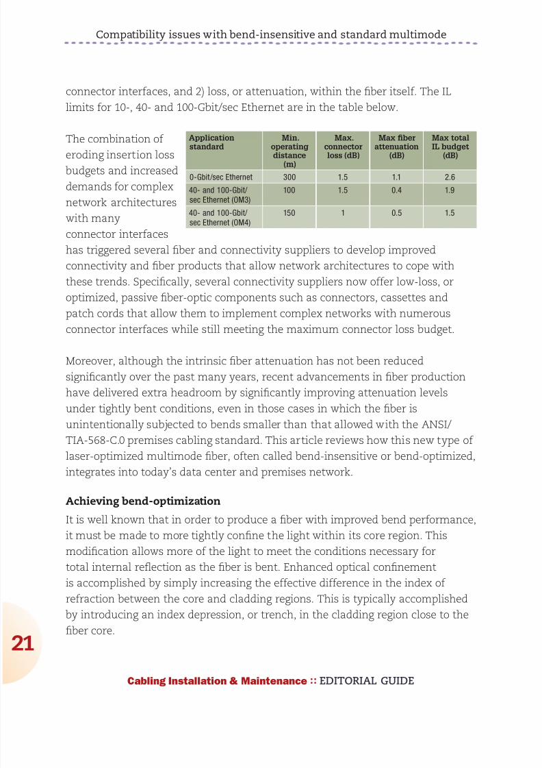
892019 Considerations for Selecting and Using Multimode Fiber
httpslidepdfcomreaderfullconsiderations-for-selecting-and-using-multimode-fiber 2232
892019 Considerations for Selecting and Using Multimode Fiber
httpslidepdfcomreaderfullconsiderations-for-selecting-and-using-multimode-fiber 2332
Compatibility issues with bend-insensitive and standard multimode
23
Cabling Installation amp Maintenance EDITORIAL GUIDE
conditions necessary for total internal reflection (ie rays with larger angles)
light emerging from bend-optimized multimode fiber will have a larger angle on
average than light emerging from standard multimode fiber The parameter that
characterizes the maximum divergence or acceptance angle of light from or to
a fiber is called numerical aperture (NA) Therefore the NA of bend-optimized
multimode is generally expected to be greater on average than the NA of
standard multimode A thorough sampling across multiple fiber manufacturers
revealed that the average NA increased
from 0199 for standard multimode fiber to
0207 for bend-optimized multimode fiber
Although this moderate increase in NAappears insignificant in some situations
the optical loss across an optical fiber
interface (eg connector) is dependent on
the differences in NAs of the fibers In the
case that light fully populates the fiber
core such as when illuminated with an
LED and is coupled from a fiber with a
higher NA into a receiver with a lower NA
the light will diverge at an angle larger
than the acceptance angle of the receive
fiber This will result in some light being
lost (into the cladding) and the interface will have loss proportional to the NA
difference (ratio) between the two fibers
Consequently increased loss may be realized when light travels from bend-
optimized multimode fiber into standard multimode fiber In fact the expected
loss across a bend-optimized fiber with an NA of 0207 and a standard fiber withan NA of 0199 is 034 dB which is a significant portion of the overall IL budget
In the case that light travels from a fiber with a lower NA into a receiver with a
higher NA or light does not fully illuminate the fiber core no loss resulting from
the difference in fiber NAs is expected
NA loss measurements
To predict the NA loss that would be realized during link certification
2 4 6
MMF LED
MMF VCSEL
8 10
3
25
2
15
1
05
0
Bend loss (1 m) (dB)
Mandrel radius (mm)
BO-MMF LED
BO-MMF VCSEL
Measured bend loss at 850 nm
representative of bend-optimized and
standard multimode fiber using both
LED and VCSEL light source Fibers were
wrapped one turn around 10 different
mandrels with radii ranging from 25mm to
10 mm
892019 Considerations for Selecting and Using Multimode Fiber
httpslidepdfcomreaderfullconsiderations-for-selecting-and-using-multimode-fiber 2432
Compatibility issues with bend-insensitive and standard multimode
24
Cabling Installation amp Maintenance EDITORIAL GUIDE
measurements of an optical
channel with bend-optimized
and standard fiber interfaces
a series of standard IL
measurements were performed
on selected bend-optimized
and standard fibers Fiber
samples from several fiber
manufacturers were selected
with a wide range of NAs in
order to provide not only a
typical NA loss from fibers withaverage NA but also provide
an upper and lower limit of
NA loss that may be expected
when connecting dissimilar
multimode fiber types without knowledge of NA differences Several fibers were
selected of each fiber typendashsome with an average NA some with a low NA and
some with a high NA The table on page 25 summarizes the samples used for this
experiment and the theoretically expected NA loss from each connection
For these measurements the various bend-optimized fiber samples were
fusion spliced to the various standard multimode fiber samples A fusion
splicer was used to connect dissimilar fiber types instead of connectors in
order to minimize other loss contributors such as lateral offset and connector
termination processing The insertion loss of the connection was calculated by
injecting light meeting the new TIAEIA-526-14-B encircled flux specification
into the bend-optimized fiber and then measuring the power coupled out of
the standard fiber Subtracting this power level from the reference power levelmeasured previously as the amount of power coupled into the bend-optimized
fiber resulted in the IL or NA loss of the connection All aspects of these
measurements were in compliance with TIAEIA-45-171A (eg diameter and
placement of cladding mode strippers)
The measurement data is shown in the chart on page 25 Each data point
represents the average of the NA losses for a set of fibers for each NA
Bend-optimizedMMF core
NA = sinq1
MMF coreα
NABO-MMF gt NAstd-MMF
This illustration shows a mismatch in NA when connecting
a fiber with a large NA (left) to a fiber with a small NA(right) Because the receive fiber on the right has a smaller
NA some light is not coupled and instead is lost into the
cladding This loss is referred to as NA loss
892019 Considerations for Selecting and Using Multimode Fiber
httpslidepdfcomreaderfullconsiderations-for-selecting-and-using-multimode-fiber 2532
Compatibility issues with bend-insensitive and standard multimode
25
Cabling Installation amp Maintenance EDITORIAL GUIDE
combination From this data
connecting dissimilar fiber types
with average NAs confirms the
theoretically predicted NA loss of
approximately 040 dB Additionally
the upper and lower limits of NA
loss were measured to be 028
dB and 106 dB Although these
average and extreme NA losses
are fairly well correlated with the
theoretically predicted NA loss
other measured values deviatesignificantly from the theoretically
predicted value This suggests that
factors other than NA such as core
diameter index profile and mode structure also significantly influence the loss
when connecting bend-optimized and standard multimode fiber As a result the
light does not couple with 100 percent efficiency between fibers and therefore an
additional mode coupling loss must exist
In fact in the case that bend-optimized fiber samples with the identical NA but
manufactured from different suppliers were connected to standard fibers with
NA equal to 0200 the NA loss differs significantly from vendor to vendor The
average NA loss from Vendor A bend-optimized interfaces nearly exactly matched
the theoretical NA loss of 030 dB while the average NA loss from Vendor B
bend-optimized interfaces was much higher at 051 dB (see graph on page 26) As
expected the bend-optimized fibers from Vendor B were found to be more bend-
tolerant than those from Vendor A
In addition to realizing
unidirectional NA
loss an increase in the
modal noise penalty
may also result
when connecting
bend-optimized and
1000 0975 0950 0925 0900 0875 0850
14
12
10
08
06
04
02
00
NA ratio
NA loss (dB)
The black line shows the theoretical loss of connected
fibers with different NA and the dots represent
actual measured loss The results suggest factorsother than NA also influence loss when connecting
bend-optimized and standard multimode fiber
NA (BO-MMF)to NA (MMF)combination
NA (BO-MMF) NA (MMF) NA ratio Theoreticalloss (dB)
Average to Average 0207 0199 0961 034
Large to Average 0215 0199 0926 067
Large to Small 0215 0185 086 131
Average to Small 0207 0185 0894 098
Small to Small 0199 0185 0928 063
Large to Large 0215 0212 0986 012
892019 Considerations for Selecting and Using Multimode Fiber
httpslidepdfcomreaderfullconsiderations-for-selecting-and-using-multimode-fiber 2632
Compatibility issues with bend-insensitive and standard multimode
26
Cabling Installation amp Maintenance EDITORIAL GUIDE
standard multimode fiber Modal noise is a power penalty related to the reduction
in the signal-to-noise ratio (SNR) of the optical signal For high-speed networks
employing VCSELs if a connector selectively attenuates higher-order modes as a
result of NA mismatch or a lateral offset between fiber cores then fluctuations in
the power distribution (spatial speckle pattern) result in fluctuations in connector
insertion loss This fluctuation is seen by the detector as an increase in noise
thereby reducing the SNR and therefore signal quality
The maximum allowed power penalty for modal noise is currently specified
in 10GBase-SR to be 03 dB Both NA loss and mode coupling loss can increase
the mode-selective loss (filter aperture) at a connector interface resulting in an
increase in modal noise Considering the overall power budget for 10G40G100GEthernet is 15 dB (or 10 dB for OM4) any
increase in modal noise may compromise
system reliability
In conclusion inconclusive
As part of our review of how bend-
optimized multimode fiber is integrating
in todayrsquos data center and premises
networks we measured the loss between
bend-insensitive and standard multimode
fibers to quantify the expected additional
loss during certification of mixed-fiber
links These additional losses were
measured to be as high as 1 dB and can
be a significant portion ofndashor even actually
exceedndashthe total optical power budget
for todayrsquos high-speed networks For a channel link that contains several bend-optimized fiber and multimode fiber interfaces which have large NA differences
the NA losses may be additive and further inhibit system certification
Furthermore although NA loss alone is unlikely to detrimentally influence
system performance it may be very difficult if not impossible to determine if
excessive channel loss is due to NA differences or other conventional sources
of loss such as macrobending or dirtydamaged components One strategy to
BO-MMF1
to MMF2
BO-MMF1
to MMF2
BO-MMF1
to MMF2
Vendor A BO-MMF
Vendor B BO-MMF
BO-MMF1
to MMF2
07
06
05
04
03
02
01
00
Measured NA loss (dB)
Bend-optimized fibers from Vendor B shown
here as the blue bars were found to be more
bend-tolerant than the bend-optimized fibers
from Vendor A shown as the green bars
The more-optimized fibers exhibited higher
NA loss
892019 Considerations for Selecting and Using Multimode Fiber
httpslidepdfcomreaderfullconsiderations-for-selecting-and-using-multimode-fiber 2732
Compatibility issues with bend-insensitive and standard multimode
27
Cabling Installation amp Maintenance EDITORIAL GUIDE
account for this loss would be to require bidirectional loss measurements of
individual optical interfaces
During the most recent meeting of the TIA TR-4212 Optical Fibers and Cable
Subcommittee a vigorous debate included many of the topics discussed in this
article and others including increased NA loss mode coupling loss modal
noise (which may negatively impact system performance) the validity of other
standardized fiber test procedures for fiber core diameter fiber bandwidth and
link attenuation (encircled flux) The subcommittee authorized the formation of
a task group to study the technical compatibility of bend-insensitive multimode
fiber with current multimode fiber standards
Based on our internal analysis and the present uncertain position within the
standards community we have concluded that the performance risks of mixing
bend-optimized and standard multimode fiber types in high-speed optical
channel links exceeds any benefit To ensure that total optical loss across data
center and premises networks remains below the allowable limit we recommend
adhering to standards-based radius-control methods and the use of one fiber
type throughout the channel link which includes cabling and patch cords This
approach enables network stakeholders to reliably deploy complex network
architectures meet stringent IL budgets and ensure optimal system performance
within current standards-based network architectures and testing methods
Some manufacturers support this effort others minimize its importance Until
the TIA subcommittee work on these issues is complete we recommend that
these two fiber types should not presently be mixed
Dr Rick Pimpinella is a Distinguished Engineer Bulent Kose is a ResearchEngineer and Dr Brett Lane is a Fiber Research Manager with Panduit
892019 Considerations for Selecting and Using Multimode Fiber
httpslidepdfcomreaderfullconsiderations-for-selecting-and-using-multimode-fiber 2832
As the demand for bandwidth in
enterprise applications such as
data centers continues to
boom new transmission media
must be developed continually
to meet end user requirementsThe latest in optical transmis-
sion media for the enterprise is
called OM4 fiber
OM4 fiber is a 50 micron (microm)
laser-optimized multimode fiber
with extended bandwidth It is
designed to enhance the sys-
tem cost benefits enabled by
850 nm Vertical Cavity Surface
Emitting Lasers (VCSELs) for existing 1 and 10 Gbs applica-
tions as well as future 40 and
100 Gbs systems
Supporting Ethernet Fibre
Channel and OIF applications
OM4 fiber allows extended
reach upwards of 550 meters at
10 Gbs for ultra long building
backbones and medium lengthcampus backbones It offers an
Effective Modal Bandwidth
(EMB) of 4700 MHz-km more
than double the IEEE require-
ment for 10 Gbs 300 meter
support
To help you use this advanced
fiber to its greatest advantage
this paper describes the tech-
nology behind OM4 fiber high-
lights the key differences with
other fiber types and explains
how its high bandwidth is
ensured through stringentmeasurement methods
Multimode Fiber Basics
Compared to single-mode
fibers multimode fibers have
larger cores that as their name
implies guide multiple ldquomodesrdquo
or rays of light simultaneously
Modes that travel at the outside
edge of the core have a longer
distance to go than modes thattravel near the center
The corersquos graded index profile
is designed to slow down
modes that have a shorter dis-
tance to travel so that all modes
arrive at the end of the fiber as
close in time as possible This
minimizes modal dispersion
also known as differential mode
delay (DMD) and maximizes
bandwidth which is the amount
of information that can travel
through the fiber per unit of
time
In addition to their large core
multimode fibers have a large
Numerical Aperture (NA) the
maximum angle at which a fiber
can accept the light that will be
transmitted through it This
allows them to work with rela-
tively low-cost optical compo-
nents and light sources such as
light-emitting diodes (LEDs)and VCSELs
Multimode Fiber Options
Multimode products are identi-
fied by the OM (ldquooptical multi-
moderdquo) designation as outlined
in the ISOIEC 11801 interna-
tional cabling standard (see
table 1)
OM4 - The Next Generation
of Multimode Fiber Tony Irujo
Sales Engineer
OPTICAL FIBER IN ENTERPRISE APPLICATIONS
Table 1 ISOIEC 11801 OM designations
892019 Considerations for Selecting and Using Multimode Fiber
httpslidepdfcomreaderfullconsiderations-for-selecting-and-using-multimode-fiber 2932
OM4 fiber is the latest develop-
ment in this series It is espe-
cially well suited for shorter
reach data center and high per-
formance computing applica-
tions where optical loss budg-
ets are tight at 10 Gbs (and
are expected to get even tighter
at 40 Gbs and 100 Gbs) Thehigh bandwidth provided by
OM4 fiber when deployed at
less than its rated distance
offers extra ldquoheadroomrdquo for
channel insertion loss
OM4 is backward compatible
with applications calling for OFL
bandwidth of at least 500 MHz-
km at 1300 nm (eg FDDI
IEEE 100BASE-FX
1000BASE-LX 10GBASE-LX4
and 10GBASE-LRM)
The latest offerings in multi-
mode fiber are 50 983221m bend
insensitive multimode fibers
(BIMMF) These fibers have
been promoted as offering all
the advantages of high band-
width laser-optimized multi-mode fiber with the added
advantage of lower bend sensi-
tivity
However recent work has
pointed to some areas of con-
cern with these fibers Studies
have identified issues with the
characterization of bend insen-
sitive fibers and questioned
whether current requirements
are adequate to guarantee sys-
tem performance Additional
studies have shown that mating
(connector) loss of BIMMFs
with standard fibers is higher
than with standard fibers con-
nected to each other This addi-
tional loss adds to the total link
loss
It has been proposed that stan-
dards organizations perform a
thorough review of BIMMFs
and incorporate them into
industry standards Until this
work is done some caution is
advised before widespread
adoption takes place
What Makes OM4 Different
Like OM3 multimode fiber OM4
fiber is considered to be ldquolaser-
optimizedrdquo or optimized for use
with VCSEL light sources OM3
and OM4 fibers are designed
and manufactured in such a
way as to get the most perform-
ance out of VCSELs compared
to LEDs That is why laser-opti-
mized fibers are specified using
Laser Bandwidth or EMB
OM2 fiber although compatible
with VCSELs is not considered
to be laser-optimized OM2
fiber is intended for use with
LED sources at speeds of 10 or
100 Mbs or for shorter reach 1
Gbs networks You can use
OM2 fiber with VCSELs but itsperformance is limited to 550
meters at 1 Gbs and only 82
meters at 10 Gbs compared to
OM4 fiberrsquos
reach of over
1000 meters
at 1 Gbs and
550 meters at
10 Gbs
As discussed
the speed at
which each
mode travels
down a multi-
mode fiberrsquos
core depends
on its refrac-
tive index
which is gov-
erned by the amount of chemi-
cal dopant Germanium at that
location in the core Because
modes traveling down the cen-
ter of the core have shorter dis-
tance to travel than those trav-
eling along the edge the refrac-
tive index profile in a multimode
fiber must be ldquogradedrdquo in a par-abolic manner across the core
This slows down the modes
that have a shorter distance to
travel equalizing the arrival
time of all the modes
The better the modes are
equalized the higher the band-
width of the fiber Mode equal-
ization depends on how well
the graded index profile is con-
structed during fiber manufac-
turing The more precise the
refractive index profile is in
terms of shape curvature and
smoothness (free of dips
spikes or defects) the better
the modes will be equalized
(see Figure 2)
OM4 fiber with its higher band-width has an extremely precise
refractive index profile virtually
free of perturbations or defects
Figure 2 A refractive index profile optimized for shape curvature
and smoothness maximizes bandwidth
892019 Considerations for Selecting and Using Multimode Fiber
httpslidepdfcomreaderfullconsiderations-for-selecting-and-using-multimode-fiber 3032
In order to make such a precise
fiber one needs to use a pre-
form manufacturing process
that has exceptional control
over the amount of Germanium
that is incorporated at particular
sub-micron positions within the
fiberrsquos core An example of a
process that lends itself to this
level of control is OFSrsquo propri-
etary MCVD process in which
each layer of the core is
deposited and sintered individu-
ally providing the utmost in
refractive index precision and
uniformity
OM4 Fiber Standards
Two standards define the useof OM4 fiber in high-speed net-
works TIA document TIA-
492AAAD which contains the
OM4 fiber performance specifi-
cations and the IEC 60793-2-
10 international standard which
provides equivalent OM4 speci-
fications under fiber type A1a3
ISOIEC 11801 will add OM4
fiber as an industry-recognized
fiber type and IEEE 8023bafor 40G and 100G Ethernet will
include OM4 fiber as an option
that provides a reach of 150
meters (50 percent greater than
OM3)
There was discussion and
debate within the standards
groups about a minimum OFL
bandwidth requirement at 850nm Although current applica-
tions primarily use 850 nm
VCSEL lasers with fibers that
are specified to a minimum
EMB there was good reason to
also establish a minimum 850
nm OFL bandwidth specifica-
tion It has been shown that
fibers with higher OFL band-
width will perform better with
VCSELs that launch more
power into outer modes That is
why the existing OM3 fiber
standards require a minimum
1500 MHz-km OFL bandwidthat 850 nm
For OM4 fiber OFS and others
in the standards group strongly
recommended at least 3500
MHz-km OFL bandwidth in
order to ensure the utmost per-
formance and reliability ulti-
mately that is the specification
that was agreed upon
Measuring Laser Bandwidth
Bandwidth performance of OM4
fiber is ensured using the same
criteria as OM3 but to much
tighter specifications Due to a
challenge posed when the now-
familiar VCSEL was first intro-
duced new measurement
methods had to be developed
to verify laser bandwidth of OM3 and OM4 fibers
Unlike an LED laser VCSELs
produce an energy output that
is not uniform it can change
sharply across the face of the
output Whatrsquos more each laser
fills a different set of light paths
in each fiber and does so with
differing amounts of power in
each path Overfilled bandwidth
measurements used to meas-
ure LED bandwidth could not
emulate the operation of aVCSEL
The standards allow two ways
to measure and verify laser
bandwidth the DMD Mask
Method and the EMBc Method
Both methods require DMD
testing -- the difference lies in
how the DMD data is used and
interpreted
In DMD testing small high-
powered laser pulses are trans-
mitted through the fiber in tiny
steps across the entire core of
the fiber Only a few modes are
excited at each step and their
arrival times are recorded The
DMD of the fiber is the differ-
ence between the earliest and
the latest arrival times of allmodes at all steps
DMD measurement is currently
the only reliable method for ver-
ifying bandwidth required for 10
Gbs performance because it is
the only method that checks all
modes across the fiber core
independently For that reason
Figure 3 DMD testing measures how different VCSELs fill different modes in each
fiber
892019 Considerations for Selecting and Using Multimode Fiber
httpslidepdfcomreaderfullconsiderations-for-selecting-and-using-multimode-fiber 3132
industry associations such as
TIAEIA and ISOIEC have pub-
lished standards for DMD
measurement and DMD specifi-
cations for laser-optimized mul-
timode fiber
The DMD Mask Method is a
simple process that directlycompares DMD test results
against a set of specifications
(called templates or masks) to
see if the fiber has the neces-
sary performance
This is a straightforward graphi-
cal approach to ensuring the
data pulses do not spread
excessively beyond therequired 10 Gbs bit period If
the fiber passes these DMD
specs then you are assured of
at least 2000 MHz-km EMB no
matter which VCSEL you use
(as long as the VCSEL is com-
pliant)
The EMBc Method is an indi-
rect and more complex
process It takes the DMD
results and matches them
against a set of theoretical
weighting functions that are
intended to represent the
launch distributions of all com-
pliant VCSELs
The DMD results are combined
mathematically with each of the
10 weighting functions This
produces 10 different EMBc
values the lowest of which is
called minEMBc The minEMBc
value is then multiplied by a
factor of 113 to obtain the
fiberrsquos EMB value If this EMB
value is gt 2000 MHz-km thefiber is deemed compliant with
OM3 requirements and there-
fore should support 300 meters
at 10 Gbs
Due to all the complex calcula-
tions required by the EMBc
method and the fact that the
weighting functions only repre-
sent a sampling of the launch
characteristics of the many
VCSELs that could actually be
used in a real system the
EMBc method does not provide
the same scrutiny on fiber qual-
ity and performance as the
DMD Mask technique Whatrsquos
more the EMBc method virtual-ly ignores the center 0 ndash 5 983221m
(radial) region of a fiberrsquos core
because the weighting func-
tions put little emphasis in this
region
Conclusion
OM4 fiber provides next-gener-
ation multimode fiber perform-
ance for today and tomorrowrsquoshigh speed applications With
its significantly higher band-
width network designers and
operators can be assured that
multimode fiber will continue to
provide the most cost effective
solutions for short reach appli-
cations in data centers and
LANs
Copyright copy 2011 Furukawa Electric North America All rights reserved printed in USA
For additional information visit our website at wwwofsopticscomofs-fiber or call 1-888-fiber-
help For regional assistance contact
North America Asia Pacific
Telephone 508-347-8590 Telephone +852 2836 7102
Toll Free 800-799-7732 Fax +852 2836 7101
Fax 508-347-1211 E-mail fibersalesapofsopticscomE-mail fibersalesnarofsopticscom
Caribbean Latin America Japan
Telephone 508-347-8590 Telephone +81-3-3286-3424
Fax 508-347-1211 Fax +81-3-3286-3708 or 3190
E-mail fibersalescalaofsopticscom E-mail fibersalesjapanofsopticscom
Europe Middle East Africa China
Telephone +45-43 48 3736 Telephone +86 10 6505 3660
Fax +45 4348 3444 Fax +86 10 65059515
E-mail ofssalesdkofsopticscom E-mail fibersaleschinaofsopticscom
OFS reserves the right to make changes to the prices
and product(s) described in this document in the
interest of improving internal design operational
function andor reliability
This document is for informational purposes only
and is not intended to modify or supplement any
OFS warranties or specifications relating to any of
its products or services
892019 Considerations for Selecting and Using Multimode Fiber
httpslidepdfcomreaderfullconsiderations-for-selecting-and-using-multimode-fiber 3232
About OFSOFS is a world-leading designer manufacturer and provider of optical fiber
optical fiber cable FTTX optical connectivity and specialty photonics products
Our manufacturing and research divisions work together to provide innovative
products and solutions that traverse many different applications as they linkpeople and machines worldwide Between continents between cities around
neighborhoods and into homes and businesses of digital consumers we provide
the right optical fiber optical cable and components for efficient cost-effective
transmission
OFSrsquo corporate lineage dates back to 1876 and includes technology powerhouses
such as ATampT (NYSE T) and Lucent Technologies (now Alcatel-Lucent NYSE
ALU) Today OFS is owned by Furukawa Electric a multi-billion dollar global
leader in optical communications Headquartered in Norcross (near Atlanta)Georgia US OFS is a global provider with facilities in Avon Connecticut
Carrollton Georgia Somerset New Jersey and Sturbridge Massachusetts as well
as in Denmark Germany and Russia
wwwofsopticscom
LINKS
LaserWavereg Laser-Optimized OM4OM3 Fibers
Multimode or Single-Mode Fiber
Measuring Bandwidth of 10G Laser-optimized Multimode Fiber
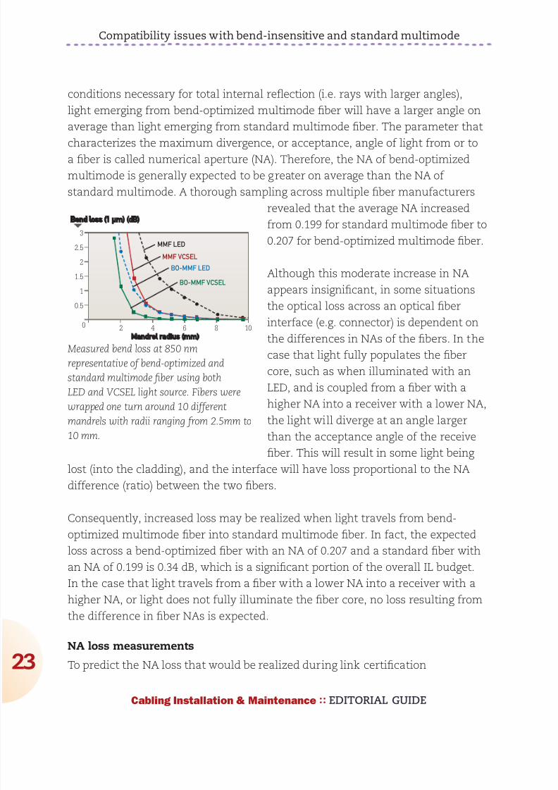
892019 Considerations for Selecting and Using Multimode Fiber
httpslidepdfcomreaderfullconsiderations-for-selecting-and-using-multimode-fiber 2332
Compatibility issues with bend-insensitive and standard multimode
23
Cabling Installation amp Maintenance EDITORIAL GUIDE
conditions necessary for total internal reflection (ie rays with larger angles)
light emerging from bend-optimized multimode fiber will have a larger angle on
average than light emerging from standard multimode fiber The parameter that
characterizes the maximum divergence or acceptance angle of light from or to
a fiber is called numerical aperture (NA) Therefore the NA of bend-optimized
multimode is generally expected to be greater on average than the NA of
standard multimode A thorough sampling across multiple fiber manufacturers
revealed that the average NA increased
from 0199 for standard multimode fiber to
0207 for bend-optimized multimode fiber
Although this moderate increase in NAappears insignificant in some situations
the optical loss across an optical fiber
interface (eg connector) is dependent on
the differences in NAs of the fibers In the
case that light fully populates the fiber
core such as when illuminated with an
LED and is coupled from a fiber with a
higher NA into a receiver with a lower NA
the light will diverge at an angle larger
than the acceptance angle of the receive
fiber This will result in some light being
lost (into the cladding) and the interface will have loss proportional to the NA
difference (ratio) between the two fibers
Consequently increased loss may be realized when light travels from bend-
optimized multimode fiber into standard multimode fiber In fact the expected
loss across a bend-optimized fiber with an NA of 0207 and a standard fiber withan NA of 0199 is 034 dB which is a significant portion of the overall IL budget
In the case that light travels from a fiber with a lower NA into a receiver with a
higher NA or light does not fully illuminate the fiber core no loss resulting from
the difference in fiber NAs is expected
NA loss measurements
To predict the NA loss that would be realized during link certification
2 4 6
MMF LED
MMF VCSEL
8 10
3
25
2
15
1
05
0
Bend loss (1 m) (dB)
Mandrel radius (mm)
BO-MMF LED
BO-MMF VCSEL
Measured bend loss at 850 nm
representative of bend-optimized and
standard multimode fiber using both
LED and VCSEL light source Fibers were
wrapped one turn around 10 different
mandrels with radii ranging from 25mm to
10 mm
892019 Considerations for Selecting and Using Multimode Fiber
httpslidepdfcomreaderfullconsiderations-for-selecting-and-using-multimode-fiber 2432
Compatibility issues with bend-insensitive and standard multimode
24
Cabling Installation amp Maintenance EDITORIAL GUIDE
measurements of an optical
channel with bend-optimized
and standard fiber interfaces
a series of standard IL
measurements were performed
on selected bend-optimized
and standard fibers Fiber
samples from several fiber
manufacturers were selected
with a wide range of NAs in
order to provide not only a
typical NA loss from fibers withaverage NA but also provide
an upper and lower limit of
NA loss that may be expected
when connecting dissimilar
multimode fiber types without knowledge of NA differences Several fibers were
selected of each fiber typendashsome with an average NA some with a low NA and
some with a high NA The table on page 25 summarizes the samples used for this
experiment and the theoretically expected NA loss from each connection
For these measurements the various bend-optimized fiber samples were
fusion spliced to the various standard multimode fiber samples A fusion
splicer was used to connect dissimilar fiber types instead of connectors in
order to minimize other loss contributors such as lateral offset and connector
termination processing The insertion loss of the connection was calculated by
injecting light meeting the new TIAEIA-526-14-B encircled flux specification
into the bend-optimized fiber and then measuring the power coupled out of
the standard fiber Subtracting this power level from the reference power levelmeasured previously as the amount of power coupled into the bend-optimized
fiber resulted in the IL or NA loss of the connection All aspects of these
measurements were in compliance with TIAEIA-45-171A (eg diameter and
placement of cladding mode strippers)
The measurement data is shown in the chart on page 25 Each data point
represents the average of the NA losses for a set of fibers for each NA
Bend-optimizedMMF core
NA = sinq1
MMF coreα
NABO-MMF gt NAstd-MMF
This illustration shows a mismatch in NA when connecting
a fiber with a large NA (left) to a fiber with a small NA(right) Because the receive fiber on the right has a smaller
NA some light is not coupled and instead is lost into the
cladding This loss is referred to as NA loss
892019 Considerations for Selecting and Using Multimode Fiber
httpslidepdfcomreaderfullconsiderations-for-selecting-and-using-multimode-fiber 2532
Compatibility issues with bend-insensitive and standard multimode
25
Cabling Installation amp Maintenance EDITORIAL GUIDE
combination From this data
connecting dissimilar fiber types
with average NAs confirms the
theoretically predicted NA loss of
approximately 040 dB Additionally
the upper and lower limits of NA
loss were measured to be 028
dB and 106 dB Although these
average and extreme NA losses
are fairly well correlated with the
theoretically predicted NA loss
other measured values deviatesignificantly from the theoretically
predicted value This suggests that
factors other than NA such as core
diameter index profile and mode structure also significantly influence the loss
when connecting bend-optimized and standard multimode fiber As a result the
light does not couple with 100 percent efficiency between fibers and therefore an
additional mode coupling loss must exist
In fact in the case that bend-optimized fiber samples with the identical NA but
manufactured from different suppliers were connected to standard fibers with
NA equal to 0200 the NA loss differs significantly from vendor to vendor The
average NA loss from Vendor A bend-optimized interfaces nearly exactly matched
the theoretical NA loss of 030 dB while the average NA loss from Vendor B
bend-optimized interfaces was much higher at 051 dB (see graph on page 26) As
expected the bend-optimized fibers from Vendor B were found to be more bend-
tolerant than those from Vendor A
In addition to realizing
unidirectional NA
loss an increase in the
modal noise penalty
may also result
when connecting
bend-optimized and
1000 0975 0950 0925 0900 0875 0850
14
12
10
08
06
04
02
00
NA ratio
NA loss (dB)
The black line shows the theoretical loss of connected
fibers with different NA and the dots represent
actual measured loss The results suggest factorsother than NA also influence loss when connecting
bend-optimized and standard multimode fiber
NA (BO-MMF)to NA (MMF)combination
NA (BO-MMF) NA (MMF) NA ratio Theoreticalloss (dB)
Average to Average 0207 0199 0961 034
Large to Average 0215 0199 0926 067
Large to Small 0215 0185 086 131
Average to Small 0207 0185 0894 098
Small to Small 0199 0185 0928 063
Large to Large 0215 0212 0986 012
892019 Considerations for Selecting and Using Multimode Fiber
httpslidepdfcomreaderfullconsiderations-for-selecting-and-using-multimode-fiber 2632
Compatibility issues with bend-insensitive and standard multimode
26
Cabling Installation amp Maintenance EDITORIAL GUIDE
standard multimode fiber Modal noise is a power penalty related to the reduction
in the signal-to-noise ratio (SNR) of the optical signal For high-speed networks
employing VCSELs if a connector selectively attenuates higher-order modes as a
result of NA mismatch or a lateral offset between fiber cores then fluctuations in
the power distribution (spatial speckle pattern) result in fluctuations in connector
insertion loss This fluctuation is seen by the detector as an increase in noise
thereby reducing the SNR and therefore signal quality
The maximum allowed power penalty for modal noise is currently specified
in 10GBase-SR to be 03 dB Both NA loss and mode coupling loss can increase
the mode-selective loss (filter aperture) at a connector interface resulting in an
increase in modal noise Considering the overall power budget for 10G40G100GEthernet is 15 dB (or 10 dB for OM4) any
increase in modal noise may compromise
system reliability
In conclusion inconclusive
As part of our review of how bend-
optimized multimode fiber is integrating
in todayrsquos data center and premises
networks we measured the loss between
bend-insensitive and standard multimode
fibers to quantify the expected additional
loss during certification of mixed-fiber
links These additional losses were
measured to be as high as 1 dB and can
be a significant portion ofndashor even actually
exceedndashthe total optical power budget
for todayrsquos high-speed networks For a channel link that contains several bend-optimized fiber and multimode fiber interfaces which have large NA differences
the NA losses may be additive and further inhibit system certification
Furthermore although NA loss alone is unlikely to detrimentally influence
system performance it may be very difficult if not impossible to determine if
excessive channel loss is due to NA differences or other conventional sources
of loss such as macrobending or dirtydamaged components One strategy to
BO-MMF1
to MMF2
BO-MMF1
to MMF2
BO-MMF1
to MMF2
Vendor A BO-MMF
Vendor B BO-MMF
BO-MMF1
to MMF2
07
06
05
04
03
02
01
00
Measured NA loss (dB)
Bend-optimized fibers from Vendor B shown
here as the blue bars were found to be more
bend-tolerant than the bend-optimized fibers
from Vendor A shown as the green bars
The more-optimized fibers exhibited higher
NA loss
892019 Considerations for Selecting and Using Multimode Fiber
httpslidepdfcomreaderfullconsiderations-for-selecting-and-using-multimode-fiber 2732
Compatibility issues with bend-insensitive and standard multimode
27
Cabling Installation amp Maintenance EDITORIAL GUIDE
account for this loss would be to require bidirectional loss measurements of
individual optical interfaces
During the most recent meeting of the TIA TR-4212 Optical Fibers and Cable
Subcommittee a vigorous debate included many of the topics discussed in this
article and others including increased NA loss mode coupling loss modal
noise (which may negatively impact system performance) the validity of other
standardized fiber test procedures for fiber core diameter fiber bandwidth and
link attenuation (encircled flux) The subcommittee authorized the formation of
a task group to study the technical compatibility of bend-insensitive multimode
fiber with current multimode fiber standards
Based on our internal analysis and the present uncertain position within the
standards community we have concluded that the performance risks of mixing
bend-optimized and standard multimode fiber types in high-speed optical
channel links exceeds any benefit To ensure that total optical loss across data
center and premises networks remains below the allowable limit we recommend
adhering to standards-based radius-control methods and the use of one fiber
type throughout the channel link which includes cabling and patch cords This
approach enables network stakeholders to reliably deploy complex network
architectures meet stringent IL budgets and ensure optimal system performance
within current standards-based network architectures and testing methods
Some manufacturers support this effort others minimize its importance Until
the TIA subcommittee work on these issues is complete we recommend that
these two fiber types should not presently be mixed
Dr Rick Pimpinella is a Distinguished Engineer Bulent Kose is a ResearchEngineer and Dr Brett Lane is a Fiber Research Manager with Panduit
892019 Considerations for Selecting and Using Multimode Fiber
httpslidepdfcomreaderfullconsiderations-for-selecting-and-using-multimode-fiber 2832
As the demand for bandwidth in
enterprise applications such as
data centers continues to
boom new transmission media
must be developed continually
to meet end user requirementsThe latest in optical transmis-
sion media for the enterprise is
called OM4 fiber
OM4 fiber is a 50 micron (microm)
laser-optimized multimode fiber
with extended bandwidth It is
designed to enhance the sys-
tem cost benefits enabled by
850 nm Vertical Cavity Surface
Emitting Lasers (VCSELs) for existing 1 and 10 Gbs applica-
tions as well as future 40 and
100 Gbs systems
Supporting Ethernet Fibre
Channel and OIF applications
OM4 fiber allows extended
reach upwards of 550 meters at
10 Gbs for ultra long building
backbones and medium lengthcampus backbones It offers an
Effective Modal Bandwidth
(EMB) of 4700 MHz-km more
than double the IEEE require-
ment for 10 Gbs 300 meter
support
To help you use this advanced
fiber to its greatest advantage
this paper describes the tech-
nology behind OM4 fiber high-
lights the key differences with
other fiber types and explains
how its high bandwidth is
ensured through stringentmeasurement methods
Multimode Fiber Basics
Compared to single-mode
fibers multimode fibers have
larger cores that as their name
implies guide multiple ldquomodesrdquo
or rays of light simultaneously
Modes that travel at the outside
edge of the core have a longer
distance to go than modes thattravel near the center
The corersquos graded index profile
is designed to slow down
modes that have a shorter dis-
tance to travel so that all modes
arrive at the end of the fiber as
close in time as possible This
minimizes modal dispersion
also known as differential mode
delay (DMD) and maximizes
bandwidth which is the amount
of information that can travel
through the fiber per unit of
time
In addition to their large core
multimode fibers have a large
Numerical Aperture (NA) the
maximum angle at which a fiber
can accept the light that will be
transmitted through it This
allows them to work with rela-
tively low-cost optical compo-
nents and light sources such as
light-emitting diodes (LEDs)and VCSELs
Multimode Fiber Options
Multimode products are identi-
fied by the OM (ldquooptical multi-
moderdquo) designation as outlined
in the ISOIEC 11801 interna-
tional cabling standard (see
table 1)
OM4 - The Next Generation
of Multimode Fiber Tony Irujo
Sales Engineer
OPTICAL FIBER IN ENTERPRISE APPLICATIONS
Table 1 ISOIEC 11801 OM designations
892019 Considerations for Selecting and Using Multimode Fiber
httpslidepdfcomreaderfullconsiderations-for-selecting-and-using-multimode-fiber 2932
OM4 fiber is the latest develop-
ment in this series It is espe-
cially well suited for shorter
reach data center and high per-
formance computing applica-
tions where optical loss budg-
ets are tight at 10 Gbs (and
are expected to get even tighter
at 40 Gbs and 100 Gbs) Thehigh bandwidth provided by
OM4 fiber when deployed at
less than its rated distance
offers extra ldquoheadroomrdquo for
channel insertion loss
OM4 is backward compatible
with applications calling for OFL
bandwidth of at least 500 MHz-
km at 1300 nm (eg FDDI
IEEE 100BASE-FX
1000BASE-LX 10GBASE-LX4
and 10GBASE-LRM)
The latest offerings in multi-
mode fiber are 50 983221m bend
insensitive multimode fibers
(BIMMF) These fibers have
been promoted as offering all
the advantages of high band-
width laser-optimized multi-mode fiber with the added
advantage of lower bend sensi-
tivity
However recent work has
pointed to some areas of con-
cern with these fibers Studies
have identified issues with the
characterization of bend insen-
sitive fibers and questioned
whether current requirements
are adequate to guarantee sys-
tem performance Additional
studies have shown that mating
(connector) loss of BIMMFs
with standard fibers is higher
than with standard fibers con-
nected to each other This addi-
tional loss adds to the total link
loss
It has been proposed that stan-
dards organizations perform a
thorough review of BIMMFs
and incorporate them into
industry standards Until this
work is done some caution is
advised before widespread
adoption takes place
What Makes OM4 Different
Like OM3 multimode fiber OM4
fiber is considered to be ldquolaser-
optimizedrdquo or optimized for use
with VCSEL light sources OM3
and OM4 fibers are designed
and manufactured in such a
way as to get the most perform-
ance out of VCSELs compared
to LEDs That is why laser-opti-
mized fibers are specified using
Laser Bandwidth or EMB
OM2 fiber although compatible
with VCSELs is not considered
to be laser-optimized OM2
fiber is intended for use with
LED sources at speeds of 10 or
100 Mbs or for shorter reach 1
Gbs networks You can use
OM2 fiber with VCSELs but itsperformance is limited to 550
meters at 1 Gbs and only 82
meters at 10 Gbs compared to
OM4 fiberrsquos
reach of over
1000 meters
at 1 Gbs and
550 meters at
10 Gbs
As discussed
the speed at
which each
mode travels
down a multi-
mode fiberrsquos
core depends
on its refrac-
tive index
which is gov-
erned by the amount of chemi-
cal dopant Germanium at that
location in the core Because
modes traveling down the cen-
ter of the core have shorter dis-
tance to travel than those trav-
eling along the edge the refrac-
tive index profile in a multimode
fiber must be ldquogradedrdquo in a par-abolic manner across the core
This slows down the modes
that have a shorter distance to
travel equalizing the arrival
time of all the modes
The better the modes are
equalized the higher the band-
width of the fiber Mode equal-
ization depends on how well
the graded index profile is con-
structed during fiber manufac-
turing The more precise the
refractive index profile is in
terms of shape curvature and
smoothness (free of dips
spikes or defects) the better
the modes will be equalized
(see Figure 2)
OM4 fiber with its higher band-width has an extremely precise
refractive index profile virtually
free of perturbations or defects
Figure 2 A refractive index profile optimized for shape curvature
and smoothness maximizes bandwidth
892019 Considerations for Selecting and Using Multimode Fiber
httpslidepdfcomreaderfullconsiderations-for-selecting-and-using-multimode-fiber 3032
In order to make such a precise
fiber one needs to use a pre-
form manufacturing process
that has exceptional control
over the amount of Germanium
that is incorporated at particular
sub-micron positions within the
fiberrsquos core An example of a
process that lends itself to this
level of control is OFSrsquo propri-
etary MCVD process in which
each layer of the core is
deposited and sintered individu-
ally providing the utmost in
refractive index precision and
uniformity
OM4 Fiber Standards
Two standards define the useof OM4 fiber in high-speed net-
works TIA document TIA-
492AAAD which contains the
OM4 fiber performance specifi-
cations and the IEC 60793-2-
10 international standard which
provides equivalent OM4 speci-
fications under fiber type A1a3
ISOIEC 11801 will add OM4
fiber as an industry-recognized
fiber type and IEEE 8023bafor 40G and 100G Ethernet will
include OM4 fiber as an option
that provides a reach of 150
meters (50 percent greater than
OM3)
There was discussion and
debate within the standards
groups about a minimum OFL
bandwidth requirement at 850nm Although current applica-
tions primarily use 850 nm
VCSEL lasers with fibers that
are specified to a minimum
EMB there was good reason to
also establish a minimum 850
nm OFL bandwidth specifica-
tion It has been shown that
fibers with higher OFL band-
width will perform better with
VCSELs that launch more
power into outer modes That is
why the existing OM3 fiber
standards require a minimum
1500 MHz-km OFL bandwidthat 850 nm
For OM4 fiber OFS and others
in the standards group strongly
recommended at least 3500
MHz-km OFL bandwidth in
order to ensure the utmost per-
formance and reliability ulti-
mately that is the specification
that was agreed upon
Measuring Laser Bandwidth
Bandwidth performance of OM4
fiber is ensured using the same
criteria as OM3 but to much
tighter specifications Due to a
challenge posed when the now-
familiar VCSEL was first intro-
duced new measurement
methods had to be developed
to verify laser bandwidth of OM3 and OM4 fibers
Unlike an LED laser VCSELs
produce an energy output that
is not uniform it can change
sharply across the face of the
output Whatrsquos more each laser
fills a different set of light paths
in each fiber and does so with
differing amounts of power in
each path Overfilled bandwidth
measurements used to meas-
ure LED bandwidth could not
emulate the operation of aVCSEL
The standards allow two ways
to measure and verify laser
bandwidth the DMD Mask
Method and the EMBc Method
Both methods require DMD
testing -- the difference lies in
how the DMD data is used and
interpreted
In DMD testing small high-
powered laser pulses are trans-
mitted through the fiber in tiny
steps across the entire core of
the fiber Only a few modes are
excited at each step and their
arrival times are recorded The
DMD of the fiber is the differ-
ence between the earliest and
the latest arrival times of allmodes at all steps
DMD measurement is currently
the only reliable method for ver-
ifying bandwidth required for 10
Gbs performance because it is
the only method that checks all
modes across the fiber core
independently For that reason
Figure 3 DMD testing measures how different VCSELs fill different modes in each
fiber
892019 Considerations for Selecting and Using Multimode Fiber
httpslidepdfcomreaderfullconsiderations-for-selecting-and-using-multimode-fiber 3132
industry associations such as
TIAEIA and ISOIEC have pub-
lished standards for DMD
measurement and DMD specifi-
cations for laser-optimized mul-
timode fiber
The DMD Mask Method is a
simple process that directlycompares DMD test results
against a set of specifications
(called templates or masks) to
see if the fiber has the neces-
sary performance
This is a straightforward graphi-
cal approach to ensuring the
data pulses do not spread
excessively beyond therequired 10 Gbs bit period If
the fiber passes these DMD
specs then you are assured of
at least 2000 MHz-km EMB no
matter which VCSEL you use
(as long as the VCSEL is com-
pliant)
The EMBc Method is an indi-
rect and more complex
process It takes the DMD
results and matches them
against a set of theoretical
weighting functions that are
intended to represent the
launch distributions of all com-
pliant VCSELs
The DMD results are combined
mathematically with each of the
10 weighting functions This
produces 10 different EMBc
values the lowest of which is
called minEMBc The minEMBc
value is then multiplied by a
factor of 113 to obtain the
fiberrsquos EMB value If this EMB
value is gt 2000 MHz-km thefiber is deemed compliant with
OM3 requirements and there-
fore should support 300 meters
at 10 Gbs
Due to all the complex calcula-
tions required by the EMBc
method and the fact that the
weighting functions only repre-
sent a sampling of the launch
characteristics of the many
VCSELs that could actually be
used in a real system the
EMBc method does not provide
the same scrutiny on fiber qual-
ity and performance as the
DMD Mask technique Whatrsquos
more the EMBc method virtual-ly ignores the center 0 ndash 5 983221m
(radial) region of a fiberrsquos core
because the weighting func-
tions put little emphasis in this
region
Conclusion
OM4 fiber provides next-gener-
ation multimode fiber perform-
ance for today and tomorrowrsquoshigh speed applications With
its significantly higher band-
width network designers and
operators can be assured that
multimode fiber will continue to
provide the most cost effective
solutions for short reach appli-
cations in data centers and
LANs
Copyright copy 2011 Furukawa Electric North America All rights reserved printed in USA
For additional information visit our website at wwwofsopticscomofs-fiber or call 1-888-fiber-
help For regional assistance contact
North America Asia Pacific
Telephone 508-347-8590 Telephone +852 2836 7102
Toll Free 800-799-7732 Fax +852 2836 7101
Fax 508-347-1211 E-mail fibersalesapofsopticscomE-mail fibersalesnarofsopticscom
Caribbean Latin America Japan
Telephone 508-347-8590 Telephone +81-3-3286-3424
Fax 508-347-1211 Fax +81-3-3286-3708 or 3190
E-mail fibersalescalaofsopticscom E-mail fibersalesjapanofsopticscom
Europe Middle East Africa China
Telephone +45-43 48 3736 Telephone +86 10 6505 3660
Fax +45 4348 3444 Fax +86 10 65059515
E-mail ofssalesdkofsopticscom E-mail fibersaleschinaofsopticscom
OFS reserves the right to make changes to the prices
and product(s) described in this document in the
interest of improving internal design operational
function andor reliability
This document is for informational purposes only
and is not intended to modify or supplement any
OFS warranties or specifications relating to any of
its products or services
892019 Considerations for Selecting and Using Multimode Fiber
httpslidepdfcomreaderfullconsiderations-for-selecting-and-using-multimode-fiber 3232
About OFSOFS is a world-leading designer manufacturer and provider of optical fiber
optical fiber cable FTTX optical connectivity and specialty photonics products
Our manufacturing and research divisions work together to provide innovative
products and solutions that traverse many different applications as they linkpeople and machines worldwide Between continents between cities around
neighborhoods and into homes and businesses of digital consumers we provide
the right optical fiber optical cable and components for efficient cost-effective
transmission
OFSrsquo corporate lineage dates back to 1876 and includes technology powerhouses
such as ATampT (NYSE T) and Lucent Technologies (now Alcatel-Lucent NYSE
ALU) Today OFS is owned by Furukawa Electric a multi-billion dollar global
leader in optical communications Headquartered in Norcross (near Atlanta)Georgia US OFS is a global provider with facilities in Avon Connecticut
Carrollton Georgia Somerset New Jersey and Sturbridge Massachusetts as well
as in Denmark Germany and Russia
wwwofsopticscom
LINKS
LaserWavereg Laser-Optimized OM4OM3 Fibers
Multimode or Single-Mode Fiber
Measuring Bandwidth of 10G Laser-optimized Multimode Fiber
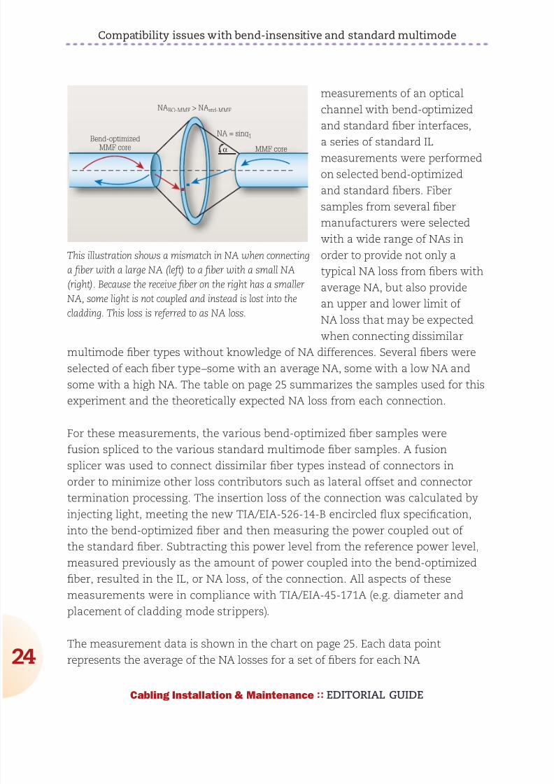
892019 Considerations for Selecting and Using Multimode Fiber
httpslidepdfcomreaderfullconsiderations-for-selecting-and-using-multimode-fiber 2432
Compatibility issues with bend-insensitive and standard multimode
24
Cabling Installation amp Maintenance EDITORIAL GUIDE
measurements of an optical
channel with bend-optimized
and standard fiber interfaces
a series of standard IL
measurements were performed
on selected bend-optimized
and standard fibers Fiber
samples from several fiber
manufacturers were selected
with a wide range of NAs in
order to provide not only a
typical NA loss from fibers withaverage NA but also provide
an upper and lower limit of
NA loss that may be expected
when connecting dissimilar
multimode fiber types without knowledge of NA differences Several fibers were
selected of each fiber typendashsome with an average NA some with a low NA and
some with a high NA The table on page 25 summarizes the samples used for this
experiment and the theoretically expected NA loss from each connection
For these measurements the various bend-optimized fiber samples were
fusion spliced to the various standard multimode fiber samples A fusion
splicer was used to connect dissimilar fiber types instead of connectors in
order to minimize other loss contributors such as lateral offset and connector
termination processing The insertion loss of the connection was calculated by
injecting light meeting the new TIAEIA-526-14-B encircled flux specification
into the bend-optimized fiber and then measuring the power coupled out of
the standard fiber Subtracting this power level from the reference power levelmeasured previously as the amount of power coupled into the bend-optimized
fiber resulted in the IL or NA loss of the connection All aspects of these
measurements were in compliance with TIAEIA-45-171A (eg diameter and
placement of cladding mode strippers)
The measurement data is shown in the chart on page 25 Each data point
represents the average of the NA losses for a set of fibers for each NA
Bend-optimizedMMF core
NA = sinq1
MMF coreα
NABO-MMF gt NAstd-MMF
This illustration shows a mismatch in NA when connecting
a fiber with a large NA (left) to a fiber with a small NA(right) Because the receive fiber on the right has a smaller
NA some light is not coupled and instead is lost into the
cladding This loss is referred to as NA loss
892019 Considerations for Selecting and Using Multimode Fiber
httpslidepdfcomreaderfullconsiderations-for-selecting-and-using-multimode-fiber 2532
Compatibility issues with bend-insensitive and standard multimode
25
Cabling Installation amp Maintenance EDITORIAL GUIDE
combination From this data
connecting dissimilar fiber types
with average NAs confirms the
theoretically predicted NA loss of
approximately 040 dB Additionally
the upper and lower limits of NA
loss were measured to be 028
dB and 106 dB Although these
average and extreme NA losses
are fairly well correlated with the
theoretically predicted NA loss
other measured values deviatesignificantly from the theoretically
predicted value This suggests that
factors other than NA such as core
diameter index profile and mode structure also significantly influence the loss
when connecting bend-optimized and standard multimode fiber As a result the
light does not couple with 100 percent efficiency between fibers and therefore an
additional mode coupling loss must exist
In fact in the case that bend-optimized fiber samples with the identical NA but
manufactured from different suppliers were connected to standard fibers with
NA equal to 0200 the NA loss differs significantly from vendor to vendor The
average NA loss from Vendor A bend-optimized interfaces nearly exactly matched
the theoretical NA loss of 030 dB while the average NA loss from Vendor B
bend-optimized interfaces was much higher at 051 dB (see graph on page 26) As
expected the bend-optimized fibers from Vendor B were found to be more bend-
tolerant than those from Vendor A
In addition to realizing
unidirectional NA
loss an increase in the
modal noise penalty
may also result
when connecting
bend-optimized and
1000 0975 0950 0925 0900 0875 0850
14
12
10
08
06
04
02
00
NA ratio
NA loss (dB)
The black line shows the theoretical loss of connected
fibers with different NA and the dots represent
actual measured loss The results suggest factorsother than NA also influence loss when connecting
bend-optimized and standard multimode fiber
NA (BO-MMF)to NA (MMF)combination
NA (BO-MMF) NA (MMF) NA ratio Theoreticalloss (dB)
Average to Average 0207 0199 0961 034
Large to Average 0215 0199 0926 067
Large to Small 0215 0185 086 131
Average to Small 0207 0185 0894 098
Small to Small 0199 0185 0928 063
Large to Large 0215 0212 0986 012
892019 Considerations for Selecting and Using Multimode Fiber
httpslidepdfcomreaderfullconsiderations-for-selecting-and-using-multimode-fiber 2632
Compatibility issues with bend-insensitive and standard multimode
26
Cabling Installation amp Maintenance EDITORIAL GUIDE
standard multimode fiber Modal noise is a power penalty related to the reduction
in the signal-to-noise ratio (SNR) of the optical signal For high-speed networks
employing VCSELs if a connector selectively attenuates higher-order modes as a
result of NA mismatch or a lateral offset between fiber cores then fluctuations in
the power distribution (spatial speckle pattern) result in fluctuations in connector
insertion loss This fluctuation is seen by the detector as an increase in noise
thereby reducing the SNR and therefore signal quality
The maximum allowed power penalty for modal noise is currently specified
in 10GBase-SR to be 03 dB Both NA loss and mode coupling loss can increase
the mode-selective loss (filter aperture) at a connector interface resulting in an
increase in modal noise Considering the overall power budget for 10G40G100GEthernet is 15 dB (or 10 dB for OM4) any
increase in modal noise may compromise
system reliability
In conclusion inconclusive
As part of our review of how bend-
optimized multimode fiber is integrating
in todayrsquos data center and premises
networks we measured the loss between
bend-insensitive and standard multimode
fibers to quantify the expected additional
loss during certification of mixed-fiber
links These additional losses were
measured to be as high as 1 dB and can
be a significant portion ofndashor even actually
exceedndashthe total optical power budget
for todayrsquos high-speed networks For a channel link that contains several bend-optimized fiber and multimode fiber interfaces which have large NA differences
the NA losses may be additive and further inhibit system certification
Furthermore although NA loss alone is unlikely to detrimentally influence
system performance it may be very difficult if not impossible to determine if
excessive channel loss is due to NA differences or other conventional sources
of loss such as macrobending or dirtydamaged components One strategy to
BO-MMF1
to MMF2
BO-MMF1
to MMF2
BO-MMF1
to MMF2
Vendor A BO-MMF
Vendor B BO-MMF
BO-MMF1
to MMF2
07
06
05
04
03
02
01
00
Measured NA loss (dB)
Bend-optimized fibers from Vendor B shown
here as the blue bars were found to be more
bend-tolerant than the bend-optimized fibers
from Vendor A shown as the green bars
The more-optimized fibers exhibited higher
NA loss
892019 Considerations for Selecting and Using Multimode Fiber
httpslidepdfcomreaderfullconsiderations-for-selecting-and-using-multimode-fiber 2732
Compatibility issues with bend-insensitive and standard multimode
27
Cabling Installation amp Maintenance EDITORIAL GUIDE
account for this loss would be to require bidirectional loss measurements of
individual optical interfaces
During the most recent meeting of the TIA TR-4212 Optical Fibers and Cable
Subcommittee a vigorous debate included many of the topics discussed in this
article and others including increased NA loss mode coupling loss modal
noise (which may negatively impact system performance) the validity of other
standardized fiber test procedures for fiber core diameter fiber bandwidth and
link attenuation (encircled flux) The subcommittee authorized the formation of
a task group to study the technical compatibility of bend-insensitive multimode
fiber with current multimode fiber standards
Based on our internal analysis and the present uncertain position within the
standards community we have concluded that the performance risks of mixing
bend-optimized and standard multimode fiber types in high-speed optical
channel links exceeds any benefit To ensure that total optical loss across data
center and premises networks remains below the allowable limit we recommend
adhering to standards-based radius-control methods and the use of one fiber
type throughout the channel link which includes cabling and patch cords This
approach enables network stakeholders to reliably deploy complex network
architectures meet stringent IL budgets and ensure optimal system performance
within current standards-based network architectures and testing methods
Some manufacturers support this effort others minimize its importance Until
the TIA subcommittee work on these issues is complete we recommend that
these two fiber types should not presently be mixed
Dr Rick Pimpinella is a Distinguished Engineer Bulent Kose is a ResearchEngineer and Dr Brett Lane is a Fiber Research Manager with Panduit
892019 Considerations for Selecting and Using Multimode Fiber
httpslidepdfcomreaderfullconsiderations-for-selecting-and-using-multimode-fiber 2832
As the demand for bandwidth in
enterprise applications such as
data centers continues to
boom new transmission media
must be developed continually
to meet end user requirementsThe latest in optical transmis-
sion media for the enterprise is
called OM4 fiber
OM4 fiber is a 50 micron (microm)
laser-optimized multimode fiber
with extended bandwidth It is
designed to enhance the sys-
tem cost benefits enabled by
850 nm Vertical Cavity Surface
Emitting Lasers (VCSELs) for existing 1 and 10 Gbs applica-
tions as well as future 40 and
100 Gbs systems
Supporting Ethernet Fibre
Channel and OIF applications
OM4 fiber allows extended
reach upwards of 550 meters at
10 Gbs for ultra long building
backbones and medium lengthcampus backbones It offers an
Effective Modal Bandwidth
(EMB) of 4700 MHz-km more
than double the IEEE require-
ment for 10 Gbs 300 meter
support
To help you use this advanced
fiber to its greatest advantage
this paper describes the tech-
nology behind OM4 fiber high-
lights the key differences with
other fiber types and explains
how its high bandwidth is
ensured through stringentmeasurement methods
Multimode Fiber Basics
Compared to single-mode
fibers multimode fibers have
larger cores that as their name
implies guide multiple ldquomodesrdquo
or rays of light simultaneously
Modes that travel at the outside
edge of the core have a longer
distance to go than modes thattravel near the center
The corersquos graded index profile
is designed to slow down
modes that have a shorter dis-
tance to travel so that all modes
arrive at the end of the fiber as
close in time as possible This
minimizes modal dispersion
also known as differential mode
delay (DMD) and maximizes
bandwidth which is the amount
of information that can travel
through the fiber per unit of
time
In addition to their large core
multimode fibers have a large
Numerical Aperture (NA) the
maximum angle at which a fiber
can accept the light that will be
transmitted through it This
allows them to work with rela-
tively low-cost optical compo-
nents and light sources such as
light-emitting diodes (LEDs)and VCSELs
Multimode Fiber Options
Multimode products are identi-
fied by the OM (ldquooptical multi-
moderdquo) designation as outlined
in the ISOIEC 11801 interna-
tional cabling standard (see
table 1)
OM4 - The Next Generation
of Multimode Fiber Tony Irujo
Sales Engineer
OPTICAL FIBER IN ENTERPRISE APPLICATIONS
Table 1 ISOIEC 11801 OM designations
892019 Considerations for Selecting and Using Multimode Fiber
httpslidepdfcomreaderfullconsiderations-for-selecting-and-using-multimode-fiber 2932
OM4 fiber is the latest develop-
ment in this series It is espe-
cially well suited for shorter
reach data center and high per-
formance computing applica-
tions where optical loss budg-
ets are tight at 10 Gbs (and
are expected to get even tighter
at 40 Gbs and 100 Gbs) Thehigh bandwidth provided by
OM4 fiber when deployed at
less than its rated distance
offers extra ldquoheadroomrdquo for
channel insertion loss
OM4 is backward compatible
with applications calling for OFL
bandwidth of at least 500 MHz-
km at 1300 nm (eg FDDI
IEEE 100BASE-FX
1000BASE-LX 10GBASE-LX4
and 10GBASE-LRM)
The latest offerings in multi-
mode fiber are 50 983221m bend
insensitive multimode fibers
(BIMMF) These fibers have
been promoted as offering all
the advantages of high band-
width laser-optimized multi-mode fiber with the added
advantage of lower bend sensi-
tivity
However recent work has
pointed to some areas of con-
cern with these fibers Studies
have identified issues with the
characterization of bend insen-
sitive fibers and questioned
whether current requirements
are adequate to guarantee sys-
tem performance Additional
studies have shown that mating
(connector) loss of BIMMFs
with standard fibers is higher
than with standard fibers con-
nected to each other This addi-
tional loss adds to the total link
loss
It has been proposed that stan-
dards organizations perform a
thorough review of BIMMFs
and incorporate them into
industry standards Until this
work is done some caution is
advised before widespread
adoption takes place
What Makes OM4 Different
Like OM3 multimode fiber OM4
fiber is considered to be ldquolaser-
optimizedrdquo or optimized for use
with VCSEL light sources OM3
and OM4 fibers are designed
and manufactured in such a
way as to get the most perform-
ance out of VCSELs compared
to LEDs That is why laser-opti-
mized fibers are specified using
Laser Bandwidth or EMB
OM2 fiber although compatible
with VCSELs is not considered
to be laser-optimized OM2
fiber is intended for use with
LED sources at speeds of 10 or
100 Mbs or for shorter reach 1
Gbs networks You can use
OM2 fiber with VCSELs but itsperformance is limited to 550
meters at 1 Gbs and only 82
meters at 10 Gbs compared to
OM4 fiberrsquos
reach of over
1000 meters
at 1 Gbs and
550 meters at
10 Gbs
As discussed
the speed at
which each
mode travels
down a multi-
mode fiberrsquos
core depends
on its refrac-
tive index
which is gov-
erned by the amount of chemi-
cal dopant Germanium at that
location in the core Because
modes traveling down the cen-
ter of the core have shorter dis-
tance to travel than those trav-
eling along the edge the refrac-
tive index profile in a multimode
fiber must be ldquogradedrdquo in a par-abolic manner across the core
This slows down the modes
that have a shorter distance to
travel equalizing the arrival
time of all the modes
The better the modes are
equalized the higher the band-
width of the fiber Mode equal-
ization depends on how well
the graded index profile is con-
structed during fiber manufac-
turing The more precise the
refractive index profile is in
terms of shape curvature and
smoothness (free of dips
spikes or defects) the better
the modes will be equalized
(see Figure 2)
OM4 fiber with its higher band-width has an extremely precise
refractive index profile virtually
free of perturbations or defects
Figure 2 A refractive index profile optimized for shape curvature
and smoothness maximizes bandwidth
892019 Considerations for Selecting and Using Multimode Fiber
httpslidepdfcomreaderfullconsiderations-for-selecting-and-using-multimode-fiber 3032
In order to make such a precise
fiber one needs to use a pre-
form manufacturing process
that has exceptional control
over the amount of Germanium
that is incorporated at particular
sub-micron positions within the
fiberrsquos core An example of a
process that lends itself to this
level of control is OFSrsquo propri-
etary MCVD process in which
each layer of the core is
deposited and sintered individu-
ally providing the utmost in
refractive index precision and
uniformity
OM4 Fiber Standards
Two standards define the useof OM4 fiber in high-speed net-
works TIA document TIA-
492AAAD which contains the
OM4 fiber performance specifi-
cations and the IEC 60793-2-
10 international standard which
provides equivalent OM4 speci-
fications under fiber type A1a3
ISOIEC 11801 will add OM4
fiber as an industry-recognized
fiber type and IEEE 8023bafor 40G and 100G Ethernet will
include OM4 fiber as an option
that provides a reach of 150
meters (50 percent greater than
OM3)
There was discussion and
debate within the standards
groups about a minimum OFL
bandwidth requirement at 850nm Although current applica-
tions primarily use 850 nm
VCSEL lasers with fibers that
are specified to a minimum
EMB there was good reason to
also establish a minimum 850
nm OFL bandwidth specifica-
tion It has been shown that
fibers with higher OFL band-
width will perform better with
VCSELs that launch more
power into outer modes That is
why the existing OM3 fiber
standards require a minimum
1500 MHz-km OFL bandwidthat 850 nm
For OM4 fiber OFS and others
in the standards group strongly
recommended at least 3500
MHz-km OFL bandwidth in
order to ensure the utmost per-
formance and reliability ulti-
mately that is the specification
that was agreed upon
Measuring Laser Bandwidth
Bandwidth performance of OM4
fiber is ensured using the same
criteria as OM3 but to much
tighter specifications Due to a
challenge posed when the now-
familiar VCSEL was first intro-
duced new measurement
methods had to be developed
to verify laser bandwidth of OM3 and OM4 fibers
Unlike an LED laser VCSELs
produce an energy output that
is not uniform it can change
sharply across the face of the
output Whatrsquos more each laser
fills a different set of light paths
in each fiber and does so with
differing amounts of power in
each path Overfilled bandwidth
measurements used to meas-
ure LED bandwidth could not
emulate the operation of aVCSEL
The standards allow two ways
to measure and verify laser
bandwidth the DMD Mask
Method and the EMBc Method
Both methods require DMD
testing -- the difference lies in
how the DMD data is used and
interpreted
In DMD testing small high-
powered laser pulses are trans-
mitted through the fiber in tiny
steps across the entire core of
the fiber Only a few modes are
excited at each step and their
arrival times are recorded The
DMD of the fiber is the differ-
ence between the earliest and
the latest arrival times of allmodes at all steps
DMD measurement is currently
the only reliable method for ver-
ifying bandwidth required for 10
Gbs performance because it is
the only method that checks all
modes across the fiber core
independently For that reason
Figure 3 DMD testing measures how different VCSELs fill different modes in each
fiber
892019 Considerations for Selecting and Using Multimode Fiber
httpslidepdfcomreaderfullconsiderations-for-selecting-and-using-multimode-fiber 3132
industry associations such as
TIAEIA and ISOIEC have pub-
lished standards for DMD
measurement and DMD specifi-
cations for laser-optimized mul-
timode fiber
The DMD Mask Method is a
simple process that directlycompares DMD test results
against a set of specifications
(called templates or masks) to
see if the fiber has the neces-
sary performance
This is a straightforward graphi-
cal approach to ensuring the
data pulses do not spread
excessively beyond therequired 10 Gbs bit period If
the fiber passes these DMD
specs then you are assured of
at least 2000 MHz-km EMB no
matter which VCSEL you use
(as long as the VCSEL is com-
pliant)
The EMBc Method is an indi-
rect and more complex
process It takes the DMD
results and matches them
against a set of theoretical
weighting functions that are
intended to represent the
launch distributions of all com-
pliant VCSELs
The DMD results are combined
mathematically with each of the
10 weighting functions This
produces 10 different EMBc
values the lowest of which is
called minEMBc The minEMBc
value is then multiplied by a
factor of 113 to obtain the
fiberrsquos EMB value If this EMB
value is gt 2000 MHz-km thefiber is deemed compliant with
OM3 requirements and there-
fore should support 300 meters
at 10 Gbs
Due to all the complex calcula-
tions required by the EMBc
method and the fact that the
weighting functions only repre-
sent a sampling of the launch
characteristics of the many
VCSELs that could actually be
used in a real system the
EMBc method does not provide
the same scrutiny on fiber qual-
ity and performance as the
DMD Mask technique Whatrsquos
more the EMBc method virtual-ly ignores the center 0 ndash 5 983221m
(radial) region of a fiberrsquos core
because the weighting func-
tions put little emphasis in this
region
Conclusion
OM4 fiber provides next-gener-
ation multimode fiber perform-
ance for today and tomorrowrsquoshigh speed applications With
its significantly higher band-
width network designers and
operators can be assured that
multimode fiber will continue to
provide the most cost effective
solutions for short reach appli-
cations in data centers and
LANs
Copyright copy 2011 Furukawa Electric North America All rights reserved printed in USA
For additional information visit our website at wwwofsopticscomofs-fiber or call 1-888-fiber-
help For regional assistance contact
North America Asia Pacific
Telephone 508-347-8590 Telephone +852 2836 7102
Toll Free 800-799-7732 Fax +852 2836 7101
Fax 508-347-1211 E-mail fibersalesapofsopticscomE-mail fibersalesnarofsopticscom
Caribbean Latin America Japan
Telephone 508-347-8590 Telephone +81-3-3286-3424
Fax 508-347-1211 Fax +81-3-3286-3708 or 3190
E-mail fibersalescalaofsopticscom E-mail fibersalesjapanofsopticscom
Europe Middle East Africa China
Telephone +45-43 48 3736 Telephone +86 10 6505 3660
Fax +45 4348 3444 Fax +86 10 65059515
E-mail ofssalesdkofsopticscom E-mail fibersaleschinaofsopticscom
OFS reserves the right to make changes to the prices
and product(s) described in this document in the
interest of improving internal design operational
function andor reliability
This document is for informational purposes only
and is not intended to modify or supplement any
OFS warranties or specifications relating to any of
its products or services
892019 Considerations for Selecting and Using Multimode Fiber
httpslidepdfcomreaderfullconsiderations-for-selecting-and-using-multimode-fiber 3232
About OFSOFS is a world-leading designer manufacturer and provider of optical fiber
optical fiber cable FTTX optical connectivity and specialty photonics products
Our manufacturing and research divisions work together to provide innovative
products and solutions that traverse many different applications as they linkpeople and machines worldwide Between continents between cities around
neighborhoods and into homes and businesses of digital consumers we provide
the right optical fiber optical cable and components for efficient cost-effective
transmission
OFSrsquo corporate lineage dates back to 1876 and includes technology powerhouses
such as ATampT (NYSE T) and Lucent Technologies (now Alcatel-Lucent NYSE
ALU) Today OFS is owned by Furukawa Electric a multi-billion dollar global
leader in optical communications Headquartered in Norcross (near Atlanta)Georgia US OFS is a global provider with facilities in Avon Connecticut
Carrollton Georgia Somerset New Jersey and Sturbridge Massachusetts as well
as in Denmark Germany and Russia
wwwofsopticscom
LINKS
LaserWavereg Laser-Optimized OM4OM3 Fibers
Multimode or Single-Mode Fiber
Measuring Bandwidth of 10G Laser-optimized Multimode Fiber
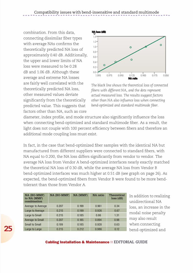
892019 Considerations for Selecting and Using Multimode Fiber
httpslidepdfcomreaderfullconsiderations-for-selecting-and-using-multimode-fiber 2532
Compatibility issues with bend-insensitive and standard multimode
25
Cabling Installation amp Maintenance EDITORIAL GUIDE
combination From this data
connecting dissimilar fiber types
with average NAs confirms the
theoretically predicted NA loss of
approximately 040 dB Additionally
the upper and lower limits of NA
loss were measured to be 028
dB and 106 dB Although these
average and extreme NA losses
are fairly well correlated with the
theoretically predicted NA loss
other measured values deviatesignificantly from the theoretically
predicted value This suggests that
factors other than NA such as core
diameter index profile and mode structure also significantly influence the loss
when connecting bend-optimized and standard multimode fiber As a result the
light does not couple with 100 percent efficiency between fibers and therefore an
additional mode coupling loss must exist
In fact in the case that bend-optimized fiber samples with the identical NA but
manufactured from different suppliers were connected to standard fibers with
NA equal to 0200 the NA loss differs significantly from vendor to vendor The
average NA loss from Vendor A bend-optimized interfaces nearly exactly matched
the theoretical NA loss of 030 dB while the average NA loss from Vendor B
bend-optimized interfaces was much higher at 051 dB (see graph on page 26) As
expected the bend-optimized fibers from Vendor B were found to be more bend-
tolerant than those from Vendor A
In addition to realizing
unidirectional NA
loss an increase in the
modal noise penalty
may also result
when connecting
bend-optimized and
1000 0975 0950 0925 0900 0875 0850
14
12
10
08
06
04
02
00
NA ratio
NA loss (dB)
The black line shows the theoretical loss of connected
fibers with different NA and the dots represent
actual measured loss The results suggest factorsother than NA also influence loss when connecting
bend-optimized and standard multimode fiber
NA (BO-MMF)to NA (MMF)combination
NA (BO-MMF) NA (MMF) NA ratio Theoreticalloss (dB)
Average to Average 0207 0199 0961 034
Large to Average 0215 0199 0926 067
Large to Small 0215 0185 086 131
Average to Small 0207 0185 0894 098
Small to Small 0199 0185 0928 063
Large to Large 0215 0212 0986 012
892019 Considerations for Selecting and Using Multimode Fiber
httpslidepdfcomreaderfullconsiderations-for-selecting-and-using-multimode-fiber 2632
Compatibility issues with bend-insensitive and standard multimode
26
Cabling Installation amp Maintenance EDITORIAL GUIDE
standard multimode fiber Modal noise is a power penalty related to the reduction
in the signal-to-noise ratio (SNR) of the optical signal For high-speed networks
employing VCSELs if a connector selectively attenuates higher-order modes as a
result of NA mismatch or a lateral offset between fiber cores then fluctuations in
the power distribution (spatial speckle pattern) result in fluctuations in connector
insertion loss This fluctuation is seen by the detector as an increase in noise
thereby reducing the SNR and therefore signal quality
The maximum allowed power penalty for modal noise is currently specified
in 10GBase-SR to be 03 dB Both NA loss and mode coupling loss can increase
the mode-selective loss (filter aperture) at a connector interface resulting in an
increase in modal noise Considering the overall power budget for 10G40G100GEthernet is 15 dB (or 10 dB for OM4) any
increase in modal noise may compromise
system reliability
In conclusion inconclusive
As part of our review of how bend-
optimized multimode fiber is integrating
in todayrsquos data center and premises
networks we measured the loss between
bend-insensitive and standard multimode
fibers to quantify the expected additional
loss during certification of mixed-fiber
links These additional losses were
measured to be as high as 1 dB and can
be a significant portion ofndashor even actually
exceedndashthe total optical power budget
for todayrsquos high-speed networks For a channel link that contains several bend-optimized fiber and multimode fiber interfaces which have large NA differences
the NA losses may be additive and further inhibit system certification
Furthermore although NA loss alone is unlikely to detrimentally influence
system performance it may be very difficult if not impossible to determine if
excessive channel loss is due to NA differences or other conventional sources
of loss such as macrobending or dirtydamaged components One strategy to
BO-MMF1
to MMF2
BO-MMF1
to MMF2
BO-MMF1
to MMF2
Vendor A BO-MMF
Vendor B BO-MMF
BO-MMF1
to MMF2
07
06
05
04
03
02
01
00
Measured NA loss (dB)
Bend-optimized fibers from Vendor B shown
here as the blue bars were found to be more
bend-tolerant than the bend-optimized fibers
from Vendor A shown as the green bars
The more-optimized fibers exhibited higher
NA loss
892019 Considerations for Selecting and Using Multimode Fiber
httpslidepdfcomreaderfullconsiderations-for-selecting-and-using-multimode-fiber 2732
Compatibility issues with bend-insensitive and standard multimode
27
Cabling Installation amp Maintenance EDITORIAL GUIDE
account for this loss would be to require bidirectional loss measurements of
individual optical interfaces
During the most recent meeting of the TIA TR-4212 Optical Fibers and Cable
Subcommittee a vigorous debate included many of the topics discussed in this
article and others including increased NA loss mode coupling loss modal
noise (which may negatively impact system performance) the validity of other
standardized fiber test procedures for fiber core diameter fiber bandwidth and
link attenuation (encircled flux) The subcommittee authorized the formation of
a task group to study the technical compatibility of bend-insensitive multimode
fiber with current multimode fiber standards
Based on our internal analysis and the present uncertain position within the
standards community we have concluded that the performance risks of mixing
bend-optimized and standard multimode fiber types in high-speed optical
channel links exceeds any benefit To ensure that total optical loss across data
center and premises networks remains below the allowable limit we recommend
adhering to standards-based radius-control methods and the use of one fiber
type throughout the channel link which includes cabling and patch cords This
approach enables network stakeholders to reliably deploy complex network
architectures meet stringent IL budgets and ensure optimal system performance
within current standards-based network architectures and testing methods
Some manufacturers support this effort others minimize its importance Until
the TIA subcommittee work on these issues is complete we recommend that
these two fiber types should not presently be mixed
Dr Rick Pimpinella is a Distinguished Engineer Bulent Kose is a ResearchEngineer and Dr Brett Lane is a Fiber Research Manager with Panduit
892019 Considerations for Selecting and Using Multimode Fiber
httpslidepdfcomreaderfullconsiderations-for-selecting-and-using-multimode-fiber 2832
As the demand for bandwidth in
enterprise applications such as
data centers continues to
boom new transmission media
must be developed continually
to meet end user requirementsThe latest in optical transmis-
sion media for the enterprise is
called OM4 fiber
OM4 fiber is a 50 micron (microm)
laser-optimized multimode fiber
with extended bandwidth It is
designed to enhance the sys-
tem cost benefits enabled by
850 nm Vertical Cavity Surface
Emitting Lasers (VCSELs) for existing 1 and 10 Gbs applica-
tions as well as future 40 and
100 Gbs systems
Supporting Ethernet Fibre
Channel and OIF applications
OM4 fiber allows extended
reach upwards of 550 meters at
10 Gbs for ultra long building
backbones and medium lengthcampus backbones It offers an
Effective Modal Bandwidth
(EMB) of 4700 MHz-km more
than double the IEEE require-
ment for 10 Gbs 300 meter
support
To help you use this advanced
fiber to its greatest advantage
this paper describes the tech-
nology behind OM4 fiber high-
lights the key differences with
other fiber types and explains
how its high bandwidth is
ensured through stringentmeasurement methods
Multimode Fiber Basics
Compared to single-mode
fibers multimode fibers have
larger cores that as their name
implies guide multiple ldquomodesrdquo
or rays of light simultaneously
Modes that travel at the outside
edge of the core have a longer
distance to go than modes thattravel near the center
The corersquos graded index profile
is designed to slow down
modes that have a shorter dis-
tance to travel so that all modes
arrive at the end of the fiber as
close in time as possible This
minimizes modal dispersion
also known as differential mode
delay (DMD) and maximizes
bandwidth which is the amount
of information that can travel
through the fiber per unit of
time
In addition to their large core
multimode fibers have a large
Numerical Aperture (NA) the
maximum angle at which a fiber
can accept the light that will be
transmitted through it This
allows them to work with rela-
tively low-cost optical compo-
nents and light sources such as
light-emitting diodes (LEDs)and VCSELs
Multimode Fiber Options
Multimode products are identi-
fied by the OM (ldquooptical multi-
moderdquo) designation as outlined
in the ISOIEC 11801 interna-
tional cabling standard (see
table 1)
OM4 - The Next Generation
of Multimode Fiber Tony Irujo
Sales Engineer
OPTICAL FIBER IN ENTERPRISE APPLICATIONS
Table 1 ISOIEC 11801 OM designations
892019 Considerations for Selecting and Using Multimode Fiber
httpslidepdfcomreaderfullconsiderations-for-selecting-and-using-multimode-fiber 2932
OM4 fiber is the latest develop-
ment in this series It is espe-
cially well suited for shorter
reach data center and high per-
formance computing applica-
tions where optical loss budg-
ets are tight at 10 Gbs (and
are expected to get even tighter
at 40 Gbs and 100 Gbs) Thehigh bandwidth provided by
OM4 fiber when deployed at
less than its rated distance
offers extra ldquoheadroomrdquo for
channel insertion loss
OM4 is backward compatible
with applications calling for OFL
bandwidth of at least 500 MHz-
km at 1300 nm (eg FDDI
IEEE 100BASE-FX
1000BASE-LX 10GBASE-LX4
and 10GBASE-LRM)
The latest offerings in multi-
mode fiber are 50 983221m bend
insensitive multimode fibers
(BIMMF) These fibers have
been promoted as offering all
the advantages of high band-
width laser-optimized multi-mode fiber with the added
advantage of lower bend sensi-
tivity
However recent work has
pointed to some areas of con-
cern with these fibers Studies
have identified issues with the
characterization of bend insen-
sitive fibers and questioned
whether current requirements
are adequate to guarantee sys-
tem performance Additional
studies have shown that mating
(connector) loss of BIMMFs
with standard fibers is higher
than with standard fibers con-
nected to each other This addi-
tional loss adds to the total link
loss
It has been proposed that stan-
dards organizations perform a
thorough review of BIMMFs
and incorporate them into
industry standards Until this
work is done some caution is
advised before widespread
adoption takes place
What Makes OM4 Different
Like OM3 multimode fiber OM4
fiber is considered to be ldquolaser-
optimizedrdquo or optimized for use
with VCSEL light sources OM3
and OM4 fibers are designed
and manufactured in such a
way as to get the most perform-
ance out of VCSELs compared
to LEDs That is why laser-opti-
mized fibers are specified using
Laser Bandwidth or EMB
OM2 fiber although compatible
with VCSELs is not considered
to be laser-optimized OM2
fiber is intended for use with
LED sources at speeds of 10 or
100 Mbs or for shorter reach 1
Gbs networks You can use
OM2 fiber with VCSELs but itsperformance is limited to 550
meters at 1 Gbs and only 82
meters at 10 Gbs compared to
OM4 fiberrsquos
reach of over
1000 meters
at 1 Gbs and
550 meters at
10 Gbs
As discussed
the speed at
which each
mode travels
down a multi-
mode fiberrsquos
core depends
on its refrac-
tive index
which is gov-
erned by the amount of chemi-
cal dopant Germanium at that
location in the core Because
modes traveling down the cen-
ter of the core have shorter dis-
tance to travel than those trav-
eling along the edge the refrac-
tive index profile in a multimode
fiber must be ldquogradedrdquo in a par-abolic manner across the core
This slows down the modes
that have a shorter distance to
travel equalizing the arrival
time of all the modes
The better the modes are
equalized the higher the band-
width of the fiber Mode equal-
ization depends on how well
the graded index profile is con-
structed during fiber manufac-
turing The more precise the
refractive index profile is in
terms of shape curvature and
smoothness (free of dips
spikes or defects) the better
the modes will be equalized
(see Figure 2)
OM4 fiber with its higher band-width has an extremely precise
refractive index profile virtually
free of perturbations or defects
Figure 2 A refractive index profile optimized for shape curvature
and smoothness maximizes bandwidth
892019 Considerations for Selecting and Using Multimode Fiber
httpslidepdfcomreaderfullconsiderations-for-selecting-and-using-multimode-fiber 3032
In order to make such a precise
fiber one needs to use a pre-
form manufacturing process
that has exceptional control
over the amount of Germanium
that is incorporated at particular
sub-micron positions within the
fiberrsquos core An example of a
process that lends itself to this
level of control is OFSrsquo propri-
etary MCVD process in which
each layer of the core is
deposited and sintered individu-
ally providing the utmost in
refractive index precision and
uniformity
OM4 Fiber Standards
Two standards define the useof OM4 fiber in high-speed net-
works TIA document TIA-
492AAAD which contains the
OM4 fiber performance specifi-
cations and the IEC 60793-2-
10 international standard which
provides equivalent OM4 speci-
fications under fiber type A1a3
ISOIEC 11801 will add OM4
fiber as an industry-recognized
fiber type and IEEE 8023bafor 40G and 100G Ethernet will
include OM4 fiber as an option
that provides a reach of 150
meters (50 percent greater than
OM3)
There was discussion and
debate within the standards
groups about a minimum OFL
bandwidth requirement at 850nm Although current applica-
tions primarily use 850 nm
VCSEL lasers with fibers that
are specified to a minimum
EMB there was good reason to
also establish a minimum 850
nm OFL bandwidth specifica-
tion It has been shown that
fibers with higher OFL band-
width will perform better with
VCSELs that launch more
power into outer modes That is
why the existing OM3 fiber
standards require a minimum
1500 MHz-km OFL bandwidthat 850 nm
For OM4 fiber OFS and others
in the standards group strongly
recommended at least 3500
MHz-km OFL bandwidth in
order to ensure the utmost per-
formance and reliability ulti-
mately that is the specification
that was agreed upon
Measuring Laser Bandwidth
Bandwidth performance of OM4
fiber is ensured using the same
criteria as OM3 but to much
tighter specifications Due to a
challenge posed when the now-
familiar VCSEL was first intro-
duced new measurement
methods had to be developed
to verify laser bandwidth of OM3 and OM4 fibers
Unlike an LED laser VCSELs
produce an energy output that
is not uniform it can change
sharply across the face of the
output Whatrsquos more each laser
fills a different set of light paths
in each fiber and does so with
differing amounts of power in
each path Overfilled bandwidth
measurements used to meas-
ure LED bandwidth could not
emulate the operation of aVCSEL
The standards allow two ways
to measure and verify laser
bandwidth the DMD Mask
Method and the EMBc Method
Both methods require DMD
testing -- the difference lies in
how the DMD data is used and
interpreted
In DMD testing small high-
powered laser pulses are trans-
mitted through the fiber in tiny
steps across the entire core of
the fiber Only a few modes are
excited at each step and their
arrival times are recorded The
DMD of the fiber is the differ-
ence between the earliest and
the latest arrival times of allmodes at all steps
DMD measurement is currently
the only reliable method for ver-
ifying bandwidth required for 10
Gbs performance because it is
the only method that checks all
modes across the fiber core
independently For that reason
Figure 3 DMD testing measures how different VCSELs fill different modes in each
fiber
892019 Considerations for Selecting and Using Multimode Fiber
httpslidepdfcomreaderfullconsiderations-for-selecting-and-using-multimode-fiber 3132
industry associations such as
TIAEIA and ISOIEC have pub-
lished standards for DMD
measurement and DMD specifi-
cations for laser-optimized mul-
timode fiber
The DMD Mask Method is a
simple process that directlycompares DMD test results
against a set of specifications
(called templates or masks) to
see if the fiber has the neces-
sary performance
This is a straightforward graphi-
cal approach to ensuring the
data pulses do not spread
excessively beyond therequired 10 Gbs bit period If
the fiber passes these DMD
specs then you are assured of
at least 2000 MHz-km EMB no
matter which VCSEL you use
(as long as the VCSEL is com-
pliant)
The EMBc Method is an indi-
rect and more complex
process It takes the DMD
results and matches them
against a set of theoretical
weighting functions that are
intended to represent the
launch distributions of all com-
pliant VCSELs
The DMD results are combined
mathematically with each of the
10 weighting functions This
produces 10 different EMBc
values the lowest of which is
called minEMBc The minEMBc
value is then multiplied by a
factor of 113 to obtain the
fiberrsquos EMB value If this EMB
value is gt 2000 MHz-km thefiber is deemed compliant with
OM3 requirements and there-
fore should support 300 meters
at 10 Gbs
Due to all the complex calcula-
tions required by the EMBc
method and the fact that the
weighting functions only repre-
sent a sampling of the launch
characteristics of the many
VCSELs that could actually be
used in a real system the
EMBc method does not provide
the same scrutiny on fiber qual-
ity and performance as the
DMD Mask technique Whatrsquos
more the EMBc method virtual-ly ignores the center 0 ndash 5 983221m
(radial) region of a fiberrsquos core
because the weighting func-
tions put little emphasis in this
region
Conclusion
OM4 fiber provides next-gener-
ation multimode fiber perform-
ance for today and tomorrowrsquoshigh speed applications With
its significantly higher band-
width network designers and
operators can be assured that
multimode fiber will continue to
provide the most cost effective
solutions for short reach appli-
cations in data centers and
LANs
Copyright copy 2011 Furukawa Electric North America All rights reserved printed in USA
For additional information visit our website at wwwofsopticscomofs-fiber or call 1-888-fiber-
help For regional assistance contact
North America Asia Pacific
Telephone 508-347-8590 Telephone +852 2836 7102
Toll Free 800-799-7732 Fax +852 2836 7101
Fax 508-347-1211 E-mail fibersalesapofsopticscomE-mail fibersalesnarofsopticscom
Caribbean Latin America Japan
Telephone 508-347-8590 Telephone +81-3-3286-3424
Fax 508-347-1211 Fax +81-3-3286-3708 or 3190
E-mail fibersalescalaofsopticscom E-mail fibersalesjapanofsopticscom
Europe Middle East Africa China
Telephone +45-43 48 3736 Telephone +86 10 6505 3660
Fax +45 4348 3444 Fax +86 10 65059515
E-mail ofssalesdkofsopticscom E-mail fibersaleschinaofsopticscom
OFS reserves the right to make changes to the prices
and product(s) described in this document in the
interest of improving internal design operational
function andor reliability
This document is for informational purposes only
and is not intended to modify or supplement any
OFS warranties or specifications relating to any of
its products or services
892019 Considerations for Selecting and Using Multimode Fiber
httpslidepdfcomreaderfullconsiderations-for-selecting-and-using-multimode-fiber 3232
About OFSOFS is a world-leading designer manufacturer and provider of optical fiber
optical fiber cable FTTX optical connectivity and specialty photonics products
Our manufacturing and research divisions work together to provide innovative
products and solutions that traverse many different applications as they linkpeople and machines worldwide Between continents between cities around
neighborhoods and into homes and businesses of digital consumers we provide
the right optical fiber optical cable and components for efficient cost-effective
transmission
OFSrsquo corporate lineage dates back to 1876 and includes technology powerhouses
such as ATampT (NYSE T) and Lucent Technologies (now Alcatel-Lucent NYSE
ALU) Today OFS is owned by Furukawa Electric a multi-billion dollar global
leader in optical communications Headquartered in Norcross (near Atlanta)Georgia US OFS is a global provider with facilities in Avon Connecticut
Carrollton Georgia Somerset New Jersey and Sturbridge Massachusetts as well
as in Denmark Germany and Russia
wwwofsopticscom
LINKS
LaserWavereg Laser-Optimized OM4OM3 Fibers
Multimode or Single-Mode Fiber
Measuring Bandwidth of 10G Laser-optimized Multimode Fiber
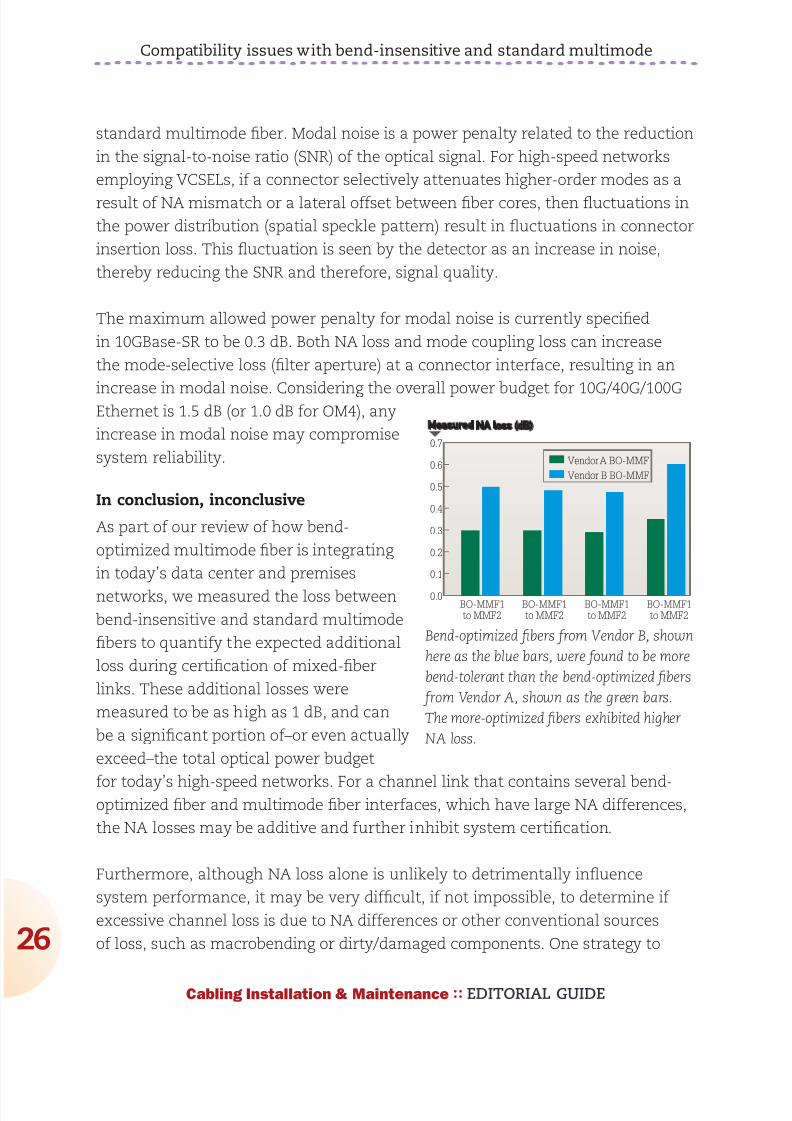
892019 Considerations for Selecting and Using Multimode Fiber
httpslidepdfcomreaderfullconsiderations-for-selecting-and-using-multimode-fiber 2632
Compatibility issues with bend-insensitive and standard multimode
26
Cabling Installation amp Maintenance EDITORIAL GUIDE
standard multimode fiber Modal noise is a power penalty related to the reduction
in the signal-to-noise ratio (SNR) of the optical signal For high-speed networks
employing VCSELs if a connector selectively attenuates higher-order modes as a
result of NA mismatch or a lateral offset between fiber cores then fluctuations in
the power distribution (spatial speckle pattern) result in fluctuations in connector
insertion loss This fluctuation is seen by the detector as an increase in noise
thereby reducing the SNR and therefore signal quality
The maximum allowed power penalty for modal noise is currently specified
in 10GBase-SR to be 03 dB Both NA loss and mode coupling loss can increase
the mode-selective loss (filter aperture) at a connector interface resulting in an
increase in modal noise Considering the overall power budget for 10G40G100GEthernet is 15 dB (or 10 dB for OM4) any
increase in modal noise may compromise
system reliability
In conclusion inconclusive
As part of our review of how bend-
optimized multimode fiber is integrating
in todayrsquos data center and premises
networks we measured the loss between
bend-insensitive and standard multimode
fibers to quantify the expected additional
loss during certification of mixed-fiber
links These additional losses were
measured to be as high as 1 dB and can
be a significant portion ofndashor even actually
exceedndashthe total optical power budget
for todayrsquos high-speed networks For a channel link that contains several bend-optimized fiber and multimode fiber interfaces which have large NA differences
the NA losses may be additive and further inhibit system certification
Furthermore although NA loss alone is unlikely to detrimentally influence
system performance it may be very difficult if not impossible to determine if
excessive channel loss is due to NA differences or other conventional sources
of loss such as macrobending or dirtydamaged components One strategy to
BO-MMF1
to MMF2
BO-MMF1
to MMF2
BO-MMF1
to MMF2
Vendor A BO-MMF
Vendor B BO-MMF
BO-MMF1
to MMF2
07
06
05
04
03
02
01
00
Measured NA loss (dB)
Bend-optimized fibers from Vendor B shown
here as the blue bars were found to be more
bend-tolerant than the bend-optimized fibers
from Vendor A shown as the green bars
The more-optimized fibers exhibited higher
NA loss
892019 Considerations for Selecting and Using Multimode Fiber
httpslidepdfcomreaderfullconsiderations-for-selecting-and-using-multimode-fiber 2732
Compatibility issues with bend-insensitive and standard multimode
27
Cabling Installation amp Maintenance EDITORIAL GUIDE
account for this loss would be to require bidirectional loss measurements of
individual optical interfaces
During the most recent meeting of the TIA TR-4212 Optical Fibers and Cable
Subcommittee a vigorous debate included many of the topics discussed in this
article and others including increased NA loss mode coupling loss modal
noise (which may negatively impact system performance) the validity of other
standardized fiber test procedures for fiber core diameter fiber bandwidth and
link attenuation (encircled flux) The subcommittee authorized the formation of
a task group to study the technical compatibility of bend-insensitive multimode
fiber with current multimode fiber standards
Based on our internal analysis and the present uncertain position within the
standards community we have concluded that the performance risks of mixing
bend-optimized and standard multimode fiber types in high-speed optical
channel links exceeds any benefit To ensure that total optical loss across data
center and premises networks remains below the allowable limit we recommend
adhering to standards-based radius-control methods and the use of one fiber
type throughout the channel link which includes cabling and patch cords This
approach enables network stakeholders to reliably deploy complex network
architectures meet stringent IL budgets and ensure optimal system performance
within current standards-based network architectures and testing methods
Some manufacturers support this effort others minimize its importance Until
the TIA subcommittee work on these issues is complete we recommend that
these two fiber types should not presently be mixed
Dr Rick Pimpinella is a Distinguished Engineer Bulent Kose is a ResearchEngineer and Dr Brett Lane is a Fiber Research Manager with Panduit
892019 Considerations for Selecting and Using Multimode Fiber
httpslidepdfcomreaderfullconsiderations-for-selecting-and-using-multimode-fiber 2832
As the demand for bandwidth in
enterprise applications such as
data centers continues to
boom new transmission media
must be developed continually
to meet end user requirementsThe latest in optical transmis-
sion media for the enterprise is
called OM4 fiber
OM4 fiber is a 50 micron (microm)
laser-optimized multimode fiber
with extended bandwidth It is
designed to enhance the sys-
tem cost benefits enabled by
850 nm Vertical Cavity Surface
Emitting Lasers (VCSELs) for existing 1 and 10 Gbs applica-
tions as well as future 40 and
100 Gbs systems
Supporting Ethernet Fibre
Channel and OIF applications
OM4 fiber allows extended
reach upwards of 550 meters at
10 Gbs for ultra long building
backbones and medium lengthcampus backbones It offers an
Effective Modal Bandwidth
(EMB) of 4700 MHz-km more
than double the IEEE require-
ment for 10 Gbs 300 meter
support
To help you use this advanced
fiber to its greatest advantage
this paper describes the tech-
nology behind OM4 fiber high-
lights the key differences with
other fiber types and explains
how its high bandwidth is
ensured through stringentmeasurement methods
Multimode Fiber Basics
Compared to single-mode
fibers multimode fibers have
larger cores that as their name
implies guide multiple ldquomodesrdquo
or rays of light simultaneously
Modes that travel at the outside
edge of the core have a longer
distance to go than modes thattravel near the center
The corersquos graded index profile
is designed to slow down
modes that have a shorter dis-
tance to travel so that all modes
arrive at the end of the fiber as
close in time as possible This
minimizes modal dispersion
also known as differential mode
delay (DMD) and maximizes
bandwidth which is the amount
of information that can travel
through the fiber per unit of
time
In addition to their large core
multimode fibers have a large
Numerical Aperture (NA) the
maximum angle at which a fiber
can accept the light that will be
transmitted through it This
allows them to work with rela-
tively low-cost optical compo-
nents and light sources such as
light-emitting diodes (LEDs)and VCSELs
Multimode Fiber Options
Multimode products are identi-
fied by the OM (ldquooptical multi-
moderdquo) designation as outlined
in the ISOIEC 11801 interna-
tional cabling standard (see
table 1)
OM4 - The Next Generation
of Multimode Fiber Tony Irujo
Sales Engineer
OPTICAL FIBER IN ENTERPRISE APPLICATIONS
Table 1 ISOIEC 11801 OM designations
892019 Considerations for Selecting and Using Multimode Fiber
httpslidepdfcomreaderfullconsiderations-for-selecting-and-using-multimode-fiber 2932
OM4 fiber is the latest develop-
ment in this series It is espe-
cially well suited for shorter
reach data center and high per-
formance computing applica-
tions where optical loss budg-
ets are tight at 10 Gbs (and
are expected to get even tighter
at 40 Gbs and 100 Gbs) Thehigh bandwidth provided by
OM4 fiber when deployed at
less than its rated distance
offers extra ldquoheadroomrdquo for
channel insertion loss
OM4 is backward compatible
with applications calling for OFL
bandwidth of at least 500 MHz-
km at 1300 nm (eg FDDI
IEEE 100BASE-FX
1000BASE-LX 10GBASE-LX4
and 10GBASE-LRM)
The latest offerings in multi-
mode fiber are 50 983221m bend
insensitive multimode fibers
(BIMMF) These fibers have
been promoted as offering all
the advantages of high band-
width laser-optimized multi-mode fiber with the added
advantage of lower bend sensi-
tivity
However recent work has
pointed to some areas of con-
cern with these fibers Studies
have identified issues with the
characterization of bend insen-
sitive fibers and questioned
whether current requirements
are adequate to guarantee sys-
tem performance Additional
studies have shown that mating
(connector) loss of BIMMFs
with standard fibers is higher
than with standard fibers con-
nected to each other This addi-
tional loss adds to the total link
loss
It has been proposed that stan-
dards organizations perform a
thorough review of BIMMFs
and incorporate them into
industry standards Until this
work is done some caution is
advised before widespread
adoption takes place
What Makes OM4 Different
Like OM3 multimode fiber OM4
fiber is considered to be ldquolaser-
optimizedrdquo or optimized for use
with VCSEL light sources OM3
and OM4 fibers are designed
and manufactured in such a
way as to get the most perform-
ance out of VCSELs compared
to LEDs That is why laser-opti-
mized fibers are specified using
Laser Bandwidth or EMB
OM2 fiber although compatible
with VCSELs is not considered
to be laser-optimized OM2
fiber is intended for use with
LED sources at speeds of 10 or
100 Mbs or for shorter reach 1
Gbs networks You can use
OM2 fiber with VCSELs but itsperformance is limited to 550
meters at 1 Gbs and only 82
meters at 10 Gbs compared to
OM4 fiberrsquos
reach of over
1000 meters
at 1 Gbs and
550 meters at
10 Gbs
As discussed
the speed at
which each
mode travels
down a multi-
mode fiberrsquos
core depends
on its refrac-
tive index
which is gov-
erned by the amount of chemi-
cal dopant Germanium at that
location in the core Because
modes traveling down the cen-
ter of the core have shorter dis-
tance to travel than those trav-
eling along the edge the refrac-
tive index profile in a multimode
fiber must be ldquogradedrdquo in a par-abolic manner across the core
This slows down the modes
that have a shorter distance to
travel equalizing the arrival
time of all the modes
The better the modes are
equalized the higher the band-
width of the fiber Mode equal-
ization depends on how well
the graded index profile is con-
structed during fiber manufac-
turing The more precise the
refractive index profile is in
terms of shape curvature and
smoothness (free of dips
spikes or defects) the better
the modes will be equalized
(see Figure 2)
OM4 fiber with its higher band-width has an extremely precise
refractive index profile virtually
free of perturbations or defects
Figure 2 A refractive index profile optimized for shape curvature
and smoothness maximizes bandwidth
892019 Considerations for Selecting and Using Multimode Fiber
httpslidepdfcomreaderfullconsiderations-for-selecting-and-using-multimode-fiber 3032
In order to make such a precise
fiber one needs to use a pre-
form manufacturing process
that has exceptional control
over the amount of Germanium
that is incorporated at particular
sub-micron positions within the
fiberrsquos core An example of a
process that lends itself to this
level of control is OFSrsquo propri-
etary MCVD process in which
each layer of the core is
deposited and sintered individu-
ally providing the utmost in
refractive index precision and
uniformity
OM4 Fiber Standards
Two standards define the useof OM4 fiber in high-speed net-
works TIA document TIA-
492AAAD which contains the
OM4 fiber performance specifi-
cations and the IEC 60793-2-
10 international standard which
provides equivalent OM4 speci-
fications under fiber type A1a3
ISOIEC 11801 will add OM4
fiber as an industry-recognized
fiber type and IEEE 8023bafor 40G and 100G Ethernet will
include OM4 fiber as an option
that provides a reach of 150
meters (50 percent greater than
OM3)
There was discussion and
debate within the standards
groups about a minimum OFL
bandwidth requirement at 850nm Although current applica-
tions primarily use 850 nm
VCSEL lasers with fibers that
are specified to a minimum
EMB there was good reason to
also establish a minimum 850
nm OFL bandwidth specifica-
tion It has been shown that
fibers with higher OFL band-
width will perform better with
VCSELs that launch more
power into outer modes That is
why the existing OM3 fiber
standards require a minimum
1500 MHz-km OFL bandwidthat 850 nm
For OM4 fiber OFS and others
in the standards group strongly
recommended at least 3500
MHz-km OFL bandwidth in
order to ensure the utmost per-
formance and reliability ulti-
mately that is the specification
that was agreed upon
Measuring Laser Bandwidth
Bandwidth performance of OM4
fiber is ensured using the same
criteria as OM3 but to much
tighter specifications Due to a
challenge posed when the now-
familiar VCSEL was first intro-
duced new measurement
methods had to be developed
to verify laser bandwidth of OM3 and OM4 fibers
Unlike an LED laser VCSELs
produce an energy output that
is not uniform it can change
sharply across the face of the
output Whatrsquos more each laser
fills a different set of light paths
in each fiber and does so with
differing amounts of power in
each path Overfilled bandwidth
measurements used to meas-
ure LED bandwidth could not
emulate the operation of aVCSEL
The standards allow two ways
to measure and verify laser
bandwidth the DMD Mask
Method and the EMBc Method
Both methods require DMD
testing -- the difference lies in
how the DMD data is used and
interpreted
In DMD testing small high-
powered laser pulses are trans-
mitted through the fiber in tiny
steps across the entire core of
the fiber Only a few modes are
excited at each step and their
arrival times are recorded The
DMD of the fiber is the differ-
ence between the earliest and
the latest arrival times of allmodes at all steps
DMD measurement is currently
the only reliable method for ver-
ifying bandwidth required for 10
Gbs performance because it is
the only method that checks all
modes across the fiber core
independently For that reason
Figure 3 DMD testing measures how different VCSELs fill different modes in each
fiber
892019 Considerations for Selecting and Using Multimode Fiber
httpslidepdfcomreaderfullconsiderations-for-selecting-and-using-multimode-fiber 3132
industry associations such as
TIAEIA and ISOIEC have pub-
lished standards for DMD
measurement and DMD specifi-
cations for laser-optimized mul-
timode fiber
The DMD Mask Method is a
simple process that directlycompares DMD test results
against a set of specifications
(called templates or masks) to
see if the fiber has the neces-
sary performance
This is a straightforward graphi-
cal approach to ensuring the
data pulses do not spread
excessively beyond therequired 10 Gbs bit period If
the fiber passes these DMD
specs then you are assured of
at least 2000 MHz-km EMB no
matter which VCSEL you use
(as long as the VCSEL is com-
pliant)
The EMBc Method is an indi-
rect and more complex
process It takes the DMD
results and matches them
against a set of theoretical
weighting functions that are
intended to represent the
launch distributions of all com-
pliant VCSELs
The DMD results are combined
mathematically with each of the
10 weighting functions This
produces 10 different EMBc
values the lowest of which is
called minEMBc The minEMBc
value is then multiplied by a
factor of 113 to obtain the
fiberrsquos EMB value If this EMB
value is gt 2000 MHz-km thefiber is deemed compliant with
OM3 requirements and there-
fore should support 300 meters
at 10 Gbs
Due to all the complex calcula-
tions required by the EMBc
method and the fact that the
weighting functions only repre-
sent a sampling of the launch
characteristics of the many
VCSELs that could actually be
used in a real system the
EMBc method does not provide
the same scrutiny on fiber qual-
ity and performance as the
DMD Mask technique Whatrsquos
more the EMBc method virtual-ly ignores the center 0 ndash 5 983221m
(radial) region of a fiberrsquos core
because the weighting func-
tions put little emphasis in this
region
Conclusion
OM4 fiber provides next-gener-
ation multimode fiber perform-
ance for today and tomorrowrsquoshigh speed applications With
its significantly higher band-
width network designers and
operators can be assured that
multimode fiber will continue to
provide the most cost effective
solutions for short reach appli-
cations in data centers and
LANs
Copyright copy 2011 Furukawa Electric North America All rights reserved printed in USA
For additional information visit our website at wwwofsopticscomofs-fiber or call 1-888-fiber-
help For regional assistance contact
North America Asia Pacific
Telephone 508-347-8590 Telephone +852 2836 7102
Toll Free 800-799-7732 Fax +852 2836 7101
Fax 508-347-1211 E-mail fibersalesapofsopticscomE-mail fibersalesnarofsopticscom
Caribbean Latin America Japan
Telephone 508-347-8590 Telephone +81-3-3286-3424
Fax 508-347-1211 Fax +81-3-3286-3708 or 3190
E-mail fibersalescalaofsopticscom E-mail fibersalesjapanofsopticscom
Europe Middle East Africa China
Telephone +45-43 48 3736 Telephone +86 10 6505 3660
Fax +45 4348 3444 Fax +86 10 65059515
E-mail ofssalesdkofsopticscom E-mail fibersaleschinaofsopticscom
OFS reserves the right to make changes to the prices
and product(s) described in this document in the
interest of improving internal design operational
function andor reliability
This document is for informational purposes only
and is not intended to modify or supplement any
OFS warranties or specifications relating to any of
its products or services
892019 Considerations for Selecting and Using Multimode Fiber
httpslidepdfcomreaderfullconsiderations-for-selecting-and-using-multimode-fiber 3232
About OFSOFS is a world-leading designer manufacturer and provider of optical fiber
optical fiber cable FTTX optical connectivity and specialty photonics products
Our manufacturing and research divisions work together to provide innovative
products and solutions that traverse many different applications as they linkpeople and machines worldwide Between continents between cities around
neighborhoods and into homes and businesses of digital consumers we provide
the right optical fiber optical cable and components for efficient cost-effective
transmission
OFSrsquo corporate lineage dates back to 1876 and includes technology powerhouses
such as ATampT (NYSE T) and Lucent Technologies (now Alcatel-Lucent NYSE
ALU) Today OFS is owned by Furukawa Electric a multi-billion dollar global
leader in optical communications Headquartered in Norcross (near Atlanta)Georgia US OFS is a global provider with facilities in Avon Connecticut
Carrollton Georgia Somerset New Jersey and Sturbridge Massachusetts as well
as in Denmark Germany and Russia
wwwofsopticscom
LINKS
LaserWavereg Laser-Optimized OM4OM3 Fibers
Multimode or Single-Mode Fiber
Measuring Bandwidth of 10G Laser-optimized Multimode Fiber
892019 Considerations for Selecting and Using Multimode Fiber
httpslidepdfcomreaderfullconsiderations-for-selecting-and-using-multimode-fiber 2732
Compatibility issues with bend-insensitive and standard multimode
27
Cabling Installation amp Maintenance EDITORIAL GUIDE
account for this loss would be to require bidirectional loss measurements of
individual optical interfaces
During the most recent meeting of the TIA TR-4212 Optical Fibers and Cable
Subcommittee a vigorous debate included many of the topics discussed in this
article and others including increased NA loss mode coupling loss modal
noise (which may negatively impact system performance) the validity of other
standardized fiber test procedures for fiber core diameter fiber bandwidth and
link attenuation (encircled flux) The subcommittee authorized the formation of
a task group to study the technical compatibility of bend-insensitive multimode
fiber with current multimode fiber standards
Based on our internal analysis and the present uncertain position within the
standards community we have concluded that the performance risks of mixing
bend-optimized and standard multimode fiber types in high-speed optical
channel links exceeds any benefit To ensure that total optical loss across data
center and premises networks remains below the allowable limit we recommend
adhering to standards-based radius-control methods and the use of one fiber
type throughout the channel link which includes cabling and patch cords This
approach enables network stakeholders to reliably deploy complex network
architectures meet stringent IL budgets and ensure optimal system performance
within current standards-based network architectures and testing methods
Some manufacturers support this effort others minimize its importance Until
the TIA subcommittee work on these issues is complete we recommend that
these two fiber types should not presently be mixed
Dr Rick Pimpinella is a Distinguished Engineer Bulent Kose is a ResearchEngineer and Dr Brett Lane is a Fiber Research Manager with Panduit
892019 Considerations for Selecting and Using Multimode Fiber
httpslidepdfcomreaderfullconsiderations-for-selecting-and-using-multimode-fiber 2832
As the demand for bandwidth in
enterprise applications such as
data centers continues to
boom new transmission media
must be developed continually
to meet end user requirementsThe latest in optical transmis-
sion media for the enterprise is
called OM4 fiber
OM4 fiber is a 50 micron (microm)
laser-optimized multimode fiber
with extended bandwidth It is
designed to enhance the sys-
tem cost benefits enabled by
850 nm Vertical Cavity Surface
Emitting Lasers (VCSELs) for existing 1 and 10 Gbs applica-
tions as well as future 40 and
100 Gbs systems
Supporting Ethernet Fibre
Channel and OIF applications
OM4 fiber allows extended
reach upwards of 550 meters at
10 Gbs for ultra long building
backbones and medium lengthcampus backbones It offers an
Effective Modal Bandwidth
(EMB) of 4700 MHz-km more
than double the IEEE require-
ment for 10 Gbs 300 meter
support
To help you use this advanced
fiber to its greatest advantage
this paper describes the tech-
nology behind OM4 fiber high-
lights the key differences with
other fiber types and explains
how its high bandwidth is
ensured through stringentmeasurement methods
Multimode Fiber Basics
Compared to single-mode
fibers multimode fibers have
larger cores that as their name
implies guide multiple ldquomodesrdquo
or rays of light simultaneously
Modes that travel at the outside
edge of the core have a longer
distance to go than modes thattravel near the center
The corersquos graded index profile
is designed to slow down
modes that have a shorter dis-
tance to travel so that all modes
arrive at the end of the fiber as
close in time as possible This
minimizes modal dispersion
also known as differential mode
delay (DMD) and maximizes
bandwidth which is the amount
of information that can travel
through the fiber per unit of
time
In addition to their large core
multimode fibers have a large
Numerical Aperture (NA) the
maximum angle at which a fiber
can accept the light that will be
transmitted through it This
allows them to work with rela-
tively low-cost optical compo-
nents and light sources such as
light-emitting diodes (LEDs)and VCSELs
Multimode Fiber Options
Multimode products are identi-
fied by the OM (ldquooptical multi-
moderdquo) designation as outlined
in the ISOIEC 11801 interna-
tional cabling standard (see
table 1)
OM4 - The Next Generation
of Multimode Fiber Tony Irujo
Sales Engineer
OPTICAL FIBER IN ENTERPRISE APPLICATIONS
Table 1 ISOIEC 11801 OM designations
892019 Considerations for Selecting and Using Multimode Fiber
httpslidepdfcomreaderfullconsiderations-for-selecting-and-using-multimode-fiber 2932
OM4 fiber is the latest develop-
ment in this series It is espe-
cially well suited for shorter
reach data center and high per-
formance computing applica-
tions where optical loss budg-
ets are tight at 10 Gbs (and
are expected to get even tighter
at 40 Gbs and 100 Gbs) Thehigh bandwidth provided by
OM4 fiber when deployed at
less than its rated distance
offers extra ldquoheadroomrdquo for
channel insertion loss
OM4 is backward compatible
with applications calling for OFL
bandwidth of at least 500 MHz-
km at 1300 nm (eg FDDI
IEEE 100BASE-FX
1000BASE-LX 10GBASE-LX4
and 10GBASE-LRM)
The latest offerings in multi-
mode fiber are 50 983221m bend
insensitive multimode fibers
(BIMMF) These fibers have
been promoted as offering all
the advantages of high band-
width laser-optimized multi-mode fiber with the added
advantage of lower bend sensi-
tivity
However recent work has
pointed to some areas of con-
cern with these fibers Studies
have identified issues with the
characterization of bend insen-
sitive fibers and questioned
whether current requirements
are adequate to guarantee sys-
tem performance Additional
studies have shown that mating
(connector) loss of BIMMFs
with standard fibers is higher
than with standard fibers con-
nected to each other This addi-
tional loss adds to the total link
loss
It has been proposed that stan-
dards organizations perform a
thorough review of BIMMFs
and incorporate them into
industry standards Until this
work is done some caution is
advised before widespread
adoption takes place
What Makes OM4 Different
Like OM3 multimode fiber OM4
fiber is considered to be ldquolaser-
optimizedrdquo or optimized for use
with VCSEL light sources OM3
and OM4 fibers are designed
and manufactured in such a
way as to get the most perform-
ance out of VCSELs compared
to LEDs That is why laser-opti-
mized fibers are specified using
Laser Bandwidth or EMB
OM2 fiber although compatible
with VCSELs is not considered
to be laser-optimized OM2
fiber is intended for use with
LED sources at speeds of 10 or
100 Mbs or for shorter reach 1
Gbs networks You can use
OM2 fiber with VCSELs but itsperformance is limited to 550
meters at 1 Gbs and only 82
meters at 10 Gbs compared to
OM4 fiberrsquos
reach of over
1000 meters
at 1 Gbs and
550 meters at
10 Gbs
As discussed
the speed at
which each
mode travels
down a multi-
mode fiberrsquos
core depends
on its refrac-
tive index
which is gov-
erned by the amount of chemi-
cal dopant Germanium at that
location in the core Because
modes traveling down the cen-
ter of the core have shorter dis-
tance to travel than those trav-
eling along the edge the refrac-
tive index profile in a multimode
fiber must be ldquogradedrdquo in a par-abolic manner across the core
This slows down the modes
that have a shorter distance to
travel equalizing the arrival
time of all the modes
The better the modes are
equalized the higher the band-
width of the fiber Mode equal-
ization depends on how well
the graded index profile is con-
structed during fiber manufac-
turing The more precise the
refractive index profile is in
terms of shape curvature and
smoothness (free of dips
spikes or defects) the better
the modes will be equalized
(see Figure 2)
OM4 fiber with its higher band-width has an extremely precise
refractive index profile virtually
free of perturbations or defects
Figure 2 A refractive index profile optimized for shape curvature
and smoothness maximizes bandwidth
892019 Considerations for Selecting and Using Multimode Fiber
httpslidepdfcomreaderfullconsiderations-for-selecting-and-using-multimode-fiber 3032
In order to make such a precise
fiber one needs to use a pre-
form manufacturing process
that has exceptional control
over the amount of Germanium
that is incorporated at particular
sub-micron positions within the
fiberrsquos core An example of a
process that lends itself to this
level of control is OFSrsquo propri-
etary MCVD process in which
each layer of the core is
deposited and sintered individu-
ally providing the utmost in
refractive index precision and
uniformity
OM4 Fiber Standards
Two standards define the useof OM4 fiber in high-speed net-
works TIA document TIA-
492AAAD which contains the
OM4 fiber performance specifi-
cations and the IEC 60793-2-
10 international standard which
provides equivalent OM4 speci-
fications under fiber type A1a3
ISOIEC 11801 will add OM4
fiber as an industry-recognized
fiber type and IEEE 8023bafor 40G and 100G Ethernet will
include OM4 fiber as an option
that provides a reach of 150
meters (50 percent greater than
OM3)
There was discussion and
debate within the standards
groups about a minimum OFL
bandwidth requirement at 850nm Although current applica-
tions primarily use 850 nm
VCSEL lasers with fibers that
are specified to a minimum
EMB there was good reason to
also establish a minimum 850
nm OFL bandwidth specifica-
tion It has been shown that
fibers with higher OFL band-
width will perform better with
VCSELs that launch more
power into outer modes That is
why the existing OM3 fiber
standards require a minimum
1500 MHz-km OFL bandwidthat 850 nm
For OM4 fiber OFS and others
in the standards group strongly
recommended at least 3500
MHz-km OFL bandwidth in
order to ensure the utmost per-
formance and reliability ulti-
mately that is the specification
that was agreed upon
Measuring Laser Bandwidth
Bandwidth performance of OM4
fiber is ensured using the same
criteria as OM3 but to much
tighter specifications Due to a
challenge posed when the now-
familiar VCSEL was first intro-
duced new measurement
methods had to be developed
to verify laser bandwidth of OM3 and OM4 fibers
Unlike an LED laser VCSELs
produce an energy output that
is not uniform it can change
sharply across the face of the
output Whatrsquos more each laser
fills a different set of light paths
in each fiber and does so with
differing amounts of power in
each path Overfilled bandwidth
measurements used to meas-
ure LED bandwidth could not
emulate the operation of aVCSEL
The standards allow two ways
to measure and verify laser
bandwidth the DMD Mask
Method and the EMBc Method
Both methods require DMD
testing -- the difference lies in
how the DMD data is used and
interpreted
In DMD testing small high-
powered laser pulses are trans-
mitted through the fiber in tiny
steps across the entire core of
the fiber Only a few modes are
excited at each step and their
arrival times are recorded The
DMD of the fiber is the differ-
ence between the earliest and
the latest arrival times of allmodes at all steps
DMD measurement is currently
the only reliable method for ver-
ifying bandwidth required for 10
Gbs performance because it is
the only method that checks all
modes across the fiber core
independently For that reason
Figure 3 DMD testing measures how different VCSELs fill different modes in each
fiber
892019 Considerations for Selecting and Using Multimode Fiber
httpslidepdfcomreaderfullconsiderations-for-selecting-and-using-multimode-fiber 3132
industry associations such as
TIAEIA and ISOIEC have pub-
lished standards for DMD
measurement and DMD specifi-
cations for laser-optimized mul-
timode fiber
The DMD Mask Method is a
simple process that directlycompares DMD test results
against a set of specifications
(called templates or masks) to
see if the fiber has the neces-
sary performance
This is a straightforward graphi-
cal approach to ensuring the
data pulses do not spread
excessively beyond therequired 10 Gbs bit period If
the fiber passes these DMD
specs then you are assured of
at least 2000 MHz-km EMB no
matter which VCSEL you use
(as long as the VCSEL is com-
pliant)
The EMBc Method is an indi-
rect and more complex
process It takes the DMD
results and matches them
against a set of theoretical
weighting functions that are
intended to represent the
launch distributions of all com-
pliant VCSELs
The DMD results are combined
mathematically with each of the
10 weighting functions This
produces 10 different EMBc
values the lowest of which is
called minEMBc The minEMBc
value is then multiplied by a
factor of 113 to obtain the
fiberrsquos EMB value If this EMB
value is gt 2000 MHz-km thefiber is deemed compliant with
OM3 requirements and there-
fore should support 300 meters
at 10 Gbs
Due to all the complex calcula-
tions required by the EMBc
method and the fact that the
weighting functions only repre-
sent a sampling of the launch
characteristics of the many
VCSELs that could actually be
used in a real system the
EMBc method does not provide
the same scrutiny on fiber qual-
ity and performance as the
DMD Mask technique Whatrsquos
more the EMBc method virtual-ly ignores the center 0 ndash 5 983221m
(radial) region of a fiberrsquos core
because the weighting func-
tions put little emphasis in this
region
Conclusion
OM4 fiber provides next-gener-
ation multimode fiber perform-
ance for today and tomorrowrsquoshigh speed applications With
its significantly higher band-
width network designers and
operators can be assured that
multimode fiber will continue to
provide the most cost effective
solutions for short reach appli-
cations in data centers and
LANs
Copyright copy 2011 Furukawa Electric North America All rights reserved printed in USA
For additional information visit our website at wwwofsopticscomofs-fiber or call 1-888-fiber-
help For regional assistance contact
North America Asia Pacific
Telephone 508-347-8590 Telephone +852 2836 7102
Toll Free 800-799-7732 Fax +852 2836 7101
Fax 508-347-1211 E-mail fibersalesapofsopticscomE-mail fibersalesnarofsopticscom
Caribbean Latin America Japan
Telephone 508-347-8590 Telephone +81-3-3286-3424
Fax 508-347-1211 Fax +81-3-3286-3708 or 3190
E-mail fibersalescalaofsopticscom E-mail fibersalesjapanofsopticscom
Europe Middle East Africa China
Telephone +45-43 48 3736 Telephone +86 10 6505 3660
Fax +45 4348 3444 Fax +86 10 65059515
E-mail ofssalesdkofsopticscom E-mail fibersaleschinaofsopticscom
OFS reserves the right to make changes to the prices
and product(s) described in this document in the
interest of improving internal design operational
function andor reliability
This document is for informational purposes only
and is not intended to modify or supplement any
OFS warranties or specifications relating to any of
its products or services
892019 Considerations for Selecting and Using Multimode Fiber
httpslidepdfcomreaderfullconsiderations-for-selecting-and-using-multimode-fiber 3232
About OFSOFS is a world-leading designer manufacturer and provider of optical fiber
optical fiber cable FTTX optical connectivity and specialty photonics products
Our manufacturing and research divisions work together to provide innovative
products and solutions that traverse many different applications as they linkpeople and machines worldwide Between continents between cities around
neighborhoods and into homes and businesses of digital consumers we provide
the right optical fiber optical cable and components for efficient cost-effective
transmission
OFSrsquo corporate lineage dates back to 1876 and includes technology powerhouses
such as ATampT (NYSE T) and Lucent Technologies (now Alcatel-Lucent NYSE
ALU) Today OFS is owned by Furukawa Electric a multi-billion dollar global
leader in optical communications Headquartered in Norcross (near Atlanta)Georgia US OFS is a global provider with facilities in Avon Connecticut
Carrollton Georgia Somerset New Jersey and Sturbridge Massachusetts as well
as in Denmark Germany and Russia
wwwofsopticscom
LINKS
LaserWavereg Laser-Optimized OM4OM3 Fibers
Multimode or Single-Mode Fiber
Measuring Bandwidth of 10G Laser-optimized Multimode Fiber

892019 Considerations for Selecting and Using Multimode Fiber
httpslidepdfcomreaderfullconsiderations-for-selecting-and-using-multimode-fiber 2832
As the demand for bandwidth in
enterprise applications such as
data centers continues to
boom new transmission media
must be developed continually
to meet end user requirementsThe latest in optical transmis-
sion media for the enterprise is
called OM4 fiber
OM4 fiber is a 50 micron (microm)
laser-optimized multimode fiber
with extended bandwidth It is
designed to enhance the sys-
tem cost benefits enabled by
850 nm Vertical Cavity Surface
Emitting Lasers (VCSELs) for existing 1 and 10 Gbs applica-
tions as well as future 40 and
100 Gbs systems
Supporting Ethernet Fibre
Channel and OIF applications
OM4 fiber allows extended
reach upwards of 550 meters at
10 Gbs for ultra long building
backbones and medium lengthcampus backbones It offers an
Effective Modal Bandwidth
(EMB) of 4700 MHz-km more
than double the IEEE require-
ment for 10 Gbs 300 meter
support
To help you use this advanced
fiber to its greatest advantage
this paper describes the tech-
nology behind OM4 fiber high-
lights the key differences with
other fiber types and explains
how its high bandwidth is
ensured through stringentmeasurement methods
Multimode Fiber Basics
Compared to single-mode
fibers multimode fibers have
larger cores that as their name
implies guide multiple ldquomodesrdquo
or rays of light simultaneously
Modes that travel at the outside
edge of the core have a longer
distance to go than modes thattravel near the center
The corersquos graded index profile
is designed to slow down
modes that have a shorter dis-
tance to travel so that all modes
arrive at the end of the fiber as
close in time as possible This
minimizes modal dispersion
also known as differential mode
delay (DMD) and maximizes
bandwidth which is the amount
of information that can travel
through the fiber per unit of
time
In addition to their large core
multimode fibers have a large
Numerical Aperture (NA) the
maximum angle at which a fiber
can accept the light that will be
transmitted through it This
allows them to work with rela-
tively low-cost optical compo-
nents and light sources such as
light-emitting diodes (LEDs)and VCSELs
Multimode Fiber Options
Multimode products are identi-
fied by the OM (ldquooptical multi-
moderdquo) designation as outlined
in the ISOIEC 11801 interna-
tional cabling standard (see
table 1)
OM4 - The Next Generation
of Multimode Fiber Tony Irujo
Sales Engineer
OPTICAL FIBER IN ENTERPRISE APPLICATIONS
Table 1 ISOIEC 11801 OM designations
892019 Considerations for Selecting and Using Multimode Fiber
httpslidepdfcomreaderfullconsiderations-for-selecting-and-using-multimode-fiber 2932
OM4 fiber is the latest develop-
ment in this series It is espe-
cially well suited for shorter
reach data center and high per-
formance computing applica-
tions where optical loss budg-
ets are tight at 10 Gbs (and
are expected to get even tighter
at 40 Gbs and 100 Gbs) Thehigh bandwidth provided by
OM4 fiber when deployed at
less than its rated distance
offers extra ldquoheadroomrdquo for
channel insertion loss
OM4 is backward compatible
with applications calling for OFL
bandwidth of at least 500 MHz-
km at 1300 nm (eg FDDI
IEEE 100BASE-FX
1000BASE-LX 10GBASE-LX4
and 10GBASE-LRM)
The latest offerings in multi-
mode fiber are 50 983221m bend
insensitive multimode fibers
(BIMMF) These fibers have
been promoted as offering all
the advantages of high band-
width laser-optimized multi-mode fiber with the added
advantage of lower bend sensi-
tivity
However recent work has
pointed to some areas of con-
cern with these fibers Studies
have identified issues with the
characterization of bend insen-
sitive fibers and questioned
whether current requirements
are adequate to guarantee sys-
tem performance Additional
studies have shown that mating
(connector) loss of BIMMFs
with standard fibers is higher
than with standard fibers con-
nected to each other This addi-
tional loss adds to the total link
loss
It has been proposed that stan-
dards organizations perform a
thorough review of BIMMFs
and incorporate them into
industry standards Until this
work is done some caution is
advised before widespread
adoption takes place
What Makes OM4 Different
Like OM3 multimode fiber OM4
fiber is considered to be ldquolaser-
optimizedrdquo or optimized for use
with VCSEL light sources OM3
and OM4 fibers are designed
and manufactured in such a
way as to get the most perform-
ance out of VCSELs compared
to LEDs That is why laser-opti-
mized fibers are specified using
Laser Bandwidth or EMB
OM2 fiber although compatible
with VCSELs is not considered
to be laser-optimized OM2
fiber is intended for use with
LED sources at speeds of 10 or
100 Mbs or for shorter reach 1
Gbs networks You can use
OM2 fiber with VCSELs but itsperformance is limited to 550
meters at 1 Gbs and only 82
meters at 10 Gbs compared to
OM4 fiberrsquos
reach of over
1000 meters
at 1 Gbs and
550 meters at
10 Gbs
As discussed
the speed at
which each
mode travels
down a multi-
mode fiberrsquos
core depends
on its refrac-
tive index
which is gov-
erned by the amount of chemi-
cal dopant Germanium at that
location in the core Because
modes traveling down the cen-
ter of the core have shorter dis-
tance to travel than those trav-
eling along the edge the refrac-
tive index profile in a multimode
fiber must be ldquogradedrdquo in a par-abolic manner across the core
This slows down the modes
that have a shorter distance to
travel equalizing the arrival
time of all the modes
The better the modes are
equalized the higher the band-
width of the fiber Mode equal-
ization depends on how well
the graded index profile is con-
structed during fiber manufac-
turing The more precise the
refractive index profile is in
terms of shape curvature and
smoothness (free of dips
spikes or defects) the better
the modes will be equalized
(see Figure 2)
OM4 fiber with its higher band-width has an extremely precise
refractive index profile virtually
free of perturbations or defects
Figure 2 A refractive index profile optimized for shape curvature
and smoothness maximizes bandwidth
892019 Considerations for Selecting and Using Multimode Fiber
httpslidepdfcomreaderfullconsiderations-for-selecting-and-using-multimode-fiber 3032
In order to make such a precise
fiber one needs to use a pre-
form manufacturing process
that has exceptional control
over the amount of Germanium
that is incorporated at particular
sub-micron positions within the
fiberrsquos core An example of a
process that lends itself to this
level of control is OFSrsquo propri-
etary MCVD process in which
each layer of the core is
deposited and sintered individu-
ally providing the utmost in
refractive index precision and
uniformity
OM4 Fiber Standards
Two standards define the useof OM4 fiber in high-speed net-
works TIA document TIA-
492AAAD which contains the
OM4 fiber performance specifi-
cations and the IEC 60793-2-
10 international standard which
provides equivalent OM4 speci-
fications under fiber type A1a3
ISOIEC 11801 will add OM4
fiber as an industry-recognized
fiber type and IEEE 8023bafor 40G and 100G Ethernet will
include OM4 fiber as an option
that provides a reach of 150
meters (50 percent greater than
OM3)
There was discussion and
debate within the standards
groups about a minimum OFL
bandwidth requirement at 850nm Although current applica-
tions primarily use 850 nm
VCSEL lasers with fibers that
are specified to a minimum
EMB there was good reason to
also establish a minimum 850
nm OFL bandwidth specifica-
tion It has been shown that
fibers with higher OFL band-
width will perform better with
VCSELs that launch more
power into outer modes That is
why the existing OM3 fiber
standards require a minimum
1500 MHz-km OFL bandwidthat 850 nm
For OM4 fiber OFS and others
in the standards group strongly
recommended at least 3500
MHz-km OFL bandwidth in
order to ensure the utmost per-
formance and reliability ulti-
mately that is the specification
that was agreed upon
Measuring Laser Bandwidth
Bandwidth performance of OM4
fiber is ensured using the same
criteria as OM3 but to much
tighter specifications Due to a
challenge posed when the now-
familiar VCSEL was first intro-
duced new measurement
methods had to be developed
to verify laser bandwidth of OM3 and OM4 fibers
Unlike an LED laser VCSELs
produce an energy output that
is not uniform it can change
sharply across the face of the
output Whatrsquos more each laser
fills a different set of light paths
in each fiber and does so with
differing amounts of power in
each path Overfilled bandwidth
measurements used to meas-
ure LED bandwidth could not
emulate the operation of aVCSEL
The standards allow two ways
to measure and verify laser
bandwidth the DMD Mask
Method and the EMBc Method
Both methods require DMD
testing -- the difference lies in
how the DMD data is used and
interpreted
In DMD testing small high-
powered laser pulses are trans-
mitted through the fiber in tiny
steps across the entire core of
the fiber Only a few modes are
excited at each step and their
arrival times are recorded The
DMD of the fiber is the differ-
ence between the earliest and
the latest arrival times of allmodes at all steps
DMD measurement is currently
the only reliable method for ver-
ifying bandwidth required for 10
Gbs performance because it is
the only method that checks all
modes across the fiber core
independently For that reason
Figure 3 DMD testing measures how different VCSELs fill different modes in each
fiber
892019 Considerations for Selecting and Using Multimode Fiber
httpslidepdfcomreaderfullconsiderations-for-selecting-and-using-multimode-fiber 3132
industry associations such as
TIAEIA and ISOIEC have pub-
lished standards for DMD
measurement and DMD specifi-
cations for laser-optimized mul-
timode fiber
The DMD Mask Method is a
simple process that directlycompares DMD test results
against a set of specifications
(called templates or masks) to
see if the fiber has the neces-
sary performance
This is a straightforward graphi-
cal approach to ensuring the
data pulses do not spread
excessively beyond therequired 10 Gbs bit period If
the fiber passes these DMD
specs then you are assured of
at least 2000 MHz-km EMB no
matter which VCSEL you use
(as long as the VCSEL is com-
pliant)
The EMBc Method is an indi-
rect and more complex
process It takes the DMD
results and matches them
against a set of theoretical
weighting functions that are
intended to represent the
launch distributions of all com-
pliant VCSELs
The DMD results are combined
mathematically with each of the
10 weighting functions This
produces 10 different EMBc
values the lowest of which is
called minEMBc The minEMBc
value is then multiplied by a
factor of 113 to obtain the
fiberrsquos EMB value If this EMB
value is gt 2000 MHz-km thefiber is deemed compliant with
OM3 requirements and there-
fore should support 300 meters
at 10 Gbs
Due to all the complex calcula-
tions required by the EMBc
method and the fact that the
weighting functions only repre-
sent a sampling of the launch
characteristics of the many
VCSELs that could actually be
used in a real system the
EMBc method does not provide
the same scrutiny on fiber qual-
ity and performance as the
DMD Mask technique Whatrsquos
more the EMBc method virtual-ly ignores the center 0 ndash 5 983221m
(radial) region of a fiberrsquos core
because the weighting func-
tions put little emphasis in this
region
Conclusion
OM4 fiber provides next-gener-
ation multimode fiber perform-
ance for today and tomorrowrsquoshigh speed applications With
its significantly higher band-
width network designers and
operators can be assured that
multimode fiber will continue to
provide the most cost effective
solutions for short reach appli-
cations in data centers and
LANs
Copyright copy 2011 Furukawa Electric North America All rights reserved printed in USA
For additional information visit our website at wwwofsopticscomofs-fiber or call 1-888-fiber-
help For regional assistance contact
North America Asia Pacific
Telephone 508-347-8590 Telephone +852 2836 7102
Toll Free 800-799-7732 Fax +852 2836 7101
Fax 508-347-1211 E-mail fibersalesapofsopticscomE-mail fibersalesnarofsopticscom
Caribbean Latin America Japan
Telephone 508-347-8590 Telephone +81-3-3286-3424
Fax 508-347-1211 Fax +81-3-3286-3708 or 3190
E-mail fibersalescalaofsopticscom E-mail fibersalesjapanofsopticscom
Europe Middle East Africa China
Telephone +45-43 48 3736 Telephone +86 10 6505 3660
Fax +45 4348 3444 Fax +86 10 65059515
E-mail ofssalesdkofsopticscom E-mail fibersaleschinaofsopticscom
OFS reserves the right to make changes to the prices
and product(s) described in this document in the
interest of improving internal design operational
function andor reliability
This document is for informational purposes only
and is not intended to modify or supplement any
OFS warranties or specifications relating to any of
its products or services
892019 Considerations for Selecting and Using Multimode Fiber
httpslidepdfcomreaderfullconsiderations-for-selecting-and-using-multimode-fiber 3232
About OFSOFS is a world-leading designer manufacturer and provider of optical fiber
optical fiber cable FTTX optical connectivity and specialty photonics products
Our manufacturing and research divisions work together to provide innovative
products and solutions that traverse many different applications as they linkpeople and machines worldwide Between continents between cities around
neighborhoods and into homes and businesses of digital consumers we provide
the right optical fiber optical cable and components for efficient cost-effective
transmission
OFSrsquo corporate lineage dates back to 1876 and includes technology powerhouses
such as ATampT (NYSE T) and Lucent Technologies (now Alcatel-Lucent NYSE
ALU) Today OFS is owned by Furukawa Electric a multi-billion dollar global
leader in optical communications Headquartered in Norcross (near Atlanta)Georgia US OFS is a global provider with facilities in Avon Connecticut
Carrollton Georgia Somerset New Jersey and Sturbridge Massachusetts as well
as in Denmark Germany and Russia
wwwofsopticscom
LINKS
LaserWavereg Laser-Optimized OM4OM3 Fibers
Multimode or Single-Mode Fiber
Measuring Bandwidth of 10G Laser-optimized Multimode Fiber
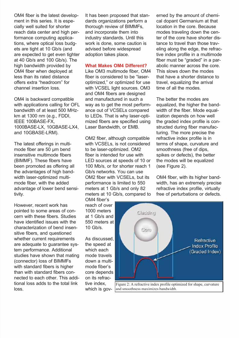
892019 Considerations for Selecting and Using Multimode Fiber
httpslidepdfcomreaderfullconsiderations-for-selecting-and-using-multimode-fiber 2932
OM4 fiber is the latest develop-
ment in this series It is espe-
cially well suited for shorter
reach data center and high per-
formance computing applica-
tions where optical loss budg-
ets are tight at 10 Gbs (and
are expected to get even tighter
at 40 Gbs and 100 Gbs) Thehigh bandwidth provided by
OM4 fiber when deployed at
less than its rated distance
offers extra ldquoheadroomrdquo for
channel insertion loss
OM4 is backward compatible
with applications calling for OFL
bandwidth of at least 500 MHz-
km at 1300 nm (eg FDDI
IEEE 100BASE-FX
1000BASE-LX 10GBASE-LX4
and 10GBASE-LRM)
The latest offerings in multi-
mode fiber are 50 983221m bend
insensitive multimode fibers
(BIMMF) These fibers have
been promoted as offering all
the advantages of high band-
width laser-optimized multi-mode fiber with the added
advantage of lower bend sensi-
tivity
However recent work has
pointed to some areas of con-
cern with these fibers Studies
have identified issues with the
characterization of bend insen-
sitive fibers and questioned
whether current requirements
are adequate to guarantee sys-
tem performance Additional
studies have shown that mating
(connector) loss of BIMMFs
with standard fibers is higher
than with standard fibers con-
nected to each other This addi-
tional loss adds to the total link
loss
It has been proposed that stan-
dards organizations perform a
thorough review of BIMMFs
and incorporate them into
industry standards Until this
work is done some caution is
advised before widespread
adoption takes place
What Makes OM4 Different
Like OM3 multimode fiber OM4
fiber is considered to be ldquolaser-
optimizedrdquo or optimized for use
with VCSEL light sources OM3
and OM4 fibers are designed
and manufactured in such a
way as to get the most perform-
ance out of VCSELs compared
to LEDs That is why laser-opti-
mized fibers are specified using
Laser Bandwidth or EMB
OM2 fiber although compatible
with VCSELs is not considered
to be laser-optimized OM2
fiber is intended for use with
LED sources at speeds of 10 or
100 Mbs or for shorter reach 1
Gbs networks You can use
OM2 fiber with VCSELs but itsperformance is limited to 550
meters at 1 Gbs and only 82
meters at 10 Gbs compared to
OM4 fiberrsquos
reach of over
1000 meters
at 1 Gbs and
550 meters at
10 Gbs
As discussed
the speed at
which each
mode travels
down a multi-
mode fiberrsquos
core depends
on its refrac-
tive index
which is gov-
erned by the amount of chemi-
cal dopant Germanium at that
location in the core Because
modes traveling down the cen-
ter of the core have shorter dis-
tance to travel than those trav-
eling along the edge the refrac-
tive index profile in a multimode
fiber must be ldquogradedrdquo in a par-abolic manner across the core
This slows down the modes
that have a shorter distance to
travel equalizing the arrival
time of all the modes
The better the modes are
equalized the higher the band-
width of the fiber Mode equal-
ization depends on how well
the graded index profile is con-
structed during fiber manufac-
turing The more precise the
refractive index profile is in
terms of shape curvature and
smoothness (free of dips
spikes or defects) the better
the modes will be equalized
(see Figure 2)
OM4 fiber with its higher band-width has an extremely precise
refractive index profile virtually
free of perturbations or defects
Figure 2 A refractive index profile optimized for shape curvature
and smoothness maximizes bandwidth
892019 Considerations for Selecting and Using Multimode Fiber
httpslidepdfcomreaderfullconsiderations-for-selecting-and-using-multimode-fiber 3032
In order to make such a precise
fiber one needs to use a pre-
form manufacturing process
that has exceptional control
over the amount of Germanium
that is incorporated at particular
sub-micron positions within the
fiberrsquos core An example of a
process that lends itself to this
level of control is OFSrsquo propri-
etary MCVD process in which
each layer of the core is
deposited and sintered individu-
ally providing the utmost in
refractive index precision and
uniformity
OM4 Fiber Standards
Two standards define the useof OM4 fiber in high-speed net-
works TIA document TIA-
492AAAD which contains the
OM4 fiber performance specifi-
cations and the IEC 60793-2-
10 international standard which
provides equivalent OM4 speci-
fications under fiber type A1a3
ISOIEC 11801 will add OM4
fiber as an industry-recognized
fiber type and IEEE 8023bafor 40G and 100G Ethernet will
include OM4 fiber as an option
that provides a reach of 150
meters (50 percent greater than
OM3)
There was discussion and
debate within the standards
groups about a minimum OFL
bandwidth requirement at 850nm Although current applica-
tions primarily use 850 nm
VCSEL lasers with fibers that
are specified to a minimum
EMB there was good reason to
also establish a minimum 850
nm OFL bandwidth specifica-
tion It has been shown that
fibers with higher OFL band-
width will perform better with
VCSELs that launch more
power into outer modes That is
why the existing OM3 fiber
standards require a minimum
1500 MHz-km OFL bandwidthat 850 nm
For OM4 fiber OFS and others
in the standards group strongly
recommended at least 3500
MHz-km OFL bandwidth in
order to ensure the utmost per-
formance and reliability ulti-
mately that is the specification
that was agreed upon
Measuring Laser Bandwidth
Bandwidth performance of OM4
fiber is ensured using the same
criteria as OM3 but to much
tighter specifications Due to a
challenge posed when the now-
familiar VCSEL was first intro-
duced new measurement
methods had to be developed
to verify laser bandwidth of OM3 and OM4 fibers
Unlike an LED laser VCSELs
produce an energy output that
is not uniform it can change
sharply across the face of the
output Whatrsquos more each laser
fills a different set of light paths
in each fiber and does so with
differing amounts of power in
each path Overfilled bandwidth
measurements used to meas-
ure LED bandwidth could not
emulate the operation of aVCSEL
The standards allow two ways
to measure and verify laser
bandwidth the DMD Mask
Method and the EMBc Method
Both methods require DMD
testing -- the difference lies in
how the DMD data is used and
interpreted
In DMD testing small high-
powered laser pulses are trans-
mitted through the fiber in tiny
steps across the entire core of
the fiber Only a few modes are
excited at each step and their
arrival times are recorded The
DMD of the fiber is the differ-
ence between the earliest and
the latest arrival times of allmodes at all steps
DMD measurement is currently
the only reliable method for ver-
ifying bandwidth required for 10
Gbs performance because it is
the only method that checks all
modes across the fiber core
independently For that reason
Figure 3 DMD testing measures how different VCSELs fill different modes in each
fiber
892019 Considerations for Selecting and Using Multimode Fiber
httpslidepdfcomreaderfullconsiderations-for-selecting-and-using-multimode-fiber 3132
industry associations such as
TIAEIA and ISOIEC have pub-
lished standards for DMD
measurement and DMD specifi-
cations for laser-optimized mul-
timode fiber
The DMD Mask Method is a
simple process that directlycompares DMD test results
against a set of specifications
(called templates or masks) to
see if the fiber has the neces-
sary performance
This is a straightforward graphi-
cal approach to ensuring the
data pulses do not spread
excessively beyond therequired 10 Gbs bit period If
the fiber passes these DMD
specs then you are assured of
at least 2000 MHz-km EMB no
matter which VCSEL you use
(as long as the VCSEL is com-
pliant)
The EMBc Method is an indi-
rect and more complex
process It takes the DMD
results and matches them
against a set of theoretical
weighting functions that are
intended to represent the
launch distributions of all com-
pliant VCSELs
The DMD results are combined
mathematically with each of the
10 weighting functions This
produces 10 different EMBc
values the lowest of which is
called minEMBc The minEMBc
value is then multiplied by a
factor of 113 to obtain the
fiberrsquos EMB value If this EMB
value is gt 2000 MHz-km thefiber is deemed compliant with
OM3 requirements and there-
fore should support 300 meters
at 10 Gbs
Due to all the complex calcula-
tions required by the EMBc
method and the fact that the
weighting functions only repre-
sent a sampling of the launch
characteristics of the many
VCSELs that could actually be
used in a real system the
EMBc method does not provide
the same scrutiny on fiber qual-
ity and performance as the
DMD Mask technique Whatrsquos
more the EMBc method virtual-ly ignores the center 0 ndash 5 983221m
(radial) region of a fiberrsquos core
because the weighting func-
tions put little emphasis in this
region
Conclusion
OM4 fiber provides next-gener-
ation multimode fiber perform-
ance for today and tomorrowrsquoshigh speed applications With
its significantly higher band-
width network designers and
operators can be assured that
multimode fiber will continue to
provide the most cost effective
solutions for short reach appli-
cations in data centers and
LANs
Copyright copy 2011 Furukawa Electric North America All rights reserved printed in USA
For additional information visit our website at wwwofsopticscomofs-fiber or call 1-888-fiber-
help For regional assistance contact
North America Asia Pacific
Telephone 508-347-8590 Telephone +852 2836 7102
Toll Free 800-799-7732 Fax +852 2836 7101
Fax 508-347-1211 E-mail fibersalesapofsopticscomE-mail fibersalesnarofsopticscom
Caribbean Latin America Japan
Telephone 508-347-8590 Telephone +81-3-3286-3424
Fax 508-347-1211 Fax +81-3-3286-3708 or 3190
E-mail fibersalescalaofsopticscom E-mail fibersalesjapanofsopticscom
Europe Middle East Africa China
Telephone +45-43 48 3736 Telephone +86 10 6505 3660
Fax +45 4348 3444 Fax +86 10 65059515
E-mail ofssalesdkofsopticscom E-mail fibersaleschinaofsopticscom
OFS reserves the right to make changes to the prices
and product(s) described in this document in the
interest of improving internal design operational
function andor reliability
This document is for informational purposes only
and is not intended to modify or supplement any
OFS warranties or specifications relating to any of
its products or services
892019 Considerations for Selecting and Using Multimode Fiber
httpslidepdfcomreaderfullconsiderations-for-selecting-and-using-multimode-fiber 3232
About OFSOFS is a world-leading designer manufacturer and provider of optical fiber
optical fiber cable FTTX optical connectivity and specialty photonics products
Our manufacturing and research divisions work together to provide innovative
products and solutions that traverse many different applications as they linkpeople and machines worldwide Between continents between cities around
neighborhoods and into homes and businesses of digital consumers we provide
the right optical fiber optical cable and components for efficient cost-effective
transmission
OFSrsquo corporate lineage dates back to 1876 and includes technology powerhouses
such as ATampT (NYSE T) and Lucent Technologies (now Alcatel-Lucent NYSE
ALU) Today OFS is owned by Furukawa Electric a multi-billion dollar global
leader in optical communications Headquartered in Norcross (near Atlanta)Georgia US OFS is a global provider with facilities in Avon Connecticut
Carrollton Georgia Somerset New Jersey and Sturbridge Massachusetts as well
as in Denmark Germany and Russia
wwwofsopticscom
LINKS
LaserWavereg Laser-Optimized OM4OM3 Fibers
Multimode or Single-Mode Fiber
Measuring Bandwidth of 10G Laser-optimized Multimode Fiber
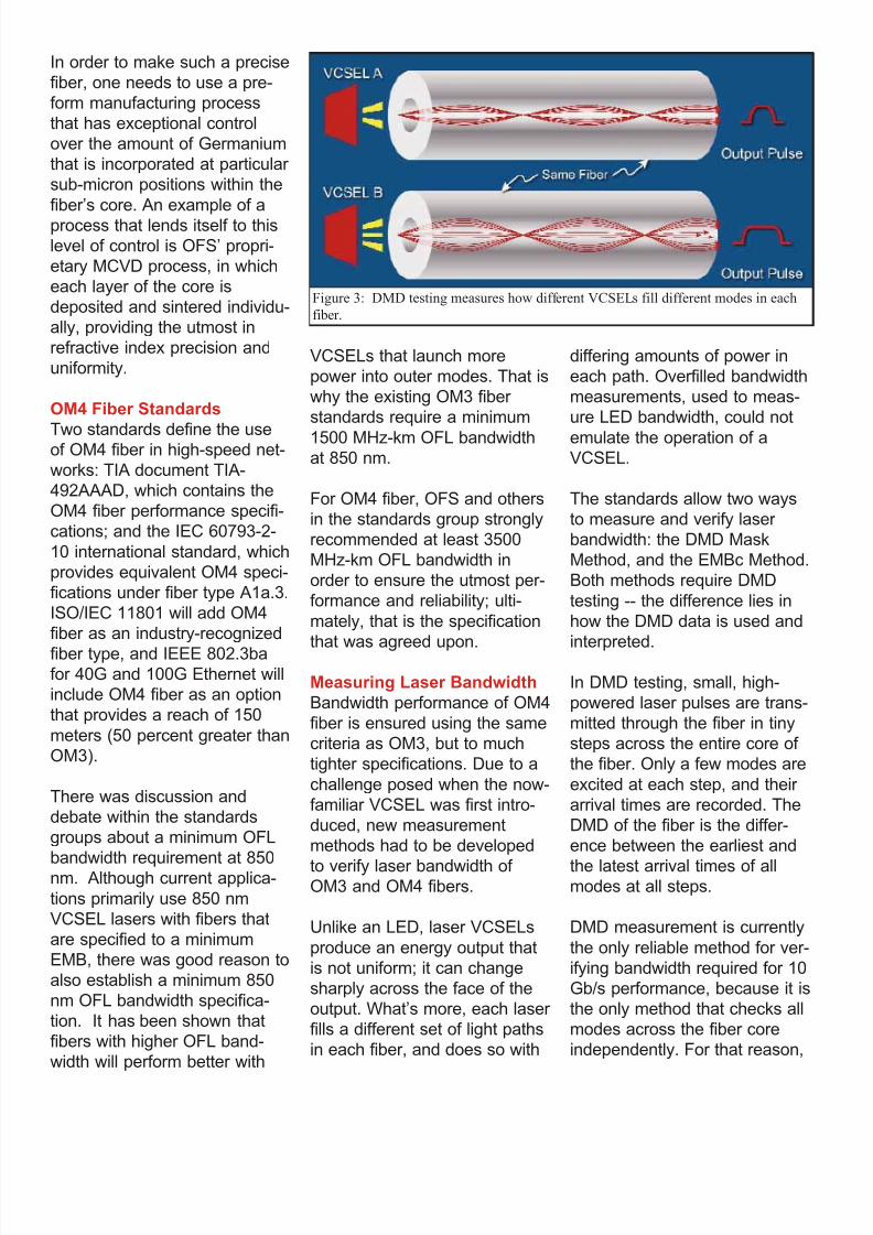
892019 Considerations for Selecting and Using Multimode Fiber
httpslidepdfcomreaderfullconsiderations-for-selecting-and-using-multimode-fiber 3032
In order to make such a precise
fiber one needs to use a pre-
form manufacturing process
that has exceptional control
over the amount of Germanium
that is incorporated at particular
sub-micron positions within the
fiberrsquos core An example of a
process that lends itself to this
level of control is OFSrsquo propri-
etary MCVD process in which
each layer of the core is
deposited and sintered individu-
ally providing the utmost in
refractive index precision and
uniformity
OM4 Fiber Standards
Two standards define the useof OM4 fiber in high-speed net-
works TIA document TIA-
492AAAD which contains the
OM4 fiber performance specifi-
cations and the IEC 60793-2-
10 international standard which
provides equivalent OM4 speci-
fications under fiber type A1a3
ISOIEC 11801 will add OM4
fiber as an industry-recognized
fiber type and IEEE 8023bafor 40G and 100G Ethernet will
include OM4 fiber as an option
that provides a reach of 150
meters (50 percent greater than
OM3)
There was discussion and
debate within the standards
groups about a minimum OFL
bandwidth requirement at 850nm Although current applica-
tions primarily use 850 nm
VCSEL lasers with fibers that
are specified to a minimum
EMB there was good reason to
also establish a minimum 850
nm OFL bandwidth specifica-
tion It has been shown that
fibers with higher OFL band-
width will perform better with
VCSELs that launch more
power into outer modes That is
why the existing OM3 fiber
standards require a minimum
1500 MHz-km OFL bandwidthat 850 nm
For OM4 fiber OFS and others
in the standards group strongly
recommended at least 3500
MHz-km OFL bandwidth in
order to ensure the utmost per-
formance and reliability ulti-
mately that is the specification
that was agreed upon
Measuring Laser Bandwidth
Bandwidth performance of OM4
fiber is ensured using the same
criteria as OM3 but to much
tighter specifications Due to a
challenge posed when the now-
familiar VCSEL was first intro-
duced new measurement
methods had to be developed
to verify laser bandwidth of OM3 and OM4 fibers
Unlike an LED laser VCSELs
produce an energy output that
is not uniform it can change
sharply across the face of the
output Whatrsquos more each laser
fills a different set of light paths
in each fiber and does so with
differing amounts of power in
each path Overfilled bandwidth
measurements used to meas-
ure LED bandwidth could not
emulate the operation of aVCSEL
The standards allow two ways
to measure and verify laser
bandwidth the DMD Mask
Method and the EMBc Method
Both methods require DMD
testing -- the difference lies in
how the DMD data is used and
interpreted
In DMD testing small high-
powered laser pulses are trans-
mitted through the fiber in tiny
steps across the entire core of
the fiber Only a few modes are
excited at each step and their
arrival times are recorded The
DMD of the fiber is the differ-
ence between the earliest and
the latest arrival times of allmodes at all steps
DMD measurement is currently
the only reliable method for ver-
ifying bandwidth required for 10
Gbs performance because it is
the only method that checks all
modes across the fiber core
independently For that reason
Figure 3 DMD testing measures how different VCSELs fill different modes in each
fiber
892019 Considerations for Selecting and Using Multimode Fiber
httpslidepdfcomreaderfullconsiderations-for-selecting-and-using-multimode-fiber 3132
industry associations such as
TIAEIA and ISOIEC have pub-
lished standards for DMD
measurement and DMD specifi-
cations for laser-optimized mul-
timode fiber
The DMD Mask Method is a
simple process that directlycompares DMD test results
against a set of specifications
(called templates or masks) to
see if the fiber has the neces-
sary performance
This is a straightforward graphi-
cal approach to ensuring the
data pulses do not spread
excessively beyond therequired 10 Gbs bit period If
the fiber passes these DMD
specs then you are assured of
at least 2000 MHz-km EMB no
matter which VCSEL you use
(as long as the VCSEL is com-
pliant)
The EMBc Method is an indi-
rect and more complex
process It takes the DMD
results and matches them
against a set of theoretical
weighting functions that are
intended to represent the
launch distributions of all com-
pliant VCSELs
The DMD results are combined
mathematically with each of the
10 weighting functions This
produces 10 different EMBc
values the lowest of which is
called minEMBc The minEMBc
value is then multiplied by a
factor of 113 to obtain the
fiberrsquos EMB value If this EMB
value is gt 2000 MHz-km thefiber is deemed compliant with
OM3 requirements and there-
fore should support 300 meters
at 10 Gbs
Due to all the complex calcula-
tions required by the EMBc
method and the fact that the
weighting functions only repre-
sent a sampling of the launch
characteristics of the many
VCSELs that could actually be
used in a real system the
EMBc method does not provide
the same scrutiny on fiber qual-
ity and performance as the
DMD Mask technique Whatrsquos
more the EMBc method virtual-ly ignores the center 0 ndash 5 983221m
(radial) region of a fiberrsquos core
because the weighting func-
tions put little emphasis in this
region
Conclusion
OM4 fiber provides next-gener-
ation multimode fiber perform-
ance for today and tomorrowrsquoshigh speed applications With
its significantly higher band-
width network designers and
operators can be assured that
multimode fiber will continue to
provide the most cost effective
solutions for short reach appli-
cations in data centers and
LANs
Copyright copy 2011 Furukawa Electric North America All rights reserved printed in USA
For additional information visit our website at wwwofsopticscomofs-fiber or call 1-888-fiber-
help For regional assistance contact
North America Asia Pacific
Telephone 508-347-8590 Telephone +852 2836 7102
Toll Free 800-799-7732 Fax +852 2836 7101
Fax 508-347-1211 E-mail fibersalesapofsopticscomE-mail fibersalesnarofsopticscom
Caribbean Latin America Japan
Telephone 508-347-8590 Telephone +81-3-3286-3424
Fax 508-347-1211 Fax +81-3-3286-3708 or 3190
E-mail fibersalescalaofsopticscom E-mail fibersalesjapanofsopticscom
Europe Middle East Africa China
Telephone +45-43 48 3736 Telephone +86 10 6505 3660
Fax +45 4348 3444 Fax +86 10 65059515
E-mail ofssalesdkofsopticscom E-mail fibersaleschinaofsopticscom
OFS reserves the right to make changes to the prices
and product(s) described in this document in the
interest of improving internal design operational
function andor reliability
This document is for informational purposes only
and is not intended to modify or supplement any
OFS warranties or specifications relating to any of
its products or services
892019 Considerations for Selecting and Using Multimode Fiber
httpslidepdfcomreaderfullconsiderations-for-selecting-and-using-multimode-fiber 3232
About OFSOFS is a world-leading designer manufacturer and provider of optical fiber
optical fiber cable FTTX optical connectivity and specialty photonics products
Our manufacturing and research divisions work together to provide innovative
products and solutions that traverse many different applications as they linkpeople and machines worldwide Between continents between cities around
neighborhoods and into homes and businesses of digital consumers we provide
the right optical fiber optical cable and components for efficient cost-effective
transmission
OFSrsquo corporate lineage dates back to 1876 and includes technology powerhouses
such as ATampT (NYSE T) and Lucent Technologies (now Alcatel-Lucent NYSE
ALU) Today OFS is owned by Furukawa Electric a multi-billion dollar global
leader in optical communications Headquartered in Norcross (near Atlanta)Georgia US OFS is a global provider with facilities in Avon Connecticut
Carrollton Georgia Somerset New Jersey and Sturbridge Massachusetts as well
as in Denmark Germany and Russia
wwwofsopticscom
LINKS
LaserWavereg Laser-Optimized OM4OM3 Fibers
Multimode or Single-Mode Fiber
Measuring Bandwidth of 10G Laser-optimized Multimode Fiber
892019 Considerations for Selecting and Using Multimode Fiber
httpslidepdfcomreaderfullconsiderations-for-selecting-and-using-multimode-fiber 3132
industry associations such as
TIAEIA and ISOIEC have pub-
lished standards for DMD
measurement and DMD specifi-
cations for laser-optimized mul-
timode fiber
The DMD Mask Method is a
simple process that directlycompares DMD test results
against a set of specifications
(called templates or masks) to
see if the fiber has the neces-
sary performance
This is a straightforward graphi-
cal approach to ensuring the
data pulses do not spread
excessively beyond therequired 10 Gbs bit period If
the fiber passes these DMD
specs then you are assured of
at least 2000 MHz-km EMB no
matter which VCSEL you use
(as long as the VCSEL is com-
pliant)
The EMBc Method is an indi-
rect and more complex
process It takes the DMD
results and matches them
against a set of theoretical
weighting functions that are
intended to represent the
launch distributions of all com-
pliant VCSELs
The DMD results are combined
mathematically with each of the
10 weighting functions This
produces 10 different EMBc
values the lowest of which is
called minEMBc The minEMBc
value is then multiplied by a
factor of 113 to obtain the
fiberrsquos EMB value If this EMB
value is gt 2000 MHz-km thefiber is deemed compliant with
OM3 requirements and there-
fore should support 300 meters
at 10 Gbs
Due to all the complex calcula-
tions required by the EMBc
method and the fact that the
weighting functions only repre-
sent a sampling of the launch
characteristics of the many
VCSELs that could actually be
used in a real system the
EMBc method does not provide
the same scrutiny on fiber qual-
ity and performance as the
DMD Mask technique Whatrsquos
more the EMBc method virtual-ly ignores the center 0 ndash 5 983221m
(radial) region of a fiberrsquos core
because the weighting func-
tions put little emphasis in this
region
Conclusion
OM4 fiber provides next-gener-
ation multimode fiber perform-
ance for today and tomorrowrsquoshigh speed applications With
its significantly higher band-
width network designers and
operators can be assured that
multimode fiber will continue to
provide the most cost effective
solutions for short reach appli-
cations in data centers and
LANs
Copyright copy 2011 Furukawa Electric North America All rights reserved printed in USA
For additional information visit our website at wwwofsopticscomofs-fiber or call 1-888-fiber-
help For regional assistance contact
North America Asia Pacific
Telephone 508-347-8590 Telephone +852 2836 7102
Toll Free 800-799-7732 Fax +852 2836 7101
Fax 508-347-1211 E-mail fibersalesapofsopticscomE-mail fibersalesnarofsopticscom
Caribbean Latin America Japan
Telephone 508-347-8590 Telephone +81-3-3286-3424
Fax 508-347-1211 Fax +81-3-3286-3708 or 3190
E-mail fibersalescalaofsopticscom E-mail fibersalesjapanofsopticscom
Europe Middle East Africa China
Telephone +45-43 48 3736 Telephone +86 10 6505 3660
Fax +45 4348 3444 Fax +86 10 65059515
E-mail ofssalesdkofsopticscom E-mail fibersaleschinaofsopticscom
OFS reserves the right to make changes to the prices
and product(s) described in this document in the
interest of improving internal design operational
function andor reliability
This document is for informational purposes only
and is not intended to modify or supplement any
OFS warranties or specifications relating to any of
its products or services
892019 Considerations for Selecting and Using Multimode Fiber
httpslidepdfcomreaderfullconsiderations-for-selecting-and-using-multimode-fiber 3232
About OFSOFS is a world-leading designer manufacturer and provider of optical fiber
optical fiber cable FTTX optical connectivity and specialty photonics products
Our manufacturing and research divisions work together to provide innovative
products and solutions that traverse many different applications as they linkpeople and machines worldwide Between continents between cities around
neighborhoods and into homes and businesses of digital consumers we provide
the right optical fiber optical cable and components for efficient cost-effective
transmission
OFSrsquo corporate lineage dates back to 1876 and includes technology powerhouses
such as ATampT (NYSE T) and Lucent Technologies (now Alcatel-Lucent NYSE
ALU) Today OFS is owned by Furukawa Electric a multi-billion dollar global
leader in optical communications Headquartered in Norcross (near Atlanta)Georgia US OFS is a global provider with facilities in Avon Connecticut
Carrollton Georgia Somerset New Jersey and Sturbridge Massachusetts as well
as in Denmark Germany and Russia
wwwofsopticscom
LINKS
LaserWavereg Laser-Optimized OM4OM3 Fibers
Multimode or Single-Mode Fiber
Measuring Bandwidth of 10G Laser-optimized Multimode Fiber