consolidated operating room equipment (core) … · use this software in any product other than the...
TRANSCRIPT

IMPORTANT INFORMATION: File in your maintenance records
Consolidated Operating Room Equipment(CORE) Powered Instrument Driver
REF 5400-50
Instructions For Use••••••••••••••••••••••
5400-050-700 Rev- 10/04
4.x4100 E. MilhamKalamazoo, Michigan(USA) 490011-269-323-77001-800-253-3210
Software Version
US Patents: ??? and other patents pending.
DRAFT

2
DRAFT
Table of Contents
Important Information ....................................................................................................................................................................................... 3Compliance Statements ................................................................................................................................................................................... 3Software License Notice .................................................................................................................................................................................. 4Limited Warranty .............................................................................................................................................................................................. 4User/Patient Safety .......................................................................................................................................................................................... 5Indications For Use .......................................................................................................................................................................................... 5Contraindications ............................................................................................................................................................................................. 5System Overview ............................................................................................................................................................................................. 6System Block Diagram .................................................................................................................................................................................... 6Hardware Features .......................................................................................................................................................................................... 7Accessories ..................................................................................................................................................................................................... 7Operating Instructions ...................................................................................................................................................................................... 8
Interconnect Diagram .................................................................................................................................................................................. 8To Connect the Components: ...................................................................................................................................................................... 9Button Definitions ...................................................................................................................................................................................... 10Software Menu Map ................................................................................................................................................................................... 12To Power Up: ............................................................................................................................................................................................. 13To View Options: ........................................................................................................................................................................................ 14
To Adjust Handpiece Speed (or Power): ................................................................................................................................................ 15To Select Handpiece Direction and Mode: ............................................................................................................................................ 15To Adjust Options: .................................................................................................................................................................................. 16
To Program Footswitch Options: ....................................................................................................................................................... 17To Set Handpiece Options: ................................................................................................................................................................ 19
To Select a User Preference Favorite: .................................................................................................................................................. 20To Replace a User Preference Favorite ............................................................................................................................................ 20
To Adjust Irrigation Pump Settings: ....................................................................................................................................................... 21To Adjust the Console Settings: - Standard and Advance User Mode .................................................................................................. 21
To Manage User Preference Files: - Advance User Mode Only ....................................................................................................... 23To Access Help: ..................................................................................................................................................................................... 27
Troubleshooting Guidelines ........................................................................................................................................................................... 28Periodic Maintenance .................................................................................................................................................................................... 28Storage and Handling .................................................................................................................................................................................... 28Cleaning and Sterilization Recommendations ............................................................................................................................................... 28Error Messages ............................................................................................................................................................................................. 29Messages ................................................................................................................................................................................................... 30Specifications ................................................................................................................................................................................................. 31
© 2003, 2004 Stryker Corporation

3
DRAFT
Important Information
WARNING - CAUTION - NOTE
Please read this manual and follow its instructions carefully. The words WARNING, CAUTION and NOTE carry special meanings andshould be carefully reviewed.
WARNING: The personal safety of the patient and user may be involved. Disregarding this information could result in injury tothe patient and/or user.
CAUTION: These instructions point out special service procedures or precautions that must be followed to avoid damagingthe instrument.
NOTE: This provides special information to make maintenance easier or important instructions clearer.
An exclamation point within a triangle displayed on the product is intended to alert the user to the presence of importantoperating and maintenance instructions in this manual.
Compliance Statements
Federal Communications Commission (FCC)FCC ID: Q9R-5400
This device complies with Part 15 of the FCC rules. Operation issubject to the following two conditions: (1) this device may notcause harmful interference, and (2) this device must accept anyinterference received, including interference that may causeundesired operation.
NOTE: FCC regulations provide that changes or modificationsnot expressly approved by Stryker Instruments could void yourauthority to operate this equipment.
Industry Canada (IC)IC: 4919A-5400
The term "IC:" before the radio certification number only signifiesthat Industry Canada technical specifications were met.

4
DRAFT
Limited Warranty
In the USA only, products of Stryker Instruments are warranted to the original purchaser for a period of one year from the date ofpurchase, with exceptions noted below. Products are warranted to be free from defects in material and workmanship. Abnormal wearand tear or damage caused by misuse or by failure to perform normal and routine maintenance as set out in the Maintenance Manualor Operating Instructions, or as demonstrated by an authorized Stryker Instruments representative, is not covered by the warranty. Anyeffort at field repair or adjustment may invalidate your warranty. Using any accessory that is not a Stryker product will invalidate yourwarranty.
The warranty extends to all purchasers and is limited to the repair or replacement of the product without charge when returned prepaidto Stryker Instruments. There are no other expressed warranties. This warranty gives you specific legal rights and you may haveother rights, which vary by state and municipality.
For selected products.• Universal Handswitch is warranted for a period of 6 months from date of invoice.• Handpiece cords are warranted for a period of 6 months from date of invoice.• Cutting accessories are not warranted.
Software License Notice
The Stryker CORE Powered Instrument Driver (console) contains software that is installed by Stryker Corporation (“Stryker”). Strykerowns this software and is licensing it to you, the original CORE Console customer, subject to the following terms and conditions.
Stryker hereby grants you a nonexclusive, nontransferable License to use the software to operate the CORE Console for your own useand to perform maintenance thereon. You hereby agree that you will not copy, alter, modify, translate, disassemble, decompile, reverseengineer, create derivative works of, distribute, sub-license, sell, lease, lend, or otherwise transfer all or any portion of this software, ineither original or modified form, except as specifically authorized under this License Agreement. In addition, you agree that you will notuse this software in any product other than the Stryker product in which the software was initially installed by Stryker.
EXCEPT FOR ANY WARRANTIES THAT MAY BE EXPRESSLY PROVIDED IN THE STRYKER PRODUCT LITERATUREACCOMPANYING YOUR CORE CONSOLE OR SOFTWARE, THIS SOFTWARE AND DOCUMENTATION IS PROVIDED “AS IS,”AND STRYKER MAKES NO REPRESENTATIONS OR WARRANTIES, EXPRESS OR IMPLIED, INCLUDING BUT NOT LIMITED TO,WARRANTIES OF MERCHANTABILITY OR FITNESS FOR ANY PARTICULAR PURPOSE.
STRYKER WILL NOT BE LIABLE FOR ANY INDIRECT, SPECIAL, PUNITIVE OR CONSEQUENTIAL DAMAGES ARISING OUT OFANY USE OF THE SOFTWARE OR DOCUMENTATION.
By using this software, you acknowledge and agree that you have read, understood, and agree to be bound by these terms andconditions.

5
DRAFT
User/Patient Safety
WARNINGS:
• Before using any system component, or any component compatible with this system, read and understand the instructions. Payspecial attention to the important User/Patient Safety information provided in the instruction booklets. Familiarization with thesystem prior to use is important. Failure to comply may result in patient and/or operating room staff injury or damage tocomponents.
• The surgeon performing any procedure is responsible to determine the appropriateness of this instrument and the specifictechnique for each patient. Stryker, as a manufacturer, does not recommend surgical technique.
• Clean and sterilize components before first and every use. See the CORE Cleaning, Maintenance and SterilizationRecommendations for specific details.
• DO NOT use this equipment in the presence of flammable anesthetic mixture with air or with oxygen or nitrous oxide.• Prior to each use, operate system components and inspect for damage. DO NOT use if damage is apparent.• Use only Stryker approved accessories. Other accessories may not properly interface with the console. Contact your Stryker
sales representative for a complete list of accessories. DO NOT modify any accessory. Failure to comply may result in patientand/or operating room staff injury.
• All cutting accessories are intended for single use only. Reuse significantly increases wear on the handpiece and attachment.Failure to comply may result in patient and/or operating room staff injury.
• Always use the appropriate accessory combination with a handpiece. Contact your Stryker sales representative for a completelist of accessories. Failure to comply may result in patient and/or operating room staff injury.
• DO NOT attempt to insert or remove any cutting accessory or attachment while the handpiece is operating. Failure to complymay result in operating room staff injury.
• DO NOT modify the ground connection of the console power cord. Failure to comply may result in patient and/or operating roomstaff injury.
• DO NOT place a handpiece on a patient. Failure to comply may result in patient injury, for example burns or damage to tissue.• DO NOT place a handpiece on or near a magnetic pad or tray. A magnetic field can simulate the output of a handswitch or
footswitch and may cause the handpiece to operate inadvertently. Failure to comply may result in patient and/or operating roomstaff injury.
• DO NOT perform footswitch mapping (assign a handpiece port to a footswitch port) while operating a handpiece. Failure tocomply may result in patient and/or operating room staff injury.
• Operating a handpiece in the Window Jog mode may increase the temperature of the handpiece. If a handpiece overheats, theconsole automatically shuts off the handpiece. (The audible alarm does not warn the user if this event occurs.) Monitor theoperating time of the handpiece to prevent overheating. Failure to comply may result in patient and/or operating room staff injury.
• Use safety glasses. Failure to comply may result in operating room staff injury.
Contraindications
None.
Indications For Use
NOTE: If the console screen is touched in two places simultaneously, unintended button activation may result.
The Stryker Consolidated Operating Room Equipment (CORE) System is intended for use in the cutting, drilling, reaming,decorticating, and smoothing of teeth, bone, bone cement, and other bone-related tissue in a variety of surgical procedures, includingbut not limited to Neuro, ENT, Dental and Endoscopic. It is also usable in the placement or cutting of screws, metal, wires, pins, andother fixation devices.

6
DRAFT
System Overview
The Stryker CORE Powered Instrument Driver (console) provides an integrated, centrally controlled environment that promotes safeand economical surgical practice.
The console’s software provides control over system components including the console, the graphical user interface (GUI), theirrigation pump, and the connected handpieces and footswitches. The software’s file management capability allows you to save andstore user preference settings and have convenient access to a favorites list of the most frequently used files to improve efficiency.
The color display, with its touch sensitive screen, provides an intuitive graphical user interface that allows you to view multiple systemcomponents and set their parameters with the touch of a finger. Changes may be made rapidly, with little to no interruption duringsurgery.
Multiple handpieces and footswitches may be connected and operated simultaneously from a single console. The console provides acommon interface for both micro and heavy-duty handpieces. Because options vary among different handpieces, the console will onlydisplay those options that are related to the connected handpiece.
Various cutting accessories and irrigation cassettes used with the system are also recognized and identified on the console screen bymeans of a wireless tag technology.
The console’s enhanced serial interface provides a serial communications channel between the console and other devices. Thisfeature allows the transfer of data and control information, like run-time data and software upgrades over a computer network.
An integral irrigation pump system reliably supplies coolant/irrigation to the cutting site with adjustable flow rates.
Console settings, like display brightness and speaker volume, may be easily adjusted. The on board speaker provides audiblefeedback during operation and configuration.
The console accepts either 115 VAC or 230 VAC input and has the capability to power heavy-duty handpieces.
System Block Diagram
CORE Console
Main Processor
Enhanced Serial Interface
Handpiece Control
Footswitch and IrrigationPump Control
SpeakerTouch
SensitiveScreen
Handpiece 1
Handpiece 2
Handpiece 3
Footswitch 1
Footswitch 2
ColorDisplay
Irrigation Pump
Other Devicesvia Computer
Network
115 or 230 VACFacility Power
Finger/StylusInput
Graphical/Audio Output
Irrigation PumpCassette

7
DRAFT
Hardware Features
Color Touch ScreenDisplay Area; allowsyou to view and makehandpiece settings usingits touch screencapability
Footswitch ConnectionArea; allows you toconnect twofootswitches simulta-neously.
Power Switch;press to turnconsole powerON and OFF.
Handpiece Connec-tion Area; allows youto connect threehandpieces simulta-neously.
Irrigation PumpCassette; install theirrigation cassette hereif you use the irrigationpump (optional).
Speaker; providesaudible sounds andalarms (located insideconsole).
Power Receptacle; connect theconsole to facility power using theconsole power cord. The console willaccept 115 or 230 V facility power.
Irrigation Bag PoleMounting Bracket;connect the pole here ifyou use the irrigationpump (optional).
Accessories
WARNING: Use only Stryker approved accessories. Other accessories may not properly interface with the COREConsole. Contact your Stryker sales representative for a complete list of accessories. DO NOT modify any accessory.Failure to comply may result in patient and/or operating room staff injury.
Description REF
Power Cord ................................................................................................................................................................................. 0996-851-010Cable; push-pull type connector with alignment markings and keyed connectors .................................................................. 5100-004-000Footswitch .................................................................................................................................................................................. 5100-008-000Disposable Irrigation Cassette ................................................................................................................................................... 5400-050-001
Enhanced Serial Interface Connectors; threecommunication ports allow you to transfer data and controlinformation, including software upgrades.

8
DRAFT
Operating Instructions
Interconnect Diagram
The interconnect diagram provides the connection sequence of CORE system components. The diagram's numbered calloutscorrespond to the numbered instructions on the next page. See the instructions for use supplied with each component for specificconnection information.
Symbol Definitions
On/Off (push-push)
Footswitch
Handpiece
Irrigation
Type BF Applied Part

9
DRAFT
NOTE: Refer to the Interconnect Diagram while performing the instructions below. See the instructions for use supplied witheach component for specific connection information.
1. Place the console on a sturdy, flat surface near a hospital grade outlet.2. Install the power cord plug into the power receptacle. Pull the bracket over the plug to secure it within the power receptacle.3. Install the other end of the power cord into a hospital-grade wall outlet.4. Press the power switch to turn the console on. See To Power Up and To Adjust Options sections for more information.
NOTES:• The universal power supply will automatically adjust to match the voltage and frequency of the facility power.• As you connect components to the console, the console’s screen will change to reflect the various components that are
connected.
CAUTIONS:• DO NOT thread or twist the push/pull connectors on the cords during installation or removal.• When connecting or disconnecting a cable(s) to the front of the console, always hold the cable by its connector (the plug, not the
cord). Failure to comply may result in damage to the cable or console.• Cables that are connected to the front of the console have keyed, push-pull type connectors that lock into place. DO NOT force a
connector into a console port. Each connector and port has an alignment mark to indicate proper cable orientation.
5. If using a footswitch, plug the footswitch cable into the console port marked with a FOOTSWITCH PORT symbol. Align the marksand gently push the connectors together. Two footswitches may be connected to the console.
6. Plug the handpiece cord(s) into the console port(s) marked with a HANDPIECE PORT symbol. Align the marks and gently pushthe connectors together. Three handpieces may be connected to the console and operated simultaneously.
NOTE: If using a CORE Universal Handswitch, attach it to the handpiece before you plug the cord into the handpiece.
7. Plug the other end of the handpiece cord(s) into the handpiece(s). See instructions for use supplied with each handpiece forconnection information.
WARNING: Use only Stryker approved cutting accessories.
8. Attach the cutting accessory to the handpieces. See the instructions for use supplied with each handpiece or attachment forcutting accessory installation information.
NOTE: If using the console irrigation pump (optional), install the Irrigation Pole REF 5100-50-28 (optional, may use equivalentirrigation pole) to the mounting bracket on the back of the console. Hang the irrigation bag from the pole.
9. If required, install the irrigation cassette into the console port marked with a IRRIGATION PUMP CASSETTE symbol.10. If required, connect the irrigation tubing to the irrigation bag.11. If required, attach the irrigation clips to the handpiece(s) and connect the tubing. Connect the irrigation tubing to the handpiece.
See the instructions for use supplied with each handpiece for connection information.12. Test all the CORE system components to ensure that they are performing properly before surgery. Refer to the Button Definitions
and Software Menu Map sections when using the graphical user interface.
To Connect the Components:

10
DRAFT
Button Definitions
DefinitionsButton NameName DefinitionsButton
HOME
HELP
BACK
UP
INCREASE
DOWN
DECREASE
OK
ESC
FACTORYDEFAULT
View and adjust handpiecesand system settings
Access task-oriented HELPrelated to screen andbutton functionality
Return to the previousscreen
Scroll up
Increase the value of asetting
Scroll down
Decrease the value of asetting
Accept inputs, changes orselections and return toprevious screen
Close a pop up or screenwithout accepting inputs,changes or selections andreturn to previous screen
Apply original factorydefault settings
OSCILLATE
FORWARD
REVERSE
LOW
HIGH
ADJUSTOPTIONS
FIXED SPEED
VARIABLESPEED
ONE TOUCH
PROGRAMFOOTSWITCH
ASSIGNFOOTSWITCHTOHANDPIECE
Set default mode ofhandpiece to oscillate
Set default mode ofhandpiece to rotate in theforward (clockwise) direction
Set default mode ofhandpiece to rotate in thereverse (counterclockwise)direction
Set default mode ofhandpiece to operate in thelow rpm range mode
Set default mode ofhandpiece to operate in thehigh rpm range mode
Adjust handpiece, footswitchand console options
Set the default run mode ofthe handpiece speed tooperate at the set speed only
Set the default run mode ofthe handpiece speed torespond to the degree ofpressure applied to thehandswitch or footswitch
Set the default run mode ofthe handpiece activation torespond to one touch of ahandswitch or footswitch
Program the footswitchpedals and pads based onthe handpiece capabilities
Assign a specific footswitchport to a specific handpieceport
11
DRAFT
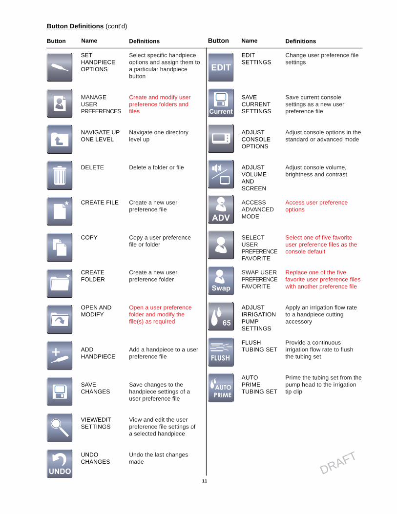
Button Definitions (cont'd)
DefinitionsButton NameName DefinitionsButton
EDITSETTINGS
SAVECURRENTSETTINGS
ADJUSTCONSOLEOPTIONS
ADJUSTVOLUMEANDSCREEN
ACCESSADVANCEDMODE
SELECTUSERPREFERENCEFAVORITE
SWAP USERPREFERENCEFAVORITE
ADJUSTIRRIGATIONPUMPSETTINGS
FLUSHTUBING SET
AUTOPRIMETUBING SET
SETHANDPIECEOPTIONS
MANAGEUSERPREFERENCES
NAVIGATE UPONE LEVEL
DELETE
CREATE FILE
COPY
CREATEFOLDER
OPEN ANDMODIFY
ADDHANDPIECE
SAVECHANGES
VIEW/EDITSETTINGS
UNDOCHANGES
Select specific handpieceoptions and assign them toa particular handpiecebutton
Create and modify userpreference folders andfiles
Navigate one directorylevel up
Delete a folder or file
Create a new userpreference file
Copy a user preferencefile or folder
Create a new userpreference folder
Open a user preferencefolder and modify thefile(s) as required
Add a handpiece to a userpreference file
Save changes to thehandpiece settings of auser preference file
View and edit the userpreference file settings ofa selected handpiece
Undo the last changesmade
Change user preference filesettings
Save current consolesettings as a new userpreference file
Adjust console options in thestandard or advanced mode
Adjust console volume,brightness and contrast
Access user preferenceoptions
Select one of five favoriteuser preference files as theconsole default
Replace one of the fivefavorite user preference fileswith another preference file
Apply an irrigation flow rateto a handpiece cuttingaccessory
Provide a continuousirrigation flow rate to flushthe tubing set
Prime the tubing set from thepump head to the irrigationtip clip

12
DRAFT
Home Screen
SelectDirection/Mode
Adjust OptionsSelect UserPreference
Favorite
Adjust IrrigationPump Settings
Access Help
ProgramFootswitch
Options
AssignFootswitch
Set HandpieceOptions
Manage UserPreferences
Folders
Adjust ConsoleOptions
Manage UserPreference
Files
Modify File
Edit Settings
Add Handpiece
Create NewFolder(s)
Adjust Speed/Power
Swap UserPreference
Favorite
AccessAdvance User
Mode
Adjust AudioVideo Controls
Create NewFile(s)
Software Menu Map
The software menu map is a visual representation of the menu structure and its hierarchy. The map also provides the sequence ofscreen information provided in this manual, top down and left to right. The icons used in this map are the same icons used on buttonsin the software and are also used with the header information in this manual.

13
DRAFT
Adjust Options
If no handpieces or cords are connected to the console during initial power up, the following screen will appear:
If the Adjust Options button ispressed before any cords orhandpieces are connected,the following screen willappear. At this time, consoleoptions that are not handpiecespecific may be set up beforethe sterile handpieces arebrought into the operatingroom and plugged into theconsole.
The subdued portions of these screenswill become available once ahandpiece is plugged into the console.These screens do not depend onwhether a footswitch is plugged into theconsole.
Plug in Handpiece Cable Screen
To Power Up:
Power Up Screen
This screen is momentarily displayed while the console powers up. Note the software version is displayed in the lower right corner ofthe screen.

14
DRAFT
To View Options:
HOME screen
The HOME screen is where most user interaction will take place. Up to three handpieces may be displayed on thescreen simultaneously. When the console is initially turned on, the console settings are factory default settings until auser preference file is selected or the settings are manually modified.
Attached HandpiecesThree handpieces maybe attached to theconsole and two maybe operated simulta-neously.
Handpiece Operating AreaView and modify keyhandpiece settings.
Console Operating AreaAccess key consolefunctions.
View User Preference File NameView name of file that containshandpiece settings for a specific
procedure, for example,ACL surgery.
View Handpiece NameView name of activehandpiece. Threehandpieces may beconnected anddisplayed. Twopowered handpieces maybe operated from the sameconsole, simultaneously.
View Cutting Accessory orAttachment NameView cutting accessory orattachment name if thehandpiece, accessory and/orattachment have recognitioncapability.
View Option SettingsView option settings such as irrigation,footswitch control, and fixed or variableRPM. All of these settings may bemodified.

15
DRAFT
To Adjust Handpiece Speed (or Power):
From the HOME screen, touch the plus and minus buttons to adjust the handpiece speed or power set point in rpms orpercentage of power.
NOTE: When you install a cutting accessory with cutter recognition capability, the system will automatically overridethe selected speed setting in each mode to the speed settings that are appropriate for the installed cutting accessory.
To Select Handpiece Direction and Mode:
From the HOME screen, touch the Select Direction/Mode button to adjust the handpiece direction and mode.
The default speed isdisplayed for eachhandpiece until youadjust the speed setpoint based on thehandpiece capability.
Touch the adjustment buttons (or slider bar thatbecomes visible when touching the speed value) toincrease or decrease the speed (power) set point.
While the handpiece isrunning, the displayshows the actualhandpiece speed. If thehandpiece is not running,the default or selectedspeed is displayed.
Direction OptionsSelect the direction ofthe cutting accessory
Mode OptionsSelect the mode ofhandpieceoperation
REVERSE: Touch to cause thehandpiece cutting accessory torotate in the reverse(counterclockwise) direction.
FORWARD: Touch to causethe handpiece cuttingaccessory to rotate in theforward (clockwise) direction.
HIGH: Touch to cause thehandpiece to operate inthe high rpm range mode.
OSC: Touch to cause thehandpiece cuttingaccessory to oscillate.
LOW: Touch to cause thehandpiece to operate in thelow rpm range mode.
NOTE: The available handpiece options,including handpiece direction and mode, willdepend on the type of handpiece that is identifiedat the top of the screen.

16
DRAFT
To Adjust Options:From the HOME screen, touch the Adjust Options button to adjust the handpiece and footswitch options. The availablehandpiece options will depend on the type of handpiece that is identified at the top of the screen.
Adjust Acceleration• Touch the plus and minus buttons or slider bar to adjust the
percent of acceleration [0 to 100%].• At 100%, the handpiece speed accelerates quickly.
Acceleration slows as the setting approaches zero percent.
Adjust Braking• Touch the plus
and minus buttonsor slider bar toadjust the percentof braking [0 to100%].
• At 100%, thehandpiece stopsabruptly. Theamount ofdecelerationdecreases as thesettingapproaches zeropercent.
Adjust Oscillate Turns• Touch the plus and minus buttons to select the number of turns per direction when
running a handpiece in the oscillate mode.
Select Run Mode• FIXED: handpiece speed runs at the maximum setting
only. Varying pressure on the footswitch or handswitchwill not vary the handpiece speed.
• VARIABLE: handpiece speed responds to the degreeof pressure applied to the footswitch or handswitch.
• ONE TOUCH: Handpiece activation responds to onetouch of a trigger device(footswitch, handswitch) andcontinues to run when thetrigger device is released.Handpiece is deactivated bytouching any trigger device.In this mode, the handpieceoperates at constant set-point speed/power level.

17
DRAFT
To Program Footswitch Options:
From the Adjust Options screen, touch the Program Footswitch button to program the footswitch pedals and pads basedon the capabilities of the connected handpiece. Two footswitches may be connected to and simultaneously operatedfrom the same console. However, two footswitches cannot be used to control the same handpiece at the same time.
Assign Specific OptionSelect a footswitch pedal or pad [A, B, I, IIor III] button and assign a specific option.
View Handpiece PortIndicates the handpiece port that thefootswitch is programmed for.
Based on handpiece capabilities, options may include:• FORWARD: pressure on the pad or pedal will cause the
handpiece to rotate in the forward (clockwise) direction.• REVERSE: pressure on the pad or pedal will cause the
handpiece to rotate in the reverse (counterclockwise) direction.• +OSC TURNS: pressure on the footswitch pad will cause the
handpiece to oscillate; increase number of turns.• -OSC TURNS: pressure on the footswitch pad will cause the
handpiece to oscillate; decrease number of turns.• ON: pressure on the footswitch pad or pedal will make the port
active, for example it will provide input to the assignedhandpiece.
• OFF: pressure on the footswitch pad or pedal will make theport inactive, for example it will not provide input to theassigned handpiece.
• HIGH: pressure on the footswitch pad will cause the handpieceto operate in the high-speed range or mode.
• LOW: pressure on the footswitch pad will cause the handpieceto operate in the low speed range or mode.
• SPEED INCREMENT: pressure on the footswitch pad willincrement the set point speed.
• SPEED DECREMENT: pressure on the footswitch pad willdecrement the set point speed.
• IRRIGATION INCREMENT: pressure on the footswitch willincrement the pump flow set point and increase irrigation to thehandpiece cutting accessory.
• IRRIGATION DECREMENT: pressure on the footswitch willdecrement the pump flow set point and decrease irrigation tothe handpiece cutting accessory.
• IRRIGATION ON/OFF: pressure on the footswitch will togglethe irrigation pump on and off. If pressed and held, theirrigation pump can be turned on without running thehandpiece. Once started, the irrigation pump can be stoppedby pressing the pad again or by starting the handpiece.
• PUMP FLUSH: pressure on the footswitch will turn theirrigation pump on at the flush rate. Once started the irrigationpump may be stopped by pressing the pad again or by startingthe handpiece.
• CHANGE PORT: pressure on the footswitch pad will changethe footswitch assignment to another active handpiece.
• ONE TOUCH: acting like an on/off toggle, tap the footswitchpad to operate the handpiece at the maximum speed. Tap thefootswitch pad again to stop the operation.
• VARIABLE: varying pressure on the footswitch pad will causethe handpiece speed to vary.
• FIXED: pressure on the footswitch pad will cause thehandpiece to operate at a constant speed as set on the HOMEscreen.
Touch the arrow buttons to scrollthrough the footswitch options.The available options arehandpiece specific. Touch the OKbutton to select the option.

18
DRAFT
Assign Handpiece Port to a Footswitch Port
The Assign Handpiece to Footswitch screen will appear automatically when connecting two footswitches and two ormore handpieces to the console.
To Program Footswitch Options:
The color options above indicate the default setting for two connected footswitches and three connected handpieces.Touch the handpiece name button to toggle through the four color options. Each color indicates a footswitch tohandpiece port assignment as described below:
Access the Assign Handpiece to Footswitch screen manually as follows:1. From HOME screen, press Adjust Options button2. From Adjust Options screen, press Program Footswitch button3. From Program Footswitch screen, press Assign Handpiece to Footswitch button
Yellow indicates the bottom (yellow) footswitch port is assigned to the handpiece port.
Green indicates the top (green) footswitch port is assigned to the handpiece port.
Green/Yellow combination indicates both footswitch ports are assigned to the handpiece port.
Gray indicates no footswitch port is assigned to the handpiece port.
WARNING: DO NOT perform footswitch mapping (assign a handpiece port to a footswitch port) whileoperating a handpiece. Failure to comply may result in patient and/or operating room staff injury.
Color icon indicates which handpiece will be operated when the associated footswitch isactuated.

19
DRAFT
To Set Handpiece Options:
From the Adjust Options screen, touch the Set Handpiece Options button to select specific handpiece options andassign them to a particular handpiece button. Options are handpiece dependent and may not be available if thehandpiece does not support them. Handpiece attachments may also be selected, if supported. If selected, the consolewill display the correct attachment information and set maximum speed values for the handpiece.
Based on handpiece capabilities, options may include:• FORWARD: option will rotate cutting accessory in the forward (clockwise) direction.• REVERSE: option will rotate cutting accessory in the reverse (counterclockwise) direction.• +OSC TURNS: option will increase the number of oscillate turns.• -OSC TURNS: option will decrease the number of oscillate turns.• HIGH: option will operate handpiece in the high-speed mode.• LOW: option will operate handpiece in the low speed mode.• CHANGE PORT: option will change the button assignment to another active handpiece.• +IRRIGATION: option will increase irrigation to the handpiece cutting accessory.• -IRRIGATION: option will decrease irrigation to the handpiece cutting accessory.• WINDOW JOG TRIGGER: option will rotate the cutting accessory at a very low speed to position the cutting edge
within the cutting window.
WARNING: Read and understand the appropriate Stryker handpiece instructions for use.
Select HandpieceAttachmentSelect specificattachment basedon the handpiececapability.Touch arrows toscroll through andhighlight ahandpieceattachment.
Program Handpiece Buttons• Touch numbered button to assign
an option.• Select specific options and assign
them to a particular handpiecebutton based on handpiececapability.

20
DRAFT
To Select a User Preference Favorite:
From the HOME screen, touch the Select a User Preference Favorite button to select a favorite user preference file orreplace an existing one. Five favorite files are available. Each file contains specific handpiece(s) settings for aparticular procedure.
To Replace a User Preference Favorite
Touch to select one ofthe five favorite userpreference files.
Touch arrow buttons to scrollthrough the list and highlightone of the preference files.Touch OK button to replaceone of the favorite preferencefiles.
From the Select a User Preference Favorite pop up, make a file selection via the arrow buttons and OK button, thentouch the Swap button to replace an existing favorite file.

21
DRAFT
To Adjust the Console Settings: - Standard and Advance User Mode
From the Adjust Options screen, touch the Adjust Console Options button to adjust the volume, brightness and contrast.
Adjust VolumeAdjust the percent ofconsole volume [0 to 100%]by touching the slide bar orthe plus, minus buttons
Adjust ContrastAdjust the percent ofconsole display contrast [0to 100%] using the slide baror the plus, minus buttons
Adjust BrightnessAdjust the percent ofconsole display brightness[0 to 100%] using the slidebar or the plus, minusbuttons
Adjust Audio/Video Controls - Standard Mode
To Adjust Irrigation Pump Settings:
NOTE: If using the irrigation pump, assemble the irrigation pole to the mounting bracket located on the back of theconsole. Hang the irrigation bag from the pole. Install the irrigation cassette into the console pump. Attach theirrigation clips onto the handpiece and connect the tubing.
From the HOME screen, touch the Adjust Irrigation Pump Settings button to apply an irrigation flow rate to a handpiececutting accessory. AUTO PRIME and FLUSH options are also provided.
Adjust Irrigation% Setting
• Touch the slidebar or plus,minus buttons toadjust the flowrate percentageof irrigation [1 to100% or OFF] tothe cuttingaccessory of thehandpiece.
• At 100%,irrigation to thehandpiece is setto maximumflow rate. The ratedecreases as thesetting approacheszero.
FLUSH Tubing Set - Touch andhold to provide a continuous flowrate of 300 ml/min with no irrigationclip and a minimum pressure of 30psi when the tubing is blocked.
AUTO PRIMETubing Set
• Touch to activatethe primingsequence of theinstalled irrigationcassette.
• The tubing will beprimed from thepump head to theirrigation tip clipwithin 20 seconds.
• The button willremain depressedduring the timedoperation.
Select Handpiece• Touch one or all of the handpiece buttons to allow activation of the irrigation
pump. If no buttons are selected, the pump will not operate.• Activation will apply an irrigation flow rate to the handpiece cutting accessory.• The flow rate will depend on the type of handpiece.• Activating a handpiece will gain control of the console irrigation. While the first
activated handpiece is running, activating a second or third handpiece will notchange pump flow, but may reduce irrigation to the first handpiece if a Y-splitteris used. To gain control of console irrigation using a second or third handpiece,activate the second or third handpiece while the first handpiece is not running.

22
DRAFT
From the Adjust Console Options screen, touch the ADV button to gain access to the Advance UserMode and the User Preference file management system. A pop up will appear to confirm your request.Once confirmed, the Manage User Preference button will appear.
Access Advance User Mode
After managing userpreference files in the advanceuser mode, touch the ADVbutton to return to the standarduser mode.
Return to Standard User Mode
To Adjust the Console Settings: - Standard and Advance User Mode

23
DRAFT
Manage user preferences
LAPARASCOPY
ENT
GEN
DR. CARRY ORAL
MAIN
? ESC
To Manage User Preference Folders: - Advance User Mode Only
NOTE: You must be in the Advance User Mode to manage user preferences. See To Adjust Console Optionssection for details.
From the Adjust Console Options screen, touch the Manage User Preferences button to create and modify userpreference folders and files. Each folder may contain multiple files and each file may contain the settings for multiplehandpieces used for a specific procedure and/or physician.
View Address BarView the directory file path (folder/filename) to help with navigation.
Create New FolderTouch to create a newfolder.
Open FolderTouch arrow buttons to scroll through and highlight a folder.Touch folder button to access files within a folder.
To Manage User Preference Files: - Advance User Mode Only
Create New FileTouch to create a newfile.
Open FileTouch arrow buttons to scroll through and highlight a file.Touch Modify button to open and modify a file.

24
DRAFT
Create a New Folder or File
From the Manage User Preferences screen (folder or file screen), touch the Create New Folder or File button to createa new preference folder or file using a keyboard screen.
Enter a Folder or FileNameTouch key buttons toenter a folder or filename.
Shift Lock/UnlockTouch to enter symbols or numbers. Use Backspace
Touch to deletekeystrokes.
To Manage User Preference Folders and Files: - Advance User Mode Only

25
DRAFT
Modify File
Add HandpieceTouch to add ahandpiece to thepreference file.
View and Edit SettingsTouch the ADD Handpiece button to add a handpiece to the file. Once handpieces areadded to a file, touch the arrow buttons to scroll through and highlight a handpiece.Touch the magnifying glass button to create or edit handpiece settings.
From the Modify File screen, touch the Add Handpiece button to add a handpiece to the preference file from a list ofavailable handpieces.
Add a Handpiece
View and Add a HandpieceTouch arrow buttons to scroll through and highlight a handpiece. Touch theADD button to add a handpiece to the user preference file.
To Manage User Preference Folders and Files: - Advance User Mode Only

26
DRAFT
From the Modify File screen, touch the View and Edit (magnifying glass) button to view and edit the preference settingsof a selected handpiece within a user preference file.
To Manage User Preference Folders and Files: - Advance User Mode Only
View and Edit Settings
View and Edit SettingsTouch arrow buttons to scrollthrough and highlight a handpiecesetting. Touch EDIT button tochange the setting.
Edit Settings
From the Edit screen, touch the EDIT button to modify the setting within the user preference file only (console defaultsremain unchanged). Notice that the user preference Edit screen below (typical example) has a light blue backgroundcolor to differentiate it from a console default Edit screen (dark blue).

27
DRAFT
To Access Help:
Select Help Topic Screen
From most screens or pop ups, touch the Help button to obtain specific screen and button information. Each Helpscreen is divided into two columns. The right column contains a summary of the screen's overall function. The leftcolumn provides a list of all the screen buttons and their function.
View Help Topics - Touch the arrow buttons to scrollthrough and view help topic information.

28
DRAFT
Problem
Sporadic electrical interference isexperienced.
Action
Turn off all electrical equipment not inuse in the operating room. Relocateelectrical equipment; increase spatialdistance. Plug the console and otheroperating room equipment intodifferent outlets.
Troubleshooting Guidelines*
*The CORE Console is not field repairable. In case of operating difficulties, return this product to Stryker Instruments for repair. Formore information, contact your Stryker sales representative or Customer Service at 1-800-253-3210.
Interval
Prior to Use.
Activity
Inspect console for damage or signs of wear. DO NOT use if damage is apparent.
Periodic Maintenance
Storage and Handling
To ensure the longevity, performance, and safety of this equipment, package in original package materials when storingor transporting.
Cleaning and Sterilization Recommendations
WARNINGS:• Clean and sterilize handpieces before first and every use.• Cutting accessories are single use only. Sterile only if package is unopened and undamaged. DO NOT resterilize or reuse.
CORE Console, Power Cord, Cable(s) and Footswitch Cleaning Instructions
CAUTIONS:• DO NOT sterilize the CORE Console or power cord.• DO NOT allow moisture in any CORE Console opening, or power cord, handpiece cable and footswitch electrical connection.• DO NOT use an aerosol spray directly on the CORE Console display.
1. Lightly wipe the CORE Console, cord, handpiece cable and footswitch surfaces with a soft cloth dampened with a non-abrasive,hospital disinfectant or mild detergent and water.
2. Apply glass cleaner to a soft cloth and wipe the CORE Console display.

29
DRAFT
Error Messages*
* For more information, contact your Stryker sales representative or Customer Service at 1-800-253-3210.
Message
Error xxx. Console hardware fault isdetected.
Error xxx. Footswitch fault is detected;the right pedal is disabled.
Error xxx. Footswitch fault detected, leftpedal is disabled.
Error xxx. Footswitch is not detected orfails to be recognized by the console.
Error xxx. Handpiece fault is detected,handpiece trigger is disabled.
Error xxx. Handpiece is not detected orfails to be recognized by the console.
Error xxx. Handpiece requiresadditional console hardware.
Error xxx. Cutting accessory requiresadditional console hardware.
Action to Take
Contact your Stryker service representative. Turn the console off and onagain. If the problem persists, return the console to Stryker for repair.
Contact your Stryker service representative. Unplug the footswitch from theconsole and plug it into the console again. If the problem persists, return thefootswitch to Stryker for repair.
Contact your Stryker service representative. Unplug the footswitch from theconsole and plug it into the console again. If the problem persists, return thefootswitch to Stryker for repair.
Contact your Stryker service representative. Unplug the footswitch from theconsole and plug it into the console again. If the problem persists, return thefootswitch to Stryker for repair.
Contact your Stryker service representative. Unplug the cord fromhandpiece and plug the cord into the handpiece again. If the problempersists, return the handpiece to Stryker for repair.
Contact your Stryker service representative. Unplug handpiece fromconsole and plug in again. If problem persists, return handpiece Stryker forrepair.
Contact your Stryker service representative.
See the instructions for use supplied with the cutting accessory.
To Be Determined

30
DRAFT
Messages*
Message
Delete all the surgeon’s user preferences?
Change the name of all the surgeon’s user preferences?
Identical record found.
Maximum number of records exceeded. Please deleteinactive records.
Initializing console hardware. Please wait.
Handpiece has reached recommended service interval.Please return for service at earliest convenience.
Handpiece does not support the selected preference.Default handpiece setting will be used.
Handpiece temperature has exceeded its nominaloperating range and may cause burning.
Handpiece temperature has exceeded its operating range.Allow to cool before restarting.
Procedure name unspecified.
DO NOT allow the handpiece speed to exceed specifiedattachment limitations. Failure to comply may result inuser and/or patient injury.
Cutter/bur is not compatible with the current handpiece.
Cutter/bur has exceeded its life. Please replace with anew cutter/bur.
If You Select OK to a Question
The surgeon ID and all user preferences will be deleted.
User preferences listed under the surgeon will be movedunder the current surgeon’s name.
To Be Determined

31
DRAFT
Model:
Size:
Weight:
Equipment Type:
Power Supply:
Enclosure Protection:
Protective Earth Ground:
Duty Cycle:
Display/Color Touch Screen:
Volume Adjustment:
Environmental Conditions:
Temperature:
Relative Humidity:
Atmospheric Pressure:
Specifications*
REF 5400-50 CORE Console
12.5 in. [317.5 mm] width5 in. [127 mm] height17 in. [431.8 mm] depth
<20 lbs. [ 9.1 kg]
Class I, Type BF Applied Part
Input voltage: 120V, 60Hz, 6.0AOutput voltage: 40V + 0.25 VOutput power: 200 W continuous, 400 W peak
IPXO Ordinary Equipment
Peak power - 10 A, 400 W 50% duty cycle for 10 secondsSustained power - 5 A, 100% duty cycle for three minutes continuous
Wide 65° minimum viewing angle;6.5 inch diagonal active LCD;resolution 800 (horizontal) x 480 (vertical);16:9 aspect ratio;16-bit color;dimensions 3.19 in. [81.0 mm] height5.67 in. [144.0 mm] width
0 dBA to 81 dBA
Operation Storage and Transportation
*Specifications listed are approximate and may vary slightly from unit to unit or by power supply fluctuations.

4100 E. MilhamKalamazoo, Michigan(USA) 490011-269-323-77001-800-253-3210
DRAFT