constant and variable torque variable speed 1 nx series constant and variable torque variable speed...
TRANSCRIPT
63-2600—1
NX Series
Constant and Variable Torque Variable Speed Drives for Induction Motors

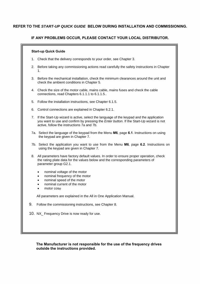
REFER TO THE START-UP QUICK GUIDE BELOW DURING INSTALLATION AND COMMISSIONING.
IF ANY PROBLEMS OCCUR, PLEASE CONTACT YOUR LOCAL DISTRIBUTOR.
Start-up Quick Guide 1. Check that the delivery corresponds to your order, see Chapter 3.
2. Before taking any commissioning actions read carefully the safety instructions in Chapter
1.
3. Before the mechanical installation, check the minimum clearances around the unit and check the ambient conditions in Chapter 5.
4. Check the size of the motor cable, mains cable, mains fuses and check the cable connections, read Chapters 6.1.1.1 to 6.1.1.5..
5. Follow the installation instructions, see Chapter 6.1.5.
6. Control connections are explained in Chapter 6.2.1.
7. If the Start-Up wizard is active, select the language of the keypad and the application you want to use and confirm by pressing the Enter button. If the Start-Up wizard is not active, follow the instructions 7a and 7b.
7a. Select the language of the keypad from the Menu M6, page 6.1. Instructions on using the keypad are given in Chapter 7.
7b. Select the application you want to use from the Menu M6, page 6.2. Instructions on using the keypad are given in Chapter 7.
8. All parameters have factory default values. In order to ensure proper operation, check
the rating plate data for the values below and the corresponding parameters of parameter group G2.1. • nominal voltage of the motor • nominal frequency of the motor • nominal speed of the motor • nominal current of the motor • motor cosϕ
All parameters are explained in the All in One Application Manual.
9. Follow the commissioning instructions, see Chapter 8.
10. NX_ Frequency Drive is now ready for use.
The Manufacturer is not responsible for the use of the frequency drives outside the instructions provided.
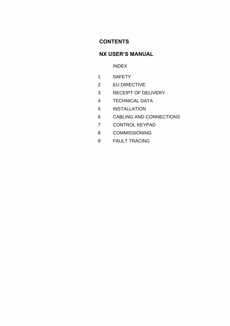
CONTENTS NX USER’S MANUAL
INDEX
1 SAFETY
2 EU DIRECTIVE
3 RECEIPT OF DELIVERY
4 TECHNICAL DATA
5 INSTALLATION
6 CABLING AND CONNECTIONS
7 CONTROL KEYPAD
8 COMMISSIONING
9 FAULT TRACING
THE NX FREQUENCY DRIVE USER'S MANUAL AND THE APPLICATION MANUAL The User's Manual will provide the necessary information about the installation, commissioning and operation of NX Frequency Drives. It is recommended that these instructions are studied, before powering up the frequency drive for the first time. The Application Manual provides information about the different applications included in the standard frequency drive. Should these applications not meet the requirements of the process, contact Honeywell for information on special applications. This manual is available in both paper and electronic editions. It is recommended that the electronic version be used where possible as it contains several links and cross-references to other locations in the manual which makes it easier for the reader to move around in the manual, to check and find things faster.
NX User's Manual Index
1. SAFETY....................................................................................................................................6 1.1 WARNINGS..............................................................................................................................................6 1.2 SAFETY INSTRUCTIONS............................................................................................................................6 1.3 GROUNDING AND GROUND FAULT PROTECTION.........................................................................................7 1.4 RUNNING THE MOTOR..............................................................................................................................7 2. DIRECTIVES.............................................................................................................................8 2.1 CE MARKING...........................................................................................................................................8 2.2 EMC DIRECTIVE......................................................................................................................................8 2.2.1 General...............................................................................................................................................8 2.2.2 Technical criteria ................................................................................................................................8 2.2.3 NX frequency drive EMC classification...............................................................................................8 2.2.4 Manufacturer's declaration of conformity............................................................................................9 2.3 UL-LABEL................................................................................................................................................9 3. RECEIPT OF SHIPMENT .......................................................................................................13 3.1 TYPE DESIGNATION CODE ......................................................................................................................13 3.2 STORAGE..............................................................................................................................................13 3.3 MAINTENANCE.......................................................................................................................................14 3.4 WARRANTY ...........................................................................................................................................14 4. TECHNICAL DATA ................................................................................................................15 4.1 INTRODUCTION......................................................................................................................................15 4.2 POWER RATINGS ...................................................................................................................................17 4.2.1 NX_5 – Mains voltage 380—500 V ..................................................................................................17 4.2.2 NX_6 – Mains voltage 525—690 V ..................................................................................................18 4.2.3 NX_2 – Mains voltage 208—240 V ..................................................................................................19 4.3 BRAKE RESISTOR RATINGS ....................................................................................................................20 4.4 TECHNICAL DATA...................................................................................................................................22 5. INSTALLATION......................................................................................................................24 5.1 MOUNTING ............................................................................................................................................24 5.2 COOLING...............................................................................................................................................34 5.2.1 FR4 to FR9 .......................................................................................................................................34 5.2.2 Standalone units (FR10 to FR12).....................................................................................................35 5.3 POWER LOSS ........................................................................................................................................36 5.3.1 Power loss as function of switching frequency .................................................................................36 6. CABLING AND CONNECTIONS............................................................................................40 6.1 POWER UNIT .........................................................................................................................................40 6.1.1 Power connections ...........................................................................................................................40 6.1.1.1 Mains and motor cables ................................................................................................................40 6.1.1.2 DC supply and brake resistor cables.............................................................................................41 6.1.1.3 Control cable .................................................................................................................................41 6.1.1.4 Cable and fuse sizes, NXS B and NXS A......................................................................................41 6.1.1.5 Cable and fuse sizes, NXS C ........................................................................................................42 6.1.1.6 Cable and fuse sizes, NX_A, FR10 to FR12 .................................................................................42 6.1.1.7 Cable and fuse sizes, NX_C, FR10 to FR12 .................................................................................43 6.1.2 Understanding the power unit topology ............................................................................................43 6.1.3 Changing EMC protection class from H to T ....................................................................................44
6.1.4 Mounting of cable accessories .........................................................................................................46 6.1.5 Installation instructions .....................................................................................................................48 6.1.5.1 Stripping lengths of motor and mains cables.................................................................................50 6.1.5.2 NX frequency drive frames and installation of cables....................................................................51 6.1.6 Cable installation and the UL standards...........................................................................................58 6.1.7 Cable and motor insulation checks...................................................................................................59 6.2 CONTROL UNIT ......................................................................................................................................60 6.2.1 NXS and NXP single phase input applications 380-500 VAC ..........................................................61 6.2.2 Control connections..........................................................................................................................62 6.2.2.1 Control cables................................................................................................................................63 6.2.2.2 Galvanic isolation barriers .............................................................................................................63 6.2.3 Control terminal signals ....................................................................................................................65 6.2.3.1 Digital input signal inversions ........................................................................................................66 6.2.3.2 Jumper selections on the OPT-A1 basic board .............................................................................67 7. CONTROL KEYPAD ..............................................................................................................69 7.1 INDICATIONS ON THE KEYPAD DISPLAY ...................................................................................................69 7.1.1 Drive status indications.....................................................................................................................69 7.1.2 Control place indications ..................................................................................................................70 7.1.3 Status LEDs (green – green – red)...................................................................................................70 7.1.4 Text lines ..........................................................................................................................................71 7.2 KEYPAD PUSH-BUTTONS........................................................................................................................72 7.2.1 Button descriptions ...........................................................................................................................72 7.3 NAVIGATION ON THE CONTROL KEYPAD ..................................................................................................73 7.3.1 Monitoring menu (M1) ......................................................................................................................75 7.3.2 Parameter menu (M2) ......................................................................................................................76 7.3.3 Keypad control menu (M3) ...............................................................................................................78 7.3.3.1 Selection of control place ..............................................................................................................78 7.3.3.2 Keypad reference ..........................................................................................................................79 7.3.3.3 Keypad direction............................................................................................................................79 7.3.3.4 Stop button activated.....................................................................................................................79 7.3.4 Active faults menu (M4)....................................................................................................................80 7.3.4.1 Fault types .....................................................................................................................................81 7.3.4.2 Fault codes ....................................................................................................................................82 7.3.4.3 Fault time data record....................................................................................................................84 7.3.5 Fault history menu (M5)....................................................................................................................85 7.3.6 System menu (M6) ...........................................................................................................................86 7.3.6.1 Language selection .......................................................................................................................89 7.3.6.2 Application selection......................................................................................................................89 7.3.6.3 Parameter copy .............................................................................................................................90 7.3.6.4 Parameter comparison ..................................................................................................................92 7.3.6.5 Security..........................................................................................................................................93 7.3.6.6 Keypad settings .............................................................................................................................95 7.3.6.7 Hardware settings..........................................................................................................................96 7.3.6.8 System info....................................................................................................................................99 7.3.7 Expander board menu (M7)............................................................................................................103 7.4 FURTHER KEYPAD FUNCTIONS .............................................................................................................104 8. COMMISSIONING ................................................................................................................105 8.1 SAFETY...............................................................................................................................................105 8.2 COMMISSIONING OF THE FREQUENCY DRIVE.........................................................................................105 9. FAULT TRACING .................................................................................................................108
6(110) Safety 1
1. SAFETY
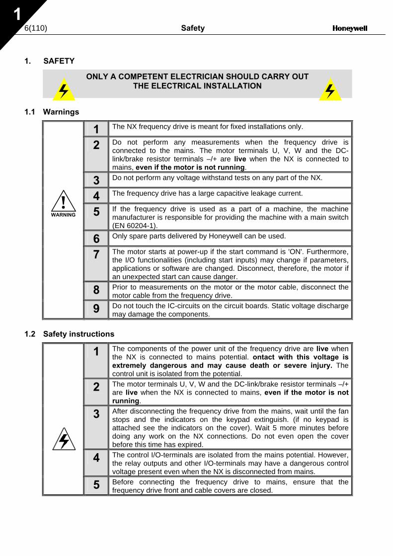
1.1 Warnings
1 The NX frequency drive is meant for fixed installations only.
2 Do not perform any measurements when the frequency drive is connected to the mains. The motor terminals U, V, W and the DC-link/brake resistor terminals –/+ are live when the NX is connected to mains, even if the motor is not running.
3 Do not perform any voltage withstand tests on any part of the NX.
4 The frequency drive has a large capacitive leakage current.
5 If the frequency drive is used as a part of a machine, the machine manufacturer is responsible for providing the machine with a main switch (EN 60204-1).
6 Only spare parts delivered by Honeywell can be used.
7 The motor starts at power-up if the start command is 'ON'. Furthermore, the I/O functionalities (including start inputs) may change if parameters, applications or software are changed. Disconnect, therefore, the motor if an unexpected start can cause danger.
8 Prior to measurements on the motor or the motor cable, disconnect the motor cable from the frequency drive.
9 Do not touch the IC-circuits on the circuit boards. Static voltage discharge may damage the components.
1.2 Safety instructions
1 The components of the power unit of the frequency drive are live when the NX is connected to mains potential. ontact with this voltage is extremely dangerous and may cause death or severe injury. The control unit is isolated from the potential.
2 The motor terminals U, V, W and the DC-link/brake resistor terminals –/+ are live when the NX is connected to mains, even if the motor is not running.
3 After disconnecting the frequency drive from the mains, wait until the fan stops and the indicators on the keypad extinguish. (if no keypad is attached see the indicators on the cover). Wait 5 more minutes before doing any work on the NX connections. Do not even open the cover before this time has expired.
4 The control I/O-terminals are isolated from the mains potential. However, the relay outputs and other I/O-terminals may have a dangerous control voltage present even when the NX is disconnected from mains.
5 Before connecting the frequency drive to mains, ensure that the frequency drive front and cable covers are closed.
ONLY A COMPETENT ELECTRICIAN SHOULD CARRY OUT THE ELECTRICAL INSTALLATION
WARNING
Safety 7(110) 1
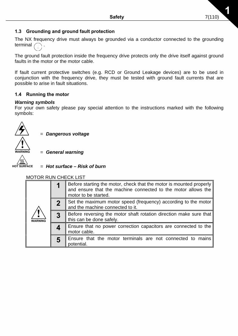
1.3 Grounding and ground fault protection
The NX frequency drive must always be grounded via a conductor connected to the grounding terminal . The ground fault protection inside the frequency drive protects only the drive itself against ground faults in the motor or the motor cable. If fault current protective switches (e.g. RCD or Ground Leakage devices) are to be used in conjunction with the frequency drive, they must be tested with ground fault currents that are possible to arise in fault situations. 1.4 Running the motor
Warning symbols For your own safety please pay special attention to the instructions marked with the following symbols:
= Dangerous voltage
WARNING = General warning
HOT SURFACE = Hot surface – Risk of burn MOTOR RUN CHECK LIST
1 Before starting the motor, check that the motor is mounted properly and ensure that the machine connected to the motor allows the motor to be started.
2 Set the maximum motor speed (frequency) according to the motor and the machine connected to it.
3 Before reversing the motor shaft rotation direction make sure that this can be done safely.
4 Ensure that no power correction capacitors are connected to the motor cable.
5 Ensure that the motor terminals are not connected to mains potential.
WARNING
8(110) DIRECTIVES
2
2. DIRECTIVES
2.1 CE marking
The CE marking on the product guarantees the free movement of the product within the EEA (European Economic Area). It also guarantees that the product meets the various requirements defined by the directive. The NX frequency drives carry the CE label as a proof of compliance with the Low Voltage Directive (LVD) and the Electro Magnetic Compatibility (EMC). The company SGS FIMKO has acted as the Competent Body. 2.2 EMC directive
2.2.1 General The EMC Directive provides that the electrical apparatus must not excessively disturb the environment it is used in, and also, it shall have an adequate level of immunity toward other disturbances from the same environment. The compliance of the NX frequency drives with the EMC directive is verified with Technical Construction Files (TCF) checked and approved by SGS FIMKO, which is a Competent Body. The Technical Construction Files are used to authenticate the comformity of the NX frequency drives with the Directive due to the large product family & variety of installations possibilities. 2.2.2 Technical criteria The NX frequency drives are marketed throughout the world, a fact which makes the EMC requirements of customers different. As far as the immunity is concerned, all NX frequency drives are designed to fulfil even the strictest requirements, while as regards the emission level, the customer may want to upgrade the NX's already high ability to filter electro-magnetic disturbances. 2.2.3 NX frequency drive EMC classification The NX frequency drives are divided into three classes, according to the level of electromagnetic disturbances emitted. There is no difference in the functions or the control electronics between these classes but their EMC properties vary as follows: Class H: NX_5 frequency drives (FR4 to FR9) and NX_2 frequency drives (FR4 to FR6) have been designed to fulfil the requirements of the product standard IEC 61800-3+A11 for the 1st environment restricted distribution and the 2nd environment. The emission levels correspond to the requirements of IEC 61000-6-4. Class L (NX_5, FR10 only): Provides filtering for the 2nd environment, restricted distribution according to IEC 61800-3+A11.
DIRECTIVES 9(110)
2
Class T: The T-class drives have a small ground current and can be used with IT supplies only. If they are used with other supplies no EMC requirements are complied with. Class N: The drives of this class do not provide EMC emission protection. This kind of drives are mounted in enclosures. All NX frequency drives fulfil all EMC immunity requirements (standards IEC 61000-6-1, 61000-6-2 and IEC 61800-3+A11).
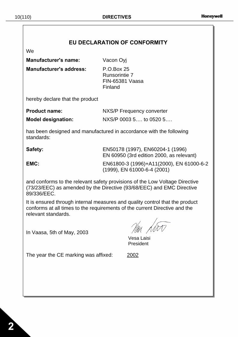
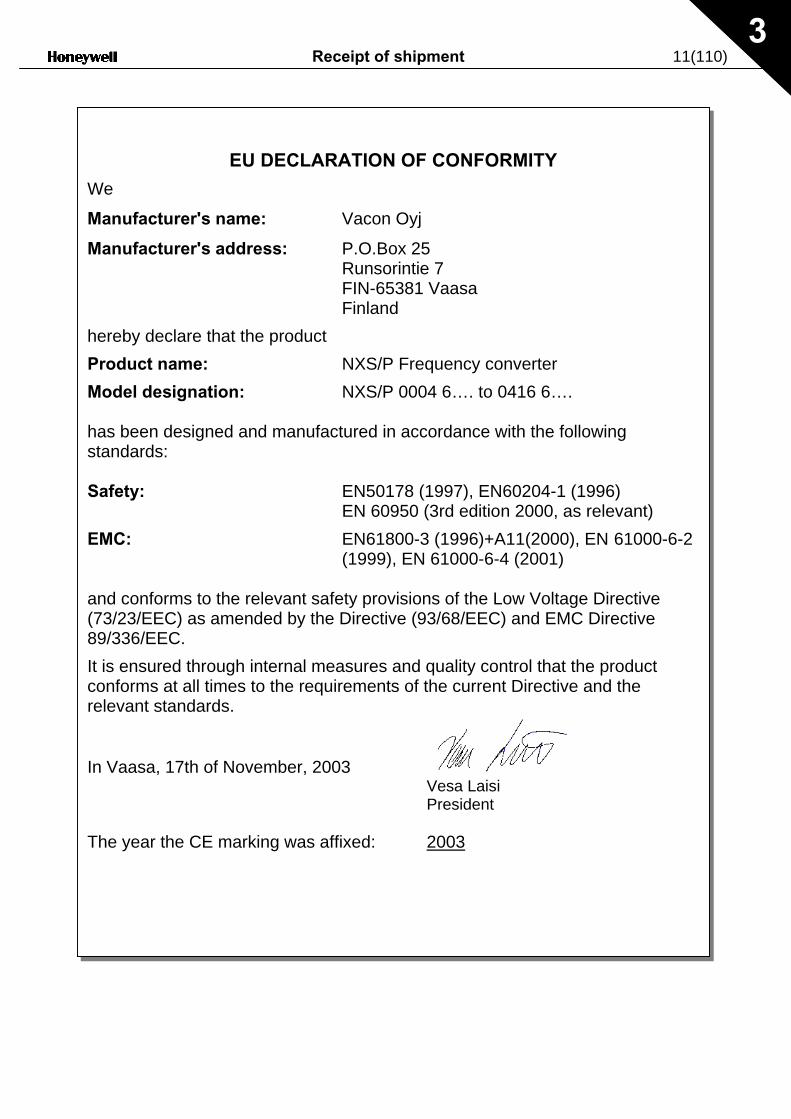
Note: For changing the EMC protection class of your NX frequency drive from class H to class T, please refer to the instructions given in Chapter 6.3.1. 2.2.4 Manufacturer's declaration of conformity The following pages present the photocopies of the Manufacturer's Declarations of Conformity assuring the compliance of the NX frequency drives with the EMC-directives. 2.3 UL-label
The NX frequency drives are UL-listed according to the standards, based on the needed voltage and power range. For more information contact you local Honeywell distributor. More information of cable selection and installation can be found from chapter 5 and 6.
Warning: This is a product of the restricted sales distribution class according to IEC 61800-3. In a domestic environment this product may cause radio interference in which case theuser may be required to take adequate measures.
10(110) DIRECTIVES
2
EU DECLARATION OF CONFORMITY We
Manufacturer's name: Vacon Oyj
Manufacturer's address: P.O.Box 25 Runsorintie 7 FIN-65381 Vaasa Finland hereby declare that the product Product name: NXS/P Frequency converter Model designation: NXS/P 0003 5…. to 0520 5…. has been designed and manufactured in accordance with the following standards: Safety: EN50178 (1997), EN60204-1 (1996) EN 60950 (3rd edition 2000, as relevant) EMC: EN61800-3 (1996)+A11(2000), EN 61000-6-2 (1999), EN 61000-6-4 (2001) and conforms to the relevant safety provisions of the Low Voltage Directive (73/23/EEC) as amended by the Directive (93/68/EEC) and EMC Directive 89/336/EEC. It is ensured through internal measures and quality control that the product conforms at all times to the requirements of the current Directive and the relevant standards.
In Vaasa, 5th of May, 2003 Vesa Laisi President The year the CE marking was affixed: 2002
Receipt of shipment 11(110) 3
EU DECLARATION OF CONFORMITY We
Manufacturer's name: Vacon Oyj
Manufacturer's address: P.O.Box 25 Runsorintie 7 FIN-65381 Vaasa Finland hereby declare that the product Product name: NXS/P Frequency converter Model designation: NXS/P 0004 6…. to 0416 6…. has been designed and manufactured in accordance with the following standards: Safety: EN50178 (1997), EN60204-1 (1996) EN 60950 (3rd edition 2000, as relevant) EMC: EN61800-3 (1996)+A11(2000), EN 61000-6-2 (1999), EN 61000-6-4 (2001) and conforms to the relevant safety provisions of the Low Voltage Directive (73/23/EEC) as amended by the Directive (93/68/EEC) and EMC Directive 89/336/EEC. It is ensured through internal measures and quality control that the product conforms at all times to the requirements of the current Directive and the relevant standards.
In Vaasa, 17th of November, 2003 Vesa Laisi President The year the CE marking was affixed: 2003
12(110) Receipt of shipment 3
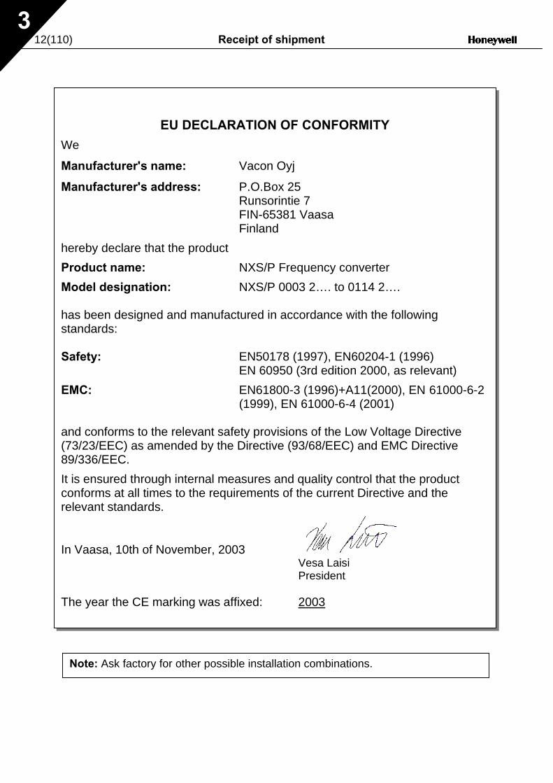
EU DECLARATION OF CONFORMITY We
Manufacturer's name: Vacon Oyj
Manufacturer's address: P.O.Box 25 Runsorintie 7 FIN-65381 Vaasa Finland hereby declare that the product Product name: NXS/P Frequency converter Model designation: NXS/P 0003 2…. to 0114 2…. has been designed and manufactured in accordance with the following standards: Safety: EN50178 (1997), EN60204-1 (1996) EN 60950 (3rd edition 2000, as relevant) EMC: EN61800-3 (1996)+A11(2000), EN 61000-6-2 (1999), EN 61000-6-4 (2001) and conforms to the relevant safety provisions of the Low Voltage Directive (73/23/EEC) as amended by the Directive (93/68/EEC) and EMC Directive 89/336/EEC. It is ensured through internal measures and quality control that the product conforms at all times to the requirements of the current Directive and the relevant standards.
In Vaasa, 10th of November, 2003 Vesa Laisi President The year the CE marking was affixed: 2003
Note: Ask factory for other possible installation combinations.
Receipt of shipment 13(110)
3
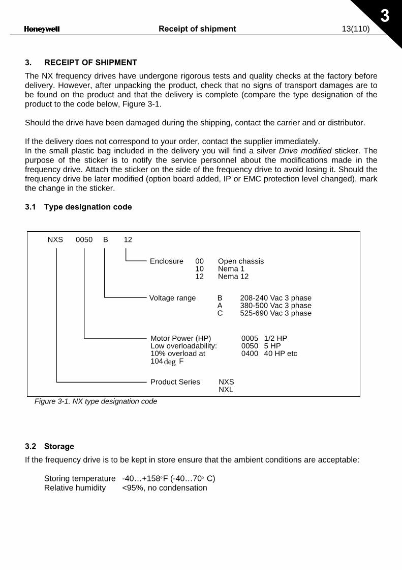
3. RECEIPT OF SHIPMENT
The NX frequency drives have undergone rigorous tests and quality checks at the factory before delivery. However, after unpacking the product, check that no signs of transport damages are to be found on the product and that the delivery is complete (compare the type designation of the product to the code below, Figure 3-1. Should the drive have been damaged during the shipping, contact the carrier and or distributor. If the delivery does not correspond to your order, contact the supplier immediately. In the small plastic bag included in the delivery you will find a silver Drive modified sticker. The purpose of the sticker is to notify the service personnel about the modifications made in the frequency drive. Attach the sticker on the side of the frequency drive to avoid losing it. Should the frequency drive be later modified (option board added, IP or EMC protection level changed), mark the change in the sticker. 3.1 Type designation code
3
If
N X S 0 0 5 0 B 1 2
Figure 3-1. NX type designation code
.2 Storage
the frequency drive is to be kept in store ensure that the ambient conditions are acceptable:
Storing temperature -40…+158°F (-40…70° C) Relative humidity <95%, no condensation
P r o duct Series NXSNXL
M o t or Power (HP) 0005 1/2 HP L o w overloadability: 0050 5 HP1 0 % overload at 0400 40 HP e t c 1 0 4 deg F
V o l t a ge range B 208-240 Vac 3 p h a s e A 380-500 Vac 3 p h a s e C 525-690 Vac 3 p h a s e
E n c l osure 00 Open chassis10 Nema 112 Nema 12
14(110) Receipt of shipment 3
3.3 Maintenance
In normal conditions, the NX frequency drives are maintenance-free. However, it is recommended the heatsink be cleared periodically with compressed air. The cooling fan can easily be changed if necessary. It may also be necessary to check the tightening torques of terminals at regular intervals. 3.4 Warranty
Only manufacturing defects are covered by the warranty. The manufacturer assumes no responsibility for damages caused during or resulting from transport, receipt of the delivery, installation, commissioning or use. The manufacturer shall in no event and under no circumstances be held responsible for damages and failures resulting from misuse, incorrect installation, unacceptable ambient temperature, dust, corrosive substances or operation outside the rated specifications. Neither can the manufacturer be held responsible for consequential damages. The Manufacturer's period of warranty is 18 months from the delivery or 12 months from the commissioning whichever expires first. The local distributor may grant a warranty time different from the above. This warranty period shall be specified in the distributor's sales and warranty terms. The manufacturer assumes no responsibility for warranties offered by others. With all warranty issues, please contact the distributor first.
Technical data 15(110)
Automation and Control Solutions Honeywell Honeywell Limited-Honeywell Limitée 1985 Douglas Drive North 35 Dynamic Drive Golden Valley, MIN 55422 Scarborough, Ontario 63-2600-1 MIV 4Z9
www.honeywell.com 4
4. TECHNICAL DATA
4.1 Introduction
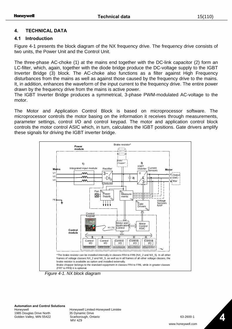
Figure 4-1 presents the block diagram of the NX frequency drive. The frequency drive consists of two units, the Power Unit and the Control Unit. The three-phase AC-choke (1) at the mains end together with the DC-link capacitor (2) form an LC-filter, which, again, together with the diode bridge produce the DC-voltage supply to the IGBT Inverter Bridge (3) block. The AC-choke also functions as a filter against High Frequency disturbances from the mains as well as against those caused by the frequency drive to the mains. It, in addition, enhances the waveform of the input current to the frequency drive. The entire power drawn by the frequency drive from the mains is active power. The IGBT Inverter Bridge produces a symmetrical, 3-phase PWM-modulated AC-voltage to the motor. The Motor and Application Control Block is based on microprocessor software. The microprocessor controls the motor basing on the information it receives through measurements, parameter settings, control I/O and control keypad. The motor and application control block controls the motor control ASIC which, in turn, calculates the IGBT positions. Gate drivers amplify these signals for driving the IGBT inverter bridge.
Figure 4-1. NX block diagram
==L1
L2
L3
U
V
W
3~
3~
Mains Motor
BrakeChopper*
Measure-ments
GateDrivers
MotorControlASIC
Motor andApplicationControl
ControlKeypad
Fan
CurrentSensors
RectifierIGBTInverter
Brake resistor*
OutputEMC-filter
PowerSupply
Control I/O
Control I/O
Control I/O
Control I/O
Control I/O
VoltageSensorsNXP
1)
2)
3)
Integrated input module
Controlmodule
Powermodule
Charg.res.
*The brake resistor can be installed internally in classes FR4 to FR6 (NX_2 and NX_5). In all otherframes of voltage classes NX_2 and NX_5, as well as in all frames of all other voltage classes, thebrake resistor is available as option and installed externally.Brake chopper belongs to the standard equipment in classes FR4 to FR6, while in greater classes(FR7 to FR9) it is optional.
16(110) Technical data
Automation and Control Solutions Honeywell Honeywell Limited-Honeywell Limitée 1985 Douglas Drive North 35 Dynamic Drive Golden Valley, MIN 55422 Scarborough, Ontario 63-2600-1 MIV 4Z9
www.honeywell.com 4
The control keypad provides a link between the user and the frequency drive. The control keypad is used for parameter setting, reading status data and giving control commands. It is detachable and can be operated externally and connected via a cable to the frequency drive. Also a PC can be used instead of the control keypad, to control the frequency drive, if connected through a similar cable. Control I/O boards which are either isolated (OPT-A8) or not isolated (OPT-A1) from the ground are available. The default application (Basic Application) is preferred when speed control will be dictated by a separate automation system. If a more versatile interface or parameters are required, a more suitable application can be chosen from the Application Package. See the Application Manual for more information on the different applications. A brake resistor is available as internal option for frames FR4 to FR6 of voltage classes NX_2 and NX_5. In all other frames of voltage classes NX_2 and NX_5, as well as in all frames of all other voltage classes, the brake resistor is available as option and installed externally. Optional I/O expander boards that increase the number of inputs and outputs to be used are also available. For details please contact your nearest Honeywell office or your local distributor (see back cover). The input and output EMC filters have no influence on the basic functions of the frequency drives and significantly enhance the protection of the drive from external interference as well as protecting other sensitive equipment from harmonics generated by the frequency drive. They are also necessary for the fulfillment of the EMC directives.
Technical data 17(110)
Automation and Control Solutions Honeywell Honeywell Limited-Honeywell Limitée 1985 Douglas Drive North 35 Dynamic Drive Golden Valley, MIN 55422 Scarborough, Ontario 63-2600-1 MIV 4Z9
www.honeywell.com 4
4.2 Power ratings
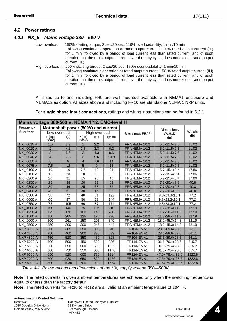
4.2.1 NX_5 – Mains voltage 380—500 V Low overload = 150% starting torque, 2 sec/20 sec, 110% overloadability, 1 min/10 min
Following continuous operation at rated output current, 110% rated output current (IL) for 1 min, followed by a period of load current less than rated current, and of such duration that the r.m.s output current, over the duty cycle, does not exceed rated output current (IL)
High overload = 200% starting torque, 2 sec/20 sec, 150% overloadability, 1 min/10 min Following continuous operation at rated output current, 150 % rated output current (IH) for 1 min, followed by a period of load current less than rated current, and of such duration that the r.m.s output current, over the duty cycle, does not exceed rated output current (IH)
All sizes up to and including FR9 are wall mounted available with NEMA1 enclosure and NEMA12 as option. All sizes above and including FR10 are standalone NEMA 1 NXP units. For single phase input connections, ratings and wiring instructions can be found in 6.2.1
Mains voltage 380-500 V, NEMA 1/12, EMC-level H Motor shaft power (500V) and current
Low overload High overload Frequency drive type
P [Hp] (500V)
I(L) P [Hp] (500V)
I(H) I(max) Size / prot. FR/IP
Dimensions WxHxD
(in)
Weight (lb)
NX_ 0015 A 1.5 3.3 1 2.2 4.4 FR4/NEMA 1/12 5.0x11.5x7.5 11.02 NX_ 0020 A 2 4.3 1.5 3.3 6.2 FR4/NEMA 1/12 5.0x11.5x7.5 11.02 NX_ 0030 A 3 5.6 2 4.3 8.6 FR4/NEMA 1/12 5.0x11.5x7.5 11.02 NX_ 0040 A 4 7.6 3 5.6 10.8 FR4/NEMA 1/12 5.0x11.5x7.5 11.02 NX_ 0050 A 5 9 4 7.6 14 FR4/NEMA 1/12 5.0x11.5x7.5 11.02 NX_ 0075 A 7.5 12 5 9 18 FR4/NEMA 1/12 5.0x11.5x7.5 11.02 NX_ 0100 A 10 16 7.5 12 24 FR5/NEMA 1/12 5.7x15.4x8.4 17.86 NX_ 0150 A 15 23 10 16 32 FR5/NEMA 1/12 5.7x15.4x8.4 17.86 NX_ 0200 A 20 31 15 23 46 FR5/NEMA 1/12 5.7x15.4x8.4 17.86 NX_ 0250 A 25 38 20 31 62 FR6/NEMA 1/12 7.7x20.4x9.3 40.8 NX_ 0300 A 30 46 25 38 76 FR6/NEMA 1/12 7.7x20.4x9.3 40.8 NX_ 0400 A 40 61 30 46 92 FR6/NEMA 1/12 7.7x20.4x9.3 40.8 NX_ 0500 A 50 72 40 61 122 FR7/NEMA 1/12 9.3x23.3x10.1 77.2 NX_ 0600 A 60 87 50 72 144 FR7/NEMA 1/12 9.3x23.3x10.1 77.2 NX_ 0750 A 75 105 60 87 174 FR7/NEMA 1/12 9.3x23.3x10.1 77.2 NX_ 1000 A 100 140 75 105 210 FR8/NEMA 1/12 11.2x28.4x11.3 127.9 NX_ 1250 A 125 170 100 140 280 FR8/NEMA 1/12 11.2x28.4x11.3 127.9 NX_ 1500 A 150 205 125 170 336 FR8/NEMA 1/12 11.2x28.4x11.3 127.9 NX_ 2000 A 200 261 150 205 349 FR9/NEMA 1/12 18.9x45.3x14.3 321.9 NX_ 2500 A 250 300 200 245 444 FR9/NEMA 1/12 18.9x45.3x14.3 321.9 NXP 3000 A 300 385 250 300 540 FR10/NEMA1 23.6x89.6x23.6 661.1 NXP 3500 A 350 460 300 385 693 FR10/NEMA1 23.6x89.6x23.6 661.1 NXP 4500 A 450 520 350 460 828 FR10/NEMA1 23.6x89.6x23.6 661.1 NXP 5000 A 500 590 450 520 936 FR11/NEMA1 31.6x79.4x23.6 815.7 NXP 5500 A 550 650 500 590 1062 FR11/NEMA1 31.6x79.4x23.6 815.7 NXP 6000 A 600 730 550 650 1170 FR11/NEMA1 31.6x79.4x23.6 815.7 NXP 6500 A 650 820 600 730 1314 FR12/NEMA1 47.6x 79.4x 23.6 1322.8 NXP 7000 A 700 920 650 820 1476 FR12/NEMA1 47.6x 79.4x 23.6 1322.8 NXP 8000 A 800 1030 700 920 1654 FR12/NEMA1 47.6x 79.4x 23.6 1322.8
Table 4-1. Power ratings and dimensions of the NX, supply voltage 380—500V.
Note: The rated currents in given ambient temperatures are achieved only when the switching frequency is equal to or less than the factory default. Note: The rated currents for FR10 to FR12 are all valid at an ambient temperature of 104 °F.
18(110) Technical data
Automation and Control Solutions Honeywell Honeywell Limited-Honeywell Limitée 1985 Douglas Drive North 35 Dynamic Drive Golden Valley, MIN 55422 Scarborough, Ontario 63-2600-1 MIV 4Z9
www.honeywell.com 4
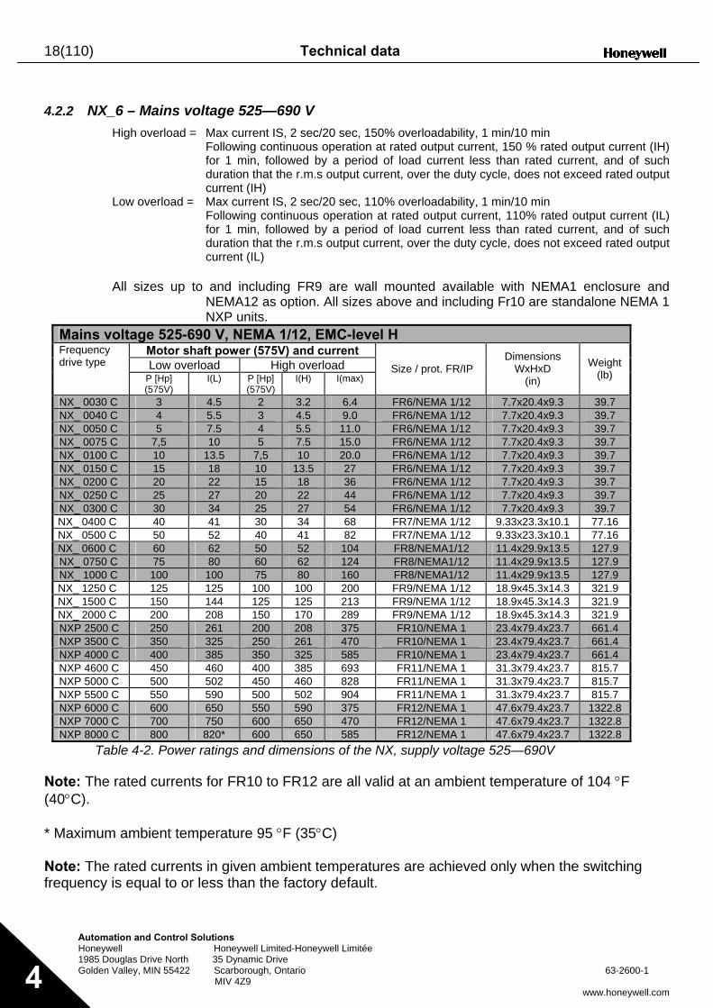
4.2.2 NX_6 – Mains voltage 525—690 V
High overload = Max current IS, 2 sec/20 sec, 150% overloadability, 1 min/10 min Following continuous operation at rated output current, 150 % rated output current (IH) for 1 min, followed by a period of load current less than rated current, and of such duration that the r.m.s output current, over the duty cycle, does not exceed rated output current (IH)
Low overload = Max current IS, 2 sec/20 sec, 110% overloadability, 1 min/10 min Following continuous operation at rated output current, 110% rated output current (IL) for 1 min, followed by a period of load current less than rated current, and of such duration that the r.m.s output current, over the duty cycle, does not exceed rated output current (IL)
All sizes up to and including FR9 are wall mounted available with NEMA1 enclosure and
NEMA12 as option. All sizes above and including Fr10 are standalone NEMA 1 NXP units.
Mains voltage 525-690 V, NEMA 1/12, EMC-level H Motor shaft power (575V) and current Low overload High overload
Frequency drive type
P [Hp] (575V)
I(L) P [Hp] (575V)
I(H) I(max) Size / prot. FR/IP
Dimensions WxHxD
(in)
Weight (lb)
NX_ 0030 C 3 4.5 2 3.2 6.4 FR6/NEMA 1/12 7.7x20.4x9.3 39.7 NX_ 0040 C 4 5.5 3 4.5 9.0 FR6/NEMA 1/12 7.7x20.4x9.3 39.7 NX_ 0050 C 5 7.5 4 5.5 11.0 FR6/NEMA 1/12 7.7x20.4x9.3 39.7 NX_ 0075 C 7,5 10 5 7.5 15.0 FR6/NEMA 1/12 7.7x20.4x9.3 39.7 NX_ 0100 C 10 13.5 7,5 10 20.0 FR6/NEMA 1/12 7.7x20.4x9.3 39.7 NX_ 0150 C 15 18 10 13.5 27 FR6/NEMA 1/12 7.7x20.4x9.3 39.7 NX_ 0200 C 20 22 15 18 36 FR6/NEMA 1/12 7.7x20.4x9.3 39.7 NX_ 0250 C 25 27 20 22 44 FR6/NEMA 1/12 7.7x20.4x9.3 39.7 NX_ 0300 C 30 34 25 27 54 FR6/NEMA 1/12 7.7x20.4x9.3 39.7 NX_ 0400 C 40 41 30 34 68 FR7/NEMA 1/12 9.33x23.3x10.1 77.16 NX_ 0500 C 50 52 40 41 82 FR7/NEMA 1/12 9.33x23.3x10.1 77.16 NX_ 0600 C 60 62 50 52 104 FR8/NEMA1/12 11.4x29.9x13.5 127.9 NX_ 0750 C 75 80 60 62 124 FR8/NEMA1/12 11.4x29.9x13.5 127.9 NX_ 1000 C 100 100 75 80 160 FR8/NEMA1/12 11.4x29.9x13.5 127.9 NX_ 1250 C 125 125 100 100 200 FR9/NEMA 1/12 18.9x45.3x14.3 321.9 NX_ 1500 C 150 144 125 125 213 FR9/NEMA 1/12 18.9x45.3x14.3 321.9 NX_ 2000 C 200 208 150 170 289 FR9/NEMA 1/12 18.9x45.3x14.3 321.9 NXP 2500 C 250 261 200 208 375 FR10/NEMA 1 23.4x79.4x23.7 661.4 NXP 3500 C 350 325 250 261 470 FR10/NEMA 1 23.4x79.4x23.7 661.4 NXP 4000 C 400 385 350 325 585 FR10/NEMA 1 23.4x79.4x23.7 661.4 NXP 4600 C 450 460 400 385 693 FR11/NEMA 1 31.3x79.4x23.7 815.7 NXP 5000 C 500 502 450 460 828 FR11/NEMA 1 31.3x79.4x23.7 815.7 NXP 5500 C 550 590 500 502 904 FR11/NEMA 1 31.3x79.4x23.7 815.7 NXP 6000 C 600 650 550 590 375 FR12/NEMA 1 47.6x79.4x23.7 1322.8 NXP 7000 C 700 750 600 650 470 FR12/NEMA 1 47.6x79.4x23.7 1322.8 NXP 8000 C 800 820* 600 650 585 FR12/NEMA 1 47.6x79.4x23.7 1322.8
Table 4-2. Power ratings and dimensions of the NX, supply voltage 525—690V
Note: The rated currents for FR10 to FR12 are all valid at an ambient temperature of 104 °F (40°C). * Maximum ambient temperature 95 °F (35°C) Note: The rated currents in given ambient temperatures are achieved only when the switching frequency is equal to or less than the factory default.
Technical data 19(110)
Automation and Control Solutions Honeywell Honeywell Limited-Honeywell Limitée 1985 Douglas Drive North 35 Dynamic Drive Golden Valley, MIN 55422 Scarborough, Ontario 63-2600-1 MIV 4Z9
www.honeywell.com 4
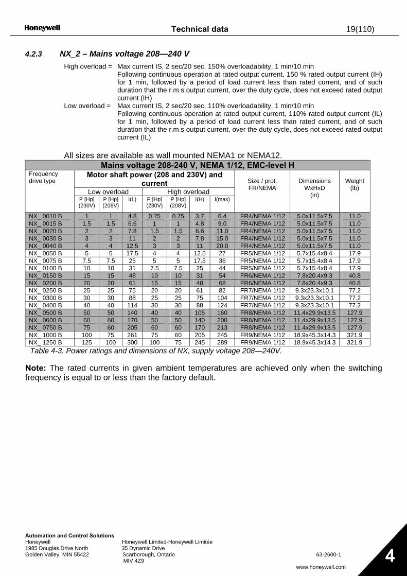
4.2.3 NX_2 – Mains voltage 208—240 V High overload = Max current IS, 2 sec/20 sec, 150% overloadability, 1 min/10 min
Following continuous operation at rated output current, 150 % rated output current (IH) for 1 min, followed by a period of load current less than rated current, and of such duration that the r.m.s output current, over the duty cycle, does not exceed rated output current (IH)
Low overload = Max current IS, 2 sec/20 sec, 110% overloadability, 1 min/10 min Following continuous operation at rated output current, 110% rated output current (IL) for 1 min, followed by a period of load current less than rated current, and of such duration that the r.m.s output current, over the duty cycle, does not exceed rated output current (IL)
All sizes are available as wall mounted NEMA1 or NEMA12.
Mains voltage 208-240 V, NEMA 1/12, EMC-level H Motor shaft power (208 and 230V) and
current Low overload High overload
Frequency drive type
P [Hp] (230V)
P [Hp] (208V)
I(L) P [Hp] (230V)
P [Hp] (208V)
I(H) I(max)
Size / prot. FR/NEMA
Dimensions
WxHxD (in)
Weight
(lb)
NX_ 0010 B 1 1 4.8 0.75 0.75 3.7 6.4 FR4/NEMA 1/12 5.0x11.5x7.5 11.0 NX_ 0015 B 1.5 1.5 6.6 1 1 4.8 9.0 FR4/NEMA 1/12 5.0x11.5x7.5 11.0 NX_ 0020 B 2 2 7.8 1.5 1.5 6.6 11.0 FR4/NEMA 1/12 5.0x11.5x7.5 11.0 NX_ 0030 B 3 3 11 2 2 7.8 15.0 FR4/NEMA 1/12 5.0x11.5x7.5 11.0 NX_ 0040 B 4 4 12.5 3 3 11 20.0 FR4/NEMA 1/12 5.0x11.5x7.5 11.0 NX_ 0050 B 5 5 17.5 4 4 12.5 27 FR5/NEMA 1/12 5.7x15.4x8.4 17.9 NX_ 0075 B 7.5 7.5 25 5 5 17.5 36 FR5/NEMA 1/12 5.7x15.4x8.4 17.9 NX_ 0100 B 10 10 31 7.5 7.5 25 44 FR5/NEMA 1/12 5.7x15.4x8.4 17.9 NX_ 0150 B 15 15 48 10 10 31 54 FR6/NEMA 1/12 7.8x20.4x9.3 40.8 NX_ 0200 B 20 20 61 15 15 48 68 FR6/NEMA 1/12 7.8x20.4x9.3 40.8 NX_ 0250 B 25 25 75 20 20 61 82 FR7/NEMA 1/12 9.3x23.3x10.1 77.2 NX_ 0300 B 30 30 88 25 25 75 104 FR7/NEMA 1/12 9.3x23.3x10.1 77.2 NX_ 0400 B 40 40 114 30 30 88 124 FR7/NEMA 1/12 9.3x23.3x10.1 77.2 NX_ 0500 B 50 50 140 40 40 105 160 FR8/NEMA 1/12 11.4x29.9x13.5 127.9 NX_ 0600 B 60 60 170 50 50 140 200 FR8/NEMA 1/12 11.4x29.9x13.5 127.9 NX_ 0750 B 75 60 205 60 60 170 213 FR8/NEMA 1/12 11.4x29.9x13.5 127.9 NX_ 1000 B 100 75 261 75 60 205 245 FR9/NEMA 1/12 18.9x45.3x14.3 321.9 NX_ 1250 B 125 100 300 100 75 245 289 FR9/NEMA 1/12 18.9x45.3x14.3 321.9 Table 4-3. Power ratings and dimensions of NX, supply voltage 208—240V.
Note: The rated currents in given ambient temperatures are achieved only when the switching frequency is equal to or less than the factory default.
20(110) Technical data
Automation and Control Solutions Honeywell Honeywell Limited-Honeywell Limitée 1985 Douglas Drive North 35 Dynamic Drive Golden Valley, MIN 55422 Scarborough, Ontario 63-2600-1 MIV 4Z9
www.honeywell.com 4
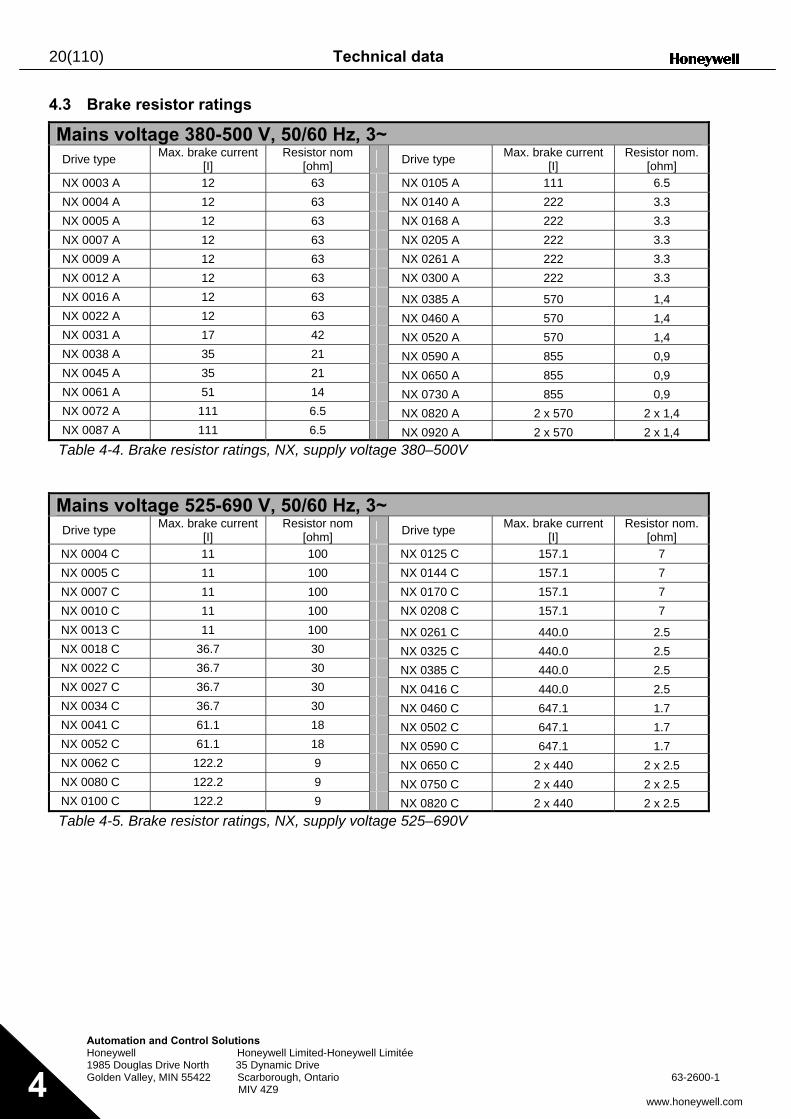
4.3 Brake resistor ratings
Mains voltage 380-500 V, 50/60 Hz, 3~ Drive type Max. brake current
[I] Resistor nom
[ohm] Drive type Max. brake current [I]
Resistor nom. [ohm]
NX 0003 A 12 63 NX 0105 A 111 6.5 NX 0004 A 12 63 NX 0140 A 222 3.3 NX 0005 A 12 63 NX 0168 A 222 3.3 NX 0007 A 12 63 NX 0205 A 222 3.3 NX 0009 A 12 63 NX 0261 A 222 3.3 NX 0012 A 12 63 NX 0300 A 222 3.3 NX 0016 A 12 63 NX 0385 A 570 1,4 NX 0022 A 12 63 NX 0460 A 570 1,4 NX 0031 A 17 42 NX 0520 A 570 1,4 NX 0038 A 35 21 NX 0590 A 855 0,9 NX 0045 A 35 21 NX 0650 A 855 0,9 NX 0061 A 51 14 NX 0730 A 855 0,9 NX 0072 A 111 6.5 NX 0820 A 2 x 570 2 x 1,4 NX 0087 A 111 6.5 NX 0920 A 2 x 570 2 x 1,4 Table 4-4. Brake resistor ratings, NX, supply voltage 380–500V
Mains voltage 525-690 V, 50/60 Hz, 3~ Drive type Max. brake current
[I] Resistor nom
[ohm] Drive type Max. brake current [I]
Resistor nom. [ohm]
NX 0004 C 11 100 NX 0125 C 157.1 7 NX 0005 C 11 100 NX 0144 C 157.1 7 NX 0007 C 11 100 NX 0170 C 157.1 7 NX 0010 C 11 100 NX 0208 C 157.1 7 NX 0013 C 11 100 NX 0261 C 440.0 2.5 NX 0018 C 36.7 30 NX 0325 C 440.0 2.5 NX 0022 C 36.7 30 NX 0385 C 440.0 2.5 NX 0027 C 36.7 30 NX 0416 C 440.0 2.5 NX 0034 C 36.7 30 NX 0460 C 647.1 1.7 NX 0041 C 61.1 18 NX 0502 C 647.1 1.7 NX 0052 C 61.1 18 NX 0590 C 647.1 1.7 NX 0062 C 122.2 9 NX 0650 C 2 x 440 2 x 2.5 NX 0080 C 122.2 9 NX 0750 C 2 x 440 2 x 2.5 NX 0100 C 122.2 9 NX 0820 C 2 x 440 2 x 2.5 Table 4-5. Brake resistor ratings, NX, supply voltage 525–690V
Technical data 21(110)
Automation and Control Solutions Honeywell Honeywell Limited-Honeywell Limitée 1985 Douglas Drive North 35 Dynamic Drive Golden Valley, MIN 55422 Scarborough, Ontario 63-2600-1 MIV 4Z9
www.honeywell.com 4
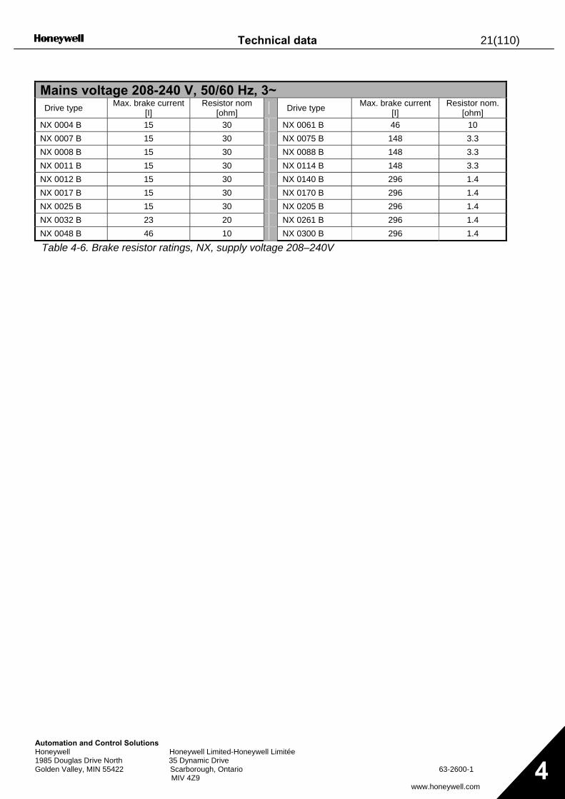
Mains voltage 208-240 V, 50/60 Hz, 3~ Drive type Max. brake current
[I] Resistor nom
[ohm] Drive type Max. brake current [I]
Resistor nom. [ohm]
NX 0004 B 15 30 NX 0061 B 46 10 NX 0007 B 15 30 NX 0075 B 148 3.3 NX 0008 B 15 30 NX 0088 B 148 3.3 NX 0011 B 15 30 NX 0114 B 148 3.3 NX 0012 B 15 30 NX 0140 B 296 1.4 NX 0017 B 15 30 NX 0170 B 296 1.4 NX 0025 B 15 30 NX 0205 B 296 1.4 NX 0032 B 23 20 NX 0261 B 296 1.4 NX 0048 B 46 10 NX 0300 B 296 1.4
Table 4-6. Brake resistor ratings, NX, supply voltage 208–240V
22(110) Technical data
Automation and Control Solutions Honeywell Honeywell Limited-Honeywell Limitée 1985 Douglas Drive North 35 Dynamic Drive Golden Valley, MIN 55422 Scarborough, Ontario 63-2600-1 MIV 4Z9
www.honeywell.com 4
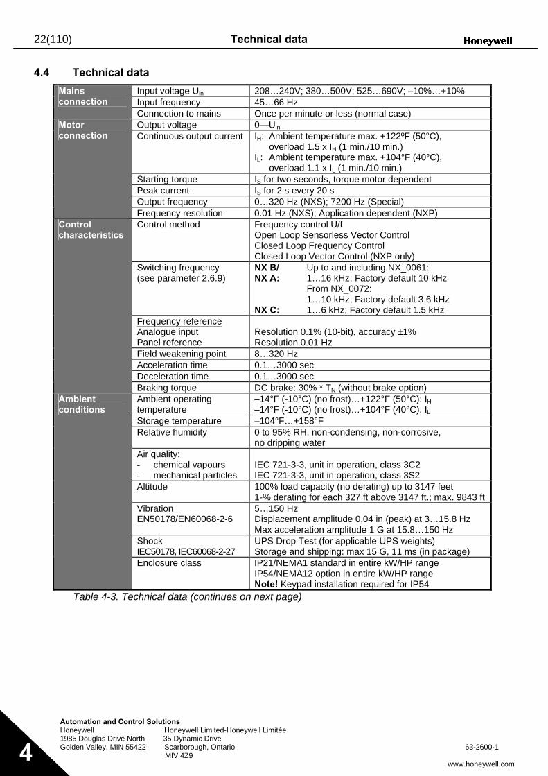
4.4 Technical data
Input voltage Uin 208…240V; 380…500V; 525…690V; –10%…+10% Input frequency 45…66 Hz
Mains connection
Connection to mains Once per minute or less (normal case) Output voltage 0—Uin Continuous output current IH: Ambient temperature max. +122ºF (50°C),
overload 1.5 x IH (1 min./10 min.) IL: Ambient temperature max. +104°F (40°C),
overload 1.1 x IL (1 min./10 min.) Starting torque IS for two seconds, torque motor dependent Peak current IS for 2 s every 20 s Output frequency 0…320 Hz (NXS); 7200 Hz (Special)
Motor connection
Frequency resolution 0.01 Hz (NXS); Application dependent (NXP) Control method Frequency control U/f
Open Loop Sensorless Vector Control Closed Loop Frequency Control Closed Loop Vector Control (NXP only)
Switching frequency (see parameter 2.6.9)
NX B/ NX A: NX C:
Up to and including NX_0061: 1…16 kHz; Factory default 10 kHz From NX_0072: 1…10 kHz; Factory default 3.6 kHz 1…6 kHz; Factory default 1.5 kHz
Frequency reference Analogue input Panel reference
Resolution 0.1% (10-bit), accuracy ±1% Resolution 0.01 Hz
Field weakening point 8…320 Hz Acceleration time 0.1…3000 sec Deceleration time 0.1…3000 sec
Control characteristics
Braking torque DC brake: 30% * TN (without brake option) Ambient operating temperature
–14°F (-10°C) (no frost)…+122°F (50°C): IH –14°F (-10°C) (no frost)…+104°F (40°C): IL
Storage temperature –104°F…+158°F Relative humidity 0 to 95% RH, non-condensing, non-corrosive,
no dripping water Air quality: - chemical vapours - mechanical particles
IEC 721-3-3, unit in operation, class 3C2 IEC 721-3-3, unit in operation, class 3S2
Altitude 100% load capacity (no derating) up to 3147 feet 1-% derating for each 327 ft above 3147 ft.; max. 9843 ft
Vibration EN50178/EN60068-2-6
5…150 Hz Displacement amplitude 0,04 in (peak) at 3…15.8 Hz Max acceleration amplitude 1 G at 15.8…150 Hz
Shock IEC50178, IEC60068-2-27
UPS Drop Test (for applicable UPS weights) Storage and shipping: max 15 G, 11 ms (in package)
Ambient conditions
Enclosure class IP21/NEMA1 standard in entire kW/HP range IP54/NEMA12 option in entire kW/HP range Note! Keypad installation required for IP54
Table 4-3. Technical data (continues on next page)
Technical data 23(110)
Automation and Control Solutions Honeywell Honeywell Limited-Honeywell Limitée 1985 Douglas Drive North 35 Dynamic Drive Golden Valley, MIN 55422 Scarborough, Ontario 63-2600-1 MIV 4Z9
www.honeywell.com 4
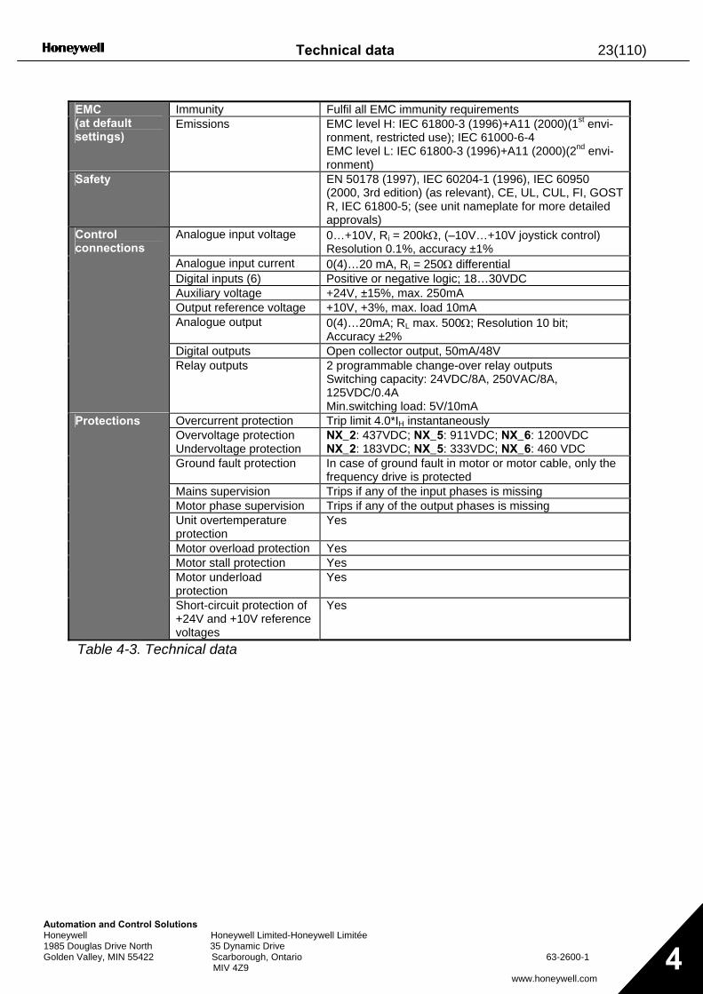
Immunity Fulfil all EMC immunity requirements EMC
(at default settings)
Emissions EMC level H: IEC 61800-3 (1996)+A11 (2000)(1st envi-ronment, restricted use); IEC 61000-6-4 EMC level L: IEC 61800-3 (1996)+A11 (2000)(2nd envi-ronment)
Safety EN 50178 (1997), IEC 60204-1 (1996), IEC 60950 (2000, 3rd edition) (as relevant), CE, UL, CUL, FI, GOST R, IEC 61800-5; (see unit nameplate for more detailed approvals)
Analogue input voltage 0…+10V, Ri = 200kΩ, (–10V…+10V joystick control) Resolution 0.1%, accuracy ±1%
Analogue input current 0(4)…20 mA, Ri = 250Ω differential Digital inputs (6) Positive or negative logic; 18…30VDC Auxiliary voltage +24V, ±15%, max. 250mA Output reference voltage +10V, +3%, max. load 10mA Analogue output 0(4)…20mA; RL max. 500Ω; Resolution 10 bit;
Accuracy ±2% Digital outputs Open collector output, 50mA/48V
Control connections
Relay outputs 2 programmable change-over relay outputs Switching capacity: 24VDC/8A, 250VAC/8A, 125VDC/0.4A Min.switching load: 5V/10mA
Overcurrent protection Trip limit 4.0*IH instantaneously Overvoltage protection Undervoltage protection
NX_2: 437VDC; NX_5: 911VDC; NX_6: 1200VDC NX_2: 183VDC; NX_5: 333VDC; NX_6: 460 VDC
Ground fault protection In case of ground fault in motor or motor cable, only the frequency drive is protected
Mains supervision Trips if any of the input phases is missing Motor phase supervision Trips if any of the output phases is missing Unit overtemperature protection
Yes
Motor overload protection Yes Motor stall protection Yes Motor underload protection
Yes
Protections
Short-circuit protection of +24V and +10V reference voltages
Yes
Table 4-3. Technical data
24(110) Installation
Automation and Control Solutions Honeywell Honeywell Limited-Honeywell Limitée 1985 Douglas Drive North 35 Dynamic Drive Golden Valley, MIN 55422 Scarborough, Ontario 63-2600-1 MIV 4Z9
www.honeywell.com
5
5. INSTALLATION
5.1 Mounting
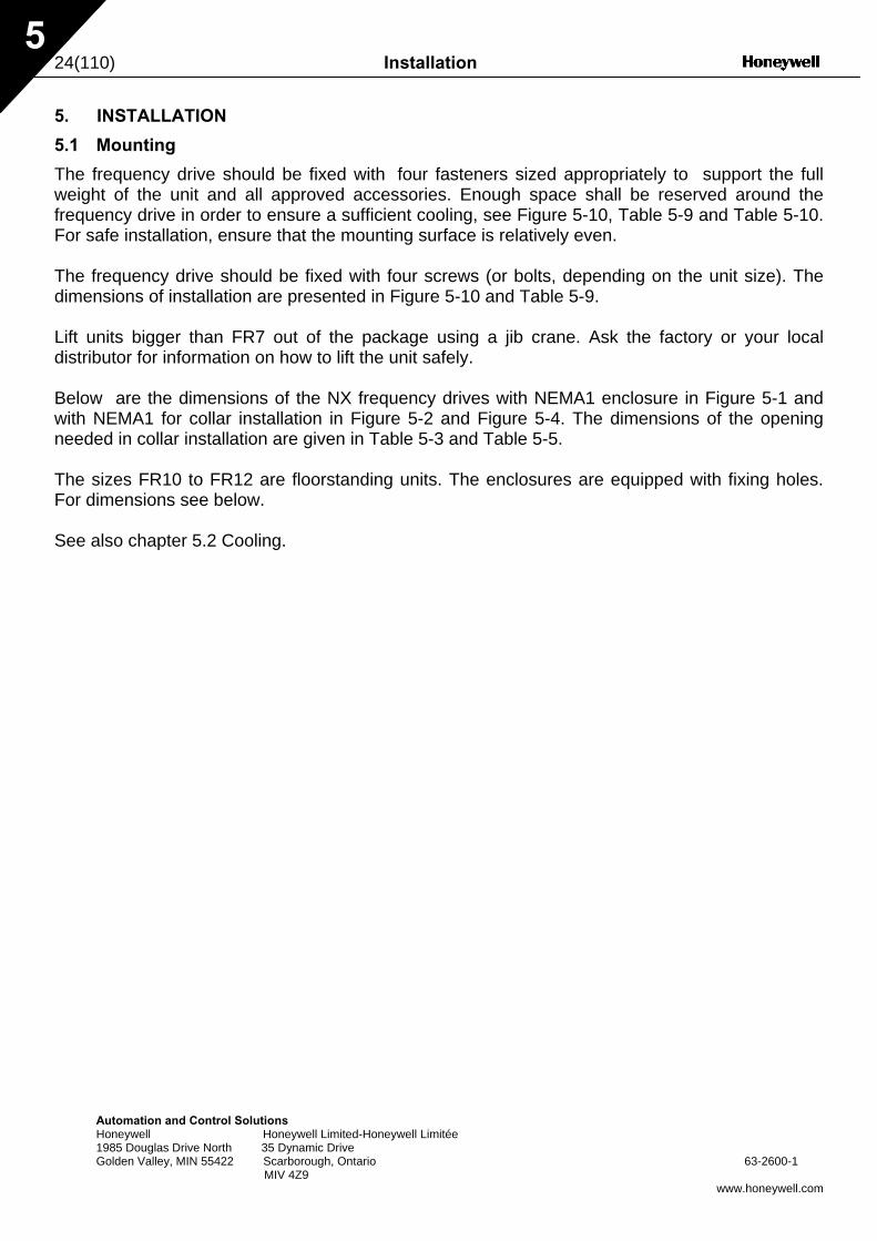
The frequency drive should be fixed with four fasteners sized appropriately to support the full weight of the unit and all approved accessories. Enough space shall be reserved around the frequency drive in order to ensure a sufficient cooling, see Figure 5-10, Table 5-9 and Table 5-10. For safe installation, ensure that the mounting surface is relatively even. The frequency drive should be fixed with four screws (or bolts, depending on the unit size). The dimensions of installation are presented in Figure 5-10 and Table 5-9. Lift units bigger than FR7 out of the package using a jib crane. Ask the factory or your local distributor for information on how to lift the unit safely. Below are the dimensions of the NX frequency drives with NEMA1 enclosure in Figure 5-1 and with NEMA1 for collar installation in Figure 5-2 and Figure 5-4. The dimensions of the opening needed in collar installation are given in Table 5-3 and Table 5-5. The sizes FR10 to FR12 are floorstanding units. The enclosures are equipped with fixing holes. For dimensions see below. See also chapter 5.2 Cooling.
Installation 25(110)
AutomHoney1985 DGolden
5
F
T
*
Ø
ation and Control Solutions well Honeywell Limited-Honeywell Limitée ouglas Drive North 35 Dynamic Drive Valley, MIN 55422 Scarborough, Ontario MIV 4Z9
igure 5-1. NX dimensions, NEMA1
Dimensions (inch) Type W1 W2 H1 H2 H3 D1 ∅
NXS 0010—0040 B NXS 0015—0075 A
5.04
3.94
12.87
12.32
11.5
7.48
7
NXS 0050—0100 B NXS 0100—0200 A
5.67
3.94
16.5
15.98
15.39
8.43
7
NXS 0150—0200 B NXS 0250—0400 A
7.68
5.83
21.97
21.3
20.43
9.33
9
NXS 0250—0400 B NXS 0500—0750 A NXS 0041—0062 C
9.33
7.48
24.8
24.17
23.27
10.12
9
NXS 1000—1500 A 11.22 10.04 29.72 28.82 28.39 12.28 9 able 5-1. Dimensions for different frequency drive types, NEMA1
FR5 only
W1
W2
H1 H2
Ø
D1
H3
E1Ø E2Ø63-2600-1
www.honeywell.com
E1∅ E2∅*
3 x 1.11
2 x 1.46
1 x 1.11
3 x 1.46
3 x 1.85
3 x 2.32
fr5ip21.fh8
26(110) Installation
5
F
T
W2
Automation and Control Solutions Honeywell Honeywell Limited-Honeywell Limitée 1985 Douglas Drive North 35 Dynamic Drive Golden Valley, MIN 55422 Scarborough, Ontario 63-2600-1
MIV 4Z9 www.honeywell.com
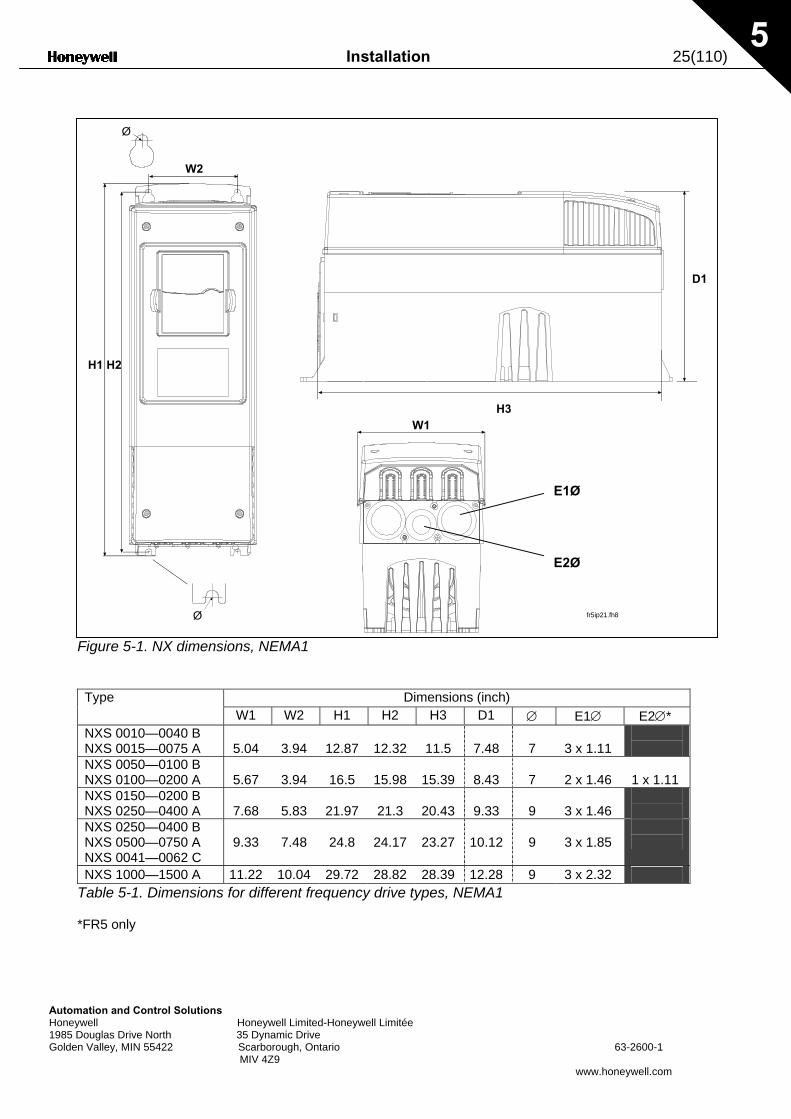
igure 5-2. NX dimensions, NEMA1 with collar, FR4 to FR6
Dimensions (inch) Type W1 W2 H1 H2 H3 H4 H5 D1 D2 ∅
NXS 0010—0040 B NXS 0015—0075 A
5.04
4.45
13.3
12.8
12.9
1.18
0.87
7.48
3.03
0.3
NXS 0050—0100 B NXS 0100—0200 A
5.67
4.72
17.1
16.5
16.5
1.42
0.71
8.43
3.94
0.3
NXS 0150—0200 B NXS 0250—0400 A
7.68
6.69
22
21.6
22
1.18
0.79
9.33
4.17
0.3
able 5-2. Dimensions for different frequency drive types FR4 to FR6, NEMA1 with collar
H1 H2
W1
D1
D2
H4
H5
fr5ip21kaulus.fh8Ø
H3
Installation 27(110)
AutoHon1985Gold
5
H2
mation and Control Solutions eywell Honeywell Limited-Honeywell Limitée Douglas Drive North 35 Dynamic Drive en Valley, MIN 55422 Scarborough, Ontario 63-2600-1 MIV 4Z9
www.honeywell.com
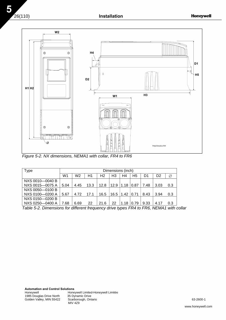
Figure 5-3. The opening needed for the collar installation, FR4 to FR6
Dimensions (inch) Type W1 W2 W3 H1 H2 H3 H4 ∅
NXS 0010—0040 B NXS 0015—0075 A
5.04
4.45
–
12.4
12.8
–
0.16
0.3
NXS 0050—0100 B NXS 0100—0200 A
5.31
4.72
–
16.1
16.5
–
0.16
0.3
NXS 0150—0200 B NXS 0250—0400 A
7.28
6.69
6.18
21.2
21.6
0.28
0.16
0.3
Table 5-3. Dimensions for the collar opening, FR4 to FR6
fr6aukko.fh8
W2
H1
W1W3
H3
Ø
H4
28(110) Installation
5
F
Ty
NXNXNXNX
T
*
H7
Automation and Control Solutions Honeywell Honeywell Limited-Honeywell Limitée 1985 Douglas Drive North 35 Dynamic Drive Golden Valley, MIN 55422 Scarborough, Ontario 63-2600-1
MIV 4Z9 www.honeywell.com
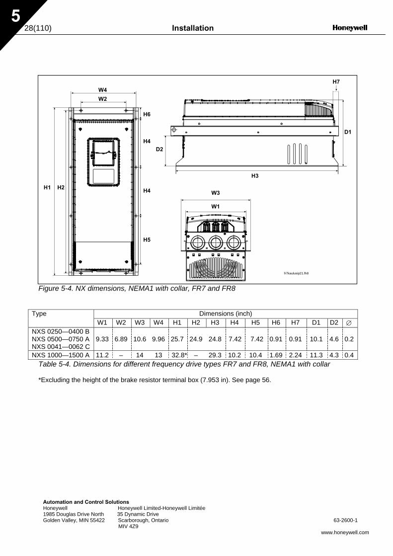
igure 5-4. NX dimensions, NEMA1 with collar, FR7 and FR8
Dimensions (inch) pe W1 W2 W3 W4 H1 H2 H3 H4 H5 H6 H7 D1 D2 ∅
S 0250—0400 B S 0500—0750 A S 0041—0062 C
9.33 6.89 10.6 9.96 25.7 24.9 24.8 7.42 7.42 0.91 0.91 10.1 4.6 0.2
S 1000—1500 A 11.2 – 14 13 32.8* – 29.3 10.2 10.4 1.69 2.24 11.3 4.3 0.4 able 5-4. Dimensions for different frequency drive types FR7 and FR8, NEMA1 with collar
Excluding the height of the brake resistor terminal box (7.953 in). See page 56.
W3
W1
W2
H1 H2
H3
D1
D2H4
H4
H5
W4
H6
fr7kaulusip21.fh8
Installation 29(110)
AuHo19Go
5
H2 H2 H3 H4H5
tomation and Control Solutions neywell Honeywell Limited-Honeywell Limitée 85 Douglas Drive North 35 Dynamic Drive lden Valley, MIN 55422 Scarborough, Ontario 63-2600-1 MIV 4Z9
www.honeywell.com
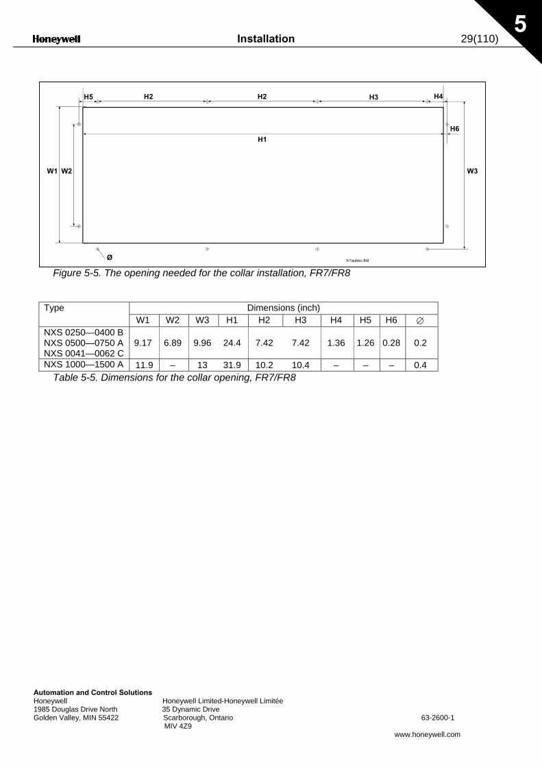
Figure 5-5. The opening needed for the collar installation, FR7/FR8
Dimensions (inch) Type W1 W2 W3 H1 H2 H3 H4 H5 H6 ∅
NXS 0250—0400 B NXS 0500—0750 A NXS 0041—0062 C
9.17 6.89 9.96 24.4 7.42 7.42 1.36 1.26 0.28 0.2
NXS 1000—1500 A 11.9 – 13 31.9 10.2 10.4 – – – 0.4 Table 5-5. Dimensions for the collar opening, FR7/FR8
W1 W2
H1
H6
Ø
W3
fr7aukko.fh8
30(110) Installation
5
Ø
Automation and Control Solutions Honeywell Honeywell Limited-Honeywell Limitée 1985 Douglas Drive North 35 Dynamic Drive Golden Valley, MIN 55422 Scarborough, Ontario 63-2600-1
MIV 4Z9 www.honeywell.com
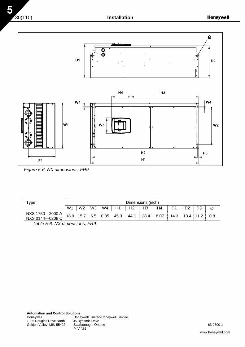
Figure 5-6. NX dimensions, FR9
Dimensions (inch) Type W1 W2 W3 W4 H1 H2 H3 H4 D1 D2 D3 ∅
NXS 1750—2000 A NXS 0144—0208 C 18.9 15.7 6.5 0.35 45.3 44.1 28.4 8.07 14.3 13.4 11.2 0.8
Table 5-6. NX dimensions, FR9
D1 D2
D3
W1 W2
H1
H2
H3H4
W3
H3
W4 W4
Installation 31(110)
Automation andHoneywell 1985 Douglas DGolden Valley, M
5
F
Type
NXS 1750—2000 ANXS 0144—0208 C
Table 5-7. N
Ø
Control Solutions Honeywell Limited-Honeywell Limitée
rive North 35 Dynamic Drive IN 55422 Scarborough, Ontario 63-2600-1 MIV 4Z9
www.honeywell.com
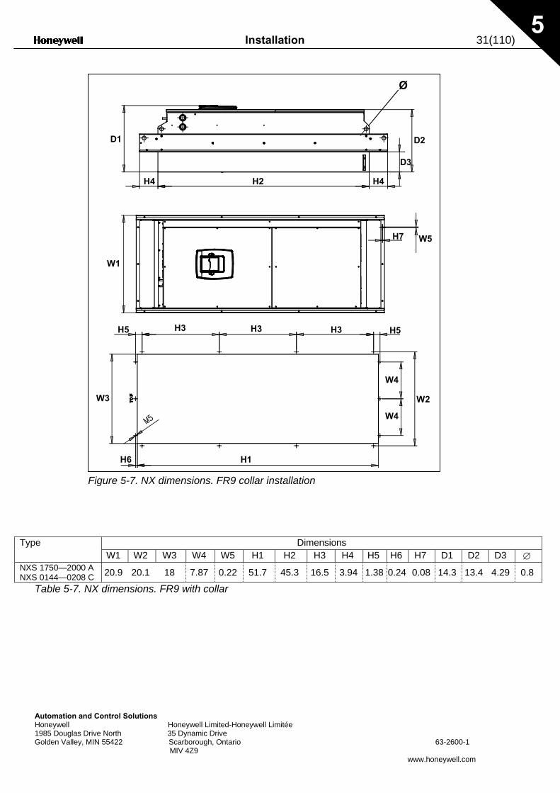
igure 5-7. NX dimensions. FR9 collar installation
Dimensions W1 W2 W3 W4 W5 H1 H2 H3 H4 H5 H6 H7 D1 D2 D3 ∅
20.9 20.1 18 7.87 0.22 51.7 45.3 16.5 3.94 1.38 0.24 0.08 14.3 13.4 4.29 0.8
X dimensions. FR9 with collar
W1
W2W3
H1
W4
W4
W5
H5 H3 H3 H3 H5
H7
H2 H4H4
D1 D2
D3
H6
32(110) Installation
Aut Hon 198 Gol
5
Type plateW4
omation and Control Solutions eywell Honeywell Limited-Honeywell Limitée 5 Douglas Drive North 35 Dynamic Drive den Valley, MIN 55422 Scarborough, Ontario 63-2600-1 MIV 4Z9
www.honeywell.com
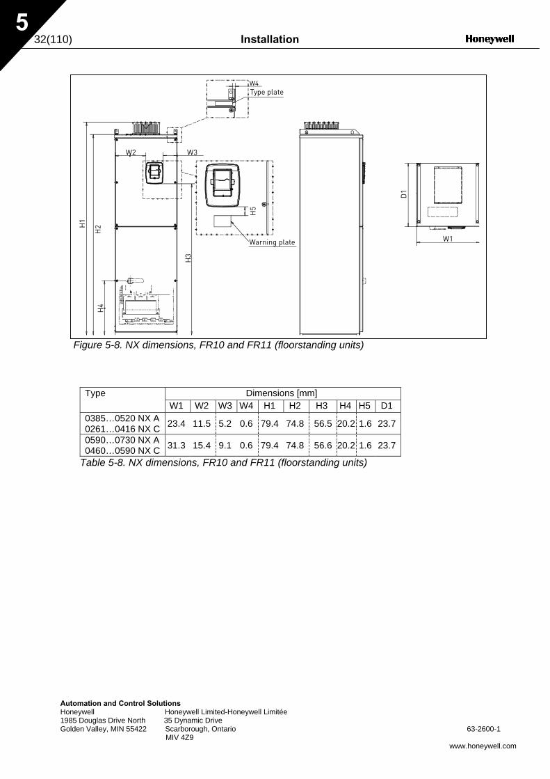
Figure 5-8. NX dimensions, FR10 and FR11 (floorstanding units)
Dimensions [mm] Type W1 W2 W3 W4 H1 H2 H3 H4 H5 D1
0385…0520 NX A 0261…0416 NX C 23.4 11.5 5.2 0.6 79.4 74.8 56.5 20.2 1.6 23.7
0590…0730 NX A 0460…0590 NX C 31.3 15.4 9.1 0.6 79.4 74.8 56.6 20.2 1.6 23.7
Table 5-8. NX dimensions, FR10 and FR11 (floorstanding units)
Warning plate
W2 W3
W1
Installation 33(110)
Automation and Control Solutions Honeywell Honeywell Limited-Honeywell Limitée 1985 Douglas Drive North 35 Dynamic Drive Golden Valley, MIN 55422 Scarborough, Ontario 63-2600-1 MIV 4Z9
www.honeywell.com
5
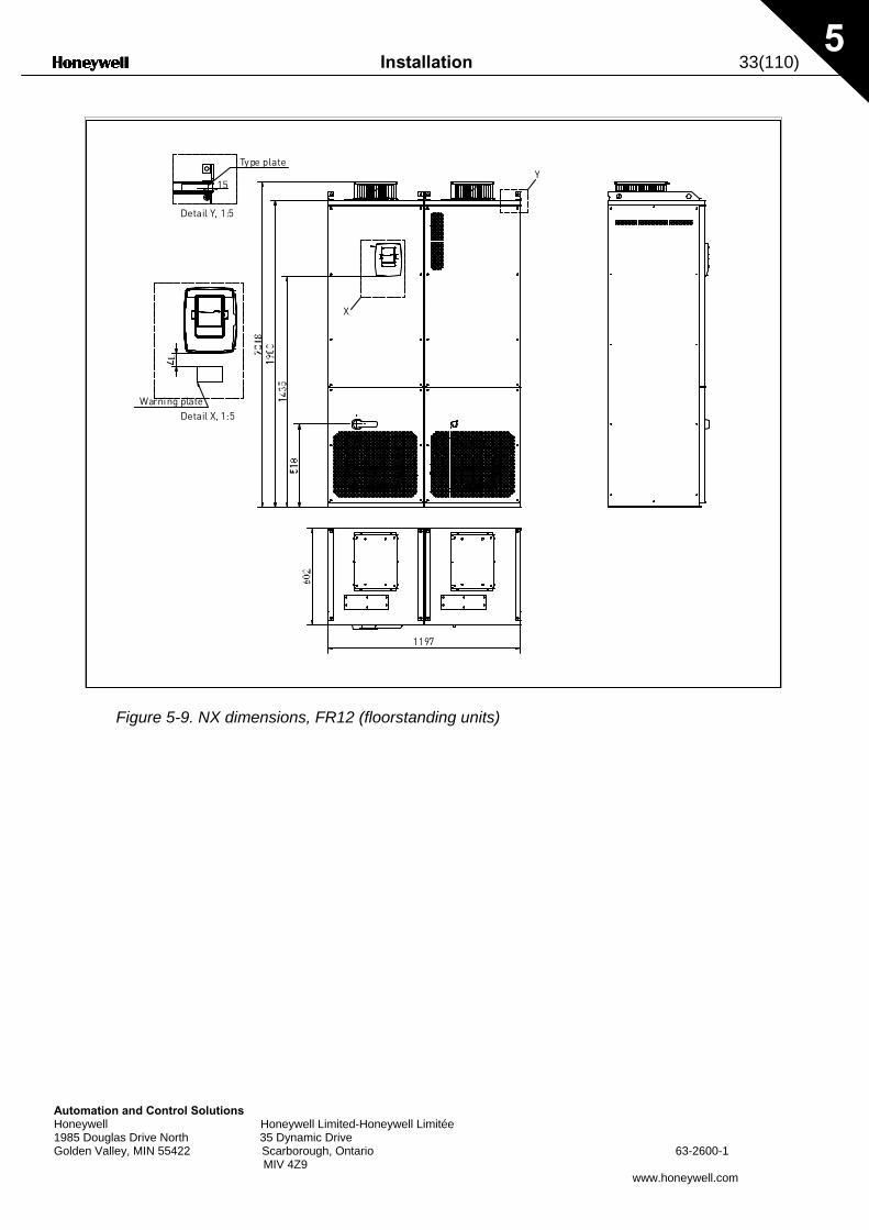
Figure 5-9. NX dimensions, FR12 (floorstanding units)
Type plate
Detail Y, 1:5
15Y
X
Warning plateDetail X, 1:5
1197
34(110) Installation
Automation and Control Solutions Honeywell Honeywell Limited-Honeywell Limitée 1985 Douglas Drive North 35 Dynamic Drive Golden Valley, MIN 55422 Scarborough, Ontario MIV 4Z9
5
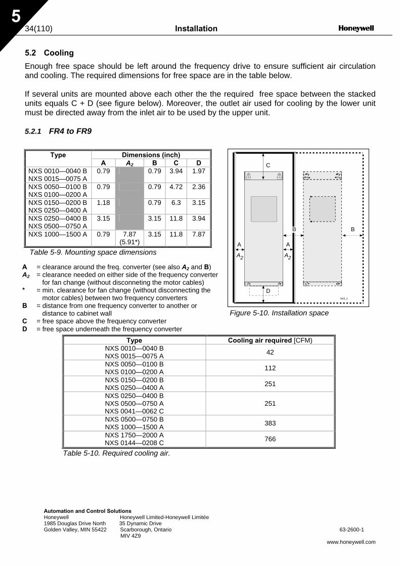
5.2 Cooling
Enough free space should be left around the frequency drive to ensure sufficient air circulation and cooling. The required dimensions for free space are in the table below. If several units are mounted above each other the the required free space between the stacked units equals C + D (see figure below). Moreover, the outlet air used for cooling by the lower unit must be directed away from the inlet air to be used by the upper unit. 5.2.1 FR4 to FR9
Type Dimensions (inch) A A2 B C D NXS 0010—0040 B NXS 0015—0075 A
0.79 0.79 3.94 1.97
NXS 0050—0100 B NXS 0100—0200 A
0.79 0.79 4.72 2.36
NXS 0150—0200 B NXS 0250—0400 A
1.18 0.79 6.3 3.15
NXS 0250—0400 B NXS 0500—0750 A
3.15 3.15 11.8 3.94
NXS 1000—1500 A 0.79 7.87 (5.91*)
3.15 11.8 7.87
Table 5-9. Mounting space dimensions
Type
NXS 0010—0040 B NXS 0015—0075 A NXS 0050—0100 B NXS 0100—0200 A NXS 0150—0200 B NXS 0250—0400 A NXS 0250—0400 B NXS 0500—0750 A NXS 0041—0062 C NXS 0500—0750 B NXS 1000—1500 A NXS 1750—2000 A NXS 0144—0208 C
Table 5-10. Required cooling air.
A = clearance around the freq. converter (see also A2 and B) A2 = clearance needed on either side of the frequency converter
for fan change (without disconneting the motor cables) * = min. clearance for fan change (without disconnecting the
motor cables) between two frequency converters B = distance from one frequency converter to another or
distance to cabinet wall C = free space above the frequency converter D = free space underneath the frequency converter
63-2600-1
www.honeywell.com
C
A
NK5_2
A2 A2
D
B
A
B
Figure 5-10. Installation space
Cooling air required [CFM)
42
112
251
251
383
766
Installation 35(110)
AH1G
5
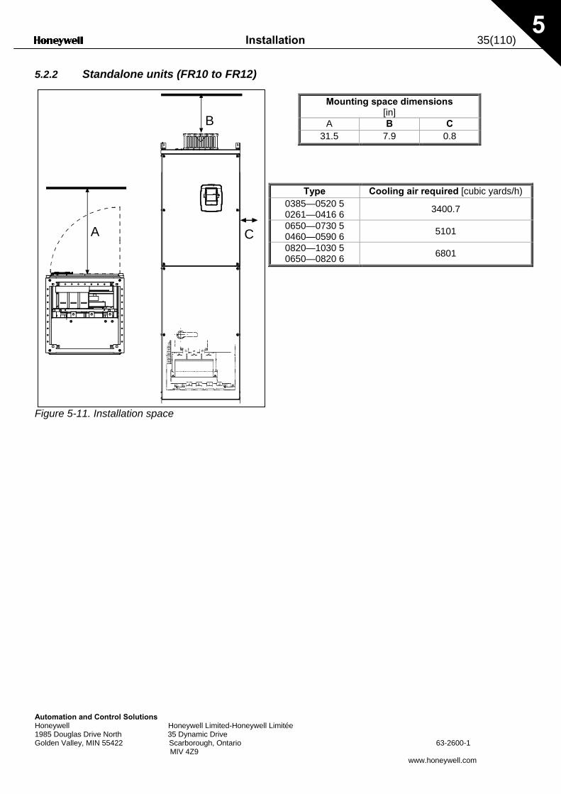
5.2.2 Standalone units (FR10 to FR12)
F
Mounting space dimensions
utomation and Control Solutions oneywell Honeywell Limited-Honeywell Limitée 985 Douglas Drive North 35 Dynamic Drive olden Valley, MIN 55422 Scarborough, Ontario 63-2600-1 MIV 4Z9
www.honeywell.com
A
B
C
igure 5-11. Installation space
[in] A B C
31.5 7.9 0.8
Type Cooling air required [cubic yards/h) 0385—0520 5 0261—0416 6 3400.7
0650—0730 5 0460—0590 6 5101
0820—1030 5 0650—0820 6 6801
36(110) Installation
5
5.3 Power loss
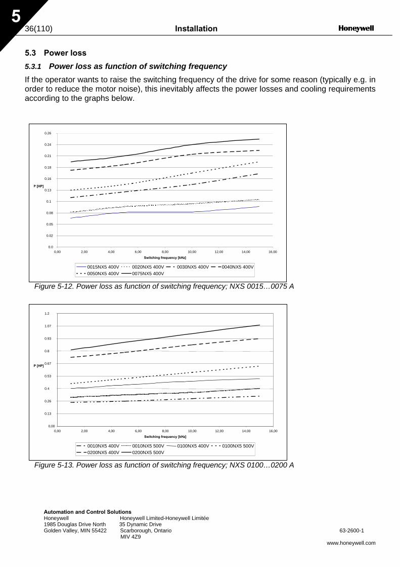
5.3.1 Power loss as function of switching frequency If the operator wants to raise the switching frequency of the drive for some reason (typically e.g. in order to reduce the motor noise), this inevitably affects the power losses and cooling requirements according to the graphs below.
0.24
0.26
Figure 5-12. Power loss as function of switching frequency; NXS 0015…0075 A
0.0
0.02
0.05
0.08
0.1
0.13
0.16
0.18
0.21
0,00 2,00 4,00 6,00 8,00 10,00 12,00 14,00 16,00
Switching frequency [kHz]
P [HP]
0015NX5 400V 0020NX5 400V 0030NX5 400V 0040NX5 400V0050NX5 400V 0075NX5 400V
1.2
Automation and Control Solutions Honeywell Honeywell Limited-Honeywell Limitée 1985 Douglas Drive North 35 Dynamic Drive Golden Valley, MIN 55422 Scarborough, Ontario 63-2600-1
MIV 4Z9 www.honeywell.com
Figure 5-13. Power loss as function of switching frequency; NXS 0100…0200 A
0,00
0.13
0.26
0.4
0.53
0.67
0.8
0.93
1.07
0,00 2,00 4,00 6,00 8,00 10,00 12,00 14,00 16,00
Switching frequency [kHz]
P [HP]
0010NX5 400V 0010NX5 500V 0100NX5 400V 0100NX5 500V0200NX5 400V 0200NX5 500V
Installation 37(110)
AuHo19Go
5
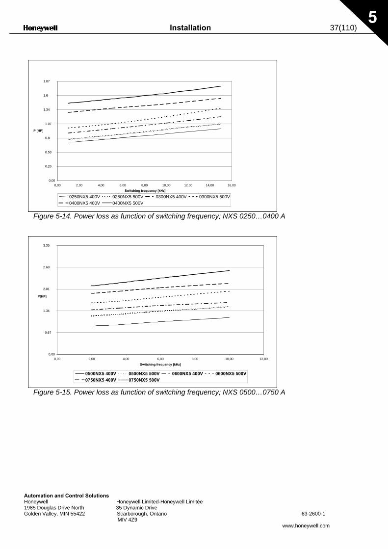
Figure 5-14. Power loss as function of switching frequency; NXS 0250…0400 A
0,00
0.26
0.53
0.8
1.07
1.34
1.6
1.87
0,00 2,00 4,00 6,00 8,00 10,00 12,00 14,00 16,00
Switching frequency [kHz]
P [HP]
0250NX5 400V 0250NX5 500V 0300NX5 400V 0300NX5 500V0400NX5 400V 0400NX5 500V
3.35
tomation and Control Solutions neywell Honeywell Limited-Honeywell Limitée 85 Douglas Drive North 35 Dynamic Drive lden Valley, MIN 55422 Scarborough, Ontario 63-2600-1 MIV 4Z9
www.honeywell.com
Figure 5-15. Power loss as function of switching frequency; NXS 0500…0750 A
0,00
0.67
1.34
2.01
2.68
0,00 2,00 4,00 6,00 8,00 10,00 12,00
Switching frequency [kHz]
P[HP]
0500NX5 400V 0500NX5 500V 0600NX5 400V 0600NX5 500V0750NX5 400V 0750NX5 500V
38(110) Cabling and connections
6
5
5.36
AH1G
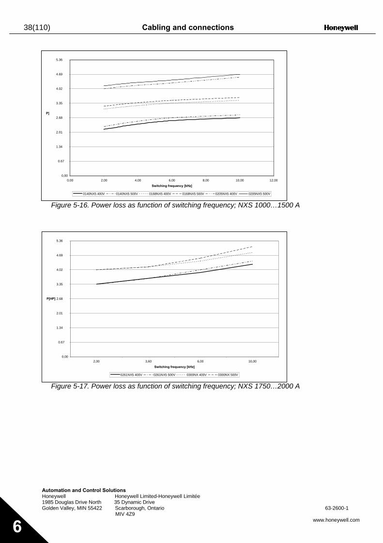
Figure 5-16. Power loss as function of switching frequency; NXS 1000…1500 A
0,00
0.67
1.34
2.01
2.68
3.35
4.02
4.69
0,00 2,00 4,00 6,00 8,00 10,00 12,00 Switching frequency [kHz]
P]
0140NX5 400V 0140NX5 500V 0168NX5 400V 0168NX5 500V 0205NX5 400V 0205NX5 500V
5.36
utomation and Control Solutions oneywell Honeywell Limited-Honeywell Limitée 985 Douglas Drive North 35 Dynamic Drive olden Valley, MIN 55422 Scarborough, Ontario 63-2600-1
MIV 4Z9 www.honeywell.com
Figure 5-17. Power loss as function of switching frequency; NXS 1750…2000 A
0,00
0.67
1.34
2.01
2.68
3.35
4.02
4.69
2,00 3,60 6,00 10,00
Switching frequency [kHz]
P[HP]
0261NX5 400V 0261NX5 500V 0300NX 400V 0300NX 500V
Cabling and connections 39(110)
AutomationHoneywell 1985 DouglGolden Vall
F
10.7
and Control Solutions Honeywell Limited-Honeywell Limitée
as Drive North 35 Dynamic Drive ey, MIN 55422 Scarborough, Ontario 63-2600-1 MIV 4Z9
www.honeywell.com 6
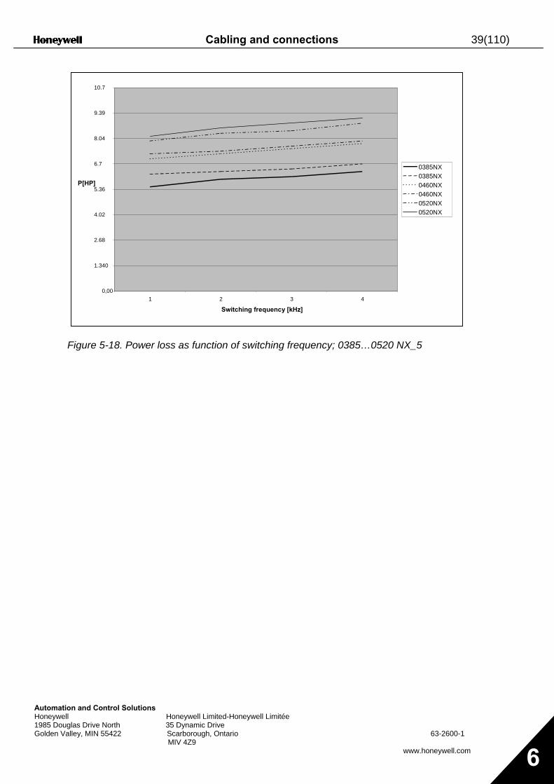
igure 5-18. Power loss as function of switching frequency; 0385…0520 NX_5
0,00
1.340
2.68
4.02
5.36
6.7
8.04
9.39
1 2 3 4
Switching frequency [kHz]
P[HP] 0385NX 0385NX 0460NX 0460NX 0520NX 0520NX
40(110) Cabling and connections
Automation and Control Solutions Honeywell Honeywell Limited-Honeywell Limitée 1985 Douglas Drive North 35 Dynamic Drive Golden Valley, MIN 55422 Scarborough, Ontario 63-2600-1 MIV 4Z9
www.honeywell.com 6
6. CABLING AND CONNECTIONS
6.1 Power unit
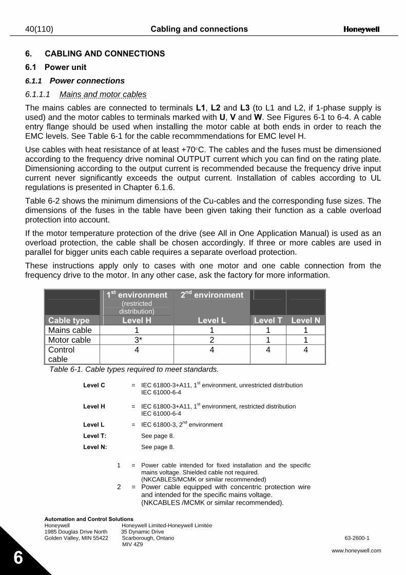
6.1.1 Power connections 6.1.1.1 Mains and motor cables The mains cables are connected to terminals L1, L2 and L3 (to L1 and L2, if 1-phase supply is used) and the motor cables to terminals marked with U, V and W. See Figures 6-1 to 6-4. A cable entry flange should be used when installing the motor cable at both ends in order to reach the EMC levels. See Table 6-1 for the cable recommmendations for EMC level H. Use cables with heat resistance of at least +70°C. The cables and the fuses must be dimensioned according to the frequency drive nominal OUTPUT current which you can find on the rating plate. Dimensioning according to the output current is recommended because the frequency drive input current never significantly exceeds the output current. Installation of cables according to UL regulations is presented in Chapter 6.1.6. Table 6-2 shows the minimum dimensions of the Cu-cables and the corresponding fuse sizes. The dimensions of the fuses in the table have been given taking their function as a cable overload protection into account. If the motor temperature protection of the drive (see All in One Application Manual) is used as an overload protection, the cable shall be chosen accordingly. If three or more cables are used in parallel for bigger units each cable requires a separate overload protection. These instructions apply only to cases with one motor and one cable connection from the frequency drive to the motor. In any other case, ask the factory for more information.
1st environment (restricted
distribution)
2nd environment
Cable type Level H Level L Level T Level N Mains cable 1 1 1 1 Motor cable 3* 2 1 1 Control cable
4 4 4 4
Table 6-1. Cable types required to meet standards.
Level C = IEC 61800-3+A11, 1st environment, unrestricted distribution IEC 61000-6-4 Level H = IEC 61800-3+A11, 1st environment, restricted distribution IEC 61000-6-4
Level L = IEC 61800-3, 2nd environment
Level T: See page 8.
Level N: See page 8.
1 = Power cable intended for fixed installation and the specific
mains voltage. Shielded cable not required. (NKCABLES/MCMK or similar recommended) 2 = Power cable equipped with concentric protection wire
and intended for the specific mains voltage. (NKCABLES /MCMK or similar recommended).
Cabling and connections 41(110)
Automation and Control Solutions Honeywell Honeywell Limited-Honeywell Limitée 1985 Douglas Drive North 35 Dynamic Drive Golden Valley, MIN 55422 Scarborough, Ontario 63-2600-1 MIV 4Z9
www.honeywell.com 6
3 = Power cable equipped with compact low-impedance shield and intended for the specific mains voltage.
(NKCABLES /MCCMK, SAB/ÖZCUY-J or similar recommended). *360º grounding of both motor and FC connection required to meet the standard
4 = Screened cable equipped with compact low-impedance shield (NKCABLES /jamak, SAB/ÖZCuY-O or similar).
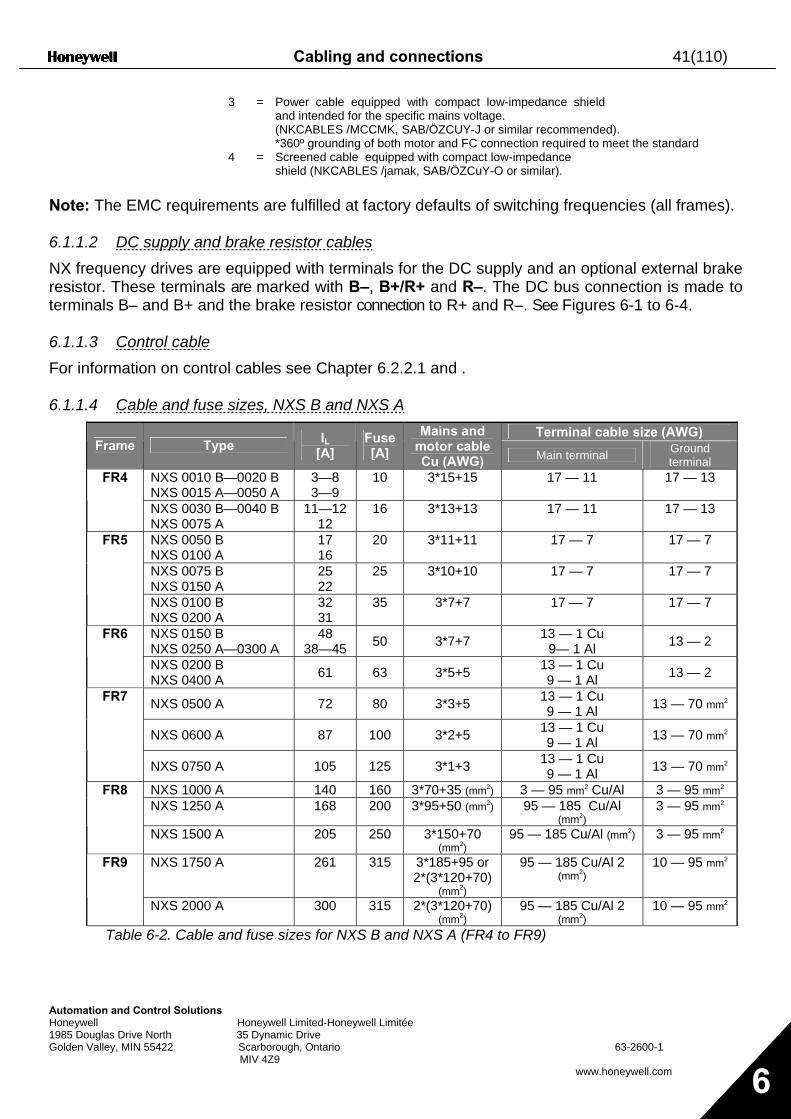
Note: The EMC requirements are fulfilled at factory defaults of switching frequencies (all frames). 6.1.1.2 DC supply and brake resistor cables NX frequency drives are equipped with terminals for the DC supply and an optional external brake resistor. These terminals are marked with B–, B+/R+ and R–. The DC bus connection is made to terminals B– and B+ and the brake resistor connection to R+ and R–. See Figures 6-1 to 6-4. 6.1.1.3 Control cable For information on control cables see Chapter 6.2.2.1 and . 6.1.1.4 Cable and fuse sizes, NXS B and NXS A
Terminal cable size (AWG) Frame Type IL
[A] Fuse [A]
Mains and motor cable Cu (AWG) Main terminal Ground
terminal NXS 0010 B—0020 B NXS 0015 A—0050 A
3—8 3—9
10 3*15+15 17 — 11 17 — 13 FR4
NXS 0030 B—0040 B NXS 0075 A
11—12 12
16 3*13+13 17 — 11 17 — 13
NXS 0050 B NXS 0100 A
17 16
20 3*11+11 17 — 7 17 — 7
NXS 0075 B NXS 0150 A
25 22
25 3*10+10 17 — 7 17 — 7
FR5
NXS 0100 B NXS 0200 A
32 31
35 3*7+7 17 — 7 17 — 7
NXS 0150 B NXS 0250 A—0300 A
48 38—45 50 3*7+7 13 — 1 Cu
9— 1 Al 13 — 2 FR6
NXS 0200 B NXS 0400 A 61 63 3*5+5 13 — 1 Cu
9 — 1 Al 13 — 2
NXS 0500 A 72 80 3*3+5 13 — 1 Cu 9 — 1 Al 13 — 70 mm2
NXS 0600 A 87 100 3*2+5 13 — 1 Cu 9 — 1 Al 13 — 70 mm2
FR7
NXS 0750 A 105 125 3*1+3 13 — 1 Cu 9 — 1 Al 13 — 70 mm2
NXS 1000 A 140 160 3*70+35 (mm2) 3 — 95 mm2 Cu/Al 3 — 95 mm2 NXS 1250 A 168 200 3*95+50 (mm2) 95 — 185 Cu/Al
(mm2) 3 — 95 mm2
FR8
NXS 1500 A 205 250 3*150+70 (mm2)
95 — 185 Cu/Al (mm2) 3 — 95 mm2
NXS 1750 A 261 315 3*185+95 or 2*(3*120+70)
(mm2)
95 — 185 Cu/Al 2 (mm2)
10 — 95 mm2 FR9
NXS 2000 A 300 315 2*(3*120+70) (mm2)
95 — 185 Cu/Al 2 (mm2)
10 — 95 mm2
Table 6-2. Cable and fuse sizes for NXS B and NXS A (FR4 to FR9)
42(110) Cabling and connections
Automation and Control Solutions Honeywell Honeywell Limited-Honeywell Limitée 1985 Douglas Drive North 35 Dynamic Drive Golden Valley, MIN 55422 Scarborough, Ontario 63-2600-1 MIV 4Z9
www.honeywell.com 6
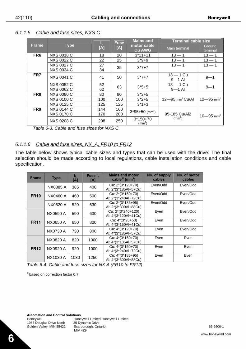
6.1.1.5 Cable and fuse sizes, NXS C Terminal cable size
Frame Type IL
[A] Fuse [A]
Mains and motor cable
Cu AWG Main terminal Ground terminal
NXS 0018 C 18 20 3*11+11 13 — 1 13 — 1 NXS 0022 C 22 25 3*9+9 13 — 1 13 — 1
FR6
NXS 0027 C NXS 0034 C
27 34 35 3*7+7 13 — 1 13 — 1
NXS 0041 C 41 50 3*7+7 13 — 1 Cu 9—1 Al 9—1 FR7
NXS 0052 C NXS 0062 C
52 62 63 3*5+5 13 — 1 Cu
9—1 Al 9—1
NXS 0080 C 80 80 3*3+5 NXS 0100 C 100 100 3*2+5
FR8
NXS 0125 C 125 125 3*1+3 12—95 mm2 Cu/Al 12—95 mm2
NXS 0144 C NXS 0170 C
144 170
160 200 3*95+50 (mm2) FR9
NXS 0208 C 208 250 3*150+70 (mm2)
95-185 Cu/Al2 (mm2) 10—95 mm2
Table 6-3. Cable and fuse sizes for NXS C.
6.1.1.6 Cable and fuse sizes, NX_A, FR10 to FR12 The table below shows typical cable sizes and types that can be used with the drive. The final selection should be made according to local regulations, cable installation conditions and cable specification.
Frame Type IL
[A] Fuse In
[A] Mains and motor
cable1) [mm2] No. of supply
cables No. of motor
cables
NX0385 A 385 400 Cu: 2*(3*120+70) Al: 2*(3*185Al+57Cu)
Even/Odd Even/Odd
NX0460 A 460 500 Cu: 2*(3*150+70) Al: 2*(3*240Al+72Cu)
Even/Odd Even/Odd FR10
NX0520 A 520 630 Cu: 2*(3*185+95) Al: 2*(3*300Al+88Cu)
Even/Odd Even/Odd
NX0590 A 590 630 Cu: 2*(3*240+120) Al: 4*(3*120Al+41Cu)
Even Even/Odd
NX0650 A 650 800 Cu: 4*(3*95+50) Al: 4*(3*150Al+41Cu)
Even Even/Odd FR11
NX0730 A 730 800 Cu: 4*(3*120+70) Al: 4*(3*185Al+57Cu)
Even Even/Odd
NX0820 A 820 1000 Cu: 4*(3*150+70) Al: 4*(3*185Al+57Cu)
Even Even
NX0920 A 920 1000 Cu: 4*(3*150+70) Al: 4*(3*240Al+72Cu)
Even Even FR12
NX1030 A 1030 1250 Cu: 4*(3*185+95) Al: 4*(3*300Al+88Cu)
Even Even
Table 6-4. Cable and fuse sizes for NX A (FR10 to FR12)
1)based on correction factor 0.7
Cabling and connections 43(110)
Automation and Control Solutions Honeywell Honeywell Limited-Honeywell Limitée 1985 Douglas Drive North 35 Dynamic Drive Golden Valley, MIN 55422 Scarborough, Ontario 63-2600-1 MIV 4Z9
www.honeywell.com 6
6.1.1.7 Cable and fuse sizes, NX_C, FR10 to FR12 The table below shows typical cable sizes and types that can be used with the drive. The final selection should be made according to local regulations, cable installation conditions and cable specification.
Frame Type IL
[A] Fuse In
[A]
Mains and motor cable1) [mm2]
No of supply cables
No of motor cables
NX0261 C 261 400 Cu: 3*185+95 Al: 2*(3*95Al+29Cu)
Even/Odd Even/Odd
NX0325 C 325 500 Cu: 2*(3*95+50) Al: 2*(3*150Al+41Cu)
Even/Odd Even/Odd
NX0385 C 385 630 Cu: 2*(3*120+70) Al: 2*(3*185Al+57Cu)
Even/Odd Even/Odd FR10
NX0416 C 416 630 Cu: 2*(3*150+70) Al: 2*(3*185Al+57Cu)
Even/Odd Even/Odd
NX0460 C 460 800 Cu: 2*(3*150+70) Al: 2*(3*240Al+72Cu)
Even Even/Odd
NX0502 C 502 800 Cu: 2*(3*185+95) Al: 2*(3*300Al+88 Cu)
Even Even/Odd FR11
NX0590 C 590 1000 Cu: 2*(3*240+120) Al: 4*(3*120Al+41Cu)
Even Even/Odd
NX0650 C 650 1000 Cu: 4*(3*95+50) Al: 4*(3*150Al+41Cu)
Even Even
NX0750 C 750 1250 Cu: 4*(3*120+70) Al: 4*(3*150Al+41Cu)
Even Even FR12
NX0820 C 820 1250 Cu: 4*(3*150+70) Al: 4*(3*185Al+57Cu)
Even Even
Table 6-5. Cable and fuse sizes for NX C (FR10 to FR12)
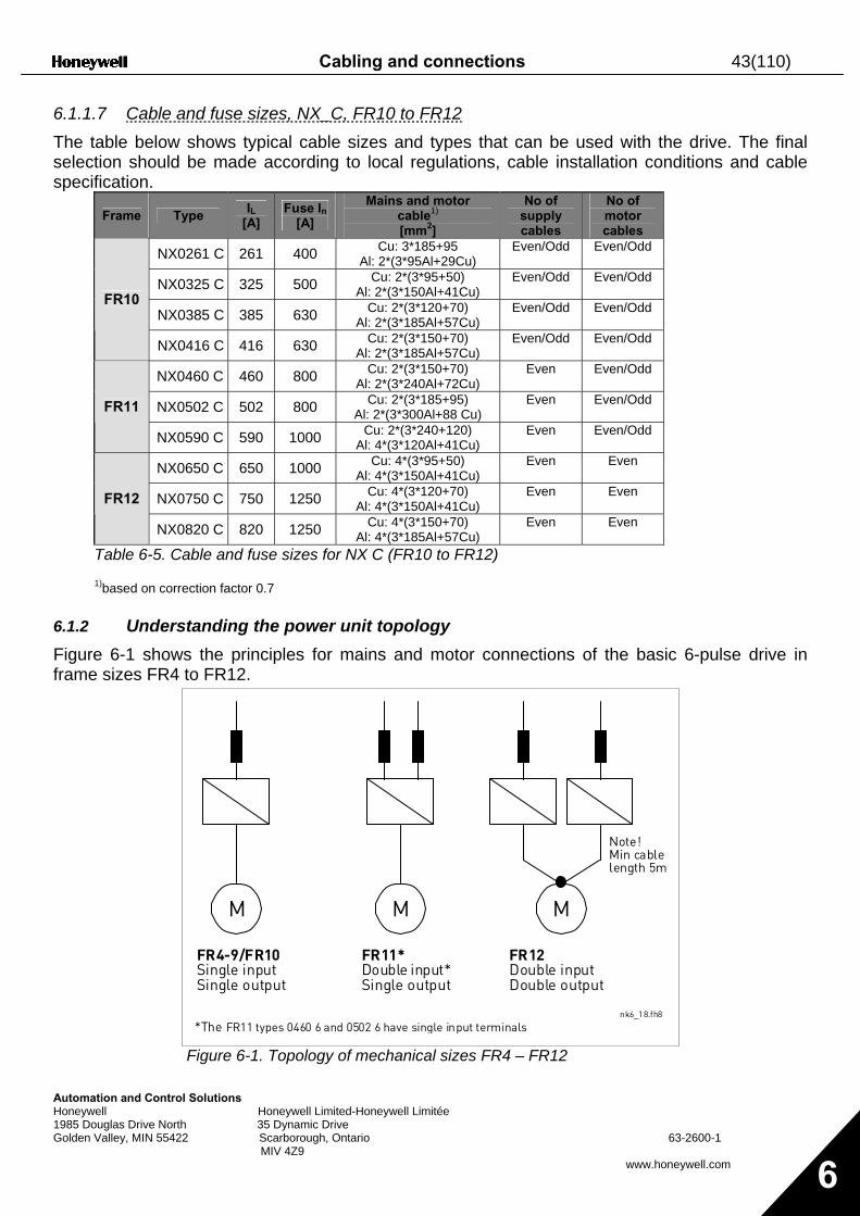
1)based on correction factor 0.7 6.1.2 Understanding the power unit topology Figure 6-1 shows the principles for mains and motor connections of the basic 6-pulse drive in frame sizes FR4 to FR12.
Figure 6-1. Topology of mechanical sizes FR4 – FR12
M M M
nk6_18.fh8
FR4-9/FR10Single inputSingle output
FR11*Double input*Single output
FR12Double inputDouble output
Note!Min cablelength 5m
*The FR11 types 0460 6 and 0502 6 have single input terminals
44(110) Cabling and connections
Automation and Control Solutions Honeywell Honeywell Limited-Honeywell Limitée 1985 Douglas Drive North 35 Dynamic Drive Golden Valley, MIN 55422 Scarborough, Ontario 63-2600-1 MIV 4Z9
www.honeywell.com 6
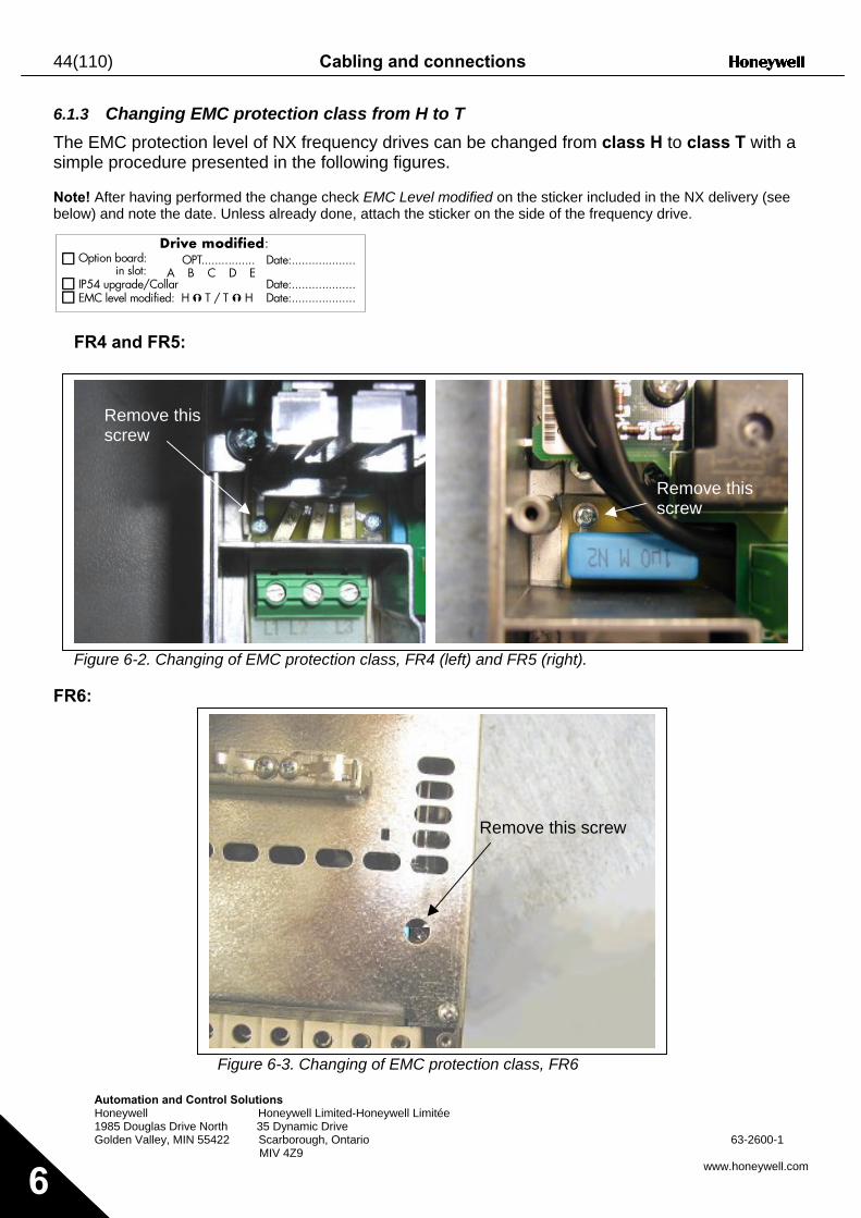
6.1.3 Changing EMC protection class from H to T The EMC protection level of NX frequency drives can be changed from class H to class T with a simple procedure presented in the following figures. Note! After having performed the change check EMC Level modified on the sticker included in the NX delivery (see below) and note the date. Unless already done, attach the sticker on the side of the frequency drive.
FR4 and FR5:
Figure 6-2. Changing of EMC protection class, FR4 (left) and FR5 (right).
FR6:
Figure 6-3. Changing of EMC protection class, FR6
Remove this screw
Remove this screw
Remove this screw
D r i v e m o d i f i ed: O p t i o n b o a r d : O P T . . . . . . . . . . . . . . . .I P 5 4 u p g r a d e / C o l l a r
i n s l o t : D a t e : . . . . . . . . . . . . . . . . . . .
A B C D EE M C l e v e l m o d i f i e d : H T / T H
D a t e : . . . . . . . . . . . . . . . . . . . D a t e : . . . . . . . . . . . . . . . . . . .
Cabling and connections 45(110)
Automation and Control Solutions Honeywell Honeywell Limited-Honeywell Limitée 1985 Douglas Drive North 35 Dynamic Drive Golden Valley, MIN 55422 Scarborough, Ontario 63-2600-1 MIV 4Z9
www.honeywell.com 6
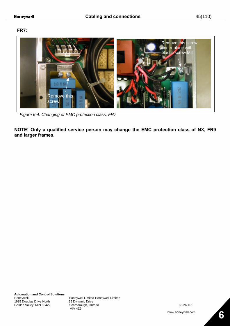
FR7:
Figure 6-4. Changing of EMC protection class, FR7
NOTE! Only a qualified service person may change the EMC protection class of NX, FR9 and larger frames.
Remove this screw
Remove this screw and replace with plastic screw M4
46(110) Cabling and connections
Automation and C Honeywell 1985 Douglas Driv Golden Valley, MIN
6
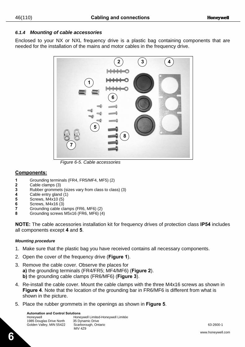
6.1.4 Mounting of cable accessories Enclosed to your NX or NXL frequency drive is a plastic bag containing components that are needed for the installation of the mains and motor cables in the frequency drive.
Components: 1 Grounding ter2 Cable clamps3 Rubber gromm4 Cable entry g5 Screws, M4x16 Screws, M4x17 Grounding ca8 Grounding sc NOTE: The cable all components ex Mounting procedure
1. Make sure that2. Open the cove3. Remove the ca
a) the groundinb) the groundin
4. Re-install the cFigure 4. Noteshown in the p
5. Place the rubb
2 3 4
ontrol Solutions Honeywell Limited-Honeywell Limitée
e North 35 Dynamic Drive 55422 Scarborough, Ontario 63-2600-1 MIV 4Z9
www.honeywell.com
Figure 6-5. Cable accessories
minals (FR4, FR5/MF4, MF5) (2) (3)
ets (sizes vary from class to class) (3) land (1) 0 (5) 6 (3)
ble clamps (FR6, MF6) (2) rews M5x16 (FR6, MF6) (4)
accessories installation kit for frequency drives of protection class IP54 includes cept 4 and 5.
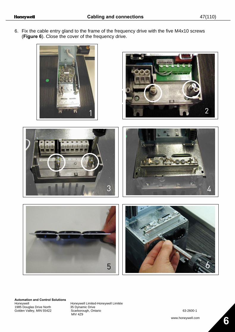
the plastic bag you have received contains all necessary components. r of the frequency drive (Figure 1). ble cover. Observe the places for g terminals (FR4/FR5; MF4/MF6) (Figure 2). g cable clamps (FR6/MF6) (Figure 3). able cover. Mount the cable clamps with the three M4x16 screws as shown in that the location of the grounding bar in FR6/MF6 is different from what is icture. er grommets in the openings as shown in Figure 5.
8
1
5
6
7
8
Cabling and connections 47(110)
Automation andHoneywell 1985 Douglas DGolden Valley, M
6. Fix the cable entry gland to the frame of the frequency drive with the five M4x10 screws (Figure 6). Close the cover of the frequency drive.
Control Solutions Honeywell Limited-Honeywell Limitée
rive North 35 Dynamic Drive IN 55422 Scarborough, Ontario MIV 4Z9
63-2600-1
www.honeywell.com 6
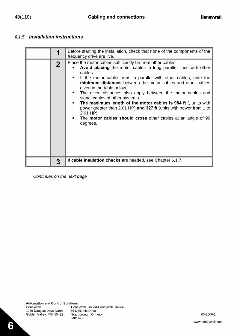
48(110) Cabling and connections
Automation and Control Solutions Honeywell Honeywell Limited-Honeywell Limitée 1985 Douglas Drive North 35 Dynamic Drive Golden Valley, MIN 55422 Scarborough, Ontario 63-2600-1 MIV 4Z9
www.honeywell.com 6
6.1.5 Installation instructions
1 Before starting the installation, check that none of the components of the frequency drive are live.
2 Place the motor cables sufficiently far from other cables: Avoid placing the motor cables in long parallel lines with other
cables If the motor cables runs in parallel with other cables, note the
minimum distances between the motor cables and other cables given in the table below.
The given distances also apply between the motor cables and signal cables of other systems.
The maximum length of the motor cables is 984 ft (, units with power greater than 2.01 HP) and 327 ft (units with power from 1 to 2.01 HP).
The motor cables should cross other cables at an angle of 90 degrees.
3 If cable insulation checks are needed, see Chapter 6.1.7.
Continues on the next page
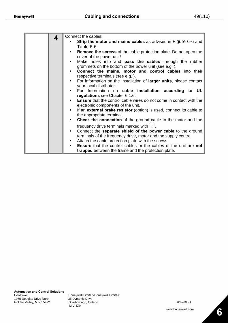
Cabling and connections 49(110)
Automation and Control Solutions Honeywell Honeywell Limited-Honeywell Limitée 1985 Douglas Drive North 35 Dynamic Drive Golden Valley, MIN 55422 Scarborough, Ontario 63-2600-1 MIV 4Z9
www.honeywell.com 6
4 Connect the cables:
Strip the motor and mains cables as advised in Figure 6-6 and Table 6-6.
Remove the screws of the cable protection plate. Do not open the cover of the power unit!
Make holes into and pass the cables through the rubber grommets on the bottom of the power unit (see e.g. ).
Connect the mains, motor and control cables into their respective terminals (see e.g. ).
For information on the installation of larger units, please contact your local distributor.
For Information on cable installation according to UL regulations see Chapter 6.1.6.
Ensure that the control cable wires do not come in contact with the electronic components of the unit.
If an external brake resistor (option) is used, connect its cable to the appropriate terminal.
Check the connection of the ground cable to the motor and the frequency drive terminals marked with .
Connect the separate shield of the power cable to the ground terminals of the frequency drive, motor and the supply centre.
Attach the cable protection plate with the screws. Ensure that the control cables or the cables of the unit are not
trapped between the frame and the protection plate.
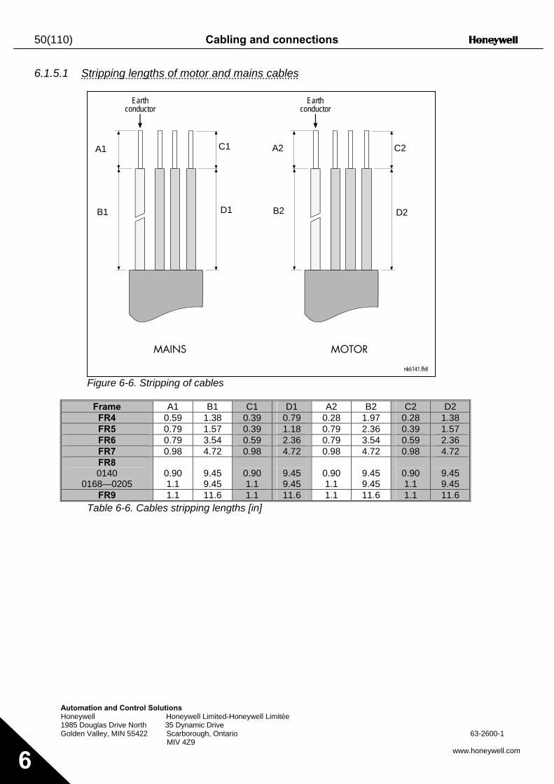
50(110) Cabling and connections
Automa Honeyw 1985 Do Golden V
6
6.1.5.1 Stripping lengths of motor and mains cables
F
01
T
Earthconductor
Earthconductor
tion and Control Solutions ell Honeywell Limited-Honeywell Limitée uglas Drive North 35 Dynamic Drive alley, MIN 55422 Scarborough, Ontario 63-2600-1
MIV 4Z9 www.honeywell.com
igure 6-6. Stripping of cables
Frame A1 B1 C1 D1 A2 B2 C2 D2 FR4 0.59 1.38 0.39 0.79 0.28 1.97 0.28 1.38 FR5 0.79 1.57 0.39 1.18 0.79 2.36 0.39 1.57 FR6 0.79 3.54 0.59 2.36 0.79 3.54 0.59 2.36 FR7 0.98 4.72 0.98 4.72 0.98 4.72 0.98 4.72 FR8 0140
68—0205
0.90 1.1
9.45 9.45
0.90 1.1
9.45 9.45
0.90 1.1
9.45 9.45
0.90 1.1
9.45 9.45
FR9 1.1 11.6 1.1 11.6 1.1 11.6 1.1 11.6 able 6-6. Cables stripping lengths [in]
nk6141.fh8
MAINS MOTOR
D1B1
C1A1
D2B2
C2A2
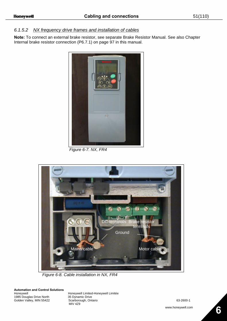
Cabling and connections 51(110)
Automation and CHoneywell 1985 Douglas DrivGolden Valley, MIN
6.1.5.2 NX frequency drive frames and installation of cables Note: To connect an external brake resistor, see separate Brake Resistor Manual. See also Chapter Internal brake resistor connection (P6.7.1) on page 97 in this manual.
Figure 6-7. NX, FR4
ontrol Solutions Honeywell Limited-Honeywell Lim
e North 35 Dynamic Drive 55422 Scarborough, Ontario MIV 4Z9
Figure 6-8. Cable installation in NX, FR
Mains cable
Brake resistor terminals
DC-terminals
Ground
itée
63-2600-1
www.honeywell.com 6
4
Motor cable
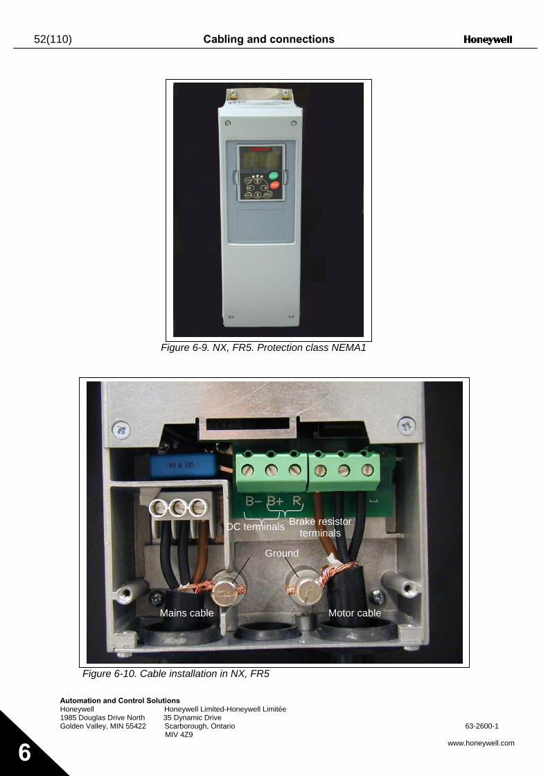
52(110) Cabling and connections
Autom Honey 1985 D Golden
6
Figure 6-9. NX, FR5. Protection class NEMA1
ation and Control Solutions well Honeywell Limited-Honeywellouglas Drive North 35 Dynamic Drive Valley, MIN 55422 Scarborough, Ontario
MIV 4Z9
Figure 6-10. Cable installation in NX, FR
Mains cable
Brake resistor terminals DC terminals
Ground
Limitée
63-2600-1
www.honeywell.com
5
Motor cable
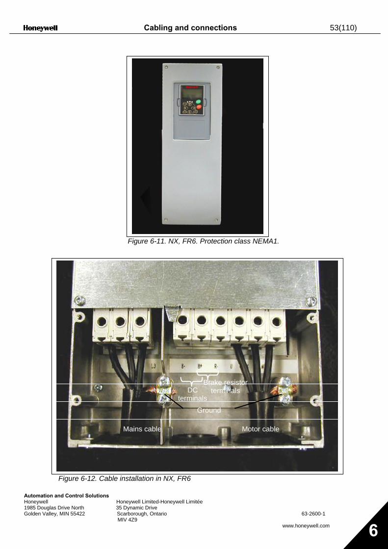
Cabling and connections 53(110)
Automation and Control Solutions Honeywell Honeywell Limited-Honeywell Lim1985 Douglas Drive North 35 Dynamic Drive Golden Valley, MIN 55422 Scarborough, Ontario MIV 4Z9
Figure 6-11. NX, FR6. Protection class NEMA1.
Figure 6-12. Cable installation in NX, FR6
Mains cable Motor cable
Brake resistor te
Brake resistor terminals
Mains cable Motor cable
DC terminals
Ground
rminals Ground
itée
63-2600-1
www.honeywell.com 6
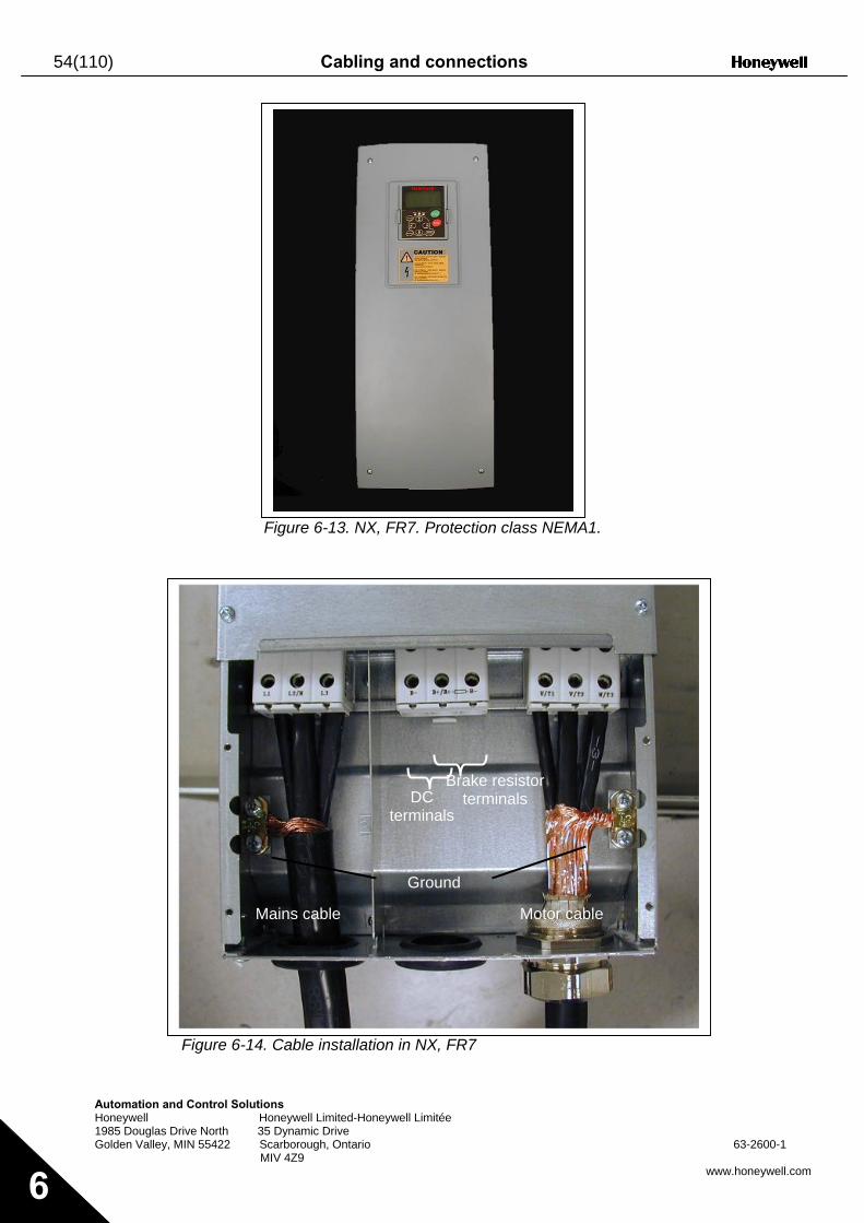
54(110) Cabling and connections
Automation a Honeywell 1985 Douglas Golden Valley,
6
Figure 6-13. NX, FR7. Protection class NEMA1.
nd Control Solutions Honeywell Limited-Honeywe
Drive North 35 Dynamic Drive MIN 55422 Scarborough, Ontario MIV 4Z9
Figure 6-14. Cable installation i
Mains cable Motor cable
Brake resistor terminals DC
terminals
Ground
ll Limitée
63-2600-1
www.honeywell.com
n NX, FR7
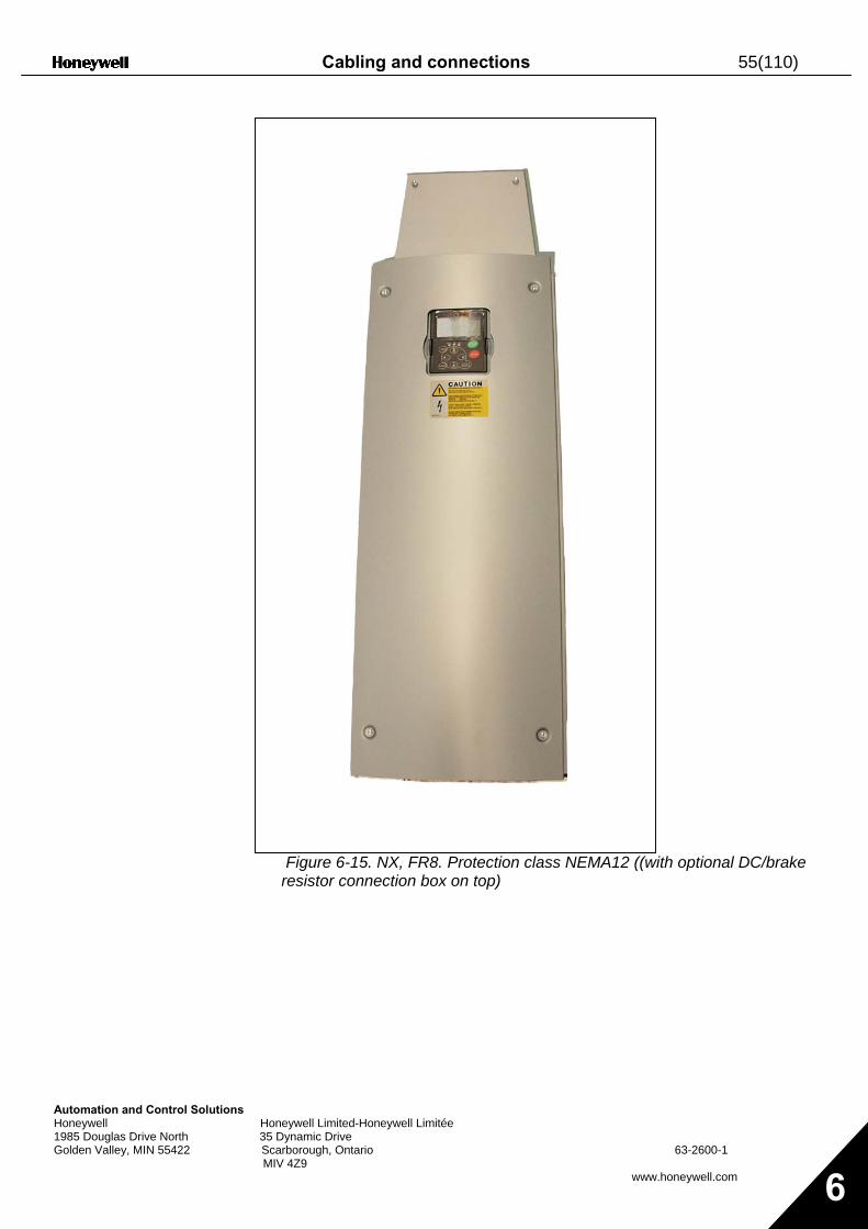
Cabling and connections 55(110)
Automation and Control Solutions Honeywell 1985 Douglas Drive North Golden Valley, MIN 55422
Honeywell Limited-Honeywell Limitée 35 Dynamic Drive Scarborough, Ontario 63-2600-1 MIV 4Z9
www.honeywell.com 6
Figure 6-15. NX, FR8. Protection class NEMA12 ((with optional DC/brake resistor connection box on top)
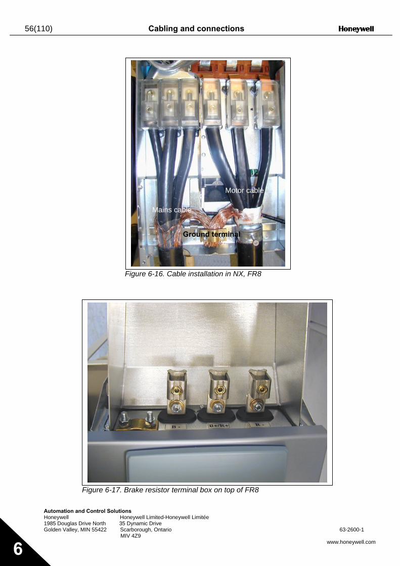
56(110) Cabling and connections
Automation and Control Solution Honeywell Ho 1985 Douglas Drive North 35 Golden Valley, MIN 55422 Sca MIV
6
F
Figure 6-17. B
s neywell Limited-Honeywell Limitée Dynamic Drive rborough, Ontario 63-2600-1 4Z9
www.honeywell.com
igure 6-16. Cable installation in NX, FR8
rake resistor terminal box on top of FR8
Mains cable
Motor cable
Ground terminal
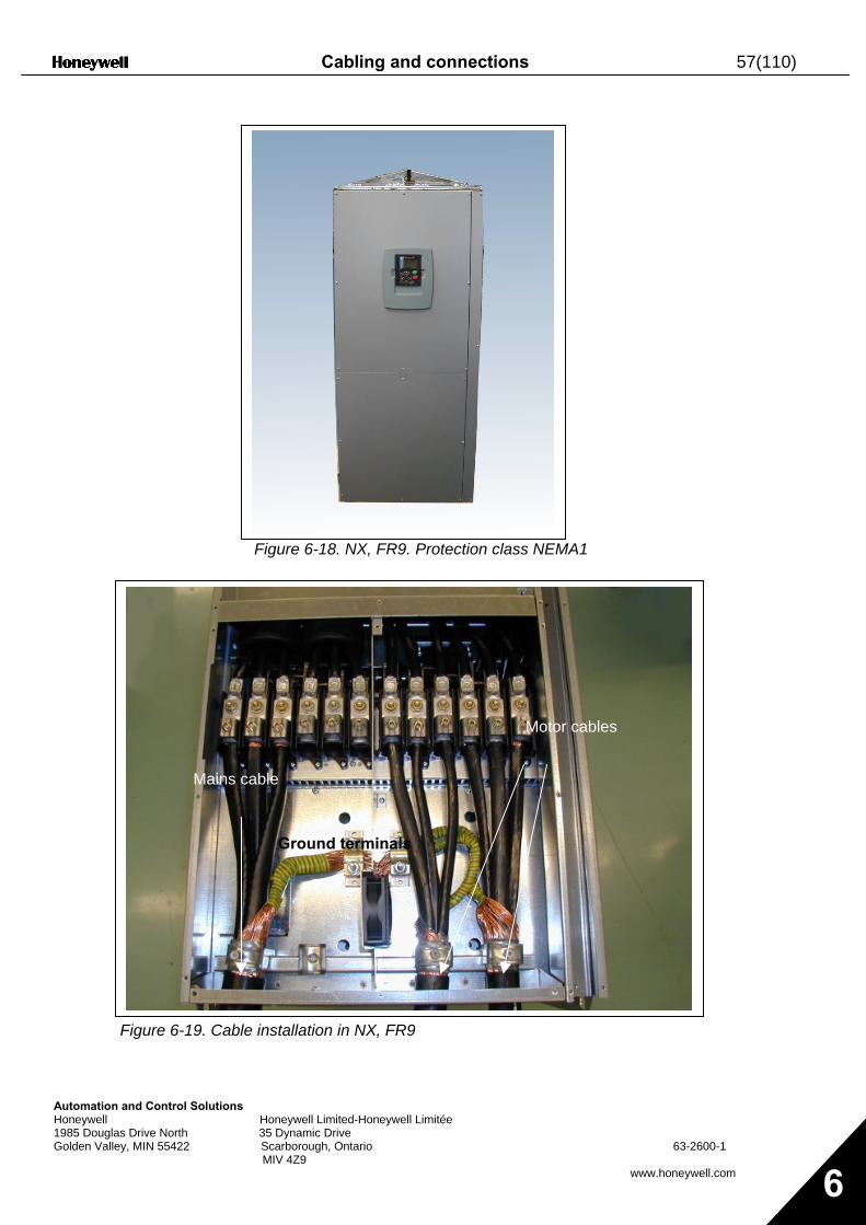
Cabling and connections 57(110)
AutomationHoneywell 1985 DouglaGolden Valle
Figure 6-18. NX, FR9. Protection class NEMA1
and Control Solutions
s Drive North y, MIN 55422
Figure 6-19. Cabl
Mains c
Honeywell Limited-Honeywell Limitée
35 Dynamic Drive Scarborough, Ontario 63-2600-1 MIV 4Z9
www.honeywell.com 6
e installation in NX, FR9
able
Motor cables
Ground terminals
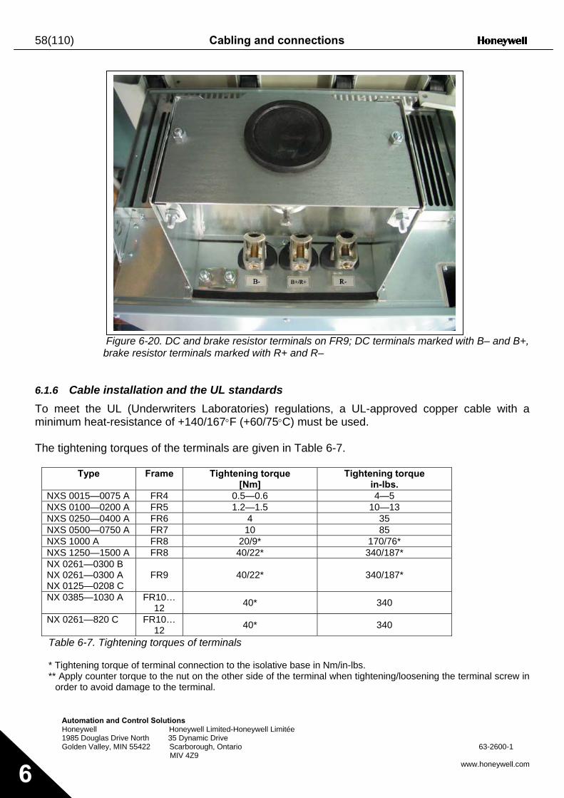
58(110) Cabling and connections
Automation a Honeywell 1985 Douglas Golden Valley
6
Fb
6.1.6 Cable inTo meet the Uminimum heat- The tightening
Type
NXS 0015—00NXS 0100—02NXS 0250—04NXS 0500—07NXS 1000 A NXS 1250—15NX 0261—030NX 0261—030NX 0125—020NX 0385—103
NX 0261—820
Table 6-7. Tig
* Tightening to** Apply count
order to avoi
nd Control Solutions Honeywell Limited-Honeywell Limitée
Drive North 35 Dynamic Drive , MIN 55422 Scarborough, Ontario 63-2600-1 MIV 4Z9
www.honeywell.com
igure 6-20. DC and brake resistor terminals on FR9; DC terminals marked with B– and B+, rake resistor terminals marked with R+ and R–
stallation and the UL standards L (Underwriters Laboratories) regulations, a UL-approved copper cable with a
resistance of +140/167°F (+60/75°C) must be used.
torques of the terminals are given in Table 6-7.
Frame Tightening torque [Nm]
Tightening torque in-lbs.
75 A FR4 0.5—0.6 4—5 00 A FR5 1.2—1.5 10—13 00 A FR6 4 35 50 A FR7 10 85
FR8 20/9* 170/76* 00 A FR8 40/22* 340/187* 0 B 0 A 8 C
FR9 40/22* 340/187*
0 A FR10…12 40* 340
C FR10…12 40* 340
htening torques of terminals
rque of terminal connection to the isolative base in Nm/in-lbs. er torque to the nut on the other side of the terminal when tightening/loosening the terminal screw in d damage to the terminal.
Cabling and connections 59(110)
Automation and Control Solutions Honeywell Honeywell Limited-Honeywell Limitée 1985 Douglas Drive North 35 Dynamic Drive Golden Valley, MIN 55422 Scarborough, Ontario 63-2600-1 MIV 4Z9
www.honeywell.com 6
6.1.7 Cable and motor insulation checks 1. Motor cable insulation checks
Disconnect the motor cable from terminals U, V and W of the frequency drive and from the motor. Measure the insulation resistance of the motor cable between each phase conductor as well as between each phase conductor and the protective ground conductor. The insulation resistance must be >1MΩ.
2. Mains cable insulation checks Disconnect the motor cable from terminals L1, L2 and L3 of the frequency drive and from the mains. Measure the insulation resistance of the motor cable between each phase conductor as well as between each phase conductor and the protective ground conductor. The insulation resistance must be >1MΩ.
3. Motor insulation checks Disconnect the motor cable from the motor and open the bridging connections in the motor connection box. Measure the insulation resistance of each motor winding. The measurement voltage must equal at least the motor nominal voltage but not exceed 1000 V. The insulation resistance must be >1MΩ.
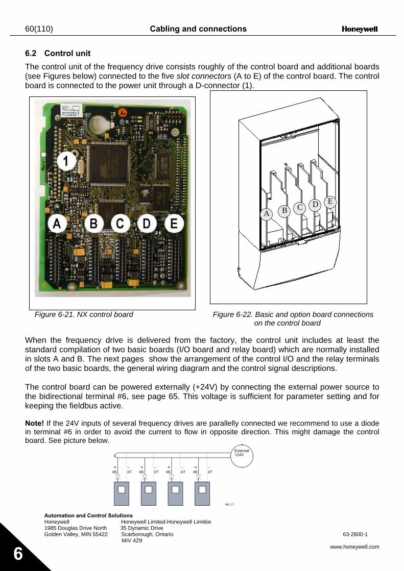
60(110) Cabling and connections
Automation and Control Solutions Honeywell Honeywell Limited-Honeywell Limitée 1985 Douglas Drive North 35 Dynamic Drive Golden Valley, MIN 55422 Scarborough, Ontario 63-2600-1 MIV 4Z9
www.honeywell.com 6
6.2 Control unit
The control unit of the frequency drive consists roughly of the control board and additional boards (see Figures below) connected to the five slot connectors (A to E) of the control board. The control board is connected to the power unit through a D-connector (1).
Figure 6-21. NX control board Figure 6-22. Basic and option board connections on the control board
When the frequency drive is delivered from the factory, the control unit includes at least the standard compilation of two basic boards (I/O board and relay board) which are normally installed in slots A and B. The next pages show the arrangement of the control I/O and the relay terminals of the two basic boards, the general wiring diagram and the control signal descriptions. The control board can be powered externally (+24V) by connecting the external power source to the bidirectional terminal #6, see page 65. This voltage is sufficient for parameter setting and for keeping the fieldbus active. Note! If the 24V inputs of several frequency drives are parallelly connected we recommend to use a diode in terminal #6 in order to avoid the current to flow in opposite direction. This might damage the control board. See picture below.
+ -#6 #7
+ -#6 #7
+ -#6 #7
+ -#6 #7
nk6_17
External+24V
A B C D E
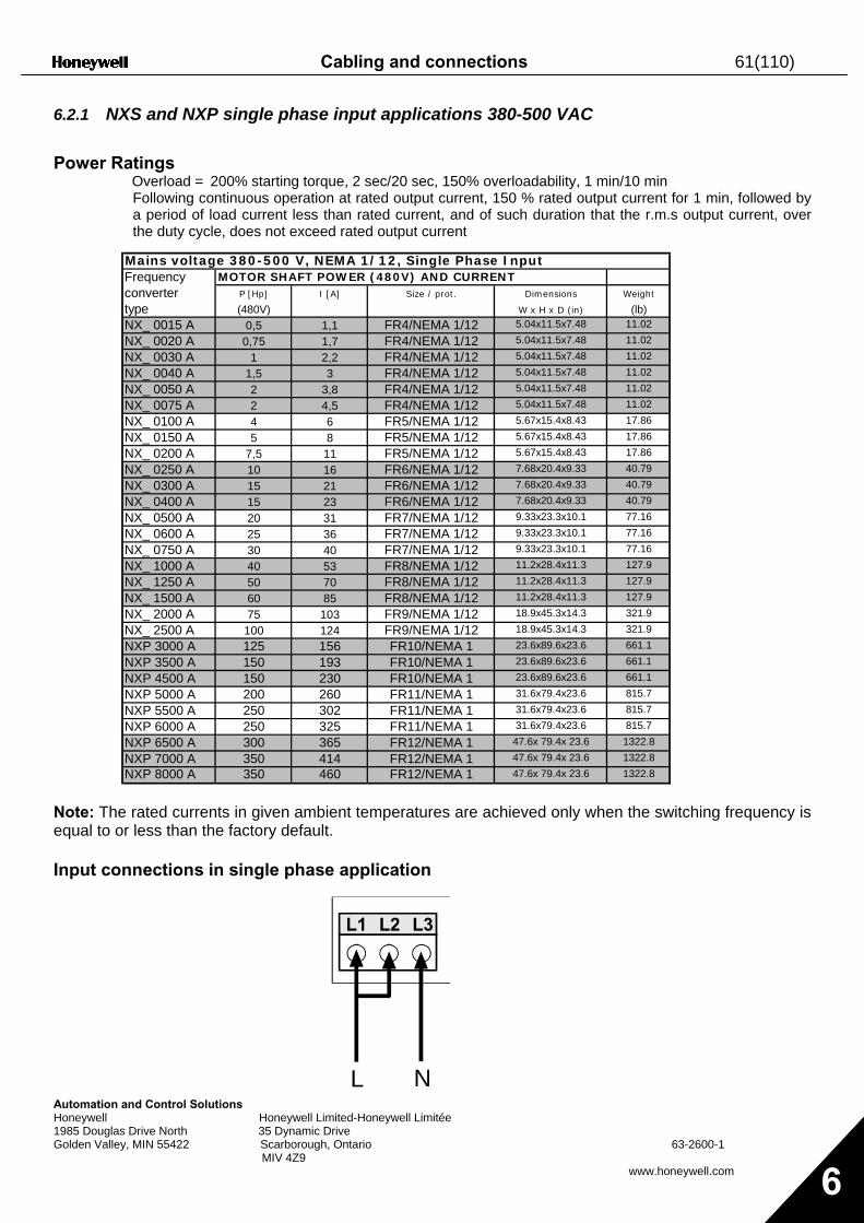
Cabling and connections 61(110)
Automation and Control Solutions Honeywell Honeywell Limited-Honeywell Limitée 1985 Douglas Drive North 35 Dynamic Drive Golden Valley, MIN 55422 Scarborough, Ontario 63-2600-1 MIV 4Z9
www.honeywell.com 6
6.2.1 NXS and NXP single phase input applications 380-500 VAC Power Ratings
Overload = 200% starting torque, 2 sec/20 sec, 150% overloadability, 1 min/10 min Following continuous operation at rated output current, 150 % rated output current for 1 min, followed by a period of load current less than rated current, and of such duration that the r.m.s output current, over the duty cycle, does not exceed rated output current
Note: The rated currents in given ambient temperatures are achieved only when the switching frequency is equal to or less than the factory default. Input connections in single phase application
Mains voltage 380-500 V, NEMA 1/12, Single Phase InputFrequency MOTOR SHAFT POWER (480V) AND CURRENTconverter P [Hp] I [A] Size / prot. Dimensions Weight
type (480V) W x H x D (in) (lb)NX_ 0015 A 0,5 1,1 FR4/NEMA 1/12 5.04x11.5x7.48 11.02
NX_ 0020 A 0,75 1,7 FR4/NEMA 1/12 5.04x11.5x7.48 11.02
NX_ 0030 A 1 2,2 FR4/NEMA 1/12 5.04x11.5x7.48 11.02
NX_ 0040 A 1,5 3 FR4/NEMA 1/12 5.04x11.5x7.48 11.02
NX_ 0050 A 2 3,8 FR4/NEMA 1/12 5.04x11.5x7.48 11.02
NX_ 0075 A 2 4,5 FR4/NEMA 1/12 5.04x11.5x7.48 11.02
NX_ 0100 A 4 6 FR5/NEMA 1/12 5.67x15.4x8.43 17.86
NX_ 0150 A 5 8 FR5/NEMA 1/12 5.67x15.4x8.43 17.86
NX_ 0200 A 7,5 11 FR5/NEMA 1/12 5.67x15.4x8.43 17.86
NX_ 0250 A 10 16 FR6/NEMA 1/12 7.68x20.4x9.33 40.79
NX_ 0300 A 15 21 FR6/NEMA 1/12 7.68x20.4x9.33 40.79
NX_ 0400 A 15 23 FR6/NEMA 1/12 7.68x20.4x9.33 40.79
NX_ 0500 A 20 31 FR7/NEMA 1/12 9.33x23.3x10.1 77.16
NX_ 0600 A 25 36 FR7/NEMA 1/12 9.33x23.3x10.1 77.16
NX_ 0750 A 30 40 FR7/NEMA 1/12 9.33x23.3x10.1 77.16
NX_ 1000 A 40 53 FR8/NEMA 1/12 11.2x28.4x11.3 127.9
NX_ 1250 A 50 70 FR8/NEMA 1/12 11.2x28.4x11.3 127.9
NX_ 1500 A 60 85 FR8/NEMA 1/12 11.2x28.4x11.3 127.9
NX_ 2000 A 75 103 FR9/NEMA 1/12 18.9x45.3x14.3 321.9
NX_ 2500 A 100 124 FR9/NEMA 1/12 18.9x45.3x14.3 321.9
NXP 3000 A 125 156 FR10/NEMA 1 23.6x89.6x23.6 661.1
NXP 3500 A 150 193 FR10/NEMA 1 23.6x89.6x23.6 661.1
NXP 4500 A 150 230 FR10/NEMA 1 23.6x89.6x23.6 661.1
NXP 5000 A 200 260 FR11/NEMA 1 31.6x79.4x23.6 815.7
NXP 5500 A 250 302 FR11/NEMA 1 31.6x79.4x23.6 815.7
NXP 6000 A 250 325 FR11/NEMA 1 31.6x79.4x23.6 815.7
NXP 6500 A 300 365 FR12/NEMA 1 47.6x 79.4x 23.6 1322.8
NXP 7000 A 350 414 FR12/NEMA 1 47.6x 79.4x 23.6 1322.8NXP 8000 A 350 460 FR12/NEMA 1 47.6x 79.4x 23.6 1322.8
L1 L2 L3
L N
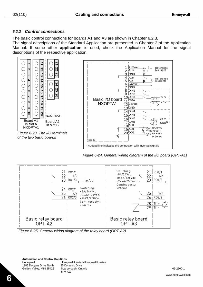
62(110) Cabling and connections
6
6.2.2 Control connections The basic control connections for boards A1 and A3 are shown in Chapter 6.2.3. The signal descriptions of the Standard Application are presented in Chapter 2 of the Application Manual. If some other application is used, check the Application Manual for the signal descriptions of the respective application.
+10Vref
Automation and Control Solutions Honeywell Honeywell Limited-1985 Douglas Drive North 35 Dynamic Drive Golden Valley, MIN 55422 Scarborough, Onta
MIV 4Z9
Figure 6-23. The I/O terminals of the two basic boards
F
Figure 6-25. General wiring diagram of
NXOPTA2Board A1in slot A
NXOPTA1
Board A2in slot B
RO1/11/2
RO1/3
RO2/12/2
RO2/3
212223
242526
Sw<8A<0.<2kCo<2A
Basic relay boardOPT-A2
igure 6-24. General wiring diagram of the I/O board (OPT-A1)
AI1+GNDAI2+AI2-24VoutGNDDIN1DIN2DIN3CMA24VoutGNDDIN4DIN5DIN6CMBAO1+AO1-DO1
123456789
1011121314151617181920
24 V
GND
24 VGND
U<+48VI<50mA
+
0(4)/20mARL<500Ω
nk6_13
Basic I/O boardNXOPTA1
Reference(voltage)
Reference(current)
Dotted line indicates the connection with inverted signals
21 RO1/1Switching:<8A/24Vdc,
Honeywell Limitée
rio 63-2600-1
www.honeywell.com
the relay board (OPT-A2)
ac/dc2223
2526
1/2RO1/3
2/1RO2/2
2829
TI1+TI1-
+t
itching:/24Vdc,
4A/125Vdc,VA/250Vac
ntinuously:rms
<0.4A/125Vdc,<2kVA/250VacContinuously:<2Arms
Basic relay boardOPT-A3
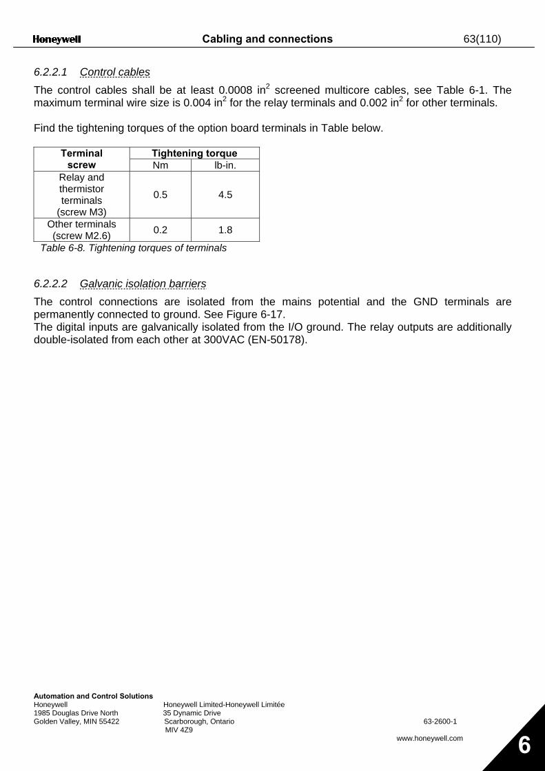
Cabling and connections 63(110)
Automation and Control Solutions Honeywell Honeywell Limited-Honeywell Limitée 1985 Douglas Drive North 35 Dynamic Drive Golden Valley, MIN 55422 Scarborough, Ontario 63-2600-1 MIV 4Z9
www.honeywell.com 6
6.2.2.1 Control cables The control cables shall be at least 0.0008 in2 screened multicore cables, see Table 6-1. The maximum terminal wire size is 0.004 in2 for the relay terminals and 0.002 in2 for other terminals. Find the tightening torques of the option board terminals in Table below.
Tightening torque Terminal screw Nm lb-in.
Relay and thermistor terminals
(screw M3)
0.5 4.5
Other terminals (screw M2.6) 0.2 1.8
Table 6-8. Tightening torques of terminals
6.2.2.2 Galvanic isolation barriers The control connections are isolated from the mains potential and the GND terminals are permanently connected to ground. See Figure 6-17. The digital inputs are galvanically isolated from the I/O ground. The relay outputs are additionally double-isolated from each other at 300VAC (EN-50178).
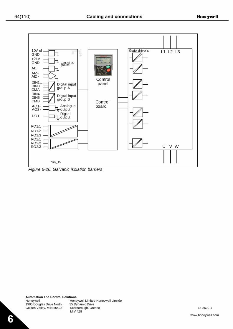
64(110) Cabling and connections
Automation and Control Solutions Honeywell Honeywell Limited-Honeywell Limitée 1985 Douglas Drive North 35 Dynamic Drive Golden Valley, MIN 55422 Scarborough, Ontario 63-2600-1 MIV 4Z9
www.honeywell.com 6
Figure 6-26. Galvanic isolation barriers
Control I/Oground
Digital inputgroup A
Digital inputgroup B
AnalogueoutputDigitaloutput
Maincircuits
Controlboard
Controlpanel Control
board
nk6_15
L1 L2 L3
U V W
RO1/1RO1/2RO1/3
RO2/3RO2/2RO2/1
10VrefGND
GND+24V
AI1AI2+AI2 -
DIN1...DIN3CMADIN4...DIN6CMBAO1+AO2 -
DO1
Gate drivers
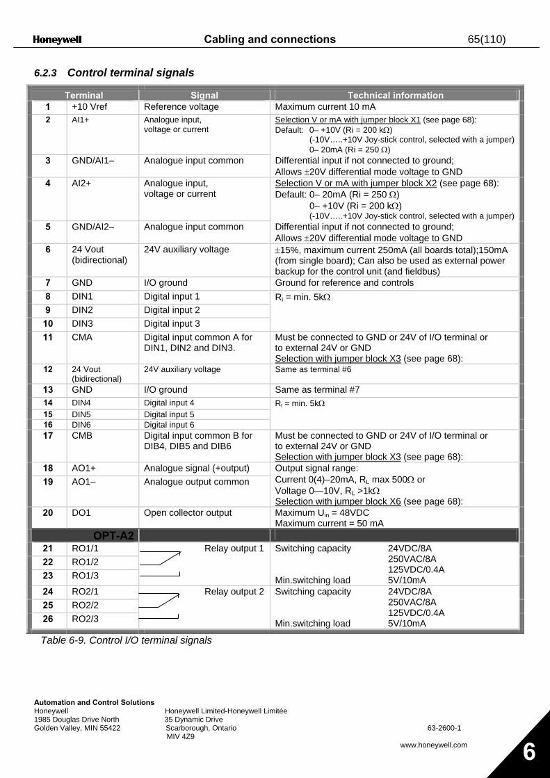
Cabling and connections 65(110)
Automation and Control Solutions Honeywell Honeywell Limited-Honeywell Limitée 1985 Douglas Drive North 35 Dynamic Drive Golden Valley, MIN 55422 Scarborough, Ontario 63-2600-1 MIV 4Z9
www.honeywell.com 6
6.2.3 Control terminal signals
Terminal Signal Technical information 1 +10 Vref Reference voltage Maximum current 10 mA 2 AI1+ Analogue input,
voltage or current Selection V or mA with jumper block X1 (see page 68): Default: 0– +10V (Ri = 200 kΩ) (-10V…..+10V Joy-stick control, selected with a jumper) 0– 20mA (Ri = 250 Ω)
3 GND/AI1– Analogue input common Differential input if not connected to ground; Allows ±20V differential mode voltage to GND
4 AI2+ Analogue input, voltage or current
Selection V or mA with jumper block X2 (see page 68): Default: 0– 20mA (Ri = 250 Ω) 0– +10V (Ri = 200 kΩ) (-10V…..+10V Joy-stick control, selected with a jumper)
5 GND/AI2– Analogue input common Differential input if not connected to ground; Allows ±20V differential mode voltage to GND
6 24 Vout (bidirectional)
24V auxiliary voltage ±15%, maximum current 250mA (all boards total);150mA (from single board); Can also be used as external power backup for the control unit (and fieldbus)
7 GND I/O ground Ground for reference and controls 8 DIN1 Digital input 1 9 DIN2 Digital input 2
10 DIN3 Digital input 3
Ri = min. 5kΩ
11 CMA Digital input common A for DIN1, DIN2 and DIN3.
Must be connected to GND or 24V of I/O terminal or to external 24V or GND Selection with jumper block X3 (see page 68):
12 24 Vout (bidirectional)
24V auxiliary voltage Same as terminal #6
13 GND I/O ground Same as terminal #7 14 DIN4 Digital input 4 15 DIN5 Digital input 5 16 DIN6 Digital input 6
Ri = min. 5kΩ
17 CMB Digital input common B for DIB4, DIB5 and DIB6
Must be connected to GND or 24V of I/O terminal or to external 24V or GND Selection with jumper block X3 (see page 68):
18 AO1+ Analogue signal (+output) 19 AO1– Analogue output common
Output signal range: Current 0(4)–20mA, RL max 500Ω or Voltage 0—10V, RL >1kΩ Selection with jumper block X6 (see page 68):
20 DO1 Open collector output Maximum Uin = 48VDC Maximum current = 50 mA
OPT-A2 21 RO1/1 22 RO1/2 23 RO1/3
Relay output 1 Switching capacity 24VDC/8A 250VAC/8A 125VDC/0.4A Min.switching load 5V/10mA
24 RO2/1 25 RO2/2 26 RO2/3
Relay output 2 Switching capacity 24VDC/8A 250VAC/8A 125VDC/0.4A Min.switching load 5V/10mA
Table 6-9. Control I/O terminal signals
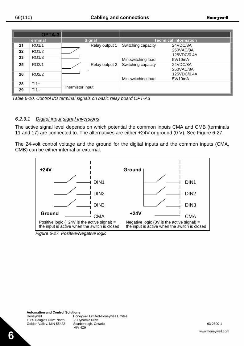
66(110) Cabling and connections
Autom Honey 1985 D Golden
6
OPTA-3 Terminal Signal Technical information
21 RO1/1 22 RO1/2 23 RO1/3
Relay output 1 Switching capacity 24VDC/8A 250VAC/8A 125VDC/0.4A Min.switching load 5V/10mA
25 RO2/1
26 RO2/2
Relay output 2
Switching capacity 24VDC/8A 250VAC/8A 125VDC/0.4A Min.switching load 5V/10mA
28 TI1+ 29 TI1– Thermistor input
Table 6-10. Control I/O terminal signals on basic relay board OPT-A3
6.2.3.1 Digital input signal inversions The active signal level depends on which potential the common inputs CMA and CMB (terminals 11 and 17) are connected to. The alternatives are either +24V or ground (0 V). See Figure 6-27. The 24-volt control voltage and the ground for the digital inputs and the common inputs (CMA, CMB) can be either internal or external.
F
+24V Ground
ation and Control Solutions well Honeywell Limited-Honeywell Limitée ouglas Drive North 35 Dynamic Drive Valley, MIN 55422 Scarborough, Ontario 63-2600-1
MIV 4Z9 www.honeywell.com
igure 6-27. Positive/Negative logic
+24V
DIN1
DIN2
DIN3
CMA
DIN1
DIN2
DIN3
CMAGround
Positive logic (+24V is the active signal) =the input is active when the switch is closed
Negative logic (0V is the active signal) =the input is active when the switch is closed
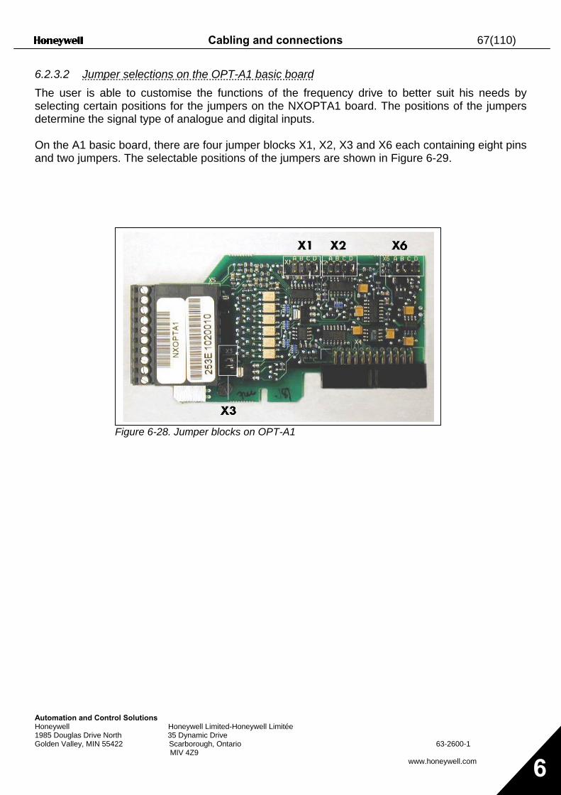
Cabling and connections 67(110)
Automation and ControHoneywell 1985 Douglas Drive NortGolden Valley, MIN 5542
6.2.3.2 Jumper selections on the OPT-A1 basic board The user is able to customise the functions of the frequency drive to better suit his needs by selecting certain positions for the jumpers on the NXOPTA1 board. The positions of the jumpers determine the signal type of analogue and digital inputs. On the A1 basic board, there are four jumper blocks X1, X2, X3 and X6 each containing eight pins and two jumpers. The selectable positions of the jumpers are shown in Figure 6-29.
F
l Solutions Honeywell Limited-Honeywell Limitée
h 35 Dynamic Drive 2 Scarborough, Ontario 63-2600-1 MIV 4Z9
www.honeywell.com 6
igure 6-28. Jumper blocks on OPT-A1
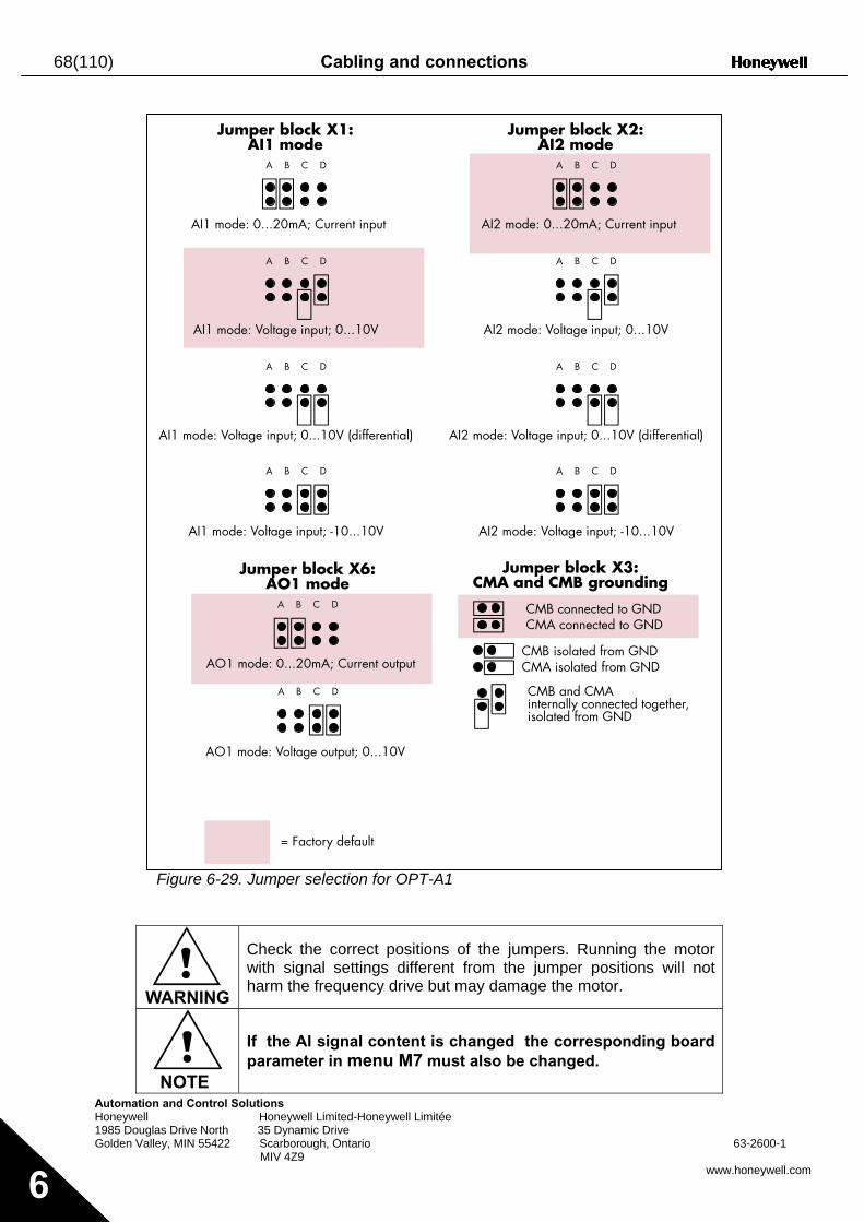
68(110) Cabling and connections
Automatio Honeywell 1985 Doug Golden Va
6
W
Jumper block X1:AI1 mode
Jumper block X2:AI2 mode
n and Control Solutions Honeywell Limited-Honeywell Limitée las Drive North 35 Dynamic Drive lley, MIN 55422 Scarborough, Ontario 63-2600-1 MIV 4Z9
www.honeywell.com
Figure 6-29. Jumper selection for OPT-A1
!ARNING
Check the correct positions of the jumpers. Running the motor with signal settings different from the jumper positions will not harm the frequency drive but may damage the motor.
!NOTE
If the AI signal content is changed the corresponding board parameter in menu M7 must also be changed.
A B C D
A B C D
A B C D
A B C D
A B C D
A B C D
A B C D
A B C D
A B C D
A B C D
AI1 mode: Voltage input; 0...10V
AI1 mode: Voltage input; 0...10V (differential)
AI1 mode: Voltage input; -10...10V
AI2 mode: 0...20mA; Current input
AI2 mode: Voltage input; 0...10V
AI2 mode: Voltage input; 0...10V (differential)
AI2 mode: Voltage input; -10...10V
Jumper block X3:CMA and CMB grounding
CMB connected to GNDCMA connected to GND
CMB isolated from GNDCMA isolated from GND
CMB and CMAinternally connected together,isolated from GND
= Factory default
Jumper block X6:AO1 mode
AO1 mode: 0...20mA; Current output
AO1 mode: Voltage output; 0...10V
AI1 mode: 0...20mA; Current input
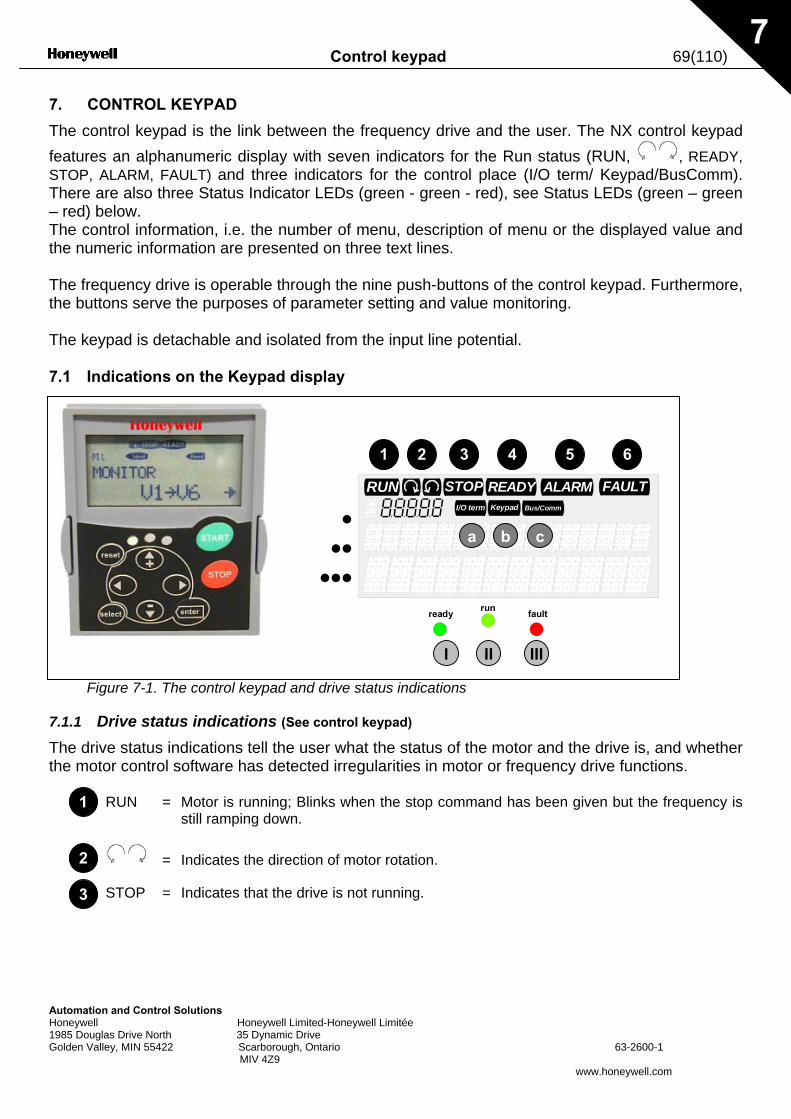
Control keypad 69(110)
Automation and Control Solutions Honeywell Honeywell Limited-Honeywell Limitée 1985 Douglas Drive North 35 Dynamic Drive Golden Valley, MIN 55422 Scarborough, Ontario 63-2600-1 MIV 4Z9
www.honeywell.com
7
7. CONTROL KEYPAD
The control keypad is the link between the frequency drive and the user. The NX control keypad features an alphanumeric display with seven indicators for the Run status (RUN, , READY, STOP, ALARM, FAULT) and three indicators for the control place (I/O term/ Keypad/BusComm). There are also three Status Indicator LEDs (green - green - red), see Status LEDs (green – green – red) below. The control information, i.e. the number of menu, description of menu or the displayed value and the numeric information are presented on three text lines. The frequency drive is operable through the nine push-buttons of the control keypad. Furthermore, the buttons serve the purposes of parameter setting and value monitoring. The keypad is detachable and isolated from the input line potential. 7.1 Indications on the Keypad display
Figure 7-1. The control keypad and drive status indications
7.1.1 Drive status indications (See control keypad) The drive status indications tell the user what the status of the motor and the drive is, and whether the motor control software has detected irregularities in motor or frequency drive functions.
RUN = Motor is running; Blinks when the stop command has been given but the frequency is still ramping down.
= Indicates the direction of motor rotation.
STOP = Indicates that the drive is not running.
READY FAULTSTOPRUNBus/CommKeypadI/O term
ALARM
runready fault
1 2 3 4 5 6
a b
I II III
•••
•••
c
1
2
3
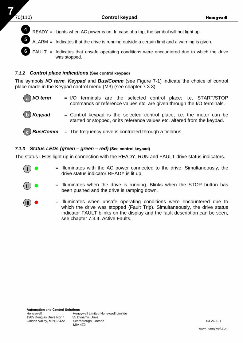
70(110) Control keypad
Automation and Control Solutions Honeywell Honeywell Limited-Honeywell Limitée 1985 Douglas Drive North 35 Dynamic Drive Golden Valley, MIN 55422 Scarborough, Ontario 63-2600-1 MIV 4Z9
www.honeywell.com
7
READY = Lights when AC power is on. In case of a trip, the symbol will not light up.
ALARM = Indicates that the drive is running outside a certain limit and a warning is given.
FAULT = Indicates that unsafe operating conditions were encountered due to which the drive was stopped.
7.1.2 Control place indications (See control keypad) The symbols I/O term, Keypad and Bus/Comm (see Figure 7-1) indicate the choice of control place made in the Keypad control menu (M3) (see chapter 7.3.3).
I/O term = I/O terminals are the selected control place; i.e. START/STOP commands or reference values etc. are given through the I/O terminals.
Keypad = Control keypad is the selected control place; i.e. the motor can be
started or stopped, or its reference values etc. altered from the keypad. Bus/Comm = The frequency drive is controlled through a fieldbus.
7.1.3 Status LEDs (green – green – red) (See control keypad) The status LEDs light up in connection with the READY, RUN and FAULT drive status indicators.
= Illuminates with the AC power connected to the drive. Simultaneously, the drive status indicator READY is lit up.
= Illuminates when the drive is running. Blinks when the STOP button has
been pushed and the drive is ramping down. = Illuminates when unsafe operating conditions were encountered due to
which the drive was stopped (Fault Trip). Simultaneously, the drive status indicator FAULT blinks on the display and the fault description can be seen, see chapter 7.3.4, Active Faults.
4
5
6
b
c
a
I
II
III
Control keypad 71(110)
Automation and Control Solutions Honeywell Honeywell Limited-Honeywell Limitée 1985 Douglas Drive North 35 Dynamic Drive Golden Valley, MIN 55422 Scarborough, Ontario 63-2600-1 MIV 4Z9
www.honeywell.com
7
7.1.4 Text lines (See control keypad)
The three text lines (•, ••, •••) provide the user with information on his present location in the keypad menu structure as well as with information related to the operation of the drive.
• = Location indication; displays the symbol and number of menu, parameter etc.
Example: M3 = Menu 3 (References); R1 = Reference no. 1 (Freq. reference)
•• = Description line; Displays the description of menu, value or fault.
••• = Value line; Displays the numerical and textual values of references, parameters etc. and the number of submenus available in each menu.
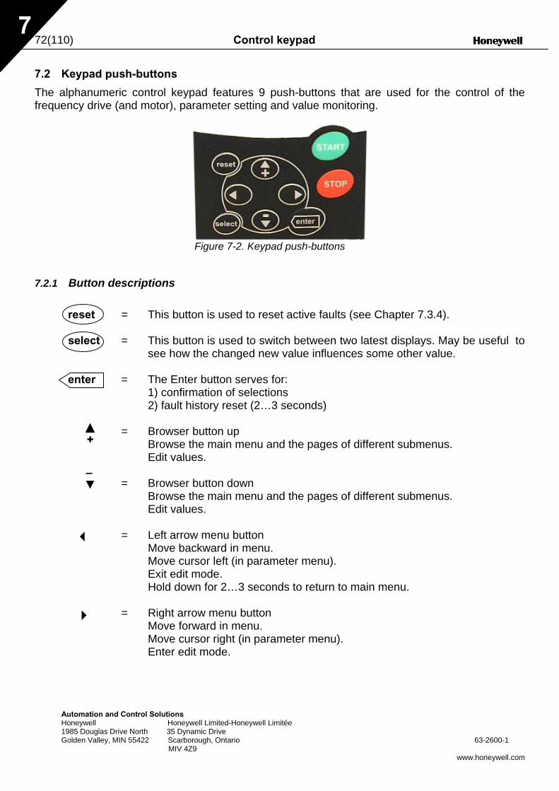
72(110) Control keypad
Auto Hone 1985 Gold
7
7.2 Keypad push-buttons
The alphanumeric control keypad features 9 push-buttons that are used for the control of the frequency drive (and motor), parameter setting and value monitoring.
Figure 7-2. Keypad push-buttons
7.2.1 Button descriptions
reset = This button is used to reset active faults (see Chapter 7.3.4). select = This button is used to switch between two latest displays. May be useful to
see how the changed new value influences some other value. enter = The Enter button serves for: 1) confirmation of selections 2) fault history reset (2…3 seconds) = Browser button up Browse the main menu and the pages of different submenus. Edit values. = Browser button down Browse the main menu and the pages of different submenus. Edit values. = Left arrow menu button Move backward in menu. Move cursor left (in parameter menu). Exit edit mode. Hold down for 2…3 seconds to return to main menu. = Right arrow menu button
3
mayw Doen
4
–
+
tion and Control Solutions ell Honeywell Limited-Honeywell Limitée uglas Drive North 35 Dynamic Drive Valley, MIN 55422 Scarborough, Ontario 63-2600-1 MIV 4Z9
www.honeywell.com
Move forward in menu. Move cursor right (in parameter menu). Enter edit mode.
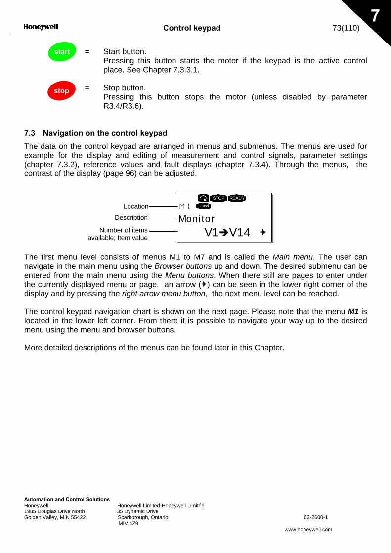
Control keypad 73(110)
Automation and Control Solutions Honeywell Honeywell Limited-Honeywell Limitée 1985 Douglas Drive North 35 Dynamic Drive Golden Valley, MIN 55422 Scarborough, Ontario 63-2600-1 MIV 4Z9
www.honeywell.com
7
= Start button. Pressing this button starts the motor if the keypad is the active control
place. See Chapter 7.3.3.1. = Stop button. Pressing this button stops the motor (unless disabled by parameter
R3.4/R3.6).
7.3 Navigation on the control keypad
The data on the control keypad are arranged in menus and submenus. The menus are used for example for the display and editing of measurement and control signals, parameter settings (chapter 7.3.2), reference values and fault displays (chapter 7.3.4). Through the menus, the contrast of the display (page 96) can be adjusted.
The first menu level consists of menus M1 to M7 and is called the Main menu. The user can navigate in the main menu using the Browser buttons up and down. The desired submenu can be entered from the main menu using the Menu buttons. When there still are pages to enter under the currently displayed menu or page, an arrow ( ) can be seen in the lower right corner of the display and by pressing the right arrow menu button, the next menu level can be reached. The control keypad navigation chart is shown on the next page. Please note that the menu M1 is located in the lower left corner. From there it is possible to navigate your way up to the desired menu using the menu and browser buttons. More detailed descriptions of the menus can be found later in this Chapter.
start
stop
MonitorV1 V14
STOP READY
LocalLocation
Description
Number of itemsavailable; Item value
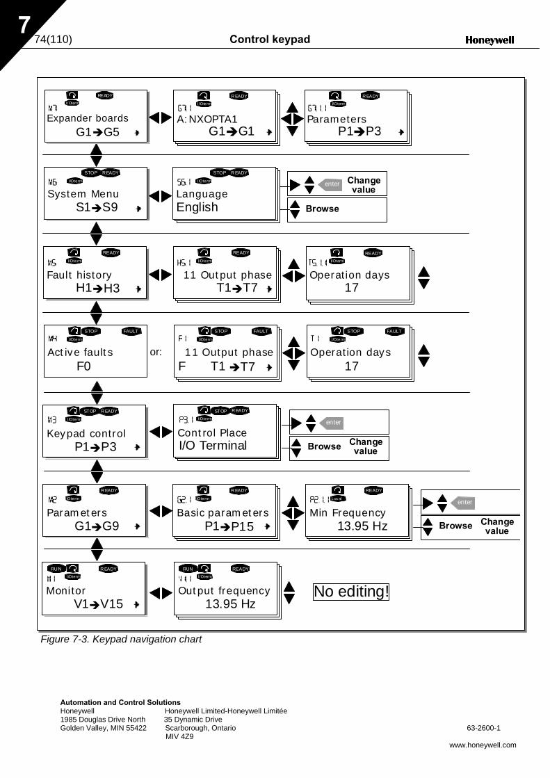
74(110) Control keypad
Automation and Control Solutions Honeywell Honeywell Limited-Honeywell Limitée 1985 Douglas Drive North 35 Dynamic Drive Golden Valley, MIN 55422 Scarborough, Ontario 63-2600-1 MIV 4Z9
www.honeywell.com
7
Figure 7-3. Keypad navigation chart
F T1 T7
STOP FAULT
I/Oterm
STOP
I/Oterm
FAULT
H1 H3
READY
I/Oterm
T1 T7
I/Oterm
READY
I/Oterm
READY
S1 S9
STOP READY
I/Oterm
STOP R EADY
I/Oterm enter
G1 G5
READYI/Oterm
A:NXOPTA1
R EADYI/Oterm
G1 G1
R EADYI/Oterm
V1 V15
R EADYI/Oterm
RU N
13.95 Hz
READYI/Oterm
RUN
G1 G9
READY
I/Oterm
P1 P15
R EADY
I/Oterm
13.95 Hz
READY
Loc al
P1 P3
READY
I/Oterm
STOP R EADY
I/Oterm
STOP
enter
enter
F0
STOP FAULT
I/Oterm
Parameters Basic parameters Min Frequency
11 Output phase Operation days17
Fault history 11 Output phase Operation days
System Menu LanguageChangevalue
Browse
Expander boards ParametersP1 P3
Monitor Output frequency No editing!
Keypad control Control PlaceI/O Terminal
Changevalue
Changevalue
Browse
Browse
Active faults
17
English
or:
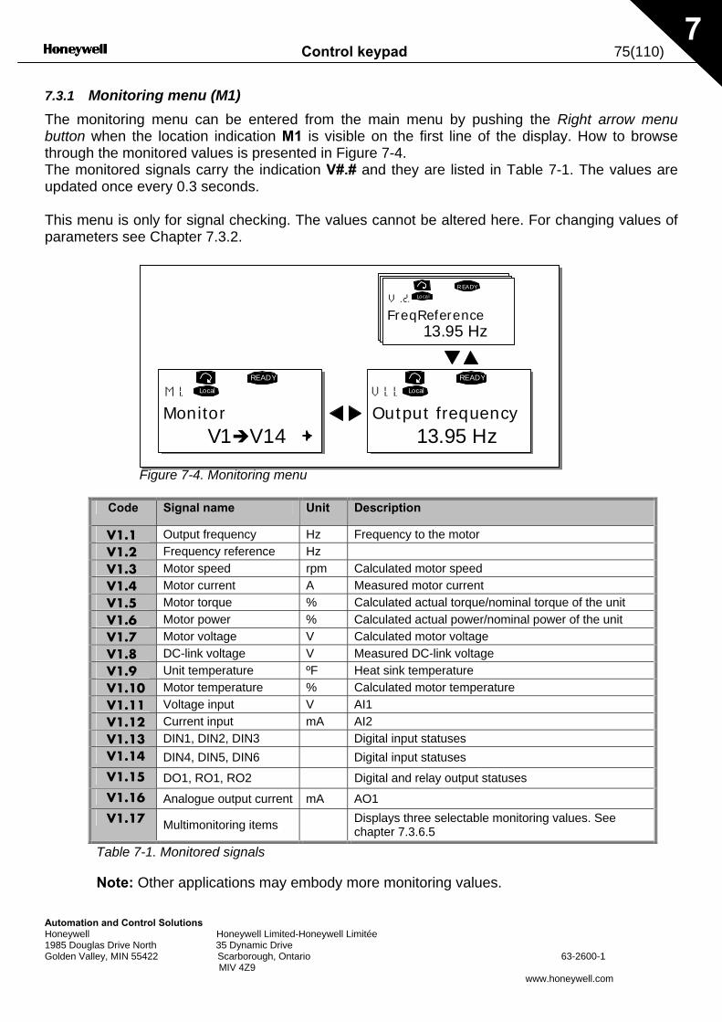
Control keypad 75(110)
Automation and Control Solutions Honeywell Honeywell Limited-Honeywell Limitée 1985 Douglas Drive North 35 Dynamic Drive Golden Valley, MIN 55422 Scarborough, Ontario 63-2600-1 MIV 4Z9
www.honeywell.com
7
7.3.1 Monitoring menu (M1) The monitoring menu can be entered from the main menu by pushing the Right arrow menu button when the location indication M1 is visible on the first line of the display. How to browse through the monitored values is presented in Figure 7-4. The monitored signals carry the indication V#.# and they are listed in Table 7-1. The values are updated once every 0.3 seconds. This menu is only for signal checking. The values cannot be altered here. For changing values of parameters see Chapter 7.3.2.
Figure 7-4. Monitoring menu
Code Signal name Unit Description
V1.1 Output frequency Hz Frequency to the motor V1.2 Frequency reference Hz V1.3 Motor speed rpm Calculated motor speed V1.4 Motor current A Measured motor current V1.5 Motor torque % Calculated actual torque/nominal torque of the unit V1.6 Motor power % Calculated actual power/nominal power of the unit V1.7 Motor voltage V Calculated motor voltage V1.8 DC-link voltage V Measured DC-link voltage V1.9 Unit temperature ºF Heat sink temperature V1.10 Motor temperature % Calculated motor temperature V1.11 Voltage input V AI1 V1.12 Current input mA AI2 V1.13 DIN1, DIN2, DIN3 Digital input statuses V1.14 DIN4, DIN5, DIN6 Digital input statuses V1.15 DO1, RO1, RO2 Digital and relay output statuses V1.16 Analogue output current mA AO1 V1.17 Multimonitoring items Displays three selectable monitoring values. See
chapter 7.3.6.5
Table 7-1. Monitored signals
Note: Other applications may embody more monitoring values.
MonitorV1 V14
READY
Local
Output frequency13.95 Hz
READY
Local
FreqReference13.95 Hz
READYLocal
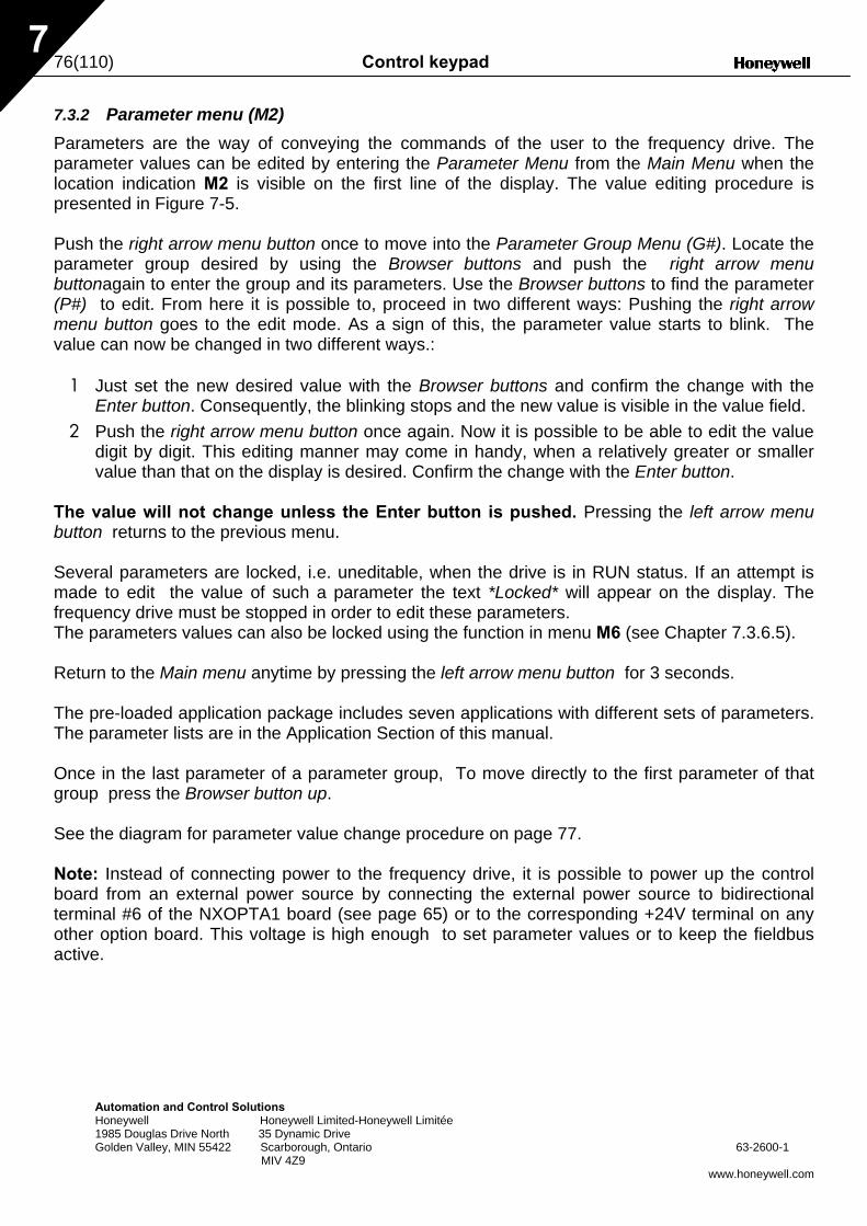
76(110) Control keypad
Automation and Control Solutions Honeywell Honeywell Limited-Honeywell Limitée 1985 Douglas Drive North 35 Dynamic Drive Golden Valley, MIN 55422 Scarborough, Ontario 63-2600-1 MIV 4Z9
www.honeywell.com
7
7.3.2 Parameter menu (M2) Parameters are the way of conveying the commands of the user to the frequency drive. The parameter values can be edited by entering the Parameter Menu from the Main Menu when the location indication M2 is visible on the first line of the display. The value editing procedure is presented in Figure 7-5. Push the right arrow menu button once to move into the Parameter Group Menu (G#). Locate the parameter group desired by using the Browser buttons and push the right arrow menu buttonagain to enter the group and its parameters. Use the Browser buttons to find the parameter (P#) to edit. From here it is possible to, proceed in two different ways: Pushing the right arrow menu button goes to the edit mode. As a sign of this, the parameter value starts to blink. The value can now be changed in two different ways.:
1 Just set the new desired value with the Browser buttons and confirm the change with the Enter button. Consequently, the blinking stops and the new value is visible in the value field.
2 Push the right arrow menu button once again. Now it is possible to be able to edit the value digit by digit. This editing manner may come in handy, when a relatively greater or smaller value than that on the display is desired. Confirm the change with the Enter button.
The value will not change unless the Enter button is pushed. Pressing the left arrow menu button returns to the previous menu. Several parameters are locked, i.e. uneditable, when the drive is in RUN status. If an attempt is made to edit the value of such a parameter the text *Locked* will appear on the display. The frequency drive must be stopped in order to edit these parameters. The parameters values can also be locked using the function in menu M6 (see Chapter 7.3.6.5). Return to the Main menu anytime by pressing the left arrow menu button for 3 seconds. The pre-loaded application package includes seven applications with different sets of parameters. The parameter lists are in the Application Section of this manual. Once in the last parameter of a parameter group, To move directly to the first parameter of that group press the Browser button up. See the diagram for parameter value change procedure on page 77. Note: Instead of connecting power to the frequency drive, it is possible to power up the control board from an external power source by connecting the external power source to bidirectional terminal #6 of the NXOPTA1 board (see page 65) or to the corresponding +24V terminal on any other option board. This voltage is high enough to set parameter values or to keep the fieldbus active.
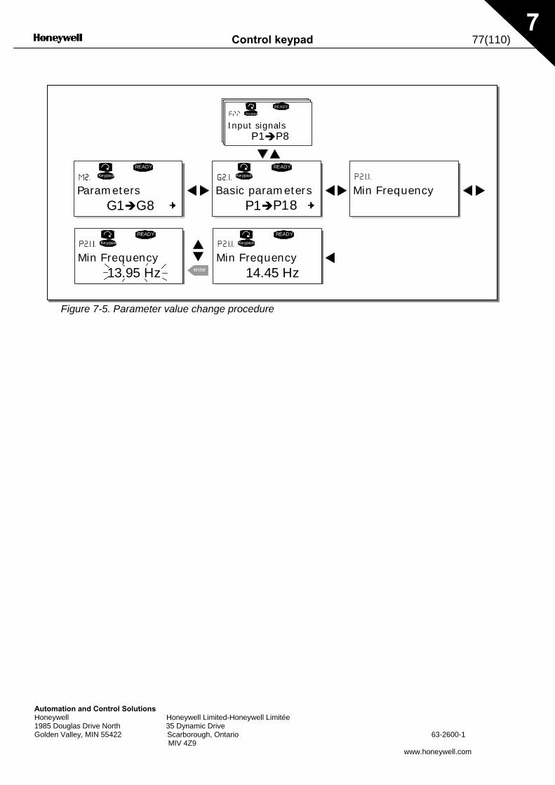
Control keypad 77(110)
Automation and Control Solutions Honeywell Honeywell Limited-Honeywell Limitée 1985 Douglas Drive North 35 Dynamic Drive Golden Valley, MIN 55422 Scarborough, Ontario 63-2600-1 MIV 4Z9
www.honeywell.com
7
Figure 7-5. Parameter value change procedure
G1 G8
READY
Keypad
P1 P18
READY
Keypad
P1 P8
READY
Keypad
READY
Keypad
13.95 Hz enter
READY
Keypad
14.45 Hz
Parameters Basic parameters Min Frequency
Input signals
Min Frequency Min Frequency
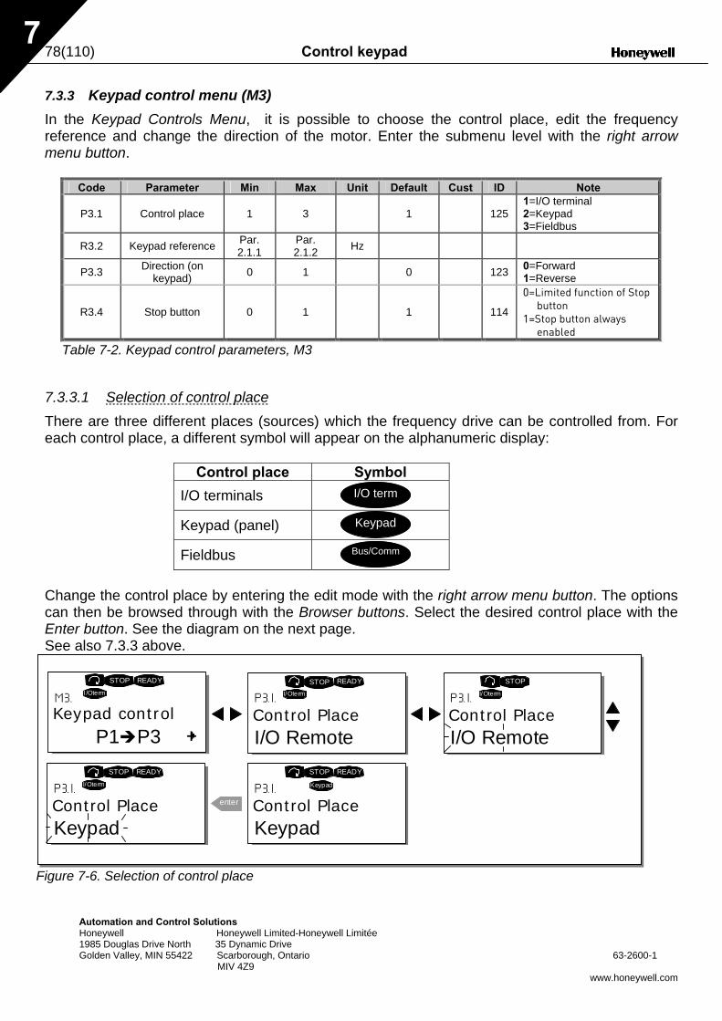
78(110) Control keypad
Automation and Control Solutions Honeywell Honeywell Limited-Honeywell Limitée 1985 Douglas Drive North 35 Dynamic Drive Golden Valley, MIN 55422 Scarborough, Ontario 63-2600-1 MIV 4Z9
www.honeywell.com
7
7.3.3 Keypad control menu (M3) In the Keypad Controls Menu, it is possible to choose the control place, edit the frequency reference and change the direction of the motor. Enter the submenu level with the right arrow menu button.
Code Parameter Min Max Unit Default Cust ID Note
P3.1 Control place 1 3 1
125 1=I/O terminal 2=Keypad 3=Fieldbus
R3.2 Keypad reference Par. 2.1.1
Par. 2.1.2 Hz
P3.3 Direction (on keypad) 0 1 0 123 0=Forward
1=Reverse
R3.4 Stop button 0 1 1
114
0=Limited function of Stop button
1=Stop button always enabled
Table 7-2. Keypad control parameters, M3
7.3.3.1 Selection of control place There are three different places (sources) which the frequency drive can be controlled from. For each control place, a different symbol will appear on the alphanumeric display:
Control place Symbol
I/O terminals
Keypad (panel)
Fieldbus
Change the control place by entering the edit mode with the right arrow menu button. The options can then be browsed through with the Browser buttons. Select the desired control place with the Enter button. See the diagram on the next page. See also 7.3.3 above.
Figure 7-6. Selection of control place
I/O term
Keypad
Bus/Comm
Keypad controlP1 P3
READY
I/Oterm
Control PlaceI/O Remote
READY
I/Oterm
Control PlaceI/O Remote
I/Oterm
Control PlaceKeypad
READY
I/Oterm
enter Control PlaceKeypad
READY
Keypad
STOP STOP STOP
STOPSTOP
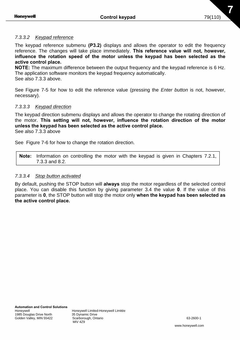
Control keypad 79(110)
Automation Honeywell 1985 DouglasGolden Valley
7
7.3.3.2 Keypad reference The keypad reference submenu (P3.2) displays and allows the operator to edit the frequency reference. The changes will take place immediately. This reference value will not, however, influence the rotation speed of the motor unless the keypad has been selected as the active control place. NOTE: The maximum difference between the output frequency and the keypad reference is 6 Hz. The application software monitors the keypad frequency automatically. See also 7.3.3 above. See Figure 7-5 for how to edit the reference value (pressing the Enter button is not, however, necessary). 7.3.3.3 Keypad direction The keypad direction submenu displays and allows the operator to change the rotating direction of the motor. This setting will not, however, influence the rotation direction of the motor unless the keypad has been selected as the active control place. See also 7.3.3 above See Figure 7-6 for how to change the rotation direction. 7.3.3.4 By defauplace. Yoparametethe activ
Note:
Information on controlling the motor with the keypad is given in Chapters 7.2.1,7.3.3 and 8.2.and Control Solutions Honeywell Limited-Honeywell Limitée
Drive North 35 Dynamic Drive , MIN 55422 Scarborough, Ontario 63-2600-1 MIV 4Z9
www.honeywell.com
Stop button activated lt, pushing the STOP button will always stop the motor regardless of the selected control u can disable this function by giving parameter 3.4 the value 0. If the value of this r is 0, the STOP button will stop the motor only when the keypad has been selected as e control place.
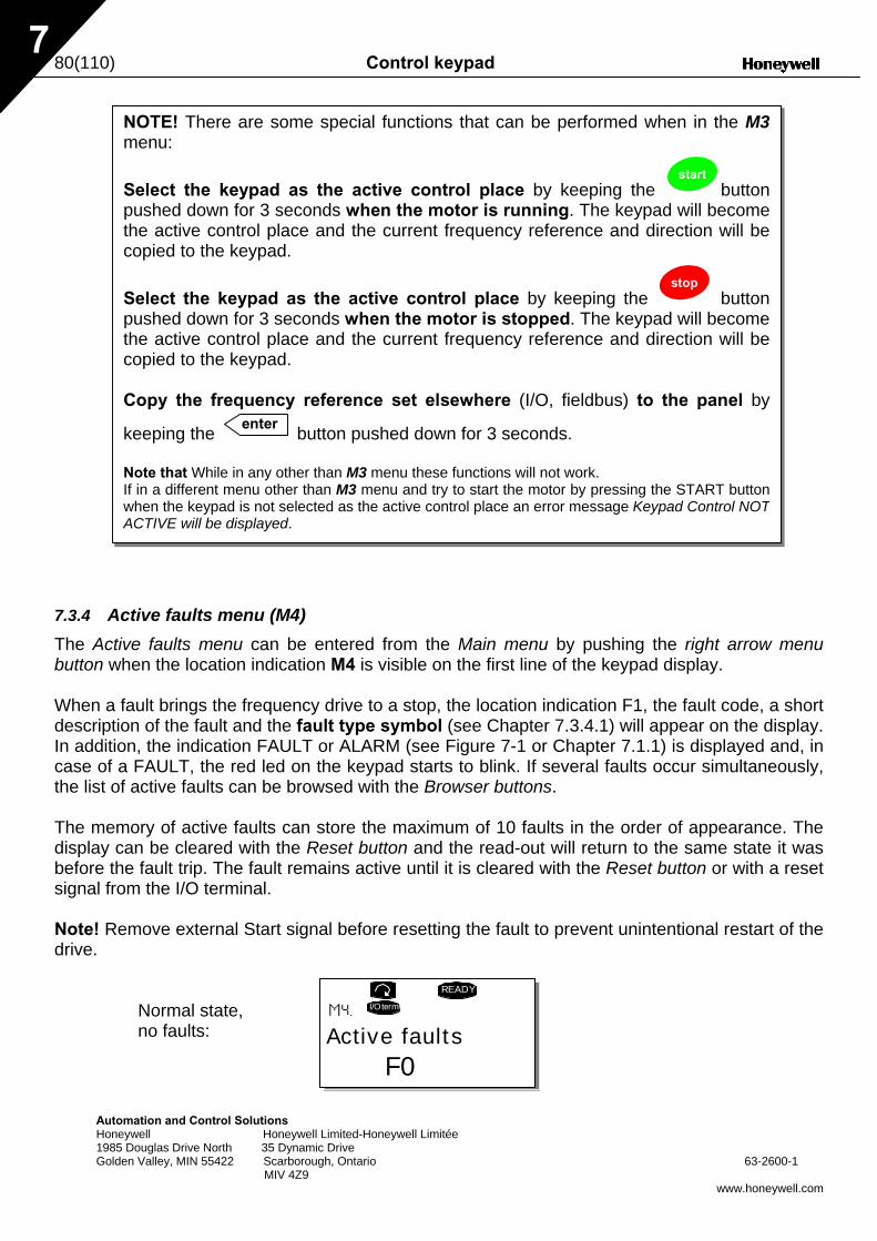
80(110) Control keypad
Automation and Control Solutions Honeywell Honeywell Limited-Honeywell Limitée 1985 Douglas Drive North 35 Dynamic Drive Golden Valley, MIN 55422 Scarborough, Ontario 63-2600-1 MIV 4Z9
www.honeywell.com
7
7.3.4 Active faults menu (M4) The Active faults menu can be entered from the Main menu by pushing the right arrow menu button when the location indication M4 is visible on the first line of the keypad display. When a fault brings the frequency drive to a stop, the location indication F1, the fault code, a short description of the fault and the fault type symbol (see Chapter 7.3.4.1) will appear on the display. In addition, the indication FAULT or ALARM (see Figure 7-1 or Chapter 7.1.1) is displayed and, in case of a FAULT, the red led on the keypad starts to blink. If several faults occur simultaneously, the list of active faults can be browsed with the Browser buttons. The memory of active faults can store the maximum of 10 faults in the order of appearance. The display can be cleared with the Reset button and the read-out will return to the same state it was before the fault trip. The fault remains active until it is cleared with the Reset button or with a reset signal from the I/O terminal. Note! Remove external Start signal before resetting the fault to prevent unintentional restart of the drive.
Normal state, no faults:
NOTE! There are some special functions that can be performed when in the M3menu:
Select the keypad as the active control place by keeping the start
button pushed down for 3 seconds when the motor is running. The keypad will become the active control place and the current frequency reference and direction will be copied to the keypad.
Select the keypad as the active control place by keeping the stop
button pushed down for 3 seconds when the motor is stopped. The keypad will become the active control place and the current frequency reference and direction will be copied to the keypad. Copy the frequency reference set elsewhere (I/O, fieldbus) to the panel by
keeping the enter button pushed down for 3 seconds. Note that While in any other than M3 menu these functions will not work. If in a different menu other than M3 menu and try to start the motor by pressing the START buttonwhen the keypad is not selected as the active control place an error message Keypad Control NOT ACTIVE will be displayed.
Active faultsF0
READY
I/Oterm
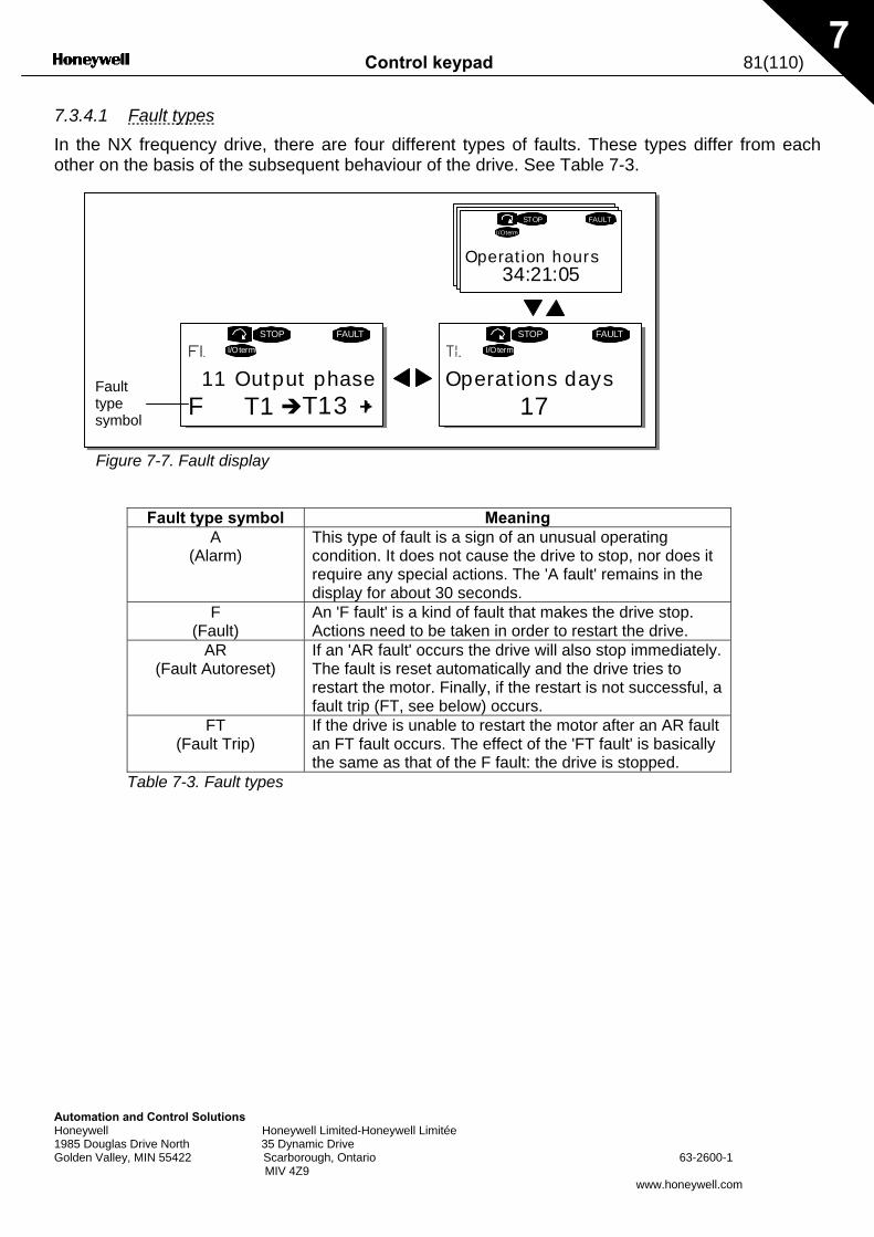
Control keypad 81(110)
Automation and Control Solutions Honeywell Honeywell Limited-Honeywell Limitée 1985 Douglas Drive North 35 Dynamic Drive Golden Valley, MIN 55422 Scarborough, Ontario 63-2600-1 MIV 4Z9
www.honeywell.com
7
7.3.4.1 Fault types In the NX frequency drive, there are four different types of faults. These types differ from each other on the basis of the subsequent behaviour of the drive. See Table 7-3.
Figure 7-7. Fault display
Fault type symbol Meaning
A (Alarm)
This type of fault is a sign of an unusual operating condition. It does not cause the drive to stop, nor does it require any special actions. The 'A fault' remains in the display for about 30 seconds.
F (Fault)
An 'F fault' is a kind of fault that makes the drive stop. Actions need to be taken in order to restart the drive.
AR (Fault Autoreset)
If an 'AR fault' occurs the drive will also stop immediately. The fault is reset automatically and the drive tries to restart the motor. Finally, if the restart is not successful, a fault trip (FT, see below) occurs.
FT (Fault Trip)
If the drive is unable to restart the motor after an AR fault an FT fault occurs. The effect of the 'FT fault' is basically the same as that of the F fault: the drive is stopped.
Table 7-3. Fault types
F T1 T13
STOP FAULTI/Oterm
STOPI/Oterm
FAULT
34:21:05
STOP
I/Oterm
FAULT
17 11 Output phase Operations days
Operation hours
Fault type symbol
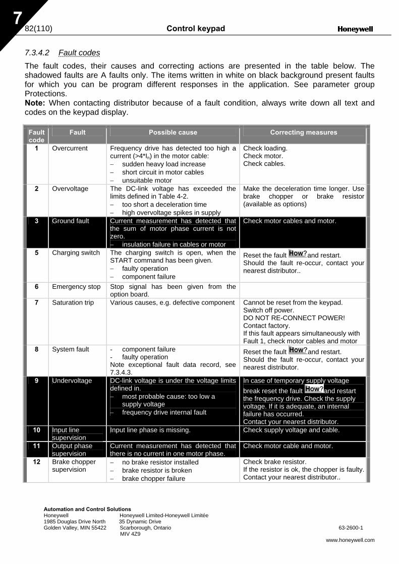
82(110) Control keypad
Automation and Control Solutions Honeywell Honeywell Limited-Honeywell Limitée 1985 Douglas Drive North 35 Dynamic Drive Golden Valley, MIN 55422 Scarborough, Ontario 63-2600-1 MIV 4Z9
www.honeywell.com
7
7.3.4.2 Fault codes The fault codes, their causes and correcting actions are presented in the table below. The shadowed faults are A faults only. The items written in white on black background present faults for which you can be program different responses in the application. See parameter group Protections. Note: When contacting distributor because of a fault condition, always write down all text and codes on the keypad display.
Fault code
Fault Possible cause Correcting measures
1 Overcurrent Frequency drive has detected too high a current (>4*In) in the motor cable: − sudden heavy load increase − short circuit in motor cables − unsuitable motor
Check loading. Check motor. Check cables.
2 Overvoltage The DC-link voltage has exceeded the limits defined in Table 4-2. − too short a deceleration time − high overvoltage spikes in supply
Make the deceleration time longer. Use brake chopper or brake resistor (available as options)
3 Ground fault Current measurement has detected that the sum of motor phase current is not zero. − insulation failure in cables or motor
Check motor cables and motor.
5 Charging switch The charging switch is open, when the START command has been given. − faulty operation − component failure
Reset the fault and restart. Should the fault re-occur, contact your nearest distributor..
6 Emergency stop Stop signal has been given from the option board.
7 Saturation trip Various causes, e.g. defective component Cannot be reset from the keypad. Switch off power. DO NOT RE-CONNECT POWER! Contact factory. If this fault appears simultaneously with Fault 1, check motor cables and motor
8 System fault - component failure - faulty operation Note exceptional fault data record, see 7.3.4.3.
Reset the fault and restart. Should the fault re-occur, contact your nearest distributor.
9 Undervoltage DC-link voltage is under the voltage limits defined in. − most probable cause: too low a
supply voltage − frequency drive internal fault
In case of temporary supply voltage break reset the fault and restart the frequency drive. Check the supply voltage. If it is adequate, an internal failure has occurred. Contact your nearest distributor.
10 Input line supervision
Input line phase is missing. Check supply voltage and cable.
11 Output phase supervision
Current measurement has detected that there is no current in one motor phase.
Check motor cable and motor.
12 Brake chopper supervision
− no brake resistor installed − brake resistor is broken − brake chopper failure
Check brake resistor. If the resistor is ok, the chopper is faulty. Contact your nearest distributor..
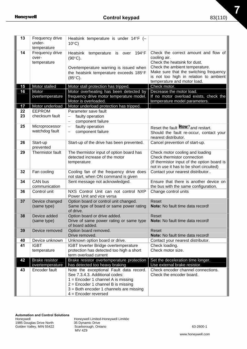
Control keypad 83(110)
Automation and Control Solutions Honeywell Honeywell Limited-Honeywell Limitée 1985 Douglas Drive North 35 Dynamic Drive Golden Valley, MIN 55422 Scarborough, Ontario 63-2600-1 MIV 4Z9
www.honeywell.com
7
13 Frequency drive
under-temperature
Heatsink temperature is under 14°F (–10°C)
14 Frequency drive over- temperature
Heatsink temperature is over 194°F (90°C). Overtemperature warning is issued when the heatsink temperature exceeds 185°F (85°C).
Check the correct amount and flow of cooling air. Check the heatsink for dust. Check the ambient temperature. Make sure that the switching frequency is not too high in relation to ambient temperature and motor load.
15 Motor stalled Motor stall protection has tripped. Check motor. 16 Motor
overtemperature Motor overheating has been detected by frequency drive motor temperature model. Motor is overloaded.
Decrease the motor load. If no motor overload exists, check the temperature model parameters.
17 Motor underload Motor underload protection has tripped. 22 23
EEPROM checksum fault
Parameter save fault − faulty operation − component failure
25 Microprocessor watchdog fault
− faulty operation − component failure
Reset the fault and restart. Should the fault re-occur, contact your nearest distributor.
26 Start-up prevented
Start-up of the drive has been prevented. Cancel prevention of start-up.
29 Thermistor fault The thermistor input of option board has detected increase of the motor temperature
Check motor cooling and loading Check thermistor connection (If thermistor input of the option board is not in use it has to be short circuited)
32 Fan cooling Cooling fan of the frequency drive does not start, when ON command is given
Contact your nearest distributor..
34 CAN bus communication
Sent message not acknowledged. Ensure that there is another device on the bus with the same configuration.
36 Control unit NXS Control Unit can not control NXP Power Unit and vice versa
Change control units
37 Device changed (same type)
Option board or control unit changed. Same type of board or same power rating of drive.
Reset Note: No fault time data record!
38 Device added (same type)
Option board or drive added. Drive of same power rating or same type of board added.
Reset Note: No fault time data record!
39 Device removed Option board removed. Drive removed.
Reset Note: No fault time data record!
40 Device unknown Unknown option board or drive. Contact your nearest distributor. 41 IGBT
temperature IGBT Inverter Bridge overtemperature protection has detected too high a short term overload current
Check loading. Check motor size.
42 Brake resistor overtemperature
Brake resistor overtemperature protection has detected too heavy braking
Set the deceleration time longer. Use external brake resistor.
43 Encoder fault Note the exceptional Fault data record. See 7.3.4.3. Additional codes: 1 = Encoder 1 channel A is missing 2 = Encoder 1 channel B is missing 3 = Both encoder 1 channels are missing 4 = Encoder reversed
Check encoder channel connections. Check the encoder board.
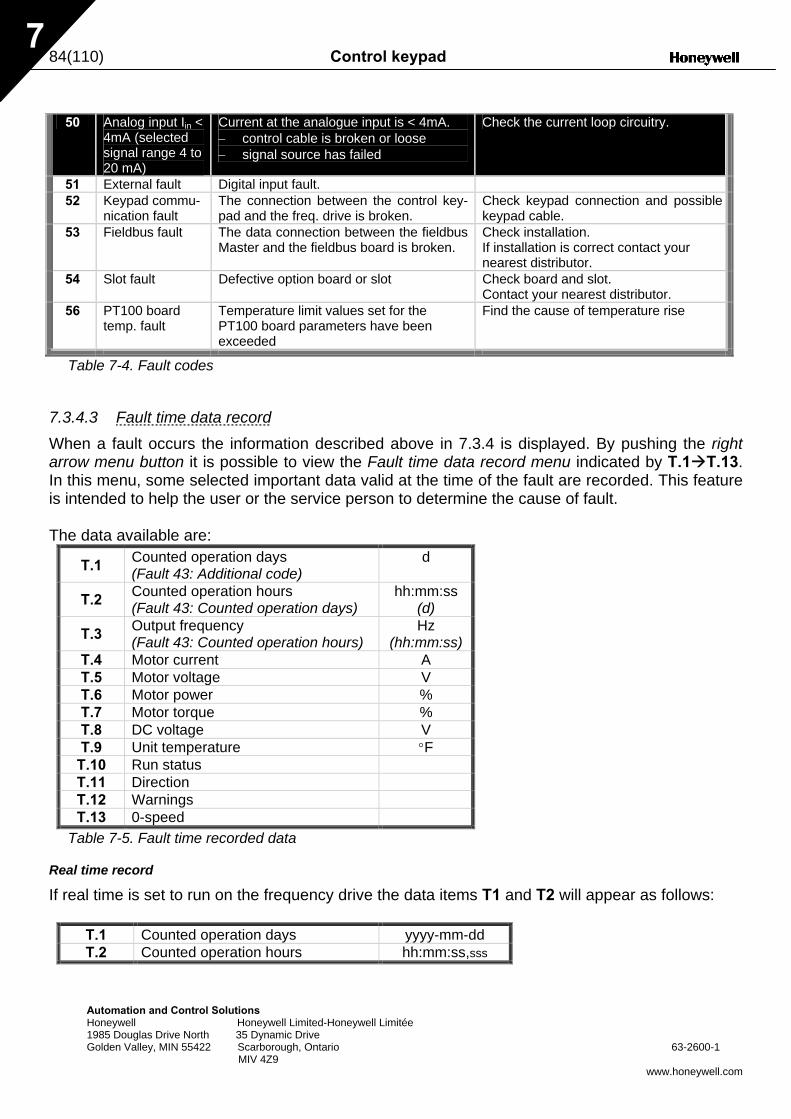
84(110) Control keypad
Automation and Control Solutions Honeywell Honeywell Limited-Honeywell Limitée 1985 Douglas Drive North 35 Dynamic Drive Golden Valley, MIN 55422 Scarborough, Ontario 63-2600-1 MIV 4Z9
www.honeywell.com
7
50 Analog input Iin <
4mA (selected signal range 4 to 20 mA)
Current at the analogue input is < 4mA. − control cable is broken or loose − signal source has failed
Check the current loop circuitry.
51 External fault Digital input fault. 52 Keypad commu-
nication fault The connection between the control key-pad and the freq. drive is broken.
Check keypad connection and possible keypad cable.
53 Fieldbus fault The data connection between the fieldbus Master and the fieldbus board is broken.
Check installation. If installation is correct contact your nearest distributor.
54 Slot fault Defective option board or slot Check board and slot. Contact your nearest distributor.
56 PT100 board temp. fault
Temperature limit values set for the PT100 board parameters have been exceeded
Find the cause of temperature rise
Table 7-4. Fault codes
7.3.4.3 Fault time data record When a fault occurs the information described above in 7.3.4 is displayed. By pushing the right arrow menu button it is possible to view the Fault time data record menu indicated by T.1 T.13. In this menu, some selected important data valid at the time of the fault are recorded. This feature is intended to help the user or the service person to determine the cause of fault. The data available are:
T.1 Counted operation days (Fault 43: Additional code)
d
T.2 Counted operation hours (Fault 43: Counted operation days)
hh:mm:ss (d)
T.3 Output frequency (Fault 43: Counted operation hours)
Hz (hh:mm:ss)
T.4 Motor current A T.5 Motor voltage V T.6 Motor power % T.7 Motor torque % T.8 DC voltage V T.9 Unit temperature °F
T.10 Run status
T.11 Direction
T.12 Warnings
T.13 0-speed
Table 7-5. Fault time recorded data
Real time record
If real time is set to run on the frequency drive the data items T1 and T2 will appear as follows:
T.1 Counted operation days yyyy-mm-dd T.2 Counted operation hours hh:mm:ss,sss
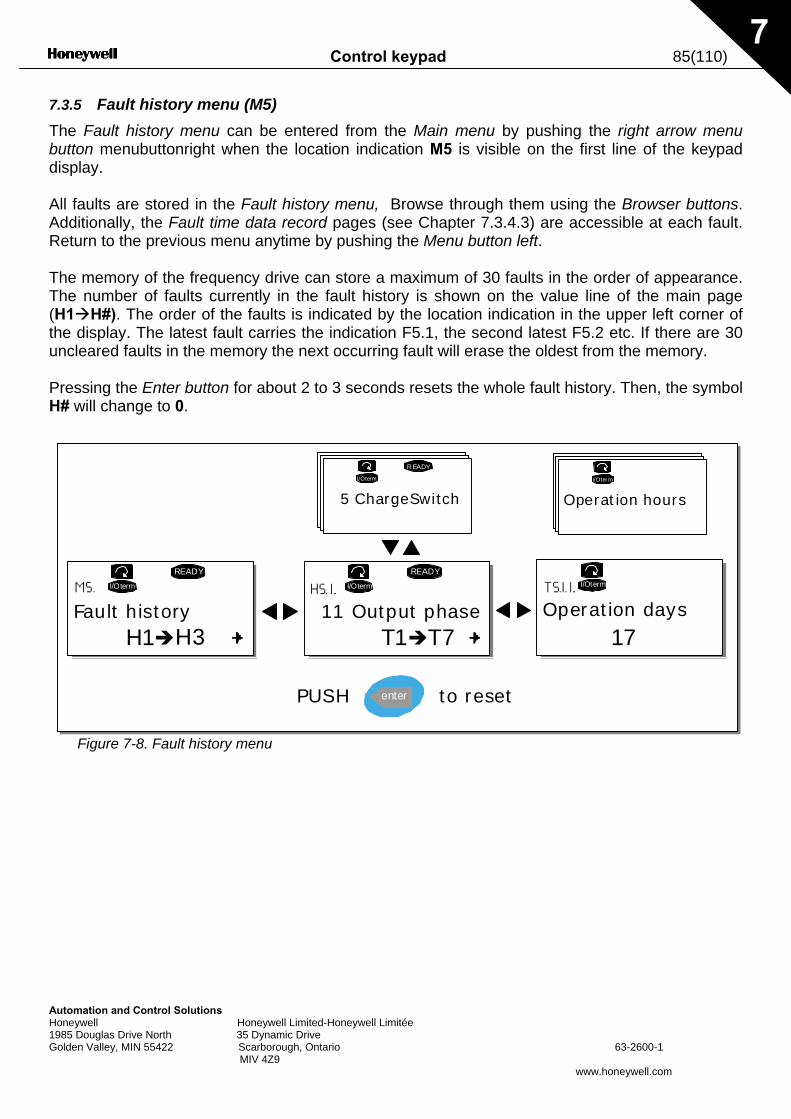
Control keypad 85(110)
Automation and Control Solutions Honeywell Honeywell Limited-Honeywell Limitée 1985 Douglas Drive North 35 Dynamic Drive Golden Valley, MIN 55422 Scarborough, Ontario 63-2600-1 MIV 4Z9
www.honeywell.com
7
7.3.5 Fault history menu (M5) The Fault history menu can be entered from the Main menu by pushing the right arrow menu button menubuttonright when the location indication M5 is visible on the first line of the keypad display. All faults are stored in the Fault history menu, Browse through them using the Browser buttons. Additionally, the Fault time data record pages (see Chapter 7.3.4.3) are accessible at each fault. Return to the previous menu anytime by pushing the Menu button left. The memory of the frequency drive can store a maximum of 30 faults in the order of appearance. The number of faults currently in the fault history is shown on the value line of the main page (H1 H#). The order of the faults is indicated by the location indication in the upper left corner of the display. The latest fault carries the indication F5.1, the second latest F5.2 etc. If there are 30 uncleared faults in the memory the next occurring fault will erase the oldest from the memory. Pressing the Enter button for about 2 to 3 seconds resets the whole fault history. Then, the symbol H# will change to 0.
Figure 7-8. Fault history menu
H1 H3
READY
I/Oterm
T1 T7
I/Oterm
READY
I/Oterm
R EADY
I/Oterm
I/Oter m
enter
17Fault history 11 Output phase
5 ChargeSwitch
Operation days
Operation hours
PUSH to reset
86(110) Control keypad
Automation and Control Solutions Honeywell Honeywell Limited-Honeywell Limitée 1985 Douglas Drive North 35 Dynamic Drive Golden Valley, MIN 55422 Scarborough, Ontario 63-2600-1 MIV 4Z9
www.honeywell.com
7
7.3.6 System menu (M6) The System menu can be entered from the main menu by pushing the right arrow menu button when the location indication M6 is visible on the display. The controls associated with the general use of the frequency drive, such as application selection, customised parameter sets or information about the hardware and software are located under the System menu. The number of submenus and sub pages is shown with the symbol S (or P) on the value line. On page 87 is a list of the functions available in the System menu.
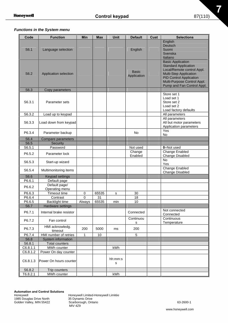
Control keypad 87(110)
Automation and Control Solutions Honeywell Honeywell Limited-Honeywell Limitée 1985 Douglas Drive North 35 Dynamic Drive Golden Valley, MIN 55422 Scarborough, Ontario 63-2600-1 MIV 4Z9
www.honeywell.com
7
Functions in the System menu
Code Function Min Max Unit Default Cust Selections
S6.1 Language selection English
English Deutsch Suomi Svenska Italiano
S6.2 Application selection Basic Application
Basic Application Standard Application Local/Remote control Appl. Multi-Step Application PID Control Application Multi-Purpose Control Appl. Pump and Fan Control Appl.
S6.3 Copy parameters
S6.3.1 Parameter sets
Store set 1 Load set 1 Store set 2 Load set 2 Load factory defaults
S6.3.2 Load up to keypad All parameters
S6.3.3 Load down from keypad All parameters
All but motor parameters Application parameters
P6.3.4 Parameter backup No Yes No
S6.4 Compare parameters S6.5 Security
S6.5.1 Password Not used 0=Not used
P6.5.2 Parameter lock Change Enabled
Change Enabled Change Disabled
S6.5.3 Start-up wizard No Yes
S6.5.4 Multimonitoring items Change Enabled Change Disabled
S6.6 Keypad settings P6.6.1 Default page
P6.6.2 Default page/ Operating menu
P6.6.3 Timeout time 0 65535 s 30 P6.6.4 Contrast 0 31 18 P6.6.5 Backlight time Always 65535 min 10 S6.7 Hardware settings
P6.7.1 Internal brake resistor Connected Not connected Connected
P6.7.2 Fan control Continuous
Continuous Temperature
P6.7.3 HMI acknowledg. timeout 200 5000 ms 200
P6.7.4 HMI number of retries 1 10 5 S6.8 System information
S6.8.1 Total counters C6.8.1.1 MWh counter kWh C6.8.1.2 Power On day counter
C6.8.1.3 Power On hours counter hh:mm:ss
S6.8.2 Trip counters T6.8.2.1 MWh counter kWh
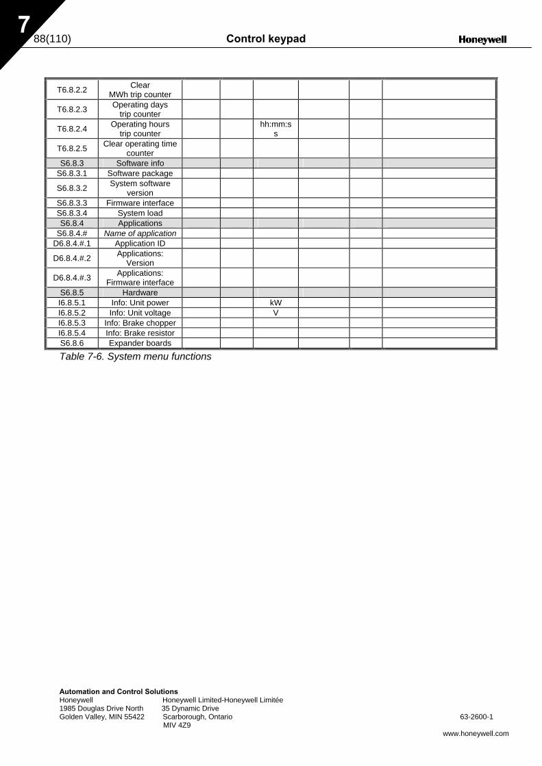
88(110) Control keypad
Automation and Control Solutions Honeywell Honeywell Limited-Honeywell Limitée 1985 Douglas Drive North 35 Dynamic Drive Golden Valley, MIN 55422 Scarborough, Ontario 63-2600-1 MIV 4Z9
www.honeywell.com
7
T6.8.2.2 Clear
MWh trip counter
T6.8.2.3 Operating days trip counter
T6.8.2.4 Operating hours trip counter hh:mm:s
s
T6.8.2.5 Clear operating time counter
S6.8.3 Software info S6.8.3.1 Software package
S6.8.3.2 System software version
S6.8.3.3 Firmware interface S6.8.3.4 System load S6.8.4 Applications
S6.8.4.# Name of application D6.8.4.#.1 Application ID
D6.8.4.#.2 Applications: Version
D6.8.4.#.3 Applications: Firmware interface
S6.8.5 Hardware I6.8.5.1 Info: Unit power kW I6.8.5.2 Info: Unit voltage V I6.8.5.3 Info: Brake chopper I6.8.5.4 Info: Brake resistor S6.8.6 Expander boards
Table 7-6. System menu functions
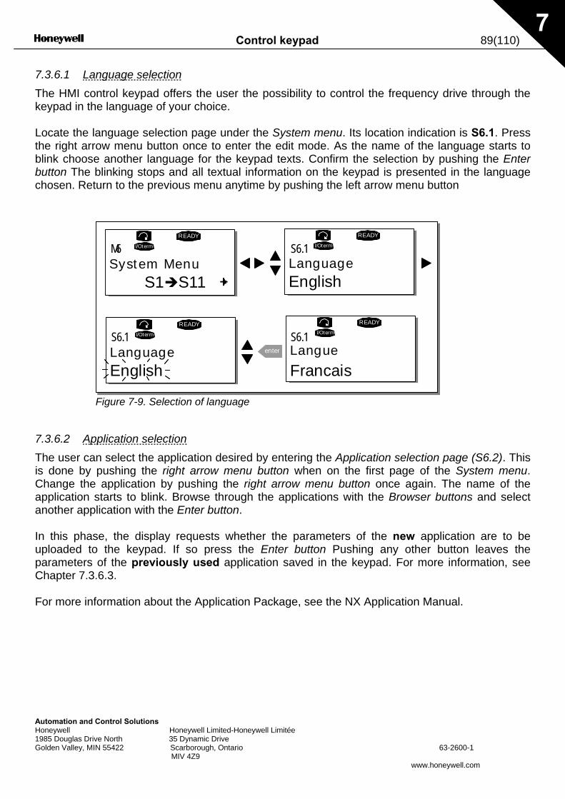
Control keypad 89(110)
Automation and Control Solutions Honeywell Honeywell Limited-Honeywell Limitée 1985 Douglas Drive North 35 Dynamic Drive Golden Valley, MIN 55422 Scarborough, Ontario 63-2600-1 MIV 4Z9
www.honeywell.com
7
7.3.6.1 Language selection The HMI control keypad offers the user the possibility to control the frequency drive through the keypad in the language of your choice. Locate the language selection page under the System menu. Its location indication is S6.1. Press the right arrow menu button once to enter the edit mode. As the name of the language starts to blink choose another language for the keypad texts. Confirm the selection by pushing the Enter button The blinking stops and all textual information on the keypad is presented in the language chosen. Return to the previous menu anytime by pushing the left arrow menu button
Figure 7-9. Selection of language
7.3.6.2 Application selection The user can select the application desired by entering the Application selection page (S6.2). This is done by pushing the right arrow menu button when on the first page of the System menu. Change the application by pushing the right arrow menu button once again. The name of the application starts to blink. Browse through the applications with the Browser buttons and select another application with the Enter button. In this phase, the display requests whether the parameters of the new application are to be uploaded to the keypad. If so press the Enter button Pushing any other button leaves the parameters of the previously used application saved in the keypad. For more information, see Chapter 7.3.6.3. For more information about the Application Package, see the NX Application Manual.
System MenuS1 S11
READY
I/Oterm
LanguageEnglish
READY
I/Oterm
LanguageEnglish
READY
I/Oterm
enter Langue
READY
I/Oterm
M6 S6.1
S6.1 S6.1
Francais
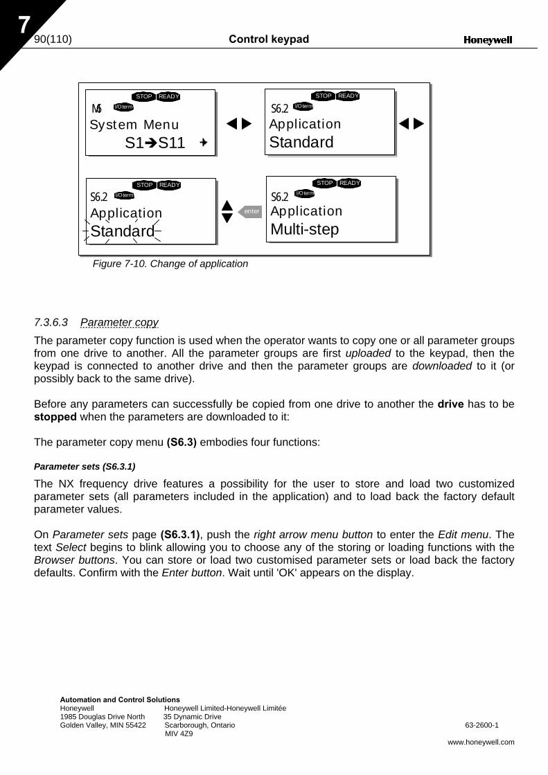
90(110) Control keypad
Automation and Control Solutions Honeywell Honeywell Limited-Honeywell Limitée 1985 Douglas Drive North 35 Dynamic Drive Golden Valley, MIN 55422 Scarborough, Ontario 63-2600-1 MIV 4Z9
www.honeywell.com
7
Figure 7-10. Change of application
7.3.6.3 Parameter copy The parameter copy function is used when the operator wants to copy one or all parameter groups from one drive to another. All the parameter groups are first uploaded to the keypad, then the keypad is connected to another drive and then the parameter groups are downloaded to it (or possibly back to the same drive). Before any parameters can successfully be copied from one drive to another the drive has to be stopped when the parameters are downloaded to it: The parameter copy menu (S6.3) embodies four functions: Parameter sets (S6.3.1)
The NX frequency drive features a possibility for the user to store and load two customized parameter sets (all parameters included in the application) and to load back the factory default parameter values. On Parameter sets page (S6.3.1), push the right arrow menu button to enter the Edit menu. The text Select begins to blink allowing you to choose any of the storing or loading functions with the Browser buttons. You can store or load two customised parameter sets or load back the factory defaults. Confirm with the Enter button. Wait until 'OK' appears on the display.
S1 S11
STOP READY
I/Oterm
STOP READY
I/Oterm
STOP READY
I/Oterm
enter
STOP READY
I/Oterm
M6 S6.2
S6.2 S6.2
System Menu ApplicationStandard
ApplicationStandard
ApplicationMulti-step
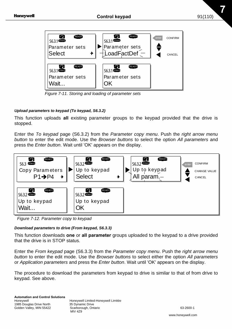
Control keypad 91(110)
Automation and Control Solutions Honeywell Honeywell Limited-Honeywell Limitée 1985 Douglas Drive North 35 Dynamic Drive Golden Valley, MIN 55422 Scarborough, Ontario 63-2600-1 MIV 4Z9
www.honeywell.com
7
Figure 7-11. Storing and loading of parameter sets
Upload parameters to keypad (To keypad, S6.3.2)
This function uploads all existing parameter groups to the keypad provided that the drive is stopped. Enter the To keypad page (S6.3.2) from the Parameter copy menu. Push the right arrow menu button to enter the edit mode. Use the Browser buttons to select the option All parameters and press the Enter button. Wait until 'OK' appears on the display.
Figure 7-12. Parameter copy to keypad
Download parameters to drive (From keypad, S6.3.3)
This function downloads one or all parameter groups uploaded to the keypad to a drive provided that the drive is in STOP status. Enter the From keypad page (S6.3.3) from the Parameter copy menu. Push the right arrow menu button to enter the edit mode. Use the Browser buttons to select either the option All parameters or Application parameters and press the Enter button. Wait until 'OK' appears on the display. The procedure to download the parameters from keypad to drive is similar to that of from drive to keypad. See above.
READY
I/Oterm
READY
I/Otermenter
READY
I/Oterm
READY
I/Oterm
OK
S6.3.1 S6.3.1
S6.3.1 S6.3.1
Parameter setsSelect
Parameter setsCANCEL
CONFIRM
Parameter setsWait...
Parameter sets
LoadFactDef
P1 P4
READY
I/Oterm
READY
I/Oterm
READY
I/Oterm enter
READY
I/Oterm
READY
I/Oterm
S6.3 S6.3.2 S6.3.2
S6.3.2S6.3.2
Copy Parameters Up to keypad Up to keypadSelect CANCEL
CONFIRM
Up to keypadWait...
Up to keypadOK
All param.CHANGE VALUE
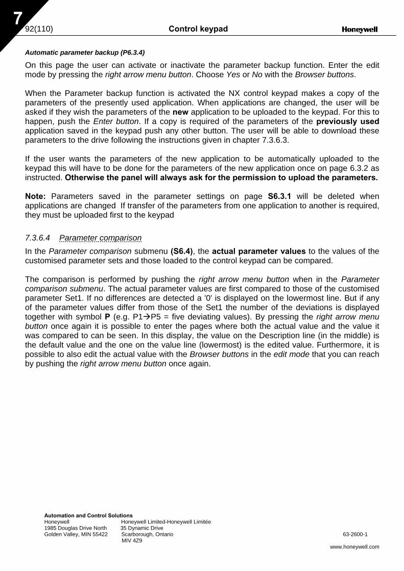
92(110) Control keypad
Automation and Control Solutions Honeywell Honeywell Limited-Honeywell Limitée 1985 Douglas Drive North 35 Dynamic Drive Golden Valley, MIN 55422 Scarborough, Ontario 63-2600-1 MIV 4Z9
www.honeywell.com
7
Automatic parameter backup (P6.3.4)
On this page the user can activate or inactivate the parameter backup function. Enter the edit mode by pressing the right arrow menu button. Choose Yes or No with the Browser buttons. When the Parameter backup function is activated the NX control keypad makes a copy of the parameters of the presently used application. When applications are changed, the user will be asked if they wish the parameters of the new application to be uploaded to the keypad. For this to happen, push the Enter button. If a copy is required of the parameters of the previously used application saved in the keypad push any other button. The user will be able to download these parameters to the drive following the instructions given in chapter 7.3.6.3. If the user wants the parameters of the new application to be automatically uploaded to the keypad this will have to be done for the parameters of the new application once on page 6.3.2 as instructed. Otherwise the panel will always ask for the permission to upload the parameters. Note: Parameters saved in the parameter settings on page S6.3.1 will be deleted when applications are changed If transfer of the parameters from one application to another is required, they must be uploaded first to the keypad 7.3.6.4 Parameter comparison In the Parameter comparison submenu (S6.4), the actual parameter values to the values of the customised parameter sets and those loaded to the control keypad can be compared. The comparison is performed by pushing the right arrow menu button when in the Parameter comparison submenu. The actual parameter values are first compared to those of the customised parameter Set1. If no differences are detected a '0' is displayed on the lowermost line. But if any of the parameter values differ from those of the Set1 the number of the deviations is displayed together with symbol P (e.g. P1 P5 = five deviating values). By pressing the right arrow menu button once again it is possible to enter the pages where both the actual value and the value it was compared to can be seen. In this display, the value on the Description line (in the middle) is the default value and the one on the value line (lowermost) is the edited value. Furthermore, it is possible to also edit the actual value with the Browser buttons in the edit mode that you can reach by pushing the right arrow menu button once again.
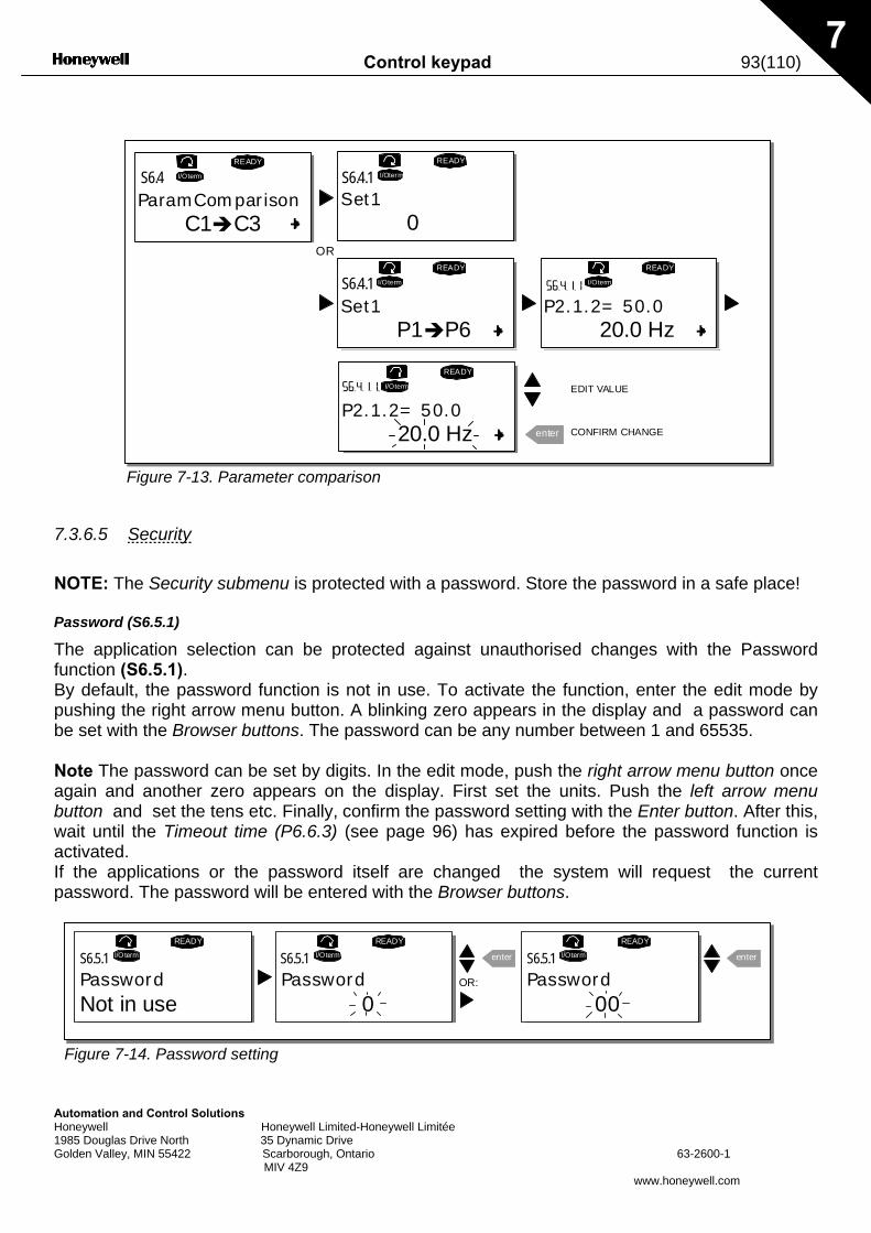
Control keypad 93(110)
Automation and Control Solutions Honeywell Honeywell Limited-Honeywell Limitée 1985 Douglas Drive North 35 Dynamic Drive Golden Valley, MIN 55422 Scarborough, Ontario 63-2600-1 MIV 4Z9
www.honeywell.com
7
Figure 7-13. Parameter comparison
7.3.6.5 Security NOTE: The Security submenu is protected with a password. Store the password in a safe place! Password (S6.5.1)
The application selection can be protected against unauthorised changes with the Password function (S6.5.1). By default, the password function is not in use. To activate the function, enter the edit mode by pushing the right arrow menu button. A blinking zero appears in the display and a password can be set with the Browser buttons. The password can be any number between 1 and 65535. Note The password can be set by digits. In the edit mode, push the right arrow menu button once again and another zero appears on the display. First set the units. Push the left arrow menu button and set the tens etc. Finally, confirm the password setting with the Enter button. After this, wait until the Timeout time (P6.6.3) (see page 96) has expired before the password function is activated. If the applications or the password itself are changed the system will request the current password. The password will be entered with the Browser buttons.
Figure 7-14. Password setting
C1 C3
READY READY
I/Oterm
READY
I/Oterm
0
enter
I/Oterm
P1 P6P2.1.2= 50.0
READY
I/Oterm
20.0 Hz
P2.1.2= 50.0
READY
I/Oterm
20.0 Hz
S6.4 S6.4.1
S6.4.1
ParamComparison Set1
Set1
CONFIRM CHANGE
EDIT VALUE
OR
READY
I/Oterm
0
READY
I/Oterm enter
00
READY
I/Oterm enterS6.5.1 S6.5.1 S6.5.1
PasswordNot in use
Password PasswordOR:
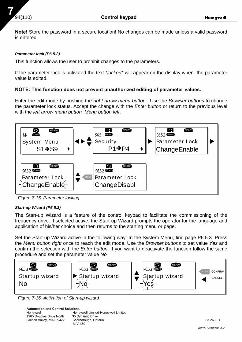
94(110) Control keypad
Automation and Control Solutions Honeywell Honeywell Limited-Honeywell Limitée 1985 Douglas Drive North 35 Dynamic Drive Golden Valley, MIN 55422 Scarborough, Ontario 63-2600-1 MIV 4Z9
www.honeywell.com
7
Note! Store the password in a secure location! No changes can be made unless a valid password is entered! Parameter lock (P6.5.2)
This function allows the user to prohibit changes to the parameters. If the parameter lock is activated the text *locked* will appear on the display when the parameter value is edited. NOTE: This function does not prevent unauthorized editing of parameter values. Enter the edit mode by pushing the right arrow menu button . Use the Browser buttons to change the parameter lock status. Accept the change with the Enter button or return to the previous level with the left arrow menu button Menu button left.
Figure 7-15. Parameter locking
Start-up Wizard (P6.5.3)
The Start-up Wizard is a feature of the control keypad to facilitate the commissioning of the frequency drive. If selected active, the Start-up Wizard prompts the operator for the language and application of his/her choice and then returns to the starting menu or page. Set the Start-up Wizard active in the following way: In the System Menu, find page P6.5.3. Press the Menu button right once to reach the edit mode. Use the Browser buttons to set value Yes and confirm the selection with the Enter button. If you want to deactivate the function follow the same procedure and set the parameter value No
Figure 7-16. Activation of Start-up wizard
S1 S9
READY
I/Oterm
READY
I/Oterm
READY
I/Oterm
enter
READY
I/Oterm
READY
I/Oterm
P1 P4
M6 S6.5 S6.5.2
S6.5.2 S6.5.2
System Menu Security
Parameter Lock
ChangeEnable
Parameter LockChangeDisabl
Parameter Lock
ChangeEnable
READY
I/OtermP6.5.3
READY
I/OtermP6.5.3
READY
I/OtermP6.5.3 enter
Startup wizard Startup wizardNo No
Startup wizardYes
CANCEL
CONFIRM

Control keypad 95(110)
Automation and Control Solutions Honeywell Honeywell Limited-Honeywell Limitée 1985 Douglas Drive North 35 Dynamic Drive Golden Valley, MIN 55422 Scarborough, Ontario 63-2600-1 MIV 4Z9
www.honeywell.com
7
Multimonitoring items (P6.5.4)
Honeywell alpha-numeric keypad features a display where the user can monitor even three actual values at the same time (see chapter 7.3.1 and chapter Monitoring values in the manual of the application you are using). On page P6.5.4 of the System Menu you can define if it is possible for the operator to replace the values monitored with other values. See below.
Figure 7-17. Enabling the change of multimonitoring items
7.3.6.6 Keypad settings Further customization of the frequency drive operator interface can be undertaken in the Keypad settings submenu under the System menu. Locate the Keypad settings submenu (S6.6). Under the submenu, there are four pages (P#) associated with the keypad operation:
Figure 7-18. Keypad settings submenu
Default page (P6.6.1)
This menu allows the user to set the location (page) to which the display automatically moves as the Timeout time (see below) has expired or as the power is switched on to the keypad. If the Default Page value is 0 the function is not activated, i.e. the last displayed page remains on the keypad display. Press the right arrow menu button once to enter the edit mode. Change the number of the Main menu with the Browser buttons. Pressing the right arrow menu button once again enables editing of the number of the submenu/page. If the page to move to by default is at the third level repeat the procedure. Confirm the new default page value with the Enter button. Return to the previous step anytime by pushing the left arrow menu button.
Figure 7-19. Default page function
READY
I/Oterm
READY
I/Oterm
enter
READY
I/OtermP6.5.4 P6.5.4 P6.5.4
Multimon. items
ChangeEnableMultimon. items Multimon. items
ChangeEnable ChangeDisable
P1 P5
READYI/Oterm
0.
READYI/OtermS6.6 P6.6.1
Keypad settings Default page
0.
READY
I/Oterm
READY
I/Oterm
READY
I/Oterm
0. 1.
enter
Default page REPEAT TO SETDEFAULT SUBMENU/PAGECANCEL
Default pageDefault pageCONFIRM CHANGE
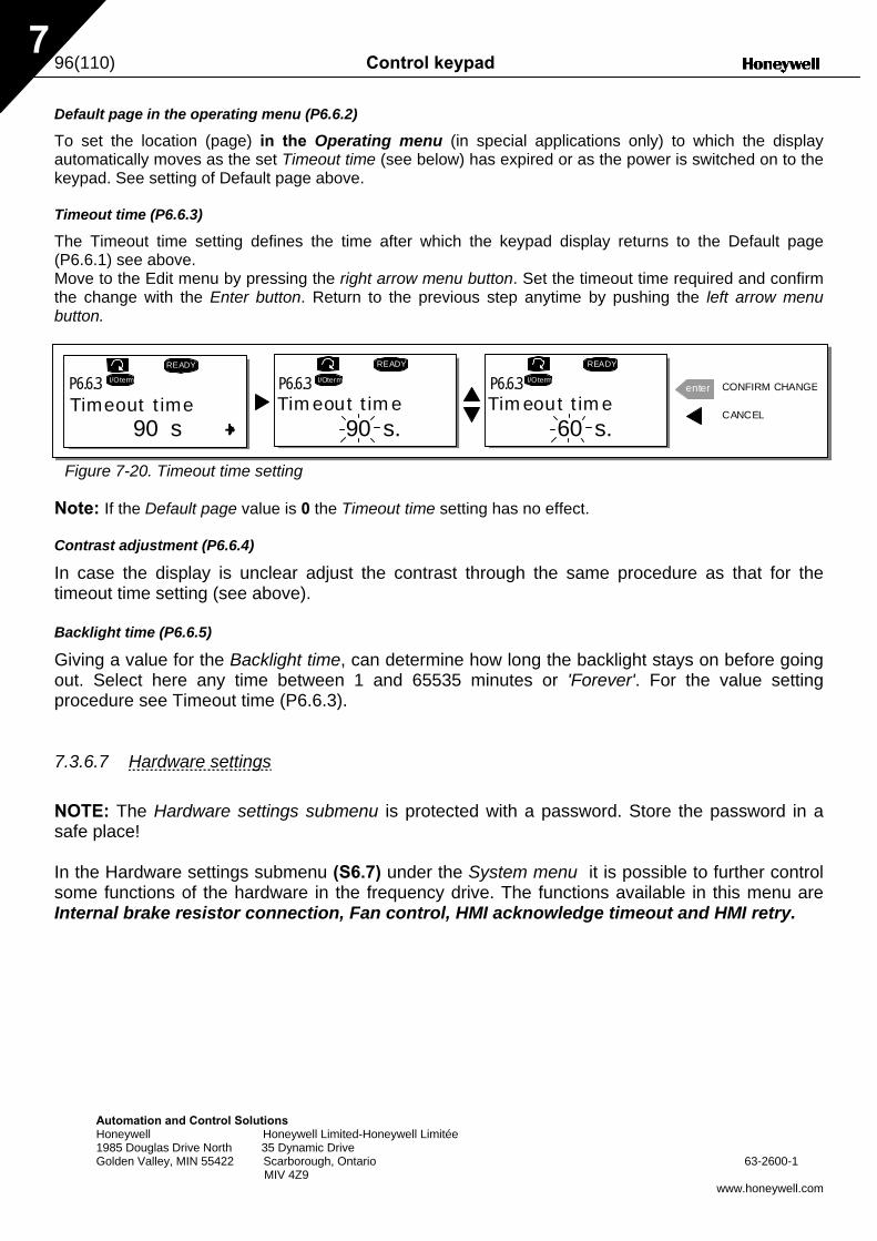
96(110) Control keypad
Automation and Control Solutions Honeywell Honeywell Limited-Honeywell Limitée 1985 Douglas Drive North 35 Dynamic Drive Golden Valley, MIN 55422 Scarborough, Ontario 63-2600-1 MIV 4Z9
www.honeywell.com
7
Default page in the operating menu (P6.6.2)
To set the location (page) in the Operating menu (in special applications only) to which the display automatically moves as the set Timeout time (see below) has expired or as the power is switched on to the keypad. See setting of Default page above. Timeout time (P6.6.3)
The Timeout time setting defines the time after which the keypad display returns to the Default page (P6.6.1) see above. Move to the Edit menu by pressing the right arrow menu button. Set the timeout time required and confirm the change with the Enter button. Return to the previous step anytime by pushing the left arrow menu button.
Figure 7-20. Timeout time setting
Note: If the Default page value is 0 the Timeout time setting has no effect. Contrast adjustment (P6.6.4)
In case the display is unclear adjust the contrast through the same procedure as that for the timeout time setting (see above). Backlight time (P6.6.5)
Giving a value for the Backlight time, can determine how long the backlight stays on before going out. Select here any time between 1 and 65535 minutes or 'Forever'. For the value setting procedure see Timeout time (P6.6.3). 7.3.6.7 Hardware settings NOTE: The Hardware settings submenu is protected with a password. Store the password in a safe place! In the Hardware settings submenu (S6.7) under the System menu it is possible to further control some functions of the hardware in the frequency drive. The functions available in this menu are Internal brake resistor connection, Fan control, HMI acknowledge timeout and HMI retry.
90 s
READY READY
I/Oterm
READY
I/Oterm
90 s.
enterI/Oterm
60 s.
P6.6.3 P6.6.3 P6.6.3
Timeout time Timeout time Timeout timeCANCEL
CONFIRM CHANGE
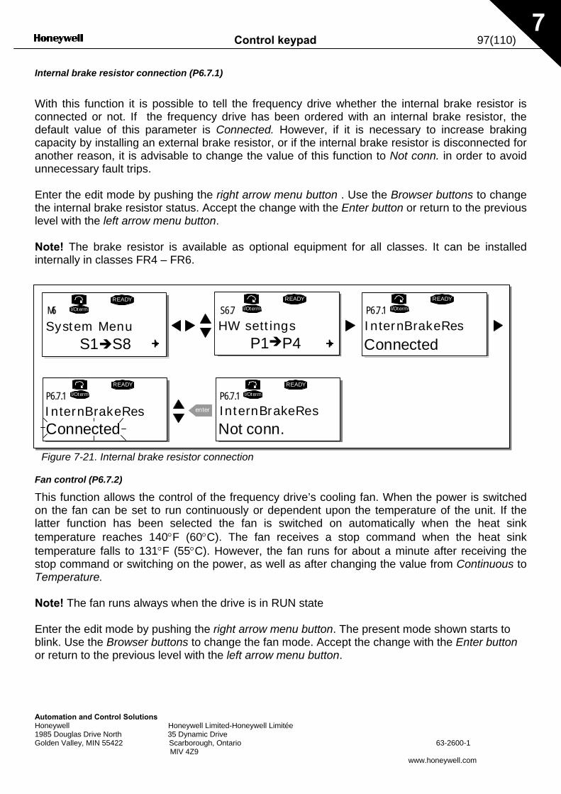
Control keypad 97(110)
Automation and Control Solutions Honeywell Honeywell Limited-Honeywell Limitée 1985 Douglas Drive North 35 Dynamic Drive Golden Valley, MIN 55422 Scarborough, Ontario 63-2600-1 MIV 4Z9
www.honeywell.com
7
Internal brake resistor connection (P6.7.1)
With this function it is possible to tell the frequency drive whether the internal brake resistor is connected or not. If the frequency drive has been ordered with an internal brake resistor, the default value of this parameter is Connected. However, if it is necessary to increase braking capacity by installing an external brake resistor, or if the internal brake resistor is disconnected for another reason, it is advisable to change the value of this function to Not conn. in order to avoid unnecessary fault trips. Enter the edit mode by pushing the right arrow menu button . Use the Browser buttons to change the internal brake resistor status. Accept the change with the Enter button or return to the previous level with the left arrow menu button. Note! The brake resistor is available as optional equipment for all classes. It can be installed internally in classes FR4 – FR6.
Figure 7-21. Internal brake resistor connection
Fan control (P6.7.2)
This function allows the control of the frequency drive’s cooling fan. When the power is switched on the fan can be set to run continuously or dependent upon the temperature of the unit. If the latter function has been selected the fan is switched on automatically when the heat sink temperature reaches 140°F (60°C). The fan receives a stop command when the heat sink temperature falls to 131°F (55°C). However, the fan runs for about a minute after receiving the stop command or switching on the power, as well as after changing the value from Continuous to Temperature. Note! The fan runs always when the drive is in RUN state Enter the edit mode by pushing the right arrow menu button. The present mode shown starts to blink. Use the Browser buttons to change the fan mode. Accept the change with the Enter button or return to the previous level with the left arrow menu button.
S1 S8
READYI/Oterm
READYI/Oterm
READYI/Oterm
enter
READYI/Oterm
READYI/Oterm
P1 P4
M6 S6.7 P6.7.1
P6.7.1 P6.7.1
System Menu HW settings
InternBrakeRes
Connected
Not conn.
InternBrakeRes
ConnectedInternBrakeRes
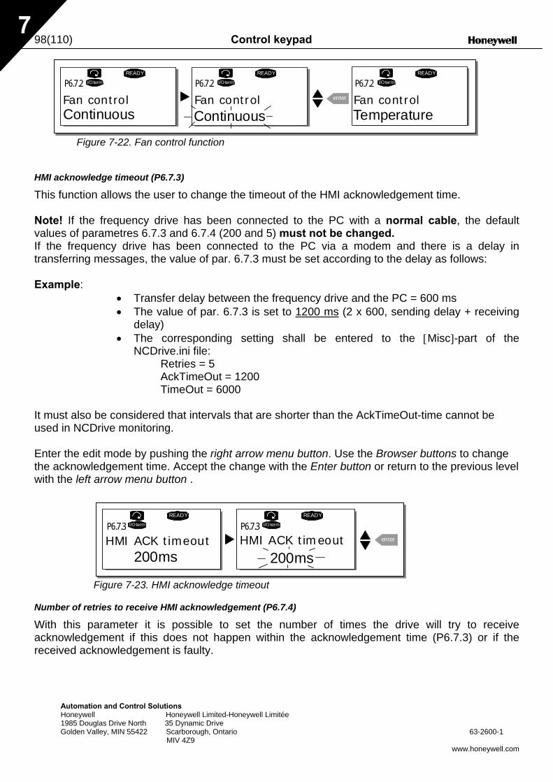
98(110) Control keypad
Automation and Control Solutions Honeywell Honeywell Limited-Honeywell Limitée 1985 Douglas Drive North 35 Dynamic Drive Golden Valley, MIN 55422 Scarborough, Ontario 63-2600-1 MIV 4Z9
www.honeywell.com
7
Figure 7-22. Fan control function
HMI acknowledge timeout (P6.7.3)
This function allows the user to change the timeout of the HMI acknowledgement time. Note! If the frequency drive has been connected to the PC with a normal cable, the default values of parametres 6.7.3 and 6.7.4 (200 and 5) must not be changed. If the frequency drive has been connected to the PC via a modem and there is a delay in transferring messages, the value of par. 6.7.3 must be set according to the delay as follows: Example:
• Transfer delay between the frequency drive and the PC = 600 ms • The value of par. 6.7.3 is set to 1200 ms (2 x 600, sending delay + receiving
delay) • The corresponding setting shall be entered to the [Misc]-part of the
NCDrive.ini file: Retries = 5 AckTimeOut = 1200 TimeOut = 6000
It must also be considered that intervals that are shorter than the AckTimeOut-time cannot be used in NCDrive monitoring. Enter the edit mode by pushing the right arrow menu button. Use the Browser buttons to change the acknowledgement time. Accept the change with the Enter button or return to the previous level with the left arrow menu button .
Figure 7-23. HMI acknowledge timeout
Number of retries to receive HMI acknowledgement (P6.7.4)
With this parameter it is possible to set the number of times the drive will try to receive acknowledgement if this does not happen within the acknowledgement time (P6.7.3) or if the received acknowledgement is faulty.
READY
I/Oterm
READY
I/Oterm
enter
READY
I/OtermP6.7.2 P6.7.2 P6.7.2
Fan controlContinuous
Fan control Fan controlContinuous Temperature
READY
I/Oterm
200ms
READY
I/Oterm
enter
200ms
P6.7.3 P6.7.3
HMI ACK timeout HMI ACK timeout
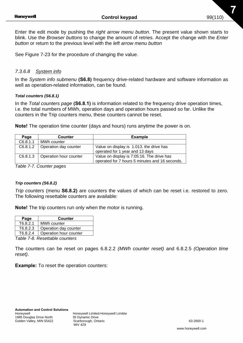
Control keypad 99(110)
Automation and Control Solutions Honeywell Honeywell Limited-Honeywell Limitée 1985 Douglas Drive North 35 Dynamic Drive Golden Valley, MIN 55422 Scarborough, Ontario 63-2600-1 MIV 4Z9
www.honeywell.com
7
Enter the edit mode by pushing the right arrow menu button. The present value shown starts to blink. Use the Browser buttons to change the amount of retries. Accept the change with the Enter button or return to the previous level with the left arrow menu button See Figure 7-23 for the procedure of changing the value. 7.3.6.8 System info In the System info submenu (S6.8) frequency drive-related hardware and software information as well as operation-related information, can be found. Total counters (S6.8.1)
In the Total counters page (S6.8.1) is information related to the frequency drive operation times, i.e. the total numbers of MWh, operation days and operation hours passed so far. Unlike the counters in the Trip counters menu, these counters cannot be reset. Note! The operation time counter (days and hours) runs anytime the power is on.
Page Counter Example C6.8.1.1 MWh counter C6.8.1.2 Operation day counter Value on display is 1.013. the drive has
operated for 1 year and 13 days C6.8.1.3 Operation hour counter Value on display is 7:05:16. The drive has
operated for 7 hours 5 minutes and 16 seconds. Table 7-7. Counter pages
Trip counters (S6.8.2)
Trip counters (menu S6.8.2) are counters the values of which can be reset i.e. restored to zero. The following resettable counters are available: Note! The trip counters run only when the motor is running.
Page Counter T6.8.2.1 MWh counter T6.8.2.3 Operation day counter T6.8.2.4 Operation hour counter
Table 7-8. Resettable counters
The counters can be reset on pages 6.8.2.2 (MWh counter reset) and 6.8.2.5 (Operation time reset). Example: To reset the operation counters:
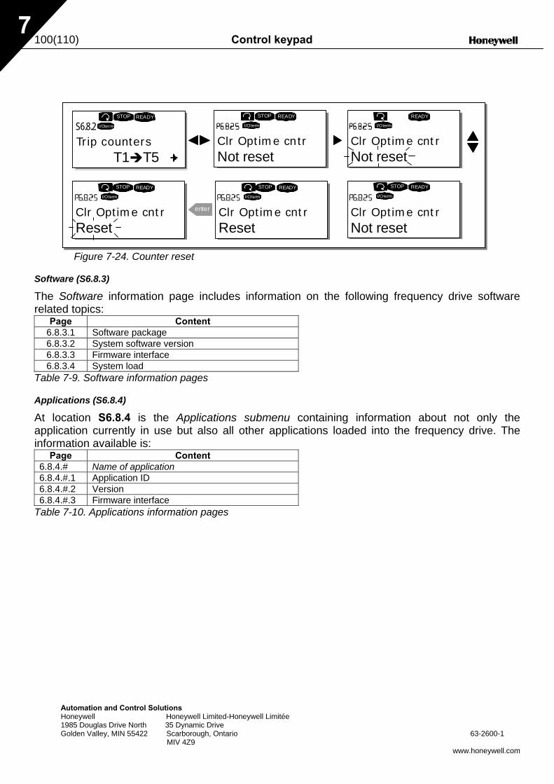
100(110) Control keypad
Automation and Control Solutions Honeywell Honeywell Limited-Honeywell Limitée 1985 Douglas Drive North 35 Dynamic Drive Golden Valley, MIN 55422 Scarborough, Ontario 63-2600-1 MIV 4Z9
www.honeywell.com
7
Figure 7-24. Counter reset
Software (S6.8.3)
The Software information page includes information on the following frequency drive software related topics:
Page Content 6.8.3.1 Software package 6.8.3.2 System software version 6.8.3.3 Firmware interface 6.8.3.4 System load
Table 7-9. Software information pages
Applications (S6.8.4)
At location S6.8.4 is the Applications submenu containing information about not only the application currently in use but also all other applications loaded into the frequency drive. The information available is:
Page Content 6.8.4.# Name of application 6.8.4.#.1 Application ID 6.8.4.#.2 Version 6.8.4.#.3 Firmware interface
Table 7-10. Applications information pages
T1 T5
READY
I/Oterm
READY
I/Oterm
READY
I/Oterm
enter
READY
I/Oterm
READY
I/Oterm
STOP STOP
STOP STOP READY
I/Oterm
STOP
S6.8.2
Trip counters Clr Optime cntr Clr Optime cntrNot reset Not reset
Clr Optime cntrReset
Clr Optime cntrReset
Clr Optime cntrNot reset
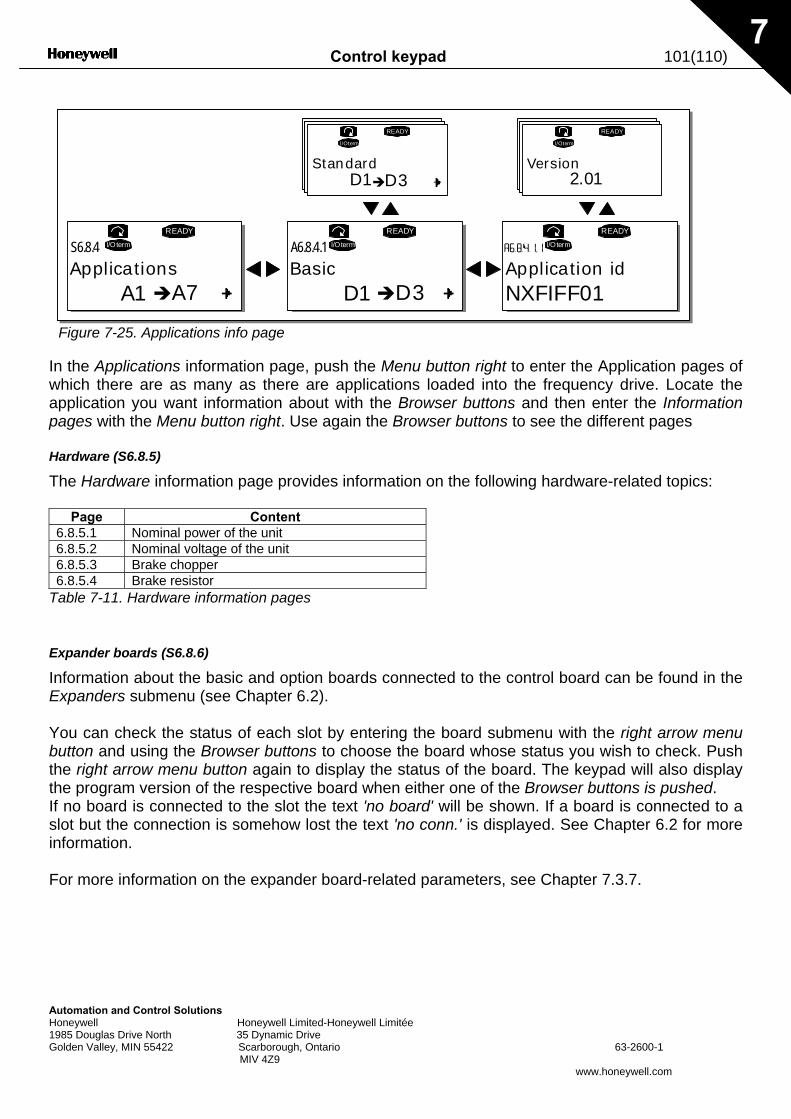
Control keypad 101(110)
Automation and Control Solutions Honeywell Honeywell Limited-Honeywell Limitée 1985 Douglas Drive North 35 Dynamic Drive Golden Valley, MIN 55422 Scarborough, Ontario 63-2600-1 MIV 4Z9
www.honeywell.com
7
Figure 7-25. Applications info page
In the Applications information page, push the Menu button right to enter the Application pages of which there are as many as there are applications loaded into the frequency drive. Locate the application you want information about with the Browser buttons and then enter the Information pages with the Menu button right. Use again the Browser buttons to see the different pages Hardware (S6.8.5)
The Hardware information page provides information on the following hardware-related topics:
Page Content 6.8.5.1 Nominal power of the unit 6.8.5.2 Nominal voltage of the unit 6.8.5.3 Brake chopper 6.8.5.4 Brake resistor
Table 7-11. Hardware information pages
Expander boards (S6.8.6)
Information about the basic and option boards connected to the control board can be found in the Expanders submenu (see Chapter 6.2). You can check the status of each slot by entering the board submenu with the right arrow menu button and using the Browser buttons to choose the board whose status you wish to check. Push the right arrow menu button again to display the status of the board. The keypad will also display the program version of the respective board when either one of the Browser buttons is pushed. If no board is connected to the slot the text 'no board' will be shown. If a board is connected to a slot but the connection is somehow lost the text 'no conn.' is displayed. See Chapter 6.2 for more information. For more information on the expander board-related parameters, see Chapter 7.3.7.
A1 A7
I/Oterm I/Oterm
D1 D3
I/Oterm
READY READY
READY
D1 D3
I/Oterm
READY
NXFIFF01
2.01
I/Oterm
READY
S6.8.4 A6.8.4.1
Applications Basic
Standard
Application id
Version
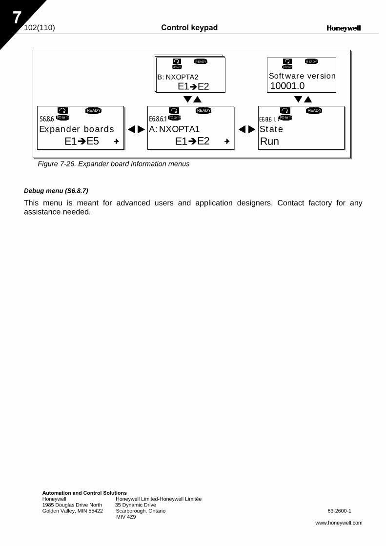
102(110) Control keypad
Automation and Control Solutions Honeywell Honeywell Limited-Honeywell Limitée 1985 Douglas Drive North 35 Dynamic Drive Golden Valley, MIN 55422 Scarborough, Ontario 63-2600-1 MIV 4Z9
www.honeywell.com
7
Figure 7-26. Expander board information menus
Debug menu (S6.8.7)
This menu is meant for advanced users and application designers. Contact factory for any assistance needed.
E1 E5
READY
I/Oterm
A:NXOPTA1
I/Oterm
READY
B:NXOPTA2
I/Oterm
READY
E1 E2
I/Oterm
READY
I/Oterm
READY
E1 E2 10001.0
S6.8.6 E6.8.6.1
Expander boards
Software version
StateRun
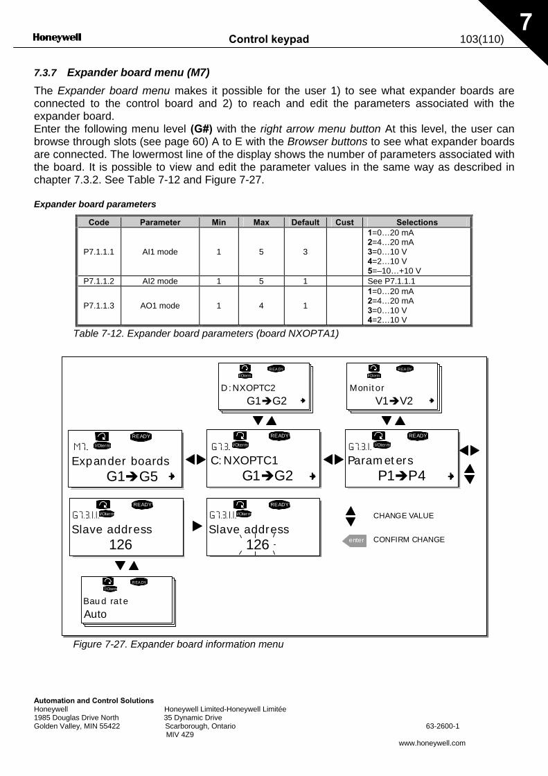
Control keypad 103(110)
Automation and Control Solutions Honeywell Honeywell Limited-Honeywell Limitée 1985 Douglas Drive North 35 Dynamic Drive Golden Valley, MIN 55422 Scarborough, Ontario 63-2600-1 MIV 4Z9
www.honeywell.com
7
7.3.7 Expander board menu (M7) The Expander board menu makes it possible for the user 1) to see what expander boards are connected to the control board and 2) to reach and edit the parameters associated with the expander board. Enter the following menu level (G#) with the right arrow menu button At this level, the user can browse through slots (see page 60) A to E with the Browser buttons to see what expander boards are connected. The lowermost line of the display shows the number of parameters associated with the board. It is possible to view and edit the parameter values in the same way as described in chapter 7.3.2. See Table 7-12 and Figure 7-27. Expander board parameters
Code Parameter Min Max Default Cust Selections
P7.1.1.1 AI1 mode 1 5 3
1=0…20 mA 2=4…20 mA 3=0…10 V 4=2…10 V 5=–10…+10 V
P7.1.1.2 AI2 mode 1 5 1 See P7.1.1.1
P7.1.1.3 AO1 mode 1 4 1
1=0…20 mA 2=4…20 mA 3=0…10 V 4=2…10 V
Table 7-12. Expander board parameters (board NXOPTA1)
Figure 7-27. Expander board information menu
G1 G5
READY
I/Oterm
C:NXOPTC1
READY
I/Oterm
G1 G2
READY
I/Oterm
READY
I/Oterm
enter
P1 P4
D:NXOPTC2
REA DYI/Oterm
G1 G2
REA DYI/Oterm
V1 V2
READY
I/Oterm
REA DY
I/Oterm
Expander boards Parameters
Slave address126
CHANGE VALUE
CONFIRM CHANGESlave address
126
Baud rate
Auto
Monitor
104(110) Control keypad
Automation and Control Solutions Honeywell Honeywell Limited-Honeywell Limitée 1985 Douglas Drive North 35 Dynamic Drive Golden Valley, MIN 55422 Scarborough, Ontario 63-2600-1 MIV 4Z9
www.honeywell.com
7
7.4 Further keypad functions
The NX control keypad embodies additional application-related functions. See the NX Application Package for more information.
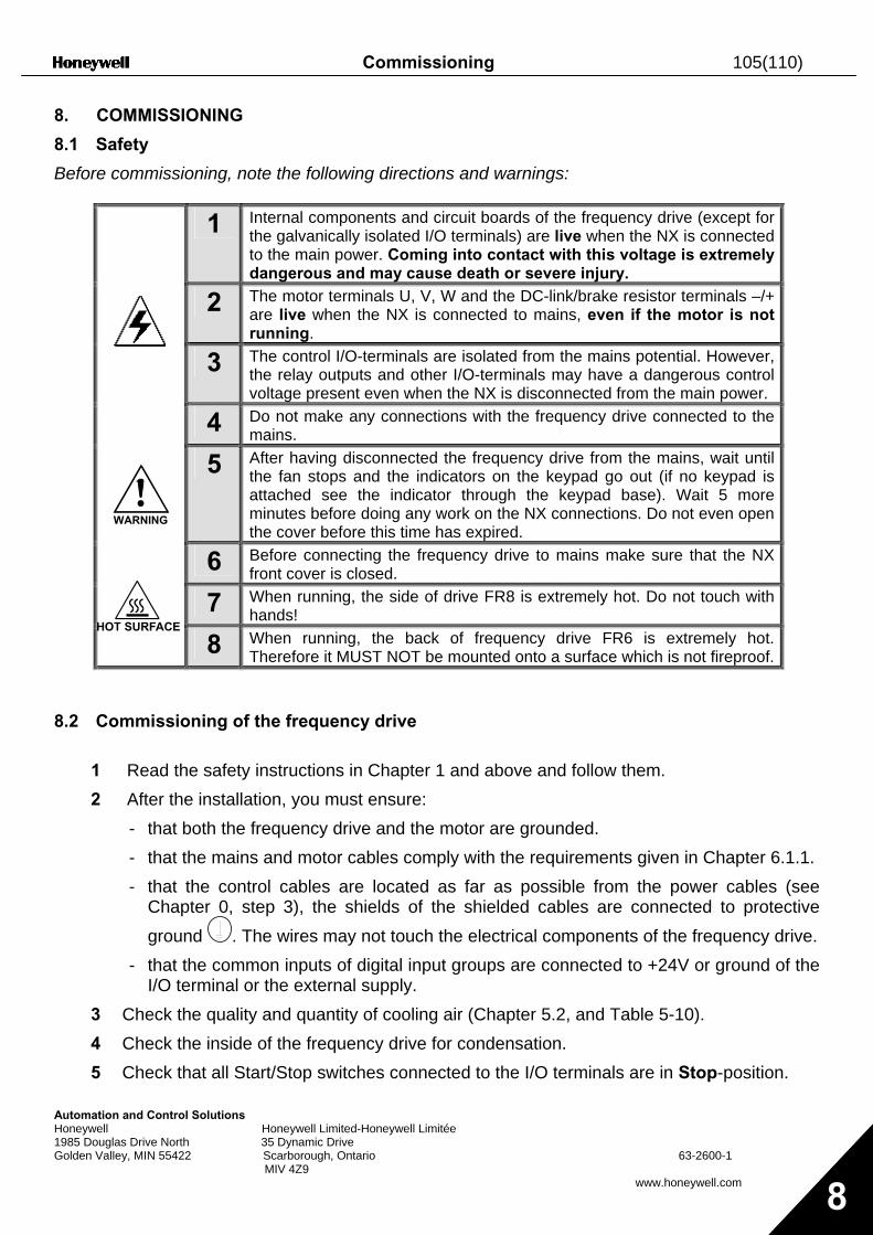
Commissioning 105(110)
Automation and Control Solutions Honeywell Honeywell Limited-Honeywell Limitée 1985 Douglas Drive North 35 Dynamic Drive Golden Valley, MIN 55422 Scarborough, Ontario 63-2600-1 MIV 4Z9
www.honeywell.com 8
8. COMMISSIONING
8.1 Safety
Before commissioning, note the following directions and warnings:
1 Internal components and circuit boards of the frequency drive (except for the galvanically isolated I/O terminals) are live when the NX is connected to the main power. Coming into contact with this voltage is extremely dangerous and may cause death or severe injury.
2 The motor terminals U, V, W and the DC-link/brake resistor terminals –/+ are live when the NX is connected to mains, even if the motor is not running.
3 The control I/O-terminals are isolated from the mains potential. However, the relay outputs and other I/O-terminals may have a dangerous control voltage present even when the NX is disconnected from the main power.
4 Do not make any connections with the frequency drive connected to the mains.
5 After having disconnected the frequency drive from the mains, wait until the fan stops and the indicators on the keypad go out (if no keypad is attached see the indicator through the keypad base). Wait 5 more minutes before doing any work on the NX connections. Do not even open the cover before this time has expired.
6 Before connecting the frequency drive to mains make sure that the NX front cover is closed.
7 When running, the side of drive FR8 is extremely hot. Do not touch with hands!
8 When running, the back of frequency drive FR6 is extremely hot. Therefore it MUST NOT be mounted onto a surface which is not fireproof.
8.2 Commissioning of the frequency drive
1 Read the safety instructions in Chapter 1 and above and follow them. 2 After the installation, you must ensure:
- that both the frequency drive and the motor are grounded. - that the mains and motor cables comply with the requirements given in Chapter 6.1.1. - that the control cables are located as far as possible from the power cables (see
Chapter 0, step 3), the shields of the shielded cables are connected to protective ground . The wires may not touch the electrical components of the frequency drive.
- that the common inputs of digital input groups are connected to +24V or ground of the I/O terminal or the external supply.
3 Check the quality and quantity of cooling air (Chapter 5.2, and Table 5-10). 4 Check the inside of the frequency drive for condensation. 5 Check that all Start/Stop switches connected to the I/O terminals are in Stop-position.
WARNING
HOT SURFACE
106(110) Commissioning
Automation and Control Solutions Honeywell Honeywell Limited-Honeywell Limitée 1985 Douglas Drive North 35 Dynamic Drive Golden Valley, MIN 55422 Scarborough, Ontario 63-2600-1 MIV 4Z9
www.honeywell.com 8
6 Connect the frequency drive to mains. 7 Set the parameters of group 1 (See the Application Manual) according to the
requirements of the application. At least the following parameters should be set: - motor nominal voltage - motor nominal frequency - motor nominal speed - motor nominal current
The values needed for the parameters are on the motor rating plate. 8 Perform run test without motor
Perform either Test A or Test B: A Controls from the I/O terminals:
a) Turn the Start/Stop switch to ON position.
b) Change the frequency reference (potentiometer)
c) Check in the Monitoring menu M1 that the value of Output frequency changes according to the change of frequency reference.
d) Turn the Start/Stop switch to OFF position.
B Control from the control keypad:
a) Change the control from the I/O terminals to the keypad as advised in Chapter 7.3.3.1.
b) Push the Start button on the keypad start
.
c) Move over to the Keypad control menu (M3) and Keypad Reference submenu (Chapter 7.3.3.2) and change the frequency reference using the Browser buttons
+-
.
d) Check in the Monitoring menu M1 that the value of Output frequency changes according to the change of frequency reference.
e) Push the Stop button on the keypad stop
. 9 Run the start-up tests without the motor being connected to the process, if possible. If
this is not possible, secure the safety of each test prior to running it. Inform co-workers of the tests.
a) Switch off the supply voltage and wait until the drive has stopped as advised in Chapter 8.1, step 5.
b) Connect the motor cable to the motor and to the motor cable terminals of the frequency drive.
c) Ensure that all Start/Stop switches are in Stop positions.
Commissioning 107(110)
Automation and Control Solutions Honeywell Honeywell Limited-Honeywell Limitée 1985 Douglas Drive North 35 Dynamic Drive Golden Valley, MIN 55422 Scarborough, Ontario 63-2600-1 MIV 4Z9
www.honeywell.com 8
d) Switch the mains ON
e) Repeat test 8A or 8B. 10 Connect the motor to the process (if the startup test was run without the motor being
connected)
a) Before running the tests, make sure that this can be done safely.
b) Inform co-workers of the tests.
c) Repeat test 8A or 8B.
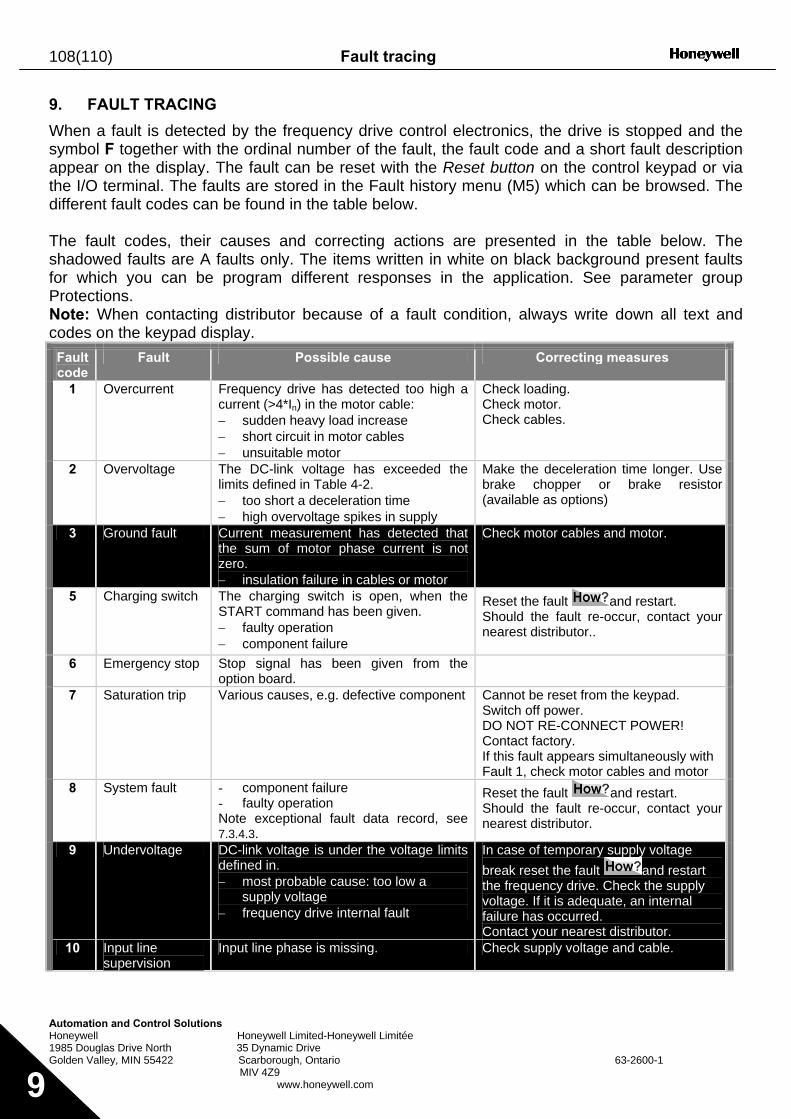
108(110) Fault tracing
Automation and Control Solutions Honeywell Honeywell Limited-Honeywell Limitée 1985 Douglas Drive North 35 Dynamic Drive Golden Valley, MIN 55422 Scarborough, Ontario 63-2600-1 MIV 4Z9 www.honeywell.com 9
9. FAULT TRACING
When a fault is detected by the frequency drive control electronics, the drive is stopped and the symbol F together with the ordinal number of the fault, the fault code and a short fault description appear on the display. The fault can be reset with the Reset button on the control keypad or via the I/O terminal. The faults are stored in the Fault history menu (M5) which can be browsed. The different fault codes can be found in the table below. The fault codes, their causes and correcting actions are presented in the table below. The shadowed faults are A faults only. The items written in white on black background present faults for which you can be program different responses in the application. See parameter group Protections. Note: When contacting distributor because of a fault condition, always write down all text and codes on the keypad display.
Fault code
Fault Possible cause Correcting measures
1 Overcurrent Frequency drive has detected too high a current (>4*In) in the motor cable: − sudden heavy load increase − short circuit in motor cables − unsuitable motor
Check loading. Check motor. Check cables.
2 Overvoltage The DC-link voltage has exceeded the limits defined in Table 4-2. − too short a deceleration time − high overvoltage spikes in supply
Make the deceleration time longer. Use brake chopper or brake resistor (available as options)
3 Ground fault Current measurement has detected that the sum of motor phase current is not zero. − insulation failure in cables or motor
Check motor cables and motor.
5 Charging switch The charging switch is open, when the START command has been given. − faulty operation − component failure
Reset the fault and restart. Should the fault re-occur, contact your nearest distributor..
6 Emergency stop Stop signal has been given from the option board.
7 Saturation trip Various causes, e.g. defective component Cannot be reset from the keypad. Switch off power. DO NOT RE-CONNECT POWER! Contact factory. If this fault appears simultaneously with Fault 1, check motor cables and motor
8 System fault - component failure - faulty operation Note exceptional fault data record, see 7.3.4.3.
Reset the fault and restart. Should the fault re-occur, contact your nearest distributor.
9 Undervoltage DC-link voltage is under the voltage limits defined in. − most probable cause: too low a
supply voltage − frequency drive internal fault
In case of temporary supply voltage break reset the fault and restart the frequency drive. Check the supply voltage. If it is adequate, an internal failure has occurred. Contact your nearest distributor.
10 Input line supervision
Input line phase is missing. Check supply voltage and cable.
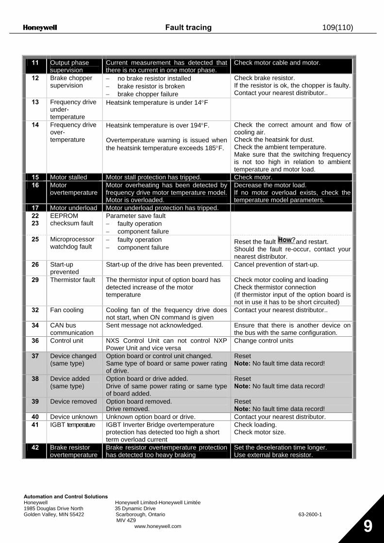
Fault tracing 109(110)
Automation and Control Solutions Honeywell Honeywell Limited-Honeywell Limitée 1985 Douglas Drive North 35 Dynamic Drive Golden Valley, MIN 55422 Scarborough, Ontario 63-2600-1 MIV 4Z9 www.honeywell.com 9
11 Output phase
supervision Current measurement has detected that there is no current in one motor phase.
Check motor cable and motor.
12 Brake chopper supervision
− no brake resistor installed − brake resistor is broken − brake chopper failure
Check brake resistor. If the resistor is ok, the chopper is faulty. Contact your nearest distributor..
13 Frequency drive under-temperature
Heatsink temperature is under 14°F
14 Frequency drive over- temperature
Heatsink temperature is over 194°F. Overtemperature warning is issued when the heatsink temperature exceeds 185°F.
Check the correct amount and flow of cooling air. Check the heatsink for dust. Check the ambient temperature. Make sure that the switching frequency is not too high in relation to ambient temperature and motor load.
15 Motor stalled Motor stall protection has tripped. Check motor. 16 Motor
overtemperature Motor overheating has been detected by frequency drive motor temperature model. Motor is overloaded.
Decrease the motor load. If no motor overload exists, check the temperature model parameters.
17 Motor underload Motor underload protection has tripped. 22 23
EEPROM checksum fault
Parameter save fault − faulty operation − component failure
25 Microprocessor watchdog fault
− faulty operation − component failure
Reset the fault and restart. Should the fault re-occur, contact your nearest distributor.
26 Start-up prevented
Start-up of the drive has been prevented. Cancel prevention of start-up.
29 Thermistor fault The thermistor input of option board has detected increase of the motor temperature
Check motor cooling and loading Check thermistor connection (If thermistor input of the option board is not in use it has to be short circuited)
32 Fan cooling Cooling fan of the frequency drive does not start, when ON command is given
Contact your nearest distributor..
34 CAN bus communication
Sent message not acknowledged. Ensure that there is another device on the bus with the same configuration.
36 Control unit NXS Control Unit can not control NXP Power Unit and vice versa
Change control units
37 Device changed (same type)
Option board or control unit changed. Same type of board or same power rating of drive.
Reset Note: No fault time data record!
38 Device added (same type)
Option board or drive added. Drive of same power rating or same type of board added.
Reset Note: No fault time data record!
39 Device removed Option board removed. Drive removed.
Reset Note: No fault time data record!
40 Device unknown Unknown option board or drive. Contact your nearest distributor. 41 IGBT temperature IGBT Inverter Bridge overtemperature
protection has detected too high a short term overload current
Check loading. Check motor size.
42 Brake resistor overtemperature
Brake resistor overtemperature protection has detected too heavy braking
Set the deceleration time longer. Use external brake resistor.
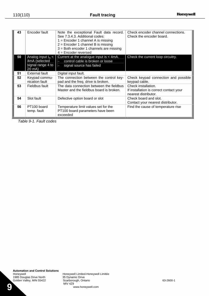
110(110) Fault tracing
Automation and Control Solutions Honeywell Honeywell Limited-Honeywell Limitée 1985 Douglas Drive North 35 Dynamic Drive Golden Valley, MIN 55422 Scarborough, Ontario 63-2600-1 MIV 4Z9 www.honeywell.com 9
43 Encoder fault Note the exceptional Fault data record.
See 7.3.4.3. Additional codes: 1 = Encoder 1 channel A is missing 2 = Encoder 1 channel B is missing 3 = Both encoder 1 channels are missing 4 = Encoder reversed
Check encoder channel connections. Check the encoder board.
50 Analog input Iin < 4mA (selected signal range 4 to 20 mA)
Current at the analogue input is < 4mA. − control cable is broken or loose − signal source has failed
Check the current loop circuitry.
51 External fault Digital input fault. 52 Keypad commu-
nication fault The connection between the control key-pad and the freq. drive is broken.
Check keypad connection and possible keypad cable.
53 Fieldbus fault The data connection between the fieldbus Master and the fieldbus board is broken.
Check installation. If installation is correct contact your nearest distributor.
54 Slot fault Defective option board or slot Check board and slot. Contact your nearest distributor.
56 PT100 board temp. fault
Temperature limit values set for the PT100 board parameters have been exceeded
Find the cause of temperature rise
Table 9-1. Fault codes


Automation and Control SolutionsHoneywell International Inc. Honeywell Limited-Honeywell Limitée1985 Douglas Drive North 35 Dynamic DriveGolden Valley, MN 55422 Scarborough, Ontario M1V 4Z9customer.honeywell.com
® U.S. Registered Trademark© 2006 Honeywell International Inc.63-26001 Rev. 05-06
63-2600—1
NX Series
Constant and Variable Torque Variable Speed Drives for Induction MotorsSoftware Application Manual

CONTENTS
NX "All in One" APPLICATION MANUAL INDEX 1 Basic Application 2 Standard Application 3 Local/Remote Control Application 4 Multi-step Speed Control Application 5 PID Control Application 6 Multi-purpose Control Application 7 Pump and Fan Control Application 8 Description of parameters 9 Appendices
2 Honeywell
Automation and Control Solutions Honeywell Honeywell Limited-Honeywell Limitée 1985 Douglas Drive North 35 Dynamic Drive Golden Valley, MIN 55422 Scarborough, Ontario 63-2600-1 MIV 4Z9 www.honeywell.com
ABOUT THE "All in One" APPLICATION MANUAL In the All in One Application Manual you will find information about the different applications included in the All in One Application Package. Should these applications not meet the requirements of your process please contact the manufacturer for information on special applications. This manual is available in both paper and electronic editions. We recommend you to use the electronic version if possible. If you have the electronic version at your disposal you will be able to benefit from the following features: The manual contains several links and cross-references to other locations in the manual which makes it easier for the reader to move around in the manual, to check and find things faster. The manual also contains hyperlinks to web pages. To visit these web pages through the links you must have an internet browser installed on your computer.
Honeywell 3
"All in One" Application manual INDEX
1. Basic Application ..................................................................................................................... 5 1.1 Introduction............................................................................................................................. 5 1.2 Control I/O.............................................................................................................................. 6 1.3 Control signal logic in Basic Application................................................................................. 7 1.4 Basic Application – Parameter lists ........................................................................................ 8
2. Standard Application ............................................................................................................. 11 2.1 Introduction........................................................................................................................... 11 2.2 Control I/O............................................................................................................................ 12 2.3 Control signal logic in Standard Application ......................................................................... 13 2.4 Standard Application – Parameter lists ................................................................................ 14
3. Local/Remote Control Application ....................................................................................... 22 3.1 Introduction........................................................................................................................... 22 3.2 Control I/O............................................................................................................................ 23 3.3 Control signal logic in Local/Remote Application ................................................................. 24 3.4 Local/Remote control application – Parameter lists ............................................................. 25
4. Multi-step Speed Control Application .................................................................................. 35 4.1 Introduction........................................................................................................................... 35 4.2 Control I/O............................................................................................................................ 36 4.3 Control signal logic in Multi-Step Speed Control Application ............................................... 37 4.4 Multi-step speed control application – Parameter lists ......................................................... 38
5. PID Control Application......................................................................................................... 48 5.1 Introduction........................................................................................................................... 48 5.2 Control I/O............................................................................................................................ 49 5.3 Control signal logic in PID Control Application ..................................................................... 50 5.4 PID Application – Parameter lists......................................................................................... 51
6. Multi-purpose Control Application ....................................................................................... 62 6.1 Introduction........................................................................................................................... 62 6.2 Control I/O............................................................................................................................ 63 6.3 Control signal logic in Multi-Purpose Control Application..................................................... 64 6.4 “Terminal To Function” (TTF) programming principle .......................................................... 65 6.5 Master/Follower function (NXP only).................................................................................... 67 6.6 Multi-purpose Control Application – Parameter lists ............................................................ 69
7. Pump and Fan Control Application ...................................................................................... 96 7.1 Introduction........................................................................................................................... 96 7.2 Control I/O............................................................................................................................ 97 7.3 Control signal logic in Pump and Fan Control Application ................................................... 99 7.4 Short description of function and essential parameters ..................................................... 100 7.5 Pump and Fan Control Application – Parameter lists......................................................... 106
8. Description of parameters................................................................................................... 122 8.1 Speed control parameters (application 6 only)................................................................... 207 8.2 Keypad control parameters ................................................................................................ 209
9. Appendices........................................................................................................................... 210
4 Honeywell
Automation and Control Solutions Honeywell Honeywell Limited-Honeywell Limitée 1985 Douglas Drive North 35 Dynamic Drive Golden Valley, MIN 55422 Scarborough, Ontario 63-2600-1 MIV 4Z9 www.honeywell.com
9.1 External brake control with additional limits (ID’s 315, 316, 346 to 349, 352, 353)............ 210 9.2 Closed loop parameters (ID’s 612 to 621).......................................................................... 212 9.3 Advanced Open Loop parameters (ID's 622 to 625, 632, 635).......................................... 212 9.4 Parameters of motor thermal protection (ID’s 704 to 708): ................................................ 213 9.5 Parameters of Stall protection (ID’s 709 to 712): ............................................................... 213 9.6 Parameters of Underload protection (ID’s 713 to 716):...................................................... 213 9.7 Fieldbus control parameters (ID’s 850 to 859) ................................................................... 213
Honeywell Basic Application 5
Automation and Control Solutions Honeywell Honeywell Limited-Honeywell Limitée 1985 Douglas Drive North 35 Dynamic Drive Golden Valley, MIN 55422 Scarborough, Ontario 63-2600-1 MIV 4Z9
www.honeywell.com 1
1. BASIC APPLICATION
1.1 Introduction
The Basic Application is easy and flexible to use due to its versatile fieldbus features. It is the default setting on delivery from the factory. Otherwise select the Basic Application in menu M6 on page S6.2. See the product's User's Manual. Digital input DIN3 is programmable. The parameters of the Basic Application are explained in Chapter 8 of this manual. The explanations are arranged according to the individual ID number of the parameter. 1.1.1 Motor protection functions in the Basic Application The Basic Application provides almost all the same protection functions as the other applications:
• External fault protection • Input phase supervision • Undervoltage protection • Output phase supervision • Ground fault protection • Motor thermal protection • Thermistor fault protection • Fieldbus fault protection • Slot fault protection
Unlike the other applications, the Basic Application does not provide any parameters for choosing the response function or limit values for the faults. The motor thermal protection is explained in more detail on page 182.
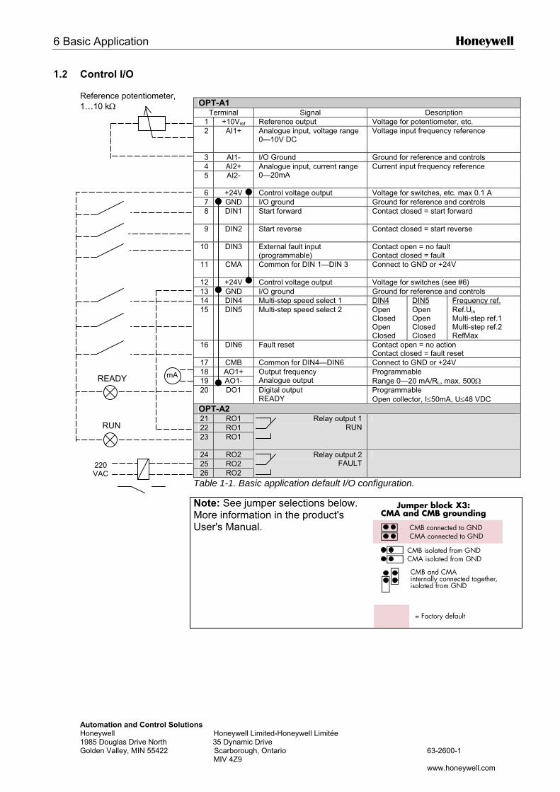
6 Basic Application Honeywell
AutHon198Gol
1.2 Control I/O
OPT-A1
Terminal Signal Description 1 +10Vref Reference output Voltage for potentiometer, etc. 2 AI1+ Analogue input, voltage range
0—10V DC Voltage input frequency reference
3 AI1- I/O Ground Ground for reference and controls 4 AI2+ 5 AI2-
Analogue input, current range 0—20mA
Current input frequency reference
6 +24V Control voltage output Voltage for switches, etc. max 0.1 A 7 GND I/O ground Ground for reference and controls 8 DIN1 Start forward
Contact closed = start forward
9 DIN2 Start reverse
Contact closed = start reverse
10 DIN3 External fault input (programmable)
Contact open = no fault Contact closed = fault
11 CMA
Common for DIN 1—DIN 3 Connect to GND or +24V
12 +24V Control voltage output Voltage for switches (see #6) 13 GND I/O ground Ground for reference and controls 14 DIN4 Multi-step speed select 1 DIN4 DIN5 Frequency ref. 15 DIN5 Multi-step speed select 2 Open
Closed Open Closed
Open Open Closed Closed
Ref.Uin Multi-step ref.1 Multi-step ref.2 RefMax
16 DIN6 Fault reset Contact open = no action Contact closed = fault reset
17 CMB Common for DIN4—DIN6 Connect to GND or +24V 18 AO1+ 19 AO1-
Output frequency Analogue output
Programmable Range 0—20 mA/RL, max. 500Ω
Reference potentiometer, 1…10 kΩ
mA
READYomation and Control Solutions eywell Honeywell Limited-Honeywell Limitée 5 Douglas Drive North 35 Dynamic Drive den Valley, MIN 55422 Scarborough, Ontario 63-2600-1 MIV 4Z9
www.honeywell.com
Jumper block X3:CMA and CMB grounding
CMB connected to GNDCMA connected to GND
CMB isolated from GNDCMA isolated from GND
CMB and CMAinternally connected together,isolated from GND
= Factory default
20 DO1 Digital output READY
Programmable Open collector, I≤50mA, U≤48 VDC
OPT-A2 21 RO1 22 RO1 23 RO1
Relay output 1 RUN
24 RO2 25 RO2 26 RO2
Relay output 2 FAULT
Table 1-1. Basic application default I/O configuration.
Note: See jumper selections below. More information in the product's User's Manual.
220 VAC
RUN
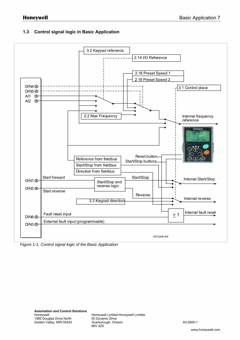
Honeywell Basic Application 7
Automation and Control Solutions Honeywell Honeywell Limited-Honeywell Limitée 1985 Douglas Drive North 35 Dynamic Drive Golden Valley, MIN 55422 Scarborough, Ontario 63-2600-1 MIV 4Z9
www.honeywell.com 1
1.3 Control signal logic in Basic Application
Figure 1-1. Control signal logic of the Basic Application
DIN4DIN5AI1AI2
DIN1
DIN2
DIN6
DIN3
> 1
NX12k00.fh8
3.2 Keypad reference
3.1 Control place
Internal frequencyreference
Start forward
Start reverse
Start/Stop andreverse logic
Start/Stop
Reverse
Internal Start/Stop
Internal reverse
Internal fault resetFault reset input
External fault input (programmable)
Reset buttonStart/Stop buttonsReference from fieldbus
Start/Stop from fieldbus
Direction from fieldbus
3.3 Keypad direction
2.14 I/O Reference
2.19 Preset Speed 2
2.18 Preset Speed 1
2.2 Max Frequency
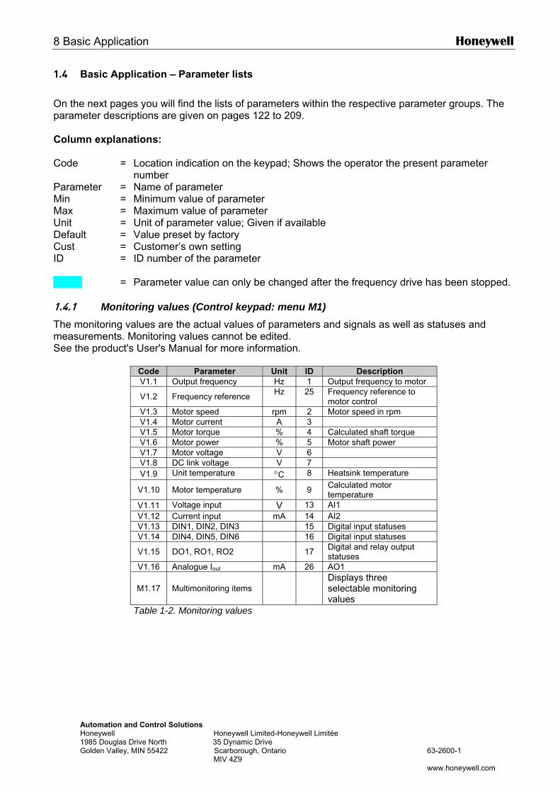
8 Basic Application Honeywell
Automation and Control Solutions Honeywell Honeywell Limited-Honeywell Limitée 1985 Douglas Drive North 35 Dynamic Drive Golden Valley, MIN 55422 Scarborough, Ontario 63-2600-1 MIV 4Z9 www.honeywell.com
1.4 Basic Application – Parameter lists
On the next pages you will find the lists of parameters within the respective parameter groups. The parameter descriptions are given on pages 122 to 209. Column explanations: Code = Location indication on the keypad; Shows the operator the present parameter
number Parameter = Name of parameter Min = Minimum value of parameter Max = Maximum value of parameter Unit = Unit of parameter value; Given if available Default = Value preset by factory Cust = Customer’s own setting ID = ID number of the parameter = Parameter value can only be changed after the frequency drive has been stopped. 1.4.1 Monitoring values (Control keypad: menu M1) The monitoring values are the actual values of parameters and signals as well as statuses and measurements. Monitoring values cannot be edited. See the product's User's Manual for more information.
Code Parameter Unit ID Description V1.1 Output frequency Hz 1 Output frequency to motor
V1.2 Frequency reference Hz 25 Frequency reference to motor control
V1.3 Motor speed rpm 2 Motor speed in rpm V1.4 Motor current A 3 V1.5 Motor torque % 4 Calculated shaft torque V1.6 Motor power % 5 Motor shaft power V1.7 Motor voltage V 6 V1.8 DC link voltage V 7 V1.9 Unit temperature °C 8 Heatsink temperature
V1.10 Motor temperature % 9 Calculated motor temperature
V1.11 Voltage input V 13 AI1 V1.12 Current input mA 14 AI2 V1.13 DIN1, DIN2, DIN3 15 Digital input statuses V1.14 DIN4, DIN5, DIN6 16 Digital input statuses
V1.15 DO1, RO1, RO2 17 Digital and relay output statuses
V1.16 Analogue Iout mA 26 AO1
M1.17 Multimonitoring items
Displays three selectable monitoring values
Table 1-2. Monitoring values
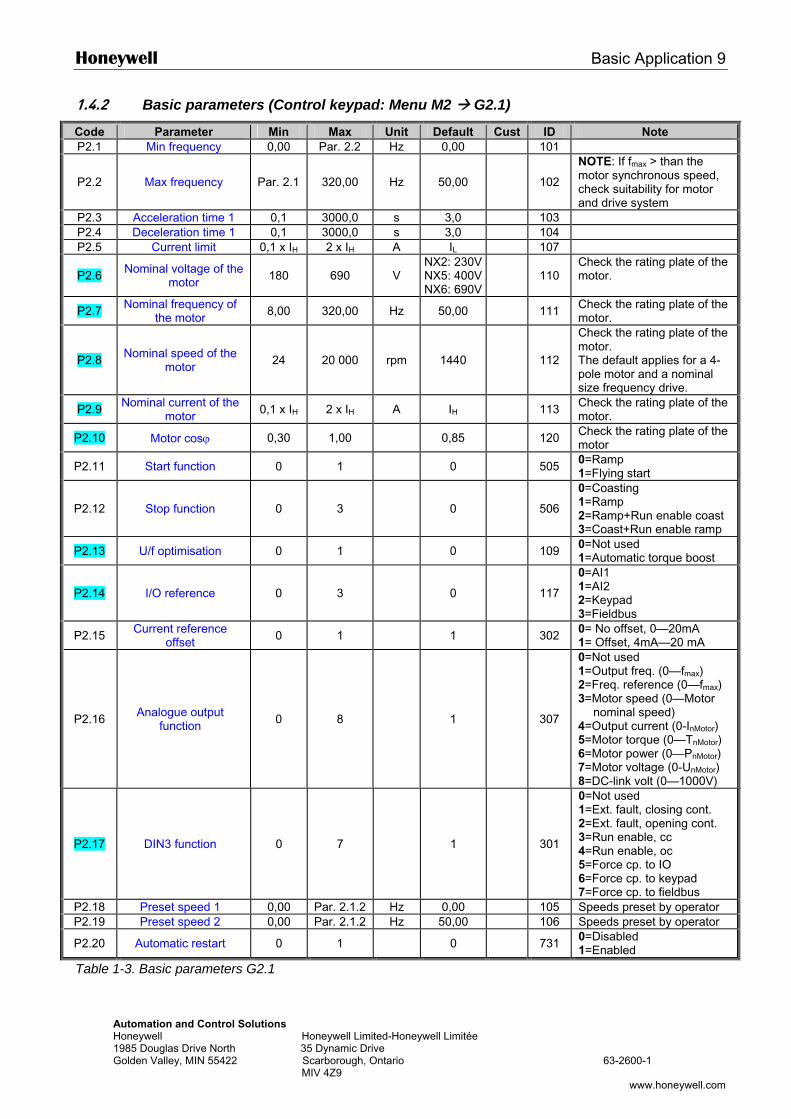
Honeywell Basic Application 9
Automation and Control Solutions Honeywell Honeywell Limited-Honeywell Limitée 1985 Douglas Drive North 35 Dynamic Drive Golden Valley, MIN 55422 Scarborough, Ontario 63-2600-1 MIV 4Z9
www.honeywell.com 1
1.4.2 Basic parameters (Control keypad: Menu M2 G2.1)
Code Parameter Min Max Unit Default Cust ID Note P2.1 Min frequency 0,00 Par. 2.2 Hz 0,00 101
P2.2 Max frequency Par. 2.1 320,00 Hz 50,00
102
NOTE: If fmax > than the motor synchronous speed, check suitability for motor and drive system
P2.3 Acceleration time 1 0,1 3000,0 s 3,0 103 P2.4 Deceleration time 1 0,1 3000,0 s 3,0 104 P2.5 Current limit 0,1 x IH 2 x IH A IL 107
P2.6 Nominal voltage of the motor 180 690 V
NX2: 230VNX5: 400VNX6: 690V
110
Check the rating plate of the motor.
P2.7 Nominal frequency of the motor 8,00 320,00 Hz 50,00 111 Check the rating plate of the
motor.
P2.8 Nominal speed of the motor 24 20 000 rpm 1440
112
Check the rating plate of the motor. The default applies for a 4-pole motor and a nominal size frequency drive.
P2.9 Nominal current of the motor 0,1 x IH 2 x IH A IH 113 Check the rating plate of the
motor.
P2.10 Motor cosϕ 0,30 1,00 0,85 120 Check the rating plate of the motor
P2.11 Start function 0 1 0 505 0=Ramp 1=Flying start
P2.12 Stop function 0 3 0
506
0=Coasting 1=Ramp 2=Ramp+Run enable coast 3=Coast+Run enable ramp
P2.13 U/f optimisation 0 1 0 109 0=Not used 1=Automatic torque boost
P2.14 I/O reference 0 3 0
117
0=AI1 1=AI2 2=Keypad 3=Fieldbus
P2.15 Current reference offset 0 1 1 302 0= No offset, 0—20mA
1= Offset, 4mA—20 mA
P2.16 Analogue output function 0 8 1
307
0=Not used 1=Output freq. (0—fmax) 2=Freq. reference (0—fmax) 3=Motor speed (0—Motor
nominal speed) 4=Output current (0-InMotor) 5=Motor torque (0—TnMotor) 6=Motor power (0—PnMotor) 7=Motor voltage (0-UnMotor) 8=DC-link volt (0—1000V)
P2.17 DIN3 function 0 7 1 301
0=Not used 1=Ext. fault, closing cont. 2=Ext. fault, opening cont. 3=Run enable, cc 4=Run enable, oc 5=Force cp. to IO 6=Force cp. to keypad 7=Force cp. to fieldbus
P2.18 Preset speed 1 0,00 Par. 2.1.2 Hz 0,00 105 Speeds preset by operator P2.19 Preset speed 2 0,00 Par. 2.1.2 Hz 50,00 106 Speeds preset by operator
P2.20 Automatic restart 0 1 0 731 0=Disabled 1=Enabled
Table 1-3. Basic parameters G2.1
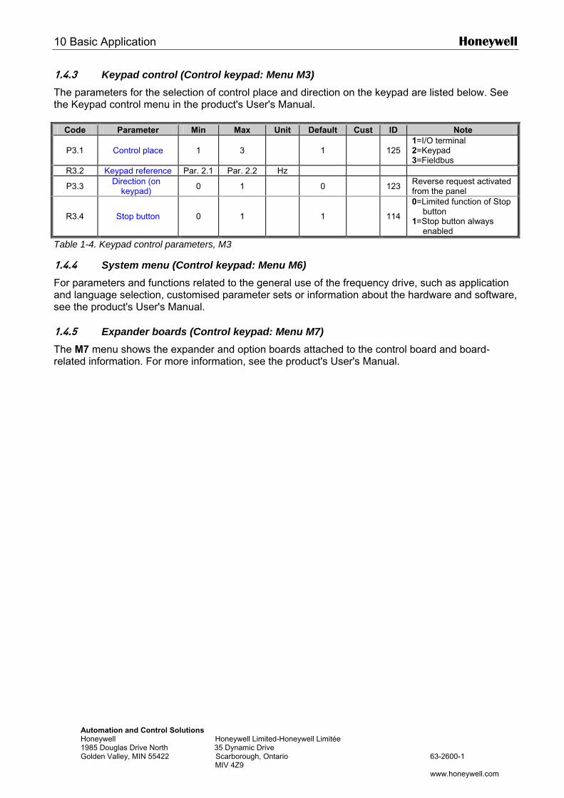
10 Basic Application Honeywell
Automation and Control Solutions Honeywell Honeywell Limited-Honeywell Limitée 1985 Douglas Drive North 35 Dynamic Drive Golden Valley, MIN 55422 Scarborough, Ontario 63-2600-1 MIV 4Z9 www.honeywell.com
1.4.3 Keypad control (Control keypad: Menu M3) The parameters for the selection of control place and direction on the keypad are listed below. See the Keypad control menu in the product's User's Manual.
Code Parameter Min Max Unit Default Cust ID Note
P3.1 Control place 1 3 1 125 1=I/O terminal 2=Keypad 3=Fieldbus
R3.2 Keypad reference Par. 2.1 Par. 2.2 Hz
P3.3 Direction (on keypad) 0 1 0 123 Reverse request activated
from the panel
R3.4 Stop button 0 1 1 114
0=Limited function of Stop button
1=Stop button always enabled
Table 1-4. Keypad control parameters, M3
1.4.4 System menu (Control keypad: Menu M6) For parameters and functions related to the general use of the frequency drive, such as application and language selection, customised parameter sets or information about the hardware and software, see the product's User's Manual. 1.4.5 Expander boards (Control keypad: Menu M7) The M7 menu shows the expander and option boards attached to the control board and board-related information. For more information, see the product's User's Manual.
Honeywell Standard Application 11
Automation and Control Solutions Honeywell Honeywell Limited-Honeywell Limitée 1985 Douglas Drive North 35 Dynamic Drive Golden Valley, MIN 55422 Scarborough, Ontario 63-2600-1 MIV 4Z9
www.honeywell.com
2. STANDARD APPLICATION
2.1 Introduction
Select the Standard Application in menu M6 on page S6.2. The Standard Application is typically used in pump and fan applications and conveyors for which the Basic Application is too limited but where no special features are needed.
• The Standard Application has the same I/O signals and the same control logic as the Basic Application.
• Digital input DIN3 and all the outputs are freely programmable.
Additional functions:
• Programmable Start/Stop and Reverse signal logic • Reference scaling • One frequency limit supervision • Second ramps and S-shape ramp programming • Programmable start and stop functions • DC-brake at stop • One prohibit frequency area • Programmable U/f curve and switching frequency • Autorestart • Motor thermal and stall protection: Programmable action; off, warning, fault
The parameters of the Standard Application are explained in Chapter 8 of this manual. The explanations are arranged according to the individual ID number of the parameter.
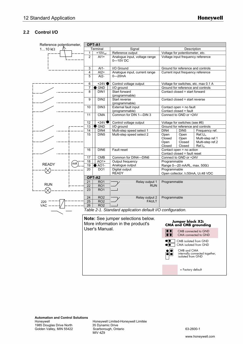
12 Standard Application Honeywell
AutHon198Gol
2.2 Control I/O
OPT-A1
Terminal Signal Description 1 +10Vref Reference output Voltage for potentiometer, etc. 2 AI1+ Analogue input, voltage range
0—10V DC Voltage input frequency reference
3 AI1- I/O Ground Ground for reference and controls 4 AI2+ 5 AI2-
Analogue input, current range 0—20mA
Current input frequency reference
6 +24V Control voltage output Voltage for switches, etc. max 0.1 A 7 GND I/O ground Ground for reference and controls 8 DIN1 Start forward
(programmable) Contact closed = start forward
9 DIN2 Start reverse (programmable)
Contact closed = start reverse
10 DIN3 External fault input (programmable)
Contact open = no fault Contact closed = fault
11 CMA
Common for DIN 1—DIN 3 Connect to GND or +24V
12 +24V Control voltage output Voltage for switches (see #6) 13 GND I/O ground Ground for reference and controls 14 DIN4 Multi-step speed select 1 DIN4 DIN5 Frequency ref. 15 DIN5 Multi-step speed select 2 Open
Closed Open Closed
Open Open Closed Closed
Ref.Uin Multi-step ref.1 Multi-step ref.2 Ref.Iin
16 DIN6 Fault reset Contact open = no action Contact closed = fault reset
17 CMB Common for DIN4—DIN6 Connect to GND or +24V 18 AO1+ 19 AO1-
Output frequency Analogue output
Programmable Range 0—20 mA/RL, max. 500Ω mA
Reference potentiometer, 1…10 kΩ
READY
omation and Control Solutions eywell Honeywell Limited-Honeywell Limitée 5 Douglas Drive North 35 Dynamic Drive den Valley, MIN 55422 Scarborough, Ontario 63-2600-1 MIV 4Z9
www.honeywell.com
Jumper block X3:CMA and CMB grounding
CMB connected to GNDCMA connected to GND
CMB isolated from GNDCMA isolated from GND
CMB and CMAinternally connected together,isolated from GND
= Factory default
20 DO1 Digital output READY
Programmable Open collector, I≤50mA, U≤48 VDC
OPT-A2 21 RO1 22 RO1 23 RO1
Relay output 1 RUN
Programmable
24 RO2 25 RO2 26 RO2
Relay output 2 FAULT
Programmable
Table 2-1. Standard application default I/O configuration.
Note: See jumper selections below. More information in the product's User's Manual.
RUN
220 VAC
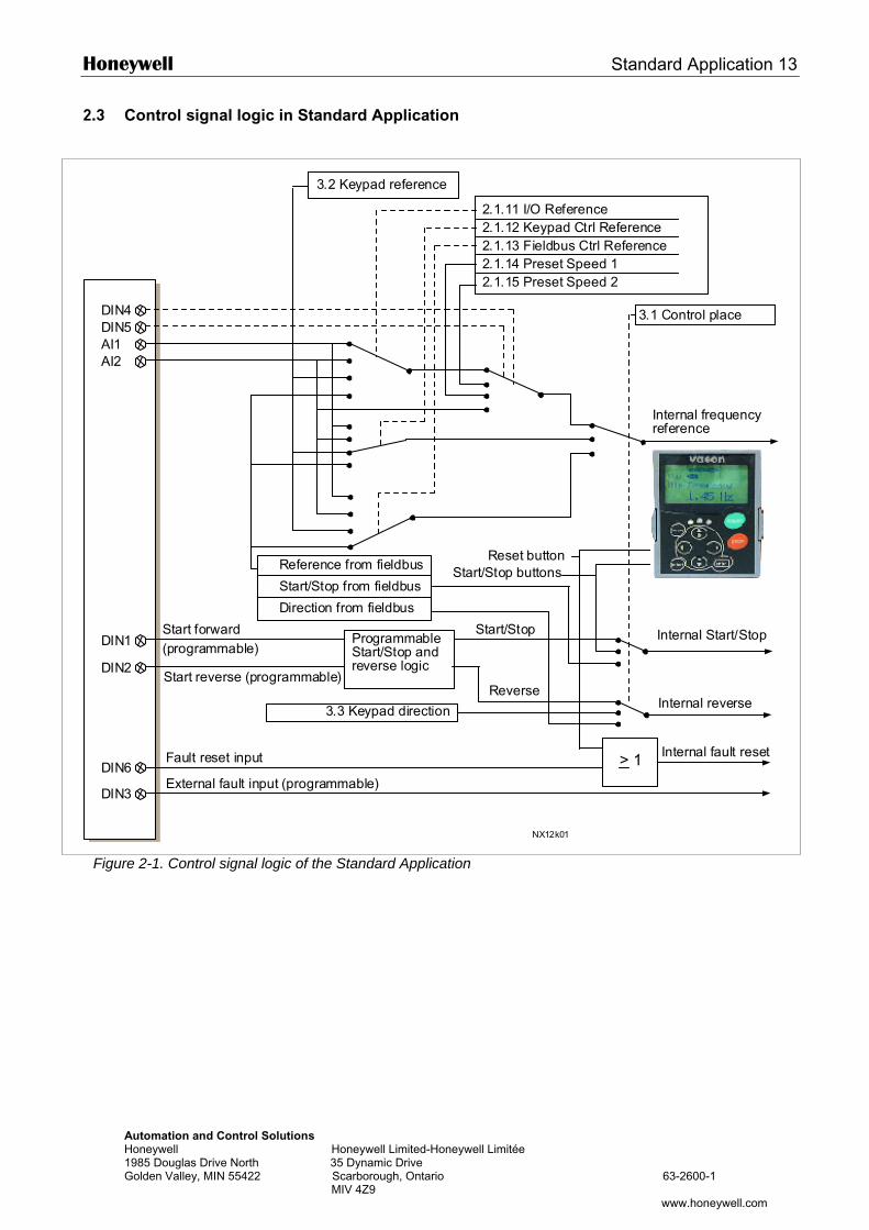
Honeywell Standard Application 13
Automation and Control Solutions Honeywell Honeywell Limited-Honeywell Limitée 1985 Douglas Drive North 35 Dynamic Drive Golden Valley, MIN 55422 Scarborough, Ontario 63-2600-1 MIV 4Z9
www.honeywell.com
2.3 Control signal logic in Standard Application
Figure 2-1. Control signal logic of the Standard Application
DIN4DIN5AI1AI2
DIN1
DIN2
DIN6
DIN3
> 1
NX12k01
3.2 Keypad reference
2.1.11 I/O Reference2.1.12 Keypad Ctrl Reference2.1.13 Fieldbus Ctrl Reference2.1.14 Preset Speed 12.1.15 Preset Speed 2
3.1 Control place
Internal frequencyreference
Start forward(programmable)
Start reverse (programmable)
ProgrammableStart/Stop andreverse logic
Start/Stop
Reverse
Internal Start/Stop
Internal reverse
Internal fault resetFault reset input
External fault input (programmable)
Reset buttonStart/Stop buttonsReference from fieldbus
Start/Stop from fieldbus
Direction from fieldbus
3.3 Keypad direction
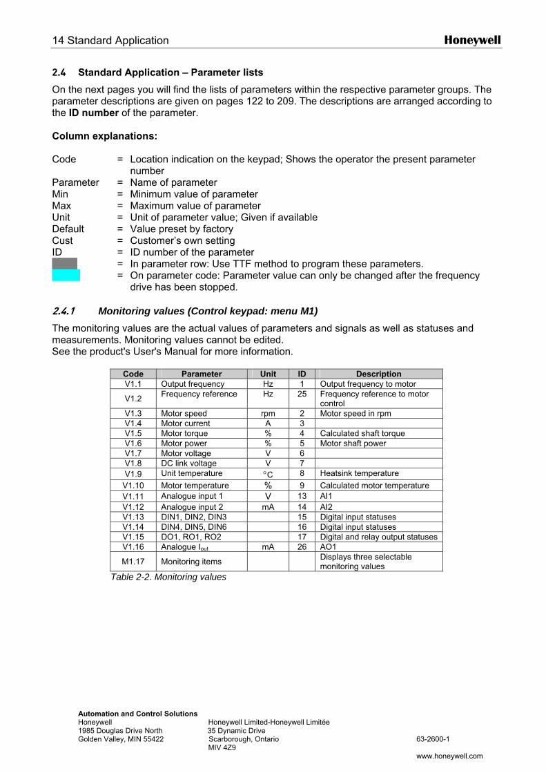
14 Standard Application Honeywell
Automation and Control Solutions Honeywell Honeywell Limited-Honeywell Limitée 1985 Douglas Drive North 35 Dynamic Drive Golden Valley, MIN 55422 Scarborough, Ontario 63-2600-1 MIV 4Z9 www.honeywell.com
2.4 Standard Application – Parameter lists
On the next pages you will find the lists of parameters within the respective parameter groups. The parameter descriptions are given on pages 122 to 209. The descriptions are arranged according to the ID number of the parameter. Column explanations: Code = Location indication on the keypad; Shows the operator the present parameter
number Parameter = Name of parameter Min = Minimum value of parameter Max = Maximum value of parameter Unit = Unit of parameter value; Given if available Default = Value preset by factory Cust = Customer’s own setting ID = ID number of the parameter = In parameter row: Use TTF method to program these parameters. = On parameter code: Parameter value can only be changed after the frequency
drive has been stopped. 2.4.1 Monitoring values (Control keypad: menu M1) The monitoring values are the actual values of parameters and signals as well as statuses and measurements. Monitoring values cannot be edited. See the product's User's Manual for more information.
Code Parameter Unit ID Description V1.1 Output frequency Hz 1 Output frequency to motor
V1.2 Frequency reference Hz 25 Frequency reference to motor control
V1.3 Motor speed rpm 2 Motor speed in rpm V1.4 Motor current A 3 V1.5 Motor torque % 4 Calculated shaft torque V1.6 Motor power % 5 Motor shaft power V1.7 Motor voltage V 6 V1.8 DC link voltage V 7 V1.9 Unit temperature °C 8 Heatsink temperature
V1.10 Motor temperature % 9 Calculated motor temperature V1.11 Analogue input 1 V 13 AI1 V1.12 Analogue input 2 mA 14 AI2 V1.13 DIN1, DIN2, DIN3 15 Digital input statuses V1.14 DIN4, DIN5, DIN6 16 Digital input statuses V1.15 DO1, RO1, RO2 17 Digital and relay output statuses V1.16 Analogue Iout mA 26 AO1
M1.17 Monitoring items Displays three selectable monitoring values
Table 2-2. Monitoring values
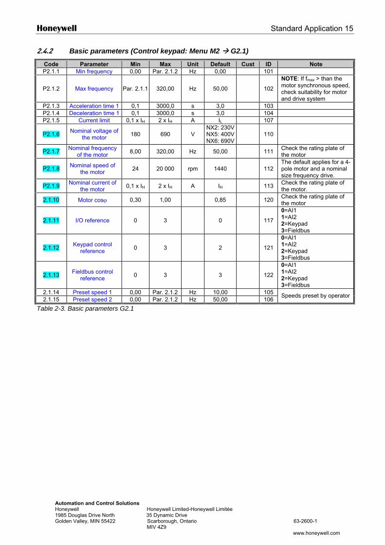
Honeywell Standard Application 15
Automation and Control Solutions Honeywell Honeywell Limited-Honeywell Limitée 1985 Douglas Drive North 35 Dynamic Drive Golden Valley, MIN 55422 Scarborough, Ontario 63-2600-1 MIV 4Z9
www.honeywell.com
2.4.2 Basic parameters (Control keypad: Menu M2 G2.1)
Code Parameter Min Max Unit Default Cust ID Note P2.1.1 Min frequency 0,00 Par. 2.1.2 Hz 0,00 101
P2.1.2 Max frequency Par. 2.1.1 320,00 Hz 50,00
102
NOTE: If fmax > than the motor synchronous speed, check suitability for motor and drive system
P2.1.3 Acceleration time 1 0,1 3000,0 s 3,0 103 P2.1.4 Deceleration time 1 0,1 3000,0 s 3,0 104 P2.1.5 Current limit 0,1 x IH 2 x IH A IL 107
P2.1.6 Nominal voltage of the motor 180 690 V
NX2: 230VNX5: 400VNX6: 690V
110
P2.1.7 Nominal frequency of the motor 8,00 320,00 Hz 50,00 111 Check the rating plate of
the motor
P2.1.8 Nominal speed of the motor 24 20 000 rpm 1440
112
The default applies for a 4-pole motor and a nominal size frequency drive.
P2.1.9 Nominal current of the motor 0,1 x IH 2 x IH A IH 113 Check the rating plate of
the motor.
2.1.10 Motor cosϕ 0,30 1,00 0,85 120 Check the rating plate of the motor
2.1.11 I/O reference 0 3 0
117
0=AI1 1=AI2 2=Keypad 3=Fieldbus
2.1.12 Keypad control reference 0 3 2
121
0=AI1 1=AI2 2=Keypad 3=Fieldbus
2.1.13 Fieldbus control reference 0 3 3
122
0=AI1 1=AI2 2=Keypad 3=Fieldbus
2.1.14 Preset speed 1 0,00 Par. 2.1.2 Hz 10,00 105 2.1.15 Preset speed 2 0,00 Par. 2.1.2 Hz 50,00 106
Speeds preset by operator
Table 2-3. Basic parameters G2.1
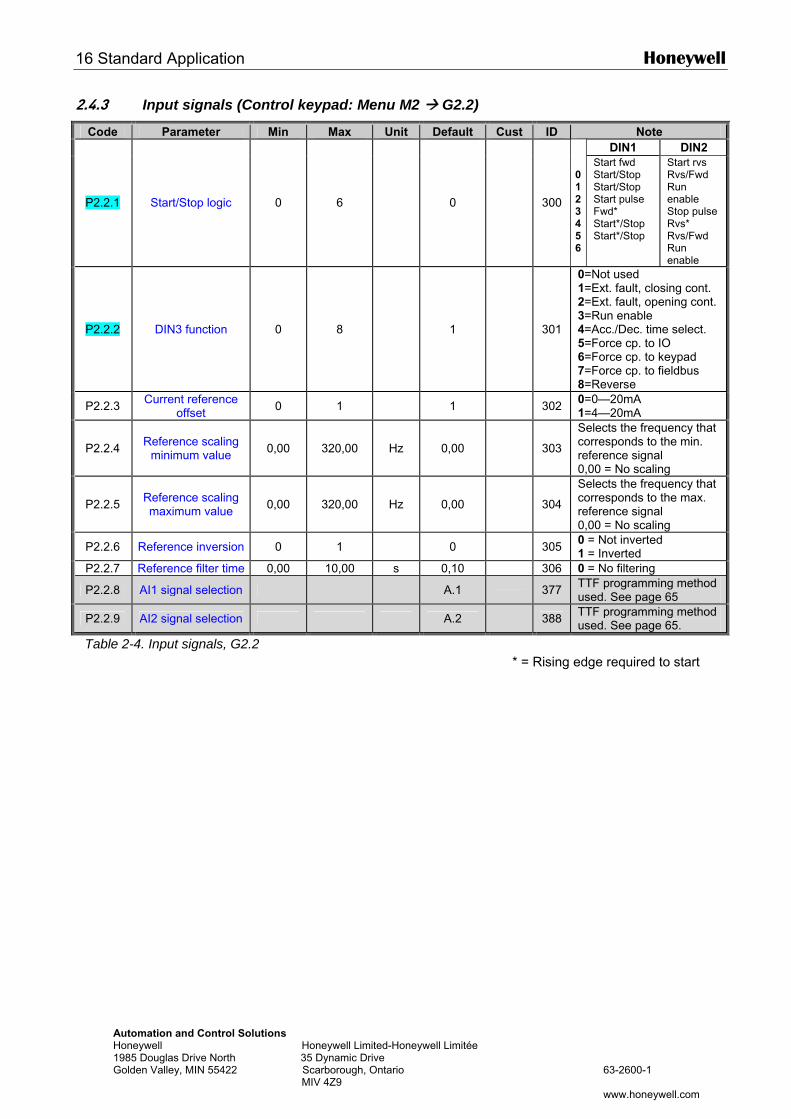
16 Standard Application Honeywell
Automation and Control Solutions Honeywell Honeywell Limited-Honeywell Limitée 1985 Douglas Drive North 35 Dynamic Drive Golden Valley, MIN 55422 Scarborough, Ontario 63-2600-1 MIV 4Z9 www.honeywell.com
2.4.3 Input signals (Control keypad: Menu M2 G2.2)
Code Parameter Min Max Unit Default Cust ID Note DIN1 DIN2
P2.2.1 Start/Stop logic 0 6 0
300
0123456
Start fwd Start/Stop Start/Stop Start pulse Fwd* Start*/Stop Start*/Stop
Start rvs Rvs/Fwd Run enable Stop pulse Rvs* Rvs/Fwd Run enable
P2.2.2 DIN3 function 0 8 1
301
0=Not used 1=Ext. fault, closing cont. 2=Ext. fault, opening cont. 3=Run enable 4=Acc./Dec. time select. 5=Force cp. to IO 6=Force cp. to keypad 7=Force cp. to fieldbus 8=Reverse
P2.2.3 Current reference offset 0 1 1 302 0=0—20mA
1=4—20mA
P2.2.4 Reference scaling minimum value 0,00 320,00 Hz 0,00
303
Selects the frequency that corresponds to the min. reference signal 0,00 = No scaling
P2.2.5 Reference scaling maximum value 0,00 320,00 Hz 0,00
304
Selects the frequency that corresponds to the max. reference signal 0,00 = No scaling
P2.2.6 Reference inversion 0 1 0 305 0 = Not inverted 1 = Inverted
P2.2.7 Reference filter time 0,00 10,00 s 0,10 306 0 = No filtering
P2.2.8 AI1 signal selection A.1 377 TTF programming method used. See page 65
P2.2.9 AI2 signal selection A.2 388 TTF programming method used. See page 65.
Table 2-4. Input signals, G2.2 * = Rising edge required to start
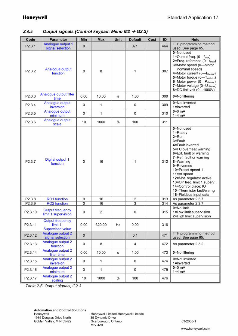
Honeywell Standard Application 17
Automation and Control Solutions Honeywell Honeywell Limited-Honeywell Limitée 1985 Douglas Drive North 35 Dynamic Drive Golden Valley, MIN 55422 Scarborough, Ontario 63-2600-1 MIV 4Z9
www.honeywell.com
2.4.4 Output signals (Control keypad: Menu M2 G2.3)
Code Parameter Min Max Unit Default Cust ID Note
P2.3.1 Analogue output 1 signal selection 0 A.1 464 TTF programming method
used. See page 65.
P2.3.2 Analogue output function 0 8 1
307
0=Not used 1=Output freq. (0—fmax) 2=Freq. reference (0—fmax) 3=Motor speed (0—Motor
nominal speed) 4=Motor current (0—InMotor) 5=Motor torque (0—TnMotor) 6=Motor power (0—PnMotor) 7=Motor voltage (0--UnMotor) 8=DC-link volt (0—1000V)
P2.3.3 Analogue output filter time 0,00 10,00 s 1,00 308 0=No filtering
P2.3.4 Analogue output inversion 0 1 0 309 0=Not inverted
1=Inverted
P2.3.5 Analogue output minimum 0 1 0 310 0=0 mA
1=4 mA
P2.3.6 Analogue output scale 10 1000 % 100 311
P2.3.7 Digital output 1 function 0 16 1
312
0=Not used 1=Ready 2=Run 3=Fault 4=Fault inverted 5=FC overheat warning 6=Ext. fault or warning 7=Ref. fault or warning 8=Warning 9=Reversed 10=Preset speed 1 11=At speed 12=Mot. regulator active 13=OP freq. limit 1 superv. 14=Control place: IO 15=Thermistor fault/warng 16=Fieldbus input data
P2.3.8 RO1 function 0 16 2 313 As parameter 2.3.7 P2.3.9 RO2 function 0 16 3 314 As parameter 2.3.7
P2.3.10 Output frequency limit 1 supervision 0 2 0
315
0=No limit 1=Low limit supervision 2=High limit supervision
P2.3.11 Output frequency
limit 1; Supervised value
0,00 320,00 Hz 0,00
316
P2.3.12 Analogue output 2 signal selection 0 0.1 471 TTF programming method
used. See page 65.
P2.3.13 Analogue output 2 function 0 8 4 472 As parameter 2.3.2
P2.3.14 Analogue output 2 filter time 0,00 10,00 s 1,00 473 0=No filtering
P2.3.15 Analogue output 2 inversion 0 1 0 474 0=Not inverted
1=Inverted
P2.3.16 Analogue output 2 minimum 0 1 0 475 0=0 mA
1=4 mA
P2.3.17 Analogue output 2 scaling 10 1000 % 100 476
Table 2-5. Output signals, G2.3
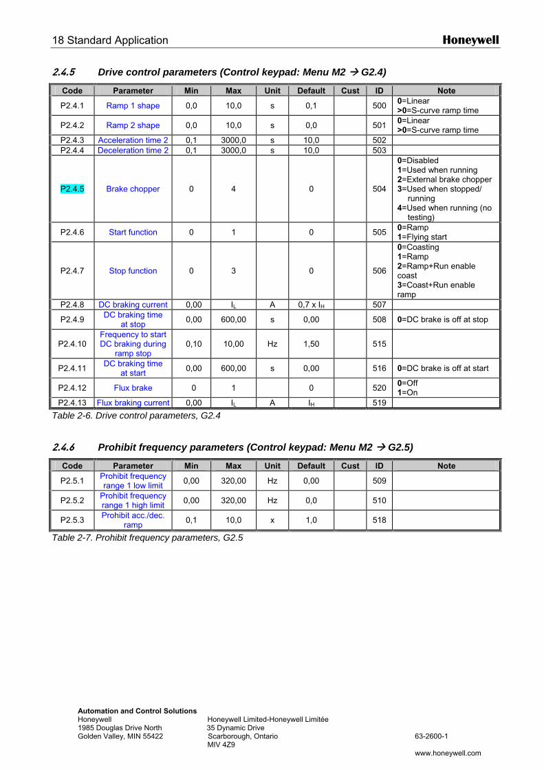
18 Standard Application Honeywell
Automation and Control Solutions Honeywell Honeywell Limited-Honeywell Limitée 1985 Douglas Drive North 35 Dynamic Drive Golden Valley, MIN 55422 Scarborough, Ontario 63-2600-1 MIV 4Z9 www.honeywell.com
2.4.5 Drive control parameters (Control keypad: Menu M2 G2.4)
Code Parameter Min Max Unit Default Cust ID Note
P2.4.1 Ramp 1 shape 0,0 10,0 s 0,1 500 0=Linear >0=S-curve ramp time
P2.4.2 Ramp 2 shape 0,0 10,0 s 0,0 501 0=Linear >0=S-curve ramp time
P2.4.3 Acceleration time 2 0,1 3000,0 s 10,0 502 P2.4.4 Deceleration time 2 0,1 3000,0 s 10,0 503
P2.4.5 Brake chopper 0 4 0
504
0=Disabled 1=Used when running 2=External brake chopper 3=Used when stopped/
running 4=Used when running (no
testing)
P2.4.6 Start function 0 1 0 505 0=Ramp 1=Flying start
P2.4.7 Stop function 0 3 0
506
0=Coasting 1=Ramp 2=Ramp+Run enable coast 3=Coast+Run enable ramp
P2.4.8 DC braking current 0,00 IL A 0,7 x IH 507
P2.4.9 DC braking time at stop 0,00 600,00 s 0,00 508 0=DC brake is off at stop
P2.4.10 Frequency to start DC braking during
ramp stop 0,10 10,00 Hz 1,50
515
P2.4.11 DC braking time at start 0,00 600,00 s 0,00 516 0=DC brake is off at start
P2.4.12 Flux brake 0 1 0 520 0=Off 1=On
P2.4.13 Flux braking current 0,00 IL A IH 519
Table 2-6. Drive control parameters, G2.4
2.4.6 Prohibit frequency parameters (Control keypad: Menu M2 G2.5)
Code Parameter Min Max Unit Default Cust ID Note
P2.5.1 Prohibit frequency range 1 low limit 0,00 320,00 Hz 0,00 509
P2.5.2 Prohibit frequency range 1 high limit 0,00 320,00 Hz 0,0 510
P2.5.3 Prohibit acc./dec. ramp 0,1 10,0 x 1,0 518
Table 2-7. Prohibit frequency parameters, G2.5
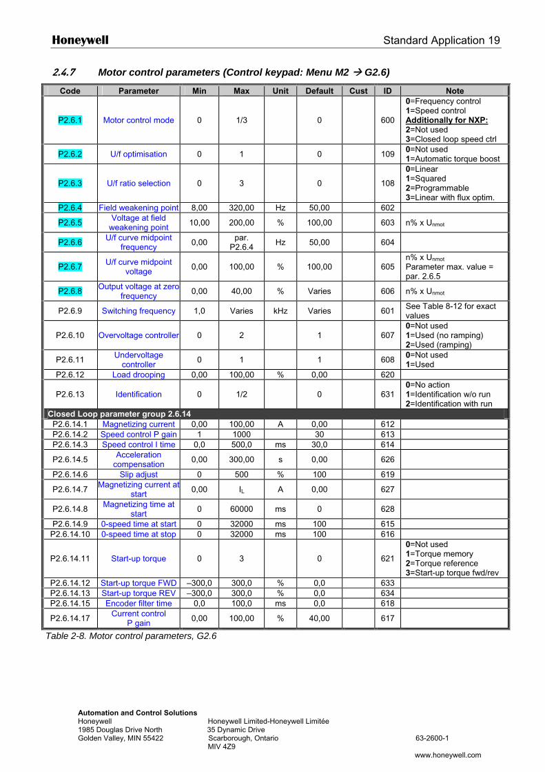
Honeywell Standard Application 19
Automation and Control Solutions Honeywell Honeywell Limited-Honeywell Limitée 1985 Douglas Drive North 35 Dynamic Drive Golden Valley, MIN 55422 Scarborough, Ontario 63-2600-1 MIV 4Z9
www.honeywell.com
2.4.7 Motor control parameters (Control keypad: Menu M2 G2.6)
Code Parameter Min Max Unit Default Cust ID Note
P2.6.1 Motor control mode 0 1/3 0
600
0=Frequency control 1=Speed control Additionally for NXP: 2=Not used 3=Closed loop speed ctrl
P2.6.2 U/f optimisation 0 1 0 109 0=Not used 1=Automatic torque boost
P2.6.3 U/f ratio selection 0 3 0
108
0=Linear 1=Squared 2=Programmable 3=Linear with flux optim.
P2.6.4 Field weakening point 8,00 320,00 Hz 50,00 602
P2.6.5 Voltage at field weakening point 10,00 200,00 % 100,00 603 n% x Unmot
P2.6.6 U/f curve midpoint frequency 0,00 par.
P2.6.4 Hz 50,00 604
P2.6.7 U/f curve midpoint voltage 0,00 100,00 % 100,00
605
n% x Unmot
Parameter max. value = par. 2.6.5
P2.6.8 Output voltage at zero frequency 0,00 40,00 % Varies 606 n% x Unmot
P2.6.9 Switching frequency 1,0 Varies kHz Varies 601 See Table 8-12 for exact values
P2.6.10 Overvoltage controller 0 2 1
607 0=Not used 1=Used (no ramping) 2=Used (ramping)
P2.6.11 Undervoltage controller 0 1 1 608 0=Not used
1=Used P2.6.12 Load drooping 0,00 100,00 % 0,00 620
P2.6.13 Identification 0 1/2 0
631 0=No action 1=Identification w/o run 2=Identification with run
Closed Loop parameter group 2.6.14 P2.6.14.1 Magnetizing current 0,00 100,00 A 0,00 612 P2.6.14.2 Speed control P gain 1 1000 30 613 P2.6.14.3 Speed control I time 0,0 500,0 ms 30,0 614
P2.6.14.5 Acceleration compensation 0,00 300,00 s 0,00 626
P2.6.14.6 Slip adjust 0 500 % 100 619
P2.6.14.7 Magnetizing current at start 0,00 IL A 0,00 627
P2.6.14.8 Magnetizing time at start 0 60000 ms 0 628
P2.6.14.9 0-speed time at start 0 32000 ms 100 615 P2.6.14.10 0-speed time at stop 0 32000 ms 100 616
P2.6.14.11 Start-up torque 0 3 0
621
0=Not used 1=Torque memory 2=Torque reference 3=Start-up torque fwd/rev
P2.6.14.12 Start-up torque FWD –300,0 300,0 % 0,0 633 P2.6.14.13 Start-up torque REV –300,0 300,0 % 0,0 634 P2.6.14.15 Encoder filter time 0,0 100,0 ms 0,0 618
P2.6.14.17 Current control P gain 0,00 100,00 % 40,00 617
Table 2-8. Motor control parameters, G2.6
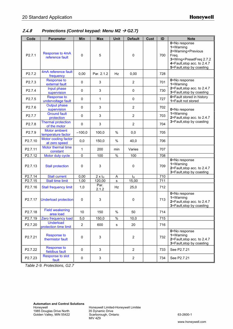
20 Standard Application Honeywell
Automation and Control Solutions Honeywell Honeywell Limited-Honeywell Limitée 1985 Douglas Drive North 35 Dynamic Drive Golden Valley, MIN 55422 Scarborough, Ontario 63-2600-1 MIV 4Z9 www.honeywell.com
2.4.8 Protections (Control keypad: Menu M2 G2.7)
Code Parameter Min Max Unit Default Cust ID Note
P2.7.1 Response to 4mA reference fault 0 5 0
700
0=No response 1=Warning 2=Warning+Previous Freq. 3=Wrng+PresetFreq 2.7.2 4=Fault,stop acc. to 2.4.7 5=Fault,stop by coasting
P2.7.2 4mA reference fault frequency 0,00 Par. 2.1.2 Hz 0,00 728
P2.7.3 Response to external fault 0 3 2 701
P2.7.4 Input phase supervision 0 3 0 730
0=No response 1=Warning 2=Fault,stop acc. to 2.4.7 3=Fault,stop by coasting
P2.7.5 Response to undervoltage fault 0 1 0 727 0=Fault stored in history
1=Fault not stored
P2.7.6 Output phase supervision 0 3 2 702
P2.7.7 Ground fault protection 0 3 2 703
P2.7.8 Thermal protection of the motor 0 3 2 704
0=No response 1=Warning 2=Fault,stop acc. to 2.4.7 3=Fault,stop by coasting
P2.7.9 Motor ambient temperature factor –100,0 100,0 % 0,0 705
P2.7.10 Motor cooling factor at zero speed 0,0 150,0 % 40,0 706
P2.7.11 Motor thermal time constant 1 200 min Varies 707
P2.7.12 Motor duty cycle 0 100 % 100 708
P2.7.13 Stall protection 0 3 0
709
0=No response 1=Warning 2=Fault,stop acc. to 2.4.7 3=Fault,stop by coasting
P2.7.14 Stall current 0,00 2 x IH A IH 710 P2.7.15 Stall time limit 1,00 120,00 s 15,00 711
P2.7.16 Stall frequency limit 1,0 Par. 2.1.2 Hz 25,0 712
P2.7.17 Underload protection 0 3 0
713
0=No response 1=Warning 2=Fault,stop acc. to 2.4.7 3=Fault,stop by coasting
P2.7.18 Field weakening area load 10 150 % 50 714
P2.7.19 Zero frequency load 5,0 150,0 % 10,0 715
P2.7.20 Underload protection time limit 2 600 s 20 716
P2.7.21 Response to thermistor fault 0 3 2
732
0=No response 1=Warning 2=Fault,stop acc. to 2.4.7 3=Fault,stop by coasting
P2.7.22 Response to fieldbus fault 0 3 2 733 See P2.7.21
P2.7.23 Response to slot fault 0 3 2 734 See P2.7.21
Table 2-9. Protections, G2.7
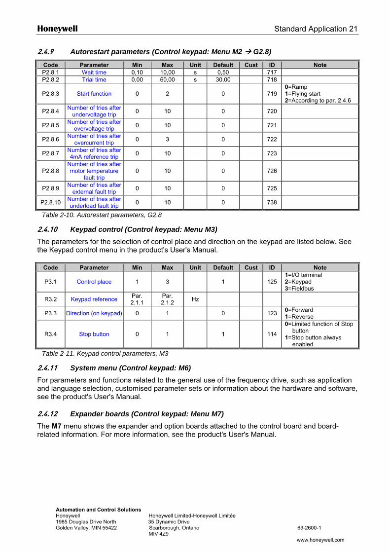
Honeywell Standard Application 21
Automation and Control Solutions Honeywell Honeywell Limited-Honeywell Limitée 1985 Douglas Drive North 35 Dynamic Drive Golden Valley, MIN 55422 Scarborough, Ontario 63-2600-1 MIV 4Z9
www.honeywell.com
2.4.9 Autorestart parameters (Control keypad: Menu M2 G2.8)
Code Parameter Min Max Unit Default Cust ID Note P2.8.1 Wait time 0,10 10,00 s 0,50 717 P2.8.2 Trial time 0,00 60,00 s 30,00 718
P2.8.3 Start function 0 2 0
719 0=Ramp 1=Flying start 2=According to par. 2.4.6
P2.8.4 Number of tries after undervoltage trip 0 10 0 720
P2.8.5 Number of tries after overvoltage trip 0 10 0 721
P2.8.6 Number of tries after overcurrent trip 0 3 0 722
P2.8.7 Number of tries after 4mA reference trip 0 10 0 723
P2.8.8 Number of tries after motor temperature
fault trip 0 10 0
726
P2.8.9 Number of tries after external fault trip 0 10 0 725
P2.8.10 Number of tries after underload fault trip 0 10 0 738
Table 2-10. Autorestart parameters, G2.8
2.4.10 Keypad control (Control keypad: Menu M3) The parameters for the selection of control place and direction on the keypad are listed below. See the Keypad control menu in the product's User's Manual.
Code Parameter Min Max Unit Default Cust ID Note
P3.1 Control place 1 3 1
125 1=I/O terminal 2=Keypad 3=Fieldbus
R3.2 Keypad reference Par. 2.1.1
Par. 2.1.2 Hz
P3.3 Direction (on keypad) 0 1 0 123 0=Forward 1=Reverse
R3.4 Stop button 0 1 1
114
0=Limited function of Stop button
1=Stop button always enabled
Table 2-11. Keypad control parameters, M3
2.4.11 System menu (Control keypad: M6) For parameters and functions related to the general use of the frequency drive, such as application and language selection, customised parameter sets or information about the hardware and software, see the product's User's Manual. 2.4.12 Expander boards (Control keypad: Menu M7) The M7 menu shows the expander and option boards attached to the control board and board-related information. For more information, see the product's User's Manual.
22 Local/Remote Control Application Honeywell
Automation and Control Solutions Honeywell Honeywell Limited-Honeywell Limitée 1985 Douglas Drive North 35 Dynamic Drive Golden Valley, MIN 55422 Scarborough, Ontario 63-2600-1 MIV 4Z9 www.honeywell.com
3. LOCAL/REMOTE CONTROL APPLICATION
3.1 Introduction
Select the Local/Remote Control Application in menu M6 on page S6.2. Utilising the Local/Remote Control Application it is possible to have two different control places. For each control place the frequency reference can be selected from either the control keypad, I/O terminal or fieldbus. The active control place is selected with the digital input DIN6.
• All outputs are freely programmable. Additional functions:
• Programmable Start/Stop and Reverse signal logic • Reference scaling • One frequency limit supervision • Second ramps and S-shape ramp programming • Programmable start and stop functions • DC-brake at stop • One prohibit frequency area • Programmable U/f curve and switching frequency • Autorestart • Motor thermal and stall protection: Programmable action; off, warning, fault
The parameters of the Local/Remote Control Application are explained in Chapter 8 of this manual. The explanations are arranged according to the individual ID number of the parameter.
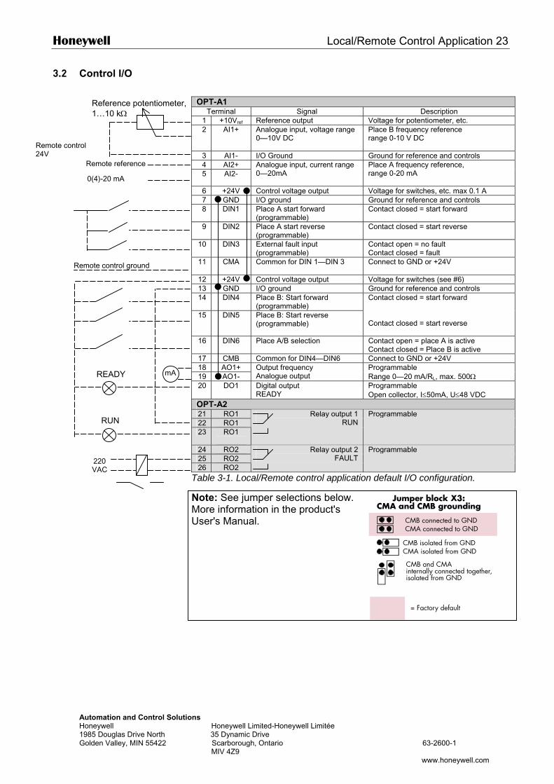
Honeywell Local/Remote Control Application 23
AutHon198Gol
3.2 Control I/O
OPT-A1
Terminal Signal Description 1 +10Vref Reference output Voltage for potentiometer, etc. 2 AI1+ Analogue input, voltage range
0—10V DC Place B frequency reference range 0-10 V DC
3 AI1- I/O Ground Ground for reference and controls 4 AI2+ 5 AI2-
Analogue input, current range 0—20mA
Place A frequency reference, range 0-20 mA
6 +24V Control voltage output Voltage for switches, etc. max 0.1 A 7 GND I/O ground Ground for reference and controls 8 DIN1 Place A start forward
(programmable) Contact closed = start forward
9 DIN2 Place A start reverse (programmable)
Contact closed = start reverse
10 DIN3 External fault input (programmable)
Contact open = no fault Contact closed = fault
11 CMA
Common for DIN 1—DIN 3 Connect to GND or +24V
12 +24V Control voltage output Voltage for switches (see #6) 13 GND I/O ground Ground for reference and controls 14 DIN4 Place B: Start forward
(programmable) 15 DIN5 Place B: Start reverse
(programmable)
Contact closed = start forward Contact closed = start reverse
16 DIN6 Place A/B selection Contact open = place A is active Contact closed = Place B is active
17 CMB Common for DIN4—DIN6 Connect to GND or +24V 18 AO1+ 19 AO1-
Output frequency Analogue output
Programmable Range 0—20 mA/RL, max. 500Ω
Remote control 24V
Remote control ground
Remote reference
0(4)-20 mA
mA
Reference potentiometer, 1…10 kΩ
READY
omation and Control Solutions eywell Honeywell Limited-Honeywell Limitée 5 Douglas Drive North 35 Dynamic Drive den Valley, MIN 55422 Scarborough, Ontario 63-2600-1 MIV 4Z9
www.honeywell.com
Jumper block X3:CMA and CMB grounding
CMB connected to GNDCMA connected to GND
CMB isolated from GNDCMA isolated from GND
CMB and CMAinternally connected together,isolated from GND
= Factory default
20 DO1 Digital output READY
Programmable Open collector, I≤50mA, U≤48 VDC
OPT-A2 21 RO1 22 RO1 23 RO1
Relay output 1 RUN
Programmable
24 RO2 25 RO2 26 RO2
Relay output 2 FAULT
Programmable
Table 3-1. Local/Remote control application default I/O configuration.
Note: See jumper selections below. More information in the product's User's Manual.
RUN
220 VAC
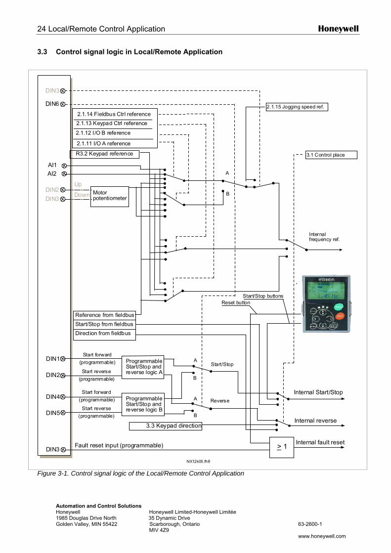
24 Local/Remote Control Application Honeywell
Automation and Control Solutions Honeywell Honeywell Limited-Honeywell Limitée 1985 Douglas Drive North 35 Dynamic Drive Golden Valley, MIN 55422 Scarborough, Ontario 63-2600-1 MIV 4Z9 www.honeywell.com
3.3 Control signal logic in Local/Remote Application
Figure 3-1. Control signal logic of the Local/Remote Control Application
DIN3 > 1
DIN6
DIN2
DIN3
AI1AI2
DIN1
DIN2
DIN3
DIN4
DIN5
A
B
A
B
A
B
NX12k05.fh8
Internal reverse
Internal fault resetFault reset input (programmable)
3.3 Keypad direction
Internal Start/Stop
Reference from fieldbus
Start/Stop from fieldbus
Direction from fieldbus
Start/Stop buttons
Internalfrequency ref.
Reset button
ProgrammableStart/Stop andreverse logic A
ProgrammableStart/Stop andreverse logic B
Start forward
(programmable)
Start reverse
(programmable)
Start forward
Start reverse
(programmable)
(programmable)
Start/Stop
Reverse
Up
Down
3.1 Control place
2.1.15 Jogging speed ref.
2.1.14 Fieldbus Ctrl reference
2.1.13 Keypad Ctrl reference
2.1.12 I/O B reference
2.1.11 I/O A reference
R3.2 Keypad reference
Motorpotentiometer
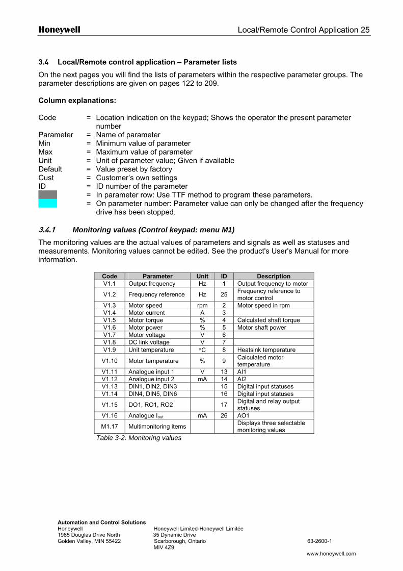
Honeywell Local/Remote Control Application 25
Automation and Control Solutions Honeywell Honeywell Limited-Honeywell Limitée 1985 Douglas Drive North 35 Dynamic Drive Golden Valley, MIN 55422 Scarborough, Ontario 63-2600-1 MIV 4Z9
www.honeywell.com
3.4 Local/Remote control application – Parameter lists
On the next pages you will find the lists of parameters within the respective parameter groups. The parameter descriptions are given on pages 122 to 209. Column explanations: Code = Location indication on the keypad; Shows the operator the present parameter
number Parameter = Name of parameter Min = Minimum value of parameter Max = Maximum value of parameter Unit = Unit of parameter value; Given if available Default = Value preset by factory Cust = Customer’s own settings ID = ID number of the parameter = In parameter row: Use TTF method to program these parameters. = On parameter number: Parameter value can only be changed after the frequency
drive has been stopped. 3.4.1 Monitoring values (Control keypad: menu M1) The monitoring values are the actual values of parameters and signals as well as statuses and measurements. Monitoring values cannot be edited. See the product's User's Manual for more information.
Code Parameter Unit ID Description V1.1 Output frequency Hz 1 Output frequency to motor
V1.2 Frequency reference Hz 25 Frequency reference to motor control
V1.3 Motor speed rpm 2 Motor speed in rpm V1.4 Motor current A 3 V1.5 Motor torque % 4 Calculated shaft torque V1.6 Motor power % 5 Motor shaft power V1.7 Motor voltage V 6 V1.8 DC link voltage V 7 V1.9 Unit temperature °C 8 Heatsink temperature
V1.10 Motor temperature % 9 Calculated motor temperature
V1.11 Analogue input 1 V 13 AI1 V1.12 Analogue input 2 mA 14 AI2 V1.13 DIN1, DIN2, DIN3 15 Digital input statuses V1.14 DIN4, DIN5, DIN6 16 Digital input statuses
V1.15 DO1, RO1, RO2 17 Digital and relay output statuses
V1.16 Analogue Iout mA 26 AO1
M1.17 Multimonitoring items Displays three selectable monitoring values
Table 3-2. Monitoring values
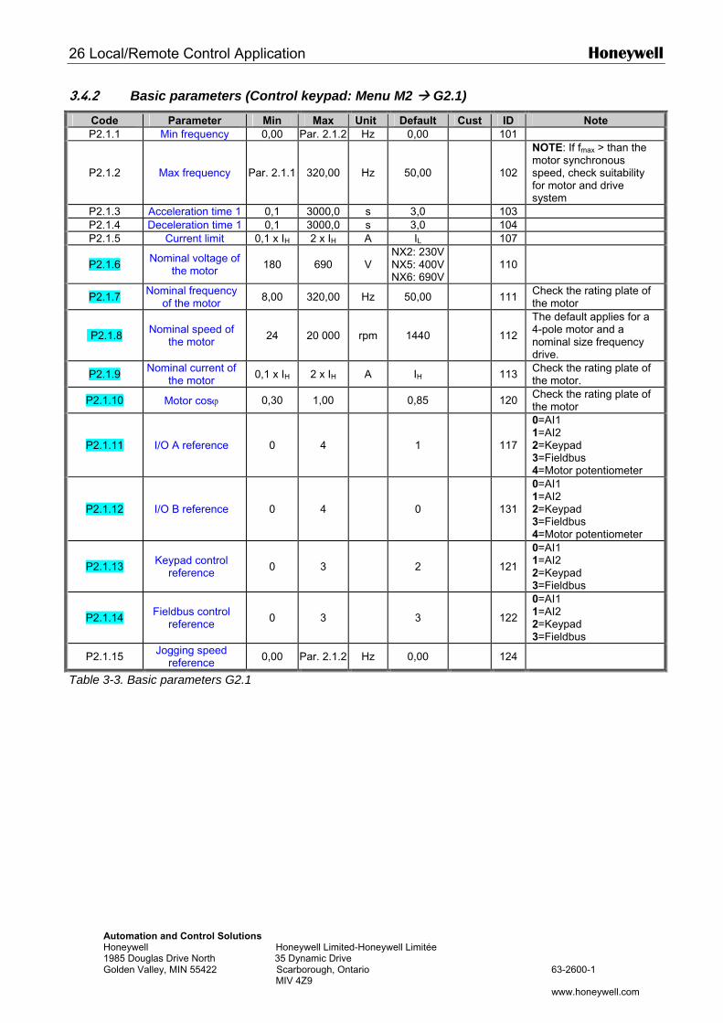
26 Local/Remote Control Application Honeywell
Automation and Control Solutions Honeywell Honeywell Limited-Honeywell Limitée 1985 Douglas Drive North 35 Dynamic Drive Golden Valley, MIN 55422 Scarborough, Ontario 63-2600-1 MIV 4Z9 www.honeywell.com
3.4.2 Basic parameters (Control keypad: Menu M2 G2.1)
Code Parameter Min Max Unit Default Cust ID Note P2.1.1 Min frequency 0,00 Par. 2.1.2 Hz 0,00 101
P2.1.2 Max frequency Par. 2.1.1 320,00 Hz 50,00
102
NOTE: If fmax > than the motor synchronous speed, check suitability for motor and drive system
P2.1.3 Acceleration time 1 0,1 3000,0 s 3,0 103 P2.1.4 Deceleration time 1 0,1 3000,0 s 3,0 104 P2.1.5 Current limit 0,1 x IH 2 x IH A IL 107
P2.1.6 Nominal voltage of the motor 180 690 V
NX2: 230VNX5: 400VNX6: 690V
110
P2.1.7 Nominal frequency of the motor 8,00 320,00 Hz 50,00 111 Check the rating plate of
the motor
P2.1.8 Nominal speed of the motor 24 20 000 rpm 1440
112
The default applies for a 4-pole motor and a nominal size frequency drive.
P2.1.9 Nominal current of the motor 0,1 x IH 2 x IH A IH 113 Check the rating plate of
the motor.
P2.1.10 Motor cosϕ 0,30 1,00 0,85 120 Check the rating plate of the motor
P2.1.11 I/O A reference 0 4 1
117
0=AI1 1=AI2 2=Keypad 3=Fieldbus 4=Motor potentiometer
P2.1.12 I/O B reference 0 4 0
131
0=AI1 1=AI2 2=Keypad 3=Fieldbus 4=Motor potentiometer
P2.1.13 Keypad control reference 0 3 2
121
0=AI1 1=AI2 2=Keypad 3=Fieldbus
P2.1.14 Fieldbus control reference 0 3 3
122
0=AI1 1=AI2 2=Keypad 3=Fieldbus
P2.1.15 Jogging speed reference 0,00 Par. 2.1.2 Hz 0,00 124
Table 3-3. Basic parameters G2.1
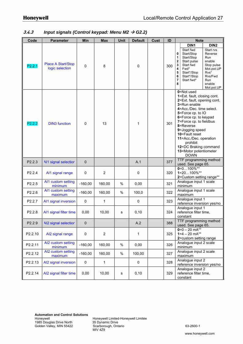
Honeywell Local/Remote Control Application 27
Automation and Control Solutions Honeywell Honeywell Limited-Honeywell Limitée 1985 Douglas Drive North 35 Dynamic Drive Golden Valley, MIN 55422 Scarborough, Ontario 63-2600-1 MIV 4Z9
www.honeywell.com
3.4.3 Input signals (Control keypad: Menu M2 G2.2)
Code Parameter Min Max Unit Default Cust ID Note DIN1 DIN2
P2.2.1 Place A Start/Stop logic selection 0 8 0 300
0123456 78
Start fwd Start/Stop Start/Stop Start pulse Start fwd Fwd* Start*/Stop Start*/Stop Start fwd*
Start rvs Reverse Run enable Stop pulse Mot.pot.UP Rvs* Rvs/Fwd Run enable Mot.pot.UP
P2.2.2 DIN3 function 0 13 1 301
0=Not used 1=Ext. fault, closing cont. 2=Ext. fault, opening cont. 3=Run enable 4=Acc./Dec. time select. 5=Force cp. to IO 6=Force cp. to keypad 7=Force cp. to fieldbus 8=Reverse 9=Jogging speed 10=Fault reset 11=Acc./Dec. operation
prohibit 12=DC Braking command 13=Motor potentiometer
DOWN
P2.2.3 AI1 signal selection 0 A.1 377 TTF programming method used. See page 65.
P2.2.4 AI1 signal range 0 2 0 320 0=0…100%** 1=20…100%** 2=Custom setting range**
P2.2.5 AI1 custom setting minimum -160,00 160,00 % 0,00 321 Analogue input 1 scale
minimum
P2.2.6 AI1 custom setting maximum -160,00 160,00 % 100,0 322 Analogue input 1 scale
maximum
P2.2.7 AI1 signal inversion 0 1 0 323 Analogue input 1 reference inversion yes/no
P2.2.8 AI1 signal filter time 0,00 10,00 s 0,10 324 Analogue input 1 reference filter time, constant
P2.2.9 AI2 signal selection 0 A.2 388 TTF programming method used. See page 65.
P2.2.10 AI2 signal range 0 2 1 325 0=0 – 20 mA** 1=4 – 20 mA** 2=custom setting range
P2.2.11 AI2 custom setting minimum -160,00 160,00 % 0,00 326 Analogue input 2 scale
minimum
P2.2.12 AI2 custom setting maximum -160,00 160,00 % 100,00 327 Analogue input 2 scale
maximum
P2.2.13 AI2 signal inversion 0 1 0 328 Analogue input 2 reference inversion yes/no
P2.2.14 AI2 signal filter time 0,00 10,00 s 0,10 329 Analogue input 2 reference filter time, constant
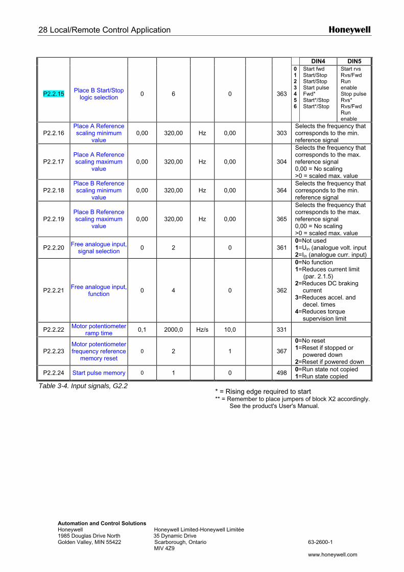
28 Local/Remote Control Application Honeywell
Automation and Control Solutions Honeywell Honeywell Limited-Honeywell Limitée 1985 Douglas Drive North 35 Dynamic Drive Golden Valley, MIN 55422 Scarborough, Ontario 63-2600-1 MIV 4Z9 www.honeywell.com
DIN4 DIN5
P2.2.15 Place B Start/Stop logic selection 0 6 0 363
0123456
Start fwd Start/Stop Start/Stop Start pulse Fwd* Start*/Stop Start*/Stop
Start rvs Rvs/Fwd Run enable Stop pulse Rvs* Rvs/Fwd Run enable
P2.2.16 Place A Reference scaling minimum
value 0,00 320,00 Hz 0,00 303
Selects the frequency that corresponds to the min. reference signal
P2.2.17 Place A Reference scaling maximum
value 0,00 320,00 Hz 0,00 304
Selects the frequency that corresponds to the max. reference signal 0,00 = No scaling >0 = scaled max. value
P2.2.18 Place B Reference scaling minimum
value 0,00 320,00 Hz 0,00 364
Selects the frequency that corresponds to the min. reference signal
P2.2.19 Place B Reference scaling maximum
value 0,00 320,00 Hz 0,00 365
Selects the frequency that corresponds to the max. reference signal 0,00 = No scaling >0 = scaled max. value
P2.2.20 Free analogue input, signal selection 0 2 0 361
0=Not used 1=Uin (analogue volt. input 2=Iin (analogue curr. input)
P2.2.21 Free analogue input, function 0 4 0 362
0=No function 1=Reduces current limit
(par. 2.1.5) 2=Reduces DC braking
current 3=Reduces accel. and
decel. times 4=Reduces torque
supervision limit
P2.2.22 Motor potentiometer ramp time 0,1 2000,0 Hz/s 10,0 331
P2.2.23 Motor potentiometer frequency reference
memory reset 0 2 1 367
0=No reset 1=Reset if stopped or
powered down 2=Reset if powered down
P2.2.24 Start pulse memory 0 1 0 498 0=Run state not copied 1=Run state copied
Table 3-4. Input signals, G2.2 * = Rising edge required to start ** = Remember to place jumpers of block X2 accordingly.
See the product's User's Manual.
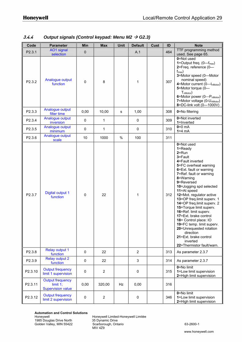
Honeywell Local/Remote Control Application 29
Automation and Control Solutions Honeywell Honeywell Limited-Honeywell Limitée 1985 Douglas Drive North 35 Dynamic Drive Golden Valley, MIN 55422 Scarborough, Ontario 63-2600-1 MIV 4Z9
www.honeywell.com
3.4.4 Output signals (Control keypad: Menu M2 G2.3)
Code Parameter Min Max Unit Default Cust ID Note
P2.3.1 AO1 signal selection 0 A.1 464 TTF programming method
used. See page 65.
P2.3.2 Analogue output function 0 8 1 307
0=Not used 1=Output freq. (0—fmax) 2=Freq. reference (0—fmax) 3=Motor speed (0—Motor
nominal speed) 4=Motor current (0—InMotor)5=Motor torque (0—
TnMotor) 6=Motor power (0—PnMotor)7=Motor voltage (0-UnMotor) 8=DC-link volt (0—1000V)
P2.3.3 Analogue output filter time 0,00 10,00 s 1,00 308 0=No filtering
P2.3.4 Analogue output inversion 0 1 0 309 0=Not inverted
1=Inverted
P2.3.5 Analogue output minimum 0 1 0 310 0=0 mA
1=4 mA
P2.3.6 Analogue output scale 10 1000 % 100 311
P2.3.7 Digital output 1 function 0 22 1 312
0=Not used 1=Ready 2=Run 3=Fault 4=Fault inverted 5=FC overheat warning 6=Ext. fault or warning 7=Ref. fault or warning 8=Warning 9=Reversed 10=Jogging spd selected 11=At speed 12=Mot. regulator active 13=OP freq.limit superv. 1 14=OP freq.limit superv. 2 15=Torque limit superv. 16=Ref. limit superv. 17=Ext. brake control 18= Control place: IO 19=FC temp. limit superv. 20=Unrequested rotation
direction 21=Ext. brake control
inverted 22=Thermistor fault/warn.
P2.3.8 Relay output 1 function 0 22 2 313 As parameter 2.3.7
P2.3.9 Relay output 2 function 0 22 3 314 As parameter 2.3.7
P2.3.10 Output frequency limit 1 supervision 0 2 0 315
0=No limit 1=Low limit supervision 2=High limit supervision
P2.3.11 Output frequency
limit 1; Supervision value
0,00 320,00 Hz 0,00 316
P2.3.12 Output frequency limit 2 supervision 0 2 0 346
0=No limit 1=Low limit supervision 2=High limit supervision
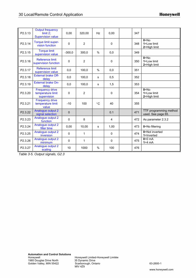
30 Local/Remote Control Application Honeywell
Automation and Control Solutions Honeywell Honeywell Limited-Honeywell Limitée 1985 Douglas Drive North 35 Dynamic Drive Golden Valley, MIN 55422 Scarborough, Ontario 63-2600-1 MIV 4Z9 www.honeywell.com
P2.3.13 Output frequency
limit 2; Supervision value
0,00 320,00 Hz 0,00 347
P2.3.14 Torque limit super-vision function 0 2 0 348
0=No 1=Low limit 2=High limit
P2.3.15 Torque limit supervision value -300,0 300,0 % 0,0 349
P2.3.16 Reference limit supervision function 0 2 0 350
0=No 1=Low limit 2=High limit
P2.3.17 Reference limit supervision value 0,0 100,0 % 0,0 351
P2.3.18 External brake Off-delay 0,0 100,0 s 0,5 352
P2.3.19 External brake On-delay 0,0 100,0 s 1,5 353
P2.3.20 Frequency drive temperature limit
supervision 0 2 0 354
0=No 1=Low limit 2=High limit
P2.3.21 Frequency drive temperature limit
value -10 100 °C 40 355
P2.3.22 Analogue output 2 signal selection 0 0.1 471 TTF programming method
used. See page 65.
P2.3.23 Analogue output 2 function 0 8 4 472 As parameter 2.3.2
P2.3.24 Analogue output 2 filter time 0,00 10,00 s 1,00 473 0=No filtering
P2.3.25 Analogue output 2 inversion 0 1 0 474 0=Not inverted
1=Inverted
P2.3.26 Analogue output 2 minimum 0 1 0 475 0=0 mA
1=4 mA
P2.3.27 Analogue output 2 scaling 10 1000 % 100 476
Table 3-5. Output signals, G2.3
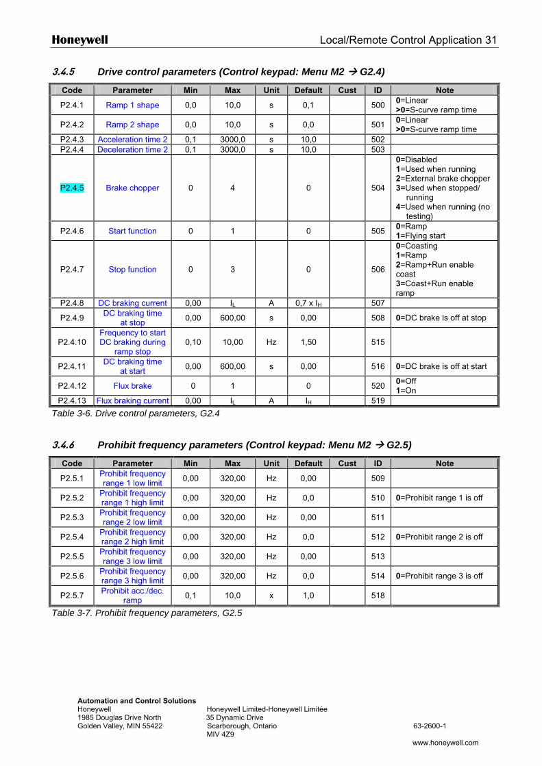
Honeywell Local/Remote Control Application 31
Automation and Control Solutions Honeywell Honeywell Limited-Honeywell Limitée 1985 Douglas Drive North 35 Dynamic Drive Golden Valley, MIN 55422 Scarborough, Ontario 63-2600-1 MIV 4Z9
www.honeywell.com
3.4.5 Drive control parameters (Control keypad: Menu M2 G2.4)
Code Parameter Min Max Unit Default Cust ID Note
P2.4.1 Ramp 1 shape 0,0 10,0 s 0,1 500 0=Linear >0=S-curve ramp time
P2.4.2 Ramp 2 shape 0,0 10,0 s 0,0 501 0=Linear >0=S-curve ramp time
P2.4.3 Acceleration time 2 0,1 3000,0 s 10,0 502 P2.4.4 Deceleration time 2 0,1 3000,0 s 10,0 503
P2.4.5 Brake chopper 0 4 0 504
0=Disabled 1=Used when running 2=External brake chopper 3=Used when stopped/
running 4=Used when running (no
testing)
P2.4.6 Start function 0 1 0 505 0=Ramp 1=Flying start
P2.4.7 Stop function 0 3 0 506
0=Coasting 1=Ramp 2=Ramp+Run enable coast 3=Coast+Run enable ramp
P2.4.8 DC braking current 0,00 IL A 0,7 x IH 507
P2.4.9 DC braking time at stop 0,00 600,00 s 0,00 508 0=DC brake is off at stop
P2.4.10 Frequency to start DC braking during
ramp stop 0,10 10,00 Hz 1,50 515
P2.4.11 DC braking time at start 0,00 600,00 s 0,00 516 0=DC brake is off at start
P2.4.12 Flux brake 0 1 0 520 0=Off 1=On
P2.4.13 Flux braking current 0,00 IL A IH 519
Table 3-6. Drive control parameters, G2.4
3.4.6 Prohibit frequency parameters (Control keypad: Menu M2 G2.5)
Code Parameter Min Max Unit Default Cust ID Note
P2.5.1 Prohibit frequency range 1 low limit 0,00 320,00 Hz 0,00 509
P2.5.2 Prohibit frequency range 1 high limit 0,00 320,00 Hz 0,0 510 0=Prohibit range 1 is off
P2.5.3 Prohibit frequency range 2 low limit 0,00 320,00 Hz 0,00 511
P2.5.4 Prohibit frequency range 2 high limit 0,00 320,00 Hz 0,0 512 0=Prohibit range 2 is off
P2.5.5 Prohibit frequency range 3 low limit 0,00 320,00 Hz 0,00 513
P2.5.6 Prohibit frequency range 3 high limit 0,00 320,00 Hz 0,0 514 0=Prohibit range 3 is off
P2.5.7 Prohibit acc./dec. ramp 0,1 10,0 x 1,0 518
Table 3-7. Prohibit frequency parameters, G2.5
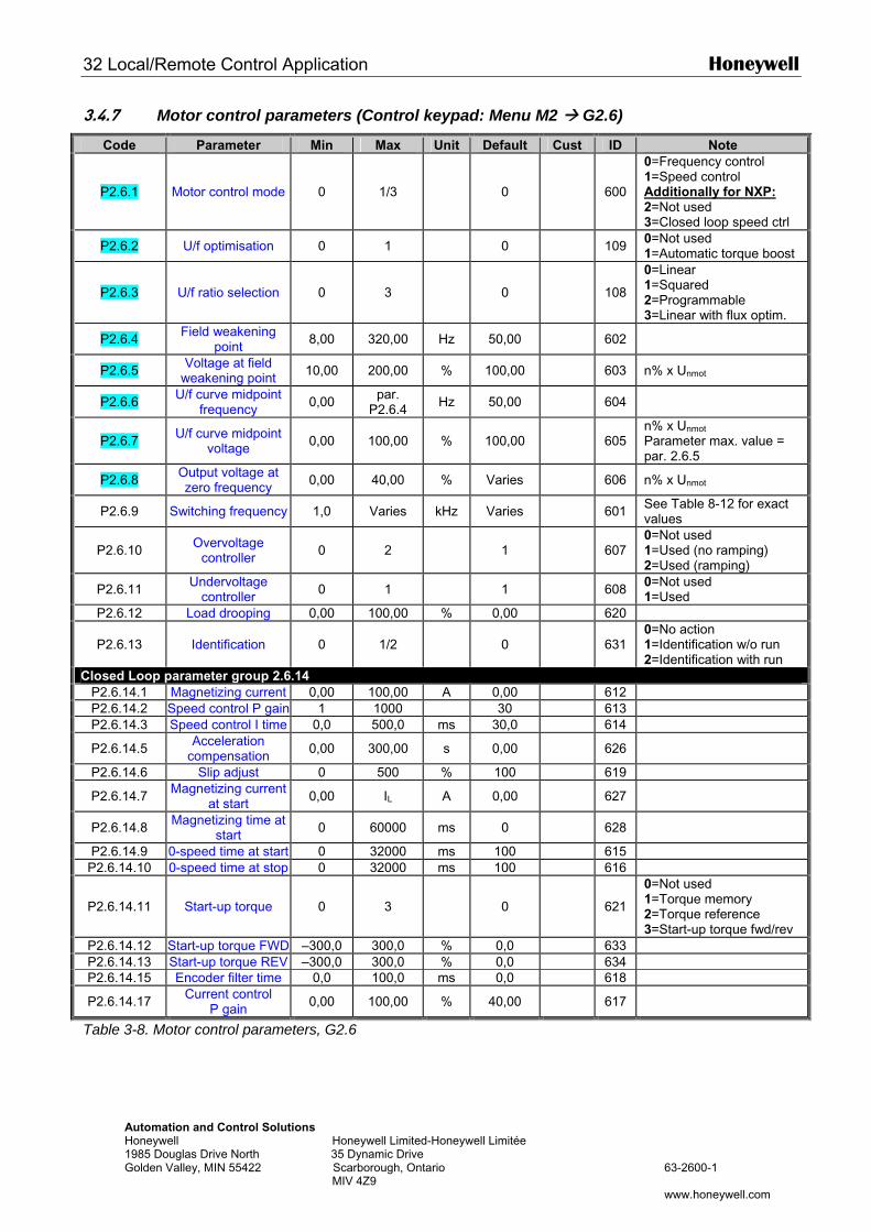
32 Local/Remote Control Application Honeywell
Automation and Control Solutions Honeywell Honeywell Limited-Honeywell Limitée 1985 Douglas Drive North 35 Dynamic Drive Golden Valley, MIN 55422 Scarborough, Ontario 63-2600-1 MIV 4Z9 www.honeywell.com
3.4.7 Motor control parameters (Control keypad: Menu M2 G2.6)
Code Parameter Min Max Unit Default Cust ID Note
P2.6.1 Motor control mode 0 1/3 0 600
0=Frequency control 1=Speed control Additionally for NXP: 2=Not used 3=Closed loop speed ctrl
P2.6.2 U/f optimisation 0 1 0 109 0=Not used 1=Automatic torque boost
P2.6.3 U/f ratio selection 0 3 0 108
0=Linear 1=Squared 2=Programmable 3=Linear with flux optim.
P2.6.4 Field weakening point 8,00 320,00 Hz 50,00 602
P2.6.5 Voltage at field weakening point 10,00 200,00 % 100,00 603 n% x Unmot
P2.6.6 U/f curve midpoint frequency 0,00 par.
P2.6.4 Hz 50,00 604
P2.6.7 U/f curve midpoint voltage 0,00 100,00 % 100,00 605
n% x Unmot
Parameter max. value = par. 2.6.5
P2.6.8 Output voltage at zero frequency 0,00 40,00 % Varies 606 n% x Unmot
P2.6.9 Switching frequency 1,0 Varies kHz Varies 601 See Table 8-12 for exact values
P2.6.10 Overvoltage controller 0 2 1 607
0=Not used 1=Used (no ramping) 2=Used (ramping)
P2.6.11 Undervoltage controller 0 1 1 608 0=Not used
1=Used P2.6.12 Load drooping 0,00 100,00 % 0,00 620
P2.6.13 Identification 0 1/2 0
631 0=No action 1=Identification w/o run 2=Identification with run
Closed Loop parameter group 2.6.14 P2.6.14.1 Magnetizing current 0,00 100,00 A 0,00 612 P2.6.14.2 Speed control P gain 1 1000 30 613 P2.6.14.3 Speed control I time 0,0 500,0 ms 30,0 614
P2.6.14.5 Acceleration compensation 0,00 300,00 s 0,00 626
P2.6.14.6 Slip adjust 0 500 % 100 619
P2.6.14.7 Magnetizing current at start 0,00 IL A 0,00 627
P2.6.14.8 Magnetizing time at start 0 60000 ms 0 628
P2.6.14.9 0-speed time at start 0 32000 ms 100 615 P2.6.14.10 0-speed time at stop 0 32000 ms 100 616
P2.6.14.11 Start-up torque 0 3 0
621
0=Not used 1=Torque memory 2=Torque reference 3=Start-up torque fwd/rev
P2.6.14.12 Start-up torque FWD –300,0 300,0 % 0,0 633 P2.6.14.13 Start-up torque REV –300,0 300,0 % 0,0 634 P2.6.14.15 Encoder filter time 0,0 100,0 ms 0,0 618
P2.6.14.17 Current control P gain 0,00 100,00 % 40,00 617
Table 3-8. Motor control parameters, G2.6

Honeywell Local/Remote Control Application 33
Automation and Control Solutions Honeywell Honeywell Limited-Honeywell Limitée 1985 Douglas Drive North 35 Dynamic Drive Golden Valley, MIN 55422 Scarborough, Ontario 63-2600-1 MIV 4Z9
www.honeywell.com
3.4.8 Protections (Control keypad: Menu M2 G2.7)
Code Parameter Min Max Unit Default Cust ID Note
P2.7.1 Response to 4mA reference fault 0 5 0 700
0=No response 1=Warning 2=Warning+Previous Freq. 3=Wrng+PresetFreq 2.7.2 4=Fault,stop acc. to 2.4.7 5=Fault,stop by coasting
P2.7.2 4mA reference fault frequency 0,00 Par. 2.1.2 Hz 0,00 728
P2.7.3 Response to external fault 0 3 2 701
P2.7.4 Input phase supervision 0 3 0 730
0=No response 1=Warning 2=Fault,stop acc. to 2.4.7 3=Fault,stop by coasting
P2.7.5 Response to undervoltage fault 0 1 0 727 0=Fault stored in history
1=Fault not stored
P2.7.6 Output phase supervision 0 3 2 702
P2.7.7 Ground fault protection 0 3 2 703
P2.7.8 Thermal protection of the motor 0 3 2 704
0=No response 1=Warning 2=Fault,stop acc. to 2.4.7 3=Fault,stop by coasting
P2.7.9 Motor ambient temperature factor –100,0 100,0 % 0,0 705
P2.7.10 Motor cooling factor at zero speed 0,0 150,0 % 40,0 706
P2.7.11 Motor thermal time constant 1 200 min Varies 707
P2.7.12 Motor duty cycle 0 100 % 100 708
P2.7.13 Stall protection 0 3 0 709
0=No response 1=Warning 2=Fault,stop acc. to 2.4.7 3=Fault,stop by coasting
P2.7.14 Stall current 0,00 2 x IH A IH 710 P2.7.15 Stall time limit 1,00 120,00 s 15,00 711
P2.7.16 Stall frequency limit 1,0 Par. 2.1.2 Hz 25,0 712
P2.7.17 Underload protection 0 3 0 713
0=No response 1=Warning 2=Fault,stop acc. to 2.4.7 3=Fault,stop by coasting
P2.7.18 Field weakening area load 10 150 % 50 714
P2.7.19 Zero frequency load 5,0 150,0 % 10,0 715
P2.7.20 Underload protection time limit 2 600 s 20 716
P2.7.21 Response to thermistor fault 0 3 2 732
0=No response 1=Warning 2=Fault,stop acc. to 2.4.7 3=Fault,stop by coasting
P2.7.22 Response to fieldbus fault 0 3 2 733 See P2.7.21
P2.7.23 Response to slot fault 0 3 2 734 See P2.7.21
Table 3-9. Protections, G2.7
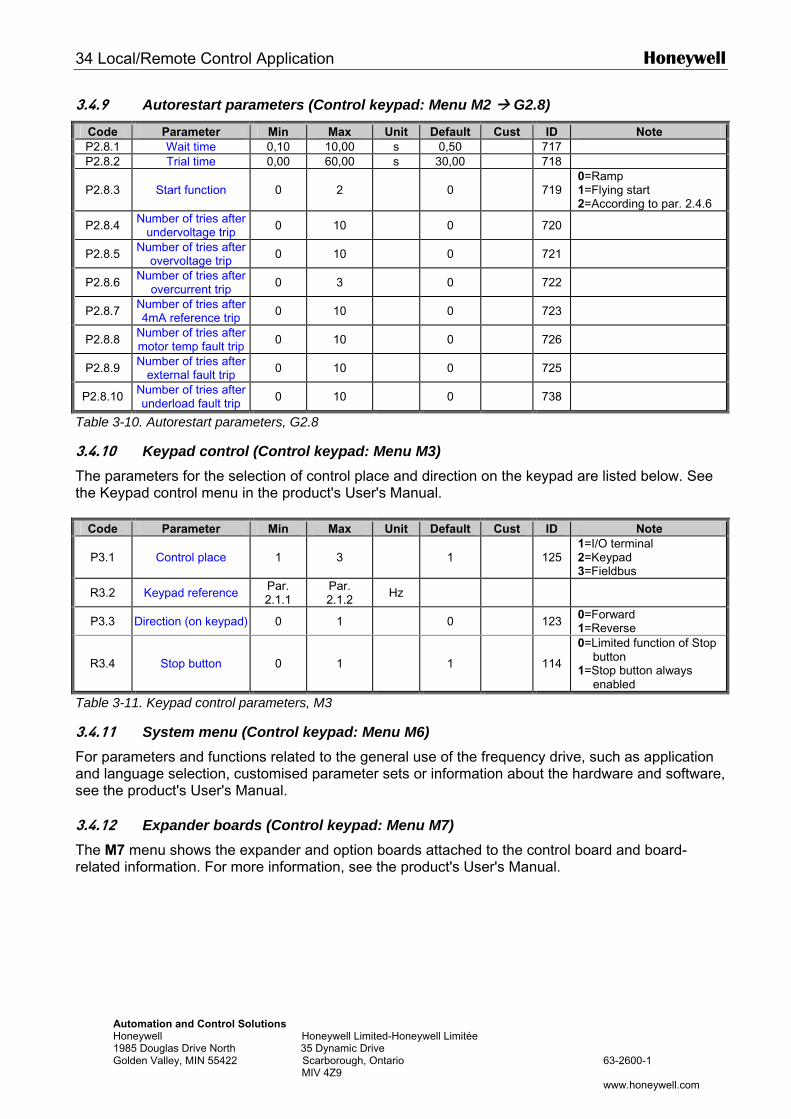
34 Local/Remote Control Application Honeywell
Automation and Control Solutions Honeywell Honeywell Limited-Honeywell Limitée 1985 Douglas Drive North 35 Dynamic Drive Golden Valley, MIN 55422 Scarborough, Ontario 63-2600-1 MIV 4Z9 www.honeywell.com
3.4.9 Autorestart parameters (Control keypad: Menu M2 G2.8)
Code Parameter Min Max Unit Default Cust ID Note P2.8.1 Wait time 0,10 10,00 s 0,50 717 P2.8.2 Trial time 0,00 60,00 s 30,00 718
P2.8.3 Start function 0 2 0 719 0=Ramp 1=Flying start 2=According to par. 2.4.6
P2.8.4 Number of tries after undervoltage trip 0 10 0 720
P2.8.5 Number of tries after overvoltage trip 0 10 0 721
P2.8.6 Number of tries after overcurrent trip 0 3 0 722
P2.8.7 Number of tries after 4mA reference trip 0 10 0 723
P2.8.8 Number of tries after motor temp fault trip 0 10 0 726
P2.8.9 Number of tries after external fault trip 0 10 0 725
P2.8.10 Number of tries after underload fault trip 0 10 0 738
Table 3-10. Autorestart parameters, G2.8
3.4.10 Keypad control (Control keypad: Menu M3) The parameters for the selection of control place and direction on the keypad are listed below. See the Keypad control menu in the product's User's Manual.
Code Parameter Min Max Unit Default Cust ID Note
P3.1 Control place 1 3 1 125 1=I/O terminal 2=Keypad 3=Fieldbus
R3.2 Keypad reference Par. 2.1.1
Par. 2.1.2 Hz
P3.3 Direction (on keypad) 0 1 0 123 0=Forward 1=Reverse
R3.4 Stop button 0 1 1 114
0=Limited function of Stop button
1=Stop button always enabled
Table 3-11. Keypad control parameters, M3
3.4.11 System menu (Control keypad: Menu M6) For parameters and functions related to the general use of the frequency drive, such as application and language selection, customised parameter sets or information about the hardware and software, see the product's User's Manual. 3.4.12 Expander boards (Control keypad: Menu M7) The M7 menu shows the expander and option boards attached to the control board and board-related information. For more information, see the product's User's Manual.
Honeywell Multi-step Speed Application 35
Automation and Control Solutions Honeywell Honeywell Limited-Honeywell Limitée 1985 Douglas Drive North 35 Dynamic Drive Golden Valley, MIN 55422 Scarborough, Ontario 63-2600-1 MIV 4Z9 www.honeywell.com
4. MULTI-STEP SPEED CONTROL APPLICATION
(Software ASFIFF04) 4.1 Introduction
Select the Multi-step Speed Control Application in menu M6 on page S6.2. The Multi-step Speed Control Application can be used in applications where fixed speeds are needed. Totally 15 + 2 different speeds can be programmed: one basic speed, 15 multi-step speeds and one jogging speed. The speed steps are selected with digital signals DIN3, DIN4, DIN5 and DIN6. If jogging speed is used, DIN3 can be programmed from fault reset to jogging speed select. The basic speed reference can be either voltage or current signal via analogue input terminals (2/3 or 4/5). The other one of the analogue inputs can be programmed for other purposes.
• All outputs are freely programmable.
Additional functions:
• Programmable Start/Stop and Reverse signal logic • Reference scaling • One frequency limit supervision • Second ramps and S-shape ramp programming • Programmable start and stop functions • DC-brake at stop • One prohibit frequency area • Programmable U/f curve and switching frequency • Autorestart • Motor thermal and stall protection: Programmable action; off, warning, fault
The parameters of the Multi-Step Speed Control Application are explained in Chapter 8 of this manual. The explanations are arranged according to the individual ID number of the parameter.

36 Multi-step Speed Application Honeywell
AutHon198Gol
4.2 Control I/O
OPT-A1
Terminal Signal Description 1 +10Vref Reference output Voltage for potentiometer, etc. 2 AI1+ Analogue input, voltage range
0—10V DC Basic reference (programmable), range 0-10 V DC
3 AI1- I/O Ground Ground for reference and controls 4 AI2+ 5 AI2-
Input for reference current Basic reference (programmable), range 0-20 mA
6 +24V Control voltage output Voltage for switches, etc. max 0.1 A 7 GND I/O ground Ground for reference and controls 8 DIN1 Start forward
(programmable) Contact closed = start forward
9 DIN2 Start reverse (programmable)
Contact closed = start reverse
10 DIN3 External fault input (programmable)
Contact open = no fault Contact closed = fault
11 CMA
Common for DIN 1—DIN 3 Connect to GND or +24V
12 +24V Control voltage output Voltage for switches (see #6) 13 GND I/O ground Ground for reference and controls 14 DIN4 Multi-step speed select 1 sel 1
0 sel 2 0
sel 3 sel 4 (with DIN3) 0 0 basic speed
15 DIN5 Multi-step speed select 2 1 0
0 1
0 0 speed 1 0 0 speed 2
16 DIN6 Multi-step speed select 3 - - - - - - 1 1 1 1 speed 15
17 CMB Common for DIN4—DIN6 Connect to GND or +24V 18 AO1+ 19 AO1-
Output frequency Analogue output
Programmable Range 0—20 mA/RL, max. 500Ω
Basic reference (optional)
mA
Reference potentiometer, 1…10 kΩ
READY
omation and Control Solutions eywell Honeywell Limited-Honeywell Limitée 5 Douglas Drive North 35 Dynamic Drive den Valley, MIN 55422 Scarborough, Ontario 63-2600-1 MIV 4Z9
www.honeywell.com
Jumper block X3:CMA and CMB grounding
CMB connected to GNDCMA connected to GND
CMB isolated from GNDCMA isolated from GND
CMB and CMAinternally connected together,isolated from GND
= Factory default
20 DO1 Digital output READY
Programmable Open collector, I≤50mA, U≤48 VDC
OPT-A2 21 RO1 22 RO1 23 RO1
Relay output 1 RUN
Programmable
24 RO2 25 RO2 26 RO2
Relay output 2 FAULT
Programmable
Table 4-1. Multi-step speed control application default I/O configuration.
Note: See jumper selections below. More information in the product's User's Manual.
RUN
220 VAC
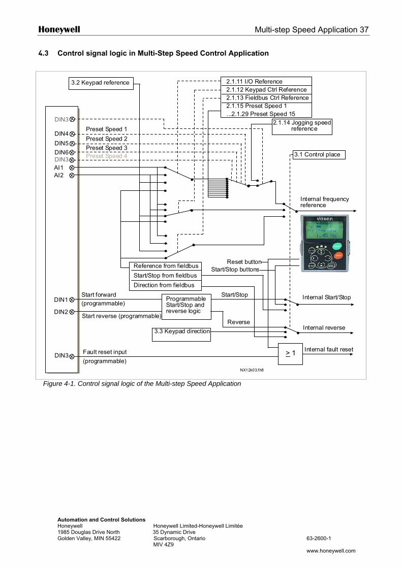
Honeywell Multi-step Speed Application 37
Automation and Control Solutions Honeywell Honeywell Limited-Honeywell Limitée 1985 Douglas Drive North 35 Dynamic Drive Golden Valley, MIN 55422 Scarborough, Ontario 63-2600-1 MIV 4Z9 www.honeywell.com
4.3 Control signal logic in Multi-Step Speed Control Application
Figure 4-1. Control signal logic of the Multi-step Speed Application
DIN4
DIN5
AI1AI2
DIN1
DIN2
DIN3 > 1
DIN6DIN3
DIN3
NX12k03.fh8
3.2 Keypad reference 2.1.11 I/O Reference2.1.12 Keypad Ctrl Reference2.1.13 Fieldbus Ctrl Reference2.1.15 Preset Speed 1...2.1.29 Preset Speed 15
3.1 Control place
Internal frequencyreference
Start forward(programmable)
Start reverse (programmable)
ProgrammableStart/Stop andreverse logic
Start/Stop
Reverse
Internal Start/Stop
Internal reverse
Internal fault resetFault reset input
Reset buttonStart/Stop buttonsReference from fieldbus
Start/Stop from fieldbus
Direction from fieldbus
3.3 Keypad direction
Preset Speed 1
Preset Speed 2
Preset Speed 3Preset Speed 4
2.1.14 Jogging speed reference
(programmable)
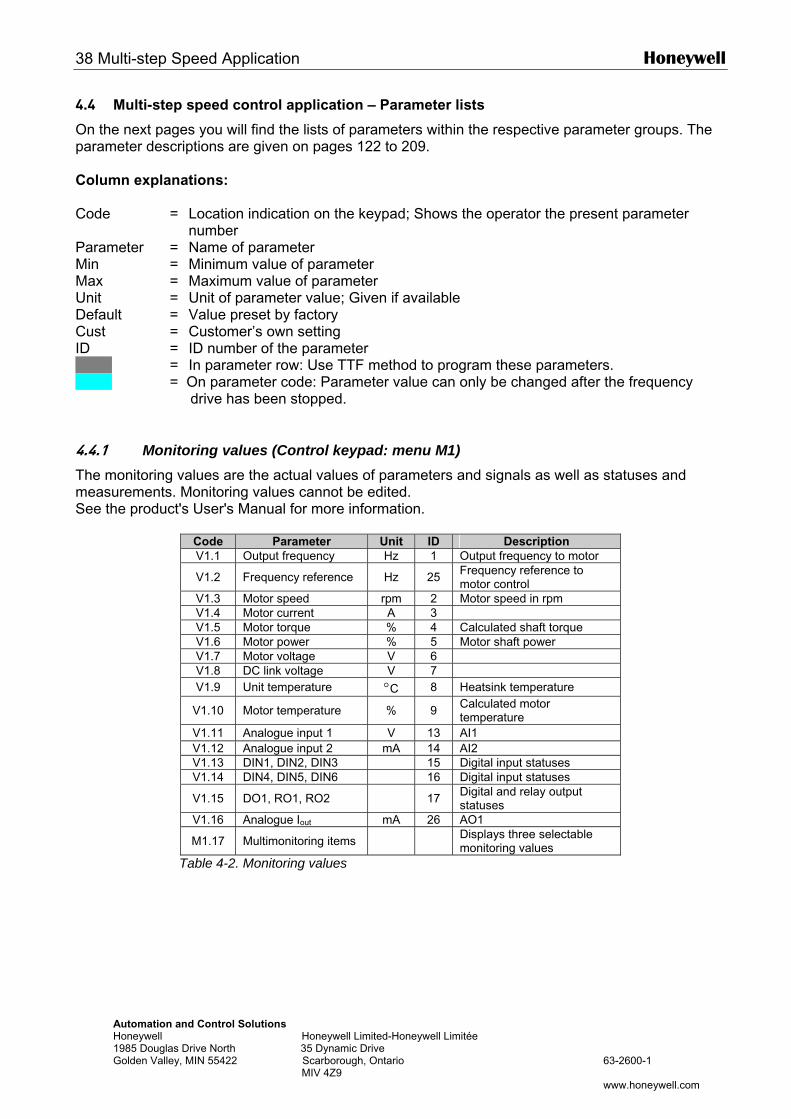
38 Multi-step Speed Application Honeywell
Automation and Control Solutions Honeywell Honeywell Limited-Honeywell Limitée 1985 Douglas Drive North 35 Dynamic Drive Golden Valley, MIN 55422 Scarborough, Ontario 63-2600-1 MIV 4Z9 www.honeywell.com
4.4 Multi-step speed control application – Parameter lists
On the next pages you will find the lists of parameters within the respective parameter groups. The parameter descriptions are given on pages 122 to 209. Column explanations: Code = Location indication on the keypad; Shows the operator the present parameter
number Parameter = Name of parameter Min = Minimum value of parameter Max = Maximum value of parameter Unit = Unit of parameter value; Given if available Default = Value preset by factory Cust = Customer’s own setting ID = ID number of the parameter = In parameter row: Use TTF method to program these parameters. = On parameter code: Parameter value can only be changed after the frequency
drive has been stopped. 4.4.1 Monitoring values (Control keypad: menu M1) The monitoring values are the actual values of parameters and signals as well as statuses and measurements. Monitoring values cannot be edited. See the product's User's Manual for more information.
Code Parameter Unit ID Description V1.1 Output frequency Hz 1 Output frequency to motor
V1.2 Frequency reference Hz 25 Frequency reference to motor control
V1.3 Motor speed rpm 2 Motor speed in rpm V1.4 Motor current A 3 V1.5 Motor torque % 4 Calculated shaft torque V1.6 Motor power % 5 Motor shaft power V1.7 Motor voltage V 6 V1.8 DC link voltage V 7 V1.9 Unit temperature °C 8 Heatsink temperature
V1.10 Motor temperature % 9 Calculated motor temperature
V1.11 Analogue input 1 V 13 AI1 V1.12 Analogue input 2 mA 14 AI2 V1.13 DIN1, DIN2, DIN3 15 Digital input statuses V1.14 DIN4, DIN5, DIN6 16 Digital input statuses
V1.15 DO1, RO1, RO2 17 Digital and relay output statuses
V1.16 Analogue Iout mA 26 AO1
M1.17 Multimonitoring items Displays three selectable monitoring values
Table 4-2. Monitoring values
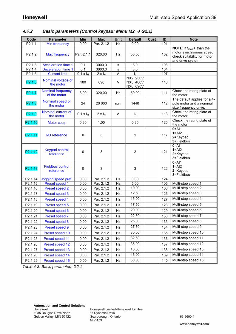
Honeywell Multi-step Speed Application 39
Automation and Control Solutions Honeywell Honeywell Limited-Honeywell Limitée 1985 Douglas Drive North 35 Dynamic Drive Golden Valley, MIN 55422 Scarborough, Ontario 63-2600-1 MIV 4Z9 www.honeywell.com
4.4.2 Basic parameters (Control keypad: Menu M2 G2.1)
Code Parameter Min Max Unit Default Cust ID Note P2.1.1 Min frequency 0,00 Par. 2.1.2 Hz 0,00 101
P2.1.2 Max frequency Par. 2.1.1 320,00 Hz 50,00 102
NOTE: If fmax > than the motor synchronous speed, check suitability for motor and drive system
P2.1.3 Acceleration time 1 0,1 3000,0 s 3,0 103 P2.1.4 Deceleration time 1 0,1 3000,0 s 3,0 104 P2.1.5 Current limit 0,1 x IH 2 x IH A IL 107
P2.1.6 Nominal voltage of the motor 180 690 V
NX2: 230VNX5: 400VNX6: 690V
110
P2.1.7 Nominal frequency of the motor 8,00 320,00 Hz 50,00 111 Check the rating plate of
the motor
P2.1.8 Nominal speed of the motor 24 20 000 rpm 1440 112
The default applies for a 4-pole motor and a nominal size frequency drive.
P2.1.9 Nominal current of the motor 0,1 x IH 2 x IH A IH 113 Check the rating plate of
the motor.
P2.1.10 Motor cosϕ 0,30 1,00 0,85 120 Check the rating plate of the motor
P2.1.11 I/O reference 0 3 1 117
0=AI1 1=AI2 2=Keypad 3=Fieldbus
P2.1.12 Keypad control reference 0 3 2 121
0=AI1 1=AI2 2=Keypad 3=Fieldbus
P2.1.13 Fieldbus control reference 0 3 3 122
0=AI1 1=AI2 2=Keypad 3=Fieldbus
P2.1.14 Jogging speed pref. 0,00 Par. 2.1.2 Hz 0,00 124 P2.1.15 Preset speed 1 0,00 Par. 2.1.2 Hz 5,00 105 Multi-step speed 1 P2.1.16 Preset speed 2 0,00 Par. 2.1.2 Hz 10,00 106 Multi-step speed 2
P2.1.17 Preset speed 3 0,00 Par. 2.1.2 Hz 12,50 126 Multi-step speed 3
P2.1.18 Preset speed 4 0,00 Par. 2.1.2 Hz 15,00 127 Multi-step speed 4
P2.1.19 Preset speed 5 0,00 Par. 2.1.2 Hz 17,50 128 Multi-step speed 5
P2.1.20 Preset speed 6 0,00 Par. 2.1.2 Hz 20,00 129 Multi-step speed 6
P2.1.21 Preset speed 7 0,00 Par. 2.1.2 Hz 22,50 130 Multi-step speed 7
P2.1.22 Preset speed 8 0,00 Par. 2.1.2 Hz 25,00 133 Multi-step speed 8
P2.1.23 Preset speed 9 0,00 Par. 2.1.2 Hz 27,50 134 Multi-step speed 9
P2.1.24 Preset speed 10 0,00 Par. 2.1.2 Hz 30,00 135 Multi-step speed 10
P2.1.25 Preset speed 11 0,00 Par. 2.1.2 Hz 32,50 136 Multi-step speed 11
P2.1.26 Preset speed 12 0,00 Par. 2.1.2 Hz 35,00 137 Multi-step speed 12
P2.1.27 Preset speed 13 0,00 Par. 2.1.2 Hz 40,00 138 Multi-step speed 13
P2.1.28 Preset speed 14 0,00 Par. 2.1.2 Hz 45,00 139 Multi-step speed 14
P2.1.29 Preset speed 15 0,00 Par. 2.1.2 Hz 50,00 140 Multi-step speed 15
Table 4-3. Basic parameters G2.1
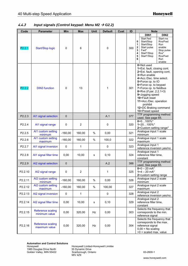
40 Multi-step Speed Application Honeywell
Automation and Control Solutions Honeywell Honeywell Limited-Honeywell Limitée 1985 Douglas Drive North 35 Dynamic Drive Golden Valley, MIN 55422 Scarborough, Ontario 63-2600-1 MIV 4Z9 www.honeywell.com
4.4.3 Input signals (Control keypad: Menu M2 G2.2)
Code Parameter Min Max Unit Default Cust ID Note DIN1 DIN2
P2.2.1 Start/Stop logic 0 6 0
300
0123456
Start fwd Start/Stop Start/Stop Start pulse Fwd* Start*/Stop Start*/Stop
Start rvs Rvs/Fwd Run enable Stop pulse Rvs* Rvs/Fwd Run enable
P2.2.2 DIN3 function 0 13 1
301
0=Not used 1=Ext. fault, closing cont. 2=Ext. fault, opening cont. 3=Run enable 4=Acc./Dec. time select. 5=Force cp. to IO 6=Force cp. to keypad 7=Force cp. to fieldbus 8=Rvs (if par. 2.2.1=3) 9=Jogging speed 10=Fault reset 11=Acc./Dec. operation
prohibit 12=DC Braking command 13=Preset speed
P2.2.3 AI1 signal selection 0 A.1 377 TTF programming method used. See page 65.
P2.2.4 AI1 signal range 0 2 0
320 0=0…100%* 1=20…100%* 2=Custom setting range*
P2.2.5 AI1 custom setting minimum -160,00 160,00 % 0,00 321 Analogue input 1 scale
minimum
P2.2.6 AI1 custom setting maximum -160,00 160,00 % 100,0 322 Analogue input 1 scale
maximum
P2.2.7 AI1 signal inversion 0 1 0 323 Analogue input 1 reference inversion yes/no
P2.2.8 AI1 signal filter time 0,00 10,00 s 0,10
324 Analogue input 1 reference filter time, constant
P2.2.9 AI2 signal selection 0 A.2 388 TTF programming method used. See page 65.
P2.2.10 AI2 signal range 0 2 1
325 0=0 – 20 mA* 1=4 – 20 mA* 2=custom setting range
P2.2.11 AI2 custom setting minimum -160,00 160,00 % 0,00 326 Analogue input 2 scale
minimum
P2.2.12 AI2 custom setting maximum -160,00 160,00 % 100,00 327 Analogue input 2 scale
maximum
P2.2.13 AI2 signal inversion 0 1 0 328 Analogue input 2 reference inversion yes/no
P2.2.14 AI2 signal filter time 0,00 10,00 s 0,10
329 Analogue input 2 reference filter time, constant
P2.2.15 Reference scaling minimum value 0,00 320,00 Hz 0,00
303
Selects the frequency that corresponds to the min. reference signal
P2.2.16 Reference scaling maximum value 0,00 320,00 Hz 0,00
304
Selects the frequency that corresponds to the max. reference signal 0,00 = No scaling >0 = scaled max. value
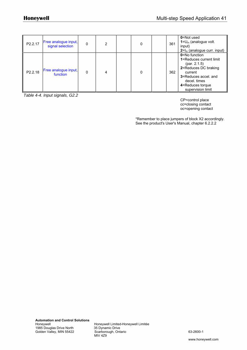
Honeywell Multi-step Speed Application 41
Automation and Control Solutions Honeywell Honeywell Limited-Honeywell Limitée 1985 Douglas Drive North 35 Dynamic Drive Golden Valley, MIN 55422 Scarborough, Ontario 63-2600-1 MIV 4Z9 www.honeywell.com
P2.2.17 Free analogue input, signal selection 0 2 0
361
0=Not used 1=Uin (analogue volt. input) 2=Iin (analogue curr. input)
P2.2.18 Free analogue input, function 0 4 0
362
0=No function 1=Reduces current limit
(par. 2.1.5) 2=Reduces DC braking
current 3=Reduces accel. and
decel. times 4=Reduces torque
supervision limit
Table 4-4. Input signals, G2.2
*Remember to place jumpers of block X2 accordingly. See the product's User's Manual, chapter 6.2.2.2
CP=control place cc=closing contact oc=opening contact
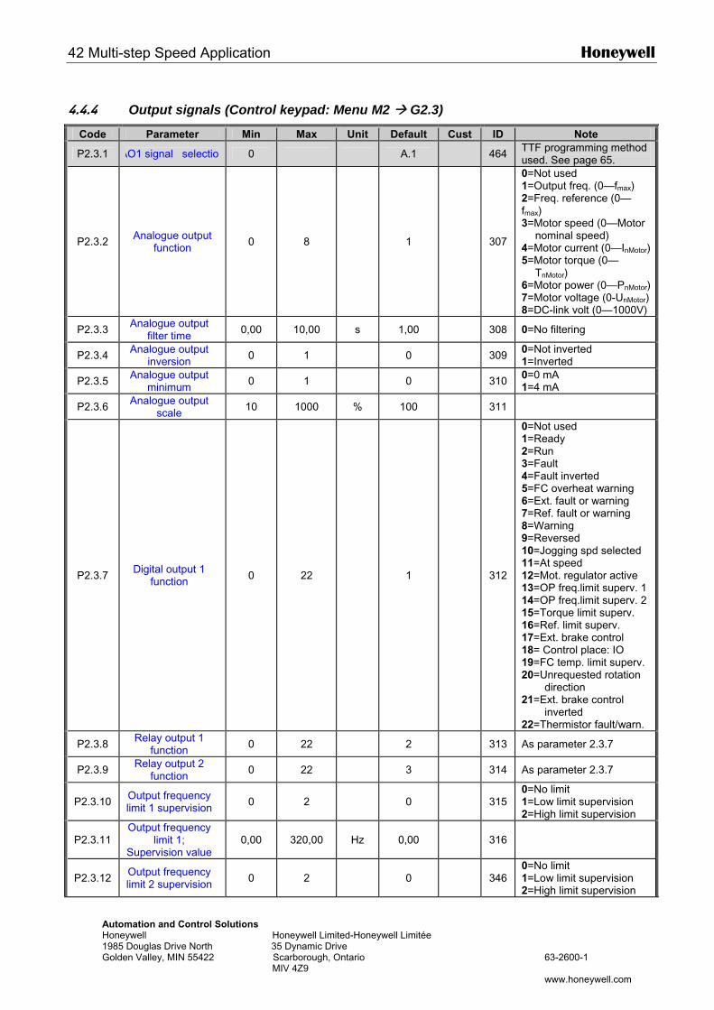
42 Multi-step Speed Application Honeywell
Automation and Control Solutions Honeywell Honeywell Limited-Honeywell Limitée 1985 Douglas Drive North 35 Dynamic Drive Golden Valley, MIN 55422 Scarborough, Ontario 63-2600-1 MIV 4Z9 www.honeywell.com
4.4.4 Output signals (Control keypad: Menu M2 G2.3)
Code Parameter Min Max Unit Default Cust ID Note
P2.3.1 AO1 signal selection 0 A.1 464 TTF programming method used. See page 65.
P2.3.2 Analogue output function 0 8 1
307
0=Not used 1=Output freq. (0—fmax) 2=Freq. reference (0—fmax) 3=Motor speed (0—Motor
nominal speed) 4=Motor current (0—InMotor)5=Motor torque (0—
TnMotor) 6=Motor power (0—PnMotor)7=Motor voltage (0-UnMotor) 8=DC-link volt (0—1000V)
P2.3.3 Analogue output filter time 0,00 10,00 s 1,00 308 0=No filtering
P2.3.4 Analogue output inversion 0 1 0 309 0=Not inverted
1=Inverted
P2.3.5 Analogue output minimum 0 1 0 310 0=0 mA
1=4 mA
P2.3.6 Analogue output scale 10 1000 % 100 311
P2.3.7 Digital output 1 function 0 22 1
312
0=Not used 1=Ready 2=Run 3=Fault 4=Fault inverted 5=FC overheat warning 6=Ext. fault or warning 7=Ref. fault or warning 8=Warning 9=Reversed 10=Jogging spd selected 11=At speed 12=Mot. regulator active 13=OP freq.limit superv. 1 14=OP freq.limit superv. 2 15=Torque limit superv. 16=Ref. limit superv. 17=Ext. brake control 18= Control place: IO 19=FC temp. limit superv. 20=Unrequested rotation
direction 21=Ext. brake control
inverted 22=Thermistor fault/warn.
P2.3.8 Relay output 1 function 0 22 2 313 As parameter 2.3.7
P2.3.9 Relay output 2 function 0 22 3 314 As parameter 2.3.7
P2.3.10 Output frequency limit 1 supervision 0 2 0
315
0=No limit 1=Low limit supervision 2=High limit supervision
P2.3.11 Output frequency
limit 1; Supervision value
0,00 320,00 Hz 0,00
316
P2.3.12 Output frequency limit 2 supervision 0 2 0
346
0=No limit 1=Low limit supervision 2=High limit supervision
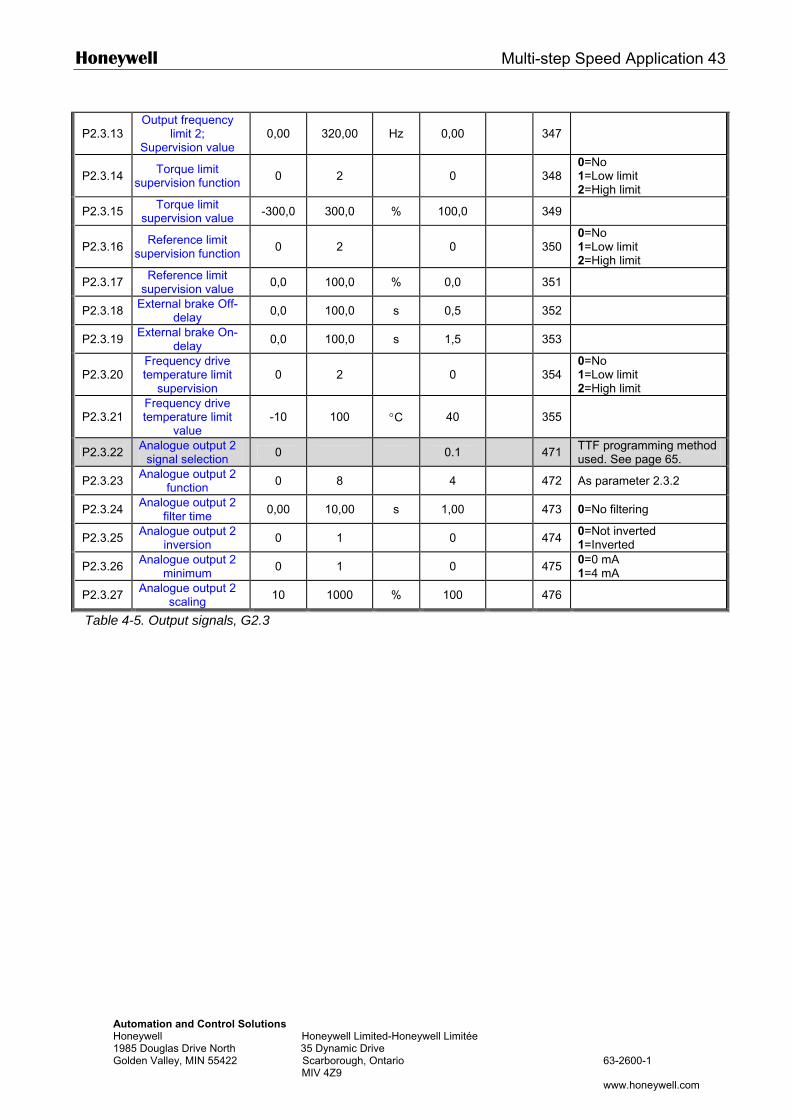
Honeywell Multi-step Speed Application 43
Automation and Control Solutions Honeywell Honeywell Limited-Honeywell Limitée 1985 Douglas Drive North 35 Dynamic Drive Golden Valley, MIN 55422 Scarborough, Ontario 63-2600-1 MIV 4Z9 www.honeywell.com
P2.3.13 Output frequency
limit 2; Supervision value
0,00 320,00 Hz 0,00
347
P2.3.14 Torque limit supervision function 0 2 0
348
0=No 1=Low limit 2=High limit
P2.3.15 Torque limit supervision value -300,0 300,0 % 100,0 349
P2.3.16 Reference limit supervision function 0 2 0
350
0=No 1=Low limit 2=High limit
P2.3.17 Reference limit supervision value 0,0 100,0 % 0,0 351
P2.3.18 External brake Off-delay 0,0 100,0 s 0,5 352
P2.3.19 External brake On-delay 0,0 100,0 s 1,5 353
P2.3.20 Frequency drive temperature limit
supervision 0 2 0
354
0=No 1=Low limit 2=High limit
P2.3.21 Frequency drive temperature limit
value -10 100 °C 40
355
P2.3.22 Analogue output 2 signal selection 0 0.1 471 TTF programming method
used. See page 65.
P2.3.23 Analogue output 2 function 0 8 4 472 As parameter 2.3.2
P2.3.24 Analogue output 2 filter time 0,00 10,00 s 1,00 473 0=No filtering
P2.3.25 Analogue output 2 inversion 0 1 0 474 0=Not inverted
1=Inverted
P2.3.26 Analogue output 2 minimum 0 1 0 475 0=0 mA
1=4 mA
P2.3.27 Analogue output 2 scaling 10 1000 % 100 476
Table 4-5. Output signals, G2.3
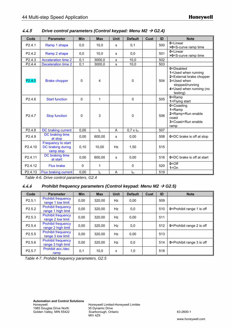
44 Multi-step Speed Application Honeywell
Automation and Control Solutions Honeywell Honeywell Limited-Honeywell Limitée 1985 Douglas Drive North 35 Dynamic Drive Golden Valley, MIN 55422 Scarborough, Ontario 63-2600-1 MIV 4Z9 www.honeywell.com
4.4.5 Drive control parameters (Control keypad: Menu M2 G2.4)
Code Parameter Min Max Unit Default Cust ID Note
P2.4.1 Ramp 1 shape 0,0 10,0 s 0,1 500 0=Linear >0=S-curve ramp time
P2.4.2 Ramp 2 shape 0,0 10,0 s 0,0 501 0=Linear >0=S-curve ramp time
P2.4.3 Acceleration time 2 0,1 3000,0 s 10,0 502 P2.4.4 Deceleration time 2 0,1 3000,0 s 10,0 503
P2.4.5 Brake chopper 0 4 0
504
0=Disabled 1=Used when running 2=External brake chopper 3=Used when
stopped/running 4=Used when running (no
testing)
P2.4.6 Start function 0 1 0 505 0=Ramp 1=Flying start
P2.4.7 Stop function 0 3 0
506
0=Coasting 1=Ramp 2=Ramp+Run enable coast 3=Coast+Run enable ramp
P2.4.8 DC braking current 0,00 IL A 0,7 x IH 507
P2.4.9 DC braking time at stop 0,00 600,00 s 0,00 508 0=DC brake is off at stop
P2.4.10 Frequency to start DC braking during
ramp stop 0,10 10,00 Hz 1,50
515
P2.4.11 DC braking time at start 0,00 600,00 s 0,00 516 0=DC brake is off at start
P2.4.12 Flux brake 0 1 0 520 0=Off 1=On
P2.4.13 Flux braking current 0,00 IL A IH 519
Table 4-6. Drive control parameters, G2.4
4.4.6 Prohibit frequency parameters (Control keypad: Menu M2 G2.5)
Code Parameter Min Max Unit Default Cust ID Note
P2.5.1 Prohibit frequency range 1 low limit 0,00 320,00 Hz 0,00 509
P2.5.2 Prohibit frequency range 1 high limit 0,00 320,00 Hz 0,0 510 0=Prohibit range 1 is off
P2.5.3 Prohibit frequency range 2 low limit 0,00 320,00 Hz 0,00 511
P2.5.4 Prohibit frequency range 2 high limit 0,00 320,00 Hz 0,0 512 0=Prohibit range 2 is off
P2.5.5 Prohibit frequency range 3 low limit 0,00 320,00 Hz 0,00 513
P2.5.6 Prohibit frequency range 3 high limit 0,00 320,00 Hz 0,0 514 0=Prohibit range 3 is off
P2.5.7 Prohibit acc./dec. ramp 0,1 10,0 x 1,0 518
Table 4-7. Prohibit frequency parameters, G2.5
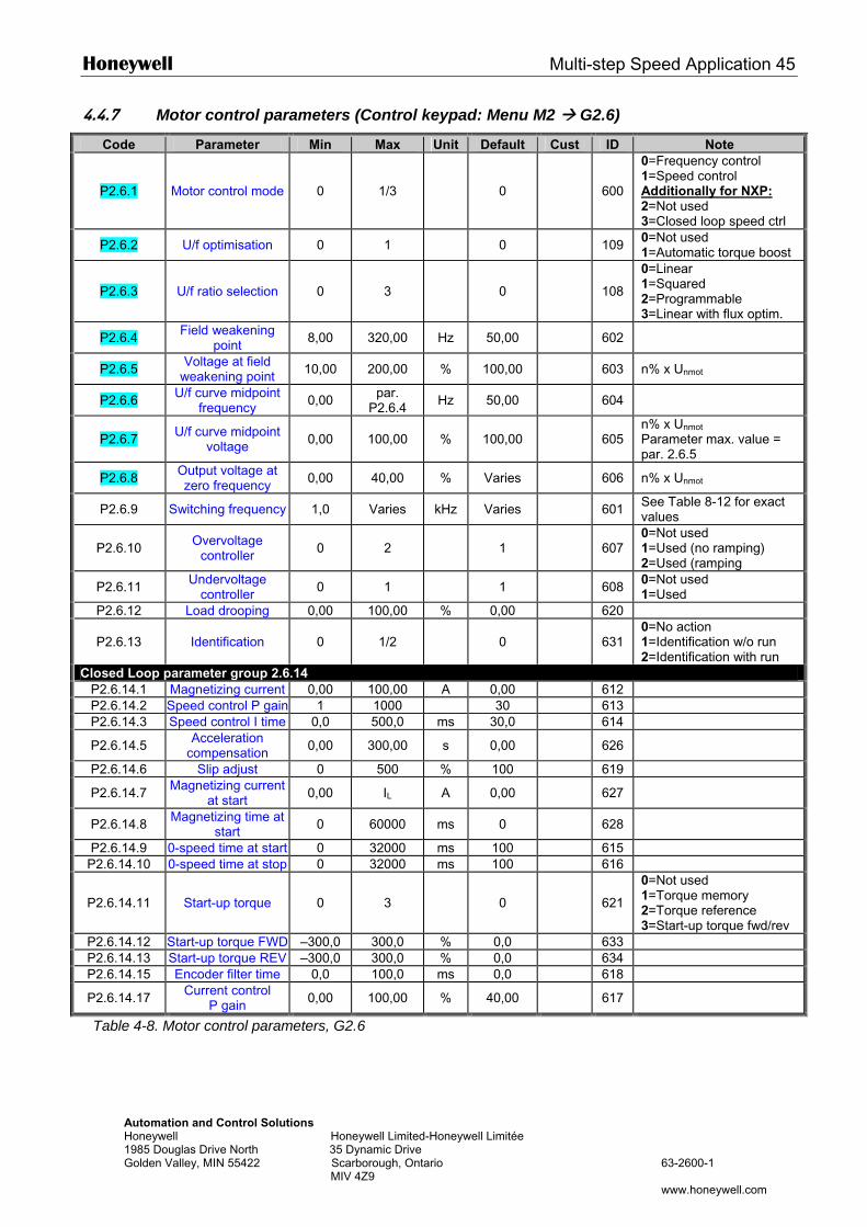
Honeywell Multi-step Speed Application 45
Automation and Control Solutions Honeywell Honeywell Limited-Honeywell Limitée 1985 Douglas Drive North 35 Dynamic Drive Golden Valley, MIN 55422 Scarborough, Ontario 63-2600-1 MIV 4Z9 www.honeywell.com
4.4.7 Motor control parameters (Control keypad: Menu M2 G2.6)
Code Parameter Min Max Unit Default Cust ID Note
P2.6.1 Motor control mode 0 1/3 0
600
0=Frequency control 1=Speed control Additionally for NXP: 2=Not used 3=Closed loop speed ctrl
P2.6.2 U/f optimisation 0 1 0 109 0=Not used 1=Automatic torque boost
P2.6.3 U/f ratio selection 0 3 0
108
0=Linear 1=Squared 2=Programmable 3=Linear with flux optim.
P2.6.4 Field weakening point 8,00 320,00 Hz 50,00 602
P2.6.5 Voltage at field weakening point 10,00 200,00 % 100,00 603 n% x Unmot
P2.6.6 U/f curve midpoint frequency 0,00 par.
P2.6.4 Hz 50,00 604
P2.6.7 U/f curve midpoint voltage 0,00 100,00 % 100,00
605
n% x Unmot
Parameter max. value = par. 2.6.5
P2.6.8 Output voltage at zero frequency 0,00 40,00 % Varies 606 n% x Unmot
P2.6.9 Switching frequency 1,0 Varies kHz Varies 601 See Table 8-12 for exact values
P2.6.10 Overvoltage controller 0 2 1
607
0=Not used 1=Used (no ramping) 2=Used (ramping
P2.6.11 Undervoltage controller 0 1 1 608 0=Not used
1=Used P2.6.12 Load drooping 0,00 100,00 % 0,00 620
P2.6.13 Identification 0 1/2 0
631 0=No action 1=Identification w/o run 2=Identification with run
Closed Loop parameter group 2.6.14 P2.6.14.1 Magnetizing current 0,00 100,00 A 0,00 612 P2.6.14.2 Speed control P gain 1 1000 30 613 P2.6.14.3 Speed control I time 0,0 500,0 ms 30,0 614
P2.6.14.5 Acceleration compensation 0,00 300,00 s 0,00 626
P2.6.14.6 Slip adjust 0 500 % 100 619
P2.6.14.7 Magnetizing current at start 0,00 IL A 0,00 627
P2.6.14.8 Magnetizing time at start 0 60000 ms 0 628
P2.6.14.9 0-speed time at start 0 32000 ms 100 615 P2.6.14.10 0-speed time at stop 0 32000 ms 100 616
P2.6.14.11 Start-up torque 0 3 0
621
0=Not used 1=Torque memory 2=Torque reference 3=Start-up torque fwd/rev
P2.6.14.12 Start-up torque FWD –300,0 300,0 % 0,0 633 P2.6.14.13 Start-up torque REV –300,0 300,0 % 0,0 634 P2.6.14.15 Encoder filter time 0,0 100,0 ms 0,0 618
P2.6.14.17 Current control P gain 0,00 100,00 % 40,00 617
Table 4-8. Motor control parameters, G2.6
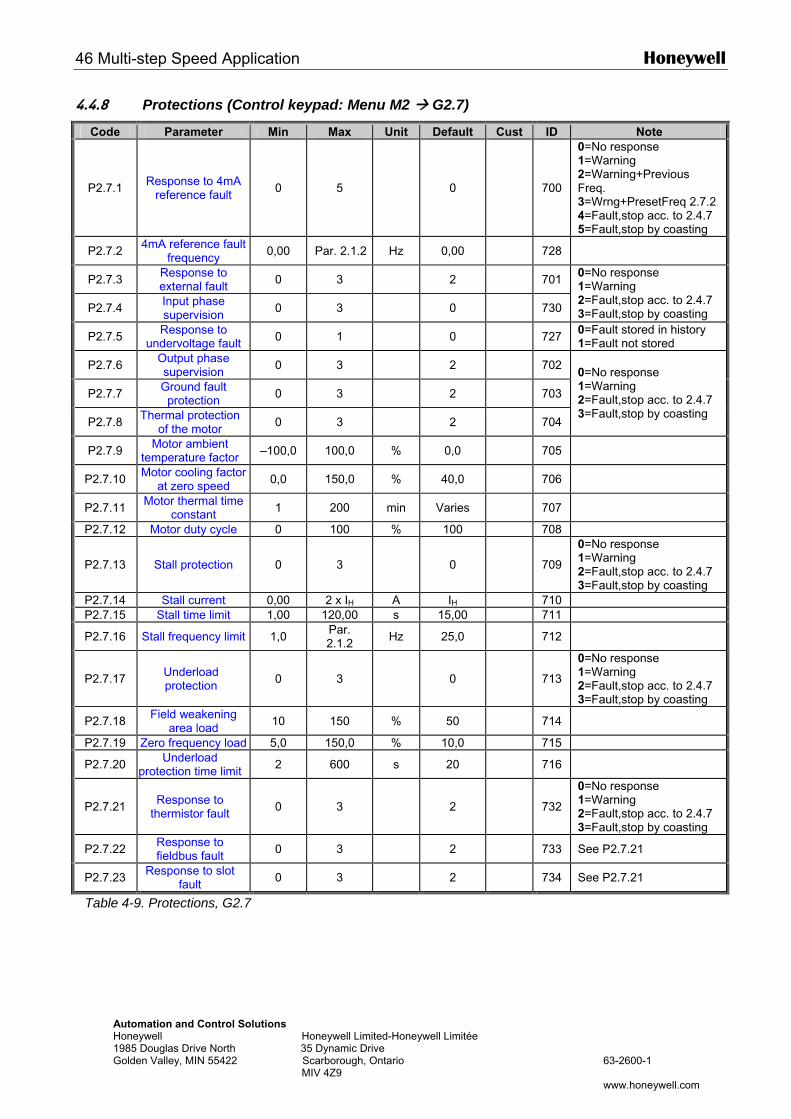
46 Multi-step Speed Application Honeywell
Automation and Control Solutions Honeywell Honeywell Limited-Honeywell Limitée 1985 Douglas Drive North 35 Dynamic Drive Golden Valley, MIN 55422 Scarborough, Ontario 63-2600-1 MIV 4Z9 www.honeywell.com
4.4.8 Protections (Control keypad: Menu M2 G2.7)
Code Parameter Min Max Unit Default Cust ID Note
P2.7.1 Response to 4mA reference fault 0 5 0
700
0=No response 1=Warning 2=Warning+Previous Freq. 3=Wrng+PresetFreq 2.7.2 4=Fault,stop acc. to 2.4.7 5=Fault,stop by coasting
P2.7.2 4mA reference fault frequency 0,00 Par. 2.1.2 Hz 0,00 728
P2.7.3 Response to external fault 0 3 2 701
P2.7.4 Input phase supervision 0 3 0 730
0=No response 1=Warning 2=Fault,stop acc. to 2.4.7 3=Fault,stop by coasting
P2.7.5 Response to undervoltage fault 0 1 0 727 0=Fault stored in history
1=Fault not stored
P2.7.6 Output phase supervision 0 3 2 702
P2.7.7 Ground fault protection 0 3 2 703
P2.7.8 Thermal protection of the motor 0 3 2 704
0=No response 1=Warning 2=Fault,stop acc. to 2.4.7 3=Fault,stop by coasting
P2.7.9 Motor ambient temperature factor –100,0 100,0 % 0,0 705
P2.7.10 Motor cooling factor at zero speed 0,0 150,0 % 40,0 706
P2.7.11 Motor thermal time constant 1 200 min Varies 707
P2.7.12 Motor duty cycle 0 100 % 100 708
P2.7.13 Stall protection 0 3 0
709
0=No response 1=Warning 2=Fault,stop acc. to 2.4.7 3=Fault,stop by coasting
P2.7.14 Stall current 0,00 2 x IH A IH 710 P2.7.15 Stall time limit 1,00 120,00 s 15,00 711
P2.7.16 Stall frequency limit 1,0 Par. 2.1.2 Hz 25,0 712
P2.7.17 Underload protection 0 3 0
713
0=No response 1=Warning 2=Fault,stop acc. to 2.4.7 3=Fault,stop by coasting
P2.7.18 Field weakening area load 10 150 % 50 714
P2.7.19 Zero frequency load 5,0 150,0 % 10,0 715
P2.7.20 Underload protection time limit 2 600 s 20 716
P2.7.21 Response to thermistor fault 0 3 2
732
0=No response 1=Warning 2=Fault,stop acc. to 2.4.7 3=Fault,stop by coasting
P2.7.22 Response to fieldbus fault 0 3 2 733 See P2.7.21
P2.7.23 Response to slot fault 0 3 2 734 See P2.7.21
Table 4-9. Protections, G2.7
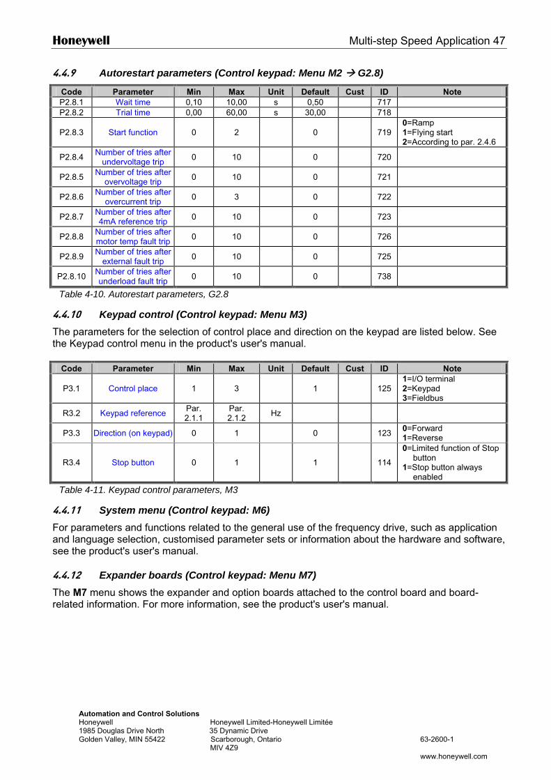
Honeywell Multi-step Speed Application 47
Automation and Control Solutions Honeywell Honeywell Limited-Honeywell Limitée 1985 Douglas Drive North 35 Dynamic Drive Golden Valley, MIN 55422 Scarborough, Ontario 63-2600-1 MIV 4Z9 www.honeywell.com
4.4.9 Autorestart parameters (Control keypad: Menu M2 G2.8)
Code Parameter Min Max Unit Default Cust ID Note P2.8.1 Wait time 0,10 10,00 s 0,50 717 P2.8.2 Trial time 0,00 60,00 s 30,00 718
P2.8.3 Start function 0 2 0
719 0=Ramp 1=Flying start 2=According to par. 2.4.6
P2.8.4 Number of tries after undervoltage trip 0 10 0 720
P2.8.5 Number of tries after overvoltage trip 0 10 0 721
P2.8.6 Number of tries after overcurrent trip 0 3 0 722
P2.8.7 Number of tries after 4mA reference trip 0 10 0 723
P2.8.8 Number of tries after motor temp fault trip 0 10 0 726
P2.8.9 Number of tries after external fault trip 0 10 0 725
P2.8.10 Number of tries after underload fault trip 0 10 0 738
Table 4-10. Autorestart parameters, G2.8
4.4.10 Keypad control (Control keypad: Menu M3) The parameters for the selection of control place and direction on the keypad are listed below. See the Keypad control menu in the product's user's manual.
Code Parameter Min Max Unit Default Cust ID Note
P3.1 Control place 1 3 1
125 1=I/O terminal 2=Keypad 3=Fieldbus
R3.2 Keypad reference Par. 2.1.1
Par. 2.1.2 Hz
P3.3 Direction (on keypad) 0 1 0 123 0=Forward 1=Reverse
R3.4 Stop button 0 1 1
114
0=Limited function of Stop button
1=Stop button always enabled
Table 4-11. Keypad control parameters, M3
4.4.11 System menu (Control keypad: M6) For parameters and functions related to the general use of the frequency drive, such as application and language selection, customised parameter sets or information about the hardware and software, see the product's user's manual. 4.4.12 Expander boards (Control keypad: Menu M7) The M7 menu shows the expander and option boards attached to the control board and board-related information. For more information, see the product's user's manual.
48 PID Control Application Honeywell
Automation and Control Solutions Honeywell Honeywell Limited-Honeywell Limitée 1985 Douglas Drive North 35 Dynamic Drive Golden Valley, MIN 55422 Scarborough, Ontario 63-2600-1 MIV 4Z9 www.honeywell.com
5. PID CONTROL APPLICATION
(Software ASFIFF05) 5.1 Introduction
Select the PID Control Application in menu M6 on page S6.2.
In the PID Control Application, there are two I/O terminal control places; place A is the PID controller and source B is the direct frequency reference. The control place A or B is selected with digital input DIN6.
The PID controller reference can be selected from the analogue inputs, fieldbus, motorised potentiometer, enabling the PID Reference 2 or applying the control keypad reference. The PID controller actual value can be selected from the analogue inputs, fieldbus, the actual values of the motor or through the mathematical functions of these.
The direct frequency reference can be used for the control without the PID controller and selected from the analogue inputs, fieldbus, motor potentiometer or keypad.
The PID Application is typically used to control level measuring or pumps and fans. In these applications, the PID Application provides a smooth control and an integrated measuring and controlling package where no additional components are needed.
• Digital inputs DIN2, DIN3, DIN5 and all the outputs are freely programmable.
Additional functions: • Analogue input signal range selection • Two frequency limit supervisions • Torque limit supervision • Reference limit supervision • Second ramps and S-shape ramp programming • Programmable start and stop functions • DC-brake at start and stop • Three prohibit frequency areas • Programmable U/f curve and switching frequency • Autorestart • Motor thermal and stall protection: fully programmable; off, warning, fault • Motor underload protection • Input and output phase supervision • Sum point frequency addition to PID output • The PID controller can additionally be used from control places I/O B, keypad and fieldbus • Easy ChangeOver function • Sleep function
The parameters of the PID Control Application are explained in Chapter 8 of this manual. The explanations are arranged according to the individual ID number of the parameter.
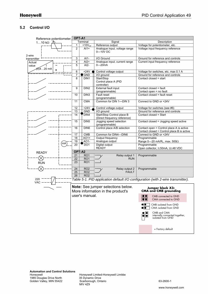
Honeywell PID Control Application 49
AutHon198Gol
5.2 Control I/O
OPT-A1
Terminal Signal Description 1 +10Vref Reference output Voltage for potentiometer, etc. 2 AI1+ Analogue input, voltage range
0—10V DC Voltage input frequency reference
3 AI1- I/O Ground Ground for reference and controls 4 AI2+ 5 AI2-
Analogue input, current range 0—20mA
Current input frequency reference
6 +24V Control voltage output Voltage for switches, etc. max 0.1 A 7 GND I/O ground Ground for reference and controls 8 DIN1 Start/Stop
Control place A (PID controller)
Contact closed = start
9 DIN2 External fault input (programmable)
Contact closed = fault Contact open = no fault
10 DIN3 Fault reset (programmable)
Contact closed = fault reset
11 CMA
Common for DIN 1—DIN 3 Connect to GND or +24V
12 +24V Control voltage output Voltage for switches (see #6) 13 GND I/O ground Ground for reference and controls 14 DIN4 Start/Stop Control place B
(Direct frequency reference) Contact closed = Start
15 DIN5 Jogging speed selection (programmable)
Contact closed = Jogging speed active
16 DIN6 Control place A/B selection Contact open = Control place A is active Contact closed = Control place B is active
17 CMB Common for DIN4—DIN6 Connect to GND or +24V 18 AO1+ 19 AO1-
Output frequency Analogue output
Programmable Range 0—20 mA/RL, max. 500Ω
20 DO1 Digital output READY
Programmable Open collector, I≤50mA, U≤48 VDC
OPT-A2
Actual value I (0)4…20 mA
2-wire transmitter
–
+
mA
Reference potentiometer, 1…10 kΩ
READY
omation and Control Solutions eywell Honeywell Limited-Honeywell Limitée 5 Douglas Drive North 35 Dynamic Drive den Valley, MIN 55422 Scarborough, Ontario 63-2600-1 MIV 4Z9
www.honeywell.com
Jumper block X3:CMA and CMB grounding
CMB connected to GNDCMA connected to GND
CMB isolated from GNDCMA isolated from GND
CMB and CMAinternally connected together,isolated from GND
= Factory default
21 RO1 22 RO1 23 RO1
Relay output 1 RUN
Programmable
24 RO2 25 RO2 26 RO2
Relay output 2 FAULT
Programmable
Table 5-1. PID application default I/O configuration (with 2-wire transmitter).
Note: See jumper selections below. More information in the product's user's manual.
RUN
220 VAC
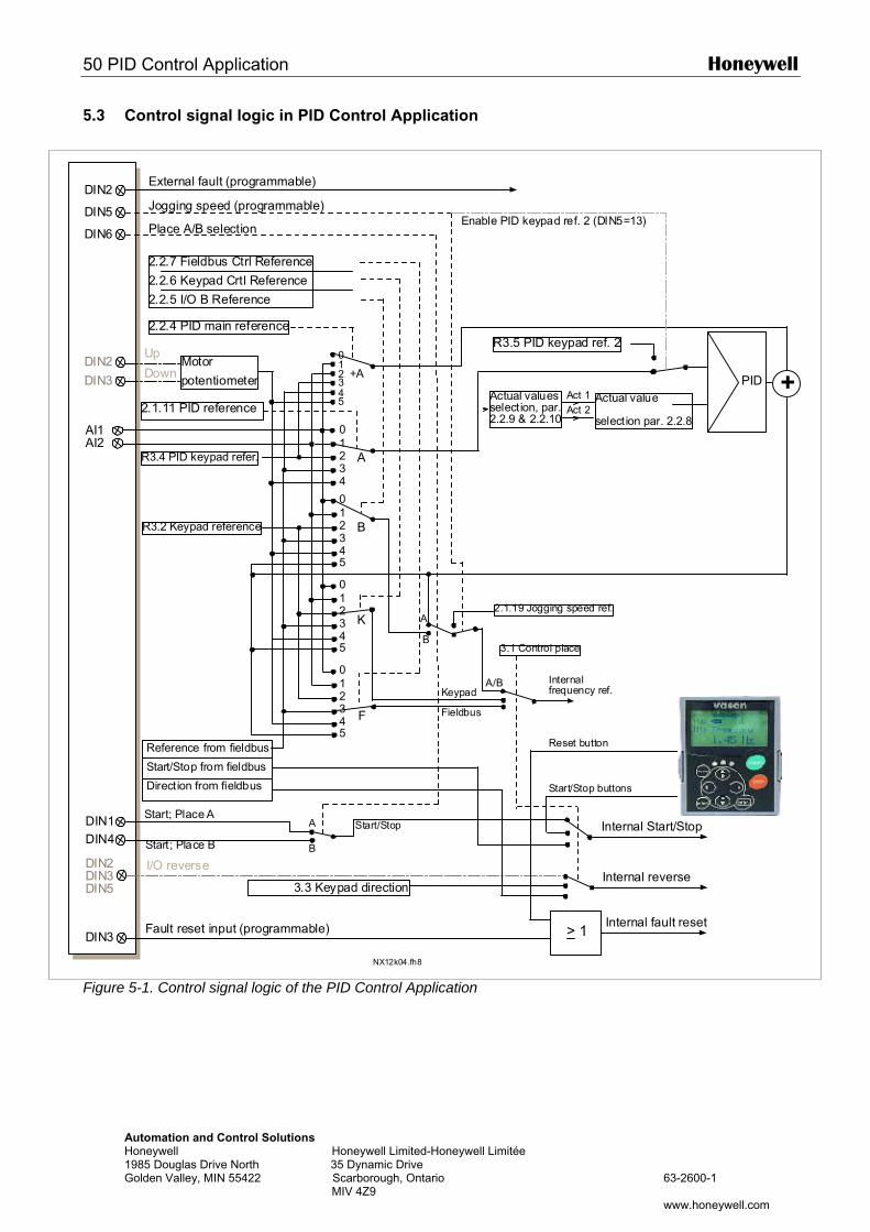
50 PID Control Application Honeywell
Automation and Control Solutions Honeywell Honeywell Limited-Honeywell Limitée 1985 Douglas Drive North 35 Dynamic Drive Golden Valley, MIN 55422 Scarborough, Ontario 63-2600-1 MIV 4Z9 www.honeywell.com
5.3 Control signal logic in PID Control Application
Figure 5-1. Control signal logic of the PID Control Application
DIN2
DIN5
DIN3 > 1
DIN2DIN3DIN5
DIN6
DIN2
DIN3
AI1AI2
01234
012345
+A
A
B
012345
012345
K
012345
F
PID +
DIN1DIN4
A
B
A
B
A/B
NX12k04.fh8
Internal reverse
Internal fault resetFault reset input (programmable)
3.3 Keypad direction
Internal Start/Stop
Reference from fieldbus
Start/Stop from fieldbus
Direction from fieldbus
External fault (programmable)
Jogging speed (programmable)
Place A/B selection
2.2.4 PID main reference
Motor
potentiometer
Up
Down
2.1.11 PID reference
I/O reverse
R3.4 PID keypad refer.
R3.2 Keypad reference
Actual valuesselection, par.2.2.9 & 2.2.10
Actual value
selection par. 2.2.8
Act 1Act 2
R3.5 PID keypad ref. 2
Enable PID keypad ref. 2 (DIN5=13)
Start; Place A
Start; Place B
Start/Stop
Start/Stop buttons
Internalfrequency ref.
2.1.19 Jogging speed ref.
Keypad
Fieldbus
Reset button
3.1 Control place
2.2.7 Fieldbus Ctrl Reference
2.2.6 Keypad Crtl Reference
2.2.5 I/O B Reference
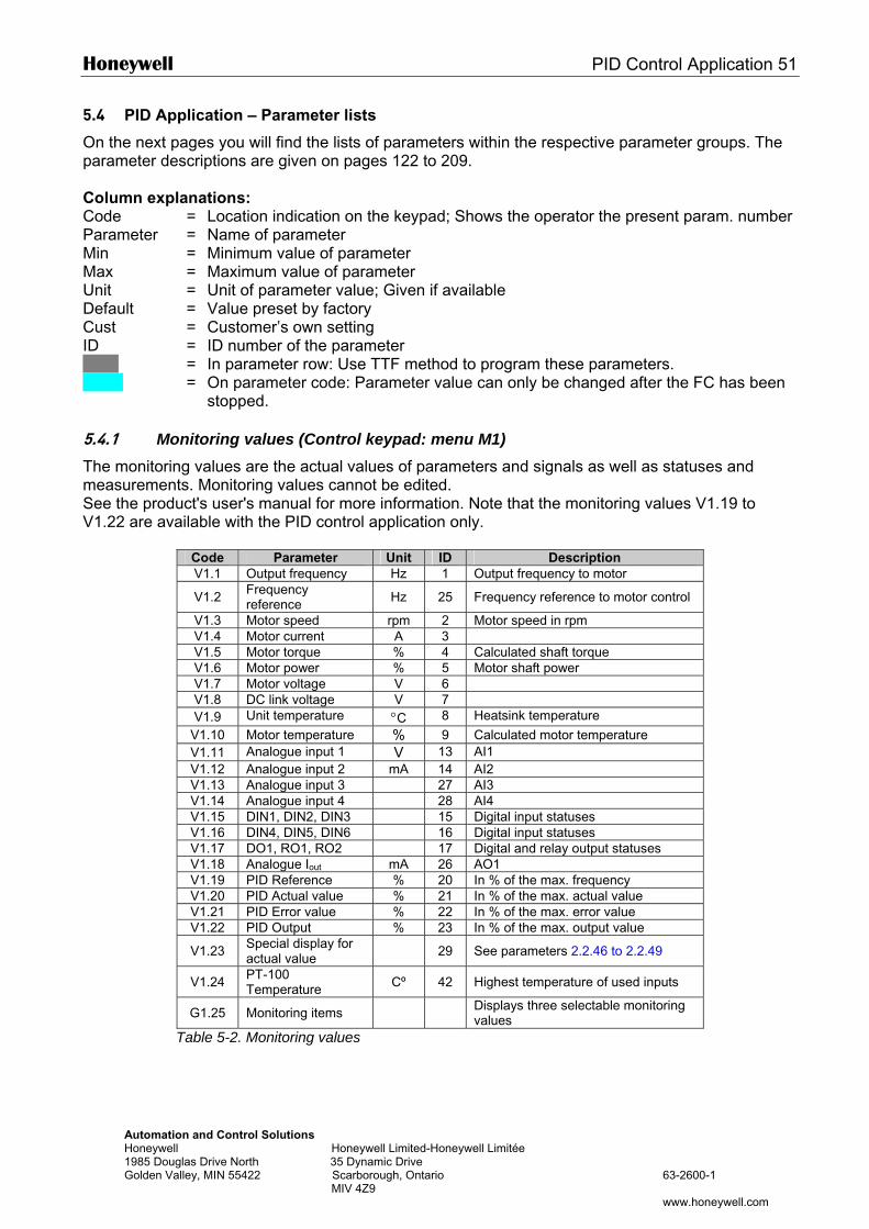
Honeywell PID Control Application 51
Automation and Control Solutions Honeywell Honeywell Limited-Honeywell Limitée 1985 Douglas Drive North 35 Dynamic Drive Golden Valley, MIN 55422 Scarborough, Ontario 63-2600-1 MIV 4Z9 www.honeywell.com
5.4 PID Application – Parameter lists
On the next pages you will find the lists of parameters within the respective parameter groups. The parameter descriptions are given on pages 122 to 209. Column explanations: Code = Location indication on the keypad; Shows the operator the present param. number Parameter = Name of parameter Min = Minimum value of parameter Max = Maximum value of parameter Unit = Unit of parameter value; Given if available Default = Value preset by factory Cust = Customer’s own setting ID = ID number of the parameter = In parameter row: Use TTF method to program these parameters. = On parameter code: Parameter value can only be changed after the FC has been
stopped. 5.4.1 Monitoring values (Control keypad: menu M1) The monitoring values are the actual values of parameters and signals as well as statuses and measurements. Monitoring values cannot be edited. See the product's user's manual for more information. Note that the monitoring values V1.19 to V1.22 are available with the PID control application only.
Code Parameter Unit ID Description V1.1 Output frequency Hz 1 Output frequency to motor
V1.2 Frequency reference Hz 25 Frequency reference to motor control
V1.3 Motor speed rpm 2 Motor speed in rpm V1.4 Motor current A 3 V1.5 Motor torque % 4 Calculated shaft torque V1.6 Motor power % 5 Motor shaft power V1.7 Motor voltage V 6 V1.8 DC link voltage V 7 V1.9 Unit temperature °C 8 Heatsink temperature
V1.10 Motor temperature % 9 Calculated motor temperature V1.11 Analogue input 1 V 13 AI1 V1.12 Analogue input 2 mA 14 AI2 V1.13 Analogue input 3 27 AI3 V1.14 Analogue input 4 28 AI4 V1.15 DIN1, DIN2, DIN3 15 Digital input statuses V1.16 DIN4, DIN5, DIN6 16 Digital input statuses V1.17 DO1, RO1, RO2 17 Digital and relay output statuses V1.18 Analogue Iout mA 26 AO1 V1.19 PID Reference % 20 In % of the max. frequency V1.20 PID Actual value % 21 In % of the max. actual value V1.21 PID Error value % 22 In % of the max. error value V1.22 PID Output % 23 In % of the max. output value
V1.23 Special display for actual value 29 See parameters 2.2.46 to 2.2.49
V1.24 PT-100 Temperature Cº 42 Highest temperature of used inputs
G1.25 Monitoring items Displays three selectable monitoring values
Table 5-2. Monitoring values
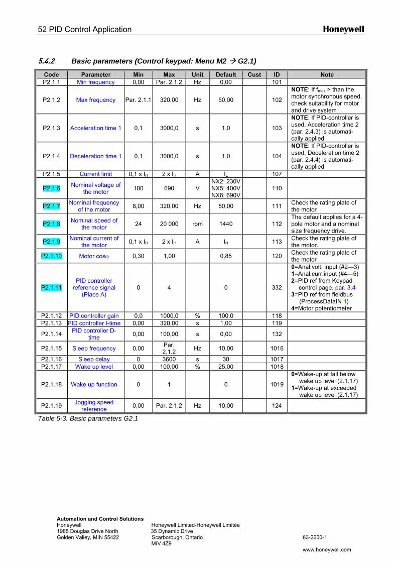
52 PID Control Application Honeywell
Automation and Control Solutions Honeywell Honeywell Limited-Honeywell Limitée 1985 Douglas Drive North 35 Dynamic Drive Golden Valley, MIN 55422 Scarborough, Ontario 63-2600-1 MIV 4Z9 www.honeywell.com
5.4.2 Basic parameters (Control keypad: Menu M2 G2.1)
Code Parameter Min Max Unit Default Cust ID Note P2.1.1 Min frequency 0,00 Par. 2.1.2 Hz 0,00 101
P2.1.2 Max frequency Par. 2.1.1 320,00 Hz 50,00
102
NOTE: If fmax > than the motor synchronous speed, check suitability for motor and drive system
P2.1.3 Acceleration time 1 0,1 3000,0 s 1,0
103
NOTE: If PID-controller is used, Acceleration time 2 (par. 2.4.3) is automati-cally applied
P2.1.4 Deceleration time 1 0,1 3000,0 s 1,0
104
NOTE: If PID-controller is used, Deceleration time 2 (par. 2.4.4) is automati-cally applied
P2.1.5 Current limit 0,1 x IH 2 x IH A IL 107
P2.1.6 Nominal voltage of the motor 180 690 V
NX2: 230VNX5: 400VNX6: 690V
110
P2.1.7 Nominal frequency of the motor 8,00 320,00 Hz 50,00 111 Check the rating plate of
the motor
P2.1.8 Nominal speed of the motor 24 20 000 rpm 1440
112
The default applies for a 4-pole motor and a nominal size frequency drive.
P2.1.9 Nominal current of the motor 0,1 x IH 2 x IH A IH 113 Check the rating plate of
the motor.
P2.1.10 Motor cosϕ 0,30 1,00 0,85 120 Check the rating plate of the motor
P2.1.11 PID controller
reference signal (Place A)
0 4 0
332
0=Anal.volt. input (#2—3) 1=Anal.curr.input (#4—5) 2=PID ref from Keypad
control page, par. 3.4 3=PID ref from fieldbus
(ProcessDataIN 1) 4=Motor potentiometer
P2.1.12 PID controller gain 0,0 1000,0 % 100,0 118 P2.1.13 PID controller I-time 0,00 320,00 s 1,00 119
P2.1.14 PID controller D-time 0,00 100,00 s 0,00 132
P2.1.15 Sleep frequency 0,00 Par. 2.1.2 Hz 10,00
1016
P2.1.16 Sleep delay 0 3600 s 30 1017 P2.1.17 Wake up level 0,00 100,00 % 25,00 1018
P2.1.18 Wake up function 0 1 0
1019
0=Wake-up at fall below wake up level (2.1.17)
1=Wake-up at exceeded wake up level (2.1.17)
P2.1.19 Jogging speed reference 0,00 Par. 2.1.2 Hz 10,00
124
Table 5-3. Basic parameters G2.1
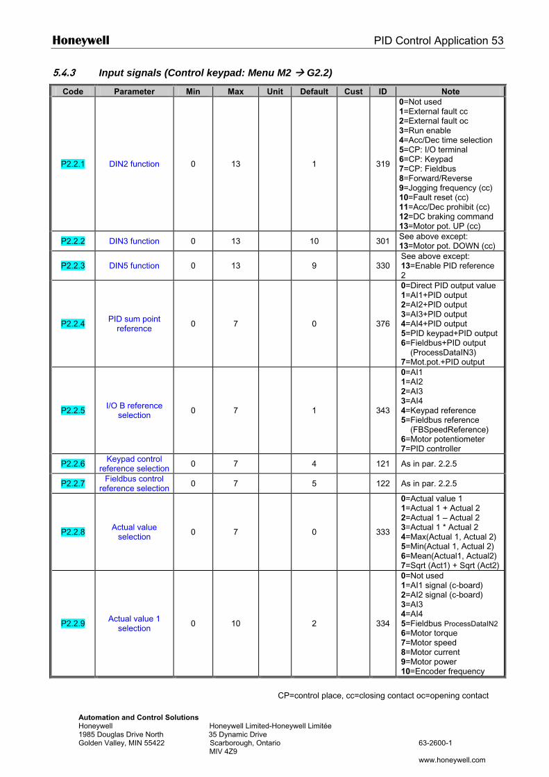
Honeywell PID Control Application 53
Automation and Control Solutions Honeywell Honeywell Limited-Honeywell Limitée 1985 Douglas Drive North 35 Dynamic Drive Golden Valley, MIN 55422 Scarborough, Ontario 63-2600-1 MIV 4Z9 www.honeywell.com
5.4.3 Input signals (Control keypad: Menu M2 G2.2)
Code Parameter Min Max Unit Default Cust ID Note
P2.2.1 DIN2 function 0 13 1
319
0=Not used 1=External fault cc 2=External fault oc 3=Run enable 4=Acc/Dec time selection 5=CP: I/O terminal 6=CP: Keypad 7=CP: Fieldbus 8=Forward/Reverse 9=Jogging frequency (cc) 10=Fault reset (cc) 11=Acc/Dec prohibit (cc) 12=DC braking command 13=Motor pot. UP (cc)
P2.2.2 DIN3 function 0 13 10 301 See above except: 13=Motor pot. DOWN (cc)
P2.2.3 DIN5 function 0 13 9
330 See above except: 13=Enable PID reference 2
P2.2.4 PID sum point reference 0 7 0
376
0=Direct PID output value 1=AI1+PID output 2=AI2+PID output 3=AI3+PID output 4=AI4+PID output 5=PID keypad+PID output 6=Fieldbus+PID output (ProcessDataIN3) 7=Mot.pot.+PID output
P2.2.5 I/O B reference selection 0 7 1
343
0=AI1 1=AI2 2=AI3 3=AI4 4=Keypad reference 5=Fieldbus reference (FBSpeedReference) 6=Motor potentiometer 7=PID controller
P2.2.6 Keypad control reference selection 0 7 4 121 As in par. 2.2.5
P2.2.7 Fieldbus control reference selection 0 7 5 122 As in par. 2.2.5
P2.2.8 Actual value selection 0 7 0
333
0=Actual value 1 1=Actual 1 + Actual 2 2=Actual 1 – Actual 2 3=Actual 1 * Actual 2 4=Max(Actual 1, Actual 2) 5=Min(Actual 1, Actual 2) 6=Mean(Actual1, Actual2) 7=Sqrt (Act1) + Sqrt (Act2)
P2.2.9 Actual value 1 selection 0 10
2
334
0=Not used 1=AI1 signal (c-board) 2=AI2 signal (c-board) 3=AI3 4=AI4 5=Fieldbus ProcessDataIN2 6=Motor torque 7=Motor speed 8=Motor current 9=Motor power 10=Encoder frequency
CP=control place, cc=closing contact oc=opening contact
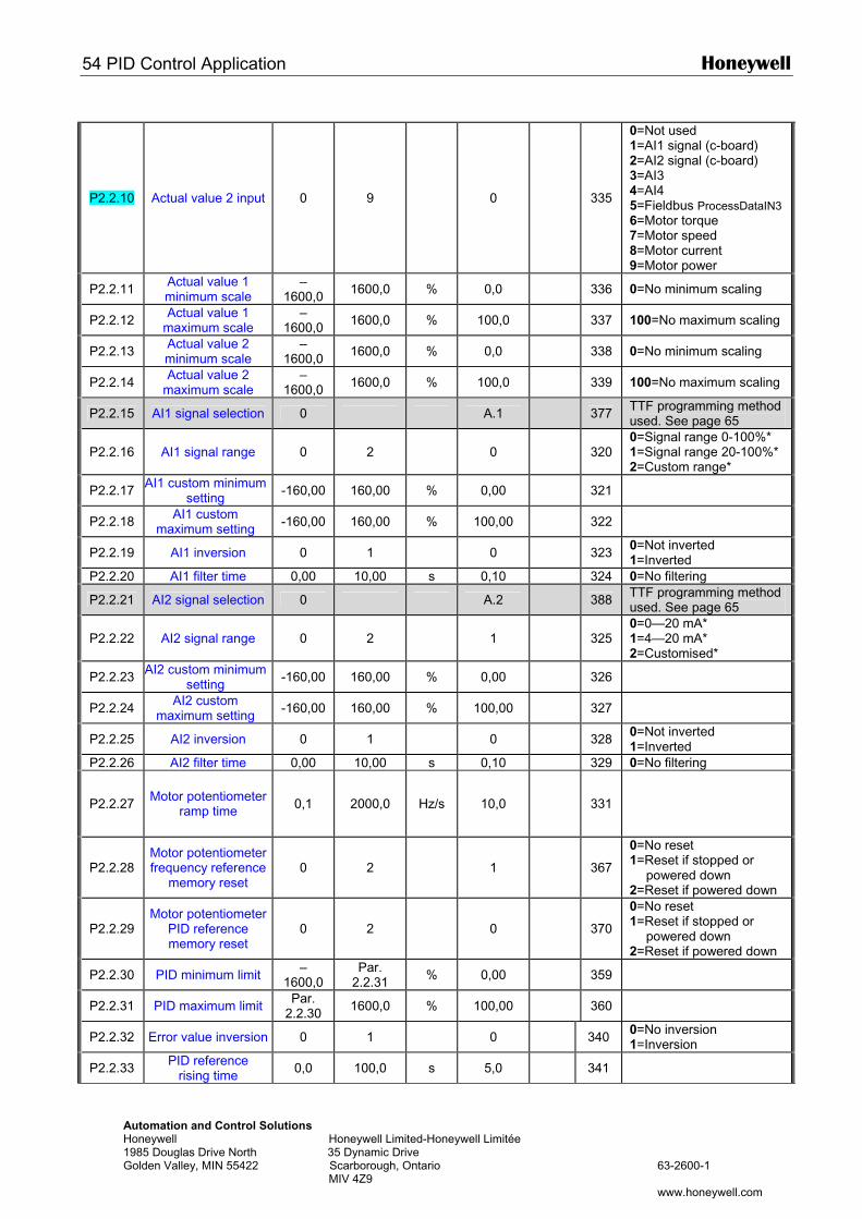
54 PID Control Application Honeywell
Automation and Control Solutions Honeywell Honeywell Limited-Honeywell Limitée 1985 Douglas Drive North 35 Dynamic Drive Golden Valley, MIN 55422 Scarborough, Ontario 63-2600-1 MIV 4Z9 www.honeywell.com
P2.2.10 Actual value 2 input 0 9 0
335
0=Not used 1=AI1 signal (c-board) 2=AI2 signal (c-board) 3=AI3 4=AI4 5=Fieldbus ProcessDataIN3 6=Motor torque 7=Motor speed 8=Motor current 9=Motor power
P2.2.11 Actual value 1 minimum scale
–1600,0 1600,0 % 0,0 336 0=No minimum scaling
P2.2.12 Actual value 1 maximum scale
–1600,0 1600,0 % 100,0 337 100=No maximum scaling
P2.2.13 Actual value 2 minimum scale
–1600,0 1600,0 % 0,0 338 0=No minimum scaling
P2.2.14 Actual value 2 maximum scale
–1600,0 1600,0 % 100,0 339 100=No maximum scaling
P2.2.15 AI1 signal selection 0 A.1 377 TTF programming method used. See page 65
P2.2.16 AI1 signal range 0 2 0
320 0=Signal range 0-100%* 1=Signal range 20-100%* 2=Custom range*
P2.2.17 AI1 custom minimum setting -160,00 160,00 % 0,00 321
P2.2.18 AI1 custom maximum setting -160,00 160,00 % 100,00 322
P2.2.19 AI1 inversion 0 1 0 323 0=Not inverted 1=Inverted
P2.2.20 AI1 filter time 0,00 10,00 s 0,10 324 0=No filtering
P2.2.21 AI2 signal selection 0 A.2 388 TTF programming method used. See page 65
P2.2.22 AI2 signal range 0 2 1
325 0=0—20 mA* 1=4—20 mA* 2=Customised*
P2.2.23 AI2 custom minimum setting -160,00 160,00 % 0,00 326
P2.2.24 AI2 custom maximum setting -160,00 160,00 % 100,00 327
P2.2.25 AI2 inversion 0 1 0 328 0=Not inverted 1=Inverted
P2.2.26 AI2 filter time 0,00 10,00 s 0,10 329 0=No filtering
P2.2.27 Motor potentiometer ramp time 0,1 2000,0 Hz/s 10,0
331
P2.2.28 Motor potentiometer frequency reference
memory reset 0 2 1
367
0=No reset 1=Reset if stopped or
powered down 2=Reset if powered down
P2.2.29 Motor potentiometer
PID reference memory reset
0 2 0
370
0=No reset 1=Reset if stopped or
powered down 2=Reset if powered down
P2.2.30 PID minimum limit –1600,0
Par. 2.2.31 % 0,00 359
P2.2.31 PID maximum limit Par. 2.2.30 1600,0 % 100,00 360
P2.2.32 Error value inversion 0 1 0 340 0=No inversion 1=Inversion
P2.2.33 PID reference rising time 0,0 100,0 s 5,0 341
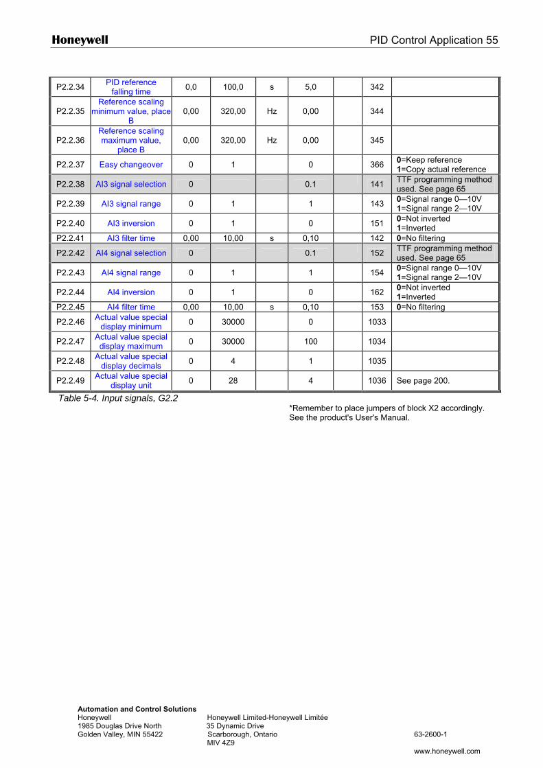
Honeywell PID Control Application 55
Automation and Control Solutions Honeywell Honeywell Limited-Honeywell Limitée 1985 Douglas Drive North 35 Dynamic Drive Golden Valley, MIN 55422 Scarborough, Ontario 63-2600-1 MIV 4Z9 www.honeywell.com
P2.2.34 PID reference falling time 0,0 100,0 s 5,0 342
P2.2.35 Reference scaling
minimum value, place B
0,00 320,00 Hz 0,00
344
P2.2.36 Reference scaling maximum value,
place B 0,00 320,00 Hz 0,00
345
P2.2.37 Easy changeover 0 1 0 366 0=Keep reference 1=Copy actual reference
P2.2.38 AI3 signal selection 0 0.1 141 TTF programming method used. See page 65
P2.2.39 AI3 signal range 0 1 1 143 0=Signal range 0—10V 1=Signal range 2—10V
P2.2.40 AI3 inversion 0 1 0 151 0=Not inverted 1=Inverted
P2.2.41 AI3 filter time 0,00 10,00 s 0,10 142 0=No filtering
P2.2.42 AI4 signal selection 0 0.1 152 TTF programming method used. See page 65
P2.2.43 AI4 signal range 0 1 1 154 0=Signal range 0—10V 1=Signal range 2—10V
P2.2.44 AI4 inversion 0 1 0 162 0=Not inverted 1=Inverted
P2.2.45 AI4 filter time 0,00 10,00 s 0,10 153 0=No filtering
P2.2.46 Actual value special display minimum 0 30000 0 1033
P2.2.47 Actual value special display maximum 0 30000 100 1034
P2.2.48 Actual value special display decimals 0 4 1 1035
P2.2.49 Actual value special display unit 0 28 4 1036 See page 200.
Table 5-4. Input signals, G2.2
*Remember to place jumpers of block X2 accordingly. See the product's User's Manual.
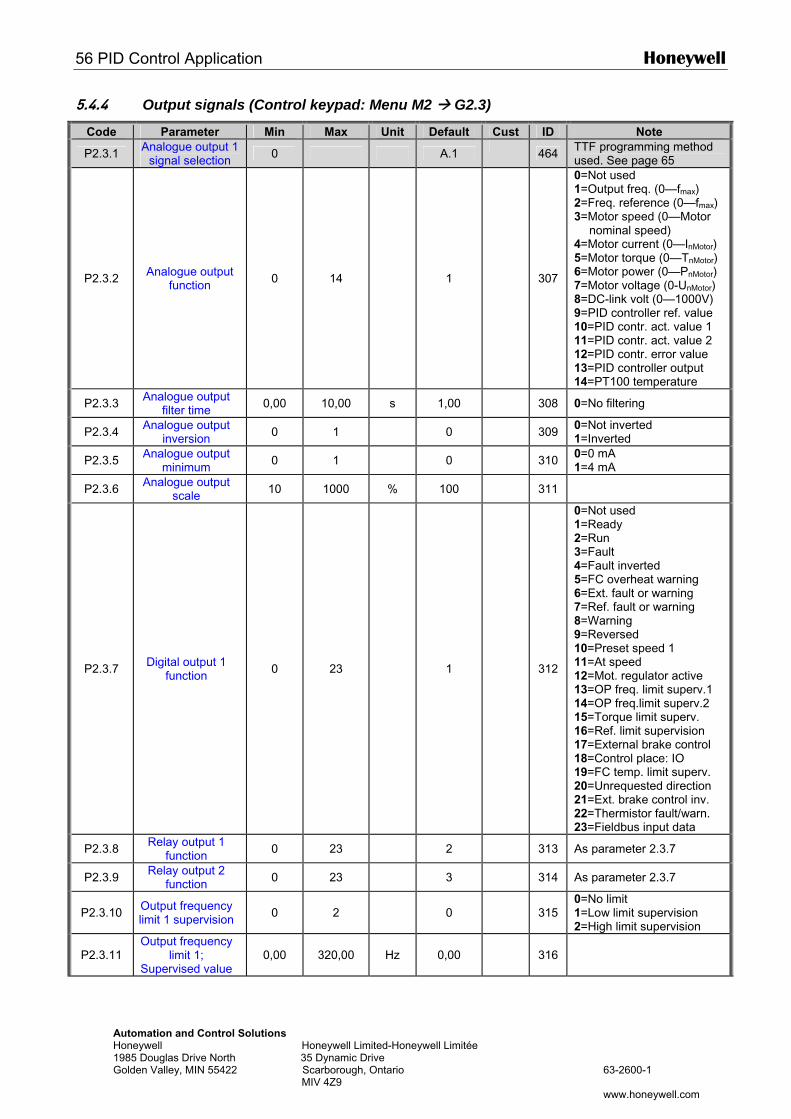
56 PID Control Application Honeywell
Automation and Control Solutions Honeywell Honeywell Limited-Honeywell Limitée 1985 Douglas Drive North 35 Dynamic Drive Golden Valley, MIN 55422 Scarborough, Ontario 63-2600-1 MIV 4Z9 www.honeywell.com
5.4.4 Output signals (Control keypad: Menu M2 G2.3)
Code Parameter Min Max Unit Default Cust ID Note
P2.3.1 Analogue output 1 signal selection 0 A.1 464 TTF programming method
used. See page 65
P2.3.2 Analogue output function 0 14 1
307
0=Not used 1=Output freq. (0—fmax) 2=Freq. reference (0—fmax) 3=Motor speed (0—Motor
nominal speed) 4=Motor current (0—InMotor) 5=Motor torque (0—TnMotor) 6=Motor power (0—PnMotor) 7=Motor voltage (0-UnMotor) 8=DC-link volt (0—1000V) 9=PID controller ref. value 10=PID contr. act. value 1 11=PID contr. act. value 2 12=PID contr. error value 13=PID controller output 14=PT100 temperature
P2.3.3 Analogue output filter time 0,00 10,00 s 1,00 308 0=No filtering
P2.3.4 Analogue output inversion 0 1 0 309 0=Not inverted
1=Inverted
P2.3.5 Analogue output minimum 0 1 0 310 0=0 mA
1=4 mA
P2.3.6 Analogue output scale 10 1000 % 100 311
P2.3.7 Digital output 1 function 0 23 1
312
0=Not used 1=Ready 2=Run 3=Fault 4=Fault inverted 5=FC overheat warning 6=Ext. fault or warning 7=Ref. fault or warning 8=Warning 9=Reversed 10=Preset speed 1 11=At speed 12=Mot. regulator active 13=OP freq. limit superv.1 14=OP freq.limit superv.2 15=Torque limit superv. 16=Ref. limit supervision 17=External brake control 18=Control place: IO 19=FC temp. limit superv. 20=Unrequested direction 21=Ext. brake control inv. 22=Thermistor fault/warn. 23=Fieldbus input data
P2.3.8 Relay output 1 function 0 23 2 313 As parameter 2.3.7
P2.3.9 Relay output 2 function 0 23 3 314 As parameter 2.3.7
P2.3.10 Output frequency limit 1 supervision 0 2 0
315
0=No limit 1=Low limit supervision 2=High limit supervision
P2.3.11 Output frequency
limit 1; Supervised value
0,00 320,00 Hz 0,00
316
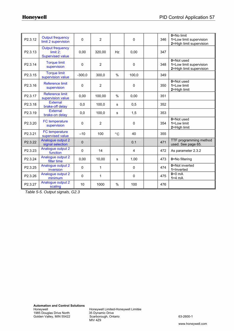
Honeywell PID Control Application 57
Automation and Control Solutions Honeywell Honeywell Limited-Honeywell Limitée 1985 Douglas Drive North 35 Dynamic Drive Golden Valley, MIN 55422 Scarborough, Ontario 63-2600-1 MIV 4Z9 www.honeywell.com
P2.3.12 Output frequency limit 2 supervision 0 2 0
346
0=No limit 1=Low limit supervision 2=High limit supervision
P2.3.13 Output frequency
limit 2; Supervised value
0,00 320,00 Hz 0,00
347
P2.3.14 Torque limit supervision 0 2 0
348
0=Not used 1=Low limit supervision 2=High limit supervision
P2.3.15 Torque limit supervision value -300,0 300,0 % 100,0 349
P2.3.16 Reference limit supervision 0 2 0
350
0=Not used 1=Low limit 2=High limit
P2.3.17 Reference limit supervision value 0,00 100,00 % 0,00 351
P2.3.18 External brake-off delay 0,0 100,0 s 0,5 352
P2.3.19 External brake-on delay 0,0 100,0 s 1,5 353
P2.3.20 FC temperature supervision 0 2 0
354
0=Not used 1=Low limit 2=High limit
P2.3.21 FC temperature supervised value –10 100 °C 40 355
P2.3.22 Analogue output 2 signal selection 0 0.1 471 TTF programming method
used. See page 65.
P2.3.23 Analogue output 2 function 0 14 4 472 As parameter 2.3.2
P2.3.24 Analogue output 2 filter time 0,00 10,00 s 1,00 473 0=No filtering
P2.3.25 Analogue output 2 inversion 0 1 0 474 0=Not inverted
1=Inverted
P2.3.26 Analogue output 2 minimum 0 1 0 475 0=0 mA
1=4 mA
P2.3.27 Analogue output 2 scaling 10 1000 % 100 476
Table 5-5. Output signals, G2.3
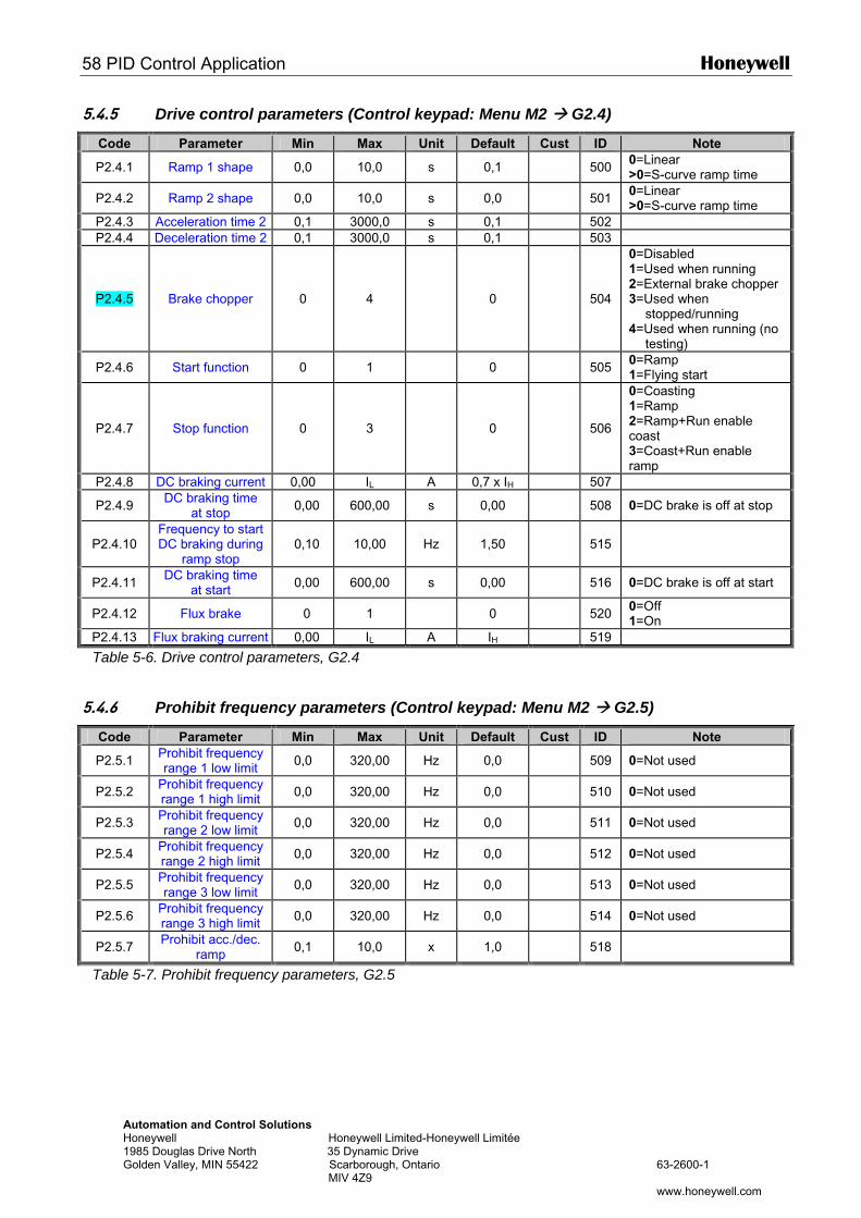
58 PID Control Application Honeywell
Automation and Control Solutions Honeywell Honeywell Limited-Honeywell Limitée 1985 Douglas Drive North 35 Dynamic Drive Golden Valley, MIN 55422 Scarborough, Ontario 63-2600-1 MIV 4Z9 www.honeywell.com
5.4.5 Drive control parameters (Control keypad: Menu M2 G2.4)
Code Parameter Min Max Unit Default Cust ID Note
P2.4.1 Ramp 1 shape 0,0 10,0 s 0,1 500 0=Linear >0=S-curve ramp time
P2.4.2 Ramp 2 shape 0,0 10,0 s 0,0 501 0=Linear >0=S-curve ramp time
P2.4.3 Acceleration time 2 0,1 3000,0 s 0,1 502 P2.4.4 Deceleration time 2 0,1 3000,0 s 0,1 503
P2.4.5 Brake chopper 0 4 0
504
0=Disabled 1=Used when running 2=External brake chopper 3=Used when
stopped/running 4=Used when running (no
testing)
P2.4.6 Start function 0 1 0 505 0=Ramp 1=Flying start
P2.4.7 Stop function 0 3 0
506
0=Coasting 1=Ramp 2=Ramp+Run enable coast 3=Coast+Run enable ramp
P2.4.8 DC braking current 0,00 IL A 0,7 x IH 507
P2.4.9 DC braking time at stop 0,00 600,00 s 0,00 508 0=DC brake is off at stop
P2.4.10 Frequency to start DC braking during
ramp stop 0,10 10,00 Hz 1,50
515
P2.4.11 DC braking time at start 0,00 600,00 s 0,00 516 0=DC brake is off at start
P2.4.12 Flux brake 0 1 0 520 0=Off 1=On
P2.4.13 Flux braking current 0,00 IL A IH 519
Table 5-6. Drive control parameters, G2.4
5.4.6 Prohibit frequency parameters (Control keypad: Menu M2 G2.5)
Code Parameter Min Max Unit Default Cust ID Note
P2.5.1 Prohibit frequency range 1 low limit 0,0 320,00 Hz 0,0 509 0=Not used
P2.5.2 Prohibit frequency range 1 high limit 0,0 320,00 Hz 0,0 510 0=Not used
P2.5.3 Prohibit frequency range 2 low limit 0,0 320,00 Hz 0,0 511 0=Not used
P2.5.4 Prohibit frequency range 2 high limit 0,0 320,00 Hz 0,0 512 0=Not used
P2.5.5 Prohibit frequency range 3 low limit 0,0 320,00 Hz 0,0 513 0=Not used
P2.5.6 Prohibit frequency range 3 high limit 0,0 320,00 Hz 0,0 514 0=Not used
P2.5.7 Prohibit acc./dec. ramp 0,1 10,0 x 1,0 518
Table 5-7. Prohibit frequency parameters, G2.5
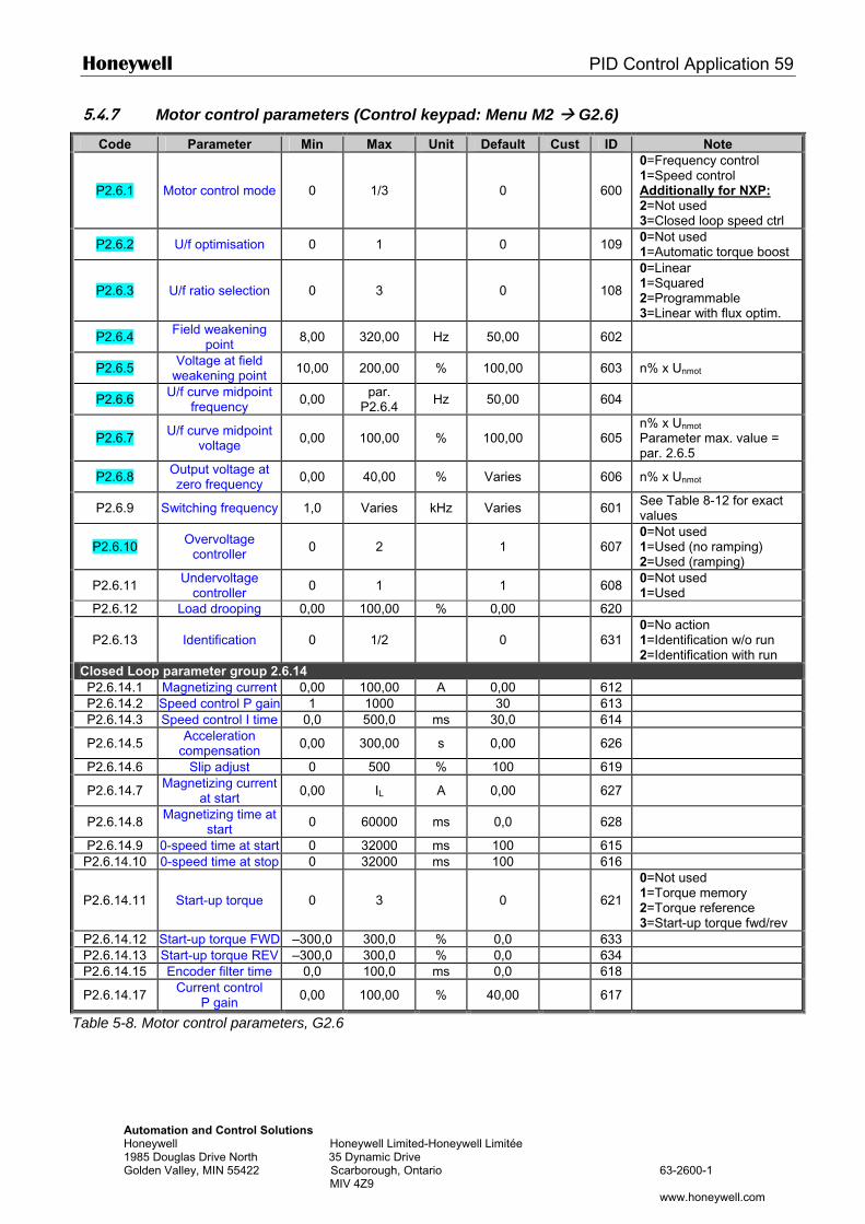
Honeywell PID Control Application 59
Automation and Control Solutions Honeywell Honeywell Limited-Honeywell Limitée 1985 Douglas Drive North 35 Dynamic Drive Golden Valley, MIN 55422 Scarborough, Ontario 63-2600-1 MIV 4Z9 www.honeywell.com
5.4.7 Motor control parameters (Control keypad: Menu M2 G2.6)
Code Parameter Min Max Unit Default Cust ID Note
P2.6.1 Motor control mode 0 1/3 0
600
0=Frequency control 1=Speed control Additionally for NXP: 2=Not used 3=Closed loop speed ctrl
P2.6.2 U/f optimisation 0 1 0 109 0=Not used 1=Automatic torque boost
P2.6.3 U/f ratio selection 0 3 0
108
0=Linear 1=Squared 2=Programmable 3=Linear with flux optim.
P2.6.4 Field weakening point 8,00 320,00 Hz 50,00 602
P2.6.5 Voltage at field weakening point 10,00 200,00 % 100,00 603 n% x Unmot
P2.6.6 U/f curve midpoint frequency 0,00 par.
P2.6.4 Hz 50,00 604
P2.6.7 U/f curve midpoint voltage 0,00 100,00 % 100,00
605
n% x Unmot
Parameter max. value = par. 2.6.5
P2.6.8 Output voltage at zero frequency 0,00 40,00 % Varies 606 n% x Unmot
P2.6.9 Switching frequency 1,0 Varies kHz Varies 601 See Table 8-12 for exact values
P2.6.10 Overvoltage controller 0 2 1
607
0=Not used 1=Used (no ramping) 2=Used (ramping)
P2.6.11 Undervoltage controller 0 1 1 608 0=Not used
1=Used P2.6.12 Load drooping 0,00 100,00 % 0,00 620
P2.6.13 Identification 0 1/2 0
631 0=No action 1=Identification w/o run 2=Identification with run
Closed Loop parameter group 2.6.14 P2.6.14.1 Magnetizing current 0,00 100,00 A 0,00 612 P2.6.14.2 Speed control P gain 1 1000 30 613 P2.6.14.3 Speed control I time 0,0 500,0 ms 30,0 614
P2.6.14.5 Acceleration compensation 0,00 300,00 s 0,00 626
P2.6.14.6 Slip adjust 0 500 % 100 619
P2.6.14.7 Magnetizing current at start 0,00 IL A 0,00 627
P2.6.14.8 Magnetizing time at start 0 60000 ms 0,0 628
P2.6.14.9 0-speed time at start 0 32000 ms 100 615 P2.6.14.10 0-speed time at stop 0 32000 ms 100 616
P2.6.14.11 Start-up torque 0 3 0
621
0=Not used 1=Torque memory 2=Torque reference 3=Start-up torque fwd/rev
P2.6.14.12 Start-up torque FWD –300,0 300,0 % 0,0 633 P2.6.14.13 Start-up torque REV –300,0 300,0 % 0,0 634 P2.6.14.15 Encoder filter time 0,0 100,0 ms 0,0 618
P2.6.14.17 Current control P gain 0,00 100,00 % 40,00 617
Table 5-8. Motor control parameters, G2.6
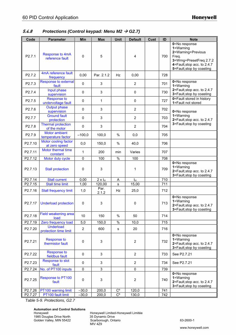
60 PID Control Application Honeywell
Automation and Control Solutions Honeywell Honeywell Limited-Honeywell Limitée 1985 Douglas Drive North 35 Dynamic Drive Golden Valley, MIN 55422 Scarborough, Ontario 63-2600-1 MIV 4Z9 www.honeywell.com
5.4.8 Protections (Control keypad: Menu M2 G2.7)
Code Parameter Min Max Unit Default Cust ID Note
P2.7.1 Response to 4mA reference fault 0 5 4
700
0=No response 1=Warning 2=Warning+Previous Freq. 3=Wrng+PresetFreq 2.7.2 4=Fault,stop acc. to 2.4.7 5=Fault,stop by coasting
P2.7.2 4mA reference fault frequency 0,00 Par. 2.1.2 Hz 0,00 728
P2.7.3 Response to external fault 0 3 2 701
P2.7.4 Input phase supervision 0 3 0 730
0=No response 1=Warning 2=Fault,stop acc. to 2.4.7 3=Fault,stop by coasting
P2.7.5 Response to undervoltage fault 0 1 0 727 0=Fault stored in history
1=Fault not stored
P2.7.6 Output phase supervision 0 3 2 702
P2.7.7 Ground fault protection 0 3 2 703
P2.7.8 Thermal protection of the motor 0 3 2 704
0=No response 1=Warning 2=Fault,stop acc. to 2.4.7 3=Fault,stop by coasting
P2.7.9 Motor ambient temperature factor –100,0 100,0 % 0,0 705
P2.7.10 Motor cooling factor at zero speed 0,0 150,0 % 40,0 706
P2.7.11 Motor thermal time constant 1 200 min Varies 707
P2.7.12 Motor duty cycle 0 100 % 100 708
P2.7.13 Stall protection 0 3 1
709
0=No response 1=Warning 2=Fault,stop acc. to 2.4.7 3=Fault,stop by coasting
P2.7.14 Stall current 0,00 2 x IH A IH 710 P2.7.15 Stall time limit 1,00 120,00 s 15,00 711
P2.7.16 Stall frequency limit 1,0 Par. 2.1.2 Hz 25,0 712
P2.7.17 Underload protection 0 3 0
713
0=No response 1=Warning 2=Fault,stop acc. to 2.4.7 3=Fault,stop by coasting
P2.7.18 Field weakening area load 10 150 % 50 714
P2.7.19 Zero frequency load 5,0 150,0 % 10,0 715
P2.7.20 Underload protection time limit 2 600 s 20 716
P2.7.21 Response to thermistor fault 0 3 2
732
0=No response 1=Warning 2=Fault,stop acc. to 2.4.7 3=Fault,stop by coasting
P2.7.22 Response to fieldbus fault 0 3 2 733 See P2.7.21
P2.7.23 Response to slot fault 0 3 2 734 See P2.7.21
P2.7.24 No. of PT100 inputs 0 3 0 739
P2.7.25 Response to PT100 fault 0 3 2
740
0=No response 1=Warning 2=Fault,stop acc. to 2.4.7 3=Fault,stop by coasting
P2.7.26 PT100 warning limit –30,0 200,0 Cº 120,0 741 P2.7.27 PT100 fault limit –30,0 200,0 Cº 130,0 742
Table 5-9. Protections, G2.7
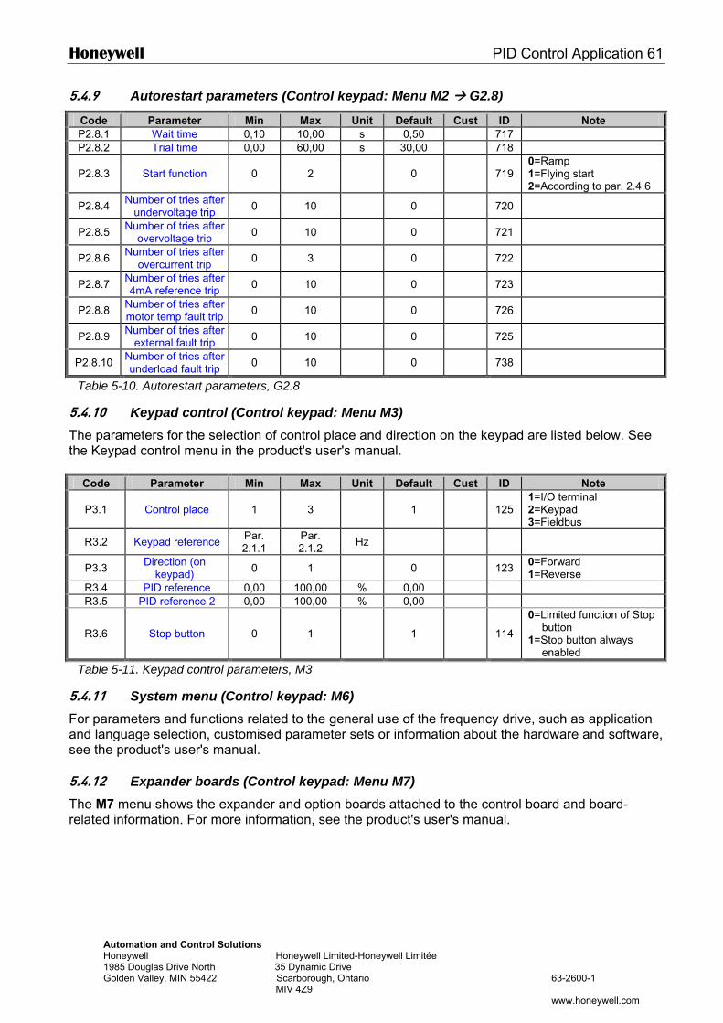
Honeywell PID Control Application 61
Automation and Control Solutions Honeywell Honeywell Limited-Honeywell Limitée 1985 Douglas Drive North 35 Dynamic Drive Golden Valley, MIN 55422 Scarborough, Ontario 63-2600-1 MIV 4Z9 www.honeywell.com
5.4.9 Autorestart parameters (Control keypad: Menu M2 G2.8)
Code Parameter Min Max Unit Default Cust ID Note P2.8.1 Wait time 0,10 10,00 s 0,50 717 P2.8.2 Trial time 0,00 60,00 s 30,00 718
P2.8.3 Start function 0 2 0
719 0=Ramp 1=Flying start 2=According to par. 2.4.6
P2.8.4 Number of tries after undervoltage trip 0 10 0 720
P2.8.5 Number of tries after overvoltage trip 0 10 0 721
P2.8.6 Number of tries after overcurrent trip 0 3 0 722
P2.8.7 Number of tries after 4mA reference trip 0 10 0 723
P2.8.8 Number of tries after motor temp fault trip 0 10 0 726
P2.8.9 Number of tries after external fault trip 0 10 0 725
P2.8.10 Number of tries after underload fault trip 0 10 0 738
Table 5-10. Autorestart parameters, G2.8
5.4.10 Keypad control (Control keypad: Menu M3) The parameters for the selection of control place and direction on the keypad are listed below. See the Keypad control menu in the product's user's manual.
Code Parameter Min Max Unit Default Cust ID Note
P3.1 Control place 1 3 1
125 1=I/O terminal 2=Keypad 3=Fieldbus
R3.2 Keypad reference Par. 2.1.1
Par. 2.1.2 Hz
P3.3 Direction (on keypad) 0 1 0 123 0=Forward
1=Reverse R3.4 PID reference 0,00 100,00 % 0,00 R3.5 PID reference 2 0,00 100,00 % 0,00
R3.6 Stop button 0 1 1
114
0=Limited function of Stop button
1=Stop button always enabled
Table 5-11. Keypad control parameters, M3
5.4.11 System menu (Control keypad: M6) For parameters and functions related to the general use of the frequency drive, such as application and language selection, customised parameter sets or information about the hardware and software, see the product's user's manual. 5.4.12 Expander boards (Control keypad: Menu M7) The M7 menu shows the expander and option boards attached to the control board and board-related information. For more information, see the product's user's manual.
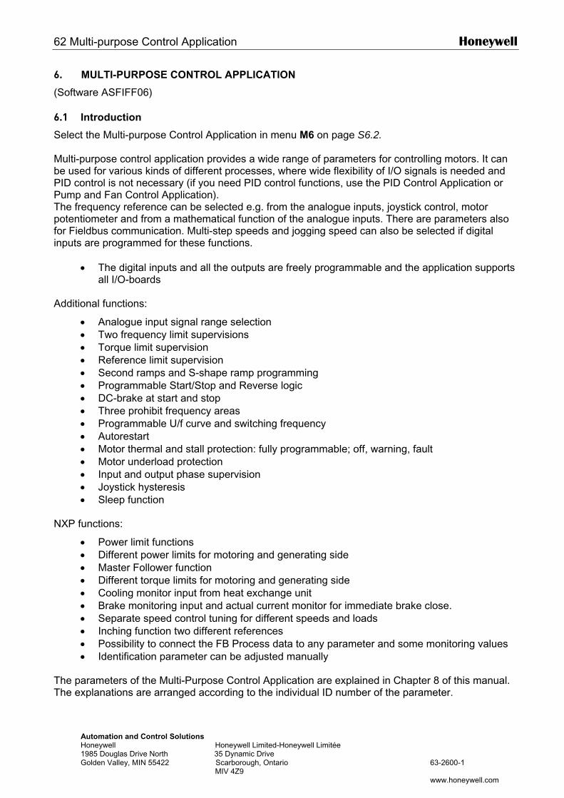
62 Multi-purpose Control Application Honeywell
Automation and Control Solutions Honeywell Honeywell Limited-Honeywell Limitée 1985 Douglas Drive North 35 Dynamic Drive Golden Valley, MIN 55422 Scarborough, Ontario 63-2600-1 MIV 4Z9 www.honeywell.com
6. MULTI-PURPOSE CONTROL APPLICATION
(Software ASFIFF06) 6.1 Introduction
Select the Multi-purpose Control Application in menu M6 on page S6.2. Multi-purpose control application provides a wide range of parameters for controlling motors. It can be used for various kinds of different processes, where wide flexibility of I/O signals is needed and PID control is not necessary (if you need PID control functions, use the PID Control Application or Pump and Fan Control Application). The frequency reference can be selected e.g. from the analogue inputs, joystick control, motor potentiometer and from a mathematical function of the analogue inputs. There are parameters also for Fieldbus communication. Multi-step speeds and jogging speed can also be selected if digital inputs are programmed for these functions.
• The digital inputs and all the outputs are freely programmable and the application supports all I/O-boards
Additional functions:
• Analogue input signal range selection • Two frequency limit supervisions • Torque limit supervision • Reference limit supervision • Second ramps and S-shape ramp programming • Programmable Start/Stop and Reverse logic • DC-brake at start and stop • Three prohibit frequency areas • Programmable U/f curve and switching frequency • Autorestart • Motor thermal and stall protection: fully programmable; off, warning, fault • Motor underload protection • Input and output phase supervision • Joystick hysteresis • Sleep function
NXP functions:
• Power limit functions • Different power limits for motoring and generating side • Master Follower function • Different torque limits for motoring and generating side • Cooling monitor input from heat exchange unit • Brake monitoring input and actual current monitor for immediate brake close. • Separate speed control tuning for different speeds and loads • Inching function two different references • Possibility to connect the FB Process data to any parameter and some monitoring values • Identification parameter can be adjusted manually
The parameters of the Multi-Purpose Control Application are explained in Chapter 8 of this manual. The explanations are arranged according to the individual ID number of the parameter.
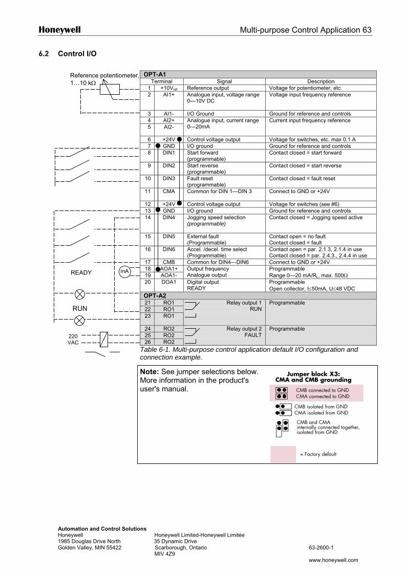
Honeywell Multi-purpose Control Application 63
AutHon198Gol
6.2 Control I/O
OPT-A1
Terminal Signal Description 1 +10Vref Reference output Voltage for potentiometer, etc. 2 AI1+ Analogue input, voltage range
0—10V DC Voltage input frequency reference
3 AI1- I/O Ground Ground for reference and controls 4 AI2+ 5 AI2-
Analogue input, current range 0—20mA
Current input frequency reference
6 +24V Control voltage output Voltage for switches, etc. max 0.1 A 7 GND I/O ground Ground for reference and controls 8 DIN1 Start forward
(programmable) Contact closed = start forward
9 DIN2 Start reverse (programmable)
Contact closed = start reverse
10 DIN3 Fault reset (programmable)
Contact closed = fault reset
11 CMA
Common for DIN 1—DIN 3 Connect to GND or +24V
12 +24V Control voltage output Voltage for switches (see #6) 13 GND I/O ground Ground for reference and controls 14 DIN4 Jogging speed selection
(programmable) Contact closed = Jogging speed active
15 DIN5 External fault (Programmable)
Contact open = no fault Contact closed = fault
16 DIN6 Accel. /decel. time select (Programmable)
Contact open = par. 2.1.3, 2.1.4 in use Contact closed = par. 2.4.3., 2.4.4 in use
17 CMB Common for DIN4—DIN6 Connect to GND or +24V 18 AOA1+ 19 AOA1-
Output frequency Analogue output
Programmable Range 0—20 mA/RL, max. 500Ω
20 DOA1 Digital output Programmable
mA
Reference potentiometer, 1…10 kΩ
READYomation and Control Solutions eywell Honeywell Limited-Honeywell Limitée 5 Douglas Drive North 35 Dynamic Drive den Valley, MIN 55422 Scarborough, Ontario 63-2600-1 MIV 4Z9
www.honeywell.com
Jumper block X3:CMA and CMB grounding
CMB connected to GNDCMA connected to GND
CMB isolated from GNDCMA isolated from GND
CMB and CMAinternally connected together,isolated from GND
= Factory default
READY Open collector, I≤50mA, U≤48 VDC OPT-A2 21 RO1 22 RO1 23 RO1
Relay output 1 RUN
Programmable
24 RO2 25 RO2 26 RO2
Relay output 2 FAULT
Programmable
Table 6-1. Multi-purpose control application default I/O configuration and connection example.
Note: See jumper selections below. More information in the product's user's manual.
220 VAC
RUN
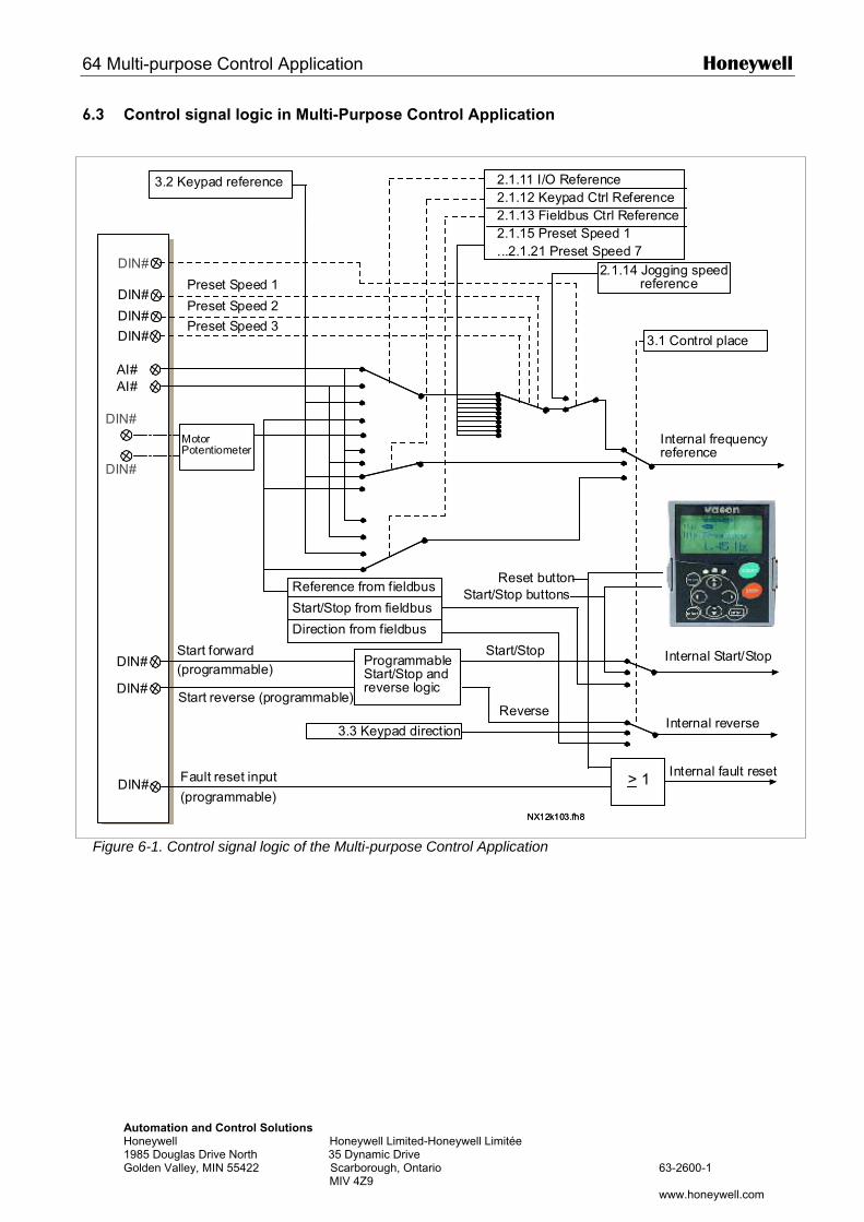
64 Multi-purpose Control Application Honeywell
Automation and Control Solutions Honeywell Honeywell Limited-Honeywell Limitée 1985 Douglas Drive North 35 Dynamic Drive Golden Valley, MIN 55422 Scarborough, Ontario 63-2600-1 MIV 4Z9 www.honeywell.com
6.3 Control signal logic in Multi-Purpose Control Application
Figure 6-1. Control signal logic of the Multi-purpose Control Application
DIN#
DIN#
AIA#AIA#
DIN#
DIN#
DIN# > 1
DIN#
DIN#
NX12k103.fh8
DIN#
DIN#
DIN#
DIN#
AI#AI#
DIN#
DIN#
DIN# > 1
DIN#
DIN#
NX12k103.fh8
DIN#
DIN#
3.2 Keypad reference 2.1.11 I/O Reference2.1.12 Keypad Ctrl Reference2.1.13 Fieldbus Ctrl Reference2.1.15 Preset Speed 1...2.1.21 Preset Speed 7
3.1 Control place
Internal frequencyreference
Start forward(programmable)
Start reverse (programmable)
ProgrammableStart/Stop andreverse logic
Start/Stop
Reverse
Internal Start/Stop
Internal reverse
Internal fault resetFault reset input
Reset buttonStart/Stop buttonsReference from fieldbus
Start/Stop from fieldbus
Direction from fieldbus
3.3 Keypad direction
Preset Speed 1
Preset Speed 2
Preset Speed 3
2.1.14 Jogging speed reference
(programmable)
MotorPotentiometer
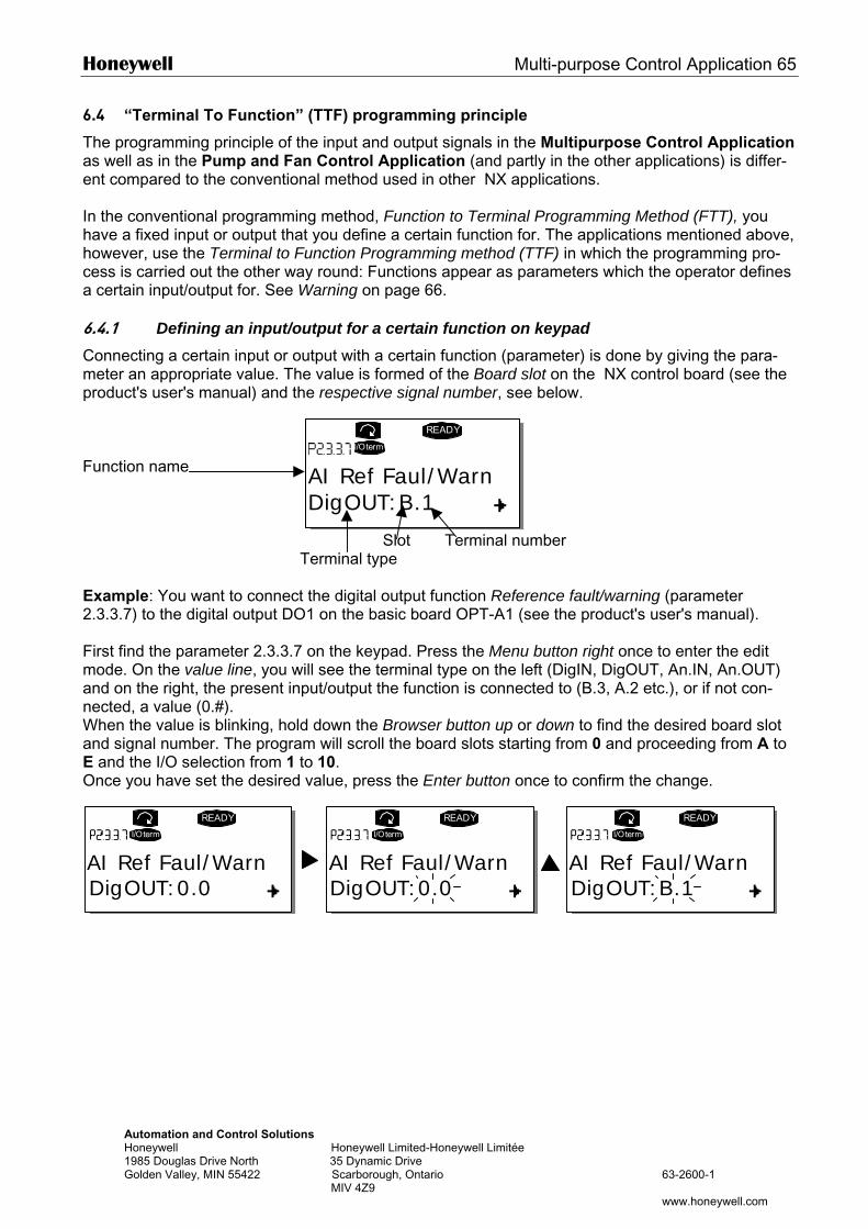
Honeywell Multi-purpose Control Application 65
Automation and Control Solutions Honeywell Honeywell Limited-Honeywell Limitée 1985 Douglas Drive North 35 Dynamic Drive Golden Valley, MIN 55422 Scarborough, Ontario 63-2600-1 MIV 4Z9 www.honeywell.com
6.4 “Terminal To Function” (TTF) programming principle
The programming principle of the input and output signals in the Multipurpose Control Application as well as in the Pump and Fan Control Application (and partly in the other applications) is differ-ent compared to the conventional method used in other NX applications. In the conventional programming method, Function to Terminal Programming Method (FTT), you have a fixed input or output that you define a certain function for. The applications mentioned above, however, use the Terminal to Function Programming method (TTF) in which the programming pro-cess is carried out the other way round: Functions appear as parameters which the operator defines a certain input/output for. See Warning on page 66. 6.4.1 Defining an input/output for a certain function on keypad Connecting a certain input or output with a certain function (parameter) is done by giving the para-meter an appropriate value. The value is formed of the Board slot on the NX control board (see the product's user's manual) and the respective signal number, see below. Function name Slot Terminal number Terminal type Example: You want to connect the digital output function Reference fault/warning (parameter 2.3.3.7) to the digital output DO1 on the basic board OPT-A1 (see the product's user's manual). First find the parameter 2.3.3.7 on the keypad. Press the Menu button right once to enter the edit mode. On the value line, you will see the terminal type on the left (DigIN, DigOUT, An.IN, An.OUT) and on the right, the present input/output the function is connected to (B.3, A.2 etc.), or if not con-nected, a value (0.#). When the value is blinking, hold down the Browser button up or down to find the desired board slot and signal number. The program will scroll the board slots starting from 0 and proceeding from A to E and the I/O selection from 1 to 10. Once you have set the desired value, press the Enter button once to confirm the change.
READY
I/Oterm
DigOUT:B.1AI Ref Faul/Warn
READY
I/Oterm
DigOUT:0.0
READY
I/Oterm
DigOUT:0.0
READY
I/Oterm
DigOUT:B.1AI Ref Faul/Warn AI Ref Faul/Warn AI Ref Faul/Warn
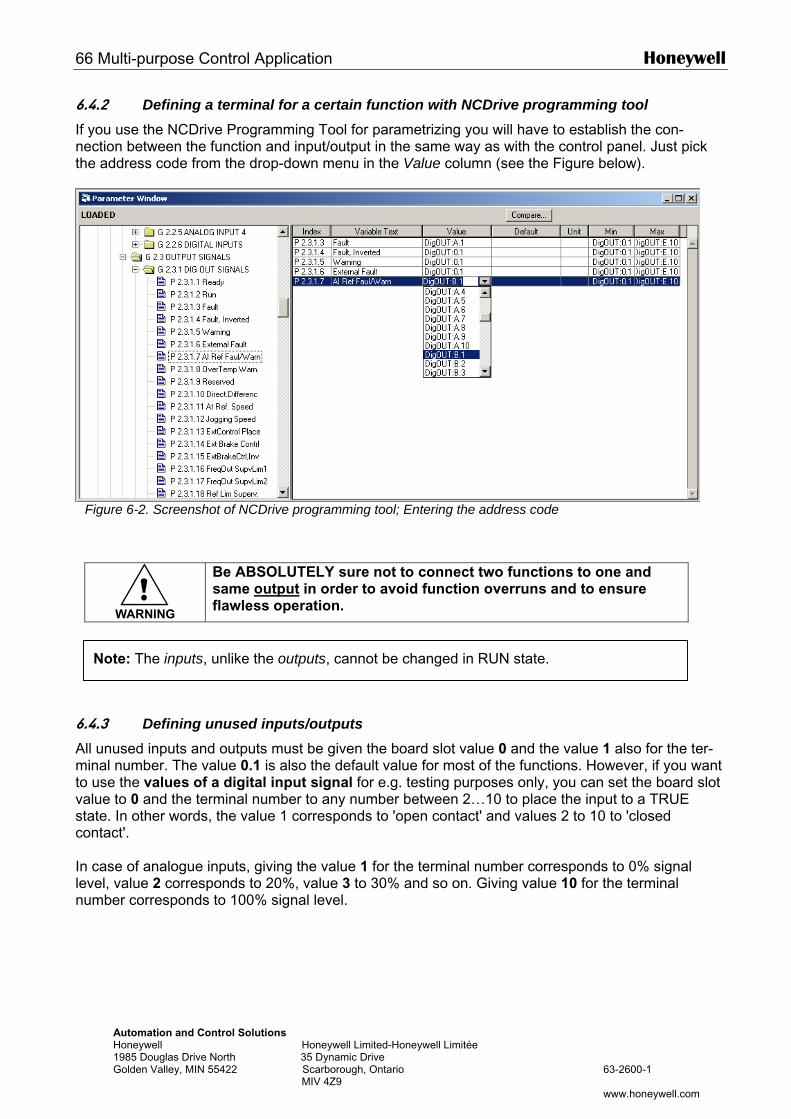
66 Multi-purpose Control Application Honeywell
Automation and Control Solutions Honeywell Honeywell Limited-Honeywell Limitée 1985 Douglas Drive North 35 Dynamic Drive Golden Valley, MIN 55422 Scarborough, Ontario 63-2600-1 MIV 4Z9 www.honeywell.com
6.4.2 Defining a terminal for a certain function with NCDrive programming tool If you use the NCDrive Programming Tool for parametrizing you will have to establish the con-nection between the function and input/output in the same way as with the control panel. Just pick the address code from the drop-down menu in the Value column (see the Figure below).
Figure 6-2. Screenshot of NCDrive programming tool; Entering the address code
!WARNING
Be ABSOLUTELY sure not to connect two functions to one and same output in order to avoid function overruns and to ensure flawless operation.
6.4.3 Defining unused inputs/outputs All unused inputs and outputs must be given the board slot value 0 and the value 1 also for the ter-minal number. The value 0.1 is also the default value for most of the functions. However, if you want to use the values of a digital input signal for e.g. testing purposes only, you can set the board slot value to 0 and the terminal number to any number between 2…10 to place the input to a TRUE state. In other words, the value 1 corresponds to 'open contact' and values 2 to 10 to 'closed contact'. In case of analogue inputs, giving the value 1 for the terminal number corresponds to 0% signal level, value 2 corresponds to 20%, value 3 to 30% and so on. Giving value 10 for the terminal number corresponds to 100% signal level.
Note: The inputs, unlike the outputs, cannot be changed in RUN state.
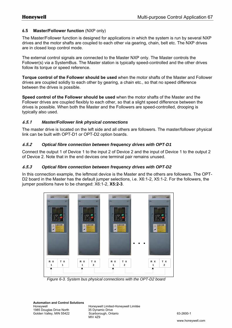
Honeywell Multi-purpose Control Application 67
AutomaHoneyw1985 DoGolden
6.5 Master/Follower function (NXP only)
The Master/Follower function is designed for applications in which the system is run by several NXP drives and the motor shafts are coupled to each other via gearing, chain, belt etc. The NXP drives are in closed loop control mode. The external control signals are connected to the Master NXP only. The Master controls the Follower(s) via a SystemBus. The Master station is typically speed-controlled and the other drives follow its torque or speed reference. Torque control of the Follower should be used when the motor shafts of the Master and Follower drives are coupled solidly to each other by gearing, a chain etc., so that no speed difference between the drives is possible. Speed control of the Follower should be used when the motor shafts of the Master and the Follower drives are coupled flexibly to each other, so that a slight speed difference between the drives is possible. When both the Master and the Followers are speed-controlled, drooping is typically also used. 6.5.1 Master/Follower link physical connections The master drive is located on the left side and all others are followers. The master/follower physical link can be built with OPT-D1 or OPT-D2 option boards. 6.5.2 Optical fibre connection between frequency drives with OPT-D1 Connect the output 1 of Device 1 to the input 2 of Device 2 and the input of Device 1 to the output 2 of Device 2. Note that in the end devices one terminal pair remains unused. 6.5.3 Optical fibre connection between frequency drives with OPT-D2 In this connection example, the leftmost device is the Master and the others are followers. The OPT-D2 board in the Master has the default jumper selections, i.e. X6:1-2, X5:1-2. For the followers, the jumper positions have to be changed: X6:1-2, X5:2-3.
tion and Control Solutions ell Honeywell Limited-Honeywell Limitée uglas Drive North 35 Dynamic Drive
Valley, MIN 55422 Scarborough, Ontario 63-2600-1 MIV 4Z9
www.honeywell.com
Figure 6-3. System bus physical connections with the OPT-D2 board
R X 1
T X 1
R X 1
T X 2
R X 1
T X 2
. . .
R X 1
T X 2
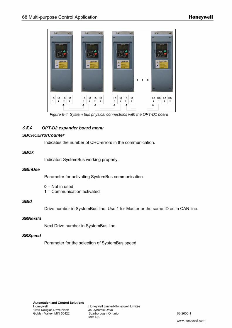
68 Multi-purpose Control Application Honeywell
AutomatioHoneywell 1985 DougGolden Va
6.5.4 OPSBCRCError
In
SBOk In
SBInUse Pa 0 1
SBId Dr
SBNextId Ne
SBSpeed Pa
n and Control Solutions Honeywell Limited-Honeywell Limitée
las Drive North 35 Dynamic Drive lley, MIN 55422 Scarborough, Ontario 63-2600-1 MIV 4Z9
www.honeywell.com
Figure 6-4. System bus physical connections with the OPT-D1 board
T-D2 expander board menu Counter dicates the number of CRC-errors in the communication.
dicator: SystemBus working properly.
rameter for activating SystemBus communication.
= Not in used = Communication activated
ive number in SystemBus line. Use 1 for Master or the same ID as in CAN line.
xt Drive number in SystemBus line.
rameter for the selection of SystemBus speed.
TX 2
RX 1
TX 1
RX 2
TX 2
RX 1
TX 1
RX 2
TX 2
RX 1
TX 1
RX 2
TX 2
RX 1
TX 1
RX 2
. . .
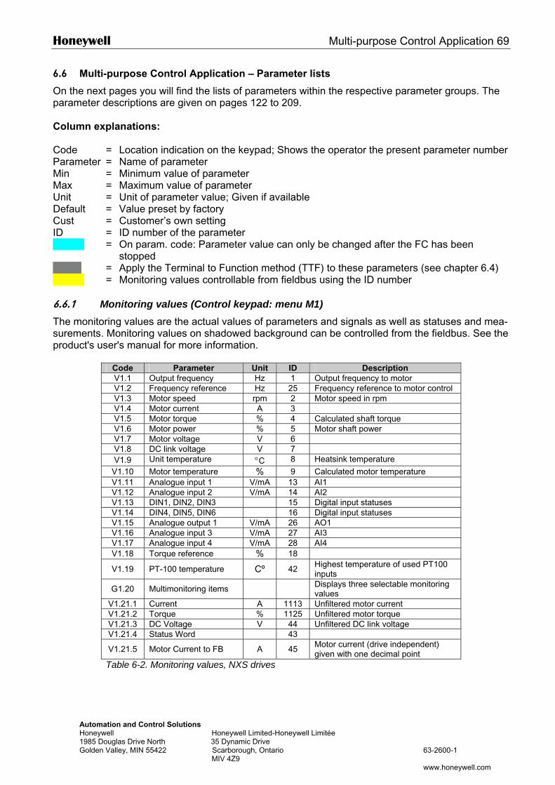
Honeywell Multi-purpose Control Application 69
Automation and Control Solutions Honeywell Honeywell Limited-Honeywell Limitée 1985 Douglas Drive North 35 Dynamic Drive Golden Valley, MIN 55422 Scarborough, Ontario 63-2600-1 MIV 4Z9 www.honeywell.com
6.6 Multi-purpose Control Application – Parameter lists
On the next pages you will find the lists of parameters within the respective parameter groups. The parameter descriptions are given on pages 122 to 209. Column explanations: Code = Location indication on the keypad; Shows the operator the present parameter number Parameter = Name of parameter Min = Minimum value of parameter Max = Maximum value of parameter Unit = Unit of parameter value; Given if available Default = Value preset by factory Cust = Customer’s own setting ID = ID number of the parameter = On param. code: Parameter value can only be changed after the FC has been
stopped = Apply the Terminal to Function method (TTF) to these parameters (see chapter 6.4) = Monitoring values controllable from fieldbus using the ID number 6.6.1 Monitoring values (Control keypad: menu M1) The monitoring values are the actual values of parameters and signals as well as statuses and mea-surements. Monitoring values on shadowed background can be controlled from the fieldbus. See the product's user's manual for more information.
Code Parameter Unit ID Description V1.1 Output frequency Hz 1 Output frequency to motor V1.2 Frequency reference Hz 25 Frequency reference to motor control V1.3 Motor speed rpm 2 Motor speed in rpm V1.4 Motor current A 3 V1.5 Motor torque % 4 Calculated shaft torque V1.6 Motor power % 5 Motor shaft power V1.7 Motor voltage V 6 V1.8 DC link voltage V 7 V1.9 Unit temperature °C 8 Heatsink temperature
V1.10 Motor temperature % 9 Calculated motor temperature V1.11 Analogue input 1 V/mA 13 AI1 V1.12 Analogue input 2 V/mA 14 AI2 V1.13 DIN1, DIN2, DIN3 15 Digital input statuses V1.14 DIN4, DIN5, DIN6 16 Digital input statuses V1.15 Analogue output 1 V/mA 26 AO1 V1.16 Analogue input 3 V/mA 27 AI3 V1.17 Analogue input 4 V/mA 28 AI4 V1.18 Torque reference % 18
V1.19 PT-100 temperature Cº 42 Highest temperature of used PT100 inputs
G1.20 Multimonitoring items Displays three selectable monitoring values
V1.21.1 Current A 1113 Unfiltered motor current V1.21.2 Torque % 1125 Unfiltered motor torque V1.21.3 DC Voltage V 44 Unfiltered DC link voltage V1.21.4 Status Word 43
V1.21.5 Motor Current to FB A 45 Motor current (drive independent) given with one decimal point
Table 6-2. Monitoring values, NXS drives
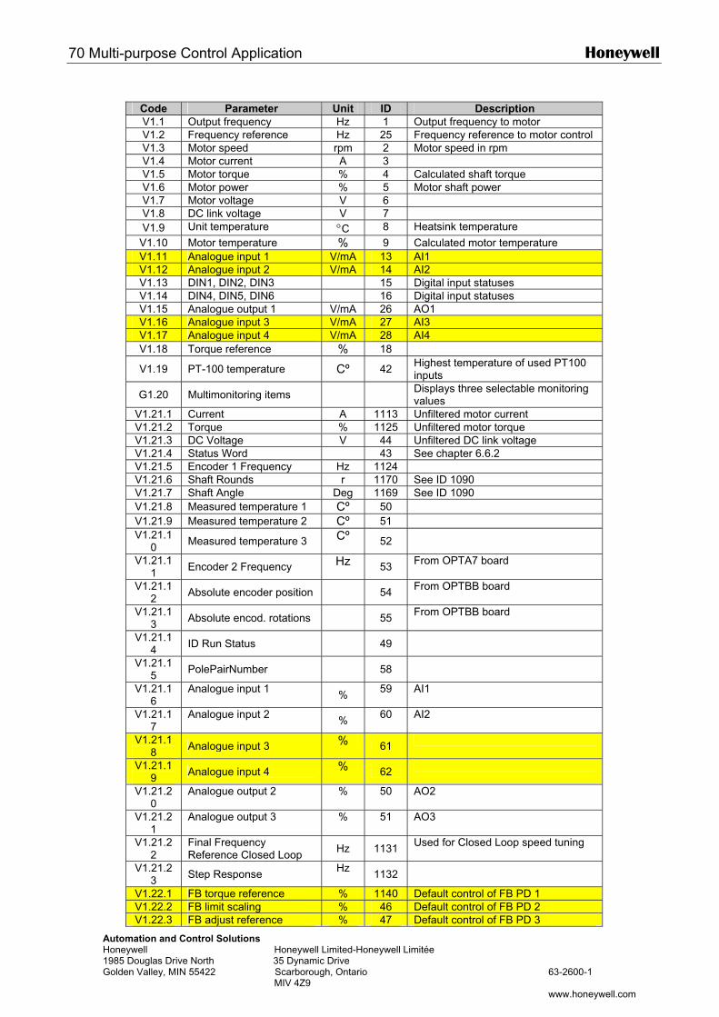
70 Multi-purpose Control Application Honeywell
Automation and Control Solutions Honeywell Honeywell Limited-Honeywell Limitée 1985 Douglas Drive North 35 Dynamic Drive Golden Valley, MIN 55422 Scarborough, Ontario 63-2600-1 MIV 4Z9 www.honeywell.com
Code Parameter Unit ID Description V1.1 Output frequency Hz 1 Output frequency to motor V1.2 Frequency reference Hz 25 Frequency reference to motor control V1.3 Motor speed rpm 2 Motor speed in rpm V1.4 Motor current A 3 V1.5 Motor torque % 4 Calculated shaft torque V1.6 Motor power % 5 Motor shaft power V1.7 Motor voltage V 6 V1.8 DC link voltage V 7 V1.9 Unit temperature °C 8 Heatsink temperature
V1.10 Motor temperature % 9 Calculated motor temperature V1.11 Analogue input 1 V/mA 13 AI1 V1.12 Analogue input 2 V/mA 14 AI2 V1.13 DIN1, DIN2, DIN3 15 Digital input statuses V1.14 DIN4, DIN5, DIN6 16 Digital input statuses V1.15 Analogue output 1 V/mA 26 AO1 V1.16 Analogue input 3 V/mA 27 AI3 V1.17 Analogue input 4 V/mA 28 AI4 V1.18 Torque reference % 18
V1.19 PT-100 temperature Cº 42 Highest temperature of used PT100 inputs
G1.20 Multimonitoring items Displays three selectable monitoring values
V1.21.1 Current A 1113 Unfiltered motor current V1.21.2 Torque % 1125 Unfiltered motor torque V1.21.3 DC Voltage V 44 Unfiltered DC link voltage V1.21.4 Status Word 43 See chapter 6.6.2 V1.21.5 Encoder 1 Frequency Hz 1124 V1.21.6 Shaft Rounds r 1170 See ID 1090 V1.21.7 Shaft Angle Deg 1169 See ID 1090 V1.21.8 Measured temperature 1 Cº 50 V1.21.9 Measured temperature 2 Cº 51 V1.21.1
0 Measured temperature 3 Cº 52
V1.21.11 Encoder 2 Frequency Hz 53 From OPTA7 board
V1.21.12 Absolute encoder position 54 From OPTBB board
V1.21.13 Absolute encod. rotations 55 From OPTBB board
V1.21.14 ID Run Status 49
V1.21.15 PolePairNumber 58
V1.21.16
Analogue input 1 % 59 AI1
V1.21.17
Analogue input 2 % 60 AI2
V1.21.18 Analogue input 3 % 61
V1.21.19 Analogue input 4 % 62
V1.21.20
Analogue output 2 % 50 AO2
V1.21.21
Analogue output 3 % 51 AO3
V1.21.22
Final Frequency Reference Closed Loop Hz 1131 Used for Closed Loop speed tuning
V1.21.23 Step Response Hz 1132
V1.22.1 FB torque reference % 1140 Default control of FB PD 1 V1.22.2 FB limit scaling % 46 Default control of FB PD 2 V1.22.3 FB adjust reference % 47 Default control of FB PD 3
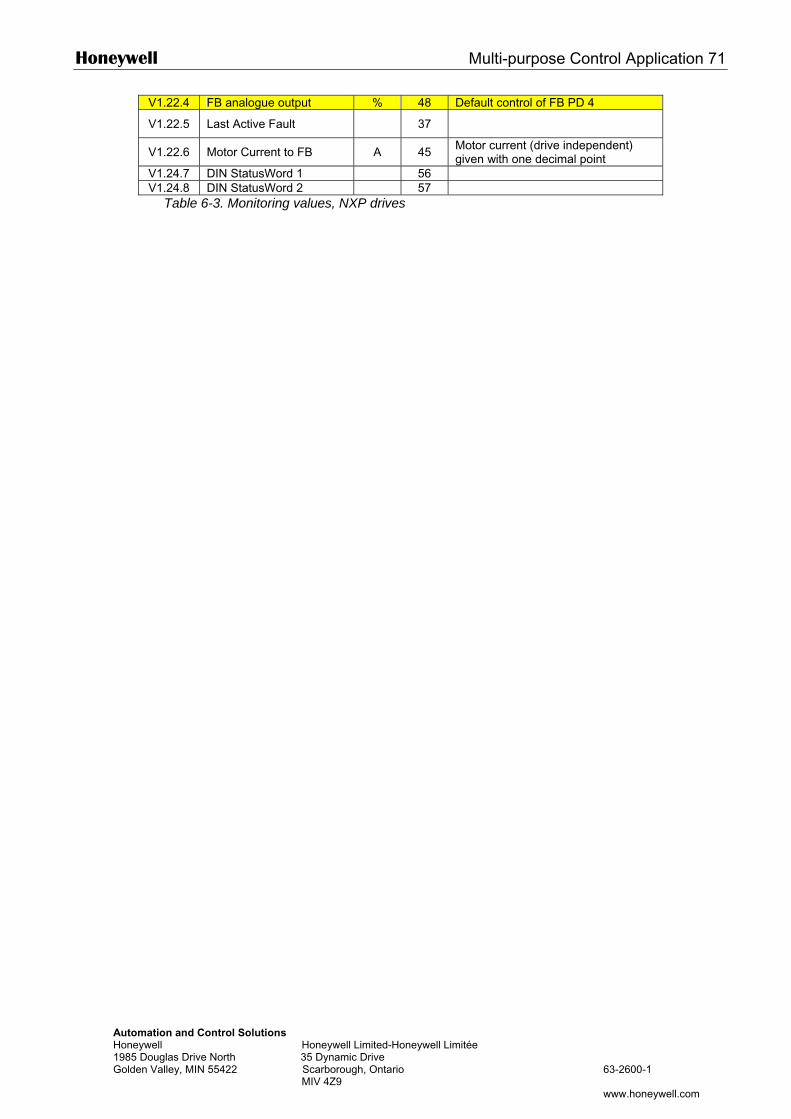
Honeywell Multi-purpose Control Application 71
Automation and Control Solutions Honeywell Honeywell Limited-Honeywell Limitée 1985 Douglas Drive North 35 Dynamic Drive Golden Valley, MIN 55422 Scarborough, Ontario 63-2600-1 MIV 4Z9 www.honeywell.com
V1.22.4 FB analogue output % 48 Default control of FB PD 4
V1.22.5 Last Active Fault 37
V1.22.6 Motor Current to FB A 45 Motor current (drive independent) given with one decimal point
V1.24.7 DIN StatusWord 1 56 V1.24.8 DIN StatusWord 2 57
Table 6-3. Monitoring values, NXP drives
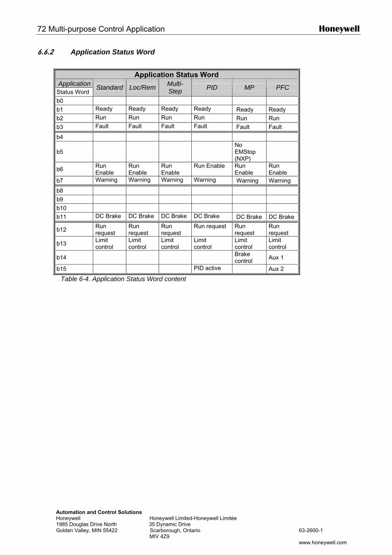
72 Multi-purpose Control Application Honeywell
Automation and Control Solutions Honeywell Honeywell Limited-Honeywell Limitée 1985 Douglas Drive North 35 Dynamic Drive Golden Valley, MIN 55422 Scarborough, Ontario 63-2600-1 MIV 4Z9 www.honeywell.com
6.6.2 Application Status Word
Application Status Word Application Status Word
Standard Loc/Rem Multi-Step PID MP PFC
b0
b1 Ready Ready Ready Ready Ready Ready
b2 Run Run Run Run Run Run
b3 Fault Fault Fault Fault Fault Fault
b4
b5 No
EMStop (NXP)
b6 Run Enable
Run Enable
Run Enable
Run Enable Run Enable
Run Enable
b7 Warning Warning Warning Warning Warning Warning
b8
b9
b10
b11 DC Brake DC Brake DC Brake DC Brake DC Brake DC Brake
b12 Run request
Run request
Run request
Run request Run request
Run request
b13 Limit control
Limit control
Limit control
Limit control
Limit control
Limit control
b14 Brake control Aux 1
b15 PID active Aux 2
Table 6-4. Application Status Word content
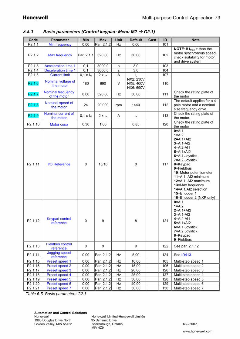
Honeywell Multi-purpose Control Application 73
Automation and Control Solutions Honeywell Honeywell Limited-Honeywell Limitée 1985 Douglas Drive North 35 Dynamic Drive Golden Valley, MIN 55422 Scarborough, Ontario 63-2600-1 MIV 4Z9 www.honeywell.com
6.6.3 Basic parameters (Control keypad: Menu M2 G2.1)
Code Parameter Min Max Unit Default Cust ID Note P2.1.1 Min frequency 0,00 Par. 2.1.2 Hz 0,00 101
P2.1.2 Max frequency Par. 2.1.1 320,00 Hz 50,00 102
NOTE: If fmax > than the motor synchronous speed, check suitability for motor and drive system
P2.1.3 Acceleration time 1 0,1 3000,0 s 3,0 103 P2.1.4 Deceleration time 1 0,1 3000,0 s 3,0 104 P2.1.5 Current limit 0,1 x IH 2 x IH A IL 107
P2.1.6 Nominal voltage of the motor 180 690 V
NX2: 230VNX5: 400VNX6: 690V
110
P2.1.7 Nominal frequency of the motor 8,00 320,00 Hz 50,00 111 Check the rating plate of
the motor
P2.1.8 Nominal speed of the motor 24 20 000 rpm 1440 112
The default applies for a 4-pole motor and a nominal size frequency drive.
P2.1.9 Nominal current of the motor 0,1 x IH 2 x IH A IH 113 Check the rating plate of
the motor.
P2.1.10 Motor cosϕ 0,30 1,00 0,85 120 Check the rating plate of the motor
P2.1.11 I/O Reference 0 15/16 0 117
0=AI1 1=AI2 2=AI1+AI2 3=AI1-AI2 4=AI2-AI1 5=AI1xAI2 6=AI1 Joystick 7=AI2 Joystick 8=Keypad 9=Fieldbus 10=Motor potentiometer 11=AI1, AI2 minimum 12=AI1, AI2 maximum 13=Max frequency 14=AI1/AI2 selection 15=Encoder 1 16=Encoder 2 (NXP only)
P2.1.12 Keypad control reference 0 9 8 121
0=AI1 1=AI2 2=AI1+AI2 3=AI1-AI2 4=AI2-AI1 5=AI1xAI2 6=AI1 Joystick 7=AI2 Joystick 8=Keypad 9=Fieldbus
P2.1.13 Fieldbus control reference 0 9 9 122 See par. 2.1.12
P2.1.14 Jogging speed reference 0,00 Par. 2.1.2 Hz 5,00 124 See ID413.
P2.1.15 Preset speed 1 0,00 Par. 2.1.2 Hz 10,00 105 Multi-step speed 1 P2.1.16 Preset speed 2 0,00 Par. 2.1.2 Hz 15,00 106 Multi-step speed 2 P2.1.17 Preset speed 3 0,00 Par. 2.1.2 Hz 20,00 126 Multi-step speed 3 P2.1.18 Preset speed 4 0,00 Par. 2.1.2 Hz 25,00 127 Multi-step speed 4 P2.1.19 Preset speed 5 0,00 Par. 2.1.2 Hz 30,00 128 Multi-step speed 5 P2.1.20 Preset speed 6 0,00 Par. 2.1.2 Hz 40,00 129 Multi-step speed 6 P2.1.21 Preset speed 7 0,00 Par. 2.1.2 Hz 50,00 130 Multi-step speed 7
Table 6-5. Basic parameters G2.1
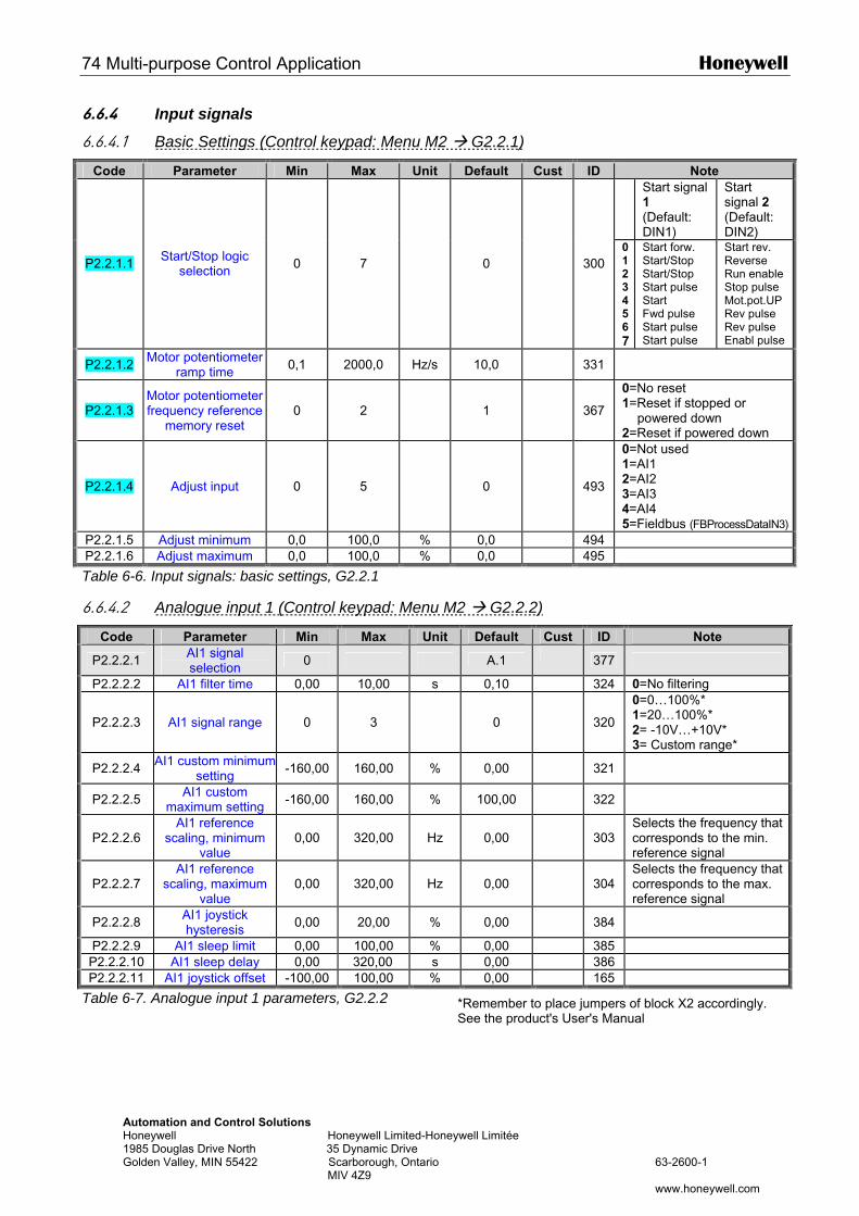
74 Multi-purpose Control Application Honeywell
Automation and Control Solutions Honeywell Honeywell Limited-Honeywell Limitée 1985 Douglas Drive North 35 Dynamic Drive Golden Valley, MIN 55422 Scarborough, Ontario 63-2600-1 MIV 4Z9 www.honeywell.com
6.6.4 Input signals
6.6.4.1 Basic Settings (Control keypad: Menu M2 G2.2.1)
Code Parameter Min Max Unit Default Cust ID Note
Start signal 1 (Default: DIN1)
Start signal 2 (Default: DIN2)
P2.2.1.1 Start/Stop logic selection 0 7 0 300
01 2 3 4 5 6 7
Start forw. Start/Stop Start/Stop Start pulse Start Fwd pulse Start pulse Start pulse
Start rev. Reverse Run enable Stop pulse Mot.pot.UP Rev pulse Rev pulse Enabl pulse
P2.2.1.2 Motor potentiometer ramp time 0,1 2000,0 Hz/s 10,0 331
P2.2.1.3 Motor potentiometer frequency reference
memory reset 0 2 1 367
0=No reset 1=Reset if stopped or
powered down 2=Reset if powered down
P2.2.1.4 Adjust input 0 5 0 493
0=Not used 1=AI1 2=AI2 3=AI3 4=AI4 5=Fieldbus (FBProcessDataIN3)
P2.2.1.5 Adjust minimum 0,0 100,0 % 0,0 494 P2.2.1.6 Adjust maximum 0,0 100,0 % 0,0 495
Table 6-6. Input signals: basic settings, G2.2.1
6.6.4.2 Analogue input 1 (Control keypad: Menu M2 G2.2.2)
Code Parameter Min Max Unit Default Cust ID Note
P2.2.2.1 AI1 signal selection 0 A.1 377
P2.2.2.2 AI1 filter time 0,00 10,00 s 0,10 324 0=No filtering
P2.2.2.3 AI1 signal range 0 3 0
320
0=0…100%* 1=20…100%* 2= -10V…+10V* 3= Custom range*
P2.2.2.4 AI1 custom minimum setting -160,00 160,00 % 0,00 321
P2.2.2.5 AI1 custom maximum setting -160,00 160,00 % 100,00 322
P2.2.2.6 AI1 reference
scaling, minimum value
0,00 320,00 Hz 0,00
303 Selects the frequency that corresponds to the min. reference signal
P2.2.2.7 AI1 reference
scaling, maximum value
0,00 320,00 Hz 0,00
304 Selects the frequency that corresponds to the max. reference signal
P2.2.2.8 AI1 joystick hysteresis 0,00 20,00 % 0,00 384
P2.2.2.9 AI1 sleep limit 0,00 100,00 % 0,00 385 P2.2.2.10 AI1 sleep delay 0,00 320,00 s 0,00 386 P2.2.2.11 AI1 joystick offset -100,00 100,00 % 0,00 165
Table 6-7. Analogue input 1 parameters, G2.2.2 *Remember to place jumpers of block X2 accordingly. See the product's User's Manual
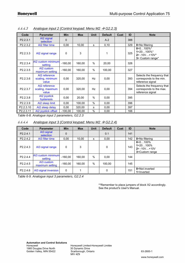
Honeywell Multi-purpose Control Application 75
Automation and Control Solutions Honeywell Honeywell Limited-Honeywell Limitée 1985 Douglas Drive North 35 Dynamic Drive Golden Valley, MIN 55422 Scarborough, Ontario 63-2600-1 MIV 4Z9 www.honeywell.com
6.6.4.3 Analogue input 2 (Control keypad: Menu M2 G2.2.3)
Code Parameter Min Max Unit Default Cust ID Note
P2.2.3.1 AI2 signal selection 0 A.2 388
P2.2.3.2 AI2 filter time 0,00 10,00 s 0,10 329 0=No filtering
P2.2.3.3 AI2 signal range 0 3 1
325
0=0…100%* 1=20…100%* 2= -10V…+10V* 3= Custom range*
P2.2.3.4 AI2 custom minimum setting -160,00 160,00 % 20,00 326
P2.2.3.5 AI2 custom maximum setting -160,00 160,00 % 100,00 327
P2.2.3.6 AI2 reference
scaling, minimum value
0,00 320,00 Hz 0,00
393 Selects the frequency that corresponds to the min. reference signal
P2.2.3.7 AI2 reference
scaling, maximum value
0,00 320,00 Hz 0,00
394 Selects the frequency that corresponds to the max. reference signal
P2.2.3.8 AI2 joystick hysteresis 0,00 20,00 % 0,00 395
P2.2.3.9 AI2 sleep limit 0,00 100,00 % 0,00 396
P2.2.3.10 AI2 sleep delay 0,00 320,00 s 0,00 397 P2.2.3.11 AI2 joystick offset -100,00 100,00 % 0,00 166
Table 6-8. Analogue input 2 parameters, G2.2.3
6.6.4.4 Analogue input 3 (Control keypad: Menu M2 G2.2.4)
Code Parameter Min Max Unit Default Cust ID Note
P2.2.4.1 AI3 signal selection 0 0.1 141
P2.2.4.2 AI3 filter time 0,00 10,00 s 0,00 142 0=No filtering
P2.2.4.3 AI3 signal range 0 3 0
143
0=0…100% 1=20…100% 2= -10V…+10V 3=Custom range
P2.2.4.4 AI3 custom minimum setting -160,00 160,00 % 0,00 144
P2.2.4.5 AI3 custom maximum setting -160,00 160,00 % 100,00 145
P2.2.4.6 AI3 signal inversion 0 1 0 151 0=Not inverted 1=Inverted
Table 6-9. Analogue input 3 parameters, G2.2.4
**Remember to place jumpers of block X2 accordingly. See the product's User's Manual.
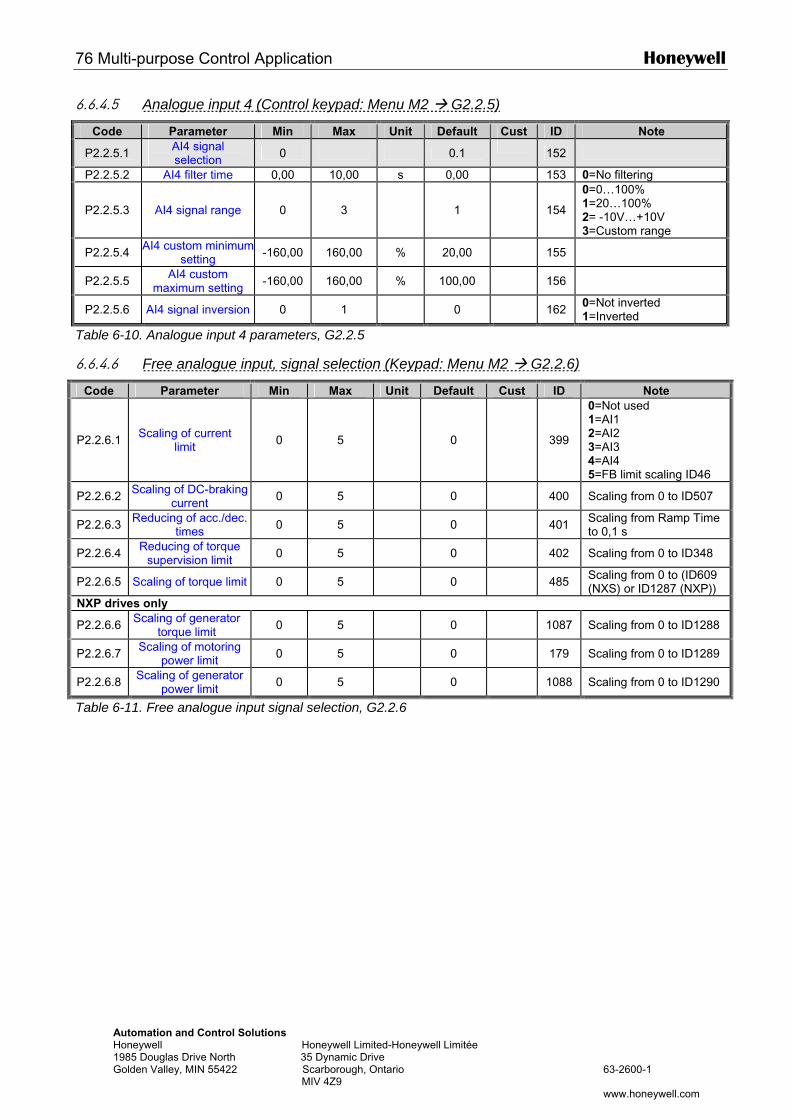
76 Multi-purpose Control Application Honeywell
Automation and Control Solutions Honeywell Honeywell Limited-Honeywell Limitée 1985 Douglas Drive North 35 Dynamic Drive Golden Valley, MIN 55422 Scarborough, Ontario 63-2600-1 MIV 4Z9 www.honeywell.com
6.6.4.5 Analogue input 4 (Control keypad: Menu M2 G2.2.5)
Code Parameter Min Max Unit Default Cust ID Note
P2.2.5.1 AI4 signal selection 0 0.1 152
P2.2.5.2 AI4 filter time 0,00 10,00 s 0,00 153 0=No filtering
P2.2.5.3 AI4 signal range 0 3 1
154
0=0…100% 1=20…100% 2= -10V…+10V 3=Custom range
P2.2.5.4 AI4 custom minimum setting -160,00 160,00 % 20,00 155
P2.2.5.5 AI4 custom maximum setting -160,00 160,00 % 100,00 156
P2.2.5.6 AI4 signal inversion 0 1 0 162 0=Not inverted 1=Inverted
Table 6-10. Analogue input 4 parameters, G2.2.5
6.6.4.6 Free analogue input, signal selection (Keypad: Menu M2 G2.2.6)
Code Parameter Min Max Unit Default Cust ID Note
P2.2.6.1 Scaling of current limit 0 5 0
399
0=Not used 1=AI1 2=AI2 3=AI3 4=AI4 5=FB limit scaling ID46
P2.2.6.2 Scaling of DC-braking current 0 5 0 400 Scaling from 0 to ID507
P2.2.6.3 Reducing of acc./dec. times 0 5 0 401 Scaling from Ramp Time
to 0,1 s
P2.2.6.4 Reducing of torque supervision limit 0 5 0 402 Scaling from 0 to ID348
P2.2.6.5 Scaling of torque limit 0 5 0 485 Scaling from 0 to (ID609 (NXS) or ID1287 (NXP))
NXP drives only
P2.2.6.6 Scaling of generator torque limit 0 5 0 1087 Scaling from 0 to ID1288
P2.2.6.7 Scaling of motoring power limit 0 5 0 179 Scaling from 0 to ID1289
P2.2.6.8 Scaling of generator power limit 0 5 0 1088 Scaling from 0 to ID1290
Table 6-11. Free analogue input signal selection, G2.2.6
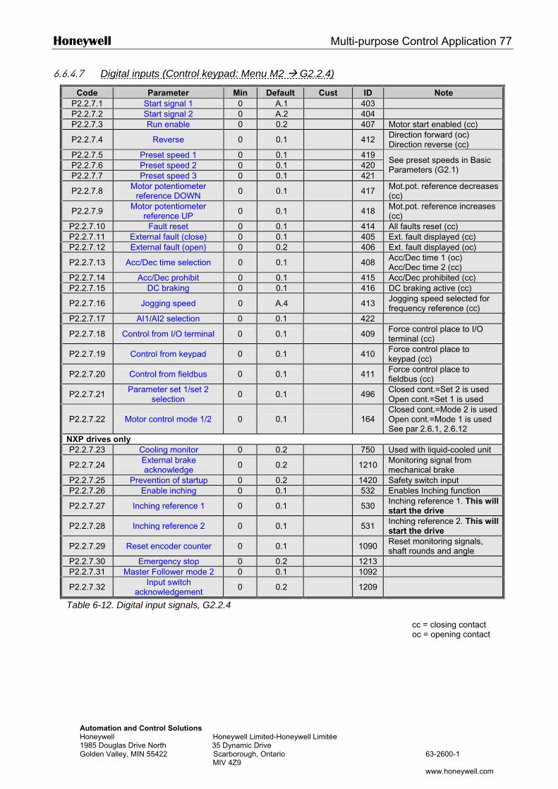
Honeywell Multi-purpose Control Application 77
Automation and Control Solutions Honeywell Honeywell Limited-Honeywell Limitée 1985 Douglas Drive North 35 Dynamic Drive Golden Valley, MIN 55422 Scarborough, Ontario 63-2600-1 MIV 4Z9 www.honeywell.com
6.6.4.7 Digital inputs (Control keypad: Menu M2 G2.2.4)
Code Parameter Min Default Cust ID Note P2.2.7.1 Start signal 1 0 A.1 403 P2.2.7.2 Start signal 2 0 A.2 404 P2.2.7.3 Run enable 0 0.2 407 Motor start enabled (cc)
P2.2.7.4 Reverse 0 0.1 412 Direction forward (oc) Direction reverse (cc)
P2.2.7.5 Preset speed 1 0 0.1 419 P2.2.7.6 Preset speed 2 0 0.1 420 P2.2.7.7 Preset speed 3 0 0.1 421
See preset speeds in Basic Parameters (G2.1)
P2.2.7.8 Motor potentiometer reference DOWN 0 0.1 417 Mot.pot. reference decreases
(cc)
P2.2.7.9 Motor potentiometer reference UP 0 0.1 418 Mot.pot. reference increases
(cc) P2.2.7.10 Fault reset 0 0.1 414 All faults reset (cc) P2.2.7.11 External fault (close) 0 0.1 405 Ext. fault displayed (cc) P2.2.7.12 External fault (open) 0 0.2 406 Ext. fault displayed (oc)
P2.2.7.13 Acc/Dec time selection 0 0.1 408 Acc/Dec time 1 (oc) Acc/Dec time 2 (cc)
P2.2.7.14 Acc/Dec prohibit 0 0.1 415 Acc/Dec prohibited (cc) P2.2.7.15 DC braking 0 0.1 416 DC braking active (cc)
P2.2.7.16 Jogging speed 0 A.4 413 Jogging speed selected for frequency reference (cc)
P2.2.7.17 AI1/AI2 selection 0 0.1 422
P2.2.7.18 Control from I/O terminal 0 0.1 409 Force control place to I/O terminal (cc)
P2.2.7.19 Control from keypad 0 0.1 410 Force control place to keypad (cc)
P2.2.7.20 Control from fieldbus 0 0.1 411 Force control place to fieldbus (cc)
P2.2.7.21 Parameter set 1/set 2 selection 0 0.1 496 Closed cont.=Set 2 is used
Open cont.=Set 1 is used
P2.2.7.22 Motor control mode 1/2 0 0.1 164 Closed cont.=Mode 2 is used Open cont.=Mode 1 is used See par 2.6.1, 2.6.12
NXP drives only P2.2.7.23 Cooling monitor 0 0.2 750 Used with liquid-cooled unit
P2.2.7.24 External brake acknowledge 0 0.2 1210 Monitoring signal from
mechanical brake P2.2.7.25 Prevention of startup 0 0.2 1420 Safety switch input P2.2.7.26 Enable inching 0 0.1 532 Enables Inching function
P2.2.7.27 Inching reference 1 0 0.1 530 Inching reference 1. This will start the drive
P2.2.7.28 Inching reference 2 0 0.1 531 Inching reference 2. This will start the drive
P2.2.7.29 Reset encoder counter 0 0.1 1090 Reset monitoring signals, shaft rounds and angle
P2.2.7.30 Emergency stop 0 0.2 1213 P2.2.7.31 Master Follower mode 2 0 0.1 1092
P2.2.7.32 Input switch acknowledgement 0 0.2 1209
Table 6-12. Digital input signals, G2.2.4
cc = closing contact oc = opening contact
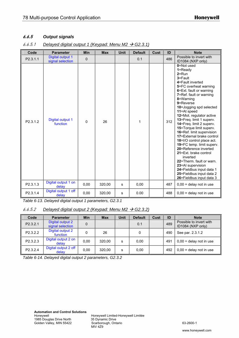
78 Multi-purpose Control Application Honeywell
Automation and Control Solutions Honeywell Honeywell Limited-Honeywell Limitée 1985 Douglas Drive North 35 Dynamic Drive Golden Valley, MIN 55422 Scarborough, Ontario 63-2600-1 MIV 4Z9 www.honeywell.com
6.6.5 Output signals
6.6.5.1 Delayed digital output 1 (Keypad: Menu M2 G2.3.1)
Code Parameter Min Max Unit Default Cust ID Note
P2.3.1.1 Digital output 1 signal selection 0 0.1 486 Possible to invert with
ID1084 (NXP only)
P2.3.1.2 Digital output 1 function 0 26 1 312
0=Not used 1=Ready 2=Run 3=Fault 4=Fault inverted 5=FC overheat warning 6=Ext. fault or warning 7=Ref. fault or warning 8=Warning 9=Reverse 10=Jogging spd selected 11=At speed 12=Mot. regulator active 13=Freq. limit 1 superv. 14=Freq. limit 2 superv. 15=Torque limit superv. 16=Ref. limit supervision 17=External brake control 18=I/O control place act. 19=FC temp. limit superv. 20=Reference inverted 21=Ext. brake control
inverted 22=Therm. fault or warn. 23=AI supervision 24=Fieldbus input data 1 25=Fieldbus input data 2 26=Fieldbus input data 3
P2.3.1.3 Digital output 1 on delay 0,00 320,00 s 0,00 487 0,00 = delay not in use
P2.3.1.4 Digital output 1 off delay 0,00 320,00 s 0.00 488 0,00 = delay not in use
Table 6-13. Delayed digital output 1 parameters, G2.3.1
6.6.5.2 Delayed digital output 2 (Keypad: Menu M2 G2.3.2)
Code Parameter Min Max Unit Default Cust ID Note
P2.3.2.1 Digital output 2 signal selection 0 0.1 489 Possible to invert with
ID1084 (NXP only)
P2.3.2.2 Digital output 2 function 0 26 0 490 See par. 2.3.1.2
P2.3.2.3 Digital output 2 on delay 0,00 320,00 s 0,00 491 0,00 = delay not in use
P2.3.2.4 Digital output 2 off delay 0,00 320,00 s 0,00 492 0,00 = delay not in use
Table 6-14. Delayed digital output 2 parameters, G2.3.2
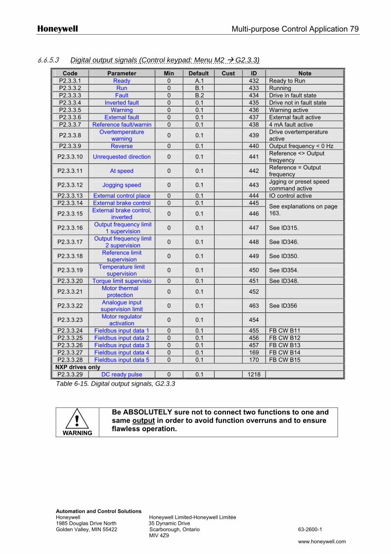
Honeywell Multi-purpose Control Application 79
Automation and Control Solutions Honeywell Honeywell Limited-Honeywell Limitée 1985 Douglas Drive North 35 Dynamic Drive Golden Valley, MIN 55422 Scarborough, Ontario 63-2600-1 MIV 4Z9 www.honeywell.com
6.6.5.3 Digital output signals (Control keypad: Menu M2 G2.3.3)
Code Parameter Min Default Cust ID Note P2.3.3.1 Ready 0 A.1 432 Ready to Run P2.3.3.2 Run 0 B.1 433 Running P2.3.3.3 Fault 0 B.2 434 Drive in fault state P2.3.3.4 Inverted fault 0 0.1 435 Drive not in fault state P2.3.3.5 Warning 0 0.1 436 Warning active P2.3.3.6 External fault 0 0.1 437 External fault active P2.3.3.7 Reference fault/warning 0 0.1 438 4 mA fault active
P2.3.3.8 Overtemperature warning 0 0.1 439 Drive overtemperature
active P2.3.3.9 Reverse 0 0.1 440 Output frequency < 0 Hz
P2.3.3.10 Unrequested direction 0 0.1 441 Reference <> Output freqyency
P2.3.3.11 At speed 0 0.1 442 Reference = Output frequency
P2.3.3.12 Jogging speed 0 0.1 443 Jgging or preset speed command active
P2.3.3.13 External control place 0 0.1 444 IO control active P2.3.3.14 External brake control 0 0.1 445
P2.3.3.15 External brake control, inverted 0 0.1 446
See explanations on page 163.
P2.3.3.16 Output frequency limit 1 supervision 0 0.1 447 See ID315.
P2.3.3.17 Output frequency limit 2 supervision 0 0.1 448 See ID346.
P2.3.3.18 Reference limit supervision 0 0.1 449 See ID350.
P2.3.3.19 Temperature limit supervision 0 0.1 450 See ID354.
P2.3.3.20 Torque limit supervision 0 0.1 451 See ID348.
P2.3.3.21 Motor thermal protection 0 0.1 452
P2.3.3.22 Analogue input supervision limit 0 0.1 463 See ID356
P2.3.3.23 Motor regulator activation 0 0.1 454
P2.3.3.24 Fieldbus input data 1 0 0.1 455 FB CW B11 P2.3.3.25 Fieldbus input data 2 0 0.1 456 FB CW B12 P2.3.3.26 Fieldbus input data 3 0 0.1 457 FB CW B13 P2.3.3.27 Fieldbus input data 4 0 0.1 169 FB CW B14 P2.3.3.28 Fieldbus input data 5 0 0.1 170 FB CW B15
NXP drives only P2.3.3.29 DC ready pulse 0 0.1 1218
Table 6-15. Digital output signals, G2.3.3
!WARNING
Be ABSOLUTELY sure not to connect two functions to one and same output in order to avoid function overruns and to ensure flawless operation.

80 Multi-purpose Control Application Honeywell
Automation and Control Solutions Honeywell Honeywell Limited-Honeywell Limitée 1985 Douglas Drive North 35 Dynamic Drive Golden Valley, MIN 55422 Scarborough, Ontario 63-2600-1 MIV 4Z9 www.honeywell.com
6.6.5.4 Limit settings (Control keypad: Menu M2 G2.3.4)
Code Parameter Min Max Unit Default Cust ID Note
P2.3.4.1 Output frequency limit 1 supervision 0 3 0 315
0=No limit 1=Low limit supervision 2=High limit supervision 3=Brake-on control
P2.3.4.2 Output frequency
limit 1; Supervised value
0,00 320,00 Hz 0,00 316
P2.3.4.3 Output frequency limit 2 supervision 0 4 0 346
0=No limit 1=Low limit supervision 2=High limit supervision 3=Brake-off control 4=Brake on/off-control
P2.3.4.4 Output frequency
limit 2; Supervised value
0,00 320,00 Hz 0,00 347
P2.3.4.5 Torque limit supervision 0 3 0 348
0=Not used 1=Low limit supervision 2=High limit supervision 3=Brake-off control
P2.3.4.6 Torque limit supervision value -300,0 300,0 % 100,0 349
P2.3.4.7 Reference limit supervision 0 2 0 350
0=Not used 1=Low limit 2=High limit
P2.3.4.8 Reference limit supervision value 0,0 100,0 % 0,0 351
P2.3.4.9 External brake-off delay 0,0 100,0 s 0,5 352
P2.3.4.10 External brake-on delay 0,0 100,0 s 1,5 353
P2.3.4.11 FC temperature supervision 0 2 0 354
0=Not used 1=Low limit 2=High limit
P2.3.4.12 FC temperature supervised value –10 100 °C 40 355
P2.3.4.13 Analogue supervision signal 0 4 0 356
0=Not used 1=AI1 2=AI2 3=AI3 4=AI4
P2.3.4.14 Analogue super-vision low limit 0,00 100,00 % 10,00 357
P2.3.4.15 Analogue super-vision high limit 0,00 100,00 % 90,00 358
NXP drives only
P2.3.4.16 Brake On/Off Current Limit 0 2 x IH A 0 1085
Brake is kept closed if current is below this value.
Table 6-16. Limit settings, G2.3.4
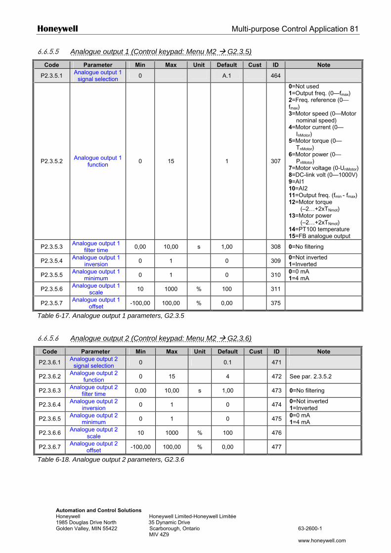
Honeywell Multi-purpose Control Application 81
Automation and Control Solutions Honeywell Honeywell Limited-Honeywell Limitée 1985 Douglas Drive North 35 Dynamic Drive Golden Valley, MIN 55422 Scarborough, Ontario 63-2600-1 MIV 4Z9 www.honeywell.com
6.6.5.5 Analogue output 1 (Control keypad: Menu M2 G2.3.5)
Code Parameter Min Max Unit Default Cust ID Note
P2.3.5.1 Analogue output 1 signal selection 0 A.1 464
P2.3.5.2 Analogue output 1 function 0 15 1 307
0=Not used 1=Output freq. (0—fmax) 2=Freq. reference (0—fmax) 3=Motor speed (0—Motor
nominal speed) 4=Motor current (0—
InMotor) 5=Motor torque (0—
TnMotor) 6=Motor power (0—
PnMotor) 7=Motor voltage (0-UnMotor)8=DC-link volt (0—1000V) 9=AI1 10=AI2 11=Output freq. (fmin - fmax) 12=Motor torque (–2…+2xTNmot) 13=Motor power (–2…+2xTNmot) 14=PT100 temperature 15=FB analogue output
P2.3.5.3 Analogue output 1 filter time 0,00 10,00 s 1,00 308 0=No filtering
P2.3.5.4 Analogue output 1 inversion 0 1 0 309 0=Not inverted
1=Inverted
P2.3.5.5 Analogue output 1 minimum 0 1 0 310 0=0 mA
1=4 mA
P2.3.5.6 Analogue output 1 scale 10 1000 % 100 311
P2.3.5.7 Analogue output 1 offset -100,00 100,00 % 0,00 375
Table 6-17. Analogue output 1 parameters, G2.3.5
6.6.5.6 Analogue output 2 (Control keypad: Menu M2 G2.3.6)
Code Parameter Min Max Unit Default Cust ID Note
P2.3.6.1 Analogue output 2 signal selection 0 0.1 471
P2.3.6.2 Analogue output 2 function 0 15 4 472 See par. 2.3.5.2
P2.3.6.3 Analogue output 2 filter time 0,00 10,00 s 1,00 473 0=No filtering
P2.3.6.4 Analogue output 2 inversion 0 1 0 474 0=Not inverted
1=Inverted
P2.3.6.5 Analogue output 2 minimum 0 1 0 475 0=0 mA
1=4 mA
P2.3.6.6 Analogue output 2 scale 10 1000 % 100 476
P2.3.6.7 Analogue output 2 offset -100,00 100,00 % 0,00 477
Table 6-18. Analogue output 2 parameters, G2.3.6
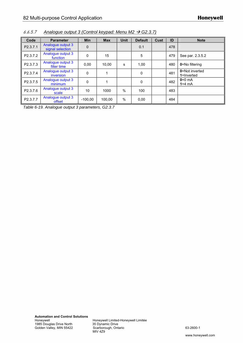
82 Multi-purpose Control Application Honeywell
Automation and Control Solutions Honeywell Honeywell Limited-Honeywell Limitée 1985 Douglas Drive North 35 Dynamic Drive Golden Valley, MIN 55422 Scarborough, Ontario 63-2600-1 MIV 4Z9 www.honeywell.com
6.6.5.7 Analogue output 3 (Control keypad: Menu M2 G2.3.7)
Code Parameter Min Max Unit Default Cust ID Note
P2.3.7.1 Analogue output 3 signal selection 0 0.1 478
P2.3.7.2 Analogue output 3 function 0 15 5 479 See par. 2.3.5.2
P2.3.7.3 Analogue output 3 filter time 0,00 10,00 s 1,00 480 0=No filtering
P2.3.7.4 Analogue output 3 inversion 0 1 0 481 0=Not inverted
1=Inverted
P2.3.7.5 Analogue output 3 minimum 0 1 0 482 0=0 mA
1=4 mA
P2.3.7.6 Analogue output 3 scale 10 1000 % 100 483
P2.3.7.7 Analogue output 3 offset -100,00 100,00 % 0,00 484
Table 6-19. Analogue output 3 parameters, G2.3.7
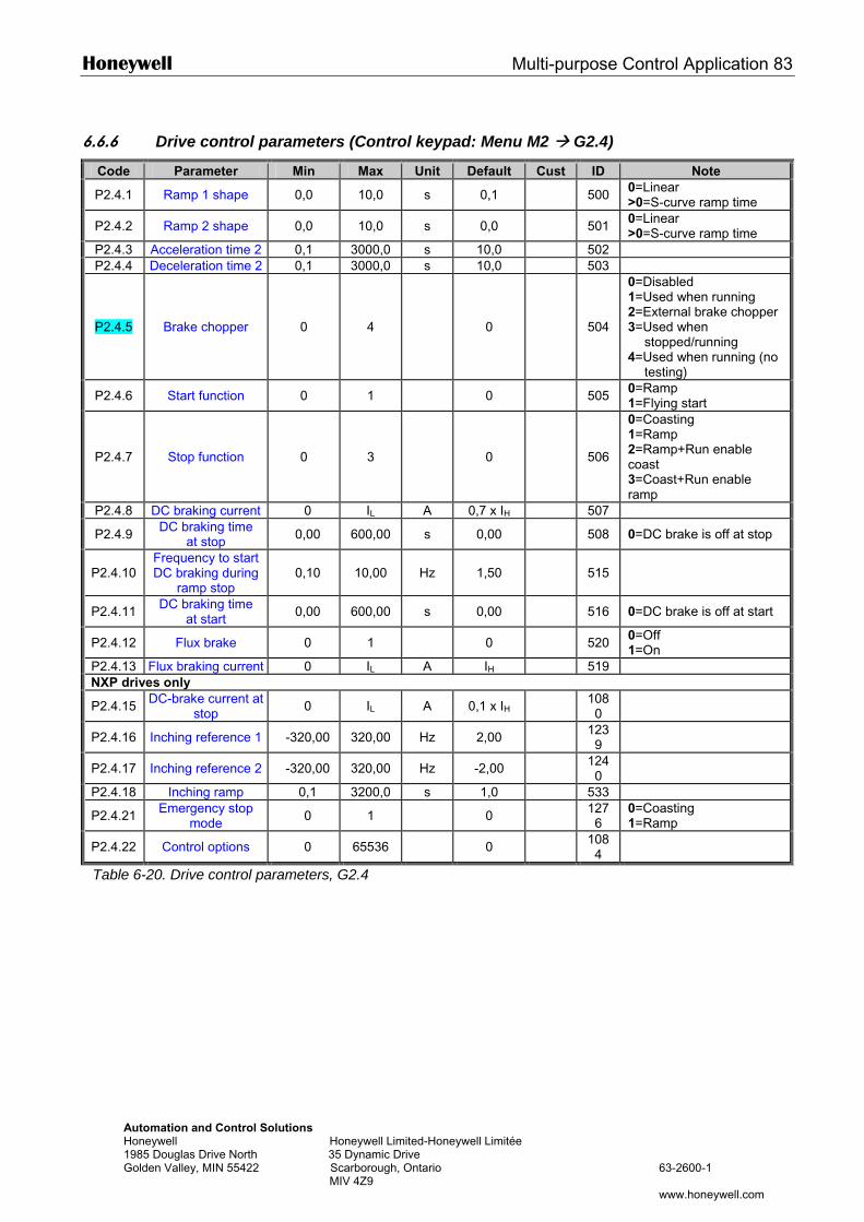
Honeywell Multi-purpose Control Application 83
Automation and Control Solutions Honeywell Honeywell Limited-Honeywell Limitée 1985 Douglas Drive North 35 Dynamic Drive Golden Valley, MIN 55422 Scarborough, Ontario 63-2600-1 MIV 4Z9 www.honeywell.com
6.6.6 Drive control parameters (Control keypad: Menu M2 G2.4)
Code Parameter Min Max Unit Default Cust ID Note
P2.4.1 Ramp 1 shape 0,0 10,0 s 0,1 500 0=Linear >0=S-curve ramp time
P2.4.2 Ramp 2 shape 0,0 10,0 s 0,0 501 0=Linear >0=S-curve ramp time
P2.4.3 Acceleration time 2 0,1 3000,0 s 10,0 502 P2.4.4 Deceleration time 2 0,1 3000,0 s 10,0 503
P2.4.5 Brake chopper 0 4 0
504
0=Disabled 1=Used when running 2=External brake chopper 3=Used when
stopped/running 4=Used when running (no
testing)
P2.4.6 Start function 0 1 0 505 0=Ramp 1=Flying start
P2.4.7 Stop function 0 3 0
506
0=Coasting 1=Ramp 2=Ramp+Run enable coast 3=Coast+Run enable ramp
P2.4.8 DC braking current 0 IL A 0,7 x IH 507
P2.4.9 DC braking time at stop 0,00 600,00 s 0,00 508 0=DC brake is off at stop
P2.4.10 Frequency to start DC braking during
ramp stop 0,10 10,00 Hz 1,50
515
P2.4.11 DC braking time at start 0,00 600,00 s 0,00 516 0=DC brake is off at start
P2.4.12 Flux brake 0 1 0 520 0=Off 1=On
P2.4.13 Flux braking current 0 IL A IH 519 NXP drives only
P2.4.15 DC-brake current at stop 0 IL A 0,1 x IH 108
0
P2.4.16 Inching reference 1 -320,00 320,00 Hz 2,00 1239
P2.4.17 Inching reference 2 -320,00 320,00 Hz -2,00 1240
P2.4.18 Inching ramp 0,1 3200,0 s 1,0 533
P2.4.21 Emergency stop mode 0 1 0 127
6 0=Coasting 1=Ramp
P2.4.22 Control options 0 65536 0 1084
Table 6-20. Drive control parameters, G2.4
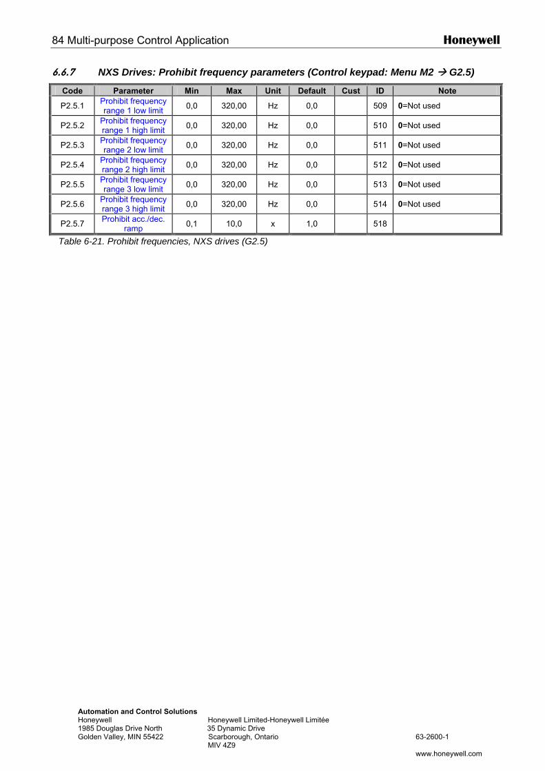
84 Multi-purpose Control Application Honeywell
Automation and Control Solutions Honeywell Honeywell Limited-Honeywell Limitée 1985 Douglas Drive North 35 Dynamic Drive Golden Valley, MIN 55422 Scarborough, Ontario 63-2600-1 MIV 4Z9 www.honeywell.com
6.6.7 NXS Drives: Prohibit frequency parameters (Control keypad: Menu M2 G2.5)
Code Parameter Min Max Unit Default Cust ID Note
P2.5.1 Prohibit frequency range 1 low limit 0,0 320,00 Hz 0,0 509 0=Not used
P2.5.2 Prohibit frequency range 1 high limit 0,0 320,00 Hz 0,0 510 0=Not used
P2.5.3 Prohibit frequency range 2 low limit 0,0 320,00 Hz 0,0 511 0=Not used
P2.5.4 Prohibit frequency range 2 high limit 0,0 320,00 Hz 0,0 512 0=Not used
P2.5.5 Prohibit frequency range 3 low limit 0,0 320,00 Hz 0,0 513 0=Not used
P2.5.6 Prohibit frequency range 3 high limit 0,0 320,00 Hz 0,0 514 0=Not used
P2.5.7 Prohibit acc./dec. ramp 0,1 10,0 x 1,0 518
Table 6-21. Prohibit frequencies, NXS drives (G2.5)
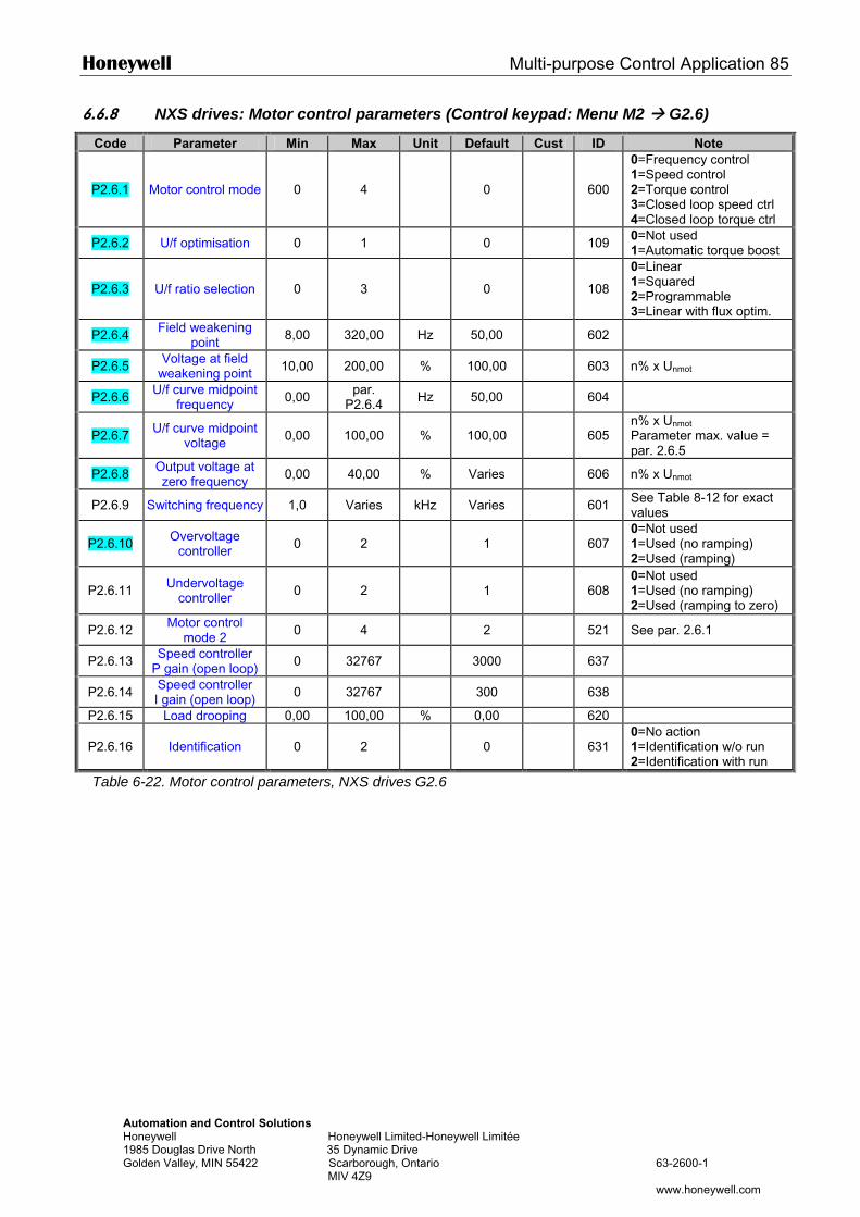
Honeywell Multi-purpose Control Application 85
Automation and Control Solutions Honeywell Honeywell Limited-Honeywell Limitée 1985 Douglas Drive North 35 Dynamic Drive Golden Valley, MIN 55422 Scarborough, Ontario 63-2600-1 MIV 4Z9 www.honeywell.com
6.6.8 NXS drives: Motor control parameters (Control keypad: Menu M2 G2.6)
Code Parameter Min Max Unit Default Cust ID Note
P2.6.1 Motor control mode 0 4 0 600
0=Frequency control 1=Speed control 2=Torque control 3=Closed loop speed ctrl 4=Closed loop torque ctrl
P2.6.2 U/f optimisation 0 1 0 109 0=Not used 1=Automatic torque boost
P2.6.3 U/f ratio selection 0 3 0 108
0=Linear 1=Squared 2=Programmable 3=Linear with flux optim.
P2.6.4 Field weakening point 8,00 320,00 Hz 50,00 602
P2.6.5 Voltage at field weakening point 10,00 200,00 % 100,00 603 n% x Unmot
P2.6.6 U/f curve midpoint frequency 0,00 par.
P2.6.4 Hz 50,00 604
P2.6.7 U/f curve midpoint voltage 0,00 100,00 % 100,00 605
n% x Unmot
Parameter max. value = par. 2.6.5
P2.6.8 Output voltage at zero frequency 0,00 40,00 % Varies 606 n% x Unmot
P2.6.9 Switching frequency 1,0 Varies kHz Varies 601 See Table 8-12 for exact values
P2.6.10 Overvoltage controller 0 2 1 607
0=Not used 1=Used (no ramping) 2=Used (ramping)
P2.6.11 Undervoltage controller 0 2 1 608
0=Not used 1=Used (no ramping) 2=Used (ramping to zero)
P2.6.12 Motor control mode 2 0 4 2 521 See par. 2.6.1
P2.6.13 Speed controller P gain (open loop) 0 32767 3000 637
P2.6.14 Speed controller I gain (open loop) 0 32767 300 638
P2.6.15 Load drooping 0,00 100,00 % 0,00 620
P2.6.16 Identification 0 2 0 631 0=No action 1=Identification w/o run 2=Identification with run
Table 6-22. Motor control parameters, NXS drives G2.6
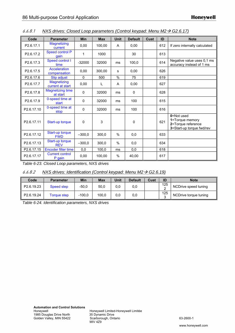
86 Multi-purpose Control Application Honeywell
Automation and Control Solutions Honeywell Honeywell Limited-Honeywell Limitée 1985 Douglas Drive North 35 Dynamic Drive Golden Valley, MIN 55422 Scarborough, Ontario 63-2600-1 MIV 4Z9 www.honeywell.com
6.6.8.1 NXS drives: Closed Loop parameters (Control keypad: Menu M2 G2.6.17)
Code Parameter Min Max Unit Default Cust ID Note
P2.6.17.1 Magnetizing current 0,00 100,00 A 0,00 612 If zero internally calculated
P2.6.17.2 Speed control P gain 1 1000 30 613
P2.6.17.3 Speed control I time -32000 32000 ms 100,0 614 Negative value uses 0,1 ms
accuracy instead of 1 ms
P2.6.17.5 Acceleration compensation 0,00 300,00 s 0,00 626
P2.6.17.6 Slip adjust 0 500 % 75 619
P2.6.17.7 Magnetizing current at start 0,00 IL A 0,00 627
P2.6.17.8 Magnetizing time at start 0 32000 ms 0 628
P2.6.17.9 0-speed time at start 0 32000 ms 100 615
P2.6.17.10 0-speed time at stop 0 32000 ms 100 616
P2.6.17.11 Start-up torque 0 3 0
621
0=Not used 1=Torque memory 2=Torque reference 3=Start-up torque fwd/rev
P2.6.17.12 Start-up torque FWD –300,0 300,0 % 0,0 633
P2.6.17.13 Start-up torque REV –300,0 300,0 % 0,0 634
P2.6.17.15 Encoder filter time 0,0 100,0 ms 0,0 618
P2.6.17.17 Current control P gain 0,00 100,00 % 40,00 617
Table 6-23. Closed Loop parameters, NXS drives
6.6.8.2 NXS drives: Identification (Control keypad: Menu M2 G2.6.19)
Code Parameter Min Max Unit Default Cust ID Note
P2.6.19.23 Speed step -50,0 50,0 0,0 0,0 1252 NCDrive speed tuning
P2.6.19.24 Torque step -100,0 100,0 0,0 0,0 1253 NCDrive torque tuning
Table 6-24. Identification parameters, NXS drives
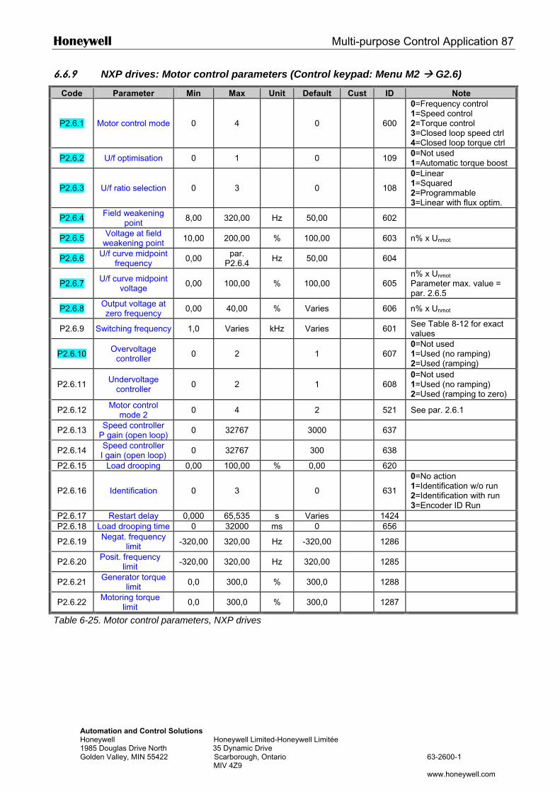
Honeywell Multi-purpose Control Application 87
Automation and Control Solutions Honeywell Honeywell Limited-Honeywell Limitée 1985 Douglas Drive North 35 Dynamic Drive Golden Valley, MIN 55422 Scarborough, Ontario 63-2600-1 MIV 4Z9 www.honeywell.com
6.6.9 NXP drives: Motor control parameters (Control keypad: Menu M2 G2.6)
Code Parameter Min Max Unit Default Cust ID Note
P2.6.1 Motor control mode 0 4 0 600
0=Frequency control 1=Speed control 2=Torque control 3=Closed loop speed ctrl 4=Closed loop torque ctrl
P2.6.2 U/f optimisation 0 1 0 109 0=Not used 1=Automatic torque boost
P2.6.3 U/f ratio selection 0 3 0 108
0=Linear 1=Squared 2=Programmable 3=Linear with flux optim.
P2.6.4 Field weakening point 8,00 320,00 Hz 50,00 602
P2.6.5 Voltage at field weakening point 10,00 200,00 % 100,00 603 n% x Unmot
P2.6.6 U/f curve midpoint frequency 0,00 par.
P2.6.4 Hz 50,00 604
P2.6.7 U/f curve midpoint voltage 0,00 100,00 % 100,00 605
n% x Unmot
Parameter max. value = par. 2.6.5
P2.6.8 Output voltage at zero frequency 0,00 40,00 % Varies 606 n% x Unmot
P2.6.9 Switching frequency 1,0 Varies kHz Varies 601 See Table 8-12 for exact values
P2.6.10 Overvoltage controller 0 2 1 607
0=Not used 1=Used (no ramping) 2=Used (ramping)
P2.6.11 Undervoltage controller 0 2 1 608
0=Not used 1=Used (no ramping) 2=Used (ramping to zero)
P2.6.12 Motor control mode 2 0 4 2 521 See par. 2.6.1
P2.6.13 Speed controller P gain (open loop) 0 32767 3000 637
P2.6.14 Speed controller I gain (open loop) 0 32767 300 638
P2.6.15 Load drooping 0,00 100,00 % 0,00 620
P2.6.16 Identification 0 3 0 631
0=No action 1=Identification w/o run 2=Identification with run 3=Encoder ID Run
P2.6.17 Restart delay 0,000 65,535 s Varies 1424 P2.6.18 Load drooping time 0 32000 ms 0 656
P2.6.19 Negat. frequency limit -320,00 320,00 Hz -320,00 1286
P2.6.20 Posit. frequency limit -320,00 320,00 Hz 320,00 1285
P2.6.21 Generator torque limit 0,0 300,0 % 300,0 1288
P2.6.22 Motoring torque limit 0,0 300,0 % 300,0 1287
Table 6-25. Motor control parameters, NXP drives
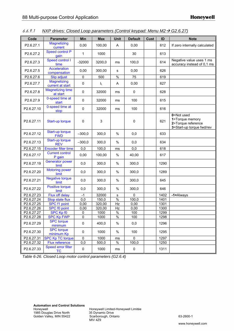
88 Multi-purpose Control Application Honeywell
Automation and Control Solutions Honeywell Honeywell Limited-Honeywell Limitée 1985 Douglas Drive North 35 Dynamic Drive Golden Valley, MIN 55422 Scarborough, Ontario 63-2600-1 MIV 4Z9 www.honeywell.com
6.6.9.1 NXP drives: Closed Loop parameters (Control keypad: Menu M2 G2.6.27)
Code Parameter Min Max Unit Default Cust ID Note
P2.6.27.1 Magnetizing current 0,00 100,00 A 0,00 612 If zero internally calculated
P2.6.27.2 Speed control P gain 1 1000 30 613
P2.6.27.3 Speed control I time -32000 3200,0 ms 100,0 614 Negative value uses 1 ms
accuracy instead of 0,1 ms
P2.6.27.5 Acceleration compensation 0,00 300,00 s 0,00 626
P2.6.27.6 Slip adjust 0 500 % 75 619
P2.6.27.7 Magnetizing current at start 0 IL A 0,00 627
P2.6.27.8 Magnetizing time at start 0 32000 ms 0 628
P2.6.27.9 0-speed time at start 0 32000 ms 100 615
P2.6.27.10 0-speed time at stop 0 32000 ms 100 616
P2.6.27.11 Start-up torque 0 3 0
621
0=Not used 1=Torque memory 2=Torque reference 3=Start-up torque fwd/rev
P2.6.27.12 Start-up torque FWD –300,0 300,0 % 0,0 633
P2.6.27.13 Start-up torque REV –300,0 300,0 % 0,0 634
P2.6.27.15 Encoder filter time 0,0 100,0 ms 0,0 618
P2.6.27.17 Current control P gain 0,00 100,00 % 40,00 617
P2.6.27.19 Generator power limit 0,0 300,0 % 300,0 1290
P2.6.27.20 Motoring power limit 0,0 300,0 % 300,0 1289
P2.6.27.21 Negative torque limit 0,0 300,0 % 300,0 645
P2.6.27.22 Positive torque limit 0,0 300,0 % 300,0 646
P2.6.27.23 Flux off delay -1 32000 s 0 1402 -1=Always P2.6.27.24 Stop state flux 0,0 150,0 % 100,0 1401 P2.6.27.25 SPC f1 point 0,00 320,00 Hz 0,00 1301 P2.6.27.26 SPC f0 point 0,00 320,00 Hz 0,00 1300 P2.6.27.27 SPC Kp f0 0 1000 % 100 1299 P2.6.27.28 SPC Kp FWP 0 1000 % 100 1298
P2.6.27.29 SPC torque minimum 0 400,0 % 0,0 1296
P2.6.27.30 SPC torque minimum Kp 0 1000 % 100 1295
P2.6.27.31 SPC Kp TC torque 0 1000 ms 0 1297 P2.6.27.32 Flux reference 0,0 500,0 % 100,0 1250
P2.6.27.33 Speed error filter TC 0 1000 ms 0 1311
Table 6-26. Closed Loop motor control parameters (G2.6.4)
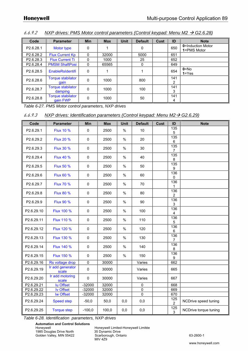
Honeywell Multi-purpose Control Application 89
Automation and Control Solutions Honeywell Honeywell Limited-Honeywell Limitée 1985 Douglas Drive North 35 Dynamic Drive Golden Valley, MIN 55422 Scarborough, Ontario 63-2600-1 MIV 4Z9 www.honeywell.com
6.6.9.2 NXP drives: PMS Motor control parameters (Control keypad: Menu M2 G2.6.28)
Code Parameter Min Max Unit Default Cust ID Note
P2.6.28.1 Motor type 0 1 0 650 0=Induction Motor 1=PMS Motor
P2.6.28.2 Flux Current Kp 0 32000 5000 651 P2.6.28.3 Flux Current Ti 0 1000 25 652 P2.6.28.4 PMSM ShaftPosi 0 65565 0 649
P2.6.28.5 EnableRsIdentifi 0 1 1 654 0=No 1=Yes
P2.6.28.6 Torque stabilator gain 0 1000 800 141
2
P2.6.28.7 Torque stabilator damping 0 1000 100 141
3
P2.6.28.8 Torque stabilator gain FWP 0 1000 50 141
4
Table 6-27. PMS Motor control parameters, NXP drives
6.6.9.3 NXP drives: Identification parameters (Control keypad: Menu M2 G2.6.29)
Code Parameter Min Max Unit Default Cust ID Note
P2.6.29.1 Flux 10 % 0 2500 % 10 1355
P2.6.29.2 Flux 20 % 0 2500 % 20 1356
P2.6.29.3 Flux 30 % 0 2500 % 30 1357
P2.6.29.4 Flux 40 % 0 2500 % 40 1358
P2.6.29.5 Flux 50 % 0 2500 % 50 1359
P2.6.29.6 Flux 60 % 0 2500 % 60 1360
P2.6.29.7 Flux 70 % 0 2500 % 70 1361
P2.6.29.8 Flux 80 % 0 2500 % 80 1362
P2.6.29.9 Flux 90 % 0 2500 % 90 1363
P2.6.29.10 Flux 100 % 0 2500 % 100 1364
P2.6.29.11 Flux 110 % 0 2500 % 110 1365
P2.6.29.12 Flux 120 % 0 2500 % 120 1366
P2.6.29.13 Flux 130 % 0 2500 % 130 1367
P2.6.29.14 Flux 140 % 0 2500 % 140 1368
P2.6.29.15 Flux 150 % 0 2500 % 150 1369
P2.6.29.16 Rs voltage drop 0 30000 Varies 662
P2.6.29.19 Ir add generator scale 0 30000 Varies 665
P2.6.29.20 Ir add motoring scale 0 30000 Varies 667
P2.6.29.21 Iu Offset -32000 32000 0 668 P2.6.29.22 Iv Offset -32000 32000 0 669 P2.6.29.23 Iw Offset -32000 32000 0 670
P2.6.29.24 Speed step -50,0 50,0 0,0 0,0 1252 NCDrive speed tuning
P2.6.29.25 Torque step -100,0 100,0 0,0 0,0 1253 NCDrive torque tuning
Table 6-28. Identification parameters, NXP drives
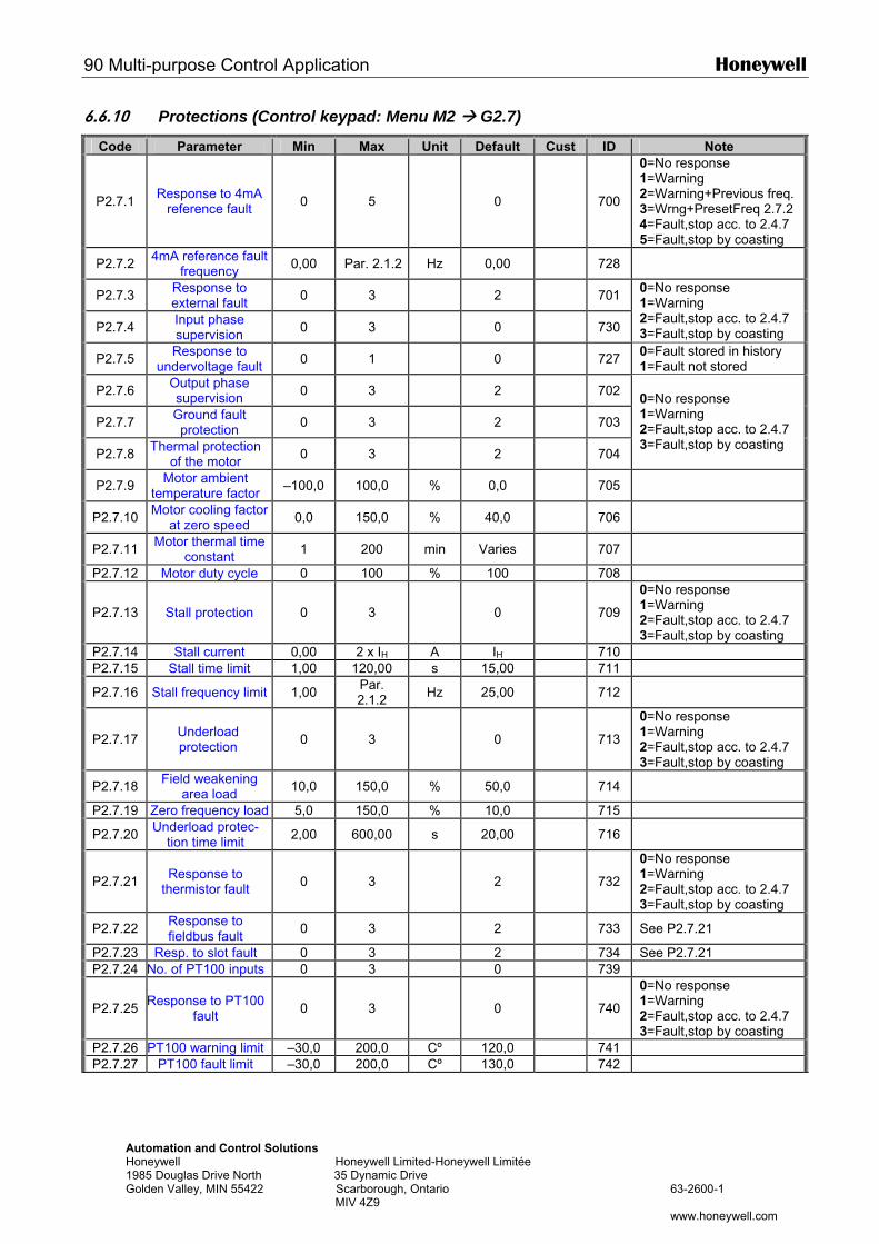
90 Multi-purpose Control Application Honeywell
Automation and Control Solutions Honeywell Honeywell Limited-Honeywell Limitée 1985 Douglas Drive North 35 Dynamic Drive Golden Valley, MIN 55422 Scarborough, Ontario 63-2600-1 MIV 4Z9 www.honeywell.com
6.6.10 Protections (Control keypad: Menu M2 G2.7)
Code Parameter Min Max Unit Default Cust ID Note
P2.7.1 Response to 4mA reference fault 0 5 0
700
0=No response 1=Warning 2=Warning+Previous freq. 3=Wrng+PresetFreq 2.7.2 4=Fault,stop acc. to 2.4.7 5=Fault,stop by coasting
P2.7.2 4mA reference fault frequency 0,00 Par. 2.1.2 Hz 0,00 728
P2.7.3 Response to external fault 0 3 2 701
P2.7.4 Input phase supervision 0 3 0 730
0=No response 1=Warning 2=Fault,stop acc. to 2.4.7 3=Fault,stop by coasting
P2.7.5 Response to undervoltage fault 0 1 0 727 0=Fault stored in history
1=Fault not stored
P2.7.6 Output phase supervision 0 3 2 702
P2.7.7 Ground fault protection 0 3 2 703
P2.7.8 Thermal protection of the motor 0 3 2 704
0=No response 1=Warning 2=Fault,stop acc. to 2.4.7 3=Fault,stop by coasting
P2.7.9 Motor ambient temperature factor –100,0 100,0 % 0,0 705
P2.7.10 Motor cooling factor at zero speed 0,0 150,0 % 40,0 706
P2.7.11 Motor thermal time constant 1 200 min Varies 707
P2.7.12 Motor duty cycle 0 100 % 100 708
P2.7.13 Stall protection 0 3 0
709
0=No response 1=Warning 2=Fault,stop acc. to 2.4.7 3=Fault,stop by coasting
P2.7.14 Stall current 0,00 2 x IH A IH 710 P2.7.15 Stall time limit 1,00 120,00 s 15,00 711
P2.7.16 Stall frequency limit 1,00 Par. 2.1.2 Hz 25,00 712
P2.7.17 Underload protection 0 3 0
713
0=No response 1=Warning 2=Fault,stop acc. to 2.4.7 3=Fault,stop by coasting
P2.7.18 Field weakening area load 10,0 150,0 % 50,0 714
P2.7.19 Zero frequency load 5,0 150,0 % 10,0 715
P2.7.20 Underload protec-tion time limit 2,00 600,00 s 20,00 716
P2.7.21 Response to thermistor fault 0 3 2
732
0=No response 1=Warning 2=Fault,stop acc. to 2.4.7 3=Fault,stop by coasting
P2.7.22 Response to fieldbus fault 0 3 2 733 See P2.7.21
P2.7.23 Resp. to slot fault 0 3 2 734 See P2.7.21 P2.7.24 No. of PT100 inputs 0 3 0 739
P2.7.25 Response to PT100 fault 0 3 0
740
0=No response 1=Warning 2=Fault,stop acc. to 2.4.7 3=Fault,stop by coasting
P2.7.26 PT100 warning limit –30,0 200,0 Cº 120,0 741 P2.7.27 PT100 fault limit –30,0 200,0 Cº 130,0 742
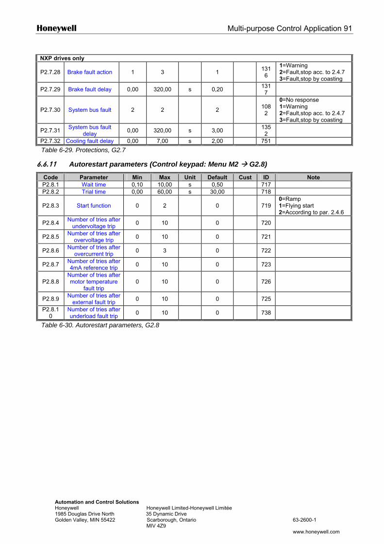
Honeywell Multi-purpose Control Application 91
Automation and Control Solutions Honeywell Honeywell Limited-Honeywell Limitée 1985 Douglas Drive North 35 Dynamic Drive Golden Valley, MIN 55422 Scarborough, Ontario 63-2600-1 MIV 4Z9 www.honeywell.com
NXP drives only
P2.7.28 Brake fault action 1 3 1 131
6
1=Warning 2=Fault,stop acc. to 2.4.7 3=Fault,stop by coasting
P2.7.29 Brake fault delay 0,00 320,00 s 0,20 1317
P2.7.30 System bus fault 2 2 2
1082
0=No response 1=Warning 2=Fault,stop acc. to 2.4.7 3=Fault,stop by coasting
P2.7.31 System bus fault delay 0,00 320,00 s 3,00 135
2
P2.7.32 Cooling fault delay 0,00 7,00 s 2,00 751
Table 6-29. Protections, G2.7
6.6.11 Autorestart parameters (Control keypad: Menu M2 G2.8)
Code Parameter Min Max Unit Default Cust ID Note P2.8.1 Wait time 0,10 10,00 s 0,50 717 P2.8.2 Trial time 0,00 60,00 s 30,00 718
P2.8.3 Start function 0 2 0
719 0=Ramp 1=Flying start 2=According to par. 2.4.6
P2.8.4 Number of tries after undervoltage trip 0 10 0 720
P2.8.5 Number of tries after overvoltage trip 0 10 0 721
P2.8.6 Number of tries after overcurrent trip 0 3 0 722
P2.8.7 Number of tries after 4mA reference trip 0 10 0 723
P2.8.8 Number of tries after motor temperature
fault trip 0 10 0
726
P2.8.9 Number of tries after external fault trip 0 10 0 725
P2.8.10
Number of tries after underload fault trip 0 10 0 738
Table 6-30. Autorestart parameters, G2.8
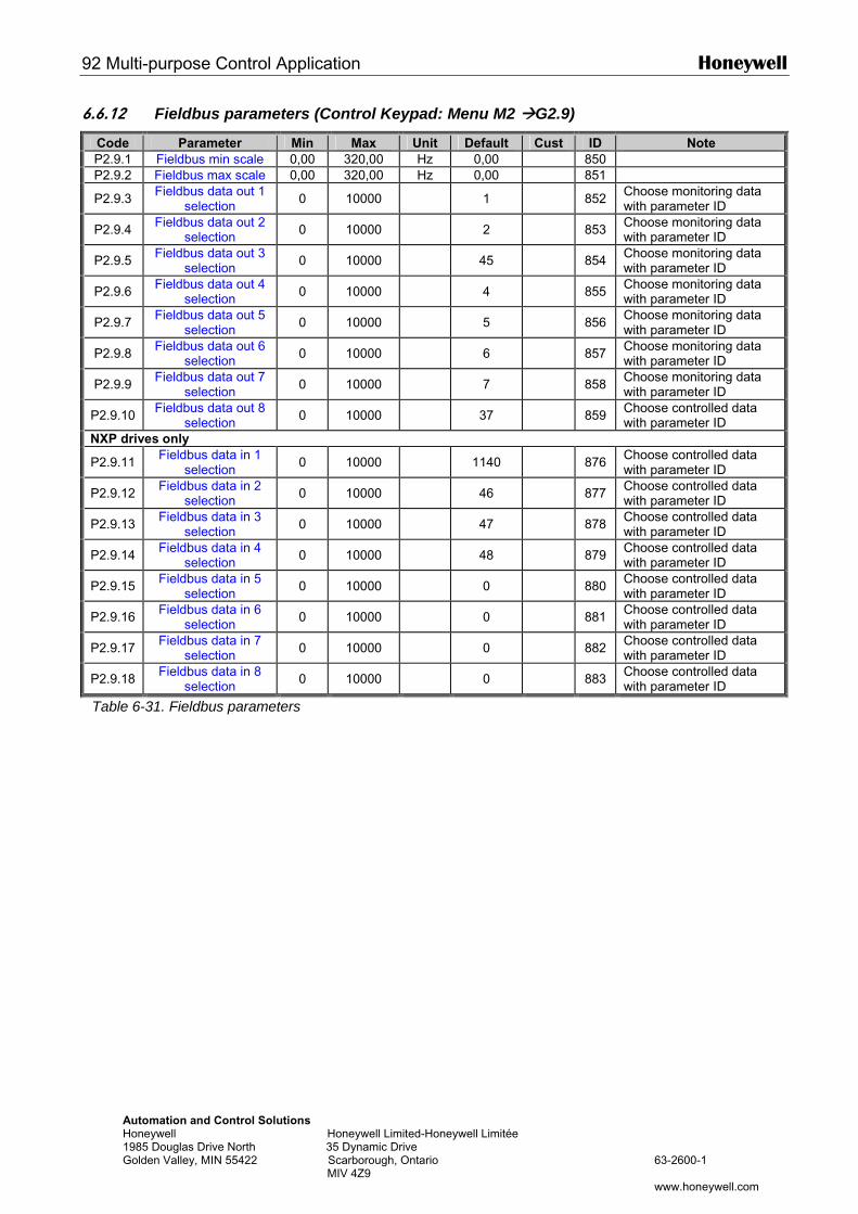
92 Multi-purpose Control Application Honeywell
Automation and Control Solutions Honeywell Honeywell Limited-Honeywell Limitée 1985 Douglas Drive North 35 Dynamic Drive Golden Valley, MIN 55422 Scarborough, Ontario 63-2600-1 MIV 4Z9 www.honeywell.com
6.6.12 Fieldbus parameters (Control Keypad: Menu M2 G2.9)
Code Parameter Min Max Unit Default Cust ID Note P2.9.1 Fieldbus min scale 0,00 320,00 Hz 0,00 850 P2.9.2 Fieldbus max scale 0,00 320,00 Hz 0,00 851
P2.9.3 Fieldbus data out 1 selection 0 10000 1 852 Choose monitoring data
with parameter ID
P2.9.4 Fieldbus data out 2 selection 0 10000 2 853 Choose monitoring data
with parameter ID
P2.9.5 Fieldbus data out 3 selection 0 10000 45 854 Choose monitoring data
with parameter ID
P2.9.6 Fieldbus data out 4 selection 0 10000 4 855 Choose monitoring data
with parameter ID
P2.9.7 Fieldbus data out 5 selection 0 10000 5 856 Choose monitoring data
with parameter ID
P2.9.8 Fieldbus data out 6 selection 0 10000 6 857 Choose monitoring data
with parameter ID
P2.9.9 Fieldbus data out 7 selection 0 10000 7 858 Choose monitoring data
with parameter ID
P2.9.10 Fieldbus data out 8 selection 0 10000 37 859 Choose controlled data
with parameter ID NXP drives only
P2.9.11 Fieldbus data in 1 selection 0 10000 1140 876 Choose controlled data
with parameter ID
P2.9.12 Fieldbus data in 2 selection 0 10000 46 877 Choose controlled data
with parameter ID
P2.9.13 Fieldbus data in 3 selection 0 10000 47 878 Choose controlled data
with parameter ID
P2.9.14 Fieldbus data in 4 selection 0 10000 48 879 Choose controlled data
with parameter ID
P2.9.15 Fieldbus data in 5 selection 0 10000 0 880 Choose controlled data
with parameter ID
P2.9.16 Fieldbus data in 6 selection 0 10000 0 881 Choose controlled data
with parameter ID
P2.9.17 Fieldbus data in 7 selection 0 10000 0 882 Choose controlled data
with parameter ID
P2.9.18 Fieldbus data in 8 selection 0 10000 0 883 Choose controlled data
with parameter ID
Table 6-31. Fieldbus parameters
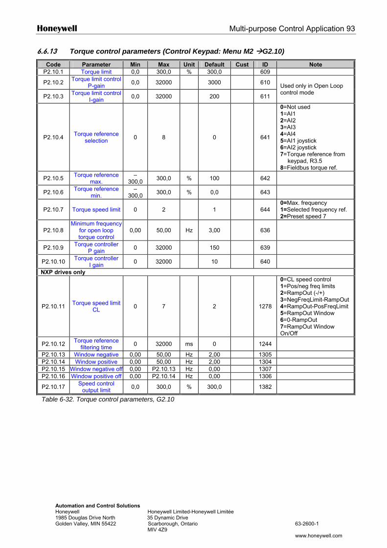
Honeywell Multi-purpose Control Application 93
Automation and Control Solutions Honeywell Honeywell Limited-Honeywell Limitée 1985 Douglas Drive North 35 Dynamic Drive Golden Valley, MIN 55422 Scarborough, Ontario 63-2600-1 MIV 4Z9 www.honeywell.com
6.6.13 Torque control parameters (Control Keypad: Menu M2 G2.10)
Code Parameter Min Max Unit Default Cust ID Note P2.10.1 Torque limit 0,0 300,0 % 300,0 609
P2.10.2 Torque limit control P-gain 0,0 32000 3000 610
P2.10.3 Torque limit control I-gain 0,0 32000 200 611
Used only in Open Loop control mode
P2.10.4 Torque reference selection 0 8 0
641
0=Not used 1=AI1 2=AI2 3=AI3 4=AI4 5=AI1 joystick 6=AI2 joystick 7=Torque reference from
keypad, R3.5 8=Fieldbus torque ref.
P2.10.5 Torque reference max.
–300,0 300,0 % 100 642
P2.10.6 Torque reference min.
–300,0 300,0 % 0,0 643
P2.10.7 Torque speed limit 0 2 1
644 0=Max. frequency 1=Selected frequency ref. 2=Preset speed 7
P2.10.8 Minimum frequency
for open loop torque control
0,00 50,00 Hz 3,00
636
P2.10.9 Torque controller P gain 0 32000 150 639
P2.10.10 Torque controller I gain 0 32000 10 640
NXP drives only
P2.10.11 Torque speed limit CL 0 7 2
1278
0=CL speed control 1=Pos/neg freq limits 2=RampOut (-/+) 3=NegFreqLimit-RampOut 4=RampOut-PosFreqLimit 5=RampOut Window 6=0-RampOut 7=RampOut Window On/Off
P2.10.12 Torque reference filtering time 0 32000 ms 0 1244
P2.10.13 Window negative 0,00 50,00 Hz 2,00 1305 P2.10.14 Window positive 0,00 50,00 Hz 2,00 1304 P2.10.15 Window negative off 0,00 P2.10.13 Hz 0,00 1307 P2.10.16 Window positive off 0,00 P2.10.14 Hz 0,00 1306
P2.10.17 Speed control output limit 0,0 300,0 % 300,0 1382
Table 6-32. Torque control parameters, G2.10
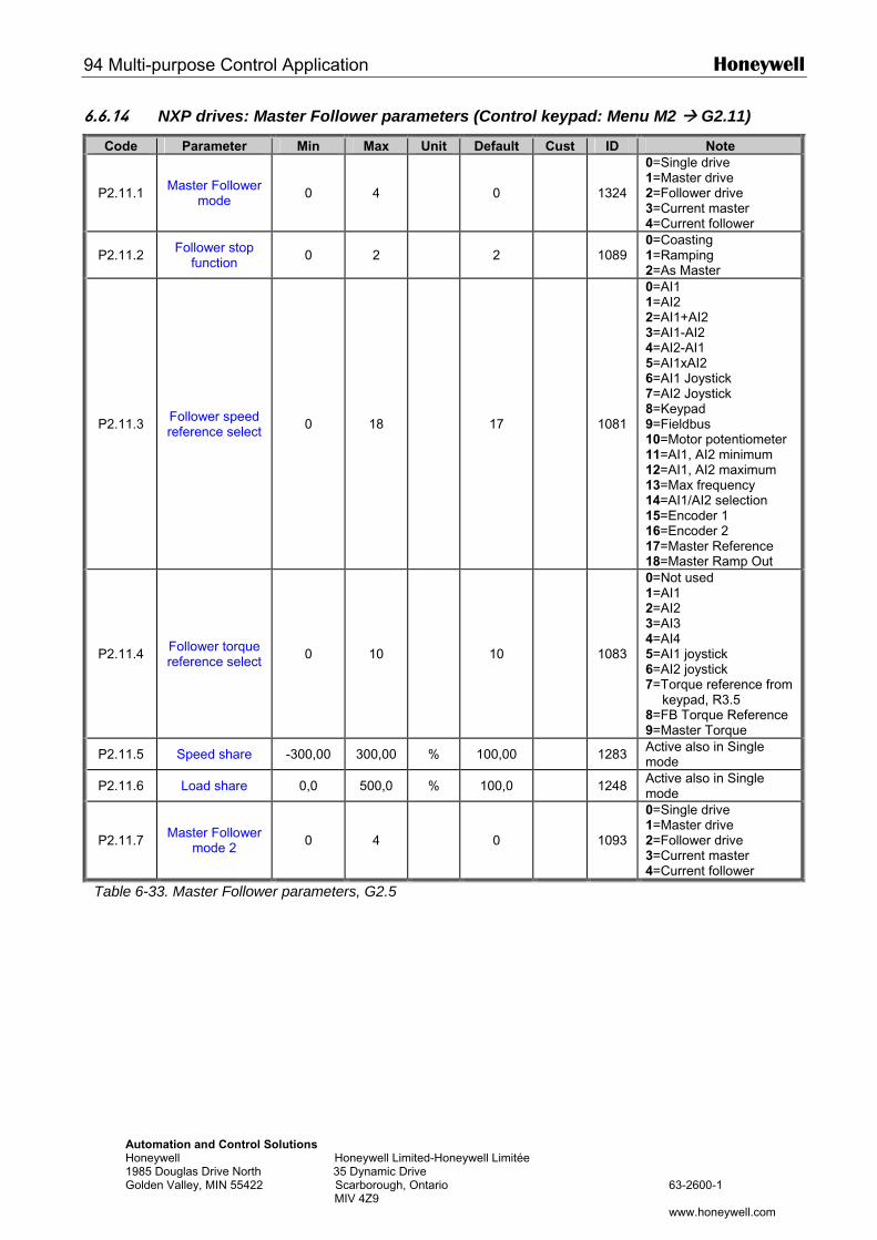
94 Multi-purpose Control Application Honeywell
Automation and Control Solutions Honeywell Honeywell Limited-Honeywell Limitée 1985 Douglas Drive North 35 Dynamic Drive Golden Valley, MIN 55422 Scarborough, Ontario 63-2600-1 MIV 4Z9 www.honeywell.com
6.6.14 NXP drives: Master Follower parameters (Control keypad: Menu M2 G2.11)
Code Parameter Min Max Unit Default Cust ID Note
P2.11.1 Master Follower mode 0 4 0
1324
0=Single drive 1=Master drive 2=Follower drive 3=Current master 4=Current follower
P2.11.2 Follower stop function 0 2 2
1089
0=Coasting 1=Ramping 2=As Master
P2.11.3 Follower speed reference select 0 18 17
1081
0=AI1 1=AI2 2=AI1+AI2 3=AI1-AI2 4=AI2-AI1 5=AI1xAI2 6=AI1 Joystick 7=AI2 Joystick 8=Keypad 9=Fieldbus 10=Motor potentiometer 11=AI1, AI2 minimum 12=AI1, AI2 maximum 13=Max frequency 14=AI1/AI2 selection 15=Encoder 1 16=Encoder 2 17=Master Reference 18=Master Ramp Out
P2.11.4 Follower torque reference select 0 10 10
1083
0=Not used 1=AI1 2=AI2 3=AI3 4=AI4 5=AI1 joystick 6=AI2 joystick 7=Torque reference from
keypad, R3.5 8=FB Torque Reference 9=Master Torque
P2.11.5 Speed share -300,00 300,00 % 100,00 1283 Active also in Single mode
P2.11.6 Load share 0,0 500,0 % 100,0 1248 Active also in Single mode
P2.11.7 Master Follower mode 2 0 4 0
1093
0=Single drive 1=Master drive 2=Follower drive 3=Current master 4=Current follower
Table 6-33. Master Follower parameters, G2.5
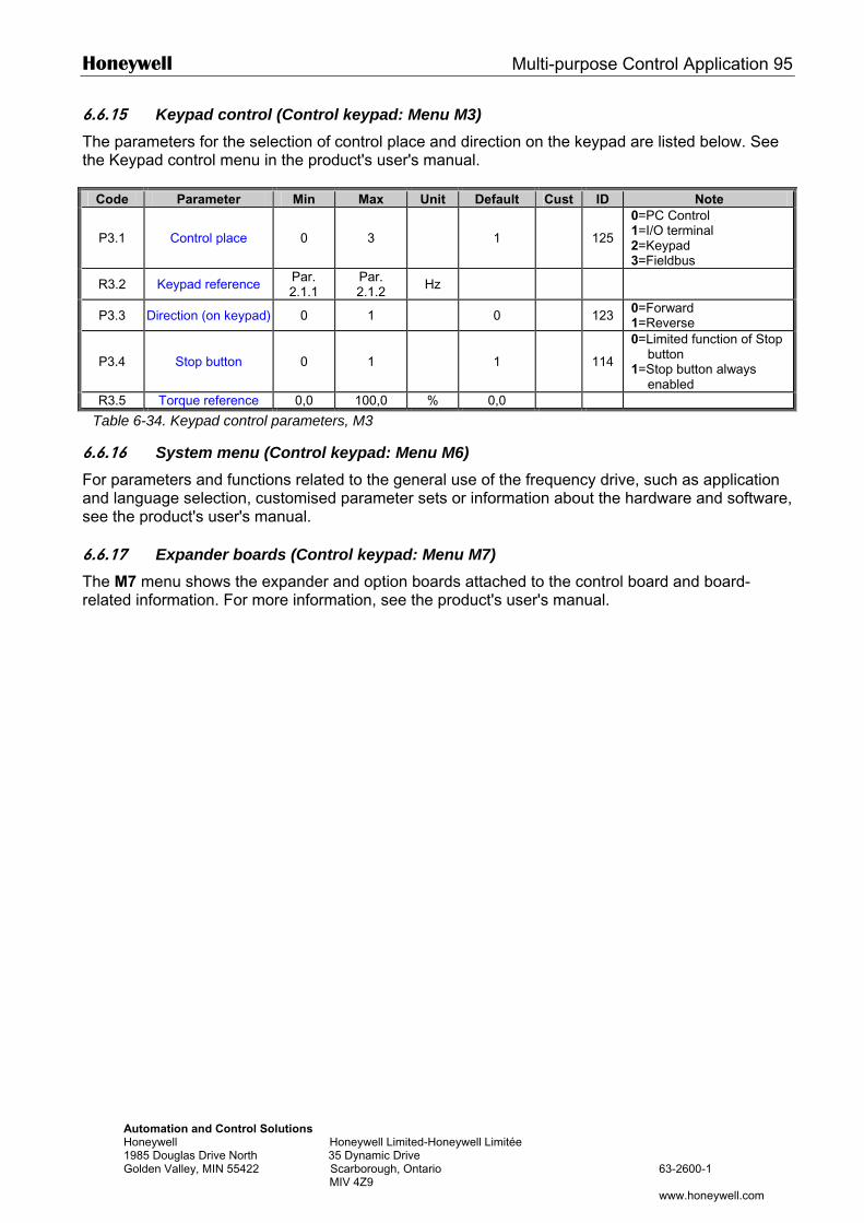
Honeywell Multi-purpose Control Application 95
Automation and Control Solutions Honeywell Honeywell Limited-Honeywell Limitée 1985 Douglas Drive North 35 Dynamic Drive Golden Valley, MIN 55422 Scarborough, Ontario 63-2600-1 MIV 4Z9 www.honeywell.com
6.6.15 Keypad control (Control keypad: Menu M3) The parameters for the selection of control place and direction on the keypad are listed below. See the Keypad control menu in the product's user's manual.
Code Parameter Min Max Unit Default Cust ID Note
P3.1 Control place 0 3 1 125
0=PC Control 1=I/O terminal 2=Keypad 3=Fieldbus
R3.2 Keypad reference Par. 2.1.1
Par. 2.1.2 Hz
P3.3 Direction (on keypad) 0 1 0 123 0=Forward 1=Reverse
P3.4 Stop button 0 1 1 114
0=Limited function of Stop button
1=Stop button always enabled
R3.5 Torque reference 0,0 100,0 % 0,0
Table 6-34. Keypad control parameters, M3
6.6.16 System menu (Control keypad: Menu M6) For parameters and functions related to the general use of the frequency drive, such as application and language selection, customised parameter sets or information about the hardware and software, see the product's user's manual. 6.6.17 Expander boards (Control keypad: Menu M7) The M7 menu shows the expander and option boards attached to the control board and board-related information. For more information, see the product's user's manual.
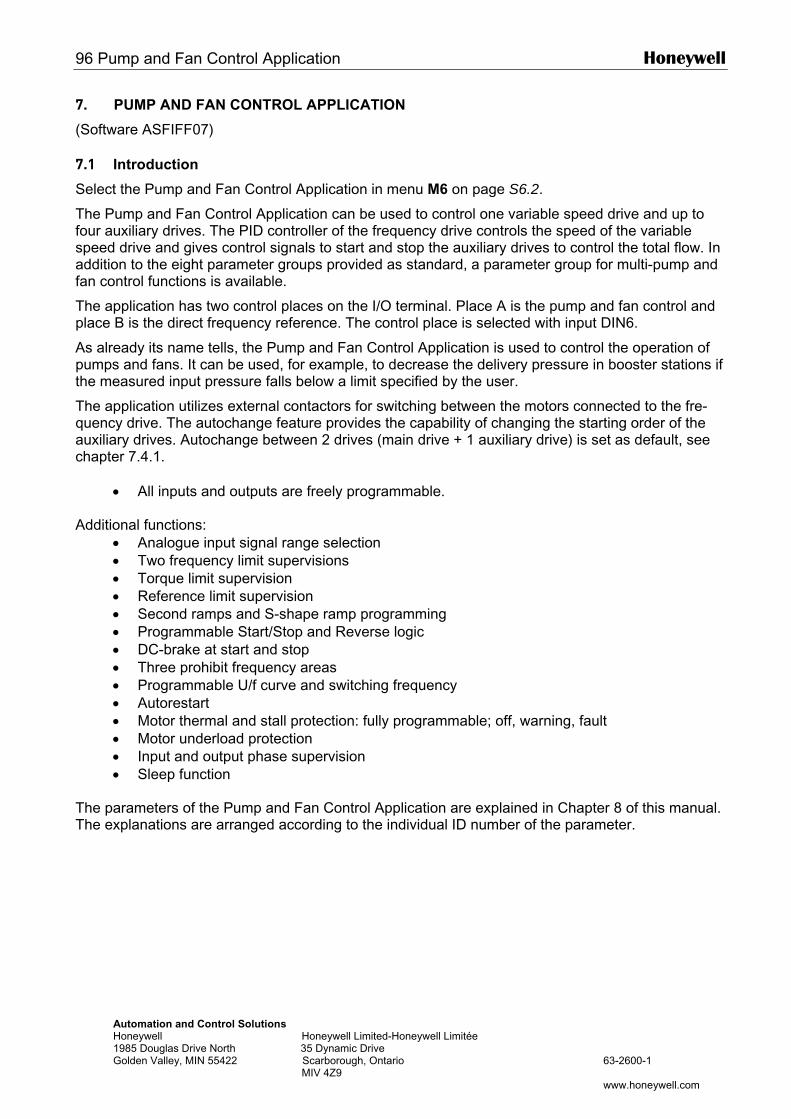
96 Pump and Fan Control Application Honeywell
Automation and Control Solutions Honeywell Honeywell Limited-Honeywell Limitée 1985 Douglas Drive North 35 Dynamic Drive Golden Valley, MIN 55422 Scarborough, Ontario 63-2600-1 MIV 4Z9 www.honeywell.com
7. PUMP AND FAN CONTROL APPLICATION
(Software ASFIFF07) 7.1 Introduction
Select the Pump and Fan Control Application in menu M6 on page S6.2.
The Pump and Fan Control Application can be used to control one variable speed drive and up to four auxiliary drives. The PID controller of the frequency drive controls the speed of the variable speed drive and gives control signals to start and stop the auxiliary drives to control the total flow. In addition to the eight parameter groups provided as standard, a parameter group for multi-pump and fan control functions is available.
The application has two control places on the I/O terminal. Place A is the pump and fan control and place B is the direct frequency reference. The control place is selected with input DIN6.
As already its name tells, the Pump and Fan Control Application is used to control the operation of pumps and fans. It can be used, for example, to decrease the delivery pressure in booster stations if the measured input pressure falls below a limit specified by the user.
The application utilizes external contactors for switching between the motors connected to the fre-quency drive. The autochange feature provides the capability of changing the starting order of the auxiliary drives. Autochange between 2 drives (main drive + 1 auxiliary drive) is set as default, see chapter 7.4.1.
• All inputs and outputs are freely programmable. Additional functions:
• Analogue input signal range selection • Two frequency limit supervisions • Torque limit supervision • Reference limit supervision • Second ramps and S-shape ramp programming • Programmable Start/Stop and Reverse logic • DC-brake at start and stop • Three prohibit frequency areas • Programmable U/f curve and switching frequency • Autorestart • Motor thermal and stall protection: fully programmable; off, warning, fault • Motor underload protection • Input and output phase supervision • Sleep function
The parameters of the Pump and Fan Control Application are explained in Chapter 8 of this manual. The explanations are arranged according to the individual ID number of the parameter.
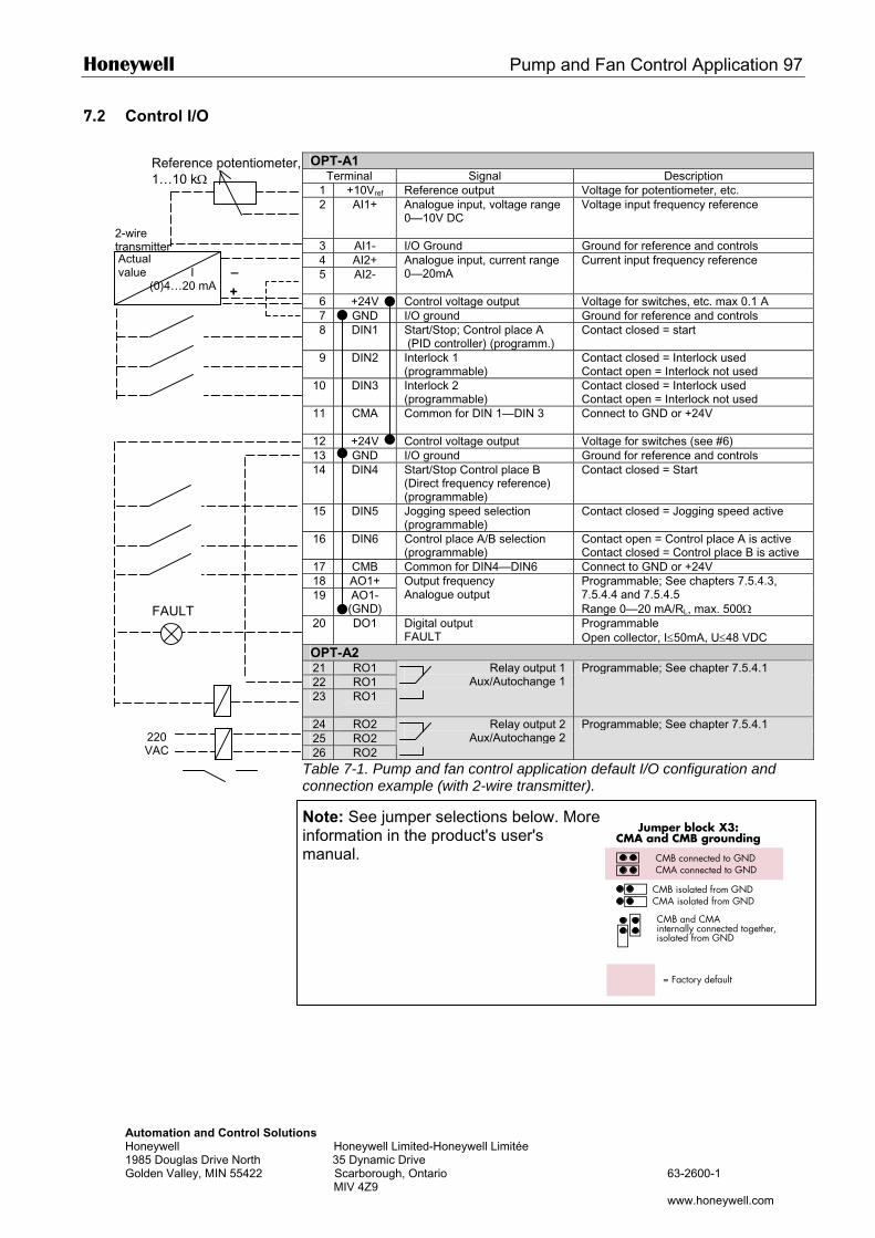
Honeywell Pump and Fan Control Application 97
AutHon198Gol
7.2 Control I/O
OPT-A1
Terminal Signal Description 1 +10Vref Reference output Voltage for potentiometer, etc. 2 AI1+ Analogue input, voltage range
0—10V DC Voltage input frequency reference
3 AI1- I/O Ground Ground for reference and controls 4 AI2+ 5 AI2-
Analogue input, current range 0—20mA
Current input frequency reference
6 +24V Control voltage output Voltage for switches, etc. max 0.1 A 7 GND I/O ground Ground for reference and controls 8 DIN1 Start/Stop; Control place A
(PID controller) (programm.) Contact closed = start
9 DIN2 Interlock 1 (programmable)
Contact closed = Interlock used Contact open = Interlock not used
10 DIN3 Interlock 2 (programmable)
Contact closed = Interlock used Contact open = Interlock not used
11 CMA
Common for DIN 1—DIN 3 Connect to GND or +24V
12 +24V Control voltage output Voltage for switches (see #6) 13 GND I/O ground Ground for reference and controls 14 DIN4 Start/Stop Control place B
(Direct frequency reference) (programmable)
Contact closed = Start
15 DIN5 Jogging speed selection (programmable)
Contact closed = Jogging speed active
16 DIN6 Control place A/B selection (programmable)
Contact open = Control place A is active Contact closed = Control place B is active
17 CMB Common for DIN4—DIN6 Connect to GND or +24V 18 AO1+ 19 AO1-
(GND)
Output frequency Analogue output
Programmable; See chapters 7.5.4.3, 7.5.4.4 and 7.5.4.5 Range 0—20 mA/RL, max. 500Ω T
Actual value I (0)4…20 mA
2-wire transmitter
– +
Reference potentiometer, 1…10 kΩ
FAUL
omation and Control Solutions eywell Honeywell Limited-Honeywell Limitée 5 Douglas Drive North 35 Dynamic Drive den Valley, MIN 55422 Scarborough, Ontario 63-2600-1 MIV 4Z9
www.honeywell.com
Jumper block X3:CMA and CMB grounding
CMB connected to GNDCMA connected to GND
CMB isolated from GNDCMA isolated from GND
CMB and CMAinternally connected together,isolated from GND
= Factory default
20 DO1 Digital output FAULT
Programmable Open collector, I≤50mA, U≤48 VDC
OPT-A2 21 RO1 22 RO1 23 RO1
Relay output 1 Aux/Autochange 1
Programmable; See chapter 7.5.4.1
24 RO2 25 RO2 26 RO2
Relay output 2 Aux/Autochange 2
Programmable; See chapter 7.5.4.1
Table 7-1. Pump and fan control application default I/O configuration and connection example (with 2-wire transmitter).
Note: See jumper selections below. More information in the product's user's manual.
220 VAC
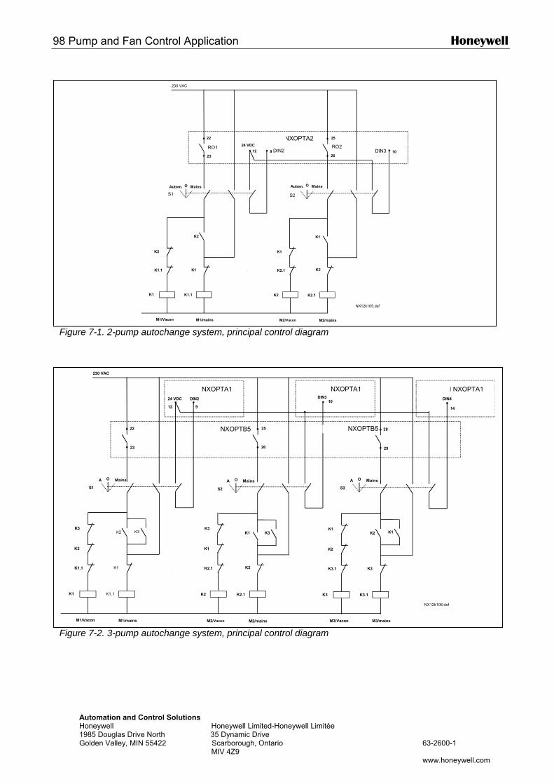
98 Pump and Fan Control Application Honeywell
Automation and Control Solutions Honeywell Honeywell Limited-Honeywell Limitée 1985 Douglas Drive North 35 Dynamic Drive Golden Valley, MIN 55422 Scarborough, Ontario 63-2600-1 MIV 4Z9 www.honeywell.com
Figure 7-1. 2-pump autochange system, principal control diagram
Figure 7-2. 3-pump autochange system, principal control diagram
22
2312 9
Autom. O Mains
25
26
230 VAC
S1
K1 K1.1
K1.1
K2
K2
K1
VACON NXOPTA2
K1
K2
K2 K2.1
M1/Vacon M2/Vacon M2/mainsM1/mains
24 VDC
S2
K2.1
K1
10RO1 RO2
DIN2 DIN3
Autom. O Mains
NX12k105.dsf
22
23
DIN2
A O Mains A O Mains
25
26
230 VAC
S1
K1 K1.1
K1.1
K2
K2
K1
VACON NXOPTB5
K1
K2
K2 K2.1
M1/Vacon M2/Vacon M2/mainsM1/mains
24 VDC
S2
K3K3
K2.1
K1
K3
DIN3
K3
28
29
A O Mains
S3
K3 K3.1
K3.1
K2
K2
K3
M3/Vacon M3/mains
K1K1
DIN4
NX12k106.dsf
1012 9 14
VACON NXOPTB5
VACON NXOPTA1 VACON NXOPTA1 VACON NXOPTA1
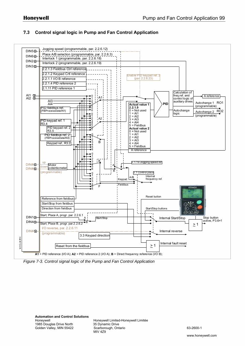
Honeywell Pump and Fan Control Application 99
Automation and Control Solutions Honeywell Honeywell Limited-Honeywell Limitée 1985 Douglas Drive North 35 Dynamic Drive Golden Valley, MIN 55422 Scarborough, Ontario 63-2600-1 MIV 4Z9 www.honeywell.com
7.3 Control signal logic in Pump and Fan Control Application
Figure 7-3. Control signal logic of the Pump and Fan Control Application
DIN5
> 1
DIN#
DIN6
DIN#DIN#
AI1AI2
0123
012345
A2
A1
B
01234
01234
K
01234
F
PID
DIN1DIN4
A
B
A
B
A/B
DIN2
DIN3
6
567
56
56
56
AI3AI4
4
> 1
A1 = PID reference (I/O A); A2 = PID reference 2 (I/O A); B = Direct frequency reference (I/O B);
Internal reverse
Internal fault reset
3.3 Keypad direction
Internal Start/Stop
Reference from fieldbus
Start/Stop from fieldbus
Direction from fieldbus
Jogging speed (programmable, par. 2.2.6.12)
Place A/B selection (programmable, par. 2.2.6.3)
I/O reverse, par. 2.2.6.11
(programmable)
Start; Place A, progr. par. 2.2.6.1
Start; Place B, progr. par.2.2.6.2
Start/Stop
Start/Stop buttons
Internalfrequency ref.
2.1.19 Jogging speed ref.
Keypad
Fieldbus
Reset button
3.1 Control place
2.2.1.3 Fieldbus Ctrl reference
2.2.1.2 Keypad Crtl reference
2.2.1.1 I/O B reference2.2.1.4 PID reference 2
2.1.11 PID reference 1
Reset from the fieldbus
Interlock 1 (programmable, par. 2.2.6.18)Interlock 2 (programmable, par. 2.2.6.19)
Actual value 12.2.1.90 = Not used1 = AI12 = AI23 = AI34 = AI45 = FieldbusActual value 20 = Not used1 = AI12 = AI23 = AI34 = AI45 = Fieldbus
Calculation offreq.ref. andcontrol logic ofauxiliary drives
Autochangelogic
Autochange 1
Autochange 2
RO1
RO2PID fieldbus ref.(FBProcessDataIN1)
Motorpotentiometer
updown
PID fieldbus ref. 2(FBProcessDataIN3)
A reference
(programmable)
(programmable)
(programmable)
Stop buttonactive, P3.6=1
PID keypad ref. 1R3.4
PID keypad ref. 2R3.5
Keypad ref., R3.2
A reference
Enable PID keypad ref. 2(par. 2.2.6.23)
100 Pump and Fan Control Application Honeywell
Automation and Control Solutions Honeywell Honeywell Limited-Honeywell Limitée 1985 Douglas Drive North 35 Dynamic Drive Golden Valley, MIN 55422 Scarborough, Ontario 63-2600-1 MIV 4Z9 www.honeywell.com
7.4 Short description of function and essential parameters
7.4.1 Automatic changing between drives (Autochange, P2.9.24) The Autochange function allows the starting and stopping order of drives controlled by the pump and fan automatics to be changed at desired intervals. The drive controlled by frequency drive can also be included in the automatic changing and locking sequence (par. 2.9.25). The Autochange function makes it possible to equalize the run times of the motors and to prevent e.g. pump stalls due to too long running breaks. • Apply the Autochange function with parameter 2.9.24, Autochange.
• The autochange takes place when the time set with parameter 2.9.26, Autochange interval, has
expired and the capacity used is below the level defined with parameter 2.9.28, Autochange frequency limit.
• The running drives are stopped and re-started according to the new order.
• External contactors controlled through the relay outputs of the frequency drive connect the drives to the frequency drive or to the mains. If the motor controlled by the frequency drive is included in the autochange sequence, it is always controlled through the relay output activated first. The other relays activated later control the auxiliary drives (see Figure 7-5 and Figure 7-6).
Parameter 2.9.24, Autochange
0 Autochange not used 1 Autochange used
The automatic change of starting and stopping order is activated and applied to either the auxiliary drives only or the auxiliary drives and the drive controlled by the frequency drive. depending on the setting of parameter 2.9.25, Automatics selection. By default, the Autochange is activated for 2 drives. See Figure 7-1 and Figure 7-5. Parameter 2.9.25, Autochange/Interlockings automatics selection
0 Automatics (autochange/interlockings) applied to auxiliary drives only The drive controlled by the frequency drive remains the same. Therefore, mains contactor is needed for one auxiliary drive only.
1 All drives included in the autochange/interlockings sequence The drive controlled by the frequency drive is included in the automatics and a contactor is needed for each drive to connect it to either the mains or the frequency drive. Parameter 2.9.26, Autochange interval
After the expiry of the time defined with this parameter, the autochange function takes place if the capacity used lies below the level defined with parameters 2.9.28 (Autochange frequency limit) and 2.9.27 (Maximum number of auxiliary drives). Should the capacity exceed the value of P2.9.28, the autochange will not take place before the capacity goes below this limit. • The time count is activated only if the Start/Stop request is active at control place A. • The time count is reset after the autochange has taken place or on removal of Start
request at control place A
Parameters 2.9.27, Maximum number of auxiliary drives and 2.9.28, Autochange frequency limit
These parameters define the level below which the capacity used must remain so that the autochange can take place.
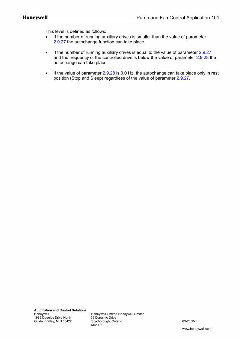
Honeywell Pump and Fan Control Application 101
Automation and Control Solutions Honeywell Honeywell Limited-Honeywell Limitée 1985 Douglas Drive North 35 Dynamic Drive Golden Valley, MIN 55422 Scarborough, Ontario 63-2600-1 MIV 4Z9 www.honeywell.com
This level is defined as follows: • If the number of running auxiliary drives is smaller than the value of parameter
2.9.27 the autochange function can take place.
• If the number of running auxiliary drives is equal to the value of parameter 2.9.27 and the frequency of the controlled drive is below the value of parameter 2.9.28 the autochange can take place.
• If the value of parameter 2.9.28 is 0.0 Hz, the autochange can take place only in rest position (Stop and Sleep) regardless of the value of parameter 2.9.27.
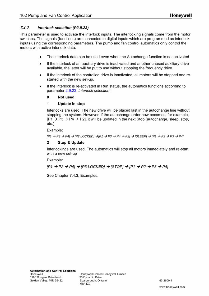
102 Pump and Fan Control Application Honeywell
Automation and Control Solutions Honeywell Honeywell Limited-Honeywell Limitée 1985 Douglas Drive North 35 Dynamic Drive Golden Valley, MIN 55422 Scarborough, Ontario 63-2600-1 MIV 4Z9 www.honeywell.com
7.4.2 Interlock selection (P2.9.23) This parameter is used to activate the interlock inputs. The interlocking signals come from the motor switches. The signals (functions) are connected to digital inputs which are programmed as interlock inputs using the corresponding parameters. The pump and fan control automatics only control the motors with active interlock data.
• The interlock data can be used even when the Autochange function is not activated
• If the interlock of an auxiliary drive is inactivated and another unused auxiliary drive available, the latter will be put to use without stopping the frequency drive.
• If the interlock of the controlled drive is inactivated, all motors will be stopped and re-started with the new set-up.
• If the interlock is re-activated in Run status, the automatics functions according to parameter 2.9.23, Interlock selection:
0 Not used
1 Update in stop
Interlocks are used. The new drive will be placed last in the autochange line without stopping the system. However, if the autochange order now becomes, for example, [P1 P3 P4 P2], it will be updated in the next Stop (autochange, sleep, stop, etc.)
Example:
[P1 P3 P4] [P2 LOCKED] [P1 P3 P4 P2] [SLEEP] [P1 P2 P3 P4]
2 Stop & Update
Interlockings are used. The automatics will stop all motors immediately and re-start with a new set-up
Example:
[P1 P2 P4] [P3 LOCKED] [STOP] [P1 P2 P3 P4] See Chapter 7.4.3, Examples.
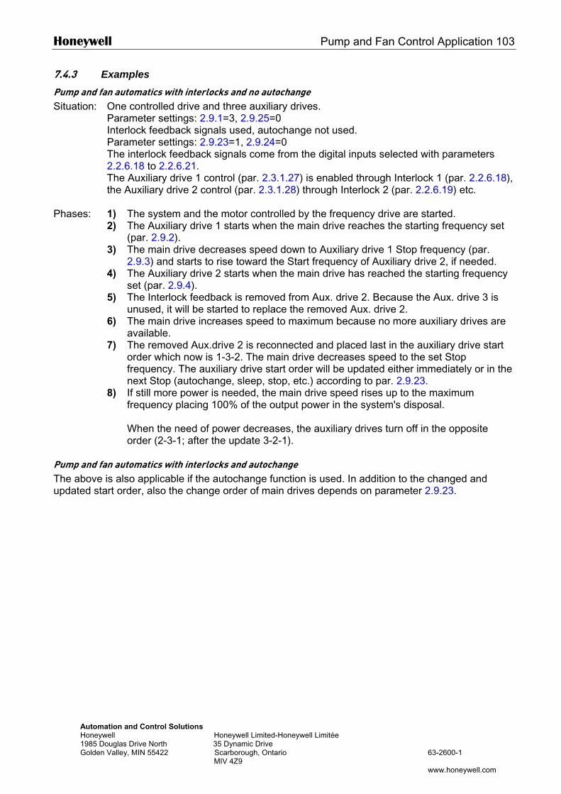
Honeywell Pump and Fan Control Application 103
Automation and Control Solutions Honeywell Honeywell Limited-Honeywell Limitée 1985 Douglas Drive North 35 Dynamic Drive Golden Valley, MIN 55422 Scarborough, Ontario 63-2600-1 MIV 4Z9 www.honeywell.com
7.4.3 Examples Pump and fan automatics with interlocks and no autochange Situation: One controlled drive and three auxiliary drives. Parameter settings: 2.9.1=3, 2.9.25=0 Interlock feedback signals used, autochange not used. Parameter settings: 2.9.23=1, 2.9.24=0 The interlock feedback signals come from the digital inputs selected with parameters
2.2.6.18 to 2.2.6.21. The Auxiliary drive 1 control (par. 2.3.1.27) is enabled through Interlock 1 (par. 2.2.6.18),
the Auxiliary drive 2 control (par. 2.3.1.28) through Interlock 2 (par. 2.2.6.19) etc. Phases: 1) The system and the motor controlled by the frequency drive are started. 2) The Auxiliary drive 1 starts when the main drive reaches the starting frequency set
(par. 2.9.2). 3) The main drive decreases speed down to Auxiliary drive 1 Stop frequency (par.
2.9.3) and starts to rise toward the Start frequency of Auxiliary drive 2, if needed. 4) The Auxiliary drive 2 starts when the main drive has reached the starting frequency
set (par. 2.9.4). 5) The Interlock feedback is removed from Aux. drive 2. Because the Aux. drive 3 is
unused, it will be started to replace the removed Aux. drive 2. 6) The main drive increases speed to maximum because no more auxiliary drives are
available. 7) The removed Aux.drive 2 is reconnected and placed last in the auxiliary drive start
order which now is 1-3-2. The main drive decreases speed to the set Stop frequency. The auxiliary drive start order will be updated either immediately or in the next Stop (autochange, sleep, stop, etc.) according to par. 2.9.23.
8) If still more power is needed, the main drive speed rises up to the maximum frequency placing 100% of the output power in the system's disposal.
When the need of power decreases, the auxiliary drives turn off in the opposite order (2-3-1; after the update 3-2-1).
Pump and fan automatics with interlocks and autochange The above is also applicable if the autochange function is used. In addition to the changed and updated start order, also the change order of main drives depends on parameter 2.9.23.
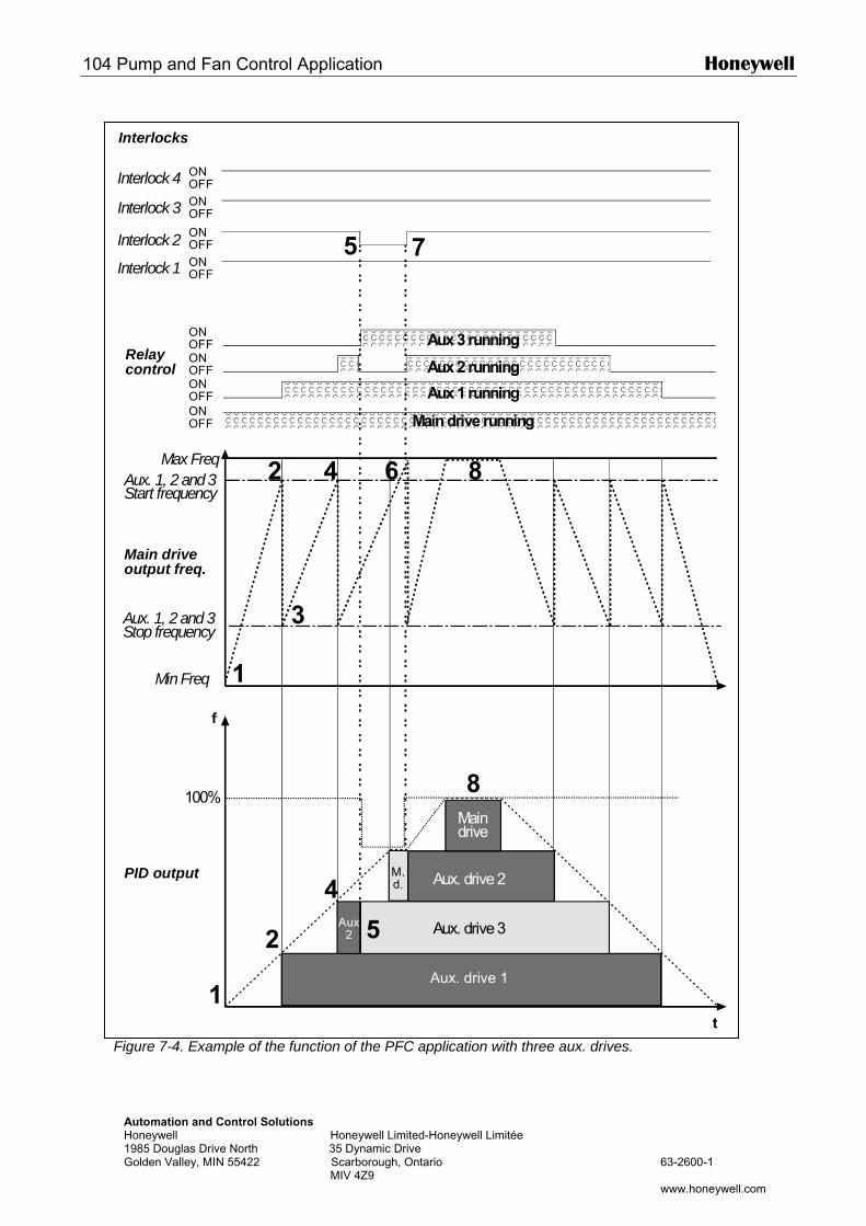
104 Pump and Fan Control Application Honeywell
Interlocks
Automation and Control Solutions Honeywell Honeywell Limited-Honeywell Limitée 1985 Douglas Drive North 35 Dynamic Drive Golden Valley, MIN 55422 Scarborough, Ontario 63-2600-1 MIV 4Z9 www.honeywell.com
Figure 7-4. Example of the function of the PFC application with three aux. drives.
f
t
Aux. drive 1
Aux. drive 3
Aux. drive 2
Maindrive
PID output
Main driveoutput freq.
Min Freq
Max FreqAux. 1, 2 and 3Start frequency
Aux. 1, 2 and 3Stop frequency
ONOFF
ONOFF
ONOFF
Aux 1 running
Aux 2 running
Aux 3 runningRelaycontrol
ONOFF Maindrive running
ONOFF
ONOFF
ONOFF
ONOFFInterlock 4
Interlock 3
Interlock 2
Interlock 1
Aux2 Aux. drive 3
M.d.
100%
Aux 2 running
1
2
4
5
8
1
2
3
4 6 8
5 7
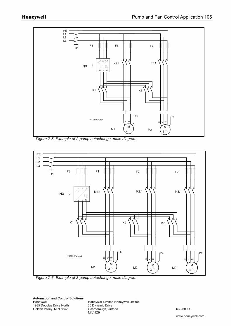
Honeywell Pump and Fan Control Application 105
Automation and Control Solutions Honeywell Honeywell Limited-Honeywell Limitée 1985 Douglas Drive North 35 Dynamic Drive Golden Valley, MIN 55422 Scarborough, Ontario 63-2600-1 MIV 4Z9 www.honeywell.com
Figure 7-5. Example of 2-pump autochange, main diagram
Figure 7-6. Example of 3-pump autochange, main diagram
PEL1L2L3
U V W
PE
U V W
PE
M1 M2
F1 F2F3
VACON
U V W
L1 L2 L3
Q1
K1 K2
K1.1 K2.1
M M3 3
NX12k107.ds4
PEL1L2L3
U V W
PE
U V W
PE
M1 M2
F1 F2F3
VACON
U V W
L1 L2 L3
Q1
K1 K2
K1.1 K2.1
M M3 3
U V W
PE
M2
F2
K3
K3.1
M
3
NX12k104.ds4
NX
NX
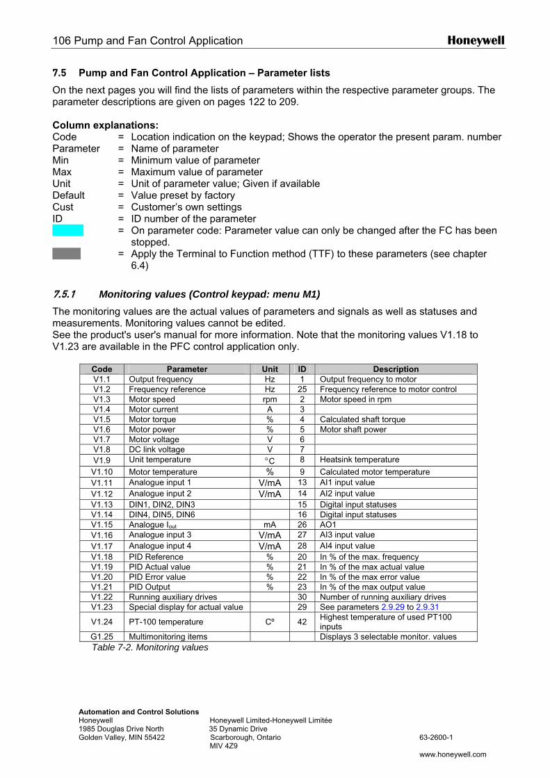
106 Pump and Fan Control Application Honeywell
Automation and Control Solutions Honeywell Honeywell Limited-Honeywell Limitée 1985 Douglas Drive North 35 Dynamic Drive Golden Valley, MIN 55422 Scarborough, Ontario 63-2600-1 MIV 4Z9 www.honeywell.com
7.5 Pump and Fan Control Application – Parameter lists
On the next pages you will find the lists of parameters within the respective parameter groups. The parameter descriptions are given on pages 122 to 209. Column explanations: Code = Location indication on the keypad; Shows the operator the present param. number Parameter = Name of parameter Min = Minimum value of parameter Max = Maximum value of parameter Unit = Unit of parameter value; Given if available Default = Value preset by factory Cust = Customer’s own settings ID = ID number of the parameter = On parameter code: Parameter value can only be changed after the FC has been
stopped. = Apply the Terminal to Function method (TTF) to these parameters (see chapter
6.4)
7.5.1 Monitoring values (Control keypad: menu M1) The monitoring values are the actual values of parameters and signals as well as statuses and measurements. Monitoring values cannot be edited. See the product's user's manual for more information. Note that the monitoring values V1.18 to V1.23 are available in the PFC control application only.
Code Parameter Unit ID Description V1.1 Output frequency Hz 1 Output frequency to motor V1.2 Frequency reference Hz 25 Frequency reference to motor control V1.3 Motor speed rpm 2 Motor speed in rpm V1.4 Motor current A 3 V1.5 Motor torque % 4 Calculated shaft torque V1.6 Motor power % 5 Motor shaft power V1.7 Motor voltage V 6 V1.8 DC link voltage V 7 V1.9 Unit temperature °C 8 Heatsink temperature
V1.10 Motor temperature % 9 Calculated motor temperature V1.11 Analogue input 1 V/mA 13 AI1 input value V1.12 Analogue input 2 V/mA 14 AI2 input value V1.13 DIN1, DIN2, DIN3 15 Digital input statuses V1.14 DIN4, DIN5, DIN6 16 Digital input statuses V1.15 Analogue Iout mA 26 AO1 V1.16 Analogue input 3 V/mA 27 AI3 input value V1.17 Analogue input 4 V/mA 28 AI4 input value V1.18 PID Reference % 20 In % of the max. frequency V1.19 PID Actual value % 21 In % of the max actual value V1.20 PID Error value % 22 In % of the max error value V1.21 PID Output % 23 In % of the max output value V1.22 Running auxiliary drives 30 Number of running auxiliary drives V1.23 Special display for actual value 29 See parameters 2.9.29 to 2.9.31
V1.24 PT-100 temperature Cº 42 Highest temperature of used PT100 inputs
G1.25 Multimonitoring items Displays 3 selectable monitor. values Table 7-2. Monitoring values
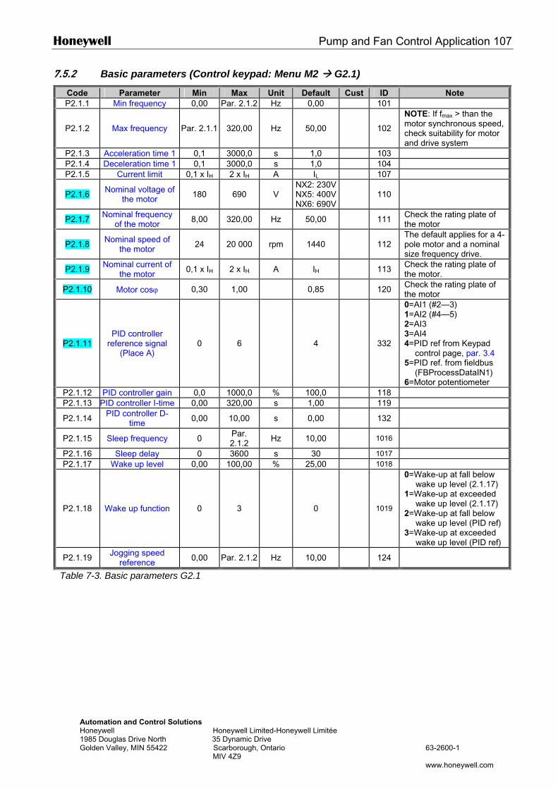
Honeywell Pump and Fan Control Application 107
Automation and Control Solutions Honeywell Honeywell Limited-Honeywell Limitée 1985 Douglas Drive North 35 Dynamic Drive Golden Valley, MIN 55422 Scarborough, Ontario 63-2600-1 MIV 4Z9 www.honeywell.com
7.5.2 Basic parameters (Control keypad: Menu M2 G2.1)
Code Parameter Min Max Unit Default Cust ID Note P2.1.1 Min frequency 0,00 Par. 2.1.2 Hz 0,00 101
P2.1.2 Max frequency Par. 2.1.1 320,00 Hz 50,00 102
NOTE: If fmax > than the motor synchronous speed, check suitability for motor and drive system
P2.1.3 Acceleration time 1 0,1 3000,0 s 1,0 103 P2.1.4 Deceleration time 1 0,1 3000,0 s 1,0 104 P2.1.5 Current limit 0,1 x IH 2 x IH A IL 107
P2.1.6 Nominal voltage of the motor 180 690 V
NX2: 230VNX5: 400VNX6: 690V
110
P2.1.7 Nominal frequency of the motor 8,00 320,00 Hz 50,00 111 Check the rating plate of
the motor
P2.1.8 Nominal speed of the motor 24 20 000 rpm 1440 112
The default applies for a 4-pole motor and a nominal size frequency drive.
P2.1.9 Nominal current of the motor 0,1 x IH 2 x IH A IH 113 Check the rating plate of
the motor.
P2.1.10 Motor cosϕ 0,30 1,00 0,85 120 Check the rating plate of the motor
P2.1.11 PID controller
reference signal (Place A)
0 6 4 332
0=AI1 (#2—3) 1=AI2 (#4—5) 2=AI3 3=AI4 4=PID ref from Keypad
control page, par. 3.4 5=PID ref. from fieldbus
(FBProcessDataIN1) 6=Motor potentiometer
P2.1.12 PID controller gain 0,0 1000,0 % 100,0 118 P2.1.13 PID controller I-time 0,00 320,00 s 1,00 119
P2.1.14 PID controller D-time 0,00 10,00 s 0,00 132
P2.1.15 Sleep frequency 0 Par. 2.1.2 Hz 10,00 1016
P2.1.16 Sleep delay 0 3600 s 30 1017 P2.1.17 Wake up level 0,00 100,00 % 25,00 1018
P2.1.18 Wake up function 0 3 0 1019
0=Wake-up at fall below wake up level (2.1.17)
1=Wake-up at exceeded wake up level (2.1.17)
2=Wake-up at fall below wake up level (PID ref)
3=Wake-up at exceeded wake up level (PID ref)
P2.1.19 Jogging speed reference 0,00 Par. 2.1.2 Hz 10,00 124
Table 7-3. Basic parameters G2.1
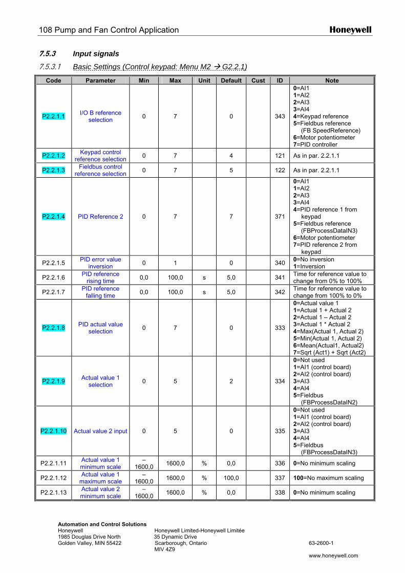
108 Pump and Fan Control Application Honeywell
Automation and Control Solutions Honeywell Honeywell Limited-Honeywell Limitée 1985 Douglas Drive North 35 Dynamic Drive Golden Valley, MIN 55422 Scarborough, Ontario 63-2600-1 MIV 4Z9 www.honeywell.com
7.5.3 Input signals
7.5.3.1 Basic Settings (Control keypad: Menu M2 G2.2.1)
Code Parameter Min Max Unit Default Cust ID Note
P2.2.1.1 I/O B reference selection 0 7 0 343
0=AI1 1=AI2 2=AI3 3=AI4 4=Keypad reference 5=Fieldbus reference (FB SpeedReference) 6=Motor potentiometer 7=PID controller
P2.2.1.2 Keypad control reference selection 0 7 4 121 As in par. 2.2.1.1
P2.2.1.3 Fieldbus control reference selection 0 7 5 122 As in par. 2.2.1.1
P2.2.1.4 PID Reference 2 0 7 7 371
0=AI1 1=AI2 2=AI3 3=AI4 4=PID reference 1 from
keypad 5=Fieldbus reference (FBProcessDataIN3) 6=Motor potentiometer 7=PID reference 2 from
keypad
P2.2.1.5 PID error value inversion 0 1 0 340 0=No inversion
1=Inversion
P2.2.1.6 PID reference rising time 0,0 100,0 s 5,0 341 Time for reference value to
change from 0% to 100%
P2.2.1.7 PID reference falling time 0,0 100,0 s 5,0 342 Time for reference value to
change from 100% to 0%
P2.2.1.8 PID actual value selection 0 7 0 333
0=Actual value 1 1=Actual 1 + Actual 2 2=Actual 1 – Actual 2 3=Actual 1 * Actual 2 4=Max(Actual 1, Actual 2) 5=Min(Actual 1, Actual 2) 6=Mean(Actual1, Actual2) 7=Sqrt (Act1) + Sqrt (Act2)
P2.2.1.9 Actual value 1 selection 0 5 2 334
0=Not used 1=AI1 (control board) 2=AI2 (control board) 3=AI3 4=AI4 5=Fieldbus
(FBProcessDataIN2)
P2.2.1.10 Actual value 2 input 0 5 0 335
0=Not used 1=AI1 (control board) 2=AI2 (control board) 3=AI3 4=AI4 5=Fieldbus
(FBProcessDataIN3)
P2.2.1.11 Actual value 1 minimum scale
–1600,0 1600,0 % 0,0 336 0=No minimum scaling
P2.2.1.12 Actual value 1 maximum scale
–1600,0 1600,0 % 100,0 337 100=No maximum scaling
P2.2.1.13 Actual value 2 minimum scale
–1600,0 1600,0 % 0,0 338 0=No minimum scaling
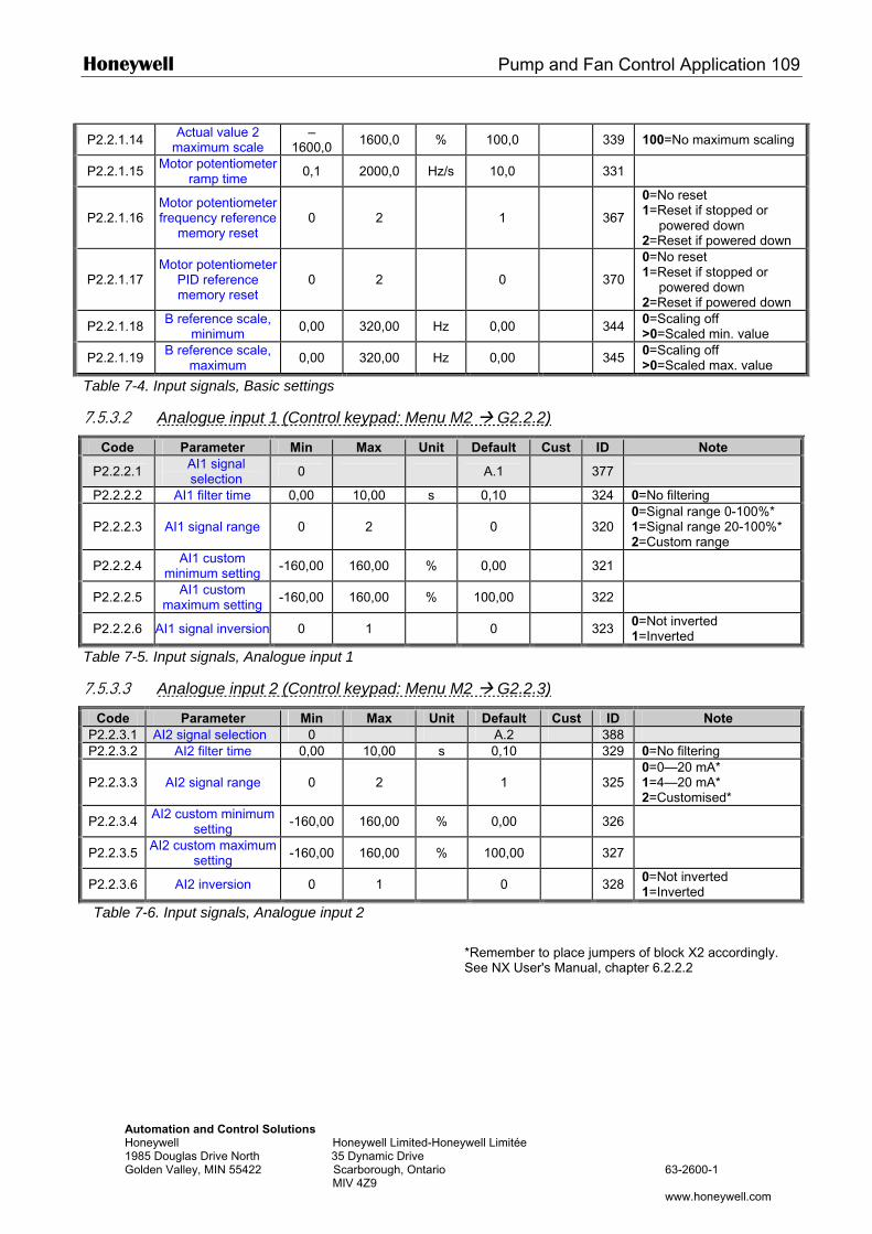
Honeywell Pump and Fan Control Application 109
Automation and Control Solutions Honeywell Honeywell Limited-Honeywell Limitée 1985 Douglas Drive North 35 Dynamic Drive Golden Valley, MIN 55422 Scarborough, Ontario 63-2600-1 MIV 4Z9 www.honeywell.com
P2.2.1.14 Actual value 2 maximum scale
–1600,0 1600,0 % 100,0 339 100=No maximum scaling
P2.2.1.15 Motor potentiometer ramp time 0,1 2000,0 Hz/s 10,0 331
P2.2.1.16 Motor potentiometer frequency reference
memory reset 0 2 1
367
0=No reset 1=Reset if stopped or
powered down 2=Reset if powered down
P2.2.1.17 Motor potentiometer
PID reference memory reset
0 2 0
370
0=No reset 1=Reset if stopped or
powered down 2=Reset if powered down
P2.2.1.18 B reference scale, minimum 0,00 320,00 Hz 0,00 344 0=Scaling off
>0=Scaled min. value
P2.2.1.19 B reference scale, maximum 0,00 320,00 Hz 0,00 345 0=Scaling off
>0=Scaled max. value
Table 7-4. Input signals, Basic settings
7.5.3.2 Analogue input 1 (Control keypad: Menu M2 G2.2.2)
Code Parameter Min Max Unit Default Cust ID Note
P2.2.2.1 AI1 signal selection 0 A.1 377
P2.2.2.2 AI1 filter time 0,00 10,00 s 0,10 324 0=No filtering
P2.2.2.3 AI1 signal range 0 2 0
320 0=Signal range 0-100%* 1=Signal range 20-100%* 2=Custom range
P2.2.2.4 AI1 custom minimum setting -160,00 160,00 % 0,00 321
P2.2.2.5 AI1 custom maximum setting -160,00 160,00 % 100,00 322
P2.2.2.6 AI1 signal inversion 0 1 0 323 0=Not inverted 1=Inverted
Table 7-5. Input signals, Analogue input 1
7.5.3.3 Analogue input 2 (Control keypad: Menu M2 G2.2.3)
Code Parameter Min Max Unit Default Cust ID Note P2.2.3.1 AI2 signal selection 0 A.2 388 P2.2.3.2 AI2 filter time 0,00 10,00 s 0,10 329 0=No filtering
P2.2.3.3 AI2 signal range 0 2 1
325 0=0—20 mA* 1=4—20 mA* 2=Customised*
P2.2.3.4 AI2 custom minimum setting -160,00 160,00 % 0,00 326
P2.2.3.5 AI2 custom maximum setting -160,00 160,00 % 100,00 327
P2.2.3.6 AI2 inversion 0 1 0 328 0=Not inverted 1=Inverted
Table 7-6. Input signals, Analogue input 2
*Remember to place jumpers of block X2 accordingly. See NX User's Manual, chapter 6.2.2.2
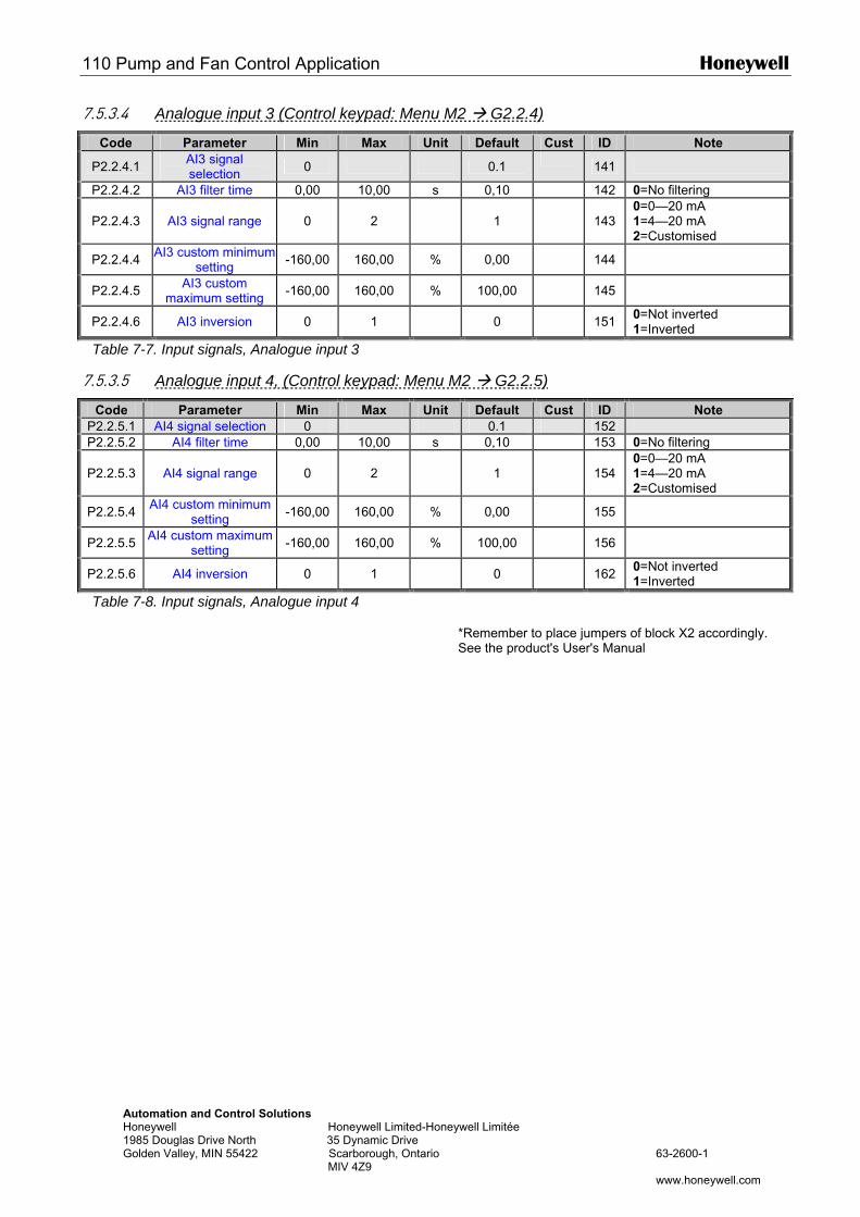
110 Pump and Fan Control Application Honeywell
Automation and Control Solutions Honeywell Honeywell Limited-Honeywell Limitée 1985 Douglas Drive North 35 Dynamic Drive Golden Valley, MIN 55422 Scarborough, Ontario 63-2600-1 MIV 4Z9 www.honeywell.com
7.5.3.4 Analogue input 3 (Control keypad: Menu M2 G2.2.4)
Code Parameter Min Max Unit Default Cust ID Note
P2.2.4.1 AI3 signal selection 0 0.1 141
P2.2.4.2 AI3 filter time 0,00 10,00 s 0,10 142 0=No filtering
P2.2.4.3 AI3 signal range 0 2 1
143 0=0—20 mA 1=4—20 mA 2=Customised
P2.2.4.4 AI3 custom minimum setting -160,00 160,00 % 0,00 144
P2.2.4.5 AI3 custom maximum setting -160,00 160,00 % 100,00 145
P2.2.4.6 AI3 inversion 0 1 0 151 0=Not inverted 1=Inverted
Table 7-7. Input signals, Analogue input 3
7.5.3.5 Analogue input 4, (Control keypad: Menu M2 G2.2.5)
Code Parameter Min Max Unit Default Cust ID Note P2.2.5.1 AI4 signal selection 0 0.1 152 P2.2.5.2 AI4 filter time 0,00 10,00 s 0,10 153 0=No filtering
P2.2.5.3 AI4 signal range 0 2 1
154 0=0—20 mA 1=4—20 mA 2=Customised
P2.2.5.4 AI4 custom minimum setting -160,00 160,00 % 0,00 155
P2.2.5.5 AI4 custom maximum setting -160,00 160,00 % 100,00 156
P2.2.5.6 AI4 inversion 0 1 0 162 0=Not inverted 1=Inverted
Table 7-8. Input signals, Analogue input 4
*Remember to place jumpers of block X2 accordingly. See the product's User's Manual
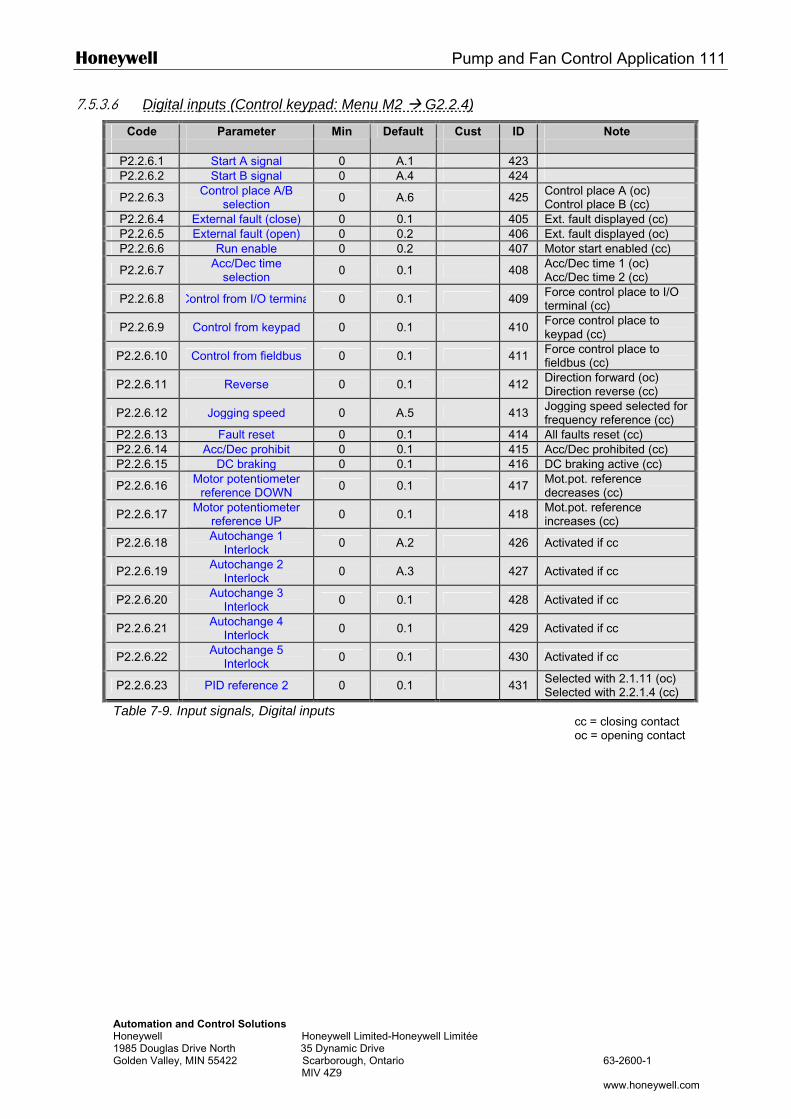
Honeywell Pump and Fan Control Application 111
Automation and Control Solutions Honeywell Honeywell Limited-Honeywell Limitée 1985 Douglas Drive North 35 Dynamic Drive Golden Valley, MIN 55422 Scarborough, Ontario 63-2600-1 MIV 4Z9 www.honeywell.com
7.5.3.6 Digital inputs (Control keypad: Menu M2 G2.2.4)
Code Parameter Min Cust ID Note
Default
P2.2.6.1 Start A signal 0 A.1 423 P2.2.6.2 Start B signal 0 A.4 424
P2.2.6.3 Control place A/B selection 0 A.6 425 Control place A (oc)
Control place B (cc) P2.2.6.4 External fault (close) 0 0.1 405 Ext. fault displayed (cc) P2.2.6.5 External fault (open) 0 0.2 406 Ext. fault displayed (oc) P2.2.6.6 Run enable 0 0.2 407 Motor start enabled (cc)
P2.2.6.7 Acc/Dec time selection 0 0.1 408 Acc/Dec time 1 (oc)
Acc/Dec time 2 (cc)
P2.2.6.8 Control from I/O terminal 0 0.1 409 Force control place to I/O terminal (cc)
P2.2.6.9 Control from keypad 0 0.1 410 Force control place to keypad (cc)
P2.2.6.10 Control from fieldbus 0 0.1 411 Force control place to fieldbus (cc)
P2.2.6.11 Reverse 0 0.1 412 Direction forward (oc) Direction reverse (cc)
P2.2.6.12 Jogging speed 0 A.5 413 Jogging speed selected for frequency reference (cc)
P2.2.6.13 Fault reset 0 0.1 414 All faults reset (cc) P2.2.6.14 Acc/Dec prohibit 0 0.1 415 Acc/Dec prohibited (cc) P2.2.6.15 DC braking 0 0.1 416 DC braking active (cc)
P2.2.6.16 Motor potentiometer reference DOWN 0 0.1 417 Mot.pot. reference
decreases (cc)
P2.2.6.17 Motor potentiometer reference UP 0 0.1 418 Mot.pot. reference
increases (cc)
P2.2.6.18 Autochange 1 Interlock 0 A.2 426 Activated if cc
P2.2.6.19 Autochange 2 Interlock 0 A.3 427 Activated if cc
P2.2.6.20 Autochange 3 Interlock 0 0.1 428 Activated if cc
P2.2.6.21 Autochange 4 Interlock 0 0.1 429 Activated if cc
P2.2.6.22 Autochange 5 Interlock 0 0.1 430 Activated if cc
P2.2.6.23 PID reference 2 0 0.1 431 Selected with 2.1.11 (oc) Selected with 2.2.1.4 (cc)
Table 7-9. Input signals, Digital inputs cc = closing contact oc = opening contact
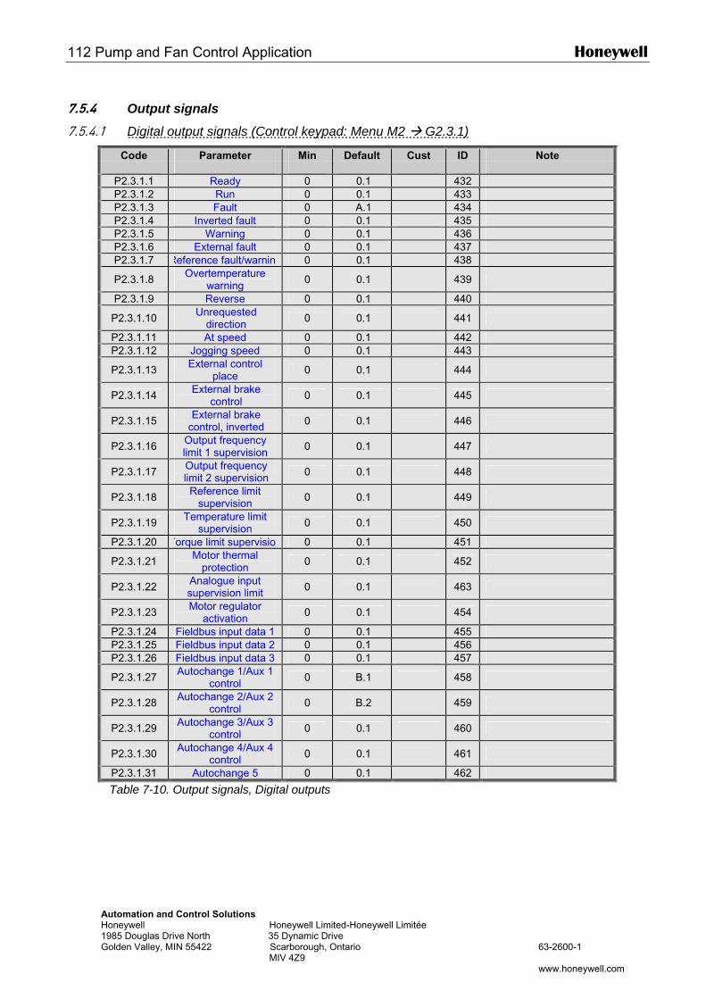
112 Pump and Fan Control Application Honeywell
Automation and Control Solutions Honeywell Honeywell Limited-Honeywell Limitée 1985 Douglas Drive North 35 Dynamic Drive Golden Valley, MIN 55422 Scarborough, Ontario 63-2600-1 MIV 4Z9 www.honeywell.com
7.5.4 Output signals
7.5.4.1 Digital output signals (Control keypad: Menu M2 G2.3.1)
Code Parameter Min Cust ID Note
Default
P2.3.1.1 Ready 0 0.1 432 P2.3.1.2 Run 0 0.1 433 P2.3.1.3 Fault 0 A.1 434 P2.3.1.4 Inverted fault 0 0.1 435 P2.3.1.5 Warning 0 0.1 436 P2.3.1.6 External fault 0 0.1 437 P2.3.1.7 Reference fault/warning 0 0.1 438
P2.3.1.8 Overtemperature warning 0 0.1 439
P2.3.1.9 Reverse 0 0.1 440
P2.3.1.10 Unrequested direction 0 0.1 441
P2.3.1.11 At speed 0 0.1 442 P2.3.1.12 Jogging speed 0 0.1 443
P2.3.1.13 External control place 0 0.1 444
P2.3.1.14 External brake control 0 0.1 445
P2.3.1.15 External brake control, inverted 0 0.1 446
P2.3.1.16 Output frequency limit 1 supervision 0 0.1 447
P2.3.1.17 Output frequency limit 2 supervision 0 0.1 448
P2.3.1.18 Reference limit supervision 0 0.1 449
P2.3.1.19 Temperature limit supervision 0 0.1 450
P2.3.1.20 Torque limit supervision 0 0.1 451
P2.3.1.21 Motor thermal protection 0 0.1 452
P2.3.1.22 Analogue input supervision limit 0 0.1 463
P2.3.1.23 Motor regulator activation 0 0.1 454
P2.3.1.24 Fieldbus input data 1 0 0.1 455 P2.3.1.25 Fieldbus input data 2 0 0.1 456 P2.3.1.26 Fieldbus input data 3 0 0.1 457
P2.3.1.27 Autochange 1/Aux 1 control 0 B.1 458
P2.3.1.28 Autochange 2/Aux 2 control 0 B.2 459
P2.3.1.29 Autochange 3/Aux 3 control 0 0.1 460
P2.3.1.30 Autochange 4/Aux 4 control 0 0.1 461
P2.3.1.31 Autochange 5 0 0.1 462
Table 7-10. Output signals, Digital outputs
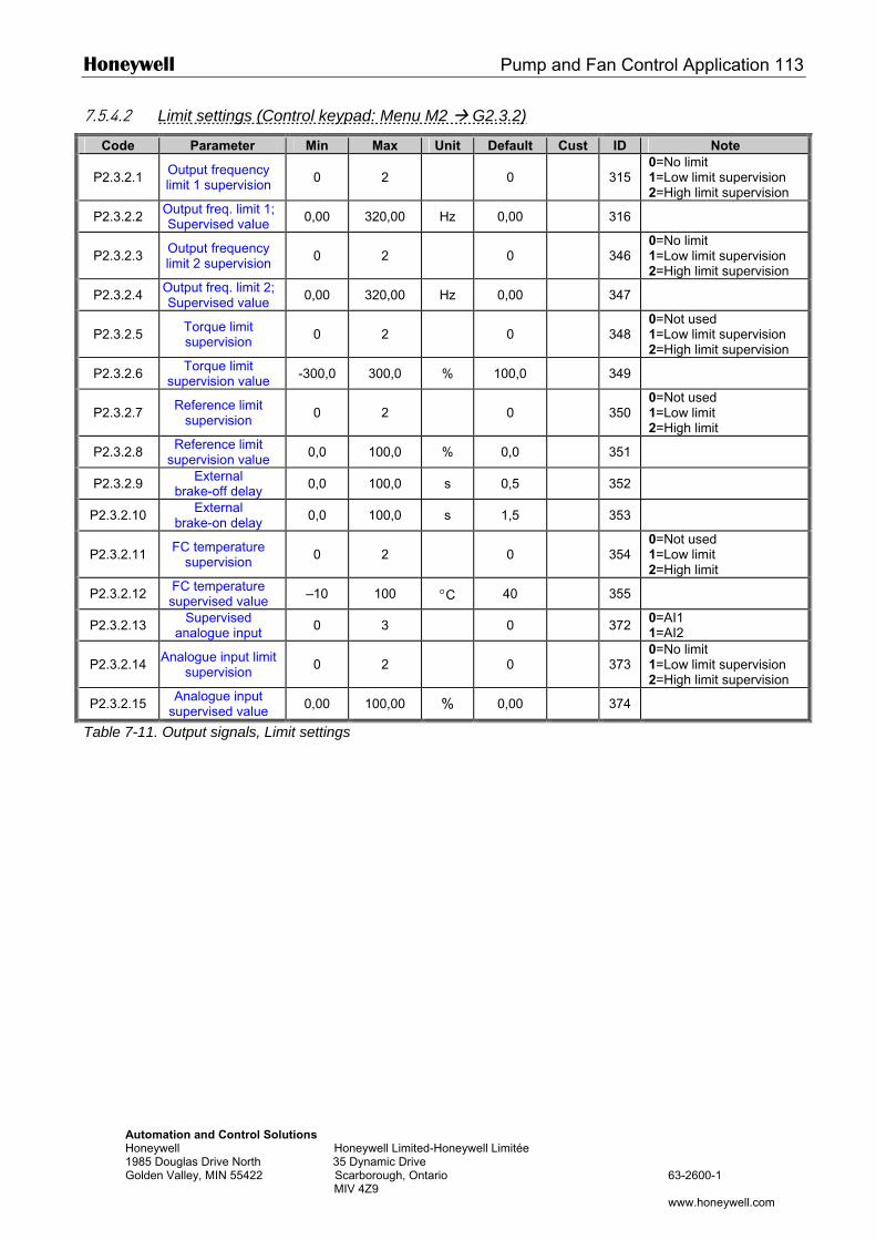
Honeywell Pump and Fan Control Application 113
Automation and Control Solutions Honeywell Honeywell Limited-Honeywell Limitée 1985 Douglas Drive North 35 Dynamic Drive Golden Valley, MIN 55422 Scarborough, Ontario 63-2600-1 MIV 4Z9 www.honeywell.com
7.5.4.2 Limit settings (Control keypad: Menu M2 G2.3.2)
Code Parameter Min Max Unit Default Cust ID Note
P2.3.2.1 Output frequency limit 1 supervision 0 2 0 315
0=No limit 1=Low limit supervision 2=High limit supervision
P2.3.2.2 Output freq. limit 1; Supervised value 0,00 320,00 Hz 0,00 316
P2.3.2.3 Output frequency limit 2 supervision 0 2 0 346
0=No limit 1=Low limit supervision 2=High limit supervision
P2.3.2.4 Output freq. limit 2; Supervised value 0,00 320,00 Hz 0,00 347
P2.3.2.5 Torque limit supervision 0 2 0 348
0=Not used 1=Low limit supervision 2=High limit supervision
P2.3.2.6 Torque limit supervision value -300,0 300,0 % 100,0 349
P2.3.2.7 Reference limit supervision 0 2 0 350
0=Not used 1=Low limit 2=High limit
P2.3.2.8 Reference limit supervision value 0,0 100,0 % 0,0 351
P2.3.2.9 External brake-off delay 0,0 100,0 s 0,5 352
P2.3.2.10 External brake-on delay 0,0 100,0 s 1,5 353
P2.3.2.11 FC temperature supervision 0 2 0 354
0=Not used 1=Low limit 2=High limit
P2.3.2.12 FC temperature supervised value –10 100 °C 40 355
P2.3.2.13 Supervised analogue input 0 3 0 372 0=AI1
1=AI2
P2.3.2.14 Analogue input limit supervision 0 2 0 373
0=No limit 1=Low limit supervision 2=High limit supervision
P2.3.2.15 Analogue input supervised value 0,00 100,00 % 0,00 374
Table 7-11. Output signals, Limit settings
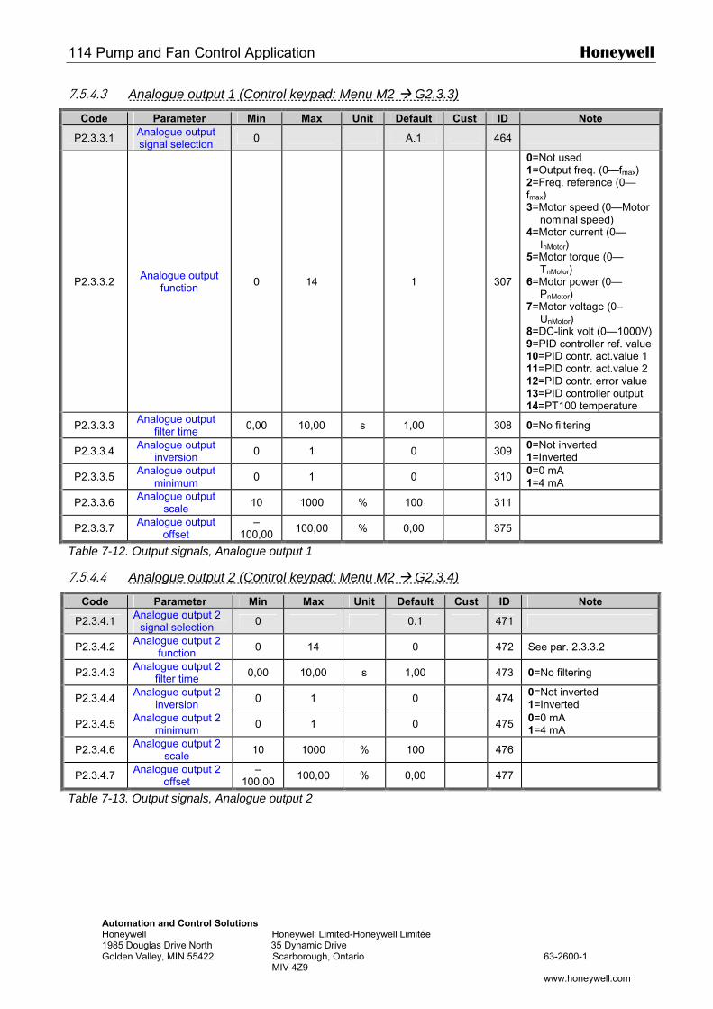
114 Pump and Fan Control Application Honeywell
Automation and Control Solutions Honeywell Honeywell Limited-Honeywell Limitée 1985 Douglas Drive North 35 Dynamic Drive Golden Valley, MIN 55422 Scarborough, Ontario 63-2600-1 MIV 4Z9 www.honeywell.com
7.5.4.3 Analogue output 1 (Control keypad: Menu M2 G2.3.3)
Code Parameter Min Max Unit Default Cust ID Note
P2.3.3.1 Analogue output signal selection 0 A.1 464
P2.3.3.2 Analogue output function 0 14 1 307
0=Not used 1=Output freq. (0—fmax) 2=Freq. reference (0—fmax) 3=Motor speed (0—Motor
nominal speed) 4=Motor current (0—
InMotor) 5=Motor torque (0—
TnMotor) 6=Motor power (0—
PnMotor) 7=Motor voltage (0–
UnMotor) 8=DC-link volt (0—1000V) 9=PID controller ref. value 10=PID contr. act.value 1 11=PID contr. act.value 2 12=PID contr. error value 13=PID controller output 14=PT100 temperature
P2.3.3.3 Analogue output filter time 0,00 10,00 s 1,00 308 0=No filtering
P2.3.3.4 Analogue output inversion 0 1 0 309 0=Not inverted
1=Inverted
P2.3.3.5 Analogue output minimum 0 1 0 310 0=0 mA
1=4 mA
P2.3.3.6 Analogue output scale 10 1000 % 100 311
P2.3.3.7 Analogue output offset
–100,00 100,00 % 0,00 375
Table 7-12. Output signals, Analogue output 1
7.5.4.4 Analogue output 2 (Control keypad: Menu M2 G2.3.4)
Code Parameter Min Max Unit Default Cust ID Note
P2.3.4.1 Analogue output 2 signal selection 0 0.1 471
P2.3.4.2 Analogue output 2 function 0 14 0 472 See par. 2.3.3.2
P2.3.4.3 Analogue output 2 filter time 0,00 10,00 s 1,00 473 0=No filtering
P2.3.4.4 Analogue output 2 inversion 0 1 0 474 0=Not inverted
1=Inverted
P2.3.4.5 Analogue output 2 minimum 0 1 0 475 0=0 mA
1=4 mA
P2.3.4.6 Analogue output 2 scale 10 1000 % 100 476
P2.3.4.7 Analogue output 2 offset
–100,00 100,00 % 0,00 477
Table 7-13. Output signals, Analogue output 2
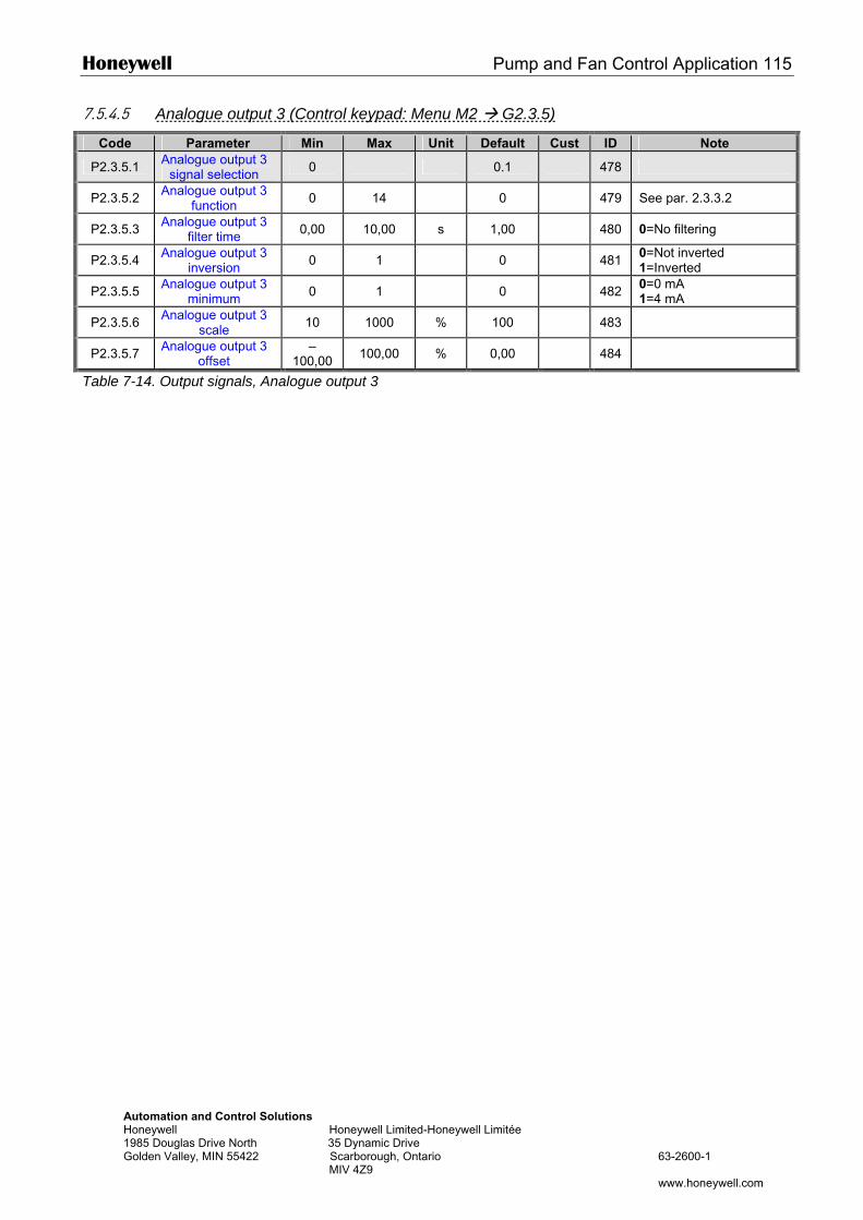
Honeywell Pump and Fan Control Application 115
Automation and Control Solutions Honeywell Honeywell Limited-Honeywell Limitée 1985 Douglas Drive North 35 Dynamic Drive Golden Valley, MIN 55422 Scarborough, Ontario 63-2600-1 MIV 4Z9 www.honeywell.com
7.5.4.5 Analogue output 3 (Control keypad: Menu M2 G2.3.5)
Code Parameter Min Max Unit Default Cust ID Note
P2.3.5.1 Analogue output 3 signal selection 0 0.1 478
P2.3.5.2 Analogue output 3 function 0 14 0 479 See par. 2.3.3.2
P2.3.5.3 Analogue output 3 filter time 0,00 10,00 s 1,00 480 0=No filtering
P2.3.5.4 Analogue output 3 inversion 0 1 0 481 0=Not inverted
1=Inverted
P2.3.5.5 Analogue output 3 minimum 0 1 0 482 0=0 mA
1=4 mA
P2.3.5.6 Analogue output 3 scale 10 1000 % 100 483
P2.3.5.7 Analogue output 3 offset
–100,00 100,00 % 0,00 484
Table 7-14. Output signals, Analogue output 3
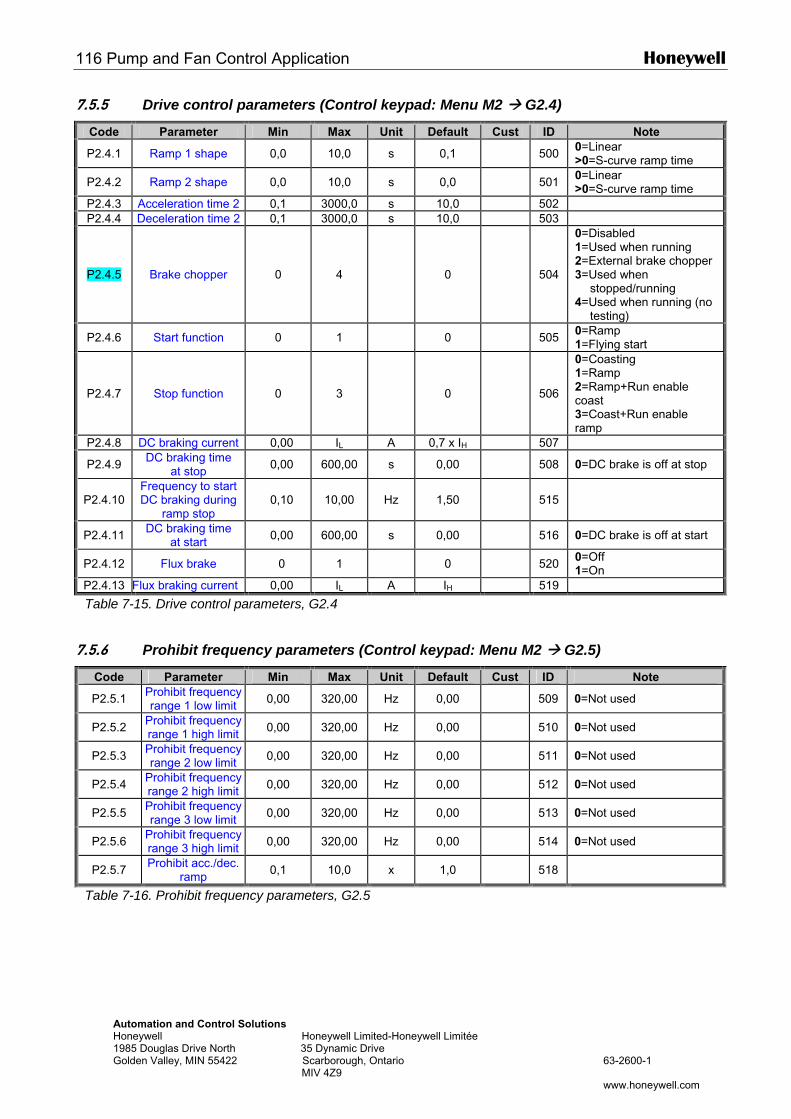
116 Pump and Fan Control Application Honeywell
Automation and Control Solutions Honeywell Honeywell Limited-Honeywell Limitée 1985 Douglas Drive North 35 Dynamic Drive Golden Valley, MIN 55422 Scarborough, Ontario 63-2600-1 MIV 4Z9 www.honeywell.com
7.5.5 Drive control parameters (Control keypad: Menu M2 G2.4)
Code Parameter Min Max Unit Default Cust ID Note
P2.4.1 Ramp 1 shape 0,0 10,0 s 0,1 500 0=Linear >0=S-curve ramp time
P2.4.2 Ramp 2 shape 0,0 10,0 s 0,0 501 0=Linear >0=S-curve ramp time
P2.4.3 Acceleration time 2 0,1 3000,0 s 10,0 502 P2.4.4 Deceleration time 2 0,1 3000,0 s 10,0 503
P2.4.5 Brake chopper 0 4 0
504
0=Disabled 1=Used when running 2=External brake chopper 3=Used when
stopped/running 4=Used when running (no
testing)
P2.4.6 Start function 0 1 0 505 0=Ramp 1=Flying start
P2.4.7 Stop function 0 3 0
506
0=Coasting 1=Ramp 2=Ramp+Run enable coast 3=Coast+Run enable ramp
P2.4.8 DC braking current 0,00 IL A 0,7 x IH 507
P2.4.9 DC braking time at stop 0,00 600,00 s 0,00 508 0=DC brake is off at stop
P2.4.10 Frequency to start DC braking during
ramp stop 0,10 10,00 Hz 1,50
515
P2.4.11 DC braking time at start 0,00 600,00 s 0,00 516 0=DC brake is off at start
P2.4.12 Flux brake 0 1 0 520 0=Off 1=On
P2.4.13 Flux braking current 0,00 IL A IH 519
Table 7-15. Drive control parameters, G2.4
7.5.6 Prohibit frequency parameters (Control keypad: Menu M2 G2.5)
Code Parameter Min Max Unit Default Cust ID Note
P2.5.1 Prohibit frequency range 1 low limit 0,00 320,00 Hz 0,00 509 0=Not used
P2.5.2 Prohibit frequency range 1 high limit 0,00 320,00 Hz 0,00 510 0=Not used
P2.5.3 Prohibit frequency range 2 low limit 0,00 320,00 Hz 0,00 511 0=Not used
P2.5.4 Prohibit frequency range 2 high limit 0,00 320,00 Hz 0,00 512 0=Not used
P2.5.5 Prohibit frequency range 3 low limit 0,00 320,00 Hz 0,00 513 0=Not used
P2.5.6 Prohibit frequency range 3 high limit 0,00 320,00 Hz 0,00 514 0=Not used
P2.5.7 Prohibit acc./dec. ramp 0,1 10,0 x 1,0 518
Table 7-16. Prohibit frequency parameters, G2.5
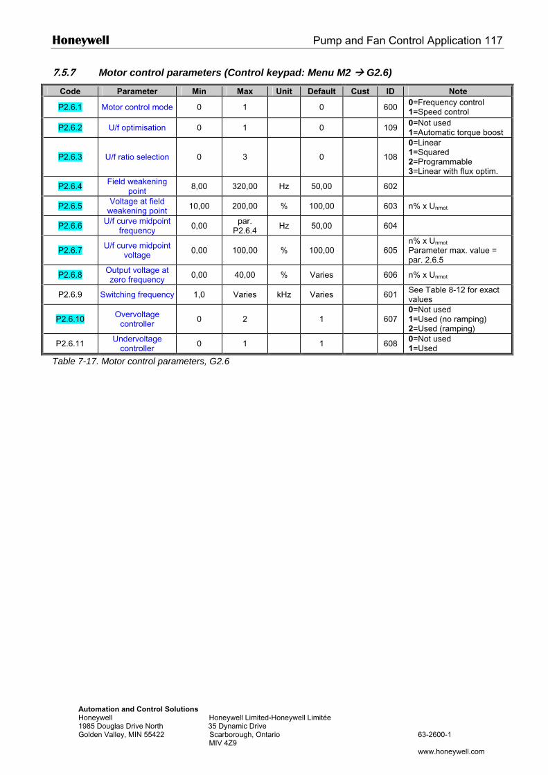
Honeywell Pump and Fan Control Application 117
Automation and Control Solutions Honeywell Honeywell Limited-Honeywell Limitée 1985 Douglas Drive North 35 Dynamic Drive Golden Valley, MIN 55422 Scarborough, Ontario 63-2600-1 MIV 4Z9 www.honeywell.com
7.5.7 Motor control parameters (Control keypad: Menu M2 G2.6)
Code Parameter Min Max Unit Default Cust ID Note
P2.6.1 Motor control mode 0 1 0
600 0=Frequency control 1=Speed control
P2.6.2 U/f optimisation 0 1 0 109 0=Not used 1=Automatic torque boost
P2.6.3 U/f ratio selection 0 3 0
108
0=Linear 1=Squared 2=Programmable 3=Linear with flux optim.
P2.6.4 Field weakening point 8,00 320,00 Hz 50,00 602
P2.6.5 Voltage at field weakening point 10,00 200,00 % 100,00 603 n% x Unmot
P2.6.6 U/f curve midpoint frequency 0,00 par.
P2.6.4 Hz 50,00 604
P2.6.7 U/f curve midpoint voltage 0,00 100,00 % 100,00
605
n% x Unmot
Parameter max. value = par. 2.6.5
P2.6.8 Output voltage at zero frequency 0,00 40,00 % Varies 606 n% x Unmot
P2.6.9 Switching frequency 1,0 Varies kHz Varies 601 See Table 8-12 for exact values
P2.6.10 Overvoltage controller 0 2 1
607
0=Not used 1=Used (no ramping) 2=Used (ramping)
P2.6.11 Undervoltage controller 0 1 1 608 0=Not used
1=Used
Table 7-17. Motor control parameters, G2.6
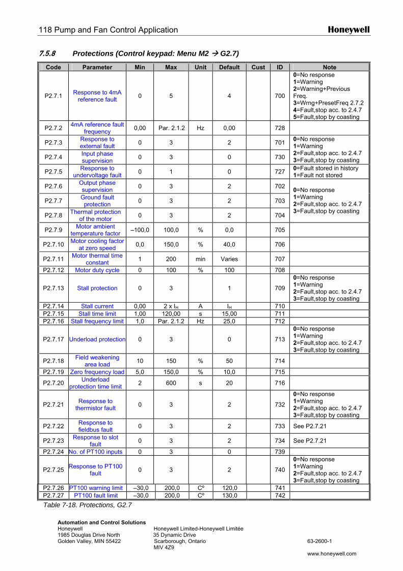
118 Pump and Fan Control Application Honeywell
Automation and Control Solutions Honeywell Honeywell Limited-Honeywell Limitée 1985 Douglas Drive North 35 Dynamic Drive Golden Valley, MIN 55422 Scarborough, Ontario 63-2600-1 MIV 4Z9 www.honeywell.com
7.5.8 Protections (Control keypad: Menu M2 G2.7)
Code Parameter Min Max Unit Default Cust ID Note
P2.7.1 Response to 4mA reference fault 0 5 4
700
0=No response 1=Warning 2=Warning+Previous Freq. 3=Wrng+PresetFreq 2.7.2 4=Fault,stop acc. to 2.4.7 5=Fault,stop by coasting
P2.7.2 4mA reference fault frequency 0,00 Par. 2.1.2 Hz 0,00 728
P2.7.3 Response to external fault 0 3 2 701
P2.7.4 Input phase supervision 0 3 0 730
0=No response 1=Warning 2=Fault,stop acc. to 2.4.7 3=Fault,stop by coasting
P2.7.5 Response to undervoltage fault 0 1 0 727 0=Fault stored in history
1=Fault not stored
P2.7.6 Output phase supervision 0 3 2 702
P2.7.7 Ground fault protection 0 3 2 703
P2.7.8 Thermal protection of the motor 0 3 2 704
0=No response 1=Warning 2=Fault,stop acc. to 2.4.7 3=Fault,stop by coasting
P2.7.9 Motor ambient temperature factor –100,0 100,0 % 0,0 705
P2.7.10 Motor cooling factor at zero speed 0,0 150,0 % 40,0 706
P2.7.11 Motor thermal time constant 1 200 min Varies 707
P2.7.12 Motor duty cycle 0 100 % 100 708
P2.7.13 Stall protection 0 3 1
709
0=No response 1=Warning 2=Fault,stop acc. to 2.4.7 3=Fault,stop by coasting
P2.7.14 Stall current 0,00 2 x IH A IH 710 P2.7.15 Stall time limit 1,00 120,00 s 15,00 711 P2.7.16 Stall frequency limit 1,0 Par. 2.1.2 Hz 25,0 712
P2.7.17 Underload protection 0 3 0
713
0=No response 1=Warning 2=Fault,stop acc. to 2.4.7 3=Fault,stop by coasting
P2.7.18 Field weakening area load 10 150 % 50 714
P2.7.19 Zero frequency load 5,0 150,0 % 10,0 715
P2.7.20 Underload protection time limit 2 600 s 20 716
P2.7.21 Response to thermistor fault 0 3 2
732
0=No response 1=Warning 2=Fault,stop acc. to 2.4.7 3=Fault,stop by coasting
P2.7.22 Response to fieldbus fault 0 3 2 733 See P2.7.21
P2.7.23 Response to slot fault 0 3 2 734 See P2.7.21
P2.7.24 No. of PT100 inputs 0 3 0 739
P2.7.25 Response to PT100 fault 0 3 2
740
0=No response 1=Warning 2=Fault,stop acc. to 2.4.7 3=Fault,stop by coasting
P2.7.26 PT100 warning limit –30,0 200,0 Cº 120,0 741 P2.7.27 PT100 fault limit –30,0 200,0 Cº 130,0 742
Table 7-18. Protections, G2.7
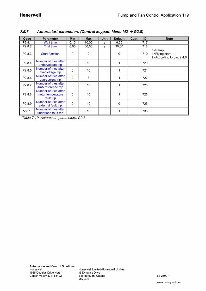
Honeywell Pump and Fan Control Application 119
Automation and Control Solutions Honeywell Honeywell Limited-Honeywell Limitée 1985 Douglas Drive North 35 Dynamic Drive Golden Valley, MIN 55422 Scarborough, Ontario 63-2600-1 MIV 4Z9 www.honeywell.com
7.5.9 Autorestart parameters (Control keypad: Menu M2 G2.8)
Code Parameter Min Max Unit Default Cust ID Note P2.8.1 Wait time 0,10 10,00 s 0,50 717 P2.8.2 Trial time 0,00 60,00 s 30,00 718
P2.8.3 Start function 0 2 0
719 0=Ramp 1=Flying start 2=According to par. 2.4.6
P2.8.4 Number of tries after undervoltage trip 0 10 1 720
P2.8.5 Number of tries after overvoltage trip 0 10 1 721
P2.8.6 Number of tries after overcurrent trip 0 3 1 722
P2.8.7 Number of tries after 4mA reference trip 0 10 1 723
P2.8.8 Number of tries after motor temperature
fault trip 0 10 1
726
P2.8.9 Number of tries after external fault trip 0 10 0 725
P2.8.10 Number of tries after underload fault trip 0 10 1 738
Table 7-19. Autorestart parameters, G2.8
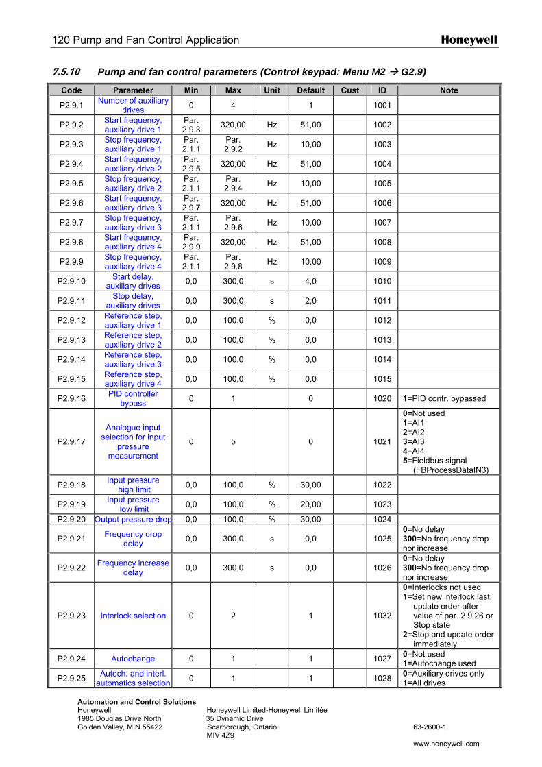
120 Pump and Fan Control Application Honeywell
Automation and Control Solutions Honeywell Honeywell Limited-Honeywell Limitée 1985 Douglas Drive North 35 Dynamic Drive Golden Valley, MIN 55422 Scarborough, Ontario 63-2600-1 MIV 4Z9 www.honeywell.com
7.5.10 Pump and fan control parameters (Control keypad: Menu M2 G2.9)
Code Parameter Min Max Unit Default Cust ID Note
P2.9.1 Number of auxiliary drives 0 4 1 1001
P2.9.2 Start frequency, auxiliary drive 1
Par. 2.9.3 320,00 Hz 51,00 1002
P2.9.3 Stop frequency, auxiliary drive 1
Par. 2.1.1
Par. 2.9.2 Hz 10,00 1003
P2.9.4 Start frequency, auxiliary drive 2
Par. 2.9.5 320,00 Hz 51,00 1004
P2.9.5 Stop frequency, auxiliary drive 2
Par. 2.1.1
Par. 2.9.4 Hz 10,00 1005
P2.9.6 Start frequency, auxiliary drive 3
Par. 2.9.7 320,00 Hz 51,00 1006
P2.9.7 Stop frequency, auxiliary drive 3
Par. 2.1.1
Par. 2.9.6 Hz 10,00 1007
P2.9.8 Start frequency, auxiliary drive 4
Par. 2.9.9 320,00 Hz 51,00 1008
P2.9.9 Stop frequency, auxiliary drive 4
Par. 2.1.1
Par. 2.9.8 Hz 10,00 1009
P2.9.10 Start delay, auxiliary drives 0,0 300,0 s 4,0 1010
P2.9.11 Stop delay, auxiliary drives 0,0 300,0 s 2,0 1011
P2.9.12 Reference step, auxiliary drive 1 0,0 100,0 % 0,0 1012
P2.9.13 Reference step, auxiliary drive 2 0,0 100,0 % 0,0 1013
P2.9.14 Reference step, auxiliary drive 3 0,0 100,0 % 0,0 1014
P2.9.15 Reference step, auxiliary drive 4 0,0 100,0 % 0,0 1015
P2.9.16 PID controller bypass 0 1 0 1020 1=PID contr. bypassed
P2.9.17
Analogue input selection for input
pressure measurement
0 5 0
1021
0=Not used 1=AI1 2=AI2 3=AI3 4=AI4 5=Fieldbus signal
(FBProcessDataIN3)
P2.9.18 Input pressure high limit 0,0 100,0 % 30,00 1022
P2.9.19 Input pressure low limit 0,0 100,0 % 20,00 1023
P2.9.20 Output pressure drop 0,0 100,0 % 30,00 1024
P2.9.21 Frequency drop delay 0,0 300,0 s 0,0
1025
0=No delay 300=No frequency drop nor increase
P2.9.22 Frequency increase delay 0,0 300,0 s 0,0
1026
0=No delay 300=No frequency drop nor increase
P2.9.23 Interlock selection 0 2 1
1032
0=Interlocks not used 1=Set new interlock last;
update order after value of par. 2.9.26 or Stop state
2=Stop and update order immediately
P2.9.24 Autochange 0 1 1 1027 0=Not used 1=Autochange used
P2.9.25 Autoch. and interl. automatics selection 0 1 1 1028 0=Auxiliary drives only
1=All drives
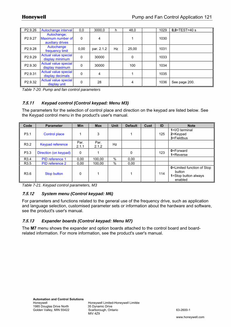
Honeywell Pump and Fan Control Application 121
Automation and Control Solutions Honeywell Honeywell Limited-Honeywell Limitée 1985 Douglas Drive North 35 Dynamic Drive Golden Valley, MIN 55422 Scarborough, Ontario 63-2600-1 MIV 4Z9 www.honeywell.com
P2.9.26 Autochange interval 0,0 3000,0 h 48,0 1029 0,0=TEST=40 s
P2.9.27 Autochange;
Maximum number of auxiliary drives
0 4 1
1030
P2.9.28 Autochange frequency limit 0,00 par. 2.1.2 Hz 25,00 1031
P2.9.29 Actual value special display minimum 0 30000 0 1033
P2.9.30 Actual value special display maximum 0 30000 100 1034
P2.9.31 Actual value special display decimals 0 4 1 1035
P2.9.32 Actual value special display unit 0 28 4 1036 See page 200.
Table 7-20. Pump and fan control parameters
7.5.11 Keypad control (Control keypad: Menu M3) The parameters for the selection of control place and direction on the keypad are listed below. See the Keypad control menu in the product's user's manual. Code Parameter Min Max Unit Default Cust ID Note
P3.1 Control place 1 3 1 125 1=I/O terminal 2=Keypad 3=Fieldbus
R3.2 Keypad reference Par. 2.1.1
Par. 2.1.2 Hz
P3.3 Direction (on keypad) 0 1 0 123 0=Forward 1=Reverse
R3.4 PID reference 1 0,00 100,00 % 0,00 R3.5 PID reference 2 0,00 100,00 % 0,00
R3.6 Stop button 0 1 1 114
0=Limited function of Stop button
1=Stop button always enabled
Table 7-21. Keypad control parameters, M3
7.5.12 System menu (Control keypad: M6) For parameters and functions related to the general use of the frequency drive, such as application and language selection, customised parameter sets or information about the hardware and software, see the product's user's manual. 7.5.13 Expander boards (Control keypad: Menu M7) The M7 menu shows the expander and option boards attached to the control board and board-related information. For more information, see the product's user's manual.
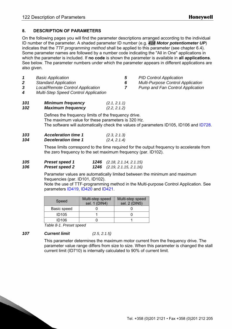
122 Description of Parameters Honeywell
Tel. +358 (0)201 2121 • Fax +358 (0)201 212 205
8. DESCRIPTION OF PARAMETERS
On the following pages you will find the parameter descriptions arranged according to the individual ID number of the parameter. A shaded parameter ID number (e.g. 418 Motor potentiometer UP) indicates that the TTF programming method shall be applied to this parameter (see chapter 6.4). Some parameter names are followed by a number code indicating the "All in One" applications in which the parameter is included. If no code is shown the parameter is available in all applications. See below. The parameter numbers under which the parameter appears in different applications are also given. 1 Basic Application 2 Standard Application 3 Local/Remote Control Application 4 Multi-Step Speed Control Application
5 PID Control Application 6 Multi-Purpose Control Application 7 Pump and Fan Control Application
101 Minimum frequency (2.1, 2.1.1) 102 Maximum frequency (2.2, 2.1.2)
Defines the frequency limits of the frequency drive. The maximum value for these parameters is 320 Hz. The software will automatically check the values of parameters ID105, ID106 and ID728.
103 Acceleration time 1 (2.3, 2.1.3) 104 Deceleration time 1 (2.4, 2.1.4)
These limits correspond to the time required for the output frequency to accelerate from the zero frequency to the set maximum frequency (par. ID102).
105 Preset speed 1 1246 (2.18, 2.1.14, 2.1.15) 106 Preset speed 2 1246 (2.19, 2.1.15, 2.1.16)
Parameter values are automatically limited between the minimum and maximum frequencies (par. ID101, ID102). Note the use of TTF-programming method in the Multi-purpose Control Application. See parameters ID419, ID420 and ID421.
Speed Multi-step speed sel. 1 (DIN4)
Multi-step speed sel. 2 (DIN5)
Basic speed 0 0
ID105 1 0 ID106 0 1
Table 8-1. Preset speed
107 Current limit (2.5, 2.1.5)
This parameter determines the maximum motor current from the frequency drive. The parameter value range differs from size to size. When this parameter is changed the stall current limit (ID710) is internally calculated to 90% of current limit.
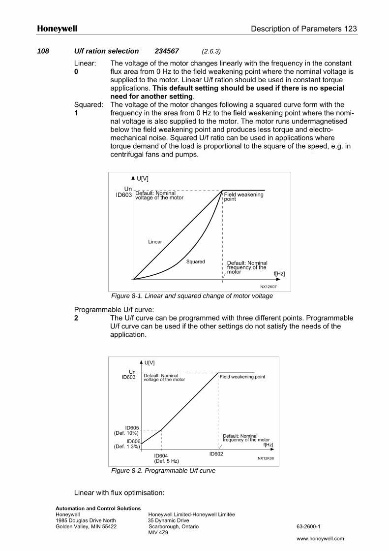
Honeywell Description of Parameters 123
Automation and ContrHoneywell 1985 Douglas Drive NoGolden Valley, MIN 554
108 U/f ration selection 234567 (2.6.3)
Linear: 0
The voltage of the motor changes linearly with the frequency in the constant flux area from 0 Hz to the field weakening point where the nominal voltage is supplied to the motor. Linear U/f ration should be used in constant torque applications. This default setting should be used if there is no special need for another setting.
Squared: 1
The voltage of the motor changes following a squared curve form with the frequency in the area from 0 Hz to the field weakening point where the nomi-nal voltage is also supplied to the motor. The motor runs undermagnetised below the field weakening point and produces less torque and electro-mechanical noise. Squared U/f ratio can be used in applications where torque demand of the load is proportional to the square of the speed, e.g. in centrifugal fans and pumps.
Programma2
Linear with
U[V]
Figure 8-1. Linear and squared change of motor voltage
ble U/f curve: The U/f curve can be programmed with three different points. Programmable U/f curve can be used if the other settings do not satisfy the needs of the application.
UnID603
f[Hz]
NX12K07
Default: Nominalvoltage of the motor
Linear
Squared
Field weakeningpoint
Default: Nominalfrequency of themotor
U[V]
ol Solutions Honeywell Limited-Honeywell Limitée
rth 35 Dynamic Drive 22 Scarborough, Ontario 63-2600-1 MIV 4Z9
www.honeywell.com
Figure 8-2. Programmable U/f curve
flux optimisation:
UnID603
ID602
f[Hz]
NX12K08ID604(Def. 5 Hz)
ID605(Def. 10%)
ID606(Def. 1.3%)
Default: Nominalvoltage of the motor Field weakening point
Default: Nominalfrequency of the motor
124 Description of Parameters Honeywell
Automation and Control Solutions Honeywell Honeywell Limited-Honeywell Limitée 1985 Douglas Drive North 35 Dynamic Drive Golden Valley, MIN 55422 Scarborough, Ontario 63-2600-1 MIV 4Z9 www.honeywell.com
3 The frequency drive starts to search for the minimum motor current in order to save energy, lower the disturbance level and the noise. This function can be used in applications with constant motor load, such as fans, pumps etc.
109 U/f optimisation (2.13, 2.6.2)
Automatic torque boost
The voltage to the motor changes automatically which makes the motor produce sufficient torque to start and run at low frequencies. The voltage increase depends on the motor type and power. Automatic torque boost can be used in applications where starting torque due to starting friction is high, e.g. in conveyors.
EXAMPLE: What changes are required to start with load from 0 Hz? ♦ First set the motor nominal values (Parameter group 2.1). Option 1: Activate the Automatic torque boost. Option 2: Programmable U/f curve To get torque you need to set the zero point voltage and midpoint voltage/frequency (in parameter group 2.6) so that the motor takes enough current at low frequencies. First set par. ID108 to Programmable U/f curve (value 2). Increase zero point voltage (ID606) to get enough current at zero speed. Set then the midpoint voltage (ID605) to 1.4142*ID606 and midpoint frequency (ID604) to value ID606/100%*ID111. NOTE! In high torque – low speed applications – it is likely that the motor will
overheat. If the motor has to run a prolonged time under these condi-tions, special attention must be paid to cooling the motor. Use external cooling for the motor if the temperature tends to rise too high.
110 Nominal voltage of the motor (2.6, 2.1.6)
Find this value Un on the rating plate of the motor. This parameter sets the voltage at the field weakening point (ID603) to 100% * UnMotor. Note also used connection Delta/Star.
111 Nominal frequency of the motor (2.7, 2.1.7)
Find this value fn on the rating plate of the motor. This parameter sets the field weakening point (ID602) to the same value.
112 Nominal speed of the motor (2.8, 2.1.8)
Find this value nn on the rating plate of the motor.
113 Nominal current of the motor (2.9, 2.1.9)
Find this value In on the rating plate of the motor.
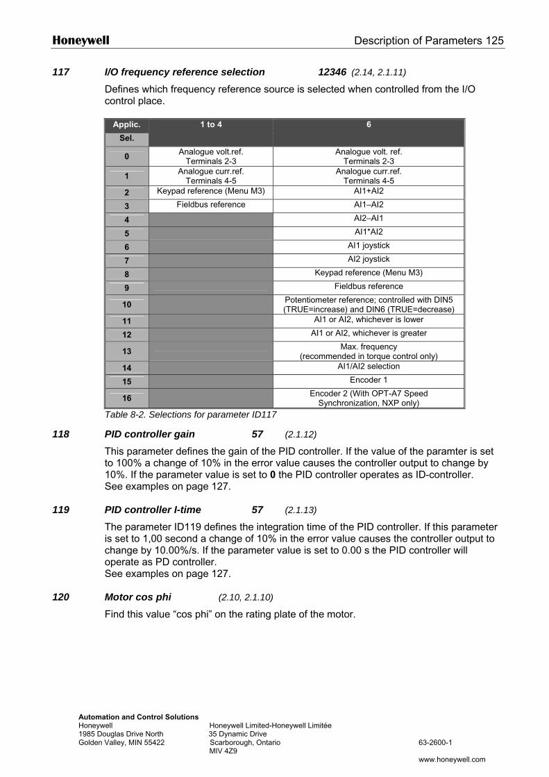
Honeywell Description of Parameters 125
Automation and Control Solutions Honeywell Honeywell Limited-Honeywell Limitée 1985 Douglas Drive North 35 Dynamic Drive Golden Valley, MIN 55422 Scarborough, Ontario 63-2600-1 MIV 4Z9 www.honeywell.com
117 I/O frequency reference selection 12346 (2.14, 2.1.11)
Defines which frequency reference source is selected when controlled from the I/O control place.
Applic.
Sel.
1 to 4 6
0 Analogue volt.ref. Terminals 2-3
Analogue volt. ref. Terminals 2-3
1 Analogue curr.ref. Terminals 4-5
Analogue curr.ref. Terminals 4-5
2 Keypad reference (Menu M3) AI1+AI2
3 Fieldbus reference AI1–AI2
4 AI2–AI1
5 AI1*AI2
6 AI1 joystick
7 AI2 joystick
8 Keypad reference (Menu M3)
9 Fieldbus reference
10 Potentiometer reference; controlled with DIN5 (TRUE=increase) and DIN6 (TRUE=decrease)
11 AI1 or AI2, whichever is lower
12 AI1 or AI2, whichever is greater
13 Max. frequency (recommended in torque control only)
14 AI1/AI2 selection
15 Encoder 1
16 Encoder 2 (With OPT-A7 Speed Synchronization, NXP only)
Table 8-2. Selections for parameter ID117
118 PID controller gain 57 (2.1.12)
This parameter defines the gain of the PID controller. If the value of the paramter is set to 100% a change of 10% in the error value causes the controller output to change by 10%. If the parameter value is set to 0 the PID controller operates as ID-controller. See examples on page 127.
119 PID controller I-time 57 (2.1.13)
The parameter ID119 defines the integration time of the PID controller. If this parameter is set to 1,00 second a change of 10% in the error value causes the controller output to change by 10.00%/s. If the parameter value is set to 0.00 s the PID controller will operate as PD controller. See examples on page 127.
120 Motor cos phi (2.10, 2.1.10)
Find this value “cos phi” on the rating plate of the motor.
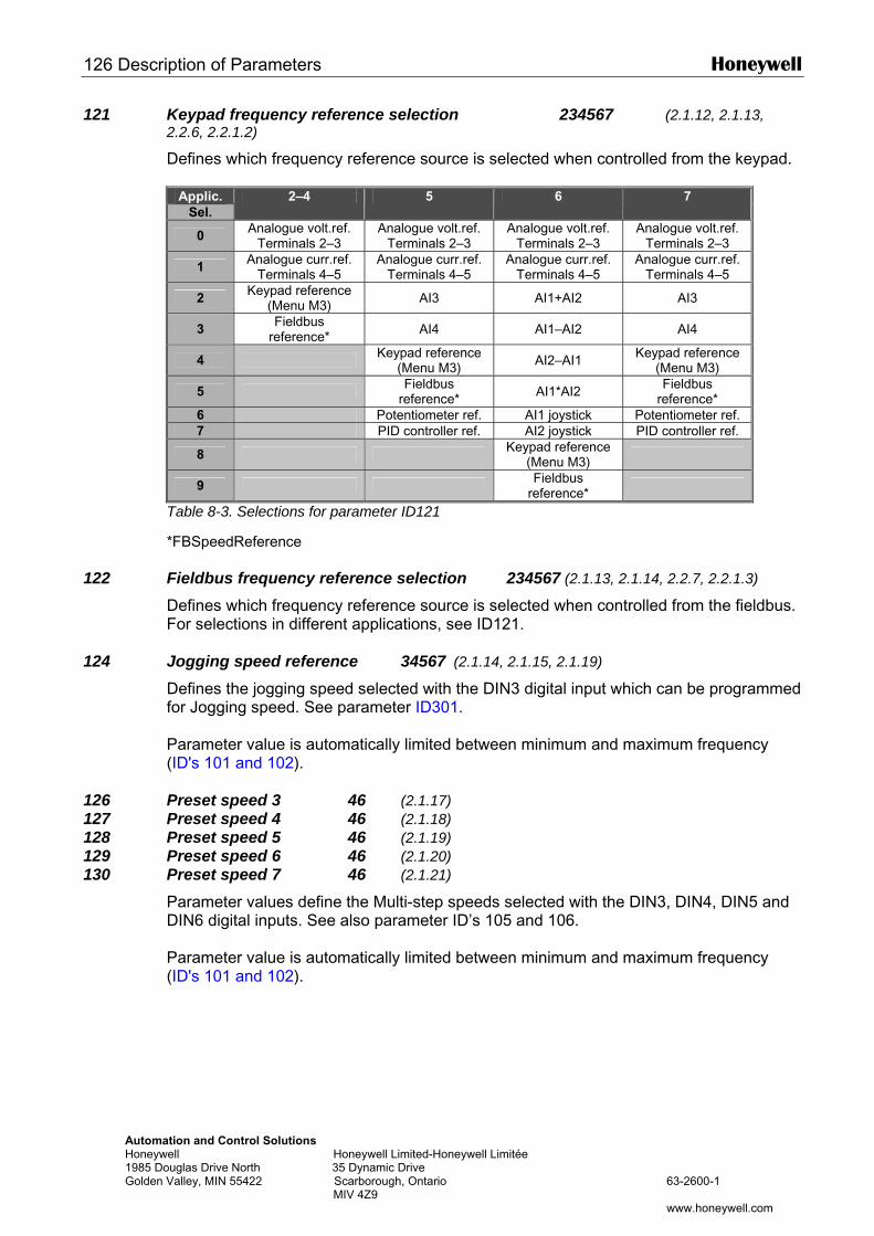
126 Description of Parameters Honeywell
Automation and Control Solutions Honeywell Honeywell Limited-Honeywell Limitée 1985 Douglas Drive North 35 Dynamic Drive Golden Valley, MIN 55422 Scarborough, Ontario 63-2600-1 MIV 4Z9 www.honeywell.com
121 Keypad frequency reference selection 234567 (2.1.12, 2.1.13, 2.2.6, 2.2.1.2)
Defines which frequency reference source is selected when controlled from the keypad.
Applic. Sel.
2–4 5 6 7
0 Analogue volt.ref. Terminals 2–3
Analogue volt.ref. Terminals 2–3
Analogue volt.ref. Terminals 2–3
Analogue volt.ref. Terminals 2–3
1 Analogue curr.ref. Terminals 4–5
Analogue curr.ref. Terminals 4–5
Analogue curr.ref. Terminals 4–5
Analogue curr.ref. Terminals 4–5
2 Keypad reference (Menu M3) AI3 AI1+AI2 AI3
3 Fieldbus reference* AI4 AI1–AI2 AI4
4 Keypad reference (Menu M3) AI2–AI1 Keypad reference
(Menu M3)
5 Fieldbus reference* AI1*AI2 Fieldbus
reference* 6 Potentiometer ref. AI1 joystick Potentiometer ref. 7 PID controller ref. AI2 joystick PID controller ref.
8 Keypad reference (Menu M3)
9 Fieldbus reference*
Table 8-3. Selections for parameter ID121
*FBSpeedReference
122 Fieldbus frequency reference selection 234567 (2.1.13, 2.1.14, 2.2.7, 2.2.1.3)
Defines which frequency reference source is selected when controlled from the fieldbus. For selections in different applications, see ID121.
124 Jogging speed reference 34567 (2.1.14, 2.1.15, 2.1.19)
Defines the jogging speed selected with the DIN3 digital input which can be programmed for Jogging speed. See parameter ID301. Parameter value is automatically limited between minimum and maximum frequency (ID's 101 and 102).
126 Preset speed 3 46 (2.1.17) 127 Preset speed 4 46 (2.1.18) 128 Preset speed 5 46 (2.1.19) 129 Preset speed 6 46 (2.1.20) 130 Preset speed 7 46 (2.1.21)
Parameter values define the Multi-step speeds selected with the DIN3, DIN4, DIN5 and DIN6 digital inputs. See also parameter ID’s 105 and 106. Parameter value is automatically limited between minimum and maximum frequency (ID's 101 and 102).
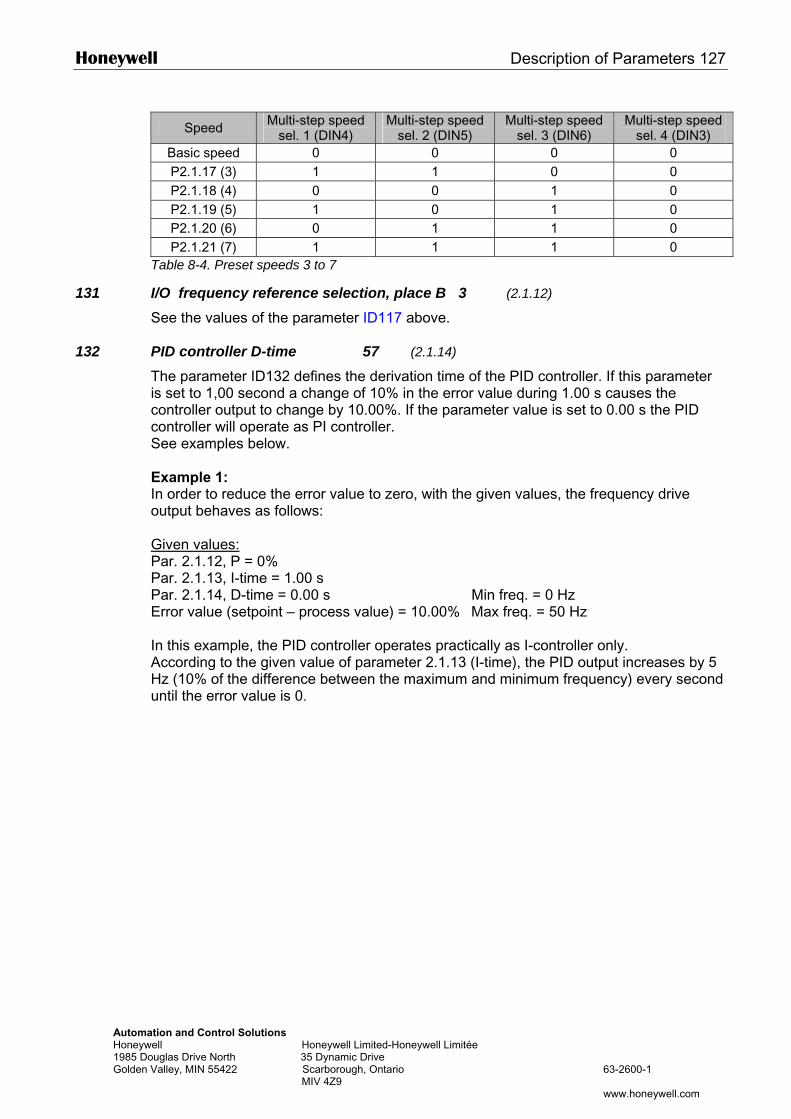
Honeywell Description of Parameters 127
Automation and Control Solutions Honeywell Honeywell Limited-Honeywell Limitée 1985 Douglas Drive North 35 Dynamic Drive Golden Valley, MIN 55422 Scarborough, Ontario 63-2600-1 MIV 4Z9 www.honeywell.com
Speed Multi-step speed sel. 1 (DIN4)
Multi-step speed sel. 2 (DIN5)
Multi-step speed sel. 3 (DIN6)
Multi-step speed sel. 4 (DIN3)
Basic speed 0 0 0 0 P2.1.17 (3) 1 1 0 0 P2.1.18 (4) 0 0 1 0 P2.1.19 (5) 1 0 1 0 P2.1.20 (6) 0 1 1 0 P2.1.21 (7) 1 1 1 0
Table 8-4. Preset speeds 3 to 7
131 I/O frequency reference selection, place B 3 (2.1.12)
See the values of the parameter ID117 above.
132 PID controller D-time 57 (2.1.14)
The parameter ID132 defines the derivation time of the PID controller. If this parameter is set to 1,00 second a change of 10% in the error value during 1.00 s causes the controller output to change by 10.00%. If the parameter value is set to 0.00 s the PID controller will operate as PI controller. See examples below. Example 1: In order to reduce the error value to zero, with the given values, the frequency drive output behaves as follows: Given values: Par. 2.1.12, P = 0% Par. 2.1.13, I-time = 1.00 s Par. 2.1.14, D-time = 0.00 s Min freq. = 0 Hz Error value (setpoint – process value) = 10.00% Max freq. = 50 Hz In this example, the PID controller operates practically as I-controller only. According to the given value of parameter 2.1.13 (I-time), the PID output increases by 5 Hz (10% of the difference between the maximum and minimum frequency) every second until the error value is 0.
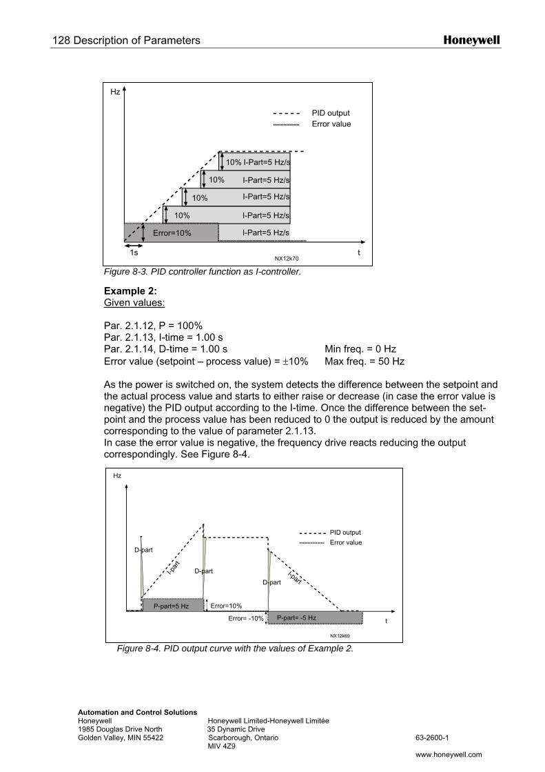
128 Description of Parameters Honeywell
AutomaHoneyw1985 DoGolden
Hz
tion and Control Solutions ell Honeywell Limited-Honeywell Limitée uglas Drive North 35 Dynamic Drive
Valley, MIN 55422 Scarborough, Ontario 63-2600-1 MIV 4Z9
www.honeywell.com
Figure 8-3. PID controller function as I-controller.
Example 2: Given values: Par. 2.1.12, P = 100% Par. 2.1.13, I-time = 1.00 s Par. 2.1.14, D-time = 1.00 s Min freq. = 0 Hz Error value (setpoint – process value) = ±10% Max freq. = 50 Hz As the power is switched on, the system detects the difference between the setpoint and the actual process value and starts to either raise or decrease (in case the error value is negative) the PID output according to the I-time. Once the difference between the set-point and the process value has been reduced to 0 the output is reduced by the amount corresponding to the value of parameter 2.1.13. In case the error value is negative, the frequency drive reacts reducing the output correspondingly. See Figure 8-4.
Figure 8-4. PID output curve with the values of Example 2.
Hz
t
D-part
D-part
P-part=5 Hz Error=10%
D-part
P-part= -5 HzError= -10%
PID output
NX12k69
Error value
t1s
Error=10%
10%
10%
10%
10% I-Part=5 Hz/s
I-Part=5 Hz/s
I-Part=5 Hz/s
I-Part=5 Hz/s
I-Part=5 Hz/s
PID outputError value
NX12k70
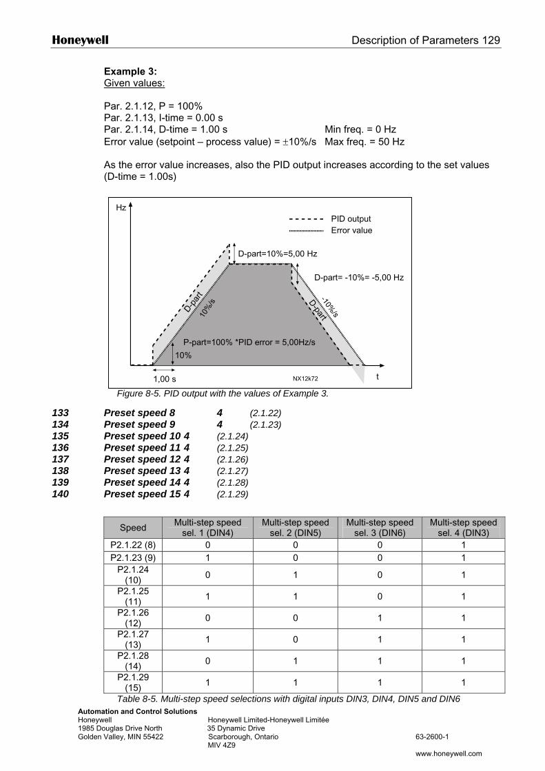
Honeywell Description of Parameters 129
AutomatiHoneywel1985 DouGolden Va
Example 3: Given values: Par. 2.1.12, P = 100% Par. 2.1.13, I-time = 0.00 s Par. 2.1.14, D-time = 1.00 s Min freq. = 0 Hz Error value (setpoint – process value) = ±10%/s Max freq. = 50 Hz As the error value increases, also the PID output increases according to the set values (D-time = 1.00s)
133 P134 P135 P136 P137 P138 P139 P140 P
HzPID output
on and Control Solutions l Honeywell Limited-Honeywell Limitée glas Drive North 35 Dynamic Drive lley, MIN 55422 Scarborough, Ontario 63-2600-1 MIV 4Z9
www.honeywell.com
Figure 8-5. PID output with the values of Example 3.
reset speed 8 4 (2.1.22) reset speed 9 4 (2.1.23) reset speed 10 4 (2.1.24) reset speed 11 4 (2.1.25) reset speed 12 4 (2.1.26) reset speed 13 4 (2.1.27) reset speed 14 4 (2.1.28) reset speed 15 4 (2.1.29)
Speed Multi-step speed sel. 1 (DIN4)
Multi-step speed sel. 2 (DIN5)
Multi-step speed sel. 3 (DIN6)
Multi-step speed sel. 4 (DIN3)
P2.1.22 (8) 0 0 0 1 P2.1.23 (9) 1 0 0 1
P2.1.24 (10) 0 1 0 1
P2.1.25 (11) 1 1 0 1
P2.1.26 (12) 0 0 1 1
P2.1.27 (13) 1 0 1 1
P2.1.28 (14) 0 1 1 1
P2.1.29 (15) 1 1 1 1
Table 8-5. Multi-step speed selections with digital inputs DIN3, DIN4, DIN5 and DIN6
t
D-part=10%=5,00 Hz
D-part= -10%= -5,00 Hz
P-part=100% *PID error = 5,00Hz/s
1,00 s
10%
NX12k72
Error value
130 Description of Parameters Honeywell
Automation and Control Solutions Honeywell Honeywell Limited-Honeywell Limitée 1985 Douglas Drive North 35 Dynamic Drive Golden Valley, MIN 55422 Scarborough, Ontario 63-2600-1 MIV 4Z9 www.honeywell.com
Honeywell Description of Parameters 131
Automation and Control Solutions Honeywell Honeywell Limited-Honeywell Limitée 1985 Douglas Drive North 35 Dynamic Drive Golden Valley, MIN 55422 Scarborough, Ontario 63-2600-1 MIV 4Z9 www.honeywell.com
141 AI3 signal selection 567 (2.2.38, 2.2.4.1) Connect the AI3 signal to the analogue input of your choice with this parameter. For more information, see Chapter 6.4 “Terminal To Function” (TTF) programming principle.
142 AI3 signal filter time 567 (2.2.41, 2.2.4.2)
When this parameter is given a value greater than 0 the function that filters out disturbances from the incoming analogue signal is activated. Long filtering time makes the regulation response slower. See parameter ID324.
143 AI3 signal range 567 (2.2.39, 2.2.4.3)
With this parameter you can select the AI3 signal range.
Applic. Sel.
5 6 7
0 0…100% 0…100% 0…100% 1 20…100% 20…100% 20…100% 2 –10…+10V Customised 3 Customised
Table 8-6. Selections for parameter ID143
144 AI3 custom setting minimum 67 (2.2.4.4) 145 AI3 custom setting maximum 67 (2.2.4.5)
Set the custom minimum and maximum levels for the AI3 signal within -160…160%.
151 AI3 signal inversion 567 (2.2.40, 2.2.4.6)
0 = No inversion 1 = Signal inverted
152 AI4 signal selection 567 (2.2.42, 2.2.5.1)
See ID141.
153 AI4 filter time 567 (2.2.45, 2.2.5.2)
See ID142.
154 AI4 signal range 567 (2.2.43, 2.2.5.3)
See ID143.
155 AI4 custom setting minimum 67 (2.2.5.3, 2.2.5.4) 156 AI4 custom setting maximum 67 (2.2.5.4, 2.2.5.5)
See ID’s 144 and 145.
162 AI4 signal inversion 567 (2.2.44, 2.2.5.5, 2.2.5.6)
See ID151. 164 Motor control mode 1/2 6 (2.2.7.22)
Contact is open = Motor control mode 1 is selected Contact is closed = Motor control mode 2 is selected See parameter ID's 600 and 521.
132 Description of Parameters Honeywell
Automation and Control Solutions Honeywell Honeywell Limited-Honeywell Limitée 1985 Douglas Drive North 35 Dynamic Drive Golden Valley, MIN 55422 Scarborough, Ontario 63-2600-1 MIV 4Z9 www.honeywell.com
165 AI1 joystick offset 6 (2.2.2.11)
Define the frequency zero point as follows: With this parameter on display, place the potentiometer at the assumed zero point and press Enter on the keypad. Note: This will not, however, change the reference scaling. Press Reset button to change the parameter value back to 0,00%.
166 AI2 joystick offset 6 (2.2.3.11)
See par. ID165.
169 Fieldbus input data 4 (FBFixedControlWord, bit 6) 6 (2.3.3.27) 170 Fieldbus input data 5 (FBFixedControlWord, bit 7) 6 (2.3.3.28)
The data from the fieldbus (FBFixedControlWord) can be led to the digital outputs of the frequency drive.
179 Scaling of motoring power limit 6 (2.2.6.7) The motoring power limit is equal to ID1289 if value 'Not used' is selected. If any of the inputs is selected the motoring power limit is scaled between zero and parameter ID1289. This parameter is available for NXP drives only. 0 = Not used 1 = AI1 2 = AI2 3 = AI3 4 = AI4 5 = FB Limit Scaling ID46 (monitoring value)
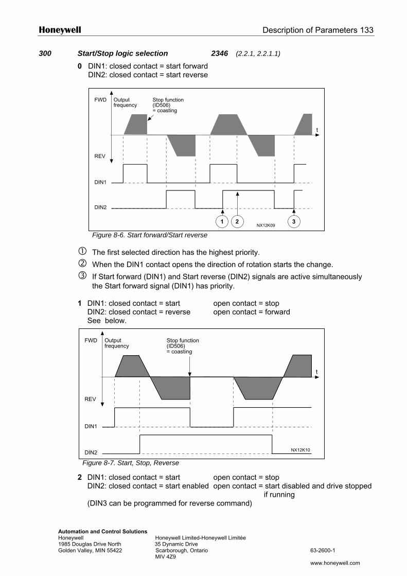
Honeywell Description of Parameters 133
Automation Honeywell 1985 DouglaGolden Valle
300 Start/Stop logic selection 2346 (2.2.1, 2.2.1.1)
0 DIN1: closed contact = start forward DIN2: closed contact = start reverse
1 D D S
Fig
2 D D
(
Outputfrequency
Stop function(ID506)
FWD
FW
RE
DI
DI
Figure 8-6. Start forward/Start reverse
The first selected direction has the highest priority.
When the DIN1 contact opens the direction of rotation starts the change.
If Start forward (DIN1) and Start reverse (DIN2) signals are active simultaneously the Start forward signal (DIN1) has priority.
IN1: closed contact = start open contact = stop IN2: closed contact = reverse open contact = forward ee below.
1 2 3
t
NX12K09
= coasting
REV
DIN1
DIN2
Outputfrequency
Stop function(ID506)
D
and Control Solutions Honeywell Limited-Honeywell Limitée
s Drive North 35 Dynamic Drive y, MIN 55422 Scarborough, Ontario 63-2600-1 MIV 4Z9
www.honeywell.com
ure 8-7. Start, Stop, Reverse
IN1: closed contact = start open contact = stop IN2: closed contact = start enabled open contact = start disabled and drive stopped
if running DIN3 can be programmed for reverse command)
t
NX12K10
= coasting
V
N1
N2
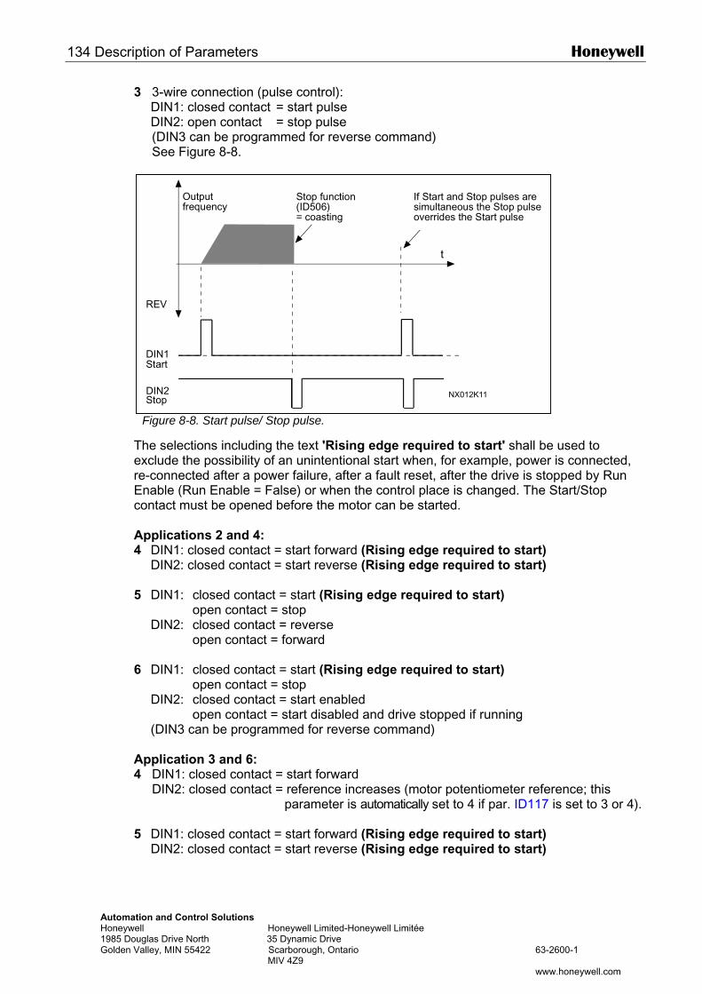
134 Description of Parameters Honeywell
AutomatHoneywe1985 DouGolden V
3 3-wire connection (pulse control): DIN1: closed contact = start pulse DIN2: open contact = stop pulse (DIN3 can be programmed for reverse command) See Figure 8-8.
TerEc A4 5 6 A4
5
Output Stop function If Start and Stop pulses are
ion and Control Solutions ll Honeywell Limited-Honeywell Limitée glas Drive North 35 Dynamic Drive alley, MIN 55422 Scarborough, Ontario 63-2600-1 MIV 4Z9
www.honeywell.com
Figure 8-8. Start pulse/ Stop pulse.
he selections including the text 'Rising edge required to start' shall be used to xclude the possibility of an unintentional start when, for example, power is connected, e-connected after a power failure, after a fault reset, after the drive is stopped by Run nable (Run Enable = False) or when the control place is changed. The Start/Stop ontact must be opened before the motor can be started.
pplications 2 and 4: DIN1: closed contact = start forward (Rising edge required to start)
DIN2: closed contact = start reverse (Rising edge required to start)
DIN1: closed contact = start (Rising edge required to start) open contact = stop DIN2: closed contact = reverse open contact = forward
DIN1: closed contact = start (Rising edge required to start) open contact = stop DIN2: closed contact = start enabled open contact = start disabled and drive stopped if running (DIN3 can be programmed for reverse command)
pplication 3 and 6: DIN1: closed contact = start forward
DIN2: closed contact = reference increases (motor potentiometer reference; this parameter is automatically set to 4 if par. ID117 is set to 3 or 4).
DIN1: closed contact = start forward (Rising edge required to start) DIN2: closed contact = start reverse (Rising edge required to start)
t
NX012K11
REV
frequency (ID506)= coasting
simultaneous the Stop pulseoverrides the Start pulse
Start
Stop
DIN1
DIN2
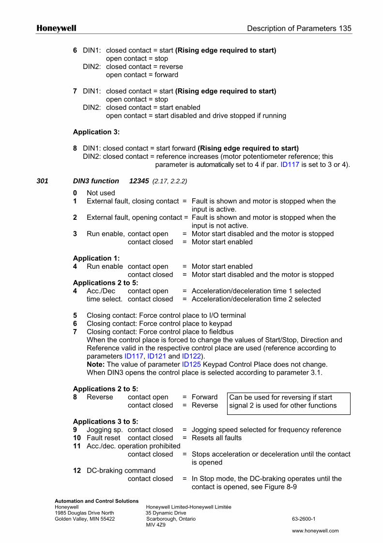
Honeywell Description of Parameters 135
Automation and Control Solutions Honeywell Honeywell Limited-Honeywell Limitée 1985 Douglas Drive North 35 Dynamic Drive Golden Valley, MIN 55422 Scarborough, Ontario 63-2600-1 MIV 4Z9 www.honeywell.com
6 DIN1: closed contact = start (Rising edge required to start) open contact = stop DIN2: closed contact = reverse open contact = forward 7 DIN1: closed contact = start (Rising edge required to start) open contact = stop DIN2: closed contact = start enabled open contact = start disabled and drive stopped if running Application 3: 8 DIN1: closed contact = start forward (Rising edge required to start)
DIN2: closed contact = reference increases (motor potentiometer reference; this parameter is automatically set to 4 if par. ID117 is set to 3 or 4).
301 DIN3 function 12345 (2.17, 2.2.2)
0 Not used 1 External fault, closing contact = Fault is shown and motor is stopped when the
input is active. 2 External fault, opening contact = Fault is shown and motor is stopped when the
input is not active. 3 Run enable, contact open = Motor start disabled and the motor is stopped contact closed = Motor start enabled Application 1: 4 Run enable contact open = Motor start enabled contact closed = Motor start disabled and the motor is stopped Applications 2 to 5: 4 Acc./Dec contact open = Acceleration/deceleration time 1 selected time select. contact closed = Acceleration/deceleration time 2 selected 5 Closing contact: Force control place to I/O terminal 6 Closing contact: Force control place to keypad 7 Closing contact: Force control place to fieldbus
When the control place is forced to change the values of Start/Stop, Direction and Reference valid in the respective control place are used (reference according to parameters ID117, ID121 and ID122). Note: The value of parameter ID125 Keypad Control Place does not change. When DIN3 opens the control place is selected according to parameter 3.1.
Applications 2 to 5: 8 Reverse contact open = Forward contact closed = Reverse Applications 3 to 5: 9 Jogging sp. contact closed = Jogging speed selected for frequency reference 10 Fault reset contact closed = Resets all faults 11 Acc./dec. operation prohibited
contact closed = Stops acceleration or deceleration until the contact is opened
12 DC-braking command contact closed = In Stop mode, the DC-braking operates until the
contact is opened, see Figure 8-9
Can be used for reversing if start signal 2 is used for other functions
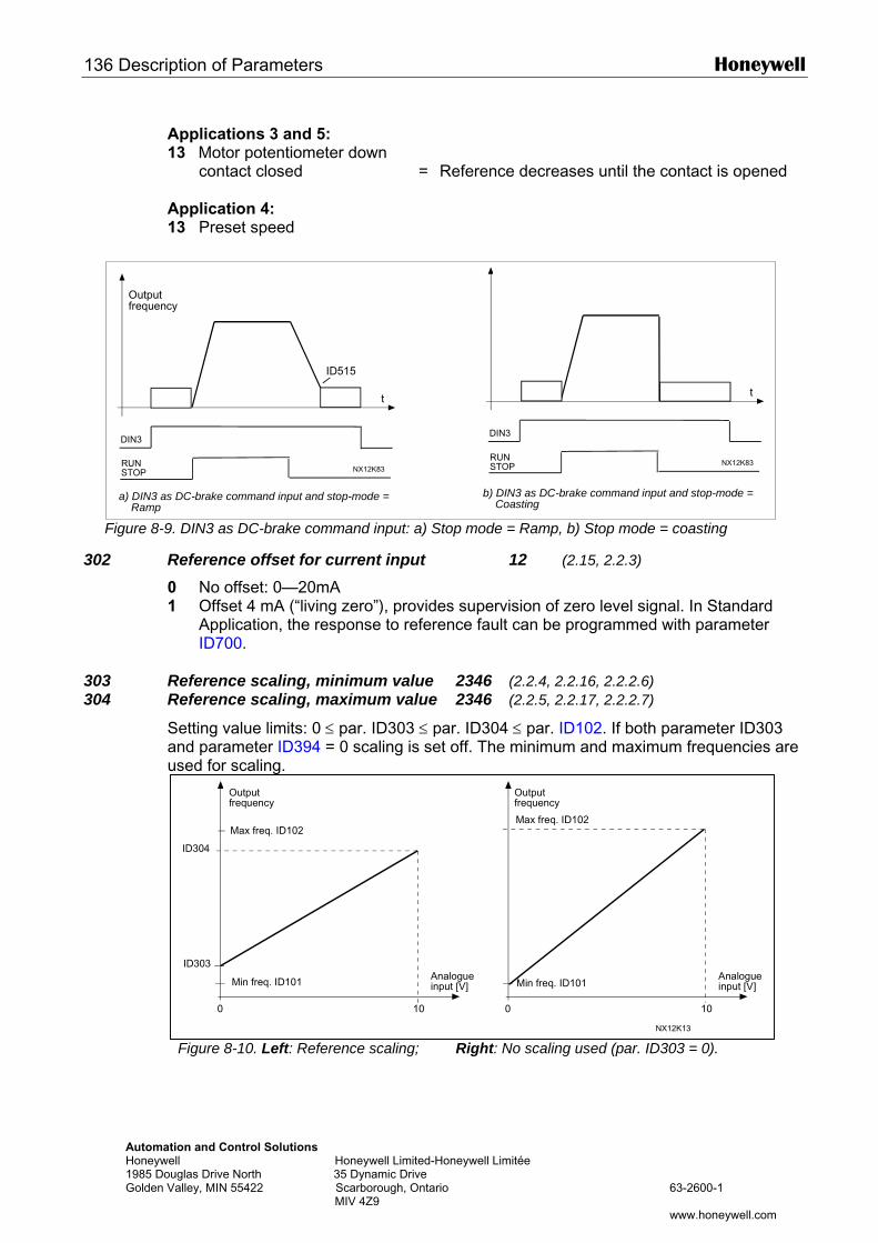
136 Description of Parameters Honeywell
AutomatHoneywe1985 DouGolden V
Applications 3 and 5: 13 Motor potentiometer down contact closed = Reference decreases until the contact is opened Application 4: 13 Preset speed
Figure 8-9. DIN3 as DC-brake command input: a) Stop mode = Ramp, b) Stop mode = coasting
302 Reference offset for current input 12 (2.15, 2.2.3)
0 No offset: 0—20mA 1 Offset 4 mA (“living zero”), provides supervision of zero level signal. In Standard
Application, the response to reference fault can be programmed with parameter ID700.
303 Reference scaling, minimum value 2346 (2.2.4, 2.2.16, 2.2.2.6) 304 Reference scaling, maximum value 2346 (2.2.5, 2.2.17, 2.2.2.7)
Setting value limits: 0 ≤ par. ID303 ≤ par. ID304 ≤ par. ID102. If both parameter ID303 and parameter ID394 = 0 scaling is set off. The minimum and maximum frequencies are used for scaling.
Outputfrequency
Outputfrequency
t
NX12K83
DIN3
t
NX12K83
ID515
DIN3
b) DIN3 as DC-brake command input and stop-mode = Coasting
RUNSTOPRUN
STOP
Outputfrequency
a) DIN3 as DC-brake command input and stop-mode = Ramp
ion and Control Solutions ll Honeywell Limited-Honeywell Limitée glas Drive North 35 Dynamic Drive alley, MIN 55422 Scarborough, Ontario 63-2600-1 MIV 4Z9
www.honeywell.com
Figure 8-10. Left: Reference scaling; Right: No scaling used (par. ID303 = 0).
100
ID303
ID304
100
NX12K13
Analogueinput [V]
Max freq. ID102
Min freq. ID101 Analogueinput [V]
Max freq. ID102
Min freq. ID101
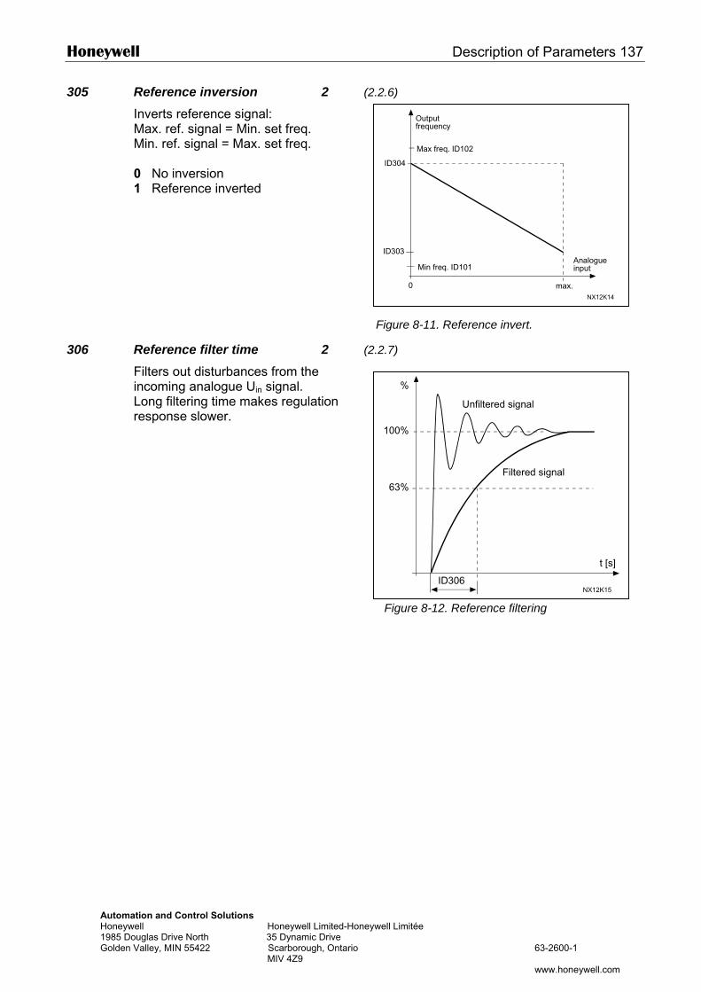
Honeywell Description of Parameters 137
Automation and Control Solutions Honeywell Honeywell Limited-Honeyw1985 Douglas Drive North 35 Dynamic Drive Golden Valley, MIN 55422 Scarborough, Ontario MIV 4Z9
Output
305 Reference inversion 2 (2.2.6)
Inverts reference signal: Max. ref. signal = Min. set freq. Min. ref. signal = Max. set freq. 0 No inversion 1 Reference inverted
306 Reference filter time 2 (2.
Filters out disturbances from the incoming analogue Uin signal. Long filtering time makes regulation response slower.
0
ID303
ID304
NX12K14
Max freq. ID102
frequency
Analogueinput
max.
Min freq. ID101
%
Figure 8-11. Reference invert.
2.7)
ell Limitée
63-2600-1
www.honeywell.com
100%
63%
ID306
t [s]
NX12K15
Filtered signal
Unfiltered signal
Figure 8-12. Reference filtering
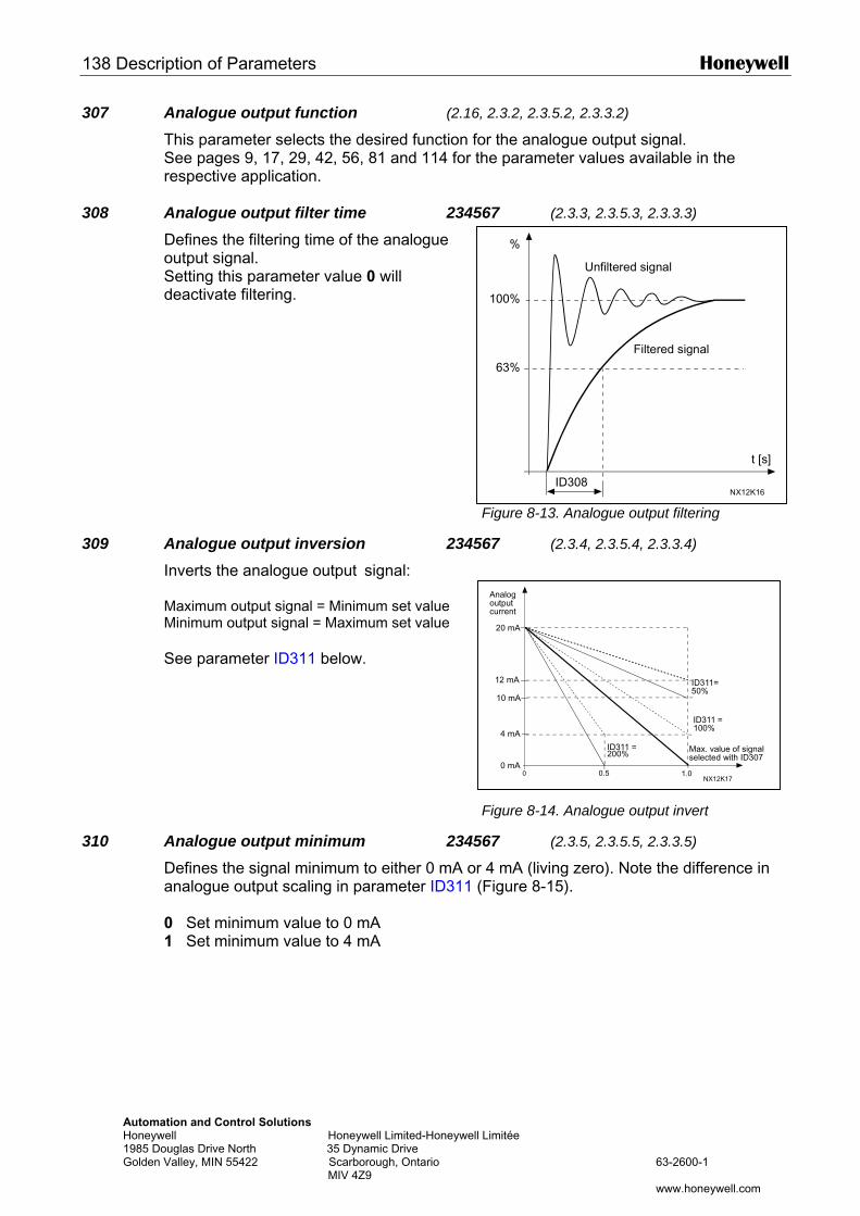
138 Description of Parameters Honeywell
Automation and Control Solutions Honeywell Honeywell Limited-Honeywell1985 Douglas Drive North 35 Dynamic Drive Golden Valley, MIN 55422 Scarborough, Ontario MIV 4Z9
Analogoutput
%
100%
63%
t [s]
NX12K16
Filtered signal
Unfiltered signal
ID308
307 Analogue output function (2.16, 2.3.2, 2.3.5.2, 2.3.3.2)
This parameter selects the desired function for the analogue output signal. See pages 9, 17, 29, 42, 56, 81 and 114 for the parameter values available in the respective application.
308 Analogue output filter time 234567 (2.3.3, 2.3.5.3, 2.3.3.3)
Defines the filtering time of the analogue output signal. Setting this parameter value 0 will deactivate filtering.
Figure 8-13. Analogue output filtering
309 Analogue output inversion 234567 (2.3.4, 2.3.5.4, 2.3.3.4)
Inverts the analogue output signal: Maximum output signal = Minimum set value Minimum output signal = Maximum set value
See parameter ID311 below.
310 Analogue output minimum 2345Defines the signal minimum to either 0 mA oranalogue output scaling in parameter ID311 ( 0 Set minimum value to 0 mA 1 Set minimum value to 4 mA
Limitée
63-2600-1
www.honeywell.com
1.00
20 mA
4 mA
10 mA
0.50 mA
12 mA
NX12K17
current
Max. value of signalselected with ID307
ID311 =200%
ID311 =100%
ID311=50%
Figure 8-14. Analogue output invert
67 (2.3.5, 2.3.5.5, 2.3.3.5)
4 mA (living zero). Note the difference in Figure 8-15).
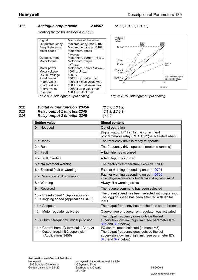
Honeywell Description of Parameters 139
Automation and Control Solutions Honeywell Honeywell Limited-Honeywell 1985 Douglas Drive North 35 Dynamic Drive Golden Valley, MIN 55422 Scarborough, Ontario MIV 4Z9
311 Analogue output scale 234567 (2.3.6, 2.3.5.6, 2.3.3.6)
Scaling factor for analogue output.
Signal Max. value of the signal Output frequency Max frequency (par.ID102) Freq. Reference Max frequency (par.ID102) Motor speed Motor nom. speed
1xnmMotor Output current Motor nom. current 1xInMotor Motor torque Motor nom. torque
1xTnMotor
Motor power Motor nom. power 1xPnMotor Motor voltage 100% x Unmotor DC-link voltage PI-ref. value PI act. value 1 PI act. value 2 PI error value PI output
1000 V 100% x ref. value max. 100% x actual value max. 100% x actual value max. 100% x error value max. 100% x output max.
Table 8-7. Analogue output scaling
312 Digital output function 23456 (2.3.7313 Relay output 1 function 2345 (2.3.8314 Relay output 2 function 2345 (2.3.9
Setting value Signal0 = Not used Out of
Digital program
1 = Ready The fre
2 = Run The fre
3 = Fault A fault
4 = Fault inverted A fault
5 = NX overheat warning The he
6 = External fault or warning Fault o
7 = Reference fault or warning Fault o- if anal
8 = Warning Always
9 = Reversed The re
10 = Preset speed 1 (Applications 2) 10 = Jogging speed (Applications 3456)
The preThe joginput
11 = At speed The ou
12 = Motor regulator activated Overvo
13 = Output frequency limit supervision The ousuperv315 an
14 = Control from I/O terminals (Appl. 2) 14 = Output freq.limit 2 supervision
(Applications 3456)
I/O conThe ousuperv346 an
Analogueoutput
Limitée
63-2600-1
www.honeywell.com
Figure 8-15. Analogue output scaling
, 2.3.1.2) , 2.3.1.3) )
content operation output DO1 sinks the current and
mable relay (RO1, RO2) is activated when: quency drive is ready to operate
quency drive operates (motor is running)
trip has occurred
trip not occurred
at-sink temperature exceeds +70°C
r warning depending on par. ID701 r warning depending on par. ID700 ogue reference is 4—20 mA and signal is <4mA if a warning exists
verse command has been selected set speed has been selected with digital input ging speed has been selected with digital
tput frequency has reached the set reference
ltage or overcurrent regulator was activated tput frequency goes outside the set ision low limit/high limit (see parameter ID's d 316 below) trol mode selected (in menu M3) tput frequency goes outside the set ision low limit/high limit (see parameter ID's d 347 below)
1.00
20 mA
4 mA
10 mA
0.50 mA
NX12K18
12 mA
ID310 = 1
ID311 =200%
ID311 =100%
ID311 =50%
ID310 = 0
current
Max. value of signalselected by ID307
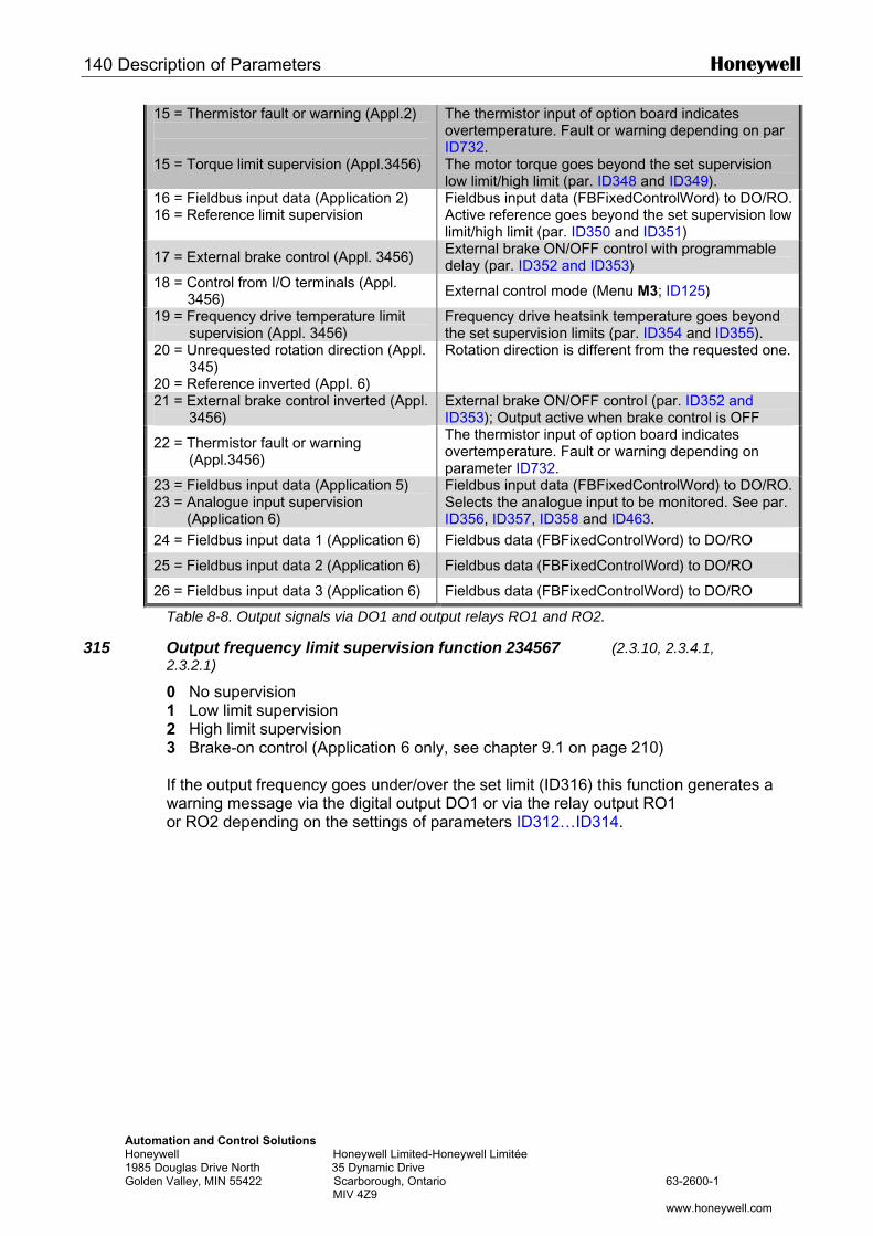
140 Description of Parameters Honeywell
Automation and Control Solutions Honeywell Honeywell Limited-Honeywell Limitée 1985 Douglas Drive North 35 Dynamic Drive Golden Valley, MIN 55422 Scarborough, Ontario 63-2600-1 MIV 4Z9 www.honeywell.com
15 = Thermistor fault or warning (Appl.2) 15 = Torque limit supervision (Appl.3456)
The thermistor input of option board indicates overtemperature. Fault or warning depending on par ID732. The motor torque goes beyond the set supervision low limit/high limit (par. ID348 and ID349).
16 = Fieldbus input data (Application 2) 16 = Reference limit supervision
Fieldbus input data (FBFixedControlWord) to DO/RO.Active reference goes beyond the set supervision low limit/high limit (par. ID350 and ID351)
17 = External brake control (Appl. 3456) External brake ON/OFF control with programmable delay (par. ID352 and ID353)
18 = Control from I/O terminals (Appl. 3456) External control mode (Menu M3; ID125)
19 = Frequency drive temperature limit supervision (Appl. 3456)
Frequency drive heatsink temperature goes beyond the set supervision limits (par. ID354 and ID355).
20 = Unrequested rotation direction (Appl. 345)
20 = Reference inverted (Appl. 6)
Rotation direction is different from the requested one.
21 = External brake control inverted (Appl. 3456)
External brake ON/OFF control (par. ID352 and ID353); Output active when brake control is OFF
22 = Thermistor fault or warning (Appl.3456)
The thermistor input of option board indicates overtemperature. Fault or warning depending on parameter ID732.
23 = Fieldbus input data (Application 5) 23 = Analogue input supervision
(Application 6)
Fieldbus input data (FBFixedControlWord) to DO/RO.Selects the analogue input to be monitored. See par. ID356, ID357, ID358 and ID463.
24 = Fieldbus input data 1 (Application 6) Fieldbus data (FBFixedControlWord) to DO/RO
25 = Fieldbus input data 2 (Application 6) Fieldbus data (FBFixedControlWord) to DO/RO
26 = Fieldbus input data 3 (Application 6) Fieldbus data (FBFixedControlWord) to DO/RO
Table 8-8. Output signals via DO1 and output relays RO1 and RO2.
315 Output frequency limit supervision function 234567 (2.3.10, 2.3.4.1, 2.3.2.1)
0 No supervision 1 Low limit supervision 2 High limit supervision 3 Brake-on control (Application 6 only, see chapter 9.1 on page 210) If the output frequency goes under/over the set limit (ID316) this function generates a warning message via the digital output DO1 or via the relay output RO1 or RO2 depending on the settings of parameters ID312…ID314.
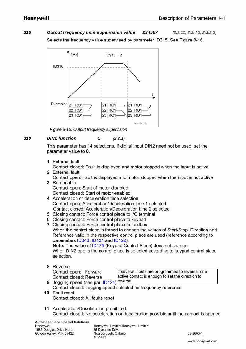
Honeywell Description of Parameters 141
Automation and Control Solutions Honeywell Honeywell Limit1985 Douglas Drive North 35 Dynamic DrivGolden Valley, MIN 55422 Scarborough, O MIV 4Z9
316 Output frequency limit supervision value 234567 (2.3.11, 2.3.4.2, 2.3.2.2)
Selects the frequency value supervised by parameter ID315. See Figure 8-16.
Figure 8-16. Output frequency supervision
319 DIN2 function 5 (2.2.1)
This parameter has 14 selections. If digital input DIN2 need not be used, set the parameter value to 0. 1 External fault Contact closed: Fault is displayed and motor stopped when the input is active 2 External fault Contact open: Fault is displayed and motor stopped when the input is not active 3 Run enable Contact open: Start of motor disabled Contact closed: Start of motor enabled 4 Acceleration or deceleration time selection Contact open: Acceleration/Deceleration time 1 selected Contact closed: Acceleration/Deceleration time 2 selected 5 Closing contact: Force control place to I/O terminal 6 Closing contact: Force control place to keypad 7 Closing contact: Force control place to fieldbus
When the control place is forced to change the values of Start/Stop, Direction and Reference valid in the respective control place are used (reference according to parameters ID343, ID121 and ID122). Note: The value of ID125 (Keypad Control Place) does not change. When DIN2 opens the control place is selected according to keypad control place selection.
8 Reverse Contact open: Forward Contact closed: Reverse
9 Jogging speed (see par. ID124) Contact closed: Jogging speed
10 Fault reset Contact closed: All faults reset 11 Acceleration/Deceleration prohib Contact closed: No acceleration
f[Hz]
t
21 RO122 RO123 RO1
21 RO122 RO123 RO1
21 RO122 RO123 RO1
NX12K19
Example:
ID316
ID315 = 2
If several inputs are programmed to reverse, oneactive contact is enough to set the direction to reverse.
ed-Honeywell Limitée e ntario 63-2600-1
www.honeywell.com
selected for frequency reference
ited or deceleration possible until the contact is opened
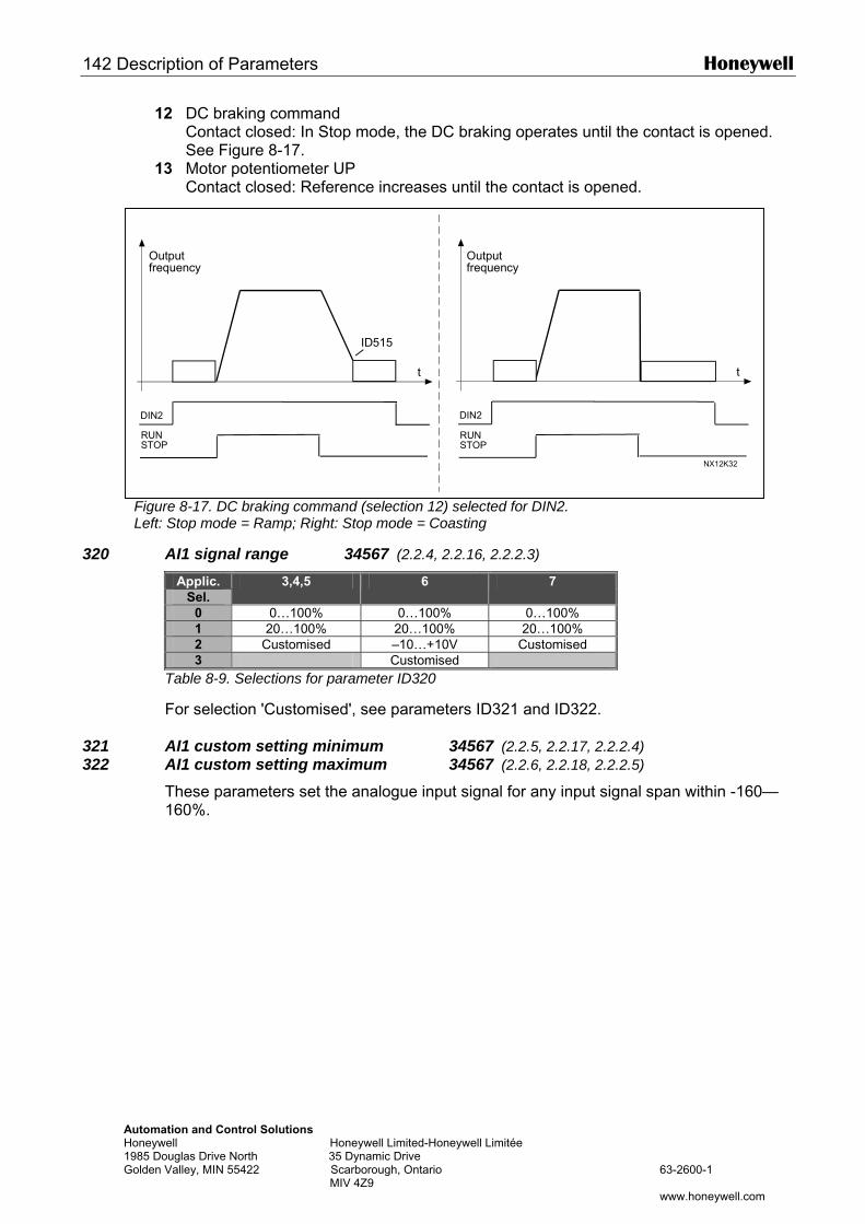
142 Description of Parameters Honeywell
AH1G
12 DC braking command Contact closed: In Stop mode, the DC braking operates until the contact is opened.
See Figure 8-17. 13 Motor potentiometer UP Contact closed: Reference increases until the contact is opened.
320
321 322
utomation and Control Solutions oneywell Honeywell Limited-Honeywell Limitée 985 Douglas Drive North 35 Dynamic Drive olden Valley, MIN 55422 Scarborough, Ontario 63-2600-1
MIV 4Z9 www.honeywell.com
Figure 8-17. DC braking command (selection 12) selected for DIN2. Left: Stop mode = Ramp; Right: Stop mode = Coasting
AI1 signal range 34567 (2.2.4, 2.2.16, 2.2.2.3)
Applic. Sel.
3,4,5 6 7
0 0…100% 0…100% 0…100% 1 20…100% 20…100% 20…100% 2 Customised –10…+10V Customised 3 Customised
Table 8-9. Selections for parameter ID320
For selection 'Customised', see parameters ID321 and ID322. AI1 custom setting minimum 34567 (2.2.5, 2.2.17, 2.2.2.4) AI1 custom setting maximum 34567 (2.2.6, 2.2.18, 2.2.2.5)
These parameters set the analogue input signal for any input signal span within -160—160%.
t
DIN2
t
NX12K32
DIN2
RUNSTOP
Outputfrequency
RUNSTOP
Outputfrequency
ID515
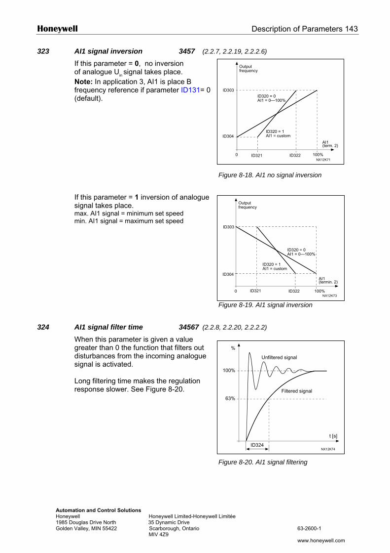
Honeywell Description of Parameters 143
Automation and Control Solutions Honeywell Honeywell Limited-Honeywell 1985 Douglas Drive North 35 Dynamic Drive Golden Valley, MIN 55422 Scarborough, Ontario MIV 4Z9
Outputfrequency
323 AI1 signal inversion 3457 (2.2.7, 2.2.19, 2.2.2.6)
If this parameter = 0, no inversion of analogue Uin signal takes place. Note: In application 3, AI1 is place B frequency reference if parameter ID131= 0 (default).
If this parameter = 1 inversion of analogue signal takes place. max. AI1 signal = minimum set speed min. AI1 signal = maximum set speed
324 AI1 signal filter time 34567 (2.2.8
When this parameter is given a value greater than 0 the function that filters out disturbances from the incoming analogue signal is activated. Long filtering time makes the regulation response slower. See Figure 8-20.
100%0
ID304
ID303
ID321 ID322NX12K71
AI1(term. 2)
ID320 = 1AI1 = custom
ID320 = 0AI1 = 0—100%
Outputfrequency
Figure 8-18. AI1 no signal inversion
100%0
ID304
ID303
ID321 ID322NX12K73
AI1(termin. 2)
ID320 = 1AI1 = custom
ID320 = 0AI1 = 0—100%
%
Figure 8-19. AI1 signal inversion
, 2.2.20, 2.2.2.2)
Limitée
63-2600-1
www.honeywell.com
100%
63%
ID324
t [s]
NX12K74
Filtered signal
Unfiltered signal
Figure 8-20. AI1 signal filtering
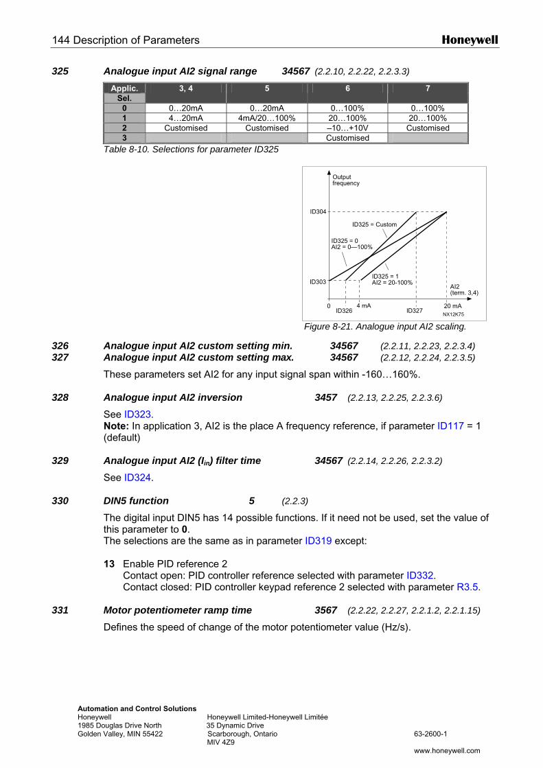
144 Description of Parameters Honeywell
Automation and Control Solutions Honeywell Honeywell Limited-Honeywell 1985 Douglas Drive North 35 Dynamic Drive Golden Valley, MIN 55422 Scarborough, Ontario MIV 4Z9
325 Analogue input AI2 signal range 34567 (2.2.10, 2.2.22, 2.2.3.3)
Applic. Sel.
3, 4 5 6 7
0 0…20mA 0…20mA 0…100% 0…100% 1 4…20mA 4mA/20…100% 20…100% 20…100% 2 Customised Customised –10…+10V Customised 3 Customised
Table 8-10. Selections for parameter ID325
326 Analogue input AI2 custom setting min. 327 Analogue input AI2 custom setting max.
These parameters set AI2 for any input signa 328 Analogue input AI2 inversion
See ID323. Note: In application 3, AI2 is the place A freq(default)
329 Analogue input AI2 (Iin) filter time See ID324.
330 DIN5 function 5 (2.2.3
The digital input DIN5 has 14 possible functiothis parameter to 0. The selections are the same as in parameter 13 Enable PID reference 2
Contact open: PID controller reference se Contact closed: PID controller keypad ref
331 Motor potentiometer ramp time
Defines the speed of change of the motor pot
Outputfrequency
Limitée
63-2600-1
www.honeywell.com
Figure 8-21. Analogue input AI2 scaling.
34567 (2.2.11, 2.2.23, 2.2.3.4) 34567 (2.2.12, 2.2.24, 2.2.3.5)
l span within -160…160%.
3457 (2.2.13, 2.2.25, 2.2.3.6)
uency reference, if parameter ID117 = 1
34567 (2.2.14, 2.2.26, 2.2.3.2)
)
ns. If it need not be used, set the value of
ID319 except:
lected with parameter ID332. erence 2 selected with parameter R3.5.
3567 (2.2.22, 2.2.27, 2.2.1.2, 2.2.1.15)
entiometer value (Hz/s).
ID325 = 0AI2 = 0—100%
20 mA0
ID303
ID304
ID326 ID327
ID325 = 1AI2 = 20-100%
4 mANX12K75
AI2(term. 3,4)
ID325 = Custom
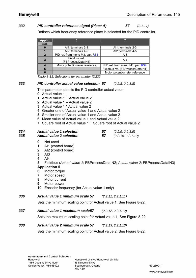
Honeywell Description of Parameters 145
Automation and Control Solutions Honeywell Honeywell Limited-Honeywell Limitée 1985 Douglas Drive North 35 Dynamic Drive Golden Valley, MIN 55422 Scarborough, Ontario 63-2600-1 MIV 4Z9 www.honeywell.com
332 PID controller reference signal (Place A) 57 (2.1.11)
Defines which frequency reference place is selected for the PID controller.
Applic. Sel.
5 7
0 AI1; terminals 2-3 AI1; terminals 2-3 1 AI2; terminals 4-5 AI2; terminals 4-5 2 PID ref. from menu M3, par. R34 AI3
3 Fieldbus ref. (FBProcessDataIN1) AI4
4 Motor potentiometer reference PID ref. from menu M3, par. R34 5 Fieldbus ref. (FBProcessDataIN1) 6 Motor potentiometer reference
Table 8-11. Selections for parameter ID332
333 PID controller actual value selection 57 (2.2.8, 2.2.1.8)
This parameter selects the PID controller actual value. 0 Actual value 1 1 Actual value 1 + Actual value 2 2 Actual value 1 – Actual value 2 3 Actual value 1 * Actual value 2 4 Greater one of Actual value 1 and Actual value 2 5 Smaller one of Actual value 1 and Actual value 2 6 Mean value of Actual value 1 and Actual value 2 7 Square root of Actual value 1 + Square root of Actual value 2
334 Actual value 1 selection 57 (2.2.9, 2.2.1.9) 335 Actual value 2 selection 57 (2.2.10, 2.2.1.10)
0 Not used 1 AI1 (control board) 2 AI2 (control board) 3 AI3 4 AI4 5 Fieldbus (Actual value 1: FBProcessDataIN2; Actual value 2: FBProcessDataIN3) Application 5 6 Motor torque 7 Motor speed 8 Motor current 9 Motor power 10 Encoder frequency (for Actual value 1 only)
336 Actual value 1 minimum scale 57 (2.2.11, 2.2.1.11)
Sets the minimum scaling point for Actual value 1. See Figure 8-22.
337 Actual value 1 maximum scale 57 (2.2.12, 2.2.1.12)
Sets the maximum scaling point for Actual value 1. See Figure 8-22.
338 Actual value 2 minimum scale 57 (2.2.13, 2.2.1.13) Sets the minimum scaling point for Actual value 2. See Figure 8-22.
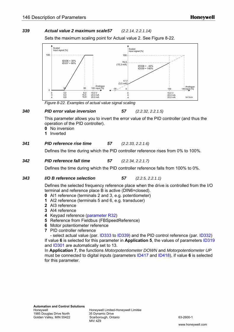
146 Description of Parameters Honeywell
AutomHoneyw1985 DGolden
339 Actual value 2 maximum scale 57 (2.2.14, 2.2.1.14) Sets the maximum scaling point for Actual value 2. See Figure 8-22.
340
341
342
343
Scaledinput signal [%]
Scaledinput signal [%]
ation and Control Solutions ell Honeywell Limited-Honeywell Limitée
ouglas Drive North 35 Dynamic Drive Valley, MIN 55422 Scarborough, Ontario 63-2600-1 MIV 4Z9
www.honeywell.com
Figure 8-22. Examples of actual value signal scaling
PID error value inversion 57 (2.2.32, 2.2.1.5)
This parameter allows you to invert the error value of the PID controller (and thus the operation of the PID controller). 0 No inversion 1 Inverted PID reference rise time 57 (2.2.33, 2.2.1.6)
Defines the time during which the PID controller reference rises from 0% to 100%. PID reference fall time 57 (2.2.34, 2.2.1.7) Defines the time during which the PID controller reference falls from 100% to 0%. I/O B reference selection 57 (2.2.5, 2.2.1.1)
Defines the selected frequency reference place when the drive is controlled from the I/O terminal and reference place B is active (DIN6=closed). 0 AI1 reference (terminals 2 and 3, e.g. potentiometer) 1 AI2 reference (terminals 5 and 6, e.g. transducer) 2 AI3 reference 3 AI4 reference 4 Keypad reference (parameter R32) 5 Reference from Fieldbus (FBSpeedReference) 6 Motor potentiometer reference 7 PID controller reference - select actual value (par. ID333 to ID339) and the PID control reference (par. ID332) If value 6 is selected for this parameter in Application 5, the values of parameters ID319 and ID301 are automatically set to 13. In Application 7, the functions Motorpotentiometer DOWN and Motorpotentiometer UP must be connected to digital inputs (parameters ID417 and ID418), if value 6 is selected for this parameter.
0
100
NX12k34
100 140-30
004
100
01008030
10,0 V
20,0 mA
76,5(15,3 mA)
17,7(3,5 mA)
004
10,0 V8,03,020,0 mA16,06,0
16,88,8 20,0 mA20,0 mA
Analogueinput [%]
Analogueinput [%]
ID338 = -30%ID339 = 140%
ID336 = 30%ID337 = 80%
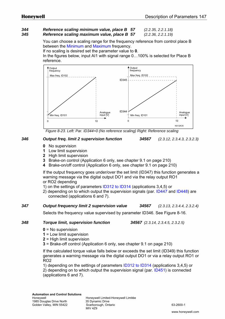
Honeywell Description of Parameters 147
AutomatHoneywe1985 DouGolden V
344 Reference scaling minimum value, place B 57 (2.2.35, 2.2.1.18) 345 Reference scaling maximum value, place B 57 (2.2.36, 2.2.1.19)
You can choose a scaling range for the frequency reference from control place B between the Minimum and Maximum frequency. If no scaling is desired set the parameter value to 0. In the figures below, input AI1 with signal range 0…100% is selected for Place B reference.
346 O01234
Iwo12
347 O
S
348 T0123
IgR12(
Outputfrequency
Outputfrequency
ion and Control Solutions ll Honeywell Limited-Honeywell Limitée glas Drive North 35 Dynamic Drive alley, MIN 55422 Scarborough, Ontario 63-2600-1 MIV 4Z9
www.honeywell.com
Figure 8-23. Left: Par. ID344=0 (No reference scaling) Right: Reference scaling
utput freq. limit 2 supervision function 34567 (2.3.12, 2.3.4.3, 2.3.2.3)
No supervision Low limit supervision High limit supervision Brake-on control (Application 6 only, see chapter 9.1 on page 210) Brake-on/off control (Application 6 only, see chapter 9.1 on page 210)
f the output frequency goes under/over the set limit (ID347) this function generates a arning message via the digital output DO1 and via the relay output RO1 r RO2 depending ) on the settings of parameters ID312 to ID314 (applications 3,4,5) or ) depending on to which output the supervision signals (par. ID447 and ID448) are
connected (applications 6 and 7).
utput frequency limit 2 supervision value 34567 (2.3.13, 2.3.4.4, 2.3.2.4)
elects the frequency value supervised by parameter ID346. See Figure 8-16.
orque limit, supervision function 34567 (2.3.14, 2.3.4.5, 2.3.2.5)
= No supervision = Low limit supervision = High limit supervision = Brake-off control (Application 6 only, see chapter 9.1 on page 210)
f the calculated torque value falls below or exceeds the set limit (ID349) this function enerates a warning message via the digital output DO1 or via a relay output RO1 or O2 ) depending on the settings of parameters ID312 to ID314 (applications 3,4,5) or ) depending on to which output the supervision signal (par. ID451) is connected applications 6 and 7).
0
NX12K35
0
Max freq. ID102
Min freq. ID101
Max freq. ID102
Min freq. ID101Analogueinput [V]
Analogueinput [V]
ID345
ID344
1010
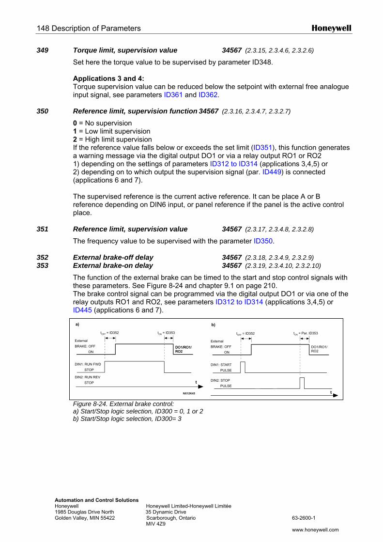
148 Description of Parameters Honeywell
AutomHoneyw1985 DGolden
349 Torque limit, supervision value 34567 (2.3.15, 2.3.4.6, 2.3.2.6)
Set here the torque value to be supervised by parameter ID348. Applications 3 and 4: Torque supervision value can be reduced below the setpoint with external free analogue input signal, see parameters ID361 and ID362.
350 Reference limit, supervision function 34567 (2.3.16, 2.3.4.7, 2.3.2.7)
0 = No supervision 1 = Low limit supervision 2 = High limit supervision If the reference value falls below or exceeds the set limit (ID351), this function generates a warning message via the digital output DO1 or via a relay output RO1 or RO2 1) depending on the settings of parameters ID312 to ID314 (applications 3,4,5) or 2) depending on to which output the supervision signal (par. ID449) is connected (applications 6 and 7). The supervised reference is the current active reference. It can be place A or B reference depending on DIN6 input, or panel reference if the panel is the active control place.
351 Reference limit, supervision value 34567 (2.3.17, 2.3.4.8, 2.3.2.8)
The frequency value to be supervised with the parameter ID350.
352 External brake-off delay 34567 (2.3.18, 2.3.4.9, 2.3.2.9) 353 External brake-on delay 34567 (2.3.19, 2.3.4.10, 2.3.2.10)
The function of the external brake can be timed to the start and stop control signals with these parameters. See Figure 8-24 and chapter 9.1 on page 210. The brake control signal can be programmed via the digital output DO1 or via one of the relay outputs RO1 and RO2, see parameters ID312 to ID314 (applications 3,4,5) or ID445 (applications 6 and 7).
a) b)
tOFF = ID352 tON = ID353 tOFF = ID352 tON = Par. ID353
ation and Control Solutions ell Honeywell Limited-Honeywell Limitée
ouglas Drive North 35 Dynamic Drive Valley, MIN 55422 Scarborough, Ontario 63-2600-1 MIV 4Z9
www.honeywell.com
Figure 8-24. External brake control: a) Start/Stop logic selection, ID300 = 0, 1 or 2 b) Start/Stop logic selection, ID300= 3
t
tNX12K45
DO1/RO1/RO2
DO1/RO1/RO2
DIN1: RUN FWD
STOP
External
BRAKE: OFF
ONDO1/RO1/RO2
DIN2: RUN REV
STOP
DIN1: START
PULSE
External
BRAKE: OFF
ON
DIN2: STOP
PULSE
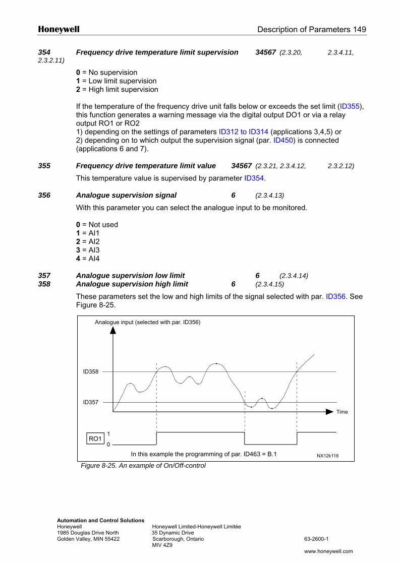
Honeywell Description of Parameters 149
AutomatHoneywe1985 DouGolden V
354 Frequency drive temperature limit supervision 34567 (2.3.20, 2.3.4.11, 2.3.2.11)
0 = No supervision 1 = Low limit supervision 2 = High limit supervision If the temperature of the frequency drive unit falls below or exceeds the set limit (ID355), this function generates a warning message via the digital output DO1 or via a relay output RO1 or RO2 1) depending on the settings of parameters ID312 to ID314 (applications 3,4,5) or 2) depending on to which output the supervision signal (par. ID450) is connected (applications 6 and 7).
355 Frequency drive temperature limit value 34567 (2.3.21, 2.3.4.12, 2.3.2.12)
This temperature value is supervised by parameter ID354.
356 Analogue supervision signal 6 (2.3.4.13)
With this parameter you can select the analogue input to be monitored. 0 = Not used 1 = AI1 2 = AI2 3 = AI3 4 = AI4
357 Analogue supervision low limit 6 (2.3.4.14) 358 Analogue supervision high limit 6 (2.3.4.15)
These parameters set the low and high limits of the signal selected with par. ID356. See Figure 8-25.
Analogue input (selected with par. ID356)
ion and Control Solutions ll Honeywell Limited-Honeywell Limitée glas Drive North 35 Dynamic Drive alley, MIN 55422 Scarborough, Ontario 63-2600-1 MIV 4Z9
www.honeywell.com
Figure 8-25. An example of On/Off-control
0
1RO1
ID357
ID358
NX12k116
Time
In this example the programming of par. ID463 = B.1
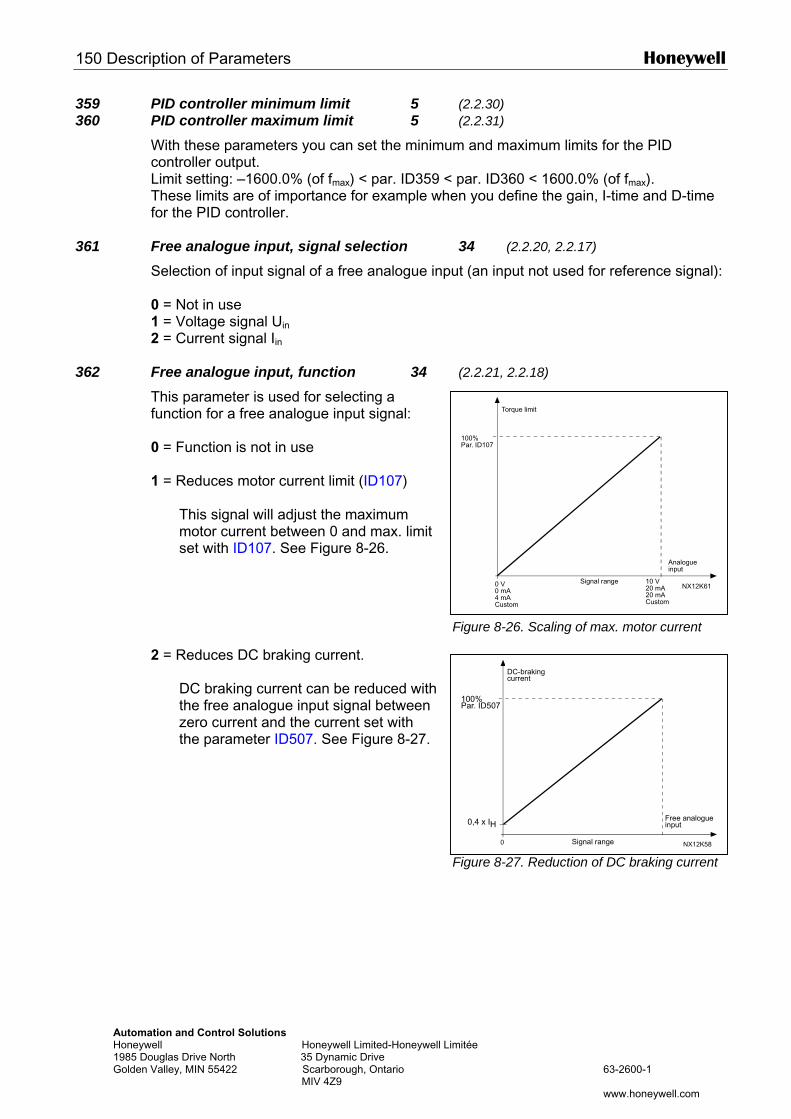
150 Description of Parameters Honeywell
Automation and Control Solutions Honeywell Honeywell Limited-Honeywell Li1985 Douglas Drive North 35 Dynamic Drive Golden Valley, MIN 55422 Scarborough, Ontario MIV 4Z9
DC-braking
100%Par. ID107
NX12K61
Torque limit
Analogueinput
Signal range0 V0 mA4 mACustom
10 V20 mA20 mACustom
359 PID controller minimum limit 5 (2.2.30) 360 PID controller maximum limit 5 (2.2.31)
With these parameters you can set the minimum and maximum limits for the PID controller output. Limit setting: –1600.0% (of fmax) < par. ID359 < par. ID360 < 1600.0% (of fmax). These limits are of importance for example when you define the gain, I-time and D-time for the PID controller.
361 Free analogue input, signal selection 34 (2.2.20, 2.2.17)
Selection of input signal of a free analogue input (an input not used for reference signal): 0 = Not in use 1 = Voltage signal Uin
2 = Current signal Iin
362 Free analogue input, function 34 (2.2.21, 2.2.18)
This parameter is used for selecting a function for a free analogue input signal: 0 = Function is not in use 1 = Reduces motor current limit (ID107)
This signal will adjust the maximum motor current between 0 and max. limit set with ID107. See Figure 8-26.
Figure 8-26. Scaling of max. motor current
2 = Reduces DC braking current.
DC braking current can be reduced with the free analogue input signal between zero current and the current set with the parameter ID507. See Figure 8-27.
mitée
63-2600-1
www.honeywell.com
0
100%Par. ID507
0,4 x IH
NX12K58
current
Free analogueinput
Signal range
Figure 8-27. Reduction of DC braking current
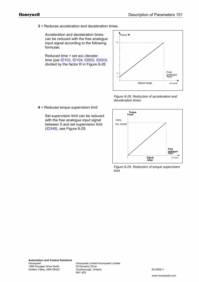
Honeywell Description of Parameters 151
Automation and Control Solutions Honeywell Honeywell Limited-Honeywell Li1985 Douglas Drive North 35 Dynamic Drive Golden Valley, MIN 55422 Scarborough, Ontario MIV 4Z9
Factor R
3 = Reduces acceleration and deceleration times.
Acceleration and deceleration times can be reduced with the free analogue input signal according to the following formulas: Reduced time = set acc./deceler. time (par.ID103, ID104; ID502, ID503) divided by the factor R in Figure 8-28.
4 = Reduces torque supervision limit
Set supervision limit can be reduced with the free analogue input signal between 0 and set supervision limit (ID349), see Figure 8-29.
10
1
NX12K59
2 Freeanalogueinput
Signal range
TorquelimitTorquelimit
Figure 8-28. Reduction of acceleration and deceleration times
mitée
63-2600-1
www.honeywell.com
0 NX12K60
Freeanalogueinput
Signalrange
Freeanalogueinput
Signalrange
100%
Par. ID349
Figure 8-29. Reduction of torque supervision limit
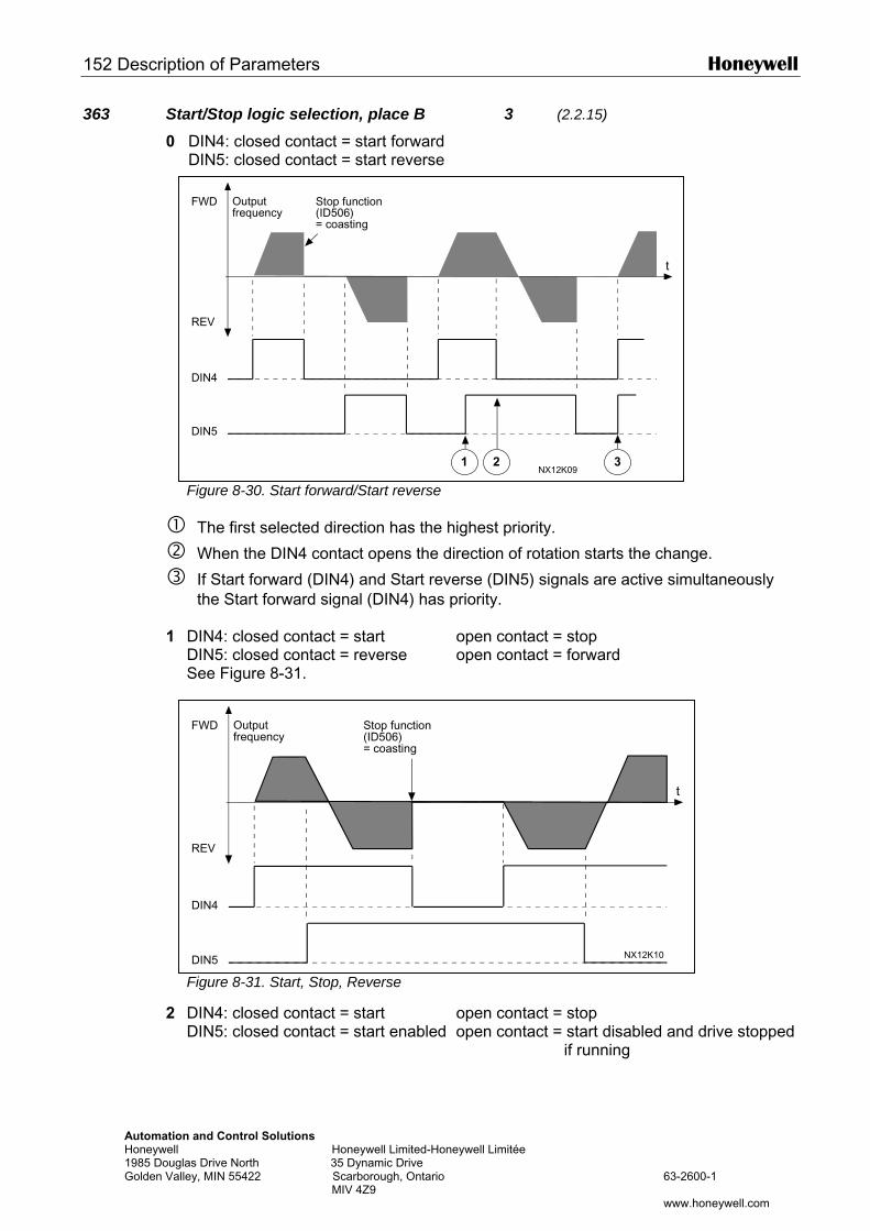
152 Description of Parameters Honeywell
AutomatioHoneywell 1985 DougGolden Val
363 Start/Stop logic selection, place B 3 (2.2.15)
0 DIN4: closed contact = start forward DIN5: closed contact = start reverse
1
2
Output Stop functionFWD
Figure 8-30. Start forward/Start reverse
The first selected direction has the highest priority.
When the DIN4 contact opens the direction of rotation starts the change.
If Start forward (DIN4) and Start reverse (DIN5) signals are active simultaneously the Start forward signal (DIN4) has priority.
DIN4: closed contact = start open contact = stop DIN5: closed contact = reverse open contact = forward See Figure 8-31.
1 2 3
t
NX12K09
frequency (ID506)= coasting
REV
DIN4
DIN5
Outputfrequency
Stop function(ID506)
FWD
n and Control Solutions Honeywell Limited-Honeywell Limitée
las Drive North 35 Dynamic Drive ley, MIN 55422 Scarborough, Ontario 63-2600-1 MIV 4Z9
www.honeywell.com
Figure 8-31. Start, Stop, Reverse
DIN4: closed contact = start open contact = stop DIN5: closed contact = start enabled open contact = start disabled and drive stopped
if running
t
NX12K10
= coasting
REV
DIN4
DIN5
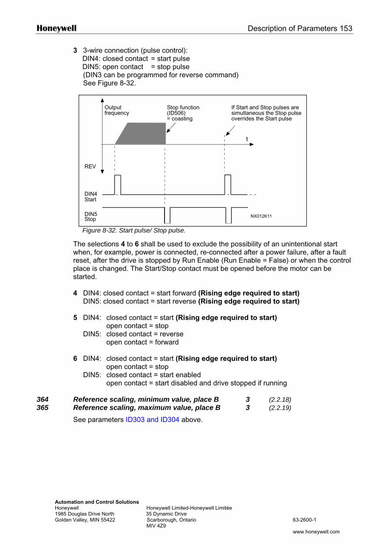
Honeywell Description of Parameters 153
AutomatioHoneywell 1985 DougGolden Val
3 3-wire connection (pulse control): DIN4: closed contact = start pulse DIN5: open contact = stop pulse (DIN3 can be programmed for reverse command) See Figure 8-32.
Thwhreplasta 4 5 6
364 Re365 Re
Se
Output Stop function If Start and Stop pulses are
n and Control Solutions Honeywell Limited-Honeywell Limitée
las Drive North 35 Dynamic Drive ley, MIN 55422 Scarborough, Ontario 63-2600-1 MIV 4Z9
www.honeywell.com
Figure 8-32. Start pulse/ Stop pulse.
e selections 4 to 6 shall be used to exclude the possibility of an unintentional start en, for example, power is connected, re-connected after a power failure, after a fault
set, after the drive is stopped by Run Enable (Run Enable = False) or when the control ce is changed. The Start/Stop contact must be opened before the motor can be rted.
DIN4: closed contact = start forward (Rising edge required to start) DIN5: closed contact = start reverse (Rising edge required to start)
DIN4: closed contact = start (Rising edge required to start) open contact = stop DIN5: closed contact = reverse open contact = forward
DIN4: closed contact = start (Rising edge required to start) open contact = stop DIN5: closed contact = start enabled open contact = start disabled and drive stopped if running
ference scaling, minimum value, place B 3 (2.2.18) ference scaling, maximum value, place B 3 (2.2.19) e parameters ID303 and ID304 above.
t
NX012K11
REV
frequency (ID506)= coasting
simultaneous the Stop pulseoverrides the Start pulse
Start
Stop
DIN4
DIN5
154 Description of Parameters Honeywell
Automation and Control Solutions Honeywell Honeywell Limited-Honeywell Limitée 1985 Douglas Drive North 35 Dynamic Drive Golden Valley, MIN 55422 Scarborough, Ontario 63-2600-1 MIV 4Z9 www.honeywell.com
366 Easy changeover 5 (2.2.37)
0 Keep reference 1 Copy reference
If Copy reference has been selected it is possible to switch from direct control to PID control and back without scaling the reference and actual value. For example: The process is driven with direct frequency reference (Control place I/O B, fieldbus or keypad) to some point and then the control place is switched to one where the PID controller is selected. The PID control starts to maintain that point. The PID controller error value is forced to zero when the control place is changed. It is also possible to change the control source back to direct frequency control. In this case, the output frequency is copied as the frequency reference. If the destination place is Keypad the run status (Run/Stop, Direction and Reference) will be copied. The changeover is smooth when the reference of the destination source comes from the Keypad or an internal motor potentiometer (par. ID332 [PID Ref.] = 2 or 4, ID343 [I/O B Ref] = 2 or 4, par. ID121 [Keypad Ref] = 2 or 4 and ID122 [Fieldbus Ref]= 2 or 4.
367 Motor potentiometer memory reset (Frequency reference) 3567 (2.2.23, 2.2.28, 2.2.1.3, 2.2.1.16)
0 No reset 1 Memory reset in stop and powerdown 2 Memory reset in powerdown
370 Motor potentiometer memory reset (PID reference) 57 (2.2.29, 2.2.1.17)
0 No reset 1 Memory reset in stop and powerdown 2 Memory reset in powerdown
371 PID reference 2 (Place A additional reference) 7 (2.2.1.4)
If the PID reference 2 enable input function (ID330)= TRUE, this parameter defines which reference place is selected as PID controller reference. 0 = AI1 reference (terminals 2 and 3, e.g. potentiometer) 1 = AI2 reference (terminals 5 and 6, e.g. transducer) 2 = AI3 reference 3 = AI4 reference 4 = PID reference 1 from keypad 5 = Reference from Fieldbus (FBProcessDataIN3) 6 = Motor potentiometer 7 = PID reference 2 from keypad If value 6 is selected for this parameter, the functions Motor potentiometer DOWN and Motor potentiometer UP must be connected to digital inputs (parameters ID417 and ID418).
372 Supervised analogue input 7 (2.3.2.13)
0 = Analogue reference from AI1 (terminals 2 and 3, e.g. potentiometer) 1 = Analogue reference from AI2 (terminals 4 and 5, e.g. transducer)
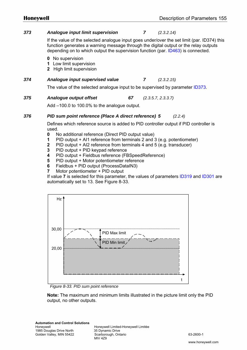
Honeywell Description of Parameters 155
AutomatHoneywe1985 DouGolden V
373 Analogue input limit supervision 7 (2.3.2.14)
If the value of the selected analogue input goes under/over the set limit (par. ID374) this function generates a warning message through the digital output or the relay outputs depending on to which output the supervision function (par. ID463) is connected.
0 No supervision 1 Low limit supervision 2 High limit supervision
374 Analogue input supervised value 7 (2.3.2.15)
The value of the selected analogue input to be supervised by parameter ID373.
375 Analogue output offset 67 (2.3.5.7, 2.3.3.7)
Add –100.0 to 100.0% to the analogue output.
376 PID sum point reference (Place A direct reference) 5 (2.2.4)
Defines which reference source is added to PID controller output if PID controller is used. 0 No additional reference (Direct PID output value) 1 PID output + AI1 reference from terminals 2 and 3 (e.g. potentiometer) 2 PID output + AI2 reference from terminals 4 and 5 (e.g. transducer) 3 PID output + PID keypad reference 4 PID output + Fieldbus reference (FBSpeedReference) 5 PID output + Motor potentiometer reference 6 Fieldbus + PID output (ProcessDataIN3) 7 Motor potentiometer + PID output If value 7 is selected for this parameter, the values of parameters ID319 and ID301 are automatically set to 13. See Figure 8-33.
No
Hz
ion and Control Solutions ll Honeywell Limited-Honeywell Limitée glas Drive North 35 Dynamic Drive alley, MIN 55422 Scarborough, Ontario 63-2600-1 MIV 4Z9
www.honeywell.com
Figure 8-33. PID sum point reference
ote: The maximum and minimum limits illustrated in the picture limit only the PID utput, no other outputs.
t
30,00
20,00
PID Min limit
PID Max limit
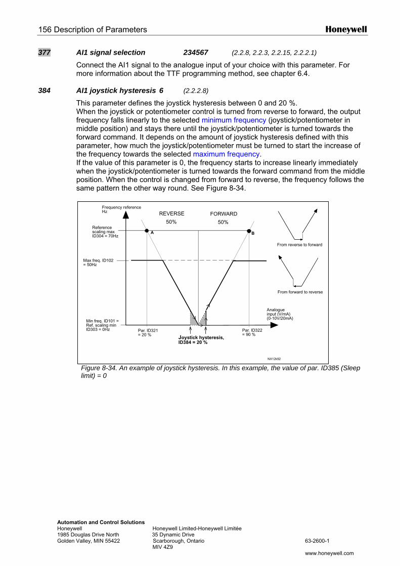
156 Description of Parameters Honeywell
AutomatHoneywe1985 DouGolden V
377 AI1 signal selection 234567 (2.2.8, 2.2.3, 2.2.15, 2.2.2.1)
Connect the AI1 signal to the analogue input of your choice with this parameter. For more information about the TTF programming method, see chapter 6.4.
384 AI1 joystick hysteresis 6 (2.2.2.8)
This parameter defines the joystick hysteresis between 0 and 20 %. When the joystick or potentiometer control is turned from reverse to forward, the output frequency falls linearly to the selected minimum frequency (joystick/potentiometer in middle position) and stays there until the joystick/potentiometer is turned towards the forward command. It depends on the amount of joystick hysteresis defined with this parameter, how much the joystick/potentiometer must be turned to start the increase of the frequency towards the selected maximum frequency. If the value of this parameter is 0, the frequency starts to increase linearly immediately when the joystick/potentiometer is turned towards the forward command from the middle position. When the control is changed from forward to reverse, the frequency follows the same pattern the other way round. See Figure 8-34.
Frequency referenceHz REVERSE FORWARD
ion and Control Solutions ll Honeywell Limited-Honeywell Limitée glas Drive North 35 Dynamic Drive alley, MIN 55422 Scarborough, Ontario 63-2600-1 MIV 4Z9
www.honeywell.com
Figure 8-34. An example of joystick hysteresis. In this example, the value of par. ID385 (Sleep limit) = 0
NX12k92
A B
Par. ID321= 20 %
Par. ID322= 90 %
50% 50%Referencescaling maxID304 = 70Hz
Max freq. ID102= 50Hz
Min freq. ID101 =Ref. scaling minID303 = 0Hz
From reverse to forward
From forward to reverse
Analogueinput (V/mA)(0-10V/20mA)
Joystick hysteresis,ID384 = 20 %
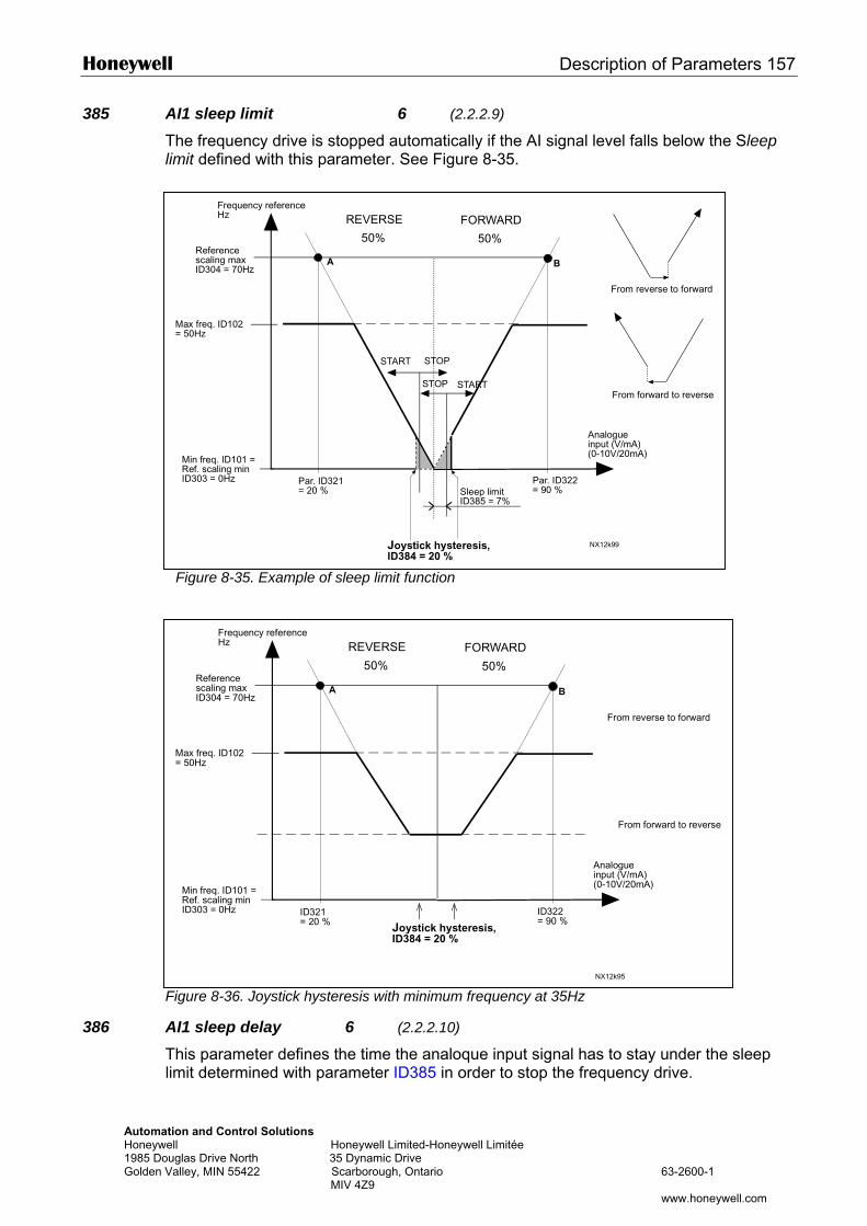
Honeywell Description of Parameters 157
AutomaHoneyw1985 DoGolden
385 AI1 sleep limit 6 (2.2.2.9)
The frequency drive is stopped automatically if the AI signal level falls below the Sleep limit defined with this parameter. See Figure 8-35.
386
Frequency referenceHz
Figure 8-35. Example of sleep limit function
NX12k99
A B
Par. ID321= 20 %
Par. ID322= 90 %
50% 50%Referencescaling maxID304 = 70Hz
Max freq. ID102= 50Hz
Min freq. ID101 =Ref. scaling minID303 = 0Hz
From reverse to forward
From forward to reverse
Sleep limitID385 = 7%
Analogueinput (V/mA)(0-10V/20mA)
Joystick hysteresis,ID384 = 20 %
REVERSE FORWARD
START
START
STOP
STOP
Frequency referenceHz REVERSE FORWARD
tion and Control Solutions ell Honeywell Limited-Honeywell Limitée uglas Drive North 35 Dynamic Drive
Valley, MIN 55422 Scarborough, Ontario 63-2600-1 MIV 4Z9
www.honeywell.com
Figure 8-36. Joystick hysteresis with minimum frequency at 35Hz
AI1 sleep delay 6 (2.2.2.10)
This parameter defines the time the analoque input signal has to stay under the sleep limit determined with parameter ID385 in order to stop the frequency drive.
NX12k95
A B
ID321= 20 %
ID322= 90 %
50% 50%Referencescaling maxID304 = 70Hz
Max freq. ID102= 50Hz
Min freq. ID101 =Ref. scaling minID303 = 0Hz
From forward to reverse
Analogueinput (V/mA)(0-10V/20mA)
Joystick hysteresis,ID384 = 20 %
From reverse to forward
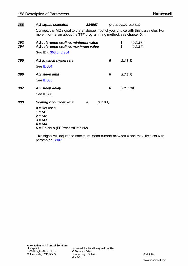
158 Description of Parameters Honeywell
Automation and Control Solutions Honeywell Honeywell Limited-Honeywell Limitée 1985 Douglas Drive North 35 Dynamic Drive Golden Valley, MIN 55422 Scarborough, Ontario 63-2600-1 MIV 4Z9 www.honeywell.com
388 AI2 signal selection 234567 (2.2.9, 2.2.21, 2.2.3.1)
Connect the AI2 signal to the analogue input of your choice with this parameter. For more information about the TTF programming method, see chapter 6.4.
393 AI2 reference scaling, minimum value 6 (2.2.3.6) 394 AI2 reference scaling, maximum value 6 (2.2.3.7)
See ID’s 303 and 304.
395 AI2 joystick hysteresis 6 (2.2.3.8)
See ID384.
396 AI2 sleep limit 6 (2.2.3.9)
See ID385.
397 AI2 sleep delay 6 (2.2.3.10)
See ID386.
399 Scaling of current limit 6 (2.2.6.1)
0 = Not used 1 = AI1 2 = AI2 3 = AI3 4 = AI4 5 = Fieldbus (FBProcessDataIN2) This signal will adjust the maximum motor current between 0 and max. limit set with parameter ID107.
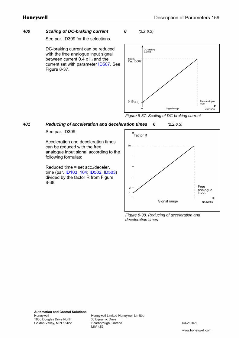
Honeywell Description of Parameters 159
Automation and Control Solutions Honeywell Honeywell Limited-Hone1985 Douglas Drive North 35 Dynamic Drive Golden Valley, MIN 55422 Scarborough, Ontario MIV 4Z9
DC-braking
400 Scaling of DC-braking current 6 (2.2.6.2)
See par. ID399 for the selections. DC-braking current can be reduced with the free analogue input signal between current 0.4 x IH and the current set with parameter ID507. See Figure 8-37.
401 Reducing of acceleration and deceleraSee par. ID399. Acceleration and deceleration times can be reduced with the free analogue input signal according to the following formulas: Reduced time = set acc./deceler. time (par. ID103, 104; ID502, ID503) divided by the factor R from Figure 8-38.
0
100%Par. ID507
0,15 x IL
NX12K58
current
Free analogueinput
Signal range
Factor R
Figure 8-37. Scaling of DC-braking current
tion times 6 (2.2.6.3)
ywell Limitée
63-2600-1
www.honeywell.com
10
1
NX12K59
2 Freeanalogueinput
Signal range
Figure 8-38. Reducing of acceleration and deceleration times
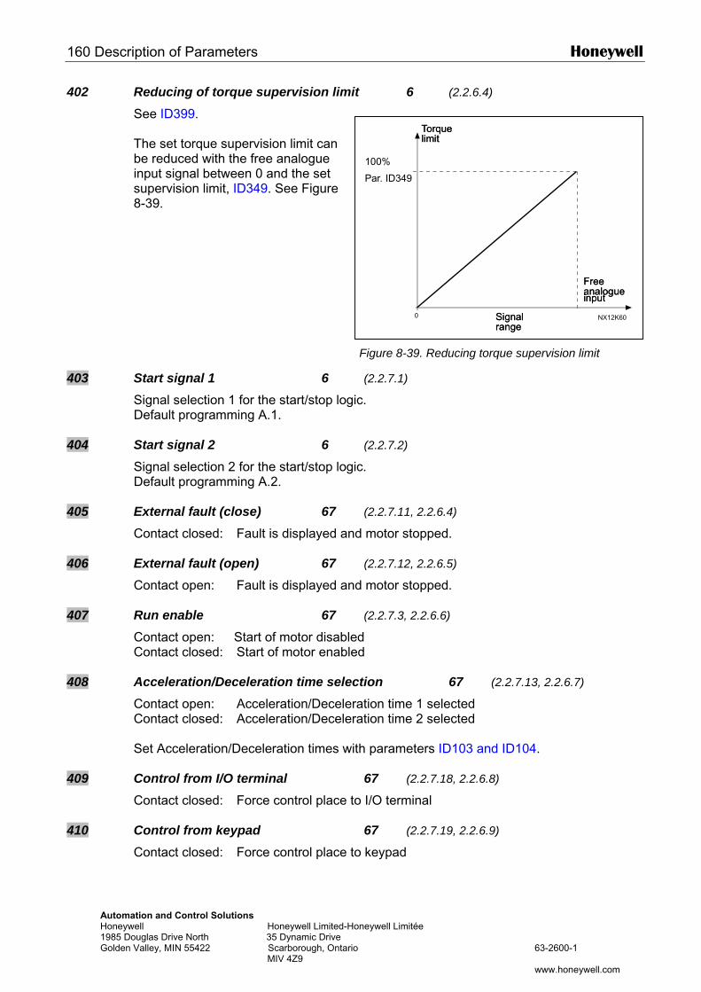
160 Description of Parameters Honeywell
Automation and Control Solutions Honeywell Honeywell Limited-Ho1985 Douglas Drive North 35 Dynamic Drive Golden Valley, MIN 55422 Scarborough, Ontario MIV 4Z9
TorqueTorque
402 Reducing of torque supervision limit 6 (2.2.6.4)
See ID399. The set torque supervision limit can be reduced with the free analogue input signal between 0 and the set supervision limit, ID349. See Figure 8-39.
403 Start signal 1 6
Signal selection 1 for the start/stop logiDefault programming A.1.
404 Start signal 2 6 Signal selection 2 for the start/stop logiDefault programming A.2.
405 External fault (close) 67
Contact closed: Fault is displayed and
406 External fault (open) 67 Contact open: Fault is displayed and
407 Run enable 67 Contact open: Start of motor disableContact closed: Start of motor enable
408 Acceleration/Deceleration time selecContact open: Acceleration/DecelerContact closed: Acceleration/Deceler Set Acceleration/Deceleration times wit
409 Control from I/O terminal Contact closed: Force control place to
410 Control from keypad
Contact closed: Force control place to
neywell Limitée
63-2600-1
www.honeywell.com
0 NX12K60
limit
Freeanalogueinput
Signalrange
limit
Freeanalogueinput
Signalrange
100%
Par. ID349
Figure 8-39. Reducing torque supervision limit
(2.2.7.1)
c.
(2.2.7.2) c.
(2.2.7.11, 2.2.6.4) motor stopped.
(2.2.7.12, 2.2.6.5) motor stopped.
(2.2.7.3, 2.2.6.6) d d
tion 67 (2.2.7.13, 2.2.6.7)
ation time 1 selected ation time 2 selected
h parameters ID103 and ID104.
67 (2.2.7.18, 2.2.6.8)
I/O terminal
67 (2.2.7.19, 2.2.6.9)
keypad
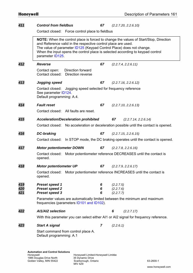
Honeywell Description of Parameters 161
Automation and Control Solutions Honeywell Honeywell Limited-Honeywell Limitée 1985 Douglas Drive North 35 Dynamic Drive Golden Valley, MIN 55422 Scarborough, Ontario 63-2600-1 MIV 4Z9 www.honeywell.com
411 Control from fieldbus 67 (2.2.7.20, 2.2.6.10) Contact closed: Force control place to fieldbus NOTE: When the control place is forced to change the values of Start/Stop, Direction and Reference valid in the respective control place are used. The value of parameter ID125 (Keypad Control Place) does not change. When the input opens the control place is selected according to keypad control parameter ID125.
412 Reverse 67 (2.2.7.4, 2.2.6.11)
Contact open: Direction forward Contact closed: Direction reverse
413 Jogging speed 67 (2.2.7.16, 2.2.6.12)
Contact closed: Jogging speed selected for frequency reference See parameter ID124. Default programming: A.4.
414 Fault reset 67 (2.2.7.10, 2.2.6.13) Contact closed: All faults are reset.
415 Acceleration/Deceleration prohibited 67 (2.2.7.14, 2.2.6.14)
Contact closed: No acceleration or deceleration possible until the contact is opened.
416 DC-braking 67 (2.2.7.15, 2.2.6.15) Contact closed: In STOP mode, the DC braking operates until the contact is opened.
417 Motor potentiometer DOWN 67 (2.2.7.8, 2.2.6.16) Contact closed: Motor potentiometer reference DECREASES until the contact is opened.
418 Motor potentiometer UP 67 (2.2.7.9, 2.2.6.17) Contact closed: Motor potentiometer reference INCREASES until the contact is opened.
419 Preset speed 1 6 (2.2.7.5) 420 Preset speed 2 6 (2.2.7.6) 421 Preset speed 3 6 (2.2.7.7)
Parameter values are automatically limited between the minimum and maximum frequencies (parameters ID101 and ID102).
422 AI1/AI2 selection 6 (2.2.7.17)
With this parameter you can select either AI1 or AI2 signal for frequency reference.
423 Start A signal 7 (2.2.6.1) Start command from control place A. Default programming: A.1
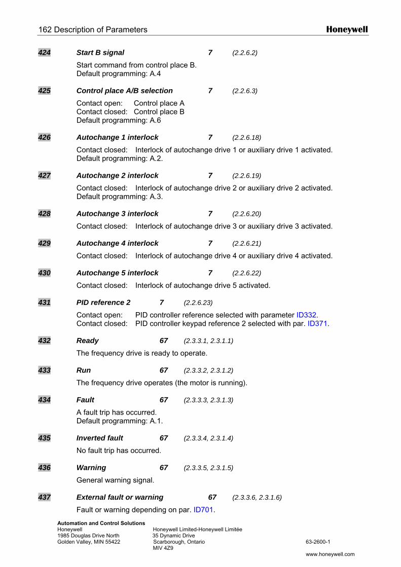
162 Description of Parameters Honeywell
Automation and Control Solutions Honeywell Honeywell Limited-Honeywell Limitée 1985 Douglas Drive North 35 Dynamic Drive Golden Valley, MIN 55422 Scarborough, Ontario 63-2600-1 MIV 4Z9 www.honeywell.com
424 Start B signal 7 (2.2.6.2) Start command from control place B. Default programming: A.4
425 Control place A/B selection 7 (2.2.6.3) Contact open: Control place A Contact closed: Control place B Default programming: A.6
426 Autochange 1 interlock 7 (2.2.6.18) Contact closed: Interlock of autochange drive 1 or auxiliary drive 1 activated. Default programming: A.2.
427 Autochange 2 interlock 7 (2.2.6.19) Contact closed: Interlock of autochange drive 2 or auxiliary drive 2 activated. Default programming: A.3.
428 Autochange 3 interlock 7 (2.2.6.20) Contact closed: Interlock of autochange drive 3 or auxiliary drive 3 activated.
429 Autochange 4 interlock 7 (2.2.6.21)
Contact closed: Interlock of autochange drive 4 or auxiliary drive 4 activated.
430 Autochange 5 interlock 7 (2.2.6.22) Contact closed: Interlock of autochange drive 5 activated.
431 PID reference 2 7 (2.2.6.23) Contact open: PID controller reference selected with parameter ID332. Contact closed: PID controller keypad reference 2 selected with par. ID371.
432 Ready 67 (2.3.3.1, 2.3.1.1) The frequency drive is ready to operate.
433 Run 67 (2.3.3.2, 2.3.1.2) The frequency drive operates (the motor is running).
434 Fault 67 (2.3.3.3, 2.3.1.3) A fault trip has occurred. Default programming: A.1.
435 Inverted fault 67 (2.3.3.4, 2.3.1.4) No fault trip has occurred.
436 Warning 67 (2.3.3.5, 2.3.1.5) General warning signal.
437 External fault or warning 67 (2.3.3.6, 2.3.1.6) Fault or warning depending on par. ID701.
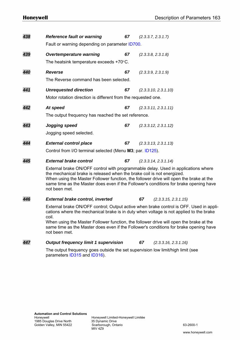
Honeywell Description of Parameters 163
Automation and Control Solutions Honeywell Honeywell Limited-Honeywell Limitée 1985 Douglas Drive North 35 Dynamic Drive Golden Valley, MIN 55422 Scarborough, Ontario 63-2600-1 MIV 4Z9 www.honeywell.com
438 Reference fault or warning 67 (2.3.3.7, 2.3.1.7)
Fault or warning depending on parameter ID700.
439 Overtemperature warning 67 (2.3.3.8, 2.3.1.8) The heatsink temperature exceeds +70°C.
440 Reverse 67 (2.3.3.9, 2.3.1.9) The Reverse command has been selected.
441 Unrequested direction 67 (2.3.3.10, 2.3.1.10) Motor rotation direction is different from the requested one.
442 At speed 67 (2.3.3.11, 2.3.1.11) The output frequency has reached the set reference.
443 Jogging speed 67 (2.3.3.12, 2.3.1.12) Jogging speed selected.
444 External control place 67 (2.3.3.13, 2.3.1.13)
Control from I/O terminal selected (Menu M3; par. ID125).
445 External brake control 67 (2.3.3.14, 2.3.1.14) External brake ON/OFF control with programmable delay. Used in applications where the mechanical brake is released when the brake coil is not energized. When using the Master Follower function, the follower drive will open the brake at the same time as the Master does even if the Follower's conditions for brake opening have not been met.
446 External brake control, inverted 67 (2.3.3.15, 2.3.1.15) External brake ON/OFF control; Output active when brake control is OFF. Used in appli-cations where the mechanical brake is in duty when voltage is not applied to the brake coil. When using the Master Follower function, the follower drive will open the brake at the same time as the Master does even if the Follower's conditions for brake opening have not been met.
447 Output frequency limit 1 supervision 67 (2.3.3.16, 2.3.1.16) The output frequency goes outside the set supervision low limit/high limit (see parameters ID315 and ID316).
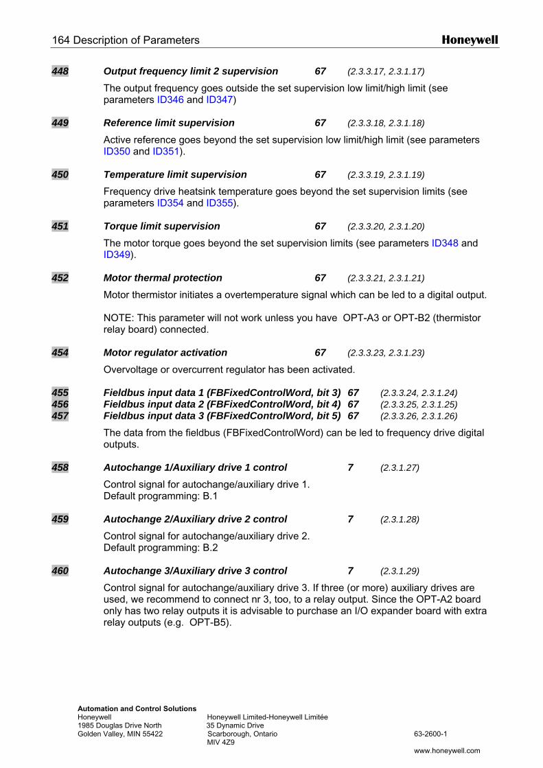
164 Description of Parameters Honeywell
Automation and Control Solutions Honeywell Honeywell Limited-Honeywell Limitée 1985 Douglas Drive North 35 Dynamic Drive Golden Valley, MIN 55422 Scarborough, Ontario 63-2600-1 MIV 4Z9 www.honeywell.com
448 Output frequency limit 2 supervision 67 (2.3.3.17, 2.3.1.17) The output frequency goes outside the set supervision low limit/high limit (see parameters ID346 and ID347)
449 Reference limit supervision 67 (2.3.3.18, 2.3.1.18) Active reference goes beyond the set supervision low limit/high limit (see parameters ID350 and ID351).
450 Temperature limit supervision 67 (2.3.3.19, 2.3.1.19) Frequency drive heatsink temperature goes beyond the set supervision limits (see parameters ID354 and ID355).
451 Torque limit supervision 67 (2.3.3.20, 2.3.1.20) The motor torque goes beyond the set supervision limits (see parameters ID348 and ID349).
452 Motor thermal protection 67 (2.3.3.21, 2.3.1.21) Motor thermistor initiates a overtemperature signal which can be led to a digital output. NOTE: This parameter will not work unless you have OPT-A3 or OPT-B2 (thermistor relay board) connected.
454 Motor regulator activation 67 (2.3.3.23, 2.3.1.23)
Overvoltage or overcurrent regulator has been activated.
455 Fieldbus input data 1 (FBFixedControlWord, bit 3) 67 (2.3.3.24, 2.3.1.24) 456 Fieldbus input data 2 (FBFixedControlWord, bit 4) 67 (2.3.3.25, 2.3.1.25) 457 Fieldbus input data 3 (FBFixedControlWord, bit 5) 67 (2.3.3.26, 2.3.1.26)
The data from the fieldbus (FBFixedControlWord) can be led to frequency drive digital outputs.
458 Autochange 1/Auxiliary drive 1 control 7 (2.3.1.27) Control signal for autochange/auxiliary drive 1. Default programming: B.1
459 Autochange 2/Auxiliary drive 2 control 7 (2.3.1.28) Control signal for autochange/auxiliary drive 2. Default programming: B.2
460 Autochange 3/Auxiliary drive 3 control 7 (2.3.1.29) Control signal for autochange/auxiliary drive 3. If three (or more) auxiliary drives are used, we recommend to connect nr 3, too, to a relay output. Since the OPT-A2 board only has two relay outputs it is advisable to purchase an I/O expander board with extra relay outputs (e.g. OPT-B5).
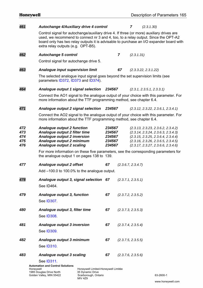
Honeywell Description of Parameters 165
Automation and Control Solutions Honeywell Honeywell Limited-Honeywell Limitée 1985 Douglas Drive North 35 Dynamic Drive Golden Valley, MIN 55422 Scarborough, Ontario 63-2600-1 MIV 4Z9 www.honeywell.com
461 Autochange 4/Auxiliary drive 4 control 7 (2.3.1.30) Control signal for autochange/auxiliary drive 4. If three (or more) auxiliary drives are used, we recommend to connect nr 3 and 4, too, to a relay output. Since the OPT-A2 board only has two relay outputs it is advisable to purchase an I/O expander board with extra relay outputs (e.g. OPT-B5).
462 Autochange 5 control 7 (2.3.1.31) Control signal for autochange drive 5.
463 Analogue input supervision limit 67 (2.3.3.22, 2.3.1.22) The selected analogue input signal goes beyond the set supervision limits (see parameters ID372, ID373 and ID374).
464 Analogue output 1 signal selection 234567 (2.3.1, 2.3.5.1, 2.3.3.1)
Connect the AO1 signal to the analogue output of your choice with this parameter. For more information about the TTF programming method, see chapter 6.4.
471 Analogue output 2 signal selection 234567 (2.3.12, 2.3.22, 2.3.6.1, 2.3.4.1)
Connect the AO2 signal to the analogue output of your choice with this parameter. For more information about the TTF programming method, see chapter 6.4.
472 Analogue output 2 function 234567 (2.3.13, 2.3.23, 2.3.6.2, 2.3.4.2) 473 Analogue output 2 filter time 234567 (2.3.14, 2.3.24, 2.3.6.3, 2.3.4.3) 474 Analogue output 2 inversion 234567 (2.3.15, 2.3.25, 2.3.6.4, 2.3.4.4) 475 Analogue output 2 minimum 234567 (2.3.16, 2.3.26, 2.3.6.5, 2.3.4.5) 476 Analogue output 2 scaling 234567 (2.3.17, 2.3.27, 2.3.6.6, 2.3.4.6)
For more information on these five parameters, see the corresponding parameters for the analogue output 1 on pages 138 to 139.
477 Analogue output 2 offset 67 (2.3.6.7, 2.3.4.7)
Add –100.0 to 100.0% to the analogue output.
478 Analogue output 3, signal selection 67 (2.3.7.1, 2.3.5.1)
See ID464.
479 Analogue output 3, function 67 (2.3.7.2, 2.3.5.2) See ID307.
480 Analogue output 3, filter time 67 (2.3.7.3, 2.3.5.3) See ID308.
481 Analogue output 3 inversion 67 (2.3.7.4, 2.3.5.4) See ID309.
482 Analogue output 3 minimum 67 (2.3.7.5, 2.3.5.5) See ID310.
483 Analogue output 3 scaling 67 (2.3.7.6, 2.3.5.6) See ID311.
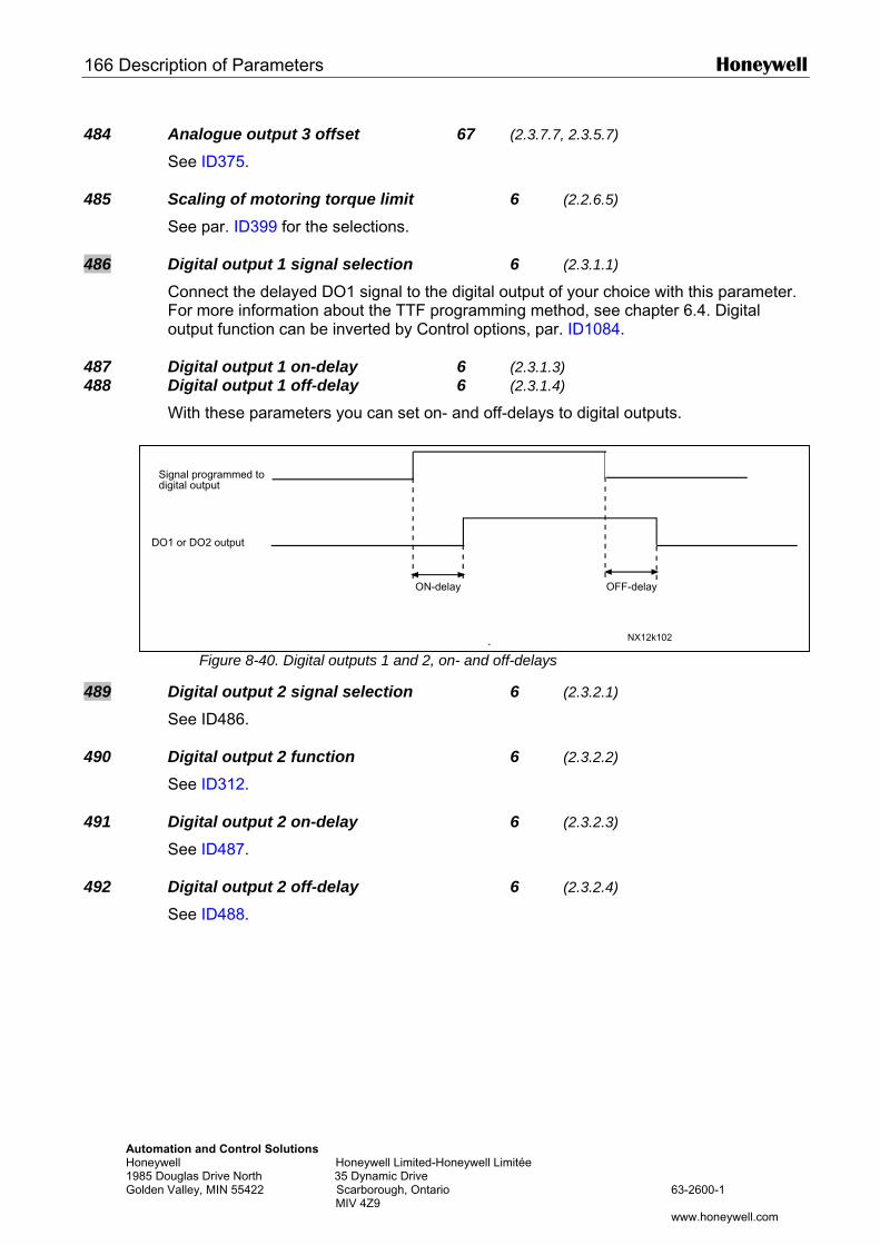
166 Description of Parameters Honeywell
AuHo198Go
484 Analogue output 3 offset 67 (2.3.7.7, 2.3.5.7)
See ID375.
485 Scaling of motoring torque limit 6 (2.2.6.5) See par. ID399 for the selections.
486 Digital output 1 signal selection 6 (2.3.1.1)
Connect the delayed DO1 signal to the digital output of your choice with this parameter. For more information about the TTF programming method, see chapter 6.4. Digital output function can be inverted by Control options, par. ID1084.
487 Digital output 1 on-delay 6 (2.3.1.3) 488 Digital output 1 off-delay 6 (2.3.1.4)
With these parameters you can set on- and off-delays to digital outputs.
489
490
491
492
Signal programmed to
tomation and Control Solutions neywell Honeywell Limited-Honeywell Limitée 5 Douglas Drive North 35 Dynamic Drive
lden Valley, MIN 55422 Scarborough, Ontario 63-2600-1 MIV 4Z9
www.honeywell.com
Figure 8-40. Digital outputs 1 and 2, on- and off-delays
Digital output 2 signal selection 6 (2.3.2.1) See ID486. Digital output 2 function 6 (2.3.2.2) See ID312. Digital output 2 on-delay 6 (2.3.2.3) See ID487. Digital output 2 off-delay 6 (2.3.2.4) See ID488.
NX12k102
ON-delay OFF-delay
digital output
DO1 or DO2 output
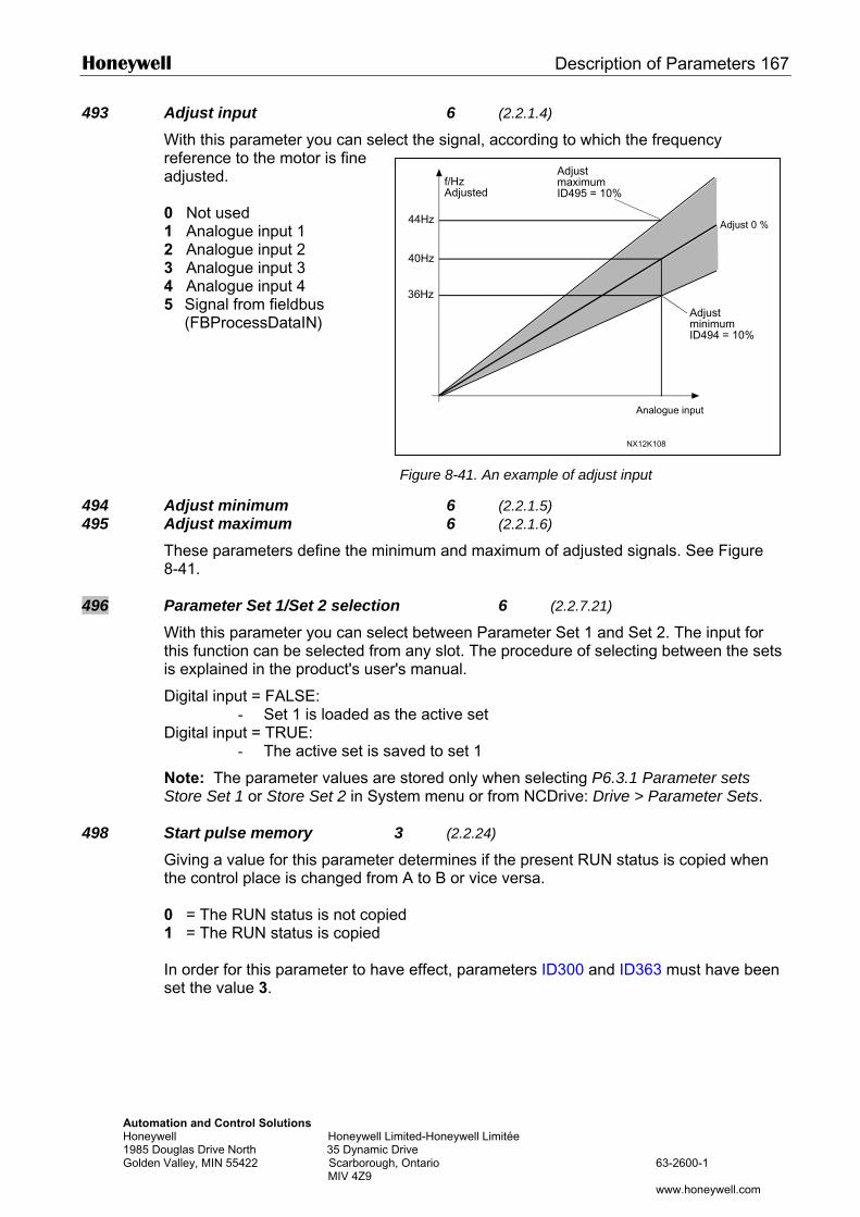
Honeywell Description of Parameters 167
Automation and Control Solutions Honeywell Honeywell Lim1985 Douglas Drive North 35 Dynamic DGolden Valley, MIN 55422 Scarborough, MIV 4Z9
f/HzAdjustmaximum
493 Adjust input 6 (2.2.1.4) With this parameter you can select the signal, according to which the frequency reference to the motor is fine adjusted. 0 Not used 1 Analogue input 1 2 Analogue input 2 3 Analogue input 3 4 Analogue input 4 5 Signal from fieldbus
(FBProcessDataIN)
494 Adjust minimum 495 Adjust maximum
These parameters define the min8-41.
496 Parameter Set 1/Set 2 selectionWith this parameter you can selecthis function can be selected fromis explained in the product's user'
Digital input = FALSE: - Set 1 is loaded as t
Digital input = TRUE: - The active set is sa
Note: The parameter values are Store Set 1 or Store Set 2 in Syst
498 Start pulse memory 3Giving a value for this parameter the control place is changed from 0 = The RUN status is not copie1 = The RUN status is copied In order for this parameter to haveset the value 3.
ited-Honeywell Limitée rive Ontario 63-2600-1
www.honeywell.com
NX12K108
44Hz
40Hz
36Hz
Adjusted
Analogue input
ID495 = 10%
AdjustminimumID494 = 10%
Adjust 0 %
Figure 8-41. An example of adjust input
6 (2.2.1.5) 6 (2.2.1.6)
imum and maximum of adjusted signals. See Figure
6 (2.2.7.21) t between Parameter Set 1 and Set 2. The input for any slot. The procedure of selecting between the sets s manual.
he active set
ved to set 1
stored only when selecting P6.3.1 Parameter sets em menu or from NCDrive: Drive > Parameter Sets.
(2.2.24) determines if the present RUN status is copied when A to B or vice versa.
d
effect, parameters ID300 and ID363 must have been
168 Description of Parameters Honeywell
AutomatHoneywe1985 DouGolden V
500 Acceleration/Deceleration ramp 1 shape 234567 (2.4.1) 501 Acceleration/Deceleration ramp 2 shape 234567 (2.4.2)
The start and end of acceleration and deceleration ramps can be smoothed with these parameters. Setting value 0 gives a linear ramp shape which causes acceleration and deceleration to act immediately to the changes in the reference signal. Setting value 0.1…10 seconds for this parameter produces an S-shaped acceleration/deceleration. The acceleration time is determined with parameters ID103/ID104 (ID502/ID503).
502 A503 D
TttT
504 B01
234 Watr
505 SR0
F
[Hz]
ion and Control Solutions ll Honeywell Limited-Honeywell Limitée glas Drive North 35 Dynamic Drive alley, MIN 55422 Scarborough, Ontario 63-2600-1 MIV 4Z9
www.honeywell.com
Figure 8-42. Acceleration/Deceleration (S-shaped)
cceleration time 2 234567 (2.4.3) eceleration time 2 234567 (2.4.4) hese values correspond to the time required for the output frequency to accelerate from
he zero frequency to the set maximum frequency (par. ID102). These parameters give he possibility to set two different acceleration/deceleration time sets for one application. he active set can be selected with the programmable signal DIN3 (par. ID301).
rake chopper 234567 (2.4.5)
= No brake chopper used = Brake chopper in use and tested when running. Can be tested also in READY
state = External brake chopper (no testing) = Used and tested in READY state and when running = Used when running (no testing)
hen the frequency drive is decelerating the motor, the inertia of the motor and the load re fed into an external brake resistor. This enables the frequency drive to decelerate
he load with a torque equal to that of acceleration (provided that the correct brake esistor has been selected). See separate Brake resistor installation manual.
tart function (2.4.6)
amp: The frequency drive starts from 0 Hz and accelerates to the set reference
frequency within the set acceleration time. (Load inertia or starting friction may cause prolonged acceleration times).
lying start:
ID103, ID104(ID502, ID503)
[t]
ID500 (ID501)
ID500 (ID501)
NX12K20
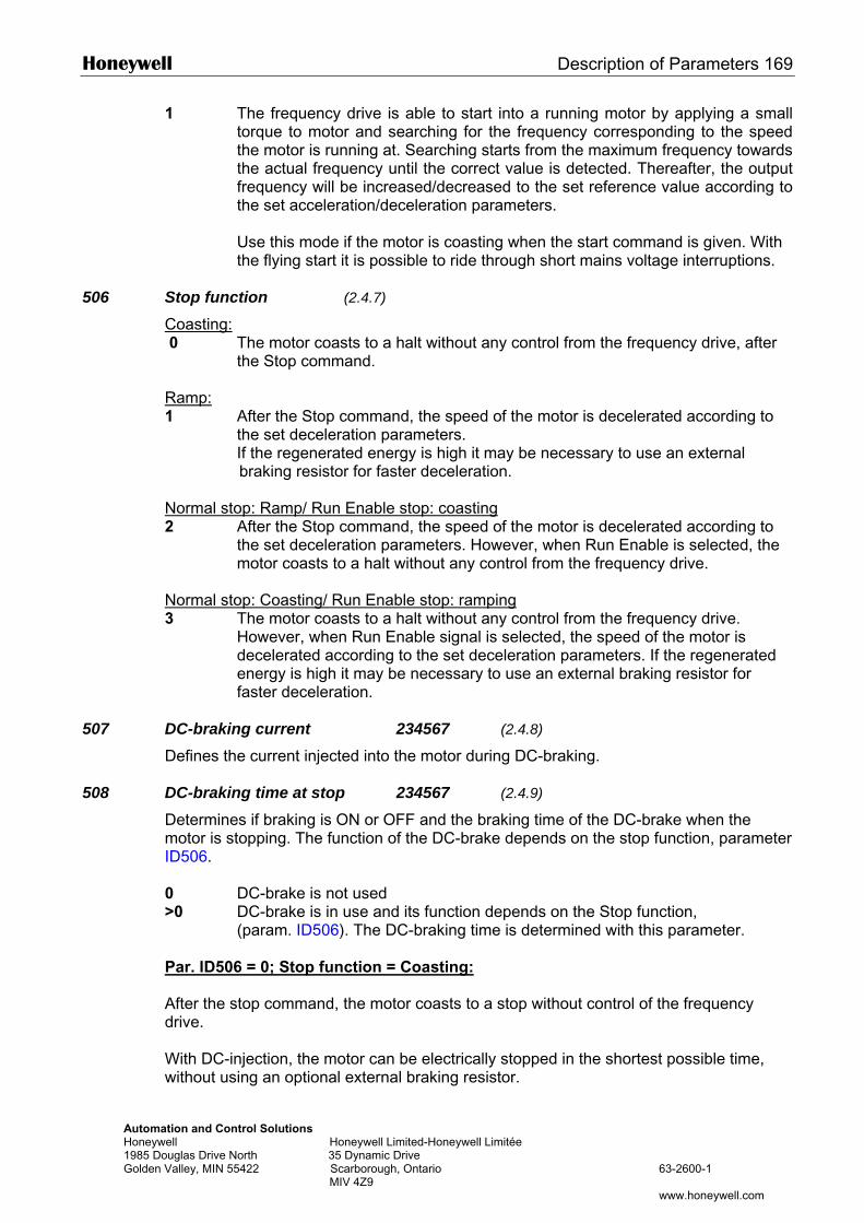
Honeywell Description of Parameters 169
Automation and Control Solutions Honeywell Honeywell Limited-Honeywell Limitée 1985 Douglas Drive North 35 Dynamic Drive Golden Valley, MIN 55422 Scarborough, Ontario 63-2600-1 MIV 4Z9 www.honeywell.com
1 The frequency drive is able to start into a running motor by applying a small torque to motor and searching for the frequency corresponding to the speed the motor is running at. Searching starts from the maximum frequency towards the actual frequency until the correct value is detected. Thereafter, the output frequency will be increased/decreased to the set reference value according to the set acceleration/deceleration parameters. Use this mode if the motor is coasting when the start command is given. With the flying start it is possible to ride through short mains voltage interruptions.
506 Stop function (2.4.7)
Coasting: 0 The motor coasts to a halt without any control from the frequency drive, after
the Stop command.
Ramp: 1 After the Stop command, the speed of the motor is decelerated according to
the set deceleration parameters. If the regenerated energy is high it may be necessary to use an external braking resistor for faster deceleration.
Normal stop: Ramp/ Run Enable stop: coasting 2 After the Stop command, the speed of the motor is decelerated according to
the set deceleration parameters. However, when Run Enable is selected, the motor coasts to a halt without any control from the frequency drive.
Normal stop: Coasting/ Run Enable stop: ramping 3 The motor coasts to a halt without any control from the frequency drive.
However, when Run Enable signal is selected, the speed of the motor is decelerated according to the set deceleration parameters. If the regenerated energy is high it may be necessary to use an external braking resistor for faster deceleration.
507 DC-braking current 234567 (2.4.8)
Defines the current injected into the motor during DC-braking.
508 DC-braking time at stop 234567 (2.4.9) Determines if braking is ON or OFF and the braking time of the DC-brake when the motor is stopping. The function of the DC-brake depends on the stop function, parameter ID506. 0 DC-brake is not used >0 DC-brake is in use and its function depends on the Stop function,
(param. ID506). The DC-braking time is determined with this parameter. Par. ID506 = 0; Stop function = Coasting: After the stop command, the motor coasts to a stop without control of the frequency drive. With DC-injection, the motor can be electrically stopped in the shortest possible time, without using an optional external braking resistor.
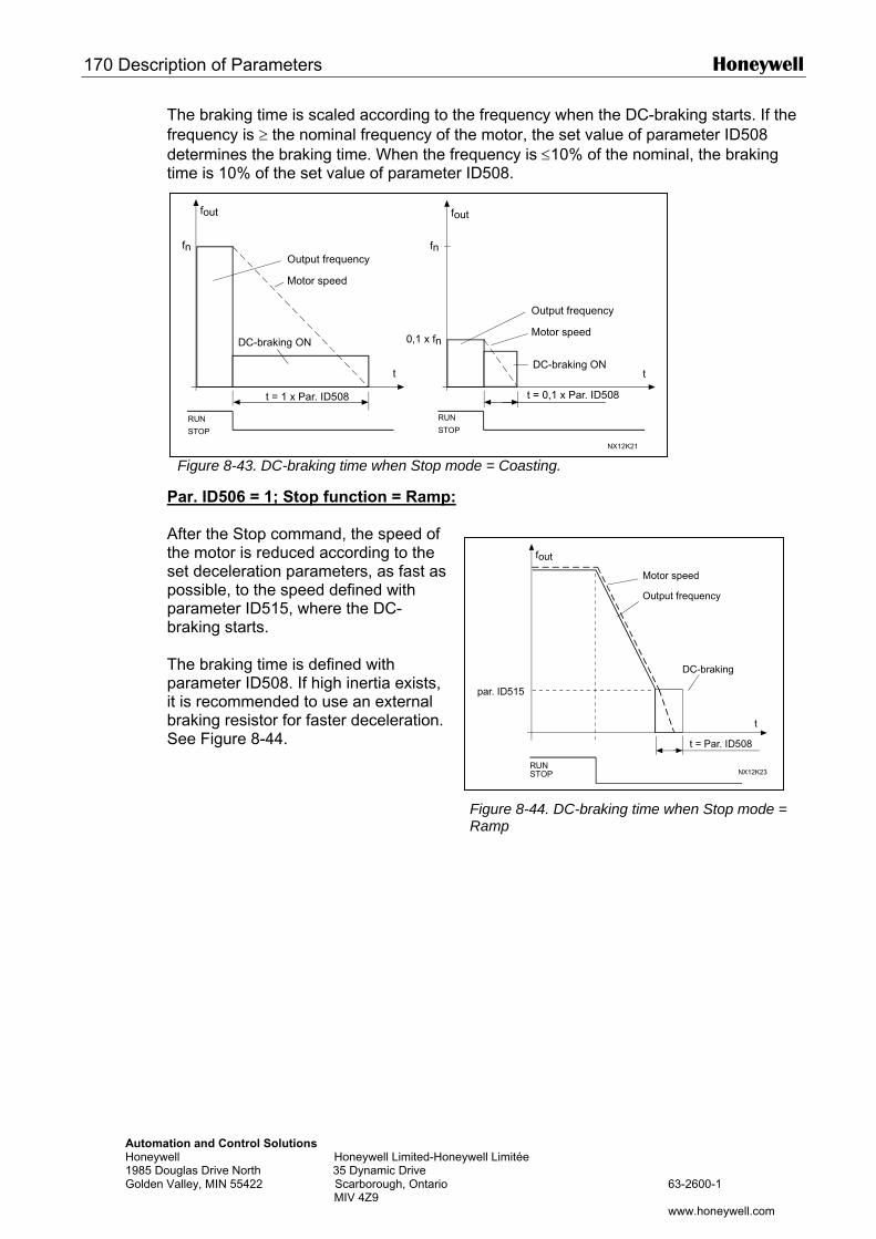
170 Description of Parameters Honeywell
AutomatHoneywe1985 DouGolden V
The braking time is scaled according to the frequency when the DC-braking starts. If the frequency is ≥ the nominal frequency of the motor, the set value of parameter ID508 determines the braking time. When the frequency is ≤10% of the nominal, the braking time is 10% of the set value of parameter ID508.
P Atsppb TpitbS
fout fout
ion and Control Solutions ll Honeywell Limited-Honeyglas Drive North 35 Dynamic Drive alley, MIN 55422 Scarborough, Ontario MIV 4Z9
fout
Figure 8-43. DC-braking time when Stop mode = Coasting.
ar. ID506 = 1; Stop function = Ramp:
fter the Stop command, the speed of he motor is reduced according to the et deceleration parameters, as fast as ossible, to the speed defined with arameter ID515, where the DC-raking starts.
he braking time is defined with arameter ID508. If high inertia exists, is recommended to use an external raking resistor for faster deceleration. ee Figure 8-44.
fn fn
t t
t = 1 x Par. ID508 t = 0,1 x Par. ID508
NX12K21
0,1 x fn
RUN
STOP
RUN
STOP
Output frequency
Motor speed
Output frequency
Motor speed
DC-braking ON
DC-braking ON
well Limitée
63-2600-1
www.honeywell.com
t = Par. ID508
t
par. ID515
NX12K23
Motor speed
Output frequency
DC-braking
RUNSTOP
Figure 8-44. DC-braking time when Stop mode = Ramp
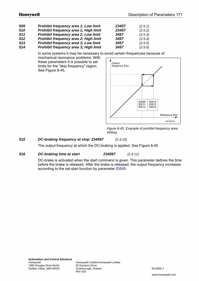
Honeywell Description of Parameters 171
Automation and Control Solutions Honeywell Honeywell Limited-Honeyw1985 Douglas Drive North 35 Dynamic Drive Golden Valley, MIN 55422 Scarborough, Ontario MIV 4Z9
Output
509 Prohibit frequency area 1; Low limit 23457 (2.5.1) 510 Prohibit frequency area 1; High limit 23457 (2.5.2) 511 Prohibit frequency area 2; Low limit 3457 (2.5.3) 512 Prohibit frequency area 2; High limit 3457 (2.5.4) 513 Prohibit frequency area 3; Low limit 3457 (2.5.5) 514 Prohibit frequency area 3; High limit 3457 (2.5.6)
In some systems it may be necessary to avoid certain frequencies because of mechanical resonance problems. With these parameters it is possible to set limits for the "skip frequency" region. See Figure 8-45.
515 DC-braking frequency at stop 234567
The output frequency at which the DC-brak
516 DC-braking time at start 23DC-brake is activated when the start commbefore the brake is released. After the brakaccording to the set start function by param
ell Limitée
63-2600-1
www.honeywell.com
ID509 ID510ID511 ID512ID513 ID514
NX12K33
Reference [Hz]
frequency [Hz]
Figure 8-45. Example of prohibit frequency area setting.
(2.4.10)
ing is applied. See Figure 8-45.
4567 (2.4.11)
and is given. This parameter defines the time e is released, the output frequency increases eter ID505.
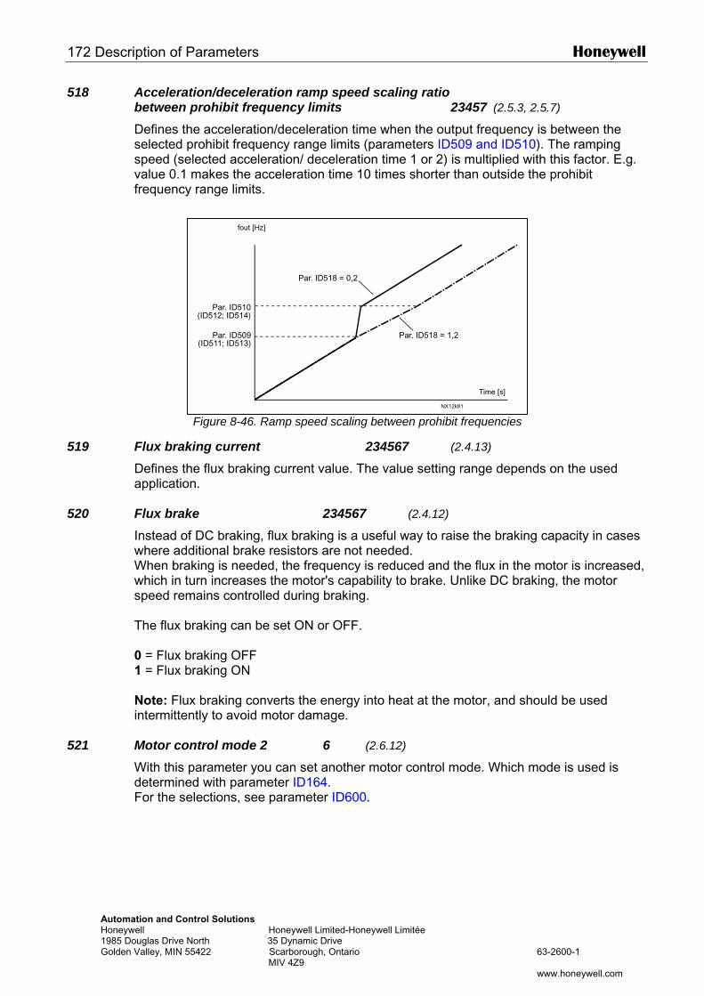
172 Description of Parameters Honeywell
Automation and ConHoneywell 1985 Douglas Drive NGolden Valley, MIN 5
fout [Hz]
518 Acceleration/deceleration ramp speed scaling ratio between prohibit frequency limits 23457 (2.5.3, 2.5.7)
Defines the acceleration/deceleration time when the output frequency is between the selected prohibit frequency range limits (parameters ID509 and ID510). The ramping speed (selected acceleration/ deceleration time 1 or 2) is multiplied with this factor. E.g. value 0.1 makes the acceleration time 10 times shorter than outside the prohibit frequency range limits.
519 Flux brakDefines thapplicatio
520 Flux brakInstead ofwhere addWhen brawhich in tspeed rem The flux b 0 = Flux b1 = Flux b Note: Fluintermitten
521 Motor coWith this pdetermineFor the se
trol Solutions Honeywell Limited-Honeywell Limitée
orth 35 Dynamic Drive 5422 Scarborough, Ontario 63-2600-1 MIV 4Z9
www.honeywell.com
Par. ID510(ID512; ID514)
Par. ID509(ID511; ID513)
Par. ID518 = 0,2
Par. ID518 = 1,2
NX12k81
Time [s]
Figure 8-46. Ramp speed scaling between prohibit frequencies
ing current 234567 (2.4.13)
e flux braking current value. The value setting range depends on the used n.
e 234567 (2.4.12)
DC braking, flux braking is a useful way to raise the braking capacity in cases itional brake resistors are not needed.
king is needed, the frequency is reduced and the flux in the motor is increased, urn increases the motor's capability to brake. Unlike DC braking, the motor
ains controlled during braking.
raking can be set ON or OFF.
raking OFF raking ON
x braking converts the energy into heat at the motor, and should be used tly to avoid motor damage.
ntrol mode 2 6 (2.6.12) arameter you can set another motor control mode. Which mode is used is d with parameter ID164. lections, see parameter ID600.
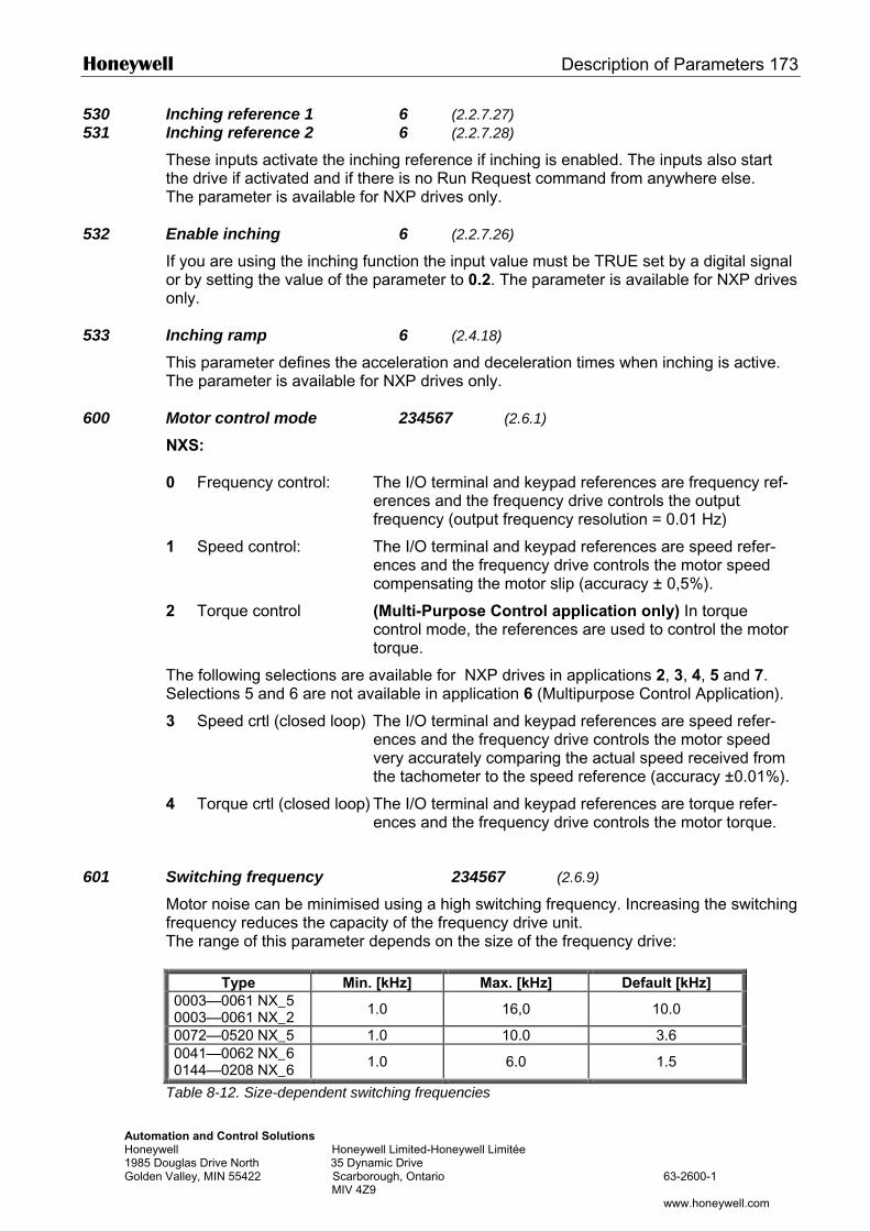
Honeywell Description of Parameters 173
Automation and Control Solutions Honeywell Honeywell Limited-Honeywell Limitée 1985 Douglas Drive North 35 Dynamic Drive Golden Valley, MIN 55422 Scarborough, Ontario 63-2600-1 MIV 4Z9 www.honeywell.com
530 Inching reference 1 6 (2.2.7.27) 531 Inching reference 2 6 (2.2.7.28)
These inputs activate the inching reference if inching is enabled. The inputs also start the drive if activated and if there is no Run Request command from anywhere else. The parameter is available for NXP drives only.
532 Enable inching 6 (2.2.7.26)
If you are using the inching function the input value must be TRUE set by a digital signal or by setting the value of the parameter to 0.2. The parameter is available for NXP drives only.
533 Inching ramp 6 (2.4.18) This parameter defines the acceleration and deceleration times when inching is active. The parameter is available for NXP drives only.
600 Motor control mode 234567 (2.6.1)
NXS:
0 Frequency control: The I/O terminal and keypad references are frequency ref-erences and the frequency drive controls the output frequency (output frequency resolution = 0.01 Hz)
1 Speed control: The I/O terminal and keypad references are speed refer-ences and the frequency drive controls the motor speed compensating the motor slip (accuracy ± 0,5%).
2 Torque control (Multi-Purpose Control application only) In torque control mode, the references are used to control the motor torque.
The following selections are available for NXP drives in applications 2, 3, 4, 5 and 7. Selections 5 and 6 are not available in application 6 (Multipurpose Control Application).
3 Speed crtl (closed loop) The I/O terminal and keypad references are speed refer-ences and the frequency drive controls the motor speed very accurately comparing the actual speed received from the tachometer to the speed reference (accuracy ±0.01%).
4 Torque crtl (closed loop) The I/O terminal and keypad references are torque refer-ences and the frequency drive controls the motor torque.
601 Switching frequency 234567 (2.6.9)
Motor noise can be minimised using a high switching frequency. Increasing the switching frequency reduces the capacity of the frequency drive unit. The range of this parameter depends on the size of the frequency drive:
Type Min. [kHz] Max. [kHz] Default [kHz] 0003—0061 NX_5 0003—0061 NX_2 1.0 16,0 10.0
0072—0520 NX_5 1.0 10.0 3.6 0041—0062 NX_6 0144—0208 NX_6 1.0 6.0 1.5
Table 8-12. Size-dependent switching frequencies
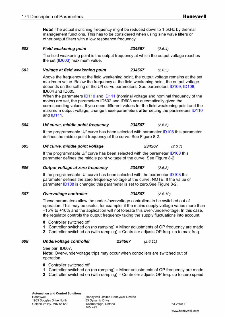
174 Description of Parameters Honeywell
Automation and Control Solutions Honeywell Honeywell Limited-Honeywell Limitée 1985 Douglas Drive North 35 Dynamic Drive Golden Valley, MIN 55422 Scarborough, Ontario 63-2600-1 MIV 4Z9 www.honeywell.com
Note! The actual switching frequency might be reduced down to 1,5kHz by thermal management functions. This has to be considered when using sine wave filters or other output filters with a low resonance frequency.
602 Field weakening point 234567 (2.6.4)
The field weakening point is the output frequency at which the output voltage reaches the set (ID603) maximum value.
603 Voltage at field weakening point 234567 (2.6.5)
Above the frequency at the field weakening point, the output voltage remains at the set maximum value. Below the frequency at the field weakening point, the output voltage depends on the setting of the U/f curve parameters. See parameters ID109, ID108, ID604 and ID605. When the parameters ID110 and ID111 (nominal voltage and nominal frequency of the motor) are set, the parameters ID602 and ID603 are automatically given the corresponding values. If you need different values for the field weakening point and the maximum output voltage, change these parameters after setting the parameters ID110 and ID111.
604 U/f curve, middle point frequency 234567 (2.6.6)
If the programmable U/f curve has been selected with parameter ID108 this parameter defines the middle point frequency of the curve. See Figure 8-2.
605 U/f curve, middle point voltage 234567 (2.6.7)
If the programmable U/f curve has been selected with the parameter ID108 this parameter defines the middle point voltage of the curve. See Figure 8-2.
606 Output voltage at zero frequency 234567 (2.6.8)
If the programmable U/f curve has been selected with the parameter ID108 this parameter defines the zero frequency voltage of the curve. NOTE: If the value of parameter ID108 is changed this parameter is set to zero.See Figure 8-2.
607 Overvoltage controller 234567 (2.6.10)
These parameters allow the under-/overvoltage controllers to be switched out of operation. This may be useful, for example, if the mains supply voltage varies more than –15% to +10% and the application will not tolerate this over-/undervoltage. In this case, the regulator controls the output frequency taking the supply fluctuations into account.
0 Controller switched off 1 Controller switched on (no ramping) = Minor adjustments of OP frequency are made 2 Controller switched on (with ramping) = Controller adjusts OP freq. up to max.freq.
608 Undervoltage controller 234567 (2.6.11)
See par. ID607. Note: Over-/undervoltage trips may occur when controllers are switched out of operation.
0 Controller switched off 1 Controller switched on (no ramping) = Minor adjustments of OP frequency are made 2 Controller switched on (with ramping) = Controller adjusts OP freq. up to zero speed
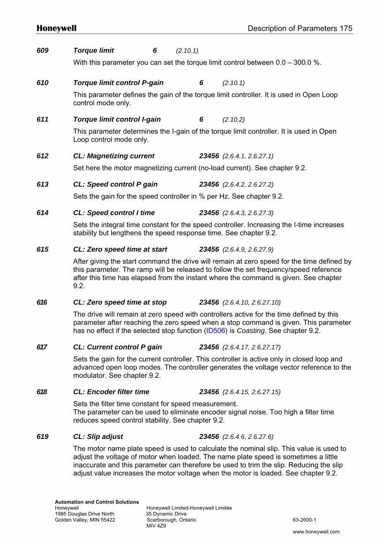
Honeywell Description of Parameters 175
Automation and Control Solutions Honeywell Honeywell Limited-Honeywell Limitée 1985 Douglas Drive North 35 Dynamic Drive Golden Valley, MIN 55422 Scarborough, Ontario 63-2600-1 MIV 4Z9 www.honeywell.com
609 Torque limit 6 (2.10.1)
With this parameter you can set the torque limit control between 0.0 – 300.0 %. 610 Torque limit control P-gain 6 (2.10.1)
This parameter defines the gain of the torque limit controller. It is used in Open Loop control mode only.
611 Torque limit control I-gain 6 (2.10.2) This parameter determines the I-gain of the torque limit controller. It is used in Open Loop control mode only.
612 CL: Magnetizing current 23456 (2.6.4.1, 2.6.27.1)
Set here the motor magnetizing current (no-load current). See chapter 9.2.
613 CL: Speed control P gain 23456 (2.6.4.2, 2.6.27.2) Sets the gain for the speed controller in % per Hz. See chapter 9.2.
614 CL: Speed control I time 23456 (2.6.4.3, 2.6.27.3) Sets the integral time constant for the speed controller. Increasing the I-time increases stability but lengthens the speed response time. See chapter 9.2.
615 CL: Zero speed time at start 23456 (2.6.4.9, 2.6.27.9) After giving the start command the drive will remain at zero speed for the time defined by this parameter. The ramp will be released to follow the set frequency/speed reference after this time has elapsed from the instant where the command is given. See chapter 9.2.
616 CL: Zero speed time at stop 23456 (2.6.4.10, 2.6.27.10) The drive will remain at zero speed with controllers active for the time defined by this parameter after reaching the zero speed when a stop command is given. This parameter has no effect if the selected stop function (ID506) is Coasting. See chapter 9.2.
617 CL: Current control P gain 23456 (2.6.4.17, 2.6.27.17) Sets the gain for the current controller. This controller is active only in closed loop and advanced open loop modes. The controller generates the voltage vector reference to the modulator. See chapter 9.2.
618 CL: Encoder filter time 23456 (2.6.4.15, 2.6.27.15) Sets the filter time constant for speed measurement. The parameter can be used to eliminate encoder signal noise. Too high a filter time reduces speed control stability. See chapter 9.2.
619 CL: Slip adjust 23456 (2.6.4.6, 2.6.27.6) The motor name plate speed is used to calculate the nominal slip. This value is used to adjust the voltage of motor when loaded. The name plate speed is sometimes a little inaccurate and this parameter can therefore be used to trim the slip. Reducing the slip adjust value increases the motor voltage when the motor is loaded. See chapter 9.2.
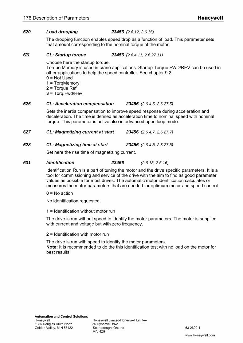
176 Description of Parameters Honeywell
Automation and Control Solutions Honeywell Honeywell Limited-Honeywell Limitée 1985 Douglas Drive North 35 Dynamic Drive Golden Valley, MIN 55422 Scarborough, Ontario 63-2600-1 MIV 4Z9 www.honeywell.com
620 Load drooping 23456 (2.6.12, 2.6.15) The drooping function enables speed drop as a function of load. This parameter sets that amount corresponding to the nominal torque of the motor.
621 CL: Startup torque 23456 (2.6.4.11, 2.6.27.11) Choose here the startup torque. Torque Memory is used in crane applications. Startup Torque FWD/REV can be used in other applications to help the speed controller. See chapter 9.2. 0 = Not Used 1 = TorqMemory 2 = Torque Ref 3 = Torq.Fwd/Rev
626 CL: Acceleration compensation 23456 (2.6.4.5, 2.6.27.5) Sets the inertia compensation to improve speed response during acceleration and deceleration. The time is defined as acceleration time to nominal speed with nominal torque. This parameter is active also in advanced open loop mode.
627 CL: Magnetizing current at start 23456 (2.6.4.7, 2.6.27.7)
628 CL: Magnetizing time at start 23456 (2.6.4.8, 2.6.27.8)
Set here the rise time of magnetizing current.
631 Identification 23456 (2.6.13, 2.6.16)
Identification Run is a part of tuning the motor and the drive specific parameters. It is a tool for commissioning and service of the drive with the aim to find as good parameter values as possible for most drives. The automatic motor identification calculates or measures the motor parameters that are needed for optimum motor and speed control.
0 = No action
No identification requested. 1 = Identification without motor run
The drive is run without speed to identify the motor parameters. The motor is supplied with current and voltage but with zero frequency. 2 = Identification with motor run
The drive is run with speed to identify the motor parameters. Note: It is recommended to do the this identification test with no load on the motor for best results.
Honeywell Description of Parameters 177
Automation and Control Solutions Honeywell Honeywell Limited-Honeywell Limitée 1985 Douglas Drive North 35 Dynamic Drive Golden Valley, MIN 55422 Scarborough, Ontario 63-2600-1 MIV 4Z9 www.honeywell.com
3 = Encoder ID run
Identifies the shaft zero position when using PMS motor with absolute encoder. The basic motor name plate data has to be set correctly before performing the identifi-cation run:
ID110 Nominal voltage of the motor (par. 2.1.6) ID111 Nominal frequency of the motor (par. 2.1.7) ID112 Nominal speed of the motor (par. 2.1.8) ID113 Nominal current of the motor (par. 2.1.9) ID120 Motor cos phi (par. 2.1.10)
When in closed loop and with an encoder installed, also the parameter for pulses / revolutions (in Menu M7) has to be set.
The automatic identification is activated by setting this parameter to the appropriate value followed by a start command in the requested direction. The start command to the drive has to be given within 20 s. If no start command is given within 20 s the identifi-cation run is cancelled and the parameter will be reset to its default setting.
The identification run can be stopped any time with normal stop command and the para-meter is reset to its default setting. In case identification run detects fault or other prob-lems, the identification run is completed if possible. After the identification is finished, the application checks the status of the identification and generates fault/ warning if any. During Identification Run, the brake control is disabled (see chapter 9.1).
633 CL: Start-up torque, forward 23456 (2.6.4.12, 2.6.27.12) Sets the start-up torque for forward direction if selected with par. ID621.
634 CL: Start-up torque, reverse 23456 (2.6.4.13, 2.6.27.13) Sets the start-up torque for reverse direction if selected with par. ID621.
636 Minimum frequency for Open Loop torque control 6 (2.10.7) Defines the frequency limit below which the frequency drive operates in frequency control mode. Because of the nominal slip of the motor, the internal torque calculation is inaccurate at low speeds where is it recommended to use the frequency control mode.
637 Speed controller P gain, Open Loop 6 (2.6.13)
Defines the P gain for the speed controlled in Open Loop control mode.
638 Speed controller I gain, Open Loop 6 (2.6.14)
Defines the I gain for the speed controlled in Open Loop control mode.
639 Torque controller P gain 6 (2.10.8)
Defines the P gain of the torque controller.
640 Torque controller I gain 6 (2.10.9)
Defines the I gain of the torque controller.
178 Description of Parameters Honeywell
Automation and Control Solutions Honeywell Honeywell Limited-Honeywell Limitée 1985 Douglas Drive North 35 Dynamic Drive Golden Valley, MIN 55422 Scarborough, Ontario 63-2600-1 MIV 4Z9 www.honeywell.com
641 Torque reference selection 6 (2.10.3)
Defines the source for torque reference. 0 Not used 1 Analogue input 1 2 Analogue input 2 3 Analogue input 3 4 Analogue input 4 5 Analogue input 1 (joystick) 6 Analogue input 2 (joystick) 7 From keypad, parameter R3.5 8 Fieldbus torque reference
642 Torque reference scaling, maximum value 6 (2.10.4) 643 Torque reference scaling, minimum value 6 (2.10.5)
Scale the custom minimum and maximum levels for analogue inputs within -300,0…300,0%.
644 Torque speed limit, NXS 6 (2.10.6)
With this parameter the maximum frequency for the torque control can be selected.
0 Maximum frequency 1 Selected frequency reference 2 Preset speed 7
NXP drives have more selections for this parameter. See page 204.
645 Negative torque limit 6 (2.6.27.21) 646 Positive torque limit 6 (2.6.27.22)
Defines the torque limit for positive and negative directions.
649 PMS motor shaft position 6 (2.6.28.4)
Identified zero shaft position when using absolute encoder for PMS motor.
650 Motor type 6 (2.6.28.1) Select used motor type with this parameter.
0 Induction motor 1 Permanent magnet synchronous motor
654 Enable Rs identification 6 (2.6.28.5)
Stator resistance identification at start. 0 No 1 Yes
655 Modulator index limit This parameter can be used to increase motor voltage in field weakening area.
Honeywell Description of Parameters 179
Automation and Control Solutions Honeywell Honeywell Limited-Honeywell Limitée 1985 Douglas Drive North 35 Dynamic Drive Golden Valley, MIN 55422 Scarborough, Ontario 63-2600-1 MIV 4Z9 www.honeywell.com
656 Load drooping time This function is used in order to achieve a dynamic speed drooping because of changing load. The parameter defines the time during which the speed is restored to the level it was before the load increase.
662 Measured voltage drop 6 (2.6.29.16)
The measured voltage drop at stator resistance between two phases with the nominal current of the motor.
665 Ir: Add generator scale 6 (2.6.29.19)
Scaling factor for generator side IR-compensation.
667 Ir: Add motoring scale 6 (2.6.29.20)
Scaling factor for motoring side IR-compensation.
668 IU Offset 6 (2.6.29.21) 669 IV Offset 6 (2.6.29.22) 670 IW Offset 6 (2.6.29.23)
Offset values for phase current measurement.
180 Description of Parameters Honeywell
Automation and Control Solutions Honeywell Honeywell Limited-Honeywell Limitée 1985 Douglas Drive North 35 Dynamic Drive Golden Valley, MIN 55422 Scarborough, Ontario 63-2600-1 MIV 4Z9 www.honeywell.com
700 Response to the 4mA reference fault 234567 (2.7.1)
0 = No response 1 = Warning 2 = Warning, the frequency from 10 seconds back is set as reference 3 = Warning, the Preset Frequency (Par. ID728) is set as reference 4 = Fault, stop mode after fault according to ID506 5 = Fault, stop mode after fault always by coasting A warning or a fault action and message is generated if the 4…20 mA reference signal is used and the signal falls below 3.5 mA for 5 seconds or below 0.5 mA for 0.5 seconds. The information can also be programmed into digital output DO1 or relay outputs RO1 and RO2.
701 Response to external fault 234567 (2.7.3)
0 = No response 1 = Warning 2 = Fault, stop mode after fault according to ID506 3 = Fault, stop mode after fault always by coasting A warning or a fault action and message is generated from the external fault signal in the programmable digital inputs DIN3. The information can also be programmed into digital output DO1 and into relay outputs RO1 and RO2.
702 Output phase supervision 234567 (2.7.6)
0 = No response 1 = Warning 2 = Fault, stop mode after fault according to ID506 3 = Fault, stop mode after fault always by coasting Output phase supervision of the motor ensures that the motor phases have an approximately equal current.
703 Ground fault protection 234567 (2.7.7)
0 = No response 1 = Warning 2 = Fault, stop mode after fault according to ID506 3 = Fault, stop mode after fault always by coasting Ground fault protection ensures that the sum of the motor phase currents is zero. The overcurrent protection is always working and protects the frequency drive from ground faults with high currents.
704 Motor thermal protection 234567 (2.7.8)
0 = No response 1 = Warning 2 = Fault, stop mode after fault according to ID506 3 = Fault, stop mode after fault always by coasting If tripping is selected the drive will stop and activate the fault stage. Deactivating the protection, i.e. setting parameter to 0, will reset the thermal stage of the motor to 0%. See chapter 9.4.
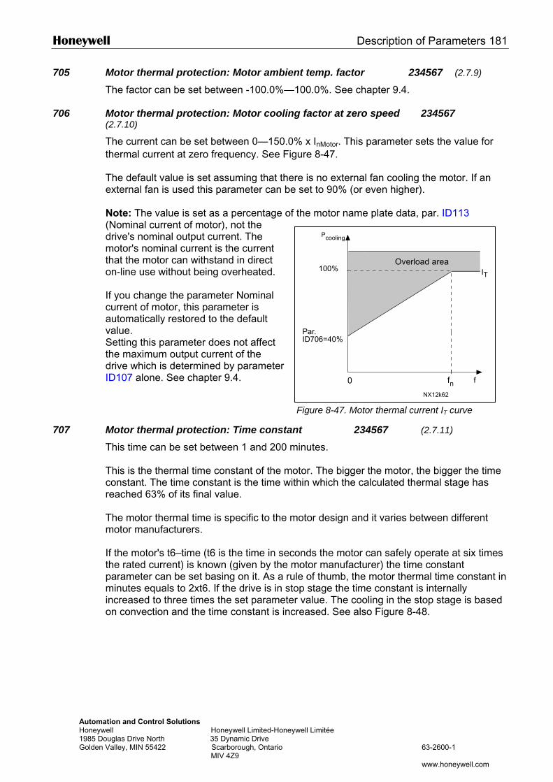
Honeywell Description of Parameters 181
Automation and Control Solutions Honeywell Honeywell Limited-Honeyw1985 Douglas Drive North 35 Dynamic Drive Golden Valley, MIN 55422 Scarborough, Ontario MIV 4Z9
Pcooling
705 Motor thermal protection: Motor ambient temp. factor 234567 (2.7.9)
The factor can be set between -100.0%—100.0%. See chapter 9.4.
706 Motor thermal protection: Motor cooling factor at zero speed 234567 (2.7.10)
The current can be set between 0—150.0% x InMotor. This parameter sets the value for thermal current at zero frequency. See Figure 8-47. The default value is set assuming that there is no external fan cooling the motor. If an external fan is used this parameter can be set to 90% (or even higher). Note: The value is set as a percentage of the motor name plate data, par. ID113 (Nominal current of motor), not the drive's nominal output current. The motor's nominal current is the current that the motor can withstand in direct on-line use without being overheated. If you change the parameter Nominal current of motor, this parameter is automatically restored to the default value. Setting this parameter does not affect the maximum output current of the drive which is determined by parameter ID107 alone. See chapter 9.4.
707 Motor thermal protection: Time constanThis time can be set between 1 and 200 m This is the thermal time constant of the moconstant. The time constant is the time witreached 63% of its final value. The motor thermal time is specific to the mmotor manufacturers. If the motor's t6–time (t6 is the time in secothe rated current) is known (given by the mparameter can be set basing on it. As a rulminutes equals to 2xt6. If the drive is in stoincreased to three times the set parameteron convection and the time constant is incr
ell Limitée
63-2600-1
www.honeywell.com
ffn
Par.ID706=40%
0
NX12k62
IT100%
Overload area
Figure 8-47. Motor thermal current IT curve
t 234567 (2.7.11)
inutes.
tor. The bigger the motor, the bigger the time hin which the calculated thermal stage has
otor design and it varies between different
nds the motor can safely operate at six times otor manufacturer) the time constant e of thumb, the motor thermal time constant in p stage the time constant is internally value. The cooling in the stop stage is based eased. See also Figure 8-48.
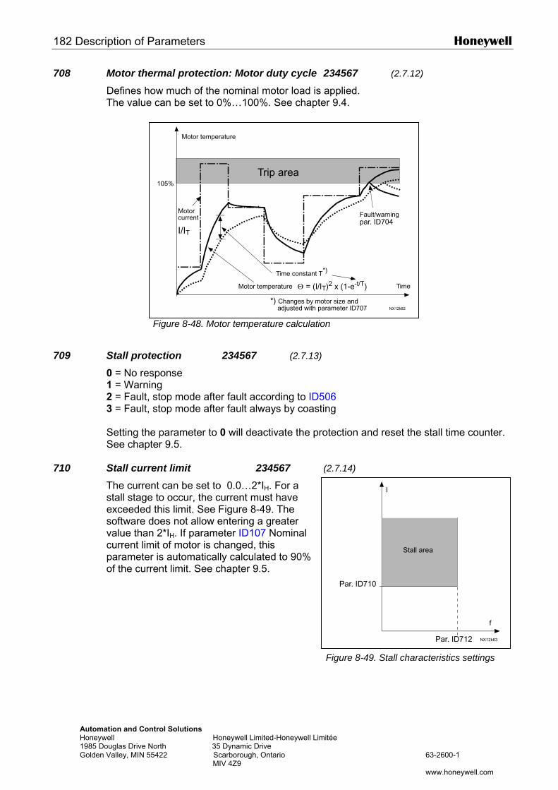
182 Description of Parameters Honeywell
Automation and Control Solutions Honeywell Honeywell Limited-Honeywell Lim1985 Douglas Drive North 35 Dynamic Drive Golden Valley, MIN 55422 Scarborough, Ontario MIV 4Z9
I
708 Motor thermal protection: Motor duty cycle 234567 (2.7.12)
Defines how much of the nominal motor load is applied. The value can be set to 0%…100%. See chapter 9.4.
Figure 8-48. Motor temperature calculation
709 Stall protection 234567 (2.7.13)
0 = No response 1 = Warning 2 = Fault, stop mode after fault according to ID506 3 = Fault, stop mode after fault always by coasting Setting the parameter to 0 will deactivate the protection and reset the stall time counter. See chapter 9.5.
710 Stall current limit 234567 (2.7.14)
The current can be set to 0.0…2*IH. For a stall stage to occur, the current must have exceeded this limit. See Figure 8-49. The software does not allow entering a greater value than 2*IH. If parameter ID107 Nominal current limit of motor is changed, this parameter is automatically calculated to 90% of the current limit. See chapter 9.5.
105%
par. ID704
Θ = (I/IT)2 x (1-e-t/T)
I/IT
NX12k82
Trip area
Motor temperature
TimeMotor temperature
Time constant T*)
*) Changes by motor size and adjusted with parameter ID707
Fault/warningMotorcurrent
itée
63-2600-1
www.honeywell.com
f
Par. ID710
Par. ID712 NX12k63
Stall area
Figure 8-49. Stall characteristics settings
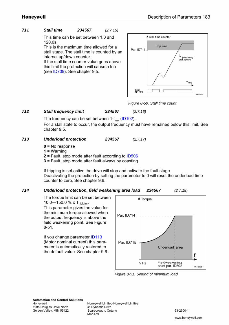
Honeywell Description of Parameters 183
Automation and Control Solutions Honeywell Honeywell Limited-Honeywell 1985 Douglas Drive North 35 Dynamic Drive Golden Valley, MIN 55422 Scarborough, Ontario MIV 4Z9
Stall time counter
Par. ID
Par. ID
711 Stall time 234567 (2.7.15)
This time can be set between 1.0 and 120.0s. This is the maximum time allowed for a stall stage. The stall time is counted by an internal up/down counter. If the stall time counter value goes above this limit the protection will cause a trip (see ID709). See chapter 9.5.
712 Stall frequency limit 234567
The frequency can be set between 1-fmax (ID1For a stall state to occur, the output frequencychapter 9.5.
713 Underload protection 234567
0 = No response 1 = Warning 2 = Fault, stop mode after fault according to I3 = Fault, stop mode after fault always by coa If tripping is set active the drive will stop and aDeactivating the protection by setting the paracounter to zero. See chapter 9.6.
714 Underload protection, field weakening are
The torque limit can be set between 10.0—150.0 % x TnMotor. This parameter gives the value for the minimum torque allowed when the output frequency is above the field weakening point. See Figure 8-51. If you change parameter ID113 (Motor nominal current) this para-meter is automatically restored to the default value. See chapter 9.6.
Figure 8
Par. ID711
NX12k64
Trip area
Time
StallNo stall
Trip/warningpar. ID709
Torque
Figure 8-50. Stall time count
(2.7.16)
02). must have remained below this limit. See
(2.7.17)
D506 sting
ctivate the fault stage. meter to 0 will reset the underload time
a load 234567 (2.7.18)
Limitée
63-2600-1
www.honeywell.com
714
NX12k65
715
f5 Hz
Underload area
Fieldweakeningpoint par. ID602
-51. Setting of minimum load
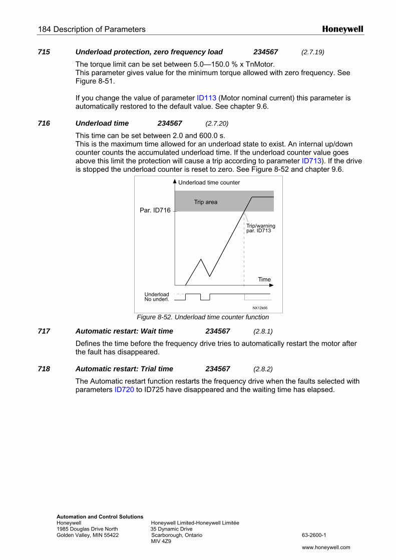
184 Description of Parameters Honeywell
Automation and Control SolutioHoneywell 1985 Douglas Drive North Golden Valley, MIN 55422
715 Underload protection, zero frequency load 234567 (2.7.19)
The torque limit can be set between 5.0—150.0 % x TnMotor. This parameter gives value for the minimum torque allowed with zero frequency. See Figure 8-51. If you change the value of parameter ID113 (Motor nominal current) this parameter is automatically restored to the default value. See chapter 9.6.
716 Underload time 234567 (2.7.20)
This time can be set between 2.0 and 600.0 s. This is the maximum time allowed for an underload state to exist. An internal up/down counter counts the accumulated underload time. If the underload counter value goes above this limit the protection will cause a trip according to parameter ID713). If the drive is stopped the underload counter is reset to zero. See Figure 8-52 and chapter 9.6.
717 Automatic restartDefines the time bethe fault has disap
718 Automatic restartThe Automatic resparameters ID720
Underload time counter
ns Honeywell Limited-Honeywell Limitée
35 Dynamic Drive Scarborough, Ontario 63-2600-1 MIV 4Z9
www.honeywell.com
Figure 8-52. Underload time counter function
: Wait time 234567 (2.8.1)
fore the frequency drive tries to automatically restart the motor after peared.
: Trial time 234567 (2.8.2)
tart function restarts the frequency drive when the faults selected with to ID725 have disappeared and the waiting time has elapsed.
Par. ID716
NX12k66
Trip area
Time
UnderloadNo underl.
Trip/warningpar. ID713
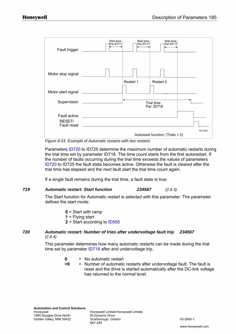
Honeywell Description of Parameters 185
AutomaHoneyw1985 DoGolden
719
720
Wait timePar.ID717
Wait timePar.ID717
Wait timePar.ID717
tion and Control Solutions ell Honeywell Limited-Honeywell Limitée uglas Drive North 35 Dynamic Drive
Valley, MIN 55422 Scarborough, Ontario 63-2600-1 MIV 4Z9
www.honeywell.com
Figure 8-53. Example of Automatic restarts with two restarts
Parameters ID720 to ID725 determine the maximum number of automatic restarts during the trial time set by parameter ID718. The time count starts from the first autorestart. If the number of faults occurring during the trial time exceeds the values of parameters ID720 to ID725 the fault state becomes active. Otherwise the fault is cleared after the trial time has elapsed and the next fault start the trial time count again. If a single fault remains during the trial time, a fault state is true. Automatic restart: Start function 234567 (2.8.3)
The Start function for Automatic restart is selected with this parameter. The parameter defines the start mode: 0 = Start with ramp 1 = Flying start 2 = Start according to ID505
Automatic restart: Number of tries after undervoltage fault trip 234567 (2.8.4)
This parameter determines how many automatic restarts can be made during the trial time set by parameter ID718 after and undervoltage trip.
0 = No automatic restart >0 = Number of automatic restarts after undervoltage fault. The fault is
reset and the drive is started automatically after the DC-link voltage has returned to the normal level.
NX12k67
Fault trigger
Motor stop signal
Motor start signal
Supervision
Restart 1 Restart 2
Trial timePar. ID718
Fault activeRESET/Fault reset
Autoreset function: (Trials = 2)
186 Description of Parameters Honeywell
Automation and Control Solutions Honeywell Honeywell Limited-Honeywell Limitée 1985 Douglas Drive North 35 Dynamic Drive Golden Valley, MIN 55422 Scarborough, Ontario 63-2600-1 MIV 4Z9 www.honeywell.com
721 Automatic restart: Number of tries after overvoltage trip 234567 (2.8.5)
This parameter determines how many automatic restarts can be made during the trial time set by parameter ID718 after an overvoltage trip.
0 = No automatic restart after overvoltage fault trip >0 = Number of automatic restarts after overvoltage fault trip. The fault is
reset and the drive is started automatically after the DC-link voltage has returned to the normal level.
722 Automatic restart: Number of tries after overcurrent trip 234567 (2.8.6)
(NOTE! IGBT temp fault also included) This parameter determines how many automatics restarts can be made during the trial time set by ID718.
0 = No automatic restart after overcurrent fault trip >0 = Number of automatic restarts after overcurrent trip and IGBT
temperature faults.
723 Automatic restart: Number of tries after 4mA reference trip 234567 (2.8.7)
This parameter determines how many automatics restarts can be made during the trial time set by ID718.
0 = No automatic restart after reference fault trip >0 = Number of automatic restarts after the analogue current signal
(4…20mA) has returned to the normal level (>4mA)
725 Automatic restart: Number of tries after external fault trip 234567 (2.8.9)
This parameter determines how many automatics restarts can be made during the trial time set by ID718.
0 = No automatic restart after External fault trip >0 = Number of automatic restarts after External fault trip
726 Automatic restart: Number of tries after motor temperature fault trip 234567 (2.8.8)
This parameter determines how many automatics restarts can be made during the trial time set by ID718.
0 = No automatic restart after Motor temperature fault trip >0 = Number of automatic restarts after the motor temperature has
returned to its normal level
727 Response to undervoltage fault 234567 (2.7.5)
0 = Fault stored in fault history 1 = Fault not stored in fault history For the undervoltage limits, see the product's user's manual.
Honeywell Description of Parameters 187
Automation and Control Solutions Honeywell Honeywell Limited-Honeywell Limitée 1985 Douglas Drive North 35 Dynamic Drive Golden Valley, MIN 55422 Scarborough, Ontario 63-2600-1 MIV 4Z9 www.honeywell.com
728 4mA reference fault: preset frequency reference 234567 (2.7.2)
If the value of parameter ID700 is set to 3 and the 4mA fault occurs then the frequency reference to the motor is the value of this parameter.
730 Input phase supervision 234567 (2.7.4)
0 = No response 1 = Warning 2 = Fault, stop mode after fault according to ID506 3 = Fault, stop mode after fault always by coasting The input phase supervision ensures that the input phases of the frequency drive have an approximately equal current.
731 Automatic restart 1 (2.20)
The Automatic restart is taken into use with this parameter. 0 = Disabled 1 = Enabled The function resets the following faults (max. three times) (see the product's user's manual: • Overcurrent (F1) • Overvoltage (F2) • Undervoltage (F9) • Frequency drive overtemperature (F14) • Motor overtemperature (F16) • Reference fault (F50)
732 Response to thermistor fault 234567 (2.7.21)
0 = No response 1 = Warning 2 = Fault, stop mode after fault according to ID506 3 = Fault, stop mode after fault always by coasting Setting the parameter to 0 will deactivate the protection.
733 Response to fieldbus fault 234567 (2.7.22)
Set here the response mode for the fieldbus fault if a fieldbus board is used. For more information, see the respective Fieldbus Board Manual. See parameter ID732.
734 Response to slot fault 234567 (2.7.23)
Set here the response mode for a board slot fault due to missing or broken board. See parameter ID732.
188 Description of Parameters Honeywell
Automation and Control Solutions Honeywell Honeywell Limited-Honeywell Limitée 1985 Douglas Drive North 35 Dynamic Drive Golden Valley, MIN 55422 Scarborough, Ontario 63-2600-1 MIV 4Z9 www.honeywell.com
738 Automatic restart: Number of tries after underload fault trip (2.8.10)
This parameter determines how many automatic restarts can be made during the trial time set by parameter ID718.
0 = No automatic restart after Underload fault trip >0 = Number of automatic restarts after Underload fault trip
739 Number of PT100 inputs in use 567 (2.7.24) If you have a PT100 input board installed in your frequency drive you can choose here the number of PT100 inputs in use. See also the I/O boards manual. Note: If the selected value is greater than the actual number of used PT100 inputs, the display will read 200ºC. If the input is short-circuited the displayed value is –30ºC.
740 Response to PT100 fault 567 (2.7.25) 0 = No response 1 = Warning 2 = Fault, stop mode after fault according to ID506 3 = Fault, stop mode after fault always by coasting
741 PT100 warning limit 567 (2.7.26) Set here the limit at which the PT100 warning will be activated.
742 PT100 fault limit 567 (2.7.27) Set here the limit at which the PT100 fault (F56) will be activated.
750 Cooling monitor 6 (2.2.7.23) When using a water-cooled drive, connect this input to the Cooling OK signal from flow control application. The parameter is available for NXP drives only.
751 Cooling fault delay The delay after the motor is stopped with coasting after the cooling OK signal is missing.
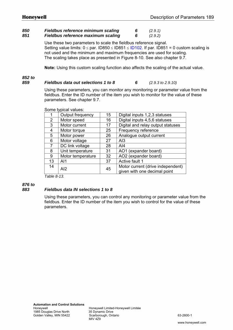
Honeywell Description of Parameters 189
Automation and Control Solutions Honeywell Honeywell Limited-Honeywell Limitée 1985 Douglas Drive North 35 Dynamic Drive Golden Valley, MIN 55422 Scarborough, Ontario 63-2600-1 MIV 4Z9 www.honeywell.com
850 Fieldbus reference minimum scaling 6 (2.9.1) 851 Fieldbus reference maximum scaling 6 (2.9.2)
Use these two parameters to scale the fieldbus reference signal. Setting value limits: 0 ≤ par. ID850 ≤ ID851 ≤ ID102. If par. ID851 = 0 custom scaling is not used and the minimum and maximum frequencies are used for scaling. The scaling takes place as presented in Figure 8-10. See also chapter 9.7. Note: Using this custom scaling function also affects the scaling of the actual value.
852 to 859 Fieldbus data out selections 1 to 8 6 (2.9.3 to 2.9.10)
Using these parameters, you can monitor any monitoring or parameter value from the fieldbus. Enter the ID number of the item you wish to monitor for the value of these parameters. See chapter 9.7. Some typical values:
1 Output frequency 15 Digital inputs 1,2,3 statuses 2 Motor speed 16 Digital inputs 4,5,6 statuses 3 Motor current 17 Digital and relay output statuses 4 Motor torque 25 Frequency reference 5 Motor power 26 Analogue output current 6 Motor voltage 27 AI3 7 DC link voltage 28 AI4 8 Unit temperature 31 AO1 (expander board) 9 Motor temperature 32 AO2 (expander board)
13 AI1 37 Active fault 1 14 AI2 45 Motor current (drive independent)
given with one decimal point Table 8-13.
876 to 883 Fieldbus data IN selections 1 to 8
Using these parameters, you can control any monitoring or parameter value from the fieldbus. Enter the ID number of the item you wish to control for the value of these parameters.
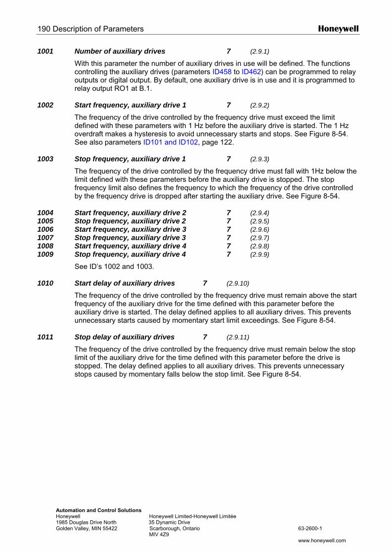
190 Description of Parameters Honeywell
Automation and Control Solutions Honeywell Honeywell Limited-Honeywell Limitée 1985 Douglas Drive North 35 Dynamic Drive Golden Valley, MIN 55422 Scarborough, Ontario 63-2600-1 MIV 4Z9 www.honeywell.com
1001 Number of auxiliary drives 7 (2.9.1)
With this parameter the number of auxiliary drives in use will be defined. The functions controlling the auxiliary drives (parameters ID458 to ID462) can be programmed to relay outputs or digital output. By default, one auxiliary drive is in use and it is programmed to relay output RO1 at B.1.
1002 Start frequency, auxiliary drive 1 7 (2.9.2)
The frequency of the drive controlled by the frequency drive must exceed the limit defined with these parameters with 1 Hz before the auxiliary drive is started. The 1 Hz overdraft makes a hysteresis to avoid unnecessary starts and stops. See Figure 8-54. See also parameters ID101 and ID102, page 122.
1003 Stop frequency, auxiliary drive 1 7 (2.9.3)
The frequency of the drive controlled by the frequency drive must fall with 1Hz below the limit defined with these parameters before the auxiliary drive is stopped. The stop frequency limit also defines the frequency to which the frequency of the drive controlled by the frequency drive is dropped after starting the auxiliary drive. See Figure 8-54.
1004 Start frequency, auxiliary drive 2 7 (2.9.4) 1005 Stop frequency, auxiliary drive 2 7 (2.9.5) 1006 Start frequency, auxiliary drive 3 7 (2.9.6) 1007 Stop frequency, auxiliary drive 3 7 (2.9.7) 1008 Start frequency, auxiliary drive 4 7 (2.9.8) 1009 Stop frequency, auxiliary drive 4 7 (2.9.9)
See ID’s 1002 and 1003.
1010 Start delay of auxiliary drives 7 (2.9.10)
The frequency of the drive controlled by the frequency drive must remain above the start frequency of the auxiliary drive for the time defined with this parameter before the auxiliary drive is started. The delay defined applies to all auxiliary drives. This prevents unnecessary starts caused by momentary start limit exceedings. See Figure 8-54.
1011 Stop delay of auxiliary drives 7 (2.9.11)
The frequency of the drive controlled by the frequency drive must remain below the stop limit of the auxiliary drive for the time defined with this parameter before the drive is stopped. The delay defined applies to all auxiliary drives. This prevents unnecessary stops caused by momentary falls below the stop limit. See Figure 8-54.
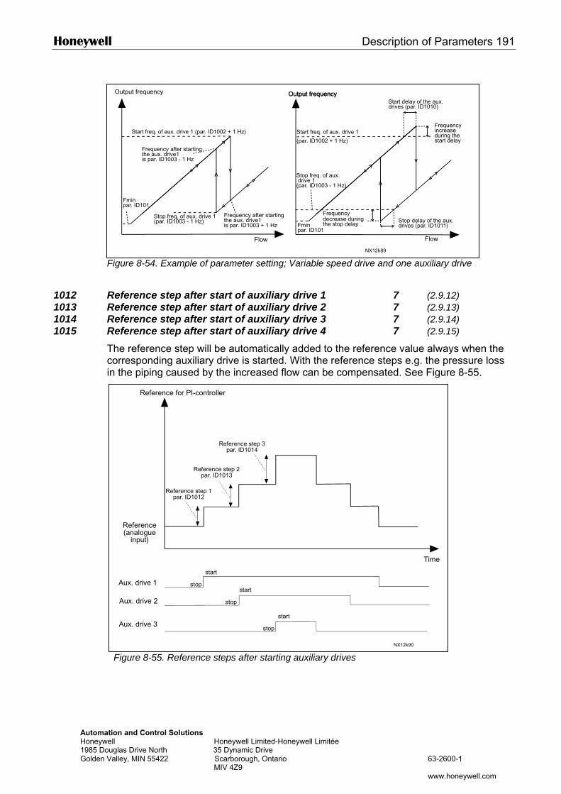
Honeywell Description of Parameters 191
AutomaHoneyw1985 DoGolden V
F
1012 R1013 R1014 R1015 R
Tci
Output frequency
Start delay of the aux.drives (par. ID1010)
Output frequencyOutput frequency
teu
igure 8-54. Example of parameter setting; Variable speed drive and one auxiliary drive
eference step after start of auxiliary drive 1 7 (2.9.12) eference step after start of auxiliary drive 2 7 (2.9.13) eference step after start of auxiliary drive 3 7 (2.9.14) eference step after start of auxiliary drive 4 7 (2.9.15) he reference step will be automatically added to the reference value always when the orresponding auxiliary drive is started. With the reference steps e.g. the pressure loss
n the piping caused by the increased flow can be compensated. See Figure 8-55.
Flow
Start freq. of aux. drive 1 (par. ID1002 + 1 Hz)
Frequency after startingthe aux. drive1is par. ID1003 + 1 Hz
Stop freq. of aux. drive 1(par. ID1003 - 1 Hz)
Frequency after startingthe aux. drive1is par. ID1003 - 1 Hz
Fminpar. ID101
Start freq. of aux. drive 1
(par. ID1002 + 1 Hz)
Frequencyincreaseduring thestart delay
Stop freq. of aux. drive 1(par. ID1003 - 1 Hz)
Frequencydecrease duringthe stop delay
Flow
Stop delay of the aux.drives (par. ID1011)Fmin
par. ID101
NX12k89
Reference for PI-controller
ion and Control Solutions ll Honeywell Limited-Honeywell Limitée glas Drive North 35 Dynamic Drive alley, MIN 55422 Scarborough, Ontario 63-2600-1 MIV 4Z9
www.honeywell.com
Figure 8-55. Reference steps after starting auxiliary drives
Time
Reference(analogue
input)
Reference step 1par. ID1012
Reference step 2par. ID1013
Reference step 3par. ID1014
Aux. drive 1
start
stop start
stopAux. drive 2
Aux. drive 3 start
stop
NX12k90
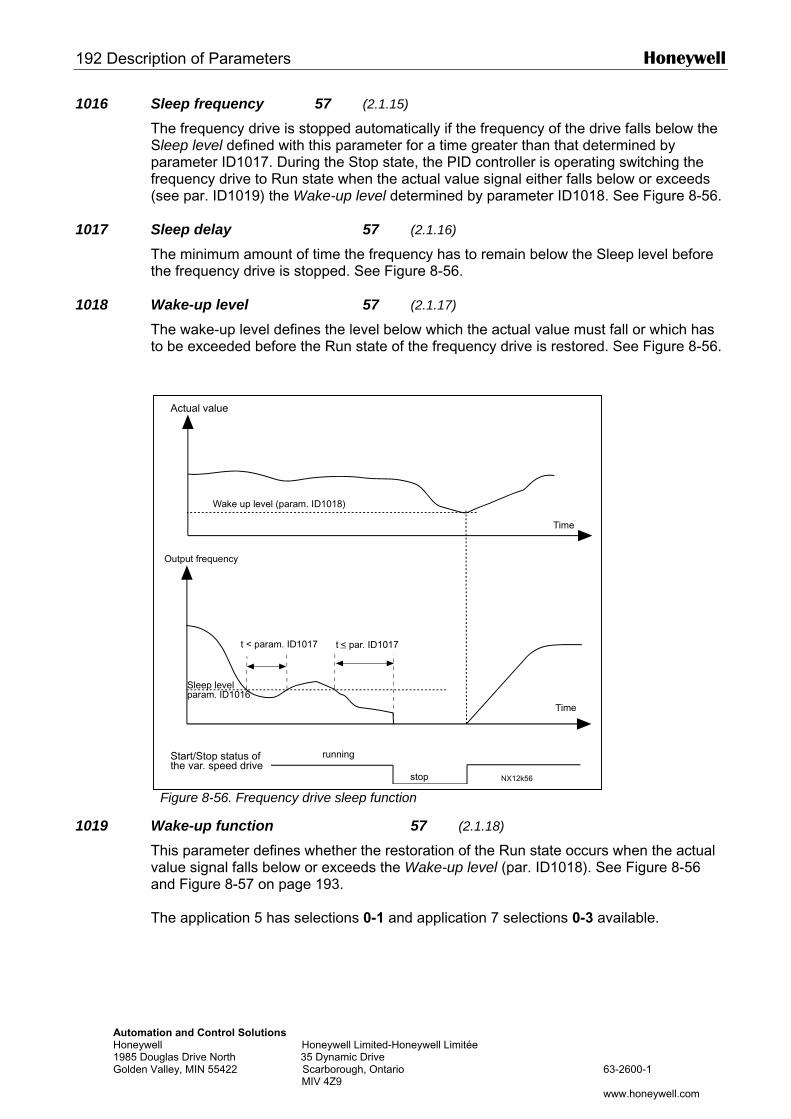
192 Description of Parameters Honeywell
AutomatHoneywe1985 DouGolden V
1016 Sleep frequency 57 (2.1.15)
The frequency drive is stopped automatically if the frequency of the drive falls below the Sleep level defined with this parameter for a time greater than that determined by parameter ID1017. During the Stop state, the PID controller is operating switching the frequency drive to Run state when the actual value signal either falls below or exceeds (see par. ID1019) the Wake-up level determined by parameter ID1018. See Figure 8-56.
1017 Sleep delay 57 (2.1.16)
The minimum amount of time the frequency has to remain below the Sleep level before the frequency drive is stopped. See Figure 8-56.
1018 Wake-up level 57 (2.1.17)
The wake-up level defines the level below which the actual value must fall or which has to be exceeded before the Run state of the frequency drive is restored. See Figure 8-56.
1019 WTva T
Actual value
ion and Control Solutions ll Honeywell Limited-Honeywell Limitée glas Drive North 35 Dynamic Drive alley, MIN 55422 Scarborough, Ontario 63-2600-1 MIV 4Z9
www.honeywell.com
Figure 8-56. Frequency drive sleep function
ake-up function 57 (2.1.18)
his parameter defines whether the restoration of the Run state occurs when the actual alue signal falls below or exceeds the Wake-up level (par. ID1018). See Figure 8-56 nd Figure 8-57 on page 193.
he application 5 has selections 0-1 and application 7 selections 0-3 available.
NX12k56
t < param. ID1017
Wake up level (param. ID1018)
Output frequency
Sleep levelparam. ID1016
Time
Time
Start/Stop status ofthe var. speed drive
running
stop
t < par. ID1017
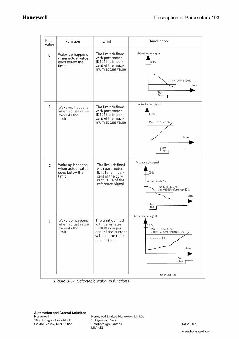
Honeywell Description of Parameters 193
AutoHone1985Golde
Par. Function Limit Description
mation and Control Solutions ywell Honeywell Limited-Honeywell Limitée Douglas Drive North 35 Dynamic Drive n Valley, MIN 55422 Scarborough, Ontario 63-2600-1 MIV 4Z9
www.honeywell.com
Figure 8-57. Selectable wake-up functions
100%
0
1
2
3
100%
Par. ID1018=30%
Par. ID1018=60%
100%
100%
value
Wake-up happenswhen actual valuegoes below thelimit
Wake-up happenswhen actual valueexceeds thelimit
Wake up happenswhen actual valuegoes below thelimit
Wake up happenswhen actual valueexceeds thelimit
Par.ID1018=60%limit=60%*reference=30%
reference=50%
time
StartStop
Actual value signal
Actual value signal
The limit definedwith parameterID1018 is in per-cent of the currentvalue of the refer-ence signal
The limit definedwith parameterID1018 is in per-cent of the cur-rent value of thereference signal
StartStop
time
Actual value signalThe limit definedwith parameterID1018 is in per-cent of the maxi-mum actual value
The limit definedwith parameterID1018 is in per-cent of the maxi-mum actual value
Actual value signal
StartStop
time
time
StartStop
reference=50%
Par.ID1018=140%limit=140%*reference=70%
NX12k88.fh8
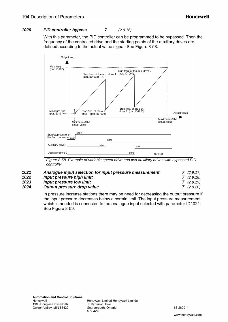
194 Description of Parameters Honeywell
AutomatHoneywe1985 DouGolden V
1020 PID controller bypass 7 (2.9.16)
With this parameter, the PID controller can be programmed to be bypassed. Then the frequency of the controlled drive and the starting points of the auxiliary drives are defined according to the actual value signal. See Figure 8-58.
1021 A1022 I1023 I1024 O
ItwS
Output freq.
ion and Control Solutions ll Honeywell Limited-Honeywell Limitée glas Drive North 35 Dynamic Drive alley, MIN 55422 Scarborough, Ontario 63-2600-1 MIV 4Z9
www.honeywell.com
Figure 8-58. Example of variable speed drive and two auxiliary drives with bypassed PID controller
nalogue input selection for input pressure measurement 7 (2.9.17) nput pressure high limit 7 (2.9.18) nput pressure low limit 7 (2.9.19) utput pressure drop value 7 (2.9.20)
n pressure increase stations there may be need for decreasing the output pressure if he input pressure decreases below a certain limit. The input pressure measurement hich is needed is connected to the analogue input selected with parameter ID1021. ee Figure 8-59.
NX12k91
Minimum freq.(par. ID101)
Minimum of theactual value
Actual value
Maximum of theactual value
Start freq. of the aux. drive 1 (par. ID1002)
Max. freq.(par. ID102)
Stop freq. of the aux.drive 1 (par. ID1003)
Stop freq. of the aux.drive 2 (par. ID1005)
Start/stop control ofthe freq. converter
Auxiliary drive 1
stop
start
stop
start
stop
start
Start freq. of the aux. drive 2 (par. ID1004)
Auxiliary drive 2
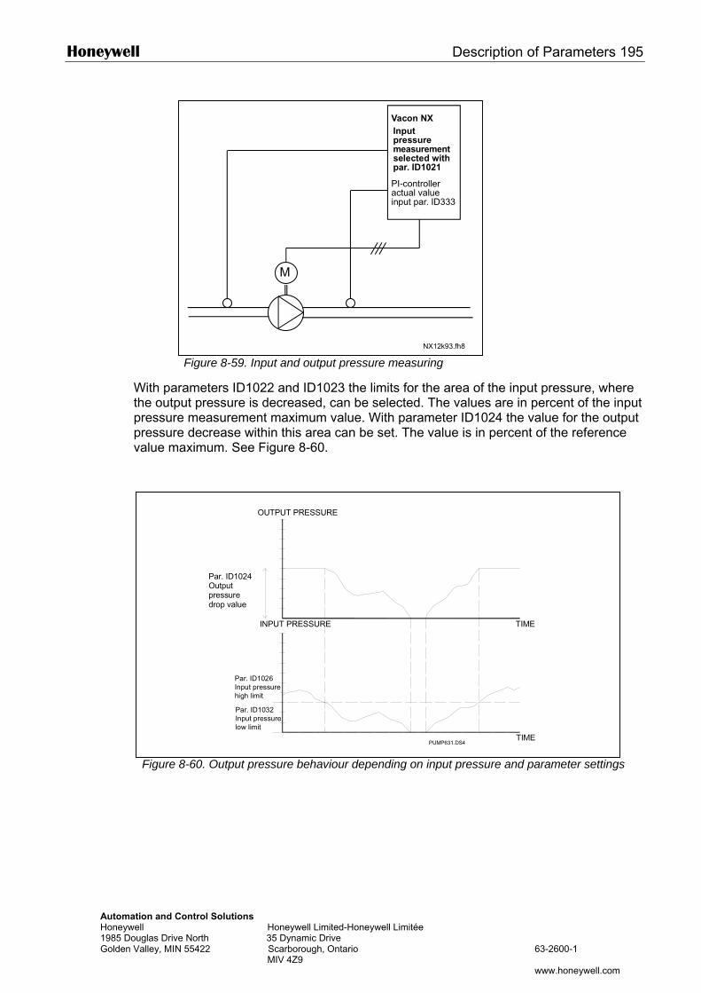
Honeywell Description of Parameters 195
Automation and CHoneywell 1985 Douglas DriveGolden Valley, MIN
With parthe outppressurepressurevalue ma
Figure 8
Vacon NX
Figure 8-59. Input and output pressure measuring
ameters ID1022 and ID1023 the limits for the area of the input pressure, where ut pressure is decreased, can be selected. The values are in percent of the input measurement maximum value. With parameter ID1024 the value for the output decrease within this area can be set. The value is in percent of the reference ximum. See Figure 8-60.
M
NX12k93.fh8
PI-controlleractual valueinput par. ID333
Inputpressuremeasurementselected withpar. ID1021
ontrol Solutions Honeywell Limited-Honeywell Limitée
North 35 Dynamic Drive 55422 Scarborough, Ontario 63-2600-1 MIV 4Z9
www.honeywell.com
-60. Output pressure behaviour depending on input pressure and parameter settings
PUMP631.DS4
OUTPUT PRESSURE
Par. ID1024Output pressuredrop value
INPUT PRESSURE
Par. ID1026Input pressurehigh limit
Par. ID1032Input pressurelow limit
TIME
TIME
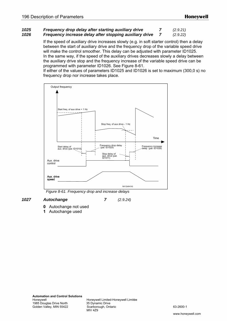
196 Description of Parameters Honeywell
AutomatHoneywe1985 DouGolden V
1025 Frequency drop delay after starting auxiliary drive 7 (2.9.21) 1026 Frequency increase delay after stopping auxiliary drive 7 (2.9.22)
If the speed of auxiliary drive increases slowly (e.g. in soft starter control) then a delay between the start of auxiliary drive and the frequency drop of the variable speed drive will make the control smoother. This delay can be adjusted with parameter ID1025. In the same way, if the speed of the auxiliary drives decreases slowly a delay between the auxiliary drive stop and the frequency increase of the variable speed drive can be programmed with parameter ID1026. See Figure 8-61. If either of the values of parameters ID1025 and ID1026 is set to maximum (300,0 s) no frequency drop nor increase takes place.
1027 A01
Output frequency
ion and Control Solutions ll Honeywell Limited-Honeywell Limitée glas Drive North 35 Dynamic Drive alley, MIN 55422 Scarborough, Ontario 63-2600-1 MIV 4Z9
www.honeywell.com
Figure 8-61. Frequency drop and increase delays
utochange 7 (2.9.24)
Autochange not used Autochange used
NX12k94.fh3
Time
Start freq. of aux drive + 1 Hz
Start delay ofaux. drive (par. ID1010)
Frequency drop delay (par. ID1025)
Aux. drivecontrol
Aux. drivespeed
Stop delay ofaux. drive (par.ID1011)
Frequency increasedelay (par. ID1026)
Stop freq. of aux drive - 1 Hz
Aux. drivespeed
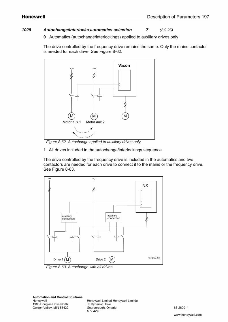
Honeywell Description of Parameters 197
Automation and CoHoneywell 1985 Douglas DriveGolden Valley, MIN
1028 Autochange/interlocks automatics selection 7 (2.9.25)
0 Automatics (autochange/interlockings) applied to auxiliary drives only The drive controlled by the frequency drive remains the same. Only the mains contactor is needed for each drive. See Figure 8-62.
Figure 8
1 All dri The drivecontactoSee Figu
Figure 8
Drive
ntrol Solutions Honeywell Limited-Honeywell Limitée
North 35 Dynamic Drive 55422 Scarborough, Ontario 63-2600-1 MIV 4Z9
www.honeywell.com
MM
Vacon
MMotor aux.1 Motor aux.2
-62. Autochange applied to auxiliary drives only.
ves included in the autochange/interlockings sequence
controlled by the frequency drive is included in the automatics and two rs are needed for each drive to connect it to the mains or the frequency drive. re 8-63.
-63. Autochange with all drives
Vacon
MMNX12k97.fh8
1 Drive 2
auxiliaryconnection
auxiliaryconnection
NX
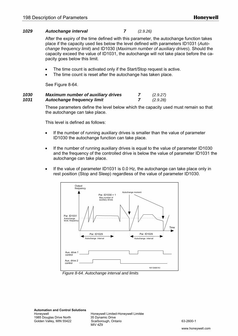
198 Description of Parameters Honeywell
Automation and CHoneywell 1985 Douglas DriveGolden Valley, MIN
1029 Autochange interval 7 (2.9.26)
After the expiry of the time defined with this parameter, the autochange function takes place if the capacity used lies below the level defined with parameters ID1031 (Auto-change frequency limit) and ID1030 (Maximum number of auxiliary drives). Should the capacity exceed the value of ID1031, the autochange will not take place before the ca-pacity goes below this limit. • The time count is activated only if the Start/Stop request is active. • The time count is reset after the autochange has taken place. See Figure 8-64.
1030 Maximum number of auxiliary drives 7 (2.9.27) 1031 Autochange frequency limit 7 (2.9.28)
These parameters define the level below which the capacity used must remain so that the autochange can take place. This level is defined as follows: • If the number of running auxiliary drives is smaller than the value of parameter
ID1030 the autochange function can take place.
• If the number of running auxiliary drives is equal to the value of parameter ID1030 and the frequency of the controlled drive is below the value of parameter ID1031 the autochange can take place.
• If the value of parameter ID1031 is 0.0 Hz, the autochange can take place only in rest position (Stop and Sleep) regardless of the value of parameter ID1030.
Outputfrequency
Autochange moment
ontrol Solutions Honeywell Limited-Honeywell Limitée
North 35 Dynamic Drive 55422 Scarborough, Ontario 63-2600-1 MIV 4Z9
www.honeywell.com
Figure 8-64. Autochange interval and limits NX12k98.fh3
Time
Par. ID1029Par. ID1029
Autochange interval
Par. ID1031Autochangelevel, frequency
Autochange interval
Aux. drive 1control
Aux. drive 2control
Par. ID1030 = 1Max.number ofauxiliary drives
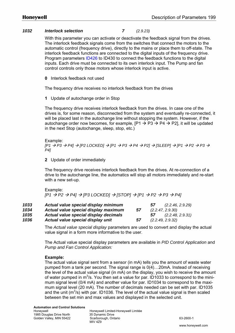
Honeywell Description of Parameters 199
Automation and Control Solutions Honeywell Honeywell Limited-Honeywell Limitée 1985 Douglas Drive North 35 Dynamic Drive Golden Valley, MIN 55422 Scarborough, Ontario 63-2600-1 MIV 4Z9 www.honeywell.com
1032 Interlock selection 7 (2.9.23)
With this parameter you can activate or deactivate the feedback signal from the drives. The interlock feedback signals come from the switches that connect the motors to the automatic control (frequency drive), directly to the mains or place them to off-state. The interlock feedback functions are connected to the digital inputs of the frequency drive. Program parameters ID426 to ID430 to connect the feedback functions to the digital inputs. Each drive must be connected to its own interlock input. The Pump and fan control controls only those motors whose interlock input is active. 0 Interlock feedback not used The frequency drive receives no interlock feedback from the drives 1 Update of autochange order in Stop
The frequency drive receives interlock feedback from the drives. In case one of the drives is, for some reason, disconnected from the system and eventually re-connected, it will be placed last in the autochange line without stopping the system. However, if the autochange order now becomes, for example, [P1 P3 P4 P2], it will be updated in the next Stop (autochange, sleep, stop, etc.)
Example: [P1 P3 P4] [P2 LOCKED] [P1 P3 P4 P2] [SLEEP] [P1 P2 P3 P4] 2 Update of order immediately The frequency drive receives interlock feedback from the drives. At re-connection of a drive to the autochange line, the automatics will stop all motors immediately and re-start with a new set-up. Example: [P1 P2 P4] [P3 LOCKED] [STOP] [P1 P2 P3 P4]
1033 Actual value special display minimum 57 (2.2.46, 2.9.29) 1034 Actual value special display maximum 57 (2.2.47, 2.9.30) 1035 Actual value special display decimals 57 (2.2.48, 2.9.31) 1036 Actual value special display unit 57 (2.2.49, 2.9.32)
The Actual value special display parameters are used to convert and display the actual value signal in a form more informative to the user.
The Actual value special display parameters are available in PID Control Application and Pump and Fan Control Application:
Example: The actual value signal sent from a sensor (in mA) tells you the amount of waste water pumped from a tank per second. The signal range is 0(4)…20mA. Instead of receiving the level of the actual value signal (in mA) on the display, you wish to receive the amount of water pumped in m3/s. You then set a value for par. ID1033 to correspond to the mini-mum signal level (0/4 mA) and another value for par. ID1034 to correspond to the maxi-mum signal level (20 mA). The number of decimals needed can be set with par. ID1035 and the unit (m3/s) with par. ID1036. The level of the actual value signal is then scaled between the set min and max values and displayed in the selected unit.
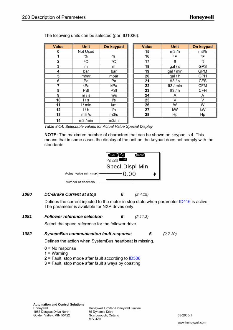
200 Description of Parameters Honeywell
Automation and Control Solutions Honeywell Honeywell Limited-Honeywell Limitée 1985 Douglas Drive North 35 Dynamic Drive Golden Valley, MIN 55422 Scarborough, Ontario 63-2600-1 MIV 4Z9 www.honeywell.com
The following units can be selected (par. ID1036):
Value Unit On keypad Value Unit On keypad
0 Not Used 15 m3 /h m3/h 1 % % 16 °F °F 2 °C °C 17 ft ft 3 m m 18 gal / s GPS 4 bar bar 19 gal / min GPM 5 mbar mbar 20 gal / h GPH 6 Pa Pa 21 ft3 / s CFS 7 kPa kPa 22 ft3 / min CFM 8 PSI PSI 23 ft3 / h CFH 9 m / s m/s 24 A A 10 l / s l/s 25 V V 11 l / min l/m 26 W W 12 l / h l/h 27 kW kW 13 m3 /s m3/s 28 Hp Hp
14 m3 /min m3/m
Table 8-14. Selectable values for Actual Value Special Display
NOTE: The maximum number of characters that can be shown on keypad is 4. This means that in some cases the display of the unit on the keypad does not comply with the standards.
1080 DC-Brake Current at stop 6 (2.4.15) Defines the current injected to the motor in stop state when parameter ID416 is active. The parameter is available for NXP drives only.
1081 Follower reference selection 6 (2.11.3) Select the speed reference for the follower drive.
1082 SystemBus communication fault response 6 (2.7.30) Defines the action when SystemBus heartbeat is missing.
0 = No response 1 = Warning 2 = Fault, stop mode after fault according to ID506 3 = Fault, stop mode after fault always by coasting
0.00
RUN READY
Local
Actual value min (max)
Number of decimals
Specl Displ Min
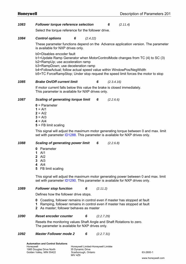
Honeywell Description of Parameters 201
Automation and Control Solutions Honeywell Honeywell Limited-Honeywell Limitée 1985 Douglas Drive North 35 Dynamic Drive Golden Valley, MIN 55422 Scarborough, Ontario 63-2600-1 MIV 4Z9 www.honeywell.com
1083 Follower torque reference selection 6 (2.11.4) Select the torque reference for the follower drive.
1084 Control options 6 (2.4.22) These parameter functions depend on the Advance application version. The parameter is available for NXP drives only.
b0=Disables encoder fault b1=Update Ramp Generator when MotorControlMode changes from TC (4) to SC (3) b2=RampUp; use acceleration ramp b3=RampDown; use deceleration ramp b4=FollowActual; follow actual speed value within WindowPos/NegWidth b5=TC ForceRampStop; Under stop request the speed limit forces the motor to stop
1085 Brake On/Off current limit 6 (2.3.4.16) If motor current falls below this value the brake is closed immediately. This parameter is available for NXP drives only.
1087 Scaling of generating torque limit 6 (2.2.6.6)
0 = Parameter 1 = AI1 2 = AI2 3 = AI3 4 = AI4 5 = FB limit scaling
This signal will adjust the maximum motor generating torque between 0 and max. limit set with parameter ID1288. This parameter is available for NXP drives only.
1088 Scaling of generating power limit 6 (2.2.6.8)
0 Parameter 1 AI1 2 AI2 3 AI3 4 AI4 5 FB limit scaling This signal will adjust the maximum motor generating power between 0 and max. limit set with parameter ID1290. This parameter is available for NXP drives only.
1089 Follower stop function 6 (2.11.2) Defines how the follower drive stops.
0 Coasting, follower remains in control even if master has stopped at fault 1 Ramping, follower remains in control even if master has stopped at fault 2 As master; follower behaves as master
1090 Reset encoder counter 6 (2.2.7.29) Resets the monitoring values Shaft Angle and Shaft Rotations to zero. The parameter is available for NXP drives only.
1092 Master Follower mode 2 6 (2.2.7.31)
202 Description of Parameters Honeywell
Automation and Control Solutions Honeywell Honeywell Limited-Honeywell Limitée 1985 Douglas Drive North 35 Dynamic Drive Golden Valley, MIN 55422 Scarborough, Ontario 63-2600-1 MIV 4Z9 www.honeywell.com
Select the digital input to activate the second Master Follower mode selected by parameter ID1093. The parameter is available for NXP drives only.
1093 Master Follower mode 2 selection 6 (2.11.7) Select Master Follower mode 2 that is used when the DI is activated. When Follower is selected the Run Request command is monitored from Master and all other references are selectable by parameters. 0 = Single Drive 1 = Master 2 = Follower 3 = Current master 4 = Current follower
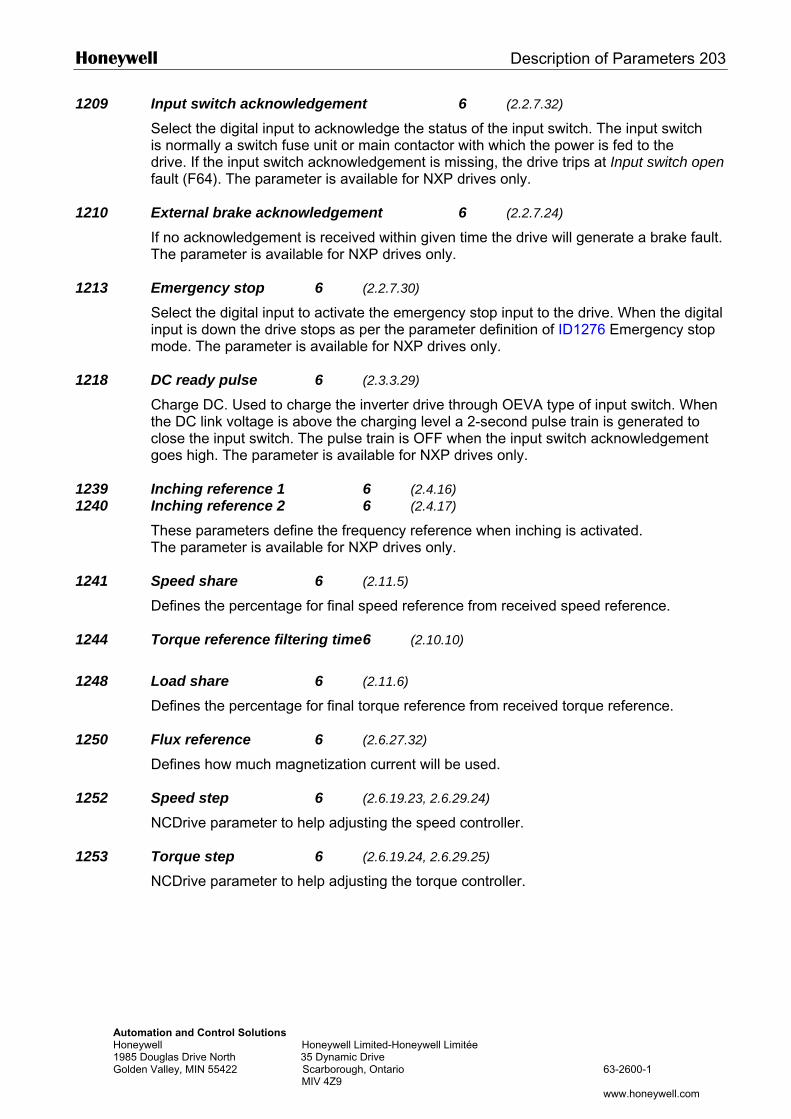
Honeywell Description of Parameters 203
Automation and Control Solutions Honeywell Honeywell Limited-Honeywell Limitée 1985 Douglas Drive North 35 Dynamic Drive Golden Valley, MIN 55422 Scarborough, Ontario 63-2600-1 MIV 4Z9 www.honeywell.com
1209 Input switch acknowledgement 6 (2.2.7.32) Select the digital input to acknowledge the status of the input switch. The input switch is normally a switch fuse unit or main contactor with which the power is fed to the drive. If the input switch acknowledgement is missing, the drive trips at Input switch open fault (F64). The parameter is available for NXP drives only.
1210 External brake acknowledgement 6 (2.2.7.24) If no acknowledgement is received within given time the drive will generate a brake fault. The parameter is available for NXP drives only.
1213 Emergency stop 6 (2.2.7.30) Select the digital input to activate the emergency stop input to the drive. When the digital input is down the drive stops as per the parameter definition of ID1276 Emergency stop mode. The parameter is available for NXP drives only.
1218 DC ready pulse 6 (2.3.3.29) Charge DC. Used to charge the inverter drive through OEVA type of input switch. When the DC link voltage is above the charging level a 2-second pulse train is generated to close the input switch. The pulse train is OFF when the input switch acknowledgement goes high. The parameter is available for NXP drives only.
1239 Inching reference 1 6 (2.4.16) 1240 Inching reference 2 6 (2.4.17)
These parameters define the frequency reference when inching is activated. The parameter is available for NXP drives only.
1241 Speed share 6 (2.11.5) Defines the percentage for final speed reference from received speed reference.
1244 Torque reference filtering time 6 (2.10.10)
1248 Load share 6 (2.11.6) Defines the percentage for final torque reference from received torque reference.
1250 Flux reference 6 (2.6.27.32) Defines how much magnetization current will be used.
1252 Speed step 6 (2.6.19.23, 2.6.29.24)
NCDrive parameter to help adjusting the speed controller.
1253 Torque step 6 (2.6.19.24, 2.6.29.25)
NCDrive parameter to help adjusting the torque controller.
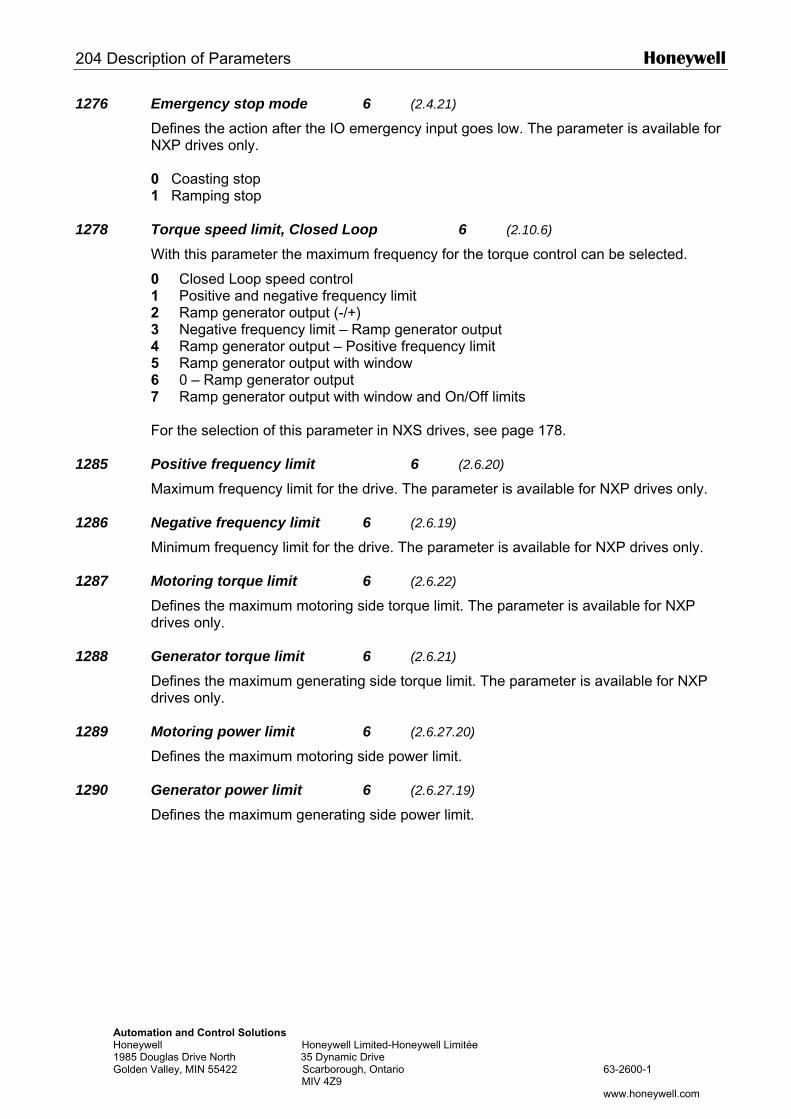
204 Description of Parameters Honeywell
Automation and Control Solutions Honeywell Honeywell Limited-Honeywell Limitée 1985 Douglas Drive North 35 Dynamic Drive Golden Valley, MIN 55422 Scarborough, Ontario 63-2600-1 MIV 4Z9 www.honeywell.com
1276 Emergency stop mode 6 (2.4.21)
Defines the action after the IO emergency input goes low. The parameter is available for NXP drives only. 0 Coasting stop 1 Ramping stop
1278 Torque speed limit, Closed Loop 6 (2.10.6)
With this parameter the maximum frequency for the torque control can be selected.
0 Closed Loop speed control 1 Positive and negative frequency limit 2 Ramp generator output (-/+) 3 Negative frequency limit – Ramp generator output 4 Ramp generator output – Positive frequency limit 5 Ramp generator output with window 6 0 – Ramp generator output 7 Ramp generator output with window and On/Off limits For the selection of this parameter in NXS drives, see page 178.
1285 Positive frequency limit 6 (2.6.20) Maximum frequency limit for the drive. The parameter is available for NXP drives only.
1286 Negative frequency limit 6 (2.6.19) Minimum frequency limit for the drive. The parameter is available for NXP drives only.
1287 Motoring torque limit 6 (2.6.22) Defines the maximum motoring side torque limit. The parameter is available for NXP drives only.
1288 Generator torque limit 6 (2.6.21) Defines the maximum generating side torque limit. The parameter is available for NXP drives only.
1289 Motoring power limit 6 (2.6.27.20) Defines the maximum motoring side power limit.
1290 Generator power limit 6 (2.6.27.19) Defines the maximum generating side power limit.
Honeywell Description of Parameters 205
Automation and Control Solutions Honeywell Honeywell Limited-Honeywell Limitée 1985 Douglas Drive North 35 Dynamic Drive Golden Valley, MIN 55422 Scarborough, Ontario 63-2600-1 MIV 4Z9 www.honeywell.com
1316 Brake fault response 6 (2.7.28) Defines the action when a brake fault is detected.
1317 Brake fault delays 6 (2.7.29)
The delay before the brake fault is activated. Used when there is mechanical delay in the brake.
1324 Master/Follower selection 6 (2.11.1) Select Master/Follower mode. When the value Follower is selected the Run Request command is monitored from Master. All other references are selectable by parameters. 0 = Single Drive 1 = Master 2 = Follower 3 = Current master 4 = Current follower
1352 SystemBus fault delay 6 (2.7.31) Defines the delays for the fault generation when heartbeat is missing.
1355 to 1369 Flux 10…150% 6 (2.6.29.1 – 2.6.29.15)
Motor voltage corresponding to 10%….150% of flux as a percentage of nominal flux voltage.
1382 Speed control output limit 6 (2.10.15) The maximum torque limit for the speed controller output as a percentage of the motor nominal torque.
206 Description of Parameters Honeywell
Automation and Control Solutions Honeywell Honeywell Limited-Honeywell Limitée 1985 Douglas Drive North 35 Dynamic Drive Golden Valley, MIN 55422 Scarborough, Ontario 63-2600-1 MIV 4Z9 www.honeywell.com
1401 Stop state flux 6 (2.6.27.24) The amount of flux as a percentage of the motor nominal flux maintained in the motor after the drive is stopped. The flux is maintained for the time set by parameter ID1402. This parameter can be used in closed loop motor control mode only.
1402 Flux off delay 6 (2.6.27.23) The flux defined by parameter ID1401 is maintained in the motor for the set time after the drive is stopped.
0 No flux after the motor is stopped. >0 The flux off delay in seconds. <0 The flux is maintained in the motor after stop until the next Run request is given to the drive.
1412 Torque stabilator gain 6 (2.6.28.6)
Additional gain for the torque stabilator at zero frequency.
1413 Torque stabilator damping 6 (2.6.28.7)
This parameter defines the time constant for the torque stabilator. The greater the parameter value, the shorter the time constant.
1414 Torque stabilator gain FWP 6 (2.6.28.8)
The general gain for the torque stabilatorx`.
1420 Prevention of startup 6 (2.2.7.25) This parameter is enabled when the “Prevention of start” circuit is used to inhibit the gate pulses. The parameter is available for NXP drives only.
1424 Restart delay 6 (2.6.17)
The delay time within which the drive can not be restarted after the coast stop. The time can be set up to 60.000 seconds. The parameter is available for NXP drives only.
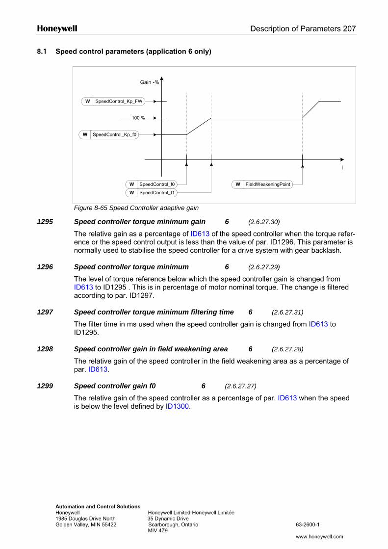
Honeywell Description of Parameters 207
Automation and Control Solutions Honeywell Honeywell Limited-Honeywell Limitée 1985 Douglas Drive North 35 Dynamic Drive Golden Valley, MIN 55422 Scarborough, Ontario 63-2600-1 MIV 4Z9 www.honeywell.com
8.1 Speed control parameters (application 6 only)
Figure 8-65 Speed Controller adaptive gain
1295 Speed controller torque minimum gain 6 (2.6.27.30) The relative gain as a percentage of ID613 of the speed controller when the torque refer-ence or the speed control output is less than the value of par. ID1296. This parameter is normally used to stabilise the speed controller for a drive system with gear backlash.
1296 Speed controller torque minimum 6 (2.6.27.29) The level of torque reference below which the speed controller gain is changed from ID613 to ID1295 . This is in percentage of motor nominal torque. The change is filtered according to par. ID1297.
1297 Speed controller torque minimum filtering time 6 (2.6.27.31) The filter time in ms used when the speed controller gain is changed from ID613 to ID1295.
1298 Speed controller gain in field weakening area 6 (2.6.27.28) The relative gain of the speed controller in the field weakening area as a percentage of par. ID613.
1299 Speed controller gain f0 6 (2.6.27.27)
The relative gain of the speed controller as a percentage of par. ID613 when the speed is below the level defined by ID1300.
W SpeedControl_f0
W SpeedControl_f1
W FieldWeakeningPoint
W SpeedControl_Kp_f0
W SpeedControl_Kp_FW
Gain -%
f
100 %
208 Description of Parameters Honeywell
Automation and Control Solutions Honeywell Honeywell Limited-Honeywell Limitée 1985 Douglas Drive North 35 Dynamic Drive Golden Valley, MIN 55422 Scarborough, Ontario 63-2600-1 MIV 4Z9 www.honeywell.com
1300 Speed controller f0 point 6 (2.6.27.26) The speed level in Hz below which the speed controller gain is equal to par. ID1299.
1301 Speed controller f1 point 6 (2.6.27.25) The speed level in Hz above which the speed controller gain is equal to par. ID613. From the speed defined by par. ID1300 to speed defined by par. ID1301, the speed controller gain changes linearly from par. ID1299 to ID613 and vice versa.
1304 Window positive 6 (2.10.12) Defines size of window to positive direction.
1305 Window negative 6 (2.10.11) Defines size of window to negative direction.
1306 Window positive Off limit 6 (2.10.14) Defines speed controller positive off limit when the speed controller brings speed back to window.
1307 Window negative Off limit 6 (2.10.13) Defines speed controller negative off limit when the speed controller brings speed back to window.
1311 Speed error filter PC 6 (2.6.27.33) Filter time constant for speed reference and actual speed error.
Honeywell Description of Parameters 209
Automation and Control Solutions Honeywell Honeywell Limited-Honeywell Limitée 1985 Douglas Drive North 35 Dynamic Drive Golden Valley, MIN 55422 Scarborough, Ontario 63-2600-1 MIV 4Z9 www.honeywell.com
8.2 Keypad control parameters
Unlike the parameters listed above, these parameters are located in the M3 menu of the control keypad. The reference parameters do not have an ID number.
114 Stop button activated (3.4, 3.6)
If you wish to make the Stop button a "hotspot" which always stops the drive regardless of the selected control place, give this parameter the value 1. See also parameter ID125.
125 Control Place (3.1)
The active control place can be changed with this parameter. For more information, see the product's user's manual. Pushing the Start button for 3 seconds selects the control keypad as the active control place and copies the Run status information (Run/Stop, direction and reference).
123 Keypad Direction (3.3)
0 Forward: The rotation of the motor is forward, when the keypad is the active control place.
1 Reverse: The rotation of the motor is reversed, when the keypad is the active control place.
For more information, see the product's user's manual.
R3.2 Keypad Reference (3.2)
The frequency reference can be adjusted from the keypad with this parameter. The output frequency can be copied as the keypad reference by pushing the Stop button for 3 seconds when you are on any of the pages of menu M3. For more information, see the product's user's manual.
R3.4 PID reference 1 57 (3.4)
The PID controller keypad reference can be set between 0% and 100%. This reference value is the active PID reference if parameter ID332 = 2.
R3.5 PID reference 2 57 (3.5)
The PID controller keypad reference 2 can be set between 0% and 100%. This reference is active if the DIN5 function=13 and the DIN5 contact is closed.
R3.5 Torque reference 6 (3.5)
Define here the torque reference within 0.0…100.0%.
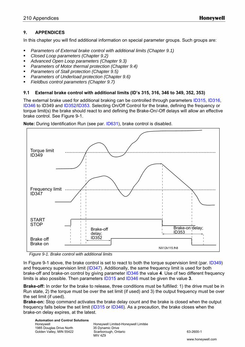
210 Appendices Honeywell
9. APPENDICES
In this chapter you will find additional information on special parameter groups. Such groups are: Parameters of External brake control with additional limits (Chapter 9.1) Closed Loop parameters (Chapter 9.2) Advanced Open Loop parameters (Chapter 9.3) Parameters of Motor thermal protection (Chapter 9.4) Parameters of Stall protection (Chapter 9.5) Parameters of Underload protection (Chapter 9.6) Fieldbus control parameters (Chapter 9.7)
9.1 External brake control with additional limits (ID’s 315, 316, 346 to 349, 352, 353)
The external brake used for additional braking can be controlled through parameters ID315, ID316, ID346 to ID349 and ID352/ID353. Selecting On/Off Control for the brake, defining the frequency or torque limit(s) the brake should react to and defining the Brake-On/-Off delays will allow an effective brake control. See Figure 9-1.
Note: During Identification Run (see par. ID631), brake control is disabled.
In anbrlim
BrRutheBrfrebr
Automation and Control Solutions Honeywell Honeywell Limited-Honeywell Limitée 1985 Douglas Drive North 35 Dynamic Drive Golden Valley, MIN 55422 Scarborough, Ontario 63-2600-1 MIV 4Z9 www.honeywell.com
Figure 9-1. Brake control with additional limits
Figure 9-1 above, the brake control is set to react to both the torque supervision limit (par. ID349) d frequency supervision limit (ID347). Additionally, the same frequency limit is used for both ake-off and brake-on control by giving parameter ID346 the value 4. Use of two different frequency its is also possible. Then parameters ID315 and ID346 must be given the value 3.
ake-off: In order for the brake to release, three conditions must be fulfilled: 1) the drive must be in n state, 2) the torque must be over the set limit (if used) and 3) the output frequency must be over set limit (if used).
ake-on: Stop command activates the brake delay count and the brake is closed when the output quency falls below the set limit (ID315 or ID346). As a precaution, the brake closes when the
ake-on delay expires, at the latest.
NX12k115.fh8
Torque limitID349
Frequency limitID347
STARTSTOP
Brake offBrake on
Brake-offdelay;ID352
Brake-on delay;ID353
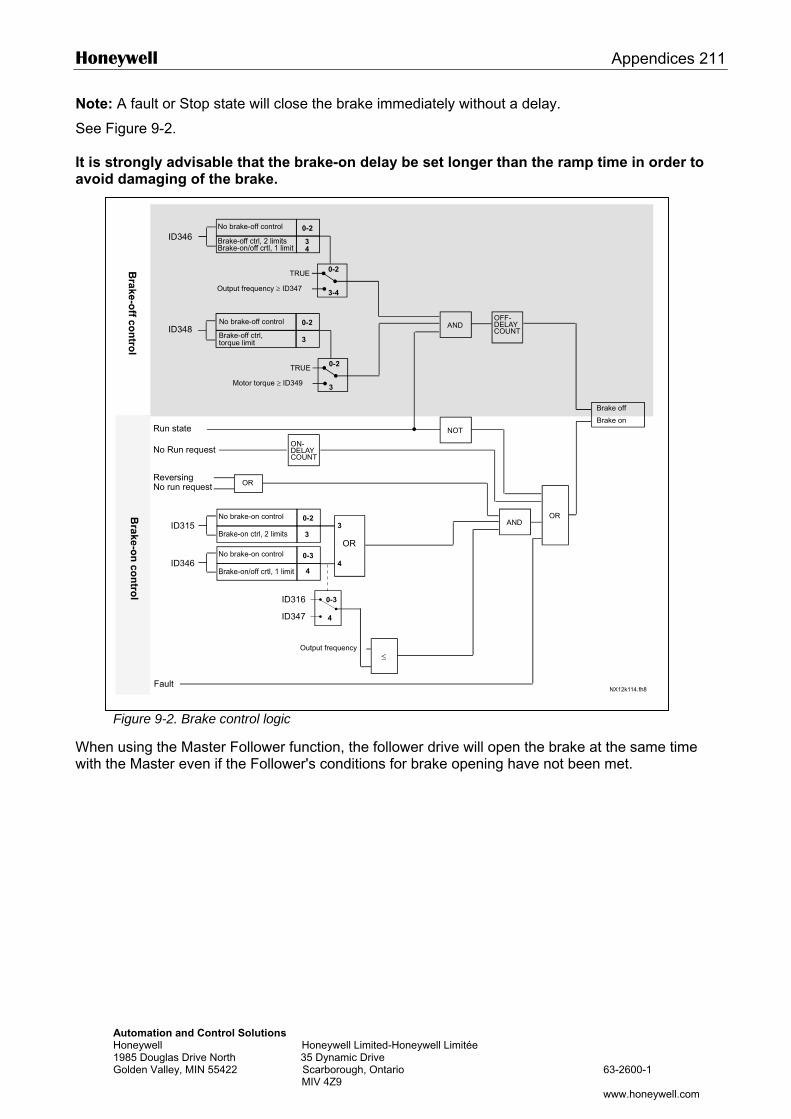
Honeywell Appendices 211
Note: A fault or Stop state will close the brake immediately without a delay.
See Figure 9-2. It is strongly advisable that the brake-on delay be set longer than the ramp time in order to avoid damaging of the brake.
Whenwith t
0-2No brake-off control
Automation and Control Solutions Honeywell Honeywell Limited-Honeywell Limitée 1985 Douglas Drive North 35 Dynamic Drive Golden Valley, MIN 55422 Scarborough, Ontario 63-2600-1 MIV 4Z9 www.honeywell.com
Figure 9-2. Brake control logic
using the Master Follower function, the follower drive will open the brake at the same time he Master even if the Follower's conditions for brake opening have not been met.
ID346
ID348
ID315
ID346
34
0-2
3-4
0-2
3
0-2
3
0-2
3
0-3
4
ID316
ID347
0-3
4
≤
NX12k114.fh8
3
4
Brake-off ctrl, 2 limitsBrake-on/off crtl, 1 limit
AND
Run state
No Run request
OFF-DELAYCOUNT
ON-DELAYCOUNT
ANDOR
Brake off
Brake on
TRUE
Output frequency ≥ ID347
No brake-off control
Brake-off ctrl,torque limit
TRUE
Motor torque ≥ ID349
Brake-on ctrl, 2 limits
No brake-on control
Brake-on/off crtl, 1 limit
No brake-on controlOR
Output frequency
Fault
NOT
ReversingNo run request OR
212 Appendices Honeywell
Automation and Control Solutions Honeywell Honeywell Limited-Honeywell Limitée 1985 Douglas Drive North 35 Dynamic Drive Golden Valley, MIN 55422 Scarborough, Ontario 63-2600-1 MIV 4Z9 www.honeywell.com
9.2 Closed loop parameters (ID’s 612 to 621)
Select the Closed loop control mode by setting value 3 or 4 for parameter ID600. Closed loop control mode (see page 173) is used when enhanced performance near zero speed and better static speed accuracy with higher speeds are needed. Closed loop control mode is based on "rotor flux oriented current vector control". With this controlling principle, the phase currents are divided into a torque producing current portion and a magnetizing current portion. Thus, the squirrel cage induction machine can be controlled in a fashion of a separately excited DC motor. Note: These parameters can be used with NXP drive only.
EXAMPLE:
Motor Control Mode = 3 (Closed loop speed control) This is the usual operation mode when fast response times, high accuracy or controlled run at zero frequencies are needed. Encoder board should be connected to slot C of the control unit. Set the encoder P/R-parameter (P7.3.1.1). Run in open loop and check the encoder speed and direction (V7.3.2.2). Change the direction parameter (P7.3.1.2) or switch the phases of motor cables if necessary. Do not run if encoder speed is wrong. Program the no-load current to parameter ID612 and set parameter ID619 (Slip Adjust) to get the voltage slightly above the linear U/f-curve with the motor frequency at about 66% of the nominal motor frequency. The Motor Nominal Speed parameter (ID112) is critical. The Current Limit parameter (ID107) controls the available torque linearly in relative to motor nominal current.
9.3 Advanced Open Loop parameters (ID's 622 to 625, 632, 635)
Select the Advanced Open Loop control mode by setting value 5 or 6 for parameter ID600 (not available in applications 1 and 6). The Advanced Open Loop control mode finds similar implementations as the Closed Loop control mode above. However, the control accuracy of the Closed Loop control mode is higher than that of the Advanced Open Loop control mode.
EXAMPLE:
Motor Control Mode = 5 Frequency control (Advanced open loop) and 6 Speed control (Advanced open loop)
The motor is running at current vector control at low frequencies. At frequencies above the frequency limit, the motor is in frequency control. The default current value is 120% at zero frequency. Use linear U/f-curve (ID108). 120% starting torque should now be possible. Sometimes increasing the frequency limit (ID635) will improve the run. The Frequency limit is the critical point. Increase the zero frequency point to get enough current at frequency limit.
Honeywell Appendices 213
Automation and Control Solutions Honeywell Honeywell Limited-Honeywell Limitée 1985 Douglas Drive North 35 Dynamic Drive Golden Valley, MIN 55422 Scarborough, Ontario 63-2600-1 MIV 4Z9 www.honeywell.com
9.4 Parameters of motor thermal protection (ID’s 704 to 708):
General The motor thermal protection is to protect the motor from overheating. The NX drive is capable of supplying higher than nominal current to the motor. If the load requires this high current there is a risk that the motor will be thermally overloaded. This is the case especially at low frequencies. At low frequencies the cooling effect of the motor is reduced as well as its capacity. If the motor is equipped with an external fan the load reduction at low speeds is small. The motor thermal protection is based on a calculated model and it uses the output current of the drive to determine the load on the motor. The motor thermal protection can be adjusted with parameters. The thermal current IT specifies the load current above which the motor is overloaded. This current limit is a function of the output frequency. The thermal stage of the motor can be monitored on the control keypad display. See the product's user's manual.
CAUTION! The calculated model does not protect the motor if the airflow to the motor is reduced by blocked air intake grill.
9.5 Parameters of Stall protection (ID’s 709 to 712):
General The motor stall protection protects the motor from short time overload situations such as one caused by a stalled shaft. The reaction time of the stall protection can be set shorter than that of motor thermal protection. The stall state is defined with two parameters, ID710 (Stall current) and ID712 (Stall frequency limit). If the current is higher than the set limit and output frequency is lower than the set limit, the stall state is true. There is actually no real indication of the shaft rotation. Stall protection is a type of overcurrent protection. 9.6 Parameters of Underload protection (ID’s 713 to 716):
General The purpose of the motor underload protection is to ensure that there is load on the motor when the drive is running. If the motor loses its load there might be a problem in the process, e.g. a broken belt or a dry pump. Motor underload protection can be adjusted by setting the underload curve with parameters ID714 (Field weakening area load) and ID715 (Zero frequency load), see below. The underload curve is a squared curve set between the zero frequency and the field weakening point. The protection is not active below 5Hz (the underload time counter is stopped). The torque values for setting the underload curve are set in percentage which refers to the nominal torque of the motor. The motor's name plate data, parameter motor nominal current and the drive's nominal current IH are used to find the scaling ratio for the internal torque value. If other than nominal motor is used with the drive, the accuracy of the torque calculation decreases. 9.7 Fieldbus control parameters (ID’s 850 to 859)
The Fieldbus control parameters are used when the frequency or the speed reference comes from the fieldbus (Modbus, Profibus, DeviceNet etc.). With the Fieldbus Data Out Selection 1…8 you can monitor values from the fieldbus.
!

Automation and Control SolutionsHoneywell International Inc. Honeywell Limited-Honeywell Limitée1985 Douglas Drive North 35 Dynamic DriveGolden Valley, MN 55422 Scarborough, Ontario M1V 4Z9customer.honeywell.com
® U.S. Registered Trademark© 2006 Honeywell International Inc.63-26001 Rev. 05-06