constant engagement tool path generation to enhance
TRANSCRIPT
43
Constant Engagement Tool Path Generation to Enhance
Machining Accuracy in End Milling∗
Mohammad Sharif UDDIN∗∗, Soichi IBARAKI∗∗, Atsushi MATSUBARA∗∗, Susumu NISHIDA∗∗∗
and Yoshiaki KAKINO∗∗∗∗
In pocketing with contour parallel (CP) paths, the cutter encounters a varying engage-ment with the workpiece, which causes variation in chip load and cutting forces. This varyingcutting force naturally leads to the variation of tool deflection, hence impairing machined sur-face accuracy. This paper presents a new tool path modification scheme, which regulates aconstant cutting engagement with workpiece in 2.5D end milling. The semi-finishing path,the path prior to the finishing path, is modified by the proposed scheme such that the engage-ment angle along the finishing path is regulated at a desired level. By maintaining cuttingengagement constant, the cutting force can be regulated approximately constant, thus mini-mizing the variation of tool deflection, and improving machining accuracy. The improvementof machining accuracy by applying the new tool path modification scheme is experimentallyvalidated for the case where the proposed scheme is applied to pocketing. The machiningresults are analyzed and compared with the cases with conventional contour parallel path andthe feed rate control scheme applied in pocketing.
Key Words: Contour-Parallel Tool Path, Offset, Constant Engagement, Cutting Force, Ma-chining Accuracy, End Milling
1. Introduction
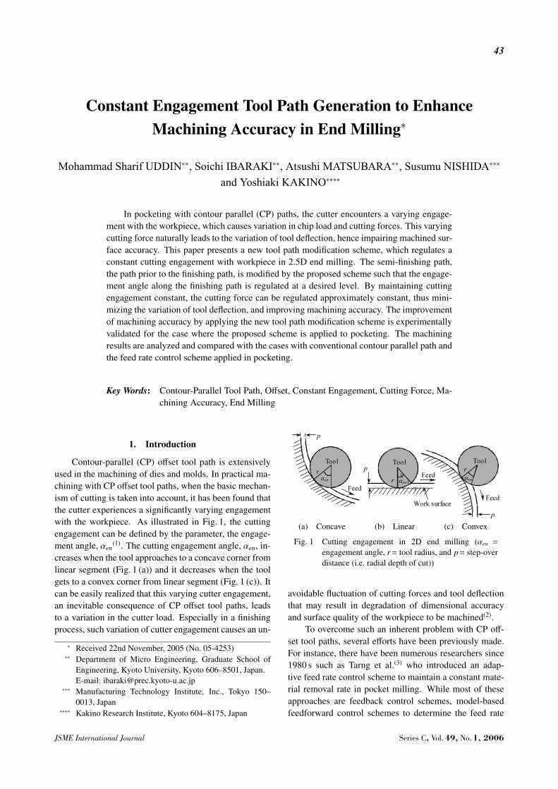
Contour-parallel (CP) offset tool path is extensivelyused in the machining of dies and molds. In practical ma-chining with CP offset tool paths, when the basic mechan-ism of cutting is taken into account, it has been found thatthe cutter experiences a significantly varying engagementwith the workpiece. As illustrated in Fig. 1, the cuttingengagement can be defined by the parameter, the engage-ment angle, αen
(1). The cutting engagement angle, αen, in-creases when the tool approaches to a concave corner fromlinear segment (Fig. 1 (a)) and it decreases when the toolgets to a convex corner from linear segment (Fig. 1 (c)). Itcan be easily realized that this varying cutter engagement,an inevitable consequence of CP offset tool paths, leadsto a variation in the cutter load. Especially in a finishingprocess, such variation of cutter engagement causes an un-
∗ Received 22nd November, 2005 (No. 05-4253)∗∗ Department of Micro Engineering, Graduate School of
Engineering, Kyoto University, Kyoto 606–8501, Japan.E-mail: [email protected]
∗∗∗ Manufacturing Technology Institute, Inc., Tokyo 150–0013, Japan
∗∗∗∗ Kakino Research Institute, Kyoto 604–8175, Japan
(a) Concave (b) Linear (c) Convex
Fig. 1 Cutting engagement in 2D end milling (αen =
engagement angle, r= tool radius, and p= step-overdistance (i.e. radial depth of cut))
avoidable fluctuation of cutting forces and tool deflectionthat may result in degradation of dimensional accuracyand surface quality of the workpiece to be machined(2).
To overcome such an inherent problem with CP off-set tool paths, several efforts have been previously made.For instance, there have been numerous researchers since1980 s such as Tarng et al.(3) who introduced an adap-tive feed rate control scheme to maintain a constant mate-rial removal rate in pocket milling. While most of theseapproaches are feedback control schemes, model-basedfeedforward control schemes to determine the feed rate
JSME International Journal Series C, Vol. 49, No. 1, 2006
44
profile in advance have been also studied by many re-searchers(4). Most recently, some commercially availableCAM software also adopt a simple model-based feed rateoptimization scheme so as to regulate the material removalrate at a constant level. In practice, however, the fruit-fulness of these approaches relies solely upon the perfor-mance of a CNC machine that must ensure a high feed ratecontrol performance in response to a frequent and quickchange of feed rate. Even with the latest CNC machines,it is often the case that a desired control performance ofcutting forces under an adaptive feed rate control schemecannot be obtained due to the limitation of servo controlperformance in feed rate. On the other hand, there hasbeen relatively little initiative offered to explicitly modifythe tool path itself to avoid the extreme variation of cuttingforces in pocketing.
Iwabe et al.(5) proposed an idea that the insertion ofan additional circular arc at a convex corner can help keepcutter engagement below the prescribed limit. The inser-tion of an additional circular arc to avoid an excessive toolengagement is now adopted in some of latest commercialCAM software. Yamaji et al.(6) introduced a tool pathplanning scheme to remove critical cutting regions by tro-choidal grooving. These approaches are, however, moreeffective to avoid an excessive tool load mainly in roughcutting. Recently, Stori and Wright(7) proposed a uniqueapproach, where an offset tool path is modified such thatthe engagement is always kept constant. However, theirmethod can be applied only to convex contours. Further-more, more importantly, since the algorithm modifies thefinishing path itself, when it is applied to a spiral-out toolpath, the proposed algorithm leaves leftover material, re-sulting in a further need of additional machining to removeexcess corner material. Therefore, this approach may bejustified in the application of rough cutting where efficientmaterial removal is of the primary interest; it is, however,practically impossible to apply this scheme to a finishingprocess.
Keeping the possible drawbacks of the above ap-proaches in mind, this research work introduces a new toolpath modification scheme, which regulates a constant cut-ting engagement such that the final workpiece geometryto be machined can be preserved. Unlike the algorithmproposed by Stori and Wright(7), we propose to modifya semi-finishing path prior to a finishing path such thata constant engagement (CE) is maintained in the finish-ing path, while the geometry of the finishing path itselfis preserved. Another attractive feature of the proposedalgorithm is that it can be applied to any kind of two-dimensional contours comprising of convex and concavecorners, whenever there exists a solution that geometri-cally meets the constant engagement requirement. The ef-fectiveness of the proposed tool path modification schemeis experimentally realized when it is applied to the pocket
milling with a radius end mill.The remainder of this paper is organized as follows.
The following section gives an illustration of the proposedalgorithm based on which a modified constant engagement(CE) tool path generation scheme is developed. Section3 presents an experimental verification of the proposedscheme. The first part of section 3 describes a detail ofexperimental conditions while the later presents the ma-chining results and discussion, justifying the effectivenessof the proposed scheme. Finally, section 4 gives a briefsummary of this paper.
2. Algorithm for Modified Constant Engagement(CE) Tool Path Generation Scheme
Given an initial planar curve representing the desiredfinal contour geometry of the pocket to be machined, andan original contour-parallel (CP) tool path to achieve thedesired contour (referred to as the finishing path here-after), the main aim of the algorithm is to compute theadjacent inner tool path (the path machined prior to thefinishing path) such that the engagement angle can be reg-ulated at a desired level (i.e. constant level) on the machin-ing along the final contour-parallel finishing path. Figure 2depicts the basic working principle of the proposed algo-rithm.
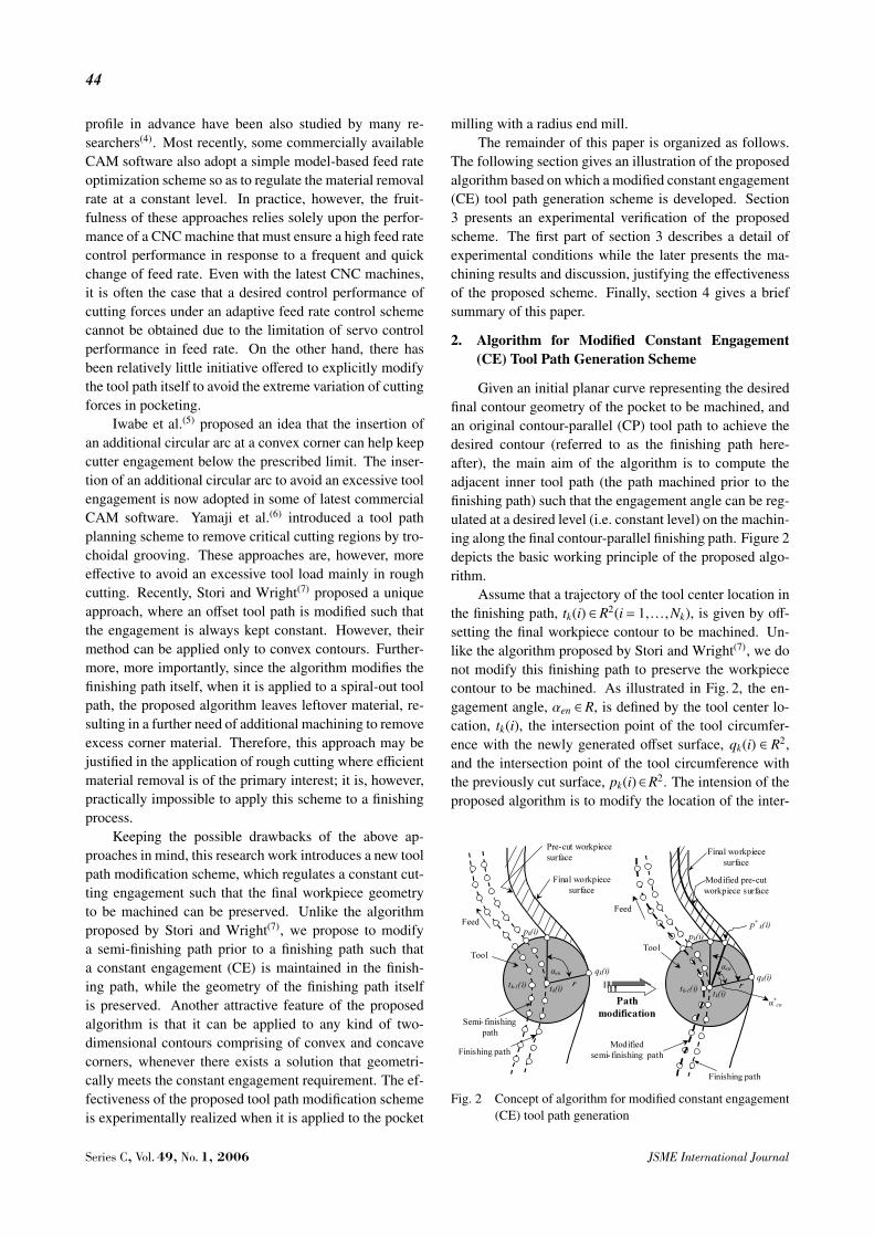
Assume that a trajectory of the tool center location inthe finishing path, tk(i) ∈ R2(i = 1, . . . ,Nk), is given by off-setting the final workpiece contour to be machined. Un-like the algorithm proposed by Stori and Wright(7), we donot modify this finishing path to preserve the workpiececontour to be machined. As illustrated in Fig. 2, the en-gagement angle, αen ∈ R, is defined by the tool center lo-cation, tk(i), the intersection point of the tool circumfer-ence with the newly generated offset surface, qk(i) ∈ R2,and the intersection point of the tool circumference withthe previously cut surface, pk(i)∈R2. The intension of theproposed algorithm is to modify the location of the inter-
Fig. 2 Concept of algorithm for modified constant engagement(CE) tool path generation
Series C, Vol. 49, No. 1, 2006 JSME International Journal
45
section between tool circumference and the previously cutsurface, pk(i), to regulate the cutting engagement angle.Since this “precut surface” is generated by the previous in-ner path (referred to as the semi-finishing path hereafter),the modification of pre-cut surface, pk(i) can be done bythe modification of the trajectory of the tool center loca-tion in the semi-finishing path, tk−1(i) ∈R2(i= 1, . . . ,Nk−1).The detailed algorithm of the computation of new modi-fied offset tool path trajectory, tk−1(i) ∈ R2(i = 1, . . . ,Nk−1)can be summarized into the following steps.Step 1: For the given tool center location, tk(i)(i =1, . . . ,Nk), of the finishing path, compute the intersectionpoint of the tool circumference with the newly generatedoffset surface, qk(i)∈R2(i= 1, . . . ,Nk), by offsetting tk(i) tothe workpiece’s side by the tool radius, r. This operationcan written by:
qk(i)=offset (tk(i),+r)(i=1, . . . ,Nk) (1)
where the function “offset(o(i), x)” represents the compu-tation of the trajectory that is generated by parallel offset-ting the trajectory o(i) by the distance x.Step 2: Compute the intersection point of the tool cir-cumference with the previously cut surface, p∗k(i) ∈R2(i=1, . . . ,Nk) such that the engagement angle, αen, can bemaintained at the given desired value, α∗en. In other words,find p∗k(i) such that:∠p∗k(i) · tk(i) · qk(i) = α∗en, and ||p∗k(i) − tk(i)|| = r,(i =
1, . . . ,Nk)Notice that p∗k(i)∈R2(i=1, . . . ,Nk) defines the trajectory ofmodified pre-cut surface (see Fig. 2).Step 3: Set i = i+ 1 and repeat the steps (1) and (2) tilli=Nk.Step 4: By offsetting modified pre-cut surface trajectory,p∗k(i)∈R2(i=1, . . . ,Nk) toward the inside by the tool radiusr, compute the tool center trajectory of the semi-finishingpath, tk−1(i)∈R2(i=1 . . .Nk−1).
tk−1(i)=offset (p∗k(i),−r)(i=1, . . . ,Nk) (2)
For the computation of parallel offsets, denoted byoffset (o(i), x), there have been numerous research effortsto build algorithms with higher robustness and smallercomputational complexity(8). In this paper, we adopt thealgorithm developed by Held(9) to compute parallel offsetsbased on the Voronoi diagram.
The desired engagement angle, α∗en, must be givenby considering proper machining conditions for the giventool and the workpiece. In this paper, the desired engage-ment angle, α∗en, is determined as follows: assuming themachining along a straight path with the given tool radius,r, and the radial depth of cut (step-over distance) of origi-nal contour parallel tool paths, the engagement angle, αen,is computed. This value is used as the desired engagementangle, α∗en, for the tool path modification. For example, ona concave corner as shown in Fig. 1 (a), the engagement
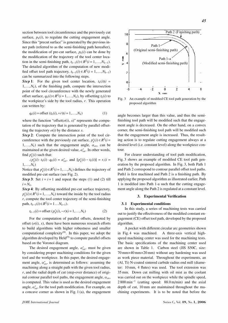
Fig. 3 An example of modified CE tool path generation by theproposed algorithm
angle becomes larger than this value, and thus the semi-finishing tool path will be modified such that the engage-ment angle is decreased. On the other hand, on a convexcorner, the semi-finishing tool path will be modified suchthat the engagement angle is increased. Thus, the result-ing action is to regulate cutting engagement always at adesired level (i.e. constant level) along the workpiece con-tour.
For clearer understanding of tool path modification,Fig. 3 shows an example of modified CE tool path gen-eration by the proposed algorithm. In Fig. 3, both Path 1and Path 2 correspond to contour parallel offset tool paths.Path1 is first machined and Path 2 is a finishing path. Byapplying the proposed algorithm as illustrated earlier, Path1 is modified into Path 1-a such that the cutting engage-ment angle along the Path 2 is regulated at a constant level.
3. Experimental Verification
3. 1 Experimental conditionsIn this study, a series of machining tests was carried
out to justify the effectiveness of the modified constant en-gagement (CE) offset tool path, developed by the proposedalgorithm.
A pocket with different circular arc geometries shownin Fig. 4 was machined. A three-axis vertical high-speed machining center was used for the machining tests.The basic specifications of the machining center usedare shown in Table 1. Carbon steel (JIS S50C, size:70 mm×40 mm×20 mm) without any hardening was usedas work piece material. Throughout the experiments, an(Al, Ti) N-coated sintered carbide radius end mill (diame-ter: 10 mm, 4 flutes) was used. The tool extension was35 mm. Down cut milling with oil mist as the coolantwas carried out on the workpiece while the spindle speed,2 800 min−1 (cutting speed: 88.0 m/min) and the axialdepth of cut, 10 mm are maintained throughout the ma-chining experiments. It is to be noted that before the
JSME International Journal Series C, Vol. 49, No. 1, 2006
46
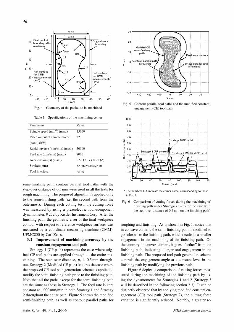
Fig. 4 Geometry of the pocket to be machined
Table 1 Specifications of the machining center
semi-finishing path, contour parallel tool paths with thestep-over distance of 0.5 mm were used in all the tests forrough machining. The proposed algorithm is applied onlyto the semi-finishing path (i.e. the second path from theoutermost). During each cutting test, the cutting forcewas measured by using a piezoelectric four-componentdynamometer, 9 272 by Kistler Instrument Corp. After thefinishing path, the geometric error of the final workpiececontour with respect to reference workpiece surfaces wasmeasured by a coordinate measuring machine (CMM),UPMC850 by Carl Zeiss.
3. 2 Improvement of machining accuracy by theconstant engagement tool path
Strategy 1 (CP path) represents the case where orig-inal CP tool paths are applied throughout the entire ma-chining. The step-over distance, p, is 0.5 mm through-out. Strategy 2 (Modified CE path) features the case wherethe proposed CE tool path generation scheme is applied tomodify the semi-finishing path prior to the finishing path.Note that all the paths except for the semi-finishing pathare the same as those in Strategy 1. The feed rate is keptconstant at 1 000 mm/min in both Strategy 1 and Strategy2 throughout the entire path. Figure 5 shows the modifiedsemi-finishing path, as well as contour parallel paths for
Fig. 5 Contour parallel tool paths and the modified constantengagement (CE) tool path
Fig. 6 Comparison of cutting forces during the machining offinishing path under Strategies 1 – 3 (for the case withthe step-over distance of 0.5 mm on the finishing path)
roughing and finishing. As is shown in Fig. 5, notice thatin concave corners, the semi-finishing path is modified togo “closer” to the finishing path, which results in a smallerengagement in the machining of the finishing path. Onthe contrary, in convex corners, it goes “further” from thefinishing path, indicating a larger tool engagement in thefinishing path. The proposed tool path generation schemecontrols the engagement angle at a constant level in thefinishing path by modifying the previous path.
Figure 6 depicts a comparison of cutting forces mea-sured during the machining of the finishing path by us-ing the dynamometer for Strategies 1 and 2 (Strategy 3will be described in the following section 3.3). It can bedistinctly observed that by applying modified constant en-gagement (CE) tool path (Strategy 2), the cutting forcevariation is significantly reduced. Notably, a greater re-
Series C, Vol. 49, No. 1, 2006 JSME International Journal
47
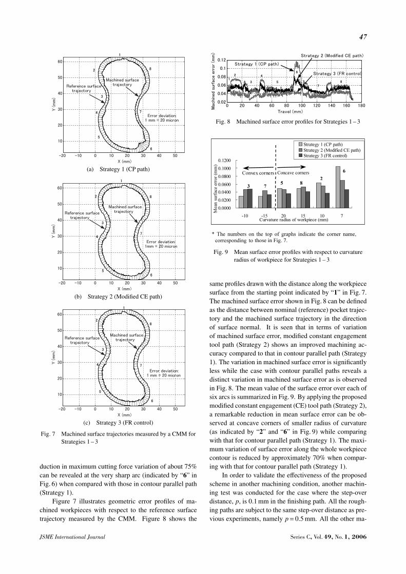
(a) Strategy 1 (CP path)
(b) Strategy 2 (Modified CE path)
(c) Strategy 3 (FR control)
Fig. 7 Machined surface trajectories measured by a CMM forStrategies 1 – 3
duction in maximum cutting force variation of about 75%can be revealed at the very sharp arc (indicated by “6” inFig. 6) when compared with those in contour parallel path(Strategy 1).
Figure 7 illustrates geometric error profiles of ma-chined workpieces with respect to the reference surfacetrajectory measured by the CMM. Figure 8 shows the
Fig. 8 Machined surface error profiles for Strategies 1 – 3
Fig. 9 Mean surface error profiles with respect to curvatureradius of workpiece for Strategies 1 – 3
same profiles drawn with the distance along the workpiecesurface from the starting point indicated by “1” in Fig. 7.The machined surface error shown in Fig. 8 can be definedas the distance between nominal (reference) pocket trajec-tory and the machined surface trajectory in the directionof surface normal. It is seen that in terms of variationof machined surface error, modified constant engagementtool path (Strategy 2) shows an improved machining ac-curacy compared to that in contour parallel path (Strategy1). The variation in machined surface error is significantlyless while the case with contour parallel paths reveals adistinct variation in machined surface error as is observedin Fig. 8. The mean value of the surface error over each ofsix arcs is summarized in Fig. 9. By applying the proposedmodified constant engagement (CE) tool path (Strategy 2),a remarkable reduction in mean surface error can be ob-served at concave corners of smaller radius of curvature(as indicated by “2” and “6” in Fig. 9) while comparingwith that for contour parallel path (Strategy 1). The maxi-mum variation of surface error along the whole workpiececontour is reduced by approximately 70% when compar-ing with that for contour parallel path (Strategy 1).
In order to validate the effectiveness of the proposedscheme in another machining condition, another machin-ing test was conducted for the case where the step-overdistance, p, is 0.1 mm in the finishing path. All the rough-ing paths are subject to the same step-over distance as pre-vious experiments, namely p= 0.5 mm. All the other ma-
JSME International Journal Series C, Vol. 49, No. 1, 2006
48
Fig. 10 Machined surface error profiles for Strategies 1 – 3 (forthe case with the step-over distance of 0.1 mm on thefinishing path)
chining conditions are the same as previous experiments.Figure 10 compares geometric error profiles of machinedworkpieces measured by the CMM. As can be easilypredicted, in all cases, the geometric error is averagelysmaller throughout the entire path compared to that for theprevious case with p= 0.5 mm, since the tool is subject tosmaller cutting force and thus smaller deflection. Evenin such a case, it is evident that the proposed modifiedconstant engagement tool path (Strategy 2) significantlyreduces the variation of the geometric error than the con-tour parallel path case (Strategy 1), particularly in sharpcorners such as “2” and “6.”
3. 3 Comparison with feed rate control schemesIn order to regulate the cutting force at a desired level
to avoid the variation in the tool deflection and thus toimprove the geometric accuracy of the machined surface,feed rate control schemes have been long studied by manyresearchers. In particular, model-based feedforward con-trol schemes to determine the feed rate profile in advancehave been accepted as a simpler, but more feasible way forpractical implementation. This paper proposes a schemeto regulate the material removal rate through the modifica-tion of tool path. In this subsection, we discuss advantagesof the proposed scheme over feed rate control schemes inthe practical implementation.
In Strategy 3 (FR control), the original contour par-allel path with variable feed rate is applied to the finish-ing path, while the feed rate is varied such that the cut-ting force is maintained constant throughout the finishingpath. In this paper, the feed rate profile is determined off-line based on the cutting force prediction model proposedby Otsuka et al.(10), such that the cutting force in the XYplane is regulated at the desired constant level, which isgiven as the cutting force under which the machining of astraight path with the radial depth of cut of 0.5 mm and thefeed rate of 1 000 mm/min is conducted.
In Fig. 6, the cutting force measured during the ma-chining of the finishing path under Strategy 3 is alsoshown. The geometric error profiles of machined work-piece under Strategy 3 are also shown in Figs. 7 (c), 8, 9,and 10.
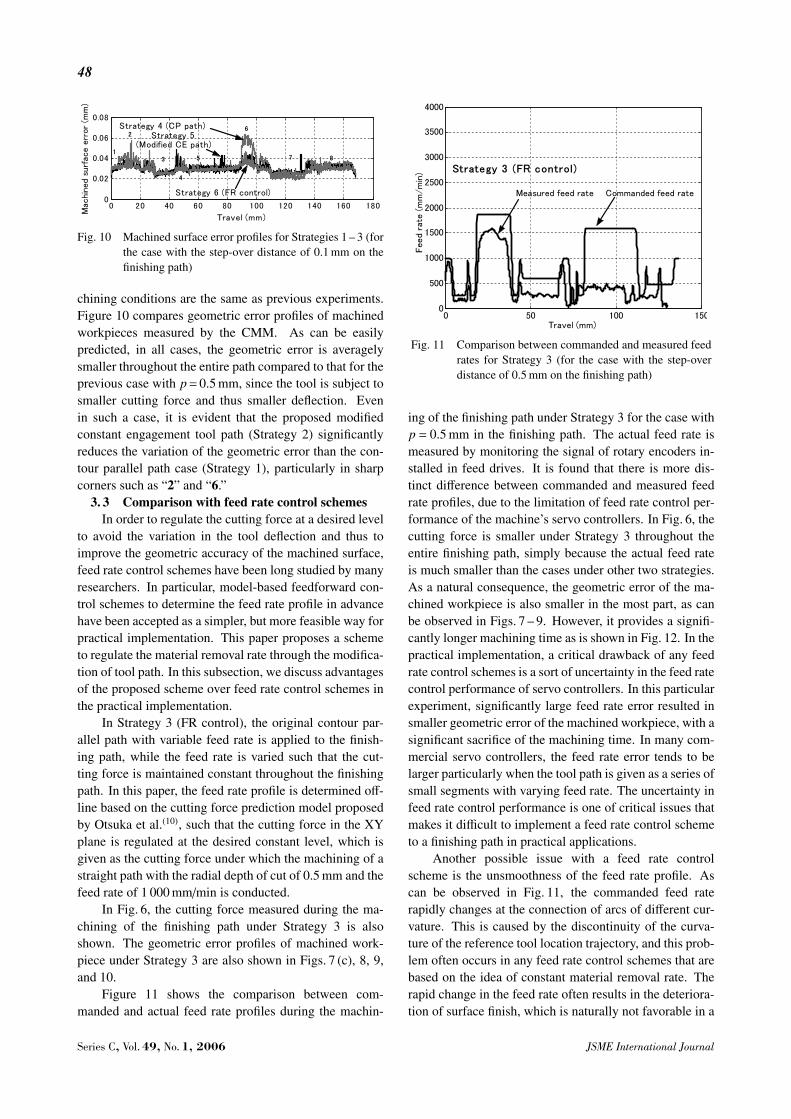
Figure 11 shows the comparison between com-manded and actual feed rate profiles during the machin-
Fig. 11 Comparison between commanded and measured feedrates for Strategy 3 (for the case with the step-overdistance of 0.5 mm on the finishing path)
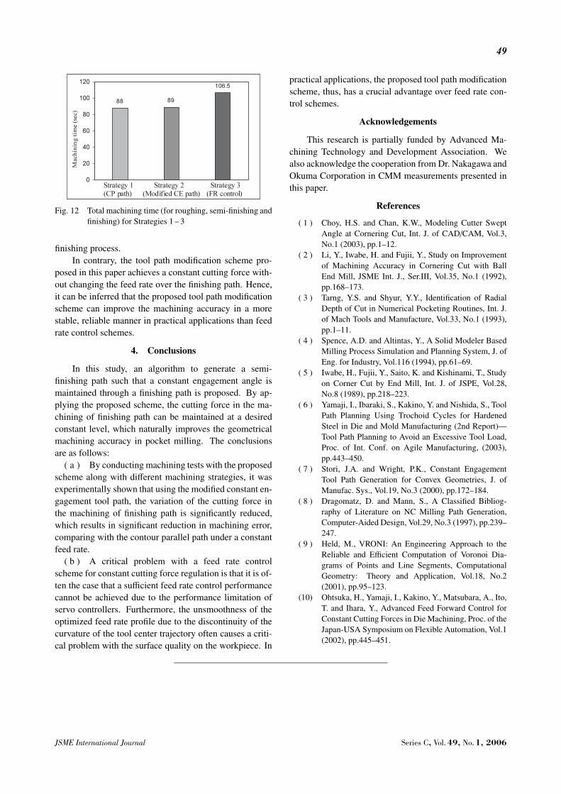
ing of the finishing path under Strategy 3 for the case withp = 0.5 mm in the finishing path. The actual feed rate ismeasured by monitoring the signal of rotary encoders in-stalled in feed drives. It is found that there is more dis-tinct difference between commanded and measured feedrate profiles, due to the limitation of feed rate control per-formance of the machine’s servo controllers. In Fig. 6, thecutting force is smaller under Strategy 3 throughout theentire finishing path, simply because the actual feed rateis much smaller than the cases under other two strategies.As a natural consequence, the geometric error of the ma-chined workpiece is also smaller in the most part, as canbe observed in Figs. 7 – 9. However, it provides a signifi-cantly longer machining time as is shown in Fig. 12. In thepractical implementation, a critical drawback of any feedrate control schemes is a sort of uncertainty in the feed ratecontrol performance of servo controllers. In this particularexperiment, significantly large feed rate error resulted insmaller geometric error of the machined workpiece, with asignificant sacrifice of the machining time. In many com-mercial servo controllers, the feed rate error tends to belarger particularly when the tool path is given as a series ofsmall segments with varying feed rate. The uncertainty infeed rate control performance is one of critical issues thatmakes it difficult to implement a feed rate control schemeto a finishing path in practical applications.
Another possible issue with a feed rate controlscheme is the unsmoothness of the feed rate profile. Ascan be observed in Fig. 11, the commanded feed raterapidly changes at the connection of arcs of different cur-vature. This is caused by the discontinuity of the curva-ture of the reference tool location trajectory, and this prob-lem often occurs in any feed rate control schemes that arebased on the idea of constant material removal rate. Therapid change in the feed rate often results in the deteriora-tion of surface finish, which is naturally not favorable in a
Series C, Vol. 49, No. 1, 2006 JSME International Journal
49
Fig. 12 Total machining time (for roughing, semi-finishing andfinishing) for Strategies 1 – 3
finishing process.In contrary, the tool path modification scheme pro-
posed in this paper achieves a constant cutting force with-out changing the feed rate over the finishing path. Hence,it can be inferred that the proposed tool path modificationscheme can improve the machining accuracy in a morestable, reliable manner in practical applications than feedrate control schemes.
4. Conclusions
In this study, an algorithm to generate a semi-finishing path such that a constant engagement angle ismaintained through a finishing path is proposed. By ap-plying the proposed scheme, the cutting force in the ma-chining of finishing path can be maintained at a desiredconstant level, which naturally improves the geometricalmachining accuracy in pocket milling. The conclusionsare as follows:
( a ) By conducting machining tests with the proposedscheme along with different machining strategies, it wasexperimentally shown that using the modified constant en-gagement tool path, the variation of the cutting force inthe machining of finishing path is significantly reduced,which results in significant reduction in machining error,comparing with the contour parallel path under a constantfeed rate.
( b ) A critical problem with a feed rate controlscheme for constant cutting force regulation is that it is of-ten the case that a sufficient feed rate control performancecannot be achieved due to the performance limitation ofservo controllers. Furthermore, the unsmoothness of theoptimized feed rate profile due to the discontinuity of thecurvature of the tool center trajectory often causes a criti-cal problem with the surface quality on the workpiece. In
practical applications, the proposed tool path modificationscheme, thus, has a crucial advantage over feed rate con-trol schemes.
Acknowledgements
This research is partially funded by Advanced Ma-chining Technology and Development Association. Wealso acknowledge the cooperation from Dr. Nakagawa andOkuma Corporation in CMM measurements presented inthis paper.
References
( 1 ) Choy, H.S. and Chan, K.W., Modeling Cutter SweptAngle at Cornering Cut, Int. J. of CAD/CAM, Vol.3,No.1 (2003), pp.1–12.
( 2 ) Li, Y., Iwabe, H. and Fujii, Y., Study on Improvementof Machining Accuracy in Cornering Cut with BallEnd Mill, JSME Int. J., Ser.III, Vol.35, No.1 (1992),pp.168–173.
( 3 ) Tarng, Y.S. and Shyur, Y.Y., Identification of RadialDepth of Cut in Numerical Pocketing Routines, Int. J.of Mach Tools and Manufacture, Vol.33, No.1 (1993),pp.1–11.
( 4 ) Spence, A.D. and Altintas, Y., A Solid Modeler BasedMilling Process Simulation and Planning System, J. ofEng. for Industry, Vol.116 (1994), pp.61–69.
( 5 ) Iwabe, H., Fujii, Y., Saito, K. and Kishinami, T., Studyon Corner Cut by End Mill, Int. J. of JSPE, Vol.28,No.8 (1989), pp.218–223.
( 6 ) Yamaji, I., Ibaraki, S., Kakino, Y. and Nishida, S., ToolPath Planning Using Trochoid Cycles for HardenedSteel in Die and Mold Manufacturing (2nd Report)—Tool Path Planning to Avoid an Excessive Tool Load,Proc. of Int. Conf. on Agile Manufacturing, (2003),pp.443–450.
( 7 ) Stori, J.A. and Wright, P.K., Constant EngagementTool Path Generation for Convex Geometries, J. ofManufac. Sys., Vol.19, No.3 (2000), pp.172–184.
( 8 ) Dragomatz, D. and Mann, S., A Classified Bibliog-raphy of Literature on NC Milling Path Generation,Computer-Aided Design, Vol.29, No.3 (1997), pp.239–247.
( 9 ) Held, M., VRONI: An Engineering Approach to theReliable and Efficient Computation of Voronoi Dia-grams of Points and Line Segments, ComputationalGeometry: Theory and Application, Vol.18, No.2(2001), pp.95–123.
(10) Ohtsuka, H., Yamaji, I., Kakino, Y., Matsubara, A., Ito,T. and Ihara, Y., Advanced Feed Forward Control forConstant Cutting Forces in Die Machining, Proc. of theJapan-USA Symposium on Flexible Automation, Vol.1(2002), pp.445–451.
JSME International Journal Series C, Vol. 49, No. 1, 2006