constructing he uilding - fema.gov · constructing he uilding ˜i hapte rovide uidanc onstructin...
TRANSCRIPT

13-1C O A S T A L C O N S T R U C T I O N M A N U A L
1 CHAPTER TITLEC O A S T A L C O N S T R U C T I O N M A N U A L
13Constructing the BuildingThis chapter provides guidance on constructing residential buildings in coastal areas, which presents challenges that are usually not present in more inland locations (risk of high winds and coastal flooding and a corrosive environment) and other challenges such as the need to elevate the building.
Considerations related to these challenges include the need to:
� Perform more detailed inspections of connection details than those performed in noncoastal areas to ensure the details can withstand the additional hazards found in coastal areas
� Include with the survey staking the building within property line setbacks and at or above the design flood elevation (DFE) (see Section 4.5 for additional coastal survey regulatory requirements)
� Ensure that all elements of the building will be able to withstand the forces associated with high winds, coastal flooding, or other hazards required of the design
� Ensure that the building envelope is constructed to minimize and withstand the intrusion of air and moisture during high-wind events (see Section 11.3.1.4)
� Provide durable exterior construction that can withstand a moist and sometimes salt-laden environment
� Protect utilities, which may include placing them at or above the DFE
CROSS REFERENCE
For resources that augment the guidance and other information in this Manual, see the Residential Coastal Construction Web site (http://www.fema.gov/rebuild/mat/fema55.shtm).

13-2 C O A S T A L C O N S T R U C T I O N M A N U A L
13 CONSTRUCTING THE BUILDING Volume II
Constructing coastal residential buildings on elevated pile foundations present the following additional challenges:
� The difficulty of constructing a driven pile foundation to accepted construction plan tolerances
� The difficulty of constructing a building on an elevated post-and-beam foundation, which is more difficult than building on a continuous wall foundation
This chapter discusses the construction aspects of the above challenges and other aspects of the coastal construction process, including the construction items that are likely to require the most attention from the builder in order for the design intent to be achieved.
Although much of the discussion in this chapter is related to constructing the building to meet the architect’s and engineer’s design intent for existing and future conditions (such as erosion and sea-level rise), durability of the building elements is also important. Wood decay, termite infestation, metal corrosion, and concrete and masonry deterioration can weaken a building significantly, making it hazardous to occupy under any conditions and more likely to fail in a severe natural hazard event.
Builders may find that the permitting and inspection procedures in coastal areas are more involved than those in inland areas. Not only must all Federal, State, and local Coastal Zone Management and other regulatory requirements be met, the design plans and specifications may need to be sealed by a design professional. Building permit submittals must often include detailed drawings and other types of information for all elements of the wind-resisting load path, including sheathing material, sheathing nailing, strap and tiedown descriptions, bolted connections, and pile description and placement. The placement of utilities at or above the DFE, breakaway walls, and flood equalization openings must be clearly shown. Site inspections are likely to focus on the approved plans, and building officials may be less tolerant of deviations from these approved construction documents than those in noncoastal areas. Inspection points are also discussed.
13.1 Foundation ConstructionConstructing a foundation in a coastal environment includes designing the layout, selecting the foundation type, selecting the foundation material with consideration for durability, and installing the foundation. Although pile foundations are the most common foundation type in Zone V and should be used in Coastal A Zones, shallow foundations, both masonry and concrete, may be acceptable elsewhere. Whether masonry, concrete, wood, or steel, all coastal foundation materials must be designed and installed to withstand the likelihood of high winds, moisture, and salt-laden air. See Chapter 10 for guidance on the design of coastal foundations.
13.1.1 Layout
Surveying and staking must be done accurately in order to establish the building setback locations, the DFE, and the house plan and support locations. Figure 13-1 is a site layout with pile locations, batter boards, and setbacks and is intended to show the constraints a builder may face when laying out a pile-supported structure on a narrow coastal lot. There may be conflicts between what the contractor would like to do to prepare the site and what the environmental controls dictate can be done on the site. For example, leveling the site, especially altering dunes, and removing existing vegetation may be restricted. Furthermore, these

13-3C O A S T A L C O N S T R U C T I O N M A N U A L
Volume II CONSTRUCTING THE BUILDING 13
restrictions may limit access by pile drivers and other heavy equipment. Similarly, masonry and concrete foundations may require concrete pumping because of limited access to the traditional concrete mix truck and chute.
In an elevated building with a pile foundation, the layout of the horizontal girders and beams should anticipate the fact that the final plan locations of the tops of the piles will likely not be precise. Irregularities in the piles and soil often prevent the piles from being driven perfectly plumb. The use of thick shims or overnotching for alignment at bolted pile-girder connections may have a significant adverse effect on the connection capacity and should be avoided.
Figure 13-2 shows the typical process of pile notching; the use of a chain saw for this process can lead to inaccuracies at this early stage of construction. Figure 13-3 shows a wood pile that is overnotched. Figure 13-4 shows a pile that has been properly notched to support the floor girder and cut so plenty of wood remains at the top of the pile.
Figure 13-1. Site layout

13-4 C O A S T A L C O N S T R U C T I O N M A N U A L
13 CONSTRUCTING THE BUILDING Volume II
Figure 13-2. Typical pile notching processSOURCE: PATTY MCDANIEL, USED WITH PERMISSION
Figure 13-3.Improper overnotched wood pileSOURCE: PATTY MCDANIEL, USED WITH PERMISSION

13-5C O A S T A L C O N S T R U C T I O N M A N U A L
Volume II CONSTRUCTING THE BUILDING 13
Figure 13-4.Properly notched pile; outer member of this three-member beam supported by the through-bolt rather than the beam seat
A rule of thumb regarding notching is to notch no more than 50 percent of the pile cross section, but in no case should notching be in excess of that specified by the design professional. Section 13.2 presents information concerning the reinforcement of overnotched and misaligned piles.
The primary floor girders spanning between pile or foundation supports should be oriented parallel to the primary flow of potential floodwater and wave action if possible. This orientation (normally at right angles to the shoreline) allows the lowest horizontal structural member perpendicular to flow to be the floor joists. Thus, in an extreme flood, the girders are not likely be subjected to the full force of the floodwater and debris along their more exposed surfaces.
The entire structure is built on the first floor, and it is therefore imperative that the first floor be level and square. The “squaring” process normally involves taking diagonal measurements across the outer corners and shifting either or both sides until the diagonal measurements are the same, at which point the building is square. An alternative is to take the measurements of a “3-4-5” triangle and shift the floor framing until the “3-4-5” triangular measurement is achieved.
13.1.2 Pile Foundations
Pile foundations are the most common foundation type in Zone V coastal buildings and should also be used in Coastal A Zones where scour and erosion conditions along with potentially destructive wave forces make it inadvisable to construct buildings on shallow foundations.
In many coastal areas, the most common type of pile foundation is the elevated wood pile foundation in which the tops of the piles extend above grade to about the level of the DFE (see Figure 13-5).

13-6 C O A S T A L C O N S T R U C T I O N M A N U A L
13 CONSTRUCTING THE BUILDING Volume II
Horizontal framing girders connected to the tops of the piles form a platform on which the house is built. Appendix B of ICC 600-2008 contains some girder designs for use with foundations discussed in FEMA P-550, Recommended Residential Construction for the Gulf Coast (FEMA 2006). In addition, the 2012 IRC contains prescriptive designs of girder and header spans. Furthermore, Fact Sheet 3.2, Pile Installation, in FEMA P-499 (FEMA 2011) presents basic information about pile design and installation, including pile types, sizes and lengths, layout, installation methods, bracing, and capacities. For more information on pile-to-beam connections, see Fact Sheet 3.3, Wood Pile-to-Beam Connections, in FEMA P-499, which presents basic construction guidance for various construction methods. The discussion in this section is focused on the construction of an elevated wood pile foundation.
Precautions should be taken in handling and storing pressure-preservative-treated round or square wood piles. They should not be dragged along the ground or dropped. They should be stored well-supported on skids so that there is air space beneath the piles and the piles are not in standing water. Additional direction and precautions for pile handling, storage, and construction are found in Section 10.5 of this Manual and AWPA Standard M4-91.
The effectiveness of pile foundations and the pile load capacity is related directly to the method of installation. The best method is to use a pile driver, which uses leads to hold the pile in position while a single- or double-acting diesel- or air-powered hammer drives the pile into the ground. Pile driving is often used with auguring to increase pile embedment. Augurs are used to drill the first several feet into the soil, and the piles are then driven to refusal. Auguring has the added benefit of improving pile alignment.
Figure 13-5.Typical wood pile foundation
WARNING
The amount of long-term and storm-induced erosion expected to occur at the site (see Section 3.5 in Volume I of this Manual) must be determined before any assumptions about soils are made or analyses of the soils are conducted. Only the soils that will remain after erosion can be relied on to support the foundation members.
13-7C O A S T A L C O N S T R U C T I O N M A N U A L
Volume II CONSTRUCTING THE BUILDING 13
The pile driver method is cost-effective in a development when a number of houses are constructed at one time but may be expensive for a single building. The drop hammer method is a lower cost alternative and is considered a type of pile driving, as discussed in Section 10.5.4. A drop hammer consists of a heavy weight that is raised by a cable attached to a power-driven winch and then dropped onto the end of the pile.
A less desirable but frequently used method of inserting piles into sandy soil is “jetting.” Jetting involves forcing a high-pressure stream of water through a pipe advanced along the side of the pile. The water blows a hole in the sand into which the pile is continuously pushed or dropped until the required depth is reached. Unfortunately, jetting loosens the soil around the pile and the soil below the tip, resulting in a lower load capacity.
Holes for piles may be excavated by an auger if the soil is sufficiently clayey or silty. In addition, some sands may contain enough clay or silt to permit augering. This method can be used by itself or in conjunction with pile driving. If the hole is full-sized, the pile is dropped in and the void backfilled. Alternatively, an undersized hole can be excavated and a pile driven into it. When the soil conditions are appropriate, the hole stays open long enough to drop or drive in a pile. In general, piles dropped or driven into augered holes may not have as much capacity as those driven without augering.
If precast concrete piles or steel piles are used, only a regular pile driver with leads and a single- or double-acting hammer should be used. For any pile driving, the building jurisdiction or the engineer-of-record will probably require that a driving log be kept for each pile. The log will show the number of inches per blow as the driving progresses—a factor used in determining the pile capacity, as shown in Equation 13-1. As noted in Section 10.3, the two primary determinants of pile capacity are the depth of embedment in the soil and the soil properties.
Piles must be able to resist vertical loads (both uplift and gravity) and lateral loads. Sections 8.5 and 8.10 contain guidance on determining pile loads. It is common practice to estimate the ultimate vertical load bearing capacity of a single pile on the basis of the driving resistance. Several equations are available for making such estimates. However, the results are not always reliable and may over-predict or under-predict the capacity, so the equations should be used with caution. One method of testing the recommended capacity based on an equation is to load test at least one pile at each location of known soil variation.
The designer should also keep in mind that constructing a pile foundation appropriately for the loads it must resist in the coastal environment may drastically reduce future costs by helping to avoid premature failure. Many factors in addition to vertical and lateral loads must be taken into account in the coastal environment. For example, erosion and scour can add stress on the foundation members and change the capacity to which the piles should be designed. The complex and costly repairs to the home shown in Figure 10-2 could have been avoided if all forces and the reduced pile capacity resulting from erosion and scour had been considered in the pile foundation design.
Equation 13.1 can be used to determine pile capacity for drop hammer pile drivers. Equations for other pile driver configurations are provided in U.S. Department of the Navy Design Manual 7.2, Foundation and Earth Structures Design (USDN 1982).
CROSS REFERENCE
See Section 10.5.4 for a discussion of pile capacities for various installation methods.

13-8 C O A S T A L C O N S T R U C T I O N M A N U A L
13 CONSTRUCTING THE BUILDING Volume II
Lateral and uplift load capacity of piles varies greatly with the soils present at the site. Pile foundation designs should be based on actual soil borings at the site (see Section 10.3.3.2). Variation in the final locations of the pile tops can complicate subsequent construction of floor beams and bracing. The problem is worsened by piles with considerable warp, non-uniform soil conditions, and material buried below the surface of the ground such as logs, gravel bars, and abandoned foundations. Builders should inquire about subsurface conditions at the site of a proposed building before committing to the type of pile or the installation method (see Section 10.3.3). A thorough investigation of site conditions can help prevent costly installation errors.
The soils investigation should determine the following:
� Type of foundations that have been installed in the area in the past
� Type of soil that might be expected (based on past soil borings and soil surveys)
� Whether the proposed site has been used for any other purpose and if so, the likelihood of buried materials present on the site
Scour and erosion both reduce pile capacities and erosion can increase flood loads on a pile. Scour and erosion must be considered in a properly designed pile foundation. Additional guidance on the effects of scour and erosion on piles is provided in Section 8.5.11 and Section 10.5.5.
13.1.3 Masonry Foundation Construction
The combination of high winds and moist and sometimes salt-laden air can have a damaging effect on masonry construction by forcing moisture into the smallest cracks or openings in the masonry joints. The entry of moisture into reinforced masonry construction can lead to corrosion of the reinforcement and subsequent cracking and spalling if proper protection of the reinforcement is not provided, as required by TMS 402/ACI 530/ASCE 5 and TMS 602/ACI 530.1/ASCE 6. Moisture resistance
WARNING
Open masonry foundations in earthquake hazard areas require special reinforcement detailing and pier proportions to meet the requirement for increased ductility.
EQUATION 13.1. PILE DRIVING RESISTANCE FOR DROP HAMMER PILE DRIVERS
where: Qall = allowable pile capacity (in lb) W = weight of the striking parts of the hammer (in lb) H = effective height of the fall (in ft) S = average net penetration, given as in. per blow for the last 6 in. of driving

13-9C O A S T A L C O N S T R U C T I O N M A N U A L
Volume II CONSTRUCTING THE BUILDING 13
is highly influenced by the quality of the materials and the quality of the masonry construction at the site. Masonry material selection is discussed in Section 9.4 of this Manual.
The quality of masonry construction depends on many considerations. Masonry units and packaged mortar and grout materials should be stored off the ground and covered. Mortar and grouts must be carefully batched and mixed. As the masonry units are placed, head and bed joints must be well mortared and tooled. The 2012 IRC provides grouting requirements. Masonry work in progress must be well protected.
Moisture penetration or retention must be carefully controlled where masonry construction adjoins other materials. As in any construction of the building envelope in the coastal environment, flashing at masonry must be continuous, durable, and of sufficient height and extent to impede the penetration of expected wind-driven precipitation. For more information on moisture barrier systems, see Fact Sheet 1.9, Moisture Barrier Systems, in FEMA P-499. Because most residential buildings with masonry foundations have other materials (e.g., wood, concrete, steel, vinyl) attached to the foundation, allowance must be made for shrinkage of materials as they dry out and for differential movement between the materials. Expansion and contraction joints must be placed so that the materials can move easily against each other.
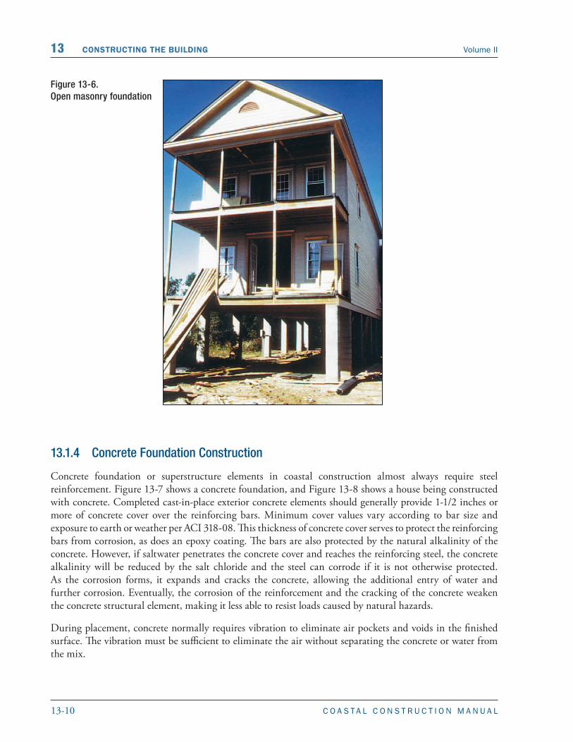
Masonry is used for piers, columns, and foundation walls. As explained in Section 10.2.1, the National Flood Insurance Program (NFIP) regulations require open foundations (e.g., piles, piers, posts, columns) for buildings constructed in Zone V. Buildings in Zone A may be constructed on any foundation system. However, because of the history of observed damage in Coastal A Zone and the magnitude of the flood and wind forces that can occur in these areas, this Manual recommends that only open foundation systems be constructed in Coastal A Zones. Figure 13-6 shows an open masonry foundation with only two rows of piers. It is unlikely that this foundation system could resist the overturning caused by the forces described in Chapter 8 and shown in Example 8-10. Fact Sheet 3.4, Reinforced Masonry Pier Construction, in FEMA P-499 provides recommendations on pier construction best practices. Fact Sheet 4.2, Masonry Details, in FEMA P-499 provides details on masonry wall-to-foundation connections.
Reinforced masonry has much more strength and ductility than unreinforced masonry for resisting large wind, water, and earthquake forces. This Manual recommends that permanent masonry foundation construction in and near coastal flood hazard areas (both Zone A and Zone V) be fully or partially reinforced and grouted solid regardless of the purpose of the construction and the design loads. Grout should be in conformance with the requirements of the 2012 IBC. Knockouts should be placed at the bottom of fully grouted cells to ensure that the grout completely fills the cells from top to bottom. Knockouts are required only for walls (or piers) exceeding 5 feet in height.
For CMUs, shrinkage cracking can be minimized by using Type I moisture-controlled units and keeping them dry in transit and on the job. Usually, for optimum crack control, Type S mortar should be used for below-grade applications and Type N mortar for above-grade applications. The 2012 IBC specifies grout proportions by volume for masonry construction.
NOTE
Tooled concave joints and V-joints provide the best moisture resistance.
NOTE
In areas not subject to earthquake hazards, breakaway walls below elevated buildings may be constructed using unreinforced and ungrouted masonry.
13-10 C O A S T A L C O N S T R U C T I O N M A N U A L
13 CONSTRUCTING THE BUILDING Volume II
13.1.4 Concrete Foundation Construction
Concrete foundation or superstructure elements in coastal construction almost always require steel reinforcement. Figure 13-7 shows a concrete foundation, and Figure 13-8 shows a house being constructed with concrete. Completed cast-in-place exterior concrete elements should generally provide 1-1/2 inches or more of concrete cover over the reinforcing bars. Minimum cover values vary according to bar size and exposure to earth or weather per ACI 318-08. This thickness of concrete cover serves to protect the reinforcing bars from corrosion, as does an epoxy coating. The bars are also protected by the natural alkalinity of the concrete. However, if saltwater penetrates the concrete cover and reaches the reinforcing steel, the concrete alkalinity will be reduced by the salt chloride and the steel can corrode if it is not otherwise protected. As the corrosion forms, it expands and cracks the concrete, allowing the additional entry of water and further corrosion. Eventually, the corrosion of the reinforcement and the cracking of the concrete weaken the concrete structural element, making it less able to resist loads caused by natural hazards.
During placement, concrete normally requires vibration to eliminate air pockets and voids in the finished surface. The vibration must be sufficient to eliminate the air without separating the concrete or water from the mix.
Figure 13-6. Open masonry foundation

13-11C O A S T A L C O N S T R U C T I O N M A N U A L
Volume II CONSTRUCTING THE BUILDING 13
To ensure durability and long life in coastal, saltwater-affected locations, it is especially important to carefully carry out concrete construction in a fashion that promotes durability. “Material Durability in Coastal Environments,” available on the Residential Coastal Construction Web site (http://www.fema.gov/rebuild/mat/fema55.html) describes the 2012 IBC requirements for more durable concrete mixes with lower water-cement ratios and higher compressive strengths (5,000 pounds/square inch) to be used in a saltwater environment. The 2012 IBC also requires that additional cover thickness be provided. Proper placement, consolidation, and curing are also essential for durable concrete. The concrete mix water-cement ratio required by 2012 IBC or by the design should not be exceeded by the addition of water at the site.
It is likely that concrete will have to be pumped at many sites because of access limitations or elevation differences between the top of the forms and the concrete mix truck chute. Pumping concrete requires some
Figure 13-7. Concrete foundation
Figure 13-8. Concrete house
13-12 C O A S T A L C O N S T R U C T I O N M A N U A L
13 CONSTRUCTING THE BUILDING Volume II
minor changes in the mix so that the concrete flows smoothly through the pump and hoses. Plasticizers should be used to make the mix pumpable; water should not be used to improve the flow of the mix. Concrete suitable for pumping must generally have a slump of at least 2 inches and a maximum aggregate size of 33 to 40 percent of the pump pipeline diameter. Pumping also increases the temperature of the concrete, thus changing the curing time and characteristics of the concrete depending on the outdoor temperature.
Freeze protection may be needed, particularly for columns and slabs, if pouring is done in cold temperatures. Concrete placed in cold weather takes longer to cure, and the uncured concrete may freeze, which adversely affects its final strength. Methods of preventing concrete from freezing during curing include:
� Heating adjacent soil before pouring on-grade concrete
� Warming the mix ingredients before batching
� Warming the concrete with heaters after pouring (avoid overheating)
� Placing insulating blankets over and around the forms after pouring
� Selecting a cement mix that will shorten curing time
Like masonry, concrete is used for piers, columns, and walls; the recommendation in Section 13.1.3 regarding open foundations in Coastal A Zones also applies to concrete foundations. In addition, because the environmental impact of salt-laden air and moisture make the damage potential significant for concrete, this Manual recommends that all concrete construction in and near coastal flood hazard areas (both Zone V and Zone A) be constructed with the more durable 5,000-pounds/square inch minimum compressive strength concrete regardless of the purpose of the construction and the design loads.
13.1.5 Wood Foundation Construction
All of the wood used in the foundation piles, girders, beams, and braces must be preservative-treated wood or, when allowed, naturally decay-resistant wood. Section 9.4 discusses materials selection for these wood elements. Piles must be treated with waterborne arsenicals, creosote, or both. Girders and braces may be treated with waterborne arsenicals, pentachlorophenol, or creosote. Certain precautions apply to working with any of these treated wood products, and additional precautions apply for pentachlorophenol- and creosote-treated wood (see Section 13.1.5.1). Additional information is available in Consumer Information Sheets where the products are sold.
Wood foundations are being constructed in some parts of the country as part of a basement or crawlspace. These foundation elements have walls constructed with pressure-preservative-treated plywood and footings constructed with wide pressure- preservative-treated wood boards such as 2x10s or 2x12s. Because the NFIP regulations allow continuous foundation walls (with the required openings) in Coastal A Zones, continuous
NOTE
ACI 318-08 specifies minimum amounts of concrete cover for various construction applications. Per the Exception to 1904.3 in the 2012 IBC, concrete mixtures for any R occupancies need only comply with the freeze/thaw requirements (as traditionally tabulated in the 2012 IBC and 2012 IRC), not the permeability and corrosion requirements of ACI 318-08.

13-13C O A S T A L C O N S T R U C T I O N M A N U A L
Volume II CONSTRUCTING THE BUILDING 13
wood foundations might seem to be acceptable in these areas. However, because of the potential forces from waves less than 2 feet high (as discussed in Section 10.8), a wood foundation supported on a wood footing is not recommended in Coastal A Zones.
When working with treated wood, the following health and safety precautions should be taken:
� Avoid frequent or prolonged inhalation of the sawdust.
� When sawing and boring, wear goggles and a dust mask.
� Use only treated wood that is visibly clean and free of surface residue should be used for patios, decks, and walkways.
� Before eating or drinking, wash all exposed skin areas thoroughly.
� If preservatives or sawdust accumulate on clothes, wash the clothes (separately from other household clothing) before wearing them again.
� Dispose of the cuttings by ordinary trash collection or burial. The cuttings should not be burned in open fires or in stoves, fireplaces, or residential boilers because toxic chemicals may be produced as part of the smoke and ashes. The cuttings may be burned only in commercial or industrial incinerators or boilers in accordance with Federal and State regulations.
� Avoid frequent or prolonged skin contact with pentachlorophenol or creosote-treated wood; when handling it, wear long-sleeved shirts and long pants and use gloves impervious to the chemicals (e.g., vinyl-coated gloves).
� Do not use pentachlorophenol-pressure-treated wood in residential interiors except for laminated beams or for building elements that are in ground contact and are subject to decay or insect infestation and where two coats of an appropriate sealer are applied. Sealers may be applied at the installation site. Urethane, shellac, latex epoxy enamel, and varnish are acceptable sealers.
� Do not use creosote-treated wood in residential interiors. Coal tar pitch and coal tar pitch emulsion are effective sealers for outdoor creosote-treated wood-block flooring. Urethane, epoxy, and shellac are acceptable sealers for all creosote-treated wood.
13.1.6 Foundation Material Durability
Ideally, all of the pile-and-beam foundation framing of a coastal building is protected from rain by the overhead structure, even though all of the exposed materials should be resistant to decay and corrosion. In practice, the overhead structure includes both enclosed spaces (such as the main house) and outside decks. The spaces between the floor boards on an outside deck allow water to pass through and fall on the framing below. A worst case for potential rain and moisture penetration exists when less permeable decks collect water and channel it to fall as a stream onto the framing below. In addition, wind-driven rain and ocean spray penetrates into many small spaces, and protection of the wood in these spaces is therefore important to long-term durability of the structure.
The durability of the exposed wood frame can be improved by detailing it to shed water during wetting and to dry readily afterward. Decay occurs in wetted locations where the moisture content of the exposed,

13-14 C O A S T A L C O N S T R U C T I O N M A N U A L
13 CONSTRUCTING THE BUILDING Volume II
untreated interior core of treated wood elements remains above the fiber saturation point—about 30 percent. The moisture content of seasoned, surface-dry 2x lumber (S-DRY) is less than or equal to 19 percent content when it arrives at the job site, but the moisture content is quickly reduced as the wood dries in the finished building. The moisture content of the large members (i.e., greater than 3 times) is much higher than 19 percent when they arrive at the job site, and the moisture content takes months to drop below 19 percent.
The potential for deterioration is greatest at end grain surfaces. Water is most easily absorbed along the grain, allowing it to penetrate deep into the member where it does not readily dry. Figure 13-9 illustrates deterioration in the end of a post installed on a concrete base. This is a typical place for wood deterioration to occur. Even when the end grain is more exposed to drying, the absorptive nature of the end grain creates an exaggerated shrink/swell cycling, resulting in checks and splits, which in turn allow increased water penetration.
Exposed pile tops present the vulnerable horizontal end grain cut to the weather. Cutting the exposed top of a pile at a slant does not prevent decay and may even channel water into checks. Water enters checks and splits in the top and side surfaces of beams and girders. It can then penetrate into the untreated core and cause decay. These checks and splits occur naturally in large sawn timbers as the wood dries and shrinks over time. They are less common in glue-laminated timbers and built-up sections. It is generally, but not universally, agreed that caulking the checks and splits is unwise because caulking is likely to promote water retention more than keep water out. The best deterrent is to try to keep the water from reaching the checks and splits.
Framing construction that readily collects and retains moisture, such as pile tops, pile-beam connections, and horizontal girder and beam top surfaces, can be covered with flashing or plywood. However, there should always be an air gap between the protected wood and the flashing so that water vapor passing out of the wood is not condensed at the wood surface. For example, a close-fitting cap of sheet metal on a pile top can cause water vapor coming out of the pile top to condense and cause decay. The cap can also funnel water into the end grain penetrations of the vertical fasteners.
Figure 13-9. Wood decay at the base of a post supported by concrete
13-15C O A S T A L C O N S T R U C T I O N M A N U A L
Volume II CONSTRUCTING THE BUILDING 13
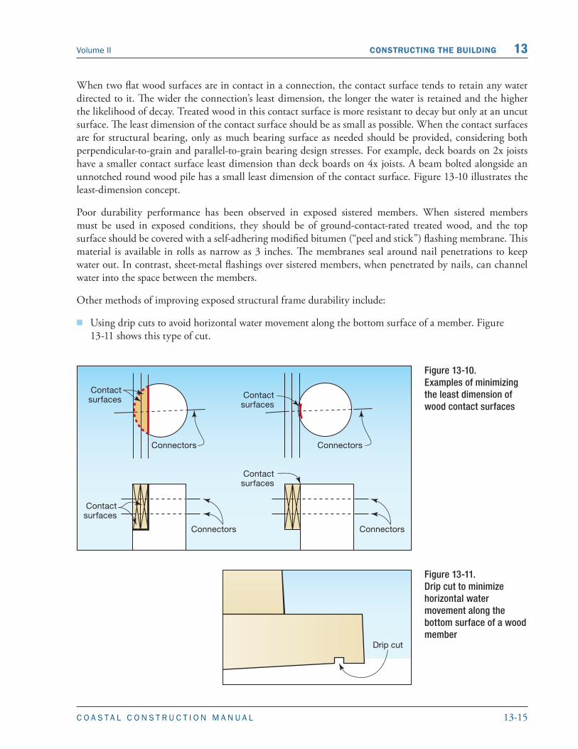
When two flat wood surfaces are in contact in a connection, the contact surface tends to retain any water directed to it. The wider the connection’s least dimension, the longer the water is retained and the higher the likelihood of decay. Treated wood in this contact surface is more resistant to decay but only at an uncut surface. The least dimension of the contact surface should be as small as possible. When the contact surfaces are for structural bearing, only as much bearing surface as needed should be provided, considering both perpendicular-to-grain and parallel-to-grain bearing design stresses. For example, deck boards on 2x joists have a smaller contact surface least dimension than deck boards on 4x joists. A beam bolted alongside an unnotched round wood pile has a small least dimension of the contact surface. Figure 13-10 illustrates the least-dimension concept.
Poor durability performance has been observed in exposed sistered members. When sistered members must be used in exposed conditions, they should be of ground-contact-rated treated wood, and the top surface should be covered with a self-adhering modified bitumen (“peel and stick”) flashing membrane. This material is available in rolls as narrow as 3 inches. The membranes seal around nail penetrations to keep water out. In contrast, sheet-metal flashings over sistered members, when penetrated by nails, can channel water into the space between the members.
Other methods of improving exposed structural frame durability include:
� Using drip cuts to avoid horizontal water movement along the bottom surface of a member. Figure 13-11 shows this type of cut.
Figure 13-10. Examples of minimizing the least dimension of wood contact surfaces
Figure 13-11.Drip cut to minimize horizontal water movement along the bottom surface of a wood member
13-16 C O A S T A L C O N S T R U C T I O N M A N U A L
13 CONSTRUCTING THE BUILDING Volume II
� Avoiding assemblies that form “buckets” and retain water adjacent to wood.
� Avoiding designs that result in ledges below a vertical or sloped surface. Ledges collect water quite readily, and the resulting ponding from rain or condensation alternating with solar radiation causes shrink-swell cycling, resulting in checks that allow increased water penetration.
� To the extent possible, minimizing the number of vertical holes in exposed horizontal surfaces from nails, lags, and bolts.
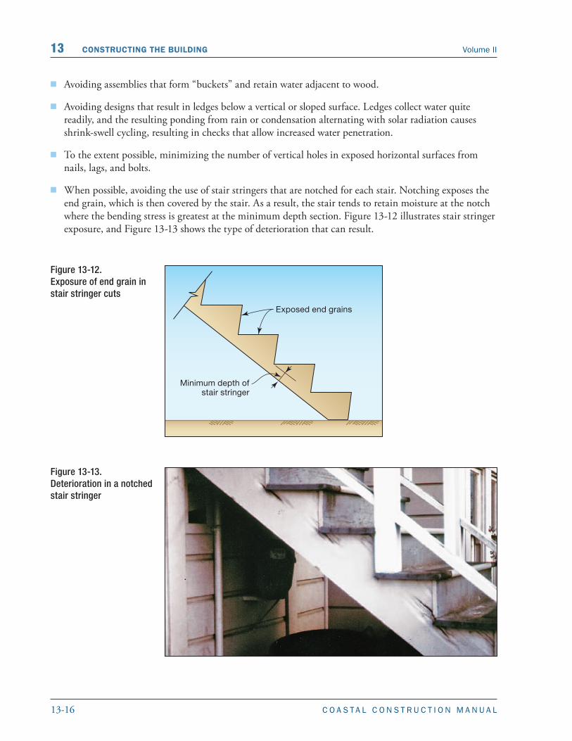
� When possible, avoiding the use of stair stringers that are notched for each stair. Notching exposes the end grain, which is then covered by the stair. As a result, the stair tends to retain moisture at the notch where the bending stress is greatest at the minimum depth section. Figure 13-12 illustrates stair stringer exposure, and Figure 13-13 shows the type of deterioration that can result.
Figure 13-12. Exposure of end grain in stair stringer cuts
Figure 13-13.Deterioration in a notched stair stringer

13-17C O A S T A L C O N S T R U C T I O N M A N U A L
Volume II CONSTRUCTING THE BUILDING 13
� Using the alternative stair stringer installation shown in Figure 13-14 when the stair treads are either nailed onto a cleat or the stringer is routed out so the tread fits into the routed-out area. Even these alternatives allow water retention at end grain surfaces, and these surfaces should therefore be field-treated with wood preservative.
� Caulking joints at wood connections to keep water out. Caulk only the top joints in the connection. Recaulk after the wood has shrunk, which can take up to a year for larger members.
� When structurally possible, considering using spacers or shims to separate contact surfaces. A space of about 1/16-inch discourages water retention by capillary action but can easily fill with dirt and debris. A 1/4- to 1/2-inch space is sufficient to allow water and debris to clear from the interface. This spacing has structural limitations; a bolted connection with an unsupported shim has much less shear capacity than an unspaced connection because of increased bolt bending and unfavorable bearing stress distribution in the wood.
Figure 13-14. Alternative method of installing stair treads
13.1.7 Field Preservative Treatment
Field cuts and bores of pressure-preservative-treated piles, timbers, and lumber are inevitable in coastal construction. Unfortunately, these cuts expose the inner untreated part of the wood member to possible decay and infestation. Although field preservative treatments are much less effective than pressure-preservative treatment, the decay and infestation potential can be minimized by treating the cuts and bolt holes with field-applied preservative.

13-18 C O A S T A L C O N S T R U C T I O N M A N U A L
13 CONSTRUCTING THE BUILDING Volume II
13.1.8 Substitutions
During construction, a builder may find that materials called for in the construction plans or specifications are not available or that the delivery time for those materials is too long and will delay the completion of the building. These conflicts require decisions about substituting one type of construction material for another. Because of the high natural hazard forces imposed on buildings near the coast and the effects of the severe year-round environment in coastal areas, substitutions should be made only after approval by a design professional and, if necessary, the local building official.
13.1.9 Foundation Inspection Points
If the foundation is not constructed properly, many construction details in the foundation can cause failure during a severe natural hazard event or premature failure because of deterioration caused by the harsh coastal environment. Improperly constructed foundations are frequently covered up, so any deficiency in the load-carrying or distributing capacity of one member is not easily detected until failure occurs. It is therefore very important to inspect the foundation while construction is in progress to ensure that the design is completed as intended. Table 13-1 is a list of suggested critical inspection points for the foundation.
Table 13-1. Foundation and Floor Framing Inspection Points
Inspection Point Reason
1. Pile-to-girder connection Ensures that pile is not overnotched, that it is field-treated, and that bolts are properly installed with washers and proper end and edge distance
2. Joist-to-girder connection Verifies presence of positive connection with properly nailed, corrosion-resistant connector
3. Joist blocking Ensures that the bottom of the joist is prevented from bending/buckling
4. Sheathing nailing – number, spacing, depth Ensures that sheathing acts as a shear diaphragm
5. Material storage – protection from elements prior to installation
Ensures that the wood does not absorb too much moisture prior to installation—exposure promotes checks and splits in wood, warp, and separation in plywood
6. Joist and beam material – excessive crown or lateral warping, large splits
Ensures that new floors are installed level and eliminates need to repair large splits in new material
13.1.10 Top Foundation Issues for Builders
The top foundation-related issues for builders are as follows:
� Piles, piers, or columns must be properly aligned.
� Piles, piers, or columns must be driven or placed at the proper elevation to resist failure and must extend below the expected depth of scour and erosion.
WARNING
When substitutions are proposed, the design professional’s approval should be obtained before the substitution is made. The ramifications of the change must be evaluated, including the effects on the building elements, constructability, and long-term durability. Code and regulatory ramifications should also be considered.

13-19C O A S T A L C O N S T R U C T I O N M A N U A L
Volume II CONSTRUCTING THE BUILDING 13
� Foundation materials must be damage-resistant to flooding (pressure-treated wood, masonry, or concrete).
� The support at the top of the foundation element must be adequate to properly attach the floor framing system. Notching of a wood foundation element should not exceed the specifications in the construction documents.
� Breakaway walls should not be overnailed to the foundation. They are intended to fail. Utilities and other obstructions should not be installed behind these walls, and the interior faces should not be finished.
� For masonry or concrete foundation elements (except slabs-on-grade), the proper size of reinforcing, proper number of steel bars, and proper concrete cover over the steel should be used.
� Concrete must have the proper mix to meet the specialized demands of the coastal environment.
� Exposed steel in the foundation corrodes; corrosion should be planned for by installing hot-dipped galvanized or stainless steel.
� Areas of pressure-treated wood that have been cut or drilled retain water and decay; these cut areas should be treated in the field.
13.2 Structural FrameStructural framing includes framing the floors, walls, and roof and installing critical connections between each element.
13.2.1 Structural Connections
One of the most critical aspects of building in a coastal area is the method that is used to connect the structural members. A substantial difference usually exists between connections acceptable in inland construction and those required to withstand the natural hazard forces and environmental conditions in coastal areas. Construction in noncoastal, nonseismic areas must normally support only vertical dead and live loads and modest wind loads. In most coastal areas, large forces are applied by wind, velocity flooding, wave impact, and floating debris. The calculated forces along the complete load path usually require that the builder provide considerable lateral and uplift capacity in and between the roof, walls, floors, girders, and piles. Consequently, builders should be sure to use the specified connectors or approved substitutes. Connectors that look alike may not have the same capacity, and a connector designed for gravity loads may have little uplift resistance. Fact Sheet 4.1, Load Path, in FEMA P-499 describes load paths and highlights important connections in a typical wind load path.
The nails required for the connection hardware may not be regularly found on the job site. For example, full-diameter 8d to 20d short nails are commonly specified for specific hurricane/seismic connection hardware.
WARNING
The connections described in this Manual are designed to hold the building together in a design event. Builders should never underestimate the importance of installing connectors according to manufacturers’ recommendations. Installing connectors properly is extremely important.

13-20 C O A S T A L C O N S T R U C T I O N M A N U A L
13 CONSTRUCTING THE BUILDING Volume II
For full strength, these connections require that all of the holes in the hardware be nailed with the proper nails. In the aftermath of investigated hurricanes, failed connector straps and other hardware have often been found to have been attached with too few nails, nails of insufficient diameter, or the wrong type of nail. Figure 13-15 shows a connector that failed because of insufficient nailing.
As mentioned previously, connection hardware must be corrosion-resistant. If galvanized connectors are used, additional care must be taken during nailing. When a hammer strikes the connector and nail during installation, some of the galvanizing protection is knocked off. One way to avoid this problem is to use corrosion-resistant connectors that do not depend on a galvanized coating, such as stainless steel or wood (see Section 9.2.3). Only stainless steel nails should be used with stainless steel connectors. An alternative to hand-nailing is to use a pneumatic hammer that “shoots” nails into connector holes.
All connections between members in a wood-frame building are made with nails, bolts, screws, or a similar fastener. Each fastener is installed by hand. The predominant method of installing nails
NOTE
Additional information about pneumatic nail guns can be obtained from the International Staple, Nail and Tool Association, 512 West Burlington Ave., Suite 203, LaGrange, IL 60525-2245. A report prepared by National Evaluation Service, Inc., NER-272, Power-Driven Staples and Nails for Use in All Types of Building Construction (NES 1997), presents information about the performance of pneumatic nail guns and includes prescriptive nailing schedules.
Figure 13-15. Connector failure caused by insufficient nailing
WARNING
Proper nail selection and installation are critical. Builders should not substitute different nails or nailing patterns without approval from the designer.

13-21C O A S T A L C O N S T R U C T I O N M A N U A L
Volume II CONSTRUCTING THE BUILDING 13
is by pneumatic nail gun. Many nail guns use nails commonly referred to as “sinkers.” Sinkers are slightly smaller in diameter and thus have lower withdrawal and shear capacities than common nails of the same size. Nail penetration is governed by air pressure for pneumatic nailers, and nail penetration is an important quality control issue for builders. Many prescriptive codes have nailing schedules for various building elements such as shearwalls and diaphragms.
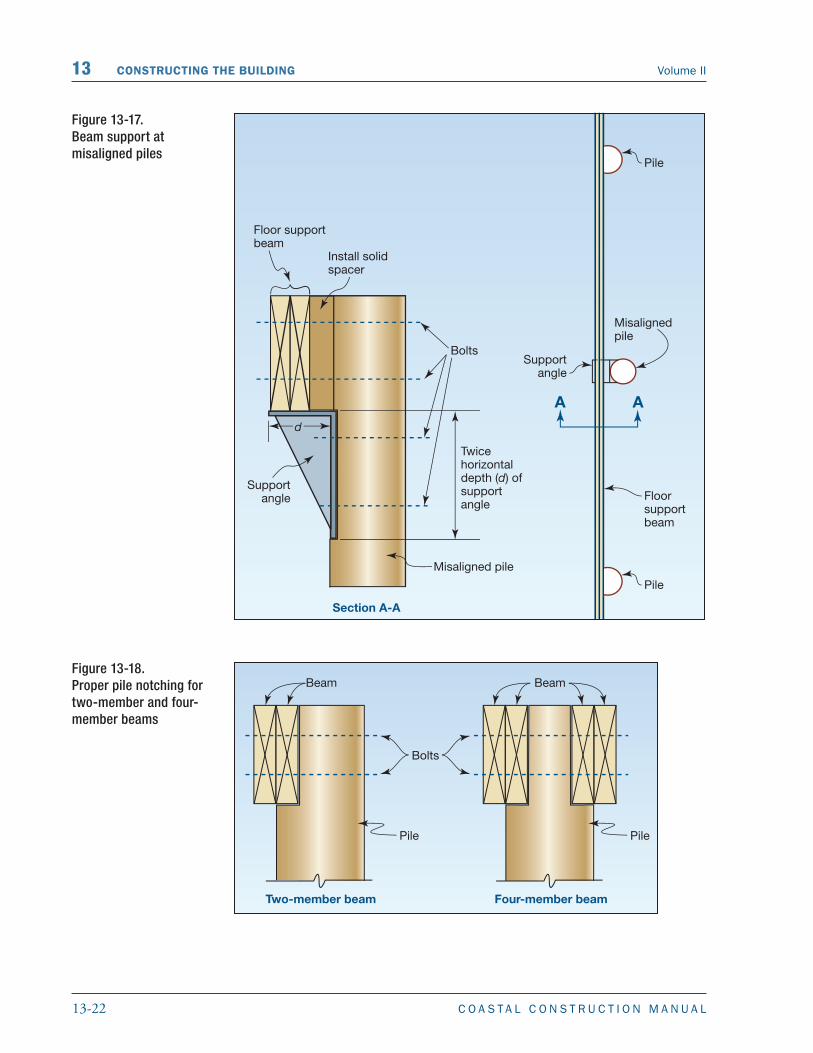
Another critical connection is the connection of the floor to the piles. Pile alignment and notching are critical not only to successful floor construction but also to the structural adequacy during a natural hazard event (see Section 13.1.1). Construction problems related to these issues are also inevitable, so solutions to pile misalignment and overnotching must be developed. Figure 13-16 illustrates a method of reinforcing an overnotched pile, including one that is placed on a corner. The most appropriate solution to pile misalignment is to re-drive a pile in the correct location. An alternative is illustrated in Figure 13-17, which shows a method of supporting a beam at a pile that has been driven “outside the layout” of the pile foundation. Figure 13-18
Figure 13-16. Reinforcement of overnotched piles
13-22 C O A S T A L C O N S T R U C T I O N M A N U A L
13 CONSTRUCTING THE BUILDING Volume II
Figure 13-17. Beam support at misaligned piles
Figure 13-18. Proper pile notching for two-member and four-member beams

13-23C O A S T A L C O N S T R U C T I O N M A N U A L
Volume II CONSTRUCTING THE BUILDING 13
illustrates the proper pile notching for both two-member and four-member beams. See Section 13.1.1 for more information on pile notching.
After the “square” foundation has been built, the primary layout concerns about how the building will perform under loads are confined to other building elements being properly located so that load transfer paths are complete.
13.2.2 Floor Framing
The connection between wood floor joists and the supporting beams and girders is usually a bearing connection for gravity forces with a twist strap tie for uplift forces. Figure 13-19 shows a twist tie connection. This connection is subjected to large uplift forces from high winds. In addition, the undersides of elevated structures, where these connectors are located, are particularly vulnerable to salt spray; the exposed surfaces are not washed by rain, and they stay damp longer because of their sheltered location. Consequently, the twist straps and the nails used to secure them must be hot-dipped galvanized or stainless steel. One way to reduce the corrosion potential for metal connectors located under the building is to cover the connectors with a plywood bottom attached to the undersides of the floor joists. (The bottom half of the joist-to-girder twist straps will still be exposed, however.) This covering will help keep insulation in the floor joist space as well as protect the metal connectors.
Because the undersides of Zone V buildings are exposed, the first floor is more vulnerable to uplift wind and wave forces, as well as to the lateral forces of moving water, wave impact, and floating debris. These loads cause compressive and lateral forces in the normally unbraced lower flange of the joist. Solid blocking or 1x3 cross-bridging at 8-foot centers is recommended for at least the first floor joists unless substantial sheathing (at least 1/2-inch thick) has been nailed well to the bottom of these joists. Figure 13-19 also shows solid blocking between floor joists.
CROSS REFERENCE
See NFIP Technical Bulletin 8-96, Corrosion Protection for Metal Connectors in Coastal Areas (FEMA 1996).
Figure 13-19. Proper use of metal twist strap ties (circled); solid blocking between floor joists

13-24 C O A S T A L C O N S T R U C T I O N M A N U A L
13 CONSTRUCTING THE BUILDING Volume II
Floor framing materials other than 2x sawn lumber are becoming popular in many parts of the country. These materials include wood floor trusses and wood I-joists. Depending on the shape of the joist and the manufacturer, the proper installation of these materials may require some additional steps. For instance, some wood I-joists require solid blocking at the end of the joist where it is supported so that the plywood web is not crushed or does not buckle. Figure 13-20 illustrates the use of plywood web I-joists. As shown in the figure, the bottom flanges of the joists are braced with a small metal strip that helps keep the flange from twisting. Solid wood blocking is a corrosion-resistant alternative to the metal braces.
Floor surfaces in high-wind, flood, or seismic hazard areas are required to act as a diaphragm. For the builder, this means that the floor joists and sheathing are an important structural element. Therefore, the following installation features may require added attention:
� Joints in the sheathing should fully bear on top of a joist, not a scabbed-on board used as floor support
� Nailing must be done in accordance with a shear diaphragm plan
� Construction adhesive is important for preventing “squeaky” floors, but the adhesive must not be relied on for shear resistance in the floor
Joints in the sheathing across the joists must be fully blocked with a full-joist-height block. Horizontal floor diaphragms with lower shear capacities can be unblocked if tongue-and-groove sheathing is used.
13.2.2.1 Horizontal Beams and Girders
Girders and beams can be solid sawn timbers, glue-laminated timbers (see Figure 13-20), or built-up sections (see “Material Durability in Coastal Environments” on the Residential Coastal Construction Web site at http://www.fema.gov/rebuild/mat/fema55.html). The girders span between the piles and support the beams and joists. The piles are usually notched to receive the girders. To meet the design intent, girders, beams, and joists must be square and level, girders must be secured to the piles, and beams and joists must be secured to the girders.
Figure 13-20. Engineered joists used as floor joists with proper metal brace to keep the bottoms of the joists from twisting; engineered wood beam
13-25C O A S T A L C O N S T R U C T I O N M A N U A L
Volume II CONSTRUCTING THE BUILDING 13
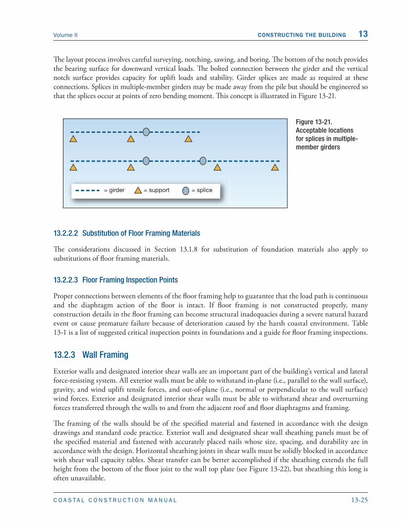
The layout process involves careful surveying, notching, sawing, and boring. The bottom of the notch provides the bearing surface for downward vertical loads. The bolted connection between the girder and the vertical notch surface provides capacity for uplift loads and stability. Girder splices are made as required at these connections. Splices in multiple-member girders may be made away from the pile but should be engineered so that the splices occur at points of zero bending moment. This concept is illustrated in Figure 13-21.
Figure 13-21. Acceptable locations for splices in multiple-member girders
13.2.2.2 Substitution of Floor Framing Materials
The considerations discussed in Section 13.1.8 for substitution of foundation materials also apply to substitutions of floor framing materials.
13.2.2.3 Floor Framing Inspection Points
Proper connections between elements of the floor framing help to guarantee that the load path is continuous and the diaphragm action of the floor is intact. If floor framing is not constructed properly, many construction details in the floor framing can become structural inadequacies during a severe natural hazard event or cause premature failure because of deterioration caused by the harsh coastal environment. Table 13-1 is a list of suggested critical inspection points in foundations and a guide for floor framing inspections.
13.2.3 Wall Framing
Exterior walls and designated interior shear walls are an important part of the building’s vertical and lateral force-resisting system. All exterior walls must be able to withstand in-plane (i.e., parallel to the wall surface), gravity, and wind uplift tensile forces, and out-of-plane (i.e., normal or perpendicular to the wall surface) wind forces. Exterior and designated interior shear walls must be able to withstand shear and overturning forces transferred through the walls to and from the adjacent roof and floor diaphragms and framing.
The framing of the walls should be of the specified material and fastened in accordance with the design drawings and standard code practice. Exterior wall and designated shear wall sheathing panels must be of the specified material and fastened with accurately placed nails whose size, spacing, and durability are in accordance with the design. Horizontal sheathing joints in shear walls must be solidly blocked in accordance with shear wall capacity tables. Shear transfer can be better accomplished if the sheathing extends the full height from the bottom of the floor joist to the wall top plate (see Figure 13-22), but sheathing this long is often unavailable.

13-26 C O A S T A L C O N S T R U C T I O N M A N U A L
13 CONSTRUCTING THE BUILDING Volume II
The design drawings may show tiedown connections between large shearwall vertical posts and main girders. Especially in larger, taller buildings, these connections must resist thousands of pounds of overturning forces during high winds. See Section 8.7 for information regarding the magnitude of these forces. The connections must be accomplished with careful layout, boring, and assembly. Shear transfer nailing at the top plates and sills must be in accordance with the design. Proper nailing and attachment of the framing material around openings is very important; see Section 9.2.1 for a discussion of the difficulty of transferring large shear loads when there are large openings in the shearwall.
It is very important that shearwall sheathing (e.g., plywood, oriented strand board [OSB]) with an exterior exposure be finished appropriately with pigmented finishes such as paint, which last longer than unpigmented finishes, or semitransparent penetrating stains. It is also important that these finishes be properly maintained. Salt crystal buildup in surface checks in siding can damage the siding. Damage is typically worse in siding that is sheltered from precipitation because the salt crystals are never washed off with fresh rainwater.
To meet the design intent, walls must:
� Be plumb and square to each other and to the floor
� Be lined up over solid support such as a beam, floor joists, or a perimeter band joist
� Not have any more openings than designated by the plans
� Not have openings located in places other than designated on the plans
� Consist of material expected to resist corrosion and deterioration
� Be properly attached to the floors above and below the wall, including the holddown brackets required to transfer overturning forces
Figure 13-22.Full-height sheathing to improve transfer of shear

13-27C O A S T A L C O N S T R U C T I O N M A N U A L
Volume II CONSTRUCTING THE BUILDING 13
In addition, all portions of walls designed as shearwalls must be covered with sheathing nailed in accordance with either the plans or a specified prescriptive standard.
13.2.3.1 Substitution of Wall Framing Materials
The considerations discussed in Section 13.1.8 for substitution of foundation materials also apply to substitutions of wall framing materials.
13.2.3.2 Wall Framing Inspection Points
Proper connections between elements of the wall framing help to guarantee a continuous load path and the diaphragm action of the walls is intact. If not completed properly, there are many construction details in the floor framing that can become structural inadequacies and fail during a severe natural hazard event or cause premature failure because of deterioration caused by the harsh coastal environment. Table 13-2 is a list of suggested critical inspection points that can be used as a guide for wall framing inspections.
Table 13-2. Wall Inspection Points
Inspection Point Reason
1. Wall framing attachment to floors Ensures that nails are of sufficient size, type, and number
2. Size and location of openings Ensures performance of shear wall
3. Wall stud blocking Ensures that there is support for edges of sheathing material
4. Sheathing nailing – number, spacing, depth of nails Ensures that sheathing acts as a shear diaphragm
5. Material storage – protection from elements prior to installation
Ensures that the wood does not absorb too much moisture prior to installation—exposure promotes checks and splits in wood, warp, and separation in plywood
6. Stud material – excessive crown (crook) or lateral warping (bow)
Maintains plumb walls and eliminates eccentricities in vertical loading
7. Header support over openings Ensures that vertical and lateral loads will be transferred along the continuous load path
13.2.4 Roof Framing
Proper roof construction is very important in high-wind and earthquake hazard areas. Reviews of wind damage to coastal buildings reveal that most damage starts with the failure of roof elements. The structural integrity of the roof depends on a complete load path, including the resistance to uplift of porch and roof overhangs, gable end overhangs, roof sheathing nailing, roof framing nailing and strapping, roof member-to-wall strapping, and gable end-wall bracing.
WARNING
The most common roof structure failure is the uplift failure of porch, eave, and gable end overhangs. The next most common is roof sheathing peeling away from the framing. Nailing the sheathing at the leading edge of the roof, the gable edge, and the joints at the hip rafter or ridge is very important, as is securing the roof framing to prevent uplift. This failure point (leading edge of sheathing at gable edge, ridge, and hip) is also the most likely place for progressive failure of the entire structure to begin.

13-28 C O A S T A L C O N S T R U C T I O N M A N U A L
13 CONSTRUCTING THE BUILDING Volume II
All of this construction must use the specified wood materials, straps, and nails. The appropriate nails must be used in all of the holes in the straps so that the straps develop their full strength. Sheathing nails must be of the specified length, diameter, and head, and the sheathing must be nailed at the correct spacing. In addition, sheathing nails must penetrate the underlying roof framing members and must not be overdriven, which frequently occurs when pneumatic nail guns are used. When prefabricated roof trusses are used, handling precautions must be observed, and the trusses must be laterally braced as specified by the design professional or manufacturer.
Fact Sheets 7.1 through 7.4 in FEMA P-499 discuss roof construction, including sheathing installation, asphalt shingle roofing, and tile roofing.
To meet the design intent, roofs must meet the following requirements:
� Roof trusses and rafters must be properly attached to the walls
� Roof sheathing must be nailed according to either the construction plans or a specified prescriptive standard
� Roofs must consist of materials expected to resist corrosion and deterioration, particularly the connectors
13.2.4.1 Substitution of Roof Framing Materials
The considerations discussed in Section 13.1.8 for substitution of foundation materials also apply to substitutions of roof framing materials.
13.2.4.2 Roof Frame Inspection Points
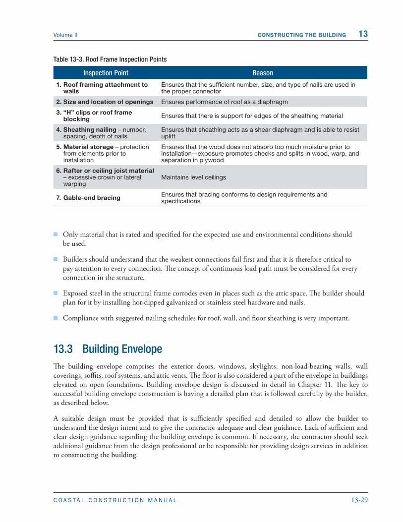
Proper connections between elements of the roof frame help to guarantee a continuous load path and the diaphragm action of the walls is intact. If not completed properly, there are many construction details in the roof framing that can become structural inadequacies and fail during a severe natural hazard event or cause premature failure because of deterioration caused by the harsh coastal environment. Table 13-3 contains suggestions of critical inspection points as a guide for roof framing inspections.
13.2.5 Top Structural Frame Issues for Builders
The top structural frame issues for builders are as follows:
� Connections between structural elements (e.g., roofs to walls) must be made so that the full natural hazard forces are transferred along a continuous load path.
� Care must be taken to nail elements so that the nails are fully embedded.
� Compliance with manufacturers’ recommendations on hardware use and load ratings is critically important.
WARNING
Do not substitute nails, fasteners, or connectors without approval of the designer.
13-29C O A S T A L C O N S T R U C T I O N M A N U A L
Volume II CONSTRUCTING THE BUILDING 13
� Only material that is rated and specified for the expected use and environmental conditions should be used.
� Builders should understand that the weakest connections fail first and that it is therefore critical to pay attention to every connection. The concept of continuous load path must be considered for every connection in the structure.
� Exposed steel in the structural frame corrodes even in places such as the attic space. The builder should plan for it by installing hot-dipped galvanized or stainless steel hardware and nails.
� Compliance with suggested nailing schedules for roof, wall, and floor sheathing is very important.
13.3 Building EnvelopeThe building envelope comprises the exterior doors, windows, skylights, non-load-bearing walls, wall coverings, soffits, roof systems, and attic vents. The floor is also considered a part of the envelope in buildings elevated on open foundations. Building envelope design is discussed in detail in Chapter 11. The key to successful building envelope construction is having a detailed plan that is followed carefully by the builder, as described below.
A suitable design must be provided that is sufficiently specified and detailed to allow the builder to understand the design intent and to give the contractor adequate and clear guidance. Lack of sufficient and clear design guidance regarding the building envelope is common. If necessary, the contractor should seek additional guidance from the design professional or be responsible for providing design services in addition to constructing the building.
Table 13-3. Roof Frame Inspection Points
Inspection Point Reason
1. Roof framing attachment to walls
Ensures that the sufficient number, size, and type of nails are used in the proper connector
2. Size and location of openings Ensures performance of roof as a diaphragm
3. “H” clips or roof frame blocking Ensures that there is support for edges of the sheathing material
4. Sheathing nailing – number, spacing, depth of nails
Ensures that sheathing acts as a shear diaphragm and is able to resist uplift
5. Material storage – protection from elements prior to installation
Ensures that the wood does not absorb too much moisture prior to installation—exposure promotes checks and splits in wood, warp, and separation in plywood
6. Rafter or ceiling joist material – excessive crown or lateral warping
Maintains level ceilings
7. Gable-end bracing Ensures that bracing conforms to design requirements and specifications

13-30 C O A S T A L C O N S T R U C T I O N M A N U A L
13 CONSTRUCTING THE BUILDING Volume II
The building must be constructed as intended by the design professional (i.e., the builder must follow the drawings and specifications). Examples are:
� Installing flashings, building paper, or air infiltration barriers so that water is shed at laps
� Using the specified type and size of fasteners and spacing them as specified
� Eliminating dissimilar metal contact
� Using materials that are compatible with one another
� Installing elements in a manner that accommodates thermal movements so that buckling or jacking out of fasteners is avoided
� Applying finishes to adequately cleaned, dried, and prepared substrates
� Installing backer rods or bond breaker tape at sealant joints
� Tooling sealant joints
For products or systems specified by performance criteria, the contractor must exercise care in selecting those products or systems and in integrating them into the building envelope. For example, if the design professional specifies a window by requiring that it be capable of resisting a specified wind pressure, the contractor should ensure that the type of window that is being considered can resist the pressure when tested in accordance with the specified test (or a suitable test if a test method is not specified). Furthermore, the contractor needs to ensure that the manufacturer, design professional, or other qualified entity provides guidance on how to attach the window frame to the wall so that the frame can resist the design pressures.
When the selection of accessory items is left to the discretion of the contractor, without prescriptive or performance guidance, the contractor must be aware of and consider special conditions at the site (e.g., termites, unusually severe corrosion, and high earthquake or wind loads) that should influence the selection of the accessory items. For example, instead of using screws in plastic sleeves to anchor elements to a concrete or masonry wall, a contractor can use metal expansion sleeves or steel spikes intended for anchoring to concrete, which should provide a stronger and more reliable connection, or the use of plastic shims at metal doors may be appropriate to avoid termite attack.
Adequate quality control (i.e., inspection by the contractor’s personnel) and adequate quality assurance (i.e., inspection by third parties such as the building official, the design professional, or a test lab) must be provided. The amount of quality control/quality assurance depends on the magnitude of the natural hazards being designed for, complexities of the building design, and the type of products or systems being used. For example, installing windows that are very tall and wide and make up the majority of a wall should receive more inspection than isolated, relatively small windows. Inspecting roof coverings and windows is generally more critical than inspecting most wall coverings because of the general susceptibility of roofing and glazing to wind and the resulting damage from water infiltration that commonly occurs when these elements fail.
13.3.1 Substitution of Building Envelope Materials
The considerations discussed in Section 13.1.8 for substitution of foundation materials also apply to substitutions of envelope materials. Proposed substitutions of materials must be thoroughly evaluated and
13-31C O A S T A L C O N S T R U C T I O N M A N U A L
Volume II CONSTRUCTING THE BUILDING 13
must be approved by the design professional (see Section 13.1.8). The building envelope must be installed in a manner that will not compromise the building’s structural integrity. For example, during construction, if a window larger than originally intended is to be installed because of delivery problems or other reasons, the contractor should obtain the design professional’s approval prior to installation. The larger window may unacceptably reduce the shear capacity of the wall, or different header or framing connection details may be necessary. Likewise, if a door is to be located in a different position, the design professional should evaluate the change to determine whether it adversely affects the structure.
13.3.2 Building Envelope Inspection Points
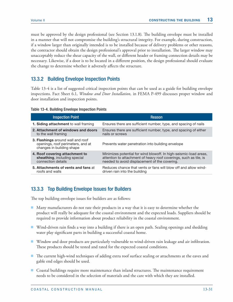
Table 13-4 is a list of suggested critical inspection points that can be used as a guide for building envelope inspections. Fact Sheet 6.1, Window and Door Installation, in FEMA P-499 discusses proper window and door installation and inspection points.
Table 13-4. Building Envelope Inspection Points
Inspection Point Reason
1. Siding attachment to wall framing Ensures there are sufficient number, type, and spacing of nails
2. Attachment of windows and doors to the wall framing
Ensures there are sufficient number, type, and spacing of either nails or screws
3. Flashings around wall and roof openings, roof perimeters, and at changes in building shape
Prevents water penetration into building envelope
4. Roof covering attachment to sheathing, including special connection details
Minimizes potential for wind blowoff. In high-seismic-load areas, attention to attachment of heavy roof coverings, such as tile, is needed to avoid displacement of the covering.
5. Attachments of vents and fans at roofs and walls
Reduces chance that vents or fans will blow off and allow wind-driven rain into the building
13.3.3 Top Building Envelope Issues for Builders
The top building envelope issues for builders are as follows:
� Many manufacturers do not rate their products in a way that it is easy to determine whether the product will really be adequate for the coastal environment and the expected loads. Suppliers should be required to provide information about product reliability in the coastal environment.
� Wind-driven rain finds a way into a building if there is an open path. Sealing openings and shedding water play significant parts in building a successful coastal home.
� Window and door products are particularly vulnerable to wind-driven rain leakage and air infiltration. These products should be tested and rated for the expected coastal conditions.
� The current high-wind techniques of adding extra roof surface sealing or attachments at the eaves and gable end edges should be used.
� Coastal buildings require more maintenance than inland structures. The maintenance requirement needs to be considered in the selection of materials and the care with which they are installed.

13-32 C O A S T A L C O N S T R U C T I O N M A N U A L
13 CONSTRUCTING THE BUILDING Volume II
13.4 ReferencesACI (American Concrete Institute). 2008. Building Code Requirements for Structural Concrete. ACI 318-08.
AWPA (American Wood Protection Association). 1991. Care of Pressure-Treated Wood Products. AWPA Standard M4-91. Woodstock, MD.
AWPA. 1994. Standards. Woodstock, MD.
FEMA (Federal Emergency Management Agency). 1996. Corrosion Protection for Metal Connectors in Coastal Areas. NFIP Technical Bulletin 8-96.
FEMA. 2006. Recommended Residential Construction for the Gulf Coast. FEMA P-550.
FEMA. 2011. Home Builder’s Guide to Coastal Construction Technical Fact Sheets. FEMA P-499.
ICC (International Code Council). 2008. Standard for Residential Construction in High-Wind Regions, ICC 600-2008. ICC: Country Club Hills, IL.
ICC. 2011a. International Building Code. 2012 IBC. Country Club Hills, IL: ICC.
ICC. 2011b. International Residential Code for One-and Two-Family Dwellings. 2012 IRC. Country Club Hills, IL: ICC.
NES (National Evaluation Service, Inc.). 1997. Power-Driven Staples and Nails for Use in All Types of Building Construction. National Evaluation Report NER-272.
TMS (The Masonry Society). 2008. Building Code Requirements and Specification for Masonry Structures and Commentaries. TMS 402-08/ACI 530-08/ASCE 5-08 and TMS 602-08/ACI 530.1-08/ASCE 6-08.
USDN (U.S. Department of the Navy). 1982. Foundation and Earth Structures Design. Design Manual 7.2.
Contents13. Constructing the Building ..................................................................................................... 13-1
13.1 Foundation Construction ......................................................................................................... 13-213.1.1 Layout .......................................................................................................................... 13-213.1.2 Pile Foundations .......................................................................................................... 13-513.1.3 Masonry Foundation Construction .............................................................................. 13-813.1.4 Concrete Foundation Construction .............................................................................13-1013.1.5 Wood Foundation Construction .................................................................................13-1213.1.6 Foundation Material Durability ..................................................................................13-1313.1.7 Field Preservative Treatment........................................................................................13-1713.1.8 Substitutions ...............................................................................................................13-1813.1.9 Foundation Inspection Points ......................................................................................13-1813.1.10 Top Foundation Issues for Builders .............................................................................13-18
13.2 Structural Frame..................................................................................................................... 13-1913.2.1 Structural Connections ...............................................................................................13-1913.2.2 Floor Framing ............................................................................................................ 13-23
13.2.2.1 Horizontal Beams and Girders ................................................................... 13-24
13.2.2.2 Substitution of Floor Framing Materials ......................................................13-25
13.2.2.3 Floor Framing Inspection Points .................................................................13-2513.2.3 Wall Framing ..............................................................................................................13-25
13.2.3.1 Substitution of Wall Framing Materials ...................................................... 13-27
13.2.3.2 Wall Framing Inspection Points ................................................................. 13-2713.2.4 Roof Framing ............................................................................................................. 13-27
13.2.4.1 Substitution of Roof Framing Materials...................................................... 13-28
13.2.4.2 Roof Frame Inspection Points ..................................................................... 13-2813.2.5 Top Structural Frame Issues for Builders .................................................................... 13-28
13.3 Building Envelope .................................................................................................................. 13-2913.3.1 Substitution of Building Envelope Materials .............................................................. 13-3013.3.2 Building Envelope Inspection Points ...........................................................................13-3113.3.3 Top Building Envelope Issues for Builders ...................................................................13-31
13.4 References ............................................................................................................................... 13-32