construction battalion battle skills guide p-1163 · training standards department n7 port hueneme,...
TRANSCRIPT
CONSTRUCTION BATTALION BATTLE SKILLS GUIDE P-1163
BOOK 4
Crew / Team Skills
OCTOBER 2005
CONSTRUCTION BATTALION BATTLE SKILLS GUIDE
BOOK 4
CREW / TEAM SKILLS
COMMANDING OFFICER NAVAL FACILITIES EXPEDITIONARY LOGISTICS CENTER
TRAINING STANDARDS DEPARTMENT N7 PORT HUENEME, CA 93043
OCT 2005
ii
CONSTRUCTION BATTALION BATTLE SKILLS GUIDE
BOOK 4
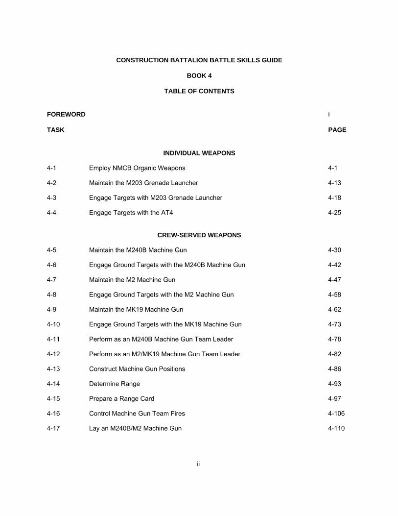
TABLE OF CONTENTS FOREWORD i TASK PAGE
INDIVIDUAL WEAPONS 4-1 Employ NMCB Organic Weapons 4-1 4-2 Maintain the M203 Grenade Launcher 4-13 4-3 Engage Targets with M203 Grenade Launcher 4-18 4-4 Engage Targets with the AT4 4-25
CREW-SERVED WEAPONS 4-5 Maintain the M240B Machine Gun 4-30 4-6 Engage Ground Targets with the M240B Machine Gun 4-42 4-7 Maintain the M2 Machine Gun 4-47 4-8 Engage Ground Targets with the M2 Machine Gun 4-58 4-9 Maintain the MK19 Machine Gun 4-62 4-10 Engage Ground Targets with the MK19 Machine Gun 4-73 4-11 Perform as an M240B Machine Gun Team Leader 4-78 4-12 Perform as an M2/MK19 Machine Gun Team Leader 4-82 4-13 Construct Machine Gun Positions 4-86 4-14 Determine Range 4-93 4-15 Prepare a Range Card 4-97 4-16 Control Machine Gun Team Fires 4-106 4-17 Lay an M240B/M2 Machine Gun 4-110

iii
4-18 Lay an MK19 Machine Gun 4-119 4-19 Zero the M240B Machine Gun 4-125 4-20 Zero the M2 Machine Gun 4-129 4-21 Zero the M2 Machine Gun Using Night Vision 4-133 4-22 Zero the MK19 Machine Gun 4-138 4-23 Zero the MK19 Machine Gun Using Night Vision Sight 4-140 4-24 Supervise the Construction of Machine Gun Positions 4-143 4-25 Control Machine Gun Squad Fires 4-144 4-26 Supervise Maintenance of Machine Guns 4-148 4-27 Determine the Error in a Lensatic Compass 4-149 4-28 Declinate an M2 Compass 4-151 4-29 Supervise Unit Individual Weapons Training 4-153 4-30 Supervise Unit Crew-Served Weapon Training 4-154 4-31 Prepare a Fire Support Plan for Platoon-Size Defensive Operations 4-155

iv
SUMMARY OF CONSTRUCTION BATTALION BATTLE SKILLS GUIDE
BOOK 1
Construction Battalion Battle Skills Guide, Book 1, All Hands, E1 and Above, Individual Skills consists of the following:
INDIVIDUAL WEAPONS Weapons Handling, Shoulder Fired Weapons Weapons Handling, Handguns Maintain the M16A3 Service Rifle Zero the M16A3 Service Rifle Engage Targets with the M16A3 Service Rifle ATTACHMENT (A1) Fundamentals of
Marksmanship Maintain the M9 Service Pistol Engage Targets with the M9 Service Pistol PATROLLING Participate in a Security Patrol Perform as a Member of a Convoy TACTICAL MEASURES Prepare Individual Combat Equipment for
Tactical Operations Perform Individual Movement Prepare a Fire Team Fire Plan and Fire Plan
Sketch React to Enemy Indirect Fire Assume Field Firing Positions React to Enemy Direct Fire Construct Fighting Position Camouflage Self and Individual Equipment Participate in Squad-Size Defense Operate Night Vision Goggles Employ Techniques of Unaided Night Vision Report Intelligence Information Conduct Vehicle Search Procedure Process Enemy Personnel Submit a Spot Report Perform as a Member of NMCB Interior Guard Perform as a Fire team Member in Civil
Disturbance Situations HAND GRENADES, MINES, AND PYROTECHNICS
Engage Targets with Hand Grenades Employ the M49A1 Trip Flare Employ the M18A1 Claymore Mine Locate Possible Mine/Boobytrap Sites
NBC DEFENSE Identify NATO NBC Markers Maintain the M40A1 Protective Mask Don the M40A1 Protective Mask with Hood Perform Basic Body Functions while in MOPP 4 Identify Chemical Agents Decontaminate Skin and Personal Equipment
Using the M291Decontamination Kit Exchange MOPP Gear React to Nuclear Attack React to a Chemical or Biological Attack Treat a Chemical Agent Casualty FIRST AID AND FIELD SANITATION Apply Basic First Aid Perform Basic First Aid Preventive Measures Practice Basic Field Sanitation Transport Casualties Using Manual Carries and
Improvised Stretchers LAND NAVIGATION Perform Basic Map Reading Navigate with a Map Using Terrain Association Navigate with a Map Using a Compass Orient a Map Using Hasty Field Expedient
Techniques Locate an Unknown Point by Resection Locate an Unknown Point by Intersection Navigate Around an Obstacle Using the Box
Method Convert Azimuths Determine the Elevation of a Point on the
Ground Using a Map COMMUNICATIONS Repair (Splice) Wire Operate a TA-1 Telephone Set Operate a TA-312 Telephone Set Operate an AN/PRC-119 Radio Set Communicate Using a Radio ATTACHMENT (A2) Phonetic Alphabet and
Numeric Pronunciation ATTACHMENT (A3) Prowords and Warning
Words and their Explanations

v
BOOK 2 Construction Battalion Battle Skills Guide, Book 2, E4 - E6, Individual Skills consists of following
INDIVIDUAL WEAPONS Conduct Refresher Training on How to Maintain
the M16A3 Service Rifle PATROLLING
Assist in the Conduct of a Squad-Sized Security Patrol
Conduct a Squad-Sized Security Patrol Issue a Patrol Warning Order Issue a Patrol Order Conduct Patrol Inspections Conduct Patrol Rehearsals Conduct Patrolling Immediate Action Drills Prepare Patrol Routes
TACTICAL MEASURES Conduct Refresher Training on Fire Team-Size
Combat Formations Prepare a Terrain Model Control Movement of Fire Team-Size Unit Establish Defensive Positions for a Fire Team-
Size Unit Establish an Observation Outpost (OP) /
Listening Post (LP) Direct Erection of Wire Obstacles Control Unit Fires Control Movement of a Squad-Size Unit Establish Defensive Positions for a Squad-Size
Unit
Adjust Indirect Fire Establish a Landing Zone Direct a Helicopter Landing Zone Direct the MEDEVAC of a Casualty
NBC DEFENSE Prepare NBC I Report (Observer's Report) Implement Mission-Oriented Protective Posture
(MOPP) Control the Spread of Contamination Minimize Adverse Effects of Wearing MOPP
Gear for Prolonged Periods FIRST AID AND FIELD SANITATION
Enforce Proper Field Sanitation Conduct Refresher First Aid and Field Sanitation
Training COMMUNICATIONS
Install a Hot Loop Operate an AN/PRC-138 Field Radio Set Conduct Refresher Training on How to Operate
the AN/PRC-104/119 Radio Set Conduct Refresher Training on How to Operate
Field Telephones Supervise Operator Level Maintenance of
Portable Communications Equipment

vi
BOOK 3 Construction Battalion Battle Skills Guide, Book 3, E-7 and Above, Individual Skills consists of the following:
CREW-SERVED WEAPONS Employ Machine Guns Select M240B Machine Gun Firing Positions Select M2/MK19 Machine Gun Firing Positions Assign a Machine Gun FPL/PDF
TACTICAL MEASURES Issue a Fragmentary Order for a Defensive
Mission Prepare a Fire Plan for Platoon-Size Defensive
Position Control Defensive Fires Direct the Placement of Wire Obstacles Establish a Company-Size Command Post Prepare Operation Overlay Direct Casualty Evacuation Direct the Handling of Captured Enemy
Personnel
NBC DEFENSE Supervise Conduct of Mask Confidence
Exercise Assist Commander on Unmasking Procedures Execute Protective Measures for a Nuclear
Attack Execute Protective Measures for a Biological
and Chemical Attack Prepare NBC 4 Report (Reconnaissance, Monitoring, and Survey Results) Lead MOPP Gear Exchange
COMMUNICATIONS Apply the Elements of Communications Supervise Unit's Individual Training in Communications

vii
BOOK 4 Construction Battalion Battle Skills Guide, Book 4, Crew/Team Skills consists of the following:
INDIVIDUAL WEAPONS Employ NMCB Organic Weapons Maintain the M203 Grenade Launcher Engage Targets with M203 Grenade Launcher Engage Targets with the AT4
CREW-SERVED WEAPONS Maintain the M240B Machine Gun Engage Ground Targets with the M60E3
Machine Gun Maintain the M2 Machine Gun Engage Ground Targets with the M2 Machine
Gun Maintain the MKI9 Machine Gun Engage Ground Targets with the MKI9 Machine
Gun Perform as an M240B Machine Gun Team
Leader Perform as an M2/MI9 Machine Gun Team
Leader Construct Machine Gun Positions Determine Range
Prepare a Range Card Control Machine Gun Team Fires Lay an M240B/M2 Machine Gun Lay an MK19 Machine Gun Zero the M240B Machine Gun Zero the M2 Machine Gun Zero the M2 Machine Gun Using Night Vision Zero the MKI9 Machine Gun Zero the MKI9 Machine Gun Using Night Vision
Sight Supervise the Construction of Machine Gun
Positions Control Machine Gun Squad Fires Supervise Maintenance of Machine Guns Determine the Error in a Lensatic Compass Declinate an M2 Compass Supervise Unit Individual Weapons Training Supervise Unit Crew-Served Weapon Training Prepare a Fire Support Plan for Platoon-Size
Defensive Operations

viii
COMBAT SKILLS TASKS
BOOK 4
4-1
TASK: EMPLOY NMCB ORGANIC WEAPONS (4-1) CONDITIONS: GIVEN A TACTICAL SCENARIO IN ANY COMBAT ENVIRONMENT,
COMMANDERS GUIDANCE, AND ORGANIC WEAPONS. STANDARD: THE SEABEE MUST IDENTIFY AND DESCRIBE THE DIFFERENT ORGANIC
WEAPONS, ITS CHARACTERICTICS, TECHNICAL DATA AND APPLICATION AS PER THE REFERENCES.
EVALUATION GUIDELINES TO BE USED DURING TRAINING:
Conditions: The Seabee is provided a tactical scenario in any combat environment, the
commanders guidance and organic weapons.
Standard: The Seabee must identify and describe different organic weapons, its characteristic, technical data and applications
PERFORMANCE STEPS: 1. Received the operation order, which will include different organic weapons to be used for this training. 2. Identify and describe the organic weapons, its characteristics, technical data and application.
a. M16A3 Service Rifle
1) The M16A3 service rifles are a lightweight, gas- operated, air-cooled, magazine-fed, shoulder- fired weapon that can be fired either on automatic or semiautomatic.
2) Characteristics:
a) Caliber: 5.56 mm
b) Weight: Approx. 8.79 lb (with 30 round magazine)
c) Length: 39 5/8 inches (w/ compensator)
d) Muzzle velocity: 3,100 fps
e) Sustained rate of fire: 12 to 15 Rounds Per Minute (rpm).
f) Maximum effective rate of fire (semiautomatic): 45 rpm
g) Maximum effective rate of fire (automatic): 90 rpm
h) Cyclic rate of fire: Approx. 800 rpm
i) Maximum range: 3534 meters

4-2
j) Maximum effective range: 550 meters (individual or point target) 800 meters (area target)
3) The M16A3 is equipped with a flash compensator to hold the muzzle down during rapid and
automatic firing.
4) The M16A3 barrel is covered by two aluminum-lined; fiberglass handguards, which are round and ridged making them stronger and easier to grip.
NOTE: The M16A3 handgrips are interchangeable.
5) A "clothespin" bipod is issued to, and used by, the automatic rifleman. The bipod attaches
to the barrel directly beneath the front sling swivel.
6) A forward assist assembly located on the right rear of the upper receiver, permits closing of the bolt when the force of the action spring does not.
7) The trigger guard adapts easily for use in winter operations.
- A spring-loaded retaining pin is depressed so the trigger guard swings down along the
pistol grip, allowing ready access to the trigger when cold weather mittens are being worn.
b. M203, 40-mm Grenade Launcher.
1) When equipped with a 40-mm grenade launcher, the M16 rifle becomes M203, and loses
its identity as the M16 rifle.
2) Characteristics:
a) Lightweight
b) Compact
c) Breech-loading
d) Pump-action (Sliding-barrel)
e) Single-shot
f) One mechanical safety
g) Manually operated
3) Technical Data
a) Approximately 3.6 pounds loaded
b) Approximately 3 pounds unloaded

4-3
NOTE: Total weight of the M203 including the M16A3 is 12.39 pounds fully loaded.
c) Maximum range: 400 meters
d) Area target range: 350 meters
e) Point target range: 150 meters
f) Minimum safe firing range from HE: 31-meters/102 ft. (combat)
4) Ammunition
a) The two most common types of 40-mm ammunition used with the launcher are High
Explosive (HE) and Training Practice (TP).
c. M9, 9mm Pistol
1) Characteristics:
- Semiautomatic, magazine fed, recoil operated, single action or double action.
2) Technical Data:
a) Description:
(1) Caliber - 9x19mm (9MM NATO)
(2) System of operation - short recoil, semiautomatic
(3) Locking System - oscillation block
(4) Length - 217 mm (8.54 in.)
(5) Width - 38 mm (1.50 in.)
(6) Height - 140 mm (5.51 in.)
(7) Weight:
(a) 960 grams (33.86 oz) (w/empty magazine)
(b) 1145 grams (40.89 oz) (w/15 round magazine)
(8) Trigger Pull
(a) Double action 9.6 to 16.6 lb
(b) Single action 4.1 to 6.4 lb
(9) Barrel Length - 125 mm (4.92 in)

4-4
(10) Muzzle Velocity - 375 meter/sec (1230.3 Feet Per Second (FPS))
(11) Maximum Effective Range - 50 meters (54.7 yards)
(12) Maximum Range - 1800 meters (1969.2 yards)
(13) Fixed Sights
b) Safeties:
(1) Ambidextrous Decocking/Safety Lever - Ambidextrous decocking/safety lever,
allows safe operation of the pistol by both right and left-handed users
(a) Located on the slide
(b) Separates the firing pin from the hammer
(c) Interrupts the connection between trigger and sear
(2) Firing Pin Block
(a) Prevents any motion of the firing pin
(b) Manufactured to always be in place
(c) Overcome only by pulling the trigger
WARNING: A POTENTIAL SAFETY HAZZARD EXISTS IF THE FIRING PIN BLOCK IS MISSING OR DOES NOT RETURN FLUSH WITH THE SLIDE SURFACE AFTER FIRING
NOTE: Half cock position of the hammer helps prevent hammer from
inadvertently striking the firing pin while cocking. Trigger manipulation overrides the half cock position. (not considered as safety).
c) Magazine - Staggered, 15 round capacity
d) Slide - held open upon firing of last round
e) Grips - Plastic checkered or magazine knurled
f) Authorized Ammunition:
WARNING: USE M882 OR ISSUED AMMUNITION ONLY
WARNING: DO NOT FIRE HEAVILY CORRODED OR DENTED CARTRIDGES,
CARTRIDGES WITH LOOSE BULLETS, OR ANY OTHER DEFECTIVE ROUNDS DETECTED BY VISUAL INPECTION

4-5
d. M240B Machine Gun
1) Used to support Company-sized unit.
2) Capable of delivering a heavy volume of controlled and accurate fire, both in defensive and limited offensive situations.
3) Its capability is more than that of other individual small arms.
4) Can effectively engage predetermined targets under all conditions of visibility.
5) NMCB fire plans are made around the final protective fires of this weapon.
6) Characteristics:
a) Air-cooled
b) Belt-fed
c) Disintegrating link.
d) Gas-operated automatic weapon
e) Features established headspace allowing rapid changing of the barrel.
f) Fires from the open-bolt position.
7) General Data:
a) Ammunition: 7.62-mm NATO
b) Length: 49 inches
c) Weight: 27.1 pounds
d) Rates Of Fire:
(1) Sustained: 100 rpm
NOTE: The weapon can fire this rate of fire (with six to nine round bursts)
for 10 minutes before the barrel must be changed.
(2) Rapid: 200 rpm
NOTE: Can be delivered for two minutes before barrel must be changed.
(3) Cyclic: 650 to 950 rpm
NOTE: Can be delivered for one minute before barrel must be changed.
e) Muzzle velocity: 2,800 fps

4-6
f) Maximum range: 3725 meters (approx.)
g) Maximum effective range: 1800 meters-area target, 800 meters-point target
8) Ammunition
a) Based upon the type of projectile, the ammunition authorized for the M240B machine gun is classified as follows:
(1) Ball cartridges are used against light targets such as houses and personnel, and
during training.
(2) Armor-piercing cartridges are used against lightly armored targets where armor- piercing effects are desired.
(3) Armor-piercing incendiary cartridges are used for desired armor piercing effects
combined with fire-producing (incendiary) effects.
SAFETY NOTE: Armor-piercing and armor-piercing incendiary ammunition is NOT authorized for training purposes.
(4) Tracer cartridges are used for observation of fire, incendiary effects, signaling,
and during training.
b) Dummy cartridges are used during training.
c) Blank cartridges are used with a Blank Firing Attachment (BFA) during training when simulated live fire is desired.
e. M2, .50-Caliber HB, Browning Machine Gun
NOTE: The "HB" designation stands for "heavy barrel."
1) Browning Machine Guns (BMGs) are standard weapons used throughout the Navy.
2) The .50-caliber BMG issued to naval activities is designated the M2.
3) General description of the .50-Caliber BMG
a) Belt-fed
b) Crew-served
c) Recoil-operated
d) Air-cooled
e) Can be set for automatic or semiautomatic fire.
f) NOT equipped with any safeties.
4) Main characteristics of the .50-Caliber BMG

4-7
a) Weight:
(1) Receiver Group: 60 lbs.
(2) Barrel: 24 lbs. (approx)
(3) Tripod Mount (with T&E): 44 lbs.
(4) Total: 128 lbs. (approx)
b) Maximum range: 6800 meters (approx)
c) Maximum effective range: 1830 meters
d) Rates of fire:
(1) Sustained: 40 rpm or less
(2) Rapid: 40 rpm or more
(3) Cyclic: 450 to 550 rpm
e) Muzzle velocity: 3,050 fps or 2,080 mph
f) Length:
(1) Gun (overall): 65 inches (approx.)
(2) Barrel: 45 inches
5) Ammunition for .50-Caliber BMG
a) Blank: For simulated fire (contains no projectile).
b) Dummy: For training (completely inert).
c) Ball: For use in marksmanship training, and against personnel and light material targets.
d) Tracer: To aid in observing fire. Secondary purposes are for incendiary effect and for
signaling.
SAFETY NOTE: The following four (4) types of ammunition are NOT authorized for training purposes.
e) Armor-piercing: For use against armored aircraft and lightly armored vehicles,
concrete shelters, and other bullet-resistant targets.
f) Incendiary: For incendiary effect, especially against aircraft.
g) Armor piercing incendiary: For combined armor-piercing and incendiary effect.

4-8
h) Armor-piercing-incendiary-tracer: For combined armor-piercing and incendiary effect, with the additional tracer feature.
f. MK 19 MOD 3 40-mm Grenade Machine Gun
1) Fires 40-mm grenades with antipersonnel fragmentation and light anti-armor capability.
2) Characteristics
a) Air-cooled
b) Belt-fed
c) Blowback-operated
d) Fully automatic
3) General Data
a) Weight: 75.6 lbs.
b) Length: 43.1 inches
c) Rates of fire:
(1) Sustained: 40 rpm
(2) Rapid: 60 rpm
(3) Cyclic: 325-375 rpm
d) Range:
(1) Effective point target: 1500 meters
(2) Effective area target: 2212 meters
e) M64 Mount
- weight: 21 lbs.
4) Ammunition for the MK 19 MOD 3
SAFETY WARNING: Ammunition for the MK 19 is NOT interchangeable with M203
ammunition.
a) HE ROUND (yellow or gold olive)
(1) A High Explosive (HE) grenade
(2) Designed to inflict personnel casualties

4-9
(3) Arming distance: 18 to 36 meters
(4) Kill radius: 5 meters
(5) Casualty radius: 15 meters
b) TP Rounds (blue or silver olive)
(1) Training Practice (TP), inert rounds with a propelling charge
(2) Muzzle velocity: 244 meters per second
(3) Maximum range: 2200 meters
c) Dummy Round (indented case, yellow or gold olive)
(1) Totally inert
(2) Used to check gun functioning and for gun crew training

4-10
h. M136 (AT4), HEAT, 84-mm Launcher
1) Characteristics
a) Lightweight, self-contained anti-armor weapons.
b) Consists of a free flight, fin-stabilized cartridge packed in an expendable launcher.
c) Issued as a round of ammunition.
d) Launcher serves as a watertight packing container for transportation and storage.
e) The launcher is a one-piece, disposable, fiberglass-wrapped tube with the following
components affixed to it:
2) Describe each component and its function.
a) Transport Safety Pin
b) Cocking Lever
c) Fire-Through Muzzle Cover
d) Color-Code Band (tactical color is black or black with gold)
e) Front Sight
f) Rear Sight
g) Venturi
h) Forward Safety
i) Red Trigger Button
j) Shoulder Stop
k) Carrying Sling
l) Firing Mechanism

4-11
SAFETY NOTE: There is a back-blast of 5 meters (casualty area) and 60
meters (danger area) at a 90O to the venture.
3) Used mainly as an antiarmor weapon.
- However, it can be used against gun emplacements and bunkers.
4) Technical Data
a) Weight: 14.8lbs.
b) Caliber: 84-mm
c) Length: 40 inches
d) Muzzle velocity: 950 fps
e) Range:
(1) Max: 2100 meters
(2) Max. Effective: 300 meters
(3) Minimum arming: 10 meters
i. Night Vision Devices
1) AN/PVS-4 (old sight) AN/PVS-12A (new sight) for M16A3 rifle and AN/TVS-5 for crew served weapon Night Vision Sights
a) Electro-optical instruments used for observation and aimed fire of weapons at night.
b) Amplifies reflected light such as moonlight, starlight, and skyglow so that the viewed
scene becomes clearly visible to the operator.
c) Does NOT emit visible or infrared light (except from the eyepiece) that can be detected by the enemy.
d) The AN/PVS-4 may be hand-held or mounted on the M16 rifles, the M203 grenade
launcher, and the M240B machine gun.
e) The AN/TVS-5 may be mounted on the M2, M240B, and MK 19 machine guns or used as a tripod mounted observation device.
2) Night Vision Goggle, AN/PVS-7A, AN/PVS-7B, AN/PVS-7C
a) Self-contained night vision system worn on the head or hand-held.
b) Provides improved night vision capabilities using available light from the night sky
(starlight and/or moonlight).

4-12
c) May be used with or without the standard battle helmet, and provides capabilities for reading, performing manual tasks, patrolling, medical aid, construction work, mobile equipment operation, walking, surveillance, and convoys.
CAUTION: Operate night vision devices under NIGHTTIME conditions only.
Using night vision devices during the day, in a brightly-lit room, or staring at a bright light source, even at night, can permanently damage the image intensifier.
3) Cleaning and Preventive Maintenance
Note: The following information relates to all three types of night vision devices.
a) Lenses:
(1) Remove loose dirt with a lens brush.
(2) Clean the glass surfaces of lenses with lens tissue. You may saturate the lens
tissue with fresh water (distilled, if available) to remove dirt that is caked on the surface.
(3) Dry and polish lens with a dry lens tissue.
b) Metal Surfaces:
(1) Clean all exposed metal surfaces with a lint-free cloth.
(2) If necessary, dampen the cloth with fresh water.
(3) Allow surfaces to dry thoroughly before storing night vision device.
c) Eyepiece:
- Clean rubber eyepiece with a wet cloth.
4) Qualified personnel should perform corrective maintenance on night vision devices only.
REFERENCES: NAVEDTRA 12003, U.S. Navy Seabee Combat Handbook, Volume I FM 23-65, U.S. Army Browning M2 .50 Caliber HB Machine Gun SW215-AD-MMO-010, Description, Operation and Maintenance for Night Vision Sight, Individual Served
Weapon AN/PVS-4 SW215-AE-MMO-010, Description, Operation and Maintenance for Night Vision Sight, Crew Served
Weapon AN/TVS-5 SW215-B4-MMO-010, Operator's and Maintenance Manual for AN/PVS-12A, Night Vision Weapon Sight TM-11-5855-262-10-1, Operators Manual Night Vision Goggle AN/PVS-7 TM 05538C-10/1A, U.S. Marine M16A2 Rifle Operators Manual

4-13
TASK: MAINTAIN THE M203 GRENADE LAUNCHER (4-2) CONDITIONS: GIVEN AN M203 GRENADE LAUNCHER, AND APPROPRIATE CLEANING
EQUIPMENT. STANDARD: THE SEABEE MUST MAINTAIN THE M203 GRENADE LAUNCHER AS PER THE
REFERENCES.
EVALUATION GUIDELINES TO BE USED DURING TRAINING:
Conditions: The Seabee is provided an M203 grenade launcher; a bore brush; Cleaner,
Lubricant and Preservative (CLP); and clean rags.
Standard: The Seabee must safely handle the weapon at all times. The Seabee must disassemble, inspect, and clean the weapon, ensuring that it is free of dirt, oil, and carbon. The Seabee must also lubricate, reassemble, and perform preventive maintenance and apply function checks.
Administrative Note: See: WEAPONS HANDLING, SHOULDER FIRED WEAPONS (1-1)
PERFORMANCE STEPS: 1. Place the M203 grenade launcher and the M16A3 rifle in condition 4. (See : WEAPONS HANDLING,
SHOULDER FIRED WEAPONS (1-1).) 2. Disassemble the M203 grenade launcher.
WARNING: DO NOT INTERCHANGE BARREL ASSEMBLIES OR COMPONENTS FROM ONE WEAPON TO ANOTHER. DOING SO MAY CAUSE INJURY OR DEATH TO PERSONNEL.
a. Remove the quadrant sight, if used, by loosening the knurled screw on the right side of the
weapon (Figure 1).
Figure 1 Figure 2
b. Pull back on the slip ring. Lift up the hand guard and pull to the rear to remove (Figure 2).
c. Press the barrel latch and move the barrel forward until it stops (Figure 3).

4-14
Figure 3 Figure 4
d. Press the barrel stop to release the barrel from the receiver (Figure 4).
e. Remove the barrel from the receiver.
Note: For quick disassembly of the barrel: Insert cleaning rod 4th hole from front sight to release barrel stop.
3. Clean the grenade launcher.
a. Clean the bore and chamber with the bore brush, thong, and CLP (Figure 5).
b. Clean the area around the breech insert and firing pin hole using CLP (Figure 6).
Figure 5 Figure 6
c. Clean all the dust and dirt from the weapon using CLP and a clean rag.
d. Clean the locator slot (Figure 7).
e. Wipe the inside of the barrel with a clean rag.
4-15
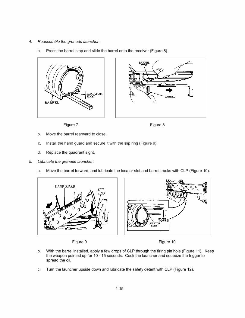
4. Reassemble the grenade launcher.
a. Press the barrel stop and slide the barrel onto the receiver (Figure 8).
Figure 7 Figure 8
b. Move the barrel rearward to close. c. Install the hand guard and secure it with the slip ring (Figure 9).
d. Replace the quadrant sight. 5. Lubricate the grenade launcher.
a. Move the barrel forward, and lubricate the locator slot and barrel tracks with CLP (Figure 10).
Figure 9 Figure 10
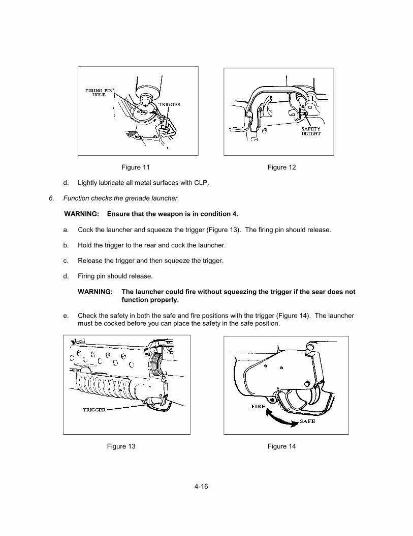
b. With the barrel installed, apply a few drops of CLP through the firing pin hole (Figure 11). Keep the weapon pointed up for 10 - 15 seconds. Cock the launcher and squeeze the trigger to spread the oil.
c. Turn the launcher upside down and lubricate the safety detent with CLP (Figure 12).
4-16
Figure 11 Figure 12
d. Lightly lubricate all metal surfaces with CLP. 6. Function checks the grenade launcher.
WARNING: Ensure that the weapon is in condition 4.
a. Cock the launcher and squeeze the trigger (Figure 13). The firing pin should release.
b. Hold the trigger to the rear and cock the launcher.
c. Release the trigger and then squeeze the trigger.
d. Firing pin should release.
WARNING: The launcher could fire without squeezing the trigger if the sear does not function properly.
e. Check the safety in both the safe and fire positions with the trigger (Figure 14). The launcher
must be cocked before you can place the safety in the safe position.
Figure 13 Figure 14

4-17
f. Move the barrel forward and backward to ensure that the barrel stop and barrel latch function
(Figure 15). 7. Perform preventive maintenance checks on the grenade launcher.
a. Before operating the grenade launcher, open the barrel and clear the launcher.
b. Make an overall visual inspection for missing or damaged components.
c. Check to ensure that the launcher is firmly attached to the rifle.
Figure 15 Figure 16
d. Wipe any oil and debris from the barrel bore and chamber.
e. Check the operation of the sear (See Performance Step 6).
f. Check the operation of the safety (See Performance Step 6).
g. Check the hand guard and leaf sight for damage, then check sight functioning (Figure 16).
h. Check the quadrant sight for damage, then check the sight functioning (Figure 17).
Figure 17
i. Observe the weapon for component failures. Report any failures to the unit armorer. REFERENCES: FMFM 0-8, Basic Marksmanship TM 9-1010-221-10, 40mm Grenade Launcher M203
4-18
TASK: ENGAGE TARGETS WITH THE M203 GRENADE LAUNCHER (4-3) CONDITIONS: GIVEN A TACTICAL SCENARIO IN ANY COMBAT ENVIRONMENT (DAY AND
NIGHT), AN M203 GRENADE LAUNCHER, ALL INDIVIDUAL COMBAT EQUIPMENT (782 GEAR), AND AMMUNITION.
STANDARD: THE SEABEE MUST EFFECTIVELY ENGAGE TARGETS WITH THE M203
GRENADE LAUNCHER USING BOTH THE LEAF AND QUADRANT SIGHTS AS PER THE REFERENCES.
EVALUATION GUIDELINES TO BE USED DURING TRAINING:
Conditions: The Seabee is provided with a tactical scenario in a combat environment (day and
night), an M203 grenade launcher, all individual combat equipment (782 gear), and Training Practice (TP) ammunition.
Standard: The Seabee must handle the weapon safely at all times, select the correct
ammunition, load, field zero the weapon, estimate range to target, respond to fire commands, and then effectively engage the target with the leaf sight and the quadrant sight. The Seabee must perform immediate action for a malfunction or stoppage, perform a function check, and ensure the weapon is completely safe after firing.
Administrative Note: See: WEAPONS HANDLING, SHOULDER FIRED WEAPONS (1-1)
PERFORMANCE STEPS: 1. Place the weapon in condition 4 (See : WEAPONS HANDLING, SHOULDER FIRED WEAPON
(1-1).) 2. Ensure that the M203 grenade launcher is assembled and functioning for firing. (See TASK:
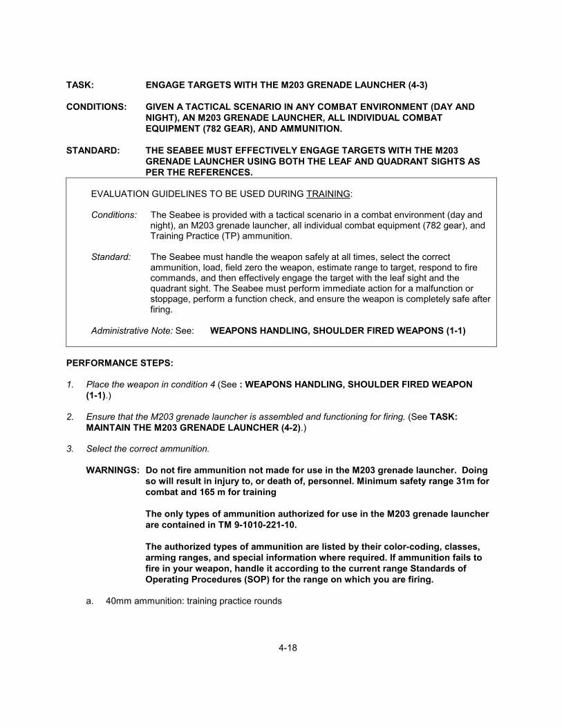
MAINTAIN THE M203 GRENADE LAUNCHER (4-2).) 3. Select the correct ammunition.
WARNINGS: Do not fire ammunition not made for use in the M203 grenade launcher. Doing so will result in injury to, or death of, personnel. Minimum safety range 31m for combat and 165 m for training
The only types of ammunition authorized for use in the M203 grenade launcher are contained in TM 9-1010-221-10.
The authorized types of ammunition are listed by their color-coding, classes, arming ranges, and special information where required. If ammunition fails to fire in your weapon, handle it according to the current range Standards of Operating Procedures (SOP) for the range on which you are firing.
a. 40mm ammunition: training practice rounds

4-19
1) The M781 practice round is completely inert and contains no fuze (Figure 1). 2) The M407A1 practice round fuze arms between 14 to 27 meters (46 to 89 ft) (Figure 2).
Figure 1 Figure 2
WARNING: The danger radius of practice grenades is 20 meters (66 ft).
b. 40mm ammunition: multiple purpose and chemical rounds
1) The multipurpose round (buckshot) M576, contains no mechanical type fuze (Figure 3).
When firing the M576 cartridge from the M203 launcher, aim at the foot of the target.
2) Chemical round (tactical CS) M651 (Figure 4) arms between 10 to 30 meters (33 to 99 ft).
Figure 3 Figure 4
4-20
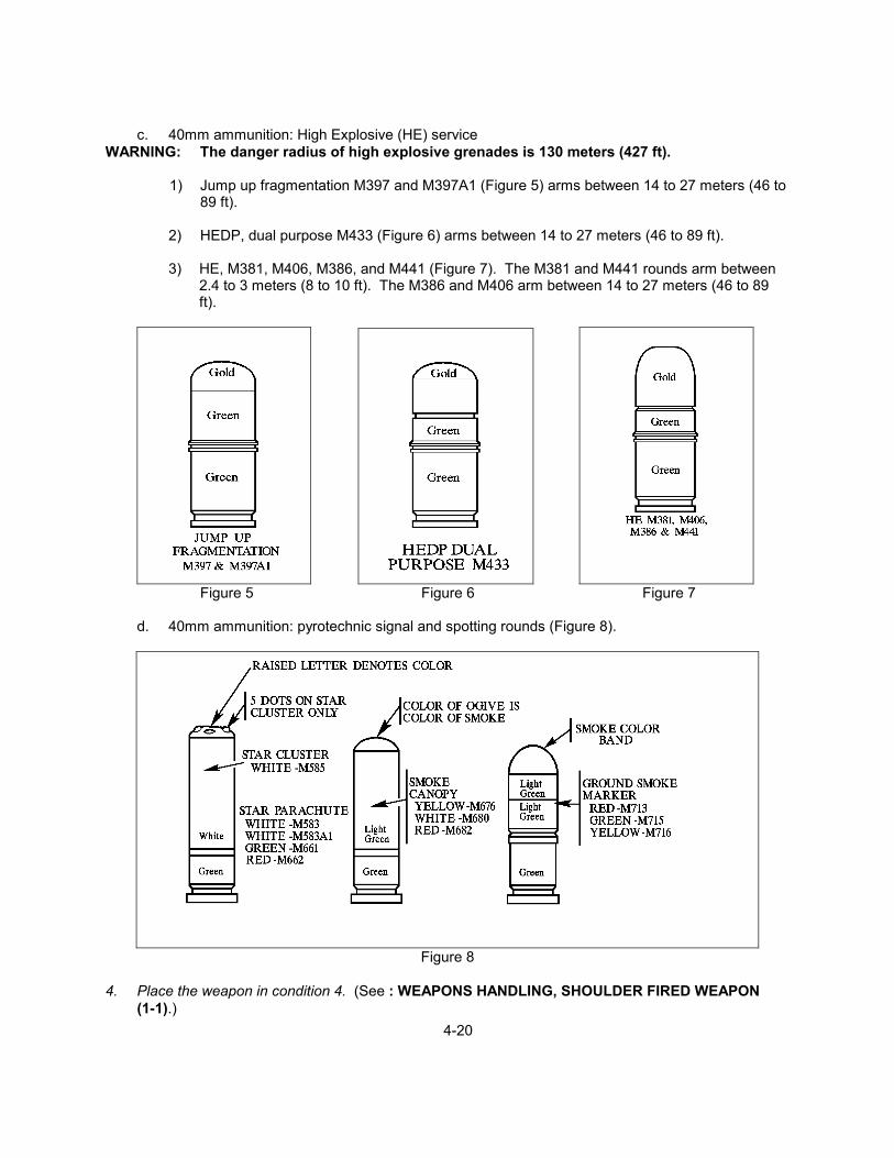
c. 40mm ammunition: High Explosive (HE) service WARNING: The danger radius of high explosive grenades is 130 meters (427 ft).
1) Jump up fragmentation M397 and M397A1 (Figure 5) arms between 14 to 27 meters (46 to 89 ft).
2) HEDP, dual purpose M433 (Figure 6) arms between 14 to 27 meters (46 to 89 ft).
3) HE, M381, M406, M386, and M441 (Figure 7). The M381 and M441 rounds arm between
2.4 to 3 meters (8 to 10 ft). The M386 and M406 arm between 14 to 27 meters (46 to 89 ft).
Figure 5 Figure 6 Figure 7
d. 40mm ammunition: pyrotechnic signal and spotting rounds (Figure 8).
Figure 8
4. Place the weapon in condition 4. (See : WEAPONS HANDLING, SHOULDER FIRED WEAPON
(1-1).)
4-21
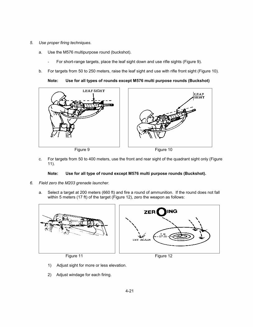
5. Use proper firing techniques.
a. Use the M576 multipurpose round (buckshot).
- For short-range targets, place the leaf sight down and use rifle sights (Figure 9).
b. For targets from 50 to 250 meters, raise the leaf sight and use with rifle front sight (Figure 10).
Note: Use for all types of rounds except M576 multi purpose rounds (Buckshot)
Figure 9 Figure 10
c. For targets from 50 to 400 meters, use the front and rear sight of the quadrant sight only (Figure
11).
Note: Use for all type of round except M576 multi purpose rounds (Buckshot). 6. Field zero the M203 grenade launcher.
a. Select a target at 200 meters (660 ft) and fire a round of ammunition. If the round does not fall within 5 meters (17 ft) of the target (Figure 12), zero the weapon as follows:
Figure 11 Figure 12
1) Adjust sight for more or less elevation.
2) Adjust windage for each firing.

4-22
3) After each round of ammunition is fired, adjust until three consecutive round lands within 5
meters (17 ft) of the aiming point.
b. Adjust leaf sight (Figure 13).
CAUTION: The 50 meter mark on the leaf sight blade is marked in red to emphasize that this range will not be used in zeroing procedures.
1) Loosen the elevation adjustment screw to move the leaf sight up to increase the range for a
headwind. Lower it to decrease range for a rear wind.
2) Use the rim of a 40mm cartridge to turn the elevation adjustment screw.
NOTE: 1 increment = 10 meters (33 ft) at 200 meters.
3) Turn windage adjustment screw clockwise to adjust for wind from the left. Turn counterclockwise to adjust for wind from the right.
NOTE: 1 increment = 1.5 meters (5 ft) at 200 meters.
Figure 13
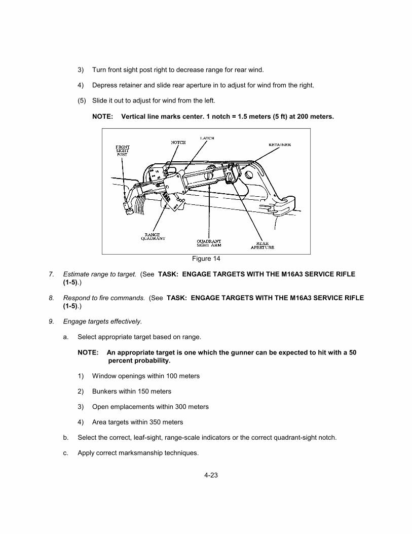
c. Adjust the quadrant sight (Figure 14).
NOTES: Range quadrant is marked in 25 meter (83 ft) increments for targets from 50 to
400 meters. Elevation adjustment: 1 notch = 5 meters (17 ft) at 200 meters.
1) Pull latch toward you to release quadrant sight arm. Select elevation.
2) Turn front sight post left to increase range for headwind.
4-23
3) Turn front sight post right to decrease range for rear wind.
4) Depress retainer and slide rear aperture in to adjust for wind from the right.
(5) Slide it out to adjust for wind from the left.
NOTE: Vertical line marks center. 1 notch = 1.5 meters (5 ft) at 200 meters.
Figure 14
7. Estimate range to target. (See TASK: ENGAGE TARGETS WITH THE M16A3 SERVICE RIFLE
(1-5).) 8. Respond to fire commands. (See TASK: ENGAGE TARGETS WITH THE M16A3 SERVICE RIFLE
(1-5).) 9. Engage targets effectively.
a. Select appropriate target based on range.
NOTE: An appropriate target is one which the gunner can be expected to hit with a 50 percent probability.
1) Window openings within 100 meters
2) Bunkers within 150 meters
3) Open emplacements within 300 meters
4) Area targets within 350 meters
b. Select the correct, leaf-sight, range-scale indicators or the correct quadrant-sight notch.
c. Apply correct marksmanship techniques.
4-24
1) Focus on the front sight post, until you have fired and the round of ammunition is enroute
downrange.
2) Apply correct trigger pull.
3) Use controlled breathing technique.
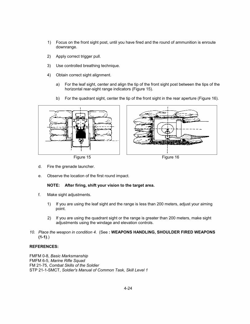
4) Obtain correct sight alignment.
a) For the leaf sight, center and align the tip of the front sight post between the tips of the horizontal rear-sight range indicators (Figure 15).
b) For the quadrant sight, center the tip of the front sight in the rear aperture (Figure 16).
Figure 15 Figure 16
d. Fire the grenade launcher.
e. Observe the location of the first round impact.
NOTE: After firing, shift your vision to the target area.
f. Make sight adjustments.
1) If you are using the leaf sight and the range is less than 200 meters, adjust your aiming
point.
2) If you are using the quadrant sight or the range is greater than 200 meters, make sight adjustments using the windage and elevation controls.
10. Place the weapon in condition 4. (See : WEAPONS HANDLING, SHOULDER FIRED WEAPONS
(1-1).) REFERENCES: FMFM 0-8, Basic Marksmanship FMFM 6-5, Marine Rifle Squad FM 21-75, Combat Skills of the Soldier STP 21-1-SMCT, Soldier's Manual of Common Task, Skill Level 1

4-25
TASK: ENGAGE TARGETS WITH THE AT-4 (4-4) CONDITIONS: GIVEN A TACTICAL SCENARIO IN ANY COMBAT ENVIRONMENT (DAY AND
NIGHT), AN AT-4, ALL INDIVIDUAL COMBAT EQUIPMENT (782 GEAR), AND ENEMY ARMORED TARGETS.
STANDARD: THE SEABEE MUST EFFECTIVELY ENGAGE TARGETS WITH THE AT-4 AS PER
THE REFERENCES.
EVALUATION GUIDELINES TO BE USED DURING TRAINING:
Conditions: Given a tactical scenario in any combat environment (day and night), an AT-4, all
individual combat equipment (782 gear), and enemy armored targets.
Standard: The Seabee must handle the weapon safely at all times, prepare the AT-4 for firing, estimate range to target, respond to fire commands, aim, fire and hit enemy armored targets. The Seabee must also perform immediate action for a misfire and ensure that the weapon is completely safe.
PERFORMANCE STEPS: 1. Handle the weapon safely at all times.
a. Keep the weapon pointed in a safe direction.
b. Handle with care. 2. Inspect the AT-4 for damage or defects.
NOTES: Inspection is limited to a visual examination of the external components.
The launcher is completely sealed because the AT-4 is issued as a round of ammunition.
a. Ensure that the transport safety pin is in place, fully inserted, and the lanyard is attached.
b. Ensure that the cocking lever is in the SAFE position and folded down.
c. Ensure that the fire-through muzzle cover is intact.
1) Cut out the seal if the fire-through muzzle cover is torn to ensure that there are no foreign
objects inside the launcher tube.
2) Turn down the tube muzzle, and shake it gently to remove any foreign objects.
d. Ensure that the launcher has a black or black and gold color-code band.
e. Ensure that the sights function properly.
4-26
- Open sight covers to ensure that the sights pop up and are not damaged.
f. Ensure that the red safety catch does not move when depressed.
g. Ensure that the rear seal is not cracked or damaged. The rear seal is inside the venturi and is
made of brown plexiglass.
NOTE: Before firing, ensure that there are no foreign objects obstructing the rear of the launcher (backblast area).
Safety Note: There is a backblast of 5 meters (casualty area) and 60 meters (danger area)
at a 90 degrees to the venturi. 3. Prepare the AT-4 for firing.
WARNING: Ensure that you have inserted earplugs. Keep the weapon pointed toward the target and keep backblast area clear.
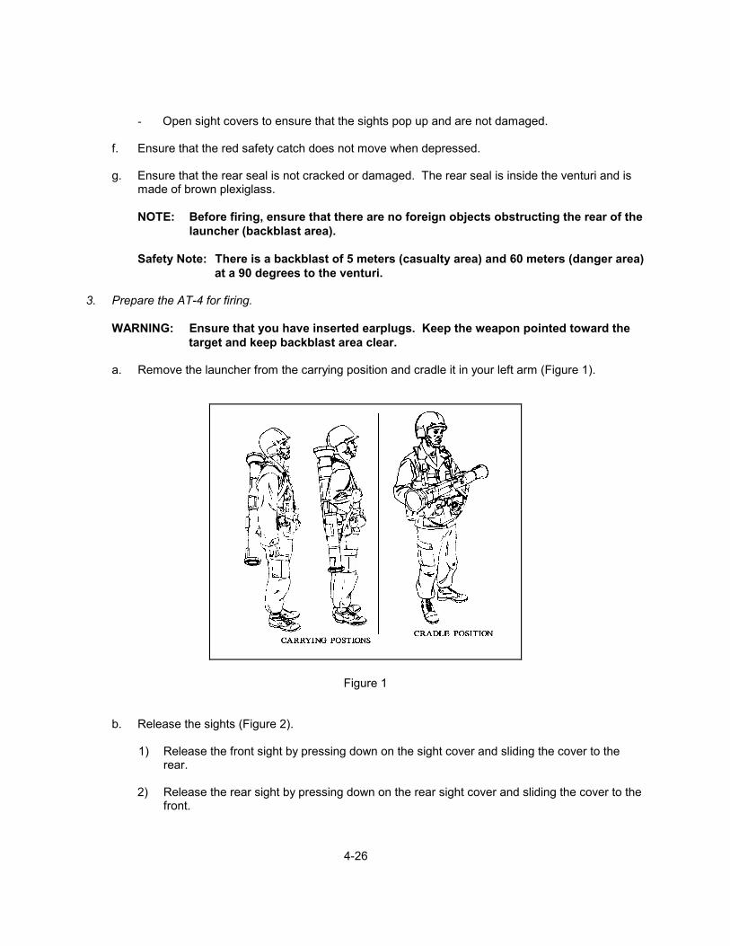
a. Remove the launcher from the carrying position and cradle it in your left arm (Figure 1).
Figure 1
b. Release the sights (Figure 2).
1) Release the front sight by pressing down on the sight cover and sliding the cover to the rear.
2) Release the rear sight by pressing down on the rear sight cover and sliding the cover to the
front.

4-27
c. Unsnap the shoulder strap and unfold it (Figure 3).
Figure 2 Figure 3
d. Remove the transport safety pin by pulling it out with your right hand and releasing it (Figure 4).
NOTE: Ensure that the transport safety pin is attached to the lanyard and that the lanyard is attached to the launcher. If it is not attached, keep the transport safety pin. It must be reinserted if the launcher is not fired.
e. Place the launcher on your right shoulder.
f. Cock the launcher by unfolding the cocking lever with your right hand (Figure 5).
Figure 4 Figure 5
g. Press the shoulder stop against your shoulder (Figure 6).
1) Grasp the carrying sling near the muzzle with your left hand.
2) Pull back on the carrying sling until the shoulder stop is snug against your shoulder.

4-28
Figure 6
h. Adjust the rear sight.
1) Adjust the rear sight range setting if the target range is more than 200 meters. (If the target range is less than 200 meters, no adjustment is necessary.)
2) Turn the range setting knob toward the desired settings (Figure 7).
Figure 7 4. Estimate range to target. (See TASK: ENGAGE TARGETS WITH THE M16A3 SERVICE RIFLE
(1-5).) 5. Respond to fire commands. (See TASK: ENGAGE TARGETS WITH THE M16A3 SERVICE RIFLE
(1-5).) 6. Aim and engage target.
a. Press the red safety catch all the way to the left with the index and middle finger of your right hand and hold it.

4-29
b. At the same time, pull the launcher into your shoulder with your right hand against the forward
edge of the firing mechanism housing.
c. Obtain a proper sight picture.
d. Fire the launcher.
- Apply pressure straightforward with the thumb of your right hand in a steady, smooth movement.
7. Perform immediate action for a misfire.
NOTE: A misfire is a complete failure to fire and may be due to a faulty firing mechanism or a faulty element in the propelling charge explosive train.
a. Shout "MISFIRE" immediately after the launcher fails to fire.
b. Maintain the original sight picture.
c. Release the red safety catch.
d. Recock the cocking lever.
e. Check the backblast area, aim; fully depress, and hold down the red safety catch.
f. Press the red trigger button.
g. Repeat steps B through F if the launcher still fails to fire.
h. Release the red safety catch and return the cocking lever to SAFE.
i. Remove the launcher from your shoulder, and keep the muzzle pointing to the target.
j. Reinsert the transport safety pin.
k. Dispose of the faulty launcher according to the current unit SOP.
REFERENCES: FMFM 0-8, Basic Marksmanship FMFM 6-5, Marine Rifle Squad FM 23-25, Launcher, Heat Projected, 84mm M136 (AT-4)

4- 30
TASK: MAINTAIN THE M240B MACHINE GUN (4-5) CONDITIONS: GIVEN A M240B MACHINEGUN AND CLEANING EQUIPMENT. STANDARD: THE SEABEE MUST MAINTAIN THE MACHINE GUN AS PER THE REFERENCES.
EVALUATION GUIDELINES TO BE USED DURING TRAINING:
Conditions: The Seabee is provided with a M240B machine gun; a cleaning kit; Cleaner, Lubricant, and Preservative (CLP); a combination wrench; rags and swabs.
Standard: The Seabee must demonstrate proper clearing, disassembly, cleaning, reassembly,
and function check procedures. The machine gun must be maintained so that it will pass a supervisor's inspection.
PERFORMANCE STEPS: 1. Inspect/inventory carrying case.
a. Tool pouch
1) Five section cleaning rod with swivel handle and swab holder section
2) 5/32 hex wrench
3) Two bore brushes
4) Receiver brush
5) Chamber brush
6) Ruptured cartridge extractor
7) Reamer cleaner
8) Scraper combination cleaner
9) Tool combination front sight adjustment
10) Tool combination scraper extractor
b. Spare barrel bag
1) Heat protective mitten
2) Spare barrel
3) T&E Mechanism
4) Pintle

4- 31
2. Clear the machine gun.
a. Point the machine gun in a safe direction.
b. Place the safety 1 in the F (fire) position (Figure 1) and pull the cocking handle 2 (Figure 2) to the rear until the bolt engages the sear.
NOTE: Always grab cocking handle palm up.
c. Return the cocking handle forward and place the safety in the S (safe) position.
d. Raise the cover by turning the cover latch and lifting up.
e. Raise the feedtray and visually inspect the chamber to ensure the machine gun is clear.
f. Place the safety in the F (fire) position, grasp and pull the cocking handle to the rear, pull the
trigger, and ride the bolt to the forward position. 3. Disassemble (general) the machine gun.
a. Remove the Buttstock and Buffer assembly (Figure 3).
Figure 1 Figure 2
1) Press back plate latch.
2) Remove the stock by sliding it straight up.
b. Remove the driving spring rod assembly.
1) Push against its base (Figure 3).
2) Lift up and outward so that it clears its retaining studs inside receiver.
3) Remove it from rear of receiver (Figure 4)
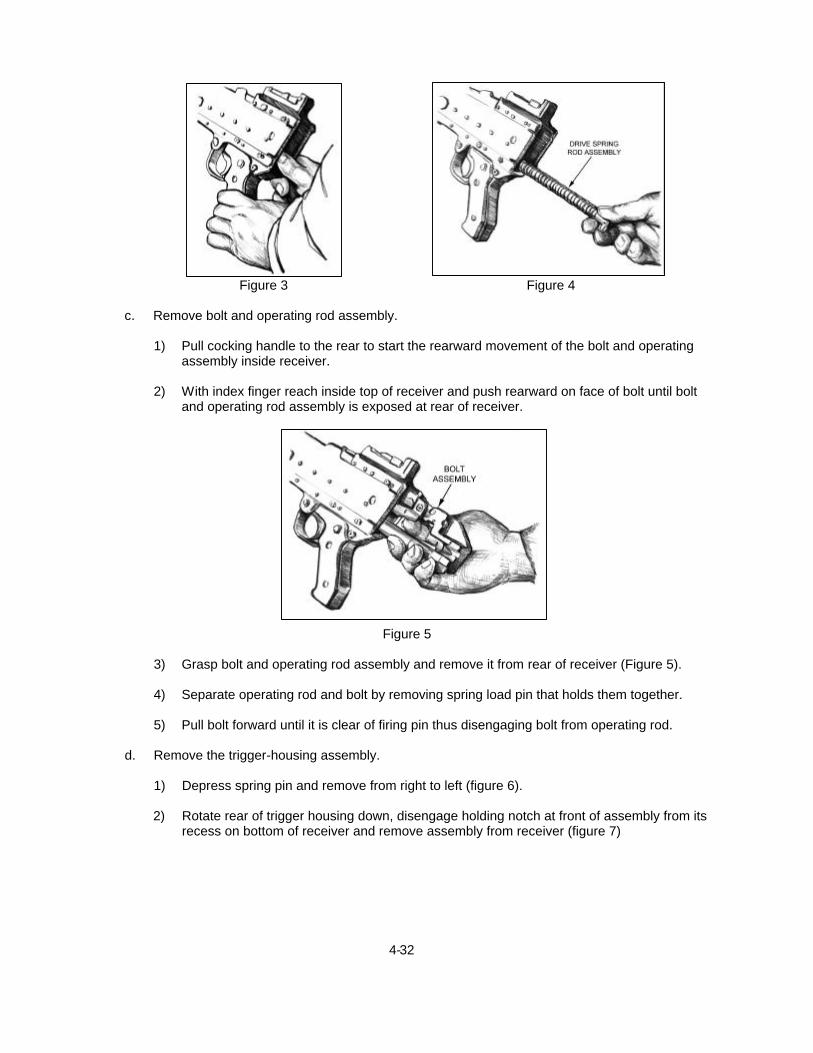
4- 32
Figure 3 Figure 4 c. Remove bolt and operating rod assembly.
1) Pull cocking handle to the rear to start the rearward movement of the bolt and operating assembly inside receiver.
2) With index finger reach inside top of receiver and push rearward on face of bolt until bolt
and operating rod assembly is exposed at rear of receiver.
Figure 5
3) Grasp bolt and operating rod assembly and remove it from rear of receiver (Figure 5).
4) Separate operating rod and bolt by removing spring load pin that holds them together.
5) Pull bolt forward until it is clear of firing pin thus disengaging bolt from operating rod.
d. Remove the trigger-housing assembly.
1) Depress spring pin and remove from right to left (figure 6). 2) Rotate rear of trigger housing down, disengage holding notch at front of assembly from its recess on bottom of receiver and remove assembly from receiver (figure 7)

4- 33
Figure 6 Figure 7
Figure 8
e. Remove cover assembly (figure 8).
1) Close cover. Depress spring pin and remove pin A.
2) Remove pin with fingers B.
3) Depress cover latch, lift upward and remover cover assembly C.
4) Remove feed tray D.
f. Remove barrel assembly (Figure 9).
1) Ensure barrel-carrying handle is to the right side. Depress barrel-locking latch. A. 2) Grasp barrel carrying handle and rotate handle to upright position B.

4- 34
Figure 9
3) Push forward and pull up, separating the barrel from the receiver C.
g. Disassemble barrel assembly (Figure 10)
1) Hold barrel at the point where gas system attaches to it A. 2) Grasp and rotate gas collar counter clockwise until it releases from gas plug B. 3) Slide gas regulator plug to the rear, removing it from gas hole bushing C. 4) Remove heat shield by lifting rear of heat shield assembly from barrel then pry front tabs out of holes on gas hole bushing D.
Figure 10

4- 35
4. Clean the machine gun.
NOTES: The only authorized cleaning materials for use at the unit level are Cleaner-Lubricant-Preservative (CLP), Semi-fluid Weapons Lubricating oil (LSA), Lubricating Oil Artic Weather (LAW), and dry cleaning solvent.
Adequate cleaning can be performed on a machine gun that has been disassembled into its eight main groups. If becomes essential to perform detailed disassembly after prolonged firing bring weapon to armory.
a. Clean Barrel group 1) Clean bore – run bore brush through bore – follow with swab wet with CLP then follow with dry swab.
2) Clean chamber – run bore brush through chamber- follow with swab wet with CLP then
follow with dry swab. 3) Clean exterior of barrel – use general purpose brush clean all exterior surfaces including flash suppressor and front sight.
4) Clean gas regulator plug – clean with reamer and combination scraper (figure's 11, 12 and 13)
Figure 11 Figure 12
Figure 13

4- 36
b. Clean buttstock / buffer assembly.
1) Wipe with clean dry cloth or may be cleaned with brush and soapy water, then rinse and wipe dry with clean cloth.
c. Clean trigger housing group.
1) Remove carbon and dust using general purpose brush - pipe cleaners should be used for hard to reach areas.
d. Clean operating group
1) Clean bolt and operating rod with scraper tool / extraction combination tool and follow with rag and CLP (figure 14).
Figure 14
e. Clean drive spring rod assembly.
1) May be submerged in dry cleaning solvent then scrub with general purpose brush.
4) Dry and apply light coat of CLP.
f. Clean receiver group
1) Clean with rags and brushes wet with dry cleaning solvent, use pipe cleaners for hard to reach areas.
2) Dry and apply light coat of CLP.
g. Clean cover group.
1) Clean with rags and brushes wet with dry cleaning solvent, use pipe cleaners for hard to reach areas.
3) Dry and apply light coat of CLP.

4- 37
h. Clean feed tray group.
1) Clean with rags and brushes wet with dry cleaning solvent, use pipe cleaners for hard to reach areas.
2) Dry and apply light coat of CLP.
i. Clean tripod / components.
1) Wipe with clean rag and lubricate moving parts with CLP. 5. Inspect the machine gun. NOTE: Inspection should begin with weapon disassembled into its eight major groups.
a. Barrel assembly. 1) Check for bulges, bends, burrs and obstructions.
2) Check gas collar and plug.
3) Ensure flash suppressor is fastened securely.
4) Check front sight for damage or looseness.
5) Inspect carrying handle for bent, broken or missing parts.
6) Ensure heat shield is fastened on barrel and is not broken, bent or missing parts.
b. Buttsttock and buffer assembly
1) Check for burrs and rough edges on mating grooves and flanges.
2) Ensure back plate latch locks buffer assembly securely to receiver.
3) Make sure buffer plug sticks out through back plate and is flush or higher than protrusion
below it.
4) Buffer should not rattle when shook and plug should not rotate by finger pressure.
5) Check for cracks in Buttstock.
c. Driving spring rod assembly.
1) Check spring for broken strands.
2) Ensure rod assembly is not bent.

4- 38
d. Bolt and operating rod assembly. 1) Check entire area of bolt and operating rod assembly for missing parts, broken or cracked areas
2) Look for burrs, bends or pits on surface.
3) Check firing pin to see if it is broken.
4) Extractor should not move with finger pressure.
5) The piston in the operating rod will have slight movement from right to left (approx 1/8 inch).
6) When bolt and operating rod are pulled to rear it should move freely without binding.
d. Trigger mechanism / housing assembly
1) Inspect tripping lever and sear for burrs on edges or shoulders. 2) Push back on tripping lever to raise sear, place safety to safe (S) and pull trigger – Sear should not drop down far enough to lock in downward position.
3) Place safety to fire (F) pull trigger and sear should drop down and lock in the downward position.
4) Check for cracked grips and loose or missing screws.
e. Cover assembly.
1) Pivot feed lever back and forth, make sure it operates smoothly.
2) Push in on cover latches, make sure retaining clip is not weak or missing and cover lathes do not bind the housing.
4) Push down on cartridge guides and feed pawls to make sure springs are not weak or missing.
4) Inspect accessory rail for nicks or burrs. g. Feed tray. 1) Check for cracks, deformation, broken welds and loose rivets. 2) Check for chips and burrs on tray face. h. Receiver assembly with handguard. 1) Check handguard for cracks, broken or missing parts. 2) Check rear sight assembly is securely mounted to receiver assembly and operates properly. 3) Check that manual control handle operates slide properly.
5) Check for damaged or missing ejection port, spring and pin.
4- 39
6) Check for damage to interrupted threads in receiver.
7) Lower and raise bipod legs ensuring they move freely.
8) Check bipod legs for cracks, twisted or incomplete assembly. i. M122 tripod with T&E mechanism. 1) T&E mechanism should not bind and numbers on scales must be legible. 2) Distinct clicks must be heard when handwheels are turned and index lines should be calibrated with indicator pointer.
3) Pintle should fit snugly in Pintle bushing and Pintle lock should hold Pintle securely.
4) Sleeve latch should function properly and traversing bar should be tight when tripod legs are extended and latched.
j. Carrying case. 1) Maintenance tools and equipment should be complete and serviceable. k. Check exterior surface of machine gun for the exterior protective finish. 6. Report any discrepancies that you cannot correct to the unit armorer. 7. Lubricate the machine gun.
a. Remove excess oil from the bore, chamber, barrel socket, and face of the bolt.
b. Lubricate the machine gun with a light coat of CLP.
1) Lubricate Driving spring rod assembly.
2) Lubricate bolt.
3) Lubricate receiver inner walls.
4) Lubricate cover assembly (springs and feed pawls).
5) Lubricate trigger housing. c. After lubricating the components, cycle by hand to spread CLP. 8. Assemble the machine gun.
a. Assemble the receiver group.
1) Replace feed tray – place cover onto receiver aligning its guides with receiver bracket.
2) Replace cover assembly.
a) Place cover on receiver aligning its holes with mounting bracket.

4- 40
b) Close cover. c) Insert spring hinge pin from right to left. d) Open cover.
3) Replace barrel assembly
a) Insert gas regulator plug - set to #1. b) Place collar over forward end of gas regulator plug and rotate counter clockwise until it locks in place. c) Place barrel in receiver. d) Rotate carry handle down. e) Count clicks if number falls between 2-7 the headspace is correct, if headspace falls outside 2-7 turn weapon into armory. 4) Replace trigger housing assembly. a) Insert forward notch of trigger housing into recess of receiver. b) Rotate trigger housing upward and align holes of trigger housing with mounting lug on receiver. c) Hold trigger housing assembly and insert spring pin into hole securing it to receiver. 5) Replace bolt and operating rod assembly. a) Insert bolt and operating rod assembly into rear of receiver ensuring bolt is on top of receiver rails. b) Push assembly into receiver as far as possible. c) Pull trigger and hold it while pushing assembly all the way into receiver. d) Close cover assembly. 6) Replace drive spring rod assembly. a) Insert driving rod spring assembly all the way into receiver. b) Push in and lower driving rod spring assembly to seat retaining stud in hole on bottom of receiver. 7) Replace buttstock and buffer assembly. a) Position bottom recess grooves of buttstock onto top of receiver recess grooves. b) Slide buttstock down until it locks on receiver. c) Top of buttstock should be flush with top of receiver.

4- 41
8) Replace handguard. 1) Line handguard on bottom of gas cylinder and push upward and handguard will snap into place. b. Perform function check. 1) Place safety on fire (F). 2) Pull cocking handle to the rear, locking bolt to the rear. NOTE: Always grab cocking handle with palm up. 3) Return cocking handle to forward position. 4) Place safety on safe (S). 5) Pull the trigger (bolt should not go forward). 6) Place safety on fire (F). 7) Pull cocking handle to the rear, pull the trigger and ride bolt forward. NOTE: Do not let bolt slam home. 8) Close ejection port. 9. Clean the pinnate and platform group, the tripod, and the traversing and elevating T&E mechanism.
a. Check the pintle and platform group and the tripod for rust and dirt.
b. Examine the cleanliness of the far ends of the T&E screws on the T&E mechanism.
NOTE: At the same time, perform a function check by testing for dead clicks and inordinate play in the M122 mount and determine whether the slide-lock lever firmly holds the T&E mechanism to the traversing bar.
10. Report any deficiencies that cannot be corrected at the unit armorer. REFERENCES: MCWP 3-15.1, Machine Guns and Machine Gun Gunnery TM 9-1005-313-10, Operator's Manual for Machine Gun, 7.62mm,M240 FM 3-22.68, Crew-Served Machine Gun 5.56-mm and 7.62mm

4-42
TASK: ENGAGE GROUND TARGETS WITH THE M60E3 MACHINE GUN (4-6) CONDITIONS: GIVEN A TACTICAL SCENARIO IN ANY COMBAT ENVIRONMENT (DAY AND
NIGHT), A MACHINE GUN (M60E3), AN M122 TRIPOD, AND AMMUNITION. STANDARD: THE SEABEE MUST EFFECTIVELY ENGAGE TARGETS WITH THE MACHINE
GUN AS PER THE REFERENCES.
EVALUATION GUIDELINES TO BE USED DURING TRAINING:
Conditions: The Seabee, acting as a gunner, is provided a machine gun (M60E3), an assistant
gunner, the appropriate amount of ammunition, an assortment of ground targets at ranges between 100 to 1100 meters, and fire commands.
Standard: The Seabee must clear, load (open and closed cover methods), and fire the
machine gun (tripod and bipod mounted) achieving effect on each of the designated ground targets by attaining at least one hit per target.
PERFORMANCE STEPS: 1. Clear the machine gun.
- See TASK: MAINTAIN THE M60E3 MACHINE GUN (4-5). 2. Load the machine gun.
a. Cover raised method.
1) Place the safety on the F (fire) position (Figure 1).
Figure 1 Figure 2
2) Pull the cocking handle to the rear, locking the bolt to the rear position.
3) Return the cocking handle to the forward position, and place the safety in the S (safe) position.
4-43
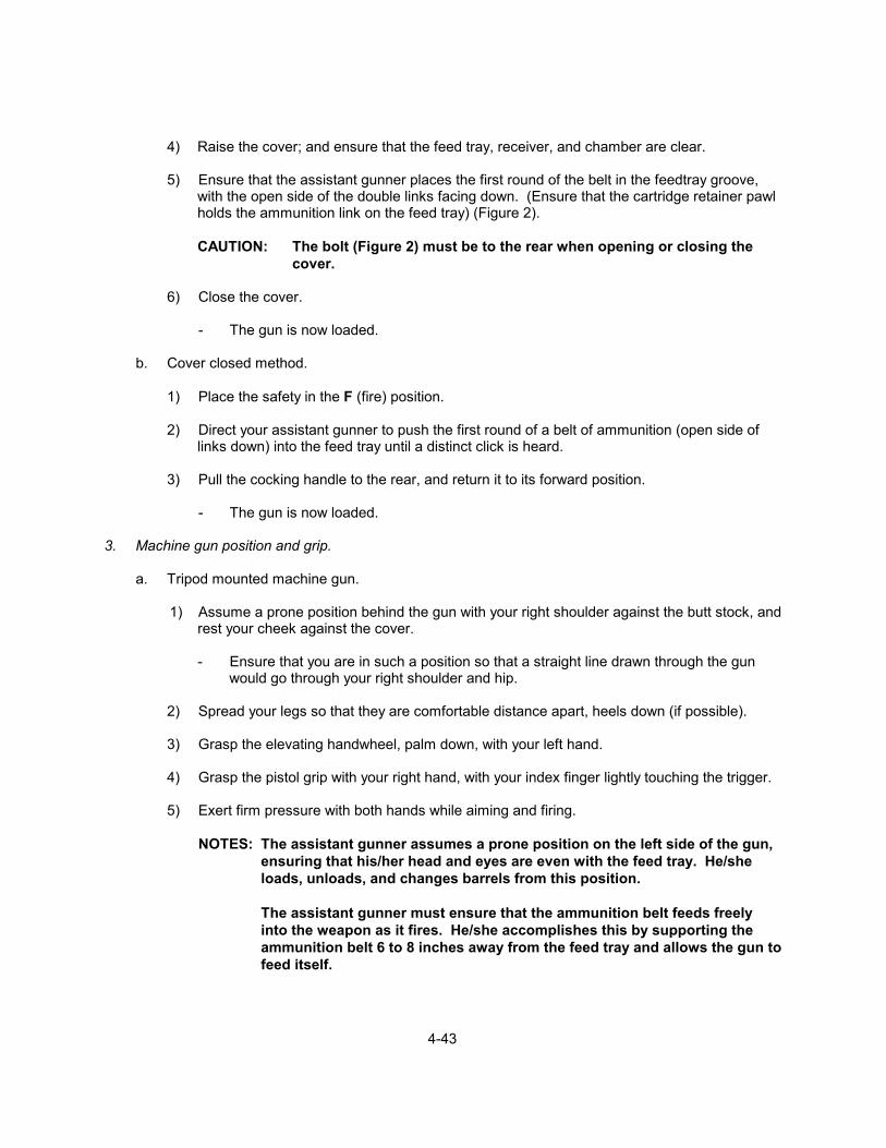
4) Raise the cover; and ensure that the feed tray, receiver, and chamber are clear.
5) Ensure that the assistant gunner places the first round of the belt in the feedtray groove,
with the open side of the double links facing down. (Ensure that the cartridge retainer pawl holds the ammunition link on the feed tray) (Figure 2).
CAUTION: The bolt (Figure 2) must be to the rear when opening or closing the
cover.
6) Close the cover.
- The gun is now loaded.
b. Cover closed method.
1) Place the safety in the F (fire) position.
2) Direct your assistant gunner to push the first round of a belt of ammunition (open side of links down) into the feed tray until a distinct click is heard.
3) Pull the cocking handle to the rear, and return it to its forward position.
- The gun is now loaded.
3. Machine gun position and grip.
a. Tripod mounted machine gun.
1) Assume a prone position behind the gun with your right shoulder against the butt stock, and rest your cheek against the cover.
- Ensure that you are in such a position so that a straight line drawn through the gun
would go through your right shoulder and hip.
2) Spread your legs so that they are comfortable distance apart, heels down (if possible).
3) Grasp the elevating handwheel, palm down, with your left hand.
4) Grasp the pistol grip with your right hand, with your index finger lightly touching the trigger.
5) Exert firm pressure with both hands while aiming and firing.
NOTES: The assistant gunner assumes a prone position on the left side of the gun, ensuring that his/her head and eyes are even with the feed tray. He/she loads, unloads, and changes barrels from this position.
The assistant gunner must ensure that the ammunition belt feeds freely into the weapon as it fires. He/she accomplishes this by supporting the ammunition belt 6 to 8 inches away from the feed tray and allows the gun to feed itself.
4-44
b. Bipod mounted machine gun.
1) Raise the rear sight.
2) Assume a prone position behind the gun.
3) Grasp the pistol grip with the right hand and place your index finger lightly touching the
trigger.
4) Raise the gun up, and place the stock in your shoulder.
5) Place your left hand on the rear of the cover; palm down, with your cheek resting on the cover and/or your left hand.
6) Exert a firm, steady pressure down and to the rear with both hands during aiming and firing.
NOTE: The assistant gunner's responsibilities and position remain the same for
bipod mounted firing. 4. Perform transition firing using a tripod-mounted gun.
a. Engage the four types of battlefield targets: point, wide, deep, and oblique.
1) Engage a point target (Fixed Fire Mission).
a) Estimate the range to the target, and place this range on the rear sight.
b) Manipulate theTraversing and Elevating (T&E) mechanism until you are on the center of the target.
c) Lower the rear sight.
d) Fire a six-round burst, adjusting the T&E mechanism until impact on the target.
2) Engage wide targets (Traverse mission).
a) Estimate the range to the center of the target, and place this range on the rear sight.
b) Manipulate the T&E mechanism until you are on target.
c) Lower the rear sight.
d) Fire a six-round burst, and adjust the T&E mechanism until impact on the target.
e) Traverse the gun by using the traversing handwheel in 2-mil increments, firing six-
round bursts every time you traverse, covering the entire target.
4-45
3) Engage deep targets (Search mission).
a) Estimate the range to the nearest portion of the target, and place this range on the
rear sight.
b) Manipulate the T&E mechanism until you are on target.
c) Lower the rear sight.
d) Fire a six-round burst, and adjust the T&E mechanism until impact on the target.
e) Fire and adjust the elevating handwheel in 2-mil increments to search up and down the entire target.
4) Engage oblique targets (Searching traverse mission).
a) Estimate the range to the nearest portion of the target.
b) Place this range on the rear sight and aim in on the target.
c) Lower the rear sight.
d) Fire a six-round burst, and adjust your impact on the target using the T&E mechanism.
e) Traverse the target in 2-mil increments using the traversing handwheel, and apply
enough searches (elevating hand wheel) to cover the entire target. 5. Perform transition firing using a bipod mounted gun.
a. Engage the four types of battlefield targets: point, wide, deep, and oblique.
1) Engage a point target (Fixed fire mission).
a) Estimate the range to the target, and place this range on the rear sight.
b) Assume a good prone position behind the gun and aim in on the target.
c) Fire a six-round burst, and observe the impact of your rounds.
d) Readjust your body position and point of aim, and then engage the target.
2) Engage a wide target (Traverse mission).
a) Estimate the range to the target and place this range on the rear sight.
b) Assume a good prone position behind the gun and aim in on the target.

4-46
c) Fire a six-round burst, and observe the impact of your rounds.
d) Readjust your body position and point of aim. Engage the target while shifting your
body position but maintaining the same elbow height to place effective fire on the target.
3) Engage a deep target (Search mission).
a) Estimate the range to the target, and place this range on the rear sight.
b) Assume a good prone position behind the gun and aim in on the target.
c) Fire a six-round burst, and observe the impact of your rounds.
d) Readjust your body position and point of aim to place your rounds on the target.
e) To adjust for elevation on the target, raise or lower your shoulder by pulling in or
pushing out with your elbows.
4) Engage oblique targets (Searching traverse mission).
a) Estimate the range to the target and place this range on the rear sight.
b) Assume a good prone position behind the gun and aim in on the target.
c) Fire a six-round burst and observe the impact of your rounds.
d) Readjust your body position and point of aim, and then engage the target. 6. Clear the machine gun.
- See TASK: MAINTAIN THE M60E3 MACHINE GUN (4-5). REFERENCES: FMFRP 6-15, Machine Guns and Machine Gun Gunnery TM 02705E-10/1, Operator's Manual, Machine Gun, 7.62MM, M60E3 FM 23-67, Machine Gun, 7.62MM, M60

4-47
TASK: MAINTAIN THE M2 MACHINE GUN (4-7) CONDITION: GIVEN AN M2 AND APPROPRIATE CLEANING EQUIPMENT. STANDARD: THE SEABEE MUST MAINTAIN THE M2 AS PER THE REFERENCES.
EVALUATION GUIDELINES TO BE USED DURING TRAINING:
Conditions: The Seabee is provided an M2 machine gun, a cleaning kit, Cleaner, Lubricant, and Preservative (CLP), rags, swabs, and a headspace and timing gauge set.
Standard: The Seabee must demonstrate proper clearing, disassembly, cleaning, reassembly,
and function check procedures. The machine gun must be maintained so that it passes a supervisor's inspection. The Seabee must also reset the headspace and timing.
PERFORMANCE STEPS: 1. Inspect/inventory tool box (Figure 1).
Figure 1

4-48
2. Clear the machine gun.
a. Point the machine gun in a safe direction.
b. Unlock the bolt latch release (Figure 2).
1) Rotate the bolt latch release lock clockwise.
2) Raise the bolt latch release to the up position.
Figure 2
c. Raise the cover and inspect for ammunition (ensure no round is left in the machine gun).
1) Rotate the cover latch shaft lever forward.
2) Raise the cover to a full upright position.
3) Lift the extractor and inspect any ammunition.
4) Check the feed way.
d. Lock the bolt to the rear.
1) Pull the retracting slide handle to the rear.
NOTE: Always palm up when retracting the slide handle to the rear.
2) Ensure the bolt is caught by the bolt latch and is locked.
3) Return the retracting slide handle forward.
e. Inspect the chamber and T-slot (face of bolt) to ensure that there are no rounds remaining in the machine gun.
f. Pull the retracting slide handle to the rear.
g. Push the bolt release and ride the bolt home.
4-49
h. Close the cover.
NOTES: During hours of low visibility, you may have to feel inside the receiver and
chamber to ensure that no rounds are present.
An additional precaution to take when clearing the machine gun is to insert a cleaning rod in the muzzle end of the barrel, and then push it through the bore until it can be seen in the receiver then remove the cleaning rod.
3. Disassemble the machine gun.
a. Unlock the bolt latch release so that it comes to the up position.
b. Raise the cover.
c. Remove the barrel group.
1) Pull the bolt partially to the rear.
2) Align the outer lug on the barrel-locking spring with the 3/8-inch hole on the right sideplate of the receiver.
3) Unscrew the barrel counterclockwise.
4) Carefully place the barrel so the threads cannot be damaged.
d. Holding the retracting slide handle, release the bolt and slowly ride it forward.
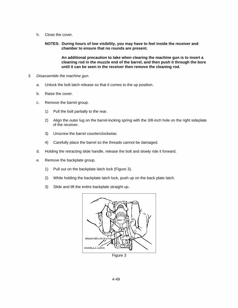
e. Remove the backplate group.
1) Pull out on the backplate latch lock (Figure 3).
2) While holding the backplate latch lock, push up on the back plate latch.
3) Slide and lift the entire backplate straight up.
Figure 3

4-50
f. Set the backplate aside.
NOTE: Backplate face up, handle down to prevent damage to the face.
g. Remove the drive rod spring assembly.
1) Locate the driver spring and driver spring rod assembly next to the right sideplate at the end of the receiver.
2) Push in and to the left on the head of the drive rod spring assembly.
3) Pull the drive rod spring assembly to the rear and out of the receiver.
CAUTION: Never attempt to cock the machine gun when the backplate has been
removed and while the drive spring rod assembly is still in the weapon. When the bolt is to the rear, pressure builds on the springs, which can slip and forcefully fly out of the receiver. This can result in injury to anyone to the rear of the receiver.
h. Remove the bolt stud.
1) Grasp the retracting slide handle and give it a quick jerk, halfway to the rear.
2) Shift the bolt forward and backward until the collar of the bolt stud aligns with the hole in the
bolt slot in the right sideplate.
NOTE: If the bolt went all the way to the rear, the bolt latch may have engaged. If this happened, you may have to hold the latch up to slide the bolt forward.
3) Pull the bolt stud out to the right (Figure 4).
Figure 4 Figure 5
i. Remove the bolt group.
1) Pull the bolt group rearward and out of the receiver.
4-51
2) Set the bolt group aside being careful to lay it down with the extractor arm up.
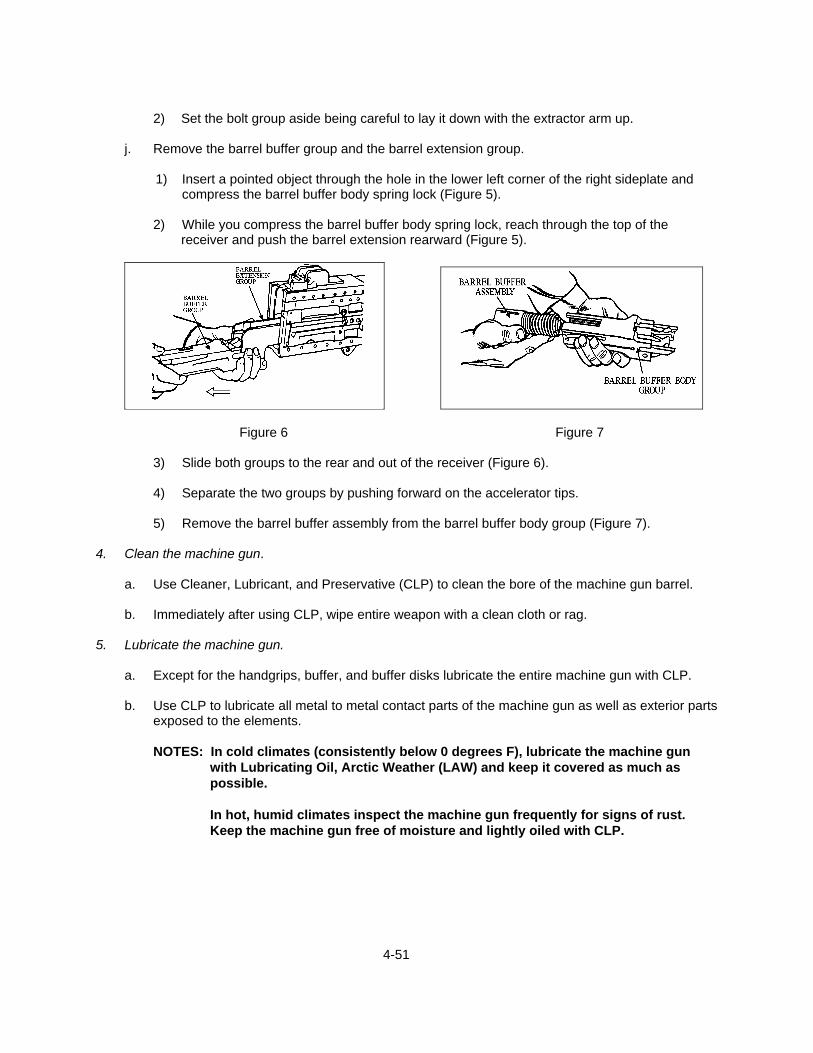
j. Remove the barrel buffer group and the barrel extension group.
1) Insert a pointed object through the hole in the lower left corner of the right sideplate and
compress the barrel buffer body spring lock (Figure 5).
2) While you compress the barrel buffer body spring lock, reach through the top of the receiver and push the barrel extension rearward (Figure 5).
Figure 6 Figure 7
3) Slide both groups to the rear and out of the receiver (Figure 6).
4) Separate the two groups by pushing forward on the accelerator tips.
5) Remove the barrel buffer assembly from the barrel buffer body group (Figure 7). 4. Clean the machine gun.
a. Use Cleaner, Lubricant, and Preservative (CLP) to clean the bore of the machine gun barrel.
b. Immediately after using CLP, wipe entire weapon with a clean cloth or rag. 5. Lubricate the machine gun.
a. Except for the handgrips, buffer, and buffer disks lubricate the entire machine gun with CLP.
b. Use CLP to lubricate all metal to metal contact parts of the machine gun as well as exterior parts exposed to the elements.
NOTES: In cold climates (consistently below 0 degrees F), lubricate the machine gun
with Lubricating Oil, Arctic Weather (LAW) and keep it covered as much as possible.
In hot, humid climates inspect the machine gun frequently for signs of rust. Keep the machine gun free of moisture and lightly oiled with CLP.

4-52
6. Reassemble the machine gun.
a. Replace the barrel buffer assembly and barrel buffer body group.
1) Replace the barrel buffer assembly in the barrel buffer body group with the key on the spring guide to the right.
NOTE: This key must fit in its slot in the right side of the barrel buffer body.
2) Turn the barrel buffer tube until the screwdriver slot is vertical and the arrow is pointing to the right.
3) Push the barrel buffer assembly fully forward.
b. Replace the barrel buffer group and barrel extension group.
1) Join the two groups together.
a) Hold the barrel buffer group in your right hand, with your index finger supporting the
accelerator.
b) Join the notch on the shank of the barrel extension group with the cross groove in the piston rod of the barrel buffer assembly.
c) Align the breech lock depressor with the guideways in the sides of the barrel
extension.
NOTE: Ensure that the tips of the accelerator are against the rear end of the barrel extension.
d) Push the groups together.
e) Press down on the accelerator tips as the accelerator rotates to the rear.
2) Place the groups in the receiver, pushing them forward until the barrel buffer body spring
lock snaps into position.
NOTE: When the parts are properly locked in place, the barrel buffer tube should protrude about 1/8 inch from the rear of the barrel buffer body group.
c. Replace the bolt.
1) Place the bolt in the receiver with the top of the cocking lever forward and the extractor
down.
2) Push the bolt forward into the receiver.
3) Ensure that the front end of the bolt clears the accelerator tips.
4) Raise the rear of the bolt, and continue to push the bolt forward until the bolt latch engages the notches in the top of the receiver.

4-53
d. Replace the bolt stud.
1) Align the stud hole in the bolt with the clearance hole.
2) Replace the bolt stud.
NOTE: Ensure that the shoulder of the stud is inside the sideplate.
e. Replace the driving spring group.
1) Press up on the bolt latch.
2) Push the bolt all the way forward by pushing on the bolt stud only.
3) Place the end of the driving spring rod in its hole in the rear of the bolt.
4) Push forward on the driving spring group and the barrel buffer tube.
5) Press in and to the right on the head of the driving spring rod.
6) Place the retaining pin in its seat in the right sideplate.
NOTE: At this time, the barrel buffer tube should be completely inside the receiver.
If not, the barrel buffer body spring is not properly seated.
f. Replace the backplate group.
1) Hold the backplate with the latch down and the trigger up.
2) Place the backplate guides in their guideways.
3) Hold out on the latch lock and tap the backplate into position until the latch snaps into place.
4) Release the latch lock.
5) Pull up on the backplate group to ensure that it is firmly seated.
g. Replace the barrel.
1) Pull the retracting slide handle to the rear until the lug is on the barrel locking spring is
visible through the 3/8-inch hole in the right sideplate.
2) Place a headspace and timing gauge between the trunnion block and the barrel extension.
3) Screw the barrel all the way into the barrel extension.
4) Unscrew the barrel two notches.
5) Remove the headspace and timing gauge and close the cover.

4-54
7. Perform function check.
a. Manually cycle the gun to check for freedom of movement of the moving parts.
b. Check functioning of the trigger and the bolt latch. 8. Set headspace and timing.
NOTE: Headspace and timing must be set when the machine gun is assembled, when the barrel or any major group or assembly within the receiver is replaced, or when there is doubt that the headspace or timing is set properly.
a. Set headspace.
1) Clear the weapon.
2) Raise the cover.
3) Retract the recoiling parts by pulling the retracting slide handle rearward until the barrel
locking spring lug is centered in the 3/8-inch hole on the right side of the receiver, and screw the barrel all the way into the barrel extension (Figure 8).
Figure 8
NOTE: The barrel cannot be turned if the barrel locking spring lug is not aligned with the hole in the side of the receiver.
4) Unscrew the barrel two notches (clicks).
5) Cock the machine gun; pull the retracting slide handle all the way to the rear.
6) Press the bolt latch release lock. Ride the bolt forward with the cover open to prevent
damage to the extractor.
CAUTION: Be careful not to depress the trigger, since this will cause the firing pin to be released. The firing pin should never be released with the gauge in the T-slot as this could damage the firing pin and gauge.
7) Pull the retracting slide handle back until the barrel extension is 1/16 inch from the trunnion
block.
4-55
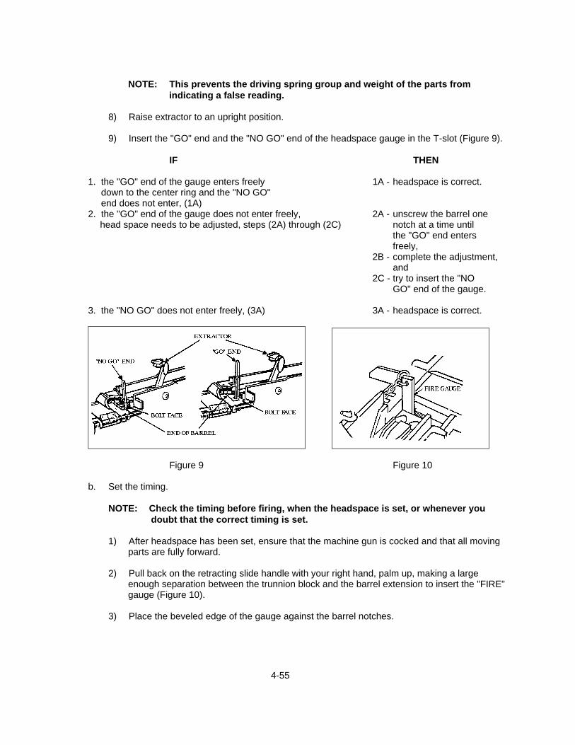
NOTE: This prevents the driving spring group and weight of the parts from
indicating a false reading.
8) Raise extractor to an upright position.
9) Insert the "GO" end and the "NO GO" end of the headspace gauge in the T-slot (Figure 9).
IF THEN
1. the "GO" end of the gauge enters freely 1A - headspace is correct. down to the center ring and the "NO GO" end does not enter, (1A) 2. the "GO" end of the gauge does not enter freely, 2A - unscrew the barrel one
head space needs to be adjusted, steps (2A) through (2C) notch at a time until the "GO" end enters freely,
2B - complete the adjustment, and
2C - try to insert the "NO GO" end of the gauge.
3. the "NO GO" does not enter freely, (3A) 3A - headspace is correct.
Figure 9 Figure 10
b. Set the timing.
NOTE: Check the timing before firing, when the headspace is set, or whenever you doubt that the correct timing is set.
1) After headspace has been set, ensure that the machine gun is cocked and that all moving
parts are fully forward.
2) Pull back on the retracting slide handle with your right hand, palm up, making a large enough separation between the trunnion block and the barrel extension to insert the "FIRE" gauge (Figure 10).
3) Place the beveled edge of the gauge against the barrel notches.
4-56
4) Allow the bolt to go forward by releasing the retracting slide handle. Attempt to fire by
depressing trigger, if firing pin does not release, timing needs to be adjusted.
5) To adjust timing, remove the backplate.
- Pull out on the backplate lock and up on the backplate latch and spade grips.
NOTE: The trigger lever and timing adjustment nut are inside the back of the
receiver.
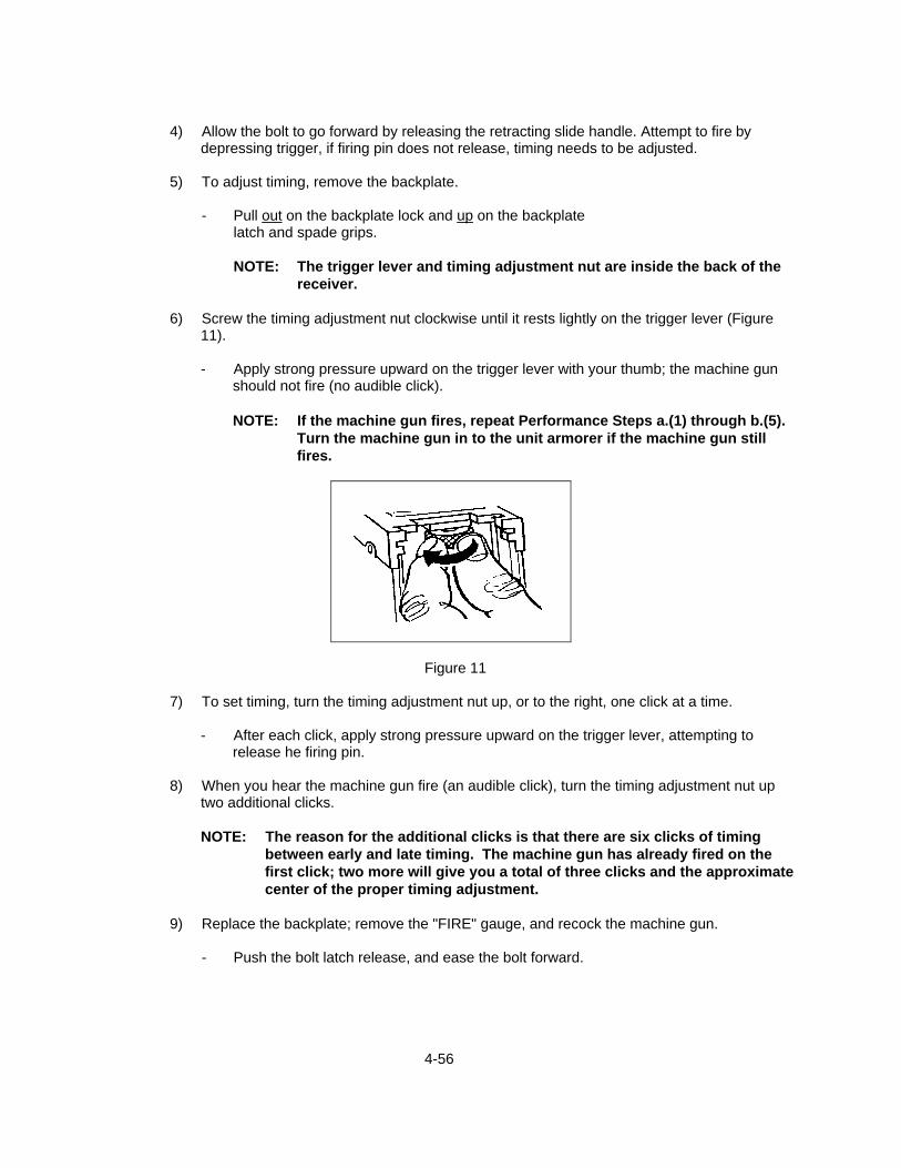
6) Screw the timing adjustment nut clockwise until it rests lightly on the trigger lever (Figure 11).
- Apply strong pressure upward on the trigger lever with your thumb; the machine gun
should not fire (no audible click).
NOTE: If the machine gun fires, repeat Performance Steps a.(1) through b.(5). Turn the machine gun in to the unit armorer if the machine gun still fires.
Figure 11
7) To set timing, turn the timing adjustment nut up, or to the right, one click at a time.
- After each click, apply strong pressure upward on the trigger lever, attempting to release he firing pin.
8) When you hear the machine gun fire (an audible click), turn the timing adjustment nut up
two additional clicks.
NOTE: The reason for the additional clicks is that there are six clicks of timing between early and late timing. The machine gun has already fired on the first click; two more will give you a total of three clicks and the approximate center of the proper timing adjustment.
9) Replace the backplate; remove the "FIRE" gauge, and recock the machine gun.
- Push the bolt latch release, and ease the bolt forward.

4-57
10) Check the timing.
a) Move to the side of the machine gun; push back on the retracting slide handle, and
insert the "NO FIRE" gauge in the same place as the "FIRE" gauge between the barrel extension and the trunnion block.
NOTE: The beveled edge of the gauge should be against the barrel notches.
b) Depress the trigger; the machine gun should not fire.
NOTE: If the firing pin is released, the timing is too early. If early timing
exists, the machine gun will fire two rounds and stop firing because the extractor will not come far enough forward to extract another round.
c) To correct early timing, remove the backplate; and turn the timing adjustment nut all
the way down until it rests lightly on the trigger level, and begin again.
- Ensure that you press up firmly on the trigger lever each click.
NOTE: If the firing pin does not release when the "NO FIRE" gauge is inserted, remove it and reinsert the "FIRE" gauge. If the firing pin is released when the trigger is depressed, proper timing has been set.
REFERENCES: MCWP 3-15.1, Machine Guns and Machine Gun Gunnery FM 23-65, Browning Machine Gun, Caliber .50 HB, M2

4-58
TASK: ENGAGE GROUND TARGETS WITH THE M2 MACHINE GUN (4-8) CONDITION: GIVEN A TACTICAL SCENARIO IN ANY COMBAT ENVIRONMENT (DAY AND
NIGHT), AN M2, A TRIPOD, AND AMMUNITION. STANDARD: THE SEABEE MUST EFFECTIVELY ENGAGE TARGETS WITH THE M2 MACHINE
GUN AS PER THE REFERENCES.
EVALUATION GUIDELINES TO BE USED DURING TRAINING:
Conditions: The Seabee, acting as a gunner, is provided an M2 machine gun, an assistant gunner, the appropriate amount of ammunition to complete the task, an assortment of ground targets at ranges between 300 and 1,800 meters, and fire commands.
Standard: The Seabee must clear, load (half and full), , field zero, and fire the machine gun
achieving effect on each of the designated ground targets by attaining at least one hit per target. The Seabee must also demonstrate the correct position and grip for tripod fire
PERFORMANCE STEPS: 1. Clear the machine gun.
- See TASK: MAINTAIN THE M2 MACHINE GUN (4-7). 2. Load the machine gun.
a. Half-load
1) Ensure that the bolt is forward and that the cover is closed.
2) Insert the double loop end of the ammunition belt in the feed way until the first round is engaged by the belt holding pawl.
3) Grasp the retracting slide handle with the
right hand, palm up (Figure 1).
4) With force, pull the retracting slide handle, locking the bolt to the rear.
NOTE: If the bolt latch release is up
and free of the bolt latch release lock, the bolt latch will hold the bolt and the retracting slide to the rear.
5) Return the retracting slide handle to its
most forward position. Figure 1
4-59
6) Press the bolt latch release, allowing the bolt to go forward.
NOTE: The machine gun is now half-loaded.
b. Fully load from half-load
1) With force, pull the retracting slide handle to the rear for a second time, locking the bolt to
the rear. Return the retracting slide handle to its forward most position.
2) Press the bolt latch release allowing the bolt to go forward.
NOTE: The machine gun is now fully loaded. 3. Position and grip for tripod fire.
a. Prone position
1) Assume a prone position behind the gun between the trail legs of the tripod with your body extending directly to the rear of the gun.
2) Place the inside of your feet as flat as possible on the ground, legs well spread, and toes
turned outward.
3) Rest your left elbow on the ground with your left hand placed on the elevating wheel.
4) Lightly grasp the right spade grip with your right hand, thumb in position to press the trigger.
NOTE: Body position will vary depending on your physique so that your eye is in the proper position to align the sights.
b. Sitting position
1) Assume a sitting position behind the gun between the trail legs of the tripod, directly behind
the gun.
NOTE: You may sit with your legs extended under the tripod or with your legs crossed.
2) Place your elbows on the inside of your thighs for maximum support.
3) Grasp the elevating handwheel of the T&E with your left hand.
4) Lightly grasp the right spade grip with your right hand, thumb in position to press the trigger.
4. Field zero the machine gun.

4-60
NOTE: Zeroing is the process of adjusting the point of aim to coincide with the strike of the rounds by adjusting the sights until a good sight picture is obtained on the point of impact.
a. Estimate the range to a target (600 meters is the recommended range for field zeroing).
b. Set the rear sight setting to the estimated range.
c. Ensure that the windage scale is centered by turning the windage knob until the center index
lines are aligned.
d. Adjust the Traversing and Elevating (T&E) mechanism until a correct sight picture is achieved at the base (6-o'clock) of the target.
e. Fire a short burst (4-6 rounds) and observe the impact of the rounds.
f. Readjust the sights and the T&E mechanism, if necessary, to get rounds on target. (See TASK
4-21: ZERO THE M2 MACHINE GUN) for proper sight adjustment procedures. 5. Perform transition firing using a tripod-mounted gun.
a. Engage the four types of battlefield targets: point, wide, deep, and oblique.
1) Engage a point target (Fixed Fire Mission).
a) Estimate the range to the target.
b) Set this range on the rear sight and aim in on the target.
c) Manipulate the Traversing and Elevating (T&E) mechanism until you are at the bottom center of the target.
d) Fire a short burst, and observe the impact of your rounds.
e) Adjust the T&E mechanism until rounds hit the target.
f) Engage the target until cease-fire commands are given or the target is destroyed.
2) Engage wide targets (Traverse Mission).
a) Estimate the range to the target.
b) Set this range on your rear sight and aim in on the target.
c) Manipulate the T&E mechanism until you are on target.
d) Fire a short burst and observe the impact of your rounds.
e) Adjust the T&E mechanism until hit impact on the target.
4-61
f) Traverse the gun by using the traversing handwheel in 2-mil increments, firing six-
round bursts every time you traverse, covering the entire target.
g) Continue to engage the target until cease-fire commands are given or the target is destroyed.
3) Engage deep targets (Search Mission).
a) Estimate the range to the nearest edge of the target.
b) Set this range on your rear sight and aim in on the target.
c) Manipulate the T&E mechanism until you are on the near edge of the target.
d) Fire a short burst and observe the impact of your rounds.
e) Adjust the T&E mechanism until hit impact on the target.
f) Fire and adjust the elevating handwheel in 2-mil increments to search up and down
the entire target.
g) Continue to engage the target until fire commands are given to cease fire or the target is destroyed.
4) Engage oblique targets (Searching Traverse Mission).
a) Estimate the range to the nearest portion of the target.
b) Set this range on the rear sight and aim in on the target.
c) Manipulate the T&E mechanism until you are on the near edge of the target.
d) Fire a short burst and observe the impact of your rounds.
e) Adjust the T&E mechanism until hit impact on the target.
f) Traverse the target in 2-mil increments using the traversing handwheel, and apply
enough search (elevating handwheel) to cover the entire target.
g) Continue to engage the target until cease-fire commands are given to cease fire or the target is destroyed.
6. Clear the machine gun.
- See TASK: MAINTAIN THE M2 MACHINE GUN (4-7). REFERENCES: MCWP 3-15.1, Machine Guns and Machine Gun Gunnery TM 9-1005-213-10, Operator's Manual for Machine Gun, Caliber .50 FM 23-27, Browning Machine Gun, Caliber .50 HB, M2
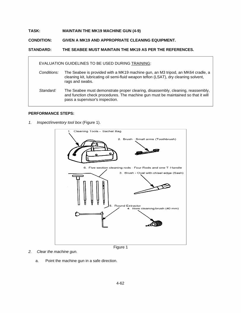
4-62
TASK: MAINTAIN THE MK19 MACHINE GUN (4-9) CONDITION: GIVEN A MK19 AND APPROPRIATE CLEANING EQUIPMENT. STANDARD: THE SEABEE MUST MAINTAIN THE MK19 AS PER THE REFERENCES.
EVALUATION GUIDELINES TO BE USED DURING TRAINING:
Conditions: The Seabee is provided with a MK19 machine gun, an M3 tripod, an MK64 cradle, a
cleaning kit, lubricating oil semi-fluid weapon teflon (LSAT), dry cleaning solvent, rags and swabs.
Standard: The Seabee must demonstrate proper clearing, disassembly, cleaning, reassembly,
and function check procedures. The machine gun must be maintained so that it will pass a supervisor's inspection.
PERFORMANCE STEPS: 1. Inspect/inventory tool box (Figure 1).
Figure 1
2. Clear the machine gun.
a. Point the machine gun in a safe direction.
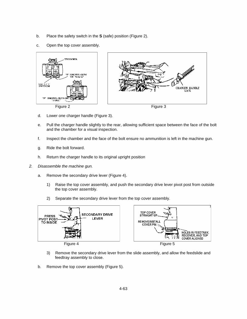
4-63
b. Place the safety switch in the S (safe) position (Figure 2).
c. Open the top cover assembly.
Figure 2 Figure 3
d. Lower one charger handle (Figure 3).
e. Pull the charger handle slightly to the rear, allowing sufficient space between the face of the bolt
and the chamber for a visual inspection.
f. Inspect the chamber and the face of the bolt ensure no ammunition is left in the machine gun.
g. Ride the bolt forward.
h. Return the charger handle to its original upright position 2. Disassemble the machine gun.
a. Remove the secondary drive lever (Figure 4).
1) Raise the top cover assembly, and push the secondary drive lever pivot post from outside the top cover assembly.
2) Separate the secondary drive lever from the top cover assembly.
Figure 4 Figure 5
3) Remove the secondary drive lever from the slide assembly, and allow the feedslide and
feedtray assembly to close.
b. Remove the top cover assembly (Figure 5).

4-64
1) Hold the cover assembly straight up with one hand at 90 °
2) Pull the top cover pins from both sides, and lift the top cover straight up and off
c. Remove the feed slide assembly and feedtray (Figure 6).
1) Align the tabs on the feed slide assembly with the slots in the feedtray, and lift them straight
up.
Figure 6 Figure 7
2) Remove the feedtray by lifting it straight up (Figure 7).
d. Remove the bolt and backplate assembly.
1) Place the safety switch in the F (fire) position.
2) Remove the backplate pin (Figure 8) using the rim of a spent cartridge case or metal link.
a) Pry outward on the pin lip.
b) Remove the pin with your fingers.
CAUTION: Before removing the backplate pin, ensure that the bolt is in the
forward position.
Figure 8 Figure 9
3) Grasp the control grips with both hands.
a) Lift it up slightly to disengage the backplate from the locking lugs in the receiver.
b) Pull the bolt and backplate assembly to the rear.

4-65
NOTE: Once the bolt clears the sear, support the bolt in one hand to prevent
damaging the backplate assembly (Figure 9).
e. Remove the primary drive lever and vertical cam (Figure 10).
1) Reaching under the top of the receiver, locate the drive lever lock, sliding the lock 1/4 inch to the rear.
2) Press down on the primary drive lever pivot post, which releases both the primary and
vertical cam.
3) Pull the primary drive lever from the front of the machine gun and the vertical cam from the back.
Figure 10 Figure 11
f. Remove the sear assembly.
1) Turn the machine gun on its side or upside down, and use the rim of a spent cartridge case
to raise the sear lock plunger (Figure 11) while squeezing the sear, and rotating the assembly 90 degrees to the right or left.
NOTE: Keep pressure on the sear until the assembly comes off.
2) Place the safety switch in the S (safe) position.
g. Remove the alignment guide.
1) Depress the tip of the alignment guide spring (Figure 12) with the finger or top cover
retaining pin.
Figure 12 Figure 13

4-66
2) Slide the alignment guide out of the receiver, pulling the assembly slightly rearward
h. Remove the ogive plunger (Figure 13) by pulling the assembly out through the inside wall of the receiver.
i. Remove the round-positioning block (Figure 14).
Figure 14 Figure 15
1) Push the round-positioning block into the side of the machine gun.
2) Slide it forward, and release it from the keyslots in the receiver wall.
j. Remove the charger assemblies (Figure 15) from both sides of the receiver.
1) Place the charger assemblies in the upright position.
2) Retract the lock plunger, using a metal link or spent cartridge, at the base of the charger
arm.
3) Slide the charger housing rearward to disengage the lugs from the keyslots in the receiver.
4) Lift the charger assembly away from the receiver. 3. Inspect the machine gun.
a. Inspect the receiver assembly.
1) Check the housing pin for cracks or rust. 2) Check the receiver rails for cracks, bends, or burrs.
3) Check the feed pawls for weak spring action or burrs.
4) Check the barrel for carbon builds up in the bore and chamber, and check for deformities in
the lands and grooves.
5) Check the flash suppressor for dents or cracks.
6) Check the rear sight.
4-67
a) Ensure it moves to the horizontal position without difficulty.
b) Ensure the dovetail is not dented.
c) Ensure the numbers on the range scale are visible.
7) Check the ogive plunger head and round-positioning block spring for weakness.
8) Check the charger assemblies for burred or grooved edges.
9) Check the vertical cam for burrs or scratches on the chrome edges.
10) Check the primary drive lever for burrs, especially around pivot posts.
11) Check the secondary drive lever.
a) Ensure there are no burrs on the pivot post or forked end.
b) Ensure the retaining ring is on the pivot post.
b. Inspect the feed slide assembly.
1) Check the feed pawls and feed tray pawls for burrs or binding.
2) Check the guide rails for burrs.
c. Inspect the top cover assembly.
1) Check the housing for cracks or rust.
2) Check the latch to ensure it does not bind and is not loose.
d. Inspect the bolt and backplate assembly.
1) Check the cocking lever to ensure it is not broken or worn on the rear tip.
2) Check the guide rods to ensure they are not bent or binding.
3) Check the recoil springs for weakness.
a) Position the bolt-end against a hard surface.
b) Push up and down on the backplate assembly.
4) Check the backplate pin to ensure it has a retaining ring.
5) Ensure the safety wire is attached to a pin.
e. Inspect the sear housing assembly for burrs.

4-68
f. Inspect the alignment guide assembly.
1) Check the alignment guide spring to ensure it is not deformed or cracked.
2) Ensure the pin is not loose and has no cracks.
4. Clean and lubricate the machine gun.
a. Clean and lubricate the receiver assembly.
1) Clean by wiping or brushing away dirt from all parts, especially the interior of the receiver housing, receiver rails, and feeder; apply solvent with a rag or brush.
2) Swab out bore and chamber, using the bore brush and dry cleaning solvent.
3) Wipe all parts dry.
4) Lightly lubricate all metal surfaces with LSAT.
b. Clean and lubricate the sear assembly.
CAUTION: Do not immerse the sear assembly in dry cleaning solvent.
1) Wipe or brush away dirt.
2) Use cleaning solvent on a rag or brush only.
3) Wipe dry.
4) Lightly lubricate all metal surfaces with LSAT.
c. Clean and lubricate the realignment guide assembly.
1) Wipe or brush off dirt.
a) Soak assembly in cleaning solvent.
b) Wipe dry.
2) Lubricate all metal surfaces with light coat of LSAT, especially the alignment spring and pin.
d. Clean and lubricate the ogive plunger assembly.
1) Wipe or brush off dirt.
2) Clean assembly with dry cleaning solvent.
SAFETY: Do not immerse ogive plunger assembly into solvent. Solvent may dilute the lubricant inside the housing.
4-69
3) Wipe dry.
4) Lightly lubricate all metal surfaces, especially the round-positioning block springs, with
LSAT
e. Clean and lubricate the charger assemblies, to include the vertical cam assembly and the primary and secondary drive levers.
1) Wipe or brush off dirt.
2) Soak in cleaning solvent.
3) Wipe dry.
4) Apply light coat of CLP.
- Apply two or three drops of lubricant on feed tray pawl and guide rails.
f. Clean and lubricate the top cover assembly.
1) Wipe or brush off dirt.
2) Soak in cleaning solvent.
3) Wipe dry.
4) Apply a light coat of CLP.
- Apply three drops of lubricant to the latch mechanism.
5) Work the latch to spread the oil.
g. Clean and lubricate the bolt and backplate assembly.
1) Wipe or brush off dirt.
2) Apply cleaning solvent with a rag or brush only.
3) Wipe dry.
4) Apply light coat of lubricant to all parts that can be reached, lubricating special areas:
a) Bolt face,
b) Bolt sear,
c) Guide rods, and
d) Recoil springs.
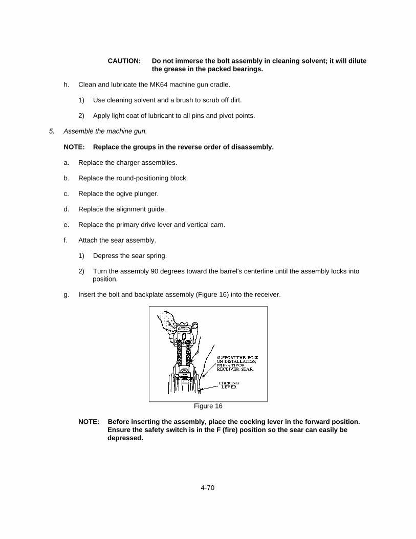
4-70
CAUTION: Do not immerse the bolt assembly in cleaning solvent; it will dilute
the grease in the packed bearings.
h. Clean and lubricate the MK64 machine gun cradle.
1) Use cleaning solvent and a brush to scrub off dirt.
2) Apply light coat of lubricant to all pins and pivot points. 5. Assemble the machine gun.
NOTE: Replace the groups in the reverse order of disassembly.
a. Replace the charger assemblies.
b. Replace the round-positioning block.
c. Replace the ogive plunger.
d. Replace the alignment guide.
e. Replace the primary drive lever and vertical cam.
f. Attach the sear assembly.
1) Depress the sear spring.
2) Turn the assembly 90 degrees toward the barrel's centerline until the assembly locks into position.
g. Insert the bolt and backplate assembly (Figure 16) into the receiver.
Figure 16
NOTE: Before inserting the assembly, place the cocking lever in the forward position.
Ensure the safety switch is in the F (fire) position so the sear can easily be depressed.

4-71
1) Ensure that the cocking lever is forward, and insert the bolt and backplate assembly into
the receiver.
2) Press the receiver sear twice, and slide the bolt assembly forward until the retainer pin holes in the backplate and receiver are aligned.
3) Insert the backplate retainer pin to lock the assembly into position.
h. Place the feed tray assembly on the receiver, and place the feed slide assembly into the cutout
slots on the feed tray.
i. Attach the top cover assembly.
1) Align the pinholes in the top cover assembly with the pinholes in the feed tray.
2) Hold the cover straight up at 90°, and insert the pins into both sides of the cover.
j. Replace the secondary drive lever.
1) Lift the feed slide assembly and feed tray.
2) Place the forked end of the secondary drive lever on the inner feed slide pin (Figure 17).
CAUTION: If the secondary drive lever is not properly engaged with the inner feed slide pin, the weapon will not fire properly, resulting in damage to the machine gun.
3) Press the raised pivot post assembly, and press the secondary drive lever firmly against the
top cover assembly.
Figure 17
6. Perform a function check.
a. Ensure the secondary drive lever is properly engaged with the feed slide pin.
b. Ensure the feed slide assembly is all the way to the left.
c. Ensure the bolt is forward.
4-72
d. Charge the machine gun.
1) If the bolt jams midway, hold the bolt back while opening the top cover.
2) Ride the bolt forward slowly.
3) Close the top cover.
e. Test the S (safe) and F (fire) positions of the safety.
1) Set the safety on S, and depress the trigger.
NOTE: Nothing should happen.
2) Set the safety on F, and depress the trigger.
NOTE: You should hear a click.
f. After firing, open the top cover assembly.
NOTE: Ensure the firing pin is forward.
1) If the firing pin is not forward, remove the bolt and backplate assembly.
2) Ensure that the cocking lever is forward.
3) Reassemble the bolt and backplate assembly.
NOTE: If the safety fails on the second try, report the failure.
7. Clean the pintle and platform group, the tripod, and the T&E mechanism. 8. Report any discrepancies that cannot be corrected to unit armorer. REFERENCES: MCWP 3-15.1, Machine Guns and Machine Gun Gunnery TM 08521A-10/1A, Operator's Manual, Machine Gun 40mm, MK19 Machin Gun FM 23-27, MK19 40mm Grenade Machine Gun, MOD 3
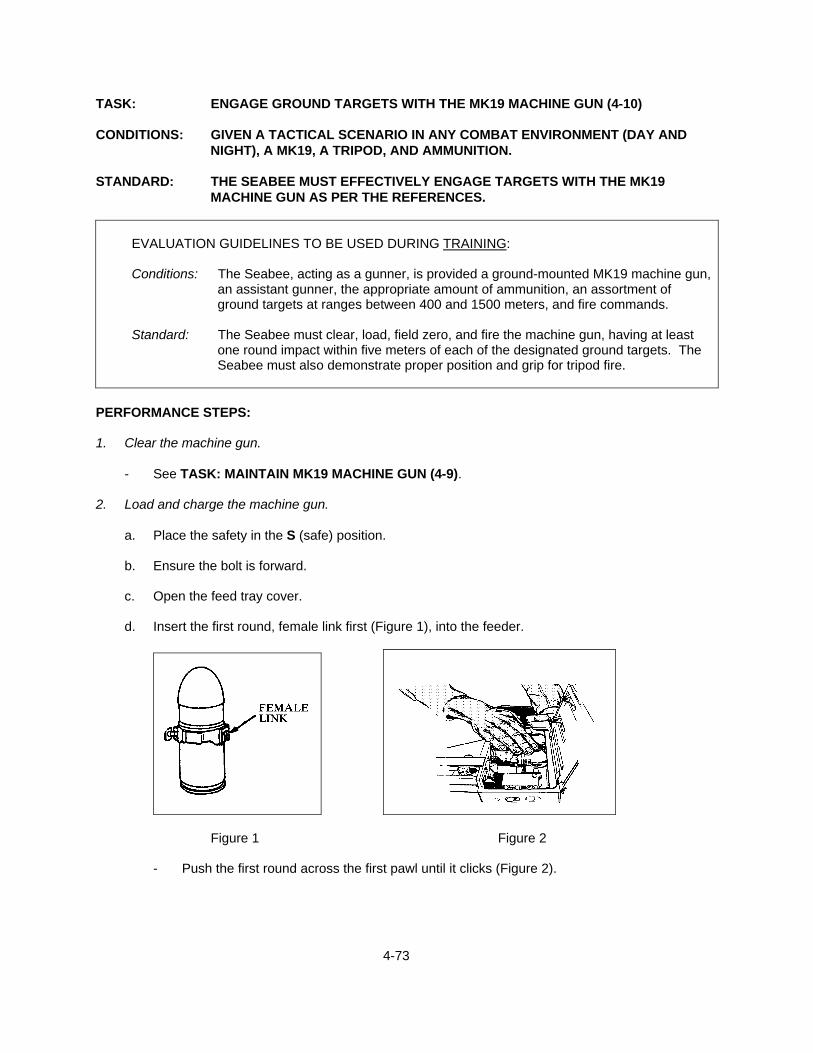
4-73
TASK: ENGAGE GROUND TARGETS WITH THE MK19 MACHINE GUN (4-10) CONDITIONS: GIVEN A TACTICAL SCENARIO IN ANY COMBAT ENVIRONMENT (DAY AND
NIGHT), A MK19, A TRIPOD, AND AMMUNITION. STANDARD: THE SEABEE MUST EFFECTIVELY ENGAGE TARGETS WITH THE MK19
MACHINE GUN AS PER THE REFERENCES.
EVALUATION GUIDELINES TO BE USED DURING TRAINING:
Conditions: The Seabee, acting as a gunner, is provided a ground-mounted MK19 machine gun,
an assistant gunner, the appropriate amount of ammunition, an assortment of ground targets at ranges between 400 and 1500 meters, and fire commands.
Standard: The Seabee must clear, load, field zero, and fire the machine gun, having at least
one round impact within five meters of each of the designated ground targets. The Seabee must also demonstrate proper position and grip for tripod fire.
PERFORMANCE STEPS: 1. Clear the machine gun.
- See TASK: MAINTAIN MK19 MACHINE GUN (4-9). 2. Load and charge the machine gun.
a. Place the safety in the S (safe) position.
b. Ensure the bolt is forward.
c. Open the feed tray cover.
d. Insert the first round, female link first (Figure 1), into the feeder.
Figure 1 Figure 2
- Push the first round across the first pawl until it clicks (Figure 2).
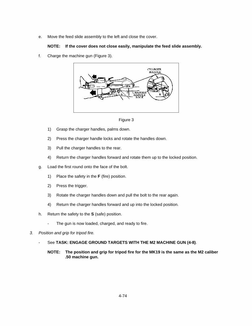
4-74
e. Move the feed slide assembly to the left and close the cover.
NOTE: If the cover does not close easily, manipulate the feed slide assembly.
f. Charge the machine gun (Figure 3).
Figure 3
1) Grasp the charger handles, palms down.
2) Press the charger handle locks and rotate the handles down.
3) Pull the charger handles to the rear.
4) Return the charger handles forward and rotate them up to the locked position.
g. Load the first round onto the face of the bolt.
1) Place the safety in the F (fire) position.
2) Press the trigger.
3) Rotate the charger handles down and pull the bolt to the rear again.
4) Return the charger handles forward and up into the locked position.
h. Return the safety to the S (safe) position.
- The gun is now loaded, charged, and ready to fire. 3. Position and grip for tripod fire.
- See TASK: ENGAGE GROUND TARGETS WITH THE M2 MACHINE GUN (4-8).
NOTE: The position and grip for tripod fire for the MK19 is the same as the M2 caliber .50 machine gun.

4-75
4. Field zero the machine gun.
a. Estimate the range to a target (400 to 600 meters is recommended for field zeroing).
b. Set the rear sight setting to the estimated target range.
c. Ensure that the windage scale is centered by turning the windage knob until the center index lines are aligned.
d. Adjust the Traversing and Elevating (T&E) mechanism until the correct sight picture is achieved
at the base (6 o'clock) of the target.
e. Fire at least a three round burst and observe its impact.
- If the round impacts on target, fire another burst of rounds to confirm the zero.
f. If the rounds were not on target, readjust the sights and the T&E mechanism until impacts are on target.
5. Perform transition firing using a tripod-mounted gun.
a. Engage the four types of ground targets: point, wide, deep, and oblique.
1) Engage a point target (Fixed Fire Mission).
a) Estimate the range to the target.
b) Set the rear sight setting to the estimated range.
c) Manipulate the T&E mechanism until the correct sight picture is achieved on the center of mass of the target.
d) Fire a short burst and observe the impacts of your rounds.
e) Manipulate the T&E mechanism to correct any errors.
f) Engage the target until fire commands are given to cease fire or the target is
destroyed.
2) Engage a wide target (Traverse Mission).
a) Estimate the range to the center of the target.
b) Set the rear sight setting to the estimated range.
c) Manipulate the T&E mechanism until the correct sight picture is achieved on the center of the target.
d) Fire a short burst and observe the impacts of your rounds.

4-76
e) Manipulate the T&E mechanism to correct any errors in range only.
f) Once range errors are corrected, start the firing and traversing sequence.
(1) Fire a burst.
(2) Traverse five meters (10 clicks at 500 meters, 5 clicks at 1,000 meters, or 3
clicks at 1,500 meters on the traversing handwheel).
(3) Fire another burst.
g) Continue traversing and firing until you reach the flank of the target.
h) Reverse the direction of traverse, and start the firing and traversing sequence in the opposite direction.
I) Continue firing and traversing until fire commands are given to cease-fire or until the
target is destroyed.
3) Engage a deep target (Search Mission).
a) Estimate the range to the near edge of the target.
b) Set the rear sight setting to the estimated range.
c) Manipulate the T&E mechanism until the correct sight picture is achieved on the near edge of the target.
d) Fire a short burst, and observe the impacts of your rounds.
e) Manipulate the T&E mechanism to correct any errors to the left or right only (deflection
errors).
f) Once deflection errors are corrected, start the firing and searching sequence.
(1) Fire a burst.
(2) Search up 4 to 6 mils (four or more clicks on the elevation handwheel).
(3) Fire another burst.
g) Continue searching and firing until you record impacts on the far edge of the target.
h) Reverse the direction of search, and start the firing and searching sequence down the length of the target.
i) Continue firing and searching until fire commands are given to cease fire or the target
is destroyed.

4-77
4) Engage an oblique target (Searching Traverse Mission).
a) Estimate the range to the near edge of the target.
b) Set the rear sight setting to the estimated range.
c) Manipulate the T&E mechanism until the correct sight picture is achieved on the
near edge of the target.
d) Fire a short burst and observe the impacts of your rounds.
e) Manipulate the T&E mechanism to correct any errors in both range and deflection.
f) Once errors are corrected, start the firing sequence including both searching and traversing manipulations.
(1) Fire a burst.
(2) Search up 4 or more mils and traverse 5 meters.
(3) Fire another burst.
g) Continue manipulating and firing until you record impacts on the far edge of the target.
h) Reverse the direction of both manipulations, and start the firing and manipulating
sequence down the length of the target.
i) Continue firing and manipulating until fire commands are given to cease fire or the target is destroyed.
5. Clear the machine gun.
- See TASK: MAINTAIN THE MK19 MACHINE GUN (4-9). REFERENCES: MCWP 3-15.1, Machine Guns and Machine Gun Gunnery TM 08521A-10/1A, Operator's Manual, Machine Gun 40mm, MK19 Machine Gun FM 23-27, MK19, 40-MM Grenade Machine Gun, MOD 3
4-78
TASK: PERFORM AS AN M240B MACHINE GUN TEAM LEADER (4-11) CONDITIONS: PROVIDED A TACTICAL SCENARIO IN ANY COMBAT ENVIRONMENT (DAY AND
NIGHT), AN M240B MACHINE GUN, A TRIPOD WITH T&E MECHANISM, AND AMMUNITION. (THE TEAM LEADER FOR AN M240B MACHINE GUN TEAM ALSO FUNCTIONS AS THE ASSISTANT GUNNER).
STANDARD: EMPLOY THE MACHINE GUN TEAM TO ACCOMPLISH THE MISSION PER
SQUAD LEADER'S COMMANDS.
EVALUATION GUIDELINES TO BE USED DURING TRAINING:
Conditions: The Seabee, acting as a machine gun team leader in a tactical scenario, is provided a machine gun team (gunner and ammunition bearer), an M240B machine gun, an M122 tripod with Traversing and Elevating (T&E) mechanism, the appropriate amount of ammunition, a designated firing position, ground targets at various ranges, and a squad leader.
Standard: The Seabee will inspect the ammunition and tripod and assist the gunner in placing
the machine gun into action. The Seabee will prepare a range card for his machine gun position, and assist in loading the machine gun. During firing, the Seabee will direct the gunner's adjustment onto the target. The Seabee will assist in making barrel changes (within 30 seconds), clearing malfunctions and stoppages, and taking the machine gun out of action.
Administrative Notes: See TASKS: ENGAGE GROUND TARGETS WITH THE M240B
MACHINE GUN (4-6)
PREPARE A RANGE CARD (4-15)
PERFORMANCE STEPS: 1. Perform as an M240B machine gun team leader.
a. Inspect equipment.
NOTE: Inspection of equipment begins on the squad leader's command.
1) Inspect the ammunition.
a) Ensure that it is properly linked.
b) Ensure that it is free of dirt and corrosion.
c) Ensure that it is serviceable.
d) Ensure that it is ready for loading.
4-79
2) Inspect the tripod.
a) Ensure that the legs are folded closely together.
b) Ensure that the sleeve latch has tension and will function.
c) Ensure that the tripod is free of all dirt and corrosion.
d) Report discrepancies that cannot be corrected to the squad leader.
2. Assist in placing the machine gun into action.
NOTE: Place the machine gun into action on the squad leader's command.
a. Set the tripod trail and front legs.
1) Place the opened tripod on the ground with the front leg pointing toward the target.
2) Ensure that the tripod legs are secure by stamping all legs into the ground.
b. Assume a prone position on the left side of the tripod.
c. Assist the gunner in placing the T&E mechanism on the machine gun.
1) Hand the T&E mechanism to the gunner.
2) Steady the rear of the machine gun while the gunner positions the T&E mechanism. 3. Prepare a range card. (See TASK: PREPARE A RANGE CARD (4-15).) 4. Assist the gunner in loading the machine gun. (See TASK: ENGAGE GROUND TARGETS WITH
THE M240B MACHINE GUN (4-6).)
- Report to the squad leader after the gunner reports "UP." 5. Direct the gunner's adjustment onto the target during firing.
a. Select a target for the gunner to engage.
b. Set the rear sight to the correct range of the target.
c. Have the gunner sight in on the target by manipulating the T&E mechanism until a good sight picture is obtained.
d. Command the gunner to fire a 6 round burst and observe the impact of the rounds.
e. Spot the impacts as being left, right, high, low or any appropriate combination.
f. Estimate the number of mils the impacts are from the target.

4-80
g. Give the gunner a correction in clicks, which will bring the rounds onto the target.
NOTE: Each click of elevation or traverse on the elevating handwheel or the traversing
knob equals one mil.
h. Repeat steps (d) through (g) until rounds impact on target. 6. Assist the gunner in changing barrels.
NOTE: A barrel change is required after firing at the sustained rate for 10 minutes and after firing at the rapid rate for 2 minutes and cyclic rate for 1 minute. The barrel change should be completed within 30 seconds.
a. (Gunner) Prepare the machine gun by pulling the bolt to the rear and by placing the machine
gun on SAFE.
NOTE: The bolt will be locked into the barrel socket, making it impossible to remove the barrel unless the operating group is forward.
b. (Team leader) Remove ammunition from the feed tray.
c. (Gunner) Raise the barrel lock lever with your right hand.
NOTE: Keep your right hand in this position.
d. (Team leader) Grasp the barrel group by the carrying handle, and pull it from the receiver.
e. (Team leader) Insert the spare barrel until it is fully seated.
f. (Gunner) Lower the barrel lock lever.
g. (Team leader) Report "UP" to the squad leader.
7. When requested by the gunner, assist in clearing malfunctions and stoppages.
NOTE: Clearing malfunctions and stoppages are the responsibility of the gunner.
- Give assistance in clearing malfunctions and stoppages when requested by the gunner. 8. Assist the gunner in taking the machine gun out of action.
NOTE: Begin the action on the squad leader's command.
a. (Team leader) Remove the ammunition from the feed tray and secure it.
b. (Gunner) Ensure that the machine gun is clear.
4-81
c. Remove the T&E mechanism.
1) (Gunner) Release the traversing slide lock lever, and raise the rear of the machine gun.
2) (Team leader) Pull down on the locating pin release.
3) (Team leader) Remove the T&E mechanism and hand it to the ammunition bearer.
d. (Team leader) Secure the tripod.
e. Report to the squad leader after the gunner reports "UP." REFERENCES: MCWP 3-15.1, Machine Guns and Machine Gun Gunnery TM 9-1005-313-10, Operator's Manual for Machine Gun, 7.62mm, M240 FM 3-22.68, Crew Served Machine Guns 5.56 and 7.62-MM

4-82
TASK: PERFORM AS AN M2/MK19 MACHINE GUN TEAM LEADER (4-12) CONDITIONS: PROVIDED A TACTICAL SCENARIO IN A COMBAT ENVIRONMENT (DAY AND
NIGHT), AN M2 OR MK19 MACHINE GUN TEAM, A TRIPOD WITH T&E MECHANISM, AND AMMUNITION. (THE TEAM LEADER FOR AN M2/MK19 MACHINE GUN TEAM ALSO FUNCTIONS AS THE GUNNER).
STANDARD: EMPLOY THE MACHINE GUN TEAM TO ACCOMPLISH THE MISSION PER
SQUAD LEADER'S COMMANDS.
EVALUATION GUIDELINES TO BE USED DURING TRAINING:
Conditions: The Seabee, acting as an M2/MK19 machine gun team leader in a tactical scenario, is provided a machine gun team (gunner and ammunition bearer), an M2/MK19 machine gun, an M3 tripod with traversing and elevating (T&E) mechanism, an MK64 MOD 7 cradle, the appropriate amount of ammunition, a designated firing position, ground targets at various ranges, and a squad leader.
Standard: The Seabee will inspect the M2/MK19 machine gun. The Seabee will place the
machine gun into action, prepare a range card for his machine gun position, load the machine gun, clear malfunctions and stoppages, change barrels (M2 only), adjust fires to hit the target, and take the machine gun out of action. The Seabee must follow all commands given by the squad leader.
Administrative Notes: See TASKS: ENGAGE GROUND TARGETS WITH THE M2
MACHINE GUN (4-8)
ENGAGE GROUND TARGETS WITH THE MK19 MACHINE GUN (4-10)
MAINTAIN THE M2 MACHINE GUN (4-7)
MAINTAIN THE MK19 MACHINE GUN (4-9)
PREPARE A RANGE CARD (4-15)
PERFORMANCE STEPS: 1. Perform as an M2 machine gun team leader/gunner.
a. Inspect the M2 machine gun.
NOTE: Inspection of equipment begins on the squad leader's command.
1) Ensure that the barrel support and breech bearings are free of dirt.
2) Ensure that the gun pintle is free of dirt.

4-83
3) Ensure that the feed mechanism and bolt switch are properly assembled to feed from the left (raise cover for inspection).
4) Ensure that the firing pin projects through the hole in the face of the bolt (close the cover).
5) Ensure that the rear sight is set at 900 meters elevation, windage 0.
6) Ensure that the T&E mechanism is securely attached to the receiver.
7) Ensure that the traversing handwheel is centered.
8) Ensure that the backplate is latched and locked in place.
9) Ensure that the bolt latch release is locked in the down position by the bolt latch release
lock.
b. Place the machine gun into action.
NOTE: Placing the machine gun into action begins on the squad leader's command.
1) (Gunner) Set up the M3 tripod.
2) Mount the machine gun on the tripod.
a) (Team leader) Grasp the spade grips with both hands.
b) (Ammunition bearer) Grasp the machine gun carrying handle with the right hand.
c) (Gunner and ammunition bearer) Lift the machine gun and insert the pintle into the pintle bushing.
d) (Ammunition bearer) Lift the gun pintle lock release cam with the right hand and push
down once the pintle is fully seated. Remove the machine gun Carry Handle.
3) (Gunner) Lower the T&E mechanism to the traversing bar.
NOTE: Ensure that the traversing handwheel is to the left and that the lock lever is to the right.
4) (Team leader and gunner) Load the machine gun. (See TASK: ENGAGE GROUND
TARGETS WITH THE M2 MACHINE GUN (4-8).)
5) (Gunner) Assume the correct prone position behind the machine gun.
c. Prepare a range card. (See TASK: PREPARE A RANGE CARD (4-15).)
d. Adjust rounds onto target. (See TASK: ENGAGE GROUND TARGETS WITH THE M2 MACHINE GUN (4-8).)

4-84
e. Perform a barrel change. (See TASK: MAINTAIN THE M2 MACHINE GUN (4-7).)
f. Take the machine gun out of action.
NOTE: Taking the machine gun out of action begins on the squad leader's command.
1) (Team leader) Raise the top cover.
2) (Gunner) Lift the ammunition out of the feedway.
3) (Team leader) Clear the machine gun. (See TASK: MAINTAIN THE M2 MACHINE GUN
(4-7).)
4) (Gunner and ammunition bearer) Dismount the machine gun from the tripod.
5) Report to the squad leader when the machine gun is completely out of action. 2. Perform as a MK19 machine gun team leader.
a. Inspect the MK19 machine gun.
NOTE: Inspection of equipment begins on the squad leader's command.
1) Ensure that the machine gun is clear by checking the feed tray chamber and bolt face.
2) Ensure that the cover is closed, the bolt is forward, and the safety is in the S (safe) position.
3) Ensure that the charging handles are up and locked in the forward position.
4) Report deficiencies that cannot be corrected to the squad leader.
b. Place the machine gun into action.
NOTE: Placing the machine gun into action begins on the squad leader's command.
1) (Gunner) Set up the M3 tripod.
2) (Gunner and ammunition bearer) Mount the MK64 cradle and the T&E mechanism to the tripod.
3) (Team leader and gunner) Mount the machine gun to the cradle.
4) (Team leader and gunner) Load the machine gun. (See TASK: ENGAGE GROUND
TARGETS WITH THE MK19 MACHINE GUN (4-10).)
c. Prepare a range card. (See TASK: PREPARE A RANGE CARD (4-15).)

4-85
d. Adjust rounds onto target. (See TASK: ENGAGE GROUND TARGETS WITH THE MK19
MACHINE GUN (4-10).)
e. Take the machine gun out of action.
NOTE: Taking the machine gun out of action begins on the squad leader's command.
1) (Team leader) Raise the top cover.
2) (Gunner) Lift the ammunition out of the feed tray.
3) (Team leader) Clear the machine gun. (See TASK: MAINTAIN THE MK19 MACHINE GUN (4-9).)
4) (Team leader and Gunner) Release and lift the machine gun from the cradle.
5) (Team leader) Report to the squad leader when the machine gun is completely out of
action. REFERENCES: MCWP 3-15.1, Machine Guns and Machine Gun Gunnery TM 08521A-10/1A, Operator's Manual and Components List, Machine Gun 40mm, MK19 MOD 3 TM 9-1005-213-10, Operator's Manual for Machine Gun, Caliber .50 FM 23-27, MK 19 40mm Grenade Machine Gun, MOD 3 FM 23-65, Browning Machine Gun, caliber .50, HB M2
4-86
TASK: CONSTRUCT MACHINE GUN POSITIONS (4-13) CONDITIONS: PROVIDED A TRIPOD MOUNTED M240B, M2, OR MK19 MACHINE GUN,
GUNNER, SECTOR OF FIRE, ENTRENCHMENT TOOLS, AND SELECTED FIRING POSITION.
STANDARD: THE POSITION MUST ALLOW THE GUN TO FIRE THE ASSIGNED MISSION
(PDF/FPL) AND COVER THE ENTIRE SECTOR OF FIRE. THE HOLE MUST BE SHAPED SO THAT THE TEAM LEADER GUNNER AND GUNNER HAVE ACCESS TO THE GUN. UPON COMPLETION, THE POSITION WILL AFFORD PROTECTION FROM DIRECT FRONTAL SMALL ARMS FIRE AND THE CRUSHING ACTION OF TANKS; IT WILL BLEND WELL ENOUGH WITH THE SURROUNDINGS SO THAT IT CANNOT BE DETECTED FROM APPROXIMATELY 35 METERS TO THE FRONT; AND FROM IT, THE SEABEE WILL BE ABLE TO OBSERVE AND TAKE UNDER FIRE PERSONNEL MOVING INTO HIS/HER SECTOR OF FIRE. THE POSITION SHOULD AFFORD NATURAL COVER SUCH AS MOUNDS OF EARTH, STUMPS, TREES, ETC., WHENEVER POSSIBLE.
EVALUATION GUIDELINES TO BE USED DURING TRAINING:
Conditions: The Seabee, acting as a member of a machine gun team in a tactical scenario, is
provided a tripod-mounted M240B, M2, or MK19 machine gun with traversing and elevating (T&E) mechanism, a gunner, entrenching tools, and a selected firing position with predetermined sectors of fire.
Standard: The Seabee must construct the fighting position so that the machine gun can fire its
assigned mission Principal Direction of Fire (PDF) or Final ProtectiveLine (FPL) and cover the entire sector of fire. The Seabee must first occupy a hasty fighting position and improve upon it until it becomes a deliberate machine gun fighting position. The position must be shaped so that both the Team Leader and gunner have access to the machine gun. The position must also have limiting stakes, a water trench, grenade sumps, a parapet, and overhead cover. The position must be camouflaged so that it cannot be detected by the enemy.
Administrative Notes: See TASKS: LAY AN M240B/M2 MACHINE GUN (4-17)
LAY A MK19 MACHINE GUN (4-18)
PERFORMANCE STEPS: 1. Position the tripod.
a. Move the machine gun to the assigned position using available cover and concealment.
b. Position the tripod legs so the machine gun can be laid on the FPL or PDF. (See TASKS: LAY AN M240B/M2 MACHINE GUN (4-7), and LAY A MK19 MACHINE GUN (4-18).)
NOTE: Once the position is occupied, the machine gun must be manned at all times,
ensuring that the assigned mission (PDF/FPL) is covered.

4-87
2. Clear fields of fire.
NOTE: Ensure that the position is not compromised by excessive or careless clearing.
a. Start clearing near your position and work forward in areas organized for close defense.
b. Leave a thin, natural screen of vegetation to hide defensive positions.
c. Remove lower branches of large, scattered trees in sparsely wooded areas.
d. Clear fields of fire in heavy woods by removing significant vegetation that will restrict firing.
NOTE: Ensure that you clear in an irregular pattern, which will not reveal the position of the machine gun.
e. Remove or thin dense brush.
f. Cut weeds only when they obstruct your view and are higher than knee level.
g. Drag away cut brush, limbs, and weeds to points where they will not be detected by the enemy
or furnish the enemy concealment.
h. Cover cuts on trees forward of the position with mud or dirt.
i. Ensure that you leave no trails in your sector of fire as lanes are cleared. 3. Prepare a hasty position.
NOTE: A hasty position should be positioned behind whatever natural cover is available. It should offer as much frontal cover and concealment as possible from enemy direct fire but should still allow firing to the front and oblique.
a. Use a natural hole, ditch, deadfall, or whatever natural cover and concealment the terrain
affords.
b. Lay the machine gun in the selected position or assigned sector of fire. (See TASK: LAY AN M240B/M2 MACHINE GUN (4-17), and LAY AN MK19 MACHINE GUN (4-18).)
c. Prepare range card. (See TASK: PREPARE RANGE CARD (4-15).)
NOTE: Every time the weapon is moved, a new range card will be made.
d. Improve the hasty position as time permits (Figure 1).

4-88
Figure 1
1) Remove vegetation from the selected position carefully so that it may be used as
camouflage.
2) Dig or scrape out dirt to form a more protective firing position.
3) Remove the excess dirt from the immediate area so that it will not be visible to the enemy. 4. Improve the position.
a. Determine the type of firing position to construct.
NOTE: The size of the area that you must cover and the time that you have to construct your position will determine the type of position that you will dig.
b. Mark the dimensions of the hole.
NOTE: Always have the machine gun laid on the assigned sector of fire, ready to fire.
1) Mark the position of the tripod legs where the machine gun can be laid on the FPL or PDF.
2) Mark the sectors of fire with sector stakes.
3) Trace the outline of the hole around the current hasty position (Figure 2).
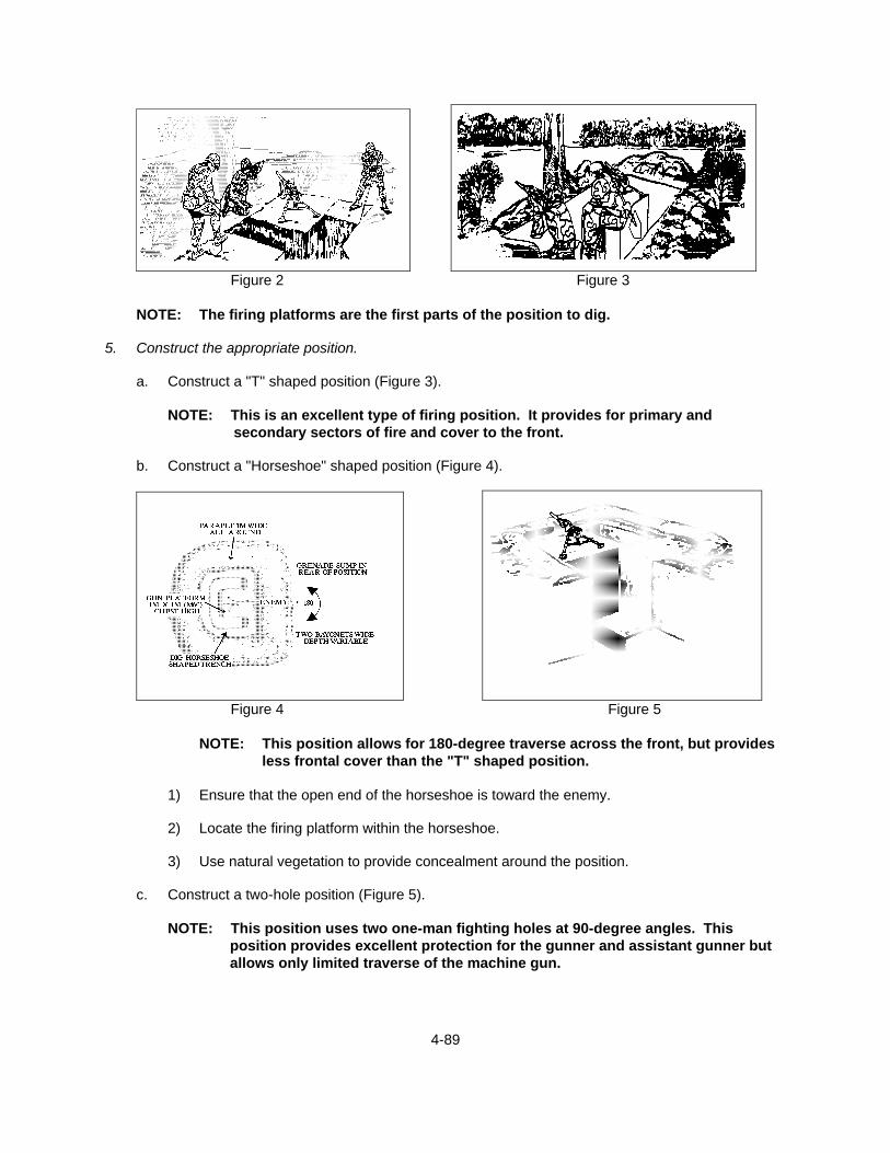
4-89
Figure 2 Figure 3
NOTE: The firing platforms are the first parts of the position to dig.
5. Construct the appropriate position.
a. Construct a "T" shaped position (Figure 3).
NOTE: This is an excellent type of firing position. It provides for primary and secondary sectors of fire and cover to the front.
b. Construct a "Horseshoe" shaped position (Figure 4).
Figure 4 Figure 5
NOTE: This position allows for 180-degree traverse across the front, but provides
less frontal cover than the "T" shaped position.
1) Ensure that the open end of the horseshoe is toward the enemy.
2) Locate the firing platform within the horseshoe.
3) Use natural vegetation to provide concealment around the position.
c. Construct a two-hole position (Figure 5).
NOTE: This position uses two one-man fighting holes at 90-degree angles. This position provides excellent protection for the gunner and assistant gunner but allows only limited traverse of the machine gun.
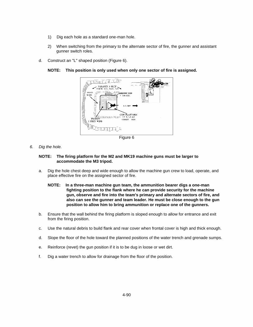
4-90
1) Dig each hole as a standard one-man hole.
2) When switching from the primary to the alternate sector of fire, the gunner and assistant
gunner switch roles.
d. Construct an "L" shaped position (Figure 6).
NOTE: This position is only used when only one sector of fire is assigned.
Figure 6
6. Dig the hole.
NOTE: The firing platform for the M2 and MK19 machine guns must be larger to accommodate the M3 tripod.
a. Dig the hole chest deep and wide enough to allow the machine gun crew to load, operate, and
place effective fire on the assigned sector of fire.
NOTE: In a three-man machine gun team, the ammunition bearer digs a one-man fighting position to the flank where he can provide security for the machine gun, observe and fire into the team's primary and alternate sectors of fire, and also can see the gunner and team leader. He must be close enough to the gun position to allow him to bring ammunition or replace one of the gunners.
b. Ensure that the wall behind the firing platform is sloped enough to allow for entrance and exit
from the firing position.
c. Use the natural debris to build flank and rear cover when frontal cover is high and thick enough.
d. Slope the floor of the hole toward the planned positions of the water trench and grenade sumps.
e. Reinforce (revet) the gun position if it is to be dug in loose or wet dirt.
f. Dig a water trench to allow for drainage from the floor of the position.
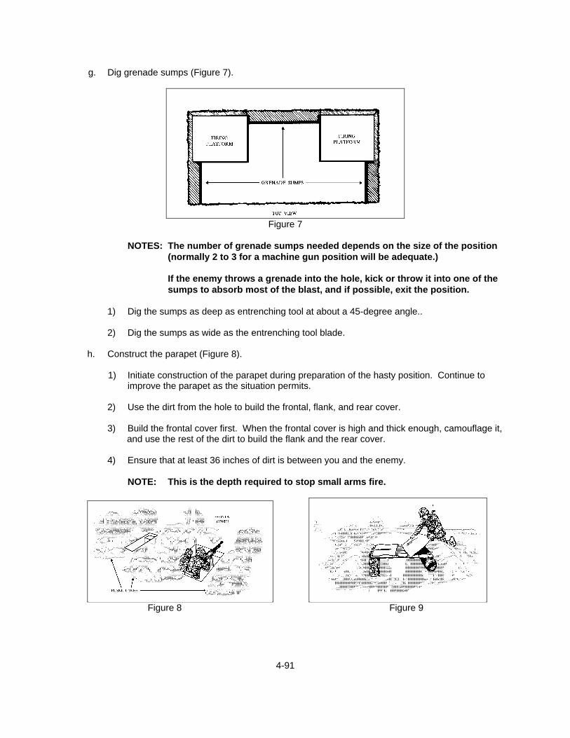
4-91
g. Dig grenade sumps (Figure 7).
Figure 7
NOTES: The number of grenade sumps needed depends on the size of the position
(normally 2 to 3 for a machine gun position will be adequate.)
If the enemy throws a grenade into the hole, kick or throw it into one of the sumps to absorb most of the blast, and if possible, exit the position.
1) Dig the sumps as deep as entrenching tool at about a 45-degree angle..
2) Dig the sumps as wide as the entrenching tool blade.
h. Construct the parapet (Figure 8).
1) Initiate construction of the parapet during preparation of the hasty position. Continue to
improve the parapet as the situation permits.
2) Use the dirt from the hole to build the frontal, flank, and rear cover.
3) Build the frontal cover first. When the frontal cover is high and thick enough, camouflage it, and use the rest of the dirt to build the flank and the rear cover.
4) Ensure that at least 36 inches of dirt is between you and the enemy.
NOTE: This is the depth required to stop small arms fire.
Figure 8 Figure 9
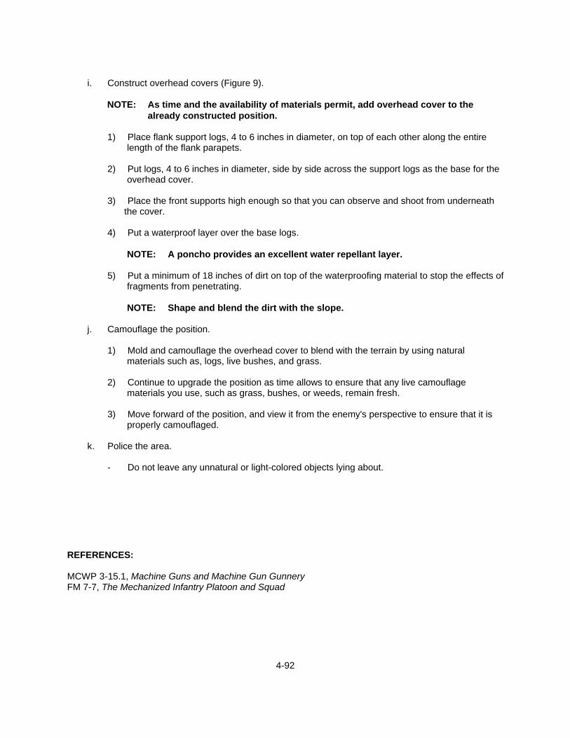
4-92
i. Construct overhead covers (Figure 9).
NOTE: As time and the availability of materials permit, add overhead cover to the
already constructed position.
1) Place flank support logs, 4 to 6 inches in diameter, on top of each other along the entire length of the flank parapets.
2) Put logs, 4 to 6 inches in diameter, side by side across the support logs as the base for the
overhead cover.
3) Place the front supports high enough so that you can observe and shoot from underneath the cover.
4) Put a waterproof layer over the base logs.
NOTE: A poncho provides an excellent water repellant layer.
5) Put a minimum of 18 inches of dirt on top of the waterproofing material to stop the effects of
fragments from penetrating.
NOTE: Shape and blend the dirt with the slope.
j. Camouflage the position.
1) Mold and camouflage the overhead cover to blend with the terrain by using natural materials such as, logs, live bushes, and grass.
2) Continue to upgrade the position as time allows to ensure that any live camouflage
materials you use, such as grass, bushes, or weeds, remain fresh.
3) Move forward of the position, and view it from the enemy's perspective to ensure that it is properly camouflaged.
k. Police the area.
- Do not leave any unnatural or light-colored objects lying about.
REFERENCES: MCWP 3-15.1, Machine Guns and Machine Gun Gunnery FM 7-7, The Mechanized Infantry Platoon and Squad
4-93
TASK: DETERMINE RANGE (4-14) CONDITIONS: THE SEABEE ACTING AS GUNNER, IS PROVIDED A ZEROED MACHINE GUN,
FIELD FIRING RANGE WITH TARGETS, DESIGNATED SECTOR OF FIRE, AND 80 ROUNDS OF AMMUNITION FOR THE M240B/M2 OR 63 ROUNDS FOR THE MK19.
STANDARDS: THE SEABEE MUST DETERMINE THE RANGE TO THE FOUR SEPARATE
TARGETS, VARYING IN DISTANCE FROM 500 TO THE MAXIMUM EFFECTIVE RANGE OF THE MACHINE GUN, TO THE NEAREST 100 METERS BY FIRING THE GUN.
EVALUATION GUIDELINES TO BE USED DURING TRAINING:
Conditions: The Seabee, acting as a gunner, is provided a zeroed M240B, M2, or MK19 tripod-mounted machine gun with Traversing and Elevating (T&E) mechanism, a firing range with targets set at ranges between 500 meters and the maximum effective range for the gun, an assigned sector of fire, binoculars, a 1:50,000 military map of the range, and the appropriate amount of ammunition.
Standard: The Seabee must determine the range to various targets using the estimate by eye
(100-meter unit of measure and appearance-of-object) methods, by using a map, by using the binocular mil scale, and by firing the machine gun (registration fire).
Administrative Notes: See TASKS: ENGAGE GROUND TARGETS WITH THE M240B
MACHINE GUN (4-6)
ENGAGE GROUND TARGETS WITH THE M2 MACHINE GUN (4-8)
ENGAGE GROUND TARGETS WITH THE MK19 MACHINE GUN (4-10)
MAINTAIN THE M240B MACHINE GUN (4-5)
MAINTAIN THE M2 MACHINE GUN (4-7)
MAINTAIN THE MK19 MACHINE GUN (4-9)
NAVIGATE WITH A MAP USING TERRAIN ASSOCIATION (1-48)
PERFORMANCE STEPS: 1. Estimate range by eye, using the appropriate method.
a. Estimate range using the 100-meter unit-of-measure method (daytime).
1) Picture a distance of 100 meters on the ground (football field or about 130 steps).

4-94
2) Estimate the number of 100-meter lengths between you and the target (Figure 1).
(a) Estimate ranges up to 500 meters.
Figure 1
- Count the number of 100-meter lengths to determine range.
b) Estimate ranges over 500 meters
(1) Select halfway point.
(2) Estimate range to that point.
(3) Multiply this estimate by two to determine range
b. Estimate range using the appearance of object method (daytime).
1) Study the appearance of men and objects at various distances until you know how far away they are.
NOTE: For example, using Figure 2, you should be able to identify armored and
wheeled vehicles from 1,500 to 2,000 meters with the unaided eye. If you can positively identify the vehicle as a tank but cannot determine the model, it is between 1,000 and 1,500 meters away.

4-95
IF YOU CAN SEE APPROXIMATE DISTANCE (IN METERS)
Troops, Machine Guns, Mortars, Antitank Guns, Antitank Missile Launchers 500
Tanks, Armored Personnel Carriers, Trucks (By Model) 1,000
Howitzers, Tanks, Trucks 1,500
Armored Vehicles, Wheeled Vehicles 2,000
Figure 2
2) Consider visibility when using this method. Use Figure 3 to help to make your estimates more accurate.
TARGET APPEARANCE SEEMS CLOSER SEEMS FARTHER Bright Clear Day Fog, Rain, Hazy Sun in Front of Target Sun Behind Target Lower Elevations Higher Elevations Large Targets Small Targets Bright Colors (White, Red, Yellow) Dark Colors Contrast Camouflaged Targets Looking Across Ravines, River Depressions At Sea
Figure 3 2. Estimate range using a map.
a. Locate your position and the target's position on a map. (See TASK: NAVIGATE WITH A MAP USING TERRAIN ASSOCIATION (1-48).)
b. Measure the distance, using the legend scale at the bottom of the map.
3. Determine range using binoculars.
a. Acquire the target to be estimated.
b. Line the target up on the bottom (width) scale of the binoculars (Figure 4).
1) Read the binocular reticle scale to obtain the mil value for the target.

4-96
2) Divide the known width, length, or height of the object by the mil value to obtain the range.
Figure 4 4. Estimate range by firing the machine gun (registration fire).
NOTE: To use this method, ensure that the machine gun has been zeroed.
a. Load the machine gun. (See TASKS: ENGAGE GROUND TARGETS WITH THE M240B MACHINE GUN (4-6), ENGAGE GROUND TARGETS WITH THE M2 MACHINE GUN (4-8), and ENGAGE GROUND TARGETS WITH THE MK19 MACHINE GUN (4-10).)
b. Engage a target.
1) Estimate the range to the target.
2) Set the rear sight to the estimated range.
3) Manipulate the T&E mechanism until a clear sight picture is obtained.
4) Fire a short burst and observe the impact of the rounds.
5) Readjust the rear sight and T&E mechanism as necessary to get the rounds on target.
c. Once the rounds impact on target, announce the rear sight setting as the range to the target.
d. Clear the machine gun. (See TASKS: MAINTAIN THE M240B MACHINE GUN (4-5),
MAINTAIN THE M2 MACHINE GUN (4-7), and MAINTAIN THE MK19 MACHINE GUN (4-9).) NOTE: This is not the recommended way to determine the range to your target due to
prematurely giving your machine gun position away. REFERENCES: FMFM 6-5, Marine Rifle Squad MCWP 3-15.1, Machine Guns and Machine Gun Gunnery
4-97
TASK: PREPARE A RANGE CARD (4-15) CONDITIONS: PROVIDED A DEFENSIVE FIRING POSITION, A TRIPOD-MOUNTED MACHINE
GUN WITH COMPONENTS, A DESIGNATED PRIMARY SECTOR OF FIRE, A FINAL PROTECTIVE LINE (FPL) OR PRINCIPLE DIRECTION OF FIRE (PDF), AND SECONDARY SECTOR OF FIRE (BOTH WITH RECOGNIZABLE TARGETS), PAPER, PENCIL, AND LENSATIC COMPASS.
STANDARD: THE RANGE CARD MUST BE PREPARED WITHIN 15 MINUTES FOR EACH
POSITION. A CARD MUST BE DONE FOR THE PRIMARY, ALTERNATE, AND SUPPLEMENTARY POSITIONS. THE SKETCH SECTION MUST INCLUDE THE MACHINE GUN POSITION, THE FPL OR PDF, SECTOR LIMITS, MAGNETIC AZIMUTH OF GUN AND 8-DIGIT COORDINATES, AREA OF GRAZE AND SPECIFIC TARGETS. THE SKETCH MUST SHOW DISTANCES WHEN APPLICABLE. THE DATA SECTION MUST LIST THE SPECIFIC TARGETS BY NUMBER AND INCLUDE DIRECTION (MILS), ELEVATION (MILS), RANGE (METERS), AS WELL AS A DESCRIPTION OF THE TARGET. THE RANGE CARD WILL BE PREPARED IN DUPLICATE, GIVING THE GUN NUMBER, DATE AND TIME OF PREPARATION.
EVALUATION GUIDELINES TO BE USED DURING TRAINING:
Conditions: The Seabee, acting as a gunner in a machine gun defensive firing position during daylight, is provided a tripod-mounted M240B, M2, or MK19 machine gun with Traversing and Elevating (T&E) mechanism, team leader, designated primary sector of fire with recognizable targets, an assigned Final Protective Line (FPL) or Principal Direction of Fire (PDF), a standard 1:50,000 military map of the range, a lensatic compass, paper and a pencil.
Standard: The Seabee, with aid from the team leader, must prepare a machine gun range
card for the primary machine gun fighting position. The Seabee must complete the sketch, showing the machine gun number, unit designation, date and time the range card was prepared. The sketch must further show the machine gun position, a magnetic North arrow, the left and right lateral limits, the assigned PDF or FPL, magnetic azimuth of the machine gun to a prominent terrain feature, dead space, areas signifying grazing fires, and specified targets numbered in sequence with their direction in mils, elevation in mils, and range in meters. A duplicate copy of the range card must be made for the unit commander.
Administrative Notes: See TASKS: DETERMINE RANGE (4-14)
LAY AN M240B/M2 MACHINE GUN (4-17)
LAY AN MK19 MACHINE GUN (4-18)
PERFORMANCE STEPS: 1. Complete the range card sketch.

4-98
NOTE: Range cards are prepared immediately upon arrival to a position regardless of the anticipated length of stay and should be continuously revised throughout the occupation of the position. Figure 1 is a sample Range Card. Figure 2 are line symbols used for preparing Range Card.
Figure 1

4-99
Figure 2
M240B MACHINE GUN
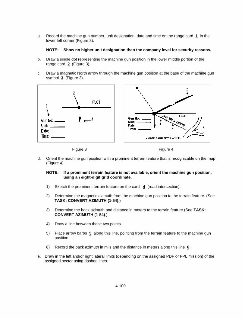
4-100
a. Record the machine gun number, unit designation, date and time on the range card 1 in the
lower left corner (Figure 3).
NOTE: Show no higher unit designation than the company level for security reasons.
b. Draw a single dot representing the machine gun position in the lower middle portion of the range card 2 (Figure 3).
c. Draw a magnetic North arrow through the machine gun position at the base of the machine gun
symbol 3 (Figure 3).
Figure 3 Figure 4
d. Orient the machine gun position with a prominent terrain feature that is recognizable on the map (Figure 4).
NOTE: If a prominent terrain feature is not available, orient the machine gun position,
using an eight-digit grid coordinate.
1) Sketch the prominent terrain feature on the card 4 (road intersection).
2) Determine the magnetic azimuth from the machine gun position to the terrain feature. (See TASK: CONVERT AZIMUTH (1-54).)
3) Determine the back azimuth and distance in meters to the terrain feature.(See TASK:
CONVERT AZIMUTH (1-54).)
4) Draw a line between these two points.
5) Place arrow barbs 5 along this line, pointing from the terrain feature to the machine gun position.
6) Record the back azimuth in mils and the distance in meters along this line 6 .
e. Draw in the left and/or right lateral limits (depending on the assigned PDF or FPL mission) of the
assigned sector using dashed lines.
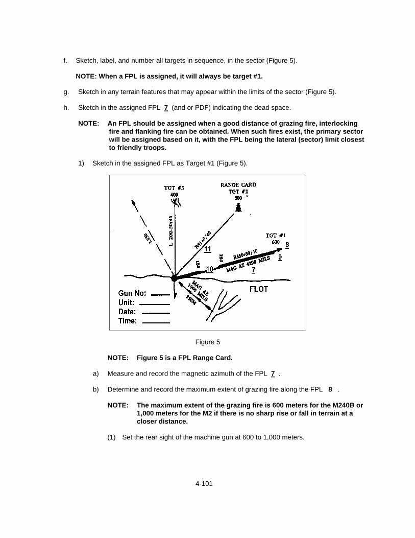
4-101
f. Sketch, label, and number all targets in sequence, in the sector (Figure 5).
NOTE: When a FPL is assigned, it will always be target #1.
g. Sketch in any terrain features that may appear within the limits of the sector (Figure 5).
h. Sketch in the assigned FPL 7 (and or PDF) indicating the dead space.
NOTE: An FPL should be assigned when a good distance of grazing fire, interlocking fire and flanking fire can be obtained. When such fires exist, the primary sector will be assigned based on it, with the FPL being the lateral (sector) limit closest to friendly troops.
1) Sketch in the assigned FPL as Target #1 (Figure 5).
Figure 5
NOTE: Figure 5 is a FPL Range Card.
a) Measure and record the magnetic azimuth of the FPL 7 .
b) Determine and record the maximum extent of grazing fire along the FPL 8 .
NOTE: The maximum extent of the grazing fire is 600 meters for the M240B or 1,000 meters for the M2 if there is no sharp rise or fall in terrain at a closer distance.
(1) Set the rear sight of the machine gun at 600 to 1,000 meters.
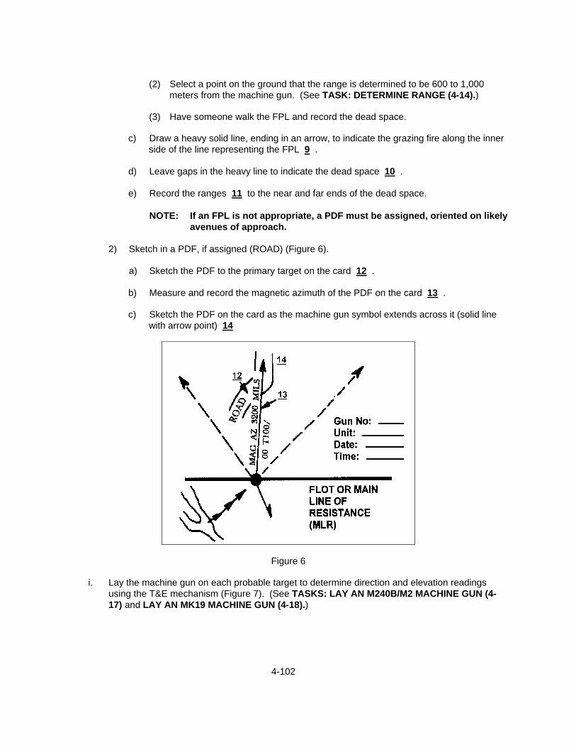
4-102
(2) Select a point on the ground that the range is determined to be 600 to 1,000
meters from the machine gun. (See TASK: DETERMINE RANGE (4-14).)
(3) Have someone walk the FPL and record the dead space.
c) Draw a heavy solid line, ending in an arrow, to indicate the grazing fire along the inner side of the line representing the FPL 9 .
d) Leave gaps in the heavy line to indicate the dead space 10 .
e) Record the ranges 11 to the near and far ends of the dead space.
NOTE: If an FPL is not appropriate, a PDF must be assigned, oriented on likely
avenues of approach.
2) Sketch in a PDF, if assigned (ROAD) (Figure 6).
a) Sketch the PDF to the primary target on the card 12 .
b) Measure and record the magnetic azimuth of the PDF on the card 13 .
c) Sketch the PDF on the card as the machine gun symbol extends across it (solid line with arrow point) 14
Figure 6
i. Lay the machine gun on each probable target to determine direction and elevation readings using the T&E mechanism (Figure 7). (See TASKS: LAY AN M240B/M2 MACHINE GUN (4-17) and LAY AN MK19 MACHINE GUN (4-18).)

4-103
Figure 7
NOTE: Obtain both the direction and elevation readings of one target before moving to the next target.
1) Obtain target direction readings.
a) Center the traversing handwheel.
b) Sketch in all targets for which data is to be determined.
c) Obtain direction readings to targets other than the FPL, using the traversing bar
and elevating (T&E) mechanism on the tripod.
NOTE: The FPL normally needs no direction reading because, in laying the FPL, the traversing slide is positioned to the extreme right or left of the traversing bar.
(1) Loosen the traversing slide lock lever.
(2) Move the traversing slide along the traversing bar until the machine gun is
laid on the center base of a point target and on either flank of a linear target.
(3) Lock the traversing slide to the traversing bar.
(4) Determine the traversing direction to the nearest mil, using the traversing bar and handwheel.
NOTE: If the left edge of the traversing slide does not fall exactly on
a 5-mil graduation (tick mark), use the nearest graduation as the direction reading.

4-104
(a) Read the direction as RIGHT (number of mils) when the traversing slide
is to the LEFT of the "0" on the traversing bar.
(b) Read the direction as LEFT (number of mils) when the traversing slide is to the RIGHT of the "0" on the traversing bar.
(5) Subtract the traversing bar and handwheel numbers if the mil is below "0."
(6) Add the traversing bar and handwheel number if the mil is above "0."
2) Obtain target elevation readings from the T&E mechanism (Figure 8).
Figure 8
a) Lay the machine gun at the base (6 o'clock) of the target.
b) Determine the MAJOR READING, using the upper elevating screw and plate with scale 15 .
(1) Lower your head until your eyes are level with the top of the elevating
handwheel.
(2) Record the first number above the first visible index line above the elevating handwheel on the target line.
NOTE: Ensure that either a POSITIVE +) or a NEGATIVE (-) sign has
been designated as the major reading.

4-105
c) Determine the MINOR READING, using the mil scale on top of the elevating
handwheel 16 , and record the number that is on line with the dial pointer.
NOTES: Record the minor reading next to the major reading on the card, separating the two numbers with a slash (/) 17 .
(Figure 9) is an FPL or PDF.T/E reading.
2. Prepare a duplicate range card.
Figure 9
a. Keep one card at the machine gun position.
b. Send the duplicate card to the unit commander. REFERENCES: MCWP 3-15.1, Machine Guns and Machine Gun Gunnery FM 21-75, Combat Skills of the Soldier

4-106
TASK: CONTROL MACHINE GUN TEAM FIRES (4-16) CONDITIONS: PROVIDED A TACTICAL SCENARIO IN ANY COMBAT ENVIRONMENT, A
MISSION, A MACHINE GUN TEAM (M240B, M2, OR MK19), SQUAD LEADER'S GUIDANCE, AND ENEMY TARGETS.
STANDARD: THE TEAM LEADER WILL ENSURE THE FIRE CONTROL AND FIRE DISCIPLINE
OF THE TEAM IS MAINTAINED AND GIVES THE COMMANDS TO ADJUST THE GUN'S FIRE.
EVALUATION GUIDELINES TO BE USED DURING TRAINING:
Conditions: The Seabee, acting as a machine gun team leader, is provided an M240B, M2, or MK19 machine gun team, a field firing range with targets at various ranges, a mission, squad leader's guidance, and the appropriate amount of ammunition.
Standard: The Seabee must brief his/her team as to the mission, ensure that the firing
positions are properly prepared and occupied, and ensure that the machine gun is properly laid. The Seabee will issue initial fire commands using the acronym ADDRAC and give subsequent fire commands to cease and adjust fires. The Seabee must ensure that his/her machine gun team demonstrates proper fire control and discipline.
Administrative Notes: See TASKS: CONSTRUCT MACHINE GUN POSITIONS (4-13)
LAY AN M240B/M2 MACHINE GUN (4-17)
LAY A MK19 MACHINE GUN (4-18)
PERFORMANCE STEPS: 1. Brief team members as to the specifics of the mission.
a. Brief as to the exact firing position(s) location(s).
b. Brief the assigned sector(s) of fire to be covered.
c. Brief the rate(s) of fire and commands used to control those rates. 2. Ensure that firing positions are properly prepared and occupied. (See TASK: CONSTRUCT
MACHINE GUN POSITIONS (4-13).) 3. Ensure that the machine gun is properly laid. (See TASKS: LAY AN M240B/M2 MACHINE GUN
(4-17) and LAY A MK19 MACHINE GUN (4-18).) 4. Issue initial and subsequent fire commands.
NOTE: Initial fire commands are issued to engage targets and to shift fire to new targets. Subsequent fire commands are issued to adjust the rate, and to cease fire.

4-107
a. Issue initial fire commands using the acronym ADDRAC (Alert, Direction, Describe, Range,
Assignment, and Control).
NOTE: The order and uniformity of commands, using ADDRAC, are not as important as ensuring that getting the required information to the team allows effective time on target.
1) Use Alert to warn the gun teams and to ready them to receive and to execute the fire
commands.
NOTE: All initial fire commands must contain Alert.
a) Announce "FIRE MISSION" when both machine guns of a squad are to fire.
b) Announce "GUN NUMBER ONE (TWO), FIRE MISSION" if only one machine gun is to fire.
c) Announce "FIRE MISSION, GUN NUMBER ONE (TWO)" to alert both machine guns,
but only one machine gun is to fire.
2) Use Direction to indicate the general target location to the gunners.
a) Orally inform the gunners where to look if the target is obvious ("DIRECT FRONT," "RIGHT" or "LEFT," etc).
b) Designate small or obscure targets by pointing with your arm and index finger or
aiming the gun.
(1) When pointing, a Seabee standing behind you should be able to look over your shoulder and sight along your arm and index finger to locate the target.
(2) When aiming the gun, a Seabee looking through the sights should be able to see
the target.
c) Use a reference point(s) when the target cannot be seen.
NOTE: A reference point is an easy-to-recognize terrain feature or man made object(s) near the target.
(1) Announce "REFERENCE" to indicate that you are using a reference point.
NOTE: The word "TARGET" always precedes the target description when
a reference point is used so that the reference point and the actual target will not be confused.
(2) Indicate the target as extending so many mils, meters, or fingers from the
reference point when the reference point is within the target area.
(3) Announce the range to the reference point when the reference point is within the target area.
4-108
(4) Announce the range to the target when the reference point is outside the target
area.
d) Use other methods to designate target direction.
- Fire a machine gun (or rifle).
(1) Announce "WATCH MY IMPACTS (TRACERS)."
(2) Fire one or more bursts on the target, and complete the designation orally.
EXAMPLE: After firing one or more bursts, announce "RIGHT (LEFT)" to pinpoint the target if necessary.
3) Describe the target if it is not obvious, using a short description (one or two words) to
inform the gunner the nature of his/her target.
EXAMPLE: "4 trucks, enemy troops in the open, small red building, etc."
4) Announce the Range (distance to the target) in even digits.
EXAMPLE: 300, 500, 900, 1,000 METERS, etc.
NOTE: All initial fire commands must contain range.
5) Use the Assignment/Method of Fire element of the initial fire commands when specific assignments are required to divide the target, assign a class of fire, or to designate a rate of fire.
(6) Command to open fire, by announcing "FIRE" or by giving the appropriate prearranged
hand-and-arm signal to fire for immediate engagement of the target.
NOTE: To ensure that machine gun fires are withheld for surprise and maximum effect and that both machine guns, if pair firing, open up at the same time, you may preface the command or signal to begin firing with "AT MY COMMAND" or "ON MY SIGNAL."
b. Issue subsequent fire commands.
1) Give the adjustment correction first when adjusting fire, ADJUST FIRE.
2) Announce, CEASE FIRE, to interrupt fire.
3) CHANGE FIRE, to change the rate of fire.
NOTE: The machine gun team will remain alert and await additional instructions.
4) Renew firing by announcing a subsequent or new fire command.
5) Announce, CEASE FIRING, END OF MISSION, to terminate firing.

4-109
c. If the gunner fails to understand any element of the fire command, he/she may request a
repetition of the element by announcing the misunderstood element with a rising inflection in his/her voice to denote a question. When repeating any portion of the fire command, the leader will preface it with the word, THE COMMAND WAS ……
d. Correct a command by announcing "CORRECTION" and then giving the correct command.
5. Maintain observation with the squad leader to ensure that fire commands or other instructions are
received and understood. 6. Displace the team to a new position on command. REFERENCES: MCWP 3-15.1, Machine Guns and Machine Gun Gunnery FM 21-75, Combat Skills of the Soldier FM 3-22.68, Crew-Served Machine Guns 5.56 and 7.62mm

4-110
TASK: LAY AN M60E3/M2 MACHINE GUN (4-17) CONDITIONS: THE SEABEE ACTING AS A GUNNER, IS PROVIDED AN M240B OR M2 MACHINE
GUN, FIELD FIRING RANGE WITH TARGETS, DESIGNATED DEFENSIVE POSITION, DESIGNATED MISSION (PDF/FPL), DESIGNATED PRIMARY SECTOR OF FIRE, DESIGNATED SECONDARY SECTOR OF FIRE, LOG (WOODEN), E-TOOL, LUMINATED TAPE, NOTCHED STAKES OR SUBSTITUTE WOODEN STAKES, COMPASS, AND 50 ROUNDS OF AMMUNITION.
STANDARD: THE SEABEE WILL DEMONSTRATE THE USE OF EACH METHOD OF LAYING
THE GUN.
EVALUATION GUIDELINES TO BE USED DURING TRAINING:
Conditions: The Seabee, acting as a gunner in a tactical scenario, is provided a team leader, a tripod- mounted M240B or M2 machine gun with Traversing and Elevating (T&E) mechanism, a field firing range with targets, a firing position, designated primary and secondary sectors of fire, a Principal Direction of Fire (PDF) or Final Protective Line (FPL) fire mission, paper, pencil, a lensatic compass, luminous tape, an entrenching tool, wood stakes, notched stakes ("Y" shaped), a log, and the appropriate amount of ammunition.
Standard: The Seabee must demonstrate, in sequence, the proper steps of laying the M240B
or M2 machine guns. The Seabee must ensure that the machine gun is clear. The Seabee must demonstrate laying the machine guns, using the T&E mechanism method and field expedient methods. All data must be confirmed by firing the machine gun.
Administrative Note: See TASKS: MAINTAIN THE M240B MACHINE GUN (4-5)
MAINTAIN THE M2 MACHINE GUN (4-7)
PERFORMANCE STEPS: 1. Clear the M240B or the M2 machine gun. (See TASKS: MAINTAIN THE M240B MACHINE GUN (4-
5), and MAINTAIN THE M2 MACHINE GUN (4-7).) 2. Lay the M240B or M2 machine gun using the Traversing and Elevating (T&E) mechanism.
NOTE: Except when engaging other targets, machine guns will continually be laid on their assigned FPL.
a. Center the traversing mechanism (Figure 1).
NOTE: The traversing mechanism can be centered at night by turning the traversing
handwheel toward your body as far as it will go and then turning it away 50 clicks for M240B (two revolutions) and 25 clicks for M2.
1) Turn the traversing handwheel (TOWARD you) as far as it will go.

4-111
2) Turn the traversing handwheel (AWAY from you) two complete revolutions.
3) Check the traversing handwheel scale to ensure that the 0 on the scale is aligned with the 0
index line before and after the two revolutions.
Figure 1
b. Lay the machine gun to obtain direction readings using the traversing bar.
1) Lay the machine gun for direction on the center of the primary sector.
a) Lock the left edge of the traversing slide on the 0 graduation (tick mark) on the traversing (Figure 2).
Figure 2

4-112
NOTE: The left edge of the traversing slide is always used as the index.
b) Adjust the rear legs of the tripod to align the muzzle in the center of the sector.
c) Emplace the tripod firmly by digging the tripod shoes in or by placing sandbags on the
tripod legs, ensuring that the tripod does not accidentally move.
2) Record direction readings on the range card to all targets within the primary sector of fire with the exception of the FPL.
NOTE: The FPL needs no direction reading since the traversing slide is positioned
to the extreme right or left of the traversing bar.
a) Loosen the traversing slide lock lever, and slide the traversing slide along the traversing bar until the machine gun is laid on the center of a point target and on either flank of a linear target.
b) Lock the traversing bar, and read the direction reading from the scale on the traversing
bar.
NOTE: If the left edge of the traversing slide does not fall exactly on a 5-mil tick mark, use the nearest 5-mil tick mark as your direction reading.
c) Determine the direction reading to a target by observing the movement of the barrel of
the machine gun.
d) Measure the width of the target by traversing across the target, using the traversing handwheel.
- Reposition the traversing mechanism before moving to another target.
Figure 3
4-113
c. Lay the machine gun to obtain elevation readings, using the upper elevating screw and elevating
handwheel (Figure 3).
1) Lay the machine gun on the base of the target.
2) Obtain and record the elevation reading, using the scales on the upper elevating screw and the top of the elevating handwheel.
NOTES: Separate the two portions of the elevation reading by a slash (/) when you
record them.
An elevation reading is valid only on the T&E mechanism from which the readings were originally taken. Data placed on another T&E mechanism, using the same machine gun and mount, will not be accurate.
a) Obtain the FIRST portion of the elevation reading from the upper elevating screw.
(1) Lower your head until your eyes are on line with the top of the elevating
handwheel.
(2) Record the first portion of the reading as the number that is visible above the index line of the upper elevating screw.
NOTES: Ensure that you use the positive (+) or negative (-) sign also.
Read the scale in 1-mil increments.
b) Obtain the SECOND portion of the elevation reading from the elevating handwheel.
(1) Locate the tick mark on the line with the indicator.
(2) Record the second portion of the reading.
EXAMPLE: Record the entire elevation reading in Figure 3 as -50/3.
3. Lay the machine gun when an FPL has been assigned.
NOTE: For irregularly sloping ground, lay the machine gun for direction by sighting in the direction of the FPL. Lay the machine gun for elevation by aiming in on a point on the ground nears the break in the uniform slope. Set the rear sight with the range to that point, then elevate the machine gun 2 mils using the elevating handwheel.
a. Lock the traversing slide in the opposite direction of the FPL.
b. Adjust the rear legs of the tripod to align the muzzle in the direction of the FPL.
EXAMPLE: If the FPL is to be laid on the gunner's right, lock the traversing slide to the
gunner's left.
c. Determine the extent of grazing fire and the precise location of deadspace.

4-114
1) (Team leader) Walk the FPL if the situation permits.
NOTE: If the situation does not permit walking the entire FPL, use a map or other
information sources to evaluate the terrain.
2) (Gunner) Secure the rear sight with the approximate range locked in, and lay the machine gun on the FPL.
3) Observe the team leader through the rear sight of the machine gun.
IF
THEN You can see the team leader You cannot see the team leader
The area represents grazing fire. The area represents deadspace.
NOTE: The team leader will maintain a pace count until visual contact is re-
established with the gunner.
4) Record the data on the range card when the team leader returns. 4. Use field-expedient methods.
NOTE: Field-expedient methods supplement other methods and help in laying the machine gun on predetermined targets in the primary sector.
a. Use the base stake method (Figure 4).
NOTE: Ensure that the machine gun is cleared.
Figure 4

4-115
1) Determine sector limits.
a) Lay the machine gun for direction along one sector limit.
b) Emplace a stake along the outer edge of the barrel.
c) Use the same procedures for placing stakes along the opposite sector limit.
2) Lay the machine gun to engage an FPL or PDF.
a) Set the rear sight at the estimated range to the target, FPL, or PDF.
b) Set elevation, using a stake.
(1) Align the sights on the target, and mark a spot on the ground under the gas
cylinder extension.
(2) Move the gun barrel aside, and emplace the stake into the ground.
(3) Drive the stake into the ground until the sights are again laid on the target when the gas cylinder is laid on top of the stake.
3) Select other targets within a sector limit in a primary sector, using additional stakes.
b. Use the aiming stake method (Figure 5).
NOTE: This method is not effective when visibility is so limited that the aiming stakes
cannot be seen.
Figure 5

4-116
1) Raise the rear-sight slide to its uppermost position in the rear-sight-leaf assembly.
2) Place a strip of luminous tape or paint at least halfway up the rear of the front-sight post
and on the top of a stake facing the machine gun.
3) Position a short aiming stake (marked on top with a strip of luminous tape or paint) 1 or 2 meters forward of the machine gun position.
4) (Gunner) Move his/her head slightly to the left so that the front-sight post appears in the left
corner of the rectangle formed by the rear-sight slide and rear-sight-leaf assembly.
5) Align the stake and machine gun on the target for direction and elevation.
a) Ensure that the two pieces of luminous material are adjacent (aligned for direction).
b) Ensure that the top edges of both pieces of material are level (aligned for elevation).
6) Maintain the correct position and grip throughout the procedure.
7) Ensure that the front-sight post appears in the LEFT position of the rear sight when engaging targets.
8) Emplace stake (one per target).
c. Use the horizontal log or board method (Figure 6).
Figure 6
NOTES: Use this method with the bipod or tripod mount to mark sector limits and to
engage wide targets. It is best suited for flat, level terrain.
HORIZONTAL LOG OR BOARD USED WITH TRIPOD MOUNTED
M240B MACHINE GUN
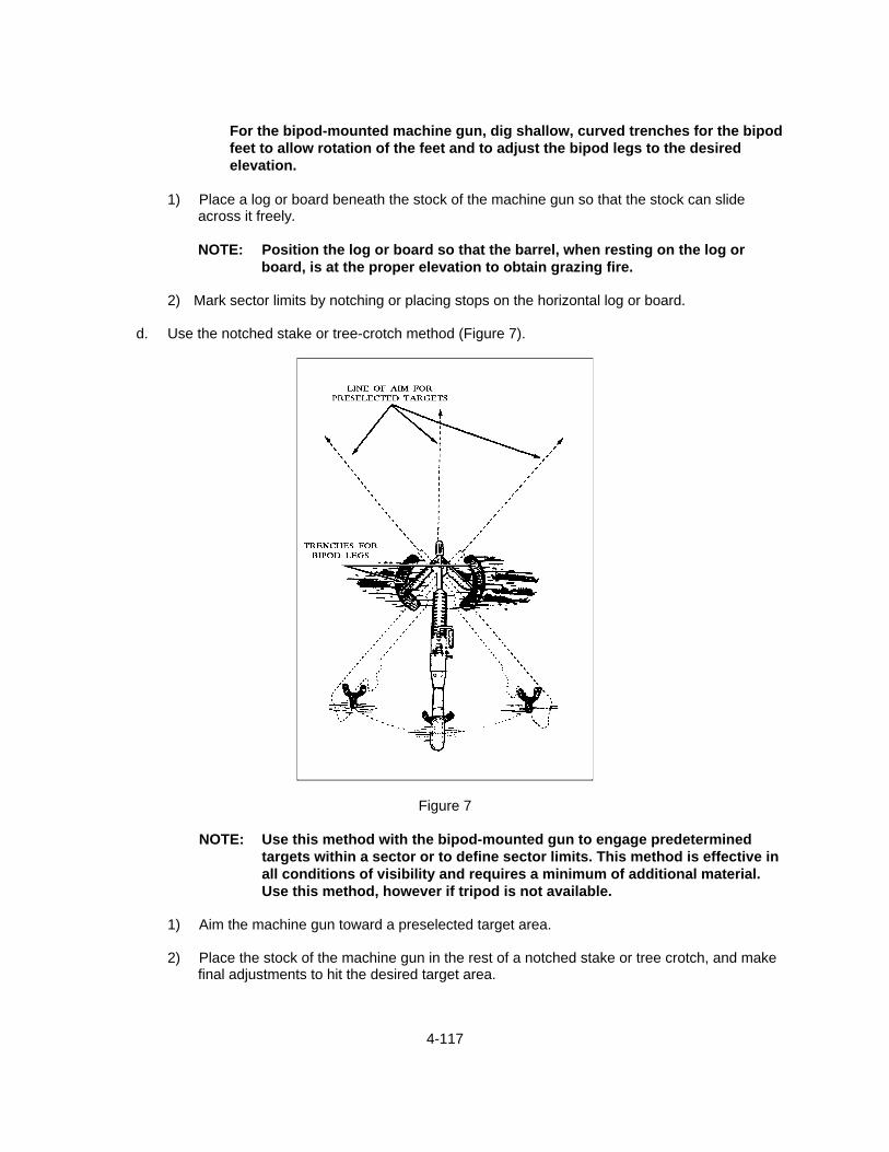
4-117
For the bipod-mounted machine gun, dig shallow, curved trenches for the bipod feet to allow rotation of the feet and to adjust the bipod legs to the desired elevation.
1) Place a log or board beneath the stock of the machine gun so that the stock can slide
across it freely.
NOTE: Position the log or board so that the barrel, when resting on the log or board, is at the proper elevation to obtain grazing fire.
2) Mark sector limits by notching or placing stops on the horizontal log or board.
d. Use the notched stake or tree-crotch method (Figure 7).
Figure 7
NOTE: Use this method with the bipod-mounted gun to engage predetermined targets within a sector or to define sector limits. This method is effective in all conditions of visibility and requires a minimum of additional material. Use this method, however if tripod is not available.
1) Aim the machine gun toward a preselected target area.
2) Place the stock of the machine gun in the rest of a notched stake or tree crotch, and make
final adjustments to hit the desired target area.

4-118
3) Dig shallow trenches or grooves for the bipod feet. NOTE: This permits rotation of the bipod feet as you move the stock from one crotch or
stake to another.
e. Use the auxiliary aiming point method.
NOTE: Use this method only when the target is not visible to the gunner.
1) Select an aiming point that is visible to the gunner from the machine gun position.
2) Determine the range to the target.
3) Measure the vertical angle to the base of the target in mils, and determine the lateral deviation in mils from the aiming point to the center of the target.
4) Lay the machine gun on the aiming point with the rear-sight setting on the machine gun or
target range.
5) Manipulate the machine gun through the number of mils measured in the vertical angle from the aiming point to the base of the target and the horizontal deflection in mils from the aiming point.
5. Confirm your data.
NOTE: Whenever the tactical situation permits, you should confirm your data before entering it on your range card.
a. Place direction and elevation data on the T&E mechanism.
b. Fire the machine gun.
c. Adjust the T&E mechanism as necessary to bring your burst onto the near edge of your sector
of fire.
d. Record this data on your range card.
e. Traverse and search through the target to the opposite end of your sector of fire.
f. Record the changes that were needed in the remarks section of the range card. REFERENCES: MCWP 3-15.1, Machine Guns and Machine Gun Gunnery FM 23-65, Browning Machine Gun Caliber .50 HB, M2 FM 3-22.68, Crew-Served Machine Guns 5.56 and 7.62mm

4-119
TASK: LAY AN MK19 MACHINE GUN (4-18) CONDITIONS: THE SEABEE ACTING AS GUNNER, IS PROVIDED AN MK19 MACHINE GUN,
FIELD FIRING RANGE WITH TARGETS, DESIGNATED DEFENSIVE POSITION, DESIGNATED MISSION (PDF/FPL), DESIGNATED PRIMARY SECTOR OF FIRE, DESIGNATED SECONDARY SECTOR OF FIRE, LOG, E-TOOL, WOODEN STAKES, AND COMPASS.
STANDARD: THE SEABEE WILL DEMONSTRATE THE USE OF EACH METHOD OF LAYING
THE GUN. THE STEPS FOR EACH METHOD MUST BE PERFORMED SEQUENTIALLY.
EVALUATION GUIDELINES TO BE USED DURING TRAINING:
Conditions: The Seabee, acting as a gunner/team leader in a tactical scenario, is provided a
team leader, a tripod-mounted MK19 machine gun with Traversing and Elevating (T&E) mechanism, a field firing range with targets, a firing position, designated primary and secondary sectors of fire, mission Principal Direction of Fire (PDF), paper, pencil, a lensatic compass, a 1:50,000 military map of the range, binoculars, an entrenching tool, wooden stakes, a log, and the appropriate firing tables.
Standard: The Seabee must demonstrate in sequence the proper steps for laying the MK19
machine gun. The Seabee must ensure that the machine gun is clear. The Seabee must demonstrate laying the machine gun using the T&E mechanism and field expedient methods. All data for each method must be recorded on range cards and the data must be confirmed by firing the machine gun.
Administrative Note: See TASKS: ENGAGE GROUND TARGETS WITH THE MK19
MACHINE GUN (4-10)
MAINTAIN THE MK19 MACHINE GUN (4-9)
PERFORMANCE STEPS: 1. Clear the MK19 machine gun. (See TASK: MAINTAIN THE MK19 MACHINE GUN (4-9).) 2. Lay the MK19 machine gun on the Principal Direction of Fire (PDF).
a. Center the traversing mechanism (Figure 1).
NOTE: The traversing mechanism can be centered at night by turning the traversing handwheel toward your body as far as it will go and then turning it away 50 clicks (two revolutions).

4-120
Figure 1
1) Turn the traversing handwheel (TOWARD you) as far as it will go.
2) Turn the traversing handwheel (AWAY from you) two complete revolutions (50 clicks).
3) Check the traversing handwheel scale to ensure that the 0 on the scale is aligned with the 0 index line before and after the two revolutions.
b. Center the windage knob and elevation handwheel.
c. Adjust the tripod to align the machine gun in the direction of the machine gun-target line.
d. Sight the gun on an aiming point at the near end of the avenue of approach along the PDF.
e. Adjust the center of impact onto the near end of the PDF, and search and traverse to cover the
entire target area.
f. Establish a firing sequence, and record the number of mils of search and traverse on the range card.
3. Lay the MK19 machine gun for direction when in a defilade position.
a. Use the direct alignment method.
NOTE: The observer posts himself on the machine gun-target line and in a position where he can see the target and direct the movement. The observer is not needed when in a partial defilade position; the gunner will lay directly on the target using the machine gun sights.
1) Align the machine gun approximately by shifting the tripod as directed by the observer.
2) Loosen the traversing slide, and move the machine gun right or left until it is aligned on the
target.
3) Use an aiming point, choosing a prominent landmark that is visible through the sights.
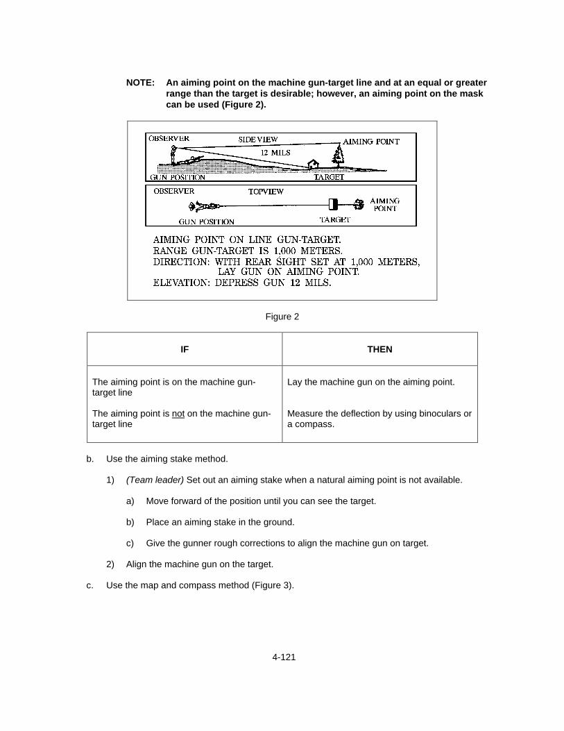
4-121
NOTE: An aiming point on the machine gun-target line and at an equal or greater
range than the target is desirable; however, an aiming point on the mask can be used (Figure 2).
Figure 2
IF
THEN
The aiming point is on the machine gun-target line The aiming point is not on the machine gun-target line
Lay the machine gun on the aiming point. Measure the deflection by using binoculars or a compass.
b. Use the aiming stake method.
1) (Team leader) Set out an aiming stake when a natural aiming point is not available.
a) Move forward of the position until you can see the target.
b) Place an aiming stake in the ground.
c) Give the gunner rough corrections to align the machine gun on target.
2) Align the machine gun on the target.
c. Use the map and compass method (Figure 3).
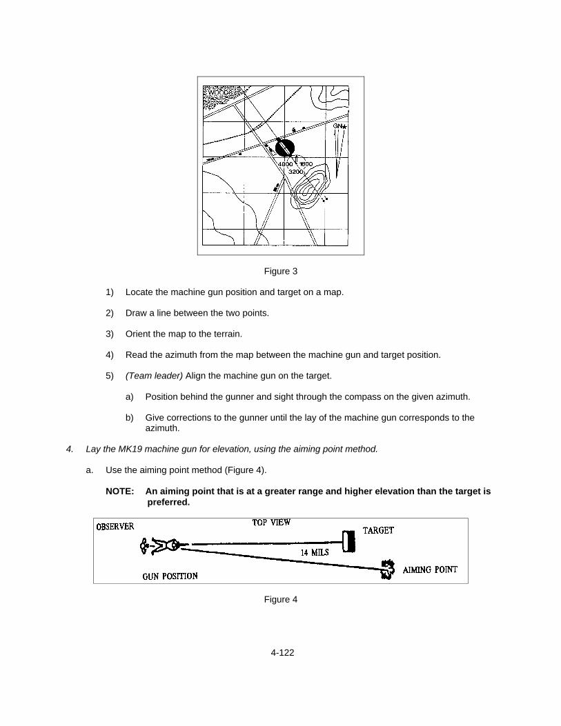
4-122
Figure 3
1) Locate the machine gun position and target on a map.
2) Draw a line between the two points.
3) Orient the map to the terrain.
4) Read the azimuth from the map between the machine gun and target position.
5) (Team leader) Align the machine gun on the target.
a) Position behind the gunner and sight through the compass on the given azimuth.
b) Give corrections to the gunner until the lay of the machine gun corresponds to the azimuth.
4. Lay the MK19 machine gun for elevation, using the aiming point method.
a. Use the aiming point method (Figure 4).
NOTE: An aiming point that is at a greater range and higher elevation than the target is preferred.
Figure 4
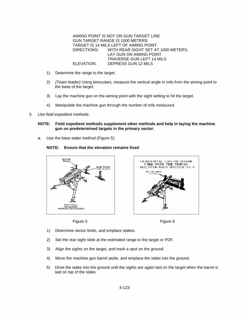
4-123
AIMING POINT IS NOT ON GUN TARGET LINE GUN TARGET RANGE IS 1000 METERS TARGET IS 14 MILS LEFT OF AIMING POINT DIRECTIONS: WITH REAR SIGHT SET AT 1000 METERS,
LAY GUN ON AIMING POINT. TRAVERSE GUN LEFT 14 MILS
ELEVATION: DEPRESS GUN 12 MILS
1) Determine the range to the target.
2) (Team leader) Using binoculars, measure the vertical angle in mils from the aiming point to the base of the target.
3) Lay the machine gun on the aiming point with the sight setting to hit the target.
4) Manipulate the machine gun through the number of mils measured.
5. Use field expedient methods.
NOTE: Field expedient methods supplement other methods and help in laying the machine gun on predetermined targets in the primary sector.
a. Use the base stake method (Figure 5).
NOTE: Ensure that the elevation remains fixed
Figure 5 Figure 6
1) Determine sector limits, and emplace stakes.
2) Set the rear sight slide at the estimated range to the target or PDF.
3) Align the sights on the target, and mark a spot on the ground.
4) Move the machine gun barrel aside, and emplace the stake into the ground.
5) Drive the stake into the ground until the sights are again laid on the target when the barrel is laid on top of the stake.

4-124
6) Lay the machine gun to engage other targets within the sector limit using Performance Step
3.a.
b. Use the horizontal log or board method (Figure 6).
NOTES: This method is used with the tripod mount to mark sector limits and engage wide targets. Also, it is used only if a traversing and elevating mechanism is not available.
1) Place a log or board beneath the barrel.
NOTE: Position the log or board so that the barrel, when resting on the log or
board, is at the proper elevation to obtain grazing fire.
2) Mark the sector limits.
c. Use the auxiliary aiming point method.
NOTE: This method may be used when the auxiliary aiming point is not more than 20 mils off the machine gun-target line.
1) Select an aiming point that is visible from the machine gun position.
NOTE: Select an aiming point, which has a greater range than the target and within
20 mils of the machine gun target-line.
2) Determine the range to the target.
3) Using binoculars, measure the vertical angle to the base of the target, and determine the lateral deviation in mils from the aiming point to the center of the target.
4) Lay the machine gun on the aiming point with the rear sight setting for the machine gun or
target range.
5) Manipulate the machine gun through the number of mils measured in the vertical angle from the aiming point to the base of the target.
NOTE: When the aiming point is off the machine gun-target line, deflection in mils
may be taken with the windage arc (not over 20 mils) or may be compensated for by manipulating the traversing handwheel.
6. Engage ground targets to confirm machine gun data. (See TASK: ENGAGE GROUND TARGETS
WITH THE MK19 MACHINE GUN (4-10).) 7. Clear the machine gun. (See TASK: MAINTAIN THE MK19 MACHINE GUN (4-9).) REFERENCES: MCWP 3-15.1, Machine Guns and Machine Gun Gunnery FM 23-27, MK19 40-MM Grenade Machine Gun, MOD 3
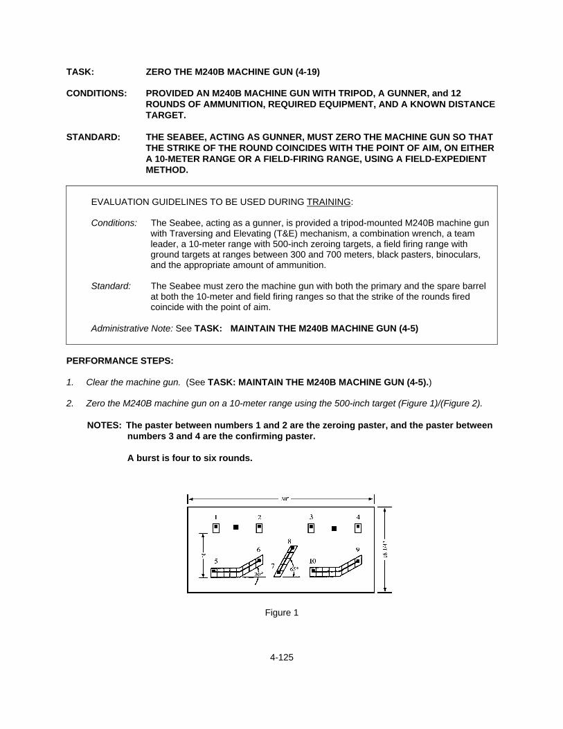
4-125
TASK: ZERO THE M240B MACHINE GUN (4-19) CONDITIONS: PROVIDED AN M240B MACHINE GUN WITH TRIPOD, A GUNNER, and 12
ROUNDS OF AMMUNITION, REQUIRED EQUIPMENT, AND A KNOWN DISTANCE TARGET.
STANDARD: THE SEABEE, ACTING AS GUNNER, MUST ZERO THE MACHINE GUN SO THAT
THE STRIKE OF THE ROUND COINCIDES WITH THE POINT OF AIM, ON EITHER A 10-METER RANGE OR A FIELD-FIRING RANGE, USING A FIELD-EXPEDIENT METHOD.
EVALUATION GUIDELINES TO BE USED DURING TRAINING:
Conditions: The Seabee, acting as a gunner, is provided a tripod-mounted M240B machine gun
with Traversing and Elevating (T&E) mechanism, a combination wrench, a team leader, a 10-meter range with 500-inch zeroing targets, a field firing range with ground targets at ranges between 300 and 700 meters, black pasters, binoculars, and the appropriate amount of ammunition.
Standard: The Seabee must zero the machine gun with both the primary and the spare barrel
at both the 10-meter and field firing ranges so that the strike of the rounds fired coincide with the point of aim.
Administrative Note: See TASK: MAINTAIN THE M240B MACHINE GUN (4-5)
PERFORMANCE STEPS: 1. Clear the machine gun. (See TASK: MAINTAIN THE M240B MACHINE GUN (4-5).) 2. Zero the M240B machine gun on a 10-meter range using the 500-inch target (Figure 1)/(Figure 2).
NOTES: The paster between numbers 1 and 2 are the zeroing paster, and the paster between numbers 3 and 4 are the confirming paster.
A burst is four to six rounds.
Figure 1

4-126
Figure 2
a. Set the rear sight.
1) Set a range of 500 meters on the rear sight.
2) Set the rear sight windage scale to mechanical zero.
3) Ensure that the range plate screw is centered in the adjustment groove on the range plate.
4) Center the traversing and elevating (T&E) mechanism as close as possible.
5) Lay the machine gun on the first black paster, ensuring a good sight picture is obtained.
6) Fire a short burst, four to six rounds.
b. Make any necessary sight adjustments.
1) Clear the machine gun.
2) (Gunner) Move forward and place a black paster on the target so that the center base of
the paster is at the center of the shot group.
3) Adjust rear sight.
a) (Gunner) Reassume position, grip, and pressure on the machine gun.
b) (Team leader) Manipulate the rear sight (windage knob, elevation knob) until you obtain a good sight picture at 6 o'clock on the paster centered on the shot group.
NOTE: When step b.(3)(b) has been accomplished, the point of aim coincides
with the strike of the rounds.

4-127
c. Adjust the range plate.
1) (Team leader) Lower the rear sight and loosen the range plate screw and slide the range
plate up or down until the 500-meter reading is again on the rear sight.
2) (Team leader) Tighten the range plate screw.
NOTE: The machine gun is now zeroed.
d. Confirm the zero.
1) (Gunner) Manipulate the T&E until he is aimed in on the confirming paster.
2) Fire a burst.
IF THEN The shot group is not on target
The shot group is on target
Team leader readjusts the rear sight until the sight picture is on the center of the shot group.
Record zero data.
3. Zero the spare barrel.
NOTE: The front sight on the M240B is fully adjustable.
a. Change barrels after zeroing the primary barrel.
b. (Gunner) Sets zero windage and places a 500-meter setting on the rear sight.
c. Lower the rear sight and fire a burst at the target.
d. (Team leader) Observes the strike of the rounds and directs the gunner to make adjustments with the T&E and fire again until the target is hit.
e. (Team leader) Raises the rear sight once rounds have hit the target.
NOTE: The gunner will not have good sight picture, since the machine gun was
adjusted onto the target.
f. (Gunner) Directs the team leader to manipulate the front sight using the combination wrench until good sight picture has been achieved.
NOTE: The rear sight and range plate is not adjusted when zeroing the spare barrel.
g. Record windage zero for the spare barrel.
4. Zero the M240B machine gun on a target at a known distance from 300 to 700 meters.
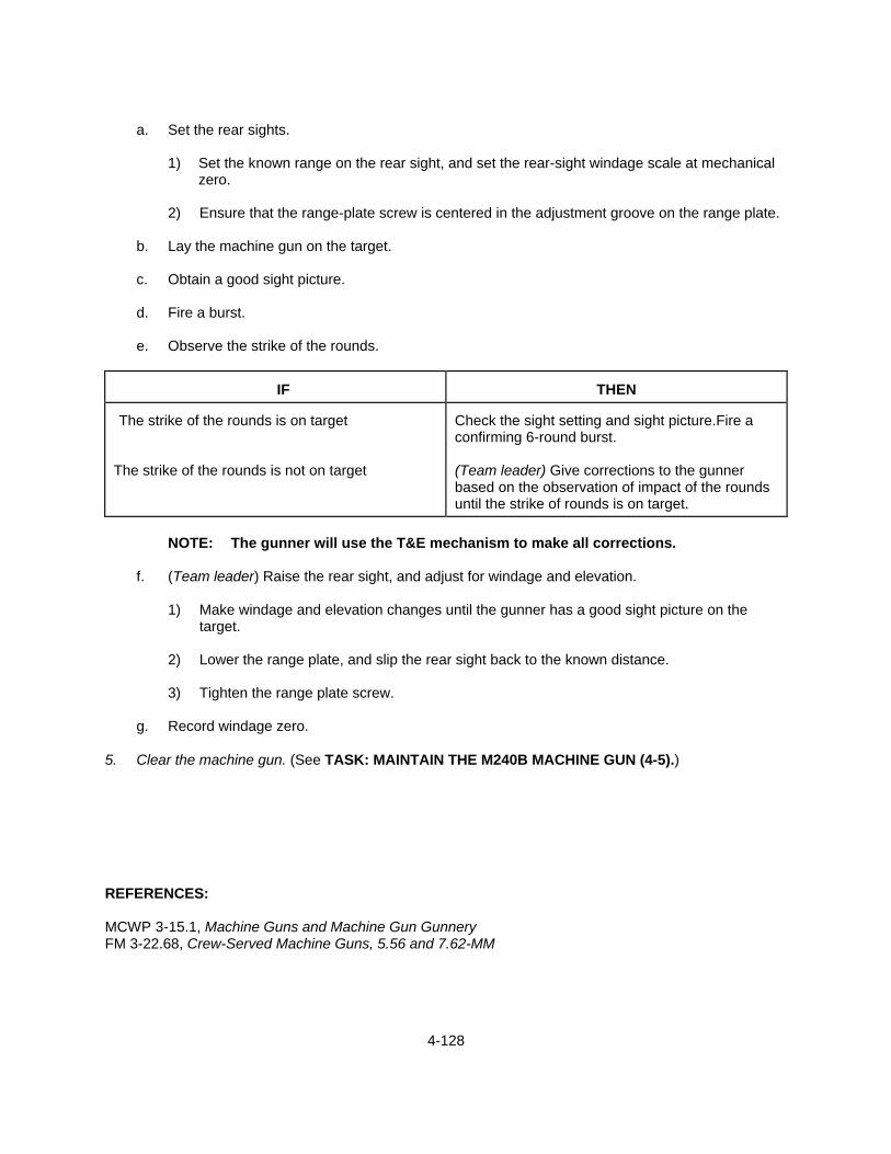
4-128
a. Set the rear sights.
1) Set the known range on the rear sight, and set the rear-sight windage scale at mechanical
zero.
2) Ensure that the range-plate screw is centered in the adjustment groove on the range plate.
b. Lay the machine gun on the target.
c. Obtain a good sight picture.
d. Fire a burst.
e. Observe the strike of the rounds.
IF
THEN
The strike of the rounds is on target
The strike of the rounds is not on target
Check the sight setting and sight picture.Fire a confirming 6-round burst. (Team leader) Give corrections to the gunner based on the observation of impact of the rounds until the strike of rounds is on target.
NOTE: The gunner will use the T&E mechanism to make all corrections.
f. (Team leader) Raise the rear sight, and adjust for windage and elevation.
1) Make windage and elevation changes until the gunner has a good sight picture on the
target.
2) Lower the range plate, and slip the rear sight back to the known distance.
3) Tighten the range plate screw.
g. Record windage zero. 5. Clear the machine gun. (See TASK: MAINTAIN THE M240B MACHINE GUN (4-5).) REFERENCES: MCWP 3-15.1, Machine Guns and Machine Gun Gunnery FM 3-22.68, Crew-Served Machine Guns, 5.56 and 7.62-MM
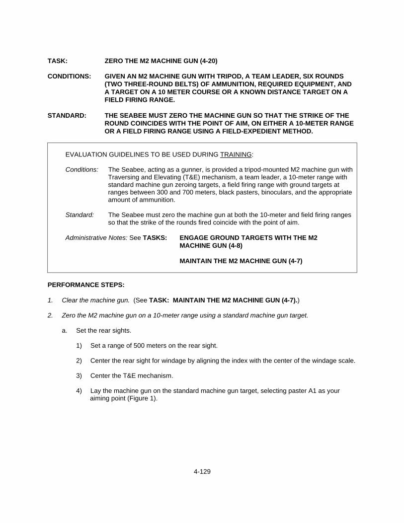
4-129
TASK: ZERO THE M2 MACHINE GUN (4-20) CONDITIONS: GIVEN AN M2 MACHINE GUN WITH TRIPOD, A TEAM LEADER, SIX ROUNDS
(TWO THREE-ROUND BELTS) OF AMMUNITION, REQUIRED EQUIPMENT, AND A TARGET ON A 10 METER COURSE OR A KNOWN DISTANCE TARGET ON A FIELD FIRING RANGE.
STANDARD: THE SEABEE MUST ZERO THE MACHINE GUN SO THAT THE STRIKE OF THE
ROUND COINCIDES WITH THE POINT OF AIM, ON EITHER A 10-METER RANGE OR A FIELD FIRING RANGE USING A FIELD-EXPEDIENT METHOD.
EVALUATION GUIDELINES TO BE USED DURING TRAINING:
Conditions: The Seabee, acting as a gunner, is provided a tripod-mounted M2 machine gun with Traversing and Elevating (T&E) mechanism, a team leader, a 10-meter range with standard machine gun zeroing targets, a field firing range with ground targets at ranges between 300 and 700 meters, black pasters, binoculars, and the appropriate amount of ammunition.
Standard: The Seabee must zero the machine gun at both the 10-meter and field firing ranges
so that the strike of the rounds fired coincide with the point of aim.
Administrative Notes: See TASKS: ENGAGE GROUND TARGETS WITH THE M2 MACHINE GUN (4-8)
MAINTAIN THE M2 MACHINE GUN (4-7)
PERFORMANCE STEPS: 1. Clear the machine gun. (See TASK: MAINTAIN THE M2 MACHINE GUN (4-7).) 2. Zero the M2 machine gun on a 10-meter range using a standard machine gun target.
a. Set the rear sights.
1) Set a range of 500 meters on the rear sight.
2) Center the rear sight for windage by aligning the index with the center of the windage scale.
3) Center the T&E mechanism.
4) Lay the machine gun on the standard machine gun target, selecting paster A1 as your aiming point (Figure 1).

4-130
Figure 1
5) Load the machine gun. (See TASK: ENGAGE GROUND TARGETS WITH THE M2 MACHINE GUN (4-8).)
6) Obtain a good sight picture.
7) Fire three individual shots.
NOTES: Ensure that you have the bolt release in the up position for single-shot
firing, and fire with the bolt forward to avoid losing your sight picture before firing.
After each shot, realign the machine gun on the aiming point.
8) Clear the machine gun.
9) Move down range and observe the impacts of your rounds.
NOTE: No sight adjustments will be made at this time.
10) Fire another three-shot group at paster A1.
11) Clear the machine gun.
12) Move down range again to observe the shot group.
b. Make any necessary sight adjustments.

4-131
1) Direct the assistant gunner in adjusting the elevation and windage controls on the rear sight
until you have obtained a good sight picture on the center of your shot group (Figure 2).
Figure 2
2) Realign on the target using paster A2 as your aiming point.
3) Repeat Performance Steps a.(10) through (12) until impacts are recorded on your point of aim.
4) Clear the machine gun.
NOTE: In most cases, the 500-meter index line on the rear-sight range scale will no
longer be aligned with the range-index line of the sight. You must record the difference in range settings on the sight and add this difference to future range settings.
3. Zero the M2 machine gun on a target at a known distance from 300 to 700 meters.
a. Set the rear sights.
1) Set the known range on the rear sight, and set the rear-sight windage scale at mechanical zero.
2) Ensure that the range plate screw is centered in the adjustment groove on the range plate.
b. Lay the machine gun on the target.
c. Obtain a good sight picture.
d. Fire a burst.

4-132
e. Observe the strike of the round.
IF
THEN The strike of the rounds is on target
The strike of the rounds is not on target
Check sight setting and sight picture and fire a confirming burst. Instruct the assistant gunner to adjust the sight for windage, then for range, until the point of aim is centered on the strike of the rounds.
f. Lay the machine gun back onto the target using the T&E mechanism.
g. Fire a confirming burst.
h. Repeat Performance Steps 3.a. through f. until the strike of the round coincides with the point of
aim.
i. Record zero data. 4. Clear the machine gun. REFERENCES: MCWP 3-15.1, Machine Guns and Machine Gun Gunnery FM 23-65, Browning Machine Gun Caliber .50 HB, M2

4-133
TASK: ZERO THE M2 MACHINE GUN USING NIGHT VISION SIGHT (4-21) CONDITIONS: GIVEN AN M2 MACHINE GUN WITH TRIPOD, AN/TVS-5 NIGHT VISION SIGHT,
MOUNTAIN BRACKET, A TEAM LEADER, REQUIRED AMMUNITION, REQUIRED EQUIPMENT, AND TARGETS ON A FIELD FIRING RANGE.
STANDARD: THE SEABEE MUST MOUNT THE AN/TVS-5 ONTO THE MACHINE GUN AND
ZERO THE WEAPON SO THAT A SHOT GROUP IS 3.75 INCHES (9.8 CM) DIRECTLY BELOW THE TARGET AIMING POINT.
EVALUATION GUIDELINES TO BE USED DURING TRAINING
Conditions: The Seabee, acting as a gunner, is provided a tripod-mounted M2 machine gun with Traversing and Elevating (T&E) mechanism, an AN/TVS-5 night vision sight with mounting bracket, a team leader, a 50-meter range with zeroing targets, a field firing range with ground targets at ranges between 400 and 600 meters, and the appropriate amount of ammunition.
Standard: The Seabee must ensure that the machine gun is clear before beginning this task.
The Seabee must mount and zero the AN/TVS-5 night vision sight using both the 50-meter range and field expedient methods. The machine gun must be zeroed so that the strike of the rounds is 3.75 inches (9.8cm) directly below the target aiming point on the 50-meter range, and the engaged ground target on the field firing range receives at least one impact.
Administrative Notes: See TASKS: ENGAGE GROUND TARGETS WITH THE M2
MACHINE GUN (4-8)
MAINTAIN THE M2 MACHINE GUN (4-7)
PERFORMANCE STEPS: 1. Clear the machine gun. (See TASK: MAINTAIN THE M2 MACHINE GUN (4-7).) 2. Mount the mounting bracket assembly on the machine gun.
NOTE: Inspect the mounting bracket assembly for obvious damage or missing parts. Pay particular attention for stripped threads on the lever-screw assembly.
a. Place the rear sight in the down position.
b. Release the cover latch, and raise the cartridge cover fully.
c. Position the mounting bracket over the breech, and slide the bracket rearward until it is seated
(Figure 1).
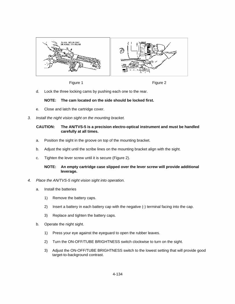
4-134
Figure 1 Figure 2
d. Lock the three locking cams by pushing each one to the rear.
NOTE: The cam located on the side should be locked first.
e. Close and latch the cartridge cover. 3. Install the night vision sight on the mounting bracket.
CAUTION: The AN/TVS-5 is a precision electro-optical instrument and must be handled carefully at all times.
a. Position the sight in the groove on top of the mounting bracket.
b. Adjust the sight until the scribe lines on the mounting bracket align with the sight.
c. Tighten the lever screw until it is secure (Figure 2).
NOTE: An empty cartridge case slipped over the lever screw will provide additional
leverage. 4. Place the AN/TVS-5 night vision sight into operation.
a. Install the batteries
1) Remove the battery caps.
2) Insert a battery in each battery cap with the negative (-) terminal facing into the cap.
3) Replace and tighten the battery caps.
b. Operate the night sight.
1) Press your eye against the eyeguard to open the rubber leaves.
2) Turn the ON-OFF/TUBE BRIGHTNESS switch clockwise to turn on the sight.
3) Adjust the ON-OFF/TUBE BRIGHTNESS switch to the lowest setting that will provide good target-to-background contrast.

4-135
4) Turn the ON-OFF/RETICLE BRIGHTNESS switch clockwise to turn on the light emitting
diode.
5) Turn the diopter focus ring until the clearest image of the reticle pattern is obtained (Figure 3 and 4).
Figure 3
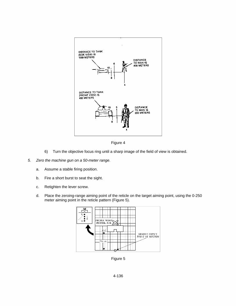
4-136
Figure 4
6) Turn the objective focus ring until a sharp image of the field of view is obtained. 5. Zero the machine gun on a 50-meter range.
a. Assume a stable firing position.
b. Fire a short burst to seat the sight.
c. Retighten the lever screw.
d. Place the zeroing-range aiming point of the reticle on the target aiming point, using the 0-250 meter aiming point in the reticle pattern (Figure 5).
Figure 5
4-137
e. Fire three individual shots. f. Direct the assistant gunner to locate the center of the shot group.
g. From the shot group, make the necessary adjustments to move the group to a point 3.75 inches
(9.8 cm) directly below the target aiming point.
NOTE: The direction arrows near the adjustment knobs indicate which way the adjustments will move the strike of the rounds. Each click of adjustment will move the strike of the round approximately 1/2 inch at 50 meters.
h. After completing your adjustments, relay on your aiming point, and fire another three individual
shots.
i. Repeat Performance Steps 5.d. through h. until your rounds hit 9.8 cm directly below your aiming point.
6. Zero the machine gun using a field expedient method.
a. Select a target between 400 and 600 meters away on a field firing range.
NOTE: Zero the weapon's daylight sights if they have not been previously zeroed. (See TASK: ENGAGE GROUND TARGETS WITH THE M2 MAGHINE GUN (4-8).)
b. Sight in on the target with the zeroed daylight sights.
c. Lower the rear sight without disturbing the alignment of the machine gun.
d. Sight through the night vision sight, and direct the assistant gunner to adjust the azimuth and
elevation actuators until the proper range mark aiming point aligns on the target.
e. Fire a short burst and observe the impacts of your rounds.
f. Make any necessary adjustments to the sight until the target is hit, using the proper aiming point on the reticle.
7. Clear the machine gun. (See TASK: MAINTAIN THE M2 MACHINE GUN (4-7).) 8. Dismount the AN/TVS-5 night vision sight.
- Reverse the order used for mounting the sight. REFERENCES: MCWP 3-15.1, Machine Guns and Machine Gun Gunnery TM 11-5855-214-10, Operator's Manual For Night-Vision Sight, Crew-Served Weapon, AN/TVS-5 FM 23-65, Browning Machine Gun, Caliber .50 HB M2
4-138
TASK: ZERO THE MK19 MACHINE GUN (4-22) CONDITIONS: GIVEN AN MK19 MACHINE GUN WITH TRIPOD, A TEAM LEADER, SIX ROUNDS
OF AMMUNITION, REQUIRED EQUIPMENT, AND A TARGET BETWEEN 500 AND 700 METERS ON A FIELD FIRING RANGE.
STANDARD: THE SEABEE MUST ZERO THE WEAPON SO THAT THE IMPACT OF THE
ROUNDS ARE WITHIN 5 METERS OF THE TARGET.
EVALUATION GUIDELINES TO BE USED DURING TRAINING:
Conditions: The Seabee acting as a gunner, is provided a tripod-mounted MK19 machine gun with traversing and elevating (T&E) mechanism, a selected firing position, a team leader, a field firing range with ground targets at ranges between 500 and 700 meters, and the appropriate amount of ammunition.
Standard: The Seabee must ensure that the machine gun is clear before beginning this task.
The Seabee must field zero the machine gun so that at least two rounds of his/her allotted ammunition impact within 5 meters of the target.
Administrative Notes: See TASKS: MAINTAIN THE MK19 MACHINE GUN(4-9)
LAY A MK19 MACHINE GUN (4-18)
PERFORMANCE STEPS: 1. Clear the machine gun. (See TASK: MAINTAIN THE MK19 MACHINE GUN (4-9).) 2. Field zero the MK19 machine gun.
a. Make initial sight settings.
1) Loosen the range plate screw and move the leaf-sight plate to the midpoint between the two studs.
2) Tighten the range plate screw.
3) Set the rear sight slide to the meter mark that represents the distance to the target.
4) Set the windage knob at the zero index line.
b. Lay the machine gun on the base of the target using the T&E mechanism (Figure 1). (See
TASK: LAY A MK19 MACHINE GUN (4-18).)
c. Load and fire a single round after lining up the front sight blade with the rear sight.
d. Observe the impact of the round.
e. Make bold adjustments if the impact is not observed.
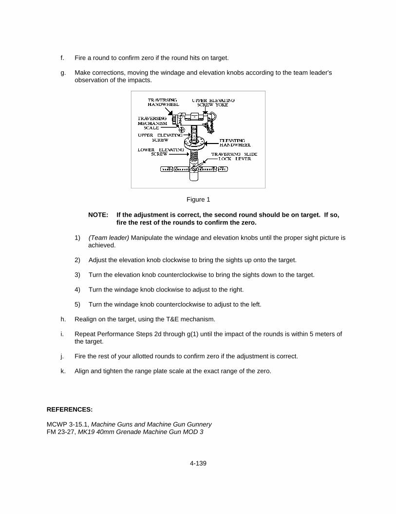
4-139
f. Fire a round to confirm zero if the round hits on target.
g. Make corrections, moving the windage and elevation knobs according to the team leader's
observation of the impacts.
Figure 1
NOTE: If the adjustment is correct, the second round should be on target. If so, fire the rest of the rounds to confirm the zero.
1) (Team leader) Manipulate the windage and elevation knobs until the proper sight picture is
achieved.
2) Adjust the elevation knob clockwise to bring the sights up onto the target.
3) Turn the elevation knob counterclockwise to bring the sights down to the target.
4) Turn the windage knob clockwise to adjust to the right.
5) Turn the windage knob counterclockwise to adjust to the left.
h. Realign on the target, using the T&E mechanism.
i. Repeat Performance Steps 2d through g(1) until the impact of the rounds is within 5 meters of the target.
j. Fire the rest of your allotted rounds to confirm zero if the adjustment is correct.
k. Align and tighten the range plate scale at the exact range of the zero.
REFERENCES: MCWP 3-15.1, Machine Guns and Machine Gun Gunnery FM 23-27, MK19 40mm Grenade Machine Gun MOD 3

4-140
TASK: ZERO THE MK19 MACHINE GUN USING NIGHT VISION SIGHT (4-23) CONDITION: GIVEN AN MK19 MACHINE GUN WITH TRIPOD, AN/TVS-5 NIGHT VISION SIGHT,
MOUNTING BRACKET, A TEAM LEADER, REQUIRED AMMUNITION, REQUIRED EQUIPMENT, AND A TARGET 500-700 METERS AWAY.
STANDARD: THE SEABEE MUST MOUNT THE AN/TVS-5 ONTO THE MACHINE GUN AND
FIELD ZERO THE MACHINE GUN SO THAT THE IMPACT OF THE ROUNDS ARE WITHIN 5 METERS OF THE TARGET.
EVALUATION GUIDELINES TO BE USED DURING TRAINING:
Conditions: The Seabee, acting as a gunner, is provided a tripod-mounted MK19 machine gun with Traversing and Elevating (T&E) mechanism, an AN/TVS-5 night vision sight with mounting bracket, a team leader, a field firing range with ground targets at ranges between 500 and 700 meters, and the appropriate amount of ammunition.
Standard: The Seabee must ensure the machine gun is clear. The Seabee must mount the
AN/TVS-5 night vision sight and field zero the machine gun so that at least two rounds of his/her allotted ammunition impact within 5 meters of the target.
Administrative Note: See TASK: MAINTAIN THE MK19 MACHINE GUN (4-9)
PERFORMANCE STEPS: 1. Clear the machine gun. (See TASK: MAINTAIN THE MK19 MACHINE GUN (4-9).) 2. Zero the MK19 machine gun with the AN/TVS-5.
a. Select a target between 500 and 700 meters away on a field firing range.
NOTE: Zero the weapon's daylight sights if they have not been previously zeroed.
b. Sight in on the target with the zeroed daylight sights.
c. Lower the rear sight.
d. Mount the mounting bracket assembly without disturbing the alignment of the machine gun.
1) Release the feed tray cover latches, and raise the feed tray cover fully.
2) Position the mounting bracket over the breech, and slide the bracket rearward until it is seated.
3) Lock down the three locking cams of the mounting bracket.
NOTE: The cam located on the side should be locked first, followed by the two top
cams.
4) Close and latch the feed tray cover.

4-141
e. Install the night vision sight on the mounting bracket.
CAUTION: The AN/TVS-5 is a precision electro-optical instrument and must be handled
carefully at all times.
1) Position the sight in the groove on top of the mounting bracket.
2) Adjust the sight until the scribe lines on the mounting bracket align with the sight.
3) Tighten the lever screw until it is secure.
NOTE: An empty cartridge case can be slipped over the lever screw to provide additional leverage.
f. Place the AN/TVS-5 night vision sight into operation.
- Install the batteries
a) Remove the battery caps.
b) Insert a battery in each battery cap with the negative (-) terminal facing into the cap.
c) Replace and tighten the battery caps.
g. Operate the night sight.
1) Press your eye against the eyeguard to open the rubber leaves.
2) Turn the ON-OFF/TUBE BRIGHTNESS switch clockwise to turn on the sight.
3) Adjust the ON-OFF/TUBE BRIGHTNESS switch to the lowest setting that will provide good
target-to-background contrast.
4) Turn the ON-OFF/RETICLE BRIGHTNESS switch clockwise to turn on the light emitting diode.
5) Turn the diopter focus ring until the clearest image of the reticle pattern is obtained (Figure
1 and 2).
6) Turn the objective focus ring until a sharp image of the field of view is obtained.
h. Engage the target.
1) Line up the reticle aiming point of the AN/TVS-5 on the center and base of the target.
2) Fire a burst to seat the sight.
3) Retighten the lever screw.

4-142
Figure 1 Figure 2
4) Aim in on target and fire a burst.
5) Observe the impacts of your rounds.
IF
THEN
The rounds did not impact within 5 meters of the target
Adjust the reticle aiming point to the impact of the rounds, and realign the machine gun on the target using the T&E mechanism and/or traversing slide.
i. Repeat Performance Steps h (4) and (5) until the impact of the rounds is within 5 meters of the
target. 3. Clear the machine gun. (See TASK: MAINTAIN THE MK19 MACHINE GUN (4-9).) 4. Dismount the AN/TVS-5 from the MK19 machine gun.
- Reverse the order of mounting. REFERENCES: MCWP 3-15.1, Machine Guns and Machine Gun Gunnery FM 23-27, MK19 40mm Grenade Gun MOD 3
4-143
TASK: SUPERVISE THE CONSTRUCTION OF MACHINE GUN FIGHTING POSITIONS (4-24) CONDITIONS: PROVIDED MACHINE GUN TEAMS OR A SQUAD, SELECTED FIGHTING
POSITIONS AND SECTORS OF FIRE. STANDARD: ENSURE THAT THE MACHINE GUN TEAMS CONSTRUCT POSITIONS THAT
COVER THE SECTORS OF FIRE, PROVIDE COVER AND CONCEALMENT, AND ENABLE THE TEAM TO ACCOMPLISH THE ASSIGNED MISSION.
EVALUATION GUIDELINES TO BE USED DURING TRAINING:
Conditions: The Seabee is provided machine gun teams equipped with a tripod-mounted M240B, M2 or MK19 machine gun, sector of fire, entrenchment tools, and selected fighting positions.
Standard: The Seabee must determine primary, alternate, and supplementary positions. The
Seabee must ensure that the machine gun teams construct positions that allow the guns to fire the assigned mission (PDF/FPL) and cover the entire sector of fire. The Seabee must ensure that the gunner and team leader have access to the machine gun and that the position affords protection from direct frontal small arms fire and the crushing action of tanks. The Seabee must ensure that the positions blend well enough with the surroundings so that they cannot be detected from approximately 35 meters to the front. The Seabee within the fighting position must be able to observe and take under fire personnel moving into his/her sector of fire. The Seabee must ensure that the positions provide cover and concealment.
Administrative Note: See TASKS: CONSTRUCT MACHINE GUN POSITION (4-13)
REFERENCES: MCWP 3-15.1, Machine Guns and Machine Gun Gunnery FM 7-7, The Mechanized Infantry Platoon and Squad FM 23-27, MK 19 40mm Grenade Machine Gun, MOD 3 FM 23-65, Browning Machine Gun, Caliber .50, HB M2 FM 3-22.68, Crew-Served Machine Guns 5.56 and 7.62
4-144
TASK: CONTROL MACHINE GUN SQUAD FIRES (4-25) CONDITIONS: PROVIDED A MACHINE GUN SQUAD, A MISSION, AND A SECTOR OF FIRE. STANDARD: EMPLOY THE SQUAD TO MAINTAIN FIRE AND FIRE DISCIPLINE AND TO
ACCOMPLISH THE MISSION.
EVALUATION GUIDELINES TO BE USED DURING TRAINING:
Conditions: The Seabee, acting as a machine gun squad leader, is provided an M240B, M2, or MK19 machine gun squad, a mission to execute, a field firing range with targets at various ranges, and the appropriate amount of ammunition.
Standard: The Seabee must brief his/her squad on the assigned mission using the 5-
paragraph order (SMEAC) format. The Seabee must ensure that security is established with adjacent units and that range cards are prepared for each position. The Seabee will direct and inspect the clearing of fields of fire and ensure that the machine guns are oriented toward assigned sectors. The Seabee will ensure that communications are established and maintained with each team. The Seabee will issue all fire commands to his/her team leaders and direct the engagement of any enemy personnel or vehicles that enter the squad's assigned sectors ensuring that fire control and discipline is maintained. The Seabee must monitor ammunition supplies and redistribute as necessary, and direct the displacement of his/her squad when ordered by higher authority.
Administrative Notes: See TASKS: PREPARE A RANGE CARD (4-15)
CONSTRUCT MACHINE GUN FIGHTING POSITION (4-
13)
MAINTAIN THE M240B MACHINE GUN (4-5)
MAINTAIN THE M2 MACHINE GUN (4-7)
MAINTAIN THE MK19 MACHINE GUN (4-9)
PERFORMANCE STEPS: 1. Issue a five-paragraph order before the mission, using the SMEAC format.
a. State the Situation.
1) Report on the composition, disposition, location, movement, capabilities, and recent activities of the enemy.
a) Use SALUTE format (Size, Activity, Location, Unit, Time, and Equipment).
b) Use DRAW-D format (Defend, Reinforce, Attack, Withdraw, and Delay).
4-145
2) Report the mission of the next higher unit, location and mission of adjacent units, and
mission of non-organic supporting units, which may affect the action of your unit.
- Use HAS format (Higher, Adjacent, and Supporting).
3) Report information on units attached and detached from the squad by higher headquarters, including the effective time of attachment or detachment.
b. State the Mission.
1) State a clear, concise statement of the task, which the squad must accomplish.
2) Answering the WHO, WHAT, WHEN, WHY and WHERE.
c. State how the mission will be Executed.
1) Include a concept of operation.
2) Include any subordinate tasks (or missions) that the squad must accomplish.
3) Include the unit which is assigned the reserve mission and the tasks that are assigned to
the reserve.
NOTE: If a reserve is not designated, this section is omitted.
4) Include any coordinating instructions that apply to two or more subordinate units.
d. State Administrative and logistical information that pertains to the mission.
e. State Command and signal instructions.
1) Include special instructions on communications.
2) Include the location of the squad leader.
3) Include the location of the platoon commander.
4) Include your location. 2. Integrate the machine gun squads security with nearby units. 3. Ensure range cards are prepared for each machine gun position. (See TASK: PREPARE A RANGE
CARD (4-15).)
a. Ensure the sketch section of the range card is complete.
b. Ensure each machine gun is laid on each probable target and is recorded on the range card.
c. Ensure the data section is complete.

4-146
d. Ensure a duplicate copy of the range card is distributed to the unit commander.
4. Direct the clearing of fields of fire. (See TASK: CONSTRUCT MACHINE GUN POSITION (4-13).)
a. Ensure your machine gun positions are not disclosed by excessive or careless clearing.
b. Ensure your machine gun teams start clearing near their position, and work forward in areas organized for close defense.
c. Ensure your machine gun teams leave a thin natural screen of vegetation to hide defensive
positions.
d. Ensure your machine gun teams remove lower branches of large, scattered trees in sparsely wooded areas.
e. If you must clear fields of fire in heavy woods, ensure that it is done in an irregular pattern, which
will not reveal position of weapons.
f. Ensure your machine gun teams remove or thin dense brush.
g. Ensure your machine gun teams cut weeds only when they obstruct the gunner's view and are higher than knee level.
h. Ensure your machine gun teams drag away cut brush, limbs, and weeds to points where they
will not be detected by the enemy or furnish the enemy concealment.
i. Ensure your machine gun teams cover cuts on trees and bushes forward of the positions with mud, dirt, or snow.
j. Ensure your machine gun teams leave no trails in their sector of fire as lanes are cleared.
k. Ensure the machine gun positions can easily be reached from the ammunition bearer's position
for resupply. 5. Ensure the machine guns are oriented toward assigned sectors. 6. Establish and maintain communications with each team.
a. Ensure you have thoroughly briefed all personnel in paragraph 5 of the operations order regarding the command and signal instructions.
b. Ensure each team receives complete, up-to-date information as it comes from the unit
commander. 7. Detect and engage all enemy personnel and vehicles in the assigned sectors of fire. 8. Issue fire commands.
a. Direct the section to deliver close support fires on command.

4-147
b. Direct the section to deliver long-range fires on command.
c. Direct the section to deliver flank protection fires on command.
d. Assist in the consolidation of objectives by firing to protect against counterattack on command.
e. Direct the squad's fires to a new target on command.
9. Search for and engage targets of opportunity. 10. Monitor each machine gun's ammunition supply.
- Once the engagement is terminated, redistribute ammunition, as needed. 11. Direct the displacement of the machine guns, on command.
- Direct your machine gun teams to clear their machine guns. (See TASKS: MAINTAIN THE M240B MACHINE GUN (4-5), MAINTAIN THE M2 MACHINE GUN (4-7), and MAINTAIN THE MK19 MACHINE GUN (4-9).)
12. Direct your squad to prepare for displacement.
a. Ensure the teams unlock the Traversing and Elevating (T&E) mechanism from the traversing bar.
b. Ensure the teams remove the T&E mechanism from the machine gun.
c. Ensure the teams disengage the pintle from the tripod.
d. Ensure the teams lower the rear machine gun sights.
e. Ensure the teams place the spare barrel and T&E mechanism into the spare barrel bag.
13. Direct your machine gun squad to stand by to displace. REFERENCES: FMFM 6-5, Marine Rifle Squad MCWP 3-15.1, Machine Guns and Machine Gun Gunnery FM 3-22-68, Crew-Served Machine Gun 5.56 and 7.62mm

4-148
TASK: SUPERVISE MAINTENANCE OF MACHINE GUNS (4-26) CONDITIONS: PROVIDED MACHINE GUN TEAMS WITH EQUIPMENT. STANDARD: ENSURE THE MACHINE GUNS ARE PROPERLY MAINTAINED AS PER THE
REFERENCES.
EVALUATION GUIDELINES TO BE USED DURING TRAINING:
Conditions: The Seabee, acting as a machine gun squad leader, is provided machine gun teams equipped with M240B or M2/MK19 machine guns. The Seabee is also provided the appropriate technical manuals, cleaning gear, and lubricants.
Standard: The Seabee must ensure that all scheduled and preventive maintenance is
conducted on the machine guns. The Seabee must brief the Seabees on their duties and ensure that they perform only operator authorized maintenance (first echelon). The Seabee must ensure that the Seabees under him/her have the proper equipment, cleaning gear, and lubricants. The Seabee must ensure that the machine guns are clear. The Seabee must supervise the disassembly, cleaning, lubricating, reassembly, and function check of the machine guns. The Seabee must note and report all discrepancies.
Administrative Notes: See TASKS: MAINTAIN THE M240B MACHINE GUN (4-5)
MAINTAIN THE M2 MACHINE GUN (4-7)
MAINTAIN THE MK19 MACHINE GUN (4-9)
REFERENCES: MCWP 3-15.1, Machine Guns and Machine Gun Gunnery TM 9-1005-313-10, Operator's Manual for Machine Gun, 7.62mm, M240 TM 08521A-10/1A, Operator's Manual and Components List, Machine Gun 40mm, MK19 MOD 3 TM 9-1005-213-10, Operator's Manual for Machine Gun, Caliber .50

4-149
TASK: DETERMINE THE ERROR IN A LENSATIC COMPASS (4-27) CONDITIONS: GIVEN A LENSATIC COMPASS, A SURVEYED POINT WITH A LEVEL
PLATFORM, AN AZIMUTH MARKER, AND A SURVEYED KNOWN DIRECTION. STANDARD: THE SEABEE MUST DETERMINE THE ERROR IN A LENSATIC COMPASS.
EVALUATION GUIDELINES TO BE USED DURING TRAINING:
Conditions: The Seabee is provided with a lensatic compass, a surveyed point with a level
platform, an azimuth marker, and a surveyed known direction.
Standard: The Seabee must determine the error between compass reading and known azimuth, and record error in mils and degrees.
PERFORMANCE STEPS: 1. Place compass, Figure 1, at survey point.
NOTE: The best and most accurate way to place the compass at the survey point is to place the compass on top of an aiming post. This will keep the compass from moving while sighting in on the survey point.
2. Remove all magnetic attractions. 3. Sight in on azimuth marker. 4. Calculate error.

4-150
5. Record THE ERROR on compass.
NOTE: If the compass is off more than 5 degrees, turn the compass back in to the armory.
- Write the error on the face of the compass with a grease pencil. Figure 1 REFERENCE: FM 21-26, Map Reading and Land Navigation

4-151
TASK: DECLINATE AN M2 COMPASS (4-28) CONDITIONS: GIVEN AN M2 COMPASS, A SURVEYED POINT WITH A LEVEL PLATFORM, AN
AZIMUTH MARKER, A SURVEYED KNOWN DIRECTION TO THAT AZIMUTH MARKER AND OTHER APPROPRIATE TOOLS.
STANDARD: THE SEABEE MUST DEMONSTRATE HOW TO DECLINATE AN M2 COMPASS.
EVALUATION GUIDELINES TO BE USED DURING TRAINING:
Conditions: The Seabee is provided with artillery M2 compass, a surveyed point with a level platform, an azimuth marker, a surveyed known direction to that azimuth marker, pencil, paper, and a map.
Standard: The Seabee must determine the declination constant by applying it to the artillery
M2 compass within 10 mils.
PERFORMANCE STEPS: 1. Place the compass over the surveyed point, leveling it, if necessary.
NOTE: Use the aiming circle tripod or other non-magnetic platform and center the circular level 1, if necessary (Figure 1).
Figure 1 2. Remove all magnetic attractions from the area, as required.

4-152
3. Sight in on the azimuth marker 2 (Figure 2).
Figure 2 4. Rotate the adjusting screw 3 (Figure 1).
- Rotate the adjusting screw on the compass until the azimuth scale matches the known azimuth. 5. Check the sight picture and verify the known azimuth. Note: The artillery M2 compass is a special purpose compass and may not be available for NCF training. REFERENCE: FM 6-50, The Field Artillery Cannon Battery
4-153
TASK: SUPERVISE UNIT INDIVIDUALWEAPONS TRAINING (4-29). CONDITIONS: PROVIDED THE REFERENCES AND THE UNIT TRAINING SCHEDULE. STANDARD: IN ACCORDANCE WITH THE COMMANDERS GUIDANCE AND THE
REFERENCES, ENSURE THE UNITS REQUIREMENTS ARE MET FOR INDIVIDUAL WEAPONS TRAINING.
EVALUATION GUIDELINES TO BE USED DURING TRAINING:
Conditions: The Seabee, is provided command guidance, the units training requirements and training schedule, training support personnel, the resources and unit SOP.
Standard: The Seabee must ensure that the unit’s requirements, the training objectives, and
standards are met for individual weapons training, in line with the commanders guidance. The training must be realistic and performance oriented, complying with safety and security regulations. The Seabee must evaluate the training, record and report problems, and recommend solutions for improving deficient performance.
REFERENCES: FMFM 0-1, Unit Training Management Guide. FMFM 0-1A, How to Conduct Training

4-154
TASK: SUPERVISE UNIT CREW-SERVED WEAPONS TRAINING (4-30) CONDITIONS: PROVIDED THE REFERENCES AND THE UNIT TRAINING SCHEDULE. STANDARD: IN ACCORDANCE WITH THE COMMANDER’S GUIDANCE AND THE
REFERENCES, ENSURE THE UNIT’S REQUIREMENTS ARE MET FOR INDIVIDUAL TRAINING IN CREW-SERVED WEAPON.
EVALUATION GUIDELINES TO BE USED DURING TRAINING:
Conditions: The Seabee, is provided a list of operational commitments, unit personnel, Individual Training Standards (ITS) applicable to crew-served weapons, and the current resources.
Standard: The Seabee must ensure that the units training requirements for crew-served
weapons are met in accordance with the commanders guidance. The Seabee must ensure that training is realistic, mission-oriented, and complies with safety regulations. The Seabee must identify training deficiencies , if any, and recommend solutions to improve deficient performance.
REFERENCES: FMFM 0-1, Unit Training Management Guide. FMFM 0-1A, How to Conduct Training MCWP 3-15.1, Machine Guns and Machine Guns Gunnery FM 23-27, MK19 40mm Grenade machine Gun , Mod 3 FM 23-65, Browning Machine Gun Caliber .50 HB M2 FM 3-22.68, Crew–Served Machine Guns, 5.56 and 7.62 mm
4-155
TASK: PREPARE A FIRE-SUPPORT PLAN FOR PLATOON SIZE DEFENSIVE POSITION (4-31)
CONDITIONS: THE SEABEE IS PROVIDED INFORMATION CONCERNING MACHINE GUN FINAL
PROTECTIVE LINES (FPL), BARRIERS, THE LOCATION OF FINAL PROTECTIVE FIRE (FPF) PLANNED BY HIGHER HEADQUARTERS, AND GUIDANCE FROM THE PLATOON COMMANDER.
STANDARD: THE SEABEE, WHEN DIRECTED, MUST DEVELOP A PLATOON FIRE SUPPORT
PLAN THAT WILL SUPPORT THE SCHEME OF MANUEVER/PLAN OF THE DEFENSE BY DESTROYING OR REPELLING THE ENEMY ASSAULT. THE PLAN MUST BE INTEGRATED WITH THE PLANS OF HIGHER HEADQUARTERS AND MUST INVOLVE THE USE OF THE PLATOONS ORGANIC, ATACHED, AND SUPPORTING WEAPONS.
EVALUATION GUIDELINES TO BE USED DURING TRAINING:
Conditions: The Seabee is provided information concerning machine gun Final Protective Lines
(FPL), barriers, the location of Final Protective Fire (FPF) planned by higher headquarters, and guidance from the platoon commander.
Standard: The Seabee, when directed, must develop a platoon fire support plan that will
support the scheme of manuever/plan of the defense by destroying or repelling the enemy assault. The plan must be integrated with the plans of higher headquarters and must involve the use of the platoons organic, attached, and supporting weapons.
PERFORMANCE STEPS: 1. Determine each squads sector of fire.
a. Prepare a map or conduct an aerial reconnaissance.
b. Conduct a walk of the area.
c. Communicate with adjacent platoons or commands. 2. Coordinate platoon fires with the company barrier plan.
a. Plan fires so that the enemy is brought under fire as soon as it comes into effective range.
b. Plan so that the enemy is subjected to increasingly heavier fire as they approach the battle area.
c. Plan to break up the assault by fires immediately in front of the battle area. 3. Request additional prearranged fires to augment the fires of higher echelons if it is determined that
existing fires are insufficient.
a. Make request to the company commander by radio or messenger.

4-156
b. Use the assigned target number in subsequent requests for delivery of prearranged fires if
request is approved. 4. Plan the fires of all assigned weapons as well as those in direct support.
a. Assign fire mission and general firing position.
b. Use the assigned target number in subsequent requests for delivery of prearranged fires if requests are approved.
c. Plan fires on all known enemy positions, all suspected enemy positions, and on prominent or
key terrain features.
d. Plan fires for indirect fire weapons in direct support of the platoon on all areas of approach that contain dead space that can not be covered by organic direct fire.
5. Cover gaps and dead spaces in the FPF by selecting general firing positions and principal directions
of fire (PDF) for specific automatic rifles and grenade launchers organic to the rifle squads. 6. Direct the squad leaders to assign the firing positions and PDFs if gaps exist or if the situation
permits. 7. Prepare a fire-plan sketch or overlay for the platoon commander to submit to the company
commander for approval.
a. Compare squads defensive sketches with the actual layout of the ground.
b. Draw the platoons fire-plan sketch
1) Use only approved military symbols.
2) Draw a topographical sketch of the platoon area.
3) Orient the sketch with a military map by recording the grid coordinates or the platoon’s center by drawing a North arrow and by recording the azimuths of all FPF’s outer sector limits.
4) Complete an administrative information block in the lower right-hand corner to include
platoon number, company letter, and date prepared.
c. Ensure that the sketch includes the following:
1) Squads primary positions and sectors of fire,
2) Positions and PDF’s for all automatic rifles,
3) Location of platoon’s observation post,
4) Positions and PDFs of grenade launchers when not assigned by the squad leaders,

4-157
5) Positions and FPL’s or PDFs for machine guns located in the platoon’s defensive area
(include sectors of fire for attached guns), and
6) Positions and PDFs of tube launched, optically tracked and wire command link in the platoon’s defensive area (includes sectors of fire for attached weapons),
d. Make a duplicate copy, and forward it to the platoon commander or higher headquarters once a
sketch is completed. REFERENCES: FMFM 6-4, Marine Rifle Company and Platoon FMFM 6-5, Marine Rifle Squad