construction contracts contracts & materials management
TRANSCRIPT
Construction Contracts Administration, Procurement Contracts & Materials Management (PCMM) Oregon State University 644 SW 13th Ave. Corvallis, Oregon 97333
P 541-737-4261 F 541-737-5546 oregonstate.edu
11/8/2018 Oregon State University Construction Contract Administration Pharmacy Chiller Replacement Rebid ADDENDUM NO. 1 THIS ADDENDUM IS BEING ISSUED for clarification and/or revisions of the drawings and specifications as noted. This document is hereby made a part of the Contract Documents to the extent as though it was originally included herein.
The following changes shall be made to the DRAWINGS:
Item 1 Sheet G-001”Cover Sheet”, REPLACE in its entirety with sheet G-001 Addendum 2 dated 11/06/2018. Be sure to note Addendum #1, it was not previously released.
Item 2 Sheet M-001”Legend and Schedule”, REPLACE in its entirety with sheet M-001
Addendum 2 dated 11/06/2018. Be sure to note COLEBREIT’S Addendum #1, it was not previously released.
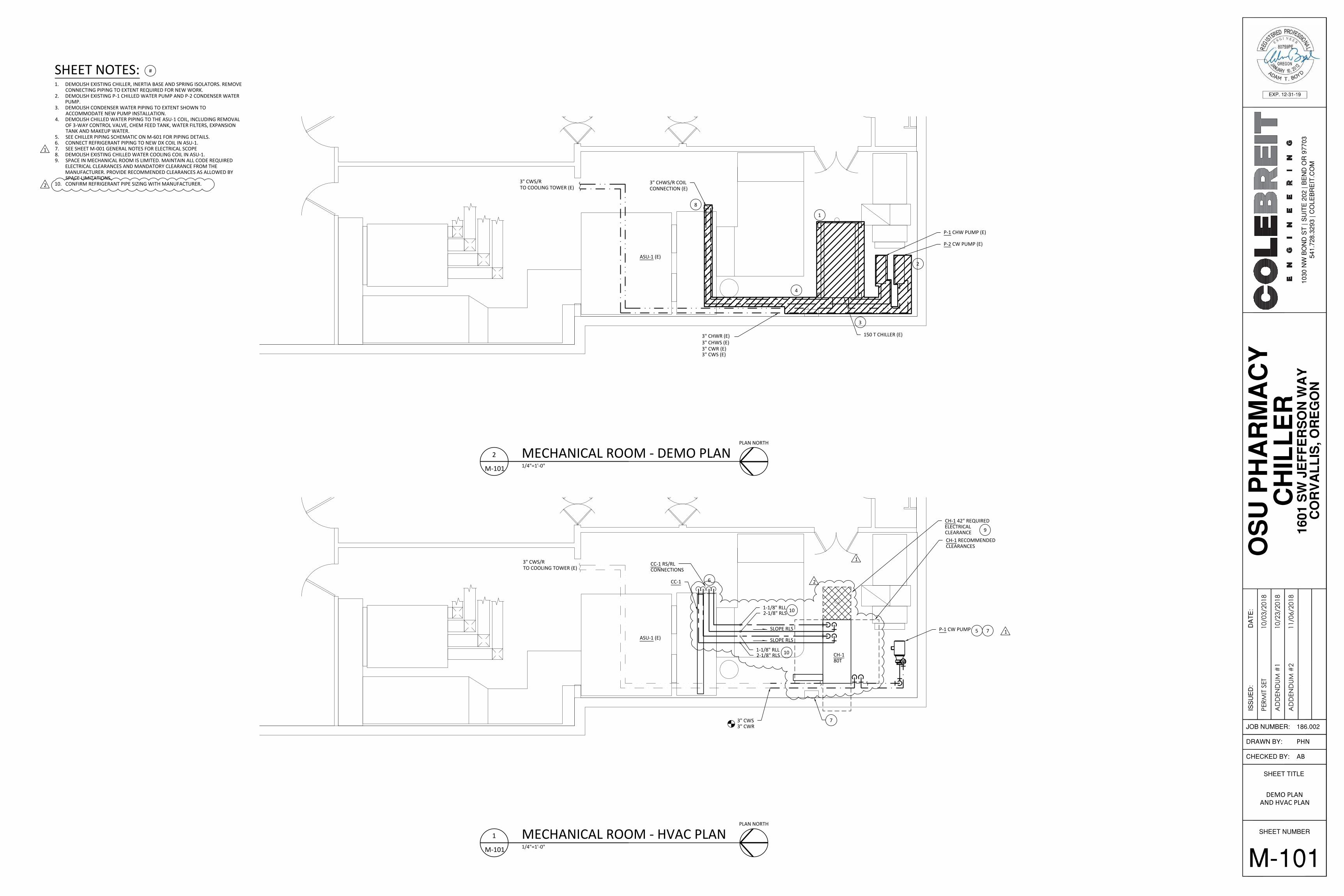
Item 3 Sheet M-101 “Demo Plan and HVAC Plan”, REPLACE in its entirety with sheet M-101
Addendum 2 dated 11/06/2018. Be sure to note COLEBREIT’S Addendum #1, it was not previously released.
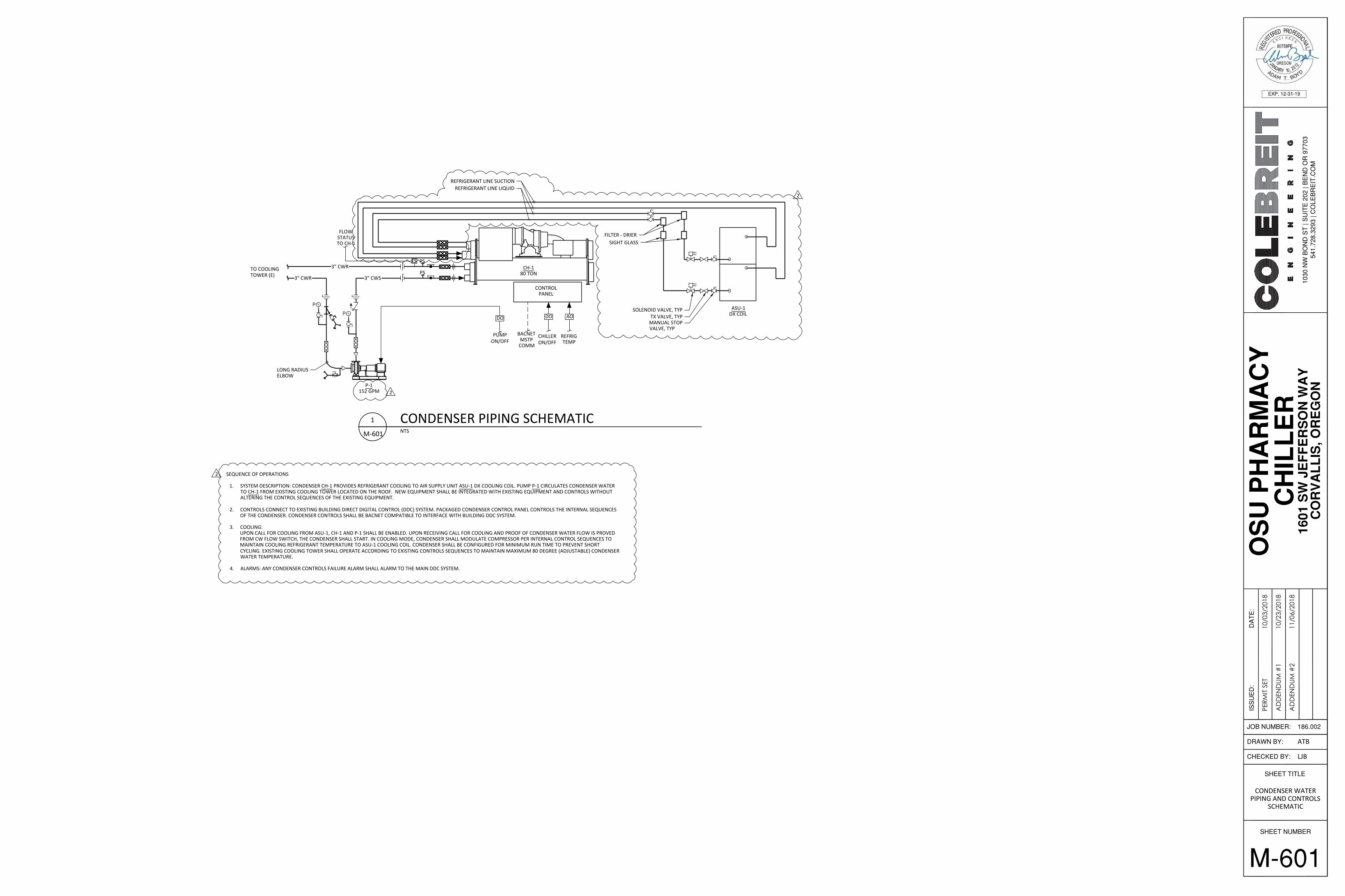
Item 4 Sheet M-601 “Condenser Water Piping and Controls Schematic”, REPLACE in its
entirety with sheet M-601 Addendum 2 dated 11/06/2018. Be sure to note COLEBREIT’S Addendum #1, it was not previously released.
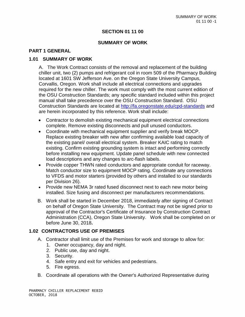
Item 5 DELETE Section 01 11 00 Summary of Work in its entirety. It is replaced
with Section 01 11 00 Summary of Work attached to this addendum. Item 6 DELETE Section 23 64 29 Summary of Work in its entirety. It is replaced
with Section 23 64 29 Summary of Work attached to this addendum.
QUESTIONS and ANSWERS: Item 7 Q: Will the freight elevator be allowed to move construction personnel to the 5th
floor or is there another public elevator available? A: Yes, OSU will provide a key that operates the freight elevator that can be
checked out daily at public safety. Item 8 Q: Who will remove the refrigerant? A: Oregon State University will remove the refrigerant in the existing chiller. Item 9 Q: Who will perform any asbestos abatement?
A: Oregon State will abate all asbestos that is discovered. See Division 1, section 1.04/1.05 for further clarification.
Item 10 Q: Who will demo the concrete pad?
A: Prime Contractor shall demolish and remove the existing concrete pad, steel frame and isolators. New chiller will mount directly to the existing concrete floor.
Item 11 Q: Are there cut sheets of the equipment?
A: Cut sheets shall be obtained from the equipment vendor/ manufacturer by the Prime Contractor.
Item 12 Q: The equipment schedule indicates a 460v Ph3 model chiller to be installed, but it appears there is only 208-240v Ph3 power available? A: Currently the Pharmacy Building only has 208v Ph3 available. ColeBreit Engineering has addressed this in their drawings marked Addendum #2.
Item 13 Q: Where is the electrical room located (which floor) that service the 400 amp disconnect currently serving the chiller? A: The 400 Amp disconnect is feed from the main electrical room (003) on the east side of the original building, just under the stairs as you walk in the east back entrance. Coordinate with OSU electrical for the shutdown of the electrical equipment.
Item 14 Q: Can the existing exhaust fans in the mechanical space be utilized to exhaust fumes/ smells when performing the demolition of the existing chiller? A: It is not recommended to use the existing exhaust fans to mitigate fumes/ smells during the demolition. The contractor should plan for and provide any mitigation for noise/fumes. There is an exterior door on the north end of the mechanical room that the contractor can use to help mitigate fumes/odors. This should be included in your bid.
Item 15 Q: Will the existing pneumatic system control the Chiller or is there a specific brand of existing BMS system that will control the new chiller? A: No, the existing pneumatic system will not operate the new chiller. See Item 16.
Item 16 Q: What controls vendor do you want? A: OSU would prefer Alerton Controls for consistency within the Pharmacy Building. The Prime Contractor shall follow industry standards and make sure that the equipment to have the following items:
• Hard wire stop/start • Hard wire chilled water set-point

• BACnet should be either have the ability to MSTP or IP Ethernet • OSU controls group will tie into BACnet and take cable back to the BAS
END OF ADDENDUM NO. 1
SHEET TITLE
SHEET NUMBER
CHECKED BY:
DRAWN BY:
JOB NUMBER:
ISS
UE
D:
DA
TE
:
PERM
IT SE
T10
/03/
2018
1030
NW
BO
ND
ST
| S
UIT
E 2
02 |
BE
ND
OR
977
0354
1.72
8.32
93 |
CO
LEB
RE
IT.C
OM
186.002
AD
DEN
DUM
#1
10/2
3/20
18
AD
DEN
DUM
#2
11/0
6/20
18
SHEET NAMESHEET NUMBER
SHEET KEY
COVER SHEETG-001
M-001
M-601
LEGEND AND SCHEDULES
CONDENSER WATER PIPING AND CONTROLS SCHEMATIC
CAMPUS MAPNTS
PLAN NORTH
SITE PLANNTS
PLAN NORTH
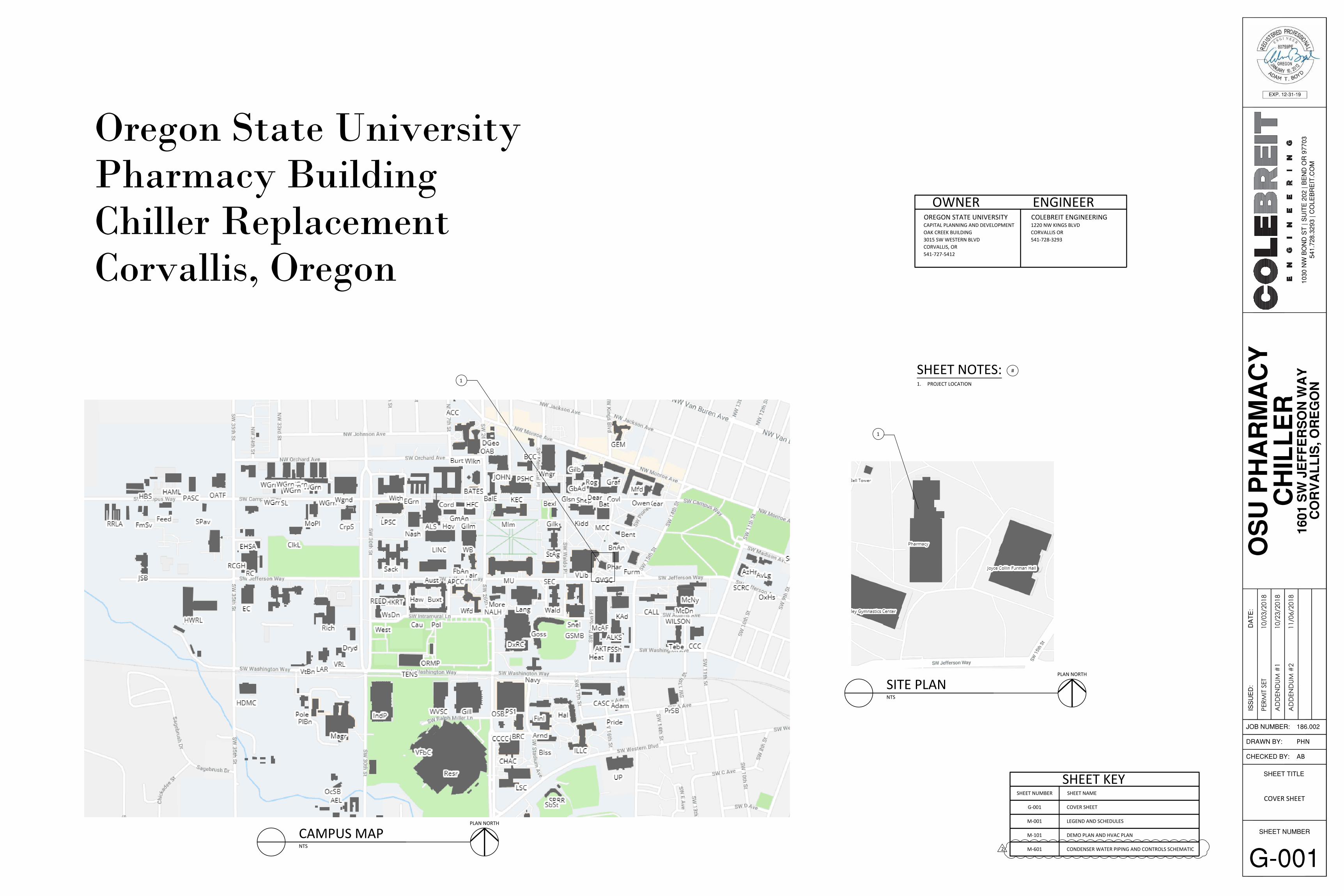
1. PROJECT LOCATION
SHEET NOTES: #
1
1
Oregon State UniversityPharmacy BuildingChiller ReplacementCorvallis, Oregon
OREGON STATE UNIVERSITY
OWNERCAPITAL PLANNING AND DEVELOPMENTOAK CREEK BUILDING3015 SW WESTERN BLVDCORVALLIS, OR541-727-5412
COLEBREIT ENGINEERING
ENGINEER1220 NW KINGS BLVDCORVALLIS OR541-728-3293
M-101 DEMO PLAN AND HVAC PLAN
G-001
COVER SHEET
PHN
AB
2
SHEET TITLE
SHEET NUMBER
CHECKED BY:
DRAWN BY:
JOB NUMBER:
ISS
UE
D:
DA
TE
:
PERM
IT SE
T10
/03/
2018
1030
NW
BO
ND
ST
| S
UIT
E 2
02 |
BE
ND
OR
977
0354
1.72
8.32
93 |
CO
LEB
RE
IT.C
OM
186.002
AD
DEN
DUM
#1
10/2
3/20
18
AD
DEN
DUM
#2
11/0
6/20
18
M-001
LEGEND ANDSCHEDULE
PHN
AB
MECHANICAL LEGEND
TEE, BRANCH DOWN
ELBOW DOWN
TEE, BRANCH UP
ELBOW UP
ELBOW DOWN
(E)
(A)
(N)
SHEET NOTE
ABANDON IN PLACE
EXISTING
NEW
REDUCER, CONCENTRIC
ISOLATOR, VIBRATION
VALVE, SWING CHECK
FLANGED CONNECTION
VALVE, BUTTERFLY
VALVE, GATE
UNION, THREADED
STRAINER WITH VALVE
PUMP, CENTRIFUGAL
PIPE CAP
FLOW METER
VENT, AIR
VALVE, PRESSURE RELIEF
CH CHILLER
CF CHEMICAL FEED SYSTEM
P PUMP
THERMOWELL
REFRIGERANT SUCTIONRS
REFRIGERANT LIQUIDRL
2
VALVE, PLUG
VALVE, BALL
VALVE, BACK PRESSURE REGULATOR
VALVE, MOTOR OPERATED
TEMPERATURE GAUGE
PRESSURE GAUGE
FM
M
TG
PG
AHU AIR HANDLING UNIT
EXPANSION TANKET
POINT OF CONNECTION
REFRIGERANT LINE LIQUIDRLL
CONDENSER WATER SUPPLYCWS
REFRIGERANT LINE SUCTIONRLS
IDENTIFICATIONABBRV.SYMBOL
CONDENSER WATER RETURNCWR
PIPING LEGEND
1. LOCATION AND ARRANGEMENT OF EXISTING PIPING, VALVES, AND EQUIPMENT IS APPROXIMATE.CONTRACTOR SHALL VERIFY LOCATION OF PIPING AND DIMENSIONS FOR INSTALLATION PRIOR TOCONSTRUCTION AND NOTIFY ENGINEER OF ANY DISCREPANCIES.
2. MECHANICAL WORK INDICATED IS DIAGRAMMATIC, EXACT LOCATIONS OF ALL COMPONENTS ARE TO BEDETERMINED IN THE FIELD TO AVOID CONFLICT WITH EXISTING SITE CONDITIONS.
3. ALL EQUIPMENT SHALL BE INSTALLED IN ACCORDANCE WITH MANUFACTURER'S WRITTEN INSTALLATIONINSTRUCTIONS.
4. PROTECT ALL EXISTING ADJACENT SURFACES, ELEMENTS AND FIXTURES SCHEDULED TO REMAIN FROMDAMAGE DUE TO DEMOLITION AND CONSTRUCTION PROCESSES. PATCH AND REPAIR TO PREVIOUSCONDITIONS.
5. PROVIDE MANUAL AIR VENTS AT ALL HIGH POINTS IN CHILLED WATER AND HOT WATER PIPING.6. CONFORM TO OREGON STATE UNIVERSITY DESIGN STANDARDS INCLUDING FOR EQUIPMENT
IDENTIFICATION AND INSTALLATION.7. DIV26 CONTRACTOR TO DEMOLISH EXISTING MECHANICAL EQUIPMENT ELECTRICAL CONNECTIONS
COMPLETE. REMOVE EXISTING DISCONNECTS AND PULL UNUSED CONDUCTORS.8. DIV26 TO COORDINATE WITH MECHANICAL EQUIPMENT SUPPLIER AND VERIFY BREAKER MOCP. REPLACE
EXISTING BREAKER WITH NEW AFTER CONFIRMING AVAILABLE LOAD CAPACITY OF THE EXISTINGPANEL/OVERALL ELECTRICAL SYSTEM. BREAKER KAIC RATING TO MATCH EXISTING. DIV26 TO CONFIRMEXISTING GROUNDING SYSTEM IS INTACT AND PERFORMING CORRECTLY BEFORE INSTALLING NEWEQUIPMENT. UPDATE PANEL SCHEDULE WITH NEW CONNECTED LOAD DESCRIPTIONS AND ANY CHANGESTO ARC-FLASH LABELS.
9. DIV26 TO PROVIDE COPPER THWN RATED CONDUCTORS AND APPROPRIATE CONDUIT FOR RACEWAY.MATCH CONDUCTOR SIZE TO EQUIPMENT MOCP RATING. DIV26 TO COORDINATE ANY CONNECTIONS TOVFDS AND MOTOR STARTERS (PROVIDED BY OTHERS, INSTALLED BY DIV26).
10. PROVIDE NEW NEMA 3R RATED FUSED DISCONNECT NEXT TO EACH NEW MOTOR BEING INSTALLED. SIZEFUSING AND DISCONNECT PER MANUFACTURERS RECOMMENDATIONS.
GENERAL NOTES:
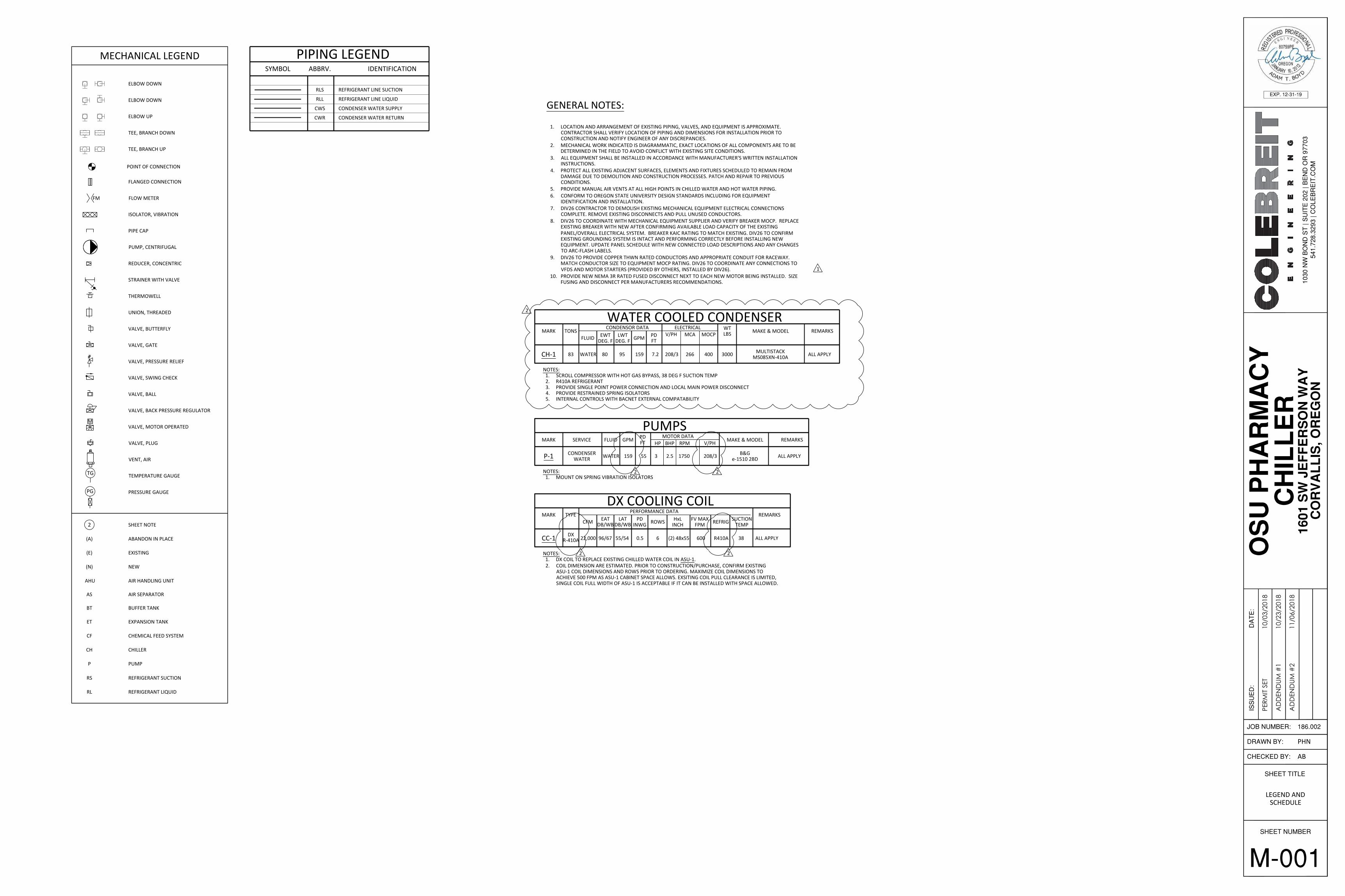
WATER COOLED CONDENSERMARK
CH-1
ELECTRICAL WTMOCPMCA LBS REMARKSMAKE & MODEL
NOTES:1. SCROLL COMPRESSOR WITH HOT GAS BYPASS, 38 DEG F SUCTION TEMP2. R410A REFRIGERANT3. PROVIDE SINGLE POINT POWER CONNECTION AND LOCAL MAIN POWER DISCONNECT4. PROVIDE RESTRAINED SPRING ISOLATORS5. INTERNAL CONTROLS WITH BACNET EXTERNAL COMPATABILITY
ALL APPLY266 400 300083 208/3 MULTISTACKMS085XN-410A
TONS V/PH
80WATER
FLUID EWTDEG. F
95
LWTDEG. F
CONDENSOR DATA
7.2
GPM
159
PDFT
PUMPSMARK REMARKSMAKE & MODEL
NOTES:1. MOUNT ON SPRING VIBRATION ISOLATORS
ALL APPLY1750 B&Ge-1510 2BD
MOTOR DATABHP
2.5
HP
3
RPMSERVICE
WATER
FLUID GPM
159 55
PDFT
208/3
V/PH
P-1 CONDENSERWATER
AS AIR SEPARATOR
BUFFER TANKBT
DX COOLING COILMARK
CC-1
NOTES:1. DX COIL TO REPLACE EXISTING CHILLED WATER COIL IN ASU-1.2. COIL DIMENSION ARE ESTIMATED. PRIOR TO CONSTRUCTION/PURCHASE, CONFIRM EXISTING
ASU-1 COIL DIMENSIONS AND ROWS PRIOR TO ORDERING. MAXIMIZE COIL DIMENSIONS TOACHIEVE 500 FPM AS ASU-1 CABINET SPACE ALLOWS. EXSITING COIL PULL CLEARANCE IS LIMITED,SINGLE COIL FULL WIDTH OF ASU-1 IS ACCEPTABLE IF IT CAN BE INSTALLED WITH SPACE ALLOWED.
DX
TYPE
96/6722,000
CFM EATDB/WB
55/54
LATDB/WB
PERFORMANCE DATA
0.5 (2) 48x55
PDINWG
HxLINCH
R410A
REFRIG
38
SUCTIONTEMP
6
ROWS
600
FV MAXFPM
REMARKS
ALL APPLYR-410A
1
2
2
22
2
CH-1 RECOMMENDEDCLEARANCES
CH-1 42" REQUIREDELECTRICALCLEARANCE
CH-180T
P-1 CW PUMP
3" CWS3" CWR
3" CWS/RTO COOLING TOWER (E)
CC-1 RS/RLCONNECTIONS
1-1/8" RLL2-1/8" RLS
CC-1
SLOPE RLSASU-1 (E)
SLOPE RLS
1-1/8" RLL2-1/8" RLS
3" CHWR (E)3" CHWS (E)3" CWR (E)3" CWS (E)
150 T CHILLER (E)
P-1 CHW PUMP (E)
P-2 CW PUMP (E)
3" CHWS/R COILCONNECTION (E)
3" CWS/RTO COOLING TOWER (E)
ASU-1 (E)
SHEET TITLE
SHEET NUMBER
CHECKED BY:
DRAWN BY:
JOB NUMBER:
ISS
UE
D:
DA
TE
:
PERM
IT SE
T10
/03/
2018
1030
NW
BO
ND
ST
| S
UIT
E 2
02 |
BE
ND
OR
977
0354
1.72
8.32
93 |
CO
LEB
RE
IT.C
OM
186.002
AD
DEN
DUM
#1
10/2
3/20
18
AD
DEN
DUM
#2
11/0
6/20
18
M-101
DEMO PLANAND HVAC PLAN
PHN
AB
MECHANICAL ROOM - HVAC PLAN1/4"=1'-0"
1
M-101
PLAN NORTH
MECHANICAL ROOM - DEMO PLAN1/4"=1'-0"
2
M-101
PLAN NORTH
1. DEMOLISH EXISTING CHILLER, INERTIA BASE AND SPRING ISOLATORS. REMOVECONNECTING PIPING TO EXTENT REQUIRED FOR NEW WORK.
2. DEMOLISH EXISTING P-1 CHILLED WATER PUMP AND P-2 CONDENSER WATERPUMP.
3. DEMOLISH CONDENSER WATER PIPING TO EXTENT SHOWN TOACCOMMODATE NEW PUMP INSTALLATION.
4. DEMOLISH CHILLED WATER PIPING TO THE ASU-1 COIL, INCLUDING REMOVALOF 3-WAY CONTROL VALVE, CHEM FEED TANK, WATER FILTERS, EXPANSIONTANK AND MAKEUP WATER.
5. SEE CHILLER PIPING SCHEMATIC ON M-601 FOR PIPING DETAILS.6. CONNECT REFRIGERANT PIPING TO NEW DX COIL IN ASU-1.7. SEE SHEET M-001 GENERAL NOTES FOR ELECTRICAL SCOPE8. DEMOLISH EXISTING CHILLED WATER COOLING COIL IN ASU-1.9. SPACE IN MECHANICAL ROOM IS LIMITED. MAINTAIN ALL CODE REQUIRED
ELECTRICAL CLEARANCES AND MANDATORY CLEARANCE FROM THEMANUFACTURER. PROVIDE RECOMMENDED CLEARANCES AS ALLOWED BYSPACE LIMITATIONS.
10. CONFIRM REFRIGERANT PIPE SIZING WITH MANUFACTURER.
SHEET NOTES: #
1
2
3
9
5
6
7
4
8
7
1
1
1
2
2
10
10
CH-180 TONPS
FS PS
P-1152 GPM
LONG RADIUSELBOW
TO COOLINGTOWER (E) 3" CWR
ASU-1DX COIL
REFRIGERANT LINE SUCTIONREFRIGERANT LINE LIQUID
3" CWS
3" CWR
CONTROLPANEL
DO
CHILLERON/OFF
AO
REFRIGTEMP
BACNETMSTP
COMM
PUMPON/OFF
FLOWSTATUSTO CH-1
DOSOLENOID VALVE, TYP
TX VALVE, TYP
FILTER - DRIERSIGHT GLASS
MANUAL STOPVALVE, TYP
M-601
CONDENSER WATERPIPING AND CONTROLS
SCHEMATIC
ATB
LJB
SHEET TITLE
SHEET NUMBER
CHECKED BY:
DRAWN BY:
JOB NUMBER:
ISS
UE
D:
DA
TE
:
PERM
IT SE
T10
/03/
2018
1030
NW
BO
ND
ST
| S
UIT
E 2
02 |
BE
ND
OR
977
0354
1.72
8.32
93 |
CO
LEB
RE
IT.C
OM
186.002
AD
DEN
DUM
#1
10/2
3/20
18
AD
DEN
DUM
#2
11/0
6/20
18
CONDENSER PIPING SCHEMATICNTS
1
M-601
SEQUENCE OF OPERATIONS
1. SYSTEM DESCRIPTION: CONDENSER CH-1 PROVIDES REFRIGERANT COOLING TO AIR SUPPLY UNIT ASU-1 DX COOLING COIL. PUMP P-1 CIRCULATES CONDENSER WATERTO CH-1 FROM EXISTING COOLING TOWER LOCATED ON THE ROOF. NEW EQUIPMENT SHALL BE INTEGRATED WITH EXISTING EQUIPMENT AND CONTROLS WITHOUTALTERING THE CONTROL SEQUENCES OF THE EXISTING EQUIPMENT.
2. CONTROLS CONNECT TO EXISTING BUILDING DIRECT DIGITAL CONTROL (DDC) SYSTEM. PACKAGED CONDENSER CONTROL PANEL CONTROLS THE INTERNAL SEQUENCESOF THE CONDENSER. CONDENSER CONTROLS SHALL BE BACNET COMPATIBLE TO INTERFACE WITH BUILDING DDC SYSTEM.
3. COOLING:UPON CALL FOR COOLING FROM ASU-1, CH-1 AND P-1 SHALL BE ENABLED. UPON RECEIVING CALL FOR COOLING AND PROOF OF CONDENSER WATER FLOW IS PROVED FROM CW FLOW SWITCH, THE CONDENSER SHALL START. IN COOLING MODE, CONDENSER SHALL MODULATE COMPRESSOR PER INTERNAL CONTROL SEQUENCES TOMAINTAIN COOLING REFRIGERANT TEMPERATURE TO ASU-1 COOLING COIL. CONDENSER SHALL BE CONFIGURED FOR MINIMUM RUN TIME TO PREVENT SHORTCYCLING. EXISTING COOLING TOWER SHALL OPERATE ACCORDING TO EXISTING CONTROLS SEQUENCES TO MAINTAIN MAXIMUM 80 DEGREE (ADJUSTABLE) CONDENSERWATER TEMPERATURE.
4. ALARMS: ANY CONDENSER CONTROLS FAILURE ALARM SHALL ALARM TO THE MAIN DDC SYSTEM.
2
2
2
SUMMARY OF WORK 01 11 00 -1
PHARMACY CHILLER REPLACEMENT REBID OCTOBER, 2018
SECTION 01 11 00
SUMMARY OF WORK PART 1 GENERAL 1.01 SUMMARY OF WORK
A. The Work Contract consists of the removal and replacement of the building chiller unit, two (2) pumps and refrigerant coil in room 509 of the Pharmacy Building located at 1601 SW Jefferson Ave. on the Oregon State University Campus, Corvallis, Oregon. Work shall include all electrical connections and upgrades required for the new chiller. The work must comply with the most current edition of the OSU Construction Standards; any specific standard included within this project manual shall take precedence over the OSU Construction Standard. OSU Construction Standards are located at http://fa.oregonstate.edu/cpd-standards and are herein incorporated by this reference. Work shall include:
• Contractor to demolish existing mechanical equipment electrical connections complete. Remove existing disconnects and pull unused conductors.
• Coordinate with mechanical equipment supplier and verify break MOCP. Replace existing breaker with new after confirming available load capacity of the existing panel/ overall electrical system. Breaker KAIC rating to match existing. Confirm existing grounding system is intact and performing correctly before installing new equipment. Update panel schedule with new connected load descriptions and any changes to arc-flash labels.
• Provide copper THWN rated conductors and appropriate conduit for raceway. Match conductor size to equipment MOCP rating. Coordinate any connections to VFDS and motor starters (provided by others and installed to our standards per Division 26).
• Provide new NEMA 3r rated fused disconnect next to each new motor being installed. Size fusing and disconnect per manufacturers recommendations.
B. Work shall be started in December 2018, immediately after signing of Contract on behalf of Oregon State University. The Contract may not be signed prior to approval of the Contractor's Certificate of Insurance by Construction Contract Administration (CCA), Oregon State University. Work shall be completed on or before June 30, 2018.
1.02 CONTRACTORS USE OF PREMISES A. Contractor shall limit use of the Premises for work and storage to allow for:
1. Owner occupancy, day and night. 2. Public use, day and night. 3. Security. 4. Safe entry and exit for vehicles and pedestrians. 5. Fire egress.
B. Coordinate all operations with the Owner's Authorized Representative during
SUMMARY OF WORK 01 11 00 -2
PHARMACY CHILLER REPLACEMENT REBID OCTOBER, 2018
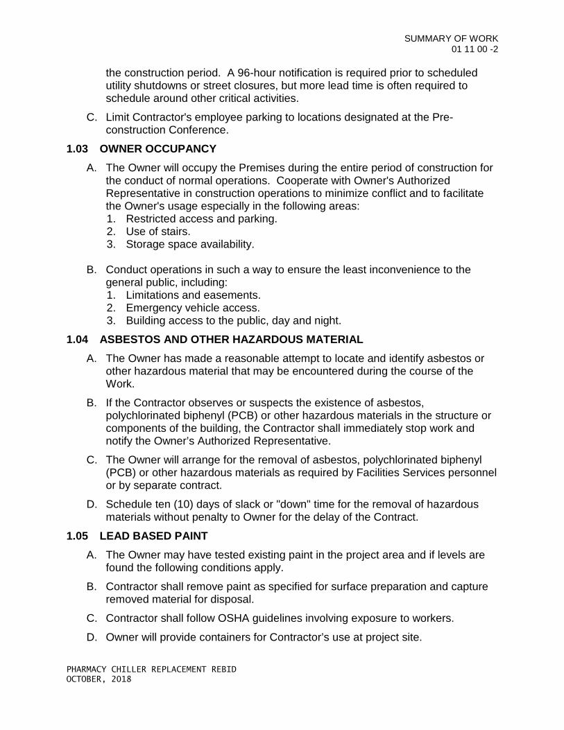
the construction period. A 96-hour notification is required prior to scheduled utility shutdowns or street closures, but more lead time is often required to schedule around other critical activities.
C. Limit Contractor's employee parking to locations designated at the Pre-construction Conference.
1.03 OWNER OCCUPANCY A. The Owner will occupy the Premises during the entire period of construction for
the conduct of normal operations. Cooperate with Owner's Authorized Representative in construction operations to minimize conflict and to facilitate the Owner's usage especially in the following areas: 1. Restricted access and parking. 2. Use of stairs. 3. Storage space availability.
B. Conduct operations in such a way to ensure the least inconvenience to the general public, including: 1. Limitations and easements. 2. Emergency vehicle access. 3. Building access to the public, day and night.
1.04 ASBESTOS AND OTHER HAZARDOUS MATERIAL A. The Owner has made a reasonable attempt to locate and identify asbestos or
other hazardous material that may be encountered during the course of the Work.
B. If the Contractor observes or suspects the existence of asbestos, polychlorinated biphenyl (PCB) or other hazardous materials in the structure or components of the building, the Contractor shall immediately stop work and notify the Owner’s Authorized Representative.
C. The Owner will arrange for the removal of asbestos, polychlorinated biphenyl (PCB) or other hazardous materials as required by Facilities Services personnel or by separate contract.
D. Schedule ten (10) days of slack or "down" time for the removal of hazardous materials without penalty to Owner for the delay of the Contract.
1.05 LEAD BASED PAINT A. The Owner may have tested existing paint in the project area and if levels are
found the following conditions apply.
B. Contractor shall remove paint as specified for surface preparation and capture removed material for disposal.
C. Contractor shall follow OSHA guidelines involving exposure to workers.
D. Owner will provide containers for Contractor’s use at project site.
SUMMARY OF WORK 01 11 00 -3
PHARMACY CHILLER REPLACEMENT REBID OCTOBER, 2018
E. Contractor shall comply with the requirements of DEQ and EPA and shall submit a lead abatement plan.
F. Contractor shall separate lead contaminated material from effluent and water.
G. Owner will dispose of lead paint and effluent resulting from stripping operation.
H. Soil contaminated by stripping operations shall be replaced with topsoil.
END OF SECTION
OREGON STATE UNIVERSITY
PHARMACY CHILLER REPLACEMENT
November 2018 23 64 29
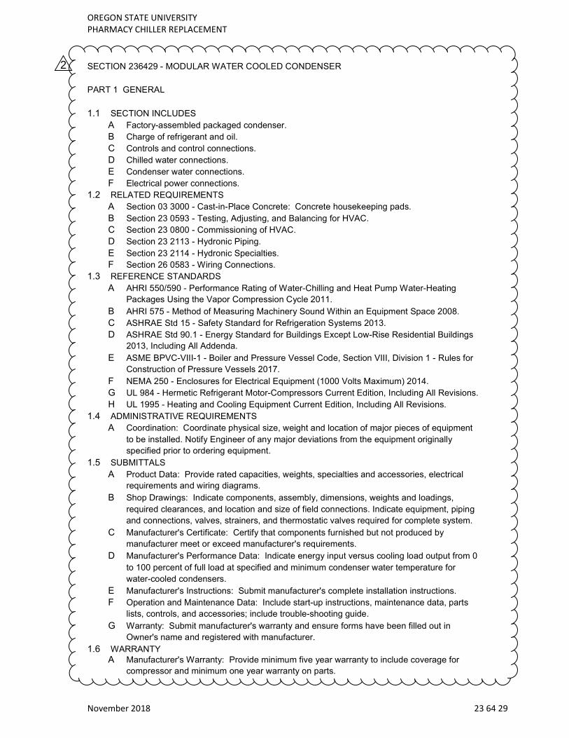
SECTION 236429 - MODULAR WATER COOLED CONDENSER
PART 1 GENERAL
1.1 SECTION INCLUDES
A Factory-assembled packaged condenser.
B Charge of refrigerant and oil.
C Controls and control connections.
D Chilled water connections.
E Condenser water connections.
F Electrical power connections.
1.2 RELATED REQUIREMENTS
A Section 03 3000 - Cast-in-Place Concrete: Concrete housekeeping pads.
B Section 23 0593 - Testing, Adjusting, and Balancing for HVAC.
C Section 23 0800 - Commissioning of HVAC.
D Section 23 2113 - Hydronic Piping.
E Section 23 2114 - Hydronic Specialties.
F Section 26 0583 - Wiring Connections.
1.3 REFERENCE STANDARDS
A AHRI 550/590 - Performance Rating of Water-Chilling and Heat Pump Water-Heating
Packages Using the Vapor Compression Cycle 2011.
B AHRI 575 - Method of Measuring Machinery Sound Within an Equipment Space 2008.
C ASHRAE Std 15 - Safety Standard for Refrigeration Systems 2013.
D ASHRAE Std 90.1 - Energy Standard for Buildings Except Low-Rise Residential Buildings
2013, Including All Addenda.
E ASME BPVC-VIII-1 - Boiler and Pressure Vessel Code, Section VIII, Division 1 - Rules for
Construction of Pressure Vessels 2017.
F NEMA 250 - Enclosures for Electrical Equipment (1000 Volts Maximum) 2014.
G UL 984 - Hermetic Refrigerant Motor-Compressors Current Edition, Including All Revisions.
H UL 1995 - Heating and Cooling Equipment Current Edition, Including All Revisions.
1.4 ADMINISTRATIVE REQUIREMENTS
A Coordination: Coordinate physical size, weight and location of major pieces of equipment
to be installed. Notify Engineer of any major deviations from the equipment originally
specified prior to ordering equipment.
1.5 SUBMITTALS
A Product Data: Provide rated capacities, weights, specialties and accessories, electrical
requirements and wiring diagrams.
B Shop Drawings: Indicate components, assembly, dimensions, weights and loadings,
required clearances, and location and size of field connections. Indicate equipment, piping
and connections, valves, strainers, and thermostatic valves required for complete system.
C Manufacturer's Certificate: Certify that components furnished but not produced by
manufacturer meet or exceed manufacturer's requirements.
D Manufacturer's Performance Data: Indicate energy input versus cooling load output from 0
to 100 percent of full load at specified and minimum condenser water temperature for
water-cooled condensers.
E Manufacturer's Instructions: Submit manufacturer's complete installation instructions.
F Operation and Maintenance Data: Include start-up instructions, maintenance data, parts
lists, controls, and accessories; include trouble-shooting guide.
G Warranty: Submit manufacturer's warranty and ensure forms have been filled out in
Owner's name and registered with manufacturer.
1.6 WARRANTY
A Manufacturer's Warranty: Provide minimum five year warranty to include coverage for
compressor and minimum one year warranty on parts.
2
OREGON STATE UNIVERSITY
PHARMACY CHILLER REPLACEMENT
November 2018 23 64 29
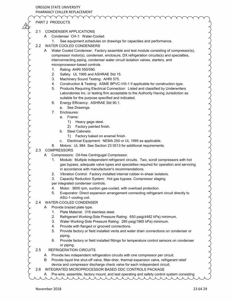
PART 2 PRODUCTS
2.1 CONDENSER APPLICATIONS
A Condenser CH-1: Water-Cooled.
1. See equipment schedules on drawings for capacities and performance.
2.2 WATER COOLED CONDENSERS
A Water Cooled Condenser: Factory assemble and test module consisting of compressor(s),
compressor motor(s), condenser, enclosure, DX refrigeration circuits(s) and specialties,
interconnecting piping, condenser water circuit isolation valves, starters, and
microprocessor-based controls.
1. Rating: AHRI 550/590.
2. Safety: UL 1995 and ASHRAE Std 15.
3. Machinery Sound Testing: AHRI 575.
4. Construction & Testing: ASME BPVC-VIII-1 if applicable for construction type.
5. Products Requiring Electrical Connection: Listed and classified by Underwriters
Laboratories Inc. or testing firm acceptable to the Authority Having Jurisdiction as
suitable for the purpose specified and indicated.
6. Energy Efficiency: ASHRAE Std 90.1.
a. See Drawings.
7. Enclosures:
a. Frame:
1) Heavy gage steel.
2) Factory painted finish.
b. Steel Cabinets:
1) Factory baked on enamel finish.
c. Electrical Equipment: NEMA 250 or UL 1995 as applicable.
8. Motors: UL 984. See Section 23 0513 for additional requirements.
2.3 COMPRESSORS
A Compressors: Oil-free Centrigugal Compressor.
1. Module: Multiple independent refrigerant circuits. Two, scroll compressors with hot
gas bypass, adequate valve types and specialties required for operation and servicing
in accordance with manufacturer's recommendations.
2. Vibration Control: Factory installed internal rubber-in-shear isolators.
3. Capacity Reduction System: Hot gas bypass. Compressor staging
per integrated condenser controls.
4. Motor: 3600 rpm, suction gas-cooled, with overload protection.
5. Evaporator: Direct expansion arrangement connecting refrigerant circuit directly to
ASU-1 cooling coil.
2.4 WATER-COOLED CONDENSER
A Provide brazed plate type.
1. Plate Material: 316 stainless steel.
2. Refrigerant Working-Side Pressure Rating: 650 psig(4482 kPa) minimum.
3. Water Working-Side Pressure Rating: 285 psig(1965 kPa) minimum.
4. Provide with flanged or grooved connections.
5. Provide factory or field installed vents and water drain connections on condenser or
piping.
6. Provide factory or field installed fittings for temperature control sensors on condenser
or piping.
2.5 REFRIGERATION CIRCUITS
A Provide two independent refrigeration circuits with one compressor per circuit.
B Provide liquid line shut-off valve, filter-drier, thermal expansion valve, refrigerant relief
device and compressor discharge check valve for each independent circuit.
2.6 INTEGRATED MICROPROCESSOR BASED DDC CONTROLS PACKAGE
A Pre-wire, assemble, factory mount, and test operating and safety control system consisting
2
OREGON STATE UNIVERSITY
PHARMACY CHILLER REPLACEMENT
November 2018 23 64 29
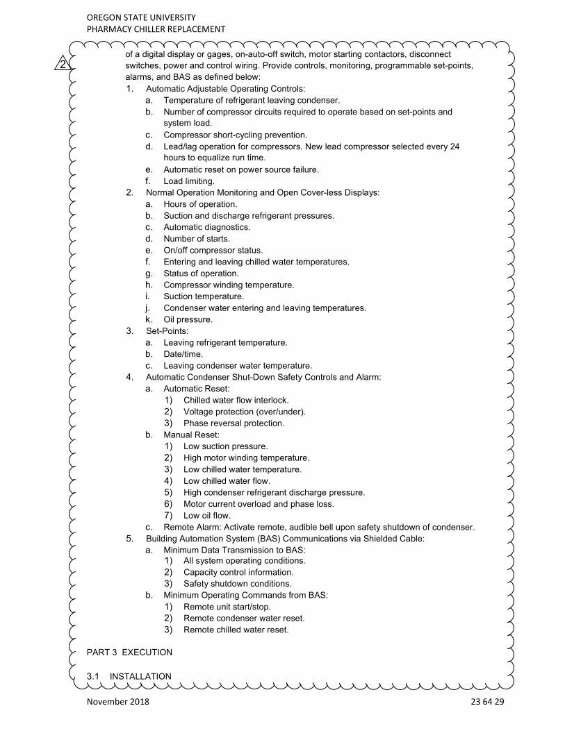
of a digital display or gages, on-auto-off switch, motor starting contactors, disconnect
switches, power and control wiring. Provide controls, monitoring, programmable set-points,
alarms, and BAS as defined below:
1. Automatic Adjustable Operating Controls:
a. Temperature of refrigerant leaving condenser.
b. Number of compressor circuits required to operate based on set-points and
system load.
c. Compressor short-cycling prevention.
d. Lead/lag operation for compressors. New lead compressor selected every 24
hours to equalize run time.
e. Automatic reset on power source failure.
f. Load limiting.
2. Normal Operation Monitoring and Open Cover-less Displays:
a. Hours of operation.
b. Suction and discharge refrigerant pressures.
c. Automatic diagnostics.
d. Number of starts.
e. On/off compressor status.
f. Entering and leaving chilled water temperatures.
g. Status of operation.
h. Compressor winding temperature.
i. Suction temperature.
j. Condenser water entering and leaving temperatures.
k. Oil pressure.
3. Set-Points:
a. Leaving refrigerant temperature.
b. Date/time.
c. Leaving condenser water temperature.
4. Automatic Condenser Shut-Down Safety Controls and Alarm:
a. Automatic Reset:
1) Chilled water flow interlock.
2) Voltage protection (over/under).
3) Phase reversal protection.
b. Manual Reset:
1) Low suction pressure.
2) High motor winding temperature.
3) Low chilled water temperature.
4) Low chilled water flow.
5) High condenser refrigerant discharge pressure.
6) Motor current overload and phase loss.
7) Low oil flow.
c. Remote Alarm: Activate remote, audible bell upon safety shutdown of condenser.
5. Building Automation System (BAS) Communications via Shielded Cable:
a. Minimum Data Transmission to BAS: 1) All system operating conditions.
2) Capacity control information.
3) Safety shutdown conditions.
b. Minimum Operating Commands from BAS:
1) Remote unit start/stop.
2) Remote condenser water reset.
3) Remote chilled water reset.
PART 3 EXECUTION
3.1 INSTALLATION
2
OREGON STATE UNIVERSITY
PHARMACY CHILLER REPLACEMENT
November 2018 23 64 29
A Install in accordance with manufacturer's instructions.
B Align condenser package on steel or concrete foundations.
C Install units on vibration isolators.
D Connect to electrical service.
E Connect to chilled water piping.
F Connect to condenser water piping.
G Arrange piping for easy dismantling to permit tube cleaning and removal.
3.2 MANUFACTURER'S FIELD SERVICES
A Perform factory startup of the condenser by factory trained and authorized servicing
technicians confirming equipment has been correctly installed prior to equipment becoming
operational and covered under the manufacturer's warranty.
B Supply initial charge of refrigerant and oil if not completely factory charged.
C Demonstrate system operations and verify specified performance.
END OF SECTION
2