construction kit "multicube" 48mc- - sch¤fter + kirchhoff gmbh
TRANSCRIPT

multicube™ – Components and Systems for the rugged and compact implementation of a wide range of different setups.

71
[email protected] www.SuKHamburg.com
multicube™ – Components and Systems
Construction Kit multicube™ 72
Combination Cubes and Plates 48MC 73
Optics for the multicube™ System 74
Accessories: Flanges, and Adapters 77
Accessories and Tools 78
Titanium Components - Amagnetic Multicube™ Elements 79
Faraday Isolators 82
Fiber-coupled Faraday Isolator 83
Laser Attenuators 48AT 84
Electro-Magnetic Shutter 85
Fiber-Optical Solutions 86

72
[email protected] www.SuKHamburg.com
05-2
018
E
Mul
ticub
e_ne
u.in
dd
• P
age
72
Mu
ltic
ub
e™ –
Co
mp
on
ents
an
d S
yste
ms
The major design features of the Schäfter+Kirchhoff multicube™ components ensure highly rugged and warp-resistant setups, especially for single-mode fiber coupling. The multicubes™ are combined and fixed using four Ø 6 mm rods in parallel and are compatible with established microbench systems. The multicube™ construction system is the perfect integration platform for laser beam couplers, beam combiners, beam splitters, polarizers or retardation optics. Self-supporting modules and laser beam assemblies can be created that are extremely resistant to torsion and contain complementary components, such as the laser diode collimator 48TA and Faraday iso lator 48FI on the mounting bracket 48MB.
The multicube™ system is compatible with the established cage system and the microbench system
Applications: see the laser diode beam sources 48TE, and fiber port clusters for magneto-optical traps (MOTs) on page 90.
Construction Kit multicube™ Series 48MCcompatible with established cage and microbench systems
Implementation of an essentially limitless range of setups: Examples
Fiber Port Cluster: 2 6
This unit splits the radiation from two polarization-maintaining (PM) fibers into 6 output polarization-maintaining fiber cables with high efficiency and variable splitting ratio.
The beam delivery system uses the compact, modular opto-mechanic units of the multicube system.
The modularity ensures that almost any desired system can be assembled that is compact and sealed.
For more details see page 91.
Fiber Port Cluster: 1 4
This unit splits the radiation from one polarization-maintaining (PM) fiber into 4 output polarization-maintaining fiber cables with high efficiency and variable splitting ratio.
For more details see page 92.
Fully assembled and pre-aligned(fibers not shown)
Schematic drawing of optics components used
Schematic drawing of optics and mechanical components

73
[email protected] www.SuKHamburg.com
05-2
018
E
Mul
ticub
e_ne
u.in
dd
• P
age
73
Mu
ltic
ub
e™ –
Co
mp
on
ents
an
d S
yste
ms
Combination Cubes and Plates 48MCcompatible with established cage and microbench systems
Order Code
48AT-A
Order Code
48MC-LT-19.5
Double-Cube with through-holes for linear arrangements
Mechanical Attenuatorwith fine thread, aperture Ø 3 mm, system mount Ø 19.5 mm
Double-T-Cubefor T-arrangements
Order Code
48MC-LTD-19.5
Order Code
48MB-19.5-150
Order Code
48MC-CL-19.5
Single-X-Cubefor X-arrangements
Triple-X-Cubefor X-arrangements
Single-Cubewith through-holes for linear arrangements, short design
Mounting Platefor mounting Ø 19.5, 25 or 32 mm system components
Extended Mounting Plate for mounting Ø 19.5 or 25 mm system components
Mechanical Shutteraperture Ø 3 mmsystem mount Ø 19.5 mm
Order Code
48MC-SM-19.5
Order Code
48MC-MP-19.5 48MC-MP-25 48MC-MP-32
Single-T-Cubefor T-arrangements
Order Code
48MC-LTS-19.5
Order Code
48AT-S
Order Code
48MC-SP-19.5 48MC-SP-25
Extended Mounting Bracket 150 x 60 mm or 60 x 60 mm, system mount Ø 19.5 mm
Dimensions
Dimensions
Dimensions
Order Code
48MC-LI-19.5
Order Code
48MB-19.5-SXY-1
x/y Adjustment platefor lateral adjustment, translation 1 mm
8
Order Code
48MB-19.5-150

74
[email protected] www.SuKHamburg.com
05-2
018
E
Mul
ticub
e_ne
u.in
dd
• P
age
74
Mu
ltic
ub
e™ –
Co
mp
on
ents
an
d S
yste
ms
Optics for the multicube™ System
Beam-splitting cube with internal dielectric and polarizing multilayer coating. Adjustable mount, for mounting with clamp collar (included).50:50 split ratio for linearly polarized input radiation with polarization direction = 45°. Maximum transmission at = 0° ( p-pol.) with maximum reflection at = 90° (s-pol.).
Polarization Beam Splitters 48PM-CC
Beam Splitter Cubes 50/50 48BM-CC
Spectral range [nm]A = 450 - 700 nmB = 750 - 1100 nmC = 1100 - 1700 nm
48BM - CC - AOrder Code
With adjustable mount, for mounting with clamp collar (included).
Spectral range [nm]A = 450 - 700 nmB = 750 - 1100 nmC = 1100 - 1700 nmW= 450 - 1000 nm
48PM - CC - AOrder Code
Order Options for Polarization Beam Splitters
Application: Beam splitter with adjus table splitting ratio, in combination with retardation optics 48WP-CA
Beam Splitter and Beam Combiner, Polarizer, Retardation Optics
• Extinction ratio 10 000 : 1• Clear aperture 6 mm • Reflection angle 90°• Broadband AR coating R < 0.5 % per surface
With adjustable mount, for mounting with clamp collar (included).
Beam Splitters 98/2 48BS-CC-A
Beam Splitters 99/1 (10/90) 48BS-CC-B
48BS - CC - AOrder Code
Order Options for Beam Splitters 98/2
48BS - CC - BOrder Code
Order Options for Beam Splitters 99/1 (10/90)
Application: Separation of a partial beam for power monitoring
• 1 mm fused silica plate, uncoated• 0.3° wedge angle for interference suppression• Transmission 98 % ( p-polarization)• Reflection 1 % per surface ( p-polarization)• Clear aperture 10 mm
• 1 mm fused silica plate, rear side coated (AR 400 - 700 nm)• 0.3° wedge angle for interference suppression• Reflection 1 %, transmission 99 % ( p-polarization)• Reflection 10 %, transmission 90 % ( s-polarization)• Clear aperture 10 mm
Order Options for Beam Splitter Cubes 50/50 48BM-CC
In adjustable mount, for mounting with clamp collar (included).

75
[email protected] www.SuKHamburg.com
05-2
018
E
Mul
ticub
e_ne
u.in
dd
• P
age
75
Edge wavelength [nm]
48BC - CC - LP xxxOrder Code
Order Options for Beam Combiner 48BC-CC-LP
Reflection long pass Transmission Pol.LP436 370 - 412 460 - 700 sLP510 405 - 488 532 - 660 sLP570 532 - 544 594 - 660 sLP580 500 - 560 600 - 700 pLP725 500 - 560 780 - 2100 pLP800 630 - 780 820 - 880 s
Reflection short passSP1500 1650 - 1700 1200 - 1380 p
• 1mm fused silica plate with wavelength dependent dielectric coating and 0.3° wedge angle for interference suppression
• Long pass (LP) and short pass (SP) version• Optimized for angle of incidence 45°, p-polarization• Fused silica plate • AR Coated reverse surface• Clear aperture 10 mm • Reflection up to 99 %, transmission up to 95 %
For a complete, fiber-coupled RGBV-Beam Combiner, see page 92.
Application:
For increasing the ex tinction ratio after collimating the radiation of a polarization-main taining fiber
Beam splitter and beam combiner with wedge-shaped substrate:
Substrate without wedge: Substrate with wedge: Mu
ltic
ub
e™ –
Co
mp
on
ents
an
d S
yste
ms
Beam Combiners 48BC-CC-LP
Application: For the coincident coupling of laser diode beam sources of different wave lengths and identical polarization into one single-mode fiber
Two laser beams of different wavelengths are coaxially combined into a single laser beam with equal polarization. In adjustable mount, for mounting with clamp collar (included).
• Adjustable within adapter flange• Polarization: linear • Extinction ratio 10 000 : 1• Clear aperture 3.5 mm• Broadband AR coating: R < 0.5 % per surface• Variety of designs
Polarizers 48PM
Spectral rangeA = 450 – 700 nmB = 750 – 1100 nmC = 1100 – 1700 nmW= 450 – 1000 nm
48PM - S - AOrder Code
Order Options for Polarizer 48PM
Option S (standard) A S-D (decentered) B SXY1 (xy adjustment) AT-19.5AC (with attenuator) C
Polarizerin adapter flange as 48MB-19.5AC
Order Code
48MC-LI-19.5
Polarizer as 48PM-S decentered 0.3 mm for combining with beam splitter plate 48BS
Order Code
48PM-S-D
Polarizer with attenuator in adapter flange 48AT-19.5AC-S1
Order Code
48PM-AT-19.5AC
Beams are reflected twice at the media/air interfaces. The reflected beam is finally parallel with the unreflected beam. Both beams inter-fere, which causes intensity instabilites (Etalon effect). If they are coupled into a fiber, they are both focused onto the same spot and are both coupled.The intensity is not stable due to the interference of the beams.
The original beam and the twice reflected beam are not parallel but inclined after passing the substrate with wedge. After focusing that results in two distinct laser spots. Only the unreflected beam overlaps with the mode field of the fiber and the reflected radiation is lost. The removal of inter ference prevents intensity instabilities.
76
[email protected] www.SuKHamburg.com
05-2
018
E
Mul
ticub
e_ne
u.in
dd
• P
age
76
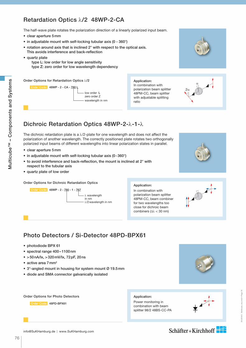
The half-wave plate rotates the polarization direction of a linearly polarized input beam.
• clear aperture 5 mm
• in adjustable mount with self-locking tubular axis (0 - 360°)
• rotation around axis that is inclined 2° with respect to the optical axis. This avoids interference and back-reflection
• quartz platetype L: low order for low angle sensitivitytype Z: zero order for low wavelength dependency
The dichroic retardation plate is a /2-plate for one wavelength and does not affect the polarization of another wavelength. The correctly positioned plate rotates two ortho gonally polarized input beams of different wave lengths into linear polarization states in parallel.
Retardation Optics /2 48WP-2-CA
Dichroic Retardation Optics 48WP-2- -1-
Photo Detectors / Si-Detector 48PD-BPX61
Application: In combination with polarization beam splitter 48PM-CC, beam splitter with adjus table splitting ratio
Application:
In combination with polari zation beam splitter 48PM-CC, beam combiner for two wavelengths too close for dichroic beam combiners ( < 30 nm)
Application:
Power monitoring in combination with beam splitter 98/2 48BS-CC-PA
• clear aperture 5 mm
• in adjustable mount with self-locking tubular axis (0 - 360°)
• to avoid interference and back-reflection, the mount is inclined at 2° with respect to the tubular axis
• quartz plate of low order
• photodiode BPX 61
• spectral range 400 – 1100 nm
• > 50 nA/lx, > 320 mV/lx, 72 pF, 20 ns
• active area 7 mm2
• 3°-angled mount in housing for system mount Ø 19.5 mm
• diode and SMA connector galvanically isolated
248WP - 2 - CA - 780 LOrder Code
Order Options for Retardation Optics /2
low order Lzero order Z wavelength in nm
48WP - 2 - 780 - 1 - 767Order Code
Order Options for Dichroic Retardation Optics
wavelength in nm/2 wavelength in nm
48PD-BPX61Order Code
Order Options for Photo Detectors
2
Mu
ltic
ub
e™ –
Co
mp
on
ents
an
d S
yste
ms

77
[email protected] www.SuKHamburg.com
05-2
018
E
Mul
ticub
e_ne
u.in
dd
• P
age
77
Schäfter+Kirchhoff offers numerous adapters and flanges suitable for incorporation into the multicube™ system. All standard adapters and flanges have Ø 19.5 mm system mount with a 19.5 mm tightly fitting cylinder. Some can be mounted using flange mounting.
Mu
ltic
ub
e™ –
Co
mp
on
ents
an
d S
yste
ms
Accessories: Flanges and Adapters for System Mount Ø 19.5 mm
Adapter Flange with AttenuatorClear aperture: Ø 3 mm; Ø 19.5 mm system mount
Adapter for Ø 25 mm or Ø 25.4 mm mounted Optics
Tube with Ø 19.5 mm both ends
Order Code
48AT-19.5-S1
Order Code
19.5AF25.4-S
Order Code
48T-19.5
Representative selection. For more please contact Schäfter+Kirchhoff.
Adapter Flange for com ponents with Ø 8 mm for fitting to Ø 19.5 mm system mount
Order Code
48MB-19.5 A
Adapter Flange for components with Ø 8 mm to Ø 19.5 mm, decentered 0.3 mm
Order Code
48MB-19.5AC-D
thAdfor
Ø19
.5
Ø20
.5
0.3Ø
19.5
Ø25
Ø11
8 25.420.5
2.4
12.5Ø
25
Ø19
.5
Ø12
.5
Ø2.4
Ø19
.5
Ø12
.5 H
9
620.5
25.4
5.5
M27
x0.7
5
Ø25
.5
Ø15
Ø19
.5
Ø35
17.9
1.5
22.5
165.5
Ø19
.5
Ø19
.5
Ø25
M17
x0.7
5
20.5
1712
.7
25.4
Ø19
.5
Ø19
.5
5.8
2115
CapFor Ø 19.5 mm system mounting
Order Code
48C-19.5
Ø22
Ø19
.5
Ø23
7
5.5
Adapter for attaching Optics with Ø 8 mm toØ 19.5 mm for attaching e.g. 5M or 5PF
Adapter for Micros cope LensesAdapter for Ø 19.5 mm to W0.8"x1/36" male
Order Code
W0.8-19.5
Adapter for Microscope Lenses Ø 19.5 mm to W0.8"x1/36" female
Order Code
W0.8-I-19.5
for
M20
.25x
0.70
55
[0.8
0"]/
36G
Ø15
Ø19
.5
10.5
4
M20
.25x
0.70
55
[0.8
0"]/
36G
13.5
5.5
6
Ø15
Ø19
.5
Order Code
8AM-19.5
Ø23 Ø8
Ø19
.5
9.55.5
Light Trapfor absorbing unused beams
Order Code
48LT-19.5
25
23,5
Ø25
Ø22 Ø6
Ø19
,5
IrisAperture Ø 1 - 13 mm
IrisAperture Ø 0 - 12 mm
Order Code
13BL1-13
re
11.5
6
Ø25
Ø19
.5
Order Code
13BL0-12
Spacer with Ø 19.5 mm both ends
Order Code
48S-19.5
11
5.5
Ø19
.5
Ø19
.5Ø
22
Adapter Both ends with Ø 19.5 mm, male/female
Order Code
AC19.5/19.5-S
Ø25
Ø19
.5
Ø19
.5
13
6
5.5
Shutter Clear Aperture 5 mm, both ends with Ø 19.5 mm male/female,
Order Code
13S-5-1
Adapter C-mountAdapter for Ø 25 mm to C-mount
Order Code
C-mount-25
11
5
C-M
ount
[1"-
32G
ang]
Ø19
.5
Ø25
18 5.5
Ø25
h8
Ø19
.5
Ø19
.5 h
8
6
Adapter C-mountAdapter for Ø 19.5 mm to C-mount
Order Code
C-mount-19.5AC
C-M
ount
[1"-
32G
ang]
Ø14
Ø19
,5
11.5
5
er
Adapter for adapting Ø 12 mm components for Ø 19.5 mm mounting
Adapter for adaptingØ 25 mm components for Ø 19.5 mm mounting
Adapter Both ends with Ø 19.5 mm mount and v-groove
er for adapting
Order Code
12AM19.5
Order Code
19.5AC-25
Order Code
19.5AC19.5
Ø25
Ø12
Ø19
,5
14
Ø25
Ø20
Ø15
.5
Ø19
.5
12
5.5
Ø19
.5
Ø19
.5
Ø14
12
5.5
er

78
[email protected] www.SuKHamburg.com
05-2
018
E
Mul
ticub
e_ne
u.in
dd
• P
age
78
Accessories and Tools for Assembly and Adjustment
Mu
ltic
ub
e™ –
Co
mp
on
ents
an
d S
yste
ms
Accessories
Hex screw DIN 912 M2 x 8 for mounting Ø 19.5 mm componentsusing a clamp collar - set of 20/50 pcs.
Order Code
48-M2-8-912-20 48-M2-8-912-50
Hex Screwdriver Order Code
50HD-15
Grub screw DIN 551 M1.6 x 1.5 for fixing fiber ferrules to 60FC-... and 60SMS - set of 20/50 pcs.
Order Code
48-M1.6-1.5-551-2048-M1.6-1.5-551-50
Screwdriver Order Code
9D-12
Grub screw DIN 553 M1.6 x 1.5-conical for mounting Ø 8 mm com-ponents with v-groove - set of 20/50 pcs.
Order Code
48-M1.6-1.5-553-2048-M1.6-1.5-553-50
Screwdriver Order Code
9D-12
Rod for combining multicubes™
Order Code
48MC-6-L
L = 30L = 75L = 150xxx = length of choice
Hex grub screw DIN 914 M3x3-conical for mounting Ø 19.5 mm components with v-groove - set of 20/50 pcs.
Order Code
48-M3-3-914-2048-M3-3-914-50
Hex Screwdriver Order Code
50HD-15
Hex grub screw DIN 913 M3x3-flat for fixing rods to multicubes™ - set of 20/50 pcs.
Order Code
48-M3-3-913-2048-M3-3-913-50
Hex ScrewdriverOrder Code
50HD-15
LL
Tools for Assembly and Adjustment
Eccentric tool for laser beam couplers 60SMS and fiber collimators 60FC
Order Code
60EX-4
60EX-5 for focal length f’ 20 mm
Screwdriver WS 1.2 mm for grub screw in fiber ferrules and accessories 5M
Order Code
9D-12
Eccentric tool for fiber collimators 60FC-T and 60FC-Q...
Order Code
55EX-5
Hex screwdriver WS 1.5 mm for screwsDIN 912, 913, and 914
Order Code
50HD-15
Adjustment tool for rotating quarter-waveplates in fiber collimators 60FC-Q...
Order Code
60Z-2803
Eccentric tool with longer handle for laser beam couplers 60SMS-... and fiber collimators 60FC-... as an alternative to 60EX-4, 60EX-5, 55EX-5 above
Order Code
60EX-4-L
60EX-5-L 55EX-5-L

79
[email protected] www.SuKHamburg.com
05-2
018
E
Mul
ticub
e_ne
u.in
dd
• P
age
79
Single-Cubewith through-holes for linear arrangements, short design
Mounting Platefor mounting Ø 19.5 or 25 mm system components
Extended Mounting Plate for mounting Ø 19.5 or 25 mm system components
Order Code
48MC-SM-19.5-Ti
Order Code
48MC-MP-19.5-Ti48MC-MP-25-Ti
Single-T-Cubefor T-arrangements
Order Code
48MC-LTS-19.5-Ti
Order Code
48MC-SP-19.5-Ti48MC-SP-25-Ti
Dimensions
Dimensions
Double-T-Cubefor T-arrangements
Order Code
48MC-LT-19.5-Ti
Order Code
48MC-LTD-19.5-Ti
Order Code
48MC-CL-19.5-Ti
Single-X-Cubefor X-arrangements
Triple-X-Cubefor X-arrangements
Titanium Combination Cubes and Plates 48MC-…-TiAmagnetic versions of the standard multicube™ components
Besides 60SMS laser beam couplers and 60FC fiber collimators some standard multicube components are availabe made of titanium.
The main advantage of these is a coefficient of thermal expansion CTE of titanium more close to that of glass compared the CTE of aluminum.
This provides even more stable multicube systems that can be used in hard environments.
Mu
ltic
ub
e™ –
Co
mp
on
ents
an
d S
yste
ms

80
[email protected] www.SuKHamburg.com
05-2
018
E
Mul
ticub
e_ne
u.in
dd
• P
age
80
Titanium Optics Mounts for the multicube™ System
50:50 split ratio for linearly polarized input radiation with polarization direction = 45°. Maximum transmission at = 0° ( p-pol.) with maximum reflection at = 90° (s-pol.).• extinction ratio 10,000 : 1• clear aperture 6 mm • reflection angle 90°• broadband AR coating R < 0.5% per surface
Polarization Beam Splitters 48PM-CC...-Ti
Beam Splitter Cubes 50/50 48BM-CC...-Ti
Spectral range [nm]A = 450 - 700 nmB = 750 - 1100 nmC = 1100 - 1700 nm
48BM - CC - A - TiOrder Code
• 50:50 split ratio• independent of polarization• aperture 6 mm• reflection angle 90°• broadband AR coating per surface
Amagnetic version of Standard Beam Splitter and Beam Combiner, Polarizer, Retardation Optics
Beam-splitting cube with internal dielectric and polarizing multilayer coating. In adjustable mount, for mounting with clamp collar (included).
Order Options for Beam Splitter Cube 50/50 48BM-CC
Spectral range [nm]A = 450 - 700 nmB = 750 - 1100 nmC = 1100 - 1700 nmW= 450 - 1000 nm
48PM - CC - A - TiOrder Code
Order Options for Polarization Beam Splitter
Beam splitter with adjus table splitting ratio, in combination with retardation optics 48WP-CA
Application
Beam Splitter Cube 50/50 48BM-CC...-Ti
Mu
ltic
ub
e™ –
Co
mp
on
ents
an
d S
yste
ms

81
[email protected] www.SuKHamburg.com
05-2
018
E
Mul
ticub
e_ne
u.in
dd
• P
age
81
Reflection long pass Transmission Pol.
LP436 370 - 412 460 - 700 sLP510 405 - 488 532 - 660 sLP570 532 - 544 594 - 660 sLP580 500 - 560 600 - 700 pLP725 500 - 560 780 - 2100 pLP800 630 - 780 820 - 880 s
Reflection short pass Transmission Pol.
SP1500 1650 - 1700 1200 - 1380 p
Beam Combiners 48BC-CC-LP...-Ti
Two laser beams of different wavelengths are coaxially combined into a single laser beam with equal polarization.
• 1mm fused silica plate with wavelength dependent dielectric coating and 0.3° wedge angle for interference suppression
• long pass (LP) and short pass (SP) version• optimized for angle of incidence 45°, p-polarization• fused silica plate • coated reverse surface• clear aperture 10 mm • reflection up to 99%, transmission up to 95%
Edge wavelength [nm]
48BC - CC - LP xxx - TiOrder Code
Order Options for Beam Combiners 48BC-CC-LP
In adjustable mount, for mounting with clamp collar (included).
In adjustable mount, for mounting with clamp collar (included).
Beam Splitters 98/2 48BS-CC-A-Ti
Beam Splitters 99/1 (10/90) 48BS-CC-B-Ti
48BS - CC - A - TiOrder Code
Order Options for Beam Splitters 98/2
48BS - CC - B - TiOrder Code
Order Options for Beam Splitters 99/1 (10/90)
• 1 mm fused silica plate, uncoated• 0.3° wedge angle for interference suppression• transmission 98% (p-polarization)• reflection 1% per surface (p-polarization)• clear aperture 10 mm
• 1 mm fused silica plate, back side coated (AR 400-700 nm)
• 0.3° wedge angle for interference suppression• reflection 1%, transmission 99% ( p-polarization)• reflection 10%, transmission 90% (s-polarization)• clear aperture 10 mm
In adjustable mount, for mounting with clamp collar (included).
Separation of a partial beam for power monitoring
Application:
For the coincident coupling of laser diode beam sources of different wave lengths and identical polarization into one single-mode fiber
Application
Mu
ltic
ub
e™ –
Co
mp
on
ents
an
d S
yste
ms
82
[email protected] www.SuKHamburg.com
05-2
018
E
Far
aday
Iso
lato
r_F
iber
op
tics.
ind
d •
Pag
e 82
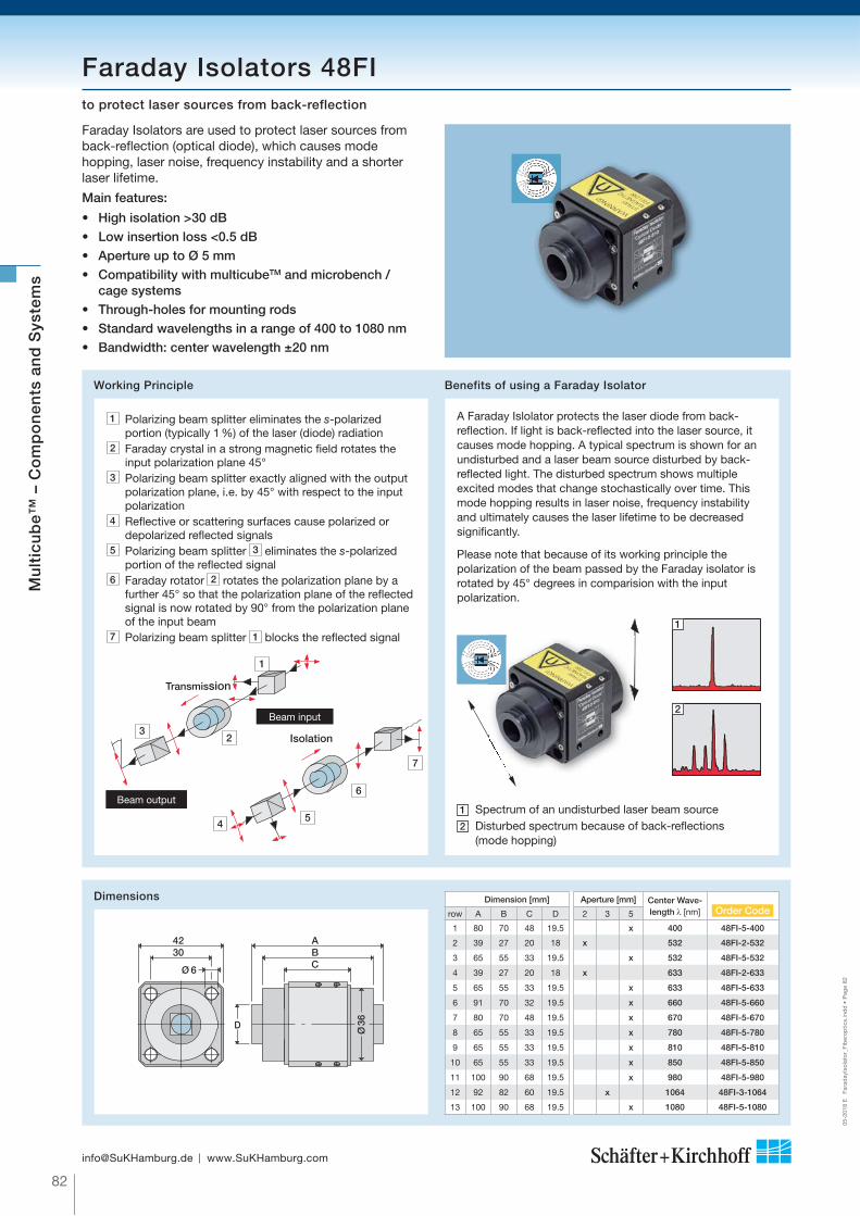
Faraday Isolators are used to protect laser sources from back-reflection (optical diode), which causes mode hopping, laser noise, frequency instability and a shorter laser lifetime.
Main features:
• High isolation >30 dB• Low insertion loss <0.5 dB • Aperture up to Ø 5 mm• Compatibility with multicubeTM and microbench /
cage systems• Through-holes for mounting rods• Standard wavelengths in a range of 400 to 1080 nm• Bandwidth: center wavelength ±20 nm
Faraday Isolators 48FIto protect laser sources from back-reflection
Dimensions Dimension [mm] Aperture [mm] Center Wave-length [nm] Order Coderow A B C D 2 3 5
1 80 70 48 19.5 x 400 48FI-5-400
2 39 27 20 18 x 532 48FI-2-532
3 65 55 33 19.5 x 532 48FI-5-532
4 39 27 20 18 x 633 48FI-2-633
5 65 55 33 19.5 x 633 48FI-5-633
6 91 70 32 19.5 x 660 48FI-5-660
7 80 70 48 19.5 x 670 48FI-5-670
8 65 55 33 19.5 x 780 48FI-5-780
9 65 55 33 19.5 x 810 48FI-5-810
10 65 55 33 19.5 x 850 48FI-5-850
11 100 90 68 19.5 x 980 48FI-5-980
12 92 82 60 19.5 x 1064 48FI-3-1064
13 100 90 68 19.5 x 1080 48FI-5-1080
Working Principle Benefits of using a Faraday Isolator
1 Polarizing beam splitter eliminates the s-polarized portion (typically 1 %) of the laser (diode) radiation
2 Faraday crystal in a strong magnetic field rotates the input polarization plane 45°
3 Polarizing beam splitter exactly aligned with the output polarization plane, i.e. by 45° with respect to the input polarization
4 Reflective or scattering surfaces cause polarized or depolarized reflected signals
5 Polarizing beam splitter 3 eliminates the s-polarized portion of the reflected signal
6 Faraday rotator 2 rotates the polarization plane by a further 45° so that the polarization plane of the reflected signal is now rotated by 90° from the polari zation plane of the input beam
7 Polarizing beam splitter 1 blocks the reflected signal
A Faraday Islolator protects the laser diode from back-reflection. If light is back-reflected into the laser source, it causes mode hopping. A typical spectrum is shown for an undisturbed and a laser beam source disturbed by back-reflected light. The disturbed spectrum shows multiple excited modes that change stochastically over time. This mode hopping results in laser noise, frequency instability and ultimately causes the laser lifetime to be decreased significantly.
Please note that because of its working principle the polarization of the beam passed by the Faraday isolator is rotated by 45° degrees in comparision with the input polarization.
1
2
1 Spectrum of an undisturbed laser beam source 2 Disturbed spectrum because of back-reflections
(mode hopping)
4230
ABC
Ø36D
Ø 6
4
Isolation
7
6
5
Beam input
Beam output
Transmission
32
1
Mu
ltic
ub
e™ –
Co
mp
on
ents
an
d S
yste
ms

83
[email protected] www.SuKHamburg.com
05-2
018
E
Far
aday
Iso
lato
r_F
iber
op
tics.
ind
d •
Pag
e 83
Mu
ltic
ub
e™ –
Co
mp
on
ents
an
d S
yste
ms
Application: Fiber-coupled Faraday Isolators
5
1
Set-up
Pos. Description Order Code Explanation
1Laser beam coupler
60SMS-1-4-for out and for in-coupling,adjustable
2Faraday isolator
48FI-avoids back-coupling of laser radiation into the fiber
3Attenuator/Shutter
48AT-A/ 48AT-SOption: Attenuator or shutter mechanism
4 Console 48MB-19.5-60
5Mounting Plate
48MC-MP-19.5
The fiber-to-fiber couplers with Faraday isolator from Schäfter+Kirchhoff supresse back-reflection and also offer - as an option - attenuator and shutter functio nalities.
A fiber-to-fiber coupler with Faraday isolator is used to protect laser beam sources where the attached fiber connectors cannot be removed (e.g. a fiber pigtail) or when back-coupling to the fiber is a desirable and discriminating characteristic (e.g. in interferometry).
They are used in combination with polarization-maintaining fiber cables.
1 13 2
Optical Schemeheheme
2
3 4

84
[email protected] www.SuKHamburg.com
05-2
018
E
Far
aday
Iso
lato
r_F
iber
op
tics.
ind
d •
Pag
e 84Motor drive
48AT-F with monitor diode 48AT-MD with motorized drive
Laser Attenuators 48AT are used for reproducible and precise reduction of the power output by the laser. The collimated laser beam is constricted by a precision ball transported by a scaled micrometer screw. The sub sequent single-mode fiber coupling is used as a mode filter.This mechanically stable attenuation method allows the precise and reproducible setting of the laser power output over a wide range (typically 0.5 to > 60 dB). Unlike a power regulation by modulation of the laser current, the wave-length and polarization status of the laser beam are preserved.• Reproducible power attenuation and safety constraints
are only assured for singlemode fibers that have a Gaussian intensity profile
Laser Attenuators 48ATfor reduction of output power
The 48AT-MD motorized laser attenuators are identical with the manual 48AT-0 laser attenuators in all respects, except for the replacement of the manual micrometer screw by a motorized version.
The additional parameters for the motorization are:• Closed-loop DC motors• Min. incremental motion down to 0.05 μm• Max. velocity 2 mm/s• Limit switch control• Controllable via USB and RS-232 interface• Macro-programmable stand-alone functionality• Additional I/O ports• DLLs and LabVIEW driver • User software
1% partial beam separation for power monitoring
Photo diodeode
Order Code 48 AT - F
For order code details see 48AT-0
LaserOUT
LaserIN
LaserIN
Configurations
Order Code 48 AT-MD
For order code details see 48AT-0
• Fiber collimator and laser beam coupler with inclined or coaxial coupling axis for single-mode fibers with FC-APC or FC-PC connector
• Insertion loss typically 0.5 dB, extinction > 60 dB• Can be used as interface between different types of fiber or connector
Input: Laser Beam Coupler 60SMS
Receptacle forFC-PC connector = 0FC-APC connector = 4(inclined coupling axis)
Assortment of Laser Beam Couplers 60SMS, see page 17
48 AT-0-SMS-1- 4 - A11 - 02 + SMS- 1- 4 - A11 - 02 Order Code
Output: Laser beam coupler 60SMSCoupling lens
Connection for 0 = FC-PC connector4 = FC-APC connector(inclined coupling axis)
Collimating lens
Order options for Laser attenuator 48AT
Mu
ltic
ub
e™ –
Co
mp
on
ents
an
d S
yste
ms
Typical calibration curves
RelativePower Output
7 8 9 10Micrometer Position (mm)
1
0,6
0,4
0,2
0
0,8-20
-40
-607 8 9 10
Micrometer Position (mm)
Attenuation in dB
0

85
[email protected] www.SuKHamburg.com
05-2
018
E
Shu
tter
_Fib
ero
ptic
s.in
dd
• P
age
85
Optical Scheme
10 9
8
4 1
36 5 2
Optical SScheme
Main features:
• Bistable shutter • No power consumption in OFF position• Internal, external, automatic or manual trigger mode• USB 2.0 and RS232 interface
Electromagnetic Shutters EMS-3-30 + SK97120 System mount Ø 19.5 mm, compatible with multicube™ system
Electrical scheme
Dimensions
Please note:
This shutter is bistable and so does NOT conform with the laser safety rules IEC 60825-1.
Shutter head: Order Code EMS-3-30
Controller with power supply, driver and control software: Order Code SK97120
multicube™ with shock absorbers:
Order Code 48MC-SM-19.5-SM
Order Options
Application: HeNe Lasers with Electromagnetic Shutter
Components1 HeNe laser 632.8 nm
2 Laser power supply
3 Mounting bracket MC-MG-C-44.5-F-R
4 Electrical shutter EMS-3-30
5 Shutter controller SK97120
6 Shutter power supply
7 multicube™ with shock absorbers 48MC-SM-19.5-SM
8 Attenuator 60A19.5-F-AT
9 Laser beam coupler 60SMS
10 Fiber cable SMC-630 / PMC-630
Upon activation, HeNe lasers require several minutes to reach a stable state of radia tion. To circumvent this latency, it is advantageous to use a shutter to block the beam, rather than subjecting the laser to a series of on-off cycles. In the present application, a shutter is mounted in a multicube™ immediately in front of the laser, with shock absorbers preventing any vibration caused by the shutter operation.
The power of the laser radiation can be reproducibly modulated with the attenuator 60A19.5-F-AT.
Subsequently, the beam is coupled using a highly efficient beam coupler into a single-mode SMC or a polarization- maintaining single-mode PMC fiber.
Mu
ltic
ub
e™ –
Co
mp
on
ents
an
d S
yste
ms

86
[email protected] www.SuKHamburg.com
05-2
018
E
Shu
tter
_Fib
ero
ptic
s.in
dd
• P
age
86
Mu
ltic
ub
e™ –
Co
mp
on
ents
an
d S
yste
ms
Single laser pulses from a Mira Optima 900-P laser with Verdi V5 pump, emitting picosecond pulses at a repetition rate of 76 MHz, are selected by an acousto-optical pulse selector. Opto-mechanics and fiber optic components from Schäfter+Kirchhoff are used to couple the beam to a polarization-maintaining optical fiber cable.
Laser back-reflections are prevented by use of a Faraday isolator. The fiber coup ling is solidly mounted on an adjustable 4-axis translational and rotational stage.
Application: Single-Mode Fiber Coupling of a Picosecond Pulse Laser System
Fiber-Optical Solutions using the multicube™ system
Sensitive laser systems must be protected against back-reflections of the laser light. Schäfter+Kirchhoff can couple single-mode and polarization-maintaining fibers to a customer laser source and integrate a Faraday isolator to prevent laser feedback.
A complete system could have additional power monitors, as shown. To guarantee the highest coupling efficiencies, different kinds of beam- shaping optics can be used, e.g. beam expansion.
Application: Fiber Coupling with Beam Shaping and Feedback Protection
1064 nm
532 nm
ABCDE
Optical Scheme
A Innolight Prometheus B Beam expansion 48EOC Faraday isolator 48FID Laser beam coupler 60SMSE Polarization-maintaining single-mode
fiber cable PMC
A Mira Optima 900-P picosecond laserB Acousto-optical pulse picker C Faraday Isolator 48FI-5-830 D Laser beam coupler 60SMSE Polarization-maintaining single-mode fiber cable PMCF /2 Plate 48WP
Optical Scheme
Pulse PickerMira Optima PS-Laser Source
VerdiPump Laser
ABCFDE

87
[email protected] www.SuKHamburg.com
05-2
018
E
Shu
tter
_Fib
ero
ptic
s.in
dd
• P
age
87
Fiber-Optical Solutions using the multicube™ system
Optically pumped laser system consisting of:A High Power Optically Pumped Semiconductor Laser
(OPSL) type COHERENT Genesis MX, 488 nm.B Fiber coupling from Schäfter+Kirchhoff.
- Optical power 650 mW ex fiber - Single-mode - Polarization extinction ratio 23 dB.
To guarantee the highest long-term stability, the fiber-coupling system is completely enclosed in a protective housing. A fiber cable feedthrough acts as additional strain relief for the fiber cable.
Application: Fiber coupling of a COHERENT Genesis MX-Series
A
B
A
BB
Single-mode, Polarization-maintaining
Mu
ltic
ub
e™ –
Co
mp
on
ents
an
d S
yste
ms
RMR-LIDAR (Rayleigh-Mie-Raman Light Detection and Ranging) is used by the ALOMAR (Arctic LIDAR Observatory for Meso-Atmospheric Research) facility in Norway for measuring the temperature and wind velocity in high altitudes.
Laser radiation from two pulsed power lasers is directed into the atmosphere. The radiation scattered back by aerosols (due to Rayleigh, Mie or Raman scattering) is collected by two 1.8 m terrestrial telescopes.
A frequency-stabilized seed laser is used to meet the strin-gent experimental restrictions for pulse length and spectral stability. The power lasers are alternately seeded, pulse-by-pulse, using two EOMs. The demanding specifications of the seeding process require the power lasers to emit extremely short pulses (~12 ns) of high spectral stability at a repetitive rate of 30 Hz.
Application: Triggered Laser-Seeding for LIDARfor measuring the temperature and wind velocity in high altitudes.
©A
LOM
AR
Obs
.
© Leibnitz Institute for Atmospheric Physics,
Kühlungsborn, Germany
All are assembled using Schäfter+Kirchhoff components and polariz ation-maintaining opti cal fibers around our proprietary multicube™ system. This robust, adaptable and modular system is a major improvement on conven tional, but bulky, optical breadboards.
A 532 nm / 1064 nm seeding laser A , iodine reference cell B and the electro-optical mo dulator units C are connected by the fiber port cluster D , which combines and distributes the laser beams.
A B
D C
C