construction manual for the great lakes region stabilised...
TRANSCRIPT

Construction Manualfor the Great Lakes Region
Stabilised Compressed Earth Blocks - SCEB


7. CONTENTS - 1
1. INTRODUCTION .............................................3
2. FOUNDATION .............................................4
3. BASE WALL .............................................6 Materials .....................................................6 Height .....................................................7 Capillary barrier .....................................................8
4. WALL - BLOCK WORK .............................................94.1. Block coursing ...................................................10 Block coursing example ...................................................11 Horizontal Coursing principles .......................................12 Vertical Coursing principles ...................................................154.2. Bonding patterns ...................................................16 Main block sizes ...................................................16 Straight walls ...................................................18 L-shape ...................................................19 T-shape ...................................................20 X-shape ...................................................22 Pillars ...................................................24 Buresses ...................................................254.3. Implementation ...................................................27
Mortar ...................................................27 Block laying ...................................................28 Pointing ...................................................32

5. OPENNINGS ...........................................335.1. Dimensions ...................................................345.2. Lintels ...................................................355.3. Sill wall ...................................................375.4. Joineries ...................................................39
6. RING-BEAM ...........................................43 Cast in situ concrete ...................................................44 U-shape bricks ...................................................45
7. ROOF / WALL BOND ...........................................467.1. Roof anchorage ...................................................46 External roof anchorage ...................................................47 Hidden anchorage ...................................................487.2. Gable wall ...................................................507.3. Terminating wall in CEB ...................................................51
7.3. Terminating wall in CEB
The batten distributing the load of the trusses is positioned on the inner side of the wall and also serves as a support for the suspended ceiling.
loaddistribution
batten
On the external side, the empty space between the trusses is fi lled by a layer of bricks laid on the edge.
- 51ROOF / WALL BOND7.

1. Use a line to position the top of the gable
2. Cut approximately the protruding blocks.
3. Build the formwork a cast a poorlystabilized concrete 1C / 3S / 4G.
3. Or : build a formwork and cast a poorly stabilized concrete
(1 volume cement / 3 volume Sand / 4 volume gravels).
5. Tie and seal the beams with the same mortar.
4. Chiselto insert the beams.
- 50ROOF / WALL BOND7.
7.2. Gable wall
y
1. Use a line to position the top of the gable
2. Cut each CEBto build the gable
3. Complete with stabilized soil mortar
there where it’s necessary.
Beyond the fact that CSEB blocks are assembled onto walls using stan-dard bricklaying and masonry techniques, building in compressed stabili-sed earth blocks sends the designer and builder directly back to the rules of «good practice» for designing and building with earth.
These essential rules respond to two categories of problems to solve :• Structural problems: respect the principles of good compressive strength
and, the poor tensile and shearing strength of earth as a building ma-terial. In respecting these principles, it is essential to choose between appropriate structural designs and construction details.
• Problems of water and humidity. Certain fundamental principles have to be respected: protecting the top and the base of the Walls («a good hat and good shoes»), allowing the earth building material to breathe and incorporating suitable details into the design principles.
1. INTRODUCTION - 3

2. FOUNDATION
REMINDER : The foundations permit equal distribution of the weight of walls and roof into the ground. They should be strong, resistant to com-pression, and should ensure total wall stability.
Standards for CSEB foundations are similar to those for brick wallsThe basic principle of building with earth is to keep the wall out of contact with the ground, in order to protect the walls from water and damp ac-tion. Therefore, waterproof materials (concrete, stone, burnt bricks or sandcrete block masonry, highly stabilized compacted soil or compressed bricks for dry and well-drained sites) should be used to stop capillarity and other water infi ltrations.
- 4 ROOF / WALL BOND7.
• through vertical U-shape frog bricks fi lled with concrete,
The height of the wall over the ring beam should be of 3 layers minimum
Concrete1C / 2S
• with cast concrete only.
The tie rods are cast in concrete which is poured between twoU-shape blocks laid vertically.
Concrete dosage :1 volume cement / 2 volume Sand /
4 volume gravels.
Concrete is cast between the bricks.
- 49

Every two layer the tie rod passes through a special perforated
brick
Space between the trusses determined by the carpenter.
Hidden anchorage
To anchor the roof to the ring beam, iron rods (1/4”) should be cast in the ring beam and brought up to the trusses. The height of the wall over the ring beam should be of 3 layers minimum. This connection can be done by passing iron rods : • through special perforated CSEB-blocks,
ROOF / WALL BOND7. - 48
Compressed earth bricks
Moisture Barrier
Ground floor slab
Ground level
Foundation
The following should be taken into consideration for a good foundation design :• Drainage : A properly designed peripheral drainage that will keep the
soil dry around the foundation.• Gradient : A gradient, outside the building, to divert rain waters into a
gutter some distance from the wall. Pervious materials must be used for it to allow good evaporation of moisture in the soil.
• Moisture Barrier : A good damp proof course between the foundation and the base course (bitumen, water repellent cement) in order to pre-vent moisture to soak slowly from the foundation into the earth wall.
2. FOUNDATION - 5

3. BASE WALL
The role of the base wall is to protect the rest of the wall from humidity.
WIND
RAINSPLASH
CAPILLARITY
BASE
COURSE
BRICKWORK
Materials
The materials used for the base should be able to carry the weight of the building and resist humidity. Such materials include :• stones• fi red bricks• hollow concrete blocks.
If the above materials are not accessible, highly stabilized earth blocks can be used if they are well protected against any contact with water and moisture, and if the surrounding is dry, well drained and protected from infi ltrating water. (Ex : 8% cement stabilized CEB).
- 6
External roof anchorage
ROOF / WALL BOND7.
The anchorage can also be achie-ved by using steel cables that connect the roof truss to the tim-ber section built in under the ring beam.
Low Ring Beam :The roof truss is fi xed to the tim-ber section built in under the ring beam with 4 battens.
High Ring beam :The ring beam that's placed at the top of the wall is too light to hold the roof. The anchorage has to be done at a lower level of the wall with two "sandwich" boards.
This anchorage system enables to attach struts
which are needed to support heavy roof overhangs.
- 47

ROOF / WALL BOND7.
7.1. Roof anchorage
Strong winds can pull out the roof and disunite the walls. To reduce the risks of distortion and uprising of the roof, it is necessary to bond the roof to the wall.
The selected anchorage solutions should be very strong and well dimen-sioned. Anchoring the roof to the exterior walls, and also possibly to interior walls, is necessary. Preferably, anchor to the ring beam (in wood, steel, or concrete) rather than to isolated supports.
- 46
Height
The base of the wall should be high enough to avoid the eroding effect of splashing water and capillary action on brickwork.
Whatever the nature of foundation is, the base wall must be raised up suffi ciently :• To about 20cm (8”) minimum above the natural ground level if there
is presence of a capillary barrier.• To about 40 cm (1’4”) if there isn’t any capillary barrier, as the function
of the base wall is to allow the humidity to evaporate before reaching the earth wall, more vulnerable.
INTERIORChamfered stone
and cementfoundation
Slope andditch
Level of thefinishedpavement
INTERIOR
Rammed earthprotecting thefoundation duringthe constructionprocess
10 CM
STABILIZED CEB WALL
A layer of hollow concrete blocks offers a good protection for a CEB wall.Even when highly stabilized, CEB’S suffer from slow decay processes, due to the repeated action of water erosion
On the external side,no horizontal surface should allow water stagnation.This would affect the masonry, especially when made from earth
3. BASE WALL - 7

Capillary barrier
Anyway, capillary barrier (cement plastering, coal tar plastering, use of plastic sheets, etc.) should be provided in base wall to prevent dampness rising easily into the building. To be effective, the capillary barrier is laid down on top of the basement wall, generally on the course above the ground level, otherwise water can rise by capillary action through the soil towards the wall.Apply plastering or the waterproof fi lm all-round the building, on every wall (external and internal), and always at the same level, on the same course.
3. BASE WALL
Whichever capillary barrier is used, apply it all around the building, on all the walls, one course above the internal slab.
- 8
U-shape bicks, used as lost framework Advantages of U-shape bricks :• Quantity of concrete is reduced.• Walls remain clean.• No formwork is needed saving time and materials (wood).• Brick laying can continue immediately after pouring the concrete.
RING-BEAM6.
In the corners :• gently break the U-shape blocks,• fi ll up the cavity with a soil mortar.
- 45

Cast in situ concrete
Concrete Mixture :200 kg/m31 vol. Cement2 vol. Sand4 vol. Gravel
reinforcingwith bars
RING-BEAM6.
Steel rod for the roof anchorage
Warning !The concrete should not smear the walls !To avoid smearing the walls, fi ll up the edges of the form-work with a soil mortar.
- 44
Earth block work permits to construct thin or thick walls, serving as support or partition.The earth works well in compression but resists badly to the forces of traction (opposing forces), bending or shearing.
The dimensions of the earth walls must follow some rules :• The relation thickness / height of the wall must be lower than 1/10. Beyond of that the wall loses its stability.• The maximal distance between sidewalls or vertical joints on a same wall is 5 meters (16’8”). If long walls are needed, they should be divided into smaller sections, providing expansion joints and buttresses.
4. WALL-BLOCK WORK - 9
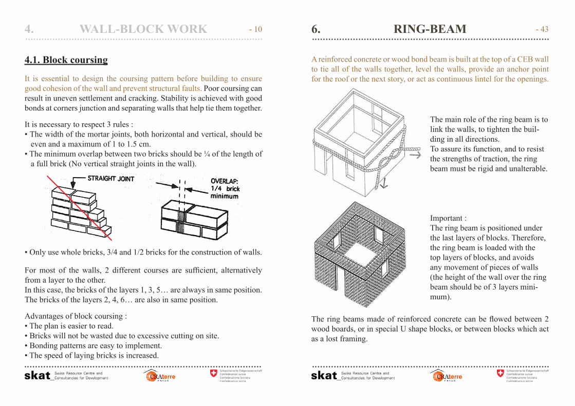
4.1. Block coursing
It is essential to design the coursing pattern before building to ensure good cohesion of the wall and prevent structural faults. Poor coursing can result in uneven settlement and cracking. Stability is achieved with good bonds at corners junction and separating walls that help tie them together.
It is necessary to respect 3 rules :• The width of the mortar joints, both horizontal and vertical, should be even and a maximum of 1 to 1.5 cm.• The minimum overlap between two bricks should be ¼ of the length of a full brick (No vertical straight joints in the wall).
• Only use whole bricks, 3/4 and 1/2 bricks for the construction of walls.
For most of the walls, 2 different courses are suffi cient, alternatively from a layer to the other.In this case, the bricks of the layers 1, 3, 5… are always in same position. The bricks of the layers 2, 4, 6… are also in same position.
Advantages of block coursing : • The plan is easier to read.• Bricks will not be wasted due to excessive cutting on site.• Bonding patterns are easy to implement.• The speed of laying bricks is increased.
4. WALL-BLOCK WORK - 10 RING-BEAM6.
A reinforced concrete or wood bond beam is built at the top of a CEB wall to tie all of the walls together, level the walls, provide an anchor point for the roof or the next story, or act as continuous lintel for the openings.
The main role of the ring beam is to link the walls, to tighten the buil-ding in all directions.To assure its function, and to resist the strengths of traction, the ring beam must be rigid and unalterable.
Important :The ring beam is positioned under the last layers of blocks. Therefore, the ring beam is loaded with the top layers of blocks, and avoids any movement of pieces of walls (the height of the wall over the ring beam should be of 3 layers mini-mum).
The ring beams made of reinforced concrete can be fl owed between 2 wood boards, or in special U shape blocks, or between blocks which act as a lost framing.
- 43

• In the masonry around the windows, integrate some wood blocks whichwill serve later to nail or screw the frames.
OPENINGS5.
EXTERIOR SIDE
In case of safety grills :
5) Drill a hole on the exterior side, and pull out the rods for fi xing the protection grill.
6) Fill the holes with cement mortar.
- 42
1st layer plan :all blocks are visible
Dimension in number of Blocks
L= 13 BTC
L= 3 BTC Butress + dilatation joint (if length of wall > 5 meters)Butresses reinforcing the walls end
Straight joint for crack control between the wall and the sill wall
Butress reinforcing the corner
Infi lling wall below window sill
Butress reinforcing the walls end
2nd layer plan :the second layer must
be drawn as well to ensure all bonding rules
are respected
End of walls supporting door frames must be reinforced (door slams)
4. WALL-BLOCK WORK
Block coursing example
- 11

4. WALL-BLOCK WORK
Horizontal Coursing principles
The masonry is well dimensioned when the elements (wall, openings) are dimensioned according to the size of the brick, and when all the mortar joints are.
All the bricks are drawn to check the bonding. All dimensions are calcu-lated according to the size of the “brick + mortar joint”.
Example, for the 29,5 x 14 x 9 CEB : • The thickness of the joint is :
L - 2 ℓ = 1,5 cm • The length of the ¾ brick is :
(L + ℓ) / 2 = 21,75 cm
8 x (L + joint) – 1 joint
7 x (L + joint) + 1 joint
Example,for the 29,5 x 14 x 9 CEB :
Working size = Length + joint
= 29,5 + 1,5 = 31 cm
Basic calculation rules :• External dimensions :
(-) 1 joint.• Internal dimensions :
(+) 1 joint.
- 12
OPENNINGS5.
INTERIOR SIDE
During the block work :
1) Place 3 U-shape half-blocks on each side of the opening.
2) Fill them with wet sand, and continue to lay bricks above.
After the block work :
3) Gently break the U-shape blocks, on the inner side, and remove the sand.
4) Put in place the joinerie and intro-duce the anchorings.
- 41

• Put in place in the same way the frames before constructing the walls, but fi x them in the masonry with special U shape blocks permitting to sink concrete for a better anchorage.
OPENINGS5.
Example : Section and elevation on an opening of a half brick thick CEB wall (CEB U-shape lintel, CEB U-shape anchoring, independent sill wall)
Sealing frames during brick work. Align the position of anchoring and U-shape blocks
- 40
Plan example – plan with ceb of 29,5x14x9 :
4. WALL-BLOCK WORK
13 ceb = 404,5 13 ceb = 404,5 9 ceb = 280,5
9,5
ceb
= 29
6 9,
5ceb
= 2
96
14,5
ceb
= 4
51
155
13,5
ceb
= 4
20
79
79
20,5
CEB
= 6
34
37 CEB = 1145,5
Bedroom 1
Bedroom 2
Bedroom 2
Veranda
LivingRoom
Toilet
Shower
Doorway : 3 CEB = 94,5 cmWindow : 3 CEB = 94,5 cm 2,5 CEB = 79 cm 1 CEB = 32,5 cm
1st layer
2nd layer
- 13

Conversion tables
To make construction with CEB easier, it is recommended to design your building according to the sizes of brick. Also, for dimensioning the walls it is possible to use conversion tables.
Example of a conversion table for CEB of 29,5 x 14 x 9 cm :
4. WALL-BLOCK WORK
p ,
The joint = 1,5 cmBlock + joint = 31 cm
I-shape (exterior) 4 x 31 – 1,5
L-shape 3 x 31
U-shape (interior) 3 x 31 +1,5
Number ofblocks
I shape L shape U shape Number ofblocks
I shape L shape U shape
0,5 14 15,5 17 20,5 634 635,5 6371 29,5 31 32,5 21 649,5 651 652,5
1,5 45 46,5 48 21,5 665 666,5 6682 60,5 62 63,5 22 680,5 682 683,5
2,5 76 77,5 79 22,5 696 697,5 6993 91,5 93 94,5 23 711,5 713 714,5
3,5 107 108,5 110 23,5 727 728,5 7304 122,5 124 125,5 24 742,5 744 745,5
4,5 138 139,5 141 24,5 758 759,5 7615 153,5 155 156,5 25 773,5 775 776,5
5,5 169 170,5 172 25,5 789 790,5 7926 184,5 186 187,5 26 804,5 806 807,5
6,5 200 201,5 203 26,5 820 821,5 8237 215,5 217 218,5 27 835,5 837 838,5
7,5 231 232,5 234 27,5 851 852,5 8548 246,5 248 249,5 28 866,5 868 869,5
8,5 262 263,5 265 28,5 882 883,5 8859 277,5 279 280,5 29 897,5 899 900,5
9,5 293 294,5 296 29,5 913 914,5 91610 308,5 310 311,5 30 928,5 930 931,5
10,5 324 325,5 327 30,5 944 945,5 94711 339,5 341 342,5 31 959,5 961 962,5
11,5 355 356,5 358 31,5 975 976,5 97812 370,5 372 373,5 32 990,5 992 993,5
12,5 386 387,5 389 32,5 1006 1007,5 100913 401,5 403 404,5 33 1021,5 1023 1024,5
13,5 417 418,5 420 33,5 1037 1038,5 104014 432,5 434 435,5 34 1052,5 1054 1055,5
14,5 448 449,5 451 34,5 1068 1069,5 107115 463,5 465 466,5 35 1083,5 1085 1086,5
15,5 479 480,5 482 35,5 1099 1100,5 110216 494,5 496 497,5 36 1114,5 1116 1117,5
16,5 510 511,5 513 36,5 1130 1131,5 113317 525,5 527 528,5 37 1145,5 1147 1148,5
17,5 541 542,5 544 37,5 1161 1162,5 116418 556,5 558 559,5 38 1176,5 1178 1179,5
18,5 572 573,5 575 38,5 1192 1193,5 119519 587,5 589 590,5 39 1207,5 1209 1210,5
19,5 603 604,5 606 39,5 1223 1224,5 122620 618,5 620 621,5 40 1238,5 1240 1241,5
(Dimensions are given in centimeters)
- 14 OPENNINGS5.
5.4. Joineries
The vibrations and shocks resulting from the manipulation of the doors and windows can cause some cracks in the walls.It is therefore necessary to anchor well the joineries in the masonry.
There are several possible solutions for the anchorage :• Put in place the door and window frames before building up the walls,
and fi x them with nails or wire at the level of a mortar joint.
2 nails every 3 layers,
Position of the frame :
Make sure the top of theframe is 1 cm higher thanthe last bricklayer.
Example :1 layer = 10,5 cm20 layers = 210 cmThe top of the frameshould be at 211 cm.
Position of the frame :Make sure the top of the frame is 1 cm higher than the last bricklayer.Example : 1 layer = 10,5 cm / 20 layers = 210 cm> The top of the frame should be at 211 cm.
When the shrinkage of the stabilized mortar is
very limited, it is possible to sealthe frame while building up the wall :
2 nails every 3 layers, inserted in the mortar joints.
At the base :The wood is not in contact with the ground.
Finished ground levelCement
- 39
OPENINGS5.
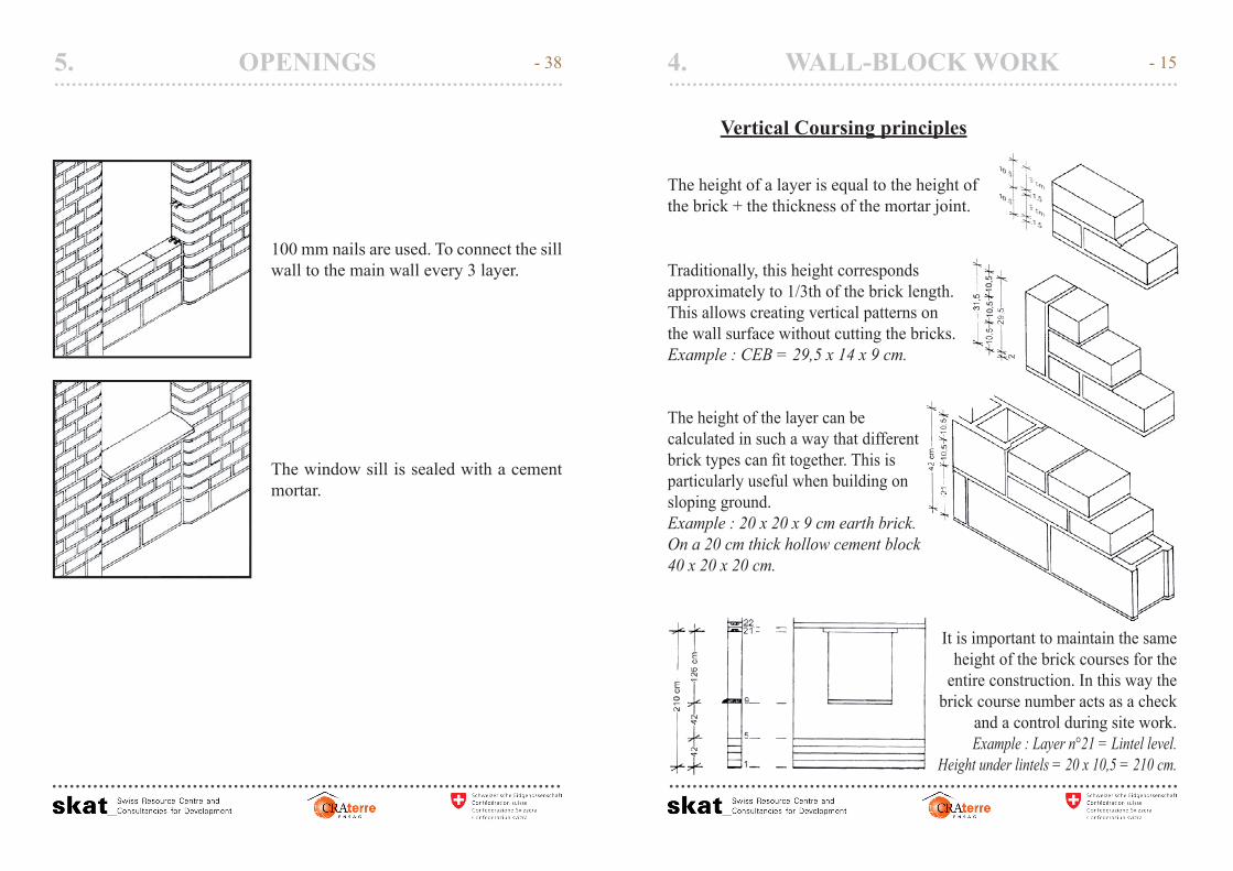
100 mm nails are used. To connect the sill wall to the main wall every 3 layer.
The window sill is sealed with a cement mortar.
- 38
Vertical Coursing principles
The height of a layer is equal to the height of the brick + the thickness of the mortar joint.
Traditionally, this height correspondsapproximately to 1/3th of the brick length. This allows creating vertical patterns onthe wall surface without cutting the bricks.Example : CEB = 29,5 x 14 x 9 cm.
The height of the layer can becalculated in such a way that different brick types can fi t together. This is particularly useful when building on sloping ground.Example : 20 x 20 x 9 cm earth brick.On a 20 cm thick hollow cement block 40 x 20 x 20 cm.
It is important to maintain the same height of the brick courses for the
entire construction. In this way the brick course number acts as a check
and a control during site work.Example : Layer n°21 = Lintel level.
Height under lintels = 20 x 10,5 = 210 cm.
4. WALL-BLOCK WORK - 15

4. WALL-BLOCK WORK
4.2. Bonding patterns
Main block sizes
Use modular bricks with a constant size : L = Length W = Width H = Height TH = Thickness of the joints
L = 3H+ 2THH = (L-2TH) / 3
L = 2W + THW = (L-TH) / 2
FULL BLOCK
Full blockexample : 29,5 x 14 x 9 cm
- 16 OPENNINGS5.
5.3. Sill wall
The sill is very solicited by the loads transmitted from the lintel by the sides of the opening. To avoid the cracks under the sill, it is possible to create straight joints under the opening either during the construction or after the construction, while jointing or pointing with a tool.It is also possible to increase the length of the sill or put some reinforce-ment underneath.
Building the sill wall at the end offers 2 advantages :• Easy circulation of materials and equipment on site, as all windows
serve as doors.• The possibility to create 2 straight joints and therefore avoids cracks
between the main wall and the sill wall.
Remark :The sill wall thickness can differ from the wall thickness (example : 20 cm thick wall / 14 cm thick sill wall).
straight joint
- 37

WARNING !Leave a 5 mm gap between the frame and the lintel to allow the lintel to go down when the masonry will settle down.(Shrinkage due to settling of the mortar and loading)
Make sure that no mortar is trapped between the frame and the lintel
OPENINGS5. - 36
Half blolckexample : 14 x 14 x 9 cm.> square block : L = W
4. WALL-BLOCK WORK
Three quarter blolckexample : 21,75 x 14 x 9 cm.> square block : L = W
2l + TH = L + W + THl = (L+W) / 2
- 17

4. WALL-BLOCK WORK
Straight walls
- 18
5.2. Lintels
Lintels are placed over openings to carry wall and roof loads.Can be used :• Wood lintels / concrete lintels : as in traditional masonry, lintels can be
made of wood, steel, stone or concrete, made on site or prefabricated.• Arches : the lintel can also be replaced by an arch in earth blocks, in
order to keep a structural homogeneity of the wall and to avoid the use of wood.
• Prefabricated CEB lintel : because bricks have little tensile strength, they can’t be used for straight lintels on their own. They must be used with other materials such as steel and cement. Frog bricks (U-shape brick) can be used to precast reinforced concrete lintels. The length of these lintels shouldn’t be more than 4 + 2 bricks, 4 bricks being the width of the opening.dth of the opening.
Stocking:• The rods are placed at the bottom• The lintel is resting on 2 supports
Transport :Do not hold the bricks when lifting up, but hold the concrete partThe concrete should always rest either at the bottom or on the side.
OPENNINGS5. - 35

5.1. Dimensions
It is necessary to respect some rules in the construction of openings :• Do not make openings too close one from another (minimum 1 meter) (3’4”).
• Do not place the openings less than 1 meter from an angle of the building.• Well anchorage the lintel in the wall: support it on a minimum of 20 cm
(8”) inside the wall on each side of the opening.
It is necessary to avoid :• Too large openings (more than 1.20 meters) (4’).• Too many openings on a same wall or openings badly equilibrated in
the wall.
OPENINGS5.
Correct partice
Openings are placed at least 1 meter far
from the corner
Regulardistribution
Good overlap of the lintel on the jambs
(min 25 cm)
Strengthening of the jambs
and sills
Straight joints in the wall under
the window
- 34
L - shape
4. WALL-BLOCK WORK - 19

4. WALL-BLOCK WORK
T - shape
option 1 option 2
HALF BRICK WALL THICKNESS
- 20
The openings (windows, doors…) represent a weak point in the structure of the building. It is often from the openings that appear many cracks. Therefore it is neces-sary to look after their solidity. Care should be taken with the structural bon-ding of frame openings with CSEB walls in order to limit cracking which could lead to water infi ltration and therefore a process of erosion.
OPENNINGS5. - 33

4. WALL-BLOCK WORK
Pointing
Stabilized blocks create a brick wall that if properly stabilized can be left exposed with no outer plaster fi nish. However, special care should be given for the pointing to give a neat fi nish to the mortar joints.
• Don’t repoint after the mortar has dried; it is a waste of time, materials and money to scrape dried mortar, clean it , refi ll and then repoint it.
• The pointing is done after partial drying of the mortar. It is therefore recommended that the laying of the blocks and the pointing is done by the same workman one after another, that is when the mortar is still workable.
• After pointing, clean the joint with a wet sponge.
Appropriate tools for pointing :
spoon bended iron rod pointing wood
- 32 4. WALL-BLOCK WORK
FULL BRICK WALL THICKNESS
option 1 option 2
- 21

4. WALL-BLOCK WORK
X - shape
HALF BRICK WALL THICKNESS
option 1 option 2
- 22 4. WALL-BLOCK WORK
Masonry with guide scales.
kA metallic orwooden graduatedscale, showing the sizeof the brick + joint helps to check the position of the brick and spacingfor openings.
• For 29,5 x 14 x 9 cm CEB’s a 94.5 cm scale corresponds to 3 bricks + 4 joints
• This scale is 94,5 cm long. The length corresponds to 9 layers of 10,5 cm each (block + joint).
• The scale also serves as a guiding tool to check that the wall remains straight.
• A nail helps to keep the scale at the right height.
- 31

4. WALL-BLOCK WORK
N°4
Fixing the line/string:
Use pins rather than
nails.
For each layer, start by laying the corner block,and check:
N°1 – Height: with the rule.N°2 – Horizontality: with the level.N°3 – Verticality: with the plumb bob.N°4 – Alignment: with the line.
N°1
N°3
N°2
N°4 – Alignment : with the line.
N°1 – Height : with the rule.
N°2 – Horizontality : with the level.
N°3 – Verticality : with the plumb bob.
Masonry with different guides.
For each layer, start by laying the corner block, and check :
- 30 4. WALL-BLOCK WORK
option 1 option 2
ONE FULL BRICK WALL THICKNESS
- 23

4. WALL-BLOCK WORK
Pilars (example with 29,5 x 14 x 9 cm blocks)
Bonding patterns for small section pillars (30 x 30 cm or 30 x 45 cm) generally require full blocks and use a rotating pattern or reversed sym-metrical patterns.
Bonding patterns for large section pillars (45 x 45 cm or 60 x 60 cm) use the three-quarter block in classic designs. Simplifi ed patterns can require only the use of a full block.
2 FULL BRICK X 2 FULL BRICKSimplified bonding pattern for a 60 x 60 cm pillar.
1,5 FULL BRICK X 1,5 FULL BRICKSimplified bonding pattern for a 45 x 45 cm pillar.
- 24 4. WALL-BLOCK WORK
Do not repoint after the mortar has dried : it is a waste of time, materials and money to scrape dried mortar, clean it , refi ll and then repoint it.It is recommended that the laying of the blocks and the pointing is done by the same workman one after another, that is when the mortar is still workable.
AVOID !
Do not strike the brick with a hard tool to put it in place. If there is too much mortar or if the mortar is too hard to push the brick down by hand, remove the brick and reduce the mortar.
AVOID !
Do not lift the brick and push some mortar under it to fi ll the gaps, it is better to replace the mortar completely in enough quantities.
AVOID !
Do not fi ll the vertical joints after laying the bricks :• Waste of time• Risk smearing the bricks• Risk of partial fi lling.
- 29

4. WALL-BLOCK WORK
Block laying
• Before laying the fi rst course, it is recommended to set it without mortar,in order to verify correctly the joining between bricks before conti-nuing the construction.
• Control the horizontal and vertical levels at every course, with spirit levels and lines.
• Do not rise up more than 5 layers of bricks per day; this may have some effect on the settling of the mortar and affect the stability of the walls.
Lay enough mortar(not excessive)
Spread the mortar evenlyincluding the vertical face
Wet bricks before usingA dry block will absorb the water ofthe mortar; therefore the mortarwill not harden correctly.
Place the brick applyingpressure evenly
Position and fix the brickcorrectly without tapping Remove the excess mortar
1 2 3
4 5 6
- 28 4. WALL-BLOCK WORK
Butresses
Straight walls :To ensure good stability and support pointed loads, buttresses can be used for fi ne walls
- 25
4. WALL-BLOCK WORK
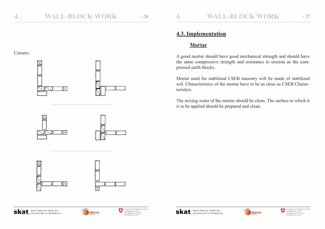
Corners :
- 26 4. WALL-BLOCK WORK
4.3. Implementation
Mortar
A good mortar should have good mechanical strength and should have the same compressive strength and resistance to erosion as the com-pressed earth blocks.
Mortar used for stabilized CSEB masonry will be made of stabilized soil. Characteristics of the mortar have to be as close as CSEB Charac-teristics.
The mixing water of the mortar should be clean. The surface to which it is to be applied should be prepared and clean.
- 27