construction of med component of pyrolyzer-desalination
TRANSCRIPT

Desalination & Water Purification Research and Development Program Report No. XXX
Construction of MED Component of Pyrolyzer-Desalination Unit for Resiliency Testing
Prepared for Reclamation Under Agreement No. XXXXXXXXXXXX
by
Catherine E. Brewer
2011-2015 FINAL REPORT - COOPERATIVE AGREEMENT NO. R10AC80283 Page 249

Disclaimer
The views, analysis, recommendations, and conclusions in this report are those of the authors and do not represent official or unofficial policies or opinions of the United States Government, and the United States takes no position with
MISSION STATEMENTS The mission of the Department of the Interior is to protect and provide access to our Nation's natural and cultural heritage and honor our trust responsibilities to Indian tribes and our commitments to island communities. The mission of the Bureau of Reclamation is to manage, develop, and protect water and related
2011-2015 FINAL REPORT - COOPERATIVE AGREEMENT NO. R10AC80283 Page 250

regard to any findings, conclusions, or recommendations made. As such, mention of trade names or commercial products does not constitute their endorsement by the United States Government.
2011-2015 FINAL REPORT - COOPERATIVE AGREEMENT NO. R10AC80283 Page 251

Acknowledgements Funding for this research was provided by a supplemental extension to a Tier 1 Proof of Concept Grant through the New Mexico State University Institute for Energy and the Environment as part of a cooperative agreement with the Desalination and Water Purification Research and Development Program, U.S. Bureau of Reclamation. The authors would like to acknowledge the NMSU Manufacturing Engineering & Technology Center for their assistance with designing, fabricating and testing the lab-scale MED unit, Mr. Brent Carrillo and Mr. Willian Do Prado for their assistance with the MED testing, and the staff of the NMSU Department of Chemical & Materials Engineering for their support.
2011-2015 FINAL REPORT - COOPERATIVE AGREEMENT NO. R10AC80283 Page 252

2011-2015 FINAL REPORT - COOPERATIVE AGREEMENT NO. R10AC80283 Page 253

Contents Page
Acknowledgements ...................................................... iii Contents ........................................................................ v Glossary ...................................................................... vii Executive Summary ....................................................... 1 1. Introduction ................................................................ 3
1.1 Motivation .............................................................. 3 1.2 Design Project ....................................................... 4
1.2.1 Project Objectives ................................................... 4 1.2.2 Project Tasks .......................................................... 4 1.2.3 Project Deliverables ................................................ 5
1.3 Organization of Report .......................................... 5 1.4 Conclusions and Recommendations ..................... 6
2. Resiliency in Thermal Water Desalination ................. 7 2.1 Thermal Desalination Technologies ...................... 7 2.2 Scaling and Fouling ............................................... 9 2.3 Brackish Water Chemistry in New Mexico ........... 10 2.4 Design Considerations to Prevent Scaling ........... 12
3. Biomass Pyrolysis for Small-Scale Water Desalination14 3.1 System Components and Parameters ................. 14 3.2 Furnace and Boiler .............................................. 16
3.2.1 VOC Combustion Methods ................................... 16 3.2.2 Steam or Hot Water .............................................. 21
3.3 Supplying Vacuum .............................................. 22 3.4 Feedwater Preheating ............................................. 24
4. Design and Fabrication of Multiple Effect Distillation Lab Unit .............................................................................. 26
4.1 Horizontal Tubes and Falling Film ....................... 26 4.2 Fabrication Considerations .................................. 27 4.3 Material and Parts Selection ................................ 30 4.4 Monitoring and Data Collection ........................... 31 4.5 Shakedown Trials and Safety Review ................. 32
4.5.1 Vertical Unit Orientation and Pump Pressure Head ...................................................................................... 33 4.5.2 Water Vapor and Vacuum Pump .......................... 34 4.5.3 Polycarbonate Sheeting and Vacuum Pressure .... 34 4.5.4 Preheating Feedwater........................................... 35
2011-2015 FINAL REPORT - COOPERATIVE AGREEMENT NO. R10AC80283 Page 254

4.6 Future Unit Improvements ................................... 35 5. Water Testing .......................................................... 39
5.1 Negative Control Benchmark ............................... 39 5.2 Positive Control Benchmark ................................ 42 5.3 Future Work ........................................................ 42
6. Project Outcomes .................................................... 44 6.1 Research Capacity Building ................................ 44 6.2 Theses, Publications, and Presentations ............. 44 6.3 Follow-On Proposals ........................................... 45 6.4 Other Products .................................................... 46
Reference List ............................................................. 48 Appendix ..................................................................... 51
Surface Area Calculations for Heat Exchangers ........ 51
2011-2015 FINAL REPORT - COOPERATIVE AGREEMENT NO. R10AC80283 Page 255

Glossary AWWA American Water Works Association BGNDRF Brackish Groundwater National Desalination Research Facility EC electrical conductivity IEE Institutue for Energy & the Environment MED multiple effect distillation MSF multiple stage flash NMSU New Mexico State University NPSH net positive suction head PFPE perfluoropoly ether TDS total dissolved solids TOC total organic carbon VC vapor compression VOC volatile organic carbon(s)
2011-2015 FINAL REPORT - COOPERATIVE AGREEMENT NO. R10AC80283 Page 256

Executive Summary Communities located in rural, arid areas face the challenge of finding local and affordable energy supplies to operate water desalination equipment. A renewable distributed energy source that has great potential for water desalination is biomass: agricultural wastes, forestry residues, residential yard waste, byproducts from biofuels production, etc. Pyrolysis, a process that transforms biomass through heating under limited-oxygen conditions, can be used to produce char, bio-oil, and non-condensable gas products. The liquid and gas products can be combusted to drive the pyrolysis process, and to provide heat and power to a desalination process. The char product can be applied to soils as biochar to improve soil quality and soil water holding capacity. This project represents the second stage in a proof-of-concept study for a biomass slow pyrolysis system that could be coupled to a multiple effect distillation (MED) unit for the small-scale desalination of brackish water. Information learned from the first stage of the study was used to design, build, and test a laboratory-scale MED unit prototype that could be used for water chemistry research. The unit contains two effects and one condenser, and was designed to produce approximately 1 m3/day of distilled water. Hot water (80°C) was used to provide the heat energy and a vacuum pump to maintain the system pressure at around 200 kPa (~1/5th atmospheric pressure) to enable feedwater to evaporate at temperatures around 60°C. These conditions were selected to help prevent scaling on heat transfer surfaces caused by the low solubility of salts commonly found in brackish groundwater, namely CaCO3 and CaSO4. Smooth copper tubes in a horizontal orientation were used for the primary heat transfer surfaces with feedwater applied as a spray to create a falling film; these design parameters were chosen due to their tendency to enhance heat transfer rates and prevent scaling. Sensors were installed at select locations on the unit to enable calculations of heat transfer coefficients and identify effects of scaling.
2011-2015 FINAL REPORT - COOPERATIVE AGREEMENT NO. R10AC80283 Page 257

After the initial design and fabrication process, a series of shakedown trials on desalination of a model feedwater helped assess base design performance and identify prototype improvements. Among the identified improvements are increased preheating of feedwater to maintain system temperatures for sustained operation, modified unit size for easier fabrication and handling, pump selection, and increased resistance to corrosion. Follow-on work will continue the performance benchmarking process and track performance changes as functions of water chemistry, as well as incorporate economic process modeling. Outcomes of this project include two manuscripts to be published as peer-reviewed journal articles, portions of two graduate student theses, three conference presentations, research capacity and expertise building in the Water-Energy Nexus for a junior faculty member and a PhD student, five follow-on grant proposals, real-world case studies in water treatment for a chemical engineering heat transfer class, and a lab-scale MED unit that can be used for thermal water desalination and heat transfer research.
2011-2015 FINAL REPORT - COOPERATIVE AGREEMENT NO. R10AC80283 Page 258

1. Introduction
1.1 Motivation
Water for agricultural use has become expensive and difficult to obtain in New Mexico and other southwestern states due primarily to an on-going drought. Well water used for irrigation can frequently be brackish and can result in the accumulation of salt in irrigated soils. Soil salinity can result in lower crop yields due to plant salt stress. Treatment of soil salinity often requires flushing the soil with fresh water to transport salts below the root zone. Use of brackish well water to meet temporary water needs can lead to the need for even more fresh water in the long term to maintain crop yield. Desalination of brackish groundwater is one way to obtain fresh water for irrigation from available water sources. However, desalination requires energy. In rural locations, electricity from a grid, or electricity generation using solid or liquid fuels, is often unavailable or prohibitively expensive at the necessary scale. Some desalination systems are designed to use what farmers have available on or near their farms: sunlight, wind, and geothermal energy. Such systems have been employed with some success, although per unit costs remain high and energy storage can be difficult. One resource that farmers have available but that has not been much explored for desalination is biomass in the form of agricultural residues and yard waste. In a previous project, we studied water desalination technologies that might be paired with biomass pyrolysis to produce biochar and thermal energy for fresh water. We found that low-temperature multiple effect distillation (MED) was promising for the small scale because of its reuse of the heat of vaporization and the opportunity to use the heat resource available. We designed and simulated an interface that would use the output of biomass pyrolysis (bio-oil and non-condensable gases) to produce electricity and thermal energy in the form of low-temperature steam.
2011-2015 FINAL REPORT - COOPERATIVE AGREEMENT NO. R10AC80283 Page 259

This project was the first step towards a prototype of the pyrolyzer-MED system. The primary goal of this project was to construct a laboratory-scale prototype of the MED and to compare that prototype’s operation to the simulation. Laboratory scale (1-2 m3 produced water per day) was chosen to represent the small end of the applications for this system while still being large enough to identify real-world challenges. A major challenge to consistent operation of thermal desalination systems is scaling and fouling, especially the formation of hard scale at elevated water temperatures. A secondary goal of this project was to design an MED system that would be resilient to differing water chemistries and minimize scaling to increase system longevity.
1.2 Design Project
1.2.1 Project Objectives The objectives of this project were to: • Build and operate a lab-scale multiple effect distillation
unit to enable thermal water desalination research and future incorporation of biomass-based thermal energy.
• Evaluate ability of MED unit design to accommodate a wide variety of water chemistries and resist fouling.
• Develop faculty and graduate student expertise in thermal water desalination and water chemistry.
1.2.2 Project Tasks The specific tasks undertaken in the project were:
1. Design and source/fabricate boiler/heater to supply steam/hot water for lab-scale MED unit.
2. Fabricate and assemble lab-scale MED unit with associated equipment (pumps, boiler, monitoring) and plumbing.
3. Perform MED unit shakedown trials. 4. Use MED unit to desalinate water with a range of
chemistries to evaluate energy requirements and resiliency to fouling.
5. Build water chemistry and desalination expertise through conference attendance, on-campus networking, and literature review.
2011-2015 FINAL REPORT - COOPERATIVE AGREEMENT NO. R10AC80283 Page 260

6. Evaluate MED unit energy efficiency and fouling resistance in relation to potential implemental scenarios.
7. Prepare final report and external proposals to fund construction of pyrolyzer and interface, and follow-on fouling resistance and energy efficiency research.
1.2.3 Project Deliverables The deliverables of this project are:
a. Fabrication designs and part lists for lab-scale MED unit. b. Working MED unit installed in the laboratory and available
for research projects. c. Results from shakedown trials and water treatment
experiments. d. Final project report. e. Proposals submitted to external funding agencies.
1.3 Organization of Report
This chapter is intended to provide context for the project and to summarize the take-away messages from the project results. The second chapter presents a literature review of relevant thermal desalination technologies and the challenges of scaling. Sections of the chapter were selected from a review article manuscript prepared by the PhD student. Also included is background information about local water chemistry that influenced the design of water treatment experiments. This text will serve as part of the literature review and introduction for Mr. Ali Amiri’s PhD dissertation. The third chapter describes the pyrolysis-MED interface design on which this project is based and the considerations leading to decisions made for how to supply heat and vacuum for the lab MED unit. This work was part of Mr. Yunhe Zhang’s MS thesis. The fourth chapter describes the design, fabrication and shakedown process for the MED unit in the laboratory. This will serve as a methods chapter in Mr. Ali Amiri’s PhD dissertation.
2011-2015 FINAL REPORT - COOPERATIVE AGREEMENT NO. R10AC80283 Page 261

The fifth chapter presents the methods of water treatment experiments for the laboratory MED unit to benchmark energy use, water production efficiency, and occurrences of scaling. This will serve as another chapter in Mr. Ali Amiri’s PhD dissertation. The final chapter summarizes the outcomes from the project.
1.4 Conclusions and Recommendations
Although it requires more overall energy than membrane water treatment methods, thermal water desalination methods, especially multiple effect distillation, provide the opportunity to produce high purity distilled water using available low-temperature heat sources. These sources can include heat from biomass thermochemical processing, solar heat, geothermal heat, and industrial waste heat. The water chemistry of brackish groundwater creates challenges for thermal water desalination due to the low solubility of certain calcium and magnesium salts, namely carbonates and sulfates, at increasing temperatures. Carefully controlling the temperature of every heat transfer surface and conducting the feedwater evaporation process under partial vacuum can prevent scaling; these two strategies require special considerations for MED unit construction. The lab-scale, first prototype of such a unit showed that distilled water of the desired quality can be produced, as long as the heat transfer into and within the unit are properly controlled. Further prototype development is needed to increase feedwater preheating capabilities, reduce corrosion, enhance evaporation heat transfer, simplify unit construction, and ensure reliable vacuum operation. Water chemistry testing in relation to MED operation performance, combined with economic modeling, can guide the unit development process to achieve robust and economically feasible thermal desalination of brackish groundwater at the small scale.
2011-2015 FINAL REPORT - COOPERATIVE AGREEMENT NO. R10AC80283 Page 262

2. Resiliency in Thermal Water Desalination
2.1 Thermal Desalination Technologies
There are three main types of thermal desalination processes: multi-stage flash distillation (MSF), vapor compression distillation (VC), and multiple effect distillation (MED). All three require low-temperature heat as the main energy input and a small amount of electricity to drive pumps. Some advantages of thermal desalination processes over membrane desalination processes are higher quality product water, no membrane replacement costs, lower sensitivity to changes in feed water quality, and less rigid monitoring requirements (Eltawil, et al., 2009, Hanson, et al., 2004, Kalogirou, 1997). MSF was first developed by Silver at Weir Co. in Glasgow, Scotland in 1960 and is based on seawater evaporation using steam from an external heat source. For many years, MSF has been the “easiest” technology for water desalination and accounts for over 40% of desalination technologies worldwide (Al-Karaghouli and Kazmerski, 2013, Likhachev and Li, 2013). The typical capacity for an MSF process is large: 10,000 to 35,000 m3/day. In MSF, water is preheated using heat exchangers up to 90-110°C before entering the first stage. Vacuum pumps create a negative pressure difference near water’s saturation point in the first stage, causing the water to partially flash. The flashed water vapor is condensed by contact with incoming feedwater in the heat exchangers and collected. The remaining brine enters the second stage, which is operated at a lower pressure than the first stage. Again, the negative pressure difference causes some of the water to flash off and be collected. This process continues until the last stage, which has the lowest temperature and pressure. VC is very similar to MSF but only has one evaporation stage and can be run under atmospheric or sub-atmospheric pressure. Hot, pressurized feed water enters the evaporation stage and flashes off, then is condensed and collected. The remaining brine can then be recycled through the process by
2011-2015 FINAL REPORT - COOPERATIVE AGREEMENT NO. R10AC80283 Page 263

re-pressurizing it. Pressurization can be done using mechanical vapor compression, which requires additional electricity energy for the pump, or thermal vapor compression, in which high-pressure steam is injected into the feed stream (Al-Karaghouli and Kazmerski, 2013, Semiat and Hasson, 2012). Multiple effect distillation (MED) or multiple effect boiling is similar to MSF in that multiple units are operated at gradually decreasing temperatures and pressures. The difference is that steam from the first effect is used as the heat source in the second effect in MED; this means that the heat of vaporization is reused. In MED, steam enters through a pipe into the first stage or effect. Feed water is sprayed onto this hot pipe. Since the effect environment is kept under partial vacuum, some of the feed water flashes into vapor, leaving behind a concentrated brine solution. The flashed water vapor is carried into a pipe and into the next effect, which is at a lower temperature and pressure than the first effect. The freshly formed vapor provides the heat for the vaporization of more feed water within the second effect. This cycle continues and results in desalinated water and brine. MED is the oldest thermal desalination process and often has a plant capacity of 600 to 300,000 m3/day (Kalogirou, 2005). A typical MED unit operates at 55-90°C, and requires 135-230 MJ and 5-9 MJ (1.5-2.5 kWh) of thermal and electrical energy, respectively, per cubic meter of feed water (Al-Karaghouli and Kazmerski, 2013). MED has been in competition with MSF technically and economically for many years. At the end of 2011, MSF and MED units accounted for approximately 26% and 8.2% of worldwide water production capacity, respectively (2012). Two main advantages of MED over MSF are MED’s lower energy consumption due to better heat transfer from the constant temperature difference in MED effects, and the fewer number of effects needed in MED to achieve a given performance ratio (mass of distillate produced per unit mass of input steam) (Al-Karaghouli and Kazmerski, 2013, Kalogirou, 2005).
2011-2015 FINAL REPORT - COOPERATIVE AGREEMENT NO. R10AC80283 Page 264

2.2 Scaling and Fouling
There are different types of scale deposits including soft, hard, silica, organic and bio-fouling. Soft scale is the precipitation of inorganic compounds due to their concentrations exceeding their solubility. They are called soft because they can be removed relatively easily through increases in temperature and/or decreasing the pH by adding acid. An example of soft scale is calcium bicarbonate. Hard scale forms by precipitation like soft scale but is much more difficult to remove and often requires mechanical cleaning. Hard scale is usually composed of divalent alkaline cations and sulfates or chlorides. An example of hard scale is calcium sulfate. Organic matter build-up may be due to marine life (i.e. bio-fouling) or from industrial discharges such as crude oil, greases, waxes and paint materials. A hot alkaline treatment can usually remove organic scale. Scale formation can be especially damaging for heat transfer surfaces because scale build-up has a low thermal conductivity, which slows conduction and decreases thermal efficiency. Slower conduction increases heat transfer plate or tube wall temperatures and these prolonged higher temperatures can lead to corrosion and/or crack formation (Al-Jaroudi, et al., 2010). For this reason, prevention and treatment of scaling is critical to heat exchanger maintenance. Scale formation within the effects of MED units is dependent on the feedwater concentrations of Ca2+, Mg2+, and bicarbonate ions, the feedwater total dissolved solids (TDS) concentration, MED operating temperature, water residence time, fluid velocity, water pH, rate of CO2 release, and roughness of evaporator materials (Al-Anezi and Hilal, 2007, Al-Jaroudi, et al., 2010). In research conducted with a MED-vapor compression (VC) unit, Al-Jaroudi, et al. observed a 14 mm-thick scale build-up comprised of soft CaCO3 and hard CaSO4, which are major scaling contributors, as well as a significant proportion of organic matter (Al-Jaroudi, et al., 2010). These build-ups greatly inhibited evaporator function. Mg(OH)2 is another alkaline scale that is sometimes observed
2011-2015 FINAL REPORT - COOPERATIVE AGREEMENT NO. R10AC80283 Page 265

in MSF or MED systems due to Mg2+ ions in the water. Non-condensable gases such as CO2, O2, and N2 released during brine evaporation within the effects or ambient air leakage into the evaporator, may cause alkaline scale formation. For example, dissolved CO2 in the condensate decreases the water pH to acidic conditions such that, with O2, the condenser tubes are subject to corrosion. The release rate of CO2 is highest in the first effect, and increases with higher water temperatures and salinities (Al-Anezi and Hilal, 2007). This causes CaCO3 deposition to be highest in the first effect while the pH decreases from the first effect to the last effect (Al-Rawajfeh, 2010). Even a low concentration of non-condensable gases within the water can significantly decrease the overall heat transfer coefficient over time, leading to a decrease in evaporator performance (Al-Anezi and Hilal, 2007).
2.3 Brackish Water Chemistry in New Mexico
Groundwater available in New Mexico ranges from fresh to very brackish depending on the location, the aquifer depth, and the time of year. Water chemistry for this research was based on baseline data from water tests of the well water at the Brackish Groundwater National Desalination Research Facility (BGNDRF) in Alamogordo, NM. Water tests were conducted by Tetra Tech in 2011 and 2012, and the results presented in a 2013 report (Inc., 2013). A summary of relevant data is presented in Table 2.1. Table 2.1 Water test results from 2011-2012 analyses of the four groundwater wells at the Brackish Groundwater National Desalination Research Facility (Inc., 2013). TDS: total dissolved solids; TOC: total organic carbon; HCO3
-: bicarbonate; CO3
2-: carbonate; SO42-: sulfate; SiO2: silicon
dioxide. Component/Parameter Well 1 Well 2 Well 3 Well 4 Temperature (°C) 32.0-
41.2 21.0-22.5
19.9-22.1
19.5-21.3
pH 7.71-8.16
7.25-7.65
7.28-7.67
7.22-7.70
2011-2015 FINAL REPORT - COOPERATIVE AGREEMENT NO. R10AC80283 Page 266

TDS (mg/L) 1,040-1,710
5,320-5,900
3,590-4,380
3,970-4,380
TOC (mg/L 0-1.0 0.97-1.30
0.56-1.30
0.70-0.83
Na (mg/L) 310-340
640-720
410-530
420-540
Ca (mg/L) 48-89 550 440-450
490-530
Mg (mg/L) 11-22 320-340
220-250
220-240
K (mg/L) 4.6-5.4
2.6-4.0
2.9-3.4
2.6-3.4
SiO2 (mg/L) 24-26 23-24 21-22 19 SO4 (mg/L) 580-
990 3,000-3,800
1,800-2,500
1,900-2,600
Cl (mg/L) 33-35 580-650
620-690
620-680
HCO3- (mg/L CaCO3) 130-
160 240-250
190-210
210
CO32- (mg/L CaCO3) 0 0 0 0
Brackish groundwater at BGNDRF can be characterized as mildly alkaline (pH of 7-8), low (Well 1) to high salinity (Wells 2-4) for brackish water, with relatively little organic carbon or silica compounds. Most of the ions are sodium, calcium, magnesium, sulfate, chloride and bicarbonate, which implies a substantial risk of producing hard scale (mostly calcium sulfate) during thermal desalination. Relative to drinking water standards, Wells 2-4 contain too much chloride and sulfate, and all wells would require desalination to a TDS concentration below 500 mg/L (Inc., 2013). As can be seen from the data, which represents four different sampling times over the course of a year, the water chemistry is quite variable. This means that desalination systems would need to be robust enough to accommodate the changes with time while still producing water with the desired quality.
2011-2015 FINAL REPORT - COOPERATIVE AGREEMENT NO. R10AC80283 Page 267

2.4 Design Considerations to Prevent Scaling
There are several management options for preventing and treating scale formation. Demisters (specially designed screens) are used to remove entrained brine droplets from the flashed vapor to prevent those droplets from adding salinity into the product water and contributing to scale formation on condenser tubes. Dissolved gases such as O2 and N2 can be removed through a suitable venting system such as the vacuum pump used to maintain effect pressure. CO2, which dissociates in water to form bicarbonate (HCO3
-) and carbonate (CO3
2-), is harder to manage through venting alone although efficient ventilation does help (Al-Rawajfeh, et al., 2004). Feedwater pretreatments, such as adding acid or scale inhibitors like polyphosphate, can be used. The hydrolysis of polyphosphate at high temperatures (90°C), however, leads to the formation of calcium phosphate and means that polyphosphate is rarely used in ambient pressure MED units. While soft scale is troublesome for MED units, hard scale, namely CaSO4, is a major concern since hard scale requires unit disassembly and mechanical cleaning. Prevention is the preferred management for hard scale and can be done in three ways: decreasing the MED operating temperature (solubility is higher at lower temperatures), decreasing the concentration factor within the effect to keep the produced brine below the concentration scaling threshold, and softening the feedwater by substitution with a monovalent cation. Lowing the temperature means simultaneously decreasing the effect pressure, which requires the use of a (more powerful) vacuum pump. Decreasing the concentration factor means increasing the feedwater flow rate and thus increasing the amount of brine that must be collected or recycled. Softening the feedwater requires an additional unit operation and creates another waste water stream. Selection of one option or a combination of options is a critical design choice and must be weighed against system cost, complexity, down-time, and available labor. Even with several management techniques, there is still a chance of scaling in MED units (Al-Jaroudi, et al., 2010).
2011-2015 FINAL REPORT - COOPERATIVE AGREEMENT NO. R10AC80283 Page 268
Tube orientation with the MED unit’s effects can also impact the likelihood of scaling. Steam tubes within the effects can be oriented vertically or horizontally. Vertical tubes tend to have greater scaling and carryover since flashing water vapor has to pass through liquid feedwater/brine on the way to the next effect. The horizontal orientation is usually preferred in MED units since it lowers the frequency of this scaling and carryover, and increases the overall heat transfer coefficient, leading to higher MED system efficiency.
2011-2015 FINAL REPORT - COOPERATIVE AGREEMENT NO. R10AC80283 Page 269

3. Biomass Pyrolysis for Small-Scale Water Desalination
3.1 System Components and Parameters
In a previous U.S. Bureau of Reclamation Desalination and Water Purification Research Program project, a biomass pyrolysis-MED unit interface was designed to model how local biomass residues might provide the energy needed to power an MED unit for desalination of brackish water at the farm or co-op scale. Briefly, that system consists of 12 unit operations in the following order:
1. Biomass is added to a feed hopper; 2. From the feed hopper, biomass enters the auger slow
pyrolysis unit and is converted into chars, bio-oil (as vapors and aerosols) and non-condensable gases (NCG) through partial combustion of the biomass;
3. Chars are fed into a char collection container where some of the cooled flue gases are warmed before being recycled into the pyrolysis unit;
4. Bio-oil vapors, aerosols and NCG flow into a furnace where they are combusted with additional air to form carbon dioxide and water;
5. Heat from the combustion furnace heats water in a boiler to produce steam;
6. Steam from the boiler is fed through a steam turbine to produce electricity;
7. Low pressure, low temperature steam is fed into the first effect of the MED unit to provide process heat; condensed steam is recycled to the boiler or collected with the distillate;
8. Electricity from the turbine generator is used to power the vacuum pump and the water pumps (feed water, brine, and distillate) of the MED;
9. Brackish feedwater is preheated using the condenser unit of the MED then a heat exchanger connected to the warm flue gas stream exiting the combustion furnace;
2011-2015 FINAL REPORT - COOPERATIVE AGREEMENT NO. R10AC80283 Page 270

10. Preheated feedwater is sprayed into the effects in a parallel feed arrangement, creating a falling film over horizontal heat transfer tubes and producing low-pressure steam that flows into the next effect;
11. Brine collected at the bottom of each effect is removed to brine storage or recycled into the feedwater tank;
12. Distilled water collected in the condenser is pumped through a valve into fresh water storage; the valve allows the diversion of the produced water into the feedwater if the electrical conductivity is too high.
More information about the system and interface design, and the process computer simulation, can be found in that final project report (Brewer and Idowu, 2015). Process flows, temperatures, pressures, and heat rates from the Aspen Plus® simulation are taken from that report and shown here as Figure 3.1.
Figure 3.1 Aspen Plus® process flow diagram for pyrolyzer-MED interface showing stream temperatures, pressures, mass flow rates, heat duties and electrical power. HX1: heat exchanger 1, boiler; HX2: heat exchanger 2, preheater for the MED brackish feedwater; NCG: non-condensable gases; MED, multiple effect distillation unit (Brewer and Idowu, 2015).
2011-2015 FINAL REPORT - COOPERATIVE AGREEMENT NO. R10AC80283 Page 271

Process needs identified with the Aspen Plus® simulations were used to specify parameters for the furnace/boiler and the vacuum for the design of the lab-scale MED unit such that the MED portion of the system prototype could be fabricated and tested. The remaining sections of this chapter detail the background information and design process going from the process simulation to equipment selection for the physical unit.
3.2 Furnace and Boiler
3.2.1 VOC Combustion Methods Biomass thermochemical processes produce large amounts of volatile organic compounds (VOCs). Many such organic compounds are toxic and some have been classified as carcinogens, such as formaldehyde, vinyl chloride, benzene, and polycyclic aromatic hydrocarbons. If these compounds are emitted directly without treatment, the resultant pollution poses a risk to the environment and public health (Urashima and Chang, 2000). Thus, a system that produces VOCs must include VOC treatment in the material and energy management considerations. Traditional VOC treatment methods include combustion, freezing, absorption, and adsorption. Some treatment methods are described in Table 3.1. For this project, different combustion methods were considered for biomass pyrolysis VOC treatment and energy recovery.
2011-2015 FINAL REPORT - COOPERATIVE AGREEMENT NO. R10AC80283 Page 272

Table 3.1 Example treatment methods for VOCs (Urashima and Chang, 2000). Method Mechanis
m Optimal Usage
Advantages
Disadvantages
Thermal Combustion
VOCs are mixed with hot gases at high temperatures, resulting in complete combustion.
High concentration, low volume, combustible VOCs
Efficient Removes VOCs fully
Tar accumulation Consumes CH4 Polluting and costly if combustion is incomplete
Absorption in Water
VOCs are dissolved in water,
Point-source, water-soluble VOCs
Easy to operate and manage
Low costs of operation
Water pollution
Inefficient
Aromatics require extra processing
Chemical Absorption
VOCs dissolve in and react with solvents, producing harmless compounds.
High concentration, high volume VOCs
Customizable
Mature technology
Inefficient Consumes solvent Incomplete reactions result in secondary pollution
2011-2015 FINAL REPORT - COOPERATIVE AGREEMENT NO. R10AC80283 Page 273

Adsorption
VOCs are bound, adsorbed into a solid material.
Low concentration VOCs; when very high purity is required.
Very high efficiency Can treat many types of VOCs
Adsorbents are expensive and not easily reusable Cannot treat high concentration or high temperature VOCs
Also known as direct spark combustion, direct combustion uses combustible VOCs as the fuel in a combustion reaction. Direct combustion is best suited for VOCs that contain combustible compounds and/or compounds that are strongly exothermic upon oxidation as this will best sustain the combustion reaction (Kim, et al., 2005). Direct combustion can be performed in a regular stove, kiln, or torch. At temperatures in excess of 1100°C, direct combustion fully breaks down VOCs into carbon dioxide and water vapor. Direct combustion is generally simple to operate and inexpensive. Torches are a type of open direct combustion device that can burn in air and do not require an initial input of natural gas. Torches often rise dozens of meters into the air and are many factories’ main method for processing combustible VOCs. Torches can be designed to separate emissions by type and can incorporate ordinary (fuel-based) or electrical combustion devices to ensure safer, more stable, and reliable combustion processes (Hewitt, 1971). The advantages of direct combustion are: 1) No pre-heating of the combustion chamber or gases is needed. 2) Combustion occurs at high temperatures with minimal flame, which makes the heat recyclable. 3) Systems can handle high concentration and/or high temperature VOC streams.
2011-2015 FINAL REPORT - COOPERATIVE AGREEMENT NO. R10AC80283 Page 274
Thermal combustion is used when there are not enough combustibles to sustain a direct combustion reaction. Thermal combustion relies on the heat produced by secondary fuels to raise the flame/chamber temperature to expedite the oxidation of hydrocarbons into carbon dioxide and water. Thermal combustion can be broken down into three steps (Cao, 2012): 1) Combustion of supplementary fuel to increase the temperature. 2) Mixing of VOCs with heated secondary fuel combustion gases to reach the reaction temperature. 3) Oxidation of VOC combustibles where the reactants are burned at the designated temperature for a specified amount of time. A thermal combustion oven is composed of the supplementary combustion chamber to produce the desired temperature by burning supplementary fuel and the main combustion chamber used to mix the heated gases with VOCs for oxidation. Assuming sufficient oxygen, the primary combustion reaction is governed by temperature (usually ~760°C), time (usually ~0.5 s), and turbulence. Within a certain range, these three governing parameters are synergistic: increasing one parameter usually decreases the minimum requirements for the other two. Increasing temperature increases fuel consumption and increasing reaction time requires a larger combustion oven, so the most economical approach is usually to increase flow turbulence. The relationship between reaction time and combustion oven size is:
τ =𝑉𝑉𝑅𝑅
𝑄𝑄𝑠𝑠( 𝑇𝑇293)
× 3600
where, τ is the residence time in the chamber in seconds, VR is the volume of the chamber in m3, QS is the total volumetric flow rate in m3/hr. at standard conditions, 3600 is the conversion factor from hours to seconds, and T is the temperature of the chamber in degrees K. Table 3.2 lists the theoretical reaction times and temperatures of various types of
2011-2015 FINAL REPORT - COOPERATIVE AGREEMENT NO. R10AC80283 Page 275

VOCs. In practice, if steam or black smoke is emitted, additional reaction time is needed. Table 3.2. Required temperatures and reaction times for treatment of various types of VOCs (Tong, 2001). Off-Gas Description
Combustion efficiency (%)
Residence time (s)
Reaction temperature (°C)
Hydrocarbons >90 0.3-0.5 590-680 Hydrocarbons + CO
>90 0.3-0.5 680-820
VOCs
50-90 0.3-0.5 540-650 90-99 0.3-0.5 590-700 >99 0.3-0.5 650-820
White smoke >90 0.3-0.5 680-820 Black smoke (particulate)
100 0.7-1 760-1100
Catalytic combustion uses catalyst to oxidize gaseous pollutants at relatively low temperatures (250-450°C) (Cai, et al., 2008). Catalytic combustion requires a solid catalyst reaction bed and a heat exchanger. Influx gases cross the pre-heated catalyst bed and both oxygen and hydrocarbon molecules adsorb to the catalyst surface. Once both molecules are present on the catalyst surface, oxygen can directly react with the hydrocarbons. The advantages of catalytic combustion are: 1) Reaction temperature is low compared to direct combustion (600-800°C). 2) Reaction has low resource consumption; it is possible for the reaction to sustain itself once the reaction temperature is reached, allowing recycling of the excess energy produced (Kim, et al., 2005). 3) Catalytic conversions can treat nearly any hydrocarbon or VOC feedstock from many industries (electronics, organics, oil and gas, etc.) 4) Reactions produce virtually no secondary pollution.
2011-2015 FINAL REPORT - COOPERATIVE AGREEMENT NO. R10AC80283 Page 276

For biomass pyrolysis operated under continuous flow conditions, direct combustion of the vapors and non-condensable gases (NCG) is possible and desirable as long as the concentration and heating value of the combustible compounds remain high enough. Reactor start-up will likely require addition of supplementary fuel to bring the furnace up to temperature until the pyrolysis process off-gases can maintain the flame. Direct combustion is unlikely to be suitable for batch pyrolysis reaction systems since the flow, concentration, and composition of VOCs in the vapors and NCGs are variable. While catalytic conversion is suitable for VOC treatment, the goal of this project was to produce flue gas at high temperatures (>900°C) for steam at high temperature and pressures (400°C and 8 bar), so catalytic combustion was not considered.
3.2.2 Steam or Hot Water The two primary inputs into an MED unit are the feedwater and a heat carrier at the desired feedwater vaporization temperature. That heat carrier is usually steam or liquid water for simplicity, safety and water’s high heat capacity and high latent heat of vaporization. The feedwater vaporization temperature, i.e. the operating temperature in each effect, is determined by the vapor-liquid equilibrium of the feedwater. The higher the temperature, the higher the vapor pressure. Once the vapor pressure exceeds the ambient pressure, the water freely boils as long as sufficient heat for the phase change is continuously supplied. Water chemistry and TDS impacts the feedwater’s vapor pressure; in general, the higher the TDS, the lower the vapor pressure and the more elevated the boiling point. To prevent formation of hard scale in MED, the effects must be kept at as low a temperature as possible. Lowing the temperature, however, creates a trade off in that lower pressure would also now be required. For example, Table 3.3 shows a comparison of the vapor pressures heats of vaporization for pure water at various temperatures. The heat of vaporization also increases as temperature decreases. For low-temperature MED of brackish water containing CaSO4
2011-2015 FINAL REPORT - COOPERATIVE AGREEMENT NO. R10AC80283 Page 277

and CaCO3, this means that all heat transfer surfaces must be kept at temperatures below approximately 80°C, the whole system must be at pressures between one half and one tenth of atmospheric pressure, and more heat must be transferred to maintain vaporization. These three factors are the principle challenge for low-temperature MED design. Table 3.3 Properties of water at temperatures between room temperature and its atmospheric-pressure boiling point (CRC, 2003). Temperature (°C)
Vapor pressure (kPa)
Heat of vaporization (kJ/mol)
25 3.2 44.0 50 12.3 60 19.9 42.5 70 31.2 80 47.4 41.6 100 101.3 40.7
While steam can be used as the primary heat transfer fluid in low-temperature MED, i.e. the heat transfer fluid used to boil water in the first effect, controlling the temperature of the steam is difficult because the pressures must be below atmospheric pressure. In this case, hot water may be as a better primary heat transfer fluid as it can be used at atmospheric pressure. Using water, however, means that all heat transfer happens as sensible heat instead of getting both sensible heat and latent heat of vaporization from the heat transfer fluid. As a result, higher flow rates and/or greater heat transfer surface areas would be needed. (Low pressure steam as the heat transfer medium for the later effects is not a problem because this steam is produced at the needed pressure and temperature in the first effect.)
3.3 Supplying Vacuum
There are two general methods for providing vacuum: through a vacuum pump or through a gas ejector. In a pump, gas is moved mechanically through sealed chambers using
2011-2015 FINAL REPORT - COOPERATIVE AGREEMENT NO. R10AC80283 Page 278

differences in pressures. There are many configurations and types of pumps; choice of pumps is dependent on the level of vacuum needed, the system volume, the gas removal rate, properties of the gas, cost, etc. Fluid ejectors, most typically steam ejectors, use Bernouli’s principle to provide vacuum. Motive fluid enters a nozzle-shaped compression tube, which increases the motive fluid’s velocity. When the high-speed (low pressure) motive fluid exits the compression tube into the larger mixing tube, suction is generated. A schematic of a fluid ejector is shown in Figure 3.1. Fluid ejectors have no moving parts and thus require no power and little maintenance.
Figure 3.1 Schematic diagram of a fluid ejector (image: Milton Beychock, 2012, public domain). For MED units, steam ejectors would use motive steam from a boiler to provide vacuum for the effects and to remove non-condensable gases. A heat exchanger at the steam ejector outlet could be used to condense the motive steam and return it to the boiler for reuse, as long as there was a way to vent the non-condensable gases. If the steam can be brought to a low-enough temperature using a de-superheater after the steam ejector, this steam might even be used as the primary heat transfer fluid in the first effect. As with any unit operation, market availability plays a key role in design feasibility. For this project, the target effect temperature to prevent scale was 60-70°C, which would require a vacuum system to maintain pressures around 20 kPa or 1/5th of atmospheric pressure. The smallest steam
2011-2015 FINAL REPORT - COOPERATIVE AGREEMENT NO. R10AC80283 Page 279

ejector available on the market for this pressure and effect volume required 265 kg/hr. of motive steam and would require significant de-superheating. As such, the flow rate and cost (approximately $18,000) of a steam ejector system were too great to be practical at the laboratory scale. At a slightly larger scale, such as farm or co-op scale, a fluid ejector system may be more practical and should be considered over a vacuum pump to lower system maintenance and electrical requirements.
3.4 Feedwater Preheating Multiple effect distillation requires several heat exchange steps. Feedwater must be warmed to vaporization temperature, boiled, and then cooled after vaporization. In low-temperature MED, the use of sub-atmospheric pressure for the vaporization step means that at least some volume of the unit must be kept under vacuum. Energy conservation and manufacturing principles dictate that the volume under vacuum should be minimized. This can be done by preheating the feedwater as much as possible prior to its entrance into the sub-atmospheric section of the unit. In practical terms, this means using the low pressure region only for the vaporization step of the distillation and doing the sensible heat increase elsewhere. Preheating feedwater can occur in several places in the MED and is a major consideration when choosing an MED flow configuration such as forward flow, backward flow, parallel flow, etc. (Darwish and Abdulrahim, 2008). Near all MED units have a condenser unit where the coldest feedwater is used to condense the steam produced in the last effect. After the condenser, regenerative preheaters can be used to remove some heat from generated vapor to warm feedwater between effects. If other waste heat is available nearby, heat exchangers can be used to further warm the feedwater. In all case, heat losses should be minimized through insulation, material selection, and other strategies as heat losses directly impact an MED units gain output ratio (GOR), i.e. how many times the heat of vaporization can be recycled to treat more
2011-2015 FINAL REPORT - COOPERATIVE AGREEMENT NO. R10AC80283 Page 280

water. GOR is a measure of MED efficiency and is generally the factor used for unit optimization.
2011-2015 FINAL REPORT - COOPERATIVE AGREEMENT NO. R10AC80283 Page 281

4. Design and Fabrication of Multiple Effect Distillation Lab Unit A two stage laboratory-scale multi effect distillation (MED) unit was designed and fabricated to be used for desalination of brackish water. The intention of the lab unit is to assist with design of future units at the application scale (farm or co-op) and to enable research on the impacts of brackish water chemistry on scaling at different thermal desalination operating conditions. The design was based on using 80 kg/hr. of brackish feedwater to produce about 20 kg/hr. of fresh water in two effects. From preliminary design work, hot water was selected as the primary heat transfer fluid and a vacuum pump was selected to provide system pressure. The main components of the system include: a heater and pump to provide the heat transfer water, two evaporator effects, a condenser, a vacuum pump, brine and distillate pumps, a feedwater pump, and assorted liquid storage and plumbing parts. The effects and condenser were set to operate 63.5, 60, and 59°C, respectively, at steam saturation conditions, which represents an absolute pressure of approximately 26 kPa.
4.1 Horizontal Tubes and Falling Film
The MED system design started from the second effect heat exchange surfaces as this would be the portion of the unit replicated to create more effects and would dictate unit size and flow requirements. Among the various heat tube and fluid flow configurations available, horizontal steam tubes with falling water film were selected due to their greater rates of heat transfer per surface area and their lower incidence of scaling (Darwish and Abdulrahim, 2008). Falling water film would be achieved by spraying feedwater over the pipes arranged to be directly over the top of each other with a space in between to optimize fluid flow and heat exchange. The number and size of the tubes was selected based on calculations of the needed heat transfer surface area from the estimation of overall heat transfer coefficients and the expected change in temperature within the effect (Incropera, et al., 2007). To ensure even heat transfer and less tube
2011-2015 FINAL REPORT - COOPERATIVE AGREEMENT NO. R10AC80283 Page 282

bending/joining, a manifold system was selected to distribute steam evenly between all the steam tubes rather than to have the steam travel in a winding path. Once the flow rate and temperature for the steam in the second effect were determined, the heat transfer area and flow rates for the first effect were calculated also assuming a horizontal tube arrangement and a falling liquid film. For the hot water, however, a single, serpentine tube was used to carry the water in a continuous loop rather than splitting the water flow with a manifold. The condenser was designed next, this time with the feedwater being the fluid inside the horizontal tubes rather than the steam. Steam from the second effect would enter at the top of the unit and condense as it contacted the cool tubes. After many iterations and optimization, the calculated surface areas for the first effect, second effect and condenser were 0.45 m2, 0.44 m2 and 0.126 m2, respectively. Sample calculations are shown in the Appendix. Tubing diameter (2.54 cm) was selected to balance number of tubes, lengths of tubes, and heat transfer fluid dynamics of the steam and water flows.
4.2 Fabrication Considerations
After the heat transfer surface area calculations, the rest of the unit design proceeded under the following considerations: • Space and fabrication equipment limitations within the
NMSU Manufacturing Engineering & Technology Center (MTEC) machine shop,
• Number and complexity of fabrication steps, • Number of unit components available commercially
compared to number of unit components that have to be special ordered or fabricated,
• Ability to visually observe and instrumentally monitor heat transfer process for teaching and research purposes,
2011-2015 FINAL REPORT - COOPERATIVE AGREEMENT NO. R10AC80283 Page 283

• Ease of unit assembly and disassembly for modification and cleaning,
• Ease of unit operation in terms of number of operators and level of operator involvement, and,
• Ability to stay within fabrication budget for parts and labor, and within fabrication schedule in the case of backordered and custom parts.
Fabrication drawings were developed using CAD software and as many hardware components as possible were found from commercial vendors; the drawing process was repeated as parts were identified and additional component capability information became available. While rounded and single part components are generally best for pressure systems, rectangles using welded or fastened flat sheets are far easier to fabricate. For this reason, the MED units were designed as tall, rectangular boxes with attached feet so that they could be placed on a floor or other surface. Dimensions were determined based on the needed space for water to be sprayed and to flow over the pipes, saving room at the bottom for water to collect and be drained. Figures 4.1 and 4.2 show a 2-D dimensional fabrication cross section of the effects and condenser, and a 3-D rendering, respectively.
2011-2015 FINAL REPORT - COOPERATIVE AGREEMENT NO. R10AC80283 Page 284

Figure 4.1 Two dimensional fabrication drawing of the first and second effects, and the condenser of the designed lab-scale MED unit. Measurements are shown in inches.
Figure 4.2 Three dimensional rendering of lab-scale MED unit using SOLIDWORKS CAD design software showing copper
2011-2015 FINAL REPORT - COOPERATIVE AGREEMENT NO. R10AC80283 Page 285
heat exchange tubing, box configuration, locations for instrumental monitoring, and stands.
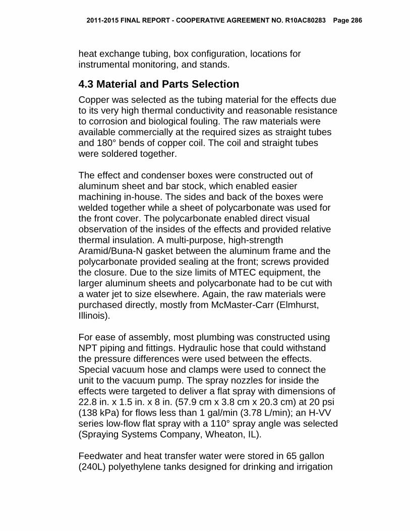
4.3 Material and Parts Selection
Copper was selected as the tubing material for the effects due to its very high thermal conductivity and reasonable resistance to corrosion and biological fouling. The raw materials were available commercially at the required sizes as straight tubes and 180° bends of copper coil. The coil and straight tubes were soldered together. The effect and condenser boxes were constructed out of aluminum sheet and bar stock, which enabled easier machining in-house. The sides and back of the boxes were welded together while a sheet of polycarbonate was used for the front cover. The polycarbonate enabled direct visual observation of the insides of the effects and provided relative thermal insulation. A multi-purpose, high-strength Aramid/Buna-N gasket between the aluminum frame and the polycarbonate provided sealing at the front; screws provided the closure. Due to the size limits of MTEC equipment, the larger aluminum sheets and polycarbonate had to be cut with a water jet to size elsewhere. Again, the raw materials were purchased directly, mostly from McMaster-Carr (Elmhurst, Illinois). For ease of assembly, most plumbing was constructed using NPT piping and fittings. Hydraulic hose that could withstand the pressure differences were used between the effects. Special vacuum hose and clamps were used to connect the unit to the vacuum pump. The spray nozzles for inside the effects were targeted to deliver a flat spray with dimensions of 22.8 in. x 1.5 in. x 8 in. (57.9 cm x 3.8 cm x 20.3 cm) at 20 psi (138 kPa) for flows less than 1 gal/min (3.78 L/min); an H-VV series low-flow flat spray with a 110° spray angle was selected (Spraying Systems Company, Wheaton, IL). Feedwater and heat transfer water were stored in 65 gallon (240L) polyethylene tanks designed for drinking and irrigation
2011-2015 FINAL REPORT - COOPERATIVE AGREEMENT NO. R10AC80283 Page 286

water (Chem-Tainer, West Babylon, NY). Brine and distillate were collected in heavy duty 5 gallon (18 L) HDPE square carboys (Dynalab Corp, Rochester, NY). Feedwater was fed into the system using a 1/125 hp compact submersible pump (McMaster-Carr). Heat transfer water was heated to 70-80°C and pumped using a 1.5 kW portable water heater/recirculator (McMaster-Carr). System pressure was achieved using a D40BCS vacuum pump (Oerlikon Leybold, Export, PA) operated at 0.1 bar absolute pressure. To prevent issues with the water vapor from the MED unit, a liquid nitrogen cold trap was installed between the pump and the condenser, and perfluoropolyether (PFPE) oil was used in the pump. Produced brine and distillate were removed from the effects using moderate-flow positive displacement bypass diaphragm pumps (Cole Palmer, Vernon Hills, IL). The pumps created a 45 psi (310 kPa) pressure differential, which was able to work with the vacuum conditions.
4.4 Monitoring and Data Collection
To enable research on MED operation, pressure gauges, thermometers, and a flow meter were incorporated into the MED unit design, as shown in Figure 4.3. Four vacuum steam pressure gauges (Ashcroft, Stratford, CT) were installed to read the pressures within the two effects and the condenser, and in the transfer line between the first and second effects. Temperatures within the effects and the condenser were measured using adjustable-angle dry dial thermometers (McMaster-Carr) capable of measuring between 0-150°C. Temperatures of the feedwater after the pump and before the effects, of the steam between the first and second effects, and of the heat transfer water before and after the first effect were measured with bottom-connection dry dial thermometers (McMaster-Carr) capable of measuring between 0-150°C.
2011-2015 FINAL REPORT - COOPERATIVE AGREEMENT NO. R10AC80283 Page 287

Temperatures of the heat transfer surfaces within the second effect were measured using remote-reading dial thermometers (McMaster-Carr) with a tin-plated copper stems capable of measuring between 0-115°C, located at the inlets and outlets of the top-most and bottom-most heat transfer tubes. A water flow meter with control valve capable of measuring 0.8-8 L/min (McMaster-Carr) was installed between the feed water tank and the first effect.
Figure 4.3 Schematic of entire lab-scale MED unit showing the unit operations and relative locations of temperature and pressure gauges, control valves, and flow meter.
4.5 Shakedown Trials and Safety Review
After fabrication and assembly of the MED components, a series of shakedown trials was conducted with tap water to assess the operation of the unit compared to design specifications. A thorough safety review was also conducted and an experimental safety plan prepared and approved as per NMSU College of Engineering procedures. A panoramic view of the completed unit in the lab near the end of the shakedown trials and modifications is shown in Figure 4.4.
2011-2015 FINAL REPORT - COOPERATIVE AGREEMENT NO. R10AC80283 Page 288
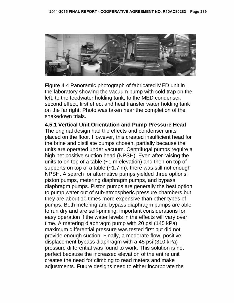
Figure 4.4 Panoramic photograph of fabricated MED unit in the laboratory showing the vacuum pump with cold trap on the left, to the feedwater holding tank, to the MED condenser, second effect, first effect and heat transfer water holding tank on the far right. Photo was taken near the completion of the shakedown trials.
4.5.1 Vertical Unit Orientation and Pump Pressure Head The original design had the effects and condenser units placed on the floor. However, this created insufficient head for the brine and distillate pumps chosen, partially because the units are operated under vacuum. Centrifugal pumps require a high net positive suction head (NPSH). Even after raising the units to on top of a table (~1 m elevation) and then on top of supports on top of a table (~1.7 m), there was still not enough NPSH. A search for alternative pumps yielded three options: piston pumps, metering diaphragm pumps, and bypass diaphragm pumps. Piston pumps are generally the best option to pump water out of sub-atmospheric pressure chambers but they are about 10 times more expensive than other types of pumps. Both metering and bypass diaphragm pumps are able to run dry and are self-priming, important considerations for easy operation if the water levels in the effects will vary over time. A metering diaphragm pump with 20 psi (145 kPa) maximum differential pressure was tested first but did not provide enough suction. Finally, a moderate-flow, positive displacement bypass diaphragm with a 45 psi (310 kPa) pressure differential was found to work. This solution is not perfect because the increased elevation of the entire unit creates the need for climbing to read meters and make adjustments. Future designs need to either incorporate the
2011-2015 FINAL REPORT - COOPERATIVE AGREEMENT NO. R10AC80283 Page 289

vertical orientation from the beginning, such as building the unit onto frames that include steps, or selecting brine and distillate pumps that can provide greater pressure differential.
4.5.2 Water Vapor and Vacuum Pump During one of the first test runs of the MED unit, it was noticed that a portion of vapor entering the condenser was being transferred into the vacuum pump along with non-condensable gases. This resulted in substantial cloudiness in the pump oil, jeopardizing the long-term durability of the pump, and steam losses from the system. To address the problem, a liquid nitrogen cold trap was added between the condenser and vacuum pump to condense vapors coming from the condenser. A butterfly valve was also installed at the pump intake port to enable isolation of the pump from the MED for liquid nitrogen refilling. Because the vapors and gases coming from the condenser are warm, the frequency of liquid nitrogen refills is higher than would be desired (approximately 4-6 L per hour of operation). Using crushed dry ice instead of liquid nitrogen did increase the cold trap’s capacity but required additional handling for crushing and trap filling. Future designs need to adjust the location of the vacuum outlet in the condenser to be farther away from the steam inlet to prevent vapors from flowing past the condenser tubes and directly out the vacuum outlet. Adding baffles to direct the steam flow over the pipes are another option. If a vacuum pump is to be used to provide unit pressure, an additional heat exchanger to further cool outlet gases prior to the cold trap would lower the liquid nitrogen/dry ice consumption.
4.5.3 Polycarbonate Sheeting and Vacuum Pressure The front panels of the two effects and the condenser are made from polycarbonate to allow direct observation into the units. Upon running the vacuum pump, the polycarbonate covers on the first and second effects of the MED buckled inward, putting pressure on the seals at the unit corners and threatening to crack the cover in the middle. To address this, three aluminum bars, shaped to prevent impeding water flow in the effects, were added horizontally to stabilize the polycarbonate sheet. Bars were not needed for the condenser
2011-2015 FINAL REPORT - COOPERATIVE AGREEMENT NO. R10AC80283 Page 290

unit as the surface area of the condenser is much smaller than that of the effects. Future problems with buckling can be prevented by using metal for all sides of the units or selecting a polymer shape and thickness that better withstand vacuum; both options would eliminate direct visual observation, so some form of sight glass might also be considered.
4.5.4 Preheating Feedwater One of the main obstacles to distilled water recovery rates is the low temperature of the feedwater entering the effects. In the current unit, the feedwater temperature after the condenser and before the first effect does not exceed 35°C, which is much lower than the first effect’s designed operating temperature of 61°C. A decrease in the first effect’s temperature decreases the amount of steam that is produced to heat the second effect, which then reduces the amount of steam flowing into the condenser to produce distillate and to warm the feedwater. After a few minutes of successful operation, the unit cools too much and the distilled water production rate is reduced to the tiny amount of feedwater that flashes under the vacuum conditions. Addition of insulation around exterior surfaces of the units, exposed plumbing, and holding tanks, and a heat tape on the piping between the condenser and the first effect, was not sufficient. (Preheating the feedwater in the feedwater holding tank would help as long as the temperature increase is not too much or the feedwater will not be cool enough to condense the water vapor in the condenser.) Future designs will need to consider an additional heat exchanger between the condenser and the first effect. In a lab research unit such as this one, heat for the heat exchanger could again come from a hot water supply as with the heat exchanger water used to warm the first effect. In a field unit, heat to preheat the feedwater could come from the final cooling step of flue gases coming from the biomass pyrolysis off-gas combustion chamber.
4.6 Future Unit Improvements
As with any design project and proof-of-concept prototype, the fabrication and shakedown trial process highlighted many opportunities for unit improvement.
2011-2015 FINAL REPORT - COOPERATIVE AGREEMENT NO. R10AC80283 Page 291

The first improvements have to do with the fabrication materials. While aluminum is relatively inexpensive, lightweight and easy to machine, aluminum is also susceptible to corrosion over time, especially in a continuously wet environments. Corrosion can be partially mitigated using an anodization process. A better option may be to construct the effects and condenser out of a rigid, molded polymer or polymer composite that can be machined, can stand up to the vacuum pressures, and can tolerate the moderate temperatures (50-80°C). A polymer molding process would also enable the corners of the effects to be rounded instead of square, a shape that is more suitable for pressurized chambers, and the addition of exterior flanges. Polymer materials generally have lower densities and lower thermal conductivities than aluminum, which would lower the weight of the unit for easier set-up handling and reduce heat losses to the environment. The heat transfer surfaces in the current MED are horizontal smooth copper tubes, chosen to simplify fabrication while lowering incidents of scaling/fouling. To improve heat transfer and the amount of produced water, enhanced geometry (i.e. corrugated) tubes, such as GEWA B and GEWA C available from Weiland Materials, can be used. These tubes have various surface microstructures; examples are shown in Figure 4.5. Some past research has shown that heat transfer improvement can be as much as 150% (Galal, et al., 2010, Kalendar and Griffiths, 2001, Nae-Hyun and Webb, 1991). If such improvement could be done with this unit, small-scale MED units for rural communities and farmers could produce more water at lower costs without needing to increase the size of the entire MED unit. The next two improvements are related to heat exchange outside of the effects. An additional heat exchangers to preheat the feedwater would help maintain temperature in the first and second effects, thus increasing distilled water production and overall unit efficiency. Future work should focus on how to take advantage of heat from other sources,
2011-2015 FINAL REPORT - COOPERATIVE AGREEMENT NO. R10AC80283 Page 292

as well as to manage how heat is retained within the unit. The cold trap for the vacuum pump is effective for removing small amounts of water vapor from room temperature non-condensable gases. The off-gases being vented from the current MED condenser are too warm and contain too much water vapor. Relocating the inlets and outlets on the condenser, increasing the tortuosity of the steam flow in the condenser, and/or adding a heat exchanger to lower the vent gas temperature would lower the consumption rate of liquid nitrogen in the lab.
Figure 4.5. Examples of enhanced geometry (corrugated) copper tubes (http://www.wieland.com.sg/internet/en/products/tubes/product_catalogue_2/finned_tubes___gewa/gewa_b___gewa_c/gewabgewac_1.jsp). Framing and wall-mounting for the unit components would improve unit stability and enable clean-up of overlapping water and steam piping. Framing could include climbing mechanisms to simplify the process of reading meters. Selection of brine and distillate pumps with greater maximum displacement pressures would also enable the units to be mounted closer to the floor. A longer-term and larger-scale improvement would be the use of a gas ejector instead of a vacuum pump for providing system vacuum. This switch would lower the maintenance and electrical power requirements of the system and would remove the need for cryogenics to operate a cold trap. Combined with optimization of heat exchangers and selection
2011-2015 FINAL REPORT - COOPERATIVE AGREEMENT NO. R10AC80283 Page 293

of water pumps, the electrical power requirements for the unit might be substantially reduced, thus reducing the load on the pyrolyzer-MED interface turbine generator. All potential improvements will be evaluated using capital and operating cost estimates through Aspen Plus® simulations of the MED and overall biomass pyrolysis-MED processes building on simulation work begun in our previous project.
2011-2015 FINAL REPORT - COOPERATIVE AGREEMENT NO. R10AC80283 Page 294

5. Water Testing Water desalination research on the fabricated MED unit is centered on the interaction of water chemistry and thermal desalination conditions to reduce mineral scale on heat transfer surfaces. Initial tests focused on water chemistries like that of Well 1 at the Brackish Groundwater National Desalination Research Facility (BGNDRF,) which contain sodium, calcium, chloride, bicarbonate, and sulfate as the primary ions at total dissolved solids (TDS) concentrations between 1000-2000 ppm (mg/L) and pH values of 7.0-8.5 (see Table 2.1). A negative control water chemistry was designed to benchmark operation of the MED. This data would be contrasted to operation performance data from treating a positive control water chemistry that was purposefully designed to promote scaling. Follow-on experiments will use the two negative control and positive control benchmarks to identify operating conditions for various brackish water chemistries that optimize distilled water production and prevent scaling.
5.1 Negative Control Benchmark
For the negative control water chemistry, a TDS of 1,200 ppm and a pH of 7.1 with 600 ppm of NaCl and 600 ppm of CaCl2 was chosen to represent the mildest scenario for brackish groundwater in terms of the likelihood of forming CaCO3 and CaSO4 scale. The relatively low pH was to ensure that any carbon dioxide from the air that dissolved into the solution would remain as bicarbonate (HCO3
-) ions rather than less-soluble carbonate (CO3
2-) ions. Enough negative control water to fill the MED feedwater holding tank (245 L) was prepared by dissolving 147 g each of NaCl and CaCl2 salts in distilled water, adjusting the pH to 7.1 using dilute hydrochloric acid and sodium hydroxide solutions, and diluting to final volume. The MED operation for the negative control runs was conducted as follows: the heat transfer water temperature was preheated to 78°C, the vacuum pump run to evacuate the system for 30 minutes prior to starting the test, and the feedwater set to recirculate
2011-2015 FINAL REPORT - COOPERATIVE AGREEMENT NO. R10AC80283 Page 295

through the holding tank to ensure good mixing. Once the MED was at the desired operating conditions (system pressure ≈ 0.2 bara and first effect temperature = 61°C), the valve between the feedwater tank and the first effect was opened to spray feed water into the first effect at a rate of approximately 1 gal/min (3.7 L/min). After about five minutes, the valve was opened to allow feedwater to spray into the second effect. As brine and distillate water collected in the effects and the condenser, the brine and distillate water pumps were switched on. The unit was allowed to run for about 80 minutes; temperatures, pressures, and flow rates were monitored and the values recorded every 2-5 minutes using the sensors at several locations on the MED (see Figure 4.3). The temperature of the cold trap was also monitored; as soon as the trap’s outer surface felt warm to the touch, the vacuum pump was temporarily isolated from the system and the liquid nitrogen reservoir refilled. Once the test was complete, the volumes of feedwater, brine, distillate water collected in the condenser, and distillate water collected in the cold trap were recorded. A pH and electrical conductivity (EC) meter (Fisher Scientific, Waltham, MA) was used to measure the pH and TDS concentrations of the feedwater and the collected water samples. The test runs were hampered by a relatively rapid temperature decrease in the system that led to almost no distilled water production after the first five or ten minutes of operation. An example of the temperatures observed in the system over the course of the test are shown in Figure 5.1. The temperature in the first effects started at 61°C, then decreased to 50-55°C after five minutes, then continued to decrease gradually to about 40°C by the end of the test. At the current system pressure, temperatures much below 60°C do not allow evaporation of water from the feedwater stream to produce steam. From about 5 to 15 minutes into the test, the temperature in the second effect and the condenser was briefly warmed by steam from the first effect from room temperature to about 37°C and 35°C, respectively. After steam was produced in the effects and traveled to the condenser, the temperature of the feedwater did increase
2011-2015 FINAL REPORT - COOPERATIVE AGREEMENT NO. R10AC80283 Page 296

from room temperature to about 35°C—warm but not warm enough to maintain the temperature in the first effect and to ensure effective MED operation.
Figure 5.1 Temperatures of the feedwater and the interiors of the effects and the condenser of the MED unit during a desalination test run of the negative control feedwater formulation. Given the temperatures within the unit, the produced water volumes were as expected: approximately 2 L of distilled water was collected in the condenser in the first five minutes of operation and almost no water thereafter. In the 1 hour+ operation time, approximately 200 ml of distilled water was collected in the vacuum cold trap, indicating that substantial produced steam was being vented prematurely from the system. The pH, EC, and TDS data for the water samples from the negative control test shown in Figure 5.1 are shown in Table 5.1. As expected, the TDS of the distillate water was very low (5 ppm) and the TDS of the feedwater (1150 ppm) was less than that of the collected brine (1231 ppm). The measured pH values, however, were lower than expected (5.9-6.7) given that the pH of the prepared feedwater was
20253035404550556065
Tem
pera
ture
(°C
)
Time (min)
Negative Control MED Test
Effect 1 Effect 2 Condenser Feedwater
2011-2015 FINAL REPORT - COOPERATIVE AGREEMENT NO. R10AC80283 Page 297
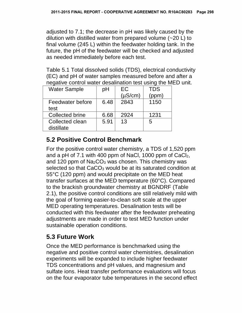
adjusted to 7.1; the decrease in pH was likely caused by the dilution with distilled water from prepared volume (~20 L) to final volume (245 L) within the feedwater holding tank. In the future, the pH of the feedwater will be checked and adjusted as needed immediately before each test. Table 5.1 Total dissolved solids (TDS), electrical conductivity (EC) and pH of water samples measured before and after a negative control water desalination test using the MED unit. Water Sample pH EC
(µS/cm) TDS (ppm)
Feedwater before test
6.48 2843 1150
Collected brine 6.68 2924 1231 Collected clean distillate
5.91 13 5
5.2 Positive Control Benchmark
For the positive control water chemistry, a TDS of 1,520 ppm and a pH of 7.1 with 400 ppm of NaCl, 1000 ppm of CaCl2, and 120 ppm of Na2CO3 was chosen. This chemistry was selected so that CaCO3 would be at its saturated condition at 55°C (120 ppm) and would precipitate on the MED heat transfer surfaces at the MED temperature (60°C). Compared to the brackish groundwater chemistry at BGNDRF (Table 2.1), the positive control conditions are still relatively mild with the goal of forming easier-to-clean soft scale at the upper MED operating temperatures. Desalination tests will be conducted with this feedwater after the feedwater preheating adjustments are made in order to test MED function under sustainable operation conditions.
5.3 Future Work
Once the MED performance is benchmarked using the negative and positive control water chemistries, desalination experiments will be expanded to include higher feedwater TDS concentrations and pH values, and magnesium and sulfate ions. Heat transfer performance evaluations will focus on the four evaporator tube temperatures in the second effect
2011-2015 FINAL REPORT - COOPERATIVE AGREEMENT NO. R10AC80283 Page 298

(to enable calculations of experimental heat transfer coefficients) and the distilled water production rates. Scaling will be observed visually and through heat transfer calculations. Periodically, the unit will be disassembled to test scale removal (cleaning) methods.
2011-2015 FINAL REPORT - COOPERATIVE AGREEMENT NO. R10AC80283 Page 299

6. Project Outcomes
6.1 Research Capacity Building
This developed the expertise and laboratory research capabilities of a new assistant professor in Chemical & Materials Engineering (Brewer). Funds from this project, combined with faculty start-up funds, contributed to the purchase and set up of several pieces of equipment associated with the MED unit. Collaborations were fostered between the PI and researchers/staff at New Mexico State University in the Institute for Energy & the Environment (IEE), the Manufacturing Technology & Engineering Center, the Department of Mechanical Engineering, Extension Food Technology, and the NMSU Agricultural Experiment Stations. Two graduate students and two undergraduate students received training in research methods, sample analysis, and laboratory safety, as well as experience in conducting original research. In addition to conference presentations, travel funding provided through this project enabled Dr. Brewer to attend the American Water Works Association (AWWA) Sustainable Water Management Conference and Mr. Amiri to attend the Water Reuse Research Foundation (WateReuse) 19th Annual Water Reuse and Desalination Research Conference as part of the expertise building process.
6.2 Theses, Publications, and Presentations
Work on this project has resulted in two manuscripts in preparation (titles are tentative), part of one in-progress Ph.D. dissertation, part of one completed M.S. thesis, and three conference presentations (two upcoming with abstract accepted): Amiri, A., Zhang, Y., Idowu, O.J., Brewer, C.E., Design of biomass pyrolyzer-multiple effect distillation system interface, in preparation.
2011-2015 FINAL REPORT - COOPERATIVE AGREEMENT NO. R10AC80283 Page 300

Amiri, A., Brewer, C.E., Small-scale brackish water thermal desalination using low-temperature multiple effect distillation to prevent scaling, in preparation. Amiri, A., Biomass as a renewable energy source for brackish water thermal desalination, Ph.D. Dissertation, Engineering: Chemical Engineering, New Mexico State University, expected Fall 2016. Zhang, Y., Design of biomass pyrolyzer-multiple effect distillation system components for laboratory testing, M.S. Thesis, Chemical Engineering, New Mexico State University, June 2015. Amiri, A., Zhang, Y., Brewer, C.E., Design and Fabrication of a Lab-Scale Multiple Effect Distillation (MED) Unit to Investigate Different Water Chemistry and Scaling Behavior, 2015 American Institute of Chemical Engineers Annual Meeting, Salt Lake City, UT, November 10, 2015. Amiri, A., Brewer, C.E., Small-scale Thermal Desalination of Brackish Water Using Biomass Energy, Water Resources Research Institute 60th Annual New Mexico Water Conference, Taos, NM, October 9, 2015. Zhang, Y., Amiri, A., Brewer, C.E., Idowu, O.J., Design and testing of biomass pyrolyzer-multiple effect distillation system components for laboratory testing, 2015 American Institute of Chemical Engineers Spring Meeting, Austin, TX, April 28, 2015.
6.3 Follow-On Proposals
Research conducted during this project has resulted in the submission of two directly related follow-on proposals, the first of which progressed to Phase II consideration and is currently be revised for resubmission, and the second of which was prepared by Mr. Amiri and was not funded:
"Halophytes and Biochar for Desalination Concentrate Management"
2011-2015 FINAL REPORT - COOPERATIVE AGREEMENT NO. R10AC80283 Page 301

US Department of Interior/Bureau of Reclamation Desalination and Water Purification Research & Development 12/1/15-12/31/16, $149,977, PIs: Brewer, Rastegary, Idowu “Corrugated Tubes for Brackish Water Desalination Improvement” New Mexico Water Resources Research Institute FY 16 Student Water Research Grant Program 10/1/15-6/30/16, $6,000, PI: Amiri (Brewer as faculty sponsor)
Collaborations fostered through this research project have resulted in the submission of three additional related proposals, the first of which is currently pending; the other two are under revision for resubmission:
“Holistic Approach for Sustainable Agriculture” USDA AFRI Water for Agriculture 1/1/16-12/31/19; $10,000,000, PIs: Ghassemi, et al. Large, multi-institutional, long-term integrated research, extension and education project focusing on water desalination techniques, use of algal and halophyte biomass, algal food products, and on-farm nutrient, water and energy use. "Integrated Training Network for Water and Energy Process Improvement Impacting WAMS" USDA NIFA Women and Minorities in STEM Fields 5/16/16-5/15/18, $141,230, PIs: Brewer, Sullivan, Flores, Valles-Rosales Train-the-trainer program to incorporate water audits, energy audits and cost benefit analysis into freshmen engineering classes and extension outreach. "Design of a Mobile Torrefaction System for Invasive Species Biomass Utilization" USDA AFRI Engineering 8/16/15-8/15/18, $479,279, PIs: Brewer, Conley Construction and testing of biomass torrefaction/pyrolysis field unit that could be used to pretreat tumbleweed and salt cedar biomass on-farm.
6.4 Other Products
Other products that are the result of this project include: • a lab-scale, two-effect thermal multiple effect distillation
unit available for thermal water desalination and general heat exchanger research;
2011-2015 FINAL REPORT - COOPERATIVE AGREEMENT NO. R10AC80283 Page 302

• an updated Aspen Plus® simulation file allowing model experimentation with different scales and conditions for the biomass pyrolyzer-MED interface;
• a long-term case study and example problems for teaching conduction and convection heat transfer used in Dr. Brewer’s Fall 2015 CHME 306 Transport Phenomena II: Heat and Mass Transfer class (43 students, mostly juniors majoring in chemical engineering);
• a webpage describing the project and results: http://wordpress.nmsu.edu/cbrewer/projects/
2011-2015 FINAL REPORT - COOPERATIVE AGREEMENT NO. R10AC80283 Page 303
Reference List 2012. 2011-2012 IDA Deslination Yearbook, Global Water Intelligence, London. Al-Anezi, K. and N. Hilal, 2007. Scale formation in desalination plants: effect of carbon dioxide solubility, Desalination, 204, 385-402. Al-Jaroudi, S.S., A. Ul-Hamid and J.A. Al-Matar, 2010. Prevention of failure in a distillation unit exhibiting extensive scale formation, Desalination, 260, 119-128. Al-Karaghouli, A. and L.L. Kazmerski, 2013. Energy consumption and water production cost of conventional and renewable-energy-powered desalination processes Renew. Sust. Energ. Rev., 24, 343-356. Al-Rawajfeh, A.E., 2010. CaCO3-CO2-H2O system in falling film on a bank of horizontal tubes: model verification, J. Ind. Eng. Chem., 16, 1050-1058. Al-Rawajfeh, A.E., H. Glade, H.M. Qiblawey and J. Ulrich, 2004. Simulation of CO2 release in multiple-effect distillers, Desalination, 166, 41-52. Brewer, C.E. and O.J. Idowu, 2015. Design of Pyrolyzer-Desalination Unit Interface for Distributed Biochar and Clean Water Production, Report No. ###, USBOR, Denver, CO. Cai, H., X. Li and S. Xu, 2008. Purification technology for removing volatile organic carbons, Journal of Chemical Industry and Engineering, 3, 6 (in Chinese). Cao, Q.W., 2012. Investigate the combustion of organic waste treatment, Technology Vision, 27, 356-357 (in Chinese). CRC, 2003. CRC Handbook of Chemistry and Physics, Chemical Rubber Publishing Company, Boca Raton, FL.
2011-2015 FINAL REPORT - COOPERATIVE AGREEMENT NO. R10AC80283 Page 304

Darwish, M.A. and H.K. Abdulrahim, 2008. Feed water arrangements in a multi-effect desalting system, Desalination, 228, 30-54. Eltawil, M.A., Z. Zhengming and L. Yuan, 2009. A review of renewable energy technologies integrated with desalination systems, Renew. Sust. Energ. Rev., 13, 2245-2262. Galal, T., A. Kalendar, A. Al-Saftawi and M. Zedan, 2010. Heat transfer performance of condenser tubes in an MSF desalination system, Journal of Mechanical Science and Technology, 24, 2347-2355. Hanson, A., W. Zachritz, K. Stevens, L. Mimbela, R. Polka and L. Cisneros, 2004. Distillate water quality of a single-basin solar still: laboratory and field studies, Sol. Energy, 76, 635-645. Hewitt, W.L., 1971, Direct spark igniter combustion safeguard apparatus, U.S. Patent 3,574,496. Inc., T.T., 2013. 2012 Analysis of Water from Four Wells and Three Ponds at the Brackish Groundwater National Desalination Research Facility, Report No. Albuquerque, NM. Incropera, F.P., D.P. Dewitt, T.L. Berman and A.S. Lavine, 2007. Fundamentals of Heat and Mass Transfer, John Wiley and Sons, Hoboken, NJ. Kalendar, A. and A. Griffiths, 2001. Performance study of enhanced and smooth surface tubes in a system condenser of a multistage flash desalination unit, Desalination, 134, 269-283. Kalogirou, S., 1997. Survey of solar desalination systems and system selection, Energy, 22, 69-81. Kalogirou, S.A., 2005. Seawater desalination using renewable energy sources, Prog. Energ. Combust., 31, 242-281.
2011-2015 FINAL REPORT - COOPERATIVE AGREEMENT NO. R10AC80283 Page 305

Kim, H.-H., S.-M. Oh, A. Ogata and S. Futamura, 2005. Decomposition of gas-phase benzene using plasma-driven catalyst (PDC) reactor packed with Ag/TiO 2 catalyst, Applied Catalysis B: Environmental, 56, 213-220. Likhachev, D.S. and F.-C. Li, 2013. Large-scale water desalination methods: a review and new perspectives, Desalination and Water Treatment, 51, 2836-2849. Nae-Hyun, K. and R.L. Webb, 1991. Particulate fouling of water in tubes having a two-dimensional roughness geometry, International Journal of Heat and Mass Transfer, 34, 2727-2738. Semiat, R. and D. Hasson, 2012. Water desalination, Rev. Chem. Eng., 28, 43-60. Tong, Z.-Q., 2001. The Purification and Utilization of Industrial Exhaust Gas, Chemical Industry Press, Beijing (in Chinese). Urashima, K. and J.-S. Chang, 2000. Removal of volatile organic compounds from air streams and industrial flue gases by non-thermal plasma technology, IEEE Transactions on Dielectrics and Electrical Insulation, 7, 602-614.
2011-2015 FINAL REPORT - COOPERATIVE AGREEMENT NO. R10AC80283 Page 306

Appendix
Surface Area Calculations for Heat Exchangers
First Effect
𝑄𝑄𝑠𝑠𝑠𝑠𝑠𝑠𝑠𝑠𝑠𝑠 = 𝑚𝑚𝑠𝑠𝑠𝑠𝑠𝑠𝑠𝑠𝑠𝑠 × ℎ63.5𝐶𝐶 =10𝑘𝑘𝑘𝑘ℎ𝑟𝑟 ×
2350𝑘𝑘𝑘𝑘𝑘𝑘𝑘𝑘 =
23500𝑘𝑘𝑘𝑘ℎ𝑟𝑟
= 6527.78𝑊𝑊
6527.78 = 𝑚𝑚𝑤𝑤𝑠𝑠𝑠𝑠𝑠𝑠𝑤𝑤 × 𝐶𝐶𝑝𝑝 × ∆𝑇𝑇 => 𝑎𝑎𝑎𝑎𝑎𝑎𝑎𝑎𝑚𝑚𝑎𝑎𝑎𝑎𝑘𝑘 ∆𝑇𝑇 = 10℃:
𝑚𝑚𝑤𝑤𝑠𝑠𝑠𝑠𝑠𝑠𝑤𝑤 =6527.78
4.12 × 10 = 158.45𝑘𝑘𝑎𝑎 =
570.42𝑘𝑘𝑘𝑘ℎ𝑟𝑟
6527.78 = 𝑈𝑈 × 𝐴𝐴 × ∆𝑇𝑇𝐿𝐿𝐿𝐿𝐿𝐿𝐿𝐿 ,
∆𝑇𝑇𝐿𝐿𝐿𝐿𝐿𝐿𝐿𝐿 =∆𝑇𝑇1 − ∆𝑇𝑇2
𝑙𝑙𝑎𝑎 ∆𝑇𝑇1∆𝑇𝑇2
=[(70− 63.5)− (63.5 − 60)]
ln �6.53.5�
= 4.84℃
Assuming U = 3000 W/m2°C :
6527.78 = 3000 × 𝐴𝐴 × 4.84
𝐴𝐴 = 0.45𝑚𝑚2 = 𝜋𝜋𝜋𝜋𝜋𝜋 For D = 1’’= 0.0254 m
𝜋𝜋𝑐𝑐𝑐𝑐𝑐𝑐𝑐𝑐 =0.45
𝜋𝜋 × 0.0254 = 5.64𝑚𝑚 = 18.5𝑓𝑓𝑓𝑓 The amount of feed water evaporated within the first effect will be:
6527.78 = 𝑀𝑀𝑓𝑓1 × 𝐶𝐶𝑝𝑝𝑓𝑓 × (𝑇𝑇𝑏𝑏1 − 𝑇𝑇𝐹𝐹ℎ) + 𝑀𝑀𝑠𝑠1 × ℎ𝑠𝑠1 Where Tb1 is the top brine temperature which is 63.5°C and TF is the temperature of feed water being sprayed into the first effect which is set to be 55°C. Mf1 is the mass flow rate of feed water in the first effect which is 40 kg/hr = 11.11 g/s. Also, if
2011-2015 FINAL REPORT - COOPERATIVE AGREEMENT NO. R10AC80283 Page 307
we neglect the BPE the hs1 will be the same as h63.5 = 2350 kJ/kg:
𝑀𝑀𝑆𝑆1 =6527.78 − 11.11 × 4.12 × (63.5− 55)
2350 = 2.61𝑘𝑘𝑎𝑎 = 9.4
𝑘𝑘𝑘𝑘ℎ𝑟𝑟
2011-2015 FINAL REPORT - COOPERATIVE AGREEMENT NO. R10AC80283 Page 308

2nd Effect Assuming OD = 1”, U = 3409 W/m2°C, ∆T= 4°C, L= 700 mm, 𝑀𝑀𝑠𝑠1 × ℎ𝑠𝑠1 = 𝑈𝑈 × 𝐴𝐴 × ∆T => A = 0.44 𝑚𝑚2 = 𝑎𝑎𝜋𝜋𝜋𝜋𝜋𝜋 => 𝑎𝑎 = 8
𝑀𝑀𝑠𝑠1 × ℎ𝑠𝑠1 = 𝑀𝑀𝑓𝑓2 × 𝐶𝐶𝑝𝑝𝑓𝑓 × (𝑇𝑇𝑏𝑏2 − 𝑇𝑇𝐹𝐹) + 𝑀𝑀𝑠𝑠2 × ℎ𝑠𝑠2@60𝐶𝐶 2.61𝑔𝑔𝑠𝑠
× 2350 = 11.11 × 4.12 × (60 − 55) + 𝑀𝑀𝑠𝑠2 × 2358.6
Ms2 = 2.31 g/s = 8.31kg/hr Condenser
LMTD =(𝑇𝑇𝑐𝑐 − 𝑇𝑇𝐹𝐹𝑐𝑐) − (𝑇𝑇𝑐𝑐 − 𝑇𝑇𝐹𝐹ℎ)
𝜋𝜋𝑎𝑎 (𝑇𝑇𝑐𝑐 − 𝑇𝑇𝐹𝐹𝑐𝑐)(𝑇𝑇𝑐𝑐 − 𝑇𝑇𝐹𝐹ℎ
= (59 − 25)− (59− 55)
𝜋𝜋𝑎𝑎(344 )
= 14℃ Where Tc is the temperature at condenser shell, TFc, the temperature of incoming feed water, TFh the temperature of pre-heated feed water. Assuming U = 3000 W/m2°C : 𝑀𝑀𝑓𝑓 × 𝐶𝐶𝑝𝑝 × ∆𝑇𝑇𝐹𝐹 = 𝑈𝑈 × 𝐴𝐴 × ∆𝑇𝑇𝐿𝐿𝐿𝐿𝐿𝐿𝐿𝐿 43 𝑔𝑔
𝑠𝑠× 4.12 × 30 = 3000 ×
𝐴𝐴 × 14 A = 0.126 m2 = 126542 mm2 𝐴𝐴 = 𝜋𝜋 × 𝜋𝜋 × 𝜋𝜋 assuming OD = 1” L = 1585mm = 1.585m = 5.2 ft
2011-2015 FINAL REPORT - COOPERATIVE AGREEMENT NO. R10AC80283 Page 309