construction, operation, and maintenance plan … · provided for the construction, operation and...
TRANSCRIPT

CONSTRUCTION, OPERATION, AND MAINTENANCE PLAN
PLAN OF DEVELOPMENT
TRINITY PUBLIC UTILITIES DISTRICT DIRECT INTERCONNECT PROJECT
Submitted to:
USDA Forest Service
Shasta-Trinity National Forest
USDI Bureau of Land Management Redding Field Office
USDI Bureau of Reclamation
Northern California Area Office
Submitted by:
Department of Energy Western Area Power Administration
Sierra Nevada Region
April 2008

i
TABLE OF CONTENTS I. INTRODUCTION................................................................................................................ 1 II. PROJECT Description ........................................................................................................ 3 III. DESIGN CRITERIA ........................................................................................................... 6
A. Road Specifications ......................................................................................................... 6 B. Power Line Specifications ............................................................................................... 6 C. Additional Project Components ....................................................................................... 7
IV. COORDINATION AND COOPERATION ...................................................................... 8
A. Principal Representatives ................................................................................................. 8 B. Reports ............................................................................................................................. 9 C. Noncompliance ................................................................................................................ 9 D. Plan Amendments and Changes ....................................................................................... 9 E. Tracking and Identification .............................................................................................. 9
V. FIRE PLAN ........................................................................................................................ 10
A. Fire Call Directory ......................................................................................................... 10 B. Background Information of Fires................................................................................... 11 C. Fire Precaution Measures ............................................................................................... 11
VI. Project Construction .......................................................................................................... 14
A. Construction Schedule ................................................................................................... 14 B. Survey ............................................................................................................................ 14 C. Clearing Requirements................................................................................................... 14 D. Access Road Requirements............................................................................................ 16 E. Construction Staging Areas ........................................................................................... 17 F. Pole, Line, and Conductor Removal .............................................................................. 18 G. Pole Delivery and Installation ........................................................................................ 18 H. Conductor Installation .................................................................................................... 19 I. Cleanup and Restoration of Construction Areas ............................................................ 20 J. Construction of Weaverville Switchyard ....................................................................... 21 K. Construction Upgrades at the Trinity Substation ........................................................... 21 L. Environmental Requirements......................................................................................... 24
VII. OPERATION AND MAINTENANCE OF THE FACILITY ....................................... 25
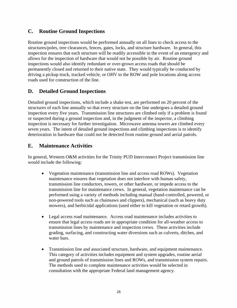
A. Inspection/System Management .................................................................................... 27 B. Aerial Inspections .......................................................................................................... 27 C. Routine Ground Inspections .......................................................................................... 28 D. Detailed Ground Inspections .......................................................................................... 28 E. Maintenance Activities .................................................................................................. 28 F. Manual Vegetation Control Methods ............................................................................. 30 G. Mechanical Vegetation Control Methods ...................................................................... 33

ii
H. Herbicide Control Methods............................................................................................ 33 I. Clearing Culverts and Ditches ....................................................................................... 36 J. Removing Slide Debris .................................................................................................. 37 K. Repairing Road Structures ............................................................................................. 38 L. Repairing Damaged Access Roads ................................................................................ 39 M. Transmission System Maintenance................................................................................ 39 N. Equipment/System Upgrades ......................................................................................... 40 O. Coordination with Regulatory and Land Management Agencies .................................. 40 P. Regulatory Coordination ................................................................................................ 40
VIII. GIS Database ...................................................................................................................... 44
A. GIS Data on DVD/External Drive ................................................................................. 45 IX. TERMINATION AND REHABILITATION.................................................................. 46 X. MISCELLANEOUS INFORMATION ............................................................................ 46 APPROVAL/CONCURRENCE .................................................................................................47

iii
APPENDICES A. Trinity-Weaverville Overview Map B. Trinity-Weaverville Plan & Profiles Drawings C. Trinity-Weaverville Ownership Maps D. Construction Contract Specifications, including Timber Sale Specifications E. Mitigation Action Plan, January 2008 F. Weaverville Substation Site Plan - Draft G. Transportation Plan H. Construction Schedule I. Trinity-Weaverville 60-kV Transmission Line Maps J. Federal Agency Environmental Protection Measures K. Construction Standard 13 – Environmental Quality Protection L. Environmental Site Maps M. National Bald Eagle Management Guidelines (USFWS 2007d) N. Spotted Owl Habitat Map O. Herbicides (Appendix D of Final EIS) P. Waters of the U.S. Map Q. Aviation and Safety Plan R. Noxious Weed Plan S. Pesticide Use Plan
TABLES Table 1 Personnel and Construction Equipment Table 2 Areas of Disturbed Land
FIGURES Figure 1 Trinity Substation Figure 2 Wire Zone/Border Zone Management Practice Figure 3 Buffered Vegetation Management

1
Construction, Operation, and Maintenance Plan Plan of Development
Trinity PUD Direct Interconnection Project I. INTRODUCTION Western Area Power Administration (Western) is planning to construct, own, operate, and maintain a power transmission facility between Trinity Dam and a new switchyard at Weaverville, Trinity County, California. See Appendix A for an overview of the area. The new transmission line and associated facilities, including access, is known as the Trinity Public Utilities District (PUD) Direct Interconnection (Project). The life of the Project is expected to be 50 years before major renovation work takes place. See Appendix B for Trinity-Weaverville (TNI-WEA) Plan & Profile Drawings. Portions of the Project would cross National Forest System (NFS) lands managed by the U.S. Forest Service (USFS) Shasta-Trinity National Forest, public lands administered by the Bureau of Land Management’s (BLM) Redding Field Office, and National Forest System lands jointly administered by the Bureau of Reclamation’s (Reclamation) Northern California Area Office and the USFS. See Appendix C, TNI-WEA Ownership Maps for an overview of the administrative jurisdictions crossed by this Project. An Environmental Impact Statement (EIS) has been prepared for the Project. Western was the lead Federal agency on this effort; the USFS, BLM, and Reclamation were cooperating agencies. The EIS satisfies the requirements of the National Environmental Policy Act (NEPA) for each Federal agency. Separate Records of Decision have been issued by Western, USFS, BLM and Reclamation. Western’s action was for the siting, construction, operation, and maintenance of the Project, and the other agencies for authorizing the project to be constructed on lands that they manage. Western is constructing, operating, and maintaining this Project in order to improve power system reliability in the Trinity PUD area by providing a direct interconnection to Western’s Trinity Power Plant transmission system. Under the Trinity River Division (TRD) Act of August 12, 1955, Western is required to deliver energy to the Trinity PUD. The TRD Act provided for the construction, operation and maintenance of the TRD facilities of the Central Valley Project, composed of the Trinity Dam, Lewiston Dam, and Clear Creek Tunnel (which transports water from Lewiston Lake into Whiskeytown Lake). Construction of this Project includes removal of about 5.3 miles of existing 12-kilovolt (kV) distribution line and construction and operation of about 16 miles of new 60-kV transmission line, a tap structure and associated equipment, and a new switchyard near Weaverville. Western would maximize the use of existing access roads but would need to construct a total of approximately five miles of new roads, which would consist of a number of short spur roads extending from existing access roads to individual structure locations.
2
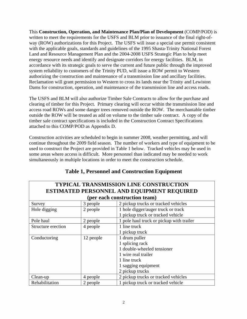
This Construction, Operation, and Maintenance Plan/Plan of Development (COMP/POD) is written to meet the requirements for the USFS and BLM prior to issuance of the final right-of-way (ROW) authorizations for this Project. The USFS will issue a special use permit consistent with the applicable goals, standards and guidelines of the 1995 Shasta-Trinity National Forest Land and Resource Management Plan and the 2004-2008 USFS Strategic Plan to help meet energy resource needs and identify and designate corridors for energy facilities. BLM, in accordance with its strategic goals to serve the current and future public through the improved system reliability to customers of the Trinity PUD, will issue a ROW permit to Western authorizing the construction and maintenance of a transmission line and ancillary facilities. Reclamation will grant permission to Western to cross its lands near the Trinity and Lewiston Dams for construction, operation, and maintenance of the transmission line and access roads. The USFS and BLM will also authorize Timber Sale Contracts to allow for the purchase and clearing of timber for this Project. Primary clearing will occur within the transmission line and access road ROWs and some danger trees removed outside the ROW. The merchantable timber outside the ROW will be treated as add on volume to the timber sale contract. A copy of the timber sale contract specifications is included in the Construction Contract Specifications attached to this COMP/POD as Appendix D. Construction activities are scheduled to begin in summer 2008, weather permitting, and will continue throughout the 2009 field season. The number of workers and type of equipment to be used to construct the Project are provided in Table 1 below. Tracked vehicles may be used in some areas where access is difficult. More personnel than indicated may be needed to work simultaneously in multiple locations in order to meet the construction schedule.
Table 1, Personnel and Construction Equipment
TYPICAL TRANSMISSION LINE CONSTRUCTION ESTIMATED PERSONNEL AND EQUIPMENT REQUIRED
(per each construction team)Survey 3 people 2 pickup trucks or tracked vehicles Hole digging 2 people 1 hole digger/auger truck or track
1 pickup truck or tracked vehicle Pole haul 2 people 1 pole haul truck or pickup with trailer Structure erection 4 people 1 line truck
1 pickup truck Conductoring 12 people 1 drum puller
1 splicing rack 1 double-wheeled tensioner 1 wire real trailer 1 line truck 1 sagging equipment 2 pickup trucks
Clean-up 4 people 2 pickup trucks or tracked vehicles Rehabilitation 2 people 1 pickup truck or tracked vehicle
3
Most, if not all, the logging on public lands will occur using a helicopter. To make certain construction activities are managed to minimize resource impacts, temporary work and staging areas are required. These areas could extend beyond the permanent ROW of 80 feet by as much as 20 feet depending on the terrain and equipment used at the site. An area approximately 30 by 40 feet per structure site is typically required for powerline line construction equipment. However, this area will be reduced to the extent possible throughout the study area. In addition, each structure site will be about five square feet except for structures that are guyed. Most guy wires will fall within the 80-foot wide ROW but may be outside that width depending on terrain. Sites for tensioning equipment are located about 10,000 feet apart. Pulling sites are about 100 by 60 feet and could occur outside the 80-foot ROW. Finally, construction yards or staging areas for equipment and pole storage could occur on Federal lands. At least two sites will be needed for this Project. These yards or staging areas are typically no more than three or four acres in size and are enclosed by a fence with a locked gate. Refer to Appendix A and Appendix C for additional information and locations of staging and helicopter landing areas. II. PROJECT DESCRIPTION The Project would require the removal of the existing 12-kV distribution line, expansion of the existing 20-foot wide ROW to a width of 80 feet, and the acquisition of a new 80-foot wide ROW for the rest of the Project. For the acquisition of ROW on private land, Western would acquire land rights in accordance with the applicable provisions of the Uniform Relocation Assistance and Real Property Acquisition Policies Act of 1970 (Public Law [P.L.] 91-646), as amended. Western would negotiate with the landowners to purchase easements at fair market value, determined by independent appraisals. Landowners would retain title to the land and could continue to use the property in ways that are compatible with the transmission line. If necessary, Western may acquire ROW easements by using its eminent domain authority; however, Western prefers to acquire easements through good faith negotiations with the landowner. To acquire any ROW that crosses Federal lands, Western would obtain permits or easements according to each agency’s process. ROW clearing for the transmission line and new roads would require removing trees. ROW clearing is done for the following reasons: to construct access roads and construction yards, to assemble and erect structures, to prepare for efficient installation of conductors, to provide for adequate and required electrical clearance for energized lines, to ensure system reliability, and to provide safe working conditions for these tasks. Conductor clearance is extremely important to prevent power outages, ensure system reliability, which may impact the power system in a very large region, and to prevent the line from being an ignition source for wildfires. To the extent possible, understory plants, shrubs, and low-growing brush or tree species would be left in place to reduce erosion potential and visual impacts and to preserve habitat. When ravines, especially those with riparian areas, are being crossed, relatively more vegetation would be left intact where conductors would be further from the ground. These ROW clearing procedures would promote a stable, low-growing plant community such as grasses and shrubs on the ROW. This type of plant community would be compatible with transmission line facilities, serving as an environmentally acceptable and useful ground cover, and naturally retarding the regrowth of tall-
4
growing vegetation. The frequency of future ROW maintenance operations and potential interruption of service would also be reduced for Western to a planned five-year vegetation management cycle. To manage the merchantable timber, Western would enter into a timber contract with the landowner or Federal land management agency for commercial timber produced from ROW clearing activities. A timber cruise of the Project area has been conducted in preparation for timber contract and timber sales activities. Timber cruising is the process of measuring forest stands to determine stand characteristics, such as average tree sizes, volume, and quality. The primary purpose of timber cruising is to obtain a volume estimation to appraise and prepare timber sales. The Project would require crossing streams classified as perennial, intermittent, and ephemeral with the transmission line and/or access roads. The term “streams” is used in the EIS to refer to all three classifications, except where a specific stream type is identified. The definition of each stream type is paraphrased from the USACE definitions provided in its 2007 nationwide permits. A perennial stream has flowing water year-round during a typical year. An intermittent stream has flowing water only during and for a short duration after precipitation events. Groundwater is the primary source of water for perennial and intermittent streams, with runoff from precipitation events a supplemental source. Stream flow for ephemeral streams comes solely from precipitation runoff. More than half of the streams in the Project area are ephemeral. Segment 1 of the Project would cross the Trinity River below Trinity Dam, and again near Lewiston Dam below the Fish Hatchery. These crossings would consist of conductors spanning the river to structures set well back from the banks on either side. Segment 3 of the Project would cross Rush Creek and Little Browns Creek. The Trinity River, Rush Creek, and Little Browns Creek are all perennial streams. There are no stream crossings in segment 2 of the Project. Existing roads would be used to cross all of the streams. Several streams have existing culverts, but the majority is low-water crossings (drive-through). Most of the streams have very low flow volumes and run over a rocky substrate. Where required, work in streams would consist of the placement of clean rock in streams, removal and/or replacement of culverts, or graveling a road across dry streams. If a culvert is removed and not replaced, the crossing would be converted to a low-water crossing. Local rock not within a cultural resource site would be used where possible. After the construction period, the crossings would probably be used once per year for routine inspection and maintenance in good weather, and would likely be used in the winter via snow cat during an emergency. Stream crossings below Lewiston Dam could have the potential to impact anadromous fish habitat. Western consulted with the National Marine Fisheries Service (NMFS) about the Project. Given the pole locations and planned activities near stream crossings, NMFS concurred with a “may affect, but is not likely to adversely affect” determination for federally listed anadromous fish species. If unanticipated activities would be required for stream crossings, NMFS would again be consulted regarding potential impacts to fish habitat. Mitigation

5
measures for stream crossings would also be implemented as described in the final EIS, Chapter 3, Affected Environment and Environmental Consequences and as Appendix E - Mitigation Action Plan, January 2008. Construction of the transmission line has been divided into four components: three transmission line segments and one switchyard (Appendix C). The first segment involves removal of the existing conductor and poles along 5.3-miles of the Trinity-Lewiston 12-kV distribution line. The existing ROW for the Trinity-Lewiston line runs through steep and rugged terrain, crossing ridges and gullies. Most of the lands are within the Shasta-Trinity National Forest, some are also within the Shasta-Trinity National Recreation Area, while about 1 mile is jointly administered by Reclamation and the USFS, 0.5 miles is owned by Sierra Pacific Industries, and 0.25 mile is privately owned. The existing ROW will be cleared of large vegetation to a width of 80 feet to accommodate the new 60-kV transmission line. This segment follows the existing distribution line ROW from Trinity Dam downstream to a three-way tap structure near Lewiston Dam, a distance of about 6.5 miles, including 5.3 miles of expanded existing ROW noted in the previous paragraph. The transmission line crosses the Trinity River in two places, one just below the Trinity Dam, the other below the Lewiston Dam near the Trinity River Fish Hatchery. Construction and maintenance of this segment of the Project will use the existing 12-kV distribution line access. About 0.5 mile of new short spurs will be constructed to provide access to new structures. The second segment involves construction of the three-way tap structure and a new 1.2-mile 60-kV transmission line that will be built south to the Trinity PUD Lewiston Substation. A steel monopole will be installed near Mile 6.5, west of the Trinity River Fish Hatchery, and a three-way switch will be attached to it. The switch will accommodate the incoming Trinity Substation line, the tap line to the Lewiston Substation, and the new line to the Weaverville Switchyard. The alignment of this segment parallels another existing Trinity PUD 12-kV distribution line to Lewiston Substation. Again, existing access roads associated with the existing distribution line will be used with new spurs constructed as needed to the new structure locations. The third segment involves construction of a new 60-kV transmission line from the Lewiston Tap to a new switchyard at Weaverville. The terrain is mostly steep and rugged. A portion of this 8.3-mile segment parallels the Pacific Gas & Electric (PG&E) Cottonwood-Humboldt 115-kV transmission line, and most of the alignment follows an existing logging road. SPI owns most of the land and manages it for timber production. BLM public lands are also crossed and about 0.25 mile is privately owned. A new 80-foot wide ROW is required, but access will be primarily along existing roads that may require minor improvements and some new short spurs will be constructed to provide access to new structures. The final component of this Project is the construction of the new switchyard at Weaverville. The switchyard is needed so that the new 60-kV transmission line can connect to the existing PG&E Trinity-Douglas City 60-kV Transmission Line. Western will obtain a ROW authorization from BLM for the new Weaverville Switchyard. The switchyard would be approximately 110 by 150 feet, which is included in the land permit. Access would be utilizing an abandoned section of State Route (SR) 299 (Appendix F - Weaverville Substation Site Plan).
6
III. DESIGN CRITERIA A. Road Specifications Western will use existing roads for most of its access needs. A total of about five miles of new access roads, mostly short spur roads extending from existing roads to individual structure locations, will need to be built as part of this Project. Of this total, about 1.5 miles would be located on public land. The typical road right-of-way width is 30 feet, although the actual road bed will only be 15 or 16 feet in width, except on sharp turns where the width may increase. The Transportation Plan prepared for this Project provides the detail needed for the USFS and BLM to issue a decision concerning access. The Transportation Plan is included as Appendix G to this COMP/POD. An aerial patrol will be conducted semi-annually to check for erosion, in addition to annual ground inspections. B. Power Line Specifications The Project crosses portions of Townships 33 and 34 North, Ranges 8 and 9 West, Mt. Diablo Meridian, Trinity County, California. The Project includes removal of 5.3 miles of an existing 12-kV distribution line and construction of a new 16-mile 60-kV transmission line. The Project connects to Western’s Trinity Substation located near Reclamation’s Trinity Power Plant. This substation is the northern terminus of the Project and is located at Trinity Dam about 10 miles northeast of Weaverville. The transmission line crosses the Trinity River below the dam, replacing the existing 12-kV line crossing, and crosses the river again near Lewiston Dam below the Trinity River Fish Hatchery. A tap line from a three-way switch structure is needed to distribute power to the Trinity PUD Substation north of Lewiston. The line continues west to a new Weaverville Switchyard, which is the southern terminus of this Project. The switchyard site lies about 2 miles south of Weaverville and east of SR 299. The Trinity PUD Direct Interconnection consists of a single circuit 60-kV transmission line with aluminum conductor steel reinforced (ACSR) conductors arranged in a horizontal or triangular configuration. A combination fiber optic cable and groundwire would be strung to provide communications capability and lightning protection as appropriate. The three conductors and a fiber optic communications cable will connect the 60-kV transmission line to Western’s existing Trinity Substation. Composite horizontal line post insulators would be used. Pole type, pole height, pole location, and the distance between poles will vary based on natural terrain and topography, structural limitations, cost, visual consideration, existing and proposed land uses, crossings manmade features such as roads, canals and telephone lines, and possible other considerations unique to the Project. The 60-kV transmission line will be constructed on wood poles ranging from 50 to 105 feet tall. Holes will be machine-augered for each wood pole and backfilled with material from the hole and any excess will be scattered around the pole area. Each hole will be 8 to 10 feet deep depending on the pole height. Holes will be hand dug in areas not accessible by an auger truck.
7
The span between poles will average 350 feet with a minimum of 100 feet and a maximum of 500 feet, depending on the terrain and other factors. Each mile of line would have about 16 structures with approximately 261 pole locations for the entire Project. Structures would be either single wood poles or three-pole turning structures. Segment 1 would require approximately 102 new poles; Segment 2 would require approximately 17 new poles; and Segment 3 would require approximately 142 new poles. Pole heights, locations, and span lengths vary and would be determined by the following factors: natural terrain and topography; structural limitations; costs; visual considerations; existing and proposed land used; crossings with manmade features such as roads, canals, and telephone lines; and other criteria that may be unique to the Project. There will be about 11 turning structures which will be three-pole structures, one pole for each conductor. The three-pole structures are needed at points where the line changes direction. The turning structures and about one-third of the single-wood poles will be guyed with wire cable to anchors in the ground. The anchors are either steel screw anchors in soil, an eight-foot anchor rod in fractured rock, or a grouted rod in solid rock. Anchors will be buried about six feet into the ground. Anchor holes will be augered by a truck mounted auger if vehicle access is available or dug by hand-powered augers or by hand otherwise. Guys are necessary to support poles at stressed locations where the angle of the line changes, at dead-end structures, and on some poles to keep them from being pulled from the ground. Single poles may need as many as 4 guys and three-pole turning structures may need up to 12 guys. Many of the anchors will fall within the 80-foot wide ROW, depending on the angles needed for the guys to properly support the pole. Where anchors fall outside the 80-foot ROW, additional clearing will occur and mature trees will not be removed. Typically a 10-foot wide path to the anchor would be needed, with 5 feet beyond the anchor added as well. These areas, called “guy pockets,” require additional ROW beyond the 80-foot width. As a rule of thumb, the guy anchors are placed about the same distance from the base of the pole as the height of that pole, i.e., a 75-foot pole would typically have the anchors 75 feet from the base of the pole. In certain locations in steep terrain, distances could be somewhat longer or shorter. In addition to the wood poles, up to 10 self-supporting steel structures, directly embedded or with concrete foundations, may be required for large spans or for increased stability. A steel structure with a three-way switch would be installed near Mile 6.5, west of the Trinity River Fish Hatchery. The switch and associated operating shafts and mechanism housing will be installed on the tap structure. The tap structure would be constructed of weathering steel, which is self-rusting to a flat, dark brown surface, resulting in a less visible structure. C. Additional Project Components The 60-kV transmission line will originate at Western’s Trinity Substation, located near Trinity Dam. The new transmission line will connect to equipment already located in the substation. The fiber-optic cable needed for the remotely operated switches will also connect to communications equipment inside the substation.
8
The existing Trinity PUD Lewiston Substation, located on Rush Creek Road near the City of Lewiston, is unmanned. The Project will require electrical equipment modifications within the currently fenced area. These modifications include additional switches and the termination of the fiber-optic cable from the Trinity Substation. A new switchyard at Weaverville is required for the Project to connect the PG&E Trinity-Douglas City 60-kV Transmission Line. The new switchyard will be on public lands administered by the BLM Redding Field Office. The property is located about 2 miles south of the center of Weaverville on the east side of SR 299. Access will be on an abandoned section of SR 299. The new Weaverville Switchyard will be approximately 110 feet by 150 feet. Trinity PUD has also requested an upgrade to an existing 12-kV distribution line oriented south-west of Trinity Dam Powerhouse and the construction of a 21-kV distribution line that would connect to a take-off structure at the Trinity Substation that parallels Powerhouse Road. Trinity PUD would construct/upgrade the 21-kV distribution line to include overhead fiber optic cable that connects Western’s Trinity Substation control house to the Reclamation’s Trinity Powerhouse. Trinity PUD will provide construction and back-up power. The local phone company will provide telephone service, including 911. IV. COORDINATION AND COOPERATION A. Principal Representatives Clear, efficient, and timely communication and coordination between the Federal land management agencies (USFS, BLM, and BOR) and Western is necessary for the implementation and monitoring of this COMP/POD on National Forest System lands, BLM administered public lands, and BOR withdrawn lands. To ensure effective coordination, each agency will designate a principal and alternate representative assigned to all Western O&M activities. Western and the land management agencies are committed to timely communication, with the goal of responding (via e-mail or phone) to one another within 48 hours of initial contact. Contact information of all representatives is provided below. USFS Contact Information Name, Title, Phone Number, E-mail Vacant, Public Uses Staff Officer, (530) 226-2525 Lisa Wrenn, Special Uses Officer, (530) 623-1731, [email protected] BLM Contact Information Name, Title, Phone Number, E-mail Howard Matzat, Realty Specialist, (530) 224-2125, [email protected] Gary Diridoni, Biologist, (530) 224-2184, [email protected] Eric Ritter, Archeologist, (530) 224-2131, [email protected]
9
Reclamation Contact Information Name, Title, Phone Number, E-mail Buford Holt, Environmental Specialist, (530) 276-2047, [email protected] Don Bader, O&M/Engineering Division Chief, Northern California Area Office, (530) 276-2002, [email protected]
Western Contact Information Name, Title, Phone Number, E-mail Louis Thompson, Project Manager, (916) 353-4049, [email protected] Heidi Miller, Realty Specialist, (916) 353-4420, [email protected] Steve Tuggle, Natural Resource Manager, (916) 353-4549, [email protected] Ami Goerdt, Biologist, (916) 353-4035, [email protected] Cherie Johnston Waldear, Archeologist, (916) 353-4526, [email protected] Notify the first available person in order listed above. Should agency contact information change, each agency is responsible for providing timely notification to the other agencies. B. Reports During the Project construction period Western will provide weekly reports to the Federal land management agencies. This responsibility has been assigned to the Trinity Project Manager, Louis Thompson, (916) 353-4049. C. Noncompliance Federal land management agencies will immediately notify Western’s principal representative should the terms of this COMP/POD be violated. If the matter has not been resolved after informal discussions, the Federal agencies may follow their regulatory procedures for suspension, termination, or revocation. D. Plan Amendments and Changes If modifications and/or changes to this COMP/POD are needed, they may be initiated at the request of Western or the Federal land management agencies. Modifications and/or changes will be negotiated between Western and the Federal agencies, and joint approval will be required by the Federal land management agency or agencies and Western’s Project Manager. E. Tracking and Identification All activities and sites will be tracked by the tower numbers or road segment designators in Western’s geographical information systems (GIS) and/or township, range, and section numbers. These tracking units may be supplemented with 1:24,000 scale topographic maps and/or photos that identify tower numbers and the road system. See section 7 for more details on Western’s GIS system.
10
V. FIRE PLAN This Fire Plan establishes standards and practices that will minimize the risk of fire danger, and in case of fire, provides for immediate suppression and notification. A. Fire Call Directory The Federal land management agencies (USFS, BLM, and BOR) understand that Western will periodically be completing maintenance activities within the Project ROW throughout the year. Should Western (or a representative of Western) identify a fire during maintenance activities, Western (or a representative of Western) shall immediately call 911 and report the location and extent of the fire. In addition, the Federal agencies request that Western (or Western’s representative) contact the agency within 15 minutes of identifying a fire using the phone numbers listed below. The phone numbers listed below will be included in all contracts between Western and private maintenance contractors. In addition, all Western line crew supervisors will have the numbers readily available, so that communication between Western and the Federal land management agencies is conducted in a timely manner. REPORTING WILD FIRES All fires shall be immediately reported to the 911 operator. The Permit Holder and Sub-contractor's shall also report fires to the dispatch centers listed below: Name, Daytime Phone Number, After-hours Phone Number Name Office telephone Emergency Communications Center (ECC) Dispatch
USFS Dispatch-ECC 6101 Airport Rd Redding Ca 96002
530-226-2801 530-226-2400
WAPA 24 Hour Folsom Dispatch Office 916-353-2201 When reporting a fire, provide the following information:
1. Your Name, contact telephone number, and project name. 2. Location information including legal description (Township, Range, Section);
descriptive location (commonly known reference point). 3. Fire Information including; acres affected, rate of spread, and wind conditions.
In addition to Federal agency fire contact numbers, this COMP/POD also includes emergency numbers for Western personnel. Western has provided the local transmission maintenance supervisor (see below). Should a Federal land management agency identify a fire near Western’s existing ROW, the agency will contact the emergency personnel listed below:
11
Western Fire Contact Numbers Name, Phone Number(s) Western Dispatch Office 916-252-2201 (24 hour contact) Ross McFate, Lineman III 530-247-6710 (office) 530-949-2970 (cell) Dave Floyd, Lineman II 530-247-6720 (office) 530-941-1714 (cell) The fire contact directory will be updated by Western and the Federal land management agencies each year (preferably before April 1). Updates will include dispatch centers, key contacts, titles, and daytime and after-hour phone numbers. The updated directory will be produced by Western and distributed to all appropriate Western and Federal agency representatives. B. Background Information of Fires The fire season is largely dependent on weather, fuel, moisture, and the calculated fire indices. Fire season typically starts in June and ends in October or when a season-ending rain event occurs. Most wildland fire starts occur in July and August, while the most severe fires typically occur in August and September, when fuel moistures reach their yearly minimum. BLM and Shasta-Trinity National Forest declare a joint start- and end-of-fire season, depending on current conditions. It should be noted that wildland fires have historically occurred in the area in all twelve months. C. Fire Precaution Measures Permit holder and sub-contractors: Shall abide by the requirements of this Section and be responsible for patrolling and preventing fires caused by Project related activities. In addition, for maintenance operations, the Permit Holder and all sub-contractors shall abide by the current Fire Restrictions (www.fs.fed.us/r5/shastatrinity/conditions/index/) for campfires, smoking and welding. Chainsaws must have approved spark arrestors and may be used during fire restrictions when the following fire fighting equipment is on site: Fire Fighting Equipment: Each 2-man crew will have the following tools with them while working with an internal combustion engine:
• 1 shovel (size “0” or larger with an overall length of 46 inches); • 1 McCloud; • 2 10-lb. ABC portable fire extinguishers; and • 1 back pump (within 50’ of working area).
Fire fighting equipment shall be maintained and kept in a state of fire readiness. Tools shall be kept sharp. Communications: Holder and/or sub-contractors will have reliable communication (cell phone, satellite phone or radio) present on the job site. If cellular coverage is not available, the location of the nearest public phone will be identified to all crewmembers. In addition, the list of phone

12
numbers for the USFS, Cal Fire, and Western can be found in the Fire Call directory under Section A, Fire Call Directory. Construction Restrictions based on Fire Conditions: Western (or a representative of Western) will be responsible for checking daily fire levels during project construction and modifying all construction operations based on Project Activity Levels (PAL) for the Trinity Zone as referenced at www.fs.fed.us/r5/shatatrinity/conditions/index/ and as set forth by the following table.
PROJECT ACTIVITY LEVELS
LEVEL PROJECT ACTIVITY
A No additional requirements.
B Furnish Fire Patrol. The fire patrol must meet the requirements below. When mechanized equipment with high-speed rotary head is utilized, the Fire Patrol shall remain in the operational area until 8:00 p.m. unless otherwise agreed in writing.
C In additional to the requirements described above, the following operations are prohibited from 1:00 p.m. until 8:00 p.m. local time. a. Dead tree felling, limbing, or bucking except recently dead trees. b. Operating high speed rotary head equipment. c. Blasting.
D In addition to the requirements described above, the following operations are prohibited from 1:00 p.m. until 8:00 p.m. local time. a. Tractor, skidder, feller-buncher (without high speed rotary head),
forwarder, chipper or shovel logging operations. b. Cable yarding with gravity operated logging systems employing non-
motorized carriages when all blocks and moving lines are 10 feet or more above the ground, excluding the line between the carriage and the choker.
c. Mechanized loading and hauling, except log trucks already at the landing.
d. Hand felling green or recently dead material. e. Power saw use at landings. f. Welding or cutting of metal except by special permit. g. Any other spark-emitting operation except by special permit. The following operations are prohibited: h. Blasting between the hours of 10:00 a.m. and 8:00 p.m. local time. i. Cable yarding except as stated above.

13
LEVEL PROJECT ACTIVITY
j. Mechanized operations for felling (with high speed rotary head), bucking, and limbing.
k. Felling dead material. l. Road clearing and pioneering in uncleared areas. m. Mechanized slash disposal.
E. Operations are prohibited except: a. Trucks at landing may be loaded and can leave sale area. b. Equipment at landings may be served. c. Roads: dust abatement or rock/aggregate installation.
EV Same as E with the exception that if site-specific conditions warrant a variance permitting operations, the District Ranger or designated representative will provide the specified emergency precautions needed.
All of the precautions listed above apply unless the District Ranger agrees to changes in writing. Such written agreement, or substitute precautions, shall prescribe measures to be taken by permittee to reduce the risk of ignition, and/or the spread of fire. Fire Patrol: For Project Activity Levels B and above, Western (or a representative of Western) shall have one full-time person (the fire watch) for the sole purpose of monitoring the fire index and watching the mechanical operations for fire ignition. The patrol shall remain on duty at least 2 hours after the close of work, unless PAL requirements require extended presence. Water Supply for Fire Fighting: Throughout the Project area and as directed by the Contracting Officer’s Representative (COR), a 300-gallon tank (minimum) filled with water shall be stored at each individual worksite(s) during the fire season. The COR will consult with the Federal land management agencies to determine appropriate tank storage locations for inaccessible worksite(s). The tank will be equipped with an engine-driven pump and a combination straight stream-fog nozzle with 300 feet of 1-inch fire hose, with no segment longer than 50 feet. The fire hose with nozzle closed shall be capable of withstanding 200 pounds per square inch (psi) pump pressure without leaking, slipping of couplings, distortions, or other failures. The nozzle discharge rating should be between 6 to 20 gallons per minute and the pump capable of delivering 23 gallons per minute at 175 pounds psi at sea level. The power unit for the pump shall have fuel for at least 2 hours of operation, with ample transport available for immediate and safe movement of the tank over roads serving the project area, and shall be in good working order. The pump outlet shall be equipped with 1-1/2 inch National Standard Fire Hose thread.

14
VI. PROJECT CONSTRUCTION Construction of each segment of the transmission line would involve several phases of work: surveying, establishing clearing requirements, establishing access, construction of staging areas, removal of the existing line (Segment 1 only), pole delivery and installation, conductor installation, and cleanup and restoration of construction areas. Each of these phases is described in more detail below. A. Construction Schedule See Appendix H for a detailed list of construction tasks, duration of each task, and projected start and finish dates in 2008 and 2009, depending on availability of funds. Once Western selects a contractor, this schedule may need to be modified. B. Survey Survey work for the construction of Segment 1 of the Project includes centerline, property boundaries, ROW width, ground profiles, access, establishment of clearing boundaries, and construction surveys. Preconstruction survey work included the centerline, access roads, and stream crossings. Pole locations from plan/profile maps would be located in the field prior to placing holes for the poles. Much of Segment 2 has already been surveyed and would use existing access roads for the distribution line along Trinity Dam Boulevard. Short spur roads would be constructed where needed. Surveying of construction areas in Segment 3 for the new Weaverville Switchyard would occur as described above for Segment 1. Survey of the Weaverville Switchyard site was completed during October 2-5, 2007. C. Clearing Requirements For Segment 1, the existing 5.3-mile long ROW will be expanded from 20 feet to 80 feet. Therefore, the existing ROW clearing for Segment 1 will include an additional 30-foot swath on each side of the existing 20-foot wide ROW except in areas near cliffs or roads, where the total 80-foot clearing might be on one side. The remaining 1.2 miles of Segment 1 is new ROW that will be cleared of large vegetation for the entire 80-foot width. For three-pole turning structures and guyed poles, small additional areas outside the 80-foot ROW will be required for guy pockets. In addition, cleared areas of 200 by 50 feet will be required at all three-pole structure locations and at some additional locations for pulling and tensioning conductors. These areas will be aligned with the transmission line in both directions so that the pulling is not at an angle to the segment of transmission line. For Segment 1, pulling and tensioning locations will be located on those previously cleared and used for constructing the 12-kV distribution line. Trinity PUD will abandon its existing ROW so that Western can obtain a new wider ROW in the same alignment as the original Trinity PUD ROW.
15
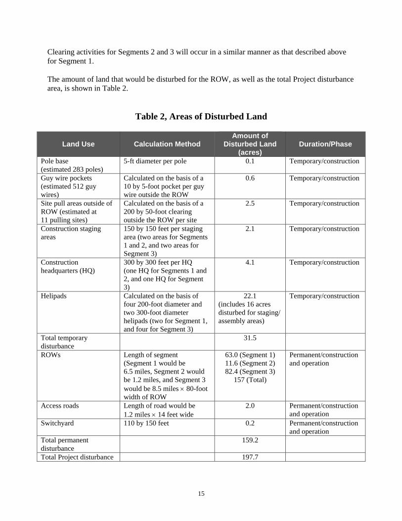
Clearing activities for Segments 2 and 3 will occur in a similar manner as that described above for Segment 1. The amount of land that would be disturbed for the ROW, as well as the total Project disturbance area, is shown in Table 2.
Table 2, Areas of Disturbed Land
Land Use Calculation Method Amount of
Disturbed Land (acres)
Duration/Phase
Pole base (estimated 283 poles)
5-ft diameter per pole 0.1 Temporary/construction
Guy wire pockets (estimated 512 guy wires)
Calculated on the basis of a 10 by 5-foot pocket per guy wire outside the ROW
0.6 Temporary/construction
Site pull areas outside of ROW (estimated at 11 pulling sites)
Calculated on the basis of a 200 by 50-foot clearing outside the ROW per site
2.5 Temporary/construction
Construction staging areas
150 by 150 feet per staging area (two areas for Segments 1 and 2, and two areas for Segment 3)
2.1 Temporary/construction
Construction headquarters (HQ)
300 by 300 feet per HQ (one HQ for Segments 1 and 2, and one HQ for Segment 3)
4.1 Temporary/construction
Helipads Calculated on the basis of four 200-foot diameter and two 300-foot diameter helipads (two for Segment 1, and four for Segment 3)
22.1 (includes 16 acres disturbed for staging/ assembly areas)
Temporary/construction
Total temporary disturbance
31.5
ROWs Length of segment (Segment 1 would be 6.5 miles, Segment 2 would be 1.2 miles, and Segment 3 would be 8.5 miles × 80-foot width of ROW
63.0 (Segment 1) 11.6 (Segment 2) 82.4 (Segment 3)
157 (Total)
Permanent/construction and operation
Access roads Length of road would be 1.2 miles × 14 feet wide
2.0 Permanent/construction and operation
Switchyard 110 by 150 feet 0.2 Permanent/construction and operation
Total permanent disturbance
159.2
Total Project disturbance 197.7
16
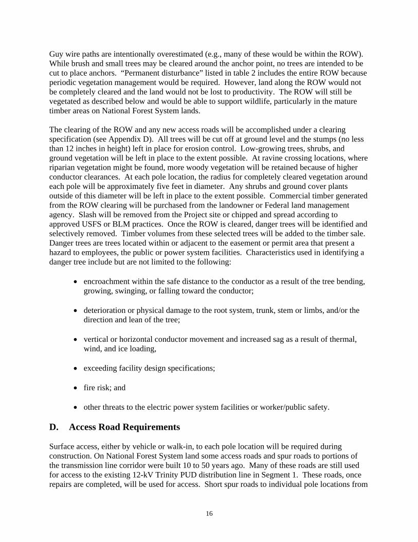
Guy wire paths are intentionally overestimated (e.g., many of these would be within the ROW). While brush and small trees may be cleared around the anchor point, no trees are intended to be cut to place anchors. “Permanent disturbance” listed in table 2 includes the entire ROW because periodic vegetation management would be required. However, land along the ROW would not be completely cleared and the land would not be lost to productivity. The ROW will still be vegetated as described below and would be able to support wildlife, particularly in the mature timber areas on National Forest System lands. The clearing of the ROW and any new access roads will be accomplished under a clearing specification (see Appendix D). All trees will be cut off at ground level and the stumps (no less than 12 inches in height) left in place for erosion control. Low-growing trees, shrubs, and ground vegetation will be left in place to the extent possible. At ravine crossing locations, where riparian vegetation might be found, more woody vegetation will be retained because of higher conductor clearances. At each pole location, the radius for completely cleared vegetation around each pole will be approximately five feet in diameter. Any shrubs and ground cover plants outside of this diameter will be left in place to the extent possible. Commercial timber generated from the ROW clearing will be purchased from the landowner or Federal land management agency. Slash will be removed from the Project site or chipped and spread according to approved USFS or BLM practices. Once the ROW is cleared, danger trees will be identified and selectively removed. Timber volumes from these selected trees will be added to the timber sale. Danger trees are trees located within or adjacent to the easement or permit area that present a hazard to employees, the public or power system facilities. Characteristics used in identifying a danger tree include but are not limited to the following:
• encroachment within the safe distance to the conductor as a result of the tree bending, growing, swinging, or falling toward the conductor;
• deterioration or physical damage to the root system, trunk, stem or limbs, and/or the
direction and lean of the tree;
• vertical or horizontal conductor movement and increased sag as a result of thermal, wind, and ice loading,
• exceeding facility design specifications;
• fire risk; and
• other threats to the electric power system facilities or worker/public safety.
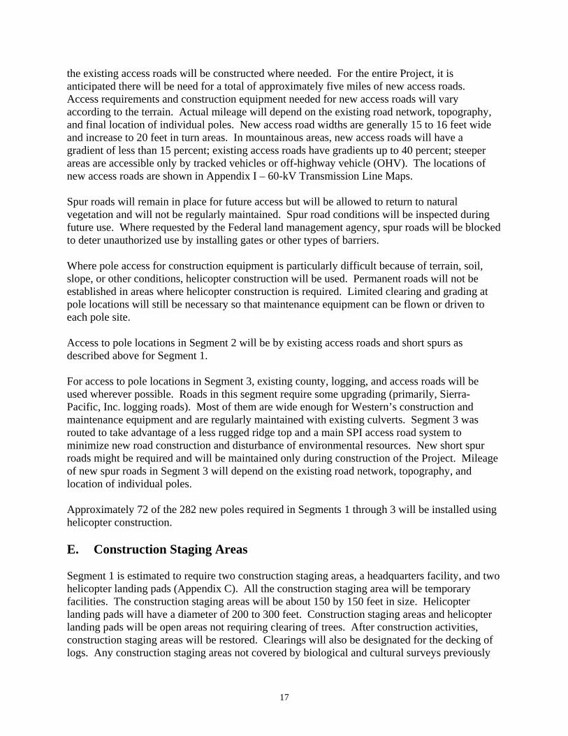
D. Access Road Requirements Surface access, either by vehicle or walk-in, to each pole location will be required during construction. On National Forest System land some access roads and spur roads to portions of the transmission line corridor were built 10 to 50 years ago. Many of these roads are still used for access to the existing 12-kV Trinity PUD distribution line in Segment 1. These roads, once repairs are completed, will be used for access. Short spur roads to individual pole locations from
17
the existing access roads will be constructed where needed. For the entire Project, it is anticipated there will be need for a total of approximately five miles of new access roads. Access requirements and construction equipment needed for new access roads will vary according to the terrain. Actual mileage will depend on the existing road network, topography, and final location of individual poles. New access road widths are generally 15 to 16 feet wide and increase to 20 feet in turn areas. In mountainous areas, new access roads will have a gradient of less than 15 percent; existing access roads have gradients up to 40 percent; steeper areas are accessible only by tracked vehicles or off-highway vehicle (OHV). The locations of new access roads are shown in Appendix I – 60-kV Transmission Line Maps. Spur roads will remain in place for future access but will be allowed to return to natural vegetation and will not be regularly maintained. Spur road conditions will be inspected during future use. Where requested by the Federal land management agency, spur roads will be blocked to deter unauthorized use by installing gates or other types of barriers. Where pole access for construction equipment is particularly difficult because of terrain, soil, slope, or other conditions, helicopter construction will be used. Permanent roads will not be established in areas where helicopter construction is required. Limited clearing and grading at pole locations will still be necessary so that maintenance equipment can be flown or driven to each pole site. Access to pole locations in Segment 2 will be by existing access roads and short spurs as described above for Segment 1. For access to pole locations in Segment 3, existing county, logging, and access roads will be used wherever possible. Roads in this segment require some upgrading (primarily, Sierra-Pacific, Inc. logging roads). Most of them are wide enough for Western’s construction and maintenance equipment and are regularly maintained with existing culverts. Segment 3 was routed to take advantage of a less rugged ridge top and a main SPI access road system to minimize new road construction and disturbance of environmental resources. New short spur roads might be required and will be maintained only during construction of the Project. Mileage of new spur roads in Segment 3 will depend on the existing road network, topography, and location of individual poles. Approximately 72 of the 282 new poles required in Segments 1 through 3 will be installed using helicopter construction. E. Construction Staging Areas Segment 1 is estimated to require two construction staging areas, a headquarters facility, and two helicopter landing pads (Appendix C). All the construction staging area will be temporary facilities. The construction staging areas will be about 150 by 150 feet in size. Helicopter landing pads will have a diameter of 200 to 300 feet. Construction staging areas and helicopter landing pads will be open areas not requiring clearing of trees. After construction activities, construction staging areas will be restored. Clearings will also be designated for the decking of logs. Any construction staging areas not covered by biological and cultural surveys previously

18
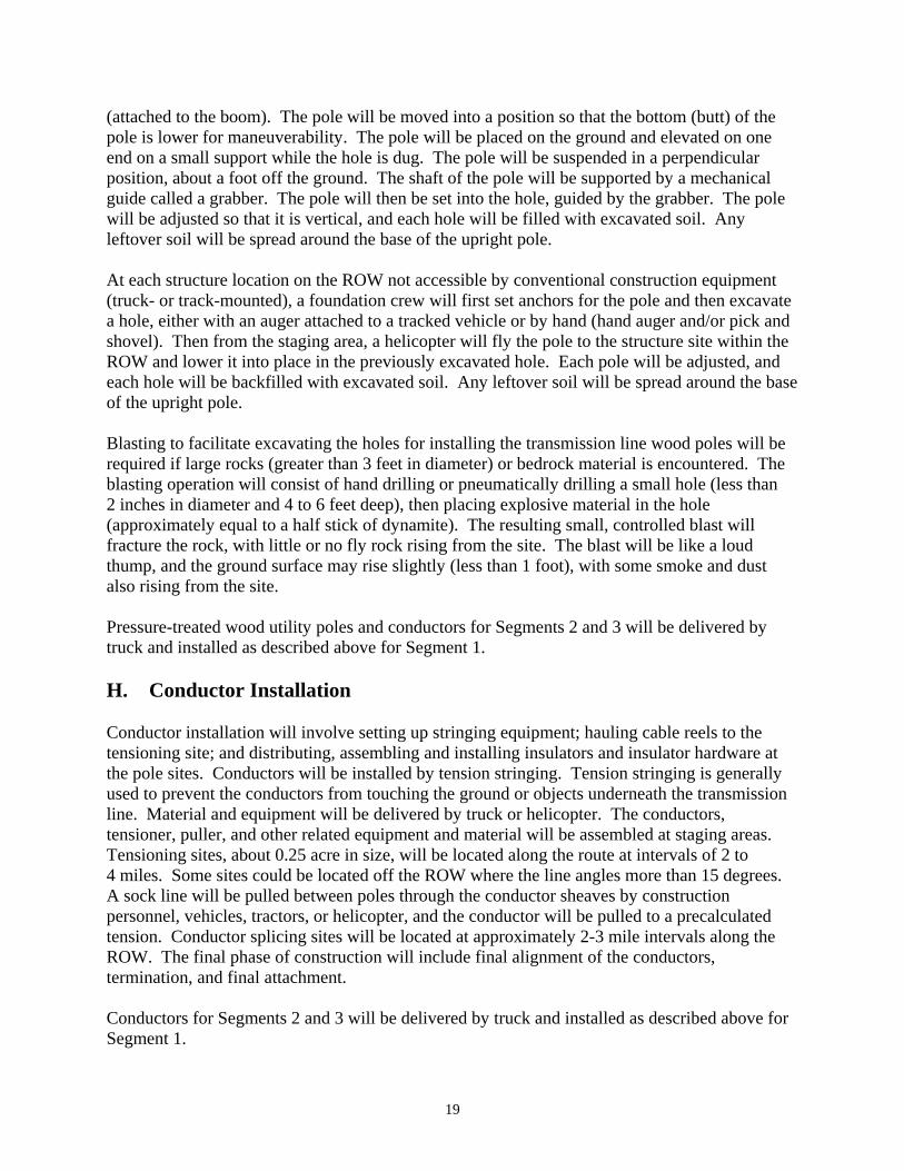
conducted for the Project will be surveyed before they are used. Mitigation measures for staging areas are described in the Mitigation Action Plan. The northern helicopter pad will be located immediately south of the Trinity Substation. This helicopter pad will use an existing concrete paved area. The paved area is a deteriorated parking lot that was originally designated for the construction buildings for the Trinity Dam but later used as the parking area for the northern trailhead of the four-mile-long North Lakeshore Trail. The construction yard headquarters is the base station where employees report at the start and end of each day’s activities along the line. Headquarters facilities are used for other activities and functions. They include an office trailer; laydown areas; buildings for storage of materials, equipment, and vehicles; a mechanics garage; and security for these items. The headquarters facility will likely be located at Trinity Power Plant. Headquarters facilities generally require an area of about 300 by 300 feet. Segment 2 will require use of the same two construction staging areas and log decking areas developed for constructing Segment 1, as described above. Segment 3 may also require the construction of two construction staging areas, a headquarters facility, and four helicopter landing pads, the latter of which may be combined with the construction staging areas. The headquarters facility for Segment 3 will likely be located along Browns Mountain Road within the ROW. F. Pole, Line, and Conductor Removal All poles currently supporting the existing 12-kV transmission line in Segment 1 will be removed by being cut off at ground level. The old cedar poles are not chemically treated and will be removed from the Project site and disposed of properly. Hardware, conductors, and insulators will be removed from the ROW and reused or recycled. Most of the components of the old line are reusable or recyclable. G. Pole Delivery and Installation Pressure-treated wood utility poles will be delivered by truck, stacked on supports at staging areas so they are off the ground and grouped according to length. Utility poles will be preserved by using oil-borne copper napthenate, which prevents decay and insect damage, and does not harden the pole which allows maintenance crews to climb the poles safely. Poles will be treated before being transported and installed at the Project site. In areas with good ground access, a derrick truck will be used to assist in setting the poles. Workers will slip a choker around the middle of the pole. The workers will balance the pole and mark the correct balance point. This mark will be used again when the pole is being readied to be set into the ground. By means of a choker, suspended from a winch line, the poles will be loaded onto a pole trailer (a flat bed truck) within the ROW. The workers will first set anchors for the pole and then dig a hole with an auger attached to the boom of the derrick truck. Each wood pole will be unloaded from the trailer by using the choker suspended from the winch line
19
(attached to the boom). The pole will be moved into a position so that the bottom (butt) of the pole is lower for maneuverability. The pole will be placed on the ground and elevated on one end on a small support while the hole is dug. The pole will be suspended in a perpendicular position, about a foot off the ground. The shaft of the pole will be supported by a mechanical guide called a grabber. The pole will then be set into the hole, guided by the grabber. The pole will be adjusted so that it is vertical, and each hole will be filled with excavated soil. Any leftover soil will be spread around the base of the upright pole. At each structure location on the ROW not accessible by conventional construction equipment (truck- or track-mounted), a foundation crew will first set anchors for the pole and then excavate a hole, either with an auger attached to a tracked vehicle or by hand (hand auger and/or pick and shovel). Then from the staging area, a helicopter will fly the pole to the structure site within the ROW and lower it into place in the previously excavated hole. Each pole will be adjusted, and each hole will be backfilled with excavated soil. Any leftover soil will be spread around the base of the upright pole. Blasting to facilitate excavating the holes for installing the transmission line wood poles will be required if large rocks (greater than 3 feet in diameter) or bedrock material is encountered. The blasting operation will consist of hand drilling or pneumatically drilling a small hole (less than 2 inches in diameter and 4 to 6 feet deep), then placing explosive material in the hole (approximately equal to a half stick of dynamite). The resulting small, controlled blast will fracture the rock, with little or no fly rock rising from the site. The blast will be like a loud thump, and the ground surface may rise slightly (less than 1 foot), with some smoke and dust also rising from the site. Pressure-treated wood utility poles and conductors for Segments 2 and 3 will be delivered by truck and installed as described above for Segment 1. H. Conductor Installation Conductor installation will involve setting up stringing equipment; hauling cable reels to the tensioning site; and distributing, assembling and installing insulators and insulator hardware at the pole sites. Conductors will be installed by tension stringing. Tension stringing is generally used to prevent the conductors from touching the ground or objects underneath the transmission line. Material and equipment will be delivered by truck or helicopter. The conductors, tensioner, puller, and other related equipment and material will be assembled at staging areas. Tensioning sites, about 0.25 acre in size, will be located along the route at intervals of 2 to 4 miles. Some sites could be located off the ROW where the line angles more than 15 degrees. A sock line will be pulled between poles through the conductor sheaves by construction personnel, vehicles, tractors, or helicopter, and the conductor will be pulled to a precalculated tension. Conductor splicing sites will be located at approximately 2-3 mile intervals along the ROW. The final phase of construction will include final alignment of the conductors, termination, and final attachment. Conductors for Segments 2 and 3 will be delivered by truck and installed as described above for Segment 1.
20
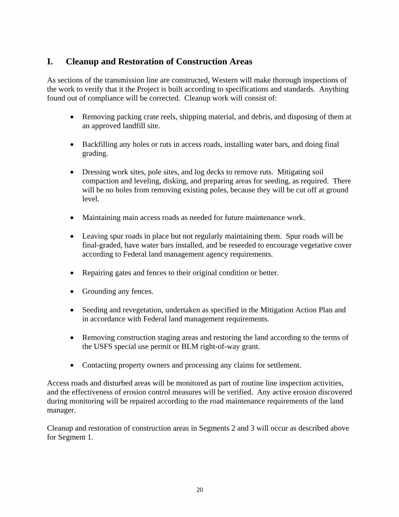
I. Cleanup and Restoration of Construction Areas As sections of the transmission line are constructed, Western will make thorough inspections of the work to verify that it the Project is built according to specifications and standards. Anything found out of compliance will be corrected. Cleanup work will consist of:
• Removing packing crate reels, shipping material, and debris, and disposing of them at an approved landfill site.
• Backfilling any holes or ruts in access roads, installing water bars, and doing final
grading.
• Dressing work sites, pole sites, and log decks to remove ruts. Mitigating soil compaction and leveling, disking, and preparing areas for seeding, as required. There will be no holes from removing existing poles, because they will be cut off at ground level.
• Maintaining main access roads as needed for future maintenance work.
• Leaving spur roads in place but not regularly maintaining them. Spur roads will be
final-graded, have water bars installed, and be reseeded to encourage vegetative cover according to Federal land management agency requirements.
• Repairing gates and fences to their original condition or better.
• Grounding any fences.
• Seeding and revegetation, undertaken as specified in the Mitigation Action Plan and
in accordance with Federal land management requirements.
• Removing construction staging areas and restoring the land according to the terms of the USFS special use permit or BLM right-of-way grant.
• Contacting property owners and processing any claims for settlement.
Access roads and disturbed areas will be monitored as part of routine line inspection activities, and the effectiveness of erosion control measures will be verified. Any active erosion discovered during monitoring will be repaired according to the road maintenance requirements of the land manager. Cleanup and restoration of construction areas in Segments 2 and 3 will occur as described above for Segment 1.
21
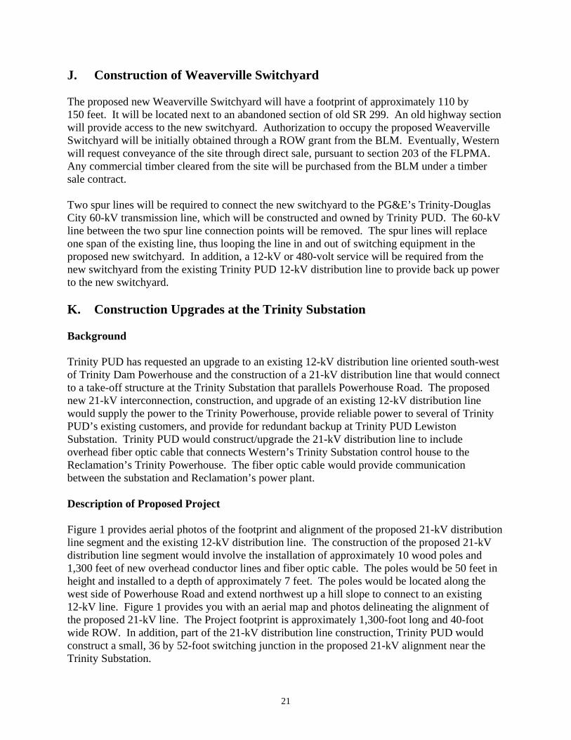
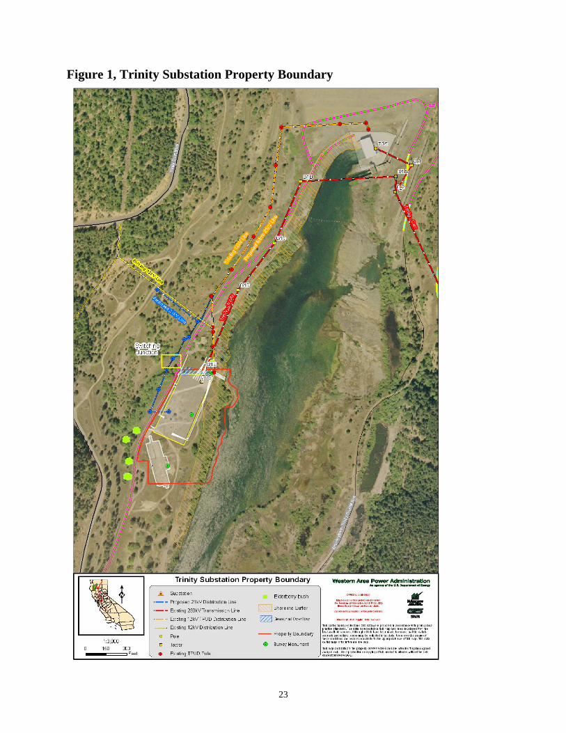
J. Construction of Weaverville Switchyard The proposed new Weaverville Switchyard will have a footprint of approximately 110 by 150 feet. It will be located next to an abandoned section of old SR 299. An old highway section will provide access to the new switchyard. Authorization to occupy the proposed Weaverville Switchyard will be initially obtained through a ROW grant from the BLM. Eventually, Western will request conveyance of the site through direct sale, pursuant to section 203 of the FLPMA. Any commercial timber cleared from the site will be purchased from the BLM under a timber sale contract. Two spur lines will be required to connect the new switchyard to the PG&E’s Trinity-Douglas City 60-kV transmission line, which will be constructed and owned by Trinity PUD. The 60-kV line between the two spur line connection points will be removed. The spur lines will replace one span of the existing line, thus looping the line in and out of switching equipment in the proposed new switchyard. In addition, a 12-kV or 480-volt service will be required from the new switchyard from the existing Trinity PUD 12-kV distribution line to provide back up power to the new switchyard. K. Construction Upgrades at the Trinity Substation Background Trinity PUD has requested an upgrade to an existing 12-kV distribution line oriented south-west of Trinity Dam Powerhouse and the construction of a 21-kV distribution line that would connect to a take-off structure at the Trinity Substation that parallels Powerhouse Road. The proposed new 21-kV interconnection, construction, and upgrade of an existing 12-kV distribution line would supply the power to the Trinity Powerhouse, provide reliable power to several of Trinity PUD’s existing customers, and provide for redundant backup at Trinity PUD Lewiston Substation. Trinity PUD would construct/upgrade the 21-kV distribution line to include overhead fiber optic cable that connects Western’s Trinity Substation control house to the Reclamation’s Trinity Powerhouse. The fiber optic cable would provide communication between the substation and Reclamation’s power plant. Description of Proposed Project Figure 1 provides aerial photos of the footprint and alignment of the proposed 21-kV distribution line segment and the existing 12-kV distribution line. The construction of the proposed 21-kV distribution line segment would involve the installation of approximately 10 wood poles and 1,300 feet of new overhead conductor lines and fiber optic cable. The poles would be 50 feet in height and installed to a depth of approximately 7 feet. The poles would be located along the west side of Powerhouse Road and extend northwest up a hill slope to connect to an existing 12-kV line. Figure 1 provides you with an aerial map and photos delineating the alignment of the proposed 21-kV line. The Project footprint is approximately 1,300-foot long and 40-foot wide ROW. In addition, part of the 21-kV distribution line construction, Trinity PUD would construct a small, 36 by 52-foot switching junction in the proposed 21-kV alignment near the Trinity Substation.

22
No new access roads are required as all construction activities for the proposed line will utilize Power House Road. Poles would be installed using an auger bore drill. The ROW for the proposed 21-kV distribution line is on land owned by Reclamation. Reclamation will be required to issue an easement agreement with Trinity PUD for this undertaking.
23
Figure 1, Trinity Substation Property Boundary

24
L. Environmental Requirements Environmental mitigation requirements, including agency Environmental Protection Measures (EPM) identified in the Final EIS, will be followed. The EPMs are discussed in Appendix J - Federal Agency Environmental Protection Measures and Appendix K - Construction Standard 13 Environmental Quality Protection. A comprehensive Plan of the Project’s mitigations is identified in Appendix E. Western is scheduled in the winter/spring of 2008 to complete additional cultural and biological surveys for the proposed staging area(s), headquarters area, access roads, and guy wire pockets. These surveys will include specific habitat for the northern spotted owl and other bird species under the Migratory Bird Treaty Act. In addition, specific limited operating periods have been designated depending on species and the type of activity to be undertaken. Appendix L - Environmental Site Maps provide GIS maps showing the environmental data collected for this Project. Western developed the environmental measures to reduce public and worker safety hazards and limit potential impacts to the environment associated with maintenance activities. These measures will be followed at all times, to include construction and O&M activities and throughout the Project area. At a minimum, Western will conduct an annual training class on these procedures for all maintenance crews. These measures will also be included in all contracts and agreements with maintenance contractors. All contractors will be responsible for understanding the requirements, schedule limitations, and notification procedures associated with each mitigation measure. Prior to each maintenance job, Western will reiterate to the contractor the importance of complying with the mitigation measures during all phases of the maintenance job. Construction crews shall notify Western’s SNR natural resources branch of any noncompliance with any measure. If appropriate, the natural resources branch will contact the Federal agency to discuss any remedies associated with the noncompliance action. Limited Operating Periods If helicopter use cannot be scheduled to avoid the raptor nesting/breeding period (approximately April 15 to August 15), then preconstruction raptor nest searches would be conducted to identify nesting raptors in the Project area. A qualified biologist would conduct Project-area-wide raptor nest surveys in appropriate habitats for listed species prior to commencement of ROW clearing and construction. However, no current locations for nesting raptors within the Project area have been identified. The following measures would be incorporated to minimize helicopter noise impacts:
• Helicopter pads would be buffered by using ridges or other sound-attenuating landscape features where available and practical.
• Helicopter flight paths would be designed to provide a buffering distance from nest
activity areas of listed species.
• Helicopter flight paths would use terrain features that would reduce noise impacts to any identified sensitive species nest locations.
25
For bald eagles: The Project area contains areas of suitable bald eagle nesting habitat. However, no nests have been identified within the Project area. Construction of the ROWs might occur in habitats suitable for nesting and winter roosting. The removal of this habitat would have a long-term impact. To mitigate these direct effects, the Project would comply with site-specific timing limitations and conservation measures for surface disturbance as identified during Project specific consultation with the USFWS. In addition:
• The line over the two Trinity River crossings would be marked with the best technology currently available to alert bald eagles and other birds to the presence of an obstruction.
• The recommendations in the National Bald Eagle Management Guidelines
(Appendix M) would be followed. For the northern spotted owl: The amendment to the Biological Assessment dated August 14, 2007, provided a justification for allowing Project implementation without limited operating periods. Western will adhere to the guidelines provided in that amendment and concurred with in the USFWS 2007 Biological Opinion. In addition, helicopters will not fly over the identified northern spotted owl nesting sites, and helicopters will yard material away from the line to the west and to the south, again avoiding the three known northern spotted owl nesting sites. Western will also follow the mitigation provided on the Spotted Owl Habitat maps (see Appendix N). VII. OPERATION AND MAINTENANCE OF THE FACILITY Western’s COMP/POD has been developed to improve the safety and reliability of Western’s electric transmission system ROWs. Western will maintain its transmission lines and legal access roads to ensure that its maintenance crews have safe and all-weather access to transmission line structures in order to maintain the reliable operation of the transmission system. Typical activities associated with operating and maintaining transmission lines will occur once the new line is constructed. These activities will be consistent with Western’s North Area ROW Maintenance Program and separate COMP/PODs prepared for activities on BLM public lands and USFS National Forest System lands. The COMP/PODs include provisions related to coordination and cooperation with the Federal land management agencies; operation and maintenance activities, including inspections and system management, maintenance activities, equipment system upgrades, O&M activity categories, and O&M implementation; fire plans; standard operating procedures; conservation measures; and GIS data sharing, accessibility and definitions. The purpose of the ROW Maintenance Program is to maintain existing transmission line and legal access road ROWs in order to ensure that Western’s maintenance crews have safe and all-weather access to its transmission facilities consistent with safety and environmental regulations

26
and policies. Western has designed its maintenance program to balance environmental protection with system reliability and compliance with National Electric Safety Code (NESC), Western Electric Coordinating Council (WECC) requirements, North American Electric Reliability Council (NERC) reliability standards, Institute of Electrical and Electronics Engineers (IEEE) standards, and Western’s directives for maintaining system reliability and ensuring protection of human safety. Western will maintain its transmission line and access road ROWs to:
• Protect against operational hazards.
• Provide access for maintenance.
• Protect facilities from fire or minimize fire from facilities.
• Control the spread of noxious weeds and protect environmental quality.
• Adhere to principles of Western’s IVM Program.
• Establish stable, low-growing plant communities within the ROW.
• Develop a technically and economically efficient program.
• Protect public and worker safety.
• Maintain sound relationships with private land owners and Federal land management agencies.
• Streamline regulatory permitting activities.
The proposed transmission line system will operate at 60-kV. The amount of power transferred along the conductors will vary depending on seasonal and time-of-day loads, as well as other system demands. Western’s power system dispatchers will direct day-to-day and emergency transmission line operation in accordance with Western’s Power System Operations Manual (PSOM) and in cooperation with adjacent control areas and systems. Western will be responsible for maintaining the transmission system by monitoring, testing, and repairing the line and terminal equipment. Maintenance crews will likely be provided by Trinity PUD, since they are located closest to the new transmission line location. Typical maintenance activities include:
• Periodic routine aerial inspections with emergency aerial inspections after storms, severe wind, lightning, or other weather conditions or after reported vandalism.
• Periodic and emergency ground inspections, normally conducted no more than once a
year.
• Routine maintenance to inspect and repair damaged structures, conductors, and insulators.
27
• Wood pole inspection and maintenance, if necessary.
• Emergency maintenance to immediately repair transmission lines damaged by storms,
floods, vandalism, or accidents. Emergency maintenance would involve prompt movement of crews to repair damage.
• Access road inspection and maintenance to regrade and repair erosion-control
features and gates.
• Vegetation management activities, as needed, to maintain conductor clearance, including cutting, trimming, lopping, and clearing trees. Low-growing shrubs and brush would be retained for ground cover and erosion control purposes.
• Control of noxious weeds, if found. Application of herbicides might be necessary for
the control of noxious weeds, to prevent regrowth of undesirable or incompatible vegetation. Herbicide application would be in accordance with the Integrated Vegetation Management Environmental Guidance Manual (IVM; Western 2007) and the Final Environmental Impact Statement Trinity Public Utility District Interconnection project November 2007.
Some land use impacts could occur during routine maintenance activities and increase during emergencies. Western would restore damaged areas or compensate landowners as appropriate when responsible for damage. In general, emergency activities are infrequent and, in most cases, restricted to small areas on the access roads or within the ROW. A. Inspection/System Management In compliance with Western’s Guidelines, Requirements, Inspections and Procedures (GRIP19) and SNR’s Transmission Line Inspection Program - Reliability Centered Maintenance (RCM) Study, Western will conduct aerial, routine ground, and detailed ground inspections of its existing transmission infrastructure. Western would continue these required inspections on the Trinity PUD Direct Interconnection Project under this COMP/POD. The following paragraphs describe Western’s inspection requirements. B. Aerial Inspections Aerial inspections would be conducted every six months by helicopter or small plane over the entire transmission system to check for hazard trees or encroaching vegetation, as well as to locate damaged or malfunctioning transmission equipment. Typically, aerial patrols would be flown between 50 and 300 feet above Western’s transmission infrastructure depending on the land use, topography, and infrastructure requirements. In general, the aerial inspections would pass over each segment of the transmission line within a two-minute period.
28
C. Routine Ground Inspections Routine ground inspections would be performed annually on all lines to check access to the structures/poles, tree clearances, fences, gates, locks, and structure hardware. In general, this inspection ensures that each structure will be readily accessible in the event of an emergency and allows for the inspection of hardware that would not be possible by air. Routine ground inspections would also identify redundant or over-grown access roads that should be permanently closed and returned to their native state. They would typically be conducted by driving a pickup truck, tracked vehicle, or OHV to the ROW and pole locations along access roads used for construction of the line. D. Detailed Ground Inspections Detailed ground inspections, which include a shake test, are performed on 20 percent of the structures of each line annually so that every structure on the line undergoes a detailed ground inspection every five years. Transmission line structures are climbed only if a problem is found or suspected during a ground inspection and, in the judgment of the inspector, a climbing inspection is necessary for further investigation. Microwave antenna towers are climbed every seven years. The intent of detailed ground inspections and climbing inspections is to identify deterioration in hardware that could not be detected from routine ground and aerial patrols. E. Maintenance Activities In general, Western O&M activities for the Trinity PUD Interconnect Project transmission line would include the following:
• Vegetation maintenance (transmission line and access road ROWs). Vegetation maintenance ensures that vegetation does not interfere with human safety, transmission line conductors, towers, or other hardware, or impede access to the transmission line for maintenance crews. In general, vegetation maintenance can be performed using a variety of methods including manual (hand-controlled, powered, or non-powered tools such as chainsaws and clippers), mechanical (such as heavy duty mowers), and herbicidal applications (used either to kill vegetation or retard growth).
• Legal access road maintenance. Access road maintenance includes activities to
ensure that legal access roads are in appropriate condition for all-weather access to transmission lines by maintenance and inspection crews. These activities include grading, surfacing, and constructing water diversions such as culverts, ditches, and water bars.
• Transmission line and associated structure, hardware, and equipment maintenance.
This category of activities includes equipment and system upgrades, routine aerial and ground patrols of transmission lines and ROWs, and transmission system repairs. The methods used to complete maintenance activities would be selected in consultation with the appropriate Federal land management agency.

29
Vegetation Maintenance. Integrated Vegetation Management (IVM) is a practice of managing undesirable vegetation in which action thresholds are considered, then all possible control options are evaluated, and finally a management program is selected, developed, and implemented. Control options are based on worker and public safety, environmental impact, effectiveness, site characteristics, and economics. Initially, the ROW is restored through the removal of undesirable vegetation. The ROW is then enhanced using various management techniques to protect facilities, reduce the potential for fire, and provide habitat for wildlife and a variety of plant species. Establishment of a wire zone/border zone is a key consideration in the development of IVM programs. For most areas, Western would adopt a Wire Zone/Border Zone ROW management prescription, which recognizes the ROW as a valuable economic and ecological resource. Key to this concept is the management of the ROW from two perspectives, the wire zone and the border zone. The wire zone includes the ROW area immediately under the transmission wire plus 10 feet on both sides. The border zone is the area between the wire zone and the edge of the existing ROW. The goal is to have a low shrub-forb-grass cover type in the wire zone and a taller shrub-forb-grass cover type in the border zone. This approach would also maintain 30 feet of clearance around each transmission tower or transmission structure. Figure 2 is an illustration of the desired appearance of a ROW subject to a Wire Zone/Border Zone management practice.
Figure 2, Wire Zone/Border Zone Management Practice
In specific areas where conversion of the ROW from naturally occurring tree-dominated native plant communities into a Wire Zone/Border Zone ROW is not appropriate, Western has developed a Buffered Vegetation Management approach that aligns the Federal agency goals with Western’s need to maintain the transmission system to NERC reliability standards (15 feet of clearance from any vegetation). Under the Buffered Vegetation Management approach, Western would maintain 15 feet of clearance between vegetation and any point of the circuit or transmission system. As with the wire zone/border zone vegetation management prescription, this approach would also maintain 30 feet of clearance around each transmission tower or structure. Benefits of this approach include the reduction of ground disturbing activities and the related reduction in the establishment of non-native plant species. Figure 3 provides an illustration of the Buffered Vegetation Management approach for a 230-kV transmission system requiring 18 feet of clearance.

30
Figure 3, Buffered Vegetation Management
A transmission circuit can move vertically depending on the atmospheric temperature and electrical load on the line. Western recommends an additional 10 feet of buffer to account for the sag in the line during periods of high temperatures and high load. As a result, the Buffered Vegetation Management area would include the mandatory 15-foot Clearance I requirements for a 60-kV transmission line plus 10 feet of buffer for vegetation growth and sag in the line. As described above, Western proposes to implement a combination of vegetation management practices that are consistent with the principles of IVM and in concert with the goals and policies of the Federal land management agencies. The following paragraphs describe the vegetation management methodologies identified for National Forest System lands and BLM-administered public lands. F. Manual Vegetation Control Methods Manual vegetation control is defined as application of powered and non-powered handheld tools or installation of static barriers (such as weed-control mats3) to manage vegetative growth. The primary benefit of manual methods is selectivity; only unwanted or target vegetation is removed, while non-target vegetation is not disturbed. The primary disadvantages of manual methods are that they are labor intensive and they are only effective in vegetation with relatively low density. The manual vegetation control techniques employed by Western are described below. Three-fiber weed-control mats are composed of synthetic polyester fibers spun tightly together to prevent weed growth by inhibiting sunlight, yet still allowing water percolation for drainage. Cutting The most commonly used manual method to control vegetation is cutting target plants with power saws. Other manually operated tools such as axes, machetes, and clippers may also be used. This method is highly effective on species that do not resprout. For species that resprout, including most deciduous trees, sprouts may resurge to original heights within several years and at much greater density than the original stems. Access for subsequent manual treatments is thereby hindered. Under the Buffered Vegetation Management approach, limbing or trimming
31
of the individual branches that encroach into the buffered vegetation area is the preferred method. Girdling Girdling involves manually cutting away bark and cambium tissues around the trunk of target trees. This treatment is rarely practiced by Western, but may be appropriate in some cases (e.g., where large trees cannot be felled by cutting) if approved by the land manager. Conifer species are killed by girdling, but hardwoods frequently will resprout below the girdle unless the cut is treated with herbicide. Girdling results in standing dead trees or snags, which are left to decompose and fall on their own. Snags are left at the request of the land manager/land owner and may provide habitat for cavity-nesting species and other wildlife (Western 2007). Girdling could pose a fuels management problem by mixing standing dead fuel with live fuel, which can significantly increase the potential for a crown fire. Topping and Trimming Topping is the indiscriminate cutting of tree branches to stubs or lateral branches that are not large enough to assume the terminal role. Other names for topping include “heading”, “tipping”, “hat-racking”, and “rounding over”. This treatment is used in rare cases by Western, as the situation dictates, and the best solution is to remove the tree and allow the ROW to revegetate with a species that is more appropriate for the site. Trimming or pruning is the removal of selected branches from tree trunks for the same purposes. Directional pruning is practiced by Western, whereby the trees are pruned to direct growth away from the conductors. Western uses these highly labor-intensive techniques in special situations where it is desirable to leave trees in place as visual screens (e.g., along roads, streams, and rivers) or where easement contracts and land/resource plans dictate such tree removal or trimming criteria (e.g., in orchards and along streams) (Western 2007). As stated above, under the Buffered Vegetation Management approach, limbing or trimming of the individual branches in the buffered vegetation area is the preferred method. Within the buffered vegetation area, topping is not acceptable because it may encourage faster growth in an undesirable direction. Slash Disposal/Fuels Reduction Manual cutting operations by Western are followed by slash disposal activities that are designed to reduce fire hazards or to improve aesthetic appeal. Slash refers to the debris left in the post-timber/vegetation removal stage within the vegetation treatment area. Depending on Federal land management agency/land owner preference, access limitations, and fire safety, the slash and fuels reduction can be treated by one or many of the following methodologies: chipping, decking, piling and burning, removal from the site, and lopping and scattering. Western acknowledges BLM and USFS concerns related to fuels left within the ROW and will promote the reduction of fuel loading during vegetation management activities. Slash disposal and fuels reduction activities on NFS lands will meet the following requirements: Chipping (at sites located within 150 feet of truck/chipper passable roads): Foliage and limbs less than 6 inches in diameter shall be chipped into the truck box, removed from the site,
32
and disposed of at an approved location. If the area is accessible to the public, limbs and logs greater than 6 inches in diameter will be decked as described below. If the area is not accessible to the public, limbs and logs greater than 6 inches will remain on the site whole, unless alternate treatment is authorized. Decking: In areas that are accessible to the public, all slash 3 feet or more in length and a minimum of 6 inches in diameter shall be skidded and decked along roadways or at designated landings for public use and disposal. Piling: If chipping is not feasible and the permittee or its operating agent opts to pile slash off-site for burning, the permittee or its operating agent and the USFS shall agree on designated piling locations. In areas designated, the permittee or its operating agent shall pile unutilized material that is 8 inches or bigger on the large end and at least 10 feet or more long. Unless agreed to otherwise, in writing, piling shall be done in the same normal operating season in which included timber is yarded from the line segment, road corridor, or other construction clearing. Construction and Size of Piles: All piles shall be as compact as possible with the heavier material placed on top. Height of piles shall not be less than 3 feet and not more than 5 feet with a diameter of not more than 8 feet. All piles shall have good base to keep the pile from toppling. The slash shall be piled so that the length is at a right angle to direction of the contour. All material in excess of 6 feet in length shall be cut before placing in the pile. Material protruding 2 feet or more beyond the general profile of the pile will be bucked off and added to the pile. All piles shall be at least 30 feet apart to prevent premature ignition during burning, unless otherwise specified. Piles will be lined (12” wide to mineral soil) and covered with a commercially available paper (not plastic) for winter burning. In remote locations, pile covers will be incorporated during pile construction. Location of Piles: The USFS and the permittee or its operating agent shall agree to pile locations. Piles will be located so that burning will not cause damage to standing green trees. Unless otherwise approved by the USFS, this will be construed to be at least 20 feet from the bole of any live tree. Piles will be located at least 30 feet from any adjacent pile unless otherwise specified. All piled slash will be burned. If burning is performed by the USFS, a collection agreement will be used to fund this activity. If burning is performed by the permittee or its operating agent, prior written approval of the authorized officer is required and the burning shall be done in accordance with restrictions, conditions, and requirements outlined in a Fire Plan. Piling Season: Slash may be piled from June 1 through October 31 except when restricted by a Limited Operating Period.

33
Lopping and Scattering: All slash material not decked, chipped, or piled will be lopped and scattered in a manner that will not create a depth of more than 18 inches, and that will ensure a separation of 6 inches or more between all material 3 feet or larger. Remaining materials 6 inches or larger in diameter will be cut into a maximum of 4 foot lengths. Total residual debris (slash and natural debris) allowed to remain will not exceed 10 tons/acre. Lopping may be done by axes or power saws. In areas where there is already substantial deadfall and downed slash material (in pre-treatment stage), the Contractor shall achieve the above criteria to the extent practicable; however, the Contractor will not be required to cut, rearrange, or remove existing deadfall. These areas shall be reviewed by the COR and the USFS Authorized Officer. When scattered, slash must not be left in streambeds, natural drainages, roadside ditches or collection basins at the entrance of culverts. Slash must not be scattered so that concentrations lie around the base of any live trees. These standards may need to be modified in Riparian Reserves to meet Aquatic Conservation Strategy objectives. Modification of slash and fuels reduction activities in Riparian Reserves could include retention of woody debris to meet woody debris objectives. G. Mechanical Vegetation Control Methods Mechanical methods employ machines to remove or control vegetation. These methods are often nonselective in that certain plants cannot be either targeted for removal or avoided. Mechanical methods, however, may be highly effective at controlling brush on gentle topography with few site obstacles. Most mechanical equipment is not safe to operate on slopes over 30 to 35 percent; mechanical methods are also constrained where soils are susceptible to compaction or erosion. Site obstacles such as rocks, stumps, or logs also reduce efficiency of these methods (Western 2007). Western plans to utilize mechanical methods to remove vegetation in portions of the ROW. H. Herbicide Control Methods Under the Project IVM, Western will comply with the list of approved herbicides on NFS lands as described in Appendix O. Western would coordinate with each land management and/or local agency to ensure that its use of herbicides is consistent with local regulations and/or guidelines (e.g., BLM Pesticide Use Permit, Integrated Pest Management Plan). An herbicide is a chemical used to kill or suppress the growth of plants. The most satisfactory classification of herbicides is based upon how they are used for weed control and how they work. Accordingly, herbicides are classified into two major types:
• Selective herbicide implies that certain plants are killed but most desirable plants are not significantly affected. For example, some selective herbicides kill broadleaf plants (including brush) but do not affect grasses.
34
• Nonselective herbicide refers to chemicals that are generally toxic to plants without regard to species. Plants differ in susceptibility to any specific chemical and the choice of herbicide and application rate depends on the species to be controlled. Western proposes using only those herbicides that have been approved for use in ROW maintenance based on evaluations of toxicity, solubility, soil adsorption potential, and persistence in water and soil. Further, these herbicides must be registered for use in California by the U.S. Environmental Protection Agency. Western would use only employees or contractors with required applicator licenses/certificates. Western would follow strict safety procedures and best management practices when applying herbicides, which would only be applied in compliance with the manufacturer’s label requirements. These practices, described in Western’s Integrated Vegetation Management Guide and Transmission Vegetation Management Program (Western 2007) are a part of the Trinity PUD Interconnect Project O&M Plan and include:
o Reviewing Federal, State, and Trinity County pesticide regulations for restrictions
on use of particular herbicides.
o Reviewing landowner/interagency agreements for herbicide type or application method restrictions.
o Using herbicides approved by the individual agencies based on herbicide-use
proposals that will be submitted by Western annually.
o Using USFS-approved herbicides on nonnative and invasive plant species on National Forest System lands.
o Using BLM-approved herbicides on nonnative and invasive plant species on BLM
public lands.
o Observing site conditions to match specific herbicides and application methods to those conditions, including the plants that are to be controlled, seasonal limitations, presence of sensitive environmental areas (such as endangered species, habitat, and wetlands), presence/proximity of non-target vegetation, and vegetation conditions (such as height and amount of tall-growing brush).
o Reviewing Western’s environmental protection requirements.
o Following all restrictions and guidance listed on the herbicide label.
o Calibrating equipment to ensure proper mixture and volume of herbicide.
o Selecting the proper nozzle tip to avoid overspray.
o Handling herbicides carefully to avoid accidental spills and ensure worker and
public safety.
35
o Adjusting herbicide application methods based on wind speed and direction,
which may include avoiding application on windy days when drift potential is greatest.
o Providing the land owner and/or appropriate agency with the following
information after completion of a particular activity: herbicide used, amount (including concentration), location of application, and method and date of application. There are several different ways to apply herbicides, and the method selected depends on the type of control needed, the type of vegetation, and the site situation (i.e., site conditions, location). Application methods are described below and include stump treatment, basal spray treatment, foliage spray treatment, soils treatment, and under-surfacing materials treatment.
Stump Treatment Western currently applies either an oil-based herbicide mixture or a ready-to-use non-oil solution. This type of treatment is used when vegetation is cut to the ground line. This method is primarily used after initial clearing and during maintenance clearing when trees have grown too tall to use foliage spray or when drift is an issue (Western 2007). Basal Spray Treatment This treatment method involves spraying the lower part of the stem and the exposed roots of incompatible vegetation with an oil-based formula. Basal spray/treatment would be used on resprouting species and identified non-native and invasive plant species. This method is more selective than a foliage spray and does not cause immediate brownout of vegetation (Western 2007). In general, this treatment is prescribed where:
• Brush is too tall to use foliage spray without causing unacceptable drift.
• The ROW is adjacent to cropland, residences, susceptible vegetation, or other sensitive areas, and drift is a problem.
• The ROW contains a high density of compatible species, and a foliage spray cannot
be applied without injuring the compatible cover.
• The ROW is in a visually sensitive area where immediate brownout would be unacceptable, and, due to seasonal limitations, only those foliage sprays which cause immediate brownout can be used.
Foliage Spray Treatment Foliar spraying is a common method of applying herbicides on brush up to 15 feet tall. This method uses a water-based formulation that is applied to the entire plant’s foliage and stems. Because it is spayed into the air, drift can be a problem under certain atmospheric conditions.

36
Also, most foliage sprays cause immediate brownout of vegetation. This method would not be used in areas where drift and brownout are concerns (e.g., adjacent to cropland, residences, susceptible vegetation, or other environmentally sensitive areas) (Western 2007). I. Clearing Culverts and Ditches Existing culverts and ditches must be kept free of debris and obstructions. Ditches on newly constructed roads may require frequent cleaning and checking after each major storm until revegetation has occurred. Additionally, each culvert should be checked at least once a year after spring rains and before winter rains. During inspection and clearing of culverts and ditches, Western will:
• Leave grass in the ditch unless it has filled with sediment and is no longer functioning.
• Check for undercutting road shoulders and banks.
• Check culverts for blockage by debris.
• Not leave berms on the side of the road; berms will channel water down the road.
Western understands the potential for adverse environmental effects if a culvert is installed without consideration of existing biological resources. As such, Western would consider the following guidelines when constructing new culverts:
• Culverts need to be large enough to pass a 100-year flood at 67 to 75 percent of capacity.
• Culverts will be installed to hydrologic grade and the outlet will not empty onto road
fill.
• Energy dissipaters, such as large rocks, will be installed immediately below the outlet.
• Whenever possible, low-water crossings will be installed instead of a culvert.
• The outlet side of the low-water crossing will be hardened with native rock to prevent
erosion.
• Applicable Clean Water Act permits (NPDES, 404, 401) will be obtained before construction.
• Culverts will be designed to accommodate water velocities and flows necessary for
fish, frogs, and other aquatic species to swim through the culvert. Culvert diameters will match the width of the stream at an average point. Stream widths will be
37
measured at the top of the banks as this may best represent the stream size during normal high water or bank-full conditions.
• The angle or slope of the culvert will be equal to the stream grade to maintain an
acceptable water velocity for fish passage.
• Projects will be scheduled so that they do not coincide with fish migrations, spawning, and egg-incubation periods.
• The appropriate erosion and sediment controls will be installed on disturbed soils as
soon as possible (i.e., before site work is finished). As appropriate, rocking upstream and downstream slopes and the banks around the culverts.
Work in jurisdictional waters of the U.S., including removal of accumulated sediment and debris from culverts and ditches and installation of new culverts, requires compliance with sections 401 and 404 of the Clean Water Act. Figures identifying jurisdictional waters of the U.S. are provided in Appendix P. Removal of sediment and debris is authorized under a section 404 Nationwide Permit (NWP) 3 (Maintenance) and may require submittal of a permit application to the U.S. Army Corps of Engineers (USACE), San Francisco District. Western would quantify stream impacts for culvert installation and identify the appropriate section 404 permit to determine whether the activity requires notifying the USACE. Removal of sediment and debris and installation of a new culvert may also require application for section 401 water quality certification. Western will review these activities to determine if they meet the requirements of the section 401 water quality certification issued by the North Coast Regional Water Quality Control Board (NCRWQCB) in January 2008. This certification is valid for 5 years from the date of issuance. It is for specific activities with specific acreage/linear foot impacts. It is also specific to a section 404 NWP 12; the certification does not apply to any other NWP. If Western does not need to apply for a section 404 permit and/or section 401 certification, written documentation will be prepared to document compliance with sections 401 and 404. All activities in jurisdictional waters of the U.S. will comply with the requirements and terms and conditions of a section 404 permit and section 401 certification. J. Removing Slide Debris Slide debris can cause increased sediment loads in established roadway drainage systems as well as in established streams. In order to prevent this, Western would not side cast removed material. Should slide debris occur, the cause would be evaluated to determine if removal of the slide debris could exacerbate slope instability by undercutting the toe of the slope. Where feasible, the slide debris material will be redistributed on the road itself. Disposal of additional slide material will be at approved locations. In some instances, removal of some debris may be required and stabilization of the remaining material may prevent further problems. The appropriate erosion and sediment controls would be installed on disturbed soils as soon as possible (i.e., before site work is finished). Mulching and other forms of erosion control like rocking slopes would be used to prevent erosion.
38
Any slide debris removal from streams identified as jurisdictional waters of the U.S. would require compliance with sections 401 and 404 of the Clean Water Act. Western will assess the type of impact, quantify impacts, identify the appropriate section 404 permit, and determine whether notification to the USACE is required. If notification is required, Western will submit an application for a section 404 permit. Western will also assess the need for, and if necessary, apply for section 401 water quality certification with the NCRWQCB. The first step will be to determine whether the section 401 water quality certification issued by the NCRWQCB in January 2008 is applicable to the slide debris removal activities. If notification is not required for a permit and/or certification, written documentation will be prepared to document compliance. Debris removal activities will comply with the requirements and terms and conditions of a section 404 permit and section 401 certification. K. Repairing Road Structures In order to maintain safe access, associated road structures would be routinely inspected and maintained. Road structures in need of repair may include bridges, culverts, cattle guards, and fences. Should a structure need to be modified, maintenance activities would be designed to reduce erosion and sedimentation in streams. Western would employ the following best management practices (BMPs):
• Provide design and specifications to the appropriate Federal agency geologist/engineer for review.
• Protect vegetation and minimize the amount of disturbance of plants and soils by
equipment.
• Work quickly to minimize the time disturbed soils are exposed.
• Divert runoff away from exposed soils into vegetated buffers.
• Disperse concentrated stream flows.
• Provide adequate run-off channels.
• Trim slopes to stable configurations and revegetate as soon as possible.
• Comply with land manager design and engineering requirements for new or modified structures.
• Inspect new or modified structures at least once a year after spring rains and before
winter rains.
• If roads are repaired under emergency situations, mitigate the damage created during the emergency work as soon as possible to prevent further damage and erosion.
39
Any activities required to repair road structures within jurisdictional waters of the U.S. will require compliance with sections 401 and 404 of the Clean Water Act. As described in Removing Slide Debris, Western will assess the applicability of section 401 and 404 to road structure repair activities and will either reapply for a section 404 permit and/or section 401 certification or prepare written documentation showing compliance. All repair activities will comply with the requirements and terms and conditions of the section 404 permit and the section 401 certification.
L. Repairing Damaged Access Roads For damaged access roads, Western would replace the surface material lost or worn away, then grade and shape the road surface, turnouts, and shoulders to their original condition. Watering may be required to control dust and to retain fine surface rock. While repairing damaged access roads, Western would:
• Minimize the amount of disturbance of plants and soils by equipment.
• Work quickly to minimize the time disturbed soils are exposed.
• Divert runoff away from exposed soils and into vegetated areas.
• Disperse concentrated stream flows.
• Provide adequate run-off channels.
• Trim slopes to stable configurations and revegetate as soon as possible.
• Check road structures at least once a year after spring rains and before winter rains.
• If repairs are made under emergency situations, mitigate any damage created as soon as possible to prevent further damage and erosion.
Any repair activities to damaged access roads within jurisdictional waters of the U.S. will require compliance with sections 401 and 404 of the Clean Water Act. As described in Removing Slide Debris, Western will assess the applicability of section 401 and 404 to activities required to repair damaged access roads and will either apply for a section 404 permit and/or section 401 certification or prepare written documentation showing compliance. All repair activities will comply with the requirements and terms and conditions of the section 404 permit and the section 401 certification. In addition, Western will consider removing access roads that are no longer needed. M. Transmission System Maintenance The need for repairs and preventative maintenance would be based on the results of inspections or other reports. Repairs and preventative maintenance include: replacing insulators; tightening,
40
replacing, or repairing towers/poles or hardware; and looking for ROW encroachments. These activities would be performed wherever damage or deterioration of transmission lines or facilities poses a threat to safety or reliability. The type of equipment needed may include a pickup truck, bulldozer, backhoe, bucket truck, and hand tools, and would depend on access and the required repair or maintenance. Western will coordinate the required maintenance activities with the respective land manager. N. Equipment/System Upgrades For the transmission system to operate in a safe, reliable, and efficient manner, Western may need to replace or upgrade system components based on the age, condition, and technology of the piece of equipment. System upgrades or replacements would include new conductors, insulators, poles, capacitor banks, transformers and breakers, small solar power arrays, and other electrical equipment. O. Coordination with Regulatory and Land Management Agencies Western will be conducting maintenance activities along the Trinity PUD ROW once the line is constructed. Maintenance activities will include vegetation removal, access and maintenance road grading and stabilization, and transmission system upgrades. These activities have been reviewed by the U.S. Fish and Wildlife Service (USFWS) and approved in a Programmatic Biological Opinion, published in 1998 and 2007. In the past, Western would identify maintenance activities along the ROWs and coordinate individually with USFWS and the appropriate land management agencies (i.e., USFS, BLM) on actions or mitigation measures needed to complete the maintenance task. P. Regulatory Coordination Western would continue to coordinate with resource agencies and land managers on specific maintenance activities. The following bullets describe the process and reporting requirements that Western would follow for Category A, B and C maintenance activities (see a summary of the O&M activity categories below). Category C maintenance activities will require project approval from the USFS prior to implementation.
• Identification of Maintenance Activity. Western is required to conduct aerial and ground inspections of its lines on a periodic basis. During inspections, Western will identify problem areas or equipment. These maintenance projects will be prioritized based on public and worker safety, system reliability, and protection of the environment.
• Coordination with resource agencies and land managers. Western will coordinate
with the appropriate resource agencies and land managers for each maintenance project, providing a description of the maintenance task and coordinating with them regarding the approved mitigation measures. The resource agencies and land managers will have access to Western’s GIS database, which includes aerial

41
photography, videos, biological and cultural resource data, and Project-specific mitigation measures.
• Training of Western personnel or contractors – Western will train its maintenance
personnel on mitigation measures on an annual basis. Should a contractor be hired to conduct a particular task, Western will train the contractor prior to Project startup. Mitigation measures will be incorporated into the contractor’s contract. Western crews and contractors will be responsible for complying with the mitigation measures.
• Monitor maintenance activity – Western’s personnel will monitor maintenance
activities to make sure that the contractor is complying with the applicable mitigation measures. Western would also conduct follow-up inspections of the ground disturbance activity sites.
• Annual meeting – Western would coordinate an annual meeting with each land
manager to discuss the activities that were completed within their jurisdiction. The following is a list of the O&M activities according to the associated level of potential effect to sensitive resources. Note that substation and facility maintenance activities are restricted to the confines of the existing fenced substation or facility perimeter.
• Category A – No or Nominal Effects • Category B – Potential to Cause Minimal (PCM) Associated Effects • Category C – Potential to Cause Adverse Effects
The PCMs were designed to reduce potential impacts and are based on the O&M categories described above. PCMs may include identification of limited operating periods, pre-activity flagging of resources, and equipment restrictions. Categories are described below.
• Category A – No or Nominal Adverse Effects - Maintenance activities in Category A are primarily inspection type actions, with some minor repairs that would not cause substantial soil disturbance. These maintenance tasks would cause no or nominal effects to sensitive resources as long as standard operating procedures (SOPs) are followed. Typical activities under Category A include but are not limited to: o Substation Maintenance
Maintenance and replacement of transformers and breakers. Servicing and testing of equipment at existing substations, including oil
change outs. Installation or replacement of brushing. Cleaning or replacement of capacitor banks. Maintenance or installation of propane tanks within a substation yard. Maintenance of switches, voltage regulators, reactors, tap changes,
reclosers and valves.
42
Replacement of wiring in substations and switch yards. Replacement of existing substation equipment including regulators,
capacitors, switches, wave traps, radiators, and lightning arresters. Installation of cut-out fuses. Adjust and clean disconnect switches. Placement of temporary transformer. Maintenance, installation and removal of solar power array and controller. Installation of foundation for storage buildings above ground mat within
existing substation yard. New footings. Ground mats repairs. Remediation of small spill of oil and hazardous materials (less than 1
gallon). Clearing vegetation by hand within the property boundary of a fenced
substation. Application of soil sterilants and herbicides within the property boundary
of fenced substation.
o Transmission Line Maintenance Ground and aerial patrols. Climbing inspection and tightening hardware on wood and steel
transmission line structures. Ground wire maintenance. Aircraft warning devices maintenance. Insulators maintenance. Bird guards maintenance. Cross arms maintenance on wood pole transmission line structures. Emergency manual removal and/or pruning of danger trees or vegetation. Steel members of steel transmission line structures. Hardware on wood and steel transmission line structures. X brace and knee brace maintenance. Dampener maintenance. Ground spike maintenance on wood pole structures. Ground rod maintenance. Armor rod maintenance and clipping-in structures. Conductor upgrade/maintenance. Wood preservatives maintenance on wooden pole structures. Emergency placement of rocks at bases of poles or structures to stabilize
small eroded areas. Remediation of small spill of oil and hazardous materials (less than 1
gallon). Antennae maintenance. Structure mile markers maintenance.
o Communication System
Microwave radio tower maintenance.
43
Communication tower and antennae maintenance. Light beacon maintenance. Microwave dish maintenance. Parabolic dish maintenance.
o Facilities Maintenance
Building maintenance including interior and exterior painting; and roof, ceiling, floor, window and door maintenance.
Clearing vegetation by hand within the property boundary of fenced maintenance facilities.
Application of soil sterilants and herbicides within the property boundary of fenced maintenance facility.
• Category B – Potential to Cause Minimal Associated Effects -
Maintenance activities in Category B include some of the typical repair tasks that occur along Western’s existing ROW. Category B actions may cause minimal effects to sensitive resources. Category B maintenance equipment may include, but is not limited to, rubber-tired vehicles such as bucket trucks, backhoes, front-end loaders, cranes, auger trucks, bobcats, and pole trucks. In addition to SOPs, Western has committed to implementing all PCMs identified for resources in the work area and Category B maintenance activities. Typical activities under Category B include but are not limited to:
o Transmission Line Maintenance
Maintenance and repair of existing culvert. Remove soil deposition around tower legs. Ground anchors maintenance. Wood pole maintenance. Fill in erosional features on access roads. Remediation of small spill of oil and hazardous materials (between 1 and
10 gallons). Grading existing access roads. Installation of minor rip-rap on creeks and rivers. Application of soil sterilants and herbicides. Place fill or rock(s) around existing culverts. Place fill or rock(s) around existing towers or structures. Vehicle and equipment staging. Installation and repair of fences and gates. Installation of underground and overhead water, power, communication or
ground electrical line (less than 100 feet). Manual removal and/or pruning of danger trees or vegetation. Mechanical vegetation management by means of bulldozers, masticators,
or other mechanical equipment.
o Communication System Maintenance Foundations or footings maintenance.

44
Installation of underground and overhead water, power, communication or ground electrical line (less than 100 feet).
Maintenance and repair of existing culverts. Remediation of small spill of oil and hazardous materials (between 1 and
10 gallons). Application of soil sterilants and herbicides.
• Category C – Potential to Cause Adverse Effects -
Maintenance activities in Category C may cause adverse effects to sensitive resources if PCMs are not implemented. Category C tasks are generally those maintenance activities that would disturb large areas and would utilize heavy equipment to complete particular tasks. Category C maintenance equipment may include, but is not limited to, the use of steel tracked and/or rubber tired bulldozers, graders, backhoes, and front-end loaders. Typical activities under Category C include, but are not limited, to:
o Transmission Line and Communication System Maintenance
Adding new access roads. Installation of new large culverts. Installation of new foundation for large storage building at an existing
facility. Erosion control projects at existing facilities. Installation of rip-rap to re-contour creeks or rivers. Tower/pole relocation/realignment. Installation of underground and overhead water, power, communication or
ground electrical line (greater than 100 feet). Remediation of small spill of oil and hazardous materials (greater than 10
gallons). VIII. GIS DATABASE Western will develop and implement the Trinity PUD Interconnect O&M program using a detailed GIS database system. All sensitive resources were captured in the field and brought into a user friendly GIS system that Western and the Federal land management agency personnel can use to manage the O&M activities for this facility. Western has coordinated with the Federal agencies (USFS and BLM) in developing this system, which will greatly enhance Western and the Federal agencies capabilities in processing proposed maintenance activities in a timely manner. All information needed to process a proposed maintenance activity is included in the GIS database system. Western will capture all infrastructure (i.e., structures/towers, transmission lines, and access roads) in the ROW using GPS units; define the Trinity PUD Interconnect Project with polygons; obtain aerial orthophotography and conduct videography of the ROW; and take still photos of transmission line corridors. All data will have a spatial accuracy of less than 5 meters horizontal resolution. The Federal land management agencies can access all this data using ArcGIS or ArcView. The final GIS database includes, but not limited to, specific locations for:

45
• Gates. • Crossing lines - other T-lines, pipes crossing the ROW, fences. • Crossing points – culverts, low water, etc. • Cultural isolates. • Cultural diagnostic artifacts. • Cultural lines. • Cultural sites. • Cultural and biological surveys – where protocol/non-protocol surveys were
conducted. • Sensitive species points and polygons. • Habitat points, lines, and polygons.
A. GIS Data on DVD/External Drive Initially, Western will provide each Federal land management agency with a DVD/External Drive with all files for the Trinity PUD Interconnect O&M program. Each subsequent year the GIS data will be updated and transferred to each Federal land management agency. Each DVD/External Drive will include the following information plus all GIS data listed above in Shapefile format:
• Western’s infrastructure data: transmission lines, ROW, access roads, structures, facilities, Federal lands, various boundaries, and street data.
• Aerial ortho imagery (MrSID or TIFF format) and image catalog.
• Aerial videos and tower photos.
• MXD file to be used with ArcGIS.
• LinearVision Viewer 2.4.55 to view videos.
• Readme.txt file.

46
IX. TERMINATION AND REHABILITATION Upon revocation or termination of the Project, Western will remove all structures and improvements installed by it within the Project area and will restore the Project area to the satisfaction of the USFS or BLM authorized officer, or other land manager. X. MISCELLANEOUS INFORMATION An Aviation and Safety Plan (see Appendix Q) is provided and additional provisions and requirements related to the use of a helicopter for timber removal and transmission line construction and public safety be prepared by the construction contractor in consultation with Western and the Federal land management agencies. A Mitigation Action Plan and Transportation Plan were completed during preparation of the EIS. These additional plans are included in this COMP/POD by reference and copies of each separate plan are appended to this document.
47
TRINITY PUBLIC UTILITIES DISTRICT DIRECT INTERCONNECT PROJECT
CONSTRUCTION, OPERATION AND MAINTENANCE PLAN
PLAN OF DEVELOPMENT
APPROVAL/CONCURRENCE
Western Area Power Administration USDA FOREST SERVICE Sierra Nevada Region Shasta-Trinity National Forest Approved by: Approved by: Regional Manager Date Forest Supervisor Date USDI Bureau of Land Management USDI Bureau of Reclamation Redding Field Office Northern California Area Office Approved by: Concur: Field Office Manager Date Area Office Manager Date