construction package general 2.pdf · into top of adjacent retaining wall and planter wall as ......
TRANSCRIPT

Renovations to t h e D e r b y R e c r e a t i o n C e n t e r SJCF #5102.00
ADDENDUM NUMBER TWO AD2-1 17 OCTOBER 2012
This Addendum is hereby made part of the Contract Documents to the same extent as though it were
originally included therein. Refer to "Bid Form" for acknowledgment of Addenda.
All Contractors, Subcontractors and Suppliers are reminded that they shall be familiar with all Addenda
items (as well as all parts of the Construction Documents) so as to understand the extent of their work and
its interrelation with other trades.
To all bidders for furnishing all labor and materials necessary for the following Contract:
CONSTRUCTION PACKAGE
RENOVATIONS TO DRC
801 E. MARKET STREET
DERBY, KANSAS
Prepared by:
Schaefer Johnson Cox Frey Architecture
GENERAL:
ITEM AD2-A00 SPECIFICATIONS, 00 21 13-1, BID DATE
CORRECTION Bid date has changed to Wednesday October 24, 2012, at 2:00 p.m.
Location remains unchanged.
ITEM AD2-A01 DEMO SITE PLAN, C21.0, KEYNOTE 19
CORRECTION Keynote 19 shall reference the existing stone paved walkway in parking lot.
Reference attached document entitled “AD2-06".
ITEM AD2-A02 DEMO SITE PLAN, C21.0, KEYNOTES
CORRECTION Keynote 17 is not used.
ITEM AD2-A03 DEMO SITE PLAN, C21.0, KEYNOTES
CORRECTION Keynote 21 is not used.
ITEM AD2-A04 DEMO SITE PLAN, C21.0, KEYNOTES
CORRECTION Keynote 22 is not used.
ITEM AD2-A05 SITE PLAN, C22.0, KEYNOTES
CORRECTION Show keynote 8 at new curb on north and east sides of building. Reference attached
document “AD2-07".
ITEM AD2-A06 SITE PLAN, C22.0, KEYNOTES
CLARIFICATION Keynote 37 shall not appear on sheet C22.0
ITEM AD2-A07 SITE PLAN, C22.0, KEYNOTES
CLARIFICATION Keynote 3 shall read “Handrails @ Ramp - Ref. A4/62.2"
ITEM AD2-A08 ENLARGED SITE PLAN, C22.1 , KEYNOTES
CLARIFICATION Keynote 16 is not used.
Keynote 3 shall read “Handrails @ Ramp - Ref. A4/62.2"
ITEM AD2-A09 ENLARGED SITE PLAN, C22.1, KEYNOTES
CLARIFICATION Keynote 34 shall not be used. All references to keynote 34 on site plan C22.1 shall
now reference Keynote 31, which reads as follows: “Planter - Wasau Planter TF4191.
30"L x 30"W x 30"H - color selection by Architect”.
ITEM AD2-A10 DEMO FLOOR PLAN, A21.1, KEYNOTES
CLARIFICATION Keynote 2.28 is not used.

Renovations to t h e D e r b y R e c r e a t i o n C e n t e r SJCF #5102.00
ADDENDUM NUMBER TWO AD2-2 17 OCTOBER 2012
ITEM AD2-A11 DEMO FLOOR PLAN, A21.1, KEYNOTES
CLARIFICATION Keynote 2.58 shall read “Existing glazing to be removed. Replace with new. Ref.
Window Schedule”.
ITEM AD2-A12 FLOOR PLAN, A22.1, DETAILS
ADDITION Add section detail tag, cutting through existing floor slab and new floor slab. Detail
tag references C10/A63.1. Reference attached document “AD2-02".
ITEM AD2-A13 FLOOR PLAN, A22.1, KEYNOTES
CLARIFICATION Keynote 10.5 shall read “(3) Accent Canopies: Armstrong Infusions, 4'x10' with 30
Degree
arc.
ITEM AD2-A14 FLOOR PLAN, A22.1, KEYNOTES
CLARIFICATION Keynote 15.1 is not used.
ITEM AD2-A15 MASONRY DETAILS, A64.1
ADDITION Dowel location at new cmu wall installation. Reference attached document “AD2-01".
ITEM AD2-A16 SPECIFICATIONS, 08 71 00, HARDWARE SCHEDULE
ADDITION Door Hardware Schedule. Reference attached document, “Hardware Schedule”.
ITEM AD2-A17 SPECIFICATIONS, 09 65 66, RESILIENT ATHLETIC FLOORING
ADDITION Include Dynamic Sports Construction (DynaForce, DynaCourt, and DynaFit
systems) as approved manufacturer for resilient athletic flooring. Must be able to
match pre-selected colors at no additional cost for final acceptance.
ITEM AD2-A18 SPECIFICATIONS, 04 72 00, CAST STONE MASONRY
ADDITION Include Midwest Cast Stone as approved manufacturer for cast stone masonry at
window sill stone only.
ITEM AD2-A19 SPECIFICATIONS, 09 51 00, ACOUSTICAL CEILINGS
ADDITION Include Norton Industries as approved manufacturer for suspended wood ceiling
system. Must be able to match specified product appearance for final acceptance.
ITEM AD2-A20 SPECIFICATIONS, 09 51 00, ACOUSTICAL CEILINGS
ADDITION Include Pretense, manufactured by Norton Industries as approved substitution for
accent canopies in lobby.
ITEM AD2-A21 SPECIFICATIONS, 09 65 66, RESILIENT ATHLETIC FLOORING
ADDITION Include Galaxy Classic Roll, manufactured by Robbins Inc as an approved
substitution for preformed athletic flooring. Must be able to match pre-selected colors
at no additional charge for final acceptance.
ITEM AD2-A22 SPECIFICATIONS, 09 65 66, RESILIENT ATHLETIC FLOORING
ADDITION Include Pulastic DG, manufactured by Robbins Inc as an approved substitution for
fluid applied athletic flooring. Must be able to match specified product appearance for
final acceptance.
ITEM AD2-A23 DEMO FLOOR PLAN, A21.1, KEYNOTES
ADDITION Keynote 2.9 shall read “Existing kitchen equipment shall be removed. See
specifications 01 10 00-1 for items to be salvaged for Owner.”
Where drawings call out to reference “Item Relocation Plan”, reference above-
mentioned section in specifications.
ITEM AD2-A24 SPECIFICATION, 09 30 00, TILING
ADDITION Prior to final installation, A 6' x 6' floor tile mockup shall be done incorporating all
types of movement joints and edge conditions.

Renovations to t h e D e r b y R e c r e a t i o n C e n t e r SJCF #5102.00
ADDENDUM NUMBER TWO AD2-3 17 OCTOBER 2012
ITEM AD2-A25 SPECIFICATION, 09 30 00, TILING
ADDITION Include a thin-set self leveling topping to be applied in all areas where 12x24
porcelain tile is installed over slab on grade. Install to conceal all non-uniformities in
slab up to 1/4". The standard approved product is Level-Right FS-10, by Maxxon
Corporation . Approved equals will be considered.
ITEM AD2-A26 SITE DETAILS, A62.1, DETAILS
ADDITION Regarding Ramp Handrail detail C10/A62.1, instead of vertical supports mounting
into top of adjacent retaining wall and planter wall as shown, vertical supports shall
sleeve into sidewalk slab, similar to D8/A62.1 at Exterior Stairway.
MECHANICAL
ITEM AD2-M01 SPECIFICATION
ADD: The following manufacturers have been approved in the sections indicated, provided
their product satisfies ALL requirements of the specifications and contract drawings:
Section/PG Product Manufacturer
23 52 16 Condensing Boilers Aerco
23 72 00 Air to Air Energy ConsERV
Recovery Units
23 83 16 Radiant Heating Zurn , Rehau
Hydronic Piping
ITEM AD2-M02 PLAN SHEET M22.2 – HVAC First Floor Area ‘B’.
CHANGE: In room 135 change the supply diffuser to a type ‘B’ and add a return grille.
Reference attached sheet M1.
ITEM AD2-M03 PLAN SHEET M32.1 – Plumbing First Floor Area ‘A’.
CHANGE: In room 109 relocate hub drain and sink to match architectural plan. In room 118
relocate the hub drain and sink to match architectural plan. Sink, P-18, to be fitted
with a ½” shut-off valve in lieu of ¼” valve. Reference attached sheet M2.
ITEM AD2-M04 PLAN SHEET M32.2 – Plumbing First Floor Area ‘A’.
CORRECTION: Sheet M32.2 is mislabeled as M32.1. Make corrections to individual sets with the
correct sheet number.
ELECTRICAL
ITEM AD2-E01 SPECIFICATION, 28 31 00 – Fire Alarm System
CORRECTION: Delete all references to Simplex/Grinnell systems. The System shall be Notifier,
installed by Sandifer Engineering.
ITEM AD2-E02 SPECIFICATION, ADDED SECTIONS
ADDITION: New sections added to specification. Reference attached documents, Section 27 10
00 for Communication Cabling Installation, and Section 27 32 00 for Communication
Cabling Systems.
ITEM AD2-E03 DRAWINGS, E10.0, FIRST FLOOR AREA ‘A’ POWER PLAN
ADDITION: Replace electrical sheet E10.0 with new sheet E10.0, revised 10/16/2012.
ITEM AD2-E04 DRAWINGS, E40.1 , FIRST FLOOR MECHANICAL CONNECTIONS
ADDITION: Panel on east wall of utility room should be identified as Panel “LH’ in lieu of “HC” as
shown on plans. Panel “HC” is located on west wall.

PRJ NO. 5102.00
AD2-01RENOVATIONS TO THE DERBY RECREATION CENTER

PRJ NO. 5102.00
AD2-02RENOVATIONS TO THE DERBY RECREATION CENTER

D3.15
WALL BASE AT EXT. ALUMINUM SWING DOOR1 1/2" = 1'-0"
PRJ NO. 5102.00
AD2-03RENOVATION TO THEDERBY RECREATION CENTER
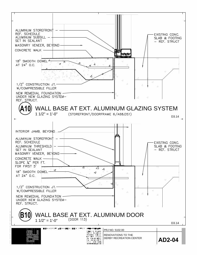
D3.14
WALL BASE AT EXT. ALUMINUM DOOR1 1/2" = 1'-0"
D3.14
WALL BASE AT EXT. ALUMINUM GLAZING SYSTEM1 1/2" = 1'-0"
PRJ NO. 5102.00
AD2-04RENOVATIONS TO THE DERBY RECREATION CENTER

D8.18
DETAIL @ POOL GLAZING1 1/2" = 1'-0"
PRJ NO. 5102.00
AD2-05RENOVATIONS TO THEDERBY RECREATION CENTER

PRJ NO. 5102.00
AD2-06RENOVATIONS TO THE DERBY RECREATION CENTER

PRJ NO. 5102.00
AD2-07RENOVATIONS TO THE DERBY RECREATION CENTER

Hardware Schedule
Set: 1.0 Doors: 109
Description: Nursery
1 Pivot 195 626 RF
1 Inter. Pivot M19 626 RF
1 Mortise Deadlock MS1850S SCH 628 AD
1 Cylinder 2153 626 YA
1 Inside Lever 4550 628 AR
1 Push Bar & Pull BF15747 Mtg-Type 1 US32D RO
1 Door Closer CLP7500 689 NO
1 Drop Plate 7788 689 NO
Set: 2.0 Doors: 109A
Description: Nursery
2 Hinge (spring) 1502 4-1/2" x 4-1/2" US26D MK
1 Exit Latch PB 5428LN 626 YA
2 Silencer 608 RO
Set: 3.0 Doors: 103, 104, 105, 106, 127B, 129B
Description: Office
3 Hinge TA2714 4-1/2" x 4-1/2" US26D MK
1 Entry Lock PB 5407LN 626 YA
1 Wall Stop 409 US32D RO
3 Silencer 608 RO
Set: 4.0 Doors: 107B
Description: Closet
6 Hinge TA2714 4-1/2" x 4-1/2" US26D MK
2 Dummy Levers PB 455LN 626 YA
2 Surface Overhead Stop 9 Series 652 RF
2 Silencer 608 RO
2 Roller Latches 592 US26D RO
Set: 5.0 Doors: 102
Description: Office (Rated)
6 Hinge TA2714 4-1/2" x 4-1/2" US26D MK
2 C.V.Rod Exit Devices 7120F PB626 US26D YA
2 Cylinder 1109 626 YA
2 Door Closer 7500 689 NO
2 Magnetic Wall Holder 998 US32D RF

1 Gasketing S88D (Head & Jambs) PE
2 Brush Astragal 18041CNB x Door Height PE
Set: 6.0 Doors: 111, 124, 125, 126
Description: Mech., Elev. Equip.
3 Hinge TA2714 4-1/2" x 4-1/2" US26D MK
1 Storeroom Lock PB 5405LN 626 YA
1 Wall Stop 409 US32D RO
3 Silencer 608 RO
Set: 7.0 Doors: 114B, 213
Description: Sprinkler, Storage
3 Hinge TA2714 4-1/2" x 4-1/2" US26D MK
1 Storeroom Lock PB 5405LN 626 YA
1 Surface Overhead Stop 9 Series 652 RF
3 Silencer 608 RO
Set: 8.0 Doors: 207C
Description: Mech.
3 Hinge TA2714 4-1/2" x 4-1/2" US26D MK
1 Storeroom Lock PB 5405LN 626 YA
1 Door Closer 7500 689 NO
1 Wall Stop 409 US32D RO
1 Gasketing S88D (Head & Jambs) PE
Set: 9.0 Doors: 112A, 116B, 117
Description: Storage
3 Hinge TA2714 4-1/2" x 4-1/2" US26D MK
1 Classroom Lock PB 5408LN 626 YA
1 Wall Stop 409 US32D RO
3 Silencer 608 RO
Set: 10.0 Doors: 112, 114, 116A
Description: Studio, Storage
1 Pivot 195 626 RF
1 Inter. Pivot M19 626 RF
1 Mortise Deadlock MS1850S SCH 628 AD
1 Cylinder 2153 626 YA
1 Inside Lever 4550 628 AR
1 Push Bar & Pull BF15747 Mtg-Type 1 US32D RO
1 Door Closer PR7500H 689 NO

1 Drop Plate 7788 689 NO
1 Wall Stop 409 US32D RO
Set: 11.0 Doors: 115
Description: Studio
1 Pivot 195 626 RF
1 Inter. Pivot M19 626 RF
1 Mortise Deadlock MS1850S SCH 628 AD
1 Cylinder 2153 626 YA
1 Inside Lever 4550 628 AR
1 Push Bar & Pull BF15747 Mtg-Type 1 US32D RO
1 Door Closer PR7500 689 NO
1 Drop Plate 7788 689 NO
1 Wall Stop 409 US32D RO
Set: 12.0 Doors: 113
Description: Exterior
1 Pivot 195 626 RF
1 Inter. Pivot M19 626 RF
1 Exit Device (exit only) 7100 630 YA
1 Door Closer CPS7500 6890 6891 689 NO
1 Drop Plate 7788 689 NO
1 Threshold 2005AT x Opening Width PE
1 Drip Sweep 345ANB x Door Width PE
Notes: Weatherstripping furnished by Aluminum Door Supplier.
Set: 13.0 Doors: 118
Description: Meeting
1 Pivot 195 626 RF
1 Inter. Pivot M19 626 RF
1 Mortise Deadlock MS1850S SCH 628 AD
1 Cylinder 2153 626 YA
1 Inside Lever 4550 628 AR
1 Push Bar & Pull BF15747 Mtg-Type 1 US32D RO
1 Door Closer 7500H 689 NO
1 Wall Stop 409 US32D RO
Set: 14.0 Doors: 135B
Description: Maint.
3 Hinge TA2714 4-1/2" x 4-1/2" US26D MK
1 Classroom Lock PB 5408LN 626 YA
1 Door Closer CLP7500 689 NO
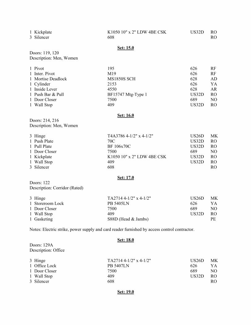
1 Kickplate K1050 10" x 2" LDW 4BE CSK US32D RO
3 Silencer 608 RO
Set: 15.0 Doors: 119, 120
Description: Men, Women
1 Pivot 195 626 RF
1 Inter. Pivot M19 626 RF
1 Mortise Deadlock MS1850S SCH 628 AD
1 Cylinder 2153 626 YA
1 Inside Lever 4550 628 AR
1 Push Bar & Pull BF15747 Mtg-Type 1 US32D RO
1 Door Closer 7500 689 NO
1 Wall Stop 409 US32D RO
Set: 16.0 Doors: 214, 216
Description: Men, Women
3 Hinge T4A3786 4-1/2" x 4-1/2" US26D MK
1 Push Plate 70C US32D RO
1 Pull Plate BF 106x70C US32D RO
1 Door Closer 7500 689 NO
1 Kickplate K1050 10" x 2" LDW 4BE CSK US32D RO
1 Wall Stop 409 US32D RO
3 Silencer 608 RO
Set: 17.0 Doors: 122
Description: Corridor (Rated)
3 Hinge TA2714 4-1/2" x 4-1/2" US26D MK
1 Storeroom Lock PB 5405LN 626 YA
1 Door Closer 7500 689 NO
1 Wall Stop 409 US32D RO
1 Gasketing S88D (Head & Jambs) PE
Notes: Electric strike, power supply and card reader furnished by access control contractor.
Set: 18.0 Doors: 129A
Description: Office
3 Hinge TA2714 4-1/2" x 4-1/2" US26D MK
1 Office Lock PB 5407LN 626 YA
1 Door Closer 7500 689 NO
1 Wall Stop 409 US32D RO
3 Silencer 608 RO
Set: 19.0

Doors: 123, 127A, 128, 210
Description: Office
1 Pivot 195 626 RF
1 Inter. Pivot M19 626 RF
1 Mortise Deadlock MS1850S SCH 628 AD
1 Cylinder 2153 626 YA
1 Inside Lever 4550 628 AR
2 Push Bar & Pull BF112 BTB US32D RO
1 Door Closer 7500H 689 NO
1 Wall Stop 409 US32D RO
Set: 20.0 Doors: 130,131
Description: Office (Rated)
3 Hinge TA2714 4-1/2" x 4-1/2" US26D MK
1 Office Lock PB 5407LN 626 YA
1 Door Closer 7500 689 NO
1 Kickplate K1050 10" x 2" LDW 4BE CSK US32D RO
1 Wall Stop 409 US32D RO
1 Gasketing S88D (Head & Jambs) PE
Set: 21.0 Doors: 132, 201
Description: Utility, Mech. (Rated)
3 Hinge TA2714 4-1/2" x 4-1/2" US26D MK
1 Storeroom Lock PB 5405LN 626 YA
1 Door Closer 7500 689 NO
1 Kickplate K1050 10" x 2" LDW 4BE CSK US32D RO
1 Wall Stop 409 US32D RO
1 Gasketing S88D (Head & Jambs) PE
Set: 22.0 Doors: 133A
Description: Exterior
1 Pivot 195 613 RF
1 Inter. Pivot M19 613 RF
1 Exit Device 7100 613 YA
1 Door Pull BF157 US10B RO
1 Cylinder 1109 613 YA
1 Door Closer CPS7500 6890 6891 690 NO
1 Drop Plate 7788 690 NO
1 Threshold 2005AT x Opening Width PE
1 Drip Sweep 345DNB x Door Width PE
Notes: Weatherstripping furnished by Aluminum Door Supplier.
Set: 23.0

Doors: 200A
Description: Fitness
1 Pivot 195 626 RF
1 Inter. Pivot M19 626 RF
1 Exit Device 7100ALK 630 YA
1 Cylinder 2153 626 YA
1 Door Closer CLP7500 6890 6891 689 NO
1 Drop Plate 7788 689 NO
Set: 24.0 Doors: 200B
Description: Corridor (Rated)
6 Hinge T4A3786 4-1/2" x 4-1/2" US26D MK
2 V.R. Exit Device 7170 (F90) PB626 630 YA
2 Cylinder 1109 626 YA
2 Door Closer PR7500 689 NO
2 Kickplate K1050 10" x 2" LDW 4BE CSK US32D RO
2 Magnetic Wall Holder 998 US32D RF
1 Gasketing S88D (Head & Jambs) PE
2 Brush Astragal 18041CNB x Door Height PE
Set: 25.0 Doors: 202A, 202B
Description: Fitness, Strength
1 Pivot 195 626 RF
1 Inter. Pivot M19 626 RF
1 Mortise Deadlock MS1850S SCH 628 AD
1 Cylinder 2153 626 YA
1 Inside Lever 4550 628 AR
1 Push Bar & Pull BF15747 Mtg-Type 1 US32D RO
1 Door Closer CLP7500 6890 6891 689 NO
1 Drop Plate 7788 689 NO
Set: 26.0 Doors: 203, 204A
Description: Fitness, Strength
1 Pivot 195 626 RF
1 Inter. Pivot M19 626 RF
1 Exit Device 7200ALK 630 YA
1 Cylinder 2153 626 YA
1 Door Closer CLP7500 6890 6891 689 NO
1 Drop Plate 7788 689 NO
Set: 27.0 Doors: 200B
Description: Stairs (Rated)

3 Hinge T4A3786 4-1/2" x 4-1/2" US26D MK
1 Exit Device 7100F PB628 630 YA
1 Door Closer 7500 689 NO
1 Kickplate K1050 10" x 2" LDW 4BE CSK US32D RO
1 Gasketing S88D (Head & Jambs) PE
Set: 28.0 Doors: 209
Description: Office
1 Cylinder 2153 626 YA
Notes: Balance of hardware furnished by Door Supplier.
Set: 29.0 Doors: 108
Description: Toilet
3 Hinge T4A3786 5" x 4-1/2" US26D MK
1 Privacy PB 5402LN 626 YA
1 Door Closer 7500 689 NO
1 Kickplate K1050 10" x 2" LDW 4BE CSK US32D RO
1 Wall Stop 409 US32D RO
1 Gasketing S773D (Head & Jambs) PE
Set: 30.0 Doors: 212
Description: Laundry
3 Hinge T4A3786 5" x 4-1/2" US26D MK
1 Classroom Lock PB 5408LN 626 YA
1 Door Closer 7500 689 NO
1 Kickplate K1050 10" x 2" LDW 4BE CSK US32D RO
1 Wall Stop 409 US32D RO
3 Silencer 608 RO
Set: 31.0 Doors: 129C
Description: Pool Locker
1 Pivot 195 613 RF
1 Inter. Pivot M19 613 RF
1 Mortise Deadlock MS1850S SCH 313 AD
1 Cylinder 2153 613 YA
1 Inside Lever 4550 121 AR
1 Push Bar & Pull BF15747 Mtg-Type 1 U10B RO
1 Door Closer CLP7500 690 NO
1 Drop Plate 7788 690 NO
Set: 32.0 Doors: 122

Description: Electrical, Mechanical
6 Hinge TA2714 4-1/2" x 4-1/2" US26D MK
2 Reinforcing Pivots 253 US2C HG
1 Dust Proof Strike 570 US26D RO
2 Flush Bolt 555 US26D RO
1 Storeroom Lock PB 5405LN 626 YA
2 Wall Stop 409 US32D RO
2 Silencer 608 RO
Set: 33.0 Doors: 207A, 207B
Description: Mech.
6 Hinge TA2714 4-1/2" x 4-1/2" US26D MK
1 Dust Proof Strike 570 US26D RO
2 Flush Bolt 555 US26D RO
1 Storeroom Lock PB 5405LN 626 YA
2 Surface Overhead Stop 9 Series 652 RF
2 Silencer 608 RO
Set: 34.0 Doors: 140A, 141A
Description: Locker
3 Hinge TA2714 4-1/2" x 4-1/2" US26D MK
1 Passage Set PB 5401LN 626 YA
1 Door Closer PR7500 689 NO
1 Kickplate K1050 10" x 2" LDW 4BE CSK US32D RO
1 Wall Stop 409 US32D RO
3 Silencer 608 RO
Set: 35.0 Doors: 105A, 106A
Description: Closet
3 Hinge TA2714 4-1/2" x 4-1/2" US26D MK
1 Passage Set PB 5401LN 626 YA
1 Wall Stop 409 US32D RO
3 Silencer 608 RO
Set: 36.0 Doors: 109B
Description: Exterior
1 Exit Device 7100 613 YA
1 Door Pull BF157 US10B RO
1 Cylinder 1109 613 YA
1 Door Closer CPS7500 6890 6891 690 NO
1 Drop Plate 7788 690 NO
1 Threshold 2005AT x Opening Width PE

1 Drip Sweep 345DNB x Door Width PE
Notes: Balance of hardware furnished by Aluminum Door Supplier.
Set: 37.0 Doors: 135A
Description: Maint.
1 Door Closer CLP7500 689 NO
Notes: Balance of hardware is existing and will remain.
Set: 38.0 Doors: 208B
Description: Maint.
1 Exit Device 7100F PB627 630 YA
1 Cylinder 1109 613 YA
1 Door Closer CPS7500 689 NO
Notes: Balance of hardware is existing and will remain.
Set: 39.0 Doors: 100A
Description: Exterior
1 Pivot 195 626 RF
1 Inter. Pivot M19 626 RF
1 Exit Device 7100 630 YA
1 Door Pull BF157 US32D RO
1 Cylinder 1109 626 YA
1 Door Closer CPS7500 6890 6891 689 NO
1 Drop Plate 7788 689 NO
1 Threshold 2005AT x Opening Width PE
1 Drip Sweep 345DNB x Door Width PE
Notes: Weatherstripping furnished by Aluminum Door Supplier.
Set: 40.0 Doors: 100C
Description: Exterior
1 Pivot 195 626 RF
1 Inter. Pivot EM19QC 626 RF
1 Exit Device 7100P 630 YA
1 Door Pull BF157 US32D RO
1 Cylinder 1109 626 YA
1 Auto Operator 5930 689 NO
2 Wall Actuators 691 NO
1 Threshold 2005AT x Opening Width PE
1 Drip Sweep 345DNB x Door Width PE

1 ElectroLynx Harness QC-C x Length Required MK
1 ElectroLynx Harness QC-C1500P MK
1 Power Supply 782 YA
Notes: Weatherstripping furnished by Aluminum Door Supplier.
Card reader furnished by the access control supplier.
Set: 41.0 Doors: 100B
Description: Vestibule
1 Pivot 195 626 RF
1 Inter. Pivot M19 626 RF
1 Push Bar 720 630 YA
1 Door Pull BF157 US32D RO
1 Door Closer CPS7500 6890 6891 689 NO
1 Drop Plate 7788 689 NO
1 Threshold 271A x Opening Width PE
1 Drip Sweep 315CN x Door Width PE
Notes: Weatherstripping furnished by Aluminum Door Supplier.
Set: 42.0 Doors: 100D
Description: Vestibule
1 Pivot 195 626 RF
1 Inter. Pivot M19 626 RF
1 Push Bar 720 630 YA
1 Door Pull BF157 US32D RO
1 Auto Operator 5930 689 NO
2 Wall Actuators 691 NO
1 Threshold 271A x Opening Width PE
1 Drip Sweep 315CN x Door Width PE
Notes: Weatherstripping furnished by Aluminum Door Supplier.
Set: 43.0 Doors: 107A (001D)
Description: Exterior
1 Pivot 195 626 RF
1 Inter. Pivot EM19QC 626 RF
1 Exit Device 7100P 630 YA
1 Door Pull BF157 US32D RO
1 Cylinder 1109 626 YA
1 Door Closer CPS7500 6890 6891 689 NO
1 Drop Plate 7788 689 NO
1 Threshold 2005AT x Opening Width PE
1 Drip Sweep 345DNB x Door Width PE
1 ElectroLynx Harness QC-C x Length Required MK

1 ElectroLynx Harness QC-C1500P MK
1 Power Supply 782 YA
Notes: Weatherstripping furnished by Aluminum Door Supplier.
Card reader furnished by the access control supplier.

801 E. MARKETDERBY KS 67037
SCALE: 1/8" = 1'-0"PARTIAL M22.2 PLAN
M1

801 E. MARKETDERBY KS 67037
SCALE: 1/8" = 1'-0"PARTIAL M32.1 PLAN
M2

Renovations to the Derby Recreation Center SJCF#5102.00
COMMUNICATION CABLE
INSTALLATION 27 10 00-1 2 4 S E P T E M B E R
2012SECTION 27 10 00 - COMMUNICATIONS CABLE INSTALLATION
PART 1 - GENERAL
1.1. SUMMARY:
A. Scope: Extent of cable system work is indicated by drawings and details, and is
hereby defined to include, but not be limited to the installation of telephone, data,
fiber, video, or CATV cables if system cables are indicated on the drawings or
included in other Specification Sections.
B. Provide submittals on all products specified with this section.
C. All cabling materials, cabling, ends, jacks, patch panels, racks, etc. are specified
in other sections and will be provided by the Contractor. The Contractor shall be
responsible for all testing as specified in individual specification sections.
D. Additional and or more stringent requirements may be found in other
communication specification sections and shall be applicable to this Project.
E. Installation of raceways, conduit sleeves etc. as required for routing of
communication systems cabling shall be per specifications Section 26 05 30
“Raceway Systems”.
1.2. QUALITY ASSURANCE:
A. Installers Qualifications: Firms with at least five (5) years successful installation
experience with projects utilizing telephone, data, video, fire alarm, nurse call
and other communication systems and wiring similar to that required for this
project. To ensure data distribution system is Category 5 compliant, installer
must be a Building Industry Consulting Service International (BICSI) member and
have a data cable certification by AT&T.
The Contractor shall provide three (3) previous references of cabling installations
for each type included in this project.
B. Codes and Standards: Conform to the following:
1. Codes Rules and Regulations: Execute all work under ADA, the latest
rules and regulations of the National Electrical Code Standard of the
national Board of Fire Underwriters, the National Fire Protection
Association, and with all laws, regulations and ordinances of the County,
State and city.

Renovations to the Derby Recreation Center SJCF#5102.00
2. Federal Communications Commission (FCC): Comply with Federal
Communications Commission Rules, pertaining to telephone equipment
and other communication systems being installed.
3. Institute of Electrical and Electronics Engineers (IEEE): Comply with
IEEE Recommended Practice for electric Power Systems in Commercial
Buildings: pertaining to communication systems and Local Area
Networks.
4. National Electrical Manufacturers Association (NEMA): Comply with
NEMA requirements for "Enclosures for Electrical Equipment”.
5. Rural Electrification Administration (REA): Comply with Rural
Electrification Administration specifications pertaining to construction and
installation of telephone cabling.
6. Electronic Industries Association (EIA): Comply with EIA Standards and
EIA/TIA (Telecommunications Industries Association) Standards for
Commercial Building Telecommunication W iring, pertaining to
categorizing and installation of telephone and data systems.
7. Underwriters Laboratories (UL): All equipment shall be U.L. listed and
installed to maintain such listings.
1.3. DELIVERY, STORAGE, AND HANDLING:
A. Delivery: Deliver communication system equipment and components in factory-
fabricated containers or wrappings, which properly protect equipment from
damage.
B. Storage: Store communication system equipment and components in original
packaging. Store inside in a well-ventilated space protected from weather,
moisture, soiling, humidity, and extreme temperatures.
C. Handling: Handle communication system equipment and components carefully
to prevent damage, breaking, and scoring of finishes. Do not install damaged
units or components; replace with new.
1.4. COORDINATING AND SEQUENCING:
A. Coordinating: Coordinate with other building trades and electrical work including
wires/cables, electrical boxes and fittings, and raceways, to properly interface
installation of systems with other work.
B. Sequencing: Sequence installation of communication systems with other work to
minimize possibility of damage and soiling during remainder of construction.

Renovations to the Derby Recreation Center SJCF#5102.00
C. Contractor will be responsible for ceiling tile replacement, wall repainting, etc.
Due to damage caused by installation of this equipment and cabling.
1.5. AS-BUILT DRAW INGS:
A. Show on blue line prints in red ink all telephone, data, video, CATV jack
identification numbers, actual cable routing paths, as well as all changes from
original plans made during the installation. Separate As-Built drawings shall be
provided for each communication system installed. Return the “as-built” red lined
drawings, specifications and addenda, as set forth in the General conditions, to
the Architect/Engineer upon completion of the project.
PART 2 - PRODUCTS
2.1. CABLING SYSTEM W ARRANTY:
A. Selected installer must provide an independent system warranty for one (1) year
from the date of final acceptance (Manufacturer’s W arranty). The system
warranty must guarantee the electrical performance of the installed system
cabling/wiring to meet or exceed the requirements as outlined in documents
TIA/EIA 568A and other cable requirements. The warranty must include
complete parts and labor replacement of defective products by the installer for a
period of one (1) year from the date of final acceptance. The products must be
warranted for a minimum of one (1) year by the Manufacturer.
2.2. CABLING:
A. All communications cabling installed outside of enclosed raceways shall be
plenum rated and U.L. Listed for use in mechanical air plenums unless directed
otherwise on the drawings.
B. Accessories:
1. Backboards shall be provided as shown on the drawings or in the
Specifications. Interconnect locations will require this Contractor to install
additional Backboards. If interconnect locations are required, they must
be approved by the Engineer/Owner prior to installation. Verify in Field
exact quantity needed. Backboards shall be 3/4" thick fire resistant
plywood with size as required for installation. Plywood shall be painted
with two (2) coats of high fire resistant, non conductive white paint. As a
minimum provide backboards as indicated on the drawings or in the
Specifications.
2. Raceways: All communications cabling shall be installed in raceway
systems when located in concealed, non accessible locations. In general,
raceways are required for outlets in walls up into accessible ceilings,
through non accessible ceilings, and through all wall penetrations etc.
Provide bushings at all raceway terminations. Fire stop and fire seal all
penetrations of fire rated walls.
3. Cable Supports: All cables above ceilings are to be supported by cable
trays and/or J-Hooks located approximately 6” above lay-in ceilings below
all mechanical and other electrical equipment.

Renovations to the Derby Recreation Center SJCF#5102.00
(a) Contractor shall install cabling to maintain a twelve (12) inch
minimum distance from all sources of Electrical Magnetic
Interference (EMI), such as; fans, motors, fluorescent fixtures,
transformers, etc. Engineer shall be notified in advance if these
clearances cannot be met. Power cable must never reside in the
same cable tray as the data cabling. No data cables will be
spliced. Specifically all cabling installation procedures will also
adhere to the recommended “do’s and Don’ts in EIA/TIA 568B.
(b) J-Hooks: J-Hooks shall be used in common areas where cable
trays are not available and/or as indicated on the plans. J-Hooks
for main runs shall be. J-Hooks shall be located 6” maximum
above ceilings with a maximum spacing of 4’-0” on center. J-Hook
must be sized to support all cable plus 15% room for additional
cable in the future. All hardware shall be submitted for approval to
Engineer prior to installation
(c) "D" Rings: “D” rings may be used in common areas in place of J-
Hooks following the same installation requirements. "D" rings are
to be provided to support all voice and data cables in telephone
communications rooms, 6" on center maximum. “D” ring numbers
13A,B, and C. Size as required.
(d) Conduit Sleeves: Conduit sleeves shall be one of the following:
(1) Rigid steel or IMC conduit with threaded ends and non-
metallic bushings on each end.
(2) EMT conduit with U.L. Listed slide on non-metallic
bushings on each end.
Conduit sleeves shall be provided where cables are indicated to
pass through walls and at other locations as indicated on the
plans. Sleeves shall be 1” conduit minimum extending 6” on
either side of walls. W here possible, sleeves shall be located 6”
above ceiling.
(e) Tie-W raps: Thomas & Betts, TY-RAPSÓ brand. W ill be plastic,
heavy duty, and flame retardant (Must meet UL 94V-O
flammability rating). Size as required. (Thomas & Betts Bulk Pkg.
Cat. Number TY28MFR)
(f) Cable Labels: A quality grade general purpose vinyl-impregnated
waterproof tape. Resistant to moderate amounts of oil, dirt, and
temperature ranges from -30°F to 200°F. (Thomas & Betts, E-Z-
CodeÓ W BC vinyl cloth, standard Cat. No. W M-A-Z)
4. Cable Management:
(a) Telephone terminal backboards shall be provided with standard
cable management rings and wire-ways to support the cabling, as
shown on project drawings. Cable management shall be used for

Renovations to the Derby Recreation Center SJCF#5102.00
both the vertical and horizontal cabling on the backboard. The
quantity of cable management rings and wire-ways shall be based
upon the cable size and number of 66 type blocks. Cable
management rings and wire-ways shall not exceed 60 percent fill.
5. Cable Labeling:
(a) Labeling of cable shall consist of permanent lettering or
numbering as required by owner to coordinate with existing
labeling schemes. Contractor to coordinate exact labeling of
cables with Owner.
6. Documentation:
(a) All cables will be labeled in accordance with current VCRMC
labeling standards.
(b) All cables will be appropriately labeled on both ends, in all junction
boxes and at 50’ intervals.
(c) No data cabling identifier will duplicate any previous, active cable
identifier.
(d) Additional cable labeling may be required in the individual
communication system specification sections.
C. Tightening: Tighten electrical connectors and terminals, including screws and
bolts, in accordance with equipment manufacturer's published torque tightening
values for equipment connectors.
2.3. GROUNDING:
A. General: Provide #6 CU. equipment grounding connections for Cabling Blocks,
patch panels, racks, metal troughs, protectors, etc. to grounding bus. Provide
ground bus and ground cable to common ground plan, and driven ground rods
for a max. impedance of 5 ohms. All communication systems shall be grounded
in compliance with ANSI/NFPA 70 requirements and practices, except where
superseded by other authorities or codes. These grounding requirements apply
to all cross-connect frames, patch panel racks, active communication system
equipment and test apparatus used for maintenance and testing.
2.4. ADJUSTING AND CLEANING:
A. Cleaning: Clean all equipment and components of dirt and construction debris
upon completion of installation.
B. Touch-up: Touch-up scratched or marred enclosure surfaces to match original
finishes.
C. Protection: Protect installed equipment, cabling and components from damage
during remainder of construction period.
2.5. DEMONSTRATION/TESTING:

Renovations to the Derby Recreation Center SJCF#5102.00
A. Testing of each system shall be performed in accordance with the manufacturers
specifications and as outlined in the other individual communication system
specification sections.
PART 3 - EXECUTION
3.1 PROJECT OVERVIEW :
A. Scope: The scope of this project includes all communication system cabling, and
labor necessary for complete installation of all cabling. The end product to be
provided is a fully functional cabling system for use by Owner and Owner
provided head end equipment at the time of Owner occupation of the facility.
B. Installation:
1. Horizontal through-wall conduits and sleeves shall be provided for cabling
runs as required and indicated on the plans. Contractor is to ensure
grommets and/or bushings are installed on all conduits prior to cable pull.
W here there is no existing vertical conduit and gangbox - Surface
mounted gangbox and wiremold stubbed 6 inches above the finished
ceiling shall be installed in each area requiring a system device or outlet
upon approval of engineer/Owner. J-Hooks suspended above ceiling
cavity or wall mounted “D” rings shall be installed by this Contractor to
extend out of the Equipment Rooms into the ceiling cavity to hold the
large bundles of horizontal cabling where cable trays are not being used.
2. At all times, the communication cable shall be at least twelve (12”) away
from all lighting and other line voltage circuits, shall not run parallel to
electrical utilities in close proximity, shall cross electrical utilities at right
angles with at least twelve (12”) of separation. Engineer shall be notified
in advance if these clearances cannot be met.
C. Examination:
1. General: Examination areas and Conditions under which systems are to
be installed. Notify the General Contractor or Engineer in writing of
conditions detrimental to proper completion of the work. Do not proceed
with work until unsatisfactory conditions have been corrected in a manner
acceptable to Installer.
D. Installation of communications systems:
1. Installation: Install cables as indicated, in accordance with
manufacturer's written instructions and with recognized industry practices.
Ensure cables comply with installation and operational requirements of
EIA/TIA, NEC, the Federal Communications Commission and all other
applicable codes governing the cables being installed.
2. All communications system cables shall be independently supported on
'J' hooks, or in cable trays if indicated on the drawings. Do not support
cables from mechanical ductwork, piping, ceiling system wires, electrical
conduits, etc.

Renovations to the Derby Recreation Center SJCF#5102.00
E. Installation of J-hooks:
1. Provide J-Hook supports from the structure above for all horizontal runs
except where cables are run in cable trays. Spacing shall be a maximum
of 4’-0”. Cables shall be located approximately 6” above the ceiling.
Cable shall not contact the ceilings, piping, light fixtures, ducts, etc. All
cables must be suspended independently from other supports.
F. Installation of tie wraps:
1. Tie-wrap all cables (except patch cords) together between the J-Hooks, in
the cable trays, and in the communications rooms. Spacing shall be a
maximum of 4’-0”. No tie-wraps shall be placed over cable labels. The
Tie-wraps shall be plastic, heavy duty, and flame retardant.
G. W all penetrations:
1. W hen cables pass through walls, conduit sleeves shall be provided.
Provide fire barrier around conduit and seal conduit with fire barrier after
cable installation in fire rated walls.
H. Interconnection to Owner equipment:
1. All interconnections between premise cabling and equipment (either
existing or new) shall be coordinated with Owner to minimize any
downtime as related to the associated communications system.
************************
END OF SECTION 27 10 00

Renovations to the Derby Recreation Center SJCF #5102.00
COMMUNICATIONS CABLING
SYSTEMS 16 742-1 24 SEPTEMBER 2012
SECTION 27 32 00 – COMMUNICATIONS CABLING SYSTEMS
PART 1 - GENERAL
1.1. SUMMARY:
A. Scope: Extent of communications system work is indicated by
drawings and details, and as noted in this Section, and is hereby
defined to include, but not by way of limitation, telephone
wiring/cabling, telephone outlets, data wiring/cabling, data outlets,
terminals, connecting blocks and other associated equipment and
hardware.
B. Provide submittals on all products specified with this section.
C. All cabling materials, cabling, ends, jacks, patch panels, racks, etc. will
be provided by the contractor. All test equipment shall be provided by
the contractor and shall be prior approved with Owner’s Network
Engineering. Copper test equipment will be meet the minimum
standards set forth for Level 3 hand held field test equipment per 568
B.1, section 11. The communications system shall be CAT 6E
enhanced, minimally swept out to 250 MHZ, and must strictly adhere
to the requirements of EIA 568 B.2.1.
D. All cabling shall be installed per Section 16740 “Communications Cable
Installation” Specification. If conflicts exist, this Section supersedes
Section 16740.
1.2. QUALITY ASSURANCE:
A. Installers Qualifications: Firms with at least 5 years successful
installation experience with projects utilizing communications systems
and wiring similar to that required for this project. To ensure that the
communications distribution system is EIA 568 B.2.1 Category 6e
compliant, the installer must maintain a current factory certification
from a third party listed & verified manufacturer of copper connectivity
products. Further, the installation company must be a Building
Industry Consulting Service International (BICSI) member.
The Contractor shall provide three (3) references of communications
cabling installations as well as the name and telephone number of a
contact person for each project.

Renovations to the Derby Recreation Center SJCF #5102.00
B. Codes and Standards: Conform to the following:
1. National Electrical Code (NEC): comply with applicable local
code requirements of the authority having jurisdiction and NEC,
including 725, 770, 800 and OFNR Series articles as applicable
to installation and construction of communications systems.
2. Federal Communications Commission (FCC): Comply with part
68 and Subpart J of part 15, Federal Communications
Commission Rules, pertaining to telephone equipment and Class
A computer registration by manufacturer.
3. Institute of Electrical and Electronics Engineers (IEEE): Comply
with Std 241 and 802, IEEE Recommended Practice for electric
Power Systems in Commercial Buildings: pertaining to
communication systems and Local Area Networks.
4. National Electrical Manufacturers Association (NEMA): Comply
with NEMA's Pub No. 250, "Enclosures for Electrical Equipment”.
5. Electronic Industries Association (EIA): Comply with EIA
Standards RS-453, 455, 464 and EIA/TIA (Telecommunications
Industries Association) Standards 568, 569, 570, 606, 607 and
Technical Systems Bulletin 36, 40, and 53 of the Commercial
Building Telecommunication Wiring Standards pertaining to
categorizing and installation of communications systems.
6. Underwriters Laboratories (UL): Comply with, specifically,
subjects 444 and 13 (STP) as referenced UL ratings and/or
classifications as mentioned in the above standards.
1.3. DELIVERY, STORAGE, AND HANDLING:
A. Delivery: Deliver equipment and components in factory-fabricated
containers or wrappings, which properly protect equipment from
damage.
B. Storage: Store equipment and components in original packaging.
Store inside in a well-ventilated space protected from weather,
moisture, soiling, humidity, and extreme temperatures.
C. Handling: Handle equipment and components carefully to prevent
damage, breaking, and scoring of finishes. Do not install damaged
units or components; replace with new.
PART 2 - PRODUCTS
2.1. CABLING SYSTEM WARRANTY:

Renovations to the Derby Recreation Center SJCF #5102.00
A. Selected vendor must provide an application independent
communications and telephone wiring system warranty for a minimum
of 15 years from the date of final acceptance (Manufacturer’s
Warranty). The system warranty must guarantee the electrical
performance of the installed system communications, wiring and to
meet or exceed the requirements as outlined in documents TIA/EIA
568b.2.1. The warranty must include complete parts and labor
replacement of defective products by the installer for a period of 15
years, from the date of final acceptance by the owner. Warranty
submittal is required to Engineer prior to installation.
2.2. MANUFACTURERS:
A. Communications Cable and Cable Connectors: Provide twisted-pair,
copper Communications cable, and cable connectors, except where
fiber optic is specified, in sizes and types indicated, and as
recommended by communications equipment manufacturer for
indicated safety and applications. Mate and match connector materials
to factory-installed equipment connectors. Submittal is required to
Engineer prior to installation. Verify telephone and data cable colors
with Owner prior to ordering.
1. Cable (Horizontal to outlet):
(a) COMMUNICATIONS: CommScope UltraPipe, P/N 6ECMP,
Plenum unshielded four pair cable. Unless otherwise
specified, all voice UTP cabling shall be Category 6e, 100
mhz solid copper conductor, four pair, 24 AWG, and shall
comply with EIA/TIA 568A for Category 6e copper cable.
The horizontal cable must consist of 4 wire pairs that are
adjoined along their longitudinal axis to insure twists are
maintained to the termination point. The cable must
exhibit stable impedance over the entire frequency
bandwidth from 1Khz to 250 MHz. Attenuation @ 250
mhz for 100 meters shall be no greater than 30.8db.
Near End Cross Talk @ 250 mhz for 100 meters shall be
no less than 44.3 db. Impedance traces of cables must
be provided and impedance averaging will not be allowed.
All copper communication products must be
independently tested by a third party laboratory for
verification of published results (UL or ETL ITS). Products
must be verified & listed with the respective testing
organization. Where required, cable shall be classified low
smoke and low flame for use in air plenums in accordance
with NFPA 70. Communications cable shall be white in
color, utilize co-extruded colored stripes, and be
sequentially marked 1000-0 feet. Manufacturer test
reports for each reel of cable must be maintained and
turned over to the owner at time of system acceptance.
Submittal is required to Engineer prior to installation.

Renovations to the Derby Recreation Center SJCF #5102.00
2. Terminal Blocks (Copper)
(a) COMMUNICATIONS: 110 Patch Panel System Terminal
Blocks (Category 6e).
(1) Patch Panels. Category 6E Communications cabling
shall terminate directly on the back of 48 port
Category 6e patch panels on Contractor provided
equipment racks in the Computer Room and wall
mounted units in the telecom interconnect locations
or as indicated in the Drawings. Use PANDUIT
DP48688TP, high density 2U 48 port CAT 6e patch
panels. Provide (1) PANDUIT 3 ½” high cable
management panel WMPH223 between each 48
port patch panel. Patch panel port label shall be 6
character label (Example “A2A05K”) as follows, 1st
character - Zone, 2nd character = Floor; 3rd -5th
character - location in grid; 6th character - is the
multiple jack designation at that location. Obtain
drop ID’s from Owner’s Network Engineering.
(2) Termination Hardware , (High Density Patch
Panels) Horizontal station cables will terminate on
high density patch panels having a published Near
End Crosstalk (NEXT) value of -42 dB or better.
This product must provide plating in the contact
area to reduce long term corrosion effects.
Contacts must be oriented at 90 degrees to the
axis of the conductor. Terminations must have
color coding on the individual contacts. Products
must provide 24 ports in 1 rack unit (1U) or 48
Ports in two rack units (2U) etc. Connectors shall
be wired with 568B configuration. See plan details
for pin-outs. One cable management organizer per
48 ports shall be provided by the Contractor on the
Contractor provided equipment rack. All hardware
shall be submitted for approval to Engineer prior to
installation.
(b) Communications Equipment Cross-connects. All
connections between the communications equipment
terminations and the station terminations shall be done
using Category 6e patch cords. These cords must meet
the performance criteria of the warranty system being
installed. All patch cords shall be factory terminated as
recommended by TIA/EIA 568.2.1 in order to insure
consistent quality and performance. The patch cords
must have a latching mechanism to secure them to the
termination block and must be keyed so they cannot be
inserted upside down. Patch cords cannot exceed 6
meters in length. The contractor will provide two (2)

Renovations to the Derby Recreation Center SJCF #5102.00
patch cables for every individual cable installation. All
patch cables must be provided from the same
manufacturer as the manufacturer of jack and panel
assemblies. For bidding purposes, Category 6e patch
cables are generally specified as being yellow and
between 7 and 10 feet long, depending on use and
situation. Length shall be long enough to easily patch
longest reaching opposite ports using cable management
rings. All hardware shall be submitted for approval to
Engineer prior to installation.
(c)EQUIPMENT RACK: Provide and install equipment racks in
locations as shown on the drawings. Rack shall be
PANDUIT CMR19X84S. Racks shall be provided with a
standard top crossmember, and pre-drilled base plate to
allow floor fastening. Frame equipment racks shall be
seven feet in height. Each rack shall be provided with a
quad 110 volt AC outlet, mounted in the bottom of the
rack, and provided with a separate 20 amp circuit.
Grounding Requirements are required per manufacturers
recommendations. Submittal is required to Engineer prior
to installation.
3. Outlets to consist of the following:
(a) Information outlet terminations will utilize modular wall
plates and Panduit P/N CJ688TP CAT 6 jacks, or equal by
Connectivity. Verify jack colors with Owner, and faceplate
colors with Architect. Faceplates must be supplied with
reversible ID Tabs (available in various colors).
All jacks must exceed the Category 6e NEXT requirement
TIA/EIA 568B.2.1. Jacks must be provided as individual
units in order to provide the maximum flexibility. Jack or
connector modules that contain more than one connector
will not be accepted. The faceplates will be available in a
variety of port sizes and styles (furniture, surface and
flush mount) which will universally accept the individual
jacks. Jacks must be available in at least 6 colors and
wall plates must be available in a minimum of 4 colors. A
minimum of 2 ports must be accommodated within a
single gang wall plate. Provide blank filler over any
unused ports. Terminations must support a minimum of
200 re-terminations and must allow for termination of
stranded wire. The product must support termination of
smaller gauge wires following insertion and removal of
larger gauge wires without modification or adjustment.
Quantity of jacks as needed plus an additional 5 complete
sets of spare jacks to be given to Owner for future use.

Renovations to the Derby Recreation Center SJCF #5102.00
All hardware shall be submitted for approval to Engineer
prior to installation.
(b) Surface mounting will be allowed only where shown on
the drawings, and where specifically approved by the
Engineer.
4. Cable & Outlet Labeling:
(a) Labeling of communications outlets shall consist of non-
permanent lettering indicating a “communications” port
and extension located above the port. Numbering shall
be as required by owner to coordinate with existing
labeling schemes, and must meet the EIA / TIA 606
standards for documentation and labeling. Contractor
shall coordinate exact labeling of outlets with Owner.
C. Tightening: Tighten electrical connectors and terminals, including
screws and bolts, in accordance with equipment manufacturer's
published torque tightening values for equipment connectors. Where
manufacturers' torque requirements are not indicated, tighten
connectors and terminals to comply with tightening torque specified in
UL Standard 486A and B, and the National Electrical Code.
2.3. ADJUSTING AND CLEANING:
A. Cleaning: Clean equipment and components of dirt and construction
debris upon completion of installation.
B. Touch-up: Touch-up scratched or marred enclosure surfaces to match
original finishes.
C. Protection: Protect installed equipment and components from damage
during remainder of construction period.
2.4. DEMONSTRATION / TESTING:
A. Minimum testing requirements for copper cabling is divided into the
following conditions, keeping in mind that Attenuation and NEXT are
the two most important factors and must be strictly adhered to by the
installer. Test results/reports shall be provided by an experienced Test
Agency and shall be provided to the Owner and the Engineer. All
communications cable shall be tested using EIA 568 B.2.1 cabling
specification.
PART 3 - EXECUTION
3.1 PROJECT OVERVIEW:

Renovations to the Derby Recreation Center SJCF #5102.00
A. The scope of this project includes communications cabling, passive
equipment and labor necessary for cross-connect and patching of all
cabling. The end product to be provided is a fully functional
communications, network cabling system for use by Owner and Owner
provided telecom headend equipment at the time of Owner occupation
of the facility.
1. Two (2) RJ45 (Communications) connector ports are to be
provided at each typical communications outlet unless indicated
otherwise by the Drawings and these specifications. (One for
telephone, one for data.) All Cables are to be distributed from
the appropriate Communications Equipment Room or
Interconnect location to each individual information outlet,
except where noted on the plans and these specifications.
Termination is required at the Communications Equipment Room
and each of the fiber interconnect locations in the patch panels
specified on Contractor provided equipment racks or wall
mounted patch or termination blocks as shown in Drawings. All
standards for Category 6e installation shall be adhered to. All
cable runs are direct home runs to the appropriate distribution
panel. Slack cable shall be provided for all cabling to ensure
proper termination locations. Minimum of 1 foot of cable slack
at each communications/telephone and CATV outlet and 10 feet
of cable at the termination/distribution panels.
2. In the Communications Equipment Room and the Interconnect
locations, on the Contractor provided Patch Panels, the
communications cable pairs shall be laid down on the blocks
according to EIA/TIA color code standards color code starting
with pair one on the blocks. The blocks shall also be labeled
with cable and pair counts. The wiring standard shall be T568B.
End to end testing of Communications wiring to be provided by
Contractor.
3. Between the Communications Equipment Room and each
information outlet, the contractor shall run the cables as
specified in Section 16740.
B. EXAMINATION:
1. General: Examine areas and Conditions under which
communications systems are to be installed. Contractor shall
notify in writing of conditions detrimental to proper completion
of the work. Do not proceed with work until unsatisfactory
conditions have been corrected in a manner acceptable to the
Owner.
C. INSTALLATION OF COMMUNICATIONS SYSTEMS:
1. Installation: Install systems as indicated, in accordance with
manufacturer's written instructions and with recognized industry

Renovations to the Derby Recreation Center SJCF #5102.00
practices (BICSI); ensure systems comply with installation and
operational requirements of EIA/TIA, NEC and the Federal
Communications Commission.
D COMMUNICATIONS CONNECTOR TERMINATION PRACTICES:
1. For Category 6e (Communications) Cables; minimize the
amount of untwisting in a pair as a result of connecting to
hardware for all terminations. For Category 6e cabling the
amount of untwisting must not exceed the requirements for
TIA/EIA TSB-40.
E. INTERCONNECTION TO OWNER EQUIPMENT:
1. All interconnections between premise wiring and equipment
(either existing or new) for communications shall be coordinated
with Owner to minimize any downtime as related to
communications service.
************************
END OF SECTION 16 742