construction program management and inspection guide
TRANSCRIPT

August 2004
FEDERAL
HIGHWAY
ADMINISTRATION
Construction Program Management
and Inspection Guide
Construction Program Management
and Inspection Guide
FEDERAL
HIGHWAY
ADMINISTRATION
August 2004

August 2004
FEDERAL
HIGHWAY
ADMINISTRATION
Construction Program Management
and Inspection Guide

NoticeThis publication is disseminated under the sponsorship of the U.S. Department of Transportation inthe interest of information exchange. The publication does not constitute a standard, specification, orregulation. The United States Government does not endorse products or manufacturers. Trade ormanufacturers’ names appear herein solely because they are considered essential to the object of thepublication.

Foreword v
List of Acronyms vii
1. Introduction 1–1
2. Background 2–1
Historical Developments in Construction Inspection . . . . . . . . . . . .2–1
A New Era of Engineering Awareness and Stewardship . . . . . . . . . .2–2
Flexibility and Accountability . . . . . . . . . . . . . . . . . . . . . . . . . . . . . . . . .2–2
3. Construction Program Management 3–1
General . . . . . . . . . . . . . . . . . . . . . . . . . . . . . . . . . . . . . . . . . . . . . . . . . . . . .3–1
Considerations . . . . . . . . . . . . . . . . . . . . . . . . . . . . . . . . . . . . . . . . . . . . . .3–1
Program Elements . . . . . . . . . . . . . . . . . . . . . . . . . . . . . . . . . . . . . . . . . . .3–2
Objectives of Inspection . . . . . . . . . . . . . . . . . . . . . . . . . . . . . . . . . . . . .3–3
Purposes of Construction Inspection Reports . . . . . . . . . . . . . . . . . . .3–4
Inspections: Types and Scope . . . . . . . . . . . . . . . . . . . . . . . . . . . . . . . . .3–5
4. Inspection and Review Activities 4–1
Preparation . . . . . . . . . . . . . . . . . . . . . . . . . . . . . . . . . . . . . . . . . . . . . . . . . .4–1
Conducting the Review . . . . . . . . . . . . . . . . . . . . . . . . . . . . . . . . . . . . . . .4–1
Collecting and Evaluating Data . . . . . . . . . . . . . . . . . . . . . . . . . . . . . . . .4–2
Writing the Report . . . . . . . . . . . . . . . . . . . . . . . . . . . . . . . . . . . . . . . . . . .4–3
Processing and Distributing the Report . . . . . . . . . . . . . . . . . . . . . . . .4–5
Followup Action, Controls, and Information Sharing . . . . . . . . . . . . .4–6
Information Sharing and Technology Transfer . . . . . . . . . . . . . . . . . . .4–7
5. Summary 5–1
Contents
CONSTRUCTION PROGRAM MANAGEMENT AND INSPECTION GUIDE (5/01/04)
iii
Contents

Appendix A A-1
Policy Memoranda Regarding Stewardship
Appendix B B-1
Quality Assurance Resources
Memorandum: Quality Assurance Guide Specification andImplementation Manual for Quality Assurance . . . . . . . . . . . . . . . . . . . . . . .B–2
Contractor Quality Control Plans: Contractor Guidelines and Examples . . . . . .B–4
A Model Quality Control Plan . . . . . . . . . . . . . . . . . . . . . . . . . . . . . . . . . . .B–17
Appendix C C-1
Sample Guidelines for Process Review/Product Evaluation Programs
California Division Program Review/Product Evaluation Program . . . . . . . . . .C–2
Illinois Division Guidelines for Conducting Process Reviews . . . . . . . . . . . . . .C–8
Appendix D D-1
Guide for Making Inspections-In-Depth on Federal-AidHighway Construction Projects
Appendix E E-1
Technical References and Resources
Appendix F F-1
Examples of Reporting Practices
Appendix G G-1
Project Implementation and Reporting Forms
Contents
CONSTRUCTION PROGRAM MANAGEMENT AND INSPECTION GUIDE (5/01/04)
iv

ForewordOver the last 15 years, the role and experience base of the Federal Highway Administration’s(FHWA’s) engineering staff have changed considerably. Today, our field engineers are typicallyinvolved in a diverse array of issues that were not common in the Federal-aid program of decades past.A decline in staffing resources and experience, coupled with increased demand on our current fieldengineering staff, requires a more focused and systematic approach to fulfill our constructionstewardship responsibilities.
Past Federal highway legislation provided many State transportation agencies and FHWA divisionswith a great deal of flexibility in delivering the program, including certification mechanisms for manytypes of construction projects. This increased State flexibility but reduced FHWA project oversight.Reorganization of FHWA, the elimination of the region offices, and a thrust towards other sensitiveissues within the Federal-aid program have also contributed to a less visible construction stewardshippresence by our field and Washington Headquarters offices. In spite of the many changes that haveoccurred, FHWA’s role in ensuring the integrity of the Federal-aid construction program remains acritical responsibility in our continuing accountability to Congress and the public.
Between 1997 and 2000, total expenditures by all levels of government increased by over 25percent for highway infrastructure. In 2000, highway expenditures totaled more than $127 billion,with over 70 percent going to reconstruction and preservation of existing roads and construction ofnew facilities. To continue meeting our construction stewardship responsibilities and to ensure safe,efficient, high-quality, Federal-aid construction, division office engineering staff must continually striveto find effective ways of conducting business. While this effort presents a tremendous challenge, wecan meet it.
In December of 2001, FHWA leadership created the Construction Quality Improvement Team(CQIT) to address this challenge. This publication, Construction Program Management and InspectionGuide, is a significant product of the CQIT. It was developed to provide our field engineering staff atechnical resource to consult in delivering an effective level of oversight and stewardship of theFederal-aid construction program. This document is not about business as usual, but rather aboutfocusing on program practices and techniques that add value and help to ensure effective oversight andacceptable accountability. It provides specifics for implementing a wide variety of strategies that, withour State partners’ involvement, will deliver quality construction products to our ultimate customers,that is, the traveling public.
I strongly urge each of you to become familiar with this document, visit the referenced Web sites,and review the other references identified as you undertake your renewed stewardship responsibilities.I believe this document is an excellent tool for adding value, enhancing technical expertise, ensuringthe highest level of construction quality, and maintaining accountability.
King W. GeeAssociate AdministratorOffice of Infrastructure
Contents
CONSTRUCTION PROGRAM MANAGEMENT AND INSPECTION GUIDE (5/01/04)
v


List of AcronymsAASHTO American Association of State Highway and Transportation Officials
ADA Americans With Disabilities Act
BPR Bureau of Public Roads
CA Certification Acceptance
CFR Code of Federal Regulations
DBE Disadvantaged Business Enterprise
EEO Equal Employment Opportunity
EPA Environmental Protection Agency
FAR Federal Acquisition Regulations
FHWA Federal Highway Administration
FP Standard Specifications for Construction of Roads and Bridges on Federal HighwayProjects
FWS Fish and Wildlife Service
HMA Hot-mix asphalt
IID Inspection-in-depth
ISTEA Intermodal Surface Transportation Efficiency Act of 1991, Public Law 102-240
NEPA National Environmental Policy Act, USC 4321-4335
NHI National Highway Institute
NHS National Highway System
NHS-1995 National Highway System Designation Act of 1995, Public Law 104-59
NPDES National Pollutant Discharge Elimination System
OMB Office of Management and Budget
OSHA Occupational Safety and Health Administration
PR/PE Process review/Product evaluation
PS&E Plans, Specifications, and Estimates
Contents
CONSTRUCTION PROGRAM MANAGEMENT AND INSPECTION GUIDE (5/01/04)
vii

QA Quality assurance
SAFETEA Safe, Accountable, Flexible, and Efficient Transportation Equity Act of 2003
SHA State highway agency
SHPO State Historic Preservation Officer
STA State transportation agency
TEA-21 Transportation Equity Act for the 21st Century, Public Law 105-178
USC United States Code
USDOL United States Department of Labor
USDOT United States Department of Transportation
Contents
CONSTRUCTION PROGRAM MANAGEMENT AND INSPECTION GUIDE (5/01/04)
viii

The Federal Highway Administration’s (FHWA’s) fieldresponsibilities and extent of involvement in project detailshave changed considerably over the years. Constructioninspection procedures and techniques have undergone anumber of changes to keep pace with changing times. Recentefforts to maintain a competent level of engineeringawareness within the agency have prompted another changein direction. The wide variety of programs and reductions instaffing without a commensurate reduction in FHWAresponsibility have further served to complicate the issue.
The role of FHWA field staff as stewards of federalrequirements is to ensure compliance by supportingcontinuous quality improvement, promoting innovation andnew technology, and providing value-added technicalsupport. These responsibilities are best accomplished bydeveloping professional relationships with our Statecounterparts in State transportation agency (STA)headquarters and in the field. The FHWA engineer shouldstrive to be a value-added element in the administration ofthe Federal-aid program.
Traditionally the front-line FHWA engineer was knownas the “area engineer.” With reorganization, constructionoversight responsibility is now carried out by field staff witha variety of titles, including “transportation engineer,” “fieldengineer,” “construction engineer,” and similar designations.For the purposes of this Guide, these terms are usedinterchangeably.
FHWA’s ultimate responsibility for stewardship andoversight of the Federal-aid highway program is affirmed inseveral sections of the United States Code. 23 USC 114states: “The construction of any highways or portions ofhighways located on the Federal-aid system shall beundertaken by the respective State transportationdepartments or under their direct supervision.…suchconstruction shall be subject to the inspection and approvalof the Secretary.” Subsection (c) of 23 USC 106, ProjectApproval and Oversight, provides for the States to assumesome responsibilities of the Secretary for certain projects.However, subsection (d), Responsibilities of the Secretary,further states that “…nothing in this section, section 133[Surface Transportation Program], or section 149[Congestion Mitigation and Air Quality ImprovementProgram] shall affect or discharge any responsibilities orobligations of the Secretary under (1) section 113 [Prevailingrate of wage] or 114 [Construction], or (2) any Federallaw….”
This Guide highlights FHWA roles and resources toassist the State in delivering a quality construction program.The Guide is intended to complement experience gained onactual construction sites. States have established processesand procedures to administer contracts and monitorsuccessful program delivery. These procedures includemonthly contract status reports, material testing, changeorder and claim evaluations, and other contractadministration reporting that provides program-levelinformation on contract delivery. These projectdocumentation and source records should be readilyavailable at the project site on all Federal-aid projects.FHWA engineers should make full use of all documentationto monitor the program and identify the potential areas ofrisk.
This Guide has been developed to assist FHWA fieldengineers in maintaining and improving technicalcompetence and in selecting a balanced program ofconstruction management techniques. The intent is to carryout this program using an appropriate level of riskmanagement. It is FHWA’s responsibility to ensure that thepublic is getting the best value for its expenditure of publicresources in all of its programs.
The Guide serves to highlight technical features andtechniques for making construction inspections that haveproven to be effective. The Guide has several purposes:
▼ Providing familiarization for newer employees
▼ Serving as a refresher for veteran employees
▼ Assisting field offices in developing a balancedconstruction program by considering the relative meritsof using a variety of construction program managementand inspection techniques
▼ Highlighting technical elements to be integrated inconstruction inspections to provide a reasonable level ofquality assurance in the construction program area
The following section provides a brief review of the historyof the FHWA’s project construction inspection practices andthe current management of FHWA’s constructionmonitoring program. This review serves as a background fordiscussing the construction program management andinspection responsibilities of FHWA field engineers.
Introduction
CONSTRUCTION PROGRAM MANAGEMENT AND INSPECTION GUIDE (5/01/04)
1–1
1. Introduction


Background
CONSTRUCTION PROGRAM MANAGEMENT AND INSPECTION GUIDE (5/01/04)
2–1
Historical Developments inConstruction Inspection
Early HistoryDuring the early years, the Bureau of Public Roads (BPR)was the main technical source for State highway agencies andcounty road departments. BPR field engineers were fre-quently looked upon to help solve complicated design orconstruction problems. All active construction projects,other than those under the Secondary Road Plan, which wasinitiated in 1954, were typically inspected once a month. TheNational Highway System Designation Act of 1995 (NHS-1995) eliminated the Secondary Road Plan.
The Early Interstate PeriodWhen Congress funded the Interstate Highway Program inthe 1950s, only a few State highway agencies were staffedwith enough engineers to design and construct a nationalhighway network of such magnitude. The BPR, therefore,made monthly field reviews of all projects and conductedrigorous inspections-in-depth (IIDs). Most BPR engineershad strong field construction backgrounds, and their advicewas actively sought on contract matters and field changes.
The Blatnik EraIn the early 1960s, with increased dollars being spent onconstruction of the Interstate Highway System, camecharges of waste, fraud, and corruption. Many of the newsmedia, including the Huntley-Brinkley Journal, Reader’sDigest, and Parade Magazine, called the Federal and Stategovernments to task for failing to control activities andexpenditures.
A number of investigations were conducted by theBlatnik Committee of Congress (chaired by Rep. JohnBlatnik of Minnesota, former Chairman of the HouseCommittee on Public Works), the General AccountingOffice, and the BPR’s Project Examination Division—forerunner of the Office of Audits and Investigations andlater the Office of Inspector General. IIDs were used as amethod to investigate corruption and fraud in response tothe charge to the highway community to assure that its ownhouse was in order.
Evolution of Highway AgenciesIn 1967, the U.S. Department of Transportation (USDOT)was formed, and the BPR became the Federal HighwayAdministration. By the 1970s, the FHWA had developedconsiderable confidence in the technical competence andabilities in construction management of State highwayagencies. A number of other topics, particularly social, eco-nomic, and environmental considerations, were vying forFHWA’s attention.
FHWA faced the dilemma of not being able to maintainthe previous level of project-level reviews. The answer to thisproblem was to turn a greater degree of direct project
responsibility over to the States in the form of CertificationAcceptance, an alternative authorization procedure foradministering non-Interstate Federal-aid projects, and torely on a process review approach for the assurances that theFederal Government needed. The theory was that if theprocess was good, the product would be, too. This newindependence may have been good for the States, but manyFHWA field engineers coming aboard in the last two decadeshave not had the same field experience and technicalexposure that FHWA engineers once had.
The enactment of the Intermodal SurfaceTransportation Efficiency Act of 1991 (ISTEA) dramaticallychanged the Federal-aid Highway Program and the Federalrole. The Federal-State partnership was changed by offeringthe States more independence in carrying out a significantportion of the program by enabling FHWA to delegate tothem, upon their request, the majority of Title 23 projectdecisions. These delegations are defined throughstewardship agreements between the respective FHWAdivision offices and the (STAs). Non-Title 23 activities,however, such as the National Environmental Policy Act
2. Background

(NEPA), civil rights, and right-of-way could not be furtherdelegated. NHS-1995 and ISTEA provided additionalflexibility, and the Transportation Equity Act for the 21stCentury of 1998 (TEA-21), eliminated CertificationAcceptance as an FHWA program.
A New Era of EngineeringAwareness and StewardshipIn recent years, events have occurred that support FHWA’srenewed construction involvement. This involvement is notthe traditional project-level activity, but is focused more onoverall, program-level management.
Increases in transportation funding have dramaticallyincreased the numbers of projects under construction at anytime. This growth in highway construction will probablycontinue in the future since more roads are operating nearcapacity and an increasing percentage of roads are in need ofrepair. Many of our older highways have outlived theiroriginal design life and are in need of rehabilitation orreconstruction. Heavy traffic complicates preservation andreconstruction projects. STAs are experiencing increasedworkloads, personnel cuts, and attrition of seasonedconstruction personnel.
In order to ensure that the public is realizing a qualityproduct, FHWA has increased construction programinvolvement and technical assistance (Appendix A, PolicyMemoranda Regarding Stewardship). This emphasis onincreased construction involvement for FHWA has resultedin renewed attention to engineering while recognizing that areturn to the old way of doing business is not possible. TheFHWA needs to maximize its use of resources by selectingthe most appropriate review programs and methodologies tofit each situation.
Operating with limited resources requires that FHWAfocus its efforts and resources in high-risk areas. FHWA fieldengineers need to develop and carry out constructionprograms in concert with their STAs. In addition to itsoversight responsibility, FHWA’s involvement shouldcomplement and supplement the STA’s constructionprogram administration. The depth and consistency of thisinvolvement should be as deemed necessary by eachdivision’s risk management analysis.
Flexibility and Accountability
Division Office FlexibilityThe posture of FHWA’s headquarters management is todelegate the maximum amount of authority andresponsibility to the division office level. This gives thedivision administrator a great deal of flexibility in designingthe division construction management program to meet localconditions and needs while still assuring proper stewardship.This delegation carries full accountability for the quality ofthe program and the final product. Definition of thedivision’s oversight roles and responsibilities should beincluded in the local FHWA-STA stewardship agreement.
Guidance Prior to 1991, FHWA’s policy guidance encouraged project-level monitoring and inspection. In the 1990s, FHWAexperienced a transition from project- to program-leveloversight. The stewardship policy issued on June 22, 2001,titled “Policy on the Stewardship and Oversight of theFederal Highway Programs” (Appendix A) encouragedprogram-level oversight with project-specific verification.The memorandum “Stewardship and Oversight of theFHWA Construction Program,” dated January 8, 2003(Appendix A), continues to strive for assurance byreemphasizing FHWA’s role in construction programmanagement.
This Guide is a tool to assist the divisions in developingtheir construction management program and project-levelinvolvement to assure a quality product. Each division isencouraged to periodically review and supplement the Guideas needed with additional guidance or instruction to addressareas of concern or to meet the needs in its State.
AccountabilityFHWA must be able to assure Congress and the Americanpublic that Federal-aid highway construction funds areexpended in accordance with law, regulation, and policy andthat the public is getting a quality product. Accountabilityresides with the division administrator in each State.Assurance can only be made when division offices have, aspart of their stewardship programs, adequate constructioninvolvement to be familiar with their STA’s constructionprogram and its delivery effectiveness. The role of FHWAheadquarters is to provide policy guidance and technicalassistance to the division offices. The FHWA ResourceCenter (www.fhwa.dot.gov/resourcecenter) and other fieldoffices are also available to provide training and othertechnology support as requested.
Background
CONSTRUCTION PROGRAM MANAGEMENT AND INSPECTION GUIDE (5/01/04)
2–2

Construction Program Management
CONSTRUCTION PROGRAM MANAGEMENT AND INSPECTION GUIDE (5/01/04)
3–1
GeneralBy inference from 23 USC 114, FHWA has oversightresponsibility for Federal-aid construction work: “Theconstruction of any highways or portions of highways locatedon the Federal-aid system shall be undertaken by therespective State transportation departments or under theirdirect supervision.…such construction shall be subject to theinspection and approval of the Secretary.” The purpose ofFHWA’s construction monitoring program is to facilitate thedivision administrator’s evaluation of the State’s use ofFederal-aid funds and to provide support for thedisbursement of Federal funds based on State policies,practices, and staffing. For the purpose of constructionprogram management, the term construction pertainsprimarily to all post-award activities. However, knowledge ofpre-award activities such as plans, specifications, andestimates (PS&E) development, mitigation measures, andthe project award process is necessary. (Refer to 23 USC 101(a)(3) for a definition of “Construction.”)
ConsiderationsIn evaluating the division’s construction managementprogram, consideration should be given to current agencyemphasis areas and the findings of past years’ programs. Thisevaluation should be incorporated in the division’s riskassessment procedures. As appropriate, the risk assessmentshould provide for evaluating various phases of the STAprogram on a cyclic basis. For more information, see the“Risk Assessment Guide” on the FHWA Intranet:http://intra.fhwa.dot.gov/programadmin/risktoc.htm.
Program areas where no major problems exist may notrequire detailed review. As a part of the division’s riskassessment, the basis for not making reviews should bedocumented in the division office files. Program areas havingmajor problems and those where insufficient information isavailable for drawing conclusions are candidates to beincluded in the review cycle.
A fundamental component of construction programmanagement is an understanding of contract administrationand construction quality. Contract administration is broadlydefined as taking a PS&E and producing a desired endproduct. Construction quality management involvestraditional quality assurance measures employed to controland verify construction, material, and product quality. It alsoencompasses broader topics of continuous qualityimprovement such as optimization of decision-making
processes, innovative contracting practices for enhancingquality, performance feedback mechanisms, and specificationimprovements and design refinements.
Quality construction is critical to a successful STAconstruction program. Completed construction projectsrepresent tangible products by which the public measures thesuccess of the STA in delivering its program objectives. Thepublic ultimately defines the success of construction projectsbased on the level of delivered quality, which may include avariety of issues such as safety characteristics, operationalefficiency during and after construction, materials qualityand long-term durability, and financial value. The proper useand knowledge of effective construction quality managementapplications, at the program and the project level, canprovide FHWA with confidence that completed, federallyfunded construction work meets the above objectives forsuccess.
Most STAs are now using some form of statistical qualityassurance specifications for their highway construction work.Statistically based specifications are an effective means ofensuring a quality product, and they are a fundamentalcomponent of construction quality management. ManySTAs are also using other quality improvement methods,such as obtaining and using highway user feedback,developing performance measures and goals, and usingvarious processes during construction to ensure qualityworkmanship. All of these quality improvement techniquesfall within the broader context of construction qualitymanagement.
Quality assurance (QA) is the systematic processesnecessary to ensure sure the quality of a product is what itshould be. Quality assurance is an all-encompassing termthat includes quality control, acceptance, independentassurance, dispute resolution, and the use of qualifiedlaboratories and qualified personnel.
All STAs are required by the Code of FederalRegulations (23 CFR 637) to have a quality assuranceprogram for Federal-aid highway construction projects onthe National Highway System. Each division’s constructionprogram management activities should include elements forencouraging and assisting the STA in implementing orrefining their QA program, and for assessing project levelimplementation of the program requirements. See Appen-dix B, Quality Assurance Resources, for additional guidanceon quality assurance program elements.
3. Construction Program Management

Program ElementsFHWA’s division-level construction management programshould include both process and project-level involvement. Aprogram should be developed to define the type andfrequencies of inspections that can best be combined withinthe limits of available resources and the needs of theconstruction program.
The program should be designed to define the requiredlevel of periodic involvement and to encourage and maintaina professional working relationship with STA personnel whoare responsible to assure continued and improved quality ofhighway construction. Construction program managementincludes both pre-award and post-award activities. The pro-gram should be flexible but should provide direction forFHWA field engineers.
The division administrator is responsible for developinga construction management program for evaluating theFederal-aid construction programs of the STAs and localgovernments. This Guide should be used as a tool indeveloping the program’s elements: determining the level ofinspection coverage, performing the inspections and reviews,preparing and distributing reports, monitoring findings,preparing special reports, and documenting the division’sprogram.
Determine Frequency and Type of Inspections
Each division is responsible for determining the degree andintensity of inspection coverage necessary to administer thedivision’s construction management program. Indetermining what constitutes “sufficient reviews orinspections,” the division administrator needs to consider avariety of factors including the qualifications and capabilitiesof STA management, project staff, and contractors; the STA’soperating procedures and internal review programsincluding local program oversight; previously identifiedproblem areas; and unique project conditions.
Perform Inspections and ReviewsThe division office is responsible for performing theinspections and reviews outlined in its constructionmanagement program. The division is encouraged to solicitthe participation of headquarters and the Resource Center inreviews of new or unusual features or practices and for otherassistance as appropriate. Reviews that are made jointly withheadquarters, the FHWA Resource Center, or Statepersonnel who have similar responsibilities should also beincluded in the division office’s program.
Prepare and Distribute ReportsThe division office is responsible for preparing anddistributing copies of construction inspection and otherreports. It is desirable that the report’s content anddistribution consider the views of potential readers as well asthe potential use of the report. Preparation and distributionof reports will be discussed in greater detail later in thisGuide; however, the importance of quality inspectiondocumentation must be acknowledged. Documentation isessential to meet several program objectives:
▼ Define progress and quality of work
▼ Establish FHWA presence in the Federal-aidconstruction program
▼ Identify project or program problem areas
▼ Document resolution of identified concerns
▼ Share innovations and new technology
Monitor FindingsDivision offices should document findings and resolutionsfrom construction reviews and inspections. These findingsshould be used as input into subsequent risk assessments.
Prepare Special Reports The program should encourage FHWA field engineers toprepare or assist their State partners in preparing reports onspecial or innovative construction materials, methods, andprocedures. The FHWA field engineer should ensureappropriate circulation of reports as a technology-sharingactivity.
Construction Program Management
CONSTRUCTION PROGRAM MANAGEMENT AND INSPECTION GUIDE (5/01/04)
3–2

Construction Program Management
CONSTRUCTION PROGRAM MANAGEMENT AND INSPECTION GUIDE (5/01/04)
3–3
Documentation Division offices should document the effectiveness of theirconstruction management programs. Documentation shouldinclude observations, findings and resolutions, and anyspecial reports. This evaluation should also discuss qualitymanagement initiatives and summarize the capability andperformance of the STA in carrying out its Federal-aidconstruction program. Additional detail is provided in thesidebar to the right.
Objectives of InspectionInspections, either at the project or program level, are theprimary method used by FHWA for fulfilling itsconstruction program oversight responsibilities. Oversightrepresents the compliance or verification component ofFHWA’s stewardship activities.
Project oversight requirements may be differentdepending upon the stewardship agreements, but the generalobjectives of construction inspections are the same. AlthoughSTAs may be delegated the authority to administer theprogram within the scope of 23 USC and related Federallaws, FHWA retains the responsibility to assure that projectsare being administered in full compliance. Specific objectivesare as follows:1. Obtain assurance that the project has been completed in
reasonably close conformity with plans and specificationsincluding authorized changes and extra work. Provide abasis for acceptance of the project and reimbursement ofproject costs with Federal-aid funds.
2. Acquire information on problems and constructionchanges. Provide an opportunity for timely remedialaction where applicable. Provide documentation ofsolutions to problems or commitments. Encourage otherSTA units’ involvement and awareness of problems toavoid future reoccurrence.
3. Assess the State’s abilities and effectiveness in managingand controlling Federal-aid construction projects withrespect to items such as these:
▼ Qualifications—training, certification, writtenguidance
▼ Staffing, equipment, and facilities
▼ Performance
▼ Project documentation, including inspection diaries,test reports, etc.
4. Promote the development and implementation of qualitymanagement programs.
ConstructionManagement ReportPossible Items Suitable for Inclusion Number and value of contracts awarded by type.
Number and value of active projects by type and area.
Field engineer workload—project complexity.
Number of inspections and reviews made by type andarea.
Process/Statewide Reviews by phase.
Selected Emphasis Reviews by phase.
Summary of reviews—objectives, findings (includingfrequency and significance), conclusions,recommendations, and disposition or actions taken.
Overall review of accomplishments as they relate to thedivision’s “risk analysis.”
Program modifications with supporting explanations.
– Impact of the construction inspection program: Does itmake a difference?
– Productivity of reviews: What is effective?
Areas of concern: construction improvements needed orachieved.
– Adequacy of specifications and plans.
– Adequacy of construction supervision: manpowermanagement, construction workload.
– Comments on State’s construction manual.
– Comments on construction practices attributed tocontract documents or bidding practices.
– Number of documented concerns with resolution.
– Program developments, such as materials sampling andtesting by contractor, experimental projects andrecycling, new methods and equipment, newspecifications.
– Project cost or time creep trends.
– Environmental mitigation measures accomplishedduring construction.
Areas needing added emphasis—future constructioninspection program needs.
Suggested program changes—program management,directives, etc.
Use of quality-level analysis.
Frequency and documentation of project contacts.
Activities that are not project-specific, such as State, district,or laboratory contacts and relationships.
Construction-related promotional activities.
Training received by State employees and its effectivenessand usefulness (not restricted to FHWA training).
FHWA and State organizational changes—functions andindividuals.
Final assessment of the acceptability of the State’sconstruction program.
Recommendations for reviews to be considered in the nextfiscal year’s risk analysis.

Construction Program Management
CONSTRUCTION PROGRAM MANAGEMENT AND INSPECTION GUIDE (5/01/04)
3–4
5. Offer technical and procedural advice. Recommendimproved construction techniques and engineeringsupervision.
6. Report on special or innovative construction materials,methods, procedures, new equipment, and othertechnological innovations.
7. Professional development of FHWA and State reviewpersonnel.
8. Other items, such as these:
▼ Establish contact and communications with projectstaff.
▼ Become familiar with project.
▼ Attend partnering workshops and project progressmeetings.
▼ Monitor and evaluate progress of work.
▼ Provide support and encouragement for projectpersonnel.
▼ Focus division resources on critical constructionfeatures and practices.
▼ Follow up on previous inspection findings.
▼ Lessons learned.
Purposes of ConstructionInspection Reports
Document Project History and Compliance
Construction inspection reports fulfill four basic require-ments:
▼ Provide permanent file evidence that inspections arebeing made as required by Federal regulations.
▼ Provide a basis for acceptance of completed work.
▼ Document field conditions, contractor performance,and the State’s project management.
▼ Document FHWA’s role, observations, findings,resolution of identified problems, claims, and any othertopics of interest.
FHWA project files are generally maintained through formalfinal acceptance before being stripped and sent to the FederalRecord Center; however, FHWA reports are generallymaintained in STA records for several years longer. Fieldinspection reports should be considered historical projectrecords.
To establish timeframes for record maintenance, consultthe Office of Management and Budget policy contained in
Circular No. A-130, Revised (Transmittal MemorandumNo. 4) and available at www.whitehouse.gov/omb/circulars/a130/print/a130trans4.html#1. The FHWA FilesManagement and Manual Records Disposition schedules areavailable on the FHWA Web site at www.fhwa.dot.gov/legsregs/directives/orders/m13241.htm.
The inspecting engineer should be aware that FHWAinspection reports are subject to Freedom of Information Actrequirements, as described in Circular No. A-130. Potentialreaders can be from the general public, and inspectionreports can be used in litigation. These possibilitiesunderscore the importance of reporting only facts,observations, and professional recommendations, and notunnecessary personal opinion. More information is availableat www.fhwa.dot.gov/foia/index.htm.
Convey Information to the ReaderThe report writer should take into consideration a variety ofpotential readers. To be comprehensive and coherent, thereport should cover these areas:
▼ Activities taking place on the project during theinspection.
▼ Observations and actions taken regarding quality andprogress of work.
▼ Comments on the adequacy of the projectadministration by the contracting agency’srepresentatives (staffing, supervision, documentation,measurement and payment of contract items, materialissues, etc.).
▼ Adequacy of addressing traffic control, safety, andenvironmental issues.
▼ The STA’s handling of change or extra work includingproper justification for the work and adequacy ofsupporting documentation.
▼ Information on special or unusual technical topics.
▼ Follow ups from previous reports.
All reports should be clear, concise with facts, and free ofunnecessary personal opinions, and should include positiveand constructive observations. Above all, reports should beaccurate and specific since the content may be used inevaluating or refuting contract claims.
The original report should be filed in the division’sproject file, a copy sent to the STA, and a copy circulated tothe program technical specialist and appropriatemanagement in the division office. Reports should be madeavailable to headquarters and the FHWA Resource Center asappropriate.

Inspections: Types and ScopeThis Guide suggests the use of specific types of constructioninspections. The type of inspection will vary depending onthe time at which it is conducted, the objective of theinspection, and the FHWA-STA stewardship agreementcriteria. Various types of inspections may be combineddepending on the circumstances. The following descriptionsof construction inspection classifications have beendeveloped to provide guidance for FHWA offices onconstruction monitoring activities.
The FHWA Construction and Maintenance Web page(www.fhwa.dot.gov/construction/reviews.htm) provides ge-neric construction review guidelines to provide the FHWAdivision offices and STAs with examples of process andindepth reviews that have been undertaken by various fieldoffices. These generic “samples” should be modified asappropriate to meet specific State program needs.
Process Review/Product Evaluation Process review/product evaluations (PR/PEs) are com-prehensive reviews that have three primary objectives:
▼ Assure that State processes, procedures, and controls arein substantial conformance with Federal requirements.
▼ Assure that projects are constructed in substantialconformance with State processes, procedures, andcontrols.
▼ Identify opportunities and implementation plans toadvance existing processes, procedures, controls, andtechnology to the state of the practice or state of the art.
PR/PEs are oriented toward reviewing the STA’s method ofdoing business with enough product verification to assurethat the process is working satisfactorily. Process reviews aregenerally undertaken on a statewide or areawide basis andshould include a review of the process at key decision points.As appropriate, State Oversight projects should be includedin the sample of projects inspected as part of the PR/PE;refer to supplemental information in Appendix C, SampleGuidelines for Process Review/Product EvaluationPrograms.
Inspections-in-DepthInspections-in-depth (IIDs) may be made on individualprojects or may be part of a statewide review effort. IIDs areproduct oriented but involve the tracking of processesnecessary to correct deficiencies or to identify and promoteprocesses that produce high quality products on either aproject or statewide basis. They are a detailed type ofinspection involving the review of specifications, proceduralmanuals, and specific contract requirements.
IIDs, as well as PR/PEs, of a subject area will require aconsiderable degree of review effort (Appendix D, Guide forMaking Inspections-in-Depth on Federal-Aid HighwayConstruction Projects). Considerable preliminary work isrequired to develop the appropriate review criteria. IIDs areuseful to follow up on recommendations or implementationof changes defined by process reviews. A blending of bothIID and PR/PE has proven to be most effective whenbalanced with other routine project reviews.
The team review concept with the STA’s central office isrecommended for both PR/PEs and IIDs in coordination tomake the reviews more efficient and effective.
Project InspectionProject inspection is an on-site review to evaluate projectactivities, the quality and progress of the work, and, ifappropriate, to follow up on findings from previousinspections.These reviews are generally more limited inscope than a PR/PE, IID, or phased inspection.
Final Inspection A final inspection is a review to determine the extent towhich the project has been completed in reasonably closeconformance with the plans, specifications, and authorizedchanges. The division administrator should develop andinclude, as a part of the construction management program,a process to determine the final inspection requirements forconstruction projects. This determination should considerthe type, size, and complexity of the project, the degree to
Construction Program Management
CONSTRUCTION PROGRAM MANAGEMENT AND INSPECTION GUIDE (5/01/04)
3–5

Construction Program Management
CONSTRUCTION PROGRAM MANAGEMENT AND INSPECTION GUIDE (5/01/04)
3–6
which the project has been previously inspected by FHWApersonnel, the adequacy of the STA’s internal controls, andthe extent of independent inspections and evaluations thathave been provided by the State. The final inspections areconducted in accordance with the FHWA/STA stewardshipagreement.
A final inspection may be accomplished by any of thefollowing methods:
▼ An on-site review conducted at or near the completionof work.
▼ A review of project records that are provided by theState at the completion of work if prior on-siteinspections have been conducted.
▼ If previous PR/PE or IID reviews of the STA’s internalcontrol programs for inspection of completed projectshave indicated the STA has satisfactory procedures, thefinal inspection may be based on the finding that theSTA is properly exercising its internal controls, and noadditional review will be required.
▼ When similar types of work are included in an areawideproject or projects using the same contractor, aninspection of a sample of contract work locations mayfulfill the requirement for a final inspection.
Specialty Reviews Sometimes division offices develop other types of reviewactivities patterned after the basic inspection types in aneffort to better meet their needs and the management styleof the STA. Special emphasis reviews have been usedsuccessfully to focus attention on high priority/high visibilitytopics; as fact-finding tools for preliminary investigations; forevaluating project staffing levels; for making state-of-the-artevaluations; for determining the extent of suspected problemareas; or for concentrated problem solving efforts.
Emphasis area reviews will typically be less detailed thanmajor phase reviews but will be more detailed than a projectinspection. This type of review envisions that a concentratedeffort will be expended over a number of projects to directadded emphasis to a particular item or phase for a shortperiod of time.
Phase reviews will typically target a major phase of workwhere all parts, such as paving, will be reviewed. Minorphases or portions of major phases, such as crushing or plantoperations, may occasionally be reviewed. Reviews willtypically be comprehensive but may be in less detail than anIID.
Contact reviews are useful for monitoring the status ofchanging situations, change orders, and constructionoperations. They are also useful in maintaining effectiverapport and working relationships with State counterpartsand local officials, and they can facilitate the scheduling ofmore detailed inspections. They typically should not replacethe more indepth reviews. However, they can be effectivewhen properly controlled. While inspections should be onsite, contacts by telephone or when passing through a projecthelp to keep FHWA aware of project status and conditions.
Factors to ConsiderIn planning inspection activities, a number of factors need tobe considered. Of prime importance is the objective of theinspection. Is it for fact-finding, program emphasis, problemidentification, problem solving, verification, or anotherpurpose? Identification of the objective may assist indetermining the inspection technique to be used. Sometimesa broad-based review is desired, and at other times it may beappropriate to review only selected elements in some depthon a few typical or individually chosen projects.
Timing of the inspection in relation to constructionactivities can dictate or limit the type of inspection to bemade. The time available for the inspection will help todetermine if one of the more intensive types of inspectionscan be used. Sometimes it will be necessary to evaluate thepotential benefits of making a greater number versus moreindepth inspections.
Inspection selection decision should be based onprogram insight and knowledge of the STA’s staffing andperformance. This is an area of risk management wherefeedback from the field engineer is necessary to optimize notonly review efforts but also construction program direction.It should be recognized that these post-award activities are a logical progression of pre-award actions (planning,environment, design, etc.) in which various standards,commitments, and conditions have been agreed to for compliance with a variety of Federal/State/Localrequirements.

Construction Program Management
CONSTRUCTION PROGRAM MANAGEMENT AND INSPECTION GUIDE (5/01/04)
4–1
The inspection and review process involves several steps:advance preparation, data gathering, conducting the physicalreview itself, evaluating and communicating the findings,writing and presenting the report, and distributing andarchiving the report and related documentation.
PreparationThe work required in preparing for a review will depend onthe type of review that is to be performed. However, theinspecting engineer should have a review objective and areview plan for every inspection.
Review ObjectiveThe first step in making any review should be to determinewhat is to be accomplished and why. Initially this will help todetermine the type of review to be made. The reviewobjective should be continually checked during the planningand guideline preparation phase, during the review, and priorto concluding it, to assure that the reviewer is still on trackand that the objective is being accomplished. Articulatingand checking the objective may be as simple as the inspectingengineer asking the questions, “What do I intend toaccomplish by being here?” and “Am I accomplishing this inan effective and efficient manner?” A more complex reviewmay require a more formal approach.
Review Plan and GuidelinesIn addition to a defined objective, a review plan and reviewguidelines should be prepared. In the case of an IID orPR/PE, the plan and guidelines should be in written formand may be in some detail. The plan may vary from a verydetailed one all the way to a simple mental image in the caseof some routine project inspections. For routine projectinspections, it is important for the reviewer to know ahead oftime the activities underway on the project. This informationwill help the FHWA engineer prepare for the review.
The plan must be flexible to accommodate unanticipatedconditions that are frequently encountered in the field, butthe reviewer needs a starting point and direction, somecheckpoints along the way, and some basis for making anongoing evaluation to determine where adjustments shouldbe made.
An FHWA short course on process reviews is available toprovide further guidance as well as generic samples ofreviews undertaken in various states. Refer to the materialcontained in the short course and other references on theFHWA Construction Management Web page (Appendix E,Technical References and Resources).
Preliminary Data GatheringPrior to an on-site review, the inspecting engineer shouldcontact the project engineer and get acquainted withactivities underway and major issues on the project. Toimprove efficiency and effectiveness, reviewers may preparethemselves by reviewing the following items:
▼ Correspondence, change orders, and material testingquality levels
▼ Previous reviews and progress reports
▼ Pre-award issues
▼ Plans and specifications, with emphasis on activitiesunderway
▼ Bid tabulations
▼ Construction inspection program and emphasis areas
▼ State policy and procedures manuals
▼ Organization, staffing, and authority
▼ Applicable Federal and State regulations
Prior to undertaking an IID or PR/PE on a particularconstruction phase or process, it is recommended thatappropriate National Highway Institute (NHI) or industrytraining materials be reviewed as a technical reference. Ifpossible, a refresher course should be considered.
Conducting the ReviewMany items can be reviewed during a constructioninspection, and the list of possible concerns about each itemreviewed is also extensive. The amount of detail to becovered depends on the scope of the inspection and the timeavailable. All data gathering and analysis should relate to theobjectives of the inspection. The list in the sidebar, page 4–2,shows some of the main items to be considered in conductingthe reviews (refer also to Appendix C and Appendix D).
4. Inspection and Review Activities

Construction Program Management
CONSTRUCTION PROGRAM MANAGEMENT AND INSPECTION GUIDE (5/01/04)
4–2
It is not necessary that all items shown on the list becovered on every inspection. Checklists are useful tools toassist the reviewer, however, inspecting engineers arecautioned against using solely a “checklist” approach toconducting any review. The engineer should have sufficientknowledge of the review subject to be able to obtain reviewinformation through observation, general discussion, and filereview in lieu of using a checklist on site. Checklists tend tobe confining, and their use can result in critical areas beingoverlooked if care is not taken.
Collecting and Evaluating DataField engineers should select methods for keeping notes thatsuit themselves, their workload, and the record-keepingprocedures of their division office. Observations should berecorded while on the project or immediately following theinspection. Laptop computers or personal digital assistantscan be of assistance in record keeping and project tracking.
1. Inspection Coveragea. Progress and quality of work
b. Materials and quality control
(1) Project sampling and testing program
(2) Project special provisions
(3) Computation and use of quality levels analysis
(4) Product acceptance
(5) Innovative materials
c. Workmanship
d. Construction operations and features
(1) Adequacy of provisions for safety and traffichandling (traffic management plan, traffic controlplan, public information and outreach, etc.)
(2) Accelerated techniques
(3) Innovative processes and procedures
e. Project records
(1) Field checks by project personnel and others
(2) Quantity and quality of materials delivered, used,and rejected
(3) Construction work performed
(4) Methods and frequencies of checks on scales andother measuring devices
(5) Adequacy of field notes, diaries, and recordssupporting pay quantities
(6) Subcontracting
(7) Labor compliance, Equal EmploymentOpportunity, Disadvantaged Business Enterprise(DBE), and on-the-job training
f. Changes and extra work including time extensions
g. Compliance with environmental and American WithDisabilities Act commitments and permit stipulations(erosion/pollution control—EPA-NPDES, 106 Cultural-SHPO, 404 permit-COE, Section 7-FWS, etc.)
h. Staffing, inspector qualifications, facilities, and projectcontrol
i. Claims and potential claims
j. Compliance with contract requirements with respectto physical measurements (number of lanes, width ofroadway/shoulders, clearance on structures, etc.)
2. Review of Work Itemsa. Right-of-way clearance, demolition
b. Utilities
c. Clearing and grubbing
d. Earthwork and grading
e. Environmental
(1) Erosion and sediment control
(2) Dust abatement
(3) Construction noise
(4) Other environmental commitments
f. Drainage and minor structures
g. Major structures
h. Subbase and base
i. Work zone
(1) Traffic management and traffic control planning
(2) Installation, and maintenance of traffic controldevices
(3) Work safety
j. Paving
(1) Flexible
(2) Rigid
k. Roadsides
l. Appurtenances
(1) Signs
(2) Signals
(3) Lighting
(4) Fencing
(5) Guardrail and other hardware
m. Disadvantaged Business Enterprise Performance
(1) Verify that DBE on the job matches DBE asproposed in bid
(2) Performing in accordance with contractcommitments
(3) Directing its own activities
(4) Performing a commercially useful function
n. Miscellaneous
o. Cleanup
p. Intelligent transportation system features
Items to Consider for Review

Construction Program Management
CONSTRUCTION PROGRAM MANAGEMENT AND INSPECTION GUIDE (5/01/04)
4–3
Both photographs and sketches are recommended, asthey can be of considerable value in depicting details,providing documentation, and reducing the report writingeffort. Digital cameras are recommended.
Inspection reports should have substance rather than justverbose wording. It is important not to lose track of what isobservation, hearsay, fact, or opinion when it comes time towrite the report. Reports should be as specific as possible,and ambiguity should be avoided. Hearsay should never bedocumented unless upon further review facts are found tosupport the hearsay. By following the six steps outlined in thesidebar, engineers can produce reviews that effectively meettheir objectives. The sidebar on the next page highlightsimportant precautions for inspection reports.
Inspectors may also refer to Appendix F, Examples ofReporting Practices, which critiques the appropriateness andsignificance of different reporting practices. The examplesshown are extracts from actual reports and commentary. Itwill be helpful to review the extracts and comments, whichcan be applied to other reporting items as well.
Writing the ReportForms
Inspections
Two FHWA forms are suggested for use in filing inspectionreports for all Federal-aid projects:
▼ Form FHWA 1446 A (or similar) “ConstructionInspection Report” (Appendix G, Project Implement-ation and Reporting Forms), may be used to report allconstruction inspections, including final inspections.
▼ Form FHWA 1446 B (or similar) “Final AcceptanceReport” (Appendix G), may be used to report finalacceptance, or the division office may include analternative method of documenting final acceptance inits construction management program. (Note: The finalacceptance report is not required, although somedivision offices use it to assist in project closeout and tosupport payment of final voucher.)
Other Reviews
The forms to be used for process reviews and emphasis areareviews where summary reports are to be prepared have notbeen prescribed. It is suggested that Form FHWA 1446 A beused for the individual project reports on which the summarywill be based. A narrative report form is typically used for thesummary with graphics or tabular displays as appropriate todemonstrate the importance or occurrence of findings.
Steps in Evalution1. Record FactsFacts are irrefutable: what is seen, what is recorded, whattest results demonstrate, what actions are taken.
2. Make ObservationsObservations may be factual or they may only represent theproject as the inspecting engineer sees it. If an observationcan be disputed, it should be supported. FHWA engineersmay request that additional inspections, measurements, ortests be performed to verify opinions or satisfy concerns (see23 CFR Subsections 1.5 and 1.36). This privilege should notbe abused, but likewise it should not be overlooked.
3. Seek OpinionsWhen faced with decisions on controversial or highlytechnical topics, the STA project engineer and the FHWAengineer should take steps to assure that the appropriatetechnical and authoritative sources are consulted.Documentation of sources used provides assurance that themost appropriate decisions are being made and that thework is being adequately supervised.
4. Offer Advice Where AppropriateThe FHWA engineer is expected to have some degree oftechnical expertise and competence as well as access tosubject area specialists. FHWA engineers should provideassistance or reassurance as appropriate but always with theunderstanding that they are not directing the operation.Advice or opinions offered should always be recorded in theinspection report. If the advice concerns the limit of Federalparticipation, this must be clearly understood.
5. Draw ConclusionsBased on all the available information, the inspectingengineer should draw conclusions on the acceptability ofoperations, actions taken, the finished product, and thequality of supervision. These conclusions serve as a basis foracceptance of the project and should serve to support thedivision’s construction program risk assessment.
6. Make Decisions and Inform Affected PartiesIf acceptance decisions must be made as a result ofconclusions drawn, the inspection report should recordthese conclusions and all affected parties should beinformed in a timely manner. Notification can be done inthe inspection report or in other formal correspondence, asappropriate.

Construction Program Management
CONSTRUCTION PROGRAM MANAGEMENT AND INSPECTION GUIDE (5/01/04)
4–4
Report IdentificationForm FHWA 1446 A contains several identification boxes atthe top of the page. These identify the inspection as initial,intermediate, or final and as a project inspection or an IID.Other identifiers in the heading can be helpful and arerecommended. Also indicate if the review is project specificor part of a statewide effort.
ContentInspection reports are a source document for FHWA’sproject oversight and involvement. They document projectobservations, findings, and recommendations; provideprogram and project information to FHWA managementand other program managers; and transmit this informationto various levels of STA management. The content ofinspection reports should be factual and in line with thedivision office policy on report content. This will help topromote a degree of uniformity throughout the State. Indetermining the report content it is important to considerhow the report may be used and by whom.
OutlineUsing an outline for inspection reports can help ensure thatall appropriate information is recorded and organized. Theoutline format is flexible, and the degree of standardizationshould be at the option of each division. All items may not beaddressed in each report, but there are merits in following aroutine sequence as outlined in the following sections.
Body of Report
Purpose
A purpose of inspection statement can be useful in helping tokeep the inspection on track and in informing the reader ofwhat to expect in the report. If the original purpose of theinspection cannot be carried out, this should be explained.
Scope
It is not always apparent what the inspection engineer hasdone from reading some construction inspection reports. Ascope-of-inspection statement can be useful in documentingthe inspection activity although action-oriented statementsin the report can accomplish the same purpose.
Work Completed
The reporting of work completed to date, placed near thebeginning of the report, gives the reader a mental picture ofthe work site and improves understanding of the discussionthat follows. If either the progress or quality of work isreported to be unsatisfactory, further comment is required tosupport the finding, discuss what is to be done to correct thesituation, and clarify the status of Federal-aid participation inthe cost of the work during the interim period pendingcorrection of the unsatisfactory condition.
Work in Progress
The discussion of work in progress helps document whetheror not the contractor is diligently pursuing the work, and theadequacy of the State’s staffing. The amount of detailreported will vary with the time spent on the project and withthe purpose and intensity of the inspection. As an example,documented knowledge of work progress serves as a basis forparticipation in time extensions or the assessment ofliquidated damages.
Findings and Comments
As a result of the inspection, it should be possible to drawconclusions about the project work. Some conclusions can beexpressed in terms of contract requirements, progress ofwork, the State’s operating procedures, overall quality ofconstruction, item/project overruns and changes, costcontainment, and compliance with Federal regulations.Related observations to be discussed are public involvement,stakeholder feedback, weather, and third-party actions thatmay affect the work.
Opinions of the inspecting engineer should be based onexperience and professional judgment. These observationsare perfectly valid and frequently valuable. Where such items
PrecautionsSome words of caution are in order to facilitate report-writing efforts:.
1. Document the findings. The inspecting engineershould make the reports factual, and be valueadded.
2. Report specific observations. Generalities tend tolead to confusion and speculations and gloss overfindings.
3. Avoid unsupported hearsay. Reports should bewritten in a manner that clearly shows FHWA’sinvolvement and knowledge of the operations.
4. Provide for followup. Findings and recom-mendations should be reported, tracked, andfollowed.
Examples of reporting practices are provided inAppendix F.

Construction Program Management
CONSTRUCTION PROGRAM MANAGEMENT AND INSPECTION GUIDE (5/01/04)
4–5
are discussed with the State, it should be understood andstated as such in the report that they are only suggestions orinformation, particularly where differences of opinion mayexist. It can be disconcerting when a report raises morequestions than it answers.
Recommendations
As a result of the inspection, it may be desirable to makerecommendations regarding further actions. Unlike thesuggestions or information recorded in the Findings andComments section, recommendations are items to which theState is expected to respond in a timely manner.
Followup Actions
The STA’s resolution of previous recommendations shouldbe discussed. Future followup actions should also be set forthin this section.
Supporting Documentation
Self-Sufficiency
Construction inspection reports should be able to stand ontheir own merit. This is not intended to imply that allinformation needs to be included in the body of the report; itis appropriate to reference other reports, documents,specifications, and sources.
Work Papers
All the information gathered during the inspection may notbe suitable or necessary for inclusion in the report. Suchinformation may be kept in the work papers and filed withthe file copy of the report.
Photographs and Drawings
Sketches, drawings, photographs, and other illustrativematerial form an important part of the report,documentation, and work papers.
Processing and Distributing the Report
FormConstruction inspection reports, as official FHWAdocuments, should be professionally completed. Theyshould be neatly prepared, legible, and grammaticallycorrect. Standard reporting forms are available on FHWA-wide software (see Appendix G). Timeliness of reporting isimportant. It is recommended that preparation anddistribution be accomplished within 2 weeks of the time thefield review is completed to increase the value andeffectiveness of the report. Inspection reports should benumbered in sequence for each project.
ReviewIt is recommended that there be at least one level of reviewby the division management prior to release. Field engineersshould report on their observations, findings, recommend-ations, and conclusions as they see conditions and needs inthe field. Recommendations and conclusions should besupportable and based on fact, technical soundness, andcompliance with Federal policy.
The inspecting engineer should accept constructivecriticism aimed at improving a report’s conciseness andclarity but should not be expected to rewrite reports forminor reasons or to satisfy the supervisor’s personalpreference. Rather than revise reports, it may be preferablefor the supervisor to add supplemental comments. Theseadditions should be signed and dated.
DistributionThe division office should have a routine procedure forrouting construction inspection reports. Some individualswill be designated to read all reports while others, such asbridge engineers, environmental specialists, and right-of-wayofficers, should be designated to receive only those reportscontaining topics within their specialties.
Inspecting engineers and their supervisors should beresponsible for assuring that appropriate individuals haveaccess to individual reports. A designated individual shouldbe responsible for summarizing observations, findings, andfollowup actions. Significant data should be included in thedivision office control system.
The State and FHWA should agree on the distributionof reports within the STA. Distribution may be routine, or itmay vary with the type and content of the reports. It isrecommended that all construction inspection reports betransmitted to the State for appropriate distribution.

Followup Action, Controls, and Information Sharing
FollowupFrequently it will be necessary for the inspecting engineer tofollow up on previous review findings and recommendations.The need for followup action may be created by a variety ofconditions, such as the following:
▼ Obsolete or substandard procedures
▼ Plan deficiencies
▼ Changed conditions
▼ Contractor requests or disputes
▼ Construction deficiencies
▼ Supervision, inspection, and testing deficiencies
▼ Materials problems and low quality levels
▼ Excessive cost variance
▼ Construction time creep
▼ Inadequate or incomplete information
▼ Need for special or additional studies
▼ Construction and performance of experimental or otherspecial features.
▼ Completion and implementation of environmentalcommitments
Implementation ResponsibilityDepending on the findings and recommendations, theresponsibility for implementation may rest at various levelswithin the STA or FHWA. Project-related findings shouldbe discussed with the responsible project individual prior toleaving the site. The inspecting engineer is responsible forfollowing through and for updating the division officecontrol system. In cases where action is taken at the projectlevel, resolution may occur at the time of the inspection orlater. Repetitive findings generally require uppermanagement program level correction. Both types of actionsshould be reported to document FHWA’s involvement and toprovide a basis for detecting repetitive problems anddeficiencies.
Method of Presentation A variety of methods exist for presenting findings to thoseresponsible for taking further actions. The method useddepends on the significance of the findings and the levelwithin the STA to which the concern must be directed.Minor items may be presented verbally or by furnishing acopy of the inspection report. Significant items not fullyresolved at the project level require followup in a futureconstruction inspection report.
Findings from statewide reviews are usually presented to STA management at a closeout conference. Significantitems requiring action require formal transmittal to STAmanagement.
Division Office Control SystemEach division office should have a control system fordocumenting, reporting, tracking, and resolving significantconstruction findings. Either engineering or administrativepersonnel may manage this control system. If the system is
not managed by engineering personnel, there should beengineering participation to determine what findings aresignificant. Construction inspection reports should be routedto the individual responsible for the control system sofindings may be logged, trends identified, and both evaluatedfor their significance. In addition to tracking constructionobservation and findings, this system should track positivetrends, cost savings, new innovations, and technologyenhancements.
See the sidebar on page 3–3 for a summary of itemssuitable for inclusion in the periodic evaluation of the STA’sconstruction management program. A constructionmanagement report is a summary of strengths andweaknesses observed. This report can serve as an excellent
Construction Program Management
CONSTRUCTION PROGRAM MANAGEMENT AND INSPECTION GUIDE (5/01/04)
4–6

Construction Program Management
CONSTRUCTION PROGRAM MANAGEMENT AND INSPECTION GUIDE (5/01/04)
4–7
management tool and as the basis for future risk assessmentand development of the division’s stewardship report. Thispractice is not mandatory but discretionary, based upon eachdivision’s needs. It is also recommended that this type ofevaluation report be coauthored by the division and the STA’scentral office.
Information Sharing andTechnology Transfer The division office’s construction monitoring programshould include procedures for reporting on special, exper-imental, or innovative construction materials, methods, orequipment. These procedures should be directed towardencouraging technology transfer (T2) and informationsharing.
Experimental features are considered a material, process,method, equipment item, or other feature that (1) has notbeen sufficiently tested under actual service conditions tomerit acceptance without reservation in normal highwayconstruction, or (2) has been accepted but needs to becompared with alternative acceptable features fordetermining their relative merits and cost-effectiveness.FHWA procedures for incorporating experimental featurescan be found in www.fhwa.dot.gov/programadmin/contracts/expermnt.htm.
General reporting procedures should include theseactions:
▼ Identifying appropriate features
▼ Working cooperatively with the STA
▼ Encouraging adequate monitoring and data gathering
▼ Ensuring report preparation
▼ Ensuring report distribution
▼ Followup as needed
Information on many valuable features, methods, andprocedures is frequently not reported because people at theproject level may not be aware of what is significant; becausethe information is not officially tagged with an experimentalor similar title; or because the information is relatively newto the contracting agency. FHWA field engineers, asindependent observers, need to make a conscientious effortto overcome these roadblocks to information sharing.
A natural reluctance to write reports is also a problem.Emphasis needs to be placed on the fact that reports need notbe long, detailed, or prepared in a formal style to be of value.FHWA field engineers are encouraged to report on suchfeatures in normal or special construction inspection reports.Where appropriate or needed, FHWA should identifyalternative resources to assist in data gathering and reportwriting. This may include other STA, FHWA, or industryresources, use of T2 funds, or other mechanisms. Engineersshould coordinate with the division T2 engineer, divisionspecialist, or other appropriate offices for information,technical assistance, and report distribution.


Summary
CONSTRUCTION PROGRAM MANAGEMENT AND INSPECTION GUIDE (5/01/04)
5–1
▼ Construction program management includesstewardship, oversight, leadership and technical support,and promotion of continuous quality improvement andnew technologies.
▼ Construction program oversight has evolved from aproject-specific to program-level emphasis. In theprocess, a variety of inspection techniques have beendeveloped and should be considered for use underappropriate circumstances. While overall programguidance is provided in regulations and by FHWA’sheadquarters, division administrators have been givenflexibility to manage their programs. Along with thisdelegation of authority comes responsibility andaccountability. Much of this has been passed along tothe individual division construction program manager(district engineer or equivalent staff position).
▼ Public agency oversight requires accountability thatshould be documented. The division should maintain arecord of significant findings, recommendations, andtheir resolution. This is typically a portion of thedivision office’s stewardship procedures.
▼ In addition to inspecting construction projects foracceptance purposes, inspections are required to obtainup-to-date information on problems and changes; toevaluate the work and the State’s project management;to provide technical assistance and promote programs;to gather information for special reports; and tomaintain rapport with STA project personnel.
▼ The reporting of construction inspection activities isnecessary to document FHWA’s efforts to carry out itsassigned responsibilities to convey information aboutprojects to appropriate parties within FHWA and theSTA in accordance with Federal law and regulations.
▼ Inspection activities included in the division office’sconstruction management program should be plannedand scheduled using an appropriate combination ofinspection techniques, in keeping with directives andguidelines that have been established, and inconsideration of individual State characteristics andconditions.
▼ All inspections should have a review objective and areview plan, the form and comprehensiveness of whichwill vary with the type and detail of the review. Reviewguidelines and preliminary review activities will alsocontribute to a successful inspection.
▼ The list of possible items to be covered on aninspection is extensive. Possible items for inspectioncoverage and a list of work items for the reviewer’sconsideration are listed in the text and in the sidebar onpage 4–2.
▼ Supportable facts, observations, opinions, hearsay,conclusions, and recommendations are all of value inconstruction inspection reports, but the inspectingengineer should be specific in identifying each.Unsupported hearsay should be avoided.
▼ The use of specific inspection report forms has beensuggested for ease of report identification (see AppendixG). Following a reasonable consistent format for reportwriting helps to make the report orderly and easy tofollow.
▼ An effort should be made to make reports reasonablyself-sufficient without making them overly bulky. Theinclusion of photographs and sketches can frequently beof value. Suggestions for writing quality reports areincluded in the text and in Appendix F.
▼ Division offices should route reports to appropriateparties internally and externally to ensure that they areinformed of significant construction program activities.
▼ Engineers making findings and recommendations onconstruction projects have the responsibility to preparea timely report.
▼ Technology transfer and quality assurance programactivities are important integral elements of the totalconstruction inspection program.
The key to a successful construction management program isthe acceptance of responsibility and accountability by thefield engineer and support from FHWA management.
5. Summary


AppendixA: Policy Memoranda Regarding Stewardship
CONSTRUCTION PROGRAM MANAGEMENT AND INSPECTION GUIDE (5/01/04)
A–1
APPENDIX APolicy Memoranda Regarding Stewardship
“Policy on Stewardship and Oversight of the Federal Highway Programs,”
June 22, 2001
“Stewardship and Federal Highway Programs,” January 8, 2003
“Stewardship and Oversight of the FHWA Construction Programs,” January 8, 2003

AppendixA: Policy Memoranda Regarding Stewardship
CONSTRUCTION PROGRAM MANAGEMENT AND INSPECTION GUIDE (5/01/04)
A–2

AppendixA: Policy Memoranda Regarding Stewardship
CONSTRUCTION PROGRAM MANAGEMENT AND INSPECTION GUIDE (5/01/04)
A–3

AppendixA: Policy Memoranda Regarding Stewardship
CONSTRUCTION PROGRAM MANAGEMENT AND INSPECTION GUIDE (5/01/04)
A–4

AppendixA: Policy Memoranda Regarding Stewardship
CONSTRUCTION PROGRAM MANAGEMENT AND INSPECTION GUIDE (10/2003)
A–5

AppendixA: Policy Memoranda Regarding Stewardship
CONSTRUCTION PROGRAM MANAGEMENT AND INSPECTION GUIDE (5/01/04)
A–6

AppendixA: Policy Memoranda Regarding Stewardship
CONSTRUCTION PROGRAM MANAGEMENT AND INSPECTION GUIDE (5/01/04)
A–7

AppendixA: Policy Memoranda Regarding Stewardship
CONSTRUCTION PROGRAM MANAGEMENT AND INSPECTION GUIDE (5/01/04)
A–8

AppendixA: Policy Memoranda Regarding Stewardship
CONSTRUCTION PROGRAM MANAGEMENT AND INSPECTION GUIDE (5/01/04)
A–9


Appendix B: Quality Assurance Resources
CONSTRUCTION PROGRAM MANAGEMENT AND INSPECTION GUIDE (5/01/04)
B–1
APPENDIX BQuality Assurance Resources
“Information: Quality Assurance Guide Specification and B–2Implementation Manual for Quality Assurance,”
Memorandum, August 2,1996
Contractor Quality Control Plans: B–4Contractor Guidelines and Example
Federal Lands Highway OfficeEngineering and Operations Division (HFL-20)
February 1998
A Model Quality Control Plan B–17New England Transportation Technician Certification Program
October 2003
See also “Quality Assurance” in Appendix E, Technical References and Resources
SAMPLE

Appendix B: Quality Assurance Resources
CONSTRUCTION PROGRAM MANAGEMENT AND INSPECTION GUIDE (5/01/04)
B–2 SAMPLE
Continued on next page

Appendix B: Quality Assurance Resources
CONSTRUCTION PROGRAM MANAGEMENT AND INSPECTION GUIDE (5/01/04)
B–3SAMPLE

Contractor Quality Control Plans:Contractor Guidelines and Example Federal Lands Highway OfficeEngineering and Operations Division (HFL-20)February 1998These guidelines are intended to assist Federal Lands Highway (FLH) contractors in the preparation of acceptable QualityControl Plans. They are based on the requirements contained in Section 153 of the Standard Specifications for Construction ofRoads and Bridges on Federal Highway Projects (FP). The guidelines are not contractual requirements and do not supplementor supersede any contractual requirements.
IntroductionA contractor quality control plan (CQCP) is thedocumentation of the contractor’s process for delivering thelevel of construction quality required by the contract. Thisdocument is intended to provide guidance to Federal Landscontractors, subcontractors, and suppliers as to what isexpected from CQCPs and what the criteria for acceptingand using the requirements for these plans will be.
The CQCP is a framework for the contractor’s processfor delivering quality construction. The plans andspecifications define the expected results or outcome. TheCQCP outlines how those results will be achieved. While itis not possible to determine from the CQCP whether thelevel of construction quality will be acceptable, it is possibleto verify that the contractor, as an organization, hasaddressed the basic elements of its quality process. Theseguidelines address not only what should be in the CQCP inorder for it to be acceptable to the Government, but alsowhat elements the Government’s QA process needs to havein order to assure quality without usurping the contractor’sresponsibilities.
It is not possible to determine from the content of the CQCPwhether quality construction will result. The plan is notapproved, but accepted based only on whether the plan clearlyaddresses all the issues it is required by the contract to address.
FAR and FP RequirementsFederal Acquisition Regulation (FAR) Clause 52.246-12,Inspection of Construction, is the foundation and basis for all contract requirements dealing with quality control and quality assurance. In summary, the clause has theseprovisions:
▼ Requires the contractor to maintain an adequateinspection system and perform inspections that willensure contract compliance.
▼ Requires the contractor to maintain inspection recordsand make them available to the Government.
▼ Allows [but does not require or obligate] theGovernment to do its own tests and inspections andrequires the contractor to assist.
▼ Says that Government tests and inspections are for itsbenefit and do not take the place of the contractor’squality control obligations.
▼ Says that anytime the contractor tells the Governmentthat work is ready for inspection and it is not (i.e., it isin not in compliance), the Government may charge thecontractor for the costs of its inspections and tests.
▼ Says that the contractor is obligated to comply with thecontract whether or not a Government inspector ispresent.
▼ Says that the Government may order previouslycompleted work torn apart for inspection, and that if itis not in compliance, the contractor will pay for theinspection and the correction of the work. If it is incompliance the Government will pay for the inspectionand disruption to the work.
Note that nothing in the FAR clause requires that thecontractor’s inspection system be described in writing or thatit be submitted to the Government for approval in advanceof the work. These requirements are contained in FP-96,Section 153. In addition, Section 153 contains a basic outlineof what should be included in the CQCP. The outline shouldbe repeated for each major category of construction.
Appendix B: Quality Assurance Resources
CONSTRUCTION PROGRAM MANAGEMENT AND INSPECTION GUIDE (5/01/04)
B–4 SAMPLE

Outline of Contractor Quality ControlPlan RequirementsFP-96, Subsection 153.02
(a) Process control testing. List the material to be tested,tests to be conducted, the location of sampling, and thefrequency of testing.
(b) Inspection/control procedures. Address each of thefollowing subjects in each phase of construction:
(1) Preparatory phase.
(a) Review all contract requirements.
(b) Ensure compliance of component material to thecontract requirements.
(c) Coordinate all submittals including certifications.
(d) Ensure capability of equipment and personnel tocomply with the contract requirements.
(e) Ensure preliminary testing is accomplished.
(f) Coordinate surveying and staking of the work.
(2) Startup phase.
(a) Review the contract requirements withpersonnel who will perform the work.
(b) Inspect startup of work.
(c) Establish standards of workmanship.
(d) Provide training as necessary.
(e) Establish detailed testing schedule based on theproduction schedule.
(3) Production phase.
(a) Conduct intermittent or continuous inspectionduring construction to identify and correctdeficiencies.
(b) Inspect completed phases before scheduledGovernment acceptance.
(c) Provide feedback and system changes to preventrepeated deficiencies.
(c) Description of records. List the records to bemaintained.
(d) Personnel qualifications.
(1) Document the name, authority, relevant experience,and qualifications of person with overallresponsibility for the inspection system.
(2) Document the names, authority, and relevantexperience of all personnel directly responsible forinspection and testing.
(e) Subcontractors. Include the work of all subcontractors.If a subcontractor is to perform work under this Section,detail how that subcontractor will interface with thecontractor’s and/or other subcontractor’s organizations.
Plan Development Unless the contractor already has a documented companyQC plan, it may be helpful to discuss what is required andhow detailed it will be. Generally, discussion of the basicwho, what, where, when, and how should comprise three tosix pages, with an additional two to four pages of detailedinformation for each major category of work. This is notincluding supplemental materials such as subcontractor/supplier plans, certifications, test data, and personnelrésumés. Also, if the QC plan contains a lot of repetitions ofcontract specifications, meaningless platitudes from qualitytextbooks, and other fluff, its necessary length will be longer.
Quality—and the processes that deliver quality—is asomewhat open ended concept. No matter how much detail isin the plan, it can always be argued that more could be, orshould be, included.
Organizational StructureOne of the first issues a contractor, or any organization mustface when designing its QC/QA procedures, is how thesesystems will relate to and impact its organizational structure.
Separate Quality Staff. Testing is a very specializedfunction. A contractor may elect to hire a separate staff orsubcontractor to perform testing and to generate thedocumentation required by the FAR Clause and the FP. Butthe testing and documentation are only part of the inspectionsystem required by the contract. If the entire inspectionsystem is performed by personnel separate from productionpersonnel, that would mirror the traditional relationshipbetween contractor and agency organizations. If a contractorhas a separate quality staff, it is important to define therelationship between those personnel and the productionorganization. What will be the disposition of failingtests/inspections? Who will have authority to orderproduction ceased? Under what circumstances? What will bethe conditions of restarting production?
Combined Staff. Quality management experts generallydiscourage separating quality control personnel fromproduction personnel. It pits one part of the organizationagainst another. This built-in adversity is seen as bothinefficient and requiring additional staff. Ideally, qualitycontrol should be achieved by developing an organizationalculture which encourages quality—a culture which is
Appendix B: Quality Assurance Resources
CONSTRUCTION PROGRAM MANAGEMENT AND INSPECTION GUIDE (5/01/04)
B–5SAMPLE

embraced by everyone in the organization. However, for anorganization transitioning from a traditional to a qualitymanagement system, superimposing a QC/QA staff on itsexisting organization may make sense while thatorganizational culture is being developed.
Process Control TestingTesting provides a reflection of quality and the process. Butonly changes to the process can improve quality. Extensivetesting needed to identify defects so that they can becorrected is an indication of a poor process. Ideally,frequencies of QC testing are dependent on characteristics ofthe overall process. In a transition environment, however,when contractors are not used to designing comprehensiveQC systems, it may be necessary for the agency to provideguide frequencies to minimize the risk of serious deficienciesundetected until late in the process.
It is easy to become preoccupied with testing whendescribing the plan. Testing is easily defined and leaves aclear documentation trail. But the organizational resourcesthat actually will control the quality of the construction areby far the most important part of the plan, even thoughdescribing these resources and procedures [the process] inwriting is often difficult.
The contract may contain a listing of mandatorycontractor testing including sampling points, frequencies,and time limits for delivering results. This testing is intendedprimarily for the agency’s use in documenting qualityassurance and accepting the work. Some contracts requireadditional testing identified as process control testing, whichis intended to provide real-time information during theconstruction and production of materials to allow thecontractor to adjust or control the process and ensure thatquality assurance testing at the end of the process willindicate compliance. Whether or not the contract specifiesprocess control testing, it is up to the contractor to addresswhether or not it is needed in the CQCP.
The standard acceptance plan in Section 106.05 of thecontract is used for most pavement structure and structuralconcrete items. While much of the work is not acceptedstatistically, the criteria on which the statistically based planis structured are consistent with the intended acceptancecriteria of all work. In general these are the criteria:
▼ The plan is based on an acceptable quality level (AQL)of 5 percent defects. That is, if production is uniformand no more than 1 out of every 20 quality assurancetests fails, the process can be assumed to be in controland additional process control testing (and otheractions) are not indicated.
▼ If defects rise to 10 percent (1 out of 10 QA tests fail),that suggests additional process control testing andother actions may be indicated.
▼ If defects rise to 15 percent or higher (more than 1 outof 6 QA tests fail), that is approximately equivalent(depending on sample size) to a pay factor of less than0.90. This indicates serious process control problems,and the Government may require that process to besuspended while the contractor modifies the processcontrol procedure (including testing) to address theproblem.In addition to those tests specifically required by the
contract, the contractor is required to tabulate in the CQCPall process control testing which will be necessary to assurethat the work and material comply with the terms of thecontract when they are ultimately subjected to qualityassurance testing. Note that, although process control testingis listed first in Subsection 153.02, it may make more sense tonot complete or finalize this section until after theinspection/control procedures are defined.
Inspection/Control ProceduresThis is the narrative portion of the CQCP, and it is thehardest part of the plan to develop and describe. Mostorganizations are used to intuitive processes, or processesthat have evolved over time to reflect the personalities anddesires of supervisory personnel. Describing anddocumenting these processes concisely in writing is oftendifficult. There is almost no physical limit to the length anddetail included in this section. Every requirement, everysentence in the contract, could precipitate a paragraph ormore of detailed process control procedures to describe howthat requirement will be fulfilled. From a practical pointthough, this is excessive. For most typical FLH constructionprojects, the narrative covering inspection/controlprocedures should adequately address the quality processbasics in two to four pages for each phase of construction (see
Appendix B: Quality Assurance Resources
CONSTRUCTION PROGRAM MANAGEMENT AND INSPECTION GUIDE (5/01/04)
B–6 SAMPLE

below). This does not include testing schedules,certifications, personnel résumés, and other attachments. Inaddition, if the narrative includes excessive redundancies,paraphrasing of the contract, and other extraneous materials,these will add to the required length. The fact that many ofthe detailed requirements of the contract are not specificallyaddressed in the CQCP does not mean they can be ignored.The contract itself is the foundation for the outcomesexpected from the CQCP.
The failure of the contractor to inspect and control any aspectof the construction process, whether or not it is specificallyaddressed by the CQCP, is a basis for adverse action under thecontract, which may include required enhancement to theCQCP itself.
Categories of ConstructionA typical contract may be divided into three to five categoriesdepending on the nature of the work and the organizationsperforming the work. These categories are referred to asphases in Subsection 153.02, but to avoid confusion withsequential phases described below, they are referred to ascategories here. For example, stakeout, erosion control,clearing, excavation, embankment, drainage, and slopeprotection might be grouped together as a single category ofGrading and Drainage.
Sometimes how categories are defined is influenced bywhich subcontractors or crews do the work, since each mayhave its own organizational relationships. It should be left upto the contractor to group items of work in logical categoriesto facilitate the development of the CQCP. Typicalcategories are as follows:
▼ Grading and Drainage
▼ Masonry
▼ Pavement Structure
▼ Permanent Traffic Control
▼ Safety Appurtenances
▼ Seeding and Landscaping
▼ Structures
▼ Temporary Traffic Control
Preliminary, Startup, and Production Phases
The FP requires each of the three sequential phases to beaddressed separately. So for five categories of construction, afive by three matrix is generated which constitutes theinspection/control part of the CQCP.
The preliminary phase includes evaluation of equipment,materials, and other resources prior to work being started. Italso involves comparing contract requirements with trainingand other needs.
Startup includes the additional management, training,and inspection resources usually needed when a new opera-tion is started.
Production addresses the routine QC resources necess-ary after the process is established.
Who, What, Where, When, and How?For each category and phase of the operation, the QC planshould answer these questions as they relate to the categoryand phase:
Who will be responsible for QC during theoperation? The Quality Control Technician may beassigned responsibility for testing and documentation andperhaps even training and monitoring of startup. As theoperation moves toward production, however, foremen orother supervisory personnel will probably be assignedincreasing responsibility. If the management official is toohigh in the organization—say the overall projectsuperintendent — then it is less likely he/she will have thetime to perform detailed QC functions. In that case,subordinate personnel should be specifically identified.
What will that person do to ensure contractcompliance? What authority will the person have overoperations? What portion of the time the operation is inprogress will the identified person actually be present toperform QC responsibilities? Testers and inspectors cannotcontrol quality if their responsibilities are limited to testing,measuring, and documentation. “What” should address notonly personnel but materials and equipment used in theconstruction. These items often have stated or impliedcontract requirements, and the QC system must verify thatthose requirements are met.
Where will these activities be performed? Willoptional process control testing be performed on-site or at acommercial laboratory? Will manufactured materials beinspected at the plant, at the contractor’s facility, or at the siteof work? Will the equipment be inspected at the yard, or willinspections be performed at the site?
Appendix B: Quality Assurance Resources
CONSTRUCTION PROGRAM MANAGEMENT AND INSPECTION GUIDE (5/01/04)
B–7SAMPLE

When will these activities be performed? The earlierQC activities are performed, the more latitude the contractorhas in dealing with problems. However, when activities areperformed too early, there is a risk of unforeseen changes orglitches prior to actual construction. When will test resultsbe available? This is a key component of the QC plan thatdetermines largely how responsive it can be to deficiencies.
How will inspections be performed? Using a standardchecklist? Using the specifications themselves (qualityassurance criteria), etc.? The more generalized and vague theinspection procedures are, the more likely they will not beconsistently effective. However, not having a checklist is nota cause for disapproving a QC plan unless a checklist isspecifically required.
The CQCP should minimize any parroting orparaphrasing of requirements in the contract, and shouldavoid simply promising to comply with the contract. Thesekinds of statements and assurances are of essentially no addedvalue. The CQCP must go beyond the contractrequirements and address the contractor’s organizationalprocess for consistently delivering those requirements.
Subcontractors and SuppliersWhen subcontractors and suppliers (other than suppliers ofcommercial items) provide part of the work, then the QCPneeds to be clear whether their QC responsibilities will beindependent or a part of the prime contractor’sresponsibilities. If they are independent, then thesubcontractors or suppliers QCP must be developed andsubmitted for approval, through the prime. Otherwise, theprime must address how it will monitor and verifysubcontractor/supplier quality as a part of its plan. In eithercase the prime is contractually responsible for all the work,but being contractually responsible is not the same as havingan active role in the quality delivery process.
Manufactured Materials An important part of the CQCP is the process for verifyingthat manufactured materials comply with the requirementsof the contract.
Commercial Items. These are materials manufacturedand sold to the general public, as opposed to materials madeto the unique specifications of the agency. For mostcommercial items, the contractor’s responsibilities arelimited to verification that the materials are as required orpermitted in the contract, and that the delivered materials arein fact those approved materials. Some materials which arearguably commercial are considered of critical importanceand have specific QC/QA requirements in the contract.
Noncommercial Items. These are materials manufac-tured offsite, but specifically to agency specifications for thisproject. QC plan coverage for noncommercial items shouldbe a separate document from the manufacturer, or themanufacture of those items should be included in the QCplan of the contractor or a subcontractor. Like criticalcommercial items, critical noncommercial items may havespecific QC/QA requirements in the contract.
Records and Documentation. While good documentation is often a reflection of goodquality control, documentation is not the same thing asquality control. Documentation should be the minimumnecessary to concisely document the adequate function of theprocess.
Personnel QualificationsWhile some contracts may have specific requiredqualifications for contractor quality control and testingpersonnel, the initial judgment as to whether a given personis or is not qualified is generally left to the contractor.However, during contract administration, the agency may bemore assertive in monitoring the qualifications of thesepersonnel. When the contract has specific experiencerequirements, the contractor should describe how theperson’s previous training and experience addresses theserequirements.
Partial Plans It is possible that subcontractors, suppliers, and overallresponsibilities for some latter phases of the construction willhave not been arranged at the time the prime is ready tobegin on the initial phases. It is permissible for the contractorto submit, and the agency to accept, a partial plan. However,the work not covered by the plan may not begin until theplan is supplemented to cover that work.
Appendix B: Quality Assurance Resources
CONSTRUCTION PROGRAM MANAGEMENT AND INSPECTION GUIDE (5/01/04)
B–8 SAMPLE

Contractor EvaluationThe performance of all contractors is required to beevaluated in accordance with FAR 36.201. Although mostcontractors are evaluated as satisfactory or better, it isimportant to understand the agency’s process for dealingwith serious or chronic unsatisfactory performance.Evaluations are made of five individual elements, plus anoverall evaluation:
▼ Quality of Work
▼ Timely Performance
▼ Effectiveness of Management
▼ Compliance With Labor Standards
▼ Compliance With Safety StandardsThe first of these five elements, Quality of Work, essentiallyoverlaps the contractor’s inspection system requirementsunder FAR Clause 52.246-12, Inspection of Construction.That is, a contractor that fails to maintain an effective qualitycontrol (inspection system) will generally warrant anunsatisfactory rating in the Quality of Work category.Deficient contractors must be clearly notified of thedeficiencies and provided an opportunity to correct them.
Evaluations may be shared with other contractingagencies and private entities. FLH Divisions may participatein the Corps of Engineers’ Construction ContractorAppraisal Support System (CCASS), which makesevaluations available to other participating Federal agencies.
Evaluations may be used in part for determinations ofresponsibility prior to award of sealed bid contracts or inevaluating past performance as a part of source selection fora negotiated contract.
If the prime contractor’s performance would be evaluatedas satisfactory but for the performance of a majorsubcontractor, it is permissible to execute a separateevaluation of the subcontractor, following the same rules as ifit were a prime.
Appendix B: Quality Assurance Resources
CONSTRUCTION PROGRAM MANAGEMENT AND INSPECTION GUIDE (5/01/04)
B–9SAMPLE

Appendix B: Quality Assurance Resources
CONSTRUCTION PROGRAM MANAGEMENT AND INSPECTION GUIDE (5/01/04)
B–10
ABC Construction CompanyP. O. Box 357
Red River, CA 94781
August 18, 1997Federal Highway Administration P. O. Box 78Sutterville, CA 94832
Gentlemen:
Re: CA FH 93-1(3), Gold Rush HighwayQuality Control Plan
The following items comprise our Quality Control Plan (QCP) required by Subsection 153.02 of the Contract.
1. All work will be performed in accordance with the contract requirements. ABC will maintain an inspectionsystem which assures compliance with the contract requirements. Any indication of system deficiencieswhether discovered as a result of the Government’s or ABC’s checks and tests will result in modificationsto the system to correct these deficiencies.
2. This QCP does not endeavor to repeat or summarize contract requirements. It describes the process whichABC will use to assure compliance with those requirements. The QCP documents broad categories ofcontract work in accordance with Subsection 153.02. Necessary details dealing with minor items that maybe overlooked in this plan will be addressed informally between the Quality Control Technician (QCT) andthe Project Engineer (PE), as the work progresses; and will be documented in writing if so requested by thePE. It is understood that the level of QC accountability and control exercised by ABC on these items willbe consistent with the details of this plan.
3. The Project Superintendent, Mr. Ralph Altway, will have overall responsibility for quality control on theproject. Mr. Altway has had similar responsibilities on other Federal (Corps of Engineers) and State(Caltrans) projects. He is a NICET Level IV Technician and Certified by Caltrans as a QC Technician.
4. Mr. Leon Williams will be the QCT for the project. He will report directly to Mr. Altway. Mr. Williams isalso a NICET Level IV Technician and Certified by Caltrans and Nevada DOT as a QC Technician. Hehas been employed in this role by ABC for nearly three years. He will be responsible for overseeing day-to-day construction operations from a QC standpoint. He will assure that all required tests anddocumentation are completed, and that the results are furnished to the Government in the time framerequired. Mr. Williams is empowered to suspend any operations which he deems to be in noncompliancewith the contract, and/or order corrective measures to assure compliance. Mr. Williams will complete theInspector’s Daily Record required by Subsection 153.04.
5. As the number of operations or their dispersion on the project starts to overextend Mr. Williams, QCresponsibilities will specifically be assigned to ABC’s supervisory personnel specifically responsible for givenoperations; or an assistant to him will be provided. In either case, standards of application of the QCP willbe the same. The names, experience, and qualifications of any personnel assuming QCP responsibilities willbe provided to the Government in advance.
SAMPLE
Continued on next page
Example Quality Control Plan

Appendix B: Quality Assurance Resources
CONSTRUCTION PROGRAM MANAGEMENT AND INSPECTION GUIDE (5/01/04)
B–11
6. ABC has an experienced and highly professional staff that is used to the responsibility entailed by the QCrequirements. We therefore do not anticipate any personnel or training problems in complying with them.If any such problems occur, ABC will take whatever actions are necessary to correct them includingretraining, providing more supervision, or removal of poorly functioning personnel.
7. Grading
Preparatory PhaseQCT will go over erosion control requirements with PE and order silt fence and other authorizedmaterials at least two weeks before work starts.QCT will go over clearing limits and slope limits with PE and Grading Foreman.
Startup Phase ABC will Install silt fences and temporary culverts as necessary along pioneer road.QCT will obtain materials samples for T-99 proctor tests as soon as cuts are started. Provide PE with splitsof samples. Provide completed proctor worksheets within 48 hours.Grading Foreman’s name will be provided to Government as soon as known.QCT will go over lift thickness and other contract requirements with Grading Foreman.
Production Phase After startup, Grading Foreman will be responsible for continuous monitoring of QC. QCT will periodically monitor work and density with a nuclear gauge. These tests will be at about one(passing) test per 1000 m3 of compactable (nonrock) material. Final test on each lift will include a one-point proctor and rock correction. QCT will advise Grading Foreman of test results.Failing tests will be followed by appropriate corrective (reworking/recompaction) efforts and retesting. Ifthe rate of initial failing tests exceeds one out of five, the QCT and Grading Foreman will meet andformally document the corrective actions to the embankment construction process which will be taken toresolve the problem.Grading Foreman will order drying operations or more water when compaction tests or appearance of fillsmaterial indicate that moisture is a problem.Density tests will be documented in tabular form showing date, time, location, offset, depth below grade,and test result. Results will be provided to PE by the next working day.Each day QCT will plot test results on control charts in the ABC project lab.
8. Drainage
Preparatory Phase QCT will obtain survey crews’ stakeout notes and review culvert design prior to submittal to PE forapproval. QCT will obtain approved designs and order culvert and end section materials.Precast inlets and similar items will be obtained from Williams Precast Co. of Susanville. Copies of theirmaterials data, mix designs, and QC plan will be obtained and furnished to PE 30 days prior to start ofwork.Cast-in-place concrete will be furnished under Section 601 and obtained from Sutterville QualityConcrete (SQC). QCT will obtain documentation from SQC. QCT will go over their procedures withthem before production.
Continued from previous page
SAMPLE
Continued on next page

Appendix B: Quality Assurance Resources
CONSTRUCTION PROGRAM MANAGEMENT AND INSPECTION GUIDE (5/01/04)
B–12
QCT will identify a source of backfill material to be used if natural material is too rocky or otherwiseunsuitable. QCT will test the material (proctor) and provide results to PE.QCT will inspect culvert materials upon arrival and obtain valid materials certifications and submit to PE.QCT will go over stakeout notes and contract requirements with pipe crew foreman prior to start of work.Pipe foreman will be identified to PE prior to start of work.
Startup Phase QCT will work nearly continuously with the pipe crew on the first day to verify layout procedures, beddingpreparation, and assembly.QCT will go over proctor data and operation of nuclear gauge with pipe foreman. They will agree on whatpassing density readings are for the borrow backfill and other possible backfill materials.QCT will go over backfill, lift thickness, and density monitoring procedures.For cast-in-place concrete, QCT will be at plant to verify QC procedures at the start of production. QCTwill perform required QC at the site.
Production Phase Pipe foreman will be responsible for QC during construction.QCT will visit each installation on a random basis to take density tests required by the contract. For eachof these tests, a one-point proctor will be run. Record of density tests will be furnished to the PE by thefollowing working day.For cast-in-place concrete QCT will obtain all required documentation and furnish to PE. QCT will be atplacement site enough to perform required QC tests. QCT will go over QC procedures with foreman, whowill be responsible for QC when the QCT is absent.
9. Subgrade
Preparatory PhaseQCT will coordinate with grading foreman and survey crew as to how subgrade will be staked, controlled,and finished.QCT will go over with grading foreman, any problems with subgrade materials quality—rocky material,clay, or other unsuitable. Such materials will be used in other than subgrade locations.
Startup Phase QCT will coordinate with grading foreman and PE the acceptable standards and tolerances for subgradefinishing.
Production PhaseGrading foreman will be responsible for day to day QC.Grading foreman will advise PE when each segment of subgrade is ready for acceptance.QCT will take subgrade density tests at required frequency using nuclear gauge. One-point proctors willbe run about once every two to three tests or whenever materials change.Test results will be plotted on control charts by QCT and also furnished to the PE by the next working day.
SAMPLE
Continued on next page
Continued from previous page

Appendix B: Quality Assurance Resources
CONSTRUCTION PROGRAM MANAGEMENT AND INSPECTION GUIDE (5/01/04)
B–13
10. Base Course
Preparatory PhaseBase course will be obtained from Whippel Mountain Aggregates, Inc. (WMA) QCT will obtain suppliers quality tests and samples of material for the PE at least 30 days prior to basework beginning.QCT will perform proctor tests on base course. QCT will also perform initial gradation tests on stockpilejust prior to startup.QCT will review supplier’s QC procedures including stockpiling, moisture control, process controltesting, and weighing.QCT will develop dumping spread sheets for base course foreman.
Startup Phase QCT will go over delivery and dumping procedures with base course foreman.QCT will go over spreading and compaction procedures with base course foreman.Base course will be pugmill mixed and delivered at optimum moisture and in nonsegregated condition sothat processing on the grade will be minimal.
Production PhaseWMA will be responsible for plant QC. WMA will perform at least one gradation test per day as long asat least 80% of tests pass. Frequency will be increased if there are more failing tests. Grading foreman will be responsible for receiving, dumping, tabulating tonnages, and delivering receivingreports to PE at the end of each day.Grading foreman will perform occasional (at least one per day) depth checks to verify spread rates.QCT will obtain gradation samples at the required frequency. Samples will be split, with the splitsdelivered to the PE.
11. Asphalt Items
Preparatory Phase All asphalt items will be furnished by Allied Paving (AP) of Sutterville. Materials will be hauled to the siteby ABC’s hauling sub, and paving or installation of materials will be by ABC.AP has a lab certified by Caltrans at the plant. Lab supervisor is William Brown, Certified AsphaltTechnician in California.QCT will obtain required mix design submittals and samples from AP and deliver to PE at least 30 daysbefore work is scheduled to start. AP’s QC/Mix Design technician is Allen Rockford, who has 15 years inthis position and is a certified asphalt technician in California and Nevada. Mr. Rockford will be thecontact for any technical discussions during the mix approval process.With the mix designs, AP will furnish a separate QC plan dealing with their plant operations, personnel,etc.
Startup PhaseQCT will review all specification requirements with paving foreman prior to start of work.QCT will be in charge of production start up procedures. Documentation and tests will be at his directionsand submitted to the PE. Full production will start when approved by PE.
SAMPLE
Continued from previous page
Continued on next page

Appendix B: Quality Assurance Resources
CONSTRUCTION PROGRAM MANAGEMENT AND INSPECTION GUIDE (5/01/04)
B–14
Production PhasePaving foreman will be responsible for QC on a daily basis. QCT will conduct periodic inspections.QCT or designee will obtain mix sample and cores. Splits will be provided to PE for acceptance.Contractor samples will be delivered to AP’s plant lab for testing. Results will be provided through theQCT by the following day. We will attempt to set up a system to provide results by FAX.AP will obtain AC samples at the plant and deliver (through QCT) to PE for testing.Test results will be plotted on control charts in ABC’s on-site lab. QCT will run QL Pay at the end of eachday, or the beginning of the next. Quality problems evident either from inspections or test results will bedealt with under the direction of the QCT. Work will be suspended if problems cannot be resolvedexpeditiously.
12. Structural Concrete
Preparatory Phase Wahoo Readymix in Martin, CA, will provide PC concrete under Section 552 for the box culverts. Wahoo’splant is certified by Caltrans as is their Quality Supervisor, Mr. Larry Ryland. Mr. Ryland will providedocumentation (through ABC’s QCT) of proposed mix design (previously approved by Caltrans) and allmaterials 30 days or more prior to first delivery. Wahoo will also be responsible for all plant QC andinspection of trucks.QCT will be responsible for on-site QC operations other than the concrete mix itself, e.g. resteel, forming,concrete placement, finishing, etc. Resteel will be inspected upon delivery for proper certification,dimensions, storage, etc. QCT will be responsible for stakeout and foundation preparation prior toforming.Startup PhaseQCT will coordinate with Wahoo to schedule delivery operations. Wahoo will send one or more certifiedconcrete technicians to each concreting operations. Technicians will be responsible for any final mixadjustments, delivery ticket validation, screening (air, slump, temperature), and acceptance testing, asrequired by FHWA inspector. Cylinders will be cured on-site at ABC’s lab, and taken to Wahoo’s lab forbreaking. QCT will advise FHWA of scheduled breaks and provide opportunity for witnessing.QCT will inspect forming and resteel operations from their inception and work with crews to assureacceptable tolerances and other compliance. QCT will inspect placement operations including vibratingand finishing. QCT will inspect curing operations and work with ABC crews to resolve any problems. Allrequired documentation will be completed by QCT and delivered to FHWA by the day following eachplacement operation.
Production Phase Wahoo will continue to provide on-site QC for each concrete delivery.Once resteel and forming crews are lined out, QCT will make spot checks of their operations, plus a finalinspections two hours or so prior to each placement. QCT will inspect curing. QCT will inspect all surfacesupon stripping and go over any necessary repairs and finishing operations.
SAMPLE
Continued on next page
Continued from previous page

Appendix B: Quality Assurance Resources
CONSTRUCTION PROGRAM MANAGEMENT AND INSPECTION GUIDE (5/01/04)
B–15
13. Miscellaneous ItemsThis covers items, mostly involving installation of manufactured items, such as guardrail, delineators,fencing, etc.
Preparatory PhaseQCT will verify all certification requirements, inspect material upon delivery and submit certifications andother documentation to PE.QCT will work with survey crew and PE to verify exact stakeout requirements and resolve any potentialstakeout problems.
Startup Phase QCT will go over the specification requirement and stakeout data with the foreman in charge ofinstallation.QCT will normally be present when any operation begins to resolve problems and verify specificationcompliance.
Production PhaseForeman will normally be responsible for QC during production. QCT will make spot checksapproximately once a day or more frequently if there are problems.QCT will perform tests required by the contract and furnish results to PE. QCT will advise PE whensegments of the work are ready for acceptance.
Please advise me if there are any additions or supplements you would like us to make to this QCP. If thereare changes to any items (personnel, suppliers, etc.), we will attempt to provide the PE notice in advance oftheir impact on the work.
We need concurrence to proceed with at least the clearing and grading portion of the work by June 1 inorder to stay on our schedule.
Sincerely yours,
Ralph Altway
Superintendent
Continued from previous page
SAMPLE
Continued on next page
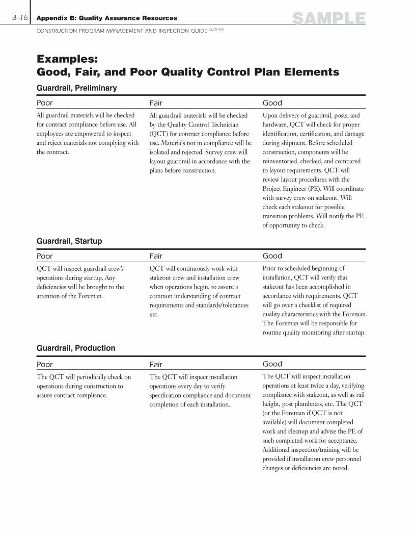
SAMPLE
Poor
All guardrail materials will be checkedfor contract compliance before use. Allemployees are empowered to inspectand reject materials not complying withthe contract.
Fair
All guardrail materials will be checkedby the Quality Control Technician(QCT) for contract compliance beforeuse. Materials not in compliance will beisolated and rejected. Survey crew willlayout guardrail in accordance with theplans before construction.
Good
Upon delivery of guardrail, posts, andhardware, QCT will check for properidentification, certification, and damageduring shipment. Before scheduledconstruction, components will bereinventoried, checked, and comparedto layout requirements. QCT willreview layout procedures with theProject Engineer (PE). Will coordinatewith survey crew on stakeout. Willcheck each stakeout for possibletransition problems. Will notify the PEof opportunity to check.
B–16 Appendix B: Quality Assurance Resources
CONSTRUCTION PROGRAM MANAGEMENT AND INSPECTION GUIDE (5/01/04)
Examples: Good, Fair, and Poor Quality Control Plan ElementsGuardrail, Preliminary
Poor
QCT will inspect guardrail crew’soperations during startup. Anydeficiencies will be brought to theattention of the Foreman.
Fair
QCT will continuously work withstakeout crew and installation crewwhen operations begin, to assure acommon understanding of contractrequirements and standards/tolerancesetc.
Good
Prior to scheduled beginning ofinstallation, QCT will verify thatstakeout has been accomplished inaccordance with requirements. QCTwill go over a checklist of requiredquality characteristics with the Foreman.The Foreman will be responsible forroutine quality monitoring after startup.
Guardrail, Startup
Poor
The QCT will periodically check onoperations during construction toassure contract compliance.
Fair
The QCT will inspect installationoperations every day to verifyspecification compliance and documentcompletion of each installation.
Good
The QCT will inspect installationoperations at least twice a day, verifyingcompliance with stakeout, as well as railheight, post plumbness, etc. The QCT(or the Foreman if QCT is notavailable) will document completedwork and cleanup and advise the PE ofsuch completed work for acceptance.Additional inspection/training will beprovided if installation crew personnelchanges or deficiencies are noted.
Guardrail, Production

Appendix B: Quality Assurance Resources
CONSTRUCTION PROGRAM MANAGEMENT AND INSPECTION GUIDE (5/01/04)
B–17SAMPLE
A Model Quality Control Plan OverviewThe model quality control (QC) plan that follows is intended to serve as a generic tool to assistcontractors in preparing complete and useful QC plans. Developed by the New EnglandTransportation Technician Certification Program (NETTCP), the model plan follows arecommended standard format that includes 10 separate sections plus appendices. Each sectionaddresses a major QC Plan item, as follows:
▼ Terms and Definitions (optional)
▼ 1.0 Applicable Specifications
▼ 2.0 Quality Control Organization
▼ 3.0 Quality Control Laboratories
▼ 4.0 Materials Control
▼ 5.0 Quality Control Sampling and Testing
▼ 6.0 Production Facility Management
▼ 7.0 Field Management
▼ 8.0 Acceptance of Work (optional)
▼ 9.0 Other Relevant Contractor QC Plans
▼ Appendices
The Model QC Plan is an example of a completed Earthwork QC Plan for a fictitious majortransportation construction project. QC Plans for other materials (e.g., HMA, PCC, etc.) can bedeveloped following the same standard format (section and subsection headings) provided in theModel Plan. It is recommended that transportation agencies adopt the format (section andsubsection headings) provided in the NETTCP Model QC Plan as a standard for contractors tofollow.
The level of detailed information in any QC Plan will obviously change depending upon the sizeand complexity of the individual construction project. The Plan is designed as a template and guide.As a minimum, all text that is shaded grey throughout the Model QC Plan will require replacementor deletion to address the specific quality control information related to a given project.
NoteEvery QC plan should include examples of forms and reports that the contractor will use todocument and report the results of QC monitoring to the transportation agency. These sampledocuments can appear as appendices to the QC plan. The samples included will differ from plan to

plan depending on the type of project. For example, in the fictitious model presented here forEarthworks, several sample documents are named as appendices to the plan:
▼ Project Drawings List
▼ Material Source Characterization Sampling and Testing Forms
▼ Standard Test Report Forms
▼ Weekly Schedule of Production Operations
▼ Standard Inspection Report Forms for Production Quality Control
▼ Weekly Schedule of Materials Placement Operations
▼ Control Charts Used for Materials Placement
▼ Standard Inspection Report Forms for Field Quality Control
Each QC plan should include samples of forms and reports that are appropriate to the project type.
Appendix B: Quality Assurance Resources
CONSTRUCTION PROGRAM MANAGEMENT AND INSPECTION GUIDE (5/01/04)
B–18 SAMPLE

State Route 99 Construction ProjectAnytown, USA
Transportation Agency Contract #54321
ABC Contractors, Inc.
NETTCPModel QC Plan
Construction Quality Control Plan
Section 1 - Earthwork
October 28, 2003 Draft
Submitted By:ABC Contractors, Inc. Date
Approved By:Transportation Agency Date
Appendix B: Quality Assurance Resources
CONSTRUCTION PROGRAM MANAGEMENT AND INSPECTION GUIDE (5/01/04)
B–19SAMPLE

Section 1 - EarthworkThis Quality Control Plan (QC Plan) identifies the specific resources and procedures which willbe utilized by ABC Contractors to control the quality of all Earthwork materials and ensure thatall associated Work is completed in accordance with Project Specifications.
Terms and DefinitionsThe following terms and definitions are applicable to this QC Plan:
▼ Contractor Information Testing (CIT) – Testing that is performed at the discretion of theQC Inspector (non-random) for information to guide Production or Field Placement ofmaterial.
▼ Control Strip – An area of Earthwork placed at the beginning of each new Earthworkoperation which is used to establish the rolling pattern and compactive effort required toachieve the In-Place Target Density at Optimum Moisture Content.
▼ Control Strip Section – One of 3 approximately equal parts of a Control Strip which aresequentially placed and tested for In-Place Density and Moisture Content.
▼ Crushed Stone – Processed Earthwork material used for “Embankment UnderBridge Foundations” which meets the materials specification requirementscontained in Subsection M2.01.0.
▼ Earth Excavate – Earthwork material, obtained from On-Site excavation (cut)activity, which is used for “Roadway Embankment Material”, and which meetsthe materials specification requirements contained in Section M1.01.0 (OrdinaryBorrow) and contains up to 50% boulders or rock fragments with a maximumsize of 600 millimeters largest dimension.
▼ Field Quality Control (FQC) – All sampling, testing, and inspection activity performed tocontrol the quality of Field Placement operations.
▼ Gravel Borrow – Earthwork material, obtained either from On-Site excavation(cut) activity or from Off-Site Borrow Producers, which is used for “RoadwayEmbankment Material”, “Embankment Under Bridge Foundations”, or “BackfillMaterial for Structures and Pipes”, and which meets the materials specificationrequirements contained in Subsection M1.03.0.
▼ Ordinary Borrow – Earthwork material, obtained either from On-Site excavation(cut) activity or from Off-Site Borrow Producers, which is used for “RoadwayEmbankment Material”, and which meets the materials specification requirementscontained in Subsection M1.01.0.
▼ Producer – A Subcontractor who supplies either “project produced” materials or“commercially manufactured” materials for incorporation into the Work.
▼ Production Quality Control (PQC) – All sampling, testing, and inspection activityperformed by ABC Contractors or their Producers to control the quality of materialproduced at the Production facility.
Appendix B: Quality Assurance Resources
CONSTRUCTION PROGRAM MANAGEMENT AND INSPECTION GUIDE (5/01/04)
B–20 SAMPLE

▼ Rock Excavate – Earthwork material, obtained from On-Site excavation (cut)activity, which is used for “Backfill Material for Muck Excavation” or “RoadwayEmbankment Material”, and which is comprised of boulders or rock fragmentswith a maximum size of 1 meter largest dimension.
▼ Source Characterization (SC) – Sampling and testing performed to determine the specific“Earthwork Material Type” which an individual material source location (On-Site or Off-Site) contains.
▼ Source Quadrant – An area of defined boundaries at an individual Earthworkmaterial source location (On-Site or Off-Site) which has been evaluated by SourceCharacterization sampling and testing.
▼ Special Borrow – Earthwork material, obtained either from On-Site excavation(cut) activity or from Off-Site Borrow Producers, which is used for “BackfillMaterial for Muck Excavation” or “Roadway Embankment Material”, and whichmeets the materials specification requirements contained in Subsection M1.02.0.
1.0 Applicable SpecificationsThe relevant specifications for all Earthwork activities are as indicated below.
1.1 – Standard SpecificationsThis QC Plan applies to all Work covered by the following sections of Transportation AgencyStandard Specifications for Highways and Bridges, 1995 Metric Edition:
▼ Division II - Section 150: Embankment
▼ Division II - Section 170: Grading
▼ Division III - Section M1: Soils and Borrow Materials, limited to:
▼ Subsection M1.01.0 Ordinary Borrow
▼ Subsection M1.02.0 Special Borrow
▼ Subsection M1.03.0 Gravel Borrow (Type a)
▼ Subsection M1.04.0 Sand Borrow (Type b)
▼ Subsection M1.08.0 Impervious Soil Borrow
▼ Division III - Section M2: Aggregates and Related Materials, limited to:
▼ Subsection M2.01.0 Crushed Stone
▼ Subsection M2.01.1 Grading Requirements (37.5 mm)
1.2 – Supplemental SpecificationsTransportation Agency Supplemental Specifications, December 23, 1998 Metric Edition,applicable to Work addressed by this QC Plan include:
▼ Division II - Section 150: Embankment
▼ Division II - Section 170: Grading
Appendix B: Quality Assurance Resources
CONSTRUCTION PROGRAM MANAGEMENT AND INSPECTION GUIDE (5/01/04)
B–21SAMPLE

1.3 – Project Special ProvisionsSpecial Provisions applicable to Work addressed by this QC Plan include:
▼ Division II - Section 150: Embankment (June 26, 2001)
▼ Subsection 150.20 General
▼ Subsection 150.66 Gravel Borrow for Bridge Foundations
▼ Subsection 150.69 Crushed Stone for Stabilized Construction Entrances
▼ Subsection 150.70 Gravel Borrow for Sidewalk
▼ Subsection 150.72 Sedimentation Control
1.4 – Project DrawingsA current listing of drawings applicable to all Work addressed by this QC Plan will be maintainedby ABC Contractors. The “Project Drawings List” will be updated and submitted monthly toTransportation Agency in electronic format. An example copy of the “Project Drawings List:Section 1 – Earthwork” is contained in Appendix __ (see Note, page B–17).
1.5 – Standard DrawingsAll Standard Drawings related to Earthwork contained in the Transportation AgencyConstruction and Traffic Standard Details (1996) are applicable to Work addressed by thisQC Plan.
2.0 Quality Control OrganizationThe personnel and their corresponding responsibilities for all Earthwork Quality Controlactivities are as indicated below.
2.1 – QC Plan ManagerThe QC Plan Manager is Mr. “Plan Manager”, P.E. He is employed by ABC Contractors,Inc. (ABC Contractors). Mr. “Plan Manager” is located at the ABC Contractors State Route99 Project Office in Anytown, USA and can be contacted as follows:
Office Phone: (508) 123-4567
Cell Phone: (508) 123-4568
Pager: (508) 123-4500
The QC Plan Manager has responsibility and authority for the following items:
▼ Development and submission of this QC Plan for Transportation Agency approval
▼ Overall coordination of personnel performing QC inspection, sampling, and testing at all Off-Site Production facilities, QC Laboratories, and On-Site Field operations
▼ Approval of Material Sources prior to the start of any related work addressed by this QC Plan
▼ Ensure that Producers have required certifications and qualified personnel and laboratories
▼ Complete adherence to all QC requirements and activities contained in this QC Plan
▼ Initiating Work suspension and determining appropriate corrective action when testing orinspection identifies nonconforming materials or construction as outlined under Section 6.5and Section 7.6 below
▼ Review and evaluation of all QC documentation for content and completeness
▼ Maintaining the “QC Record System – Earthwork” in accordance with Section 5.5 below
▼ Preparing and submitting a “Weekly QC Summary Report” to TransportationAgency within 7 Calendar Days following the end of the reporting period
Appendix B: Quality Assurance Resources
CONSTRUCTION PROGRAM MANAGEMENT AND INSPECTION GUIDE (5/01/04)
B–22 SAMPLE

2.2 – Qualified Off-Site Production Facility QC PersonnelPersonnel assigned to perform Off-Site Production Facility QC sampling, testing, and inspectionof Earthwork materials will be as indicated in the table below. A current listing of qualifiedOff-Site Production Facility QC personnel will be included in the “Weekly QCSummary Report.”
ProjectSegment QC Position Personnel - Company Qualifications
1, 2, 3Various – Producers NETTCP Soils and Agg.
Soils Inspector (See Weekly InspectorQC Summary Report) (See Weekly Report)
Off-Site Production QC activities by ABC Contractors will be scheduled as necessary and willgenerally involve the collection of samples for Source Characterization testing frompotential Earthwork material Producers.
Where Earthwork materials Producers possess their own qualified QC personnel andlaboratories, the results of the Producer’s QC inspection and testing may be used by ABCContractors. In such instances, the Producer will perform Source Characterization samplingand testing in accordance with the required test methods and frequencies outlined in Section 4.0below.
Off-Site Production Facility QC personnel have responsibility and authority for the followingitems:
▼ Obtaining random Source Characterization samples of Earthwork materials at eachProduction Facility
▼ Inspecting Earthwork Production operations at each Production Facility
▼ Preparing and signing standard QC Inspection report forms for each Production location
▼ Identifying Production Facility practices or materials which do not conform with therequirements of the relevant specifications and this QC Plan, and discussing appropriatecorrective action with the Production Facility Superintendent and the QC Manager
▼ Suspending the transport of Earthwork materials to On-Site placement locations whenmaterials are not in conformance with the relevant specification requirements or whencorrective actions have been determined necessary and are not implemented
2.3 – Qualified QC Laboratory PersonnelPersonnel assigned to perform QC Laboratory sampling and testing of Earthwork materials areidentified in the table below. A current listing of qualified QC Laboratory personnel willbe included in the “Weekly QC Summary Report.”
ProjectSegment QC Position Personnel – Company Qualifications
1, 2, 3Laboratory Supervisor Bob Supervisor – XYZ NETTCP Soils and Agg.
(ABC Contractors Technician # SAT 100Anytown, USA)
1, 2, 3 Laboratory Technician Cathy Technician – XYZ NETTCP Soils and Agg. Technician # SAT 190
1, 2, 3 Laboratory Technician Mike Technician – XYZ NETTCP Soils and Agg. Inspector # SAI 450
Appendix B: Quality Assurance Resources
CONSTRUCTION PROGRAM MANAGEMENT AND INSPECTION GUIDE (5/01/04)
B–23SAMPLE

QC Laboratory personnel have responsibility and authority for the following items:
▼ Sampling of Earthwork materials
▼ Laboratory testing of Earthwork materials
▼ Preparing and signing standard Test Report Forms (TRFs) for each test completed
▼ Properly storing all Earthwork material samples
▼ Identifying Earthwork materials test results which do not conform with the requirements ofthe relevant specifications and this QC Plan, and discussing with the QC Manager
2.4 – Qualified On-Site Field QC PersonnelPersonnel assigned to perform On-Site Field QC sampling, testing, and inspection of Earthworkmaterials are identified in the table below. A current listing of qualified On-Site Field QCpersonnel will be included in the “Weekly QC Summary Report.”
ProjectSegment QC Position Personnel - Company Qualifications
1 Lead QC Inspector Kevin Boulder – XYZ NETTCP Soils and Agg.Inspector# SAI 491
2 Lead QC Inspector George Troxler – XYZ Not CurrentlyNETTCP Certified
3 Lead QC Inspector Mike Gravel – XYZ Not Currently NETTCP Certified
1, 2, 3 Soils Inspector Various – XYZ NETTCP Soils and Agg. Inspector(See Weekly (See Weekly
QC Summary Report) QC Summary Report)
On-Site Field QC personnel have responsibility and authority for the following items:
▼ Obtaining random Field samples of Earthwork materials for laboratory testing
▼ Performing In-Place sampling and testing of Earthwork
▼ Preparing and signing standard Test Report Forms (TRFs) for each test completed
▼ Inspecting On-Site Earthwork production and placement operations
▼ Preparing and signing standard QC Inspection report forms for each placement location
▼ Identifying On-Site Field placement practices or materials which do not conform with therequirements of the relevant specifications and this QC Plan, and discussing appropriatecorrective action with the Segment Field Superintendent and the QC Manager
▼ Suspending the placement of Earthwork materials when materials are not in conformancewith the relevant specification requirements or when corrective actions have been determinednecessary and are not implemented
Appendix B: Quality Assurance Resources
CONSTRUCTION PROGRAM MANAGEMENT AND INSPECTION GUIDE (5/01/04)
B–24 SAMPLE

3.0 Quality Control LaboratoriesThe Quality Control Laboratories to be used for all Earthwork materials and theircorresponding testing responsibilities are as indicated below.
3.1 – Qualified Primary QC LaboratoryThe primary QC Laboratory responsible for performing sampling and testing of Earthworkmaterials is identified in the table below.
ProjectSegment Laboratory Location Qualifications
1, 2, 3ABC Contractors NETTCP Laboratory Qualification State Route 99 Anytown, USA Program – Category 2-T: Soils,
Project Laboratory Aggregates (MM/DD/YY)
The ABC Contractors State Route 99 Project Laboratory is responsible for performing testingof all On-Site Earthwork materials as well as testing of any Off-Site Borrow material. Thefollowing tests will be performed on Earthwork materials by this laboratory:
▼ Soil Classification AASHTO M145
▼ Gradation AASHTO T11 and T27
▼ Liquid Limit AASHTO T89
▼ Plastic Limit/Plasticity Index AASHTO T90
▼ Optimum Moisture Content AASHTO T99 and AASHTO T180
▼ Maximum Dry Density AASHTO T99 and AASHTO T180
▼ Coarse Particles Correction AASHTO T224
▼ Grain-Size Analysis AASHTO T311
3.2 – Qualified Subcontractor or Consultant LaboratoriesOther qualified Subcontractor or Consultant laboratories that will perform QC sampling andtesting of Earthwork materials are identified in the table below.
ProjectSegment Laboratory Location Qualifications
1, 2, 3 XYZ Company Soil City, USA AASHTO Accreditation Laboratory Program: Soils (08/15/00)
The XYZ Company Laboratory in Soil City, USA, will serve as a backup to assist the PrimaryQC Laboratory in performing testing of all On-Site Earthwork materials as well as testing ofany Off-Site Borrow for Embankment. The following tests will be performed on Earthworkmaterials by this laboratory:
▼ Soil Classification AASHTO M145
▼ Gradation AASHTO T11 and T27
▼ Liquid Limit AASHTO T89
▼ Plastic Limit/Plasticity Index AASHTO T90
▼ Maximum Wear (LA Abrasion) AASHTO T96
▼ Optimum Moisture Content AASHTO T99 and AASHTO T180
▼ Maximum Dry Density AASHTO T99 and AASHTO T180
▼ Coarse Particles Correction AASHTO T224
▼ Grain-Size Analysis AASHTO T311
Appendix B: Quality Assurance Resources
CONSTRUCTION PROGRAM MANAGEMENT AND INSPECTION GUIDE (5/01/04)
B–25SAMPLE

4.0 Materials ControlThe types, sources, properties, and procedures for storing of materials to be used for eachEarthwork category are as indicated below.
4.1 – Material Types and Source(s) of SupplyEarthwork material will be classified according to the following Earthwork Item categories:
▼ Backfill Material for Muck Excavation
▼ Roadway Embankment Material
▼ Embankment Material under Bridge Foundations
▼ Backfill Material for Structures
▼ Backfill Material for Pipes
4.1.1 – Backfill Material for Muck Excavation
The types and potential sources of material currently identified for use as Backfill Materialfor Muck Excavation are listed in the table below.
Backfill Material for Muck ExcavationMaterial Type Material Source
Rock Excavate ▼ On-Site, Segment 1, Rte 99 Median▼ On-Site, Segment 3, Rte 99 Median
Special Borrow ▼ On-Site, Segment 1▼ On-Site, Segment 2▼ Borrow Producer (TBD)
ABC Contractors will submit updated information on the types and sources of Backfill Materialfor Muck Excavation as part of the “Weekly Schedule of Earthwork MaterialsProduction Operations” as outlined under Section 6.1 below.
Appendix B: Quality Assurance Resources
CONSTRUCTION PROGRAM MANAGEMENT AND INSPECTION GUIDE (5/01/04)
B–26 SAMPLE

4.1.2 – Roadway Embankment Material
The types and sources of material currently identified for use as Roadway Embankment arelisted in the table below. At this time, sufficient quantities of Earth Excavate, RockExcavate, Ordinary Borrow, and Gravel Borrow appear to be available On-Site forRoadway Embankment construction. If Off-Site sources of these materials are determinednecessary by ABC Contractors, the table will be updated to reflect these sources.
Roadway Embankment MaterialMaterial Type Material Source
Rock Excavate ▼ On-Site, Segment 1, Rte 99 Median▼ On-Site, Segment 3, Rte 99 Median
Earth Excavate ▼ On-Site, Segment 1, Rte 99 Median▼ On-Site, Segment 3, Rte 99 Median
Ordinary Borrow ▼ On-Site, Segment 1▼ On-Site, Segment 2▼ On-Site, Segment 3▼ Borrow Producer (TBD)
Gravel Borrow ▼ On-Site, Segment 1▼ On-Site, Segment 3▼ Borrow Producer (TBD)
Special Borrow ▼ On-Site, Segment 1▼ On-Site, Segment 2▼ Borrow Producer (TBD)
ABC Contractors will submit updated information on the types and sources of RoadwayEmbankment Material as part of the “Weekly Schedule of Earthwork MaterialsProduction Operations” as outlined under Section 6.1 below.
4.1.3 – Embankment Material Under Bridge Foundations
The types and potential sources of material currently identified for use as EmbankmentMaterial under Bridge Foundations are listed in the table below.
Embankment Material Under Bridge FoundationsMaterial Type Material Source
Gravel Borrow ▼ Borrow Producer (TBD)
Crushed Stone ▼ Borrow Producer (TBD)
ABC Contractors will submit updated information on the types and sources of EmbankmentMaterial under Bridge Foundations as part of the “Weekly Schedule of EarthworkMaterials Production Operations” as outlined under Section 6.1 below.
Appendix B: Quality Assurance Resources
CONSTRUCTION PROGRAM MANAGEMENT AND INSPECTION GUIDE (5/01/04)
B–27SAMPLE

4.1.4 – Backfill Material for Structures
The types and potential sources of material currently identified for use as Backfill Materialfor Structures are listed in the table below.
Backfill Material for StructuresMaterial Type Material Source
Gravel Borrow ▼ Borrow Producer (TBD)
ABC Contractors will submit updated information on the types and sources of Backfill Materialfor Structures as part of the “Weekly Schedule of Earthwork Materials ProductionOperations” as outlined under Section 6.1 below.
4.1.5 – Backfill Material for Pipes
The types and potential sources of material currently identified for use as Backfill Materialfor Pipes are listed in the table below.
Backfill Material for PipesMaterial Type Material Source
Ordinary Borrow ▼ On-Site, Segment 1▼ On-Site, Segment 2▼ On-Site, Segment 3▼ Borrow Producer (TBD)
Gravel Borrow ▼ Borrow Producer (TBD)
ABC Contractors will submit updated information on the types and sources of Backfill Materialfor Pipes as part of the “Weekly Schedule of Earthwork Materials ProductionOperations” as outlined under Section 6.1 below.
4.2 – Material PropertiesEarthwork material Source Characterization and Mix Designs will be performed as describedbelow.
4.2.1 – Material Source Characterization Sampling and Testing
Earthwork materials will be fully characterized by ABC Contractors prior to their use in theintended location. Grids will be established and maintained at each Earthwork sourcelocation identifying “Quadrants.” Each Quadrant will be numbered for SourceCharacterization identification (e.g. SC-1, SC-2, SC-99, etc.). ABC Contractors willsubmit the results of Source Characterization testing for each Source Quadrant ofEarthwork material to Transportation Agency a minimum of two (2) calendar days priorto placement of any material from the Source Quadrant. The following table identifies thespecific Source Characterization testing that will be performed on all Earthwork materials.
Appendix B: Quality Assurance Resources
CONSTRUCTION PROGRAM MANAGEMENT AND INSPECTION GUIDE (5/01/04)
B–28 SAMPLE

Material Source Characterization Sampling and TestingMaterial Type Characteristic Tested Test Method Test Frequency
Rock Excavate Maximum Size (< 1m) Visual/Tape Minimum 4/Day/Quadrant
Earth Excavate
Soil Classification AASHTO M145 Minimum 4/Quadrant
(M1.01.0 Modified)
Liquid Limit AASHTO T89 Minimum 4/Quadrant
(Contains Boulders
Plastic Limit/ PI AASHTO T90 Minimum 4/Quadrant
< 600 mm)
Maximum Dry Density AASHTO T180 Minimum 4/Quadrant(Method D)
Optimum Moisture AASHTO T180 Minimum 4/QuadrantContent (Method D)
Coarse Particles AASHTO T224 Minimum 4/QuadrantCorrection
Grain-Size Analysis AASHTO T311 Minimum 4/Quadrant
Ordinary Borrow
Soil Classification AASHTO M145 Minimum 4/Quadrant
(M1.01.0)
Liquid Limit AASHTO T89 Minimum 4/Quadrant
Plastic Limit/ PI AASHTO T90 Minimum 4/Quadrant
Maximum Dry Density AASHTO T99 Minimum 4/Quadrant(Method C)
Optimum Moisture AASHTO T99 Minimum 4/QuadrantContent (Method C)
Coarse Particles AASHTO T224 Minimum 4/QuadrantCorrection
Grain-Size Analysis AASHTO T311 Minimum 4/Quadrant
Gravel Borrow
Soil Classification AASHTO M145 Minimum 4/Quadrant
(M1.03.0)
Gradation AASHTO T11, T27 Minimum 4/Quadrant
Maximum Dry Density AASHTO T180 Minimum 4/Quadrant(Method D)
Optimum Moisture AASHTO T180 Minimum 4/QuadrantContent (Method D)
Appendix B: Quality Assurance Resources
CONSTRUCTION PROGRAM MANAGEMENT AND INSPECTION GUIDE (5/01/04)
B–29SAMPLE
Continued on next page

(Continued from page B-29)
Material Source Characterization Sampling and TestingMaterial Type Characteristic Tested Test Method Test Frequency
Special Borrow
Soil Classification AASHTO M145 Minimum 4/Quadrant
(M1.02.0)
Gradation AASHTO T11, T27 Minimum 4/Quadrant
Plastic Limit/ PI AASHTO T90 Minimum 4/Quadrant
Maximum Dry Density AASHTO T180 Minimum 4/Quadrant(Method D)
Optimum Moisture AASHTO T180 Minimum 4/Quadrant Content (Method D)
Maximum Percentage AASHTO T96 Minimum 4/Quadrantof Wear (LA Abrasion)
Crushed Stone
Soil Classification AASHTO M145 Minimum 1/10,000 m3
(M2.01.0)
Gradation AASHTO T11, T27 Minimum 1/10,000 m3
Maximum Percentage AASHTO T96 Minimum 1/10,000 m3
of Wear (LA Abrasion)
Flat and Elongated ASTM D4791 Minimum 1/10,000 m3
Particles
All Earthwork Source Characterization samples will be obtained randomly in accordance withASTM D3665. The random sample locations within each Source Quadrant will be determinedby Station, Offset, and Elevation within the Quadrant. All random sample locations will bedocumented on NETTCP Standard Test Report Form D3665 or D3665RNG. A copy of theseRandom Sampling Forms is located in Appendix __ (see Note, page B–17).
All Earthwork Source samples will be obtained following AASHTO T2 and split in accordancewith AASHTO T248.
All Source Characterization sampling and testing results will be documented on the followingStandard Test Report Forms (TRFs):
Source Characterization Standard Test Report FormsForm No. Form Title
M145-T89-T90 Classification of Soils (Includes Liquid Limit and Plastic Limit)
NETTCP T27 Sieve Analysis Test Report
NETTCP T96 Resistance to Degradation of Aggregate by Abrasion Test Report
T99 Moisture-Density Relations of Soils (Standard)
T180 Moisture Density Relations of Soils (Modified)
T311 Grain-Size Analysis of Granular Soil Materials
Rock Size Evaluation of Maximum Rock Size in Earthwork Materials
A copy of the standard TRFs used for Source Characterization sampling and testing is located in Appendix __ (see Note, pageB–17).
Appendix B: Quality Assurance Resources
CONSTRUCTION PROGRAM MANAGEMENT AND INSPECTION GUIDE (5/01/04)
B–30 SAMPLE

4.2.2 – Mix Designs
Earthwork Materials “Mix Designs” are generally not required. Source Characterizationtesting will determine whether specific Earthwork Materials sources meet the specificationrequirements for a particular material type required (i.e. Ordinary Borrow, Gravel Borrow,Special Borrow, etc.).
4.3 – Processing of Existing MaterialsWhere On-Site excavate proposed to be used for Earthwork is found to not meetspecification requirements, the following procedures will be used to process or blend thematerial to meet the requirements of a specific Earthwork Material Type:
▼ A blended material “Mix Design” will be developed by the Project Laboratory.
▼ A stockpile of the excavate, not to exceed one day’s production, will be blended withother material per the “Mix Design.”
▼ At the completion of blending of the stockpile, samples will be obtained and SourceCharacterization testing will be performed to confirm that the blended material meets thespecification requirements.
4.4 – Material Storage and StockpilingAll Earthwork materials will be properly stored and maintained to prevent contamination orcommingling of different materials. Storage and stockpiling procedures will be as follows:
▼ The limits of each storage or stockpile location will be clearly marked by grade stakeslegibly marked indicating the corresponding Source Characterization sample number (i.e.SC-1, SC-2, etc.) contained in the Project “Soils Source Characterization Log.”
▼ All active/working stockpiles of Earthwork materials will be characterized in accordancewith Section 4.2.1 above a minimum of once per week.
5.0 Quality Control Sampling and TestingThe requirements and procedures to be used for QC sampling and testing of Earthwork are asindicated below.
5.1 – Lot and Sublot SizesEach Lot of Earthwork material will represent material from the same source, be produced orobtained under the same controlled process, and will possess normally distributed specificationproperties. Each Lot will be divided into Sublots of equal size in order to assess the QualityCharacteristics of the Lot. The Lot size and corresponding Sublot size for each Earthwork Itemare identified in the following table.
Appendix B: Quality Assurance Resources
CONSTRUCTION PROGRAM MANAGEMENT AND INSPECTION GUIDE (5/01/04)
B–31SAMPLE

Earthwork Lot and Sublot SizesEarthwork Item Material Type(s) Lot Size Sublot Size
Backfill Material ▼ Rock Excavate Total Quantity (m3)for Muck Excavation ▼ Special Borrow of Backfill material (See Table 5.4.1)(Section 150.65) type, per material
Source, per Project
Roadway ▼ Rock Excavate Total Quantity (m3)Embankment ▼ Earth Excavate of EmbankmentMaterial ▼ Ordinary Borrow Material Type, per (See Table 5.4.2)(Section 150.62 ▼ Gravel Borrow Material Source, perand Section 150.63) ▼ Special Borrow per Project Segment
Embankment Total Quantity (m3)Material Under ▼ Gravel Borrow of EmbankmentBridge Foundations ▼ Crushed Stone material type, per (See Table 5.4.3)(Section 150.66 and material Source, per Section 150.67) Project Segment
Backfill Material Total Quantity (m3) for Structures ▼ Gravel Borrow of Backfill material (See Table 5.4.4)(Section 150.64 type, per material
Source, per Project Segment
Backfill Material Total Quantity (m3)for Pipes ▼ Gravel Borrow of Backfill material Segment(Section 150.64) ▼ Ordinary Borrow type, per material
Source, per Project Segment
5.2 – Random Sampling PlanABC Contractors will establish a Random Sampling Plan for QC sampling and testing for eachLot of Earthwork material prior to placement of the Lot. All Earthwork samples will beobtained randomly in accordance with ASTM D3665. The random sample location for eachSublot will be determined by Station, Offset, and Depth within the Sublot.
All random sample locations will be documented on NETTCP Standard Test Report FormD3665 or D3665RNG. A copy of the Random Sampling Forms is located in Appendix __ (seeNote, page B–17). ABC Contractors will provide Transportation Agency a copy of theRandom Sampling locations (i.e. completed NETTCP Form D3665) for each Earthworkplacement operation, during the start of the placement operation each day.
5.3 – Sample Identification SystemAll Earthwork material samples will be clearly identified as follows:
▼ Project Segment (i.e. 1, 2, 3)
▼ Material Type (i.e. Rock Excavate, Earth Excavate, Ordinary Borrow, etc.)
▼ Sample Type (QC, CIT) and Random/Non-Random
▼ Lot Number and Sublot Number
▼ Sample Location (i.e. Rte 99 Median, Borrow Subcontractor, etc.)
▼ Station, Offset, and Depth
▼ Sample Date
▼ Technician or Inspector
Appendix B: Quality Assurance Resources
CONSTRUCTION PROGRAM MANAGEMENT AND INSPECTION GUIDE (5/01/04)
B–32 SAMPLE

5.4 – QC Sampling and Testing RequirementsThe specific requirements (Quality Characteristics, frequency, location, methods) for QCsampling and testing of each Earthwork item are outlined in the tables below.
5.4.1 – Backfill Material for Muck Excavation
QC Sampling and Testing RequirementsSublot Size/
Quality Test Point of SamplingCharacteristic Test Method(s) Lot Size Frequency Sampling Method
Gradation AASHTO T11 Total Quantity of 1 Sample/ AASHTO T27 Backfill Material 5,000 m3 for
Type / Source / 1st 50,000 m3 From In-Place RandomProject Segment 10,000 m3 Lift of Backfill T2, T248
thereafter
Maximum Dry AASHTO T99 Total Quantity of 1 Sample/Density and (Method C) Backfill Material 5,000 m3 for Optimum AASHTO T180 Type / Source / 1st 50,000 m3 From In-Place Random
Moisture Content (Method D) Project Segment and 1 Sample/ Lift of Backfill T2, T24810,000 m3
thereafter
Maximum Total Quantity of Rock Size Visual/Tape Backfill Material Minimum From In-Place Random(< 1 m) Type / Source / 4/Lift/Day Lift of Backfill Visual
Project Segment
Maximum Total Quantity of Lift Thickness Rod/Grade Backfill Material Minimum From In-Place Random (< 300 mm) Stake Type / Source / 4/Lift/Day Lift of Backfill Visual
Project Segment
In-Place Total Quantity of 1 Sample/1,000Density and AASHTO T310 Backfill Material m3, but From Random
Moisture Content (Method B) Type / Source / not less than Compacted T310 (Per Targets) Project Segment 1/Placement Backfill
Location/Day
Appendix B: Quality Assurance Resources
CONSTRUCTION PROGRAM MANAGEMENT AND INSPECTION GUIDE (5/01/04)
B–33SAMPLE

5.4.2 – Roadway Embankment Material
QC Sampling and Testing Requirements
Sublot Size/Quality Test Point of Sampling
Characteristic Test Method(s) Lot Size Frequency Sampling Method
Gradation AASHTO T11 Total Quantity 1 Sample/ AASHTO T27 of Embankment 5,000 m3 for From In-Place
Material Type / 1st 5,000 m3 and Lift of RandomSource / Project 1 Sample/ Embankment T2, T248
Segment 10,000 m3
thereafter
Maximum Dry AASHTO T99 Total Quantity of 1 Sample/ Density and (Method C) Embankment 5,000 m3 for From In-Place Optimum AASHTO T180 Material Type / 1st 50,000 m3 and Lift of RandomMoisture (Method D) Source / Project 1 Sample/ Embankment T2, T248Content Segment 10,000 m3
thereafter
Total Quantity of Maximum Embankment Minimum From In-Place Random Rock Size Visual/Tape Material Type / 4/Lift/Day Lift of Backfill Visual(< 1 m) Source / Project
Segment
Maximum Total Quantity of Lift Thickness Rod/Grade Stake Embankment Minimum From In-Place Random Visual(< 600 mm for Material Type / 4/Lift/Day Lift of MaximumEarth Excavate) Source / Project Embankment
Segment
Maximum Total Quantity of Lift Thickness Embankment Minimum From In-Place Random (< 300 mm for Rod/Grade Material Type / 4/Lift/Day Lift of Visual
Ordinary Borrow Stake Source / Project Embankmentand Gravel Segment
Borrow)
Maximum Total Quantity of Lift Thickness Rod/Grade Embankment Minimum From In-Place Random (< 200 mm for Stake Material Type / 4/Lift/Day Lift of VisualSpecial Borrow) Source / Project Embankment
Segment
In-Place Total Quantity of 1 Sample/1,000 Density and AASHTO T310 Embankment m3, but From Random
Moisture Content (Method B) Material Type / not less than Compacted T310(Per Targets) Source / Project 1/Placement Embankment
Segment Location/Day
Appendix B: Quality Assurance Resources
CONSTRUCTION PROGRAM MANAGEMENT AND INSPECTION GUIDE (5/01/04)
B–34 SAMPLE

5.4.3 – Embankment Material Under Bridge Foundations
QC Sampling and Testing Requirements
Lot Size Sublot Size/Quality Test Test Point of Sampling
Characteristic Method Frequency Sampling Method
Total Quantity of AASHTO T11 Embankment 1 Sample/ From In-Place Random
Gradation AASHTO T27 Material Type / Placement Lift of T2, T248Source / Project Location Embankment
Segment
Maximum Dry AASHTO T99 Total Quantity of Density and (Method C) Embankment 1 Sample/ From In-Place RandomOptimum AASHTO T180 Material Type / Placement Lift of T2, T248Moisture (Method D) Source / Project Location EmbankmentContent Segment
Maximum Total Quantity of Stone Size Visual/Tape Backfill Material Minimum From In-Place Random(< 75 mm) Type / Source / 4/Lift/Day Lift of Backfill Visual
Project Segment
Maximum Total Quantity of Lift Thickness Rod/Grade Embankment Minimum From In-Place Random (< 300 mm) Stake Material Type / 4/Lift/Day Lift of Visual
Source / Project EmbankmentSegment
Total Quantity of Gravel Borrow: In-Place Embankment 1 Sample/
Density and AASHTO T310 Material Type / Each Lift/Moisture Content (Method B) Source / Project Placement From Random
(Per Targets) Segment Location/Day Compacted T310Embankment
Crushed Stone:N/A
Appendix B: Quality Assurance Resources
CONSTRUCTION PROGRAM MANAGEMENT AND INSPECTION GUIDE (5/01/04)
B–35SAMPLE

5.4.4 – Backfill Material for Structures
QC Sampling and Testing Requirements
Sublot Size/Quality Test Point of Sampling
Characteristic Test Method(s) Lot Size Frequency Sampling Method
Total Quantity of AASHTO T11 Backfill Material 1 Sample/ From In-Place Random
Gradation AASHTO T27 Type / Source / 1,000 m3 Lift of Backfill T2, T248Project Segment
Maximum Dry AASHTO T99 Total Quantity of Density and (Method C) Backfill Material 1 Sample/ From In-Place Random Optimum AASHTO T180 Type / Source / 1,000 m3 Lift of Backfill T2, T248
Moisture Content (Method D) Project Segment
Maximum Total Quantity of Stone Size Visual/Tape Backfill Material Minimum Minimum Random(< 75 mm) Type / Source / 4/Lift/Day Lift of Backfill Visual
Project Segment
Total Quantity of Maximum Backfill Material Minimum From In-Place Random
Lift Thickness Rod/Grade Type / Source / 4/Lift/Day Lift of Backfill Visual(< 150 mm) Stake Project Segment
In-Place Total Quantity of Density and AASHTO T310 Backfill Material 1 Sample/100 From Random
Moisture Content (Method B) Type / Source / m3, but not less Compacted T310(Per Targets) Project Segment than 1/Lift/Day Backfill
Appendix B: Quality Assurance Resources
CONSTRUCTION PROGRAM MANAGEMENT AND INSPECTION GUIDE (5/01/04)
B–36 SAMPLE

5.4.5 – Backfill Material for Pipes*
QC Sampling and Testing Requirements
Sublot Size/Quality Test Point of Sampling
Characteristic Test Method(s) Lot Size Frequency Sampling Method
Total Quantity ofAASHTO T11 Backfill Material 1 Sample/ From In-Place Random
Gradation AASHTO T27 Type / Source / 1,000 m3 Lift of Backfill T2, T248Project Segment
Maximum Dry AASHTO T99 Total Quantity of Density and (Method C) Backfill Material 1 Sample/ From In-Place RandomOptimum AASHTO T180 Type / Source / 1,000 m3 Lift of Backfill T2, T248
Moisture Content (Method D) Project Segment
Total Quantity of Maximum Backfill Material Minimum From In-Place RandomStone Size Visual/Tape Type / Source / 4/Lift/Day Lift of Backfill Visual(< 75 mm) Project Segment
Total Quantity of Maximum Rod/Grade Backfill Material Minimum From In-Place Random
Lift Thickness Stake Type / Source / 4/Lift/Day Lift of Backfill Visual(< 150 mm) Project Segment
Gravel Borrow:1 Sample/100 m of Trench, but not less than
1/Lift/DayIn-Place Total Quantity of From
Density and AASHTO T310 Backfill Material Ordinary Borrow: Compacted RandomMoisture Content (Method B) Type / Source / 1 Sample/100 m Backfill T310
(Per Targets) Project Segment of trench, but not less than 1/Placement Location/Day
(*) Backfill Material for Pipes will include Gravel Borrow and Ordinary Borrow to beplaced as follows:
Gravel Borrow – Gravel Borrow shall be used for bedding and backfilling of pipeto a point 600 mm above the top of pipe.
Ordinary Borrow – Ordinary Borrow shall be used to backfill the remainingdepth of trench from the top of the Gravel Borrow to the top of the finishedsubgrade.
Appendix B: Quality Assurance Resources
CONSTRUCTION PROGRAM MANAGEMENT AND INSPECTION GUIDE (5/01/04)
B–37SAMPLE

5.5 – QC Test Result ReportingAll QC sampling and testing of In-Place Earthwork materials will be documented on thefollowing Standard Test Report Forms (TRFs):
Form No. Form Title
NETTCP T27 Sieve Analysis Test ReportT99 Moisture-Density Relations of Soils (Standard)T180 Moisture Density Relations of Soils (Modified)T310 Soils In-Place Density and Moisture Content Test ReportRock Size and Lift Maximum Rock Size and Lift Thickness Test Report
A copy of the Standard TRFs used for QC sampling and testing of Earthwork materials islocated in Appendix __ (see Note, page B–17).
ABC Contractors will retain a complete record of all completed Earthwork testing andinspection in accessible files which will be labeled as the “QC Record System – Earthwork.”The QC Record System will contain the following QC documents:
▼ The approved Earthwork QC Plan
▼ Original copies of all completed Earthwork QC Standard Test Report Forms (includingRandom Sampling Forms)
▼ Earthwork Control Charts
▼ Summaries of all Earthwork test results
▼ Records of Earthwork Daily Production quantity information
ABC Contractors will also submit copies of all completed QC sampling and testing ReportForms to Transportation Agency with each “Weekly QC Summary Report.”
5.6 – QC Sample Storage and Retention ProceduresAll physical QC samples of Earthwork material will be split prior to testing in accordance withrelevant AASHTO and NETTCP procedures.
The split sample portion of Earthwork material not used for testing will be retained in theoriginal sample bag with proper identification. The split sample will be stored in the SampleStorage Room at the Laboratory which performed the test for a minimum of 60 Days followingtesting.
Appendix B: Quality Assurance Resources
CONSTRUCTION PROGRAM MANAGEMENT AND INSPECTION GUIDE (5/01/04)
B–38 SAMPLE

6.0 Production Facility ManagementThe activities and procedures to be followed for QC during production of Earthwork materialsare as indicated below.
6.1 – Schedule of Production OperationsABC Contractors will provide Transportation Agency with a “Weekly Schedule ofEarthwork Materials Production Operations” on each Friday prior to the week of produc-tion. A copy of the “Weekly Schedule of Earthwork Materials Production Operations” islocated in Appendix __ (see Note, page B–17). The weekly schedule of ProductionOperations will identify the following:
▼ Material Type
▼ Material Source
▼ Production Location
▼ Estimated Production Quantity
ABC Contractors will track the actual production quantities on a daily basis and maintain a“Record of Earthwork Production” for each week. Copies of the “Record of EarthworkProduction” will be made available to Transportation Agency in the “Weekly QC SummaryReport.”
6.2 – Production Facilities and EquipmentABC Contractors and their Subcontractors and Suppliers will utilize conventional facilities andequipment for the production of all Earthwork materials. The major types of facilities and equip-ment to be utilized for On-Site and Off-Site production are summarized below.
Material SourceProduction Facility Production Equipment
On-Site, Segment ▼ Crawler Drills (Multiple, Various Make)1, 2, and 3 ▼ Explosives and Blasting Mats
▼ Backhoes (Multiple, Various Make)▼ Tractor/Dozers (Multiple, Various Make)▼ Front End Loaders (Multiple, Various Make)▼ End Dump Trucks (Multiple, Various Make)
Bedrock Industries, ▼ Tractor/Dozers (Multiple, Various Make)Bedrock, MA ▼ Rock Crusher
▼ Conveyor Belt▼ Front End Loaders (Multiple, Various Make)▼ End Dump Trucks (Multiple, Various Make)
Borrow Producer(s) ▼ Tractor/Dozers (Multiple, Various Make)(TBD) ▼ Front End Loaders (Multiple, Various Make)
▼ End Dump Trucks (Multiple, Various Make)
Appendix B: Quality Assurance Resources
CONSTRUCTION PROGRAM MANAGEMENT AND INSPECTION GUIDE (5/01/04)
B–39SAMPLE

6.3 – Production Quality Control ActivitiesProduction Quality Control (PQC) personnel will perform the following inspection, sampling,and testing activities at the frequencies indicated:
6.3.1 – Pre-Production QC Activities
▼ Conduct a Pre-Production Quality Control Audit at each Earthwork Source facility orlocation in accordance with CQMP Part XIII prior to the start of Earthwork production.
▼ Maintain a reference grid system (Stations, Offsets) and boundaries for each EarthworkSource facility or location.
▼ Determine and document random sampling locations of Earthwork materials atProduction Facility in accordance with Section 4.2.1 above.
▼ Obtain and properly label all Source Characterization (SC) samples of Earthwork materials atthe frequencies indicated in Section 4.2.1 above.
▼ Transport Earthwork Source Characterization samples to the appropriate laboratory fortesting.
▼ Ensure that Source Characterization sampling and testing is completed for each SourceQuadrant prior to production/removal of material from the Source Quadrant.
▼ Inspect stockpiles to ensure that different Earthwork material types are not commingled orcontaminated.
6.3.2 – Production QC Activities
▼ Visually monitor Earthwork materials production to ensure no change in material type withinthe Source Quadrant.
▼ Determine and document random sampling locations for each Sublot of Earthwork materialproduced.
▼ Obtain and properly label all PQC Field samples of Earthwork materials.
▼ Transport Earthwork PQC Field samples to the appropriate laboratory for testing.
▼ Perform PQC sampling and testing of Earthwork in accordance with the required testmethods and frequencies outlined in Section 5.0 above.
▼ Prepare and sign standard Test Report Forms (TRFs) for each test completed.
▼ Maintain Production Facility Control Charts per Section 6.4 below.
▼ Monitor loading and transportation of Earthwork materials to ensure that the correctmaterials are being transported to the correct Project location.
▼ Ensure that all Borrow Pits are neatly trimmed and finished to the minimumgrades and dimensions required under Section 150.21 of the StandardSpecifications.
▼ Document Off-Site and On-Site Earthwork Production QC inspection activities and findingson standard QC Inspection Report Forms (IRFs) for each production location in accordancewith Section 6.6 below.
▼ Identify Production Facility practices or materials which do not conform with therequirements of the relevant specifications and this QC Plan, and discuss appropriatecorrective action with the Production Facility Superintendent and the QC Manager.
Appendix B: Quality Assurance Resources
CONSTRUCTION PROGRAM MANAGEMENT AND INSPECTION GUIDE (5/01/04)
B–40 SAMPLE

6.4 – Production Facility Control ChartsControl Charts may be used by ABC Contractors and their Earthwork material Producers tocontrol production operations as described below.
6.4.1 – Off-Site Production Control Charts
Off-Site Earthwork material Producers will use Control Charts as needed to provideadequate control of their production operations. Prior to production, ABC Contractors willrequest each Earthwork material Producer to identify and submit examples of any ControlCharts to be used. ABC Contractors will monitor and discuss the Control Charts with theProducer during Earthwork production.
6.4.2 – On-Site Production Control Charts
At this time, the application of Control Charts does not appear necessary for theproduction of On-Site Earthwork materials (i.e. Earth Excavate). However, in theevent that Rock Crushing operations are established to produce Earthworkmaterials from On-Site Rock Excavate, Control Charts will be maintained tomonitor control of the operation.
6.5 – Procedures for Corrective Action of Non-Conforming MaterialsThe following procedures will be followed for corrective action of non-specification materialsencountered at the Source/Production facility:
▼ If contaminated materials are encountered, the limit of contaminated material will beidentified. The contaminated material will be clearly marked off by signs labeled “No Use OnRte 99.”
▼ If a change in material type is encountered within a Source Lot, additional sampling andtesting will be performed to characterize the material. The disposition of such material will beas follows:
▼ If the material meets specification requirements for another Project Material Type, thenthe material will be approved for use at an appropriate location for that Material Type.
▼ If the material can be blended with other material and subsequently meetspecification requirements for a Project Material Type, then the material willbe approved for use at an appropriate location for that Material Type.
▼ If the material does not meet specification requirements for a Project Material Type, thematerial will not be permitted for use on the Project. ABC Contractors will prepare aNon-Conformance Report (NCR) for such material in accordance with Part X of theCQMP. If the source of such material is On-Site (e.g. Rte 99 Median), ABCContractors will dispose of the material Off-Site at an approved disposal site. If thesource of such material is Off-Site (e.g. Borrow), the material will be clearly marked off bysigns labeled “No Use On Rte 99.”
Appendix B: Quality Assurance Resources
CONSTRUCTION PROGRAM MANAGEMENT AND INSPECTION GUIDE (5/01/04)
B–41SAMPLE

6.6 – Production QC Inspection ReportingAll PQC inspection activities will be documented on the following standard QC Inspection ReportForms (IRFs):
Form No. Form Title
PQC-PPA Production QC - Pre-Production Audit ReportPQC-IDR Production QC – Inspectors Daily Report
A copy of the Standard IRFs used for Production QC inspection of Earthwork materials islocated in Appendix __ (see Note, page B–17).
7.0 Field ManagementThe activities and procedures to be followed for QC during placement of Earthwork materialsare as indicated below.
7.1 – Schedule of Field Placement OperationsABC Contractors will provide Transportation Agency with a “Weekly Schedule ofEarthwork Materials Placement Operations” on each Friday prior to the week ofplacement. A copy of the “Weekly Schedule of Earthwork Materials PlacementOperations” is located in Appendix __ (see Note, page B–17). The weekly schedule ofPlacement Operations will identify the following:
▼ Project Segment
▼ Placement Location
▼ Maximum Placement Depth
▼ Intended Placement Locations (Roadway, Station Limits)
▼ Material Type(s)
▼ Estimated Placement Quantities
▼ Material Source(s)
ABC Contractors will track the actual placement quantities on a daily basis and maintain a “Recordof Earthwork Placement” for each week. Copies of the “Record of Earthwork Placement” will bemade available to Transportation Agency.
7.2 – Field Placement Facilities and EquipmentABC Contractors will utilize conventional facilities and equipment for the placement of allEarthwork materials. The major types of facilities and equipment to be utilized for Earthworkplacement are summarized below for each type of Earthwork Item.
Appendix B: Quality Assurance Resources
CONSTRUCTION PROGRAM MANAGEMENT AND INSPECTION GUIDE (5/01/04)
B–42 SAMPLE

Earthwork Item Placement Equipment
Backfill Material for ▼ End Dump Trucks (Multiple, Various Make)Muck Excavation and ▼ Tractor/Dozers (Multiple, Various Make)Roadway Embankment ▼ Vibratory Rollers - 50 Ton (Multiple, Various Make)Material ▼ Sheepsfoot Rollers (Multiple, Various Make)
▼ Water Trucks (Multiple, Various Make)
Embankment Material ▼ End Dump Trucks (Multiple, Various Make)Under Bridge ▼ Tractor/Dozers (Multiple, Various Make)Foundations ▼ Vibratory Rollers - 50 Ton (Multiple, Various Make)
Backfill Material for ▼ End Dump Trucks (Multiple, Various Make)Structures and Pipes ▼ Backhoes (Multiple, Various Make)
▼ Front End Loaders (Multiple, Various Make)▼ Vibratory Sled Compactors (Various Make)
7.3 – Establishment of Compaction Rolling Pattern (Control Strips)Control Strips will be constructed at the start of each Earthwork placement operation. A newControl Strip will be constructed whenever one of the following occurs:
▼ A new Earthwork Lot
▼ A change in weather
▼ A change in environment
▼ A PWL < 85% for 3 or more consecutive QC Test Results
The Control Strips will be used to establish an effective rolling pattern and the correspondingcompactive effort required to achieve the in-place Target Density (Maximum Dry Density)at Optimum Moisture Content. The procedure to be followed for developing a Control Stripis outlined as follows:
7.3.1 - Earthwork Compacted by Rollers
Step A. – The Control Strip will be established on the first lift to be constructed within anarea not to exceed 30m long by 15m wide. The Strip will be divided longitudinally into 3approximately equal Control Strip Sections.Step B. – Material will be loose placed in the first Control Strip Section. The FieldSuperintendent, Roller Operator(s) and QC Field Inspector will visually assess themoisture content of Earthwork placed and determine whether additional moisture isneeded to achieve Optimum Moisture Content.Step C. – The Field Superintendent, Roller Operator(s) and QC Field Inspector will discussand agree upon the proposed number and sequence of passes and compactive mode(s)(static, vibratory) to be used for the particular Earthwork being placed.Step D. – The Roller Operator(s) will compact Control Strip Section #1 following theagreed upon number and sequence of passes and compactive mode(s).Step E. – After compacting Control Strip Section #1, the Roller Operator will suspendoperation. The QC Inspector will perform Contractor Information Testing (CIT) withinControl Strip Section #1and obtain a minimum of three separate (Random or Non-Random)In-Place Density and Moisture Content readings.Step F. – The Field Superintendent, Roller Operator(s) and QC Field Inspector will reviewthe In-Place Density and Moisture Content readings for Control Strip Section #1 anddetermine any necessary adjustment to the number and sequence of passes and compactivemode(s).
Appendix B: Quality Assurance Resources
CONSTRUCTION PROGRAM MANAGEMENT AND INSPECTION GUIDE (5/01/04)
B–43SAMPLE

Step G. - The Roller Operator will move on to Control Strip Section #2 and compact thematerial following the agreed upon number and sequence of passes and compactivemode(s). Step H. – After compacting Control Strip Section #2, the Roller Operator will suspendoperation and permit the QC Inspector to obtain a minimum of three separate random In-Place Density and Moisture Content readings in Control Strip Section #2.Step I. – The CIT results for Control Strip Section #2 will be evaluated by the QC Inspectorusing Quality Level Analysis (QLA). The QLA must indicate a Percent Within Limits (PWL)of 85% or more for the In-Place Density and Moisture Content as indicated in Section 8.1below.Step J. – If the PWL for Control Strip Section #2 is 85% or greater, then the number andsequence of passes and compactive mode(s) used in Control Strip Section #2 will beestablished as the approved “Compaction Pattern” for the remainder of the placementoperation on that day.Step K. – If the PWL for Control Strip Section #2 is less than 85%, then Steps F through Iabove will be repeated on segment #3.
7.3.2 - Earthwork Compacted by Hand Operated Compacters
Step A. – The Control Strip will be established on the first lift to be constructed within anarea not to exceed 24m long by 1m wide. The Strip will be divided longitudinally into 3approximately equal Control Strip Sections.Step B. – Material will be loose placed in the first Control Strip Section. The FieldSuperintendent, Compactor Operator and QC Field Inspector will visually assess themoisture content of Earthwork placed and determine whether additional moisture isneeded to achieve Optimum Moisture Content.Step C. – The Field Superintendent, Compactor Operator(s) and QC Field Inspector willdiscuss and agree upon the proposed number and sequence of passes and compactivemode to be used for the particular Earthwork being placed.Step D. – The Compactor Operator will compact Control Strip Section #1 following theagreed upon number and sequence of passes and compactive mode.Step E. – After compacting Control Strip Section #1, the Compactor Operator willsuspend operation. The QC Inspector will perform Contractor Information Testing (CIT)within Control Strip Section #1and obtain a minimum of three separate (Random or Non-Random) In-Place Density and Moisture Content readings.Step F. – The Field Superintendent, Compactor Operator and QC Field Inspector willreview the In-Place Density and Moisture Content readings for Control Strip Section #1and determine any necessary adjustment to the number and sequence of passes andcompactive mode.Step G. - The Compactor Operator will move on to Control Strip Section #2 andcompact the material following the agreed upon number and sequence of passes andcompactive mode(s). Step H. – After compacting Control Strip Section #2, the Compactor Operator willsuspend operation and permit the QC Inspector to obtain a minimum of three separaterandom In-Place Density and Moisture Content readings in Control Strip Section #2.Step I. – The CIT results for Control Strip Section #2 will be evaluated by the QC Inspectorusing Quality Level Analysis (QLA). The QLA must indicate a Percent Within Limits (PWL)of 85% or more for the In-Place Density and Moisture Content as indicated in Section 8.1below.
Appendix B: Quality Assurance Resources
CONSTRUCTION PROGRAM MANAGEMENT AND INSPECTION GUIDE (5/01/04)
B–44 SAMPLE

Step J. – If the PWL for Control Strip Section #2 is 85% or greater, then the number andsequence of passes and compactive mode(s) used in Control Strip Section #2 will beestablished as the approved “Compaction Pattern” for the remainder of the placementoperation on that day.Step K. – If the PWL for Control Strip Section #2 is less than 85%, then Steps F through Iabove will be repeated on segment #3.
7.4 – Field Quality Control ActivitiesField Quality Control (FQC) personnel will perform inspection, sampling, and testing ofEarthwork as described below.
7.4.1 – Pre-Placement QC Activities
▼ Check Earthwork line and grade for conformance to the design documents.
▼ Ensure that all erosion control measures are in place per approved plans andspecifications.
▼ Ensure that the existing ground has been cleared, grubbed and stripped asspecified in Section 101 and 120 of the Standard Specifications, prior to theplacing of any Earthwork materials.
▼ Verify that all vegetation and other organic material is removed within and immediatelyadjacent to Earthwork placement location.
▼ Determine that excavations have been conducted to suitable foundingmaterial and grade.
▼ Where Earthwork material is to be placed against existing earth slopessteeper than 1 Vertical:3 Horizontal, ensure that the slope is broken up intosteps of random width in order to provide a suitable bond between theexisting ground and the new material.
7.4.2 – Placement QC Activities
▼ Ensure that Control Strips are constructed at the start of each Earthwork placementoperation and as required thereafter per Section 7.3 above.
▼ Ensure that stumps, rubbish, sod, or other unsuitable materials are not incorporated inthe Earthwork.
▼ Ensure that frozen Earthwork materials are not placed and that Earthwork is not placedon material frozen to a depth of over 75 millimeters.
▼ Ensure that correct Earthwork material type, per Section 4.1 above, is beingdelivered/received at the intended placement location.
▼ Ensure that Earthwork is placed in successive layers of uniformly distributed material andcompacted over the full width of the cross-section.
▼ Monitor lift placement to ensure that maximum lift thicknesses specified in Section 5.4above are not exceeded.
▼ Ensure that each lift of compacted Earthwork materials is visibly crowned toallow drainage of surface water and rainwater off the surface.
▼ Monitor maximum Rock Size and maximum Stone Size in Earthwork materialsfor conformance with the requirements of Section 5.4 above.
▼ Ensure that where Rock Excavate is placed, all voids and interstices are filledwith an appropriate clean, granular Earthwork material type identified inSection 4.1 above.
Appendix B: Quality Assurance Resources
CONSTRUCTION PROGRAM MANAGEMENT AND INSPECTION GUIDE (5/01/04)
B–45SAMPLE

▼ Ensure that the placed Earthwork moisture content is near the optimummoisture content established through Source Characterization testing (Section4.2 above) and through the Control Strip (Section 7.3 above).
▼ Ensure that moisture is added when Earthwork material is too dry and thatEarthwork which is too wet is dried by disking, harrowing, blading, rotarymixing, or other approved means so that proper compaction can beachieved.
▼ Monitor compaction patterns against the approved Control Strip “CompactionPattern” and perform Contractor Information Testing (CIT) to ensure that the in-placedensity is near the target (100%) in-place density.
▼ Ensure that no rock in excess of 150 millimeters in its largest dimension isincorporated in the top 600-millimeter layer of Earthwork immediately belowthe finished Subgrade elevation.
▼ Perform check measurements during placement of Roadway EmbankmentMaterial final Subgrade Course (Special Borrow) in accordance withSection170.61 of the Standard Specifications to ensure proper depth andelevations of finished Subgrade within +/-15 millimeters.
▼ Ensure that Roadway Embankment Material 3 meters or more in height fromthe elevation of the Subgrade to the original ground elevation is constructedto the elevation of the proposed Subgrade and then allowed to settle for 60days (or other period as specified by the Design Engineer) before thepavement structure is constructed thereon.
▼ Ensure that Embankment Material Under Bridge Foundations is placed inembankment prior to driving piles.
▼ Determine and document random sampling locations for each Sublot of Earthworkmaterial placed.
▼ Obtain and properly label all Field samples of Earthwork materials.
▼ Transport Earthwork Field samples to the appropriate laboratory for testing.
▼ Perform In-Place QC sampling and testing of Earthwork in accordance with therequired test methods and frequencies outlined in Section 5.0 above.
▼ Prepare and sign standard Test Report Forms (TRFs) for each test completed.
▼ Maintain Control Charts per Section 7.5 below.
▼ Document On-Site Earthwork QC inspection activities and findings on standard QCInspection Report Forms (IRFs) for each On-Site placement location per Section 7.7below.
▼ Identify On-Site Field placement practices or materials which do not conform with therequirements of the relevant specifications and this QC Plan, and discuss appropriatecorrective action with the Segment Field Superintendent and the QC Manager.
Appendix B: Quality Assurance Resources
CONSTRUCTION PROGRAM MANAGEMENT AND INSPECTION GUIDE (5/01/04)
B–46 SAMPLE

7.5 – Placement Control ChartsControl Charts may be used by ABC Contractors to control placement operations for each ofthe five Earthwork Item categories as described below.
7.5.1 – Control Charts for Backfill Material for Muck Excavation
Since the placement of Backfill Material for Muck Excavation will generallyinvolve smaller Earthwork quantities at sporadic locations, the application ofControl Charts as a tool to provide field control for this Earthwork Item will yieldlimited QC information. Accordingly, Control Charts will not be used forplacement of Backfill Material for Muck Excavation.
7.5.2 – Control Charts for Roadway Embankment Material
The placement of Roadway Embankment Material will involve large quantities ofEarthwork within each Project Segment. Accordingly, Control Charts will be used as atool to assist in the field control for placement of this Earthwork Item. Control Charts willbe maintained for each Lot of Roadway Embankment Material by the QC FieldInspection staff. Control Charts will monitor the In-Place Density and Moisture Contentof each Lot. The Mean QC Test results will be plotted according to daily subgrouping.
7.5.3 – Control Charts for Embankment Material Under Bridge Foundations
The placement of Embankment Material Under Bridge Foundations will involve largequantities of Earthwork within each Project Segment. Accordingly, Control Charts will beused as a tool to assist in the field control for placement of this Earthwork Item. ControlCharts will be maintained for each Lot of Embankment Material Under BridgeFoundations by the QC Field Inspection staff. Control Charts will monitor the In-PlaceDensity and Moisture Content of each Lot. The Mean QC Test results will be plottedaccording to daily subgrouping.
7.5.4 – Control Charts for Backfill Material for Structures
Since the placement of Backfill Material for Structures will generally involvesmaller Earthwork quantities at various locations, the application of ControlCharts as a tool to provide field control for this Earthwork Item will yield limitedQC information. Accordingly, Control Charts will not be used for placement ofBackfill Material for Structures.
7.5.5 – Control Charts for Backfill Material for Pipes
Since the placement of Backfill Material for and Pipes will generally involvesmaller Earthwork quantities at various locations, the application of ControlCharts as a tool to provide field control for this Earthwork Item will yield limitedQC information. Accordingly, Control Charts will not be used for placement ofBackfill Material for Pipes.
An example of the types of Control Charts which will be used for Earthwork placement iscontained in Appendix __ (see Note, page B–17).
Appendix B: Quality Assurance Resources
CONSTRUCTION PROGRAM MANAGEMENT AND INSPECTION GUIDE (5/01/04)
B–47SAMPLE

7.6 – Procedures for Corrective Action of Non-Conforming MaterialsThe following procedures will be followed for corrective action of non-specification materialsencountered during placement of Earthwork Items:
▼ If the Earthwork material delivered/received at the placement location is not the correctMaterial Type (i.e. Earth Excavate, Ordinary Borrow, Special Borrow, etc.), it will beremoved (if placed) and returned to the material source.
▼ If the Earthwork material delivered/received at the placement location is determined to bethe correct Material Type, but does not meet specification requirements (e.g. gradation), thelimits of such material will be determined and it will be removed from the Project. Furtherreceipt and placement of Earthwork material from the source will be suspended until QualityControl personnel have determined and corrected the cause of non-specification material.
▼ If new Earthwork material delivered/received at the placement location is commingled withexisting On-Site non-specification material (e.g. Organic material, Other), the limits of thecommingled area will be determined and the commingled material will be removed anddisposed of at an approved Off-Site location.
▼ If rock contained in Earthwork material is determined to exceed the specified sizelimits (e.g. Earth Excavate: <600 mm), appropriate equipment will be used tobreak the rock to conform to the maximum size requirements, or the rock will beremoved and disposed of at an approved Off-Site location.
▼ If the percentage of rock contained in Earthwork material is determined toexceed the specified limit (e.g. Earth Excavate: < 50%), the material will either bespread and blended with other material to conform with requirements or it willbe removed.
▼ If the lift thickness of Earthwork material is determined to exceed the specified limits, thelift will be cut using appropriate equipment and regraded to conform to themaximum lift thickness requirements.
▼ If an individual QC test result for in-place density or in-place moisture content is outsidethe Engineering Limits contained in Section 8.6 below, placement of Earthwork material inthe corresponding Sublot will be stopped. The following steps will be taken:
▼ A Re-Test within 300 mm of the original random test location may be performed only if thecause of the results is believed to be due to sampling/testing error.
▼ If a Re-Test is not warranted, or if a Re-Test is performed and the test results of the Re-Testare also outside the Engineering Limits, then three (3) additional random QC tests may beperformed within the Sublot. The results of the 3 additional random QC tests will beevaluated as follows:
▼ If all three tests are above the Lower Engineering Limit (95%), then the Sublot willbe accepted and all of the test results (the original failing result + the 3 passing results)will be included for Quality Level Analysis.
▼ If any one of the 3 additional random QC tests is below the Lower Engineering Limit(95%), then the Sublot will not be accepted. Field QC personnel will troubleshoot todetermine if the failing results are due to:
▼ Improper compaction procedure
▼ Inadequate moisture content
▼ Other
Appendix B: Quality Assurance Resources
CONSTRUCTION PROGRAM MANAGEMENT AND INSPECTION GUIDE (5/01/04)
B–48 SAMPLE

▼ Once the cause of the failing test results is determined, appropriate corrective actionwill be taken (e.g. Add moisture, Regrade and compact. The failing Earthworkmaterial will be reworked and three additional random QC tests will be performedfor the Sublot. The results of the 3 additional random QC tests will be evaluated inaccordance with the steps above until all 3 additional test results are within theEngineering Limits and the overall Percent Within Limits (PWL) for the Sublotequals or exceeds 85%.
▼ Earthwork material that cannot be reworked to achieve the specified in-place densityand in-place moisture content will be disposed of Off-Site.
7.7 – Field QC Inspection ReportingAll FQC inspection activities will be documented on the following standard QC Inspection ReportForms (IRFs):
Form No. Form Title
FQC-MRIR Field QC – Material Receiving Inspection ReportFQC-IDR Field QC – Inspectors Daily Quality Surveillance Report*FQC-EBIR Field QC – Embankment and Backfill Inspection Report
* For Off-Site Earthwork Producer material only
A copy of the Standard IRFs used for Field QC inspection of Earthwork materials is located inAppendix __ (see Note, page B–17).
8.0 Acceptance of WorkTransportation Agency is responsible for acceptance of all work completed. Acceptance will bebased on the results of sampling and testing along with visual inspection. The procedures foracceptance of all Earthwork Items will be as indicated below.
8.1 – Use of Quality Control Information for AcceptanceABC Contractors’ QC sampling, testing, and inspection results will be included in the acceptancedetermination provided that:
1) All QC procedures and activities are completed in accordance with the requirements set forthin this QC Plan.
2) Correlation Testing is conducted prior to production and placement of material.
3) All QC test results used in the acceptance determination are from random samples.
4) All QC information (sampling, testing, inspection) is Validated by Transportation Agency.
5) All QC test results for each Quality Characteristic are within the Engineering Limits identifiedin Section 8.6 below and the Percent Within Limits (PWL) identified in Section 8.7 below.
8.2 – Transportation Agency Acceptance ActivitiesTransportation Agency will perform Acceptance sampling, testing, and inspection at aminimum frequency of 20% of the QC activities outlined in this QC Plan. All Acceptancesampling and testing will be randomly performed independent of ABC Contractors’ QCsampling and testing (i.e. No Split Samples). Transportation Agency will establish randomlocations for Acceptance sampling and testing in accordance with ASTM D3665. All randomsample locations will be documented on NETTCP Standard Test Report Form D3665 orD3665RNG.
Appendix B: Quality Assurance Resources
CONSTRUCTION PROGRAM MANAGEMENT AND INSPECTION GUIDE (5/01/04)
B–49SAMPLE

All physical Acceptance samples of material will be split prior to testing in accordance withrelevant AASHTO and NETTCP procedures. The split sample portion of material not used fortesting will be retained in the original sample bag with proper identification. The split sample willbe stored in the Sample Storage Room at the Laboratory which performed the test for a minimumof 60 Days following testing.
8.3 – Correlation Testing Prior to ProductionTransportation Agency Acceptance personnel and ABC Contractors QC Personnel willperform Correlation Testing on split samples prior to the start of construction. The purpose of theCorrelation samples is to correlate the laboratory and field Acceptance testing results with thelaboratory and field QC testing results to determine any between laboratory/field testingequipment variability before production begins. The results of Correlation testing will bedocumented on the relevant Standard Test Report Forms contained in Appendix __ (see Note,page B–17).
8.4 – Validation of QC Test ResultsValidation is defined as the process of comparing two independently obtained sets of test results(i.e. Transportation Agency’s Acceptance test results to ABC Contractors’ QC test results)during the progress of the work to determine whether they came from the same Population ofmaterial. The Validation will be performed through a statistical comparison of TransportationAgency’s Acceptance test results and ABC Contractors’ QC test results. The statisticalcomparison of test results will be made using the test result standard deviations (F-test) and thetest result means (t-test) at a significance level of 0.01 and in accordance with the procedurescontained in Appendix F of the AASHTO Implementation Manual For Quality Assurance (February1996).
If the Validation results indicate that ABC Contractors’ QC test results and TransportationAgency’s Acceptance test results came from the same Population, then the QC test results will beincluded with the Acceptance test results in the final acceptance determination as outlined inSections 8.6 and 8.7 below. If the Validation results indicate that ABC Contractors’ QC testresults and Transportation Agency’s Acceptance test results are not from the same Population,then only Transportation Agency’s Acceptance test results will be used in the final acceptancedetermination.
8.5 – Quality LimitsTwo types of Quality Limits will be applied to Validated QC and Acceptance testing results for theacceptance determination. These are “Engineering Limits” and “Specification Limits”, whichare defined as follows:
Engineering Limits – Absolute limits, established on the basis of Engineering study orjudgment, which each individual test result for a given Lot must fall within. Work representedby individual test results which are above or below the Engineering Limits will not beaccepted.Specification Limits – Limiting values, established on the basis of statistical concepts andanalysis, which are used to assess the Percent Within Limits (PWL) for a given Lot. TheMean of all individual test results for a given Lot must fall within the Specification Limits andthe PWL must meet or exceed the specified PWL in order for the Lot to be accepted.
Appendix B: Quality Assurance Resources
CONSTRUCTION PROGRAM MANAGEMENT AND INSPECTION GUIDE (5/01/04)
B–50 SAMPLE

8.6 – Application of Engineering Limits in the AcceptanceDetermination
All work shall be performed to the lines, grades, cross-sections, dimensions, and materialrequirements set forth in the plans, specifications and this QC Plan. Each Lot of Earthworkmaterial shall be uniform in character and reasonably close to the prescribed Target values andwithin the Engineering Limits for each of the Quality Characteristics outlined in the tablesbelow. If a QC or Acceptance test result for an individual Sublot falls outside of the EngineeringLimits, the material contained in the Sublot represented by the failing test result will be reworkedor disposed of in accordance with the procedures outlined in Section 7.6 above.
8.6.1 – Backfill Material for Muck Excavation
Targets and Engineering Limits
Lower Upper Engineering Engineering
Material Type(s) Quality Characteristic Limit Target Limit
Rock Excavate Maximum Rock Size - - 1 meter
Soil Classification (AASHTO M145) A-3 or Portion of A-2 and A-1 per M1.02.0
150 mm Sieve - Per SC 10050 mm Sieve 90 Per SC 100
(AASHTO T311) 4.75 µm Sieve 20 PerSC 6575 µm Sieve 0 Per SC 12
Plasticity Index (AASHTO T90) - - 6%
Special Borrow Maximum Percentage of Wear - - 50%(M1.02.0) (LA Abrasion) (AASHTO T96)
Maximum Dry Density (Wdm) SC – 5 kg/m3 Per SC SC + 5 kg/m3
(AASHTO T180, Method D)
Optimum Moisture Content (Wmo) SC - 2% Per SC SC + 2%(AASHTO T180, Method D)
Maximum Lift Thickness - - 300 mm
In-Place Density 95% Wdm 100% Wdm
(AASHTO T310, Method B)
In-Place Moisture Content Wmo - 2% (Wmo) Wmo + 2%(AASHTO T310, Method B)
Appendix B: Quality Assurance Resources
CONSTRUCTION PROGRAM MANAGEMENT AND INSPECTION GUIDE (5/01/04)
B–51SAMPLE

8.6.2 – Roadway Embankment Material
Targets and Engineering Limits
Lower Upper Material Type(s) Quality Characteristic Engineering Target Engineering
Limit Limit
Rock Excavate Maximum Rock Size - - 1 meter
A-1, A-2-4, or A-3Soil Classification (AASHTO M1145) +
Up to 50% Boulders/Rock < 600 mm
Grain Size + 6.3 mm Sieve Per Per SC PerAnalysis AASHTO AASHTO
(AASHTO T311) - 6.3 mm Sieve M145 Per SC M145
PerLiquid Limit (AASHTO T89) - - AASHTO
M145
Earth Excavate Per (M1.01.0 Plasticity Index (AASHTO T90) - - AASHTOModified) M145
Maximum Dry Density (Wdm) SC - 5 kg/m3 Per SC SC + 5 kg/m3
(AASHTO T180, Method D)
Optimum Moisture Content (Wmo) SC - 2% Per SC SC + 2%(AASHTO T180, Method D)
Maximum Rock/Boulder Size - - 600 mm
Maximum Lift Thickness - - 600 mm
In-Place Density 95% Wdm 100% Wdm -(AASHTO T310, Method B)
In-Place Moisture Content Wmo - 2% (Wmo) Wmo + 2%
Appendix B: Quality Assurance Resources
CONSTRUCTION PROGRAM MANAGEMENT AND INSPECTION GUIDE (5/01/04)
B–52 SAMPLE
Continued on next page

8.6.2 – Roadway Embankment Material (Continued from page B-52)
Targets and Engineering Limits
Lower Upper Material Type(s) Quality Characteristic Engineering Target Engineering
Limit Limit
Rock Excavate Maximum Rock Size - - 1 meter
A-1, A-2-4, or A-3Soil Classification (AASHTO M1145) +
Up to 50% Boulders/Rock < 600 mm
Grain Size + 6.3 mm Sieve Per Per SC PerAnalysis AASHTO AASHTO
(AASHTO T311) - 6.3 mm Sieve M145 Per SC M145
Grain Size Per PerAnalysis 6.3 mm Sieve AASHTO Per SC AASHTO
(AASHTO T311) -6.3 mm Sieve M145 Per SC M145
Per Liquid Limit (AASHTO T89) - - AASHTO
M145
Ordinary PerBarrow Plasticity Index (AASHTO T90) - - AASHTO
(M1.010) M145
Maximum Dry Density (Wdm) SC – 5 kg/m3 Per SC SC + 5 kg/m3
(AASHTO T99, Method C)
Optimum Moisture Content (Wmo) SC - 2% Per SC SC + 2%(AASHTO T99, Method C)
Maximum Rock/Boulder Size - - 300 mm
Maximum Lift Thickness - - 300 mm
In-Place Density 95% Wdm 100% Wdm -(AASHTO T310, Method B)
In-Place Moisture Content Wmo - 2% (Wmo) Wmo + 2%(AASHTO T310, Method B)
Appendix B: Quality Assurance Resources
CONSTRUCTION PROGRAM MANAGEMENT AND INSPECTION GUIDE (5/01/04)
B–53SAMPLE
Continued on next page

8.6.2 – Roadway Embankment Material (Continued from page B-53)
Targets and Engineering Limits
Lower Upper Engineering Engineering
Material Type(s) Quality Characteristic Limit Target Limit
Soil Classification (AASHTO M145) A-3 or Portion of A-2 and A-1 per M1.02.0
150 mm Sieve - Per SC 100
Gradation 50 mm Sieve 90 Per SC 100
(AASHTO T11) 4.75 µm Sieve 20 Per SC 65
(AASHTO T27) 75 µm Sieve 0 Per SC 12
Special Plasticity Index (AASHTO T90) - - 6%
Borrow Maximum Percentage of Wear - - 50%(LA Abrasion) (AASHTO T96)
(M1.02.0)Maximum Dry Density (Wdm) SC - 5 kg/m3 Per SC SC + 5 kg/m3
(AASHTO T180, Method D)
Optimum Moisture Content (Wmo) SC - 2% Per SC SC + 2%(AASHTO T180, Method D)
Maximum Lift Thickness - - 200 mm
In-Place Moisture Content 95% Wdm 100% Wdm -(AASHTO T310, Method B)
In-Place Moisture Content Wmo - 2% (Wmo) Wmo + 2%Wmo - 2%
Appendix B: Quality Assurance Resources
CONSTRUCTION PROGRAM MANAGEMENT AND INSPECTION GUIDE (5/01/04)
B–54 SAMPLE
Continued on next page

8.6.2 – Roadway Embankment Material (Continued from page B-54)
Targets and Engineering Limits
Lower Upper Material Type(s) Quality Characteristic Engineering Target Engineering
Limit Limit
Soil Classification (AASHTO M145) Hard, durable stone and sand per M1.03.0
Gradation12.5 mm Sieve 50 Per SC 85
(ASHTO T11) 4.75 mm Sieve 40 Per SC 75(ASHTO T27)
300 µm Sieve 8 Per SC 28
75 µm Sieve 0 Per SC 10
Gravel BorrowPlasticity Index (AASHTO T90) N.P. N.P. N.P.
(M1.03.0) Maximum Dry Density (Wdm) SC - 5 kg/m3 Per SC SC + 5 kg/m3
(AASHTO T180, Method D)
Optimum Moisture Content (Wdm) SC - 2% Per SC SC + 2%(AASHTO T180, Method D)
Maximum Lift Thickness - - 300 mm
In-Place Density 95% Wdm 100% Wdm -(AASHTO T310, Method B)
In-Place Moisture Content Wmo - 2% (Wmo) Wmo + 2%(AASHTO T310, Method B)
Appendix B: Quality Assurance Resources
CONSTRUCTION PROGRAM MANAGEMENT AND INSPECTION GUIDE (5/01/04)
B–55SAMPLE

8.6.3 – Embankment Material Under Bridge Foundations
Targets and Engineering Limits
Lower Upper Engineering Engineering
Material Type(s) Quality Characteristic Limit Target Limit
Soil Classification (AASHTO M145) Hard, durable stone and sand per M1.03.0
12.5 mm Sieve 50 Per SC 85
Gradation4.75 mm Sieve 40 Per SC 75
(AASHTO T11) 300 µm Sieve 8 Per SC 28(AASHTO T27)
75 µm Sieve 0 Per SC 10
Gravel Borrow Plasticity Index (AASHTO T90) N.P. N.P. N.P.(M1.03.0)
Maximum Dry Density (Wdm) SC - 5 kg/m3 Per SC SC + 5 kg/m3
(AASHTO T180, Method D)
Maximum Stone Size - - 75 mm
Maximum Lift Thickness - - 300 mm
In-Place Density 95% Wdm 100% Wdm -(AASHTO T310, Method B)
In-Place Moisture Content Wmo - 2% (Wmo) Wmo + 2%(AASHTO T310, Method B)
Rock Classification Durable, crushed natural rock per M2.01.0
Flat and Elongated Particles (4:1) - - 15%(ASTM D4791)
Crushed Stone Per Nominal (M2.01.0) Maximum
Gradation Stone Size: Per M2.01.0 Per M2.01.0(AASHTO T11) 63 mm Sieve Table 1 Per SC Table 1(AASHTO T27) Through
1.18 mm Sieve
Maximum Percentage of Wear - - 45%(LA Abrasion) (AASHTO T96)
Maximum Lift Thickness - - 300 mm
Appendix B: Quality Assurance Resources
CONSTRUCTION PROGRAM MANAGEMENT AND INSPECTION GUIDE (5/01/04)
B–56 SAMPLE

8.6.4 – Backfill Material for Structures
Targets and Engineering Limits
Lower Upper Engineering Engineering
Material Type(s) Quality Characteristic Limit Target Limit
Soil Classification (AASHTO M145) Hard, durable stone and sand per M1.03.0
12.5 mm Sieve 50 Per SC 85
Gradation 4.75 mm Sieve 40 Per SC 75(AASHTO T11)
300 µm Sieve 8 Per SC 28(AASHTO T27)
75 µm Sieve 0 Per SC 10
Plasticity Index (AASHTO T90) N.P. N.P. N.P.
Gravel Maximum Dry Density (Wdm) SC - 5 kg/m3 Per SC SC + 5 kg/m3
Barrow (AASHTO T180, Method D)(M1.03.0)
Optimum Moisture Content (Wmo) SC - 2% Per SC SC + 2%(AASHTO T180, Method D)
Maximum Stone Size - - 75 mm
Maximum Lift Thickness - - 150 mm
In-Place Density 95% Wdm 100% Wdm -(AASHTO T310, Method B)
In-Place Moisture Content Wdm - 2% (Wmo) Wmo + 2%(AASHTO T310, Method B)
Appendix B: Quality Assurance Resources
CONSTRUCTION PROGRAM MANAGEMENT AND INSPECTION GUIDE (5/01/04)
B–57SAMPLE

8.6.5 – Backfill Material for Pipes
Targets and Engineering Limits
Lower Upper Engineering Engineering
Material Type(s) Quality Characteristic Limit Target Limit
Soil Classification (AASHTO M145) A-1, A-2-4, or A-3
Grain Size + 6.3 mm Sieve Per Per SC PerAnalysis AASHTO AASHTO
(AASHTO T311) - 6.3 mm Sieve M145 Per SC M145
Ordinary Per Borrow Liquid Limit (AASHTO T89) - - AASHTO
(M1.01.0) M145
Per Plasticity Index (AASHTO T90) - - AASHTO
M145
Maximum Dry Density (Wdm) SC - 5 kg/m3
Per SC SC + 5 kg/m3
(AASHTO T99, Method C)
Optimum Moisture Content (Wmo) SC - 2% Per SC SC + 2%(AASHTO T99, Method C)
Maximum Rock/Boulder Size - - 300 mm
Maximum Lift Thickness - - 300 mm
In-Place Density 95% Wdm 100% Wdm -(AASHTO T310, Method B)
In-Place Moisture Content Wmo - 2% (Wmo) Wmo + 2%(AASHTO T310, Method B)
Appendix B: Quality Assurance Resources
CONSTRUCTION PROGRAM MANAGEMENT AND INSPECTION GUIDE (5/01/04)
B–58 SAMPLE
Continued on next page

8.6.5 – Backfill Material for Pipes (Continued from page B-58)
Targets and Engineering Limits
Lower Upper Engineering Engineering
Material Type(s) Quality Characteristic Limit Target Limit
Soil Classification (AASHTO M145) Hard, durable stone and sand per M1.03.0
12.5 mm Sieve 50 Per SC 85
Gradation 4.75 mm Sieve 40 Per SC 75(AASHTO T11)
300 µm Sieve 8 Per SC 28(AASHTO T27)
75 µm Sieve 0 Per SC 10
Gravel Plasticity Index (AASHTO T90) N.P. N.P. N.P.Borrow
Maximum Dry Density (Wdm) SC - 5 kg/m3 Per SC SC + 5 kg/m3(M1.03.0)
(AASHTO T180, Method D)
Optimum Moisture Content (Wmo) SC - 2% Per SC SC + 2%(AASHTO T180, Method D)
Maximum Stone Size - - 75 mm
Maximum Lift Thickness - - 150 mm
In-Place Density 95% Wdm 100% Wdm -(AASHTO T310, Method B)
In-Place Moisture Content Wmo - 2% (Wmo) Wmo + 2%(AASHTO T310, Method B)
Appendix B: Quality Assurance Resources
CONSTRUCTION PROGRAM MANAGEMENT AND INSPECTION GUIDE (5/01/04)
B–59SAMPLE

8.7 - Application of Quality Level Analysis in the AcceptanceDetermination
In addition to evaluation for conformance with the Engineering Limits identified above, the QCand Acceptance test results for each Lot of Earthwork material will be continuously evaluatedusing Quality Level Analysis (QLA) for the following Quality Characteristics:
▼ In-Place Density
▼ In-Place Moisture Content
The QLA for each Lot must indicate a Percent Within Limits (PWL) of 85% or higher, basedupon the Targets and Specification Limits indicated in the Table below, in order for the Work tobe accepted by Transportation Agency.
Quality Level Analysis - Targets and Specification Limits
Specification LimitsQuality Characteristic Target LSL USL
In-place Density 100% of Wdm 95% of Wdm None
In-place Moisture Optimum (Wmo) Wmo – 1% Wmo + 1%
9.0 – Other Relevant contractor QC PlansAll Subcontractor and Producer QC activities for Earthwork are addressed within this QC Plan. There are no separateSubcontractor or Producer QC Plans included as Appendices at this time.
In the event that separate Subcontractor or Producer QC Plans are submitted for Earthwork activity, this ABCContractors Quality Control Plan for Section 1 – Earthwork will be amended to include such Plans and resubmitted forTransportation Agency approval.
Appendix B: Quality Assurance Resources
CONSTRUCTION PROGRAM MANAGEMENT AND INSPECTION GUIDE (5/01/04)
B–60 SAMPLE

CONSTRUCTION PROGRAM MANAGEMENT AND INSPECTION GUIDE (5/01/04)
C–1SAMPLE Appendix C: Process Review/Product Evaluation Guidelines
APPENDIX CSample Guidelines for Process
Review/Product Evaluation Programs
California Division C–2Program Review/Product Evaluation Program
Illinois Division C–8Guidelines for Conducting Process Reviews
See also review information inAppendix E, Technical Resources

I. Table of Contents Section II: ReferencesSection III: PurposeSection IV: BackgroundSection V: Overview of Program Review and Product
EvaluationSection VI: Developmental Procedures for the Annual
Review ScheduleSection VII: MilestonesSection VIII: Program Approval and Review Procedures
II. References 23 CFR 640.115 EvaluationsFAPG G6021.2 Monitoring of Federal-aid Highway
Design ProjectsPM D6021 Design Monitoring ProgramPM D6420 Construction Monitoring ProgramPM D6520 Certification Acceptance ProceduresPM D1601 Program Review/Product Evaluation Program
Guide
III. PurposeThis issuance supersedes the December 9, 1982, ProcedureMemorandum “Process Review - Engineering ManagementAssessment Plan.”
The purpose of this Division Office ProcedureMemorandum is to describe the Program Review/ProductEvaluation Program (PR/PE). The program provides a basisto fulfill requirements for the administration of the Federal-aid program as prescribed in regulations and directives. Theprogram also evaluates the quality of the work performedand maintains lines of communication with responsible Stateand Local Agency representatives for the transfer oftechnology. Additionally, the program facilitates a continualevaluation of the Division’s operations to ensure qualityengineering and environmental processes and products.
IV. BackgroundIn 1977, the California Certification Acceptance (CA) Planwas approved for Local Agency projects and amended in thesame year to include all State-administered projects not onthe Interstate system. This was the beginning of theCalifornia Division Office’s process review program forconducting oversight responsibilities on CA projects. Theprocess review program continued until 1991 when theIntermodal Surface Transportation Efficiency Act of 1991was implemented. Major changes to Title 23 USC inprogram direction and permissive delegations to the Stateswere introduced. A major provision of the new Act allowedthe States to accept increased levels of authority thatexempted various types of Federal-aid highway projects fromFHWA project review and oversight. In response to theauthority granted by this provision, FHWA entered intoagreement with Caltrans, approved May 12, 1992, thatprovided Caltrans with the maximum delegation of authorityallowed by law. This authority, granted through Stewardshipagreements, delegated oversight authority to Caltrans for“Exempt” projects. In order to better address these programchanges and new directions, it is FHWA’s policy toincreasingly rely on the State organizations for detailed,project-related actions. In keeping with this policy, theProgram Review/Product Evaluation will be the CaliforniaDivision Office’s primary mode of operation in carrying outits program oversight responsibilities. This does not precludethe use of other program monitoring techniques, includingproject-specific activities when appropriate.
Factors to be considered in advancing this policy include:
▼ Level of Federal Interest
▼ Technical Complexity
▼ Local Circumstances
▼ Risk Management
▼ Statutory Requirements
This Program Review/Product Evaluation Program willcover all activities for exempt projects on the NationalHighway System (NHS), projects administered underCertification Acceptance, and non-Title 23 activities fornon-NHS projects.
Appendix C: Process Review/Product Evaluation Guidelines
CONSTRUCTION PROGRAM MANAGEMENT AND INSPECTION GUIDE (5/01/04)
C–2 SAMPLE
California Division OfficeProcedure MemorandumSUBJECT: Program Review/Product Evaluation ProgramD6101 February 10, 1993

V. Overview of the ProgramReview/Product Evaluation Program
The Program Review/Product Evaluation (PR/PE) programis an annual monitoring program that provides the DivisionOffice with a control technique that documents and assuresFHWA that State and local agencies are complying withCertification Acceptance procedures and Stewardshipagreements. The PR/PE is performed through managementreviews and special emphasis reviews. These reviews willevaluate the adequacy of the processes, procedures, andproducts developed by Caltrans in project development andconstruction activities. Based on these reviews, assurancescan be established that a process is being implemented asintended and is producing the desired product. The purposeis to provide oversight and improvements of policies,procedures, techniques or methods on a statewide or area-wide basis. The PR/PE reviews can be broad in scope,covering a major activity or program such as conceptualstudies, preliminary plan development, or PS&Epreparation, or they can be more specific in scope, coveringproducts or elements such as geometrics, pavementdesign/construction, safety, structures, etc. Occasionally abroad review could generate a specific review that could beaddressed in an upcoming program or during the presentyear if it is deemed necessary.
The annual schedule for the PR/PE program will bedeveloped through recurring and cyclical review activities.The recurring reviews are regulatory, statutory, oradministrative requirements. As required by FAPG 640.115,the cyclical reviews are considered on a four-year basis andwill be developed using special emphasis areas covering theState’s administration of CA and exempt NHS projects.Detailed procedures for the development of the annualprogram schedule are discussed below.
The Program Review/Policy Coordination Section(PR/PC) will develop the annual engineering reviewschedule. The Planning, Research, and Environment(PR&E), Administration, and Right of Way (R/W) Officeswill be responsible for developing respective annual reviewschedules in accordance with this D-memo with assistancefrom the Program Review/Coordination Section.
VI. Development Procedures for AnnualProgram Schedule
Prior to the beginning of each fiscal year, the ProgramReview/Product Evaluation Engineer(s) will develop theannual program schedule. The subject areas for review areidentified from external sources (outside PR/PC) and fromthe list of special emphasis areas (see page C–5).
The external sources and special emphasis areas areexplained below:
1. Washington/Region Offices. This source defines nationaland regional emphasis areas.
2. Division Office Management. Reviews initiated by theDivision Office generally are identified as statewide policyconcerns.
3. Caltrans Management. Caltrans Headquarters Offices (i.e.,Office of Highway Construction, Office of ProjectPlanning and Development, Office of Local Streets andRoads, etc.) provide input and historical reference for highrisk, problem, or procedural areas that are a concern.
4. Design, Construction and Maintenance Monitoring Programs.These programs will produce historical data derived fromdesign reviews, construction inspection reports, phaseinspections, maintenance monitoring reviews, and relatedactivities.
5. Special Emphasis Areas. This is a prepared list of potentialmajor review elements for the PR/PE program (see page C-5). This list covers a multitude of phases in thedevelopment, design, and construction of Federal-aidprojects, but is not considered all-inclusive.
The process the Division Office will use to identifyreviews that will be beneficial to FHWA and Caltrans iscalled the “criteria assessment model.” The criteriaassessment model is a process that will help evaluate andobjectively rate each potential topic to determine the needfor a PR/PE review. The criteria assessment was developedto consider five distinct areas in advancing the DivisionOffice’s program. They are as follows:
▼ Level of Federal Interest
▼ Technical Complexity
▼ Local Circumstances
▼ Risk Management
▼ Statutory Requirements
(The Criteria Assessment Review Form is shown on pageC-7.)
Appendix C: Process Review/Product Evaluation Guidelines
CONSTRUCTION PROGRAM MANAGEMENT AND INSPECTION GUIDE (5/01/04)
C–3SAMPLE

The Program Review/Policy Coordination Section willconvene a select group of FHWA and Caltrans officials,considering available time/resources, to complete theselection of reviews. The composition of this group is to beconsidered flexible. The number of individuals comprisingthis group should be large enough, yet variable, to providefor objectivity in the relative numerical rankings which areassigned during the criteria assessment. Each potentialreview topic shall be addressed in an objective and impartialmanner when utilizing the model. The criteria assessmentsshould not be viewed as absolute for selection or non-selection of a particular review. However, there should bedocumentation to support selection or non-selection whenthe criteria assessment ranking is overridden by managementor executive decision-making.
VII. Milestones1. August 20: All external sources listed above should besolicited for any additional subject areas. The subject areasprovided by the external sources will be combined with theSpecial Emphasis Area list to develop a working list ofpotential areas to be reviewed. 2. September 1: The working list is evaluated by the ProgramReview/Policy Coordination Section for those areas whichshould receive first consideration for PR/PE review. Thisevaluation should include historical data and input from theexternal sources. Those areas considered to be a problemarea or concern are transferred to a “short list.” Likewise,those areas where there is potential for improvement shouldalso be included on the short list. 3. September 15: The “short list” is advanced through thecriteria assessment model for an objective rating and priorityranking. The criteria assessment model also providesdocumentation of the relative ranking for those reviews thatwere not selected. Once the criteria assessment modeling iscompleted, the final list is provided to the Division Officeand Caltrans management for any additional input on theproposed schedule. 4. October 1: The Annual Program Schedule including thereview schedules developed by PR&E, Administration, andR/W shall be approved.
The reviews completed may not be considered for the specialemphasis list for the ensuing three years. At the end of thefour-year cycle, the group of subjects dropped fromconsideration are then returned to the special emphasis arealist. This method is repeated yearly by adding the subjectsreviewed four years prior.
VIII. Program Approval and ReviewProcedures
The annual program schedules proposed by the R/W,Administration, and PR&E offices shall be submitted to theProgram Review/Policy Coordination Section forcompilation by September 15 of each year. Each office willbe responsible for documenting the selection process.
Prior to the submittal and approval of the annualprogram schedule, a proposed schedule of review topics andassignments will be circulated to all staff members to assessthe impact on other engineering and administrativeoperations within the Division Office. The ProgramReview/Policy Coordination Section will then submit thefinal annual program schedule and proposed reviewassignments to the Assistant Division Administrator forreview and approval.
Establishment and conduct of reviews will be inaccordance with the procedures outlined in Process ReviewGuide Memorandum D1601.
If at any time a review is considered to be unnecessary orexcessive, cancellation or down scoping can be requestedthrough the Chief, Program Review/Coordination Section.Documentation supporting the recommendation will beinitiated by the Review Coordinator with final approval bythe Assistant Division Administrator. While the reviewactivities are proceeding, the PR/PE engineer(s) willcoordinate and track all reviews performed by review teams.
Roger BorgDivision Administrator
Appendix C: Process Review/Product Evaluation Guidelines
CONSTRUCTION PROGRAM MANAGEMENT AND INSPECTION GUIDE (5/01/04)
C–4 SAMPLE
Graphical Timeline
Working List Developed Short List Developed Criteria Assessment Completed Schedule Approved
Aug 20 Sept 1 Sept 15 Oct 1

Special Emphasis Areas
Design ▼ Selection of 3R Strategy, Adequacy of
Structural Section
▼ Accommodation of Safety Features, Roadside Safety
▼ Accommodation of the Handicapped
▼ Design Standards, Design Exceptions, Commitments to FHWA
▼ Drainage, Hydraulic Analysis, Floodplain Risk Assessment
▼ Foundations Analysis for Bridge Design
▼ Seismic Analysis
▼ Traffic Through Construction
▼ Traffic Management Planning
▼ Traffic Signals and Traffic Signal Systems
▼ Railroads and Utilities Agreements and Plans
▼ Bridge Widening and Rehabilitation
▼ Bridge Design
▼ Consultant Services
▼ Highway Landscaping
▼ Pavement, Pavement Selection
▼ Culverts and Retaining Walls
▼ Signs and Markings
▼ Safety Roadside Rest Areas
▼ Standard Plans
▼ HOV Lanes, Ramp Meters
▼ Plans, Specifications, and Estimates Approval of LocalAgency Projects
▼ Oversight of Local Agency Delegations (CertificationAcceptance)
▼ Federal-Aid Requirements
▼ 50% Minimum Federal Funds
▼ State Preference in the Selection of Materials
▼ Materials Produced by Convict Labor
▼ Local Hiring Preferences
▼ Publicly Owned Equipment
▼ Patented or Proprietary Products
▼ Warranty Clauses
▼ State-Owned or State-Furnished Materials
▼ Salvage Credit
▼ Public Interest Findings
Environment ▼ Public Involvement, Public Hearings
▼ Accomplishment of Mitigation Measures
▼ Noise Walls, Selection, Design, and Construction
▼ Processing of Local Agency Documents
Construction (also see Contract Administration)
▼ Grading and Drainage
▼ Subbase and Base
▼ Asphalt Concrete Pavements
▼ Portland Cement Concrete Pavements
▼ Signs, Signals, and Traffic Control Devices
▼ Guardrail and Median Barriers
▼ Traffic Safety in Work Zones (see 23 CFR 630.1010 (e))
▼ Bank and Slope Protection
▼ Bridges and Major Structures
▼ Culverts and Retaining Walls
▼ Materials Sampling and Testing
▼ Inspection/Project Administration by Consultants
▼ Oversight of Local Agency Projects
▼ Experimental Features/Projects
▼ OSHA Safety
▼ Bridge Deck Construction
Appendix C: Process Review/Product Evaluation Guidelines
CONSTRUCTION PROGRAM MANAGEMENT AND INSPECTION GUIDE (5/01/04)
C–5SAMPLE

Contract Administration (See Non-regulatory
Supp. FAPG 23 CFR 635A, para. 8a)
▼ Determination of Contract Time
▼ Plan Development and Preparation of Specificationsand Contract Provisions
▼ Estimating, Accuracy of the Engineer’s Estimate
▼ Licensing and Bonding
▼ Advertising and Bid Opening
▼ Alternate Bids
▼ Bid Analysis and Award of Contract
▼ Project Staffing and Supervision
▼ Subcontracting (See 23 CFR 635.116 (b))
▼ Change Orders and Time Extensions
▼ Force Account Procedures, Equipment Rental Rates
▼ Progress Payments
▼ Liquidated Damages
▼ Claims
▼ Bidrigging, Suspension, and Debarment
▼ Oversight of Local Agency Projects
▼ Contract Provisions
▼ Nondiscrimination, Nonsegregated Facilities
▼ Payment of Predetermined Minimum Wage
▼ Statements and Payrolls
▼ Record of Materials, Supplies and Labor
▼ Subletting or Assigning the Contract
▼ Safety and Accident Prevention
▼ False Statements
▼ Implementation of the Clean Air Act and FederalWater Pollution Control Act
▼ Buy America
▼ Disadvantaged Business Enterprise Goals
▼ On-the-Job Training
▼ Cargo Preference
▼ Noncollusion Certification
▼ Changed Conditions
▼ Indian Preference
▼ Suspension and Debarment Certification
▼ Restrictions Against Foreign Contractors
▼ Termination
Administration of Federal-aid Projects ▼ Administration of Public Law Funds
▼ Administrative Costs
▼ Agreements and Program Delegation
▼ Document Coding
▼ External Audits
▼ Federal-aid Billing
▼ Final Vouchering
▼ Program Approval, Fiscal, and MMA
▼ Approved Administrative Rates
Right-of-Way ▼ Appraisals
▼ Business Relocation
▼ Local Agency Right-of-Way Program Activities
▼ Property Management
▼ Residential Relocation
▼ Right-of-Way Billing
▼ Acquisitions
▼ Legal Settlements and Court Awards
▼ Outdoor Advertising
▼ Utilities
EEO, Civil Rights, DBE and LaborCompliance (also see Construction)
▼ Title VI and EEO Requirements and Complaints
▼ Supportive Services
▼ DBE Certification
Planning and Research ▼ Ridesharing
▼ Certification of Metropolitan Planning Organizations
▼ Public Involvement
Traffic and Safety ▼ Section 402 Program Activities
▼ MUTCD Compliance
Consultant Services ▼ In Design
▼ In Construction
Appendix C: Process Review/Product Evaluation Guidelines
CONSTRUCTION PROGRAM MANAGEMENT AND INSPECTION GUIDE (5/01/04)
C–6 SAMPLE

Criteria Assessment Review Form
SUBJECT AREA: FISCAL YEAR:
The following decision factors shall be used in the process of evaluating the need for process review/product evaluations. Respondto each of the questions with a rating of 1 for low, 3 for medium, and 5 for high; the criteria assessment will summarize the ratingsfor each factor and subsequently determine the overall rating of all factors.
Level of Federal Interest
How does it relate to the current emphasis areas(s)?
What is the level of investment?
What is the level of national concern?
Technical Complexity
What is the level of new or innovative technology?
What is the level of experience for those involved in the process/product?
What is the advocacy role in new or innovative technology?
Local Circumstances
What is the degree of obvious trends or concerns?
To what extent are there known weaknesses?
How does it relate to the length of time since the last review?
Risk Management
What is the risk element?
What is the shareholders’ stake?
What is the opportunity to achieve substantive results?
Statutory Requirements
What are the risks of noncompliance?
What are the strengths of statutory requirements?
What is the degree of conflict if there is noncompliance?
Total the ratings for the 15 items and divide the total by 15.Use the result as the overall rating.
Overall Rating
Appendix C: Process Review/Product Evaluation Guidelines
CONSTRUCTION PROGRAM MANAGEMENT AND INSPECTION GUIDE (5/01/04)
C–7SAMPLE

Illinois Division OfficeGuidelines for Conducting Process Reviews
Appendix C: Process Review/Product Evaluation Guidelines
CONSTRUCTION PROGRAM MANAGEMENT AND INSPECTION GUIDE (5/01/04)
C–8 SAMPLE
The following is general guidance on how a typical processreview should be conducted. This guidance is based on acompilation of “best practices” and recommendations frommanagement at both FHWA and IDOT. Flexibility of theseguidelines is necessary because many action items varydepending on the topic of the process review.
The guidance has been organized into the followingcategories:
1. Selection of Process Review Topics
2. Selection of Team Members/Identification of ReviewTeam Leaders
3. Development of Purpose and Scope
4. Guideline Development
5. District Reviews
6. Statewide Close-out Report
7. Conducting the Statewide Close-out Meeting
8. Evaluation of Process Review Quality
9. Follow-up to Process Review Observations
10. Attachments
▼ Sample Statewide Close-out Report
▼ Sample Process Review Letterhead for TransmittingProcess Review
▼ Process Review Flowchart
▼ Summary of Duties: Process Review ProgramCoordinator
Selection of Process Review TopicsThe current format of inviting IDOT and FHWAmanagement together for an annual joint meeting in earlySeptember is the preferred method of selecting topics forprocess reviews. This September meeting is desirable inorder for the review topics to be finalized by October 1 andannounced and advertised at the annual IDOT ProgramDevelopment Engineer’s Meeting (September/October) andthe Project Implementation Engineer’s Meeting(January/February). The format of the annual processreview topic selection meeting should remain the same as in
the past. All IDOT Deputy Directors should attend as wellas a representative from each IDOT Central Office Bureau.FHWA should be represented by the DivisionAdministrator, Assistant Division Administrator, TeamLeaders, and program specialists (i.e., bridge engineer,environmental specialist, etc.). Others interested in attendingshould be invited to listen to the discussion in a galleryformat.
The FHWA and IDOT process review programcoordinators will be responsible for collecting, organizing,and distributing a proposed list of topics. IDOT and/orFHWA personnel should submit topics to either of theprocess review program coordinators. These submittalsshould consist of a briefing (one or two paragraphs)explaining why the topic should be chosen, an example of anyspecific incidences for correction, and what outputs areanticipated from the process review (specification change,new policy, new product, etc.). The target deadline forsubmission of topics should be August 15 of each year. Theprocess review program coordinators should distribute thelist of potential topics (with briefings) to all IDOT BureauChiefs, Deputy Directors, and FHWA management at leasttwo weeks prior to the annual topic selection meeting. Thiswill allow for better preparation and evaluation of topics andwill eliminate some of the “on-the-spot” decision making.
Before the annual topic selection meeting, all FHWAengineers/specialists will meet to discuss the proposed topicsand provide feedback to management on recommendedreview activities. It is recommended that appropriate IDOTstaff meet prior to the annual meeting for the same purpose.
FHWA transportation engineers and specialists shouldbe gathering information for process review topicsthroughout the year from the Districts. The Districts shouldbe solicited for topics on an informal basis, when thetransportation engineers are in the Districts. At everyFHWA Engineers/Specialists meeting (generally held everytwo months), there should be time set aside for discussion offuture process review topics. A current list of possible topics(with briefings) should be kept on the common directory ofFHWA’s LAN system for review and comment.
IDOT should perform similar activities for solicitingtopics from the Districts. In the past, memos were sent to allDistrict Bureaus of Project Implementation asking forprocess review proposals. Other District Bureaus haveindicated that they would also like to have an opportunity for

Appendix C: Process Review/Product Evaluation Guidelines
CONSTRUCTION PROGRAM MANAGEMENT AND INSPECTION GUIDE (5/01/04)
C–9SAMPLE
input. It is recommended, therefore, that the Central Officecontinue to ask for topics from the Districts, but theinvitation should be extended to all District Bureaus,including Program Development and Operations.
Selection of topics should be based on real or perceivedopportunities for improvement, and consideration should begiven to a fairly uniform distribution of review topics amongthe various IDOT Bureaus or program areas. Final topicselection should be based on consensus of both IDOT andFHWA management. The number of reviews chosen shouldtake into consideration the workload on IDOT Districts,Central Office, and FHWA staff. The Districts haveindicated they can handle one or two reviews per Bureau peryear. There was general agreement that the number ofengineering process reviews conducted per year should befive or six.
Selection of Team Members/Identificationof Review Team LeadersTeams should be selected shortly after the annual processreview topic selection meeting in order to get the reviewsorganized and guidelines developed in a timely manner.Traditionally, teams have not been selected until Decemberwith the first team meeting not held until the first part of thefollowing year. This leads to a loss of several months duringthe winter when most of the Districts have indicated theywould have more time to devote to a process review.
Process reviews have been conducted in the past withDistrict personnel on the review teams. Generally, this hasbeen the exception rather than the rule. Districtrepresentation has proven to be very beneficial in pastreviews. Not only does it benefit the statewide review team,but it benefits the District through observation of otherDistricts’ practices. All Districts should be given theopportunity to participate on the review teams. Solicitationof District team members should be done by IDOT CentralOffice management with input and recommendations fromthe individual IDOT and FHWA team leaders. Although theDistricts would like the opportunity to participate, severalDistricts have indicated that unless there is a strong interestin the topic, they may not want to commit their staff to be onthe reviews due to limited staff resources. This should be aconsideration when discussing team composition.
Generally, two or three FHWA staff with two or threeIDOT Central Office staff should make up a core processreview team. District personnel should be considered forinclusion as discussed above. Efforts should be made toensure that all affected IDOT Bureaus are represented onthe team, and additional team members could be included for
specific tasks throughout the review if necessary. Each teamshould have an assigned FHWA and IDOT team leader tolead the review. FHWA management should be responsiblefor assigning the FHWA process review team leaders andteam members, with individual interest taken into account.The IDOT Deputy Directors should be responsible forselecting the IDOT team leaders and team members inconsultation with the appropriate Bureau Chiefs.
The FHWA and IDOT process review team leadersshould have substantial knowledge in the review area. Noindividual should be a team leader on more than one reviewper year. It is the responsibility of the review team leaders toorganize the review and keep the review on track and withinscope. FHWA management should choose an FHWAadvisor if the assigned FHWA review team leader needsadditional guidance and expertise in coordinating a particularprocess review.
The IDOT team leader should be selected as a centralpoint of contact for IDOT and should provide guidance onthe direction that the Central Office wants to take with thereview. Communication between the IDOT team leader andIDOT management is essential to ensure that all affectedBureaus are informed of the progress and preliminaryobservations of the review.
A District contact person should be selected by theDistrict Engineer for each of the Districts to be reviewed.This individual will serve as the focal point for allcommunication concerning the process review at the Districtlevel and be responsible for arranging a meeting time andplace for the District review and coordinating with allDistrict personnel involved in the review. The Districtcontact person would also be responsible for gatheringinformation on projects to be reviewed.
Purpose and ScopeThe development of a purpose and scope is very importantin defining a process review. As discussed above (in“Selection of Process Review Topics”) a briefing shouldaccompany a topic suggested for review which provides adescription of the objective, an example of any specificincidences for correction, and the intension of the suggestedreview. This briefing will serve as the framework for thedevelopment of the purpose and scope.
In addition to the topic briefing, additional discussionsheld at the annual process review topic selection meetingshould provide a substantial basis for the process review teamto establish a purpose and scope. Based on the observationsof the initial District review (pilot review), the team shouldreassess the purpose and scope to determine if they are on the

right track to accomplish the goals of the review. If the teambelieves it is necessary to deviate from the intended purposeand scope identified through the topic briefing and theannual topic selection meeting, the team should meet withmanagement before proceeding.
A review team should develop a finalized “Purpose”which clearly states the objective of the review. If the reviewincludes a specific issue for improvement, the purpose shouldinclude background information and desired changes. As anote, it was often repeated through the interview process thatthe review teams should stay better focused on the review’soriginal purpose throughout the entire review.
The Scope of Review should generally include thenumber of Districts involved, the number of projects to bereviewed, the specific action items (key steps in the process)to be reviewed in each District, and the review schedule, allas applicable. The “Scope” should also identify whichDistrict and/or Central Office Bureaus will be directlyinvolved in the review. The need to re-analyze the scope afterthe pilot review can be determined by the review team on acase-by-case basis.
The number of Districts reviewed should be three orfour; however, this also depends on the topic of the review.The process review teams should consider informallycollecting key information from as many other Districts aspossible. This can be done through telephone conversations,brief office visits, or by requesting that the Districts completecertain parts of the review guidelines. Districts should bechosen based on the availability of projects or action itemsrelated to the review topic. Districts that have limited or noprojects available for review or Districts that have onlylimited involvement in the particular review topic should notbe selected, if possible. The IDOT and FHWA processreview program coordinators should monitor Districtselections of the various process review teams. Efforts shouldbe made to ensure that no particular District is overburdenedwith too many process reviews while other Districts do notget reviewed at all. When scoping a review, considerationshould also be given to selecting the Chicago Department ofTransportation as a potential review candidate.
The number of projects selected for review in a particularDistrict certainly depends on the topic. However, as a rule ofthumb, a minimum of three projects should be selected forreview. It is important to note that the more projectsreviewed in a District, the more statistically valid theobservations and recommendations will be.
Many process reviews will also require an IDOT CentralOffice review in order to assess the procedures andresponsibilities of the Central Office staff. Since IDOT
Central Office has the primary responsibility of policydevelopment and project oversight, it is very important thatthe appropriate Bureaus be reviewed as a part of the overallprocess. It is suggested, but not necessary, that the CentralOffice review be conducted prior to any of the Districtreviews. Generally, an individual Central Office report wouldnot need to be developed; however, the significantobservations and recommendations should be included in thestatewide close-out report for discussion and resolution.
Guideline DevelopmentThe first step in developing guidelines is to perform a searchof any existing process review files that may be used ormodified. There is no sense in “re-inventing the wheel” if itis not needed. The second step is to check with other StateDOTs and FHWA Divisions to see if they have done similarreviews for which guidelines may be available for reference.
When preparing guidelines, every attempt should bemade to avoid simple yes/no questions. Questions should bephrased to produce comprehensive feedback and be clearenough for everyone involved in the review to easilyunderstand. The Districts often research answers ahead oftime so it is important to be very clear as to what is reallywanted from them. Guidelines should generally include thefollowing: Purpose of Review, Scope of Review,Identification of the Review Team, and finally the ReviewQuestions. Upon completion of the draft review guidelines,they should be placed in the common directory of theFHWA LAN system. The FHWA process review teamleader should e-mail all appropriate personnel in theDivision Office to alert them that the guidelines are availablefor review and comment. A two-week time frame forcomments is adequate. The IDOT process review teamleader should be responsible for ensuring that the guidelinesare reviewed by proper IDOT personnel.
Upon finalizing the guidelines, the IDOT and FHWAteam leaders will co-sign a cover letter to the FHWADivision Administrator and the IDOT Director of Highwayswith attention to the appropriate Deputy Director(s). Thenewly developed standard process review letterhead will beused for this transmittal as well as all other process reviewcorrespondence (see page C–17 for sample). A copy of thisletter should be sent to all affected Bureau Chiefs in theCentral Office. The time frame for formal distribution ofguidelines should be at least 30 days prior to the first plannedDistrict review. The review guidelines should be transmittedto the Districts selected for review as an attachment to aformal cover letter to the District Engineer co-signed by thetwo team leaders.
Appendix C: Process Review/Product Evaluation Guidelines
CONSTRUCTION PROGRAM MANAGEMENT AND INSPECTION GUIDE (5/01/04)
SAMPLEC–10

The guidelines should also be sent to all of the otherDistricts not selected for review. This should be donethrough a formal cover letter to the District Engineer withinstruction that it is for informational purposes only. If thereview team determines that it is desirable to obtain certaininformation from Districts not selected for specific review,the cover letter should include a request that the appropriatesections of the guidelines be completed and returned to theteam.
After sending guidelines to the Districts selected forreview, the process review team should follow upapproximately two weeks prior to the District review toremind the District of the upcoming review and to ensurethere are no questions concerning the guidelines.
A copy of the final version of the guidelines should beplaced in FHWA’s electronic process review file. This fileshould be maintained by the FHWA process review programcoordinator.
District ReviewsDistrict reviews are intended to establish a statewide trendfor the particular topic under review. A District reviewshould consist of Entrance Meeting, Interviews and ProjectReviews (either ongoing projects or archived project files),Close-out Meeting and District Report.
From past experience, too many people conducting aDistrict review can cause a loss in efficiency; therefore, thenumber of team members participating in a District reviewshould be kept to three or four. It is important that there isan appropriate mix of both IDOT and FHWA teammembers on the reviews. All process review team membersshould attend the first (pilot) District review in order for theentire team to be familiar with what is expected inconducting subsequent reviews. The FHWA and IDOTteam leaders should attend all the District reviews forcontinuity purposes.
Entrance MeetingEntrance meetings are highly recommended in order to alertDistrict management of the team’s presence in the Districtand to explain the purpose and scope of the review. Duringthis entrance meeting, a tentative time should be establishedfor conducting the close-out meeting. Most Districts haveindicated they want an entrance meeting with the DistrictEngineer present along with all the affected Bureau Chiefs(or delegated substitutes). If the District Engineer is notavailable for an entrance meeting, it is important to at leastinform him/her of the review team’s presence in the District.
District Interviews and Project ReviewsThe District interviews should be consistent throughout thecourse of the review to make sure the same information isobtained from each District. The process review guidelinesshould provide a good format for the interviews, and theDistricts should review the guidelines in advance to beprepared to provide the desired information.
The purpose and scope of the review will define thenumber of projects to be reviewed in a District. Enoughprojects should be reviewed in order to get a good sample ofthe total projects fitting the topic of review. Usually three ormore projects will establish a good trend of how the processunder investigation is handled in the District. BecauseDistricts spend a lot of time gathering project files for thereview, careful project selection is important so as to notcause unnecessary project file search for the Districts.
Upon completion of interviews and project reviews, apreliminary report of observations should be drafted for useat the District close-out meeting.
District Close-out MeetingIf at all possible, the District Engineer should be at theDistrict close-out meeting. The close-out meeting should beheld before the team leaves the District and should be at atime when the District Engineer and the affected Bureauscan be represented. This meeting should cover all theobservations the team made during the review. However,minor observations can be discussed and resolved informallyand do not necessarily need to be included in the Districtreport. During the close-out meeting, the team shoulddiscuss which observations are isolated incidences (i.e.,occurred on only one project), which observations werefound to occur only in that District, and which observationsare of statewide concern and will be included in the statewidereport. Generally, the observations of statewide concern areissues found in several Districts or issues that involve aCentral Office function.
District ReportThe purpose of the District report is to summarize theresults of the District review and to document the team’sobservations and recommendations and the comments fromthe District. All Districts have indicated they want a writtenreport in order to document the District review.
Appendix C: Process Review/Product Evaluation Guidelines
CONSTRUCTION PROGRAM MANAGEMENT AND INSPECTION GUIDE (5/01/04)
C–11SAMPLE

Appendix C: Process Review/Product Evaluation Guidelines
CONSTRUCTION PROGRAM MANAGEMENT AND INSPECTION GUIDE (5/01/04)
SAMPLE
The review team should develop a draft District reportwithin one week of the District review while the observationsand discussions of the review are fresh in the minds of thereview team as well as the District. The final District reportshould be completed and sent to the District as soon aspossible but within 30 days of the review.
The format of the District report should be standardizedas much as possible, similar to the statewide close-out report.Using a newly developed standard reporting form (see pageC–16 for sample), the report should include the following inthis recommended order:
1. Title of Review
2. Purpose of Review
3. Scope of Review (including projects reviewed)
4. Team Members
5. District Staff involved
6. Executive Summary (optional but recommended)
7. Observations, including “best practices” in order ofsignificance - each observation should have arecommendation (The use of “Observation” is preferredover “ Finding”)
8. Conclusion (optional)
9. Attachments (supporting documents, projectinformation, etc.)
The FHWA and/or IDOT review team leader should ensurethat all team members and the District have a chance toreview the draft report before the final copy is released. Thefinal version of the District report should be sent by formalcover letter to the District Engineer with a copy sent to allteam members and others (if applicable) who participated inthe review. The letter should be co-signed by the FHWA andIDOT team leaders, using the newly developed processreview letterhead.
Statewide Close-out ReportThe purpose of a statewide close-out report is to summarizethe results of the process review, document statewideobservations found in the Districts and to document theresolutions discussed at the statewide close-out meeting.Observations in the report can be either positive or negative.The review team should provide recommendations in thereport that will resolve or improve the documentedobservations. The report also serves as an avenue to share“best practices” in Illinois as well as from other states, ifapplicable.
The newly developed standard reporting form should beused for the statewide close-out report (similar to the Districtreports). The review team should complete an initial draft ofthe statewide close-out report within 30 days of the lastDistrict review. As a note, this will require finalization of thelast District report concurrently with the preparation of theinitial draft statewide report. This is necessary in order tocomplete the entire review by the November 30 target date.
Close-out reports can often get to be fairly lengthydocuments. Therefore, there is a need and a clearly expresseddesire to provide an executive summary of the process review.The executive summary should be concise and shouldprovide information including purpose, scope, majorobservations, and recommendations.
Observations in a close-out report should be arranged inorder of priority and significance. If the team considers anobservation to be significant, it should be reported andaddressed. There is no maximum number of observations ina report.
The format of the statewide close-out report should bestandardized as much as possible. Using the new standardreporting form, the report should include the following inthis recommended order:
1. Title of Review
2. Purpose of Review
3. Scope of Review
4. Identification of Team Members
5. Executive Summary
6. Observations, including “Best Practices,” in order ofsignificance—each observation should have arecommendation
7. Conclusion (optional)
8. Attachments (supporting documentation, examplespecifications, graphs, photos, etc.)
Upon completion of the initial draft statewide close-outreport, the FHWA review team leader should ensure that theappropriate FHWA staff are provided an opportunity toreview the report and provide comments. This shouldinclude all affected specialists, engineering team leaders, andthe Assistant Division Administrator. The recommendedprocedure (internal to FHWA) is to place the initial draftreport in the common directory of the FHWA LAN systemand e-mail all engineers and affected specialists to informthem of the availability of the draft report for comment. Aset time frame for review of the initial draft report of two
C–12

weeks should be adequate. The IDOT team leader isexpected to coordinate all necessary reviews at the IDOTCentral Office.
The final draft version of the statewide close-out reportshould be sent by formal cover letter to the Director ofHighways, with attention to the Deputy Director(s) and tothe FHWA Division Administrator. The cover letter shouldbe co-signed by the FHWA and IDOT review team leadersusing the newly developed process review letterhead for theofficial transmittal. A copy of the cover letter and attachedstatewide close-out report should be sent to all affectedCentral Office Bureau Chiefs and to the process review teammembers.
Recommendations to improve the content of processreview statewide close-out reports include the following:
▼ Use statistics whenever possible to justify observations(i.e., “In 7 out of 9 Districts, this procedure wasfollowed...etc.”).
▼ Recommendations should have substance and havespecific actions or products ready for recommendedimplementation. Do not just hand over the issue toIDOT.
▼ Whenever possible, obtain information from otherstates on their processes, procedures, etc. These can beshared as “best practices” (sample specifications,procedures, forms, etc.).
▼ Use the term “Observation” rather than “Finding.”
▼ Material to back up the observations should be includedas attachments to the statewide report. Examplesinclude charts, graphs, sample specifications, checklists, etc.
▼ The District reports do not need to be included asattachments to the statewide report.
Conducting the Statewide Close-out MeetingTimely scheduling of statewide close-out meetings is criticalfor the proper dissemination of process review results. Forexample, it is important to close out all design-relatedprocess reviews by the end of August so that the results canbe shared and discussed at the annual Program DevelopmentEngineers meeting in mid-September. Likewise, forconstruction-related process reviews, the close-out meetingshould be held by the end of November. This will allow forthe discussion of process review results at the annualConstruction Engineer’s meeting and the annual MaterialsEngineer’s meetings scheduled in January and earlyFebruary.
The IDOT review team leader should contact theappropriate Deputy Director(s) and the affected BureauChiefs to identify possible statewide close-out meeting dates.The FHWA team leader should likewise coordinate with theDivision Administrator and the Assistant DivisionAdministrator to determine possible meeting dates. One ortwo days before the statewide close-out meeting, the reviewteam leaders should follow up with appropriate managementas a reminder in order to assure attendance.
For those process review recommendations perceived tobe highly controversial or considered a tough sell, it isrecommended that a preliminary close-out meeting be held.This meeting should be held with IDOT Bureau Chiefs,Section Chiefs, and/or other appropriate IDOT staff, as wellas FHWA Team Leaders/Specialists to agree on tentativeresolutions. The need for a preliminary close-out meetingshould be left to the discretion of the FHWA and IDOTreview team leaders.
Close-out meetings should be as brief as possible andshould not exceed two hours. Multimedia communicationsuch as slides, photographs, videos, and computer generatedpresentations should be used whenever possible to increasethe effectiveness of focusing attention on the observationsand recommendations. Presentations which consist of astand-alone reading of the observations andrecommendations directly from the statewide close-outreport are discouraged. In order to stress that these processreviews are joint efforts, presentation of observations shouldbe done by the entire team, including both IDOT andFHWA team members.
At the end of the statewide close-out meeting, theFHWA and IDOT review team leaders should summarizethe proposed resolutions made during the meeting. This isnecessary to ensure that everyone in attendance has acomplete understanding of what was agreed upon. It is alsoimportant that the review team leaders ensure that someoneis assigned to take meeting minutes for the documentation ofagreements. In the past, some close-out meetings wereconducted and concluded without proper documentation,and later discussions resulted in confusion and uncertainty ofthe agreements reached at the meeting.
Within two weeks of the statewide close-out meeting, theIDOT review team leader should ensure that a formalwritten response is provided to the process review team. Thereview team should then finalize the statewide report byinserting the resolutions after the appropriaterecommendations. Resolutions may include immediateactions, action plans, proposed implementation dates, orother action items. The completed version of the final
Appendix C: Process Review/Product Evaluation Guidelines
CONSTRUCTION PROGRAM MANAGEMENT AND INSPECTION GUIDE (5/01/04)
C–13SAMPLE

Appendix C: Process Review/Product Evaluation Guidelines
CONSTRUCTION PROGRAM MANAGEMENT AND INSPECTION GUIDE (5/01/04)
SAMPLE
statewide report should be sent by formal cover letter (underdual signature) to the IDOT Director of Highways withattention to the Deputy Director(s). Copies should be sentto all affected Central Office Bureau Chiefs, all IDOTDistrict Engineers, and to the FHWA DivisionAdministrator. A copy of the final report should also be sentto the FHWA Resource Center for their information. Anelectronic copy of the final report should be placed in theFHWA LAN common directory with an e-mail notificationof availability to all Division Office engineers and specialists.
Evaluation of Process Review QualityThe overall quality of the process review program is criticalin order to gain wide acceptance, favorable recognition, andcontinued support from IDOT and FHWA uppermanagement. Previous attempts have been made to quantifythe “value added” from the process review program, butthese efforts have had limited success. Currently, there is nostandard format for assessing the quality of process reviews.
The quality assessment of the process review programshould be enhanced with the establishment of FHWA andIDOT process review program coordinators. The programcoordinators will facilitate in the continual attention on theprogress of the process reviews and the follow-up activitiesfrom previous reviews. Through constant and directinvolvement, the process review program coordinatorsshould be able to easily identify the strengths and weaknessesof the entire program and also individual process reviews.The program coordinators should give guidance to theprocess review team leaders throughout the year. Theprogram coordinators should conduct an annual programquality assessment as follows:
Approximately one month prior to the annual processreview topic selection meeting, the program coordinatorsshould meet with all the FHWA and IDOT team leaders ofthe ongoing process reviews. The discussions should focuson strengths, weaknesses, and successes of the ongoingprocess reviews. Many of the ongoing process reviews maynot be entirely complete at this time, but the team leadersshould have a good handle on the progress and direction oftheir review. Feedback and discussions between all processreview team leaders will provide the benefit of learning fromthe successes and mistakes for future process reviews. Theprogram coordinators should present to IDOT and FHWAmanagement (at the annual process review topic selectionmeeting) any significant observations that would result in amajor change to the current process review program.
This same meeting should be used to summarize thepreliminary issues of the current reviews. The process review
program coordinators should use the information gatheredto determine if any of the ongoing reviews should becontinued on or expanded into the next year’s reviewprogram. If so, this need should be brought up at the annualtopic selection meeting in September.
IDOT and FHWA management should also discussprocess review quality at one or more of their regularlyscheduled monthly “breakfast meetings.” This item should ata minimum be discussed during the November “breakfastmeeting” when purpose and scope statements have beendeveloped for the following year’s process reviews and whenmost of the current process reviews are nearing completion.The process review program coordinators should briefmanagement on the status of current process reviews andprovide purpose and scope statements for the following year’sreviews prior to the meeting. It is essential for IDOT andFHWA management to discuss the purpose and scope of thenew process reviews at this time to ensure that the processreview teams are proceeding in the right direction.
Followup to Process Review ObservationsA high-quality process review requires follow-up onobservations to ensure that all resolutions torecommendations are implemented. Many times in the past,the resolutions reached at the statewide close-out meetingwere not aggressively pursued and, ultimately, many actionswere not implemented because of the lack of follow-up.
A key to ensuring adequate follow-up to reviewrecommendations is the implementation of a comprehensivetracking system. Previously, the Illinois Division used theManagement Information Control System (MICS) whichwas useful to track the status of recommendations, butbecause of limited capability, restricted access, and not beinguser friendly, the use of the system has been essentiallydiscontinued. A primary component of a new system shouldbe the tracking of follow-up activities. If and when such asystem is implemented, the process review programcoordinator and the appropriate FHWA specialists andengineers should use this system to assist in following up onresolutions to ensure implementation.
In order to ensure adequate follow-up, it is necessary toestablish clear action items with specified deadlines at thetime of the statewide close-out meeting. Upon agreement ofresolutions from the close-out meeting, the review teamleaders should ensure that all follow-up items aredocumented and entered into the process review trackingsystem. The follow-up activities after this point should beassigned to the appropriate Division Office specialist. In
C–14

Appendix C: Process Review/Product Evaluation Guidelines
CONSTRUCTION PROGRAM MANAGEMENT AND INSPECTION GUIDE (5/01/04)
C–15SAMPLE
cases where there is no specific specialist (i.e., plan quality,etc.) for the process review topic, the follow-up responsibilityshould be assigned by the FHWA process review programcoordinator in consultation with FHWA management. Theassigned individual should, at a minimum, perform follow-upactivities at three months, six months, and one year after thestatewide close-out meeting. Follow-up after one yearshould be left to the individual responsible for follow-up ofthat review. The tracking system should keep a processreview status open until all the agreed activities have beenaddressed and/or accomplished.
Because of continual staff turnover, the FHWA processreview program coordinator should monitor the follow-up/tracking system and establish contingency plans if a teamleader or assigned specialist in charge of specific follow-upactivities leaves the office or is reassigned to a differentposition. This contingency plan could require another teammember from that particular review to be responsible foradditional follow-up.
A common problem frequently identified was that manypeople are not informed of the proposed changes resultingfrom the process reviews. This is particularly true for DistrictOffice personnel. They are familiar with the reviewconducted in their District, but are often excluded in thedistribution of all the final statewide reports.Communication of process review resolutions is extremelycritical. The resolutions of process reviews should bediscussed at appropriate IDOT annual meetings. This wouldinclude the annual Construction Engineer’s Meeting, theMaterials Engineer’s Meeting, and the ProgramDevelopment Engineer’s Meeting. Process reviewresolutions should also be discussed at DistrictEngineer/Bureau Chiefs Meetings, District ResidentEngineers Meetings, Illinois Road Builders AssociationMeetings, and other management meetings. For thosereviews which have major issues and warrant special
emphasis, members from the process review team shouldoffer their services in visiting the Districts to discuss thereview. For those observations which result in significantchanges to specifications, policies, or procedures, thechanges should be incorporated into IDOT’s specific tasktraining program, if applicable. Another good practice forensuring that process review resolutions are disseminated isto provide copies of all construction-related process reviewreports to all Resident Engineers.
When changes are made at the Central Office level (i.e.,specification changes, new policies, etc.) as a result of aprocess review, the FHWA Transportation Engineer shouldfollow up at the District level to ensure they areincorporating the recommended changes. If the Districts arereluctant to make changes, reasons should be brought to theattention of the FHWA specialist and the appropriateCentral Office staff for discussion.
It is also important to note that follow-up to positiveobservations is critical. This follow-up is necessary in orderto ensure that “best practices” are shared and considered byothers for adoption. Follow-up procedures for best practiceswould be similar to those provided in the discussion above.
A final step in the follow-up process is the developmentof an annual summary report of all the process reviews. Thissummary report should be produced by the FHWA andIDOT process review program coordinators and should belimited to two pages or less in length. It should conciselystate the purpose and scope of the reviews along with thesignificant observations, recommendations, and the status ofimplementation of resolutions. Appropriate IDOT andFHWA staff should be involved in the review of thisdocument. This annual report should be sent to the IDOTDirector of Highways and to the FHWA DivisionAdministrator. The report should be targeted for completionby January 15 of each year.

US Department of TransportationFederal Highway AdministrationIllinois Division
IDOT/FHWA Joint Process Review Program
STATEWIDE SUMMARY REPORTNATIONAL BRIDGE INSPECTION STANDARDS (NBIS)
AND BRIDGE MAINTENANCE REVIEW (1997)
DATE OF REPORT: July 21, 1998PURPOSE OF REVIEW:
The purpose of this review was to assess the Illinois Department of Transportation’s (IDOT’s) compliance with the requirementsand procedures of 23 CFR 650, Subpart C - NBIS.
SCOPE OF REVIEW:This review focused on the NBIS programs in IDOT Districts 8 and 9. The District Bridge Maintenance Engineers and staffwere interviewed to evaluate whether the District’s procedures, policies, inspector’s qualifications, and documentation wereadequate to satisfy the NBIS requirements....
REVIEW PERSONNEL:Dan Brydl FHWA Division Bridge Engineer
Tim Souther IDOT Bureau of Bridges and StructuresNick Sovell IDOT Bureau of Bridges and Structures
EXECUTIVE SUMMARY:This review consisted of ......
OBSERVATIONS AND RECOMMENDATIONS:1. Observation:
All of the Districts reviewed had ...Discussion:
The Code of Federal Regulations (CFR), 23 Highways - PART 650, Subpart C, contains language that ...Recommendation:
IDOT should revise ....Resolution:
2. Observation:
In two out of three Districts reviewed .....Discussion:
Recommendation:Resolution:
3. CONCLUSION:
Appendix C: Process Review/Product Evaluation Guidelines
CONSTRUCTION PROGRAM MANAGEMENT AND INSPECTION GUIDE (5/01/04)
SAMPLEC–16

Appendix C: Process Review/Product Evaluation Guidelines
CONSTRUCTION PROGRAM MANAGEMENT AND INSPECTION GUIDE (5/01/04)
C–17SAMPLE
US Department of TransportationFederal Highway AdministrationIllinois Division
Mr. James C. Slifer, P.E. Mr. Ronald C. Marshall, P.E.Director of Highways Division AdministratorIllinois Department of Transportation Federal Highway Administration2300 South Dirksen Parkway 3250 Executive Park DriveSpringfield, Illinois 62764 Springfield, Illinois 62703
Attention: Mr. Jay W. Miller, Deputy Director of HighwaysMr. Daniel M. Mathis, Assistant Division AdministratorDear Messrs. Slifer and Marshall:
Subject: Process Review QIT - Final Report
Enclosed for your information and action is the final report from the Process Review Quality Improvement Team. This reportwas written to establish clear and uniform guidelines for conducting process reviews in the State of Illinois. We would like toschedule a meeting with you and your staff to discuss this review. Meeting time and location can be established at a later date.
Sincerely yours, Sincerely yours,
Daniel R. Brydl, FHWA Michael J. Ripka, IDOTProcess Review Team Leader Process Review Team Leader
Enclosure
cc: Mr. Ralph Anderson, Chief, Bureau of Bridges and StructuresMr. Eric Harm, Chief, Bureau of Materials and Physical ResearchMr. Gary Gould, Chief, Bureau of Design and Environment

Appendix C: Process Review/Product Evaluation Guidelines
CONSTRUCTION PROGRAM MANAGEMENT AND INSPECTION GUIDE (5/01/04)
SAMPLEC–18

Summary of DutiesProcess Review Program Coordinator
Appendix C: Process Review/Product Evaluation Guidelines
CONSTRUCTION PROGRAM MANAGEMENT AND INSPECTION GUIDE (5/01/04)
C–19SAMPLE
▼ Responsible for the overall management of theIDOT/FWHA joint process review program
▼ Sends notice to IDOT and FHWA to begin identifyingreview topics for upcoming year
▼ Assembles all proposed process review briefing papersand distribute to IDOT/FHWA management
▼ Schedules and leads the annual topic selection meeting
▼ Prepares/Distributes minutes from topic selectionmeeting
▼ Drafts letter to IDOT and FHWA outlining theupcoming process review program
▼ Coordinates selection of team members
▼ Recommends individual process review coordinators
▼ Suggests advisors for reviews as necessary
▼ Oversees development of “Purpose and Scope”statements
▼ Briefs management on purpose and scope developmentand preliminary observations and recommendations for“breakfast meeting” discussions
▼ Reviews and comments on process review guidelines
▼ Coordinates selection of districts to be reviewed toensure adequate distribution of reviews among theteams
▼ Continually monitors timeliness of the steps in theprocess review program
▼ Attends reviews occasionally
▼ Reviews and comments on all process review reports
▼ Coordinates review activities for programs which crossorganizational lines
▼ Attends statewide close-out meetings
▼ Conducts meeting with all this year’s process reviewcoordinators to discuss successes and problems of thereview program. Significant observations should bepresented to management at the annual topic selectionmeeting
▼ Maintains process review tracking system
▼ Coordinates and ensures follow-up to process reviewrecommendations
▼ Prepares end-of-year report to IDOT Director ofHighways and FHWA Division Administratorsummarizing the major results of all process reviews
▼ FHWA process review program coordinator shouldwork closely with IDOT process review programcoordinator in all these efforts to ensure the intent of“joint process reviews”
▼ Prepares process review summary presentations for usein IDOT annual meetings, annual District meetings,County Engineer’s meetings, and other meetings asappropriate


Appendix D: Inspections-in-Depth
CONSTRUCTION PROGRAM MANAGEMENT AND INSPECTION GUIDE (5/01/04)
D–1
APPENDIX DGuide for Making Inspections-in-Depth
on Federal-Aid Highway Construction Projects

Appendix D: Inspections-in-Depth
CONSTRUCTION PROGRAM MANAGEMENT AND INSPECTION GUIDE (5/01/04)
D–2
Purpose of Inspections-in-DepthThe need for and purpose of making inspections on Federal-aid highway construction projects can be found in 23 UnitedStates Code (USC). Representing the Secretary ofTransportation, we are charged with certain responsibilities.23 USC 114 states:
The construction of any highways or portions ofhighways located on the Federal-aid system shall beundertaken by the respective State transportationdepartments or under their direct supervision.…suchconstruction shall be subject to the inspection andapproval of the Secretary.
This responsibility is further clarified in memoranda datedJune 22, 2001, Policy on the Stewardship and Oversight ofthe Federal Highway Programs, and January 8, 2003,Stewardship and Oversight of the FHWA ConstructionPrograms (see Appendix A).
It is recognized that because of staffing and timelimitations, it will not be possible to make thoroughinspections of all active projects with FHWA oversight.From time to time, however, the division field engineershould designate a number of representative projects uponwhich comprehensive, thorough, complete, and detailedinspections and analyses of a selected phase or phases of theconstruction and engineering are to be made. The primarypurpose of an inspection-in-depth (IID) and analysis of thefindings is to evaluate the accuracy, adequacy, andeffectiveness of procedures, methods, controls, andoperations used by the contractor and the State to assurehigh quality construction, accurate determination ofquantities, and correct payment in accordance with thecontract provisions. Should the findings on these inspectionsdisclose the need for additional controls, supervision, orimprovements, a statewide process review/productevaluation (PR/PE) should be conducted.
Intent of GuideIIDs, like PR/PEs, are a tool to support the Statetransportation agency’s (STA’s) construction managementprogram. This guide is intended to provide assistance to fieldengineers in the performance of IIDs. It is neither practicablenor desirable to specify precisely each step to be taken on anIID because of the many variations encountered on differentprojects and the specific reasons for making a particularinspection. It is expected that divisions may supplement thisguide by adding material applicable to the conditions in theirparticular jurisdictions.
Scope of Inspection-in-DepthIIDs may be specific or broad in nature. Steps presentedherein are intended to facilitate the inspection of the morecommon types of work and to obtain a reasonable degree ofuniformity. This guide is not a substitute for the exercise ofgood judgment, especially in determining the scope anddepth of the inspection.
Refer to the generic inspection guidelines linked to theFHWA headquarters Construction and Maintenance Webpage (www.fhwa.dot.gov/construction/reviews.htm).
Basis of EvaluationBase the engineering evaluation of construction work on theapproved plans, specifications, special provisions, contractprovisions and applicable agency standards, instructionmanuals, and operating procedures. Ensure that program orproject concerns are brought to the attention of theappropriate officials with a recommendation for effectingdesirable improvements on present and future work.
Responsibility of Inspecting Engineer The field engineer is directly responsible for all work in hisor her assigned area. Make the IID as defined in the division’soperating procedures. If specialized knowledge of theconstruction project work is necessary, ensure that the IID isa team effort with the appropriate technical specialists asteam members.
Reach agreement with State personnel on correctiveaction that will be taken to address findings, and establish atime frame for implementing the action. Elevate thediscussion to the STA’s resident engineer, district office, orcentral office if required. Notify the FHWA division office ifa condition or deficiency requires immediate attention andresolution cannot be obtained on-site. In situations whereimmediate attention is not required, the followingapproaches are available to assure the appropriate action istaken:a. Transmit the inspection report by letter requesting
appropriate corrective action (this should always be thefirst step when resolution cannot be resolved at theproject level).
b. Make the affected item of work nonparticipating.c. Suspend Federal participation in progress payments
(49 CFR 18.43).d. Make the project nonparticipating.
General

The goal is for FHWA field engineers and STA fieldpersonnel to reach agreement on appropriate action toaddress findings of concern; in rare situations, moreaggressive action is required. Consult with the FHWAdivision office management when these situations occur.
Selection of Project or Phase of OperationsSelect the particular projects and phases of operations for anIID in consultation with your supervisor and constructionmanagement program. Base the selection on definedobjectives. Schedule the inspection of any individual phasewhen that particular phase is actively under way on theproject. Evaluate new construction techniques wheneverpossible and prepare a summary report for posting on theFHWA headquarters Construction Web page (www.fhwa.dot.gov/construction/reviews.htm).
Frequency of Inspections-in-DepthThe number and frequency of IIDs will vary according to theneed for such reviews and according to the availability ofpersonnel to make them. Inspections-in-depth are preferredto more general contact reviews. Contact reviews typically donot provide adequate knowledge of the substantiveoperations underway. Contact reviews do provide anopportunity to review project time and cost status, as well asto maintain rapport with the project team. Within eachdivision, there will be certain areas of the State that willwarrant more emphasis than others; similarly, there will becertain phases of operations that will require moreconcentration of effort.
Time Required for InspectionThe time required for each inspection will depend upon theextent of inquiry and investigation considered warranted bythe circumstances encountered and the number ofconstruction operations involved. Ensure that sufficient timeis available to thoroughly investigate the phases of theoperations that are the objective of the inspection. Adequatereview of paving operations on a major project, for example,may require about three days at the project site.
Contract DocumentsPrior to visiting the site of the project selected for inspection,study the plans and specifications governing the work toassure familiarity with all phases of the project. Place specialemphasis on the features that are anticipated to be the focalpoints of concern during the inspection. In States where thecontractor is required to develop a project-specific qualitycontrol plan, ensure that the plan is an integral part of anyIID that involves material or product acceptance.
State Construction and Materials ManualsPrior to visiting the site of the project selected for inspection,review the STA’s construction and materials manuals forapplicability to the work. These documents set forth thebasic operating instruction to STA field personnel andgenerally define inspection and acceptance procedures.
Quality Assurance Requirements23 CFR 637 sets forth the policies, procedures, andguidelines to assure the quality of materials and constructionon Federal-aid highway NHS projects. Become familiar withthe requirements within this regulation and ensure that theyare being properly administered on the project. Focusspecific attention on these processes:
▼ Random quality control sampling and testingperformed by qualified personnel employed by thecontractor or vendor.
▼ Random verification sampling and testing by qualifiedtesting personnel employed by the STA or itsdesignated agent, excluding the contractor or vendor(split samples not acceptable).
▼ Optional use of contractor’s quality control for theacceptance decision when properly verified by theowner.
▼ Use of qualified laboratories for all testing of materialsas a basis of acceptance.
▼ Independent assurance sampling and testing byqualified personnel employed by the STA or itsdesignated agent, excluding the contractor or vendor.
Appendix D: Inspections-in-Depth
CONSTRUCTION PROGRAM MANAGEMENT AND INSPECTION GUIDE (5/01/04)
D–3

Appendix D: Inspections-in-Depth
CONSTRUCTION PROGRAM MANAGEMENT AND INSPECTION GUIDE (5/01/04)
D–4
Evaluation of Project PersonnelEvaluate the STA and contractor personnel assigned to theproject for adequacy as to number, knowledge, skills, andabilities. Consider findings made on previous inspections onthe same project or other projects that may be reoccurring.
Obtain information by general and technical discus-sion of the work and by reviewing diaries and project records.Strive for open communication and to develop anatmosphere of trust. Avoid focusing on minor issues of verylow risk.
Observe the attentiveness and effectiveness dem-onstrated by the project personnel at the site. The on-sitereview quite often provides a better basis for evaluation thanthe specifics of an individual’s education or on-the-jobexperience as documented in personnel records. Includecomments on the attentiveness and effectiveness of theproject personnel in the report. Adequate and assertiveresponses to questions are good indications of properexperience. Comment on education and experience data onlywhen it appears that certain individuals are not adequatelyperforming their duties and their performance is believed toresult from lack of training and experience.
Adequacy of Delegated Authority Evaluate the extent of the authority that has been delegatedto project engineering personnel; verify that delegation ofauthority is adequate to permit conducting the workeffectively. Ascertain whether inspectors and otherengineering personnel below the level of the project engineerhave been given sufficient instruction to have adequateunderstanding of their authority and responsibilities. Verifythat project personnel understand and have an appropriatenumber of contract documents and other guidance material.
Preconstruction ConferenceDetermine if a preconstruction conference was held and, ifso, who participated, whether an agenda was used, and ifminutes were developed. Read the minutes to familiarizeyourself with the project. Confirm that issues raised duringthe preconstruction conference have been properly resolved.
Report Summary, Recommendations, and Followup
Appendix D: Inspections-in-Depth
CONSTRUCTION PROGRAM MANAGEMENT AND INSPECTION GUIDE (5/01/04)
D–5
Prepare a report of each IID and distribute in accordancewith division office procedures. Refer to example forms forinspections as shown in Appendix G and on the FHWAheadquarters Construction Web page: www.fhwa.dot.gov/construction/reviews.htm.
Within the report, identify the project, location,contractor, and project engineer; provide a generaldescription of the work and a more detailed description ofthe particular phases of work involved in the inspection. Useinspection questionnaires based on the specific contractrequirements and STA procedures.
Discuss deficiencies, irregularities, and concerns, alongwith exemplary work, in adequate detail to provide anunderstanding of the issue. Emphasize recurring concerns byusing photographs, charts, and tabulations.
Avoid overemphasizing deviations from desirableprocedures that are trivial in character or that do not havesignificant effect on the value or serviceability of thecompleted project nor on the effectiveness of the controlover the work.
Include a concise summary statement of the importantfindings and recommendations for corrective actions if anyare required. Whenever improvements are necessary or
desirable, ensure that there is appropriate followup to verifythat corrective action is taken and that the desired results areaccomplished. In some instances, conditions and practicesfound on one project will indicate the need for checkingwhether similar conditions and practices exist throughout theState or jurisdictional subdivision thereof or on otherprojects where the same engineers and contractors areinvolved. Establish reasonable time frames for the resolutionof issues.
Document followup in subsequent reports. When theconditions and actions are limited to one project, reportfurther developments in either special followup reports or insubsequent regular intermediate or final inspection reports.When the conditions are found to exist generally or on anumber of projects and the corrective actions havecorresponding application, report specific followup actionsin special reports. Cross-reference the original IID reportand provide the same distribution as the original IID report.
Consider withholding further Federal funds from theproject or projects as appropriate when the necessaryimprovements are not accomplished.
Ensure that the original of the report and all significantwork papers are made a part of the division’s project files.

Project Supervision and Control
Appendix D: Inspections-in-Depth
CONSTRUCTION PROGRAM MANAGEMENT AND INSPECTION GUIDE (5/01/04)
D–6
Preconstruction ConferencesMost STAs require that a preconstruction conference be heldprior to work commencing. All parties involved in thecontract—and representatives from other contracts thatcould affect the project—should attend. Minutes from theconference should have been prepared and should document,as a minimum:
▼ Railroad or utility adjustments
▼ Public relations and the interests of abutting propertyowners
▼ Contractor’s work plan and schedule of operations
▼ Contractor’s backup plan for major stages ofconstruction
▼ Specific contract requirements
▼ Safety measures, traffic management, and traffic controlconsiderations
▼ Environmental commitments
▼ Erosion and sedimentation control
▼ Dust abatement
▼ Noise mitigation
▼ Rights-of-way available for use by the contractor
▼ Time limits and performance of operations includingmaterials delivery considerations
▼ Construction time and cost control
▼ Emergency response to incidentsAttend these meetings on full involvement projects, ifpossible, or review the minutes during inspection trips.
Project Diary, Inspectors’ Daily Reports,and Orders to ContractorExamine the project diary, inspectors’ daily reports, progresscharts, and other data compiled in the field office to facilitatejob control. Diaries and inspectors’ daily reports are veryimportant documents and must be complete yet concise,accurate, and factual to be effective. Ensure that diary entriesare signed and dated and have been reviewed by the engineerin charge. Verify that discussions with the contractor areconfirmed in writing and are made a part of the officialproject file. Review and confirm that there is a completeaudit trail for work performed, measured, and paid.
SubcontractingEnsure the STA’s subcontracting procedures on NHSprojects meet the requirements set forth in 23 CFR 635.116.State procedures should be followed for non-NHS projects.Review and comment on the extent of subcontracted work.Verify that each subcontract has been approved by the Stateor that an FHWA-approved contractor certification processis being followed. Review copies of the subcontracts to seethat they comply with the contract and contain Form FHWA1273. Assess the prime contractor’s general administration ofsubcontract work. Ensure that Disadvantaged BusinessEnterprise (DBE) subcontractors are performing a com-mercially useful function.
Engineering SurveysEvaluate the adequacy of the project base control andsubsequent construction survey procedures. When thestaking of part or all of the work is by the contractor or aconsultant, it is recommended that there be adequateverification checks by the STA to assure that the work iscorrect. If there are survey errors that have led to contractchange orders, determine if FHWA participation isappropriate.
Examine a sample of survey notes covering slope stakingfor grading operations or layout for bridges and culvertconstruction to determine the degree of clarity andorderliness of procedures. Verify that checks have been madeto avoid errors in layout.
Examine a sample of survey notes used for measurementof pay quantities, such as cross-sections, to determineaccuracy and correctness of procedures used.
Ensure that project control staking is adequatelyprotected during construction operations.
Quality AssuranceEvaluate the project’s quality control and acceptanceprocedures, personnel, and facilities. If required by thecontract, the contractor must develop a quality control planto define sampling, testing, and inspection procedures to befollowed. Refer to Appendix B and Appendix E for samplesof quality control plan requirements and actual project-specific plans. The contract will also define required accept-ance testing, whether by the STA or by the contractor withSTA verification. Ensure that adequate quality control andacceptance is being exercised and that materials incorporatedin the work are in substantial conformity with the contract.

Appendix D: Inspections-in-Depth
CONSTRUCTION PROGRAM MANAGEMENT AND INSPECTION GUIDE (5/01/04)
D–7
Project Laboratory Verify that contractor-furnished laboratories meet contractrequirements. Ensure that scales and measuring devices havecurrent certifications for accuracy. Typical equipmentrequirements for various construction operations are asfollows:(1) Grading: sieves, scales, liquid limit devices, compaction
test equipment, field density equipment, hot plates orfield stove, oven, sampling equipment, samplecontainers, and drying pans.
(2) Subbase and base course: sieves, sample splitters, scales,hot plates, devices for determination of moisture contentand liquid limit, drying pans, and apparatus for makinglaboratory compaction tests and for determining in-placedensities.
(3) Hot mix asphalt (HMA): thermometers, sieves, samplesplitters, scales, hot plates or field stove, burn-off oven,equipment for taking samples from the pavement, andapparatus for determining pavement density and stabilityof the HMA mixture.
(4) Portland cement concrete: slump cone or other specifiedequipment for determining consistency of the mix, airmeter, concrete cylinder or beam molds, sieves, samplesplitters, scales, pans, stove or hot plate, and containersfor determining unit weights.Determine what method is used by the STA to “qualify”
the laboratories used for NHS project testing as required by23 CFR 637. If the IID permits review of the STA’s centrallaboratory, verify that it has been accredited by theAccreditation Program of the American Association of StateHighway and Transportation Officials (AASHTO) or acomparable laboratory accreditation program approved byFHWA (23 CFR 637). District laboratories may beaccredited by the AASHTO Accreditation Program or acomparable laboratory accreditation program approved byFHWA or reviewed by the STA’s central laboratory.
Materials Inspection Personnel Identify the inspectors assigned to the particular phases ofthe work and discuss their responsibilities with them. Focuson these responsibilities:
▼ Inspection duties
▼ Field diary entries
▼ Tests required and frequency
▼ Test results and statistical summaries
▼ Action on marginal or failing tests
▼ Records forwarded to the project engineer
▼ Inspectors’ particular sampling and testing qualifications
Appraise the technical ability and effectiveness of theinspector and evaluate the adequacy of the control methodsapplied on the project. Observe the inspector’s sampling andtesting techniques to ensure that the specified procedures arebeing followed.
Test Reports Check the project files to verify these testing conditions:
▼ All materials are covered by adequate quality controland acceptance tests, and the frequency of sampling andtesting is in accordance with the contract’s schedule oftest requirements.
▼ The statistical method used to verify the contractor’stest population has been validated by independentrandom STA tests.
▼ Third-party independent assurance test results (splitsamples) compare favorably with project quality controland acceptance tests.
Report minimum and maximum test results and statisticalsummaries with appropriate remarks regarding the suitabilityof the material. Evaluate project office procedures for filingtest reports, checks made to ensure that all necessary reportshave been received, methods to readily identifyunsatisfactory or borderline materials, and general house-keeping methods in the handling of the reports.
Ensure that any deviations from the specificationsindicated by the test results are explained and that allcorrective actions taken are documented. Comment on thedisposition of all nonconforming materials received on theproject. Verify the process for getting deviations listed in theproject’s final material certification on NHS projects(23 CFR 637.201).

Appendix D: Inspections-in-Depth
CONSTRUCTION PROGRAM MANAGEMENT AND INSPECTION GUIDE (5/01/04)
D–8
Verify that certifications, inspections, and test reports onmanufactured materials document conformity with thespecification and that the test reports on file cover thematerials actually delivered to the project. Determinewhether certifications for iron and steel products conform toBuy America requirements.
Witness the sampling and testing of quality control andacceptance tests to the extent practical. Take independentmeasurements of width and depth of bases, surfaces, andother components of the construction, including structures,to validate that the project is being constructed in substantialcompliance with the plans and specifications.
Measurement of QuantitiesEnsure that the methods used in the measurement ofquantities meet contract requirements (23 CFR 635.123).
Determine the frequency of contractor progresspayments. Verify that the appropriate quantities ofcompleted work are reported for progress payments.Comment on whether or not a new overall estimate is madefor each progress estimate or if computed monthly workquantities are merely added on the estimate of work doneduring each succeeding period; the latter could result incumulative errors of consequence. Check the quantitycalculations for two or three major items and one or moreminor items. Note significant digits. The validity of finalestimates cannot be greater than the accuracy exercised inmaking the field measurements used in the computations.Careless field measurements are difficult to detect, but anexamination of the field books will provide some indicationas to the extent to which good survey and measurementpractices are being followed. Identify in the report what biditems or stockpiled materials were reviewed, if properlyidentified, dates and personnel making the measurements,proper explanations and initials on corrections, and overalllegibility.
At the final estimate stage, review final quantities inconsiderable detail on a few items. Note assumptions made,significant figures, accuracy observed, and amount ofchecking done. Indicate the extent of checks and reviewsmade beyond the project level, such as in the district andcentral offices. Where appropriate, evaluate the additionalchecks to assure the sufficiency of the validation.
The following is a summary of recommended inspectiontechniques:
▼ Verify that the items reviewed were measured in theunits called for in the contract provisions and that themethods of measurement prescribed in the contract andin authorized instructions were followed.
▼ Examine project records to insure that all materialsmeasured for payment were delivered and incorporatedinto the project or stockpiled for future incorporation.
▼ When payment is based on weight or mass, verify theaccuracy of the measurements; consider the calibrationof scales, checking of truck tare weights, and weighingof haul loads.
▼ Where payment is based on loads delivered to theproject, either on a weight or volume basis, verify theprocedures followed for assuring validity in receipt ofhaul tickets. Discuss the procedures in effect with theproject personnel. Focus on practical concepts (falsifiedhaul tickets can be determined by analyzing projectrecords and determining that the number of tripsreported was impossible considering time and length ofhaul involved).
▼ Where area methods of measurement are specified,make dimensional checks to the extent necessary toverify the actual work performed. Ensure thatmeasurements were made at the proper time and priorto the subsequent placement of other courses ofmaterials.
▼ Where final quantities are determined by volumecomputations, verify the method of measurement anddocumentation of calculations.
Construction Changes and Extra Work On full oversight projects, be aware of circumstances thatrequired the changes in the plans and specifications.Comment on the need for the construction change andwhether the revisions and additions are necessitated byconditions that could not be reasonably anticipated beforethe project was advertised for bids. Discuss weaknesses in thepreparation of plans, specifications, and estimates, and otherdeficiencies of this nature to assist in funding determinationsand in strengthening the State’s design procedures and theFHWA’s review procedures. Document the steps taken bythe Construction Unit to inform Design of plans errors andomissions resulting in change orders.
Appendix D: Inspections-in-Depth
CONSTRUCTION PROGRAM MANAGEMENT AND INSPECTION GUIDE (5/01/04)
D–9
Verify that proposed changes are consistent with sounddesign and construction practices and are compatible withthe objectives sought in the original design andenvironmental clearances. Ensure that decisions are in thepublic interest, are not swayed by the expediency ofconstruction convenience, and are not counter to theintended design concepts.
Support cost-effective changes that improve aesthetics,reduce overall construction costs, and improve the safety ofthe highway. Verify if project personnel take steps toincorporate these advantages into the project (e.g., anunexpected surplus of excavation becomes available thatcould be placed within an interchange loop or used to flattenembankment slopes, thus eliminating guardrail andincreasing the safety features of the highway).
Become familiar with the Division/STA StewardshipPlan, the definition of major and minor changes, and theapproval process on full oversight projects; refer to 23 CFR635.102 and 23 CFR 635.120. Evaluate the reasonableness ofunit prices, labor, overheads (field and unabsorbed homeoffice), and rental rates established for items of work to beperformed. Since the cost to process a change order is adirect project expense, consider the following “rules ofthumb” when evaluating changes: obtain a better product atno increase in cost or time; obtain an equivalent product at a
savings in cost or time; use a change when the product asdesigned can not be constructed at no fault of the contractor(differing site conditions, “acts of God,” etc.).
Ensure that project personnel have evaluated anddocumented the effect of the contract change to theapproved project schedule. Include the appropriate timeextension on the change order; refer to 23 CFR 635.121.
Contract Time Charges,Time Extension,Liquidated Damages, and Cost ControlVerify that project personnel are assessing the correct timecharges. Compare work completed, as noted in projectdiaries, to contract time charges. Evaluate the contractor’scritical path method schedule to support time charges.Ensure that contractors are provided formal warning whenwork is behind schedule and that corrective actions arerequested.
Ensure that the correct liquidated damages are assessedon projects that exceed the allowable contract time; refer to23 CFR 635.127.
Review contract expenditures and changes to ensure thatthe work is constructed in accord within the approved scope,cost, and termini.

Grading and Associated Items
Appendix D: Inspections-in-Depth
CONSTRUCTION PROGRAM MANAGEMENT AND INSPECTION GUIDE (5/01/04)
D–10
Maintenance of TrafficVerify that maintenance of traffic and preservation ofabutting property owners’ interests are in accordance withcontract provisions. Observe that the proper barricades,signing, striping, and flagging are in place to ensure themaximum safety to the public and the workers. Examine theproject diaries and other project records to verify thatrevisions to the approved traffic control plans aredocumented. Drive through the project and verify that astranger to the area can satisfactorily pass through or reach adestination within the project termini. Ensure thatmaintenance of traffic is reviewed daily by project personnel,followups on findings are made, and field correctionsdocumented.
UtilitiesObserve the coordination of the work between thecontractor and railroad or utility companies, the supervisionand inspection by the project personnel, and the efficiencyand economy with which the work is being performed.Where the work is reimbursable, verify project recorddocumentation:
▼ Labor used, including classifications, number ofpersonnel, and hours worked.
▼ Equipment used (including type, capacity, and amountof usage).
▼ Materials utilized (whether they are used or new).
▼ Materials retired and their disposition (e.g., salvaged,returned to stock, or junked). Evaluate the proceduresand practices used to determine if retired materialsshould be left in place, salvaged, returned to stock,reused, or junked, and the appropriate credits.
▼ Special features such as unusual soil conditions, rock,presence of excessive moisture, dewatering required,adequacy of backfilling operations, weather, and unusualconditions that affect the prosecution and cost of thework.
▼ Contract units constructed if time and materialreimbursement is not used.
Removal of Structures and Obstructions Verify that any structures and other improvements removedwere disposed of in compliance with contract provisions.Ensure that any hazardous materials, such as lead-paintedgirders, were sent to the appropriate disposal site and that therequired documentation is in the contract files. Wheresalvage value is required, verify that the appropriate Federalshare is credited to the contract.
Clearing and Grubbing Prior to work beginning, verify that these conditions are met:
▼ Clearing limits are clearly marked.
▼ Trees, shrubs, and other items that are to remain aremarked and protected.
▼ Project survey control is marked and protected.
▼ Erosion control features are in place.
▼ Project personnel are familiar with environmentalcommitments.
▼ A plan is in place for stockpiling merchantable timberunless it is the property of the contractor.
▼ Burning plans have been approved by the appropriatejurisdiction.
Observe the adequacy of operations for removal of stumps,organic materials, and other objectionable materials to thespecified depth throughout the required limits ofconstruction. Verify procedures for stockpiling topsoilincluding stockpile erosion control.

Appendix D: Inspections-in-Depth
CONSTRUCTION PROGRAM MANAGEMENT AND INSPECTION GUIDE (5/01/04)
D–11
Grading and Drainage Review the soil survey report or soil profile sheets to becomefamiliar with conditions:
▼ Identification or classification of the soil or rock typesexpected to be encountered throughout the project(Note: this information is useful should a differing siteclaim be submitted by the contractor.) Verify if thebidding contractors had access to the soils report.
▼ Location of areas requiring special treatment and thetype of treatment specified.
▼ Location of borrow materials for embankment andsubgrade improvement if specified.
▼ Requirements for soil selection in placing poorer soilsin lower portions of fill sections and better soils in toplifts.
Verify that the quality control and acceptance procedures arebeing followed to ensure that specification requirements aremet.
Ensure that information on the following conditions isincluded in the project records:
▼ Depth of lifts compacted.
▼ General conditions under which embankments areplaced.
▼ Moisture and density tests required.
▼ Density curves utilized and method for matching thecurve to the soil type(s) being compacted.
▼ Test results obtained.
▼ Subexcavation required, the quality of replacementmaterial, and the methods used for measuring andpaying. Note whether subexcavation was anticipatedand properly provided for in the contract or if paymentis by contract change order.
▼ Examine and comment on the uniformity ofembankment and cut sections, compliance with contractrequirements, and proper slope for drainage. (Assumingthe catch points remain as designed, fill slopesconstructed with a steeper slope than designed cansignificantly increase embankment quantities and canresult in excessive erosion and safety concerns.)
▼ Erosion control procedures.
▼ Control exercised to secure the required finished gradeand cross-section including slope rounding.
▼ Measurement of roadway cross-sections as toconformity with plans.
▼ Final measurements of borrow areas.
▼ Borrow area appearance and drainage.
▼ Roadway and borrow excavation quantity calculationsincluding overhaul.
▼ Actual versus anticipated (design) shrink or swell andthe method used to calculate actual values.
▼ Watering quantities unless subsidiary to the bid item.
▼ Culvert material certifications, backfill densities, andalignment.
Pay particular attention to those areas that are difficult toproperly control, such as the outside edges of embankments,shallow fills, small work areas, and transitions from cuts tofill.
Review and comment on underdrain installations. Noteif underdrain quantities were as anticipated or if majoroverruns have occurred. Overruns could indicate thatadditional predesign geotechnical investigation would havebeen appropriate. Comment on the liaison between theproject personnel and the central laboratory in resolvingmajor soil and foundation problems arising duringconstruction.
Review and comment on the waterway, ditches, anddrainage structures. Note whether there are abrupt changesin ditch alignment, horizontal or vertical, that could result infuture erosion. Verify compliance with the approved StormWater Pollution Prevention Plan on file in the project office.Verify that appropriate permanent erosion control measuresare incorporated at the discharge of culverts and otherwaterways. Check for sediments leaving the right-of-way.
Match test reports covering the acceptance of corrugatedmetal culvert pipe and concrete pipe against the actual pipedelivery reports. Verify that the alignment, bedding, andjoint construction were examined prior to the backfillingoperations and a determination made that the pipe has notbeen damaged in handling and placing operations. Observebackfilling operations and witness density tests to ensureproper inspection control is being exercised. Evaluateinstallation procedures and inspection control.
Ensure grade and drain operations are properlysupervised and inspected and that the STA has a qualifiedgrade inspector at the point of grading operations during allgrading operations.

StructuresIncluded in this category along with bridges are poured-in-place culverts of any span length.
▼ Verify that the quality assurance procedures maintaineffective inspection at all points of work. Ensure thatoperations performed away from the actual site of work,such as the production of concrete at a central plant ormanufacturer facility, are covered.
▼ Include the division structural engineer in reviews.
The structures inspection category covers driven piling,drilled shafts, shallow foundations, structural steel, generalstructural concrete, prestressed concrete members, andtemporary structures.
Driven Piling For more information, see “Design and Construction ofDriven Pile Foundations, Volume II,” FHWA-HI-97-014.
Evaluate pile driving documentation:
▼ Equipment and procedures to be followed.
▼ Inspector responsibility (observational or directional).
▼ Primary contact if problems are encountered.
▼ Routing of copies of driving records and dailyinspection reports.
▼ Required data in the pile driving report.
▼ Material certificates.
Inspect piles and equipment prior to driving:
▼ Spot check that piles meet specifications for type, size,length, strength, and quantity.
▼ Confirm driving shoes and splices (if specified) andconnection requirements.
▼ Confirm that piles are not damaged.
▼ Confirm proper handling and storage.
▼ Pile driving hammer is the specified type and size.
▼ Hammer cushion is of approved material type, size, andthickness.
▼ Helmet properly fits the pile.
▼ Pile cushion is correct type material and thickness(concrete piles only).
▼ Predrilling, jetting, or spudding equipment (if specified)meets specifications.
▼ Lead system meets specifications.
Evaluate inspection of test or indicator pile driving (ifrequired by contract):
▼ Correct test pile location.
▼ Test pile driving criteria followed.
▼ Proper ram weight.
▼ Hammer in good working order.
▼ Proper alignment of hammer with pile.
▼ Helmet remains properly seated on the pile.
▼ Hammer hoist line is always slack during driving.
▼ Requirements for dynamic testing met.
▼ Ground heave noted and recorded.
▼ Cut-off elevation checked and recorded.
▼ Visual damage of pile recorded.
▼ Static testing criteria met.
▼ Coordination with designer if additional test piles arerequired.
▼ Coordination with designer when production piledriving is allowed.
Evaluate inspection during production pile driving:
▼ Pile driving sequence is proper.
▼ Pile plumbness is within tolerance.
▼ Driving shoes and splices meet contract requirements.
▼ Pile driving logs are properly maintained (see below).
▼ Dynamic testing indicates capacity and no damageduring driving.
▼ Periodic checks are made on the hammer and pilecushions.
▼ Ground heave is noted and recorded.
▼ Visual damage of pile is recorded.
▼ Hammer is warmed up prior to retap.
▼ Pipe piles are visually inspected prior to concrete filling.
Appendix D: Inspections-in-Depth
CONSTRUCTION PROGRAM MANAGEMENT AND INSPECTION GUIDE (5/01/04)
D–12

Appendix D: Inspections-in-Depth
CONSTRUCTION PROGRAM MANAGEMENT AND INSPECTION GUIDE (5/01/04)
D–13
Ensure that pile driving records contain these items:
▼ Project identification number.
▼ Project name and location.
▼ Structure identification number.
▼ Date and time of driving (start, stop, interruptions).
▼ Name of contractor.
▼ Hammer information.
▼ Hammer and pile cushions.
▼ Pile location, type, size, and length.
▼ Pile number or designation matching pile layout plans.
▼ Pile ground surface, cut-off, final tip elevation, andembedded length.
▼ Driving resistance data throughout driving.
▼ Cut-off length, length in ground, and order length.
▼ Comments on unusual observations, including reasonsfor all interruptions.
▼ Signature and title of the inspector.
Drilled Shafts For more information see “Drilled Shaft FoundationInspection” (National Geotechnical Inspector QualificationProgram), NHI Course No. 132070A.
Evaluate preconstruction preparation items as applicable:
▼ Review contract requirements.
▼ Preconstruction meeting held and minutes documented.
▼ Drilled shaft installation plan submitted and approved.
▼ Concrete mix design approved.
▼ Trial mix designed and concrete slump loss test run.
▼ Procedure for taking required soil or rock core samplesshaft bottom.
▼ Procedures for protection of existing structures.
▼ Site preparation completed in accordance with theplans.
▼ Procedures for coffer dam inspection.
▼ On-site equipment and tools meet the approved drilledshaft installation plan.
▼ Correct size(s) casing.
▼ Correct slurry mixing equipment.
▼ Desanding equipment.
▼ Proper tremies.
▼ Proper drilled shaft inspection forms are utilized.
Review the findings from the trial shaft installation:
▼ Not a production shaft unless allowed by contract.
▼ Met contract requirements.
▼ Problems encountered resulted in positive revisions toinstallation techniques or equipment.
Verify production drilled shaft excavation and cleaningprocedures as applicable:
▼ Shafts are constructed in the correct location and withinhorizontal tolerances.
▼ A benchmark is available and is used to record shaftelevations.
▼ Required soil or rock core samples of shaft bottoms areobtained.
▼ Slurry levels, tests, and test reports are conductedaccording to specifications.
▼ Soil/rock excavation inspections forms have beencompleted.
▼ Permanent/temporary casings meet specifications.
▼ Belling meets specifications.
▼ Excavation logs for each shaft are maintained.
▼ Completed shafts are within vertical alignmenttolerances and to the proper depths.
▼ Shaft excavation time meets the specified time limit.
▼ Shaft over-reaming is performed in accordance withspecifications.
▼ Shaft bottoms meet cleanliness requirements.
▼ Shaft inspection forms are completed.
Inspect reinforcing cages to ensure:
▼ Correct size, configuration, and tying of reinforcingsteel.
▼ Use of proper spacers.
▼ Correct length of splices.
▼ A positive method to secure cages from settling orfloating during concrete placement.
▼ Proper elevation of the top of the cage.

During concreting operations, ensure these conditions:
▼ Slurry is tested prior to concrete placement (ifapplicable).
▼ Temporary casings are removed in accordance withspecifications.
▼ The discharge end of the tremie is maintained at least1.5 m (5 ft) into concrete mass.
▼ The concrete head in tremie is maintained at least1.5 m (5 ft) above top of slurry.
▼ The height of concrete free-fall (dry shaft only) islimited as specified.
▼ Placement of concrete occurs within the specified timelimit.
▼ Concrete placement and volume forms are completedfor each shaft.
▼ Contaminated concrete overflows shafts until goodconcrete appears.
▼ Concrete acceptance tests are performed as required.
Verify the following postinstallation steps:
▼ In open water, shafts are protected 7 days or untilconcrete reaches specified strength.
▼ Permanent casing is cut off at proper elevation.
▼ Nondestructive evaluations are completed (if required).
▼ Shafts meet all applicable construction tolerances.
▼ Drilled shaft logs have been completed.
▼ All pay items have been documented.
Shallow FoundationsFor more information, see “Shallow Foundations,” FHWA-NHI-01-023.
Evaluate foundation preparation:
▼ All unsuitable materials are removed to the approvedsubgrade.
▼ A shoring system is used for excavations greater than1.5 m (5 ft) deep, or appropriate slopes are constructed.
▼ If blasting is required, the blasting program is designedto limit overblasting.
▼ Bearing soils exposed overnight or to rain are protectedfrom degradation.
▼ Compacted subgrade fill meets material and compactionspecifications.
Evaluate groundwater control:
▼ The contractor has a site drainage plan to preventsurface water intrusion.
▼ Bearing soils softened by intrusion of water areremoved prior to footing placement.
▼ The contractor has a groundwater control plan whengroundwater table is near bottom of excavation.
▼ Sump pumps are an option for controlling groundwater intrusion in cohesive soils.
▼ The contractor’s groundwater control plan includesmethod(s) to control perched water tables incohesionless soils without causing piping (well pointsare an option to control ground water intrusion incohesionless soils).
Appendix D: Inspections-in-Depth
CONSTRUCTION PROGRAM MANAGEMENT AND INSPECTION GUIDE (5/01/04)
D–14

Verify:
▼ Foundation-bearing stratum in the field is the same asthat considered in design.
▼ All unsuitable material is removed from below thefooting.
▼ Required fill material is placed in accordance withspecifications.
▼ Reinforcing steel and concrete are placed in accordancewith contract plans and specifications.
▼ Limits of pay for structural excavation.
Structural Steel Review these items:
▼ Procedures for fabrication shop inspection. Verifycompliance on current project.
▼ Erection sequence and equipment requirements forlifting. Verify compliance with the approved erectionplan.
▼ Field connecting and splicing. Focus on field splicing,specifically the inspection procedures employed for fieldwelds and high-strength bolting; welder certifications;required and field-applied torque; method forcalibrating torque wrenches.
▼ Bearing seats at correct elevation and alignment.
▼ Expansion devices properly set.
▼ Field cleaning, priming, and painting.
General Structural ConcreteReview:
▼ Minutes from the prepour meeting (attend if possible).
▼ Forms for support, tightness, form release agent, defectsin the lumber, and removal of debris.
▼ Approvals of the formwork and falsework and means ofchecking deflections during concrete placementoperations.
▼ Approved mix design and source of materials; verifyproper sequence for adding admixtures.
▼ Condition, tying, and support of the reinforcing steeland other imbedded items such as conduits, void spaces,bolts for railings, etc.; ensure damage to coatings isrepaired.
▼ Inspection and record procedures used for documentingthat reinforcing steel and other imbedded items areplaced in accordance with the plans and that thenumber, sizes, and splice lengths of bars are verified andcorrectly summarized for pay purposes.
▼ Record heat numbers of reinforcement delivered andinstalled; verify correlation to test reports orcertifications.
▼ Methods used in placing and finishing the concrete.
▼ Air content and strength testing.
▼ Time between batching and placement of each load ofconcrete.
▼ Procedures for assuring that the riding surface, curbs,and walks, etc., conform to the proper grades and cross-section.
▼ Final finishing and curing procedures.
▼ Fabrication, erection, alignment, and quality ofworkmanship in the railings.
Appendix D: Inspections-in-Depth
CONSTRUCTION PROGRAM MANAGEMENT AND INSPECTION GUIDE (5/01/04)
D–15

Examine those physical features of completed work that arevisible:
▼ Apparent workmanship and degree of care given by thequality control and acceptance process.
▼ Visual lines and grades.
▼ Straightness of overhangs, curb chamfers, railings.
▼ Uniformity of the surface texture.
▼ Surface drainage and outfalls.
▼ Uniformity of position of roller-bearing devices.
▼ Conformance of expansion plates to the grades of thedeck and required gap.
▼ Final cleanup; the removal of temporary supports,detour facilities, and debris.
Review field office documentation:
▼ Test reports.
▼ Pay quantities. Verify that calculations meet standardspecification requirements.
▼ Delivery records (invoices, delivery tickets, reports, etc.)on incorporated materials.
▼ Verify that test and inspection reports coveringmaterials incorporated in the minor structuresdocument compliance with the contract.
Prestressed Concrete MembersReview during construction:
▼ Procedures for prestress plant inspection; verifycompliance on current project.
▼ Erection sequence and equipment requirements forlifting; verify compliance with the approved erectionplan.
▼ Bearing seats at correct elevation and alignment.
▼ Inspect beams for correct camber, length, alignment,and damage.
Temporary StructuresEnsure:
▼ Shop drawings or plans are signed by a registeredprofessional engineer.
▼ Structure meets plan requirements for minimumroadway width, vertical clearance, and minimumopening size.
Subbase and Base
▼ Verify if this should include subgrade.
▼ Verify that the quality control and acceptanceprocedures maintain effective inspection at all points ofwork.
Subgrade
▼ Verify procedures used to document subgradepreparation for grade, cross-section, surface uniformity,moisture content, density, and correction of soft spotsprior to placing subsequent pavement structure.
▼ Verify subbase and base as-constructed and materialproperties.
On projects where the final thickness of the pavementstructure is established from test results obtained from theconstructed subgrade, verify the frequency and adequacy ofthe on-site sampling and testing; check that therecommended thickness is in conformity with the State’sdesign criteria for thickness of flexible pavements.
Appendix D: Inspections-in-Depth
CONSTRUCTION PROGRAM MANAGEMENT AND INSPECTION GUIDE (5/01/04)
D–16

Aggregate Material Sources
▼ Examine material sources (pits or quarries) foruniformity of materials, presence of pockets or lenses ofdeleterious material, pit operations, supervision, andother production procedures.
▼ Check on any materials source testing and approvals.
▼ Comment on the uniformity of product.
▼ Document whether the source has been designated bythe STA or selected by the contractor and approved bythe STA.
▼ Verify that appropriate environmental clearances wereobtained.
▼ Inspect processing equipment for compliance withspecifications. If more than one material is proportionedand mixed into a combined subbase or base material inorder to comply with the specifications, either in acentral plant or by road mixing operations, determinethe types, quality, and proportions of the materials usedand the tests performed to ensure that the specifiedproportions are followed and that the end productcomplies with the specified requirements.
On-site Production
▼ Review quality control and acceptance moisture,density, aggregate quality, and gradation tests.
▼ Verify subbase and base width and compacted thickness.
▼ Ensure that soft or failing subgrade areas were replacedprior to placement of subbase or base.
▼ Verify method used for documenting pay quantities.
Appendix D: Inspections-in-Depth
CONSTRUCTION PROGRAM MANAGEMENT AND INSPECTION GUIDE (5/01/04)
D–17

Appendix D: Inspections-in-Depth
CONSTRUCTION PROGRAM MANAGEMENT AND INSPECTION GUIDE (5/01/04)
D–18
Verify that the quality control/quality acceptance proceduresmaintain effective inspection at all points of work.
Conventional SealsEvaluate:
▼ Contractor’s equipment and procedures.
▼ Condition (properly cleaned, patched, and graded) ofthe surface to receive the prime or surface treatmentasphalt.
▼ Control of heating and means for the verification of thequantity and temperatures of the asphalt.
▼ Quality and quantity of aggregate.
▼ Weather conditions at the time of application.
▼ Technique for application of cover stone and theattention given to the obtainment of uniformity andcompleteness of coverage.
▼ Rolling and subsequent maintenance of the cover stoneduring the curing or setting period.
▼ Requirements for opening to traffic.
Hot-Mix Asphalt PavementsPrior to observing work, examine the prepave meetingminutes. Use these notes to become familiar with workprocesses to be observed. Discuss procedures established tomaintain continuous and effective inspection at all points ofwork and proper liaison between quarry, plant, and pavingoperations. Verify that plant production has been designed tomeet delivery, laydown, and compaction rates (i.e.,continuous production with minimal stops and starts).
Evaluate:
▼ Equipment, to determine whether its type, size, andoperation comply with the contract requirements, ifapplicable.
▼ Backup equipment in case of breakdowns.
▼ Procedures for checking and maintaining paymentrecords for asphalt and the asphalt mix, and fordocumenting that all items paid for are actuallyincorporated into the pavement; pay particular attentionto criteria established to define acceptance.
▼ Diaries, plant and road reports, and other day-to-dayrecords of the operations.
▼ Use of control charts to control operations.
▼ Operation of cold-feed proportioning, the dryer,screening, and batching equipment.
▼ Mixing time.
▼ Substrata condition ahead of the placement of the hot-mix asphalt (i.e., tack or prime coat, cleaning, patching,absence of raveling, etc.).
▼ Adequacy and effectiveness of the contractor’soperations and the STA’s inspection of the layingoperations.
▼ Continuity in the delivery, laydown, and compaction(minimal stops and starts).
▼ Temperature of the mix versus required range (plantand laydown).
▼ Thickness and calculated spread rate.
▼ Slope pavement (eliminate edge dropoffs for errantvehicles).
▼ Density results.
▼ Finished section smoothness, cross-section, andtransitions.
▼ Grade match into manholes, curb and gutter, and watervalves.
▼ Work zone safety and control.
▼ Uniformity of gradation, asphalt content, and other mixproperties.
▼ Applicable contract warranties.
Observe field inspector and laboratory personnel as theyperform their normal duties. Comment on inspections of thebatching operations, weighing of trucks (both empty andfull), collection of samples at all points and where they aretaken, performance of the various tests, adequacy of thefacilities and equipment, etc. Comment on how soon testresults are available and necessary adjustments or correctionsare made based on this information.
Paving

Portland Cement Concrete PavementVerify that the QA procedures maintain effective inspectionat all points of work.
Prior to observing the work:
▼ Examine the prepave meeting minutes.
▼ Become familiar with work processes to be observed.
▼ Discuss procedures established to maintain continuousand effective inspection at all points of work and properliaison between quarry, plant, and paving operations.
▼ Verify that the mix design and material sources havebeen approved.
Forms Examine completed forms in advance of concrete placingoperations:
▼ Take sufficient measurements to ensure compliancewith applicable specifications; identify the location ofmeasurements by station.
▼ Quality of foundations material under forms.
▼ Line and grade.
▼ Method of securing forms to substrata.
Joints
Verify:
▼ Alignment of the dowel bars meets contractrequirements (generally bars should be parallel to thecenterline of the slab—not necessarily at right angleswith joint, i.e., skewed joints—and parallel to surfacepavement). Document the frequency and results ofchecks made after paving operations have beencompleted; this is particularly important when dowelbar inserters are used in the paving train.
▼ Dowel baskets are securely fastened to the substrata.
▼ Dowel bars are lubricated, free of deformities, andproperly capped.
▼ Preformed expansion joints are properly secured;comment if they are tilted or displaced by strike-off orfinishing equipment.
Paving Operations Allow sufficient time to become reasonably familiar with allthe operations involved; this should include the beginningand ending of the day’s operations.
Verify:
▼ Type of equipment used and if in compliance withcontract requirements.
▼ Mixing and delivery time is in compliance with contractrequirements.
▼ Adequacy of batch design and batch control.
▼ Tests for slump, or consistency, and air content.
▼ Methods of making, transporting, and curing concretetest specimens; when possible, witness flexural orcompressive tests.
▼ Frequency and adequacy of control tests.
▼ Theoretical yield against actual yield to ensureconformity with the specified mix proportions.
▼ Method of placing concrete.
▼ Finishing operations including micro and macrotexture.
▼ Curing operations.
▼ Joint forming, sawing, depth of cut, uncontrolledcracking before or during sawing operations, cleaning,and sealing operations.
▼ Surface smoothness.
▼ Pavement thickness as determined from coremeasurements.
▼ Applicable contract warranties.
Appendix D: Inspections-in-Depth
CONSTRUCTION PROGRAM MANAGEMENT AND INSPECTION GUIDE (5/01/04)
D–19

Environmental Commitments
Appendix D: Inspections-in-Depth
CONSTRUCTION PROGRAM MANAGEMENT AND INSPECTION GUIDE (5/01/04)
D–20
Verify:
▼ Environmentally sensitive areas fenced off asappropriate.
▼ Certified biologist and archeologist available as needed.
▼ Mitigation features (temporary and permanent)constructed as defined within environmental (NEPA)clearance documents such as noise, erosion, dust, andsediment control, etc.
Review:
▼ Procedures for shop inspection; verify compliance oncurrent project requirements.
▼ Shop drawings or plans; ensure they are signed by aregistered professional engineer if applicable.
▼ Material certifications.
▼ Sign placement relative to field conditions and safetyrequirements.
Signs
▼ Tightening procedures for bolts.
▼ Structural members for cracking or defects in coatings.
▼ Proper retroreflectiveness.
▼ Proper coverage of signs when not in use.
▼ Proper breakaway features.

Guardrail and End Treatments
Appendix D: Inspections-in-Depth
CONSTRUCTION PROGRAM MANAGEMENT AND INSPECTION GUIDE (5/01/04)
D–21
Strong Post W-Beam GuardrailVerify:
Height
▼ Roadside installations: 706 mm (27-28 in) to top of w-beam rail.
▼ Median installations: 550 mm (22 in) to center of railwith no rubrail, or 610 mm (24 in) to center of rail and300 mm (12 in) to center of rubrail.
Blockout
▼ Wood blockouts with wood posts toenailed to preventrotation of blockout.
▼ Wood blockouts with steel posts routed and fit aroundedge of steel post.
▼ Steel blockouts only if speeds are 72 km (45 mph) or less.
▼ Recycled or composite blockouts connected in amanner that prevents rotation.
Rail
▼ Splices lapped to prevent snagging for the direction oftraffic nearest the rail.
Location
▼ Slope in front of w-beam guardrail no steeper than1:10.
▼ Preferred minimum offset from shoulder is 0.6 m (2 ft).
▼ No rigid objects within 0.9 m (3 ft) of the back of theline of posts unless measures have been taken to furtherstiffen the system.
Terminals
▼ Strut on ground or partially buried.
▼ Wood post holes near ground (see manufacturer’sdrawing for height and number of drilled posts as wellas need for soil tubes).
▼ Steel posts hinged for breakaway design.
▼ Slope approaching and around terminal no steeper than1:10.
Concrete BarrierVerify:
Height
▼ Basic: 810 mm (32 in) minimum to top of w-beambarrier.
▼ Heavy truck traffic: 1070 mm (42 in) to top of barrier.
General
▼ Ensure that all concrete barriers are terminated in abackslope with an approved crash cushion or with anapproved transition to guardrail design.
NOTE: Substantiate the above dimensions with theapproved plans and details or manufacturersrecommendations prior to the review. For furtherinformation on these issues or other types of roadsidehardware, see the AASHTO Roadside Design Guide (see Appendix E).

Landscaping and PlantingEnsure the contract-specified landscaping and planting itemsmeet design concepts of aesthetics and erosion control.
Fertilizing, seeding, and mulching
▼ Evaluate both quality and rate of application of thematerials used.
▼ Record information from tags on seed bags andcompare to contract requirements.
▼ Examine project test reports on the materials used andthe rates of application.
▼ Verify that the time or season of planting is appropriate.
▼ Where sufficient time has elapsed since planting,examine and document apparent growth as a percentageof the surrounding undisturbed area (70 percent growthis generally required by the National PollutantDischarge Elimination System [NPDES] permit).
Shrubs, trees, and other plantings
▼ Check to assure that the quantity, size, and quality meetspecifications.
▼ Visit the source nursery or other source of supply ifpossible.
▼ Document methods and procedures used in planting,watering, and caring for trees and shrubs.
▼ Discuss applicable warranty provisions and proceduresfor administering.
Other ItemsThere are many items that may be included in projects thatare not specifically mentioned in this Guide. Some areincidental to other bid items, and some are bid separately.Become familiar with the specific contract requirements andinspect in a similar manner.
There are other items of work that consist principally ofthe assembly and erection of components of manufacturedproducts that are delivered to the project site. Examples ofthese items are signs, signals, lighting, and pump stationequipment. Confirm the method of acceptance of these typesof work. Generally, a manufacturer’s certification that verifiesthe material characteristics of the product is required foracceptance. Ensure that these certifications are on file in theproject records.
Project CleanupEvaluate the overall effectiveness of the contractor’soperations in successfully completing all items of work. Fieldreview the entire project and note:
▼ Surplus materials including stumps and brush have beendisposed of in accordance with the contract.
▼ The project presents a pleasing appearance.
▼ Encroachments exist upon the right-of-way; payparticular attention to signs that overhang the right-of-way in urban areas.
▼ Borrow pits and ditches drainage are as required.
▼ Borrow areas, both on the right-of-way and on privateproperty, have been regraded and seeded, and pitreleases have been obtained from the owners.
▼ Haul roads have been restored and abandoned roadbedsobliterated.
Miscellaneous
Appendix D: Inspections-in-Depth
CONSTRUCTION PROGRAM MANAGEMENT AND INSPECTION GUIDE (5/01/04)
D–22

Labor Compliance Become familiar with the U.S. Department of Labor(USDOL) labor compliance provisions contained in FormFHWA 1273. Evaluate the effectiveness of the contractorand the contracting agency in administering theserequirements:
▼ Weekly payrolls are submitted from the primecontractor and all subcontractors.
▼ Statements of compliance are signed and attached topayrolls.
▼ Seven-day pay periods are established and constant.
▼ Wages and fringe benefits are at rates not less thanthose predetermined by the Secretary of Labor ascontained in the contract provisions.
▼ Work performed by any specific class of employees,including helpers and apprentices, conforms to theclassifications set forth in the contract provisions.
▼ Employee classifications are correct for the workperformed.
▼ Payroll forms reflect number of hours worked per dayand per week.
▼ Gross and net wages are shown.
▼ When hours worked exceeds 40 in any work week, 1.5base rate is paid.
▼ All weeks to date are accounted for.
▼ There is no evidence of any disproportionateemployment of laborers, helpers, or apprentices thatwould indicate avoidance of the appropriate journeymanwage rate provisions.
▼ Trainee/apprentice documentation on file.
▼ Spot check interviews with employees of the contractorand subcontractors; comment on how these interviewsare documented in project records. Make several spotinterviews with employees and document findings.
▼ The contract wage rates are posted and available to thecontractor’s and subcontractor’s employees.
▼ Unresolved violations are properly dealt with inaccordance with STA, FHWA, and USDOLprocedures.
▼ FHWA representatives are kept aware of labordiscrepancies.
▼ The STA is preparing and submitting the Semi-AnnualLabor Compliance Enforcement Report, Form FHWA1494.
Bulletin BoardVerify that the prime contractor maintains a bulletin board ina prominent location where employees congregate. Refer tothe appendix of FHWA’s Contract Administration CoreCurriculum Manual for a listing of job site posters andFederal forms to be displayed (www.FHWA.dot.gov/programadmin/contracts/poster.htm).
Construction SafetyBecome familiar with the USDOL Occupational Safety andHealth Administration (OSHA) provisions contained in 29CFR 1926 (see the OSHA Web site: www.osha.gov).
▼ Evaluate the effectiveness of the contractor and thecontracting agency in administering safety and healthrequirements.
▼ Document STA guidance provided to field engineersand inspectors on their role and responsibility.
▼ Inspect the project to identify potential safety andhealth hazards; photograph concerns for discussion withthe STA and the contractor.
▼ Document how many contractor personnel workdayshave been lost to project injury.
▼ Obtain a copy of OSHA Document 2202 for a quickreference.
Appendix D: Inspections-in-Depth
CONSTRUCTION PROGRAM MANAGEMENT AND INSPECTION GUIDE (5/01/04)
D–23


Appendix E: Technical References and Resources
CONSTRUCTION PROGRAM MANAGEMENT AND INSPECTION GUIDE (5/01/04)
E–1
APPENDIX ETechnical References and Resources

Bridge Inspection
Bridge Construction Inspection for Area Engineers. FederalHighway Administration, Region 10, 1985.
Safety Inspection of In-Service Bridges (training course).Federal Highway Administration, National HighwayInstitute Course No. 130055A. Course Scheduling:www.nhi.fhwa.dot.gov/coursedesc.asp?coursenum=22.Course Manual: www.nhi.fhwa.dot.gov/crsmaterial.asp?courseno= 130055.
Construction Reviews
Conducting Reviews That Get Results. Federal HighwayAdministration, National Highway Institute CourseNo. 310111. Available: www.nhi.fhwa.dot.gov/coursedesc.asp?coursenum= 1146.
Generic Construction Related Review Guidelines. FederalHighway Administration, Office of Asset Management.Available (online): www.fhwa.dot.gov/construction/reviews.htm.
Contract Administration
Contract Administration Core Curriculum Manual,Participant’s Manual and Reference Guide. FederalHighway Administration, 2001. Available (online):www.fhwa.dot.gov/programadmin/contracts/coretoc.htm.
Critical Path Method
Critical Path Method (CPM) Guidance for FHWA AreaEngineers. Federal Highway Administration, March1985.
Use of Critical Path Method (CPM) for Estimating,Scheduling, and Timely Completion (training course).Federal Highway Administration, National HighwayInstitute Course No. 134049A. Available (online):www.nhi.fhwa.dot.gov/coursedesc.asp?coursenum=1001.
Experimental Construction Features
FHWA Program Administration Web site:www.fhwa.dot.gov/programadmin/contracts/expermnt.htm.
Freedom of Information Act
FHWA Freedom of Information Act Web site:www.fhwa.dot.gov/foia/index.htm.
Geotechnical
Checklist and Guideline for Review of Geotechnical Reportsand Preliminary Plans and Specifications. FederalHighway Administration, October 1985, PublicationNo. FHWA ED-88-053.
Design and Construction of Driven Pile Foundations,Volumes I and II. Federal Highway Administration,November 1998, Publication Nos. FHWA HI-97-013and FHWA HI-97-014 (NTIS Nos. PB97-134407 andPB97-141311). Available (online): www.fhwa.dot.gov/bridge/geopub.htm#pilefoundations. Available (print):www.ntis.gov.
Drilled Shaft Foundation Inspection (training course).Federal Highway Administration, National HighwayInstitute Course No. 132070A. Available (online):www.nhi.fhwa.dot.gov/coursedesc.asp?coursenum=1062.
Driven Pile Foundation Inspection (training course). FederalHighway Administration, National Highway InstituteCourse No. 132069A. Available (online):www.nhi.fhwa.dot.gov/coursedesc.asp?coursenum=1070.
Performance of Pile Driving Systems: Inspection Manual.Federal Highway Administration, Pub. No. FHWARD-86-160, December 1986. Available (online):www.fhwa.dot.gov/bridge/geopuba.htm#pilefoundations.
Appendix E: Technical References and Resources
CONSTRUCTION PROGRAM MANAGEMENT AND INSPECTION GUIDE (5/01/04)
E–2
Technical References and ResourcesThe following list contains sources used in preparing this guide and related information. The list is not intended to be acomprehensive resource on construction program management and inspection. Web and e-mail addresses are current as ofApril 1, 2004. See page E-4 for a list of the training courses included in this section that are related to construction programmanagement and inspections. For more information, contact your local division office and visit the FHWA home page:www.fhwa.dot.gov.

Shallow Foundations (training course). Federal HighwayAdministration, National Highway Institute CourseNo. 132037A. Available (online):www.nhi.fhwa.dot.gov/coursedesc.asp?coursenum=75.Reference Manual (FHWA-NHI-01-023).
Tiebacks. Federal Highway Administration, Pub. No.FHWA RD-82-047 (Report) and FHWA RD-82-046(Executive Summary), July 1982. Available (print): e-mail [email protected] or at www.ntis.gov,report code PB83-178368; Executive Summary codePB83-178350. Available (online): www.fhwa.dot.gov/bridge/geopuba.htm#permanentgroundanchors.
Inspections (general)
Construction Inspection Techniques for Base CourseConstruction. Federal Highway Administration, May1986. Available by e-mail: [email protected].
Design and Control of Concrete Mixtures, 14th ed. S.Kosmatka, B. Kerkhoff, W. Panarese, 2002. Skokie, IL:Portland Cement Association (www.portcement.org).
Federal-Aid Policy Guide. FHWA Web site: www.fhwa.dot.gov/legsregs/directives/fapg/ cfr0470a.htm.
FHWA Construction Web site:www.fhwa.dot.gov/construction/reviews.htm.
Major Types of Transportation Construction Specifications: AGuideline to Understanding Their Evolution andApplication. AASHTO Highway Subcommittee onConstruction, Quality Construction Task Force,August 2003. Available (online):www.fhwa.dot.gov/construction.
Public Works Inspector’s Manual. S. B. Birch, Jr., E. B.Wetherill. BNI Publications, February 2001.www.buildersbook.com, code 1557013942.
Pavements
Construction Inspection Techniques for Flexible Pavements.Federal Highway Administration, May 1986. Availableby e-mail: [email protected].
Hot-Mix Asphalt Paving Handbook 2000. TransportationResearch Board. Print and CD formats available fromAASHTO Publications ([email protected]), FHWAReport Center ([email protected]), orNational Asphalt Pavement Association([email protected]).
Principles of Construction of Hot-Mix Asphalt Pavements, 2nded. Asphalt Institute. Available: www.buildersbook.com, code MS22.
Quality Assurance
Implementation Manual for Quality Assurance. AmericanAssociation of State Highway and TransportationOfficials, February 1996. www.transportation.org/publications/bookstore.nsf, code IMQA-1.
Optimal Procedures for Quality Assurance Specifications.Federal Highway Administration, April 2003,Publication No. FHWA-RD-02-095. Available (print):www.ntis.gov. Available (online): www.tfhrc.gov/pavement/pccp/pubs/02095/index.htm.
Quality Assurance Guide Specification. American Associationof State Highway and Transportation Officials,February 1996. www.transportation.org/publications/bookstore.nsf, code QA-1.
Quality Assurance Software for the Personal Computer.FHWA Demonstration Project 89, Publication No.FHWA-SA-96-026, May 1996. Available (print):[email protected]. Available (software):www.ntis.gov, NTIS number PB96-502729.
Appendix E: Technical References and Resources
CONSTRUCTION PROGRAM MANAGEMENT AND INSPECTION GUIDE (5/01/04)
E–3

Records
Office of Management and Budget Web site:www.whitehouse.gov/omb/circulars/a130/print/a130trans4.html#1.
FHWA Web site:www.fhwa.dot.gov/legsregs/directives/orders/m13241.htm.
Risk Assessment
Risk Assessment Guide. FHWA Intranet: intra.fhwa.dot.gov/programadmin/risktoc.htm
Appendix E: Technical References and Resources
CONSTRUCTION PROGRAM MANAGEMENT AND INSPECTION GUIDE (5/01/04)
E–4
National Highway Institute Training Courses
National Highway Institute (NHI) training coursesare readily available at little or no cost in hard copyor CD format. The NHI course catalog is availableat www.nhi.fhwa.dot.gov/coursec.asp. Following arecourses related to topics in this Guide.
Conducting Reviews That Get Results. Course No. 310111.
Drilled Shaft Foundation Inspection. Course No. 132070A.
Driven Pile Foundations Inspection. Course No. 132069A.
Safety Inspection of In-Service Bridges. Course No. 130055A.
Shallow Foundations. Course No. 132037A.
Use of Critical Path Method (CPM) for Estimating, Scheduling, and Timely Completion.Course No. 134049A.

Appendix F: Examples of Reporting Practices
CONSTRUCTION PROGRAM MANAGEMENT AND INSPECTION GUIDE (5/01/04)
F–1
APPENDIX FExamples of Reporting Practices

Appendix F: Examples of Reporting Practices
CONSTRUCTION PROGRAM MANAGEMENT AND INSPECTION GUIDE (5/01/04)
F–2
Examples of Reporting PracticesThe following items were extracted from actual construction inspection reports. Included with them are comments regarding theappropriateness and significance of each of these items. The included items represent a variety of topics that could be covered inconstruction inspection reports. Although they relate to specific items, the treatment of these items could be applicable to otheritems as well.
Inspection CoverageReport Item
The primary purpose of this stage inspection was to determinethe adequacy of the State’s construction inspection processesfor bituminous pavement.
Scope of inspection: review traffic control and placement ofasphalt concrete pavement.
The purpose of this inspection was to get information for thebridge deck quality construction. At the same time, a jointinspection of concrete bridge deck placement was conductedwith the State’s contract administration staff.
With the best intentions, a major phase (IID) of concretepaving operations was scheduled to be performed on thisproject on July 20, 2002. Just prior to reaching the plant site, apower outage at the plant and a major rain downpour on thegrade resulted in the operations being shut down for the day.However, we were provided with a detailed briefing of theplant’s operation. (This item was followed with over a full pageof text on the review and six pages of photographs.)
This is an experimental project that consists of installing a“Tensar” polymer grid fabric wall. The project was inspectedto observe the forming system and the overall appearance ofthe wall.
Comments
This statement covers the type of inspection, phase of work,and how the review will be focused. It gives the reader an ideaof what to expect.
This is a brief way of covering the purpose statement. Thetype of review phase (e.g., initial, inspection-in-depth (IID),etc.) should be identified.
In addition to providing the type of information in the abovestatements, this example demonstrates conservation ofresources by performing a dual-purpose review. It also clarifiesthe State’s role in the review.
This is a good explanation of why an intended inspectioncould not be carried out. It explains what was done in lieu ofthe originally planned review. The field engineer could havealso considered a review of materials test reports, stockpilingoperations, materials payment records, or other requiredproject documentation as an alternative. Another aspect thatcould have been reviewed would have been on the contractor’squality test control results and charts.
This report contains an up-front identification of a specialfeature of the project as well as the purpose of the inspection.

Appendix F: Examples of Reporting Practices
CONSTRUCTION PROGRAM MANAGEMENT AND INSPECTION GUIDE (5/01/04)
F–3
Progress and Quality of WorkReport Item
Time Elapsed: 121 percentProgress of Work: Unsatisfactory
At the time of this inspection, the asphalt concrete levelingwork was substantially completed and the contractor was justbeginning the paving of the base lift, starting at the westerlyend of the project.
The contractor hopes to start paving operations the first weekin August.
Currently the contractor is behind schedule but he hasdeveloped an accelerated schedule that shows he may completethe work on time.
It was clear that the contractor on this project has doneeverything he could to maintain his construction schedule.However, the nature of the somewhat abnormal rains thissummer combined with the volcanic silt in this area has slowedhis progress. It is important to note that the contractor didwork every time that soil conditions allowed.
The contract time was extended 42 days to completion time of252 days. The contractor used 253 days and is being chargedone day of liquidated damages.
For a project of this magnitude, it appeared that very littleconstruction activity was occurring at the time of theinspection. Construction weather and soil conditions wereideal. (Note: time = 15 percent, work = 3 percent)
Although the percentage of work completed (16 percent) lagsthe percentage of time elapsed (50 percent), it is anticipatedthat the contractor will complete this project on time. Oncethe paving operations commence, the percentage of workcompleted will accelerate.
Comments
It is undesirable to get report heading data such as this withoutan explanation and a projection of future progress or actions tobe taken. Expansion of statistical data is encouraged.
This example of project status presents a meaningful picture ofthe ongoing major work on the project at the time ofinspection.
Future scheduling is appropriate for reporting. Is this ahead ofor behind schedule?
Information on revised scheduling is also of interest.
This comment is not as speculative as the last one. It isapparent that some support for the conclusion probably existsin addition to the general statements here. The level ofsupport here is fully acceptable. It is helpful if the informationsource can be identified (e.g., project engineer, diaries, etc.).
This is a factual report of contract time charges, but it reallyadds very little value to the report without further explanation.Also, it does not discuss justification for the 42-day extensionor whether it was agreed to by FHWA.
The inspecting engineer should add sufficient information toclarify the reasons why no construction has taken place,his/her reaction to these reasons, and a remark resolving theissue of lack of progress.
A logical explanation has been included for the slow progressto avoid creating alarm on the part of the reader.
Continued on next page

Appendix F: Examples of Reporting Practices
CONSTRUCTION PROGRAM MANAGEMENT AND INSPECTION GUIDE (5/01/04)
F–4
Progress and Quality of Work (continued from previous page)
The completed work was found satisfactory except that severalruns of guardrail needed better line and grade and threeturnouts did not have terminal end sections installed on theguardrail. The State’s traffic section was requested to reviewthis situation.
A brief windshield review was made of the completed workand it appeared satisfactory.
The project has been built in general conformance with theplans and specifications and is considered satisfactory foracceptance.
The use of exception statements permits a general statementof acceptability to be made without glossing over minor itemsthat are not fully satisfactory.
The FHWA engineer properly described a brief inspection.These type of cursory reviews are discouraged in lieu of moredetailed inspections.
There may be some differences in opinion as to what issubstantial conformance or reasonably close conformance.However, “general conformance” seems much more nebulousand leaves considerable doubt as to the quality of the work. Aneffort should be made to stick to commonly accepted terms.When this is not possible, a more detailed explanation is inorder.

Appendix F: Examples of Reporting Practices
CONSTRUCTION PROGRAM MANAGEMENT AND INSPECTION GUIDE (5/01/04)
F–5
Materials and Quality ControlReport Item
The specified quality has been obtained on all materialsincorporated into the project to date.
The compaction testing was accomplished with a nucleargauge, and all testing for the day’s laydown was found to havepassed the required 92 percent density. The density rangedfrom 92.2 percent to 94.0 percent.
The stockpiling of materials was situated such thatcontamination or segregation was minimized.
M. Gardner indicated that the burner was not functioningproperly for about 3 hours in the afternoon and that mix wasbeing delivered to the street at approximately 115–118 ºC(240–245 ºF). The plant was run at approximately 146 ºC(295º F) thereafter.
A quality level (QL) analysis was performed on the aphaltconcrete pavement Class B material, particularly the #10 and#200 sieves and asphalt content. The QLs were 82, 100, and100 respectively. The QL for the #10 sieve was less than thedesirable 90. The material tests showed a wide variability andone test to be out of specifications, but within tolerance limits.
The traffic has been moved to the new lane, and the oldpavement has been milled and stockpiled for future recyclinginto the asphalt-treated base. The recycled asphalt appearsuniformly graded and has no noticeable contamination.
Approximately 457 m (1,500 ft) of the base lift were rejected,removed by the contractor, and replaced at his expense. Iinspected the material before it was removed from the roadand concur with the State’s action. The asphalt did not coatthe aggregates well. It is felt that possibly the wrong asphalthad been delivered to the project.
Aggregate moisture samples had not been taken forapproximately 5 days; moisture content was being estimatedfor water/cement ratio calculation.
Comments
This statement is all-inclusive and does not reflect anyparticular effort by the field engineer to verify it. It would beappropriate to include the source and basis for this statement.
The reporting of specific data is helpful in supporting qualityevaluations. This comment should include the type of nucleargauge and test method followed.
Comments such as this reinforce the validity of test results.
Comments received verbally without confirmation should beidentified as such.
It is meaningful to note that QL analysis is being made.Specific findings are stated together with a further explanationof the reason for the low quality level. It further indicatesspecification compliance.
Observations of visual acceptability add to the value of theinspection report.
Here the field engineer recorded a problem and correctiveaction. In addition, the engineer chose to document FHWAsupport of the State’s action and speculate on the cause of theproblem.
Adverse findings should be supported with specifics. Actionthat FHWA will be taking as a result of improper testingprocedures should be noted and documented.

Appendix F: Examples of Reporting Practices
CONSTRUCTION PROGRAM MANAGEMENT AND INSPECTION GUIDE (5/01/04)
F–6
Workmanship
Report Item
The pavement looks and rides good. The emulsion asphaltseal, using a slow setting emulsion, is being placed at betweenapproximately 0.45–0.57 l per 0.84 m2 (0.12–0.15 gal per yd2)The uphill lanes were shot slightly lighter. The emulsionappears to penetrate into the pavement well and should notaffect the skid qualities of the pavement. It appears thispavement could absorb more emulsion if that were necessary.
Representatives from the city were present at the finalinspection and indicated their pleasure with the way theproject turned out.
Curbing exists along some of the northerly part of the project.The typical section calls for the pavement to be tapered atthese locations to match the existing curbing. Very littletapering was done, and consequently abrupt edges exist alongthe curb-pavement match joint. The abrupt edges should becorrected.
It was found that many of the compartmentalized neoprenejoint installations were at the surface of the pavement slabrather than embedded 3.175 mm (1/8 in) according to theplan. This is not acceptable because of the tire wear on thejoint and possible removal of the compartmentalized joint bythe traffic.
Comments
Opinions by the field engineer are particularly appropriate indiscussing workmanship. Details of materials design can be ofvalue in making future post-construction evaluations of thequality of work.
When possible, it is desirable to include the opinions of othersas well.
This comment explains why the work is unsatisfactory. Thefact that the work is being redone is also of value in the report.
Where possible, it is also desirable to include reasons otherthan specifications for making unsatisfactory findings.Providing this information to the inspector and contractormay also be helpful in getting future compliance.

Appendix F: Examples of Reporting Practices
CONSTRUCTION PROGRAM MANAGEMENT AND INSPECTION GUIDE (5/01/04)
F–7
Construction Operations and FeaturesReport Item
The project engineer stated that there were no problems withthe contractor’s construction methods.
The latex-modified deck overlay was placed on thenorthbound lanes of Fords Bridge on July 20, 2002, withexcellent results. The project manager indicated that the workwent very smoothly.
Present plans are to place concrete on Thursday and Friday ofthis week. The pours are scheduled to begin during the earlyhours of the morning (3 a.m. to 4 a.m.) and be completedbefore the hotter weather of the day.
The contractor demonstrated a device called a scabbler that isa lightweight mechanical hammer that turns when it hits theconcrete surface. The impact of the hammer can be regulatedfrom light to heavy within the operating range of theequipment. This device leaves a very nice surface on which toplace the overlay and does not appear to damage the deck.
The contractor’s rolling equipment consisted of one pneumaticbreakdown roller immediately behind the paver followed by avibratory steel wheel roller. The inspectors were continuallymaintaining temperature checks on the material, and found itto fluctuate between 121 and 135 ºC (250 and 275 ºF), whichis well above the minimum 82 ºC (180 ºF) for compaction.Generally there were three passes of the pneumatic and twopasses of the steel-wheel roller, which brought the densitiesinto the 92.2 percent to 94.4 percent compaction area, whichis within specifications.
There was some evidence of erosion control used. Items notedwere seeded slopes, straw bales, settlement areas, and siltscreens.
Comments
We value the observations of the project engineer to help usreport the things we have not seen, but when a statement suchas this is included without expansion it raises doubt as towhether or not the area engineer ever got out of the projectoffice. The area engineer needs to address specific operations.It is possible that the area engineer visited the project after theconstruction activity was completed. In those cases he shouldlook at project documents such as diaries for corroboration ofthe project engineer’s statements.
This comment combines personal evaluation with the projectengineer’s report of what could not be observed personally. Seeabove.
Comments on future operations may be useful in schedulingadditional reviews or in gaining assurance of the probableacceptability of the operations.
Reports on unusual features are of particular interest. Thedescription of activities as well as the results of using theunusual feature is of additional value.
The reporting of State as well as contractor activities providesassurance of adequate State supervision. Specification citationsare of particular value to readers who encounter projects inmore than one State.
An observant inspection engineer may be able to report oncompliance with contract provisions even when the operationis not in progress during the inspection and will not be evidentin the completed work.

Project Records
Report Items
Compaction of this project has not been a problem in the past,and therefore the compaction tests were not reviewed duringthis inspection.
Project records indicate that all materials incorporated into thework are in reasonably close conformance with thespecification requirements.
Material test reports were not reviewed. However, the projectsupervisor indicated that specification materials were beingincorporated into the work and good densities were beingobtained.
A review of the project records indicates compaction testingfrequencies well above the specification requirements. Lessthan 10 percent of the tests indicated failing results. All failingareas were reworked and retested until specified levels wereattained.
Compaction and gradation tests were examined and found tobe adequate in frequency and within specifications.
Project diaries were reviewed and found to be current.
The asphalt plant, rollers, and paver inspection forms werereviewed and found in order.
Bid Item No. 8, Class E Hot Mix, was reviewed fordocumentation of pay quantities. The estimate paid for 8,196tonnes (9,035 tons) of material. The quantity summary had asimilar figure posted that was documented by weigh tickets.The weigh tickets were properly signed and receipted.
Negotiated unit prices were used for all three items. Based onthe conversation with the project engineer, the basis for theunit prices was the average bid prices for other projects.However, the project files should be documented as to howthe price was selected.
There have been 10 change orders (COs) processed to date onthis project. CO numbers 2, 3, and 7 were reviewed in detail.The project files contain adequate justification for makingchanges on this project.
Comments
Risk management frequently means that not all items can bechecked. Support for these judgment calls is desirable.However, the privilege of not looking should not be abused.
It is highly improbable that an area engineer examined allproject records. The basis for making broad-brush statementsshould be reported.
Here, verbal reporting is accurately reported. This isacceptable provided that occasional checks are made.
In this example, the acceptability of test results is quantifiedalong with a notation of corrective action.
This report identified the records reviewed and type of checksmade. However, it does not indicate what tests were spot-checked or if all tests were reviewed.
This comment shows that a specific check of diaries was made.
This comment indicates the specific inspection forms thatwere reviewed.
The field engineer has identified the specific item and the typeof quantity check made.
Information received verbally should be properly identified.The request for documentation is also properly recorded.
Accuracy in recording what was reviewed avoids creatingmistaken impressions that all records were reviewed.
Appendix F: Examples of Reporting Practices
CONSTRUCTION PROGRAM MANAGEMENT AND INSPECTION GUIDE (5/01/04)
F–8

Appendix F: Examples of Reporting Practices
CONSTRUCTION PROGRAM MANAGEMENT AND INSPECTION GUIDE (5/01/04)
F–9
SubcontractingReport Item
Names of six subcontractors have been submitted for approvalto date with an additional three pending. Of these, four areDisadvantaged Business Enterprises (DBEs). The DBEcontract goal was $40,000. The subcontractor approvalssubmitted far exceed these contract goals.
Comments
It is important to keep track of subcontracting and compliancewith DBE subcontracting goals.
Labor Compliance and Disadvantaged BusinessEnterprises PerformanceReport Items
A check on labor compliance (payroll data) showed compliancewith contract provisions.
It was found that in some cases the “Project Site Labor andEEO Standards Interview Forms” were not completely filledout or contained information that did not correlate with thepayrolls. In some cases the dates, the contractor’s name, or theinterviewer’s name was not included on the form. In othercases the employee’s job title or pay rate did not match thatlisted on the payrolls. It is recommended that training orguidance on conducting the job site interviews be issued to thefield personnel responsible for the interviews.
It was reported that DBE participation on this project hasbeen satisfactory.
Contract DBE goal was 8 percent of the total contractamount. This goal has been met as follows: (A list followed offirm name, bid item, amount, and percentage of totalcontract.)
This inspection included reviewing various DBE projectrecords. During this review it was found that some of theDBE’s employees were on the prime contractor’s payroll. Ameeting has been set up at State headquarters to discuss thismatter with civil rights personnel.
Comments
While most labor compliance responsibilities have been turnedover to the State, occasional checks are appropriate.
It is important to keep track of labor interviews as they are acritical portion of labor compliance verification.
We need to know if there is appropriate DBE participation onprojects. Where direct observation is not possible, we need torely on feedback from project personnel.
Specifics on how goals are being met should be reported.Desirably, the inspecting engineer should report DBEsactually on the job, performing a commercially useful function,and supervising the work being done.
The inspecting engineer should not only report on goals andattainment but also from time to time review office recordsregarding DBE operations. In this case, when determiningwhether a DBE is an independent business, recordsdocumenting personnel actions, ownership of equipment, etc.,should be scrutinized. A finding such as this one is significantand may affect a firm’s eligibility. A followup meeting withappropriate STA staff is a “good call.”

Appendix F: Examples of Reporting Practices
CONSTRUCTION PROGRAM MANAGEMENT AND INSPECTION GUIDE (5/01/04)
F–10
Safety and Handling of Traffic
Report Item
It was reported that the approved traffic control plans (TCPs)had been working in a satisfactory manner on this project.
Some deficiencies in construction signing (mainly drums andbarricades) were noted.
The construction traffic control was observed carefullythroughout the length of the project and found to beexceptionally good.
There have been several reviews on the traffic control by theState’s traffic section during the life of the project. From thesereports, the traffic control used appeared to have improvedsince our previous inspection.
The detour was well marked for two-directional traffic.Striping was very visible, and the numerous reflector buttonsindicate that visibility at night is probably very good also.Barrels and candle delineators were up, as appropriate,through the entire length of the project and appeared to be invery good condition.
All flag persons were properly equipped with hard hats andorange vests, and appeared to understand proper flaggingprocedures.
During a field review, it was noted that a piece of heavyequipment was parked in the median area. This hazard wasbrought to the attention of the inspectors, and steps weretaken immediately to have the contractor move the equipment
The detour appears to be operating in a satisfactory manner.The project engineer indicated he had made a night inspectionof the detour to insure that nighttime operation wassatisfactory. Several minor adjustments were made as a resultof this nighttime inspection.
Comments
Reports from project personnel are of value, but it wassurprising that this comment was not reinforced by personalobservation.
The citation of deficiencies should be as specific as possible.Was the problem in reflectivity, placement, or some otheraspect?
This comment reflects a detailed review of the situations.
Commenting on the State’s management as well as observedconditions is of value.
The inspecting engineer has provided information to supportthe conclusion that the use, location, and maintenance oftraffic control devices are all being adequately handled.
In this instance, it is apparent that all aspects of the flaggingoperation had been evaluated; however, if the flag person’soperations were observed, the area engineer should report thatthe flag person demonstrated an understanding and use ofproper techniques.
The comment made here reflects an awareness of unsafeconditions and shows a product of the inspection effort.
Good coverage of the item being reviewed is provided bycombining firsthand observation with reports of those itemsthat could not be reviewed during the inspection.

Appendix F: Examples of Reporting Practices
CONSTRUCTION PROGRAM MANAGEMENT AND INSPECTION GUIDE (5/01/04)
F–11
Changes, Extra Work, and Time Extensions
Report Items
The final contract cost is expected to exceed the contract bidamount by 26 percent.
The final project cost will be approximately $700,000—anoverrun of about 10 percent. Major items making up theoverrun are: (list followed)
The final project cost overran the original authorization byapproximately 22 percent. The majority of this overrun wasdue to encountering a very wet subgrade that required aconsiderable amount of subexcavation and importing ofembankment materials. Overruns also occurred in temporarystriping, stripe removal, cement-treated base and asphaltpaving.
Several change order documents were discussed and foundsatisfactory.
There have been three COs to date on this project. CO No. 1was reviewed in detail. The file contained adequatejustification for making changes on the project as directed byCO No. 1.
The slide area mentioned in a previous report has movedenough to cause displacement of the new pavement surface. Ifmovement continues, stabilization work may be required. Anycorrective work could best be handled separately from thiscontract.
The material had to be removed from the deck surface. Thisrequirement had not been specifically noted in the plans orspecial provisions. The contractor may request extracompensation for this work.
The contractor has submitted a request for a time extension,which is currently being reviewed.
Comments
Since early notice of the overrun will probably not be used forfiscal control, this comment is of little value without moreexplanation.
Specific comments such as this are more of value than thegeneral comment noted above. If possible at this time, theFHWA position regarding the overruns should be reported.
This comment goes a step further and identifies the reason forthe major overrun as well as the items involved. This level ofdetail is desirable.
This discussion may have been of value at the time, but thefailure to be specific makes the comment meaningless toanyone other than the principals involved.
This specific comment is much more appropriate than the oneabove.
An anticipated future problem has been identified. This note,which serves to alert readers of the possible need for action,also contains FHWA’s suggestion for contracting the work.
The possible need for change orders or claims on work, whichhas already been accomplished, should also be noted.
This comment concerning a time extension is of little valuewithout additional information. Since the discussion isappropriate, it should have been expanded.

Appendix F: Examples of Reporting Practices
CONSTRUCTION PROGRAM MANAGEMENT AND INSPECTION GUIDE (5/01/04)
F–12
Environmental CommitmentsReport Items
Material source cleanup will be coordinated with the Fish andGame Commission, as a small stream passes through thesource area.
There was one location at Sta 13+90 on the north side of thenew roadway near Kincaid Lake with an excessive amount ofsilt accumulation. It is recommended that a floating boom beinstalled on the south side of the roadway to keep any silt fromentering the lake. There was also quite a bit of silt in the pondarea on the north side of the roadway at Sta 51+55. A largeamount of silt was exiting the side slope and entering thepond. It is recommended that a large rock dam/sediment basinbe constructed along with a rock ditch at the toe of the slopeto prevent this situation from reoccurring.
During this final inspection, wetland plantings were visuallyobserved to be healthy and well maintained. The types ofplants and spacing matched the requirements committed to inthe project’s environmental assessment.
Comments
Environmental sensitivity and mitigation efforts have beenproperly noted without being limited to items included in theapplicable environmental document.
The inspecting engineer should make sure that bodies of waterreceiving direct runoff be adequately protected. Structuralcontrols are often used as a second or third line of defense tocapture sediment as it leaves the site. A continuing effort isneeded to address environmental concerns. Constructioninspection reports should acknowledge these efforts.
It is important that the inspecting engineer know about allprior environmental commitments and document that allmeasures were carried out.

Appendix F: Examples of Reporting Practices
CONSTRUCTION PROGRAM MANAGEMENT AND INSPECTION GUIDE (5/01/04)
F–13
Staffing and Project Control
Report Items
I found the project adequately staffed with experiencedpersonnel to adequately inspect the testing and constructionprocedures on the project.
The project is presently being staffed with adequately trainedand experienced personnel (10 employees).
The engineer crew was considered adequate but minimal. Ifthe contractor elects to double-shift, it will not be possible tocover all operations with the existing staff.
The city’s project manager advised that the city electrician hadinspected the electrical wiring at all signals.
During the inspection, I noted several major work items beingaccomplished on this bridge rehabilitation project without therequired STA project inspector on the project. Resteelappeared high, and the stripped forms showed pockets ofhoneycomb. A review of the project diary showed that allavailable inspectors were assigned elsewhere. The State felt thetest results and periodic spot inspection for this work werereasonable. I have asked that each major work item receive atleast the “minimum” level of inspection required byspecifications and the State construction manual. I have alsoarranged a meeting with the district engineer before Irecommend further action.
Overall, the contract administration and sampling and testingwere found satisfactory. The minor discrepancies found duringthe inspection were immediately taken care of to thesatisfaction of FHWA. The project staff needs to becommended for a job well done.
The project engineer and crew are complimented for keepingthe engineering costs to a minimum, especially whenconsidering the isolated location of the project.
This was a difficult project to construct in that it had constantheavy traffic and was in a rather tight work area. Thecompleted work looked very good. This is a reflection of thegood job done by both the contractor and the State’s projectmanager.
Comments
Project staffing and qualifications are appropriate items forevaluation and reporting.
This comment provides additional information by quantifyingthe staff size.
Evaluations should also anticipate future needs.
Notes regarding outside inspections are desirable.
This series of comments on staffing findings is not unusual. Itcould probably occur on most projects today. The areaengineer noted a problem, observed the process, and discussedobservations with STA project and district constructionpersonnel. FHWA’s position was set for that project, and whenthe resolution or future corrective action was beyond theproject level, the field engineer stated the next course ofaction.
Appropriate compliments to the project staff are appreciated.
Performance under unusual circumstances is worthy ofrecognition.
Contractors should also be complimented for qualityperformance.

Appendix F: Examples of Reporting Practices
CONSTRUCTION PROGRAM MANAGEMENT AND INSPECTION GUIDE (5/01/04)
F–14
Claims and Potential Claims
Report Items
The contractor has submitted seven claims totaling$379,221.41. Following is a brief discussion of each includingthe current status: (amounts, facts, alleged claims, and initialState analysis of each has been omitted here for brevity).
Longitudinal bracing was required for the detour by therailroad and State. There has been a minor dispute over thisitem.
While excavating on June 9, the contractor broke a water line.A repair joint was installed by the contractor. Since there wasless than 38 cm (1ft) of cover over the pipe, the contractor willbe filing a claim. The water line was there before the existingroadway was built.
The contractor has filed a notice of intent to file a claim foradditional excavation quantity at Pier 5. Contract plansprovide for pay limits for riprap excavation at a 1:1 slope.Based on observations at this inspection, it appears that thecontractor is accomplishing an excavation slope of 2.5:1 or 3:1.The project manager is taking appropriate action to resist sucha claim.
Comments
The recording of claims and potential claims permits FHWAto begin evaluation of their merits at an early date. Specificsare of value here.
In this case, a dispute has been identified, but the value of thecomment is limited since neither the nature of the dispute norparties involved, i.e., contractor, railroad, State, etc. wereincluded.
In this instance, the facts upon which the claim is based havebeen appropriately noted.
Contractor actions affecting claims should be recorded as wasdone here. The State’s position on the claim is also of value.

Appendix F: Examples of Reporting Practices
CONSTRUCTION PROGRAM MANAGEMENT AND INSPECTION GUIDE (5/01/04)
F–15
Evaluation of Design and Potential Maintenance ProblemsReport Item
The project engineer noted that the major problems with theplans were related to the fact that the utility locations, whichwere based on information obtained from the utilities, werenot verified in the field.
The project manager advised that a small concrete retainingwall was added adjacent to the railroad tracks. It was requiredby the railroad agreement but was somehow overlooked in theplans.
A free right turning movement is not presently operating aswas expected. During our observation, approximately 50percent of the time, the lead vehicle stopped and waited for ashort time before realizing that they were in a free movementlane. It appears that the location of the signal heads for thethrough movement is causing the confusion. These signalheads will be relocated over the appropriate lanes andadditional signing and radius work will be provided on theright turn.
One shaded area just westerly from the Beaver Creek crossingdid not take the cover aggregates very well. This area mayrequire minor work next year.
Comments
The circumstances responsible for the preparation ofinaccurate plans have been appropriately recorded here. In thisinstance, additional reconnaissance should have been made.
Design oversights occur for a variety of reasons. Identificationof the source of oversight may help to prevent futureoccurrences.
Where facilities do not function as designed, changes may berequired. The feedback of this information to design may beof use in improving future designs.
The identification of potential maintenance items serves topoint out areas that should be monitored for performance.This identification may also be of benefit in achieving futuredesign and construction improvement.


Appendix G: Project Implementation and Reporting Forms
CONSTRUCTION PROGRAM MANAGEMENT AND INSPECTION GUIDE (5/01/04)
G–1
APPENDIX GProject Implementation
and Reporting Forms

Appendix G: Project Implementation and Reporting Forms
CONSTRUCTION PROGRAM MANAGEMENT AND INSPECTION GUIDE (5/01/04)
G–2
Contents
Related Project Information - Field Inspection Reports/Checklists/Forms
Forms may be modified as appropriate for Division use.
Bid Price Data (Form FHWA-45) G–3
www.fhwa.dot.gov/programadmin/contracts/index.htm
Bid Price Data – Metric (Form FHWA-45M) G–5
www.fhwa.dot.gov/programadmin/contracts/index.htm
Bid Review Checklist* G–7
Construction Inspection Report (Form 1446A) G–8
Construction Inspection Report—Example (Form 1446A)* G-9
Design Project Checklist* G–13
Engineers Estimate Checklist for Full Oversight Projects* G–14
Final Acceptance Checklist* G–15
Final Acceptance Report (Form 1446B) G–16
National ITS Architecture and Standards Checklist* G–17
Plans, Specifications, and Estimates Checklist* G–18
Record of Authorization to Proceed With Major Contract Revision (Form FHWA-1365) G–24
Record of Prior Approval for Contract Addendum* G–25
Record of Prior Approval for Major Contract Change Order* G–26
Statement of Materials and Labor Used by Contractors (Form FHWA-47) G–27
www.fhwa.dot.gov/programadmin/contracts/index.htm
Statement of Materials and Labor Used by Contractors – Metric (Form FHWA-47M) G–30
www.fhwa.dot.gov/programadmin/contracts/index.htm
* Forms shown are division office forms that have been modified to suit a division‘s needs.

Appendix G: Project Implementation and Reporting Forms
CONSTRUCTION PROGRAM MANAGEMENT AND INSPECTION GUIDE (5/01/04)
G–3
www.fhwa.dot.gov/programadmin/contracts/index.htm

Appendix G: Project Implementation and Reporting Forms
CONSTRUCTION PROGRAM MANAGEMENT AND INSPECTION GUIDE (5/01/04)
G–4

Appendix G: Project Implementation and Reporting Forms
CONSTRUCTION PROGRAM MANAGEMENT AND INSPECTION GUIDE (5/01/04)
G–5
www.fhwa.dot.gov/programadmin/contracts/index.htm

Appendix G: Project Implementation and Reporting Forms
CONSTRUCTION PROGRAM MANAGEMENT AND INSPECTION GUIDE (5/01/04)
G–6

Appendix G: Project Implementation and Reporting Forms
CONSTRUCTION PROGRAM MANAGEMENT AND INSPECTION GUIDE (5/01/04)
G–7

Appendix G: Project Implementation and Reporting Forms
CONSTRUCTION PROGRAM MANAGEMENT AND INSPECTION GUIDE (5/01/04)
G–8

Appendix G: Project Implementation and Reporting Forms
CONSTRUCTION PROGRAM MANAGEMENT AND INSPECTION GUIDE (5/01/04)
G–9

Appendix G: Project Implementation and Reporting Forms
CONSTRUCTION PROGRAM MANAGEMENT AND INSPECTION GUIDE (5/01/04)
G–10
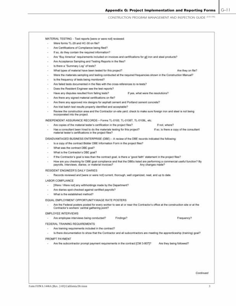
Appendix G: Project Implementation and Reporting Forms
CONSTRUCTION PROGRAM MANAGEMENT AND INSPECTION GUIDE (5/01/04)
G–11

Appendix G: Project Implementation and Reporting Forms
CONSTRUCTION PROGRAM MANAGEMENT AND INSPECTION GUIDE (5/01/04)
G–12

Appendix G: Project Implementation and Reporting Forms
CONSTRUCTION PROGRAM MANAGEMENT AND INSPECTION GUIDE (5/01/04)
G–13

Appendix G: Project Implementation and Reporting Forms
CONSTRUCTION PROGRAM MANAGEMENT AND INSPECTION GUIDE (5/01/04)
G–14

Appendix G: Project Implementation and Reporting Forms
CONSTRUCTION PROGRAM MANAGEMENT AND INSPECTION GUIDE (5/01/04)
G–15

Appendix G: Project Implementation and Reporting Forms
CONSTRUCTION PROGRAM MANAGEMENT AND INSPECTION GUIDE (5/01/04)
G–16
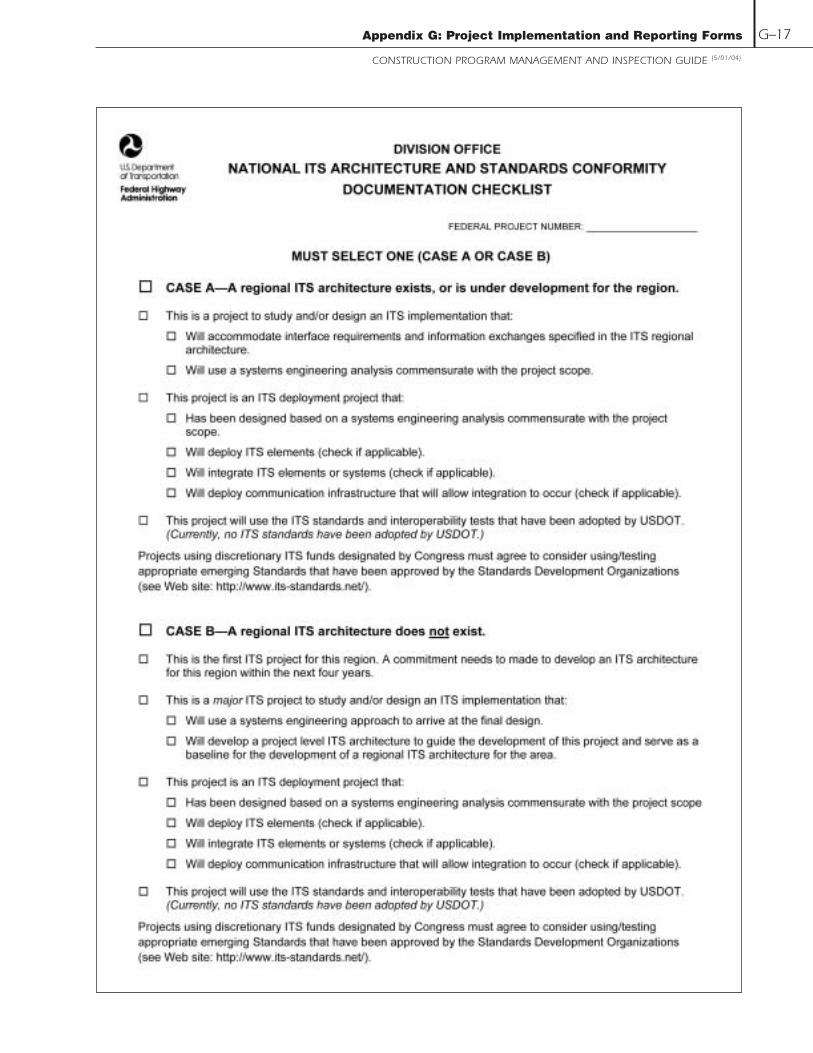
Appendix G: Project Implementation and Reporting Forms
CONSTRUCTION PROGRAM MANAGEMENT AND INSPECTION GUIDE (5/01/04)
G–17

Appendix G: Project Implementation and Reporting Forms
CONSTRUCTION PROGRAM MANAGEMENT AND INSPECTION GUIDE (5/01/04)
G–18

Appendix G: Project Implementation and Reporting Forms
CONSTRUCTION PROGRAM MANAGEMENT AND INSPECTION GUIDE (5/01/04)
G–19

Appendix G: Project Implementation and Reporting Forms
CONSTRUCTION PROGRAM MANAGEMENT AND INSPECTION GUIDE (5/01/04)
G–20

Appendix G: Project Implementation and Reporting Forms
CONSTRUCTION PROGRAM MANAGEMENT AND INSPECTION GUIDE (5/01/04)
G–21

Appendix G: Project Implementation and Reporting Forms
CONSTRUCTION PROGRAM MANAGEMENT AND INSPECTION GUIDE (5/01/04)
G–22

Appendix G: Project Implementation and Reporting Forms
CONSTRUCTION PROGRAM MANAGEMENT AND INSPECTION GUIDE (5/01/04)
G–23

Appendix G: Project Implementation and Reporting Forms
CONSTRUCTION PROGRAM MANAGEMENT AND INSPECTION GUIDE (5/01/04)
G–24

Appendix G: Project Implementation and Reporting Forms
CONSTRUCTION PROGRAM MANAGEMENT AND INSPECTION GUIDE (5/01/04)
G–25

Appendix G: Project Implementation and Reporting Forms
CONSTRUCTION PROGRAM MANAGEMENT AND INSPECTION GUIDE (5/01/04)
G–26

Appendix G: Project Implementation and Reporting Forms
CONSTRUCTION PROGRAM MANAGEMENT AND INSPECTION GUIDE (5/01/04)
G–27
www.fhwa.dot.gov/programadmin/contracts/index.htm

Appendix G: Project Implementation and Reporting Forms
CONSTRUCTION PROGRAM MANAGEMENT AND INSPECTION GUIDE (5/01/04)
G–28

Appendix G: Project Implementation and Reporting Forms
CONSTRUCTION PROGRAM MANAGEMENT AND INSPECTION GUIDE (5/01/04)
G–29

Appendix G: Project Implementation and Reporting Forms
CONSTRUCTION PROGRAM MANAGEMENT AND INSPECTION GUIDE (5/01/04)
G–30
www.fhwa.dot.gov/programadmin/contracts/index.htm

Appendix G: Project Implementation and Reporting Forms
CONSTRUCTION PROGRAM MANAGEMENT AND INSPECTION GUIDE (5/01/04)
G–31

Appendix G: Project Implementation and Reporting Forms
CONSTRUCTION PROGRAM MANAGEMENT AND INSPECTION GUIDE (5/01/04)
G–32

Office of Asset Management
Federal Highway Administration
U.S. Department of Transportation
400 7th Street, SW, HIAM-1
Washington, DC 20590
Telephone: 202-366-0392
Fax: 202-366-9981
FHWA-IF-04-013