construction quality assurance plan for kendal … · 20 april 2015 1 12935-45-rep-013 zitholele...
TRANSCRIPT
Zitholele ConsultingReg. No. 2000/000392/07
PO Box 6002 Halfway House 1685, South AfricaBuilding 1, Maxwell Office Park, Magwa Crescent Westc/o Allandale Road & Maxwell Drive, Waterfall City, MidrandTel + (27) 11 207 2060Fax + (27) 86 674 6121E-mail : [email protected]
Directors: S Pillay (Managing Director); N Rajasakran (Director); Dr AM Van Niekerk (Director)
REPORT ON
Construction Quality AssurancePlan for Kendal Power Station 30Year Ash Disposal Facility Project
Liner Installation
Report No : 12935-45-Rep-013
Submitted to:
EskomP O Box 1091Johannesburg
2000
DISTRIBUTION:
2 Copies - Eskom1 Copy - Zitholele Consulting (Pty) Ltd – Library
20 April 2015 12935

20 April 2015 i 12935
ZITHOLELE CONSULTING
TABLE OF CONTENTS
SECTION PAGE
1 INTRODUCTION................................................................................................ 11.1 Purpose and Scope of the Construction Quality Assurance (CQA) Plan ......... 1
2 DEFINITIONS RELATING TO CQA .................................................................. 12.1 Client .............................................................................................................. 12.2 Construction Manager..................................................................................... 22.3 Engineer ......................................................................................................... 22.4 Contractor....................................................................................................... 22.5 Manufacturers................................................................................................. 22.6 Geosynthetic Installer ..................................................................................... 32.7 Resident Engineer .......................................................................................... 32.8 Surveyor ......................................................................................................... 3
3 DEFECTS IDENTIFICATION AND RECTIFICATION....................................... 44 SITE AND PROJECT PROTOCOL ................................................................... 4
4.1 Project Coordination Meetings ........................................................................ 44.1.1 Pre-Construction Meeting.................................................................. 44.1.2 Progress Meetings ............................................................................ 54.1.3 Problem or Work Deficiency Meeting ................................................ 5
5 DOCUMENTATION ........................................................................................... 65.1 Daily Recordkeeping....................................................................................... 65.2 Construction Problems and Resolution Data Sheets....................................... 75.3 Photographic Documentation.......................................................................... 75.4 Design and/or Specification Changes ............................................................. 85.5 CQA Report .................................................................................................... 8
6 EARTHWORKS ................................................................................................. 96.1 Introduction..................................................................................................... 96.2 CQA Monitoring Activities ............................................................................... 9
6.2.1 Vegetation Removal .......................................................................... 96.2.2 Grading ............................................................................................. 96.2.3 Anchor Trench Construction.............................................................10
6.3 Deficiencies ...................................................................................................106.3.1 Notification .......................................................................................106.3.2 Repairs and Re-Testing ...................................................................10
7 DRAINAGE AGGREGATE .............................................................................. 117.1 Introduction....................................................................................................117.2 Testing Activities............................................................................................11
7.2.1 Sample Frequency ...........................................................................117.2.2 Sample Selection .............................................................................12
7.3 CQA Monitoring Activities ..............................................................................127.3.1 Drainage Aggregate .........................................................................12
7.4 Deficiencies ...................................................................................................137.4.1 Notification .......................................................................................137.4.2 Repairs & Re-testing ........................................................................13
8 GEOMEMBRANE ............................................................................................ 138.1 General..........................................................................................................138.2 Geomembrane Material Conformance ...........................................................14
8.2.1 Introduction ......................................................................................148.2.2 Review of Quality Control .................................................................148.2.2.1 Material Properties Certification .......................................................148.2.2.2 Geomembrane Roll MQC Certification .............................................148.2.3 Conformance Testing .......................................................................15
20 April 2015 ii 12935
ZITHOLELE CONSULTING
8.2.4 Cuspated Drainage Sheet Specifications .........................................218.3 Delivery..........................................................................................................23
8.3.1 Transportation & Handling................................................................238.3.2 Storage ............................................................................................23
8.4 Geomembrane Installation .............................................................................238.4.1 Introduction ......................................................................................238.4.2 Earthworks .......................................................................................238.4.2.1 Surface Preparation .........................................................................238.4.2.2 Geosynthetic Termination ................................................................248.4.3 Geomembrane Placement ...............................................................248.4.3.1 Panel Identification...........................................................................248.4.3.2 Field Panel Placement .....................................................................258.4.4 Field Seaming ..................................................................................278.4.4.1 Requirements of Personnel ..............................................................278.4.4.2 Seaming Equipment & Products.......................................................278.4.4.3 Seam Preparation ............................................................................298.4.4.4 Weather Conditions for Seaming......................................................298.4.4.5 Overlapping & Temporary Bonding ..................................................298.4.4.6 Trial seams ......................................................................................308.4.4.7 General Seaming Procedures ..........................................................308.4.4.8 Non-destructive Seam Continuity Testing.........................................318.4.4.9 Destructive Testing ..........................................................................328.4.5 Defects & Repairs ............................................................................368.4.5.1 Identification.....................................................................................368.4.5.2 Evaluation ........................................................................................368.4.5.3 Repair Procedures ...........................................................................368.4.5.4 Verification Repairs ..........................................................................378.4.5.5 Large Wrinkles .................................................................................388.4.6 Lining System Acceptance ...............................................................38
9 GEOTEXTILE................................................................................................... 389.1 Introduction....................................................................................................389.2 Manufacturing ................................................................................................389.3 Labelling ........................................................................................................409.4 Shipment & Storage.......................................................................................409.5 Conformance Testing.....................................................................................40
9.5.1 Tests ................................................................................................409.5.2 Sampling Procedures.......................................................................419.5.3 Test Results .....................................................................................419.5.4 Conformance Sampling Failure ........................................................41
9.6 Handling & Placement ...................................................................................429.7 Seams & Overlaps.........................................................................................429.8 Repair ............................................................................................................429.9 Placement of Soil or Aggregate Materials ......................................................43

20 April 2015 iii 12935
ZITHOLELE CONSULTING
LIST OF TABLES
Table 7-1: Test procedures for evaluating of aggregate ...................................................12
Table 7-2: Minimum aggregate testing frequencies for conformance testing ....................12
Table 8-1: Geomembrane conformance testing requirements..........................................16
Table 8-2: High Density Polyethylene (HDPE) Geomembrane - Smooth..........................17
Table 8-3: High Density Polyethylene (HDPE) Geomembrane - Smooth..........................19
Table 8-4: Cuspated Drainage Sheet, Leakdrain Super S6U Specifications.....................21
Table 9-1: Geotextile conformance testing requirements .................................................39

20 April 2015 iv 12935
ZITHOLELE CONSULTING
LIST OF ACROYNYMS
CQA Construction Quality Assurance
CQC Construction Quality Control
HDPE High Density Polyethylene
MQC Manufacturing Quality Control
UV Ultraviolet
ASTM American Society for Testing and Materials
OIT Oxidative Induction Time
MD Machine Direction
XMD Cross Machine Direction

20 April 2015 1 12935-45-Rep-013
ZITHOLELE CONSULTING
1 INTRODUCTION
1.1 Purpose and Scope of the Construction Quality Assurance (CQA) Plan
The purpose of the CQA Plan is to address the CQA procedures and monitoring
requirements for construction of the project. The CQA Plan is intended to:
(i) define the responsibilities of parties involved with the construction;
(ii) provide guidance in the proper construction of the major components of the
project;
(iii) establish testing protocols;
(iv) establish guidelines for construction documentation; and
(v) provide the means for assuring that the project is constructed in conformance to
the Technical Specifications, permit conditions, applicable regulatory
requirements, and Construction Drawings.
2 DEFINITIONS RELATING TO CQA
In the context of this document, Construction Quality Assurance and Construction Quality
Control are defined as follows:
Construction Quality Assurance (CQA) - A planned and systematic pattern of means and
actions designed to assure adequate confidence that material and/or services meet
contractual and regulatory requirements and will perform satisfactorily in service. CQA
refers to means and actions employed by the Client and the Engineer to assure conformity
of the project “Work” with this CQA Plan, the Drawings, and the Technical Specifications.
Construction Quality Control (CQC) - Actions which provide a means to measure and
regulate the characteristics of an item or service in relation to contractual and regulatory
requirements. CQC refers to those actions taken by the Contractor, Manufacturer, or
Geosynthetic Installer to verify that the materials and the workmanship meet the
requirements of this CQA Plan, the Drawings, and the Technical Specifications. In the case
of the geosynthetic components and piping of the Work, CQC is provided by the
Manufacturer, Geosynthetic Installer, and Contractor.
2.1 Client
The Client on this project is Eskom SOC Ltd.

20 April 2015 2 12935-45-Rep-013
ZITHOLELE CONSULTING
2.2 Construction Manager
The Construction Manager is responsible for managing the construction and implementation
of the Drawings, and Technical Specifications for the project work. The Construction
Manager is selected/appointed by the Owner.
2.3 Engineer
The Engineer is responsible for the design, Drawings, and Technical Specifications for the
project work. The Engineer of Record shall be a qualified engineer, registered as a
professional engineer with the Engineering Council of South Africa. The Engineer should
have expertise, which demonstrates significant familiarity with piping, geosynthetics and
soils, as appropriate, including design and construction experience related to liner systems.
2.4 Contractor
In this CQA Plan, Contractor refers to an independent party or parties, contracted by the
Owner, performing the work in general accordance with this CQA Plan, the Drawings, and
the Technical Specifications. The Contractor will be responsible for the installation of the
soils, pipe, drainage aggregate, and geosynthetic components of the liner systems
The Contractor will be responsible for constructing the liner system and appurtenant
components in general accordance with the Drawings and complying with the quality control
requirements specified in the Technical Specifications.
Qualifications of the Contractor are specific to the construction contract. The Contractor
should have a demonstrated history of successful earthworks, piping, and liner system
construction.
2.5 Manufacturers
The Manufacturers are responsible for the production of finished material (geomembrane,
geotextile, and pipe) from appropriate raw materials. The Manufacturer(s) will be able to
provide sufficient production capacity and qualified personnel to meet the demands of the
project. The Manufacturer(s) must be well established firms that meet the requirements
identified in the Technical Specifications.

20 April 2015 3 12935-45-Rep-013
ZITHOLELE CONSULTING
2.6 Geosynthetic Installer
The Geosynthetic Installer is responsible for field handling, storage, placement, seaming,
ballasting or anchoring against wind uplift, and other aspects of the geosynthetic material
installation.
The Geosynthetic Installer will be trained and qualified to install the geosynthetic materials of
the type specified for this project. The Geosynthetic Installer shall meet the qualification
requirements identified in the Technical Specifications.
2.7 Resident Engineer
Responsibilities
The Resident Engineer is a party, independent from the Owner, Contractor, Manufacturer,
and Geosynthetic Installer, who is responsible for observing, testing, and documenting
activities related to the CQC and CQA of the earthwork, piping, and geosynthetic
components used in the construction of the Project as required by this CQA Plan and the
Technical Specifications. The Resident Engineer will also be responsible for issuing a
CQA report at the completion of the Project construction, which documents construction
and associated CQA activities.
Qualifications
The Resident Engineer will be experienced with earthwork and installation of geosynthetic
materials similar to those materials used in construction of the Project. The Resident
Engineer will be experienced in the preparation of CQA documentation including CQA
Plans, field documentation, field testing procedures, laboratory testing procedures,
construction specifications, construction Drawings, and CQA reports.
2.8 Surveyor
The Surveyor is a party, independent from the Contractor, Manufacturer, and Geosynthetic
Installer, that is responsible for surveying, documenting, and verifying the location of all
significant components of the Work. The Surveyor’s work is coordinated and employed by
the Contractor. The Surveyor is responsible for issuing Record Drawings of the
construction.

20 April 2015 4 12935-45-Rep-013
ZITHOLELE CONSULTING
3 DEFECTS IDENTIFICATION AND RECTIFICATION
If a defect is discovered in the work, the Engineer will evaluate the extent and nature of the
defect. If the defect is indicated by an unsatisfactory test result, the Engineer will determine
the extent of the deficient area by additional tests, observations, a review of records, or other
means that the Engineer deems appropriate.
After evaluating the extent and nature of a defect, the Engineer will notify the Construction
Manager and schedule appropriate re-tests when the work deficiency is corrected by the
Contractor.
The Contractor will correct the deficiency to the satisfaction of the Engineer. Defect
corrections will be monitored and documented.
4 SITE AND PROJECT PROTOCOL
4.1 Project Coordination Meetings
Meetings of key project personnel are necessary to assure a high degree of quality during
installation and to promote clear, open channels of communication. Therefore, Project
Coordination Meetings are an essential element in the success of the project. Several types
of Project Coordination Meetings are described below, including: (i) pre-construction
meetings; (ii) progress meetings; and (iii) problem or work deficiency meetings.
4.1.1 Pre-Construction Meeting
A Pre-Construction Meeting will be held at the site prior to construction of the Project. At a
minimum, the Pre-Construction Meeting will be attended by the Contractor, the Geosynthetic
Installer’s Superintendent, the Engineer, and the Construction Manager.
Specific items for discussion at the Pre-Construction Meeting include:
Appropriate modifications or clarifications to the CQA Plan;
The Drawings and Technical Specifications;
The responsibilities of each party;
The lines of authority and communication;
The methods for documenting and reporting, and for distributing documents
and reports;
The acceptance and rejection criteria;

20 April 2015 5 12935-45-Rep-013
ZITHOLELE CONSULTING
The protocols for testing;
The protocols for handling deficiencies, repairs, and re-testing;
The time schedule for all operations;
The procedures for packaging and storing archive samples;
The panel layout and numbering systems for panels and seams;
The seaming procedures;
The repair procedures; and
The soil stockpiling locations.
The Construction Manager will conduct a site tour to observe the current site conditions and
to review construction material and equipment storage locations. A person in attendance at
the meeting will be appointed by the Construction Manager to record the discussions and
decisions of the meeting in the form of meeting minutes. Copies of the meeting minutes will
be distributed to all attendees.
4.1.2 Progress Meetings
Progress meetings will be held between the Engineer, the Contractor, Construction
Manager, and other concerned parties participating in the construction of the project. This
meeting will include discussions on the current progress of the project, planned activities for
the next week, and revisions to the work plan and/or schedule. The meeting will be
documented in meeting minutes prepared by a person designated for the purpose. Within 2
working days of the meeting, draft minutes will be transmitted to representatives of parties in
attendance for review and comment. Corrections and/or comments to the draft minutes
shall be made within 2 working days of receipt of the draft minutes to be incorporated in the
final meeting minutes.
4.1.3 Problem or Work Deficiency Meeting
A special meeting will be held when and if a problem or deficiency is present or likely to
occur. The meeting will be attended by the Contractor, the Construction Manager, the
Engineer, and other parties as appropriate. The purpose of the work deficiency meeting is to
define and resolve the problem or work deficiency as follows:
Define and discuss the problem or deficiency;
Review alternative solutions;
Select a suitable solution agreeable to all parties; and

20 April 2015 6 12935-45-Rep-013
ZITHOLELE CONSULTING
Implement an action plan to resolve the problem or deficiency.
The Construction Manager will appoint one attendee to record the discussions and decisions
of the meeting. The meeting record will be documented in the form of meeting minutes and
copies will be distributed to all affected parties. A copy of the minutes will be retained in
facility records.
5 DOCUMENTATION
5.1 Daily Recordkeeping
Preparation of daily CQA documentation will consist of daily field reports prepared by the
Resident Engineer which may include CQA monitoring logs and testing data sheets. This
information may be regularly submitted to and reviewed by the Construction Manager. Daily
field reports will include documentation of the observed activities during each day of activity.
The daily field reports may include monitoring logs and testing data sheets. At a minimum,
these logs and data sheets will include the following information:
The date, project name, location, and other identification;
A summary of the weather conditions;
A summary of locations where construction is occurring;
Equipment and personnel on the project;
A summary of meetings held and attendees;
A description of materials used and references of results of testing and
documentation;
Identification of deficient work and materials;
Results of re-testing corrected “deficient work;”
An identifying sheet number for cross referencing and document control;
Descriptions and locations of construction monitored;
Type of construction and monitoring performed;
Description of construction procedures and procedures used to evaluate
construction;
A summary of test data and results;
Calibrations or re-calibrations of test equipment and actions taken as a result of re-
calibration;

20 April 2015 7 12935-45-Rep-013
ZITHOLELE CONSULTING
Decisions made regarding acceptance of units of work and/or corrective actions
to be taken in instances of substandard testing results;
A discussion of agreements made between the interested parties which may
affect the work; and
Signature of the Engineer and Construction Manager.
5.2 Construction Problems and Resolution Data Sheets
Construction Problems and Resolution Data Sheets, to be submitted with the daily field
reports prepared by the Resident Engineer, describing special construction situations, will be
cross-referenced with daily field reports, specific observation logs, and testing data sheets
and will include the following information, where available:
An identifying sheet number for cross-referencing and document control;
A detailed description of the situation or deficiency;
The location and probable cause of the situation or deficiency;
How and when the situation or deficiency was found or located;
Documentation of the response to the situation or deficiency;
Final results of responses;
Measures taken to prevent a similar situation from occurring in the future; and
Signature of the Engineer and a signature indicating concurrence by the Construction
Manager.
The Construction Manager will be made aware of significant recurring non-conformance with
the Drawings, Technical Specifications, or CQA Plan. The cause of the non-conformance
will be determined and appropriate changes in procedures or specifications will be
recommended. These changes will be submitted to the Construction Manager for approval.
When this type of evaluation is made, the results will be documented and any revision to
procedures or specifications will be approved by the Contractor and Engineer.
5.3 Photographic Documentation
Photographs will be taken and documented in order to serve as a pictorial record of work
progress, problems, and mitigation activities. These records will be presented to the
Construction Manager upon completion of the project. Photographic reporting data sheets,
where used, will be cross-referenced with observation and testing data sheet(s), and/or
construction problem and solution data sheet(s).

20 April 2015 8 12935-45-Rep-013
ZITHOLELE CONSULTING
5.4 Design and/or Specification Changes
Design and/or specifications changes may be required during construction. In such cases,
the Engineer will be notified. Design and/or specification changes will be made with the
written agreement of the Engineer and will take the form of an addendum to the Drawings
and Technical Specifications.
5.5 CQA Report
At the completion of the Project, the Engineer will submit to the Client a CQA report. The
CQA report will acknowledge: (i) that the work has been performed in compliance with the
Drawings and Technical Specifications; (ii) physical sampling and testing has been
conducted at the appropriate frequencies; and (iii) that the summary document provides
the necessary supporting information. At a minimum, this report will include:
A summary report describing the CQA activities and indicating compliance with
the Drawings and Technical Specifications;
A summary of CQA/CQC testing, including failures, corrective measures, and
retest results;
Contractor and Installer personnel CV’s and qualifications as necessary;
Documentation that the geomembrane trial seams were performed in general
accordance with the CQA Plan and Technical Specifications;
Documentation that field seams were non-destructively tested using a method in
general accordance with the applicable test standards;
Documentation that non-destructive testing was monitored by the Resident
Engineer;
Records of sample locations, the name of the individual conducting the tests, and the
results of tests;
Record Drawings as provided by the Surveyor;
Daily field reports.
The Record Drawings will include scale drawings depicting the location of the construction
and details pertaining to the extent of construction (e.g., plan dimensions and
appropriate elevations).

20 April 2015 9 12935-45-Rep-013
ZITHOLELE CONSULTING
6 EARTHWORKS
6.1 Introduction
This section prescribes the CQA activities to be performed to monitor that prepared
subgrade is constructed in general accordance with Drawings and Technical Specifications.
The prepared subgrade construction procedures to be monitored by the Resident Engineer,
if required, shall include:
Vegetation removal;
Subgrade preparation;
Fine-grading; and
Anchor trench excavation and backfill.
6.2 CQA Monitoring Activities
6.2.1 Vegetation Removal
The Resident Engineer will monitor and document that vegetation is sufficiently cleared and
grubbed in areas where geosynthetics are to be placed. Vegetation removal shall be
performed as described in the Technical Specification and the Drawings.
6.2.2 Grading
Construction of the liner system will require minor re-grading in certain areas. The Resident
Engineer shall monitor and document that site re-grading performed meets the requirements
of the Technical Specifications and the Drawings. At a minimum, the Resident Engineer shall
monitor that:
The subgrade surface is free of sharp rocks, debris, and other undesirable
materials;
The subgrade surface is smooth and uniform by visually monitoring proof rolling
activities; and
The subgrade surface meets the lines and grades shown on the Drawings.

20 April 2015 10 12935-45-Rep-013
ZITHOLELE CONSULTING
6.2.3 Anchor Trench Construction
During construction, the Resident Engineer will monitor the anchor trench excavation and
backfill methods are consistent with the requirements specified in the Technical
Specifications and the Drawings. The Resident Engineer will monitor, at a minimum, that:
The anchor trench is free of sharp rocks, debris and other undesirable materials and
that particles are no larger than 150 mm in longest dimension;
The anchor trench is constructed to the lines and grades shown on the Drawings;
and
Compaction requirements are met, through visual observations, as specified in the
Technical Specifications.
6.3 Deficiencies
If a defect is discovered in the earthwork product, the Resident Engineer will immediately
determine the extent and nature of the defect. If the defect is indicated by an unsatisfactory
test result, the Resident Engineer will determine the extent of the defective area by
additional tests, observations, a review of records, or other means that the Resident
Engineer deems appropriate. If the defect is related to adverse site conditions, such as
overly wet soils or non-conforming particle sizes, the Resident Engineer will define the limits
and nature of the defect.
6.3.1 Notification
After evaluating the extent and nature of a defect, the Resident Engineer will notify the
Construction Manager and Contractor and schedule appropriate re-evaluation when the
work deficiency is to be corrected.
6.3.2 Repairs and Re-Testing
The Contractor will correct deficiencies to the satisfaction of the Resident Engineer. If a
project specification criterion cannot be met, or unusual weather conditions hinder work, then
the Resident Engineer will develop and present to the Construction Manager suggested
solutions for his approval.
Re-evaluations by the Resident Engineer shall continue until it is verified that defects have
been corrected before any additional work is performed by the Contractor in the area of the
deficiency.
20 April 2015 11 12935-45-Rep-013
ZITHOLELE CONSULTING
7 DRAINAGE AGGREGATE
7.1 Introduction
This section prescribes the CQA activities to be performed to monitor that drainage
aggregates are constructed in general accordance with Drawings and Technical
Specifications. The drainage aggregates construction procedures to be monitored by the
Resident Engineer include drainage aggregate placement.
7.2 Testing Activities
Aggregate testing will be performed for material qualification and material conformance.
These two stages of testing are defined as follows:
Material qualification tests are used to evaluate the conformance of a proposed
aggregate source with the Technical Specifications for qualification of the source
prior to construction;
Aggregate conformance testing is used to evaluate the conformance of a particular
batch of aggregate from a qualified source to the Technical Specifications prior to
installation of the aggregate.
The Contractor will be responsible for submitting material qualification test results to the
Construction Manager and to the Resident Engineer for review. The Laboratory will perform
the conformance testing and CQC testing. Aggregate testing will be conducted in general
accordance with the current versions of the South African National Standards (SANS).
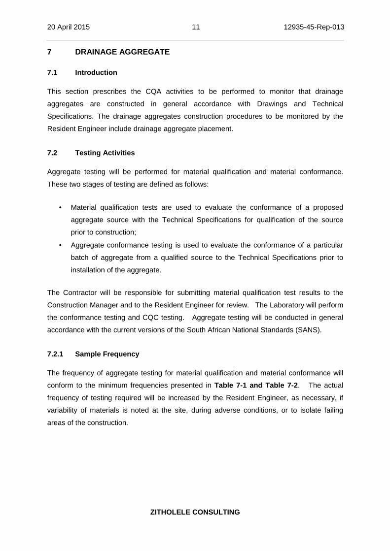
7.2.1 Sample Frequency
The frequency of aggregate testing for material qualification and material conformance will
conform to the minimum frequencies presented in Table 7-1 and Table 7-2. The actual
frequency of testing required will be increased by the Resident Engineer, as necessary, if
variability of materials is noted at the site, during adverse conditions, or to isolate failing
areas of the construction.

20 April 2015 12 12935-45-Rep-013
ZITHOLELE CONSULTING
Table 7-1: Test procedures for evaluating of aggregate
Test Method Description Test Standard
Sieve Analysis Particle Size Distribution of Fine andCoarse Aggregates ASTM C 136
Hydraulic Conductivity(Rigid Wall Permeater) Permeability of Aggregates ASTM D 2434
Table 7-2: Minimum aggregate testing frequencies for conformance testing
Test Test Method Test StandardSieve Analysis ASTM C 136 1 per 3800 m3
Hydraulic Conductivity ASTM D 2434 1 per 7600 m3
7.2.2 Sample Selection
With the exception of qualification samples, sampling locations will be selected by the
Resident Engineer. Conformance samples will be obtained from borrow pits and/or
stockpiles of material. The Contractor must plan the work and make aggregate available for
sampling in a timely and organized manner so that the test results can be obtained before
the material is installed. The Resident Engineer must document sample locations so that
failing areas can be immediately isolated. The Resident Engineer will follow standard
sampling procedures to obtain representative samples of the proposed aggregate materials.
7.3 CQA Monitoring Activities
7.3.1 Drainage Aggregate
The Resident Engineer will monitor and document the installation of the drainage
aggregates. In general, monitoring of the installation of drainage aggregate includes the
following activities:
Reviewing documentation of the material qualification test results provided by
the Contractor;
Sampling and testing for conformance of the materials to the Technical
Specifications;
Documenting that the drainage aggregates are installed using the specified
equipment and procedures;
Documenting that the drainage aggregates are constructed to the lines and grades
shown on the Drawings; and

20 April 2015 13 12935-45-Rep-013
ZITHOLELE CONSULTING
Monitoring that the construction activities do not cause damage to underlying
geosynthetic materials.
7.4 Deficiencies
If a defect is discovered in the drainage aggregates, the Resident Engineer will evaluate the
extent and nature of the defect. If the defect is indicated by an unsatisfactory test result, the
Resident Engineer will determine the extent of the deficient area by additional tests,
observations, a review of records, or other means that the Resident Engineer deems
appropriate.
7.4.1 Notification
After evaluating the extent and nature of a defect, the Resident Engineer will notify the
Construction Manager and Contractor and schedule appropriate re-tests when the work
deficiency is to be corrected.
7.4.2 Repairs & Re-testing
The Contractor will correct the deficiency to the satisfaction of the Resident Engineer. If a
project specification criterion cannot be met, or unusual weather conditions hinder work, then
the Resident Engineer will develop and present to the Construction Manager suggested
solutions for approval.
Re-tests recommended by the Resident Engineer shall continue until it is verified that the
defect has been corrected before any additional work is performed by the Contractor in the
area of the deficiency. The Resident Engineer will also verify that installation requirements
are met and that submittals are provided.
8 GEOMEMBRANE
8.1 General
This section discusses and outlines the CQA activities to be performed for high density
polyethylene (HDPE) geomembrane installation. The Resident Engineer will review the
Drawings, Technical Specifications, and any approved Addenda regarding this material.

20 April 2015 14 12935-45-Rep-013
ZITHOLELE CONSULTING
8.2 Geomembrane Material Conformance
8.2.1 Introduction
The Resident Engineer will document that the geomembrane delivered to the site meets the
requirements of the Technical Specifications prior to installation. The Resident Engineer will:
Review the manufacturer’s submittals for compliance with the Technical
Specifications;
Document the delivery and proper storage of geomembrane rolls; and
Conduct conformance testing of the rolls before the geomembrane is installed.
The following sections describe the CQA activities required to verify the conformance of
geomembrane.
8.2.2 Review of Quality Control
8.2.2.1 Material Properties Certification
The Manufacturer will provide the Construction Manager and the Resident Engineer with the
following:
Property data sheets, including, at a minimum, all specified properties,
measured using test methods indicated in the Technical Specifications, or equivalent;
Sampling procedures and results of testing.
The Resident Engineer will document that:
The property values certified by the Manufacturer meet all of the requirements of the
Technical Specifications; and
The measurements of properties by the Manufacturer are properly documented and
that the test methods used are acceptable.
8.2.2.2 Geomembrane Roll MQC Certification
Prior to shipment, the Manufacturer will provide the Construction Manager and the Resident
Engineer with Manufacturing Quality Control (MQC) certificates for every roll of
geomembrane provided. The MQC certificates will be signed by a responsible party

20 April 2015 15 12935-45-Rep-013
ZITHOLELE CONSULTING
employed by the Geomembrane Manufacturer, such as the production manager. The MQC
certificates shall include:
Roll numbers and identification; and
Results of MQC tests - as a minimum, results will be given for thickness,
specific gravity, carbon black content, carbon black dispersion, tensile properties,
and puncture resistance evaluated in general accordance with the methods indicated
in the Technical Specifications or equivalent methods approved by the Construction
Manager.
The Resident Engineer will document that:
That MQC certificates have been provided at the specified frequency, and that the
certificates identify the rolls related to the roll represented by the test results; and
Review the MQC certificates and monitor that the certified roll properties meet the
specifications.
8.2.3 Conformance Testing
The Resident Engineer shall obtain conformance samples (at the manufacturing facility or
site) at the specified frequency and forward them to the Geosynthetics Laboratory for
testing to monitor conformance to both the Technical Specifications and the list of
properties certified by the Manufacturer. The test procedures will be as indicated in Table 8-1. Where optional procedures are noted in the test method, the requirements of the
Technical Specifications will prevail.

20 April 2015 16 12935-45-Rep-013
ZITHOLELE CONSULTING
Table 8-1: Geomembrane conformance testing requirements
Test Name Test Method Frequency
Specific Gravity ASTM D 792 Method A or ASTM D 1505 18600 m2
Thickness ASTM D 5199 18600 m2
Tensile Strength at Yield ASTM D 638 18600 m2
Tensile Strength at Break ASTM D 638 18600 m2
Elongation at Yield ASTM D 638 18600 m2
Elongation at Break ASTM D 638 18600 m2
Carbon Back Content ASTM D 1603 18600 m2
Carbon Back Dispersion ASTM D 5596 18600 m2
Interface Shear Strength ASTM D 5321 1 per project
Samples will be taken across the width of the roll and will not include the first linear 75 mm of
material. Unless otherwise specified, samples will be 75 mm long by the roll width. The
Resident Engineer will mark the machine direction on the samples with an arrow along with
the date and roll number. The required minimum sampling frequencies are provided in
Table 8-1.
The Resident Engineer will examine results from laboratory conformance testing and will
report any non-conformance to the Construction Manager and the Geosynthetic Installer.
The procedures prescribed in the Technical Specifications will be followed in the event of a
failing conformance test.
The number of tests shall be in accordance with the appropriate test methods listed in Table8-2 and 8-3 from the GRI Test Method GM13.

20 April 2015 17 12935-45-Rep-013
ZITHOLELE CONSULTING
Table 8-2: High Density Polyethylene (HDPE) Geomembrane - Smooth
Properties
TestMethod
TestValue
TestingFrequency(minimum)
0.75 mm 1.00 mm 1.25 mm 1.50 mm 2.00 mm 2.50 mm 3.00 mmThickness - mils (min. ave.)
lowest individual of 10 valuesD5199 nom. (mil)
-10%nom. (mil)
-10%nom. (mil)
-10%nom. (mil)
-10%nom. (mil)
-10%nom. (mil)
-10%nom. (mil)
-10%per roll
Density (min.) D 1505/D 792 0.940 g/cc 0.940g/cc
0.940g/cc
0.940g/cc
0.940g/cc
0.940g/cc
0.940 g/cc 90,000 kgTensile Properties (1) (min.
ave.) yield strength break strength yield elongation break elongation
D 6693Type IV 11 kN/m
20 kN/m12%700%
15 kN/m27 kN/m
12%700%
18 kN/m33 kN/m
12%700%
22 kN/m40 kN/m
12%700%
29 kN/m53 kN/m
12%700%
37 kN/m67 kN/m
12%700%
44 kN/m80 kN/m
12%700%
9,000 kg
Tear Resistance (min. ave.) D 1004 93 N 125 N 156 N 187 N 249 N 311 N 374 N 20,000 kgPuncture Resistance (min. ave.) D 4833 240 N 320 N 400 N 480 N 640 N 800 N 960 N 20,000 kgStress Crack Resistance (2) D 5397
(App.)300 hr. 300 hr. 300 hr. 300 hr. 300 hr. 300 hr. 300 hr. per GRI GM-10
Carbon Black Content - % D 4218 (3) 2.0-3.0% 2.0-3.0% 2.0-3.0% 2.0-3.0% 2.0-3.0% 2.0-3.0% 2.0-3.0% 9,000 kgCarbon Black Dispersion D 5596 note (4) note (4) note (4) note (4) note (4) note (4) note (4) 20,000 kgOxidative Induction Time (OIT) (min. ave.) (5)(a) Standard OIT
— or —(b) High Pressure OIT
D 3895
D 5885
100 min.
400 min.
100 min.
400 min.
100 min.
400 min.
100 min.
400 min.
100 min.
400 min.
100 min.
400 min.
100 min.
400 min.
90,000 kg
Oven Aging at 85°C (5), (6)(a) Standard OIT (min. ave.) - % retained after 90 days
— or —(b) High Pressure OIT (min. ave.) - % retained after 90days
D 5721D 3895
D 5885
55%
80%
55%
80%
55%
80%
55%
80%
55%
80%
55%
80%
55%
80%
per eachformulation
UV Resistance (7)(a) Standard OIT (min. ave.)
— or —(b) High Pressure OIT (min. ave.) - % retained after 1600hrs (9)
D 7238D 3895
D 5885
N. R. (8)
50%
N.R. (8)
50%
N.R. (8)
50%
N.R. (8)
50%
N.R. (8)
50%
N.R. (8)
50%
N.R. (8)
50%
per eachformulation
(1) Machine direction (MD) and cross machine direction (XMD) average values should be on the basis of 5 test specimens each directionYield elongation is calculated using a gage length of 33 mmBreak elongation is calculated using a gage length of 50 mm
(2) The yield stress used to calculate the applied load for the SP-NCTL test should be the manufacturer’s mean value via MQC testing.(3) Other methods such as D 1603 (tube furnace) or D 6370 (TGA) are acceptable if an appropriate correlation to D 4218 (muffle furnace) can be established.(4) Carbon black dispersion (only near spherical agglomerates) for 10 different views:
9 in Categories 1 or 2 and 1 in Category 3

20 April 2015 18 12935-45-Rep-013
ZITHOLELE CONSULTING
(5) The manufacturer has the option to select either one of the OIT methods listed to evaluate the antioxidant content in the geomembrane.(6) It is also recommended to evaluate samples at 30 and 60 days to compare with the 90 day response.(7) The condition of the test should be 20 hr. UV cycle at 75 C followed by 4 hr. condensation at 60 C.(8) Not recommended since the high temperature of the Std-OIT test produces an unrealistic result for some of the antioxidants in the UV exposed samples.(9) UV resistance is based on percent retained value regardless of the original HP-OIT value.

20 April 2015 19 12935-45-Rep-013
ZITHOLELE CONSULTING
Table 8-3: High Density Polyethylene (HDPE) Geomembrane - Smooth
Properties
Test
Method
TestValue
Testing
Frequency(minimum
)
0.75 mm 1.00 mm 1.25 mm 1.50 mm 2.00 mm 2.50 mm 3.00 mm
Thickness mils (min. ave.) lowest individual for 8 out of 10 values lowest individual for any of the 10 values
D 5994 nom. (-5%)
-10%
-15%
nom. (-5%)
-10%
-15%
nom. (-5%)
-10%
-15%
nom. (-5%)
-10%
-15%
nom. (-5%)
-10%
-15%
nom. (-5%)
-10%
-15%
nom. (-5%)
-10%
-15%
per roll
Asperity Height mils (min. ave.) (1)D 7466 0.25 mm 0.25 mm 0.25 mm 0.25 mm 0.25 mm 0.25 mm 0.25 mm every 2nd roll
(2)
Density (min. ave.) D 1505/D792 0.940 g/cc 0.940 g/cc 0.940 g/cc 0.940 g/cc 0.940 g/cc 0.940 g/cc 0.940 g/cc 90,000 kg
Tensile Properties (min.ave.) (3)
yield strength break strength
yieldelongation breakelongation
D 6693Type IV 11
kN/m8
kN/m12%100%
15kN/m
10kN/m12%100%
18kN/m
13kN/m
12%
100%
22kN/m
16kN/m12%100%
29kN/m
21kN/m12%100%
37kN/m
26kN/m12%100%
44kN/m
32kN/m12%100%
9,000 kg
Tear Resistance (min. ave.) D 1004 93 N 125 N 156 N 187 N 249 N 311 N 374 N 20,000 kg
Puncture Resistance (min. ave.) D 4833 200N 267 N 333 N 400 N 534 N 667 N 800 N 20,000 kg
Stress Crack Resistance (4) D 5397(App.) 300 hr. 300 hr. 300 hr. 300 hr. 300 hr. 300 hr. 300 hr. per GRI
GM10Carbon Black Content (range) D 4218 (5) 2.0-3.0 % 2.0-3.0 % 2.0-3.0 % 2.0-3.0 % 2.0-3.0 % 2.0-3.0 % 2.0-3.0 % 9,000 kg
Carbon Black DispersionD 5596 note (6) note (6) note (6) note (6) note (6) note (6) note (6) 20,000 kg
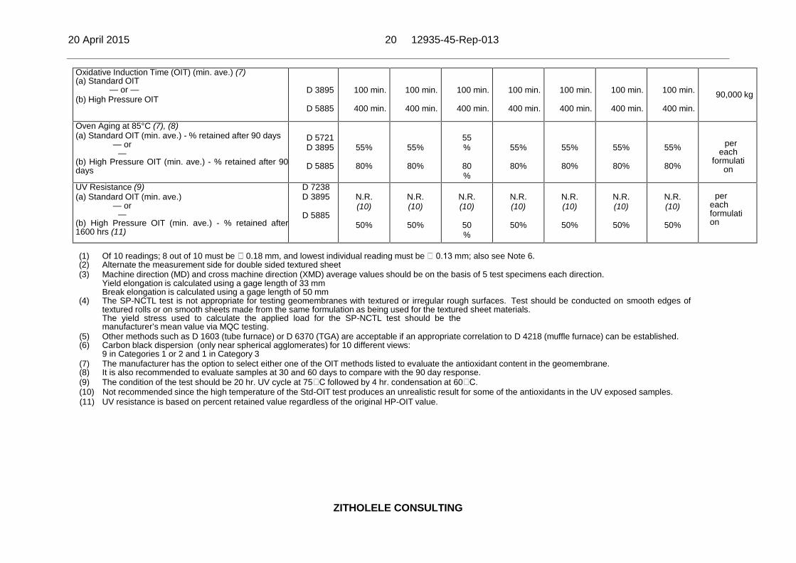
20 April 2015 20 12935-45-Rep-013
ZITHOLELE CONSULTING
Oxidative Induction Time (OIT) (min. ave.) (7)(a) Standard OIT
— or —(b) High Pressure OIT
D 3895
D 5885
100 min.
400 min.
100 min.
400 min.
100 min.
400 min.
100 min.
400 min.
100 min.
400 min.
100 min.
400 min.
100 min.
400 min.90,000 kg
Oven Aging at 85°C (7), (8)(a) Standard OIT (min. ave.) - % retained after 90 days
— or—
(b) High Pressure OIT (min. ave.) - % retained after 90days
D 5721D 3895
D 5885
55%
80%
55%
80%
55%
80%
55%
80%
55%
80%
55%
80%
55%
80%
pereach
formulation
UV Resistance (9)(a) Standard OIT (min. ave.)
— or—
(b) High Pressure OIT (min. ave.) - % retained after1600 hrs (11)
D 7238D 3895
D 5885
N.R.(10)
50%
N.R.(10)
50%
N.R.(10)
50%
N.R.(10)
50%
N.R.(10)
50%
N.R.(10)
50%
N.R.(10)
50%
pereachformulation
(1) Of 10 readings; 8 out of 10 must be 0.18 mm, and lowest individual reading must be 0.13 mm; also see Note 6.(2) Alternate the measurement side for double sided textured sheet(3) Machine direction (MD) and cross machine direction (XMD) average values should be on the basis of 5 test specimens each direction.
Yield elongation is calculated using a gage length of 33 mmBreak elongation is calculated using a gage length of 50 mm
(4) The SP-NCTL test is not appropriate for testing geomembranes with textured or irregular rough surfaces. Test should be conducted on smooth edges oftextured rolls or on smooth sheets made from the same formulation as being used for the textured sheet materials.The yield stress used to calculate the applied load for the SP-NCTL test should be themanufacturer’s mean value via MQC testing.
(5) Other methods such as D 1603 (tube furnace) or D 6370 (TGA) are acceptable if an appropriate correlation to D 4218 (muffle furnace) can be established.(6) Carbon black dispersion (only near spherical agglomerates) for 10 different views:
9 in Categories 1 or 2 and 1 in Category 3(7) The manufacturer has the option to select either one of the OIT methods listed to evaluate the antioxidant content in the geomembrane.(8) It is also recommended to evaluate samples at 30 and 60 days to compare with the 90 day response.(9) The condition of the test should be 20 hr. UV cycle at 75 C followed by 4 hr. condensation at 60 C.(10) Not recommended since the high temperature of the Std-OIT test produces an unrealistic result for some of the antioxidants in the UV exposed samples.(11) UV resistance is based on percent retained value regardless of the original HP-OIT value.

20 April 2015 21 12935-45-Rep-013
ZITHOLELE CONSULTING
8.2.4 Cuspated Drainage Sheet Specifications
The following table, Table 8-4, indicated the specifications for the Cuspated Drainage Sheet, Leakdrain Super S6U:
Table 8-4: Cuspated Drainage Sheet, Leakdrain Super S6U Specifications
Physical Properties:Colour BlackType Single Cuspated (Dimpled)Material HDPE (High Density Polyethylene)Mass per unit area 800 g/m EN ISO 9864Equivalent sheet thickness 0.85 mmDimple Height 6.65 mm EN ISO 9863-1Dimple Centres 8.0 mmHeight of Flow path 5.5 mmSurface contact - top 10%Surface contact - bottom 60%
Performance:Carbon Black Content 0.8 – 2.5% ASTM D1603:94Tensile Strength (MD/CD) 8 / 5.5 kN/m EN ISO 10319Elongation (MD/CD) 50 / 35% EN ISO 10319CBR puncture resistance 1000 N EN ISO 12236
Compressive strength 500 kPa ASTM D1621(mod)
Life expectancy 120 Years (manufacturers declaration)Working Temperature -20 to 80 °CChemical resistance Excellent resistance to all common chemicalsResistance to microbes No significant effectCompatibility withgeomembranes Fully compatible. All components compatible with potable water

20 April 2015 22 12935-45-Rep-013
ZITHOLELE CONSULTING
Performance:Slope Stability Data Available on requestHealth, safety, environment INERT. No known health hazard. No precautions necessary.
Roll DimensionsRoll Width & Length 2.2 x 100 mmRoll weight and diameter 180 kg, 0.83 m with 100mm ID tubeOverlap & Wastage allowance 2%, 1-5% depending on the shape of the area to be covered
Notes:1. The values given are indicative and correspond to nominal results obtained in the manufacturer’s laboratories and testing institutes.2. Flow values in excess of 200kPa are outside the scope of EN ISO 12958.3. The product will continue to perform well under short term loading in excess of 500 kPa. Please request details.4. Unless otherwise stated allowable tolerances are ±10% of the typical value. The tolerance on roll length is 1.5% and on roll width is 1.0%.
20 April 2015 23 12935-45-Rep-013
ZITHOLELE CONSULTING
8.3 Delivery
8.3.1 Transportation & Handling
The Resident Engineer will document that the transportation and handling does not pose a
risk of damage to the geomembrane.
Upon delivery of the rolls of geomembrane, the Resident Engineer will document that the
rolls are unloaded and stored on site as required by the Technical Specifications. Damage
caused by unloading will be documented by the Resident Engineer and the damaged
material shall not be installed.
8.3.2 Storage
The Geosynthetic Installer will be responsible for the storage of the geomembrane on site.
The Contractor will provide storage space in a location (or several locations) such that on-
site transportation and handling are optimized, if possible, to limit potential damage.
The Resident Engineer will document that storage of the geomembrane provides adequate
protection against sources of damage.
8.4 Geomembrane Installation
8.4.1 Introduction
The Resident Engineer will document that the geomembrane installation is carried out in
general accordance with the Drawings, Technical Specifications, and Manufacturer’s
recommendations.
8.4.2 Earthworks
8.4.2.1 Surface Preparation
The Resident Engineer will document that:
The prepared subgrade meets the requirements of the Technical Specifications
and has been approved; and
Placement of the overlying materials does not damage, create large wrinkles, or
induce excessive tensile stress in any underlying geosynthetic materials.

20 April 2015 24 12935-45-Rep-013
ZITHOLELE CONSULTING
The Geosynthetic Installer will certify in writing that the surface on which the geomembrane
will be installed is acceptable. The Certificate of Acceptance, as presented in the Technical
Specifications, will be signed by the Geosynthetic Installer and given to the Resident
Engineer prior to commencement of geomembrane installation in the area under
consideration.
After the subgrade has been accepted by the Geosynthetic Installer, it will be the
Geosynthetic Installer’s responsibility to indicate to the Construction Manager any change in
the subgrade soil condition that may require repair work. If the Resident Engineer concurs
with the Geosynthetic Installer, then the Resident Engineer shall monitor and document that
the subgrade soil is repaired before geosynthetic installation begins.
At any time before and during the geomembrane installation, the Resident Engineer will
indicate to the Construction Manager locations that may not provide adequate support to the
geomembrane.
8.4.2.2 Geosynthetic Termination
The Resident Engineer will document that the geosynthetic terminations (Anchor Trench)
have been constructed in general accordance with the Drawings. Backfilling above the
terminations will be conducted in general accordance with the Technical Specifications.
8.4.3 Geomembrane Placement
8.4.3.1 Panel Identification
A field panel is the unit area of geomembrane which is to be seamed in the field, i.e., a field
panel is a roll or a portion of roll cut in the field. It will be the responsibility of the Resident
Engineer to document that each field panel is given an “identification code” (number or letter-
number) consistent with the Panel Layout Drawing. This identification code will be agreed
upon by the Construction Manager, Geosynthetic Installer and Resident Engineer. This field
panel identification code will be as simple and logical as possible. Roll numbers established
in the manufacturing plant must be traceable to the field panel identification code.
The Resident Engineer will establish documentation showing correspondence between roll
numbers, and field panel identification codes. The field panel identification code will be used
for all CQA records.

20 April 2015 25 12935-45-Rep-013
ZITHOLELE CONSULTING
8.4.3.2 Field Panel Placement
Location
The Resident Engineer will document that field panels are installed at the location indicated
in the Geosynthetic Installer’s Panel Layout Drawing, as approved or modified by the
Construction Manager.
Installation Schedule
Field panels may be installed using one of the following schedules:
All field panels are placed prior to field seaming in order to protect the subgrade from
erosion by rain;
Field panels are placed one at a time and each field panel is seamed after its
placement (in order to minimize the number of unseamed field panels exposed to
wind); and
Any combination of the above.
If a decision is reached to place all field panels prior to field seaming, it is usually beneficial
to begin at the high point area and proceed toward the low point with “shingle” overlaps to
facilitate drainage in the event of precipitation. It is also usually beneficial to proceed in the
direction of prevailing winds. Accordingly, an early decision regarding installation scheduling
should be made if and only if weather conditions can be predicted with reasonable certainty.
Otherwise, scheduling decisions must be made during installation, in general accordance
with varying conditions. In any event, the Geosynthetic Installer is fully responsible for the
decision made regarding placement procedures.
The Resident Engineer will evaluate every change in the schedule proposed by the
Geosynthetic Installer and advise the Construction Manager on the acceptability of that
change. The Resident Engineer will document that the condition of the subgrade soil
has not changed detrimentally during installation.
The Resident Engineer will record the identification code, location, and date of installation of
each field panel.

20 April 2015 26 12935-45-Rep-013
ZITHOLELE CONSULTING
Weather Conditions
Geomembrane placement will not proceed unless otherwise authorized when the ambient
temperature is below 5°C or above 50°C. In addition, wind speeds and direction will be
monitored for potential impact to geosynthetic installation. Geomembrane placement will
not be performed during any precipitation, in the presence of excessive moisture (e.g.,
fog, dew), and/or in an area of ponded water.
The Resident Engineer will document that the above conditions are fulfilled. Additionally, the
Resident Engineer will document that the subgrade soil has not been damaged by weather
conditions. The Geosynthetics Installer will inform the Construction Manager if the above
conditions are not fulfilled.
Method of Placement
The Resident Engineer will document the following:
Equipment used does not damage the geomembrane by handling, trafficking,
excessive heat, leakage of hydrocarbons or other means;
The surface underlying the geomembrane has not deteriorated since previous
acceptance, and is still acceptable immediately prior to geomembrane placement;
Geosynthetic elements immediately underlying the geomembrane are clean and free
of debris;
Personnel working on the geomembrane do not smoke, wear damaging shoes,
or engage in other activities which could damage the geomembrane;
The method used to unroll the panels does not cause scratches or crimps in the
geomembrane and does not damage the supporting soil;
The method used to place the panels minimizes wrinkles (especially differential
wrinkles between adjacent panels); and
Adequate temporary loading and/or anchoring (e.g., sand bags, tires), not likely to
damage the geomembrane, has been placed to prevent uplift by wind (in case of high
winds, continuous loading, e.g., by adjacent sand bags, is recommended along
edges of panels to minimize risk of wind flow under the panels).
The Resident Engineer will inform the Construction Manager if the above conditions are not
fulfilled.

20 April 2015 27 12935-45-Rep-013
ZITHOLELE CONSULTING
Damaged panels or portions of damaged panels that have been rejected will be marked and
their removal from the work area recorded by the Resident Engineer. Repairs will be made in
general accordance with procedures described in Section 8.4.5.
8.4.4 Field Seaming
This section details CQA procedures to document that seams are properly constructed and
tested in general accordance with the Manufacturer’s specifications and industry standards.
8.4.4.1 Requirements of Personnel
All personnel performing seaming operations will be qualified by experience or by
successfully passing seaming tests, as outlined in the Technical Specifications. The most
experienced seamer, the “master seamer”, will provide direct supervision over less
experienced seamers.
The Geosynthetic Installer will provide the Construction Manager and the Resident Engineer
with a list of proposed seaming personnel and their experience records. These documents
will be reviewed by the Construction Manager and the Resident Engineer.
8.4.4.2 Seaming Equipment & Products
Approved processes for field seaming are fillet extrusion welding and double-track fusion
welding.
Fillet Extrusion Process
The fillet extrusion-welding apparatus will be equipped with gauges giving the temperature in
the apparatus.
The Geosynthetic Installer will provide documentation regarding the extrusion welding rod to
the Resident Engineer, and will certify that the extrusion welding rod is compatible with the
Technical Specification, and in any event, is comprised of the same resin as the
geomembrane.
The Resident Engineer will log apparatus temperatures, ambient temperatures, and
geomembrane surface temperatures at appropriate intervals.

20 April 2015 28 12935-45-Rep-013
ZITHOLELE CONSULTING
The Resident Engineer will document that:
The Geosynthetic Installer maintains, on site, the number of spare operable seaming
apparatus decided at the Pre-construction Meeting;
Equipment used for seaming is not likely to damage the geomembrane;
The extruder is purged prior to beginning a seam until all heat- degraded
extrudate has been removed from the barrel;
The electric generator is placed on a smooth base such that no damage occurs to
the geomembrane;
A smooth insulating plate or fabric is placed beneath the hot welding apparatus after
usage; and
The geomembrane is protected from damage in heavily trafficked areas.
Fusion Process
The fusion-welding apparatus must be automated vehicular-mounted devices. The
fusion-welding apparatus will be equipped with gauges giving the applicable temperatures
and pressures.
The Resident Engineer will log ambient, seaming apparatus and geomembrane surface
temperatures as well as seaming apparatus speeds.
The Resident Engineer will also document that:
The Geosynthetic Installer maintains on-site the number of spare operable
seaming apparatus decided at the Pre-construction Meeting;
Equipment used for seaming is not likely to damage the geomembrane;
For cross seams, the edge of the cross seam is ground to a smooth incline (top and
bottom) prior to welding;
The electric generator is placed on a smooth cushioning base such that no damage
occurs to the geomembrane from ground pressure or fuel leaks;
A smooth insulating plate or fabric is placed beneath the hot welding apparatus after
usage; and
The geomembrane is protected from damage in heavily trafficked areas.

20 April 2015 29 12935-45-Rep-013
ZITHOLELE CONSULTING
8.4.4.3 Seam Preparation
The Resident Engineer will document that:
Prior to seaming, the seam area is clean and free of moisture, dust, dirt, debris, and
foreign material; and
Seams are aligned with the fewest possible number of wrinkles and “fishmouths.”
8.4.4.4 Weather Conditions for Seaming
The normally required weather conditions for seaming are as follows unless authorized in
writing by the Engineer:
Seaming will only be approved between ambient temperatures of 5°C or above 50°C.
If the Geosynthetic Installer wishes to use methods that may allow seaming at ambient
temperatures below 5°C or above 50°C, the Geosynthetic Installer will demonstrate and
certify that such methods produce seams which are entirely equivalent to seams produced
within acceptable temperature, and that the overall quality of the geomembrane is not
adversely affected.
The Resident Engineer will document that these seaming conditions are fulfilled and will
advise the Geosynthetics Installer if they are not.
8.4.4.5 Overlapping & Temporary Bonding
The Resident Engineer will document that:
The panels of geomembrane have a finished overlap of a minimum of 75 mm for both
extrusion and fusion welding;
No solvent or adhesive bonding materials are used; and
The procedures utilized to temporarily bond adjacent panels together do not damage
the geomembrane.
The Resident Engineer will log appropriate temperatures and conditions, and will log and
report non-compliances to the Construction Manager.

20 April 2015 30 12935-45-Rep-013
ZITHOLELE CONSULTING
8.4.4.6 Trial seams
Trial seams shall be prepared with the procedures and dimensions as indicated in the
Technical Specifications. The Resident Engineer will observe trial seam procedures and
will document the results of trial seams on trial seam logs. Each trial seam samples will be
assigned a number. The Resident Engineer will log the date, time, machine temperature(s),
seaming unit identification, name of the seamer, and pass or fail description for each trial
seam sample tested.
Separate trial seaming logs shall be maintained for fusion welded and extrusion welded trial
seams.
8.4.4.7 General Seaming Procedures
Unless otherwise specified, the general production seaming procedure used by the
Geosynthetic Installer will be as follows:
Fusion-welded seams are continuous, commencing at one end to the seam and
ending at the opposite end.
Cleaning, overlap, and shingling requirements shall be maintained.
If seaming operations are carried out at night, adequate illumination will be provided
at the Geosynthetic Installer’s expense.
Seaming will extend to the outside edge of panels to be placed in the anchor trench.
The Resident Engineer shall document geomembrane seaming operations on seaming logs.
Seaming logs shall include, at a minimum:
Seam identifications (typically associated with panels being joined);
Seam starting time and date;
Seam ending time and date;
Seam length;
Identification of person performing seam; and
Identification of seaming equipment.
Separate logs shall be maintained for fusion and extrusion welded seams. In addition,
Resident Engineer shall monitor during seaming that:

20 April 2015 31 12935-45-Rep-013
ZITHOLELE CONSULTING
Fusion-welded seams are continuous, commencing at one end of the seam and
ending at the opposite end.
Cleaning, overlap, and shingling requirements are maintained.
8.4.4.8 Non-destructive Seam Continuity Testing
Concept
The Geosynthetic Installer will non-destructively test field seams over their length using a
vacuum test unit, air pressure test (for double fusion seams only), or other method approved
by the Construction Manager. The purpose of non-destructive tests is to check the
continuity of seams. It does not provide information on seam strength. Continuity testing
will be carried out as the seaming work progresses, not at the completion of field seaming.
The Resident Engineer will:
Observe continuity testing;
Record location, date, name of person conducting the test, and the results of tests;
and
Inform the Geosynthetic Installer of required repairs.
The Geosynthetic Installer will complete any required repairs in general accordance with
Section 8.4.5.
The Resident Engineer will:
Observe the repair and re-testing of the repair;
Mark on the geomembrane that the repair has been made; and
Document the results.
The following procedures will apply to locations where seams cannot be non-destructively
tested:
All such seams will be cap-stripped with the same geomembrane.
If the seam is accessible to testing equipment prior to final installation, the
seam will be non-destructively tested prior to final installation.

20 April 2015 32 12935-45-Rep-013
ZITHOLELE CONSULTING
If the seam cannot be tested prior to final installation, the seaming and cap-stripping
operations will be observed by the Resident Engineer and Geosynthetic Installer for
uniformity and completeness.
The seam number, date of observation, name of tester, and outcome of the test or
observation will be recorded by the Resident Engineer.
Vacuum Testing
Vacuum testing shall be performed utilizing the equipment and procedures specified in the
Technical Specifications. The Resident Engineer shall observe the vacuum testing
procedures and document that they are performed in accordance with the Technical
Specifications. The result of vacuum testing shall be recorded on the CQA seaming logs.
Results shall include, at a minimum, the personnel performing the vacuum test and the result
of the test (pass or fail), and the test date. Seams failing the vacuum test shall be repaired
in accordance with the procedures listed in the Technical Specifications. The Resident
Engineer shall document seam repairs in the seaming logs.
Air Pressure Testing
Air channel pressure testing shall be performed on double-track seams created with a
fusion welding device, utilizing the equipment and procedures specified in the Technical
Specifications. The Resident Engineer shall observe the vacuum testing procedures and
document that they are performed in accordance with the Technical Specifications. The
result of air channel pressure testing shall be recorded on the CQA seaming logs. Results
shall include, at a minimum, personnel performing the air pressure test, the starting air
pressure and time, the final air pressure and time, the drop in psi during the test, and the
result of the test (pass or fail). Seams failing the air pressure test shall be repaired in
accordance with the procedures listed in the Technical Specifications. The Resident
Engineer shall document seam repairs in the seaming logs.
8.4.4.9 Destructive Testing
Concept
Destructive seam testing will be performed on site and at an independent laboratory in
general accordance with the Drawings and the Technical Specifications. Destructive seam
tests will be performed at selected locations. The purpose of these tests is to evaluate seam

20 April 2015 33 12935-45-Rep-013
ZITHOLELE CONSULTING
strength. Seam strength testing will be done as the seaming work progresses, not at the
completion of all field seaming.
Location and Frequency
The Resident Engineer will select locations where seam samples will be cut out for
laboratory testing. Those locations will be established as follows.
The frequency of geomembrane seam testing is a minimum of one destructive
sample per 150 m of weld. The minimum frequency is to be evaluated as an average
taken throughout the entire facility.
A minimum of one test per seaming machine over the duration of the project.
Additional test locations may be selected during seaming at the Resident Engineer’s
discretion. Selection of such locations may be prompted by suspicion of excess
crystallinity, contamination, offset welds, or any other potential cause of imperfect
welding.
The Geosynthetic Installer will not be informed in advance of the locations where the seam
samples will be taken.
Sampling Procedure
Samples will be marked by the Resident Engineer following the procedures listed in the
Technical Specifications. Preliminary samples will be taken from either side of the marked
sample and tested before obtaining the full sample per the requirements of the Technical
Specifications. Samples shall be obtained by the Geosynthetic Installer. Samples shall be
obtained as the seaming progresses in order to have laboratory test results before the
geomembrane is covered by another material. The Resident Engineer will:
Observe sample cutting and monitor that corners are rounded;
Assign a number to each sample, and mark it accordingly;
Record sample location on the Panel Layout Drawing; and
Record reason for taking the sample at this location (e.g., statistical routine,
suspicious feature of the geomembrane).
Holes in the geomembrane resulting from destructive seam sampling will be immediately
repaired in general accordance with repair procedures described in Section 8.4.5. The
20 April 2015 34 12935-45-Rep-013
ZITHOLELE CONSULTING
continuity of the new seams in the repaired area will be tested in general accordance with
Section 8.4.4.8.
Size and Distribution of Samples
The destructive sample will be 0.3 m wide by 1.1 m long with the seam centred lengthwise.
The sample will be cut into three parts and distributed as follows:
One portion, measuring 30 cm × 30 cm, to the Geosynthetic Installer for field testing;
One portion, measuring 30 cm × 45 cm, for Laboratory testing; and
One portion, measuring 30 cm × 30 cm, to the Construction Manager for archive
storage.
Final evaluation of the destructive sample sizes and distribution will be made at the Pre-
Construction Meeting.
Field Testing
Field testing will be performed by the Geosynthetic Installer using a gauged tension-meter.
Prior to field testing the Geosynthetic Installer shall submit a calibration certificate for gauge
tension-meter to the Engineer for review. Calibration must have been performed within one
year of use on the current project. The destructive sample shall be tested according to the
requirements of the Technical Specifications. The specimens shall not fail in the seam and
shall meet the strength requirements outlined in the Technical Specifications. If any field
test specimen fails, then the procedures outlined in Procedures for Destructive Test Failures
of this section will be followed.
The Resident Engineer will witness field tests and mark samples and portions with their
number. The Resident Engineer will also document the date and time, ambient temperature,
number of seaming unit, name of seamer, welding apparatus temperatures and pressures,
and pass or fail description.
CQA Laboratory Testing
Destructive test samples will be packaged under the responsibility of the Resident Engineer
in a manner that will not damage the test sample. The Construction Manager will be
responsible for storing the archive samples. This procedure will be outlined at the Pre-
20 April 2015 35 12935-45-Rep-013
ZITHOLELE CONSULTING
construction Meeting. Samples will be tested by a Laboratory. The Laboratory will be
selected by the Resident Engineer with the concurrence of the Engineer.
Testing will include “Bonded Seam Strength” and “Peel Adhesion.” The minimum acceptable
values to be obtained in these tests are given in the Technical Specifications. At least five
specimens will be tested for each test method. Specimens will be selected alternately, by
test, from the samples (i.e., peel, shear, peel, shear...). A passing test will meet the
minimum required values in at least four out of five specimens.
The Laboratory will provide test results no more than 24 hours after they receive the
samples. The Resident Engineer will review laboratory test results as soon as they become
available, and make appropriate recommendations to the Construction Manager.
Geosynthetic Installer’s Laboratory Testing
The Geosynthetic Installer’s laboratory test results will be presented to the Construction
Manager and the Resident Engineer for comments.
Procedures for Destructive Test Failure
The following procedures will apply whenever a sample fails a destructive test, whether that
test conducted by the Laboratory, the Geosynthetic Installer’s laboratory, or by gauged
tension-meter in the field. The Geosynthetic Installer has two options:
The Geosynthetic Installer can reconstruct the seam between two passed test
locations.
The Geosynthetic Installer can trace the welding path to an intermediate location at
3 m minimum from the point of the failed test in each direction and take a small
sample for an additional field test at each location. If these additional samples pass
the test, then full laboratory samples are taken. If these laboratory samples pass the
tests, then the seam is reconstructed between these locations. If either sample fails,
then the process is repeated to establish the zone in which the seam should be
reconstructed.
Acceptable seams must be bounded by two locations from which samples passing
laboratory destructive tests have been taken. Repairs will be made in general accordance
with Section 8.4.5.

20 April 2015 36 12935-45-Rep-013
ZITHOLELE CONSULTING
The Resident Engineer will document actions taken in conjunction with destructive test
failures.
8.4.5 Defects & Repairs
This section prescribes CQA activities to document that defects, tears, rips, punctures,
damage, or failing seams shall be repaired.
8.4.5.1 Identification
Seams and non-seam areas of the geomembrane shall be examined by the Resident
Engineer for identification of defects, holes, blisters, undispersed raw materials and signs of
contamination by foreign matter. Because light reflected by the geomembrane helps to
detect defects, the surface of the geomembrane shall be clean at the time of examination.
8.4.5.2 Evaluation
Potentially flawed locations, both in seam and non-seam areas, shall be non-destructively
tested using the methods described in Section 8.4.4.8 as appropriate. Each location that
fails the non-destructive testing will be marked by the Resident Engineer and repaired by the
Geosynthetic Installer. Work will not proceed with any materials that will cover locations
which have been repaired until laboratory test results with passing values are available.
8.4.5.3 Repair Procedures
Portions of the geomembrane exhibiting a flaw, or failing a destructive or non-destructive
test, will be repaired. Several procedures exist for the repair of these areas. The final
decision as to the appropriate repair procedure will be at the discretion of the Engineer with
input from the Construction Manager and Geosynthetic Installer. The procedures available
include:
Patching, used to repair large holes, tears, undispersed raw materials, and
contamination by foreign matter;
Grinding and re-welding, used to repair small sections of extruded seams;
Spot welding or seaming, used to repair small tears, pinholes, or other minor,
localized flaws;
Capping, used to repair large lengths of failed seams;

20 April 2015 37 12935-45-Rep-013
ZITHOLELE CONSULTING
Removing bad seam and replacing with a strip of new material welded into
place (used with large lengths of fusion seams).
In addition, the following provisions will be satisfied:
Surfaces of the geomembrane which are to be repaired will be abraded no
more than 20 minutes prior to the repair;
Surfaces must be clean and dry at the time of the repair;
All seaming equipment used in repairing procedures must be approved;
The repair procedures, materials, and techniques will be approved in advance by the
Resident Engineer with input from the Engineer and Geosynthetic Installer;
Patches or caps will extend at least 150 mm beyond the edge of the defect, and all
corners of patches will be rounded with a radius of at least 75 mm;
Cuts and holes to be patched shall have rounded corners; and
The geomembrane below large caps should be appropriately cut to avoid water or
gas collection between the two sheets.
8.4.5.4 Verification Repairs
The Resident Engineer shall monitor and document repairs. Records of repairs shall be
maintained on repair logs. Repair logs shall include, at a minimum:
Panel containing repair and approximate location on panel;
Approximate dimensions of repair;
Repair type, i.e. fusion weld or extrusion weld;
Date of repair;
Seamer making the repair; and
Results of repair non-destructive testing (pass or fail).
Each repair will be non-destructively tested using the methods described herein, as
appropriate. Repairs that pass the non-destructive test will be taken as an indication of an
adequate repair. Large caps may be of sufficient extent to require destructive test sampling,
per the requirements of the Technical Specifications. Failed tests shall be redone and re-
tested until passing test results are observed.

20 April 2015 38 12935-45-Rep-013
ZITHOLELE CONSULTING
8.4.5.5 Large Wrinkles
When seaming of the geomembrane is completed (or when seaming of a large area of the
geomembrane liner is completed) and prior to placing overlying materials, the Resident
Engineer will observe the geomembrane wrinkles. The Resident Engineer will indicate to the
Geosynthetic Installer which wrinkles should be cut and re-seamed. The seam thus
produced will be tested like any other seam.
8.4.6 Lining System Acceptance
The Geosynthetic Installer and the Manufacturer(s) will retain all responsibility for the
geosynthetic materials in the liner system until acceptance by the Construction Manager.
The geosynthetic liner system will be accepted by the Construction Manager when:
The installation is finished;
Verification of the adequacy of all seams and repairs, including associated
testing, is complete;
All documentation of installation is completed including the Resident Engineer
acceptance report and appropriate warranties; and
CQA report, including “as built” drawing(s), sealed by a registered professional
engineer has been received by the Construction Manager.
The Resident Engineer will document that installation preceded in general accordance with
the Technical Specifications for the project.
9 GEOTEXTILE
9.1 Introduction
This section of the CQA Plan outlines the CQA activities to be performed for the geotextile
installation.
9.2 Manufacturing
The Manufacturer will provide the Construction Manager with a list of guaranteed “minimum
average roll value” properties (defined as the mean less two standard deviations), for each
type of geotextile to be delivered. The Manufacturer will also provide the Construction
Manager with a written quality control certification signed by a responsible party

20 April 2015 39 12935-45-Rep-013
ZITHOLELE CONSULTING
employed by the Manufacturer that the materials actually delivered have property
“minimum average roll values” which meet or exceed all property values guaranteed for
that type of geotextile.
The quality control certificates will include:
Roll identification numbers; and
Results of MQC testing.
The Manufacturer will provide, as a minimum, test results for the following:
Mass per unit area;
Grab strength;
Tear strength;
Puncture strength;
Permittivity; and
Apparent opening size.
MQC tests shall be performed at the frequency listed in the Technical Specifications. CQA
tests on geotextile produced for the project shall be performed according to the test methods
specified and frequencies presented in Table 9-1.
Table 9-1: Geotextile conformance testing requirements
Test Name Test Method Min. FrequencyMass per Unit Area ASTM D 5261 2.5 haGrab Strength ASTM D 4632 2.5 haPuncture Resistance ASTM D 4833 2.5 haPermittivity ASTM D 4491 2.5 haApparent Opening Size ASTM D 4751 2.5 ha
The Resident Engineer will examine Manufacturer certifications to evaluate that the property
values listed on the certifications meet or exceed those specified for the particular type of
geotextile and the measurements of properties by the Manufacturer are properly
documented, test methods acceptable and the certificates have been provided at the
specified frequency properly identifying the rolls related to testing. Deviations will be
reported to the Construction Manager.

20 April 2015 40 12935-45-Rep-013
ZITHOLELE CONSULTING
9.3 Labelling
The Manufacturer will identify all rolls of geotextile with the following:
Manufacturer’s name;
Product identification;
Lot number;
Roll number; and
Roll dimensions.
The Resident Engineer will examine rolls upon delivery and deviation from the above
requirements will be reported to the Construction Manager.
9.4 Shipment & Storage
During shipment and storage, the geotextile will be protected from ultraviolet light exposure,
precipitation or other inundation, mud, dirt, dust, puncture, cutting or any other damaging or
deleterious conditions. To that effect, geotextile rolls will be shipped and stored in relatively
opaque and watertight wrappings.
Protective wrappings will be removed less than one hour prior to unrolling the geotextile.
After the wrapping has been removed, a geotextile will not be exposed to sunlight for more
than 15 days, except for UV protection geotextile, unless otherwise specified and
guaranteed by the Manufacturer.
The Resident Engineer will observe rolls upon delivery at the site and deviation from the
above requirements will be reported to the Geosynthetic Installer.
9.5 Conformance Testing
9.5.1 Tests
Upon delivery of the rolls of geotextiles, the Resident Engineer will obtain conformance
samples and forward to the Geosynthetics Laboratory for testing to evaluate conformance to
Technical Specifications. Required test and testing frequency for the geotextiles are
presented in Table 9-1. These conformance tests will be performed in general accordance
with the test methods specified in the Technical Specifications and will be documented by
the Resident Engineer.

20 April 2015 41 12935-45-Rep-013
ZITHOLELE CONSULTING
9.5.2 Sampling Procedures
Samples will be taken across the width of the roll and will not include the first three feet.
Unless otherwise specified, samples will be 1 m long by the roll width. The Resident
engineer will mark the machine direction on the samples with an arrow.
Unless otherwise specified, samples will be taken at a rate as indicated in Table 9-1 for
geotextiles.
9.5.3 Test Results
The Resident Engineer will examine results from laboratory conformance testing and will
report non-conformance with the Technical Specifications and this CQA Plan to the
Construction Manager.
9.5.4 Conformance Sampling Failure
The following procedure will apply whenever a sample fails a conformance test that is
conducted by the Laboratory:
The Manufacturer will replace every roll of geotextile that is in non-
conformance with the Technical Specifications with a roll(s) that meets Technical
Specifications; or
The Geosynthetic Installer will remove conformance samples for testing by the
Laboratory from the closest numerical rolls on both sides of the failed roll. These two
samples must conform to the Technical Specifications. If either of these samples
fails, the numerically closest rolls on the side of the failed sample will be tested by the
Laboratory. These samples must conform to the Technical Specifications. If any of
these samples fail, every roll of geotextile on site from this lot and every
subsequently delivered roll that is from the same lot must be tested by the Laboratory
for conformance to the Technical Specifications. This additional conformance testing
will be at the expense of the Manufacturer.
The Resident Engineer will document actions taken in conjunction with conformance test
failures.

20 April 2015 42 12935-45-Rep-013
ZITHOLELE CONSULTING
9.6 Handling & Placement
The Geosynthetic Installer will handle all geotextiles in such a manner as to document they
are not damaged in any way, and the following will be complied with:
In the presence of wind, all geotextiles will be weighted with sandbags or the
equivalent. Such sandbags will be installed during placement and will remain until
replaced with earth cover material.
Geotextiles will be cut using an approved geotextile cutter only. If in place, special
care must be taken to protect other materials from damage, which could be caused
by the cutting of the geotextiles.
The Geosynthetic Installer will take all necessary precautions to prevent damage to
underlying layers during placement of the geotextile.
During placement of geotextiles, care will be taken not to entrap in the geotextile
stones, excessive dust, or moisture that could damage the geotextile, generate
clogging of drains or filters, or hamper subsequent seaming.
A visual examination of the geotextile will be carried out over the entire surface, after
installation, to document that no potentially harmful foreign objects, such as needles,
are present.
The Resident Engineer will note non-compliance and report it to the Construction Manager.
9.7 Seams & Overlaps
All geotextiles will be continuously sewn in accordance with Technical Specifications.
Geotextiles will be overlapped 300 mm prior to seaming. No horizontal seams will be
allowed on side slopes (i.e. seams will be along, not across, the slope), except as part of a
patch.
Sewing will be done using polymeric thread with chemical and ultraviolet resistance
properties equal to or exceeding those of the geotextile.
9.8 Repair
Holes or tears in the geotextile will be repaired as follows:
20 April 2015 43 12935-45-Rep-013
ZITHOLELE CONSULTING
On slopes: A patch made from the same geotextile will be double seamed into place.
Should a tear exceed 10 percent of the width of the roll, that roll will be removed from
the slope and replaced.
Non-slopes: A patch made from the same geotextile will be spot- seamed in place
with a minimum of 0.60 m overlap in all directions.
Care will be taken to remove any soil or other material that may have penetrated the torn
geotextile.
The Resident Engineer will observe any repair, note any non-compliance with the above
requirements and report them to the Construction Manager.
9.9 Placement of Soil or Aggregate Materials
The Contractor will place all soil or aggregate materials located on top of a geotextile, in
such a manner as to document:
No damage of the geotextile;
Minimal slippage of the geotextile on underlying layers; and
No excess tensile stresses in the geotextile.
Non-compliance will be noted by the Resident Engineer and reported to the Construction
Manager.
ZITHOLELE CONSULTING (PTY) LTD
J Heera N Rajasakran PrEngCivil Engineering Technologist Lead Engineer
Z:\PROJECTS\12935 - KENDAL 30YR ASH\4 REPORTS\45 ENGINEERING\CONCEPTUAL ENGINEERING DESIGN REPORT\12935-45-REP-013-KENDAL 30 YEAR
ADF PROJECT CONSTRUCTION QUALITY ASSURANCE PLAN-REV0.DOCX

ZITHOLELE CONSULTING