construction report - government of new jersey
TRANSCRIPT

83-008-7799 Item 14
CONSTRUCTION REPORT
, I, I
11,
SHOULDER REHABILITATION EVALUATION
1- 78, -VICINITY OF COKESBURY RD TO WEST OF BUNNS RD.)
BY
EDGAR J. HELLRIEGEL
Principal Engineer
1982August
Prepared ByNew Jersey Department of Transportation
Division of Research and DemonstrationIn Cooperation With
U.S. Department of TransportationFederal Highway Administration

NOTICE
This publication is disseminated in
the interest of information exchange.
The opinions, findings, and conclusions
expressed in the publication are those
of the author and not necessarily those
of the New Jersey Department of Trans-
portation or the Federal Highway
Administration.
This report does not constitute a
standard, specification, or regulation.
i
TECHNICAL REPORT STANDARD TITLE PAGE
"eporl No. 2. (.;overnmenl J..cc ~ecipient.s
FHWA/NJ-B3/00B.: i 5. f<eporl Dole I
16. :e~~~~:9'Or~~~Z~'jOn Cooe i
, ;lie and Sublitie
Shoulder Rehabilitation Evaluation (1-78, From
Vicinity of Cokesbury Rd. to West of Bunns Rd.
Author' 5)
Edgar J. Hellriegel
18. P.rforming Orgoni%otio" R.port No
tI, 83-008-7799, Item 14
9. Performing Orgonizotion Nome and Address
New Jersey Department of Transportation
Division of Research and Demonstration
1035 Parkway Avenue
NJ
11 :-Controct or G;-an~,
13. Type of Report ond Pe',oc Coverec-12. Sponscring Agency Name and Address
Federal Highway Administration
U.S. Department of Transportation
Washington, D.C.14~S;;onsori ng Agency Code
IS. Supplementary Notes
Construction Report
16. Abstrocl
This report describes the construction phase of a shoulder rehabilitation
evaluation on Route 1-78 in Hunterdon and Somerset Counties, New Jersey. The
installation consisted of the placement of six distinct sections varying in
degrees of effort, ranging in price from $3.45 to $44.80 per lineal foot.
These sections incorporated the use of plain concrete, stone bases stabilized
with lime-fly ash and cement, inlays of lime-fly ash and bituminous concrete, and
recycled bituminous surface courses of two and four inch thicknesses.
A description of the designs, methods of construction, problems encountered
and the solutions thereof are presented.
The methods for reducing the amount of oversized material in the milling
of severely cracked pavement, the prevention of air contamination by lime and
fly ashes, compaction of inlaid material in narrow trenches and other ancillary
problems should be of interest to other agencies engaged in pavement rehabilitation
StatementK~yWords Shoulder rehabilitation,
milling, bituminous recycling, in-place!
stabilization, lime-fly ash, slurry I
seal, faulting
No Restrictions
Form DOT F 1700.7 (e.-6S
i i
soon No

TABLE OF CONTENTS
~
1
1
4
4
5
5
5
6
6
7
9
11
11
16
16
16
17
22
22
23
24
INTRODUCTION. PROJECT DESCRIPTION. PRECONSTRUCTION TESTING AND DESIGN.. Bituminous Pavement. Base Stabilization Soi 1 Cement. LiJT1e-Fly Ash. METHODS OF CONSTRUCTION. Mi 11 ing. Lime-Fly Ash Stabi 1 ization Soil Cement Stabilization. Shou 1 der I n 1 ays Excavation and Stabilization B i t um i n o u s S e c t i o n s New Shoulder Pavement. Portland Cement Concrete... Bituminous Concrete. Wedge Course. S L U R R y S E AL COSTS. CONCLUSIONS & RECOMMENDATIONS. '. ..
APPENDICES
25
29
35
41
42
Append i x A. Appendix B. Appen d i x C Append i x D. Append i x E
.; .; .;

LIST OF PHOTOGRAPHS
~
No.1 -Tail Gate Unloading of Lime-Fly Ash 8
No.2 -Pneumatic Placement of Lime-Fly Ash 8
No.3 -Placement of Enriched Plant Mix Lime-Fly Ash 10
No.4 -Tilling in Enriched Plant Mix Lime-Fly Ash 10
No.5 -Pneumatic Placement of Cement 12
No.6 -Cutting by Whee on Grader 12
No.7 Enlarging Cracks 14
No.8 -Pressure Cracking 14
No.9 -Excavation for Inlay of Lime-Fly Ash15
15No. 10 -4" MABC I n 1 ay.
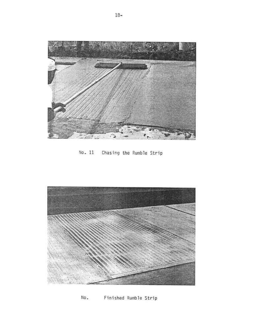
No.11 -Chasing the Rumble Strip. 18
No.12 -Finished Rumble Strip. 18
20No.13 -Install Drainage Ditches
20No. 14 -Prevent Water Damage.
21No.15 -Intrusive Grass.
No.16 -Paver Pushing Back Berm. 21

INTRODUCTION
Many shoulders along portland cement concrete interstate highways
exhibit various signs of distress long before overlayment of the main-
line pavement becomes necessary
An ideal candidate for a shoulder rehabilitation project was
New Jersey's 1-78 near Pluckemin where severe alligatoring of some
areas of the shoulders and continuous faulting at the juncture with
the mainline pavement had progressed beyond the repair capabilities
of normal maintenance operations.
Several methods were advanced for correcting the various types
of distress. It was expected that field application of these methods
on a contract project would provide information on construction costs,
maintenance cost factors as well as generating methods of construction
for guidelines on future projects. These methods incorporated recycling
the bituminous concrete shoulder pavement and stabilizing the under-
lying quarry processed stone base by the addition of cement and waste
mineral fly ash.
PROJECT DESCRIPTION
Route 1-78, Section 3F and 3G was constructed in 1964 as a four
lane divided highway. The mainline pavement consists of 9" thick
reinforced portland cement concrete lanes, 121 wide with 3/4" expansion

-2-
joints spaced at 78'2". The 121 wide outside shoulders consisted of
7" of quarry processed stone base topped with a 2" surface course of
fine aggregate bituminous concrete (FABC).
In 1977 a condition survey was made by personnel of the Bureau
of Geotechnical Engineering and the Bureau of Transportation Structures
Research. During the survey it became obvious that portions of both
the eastbound and westbound shoulders had become severely deteriorated
due to their use as a truck stop rather than for emergency stopping.
Until trucks were somehow kept off the shoulder by either increased
police enforcement, additional signing or the building of rest areas,
the problem would persist unless a stronger pavement section was
provided
Research personnel proposed a stronger section by milling and
hot mix recycling the bituminous surface course and stabilization of
the base course with cement and/or lime-fly ash additions. They
also suggested a 4" recycled bituminous mat for use on a non-stabilized
base section. Geotechnical Engineering included a shoulder section
of eight inch thick plain portland cement concrete tied to the existing
outside portland cement concrete travel lane.
Many miles of the shoulders were in good condition except for
faulting. In those areas, the shoulder was strengthened by placing
The eastbounda 25" wide inlay adjacent to the mainline pavement.
inlay consisted of a 7" layer of plant-mix lime-fly ash (LFA) placed
to the bottom of the 9" concrete mainline slab and topped with a 2"
The westbound shoulder received a 25"lift of bituminous concrete.
wide, 4" thick bituminous inlay. The repaired shoulders were then slurry
The aforementioned sections are shown in detail in Figure 1.sealed.

-3-
E.B. W.B
Slurry seal
WedQe course II cled
~ B C -~ I.':.~..:~!;-.:;.:~::~:::l e~} s t! n9 .;::..:'~:'~;::~~:.::..:i "7 " ~.A .&. ,4:... 9 reinforced c.. : ." 5 5A) I'. .-~ o concrete .'c.. ..
STA. 415+50 to 220+75STA. 170+00 to 216+00
8 Plain concrete ::;.~':.::::.':;~:;:;;
-.;::;;:;::..:0:';~;I I 3 " , ,.'0':""~
STA.220+00 to 305+00 STA.627+07 to 419 + 60214 +55 to 170+00
2 Recvcled I- 4 :,;::.;:;:.~~::-" ...; :~c.:;:,:"~';..:;::~
7 mixed In place LFA ::?'::':Ii!.:,'.:..
STA. 305+00 to 3581-00special mix '357+00 to '358+00
THE CONTRACT PROVIDED FOREITHER NEW OR RECYCLEDMATERIAL TO BE PLACED IN THEINLAY SECTIONS.
.
2.. Recycled I- 4
7"mixed in Dlace sail cement
STA. 358...00 to 414+00
FIGURE

-4
PRECONSTRUCTION TESTING AND DESIGN
Bituminous Pavement
Six samples were taken of the bituminous shoulder pavement
reclaimed asphalt pavement, RAP) throughout the milled area. The
recovery results showed the asphalt cement to be quite hard. The
penetration at 77oF ranged from 13 to 24 and averaged 18.83 dmm
The viscosity at 140oF ranged from 31,441 to 83,857 and averaged
47,379 poises.
Samples of the recovered asphalt having penetrations of 16,
17, and 18 and viscosities at 140oF of 36,913,55,230, and 45,379
poises were mixed with two new asphalt cements. The first samples
mixed with an AC-20 having a penetration (pen} of 81 at ratios
of 50/50 and 30/70 recovered to new asphalt. The penetrations were
increased to 34 and 49 respectively. The viscosities decreased to
10,448 and 4,849 respectively. The third sample was mixed with a
hot-mix recycling agent, HMA 2.5, at a 50/50 ratio which increased
the penetration to 56 and reduced the viscosity to 2,805 poises
Further laboratory work with an AC-20 with a 98 pen yielded recovered
penetrations of 44 and 57 respectively, for ratios of 50/50 and
30/70 reclaimed asphalt to new asphalt.
Job mix formulas were developed for the utilization of 30%,
and 50% RAP employing a modified AC-20 having a penetration of
109 @ 77° Fahrenheit (see Appendix A).

-5-
Base Stabilization
Soil Cement -The contractor presented the Department with the
results of his testing of the SA base material (see Appendix B) stabilized
with 4% and 7% additions of Type II cement. The NJDOT prepared mixes
at additive percentages of 4, 5,6, and 7% of Type I cement yielding
strengths of 890 to 1,260 psi (see Appendix B). The decision was made
to use a 5% cement addition which would give a seven day strength of
approximately 910 psi. The lesser strength was selected on the theory
that more but smaller shrinkage cracks may form, lessening theikelihood
of their reflecting through the bituminous overlay. Cylinders made of
the eventual field mixed material were humidity cured at lOOoF for 7~
28, and 45 days. The unconfined compressive strengths of these samples
were 486, 700, and 744 psi respectively. The lower strengths obtained
in the field are indicative of the variability inherent in stabilization
under field conditions as opposed to plant mixing.
Lime-Fly Ash - The lime-fly ash admixture composition conformed
to NJDOT's standard specification (see Appendix D). The old Type 5
Class A base material, however, differed slightly in gradation with
100% passing the 2" screen (see Appendix B) rather than the 11/2"
screen as in the present $pecification. The percentages of ime-fly
ash, aggregate and water which produced the greatest density were chosen
as the mix design properties. Test cylinders from the eventual field
mixed and plant mixed materials were prepared. The field mixed compression
test cylinders were humidity cured for 7, 14,28, 105, and 120 days and

-6-
the plant mixed materia for 7, 28, and 45 days. Unconfined compressive
strength values were 375,700,923, 1370, and 1435 psi for the field mix
specimens, and 763, 1850, 1743 psi respectively for the plant mixed
material (see Appendix C). These latter values again indicate the
relative lack of control occurring with a field-mixed operation
METHODS OF CONSTRUCTION
The project started with the milling of the eastbound bituminous
surface on May 13,1981 and finished with the slurry seal application of
the westbound shoulder on October 29, 1981. A key sheet showing the
exact location is shown in Appendix E.
Milling
The 2" bituminous surface course was milled from both the eastbound
and westbound shoulder for recycling feedstock (RAP) in those areas where
stabilization and the 4" surface course replacements were to be
placed. On start up, the machine was making a single pass at approximately
fifty feet per minute. The bituminous pavement was coming up in chunks
than desired and also contained a small amount of the base material.
Approximately 50% of the material passed the 2" screen. The forward speed
slowed to 30 feet per minute and the amount of oversized was reduced
to approximately 25%. Alligatored pavement tends to come up in the same
size as the pattern in situ. It was decided to change the depth of cut
1/2" in an effort to reduce the oversize as well as eliminate the

-7-
pick up of the stone base. This system worked very we at forward
speeds of 35 to 40 feet per minute with little or no pick up of the
stone base and approximately 90% of the material passing the 2" screen.
The second pass with the milling machine removed the residual bituminous
pavement and was not used for recycling.
Lime-Fly Ash Stabilization
Previous laboratory trials showed that a 3.5% lime and 12% fly
ash addition to the stone base would require removal of 11/2" of the SA
stone base leaving a 51/2" thickness to be stabilized. This blend of
lime-fly ash, when applied to the stone at a rate of 100 #/sq. yd.*,
wetted, mixed with a Bomag machine (rotor tiller) and rolled, gave the
desired 7" thickness of stabilized base. The moistened ime-flyash
blended material was first placed by tailgate dumping from tandem trailers.
The material was then fine spread by grader to the desired coverage of
lOO#/sq. yd., on the stone base. Unfortunately, the addition of the
water at the plant during loading was not uniformly distributed through
Six truckloads were placedthe load of LFA mixture to prevent dusting.
using this method.
During the following week, 12 tanker loads of the dry blended
lime-fly ash were placed by pneumatic unloading as the truck traversed a
measured distance. This and the previous method produced clouds of dust
(see photos 1 and 2) that were considered hazardous to drivers and
workers. A third method was to remove approximately 200# per square yard
*This quantity of lime-fly ash amounted to a 23/4" thickness of deposited
material.

-8-
No. 1 -rail Gate Unloading of Lime-Fly Ash
No.2 -Pneumatic Placement of Lime-Fly Ash

-9-
of the stone base, return it to the plant and add the entire lOO#/sq. yd
of blended lime-fly ash and water to produce an extremely enriched
plant mix. This material was then transported and placed by tailgating
the material, graded out and mixed with the stone base as previously
described. There was absolutely no dusting (see photos 3 and 4 This
method is the only one that would be recommended for any future mixed-in
place project along a trafficked highway or adjacent to a residential area.
Another problem addressed was mixing with the Bomag machine.
The bearing housing on this piece of equipment protrudes about six inches
out from the drum and prevents the machine from mixing close to the concrete
slab. This necessitates casting the unmixed ,aggregate and lime-fly ash
by grader atop the adjacent mixed" material and mixing by two passes of
the Bomag machine. The material was then bladed into the excavated area
by the grader. Moisture content was checked after the second pass
if necessary, water was added through the Bomag machine as additional
passes were made. Water is supplied to the Bomag machine bya tanker.
A pump on the Bomag is adjusted to deliver the quantity of water
needed as determined from a chart which takes into account the forward
speed, the depth to be tilled and the moisture needed. The stabilized
base was then rolled, fine graded and rerolled
Soil Cement Stabilization
The cement stabilization was performed in the same manner as the
lime-flyash. It differed only in the amount to be excavated (less than
1/2") due to the smaller quantity and volume of the cementt 31 lbs

-11-
square yard. The pneumatic placement of the cement caused dusting
almost as severe as the lime-fly ash and both would present problems
with EPA and OSHA (see photo 5). Since cement is a hydraulic setting
materialt there is no way of premoistening or using the enriched plant
To alleviatemix method if the project is any distance from the plant.
these problems it would be best to bring a portable plant to the job
site and mix the fu thickness of the base material with the cement
and place it as a plant mix material.
Shoulder Inlays
Excavation and Stabilization -Faulting of the shoulder adjacent
to the mainline pavement was to be corrected through the placement of
an inlay of new materials to bring the shoulder to the height of the
The eastbound inlay was a 25\1 wide, 7\1 deep section of plantpavement.
The westbound inlay was a 25"mix lime-fly ash topped with 2" of 1-4.
wide medium aggregate bituminous concrete (!-4 mix) inlay 4" deep (see
Appendix D).
The contract called for longitudinal saw cutting of the bituminous
After 2700 feet of saw cutting had been completed,shoulder pavement.
the resident engineer permitted cutting with a hardened wheel mounted
First of all,This method leaves alot to be desired.on a grader.
the cut is not as straight as that achieved by saw cutting. In the
vicinity of milepost 25 the width of the FABC cut for excavation varied
from 25-3/4" to 22-1/2" to 27-1/4" in a 251 length. Furthermore, the
damage is compounded when the operator tries to correct his errors
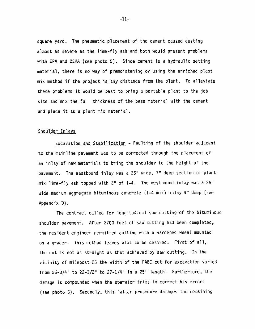
Secondly, this latter procedure damages the remaining(see photo 6).

-12-
No.5 -Pneumatic Placement of Cement
No.6 -Cutting by Wheel on Grader

-13-
The pressure exerted on the wheel caused some new longitudinalpavement.
as opening up some of the hairline cracks to 3/8 of ancracking as wel
(see photos 7 and 8). Thirdly, the depth of cut varied due to the
long wheelbase of the grader which cannot follow the undulation of the
pavement surface. Since the cut wasn't entirely through the pavement
there was a tendency to lift the residual mat off the stone base during
A good operator on the grader coupled withthe excavation operation.
prudent inspection could alleviate some of the aforementioned problems,
however, sawing appears to be the preferable method.
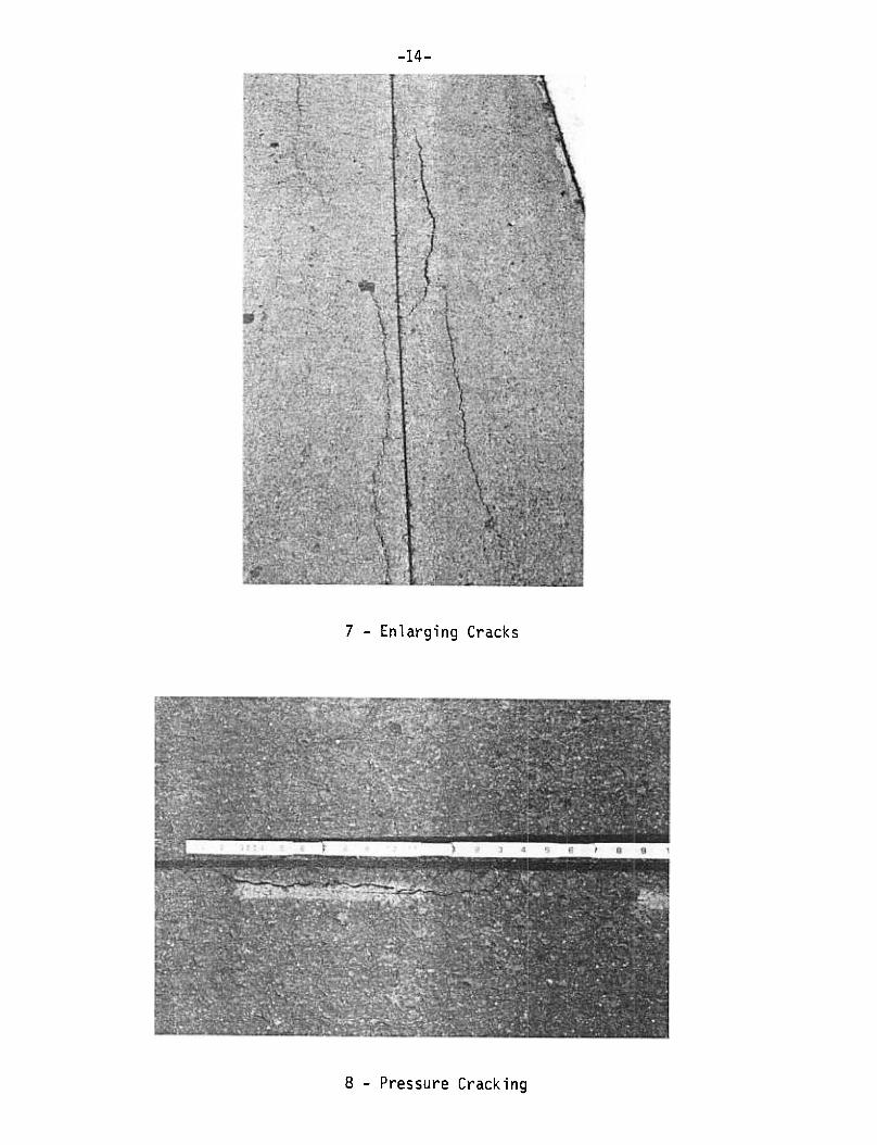
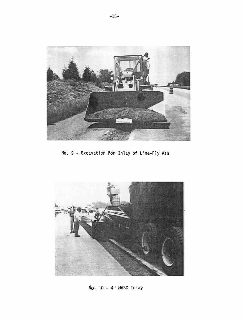
The excavation of the sawn bituminous and base materials was
A fixturemethod devised by the contractor.accomplished by a nove
welded inside the bucket of a front-end loader and a plate with
an inclined plane was inserted and locked in place (see photo 9
simple arrangement permitted the excavation and loading of the
truck in a single operation
The trench was filled with plant mix lime-fly ash by paver
with a strike-off extension adjusted to the width of the trench
Compaction was with the right wheel of a three-wheeled rolle.r, the
left rear wheel and front drum remaining on the mainline pavement.
This caused differential compaction due to the cant of the roller
The roller was then moved onto the shoulder and the left rear wheel
The cross slope compensated for the 2" depth offor compaction.
the base material keeping the roller on an even plane and giving excel-
The material compacted when the roller was on thelent compaction.
-14-
7- Enlarging Cracks
8- Pressure Cracking
-15-
No.9 -Excavation for Inlay of Lime-Fly Ash
No.10 -411 MABC Inl ay

-16-
pavement, subsided an additiona 111-1~" against the mainline pavement
when rerolled with the roller placed on the shoulder. This method of
compaction, however, had to be discontinued be:ause the inside edge of
the right whee started to cut into the shoulder pavement due to the
The balance of the project was tamped withheat of the noonday sun.
The best method for future work would be to specifya plate compactor.
a trench roller.
Bituminous Sections -All of the bituminous mix used in the
inlay work, both the 2" eastbound and 411 westbound was constructed
with virgin MABC top course material (Mix 1-4) placed with a paving
machine with a strike-off extension (see photo 10). Virgin material was
used since the daily tonnage was too small to justify a recycled mix
New Shoulder Pavement
Portland Cement Concrete -In the area to receive a portland
cement concrete shouldert the existing bituminous concrete pavement
One inch of 1-3 soil aggregate (seeand stone base was excavated.
Appendix D) was placed on the subbase as a leveling and fill-er course
for the 8" plain concrete shoulder. Deformed 5/8" bars were used to
The bars were 1511 long ,tie the shoulder to the mainline pavement.
411 of which was grouted in 1-1/4" diameter holes drilled horizontally
Some of thethe mainline slabs at mid-depth. Spacing was 30".
slabs had the tie bars inserted within 6" of the expansion joints.
Because of interference with the mainline pavement dowels, this was

-17-
changed to keep the bar at a minimum of 12" from the joint.Type A
mainline pavement.
3/4" bituminous impregnated fiber joint filler 7" high.A 1" finishing
to Federal Specification SS-r-405. Four contraction joints were
equally spaced at 15.631 within the 781-2" slabs.A 61 corrugated
rumble strip was formed 51 from each Type A joint.The corrugations
mainline pavement and running out to the shoulder pavement edge to
avoid water entrapment.
shovelfulsIn forming the rumble strip, severa
11 and 12
Bituminous CQD-crete~ -Approximately 7100 tons of recycled -4
on the east and westbound lanes. The thickness on the lime-fly ash
and soil cement was designed for a 2" overlay, whereas the westbound
lane was designed for a single 4" lift over the in-place stone base
sections.

-19-
had been retrofit for recycling. Although the origina specifications
called for a 50/50 salvaged to new materia ratio, the plant was
permitted to start up at a 30/70 ratio to ascertain the effect on the
plant baghouse and on the air quality at the plant site. After producing
1823 tons, the ratio was changed to 40/60 for the remaining 5250 tons.
No problem was encountered in the hot mix recycling efforts.
It should be pointed out that the plant was paid on the basis
of a 50/50 mixture and that any additional cost for virgin materials
was bo~ne by the producer. During and after placement of the mix
several noteworthy observations were made. 1 Drainage ditches should
be installed (especially in cuts to prevent water from permeating the
base or flowing along the newly pl.aced pavement (see photos 13 and 14)
2) The berm should be graded back at least one foot from the pavement
edge. This would prevent grass and soil from being imbedded in the mix
by the paver (see photos 15 and 16). 3) The riding quality on the west-
bound shoulder is not as good as the eastbound. It would be preferable
to place two 2" lifts rather than a single 4" lift. 4) The Dituminous
mat can and should be placed over the lime-fly ash stabilized base as
soon as convenient. This would eliminate the necessity of a 'contractor
having to water cure over a weekend, prevent damage due to inclement
weather and surface contamination due to traffic. Furthermore, it can
be a safety factor against dropping off the pavement as wel as reducing
the possibility of collision with the safety protective equipment.
A bituminous core survey of the 4" westbound shoulder showed an
average thickness of 4.72". The air voids ranged from 2.1 to 5.6%, the

-20-
No. 13- Install Drainage Ditches
No. 14- Prevent Water Damage


-22-
average being 3.45%.
from 3.1 to 7.9%, the average being 5.96%. The average thickness over
the lime-fly ash was 2.46"; the average thickness over the soil cement
was 3.38".
base rather than the 1/2" to accommodate the lesser weight of 31 lbs./
sq. yds. of cement versus 100 lbs./sq. yd. ofime-flyash
t'!ed ge Course
A section of the shoulder from Station 170+0 to 215+90 was
scheduled to be replaced with concrete. The shoulder was in good condi-
tion except for minor faulting. It was decided to correct the faulting
via a wedge course and a slurry seal applied over the entire shoulder.
The wedge was variable in width running from 18" to 36".An 1-6 mix
(see Appendix D) was selected for its ability to be feathered out.
The tack material was an RC-70. Because of undulation of the shoulder
pavement, the tack coat and bituminous mix were hand placed to meet
the desired grade and cross slope. A slurry seal was then applied.
This construction change saved approximately $190,000.
SLURRY SEAL
A Type II slurry seal was placed in a single pass.Prior to
application, the pavement was broomed and cracks cleaned of intrusive
grass and other debris. A light spray of water was applied to the
pavement surface directly preceding the spreader. The average rate

-23-
or percentage of material deposited was 15.5% CCS-1H cationic emulsified
asphalt, 12 lbs. of washed traprock per square yard, and 1% portland
filler.cement as the m;nera
COSTS
The following table gives the cost of the various test sections
based on the unit bid prices in-place, including any ancillary costs
such as excavation, saw cutting, asphalt prime coat, tack coat,
surface course, and slurry seal.
Dollars
Per Sq. Yard Per Linear Foot
44.8033.60Concrete
Lime-Fly Ash and
2" Recycled 1-420.7115.53
1 Cement and
2" Recycled
Soi 12.53-4
13.7910.341-4,4" Thick
19.641nlay-7" LFA
2" 1-4 and Slurry Seal
15.531nlay-4" 1-4
and Slurry Seal
.883Wedge Course*and Slurry Seal
*Not to be considered in the study since would only be used in specific
applications.

-24-
CONCLUSIONS AND RECOMMENDATIONS
1. The pneumatic placement of cement and lime-fly ash for
shoulder stabilization should not be considered on future projects
2. Lime-fly ash aggregate base mixed in a central plant can be
effectively placed through a conventiona paver.
3. The enriched mixed method for the placement of lime-fly ash
should be used for in-place base stabilization (see page 7).
4. A trench roller should be used for compaction on narrow
inlays too small for a conventional roller
In the placement of bituminous materia5. on a shoulder, the
berm should be cleared for at least one foot beyond the edge of the
shoulder.
6. Drainage ditches should be installed, cleared, or reshaped
prior to shoulder rehabilitation to prevent water from infiltrating
the stone or flowing along the newly stabilized base
A bituminous surface course should be placed on a lime-fly7.
ash stabilized base as soon as possible to prevent damage from traffic
reduce the danger of pavement dropoff and collision with safety
protective equipment.
8. If riding quality is a factor in shoulder resurfacingt two
2" lifts are preferable to a single 4" lift
-789. The experimental shoulder sections established on Route
should be monitored for four years to establish cost/performance factors
for each of the trial rehabilitation strategies


-25- APPENDIX A
NEW JERSEY DEPARTMENT OF TRANSPORTATION
BITUMINOUS CONCRETE MIX DESIGN
Fonn LB-83 S/8D
DATE May 28,1981
-181630Z
PROJECT Route 78 Section 3K & 4T I-Ir-78-0(3)2ZJOBCODE 1816303
PRODUCER~;et Asphalt PLANT LOCATION Watchun2. NJ
CONTRACTOR Whitmever Brothers ADDRESS P.O.Box 617-Hanunonton. NJ 08037
JOB MIX FORMULA
(Total percent passing each sieve)
SIEVE
SIZE
I Mix No.
Formul~
I Mix Ha. 14 .30% ReCvc .
I F~rmula , Average af 5
I Mix No. I~-40% ReCyc. i
1 Form-~la I Average of 5
Mix N°.I4 50% Recvc.
I Formulo I Averoge of 5 I Average of 5
I RANGE1-2"
~1~ 1"
31."~
, 8,1
: 75
I ~?
35.5-43.5
I 100
I q8
R~~~
~
~"- ---
~ 3/8"
It 8
It 16
L 40.0 .
~
I 13 -
I # :SI)1--- -
-16.5 13.5-19.5 14.0-20.0 16.0-22.0
5.3 I 3.9-6.7 5.4 I 4.0-6.8 6.3 4.9-7.7 ~8
1#50
~ 100 # 200
* ASPH.
CONT. 5.00 4.55-5.~ 5.00 4.55-5.45 5.00 4.55-5.45 1.5* PERCENT ASPHALT CEMENT BASED ON THE TOTAL WEIGHT OF MIXTURE.
Mix temperature at plant must exceed lay-dawn temperature by at least 10 if
ambient temperature is ar abave. If ambient temperature is ar lawer,
mix temperature must exceed lay-dawn temperature by at least 150. Mix tempo
ature must not exceed 325°.
J. Smith NJDOT
Verification
Plug-LabDATE APPROVED: 5-26-81 SERIAL HO.: N/A
OH FILE WITH THE H.J.D.O. T.
MIX DESIGNED BY:
AMENDED BY JOB MIX FORMULA CHANGE DATED
RECYCLED ASPHALT MATERIALS
DRYER DRUM PLANT
This design for 2" thickness
DISTRIBUTION
IBureau of Inspection
Bureau of Q,atity Contra
Regional Construction Engineer
Bituminous Laboratory
Core Dri II Group
Residnet Engineer
Contractor
SupplierRegional Materials Office (2)
J. Smith-LabSigned

-26-
BIN PULLS
MIX HO.~.
N/AI I'
~
Bin No. S
Bin No.4 Rec k 29.l
Bin No. 3 -24.~ I
Bin No. 2 23-2 I
Bin No. 1 -" 19.:
Filler I.
Asph. ContentMoximum Theoreticol Specific Grovity: 2.595 -
Approximote Cold Feed Proportions: c
APPRARENT
Specific GravityPERCENT COMPONENTS PRODUCER AND LOCATIONMI X NO. -!!Q!- I
I din No.5
I R~('~~l~ M,qrp,.i,ql I
Fant.TQQd ~nl~hpi! ~rn"~-T.7,qr ,.h,," 9II II
l..in...o.ISanrl !I Filler . C' aytnn ~J=lnr'i-T,J=Ikt:.TJnnt'l, M-T * I14.6
--2.8 i W'~!;t:R~nk Oi1 10Q ppn- I
Maximum Thearetic:al Specific Gravity:
Approximate Cold Feed Proportions~
MIX NO.--2m; PER CENT
~
, ;~~~~~~~~~~:~ ~t-n"c-TJ.!2t-,..h,,"a II I Fan~~nd Cnl~hpn ~f"nnp-TN~~/"h11ngBin No.3
Bin No.2 ~
Bin No.1
Filler
~- I Cl~y~nn ~~nt'!-T.~t.."TJnnr1 , NT * i
~ximumTheoretical Specific GravityApproximate Cold Feed Proportions .
APPARENT
Specific GroyityPRODUCER AND LOCATIONCOMPONENTSPERCENTMIX NO
Bin No.5
Bin No.4
Bin No.3
Bin No.2
Bin No.1IFiller -.1I Asph. Content -
Maximum Theoretical Specific Gravity
.A.pproximote Cold f:eed Proportions:
REMARKS, -
* Supplier has the option to use screenings
mixture should they desire. (as per J.controlo£
JUN 31981RECYCLE ASPHALT -2 II ATw~K~ Thickness
tJ ~P,. ~ f1A1t)i'OJJAf-DRYER DRUM PLANT

-27-
~E". JERSEY DEPARTME~T OF TRA~SPORTATIO~
BITUMINOUS CONCRETE MIX OESIGN
Fonn LB.83 S/SO
DATE May 282 1981
1816302
JOB CODE 1816303PROJECT
PRODUCER Uniset AsphaltPLAHT LOCATION W~rC'htt"g. N.T
CONTRACTOR D11it~ever BrotherSAOORESS P.O. Box 617-Hammonton. NJ 98037
JOB MIX FORMULA
(Total percent passing each sieve)
Mix No.SIEVE Mix No:r4 JO% Re~~.
! ormula I Averag~ of 5
~ ~n~ Rp~~('-1
Average 01 5
Mix No. T~ SOZ FeC¥c .1
F~mula I Average afS I
Mix No. Ti
Forrnulo FormulaAverageO~SIZE
I 2..
98
~~
=~35-65
360-44-0
# 4
# 8
# 16~~ 30 #so
# 100
# 200
13 l
.R.C;
77
C;L..
40.0
1~-~1 1?"-1~~ I If\n 11~ n-1Qn I lZO 1140-20-0
I 3.5-6.3
~
4-.0, I
.ASPH.
CONT. 5.00 I 4.55-5.45 I 5.00 14.~J-5.u5 I 5.00 14.55-5.45 .
.PERCENT ASPHALT CEMENT BASED ON THE TOTAL WEIGHT OF MIXTURE.
Mix temperature at plont must exceed loy-down temperature by at least 10 if
ombient temperature is or obove. If ambient temperature is or lower,
mix temperature must exceed lay-down temperoture by at least 15°. Mix temp.
ature "'USt not exceed 325° .
Verification
Plu9-LabDATE APPROVED: 5-26-81 SERIAL NO
OH FILE WITH THE H.J.D.O. T.
J. Smith NJJ)~ N.AMIX DESIGNED BY: -
AMENDED BY JOB MIX FORMULA CHANGE DATED
DISTRIBUTION
Bureou of Inspection
/Bureou of ~ol ity Contro
Regionol Construction Engineer
Bituminous Loborotory
Core Dri II Group
Re5idnet Engineer
Controctor
Supplier
Re9ionol Moterials Office (2)
J. Smith-Lab
RECYCLED ASP"t:I...ALT MATERI.A.LSThis design for 411 thickness .
*Milling Contains Type 5 Class A coarse aggregatewhich is in excess of 1" size .
DRYER DR~ PLANT
Sic;ned

MIX ~0.2!1L
I NLA
i ~~~~~~~ ~~~~~JStone-Watc.hung. NJj" II I
, .
24.
20. Clayton Sand-Lakewood. NJ * ,
I.. Reclaimed Fines~
$P .on e 3 West B Oi
~x-:;:: Theoretical Specific Gravity: ? -~Q~
Approximate Cold Feed Praportions:
APPRARENT
Specific GravityPER CENT COMPONENTS.. PRODUCER AND LOCATIONMI X HO. I~O%
I~N~.S --i N/A !
~
---
Bin No.2
Bin No. 1 Cl a~t:nn "'~nd-1 ~kPtJnnn , 111.1 *
Filler Rp('l ~;mpti "It';np~
Maximum Theoreticol Specific Grovity: 2.5q~
Approximote Cold Feed Proportions-~-
[ Asph. Conte;;~-
MIX HO.2.Q!
I Bin No.5
,I N/A~ !~~~inNO.4 4P.-I
BinNo.3 16.'.
Bin No.2I
~i~~o. 1 Sand 12-1
I FillerI r,~~t-'.'n ~~,.,r1-T~1r",T.7n'.'r1. NT * I
j Asph. Content. '--Q .A ~A~ TJest ~~tjk n;, 109 PQ~-~ximumTheoreticoISpecificGrovity: 2.595 .
Approximate Cold Feed Proportions. .
APPARENT
Specific GravityPRODUCER AND LOCATIONCOMPONENTSPER CENT
* Supplier has the option to use screenings Vith sand to maintain control
of mixture should they desire (as per J. Smith-NJDOT).
RECYCLE. ASPHALT -4" Thickness ~ ~FCE'\lE'O
()UALlr) COhr ,;DRYER DRUM PLANT .."- Rq ;
REMARKS: .
3 1981
..-' D~.t' '..0 (11 rRA!tSPON1~rlt»

-29- APPENDIX B
Form AD-4lJ Sn7 NEW JERSEY DEPART:\1F~'\:T OF TRA!\:SPORTAnO~
I MEMORANDUM I1 MCMU~A"UUM I FROMDon SessaTO Joe Smith
SUBJECT Rt. 78, Sec. 3K & 4TSoil Cement Recommendations
2-3471DATE 06-08-81 TELEPHONE NO.
Cement Content = 5% Type
Avg Max Density = 137 #/IFt3
Avg Optimum Mosture = 7.5%
Density Control:
Method = AASHTO T-99 Method C
95% of Avg Max Density = 130.2 #/Ft3
The maximum density, compressive strength and the optirnurn~,oisture content all vary depending upon the gradation ofthe SA subbase material. Unfortunately, the SA subbasematerial is also variable.
To assist you in.your field controi work, I have providedthe following information:
1.
2.
3.
4.
5.
SA Gradations.Graph of Compressive Strengths.Density Curve -No Cement.Density Curve -With Cement.Rate of A~plication.
0. AbbottF. StiaK. Afferton "
cc
/

PLANTLOCATION
SAMPLE TAKEN FROM
QUANTITY REPRESENTED REPORTED TO
-~~.~:.s~o~ -S~MPLE li i "FJ- ' A
SAMPLED BY /'1 ~--L.r
DATE TAKEN "
DATE RECtD. AT LAB.
~EAL NO.
12 PJ .2-4G 2- i
REQUIREDTOT A.L PERCENT p A.SSINC
Min.
4.'J1,,-(~-
Present
1-5 (SA) Specs.
100
~ ~ -&21
L-C' C) /D O
~ (0
r [pt, I ~..:5-"' 1/0 70 100
$3 I 4a.. I z I;"" i---r.;o1;:.)...:::- 30 80
..,
1?-..0.;,.;., 10 35
5 12KEFLECTA~CE I
LIQUID LIMIT i
REMARKS:


.501L Ce-I17EN! .::. C--",1l 1?'!' ?; I:::. '-r' o ~
\,." !P!"c,., !)erartment of Transrortation
LABORA TORY SOIL ANAL YSIS
KcSvJ.-'T ~-32-
., "."' LS.~;:: ,'oi 6 72MOISTURE- DENSITY RELATIONSHIP
/'ffj'/Seriol No. Dote T ested f»roducerl'tw 4 - Roule ,. -
" 4 -
Section -" -
AASHO 0' ASiM D~ ~notion -Method
REST RESULTS
T"al No. 1 2 3 74 s 6 8 9
~Water Ad.:ec
Weight of Cyi. & Soil gms.
..";;..,, ", cy,- gms.
Con Number {
Weigh. We. Soil & Con 9ms.
Weiahf Dr, S" ; I & Con Qm5.
We,~h. l",. q!!'~:--
Weiqht of Can gms.
Dry Den~iry p.c.f.
MOISTURE -DENSITY CURVE
i
l.2.:f::O
!-"
::tl~
I '! ; I I
!
-t-
~
I~/~,..7'-'
3
--rut ,~ , I I
I
: I
...I
-I ! i
I-+:
$ !-::;:!:G
!r --1
~i"--
!-/
t:?j
;1.6
4 10b 8
Moisture Content -% of Dry Weight
("L 14~ 4' ..-~ / dl: ".
Mox. Dry Density / 3 ~. ..s p.c.f. ' .., II C.' e-';.. "7 r
Optimum Moi sture ' .-;;, , ,
(':::>
".
c.
(.I
~
;C"
Q..
0

Serial Ha. / 7.8 I ~roducer
R 7 /~ -~ I -("~ , ., -3,, + ~4 -oute c ~- --4 H -
./,'~, 1--, -):J/"..:.:-::...I: ..-Sectlo" ,,£.-.c.-~.'-- ,-'T b ~.~ L'--' -,. 4 -
AASHO or AST. ~SI9"otion -Method C-7=- qt:';
~
Trio: No. 6 9
: Wo'er AQded ~ -
r~~~~I Wei9ht of Cyl. & Soil g-5.
'0; I I"'9"t o cy. gms.
Weigh' of Soil
Wet Density p.~'.,-, ;
,- ~.-~
~ I"
..." 0'-. -~"'c:1 j:=' ~E "':1.J:-..uz:1
Con Number
W~i9ht W~t Soil & C- g-$.
i \Oeioht Dry Scil & Con 0...5. i
J '.'.e:ch~ Loss !,rr5. l
Wei9n. of Con gms., We~fDry So;1 gm~-Ji-- ---
~
:; ~ ~-?Ot,p (.t.. 2.. ca ~ ~ ~
.-MOISTURE -DENSITY ~~~
i i I -
i i, 3d~( !1 ."*~~ ~ ~ , r::J
:'I i7~~y
i! ! iL....~:
;r-<,
.; '-.:.J ", .;.. "-:' " ,
I /'
,r
~-
ic.?;;
/---
~
1f- t b .b ~-'.;-~
:::J-
"'~:!: -~l~;.I~i 1""' -/ I, .r- .~,-"' ,,--1.!1
= ~I;,
i. "---
-r'/] 7 "' ~ .,'~ '- -
-1 ,~ .ll l , Ii .../ , f
-..4-, :::.-.1:::- /'.,
!-~,.
... -r~jc;!:::::::-- ,~-...'" -, i
"
I~i
-+-+
~~!U:::;i iL
I 1 :iI I
;2.~
I...
L~
j -,." -I
B Mo~ture Content - '1; of Dry Weight
" =-
Max. Dry Density-
Optimum Moisture

II-3~- ~,
-'..J
) .-"..:-,'...
,.-;.~;-~-j. ..:.-, --
c~"../-,.I.J
,0)
fi-.:-&
I -,-~ " ~ IJ'
f ' -.-,c::;' ~. -, .~: / ~
12.t, I.;..-
..:.J,
~ 3/CI
-
4- Ir
~
- / ,. ;- I --
r .I --t'" ,. -' , -" -~--,'.'---, ~ ---<,-,-,-.-1' -" -.;;-.,.I
.~---
FT3<1"-..1
r;;:" ? It''.. '..:?
.18;
~'-""
--!
I' --.:.: ~ .
"-.::!
1-7.:::- , I'(.S'"~)
/37 ~F73
,- .~~ , /") -:-'- , ,. "--iv' \. ...,e...k ,-,"'.:.-c ..
..., / -,1-." -: ~
-,
~
r.~v1..5. I
\ : ,1-..,-,CI:O
F"-'"'"~-.. : "7'-
f'?~:.~ct---
I.-,:{ /.
~ .
/1-F-.-"... .:-..;.
1
~ 1.4...:--I -
--~.
94 ;tr'
~
..:-'<>?r T; ...;:,) /
-
"--
..Si..;:y ~.,.,
...
I/" ( ~~..
~~
.-"), (
-."., -
""', . } ::
-'-' :
-.q FT "2-
-,
~
-~
t7
- , ; , ~;j' 1: (.r: ,. ;1.: ,--
~
44,..(..1~'.~IJ
\~;: :".
...,.,.f'
~,/"~ J
J .i I'.1( ~ ..~ I, ~~~r-

-35- APPENDIX C
NEW JERSEY DEPARDIL~T OF TRANSPORTATIONForm A;)-40 5/77
TO t~EMORANDUM OF RECORD -FROM Nichnl;1c p- Vitilln--
~@cn;n~ I='ng;n~~~.-
Transportation Research
SUBJECT Lime-Fly Ash and Soil-Cement:jtablilzatlon -~ DATE 8-21-81 TELEPHONE NO
,
1:he mix design for both types of stabilization. The proportions were based
of the mixtures
Method C with replacement for compaction of the moisture-density tests
(ASTM 0698). The percentages of ime-fly ash aggregate and water which
produced the greatest density were chosen as the mix design proportions.
them at specific temperature and for various times, and then'soaking the
Section 8.
The field and subsequent investigation included preparing unconfined
compression test cylinders from field mixed material recording field
-36-
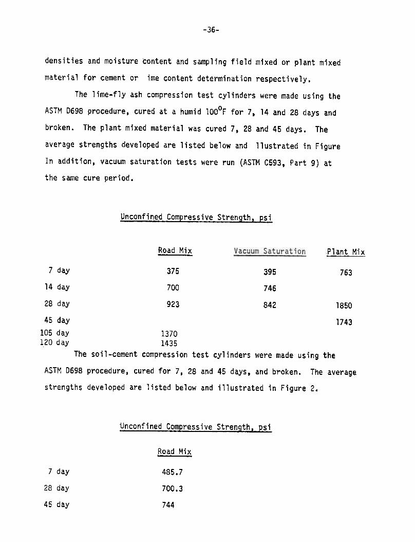
densities and moisture content and sampling field mixed or plant mixed
material for cement or ;me content determination respectively.
The lime-fly ash compression test cylinders were made using the
ASTM 0698 procedure, cured at a humid lOOoF for 7. 14 and 28 days and
broken. TheThe plant mixed material was cured 7, 28 and 45 days.
average strengths developed are listed below and llustrated in Figure
In addition, vacuum saturation tests were run (ASTM C593, Part 9) at
the same cure period.
Unconfined Compressive Strength. psi
Road Mix Plant Mix
7 day 375 395 763
14 day 700 746
28 day 923 842 1850
45 day
105 day
120 day
1743
1370
1435
The soil-cement compression test cylinders were made using the
ASTM 0698 procedure. cured for 7.28 and 45 days. and broken. The average
strengths developed are listed below and illustrated in Figure 2.
Unconfined Compressive Strength. psi
Road Mix.
7 day 485.7
28 day 700.3
45 day 744


-39-
In addition. Freeze-Thaw test (ASTM 0560) and Wet-Ory test (AS1}10559)
were run on soil-cement cylinders. The average weight loss for the Freeze-
Thaw test and Wet-Dry test was 7.17% and 5.5% respectively were 10% if
allowable
The field densities of the mixtures were estimated by using a
surface nuclear gauge in the 2" direct transmission mode. The lime-fly
ash had an average dry density of 123.35 pcf at a moisture content of 12%.
The soi1-cement had a density of 120 pcf at 16. (% moisture).
Samples of the mixed materia was brought to the Fernwood lab for
titration analysis (ASTM DBO6 Soi1-Cement and ASTM 3155 Lime-Fly Ash) to
determine the cement content of the soil-cement mixture and to determine
the lime content of the lime-fly.ash mixtures (road and plant mixed).
Confusion in communication at the lab caused neither of these tests
to be performed. The cement or lime content of the mixture therefore was
not determined. The lab did run a chemical analysis of the component
parts of the mixture. as well as. a chemical analysis of the mixture
but the results are too varied to be conclusive.
Cores were taken by removing an 8" core from the bituminous layer
and taking a 4" core from the lime-fly ash layer. The core taken from
the plant mixed material had a strength of 1406.9 psi after 36 days of
curing in the field. The cores taken from the road-mix materic hac ar;
average of 709 psi after 62 days of curing in the field
Th~The longest core had a length to diameter ratio of almost 2.
rupture angle was recorded along with the unconfined compressive strength
and the ~'ohr circle in Figure 3 was developed.


-41-
APPEr~DIX D~~~
~!egate Gradations
Slurry Seal Soil AggregateTop Course
Type II 1-31-4 I-h
(4") 100
60-100
100
95-100
75-95
65-85
35-65
25-50
18-40
12-30
10-23
100
85-100
65-90
45-75
30-55
18-35
10-21
5-15
100
80-100
65-100
40-80
20-65
7-40
5-20
4-16
30-70
1"
3/4
1/2
3/8
No.
No.
No.
No.
No.
No.
No.
AC
5-35
0-54-10
4.5-9.5
Slurry Specifications
Cationic CCS-1H
Washed Traprock
Portland Cement
Emulsion
Aggregate
Mineral Filler
Water
12% to 21%
M i n .10 1 b s ./ yd .
1%
As per design formula
Lime-Fly Ash Specification
1.
2.
3.
4.
Soil Aggregate 87.0~~ t 3%
Hydrated Lime 3.5% f 1%
Fly Ash 12.0% t 2%
The amount of \'later used in the mix shall be.within 2%
at the time of final mixing: During excessive hot
""eathej~ or long travelling distancest an excess may be
requested by the engineer.
4
8
16
30
50
loo
200

APPENDIX E
-42