construction specification for - ontario · construction specification for ... .02 operating manual...
TRANSCRIPT
ONTARIO PROVINCIAL STANDARD SPECIFICATION
METRICOPSS 935
MARCH 1998
CONSTRUCTION SPECIFICATION FOR CATHODIC PROTECTION
TABLE OF CONTENTS 935.01 SCOPE 935.02 REFERENCES 935.03 DEFINITIONS 935.04 SUBMISSION AND DESIGN REQUIREMENTS 935.04.01 Submissions 935.04.01.01 Working Drawings
.02 Operating Manual
.03 Full Enclosures 935.04.01.03.01 Return of Submissions 935.04.01.04 Corrosion Specialist
.05 Equipment for Arc Sprayed Zinc
.06 Supplier Certificate for Zinc Wire
.07 Plastic Spacer Mesh
.08 Anode Mesh and Distribution Bars
.09 Test Panels for Zinc Spray and Anode Overcoat
.10 Mixer and Spray Equipment for Anode Overcoat
.11 Test Results
.12 Notification of Suppliers
.13 Notification of Production 935.05 MATERIALS 935.05.01 Concrete Pad
.02 Cathodic Protection Equipment Assembly
.03 Extra Low Voltage Cables
.04 Grounding Materials
.05 Connectors
.06 Ducts and Fittings
.07 Junction Boxes
.08 Anodes, Pancake Type
.09 Anodes, Mesh Type
Page 1 Rev. Date: 03/1998 OPSS 935

935.05.09.01 General .02 Bridge Decks .03 Soffit and Substructure
935.05.10 Anodes, Zinc Type
.11 Zinc Brush Coating
.12 Distribution Bars 935.05.12.01 Anode Mesh System
.02 Zinc Spray System 935.05.12.02.01 Titanium
.02 Copper 935.05.13 Zinc Spray Protective Coating
.14 Anode Mesh Fasteners
.15 Spacer Mesh
.16 Voltage Probes and Reference Cells
.17 Thermocouple
.18 Cathode Connections
.19 Silicone Seal
.20 Heat Shrink Tubing
.21 Heat Shrink Tape
.22 Splice Kit
.23 Concrete for Blockout
.24 Overcoat
.25 Water
.26 Epoxy
.27 Thread Locking Compound 935.06 EQUIPMENT 935.06.01 AC Resistance Meter
.02 Multimeter
.03 Spray Equipment for Zinc
.04 Mixer and Spray Equipment for Anode Overcoat
.05 Air Compressor - Air Blasting
.06 Pressure Wash Equipment
.07 Holiday Detector
.08 Cover Meter
.09 Zinc Adhesion Gauge
.10 Zinc Thickness Gauge
.11 Concrete Saw 935.07 CONSTRUCTION 935.07.01 General 935.07.01.01 Work Content
.02 Sequence of Work
.03 Access
.04 Electrical
.05 Concrete Removal in Recesses and Cable Slots
.06 Abrasive Blast Cleaning
.07 Concrete
.08 Curing
Page 2 Rev. Date: 03/1998 OPSS 935

935.07.02 Cathode Connections 935.07.02.01 Installation 935.07.02.01.01 Scheduling
.02 Layout
.03 Preparation of Reinforcement and Recess
.04 Connection to Reinforcing Steel
.05 Cable Installation 935.07.02.02 Testing During Installation 935.07.03 Reference Cells 935.07.03.01 Installation 935.07.03.01.01 Scheduling
.02 Layout
.03 Preparation of Recess and Cell Placement
.04 Cable Installation
.05 Testing During Installation 935.07.04 Voltage Probes 935.07.04.01 Installation 935.07.04.01.01 Scheduling
.02 Layout
.03 Preparation of Recess and Voltage Probe Placement
.04 Cable Installation 935.07.04.02 Testing During Installation 935.07.05 Anodes, Pancake Type for Electrically Conductive Mix 935.07.05.01 Preparation of Anodes
.02 Installation 935.07.05.02.01 Scheduling
.02 Layout
.03 Preparation of Anode Recess and Anode Placement
.04 Cable Installation 935.07.05.02.05 Deck Preparation for Electrically Conductive Mix 935.07.05.03 Testing During Installation 935.07.06 Anodes, Mesh Type 935.07.06.01 Handling and Storing
.02 Installation
935.07.06.02.01 Scheduling .02 Isolation .03 Distribution Bars .04 Anode Mesh Placement
Page 3 Rev. Date: 03/1998 OPSS 935
935.07.06.03 Testing 935.07.06.03.01 Weld Between the Anode Mesh and Distribution Bars
.02 During Installation 935.07.07 Anode Overcoat 935.07.07.01 Scheduling
.02 Operational Constraints
.03 Test Panels - Anode Overcoat
.04 Test Cubes from Test Panels
.05 Installation
.06 Test Cubes from Anode Overcoat 935.07.08 Anodes, Zinc Spray Type 935.07.08.01 Full Enclosures
.02 Zinc Thickness Measurement
.03 Handling and Storing
.04 Operational Constraints
.05 Test Panels - Zinc Spray
.06 Installation - Zinc Spray Anode with Copper Distribution Bars 935.07.08.06.01 Scheduling
.02 Isolation
.03 Application of Zinc
.04 Distribution Bars 935.07.08.07 Installation-Zinc Spray Anode with Titanium Distribution Bars 935.07.08.07.01 Scheduling
.02 Isolation
.03 Distribution Bars
.04 Application of Zinc 935.07.08.08 Testing 935.07.08.08.01 Testing for Short Circuits During Zinc Spraying 935.07.08.08.02 Testing for Short Circuits in the Distribution Bars
.03 Testing for Adhesion
.04 Testing for Zinc Thickness 935.07.08.09 Zinc Usage
.10 Protective Coating 935.07.09 Rigid PVC Junction Boxes, Surface Mounted
Rigid Duct, Surface Mounted .10 Rigid PVC Junction Boxes, Embedded in Concrete
Rigid Duct, Embedded in Concrete .11 Rigid Ducts, Direct Buried .12 Extra Low Voltage Cables in Ducts and Junction Boxes .13 Installation of Cathodic Protection Equipment Assembly
Page 4 Rev. Date: 03/1998 OPSS 935

935.07.13.01 Concrete Pad and Ground Electrode .02 Installation of Cabinet .03 Grounding .04 Connection of Incoming Cables
935.07.14 Trial Operating Period 935.07.14.01 General
.02 Testing Prior to Energizing the System 935.07.14.02.01 Embedded Components
.02 Cathodic Protection Rectifier
.03 Cathodic Protection Remote Monitoring Unit 935.07.14.03 Testing During the Trial Operating Period 935.07.15 Remedial Work
.16 Management and Disposal of Excess Material
.17 As Built Drawings 935.08 QUALITY ASSURANCE 935.08.01 Anode Overcoat
.02 Anode Mesh
.03 Sprayed Zinc 935.08.03.01 Surface Appearance
.02 Adhesion of Zinc
.03 Zinc Thickness 935.08.04 Control and Monitoring Equipment 935.08.05 Acceptance and Rejection 935.09 MEASUREMENT FOR PAYMENT 935.09.01 Actual Measurement 935.09.01.01 Cathode Connections
Reference Cells Voltage Probes Anodes, Pancake Type
.02 Anodes, Mesh Type Anodes, Zinc Type Anodes, Overcoat
Page 5 Rev. Date: 03/1998 OPSS 935

935.10 BASIS OF PAYMENT 935.10.01 Cathode Connections - Item
Reference Cells - Item Voltage Probes - Item Anode, Overcoat - Item Rigid P.V.C. Junction Boxes, Surface Mounted for Cathodic Protection - Item Rigid Duct Surface Mounted for Cathodic Protection - Item Rigid P.V.C. Junction Boxes Embedded in Concrete for Cathodic Protection - Item Rigid Duct Embedded in Concrete for Cathodic Protection - Item Rigid Ducts, Direct Buried for Cathodic Protection - Item Extra Low Voltage Cables for Cathodic Protection - Item Installation of Cathode Protection Equipment Assembly - Item Acceptance Testing - Item
935.10.02 Anodes, Mesh Type - Item
Anodes, Zinc Type - Item Anodes, Pancake Type - Item
935.01 SCOPE This specification covers the requirements for the rehabilitation of structure decks and substructures by means of the following cathodic protection systems: Electrically Conductive Mix - Decks Anode Mesh - Decks and Substructures Arc Sprayed Zinc - Substructures 935.02 REFERENCES This specification refers to the following standards, specifications or publications: Ontario Provincial Standards Specifications, General: OPSS 180 Management and Disposal of Excess Material Ontario Provincial Standards Specifications, Construction: OPSS 601 Electrical Work - General OPSS 603 The Installation of Ducts OPSS 604 Cable Installation OPSS 609 Grounding OPSS 616 Footings and Pads for Electrical Equipment OPSS 913 Embedded Work in Structures for Electrical Systems OPSS 928 Structure Rehabilitation - Concrete Removal OPSS 929 Abrasive Blast Cleaning - Concrete Construction OPSS 930 Structure Rehabilitation - Concrete Patches and Overlays
Page 6 Rev. Date: 03/1998 OPSS 935

Ontario Provincial Standards Specifications, Material: OPSS 1302 Water OPSS 1350 Concrete - Materials and Production OPSS 2410 Extra Low Voltage Cables OPSS 2320 Cathodic Protection Terminal Block Assembly OPSS 2321 Cathodic Protection Cabinet OPSS 2322 Cathodic Protection Equipment Assembly OPSS 2323 Cathodic Protection AC Power Distribution Assembly OPSS 2324 Cathodic Protection Remote Monitoring and Control Unit OPSS 2325 Cathodic Protection Rectifier Canadian Standards Association Standards: CSA A23.1/A23.2-94 - Concrete Materials and Methods of Construction/Methods of Test for Concrete CSA C22.2 No. 38-95 - Thermoset Insulated Wires and Cables CSA C22.2 No. 56-1977(R1992) - Flexible Metal Conduit and Liquid Tight Flexible Metal Conduit CSA C22.2 No. 65-93 - Wire Connectors CAN/CSA C22.2 No. 85-M89 - Rigid PVC Boxes and Fittings CSA C57-1966 (R1994) - Electrical Power Connectors for Use in Overhead Line Conductors American Standards for Testing and Materials Standards: ASTM A 518M-92 - Corrosion-Resistant High-Silicon Iron Castings ASTM B 265-95 - Titanium and Titanium Alloy Strip, Sheet and Plate ASTM D 285-83 (1993) - Test Method for Indicating Oil or Water in Compressed Air ASTM D 541-93 - Test Method for Pull-Off Strength of Coatings Using Portable Adhesion-Testers Others: NACE - National Association of Corrosion Engineers 935.03 DEFINITIONS Cathode Connection: means a cable connection of the following two types, made to reinforcing bars: a. CS: a current carrying cathode connection that is connected to the negative terminal of the rectifier. b. CM: a non-current carrying cathode connection that is used to monitor the potential of the reinforcing
steel with respect to a reference cell. Certified Technologist: means a member of the Ontario Association of Certified Engineering Technicians and Technologists.
Page 7 Rev. Date: 03/1998 OPSS 935

Corrosion Specialist: means an individual having: 1. A minimum of five years experience in cathodic protection of reinforced concrete structures and 2. One or more of the following qualifications:
a. Is a NACE accredited corrosion specialist b. Is a NACE accredited cathodic protection specialist c. Is an Engineer d. Is a certified technologist
Distribution Bar: means a component of the anode that distributes current from the power feed point. Instant Off Potential: means the potential reading taken immediately after the current flowing to the system has been interrupted. RMU: means Remote Monitoring Unit. Stamped: means the drawings have been stamped with the note "Reviewed, Permission to Construct Granted". Subzone: means the division of a concrete component into areas where the anode in an area is not continuous with the anode in the adjacent area. Zone: means an area of a concrete component, energized by one rectifier unit, consisting of one or more subzones. 935.04 SUBMISSION AND DESIGN REQUIREMENTS 935.04.01 Submissions 935.04.01.01 Working Drawings At least eight weeks prior to commencement of the work five copies of working drawings, obtained from the supplier of the cathodic protection equipment assembly, for each of the following pieces of equipment, shall be submitted to the Contract Administrator: a. The Cathodic Protection Remote Monitoring Unit b. The Cathodic Protection Rectifier c. The Cathodic Protection Cabinet d. The Cathodic Protection AC Power Distribution Assembly e. The Cathodic Protection Terminal Block Assembly f. The Cathodic Protection Equipment Assembly The working drawings shall include the information specified in the applicable OPS Specifications. The working drawings will be returned within 21 calendar days of submission. 935.04.01.02 Operating Manual Prior to commencement of work an operating manual for the system shall be submitted to the Contract Administrator.
Page 8 Rev. Date: 03/1998 OPSS 935

935.04.01.03 Full Enclosures One week prior to installation of the enclosures the details of the enclosures to be used shall be submitted to the Contract Administrator. 935.04.01.03.01 Return of Submissions Two copies will be returned as follows: a. Stamped with the wording "Permission to Construct".
In this case work can start on receipt. A copy of the drawings and enclosure details shall be available at the site prior to and during construction.
or
b. Stamped with the wording "Permission to Construct Approved As Noted".
In this case the drawings and enclosure details shall be updated as noted, shall have a stamp affixed signed by an Engineer stating the drawings have been revised according to the approved as noted comments. Work can start on receipt of these drawings by the Contractor. A copy of the drawings and enclosure details shall be available at the site prior to and during construction.
c. Showing only required changes.
In this case the submission shall be updated as required and the submission process repeated.
or d. The Contractor shall distribute the drawings to the appropriate component manufacturer. 935.04.01.04 Corrosion Specialist One week prior to commencement of work on the structure the name and qualifications of the corrosion specialist shall be submitted to the Contract Administrator. 935.04.01.05 Equipment for Arc Sprayed Zinc One week prior to commencement of the arc sprayed zinc work the manufacturer's equipment specifications and recommended operational procedures shall be submitted to the Contract Administrator. 935.04.01.06 Supplier Certificate for Zinc Wire One week prior to the commencement of the zinc spray, the supplier shall submit to the Contract Administrator, a certificate verifying the purity of the zinc wire. 935.04.01.07 Plastic Spacer Mesh One week prior to the installation of the anode mesh, a letter from the anode mesh manufacturer specifying the plastic spacer mesh recommended for use with their product, shall be submitted to the Contract Administrator.
Page 9 Rev. Date: 03/1998 OPSS 935

935.04.01.08 Anode Mesh and Distribution Bars One week prior to the commencement of the installation of the distribution bars and the anode mesh the following samples, fabricated with the equipment and procedures to be used in the work together with the power setting used in welding the samples, shall be submitted to the Contract Administrator: a. Two 100 mm lengths of distribution bar overlapped and welded at four locations at 10 mm intervals. b. Anode mesh welded at the diamond junctions to a 100 mm length of distribution bar. 935.04.01.09 Test Panels for Zinc Spray and Anode Overcoat Three weeks prior to the prequalification test a letter specifying the date, time and place of the test shall be submitted to the Contract Administrator. 935.04.01.10 Mixer and Spray Equipment for Anode Overcoat One week prior to commencement of the anode overcoat work the equipment and the procedures to be used when applying the overcoat, as specified by the supplier of the anode overcoat, shall be submitted to the Contract Administrator. 935.04.01.11 Test Results Within three working days of the tests the results of all tests that are specified to be recorded by the Contractor shall be submitted in writing to the Contract Administrator. Each test result shall be identified by the corresponding test location. 935.04.01.12 Notification of Suppliers Prior to commencement of work on the structure the names of the suppliers of the cathodic protection control and monitoring equipment shall be submitted to the Contract Administrator. 935.04.01.13 Notification of Production Notification of the date of commencement of fabrication, the date of completion of fabrication and the date of shipping as specified in the Material Specifications OPSS 2320, 2321, 2322, 2323, 2324, and 2325 shall be submitted to the Contract Administrator. 935.05 MATERIALS 935.05.01 Concrete Pad The concrete pad shall conform to OPSS 616. 935.05.02 Cathodic Protection Equipment Assembly The cathodic protection equipment assembly shall be supplied according to OPSS 2322. The cathodic protection equipment assembly shall consist of a cathodic protection cabinet in which is installed and wired the equipment required to control and monitor the cathodic protection system. The control and monitoring equipment consists of the remote monitoring unit, the rectifier, the cathodic protection AC power distribution assembly, the cathodic protection terminal block assembly, a fan with thermostat, and when specified the cellular modem antenna.
Page 10 Rev. Date: 03/1998 OPSS 935
935.05.03 Extra Low Voltage Cables All extra low voltage cable shall be according to OPSS 2410 or shall be type RWU90, cross link, -40°C, minimum 19 strand copper conforming to CSA C22.2 No. 38. 935.05.04 Grounding Materials The ground wire, ground electrodes, and connectors shall be according to OPSS 609. 935.05.05 Connectors The cable connectors shall be according to CSA C22.2 No. 65 and CSA C57. 935.05.06 Ducts and Fittings The ducts and fittings shall be rigid RE/PVC watertight, and shall be according to OPSS 603. The flexible liquid tight ducts and fittings shall be according to CSA C22.2 No. 56. 935.05.07 Junction Boxes The junction boxes shall be rigid PVC watertight boxes with screw down lids according to CAN/CSA C22.2 No. 85. The boxes shall be supplied with predrilled holes for connectors and two 6 mm diameter drain holes. The drain holes shall be located with a minimum separation of 250 mm at the lowest point in the box where water may collect. The drain holes shall be covered with a durable mesh. 935.05.08 Anodes, Pancake Type The pancake type anode shall be high silicon cast iron according to ASTM A518 Grade 3 with a diameter of 300 mm and a thickness of 38 mm. The anode shall be fitted with a length of extra low voltage cable, AWG size 10 with black insulation sufficiently long to extend, without splicing, from the point of embedment in the anode to the junction box. The cable shall be installed in the anode by the anode supplier according to the anode manufacturer's recommendations. The resistance between the end of the extra low voltage cable and the end of the anode shall not exceed 1.0 ohm. 935.05.09 Anodes, Mesh Type 935.05.09.01 General The anode material shall be high purity titanium Grade 1, according to ASTM B265 coated with a mixed metal oxide catalyst. The diamond dimensions for the mesh shall be 80 x 40 mm maximum. The mesh shall be supplied in rolls with a minimum width of 1 m. 935.05.09.02 Bridge Decks The mass of the mesh used on bridge decks shall be at least 0.127 kg/m2. 935.05.09.03 Soffit and Substructure The mass of the mesh used on soffits and substructures shall be at least 0.220 kg/m2.
Page 11 Rev. Date: 03/1998 OPSS 935
935.05.10 Anodes, Zinc Type The zinc for the zinc anode coating shall be zinc wire of minimum 99.9% purity. 935.05.11 Zinc Brush Coating The zinc brush coating shall consist of at least 90% zinc metal in an organic or inorganic carrier. 935.05.12 Distribution Bars 935.05.12.01 Anode Mesh System The distribution bars shall be titanium Grade 1, according to ASTM B265 coated with a mixed metal oxide. The bars shall be 12 mm wide x 1 mm thick and shall be supplied in lengths at least 3 m long. The surfaces of the bar shall be free of oxides, grease and other contaminants. 935.05.12.02 Zinc Spray System 935.05.12.02.01 Titanium The distribution bars shall be titanium Grade 1, according to ASTM B265 coated with a mixed metal oxide. The bars shall be 12 mm wide x 1 mm thick and shall be supplied in lengths at least 3 m long. 935.05.12.02.02 Copper The distribution bars shall be copper strips, 50 mm wide x 1.6 mm thick of minimum 99.9% purity. Holes 6.5 mm in diameter shall be drilled along the centre-line of the bar on a spacing of 150 mm. Both sides of the bar shall be abrasive blast cleaned and arc sprayed with a zinc coating, in the shop, to a thickness of 300 ± 50 µm prior to delivery to the site. The surfaces of the bar shall be free of oxides, grease and other contaminants and shall be sufficiently flat to ensure the gap requirements, after installation of the bar, as specified in the Construction Section are satisfied. 935.05.13 Zinc Spray Protective Coating The zinc spray protective coating shall be a vinyl or polyurethane coating. 935.05.14 Anode Mesh Fasteners Fasteners shall be fabricated from plastic suitable for long term embedment in concrete, shall be resistant to acid and shall be capable of securing mesh anodes in place on horizontal and vertical concrete surfaces. The portion of the fastener embedded in the concrete shall be no larger than 8 mm in diameter and no more than 25 mm in length. 935.05.15 Spacer Mesh The spacer mesh shall be not less than 75 x 75 mm, nor more than 100 x 100 mm and shall be fabricated from plastic suitable for long term embedment in concrete and shall be resistant to acid. 935.05.16 Voltage Probes and Reference Cells Voltage probes and reference cells shall be 40 x 40 x 150 mm graphite bars.
Page 12 Rev. Date: 03/1998 OPSS 935

The voltage probe shall be fitted with a length of extra low voltage cable AWG #10 with red insulation. The reference cell shall be fitted with a length of extra low voltage cable AWG #10 with green insulation. The extra low voltage cable shall be securely attached to the graphite bar by means of a threaded brass connector. The cable shall be soldered in a hole in the centre of the brass connector. The brass connector shall be fitted into a drilled and tapped hole in the graphite bar. The brass connector shall be recessed at least 15 mm and shall have side clearances of 15 mm. After soldering the recess shall be filled to fully seal out water from the soldered area. The cable shall be installed by the supplier prior to delivery of the voltage probes and reference cells to the site. The resistance between the end of the cable and the end of the graphite block shall not exceed 1 ohm. The extra low voltage cable shall be sufficiently long to extend from the point of embedment, to the splice in the junction box, without splicing. 935.05.17 Thermocouple The thermocouple wire shall be solid wire size AWG #20, T Type. Wire insulation shall be chemically inert and thermally stable. Insulation shall be high temperature fluorocarbon, rated for 200°C. The outside insulation shall be 0.20 mm extruded fluorocarbon and the jacket 0.25 mm extruded fluorocarbon. The thermocouple shall be fitted with sufficient wire to extend from the point of embedment to the cathodic protection cabinet without splicing. Thermocouple precision shall be ± 0.5°C. 935.05.18 Cathode Connections The cathode CS cable from the point of connection to the reinforcing steel to the junction box shall be extra low voltage cable AWG #10 with white insulation. The CS bus cable from the junction box to the panel shall be extra low voltage cable AWG #6 with white insulation. All cathode CM cable shall be extra low voltage cable AWG #10 with white insulation. The cathode connections shall be made by thermite weld or brazing where permitted in the Construction Section. 935.05.19 Silicone Seal The silicone seal shall be suitable for electrical applications and burial in concrete. 935.05.20 Heat Shrink Tubing The heat shrink tubing shall fully insulate and seal out water from the connection area of the splice and shall be suitable for burial applications. 935.05.21 Heat Shrink Tape The heat shrink tape shall fully insulate and seal out water from the connection area of the splice. 935.05.22 Splice Kit The splice kit shall fully insulate and seal out water from the connection area of the splice.
Page 13 Rev. Date: 03/1998 OPSS 935

935.05.23 Concrete for Blockout The concrete used to fill blockouts for installation of cables in curbs, sidewalks and barrier walls shall have a 28 day strength of 30 MPa according to OPSS 1350. Nominal maximum size of aggregate shall be 9.5 mm. 935.05.24 Overcoat The anode overcoat shall be a cementitious mixture meeting the requirements specified and shall be supplied to the site in sealed containers. All containers shall bear the name and brand of the manufacturer and show the date of manufacture. All material shall be stored and handled according to the manufacturer's recommendations. Damaged or deteriorated material shall be removed from the site immediately on rejection. 935.05.25 Water Water shall be according to OPSS 1302. 935.05.26 Epoxy The following types of epoxy shall be used in the work, low viscosity, high viscosity and paste. When a type of epoxy is not specified one of the above epoxies, appropriate for the application and installation conditions shall be used. 935.05.27 Thread Locking Compound The thread locking compound shall be a removable anaerobic setting liquid compound that when used in metal to metal contact positively locks and seals the threaded fastener to prevent corrosion and loosening. 935.06 EQUIPMENT 935.06.01 AC Resistance Meter The AC resistance meter shall be capable of measuring from 0.1 ohms to 10,000 ohms, with an accuracy of ± 1% of full scale, and shall be insensitive to AC and DC ground currents. 935.06.02 Multimeter The multimeter shall have an input impedance of not less than 10 megohms when operated at a full scale of 100 mV. The meter shall have an accuracy of ± 2.5% of the reading in DC volts with a resolution of 0.1 mV. 935.06.03 Spray Equipment for Zinc The spray equipment shall be an electric arc type capable of spraying zinc at 15 kg/hr. and shall be equipped with a device that will shut off spraying when the voltage between the zinc and the reinforcing steel is 150 mV or less. 935.06.04 Mixer and Spray Equipment for Anode Overcoat The mixer and spray equipment for anode overcoat shall be according to the anode overcoat manufacturer's requirements.
Page 14 Rev. Date: 03/1998 OPSS 935
935.06.05 Air Compressor - Air Blasting The air compressor for air blasting shall have a minimum capacity of 3.5 m3/min. The compressed air shall be free of oil according to ASTM D4285. 935.06.06 Pressure Wash Equipment The pressure wash equipment shall produce a minimum pressure at the nozzle of 1.4 MPa. 935.06.07 Holiday Detector The holiday detector shall have pulse type output voltages adjustable to produce from 1000 to 3000 volts. The device shall be equipped with a 300 mm wide conductive steel or copper brush to scan the concrete surface and shall produce a loud audible signal when metals which are electrically connected to the reinforcement are detected. 935.06.08 Cover Meter The cover meter shall have a digital read out for measurement of cover and an audio signal indicating detection of reinforcing steel bars in concrete with cover up to 150 mm. The accuracy of the meter shall be ± 5% of full scale. 935.06.09 Zinc Adhesion Gauge The zinc adhesion gauge shall be an Elcometer Model 106 or Proceq Model Dyna Z5. 935.06.10 Zinc Thickness Gauge The zinc thickness gauge shall be a Positector 100 Zn Model Zn3. 935.06.11 Concrete Saw The concrete saw shall be self propelled and capable of making a full depth cut in one pass as required for removal of material and preparation of cube samples. 935.07 CONSTRUCTION 935.07.01 General 935.07.01.01 Work Content The operations of concrete removal and replacement and abrasive blast cleaning associated with the installation of various components are part of that work. 935.07.01.02 Sequence of Work The cathodic protection work shall not commence until the repairs in the areas to receive cathodic protection have been completed, fully or in sections and accepted by the Contract Administrator. 935.07.01.03 Access Adequate access shall be provided to facilitate: a. Performance of work; b. Inspection and measurement of the work by the Contract Administrator.
Page 15 Rev. Date: 03/1998 OPSS 935
The Contractor shall arrange, through the supplier of the cathodic protection equipment assembly, for the Contract Administrator to have access to the place of manufacture of the cathodic protection control and monitoring equipment. 935.07.01.04 Electrical All electrical work shall be according to OPSS 601 and as specified herein. Except when measuring resistance between two cathode connections where resistance measurements are specified, measurement shall be made with an A.C. meter. 935.07.01.05 Concrete Removal in Recesses and Cable Slots The recesses for the embedded components and cable slots shall be saw cut prior to concrete removal. Concrete removal shall be according to OPSS 928. 935.07.01.06 Abrasive Blast Cleaning Abrasive blast cleaning shall be according to OPSS 929. 935.07.01.07 Concrete Concrete shall be according to OPSS 904. 935.07.01.08 Curing Curing of concrete, non-shrink grout and anode overcoat shall be according to OPSS 904 utilizing the wet burlap method. 935.07.02 Cathode Connections 935.07.02.01 Installation 935.07.02.01.01 Scheduling Cathode connections shall be made after removal of concrete and abrasive blast cleaning in the removal areas. 935.07.02.01.02 Layout The CS cathode cable shall be connected to the reinforcing steel at the locations specified. Adjustment up to 1 m will be allowed. Non-current carrying CM cathode cable shall be connected to the reinforcing steel and shall be located between 600 mm and 1 m of the respective reference cells. 935.07.02.01.03 Preparation of Reinforcement and Recess Concrete shall be removed to expose a 150 mm length of reinforcing bar. The reinforcing steel and the concrete surface of the recess shall be abrasive blast cleaned and cleaned of all deleterious material by means of compressed air forced through a nozzle at a minimum pressure of 300 kPa. The reinforcing bar shall be ground locally to expose bare metal prior to making the thermite weld or brazed connection.
Page 16 Rev. Date: 03/1998 OPSS 935
935.07.02.01.04 Connection to Reinforcing Steel The connection shall be made centred on the ground portion of the reinforcing steel. The bare portion of the cathode cable shall be protected by a copper sleeve and shall be connected by thermite welding to the reinforcing bar. For vertical and overhead positions brazing may be done. Mechanical connections shall not be used. When the weld has cooled, slag shall be removed and two coats of epoxy paste shall be applied to the entire weld area of the bar and to all exposed copper cable. After setting of the epoxy paste all debris shall be removed from the recess and the surface of the recess shall be dampened. All free water shall be removed from the recess and the recess shall be filled with non-shrink grout according to the manufacturer's recommendations. 935.07.02.01.05 Cable Installation Cable slots, 6 mm wide by 10 mm deep, shall be sawn between the cathode connection locations and the PVC junction box for the installation of cathode connection cable. The edges of the slot shall be rounded where the slot meets the recess. Immediately prior to placing material in them, the slots and recesses shall be abrasive blast cleaned and all deleterious material removed by means of compressed air forced through a nozzle at a minimum pressure of 300 kPa. The cable shall be continuously contained in the slot between the cathode connection and the junction box, and held in place with non metallic plugs spaced at 600 mm on centres to prevent migration of the cable towards the surface. Cable slots shall be backfilled with epoxy to the level of the original concrete surface according to the manufacturer's recommendations. 935.07.02.02 Testing During Installation Before filling cathode recesses the mechanical soundness of each completed cathode connection shall be verified and the resistance and voltage between the ends of cables from cathode connections shall be measured and recorded. The resistance between any two cathode cables in a single zone shall be less than 1.0 ohms and voltage shall be less than 1 mV. If the resistance is greater than 1.0 ohms, or voltage is greater than 1 mv, each individual cathode connection cable shall be checked as follows and the remedial work specified done. a. when resistance between the end of the cable and the reinforcing bar to which it is connected is
greater than 1.0 ohm, or the voltage is greater than 1 mV, the cable shall be cut and reattached to the same reinforcing bar at least 150 mm away from the previous connection.
b. when the resistance between the end of the cable and the reinforcing bar to which it is connected is
less than 1.0 ohm, and voltage is less than 1 mV, additional cathode connections shall be installed at locations determined by the Contract Administrator.
Resistance and voltage measurements between pairs of cable shall be repeated and recorded following remedial work. When mechanical soundness of the cathode connections and continuity of reinforcing steel have been verified, patching of cathode cavities may proceed. After patches are placed, the resistance between pairs of cathode cables shall be measured and recorded, to check the connections.
Page 17 Rev. Date: 03/1998 OPSS 935

935.07.03 Reference Cells 935.07.03.01 Installation 935.07.03.01.01 Scheduling Reference cells shall be installed after removal of concrete and abrasive blast cleaning in the removal areas. When conductive asphalt work is done in conjunction with a concrete overlay the reference cell shall be installed after the curing period for the concrete overlay. 935.07.03.01.02 Layout At the reference cell positions specified the location of the reinforcing steel bars shall be determined by means of a cover meter. A recess just large enough to accommodate the reference cell shall be cut into the concrete within 10 to 25 mm from a reinforcing steel bar with the longitudinal axis of the cell parallel to the reinforcing steel bar. When reinforcing steel interferes with the placement of a cell, the recess shall be extended to permit installing the cell without cutting the reinforcing steel, or a new recess shall be cut. Reference cells shall not be positioned in a patched area nor within 600 mm of a patched area. To comply with the above requirements the cell may be moved a maximum of 1 m from the location specified on the drawings. New locations will be specified by the Contract Administrator when the above conditions cannot be satisfied. 935.07.03.01.03 Preparation of Recess and Cell Placement The depth of the recess shall permit the cell to be installed with the adjacent reinforcing steel bar at the mid height of the cell. When 10 mm of cover is not provided to the top of the cell under the above conditions, the recess shall be deepened to provide the 10 mm of cover. Cells installed adjacent to ducts containing post tensioning steel shall be installed at the depth specified. The concrete surface in the recess shall be abrasive blast cleaned and all deleterious material removed by means of compressed air forced through a nozzle at a minimum pressure of 300 kPa. The surfaces of the recess shall be dampened, all free water removed, the recess coated with non-shrink grout. The reference cell shall be placed tight against the side of the recess closest to the reinforcing steel; however, contact between the cell and the exposed reinforcing steel shall be avoided. The recess including cavities induced by saw cutting shall be filled with non-shrink grout, according to the manufacturers recommendations, to the level of the original concrete surface. Thermocouples, where specified, shall be installed in the common recess with reference cells. 935.07.03.01.04 Cable Installation Cable slots 6 mm wide by 10 mm deep shall be sawn between the reference cell recess and the junction box for installation of the reference cell cable. The edges of the slot shall be rounded where the slot meets the recess.
Page 18 Rev. Date: 03/1998 OPSS 935

Immediately prior to placing material in them, the slots and recesses shall be abrasive blast cleaned and cleaned of all deleterious material by means of compressed air forced through a nozzle at a minimum pressure of 300 kPa. The cable shall be continuously contained in the slot between the reference cell and the junction box, and held in place with non metallic plugs spaced at 600 mm on centres. Cable slots shall be backfilled with epoxy, according to the manufacturer's recommendations, to the level of the original concrete surface. 935.07.03.01.05 Testing During Installation Upon completion of cell installation, the voltage and resistance between the reference cell and the cathode connection shall be measured and recorded. If the resistance between the cell and the cathode connection is less than 10 ohms or more than 1,000 ohms or if the voltage reading is unstable, the cell shall be removed and replaced. The voltage and resistance measurements shall be repeated and recorded. 935.07.04 Voltage Probes 935.07.04.01 Installation 935.07.04.01.01 Scheduling Voltage probes shall be installed after removal of concrete and abrasive blast cleaning in the removal area. When used in conjunction with a concrete deck overlay or placed within a concrete patch, the probes shall be installed after the concrete curing period. 935.07.04.01.02 Layout At the voltage probe positions specified, the location of the steel bars shall be determined by means of a cover meter. The voltage probe shall be located such that a minimum number of reinforcing steel bars will be cut when preparing the recess. The voltage probe shall be positioned midway between adjacent top layer reinforcing steel, in a recess just large enough to accommodate the voltage probe. 935.07.04.01.03 Preparation of Recess and Voltage Probe Placement The depth of the recess shall permit the probe to be installed flush with the deck surface. Contact between the voltage probe and the exposed reinforcing steel shall be avoided. All reinforcing steel bars exposed when preparing the recess shall be coated with a thick layer of high viscosity epoxy or epoxy paste. The recess shall be abrasive blast cleaned and cleaned of all deleterious material by means of compressed air forced through a nozzle at a minimum pressure of 300 kPa.
Page 19 Rev. Date: 03/1998 OPSS 935
Prior to installing the voltage probe, the surface of the recess shall be dampened, all free water removed and the recess coated with non-shrink grout. The top of the probe shall be adjusted flush with the deck on a bed of non-shrink grout and the recess including cavities induced by saw overcutting shall be filled with non-shrink grout, according to the manufacturer's recommendations, to the level of the original concrete surface. Where voltage probes are to be placed in an overlay, block-outs, the full depth of the overlay, may be used to provide a recess. 935.07.04.01.04 Cable Installation Cable slots 6 mm wide by 10 mm deep shall be sawn in the deck between the voltage probe recess and the junction box for the installation of voltage probe cables. The edges of the slot shall be rounded where the slot meets the recess. Immediately prior to placing material in them, the slots and recess shall be abrasive blast cleaned and all deleterious material removed by means of compressed air forced through a nozzle at a minimum pressure of 300 kPa. The cable shall be continuously contained in the slot between the voltage probe and the junction box, and held in place with non-metallic plugs spaced at 600 mm on centres. Cable slots shall be backfilled with epoxy to the level of the original concrete surface according to the manufacturer's recommendations. 935.07.04.02 Testing During Installation The resistance between each voltage probe and cathode connection shall be measured and recorded. If the measured resistance between the voltage probe and the cathode connection is less than 10 ohms, the voltage probe shall be removed and repositioned. The resistance measurement shall then be repeated and recorded. 935.07.05 Anodes, Pancake Type for Electrically Conductive Mix 935.07.05.01 Preparation of Anodes The base and sides of the anodes shall be given two coats of a low viscosity epoxy applied not less than 24 hours before they are placed in the structure. 935.07.05.02 Installation 935.07.05.02.01 Scheduling Pancake anodes shall be installed after removal of concrete and abrasive blast cleaning in the removal areas. When used in conjunction with a concrete deck overlay or placed within a concrete patch, the pancake anodes shall be installed after the concrete curing period. 935.07.05.02.02 Layout At the anode positions specified the location of the reinforcing steel bars shall be determined by means of a cover meter. The anode shall be located such that the minimum number of reinforcing steel bars will be cut when preparing the recess. The anode shall be moved, a maximum of 150 mm in any direction, to minimize the number of reinforcing steel bars requiring cutting. The anode shall not be relocated when the cover to the reinforcing steel bars at the specified anode location is greater than 50 mm.
Page 20 Rev. Date: 03/1998 OPSS 935

935.07.05.02.03 Preparation of Anode Recess and Anode Placement Anode recesses just large enough to accommodate the anode shall be cut to provide a recess 50 mm deep with as smooth a bottom as practical. Reinforcing steel exposed in the recess shall be cut flush with the wall and removed. Cut ends of reinforcing steel exposed when preparing the recess shall be coated with a thick coat of a high viscosity epoxy. The recess shall be abrasive blast cleaned and deleterious materials removed by means of compressed air forced through a nozzle at a minimum pressure of 300 kPa. Where anodes are to be placed in an overlay, blockouts, the full depth of the overlay, may be used to provide a recess. A bed of an epoxy at least 12 mm thick shall be placed in the anode recess. The anode shall be supported by insulating spacers to prevent settlement in the epoxy. The anode shall be placed such that the cable feeds directly into the anode cable slot, and adjusted such that the top of the anode is flush with the surface of the concrete deck. After the epoxy bed has set all cavities around the anode, including those induced by overcutting with the saw, shall be dampened, all free water removed and the cavities filled with non-shrink grout, according to the manufacturer's recommendation, flush with the deck surface. 935.07.05.02.04 Cable Installation Cable slots 6 mm wide by 10 mm deep shall be sawn in the deck between the anode recess and the junction box for the installation of the anode cable. The edges of the slot shall be rounded where the slot meets the recess. Immediately prior to placing material in them, the slots and recess shall be abrasive blast cleaned and all deleterious material removed by means of compressed air forced through a nozzle at a minimum pressure of 300 kPa. The cable shall be continuously contained in the slot between the anode and the junction box, and held in place with non-metallic plugs spaced at 600 mm on centres. Cable slots shall be backfilled with epoxy, according to the manufacturer's recommendations, to the level of the original concrete surface. 935.07.05.02.05 Deck Preparation for Electrically Conductive Mix Prior to placement of the electrically conductive mix, the deck surface shall be abrasive blast cleaned. The deck surface shall then be air blasted to remove debris and shall be inspected for exposed metal, such as tie-wire, tie-rods, reinforcing steel, bolts and other metallic components. All exposed metal and metal within 5 mm of the concrete surface, which is continuous with the reinforcing steel, shall be identified by visual means and by means of a holiday detector. The metal shall be insulated by coating with two coats of epoxy or shall be removed as directed by the Contract Administrator. When epoxy is used only the metal shall be coated. The top of the anodes and voltage probes shall be cleaned with a wire brush immediately prior to placing the electrically conductive mix.
Page 21 Rev. Date: 03/1998 OPSS 935
935.07.05.03 Testing During Installation The resistance between the individual anode lead cable and the cathode connection lead cable shall be measured and recorded prior to the placement of the electrically conductive mix. If the resistance is less than 50 ohms, the anode shall be removed, the sides and base of the recess insulated with epoxy and the anode repositioned. Resistance measurements shall be repeated and recorded after the anode is repositioned. All final resistance measurements will be reviewed by the Contract Administrator prior to the connection of the anode lead cables to an anode bus. 935.07.06 Anodes, Mesh Type 935.07.06.01 Handling and Storing The anode mesh shall be handled and stored in such a manner to avoid breakage or shape distortion due to stretching. The mesh shall be kept clean and dry prior to installation. 935.07.06.02 Installation 935.07.06.02.01 Scheduling Abrasive blast cleaning of the deck shall not commence until curing of the patches has been completed. The concrete surface shall be abrasive blast cleaned prior to placing the anode mesh. 935.07.06.02.02 Isolation Electrical isolation of the anode from the reinforcing steel and from any metallic components on the surface of the structure shall be ensured prior to proceeding with the work. When a deck has been scarified a concrete cover survey on a 1.5 m x 1.5 m grid shall be done after scarifying and prior to the installation of the anode mesh. A plastic spacer mesh shall be placed between the anode mesh and the concrete in areas where cover to the reinforcing steel is less than 15 mm. The results of the survey shall be recorded and submitted to the Contract Administrator. Immediately prior to installation of the anode mesh, all concrete surfaces shall be inspected for exposed metal, such as tie-wire, tie-rods, reinforcing steel, bolts and other metallic components. All exposed metal and metal within 5 mm of the concrete surface, which is continuous with the reinforcing steel, shall be identified by visual means and by means of a holiday detector. The metal shall be insulated by coating with two coats of epoxy or shall be removed as directed by the Contract Administrator. When epoxy is used only the metal shall be coated. 935.07.06.02.03 Distribution Bars Distribution bars shall be installed in straight lines. Where required the locations shall line up with junction box locations to facilitate connection within the box. Distribution bars may be extended by overlapping approximately 75 mm and resistance welding every 12 mm. Mesh shall be resistance welded to the distribution bars at every mesh diamond intersection point. The welding equipment and the procedures used shall be according to the mesh manufacturer's recommendations and shall be those used in making the samples for submission.
Page 22 Rev. Date: 03/1998 OPSS 935

The distribution bars shall be protected by the application of heat shrink tubing: a. in drilled holes; b. where passing through sidewalks; c. where traversing concrete cracks greater than 1 mm; d. where specified. Jumper wires shall be welded to the distribution bar at concrete crack locations greater than 1 mm in width. The distribution bars shall enter the junction box through drilled holes. When bending of the distribution bars is required, a 200 mm length of the bar shall be protected by application of heat shrink tubing extending from 50 mm inside the box to around the bend in the bar. The bar shall be connected to the anode bus cable by means of a bolted connector. The bolt threads shall be coated with a locking compound and the connection shall be sealed and insulated with heat shrink tape. The distribution bars shall be connected, inside the junction box, by means of a short stub of distribution bar, resistance welded to them. 935.07.06.02.04 Anode Mesh Placement Adjacent rolls of anode mesh within the same zone or subzone shall be in contact with a maximum overlap of 100 mm. When two or more zones or subzones are specified, the separation between anode mesh in adjacent zones or subzones shall be 150 ± 25 mm. Anode mesh shall be cut where necessary to provide a separation of 150 ± 25 mm between the anode mesh and metal features mounted on or protruding from the concrete surface. At splices and at joints where irregularly shaped sections are added, the anode mesh shall be overlapped a minimum of 75 mm and both sections of the anode mesh shall be welded to a distribution bar. The anode mesh shall be either offset a maximum of 75 mm from a concrete corner or shall be wrapped tightly around the corner. The edge of anode mesh shall be offset 150 ± 25 mm from the curb face throughout the length of the deck. The location of embedded cables shall be determined and marked on the concrete prior to drilling for fasteners. Anode mesh shall be held in place by non-conductive fasteners inserted in drilled holes. There shall be at least three fasteners installed across the full width of anode mesh such that two anchors are placed 50-75 mm from the anode mesh edge with a third anchor in the centre. The maximum distance between two adjacent anchors along the length and width of the anode mesh shall not exceed 600 mm on horizontal and vertical surfaces and 300 mm on overhead surfaces. Overlapping anode mesh may be attached with a common fastener. The anode mesh shall be installed as close to the concrete surface as practical, with a maximum offset from the surface of 3 mm. Bulges shall be removed and additional fasteners shall be installed to maintain the specified clearance.
Page 23 Rev. Date: 03/1998 OPSS 935

The anode mesh shall not be tensioned to such an extent that the mesh diamond pattern is distorted. Edges of anode mesh cut to avoid contact with objects on the concrete surface shall be fastened at no more than 300 mm intervals to prevent cut edges of the anode mesh from protruding through the overcoat. All debris and dirt resulting from drilling holes for bolts and other work associated with the installation of the anode mesh shall be removed from the concrete surface by air blasting not less frequently than the end of each day. Under no circumstances shall the anode mesh be subjected to abrasive blast cleaning. 935.07.06.03 Testing 935.07.06.03.01 Weld Between the Anode Mesh and Distribution Bars Random pull tests shall be performed on the weld connecting the anode mesh to the distribution bar and on the distributor bar to distributor bar welds to verify the adequacy of the welds. 935.07.06.03.02 During Installation Tests for short circuits between the anode mesh, the reinforcing steel and all metallic appurtenances shall be done during installation of the anode mesh and during application of the concrete overlay or anode overcoat. Short circuits shall be corrected and the area retested prior to proceeding with the concrete overlay or anode overcoat. When the area requiring treatment, to correct short circuits, is equal to or less than 150 x 150 mm the anode mesh shall be cut clear. When the area requiring treatment is greater than 150 x 150 mm the anode mesh shall be separated from the concrete surface using a plastic spacer mesh. The location and extent of the areas requiring treatment, and the treatment undertaken to eliminate the short circuit shall be recorded and submitted to the Contract Administrator. For concrete overlays that are to be waterproofed, before installation of the deck waterproofing and at each stage, a test shall be done to confirm that there are no short circuits by temporarily applying a direct current using a portable power supply, sufficient to produce an applied current density between 1 and 10 mA/m2. When the occurrence of a short circuit is detected, the short circuit shall be located and removed. 935.07.07 Anode Overcoat 935.07.07.01 Scheduling The anode overcoat shall not be applied until the test panels have been prepared and accepted. The anode overcoat shall be placed within 72 h of the abrasive blast cleaning done prior to placement of the anode mesh. Application of anode overcoat at the site shall not begin unless the results of 7 day compressive strength tests, conducted on the cubes made with the test panels, meet or exceed the specified strength. 935.07.07.02 Operational Constraints The overcoat application shall be temporarily suspended when:
Page 24 Rev. Date: 03/1998 OPSS 935
a. High winds prevent proper application of the material by the spray gun operators. b. The air or concrete temperature is below 10°C or is likely to fall below 10°C within 24 hours of
application or is above 30°C or likely to rise above 30°C within 24 hours of application. c. Rain occurs, which may damage the freshly placed material. 935.07.07.03 Test Panels - Anode Overcoat Test panels shall be prepared in the presence of the Contract Administrator, not less than ten days before commencement of the application of the anode overcoat. These panels shall be constructed utilizing the same personnel, equipment, materials and procedures to be used in the work. The panels will be used to observe workmanship, overcoat application technique and finished appearance. Two precast concrete panels at least 600 x 750 mm in dimension, on which are installed anode mesh and a 750 mm length of distribution bar, using the components, methods, equipment and procedures to be used in the work shall be supplied. The distribution bar shall include one splice. The specified thickness of overcoat shall then be applied to the panels, which shall be positioned one in the vertical position and one in the overhead position. An applicator shall successfully complete a test panel before being allowed to apply overcoat material to the structure. The panels will be retained by the Contract Administrator and used as a standard for judging the acceptability of work during the course of the Contract. 935.07.07.04 Test Cubes from Test Panels At the time test panels are prepared an additional panel 250 x 250 mm shall be sprayed from which two sets of three 50 x 50 x 50 mm cubes will be cut at the testing laboratory. The thickness of the panel shall be greater than 50 mm to provide for finishing of the cubes prior to testing. After spraying, the panels shall remain undisturbed at the site for a 24 h period and cured in the same manner as work on the structure is to be cured. The panel shall be forwarded to a laboratory designated by the Contract Administrator for evaluation of the compressive strength. 935.07.07.05 Installation Within four hours of the application of the anode overcoat the surfaces of the concrete substructure, with anode mesh in place, shall be pressure washed with water to remove debris resulting from drilling of anchor holes and other accumulated dirt adhering to the anode or concrete surfaces. All free water shall be removed prior to the application of the anode overcoat. The anode overcoat shall be applied according to the manufacturer's specifications and the following: At all locations the overcoat shall be sprayed to a maximum thickness of 12 mm except the thickness shall be increased as required to provide a minimum cover of 2 mm over the anode mesh. The mesh shall not be visible when the overcoat is applied to the specified thickness. All junction boxes, wires, components and other appurtenances on the structure, not being overcoated, shall be protected from the overcoat, overspray and rebound material. Placement of the overcoat shall commence at the base of each structure component and proceed upwards.
Page 25 Rev. Date: 03/1998 OPSS 935

935.07.07.06 Test Cubes from Anode Overcoat One panel similar to that specified in the clause "test cubes from test panels" shall be prepared each day the anode overcoat is being applied. This panel shall remain undisturbed at the site for a 24 h period and cured in the same manner as the work on the structure is to be cured. The panel shall be forwarded to a laboratory designated by the Contract Administrator for evaluation of compressive strength. 935.07.08 Anodes, Zinc Spray Type 935.07.08.01 Full Enclosures A full enclosure shall be installed, operated and maintained during the application of zinc spray. The full enclosure shall be sufficiently tight to prevent the escape of all excess zinc spray material. Residual material accumulated within the enclosure shall be contained and disposed of as excess materials. 935.07.08.02 Zinc Thickness Measurement The zinc thickness shall be measured by means of a zinc thickness gauge which shall be calibrated using two zinc sprayed concrete cubes supplied by the Contract Administrator. One cube shall be used to calibrate for the low range of readings the other cube shall be used for the high range of readings. The following information shall be recorded on the printout from the gauge. a. individual readings b. arithmetic means c. standard deviations d. highest thickness reading noted e. lowest thickness reading noted A copy of the measurements for each zone or subzone shall be submitted to the Contract Administrator immediately on completion of the measurements. 935.07.08.03 Handling and Storing The distribution bars shall be handled and stored in such a manner to avoid damage to the coating and to avoid shape distortion. The zinc wire and distribution bars shall be kept clean and dry prior to installation. 935.07.08.04 Operational Constraints The concrete surface shall be dry when zinc spraying is performed. Zinc spraying shall not be performed when the relative humidity inside the enclosure is 90% or greater, or when the concrete surface temperature is less than 15°C. 935.07.08.05 Test Panels - Zinc Spray Test panels shall be prepared, for each contract, in the presence of the Contract Administrator not less than ten days before commencement of application of the zinc spray. These panels shall be constructed utilizing the same personnel, equipment, materials and procedures to be used in the work. The panels will be used to observe workmanship, zinc application technique and finished appearance.
Page 26 Rev. Date: 03/1998 OPSS 935
Three precast concrete panels at least 600 x 750 mm in dimension, on which are installed a 750 mm length of distribution bar, using the components, methods, equipment and procedures to be used in the work, shall be supplied. Six 40 x 40 x 0.5 mm steel coupons shall be installed on each panel using an epoxy paste at locations approved by the Contract Administrator for a thickness test of the zinc coating. The applicator shall spray the zinc coating in multiple passes with a cross pattern until a thickness of 300 ± 50 µm is achieved. Three test panels shall be sprayed, one in the overhead position, one in the vertical position, and one in the downhand position. The following specimen inspection and testing shall be performed by a Contractor's representative, other than the applicator, in the presence of the Contract Administrator: a. Visual Examination
Test panels shall be visually inspected. The zinc coating shall have uniform appearance and thickness. The coating shall not contain any lumps, blisters, cracks or loosely adhering particles.
b. Adhesion Test
Three tests shall be carried out on each test panel at locations selected by the Contract Administrator. Adhesion strength of the zinc coating shall be at least 1.0 MPa. The adhesion tests shall be performed 24 hours after installation of the adhesion device disks and the readings recorded. The disks shall be installed according to the equipment manufacturer's recommendations.
c. Thickness Test
Twenty thickness measurements shall be taken on a grid approximately 150 x 150 mm square using the thickness gauge. No reading shall be taken within 50 mm of an edge. The readings shall be recorded on the print out from the gauge. The thickness of the zinc coating shall be 300 ± 50 µm.
An applicator shall successfully complete the test panels before applying zinc to the structure. Work on the structure shall not proceed unless the panels meet the acceptance criteria for appearance, adhesion and thickness. The panels will be retained by the Contract Administrator and used as a standard for judging the acceptability of work during the course of the Contract. 935.07.08.06 Installation - Zinc Spray Anode with Copper Distribution Bars 935.07.08.06.01 Scheduling Abrasive blast cleaning of the concrete surface shall not commence until curing of the concrete patches or overlay is complete. When the zinc spray anode with copper distribution bars is specified, the zinc coating shall be applied to the concrete surface before the distribution bars are installed. Installation of the zinc coating and distribution bars shall be performed after the embedded components have been installed, the concrete surface prepared, and the isolation work completed. The concrete surface shall be abrasive blast cleaned and shall be thoroughly cleaned with dry, compressed air to remove the abrasive residue. The abrasive blast cleaning shall be performed not more than 72 hours prior to the application of the zinc spray. The zinc spray shall not be applied to shotcrete or concrete patch repairs that are less than 28 days old.
Page 27 Rev. Date: 03/1998 OPSS 935
935.07.08.06.02 Isolation After the preparation of the concrete surface is completed, visual inspection of the prepared concrete surface shall be carried out to locate exposed metal and bug holes that are liable to cause shorts in the system. A holiday detector shall be used to locate all metal that is electrically continuous with the reinforcing steel. All bug holes that are liable to cause shorts shall be filled with non-shrink grout according to the manufacturer's specifications. All exposed metal, located visually or by the holiday detector, shall be removed to a depth of 5 mm below the concrete surface, and the area patched with epoxy paste. All metal fixtures and metallic structural components on the concrete surface shall be isolated by the use of non-conductive fasteners, by the installation of materials such as neoprene between metal ducts and concrete surfaces or by temporarily masking exposed metal and the adjacent concrete surface within 150 ± 25 mm of the metal to ensure no electrical connection. Structural components and appurtenances not receiving zinc spray shall be temporarily covered with plastic or other protective materials prior to zinc spraying. 935.07.08.06.03 Application of Zinc All oil, grease, and other foreign material on the concrete surface shall be removed before the zinc is applied. The concrete surface shall be vacuum cleaned immediately prior to zinc spraying. The zinc shall be applied to the concrete surface in multiple passes with a cross pattern. The sequence of the zinc application shall be according to the details shown on the contract drawings. The thickness of the zinc applied to the concrete surface shall be 300 ± 50 µm. When two or more zones or subzones are specified, the separation between the zinc spray in adjacent zones or subzones shall be 150 ± 25 mm. Zinc spray shall be stopped, to provide a gap of 150 ± 25 mm between the zinc spray and any metal mounted on or protruding from the concrete surface. For quality control purposes coupons may be installed by the Contractor to permit monitoring the applied zinc; however, when they are used their size shall be limited to that used for determination of the zinc thickness on the test panels. 935.07.08.06.04 Distribution Bars After the application of the zinc coating, the distribution bars shall be installed on the concrete surface in straight lines and shall conform to the concrete surface. The horizontal bars shall line up with junction box locations to facilitate splicing, inside the box. The distribution bars shall be attached to the concrete surface with stainless steel screws and plastic anchors at each hole along the bar. At each junction box, a 200 mm length of the bar shall be protected by application of heat shrink tubing extending from 50 mm inside the box. The bar shall be connected to the anode bus cable by means of a bolted connector. The bolt threads shall be coated with a locking compound, and the connection shall be sealed and insulated with heat shrink tape. A zinc coating shall be applied by brush to the edges along the distribution bar to seal the gaps between the edges of the bar and the concrete surface. Gaps visible after curing of the zinc coating shall not exceed 20% of the length of the distribution bar.
Page 28 Rev. Date: 03/1998 OPSS 935
935.07.08.07 Installation Zinc Spray Anode with Titanium Distribution Bars 935.07.08.07.01 Scheduling When the zinc spray anode with titanium distribution bars is specified in the contract the distribution bars shall be installed on the concrete surface before the zinc coating is applied. Installation of the zinc coating and distribution bars shall be performed after the embedded components have been installed, the concrete surface prepared, and the isolation work completed. Abrasive blast cleaning of the concrete surface shall not commence until curing of the concrete patches or overlay is complete. The concrete surface shall be abrasive blast cleaned and shall be thoroughly cleaned with dry, compressed air to remove the abrasive residue. The abrasive blast cleaning shall be performed not more than 72 hours prior to the application of the zinc spray. The zinc spray shall not be applied to shotcrete or concrete patch repairs that are less than 28 days old. 935.07.08.07.02 Isolation After the preparation of the concrete surface is completed, visual inspection of the prepared concrete surface shall be carried out to locate exposed metal and bug holes that are liable to cause shorts in the system. A holiday detector shall be used to locate all metal that is electrically continuous with the reinforcing steel. All bug holes that are liable to cause shorts in the system shall be filled with non-shrink grout according to the manufacturer's specifications. All exposed metal, located visually or by the holiday detector, shall be removed to a depth of 5 mm below the concrete surface, and the area patched with epoxy paste. All metal fixtures and metallic structural components on the concrete surface shall be isolated by the use of non-conductive fasteners, by the installation of materials such as neoprene between metal ducts and concrete surfaces or by temporarily masking exposed metal and the adjacent concrete surface within 150 ± 25 mm of the metal to ensure no electrical connection. Structural components and appurtenances not receiving zinc spray shall be temporarily covered with plastic or other protective materials prior to zinc spraying. 935.07.08.07.03 Distribution Bars The distribution bars shall be installed in sawcut grooves 13 mm wide by 6 mm deep at locations specified. All oil, grease and other foreign material shall be removed from the concrete surface in the groove. The distribution bars shall be placed such that the top surface of the bar is flush with the adjacent concrete surface. The grooves shall be coated with epoxy that shall be permitted to cure prior to installing beads of epoxy 2 mm thick by 50 mm long on 200 mm spacing in which the distribution bars shall be embedded. Epoxy shall not extrude from the groove and contaminate adjacent concrete surfaces. The distribution bars shall line up with junction box locations to facilitate splicing inside the box. They shall enter the junction boxes through drilled holes. At each junction box, a 200 mm length of the bar shall be protected by application of heat shrink tubing extending from 50 mm inside the box. The bar shall be connected to the anode bus cable by means of a bolt connector. The bolt threads shall be coated with a locking compound and the connection shall be sealed and insulated with heat shrink tape.
Page 29 Rev. Date: 03/1998 OPSS 935
935.07.08.07.04 Application of Zinc All oil, grease, and other foreign material on the concrete surface shall be removed before the zinc is applied. The concrete surface shall be vacuum cleaned immediately prior to zinc spraying. The zinc shall be applied to the concrete surface in multiple passes with a cross pattern. The sequence of the zinc application shall be according to the details shown on the contract drawings. The thickness of the zinc applied to the concrete surface shall be 300 ± 50 µm. A 700 ± 50 µm of zinc spray shall be applied to the surfaces of the distribution bar and feathered out over 100 mm of the adjacent concrete. When two or more zones or subzones are specified, the separation between the zinc spray in adjacent zones or subzones shall be 150 ± 25 mm. Zinc spray shall be stopped, to provide a gap of 150 ± 25 mm between the zinc spray and any metal mounted on or protruding from the concrete surface. For quality control purposes coupons may be installed by the Contractor to permit monitoring the applied zinc; however, when they are used their size shall be limited to that used for determination of the zinc thickness on the test panels. 935.07.08.08 Testing The following additional tests shall be conducted. 935.07.08.08.01 Testing for Short Circuits During Zinc Spraying The presence of a short circuits during zinc spraying will be demonstrated by the activation of the automatic shut off on the sprayer. When shorts circuits are detected the shorts shall be located and corrected by removing the zinc coating and isolating the metal before proceeding with further zinc spraying. After the zinc spraying on each zone or subzone is completed, tests for short circuits between the zinc coating and the reinforcing steel shall be performed by temporarily applying a direct current using a portable power supply sufficient to produce an applied current density between 1 and 10 mA/m2. All shorts shall be corrected before proceeding with further zinc spraying. 935.07.08.08.02 Testing for Short Circuits in the Distribution Bars Testing shall be done to check for short circuits during installation of the distribution bars. When short circuits are detected they shall be located and removed prior to proceeding with additional work. 935.07.08.08.03 Testing for Adhesion After the zinc spraying on each zone or subzone is completed, six adhesion tests shall be conducted according to ASTM D4541 at locations selected by the Contract Administrator for every 100 m2, or portion thereof, of zinc application. The tests shall be conducted in the presence of the Contract Administrator and the test results recorded. The minimum acceptable zinc to concrete adhesion strength shall be 1 MPa. Where readings less than 1 MPa are obtained, additional tests shall be made to define the limits of the unacceptable area. The adhesion test device discs shall not be installed until at least five hours after installation of the zinc spray.
Page 30 Rev. Date: 03/1998 OPSS 935
935.07.08.08.04 Testing for Zinc Thickness After zinc spraying is completed on each zone or subzone the zinc thickness shall be measured as follows: A one metre square grid shall be laid out on the area to be measured and readings shall be taken at the intersection of the grid lines. A concrete nail, with a ribbon attached, shall be installed at all locations where the individual thickness reading indicates a zinc thickness of less than 250 µm. Where readings less than 250 µm are obtained, additional measurements shall be made to define the limits of the unacceptable area. 935.07.08.09 Zinc Usage The following shall be submitted to the Contract Administrator: a. A record of the mass of the zinc coil at the beginning and the end of the application of zinc each day. b. A record of the total quantity of zinc applied upon the completion of zinc spraying of each zone and
subzone. 935.07.08.10 Protective Coating When specified a protective coating shall be applied to the surface of the zinc spray according to the manufacturers recommendations. The coating thickness shall be 75 ± 25 µm. 935.07.09 Rigid PVC Junction Boxes, Surface Mounted
Rigid Duct, Surface Mounted The duct, fittings and junction boxes shall be installed in neat straight lines. Rigid ducts shall be installed vertically and either horizontally or parallel to structural surfaces using offset bends or fittings where changes in alignment are necessary. When holes are specified, to permit installation through concrete components, they shall be core drilled. Expansion and contraction joints shall be installed according to the manufacturer's recommendations with at least one expansion joint between adjacent junction boxes. The temperature range to be used to determine expansion and contraction requirements is -50°C to +50°C. Duct straps and junction boxes shall be fastened to the concrete surface by drilling and inserting anchors and bolts. Non-metallic concrete anchors and stainless steel bolts shall be used on surfaces that are to be cathodically protected. Tests for short circuits shall be conducted where stainless steel bolts are used and the short circuits corrected as required. Stainless steel anchors and bolts shall be used on surfaces that do not require cathodic protection. Duct straps shall be located at a maximum of 1.5 m centres and shall be one trade size larger than the conduit supported. The duct shall be free sliding in the straps.
Page 31 Rev. Date: 03/1998 OPSS 935

Where ducts are intended for use with ground wires, they shall be installed with a 12 mm space between the duct and the concrete surface. In such cases, the duct straps shall be held in a standoff position by a polypropylene plastic spacer. All junction boxes shall be attached to the surface to be protected prior to the installation of the anode system. Ducts shall be installed after completion of the anode overcoat or zinc spray. The duct shall be attached to the junction boxes using P.V.C. cement. On substructure installations, the junction boxes shall be provided with slots and drilled holes to accommodate distribution bars and cables for reference cells and cathode connections as shown in the Contract. The slots and holes shall be sealed with epoxy paste after installation of the distribution bars and cables. 935.07.10 Rigid PVC Junction Boxes, Embedded in Concrete
Rigid Duct, Embedded in Concrete The installation of rigid PVC junction boxes and rigid duct embedded in concrete shall be according to OPSS 913. When cables are to be routed through the curb to a junction box mounted on the outside face of a deck, concrete shall be removed at the curb locations to the width and depth specified. All sharp edges of concrete shall be rounded off. A hole shall be drilled to provide access to the junction box or to provide a deck entry hole where indicated in the contract. A non-conductive duct shall be installed and grouted in place with non-shrink grout. After the installation of the cables, the duct embedded in the curb shall be sealed with a silicone plug to a depth of 50 mm. The cavities in the curb, barrier wall or sidewalk shall be filled with concrete to the original surface according to OPSS 930. 935.07.11 Rigid Ducts, Direct Buried The installation of rigid ducts direct buried shall be according to OPSS 603. 935.07.12 Extra Low Voltage Cables in Ducts and Junction Boxes The installation of the extra low voltage cables shall be according to OPSS 604. The run of extra low voltage cable from the initial splice in the junction box to the cathodic protection cabinet shall be of one continuous length. Heat shrink identification sleeves shall be placed over the free end of each cable at the cathodic protection cabinet and at the end of each cable from the structure, in the junction boxes, with the number of the component as shown in the Contract. All splices with the exception of anode distribution bars shall be made in the junction boxes with compression connectors. Each splice shall be soldered after installation. Both ends of the connector shall be soldered to the cable. All splices for reference cells, voltage probes and cathode CM cables shall be sealed and insulated with heat shrink tubing. The splices for the pancake anode and cathode CS cables shall be sealed and insulated with a motor splice kit. Cable that will be unconnected at the junction box location, for more than one week, shall have a heat shrink end boot installed until the permanent connection is made.
Page 32 Rev. Date: 03/1998 OPSS 935

935.07.13 Installation of Cathodic Protection Equipment Assembly 935.07.13.01 Concrete Pad and Ground Electrode The concrete pad shall be constructed according to OPSS 616 except that the anchor bolts shall be drilled in place. The installation of the ground wires and ground electrode shall be according to OPSS 609. 935.07.13.02 Installation of Cabinet The pedestal and cabinet shall be installed squarely and symmetrically on the concrete pad with a neoprene gasket installed on the bottom channel of the enclosure and the bottom of the pedestal. Holes for mounting bolts shall be drilled as required and anchor bolts installed. 935.07.13.03 Grounding The ground bar installed on the bottom part of the cabinet shall be connected to the external ground electrode. 935.07.13.04 Connection of Incoming Cables The AC power supply shall be connected to the AC power distribution assembly. Each cable from the structure shall be connected to the proper terminal on the terminal block assembly conforming to the colour code and labelling. The thermocouple wires shall be connected to the RMU. Upon completion of wiring and connection, all incoming cables shall be bundled and held in place with nylon cable ties. Cables and connectors shall not be subject to stress during or after installation. When a land line to the RMU is specified, the Contractor shall notify the Telephone Company to arrange for the installation of the land line to the cabinet. The Contractor shall connect the land line to the RMU. 935.07.14 Trial Operating Period 935.07.14.01 General Prior to acceptance of the work, it shall be demonstrated by means of a trial operating period that all components of the cathodic protection system, including the rectifier and the remote monitoring unit, are in proper working order and that no short circuits exist between the anode and its hardware, and the reinforcing steel or any other metallic components of the structure in contact with the reinforcing steel such as drainage pipe, or expansion joints. The trial operating period shall be supervised by the Corrosion Specialist. The system shall be energized for a period of 24 hours at a power level which applies an average current density of 2 mA/m,2 on all cathodically protected areas of the structure. If AC power is not available at the site at the time of the trial operating period, power shall be provided to the rectifier and remote monitoring unit by means of a portable power source. The Contract Administrator shall be informed 48 h in advance of the planned trial operating period. When measuring voltage, the positive lead of the volt meter shall be connected to the cathode connection terminal and the negative lead shall be connected to the voltage probe terminal or reference cell terminal. The sign of the reading shall be recorded. Testing shall be done when the air temperature is at least 5°C.
Page 33 Rev. Date: 03/1998 OPSS 935
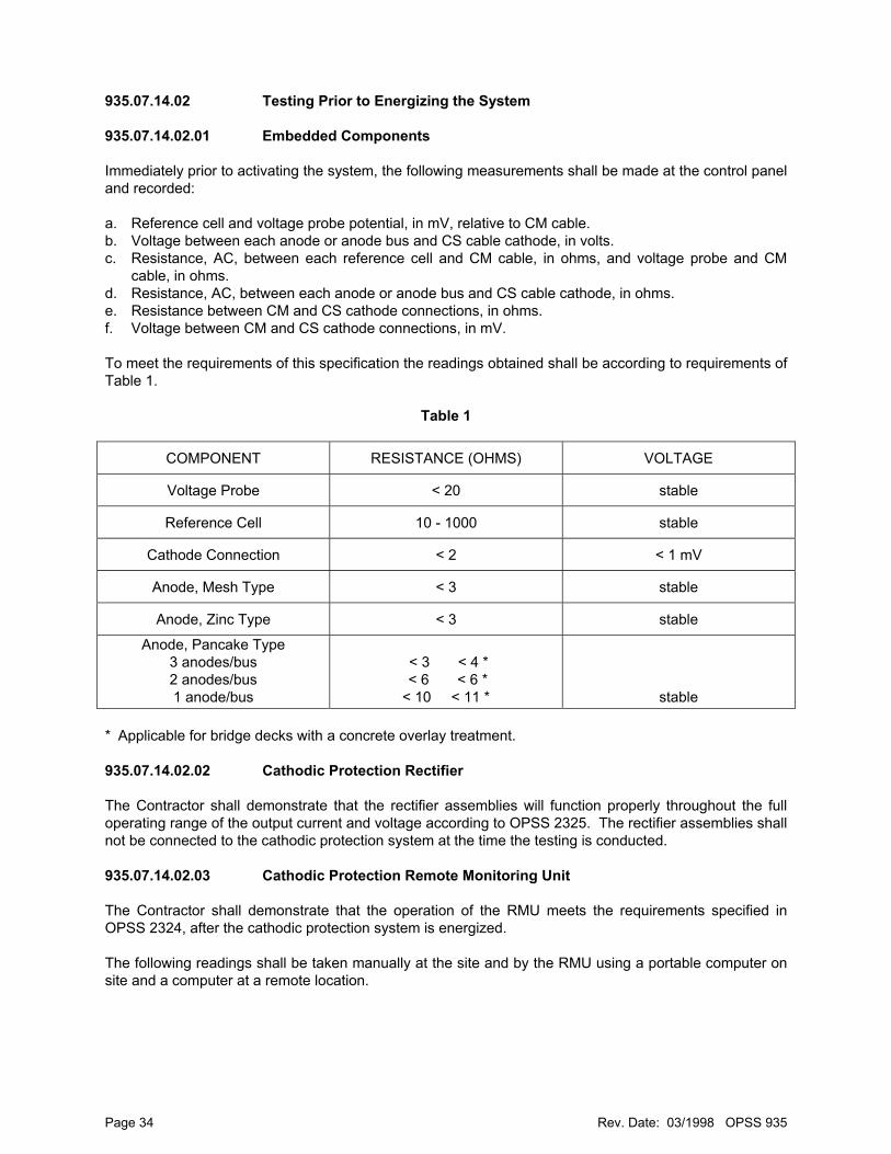
935.07.14.02 Testing Prior to Energizing the System 935.07.14.02.01 Embedded Components Immediately prior to activating the system, the following measurements shall be made at the control panel and recorded: a. Reference cell and voltage probe potential, in mV, relative to CM cable. b. Voltage between each anode or anode bus and CS cable cathode, in volts. c. Resistance, AC, between each reference cell and CM cable, in ohms, and voltage probe and CM
cable, in ohms. d. Resistance, AC, between each anode or anode bus and CS cable cathode, in ohms. e. Resistance between CM and CS cathode connections, in ohms. f. Voltage between CM and CS cathode connections, in mV. To meet the requirements of this specification the readings obtained shall be according to requirements of Table 1.
Table 1
COMPONENT RESISTANCE (OHMS) VOLTAGE
Voltage Probe < 20 stable
Reference Cell 10 - 1000 stable
Cathode Connection < 2 < 1 mV
Anode, Mesh Type < 3 stable
Anode, Zinc Type < 3 stable
Anode, Pancake Type 3 anodes/bus 2 anodes/bus 1 anode/bus
< 3 < 4 * < 6 < 6 * < 10 < 11 *
stable * Applicable for bridge decks with a concrete overlay treatment. 935.07.14.02.02 Cathodic Protection Rectifier The Contractor shall demonstrate that the rectifier assemblies will function properly throughout the full operating range of the output current and voltage according to OPSS 2325. The rectifier assemblies shall not be connected to the cathodic protection system at the time the testing is conducted. 935.07.14.02.03 Cathodic Protection Remote Monitoring Unit The Contractor shall demonstrate that the operation of the RMU meets the requirements specified in OPSS 2324, after the cathodic protection system is energized. The following readings shall be taken manually at the site and by the RMU using a portable computer on site and a computer at a remote location.
Page 34 Rev. Date: 03/1998 OPSS 935

a. Voltage b. Current c. Reference cells d. Probes, for conductive mix e. Temperature All the measurements obtained by the RMU shall be the same as the readings obtained manually on site. When field testing of the installed cathodic protection system is being conducted and the RMU is being used, the Contractor shall arrange, through the supplier of the cathodic protection equipment assembly, to in attendance. 935.07.14.03 Testing During the Trial Operating Period During the trial operating period, the following readings shall be made on an hourly basis for a period of 24 hours using a manual or automatic technique. a. current and voltage; b. current flow to each area of the system, zones and/or subzones, or anode bus, as applicable; c. reference cell and voltage probe potentials, on and instant-off. Immediately after the 24 hour readings are made, the system shall be switched off and allowed to depolarize for a period of four hours. At the end of the four hour depolarization period, reference cell potentials shall be recorded and the differences between instant-off readings at 24 hours and the 28 hour readings shall be calculated. Voltage between anodes and cathode shall be recorded. The performance of the system shall be monitored during the trial operating period and appropriate actions shall be taken to repair any defects detected. The trial operating period shall be repeated as many times as required to prove proper functioning of the system. Within seven days of the completion of the trial operating period a report shall be submitted to the Contract Administrator recording: a. the dates and times of the periods of trial operation; b. names of individuals collecting and recording data; c. equipment used, including power source if applicable; d. all readings noted above, labelled as to appropriate zone, subzone, or bus, as applicable; e. all remedial action taken. The report shall be signed by the Corrosion Specialist verifying that: a. the rectifier and remote monitoring unit are functional; b. the wiring of the system complies with contract drawings, and the labelling and identification of wire
terminations is correct in the control panel; c. all areas, zones and subzones, or buses, as applicable, of the system were functional and received
current flow during the trial operating period; d. there are no short circuits between anodes and cathodes; e. there are no short circuits between reference cells and cathode, or voltage probes and cathode; f. the accuracy of all meters and proper circuit polarity has been verified using a multimeter.
Page 35 Rev. Date: 03/1998 OPSS 935
935.07.15 Remedial Work Work not meeting the acceptance requirements shall be repaired or replaced. Proposals for correcting the deficiency shall be submitted to the Contract Administrator for review and comment prior to commencement of the remedial work. 935.07.16 Management and Disposal of Excess Material Management and disposal of excess material shall be according to OPSS 180. 935.07.17 As Built Drawings As built drawings shall be prepared by the Contractor as follows: a. for all work incorporated in the completed structure that required the submission of working drawings. b. for all changes from the original Contract requirements. The as built drawings shall be submitted to the Contract Administrator in a reproducable format such as a mylar prior to final acceptance of the work. The as built drawings shall bear the seal and signature of an Engineer. 935.08 QUALITY ASSURANCE 935.08.01 Anode Overcoat The sets of 50 x 50 x 50 mm cubes prepared each day the anode overcoat material is being applied and the cubes prepared during preparation of the test panels will be tested for compressive strength according to CSA A23.2. 935.08.02 Anode Mesh A manual pull test will randomly conducted on the weld connecting the anode mesh to the distribution bar to check the weld quality. 935.08.03 Sprayed Zinc 935.08.03.01 Surface Appearance The zinc surface will be visually inspected for uniformity of appearance and thickness. The coating shall not contain any lumps, blisters, cracks, or loosely adhering particles. A panel selected from the test panels will be used by the Contract Administrator as a standard of acceptability of the sprayed zinc. 935.08.03.02 Adhesion of Zinc All areas of the sprayed zinc shall have an adhesion strength of at least 1 MPa. 935.08.03.03 Zinc Thickness The thickness of the zinc applied to the concrete surface shall be 300 ± 50 µm.
Page 36 Rev. Date: 03/1998 OPSS 935
935.08.04 Control and Monitoring Equipment The Owner's representative will visit the plants of the suppliers of the control and monitoring equipment to inspect the materials, plant records and the process of fabrication. 935.08.05 Acceptance and Rejection Work not meeting the requirements of this specification will be subject to rejection. 935.09 MEASUREMENT FOR PAYMENT 935.09.01 Actual Measurement 935.09.01.01 Cathode Connections
Reference Cells Voltage Probes Anodes, Pancake Type
For measurement purposes a count will be made of the units installed. 935.09.01.02 Anodes, Mesh Type
Anodes, Zinc Type Anodes, Overcoat
The area of the material placed will be measured in the plane of the applied surface in square metres. The total area will be calculated to the nearest m2. 935.10 BASIS OF PAYMENT 935.10.01 Cathode Connections - Item
Reference Cells - Item Voltage Probes - Item Anode, Overcoat - Item Rigid P.V.C. Junction Boxes, Surface Mounted for Cathodic Protection - Item Rigid Duct Surface Mounted for Cathodic Protection - Item Rigid P.V.C. Junction Boxes Embedded in Concrete for Cathodic Protection - Item Rigid Duct Embedded in Concrete for Cathodic Protection - Item Rigid Ducts, Direct Buried for Cathodic Protection - Item Extra Low Voltage Cables for Cathodic Protection - Item Installation of Cathode Protection Equipment Assembly - Item Acceptance Testing - Item
Payment at the contract price for the above tender items shall be full compensation for all labour, equipment and materials to do the work.
Page 37 Rev. Date: 03/1998 OPSS 935

Page 38 Rev. Date: 03/1998 OPSS 935
935.10.02 Anodes, Mesh Type - Item Anodes, Zinc Type - Item Anodes, Pancake Type - Item
Payment at the contract price for the above tender items shall be full compensation for all labour, equipment and materials to do the work. Payment shall include the cost of isolating 20 distinct areas of exposed metal and metal detected within 5 mm below the concrete surface.