construction supervision - risk engeneering control, for each construction stage key events through...
TRANSCRIPT
May 16, 2013
CONSTRUCTION SUPERVISION
Rehabilitation of Maritsa East 2 TPP
May 16, 2013
STAGES OF THE CONSTRUCTION WORK IMPLEMENTATION AND FACILITY COMMISSIONING (ART.152 PARA. 2 OF SPA):
Stage 1 Preparatory work and temporary structures
Stage 2 Unit 1 Steam turbine and generator rehabilitation
Stage 3 Replacement of Unit 2 generator
Stage 4 Unit 3 Steam turbine and generator rehabilitation
Stage 5 Unit 4 Steam turbine and generator rehabilitation
Stage 6 Construction of flue gases desulphurization plant for Units 1 and 2, including common facilities
Stage 7 Construction of flue gases desulphurization plant for Units 3 and 4
Stage 8 Unit 5 Steam turbine rehabilitation
Stage 9 Unit 6 Steam turbine rehabilitation
Stage 10 Rehabilitation and strengthening work on the turbine hall external facade.
CONSTRUCTION OF THE DESULPHURIZATION PLANTS FOR UNITS 1, 2, 3 AND 4;
UPGRADING THE UNITS 5 AND 6 POWER CAPACITY
ACTUAL STATUS OF THE PROJECT IMPLEMENTATION:
Stage 1 is accomplished – it includes preparatory and temporary construction and installation work (CIW), and commissioning approval by State Approval Commission
Objects accomplished through stages 2, 3, 4, 5, 6 and 7 are commissioned into operation as per Permit for Use.
Stage 10 object is in state of preparation for presentation to the State Approval Commission.
Stages 8 and 9 are in process of implementation – assessment is being made on conformity with the Detailed designs.
CONSTRUCTION OF THE DESULPHURIZATION PLANTS FOR UNITS 1, 2, 3 AND 4;
UPGRADING THE UNITS 5 AND 6 POWER CAPACITY
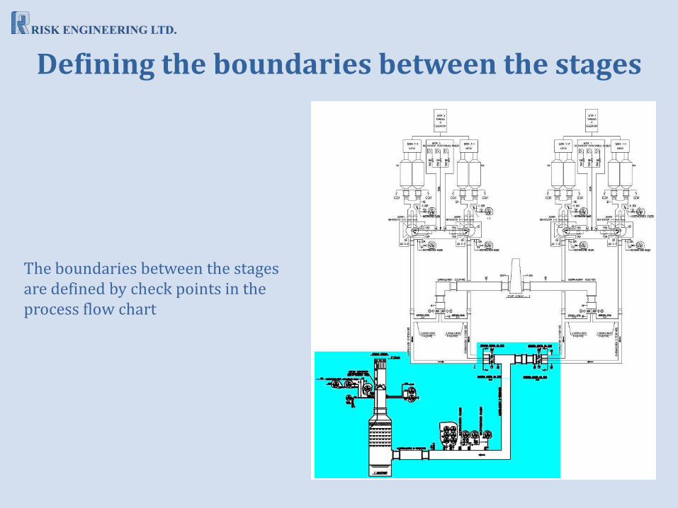
The boundaries between the stages are defined by check points in the process flow chart
Defining the boundaries between the stages

Objectives of Units 1÷4 reconstruction:
• Upgrading the turbine efficiency: from 34,1% as before the rehabilitation, up to 45% after the rehabilitation
• Increasing the generator output power capacity – with old output power capacity on the bus 150 MW, this power capacity after the rehabilitation becomes 170 MW (an increase by more than 13%)
• Prolongation of the facilities useful life, replacing physically depreciated equipment by new up-to-date one
Objectives of the desulphurization plant construction for Units 1÷4 :
• The newly built desulphurization plant shall ensure degree of the flue gases desulphurization minimum 94%
• The dust concentration after the electric filters shall be decreased by 50%
Reconstruction objectives

Approval of the conceptual design and obtaining construction permit
Consultant’s complex report on conformity with the Conceptual design
Construction permit issued by the Ministry of Regional development and welfare (MRDW) of
12.10.2005 as per Art. 142, Para.2 of SPA
Key events through the investment process implementation

Cooperation with the Employer thereby ensuring flexible management through the project implementation, using the legislation regulatory instruments stipulated in the Spatial planning act (SPA)
Order by MRDW No. РС-10/11.06.2007 on supplementing Construction permit №РС 23 of 12.10.2005, with significant divergences in the meaning of Art. 154, Para 2, Items 6 and7 of SPA
Cooperation with the Employer

Approval of Detailed designs prior to CIW implementation
Consultant’s complex report on conformity with the Detailed design
Construction permit by MRDW of 12.10.2005 as per Art.142 Para 2 of SPA
Key events through the investment process implementation
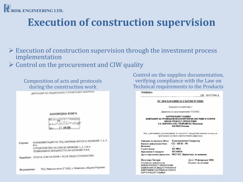
Execution of construction supervision through the investment process implementation
Control on the procurement and CIW quality
Composition of acts and protocols during the construction work
Control on the supplies documentation, verifying compliance with the Law on
Technical requirements to the Products
Execution of construction supervision

Verification of conformity of the accomplished construction with the design and normative parameters and requirements
Complex tests performed by certified laboratories
Positive statements of control/regulatory authorities
Key events through the investment process implementation

Commissioning into operation and obtaining usage permit
Final Consultant’s report on establishing the capability of usage on each construction Stage
Usage permit by the Directorate for national construction control, for each construction Stage
Key events through the investment process implementation
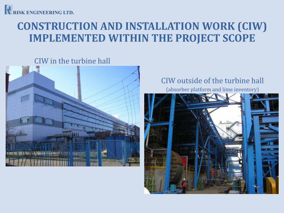
CONSTRUCTION AND INSTALLATION WORK (CIW) IMPLEMENTED WITHIN THE PROJECT SCOPE
CIW in the turbine hall
CIW outside of the turbine hall (absorber platform and lime inventory)
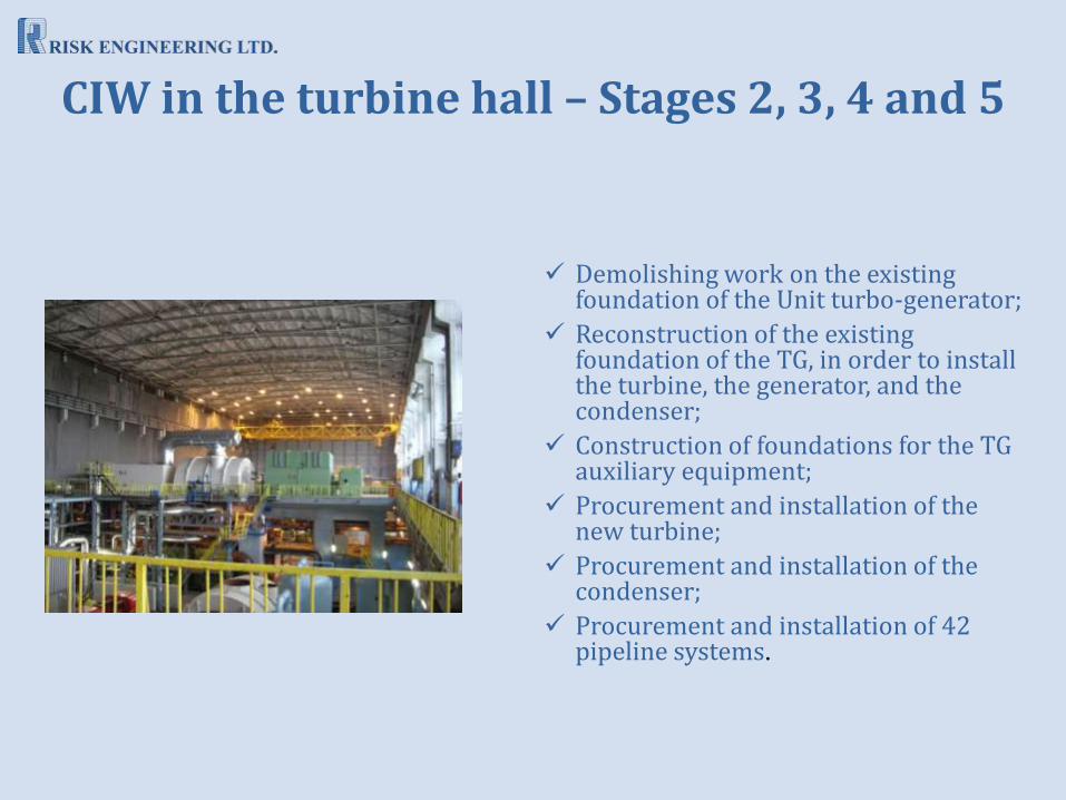
Demolishing work on the existing foundation of the Unit turbo-generator;
Reconstruction of the existing foundation of the TG, in order to install the turbine, the generator, and the condenser;
Construction of foundations for the TG auxiliary equipment;
Procurement and installation of the new turbine;
Procurement and installation of the condenser;
Procurement and installation of 42 pipeline systems.
CIW in the turbine hall – Stages 2, 3, 4 and 5

PROCUREMENT AND INSTALLATION OF MAIN EQUIPMENT
Procurement and installation of the generator
Procurement and installation of the turbine
Procurement and installation of auxiliary equipment for the turbine; Procurement and installation of new generator “Toshiba”; Procurement and installation of grounding cabinet, connecting (coupling) the
generator with the existing turbine; Procurement and installation of two pipeline systems – for the generator stator
cooling water; Procurement and installation of relevant I&C equipment for the new TG.
CIW in the turbine hall – Stages 2, 3, 4 and 5

Main steam control valve (MSCV)
Combined reheat valve (CRV)
HPR8 (high pressure reheater 8)
HPR7
HPR6
LPR4 (low pressure reheater 4)
LPR3
LPR2
LPR1
Drain vessel
Main ejector
PROCUREMENT AND INSTALLATION OF AUXILIARY EQUIPMENT
CIW in the turbine hall – Stages 2, 3, 4 and 5

Main oil pump
Emergency oil pump
Main oil tank
Main oil cooler
Oil clean-up unit
Filter pump of the oil clean-up unit
Extractor of the evaporation products from the oil tank
Governor system oil tank (EHC)
Governor system oil pump
Steam sealings condenser
Steam sealings exhauster
PROCUREMENT AND INSTALLATION OF AUXILIARY EQUIPMENT (2)
CIW in the turbine hall – Stages 2, 3, 4 and 5

Installation of measuring instruments and transducers
Installation of pressure and differential pressure transducers on the elevations around turbogenerator 3 (elevation -3.60, up to elevation +9.00)
Placement and installation of the cabinets of the TG control system in the Unit Main control room 2 non-operative part (MCR 2)
Installation of the UPS cabinets in the MCR non-operative part
In place installation of connection boxes around turbine 3
INSTALLATION OF NEW I&C EQUIPMENT IMPLEMENTATION OF UP-TO-DATE PROCESS CONTROL
CIW in the turbine hall – Stages 2, 3, 4 and 5

Installation of cable routes; cable laying, connecting and ring testing
Start-up and adjustment work on measuring instruments and transducers, as well as actuating mechanisms of the isolating and control valves
Implementation of the dedicated software realizing the TG control logic in the ТАС and D-EHC systems, as well as visualization of the state of the actuators and measured parameters
72-hour trial tests, with composed protocols on the results thereof
INSTALLATION OF NEW I&C EQUIPMENT IMPLEMENTATION OF UP-TO-DATE PROCESS CONTROL (2)
CIW in the turbine hall – Stages 2, 3, 4 and 5

Procurement and installation of two flue fans (FF) for the Unit;
Procurement and installation of three compressing air fans, servicing the FF;
Procurement and installation of a bypass damper;
Procurement and installation of two hoists serving the FF;
Procurement and installation of following Unit gas ducts: electric filters outlet duct – from the electric filters to the flue fans inlets, outlet gas duct from the flue fans to the desulphurizing plant inlet damper and to the bypass damper, bypass gas duct from the bypass damp to the existing 180m stack К1 or К2;
Construction of oil station for servicing the flue fans and the relevant pipelines and facilities thereof.
CIW outside of the turbine hall – Stages 2, 3, 4 and 5

CIW on the absorber platform CIW on the lime inventory
CONSTRUCTION OF FLUE GAS DESULPHURIZATION (FGD) PLANTS FOR UNITS 1-4
CIW IMPLEMENTED WITHIN THE PROJECT SCOPE

Recirculation pumps
Absorber suspension pumps
Oxidation air compressors
Dampers at the FGD inlet
Absorber suspension agitators
Device for mist removal
Gypsum hydrocyclone
CIW implemented on the absorber platform PROCUREMENT AND INSTALLATION OF THE MECHANICAL AND PROCESS
EQUIPMENT
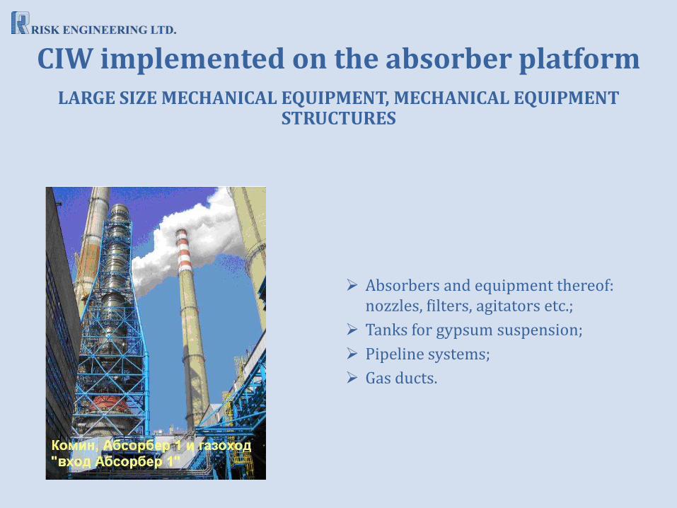
Absorbers and equipment thereof: nozzles, filters, agitators etc.;
Tanks for gypsum suspension;
Pipeline systems;
Gas ducts.
LARGE SIZE MECHANICAL EQUIPMENT, MECHANICAL EQUIPMENT STRUCTURES
CIW implemented on the absorber platform
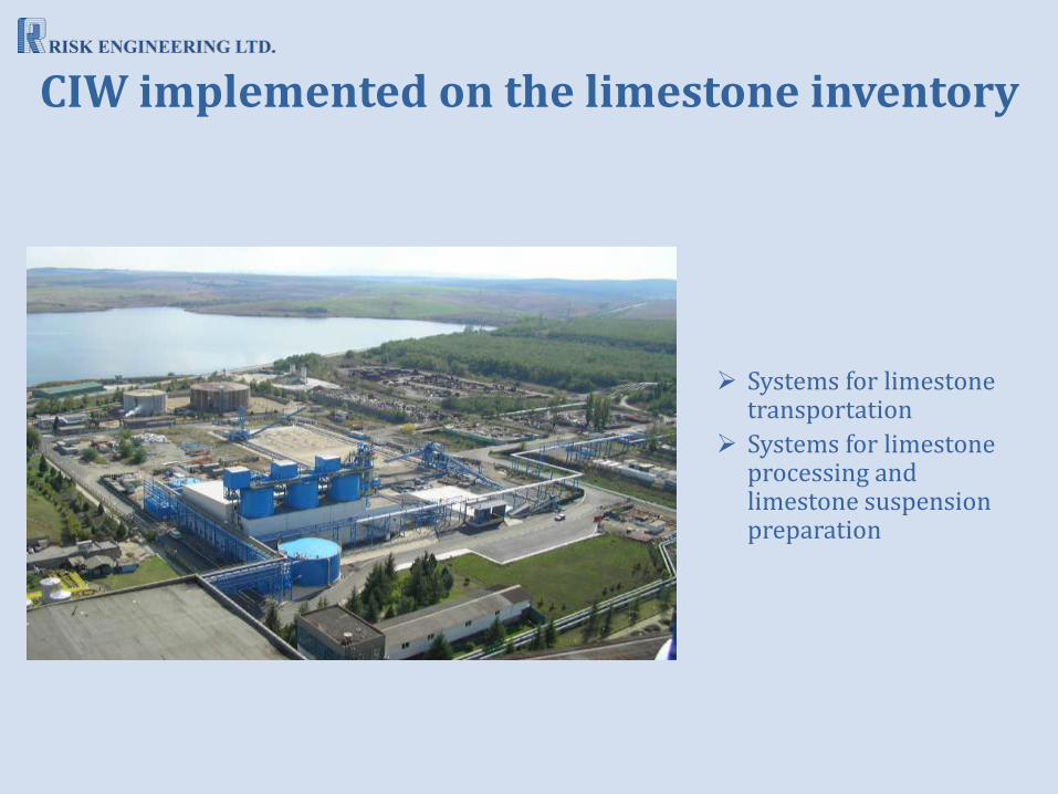
Systems for limestone transportation
Systems for limestone processing and limestone suspension preparation
CIW implemented on the limestone inventory

Bearing structures and foundations of cable-pipe trestles „А”, „В” and pipe trestles „L” and „К”, serving for transportation of the gypsum suspension to the excavator pump station – starting from the absorber, the gypsum suspension is transported by trestles “E”, “C” and “D” to the limestone inventory area, where from, by trestles “B”, “A”, “L”, “K” and again by trestle “L”, is directed to the excavator pump station (trestle “K” over-bridges the canal, whereby its both ends border upon the two parts of trestle “L”).
CIW implemented on the limestone inventory

Building for limestone processing (grounding, crushing, silos, and electrical equipment hall)
Pump compartments for process water and limestone suspension
CIW implemented on the limestone inventory