contact elimination in mechanical face seals using...
TRANSCRIPT

Contact Elimination in Mechanical Face Seals Using Active Control
Joshua Dayan*, Min Zou and Itzhak Green
The George W. Woodruff School of Mechanical Engineering
Georgia Institute of Technology
Atlanta, Georgia 30332-0405
ABSTRACT
Wear and failure of mechanical seals may be critical in certain application and should be avoided. Large relative misalignment between the seal faces is the most likely cause for intermittent contact and the increased friction that eventually brings failure. Adjustment of seal clearance is probably the most readily implemented method of reducing the relative misalignment and the elimination of seal face contact during its operation. This method is demonstrated with the aid of a noncontacting flexibly mounted rotor (FMR) mechanical face seal test rig employing a cascade control scheme. Eddy current proximity probes measure the seal clearance directly. The inner loop controls the clearance, maintaining a desired gap through adjusting the air pressure in the rotor chamber of the seal. When contact is detected the outer loop adjusts the clearance set point according to variance differences in the probes signals. These differences in variance have been found to be a reliable quantitative indication for such contacts. They are complimentary to other more qualitative phenomenological indications, and provide the controlled variable data for the outer loop. Experiments are conducted to test and verify this active control scheme and strategy. Analysis and results both show that contrary to intuition for the seal under investigation reducing seal clearance can eliminate contact and the outer cascade loop indeed drives the control toward this solution.
1. Introduction
Mechanical seals are widely used in pumps, compressors, turbo-machinery and powered vessels. Two types are employed, contacting and noncontacting mechanical face seals. The first seal type provides the most effective separation of the fluids on both sides of the seal at the expense of high friction and faster wear. The second type provides longer life but at the cost of some leakage. Premature failure of the seal may inflict far greater damage than the value of the seal itself and therefore should be avoided. In noncontacting seals the cause of failure is not always clear and may be attributed to the process, operation, design, or their combination. Nevertheless, a most probable cause of noncontacting seal failure is the occurrence of some undesired intermittent contacts between the seal faces. Therefore, contact elimination is of prime importance, especially in critical applications (such as nuclear reactor cooling pumps) where seal failure may have severe implications.
Support of this research was made by the US Office of Naval Research through grant N00014-95-1-0539, entitled Integrated Diagnostics. *Email: [email protected]
Proceedings of the 7th Mediterranean Conference on Control and Automation (MED99) Haifa, Israel - June 28-30, 1999
618

A comprehensive design that takes into account all the information such as seal face geometry, materials, heat transfer, mechanics, system dynamics, and empirical data, promotes long lasting seal life. This, however, is by no means an easy task, and in many cases a great amount of the information is missing. The problem may be tackled though, through active control of the seal operation. This approach have been taken by Salant, et al., (1987), Heilala and Kangasneimi, (1987), Etsion, et al., (1991), and by Wolff and Salant, (1995). All these researchers concentrated solely on clearance adjustment through temperature control, where temperatures measured by thermocouples were used as the feedback. Rise in temperature has been claimed to be the result of friction caused by contact. However, rise in temperature may result from other physical phenomena and the thermocouples only measure local sealing dam temperatures, not necessarily right at the location of contact. Therefore, this approach may erroneously activate the control as it contains large time delays between event occurrence and the action taken by the control. Since temperature is not a direct measure of the clearance, it may not detect situations of damaging seal operations, e.g., seal face contact caused by large relative misalignment. In this case the temperature measurements could still remain low because of the cooling effect of large leakage.
In this research, various ways of reducing the relative misalignment and diminishing the possibility of seal face contact are introduced and considered. First contact is monitored from the dynamic behavior of the seal using eddy current proximity probes. These provide instantaneous information on proper or improper seal behavior. Then, a control strategy as well as control system are developed and physically implemented to keep both the clearance and the relative misalignment as small as possible in order to ensure noncontacting operation of the FMR mechanical face seal.
2. Intermittent Face Contact
Basic description and nomenclature of the FMR mechanical face seal are given in Fig. 1. The sealing dam is the area between the face of the rotor and the slanted disk (dark cross-section in Fig. 1) of the stator. The latter is usually made of softer material (e.g., graphite). During operation the softer material is distorted to a certain extend and a coning angle β* of a fraction to a few mrad is formed. Fluid leakage due to the pressure drop across the seal occurs by flow into the converging gap created by β* (in Fig. 1 flow occurs from the peripheral area into the center). Ideally, seal faces are arranged perpendicular to the shaft and parallel to each other. As the name implies, there should be no face contact during the operation of the noncontacting mechanical face seal. However, in reality, contact may occur due to large relative misalignment between the seal faces at the normally small clearances separating them (of the order of only a few microns). Relative misalignment γ*, between seal faces (shown in Fig. 1) may result from manufacturing and assembly tolerances, machine deterioration, or from disturbances in the process operation (e.g., axial load change). Seal face contact, not only generates an impact force not easy to predict, but it also increases the friction and wear of the faces. Heat generated by prolonged contact can also deform the seal faces and generate additional stress problems.
Whether seal face contact will occur depends not only on the relative misalignment between the rotor and the stator, γ*, but also on the seal clearance, Co, and the seal inner and outer radii, ri and ro (for consistency with previous publications '*' or, low-case letters without asterisk indicates dimensional/non-normalized variables). These can be grouped together into the normalized relative misalignment, γ, defined as γ*ro/Co (Green, 1989). Seal face contact could either occur at the inner radius or the outer radius, depending on the normalized coning angle, β = β*ro/Co (Fig. 1). A properly designed seal, must have a coning angle, β, greater than critical. (The critical coning angle βcritical=1/Ri, provides positive fluid film stiffness; where Ri is the dimensionless inner radius of the seal, ri/ro.) Should contact occur it would take place at the inner radius. In which case, the normalized relative misalignment, γ, can be used to determine the contact occurrence. When contact occurs at the inner radius,
Proceedings of the 7th Mediterranean Conference on Control and Automation (MED99) Haifa, Israel - June 28-30, 1999
619

io rC /* =γ (1)
and therefore, nondimensionally
criticaliR γγ == /1 (2)
Thus, in order to avoid the possibility of contact between the seal faces both the design and operation should ensure criticalγγ < at all times.
ri
ro
Rotor
Statorγ∗
β∗
Co
Fig. 1: The relative misalignment between the rotor and the stator in the sealing dam
3. Reducing the Normalized Relative Misalignment
In some applications preventing seal contact can be achieved by proper design, i.e., selecting the seal parameters in such a way that it will not be sensitive to changes in the operational variables about its nominal working point. In other cases, however, the load changes or the disturbances may vary substantially, causing large misalignment, beyond what rigid design can rectify. In the latter one or more of the operational variables, clearance, sealed fluid pressure, and shaft speed, can be used to actively control the seal behavior (Dayan et al. 1999 and Zou et al. 1999a).
Contact caused by large relative misalignment between the seal rotor and stator can be eliminated by reducing this misalignment, which is the vector subtraction of the total rotor misalignment and the stator misalignment. The maximum of the total rotor misalignment is the vector addition of both the maximum rotor responses to the stator misalignment and to the maximum initial rotor misalignment (Green, 1989).
For a noncontacting FMR mechanical face seal, the maximum relative misalignment can be calculated according to the closed form solutions of the Green (1989 and 1990) dynamic model. Based on this solution, parametric and sensitivity studies (Zou, et al., 1999a, and Dayan et al., 1999) were performed to investigate the effect of basic seal parameters (mainly shaft speed, sealed fluid pressure, coning angle, and clearance) on the maximum relative misalignment for a noncontacting FMR seal test rig (Fig. 2). It was found that increasing the shaft speed and the sealed fluid pressure decreases the maximum normalized relative misalignment. However, clearance effect on the maximum normalized relative misalignment, depends on the coning angle. When coning angle is small, contrary to intuition, decreasing seal clearance will decrease the maximum normalized relative misalignment. When coning angle is large increasing clearance will decrease the maximum normalized relative misalignment. Therefore, the shaft speed, the sealed fluid pressure, or the clearance can be used to reduce the maximum normalized relative misalignment, hence eliminate seal face
Proceedings of the 7th Mediterranean Conference on Control and Automation (MED99) Haifa, Israel - June 28-30, 1999
620

contact. However, since in most applications the shaft speed and sealed fluid pressure are fixed, the best way of contact elimination is by controlling the seal clearance. The present study describes contact elimination by clearance control in a noncontacting FMR seal test rig.
shaft
rotor
stator
proximityprobe
lip sealcontacting seal carbon ring
sealing damrotor chamber
pressurized air pressurized waterspindle
Part I Part II Part III Fig. 2 Schematic of the FMR noncontacting mechanical seal assembly
4. Contact elimination
4.1 The test rig
The basic noncontacting FMR mechanical face seal test rig used in this study (Fig. 2) was described by Lee and Green (1994, 1995a, and 1995b). It is equipped with an advanced real-time data acquisition and analysis system (Zou and Green 1997, 1998). Other significant modifications to the basic system include the stator, which is made entirely of carbon graphite, and the rotor, which is made entirely of AISI 440C stainless steel. Both have been fabricated and lapped to industry standards by seal manufacturers. The integrated system provides reliable measurement and determination of the relative position between rotor and stator.
The rotor is flexibly mounted on the rotating shaft through an elastomer O-ring. This allows the rotor to track the stator misalignment and to move axially. The seal stator assembly is composed of several components: the carbon stator, the spacer, and the stator holders. This design is capable of mechanically deforming the stator and produces seals with different coning angles (Lee and Green, 1995a). For stability it is mandatory for the seal to maintain a converging gap in the direction of radial flow. For an outside pressurized seal the minimum seal film thickness has to be on the ID (Green, 1987). In real applications the actual coning angle results from pressure differences and thermal stresses. Therefore, it is varying with time. However, these transients in deformations occur at a much slower pace than the time scale of interest in seal dynamics. Thus, the two processes (coning angle variations and instantaneous dynamics) can be regarded as decoupled. For
Proceedings of the 7th Mediterranean Conference on Control and Automation (MED99) Haifa, Israel - June 28-30, 1999
621

this reason the coning in the present test rig is induced by deforming the faces in the stator fixture and held fixed throughout the experiments. In that regard, data sufficient for dynamic analysis and monitoring is acquired in a fraction of a second, a time scale insignificant for any thermal deformations to occur.
The stator assembly is fixed in the housing, which is made of three parts for convenience in machining, maintenance, and adjustment of the test rig. All possible leakage paths are sealed by O-rings. The sealed fluid in the housing is pressurized water. The shaft is connected to a spindle driven by a speed controlled DC motor through two pulleys and a timing belt. Pressurized air is supplied from the main air supply line to the rotor chamber through holes in the housing and the shaft. It is sealed by a lip seal at one end and separated from the water by a contacting seal at the other end. The seal operates at an equilibrium clearance where the opening and closing forces are balanced. Changing the closing force by adjusting the air pressure in the rotor chamber (whether manually or by the computer through a voltage to pressure converter) varies the clearance.
Three eddy current proximity probes mounted on the end of the housing measure the instantaneous distances between their tips and the end surface of the rotor face. Thus, they can measure both the static and the dynamic distances between their tips and the rotor. The three probes are mounted on a circle of 25 mm diameter and located 90° apart. At any particular moment the clearance of the seal is the difference between the instantaneous average readings of the two probes, which are mounted 180° apart, and the zero reference. The latter is obtained once, while the shaft is stationary and high air pressure is applied in the rotor chamber to ensure that the rotor is pressed against the stator. At this state the average of these two probes represents the zero clearance reference. The proximity probes have a bandwidth of about 10 kHz. A low pass filter with a cut-off frequency of 1 kHz is used to eliminate high frequency cross-talk noise among the probes and also to serve as an anti-aliasing filter. The proximity probe signals in terms of the reduced voltages are sent through analog to digital converters to a floating-point Digital Signal Processor (DSP). This DSP, supplemented by a set of on-board peripherals, such as analog to digital and digital to analog converters, comprise a universal board mounted in a personal computer. It should be mentioned that although Sehnal, et al. (1983), and Etsion and Constantinescu, (1984), have made similar attempts to determine the clearance from proximity probe readings, they have eventually reverted to estimating the clearance indirectly from a simplified equation applied to the measured leakage.
Other key parameters including stator misalignment, rotor misalignment, relative misalignment between the rotor and the stator are calculated on-line in real-time from the probe measurements (Zou and Green, 1997). Further details of the test rig components, data acquisition and analysis can be found in the aforementioned references.
4.2 Contact detection and contact elimination strategy
As mentioned, stator and initial rotor misalignments are responsible for γmax. The parametric study of Zou et al. (1999a) explores the effects of various seal parameters on this γmax and provides valuable information concerning seal design and performance prediction. This study also provides guidelines for action while contact occurs. However, other factors, such as kinematics of the flexible support and its rotordynamic coefficients uncertainties, machine deterioration, transients in sealed pressure or shaft speed, or unexpected shaft vibration, affect the dynamic behavior of the seal and, hence, the relative position and misalignment between the rotor and the stator. This is where strict reliance on precise analysis loses effectiveness because some or all of the assumptions imbedded in the analysis may be borne out physically. Particularly, when
problem of finding a proper indication for the contact is raised. Zou et al. (1999b) suggested that when it comes to actual diagnostics a phenomenological approach for contact detection is more appropriate. Indeed, they have experimentally showed that under certain conditions (which have been predicted by the analysis) the
Proceedings of the 7th Mediterranean Conference on Control and Automation (MED99) Haifa, Israel - June 28-30, 1999
622
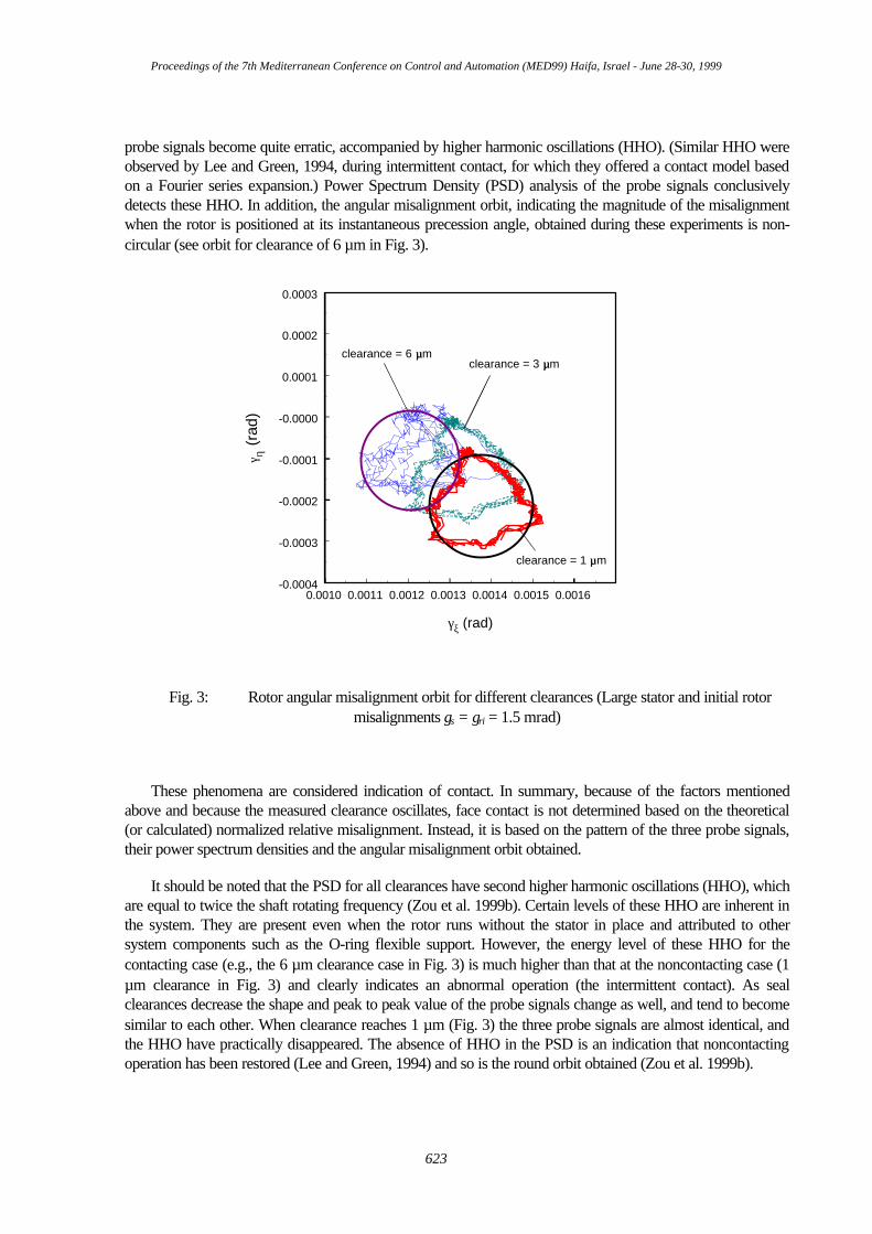
probe signals become quite erratic, accompanied by higher harmonic oscillations (HHO). (Similar HHO were observed by Lee and Green, 1994, during intermittent contact, for which they offered a contact model based on a Fourier series expansion.) Power Spectrum Density (PSD) analysis of the probe signals conclusively detects these HHO. In addition, the angular misalignment orbit, indicating the magnitude of the misalignment when the rotor is positioned at its instantaneous precession angle, obtained during these experiments is non-circular (see orbit for clearance of 6 µm in Fig. 3).
0.0010 0.0011 0.0012 0.0013 0.0014 0.0015 0.0016
γξ (rad)
-0.0004
-0.0003
-0.0002
-0.0001
-0.0000
0.0001
0.0002
0.0003
γ η (r
ad)
clearance = 6 µµm
clearance = 1 µµm
clearance = 3 µµm
Fig. 3: Rotor angular misalignment orbit for different clearances (Large stator and initial rotor misalignments γs = γri = 1.5 mrad)
These phenomena are considered indication of contact. In summary, because of the factors mentioned above and because the measured clearance oscillates, face contact is not determined based on the theoretical (or calculated) normalized relative misalignment. Instead, it is based on the pattern of the three probe signals, their power spectrum densities and the angular misalignment orbit obtained.
It should be noted that the PSD for all clearances have second higher harmonic oscillations (HHO), which are equal to twice the shaft rotating frequency (Zou et al. 1999b). Certain levels of these HHO are inherent in the system. They are present even when the rotor runs without the stator in place and attributed to other system components such as the O-ring flexible support. However, the energy level of these HHO for the contacting case (e.g., the 6 µm clearance case in Fig. 3) is much higher than that at the noncontacting case (1 µm clearance in Fig. 3) and clearly indicates an abnormal operation (the intermittent contact). As seal clearances decrease the shape and peak to peak value of the probe signals change as well, and tend to become similar to each other. When clearance reaches 1 µm (Fig. 3) the three probe signals are almost identical, and the HHO have practically disappeared. The absence of HHO in the PSD is an indication that noncontacting operation has been restored (Lee and Green, 1994) and so is the round orbit obtained (Zou et al. 1999b).
Proceedings of the 7th Mediterranean Conference on Control and Automation (MED99) Haifa, Israel - June 28-30, 1999
623
After contact is detected the required next step should trigger a mechanism, which would dictate the desired clearance to the control loop. Maintaining this desired clearance would eliminate the contact and restore normal (noncontacting) operation.
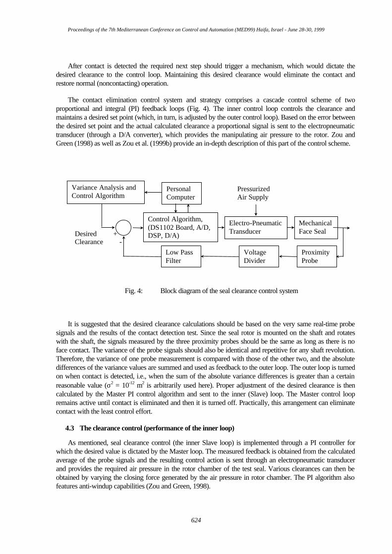
The contact elimination control system and strategy comprises a cascade control scheme of two proportional and integral (PI) feedback loops (Fig. 4). The inner control loop controls the clearance and maintains a desired set point (which, in turn, is adjusted by the outer control loop). Based on the error between the desired set point and the actual calculated clearance a proportional signal is sent to the electropneumatic transducer (through a D/A converter), which provides the manipulating air pressure to the rotor. Zou and Green (1998) as well as Zou et al. (1999b) provide an in-depth description of this part of the control scheme.
Desired +Clearance -
PersonalComputer
Control Algorithm,(DS1102 Board, A/D,DSP, D/A)
Electro-PneumaticTransducer
MechanicalFace Seal
ProximityProbe
VoltageDivider
Low PassFilter
PressurizedAir Supply
Variance Analysis andControl Algorithm
Fig. 4: Block diagram of the seal clearance control system
It is suggested that the desired clearance calculations should be based on the very same real-time probe signals and the results of the contact detection test. Since the seal rotor is mounted on the shaft and rotates with the shaft, the signals measured by the three proximity probes should be the same as long as there is no face contact. The variance of the probe signals should also be identical and repetitive for any shaft revolution. Therefore, the variance of one probe measurement is compared with those of the other two, and the absolute differences of the variance values are summed and used as feedback to the outer loop. The outer loop is turned on when contact is detected, i.e., when the sum of the absolute variance differences is greater than a certain reasonable value (σ2 = 10-12 m2 is arbitrarily used here). Proper adjustment of the desired clearance is then calculated by the Master PI control algorithm and sent to the inner (Slave) loop. The Master control loop remains active until contact is eliminated and then it is turned off. Practically, this arrangement can eliminate contact with the least control effort.
4.3 The clearance control (performance of the inner loop)
As mentioned, seal clearance control (the inner Slave loop) is implemented through a PI controller for which the desired value is dictated by the Master loop. The measured feedback is obtained from the calculated average of the probe signals and the resulting control action is sent through an electropneumatic transducer and provides the required air pressure in the rotor chamber of the test seal. Various clearances can then be obtained by varying the closing force generated by the air pressure in rotor chamber. The PI algorithm also features anti-windup capabilities (Zou and Green, 1998).
Proceedings of the 7th Mediterranean Conference on Control and Automation (MED99) Haifa, Israel - June 28-30, 1999
624
The ability of the clearance control loop to follow the set-point changes, with and without disturbances in shaft speed and sealed water pressure, is tested and the performance is demonstrated by the test rig. All the experiments are conducted about nominal operation condition of 207 kPa sealed water pressure, 15 Hz shaft rotating speed and 1.6 mrad seal coning angle.
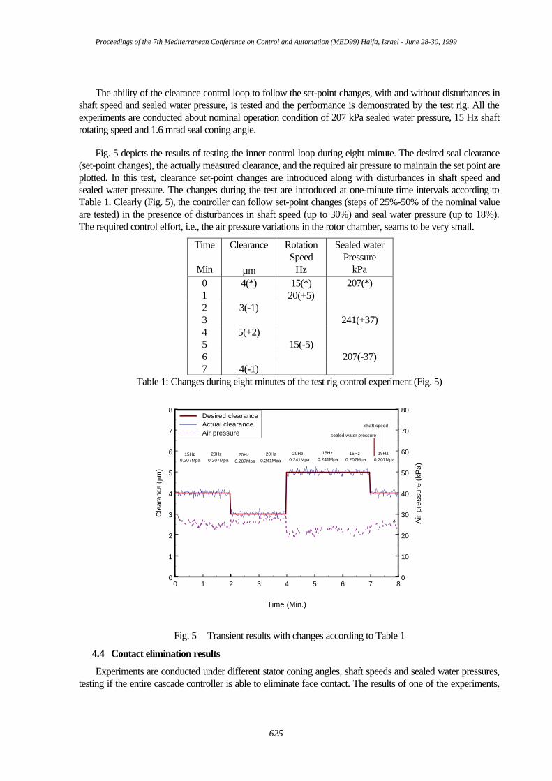
Fig. 5 depicts the results of testing the inner control loop during eight-minute. The desired seal clearance (set-point changes), the actually measured clearance, and the required air pressure to maintain the set point are plotted. In this test, clearance set-point changes are introduced along with disturbances in shaft speed and sealed water pressure. The changes during the test are introduced at one-minute time intervals according to Table 1. Clearly (Fig. 5), the controller can follow set-point changes (steps of 25%-50% of the nominal value are tested) in the presence of disturbances in shaft speed (up to 30%) and seal water pressure (up to 18%). The required control effort, i.e., the air pressure variations in the rotor chamber, seams to be very small.
Time
Min
Clearance
µm
Rotation Speed
Hz
Sealed water Pressure
kPa 0 4(*) 15(*) 207(*) 1 20(+5) 2 3(-1) 3 241(+37) 4 5(+2) 5 15(-5) 6 207(-37) 7 4(-1)
Table 1: Changes during eight minutes of the test rig control experiment (Fig. 5)
0 1 2 3 4 5 6 7 8
Time (Min.)
0
1
2
3
4
5
6
7
8
Cle
aran
ce (
µm)
0
10
20
30
40
50
60
70
80A
ir pr
essu
re (k
Pa)
Desired clearanceActual clearanceAir pressure
20Hz15Hz0.207Mpa 0.207Mpa
20Hz0.207Mpa 0.241Mpa
20Hz 20Hz0.241Mpa
15Hz0.241Mpa 0.207Mpa
15Hz 15Hz0.207Mpa
shaft speed
sealed water pressure
Fig. 5 Transient results with changes according to Table 1
4.4 Contact elimination results
Experiments are conducted under different stator coning angles, shaft speeds and sealed water pressures, testing if the entire cascade controller is able to eliminate face contact. The results of one of the experiments,
Proceedings of the 7th Mediterranean Conference on Control and Automation (MED99) Haifa, Israel - June 28-30, 1999
625

where coning angle is 1 mrad, water pressure is 344.8 kPa, shaft speed is 28 Hz, and stator misalignment 2 mrad are plotted in the following set of figures (6-10).
Figure 6 depicts the changes in probe displacement signals obtained when the control is switched on and off. Clearly, the shape and peak to peak values of the signals are different for the three probes when control is off but they are almost identical when the control is on.
0.0 0.2 0.4 0.6 0.8 1.0 1.2
Time (sec.)
180
190
200
210
220
230
240
250P
roxi
mity
pro
be s
igna
ls (
µµm) control on
(1st time)control on(2nd time)
control off(1st time)
control off(2ndtime)
control off(3rd time)
control on(3rd time)
probe A displacementprobe B displacementprobe C displacement
Fig. 6 Proximity probe signals when the control is on and off
It is easier to see these differences from the PSDs of the three probes as plotted in Fig.7, for the respective control on and control off cases.
0 20 40 60 80 100 120 140 160 180 200
Frequency (Hz)
0
100
200
300
400
Pro
xim
ity p
robe
PS
D
probe Aprobe Bprobe C
control off (2nd time)
0 20 40 60 80 100 120 140 160 180 200
Frequency (Hz)
0
100
200
300
400
Pro
xim
ity p
robe
PS
D
probe Aprobe Bprobe C
control on (2nd time)
Fig. 7 Proximity probe PSDs when the control is on and off
The relative misalignment between the rotor and the stator is smaller when the control is on (Fig. 8).
Proceedings of the 7th Mediterranean Conference on Control and Automation (MED99) Haifa, Israel - June 28-30, 1999
626

0.0 0.2 0.4 0.6 0.8 1.0 1.2
Time (sec.)
0.0016
0.0017
0.0018
0.0019
0.0020
0.0021
0.0022
0.0023
0.0024
0.0025
Rot
or m
isal
ignm
ent,
γγ r, (ra
d)
stator misalignment = 2 mrad
control on(1st time)
control on(2nd time)
control off(1st time)
control off(2ndtime)
control off(3rd time)
control on(3rd time)
Fig. 8: Rotor misalignment when the control is on and off
The rotor misalignment orbit for control on and control off cases, is plotted in Fig. 9. The orbit becomes more circular for the 'control on' case, and its center moves towards the point defined by the stator misalignment and angle.
0.0016 0.0017 0.0018 0.0019 0.0020 0.0021 0.0022
γγξξ (rad)
0.0003
0.0004
0.0005
0.0006
0.0007
0.0008
γγ ηη (r
ad)
control off, 1st timecontrol on, 1st timecontrol off, 2nd timecontrol on, 2nd timecontrol off, 3rd timecontrol on, 3rd time
control off
control on
Fig. 9: Rotor angular misalignment orbit for control on and off cases
Proceedings of the 7th Mediterranean Conference on Control and Automation (MED99) Haifa, Israel - June 28-30, 1999
627

When the cascade control is 'on' the variance loop drives the system toward better alignment (eliminating the contact), and as can be seen from Fig. 10 it is automatically reduces the clearance. This is an indication that under the tested conditions reducing the clearance does indeed reduce the relative misalignment, as was shown analytically by Green (1990). Figure 10 also shows that clearances calculated from the probe measurements are well correlated and in good agreement with clearances calculated from leakage measurements (assuring that both methods are adequate). The changes in the controller output required (air pressure in the rotor chamber) are very small, demonstrating that the control is well tuned and quite effective.
0.0 0.2 0.4 0.6 0.8 1.0 1.2
Time (sec.)
0
2
4
6
8
10
12
Sea
l cle
aran
ce (
µm)
control on(1st time)
control off(1st time)
control on(3rd time)
control on(2nd time)
control off(2nd time)
control off(3rd time)
clearance from probesclearance mean value from probesclearance from flowmeterAir pressure
0
20
40
60
80
100
120
140
Air
pres
sure
(kP
a)
Fig. 10: Seal clearance and air pressure when the control is on and off
5. Conclusions
A novel method of eliminating contact in mechanical face seals is introduced. This method employs active control of the clearance between the seal faces. It emerged as a conclusion from the results of a detailed parametric and sensitivity analysis for the noncontacting FMR mechanical seal. Contrary to intuition, it is suggested to decrease the clearance rather than to increase it, when contact occurs. The reduction in the clearance reduces the relative misalignment between the seal faces; therefore, reduces the possibility of seal face contact. By bringing the seal faces closer together, not only contact is eliminated, but also leakage is significantly reduced.
The active control is realized by a cascade scheme using two PI control loops. The inner control loop maintains the desired clearance, while the outer loop calculates and dictates the set-point, based on the contact detecting result.
The contact is determined by the appearance of abnormal HHO in the signal of the measured clearance (the output of eddy current proximity probes). These HHO are detected by parameters of the DSP and misalignment orbit for the seal. Once detected, a feedback control loop measuring the probe signal variance differences determines the new target gap, which will eliminate the contact and resume normal noncontacting operations.
Proceedings of the 7th Mediterranean Conference on Control and Automation (MED99) Haifa, Israel - June 28-30, 1999
628
REFERENCES
Dayan, J. Zou, M. and Green I., 1999, Sensitivity Analysis for the Design and Operation of a Noncontacting Mechanical Face Seal, submitted to J. Mech. Eng. Science.
Etsion, I., and Constantinescu, I., 1984, Experimental Observation of the Dynamic behavior of Noncontacting Coned-face Mechanical Seal, ASLE Trans., 27, 3, pp. 263-270.
Etsion, I., Palmor, Z.J., and Harari, N., 1991, Feasibility Study of a Controlled Mechanical Seal, Lubrication Engineering, Vol. 47, No. 8, pp. 621-625.
Green, I., 1987, The Rotor Dynamic Coefficients of Coned-face Mechanical Seals With Inward or Outward Flow, ASME J. of Tribology, 109, 1, pp.129-135.
Green, I., 1989, Gyroscopic and Support Effects on the Steady-State Response of a Noncontacting Flexibly-Mounted Rotor Mechanical face Seal, ASME Journal of Tribology, Vol. 111, pp. 200-208.
Green, I., 1990, Gyroscopic and Damping Effects on the Stability of a Noncontacting Flexibly Mounted Rotor Mechanical Face Seal, Dynamics of Rotating Machinery, Hemisphere Publishing Company, pp. 153-173.
Heilala, A. J. and Kangasneimi, A., 1987, Adjustment and Control of a Mechanical Seal Against Dry Running and Severe Wear, Proceedings 11th International Conference on Fluid Sealing, BHRA, pp. 548-575.
Lee, A.S., and Green, I., 1994, Higher Harmonic Oscillations in a noncontacting FMR Mechanical Face Seal Test Rig, ASME J. Vibration and Acoustics, 116,2,pp.161-167.
Lee, A.S., and Green, I., 1995a, Physical Modeling and Data Analysis of the Dynamic Response of Flexibly Mounted Rotor Mechanical Seal, ASME Journal of Tribology, Vol. 117, 1, pp. 130-135.
Lee, A.S., and Green, I., 1995b, An Experimental Investigation of the Steady State Response of a noncontacting FMR Mechanical Face Seal, ASME Journal of Tribology, Vol. 117, 1, pp. 153-159.
Salant, R. F., Miller A.L., Kay, P.L., Kozlowski, J., Kay, W.E., and Algrain, M.C., 1987, Development of an Electrically Controlled Mechanical Seal, Proceedings 11th International Conference on Fluid Sealing, BHRA, pp. 576-595.
Wolff, P. and Salant, R. F., 1995, Electronically Controlled Mechanical Seal for Aerospace Applications - Part II: Transient Tests, Tribology Trans., Vol. 38, No. 1, pp. 51-56.
Zou, M. and Green, I., 1997, Real-time Condition Monitoring of a Mechanical Face Seal, Proc. 24th Leeds-Lyon Symp. On Tribology, London, Imperial College.
Zou, M. and Green, I., 1998, Clearance Control of a Mechanical Face Seal, STLE Trans. preprint No. 98-TC-2-B-1.
Zou, M., Dayan, J., and Green, I., 1999a, Parametric Analysis for Contact Control of a Noncontacting Mechanical Face Seal, Accepted for presentation and publication at the Vibration, Noise & Structural Dynamics, Venice Italy, April 28-30.
Zou, M. Dayan, J. and Green, I., 1999b, Feasibility of Contact Elimination of a Mechanical Face Seal Through Clearance Adjustment, ASME Turbo Expo '99 Conference, Indianapolis, June 7-10.
Proceedings of the 7th Mediterranean Conference on Control and Automation (MED99) Haifa, Israel - June 28-30, 1999
629