contact line: design. autotransformer system with ... regulations/overhead... · contact line:...
TRANSCRIPT

Contact line: Design. Autotransformer system with segmented overhead contact line
1 Purpose and scopeThis chapter describes special technical requirements and guidelines applying to the design, construction and maintenance of the autotransformer system (hereinafter referred to as the 'AT system'), including its positive feeder (hereinafter referred to as 'PL'), negative feeder (hereinafter referred to as 'NL'), and segmented overhead contact line system).
The chapter does not cover the complete requirements regarding all the components involved in an AT system with a segmented overhead contact line system, such as the overhead contact line as a system, or earthing installations. Existing requirements in the Technical Regulations are assumed to apply to aspects such as these.
New requirements are only included in this document when this is necessitated by considerations regarding an AT system with a segmented overhead contact line.
A supplementary report based on the requirements in this chapter is available in the NNRA's system documentation (Document no EK.800118-000).
1.1 Introduction
The requirements in this document apply to an AT system as shown in principle in Figur 1.
Figur 1: Principles of AT system with positive feeder (PL), negative feeder (NL) and segmented overhead contact line (KL)
This section goes on to list the special technical requirements that have been stipulated regarding the planning, construction and maintenance of AT systems, based on studies made of the AT system in Norway.
All assessments and calculations regarding the AT system are indirectly based on the assumption that the maximum distance between feeder stations is 120 km. On sections with minimal or 'light' traffic (not goods traffic), it may be possible to have even longer distances between feeder stations, and this should be specially evaluated on those sections.
Although this document only includes requirements for one approved AT system option, it is possible that approval may be granted for other versions of the AT system in the future.

2 AT feedersThe function of AT feeders is to transfer power from feeder stations to the feeder point for the overhead contact line section. The impedance in the PL-NL loop will form the dominant part of impedance from the feeder point to a train, but impedance on the overhead contact line section on which the train is located will also contribute, particularly when the train is at the end of that section. The cross section and location of the feeders will determine the impedance.
a) The design of the cross section of AT feeders must take into account the following factors: Qualitative or quantitative functional requirements:
1. The load current in PL and NL must not result in a damaging level of heat in the feeders at the levels of current that can be anticipated during normal operation and at the levels of residual current (short-circuit current) that may occur in the system
2. The voltage conditions for trains must satisfy the requirements specified in Banestrømforsyning/Prosjektering/Energiforsyning
3. Calculations must take into account reductions in voltage on a particular overhead contact line section as well as reductions in voltage in the PL-NL circuit.
b) For practical reasons, feeders with a cross section greater than 400 mm² should not be used.
2.1 Positioning and means of suspending feeders
2.1.1 Overhead lines
a) PL and NL feeders must be mounted in a horizontally symmetrical position at the top of overhead contact line masts.
b)
Normal phase break should be 1,000 mm ± 50 mm
1. The phase break should not be significantly greater than 1,000 mm, since this results in increased system impedance.
c) Feeders should be mounted a minimum of 10.0 m above top rail level (SOK).
d)
At locations where the system crosses the track, it is essential to check that the gap between the messenger wire and the AT feeders is at least 2.0 m, also taking into account the design temperature and local snow conditions.
The position of PL and NL feeders is of little or no significance to the system's EMC properties, provided that the gap between the feeders is relatively small, i.e. no greater than the normal phase break (1,000 mm). There are many different options for feeder positioning, without risking a less effective system in terms of electro-magnetic interference.
e) If necessary, feeders may be laid as cables, moved further away from the track (on a separate row of masts) or suspended directly above the track in cuttings.
f) The distance from AT feeders to their surroundings must be in accordance with the requirements in § 6-4 [FEF]for cables with fixed terminations.
g)
The positive feeder (PL) must always be furthest to the right, viewed in the direction of increasing kilometre indications (i.e. facing away from Oslo).
h)
Positive and negative feeders must be marked by permanent, clearly visible signs at the following locations as a minimum:
• all connections or branches to feeders in the AT system

• all transitions between overhead lines and cables • all switches • the autotransformers
i) Approved signs must be used, marked with 'PL' and 'NL'.
j) In accordance with [FEF], reinforced suspension equipment must be used at locations where AT feeders cross over the overhead contact line system, roads or areas used by people.
At a normal overhead contact line mast span and mounted with a normal tension/sag, cf. Kontaktledning/Prosjektering/Kontaktledningssystemer vedlegg b (Tabeller), Table 73, a phase break of 1,000 mm will be sufficient in order to ensure that the feeders operate safely and in accordance with the requirements of the regulations. The required phase break has been evaluated and documented in a special study conducted by Statnett.
A mast height of 9.5 m (above SOK) and standard insulators (approximately 500 mm long) results in a directly measured distance between the suspension points for PL/NL and the highest point in the overhead contact line system of approximately 2.8 m at the mast (based on System 20 with contact wire height of 5.6 m and system height of 1.6 m, and PL/NL mounted horizontally symmetrically at the top of the overhead contact line mast). For AT feeders, the maximum sag in the centre of the span occurs when aluminium wires are tensioned in accordance with Kontaktledning/Prosjektering/Kontaktledningssystemer vedlegg b (Tabeller) (Table 73) when droop in the cable is taken into account. The maximum sag occurs either at high temperatures or at 0 °C when there is a snow or ice load on the cable. The tables go up to a maximum of 50 °C. If the temperature of the cables is close to the permitted maximum (70 °C), in the worst case, the sag could be greater than that shown by the tables. However, it will be extremely rare for such a high operating temperature to occur in AT feeders. The maximum sag at 50 °C should therefore be regarded as sufficient in these assessments.
The maximum span is normally 60 m, and the maximum sag according to Appendices 6 and 8 of Table 73 is approximately 2.0 m. The direct gap between PL/NL and the messenger wire in the centre of the span then becomes approximately 3.8 m. At locations where the system crosses the track, the direct gap will decrease, and it will be necessary to check that the gap between the overhead contact line system and the closest AT feeder is at least 2.0 m, measured directly. If necessary, measures must be implemented to ensure that this gap is achieved.
Example 1, crossing: A 45 m span results in a maximum sag of 1.4 m for AT feeders. The messenger wire sag is approximately 0.35 m. This results in a PL/NL height of approximately 8.6 m, and a messenger wire height of approximately 6.9 m. The directly measured gap at the crossing point is approximately 1.7 m.
Example 2, crossing: A 35 m span results in a maximum sag of approximately 1.0 m for AT feeders. The messenger wire sag is approximately 0.21 m. This results in a PL/NL height of approximately 9.0 m, a messenger wire height of approximately 7.0 m and a directly measured gap at the crossing point of approximately 2.0 m.
The maximum sag of PL/NL and the messenger wire will generally decrease on shorter spans.
In order to ensure that the gap between the systems (AT feeders and the overhead contact line system) is sufficient, the following measures may be implemented:

• higher masts, thereby raising the height of PL and NL • lower contact wire height, thereby also reducing the height of the messenger wire • a lower system height in the overhead contact line system, which also reduces the
height of the messenger wire • shorter spans at the crossing point
When the feeders are tensioned in accordance with the tension in Kontaktledning/Prosjektering/Kontaktledningssystemer vedlegg b (Tabeller) (Table 73), there will be no risk of the feeders becoming mechanically overloaded if the applicable cross sections are used (240 and 400 mm²).
The maximum permissible tension for cables with fixed terminations on overhead contact line masts is limited by the curve forces (perpendicular to the track). The design of overhead contact line masts and foundations normally takes this into account. It is not possible to increase the tension of the cables, in order to reduce sag, to a greater tension than that specified in the tables referenced above, without the use of curve anchors or a reinforced design for masts and foundations.
Crossovers should be avoided in spans containing overlap sections or insulated overlap sections. If this cannot be avoided, higher overhead contact line masts will be required in order to achieve a sufficient gap to the 'raised' cable in the overlap section.
In order to avoid multiple crossings of the AT feeders, it may be possible to use more overhead contact line masts in the inner curve than is usual in conventional overhead contact line systems; this option should be assessed. Multiple crossings with the PL and NL feeders may be avoided if this method is used.
2.1.2 Cables
a) Cables may be used in locations where it is not possible to convey AT feeders as bare conductors, such as in tunnels, under flyovers and, if relevant, in stations or other areas where bare wires are not suitable for reasons of electrical safety (proximity to terrain, buildings, vegetation, etc.).
b) PL and NL cables must be laid close together, but with a gap of a minimum of one cable diameter between them, in order to ensure adequate cable cooling.
1. The maximum gap between PL and NL cables may be greater than one cable diameter, but should not exceed the phase break for overhead lines (1,000 mm). A phase break greater than this results in higher impedance and less effective EMC conditions.
c) If the use of short cables is required in locations such as underneath flyovers, cables may be suspended from wires tensioned between overhead contact line masts.
d) The cable cross section must be selected in order to satisfy the current-carrying capacity required for the section's anticipated load current.
e) The cable cross section selected should also ensure that the total impedance in the PL-NL loop on the section between two feeder stations does not increase by more than 10% of what it would be if the section comprised only bare overhead wires.
f) Limited current-carrying capacity for cables: Insert table Calculation situation 1: Load situation 2: Load situation 3:

Suspended cable ladder in tunnels, 25 °C
In cable duct/cable pipe in tunnels, 15 °C
In outdoor cable duct, 25°C
Stationary
Overload 1 hour
Overload 10 min.
Stationary
Overload 1 hour
Overload 10 min.
Stationary
Overload 1 hour
Overload 10 min.
240 mm² Al
Closed screen
620 690 1035 542 605 910 505 563 844
Open screen
622 691 1035 542 605 910 507 564 845
400 mm² Al
Closed screen
838 964 1525 722 836 1330 672 777 1234
Open screen
843 967 1526 727 839 1331 676 780 1235
630 mm² Al
Closed screen
1153 1383 2308 975 1188 1999 907 1103 1855
Open screen
1165 1389 2312 988 1194 2002 918 1110 1857
• assumptions for transient overload are 50% of maximum load prior to overload • maximum temperature for PEX cable is 90 °C for both stationary and transient loads • for all the calculation situations, the cables are separated by a gap of one cable
diameter (i.e. c-c 120 mm) • for calculation situations 2 and 3, both cables are located in the same cable duct/cable
pipe • The calculations are based on IEC 60287 for stationary currents and IEC 60853 for
transient currents
2.2 System impedance
Impedance in the PL-NL circuit depends on two factors: The gap between PL and NL generally determines the inductive element of the impedance. The cross section of the feeders determines the resistive element of the impedance, but also has some bearing on inductance.
Studies have been conducted for three different phase breaks and two different feeder cross sections. The following may be summarised in accordance with these calculations:
DesignationActual feeder cross section [mm² Al]
DC resistance [Ω/km]
Phase break[mm]
Calculated impedance Zloop, 15 kV [Ω/km]
|Z| [p.u.]
400240400400
381238381381
0.07780.11990.07780.0778
100010005001000
0.063e51
0.080e41
0.058e47
0.067e54
10012792106
Impedance in the PL-NL circuit depends on two factors: The gap between PL and NL generally determines the inductive element of the impedance. The cross section of the feeders determines the resistive element of the impedance, but also has some bearing on inductance.
Studies have been conducted for three different phase breaks and two different feeder cross


Results in Rloop = 0.25 ohm/km
Insert formulae
Conclusion: Cable of 240 mm² laid with a gap of approximately one cable diameter results in an approximate increase of 10 % in Zloop compared with 400 mm² bare wire with a 1,000 mm
phase break.
The planned traffic capacity of main lines assumes the use of bare NL and PL overhead lines with a cross section of 400 mm², separated by a gap of 1,000 mm. It also assumes a distance of 120 km between converters.
2.2.1 Impedance for PL, NL and segmented overhead contact line
Figur 2 below shows examples of calculated impedance (VARJU EMC BT; Further investigation for the Norwegian Railway, Part 2, EMC study for ATPLNL system in Norway, EB.800038-000) between various unilaterally fed feeders over 84 km, where the distance between each AT is 12 km and the overhead contact line sections are 6 km long.
Figur 2: Impedance between overhead contact line and rail, ZCL-RR (shown in red) for system
with 6 km long overhead contact line sections and 12 km between two unilaterally fed AT units with 400 mm2 feeder cross section on PL and NL
As the figure shows, the impedance between overhead contact line (KL) and rail (ZKL-RR) varies considerably, depending on location within the overhead contact line section. When overhead contact line and PL are connected, the impedance KL-RR is equal to the impedance PL-RR, and at each AT, this in turn is close to the impedance between PL and NL. If the overhead contact line system had not been segmented, but had also contributed to the transmission of the total current from feeder station to train, ZKL-RR would have been equal to ZPL-RR.
Values taken from figure:
15 km; ZKL-RR = 2.3 ohm, ZPL-RR = 1.6 ohm21 km; ZKL-RR = 2.4 ohm, ZPL-RR = 1.9 ohm
24 km; ZKL-RR = ZPL-RR = 1.75 ohm.
In comparison, the impedance with a standard overhead contact line system without return-
current conductor (BTRR) is approximately
0.21 + j0.21 = 0.3 ohm / km which results in:15 km; ZKL-kl-RR = 4.4 ohm21 km; ZKL-kl-RR = 6.2 ohm24 km; ZKL-kl-RR = 7.1 ohm
For AT, the total impedance from feeder station to train is in the region of approximately 25% to 50% of the impedance of a conventional overhead contact line system, assuming the same voltage level (15 kV).
A 240 mm² feeder cross section on PL and NL will result in an impedance in the region of 27% higher than with a cross section of 400 mm².
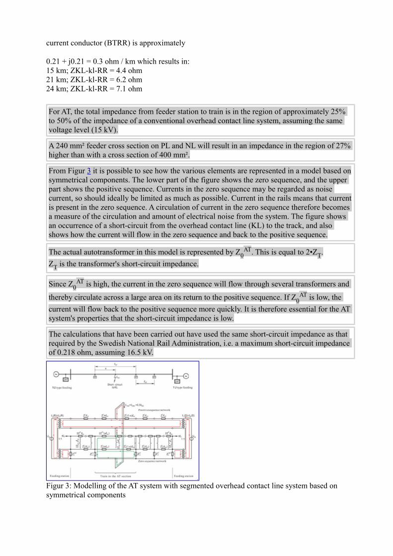
From Figur 3 it is possible to see how the various elements are represented in a model based on symmetrical components. The lower part of the figure shows the zero sequence, and the upper part shows the positive sequence. Currents in the zero sequence may be regarded as noise current, so should ideally be limited as much as possible. Current in the rails means that current is present in the zero sequence. A circulation of current in the zero sequence therefore becomes a measure of the circulation and amount of electrical noise from the system. The figure shows an occurrence of a short-circuit from the overhead contact line (KL) to the track, and also shows how the current will flow in the zero sequence and back to the positive sequence.
The actual autotransformer in this model is represented by Z0AT. This is equal to 2•ZT.
ZT is the transformer's short-circuit impedance.
Since Z0AT is high, the current in the zero sequence will flow through several transformers and
thereby circulate across a large area on its return to the positive sequence. If Z0AT is low, the
current will flow back to the positive sequence more quickly. It is therefore essential for the AT system's properties that the short-circuit impedance is low.
The calculations that have been carried out have used the same short-circuit impedance as that required by the Swedish National Rail Administration, i.e. a maximum short-circuit impedance of 0.218 ohm, assuming 16.5 kV.
Figur 3: Modelling of the AT system with segmented overhead contact line system based on symmetrical components

3 Autotransformer
In accordance with the most recent edition of the technical specification for autotransformers (EB.800040-000), the NNRA and Swedish National Rail Administration have two different outputs for transformers: 3/1.5 MVA and 5/2.5 MVA. Type-approved transformers for the Swedish National Rail Administration have so far been supplied by ABB Transmit Oy of Vasa in Finland and ABB Transformers of Ludvika in Sweden (only 5 MVA).
a) Autotransformers must satisfy the technical specifications formulated by the NNRA and Swedish National Rail Administration.
1. In addition, when transformers are ordered/approved, it is a requirement that the supplier calculates their no-load losses over an anticipated operating life/service life of 30 years. It must be assumed that the transformer will have been live for the entire period (8,760 hours annually). Similarly, the load losses must be calculated on the basis of a given representative load cycle. An internal rate of return of 4.5%, an annual price increase of 2.5% and 25 øre/kWh must be used in these calculations. Calculated loss costs will be added to the procurement cost of the transformer and used for comparisons with other suppliers.
b) Autotransformers must be connected to the outgoing cable/line lead at the feeder station/switching post (15 kV).
c) If feeder points are used, two transformers must be used in parallel. d) If the AT system is only constructed on parts of a section, it may also be necessary to use two
transformers at the end that transitions to a conventional system. 1. calculations must verify whether two parallel transformers are required
e) The same type of transformers should be used throughout the entire system, for reasons of interchangeability and backup.
Output transformers may be considered for new feeder stations or old systems undergoing modification; these transform the power deriving directly from generator/converter to the voltage level of the AT system. In this case, two transformers in parallel for each output connection may then become unnecessary. The concept for this must be specially developed and approved.
3.1 Location of autotransformers
The distance between autotransformers is significant in terms of proportion of earth leakage current, and thereby the effect on lineside cables.
There are no known limit values regarding how much earth leakage is acceptable for return current. As the distance increases between the locations at which current is injected and extracted from the rails, so the proportion of earth leakage current increases. If the distances are significant, leakage from the track will decrease and the proportion of earth leakage current will be virtually constant. In practical terms, this type of stable state would never be achieved between autotransformers in an AT system. The level of earth leakage current is highest in the AT window in which a train is situated, and is mainly determined by the distance between the train and the nearest autotransformer. In the closest AT window with no train, there will also be some earth leakage current, but for the other sections, the level of earth leakage current will be virtually zero.

Return current leaking to earth mainly causes two adverse phenomena:
1. return current in conductive lineside structures such as fences, water pipes, etc. (conductive coupling), and
2. induced currents in lineside cables (inductive coupling)
In addition to the distance between the transformers, the conductivity of the soil and diversion from the track are significant factors in terms of the level of earth leakage current and the effect of this current in earth. If the conductivity to earth is poor, the current will utilise a greater proportion of the soil. This will then result in a greater imbalance between the outward and return feeders in the circuit and thereby higher induced noise on other systems (telecom cables, signalling cables, etc.). However, it may mean that the current could flow to lineside conductive objects at a greater distance from the track than if the soil had good conductive properties. If diversion from track to earth is high, a greater proportion of the return current will leak into the soil.
The induced noise on parallel cables can generally be divided into two:
1. noise on cables close to the track, mainly caused by the imbalance in current distribution between outward and return feeders, and
2. noise on cables at some distance from the track, mainly caused by earth leakage current
Noise from the system is greatest in the AT window in which a train is situated. Within the AT window, noise is lowest when the train is in the immediate vicinity of an autotransformer. The drop in voltage is also lowest when the train is fed directly from a transformer. Autotransformers should therefore be located at locations where the greatest loads can be expected.
a) Autotransformers should be located with an average intervening distance of approximately 10 km.
1. the maximum distance between two consecutive autotransformers must not exceed 12 km
2. placing autotransformers closer together generally results in improved EMC properties for the system
3. shorter distances between autotransformers should therefore be considered in locations where it may be necessary because of buildings in proximity and critical/essential lineside installations that could be particularly susceptible to
In special cases, other AT systems with draining transformers and separate return-current conductors may be considered, if particularly stringent requirements have been imposed regarding EMC factors. In such instances, separate studies must then be conducted.
b) The maximum length of cables between overhead contact line masts and transformers should be 60 m. If cables are longer, overvoltage protection will then be required at both ends; refer to Overspenningsvern.

c) Autotransformers should be located close to roads so that during the construction phase it is possible to transport the transformers by road, and that future access to the transformers for inspection or maintenance purposes will be possible without using rail-based vehicles.
Dedicated protection (Buchholz relay, differential protection or thermal protection) or circuit breakers for selective and rapid disconnection are not planned for autotransformers in cabins.
1. cabins containing autotransformers must be located as far as possible from other essential technical installations, buildings, areas trafficked by people, and combustible buildings. If this is not possible, dedicated protection must be considered for the transformers
2. if the autotransformers are located in a separate transformer room in a building for a specific reason, all of the protection and equipment usual for this type of installation must be considered
3. the location of autotransformers must also take into account acoustic noise that may disturb residents living nearby
In practice, the most practical location for autotransformers in cabins will be near the perimeter of station areas. There will normally be road access to such locations, and the NNRA will own sufficient land to be able to locate the transformers on its own property.
In addition, a station will normally be the location where two passing trains (accelerating simultaneously) cause the greatest loads, making this the most optimum location from an electrical point of view.
Normally, a location at least 60 metres from residential buildings will be sufficient to avoid noise disturbance. Special measures must be considered for locations closer than 60 metres to buildings.
In special cases, where several autotransformers must be located close together, a dedicated building, capable of housing several units, may be considered. Thus, it would not be necessary to house multiple units in multiple separate cabins.
4 Network segmentation
5 Overhead contact line network segmentation
The most optimum system, from the aspect of noise on parallel cables, requires the overhead contact line network to be segmented, in order to avoid a through load current to the system. Because of the differences in tension that will occur between the various sections, the length of individual overhead contact line sections must be restricted.
Calculations have been carried out to determine how the proportion of earth leakage current varies according to different section lengths and different train positions.
In addition, the length of the overhead contact line sections (KL) will have a relatively large effect on the total impedance up to the train, cf. Figur 4 and Figur 5 under.

Figur 4: Impedance between overhead contact line and rail, ZCL-RR (shown in red) for system
with 6 km long overhead contact line sections and 12 km between two unilaterally fed AT units
Figur 5: Impedance between overhead contact line and rail, ZCL-RR (shown in red) for system
with 12 km long overhead contact line sections and 12 km between two unilaterally fed AT units<
The voltage between the overhead contact line sections has been calculated using a continuous load current of 500 A from a single train on the entire section. If there is more than one train on the section, the through load current in PL will also contribute to an increase in the voltage drop along the section between two overhead contact line sections.
The greatest difference in voltage occurs on the section closest to a feeder station. On 6 km overhead contact line sections and with a 500 A load current, the maximum voltage has been calculated at approximately 600 V; on 12 km sections the maximum value is approximately 1,000 V, when only a single train is on the section. If other traffic is to be taken into account on the section, the length of the overhead contact line sections should normally not exceed 6 km. Roughly speaking, the contribution from other trains on the section can be set to approximately 180 V/500 A for trains in the closest AT windows, and approximately 120 V/500 A for trains in other AT windows further away.
By comparison, the same voltage difference over a draining transformer is calculated to be 380 V at a distance of 6 km between draining transformers, and approximately 200 V at a distance of 3 km between draining transformers, with a total load current of 500 A.
a) There must be no more than 1,200 V between two overhead contact line sections at the load

currents normally occurring on the system b)
The length of individual sections must be limited because of the system's noise properties, and should be shorter than the maximum length, with regard to voltage between two sections
c) The maximum length of overhead contact line sections should be 6 km, if each overhead contact line section is fed via a disconnector from PL in the centre of the section (T-feeding) For end-fed overhead contact line sections, the maximum length should be 3 km
d)
On sections where the load is small, on which only a single train is expected to be within an overhead contact line section, with a normal distance between trains of two AT windows (20–24 km), the permitted length of overhead contact line sections can be up to 10 km (centre-fed)
e) It is not permissible for an overhead contact line network to have switches coupled in series that enable the connection of two overhead contact line sections that are separately fed from PL (T-feeding from PL). In practice, this means that switches coupled in series will only be used between an overhead contact line section and sidings, dead-end tracks, industrial sidings, etc.
f) It must be possible to segment all stations (from entry A to entry B) independently of the rest of the network
1. this means a separate T-fed section for each station
g)
Breaks between the various sections on the overhead contact line network must be constructed as insulated overlap sections, cf. Kontaktledning/Prosjektering/Seksjonering
6 AT network segmentation
It is a general rule that it must be possible to segment the AT network so that:
• operational disruption to the overhead contact line and/or AT network results in as little operational disruption to train traffic on the section as possible
• essential operational and maintenance work can be carried out on the system without extensive disruption to train traffic
When the network is segmented, sections that are fed unilaterally from only one autotransformer must be kept within lengths that ensure that induced noise on lineside cables remains at acceptable limit values. If these unilaterally-fed overhead contact line sections become too long, or if this type of abnormal operational situation continues for an extended period, operational measures may become necessary in order to restrict train traffic, or the load on the traction power supply. Unilaterally-fed sections up to 6 km will normally be acceptable for a limited period of time.
a) It must be possible to segment the AT network at each autotransformer b) Double-pole switch disconnectors, which disconnect PL and NL simultaneously, must be used c) All disconnectors in PL and NL should be remote-controlled d) When the AT network is disconnected between two AT units, there must always be an
autotransformer at the end of the last live AT window. Unilaterally-fed sections should not be longer than 6 km in total, calculated from the nearest autotransformer
e) If a feeder station is servicing an AT system in several directions (more than one line lead to an AT system), it must be possible to energise all AT cables by connecting PL and NL if there is a fault on one busbar section or if there is a fault on the line lead's circuit breaker
f) In order to disconnect autotransformers for inspection and maintenance, or in the event of a fault on an autotransformer, manual double-poled disconnectors may be mounted on the mast

at the cable down-lead to each unit.
1. when such disconnectors are used, these should be fitted with earthing blades that earth the cable when it is disconnected
7 AT systems on double tracksThe same rules generally apply to the construction of AT systems on double tracks as for single tracks. The following section describes the differences.
a) AT systems on double tracks: Overhead contact line systems with an AT system must be constructed with segmented overhead contact lines on double-track sections[1].
b) Separate AT systems: There must be separate AT systems for the two tracks, with negative (NL) and positive (PL) feeders for each of the overhead contact line systems at the tops of masts[1].
c) Separate autotransformers: There must be separate autotransformers for each of the tracks[1].
d) Autotransformers at the same location: Autotransformers for the two tracks must normally be sited at the same location (same km), one on each side of the alignment[2].
1. Implementation: The siting of autotransformers in relation to stations and track loops is flexible[1].
2. Exception: In exceptional cases, autotransformers may be located on the same side of the track, if dictated by practical factors[2].
3. Implementation: If autotransformers are sited on the same side of the track, there must be good, clear labelling to indicate which unit belongs to which track[2].
e) Positive feeder closest to overhead contact line system: The positive feeder (PL) for both tracks must be closest to the overhead contact line system for both tracks[2].
In cases where there are sets of tracks and several sets of positive and negative feeders suspended from portal structures, identification of the feeders can be a problem. In such cases, if the positive feeder is consistently suspended at the right hand side, viewed in the direction of increasing kilometre indications, this may simplify identification.
1. Implementation: Each group should be kept separate in order to simplify maintenance work[2].
2. Implementation: On track areas, there must be clear, appropriate labelling of each group of NL/PL and of individual feeders[2].
f) Remote-controlled switches between positive feeder (PL) and overhead contact line: There must be remote-controlled disconnectors for the connection between the positive feeder and overhead contact line[2].
g) Segmentation of the overhead contact line: The overhead contact line should be segmented at maximum intervals of 5 km, as shown in Figur 1 [1].
1. Exception: shorter sections may be chosen if dictated by the load.
On single-track sections, the segmentation selected for the overhead contact line should fit in with the distance between stations and positioning of signals; refer to Section 2 in 540 Chapter 6 regarding segmentation. In respect of double-track lines on new sections, there will no longer be an approximate distance of 10 km between stations; other factors will also apply. Segmentation must therefore be implemented as extensively as possible in accordance with the ideal recommended in Figur 6.

h) Segmentation of overhead contact line must satisfy the Traffic Rules: Segmentation must be designed so that the requirements in Kontaktledning/Prosjektering/Seksjonering, section 2.6.3 Location of insulated overlap section at main signal has been complied with for both signals. Segmentation must also be designed so as to comply with the Traffic Rules in STY-5093 that apply to the NNRA network, in particular Chapter 8.4.3.3[2]. Also refer to Figur 6.
7.1 Dividing and segmenting negative (NL) and positive (PL) feeders with switches
Section switches are not necessary for NL and PL at autotransformers for AT systems on double-track lines, as they would be on single-track lines. Section switches are only necessary on diversion loops. This is because trains will not run between two diversion loops when these are disconnected; refer to Figur 6. The location of switches to segment PL and NL must be coordinated with the transfer options that will exist on double-track lines.
a) Segmentation with switches at cross-overs: Segmentation must be possible using remote-controlled double-poled switch disconnectors for NL and PL at signals relating to cross-overs[1].
1. Implementation: The overhead contact line must be segmented as shown in Figur 6.
b) Switches between positive feeders (PL) and overhead contact line at cross-overs: Feeding from positive feeder to overhead contact line must be via remote-controlled disconnectors[2].
Figur 6: Illustration of AT system on double-track line. The drawing is not to scale and the number of autotransformers along the line may be higher.

7.2 Segmentation stations
a) Segmentation stations are implemented as for single-track lines: Segmentation stations must be implemented in the same manner as for sections of single-track line: refer to section 540/5, Appendix d, 8.3.1
1. Exception: However, switching posts may be set up that share a double-poled busbar for the two tracks. This will be a parallel connection between the two overhead contact line systems that increases their transmission capacity[1].
7.3 Lineside earthing conductor
Refer to 'Electrical – universal application', Chapter 6.
8 Electrical safetya) All installations must be planned and constructed so that it is technically possible to disconnect
and earth the overhead contact line system while the AT network is live. b) In worst-case scenarios, the gap between the AT network and live components in the overhead
contact line (including cantilevers and insulators) should not be less than 2.0 m, measured directly to any point in the cable span.
c) The distance to other high-voltage crossing lines,proximity to terrain, vegetation, etc. must be in accordance with [FEF].
d) All overhead contact line masts in an AT system must have holes for grounding ball studs 1 m above SOK and 2 m below mast top, as well as holes for earthing hooks 6 m above SOK.
1. grounding ball studs and hooks are fitted to selected overhead contact line masts, depending on the requirements of a particular section
If the system is constructed with a gap of at least 2.0 m between the AT system and the overhead contact line system, this will make it easier to carry out maintenance work on the overhead contact line network. If the AT network is still live and there is grid interconnection, this will not affect the operating conditions for trains outside the overhead contact line section under maintenance. This may provide further options and enable the overhead contact line system to be worked on for longer periods.
The gap of 2.0 m is the same as the normal gap for conventional overhead contact line systems constructed with feeders at the tops of overhead contact line masts. Refer also to requirements regarding the design of masts in section 1.3.
An assessment should be carried out as to whether separate guidelines and requirements are necessary for certain work operations on overhead contact line systems in close proximity to the AT network. In each and every instance, it is always the Head of Electrical Safety who is responsible for assessing whether work may be carried out when the AT network is live.
9 AT system in tunnels longer than 5 km“TSI safety in railway tunnels" requires the overhead contact line to be segmented and for remote-controlled switches to be installed in tunnels longer than 5 km. The overhead contact line is segmented in this way in order to make it possible to supply energy to trains in the tunnel, even

after the occurrence of what is known as a 'hot incident'. An incident of this kind could mean that the overhead contact line has been either damaged or short-circuited, and this provision means that it would be possible to disconnect the affected portion and enable other trains to exit the tunnel. An AT system with segmented overhead contact line is divided into sections approximately 5 km long, and is fitted with switches, thus requiring only minor changes to make this compatible with the requirements of the TSI. The NNRA uses the following requirements in order to satisfy the requirements of the TSI. For tunnels less than 5 km long, the TSI does not specify any particular requirements. For tunnels more than 20 km long, the TSI requires separate safety analyses to be carried out. This may mean that additional safety measures must be implemented.[3]
a) Segmentation of the overhead contact line: In accordance with TSI Safety in Railway Tunnels, the overhead contact line must be segmented into sections no longer than 5 km[3].
1. Implementation: There must be as few switches as possible[3]. 2. Implementation: The location of the section separation points must be coordinated with the
location of signals, the distance between trains during normal operation and the number of trains expected to be in the tunnel simultaneously[3] [4] .
3. Implementation: The sections must be of equal length[4]. 4. Implementation: The number of NL and PL switches must not exceed the number required
by the regulations[4]. 5. Implementation: On double-track lines, it must be possible to segment and earth each of the
tracks independently[3]. 6. Exception: It is not necessary to take segmentation into particular consideration in tunnels in
which the signalling system does not permit more than one train at a time[3]. 7. Exception: Where one tunnel is followed very closely by another, both tunnels are defined as
one tunnel, provided that the following conditions are met: 1. The open-air distance between the tunnels is less than 500 m. 2. It is not possible to gain access to a secure area between the two tunnels[3].
b) Switches for the sections: In accordance with TSI Safety in Railway Tunnels, there must be an option to operate the switches by remote control and manually for each section of the overhead contact line[3].
1. Implementation: The location of the switches between PL and the overhead contact line in the centre of each section of overhead contact line must be the same as for the AT system in general[4].
2. Implementation: Switch disconnectors must be used[4]. 3. Implementation: The section switches must be illuminated[3].
c) Earthing the AT system (and indirect earthing of the overhead contact line – series earth): In accordance with TSI Safety in Railway Tunnels, it must be possible to disconnect and earth the AT system and thereby also the overhead contact line in tunnels by remote control[3].
1. Implementation: In feeder stations and switching posts, there must be disconnect and end-point earthing options for NL and PL for all output connections to feeder sections that include tunnels.[4]
2. Implementation: The relevant tunnel section must be disconnected and earthed at all feeder input points[4].
3. Implementation: Earthing switches must have a secure setting indication for signals that confirms that the earthed setting has been selected[4].
4. Implementation: Fire crews must be instructed to bring voltage testers and earthing equipment to the scene of an accident and to use these[4].
Local fire and rescue services must be consulted during the preparation of procedures regarding how they should approach incidents in tunnels that have a traction power supply. In particular, this

applies to communication between electrical energy centres and fire crews, and to the use of earthing equipment. Using end-point earthing will make it possible to disconnect power simultaneously to all tunnels on a feeder section. This can be achieved very rapidly, unlike other methods that require technical experts for fault localisation, disconnection and earthing. This avoids the need to set up remote-controlled switches at every access point and for every section of the overhead contact line system, although trains that are not affected by the incident will be without power. However, this situation is only intended to be used in disaster situations[4].
9.1 Insulation coordination
a) Insulation coordination for the AT network must be carried out in the same way as for the overhead contact line system; refer to Felles elektro/Prosjektering og bygging/Isolasjonskoordinering og overspenningsbeskyttelse.
The highest voltage between the phase conductor and earth in the AT system is the same as that between the overhead contact line and earth. The maximum permissible continuous voltage between phase and earth is in accordance with NEK EN 50163, which permits 17.25 kV. The closest standard voltage level that satisfies this is 30 kV phase-phase (17.32 kV phase-earth).
The Technical Regulations currently stipulate the requirement that the overhead contact line system must be designed for 70 kV for one minute (operating frequency) and a 170 kV lightning impulse. The same must be used for the AT system.
9.2 Insulation gaps
The regulatory requirements applying to insulation gaps in the overhead contact line system are different to those applying to cables with fixed terminations.
Overhead lines with fixed terminations; refer to FEF Kapittel 6. [FEF] must be used in the design of insulation gaps for cables with fixed terminations. For wires in the overhead contact line system that are tensioned by counterweights, refer to FEF til kapittel 8 for railway installations; however, Chapter 6 applies to overhead lines with fixed terminations.
From Table 6-1, the requirements for insulation gaps between phase-phase, Dpp are a
minimum of 0.40 m for 30 kV, nominal system voltage (applicable to gap between PL and NL).
The gap for 15 kV voltage may be obtained by interpolating between the 10 and 20 kV requirements applying to the phase-earth gap: Del = 0.16 m
Installations FEF Kapittel 4. The NNRA would like the general requirements in FEF Kapittel 4 (tabell 4-1) also to apply to railway installations (switchgear layouts, etc.).
The values in Table 4.1 result in a minimum requirement of 160 mm phase-earth insulation gap. This will apply to all conductors connected to earth in 'installations', i.e. switchgear layouts and transformer connections.

The static insulation gap requirements in the overhead contact line system are 250 mm to earth. Ideally, the insulation gap in the AT network should not be less effective than the gap in the overhead contact line network, and it is for this reason that the same minimum insulation gap to earth is to be selected as for the rest of the overhead contact line system, i.e. 250 mm phase-earth as the minimum gap.
For 30 kV, Table 4 of the Regulations relating to electrical supply installations gives a minimum insulation gap of 320 mm phase-phase to satisfy BIL 170 kV.
a) The air insulation gap for PL and NL feeders must be in accordance with [FEF] 1. gap between PL and earth must be a minimum of 250 mm 2. gap between NL and earth must be a minimum of 250 mm 3. gap between PL and NL must be a minimum of 400 mm 4. gap between NL and KL (overhead contact line) must be a minimum of 400 mm 5. gap between PL and KL must be a minimum of 250 mm
b) Insulation gaps for switchgear layouts and at feeds to transformers must be in accordance with [FEF].
1. gap between PL and earth must be a minimum of 250 mm 2. gap between NL and earth must be a minimum of 250 mm 3. gap between PL and NL must be a minimum of 320 mm 4. gap between NL and KL (overhead contact line) must be a minimum of 320 mm 5. gap between PL and KL must be a minimum of 250 mm
Locating the AT feeders at the top of masts reduces the likelihood, in the event of a lightning strike, of lightning striking the overhead contact line system directly. It will be easier for the AT feeders to 'capture' the lightning. In the event of a direct strike, the insulation gaps mentioned above will send the direct flashover to earth from PL or NL with backflash also resulting in a flashover between PL and NL. The lightning current will thereby be divided between these feeders with a reduced wave impedance, which in turn will reduce the amount of overvoltage stress on the system. If the system also has lineside earthing conductors, the stress will be reduced even further.
9.3 Insulators
a) The creep current path for insulators between phase and earth must be the same in the AT network as in the overhead contact line network.
In accordance with Kontaktledning/Prosjektering/Isolatorer, the creep current path for insulators must be at least 40, 48 or 52 mm/kV normal voltage, depending on pollution/environmental factors.
In respect of the AT system, any insulation failure between PL and earth or between NL and earth will result in a short circuit. Voltage stress across an insulator will thereby never be more than 17.25 kV continuous voltage, and the requirement regarding creep current path will be the same as for insulators in the overhead contact line system, i.e. 690, 828 or 897 mm.

9.4 Overvoltage protection
A special study has been carried out of overvoltage protection in the AT network (TRANSINOR). The study was primarily initiated in order to examine whether, in a network containing so many cables, it might be acceptable not to have overvoltage protection at all cable terminations.
a) Surge arresters in overhead contact line systems with AT systems must be designed on the same basis as conventional overhead contact line systems; Felles elektro/Prosjektering og bygging/Isolasjonskoordinering og overspenningsbeskyttelse. Extra earth rods should also be considered for mast foundations, which would also help improve the overvoltage protection of the systems.
b) Surge arresters in the AT network must be located between phase and earth in both PL and NL; 1. at both ends of embedded cables longer than 70 m in the AT network 2. at one end of embedded cables shorter than 70 m 3. at the end towards overhead wires/overhead contact line masts, for autotransformer
cable branches shorter than 60 m 4. at both ends for autotransformer cable branches longer than 60 m
10 Mechanical design of mastsa) The design must allow a direct gap between the overhead contact line system and the AT
network of a minimum of 2.0 m in worst-case scenarios. 1. The design must take into account the maximum sag and maximum (design) wind
deflection of cables with fixed terminations.
b) The use of curved anchoring wires should be avoided. c) Masts and foundations must be designed in accordance with
Kontaktledning/Prosjektering/Konstruksjoner. 1. The additional load subjected to masts by AT feeders must be taken into account. 2. An evaluation must be performed, examining whether the masts should be designed for
further loads in the form of additional cables such as lineside earthing conductors on masts.
11 Protection on outgoing line leads
The report 'Protection in the AT system for the Norwegian traction power supply' recommends using the same protection as for conventional overhead contact line systems, although it recommends replacing certain types of protection.
Connecting the autotransformers to existing outgoing line leads (at the 15 kV level) means that it is then unnecessary to make changes to the protection at existing feeder stations, provided that these are able to tolerate increased loads resulting from increased distances between the feeder stations.

11.1 Distance protection
Distance protection must continue to be used as the main protection.
The protection settings must be selected in accordance with Banestrømforsyning/Prosjektering/Energiforsyning.
a) Electromechanical distance protection with 'MHO characteristic' must be replaced by electronic protection.
b) The 'distance to fault' function in distance protection should be utilised by ensuring that this is transferred as a signal to the electrical energy centre.
The 'distance to fault' function will be able to provide a good indication of the location of the fault, and thereby help to ensure that faults in the system are identified more quickly.
11.2 Overcurrent protection
a) The settings of overcurrent protection systems must be selected in accordance with Banestrømforsyning/Prosjektering/Energiforsyning.
11.3 Segmentation stations
It is recommended that one segmentation station with switch disconnectors and undervoltage protection is constructed between each feeder station, in order to provide an acceptable outage time in the system in the event of a fault. The segmentation station will help to ensure that the network is automatically sectioned in the event of short circuits, and reduce the down-time for the fault-free half of the section. If there is no segmentation station, and there are long distances between the feeder stations, with large numbers of cables and components in the system, a considerably longer down-time could be expected for the fault-free part of the network than is currently the case for the overhead contact line network, with about 80 km and a zone limit switch.
a) Where the distance between two feeder stations is greater than 60 km, a segmentation station must be provided between feeder stations.
1. A segmentation station must consist of a three-poled switch disconnector fitted with undervoltage protection and phase-lock protection.
2. The segmentation station must normally be located within the network (connected to the network).
3. In the event of a fault, the undervoltage protection must disconnect the switch disconnector before further reconnection attempts are made in the feeder station or switching post.
4. The switch disconnector must break PL and NL, and disconnect from the dead section in the overhead contact line network; refer to Dødseksjoner.

Figur 7: Principles of a segmentation station in the centre of an approximately 120 km long feeder section
11.4 Dead sections
a) Every segmentation station in the AT system must have a dead section. 1. In addition to breaking PL and NL, the switch disconnector in the segmentation station
must also establish a dead section in the overhead contact line network. 2. The dead section in the overhead contact line network must be implemented as shown
in Figur 8. 3. The dead section must normally be connected. 4. The length of the actual dead section in the overhead contact line network must be at
least 400 m and be implemented in accordance with Kontaktledning/Prosjektering/Seksjonering.
Figur 8: Principles for a dead section in an AT system with three-poled switch disconnector
12 Return circuit
A return wire is not normally needed for an AT system with PL and NL.
a) An assessment must be made as to whether a return wire may be necessary, taking into account the local magnetic field around the overhead contact line system.
The return wire will help minimise the low-frequency magnetic field for nearby buildings or other technically sensitive or critical equipment.
b) If a return wire is used, this must be suspended as close as possible to the AT feeders above the

station, on the same overhead contact line mast, at about the same height as a return wire is normally suspended.
c) An assessment must also be made as to whether it is necessary to have a return wire above stations at which autotransformers are located, taking into account the effect on track circuits.
d) Requirements in the Technical Regulations for signalling Signal/Prosjektering regarding maximum lengths of track circuits must be complied with.
e) In respect of the design of the return circuit in the rails, Kontaktledning/Prosjektering/Returkrets must also be complied with, with the exception of the requirement regarding draining transformers, which must not be used on sections with an AT system.
12.1 Connection to the track
a) A return busbar must be installed at all autotransformers. b) If there is more than one autotransformer, the neutral point of all the transformers must be
connected to one common return busbar. c) The return busbar at the autotransformers' outgoing feed must be connected directly to the
converter station's return busbar. d) The design of all return connections from an autotransformer must be at least equivalent to the
transformer's nominal load current (ref. 15 kV). e) The connection from the return busbar to the track must be designed with a current-carrying
capacity at least equivalent to the design load current in the feeder cables on the high-voltage side of the autotransformers (ref. 15 kV).
1. A duplicate, redundant connection to the track must be provided.
'Redundant' is understood to mean that at least two parallel current paths must be installed, each designed to carry the design load current at that location, in the event of a failure in one of the current paths.
Each of these current paths should be laid in separate cable routes, and connected to the track 2–3 m apart, to reduce the likelihood of damage/failure to both of the current paths simultaneously.
f) The connection to the track must be made in accordance with the track insulation at that location.
1. Where track circuits are single-insulated, the return busbar must be connected directly to the earthed rail, and at stations with multiple tracks, there must also be a cross-connection between the tracks.
2. Where track circuits are double-insulated, the return busbar must be connected to the track via filter impedances.
Note that if there are two or more connections to a track that is connected to the return busbar, it will not be possible to detect rail fractures in the track between these connections. The distance between two such connections should not be greater than 3 metres.
1. On sections of line that do not contain track circuits, the return busbar must be connected directly to both sets of rails.

g) If the section has a return wire, the connection of the return busbar at the autotransformers must be coordinated with the down-lead from the return wire to the track.
13 Traction power supply stability
Analyses of low-frequency stability and electrical resonance stability must be carried out in accordance with Banestrømforsyning/Prosjektering/Energiforsyning.
If resonance frequencies of less than 250 Hz are likely in the area, stability analyses must be carried out. The following factors are indicators for resonance frequencies below 250 Hz:
• long sections between two feeder stations with cable extending over about 10% of the section
• unilaterally-fed sections of about 40 km or more, with only one converter unit in operation
• unilaterally-fed, long sections over about 80 km
a) Due to the low transmission impedance produced by the autotransformer system, a falling voltage characteristic must be considered at feeder stations in order to stabilise these against each other, and reduce the flow of power between them; refer also to Banestrømforsyning/Vedlikehold/Energiforsyning
When long lines are connected in, there is a risk of connection surges. On lines with low resonance frequencies (high proportion of cables), there is a higher probability of major surges. This is not a problem if the inward connection is made using circuit breakers and test resistance, but when lines are connected in without test resistance (with disconnectors or circuit breakers in zone limit switches), it can result in unacceptably high connection surges.
b) Connecting in long lines without using test resistance should be limited 1. The requirements for protection of inward connections
Banestrømforsyning/Prosjektering/Energiforsyning must be complied with
14 Special rules for the construction of overhead contact line systems with AT systems
When overhead contact lines are being refurbished with AT systems on existing sections of line, there will be a very limited amount of time available to work on the line. Normally, it will be possible to change over a maximum of one section of overhead line during a single long shift.
a) In order to be able to operate an overhead contact line system (including during a construction period), there must either be an operational conventional overhead contact line system with draining transformers (BT system), on which at least half of the draining transformers are operational, or an AT system in accordance with the above requirements
During the construction of an AT system, the following procedures are proposed for use:
1. Existing overhead contact line system is retained, unchanged. 2. New overhead contact line masts are erected. 3. AT feeders are suspended and segmented, as for planned final installations. At least

30–40 km of the AT system should be constructed before the overhead contact line system is changed over[5].
4. All RTUs with associated cabling must be installed and connected to electric energy centres.
5. New relay plan for planned final AT system must be prepared (existing plan revised). This relay plan should also include any temporary phases, if there is to be a changeover from a conventional overhead contact line system to one with an AT system. If necessary, new protective equipment must be procured, installed and commissioned on the basis of the existing relay plan.
6. Autotransformers and kiosks are installed – two parallel transformers fed from 15 kV (converter/switching post) and one or two transformers at the end of the AT network transitioning to BT[6].
7. The switchgear layout for branches (T-feeding) to the overhead contact line system is constructed as for planned final installations.
8. The AT network (PL, NL and transformers) may be energised and tested at idle. 9. Changeover from an operational BT system to an operational AT system, but retaining
the old overhead contact line system.
Generally, all changeovers from BT to AT are implemented in such a way that it is possible to change back to a conventional system. This means that all components that are to be disconnected or short-circuited (such as switches, transformers, joints in tracks) are not physically removed until the system has been tested and 'approved'. Changeovers must be implemented over an extended period during which there are no train operations. The time that this will require is determined by the total section of line to be changed over. During the construction of an AT system, the following procedures are proposed for use:
10.All draining transformers are short-circuited on the primary and secondary sides (including switches, if these exist).
11.Temporary loop/drop is established from new switches to the old overhead contact line system. All old overhead contact line system switches connected in series are opened and locked/physically blocked.
12.If there is a long distance between insulated overlap sections in the old overhead contact line system, it may be necessary to divide/segment this further. The overlap section closest to the planned new permanent segmentation may then be used. The overhead contact line system is 'opened' by removing the drop/loop, which is used temporarily as a segmentation between two sections of overhead contact line.
NB: If it is necessary to use this new overlap section during work on the live overhead contact line system, it must be inspected and, if necessary, reconstructed to ensure that it contains sufficient gaps, as for an insulated overlap section.
13.The overhead contact line network may be energised from the AT system. Verification tests of the AT system under load may be carried out[7].
14.Any other tests regarding verification/approval of the AT system may be performed. 15.The construction of the new AT system may now be carried out by installing new
cantilevers. Sections of overhead contact line are replaced one section at a time with a new system on new masts that are already in place.

15 Special requirements regarding the maintenance of overhead contact line systems with AT systems
a) during the preparation of generic maintenance procedures for AT systems, there should be particular focus on checks to detect failures in NL or PL
Failures in PL and NL that do not result in short-circuits will not necessarily be detected. There is no protection that would immediately detect such a failure. Such failures could result in a risk of overload to the autotransformers and AT feeders, and increased electro-magnetic interference from the system.
b) switches and feeders must be periodically checked, with the particular aim of detecting failures
No system or concept has been developed for broken phase detection. This has been deemed unnecessary in other countries. However, since in Norway the plan is to install multiple disconnectors etc., there is a potentially higher risk of breaks in the terminations to such disconnectors. This risk will be assessed. Other detection systems will also be assessed in order to find a practical method of fault notification.
16 AT system preparationa) When overhead contact line systems are being refurbished (new masts and new cable systems)
on sections of line on which it is possible that an AT system will be developed in the future, cf. 'Strategy for overhead contact line systems and traction power supply, NNRA, December 2006), the planning and implementation of the overhead contact line system refurbishment must, as a minimum, take into consideration the factors described in the guidelines below.
1. Higher, more robust overhead contact line masts and foundations
The standard mast is currently an 8.5 m high lattice mast. For AT systems, masts should have a minimum height of 9.5 m, topped by insulators, allowing AT feeders to run 10 m above SOK. It is possible to add spires to all lattice masts and beam masts, so that one option is to design masts and foundations for AT feeders at a height of 10 m, but actually to construct the masts only to the height that is required (8 m, for example) and then retrofit spires. System drawings/diagrams are available for lattice and beam masts.
2. Span lengths at crossing points
Where the overhead contact line system crosses the track (changes sides), the distance between overhead contact line masts should be no greater than 35 m. If the span length is longer at a crossing point, higher overhead contact line masts should be considered, in order to ensure a gap of at least 2 m between the overhead contact line and NL/PL at the crossing point.
3. As few crossing points as possible
Overhead contact line masts should not cross the track/change sides at ordinary overlap sections, since if AT feeders cross the track at a later date, there will not be a sufficient gap between the raised cable/tensioning lines and AT feeders. Overhead contact line masts should be permitted on inner curves more often than normal, in order to achieve as few crossing points as possible. For example, on an S curve where the curve radius permits, it is possible to save on two track crossings by constructing overhead contact line masts on the inner curve.
4. Network segmentation

The future connection situation for the AT system should be prepared. If insulated overlap sections are required on block sections between two stations (cf. requirements in AT document), every effort should be made to site the overlap section in the new overhead contact line system at the future location of the break. This overlap section is to be implemented as an insulated overlap section (i.e. greater insulation gaps). Insulated overlap sections at home signals will be as previously.
5. Design of protective earthing
An increased short-circuit current on the section must be taken into account; refer to Felles elektro/Prosjektering og bygging/Jording.
17 References 1. ↑ 1,0 1,1 1,2 1,3 1,4 1,5 1,6 1. Traction power supply on double-track lines – Evaluating
alternative systems of traction power supply on double-track lines . NNRA, 17.03.2010. Document no EK.800101-000.
2. ↑ 2,0 2,1 2,2 2,3 2,4 2,5 2,6 2,7 2,8 2. Minutes of meeting of 20.04.2012, case reference 201101543-9.
3. ↑ 3,0 3,1 3,2 3,3 3,4 3,5 3,6 3,7 3,8 3,9 TSI – Safety in railway tunnels in the trans-European conventional and high-speed rail system.
4. ↑ 4,0 4,1 4,2 4,3 4,4 4,5 4,6 4,7 4,8 4,9 Case no 201101543-14, Summary of meetings and discussions regarding TSI safety in tunnels.
5. ↑ The length of AT systems constructed should be such that the load on the last transformer is no greater than the load that one transformer can handle alone. If the load is too great, a temporary transformer must be used in parallel, until the next stage/section of the AT system is constructed.
6. ↑ The length of AT systems constructed should be such that the load on the last transformer is no greater than the load that one transformer can handle alone. If the load is too great, a temporary transformer must be used in parallel, until the next stage/section of the AT system is constructed.
7. ↑ During the pilot phase of the AT system, separate procedures will be prepared for the commissioning of the system
