contact mesh and penalty method approaches …
TRANSCRIPT

Contact mesh and penalty method approaches applied to a severe contact problem
XIV International Conference on Computational Plasticity. Fundamentals and Applications
COMPLAS 2017
E. Oñate, D.R.J. Owen, D. Peric and M. Chiumenti (Eds)
CONTACT MESH AND PENALTY METHOD APPROACHES APPLIED
TO A SEVERE CONTACT PROBLEM
OLIVEIRA, S. A. G.*, FELICE-NETO, F. R. †
AND WEYLER, R.§
*† FEMEC-CIMNE Classroom - School of Mechanical Engineering - Federal University of
Uberlândia - Campus Santa Mônica -Caixa Postal 593 - CEP 38400-902 - Uberlândia - MG - Brasil
§ E.T.S. Enginyeria Aeronáutica i Industrial Technical University of Catalonia (UPC),
Edifici TR45 (ETSEIAT), Terrassa, Spain
Keywords: Explicit FEM, Contact, Contact Mesh, Severe Contact
Abstract. This work aims to propose a comparison between the well known penalty method
and the contact mesh approach in an Explicit Finite Element Method applied to a severe
contact simulation. The contact mesh links the probable contact regions and minimizes the
potential error. In this approach, the algorithm shrinks the whole model in the same
proportion, searches for the nodes which will probably start contact in the next iterations,
creates the contact mesh and transfers the conditions when the distance would be enough to
start the contact without the shrinkage. After the simulation finishes, the whole model returns
to its normal size to correct visualization. In order to test the method efficiency and guarantee
a reliable comparison, a microindentation experiment that represents a severe contact problem
was simulated using explicit integration for both contact approaches. As results, both methods
showed similar good results when compared to experimental tests for large deformations and
to observe the overall behavior. In the case of small deformations and to observe the local
behavior of small contact areas, the penalty method presents instabilities variations that are
close in size to the real deformations, different from the contact mesh approach, which shows
smooth transition between the mesh nodes, similar to the experimental results.
1 INTRODUCTION
Numerical Methods are often used to solve mathematical problems which describe
physical phenomena, when they have several variables or even does not have analytical
solution. A heavily widespread numerical method is the Finite Element Method (FEM), which
provides an approximate solution to differential equations that usually represent physical
phenomena, such as continuum mechanics and fluid mechanics [1, 2, 3].
502

OLIVEIRA, S. A. G. , FELICE-NETO, F. R. AND WEYLER, R.
2
The contact method most used in FEM commercial programs is the Penalty Method, in
which is used a force to avoid the penetration of volumes. Its calculation considers
geometrical and space conditions (such as body shape and penetration gap), other variables
(material properties and process parameters) and a penalty constant to multiply the
penetration, which is chosen by the user. A small value for the penalty could violate the
contact condition (allow penetration) and a big value could destabilize the simulation. This
method achieves good results for macro sized problems, like stamping process, but for micro
and nano sized process, like microindentation tests, the error can be greater than the
tolerances for a correct analysis. Another problem is the penalty constant given by the user,
which is highly non-linear and dependent on the user experience. [4]
Another method to deal with the contact problem is the Lagrange Method, which
establishes a minimization with boundary conditions, creating a Lagrangian function. This
function relates the objective function to the problem restrictions and is ensured by the Kuhn-
Tucker conditions [5]. Based on the Lagrange and Penalty Method the Augmented Lagrange
Method can be also postulated, using both the penalty factor and the Lagrange multipliers, but
in this case the Lagrange multipliers are updated each step and a finite penalty factor
guarantee the convergence. This method is stable but it must iterate each step, which is a
problem for explicit methods. [6]
A relatively new approach on the contact problem is the contact domain approach, or
contact mesh, which creates a mesh linking the nodes that will possibly begin contact from
one surface to another, with a single layer of elements. This mesh is responsible for predicting
the contact and reduces the error, by virtually shrinking the elements and transmitting the
conditions from one surface to another.
Thus, this work aims to compare the mesh approach method and the penalty method, both
in Explicit FEM time integration codes. The first approach (contact mesh) was simulated
using the COMFORM software, which is an academic algorithm, developed by the
Polytechnic University of Catalunya (UPC) in partnership with other institutes [7]. The
second contact approach (penalty method) was simulated using the STAMPACK® software,
developed by QUANTECH ATZ, an explicit FEM commercial algorithm, focused on
mechanical forming processes. The severe contact problem chosen to simulate were a
microindentation problem in a copper specimen, with maximum penetration depth not
superior to 3 µm.
2 CONTACT MESH APPROACH
According to Oliver et al. [8], the contact domain is a fictive intermediate region, with the
same dimension as the contacting bodies, connecting the potential contact surfaces of those
bodies. This leads to a purely displacement problem, because the contact function is now
based on the dimensionless measure of the normal and tangential gaps. Therefore, the
difference between this method and the node-to-node or segment-to-segment strategy lays on
the interpretation of the contact domain. In the classical methods, the contact conditions are
formulated due to a projection of the contact surface or point (slave contact surface) onto the
other contact surface (master contact surface), as shown in Fig. 1 (a). Considering that, the
contact problem is a subdomain, with lower dimension. On the other hand, the contact mesh
503
OLIVEIRA, S. A. G. , FELICE-NETO, F. R. AND WEYLER, R.
3
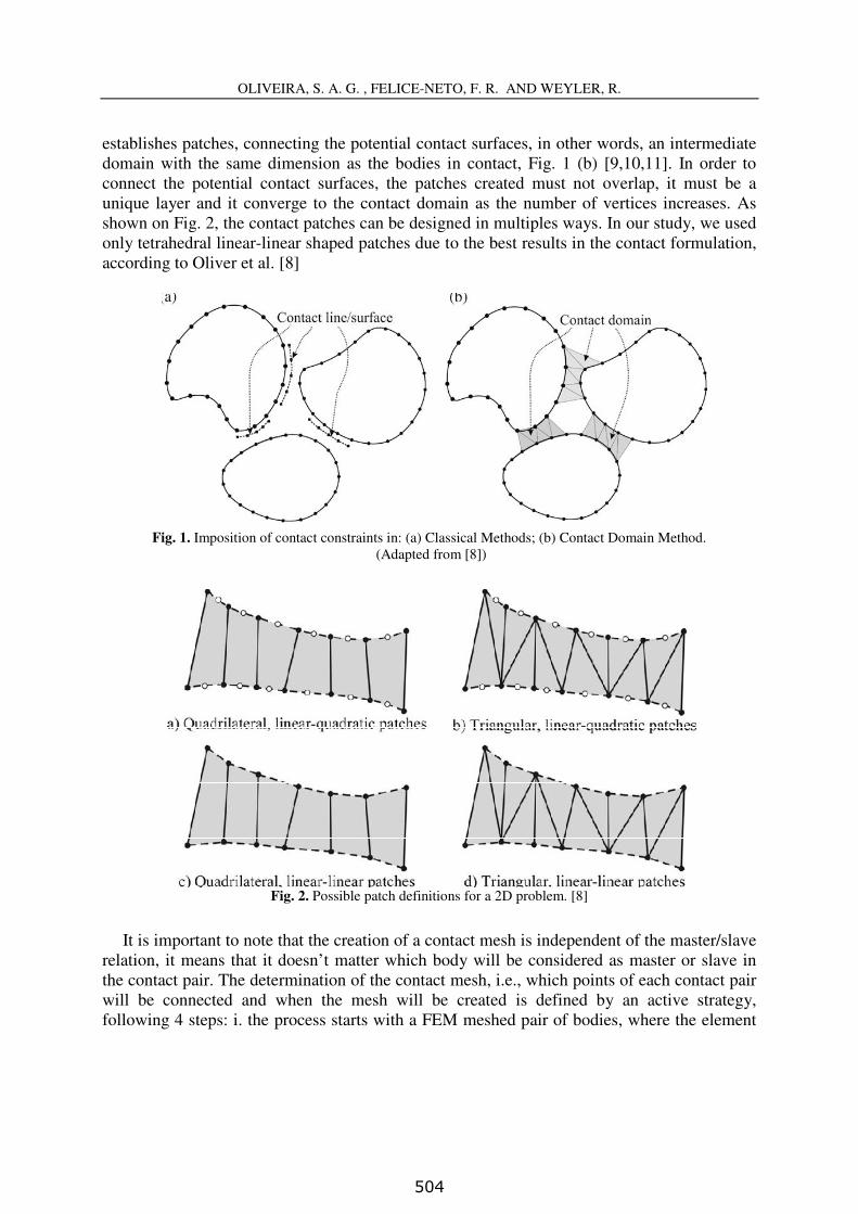
establishes patches, connecting the potential contact surfaces, in other words, an intermediate
domain with the same dimension as the bodies in contact, Fig. 1 (b) [9,10,11]. In order to
connect the potential contact surfaces, the patches created must not overlap, it must be a
unique layer and it converge to the contact domain as the number of vertices increases. As
shown on Fig. 2, the contact patches can be designed in multiples ways. In our study, we used
only tetrahedral linear-linear shaped patches due to the best results in the contact formulation,
according to Oliver et al. [8]
Fig. 1. Imposition of contact constraints in: (a) Classical Methods; (b) Contact Domain Method.
(Adapted from [8])
Fig. 2. Possible patch definitions for a 2D problem. [8]
It is important to note that the creation of a contact mesh is independent of the master/slave
relation, it means that it doesn’t matter which body will be considered as master or slave in
the contact pair. The determination of the contact mesh, i.e., which points of each contact pair
will be connected and when the mesh will be created is defined by an active strategy,
following 4 steps: i. the process starts with a FEM meshed pair of bodies, where the element
504

OLIVEIRA, S. A. G. , FELICE-NETO, F. R. AND WEYLER, R.
4
chosen doesn’t affect the contact approach (Fig. 3 (a)); ii. the interior nodes are removed and
the boundaries are shrunk (Fig. 3 (b)); iii. the contact mesh is created, linking both bodies in
the probable contact areas (Fig. 3 (c)); iv. The original boundary and mesh are retrieved (Fig.
3.6 (d)). [10]
Fig. 3. Generating of the contact mesh: (a) Original Mesh; (b) Removal of internal nodes and shrinkage; (c)
Creation of the contact mesh; (d) Original boundary and mesh retrieved.[10]
3 MICROINDENTATION TEST
A microindentation test consists in an experimental method in which the specimen is
pressed by a known shaped indenter, with controlled load and displacement. Analyzing the
load, displacement and also the indentation mark, it is possible to calculate the bulk or multi-
layered materials properties. It is also possible to characterize the multi-layered material
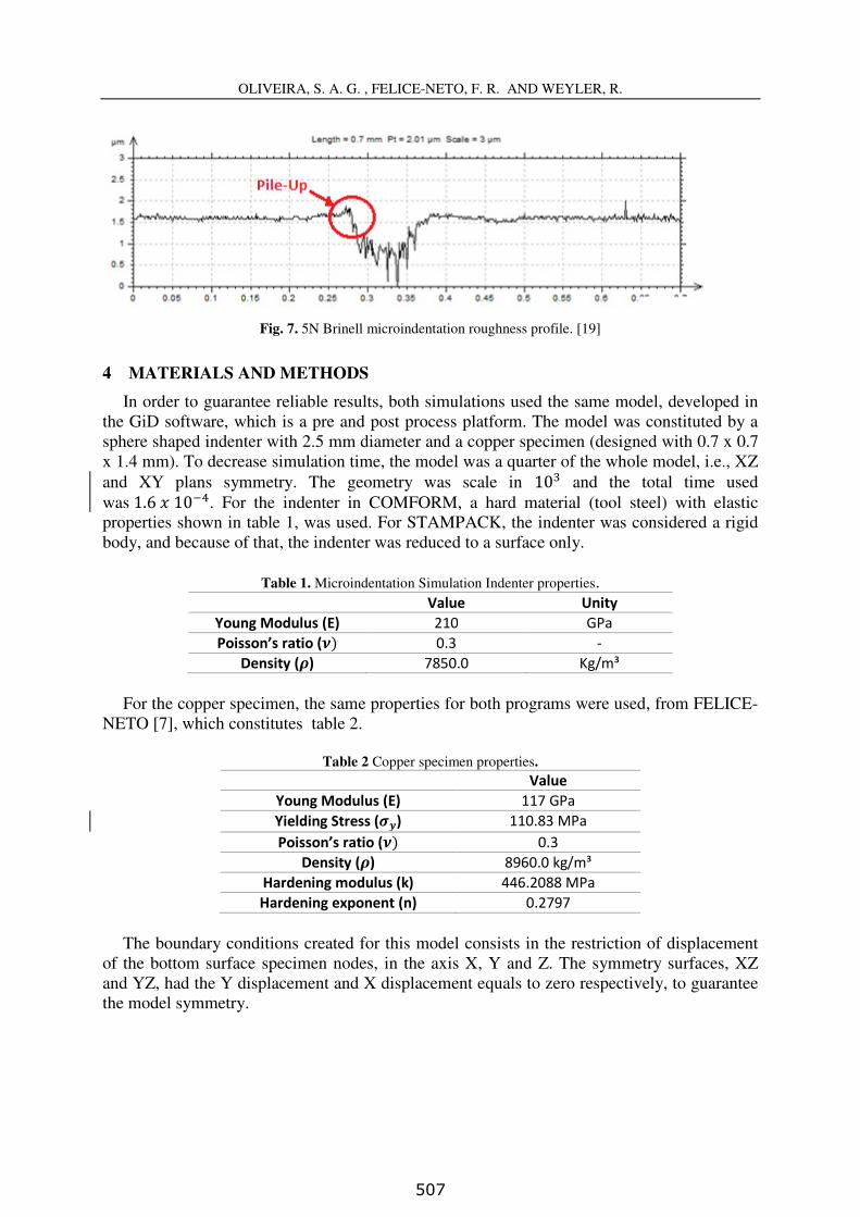
adhesion between layers and analyze other phenomena, such as the pile-up and sink-in. A
microindentation experiment can be simulated as if the plastic deformations are greater when
compared to elastic ones, enough to neglect the elastic part of the total deformations in the
material formulation. Considering that, the formulation respected the big plastic deformation
continuum mechanics theory, in which the process was considered purely mechanic, because
in a quasistatic process, velocities are sufficiently low to neglect any heat or heat transfer. [12,
13, 14, 15]
The microindentation test performs a deformation in the specimen under the tool and that
causes deformation in the mark´ surroundings. If the material experience hardening when it
undergoes plastic deformation, the surroundings will go up, forming the pile up. On the other
hand, if the specimen undergoes annealing during the plastic deformation, the surroundings
go down, performing a sink in phenomena. Both the pile up and the sink in are represented by
the Fig.4. [16, 17, 18]
505

OLIVEIRA, S. A. G. , FELICE-NETO, F. R. AND WEYLER, R.
5
Fig. 4. Pile up and sink in phenomena. (Adapted from [18])
In order to validate and compare the simulations, experimental results from Da Silva
[19] were used. Figure 5 shows the Force vs. Depth experimental curve for a maximum force
of 5 N. Figure 6 shows the laser interferometry of the indented surface after the
microindentation. Finally, Fig. 7 shows the roughness profile of the indented surface,
emphasizing the pile up phenomena.
Fig.5. 5N Brinell Microindentation Force vs. Depth curve [19]
Fig. 6. Laser Interferometry of the 5N Brinell microindentation [19]
0,0
1,0
2,0
3,0
4,0
5,0
6,0
0,0 5,0 10,0 15,0 20,0
Fz (N
)
Depth (µm)
5N Brinell Microindentation
506
OLIVEIRA, S. A. G. , FELICE-NETO, F. R. AND WEYLER, R.
6
Fig. 7. 5N Brinell microindentation roughness profile. [19]
4 MATERIALS AND METHODS
In order to guarantee reliable results, both simulations used the same model, developed in
the GiD software, which is a pre and post process platform. The model was constituted by a
sphere shaped indenter with 2.5 mm diameter and a copper specimen (designed with 0.7 x 0.7
x 1.4 mm). To decrease simulation time, the model was a quarter of the whole model, i.e., XZ
and XY plans symmetry. The geometry was scale in 10 and the total time used
was1.610. For the indenter in COMFORM, a hard material (tool steel) with elastic
properties shown in table 1, was used. For STAMPACK, the indenter was considered a rigid
body, and because of that, the indenter was reduced to a surface only.
Table 1. Microindentation Simulation Indenter properties.
Value Unity Young Modulus (E) 210 GPa Poisson’s ratio () 0.3 -
Density () 7850.0 Kg/m³
For the copper specimen, the same properties for both programs were used, from FELICE-
NETO [7], which constitutes table 2.
Table 2 Copper specimen properties.
Value Young Modulus (E) 117 GPa Yielding Stress () 110.83 MPa Poisson’s ratio () 0.3
Density () 8960.0 kg/m³ Hardening modulus (k) 446.2088 MPa Hardening exponent (n) 0.2797
The boundary conditions created for this model consists in the restriction of displacement
of the bottom surface specimen nodes, in the axis X, Y and Z. The symmetry surfaces, XZ
and YZ, had the Y displacement and X displacement equals to zero respectively, to guarantee
the model symmetry.
507

OLIVEIRA, S. A. G. , FELICE-NETO, F. R. AND WEYLER, R.
7
The displacement imposed to the indenter is 3 µm (indentation depth) and shows 4 stages:
i. In the first stage the displacement is in a short range, just to approximate the indenter to the
copper specimen. The simulation did not start with the bodies in touch, because of several
convergence problems found; ii. In the second stage the displacement is increased slowly to
guarantee the algorithm convergence, until it comes to the maximum Z axis Displacement; iii.
In the third stage the displacement is constant, to be sure that there are no dynamic effect or
numerical disturbance, which would make the specimen surface point to move even with the
indenter stopped; iv. The fourth stage is the unloading, which can be fast and is really
important because the specimen material will undergo a spring-back (elastic deformation
recuperation) that will enable the comparison between the final stage of the simulation with
experimental specimen surface topography, measured with a Laser Interferometry.
The two codes have different algorithms, which forbid some mesh properties. Considering
that the meshes were created differently. For COMFORM the mesh created is constituted by
tetrahedral elements in both bodies (indenter and specimen). The global element size for the
unstructured mesh is 0.09. This size was chosen considering the minimum deformation
expected in the copper specimen, i.e., the mesh must be small enough to perform the shape of
the indentation mark left on the copper specimen surface. The indenter has the global element
size for the bottom surface and the global size multiplied by a factor of 10, totalizing 1142
nodes and 5750 elements. For the specimen, the top surface has the global element size (0.09)
and the bottom surface has the global element size multiplied by a factor of 100, totalizing
2636 nodes and 22847 elements. Fig.8 (a) represents the mesh created for the whole model.
On the other hand, the STAMPACK mesh is constituted by triangular elements for the
indenter (surface) and hexahedral elements for the indenter (volume). The indenter has 783
nodes and 1539 elements and the specimen has 13002 nodes and 100000 elements, as shown
in Fig. 8 (b).
(a) (b)
Fig. 8. Mesh of the FEM Microindentation model.(a) COMFORM. (b) STAMPACK
508

OLIVEIRA, S. A. G. , FELICE-NETO, F. R. AND WEYLER, R.
8
5 RESULTS AND DISCUSSION
After simulating in COMFORM and STAMPACK, the nodal Z displacement results were
obtained for the indentation depth profile, for the nodes marked in the Fig.9. Considering that
the two models had different meshes, the analyzed nodes positions had a minimum position
variation, as shown in table 3.
Fig. 9. Nodes taken in the surface, X axis, to analyze the microindentation Z displacement profile.
Table 3. Analyzed nodes position Node (X,Y) position
COMFORM (X,Y) position STAMPACK
1 (0.0,0.31805) (0.0,0.31805) 2 (0.02331,0.31805) (0.01396,0.31805) 3 (0.04662,0.31805) (0.02793,0.31805) 4 (0.06992,0.31805) (0.04195,0.31805) 5 (0.09312,0.31805) (0.05599,0.31805) 6 (0.11675,0.31805) (0.06997,0.31805) 7 (0.14052,0.31805) (0.08410,0.31805) 8 (0.16519,0.31805) (0.09864,0.31805)
The Z axis Displacement vs. the X axis position for both simulations (Fig.10) shows a
smoother result transition for the contact mesh approach (COMFORM) when compared to the
penalty method approach (STAMPACK) result.
509

OLIVEIRA, S. A. G. , FELICE-NETO, F. R. AND WEYLER, R.
9
Fig.10. Z axis Displacement vs. the X axis position for both simulations.
Figures 11 and 12 show the Z displacement distribution for the contact mesh and penalty
method approaches respectively. The difference in the distribution along the surface indicates
instability due to the contact development. For a macro sized contact, this instability probably
would not represent great result divergence, but for micro sized analysis the contact gap error
introduced by the penalty method could lead to considerable errors.
6 CONCLUSIONS
- First, it is important to emphasize that both simulations used similar models with
different meshes due to limitations in the software used, not the contact method. This
shows that the contact mesh approach can be as versatile as the penalty method,
which is the most used in FEM algorithms.
- Comparing the indentation depth results, the contact mesh approach shows smoother
transition between nodes, which possibly lead to more reliable results for severe
contact problems.
- Comparing the simulation results to the experimental results from Da Silva [19], it is
reasonable to infer that the contact mesh approach obtained more accurate results
when compared to the penalty method approach. The maximum experimental
indentation depth is ~1.5 µm, which is closer to 1.5132 µm from the contact mesh
approach than from 1.4000 µm from the penalty method.
-1,6-1,4-1,2-1
-0,8-0,6-0,4-0,2
00,20,4
0 0,05 0,1 0,15 0,2
Z di
spla
cem
ent [
µm]
X position [µm]
Z Displacement vs. X position
COMFORM
STAMPACK
510

OLIVEIRA, S. A. G. , FELICE-NETO, F. R. AND WEYLER, R.
10
Fig. 11. Z Displacement for the Contact Mesh Approach
Fig. 12. Z Displacement for the Penalty Method Approach
511

OLIVEIRA, S. A. G. , FELICE-NETO, F. R. AND WEYLER, R.
11
7 ACKNOWLEDGEMENTS
The authors would like to thank Capes/Proex, CNPq, and FAPEMIG for financial support.
They are also thankful to Red de Aulas CIMNE and QUANTECH ATZ
REFERENCES
[1] ZIENKIEWICZ, O.C., The Finite Element Method, 3rd edition, McGraw-Hill
BookCo.,1991.
[2] BARKANOV, E., Introduction To The Finite Element Method, Institute of Materials and
Structures , Faculty of Civil Engineering, Riga Technical University, 2001.
[3] DESAI, C.S., ABEL, J.F., INTRODUCTION TO THE FINITE ELEMENT METHOD,
Van Nostrand, 1972.
[4] SILVA, P.S. da., Análise Do Uso De Escalas Nas Simulações De Processos De
Estampagem. 100f. Dissertação de Mestrado, Faculdade de EngenhariaMecânica,
Universidade Federal de Uberlândia, Uberlândia, 2016.
[5] SIMO, J. C., LAURSEN, T. A., An Augmented Lagrangian Treatment Of Contact
Problems Involving Friction, Computers & Structures, Vol. 42, No. 1, pp 97-116, 1992.
[6] BERTSEKAS, D.P., Nonlinear Programming, Massachusetts Institute of Technology,
second edition, Athena Scientific, Belmont, Massachusetts, 1995.
[7] FELICE-NETO, F.R., Contact Mesh Approach in Explicit Finite Element Method: An
Application to a Severe Contact Problem, PhD thesis, Federal University of Uberlândia,
Brazil, 2016.
[8] OLIVER, J., HARTMANN, S., CANTE, J.C., WEYLER, R., HERNANDEZ, J.A., A
Contact Domain Method For Large Deformation Frictional Contact Problems. Part i:
Theoretical Basis, Computational Methods Applied to Engineering, 198, pg 2591-2606,
Elsevier, 2009.
[9] HARTMANN, S, OLIVER, J., WEYLER, R., CANTE, J.C., HERNANDEZ, J.A., A
Contact Domain Method For Large Deformation Frictionless Problem. Part 2: Numerical
Aspects, Computational Methods Applied to Engineering, 198, pg 2607-2631, Elsevier,
2009.
[10] HARTMANN, S,WEYLER, R.,OLIVER, J.,CANTE, J.C.,HERNANDEZ, J.A., A 3d
Frictionless Contact Domain Method For Large Deformation Problems, Computer
Modeling in Engineering & Science (CMES), vol. 55, no. 3, pp.211-269, Tech Science
Press, 2010.
[11] WEYLER, R., Simulación Numérica De Procesos De Compactación Y Extrusión De
Materiales Pulverulentos - Aplicación A La Pulvimetalurgia Industrial, Tesis doctoral,
Universitat Politécnica de Catalunya, Barcelona, 2000.
[12] GU, Y., NAKAMURA, T., PRCHLIK, L., SAMPATH, S., WALLACE, J., Micro-
Indentation And Inverse Analysis To Characterize Elastic-Plastic Graded Materials,
Materials Science and Engineering, Elsevier, 2003.
512

OLIVEIRA, S. A. G. , FELICE-NETO, F. R. AND WEYLER, R.
12
[13] CHEN, R., YANG, F., LIAW, P.K., FAN, G., CHOO, H., Microindentation Of A
Zr57ti5cu20ni8al10 Bulk Metallic Glass, Special Issue on Bulk Metallic Glasses –
Selected Papers from the Fifth International Conference on Bulk Metallic Glasses
(BMGV), Materials Transactions, vol. 48, No. 7, pp. 1743 to 1747, The Japan Institute
of Metals, 2007.
[14] HOLMBERG, K, MATTHEWS, A, COATINGSTRIBOLOGY – Properties,
Mechanisms, Techniques And Applications In Surface Engineering, Second Edition,
Tribology and Interface Engineering Series, vol. 56, Elsevier, 2009.
[15] RUTHERFORD, K. L.; HUTCHINGS, I. M. A Micro-Abrasive Wear Test, With
Particular Application To Coated Systems, Surface And Coatings Technology, volume
79, pp 231-239, 1996.
[16] LEE, Y.H., HAHN, J.H., NAHM, S.H., JANG, J.I., KWON, D., Investigations On
Indentation Size Effects Using A Pile-Up Corrected Hardness, Journal of Physics D:
Applied Physics, volume 41, number 7, 2008.
[17] TALJAT, B., PHARR, G. M., Development Of Pile-Up During Spherical Indentation Of
Elastic-Plastic Solids, International Journal of Solids and Structures, Elsevier, 2004.
[18] TALJAT, B., ZACHARIA, T., PHARR, G. M., Pile-Up Behaviour Of Spherical
Indentations In Engineering Materials, MRS Procedings, Volume 522, 2011.
[19] DA SILVA, W. M., Simulação Do Desgaste Abrasivo Via Iterações Múltiplas, Tese de
Doutorado, 177f., Programa de Pós Graduação em Engenharia Mecânica, Universidade
Federal de Uberlândia, Uberlandia, 2008.
513