container refrigerator service manual · 2013-12-17 · always open the transport refrigerator...
TRANSCRIPT
Container RefrigeratorService Manual
Issued : October 2012
90400003E

© 2012 DENSO CORPORATION
All rights reserved. This material may not be reproduced or copied, in whole or in part, without the written permission of DENSO Corporation.

Table of Contents
Table of Contents
Operation Section
1. Features
1.1 Product Features . . . . . . . . . . . . . . . . . . . . . . . . . . . . . . . . . . . . . . . . . . . . . . . . . . . . . . . . . . . . . . . . . . . . . . . . 1-1
2. Product Liability (PL) Information
2.1 Precautions for Refrigerator Use . . . . . . . . . . . . . . . . . . . . . . . . . . . . . . . . . . . . . . . . . . . . . . . . . . . . . . . . . . . . 1-3
3. Product Outline
3.1 Primary Specifications . . . . . . . . . . . . . . . . . . . . . . . . . . . . . . . . . . . . . . . . . . . . . . . . . . . . . . . . . . . . . . . . . . . . 1-6
3.2 Construction and Part Names . . . . . . . . . . . . . . . . . . . . . . . . . . . . . . . . . . . . . . . . . . . . . . . . . . . . . . . . . . . . . . 1-7
3.3 Configuration of Each Unit. . . . . . . . . . . . . . . . . . . . . . . . . . . . . . . . . . . . . . . . . . . . . . . . . . . . . . . . . . . . . . . . . 1-9
3.4 Refrigeration Cycle . . . . . . . . . . . . . . . . . . . . . . . . . . . . . . . . . . . . . . . . . . . . . . . . . . . . . . . . . . . . . . . . . . . . . 1-14
4. Explanation of Operation
4.1 Display Part Names. . . . . . . . . . . . . . . . . . . . . . . . . . . . . . . . . . . . . . . . . . . . . . . . . . . . . . . . . . . . . . . . . . . . . 1-15
4.2 Operation Switch Names. . . . . . . . . . . . . . . . . . . . . . . . . . . . . . . . . . . . . . . . . . . . . . . . . . . . . . . . . . . . . . . . . 1-16
4.3 Normal Display Screen . . . . . . . . . . . . . . . . . . . . . . . . . . . . . . . . . . . . . . . . . . . . . . . . . . . . . . . . . . . . . . . . . . 1-17
4.4 Operation Menu Transitions . . . . . . . . . . . . . . . . . . . . . . . . . . . . . . . . . . . . . . . . . . . . . . . . . . . . . . . . . . . . . . 1-18
4.5 List of Items for Setting Menu 1. . . . . . . . . . . . . . . . . . . . . . . . . . . . . . . . . . . . . . . . . . . . . . . . . . . . . . . . . . . . 1-19
4.6 List of Items for Setting Menu 2. . . . . . . . . . . . . . . . . . . . . . . . . . . . . . . . . . . . . . . . . . . . . . . . . . . . . . . . . . . . 1-20
4.7 List of Items for the Information Display Menu . . . . . . . . . . . . . . . . . . . . . . . . . . . . . . . . . . . . . . . . . . . . . . . . 1-21
4.8 Operating Method for Setting Menu 1 . . . . . . . . . . . . . . . . . . . . . . . . . . . . . . . . . . . . . . . . . . . . . . . . . . . . . . . 1-23
4.9 Operating Method for Setting Menu 2 . . . . . . . . . . . . . . . . . . . . . . . . . . . . . . . . . . . . . . . . . . . . . . . . . . . . . . . 1-28
4.10 Information Display Menu Operation . . . . . . . . . . . . . . . . . . . . . . . . . . . . . . . . . . . . . . . . . . . . . . . . . . . . . . . . 1-39
4.11 Defrost Operation . . . . . . . . . . . . . . . . . . . . . . . . . . . . . . . . . . . . . . . . . . . . . . . . . . . . . . . . . . . . . . . . . . . . . . 1-56
4.12 Eco-Mode Operation . . . . . . . . . . . . . . . . . . . . . . . . . . . . . . . . . . . . . . . . . . . . . . . . . . . . . . . . . . . . . . . . . . . . 1-57
4.13 PTI Mode Item List . . . . . . . . . . . . . . . . . . . . . . . . . . . . . . . . . . . . . . . . . . . . . . . . . . . . . . . . . . . . . . . . . . . . . 1-58
4.14 PTI Mode Operation . . . . . . . . . . . . . . . . . . . . . . . . . . . . . . . . . . . . . . . . . . . . . . . . . . . . . . . . . . . . . . . . . . . . 1-60
4.15 Manual Defrost Operation . . . . . . . . . . . . . . . . . . . . . . . . . . . . . . . . . . . . . . . . . . . . . . . . . . . . . . . . . . . . . . . . 1-64
4.16 Wake Up Mode Operation . . . . . . . . . . . . . . . . . . . . . . . . . . . . . . . . . . . . . . . . . . . . . . . . . . . . . . . . . . . . . . . . 1-80
4.17 Wake Up Mode Item List . . . . . . . . . . . . . . . . . . . . . . . . . . . . . . . . . . . . . . . . . . . . . . . . . . . . . . . . . . . . . . . . . 1-80
5. Explanation of Controls
5.1 Transitioning Between Operating States . . . . . . . . . . . . . . . . . . . . . . . . . . . . . . . . . . . . . . . . . . . . . . . . . . . . . 1-83
5.2 Cooling Operation . . . . . . . . . . . . . . . . . . . . . . . . . . . . . . . . . . . . . . . . . . . . . . . . . . . . . . . . . . . . . . . . . . . . . . 1-84
5.3 Defrost Operation . . . . . . . . . . . . . . . . . . . . . . . . . . . . . . . . . . . . . . . . . . . . . . . . . . . . . . . . . . . . . . . . . . . . . . 1-84
6. Alarm Code Display and Operation During and Abnormality
6.1 Alarm Code Display. . . . . . . . . . . . . . . . . . . . . . . . . . . . . . . . . . . . . . . . . . . . . . . . . . . . . . . . . . . . . . . . . . . . . 1-85
6.2 Alarm Code List . . . . . . . . . . . . . . . . . . . . . . . . . . . . . . . . . . . . . . . . . . . . . . . . . . . . . . . . . . . . . . . . . . . . . . . . 1-86
6.3 Method to Display Present Alarms . . . . . . . . . . . . . . . . . . . . . . . . . . . . . . . . . . . . . . . . . . . . . . . . . . . . . . . . . 1-96
6.4 Method to Display Past Alarms . . . . . . . . . . . . . . . . . . . . . . . . . . . . . . . . . . . . . . . . . . . . . . . . . . . . . . . . . . . . 1-97

Table of Contents
7. CF Card Mode and Operation Method
7.1 CF Card Mode. . . . . . . . . . . . . . . . . . . . . . . . . . . . . . . . . . . . . . . . . . . . . . . . . . . . . . . . . . . . . . . . . . . . . . . . . 1-98
7.2 Initial Display Screen for CR Card Mode. . . . . . . . . . . . . . . . . . . . . . . . . . . . . . . . . . . . . . . . . . . . . . . . . . . . . 1-99
7.3 Operation Menu Transitions . . . . . . . . . . . . . . . . . . . . . . . . . . . . . . . . . . . . . . . . . . . . . . . . . . . . . . . . . . . . . . 1-99
7.4 List of Items for the CF Card Mode Menu . . . . . . . . . . . . . . . . . . . . . . . . . . . . . . . . . . . . . . . . . . . . . . . . . . . 1-100
7.5 CF Card Mode Menu Operation . . . . . . . . . . . . . . . . . . . . . . . . . . . . . . . . . . . . . . . . . . . . . . . . . . . . . . . . . . 1-100
Repair Section
1. Alarm Codes and Troubleshooting
1.1 Response Method by Alarm Code, and Related Parts . . . . . . . . . . . . . . . . . . . . . . . . . . . . . . . . . . . . . . . . . 2-103
2. Replacement Parts
2.1 Replacement Parts List . . . . . . . . . . . . . . . . . . . . . . . . . . . . . . . . . . . . . . . . . . . . . . . . . . . . . . . . . . . . . . . . . 2-108
3. Part Installation Locations
3.1 Diagram 1 . . . . . . . . . . . . . . . . . . . . . . . . . . . . . . . . . . . . . . . . . . . . . . . . . . . . . . . . . . . . . . . . . . . . . . . . . . . 2-110
3.2 Diagram 2 . . . . . . . . . . . . . . . . . . . . . . . . . . . . . . . . . . . . . . . . . . . . . . . . . . . . . . . . . . . . . . . . . . . . . . . . . . . 2-111
3.3 Diagram 3 . . . . . . . . . . . . . . . . . . . . . . . . . . . . . . . . . . . . . . . . . . . . . . . . . . . . . . . . . . . . . . . . . . . . . . . . . . . 2-112
3.4 Diagram 4 . . . . . . . . . . . . . . . . . . . . . . . . . . . . . . . . . . . . . . . . . . . . . . . . . . . . . . . . . . . . . . . . . . . . . . . . . . . 2-113
3.5 Diagram 5 . . . . . . . . . . . . . . . . . . . . . . . . . . . . . . . . . . . . . . . . . . . . . . . . . . . . . . . . . . . . . . . . . . . . . . . . . . . 2-114
4. Primary Component Characteristics
4.1 Characteristic Values. . . . . . . . . . . . . . . . . . . . . . . . . . . . . . . . . . . . . . . . . . . . . . . . . . . . . . . . . . . . . . . . . . . 2-115
5. Parts Disassembly and Assembly
5.1 Disassembly and Assembly Procedures . . . . . . . . . . . . . . . . . . . . . . . . . . . . . . . . . . . . . . . . . . . . . . . . . . . . 2-118
6. Refrigerant Recovery and Charging Method
6.1 CAUTION Items for Refrigerant Handling . . . . . . . . . . . . . . . . . . . . . . . . . . . . . . . . . . . . . . . . . . . . . . . . . . . 2-139
6.2 Refrigerant Recovery Method . . . . . . . . . . . . . . . . . . . . . . . . . . . . . . . . . . . . . . . . . . . . . . . . . . . . . . . . . . . . 2-143
6.3 Refrigerant Charging Method . . . . . . . . . . . . . . . . . . . . . . . . . . . . . . . . . . . . . . . . . . . . . . . . . . . . . . . . . . . . 2-144
7. Operating Current/Pressure Graph
7.1 60 Hz . . . . . . . . . . . . . . . . . . . . . . . . . . . . . . . . . . . . . . . . . . . . . . . . . . . . . . . . . . . . . . . . . . . . . . . . . . . . . . . 2-149
7.2 50 Hz . . . . . . . . . . . . . . . . . . . . . . . . . . . . . . . . . . . . . . . . . . . . . . . . . . . . . . . . . . . . . . . . . . . . . . . . . . . . . . . 2-150
8. Emergency Operation Method
8.1 Determinations for Switching to Emergency Operation. . . . . . . . . . . . . . . . . . . . . . . . . . . . . . . . . . . . . . . . . 2-151
8.2 Emergency Operation Procedure (Expansion Valve-Side Preparation) . . . . . . . . . . . . . . . . . . . . . . . . . . . . 2-152
8.3 Emergency Operation Procedure (ECU-Side Preparation) . . . . . . . . . . . . . . . . . . . . . . . . . . . . . . . . . . . . . . 2-153
8.4 Emergency Operation Procedure (Reefer Unit enforcement operation) . . . . . . . . . . . . . . . . . . . . . . . . . . . . 2-154

Table of Contents
Circuit diagram / Wiring diagram (A3)
1. Wiring Diagram
1.1 Wiring Diagram . . . . . . . . . . . . . . . . . . . . . . . . . . . . . . . . . . . . . . . . . . . . . . . . . . . . . . . . . . . . . . . . . . . . . . . 3-155
Circuit diagram / Wiring diagram (A4)
1. Connector Layout Diagram
1.1 ECU Connector Layout Diagram. . . . . . . . . . . . . . . . . . . . . . . . . . . . . . . . . . . . . . . . . . . . . . . . . . . . . . . . . . 4-157

Table of Contents

Operation Section1–1
1. Features
1.1 Product Features
The DENSO sea container transport refrigerator uses an economizer cycle equipped with two compressors. In an economizer
cycle, a portion of the high-pressure refrigerant from the compressor is expanded by the economizer expansion valve, and then
supercooled by an economizer to improve refrigeration capacity.
In the economizer cycle, compressor rotational speed is controlled by an inverter. Inverter control enables
more accurate temperature regulation in relation to fluctuations in both ambient temperature and container-
internal temperatures, thereby reducing power consumption. In addition, using two compressors lowers the
compressor compression ratio, thereby decreasing compressor motive power.
The sea container transport refrigerator is specially constructed for mounting to the container box. Since
container boxes have no mating surface, insulation performance is improved.

Operation Section1–2

Operation Section1–3
2. Product Liability (PL) Information
2.1 Precautions for Refrigerator Use
The following signal word explanations contain important information to prevent harm and material losses
to personnel, and to promote safe and correct usage of the sea container transport refrigerator. Familiarize
yourself with the following items, and follow the relevant content as necessary throughout this manual.
*1 : *Serious injury is defined herein as those injuries such as vision loss, burns (high temperature, lowtemperature), electric shock, broken bones, and poisoning. The subsequent effects and treatmentof the aforementioned injuries require hospitalization and/or long-term outpatient hospital visitation.
*2 : *2 Injury is defined herein as wounds, burns, electric shock, etc. whose subsequent treatment doesnot require hospitalization or long-term outpatient hospital visitation.
*3 : Material loss is defined herein as extensive losses in regards to residence, household articles, live-stock, pets, etc. Material loss also includes damage that impacts the environment.
Symbol Meaning
Indicates a high possibility that "improper handling by the user may result
in death or serious injury*1".
Indicates a possibility that "improper handling by the user may result in
death or serious injury*1".
Indicates a possibility that "improper handling by the user may result in
injury*2 and/or material loss*3".
Always turn the transport refrigerator power switch OFF before removing the power plug.
• Failure to do so may lead to electrical shock.
Always open the transport refrigerator circuit breaker when inspecting the control box.
• Failure to do so may lead to electric shock from the high voltage applied to the circuit breaker,
even if the transport refrigerator power supply switch (operation switch) is OFF.
Never touch power plugs or electrical components with wet hands.
• Doing so may lead to electrical shock.
Provide sufficient ventilation when working inside the compartment.
• Failure to provide sufficient ventilation may lead to serious accidents.
Do not store volatile or inflammable items in either compartment.
• Doing so may lead to an explosion and/or fire.
Do not approach the transport refrigerator with an open flame.
• Leaving open fires in the work area may lead to serious accidents due to the production of toxic
gases arising from refrigerant contacting the flame.
When operating the transport refrigerator, verify that there are no personnel in the container.
• Leaving personnel inside the container may lead to death from exposure to the cold.
Do not touch any portion of the transport refrigerator other than the control panel during operation.
• Doing so may lead to injuries due to the rotating condenser and cooling fans, or injuries from
other components such as the compressor.
DANGER
WARNING
CAUTION

Operation Section1–4
Do not place any objects or your hand over the air intakes or air outlets.
• Doing so may lead to injury due to fan rotation.
Install a ground fault breaker on the power supply side of the system.
• Failure to do so may lead to electrical shock.
Always perform grounding work on the power supply side of the system.
• Unstable grounding may lead to electrical shock.
In the event of a transport refrigerator abnormality, immediately stop the refrigerator, and contact a
specialist for inspections and repair.
• Continuing to operate the transport refrigerator under abnormal conditions may lead to fires.
Do not allow anyone other than a specialist disassemble or repair the transport refrigerator.
• Incorrect disassembly or repairs may lead to injuries due to incorrect operation, as well as elec-
trical shock and fires.
Always stop the transport refrigerator by turning the power supply switch OFF prior to cleaning,
maintenance, and inspections. In addition, open the circuit breaker, and remove the power plug.
• Failure to do so may lead electrical shock or injury from rotating parts.
Never grasp the cord to remove the power plug.
• Pulling on the cord may lead to heat generation and/or sparking due to a portion of the wire core
being open circuited.
When connecting the power plug, verify that there is no dust adhering to the plug, and then firmly
insert the plug into the outlet.
• Using a dusty plug, or a plug that is not firmly connected may lead to electrical shock and/or fire.
Do not connect the power cord during transport refrigerator operation. In addition, do not use an
extension cord.
• Doing so may lead to electrical shock, heat generation, and/or fires.
Beware of the following when handling the power cord.
• Do not excessively bend, pull, or twist the power cord.
• Do not place heavy items on the power cord.
• Do not run the power cord between objects.
Doing so may lead to electrical shock, heat generation, and/or fires.
Do not get water on any electrical systems such as the electrical box module, etc.
• Doing so may lead to short circuits, electrical shock, and/or fires.
Use caution, as there are cases in which the evaporator and condenser fan start to operate without
warning while the transport refrigerator is running.
• Failure to use caution during transport refrigerator operation may lead to injury.

Operation Section1–5
Periodically check to ensure that power supply side outlets are not damaged.
• Using a damaged power outlet may lead to short circuits, electrical shock and/or fires.
Never use any refrigerant other than R404A with the transport refrigerator.
• Charging with other than the specified refrigerant may lead to transport refrigerator damage.
Use ether oil as the lubricating oil for the transport refrigerator.
• Using other than the specified lubricating oil may lead to transport refrigerator damage.
Securely close the electrical box module lid.
• Failure to securely close the lid so may lead to short circuits, electrical shock and/or fires due to
water intrusion.
Remove the electrical box module wire, wiring harnesses, and connector prior to arc welding any
portion of the container.
Operation Section1–6
3. Product Outline
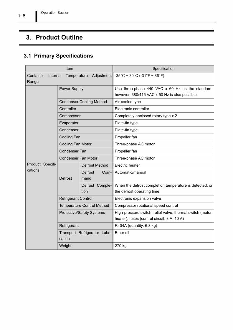
3.1 Primary Specifications
Item Specification
Container Internal Temperature Adjustment
Range
-35°C ~ 30°C (-31°F ~ 86°F)
Product Specifi-
cations
Power Supply Use three-phase 440 VAC x 60 Hz as the standard;
however, 380/415 VAC x 50 Hz is also possible.
Condenser Cooling Method Air-cooled type
Controller Electronic controller
Compressor Completely enclosed rotary type x 2
Evaporator Plate-fin type
Condenser Plate-fin type
Cooling Fan Propeller fan
Cooling Fan Motor Three-phase AC motor
Condenser Fan Propeller fan
Condenser Fan Motor Three-phase AC motor
Defrost
Defrost Method Electric heater
Defrost Com-
mand
Automatic/manual
Defrost Comple-
tion
When the defrost completion temperature is detected, or
the defrost operating time
Refrigerant Control Electronic expansion valve
Temperature Control Method Compressor rotational speed control
Protective/Safety Systems High-pressure switch, relief valve, thermal switch (motor,
heater), fuses (control circuit: 8 A, 10 A)
Refrigerant R404A (quantity: 6.3 kg)
Transport Refrigerator Lubri-
cation
Ether oil
Weight 270 kg

Operation Section1–7
3.2 Construction and Part Names
(1) Overview
• Container Front Wall (Viewed from Container Exterior)

Operation Section1–8
• Container Front Wall (Viewed from Container Interior)
Operation Section1–9
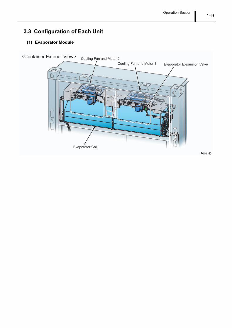
3.3 Configuration of Each Unit
(1) Evaporator Module

Operation Section1–10

Operation Section1–11
(2) Compressor Module

Operation Section1–12
(3) Electrical Box Module

Operation Section1–13
(4) Inverter Module
Operation Section1–14
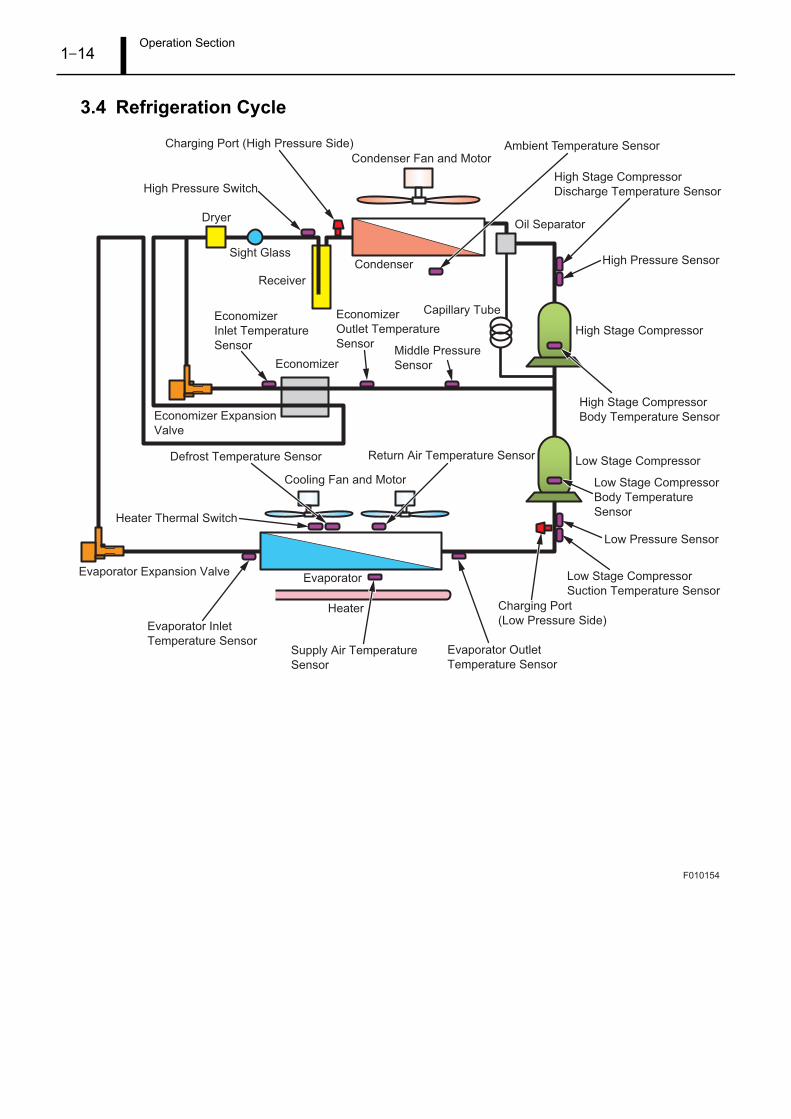
3.4 Refrigeration Cycle
F010154
Sight Glass
Economizer Expansion
Valve
Heater Thermal Switch
Evaporator Expansion Valve
Evaporator Inlet
Temperature SensorEvaporator Outlet
Temperature Sensor
Supply Air Temperature
Sensor
Low Stage Compressor
Suction Temperature Sensor
Charging Port
(Low Pressure Side)
Charging Port (High Pressure Side)
Return Air Temperature SensorDefrost Temperature Sensor
High Pressure Switch
Economizer
Economizer
Inlet Temperature
Sensor
Economizer
Outlet Temperature
Sensor
Evaporator
Heater
Dryer
Receiver
Condenser
Capillary Tube
Condenser Fan and Motor
Cooling Fan and Motor
Ambient Temperature Sensor
High Stage Compressor
Discharge Temperature Sensor
High Pressure Sensor
Low Pressure Sensor
Low Stage Compressor
Body Temperature
Sensor
High Stage Compressor
Body Temperature Sensor
High Stage Compressor
Low Stage Compressor
Oil Separator
Middle Pressure
Sensor

Operation Section1–15
4. Explanation of Operation
4.1 Display Part Names
No. Name Display Content
1
LED
Display
Light
COOL (Amber) Lit during cooling operation.
HEAT (Amber) Lit during heater operation.
DEFROST (Amber) Lit during defrost operations.
IN RANGE (Green) Lit when the container-internal temperature is being controlled to the
set temperature.
ALARM (Red) Lit or flashing when there is a system abnormality.
2 Set Value Display • Normally displays the set temperature.
• When performing settings, displays the setting code.
3 Measured Value Display • Normally displays the container-internal temperature. (During
chilled operation, displays the supply air temperature. During fro-
zen operation, displays the return air temperature.)
• Shows the measured value for each item when the operational
status is displayed.
• Shows the alarm code when an alarm is being displayed.
4 Sub-Display • Normally indicates whether the measured value display is showing
the supply air temperature (SUPPLY) or the return air temperature
(RETURN).
• Displays the alarm case number when an alarm occurs.
• Displays information relevant to each setting and operation being
performed.
F008359
C O O L H E AT DEFROST IN RANGE A L A R M
XXXXXXXXX
1
2 3
7 6 5 4

Operation Section1–16
4.2 Operation Switch Names
5 Fahrenheit Display Lit when the temperature is set to display in the Fahrenheit scale.
6 Celsius Display Lit when the temperature is set to display in the Celsius scale.
7 ECO Display Lit when eco-mode operation is set.
No. Operation Switch Name Function
1 DEF Switch • Displays the defrost temperature during defrost operation.
• Manually start defrost operation.
2 PTI Switch • Starts PTI operation (checks for any system abnormalities).
• Starts individual component operation (checks for any individual com-
ponent abnormalities).
3 ECO Switch Starts eco-mode operation.
4 SET Switch Enters the set mode for each setting operation.
5 ALARM Switch • Displays the alarm code and the alarm case number.
• Clears the alarm.
6 DATA Switch Display operational information such as system pressure and temperature.
7 °C/°F Switch Switches the temperature display between Celsius and Fahrenheit (while
the switch is depressed).
8 SUP/RET Switch Switches the temperature display between the supply air temperature and
the return air temperature (while the switch is depressed).
9 ESC Switch Returns the display for each mode to the first level.
10 Switch Switches between display codes and data set values (up).
11 Switch Switches between display codes and data set values (down).
12 ENTER Switch Determines the operations for each mode.
No. Name Display Content
F008040
Operation Section1–17
4.3 Normal Display Screen
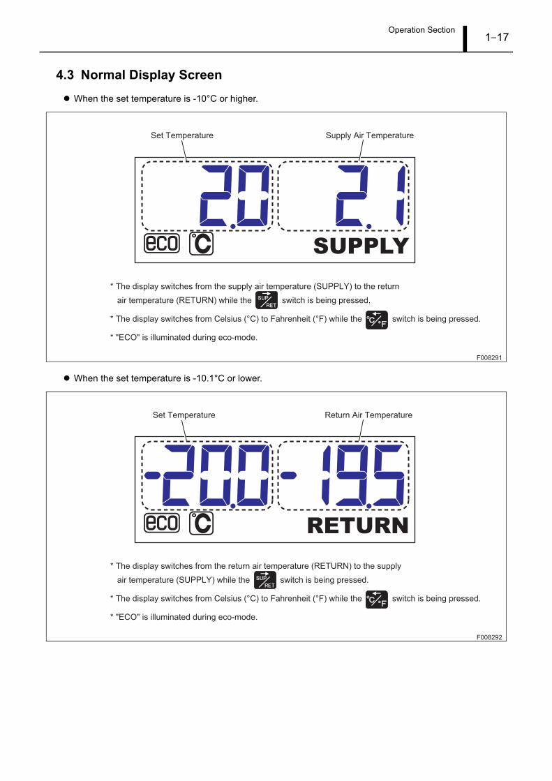
When the set temperature is -10°C or higher.
When the set temperature is -10.1°C or lower.
F008291
SUPPLY
Set Temperature Supply Air Temperature
* The display switches from the supply air temperature (SUPPLY) to the return
air temperature (RETURN) while the switch is being pressed.
* The display switches from Celsius (°C) to Fahrenheit (°F) while the switch is being pressed.
* "ECO" is illuminated during eco-mode.
F008292
RETURN
* The display switches from the return air temperature (RETURN) to the supply
air temperature (SUPPLY) while the switch is being pressed.
* The display switches from Celsius (°C) to Fahrenheit (°F) while the switch is being pressed.
* "ECO" is illuminated during eco-mode.
Set Temperature Return Air Temperature

Operation Section1–18
4.4 Operation Menu Transitions
F010155
Settings
60 seconds passes with no switch operation.
Information
Display Menu
Past Alarm Mode*
PTI Selection Mode
Eco Mode
Switching
pressed for
approximately three seconds.
pressed for approximately
three seconds.
Temperature
Display Switches
Measured
Temperature Switching
pressed for
approximately three seconds.
pressed for
approximately three seconds.
Defrost Temperature Display
(Only During Defrost Operation)
Manual
Defrost Operation
While is being pressed.
While is being pressed.
While is being pressed.
Alarm Mode*
pressed, or 60 seconds
passes with no switch operation.
pressed, or 60 seconds
passes with no switch operation.
Setting Menu 1
Setting Menu 2
pressed, or 60 seconds
passes with no switch operation.
Normal Display
*For the operation method, refer to "Alarm Code Display and Operation During an Abnormality."

Operation Section1–19
4.5 List of Items for Setting Menu 1
No. Setting DescriptionSet
Value
Measured
ValueSub-Display
Reference
Page
1 Set temperature change S01 - STCHG P1-23
2Switching between Celsius and Fahren-
heitS02 - C/FCHG P1-23
3 Defrost interval change S03 - dEFTCHG P1-24
4 Sensor logging interval change S05 - LOGICHG P1-24
5 Dehumidification operation S06 - dEHCHG P1-25
6 Set humidity change S07 - SHCHG P1-25
7 Defrost completion temperature change S08 - dEFTTCHG P1-26
8 Current limit S09 - AMPLCHG P1-26
9 Battery check S10 - bATCHK P1-27
Operation Section1–20
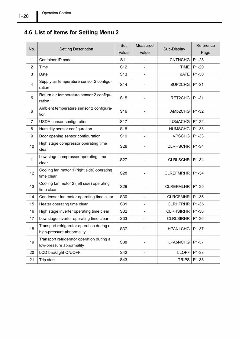
4.6 List of Items for Setting Menu 2
No. Setting DescriptionSet
Value
Measured
ValueSub-Display
Reference
Page
1 Container ID code S11 - CNTNCHG P1-28
2 Time S12 - TIME P1-29
3 Date S13 - dATE P1-30
4Supply air temperature sensor 2 configu-
rationS14 - SUP2CHG P1-31
5Return air temperature sensor 2 configu-
rationS15 - RET2CHG P1-31
6Ambient temperature sensor 2 configura-
tionS16 - AMb2CHG P1-32
7 USDA sensor configuration S17 - USdACHG P1-32
8 Humidity sensor configuration S18 - HUMSCHG P1-33
9 Door opening sensor configuration S19 - VPSCHG P1-33
10High stage compressor operating time
clearS26 - CLRHSCHR P1-34
11Low stage compressor operating time
clearS27 - CLRLSCHR P1-34
12Cooling fan motor 1 (right side) operating
time clearS28 - CLREFMRHR P1-34
13Cooling fan motor 2 (left side) operating
time clearS29 - CLREFMLHR P1-35
14 Condenser fan motor operating time clear S30 - CLRCFMHR P1-35
15 Heater operating time clear S31 - CLRHTRHR P1-35
16 High stage inverter operating time clear S32 - CLRHSIRHR P1-36
17 Low stage inverter operating time clear S33 - CLRLSIRHR P1-36
18Transport refrigerator operation during a
high-pressure abnormalityS37 - HPANLCHG P1-37
19Transport refrigerator operation during a
low-pressure abnormalityS38 - LPAbNCHG P1-37
20 LCD backlight ON/OFF S42 - bLOFF P1-38
21 Trip start S43 - TRIPS P1-38

Operation Section1–21
4.7 List of Items for the Information Display Menu
No. Setting DescriptionSet
Value
Measured
ValueSub-Display
Reference
Page
1 Return air temperature 1 01 ***.* RET1 P1-39
2 Supply air temperature 1 02 ***.* SUP1 P1-39
3 Ambient temperature 1 03 ***.* AMb1 P1-39
4 USDA1 temperature 04 ***.* USdA1 P1-40
5 USDA2 temperature 05 ***.* USdA2 P1-40
6 USDA3 temperature 06 ***.* USdA3 P1-40
7 Cargo temperature 07 ***.* CARGO P1-41
8 Relative humidity 08 *** RETRH P1-41
9 Ventilation flow volume 09 *** VENT P1-41
10 Return air temperature 2 10 ***.* RET2 P1-42
11 Supply air temperature 2 11 ***.* SUP2 P1-42
12 Ambient temperature 2 12 ***.* AMb2 P1-42
13 Defrost temperature 13 ***.* dEFT P1-43
14 High stage compressor discharge tem-
perature14 ***.*
HSCdTP1-43
15 High stage compressor body temperature 16 ***.* HSCbT P1-43
16 Low stage compressor suction tempera-
ture18 ***.*
LSCSTP1-44
17 Low stage compressor body temperature 19 ***.* LSCbT P1-44
18 Evaporator inlet temperature 20 ***.* EI P1-44
19 Evaporator outlet temperature 21 ***.* EO P1-45
20 Economizer inlet temperature 22 ***.* ECI P1-45
21 Economizer outlet temperature 23 ***.* ECO P1-45
22 High pressure 24 - HP **** P1-46
23 Middle pressure 25 - MP **** P1-46
24 Low Pressure 26 - LP **** P1-46
25 High stage compressor current 27 **.* HSCC P1-47
26 Low stage compressor current 28 **.* LSCC P1-47
27 High stage inverter frequency display 29 *** HSIF P1-47
28 Low stage inverter frequency display 30 *** LSIF P1-48
29 High stage inverter temperature 31 *** HSIT P1-48
30 Low stage inverter temperature 32 *** LSIT P1-48
31 Evaporator expansion valve opening 33 *** EVA EXP P1-49
32 Economizer expansion valve opening 34 *** ECO EXP P1-49
33 Cooling fan status 35 *** EFM P1-49
34 Main power supply voltage 37 *** VOL P1-50

Operation Section1–22
35 Main power supply U-phase current 38 **.* L1 P1-50
36 Main power supply V-phase current 39 **.* L2 P1-50
37 Main power supply W-phase current 40 **.* L3 P1-51
38 Main power supply frequency 41 ** HZ P1-51
39 High stage compressor operating time 42 - HSCRHR P1-51
40 Low stage compressor operating time 43 - LSCRHR P1-52
41 Cooling fan motor 1 (right side) operating
time44 -
EFMRRHRP1-52
42 Cooling fan motor 2 (left side) operating
time45 -
EFMLRHRP1-52
43 Condenser fan motor operating time 46 - CFMRHR P1-53
44 Heater operating time 47 - HTRHR P1-53
45 High stage inverter operating time 48 - HSIRHR P1-53
46 Low stage inverter operating time 49 - LSIRHR P1-54
47 Supply air temperature log data 50 - SUP dATA P1-54
48 Return air temperature log data 51 - RET dATA P1-55
49 Program version 52 - PGM VER P1-55
No. Setting DescriptionSet
Value
Measured
ValueSub-Display
Reference
Page
Operation Section1–23
4.8 Operating Method for Setting Menu 1
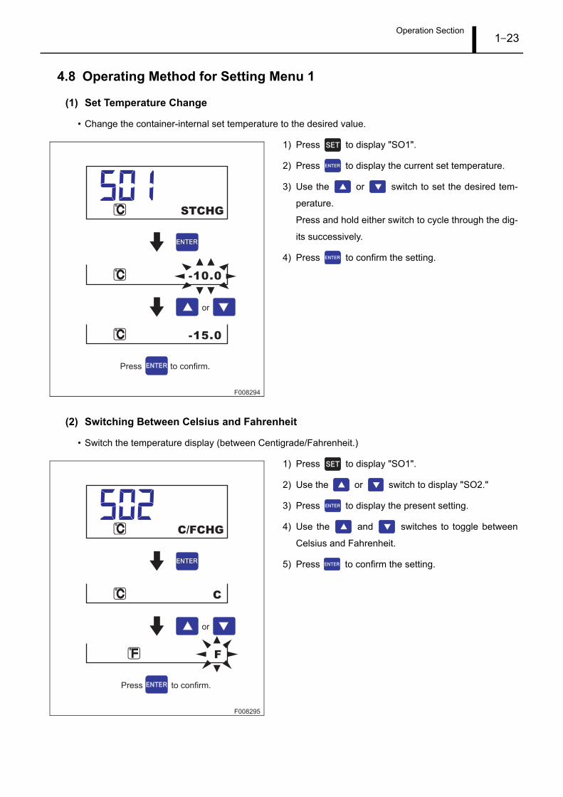
(1) Set Temperature Change
• Change the container-internal set temperature to the desired value.
1) Press to display "SO1".
2) Press to display the current set temperature.
3) Use the or switch to set the desired tem-
perature.
Press and hold either switch to cycle through the dig-
its successively.
4) Press to confirm the setting.
(2) Switching Between Celsius and Fahrenheit
• Switch the temperature display (between Centigrade/Fahrenheit.)
1) Press to display "SO1".
2) Use the or switch to display "SO2."
3) Press to display the present setting.
4) Use the and switches to toggle between
Celsius and Fahrenheit.
5) Press to confirm the setting.
F008294
-15.0
-10.0
STCHG
or
Press to confirm.
F008295
F
C
C/FCHG
or
Press to confirm.

Operation Section1–24
(3) Defrost Interval Change
• Change the defrost interval with the timer.
1) Press to display "SO1".
2) Use the or switch to display "SO3."
3) Press to display the present setting.
4) Use the or switch to change the defrost in-
terval.
Set values: 03H, 06H, 09H, 12H, 24H
5) Press to confirm the setting.
(4) Sensor Logging Interval Change
• Change the interval at which the sensor output is recorded.
1) Press to display "SO1".
2) Use the and switches to display "SO5."
3) Press to display the present setting.
4) Use the or switch to change the interval.
Set values: 15 min, 30 min, 60 min, 120 min
5) Press to confirm the setting.
F010156
09H
12H
dEFTCHG
or
Press to confirm.
F008298
30MIN
60MIN
LOGICHG
or
Press to confirm.
Operation Section1–25
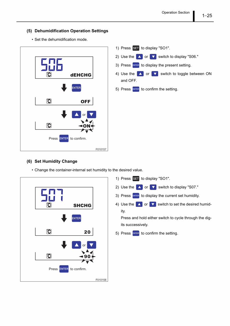
(5) Dehumidification Operation Settings
• Set the dehumidification mode.
1) Press to display "SO1".
2) Use the or switch to display "S06."
3) Press to display the present setting.
4) Use the or switch to toggle between ON
and OFF.
5) Press to confirm the setting.
(6) Set Humidity Change
• Change the container-internal set humidity to the desired value.
1) Press to display "SO1".
2) Use the or switch to display "S07."
3) Press to display the current set humidity.
4) Use the or switch to set the desired humid-
ity.
Press and hold either switch to cycle through the dig-
its successively.
5) Press to confirm the setting.
F010157
ON
OFF
dEHCHG
or
Press to confirm.
F010158
90
20
SHCHG
or
Press to confirm.

Operation Section1–26
(7) Defrost Completion Temperature Change
• Change the defrost completion temperature.
1) Press to display "SO1".
2) Use the or switch to display "S08."
3) Press to display the present setting.
4) Use the or switch to change the defrost
completion temperature.
Set temperature: 10°C, 25°C
5) Press to confirm the setting.
(8) Current Limit
• Set the current limit.
1) Press to display "SO1".
2) Use the or switch to display "SO9."
3) Press to display the present setting.
4) Use the or switch to change the current lim-
it.
Set values: 10.5 A, 13 A, 15 A, 17 A, 19 A
5) Press to confirm the setting.
F010159
25.0
10.0
dEFTTCHG
or
Press to confirm.
F010160
17A
OFF
or
AMPLCHG
Press to confirm.

Operation Section1–27
(9) Battery Check
• Verify the battery voltage.
1) Press to display "SO1".
2) Use the or switch to display "S10."
3) Press to check the battery voltage.
When the check is completed successfully, the battery
voltage will display. When the battery is not connect-
ed, a value of 10.1 V or more will display.
F010161
8.0V
bATCHK
Completed Successfully

Operation Section1–28
4.9 Operating Method for Setting Menu 2
(1) Container ID Code
• Register the container ID code.
1) Press and hold for approximately three seconds
to display "S11."
2) Press to show a scroll display of the present set-
ting.
3) Pressing , , , or will cause the left
end of the character string to flash.
4) Use the or switch to change the flashing
characters.
5) Use the or switch to change between flash-
ing characters.
6) Change the first character, then repeat the process for
the remaining character.
7) Press to confirm the setting.
Normally, the container ID code will be shown in a
scroll display. However, during an abnormality, "ER-
ROR" will be displayed.
F008301
CNTNCHG
ZZZU9999999ZZZU9999999
AZZU9999999AZZU9999999
A ~ Z (Four Letters) 0 ~ 9 (Seven Digits)
Hidden Characters
ZZZU9999999
ZZZU9999999ZZZU9999999
AZZU9999999AZZU9999999
or
or
or
Press to confirm.
*Press to scroll to
the right, or to
scroll to the left to view
the hidden characters
in order.

Operation Section1–29
(2) Time
• Set the time.
1) Press and hold for approximately three seconds
to display "S11."
2) Use the or switch to display "S12."
3) Press to display the time.
4) Pressing , , , or will cause the
"hour" to flash.
5) Use the or switch to change the flashing
value.
6) Use the or switch to change to "minutes."
7) Use the or switch to change the value.
8) Press to confirm the setting.
F008302
12:00
12:00
13:00
13:00
13:01
TIME
or
or
or
or
Press to confirm.

Operation Section1–30
(3) Date
• Set the date.
1) Press and hold for approximately three seconds
to display "S11."
2) Use the or switch to display "S13."
3) Press to display the date.
4) Pressing , , , or will cause the
"day" to flash.
5) Use the or switch to change the flashing
"day."
6) Use the or switch to toggle between the
flashing "day", "month", and "year."
7) Use the or switch in the same fashion to
change the remaining values.
8) Press to confirm the setting.
F008303
01APR2010
02APR2010
02MAY2010
01APR2010
02APR2010
dATE
or
or
or
MonthDay Year
APR 201001
or
Press to confirm.

Operation Section1–31
(4) Supply Air Temperature Sensor 2 Configuration
• Set supply air temperature sensor 2 ON or OFF.
1) Press and hold for approximately three seconds
to display "S11."
2) Use the or switch to display "S14."
3) Press to display the present setting.
4) Use the or switch to set the sensor "ON" or
"OFF."
5) Press to confirm the setting.
(5) Return Air Temperature Sensor 2 Configuration
• Set return air temperature sensor 2 ON or OFF.
1) Press and hold for approximately three seconds
to display "S11."
2) Use the or switch to display "S15."
3) Press to display the present setting.
4) Use the or switch to set the sensor "ON" or
"OFF."
5) Press to confirm the setting.
F008304
ON
OFF
SUP2CHG
or
Press to confirm.
F008305
ON
OFF
RET2CHG
or
Press to confirm.
Operation Section1–32
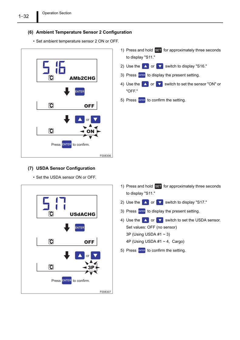
(6) Ambient Temperature Sensor 2 Configuration
• Set ambient temperature sensor 2 ON or OFF.
1) Press and hold for approximately three seconds
to display "S11."
2) Use the or switch to display "S16."
3) Press to display the present setting.
4) Use the or switch to set the sensor "ON" or
"OFF."
5) Press to confirm the setting.
(7) USDA Sensor Configuration
• Set the USDA sensor ON or OFF.
1) Press and hold for approximately three seconds
to display "S11."
2) Use the or switch to display "S17."
3) Press to display the present setting.
4) Use the or switch to set the USDA sensor.
Set values: OFF (no sensor)
3P (Using USDA #1 ~ 3)
4P (Using USDA #1 ~ 4, Cargo)
5) Press to confirm the setting.
F008306
ON
OFF
AMb2CHG
or
Press to confirm.
F008307
3P
OFF
USdACHG
or
Press to confirm.

Operation Section1–33
(8) Humidity Sensor Configuration
• Set the humidity sensor ON or OFF.
1) Press and hold for approximately three seconds
to display "S11."
2) Use the or switch to display "S18."
3) Press to display the present setting.
4) Use the or switch to set the sensor "ON" or
"OFF."
5) Press to confirm the setting.
(9) Door Opening Sensor Configuration
• Set the door opening sensor ON or OFF.
1) Press and hold for approximately three seconds
to display "S11."
2) Use the or switch to display "S19."
3) Press to display the present setting.
4) Use the or switch to set the sensor "ON" or
"OFF."
5) Press to confirm the setting.
F008308
ON
OFF
HUMSCHG
or
Press to confirm.
F008309
ON
OFF
VPSCHG
or
Press to confirm.

Operation Section1–34
(10) High Stage Compressor Operating Time Clear
• Clear the high stage compressor operating time.
1) Press and hold for approximately three seconds
to display "S11."
2) Use the or switch to display "S26."
3) When is pressed, "CLRHSCHR" will flash.
4) Press and hold for approximately five seconds to
clear the operating time.
(11) Low Stage Compressor Operating Time Clear
• Clear the low stage compressor operating time.
1) Press and hold for approximately three seconds
to display "S11."
2) Use the or switch to display "S27."
3) When is pressed, "CLRLSCHR" will flash.
4) Press and hold for approximately five seconds to
clear the operating time.
(12) Cooling Fan Motor 1 (Right Side) Operating Time Clear
• Clear the cooling fan motor 1 (right side) operating time.
1) Press and hold for approximately three seconds
to display "S11."
2) Use the or switch to display "S28."
3) When is pressed, "CLREFMRHR" will flash.
4) Press and hold for approximately five seconds to
clear the operating time.
F008315
CLRHSCHR
CLEAR ENd
Press and hold for
approximately five seconds.
F008316
CLRLSCHR
CLEAR ENd
Press and hold for
approximately five seconds.
F008317
CLEAR ENd
CLREFMRHR
Press and hold for
approximately five seconds.

Operation Section1–35
(13) Cooling Fan Motor 2 (Left Side) Operating Time Clear
• Clear the cooling fan motor 2 (left side) operating time.
1) Press and hold for approximately three seconds
to display "S11."
2) Use the or switch to display "S29."
3) When is pressed, "CLREFMLHR" will flash.
4) Press and hold for approximately five seconds to
clear the operating time.
(14) Condenser Fan Motor Operating Time Clear
• Clear the condenser fan motor operating time.
1) Press and hold for approximately three seconds
to display "S11."
2) Use the or switch to display "S30."
3) When is pressed, "CLRCFMHR" will flash.
4) Press and hold for approximately five seconds to
clear the operating time.
(15) Heater Operating Time Clear
• Clear the heater operating time.
1) Press and hold for approximately three seconds
to display "S11."
2) Use the or switch to display "S31."
3) When is pressed, "CLRHTRHR" will flash.
4) Press and hold for approximately five seconds to
clear the operating time.
F008318
CLREFMLHR
CLEAR ENd
Press and hold for
approximately five seconds.
F008319
CLRCFMHR
CLEAR ENd
Press and hold for
approximately five seconds.
F008320
CLRHTRHR
CLEAR ENd
Press and hold for
approximately five seconds.
Operation Section1–36
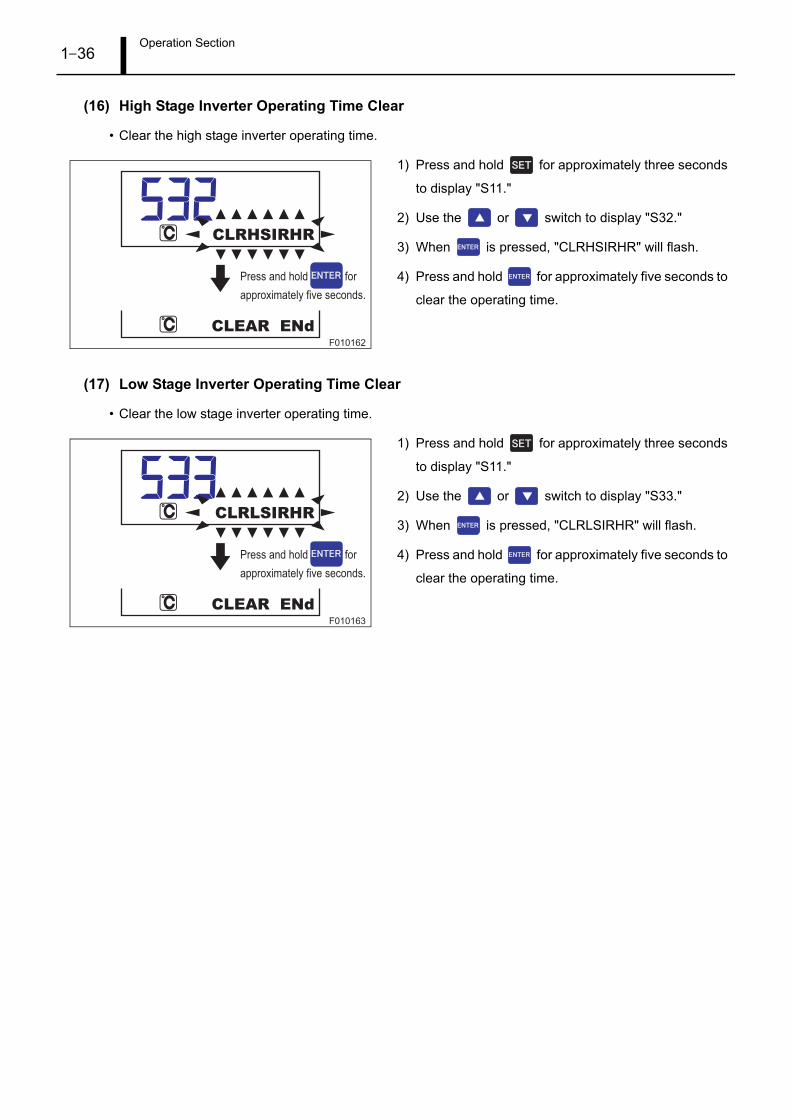
(16) High Stage Inverter Operating Time Clear
• Clear the high stage inverter operating time.
1) Press and hold for approximately three seconds
to display "S11."
2) Use the or switch to display "S32."
3) When is pressed, "CLRHSIRHR" will flash.
4) Press and hold for approximately five seconds to
clear the operating time.
(17) Low Stage Inverter Operating Time Clear
• Clear the low stage inverter operating time.
1) Press and hold for approximately three seconds
to display "S11."
2) Use the or switch to display "S33."
3) When is pressed, "CLRLSIRHR" will flash.
4) Press and hold for approximately five seconds to
clear the operating time.
F010162
CLRHSIRHR
CLEAR ENd
Press and hold for
approximately five seconds.
F010163
CLEAR ENd
CLRLSIRHR
Press and hold for
approximately five seconds.

Operation Section1–37
(18) Transport Refrigerator Operation During a High-Pressure Abnormality
• Set the transport refrigerator to continue/stop operating during a high pressure abnormality.
1) Press and hold for approximately three seconds
to display "S11."
2) Use the or switch to display "S37."
3) Press to display the present setting.
4) Use the or switch to set the transport refrig-
erator to remain ON (continue operating) or to turn
OFF (stop operating).
5) Press to confirm the setting.
(19) Transport Refrigerator Operation During a Low-Pressure Abnormality
• Set the transport refrigerator to continue/stop operating during a low pressure abnormality.
1) Press and hold for approximately three seconds
to display "S11."
2) Use the or switch to display "S38."
3) Press to display the present setting.
4) Use the or switch to set the transport refrig-
erator to remain ON (continue operating) or to turn
OFF (stop operating).
5) Press to confirm the setting.
F008326
OFF
ON
HPANLCHG
or
Press to confirm.
F008327
OFF
ON
LPAbNCHG
or
Press to confirm.

Operation Section1–38
(20) LCD Backlight ON/OFF
• Set the LCD backlight ON or OFF.
1) Press and hold for approximately three seconds
to display "S11."
2) Use the or switch to display "S42."
3) Press to display the present setting.
4) Use the or switch to set the backlight ON
or OFF.
5) Press to confirm the setting.
(21) Trip Start
• Set the departure date used for the last trip readout log data.
1) Press and hold for approximately three seconds
to display "S11."
2) Use the or switch to display "S43."
3) Press to display the present setting.
4) Press and hold for approximately three seconds
to display today's date.
Today's date will be set as the departure.
F008331
OFF
ON
bLOFF
or
Press to confirm.
F008332
02APR2010
01APR2010
TRIPS
Press and hold for
approximately three seconds.
Operation Section1–39
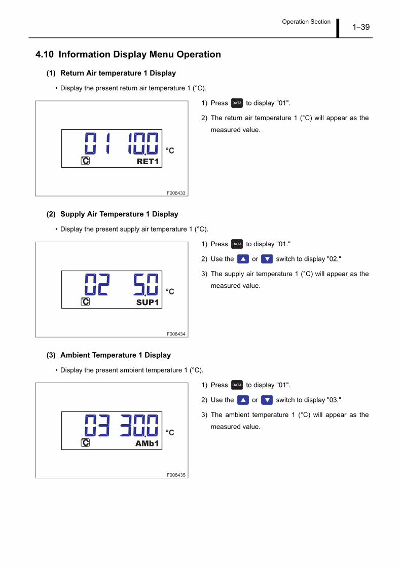
4.10 Information Display Menu Operation
(1) Return Air temperature 1 Display
• Display the present return air temperature 1 (°C).
1) Press to display "01".
2) The return air temperature 1 (°C) will appear as the
measured value.
(2) Supply Air Temperature 1 Display
• Display the present supply air temperature 1 (°C).
1) Press to display "01."
2) Use the or switch to display "02."
3) The supply air temperature 1 (°C) will appear as the
measured value.
(3) Ambient Temperature 1 Display
• Display the present ambient temperature 1 (°C).
1) Press to display "01".
2) Use the or switch to display "03."
3) The ambient temperature 1 (°C) will appear as the
measured value.
F008433
RET1
°C
F008434
SUP1
°C
F008435
AMb1
°C
Operation Section1–40
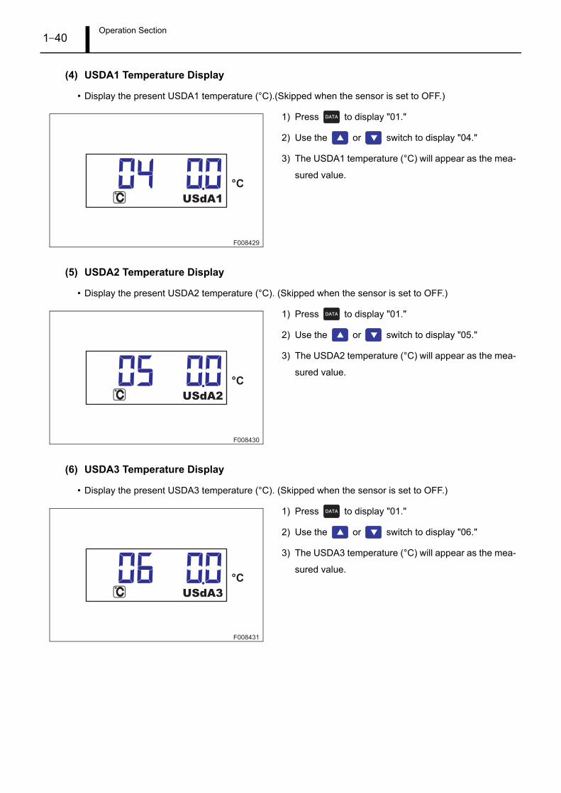
(4) USDA1 Temperature Display
• Display the present USDA1 temperature (°C).(Skipped when the sensor is set to OFF.)
1) Press to display "01."
2) Use the or switch to display "04."
3) The USDA1 temperature (°C) will appear as the mea-
sured value.
(5) USDA2 Temperature Display
• Display the present USDA2 temperature (°C). (Skipped when the sensor is set to OFF.)
1) Press to display "01."
2) Use the or switch to display "05."
3) The USDA2 temperature (°C) will appear as the mea-
sured value.
(6) USDA3 Temperature Display
• Display the present USDA3 temperature (°C). (Skipped when the sensor is set to OFF.)
1) Press to display "01."
2) Use the or switch to display "06."
3) The USDA3 temperature (°C) will appear as the mea-
sured value.
F008429
USdA1
°C
F008430
USdA2
°C
F008431
USdA3
°C
Operation Section1–41
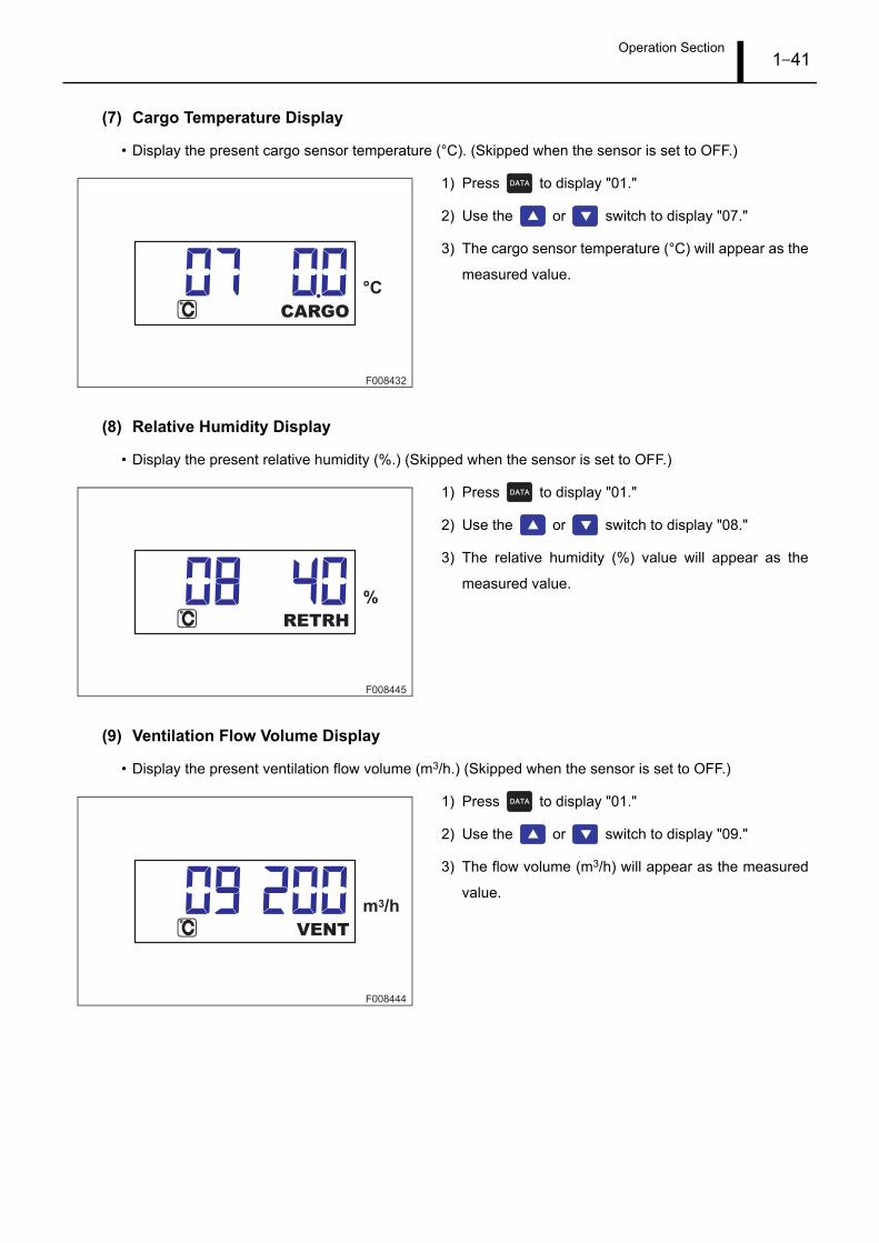
(7) Cargo Temperature Display
• Display the present cargo sensor temperature (°C). (Skipped when the sensor is set to OFF.)
1) Press to display "01."
2) Use the or switch to display "07."
3) The cargo sensor temperature (°C) will appear as the
measured value.
(8) Relative Humidity Display
• Display the present relative humidity (%.) (Skipped when the sensor is set to OFF.)
1) Press to display "01."
2) Use the or switch to display "08."
3) The relative humidity (%) value will appear as the
measured value.
(9) Ventilation Flow Volume Display
• Display the present ventilation flow volume (m3/h.) (Skipped when the sensor is set to OFF.)
1) Press to display "01."
2) Use the or switch to display "09."
3) The flow volume (m3/h) will appear as the measured
value.
F008432
CARGO
°C
F008445
RETRH
%
F008444
m3/h
VENT

Operation Section1–42
(10) Return Air Temperature 2 Display
• Display the present return air temperature 2 (°C).
1) Press to display "01."
2) Use the or switch to display "10."
3) The return air temperature 2 (×C) will appear as the
measured value.
(11) Supply Air Temperature 2 Display
• Display the present supply air temperature 2 (°C).
1) Press to display "01."
2) Use the or switch to display "11."
3) The supply air temperature 2 (°C) will appear as the
measured value.
(12) Ambient Temperature 2 Display
• Display the present ambient temperature 2 (°C).
1) Press to display "01."
2) Use the or switch to display "12."
3) The ambient temperature 2 (°C) will appear as the
measured value.
F008436
RET2
°C
F008437
SUP2
°C
F008438
AMb2
°C

Operation Section1–43
(13) Defrost Temperature Display
• Display the present defrost temperature (°C).
1) Press to display "01."
2) Use the or switch to display "13."
3) The defrost temperature (°C) will appear as the mea-
sured value.
(14) High Stage Compressor Discharge Temperature Display
• Display the present high stage compressor discharge temperature (°C).
1) Press display "01."
2) Use the or switch to display "14."
3) The high stage compressor discharge temperature
(°C) value will appear as the measured value.
(15) High Stage Compressor Body Temperature Display
• Display the present high stage compressor body temperature (°C).
1) Press to display "01."
2) Use the or switch to display "16."
3) The high stage compressor body temperature (°C)
will appear as the measured value.
F008439
dEFT
°C
F008440
°C
HSCdT
F008441
°C
HSCbT

Operation Section1–44
(16) Low Stage Compressor Suction Temperature Display
• Display the present low stage compressor suction temperature (°C).
1) Press to display "01."
2) Use the or switch to display "18."
3) The low stage compressor suction temperature (°C)
will appear as the measured value.
(17) Low Stage Compressor Body Temperature Display
• Display the present low stage compressor body temperature (°C).
1) Press to display "01."
2) Use the or switch to display "19."
3) The low stage compressor body temperature (°C) will
appear as the measured value.
(18) Evaporator Inlet Temperature Display
• Display the present evaporator inlet temperature (°C).
1) Press to display "01."
2) Use the or switch to display "20."
3) The evaporator inlet temperature (°C) will display as
the measured value.
F008442
°C
LSCST
F008443
°C
LSCbT
F008455
EI
°C

Operation Section1–45
(19) Evaporator Outlet Temperature Display
• Display the present evaporator outlet temperature (°C).
1) Press to display "01."
2) Use the or switch to display "21."
3) The evaporator outlet temperature (°C) will display as
the measured value.
(20) Economizer Inlet Temperature Display
• Display the present economizer inlet temperature (°C).
1) Press to display "01."
2) Use the or switch to display "22."
3) The present economizer inlet temperature (°C) will be
displayed as the measured value.
(21) Economizer Outlet Temperature Display
• Display the present economizer outlet temperature (°C).
1) Press to display "01."
2) Use the or switch to display "23."
3) The present economizer outlet temperature (°C) will
be displayed as the measured value.
F008456
EO
°C
F008457
ECI
°C
F008458
°C
ECO

Operation Section1–46
(22) High Pressure Display
• Display the present high-pressure value (KPa).
1) Press to display "01."
2) Use the or switch to display "24."
3) The high-pressure value (KPa) will appear on the sub-
display.
(23) Middle Pressure Display
• Display the present middle pressure value (KPa).
1) Press to display "01."
2) Use the or switch to display "25."
3) The middle pressure value (KPa) will appear on the
sub-display.
(24) Low-Pressure Display
• Display the present low-pressure value (KPa).
1) Press to display "01."
2) Use the or switch to display "26."
3) The low-pressure value (KPa) will appear on the sub-
display.
F008419
HP 170 KPa
F008420
MP 90 KPa
F008421
LP 10 KPa

Operation Section1–47
(25) High Stage Compressor Current Display
• Display the present high stage compressor current (A).
1) Press to display "01."
2) Use the or switch to display "27."
3) The high stage compressor current (A) will appear as
the measured value.
(26) Low Stage Compressor Current Display
• Display the present low stage compressor current (A).
1) Press to display "01."
2) Use the or switch to display "28."
3) The low stage compressor current (A) will appear as
the measured value.
(27) High Stage Inverter Frequency Display
• Display the present high stage inverter frequency (Hz).
1) Press to display "01."
2) Use the or switch to display "29."
3) The high stage inverter frequency (Hz) will appear as
the measured value.
F008427
A
HSCC
F008428
A
LSCC
F008003
HSIF
Hz

Operation Section1–48
(28) Low Stage Inverter Frequency Display
• Display the present low stage inverter frequency (Hz).
1) Press to display "01."
2) Use the or switch to display "30."
3) The low stage inverter frequency (Hz) value will ap-
pear as the measured value.
(29) High Stage Inverter Temperature Display
• Display the present high stage inverter temperature (°C).
1) Press to display "01."
2) Use the or switch to display "31."
3) The high stage inverter temperature (°C) will appear
as the measured value.
(30) Low Stage Inverter Temperature Display
• Display the present low stage inverter temperature (°C).
1) Press to display "01."
2) Use the or switch to display "32."
3) The low stage inverter temperature (°C) will appear as
the measured value.
F008004
LSIF
Hz
F006859
HSIT
°C
F006860
LSIT
°C
Operation Section1–49
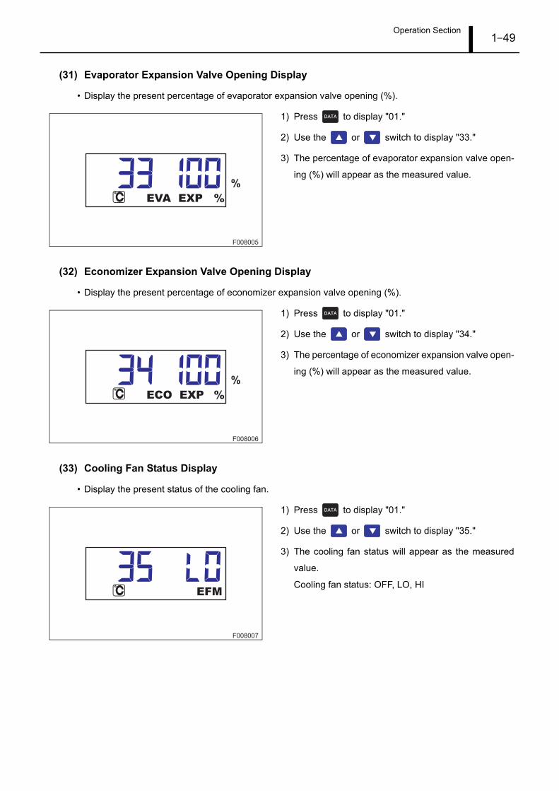
(31) Evaporator Expansion Valve Opening Display
• Display the present percentage of evaporator expansion valve opening (%).
1) Press to display "01."
2) Use the or switch to display "33."
3) The percentage of evaporator expansion valve open-
ing (%) will appear as the measured value.
(32) Economizer Expansion Valve Opening Display
• Display the present percentage of economizer expansion valve opening (%).
1) Press to display "01."
2) Use the or switch to display "34."
3) The percentage of economizer expansion valve open-
ing (%) will appear as the measured value.
(33) Cooling Fan Status Display
• Display the present status of the cooling fan.
1) Press to display "01."
2) Use the or switch to display "35."
3) The cooling fan status will appear as the measured
value.
Cooling fan status: OFF, LO, HI
F008005
EVA EXP
%
%
F008006
ECO EXP
%
%
F008007
EFM

Operation Section1–50
(34) Main Power Supply Voltage Display
• Display the present voltage (V) for the main power supply.
1) Press to display "01."
2) Use the or switch to display "37."
3) The voltage (V) for the main power supply will appear
as the measured value.
(35) Main Power Supply U-Phase Current Display
• Display the present U-phase current (A) for the main power supply.
1) Press to display "01."
2) Use the or switch to display "38."
3) The U-phase current (A) for the main power supply
will appear as the measured value.
(36) Main Power Supply V-Phase Current Display
• Display the present V-phase current (A) for the main power supply.
1) Press to display "01."
2) Use the or switch to display "39."
3) The V-phase current (A) for the main power supply will
appear as the measured value.
F008422
VOL
V
F008423
L1
A
F008424
L2
A

Operation Section1–51
(37) Main Power Supply W-Phase Current Display
• Display the present W-phase current (A) for the main power supply.
1) Press to display "01."
2) Use the or switch to display "40."
3) The W-phase current (A) value for the main power
supply will appear as the measured value.
(38) Main Power Supply Frequency Display
• Display the present frequency (Hz) for the main power supply.
1) Press to display "01."
2) Use the or switch to display "41."
3) The frequency (Hz) for the main power supply will ap-
pear as the measured value.
(39) High Stage Compressor Operating Time Display
• Display the high stage compressor operating time accumulated up until the present.
1) Press to display "01."
2) Use the or switch to display "42."
3) Press to show the high stage compressor oper-
ating time on the sub-display.
F008425
L3
A
F008426
HZ
Hz
F008446
HSCRHR
234567H

Operation Section1–52
(40) Low Stage Compressor Operating Time Display
• Display the low stage compressor operating time accumulated up until the present.
1) Press to display "01."
2) Use the or switch to display "43."
3) Press to show the low stage compressor operat-
ing time on the sub-display.
(41) Cooling Fan Motor 1 (Right Side) Operating Time Display
• Display the cooling fan motor 1 (right side) operating time accumulated up until the present.
1) Press to display "01."
2) Use the or switch to display "44."
3) Press to show the cooling fan motor 1 (right side)
operating time on the sub-display.
(42) Cooling Fan Motor 2 (Left Side) Operating Time Display
• Display the cooling fan motor 2 (left side) operating time accumulated up until the present.
1) Press to display "01."
2) Use the or switch to display "45."
3) Press to show the cooling fan motor 2 (left side)
operating time on the sub-display.
F008447
LSCRHR
234567H
F008448
234567H
EFMRRHR
F008449
EFMLRHR
234567H

Operation Section1–53
(43) Condenser Fan Motor Operating Time Display
• Display the condenser fan motor operating time accumulated up until the present.
1) Press to display "01."
2) Use the or switch to display "46."
3) Press to show the condenser fan motor operat-
ing time on the sub-display.
(44) Heater Operating Time Display
• Display the heater operating time accumulated up until the present.
1) Press to display "01."
2) Use the or switch to display "47."
3) Press to show the heater operating time on the
sub-display.
(45) High Stage Inverter Operating Time Display
• Display the high stage inverter operating time accumulated up until the present.
1) Press to display "01."
2) Use the or switch to display "48."
3) Press to show the high stage inverter operating
time on the sub-display.
F008450
CFMRHR
234567H
F008451
HTRHR
234567H
F008459
HSIRHR
234567H

Operation Section1–54
(46) Low Stage Inverter Operating Time Display
• Display the low stage inverter operating time accumulated up until the present.
1) Press to display "01."
2) Use the or switch to display "49."
3) Press to show the low stage inverter operating
time on the sub-display.
(47) Supply Air Temperature Log Data Display
• Display the supply air temperature log data.
1) Press to display "01."
2) Use the or switch to display "50."
3) Press to show the supply air temperature log
data as the measured value, and the log entry date on
the sub-display.
4) Use the or switch to toggle between log en-
try dates.
F008460
LSIRHR
234567H
F010203
SUP dATA
01 APR 15
05 APR 10
or
MonthDay Time
01 APR 15

Operation Section1–55
(48) Return Air Temperature Log Data Display
• Display the return air temperature log data.
1) Press to display "01."
2) Use the or switch to display "51."
3) Press to show the return air temperature log
data as the measured value, and the log entry date on
the sub-display.
4) Use the or switch to toggle between log en-
try dates.
(49) Program Version Display
• Display the present program version.
1) Press to display "01."
2) Use the or switch to display "52."
3) Press to show the program version on the sub-
display.
F010204
RET dATA
20 MAY 08
28 MAY 20
20 MAY 08
or
MonthDay Time
F008452
RA 16.09.00
PGM VER

Operation Section1–56
4.11 Defrost Operation
(1) Defrost Temperature Display
• Display the defrost temperature during defrost operation.
1) Press during defrost operation.
The defrost temperature (°C) will appear while is
pressed.
2) Release to return to the normal display.
(2) Manual Defrost Operation
• Manually start defrost operation.
1) To start defrost operation, press for approxi-
mately three seconds during frozen or chilled opera-
tion.
2) Defrost operation stops automatically.
F008335
SUPPLY
SUPPLY
-5.0dEFT
While is being
pressed
Release .
F008336
SUPPLY
SUPPLY
Press and hold for
approximately three seconds.

Operation Section1–57
4.12 Eco-Mode Operation
(1) Eco-Mode Setting
• Set the eco-mode.
1) Press for approximately three seconds during
the normal display mode.
When the "ECO" display illuminates, the system is in
eco-mode.
F008362
SUPPLY
SUPPLY
ON OFF
Press and hold
for
approximately three seconds.

Operation Section1–58
4.13 PTI Mode Item List
Modes to check device operation when leaving port, etc.
PTI Mode Step Item
Full
Short
1 PTI mode preparation
2 Alarm check
3 Heater energization check
4 Heater contactor weld check
5 Condenser fan motor energization check
6 Condenser fan motor contactor weld check
7 Cooling fan motor high-speed energization check
8 Cooling fan motor high-speed contactor weld check
9 Cooling fan motor low-speed energization check
10 Cooling fan motor low-speed contactor weld check
11 Pressure sensor check
12 Economizer outlet sensor accuracy check
13 Economizer expansion valve operation check
14 Return air temperature sensor, air outlet temperature sensor accu-
racy check
15 Evaporator outlet temperature sensor accuracy check
16 Spare sensor accuracy check
17 Evaporator expansion valve open-close check
18 Compressor energization check
19• Compressor contactor weld check
• PTI short mode completion
-
20 Chilled heating check
21 Chilled cooldown check
22 Chilled temperature fluctuation check
23 Defrost check
24 Frozen cooldown operation
25 Low pressure sensor accuracy check
26 PTI full mode completion

Operation Section1–59
Item Description
MANUAL
Individual operation of the high stage compressor
Individual operation of the low stage compressor
Individual operation of the condenser fan motor
Individual low-speed operation of the cooling fan motor
Individual high-speed operation of the cooling fan motor
Individual operation of the evaporator expansion valve
Individual operation of the economizer expansion valve
Individual heater operation
DATA Information display menu content check
P/S TEST Not used

Operation Section1–60
4.14 PTI Mode Operation
(1) SHORT PTI Operation
• Initiate SHORT PTI operation.
1) Press during the normal display mode.
2) Press the or switch to select the PTI mode.
Modes: FULL PTI, SHORT PTI, MANUAL, DATA, P/S
TEST
3) When "SHORT PTI" displays, press to start the
SHORT PTI mode.
The "Step" is displayed during SHORT PTI.
4) When PTI is completed successfully and "NORMAL-
ENd" is displayed, press to return to the normal
display (normal operation).
F008280
FULL PTI
SUPPLY
SHORT PTI
F010206
SHORT PTI
01/19PTI
NORMALENd
Current
Step
Total
Steps
PTI 01/19
Completed Successfully
Normal Display
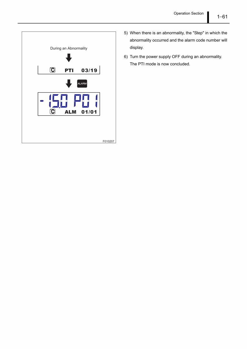
Operation Section1–61
5) When there is an abnormality, the "Step" in which the
abnormality occurred and the alarm code number will
display.
6) Turn the power supply OFF during an abnormality.
The PTI mode is now concluded.
F010207
03/19PTI
01/01ALM
During an Abnormality

Operation Section1–62
(2) FULL PTI Operation
• Initiate FULL PTI operation.
1) Press during the normal display mode.
2) Press the or switch to select the PTI mode.
Modes: FULL PTI, SHORT PTI, MANUAL, DATA, P/S
TEST
3) When "FULL PTI" displays, press to start the
FULL PTI mode.
The "Step" is displayed during FULL PTI.
4) When PTI is completed successfully and "NORMAL-
ENd" is displayed, press to return to the normal
display (normal operation).
F008281
FULL PTI
SUPPLY
SHORT PTI
F010208
FULL PTI
01/26PTI
NORMALENd
PTI 01/26
Current
Step
Total
Steps
Completed Successfully
Normal Display

Operation Section1–63
5) When there is an abnormality, the "Step" in which the
abnormality occurred and the alarm code number will
display.
6) Turn the power supply OFF during an abnormality.
The PTI mode is now concluded.
F010209
05/26PTI
01/01ALM
During an Abnormality
Operation Section1–64
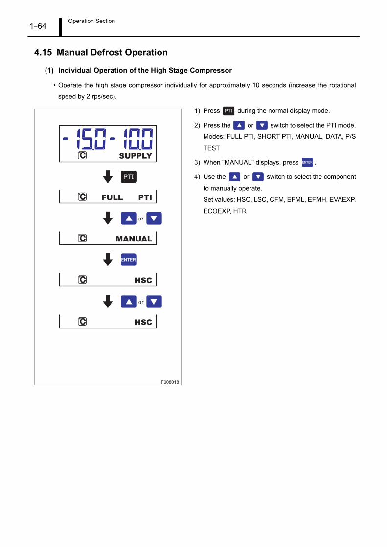
4.15 Manual Defrost Operation
(1) Individual Operation of the High Stage Compressor
• Operate the high stage compressor individually for approximately 10 seconds (increase the rotational
speed by 2 rps/sec).
1) Press during the normal display mode.
2) Press the or switch to select the PTI mode.
Modes: FULL PTI, SHORT PTI, MANUAL, DATA, P/S
TEST
3) When "MANUAL" displays, press .
4) Use the or switch to select the component
to manually operate.
Set values: HSC, LSC, CFM, EFML, EFMH, EVAEXP,
ECOEXP, HTR
F008018
FULL PTI
MANUAL
HSC
HSC
SUPPLY

Operation Section1–65
5) When "HSC" displays, press .
6) Use the or switch to select "HSC ON", and
then press to start individual high stage com-
pressor operation.
During operation, the present current value is dis-
played.
7) When operation is complete, the system returns to the
individual operation setting for the high stage com-
pressor.
To operate other components, press several
times to return to the setting display.
F008339
ON
OFF
U1.0V1.0W1.0
HSC
HSC
HSC
ONHSC
Press to begin
operation.
or
Operation Completed
Returns to the settings display.
*If under 10 A, up until the first decimal place will be shown.
If 10 A or greater, the value is displayed in 1-A increments.

Operation Section1–66
(2) Individual Operation of the Low Stage Compressor
• Operate the low stage compressor individually for approximately 10 seconds (increase the rotational
speed by 2 rps/sec).
1) Press during the normal display mode.
2) Press the or switch to select the PTI mode.
Modes: FULL PTI, SHORT PTI, MANUAL, DATA, P/S
TEST
3) When "MANUAL" displays, press .
4) Use the or switch to select the component
to manually operate.
Set values: HSC, LSC, CFM, EFML, EFMH, EVAEXP,
ECOEXP, HTR
F008020
FULL PTI
MANUAL
HSC
LSC
SUPPLY

Operation Section1–67
5) When "LSC" displays, press .
6) Use the or switch to select "LSC ON", and
then press to start individual low stage compres-
sor operation.
During operation, the present current value is dis-
played.
7) When operation is complete, the system returns to the
individual operation setting for the low stage compres-
sor.
To operate other components, press several
times to return to the setting display.
F008340
LSC
U1.0V1.0W1.0
ON
OFFLSC
LSC
ONLSC
Returns to the settings display.
or
Press to begin
operation.
Operation Completed
*If under 10 A, up until the first decimal place will be shown.
If 10 A or greater, the value is displayed in 1-A increments.

Operation Section1–68
(3) Individual Operation of the Condenser Fan Motor
• Operate the condenser fan motor individually for approximately 60 seconds.
1) Press during the normal display mode.
2) Press the or switch to select the PTI mode.
Modes: FULL PTI, SHORT PTI, MANUAL, DATA, P/S
TEST
3) When "MANUAL" displays, press .
4) Use the or switch to select the component
to manually operate.
Set values: HSC, LSC, CFM, EFML, EFMH, EVAEXP,
ECOEXP, HTR
F008022
FULL PTI
MANUAL
HSC
CFM
SUPPLY

Operation Section1–69
5) When "CFM" displays, press .
6) Use the or switch to select "CFM ON", then
press to start individual condenser fan motor op-
eration.
During operation, the present current value is dis-
played.
7) When operation is complete, the system returns to the
individual operation setting for the condenser fan mo-
tor.
To operate other components, press several
times to return to the setting display.
F008341
CFM
U1.0V1.0W1.0
ON
OFFCFM
CFM
ONCFM
Returns to the settings display.
or
Press to begin
operation.
Operation Completed
*If under 10 A, up until the first decimal place will be shown.
If 10 A or greater, the value is displayed in 1-A increments.

Operation Section1–70
(4) Individual Low-Speed Operation of the Cooling Fan Motor
• Operate the cooling fan motor individually at low speed for approximately 300 seconds.
1) Press during the normal display mode.
2) Press the or switch to select the PTI mode.
Modes: FULL PTI, SHORT PTI, MANUAL, DATA, P/S
TEST
3) When "MANUAL" displays, press .
4) Use the or switch to select the component
to manually operate.
Set values: HSC, LSC, CFM, EFML, EFMH, EVAEXP,
ECOEXP, HTR
F008024
FULL PTI
MANUAL
HSC
EFML
SUPPLY

Operation Section1–71
5) When "EFML" displays, press .
6) Use the or switch to select "EFML ON",
then press to start individual low-speed opera-
tion of the cooling fan motor.
During operation, the present current value is dis-
played.
7) When operation is complete, the system returns to the
individual low speed operation setting for the cooling
fan motor.
To operate other components, press several
times to return to the setting display.
F008342
U1.0V1.0W1.0
EFML
ON
OFFEFML
EFML
ONEFML
Returns to the settings display.
Operation Completed
or
Press to begin
operation.
*If under 10 A, up until the first decimal place will be shown.
If 10 A or greater, the value is displayed in 1-A increments.

Operation Section1–72
(5) Individual High-Speed Operation of the Cooling Fan Motor
• Operate the cooling fan motor individually at high speed for approximately 300 seconds.
1) Press during the normal display mode.
2) Press the or switch to select the PTI mode.
Modes: FULL PTI, SHORT PTI, MANUAL, DATA, P/S
TEST
3) When "MANUAL" displays, press .
4) Use the or switch to select the component
to manually operate.
Set values: HSC, LSC, CFM, EFML, EFMH, EVAEXP,
ECOEXP, HTR
F008026
FULL PTI
MANUAL
HSC
EFMH
SUPPLY

Operation Section1–73
5) When "EFMH" displays, press .
6) Use the or switch to select "EFMH ON",
then press to start individual high-speed opera-
tion of the cooling fan motor.
During operation, the present current value is dis-
played.
7) When operation is complete, the system returns to the
individual high speed operation setting for the cooling
fan motor.
To operate other components, press several
times to return to the setting display.
F008343
U1.0V1.0W1.0
EFMH
ON
OFFEFMH
EFMH
ONEFMH
Returns to the settings display.
Operation Completed
or
Press to begin
operation.
*If under 10 A, up until the first decimal place will be shown.
If 10 A or greater, the value is displayed in 1-A increments.

Operation Section1–74
(6) Individual Operation of the Evaporator Expansion Valve
• Operate the evaporator expansion valve individually.
1) Press during the normal display mode.
2) Press the or switch to select the PTI mode.
Modes: FULL PTI, SHORT PTI, MANUAL, DATA, P/S
TEST
3) When "MANUAL" displays, press .
4) Use the or switch to select the component
to manually operate.
Set values: HSC, LSC, CFM, EFML, EFMH, EVAEXP,
ECOEXP, HTR
F008028
FULL PTI
MANUAL
HSC
EVAEXP
SUPPLY

Operation Section1–75
5) When "EVAEXP" displays, press to display the
evaporator expansion valve opening (%).
6) Use the or switch to change the evaporator
expansion valve opening (%).
Press and hold either switch to cycle through the dig-
its successively.
7) Press to start individual evaporator expansion
valve operation.
When operation is complete, the system returns to the
original settings.
F008344
50
51
EVAEXP
EVAEXP
EVAEXP
or
Press to begin
operation.Returns to the settings display.

Operation Section1–76
(7) Individual Operation of the Economizer Expansion Valve
• Operate the economizer expansion valve individually.
1) Press during the normal display mode.
2) Press the or switch to select the PTI mode.
Modes: FULL PTI, SHORT PTI, MANUAL, DATA, P/S
TEST
3) When "MANUAL" displays, press .
4) Use the or switch to select the component
to manually operate.
Set values: HSC, LSC, CFM, EFML, EFMH, EVAEXP,
ECOEXP, HTR
F008030
FULL PTI
MANUAL
HSC
ECOEXP
SUPPLY
Operation Section1–77
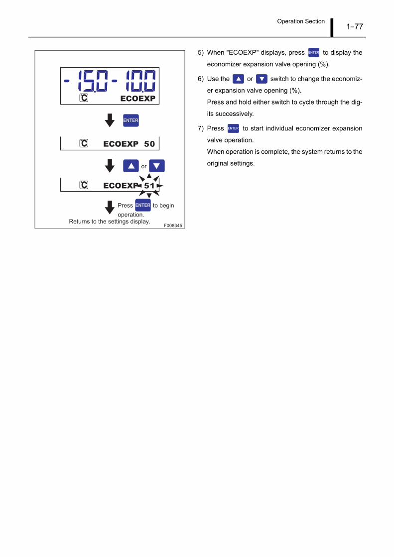
5) When "ECOEXP" displays, press to display the
economizer expansion valve opening (%).
6) Use the or switch to change the economiz-
er expansion valve opening (%).
Press and hold either switch to cycle through the dig-
its successively.
7) Press to start individual economizer expansion
valve operation.
When operation is complete, the system returns to the
original settings.
F008345
50
51
ECOEXP
ECOEXP
ECOEXP
or
Press to begin
operation.Returns to the settings display.

Operation Section1–78
(8) Individual Heater Operation
• Operate the heater individually for approximately 300 seconds.
1) Press during the normal display mode.
2) Press the or switch to select the PTI mode.
Modes: FULL PTI, SHORT PTI, MANUAL, DATA, P/S
TEST
3) When "MANUAL" displays, press .
4) Use the or switch to select the component
to manually operate.
Set values: HSC, LSC, CFM, EFML, EFMH, EVAEXP,
ECOEXP, HTR
F008032
FULL PTI
MANUAL
HSC
HTR
SUPPLY

Operation Section1–79
5) When "HTR" displays, press .
6) Use the or switch to select "HTR ON", then
press to start individual heater operation.
During operation, the present current value is dis-
played.
7) When operation is complete, the system returns to the
individual operation setting for the heater.
To operate other components, press several
times to return to the setting display.
F008346
HTR
U1.0V1.0W1.0
ON
OFFHTR
HTR
ONHTR
Returns to the settings display.
or
Press to begin
operation.
Operation Completed
*If under 10 A, up until the first decimal place will be shown.
If 10 A or greater, the value is displayed in 1-A increments.

Operation Section1–80
4.16 Wake Up Mode Operation
Wake Up Mode Operation
When the power supply is OFF, a battery built into the transport refrigerator enables a portion of the setting
menus to be changed and the information display menus to be checked.
In addition, a service tool can be used via a PC connection to download various data types.
• Press for approximately three seconds to transition to the Wake Up Mode.
• The operation methods for the setting menus and information display menus are the same as for normal
operation.
4.17 Wake Up Mode Item List
(1) Setting Menu
No. Setting DescriptionSet
Value
Measured
ValueSub-Display
Reference
Page
1 Set temperature change S01 - STCHG P1-23
2Switching between Celsius and Fahren-
heitS02 - C/FCHG P1-23
3 Defrost interval change S03 - dEFTCHG P1-24
4 Sensor logging interval change S05 - LOGICHG P1-24
5 Dehumidification operation S06 - dEHCHG P1-25
6 Set humidity change S07 - SHCHG P1-25
7 Defrost completion temperature change S08 - dEFTTCHG P1-26
8 Current limit S09 - AMPLCHG P1-26
9 Battery check S10 - bATCHK P1-27
F010210
Setting
Menu
Information
Display
Menu
When the
Power
Supply
is OFF
When the
Power
Supply
is ON
Normal
Display
Settings
Press and hold for
approximately three seconds.
60 seconds passes with no
switch operation.
Power Supply ON
Wake Up Mode

Operation Section1–81
(2) Information Display Menu
No. Setting DescriptionSet
Value
Measured
ValueSub-Display
Reference
Page
1 Return air temperature 1 01 ***.* RET1 P1-39
2 Supply air temperature 1 02 ***.* SUP1 P1-39
3 Ambient temperature 1 03 ***.* AMb1 P1-39
4 USDA1 temperature 04 ***.* USdA1 P1-40
5 USDA2 temperature 05 ***.* USdA2 P1-40
6 USDA3 temperature 06 ***.* USdA3 P1-40
7 Cargo temperature 07 ***.* CARGO P1-41
8 Relative humidity 08 *** RETRH P1-41
9 Ventilation flow volume 09 *** VENT P1-41
10 Return air temperature 2 10 ***.* RET2 P1-42
11 Supply air temperature 2 11 ***.* SUP2 P1-42
12 Ambient temperature 2 12 ***.* AMb2 P1-42
13 Defrost temperature 13 ***.* dEFT P1-43
14 High stage compressor discharge tem-
perature14 ***.*
HSCdTP1-43
15 High stage compressor body temperature 16 ***.* HSCbT P1-43
16 Low stage compressor suction tempera-
ture18 ***.*
LSCSTP1-44
17 Low stage compressor body temperature 19 ***.* LSCbT P1-44
18 Evaporator inlet temperature 20 ***.* EI P1-44
19 Evaporator outlet temperature 21 ***.* EO P1-45
20 Economizer inlet temperature 22 ***.* ECI P1-45
21 Economizer outlet temperature 23 ***.* ECO P1-45
22 High pressure 24 - HP **** P1-46
23 Middle pressure 25 - MP **** P1-46
24 Low pressure 26 - LP **** P1-46
25 High stage compressor current 27 **.* HSCC P1-47
26 Low stage compressor current 28 **.* LSCC P1-47
27 High stage inverter frequency display 29 *** HSIF P1-47
28 Low stage inverter frequency display 30 *** LSIF P1-48
29 High stage inverter temperature 31 *** HSIT P1-48
30 Low stage inverter temperature 32 *** LSIT P1-48
31 Evaporator expansion valve opening 33 *** EVA EXP P1-49
32 Economizer expansion valve opening 34 *** ECO EXP P1-49
33 Cooling fan status 35 *** EFM P1-49
34 Main power supply voltage 37 *** VOL P1-50
35 Main power supply U-phase current 38 **.* L1 P1-50
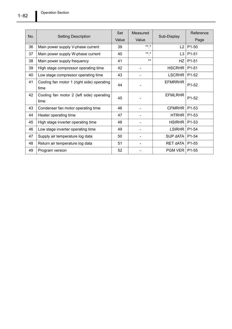
Operation Section1–82
36 Main power supply V-phase current 39 **.* L2 P1-50
37 Main power supply W-phase current 40 **.* L3 P1-51
38 Main power supply frequency 41 ** HZ P1-51
39 High stage compressor operating time 42 - HSCRHR P1-51
40 Low stage compressor operating time 43 - LSCRHR P1-52
41 Cooling fan motor 1 (right side) operating
time44 -
EFMRRHRP1-52
42 Cooling fan motor 2 (left side) operating
time45 -
EFMLRHRP1-52
43 Condenser fan motor operating time 46 - CFMRHR P1-53
44 Heater operating time 47 - HTRHR P1-53
45 High stage inverter operating time 48 - HSIRHR P1-53
46 Low stage inverter operating time 49 - LSIRHR P1-54
47 Supply air temperature log data 50 - SUP dATA P1-54
48 Return air temperature log data 51 - RET dATA P1-55
49 Program version 52 - PGM VER P1-55
No. Setting DescriptionSet
Value
Measured
ValueSub-Display
Reference
Page

Operation Section1–83
5. Explanation of Controls
5.1 Transitioning Between Operating States
F010211
Cycle Initialization
Defrost Operation
Operation Stopped PTI
Completed Successfully
Cooling Operation
Decision Established for
Defrost Operation Start or
Defrost Operation
Command (Manual)
Defrost Completed
AC Power Supply
ON OFF or Major
Malfunction
AC Power Supply
OFF ON
PTI Completed or
Abnormality Present
PTI Command (Manual)
AC Power Supply OFF ON
(Operation Resumes)

Operation Section1–84
5.2 Cooling Operation
Chilled operation is divided into chilled operation and frozen operation in accordance with the set tempera-
ture.
When the set temperature is -10°C or higher, the system runs in chilled mode; when the set temperature is
lower than -10°C, the system runs in frozen mode.
During cooling operation the temperature inside the container is adjusted by changing the compressor ro-
tational speed, and turning the heater ON and OFF.
(1) Chilled Operation
• When the set temperature is -10°C or higher, the system runs in chilled mode.
• In chilled mode, the cooling fan operates at high speed.
(During Eco mode, the cooling fan will operate at low speed.)
• In chilled mode, the compressor rotational speed is regulated to adjust the air outlet temperature to the
set temperature.
When there is a danger of supercooling, the thermistor turns OFF (compressor stops), and the heater is
energized to start heating operation.
• The condenser fan and each expansion valve are optimally controlled.
• When a humidity sensor (optional) is installed, humidification operation (S06) is turned ON, and humidi-
fication operation is conducted in accordance with the set humidity (S07).
(2) Frozen Operation
• When the set temperature is lower than -10°C, the system runs in frozen mode.
• In frozen mode, the cooling fan operates at low speed.
• In frozen mode, the compressor rotational speed is regulated to adjust the return air temperature to the
set temperature.
When there is a danger of supercooling, the thermistor turns OFF (compressor stops), and the cooling
fan is switched to high-speed operation.
• The condenser fan and each expansion valve are optimally controlled.
• Humidification operation cannot be set when in frozen mode.
5.3 Defrost Operation
Defrost operation starts when the defrost interval set for the defrost timer is reached.
During defrost operation the compressor, cooling fan, and condenser fan are stopped.
The heater is energized to heat the evaporator and melt any frost.
Defrost operation is completed when the defrost stop sensor reaches the set stop temperature, or when 90
minutes have elapsed since defrost operation began.
After defrost operation is completed, cold insulation operation (cooling operation with the cooling fan
stopped) is initiated to start cooling operation.

Operation Section1–85
6. Alarm Code Display and Operation During and Abnormality
6.1 Alarm Code Display
Alarm codes are divided into "abnormal operation codes" that require the applicable component to be
stopped and repaired, and "backup operation codes", under which continued transport refrigerator opera-
tion is possible.
Code Component Status Malfunction Level LED Display
Abnormal Operation Code Component stops Serious malfunction Flashing
Backup Operation CodeContinued operation at a
substitute value
Serious malfunction Flashing
Minor malfunctionIlluminated or Extin-
guished
F008351
C O O L H E AT DEFROST IN RANGE A L A R M
SUPPLY
LED Display

Operation Section1–86
6.2 Alarm Code List
Code
No.Details of Abnormality
Operation When Abnormality Occurred Condition for
ReleaseOperation Details LED Display
A01
High stage compressor dis-
charge temperature sensor
open circuit or short circuit
Back-up operation Lit
When the sensor
value reverts to the
normal value.
A03
High stage compressor body
temperature sensor open cir-
cuit or short circuit
Back-up operation Lit
When the sensor
value reverts to the
normal value.
A05
Low stage compressor inlet
temperature sensor open cir-
cuit or short circuit
Back-up operation Lit
When the sensor
value reverts to the
normal value.
A06
Low stage compressor body
temperature sensor open cir-
cuit or short circuit
Back-up operation Lit
When the sensor
value reverts to the
normal value.
A07Ambient temperature sensor 1
open circuit or short circuitBack-up operation Lit
When the sensor
value reverts to the
normal value.
A08Return temperature sensor 1
open circuit or short circuitBack-up operation Lit
When the sensor
value reverts to the
normal value.
A09Supply air temperature sensor
1 open circuit or short circuitBack-up operation Lit
When the sensor
value reverts to the
normal value.
A10
Evaporator inlet temperature
sensor open circuit or short
circuit
Back-up operation Lit
When the sensor
value reverts to the
normal value.
A11
Evaporator outlet tempera-
ture sensor open circuit or
short circuit
Back-up operation Lit
When the sensor
value reverts to the
normal value.
A12
Economizer inlet temperature
sensor open circuit or short
circuit
Back-up operation Lit
When the sensor
value reverts to the
normal value.
A13
Economizer outlet tempera-
ture sensor open circuit or
short circuit
Back-up operation Lit
When the sensor
value reverts to the
normal value.
A14Defrost temperature sensor
open circuit or short circuitBack-up operation Lit
When the sensor
value reverts to the
normal value.
A15High pressure sensor open
circuit or short circuitBack-up operation Lit
When the sensor
value reverts to the
normal value.

Operation Section1–87
A16Middle pressure sensor open
circuit or short circuitBack-up operation Lit
When the sensor
value reverts to the
normal value.
A17Low pressure sensor open cir-
cuit or short circuitBack-up operation Lit
When the sensor
value reverts to the
normal value.
A18Current sensor U open circuit
or short circuitBack-up operation Lit
When the sensor
value reverts to the
normal value.
A19Current sensor V open circuit
or short circuitBack-up operation Lit
When the sensor
value reverts to the
normal value.
A20Current sensor W open circuit
or short circuitBack-up operation Lit
When the sensor
value reverts to the
normal value.
A21USDA #1 sensor open circuit
or short circuitNormal operation Lit
When the sensor
value reverts to the
normal value.
A22USDA #2 sensor open circuit
or short circuitNormal operation Lit
When the sensor
value reverts to the
normal value.
A23USDA #3 sensor open circuit
or short circuitNormal operation Lit
When the sensor
value reverts to the
normal value.
A24Cargo sensor open circuit or
short circuitNormal operation Lit
When the sensor
value reverts to the
normal value.
A25Ambient temperature sensor 2
open circuit or short circuitNormal operation Lit
When the sensor
value reverts to the
normal value.
A26Return temperature sensor 2
open circuit or short circuitNormal operation Lit
When the sensor
value reverts to the
normal value.
A27Supply air temperature sensor
2 open circuit or short circuitNormal operation Lit
When the sensor
value reverts to the
normal value.
A28Humidity sensor open circuit
or short circuitBack-up operation Lit
When the sensor
value reverts to the
normal value.
A29Ambient air temperature dif-
ferential abnormalityNormal operation Lit
When the sensor
value reverts to the
normal value.
Code
No.Details of Abnormality
Operation When Abnormality Occurred Condition for
ReleaseOperation Details LED Display

Operation Section1–88
A30Return air temperature differ-
ential abnormalityNormal operation Lit
When the sensor
value reverts to the
normal value.
A31Supply air temperature differ-
ential abnormalityNormal operation Lit
When the sensor
value reverts to the
normal value.
A32Low pressure sensor accu-
racy abnormalityNormal operation Lit
When the sensor
value reverts to the
normal value.
A33Vent position sensor open cir-
cuit or short circuitNormal operation Lit
When the sensor
value reverts to the
normal value.
B01
High stage compressor dis-
charge temperature abnor-
mality
Normal operation after
THERMO OFF and the
alarm release conditions are
reached (perpetually
repeated).
Lit
When the high stage
compressor dis-
charge temperature
reverts to the normal
value.
B02High stage compressor body
temperature abnormality
Normal operation after
THERMO OFF and the
alarm release conditions are
reached (perpetually
repeated).
Lit
When the high stage
compressor body
temperature reverts
to the normal value.
Perpetually stopped FlashingWhen the power
supply is OFF.
B03
Low stage compressor dis-
charge temperature abnor-
mality
Normal operation after
THERMO OFF and the
alarm release conditions are
reached (perpetually
repeated).
Lit
When the low stage
compressor dis-
charge temperature
reverts to the normal
value.
B04Low stage compressor body
temperature abnormality
Normal operation after
THERMO OFF and the
alarm release conditions are
reached (perpetually
repeated).
Lit
When the low stage
compressor body
temperature reverts
to the normal value.
Perpetually stopped FlashingWhen the power
supply is OFF.
B05 Inverter contactor abnormality
Normal operation after
THERMO OFF and the
alarm release conditions are
reached (perpetually
repeated).
Lit
When voltage is
applied to the
inverter contactor
coil during an
inverter contactor
operation command.
Code
No.Details of Abnormality
Operation When Abnormality Occurred Condition for
ReleaseOperation Details LED Display

Operation Section1–89
B06High stage compressor dis-
charge pressure abnormality
Normal operation after
THERMO OFF and the
alarm release conditions are
reached (perpetually
repeated).
Lit
When the high pres-
sure sensor value
reverts to the normal
value.
Perpetually stopped FlashingWhen the power
supply is OFF.
B07Low stage compressor suc-
tion pressure abnormality
Normal operation after
THERMO OFF and the
alarm release conditions are
reached (perpetually
repeated).
Lit
When the low pres-
sure sensor value
reverts to the normal
value.
Perpetually stopped FlashingWhen the power
supply is OFF.
B08Cooling fan contactor abnor-
mality
Normal operation after
THERMO OFF and the
alarm release conditions are
reached (perpetually
repeated).
Lit
When voltage is
applied to the cool-
ing fan contactor coil
during a cooling fan
contactor operation
command.
Perpetually stopped FlashingWhen the power
supply is OFF.
B09Condenser fan motor contac-
tor abnormality
Normal operation after
THERMO OFF and the
alarm release conditions are
reached (perpetually
repeated).
Lit
When voltage is
applied to the con-
denser fan motor
contactor coil dur-
ing a condenser fan
motor contactor
operation command.
Perpetually stopped FlashingWhen the power
supply is OFF.
B10 Heater contactor abnormality
Only active when turned ON
as an optional selection.Lit
When voltage is
applied to the heater
contactor coil dur-
ing a heater contac-
tor operation
command.
Perpetually stopped FlashingWhen the power
supply is OFF.
Code
No.Details of Abnormality
Operation When Abnormality Occurred Condition for
ReleaseOperation Details LED Display

Operation Section1–90
B11 Out-of-range Normal operation Lit
When the tempera-
ture returns into
range, when the set
temperature is
changed, or when
PTI is started.
B12 Set temperature not achieved Normal operation Lit
When the tempera-
ture returns into
range, when the set
temperature is
changed, or when
PTI is started.
B13Insufficient refrigeration
capacityNormal operation Lit
When the difference
between the return
and supply air tem-
peratures returns to
the normal value.
B14Vent open during frozen oper-
ationNormal operation Lit
Recovers when the
ventilation volume is
at or below the nor-
mal value.
C01High stage inverter communi-
cation abnormality
Normal operation after
THERMO OFF and the
alarm release conditions are
reached (perpetually
repeated).
Lit
Released 40 sec-
onds after the alarm
occurs.
Perpetually stopped FlashingWhen the power
supply is OFF.
C02High stage compressor abnor-
mal rotating torque
Normal operation after
THERMO OFF and the
alarm release conditions are
reached (perpetually
repeated).
Lit
Recovers when the
power supply is
turned OFF or when
there is no alarm
from the inverter.
C03High stage inverter power
supply line short circuitPerpetually stopped Flashing
When the power
supply is OFF.
C04Phase interruption in the high
stage inverter output
Normal operation after
THERMO OFF and the
alarm release conditions are
reached (perpetually
repeated).
Lit
Recovers when
there is no alarm
from the inverter.
Perpetually stopped FlashingWhen the power
supply is OFF.
Code
No.Details of Abnormality
Operation When Abnormality Occurred Condition for
ReleaseOperation Details LED Display

Operation Section1–91
C05High stage inverter overcur-
rent
Normal operation after
THERMO OFF and the
alarm release conditions are
reached (perpetually
repeated).
Lit
Recovers when
there is no alarm
from the inverter.
C06High stage inverter heat sink
high temperature abnormality
Normal operation after
THERMO OFF and the
alarm release conditions are
reached (perpetually
repeated).
Lit
When the fin tem-
perature reverts to
the normal value.
C07High stage inverter fan abnor-
malityPerpetually stopped Flashing
When the power
supply is OFF.
C08High stage inverter motor
overload
Normal operation after
THERMO OFF and the
alarm release conditions are
reached (perpetually
repeated).
Lit
Recovers when
there is no alarm
from the inverter.
C09 High stage inverter overload
Normal operation after
THERMO OFF and the
alarm release conditions are
reached (perpetually
repeated).
Lit
Recovers when
there is no alarm
from the inverter.
C10High stage inverter main cir-
cuit overvoltage abnormality
Normal operation after
THERMO OFF and the
alarm release conditions are
reached (perpetually
repeated).
Lit
When the high stage
inverter voltage
reverts to the normal
value.
C11High stage inverter loss of
synchronism detection
Normal operation after
THERMO OFF and the
alarm release conditions are
reached (perpetually
repeated).
Lit
Recovers when
there is no alarm
from the inverter.
C12High stage inverter main cir-
cuit low voltage abnormality
Normal operation after
THERMO OFF and the
alarm release conditions are
reached (perpetually
repeated).
Lit
When the high stage
inverter voltage
reverts to the normal
value.
C13High stage inverter control
power supply abnormality
Normal operation after
THERMO OFF and the
alarm release conditions are
reached (perpetually
repeated).
Lit
When the high stage
inverter voltage
reverts to the normal
value.
Code
No.Details of Abnormality
Operation When Abnormality Occurred Condition for
ReleaseOperation Details LED Display

Operation Section1–92
C14High stage inverter hardware
abnormality
Normal operation after
THERMO OFF and the
alarm release conditions are
reached (perpetually
repeated).
Lit
Recovers when
there is no alarm
from the inverter.
Perpetually stopped FlashingWhen the power
supply is OFF.
C15High stage inverter abnormal-
ity other than C01 - C14
Normal operation after
THERMO OFF and the
alarm release conditions are
reached (perpetually
repeated).
Lit
Recovers when
there is no alarm
from the inverter.
C16Low stage inverter communi-
cation abnormality
Normal operation after
THERMO OFF and the
alarm release conditions are
reached (perpetually
repeated).
Lit
Released 40 sec-
onds after the alarm
occurs.
Perpetually stopped FlashingWhen the power
supply is OFF.
C17Low stage compressor abnor-
mal rotating torque
Normal operation after
THERMO OFF and the
alarm release conditions are
reached (perpetually
repeated).
Lit
Recovers when the
power supply is
turned OFF or when
there is no alarm
from the inverter.
C18Low stage inverter power sup-
ply line short circuitPerpetually stopped Flashing
When the power
supply is OFF.
C19Phase interruption in the low
stage inverter output
Normal operation after
THERMO OFF and the
alarm release conditions are
reached (perpetually
repeated).
Lit
Recovers when
there is no alarm
from the inverter.
Perpetually stopped FlashingWhen the power
supply is OFF.
C20Low stage inverter overcur-
rent
Normal operation after
THERMO OFF and the
alarm release conditions are
reached (perpetually
repeated).
Lit
Recovers when
there is no alarm
from the inverter.
Code
No.Details of Abnormality
Operation When Abnormality Occurred Condition for
ReleaseOperation Details LED Display
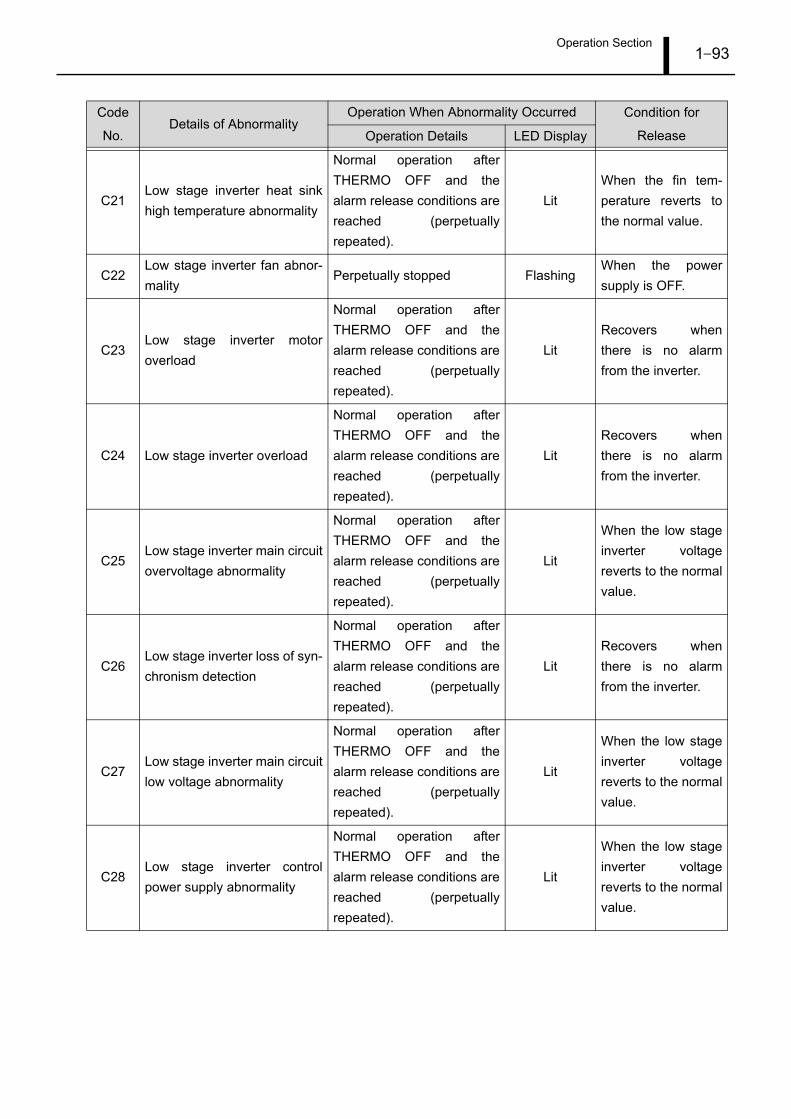
Operation Section1–93
C21Low stage inverter heat sink
high temperature abnormality
Normal operation after
THERMO OFF and the
alarm release conditions are
reached (perpetually
repeated).
Lit
When the fin tem-
perature reverts to
the normal value.
C22Low stage inverter fan abnor-
malityPerpetually stopped Flashing
When the power
supply is OFF.
C23Low stage inverter motor
overload
Normal operation after
THERMO OFF and the
alarm release conditions are
reached (perpetually
repeated).
Lit
Recovers when
there is no alarm
from the inverter.
C24 Low stage inverter overload
Normal operation after
THERMO OFF and the
alarm release conditions are
reached (perpetually
repeated).
Lit
Recovers when
there is no alarm
from the inverter.
C25Low stage inverter main circuit
overvoltage abnormality
Normal operation after
THERMO OFF and the
alarm release conditions are
reached (perpetually
repeated).
Lit
When the low stage
inverter voltage
reverts to the normal
value.
C26Low stage inverter loss of syn-
chronism detection
Normal operation after
THERMO OFF and the
alarm release conditions are
reached (perpetually
repeated).
Lit
Recovers when
there is no alarm
from the inverter.
C27Low stage inverter main circuit
low voltage abnormality
Normal operation after
THERMO OFF and the
alarm release conditions are
reached (perpetually
repeated).
Lit
When the low stage
inverter voltage
reverts to the normal
value.
C28Low stage inverter control
power supply abnormality
Normal operation after
THERMO OFF and the
alarm release conditions are
reached (perpetually
repeated).
Lit
When the low stage
inverter voltage
reverts to the normal
value.
Code
No.Details of Abnormality
Operation When Abnormality Occurred Condition for
ReleaseOperation Details LED Display

Operation Section1–94
C29Low stage inverter hardware
abnormality
Normal operation after
THERMO OFF and the
alarm release conditions are
reached (perpetually
repeated).
Lit
Recovers when
there is no alarm
from the inverter.
Perpetually stopped FlashingWhen the power
supply is OFF.
C30Low stage inverter abnormal-
ity other than C16 - C29
Normal operation after
THERMO OFF and the
alarm release conditions are
reached (perpetually
repeated).
Lit
Recovers when
there is no alarm
from the inverter.
D01 Power supply low voltage
Normal operation after
THERMO OFF and the
alarm release conditions are
reached (perpetually
repeated).
Lit
When the power
supply voltage
reverts to the normal
value.
D02Abnormal power supply volt-
age increase
Normal operation after
THERMO OFF and the
alarm release conditions are
reached (perpetually
repeated).
Lit
When the power
supply voltage
reverts to the normal
value.
D03Power supply frequency
abnormality
Normal operation after
THERMO OFF and the
alarm release conditions are
reached (perpetually
repeated).
Lit
When the power
supply frequency
reverts to the normal
value.
D04 Phase cannot be detected
Previous phase sequence is
memorized, and operation
continues.
LitWhen the power
supply is OFF.
D05 Battery disconnected Operation continues Lit
When the battery
voltage reverts to
the normal value.
D06 Control panel abnormalityKey entry is disabled, and
operation continues.Lit
When all key
switches are OFF or
when the power
supply is OFF.
D07
Communication abnormality
between the main ECU and
the control panel
Key entry is disabled, and
operation continues.Lit
When communica-
tion resumes
between the main
ECU and the con-
trol panel.
Code
No.Details of Abnormality
Operation When Abnormality Occurred Condition for
ReleaseOperation Details LED Display

Operation Section1–95
D1112-volt power supply abnor-
mality
Normal operation after
THERMO OFF and the
alarm release conditions are
reached (perpetually
repeated).
Lit
When the 12-volt
power supply volt-
age reverts to the
normal value.
D12 RTC abnormality Normal operation Lit
Normally recovers
when the time is
acquired.
D13 EEPROM abnormality Operation continues LitWhen the power
supply is OFF.
D14 Flash memory abnormality Normal operation LitWhen the power
supply is OFF.
D15 ADC abnormality Perpetually stopped FlashingWhen the power
supply is OFF.
E01
Communication abnormality
between the panel ECU and
the main ECU
Operation continues Lit
When communica-
tion resumes
between the panel
ECU and the main
ECU.
Code
No.Details of Abnormality
Operation When Abnormality Occurred Condition for
ReleaseOperation Details LED Display

Operation Section1–96
6.3 Method to Display Present Alarms
Display the alarm code(s) when an alarm occurs.
1) When an alarm occurs, press .
2) The alarm code will appear as the measured value,
and the alarm code case number will be shown on the
sub-display.
3) When there are two or more alarm code cases, use
the or switch to display the next alarm
code.
A maximum of ten past alarm code cases can be dis-
played.
F008489
05 ALARMS
ALM 01/05
ALM 02/05

Operation Section1–97
6.4 Method to Display Past Alarms
Display the alarm code(s) for alarms that have occurred in the past. (When an alarm occurs, the alarm code
is recorded as a past alarm.)
1) Press and hold for approximately three seconds.
2) The alarm code will appear as the measured value,
and the alarm occurrence date will be shown on the
sub-display.
3) When there are two or more past alarm code cases,
use the or switch to display the next past
alarm code.
A maximum of ten past alarm code cases can be dis-
played.
F010213
1830 0303
2322 2403
or
Press and hold for
approximately three seconds.
Hour Minute Day Month
2322 2403
Normal Display

Operation Section1–98
7. CF Card Mode and Operation Method
7.1 CF Card Mode
When the CF card is inserted and power is introduced, the system transitions to CF card mode.
The CF card can be used for transport refrigerator software updates, settings data writing, etc.
F008354
Power Supply
OFF ON
CF Card Mode
Normal Refrigeration
Operation
CF Card Inserted
CF Card Not Inserted

Operation Section1–99
7.2 Initial Display Screen for CR Card Mode
The initial display screen shows the remaining CF card capacity.
7.3 Operation Menu Transitions
F010214
500Mb
Remaining CF Card Capacity
F008356
CF Card
Mode MenuDisplay of
Remaining CF
Card Capacity
Enter Each
Type of Menu
Completed
(Component
Stopped)

Operation Section1–100
7.4 List of Items for the CF Card Mode Menu
7.5 CF Card Mode Menu Operation
(1) Software Update
• Update the main ECU software.
1) Press to display "SW" as the measured value.
2) Use the or switch to select the file to be up-
dated.
3) Press to prepare the update.
"SW UPdATE" will flash.
4) Press to prepare the update.
During the update, the remaining amount of the up-
date task will be displayed.
5) When the update is completed successfully, "UPdT
ENd" will display. If an abnormality has occurred, "UP-
dT FAIL" will display.
Menu Content Set ValueMeasured
ValueSub-Display Reference Page
Software update -CF- SW UPdATE P1-100
Settings data writing -CF- Id SETTING P1-101
Log data reading -CF- LOG dOWNLOAd P1-102
F008364
PG121501
SW UPdATE
UPdT ENd
UPdATE
30/100
File Name
Displayed

Operation Section1–101
(2) Settings Data Writing
• Write settings data from the CF card to the main ECU.
1) Press to display "SW" as the measured value.
2) Use the or switch to display "ID" as the
measured value, then press to confirm the set-
ting.
3) Use the or switch to select the file to be
written.
4) Press to prepare for writing.
"idSETTING" will flash.
5) Press to start writing.
During the writing process, the remaining amount of
the writing task will be displayed.
6) When writing is completed successfully, "IdSET ENd"
will display. If an abnormality has occurred, "IdSET
FAIL" will display.
F008365
1G110955
IdSETTING
IdSET ENd
SETTING
30/100
File Name
Displayed

Operation Section1–102
(3) Log Data Reading
• Read the main ECU log data to the CF card.
1) Press to display "SW" as the measured value.
2) Use the or switch to display "LOG" as the
measured value, then press to confirm the set-
ting.
3) Use the or switch to select the log data to
be read.
Selection range: LAST TRIP, 30DAYS, 60DAYS,
90DAYS, ALL TRIP
4) Press to prepare for reading.
"LG.dWNLOAd" will flash. If the CF card does not
have a sufficient amount of remaining capacity, "dIS-
AbLE" will display.
5) Press to start reading.
During the reading process, the remaining amount of
the reading task will be displayed.
6) When reading is completed successfully, "LOG ENd"
will display. If an abnormality has occurred, "LOG
FAIL" will display.
F010140
LAST TRIP
LG.dWNLOAd
LOG ENd
dOWNLOAd
30/100
Repair Section2–103
1. Alarm Codes and Troubleshooting
1.1 Response Method by Alarm Code, and Related Parts
When an alarm LED is lit, unit operation continues. Therefore, load cargo, and if there is no replacement
part, continue operation as is.
A flashing alarm LED indicates that another sensor is unsatisfactory. Since there is no substitute means of
operation and the unit is stopped, perform troubleshooting, and replace parts as necessary.
When an alarm occurs, verify the cause of the malfunction and take the appropriate actions in accordance
with the following charts.

Repair Section2–104
A1
5
A16
A17
A18
A19
A2
0
A2
1
A22
A23
A2
4
A2
5
A26
A27
A28
A29
A3
0
A3
1
A0
1
A03
A0
5
A06
A07
A08
A09
A1
0
A11
A12
A13
A1
4
1.
Se
nso
r a
bn
orm
alit
y
2. W
irin
g h
arn
ess o
pe
n c
ircu
it,
inco
rre
ct
wirin
g,
po
or
co
nn
ecto
r co
nta
ct,
etc
.
Th
e t
he
rmis
tor
resis
tan
ce
va
lue
is o
uts
ide
th
e
me
asu
rem
en
t ra
ng
e.
Th
e p
ressu
re s
en
so
r o
utp
ut
vo
lta
ge
is o
uts
ide
the
me
asu
rem
en
t ra
ng
e.
Th
e c
urr
en
t se
nso
r o
utp
ut
va
lue
is a
t o
r b
elo
w
the
sta
nd
ard
va
lue
.
Th
e o
ptio
na
l se
nso
r th
erm
isto
r re
sis
tan
ce
va
lue
is o
uts
ide
th
e m
ea
su
rem
en
t ra
ng
e.
Th
e h
um
idity s
en
so
r o
utp
ut
va
lue
is o
uts
ide
th
e
me
asu
rem
en
t ra
ng
e.
La
rge
diffe
ren
ce
in
th
e m
ea
su
red
va
lue
s
be
twe
en
se
nso
r 1
an
d t
he
op
tio
na
l se
nso
r.
1.
Se
nso
r a
bn
orm
alit
y
2. W
irin
g h
arn
ess o
pe
n c
ircu
it,
inco
rre
ct
wirin
g,
po
or
co
nn
ecto
r co
nta
ct,
etc
.
1.
Po
we
r su
pp
ly p
ha
se
in
terr
up
tio
n
2. W
irin
g h
arn
ess o
pe
n c
ircu
it,
inco
rre
ct
wirin
g,
po
or
co
nn
ecto
r co
nta
ct,
etc
.
3.
Fa
ulty m
ag
ne
tic c
on
tacto
r o
pe
ratio
n
1.
Se
nso
r a
bn
orm
alit
y
2. W
irin
g h
arn
ess o
pe
n c
ircu
it,
inco
rre
ct
wirin
g,
po
or
co
nn
ecto
r co
nta
ct,
etc
.
1.
Se
nso
r a
bn
orm
alit
y
2. W
irin
g h
arn
ess o
pe
n c
ircu
it,
inco
rre
ct
wirin
g,
po
or
co
nn
ecto
r co
nta
ct,
etc
.
1.2
. S
en
so
r a
bn
orm
alit
y
3. W
irin
g h
arn
ess o
pe
n c
ircu
it,
inco
rre
ct
wirin
g,
po
or
co
nn
ecto
r co
nta
ct,
etc
.
1.
Me
asu
re t
he
co
rre
sp
on
din
g s
en
so
r re
sis
tan
ce
va
lue
s
(CN
1, 2
) a
nd
co
nve
rt t
he
m in
to t
em
pe
ratu
res u
sin
g t
he
th
erm
isto
r ch
ara
cte
ristics c
ha
rt.
Me
asu
re t
he
te
mp
era
ture
in
th
e v
icin
ity o
f th
e c
orr
esp
on
din
g s
en
so
r, a
nd
ch
eck t
ha
t it is
the
sa
me
as t
he
co
nve
rte
d v
alu
e.
2. C
he
ck t
he
wirin
g h
arn
ess f
rom
th
e c
orr
esp
on
din
g s
en
so
r u
p t
o t
he
ECU
an
d c
on
ne
cto
r C
N1
fo
r p
oo
r co
nta
ct,
etc
.
1.
Me
asu
re t
he
ou
tpu
t va
lue
s (
pin
s 2
-3, 8
-9, a
nd
11
-12
on
C
N3
) fo
r th
e c
orr
esp
on
din
g s
en
so
rs a
nd
co
nve
rt t
he
m in
to
pre
ssu
res u
sin
g t
he
pre
ssu
re c
ha
racte
ristics t
ab
le.
Me
asu
re
the
pre
ssu
re in
th
e v
icin
ity o
f th
e c
orr
esp
on
din
g s
en
so
r, a
nd
ch
eck t
ha
t it is t
he
sa
me
as t
he
co
nve
rte
d v
alu
e.
2. C
he
ck t
he
wirin
g h
arn
ess f
rom
th
e c
orr
esp
on
din
g s
en
so
r u
p t
o t
he
ECU
an
d c
on
ne
cto
r C
N3
fo
r p
oo
r co
nta
ct, e
tc.
1.C
he
ck t
ha
t th
ere
is n
o p
ha
se
in
terr
up
tio
n in
ea
ch
ph
ase
of
the
po
we
r su
pp
ly.
2. C
he
ck t
ha
t th
e b
reake
r a
nd
te
rmin
al b
oa
rd s
cre
ws a
re
tig
ht,
an
d v
erify
th
at C
N7, C
N1
0, a
nd
CN3
5 a
re n
ot
po
orly o
r lo
ose
ly c
on
ne
cte
d. In
ad
ditio
n,
ch
eck t
he
wirin
g h
arn
ess f
rom
th
e s
en
so
r u
p t
o t
he
ECU
an
d t
he
co
nn
ecto
r fo
r a
ny
ab
no
rma
litie
s.
3. C
he
ck f
or
ma
gn
etic c
on
tacto
r b
reaka
ge
.
1.
Me
asu
re t
he
co
rre
sp
on
din
g s
en
so
r re
sis
tan
ce
va
lue
s
(CN
1, C
N2,
CN
40
) a
nd
co
nve
rt t
he
m in
to t
em
pe
ratu
res u
sin
g
the
th
erm
isto
r ch
ara
cte
ristics c
ha
rt.
Me
asu
re t
he
te
mp
era
ture
in
th
e v
icin
ity o
f th
e c
orr
esp
on
din
g s
en
so
r, a
nd
ch
eck t
ha
t it is
the
sa
me
as t
he
co
nve
rte
d v
alu
e.
2. C
he
ck t
he
wirin
g h
arn
ess f
rom
th
e c
orr
esp
on
din
g s
en
so
r u
p t
o t
he
ECU
an
d c
on
ne
cto
r C
N1
fo
r p
oo
r co
nta
ct,
etc
.
1.
Measu
re t
he o
utp
ut
valu
e (
pin
s 5-6
on C
N3
) fo
r th
e s
enso
r and
conve
rt it
into
a h
um
idity
usi
ng the h
um
idity
senso
r ch
ara
cterist
ics
table
. M
easu
re the h
um
idity
in the v
icin
ity o
f th
e h
um
idity
senso
r,
an
d c
he
ck that it
is the s
am
e a
s th
e c
onve
rted v
alu
e.
2. C
heck
the w
irin
g h
arn
ess
fro
m the h
um
idity
senso
r up to the E
CU
and c
onnect
or
CN3
for
poor
conta
ct, abnorm
alit
ies,
etc
.
1.
Me
asu
re t
he
re
sis
tan
ce
va
lue
fo
r b
oth
se
nso
rs a
nd
ch
eck
tha
t th
e v
alu
es a
re t
he
sa
me
.2
. C
he
ck t
ha
t th
e in
sta
llatio
n lo
ca
tio
n f
or
ea
ch
se
nso
r is
co
rre
ct.
3. C
he
ck t
he
wirin
g h
arn
ess f
rom
ea
ch
se
nso
r u
p t
o t
he
ECU
a
nd
co
nn
ecto
r C
N3
fo
r p
oo
r co
nta
ct, a
bn
orm
alit
ies,
etc
.
Hig
h S
tage
Com
pres
sor D
isch
arge
Tem
pera
ture
Sen
sor
Hig
h S
tage
Com
pres
sor B
ody
Tem
pera
ture
Sen
sor
Low
Sta
ge C
ompr
esso
r Suc
tion
Tem
pera
ture
Sen
sor
Low
Sta
ge C
ompr
esso
r B
ody
Tem
pera
ture
Sen
sor
Am
bie
nt Te
mp
era
ture
Se
nso
r 1
Re
turn
Air T
em
pe
ratu
re S
en
so
r 1
Su
pp
ly A
ir T
em
pe
ratu
re S
en
so
r 1
Eva
po
rato
r In
let Te
mp
era
ture
Se
nso
r
Eva
po
rato
r O
utle
t Te
mp
era
ture
Se
nso
r
Eco
no
miz
er
Inle
t Te
mp
era
ture
Se
nso
r
Eco
no
miz
er
Ou
tle
t Te
mp
era
ture
Se
nso
r
De
fro
st Te
mp
era
ture
Se
nso
r
Hig
h P
ressu
re S
en
so
r
Mid
dle
Pre
ssu
re S
en
so
r
Lo
w P
ressu
re S
en
so
r
Cu
rre
nt
Se
nso
r U
Cu
rre
nt
Se
nso
r V
Cu
rre
nt
Se
nso
r W
Hu
mid
ity S
en
so
r
Am
bie
nt Te
mp
era
ture
Se
nso
rs 1, 2
Re
turn
Air T
em
pe
ratu
re S
en
so
rs 1, 2
Su
pp
ly A
ir T
em
pe
ratu
re S
en
so
rs 1, 2
US
DA
Se
nso
r 1
US
DA
Se
nso
r 2
US
DA
Se
nso
r 3
Ca
rgo
Te
mp
era
ture
Se
nso
r
Am
bie
nt Te
mp
era
ture
Se
nso
r 2
Re
turn
Air T
em
pe
ratu
re S
en
so
r 2
Su
pp
ly A
ir T
em
pe
ratu
re S
en
so
r 2
6 6 76 77 6 8 10 -- - - - - - 6 6 67
Ala
rm C
od
e
Lis
tD
escrip
tio
nP
ossib
le C
au
se
Ve
rifica
tio
n M
eth
od
Re
late
d P
art
sIn
stal
latio
n Lo
catio
n (R
efer
to th
e D
iagr
am)
Part
Cod
e
Dia
gra
m3
-1
Dia
gra
m3
-2
Dia
gra
m3
-3
Dia
gra
m3
-4
Dia
gra
m1
-9
Dia
gra
m2
-6
Dia
gra
m2
-4
Dia
gra
m2
-7
Dia
gra
m2
-8
Dia
gra
m3
-5
Dia
gra
m3
-6
Dia
gra
m2
-10
Dia
gra
m3
-7
Dia
gra
m3
-14
Dia
gra
m3
-8
Dia
gra
m2
-1
- - -
Dia
gra
m2
-2
Dia
gra
m2
-3
-
Dia
gra
m1
-9
Dia
gra
m2
-6
Dia
gra
m2
-6
Dia
gra
m2
-4
Dia
gra
m2
-5
Dia
gra
m2
-5
Dia
gra
m1
-14
Dia
gra
m1
-9
F010216

Repair Section2–105
1 3066 10
13
11
23 2 4 3
Diagram
3-9
Diagram1
-13
Diagram
3-5
Diagram
3-8
Diagram
3-10
Diagram
3-11
Diagram1
-1
Diagram1
-2
Diagram
4-8
Diagram
3-1
2
Diagram1
-4
Diagram1
-3
A3
2
A3
3
B01
B0
2
B0
3
B0
4
B05
B0
6
B0
7
1.
Wiring
harness open
circu
it,
incorrect
wiring
, poor connector contact,
etc
.
2.
Evaporator
inlet temperature
sensor
abnorma
lity
3.
Low
pressure
sensor abnorma
lity
1. Sensor abnorma
lity
2.
Wiring
harness open
circu
it,
incorrect
wiring
, poor connector contact,
etc
.
1.
Evaporator expansion
va
lve
abnorma
lity
2.
Insuffic
ient refr
igerant
1.
Evaporator expansion
va
lve
abnorma
lity
2.
Insuffic
ient refr
igerant
1.
Evaporator expansion
va
lve
abnorma
lity
2.
Insuffic
ient refr
igerant
1.
High
pressure
increase
abnorma
lity
2.
Fuse
2 b
lown
3. Magnetic contactor abnorma
lity
4.
Wiring
harness open
circu
it,
incorrect
wiring
, poor connector contact,
etc
.
1. Check that the
condenser fan
is
rotating
, and
rotating
in
the
correct
direction
.2
. Condenser fins c
logged
with
dirt or
condenser corrosion
/damage
3. Condenser fan
damage
4. Condenser fan
motor damage
5. MC5
(condenser fan
contactor)
damage
6. C
logged dryer
7. The
temperature
in
the
vic
inity of the
transport
refr
igerator has exceeded
the
specification
range
.
Insuffic
ient refr
igerant
Insuffic
ient refr
igerant
1. Check
the w
iring
harnesses
from
the evaporator
inlet temperature
sensor
and the
low
pressure sensor
up to
the
EC
U and
connectors C
N1 and C
N3
for poor
contact
, abnormal
ities
, etc
.2.
Measure
the resistance
value
for the evaporator
inlet temperature
sensor
and convert it into a temperature
using
the therm
istor characteristics chart.
Measure
the temperature
in the vicinity
of the
corresponding
sensor, and
chec
k that
it is
the same as
the converted va
lue.
In add
ition
, check
that
the
evaporator
inlet temperature
sensor
location
is correct
.3.
Measure
the output
value
(pins
11-12
on C
N3)
for the
low
pressure
sensor
and
convert
it into
a pressure us
ing the pressure
sensor
characteristics table.
Measure
the pressure
in the vicinity
of the
low
pressure
sensor, and chec
k that
it is
the same as
the converted va
lue.
1. Check that the vent position sensor w
ires are
connected.
2. Check the w
iring harness from
the vent position sensor up to
the EC
U and connector C
N5 poor contact, abnormalit
ies, etc
.
1. Check for poor contact
in connectors
near the
evaporator
expansion
va
lve
as we
ll as the
EC
U connector (C
N1
2).
Check the
wiring
harness from
the
expansion
va
lve
up
to
the
EC
U for any abnorma
lities. Conduct a
short
PT
I and
check
that the
va
lve
opens and
closes.
2. Add
the
specified
quantity
of refr
igerant.
1. Check for poor contact
in connectors
near the
evaporator
expansion
va
lve
as we
ll as the
EC
U connector (C
N1
2).
Check the
wiring
harness from
the
expansi on
va
lve
up
to
the
EC
U for any abnorma
lities. Conduct a
short
PT
I and
check
that the
va
lve
opens and
closes.
2. Add
the
specified
quantity
of refr
igerant.
1. Check for factors
causing
the
abnorma
l h
igh
pressure
increase
.2
. V
isua
lly check to
see
if fuse
F2
is b
lown
.3
. Check for
24
VAC
on
the
co
il side
of MC1
(compressor
contactor)
.4
. Check the
wiring
harness from
the
pressure
sw
itch
up
to
the
EC
U and
the
connectors
for any abnorma
lities.
1. Check for poor contact
in connectors
near the
evaporator
expansion
va
lve
as we
ll as the
EC
U connector (C
N1
2).
Check the
wiring
harness from
the
expansion
va
lve
up
to
the
EC
U for any abnorma
lities. Conduct a
short
PT
I and
check
that the
va
lve
opens and
closes.
2. Add
the
specified
quantity
of refr
igerant.
1.Check v
isua
lly.
2.Check v
isua
lly.
3.Check v
isua
lly.
4. Turn
contactor MC5
ON
and
measure
the
current va
lue
.5
. Check for magnetic contactor brea
kage
.6
. Check for a
temperature
difference
in
the
pip
ing
before
and
after the
dryer.
7. Check to
see
if the
condenser
inlet temperature
has
exceeded
50
°C.
Add
the
specified
quantity
of refr
igerant.
Add
the
specified
quantity
of refr
igerant.
Econom
izer
Inlet Temperature
Sensor
Low
Pressure
Sensor
Vent Position
Sensor
High
Stage
Compressor
Low
Stage
Compressor
High
Pressure
Sw
itch
Evaporator
Expansion
Va
lve
Co
il
Evaporator
Expansion
Va
lve
Body
Condenser
Fan
Condenser
Fan
Motor
Condenser
Fan
Contactor
Dryer
The
sensor accuracy is outs
ide
the
specification
range
.
The
vent position
sensor output va
lue
is outs
ide
the
measurement range
.
The
refr
igerant temperature
at the
high
stage
compressor outlet exceeds the
standard
va
lue
.
The
high
stage
compressor body temperature
exceeds the
standard
va
lue
.
The
refr
igerant temperature
at the
low
stage
compressor outlet exceeds the
standard
va
lue
.
The
low
stage
compressor body temperature
exceeds the
standard
va
lue
.
Pressure
sw
itch
operation
The
high
stage
compressor outlet pressure
exceeds the
standard
va
lue
.
The
low
stage
compressor suction
pressure
has
dropped
be
low
the
standard
va
lue
.
Alarm
Code
L
ist
Description
Possib
le Cause
Verification
Method
Re
lated
Parts
Instal
lation
Location
(Refer
to the D
iagram)
Part
Code
F010217

Repair Section2–106
27
12 1 27
271
Dia
gra
m5
-2
--
--
--
6D
iag
ram
1-13
Dia
gra
m1
-7
11
Dia
gra
m1
-2
9 23
Dia
gra
m2
-9
Dia
gra
m4
-1
Dia
gra
m5
-2
Dia
gra
m5
-1
Dia
gra
m5
-1
Dia
gra
m3
-10
Dia
gra
m3
-9
Co
olin
g F
an
Mo
tor
Co
nd
en
se
r F
an
Mo
tor
He
ate
r
Eva
po
rato
r
Eva
po
rato
r
Eva
po
rato
r
Ve
nt
Po
sitio
n S
en
so
r
Hig
h S
tag
e I
nve
rte
r
Lo
w S
tag
e In
ve
rte
r
Lo
w S
tag
e In
ve
rte
r
Lo
w S
tag
e C
om
pre
sso
r
Hig
h S
tag
e C
om
pre
sso
r
Hig
h S
tag
e I
nve
rte
r
B08
1. A
bn
orm
al te
mp
era
ture
in
cre
ase
in
th
e
mo
tor
win
din
gs.
2. F
use 3
blo
wn
3. W
irin
g h
arn
ess o
pe
n c
ircu
it, in
co
rre
ct
wirin
g, p
oo
r co
nn
ecto
r co
nta
ct, e
tc.
1. A
bn
orm
al te
mp
era
ture
in
cre
ase
in
th
e
mo
tor
win
din
gs
2. F
use 2
blo
wn
3. W
irin
g h
arn
ess o
pe
n c
ircu
it, in
co
rre
ct
wirin
g, p
oo
r co
nn
ecto
r co
nta
ct, e
tc.
1. A
bn
orm
al te
mp
era
ture
in
cre
ase
in
th
e
he
ate
r
2. F
use
4 b
low
n
3. W
irin
g h
arn
ess o
pe
n c
ircu
it, in
co
rre
ct
wirin
g, p
oo
r co
nn
ecto
r co
nta
ct, e
tc.
Exce
ssiv
e f
rost
on
th
e e
va
po
rato
r
Exce
ssiv
e f
rost
on
th
e e
va
po
rato
r
Exce
ssiv
e f
rost
on
th
e e
va
po
rato
r
1. T
he
exh
au
st
ou
tle
t is
op
en
2. F
au
lty s
en
so
r
1.
Op
era
tin
g o
uts
ide
th
e s
pe
cific
atio
n
ran
ge
.
2. O
pe
n c
ircu
it, e
tc. in
th
e c
om
mu
nic
atio
n
wirin
g h
arn
ess b
etw
ee
n t
he
in
ve
rte
r a
nd
ECU
.
3. P
oo
r co
nn
ecto
r co
nta
ct.
4. W
he
n M
C1
is O
FF
5. T
he
po
we
r su
pp
ly v
olta
ge
ha
s f
alle
n
be
low
th
e u
sa
ge
ra
ng
e.
6. D
C r
ea
cto
r d
am
ag
e
7. O
pe
n c
ircu
it in
th
e o
utp
ut lin
es, m
oto
r
ab
no
rma
lity
1.
Ch
eck f
or
facto
rs c
au
sin
g t
he
ab
no
rma
l te
mp
era
ture
in
cre
ase
in
th
e m
oto
r w
ind
ing
s.
2. V
isu
ally
ch
eck to
se
e if fu
se
F3
is b
low
n.
3.
Ch
eck fo
r 2
4 V
AC
on
th
e c
oil
sid
e o
f M
C6
or
MC7
.4
. C
he
ck t
he
wirin
g h
arn
ess f
rom
th
e m
oto
r u
p t
o t
he
ECU
a
nd
th
e c
on
ne
cto
r fo
r a
ny a
bn
orm
alit
ies.
1.
Ch
eck f
or
facto
rs c
au
sin
g t
he
ab
no
rma
l te
mp
era
ture
in
cre
ase
in
th
e m
oto
r w
ind
ing
s.
2. V
isu
ally
ch
eck to
se
e if fu
se
F2
is b
low
n.
3.
Ch
eck fo
r 2
4 V
AC
on
th
e c
oil
sid
e o
f M
C5
.4
. In
ad
ditio
n, ch
eck t
he
wirin
g h
arn
ess f
rom
th
e m
oto
r u
p t
o
the
ECU
an
d t
he
co
nn
ecto
r fo
r a
ny a
bn
orm
alit
ies.
1.
Ch
eck f
or
facto
rs c
au
sin
g t
he
ab
no
rma
l te
mp
era
ture
in
cre
ase
in
th
e h
ea
ter.
2. V
isu
ally
ch
eck to
se
e if fu
se
F4
is b
low
n.
3.
Ch
eck fo
r 2
4 V
AC
on
th
e c
oil
sid
e o
f M
C2
.4
. C
he
ck t
he
wirin
g h
arn
ess f
rom
th
e h
ea
ter
the
rma
l sw
itch
u
p t
o t
he
ECU
an
d t
he
co
nn
ecto
rs f
or
an
y a
bn
orm
alit
ies.
Ch
eck t
ha
t th
ere
is n
o f
rost
on
th
e e
va
po
rato
r fr
om
th
e
insp
ectio
n p
ort
. If
th
ere
is fro
st,
co
nd
uct
ma
nu
al d
efr
ostin
g.
1.
Ch
eck t
ha
t th
ere
is n
o f
rost
on
th
e e
va
po
rato
r fr
om
th
e
insp
ectio
n p
ort
. If
th
ere
is fro
st,
co
nd
uct
ma
nu
al d
efr
ostin
g.
2.
Ch
eck t
ha
t th
e c
arg
o h
as b
ee
n p
re-c
oo
led
.
1.
Ch
eck t
o s
ee
if
the
exh
au
st
ou
tle
t is
op
en
.2
. C
he
ck t
ha
t th
e v
en
t p
ositio
n s
en
so
r w
ire
s a
re c
on
ne
cte
d.
1. T
urn
th
e p
ow
er
su
pp
ly O
FF
an
d t
he
n b
ack O
N, a
nd
th
en
ve
rify
th
at th
e tra
nsp
ort
re
frig
era
tor
op
era
tes w
ith
ou
t a
ny
pro
ble
ms.
2. If
th
e c
om
pre
sso
r is
fo
un
d to
be
no
t o
pe
ratin
g a
s a
re
su
lt o
f
the
ch
eck a
bo
ve, ch
eck c
on
tin
uity in
th
e c
on
ne
cto
r fo
r th
e
inve
rte
r co
mm
un
ica
tio
n w
irin
g h
arn
ess.
3. V
isu
ally
ch
eck f
or
sig
ns o
f fr
ett
ing
we
ar
on
th
e t
erm
ina
ls,
an
d t
he
pre
se
nce
of
we
ar
pa
rtic
les.
Ch
eck b
oth
th
e E
CU
-sid
e
an
d s
en
so
r-sid
e c
on
ne
cto
rs.
Vis
ua
lly c
he
ck t
o s
ee
if
the
fe
ma
le t
erm
ina
l is
sp
rea
d o
pe
n.
Vis
ua
lly c
he
ck to
se
e if th
e m
ale
te
rmin
al is
be
nt.
4.
Ch
eck c
on
tin
uity in
th
e w
irin
g h
arn
ess b
etw
ee
n t
he
ECU
an
d c
on
tacto
r. V
isu
ally
ch
eck fo
r w
ea
r o
n th
e E
CU
co
nn
ecto
r
term
ina
ls.
5.
Ch
eck t
he
in
ve
rte
r in
pu
t vo
lta
ge
.
6.
Ch
eck c
on
tin
uity b
etw
ee
n t
he
DC
re
acto
r te
rmin
als
.
7.
Ch
eck r
esis
tan
ce
be
twe
en
th
e m
oto
r le
ad
s o
n t
he
in
ve
rte
r-
sid
e o
utp
ut.
B09
B1
0
B11
B12
B13
B1
4
C0
1
C02
C03
C0
4
C0
5
C06
C07
C08
C09
C1
0
C11
C12
C13
C1
4
C1
5
C16
C17
C18
C19
C2
0
C2
1
C22
C23
C2
4
C2
5
C26
C27
C28
C29
C3
0
1.
Ch
eck t
ha
t th
ere
is n
o f
rost
on
th
e e
va
po
rato
r fr
om
th
e
insp
ectio
n p
ort
. If
th
ere
is fro
st,
co
nd
uct
ma
nu
al d
efr
ostin
g.
2.
Ch
eck t
ha
t th
e c
arg
o h
as b
ee
n p
re-c
oo
led
.
Ala
rm C
od
e
Lis
tD
escrip
tio
nP
ossib
le C
au
se
Ve
rifica
tio
n M
eth
od
Re
late
d P
art
sIn
stal
latio
n Lo
catio
n (R
efer
to th
e D
iagr
am)
Part
Cod
e
Co
olin
g f
an
mo
tor
the
rma
l o
pe
ratio
n
Vo
lta
ge
is n
ot
ap
plie
d t
o t
he
co
nta
cto
r co
il d
urin
g
a c
on
de
nse
r fa
n O
N c
om
ma
nd
.
Vo
lta
ge
is n
ot
ap
plie
d t
o t
he
co
nta
cto
r co
il d
urin
g
a h
ea
ter
ON
co
mm
an
d.
Aft
er
co
min
g in
to r
an
ge, th
e v
alu
e g
oe
s o
ut
of
ran
ge
fo
r a
fix
ed
pe
rio
d o
f tim
e.
Th
e s
et
tem
pe
ratu
re w
as n
ot
rea
ch
ed
with
in a
fixe
d p
erio
d o
f tim
e.
Insu
ffic
ien
t re
frig
era
tio
n c
ap
acity
Th
e e
xh
au
st
ou
tle
t is
op
en
du
rin
g f
roze
n
op
era
tio
n.
An
ab
no
rma
lity h
as o
ccu
rre
d in
th
e in
ve
rte
r.
F010218

Repair Section2–107
18
18
Diagram
4-2
Diagram
4-2
Transformer
Transformer
1. The
power supp
ly vo
ltage
is be
low
the
usage
range
for one
second
.
2.
Wiring
harness open
circu
it,
incorrect
wiring
, connector poor contact,
etc
.
3. Transformer ma
lfunction
1. The
power supp
ly vo
ltage
is above
the
usage
range
for one
second
.
2.
Wiring
harness open
circu
it,
incorrect
wiring
, connector poor contact,
etc
.
3. Transformer ma
lfunction
1. Measure
the power supply
voltage; check
that the value is
at least
360 V
.2. Check
for abnormalit
ies
in the w
iring between the transformer and
the C
N25 connector.
3. Measure
the voltage at pins 1 and 2
on C
N25. Check
that the
voltage between p
ins 1 and 2
= power supply
voltage x
15 V
/440 V
.
1. Measure
the power supply
voltage; check
that the value is
500 V
or
less
.2. Check
for abnormalit
ies
in the w
iring between the transformer
and the C
N25 connector.
3. Measure
the voltage at pins 1 and 2
on C
N25. Check
that the
voltage between p
ins 1 and 2
= power supply
voltage x
15 V
/440 V
.
D01
D0
2
16
25
22
Diagram
4-6
21
Diagram
4-4
17
Diagram
4-5
16
Diagram
4-6
17
Diagram
4-5
16
Diagram
4-6
--
--
Diagram
4-7
Diagram
4-3
Ma
in EC
U
Battery
Contro
l Pane
l
Electron
ic Expansion
Va
lve
Co
il
Ma
in EC
U
Ma
in EC
U
Contro
l Pane
l
Current Sensor R
, S
, T
Phase
Se
quence
Connector
1. The
power supp
ly fre
quency is outs
ide
the
usage
range
.
2.
Wiring
harness open
circu
it,
incorrect
wiring
, connector poor contact,
etc
.
3. Ma
in EC
U ma
lfunction
4. A
device
is generating
no
ise
1. B
lown
fuse
2.
Fau
lty current sensor,
wiring
harness
3. Power supp
ly phase
interruption
1. Battery
connector d
isconnected
2. Poor connector contact.
3.
Fau
lty battery
1.
Key sw
itch
ma
lfunction
2. An
obstruction
has been
in
contact w
ith
the
key sw
itch
for an
extended
period
of
1.
Fau
lty w
iring
harness
2. Contro
l pane
l EC
U ma
lfunction
Fau
lty w
iring
harness
Layer short
in
the
electron
ic expansion
Ma
in EC
U ma
lfunction
1. Measure
the
power supp
ly fre
quency; check that the
va
lue
is
48
~ 5
2 Hz or 5
8 ~
62
Hz.
2. Check for abnorma
lities in
the
wiring
between
the
transformer and
CN
25
connector.
3. Measure
the
vo
ltage
between
pins 1
and
2 on
CN
25
; check that the
va
lue
is at
least 1
2 VAC
.4
. Check whether the
device
generating the
no
ise
is
connected
to
the
same
power supp
ly line
(e
lectr
ic we
lder,
etc
.)
1.
Is fuse
F2
/F3
blown
?
2.
Is each
wiring
harness connected
to
each
current sensor?
Check to
ma
ke
sure
connector C
N6
is fu
lly connected
.
3. Check for phase
interruption
in
the
power supp
ly.
1. Check to
see
if the
battery
is connected
.
2. Check for
looseness in
the
connector C
N2
8 term
ina
ls.
3. Measure
the
vo
ltage
between
pins 1
and
2 on
connector
CN
28
. If
the
va
lue
is 10
V or more
, the
battery
is fau
lty.
1. Check each
key sw
itch
operation
.
2. Check for any items in
contact w
ith
the
pane
l.
Check for
loose
term
ina
ls in
connector C
N01
on
the
contro
l pane
l side
and
connector C
N2
4 on
the
ma
in EC
U s
ide
. A
lso
check for w
iring
harness abnorma
lities.
Disconnect connector C
N1
2 and
verify
that the
alarm
code
disappears
.
Check for
loose
term
ina
ls in
the
contro
l pane
l side
connector
and
connector C
N2
4 on
the
ma
in EC
U s
ide
. A
lso
check for
wiring
harness abnorma
lities.
Rep
lace
the
ma
in EC
U.
16
Diagram
4-6
Ma
in EC
UMa
in EC
U ma
lfunction
Rep
lace
the
ma
in EC
U.
16
Diagram
4-6
Ma
in EC
UMa
in EC
U ma
lfunction
Rep
lace
the
ma
in EC
U.
16
Diagram
4-6
Ma
in EC
U
Contro
l Pane
l EC
U
Ma
in EC
U ma
lfunction
Rep
lace
the
ma
in EC
U.
D0
3
D0
4
D05
D0
6
D0
7
D11
D1
2
D1
3
D1
4
D15
E01
Alarm
Code
L
ist
Description
Possib
le Cause
Verification
Method
Re
lated
Parts
Instal
lation
Location
(Refer
to the D
iagram)
Part
Code
The
ma
in power supp
ly vo
ltage
is be
low
the
usage
range
.
The
ma
in power supp
ly vo
ltage
is above
the
usage
range
.
The
ma
in power supp
ly fre
quency is outs
ide
the
usage
range
.
The
power supp
ly phase
se
quence
cannot be
determ
ined
.
The
battery
is d
isconnected
.
The
operation
pane
l key sw
itch
is stuck down
.
Commun
ications between
the
EC
U and
contro
l
pane
l have
been
interrupted
.
The
12
-vo
lt power supp
ly is be
low
the
usage
range
.
RTC
abnorma
lity
EEPROM
abnormality
Flash
memory
abnorma
lity
ADC
abnorma
lity
Commun
ications between
the
EC
U and
contro
l
pane
l have
been
interrupted
.
F010219

Repair Section2–108
2. Replacement Parts
2.1 Replacement Parts List
Part Num-
berPart Name
Installation Location
(Refer to the Diagram)
1 CompressorHigh Stage Compressor Diagram 3-9
Low Stage Compressor Diagram 3-10
2 Dryer Diagram 3-12
3 Expansion Valve BodyFor Evaporator Diagram 1-3
For Economizer Diagram 1-10
4 Expansion Valve CoilFor Evaporator Diagram 1-4
For Economizer Diagram 1-11
5 Expansion Valve Coil CoverFor Evaporator Diagram 1-5
For Economizer Diagram 1-12
6 Thermistors
Ambient Temperature Sensor Diagram 1-9
Vent Position Sensor Diagram 1-13
Humidity Sensor Diagram 1-14
Return Air Temperature Sensor Diagram 2-6
Evaporator Inlet Temperature
Sensor
Diagram 2-7
Evaporator Outlet Temperature
Sensor
Diagram 2-8
Economizer Inlet Temperature
Sensor
Diagram 3-5
Economizer Outlet Temperature
Sensor
Diagram 3-6
High Stage Compressor Dis-
charge Temperature Sensor
Diagram 3-1
High Stage Compressor Body
Temperature Sensor
Diagram 3-2
Low Stage Compressor Suction
Temperature Sensor
Diagram 3-3
Low Stage Compressor Body
Temperature Sensor
Diagram 3-4
7 ThermistorsSupply Air Temperature Sensor 1 Diagram 2-4
Supply Air Temperature Sensor 2 Diagram 2-5
8 Thermistor Defrost Temperature Sensor Diagram 2-10
9 Heater Thermal Switch Diagram 2-9

Repair Section2–109
10 Pressure Sensors
High Pressure Sensor Diagram 3-7
Middle Pressure Sensor Diagram 3-14
Low Pressure Sensor Diagram 3-8
11 Condenser Fan Motor Diagram 1-2
12 Cooling Fan Motor Diagram 1-7
13 Condenser Fan Diagram 1-1
14 Cooling Fan Diagram 1-6
15 Sight Glass Diagram 3-13
16 Main ECU Diagram 4-6
17 Control Panel Diagram 4-5
18 Transformer Diagram 4-2
19 Power Supply Switch Diagram 4-11
20 Power Supply Switch Cap Diagram 4-12
21 Battery Diagram 4-4
22 Contactor
Compressor Contactor (MC1) Diagram 4-15
Phase Sequence Contactors
(MC3, MC4)
Diagram 4-3
23 Contactors
Heater Contactor (MC2) Diagram 4-1
Condenser Fan Contactor (MC5) Diagram 4-8
Cooling Fan HI Contactor (MC6) Diagram 4-9
Cooling Fan LO Contactor (MC7) Diagram 4-10
24 Circuit Breaker Diagram 4-13
25 Current Sensors R, S, T Diagram 4-7
26 Fuses Diagram 4-14
27 InvertersLow Stage Inverter Diagram 5-1
High Stage Inverter Diagram 5-2
28 Noise Filter Diagram 5-5
29 ReactorsLow Stage DC Reactor Diagram 5-3
High Stage DC Reactor Diagram 5-4
30 High Pressure Switch Diagram 3-11
31 Power Cord Diagram 1-8
Part Num-
berPart Name
Installation Location
(Refer to the Diagram)

Repair Section2–110
3. Part Installation Locations
3.1 Diagram 1

Repair Section2–111
3.2 Diagram 2
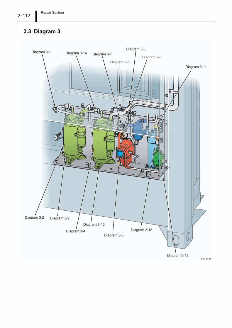
Repair Section2–112
3.3 Diagram 3

Repair Section2–113
3.4 Diagram 4
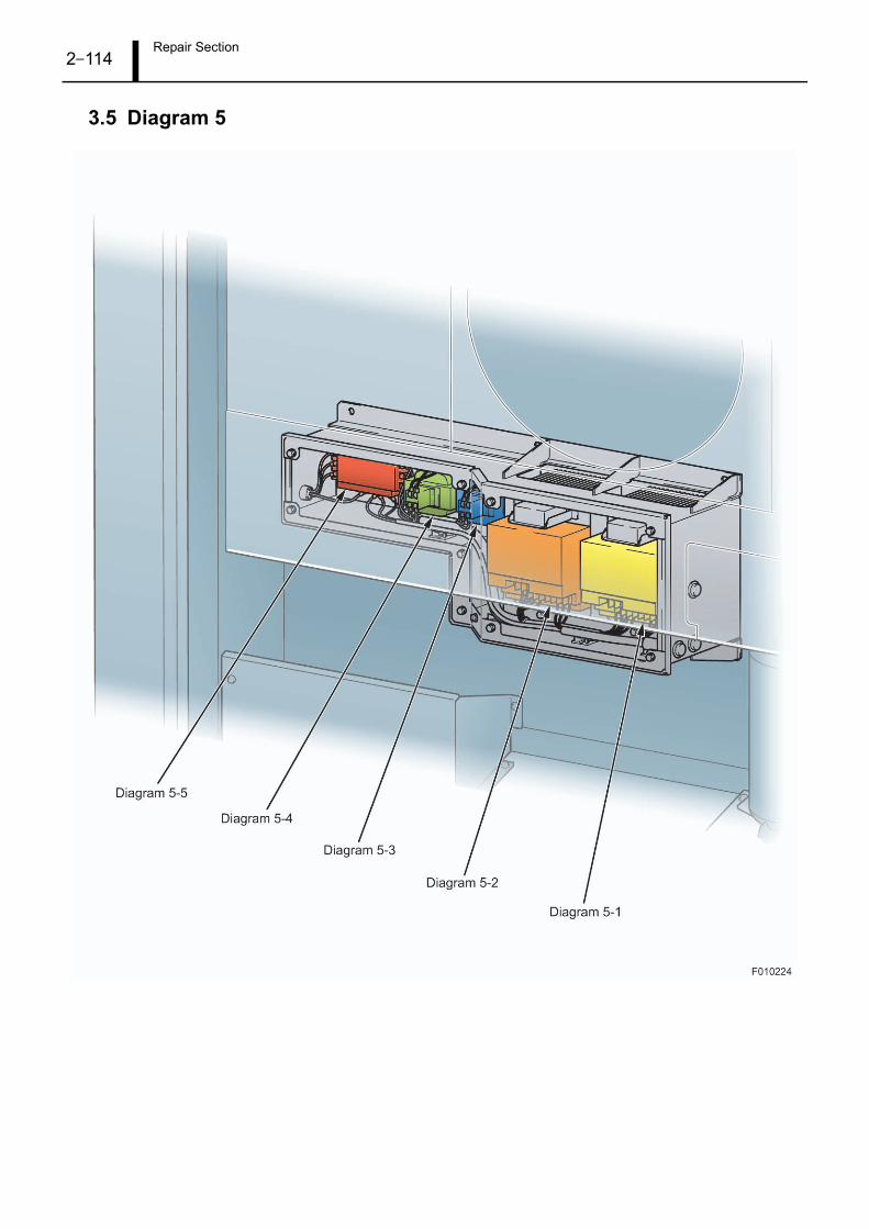
Repair Section2–114
3.5 Diagram 5

Repair Section2–115
4. Primary Component Characteristics
4.1 Characteristic Values
(1) Compressor
(2) Expansion Valve
(3) Pressure Sensor
Resistance Value 0.73 ±7%
Insulation Resistance (500 VDC Megger) At least 10 M
Installation Bolts (M8) 8.4 ~ 15.6 N·m
Resistance Value 46 ±3
Insulation Resistance (500 VDC Megger) At least 10 M
Output voltage value
Pressure (MPa)
1.1
0.1
0.2
0.3
0.4
0.5
0.6
0.7
0.8
0.9
-0.1
F010225
-0.1 0.1 0.3 0.5 0.7 0.9 1.1 1.3 1.5 1.7 1.9 2.1 2.3 2.5 2.7 2.9 3.1 3.3 3.5
0
1
Output Vo
ltage (V)

Repair Section2–116
(4) Humidity Sensor (Optional)
(5) Temperature Sensor
(6) Condenser Fan Motor
Output Voltage Value
Resistance Value
Current Value60 Hz operation 1.0 A
50 Hz operation 0.6 A
Resistance Value 39.9 ±10 %
Insulation Resistance (500 VDC Megger) At least 10 M
Installation Bolts (M8) 8.4 ~ 15.6 N·m
Clearance between Fan and Shroud 3.0 ~ 5.0 mm
Relative Humidity (%RH)
0.4
0.6
0.8
1
1.2
1.4
1.6
1.8
2
2.2
2.4
2.6
2.8
3
0
F010226
0 10 20 30 40 50 60 70 80 90 100
0.2
Ou
tpu
t V
olta
ge
(V
)
(°C)
(°F)
Temperature
200
1008060
40
40
1086
4
2
10.80.6
0.4
0.2
0.1
F010227
-60
-76
-50
-58
-40
-40
-30
-22
-20
-4
-10
14
0
32
10
50
20
68
30
86
40
104
50
122
60
140
70
158
80
176
90
194
100
212
110
230
120
248
130
266
Standard
Resistance Va
lue
(k
)

Repair Section2–117
(7) Cooling Fan Motor
* : Value for two motors.
(8) Heater
* : As per the following, the current value is for one phase when six heaters are connected in a con-figuration.
(9) Contactors
(Cooling Fan LO Contactor, Cooling Fan HI Contactor, Condenser Fan Contactor, Heater
Contactor, Compressor Contactor, Phase Sequence Contactor)
(10) High Pressure Switch
Current Value
60 Hz operationHigh speed 3.0 A*
Low speed 0.7 A*
50 Hz operationHigh speed 1.7 A*
Low speed 0.4 A*
Resistance ValueHigh speed 30.1 ±10 %
Low speed 115 ±10 %
Insulation Resistance (500 VDC Megger) At least 10 M
Installation Bolts (M8) 8.4 ~ 15.6 N·m
Clearance between Fan and Shroud 3.0 ~ 5.0 mm
Current Value 4.8 A (when 440 VAC)*
Resistance Value 79 ±5 %
Insulation Resistance (500 VDC Megger) At least 0.3 M
Resistance Value 3 ±10 %
Insulation Resistance (500 VDC Megger) At least 10 M
High-Pressure Operating Val-
ues
F010146
F010147

Repair Section2–118
5. Parts Disassembly and Assembly
5.1 Disassembly and Assembly Procedures
(1) Compressors
(Removal Procedure)
1) Remove the terminal cover.
2) Remove the power supply terminal screws.
3) Loosen the connector seal nut to disconnect the pow-
er cord.
4) Peel the heat insulator off of the compressors.
5) Remove the temperature sensor clips from the com-
pressors.
6) Remove the sensors from the clips. Reuse the clips.
7) Remove the compressor installation bolts.
8) Disconnect the high and low-pressure pipe joints.
High Stage Compressor Body Temperature Sensor
HeatInsulator
Clip
TemperatureSensor
Low StageCompressor BodyTemperature Sensor
S (White)T (Black)
TerminalCover
TerminalCover
G (Green)
R (Red)
F010172
Part Compressor
Refrigerant
Recovery
Required
Special Tools -
Other Required
Parts
O-rings, heat insulators, waterproof washers

Repair Section2–119
(Installation Procedure)
1) Connect the compressor high and low-pressure pip-
ing connections.
High-pressure piping tightening torque: 41.0 (39.2 ~
44.1) N·m
Low-pressure piping tightening torque: 25.0 (17.5 ~
32.5) N·m
2) Tighten the compressor installation bolts.
Tightening torque: 12.0 (8.4 ~ 15.6) N·m
3) Insert the temperature sensors into the clips.
4) Attach the clips and sensors to the brackets on the
compressor body.
5) Attach heat insulators so that there is no gap between
the compressors and sensors.
6) Connect the power cord to the power supply termi-
nals.
Tightening torque: 2.7 (2.4 ~ 2.9) N·m
7) Tighten the connector seal nut.
Tightening torque: 1.9 (1.8 ~ 2.0) N·m
8) When attaching the terminal cover, replace the water-
proof washers with new parts, then tighten the bolts.
Tightening torque: 3.0 (2.7 ~ 3.3) N·m
ATTENTION
Items
• Do not reuse O-rings, heat insulators, or the waterproof washers for terminal cover
installation.
• Do not allow items such as loose threads or dust to adhere to pipe connections.
Doing so may lead to loose pipe connections. Do not wear cotton gloves when con-
necting pipes.
• Preliminarily tighten pipes by hand, then use an open-end wrench (spanner) to per-
form the final tightening.
• Do not confuse the wiring locations for the power supply terminals. If the wir-
ing procedure is not followed, the compressor will rotate in the opposite direc-
tion.
R (Red), S (White), T (Black), G (Green)
• Use insulated washers to install the compressor.
• Since an oil separator is included, there is not need to add oil.
• Quickly connect all pipes after the compressor piping caps are removed. Failing to do
so may lead to moisture being adsorbed by the oil.
• Do not scratch the outside of the compressor when performing work. Doing so may
lead to corrosion and/or rusting due to the paint peeling.
Part Compressor

Repair Section2–120
(2) Dryer
(Removal Procedure)
1) Remove the dryer bracket.
2) Peel off the butyl rubber on the piping connections.
3) Loosen the nuts on the connection joints.
4) Remove the dryer bracket.
(Installation Procedure)
1) Install the dryer by using the removal procedure in re-
verse order.
Tightening torque: 34.3 (29.4 ~ 39.2) N·m
(3) Sight Glass
(Removal Procedure)
1) Heat the brazed sections of the pipe with a burner and
remove the sight glass.
(Installation Procedure)
1) Install the sight glass by brazing the pipe.
F010173
DryerBracket
PipingConnectionPoints
Part Dryer
Refrigerant
Recovery
Required
Special Tools -
Other Required
Parts
Insulating sheet, butyl rubber
ATTENTION
Items
-
F010174
Sight Glass
BrazedSections
Part Sight Glass
Refrigerant
Recovery
Required
Special Tools Brazing tool
Other Required
Parts
-
ATTENTION
Items
-

Repair Section2–121
(4) Expansion Valve (Evaporator Side)
(Removal Procedure)
1) Remove the bracket.
2) Remove the coil sub-assembly.
3) Loosen the piping nut and remove the expansion
valve.
4) Heat the two brazed sections of the pipe with a burner
and remove the expansion valve.
Reuse the removed piping.
(Installation Procedure)
1) Attach the expansion valve by using the removal pro-
cedure in reverse order.
Piping connection points
Tightening torque: 22.1 (19.6 ~ 24.5) N·m
Bracket
Tightening torque: 5.0 (3.5 ~ 6.5) N·m
Brazed Section
BrazedSection
Reuse
O-Rings(Cannot Reuse)
Bracket
BrazedSections
Expansion ValveCoil Sub-Assembly
F010175
PartExpansion Valve
(Evaporator Side)
Refrigerant
Recovery
Required
Special Tools Brazing tool
Other Required
Parts
O-rings
ATTENTION
Items
When brazing, wrap the
expansion valve body in a
damp cloth or the like to pro-
vide cooling.
The O-rings cannot be
reused.

Repair Section2–122
(5) Expansion Valve (Economizer Side)
(Removal Procedure)
1) Remove the bracket.
2) Remove the coil cover.
3) Remove the coil sub-assembly.
4) Remove the expansion valve from the piping at the
brazed sections.
(Installation Procedure)
1) Attach the expansion valve by using the removal pro-
cedure in reverse order.
Tightening torque: 5.0 (3.5 ~ 6.5) N·m
Bracket
Expansion ValveCoil Sub-Assembly
Coil Cover
Expansion Valve(Economizer Side)
BrazedSections
F010176
PartExpansion Valve
(Economizer Side)
Refrigerant
Recovery
Required
Special Tools Brazing tool
Other Required
Parts
-
ATTENTION
Items
When brazing, wrap the
expansion valve body in a
damp cloth or the like to pro-
vide cooling.

Repair Section2–123
(6) Pressure Sensors
(Removal Procedure)
1) Disconnect the pressure sensor connectors.
2) Remove the pressure sensors.
(Installation Procedure)
1) Install the sensors by using the removal procedure in
reverse order.
Tightening torque: 10.0 (9.0 ~ 11.0) N·m
Replacement Unit
Middle Pressure Sensor
LowPressureSensor
Union
PressureSensor
HighPressureSensor
Refrigerant gas willleak from here if theunion is removed. (Removal Prohibited)
Part to beRemoved
F010177
Part Pressure Sensor
Refrigerant
Recovery
Not required
Special Tools -
Other Required
Parts
-
ATTENTION
Items
-

Repair Section2–124
(7) Sensors
(Removal Procedure)
1) Remove the sensors by cutting the wires.
(Installation Procedure)
1) Prepare the sensor-side and device-side wires as
shown in the figure above.
2) Place heat shrink tubing (large, small) over the de-
vice-side wires.
3) Use butt-type terminals to crimp the cut wires togeth-
er.
4) Place heat shrink tubing (small) over the butt-type ter-
minal connections, and then heat the tubing to shrink
it in place.
5) Place the heat shrink tubing (large) over the two
wires, and then use heat to shrink the tubing in place.
DefrostTemperatureSensor
Supply AirTemperatureSensorSensors
F010178
Part Sensors
Refrigerant
Recovery
Not required
Special Tools -
Other Required
Parts
Butt type terminals, heat
shrink tubing (large, small)
ATTENTION
Items
-
Butt-Type Terminal
At least 10 mm
Heat Shrink Tubing(Small)
Heat Shrink Tubing(Large)
At least 10 mm
40 mm
40 mm6.3 mm
6.3 mm
Device Side Sensor Side
F010179

Repair Section2–125
(8) Condenser Fan/Motor
(Removal Procedure)
1) Remove the fan cover.
2) Use a pulley remover to remove the fan.
3) Disconnect the condenser motor contactor terminals
inside the electric box, and then cut the sensing cord.
4) Remove the motor cord from the electric box.
5) Remove the motor installation bolts and the insulated
washers.Fan Cover Condenser Fan
Condenser Motor
Installation Bolt
InstallationBolts
Insulated Washer(Do Not Reuse)
F010180
PartCondenser Fan/
Motor
Refrigerant
Recovery
Not required
Special Tools Pulley remover
Other Required
Parts
Insulated washers, butt-type
terminal, heat shrink tubing
ATTENTION
Items
• Do not reuse the insulated
washers.
• Make the motor shaft flush
with the edge of the fan.
• Adjust the clearance
between the fan and the
shroud to between 3 mm
and 5 mm.

Repair Section2–126
(Installation Procedure)
1) Use insulated washers and bolts to install the motor.
Tightening torque: 12.0 (8.4 ~ 15.6) N·m
2) Insert the wires into the heat shrink tubing.
3) Use butt-type terminals to crimp the cut wires togeth-
er.
4) Place heat shrink tubing over the butt-type terminal
connections, and then heat the tubing to shrink it in
place.
5) Attach the fan to the motor shaft.
Tightening torque: 9.3 (7.4 ~ 10.2) N·m
6) Attach the fan cover.
Tightening torque: 5.0 (3.5 ~ 6.5) N·m
7) Insert the motor wires into the electric box.
8) Connect the wires to the condenser motor contactor
terminals.
At least 10 mmAt least 10 mm
Butt-Type Terminal
Condenser Fan
Flush
Condenser Motor
Motor Shaft
Heat Shrink Tubing
F010181

Repair Section2–127
(9) Cooling Fan/Motor
(Removal Procedure)
1) Open the inspection lid.
2) Open the terminal cover.
3) Cut the wires.
4) Remove the installation bolts.
5) Remove the fan and the motor.
(Installation Procedure)
1) Attach the fan to the motor.
Tightening torque: 9.3 (7.4 ~ 10.2) N·m
2) Attach the motor and fan.
Tightening torque: 12.0 (8.4 ~ 15.6) N·m
3) Insert the wires into the heat shrink tubing.
4) Use butt-type terminals to crimp the cut wires togeth-
er.
5) Place heat shrink tubing over the butt-type terminal
connections, and then heat the tubing to shrink it in
place.
6) Attach the terminal cover.
Tightening torque: 1.8 (1.3 ~ 2.3) N·m
7) Attach the inspection lid.
Tightening torque: 5.0 (3.5 ~ 6.5) N·m
Inspection Lid
Installation Bolts
Installation BoltsTerminal CoverF010182
PartCooling Fan/
Motor
Refrigerant
Recovery
Not required
Special Tools -
Other Required
Parts
Butt type terminals, heat
shrink tubing
ATTENTION
Items
• Adjust the clearance
between the fan and the
shroud to between 3 mm
and 5 mm.
• When assembling the fan
and the motor, press the
motor shaft in up to the
stepped portion of the
shaft.
EvaporatorFan
Evaporator Motor
At least 10 mmAt least 10 mm
Butt-Type Terminal Heat Shrink Tubing
Press the fan in up to the stepped portion of the shaft.
F010183

Repair Section2–128
(10) Main ECU
(Removal Procedure)
1) Disconnect all of the connectors.
2) Remove the installation bolts.
(Installation Procedure)
1) Install the main ECU by using the removal procedure
in reverse order.
Tightening torque: 4.7 (4.2 ~ 5.2) N·m
F010184
Installation Bolt Installation Bolt
Installation BoltInstallation Bolt
Part Main ECU
Refrigerant
Recovery
Not required
Special Tools -
Other Required
Parts
-
ATTENTION
Items
-

Repair Section2–129
(11) Control Panel
(Removal Procedure)
1) Disconnect connector CN24.
2) Remove the installation bolts.
(Installation Procedure)
1) Install the control panel by using the removal proce-
dure in reverse order.
Tightening torque: 2.6 (2.3 ~ 2.8) N·m
(12) Transformer
(Removal Procedure)
1) Disconnect each terminal.
2) Remove the installation bolts.
(Installation Procedure)
1) Install the transformer by using the removal procedure
in reverse order.
Tightening torque: 5.0 (3.5 ~ 6.5) N·m
F010185
Front Side
Rear Side InstallationBolts (12)
Connector
Part Control Panel
Refrigerant
Recovery
Not required
Special Tools -
Other Required
Parts
-
ATTENTION
Items
-
F008411
Part Transformer
Refrigerant
Recovery
Not required
Special Tools -
Other Required
Parts
-
ATTENTION
Items
-

Repair Section2–130
(13) Toggle Switch
(Removal Procedure)
1) Remove the toggle cap.
2) Disconnect each terminal.
3) Remove the installation nut.
(Installation Procedure)
1) Insert the wires into the heat shrink tubing.
2) Solder each connection terminal.
3) Attach the toggle switch.
Nut tightening torque: 1.2 (1.0 ~ 1.4) N·m
Toggle Cap
F010186
Part Toggle Switch
Refrigerant
Recovery
Not required
Special Tools Soldering tool
Other Required
Parts
Heat shrink tubing
ATTENTION
Items
-
Soldering Toggle Switch
Heat Shrink Tubing
F010187

Repair Section2–131
(14) Circuit Breaker
(Removal Procedure)
1) Remove the cover.
2) Disconnect each terminal.
3) Remove the installation screws.
(Installation Procedure)
1) Install the circuit breaker by using the removal proce-
dure in reverse order.
Tightening torque: 1.8 (1.3 ~ 2.3) N·m
F008413
Part Circuit Breaker
Refrigerant
Recovery
Not required
Special Tools -
Other Required
Parts
-
ATTENTION
Items
-

Repair Section2–132
(15) Current Sensors R, S, T
(Removal Procedure)
1) Cut the cords.
2) Remove the installation screws.
(Installation Procedure)
1) Place heat shrink tubing over the wires, and then use
butt-type terminals to make the connections.
2) Attach the current sensors.
Tightening torque: 1.8 (1.3 ~ 2.3) N·m
Current SensorR, S, T
F010188
Part Current Sensors R, S, T
Refrigerant
Recovery
Not required
Special Tools -
Other Required
Parts
Butt type terminals, heat
shrink tubing
ATTENTION
Items
-
At least 10 mmAt least 10 mm
Butt-Type Terminal Heat Shrink Tubing
Do not wrap thewire around thecurrent sensor;pass the wire straight through.
F010189

Repair Section2–133
(16) Inverters
(Removal Procedure)
1) Remove the inverter case installation bolts.
2) Remove the inverter case cover.
3) Disconnect the inverter cords.
4) Remove the inverter installation bolts.
(Installation Procedure)
1) Cut off the incorrect wiring prevention cover attached
to the reactor connection terminal block with a pair of
nippers.
2) Remove the short bar attached to the reactor terminal
block.
3) Remove the labels attached to the communication
sensor terminal block and the compressor connection
terminal block.
F010190High Stage Inverter Low Stage Inverter
Part Inverter
Refrigerant
Recovery
Not required
Special Tools -
Other Required
Parts
Packing, waterproof washers
ATTENTION
Items
• Do not reuse the packing
for the inverter case cover
or the waterproof washers.
• Use caution, as if the cord
to the compressor is incor-
rectly connected, the com-
pressor will rotate in
reverse.
Incorrect WiringPrevention Cover
Label
Label
Short BarF010191

Repair Section2–134
4) Install the inverters by using the removal procedure in
reverse order.
Inverter case tightening torque
: 12.0 (8.4 ~ 15.6) N·m
Inverter unit tightening torque
: 5.0 (3.5 ~ 6.5) N·m
Inverter case cover tightening torque
: 5.0 (3.5 ~ 6.5) N·m
RRed
SWhite
TBlack
URed
ShieldGreen
GroundGreen
VWhite
WBlack
M-5R+
S+
M-6R-
S-
M-7 S5
M-8SC
S1
Low StageHigh Stage
Wiring
Harness No.
to Reactor
from Electric Box to Compressor
Inverter
Symbol
Wiring
Harness No.
Inverter
Symbol
M-1R+
S+
M-2R-
S-
M-3 S5
M-4SC
S1
P1
S3
P2 PC A1 A2
R+ R- S+ S- IG
+V AC AM AC MP
S2S1 S6S5S4 SCHCS7 RPH1MA MB MC
Compressor Load Line
Lines for Communication with ECU
F010192

Repair Section2–135
(17) Noise Filter
(Removal Procedure)
1) Remove the inverter cover.
2) Disconnect the cord.
3) Remove the installation bolts.
(Installation Procedure)
1) Install the noise filter by using the removal procedure
in reverse order.
Installation bolt tightening torque: 1.8 (1.3 ~ 2.3) N·m
(18) Reactors
(Removal Procedure)
1) Remove the inverter cover.
2) Disconnect the cords.
3) Remove the installation bolts.
(Installation Procedure)
1) Install the reactors by using the removal procedure in
reverse order.
Installation bolt tightening torque: 1.8 (1.3 ~ 2.3) N·m
F010193Noise Filter
Part Noise Filter
Refrigerant
Recovery
Not required
Special Tools -
Other Required
Parts
-
ATTENTION
Items
-
F010194
High Stage DC Reactor Low Stage DC Reactor
Part Reactor
Refrigerant
Recovery
Not required
Special Tools -
Other Required
Parts
-
ATTENTION
Items
-

Repair Section2–136
(19) Battery
(Removal Procedure)
1) Disconnect the connectors.
2) Remove the bracket.
(Installation Procedure)
1) Install the battery by using the removal procedure in
reverse order.
Tightening torque: 5.0 (3.5 ~ 6.5) N·m
BatteryF010195
Part Battery
Refrigerant
Recovery
Not required
Special Tools Hexagonal nut
Other Required
Parts
-
ATTENTION
Items
-

Repair Section2–137
(20) Heater
(Removal Procedure)
1) Remove the heater brackets.
2) Cut the heater wires.
(Installation Procedure)
1) Insert the wires into the heat shrink tubing.
2) Use butt-type terminals to crimp the cut wires togeth-
er.
3) Place heat shrink tubing over the butt-type terminal
connections, and then heat the tubing to shrink it in
place.
4) Attach the heater brackets.
Tightening torque: 5.0 (3.5 ~ 6.5) N·m
Heater Bracket Heater BracketF010196
Part Heater
Refrigerant
Recovery
Not required
Special Tools -
Other Required
Parts
Butt type terminals, heat
shrink tubing
ATTENTION
Items
Do not confuse the wire col-
ors.
Connection to Control Box Magnetic Contactor
Wire Color: Red
Wire Color: Black
Wire Color: Blue
Wire Color: Blue
Wire Color: Black
Wire Color: Red
Wire Color: White
Wire Color: Green
Wire Color: Yellow
Wire Color: Yellow
Wire Color: Green
Wire Color: White
T-1
T-1
T-2
T-2
T-1
T-1
T-2
T-2
T-3
T-3
T-3
T-3
Make connections usingbutt-type terminals andheat shrink tubing.
F010197
At least 10 mmAt least 10 mm
Butt-Type Terminal Heat Shrink Tubing
F010198

Repair Section2–138
(21) Fuses
(Removal Procedure)
1) Remove the fuses with long nose pliers.
(Installation Procedure)
1) Install the fuses gently by hand; do not use tools.
Fuse F12
Fuse F13
Fuse F11
F010199
Fuse F4
Fuse F3
Fuse F2
Fuse F1
Long Nose Pliers
Fuse
F010200

Repair Section2–139
6. Refrigerant Recovery and Charging Method
6.1 CAUTION Items for Refrigerant Handling
The following explains the refrigerant (R404A) handling procedures.
< ATTENTION >
The release of refrigerant to the atmosphere is strictly prohibited by law. Do not release refrigerant
to the atmosphere. Always use a refrigerant recovery device to remove refrigerant from the cycle.
R404A cannot be reused; request that a Freon recovery specialist handle R404a refrigerant dispos-
al.
(1) CAUTION Items for Refrigerant Charging (Safety)
Work by anyone other than an expert is strictly prohibited.
• There are a number of dangers in refrigerant charging work associated with handling high-pressure gas.
Always have an expert perform charging work.
CAUTION Items for Storage and Handling of Refrigerant Cylinders (or Service Cans)
• Store refrigerant cylinders in a dry, dark location.
• Do not store refrigerant cylinders in locations where the refrigerant temperature may become excessively
high such as near an open flame, in direct sunlight, or inside a vehicle (including the trunk).
• Do not topple or drop refrigerant cylinders.
F007742
Danger
F007743
NG
D
anger
The cyli
nder will br
eak.
Bang
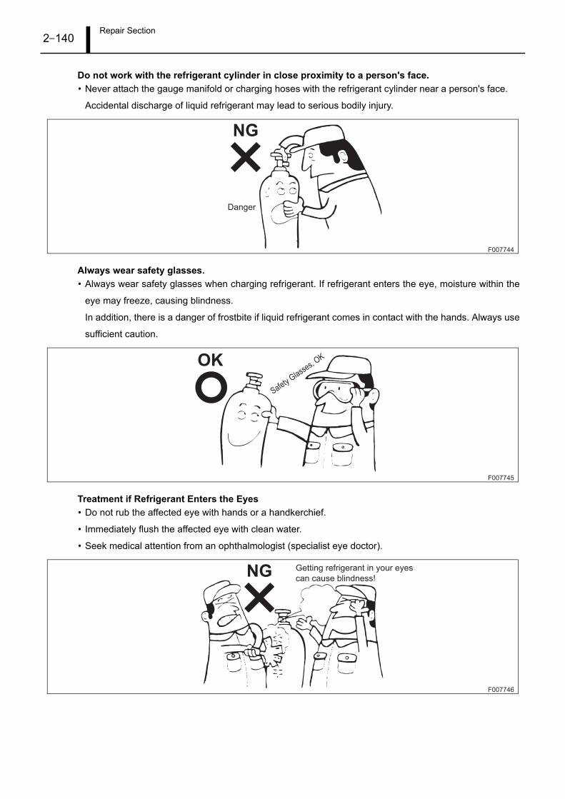
Repair Section2–140
Do not work with the refrigerant cylinder in close proximity to a person's face.
• Never attach the gauge manifold or charging hoses with the refrigerant cylinder near a person's face.
Accidental discharge of liquid refrigerant may lead to serious bodily injury.
Always wear safety glasses.
• Always wear safety glasses when charging refrigerant. If refrigerant enters the eye, moisture within the
eye may freeze, causing blindness.
In addition, there is a danger of frostbite if liquid refrigerant comes in contact with the hands. Always use
sufficient caution.
Treatment if Refrigerant Enters the Eyes
• Do not rub the affected eye with hands or a handkerchief.
• Immediately flush the affected eye with clean water.
• Seek medical attention from an ophthalmologist (specialist eye doctor).
F007744
NG
Danger
F007745
OK
Safety G
lasses, OK
F007746
NG Getting refrigerant in your eyes
can cause blindness!

Repair Section2–141
Removing Refrigerant from the Refrigeration Cycle
• Do not release refrigerant to the atmosphere. Always use a refrigerant recovery device to remove refrig-
erant from the cycle.
(2) CAUTION Items for Charging R404A Refrigerant (Service)
Gauge Manifold Handling
• Use the special gauge manifold for R404A refrigerant.
F007747
LO H I
Gauge Manifold
Open
Vent to
Atmosphere
NG
F007748Low-Pressure Valve High-Pressure Valve
High-Pressure GaugeLow-Pressure Gauge

Repair Section2–142
Refrigerant Handling
• Do not use an R404A refrigerant cylinder that is laying horizontally or inverted.
(The R404A cylinder is a receiver type, structured so that the liquid refrigerant comes out of the valve
when the cylinder is positioned vertically.)
• Always charge R404A refrigerant in a liquid state.
• Always use R404A refrigerant cylinders with a scale (accuracy: ±10 g) to ensure accurate charging.
< ATTENTION >
Never charge refrigerant above the specified quantity.
If refrigerant is overcharged (by +50 g or more), remove all of the refrigerant from the cycle, perform
evacuation once again, and then begin recharging. Do not release refrigerant to the atmosphere;
always use a refrigerant recovery device to remove refrigerant from the cycle. R404A cannot be re-
used; request that a Freon recovery specialist handle R404a refrigerant disposal.
Quick Joint Connections
• Refrigerant pressure is very high. Firmly attach the quick joints with two hands to ensure proper connec-
tion.
F007749
Vertical Cylinder
Liquid Refrigerant
Receiver Type Type in which Liquid Refrigerant is Taken from the Top
Release refrigerant after the cylinder is placed vertically.
Scale
R
4
0
4
A
F006977

Repair Section2–143
6.2 Refrigerant Recovery Method
(1) CAUTION Items for Recovery Work
• Recover the refrigerant from the high-pressure side to prevent refrigeration machine oil from entering the
recovery device.
• To ensure that all of the refrigerant is recovered, when the high-pressure side pressure drops to 0.1 MPa
or lower, recover the refrigerant from the low-pressure side.
• In circumstances other than the aforementioned, conduct work in accordance with the refrigerant recov-
ery device owner's manual.
Recovery Container
Recovery Device
Gauge Manifold
Container Refrigerator
Low-Pressure Side
Charging Port
Gauge Manifold
High-Pressure
Side Charging
Port
F010465

Repair Section2–144
6.3 Refrigerant Charging Method
(1) Refrigerant Charging Procedure
Gauge Manifold
Connect the vacuum pump
and refrigerant cylinder.
Container Refrigerator
Low-Pressure Side Charging Port
Gauge Manifold
High-Pressure
Side Charging
Port
Evacuation
Refrigerant Charging Quantity Verification
Gas Leak Check
Refrigerant Charging Quantity: 6.30 ± 0.05 kg
Charging from High-Pressure Side
Charging from Low-Pressure Side
(When Charging from the High-Pressure Side is Not Possible)
Refrigerant
Charging
F010466
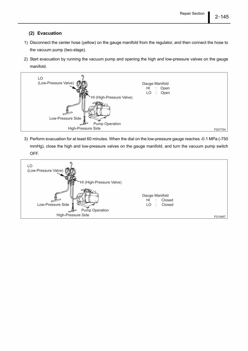
Repair Section2–145
(2) Evacuation
1) Disconnect the center hose (yellow) on the gauge manifold from the regulator, and then connect the hose to
the vacuum pump (two-stage).
2) Start evacuation by running the vacuum pump and opening the high and low-pressure valves on the gauge
manifold.
3) Perform evacuation for at least 60 minutes. When the dial on the low-pressure gauge reaches -0.1 MPa (-750
mmHg), close the high and low-pressure valves on the gauge manifold, and turn the vacuum pump switch
OFF.
F007754
Gauge Manifold
HI : Open
LO : Open
High-Pressure Side
Low-Pressure Side
Pump Operation
LO
(Low-Pressure Valve)
HI (High-Pressure Valve)
F010467
Gauge Manifold
HI : Closed
LO : Closed
High-Pressure Side
Low-Pressure Side
Pump Operation
LO
(Low-Pressure Valve)
HI (High-Pressure Valve)

Repair Section2–146
(3) Refrigerant Charging (Charging from the High-Pressure Side)
1) Disconnect the center hose (yellow) connected to the vacuum pump, and then connect the hose to the refrig-
erant cylinder (or service can).
[ ADVICE ]
• Manage the refrigerant quantity by placing the refrigerant cylinder on a scale with an accuracy of ±10 g.
• Leave the engine OFF.
2) Evacuate any air from inside the hose by opening the refrigerant cylinder valve, and then pressing the purge
valve on the gauge manifold.
3) Open the gauge manifold high-pressure valve to begin charging liquid refrigerant.
4) Charge the specified quantity of refrigerant, and then close the high-pressure valve and the refrigerant cylin-
der valve.
< ATTENTION >
Always charge the refrigerant in a liquid state.
• When the specified quantity of refrigerant cannot be charged from the high-pressure side, charge from
the low-pressure side.
F010470
Gauge Manifold
HI : Left Closed
LO : Left Closed
Refrigerant Cylinder Valve : Open
HI
(High-Pressure Valve)
LO
(Low-Pressure Valve)
Open the valve.
Low-Pressure Side
High-Pressure Side
Blue Red
Yellow
Press the
purge valve.
Refrigerant Cylinder
F010471
HI
(High-Pressure Valve)
Open the valve.
Refrigerant Cylinder
Low-Pressure Side High-Pressure Side
Blue Red
Yellow
LO
(Low-Pressure Valve)
Gauge Manifold
HI : Open, then close after charging to
the specified quantity is completed.
LO : Left Closed

Repair Section2–147
(4) Refrigerant Charging (Charging from the Low-Pressure Side)
• When the specified quantity of refrigerant cannot be charged from the high-pressure side, run the trans-
port refrigerator and charge from the low-pressure side.
1) Start the vehicle engine, and while idling, start the transport refrigerator.
2) Open the refrigerant cylinder valve, then repeatedly open and close the low-pressure valve until the specified
quantity of refrigerant is charged.
< ATTENTION >
• Since liquid refrigerant is also charged from the low-pressure side, always repeatedly and slowly
open and close the low-pressure valve.
Opening the valve too quickly may lead to compressor damage due to liquid compression.
3) When charging is complete, close the gauge manifold and refrigerant cylinder valves.
F010472
HI
(High-Pressure Valve)
LO
(Low-Pressure Valve)
Open the valve.
Never open the
high-pressure side.
Low-Pressure Side High-Pressure Side
Blue Red
Yellow
Gauge Manifold
HI : Left Closed
LO : Open "slowly" only a "slight" amount
Refrigerant Cylinder Valve : Open
Refrigerant Cylinder
F010473
HI
(High-Pressure Valve)
Close the valve.
Refrigerant Cylinder
LO
(Low-Pressure Valve)
Low-Pressure Side High-Pressure Side
Blue Red
Yellow
Gauge Manifold
HI : Left Closed
LO : Closed
Refrigerant Cylinder Valve : Close
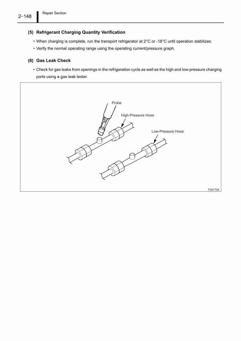
Repair Section2–148
(5) Refrigerant Charging Quantity Verification
• When charging is complete, run the transport refrigerator at 2°C or -18°C until operation stabilizes.
• Verify the normal operating range using the operating current/pressure graph.
(6) Gas Leak Check
• Check for gas leaks from openings in the refrigeration cycle as well as the high and low-pressure charging
ports using a gas leak tester.
F007764
Probe
High-Pressure Hose
Low-Pressure Hose

Repair Section2–149
7. Operating Current/Pressure Graph
7.1 60 Hz
F010468
10 15 20 25 30 35 40
2
4
6
8
10
12
14
16
0.5
1
1.5
2
2.5
3
3.5
0
0.1
0.2
0.3
0.4
0.5
When at maximum rotation
When balanced
When at maximum rotation
When balanced
10 15 20 25 30 35 40
Ambient Temperature ( )
Ambient Temperature ( )
0
0.05
0.1
0.15
0.2
0
2
4
6
8
10
12
0
0.5
1
1.5
2
2.5
3
To
tal C
urr
en
t (A
)H
igh
Pre
ssu
re (
MP
a)
Lo
w P
ressu
re (
MP
a)
To
tal C
urr
en
t (A
)H
igh
Pre
ssu
re (
MP
a)
Lo
w P
ressu
re (
MP
a)
-18
OFF
Compartment Temperature
Eco-Mode
440 V 60 HzPower Supply
2
OFF
Compartment Temperature
Eco-Mode
440 V 60 HzPower Supply

Repair Section2–150
7.2 50 Hz
F010469
2
4
6
8
10
12
14
16
0.5
1
1.5
2
2.5
3
3.5
0
0.1
0.2
0.3
0.4
0.5
10 15 20 25 30 35 40
10 15 20 25 30 35 40
10
12
14
8
6
4
2
3
2.5
2
1.5
1
0.5
0
0
0.2
0.15
0.1
0.05
0
When at maximum rotation
When balanced
When at maximum rotation
When balanced
Ambient Temperature ( )
Ambient Temperature ( )
To
tal C
urr
en
t (A
)H
igh
Pre
ssu
re (
MP
a)
Lo
w P
ressu
re (
MP
a)
To
tal C
urr
en
t (A
)H
igh
Pre
ssu
re (
MP
a)
Lo
w P
ressu
re (
MP
a)
-18
OFF
Compartment Temperature
Eco-Mode
380 V 50 HzPower Supply
2
OFF
Compartment Temperature
Eco-Mode
380 V 50 HzPower Supply
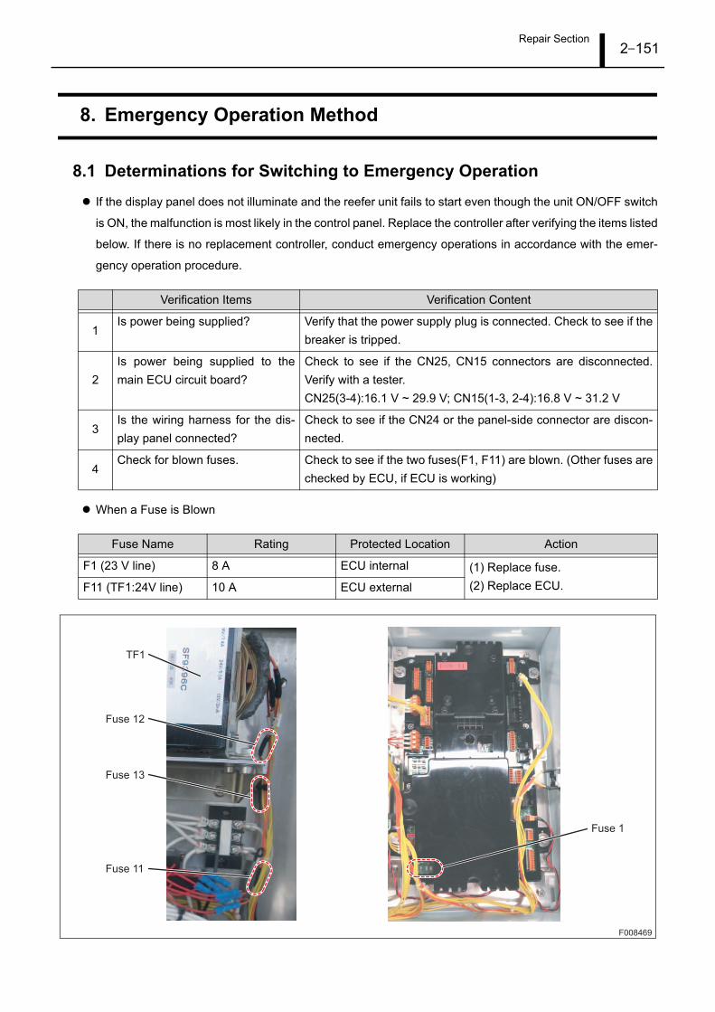
Repair Section2–151
8. Emergency Operation Method
8.1 Determinations for Switching to Emergency Operation
If the display panel does not illuminate and the reefer unit fails to start even though the unit ON/OFF switch
is ON, the malfunction is most likely in the control panel. Replace the controller after verifying the items listed
below. If there is no replacement controller, conduct emergency operations in accordance with the emer-
gency operation procedure.
When a Fuse is Blown
Verification Items Verification Content
1Is power being supplied? Verify that the power supply plug is connected. Check to see if the
breaker is tripped.
2
Is power being supplied to the
main ECU circuit board?
Check to see if the CN25, CN15 connectors are disconnected.
Verify with a tester.
CN25(3-4):16.1 V ~ 29.9 V; CN15(1-3, 2-4):16.8 V ~ 31.2 V
3Is the wiring harness for the dis-
play panel connected?
Check to see if the CN24 or the panel-side connector are discon-
nected.
4Check for blown fuses. Check to see if the two fuses(F1, F11) are blown. (Other fuses are
checked by ECU, if ECU is working)
Fuse Name Rating Protected Location Action
F1 (23 V line) 8 A ECU internal (1) Replace fuse.
(2) Replace ECU.F11 (TF1:24V line) 10 A ECU external
F008469
TF1
Fuse 12
Fuse 13
Fuse 11
Fuse 1

Repair Section2–152
8.2 Emergency Operation Procedure (Expansion Valve-Side Preparation)
1) Remove the coil from the evaporator expansion valve
and economizer expansion valve body. Disconnect
the harness connector as well.
2) Turn the coil clockwise to fully close both of expansion
valves.(approximately 7 turns.)
3) Turn the evaporator expansion valve counter clock-
wise (2 times) to open the valve. After adjustment,
press the coil onto the body to fix it in place.
F008470
Evaporator Expansion Valve
Remove the coil from the body.
Economizer Expansion Valve
Expansion Valve Connector

Repair Section2–153
8.3 Emergency Operation Procedure (ECU-Side Preparation)
1) Disconnect the connector from ECU CN25 (23 V pow-
er supply.)
2) Connect ECU CN29 (cooling operation), CN31*
(phase reversal switching), and CN8 (inverter com-
mand) to the emergency operation bypass connector.
* : The ECU-side CN31 connector is 3 pins inrelation to the 2 pins on the bypass connec-tor. The phase sequence can be switched byinserting into numbers 1 and 2, or numbers 2and 3, thereby changing the direction that thecondenser fan air flow.
F008471
1
2
3
4
1
2
3
4
5
6
7
1
21
23
CN25 (4 Pins)
Inside of plastic
bag
ECU-Side Connector
CN8 (4 Pins)
CN29 (7 Pins) CN31 (3 Pins)
CN29(EF:COM)
CN29
(EF:LOW)
(EF:HIGH)
(COND.FAN)
(COND.FAN)
(COMP)
(COMP)
CoolingOperation
Phase Reversal Switching
InverterCommand
CN8
CN8
CN31(MC3)
CN31
(COM)
(MC4) CN31

Repair Section2–154
8.4 Emergency Operation Procedure (Reefer Unit enforcement operation)
1) Turn the unit ON/OFF switch to the ON position, then
check for the condenser airflow direction. The airflow
should blow towards you and not into the unit. (for il-
lustration, a paper or cloth hold in the front of the con-
denser grill should blow away towards you and not
stick on the grill.) In case of wrong airflow direction,
turn OFF the unit ON/OFF switch and change the
jumper in CN31 from pin 1 and 2 to pin 2 and 3 or vice
versa.
2) Place thermometers in to the two ports shown in left
picture for Return Air-and Supply Air, Thermometer
Insertion Hole. This for precise manual control howev-
er avoid entrance of outside - or loss of conditioned,
air through the ports, for economic reason.
3) Check regularly for frost on the Low Stage Compres-
sor suction pipe. In case of frost signs, close the evap-
orator expansion valve by rotation of the valve coil,
while placed on the valve stem, by half a turn clock
wise.
4) In case of extra care for chill damage to the cargo
load, switch from low evaporator fan speed to high
evaporator fan speed. Change on CN29 jumper be-
tween pin 1and 2 into jumper between pin 1 and 3
without cooling (no running of compressors and con-
denser fan motor) .
1CN29
(EF:COM)
CN29 (1)
(EF:LOW)
(EF:HIGH)
COND.FAN
running
COMP
running
2
3
4
5
6
7
1CN29
(EF:COM)
CN29 (2)
(EF:LOW)
(EF:HIGH)
2
3
4
5
6
7
Supply Air ThermometerInsertion Hole
Paper or Shop Towel
Return Air Thermometer Insertion Hole
CoolingOperation
High speed air circulation
F008472
F008505

Circuit diagram / Wiring diagram (A3)3–155
1. Wiring Diagram
1.1 Wiring Diagram
F008487

Circuit diagram / Wiring diagram (A3)3–156
CTR Current Sensor R S-PLC Low Pressure Sensor
CTS Current Sensor S SPH High Pressure Switch
CTT Current Sensor T STHH Heater Thermal Switch
CF Condenser Fan Motor TB Terminal Block
EL Cooling Fan Motor, Left THAM1 Ambient Temperature Sensor 1
ER Cooling Fan Motor, Right THAM2 Ambient Temperature Sensor 2
CMH High Stage Compressor THECI Economizer Inlet Temperature Sensor
CML Low Stage Compressor THECO Economizer Outlet Temperature Sensor
MC1 Compressor Contactor THEI Evaporator Inlet Temperature Sensor
MC2 Heater Contactor THEO Evaporator Outlet Temperature Sensor
MC3 Phase Sequence Contactor THFL Defrost Temperature Sensor
MC4 Phase Sequence Contactor THHCD High Stage Compressor Discharge Temperature Sensor
MC5 Condenser Fan Contactor THHCH High Stage Compressor Body Temperature Sensor
MC6 Cooling Fan Hi Contactor THLCH Low Stage Compressor Body Temperature Sensor
MC7 Cooling Fan Lo Contactor THLCS Low Stage Compressor Suction Temperature Sensor
PC1 Personal Computer (PC) THRE1 Return Air Temperature Sensor 1
PC2 Personal Computer (PC) THRE2 Return Air Temperature Sensor 2 (Optional)
S-PHC High Pressure Sensor THSU1 Supply Air Temperature Sensor 1
S-PMC Middle Pressure Sensor THSU2 Supply Air Temperature Sensor 2 (Optional)

Circuit diagram / Wiring diagram (A4)4–157
1. Connector Layout Diagram
1.1 ECU Connector Layout Diagram
Battery
PC.Communication
RMM.Emergency
Operation
Emergency
Operation MC Panel
Thermistor
Thermistor
USDA
Pressure
Sensor
Ventilation
Opening Sensor
Current Sensor
Emergency
Operation MC
Pressure Switch
Thermal
Magnet
Contactor
Magnet
Contactor
Power
Supply 24 VRemote
Monitoring
CF Card Slot
Power
Supply 23 V
Fuse 4
Fuse 3
Fuse 2
Fuse 1
Expansion Valve
(Evaporator)
Emergency
Operation
INV.Communication
INV.Emergency
Operation
F008497

Circuit diagram / Wiring diagram (A4)4–158


Service Division DENSO CORPORATION1-1, Showa-cho, Kariya-shi, Aichi-ken, 448-8661, Japan
10P100KPrinted in Japan