containment vessels - unt digital library
TRANSCRIPT
Approvedforpublicrelease;distributionIs unlimited.
,
The Design, Fabrication, and Testing of WETF
H’igh-Quality, Long-Term-Storage, Seconday
Containment Vessels
Los Alamos
I
i
NATIONAL LABORATORY
Los Alamos National Izzborafoy is operatedby the University of Cal~orniafor the United States Department of Energy nnder contract W-7405-ENG-36.
An Aj%-nmtive Action fEqual Opportunity Employer
This report was prepared as an account of work sponsored by an agency of the United StatesGovernment. Neither The Regents of the University of Cal~ornia, the United StatesGovernment nor any agency thereo~ nor any of their employees, makes any warranty, expressor implied, or assumes any lega[ liability or responsibility for the accuracy, completeness, orusefulness of any information, apparatus, product, or proczss disclosed, or represents that itsuse would not infringe privately owned rights. R@rence herein to any specijc commercialproduct, process, or sm”ce tm trade name, trademark, manufacturer, or otherwise, does notnea?ssarily constitute or imply its endorsement, rewmrnendation, orfavon”ng by The Regentsof the UniversihJ of Calfornia, the United States Government, or any ageq thereof. Theviews and opinions of authors expressed hem-n do not necessarily state or r.+ect those ofThe Regents of the University of Gdfornia, the United States Government, or any agenqthereofi Los Alamos National bboratory strongly supports amdernicfreedom and aresearcher’s n“ght to ptiblish; as an institution, however, the laboratory does not endorse theviewpoint of a publication or guarantee its techniml correctness.

DISCLAIMER
Portions of this document may be illegiblein electronic image products. Images areproduced from the best available originaldocument.

LA-13703-MS!,
Issued: March 2000 “
,,
The Design, Fabrication, and Testing of WETF
High-Quality, Long-Term-Storage, Secondary
Containment Vessels
Kane J. Fisher
“U.S. Geolo@d SurveII; Reston, Virginiat Graduate Research Assistant, f.hZkI?YSihJof CM@omia, Sanfa Barbara
Los AlamosNATIONAL LABORATORY
LosAlamos,NewMexico87545
LA-13703-MS March 2000
THE DESIGN, FABRICATION, AND TESTING OF WETF HIGH-QUALITY, LONG-TERM-STORAGE,SECONDARY CONTAINMENT VESSELS
by
Kane J. Fkher
ABSTRACT
Los Alamos National Laboratory’s Weapons Engineering Tritium Facility
(WETF) requires secondary containment vessels to store primary tritium
containment vessels. The primary containment vessel provides the first
boundary for tritium containment. The primary containment vessel is stored
within a secondary containment vessel that provides the secondary boundary
for tritium containment. WETF requires high-quality, long-term-storage,
secondary tritium containment vessels that fit within a Mound-designed
calorimeter. In order to qualify the WETF high-quality, long-term-storage,
secondary containment vessels for use at WETF, steps have been taken to
ensure the appropriate design, adequate testing, quality in fabrication, and
acceptable documentation.
INTRODUCTION
The Weapons Engineering Tritium Facility (WETF) uses secondary containment vessels to store primary tritium
containment vessels. The primary containment vessel is the first boundary used for tritium containment. The primary
container is stored in a secondary containment vessel that provides the second tritium boundary. III order to assay the
quantity of tritium contained within the secondary containment vessel, it must fit within the WETF Mound-designed
calorimeter. Of the existing secondary containment vessels at WETF, only one desi~mcan be placed within the
calorimeter to assay the quantity of tritium contained within the vessel.
The Tritium Operations Engineering team at WETF was tasked in February 1999 with providing secondary
containment vessels for WETF that fit withh the calorimeter. The use of secondary containment at WETF originates
from the safe handling and storage of primary tritium vessels within high-quality secondary containers. Secondary
containment is crucial to limiting the release of tritium or tritiated water into the room atmosphere at WETF.
LA- 13703-MS March 2000
REQUIREMENTS
These vessels were to be designed and fabricated with the engineering rigor and design requirements of a
high-quality, secondary tritium containment vessel as defined by the Department of Energy (DOE) Document, DOE
HDBK-1 129-99, Tritium Handling and Safe Storage. This design requirement includes the requirement that the vessel
be designed and fabricated in accordance with the American Society of Mechanical Engineers (ASME) Boiler and
Pressure Vessel Code.
A design requirement of the WETF high-quality, long-term-storage, secondary containment vessel was to establish
a pedigree and set a design, fabrication, and testing standard that could be used for all future secondary containment
vessels at WETF. The Tritium Operations Engineering team at WETF used the Mound design in the fabrication of the
new WETF high-quality, long-term-storage, secondary containment vessels. In the manufacture of these secondaries,
the Mound drawing # AYD901O39, Revision 4, was modified and redrawn to produce a new drawing for the
containers. This drawing of the newly manufactured WETF high-quality, long-term-storage, secondary containment
vessels, WETF drawing number 141Y-634984, is shown in Appendix A.
The required maximum allowable working pressure (MAWP) for these vessels was 200 psig. The required outside
diameter is 6.844 inches (see Appendix A). This diameter is for a close tolerance fit between the vessel and the WETF
calorimeter. This close tolerance allows for faster achievement of thermal equilibrium within the calorimeter and thus
reduces measurement times.
The Mound-designed containers originally carried a certain pedigree that included calculations, material
specifications, fabrication specifications, and testing. Whh the closure of Mound Laboratory, the loss of
knowledgeable personnel, and wholesale elimination of files, this Mound pedigree was lost. Mound sent LANL a
secondary container that was designed to fit within the calorimeters. This vessel was fabricated at Mound, serial #012,
according to Mound drawing#AYD901039, Revision 4. WETF had a need for more of the secondaries in 1993 and
had six more manufactured according to the Mound drawing # AYD901O39, Revision 4.
A requirement of the vessel is to limit the weight because WETF personnel must lift the vessel up into the
calorimeter. The vessel was constructed using 2024-T351 aluminum that gives the vessel an empty weight of
19.5 pounds.
The WETF high-quality, secondary containment vessel must have no detectable leak below 1.05108
standard-cm3/s helium. This leak testis performed with the vessel pressurized with helium at the MAWP. After the
manufacture and assembly of the vessel, it must also pass a 5-minute-proof pressure test with no permanent
deformation, visible cracks, or leaks. This proof testis at 150% of the MAWP.

LA- 13703-MS March 2000
The WETF high-quality, long-term-storage, secondary containment vessel must survive a 10-foot drop onto
concrete, because it will be lifted by WETF personnel into the calorimeter and there exists a possibility of its being
dropped. The drop survivability of the WETF high-quality, secondary containment vessel was determined by dropping
containers with an orientation so that they hit the Nupro 4H valve or the Ashcroft pressure gauge. These parts are
considered the most vulnerable to damage from a drop. The drop tests were performed with the MAWP of 200 psi
helium. After the drop tests the vessels must pass a helium leak check (see Appendix B).
A requirement for the WETF high-quality, long-term-storage, secondary containment vessel is to be manufactured
from parts’that have a temperature rating higher than 200”F. The WETF high-quality, Iong-term-storage, secondary
containment vessel can use either a Nitrile O-ring or a Helicoflex all metal seal. The Nitrile O-ring has a usable
temperature of up to 275°F. The Helicoflex close-wound, helical spring seal has a maximum usable temperature of
482”F. The Nupro SS-4H-W96 valve has an all-metal stem tip that enables the valve to have a maximum usable
temperature of 600”F.
Also in the design requirements of the WETF high-quality, Iong-term-storage, secondary containment vessels, the
DOE Handbook, Design Considerations, DOE-HDBK-1 132-99 was used as a guide for the selection of the materials
and construction of the high-quality, WETF secondary containers.
FABRICATION
The machining and manufacture of the 110 secondary containers were submitted through a competitive bid process
to three fabrications shops that were deemed by ESA-WMM to be competent enough to complete the fabrication.Bogue Machine company, Inc., in Albuquerque won the bid and started to order materials in March of 1999.
Manufacture started soon thereafter and was completed in June 1999. Throughout the manufacture of the WETFhigh.qu~lity, ]Ong-term.storage, second~ containment vessels, visitsand preliminary inspections were made by
Kane J. Fisher at Bogue Machine Company, Inc., in Albuquerque.
TESTING, CALCULATIONS, AND MATERIAL SPECIFICATIONS
The qualification and subsequent pedigree of these secondary containers emanated from a series of physical tests,
calculations, and material specifications. Each container has an identical machined serial number and the MAWP on
both the top flange and bottom piece. An inspection was performed at Bogue on 20 out of 110 pieces for compliance to
24 different specifications. This inspection was done before delivery of the vessels to LANL. These 20 vessels were
considered a representative sample of the total vessels made. Each of the 20 vessels inspected was within the
tolerances for each of the given 24 specifications. A picture of a completed WETF high quality secondary is shown in
Figure 1.
3

LA- 13703-MS
- ..<——...
March 2000
.,1” ,““ ;> .!,>
-’---..4.”.+.. <“”
Figure 1. WETF high-quali~, secondary container.
The physical tests performed on the WETF secondary containers were helium leak tests at the MAWP, proof tests
to 150% of the MAWP, pressure rise to failure (burst test), and destructive drop tests at the MAWP.
A certified Level-II Helium leak tester performed an inside-out leak test on the WETF secondary containers in a
bell jar. This leak test must be performed and documented on each WETF high-quality, long-term-storage, secondary
containment vessel before it can be used. The WETF high-quality, long-term-storage, secondary containment vessels
were placed within a bell jar and pressurized to the MAWP of 200 psig. The bell jar was then evacuated and the true
helium leak rate of all sealing surfaces was determined. A leak rate greater than 1.05 10* standard-cm3/s helium is not
acceptable.
4

LA-13703-MS March 2000
A proof test with helium gas is performed to 150% of the 200 psig MAWP. In this proof test, 300 psig gas pressure
is loaded into the WETF secondary container and left for 5 minutes. The proof testis performed in a bell jar, and the
helium leak detector can detect any leaks. This proof test must be performed and documented on all of the WETF
secondary containers before they can be used. Any visible cracks, leaks, or deformation within this 5-minute period at
the proof pressure constitutes a failure of the proof test, and the container is not acceptable.
Three WETF secondary containers (serial numbers 26,51, 76) were burst-test (pressure rise to failure) with helium
gas pressure. The burst pressures were 3,369.0 psig, 3,480.0 psig, and 3,480.0 psig, respectively. This burst pressure is
17 times the MAWP of 200 psig and is greater than the ASME required safety factor of four times the MAWP.
The containers were placed inside a “boom ball” ~d plumbed to a high pressure compressor. The gas pressure was
increased until there was a failure in the containment of the gas. Each one of the containers tested failed by blow-by
on the O-ring seal, which is a desirable failure, shown in Figure 2. There were no catastrophic or projectile producing
failures.
r .,. .
.-“-...-.. .,,. . fllll.l lll!lll~l~ii!lli!
I I 71 I , I ‘ 31 41
Figure 2. Blow-by on the O-ring and stressed bolt.
5
LA-1 3703-MS March 2000
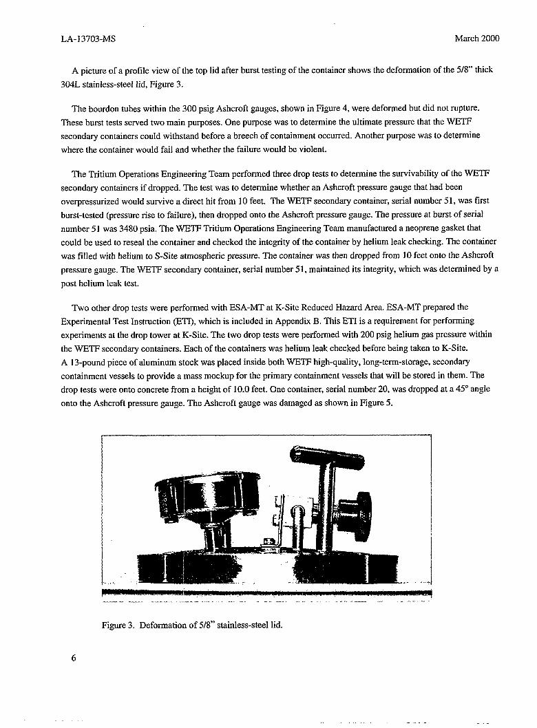
A picture of a profile view of the top lid after burst testing of the container shows the deformation of the 5/8” thick
3(MLstainless-steel lid, Figure 3.
The bourdon tubes within the 300 psig Ashcroft gauges, shown in Figure 4, were deformed but did not rupture.
These burst tests served two main purposes. One purpose was to determine the ultimate pressure that the WETF
secondary containers could withstand before a breech of containment occurred. Another purpose was to determine
where the container would fail and whether the failure would be violent.
The Tritium Operations Engineering Team performed three drop tests to determine the survivability of the WETF
secondary containers if dropped. The test was to determine whether an Ashcroft pressure gauge that had been
overpressurized would survive a direct hit from 10 feet. The WETF secondary container, serial number51, was first
burst-tested (pressure rise to failure), then dropped onto the Ashcroft pressure gauge. The pressure at burst of serial
number 51 was 3480 psia. The WETF Tritium Operations Engineering Team manufactured a neoprene gasket that
could be used to reseal the container and checked the inte=gity of the container by helium leak checking. The container
was tilled with helium to S-Site atmospheric pressure. The container was then dropped from 10 feet onto the Ashcroft
pressure gauge. The Y$%m seconda~ container, serial number 51, maintained its integrity, which was determined by a
post helium leak test.
Two other drop tests were performed with ESA-MT at K-Site Reduced Hazard Area. ESA-MT prepared the
Experimental Test Instruction (ETI), which is included in Appendix B. This ETI is a requirement for performing
experiments at the drop tower at K-Site. The two drop tests were performed with 200 psig helium gas pressure within
the WETF secondary containers. Each of the containers was helium leak checked before being taken to K-Site.
A 13-pound piece of aluminum stock was placed inside both WETF high-quality, long-term-storage, secondary
containment vessels to provide a mass mockup for the primary containment vessels that will be stored in them. The
drop tests were onto concrete from a height of 10.0 feet. One container, serial number 20, was dropped at a 45° angle
ontlo the Ashcroft pressure gauge. The Ashcroft gauge was damaged as shown in Figure 5.
1
.. . . ..
—-.—. ---- ...”-----....... .... ------ --”-..... . . . ...””.. —,..-. -------
Figure 3. Deformation of 5/8” stainless-steel lid.
6
————..—.--..—

LA-13703-MS
Figure 4. Comparison of deformed bourdon tubes.
,,
.$
.
.
.,
‘,
-,- - -,..-.-,,,, ., :,7., ,.. ,i,., -r. ‘,. . ., ;,. . . . . ----
. . . . . . . . . . . .~:, ,. . . . . . . :~??!’r’”,~.- - : . .. T-mm-f:,-..,.; - .~.,,... ,,
Figure 5. Damage to Ashcrojl gaugefiom 10-- drop test.
March 2000
7
LA- 13703-MS March 2000
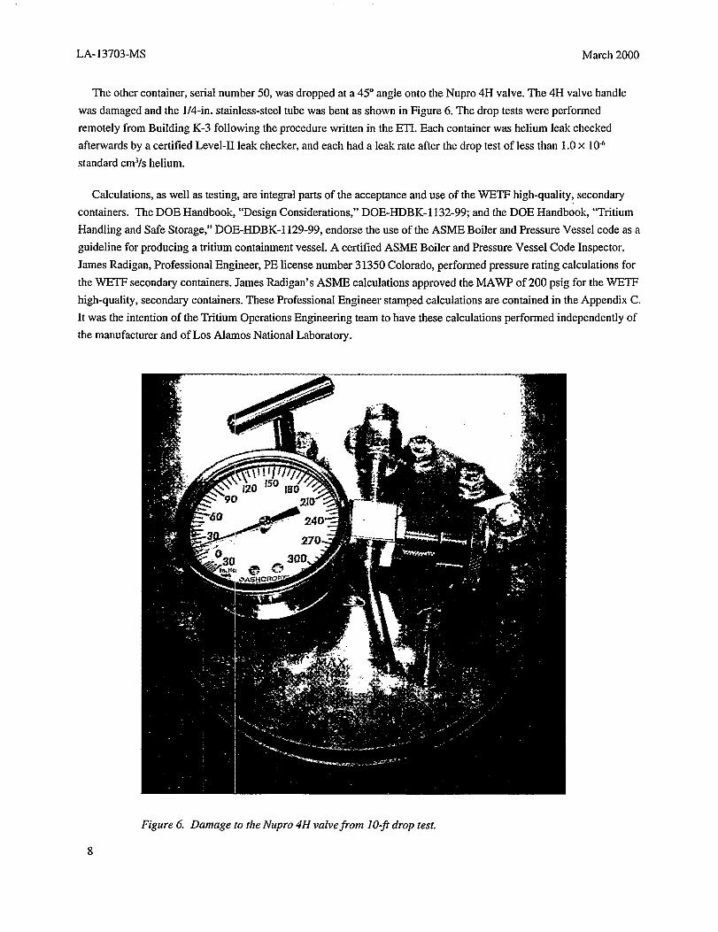
The other container, serial number 50, was dropped at a 45° angle onto the Nupro 4H valve. The 4H valve handle
was damaged and the l/4-in. stainless-steel tube was bent as shown in Figure 6. The drop tests were performed
remotely from Building K-3 following the procedure written in the ETI. Each container was helium leak checked
afterwards by a certified Level-II leak checker, and each had a leak rate after the drop test of less than 1.0x 10⁴
standard cm3/shelium.
Calculations, as well as testing, are integral parts of the acceptance and use of the WETF high-quality, secondary
containers. The DOE Handbook, “Design Considerations,” DOE-HDBK-1 132-99; and the DOE Handbook, “Tritium
Handling and Safe Storage:’ DOE-HDBK-1 129-99, endorse the use of the ASME Boiler and Pressure Vessel code as a
guideline for producing a tritium containment vessel. A certified ASME Boiler and Pressure Vessel Code Inspector,
James Radigan, Professional Engineer, PE license number 31350 Colorado, performed pressure rating calculations for
the WETF secondary containers. James Radigan’s ASME calculations approved the MAWP of 200 psig for the WETF
high-quality, secondary containers. These Professional Engineer stamped calculations are contained in the Appendix C.
It was the intention of the Tritium operations Engineering team to have these calculations performed independently of
the manufacturer and of Los Alamos National Laboratory.
Figure 6. Damage to the Nupro 4H valvefiom 10-ji drop test.
LA-1 3703-MS March 2000
The material specifications for the WETF high-quality, secondary containers are materials that are suggested for
tritium service in the DOE Handbook, “Design Considerations:’ DOE-HDBK-1 132-99; and the DOE Handbook,
“Tritium Handling and Safe Storage:’ DOE-HDBK-1 129-99. The lower portion of the container is made of 2024-T351
aluminum. Aluminum is used’to minimize the weight of the container because WETF personnel must manually lift
these containers. This particular aluminum was used because of the very high strength and mechanical properties. The
Aluminum Associations temper designation, -T351 is used by industry, Machinery’s Handbook, 25ti Ed. The temper
-T351 explains that the aluminum is solution heat-treated, cold-worked, and stress-relieved by stretching 1$70to 3% of
the permanent set, from Machinery’s Handbook, 25* Ed. Bogue Machine Company purchased the 2024-T351
aluminum from the Kaiser Ahuninum & ChemicaI Corporation. One of the Kaiser Aluminum & Chemical Corporation
materials certification reports for the 2024-T351 aluminum is included in Appendix D. This certified test report lists
the actual physical properties of the aluminum as well as the weight percent of the chemical composition.
The top lid of the container is made of 304L (low carbon) stainless steel. This steel is desirable for tritium service
because it provides good strength, weldability, and resistance to hydrogen embrittlement. A certificate of tests for the
bar stock 304L from Ugine-Savoie, France is included in Appendix E.
The selection and use of the Nupro 4H valve was done because of reliability in tritium service. The Nupro 4H valve
was received from the factory with a 3.O-in. tube extension, female end cap, and a Vespel stem tip. Receiving this
Nupro 4H valve this way from the factory saved Bogue Machining Inc. two difficult welds on the valve. we VespeI
stem tip has shown good reliability in tritium service as long as the valve is not repeatedly overtightened. The WETF
operators are trained about the consequences of overtightening Nupro 4H valves as part of their facility operator
certification. The valves are made of316L (low carbon) stainless steel, which is desirable for tritium service because it
provides good strength, weldability, and resistance to hydrogen embrittlement, much like 304L stainless stqel.
The Ashcroft 300 psig pressure gauge was also selected because of its all stainless-steel construction on the wetted
surfaces. This Ashcroft gauge has l/4-in. NPT threads that provide bonding strength to the stainless-steel lid. The
Ashcroft gauge and the Nupro 4H valve were both welded to the lid by a certified 6G welder by Bogue Machining,
Inc. The seal on the top lid of the WETF high-quality, secondary container is made with an O-ring, or a Helicoflex
seal. The O-ring selected is a Parker Seals O-ring, part number 2-252 (Nitrile, BUNA-N). Thk O-ring is compounded
for service over a temperature range of -65° F to 275”F, from Parker O-ring Handbook. Although Nitrile is compatible
for tritium service an all-metal seal can also be used. The Helicoflex seal is an all-metal seal that can be used in the
WETF high-quality, secondary containers. Because of the all-metal characteristics of the Helicoflex seals, they are
only used once. The Parker O-rings will be used when the WETF high-quality, secondary containers can be reused.
9

LA-13703-MS
REFERENCES
1. Ttitium Handling and Safe Stomge, Depatiment of Ener~document DOE~BK-l I29-99(l999).
2. DOE Handbook Design Considerations, Department of Energy document DOE-HDBK-1 132-99 (1999)
3. Machinery’s Handbook, 25ti Edition, (Industrial Press Inc., New York, NY, 1996).
4. Parker O-Ring Handbook, (Parker Hannifin Corporation, Cleveland, Ohio, 1992).
March 2000
10

LA-13703-MS March 2000
APPENDICES
A. WETF drawing number 141Y-634984
B. ESA-MT prepared Experimental Test Instruction (ETI)
C. Photocopy of ASME calculations by James Radigan, PE
D. Kaiser Aluminum& Chemical Corporation material certification report
E. Ugine-Savoie, France, certificate of tests for the bar stock 304L
11

LA- 13703-MS March 2000
12

LA-13703-MS
Appendix AMarch 2000
WETF drawing number 141Y-634984

LA- 13703-MS
Appendix A
A-2
March 2000
--- ——________ _.._

I
1
,.
WETIF HllaH1-QLLONG–TERM STI
SECONDARY colivrir)
BLDG. 205AI
TA —f
o
LIST OF DRAWINGSo .
}DISCIPUNE
SHE= SHIHNUMBER NUMBER DRAWING TITLE
1
1 T1 dTITLE SHEET AND DRA ,
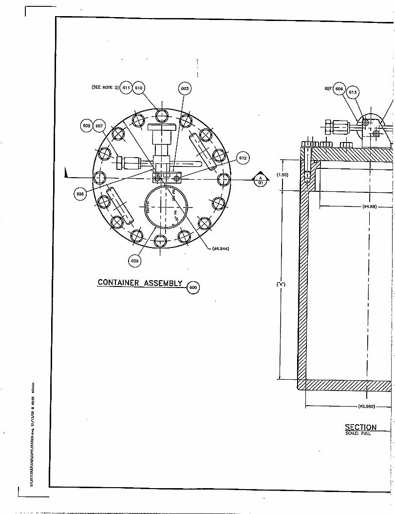
2 Q1 CONTAINER ASSEMBLY
3 02 CONTAINER BDOY 601A
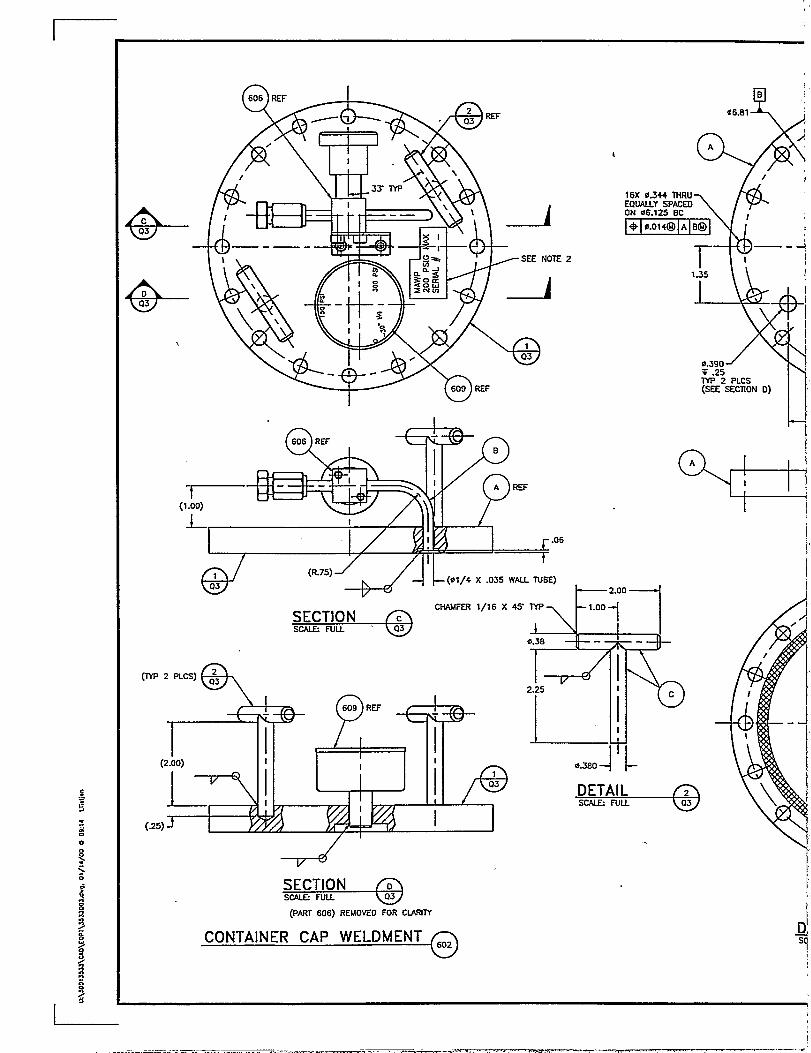
4 Q3 CONTAINER CAP WELDM!
1
I
I
I

7
ALIT)(NFL4GE
PRODUCT OPTIONS/SUBSTITLITIONS
“OR APPROVED EQUAL- IS ALWAYS IMPUED AFIER A BRAND NAME,PATENTEO PROCESS OR CATALOG NUMBER. THE CONTRACTOR MAYSUBSTITUTE ANY BRAND, PROCESS OR CATALOG NUMBER APPROVEDAS AND EQUAL BY THE CONTRACT ADMINISTRATOR THE ONLY EXCEPTIONIS WHERE “NO SUBSTITURON. IS SPECIFIED. SEE GENERAL PRDWSION%(ATERIAL AND WORKMANSHIP..
AIINMENT
16
G LET
ND 6018
T ANO VALVE SUPPOf?l BRACKn
HlvI f—- REvEWN D2SCftPlWN I MTEIW’IW’IWIZ%’IV2WIwm
Di?AYINLK2u3iI Lsm47a 1-12-2C?M
1-12-2030 WETF HIGH–QUALITYENG m ffw 1-1.3-W LONG-TERM STORAGE— B 1-13-m
1-1s-00 SECONDARY CONTAINMENTTsc VESSEL
21Z 1-13-00
I-13-(M TITLE SHEET AND DRAWING LIST
:I+UCK
I
—-0=. m .- 87545
**---9- L---- ,%4.-—mt=llm-wv
WEF GROUP NO. ~AIh3M IJNUA29P5J - NM wia R2UEKR MU ~PRWK! D ~-
M1’e 1-13-002CUE
WETF–DR–GEN–174Cxuwno. REV
3533T01 NONE 141 Y–634984
A-3 —-1
Q(sEE NOTE 2) 611 610 Q603
(3I
609
CONTAINER ASSEMBLY
T(1.s0)
I
~QREF 606
613
nI
I
I
I
1
I
~ (@5.9t30)—
SECTIONscAl&FULL
. . . . ..

-— — . . ----- .. . -. ——-—. ...- -—. —-——- --.-— ----
3i03 REF
7604) oR(605)
ON
(
—
)
awNmY REmgWPE-LI Ntt”% DESCRIPTIONLONG TERY4 SMRAGE CONIAUfER ~Y
600 I II I 1 I1 I
. e,.. . ---------- --
OY
DY—-
FFPFTlI 1 I 11 I 605
I1 606 I I
F13=l=H
I IAJNIJWNLK 15u1
CONTAINER BOI1 7 I cm CONTAJNER CAP WELOMENT
VALVE SUPPORT BRACKfl
SPRING SEAIJ 0.132 SECTION, 05.492 (+.000, -.01 O)NIMONIC SPRING, ALUMINUM JACKfl, INCONEL 600 LINING,HELICOFLEX co. PART #H-306346
O-RING PARKER #2-9=7 M~ll =
BELLOWS sEALEo VAUMOOEL #SS
. . ----
VCR PLU& CAKJN CO. MODEL #SS-
VCR CASK= CAJON CO. MOOEL #S=
PRESSURE GAUG& 30- Hg VACUUMASHCRO~ MOOEL #25-1009-SW-028
& CAP SCREW: 5/16-18 UNC X 1 1/4 LC. HEX HO. SST
FIAT WASHER CARR LANE MFG. CO. #CL-=fi
CAP SCREW: 8-32 UNC X 3/8 LG. SOCKk I iiu, >>1
I 4 1 “1+ I I CAP SCREW: 10-32 UNF X 1/4 LG. SOCKET HO. SST
NmE%
‘.”-, ,.O, ,., -
.W rwv+o COMpANY (SWAGELOK)>-4 H-WYb
-. .-. -- .. --—. -——.4-VCR-P
,5-4 -VCR-2
I TO 300 PSI. 2- OWL S12
---.- ... -—
1. TOROUE TO 8 IT-LBS.
2. PARTS TO BE THOROUGHLY CLEANEO TO REMOvE u OIL. GREASE, OIRT. ANO cHlps.
3. WELO IN ACCORDANCE WITH ANS1/AWS 01.1 ANO 010.4-1996
4. LEAK PATE OF ASSEMBLED UNIT TO BE LESS THAN 1 E-8 AllJ-CC/SEC. He AT MAWP
5. PRESSURE TEST TO 300 PSIG HELIUM FOR A
PERlOO OF 5 MINUTES WITH NO PERMANENT
DEFORMATION, VISIBLE CRACKS, OR LEAKS. i
3‘A91
WEF GROUP NO.
WETF–DR–GEN–157
“Ea==EElWETF HIGH–QUALITY
LONG-TERM STORAGE
SECONDARY CONTAINMENT
VESSEL
CONTAINER ASSEMBLY
I, 1 n
mLmnEN Cnr&wm OH ------- .,. . . . . .. . . . ------ ..-. —-“,. - “. “nTU.J. U!.-a’.. #AMnm.u
I I —
l_xx3,A~airJl&M@ &j MERFUCKL= bbms. t+= Mm-m 87&
G#-=h-.--.-.-*W .w --- m) ta-=,
~ utuussnm- NOT w, Rmm Muz llxmf DATE 1/13/03PR&!EC: Q nl,EtLIJ&
ISCALE
AONMING NO.
IRCV
I 3533Q01 FULL Q1 /“; 141 Y–634984
I
IA-5

II
I~
J=iF(05.512) . \
.1 60+.003
m-s ~6.3 v-s
BRE4K CR.005 AF
%/ \
0
I
*
/0
.’ T x El
16-WCJ-.LPJ4IJ?
dA
. . ----R ;/ii-18 X 1/2 LG. KEENSERTS
CONTAINER BODY
+.015-.000
1

I PAJlls LIsr
NERSLox.
Wm-m7Pml
NUUW? -mm
II
I I 601A CONTAJNER BODY ALUMINUM 2024-T351
I 6010 CONTAINER BOO’t ALUMINUM 2024-T351
NOTES”-
1. MACHINING/POLISHING hMRKS MUST FOLLOW SEAL
[3X R.12
II
IIII
EXTERIOR SURFACES
w:..
REV .%?22I RMsIONOEW?PllON ME I REV lC#Ol~BIPRf#lP&.J] OM
MERRICK nu
I WE ME
0W4N J. FREAs 8-6-99
E5Kn i s D0c3Nmlml 8-39-91 WETF HIGH–QUALITY5nwni/cOOrl3-IS-W LONG–TERM STORAGE
m 1-23-00
rm 1-lS-C.3 SECONDARY CONTAINMENTE VESSEL
-‘ ‘-’3-W CONTAINER BODY 601A AND 601B>..,. 1 .—,.—m
I I I
CWPUlE7 GENfWD ON AXlR14 - NO U.WLU — N.WWIo
TOWtAJWE-(~ om~ NOlm)
x-*~OXx -*.01 McUAR- *& Los Aklmm HMERRICK
0.x= *_ Om. is FINUH =Los A&rms Notkml Labwet
%LOS uamm. N- Mexti 87 5*b A.dam
CmSa.-.-.- ,~.(=m-ml=r. l-.,
WEI’F GROUP NO. CW5SFC411LW13NCI.ASIFIED- NUl UCNl RCW~ CUE IUCCLE ME 1-13-00PRa.Xcl 0 m.ENbnE Sr.ul
WETF–DR–GEN–158mumNo. RN
3533002 FULL 141 Y–634984
I
I-A-7
I
0
e-CQ3
e-D03
E’
-—K?---- -+!!&iE--‘i ‘J,
I1
h‘E’
(1.00)
L 1
~ .06
/ / / I t
.!9103
~ c“’”““x&(TYP 2 PLCS) ;3
(.2
v
~(PART 606) REMOVEO FOR CIAR17Y
CONTAINER CAP WELDMENT
4B ,!
06.81
JA
1
16X 0.344 lliRUEQUALLY SPACEDON @6.125 BC
T-—--
1.35
I f \
0.390v .25TYP 2 PLCS(SEE SECnON O)
t-
w=A
I
+ 2JYJ —
4s m -1.00
i
I
0.38 1 i -.
17 ‘“2.25 I
L %
c
I
0.3B0 4+L
.- -.. — .— .
.- .-
(0.260)
m I I
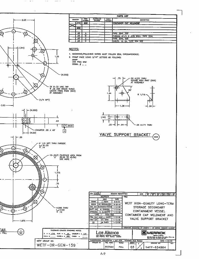
I I IAR A [17PE 304L SSTm B I ITU131NG 01/4 X .035 WALL, TYPE 304LAR c 1lYPE 3041 SSTAR o I [SHE= 16 GA ~E 304 ssr
NOTES:
1. tJACHINING/POUSHING W4RKS MUST
2. STAMP FACE USING 3/16- ~
MAWP200 PSIG WSERIAL # _ _
FolloW SW
AS FOUOV&
CIRCUMFERENCE.
I
2X 8-32 UNC TAPV .38 (NO BREAK THRU)LOCATE FROM PART (603)AT ASSEMBLY
I > (1/4 NPT)
-2.03 --l
-i t-”=
i15’$.75 2X 6.221 THRu
LOCATE wiTH PART (6o6)AT ASSEMBLY
T-+-
6V
1.44
1-
R 1/16
~13B~ --1.50
,.* ml+---———.
.22 --l .94 2X 0.171 THRu
VALVE SUPPORT BRACKET
NEW30N ~mON DATE RWE+ ~ 5# pcultw~l au
nn.s
“36-0-ss
a-w-97 WETF HIGH-QUALITY LONG–TERMlow 1-13-00 STORAGE SECONDARY
1-13-00
1-1s-00 CONTAINMENT VESSEL
CONTAINER CAP WELDMENT AND1-13-09
1-13-00 VALVE SUPPORT BRACKETPml m] G.P. Rum
au I m - 1 I-IS-M I
MI I I cwF’uER ~lEDONAXuu 4-No wNLlucwXEs N.lov,’m
r0Lm4NcE-(muss OTIERWSE NOTED)
x.*lJl&OXx .** —“ *JK- LJDsJJaNaEEl
MEI=J?U2JK0x. *_ Oxu. i- mEH._ b AJ9m.as.k U.ko L&s K9 ------ ,%.
W.--W-. *
WEF GROUP NO. ~IUYt UNCUSWIED - Ml uCr+l RWl~ w mm LL4TE 1-13-00PROJccl D FI-EM& ScA1.z
WETF–DR–GEN–l 59OP.AnwNO. RW
3S33Q03 FULL 141 Y-634984
A-9

LA-13703-MS March 2000
Appendix B
ESA -MT prepared Experimental Test Instruction (ETI)
,,,,
.,,,
,,
.,,,
.’
-, ----- -m-.- -T,—-.-y; :, y, j: .,->,.,,.. --- ,, ., .,-., ! : , ,,;,>.,. , .:’
,, -.,,., L....-.--”. <.,,.+,,,. . . ,. , ,:,!’: -.7;.$~<. , .. ,,-;-,;.(: - . ,., — —---- - .—

LA- 13703-MS
Appendix BMarch 2000
B-2
LA-13703-MS March 2000
Appendix B
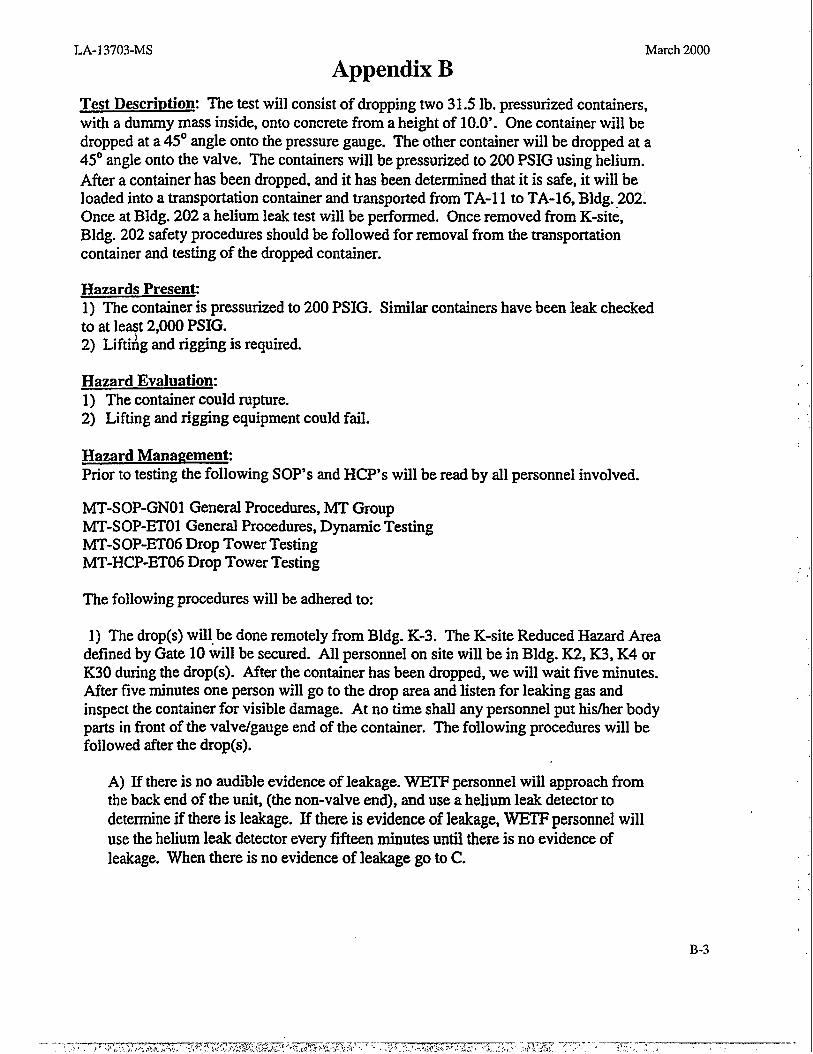
Test Description: The test will consist of dropping two 31S lb. pressurized containers,with a dummy mass inside, onto concrete from a height of 10.0’. One container will bedropped at a 45° angle onto the pressure gauge. The other container will be dropped at a45° angle onto the valve. The containers will be pressurized to 200 PSIG using helium.After a container has been dropped, and it has been determined that it is safe, it will beloaded into a transportation container and transported fromTA-11 to TA-16, Bldg. 2021Once at Bldg. 202a helium leak test will be performed. Once removed from K-site,Bldg. 202 safety procedures should be followed for removal from the transportationcontainer and testing of the dropped container.
Hazards Present1) The container is pressurized to 200 PSIG. Similar containers have been leak cheekedto at least 2,000 PSIG.2) Lifti~g and rigging is required.
Hazard Evaluation:
1) The container could rupture.2) Liting and rigging equipment could fail.
Hazard ManagementPrior to testing the following SOP’s and HCP’S will be read by all personnel involved.
MT-SOP-GNO1 General Procedures, MT GroupMT-SOP-ETO1 General Procedures, Dynamic TestingMT-SOP-ET06 Drop Tower TestingMT-HCP-ET06 Drop Tower Testing
The following procedures will be adhered to:
1) The drop(s) will be done remotely from Bldg. K-3. The K-site Reduced Hazard Areadefined by Gate 10 will be secured. All personnel on site will be in Bldg. K2, K3, K4 orK30 during the drop(s). After the container has been dropped, we will wait five minutes.After five minutes one person will go to the drop area and listen for leaking gas andinspect the container for visible damage. At no time shall any personnel put hisher bodyparts in front of the valve/gauge end of the container. The following procedures will befollowed after the drop(s).
A) If there is no audible evidenee of leakage. WETF personnel will approach fromthe back end of the unit, (the non-valve end), and use a helium leak detector todetermine if there is leakage. If there is evidenee of leakage, WETF personnel willuse the helium leak detector every fifteen minutes until there is no evidenee ofleakage. When there is no evidence of leakage go to C.
B-3

LA-13703-MS March 2000
Appendix B
2)
3)
B) If there is audible evidence of leakage. Wait until the audible leakage hasstopped. WETF personnel will approach from the back end of the unit (the non-valve
end), use a helium leak detector to determine if there is leakage. If there is evidenceof leakage, WETF personnel will use the helium leak detector every fifteen minutesuntil there is no evidence of leakage. When there is no evidence of leakage go to C.
C) One person will lift the container, with the gaugehalve end away from hidherbody, and put it into the transportation container. The transportation container will beclosed and transported to Bldg. 202. Knowledgeable Bldg. 202 personnel willaccompany the container so as not to endanger unsuspecting 202 personnel receivingthe container.
The crane and drop mechanism will be inspected prior to lifting the container for thedrop. The container will be placed on a hydraulic lift and raised to approximately4.0’. The container will be lifted approximately 1“ to allow the correct orientation tobe verified and the hydraulic lift will be removed. The remainder of the lift will bedone remotely from Bldg. K-3.
All personnel that go to the drop tower area shall wear a hard hat. After the drop(s),any personnel that go to the drop tower area shall wear eye protection until thetransportation container has been removed from the area.
S13VHUTY LIKELIHOOD RISKViolent Release of Pressure critical Improbable LOw
Slow Release of Pressure Negligible Probable MinimalLifting Moderate Remote Minimal
S&mitted: James E. bke
U[&&
vy&v wed” oh “n
J.
-..
A~proved Paul Smith
If-f’ ? 7Date
Date
Date
B-4
.— .- —
LA-13703-MS
Appendix CMarch 2000
Photocopy of ASME calculations by James Radigan, PE

LA- 13703-MS March 2000
Appendix C
c-2
LA-13703-MS
Sept. 29,1999
Appendix C
Kane J. FisherLos Alamos National LaboratoryP.O. BoX 1663Mail Stop C927Los Alamos, NM 87545
Mr. Fisher,
March 2000
James RadiganP.O. BOX 39278
Denver, CO 80239
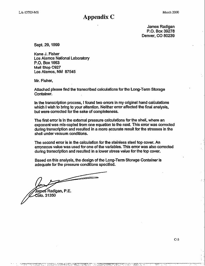
Attached please find the transcribed calculations for the Long-Term StorageContainer.
In the transcription process, I found two errors in my original hand calculationswhich I wish to bring to your attention. Ne-fier error affected the final analysis,but were mrrected for the sake of mmpleteness.
The first error is in the external pressure calculations for the shell, where anexponent was mis-copied from one equation to the next. This error was correctedduring transcription and resulted in a more accurate result for the stresses in theshell under vacuum conditions.
The second error is in the calculation for the stainless steel top cover. Anerroneous value was used fo~one of the variables. This error was also correctedduring transcription and resulted in a lower stress value for the top cover.
Based on this analysis, the design of the Long-Term Storage Container isadequate for the pressure conditions specified.
c-3

LA- 13703-MS March 2000
Appendix C
Los Alamos National Laboratory
Long-Term Storage Container
Materlah COmirKX “&211 -2024 -T351 Aluminum
v= 0.3W
Ud A-240-304SW&s SW
v= 0.305
?m!mlro: 200 pai (internal)15 psi (extema!)
Aluminum S= SU14
= 82$00/4
= 15;kO0 pd
sy=45,000pd
1.5” 15,500or
(2/3) ”45,000
=23250 psior= 30,0D0 pd
Ttm3fom, am= 23250 pd
Stainless: mm= 18,800 psi
c-4
LA-13703-MS
Appendix CMarch 2000
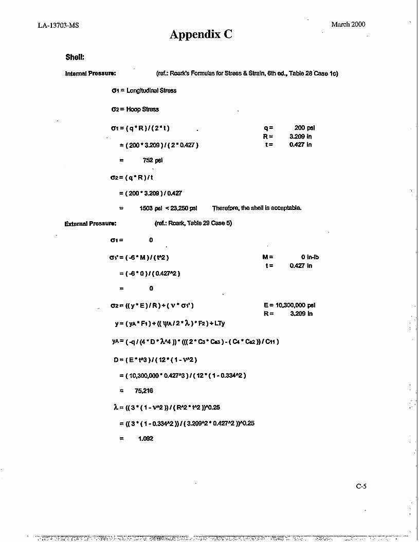
Shell:
Internal Pfassurw ‘ (ref.: Roadts Formulas for Strass & Strain, 6th ad., Table 28”@e Ic)
61= Longitudinal Stres2
cr2=HOOpsb?3ss
m=(q*R)/(2”t)
=(200 ”3.209)/(2”0.427)
= 752 psi
q = 200 pal
R= 3.209 int= 0.427 in
Uz=(q” R)/t
=(200 ”3.209)/0.427
= 1503 psi <23250 PSI Tharatbra, the shall is acceptable.
External Pressurw (wit; RoarkTabh 29 Case 5)
c1 = o
m’=(-8*M)/(t”2) M= O Iwlb
t = 0.427 in=(-8” 0)/(0.427”2)
= o
a2=((y*E)/R)+( v” Cm) E= 10,300,000 pa!
R= 3.209 In
y=(yA*Fl)+((lpA/2 *A)* F2)+LTy
yA=(q/(4*D*h44 ))”(((2*&* Css)-(Q” Cn2))/cll)
D=(E*t”3)/( 12*(1 -vA2)
= ( 10,300,000 ● 0.427”3 )/ ( 12” ( 1-0.334”2 )
= 75216
k=((3*(l-vA2))/( RA2”t”2)~-25
= (( 3 ● ( 1-0.334”2 ))/ ( 3.209”2 “ 0.427”2 ))”025
= 1.092
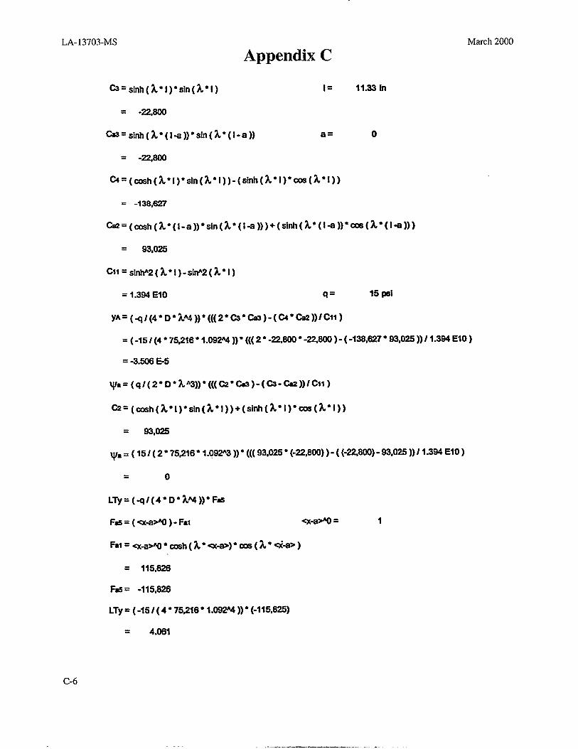
LA- 13703-MS
Appendix C
&=Slnh(~*l)*S]n(~*l) I=
= -22@O0
ti=si~(~’( l+))”sln(~’(].a)) a =
= -22@0
~=(cosh(~” l)”sln(~” l))-(slnh( %”i)”cos(k’l))
= -133,627
March 2000
11.33 in
o
-=(~h(~*(l. a))"sin(h" (14)))+(Si~( h*(!4))*-(~*(l4)))
= 93,025
cll=sl*2(z*l )-silp2(h*l)
= 1.3% EtO q= 15 psi
yA=(q/(4*D* ~~))*(((2” @”m)-(~*ti))/cll)
= ( -15/(4 ● 75Z16* 1.092% ))” (((2* -2Zm ● -22WJ )-(-136,627 ● 93.025 ))/ l-~ Elo )
= -3.506 E-5
~a=(q/(2*D*~”3)) *((( C2?*Cas)-(@--)) /Cl~)
@=(cosh(~* l)*sin(~*l ))+(sinh(%” l)* C06(~”l))
= 93,025
~a = ( 15/ ( 2* 75t216” 1.09N3 ))* ((( 93,025 ● (-2Z800) )- ( (-22MO)- 93,025 ))/ 1.394 E1O )
= o
LTy=(q/(4* D*%W))*F@
Fa!s=(cx+~)-Fat *+* =
Fal=~+~*~h(~*~+>)*~(~*d+>)
= 115,626
F== -115,626
LTy = ( -15 / ( 4 ● 75W6 ● 1.092% )) ● (-115,825)
= 4.061
C-6
LA-13703-MS
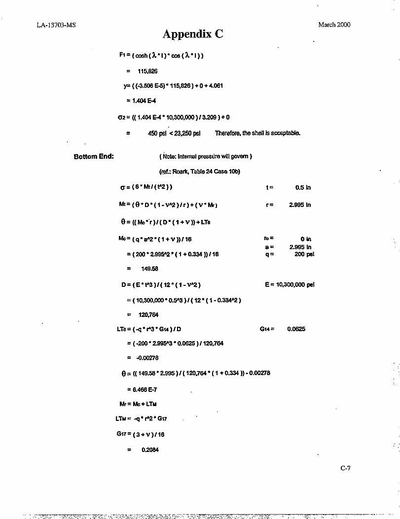
Bottom End: ( NottxInternalprasaurawill govern)
(r@.: Roark Table24 Case 10b)
c=(6*h4/(V’2))
March 2000
Appendix C
= 115,828
P((-3.WE~* l15,=)+O+4.wl
= 1.404E-4
~2=((1.W~*lO,~,~)/3~)+o
= 450 1A c 23&(l pal Therefixa,the shall laacceptable.
hk=(e*D*(l -vA2)/r)+(V*Wl
()=((Mc*”r)/(D* (l+ V))+LTe
~=(q*#2*(l+v))/16
=(200 ”2.W2*(l+0.3W))/16
= 149.58
D=(E” F3)/(12*(1-VA2)
=(100300,000 *0.!Y3)/(12”( 1-0.334A2)
= 120,764
LTe=(q*F3*Glt)/t) G14 =
= (-200 ● 2.8W3” 0.0625 )/ 120,764
= -0.00278
6=((149.W*2W5 )/(lM,764*( l+0.W))-O.W8
= 8.468 E-7
W= Mc+LTM
0.0625
LTM= -q* F2*G17 ~ “
GlT=(3+v)/16
= 0.2084
c-7
t = 0.5 in
r = 2.995 in
E= 10,300,000@
LA- 13703-MS
Appendix C
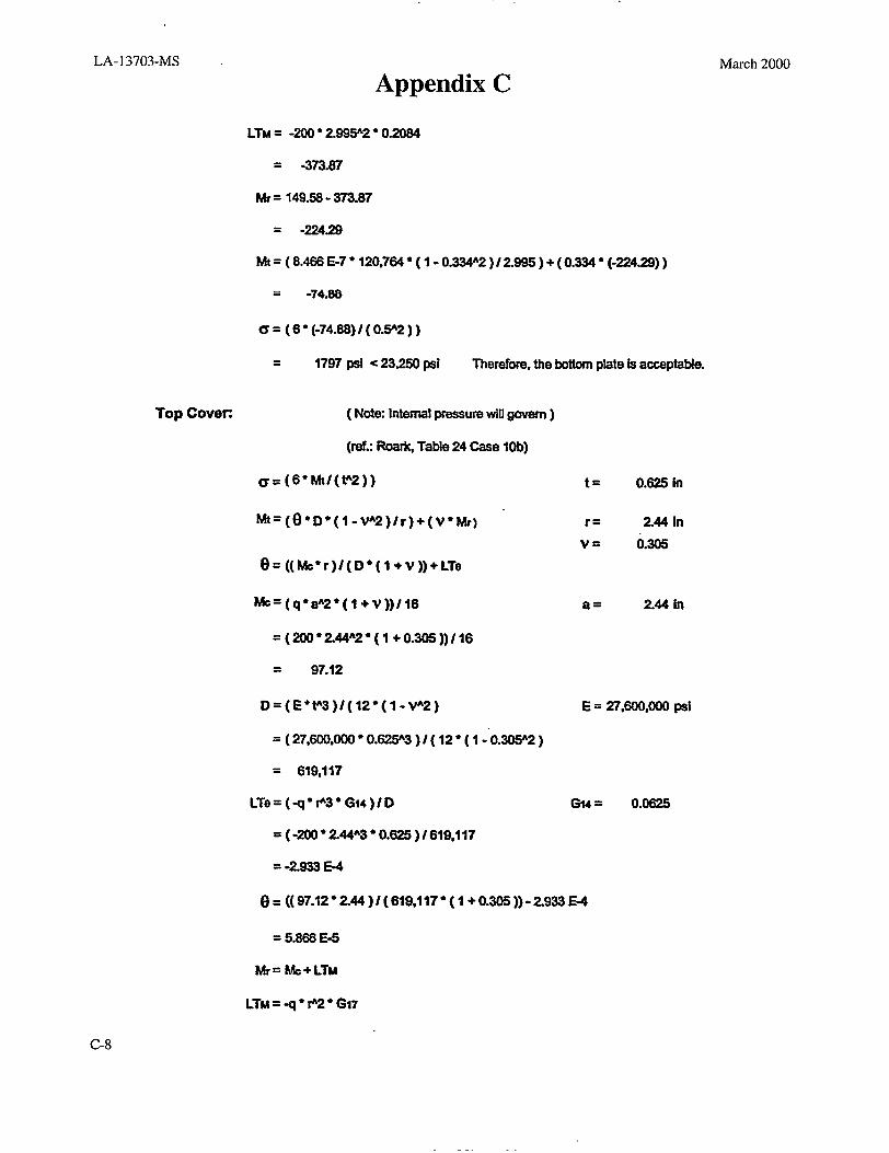
LTM = -200 ● 2995’2 ● 0.2084
= -373.67
MT= 149.58-373.87
= -224.29
~= ( 8.466 E-7*120.754*(1 -0.334’2 )/2.995 )+ (0.334 ● (-224.29) )
= -74.66
C= (6*(-74.68) /(().!jA2))
= 1797 psi <23,250 pei Therefore, the bottomplateIsacceptable.
Top Covm ( F40kcInternalpreseurewillgovern)
(raf: FbariGTable 24 Caae lob)
c=(6” Mt/(P2))
~=(e*D*(l -VA2)/r)+(v*MrJ
t = 0.625 in
r = 244 in
v= 0.30s
a = 2.44 In
E= 27,600,000 pal
e=((hk*r)/(D* (l+v))+LTe
hk=(q”a’2* (l+ V))/16
=(200 ”244’2’(1+0.305 ))/16
= 97.12
D=(E*P3)/( 12”(1-vA2)
= ( 27,600,000 “ 0.626’3 )/ ( 12 “ ( 1 -“0.305’2 )
= 619,117
LTe=(q*r’3*Gtq)/D G14 = 0.0625
= ( -200•244”3’0.625 )1619,117
= -2.933 E-4
0=((97.12*244)/( 619,117 ”(1+0.305))-2.933 E-4
= 5.868 E-5
Mr=Mc+LTM
LTM=-q*f’2*G17
March 2000
C-8

LA-13703-MS March 2000
Appendix C
Gt7=(3+r)/16
=(3+2.44)116
= 0.2086
LTM = -200 ● 244A2 ● 0.2066
= -246.0
Mr= 97.12 -246.0
= -148.88
Mt= ( 5.866 E-5 ● 619,117 ● ( 1- 0.3W2 )/244 ) + ( 0.305” (-148.88))
= 4.35
c7=(6*43.35/(o.625P2))
= 666 PSl <18,800 Wi Theretbre, the top cover k acceptable.
Bolting:
EndLoaCL
F=q” A
A=z”dA214
q = 200 pd
d = 4.88 in
n = 16 bolts
=Z*4.88A214
= 18.70 i@2
F= 200”18.70
= 3740 lb
L=Fln
= 3740116
= 234ib
ASSUlllf35/1!%18 UNC boita
G= LIAb Ab= 0.0524 irP2
= 234/ 0.0524
= 4466 pal <18,800 PSI Therafore, the bolting la acceptdk
Thkaame2341bload vfillaiSOaCtM*Aiti
c-9
,’
~.
,
,,
,,
.’ ‘,,
,
.
,,
:,
-., .- .- ,.,4$ ., . ... . . ‘ . . . . .. . . ., , ,~q-, ..... :.7. ,~- W.TT,C -.,..w.~?+>>17,-:- -.7. -.? 7 -, ,. ,, -. ., . .: ,;, ,.,>.,.,<..:, -—. —.. .
. . .

LA-13703-MS March 2000
Appendix C
I = 0.88 in ( assumed insart length)
d= 0.512 in ( hole dmmeter )
Tmax= 0.5 ● Z%25il
= 11,600 psi
C=z”d
= 1.E08in
At=C*l
= 1.608”0.88
= 1.415 in
T= LIAr
= ml 1.415
= 165 psi < 23J?50 psi Therefore, the thraaded inserk are acceptable.
I
c-lo

LA-13703-MS
Appendix DMarch 2000
Kaiser Aluminum & ChemicalCorporation material certification report
LA-13703-MS
Appendix D
D-2
March 2000
——.—_—-.— _

LA-13703-MS
Appendix
KAISER A \A l. UA##NUM
MADE IN USA /?zA\—. —
March 2000
J—— \P. O. BOX 669 JACKSON, TN 383B2
$~’p 9RA~C0 METALS ~13RALc0 METALS1509B NORTHAF! STREET 15k)90”N0RTliAM STREET
LA MIRAOA, CA USA 90638 LA mXRaDA, CA USA 96638rwlm —-mw.amu :?M7 — l--m 1
LISO 90@2sASTMB211-95A,[email protected] a.~ -=G%-opw8flcas lm~ lw=~
7’ “ ‘ “1009 c 6171 -- 11 13984 12 04/21/99 M. L. Coats, Qua13ty. Hanager
ACTUAL PHYSICAL PROPERTIES
Lm—
20091338
‘ens$le 11.hls meter
wumdwnt
. .
1;‘ 14;●
UTS YTs ELONGksl *S 4 %
66.7 47.8 22.0
lts us d ● re enna~u *nter al Itm :s sln noneml nee s the equlrem ents o 74 te pep an of QQ.
(CANC LLED).
:
I i
I 1 I I 1
m re~-225/{
.
Slu99SOLOTO:MARCOSTEELPONUM8ER..A8Q254S9 PARTNUM8Hk
8RAM0OROERNUM8EFC 584 GHT~6171 ~.
TRCERK SIONATUREl%c%cCmncaDum @qNmmm CimsNcvhB EkzabdbO’l?cdL&owm
:
D-3
LA-1 3703-MS
Appendix DMarch 2000
D-4
LA-13703-MS
Appendix E
Ugine-Savoie, France,certificate of tests for the bar stock 304L
.,
March 2000

—---
LA- I3703-MS
Appendix EMarch 2000 I
E-2

LA-13703-MS
Appendix E
------ 1 CERTIFICATE 0? TESTSs—UQINE mtmm=asS?nmmam -@=--
tilLo60J22s310\ “2stuuND-- 177,000 ‘“ 2240 XG
I
March 2000
E-3

LA-13703-MS
Appendix E