contaminants and effects
TRANSCRIPT
Contaminants and Effects on Amines - Glycols MPR.doc Page 1 of 24
Contaminants and Their Effects on Operations – Yes! You can have better operating amine and glycol systems!
For Presentation at
The Brimstone Sulfur Conference
Banff, Alberta, May 2003
By
Arthur L. Cummings (Presenter),
David Street, and Gary Lawson
MPR Services Inc., Dickinson Texas
ABSTRACT
Gas processing plants encounter a variety of operational problems in their amine and glycol
units. Some of these problems are caused by or exacerbated by contaminants – solids,
hydrocarbons, salts and degradation products – that accumulate in the system. Drawing from
multi-plant experience analyzing and controlling these contaminants, this paper addresses
commonly posed questions such as:
- What contaminants accumulate in gas processing amine and glycol systems?
- Why do these contaminants accumulate in the amine and glycol systems?
- What are Heat Stable Salts and Degradation Products?
- What effects do contaminants have on amine and glycol operations?
- What do analytical reports really say about solvent condition?
- How can the contaminants – hydrocarbons, solids, salts and degradation products – be
reduced, removed and controlled?
- How can lower sulfur emission specifications be met by sour gas plants and SRUs with
and without SCOT units?
Contaminants and Effects on Amines - Glycols MPR.doc Page 2 of 24
INTRODUCTION
Gas treating applications utilizing solvents such as alkanolamines and glycols rarely work
trouble-free. Yet their design is based on a simple concept: the solvent absorbs undesirable
substances from the natural gas, circulates to the regeneration or stripping section of the process,
releasing the absorbed substances such that they can be collected for further processing or
disposal, then circulates the regenerated solvent back to absorbing section. The regenerative
recycle principle is wonderful. The solvent can be circulated indefinitely, performing its
function flawlessly. The reality is, however, that over the long-term the solvent becomes
contaminated and these contaminants cause operational problems.
When operational problems arise, a common response is to add something: anti-foam, corrosion
inhibitor, neutralizer, fresh solvent, etc. However, additives can change the solvents properties
and eventually contribute to the very operational problems they are intended to solve. For
example, it is well accepted that excessive anti-foam can cause foaming in amine systems. The
viscosity, surface tension, thermal conductivity, electrical conductivity, and water content of the
solvent solution, are important characteristics of the solution that can be altered by accumulated
additives and contaminants. Operators become accustomed to gas treating systems with
operational problems because the composition of the solvent (amine or glycol) is much different
than the pure solvent solution due to contamination and excessive additive issues.
This paper looks at methods of eliminating operational problems by removing solvent
contaminants and minimizing additives. We propose that solvent based corrosion is best
controlled by removing corrosion enhancers and corrosion products; solvent foaming is best
controlled by removing hydrocarbons and corrosion products; solvent degradation is best
controlled by minimizing contaminants so that degradation rates are minimized. Also, low sulfur
specs are best achieved with clean amine solvent that can be made “ultralean”. Removing the
common contaminants allows the gas treating application to operate with a solvent solution that
approaches the theoretical design. Plants can best approach goal of trouble-free operation by
maintaining chemically and physically clean solvents. In simple terms, a clean gas treating
solvent is a good gas treating solvent!
AMINES
Alkanolamine solvents are used in Gas Plants and Petroleum Refineries for removing acid gases
from various gas and liquid hydrocarbon streams. The acid gases removed are H2S and CO2. The
low sulfur specification of the products requires that the amine solvent work continuously and
efficiently. The amine solvents have proven to be very predictable in removing acid gases until
they become contaminated. Contaminated amines usually result in unstable operations and poor
performance, which frequently becomes a limiting factor in the operation of the gas plant. More
stringent sulfur emissions specifications increase the need for smoothly operating amine systems
and may also require enhanced amine performance.
The principle contaminants of an amine solvent include:
Contaminants and Effects on Amines - Glycols MPR.doc Page 3 of 24
1. Hydrocarbons
2. Iron Sulfide
3. Heat Stable Salts
4. Amine Degradation Products
5. H2S
Hydrocarbons
Hydrocarbons enter the amine system due to their natural solubility in the amine solvent, by
mechanical entrainment, by condensation into the cooler amine solution, and by upset conditions
within the amine contactor. The foaming episodes, process upsets, and poor treating that result
from hydrocarbon contamination are well known to amine system operators. While it is well
known that hydrocarbons are related to foaming, the relationship has not really been well
understood.
Surface tension effect
The function of amine contactors is essentially to generate surface area between the liquid amine
phase and the hydrocarbon stream being treated to facilitate mass transport of acid gas
components across the surface interface. Contactors can do this either by providing a large
surface area for one phase to cling to while the other phase passes by the surface (packing,
FiberFilmTM
), by generating the surface area by agitation (trays), or by creating droplets that pass
through the other phase (spray towers). Regardless of the device, energy is expended in the
formation of the surface area. The amount of energy required per unit of surface area generated
is proportional to the surface tension of the liquid. Therefore as the surface tension of the fluid
decreases, the greater the amount of liquid surface area generated by doing work on the system.R-
1
Foam and emulsions
Foam is generally associated with the use of detergents, i.e. soaps which generates the familiar
head of suds during a shampoo or while doing the dishes. Foam is simply a structure of
expanded liquid surface area containing the gas. The energy from agitation generates the surface
area in the liquid; the low surface tension of the liquid makes the energy more efficient in the
generation of the surface area; and the liquid surface stays stable because it cannot drain
effectively from the structure. The soap or detergent generates a stable foam by lowering the
surface tension and increasing the liquid viscosity in the bubble film. Dissolved heavy
hydrocarbons influence amine solutions to foam in a similar fashion.
Emulsions in liquid/liquid treating applications are analogous to foaming. The significant
difference is that emulsions involve generating large surface areas between two liquid phases.
Liquid-liquid treaters generate emulsions through agitation the same way gas treaters generate
foam.
Contaminants and Effects on Amines - Glycols MPR.doc Page 4 of 24
The amine solution is considered aqueous. Common sense tells us that oil and water don‟t mix,
so it is understood hydrocarbons will separate easily from the amine solution. This is the
premise behind the use of a rich amine flash drum to reduce hydrocarbon contamination. If you
build it large enough, the oil will be separated. If any slips out, an activated carbon filter will get
the little bit that did not separate.
There are two regimes of hydrocarbon contamination. The very familiar one is the rapid
deterioration of the amine system performance usually concurrent with a large scale upset in a
process unit tied to the amine system. A large amount of oil accumulates quickly in the amine
system causing a large upset episode somewhere in the system. Much of the time the entry point
of the oil and the place where the upset in the amine system occurs is not the same. The flash
drum is essential for combating this situation as bulk hydrocarbons can be skimmed easily.
Operators typically work out of this regime with better control of the upstream units, or
installation of preventative measures at the contactors such as inlet knock-out drums,
filter/coalescers, and sour gas lean amine differential temperature controllers to make them
resistant to large incursions.
The more subtle and troublesome hydrocarbon contamination regime occurs when the large-
scale contamination measures listed above are in place, but small amounts of hydrocarbon
accumulate in the solution by contacting a stream containing low levels of oil. This is
particularly true when treating streams such as recycle hydrogen from a diesel or gas oil
hydrotreater or from a lean oil absorption LPG recovery system following a cracking unit or gas
that contains well additives. In this regime, the oil contamination accumulates in small
increments. At low levels, the oil is dispersed throughout the entire solution. It has been shown
that olefinic/aromatic hydrocarbons are more soluble in amine than paraffinic hydrocarbons. As
the amount of oil increases toward saturation, the natural tendency is for the oil to migrate to the
surface and to break out in a free oil phase once the saturation point is reached. With oil
accumulating near the surface of the amine, the surface chemistry of the amine will change; a
lowering of the surface tension and increase in the liquid viscosity occurs. So as surface area is
generated in the contactor, and even in the regenerator, the bubbles that were once easily broken
by removing the agitation energy now stay stable because the hydrocarbon contamination
changed the surface chemistry of the amine in a manner similar to the changes soaps cause in
water. Foam forms when the heavy liquid hydrocarbons alter the surface chemistry.
Similarly, emulsions form in a liquid/liquid contactor as a surface layer of oil-contaminated
amine stabilizes tiny droplets of amine. The NGL or LPG stream being treated carries these
emulsions away causing significant amine losses.
The flash drum is ineffective at dealing with this regime because no oil separation takes place
until the amine is saturated with the contaminant. Activated carbon filters are effective at
removing the dissolved oil, until the surface of the carbon becomes saturated with adsorbed oil.
After that, an amine system will cycle through periods of foaming or emulsions which purge
some of the oil accumulation, then settle down and accumulate more until the amine surface
chemistry is altered again through the hydrocarbon contamination.

Contaminants and Effects on Amines - Glycols MPR.doc Page 5 of 24
One effective method of dealing with both dissolved and entrained hydrocarbons in amine
solvents is the HCX™ process, as illustrated in the following table.
Hydrocarbon at HCX inlet
ppm
Hydrocarbon at HCX outlet
ppm
Removal
%
6480 420 94%
226 27 88%
44 7 84%
5 1 80%
Anti-foam
Most amine operators don‟t consider anti-foam a contaminant. If used properly, it isn‟t.
However, anti-foam is a contaminant when used improperly.
Anti-foam works in small quantities by making big changes in the surface chemistry of the
amine solution trapped in a foam structure. This allows effective drainage of the liquid from the
foam structure. Anti-foam is more properly described as an anti foam-stabilizer because it
doesn‟t really prevent foam; rather, it acts to destroy stable foam structures.
To some degree, anti-foam works against the amine system operator because anti-foam disperses
over the surface of activated carbon, stealing activated carbon capacity. The surface available on
the activated carbon for hydrocarbon removal diminishes. Antifoam, heavy liquid hydrocarbon,
and iron sulfide can combine into tight emulsions with the amine solution causing large LPG
treater carryover. This is particularly true when anti-foam is added to liquid/liquid treaters to
reduce “foaming”. The problem is that liquid-liquid treaters don‟t form “foams”, so anti-foam
technically is misapplied in this circumstance.
Anti-foam contaminated amine accumulates hydrocarbon contamination because the carbon
filter is disabled by the anti-foam removal as described above. Hydrocarbon will cause changes
in surface chemistry as it builds in the system. Operators will typically fight the foaming episode
with more injections of anti-foam. After so many injections, the amount of anti-foam in the
foam liquid structure will be great enough that small dosages of antifoam will not change the
concentration of anti-foam in the structure. At that point, anti-foam becomes totally ineffective.
One refinery added enough antifoam to have a two-inch layer of anti-foam break out on the
surface of the lean amine sample. The main operations complaint at the time of the incident was
foaming!
Iron Sulfide – Corrosion Products
Iron Sulfide (FeS) is a common contaminant in amine systems processing gas containing H2S.
The H2S reacts with carbon steel and forms FeS. Under the proper conditions, this FeS adheres
to the carbon steel and forms a protective barrier to retard continuing H2S attack. It is this
protection (or passivation) that makes it possible to use carbon steel as a material of construction.

Contaminants and Effects on Amines - Glycols MPR.doc Page 6 of 24
FeS suspended in the amine solution will cause many problems in the amine system operation.
FeS plugs exchanger tubes, stripper and absorber trays, and piping, leading to fouling,
channeling, and a reduction in heat and mass transfer efficiencies. Suspended FeS is abrasive, so
it contributes to erosion of the protective FeS layers, leading to a cycle of corrosion, erosion,
corrosion, and erosion. ConocoPhillips conducted lab tests that indicate that FeS particles tend
to migrate to oil/water interfaces. The combination of high levels of hydrocarbon and FeS
particles at the surface of amine solutions contributes to more frequent or severe foaming
incidents. FeS will also stabilize foam and emulsions by not allowing the liquid in the foam
structure to drain.
There are conditions in the amine system that interfere with FeS passivation and, thus, cause
increased corrosion and FeS formation. These conditions can be mechanical, thermal, or
chemical. Mechanical conditions include vibrations, erosion in high velocity areas, and
mechanical shocks during shut down and start-up. These remove the FeS layer, sending particles
into the circulating amine. Rapid thermal changes can cause FeS to come loose from the carbon
steel and then become an abrasive material as it is circulated in suspension. This suspended FeS
mechanically removes more FeS, exposing more carbon steel to H2S and accelerates the
deterioration of the amine system. Chemical factors that affect the passivation nature of FeS
include high levels of Heat Stable Salts and amine degradation products.R-2
These contaminants
must be kept as low as possible at all times to prevent the FeS corrosion, more FeS, more
corrosion cycle.
One effective method of dealing with suspended solids in amine is the SSX™ process, as
illustrated in the following table.
Suspended Solids at SSX inlet
ppm
Suspended Solids at SSX outlet
ppm
Removal
%
1050 315 70%
550 117 79%
624 27 96%
27 3 89%
A distinguishing characteristic of the SSX process is the open fiber construction of the filtration
media. Iron sulfide particles large and small (even sub-micron) adhere to the fibrous media
without occluding passages or restricting flow. In one pass of the amine solution through the
filtering media, most particles are retained on the media, but some particles may pass through.
As the amine circulates and re-circulates, the number and average size of particles remaining in
solution decreases, until only the green color caused by colloidal iron sulfide is visible.
Eventually even the green disappears.
Heat Stable Salts – Corrosion Contributors
Heat Stable Salts (HSS) are any ionic substances that are not removed from the amine solution
by heat (as in the regenerator or “stripper”). This definition is not restricted to salts that arise
from reactions with contaminants absorbed in the contactor. It includes as well salts arising from

Contaminants and Effects on Amines - Glycols MPR.doc Page 7 of 24
addition of “neutralizers” and other special additives, and salts that enter the amine from cooling
water leaks, etc.
When the cation of the salt is the protonated amine, the salts are often termed Heat Stable Amine
Salts (HSAS). There has been a tendency to ignore heat stable salt anions where the cation is
something other than protonated amine, such as sodium or potassium. That leads to incorrect
understanding of the amine solution. Tests conducted by MPR Services and ConocoPhillips
show that negatively charged HSS anions have a pronounced affect on corrosion rates regardless
of the cations they are associated with (whether protonated amine or sodium or potassium)
because the anions are the same as they were when paired with a protonated amine.R-2,R-4
It is
believed that the negatively charged anions compete with sulfide ion in the passivation layer for
ionic iron in the layer by forming stable complexes.
Caustic “neutralization” is the main source of sodium and potassium HSS in amine systems.
Cooling water leaks may also bring sodium and potassium salts into the amine.
The HSS are generally identified by the name of the anion of the ion pair, such as acetates,
formates, thiosulfates, sulfates, thiocyanates, oxalates, butyrates, propionates, chlorides, phosphates,
and nitrates, etc. Heat Stable Salts are termed “heat stable”, because they do not leave the
solution or release the "bound" amine as the solution passes through the regenerator. This
means every mole of Heat Stable Salt removes a mole of amine from being "free" or available
for removing acid gas. This reduces the amine system capacity, and can result in increased amine
circulation rates, increased steam usage to the amine stripper reboiler, lower sulfur removal from
the feed gas, or reduced production capacity.
In addition to the effect of Heat Stable Salts on capacity, they also increase corrosion, increase
iron sulfide production, increase filtration requirements, and increase hydrocarbon entrainment.
All of these combine to increase foaming, system instability, and reduce production rates. An
amine system in an upset condition results in more flaring incidents, excess sulfur in fuel gas and
tail gas incinerators, amine in flare knockout drums, and amine in waste water. Elevated levels
of amine in waste water treatment systems can kill microbes and will result in reduced waste
water treatment capacity.
Degradation Products
Degradation Products are molecules formed that include the amine as part of the molecule. These
degradation products are usually inert, but can be polar and strong chelators of iron and thereby
contributors to corrosion. They also cause increased solution viscosity and density, reduced
surface tension, reduced water content and reduced available amine which can lead to increased
foaming, fouling, and high flash gas production. Many amine degradation products have been
known for years, but higher demands on amine system performance and analytical advances
have resulted in a resurgence of interest. R-5, R-6, R-3, R-7
Examples of Degradation Products in a primary or secondary amine include amides, such as
Formyl-MEA, Formyl-DEA, and Formyl-DIPA (alternatively referred to as MEAF, DEAF,
Contaminants and Effects on Amines - Glycols MPR.doc Page 8 of 24
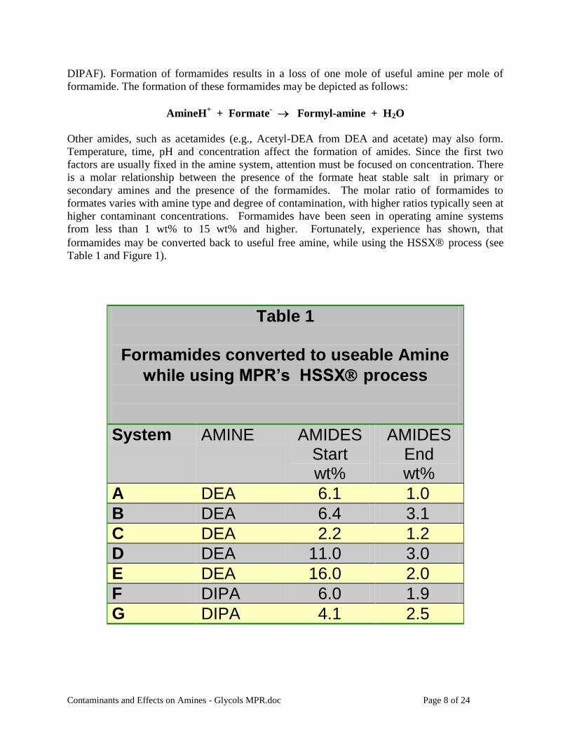
DIPAF). Formation of formamides results in a loss of one mole of useful amine per mole of
formamide. The formation of these formamides may be depicted as follows:
AmineH+ + Formate
- Formyl-amine + H2O
Other amides, such as acetamides (e.g., Acetyl-DEA from DEA and acetate) may also form.
Temperature, time, pH and concentration affect the formation of amides. Since the first two
factors are usually fixed in the amine system, attention must be focused on concentration. There
is a molar relationship between the presence of the formate heat stable salt in primary or
secondary amines and the presence of the formamides. The molar ratio of formamides to
formates varies with amine type and degree of contamination, with higher ratios typically seen at
higher contaminant concentrations. Formamides have been seen in operating amine systems
from less than 1 wt% to 15 wt% and higher. Fortunately, experience has shown, that
formamides may be converted back to useful free amine, while using the HSSX process (see
Table 1 and Figure 1).
Table 1
Formamides converted to useable Amine
while using MPR’s HSSX process
System AMINE AMIDES Start wt%
AMIDES End wt%
A DEA 6.1 1.0
B DEA 6.4 3.1
C DEA 2.2 1.2
D DEA 11.0 3.0
E DEA 16.0 2.0
F DIPA 6.0 1.9
G DIPA 4.1 2.5

Contaminants and Effects on Amines - Glycols MPR.doc Page 9 of 24
FIGURE 1
Contaminants and Effects on Amines - Glycols MPR.doc Page 10 of 24
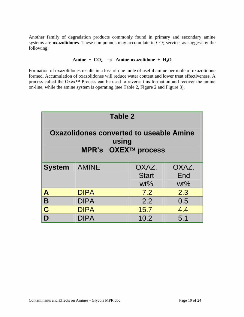
Another family of degradation products commonly found in primary and secondary amine
systems are oxazolidones. These compounds may accumulate in CO2 service, as suggest by the
following:
Amine + CO2 Amine-oxazolidone + H2O
Formation of oxazolidones results in a loss of one mole of useful amine per mole of oxazolidone
formed. Accumulation of oxazolidones will reduce water content and lower treat effectiveness. A
process called the Oxex™ Process can be used to reverse this formation and recover the amine
on-line, while the amine system is operating (see Table 2, Figure 2 and Figure 3).
Table 2
Oxazolidones converted to useable Amine using
MPR’s OXEX process
System AMINE OXAZ. Start wt%
OXAZ. End wt%
A DIPA 7.2 2.3
B DIPA 2.2 0.5
C DIPA 15.7 4.4
D DIPA 10.2 5.1

Contaminants and Effects on Amines - Glycols MPR.doc Page 11 of 24
FIGURE 2

Contaminants and Effects on Amines - Glycols MPR.doc Page 12 of 24
FIGURE 3

Contaminants and Effects on Amines - Glycols MPR.doc Page 13 of 24
Amino acids, such as bicine, are degradation products found in systems using tertiary amines
such as MDEA, as well as secondary amines, such as DEA.R-3, R-8
Bicine has been shown to
contribute to corrosionR-2, R-4, R-9
and should be monitored closely. One amine vendor
recommends that Bicine not exceed 250 ppm.R-9
Amino acids form after oxygen and SO2 ingress
to Tail Gas Treating systems. Serious increases in bicine and secondary amines occur in tail gas
units in the weeks following Claus plant upsets.R-3
Bicine formation can be interrupted by
immediate removal of the Heat Stable Salts (primarily thiosulfate) caused by the upset. Bicine
has been successfully removed by MPR‟s HSSX® Process (see Table 3).R-8
Table 3 – Examples of Bicine Removal Projects
System Amine Initial Bicine, Wt. % or ppm Removal End Point, Wt % or ppm
A MDEA 4.9 1.8
B MDEA 3.9 1,200 ppm
C MDEA 2.1 3,200 ppm
D MDEA 3.1 0.7
E MDEA 2.0 0.6
F DEA 1.2 0.6
G MDEA 1.0 2,300 ppm
H MDEA 2.1 1,400 ppm
I MDEA 3,000 ppm 200 ppm
J MDEA 4,000 ppm 500 ppm
K MDEA 1,825 ppm 24 ppm
L MDEA 500 ppm 40 ppm
Hydrogen Sulfide (H2S)
When an amine system is unable to meet desired treatment levels or final emissions
specifications, then hydrogen sulfide can play the role of a contaminant that affects the
effectiveness of the amine system. It has long been recognized, particularly in tail gas systems,
that increased H2S removal can be obtained by reducing the H2S concentration (the lean loading)
in the lean amine that is directed to the top of the absorber. Thus, in this instance, H2S is not
only the target of the amine absorber, but it also acts as a contaminant in the lean amine.
New sulfur emission regulations are requiring reduced emission levels, so the topic of increased
H2S absorption has new life. For example, Shell recently introduced SCOT modifications to
address the issueR-11
and MPR has introduced the UltraLean™ Amine (ULA) process.R-12
The
UltraLean process addresses the problem without affecting the design and operation of the
existing amine system. By taking a small slipstream of the lean amine that was previously
flowing to the existing absorber, and removing essentially all of the residual acid gas that was
not removed during the normal stripping operation (zero H2S lean loading), an amine is produced
with enhanced absorption capability. The result is that the vapor/liquid equilibrium on the top
tray of a ULA Absorber will be markedly shifted in favor of increased acid gas absorption.
Contaminants and Effects on Amines - Glycols MPR.doc Page 14 of 24
Typical improvements would be reductions in the H2S content in the Sweet Fuel Gas from 300
ppmv to 30 ppmv, 150 ppmv to 15 ppmv, and 30 ppmv to 3 ppmv.
Figures 4 and 5 illustrate a implemenatation of the UltraLean process on typical amine systems.
The UltraLean Process does more than just remove the residual lean loading from the amine. It
simultaneously removes Heat Stable Salts and can be packaged with processes for the removal of
Suspended Solids and Hydrocarbons. If desired, the UltraLean process can slip CO2. Impurities
are removed from the entire amine system. Even though only a slipstream of the amine system is
being processed, over a short period of time the entire amine system will be treated. The HSS
incursion rate, the HSS concentration, and the HSS removal rate will come into balance such that
the entire amine system solution will be maintained in nearly new condition.
Major emissions reductions are also possible in TGUs utilizing SCOT type treaters. As
described above, the ULA will shift the vapor/liquid equilibrium markedly towards the
absorption of H2S thereby reducing TGU emissions. Emission level reductions from 200 ppmv
H2S to less than 20 ppmv can be accomplished.
For smaller SRUs that do not currently have a TGU, the addition of a single ULA Absorber will
meet the required emission levels without the necessity of a “full blown” TGU. Quenching and
cooling is all accomplished in a single tower. The SO2 salts are a small quantity and are
removed simultaneously with the other HSS.

Contaminants and Effects on Amines - Glycols MPR.doc Page 15 of 24
FIGURE 4

Contaminants and Effects on Amines - Glycols MPR.doc Page 16 of 24
FIGURE 5
Contaminants and Effects on Amines - Glycols MPR.doc Page 17 of 24
GLYCOLS
Glycols are typically used for natural gas dehydration, oil and gas production hydrate inhibition,
and aromatics extraction. Primary contaminants are salt (chlorides) from seawater and salt
domes and glycol degradation products. The typical range of salt concentrations in operating
glycol systems may run from hundreds of ppm to several percent. MPR‟s Glycolex™ process,
based on MPR‟s ion exchange technology, has successfully reduced salt concentrations from
several percent to the low ppm levels. Permanent Glycolex installations maintain salt levels
continually below 100 ppm.
ANALYTICAL REPORTS
Knowledge of the concentration of the active solvent (e.g., free amine or glycol) and of the target
compounds (e.g., acid gases or water) is clearly necessary for proper operation of a amine or
glycol system. Contaminant concentrations are also important to know, but there exist a variety
of attitudes as to what degree of analysis is necessary. An amine analysis report, for example,
might contain only free amine, lean loading, water, with the “residue” left to the imagination of
the reader. If an amine or glycol system is to be properly managed, however, one must know the
quantity and distribution of contaminants (hydrocarbons, solids, salts, degradation products) in
the residue.
Currently there is great need for definition and standardization of terms used in the reports of
analysis of amine and glycol solutions. Significant confusion and misinterpretation occurs
because different analytical laboratories report results in similar sounding, but much different
units. A thorough discussion of the problem is beyond the scope of the present paper, but all
amine and glycol uses should be aware fo the current confusion in the industry.
METHODS OF CONTAMINANT REMOVAL
Observation of amine and glycol system operations both clean and dirty, leads to the conclusion
that systems operate much better and contribute more to the „bottom line‟ when the operating
solvents are clean – as they were designed to be. In the foregoing text, mention has been made
of hydrocarbon removal and solids removal by an on-site process that is regenerable (HCX and
SSX processes) and of salts removal and degradation products removal or conversion by ion
exchange based regenerable processes (HSSX, GLYCOLEX, and OXEX processes). All these
are focused on the target impurities and are well suited to achieving and maintaining low
concentrations of the contaminants.
Other means for the removal of hydrocarbons (activated carbon) and solids (varieties of filters)
are well known. Other available means of removing salts include distillation, electrodialysis, and
bleed-and-feed. These methods are efficient at high contaminant concentrations, but, as
discussed above, high contaminant concentration is not a desirable amine system operating
condition. Furthermore, they suffer disadvantage from high solvent loss rates. Bleed-and-feed –
removing contaminants by removing contaminating amine and feeding in new amine – requires
disposal of large amounts of amine and is environmentally unfriendly.
Contaminants and Effects on Amines - Glycols MPR.doc Page 18 of 24
GAS PLANT EXAMPLES
AMINES
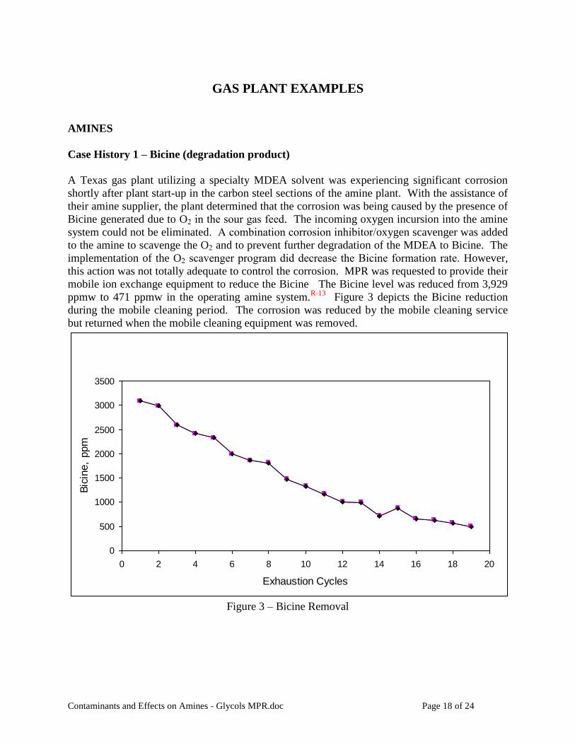
Case History 1 – Bicine (degradation product)
A Texas gas plant utilizing a specialty MDEA solvent was experiencing significant corrosion
shortly after plant start-up in the carbon steel sections of the amine plant. With the assistance of
their amine supplier, the plant determined that the corrosion was being caused by the presence of
Bicine generated due to O2 in the sour gas feed. The incoming oxygen incursion into the amine
system could not be eliminated. A combination corrosion inhibitor/oxygen scavenger was added
to the amine to scavenge the O2 and to prevent further degradation of the MDEA to Bicine. The
implementation of the O2 scavenger program did decrease the Bicine formation rate. However,
this action was not totally adequate to control the corrosion. MPR was requested to provide their
mobile ion exchange equipment to reduce the Bicine The Bicine level was reduced from 3,929
ppmw to 471 ppmw in the operating amine system.R-13
Figure 3 depicts the Bicine reduction
during the mobile cleaning period. The corrosion was reduced by the mobile cleaning service
but returned when the mobile cleaning equipment was removed.
0
500
1000
1500
2000
2500
3000
3500
0 2 4 6 8 10 12 14 16 18 20
Exhaustion Cycles
Bic
ine,
ppm
Figure 3 – Bicine Removal
Contaminants and Effects on Amines - Glycols MPR.doc Page 19 of 24
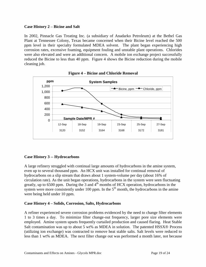
Case History 2 – Bicine and Salt
In 2002, Pinnacle Gas Treating Inc. (a subsidiary of Anadarko Petroleum) at the Bethel Gas
Plant at Tennessee Colony, Texas became concerned when their Bicine level reached the 500
ppm level in their specialty formulated MDEA solvent. The plant began experiencing high
corrosion rates, excessive foaming, equipment fouling and unstable plant operations. Chlorides
were also elevated and were an additional concern. A mobile ion exchange project successfully
reduced the Bicine to less than 40 ppm. Figure 4 shows the Bicine reduction during the mobile
cleaning job.
Figure 4 – Bicine and Chloride Removal
System Samples
0
200
400
600
800
1,000
1,200
12-Sep 18-Sep 19-Sep 23-Sep 25-Sep 27-Sep
3120 3152 3164 3168 3172 3181
Sample Date/MPR #
ppm
Bicine, ppm Chloride, ppm
Case History 3 -- Hydrocarbons
A large refinery struggled with continual large amounts of hydrocarbons in the amine system,
even up to several thousand ppm. An HCX unit was installed for continual removal of
hydrocarbons on a slip stream that draws about 1 system-volume per day (about 16% of
circulation rate). As the unit began operations, hydrocarbons in the system were seen fluctuating
greatly, up to 6500 ppm. During the 3 and 4th
months of HCX operation, hydrocarbons in the
system were more consistently under 100 ppm. In the 5th
month, the hydrocarbons in the amine
were being held under 10 ppm.
Case History 4 – Solids, Corrosion, Salts, Hydrocarbons
A refiner experienced severe corrosion problems evidenced by the need to change filter elements
1 to 3 times a day. To minimize filter change-out frequency, larger pore size elements were
employed. Amine system upsets frequently curtailed production and caused flaring. Heat Stable
Salt contamination was up to about 5 wt% as MDEA in solution. The patented HSSX Process
(utilizing ion exchange) was contracted to remove heat stable salts. Salt levels were reduced to
less than 1 wt% as MDEA. The next filter change out was performed a month later, not because

Contaminants and Effects on Amines - Glycols MPR.doc Page 20 of 24
of need, but to inspect the filters, which were found to be in good condition. Corrosion had also
been controlled by removing contaminants. Flaring incidents ceased for 6 months. Only after
heat stable salt levels increased again did operational problems recur and filter change out
frequency increase. Operational problems had been reduced by removing contaminants.
For several years this refinery repeated this cycle with regular periodic removal of HSS. As
production demands became more severe, hydrocarbon incursions into the amine system and
solids accumulations became more significant and frequent, resulting in operational difficulties
and production curtailments. Trials of the SSX™ and HCX™ processes were conducted,
producing clear proof of capacity and effectiveness of solids and hydrocarbon removal. A
continuous Amine Shield™ Slip Stream Unit (SSU) [an automated unit comprising the SSX,
HCX, and HSSX processes] was installed to continuously keep HSS, hydrocarbons and solids
concentrations low. Immediate benefits to the refinery production were evident. In the first year
of SSU operation, amine-related incidents at the wastewater treatment plant were reduced 98%
and increased sour crude purchases attributable to smoother amine system operations were
valued at $2.6 million. After 2.5 years of continuous SSU operation, the refinery ascribes the
following benefits to the use of the SSU:
Reduced operational upsets
Reduced amine losses
Reduced corrosion – even the rich amine is clear (low corrosion rate; minimal dissolved
iron in lean amine; erosion miniscule; any suspended FeS particles are much less than 1
micron in size)
Estimated annual bottom line return $3.5 million
Discussion – Hydrocarbons, Solids, Foaming in Gas Plants
Gas plants often experience operational problems with amine systems. Hydrocarbons and solids
are well-known contributors to the problems. A recent presentation at the GPA convention
detailed an example of what is all too typical. R-10
A Texas cryogenic natural gas liquids
recovery facility had experienced years of difficulties with their amine plants, resulting in high
amine losses and off spec product. An engineering study found that filtration of the amine was
inadequate as was downstream amine / product separation equipment. Operations were much
improved after specific application of high-technology mechanical separation and filtration
systems to address the contamination issues.
New tools are now available to address such gas plant problems – the onsite-regenerable SSX
and HCX processes. These new processes, previously described, offer increased removal of
solids and hydrocarbons over that now available by mechanical methods. The enhanced removal
results in much cleaner amine solutions without the need to replace mechanical filter elements.
The on-site regeneration is accomplished with the use of a combination of ambient temperature
water and hot water or steam condensate.
Contaminants and Effects on Amines - Glycols MPR.doc Page 21 of 24
GLYCOLS
Case History 5 – TEG
A gas plant utilizing salt dome storage periodically experienced carry over of sodium chloride
into its TEG system during periods of heavy gas demand. The sodium chloride level exceeded
its solubility level at some points in the system causing fouling of reboilers. A proprietary
process (the Glycolex Process utilizing ion exchange) was contracted to remove the chloride.
While the regenerators were off line, the glycol system was cleaned producing a product with
less than 20 ppm chloride without glycol loss. Salt removal continued until precipitated salt was
redissolved and the chloride level in the system was less than 200 ppm. Operational problems
were eliminated by removal of contaminants.
Case History 6 – MEG
A MEG system at a gas plant associated with a pipeline was plagued by operations and
maintenance problems because of the precipitation of iron carbonate in heat exchangers and
regenerators. Additionally, the extremely fine particulate iron carbonate defied filtration, and
added to the fouling in the heat exchangers and tower elements. Agglomerated particles formed
during regeneration collected on filters in the regeneration trains necessitating 6 or more filter
changes per day. The Glycolex process was utilized and dissolved iron and salts were
removed. Glycol from the rich and lean storage tanks was cleaned of dissolved iron,
agglomerated particulate iron, fine particulate iron, condensed hydrocarbon and sodium chloride.
From black, particulate-laden glycol containing over 6000 ppm sodium chloride, dissolved and
particulate iron ranging from hundreds to thousands of ppm, and condensed organics, a product
was produced that was clear, colorless glycol containing consistently less than 1 ppm iron, 20
ppm chloride, and 20 ppm sodium, with the pH maintained at the desired level. As the plant
circulated this cleaned glycol in their system, filter changes dropped to less than 1 per day and o
operational problems were greatly reduced.
Case History 7 – EG
An EG system at a gas plant associated with a pipeline contained over 4900 ppm sodium
chloride. The Glycolex Process was employed to reduce the sodium and the chloride. The
desired level of less than 350 ppm chloride and less than 300 ppm sodium was achieved by
processing a slipstream of glycol while the system continued to treat gas. Corrosion concerns
were eliminated by removal of contaminants.
Summary and Conclusions
The primary contaminants that cause trouble in amine and/or glycol systems are Heat Stable
Salts, Hydrocarbons, Solids, degradation products, and Hydrogen Sulfide (H2S). The
relationship of these contaminants to operational problems was discussed and several means of
reducing and maintaining low contaminant concentrations were presented.

Contaminants and Effects on Amines - Glycols MPR.doc Page 22 of 24
Tremendous benefits to the gas plant operator result from controlling amine and glycol system
contaminants at very low levels. Demonstrated benefits include reduced operational problems
and increased plant throughput. These benefits have been experienced by some operators by
employing a system for controlling contaminants that has the unique feature that all three
processes – salt, hydrocarbon and solids removal – are all regenerable on site with water-based
regenerants.

Contaminants and Effects on Amines - Glycols MPR.doc Page 23 of 24
References
R-1: Pauley, C. R., Hashemi, R., and Caothien, S., "Analysis of Foaming Mechanisms in Amine
Plants", paper presented at AIChE Summer Meeting, Denver, Colorado, August 22-24, 1988.
R-2: Cummings, A.L., Veatch, F.C., Keller, A.E., “Corrosion and Corrosion Control Methods in
Amine Systems Containing H2S”, Paper 97341, NACE International (1997).
R-3: Critchfield, J.E., and Jenkins, J.L., “Evidence of MDEA Degradation in Tail Gas Treating
Plants”, Petroleum Technology Quarterly, Spring 1999, pp 87-95.
R-4: Mecum, S.M., Veatch, F.C., and Cummings, A.L., “Why Caustic Addition is Bad for Amine
Systems”, Hydrocarbon Processing, October 1997, pp. 115-19.
R-5: Blanc, C., Grall, M., and Demarais, G., “The Part Played by Degradation Products in the
Corrosion and Gas Sweetening Plants using DEA and MDEA”, Laurance Reid Gas Conditioning
Conference, 1982.
R-6: Rooney, P.C., DuPart, M.S., and Bacon, T.R., “The Role of Oxygen in the Degradation of
MEA, DGA, DEA, and MDEA”, Laurance Reid Gas Conditioning Conference, 1998.
R-7: Smit, C.J., van Heeringen, G.J., and van Grinsven, P.F.A., “Degradation of Amine Solvents
and the Relation with Operational Problems”, Laurance Reid Gas Conditioning Conference, 2002.
R-8: Lawson, G.L., Cummings, A.L., and Mecum, S.M., “Amine Plant Corrosion Reduced by
Removal of Bicine”, Gas Processors Association, San Antonio, Texas, March 2003.
R-9: Rooney, P.C., Bacon, T.R., DuPart, M.S., "Effect of Heat Stable Salts on Solution
Corrosivity of MDEA-based Alkanolamine Plants. Part III", Proceedings of the Laurance Reid
Gas Conditioning Conference, March 1997.
R-10: Webb, T., Lopez, M., Miller, M., and McDowell, M., “Duke Entergy Field Services East
Texas Gas plant Optimizes Productivity Through Implementation of Enhanced Separation and
Filtration Technology”, Gas Processors Association Annual Convention, San Antonio, TX,
March 12, 2003.
R-11: van den Brand, Kees, “Shell‟s New Low Cost SCOT Process”, 2002 Sulfur Recovery
Symposium, Vail Colorado, September 2002.
R-12: Lawson, G., “UltraLean™ Amine Zero Residual Acid Gas Loading”, Gas Processors
Association 80th
Annual Convention, San Antonio, TX, March 2001.

Contaminants and Effects on Amines - Glycols MPR.doc Page 24 of 24
R-13: Howard, M. and Sargent, A., “Operating Experience at Duke Energy Field Services Wilcox
Plant with Oxygen Contamination and Amine Degradation”, Proceedings of the Laurance Reid
Gas Conditioning Conference, February 2001.
HSSX is a registered servicemark of MPR Services Inc. GLYCOLEX™, HCX™, SSX™ and
Amine Shield™ are trademarks of MPR Services Inc.