contamination control and rdd response overview
TRANSCRIPT
The INL is a U.S. Department of Energy National Laboratoryoperated by Battelle Energy Alliance
INL/MIS-19-52908-Revision-0
Contamination Controland RDD ResponseOverview
Bryce J Marsh, Christopher P Oertel,Benjamin W Walker
February 2019

INL/MIS-19-52908-Revision-0
Contamination Control and RDD Response Overview
Bryce J Marsh, Christopher P Oertel, Benjamin W Walker
February 2019
Idaho National LaboratoryIdaho Falls, Idaho 83415
http://www.inl.gov
Prepared for theU.S. Department of Energy
National Nuclear Security AdministrationUnder DOE Idaho Operations Office
Contract DE-AC07-05ID14517
Contamination Control & RDD Response
OverviewAdvanced Radiological Detection Training
WMD-Civil Support Team, 2019
Lesson Objectives
1. Explain the differences between radiation and contamination
2. Identify types and levels of contamination
3. Identify sources and indicators of contamination
4. Discuss methods to control contamination
5. Discuss DHS S&T response guidance post RDD
6. Discuss the 10 Point Survey method
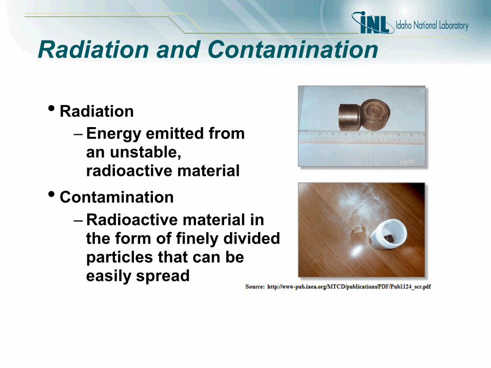
Radiation and Contamination
• Radiation
– Energy emitted froman unstable,radioactive material
• Contamination
– Radioactive material inthe form of finely dividedparticles that can beeasily spread
Contamination Types
• Fixed
– Cannot be easily removed
– May be released by buffing, grinding, chemical etching, etc.
• Removable
– Can be easily removed/transferred by casual contact, wiping, brushing, washing, air movement, etc.
• Airborne
– Contamination suspended in air

Contamination Control
• Understand the conditions through surveys
– Direct measurements
– Swipes or wipes
• Keep it off your skin/personal clothing
– Wear appropriate PPE
– Avoid contacting contaminated surfaces
• Avoid ingesting or inhaling it
– Don’t touch your face/head
– Respiratory protection

Contamination Control • Minimize cross-contamination
– Use laydown area (plastic or other material)
– Wrap equipment/tools prior to entry
– Frequent glove changes
– Avoid contact with uncontaminated equipment
• Monitor yourself and equipment prior to leaving area
– “Frisking”
• Decontaminate if necessary, or control contaminated items/materials
– Dry vs. wet

Contamination
• – Contamination is indicated if any increase in count rate is seen for Alpha contamination surveys.
• , – Contamination is indicated if count rate increases to 100 CPM above (or 2 X) background for Beta/Gamma contamination surveys.
DHS RDD Response Guidance: contamination safety boundary can be set at
levels that exceed 60,000 dpm/cm2 at ground level for and , or 6,000
dpm/cm2 for
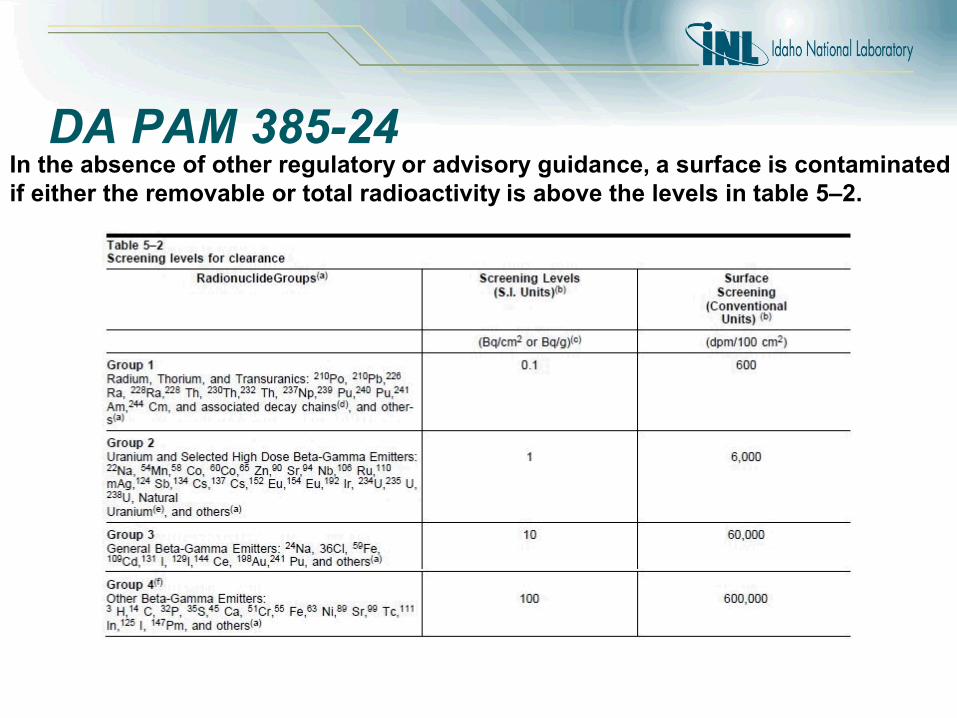
DA PAM 385-24In the absence of other regulatory or advisory guidance, a surface is contaminated if either the removable or total radioactivity is above the levels in table 5–2.
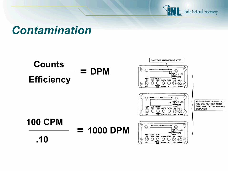
Contamination
Counts
Efficiency = DPM
100 CPM
.10= 1000 DPM
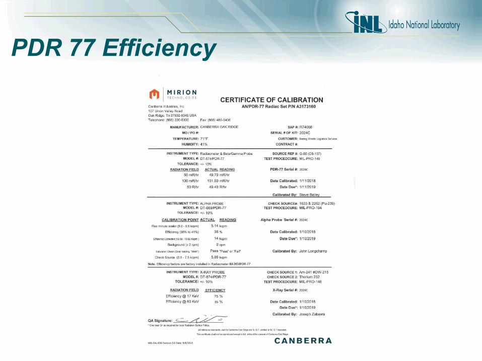
PDR 77 Efficiency
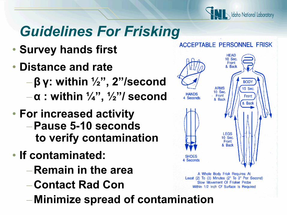
• Survey hands first
• Distance and rate
– β γ: within ½”, 2”/second
– α : within ¼”, ½”/ second
• For increased activity– Pause 5-10 seconds
to verify contamination
• If contaminated:
– Remain in the area
– Contact Rad Con
– Minimize spread of contamination
Guidelines For Frisking
Personnel Decontamination
• If contamination is present on an individualremoval is normally accomplished using mild soap and lukewarm water on the affected area
• If contamination can not be removed secure the affected area with a secure wrapping and transport the person to a medical treatment facility
Case Study: Personnel Contamination At 15:20 a researcher working in the RCL Lab B-7 detected contamination on their thumb and index finger of the left hand. The facility HPT was immediately notified and confirmed initial contamination levels of 6,000 dpm beta/gamma and 3,000 dpmalpha on the researcher’s left hand. The researcher was taken to the EBR-II decon facility where the hand was resurveyed showing contamination levels of 12,000 dpm beta/gamma and 8,000 dpmalpha. These contamination levels were significantly higher than the initial survey. After approximately 20 minutes of decon efforts the hand was resurveyed showing 6,000 dpm beta/gamma and 2,200 dpm alpha on the first crease of the middle finger. With Rad engineering support a glove was placed over the left hand to allow the hand to sweat to assist with releasing the contamination from the skin. The glove was removed approximately 15 minutes later and the hand was deconned and showed 1,000 dpmbeta/gamma and no detectable alpha. Another glove was placed on the hand to allow for the hand to continue to sweat to release the contamination. Decontamination efforts continued for several hours. The researcher’s hand was successfully decontaminated.
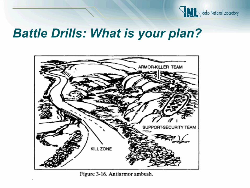
Battle Drills: What is your plan?
Boston Bombing

Radiological Dispersal Device Detonation is a Contamination Event
• Three teams will make entry into a contamination zone with specific tasks to conduct Phase I survey operations− DHS S&T ConOp
• Avoid contamination and follow all instructions from RadCon as per the RPP
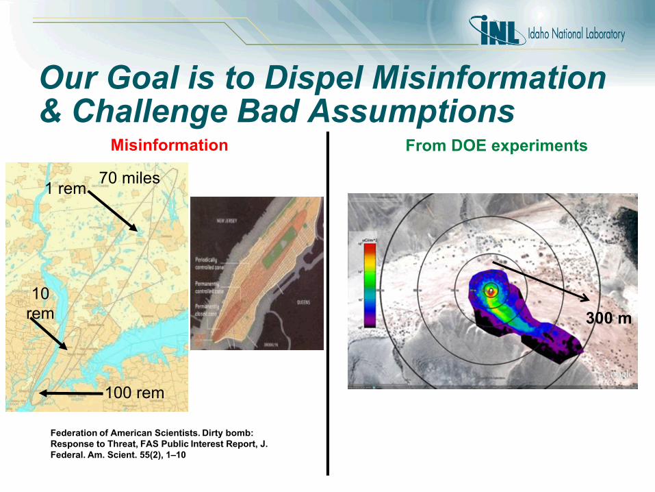
Federation of American Scientists. Dirty bomb: Response to Threat, FAS Public Interest Report, J. Federal. Am. Scient. 55(2), 1–10
Misinformation From DOE experiments
1 rem
10 rem
100 rem
70 miles
300 m
Our Goal is to Dispel Misinformation & Challenge Bad Assumptions
Factors that Affect Dispersion
“RDDs, or dirty bombs are devices that disperse radioactive materials. They can take many forms – from containers of
radioactive materials wrapped around with conventional explosives, to aerosolized materials sprayed using conventional equipment,
and to manual dispersion of fine powder..”
Final Presentation: Dhiren Barot
• Source Material, Form
• Energetic Material
• Device, “BBs or Smoke?” – Fireball interaction with surface, ground zero
hotspot vs down wind plume
• Environment, Micro Weather

Fireball Interaction Area
Large Particles (~ 100-500 µm)
Ballistic Fragments (> 1 cm)
Downwind Fallout (small particles)
BB’s versus smoke
Impact of particle/frag size on deposition
Particle/Frag Size, HE amount/location determine deposition pattern – size matters
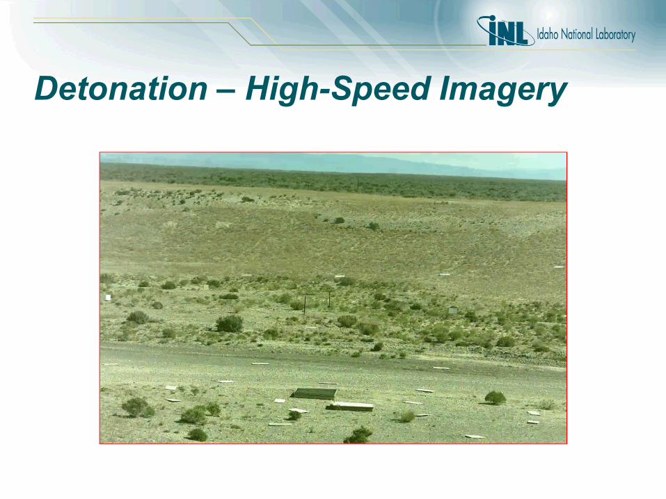
Detonation – High-Speed Imagery

Detonation – IR Imagery
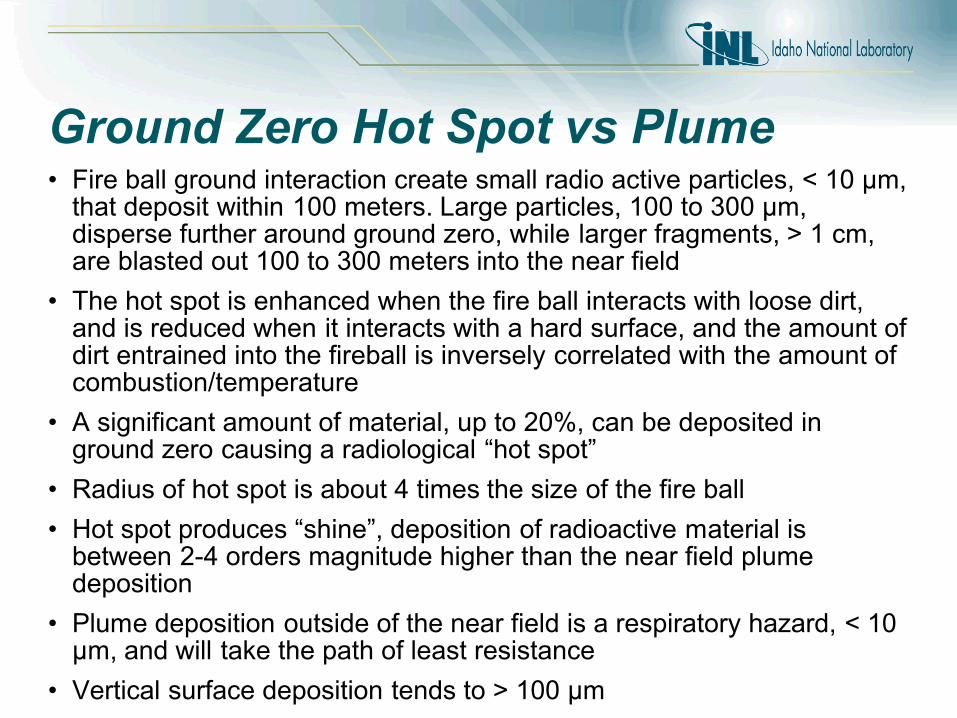
Ground Zero Hot Spot vs Plume• Fire ball ground interaction create small radio active particles, < 10 µm,
that deposit within 100 meters. Large particles, 100 to 300 µm, disperse further around ground zero, while larger fragments, > 1 cm, are blasted out 100 to 300 meters into the near field
• The hot spot is enhanced when the fire ball interacts with loose dirt, and is reduced when it interacts with a hard surface, and the amount of dirt entrained into the fireball is inversely correlated with the amount of combustion/temperature
• A significant amount of material, up to 20%, can be deposited in ground zero causing a radiological “hot spot”
• Radius of hot spot is about 4 times the size of the fire ball
• Hot spot produces “shine”, deposition of radioactive material is between 2-4 orders magnitude higher than the near field plume deposition
• Plume deposition outside of the near field is a respiratory hazard, < 10 µm, and will take the path of least resistance
• Vertical surface deposition tends to > 100 µm

After burn and Fireball Comparisons
Steel Plate on the ground Steel Plate, 1 meter highOn grass
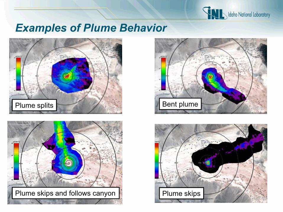
Bent plumePlume splits
Plume skipsPlume skips and follows canyon
Examples of Plume Behavior

DHS S&T: First 100 Minutes Post RDD Detonation
Initial LE SafetyPerimeter 250 m
1 Km
Wind Direction
500 m
1. Initial Response & On Scene Recognition: Safety Perimeter
2. Confirm Presence of Radiation: 2 readings from 2 locations
3. Report RDD Incident4. Characterization of
Detonation Site (strike team 1) establish hot side
5. Transect downwind & establish Centerline (strike team 2)
6. Establish Near Field (strike team 3) plume
7. If 1Km detection start 10 Point Survey (strike team 4/RAP)
Near Field
Survey Point 1
Survey Point 2
Detonation Site
Crime Scene:20 m around detonation site
Transect Survey:Confirm Plume
DHS S&T: First 100 Minutes Post RDD Detonation
Initial LE SafetyPerimeter 250 m
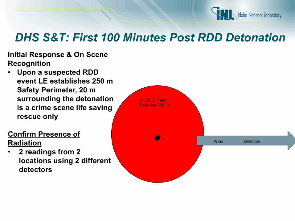
Initial Response & On Scene Recognition• Upon a suspected RDD
event LE establishes 250 m Safety Perimeter, 20 m surrounding the detonation is a crime scene life saving rescue only
Confirm Presence of Radiation • 2 readings from 2
locations using 2 different detectors
Wind Direction

DHS S&T: First 100 Minutes Post RDD Detonation
Initial LE SafetyPerimeter 250 m
Report Notification of RDD Incident (state EMA, FBI, DOE, Command)
• First 10 minutes
The initial notification should include the following: • Location of detonation• Initial radiation and
background readings • ID Direction of plume
(needed for HPAC and NARAC)
• Extent of damage & casualties
• Fires or other hazards on scene resulting from the explosion
Wind Direction
DHS S&T: First 100 Minutes Post RDD Detonation
Initial LE SafetyPerimeter 250 m
Wind Direction
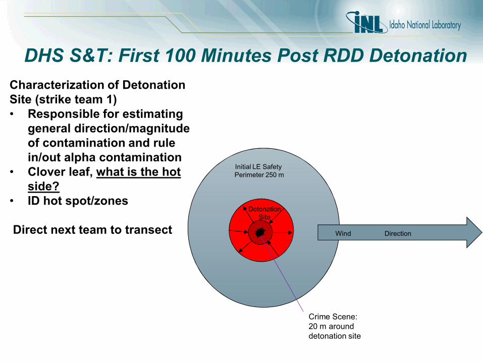
Characterization of Detonation Site (strike team 1) • Responsible for estimating
general direction/magnitude of contamination and rule in/out alpha contamination
• Clover leaf, what is the hot side?
• ID hot spot/zones
Direct next team to transect
Detonation Site
Crime Scene:20 m around detonation site
DHS S&T: First 100 Minutes Post RDD Detonation
Initial LE SafetyPerimeter 250 m
1 Km
Wind Direction
500 m
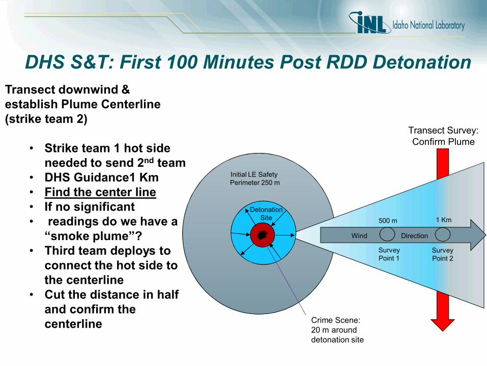
Transect downwind & establish Plume Centerline (strike team 2)
• Strike team 1 hot side needed to send 2nd team
• DHS Guidance1 Km • Find the center line• If no significant• readings do we have a
“smoke plume”? • Third team deploys to
connect the hot side to the centerline
• Cut the distance in half and confirm the centerline
Survey Point 1
Survey Point 2
Detonation Site
Crime Scene:20 m around detonation site
Transect Survey:Confirm Plume

DHS S&T: First 100 Minutes Post RDD Detonation
Initial LE SafetyPerimeter 250 m
1 Km
Wind Direction
500 m
Establish Near Field w/ Hot Zone boundaries at 10 mR/hr (strike team 3)
• Connect the hot side to the center line at the transect
• Map the plume by “mowing the grass”
Near Field
Survey Point 1
Survey Point 2
Detonation Site
Crime Scene:20 m around detonation site
Transect Survey:Confirm Plume
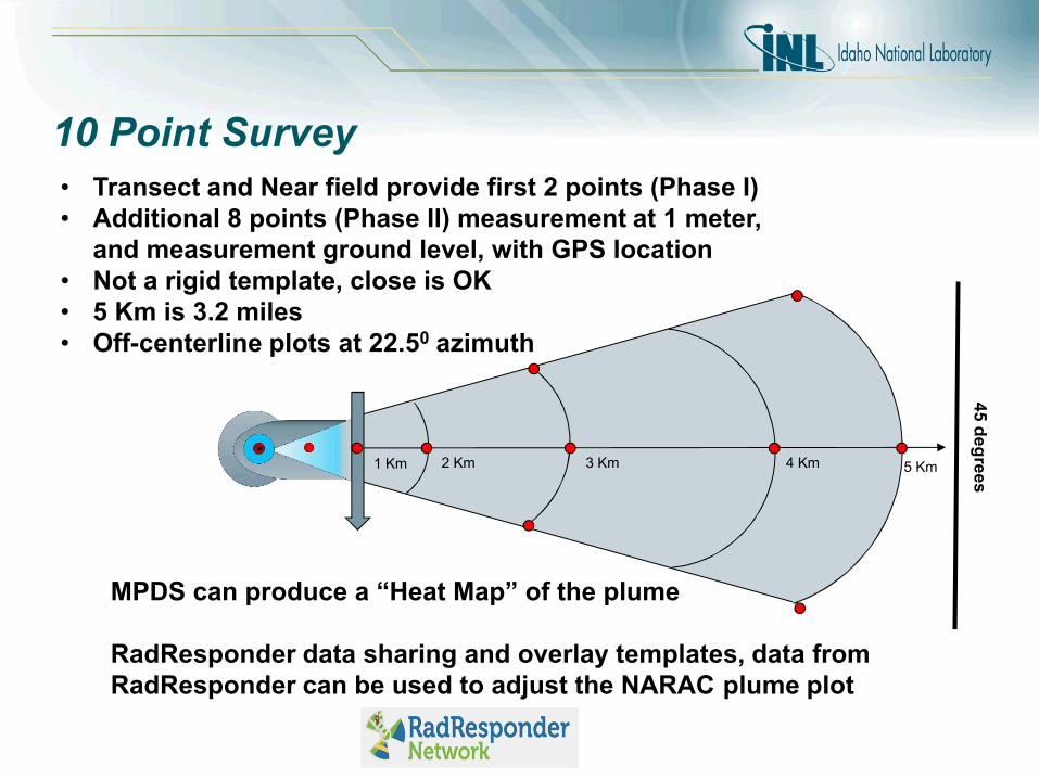
10 Point Survey
5 Km4 Km3 Km2 Km1 Km
• Transect and Near field provide first 2 points (Phase I)• Additional 8 points (Phase II) measurement at 1 meter,
and measurement ground level, with GPS location• Not a rigid template, close is OK• 5 Km is 3.2 miles• Off-centerline plots at 22.50 azimuth
45
de
gre
es
MPDS can produce a “Heat Map” of the plume
RadResponder data sharing and overlay templates, data from RadResponder can be used to adjust the NARAC plume plot
Questions?