contamination in amine systems - refining...
TRANSCRIPT
September 2010
1
Contamination in Amine SystemsLouis Beke, BSDT Seminars
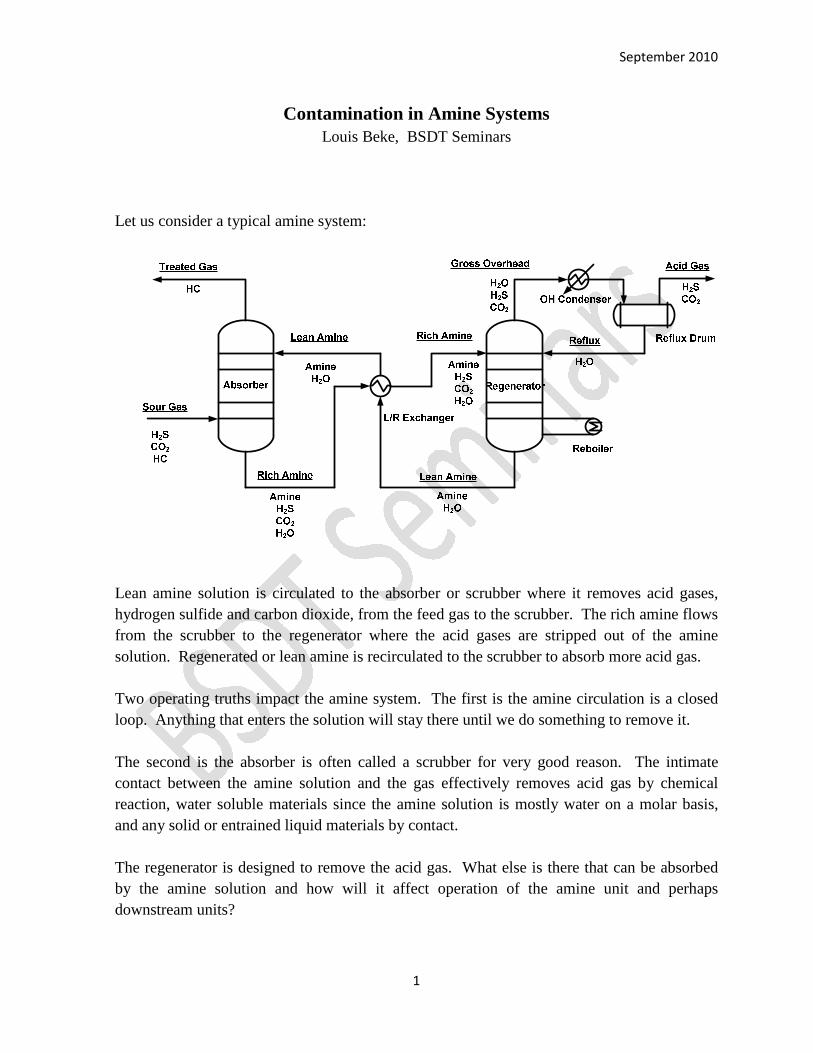
Let us consider a typical amine system:
Lean amine solution is circulated to the absorber or scrubber where it removes acid gases,
hydrogen sulfide and carbon dioxide, from the feed gas to the scrubber. The rich amine flows
from the scrubber to the regenerator where the acid gases are stripped out of the amine
solution. Regenerated or lean amine is recirculated to the scrubber to absorb more acid gas.
Two operating truths impact the amine system. The first is the amine circulation is a closed
loop. Anything that enters the solution will stay there until we do something to remove it.
The second is the absorber is often called a scrubber for very good reason. The intimate
contact between the amine solution and the gas effectively removes acid gas by chemical
reaction, water soluble materials since the amine solution is mostly water on a molar basis,
and any solid or entrained liquid materials by contact.
The regenerator is designed to remove the acid gas. What else is there that can be absorbed
by the amine solution and how will it affect operation of the amine unit and perhaps
downstream units?
Contamination in Amine Systems September 2010
2
IMPACT OF CONTAMINATION
Amine Degradation
Amine quality has a strong impact on the good operation of the amine unit. Amine that is
weak, dirty, or partially spent by heat stable salts (HSS) cannot do a good job of cleaning gas.
“Free” amine, amine not bound by HSS, is the active ingredient for acid gas pick up. Target
free amine strengths depend on the type of amine used. Heat stable salts (HSS) in amine
solution are those amine salts that do not break up at regenerator conditions. These salts tie
up amine molecules, which then cannot react with acid gas, and can lead to fouling and
corrosion.
Acidic anions can come from the gases being treated (HCl, HCN, SO2, formic acid, and the
like), from oxygen in un-blanketed tanks or from vacuum columns, and can be formed in the
amine solution. For example, formic acid can form from CO and the OH- in the alkaline
amine solution and several organic acids (including formic acid) are products the hydrolysis
of nitriles formed in cat crackers. Though they are not strictly speaking salts, polymeric and
other organic amine degradation products are often included in the HSS category.
Foaming
Amine solution becomes frothy when vigorously agitated as on a tray in a gas absorber or
regenerator. Fortunately, this froth quickly subsides in good quality amine solution and the
column functions normally. However, this froth can be stabilized by altering the surface
properties of the amine solution or more commonly by the presence of a third phase in the
column. The third phase can be solids such as iron sulfide or it can be a second liquid phase
such as hydrocarbon. The third phase occurs at the gas-liquid interface. The froth does not
break in the tray downcomer as it does in normal operation and a situation analogous to jet
flooding occurs. Pressure drop
increases across the column, operation
becomes unstable, and capacity is
reduced.
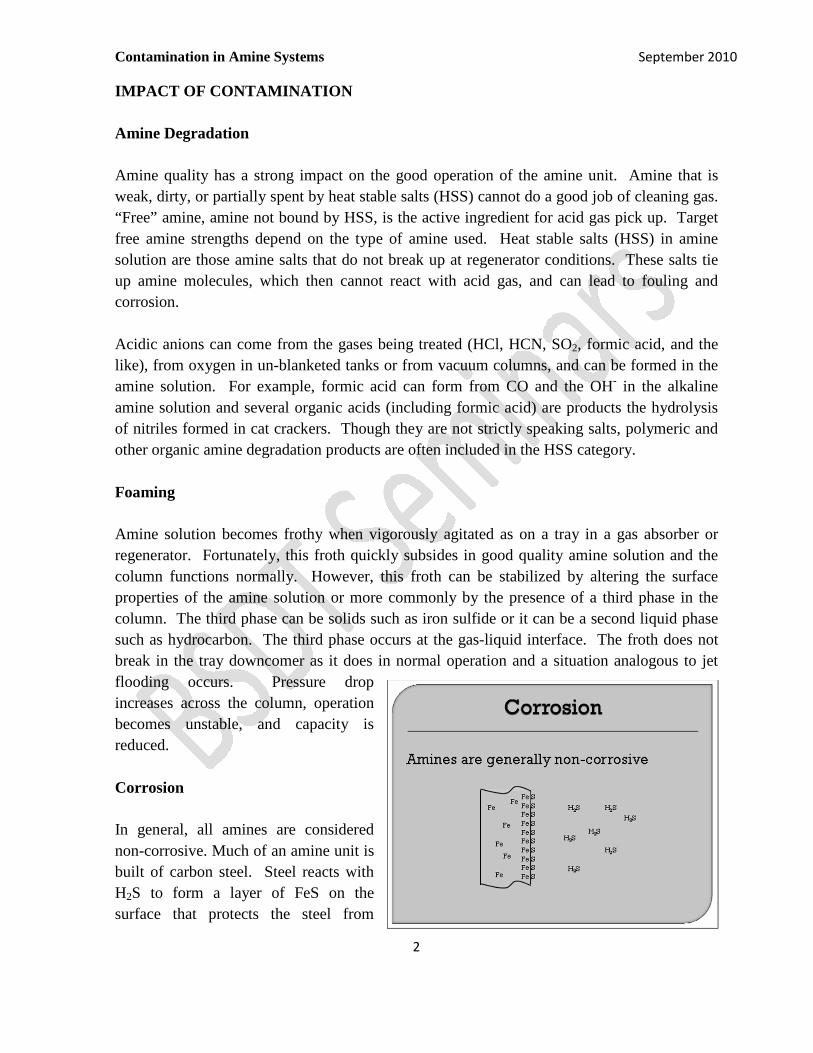
Corrosion
In general, all amines are considered
non-corrosive. Much of an amine unit is
built of carbon steel. Steel reacts with
H2S to form a layer of FeS on the
surface that protects the steel from
Contamination in Amine Systems September 2010
3
further attack. As long as the layer of FeS is intact, the overall corrosion rate is quite low.
The iron sulfide layer is soft and friable; it can be worn away by high flow velocity or
turbulence. High HSS content increases the viscosity and density of the amine solution. At
the same time if higher amine solution circulation rates are required to circulate enough free
amine to pick up the acid gas, solution velocities go up. This combination can result in
erosion of the protective iron sulfide layer exposing bare steel to further sulfidic attack and
higher rates of corrosion.
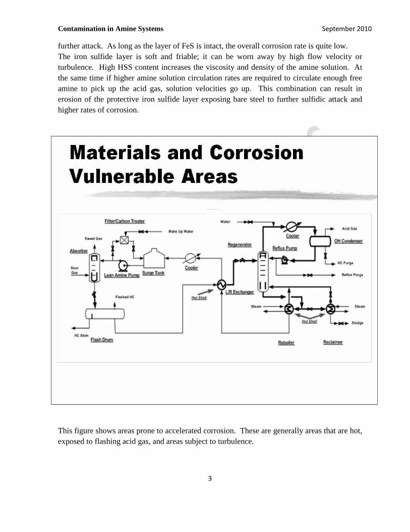
This figure shows areas prone to accelerated corrosion. These are generally areas that are hot,
exposed to flashing acid gas, and areas subject to turbulence.
Contamination in Amine Systems September 2010
4
Other contaminants that could accelerate corrosion include:
o Excessive ammonium bisulfide or cyanide in the regenerator overhead; both
compounds can penetrate the iron sulfide protective layer and attack steel.
o High levels of chloride ions in the amine solution can attack the stainless steel alloys
used in corrosion prone areas of the amine unit.
o Excessive acid gas loading, above 0.5-0.6 m/m in the rich amine; not really a
contaminant since the objective of the amine unit is to pickup acid gas. However,
loadings above about 0.5 moles of acid gas per mole of amine forms the amine-
bisulfide salt. The bisulfide ion can penetrate the iron sulfide protective layer and
cause accelerated corrosion of carbon steel.
o Oxygen and wet steel rapidly can result in scale or rust formation. This is most likely
to happen during startup or turnaround. The oxidized iron in the pipe scale is
immediately converted to iron sulfide. This iron sulfide is not bonded to the pipe wall
so does not form part of the protective iron sulfide layer. The iron sulfide formed in
this manner is free to circulate in the amine solution.
o Solids in the solution, primarily iron sulfide, can be abrasive to the iron sulfide
protective layer, exposing new steel surface to sulfidic attack.
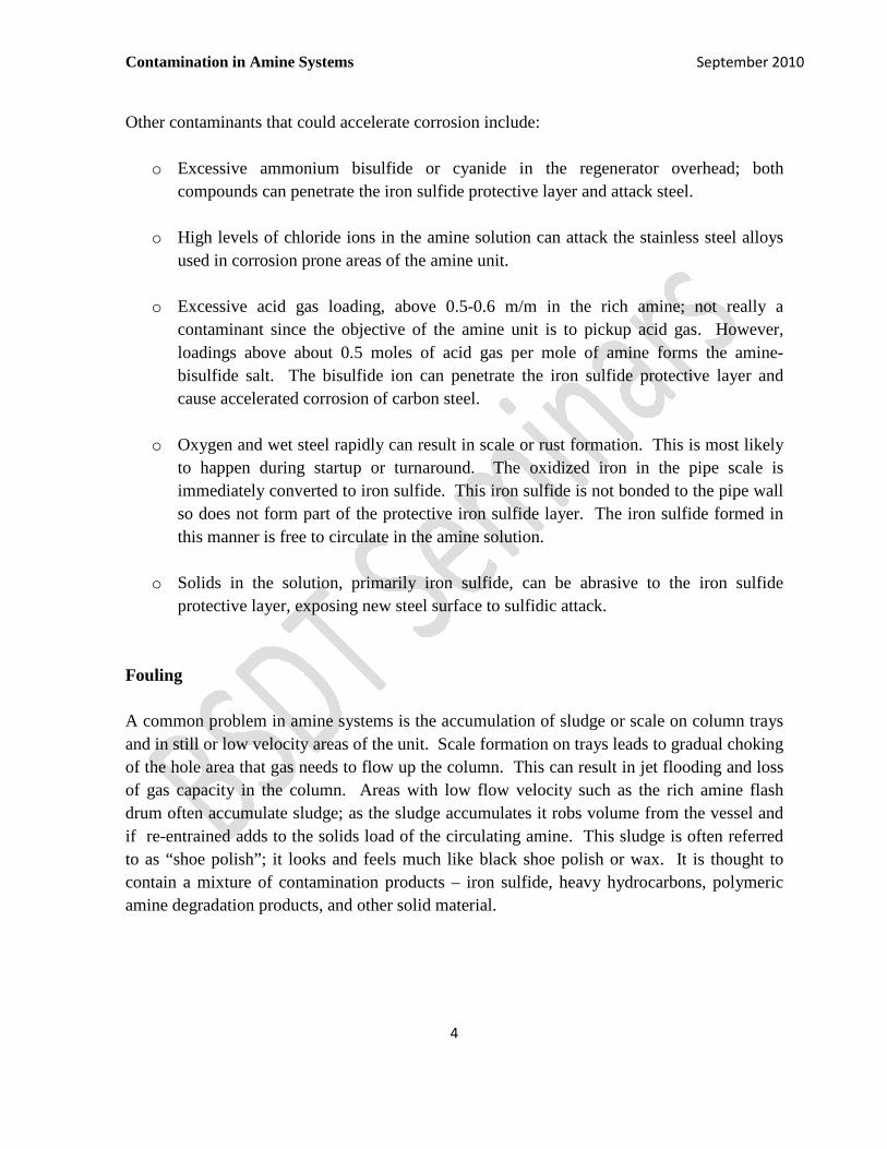
Fouling
A common problem in amine systems is the accumulation of sludge or scale on column trays
and in still or low velocity areas of the unit. Scale formation on trays leads to gradual choking
of the hole area that gas needs to flow up the column. This can result in jet flooding and loss
of gas capacity in the column. Areas with low flow velocity such as the rich amine flash
drum often accumulate sludge; as the sludge accumulates it robs volume from the vessel and
if re-entrained adds to the solids load of the circulating amine. This sludge is often referred
to as “shoe polish”; it looks and feels much like black shoe polish or wax. It is thought to
contain a mixture of contamination products – iron sulfide, heavy hydrocarbons, polymeric
amine degradation products, and other solid material.
Contamination in Amine Systems September 2010
5
SRU Problems
Some of the contaminants that enter the amines system get removed in the regenerator and
then get sent to the sulfur recovery unit. Of primary concern to the SRU is ammonia and
hydrocarbons in the acid gas feed. The sulfur plant uses oxygen from air that is pumped into
the unit to convert H2S to elemental sulfur. Overall reaction is:
H2S + ½ O2 → S + H2O
The amount of oxygen, generally provided by atmospheric air pumped into the sulfur unit by
an air blower, added to the sulfur plant is the essential control variable for efficient sulfur
plant operation. On a volume basis, both NH3 and hydrocarbon consume more oxygen in the
sulfur unit than required for the conversion of H2S to sulfur.
NH3 + ¾ O2 → N2 + H2O
C2H6 + 3 ½ O2 → 2 CO2 + 3 H2O
Typically, the first limit in sulfur plant capacity is volume and pressure the air blower can
deliver. So both ammonia and hydrocarbon rob the sulfur plant of capacity.
In refineries, ammonia is often intentionally disposed of in the sulfur unit. Even though sulfur
capacity is given up, the sulfur plant can be designed and operated to effectively destroy
ammonia, a noxious and toxic gas. A necessary condition for this operation is introducing the
ammonia properly to the sulfur plant so it can be destroyed. If ammonia enters the sulfur
plant in the acid gas feed it may not be destroyed and can lead to deposition of ammonium
salts in cooler parts of the sulfur plant with resulting plugging, pressure drop and localized
corrosion issues.
Hydrocarbon in the acid gas feed is not controlled by the sulfur plant operators. And a bigger
problem is the amount of hydrocarbons in the feed will change with time. This presents a
control problem at the sulfur plant.
Another problem caused by hydrocarbons in the sulfur plant feed is the potential to form soot
in the main burner flame. Any soot formed will eventually be collected on the catalyst bed.
The soot can physically block the active sites of the catalyst reducing bed activity. If enough
soot accumulates, the pressure drop across the bed increases and affects the unit capacity.
Contamination in Amine Systems September 2010
6
Environmental Violation
Should the level of contamination rise to a point where they interfere with good operation of
the amine unit, direct violation environment permit may occur. For example, high sulfur in
fuel gas system in the refinery. Poor treating in a gas plant can result in the sales gas failing
to meet pipeline specification.
Poor control of air in the sulfur plant caused by contaminants in the acid gas feed can lead to
poor sulfur recovery in the sulfur plant and resulting high SOX emissions from the tail gas
thermal oxidizer. Classic upset in a sulfur unit results from a slug of hydrocarbon in the acid
gas. The hydrocarbons consume the oxygen at the main burner resulting in a high H2S to SO2
ratio in the SRU tail gas. The tail gas analyzer calls for more air to the burner to correct the
off-ratio operation. The hydrocarbon slug passes through the sulfur unit; the air rate remains
high driving the SRU tail gas to high SO2. During this swinging air supply scenario, the
sulfur unit is operating inefficiently and so leaving excessive unrecovered sulfur compounds
in the tail gas. There is a strong possibility for high SOX emissions in the stack during such
an episode.
In a worst case scenario, there is a selective amine based tail gas treating unit removing sulfur
from the SRU tail gas. During the air control upset high concentrations of SO2 can be sent to
the tail gas treating unit. If the SO2 reaches the tail gas treating unit amine system it will react
with the amine to from heat stable salts.
SOURCES OF CONTAMINATION
Feed Gas
Most contaminants probably enter the amine system in the feed gas. Ammonia is a gas that is
readily absorbed by the aqueous part of the amine solution. Ammonia can cause corrosion in
the amine unit and operability problems in the SRU. Organic acids like formic acid and
mineral acids like HCl that can contribute to heat stable salt formation are found as volatile
materials in the refinery. Amine is an organic chemical so there is some natural affinity for
hydrocarbon gas to dissolve in the amine solution. This is a physical phenomenon favored by
the higher molecular weight amines such as MDEA or DGA, higher concentration amine
solutions, and at higher pressures such as in gas plants or in high severity hydrogen
processing units in the refinery. Oxygen can contribute to amine degradation and to
corrosion.

Contamination in Amine Systems September 2010
7
Hydrocarbon
Hydrocarbons can enter the amine system in the liquid phase. Feed gas to a scrubber is
almost always a hydrocarbon gas from a single-stage flash operation separating vapor and
liquid. In a perfect separation, the vapor is at its dew point. A poorly designed or overloaded
separator will allow some liquid to flow out in the gas phase as a mist of liquid droplets. Any
cooling of the gas stream will likewise result in condensation of the heavier components in the
gas stream. The intimate gas-liquid contact in the scrubber will remove any liquid droplets
from the gas stream.
A special case is liquefied Petroleum Gas treating. LPG can be physically absorbed by the
amine solution. It can also be carried under from the LPG contactor in the rich amine stream
exiting the treater.
Make Up Water
Fresh amine is usually delivered to the plant as 100 % or 85 % amine and must be diluted to
target solution strength. Virtually all amine systems lose water from the amine solution
during normal operation. The amine solution loses water as water vapor in treated gas at the
absorber and some water is continually lost to the sulfur recovery unit in the acid gas from the
regenerator. Water is frequently purged from the regenerator overhead to control ammonia in
the reflux system.
Therefore, water is added to the amine system routinely. Contaminants in the water will
accumulate in the amine solution. Steam condensate is the water of choice. Boiler feed water
may contain sulfite oxygen scavengers, phosphate corrosion inhibitors, and filming amines.
City water may contain considerable calcium hardness, sodium, some chlorine, and may be
high in chlorides. The key is to know what is being added to your amine, and how to remedy
to contamination.
Oxygen
The most obvious source of oxygen contamination is an amine surge tank breathing freely to
atmosphere. Less obvious sources involve the feed gas. Leaks in compressor suction piping
can occur in natural gas collection networks. In refineries, vapor recovery systems and flare
gas recovery systems are common sources of oxygen in the gas feed to a fuel gas scrubber.
Contamination in Amine Systems September 2010
8
Startup/Turnaround
Pipe scale readily forms on steel exposed to air, especially in the presence of moisture. This
is a common occurrence at unit startup and during maintenance turnarounds. Any pipe scale
or rust in the unit when H2S is introduced gets immediately converted to iron sulfide. And
this iron sulfide is not bonded to the pipe and equipment walls so it is carried away by the
circulating solution.
REMEDIES FOR CONTAMINATION
Particulate Filtration
Corrosion in the amine system produces fine iron sulfide particles. Solids can also enter with
the treated gas. Excessive solids (> 200 - 400 ppm wt) can cause foaming. Solids also tend to
scour off the protective iron sulfide scale in piping and promote corrosion. Removing these
solids by filtration is essential to reliable operation of the amine unit. Filtration is typically
done on the lean amine to minimize odor and potential safety problems when opening the
filter vessel. Filtering the rich stream is done, and may be marginally more efficient. A
variety of filtration systems are in use.
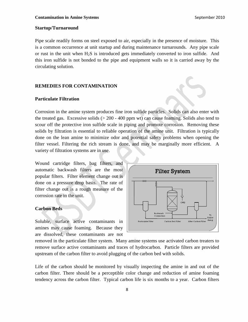
Wound cartridge filters, bag filters, and
automatic backwash filters are the most
popular filters. Filter element change out is
done on a pressure drop basis. The rate of
filter change out is a rough measure of the
corrosion rate in the unit.
Carbon Beds
Soluble, surface active contaminants in
amines may cause foaming. Because they
are dissolved, these contaminants are not
removed in the particulate filter system. Many amine systems use activated carbon treaters to
remove surface active contaminants and traces of hydrocarbon. Particle filters are provided
upstream of the carbon filter to avoid plugging of the carbon bed with solids.
Life of the carbon should be monitored by visually inspecting the amine in and out of the
carbon filter. There should be a perceptible color change and reduction of amine foaming
tendency across the carbon filter. Typical carbon life is six months to a year. Carbon filters
Contamination in Amine Systems September 2010
9
are generally not effective in controlling hydrocarbon content of the amine solution. The
carbon will only hold about 30% of its weight in contaminants. The principal reason for using
carbon filtration is to remove dissolved surface active materials that would cause foaming.
Hydrocarbon Skimming
Rich Amine Flash Drum
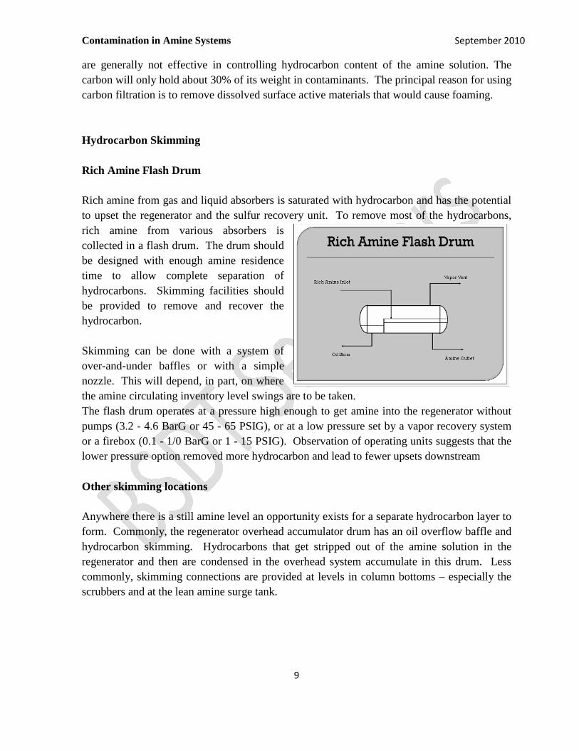
Rich amine from gas and liquid absorbers is saturated with hydrocarbon and has the potential
to upset the regenerator and the sulfur recovery unit. To remove most of the hydrocarbons,
rich amine from various absorbers is
collected in a flash drum. The drum should
be designed with enough amine residence
time to allow complete separation of
hydrocarbons. Skimming facilities should
be provided to remove and recover the
hydrocarbon.
Skimming can be done with a system of
over-and-under baffles or with a simple
nozzle. This will depend, in part, on where
the amine circulating inventory level swings are to be taken.
The flash drum operates at a pressure high enough to get amine into the regenerator without
pumps (3.2 - 4.6 BarG or 45 - 65 PSIG), or at a low pressure set by a vapor recovery system
or a firebox (0.1 - 1/0 BarG or 1 - 15 PSIG). Observation of operating units suggests that the
lower pressure option removed more hydrocarbon and lead to fewer upsets downstream
Other skimming locations
Anywhere there is a still amine level an opportunity exists for a separate hydrocarbon layer to
form. Commonly, the regenerator overhead accumulator drum has an oil overflow baffle and
hydrocarbon skimming. Hydrocarbons that get stripped out of the amine solution in the
regenerator and then are condensed in the overhead system accumulate in this drum. Less
commonly, skimming connections are provided at levels in column bottoms – especially the
scrubbers and at the lean amine surge tank.
Contamination in Amine Systems September 2010
10
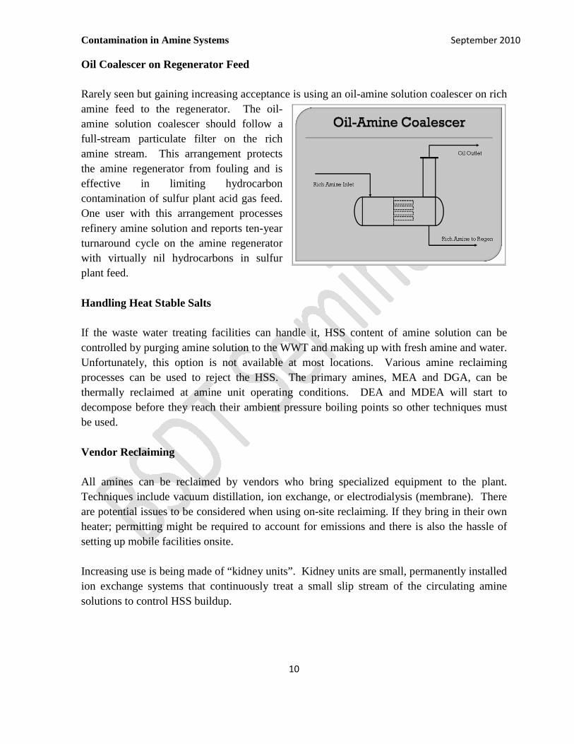
Oil Coalescer on Regenerator Feed
Rarely seen but gaining increasing acceptance is using an oil-amine solution coalescer on rich
amine feed to the regenerator. The oil-
amine solution coalescer should follow a
full-stream particulate filter on the rich
amine stream. This arrangement protects
the amine regenerator from fouling and is
effective in limiting hydrocarbon
contamination of sulfur plant acid gas feed.
One user with this arrangement processes
refinery amine solution and reports ten-year
turnaround cycle on the amine regenerator
with virtually nil hydrocarbons in sulfur
plant feed.
Handling Heat Stable Salts
If the waste water treating facilities can handle it, HSS content of amine solution can be
controlled by purging amine solution to the WWT and making up with fresh amine and water.
Unfortunately, this option is not available at most locations. Various amine reclaiming
processes can be used to reject the HSS. The primary amines, MEA and DGA, can be
thermally reclaimed at amine unit operating conditions. DEA and MDEA will start to
decompose before they reach their ambient pressure boiling points so other techniques must
be used.
Vendor Reclaiming
All amines can be reclaimed by vendors who bring specialized equipment to the plant.
Techniques include vacuum distillation, ion exchange, or electrodialysis (membrane). There
are potential issues to be considered when using on-site reclaiming. If they bring in their own
heater; permitting might be required to account for emissions and there is also the hassle of
setting up mobile facilities onsite.
Increasing use is being made of “kidney units”. Kidney units are small, permanently installed
ion exchange systems that continuously treat a small slip stream of the circulating amine
solutions to control HSS buildup.
Contamination in Amine Systems September 2010
11
Amine Regenerator Reflux Purge
Volatile contaminants, in particular ammonia, will accumulate in the regenerator overhead
reflux system. A controlled purge of this stream can control the concentration of ammonia to
limit the corrosion potential of ammonium bisulfide. The purge can also be used to limit the
ammonia content of the acid gas feed to the sulfur unit.
PREVENTION OF AMINE SYSTEM CONTAMINATION
A better approach to limiting the operating problems of contamination in amine systems is to
prevent the contaminants from getting in the amine solution. Gas streams fed to gas absorbers
typically come from a column or exchanger saturated with water and hydrocarbon liquids.
Any cooling of these streams will cause these materials to condense. If they are not removed,
they will cause foaming or contamination of the amine in the absorber. For these gas streams,
commonly used equipment includes knockout drums, filter-separators or a water wash drum
or column.
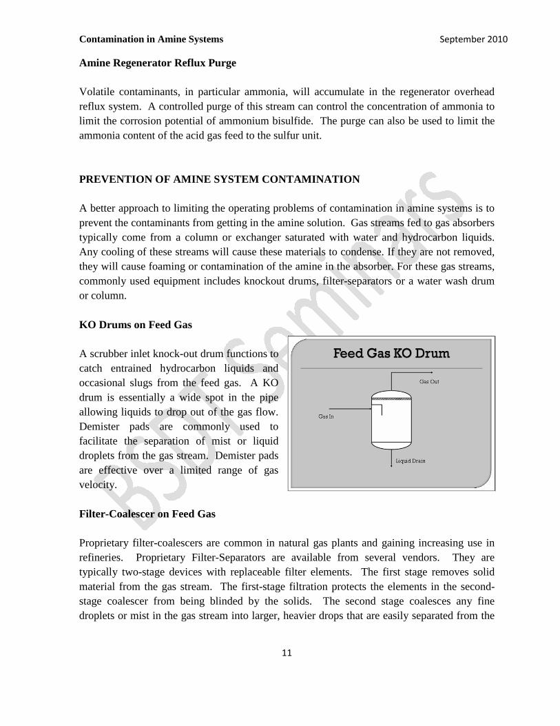
KO Drums on Feed Gas
A scrubber inlet knock-out drum functions to
catch entrained hydrocarbon liquids and
occasional slugs from the feed gas. A KO
drum is essentially a wide spot in the pipe
allowing liquids to drop out of the gas flow.
Demister pads are commonly used to
facilitate the separation of mist or liquid
droplets from the gas stream. Demister pads
are effective over a limited range of gas
velocity.
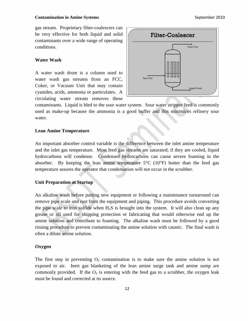
Filter-Coalescer on Feed Gas
Proprietary filter-coalescers are common in natural gas plants and gaining increasing use in
refineries. Proprietary Filter-Separators are available from several vendors. They are
typically two-stage devices with replaceable filter elements. The first stage removes solid
material from the gas stream. The first-stage filtration protects the elements in the second-
stage coalescer from being blinded by the solids. The second stage coalesces any fine
droplets or mist in the gas stream into larger, heavier drops that are easily separated from the
Contamination in Amine Systems September 2010
12
gas stream. Proprietary filter-coalescers can
be very effective for both liquid and solid
contaminants over a wide range of operating
conditions.
Water Wash
A water wash drum is a column used to
water wash gas streams from an FCC,
Coker, or Vacuum Unit that may contain
cyanides, acids, ammonia or particulates. A
circulating water stream removes these
contaminants. Liquid is bled to the sour water system. Sour water stripper feed is commonly
used as make-up because the ammonia is a good buffer and this minimizes refinery sour
water.
Lean Amine Temperature
An important absorber control variable is the difference between the inlet amine temperature
and the inlet gas temperature. Most feed gas streams are saturated; if they are cooled, liquid
hydrocarbons will condense. Condensed hydrocarbons can cause severe foaming in the
absorber. By keeping the lean amine temperature 5°C (10°F) hotter than the feed gas
temperature assures the operator that condensation will not occur in the scrubber.
Unit Preparation at Startup
An alkaline wash before putting new equipment or following a maintenance turnaround can
remove pipe scale and rust from the equipment and piping. This procedure avoids converting
the pipe scale to iron sulfide when H2S is brought into the system. It will also clean up any
grease or oil used for shipping protection or fabricating that would otherwise end up the
amine solution and contribute to foaming. The alkaline wash must be followed by a good
rinsing procedure to prevent contaminating the amine solution with caustic. The final wash is
often a dilute amine solution.
Oxygen
The first step in preventing O2 contamination is to make sure the amine solution is not
exposed to air. Inert gas blanketing of the lean amine surge tank and amine sump are
commonly provided. If the O2 is entering with the feed gas to a scrubber, the oxygen leak
must be found and corrected at its source.
Contamination in Amine Systems September 2010
13
Iron Sulfide
There is not much that can be done to prevent the formation of iron sulfide in a system that
contains H2S. Good design practice includes low amine solution velocity especially in the
rich amine piping to prevent eroding the sulfide layer. Alloys such as stainless steel are used
in those areas prone to accelerated corrosion.
CONCLUSION
Contamination costs are more difficult to quantify than energy costs or amine loss costs.
However, if the contaminant level is allowed to get high enough to cause operating problems,
the cost can be surprisingly high.
A principal contaminant of concern is the amine heat stable salts (HSS) formed when strong
acids or oxygen react with the amine solution to make amine salts that will not regenerate
with the limited heat available in the regenerator. HSS reduce the capacity and reliability of
the amine unit. Addressing high HSS often involves bringing in a vendor to reclaim the
amine solution incurring more costs.
A second major contaminant is suspended iron sulfide solids in the solution. These solids
contribute to foaming, plugging and fouling of equipment. In addition, it becomes necessary
to change out filters more frequently. Other solids, like carbon fines, have the same bad effect
on the operation of the amine unit.
Hydrocarbons are a common contaminant in an amine system. They can affect the amine unit
directly by causing foaming. Excess hydrocarbons generally end up in the acid gas feed to the
sulfur plant contributing to operability problems for the sulfur recovery unit. Control is by
flashing at the rich amine flash drum and skimming at the flash drum and other locations such
as the regenerator overhead accumulator. A filter-coalescer arrangement on rich amine feed
to the amine regenerator is an effective control for hydrocarbon contamination.
Preventing contaminants from entering the amine system is a good strategy to mitigate the
operating problems posed by contaminants.
Knock out drums on scrubber feed gas provide some protection to the amine solution from
hydrocarbon carryover. Filter-coalescers on the feed gas are much more effective in
removing solids and liquid mist from the incoming gas.

Contamination in Amine Systems September 2010
14
Water wash on suspect feed gas streams has been used effectively to prevent accumulation of
water soluble contaminants such as organic acids and ammonia.
Maintaining lean amine temperature hotter than the feed gas to a scrubber prevents
hydrocarbon condensation in the scrubber.
Insuring makeup water is contaminant free prevents accumulation of those contaminants.
While industry has learned how to mitigate the effects of contamination on amine system
operation, preventing the accumulation of contaminants in the amine system may be a better
approach to good amine system operation.
This table shows a matrix of contaminants, impacts, remedies and prevention of
contamination of amine systems:
Contaminant Source Impact Remedy Prevention
Heat Stable Salts Acidic compounds
Oxygen
Feed gas
Binds amine
Increases density
and viscosity
Corrosion
Purge and
Makeup
Reclaiming
Water wash feed
gas
Inert gas blanket
surge tank
Iron Sulfide H2S
Corrosion
Foaming
Fouling
Erosion/corrosion
Filtration Limit amine
velocity
S/U Procedures
Other solids Feed gas
Pipe scale
Carbon bed
Foaming
Fouling
Erosion/corrosion
Filtration Filter-coalescer
on feed gas
Hydrocarbons Feed gas
Condensation
LPG Treating
Foaming
Fouling
SRU operability
SRU capacity
SRU Pressure drop
HC skimming
Filter-coalescer
on regenerator
feed
Filter-coalescer
on feed gas
Maintain lean
amine
temperature
Oxygen Unblanketed tank
Feed gas
HSS
Corrosion
Inert gas blanket
tank
Locate and repair
feed source O2
leak
Ammonia Feed gas Corrosion
SRU operability
SRU capacity
Regenerator
reflux purge
Water wash feed
gas