contatto magnetico via radio wireless magnetic … · contatto magnetico da interno via radio per...
TRANSCRIPT

IT CONTATTO MAGNETICO VIA RADIOManuale di installazione, uso e manutenzione
EN WIRELESS MAGNETIC CONTACT
Installation, programming and operating manual.
MADE IN ITALY
La dichiarazione CE del presente articolo è reperibile sul sito www.lince.net.
The CE declaration of this item is available on www.lince.net website.
CONTATTO MAGNETICO VIA RADIO
WIRELESS MAGNETICCONTACT
ART.: 9507-GOLD-TP
9508-GOLD-TP/M

2
LINCE ITALIA S.p.A.
- Istruzioni originali -
INDICE
1. INTRODUZIONE ................................................................................................. 31.1 CARATTERISTICHE TECNICHE ............................................................ 31.2 CONTENUTO DELLA CONFEZIONE ..................................................... 31.3 IDENTIFICAZIONE DELLE PARTI .......................................................... 4
2. MEMORIZZAZIONE ........................................................................................... 52.1 FUNZIONE SLEEP .................................................................................. 52.2 FUNZIONE DES - DETECTION EVENT STORED ................................. 6
3. VERIFICA PORTATA ......................................................................................... 64. INSTALLAZIONE ............................................................................................... 6
4.1 INSTALLAZIONE CON BI-ADESIVO ..................................................... 64.2 INSTALLAZIONE CON TASSELLI .......................................................... 74.3 UTILIZZO INGRESSO AUSILIARIO ....................................................... 7
5. IMPOSTAZIONI .................................................................................................. 76. MANUTENZIONE E VERIFICHE PERIODICHE ................................................ 87. SMALTIMENTO E ROTTAMAZIONE ................................................................. 8
- Translation of the original instructions (original instructions in Italian) -
Le informazioni riportate in questo manuale sono state compilate con cura, tuttavia LINCE ITALIA S.p.A. non può essere ritenuta responsabile per eventuali errori e/o omissioni. LINCE ITALIA S.p.A. si riserva il diritto di apportare in ogni momento e senza preavviso, miglioramenti e/o modifiche ai prodotti descritti nel presente manuale. Consultare il sito www.lince.net per le condizioni di assistenza e garanzia. LINCE ITALIA S.p.A. pone particolare attenzione al rispetto dell’ambiente. Tutti i prodotti ed i processi produttivi sono progettati con criteri di eco-compatibilità. Il presente articolo è stato prodotto in Italia.
The information in this manual has been issued with care, but LINCE ITALIA S.p.A. will not be responsible for any errors or omissions. LINCE ITALIA S.p.A. reserves the right to improve or modify the products described in this manual at any time and without advance notice. Terms and conditions regarding assistance and the product warranty can be found at LINCE ITALIA’s website www.lince.net. LINCE ITALIA S.p.A. makes it a priority to respect the environment. All products and production processes are designed to be eco-friendly and sustainable.
1. DESCRIPTION ................................................................................................... 31.1 TECHNICAL FEATURES ........................................................................ 31.2 PACKAGING CONTENTS ....................................................................... 31.3 PARTS IDENTIFICATION........................................................................ 4
2. STORAGE .......................................................................................................... 52.1 SLEEP FUNCTION ................................................................................. 52.2 DES FUNCTION - DETECTION EVENT STORED ................................. 6
3. RADIO RANGE CHECK .................................................................................... 64. INSTALLATION ................................................................................................. 6
4.1 INSTALLATION WITH BIADHESIVE ...................................................... 64.2 INSTALLAZTION USING WALL PLUGS ................................................. 74.3 ADDITIONAL INPUT USE ....................................................................... 7
5. SETTINGS .......................................................................................................... 76. MAINTENANCE AND PERIODIC CHECKS ...................................................... 87. DISPOSAL AND SCRAPPING ........................................................................... 8
CONTENTS

3
LINCE ITALIA S.p.A.
1.2 CONTENUTO DELLA CONFEZIONE
Fig. 1
1. INTRODUZIONE
Contatto magnetico da interno via radio per segnalazione di apertura di porte e finestre. Concepito per offrire la massima resa in quanto a rilevazione, immunità ai falsi allarmi e distanza di trasmissione radio. Ingresso supplementare per ulteriore contatto magnetico o rivelatore a corda per tapparelle con discriminazione degli impulsi selezionabile da centrale.
C
A
B
Tabella 1Part. Identificazione
A Contatto magnetico
B Kit magnete con distanziali, viti e stri-sce di bi-adesivo
C manuale
1.1 CARATTERISTICHE TECNICHE9507-GOLD-TP 9508-GOLD-TP/M
Alimentazione Pila al litio AA 3,6 V 2200 mAh (inclusa)
Consumo 12 μA
Frequenze di rasmissione 869,40 MHz-869,65 MHz 1 canale, 868,00 MHz-868,60 MHz 4 canali
FH Frequency Hopping
TDMA Time Division Multiple Access
AES Advanced Encryption Standard
Portata fino a 600 m in aria libera
Protezione contro l’apertura e lo strappo microswitch
Classe ambientale Classe II (da interno)
Immunità alla radiofrequenza EN50130-4
Temperatura di esercizio -10°C ÷ +40°C
Dimensioni 90 x 30 x 28,5 mm
Colore Bianco Marrone
1. DESCRIPTION
Wireless indoor magnetic contact for doors and windows. Designed to provide maximum performance in terms of detection, false alarm immunity and radio transmission distance. Provided with an additional input for an external magnetic contact or a detector for roller shutters with discrimination of impulses selectable from the control panel.
1.2 PACKAGING CONTENTS
Table 1Part. Identification
A Magnetic contact
B kit with magnet, spacers, screws and biadhesive stripes
C Product manual
1.1 TECHNICAL FEATURES9507-GOLD-TP 9508-GOLD-TP/M
Operating voltage Lithium battery AA 3,6 V 2200 mAh (included)
Power consumotion 12 μA
Operating frequency 869,400 MHz-869,65 MHz 1 channel 868,00 MHz-868,60 MHz 4 channels
FH Frequency Hopping
TDMA Time Division Multiple Access
AES Advanced Encryption Standard
Wireless range up to 600 m in free air
Protection againts tamper and wall removal microswitch
Class Class II (indoor)
Radiofrequency immunity EN50130-4
Working temperature -10°C ÷ +40°C
Dimensions 90 x 30 x 28,5 mm
Color White Brown
4
LINCE ITALIA S.p.A.
1.3 IDENTIFICAZIONE DELLE PARTI
Fig. 2
A A
G
D
C
F
E
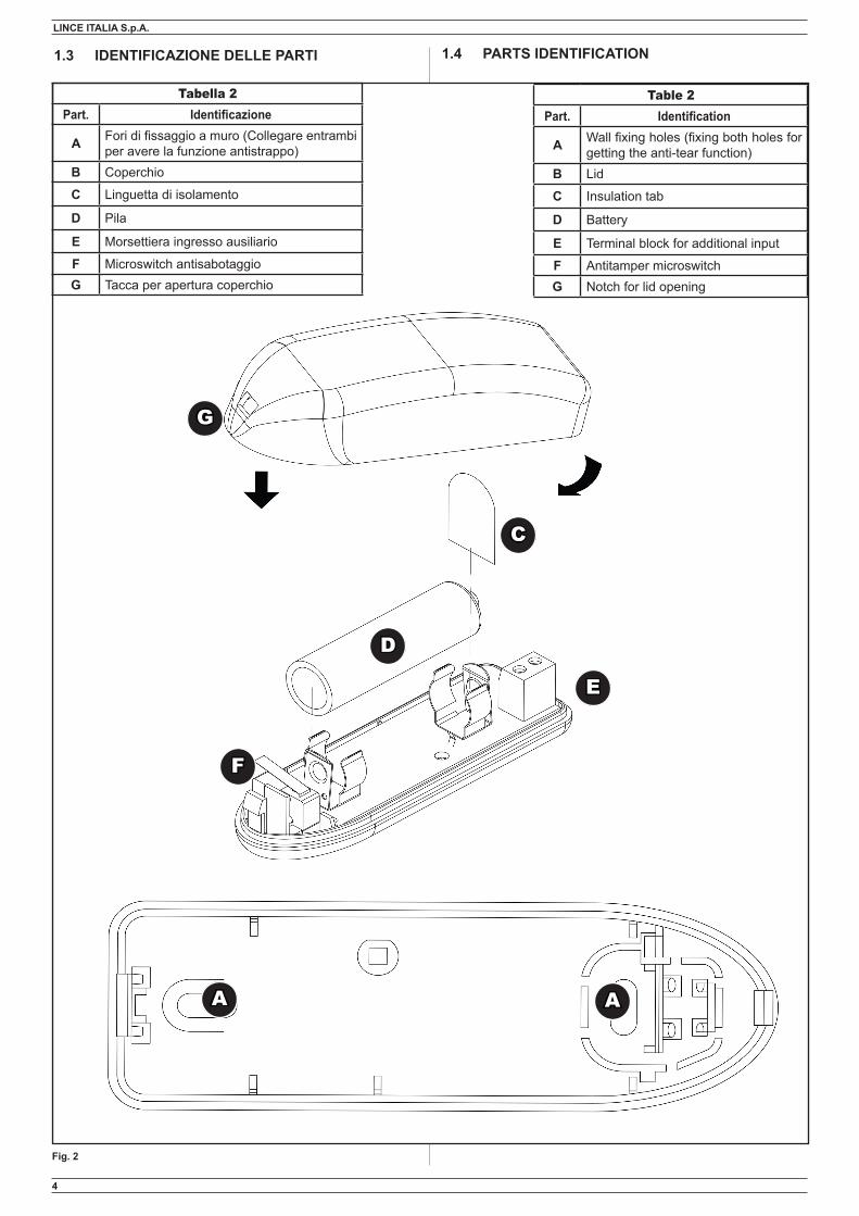
Tabella 2Part. Identificazione
A Fori di fissaggio a muro (Collegare entrambi per avere la funzione antistrappo)
B Coperchio
C Linguetta di isolamento
D Pila
E Morsettiera ingresso ausiliario
F Microswitch antisabotaggioG Tacca per apertura coperchio
1.4 PARTS IDENTIFICATION
Table 2Part. Identification
A Wall fixing holes (fixing both holes for getting the anti-tear function)
B Lid
C Insulation tab
D Battery
E Terminal block for additional input
F Antitamper microswitchG Notch for lid opening

5
LINCE ITALIA S.p.A.
2.1 FUNZIONE SLEEP
Questa funzione pone la periferica in uno stato dormiente a basso consumo (in cui non trasmette e non rileva), nel caso debba essere rimossa la centrale per eventuale manutenzione. La periferica una volta entrata in questa modalità dopo un'ora si riattiva per un minuto, controllando la presenza della trama della centrale e, qualora non sia presente, rientra in uno stato dormiente fino all'ora successiva.
2. MEMORIZZAZIONE
Prima di installare la periferica procedere alla memorizzazione seguendo i passi riportati di seguito: 1. impostare la centrale GOLD 869 o il modulo TX/RX GOLD
869 in apprendimento periferiche facendo riferimento al relativo manuale;
2. aprire il contatto magnetico applicando una leggera pressione in corrispondenza della piccola fessura riportata sul coperchio G fig. 2;
3. sfilare la linguetta di isolamento presente sulla pila. Il LED rosso comincierà a lampeggiare ad intermittenza.
4. Premere per tre volte il microswitch antisabotaggio per inviare la trama di memorizzazione. Il LED rosso cesserà di lampeggiare;
5. a convalida dell'effettuva memorizzazione del dispositivo in centrale, il LED sulla periferica emette un lampeggio lungo; attendere che sulla centrale venga visualizzato il messaggio della modifica dei parametri come termine della procedura di memorizzazione.
NOTA:
Nel caso la periferica fosse già stata memorizzata si avrà una seganalazione diversa a seconda della revisione firmare dalla centrale stessa:• se la centrale ha una revisione di firmware 1.xx emette un
suono;• dalla revisione 2.xx in poi sul display compare la voce
“periferica già presente”.
Se si desidera riportare la periferica alle impostazioni di fabbrica premere per 10 volte il microswitch antisabotaggio.
ATTENZIONE!
PERIFERICHE CON REVISIONE FIRMWARE INFERIORE AD 1.20
Nel caso in cui dopo la memorizzazione delle periferiche la cen-trale venga spenta o nel caso in cui centrale e periferica siano fuori portata, si raccomanda la rimozione delle pile dalle periferi-che al fine di preservare l'autonomia delle stesse.
PERIFERICHE CON REVISIONE FIRMWARE SUPERIORE AD 1.20
Nel caso in cui dopo la memorizzazione delle periferiche la cen-trale venga spenta o nel caso in cui la centrale e periferica siano fuori portata, le periferiche entreranno in modalità “sleep” al fine di ottimizzarne i consumi. Le periferiche si potranno riattivare in due modalità:• manualmente, aprendo e chiudendo il microswitch anti-sa-
botaggio o pigiando sul tasto di memorizzazione;• automaticamente, ogni ora dall'attivazione della modalità
“sleep”.
2. STORAGE
Before installing the device proceed to storage it by following the steps below:1. set the GOLD 869 control panel or the GOLD TX/RX module
869 in the storage mode by referring to the manual;2. open the magnetic contact by applying a pressure at the
small slot on the cover shown in G fig. 2;3. remove the insulation tab on the battery. The red LED will
begin to flash intermittently;4. Press for three times the tamper microswitch to send the
storage message. The red LED will stop flashing;5. as confirmation of the device storage in the control panel,
the LED on the device flashes long; wait until the parameter change message appears on the control panel as the end of the storage procedure.
NOTE:
If the device has already been stored it will have a different segnalation depending on the revision signed by the control pa-nel:• If the control panel has a firmware version 1.xx, it sounds;• from revision 2.xx onwards the “peripheral device already
present” appears on the display.
If you want to return the device to the factory settings, press the antitamper microswitch for 10 times
ATTENTION!
PERIPHERLAS WITH FIRMWARE REVISION LOWER THAN 1.20
If after the storage of the devices, the control panel is switched off or if the control panel and the peripheral are out of range, it is recommended the removal of the batteries from the devices in order to preserve their autonomy.
PERIPHERLAS WITH FIRMWARE REVISION UPPER THAN 1.20
If after the storage of the peripherals the control panel is switched off or if the control panel and peripherals are out of range, the devices will go into "sleep" mode in order to optimize consumption. The devices can be reactivated in two ways:• manually by onpening an closing the antitamper microswitch
or by pushing the storage button;• automatically, every hour from the activation of the “sleep”
mode.
2.1 SLEEP FUNCTION
This function puts the device in a sleepy low-power state (where not transmitting and not detecting), in case the control panel must be removed for maintenance. Once in this mode, after 1 hour the device wakes for a minute controlling the presence of the message of the control panel. If not present, falls again into a sleepy state until the next hour.

6
LINCE ITALIA S.p.A.
4.1 INSTALLAZIONE CON BI-ADESIVO ATTENZIONE!
Nel caso in cui si opti per l'installazione senza tasselli, non sarà disponibile la funzione anti-strappo.
• installare la base con la scheda nella sede più opportuna utilizzando le strisce bi-adesive in dotazione;
• togliere e rimettere nuovamente la pila di alimentazione al fine di permettere la corretta sincronizzazione con la centrale;
• chiudere il coperchio;• installare il magnete utilizzando le strisce bi-adesive in
dotazione;
3. VERIFICA PORTATA
Prima di installare il dispositivo è consigliabile verificare la bontà del segnale visualizzandone l'intensità direttamente sulla centrale. Disturbi e condizioni ambientali infatti possono alterarne la qualità; è consigliato dunque effettuare il test ad una distanza superiore rispetto a quella effettiva di installazione e interponenendo tutti gli ostacoli che potrebbero presentarsi durante il normale utilizzo (es.: chiudere porte, finestre, ecc).
2.2 FUNZIONE DES - DETECTION EVENT STORED
Nel caso in cui la periferica rilevasse un evento di allarme in un periodo in cui non comunica con la centrale (per esempio se l'ambiente è disturbato) il dato di allarme verrà tenuto in attesa e comunicato alla centrale non appena la comunicazione viene ristabilita. La centrale, se il sistema è ancora allarmato, gestirà l’allarme DES come un allarme normale (uscita sirena, SMS etc). In memoria eventi saranno distinguibili gli allarmi normali e gli allarmi DES.
2.2 DES FUNCTION - DETECTION EVENT STORED
If the device detects an alarm event at a time when it does not communicate with the control panel (for example, if the environment is disturbed), the alarm data will be kept on hold and communicated to the control panel as soon as communication is restored. The control panel, if the system is still alarmed, will handle the DES alarm as a normal alarm (siren output, SMS etc). In event memory, normal alarms and DES alarms can be distinguished.
NOTA
La funzione DES è disponibile sulla centrale a partire dalla revi-sone 2.x e sul contatto magnetico a partire dalla revisione 1.4.
NOTE
The DES function is available on the control panel from the 2.x revision and the magnetic contact from the 1.4 revision.
4.1 INSTALLATION WITH BIADHESIVE ATTENTION!
In case you choose the installation with no plugs, the anti-tear function is not available.
• install the base with the electronics board into the appropriate place using the bi-adhesive strips provided;
• remove and replace again the battery in order to allow the correct synchronization with the control panel;
• close the lid;• install the magnet using the supplied biadhesive strips;
Fig. 3
4. INSTALLAZIONE
Verranno illustrate due possibilità installative, tramite le strisce biadesive (in dotazione) o tramite tasselli (non in dotazione); in entrambi i casi è necessario fissare il magnete come indicato nella figura successiva: il magnete deve infatti trovarsi alla stessa altezza del dispositivo, in caso di differenze di altezza, è possibile utilizzare gli spessori in dotazione (da 2 a 5 mm).
4. INSTALLATION
Will be shown two different installation possibilities, using double-sided adhesive strips (supplied) or via plugs (not supplied); in both cases it is necessary to fix the magnet as shown in the following picture: the magnet must in fact be at the same height of the device, in case of differences in height, it is possible to use the supplied spacers (from 2 to 5 mm).
3. RADIO RANGE CHECK
Before installing the device it is advisable to verify the quality of the signal by displaying its intensity directly on the control panel. Therefore Noise and environmental conditions may alter its quality; it is recommended to carry out the test at a distance greater than the actual installation and interposing all obstacles that may arise during normal use (eg .: close doors, windows, etc).
7
LINCE ITALIA S.p.A.
5. IMPOSTAZIONI
Per impostazioni e settaggi della periferica fare riferimento al manuale della centrale serie GOLD 869.
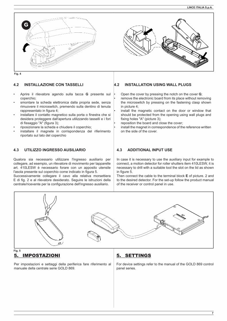
4.2 INSTALLAZIONE CON TASSELLI
• Aprire il rilevatore agendo sulla tacca G presente sul coperchio;
• smontare la scheda elettronica dalla propria sede, senza rimuovere il microswitch, premendo sulla dentino di tenuta rappresentato in figura 4;
• installare il contatto magnetico sulla porta o finestra che si desidera proteggere dall'apertura utilizzando tasselli e i fori di fissaggio "A" (figura 3);
• riposizionare la scheda e chiudere il coperchio;• installare il magnete in corrispondenza del riferimento
riportato sul lato del coperchio
4.3 UTILIZZO INGRESSO AUSILIARIO
Qualora sia necessario utilizzare l'ingresso ausiliario per collegare, ad esempio, un rilevatore di movimento per tapparelle art. 410LESW è necessario forare con un apposito utensile l'asola presente sul coperchio come indicato in figura 5.Successivamente collegare il cavo alla relativa morsettiera E di fig. 2 e al rilevatore desiderato. Seguire le istruzioni della centrale/ricevente per la configurazione dell'ingresso ausiliario.
5. SETTINGS
For device settings refer to the manual of the GOLD 869 control panel series.
Fig. 4
G
4.2 INSTALLATION USING WALL PLUGS
• Open the cover by pressing the notch on the cover G;• remove the electronic board from its place without removing
the microswitch by pressing on the fastening clasp shown in picture 4;
• install the magnetic contact on the door or window that should be protected from the opening using wall plugs and fixing holes "A" (picture 3);
• reposition the board and close the cover;• install the magnet in correspondence of the reference written
on the side of the cover.
4.3 ADDITIONAL INPUT USE
In case it is necessary to use the auxiliary input for example to connect, a motion detector for roller shutters item 410LESW, it is necessary to drill with a suitable tool the slot on the lid as shown in figure 5.Then connect the cable to the terminal block E of picture. 2 and to the desired detector. For the set-up follow the product manual of the receiver or control panel in use.
Fig. 5

001530/00820AD
LINCE ITALIA S.p.AVia Variante di Cancelliera, snc00040 ARICCIA (Roma)Tel. +39 06 9301801Fax +39 06 [email protected]
6. MANUTENZIONE E VERIFICHE PE-RIODICHE
Al fine di garantire il corretto funzionamento, è necessario sosti-tuire la batteria ogni 2 anni
ATTENZIONE! Per rimuovere sporcizie particolar-mente evidenti NON utilizzare prodotti a base di clo-ro, prodotti abrasivi oppure alcool.
1. Pulire il coperchio con un panno inumidito con acqua.2. Ripassare con un panno asciutto.
7. SMALTIMENTO E ROTTAMAZIONE
1. Rimuovere il coperchio frontale. 2. Scollegare la scheda: sulla morsettiera scollegare tutti i mor-
setti (v. Fig. 3).3. Dividere le parti in base alla loro tipologia e smaltirle in accor-
do con le leggi vigenti.
ATTENZIONE! Non disperdere nell’ambiente i componenti ed ogni altro materiale del prodotto.
Rivolgersi a consorzi abilitati allo smaltimento ed al riciclag-gio dei materiali.
6. MAINTENANCE AND PERIODIC CHECKS
In order to guarantee the ensure the correct work, is compulsory to replace the battert every 2 years.
IMPORTANT! Do NOT use chlorine-based or abrasive products or alcohol to remove particularly noticeable dirt.
1. Clean the lid with a cloth dampened with water.2. 2. Wipe with a dry cloth.
7. DISPOSAL AND SCRAPPING
1. Remove the front lid. 2. Disconnect the board: disconnect all the terminals on the ter-
minal block (see Fig. 3).3. Divide the parts by type and dispose of them in accordance
with applicable laws.
IMPORTANT! Do not dispose of the components or any other pro-duct material in the environment.
Seek the assistance of companies authorised to dispose of and recycle waste materials.