content part i - tud · pdf fileand loop filter bandwidth; ... test ramp scenario ... •...
TRANSCRIPT

Concepts for Highly Integrated
Automotive Radar Circuits
Herbert Jäger
DICE GmbH & Co KG
(Part I)
Matthias Porranzl
Johannes Kepler University Linz
(Part II)
WS12: EuMIC - SiGe for mm-Wave and THz
SiGe for mm-Wave and THz
Content – Part I
• A short history of SiGe in automotive radar (AR)
• Upcoming system level requirements
• Concepts to meet those requirements
• Taking a look at radar outside automotive
• The interplay of systems engineering and circuit
design

SiGe for mm-Wave and THz
SiGe in AR – the very beginnings
÷384
÷4
TX path
DRO
PLL
ASIC
TX/RX
TX/RX
RX
RX
?
?
?
?
An early draft (ca. 2005)
When SiGe first entered the AR field, it had to compete against systems that were
highly fragmented over many individual special-function chips or discrete
semiconductors. Our first ‘RF system’ sketches reflect this mindset …
SiGe for mm-Wave and THz
Looking only at individual performance parameters, SiGe could not directly
compete against those special-function chips.
SiGe in AR – the very beginnings
÷384
÷4
DRO
LO
LO
I 1f
I 2f
I 3f
I 4f
PLL + RX
ASIC
TX/RX
RX
RX
TX/RX
PLL
An early draft (ca. 2005)

SiGe for mm-Wave and THz
SiGe in AR – the very beginnings
The key to success was integration:
When combining multiple function blocks into one single chip, SiGe could
leverage a benefit.
÷384
÷4
DRO
LO
LO
I 1f
I 2f
I 3f
I 4f
PLL + RX
ASIC
TX/RX
RX
RX
TX/RX
PLL
The product
SiGe for mm-Wave and THz
GaAs discrete - 2005
RF-Board 2nd Gen.
62 x 68 mm² (~42 cm²)
RF-Board 3rd Gen.
25 x 35 mm² (~9 cm²)
Ref. Osc.
4x
MIX. Ref. Osc.
Antennas
Antennas
SiGe
2009
Range Accuracy
Distance
m
LRR2 (GaAs)
LRR3 (SiGe)
2 – 150
0.5 - 250
0.5
0.1
Relative Velocity
m/s
LRR2 (GaAs)
LRR3 (SiGe)
–60 to + 20
-80 to +30
0.25
0.12
Angle
deg
LRR2 (GaAs)
LRR3 (SiGe)
8
15
0.4
0.1
GaAs discrete (LRR2) vs.
SiGe integrated (LRR3)

SiGe for mm-Wave and THz
Integration in SiGe
• All mm-Wave functions
in one chip
• Four transmit/receive
(TRX) channels
• Built-in self test;
monitoring
• Programmable
features
through
digital interface
What are the limits for integration in purely bipolar SiGe?
ns
Ref. (1)
SiGe for mm-Wave and THz
Limitations of pure SiGe bipolar
• RF functionality has been demonstrated:
+ transmit output power
+ VCO phase noise and tuning bandwidth
+ receiver noise floor, linearity and conversion gain
+ Access to relevant parameters to allow ‘health’ monitoring, e.g. power and
temperature sensors
+ Contol methods and algorithms can be applied externally (serial interface)
• On the other side:
– Bipolar transistors are not the first choice for implementing more complex digital
functions (circuit size, current consumption, design tools)
– Higher RF I/O count à larger chip size, PCB fan-out
– Integrating more functions (e.g., more transmit or receive channels) in this
technology will result in too high power dissipation

SiGe for mm-Wave and THz
What comes next?
• In Europe each year about 1.3 million traffic accidents cause: – More than 40.000 fatalities
– Economic damage of more than 200 billion € per year
• Human error is involved in over 90% of accidents
• Automotive radar help drivers to – Maintain a safe speed
– Keep a safe distance
– Avoid overtaking in critical situations
– Safely pass intersections
– Avoid crashes with vulnerable road user
– Reduce severity of an accident
– Drive more efficiently en.wikipedia.org/wiki/Rear-end_collision#mediaviewer/File:Car_accident_-_NSE_Malaysia.jpg
http://en.wikipedia.org/wiki/File:401_Gridlock.jpg
Moving from
comfort functions
(e.g. adaptive cruise control)
in luxury cars to
safety functions
(e.g., emergency braking, pre-crash preparation)
in every car.
SiGe for mm-Wave and THz
The Safety Market –
EuroNCAP* is a strong driver
• European OEMs consider 5 stars a MUST and add required technology to new platforms
• From 2016 onwards , a 5 star rating is not possible without radar/camera
• Radar/camera combination standard equipment for EU cars
• Other regions expected to follow the EU with several years delay (e.g. Korea in 2016)
• From 2018 e.g. cyclist protection is expected raise the bar further NCAP = New Car Assessment Program
VRU = Vulnerable Road User
AEB = Autonomous Emergency Braking
2014 2012 2016
AEB city
AEB interurban + (LDW)
Pedestrian protection Passive
AEB pedestrian
Occupant Protection Passive
Mandatory for 5*
Safety support
2018
Bicyclist/VRU* protection passive
tbd

SiGe for mm-Wave and THz
New applications – new requirements
• Top-level system requirements: – High availability – provide an operational system also in adverse conditions
– High data quality – acquire relevant radar data; identify and avoid false
targets
– Functional safety – Monitor if the system is in nominal condition; quickly
detect a faulty function; do not pass on false data
– Higher resolution – (e.g., pedestrian detection) à bandwidth, number of
antennas à MIMO, virtual antennas
SiGe for mm-Wave and THz
New system concepts
• What is different for upcoming system concepts?
– Available processing power / DSP is growing continuously, new concepts become
feasible
– Digital beamforming (RX), multiple RX channels
– Virtual antenna arrays, multiple-input, multiple output (MIMO) radar through
sophisticated signal processing
– Very fast ramps, higher sweep bandwidth, signal processing over multiple ramps
– A great variety of FMCW scenarios, i.e., ramp times and ramp bandwidth,
resulting in the requirement for
• a very flexible IF processing chain (gain steps, high-pass / low-pass corner frequencies,
sampling rates)
• A very agile PLL / frequency ramper and higher bandwidth VCO
– Different modulation schemes, e.g. BPSK, coded, pseudo-noise …
– Integrated support for functional safety: ISO 26262; ASIL levels …
SiGe for mm-Wave and THz
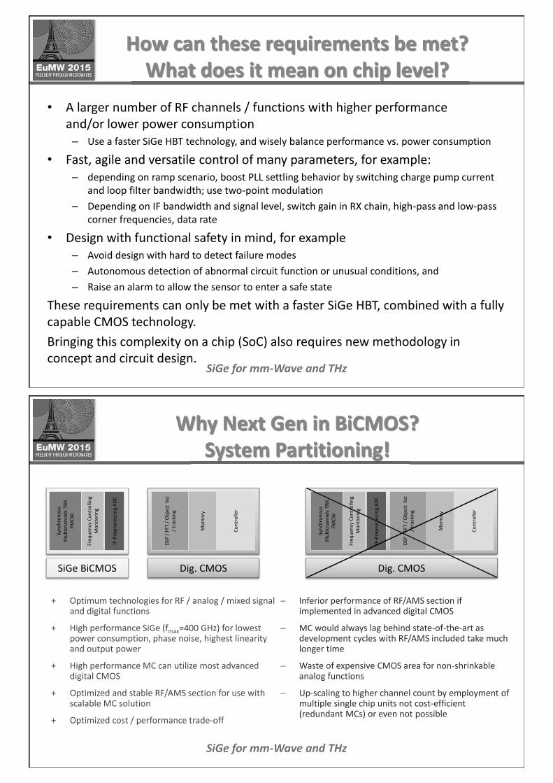
How can these requirements be met?
What does it mean on chip level?
• A larger number of RF channels / functions with higher performance
and/or lower power consumption
– Use a faster SiGe HBT technology, and wisely balance performance vs. power consumption
• Fast, agile and versatile control of many parameters, for example:
– depending on ramp scenario, boost PLL settling behavior by switching charge pump current
and loop filter bandwidth; use two-point modulation
– Depending on IF bandwidth and signal level, switch gain in RX chain, high-pass and low-pass
corner frequencies, data rate
• Design with functional safety in mind, for example
– Avoid design with hard to detect failure modes
– Autonomous detection of abnormal circuit function or unusual conditions, and
– Raise an alarm to allow the sensor to enter a safe state
These requirements can only be met with a faster SiGe HBT, combined with a fully
capable CMOS technology.
Bringing this complexity on a chip (SoC) also requires new methodology in
concept and circuit design.
SiGe for mm-Wave and THz
Why Next Gen in BiCMOS?
System Partitioning!
+ Optimum technologies for RF / analog / mixed signal and digital functions
+ High performance SiGe (fmax=400 GHz) for lowest power consumption, phase noise, highest linearity and output power
+ High performance MC can utilize most advanced digital CMOS
+ Optimized and stable RF/AMS section for use with scalable MC solution
+ Optimized cost / performance trade-off
- Inferior performance of RF/AMS section if implemented in advanced digital CMOS
- MC would always lag behind state-of-the-art as development cycles with RF/AMS included take much longer time
- Waste of expensive CMOS area for non-shrinkable analog functions
- Up-scaling to higher channel count by employment of multiple single chip units not cost-efficient (redundant MCs) or even not possible
Syn
chro
no
us
Mu
ltic
na
nn
els
TR
X
FM
CW
IF-P
rep
roce
ssin
g A
DC
Fre
qu
en
cy C
on
tro
llin
g
Mo
nit
ori
ng
SiGe BiCMOS
DS
P /
FF
T /
Ob
ject
list
/ tr
ack
ing
Me
mo
ry
Co
ntr
olle
r
Dig. CMOS
Syn
chro
no
us
Mu
ltic
na
nn
els
TR
X
FM
CW
IF-P
rep
roce
ssin
g A
DC
Fre
qu
en
cy C
on
tro
llin
g
Mo
nit
ori
ng
DS
P /
FF
T /
Ob
ject
list
/ tr
ack
ing
Me
mo
ry
Co
ntr
olle
r
Dig. CMOS
SiGe for mm-Wave and THz
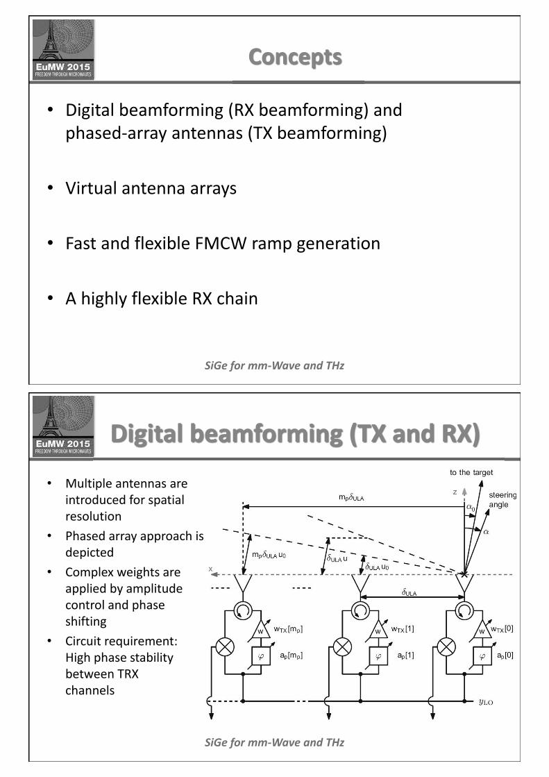
Concepts
• Digital beamforming (RX beamforming) and
phased-array antennas (TX beamforming)
• Virtual antenna arrays
• Fast and flexible FMCW ramp generation
• A highly flexible RX chain
SiGe for mm-Wave and THz
Digital beamforming (TX and RX)
• Multiple antennas are
introduced for spatial
resolution
• Phased array approach is
depicted
• Complex weights are
applied by amplitude
control and phase
shifting
• Circuit requirement:
High phase stability
between TRX
channels

SiGe for mm-Wave and THz
The FMCW Principle
• Single chirp: Range/Doppler
coupled frequency
SiGe for mm-Wave and THz
The FMCW Principle
• Single chirp: Range/Doppler
coupled frequency
Ref. (2)

SiGe for mm-Wave and THz
Uniform Linear Virtual Array
Ref. (3)
SiGe for mm-Wave and THz
Agile PLL frequency ramping
• Minimize settling times by switching loop filter bandwidth
and charge pump current
x 4 ~ PFD
CP
~
: 32
MMD
VCO 77 GHz
Pre divider
f out
MASH
C 1 C 4
clk gen
clk
DAC coarse
RAMPER
gain
ramp trigger
trigger unit
C 2
C 3 R 2 R 2 p
R 3
R 3 p
R 4
R 4 p
switch
Loop Filter
CP = charge pump
PFD = phase-frequency detector
MMD = multi-modulus divider
MASH = noise shaping modulator

SiGe for mm-Wave and THz
Agile PLL frequency ramping
• Boost PLL speed by using two-point modulation
Challenge:
• VCO tuning characteristic is highly variable over the tuning range
• Automatic optimum adjustment of all parameters (charge pump current, loop
filter bandwidth, modulator DAC amplitude, coarse tune preset …)
x 4 ~ PFD
CP 3 . 3 V
~ LF
: 32
MMD
VCO 77 GHz
Pre - divider
f out
MASH
C 1 C 4
DAC
Ramp modulation
clk
2 - point on
control
DAC coarse
CP = charge pump
PFD = phase-frequency detector
LF = loop filter
MMD = multi-modulus divider
MASH = noise shaping modulator
SiGe for mm-Wave and THz
• Advanced PLL concept evaluation for sawtooth ramp
scenario: Df = 1 GHz; Tramp = 15 µs; Tidle = 1.5 µs
• Results of dynamic evaluation:
With advanced modulation technique
Without advanced modulation technique
THz
• Very fast ramp scenarios possible
• Linear ramp generation
• No cycle slips for frequency jumps
• Reduced frequency overshoots
• Dead time between ramps significantly reduced
• PN spectrum unaffected
Df
T_ramp T_idle
f
t
ff
Agile PLL frequency ramping

SiGe for mm-Wave and THz
Test Ramp Scenario
• Simulated Ramp scenario
with accurate VCO model
Frequency vs. time, ZOOM
Frequency vs. time
blue: instantaneous frequency
red: boost on / off
SiGe for mm-Wave and THz
Highly flexible RX chain
• Flexibility is achieved by:
– A high level of configurability in every single block
– An overall ‘supervising’ control function to improve applicability
– Moving as much functionality as possible into the digital domain
This challenge is similar to mobile phone receivers supporting multiple standards
D i f
f
S E
A
D
DFE
LVDS AFE
RF-RX BB-RX
D i f f
S E
A
D
DFE LVDS AFE D i f
f
S E
A
D
DFE LVDS AFE D i f
f
S E
A
D
DFE AFE LVDS
Test
signal
Control loops
Gain
Lowpass / Highpass
bandwidth
Decimation
Filtering
Local
Oscillator
Synchronization
& Framing
AFE = analog frontend
DFE = digital frontend
LVDS = low voltage digital signalling
SiGe for mm-Wave and THz
Let us take a look outside AR …
• What other applications could be feasible with
similar top level requirements?
• How about a very compact, fully integrated short
range sensor?
SiGe for mm-Wave and THz
What could that sensor look like?
• Integrate the complete radar in a single chip
– Requires advanced semiconductor technology – B11HFC
• Employ MIMO technique to create a larger array of virtual antennas
• Integrate antennas in the package (AiP)
– No RF PCB required; simple application
• Use TRX channels instead of separate transmit / receive channels
– This will yield an even larger virtual array.
• Choose frequency band (Ref. 4) à antenna size, available bandwidth
– Automotive: 76-77 GHz, 77-81 GHz
– ISM: 61-61.5 GHz
– SRD (short range device): 57-64 GHz, 122-123 GHz

SiGe for mm-Wave and THz
Multiple TRX antennas
• Use transmit + receive (TRX)
channels instead of individual
transmit and receive channels
• Operating frequency: 77 GHz
• Package size: 8 x 8 mm2
• NOTE: This antenna placement
has not been optimized for
MIMO operation.
(Ref. 5)
SiGe for mm-Wave and THz
Antenna in package (AiP) at 160 GHz
• Circuit design for higher
frequencies is feasible with the
next SiGe technology step
• Antennas can be integrated in a
standard embedded wafer level
ball grid array (eWLB) package
• directional antenna
• This design was done in B7HF500,
a precursor to B11HFC
(Ref. 6)

SiGe for mm-Wave and THz
Combining AiP and mono-static concept
• Antennas aligned at the periphery
of the eWLB package
+ Maximize achievable aperture
+ Non-uniform arrangement is possible with
MIMO radar (Ref. 2)
• Use TRX channels instead of
dedicated TX and RX channels
+ Best utilization of the available space
+ Max. n(n+1)/2 virtual antennas (Ref. 3)
+ Redundant virtual antennas
– Potential blocking of receiver when antenna
matching is insufficient
– Degradation of available dynamic due to
duplexing function (TX/RX separation)
Associated virtual array
SiGe for mm-Wave and THz
References
(1) Christoph Wagner: Application-Driven Design and Characterization of a
77-GHz Radar Transceiver, EuMW 2013, Workshop W 20
(2) R. Feger, C. Wagner, S. Schuster, S. Scheiblhofer, H. Jäger, A. Stelzer:
A 77-GHz FMCW MIMO Radar Based on an SiGe Single-Chip Transceiver,
IEEE TRANSACTIONS ON MICROWAVE THEORY AND TECHNIQUES, VOL.
57, NO. 5, MAY 2009
(3) Christian M. Schmid, Reinhard Feger, Clemens Pfeffer, Andreas Stelzer:
Motion Compensation and Efficient Array Design for TDMA FMCW MIMO Radar
Systems, EUCAP 2012
(4) ECC/CEPT: ERC Report 25: The European Table of Frequency Allocations, May 2015;
http://www.erodocdb.dk/Docs/doc98/official/pdf/ercrep025.pdf
(5) A. Hamidipour, A. Fischer, M. Jahn, A. Stelzer: 160-GHz SiGe-Based Transmitter and
Receiver with Highly Directional Antennas in Package, EUMW 2013
(6) Wojnowski et al: A 77-GHz SiGe Single-Chip Four-Channel Transceiver Module with
Integrated Antennas in Embedded Wafer-Level BGA Package, ECTC 2012

Concepts for Highly Integrated
Automotive Radar Circuits
Herbert Jäger
DICE GmbH & Co KG
(Part I)
Matthias Porranzl
Johannes Kepler University Linz
(Part II)
WS12: EuMIC - SiGe for mm-Wave and THz
SiGe for mm-Wave and THz
Content – Part II
• Why monostatic radars?
• Current implementation vs. quasi-circulator (QC)
• Antenna mismatch and leakage cancelation
• Impedance tuner – bipolar vs. BiCMOS
SiGe for mm-Wave and THz
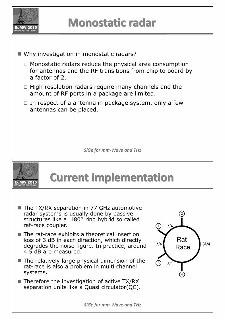
Monostatic radar
n Why investigation in monostatic radars?
o Monostatic radars reduce the physical area consumption for antennas and the RF transitions from chip to board by a factor of 2.
o High resolution radars require many channels and the amount of RF ports in a package are limited.
o In respect of a antenna in package system, only a few antennas can be placed.
SiGe for mm-Wave and THz
Current implementation
n The TX/RX separation in 77 GHz automotive radar systems is usually done by passive structures like a 180° ring hybrid so called rat-race coupler.
n The rat-race exhibits a theoretical insertion loss of 3 dB in each direction, which directly degrades the noise figure. In practice, around 4.5 dB are measured.
n The relatively large physical dimension of the rat-race is also a problem in multi channel systems.
n Therefore the investigation of active TX/RX separation units like a Quasi circulator(QC).
Rat-
Race
λ/4
3λ/4
λ/4
λ/4
1
2
3
4
SiGe for mm-Wave and THz
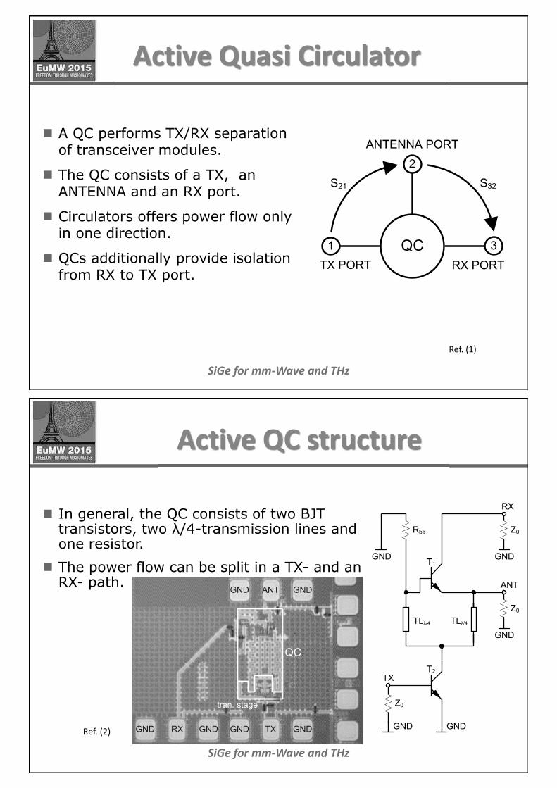
Active Quasi Circulator
n A QC performs TX/RX separation of transceiver modules.
n The QC consists of a TX, an ANTENNA and an RX port.
n Circulators offers power flow only in one direction.
n QCs additionally provide isolation from RX to TX port.
S21 S32
QC1
TX PORT RX PORT
ANTENNA PORT
3
2
Ref. (1)
SiGe for mm-Wave and THz
Active QC structure
n In general, the QC consists of two BJT transistors, two λ/4-transmission lines and one resistor.
n The power flow can be split in a TX- and an RX- path.
GND
T1GND
ANT
RX
Rba
TLλ/4TLλ/4
Z0
GND
Z0
GND
T2
Z0
GND
TX
QC
tran. stage
ANT
TXRXGND GND GND GND
GNDGND
Ref. (2)

SiGe for mm-Wave and THz
Power flow in the QC
n If Rba = Z0, the transmit signal appears in-phase at the base and the emitter of T1 and therefore the signal is isolated from the RX port.
n T2 is assumed as unilateral.
n The receive signal appears out-of-phase at the base and the emitter of T1. Consequently, it is amplified by T1 and transferred to the RX port.
GND
T1GND
ANT
RX
Rba
TLλ/4TLλ/4
Z0
GND
Z0
GND
TX-path
RX-path
T2
Z0
GND
TX
SiGe for mm-Wave and THz
QC vs rat-race
n In theory, 3 dB of the TX signal is terminated by a resistor in both approaches.
n Assuming T2 in the QC as unilateral, none of the receive signal is dissipated. This involves an improvement over the rat-race implementation.
n As the QC is an active device, T1 adds some noise to the receive signal.
n Therefore, when comparing a QC and a rat-race system with respect to noise figure, the whole receiver including the mixer has to be taken into account.
n Based on the Friis formula, the shown QC system offers a better total NF if the following stages have a NF worse than 9.1 dB (2). For comparison, a published 77 GHz mixer processed in the same technology is stated with around 14.9 dB NF (3).
SiGe for mm-Wave and THz
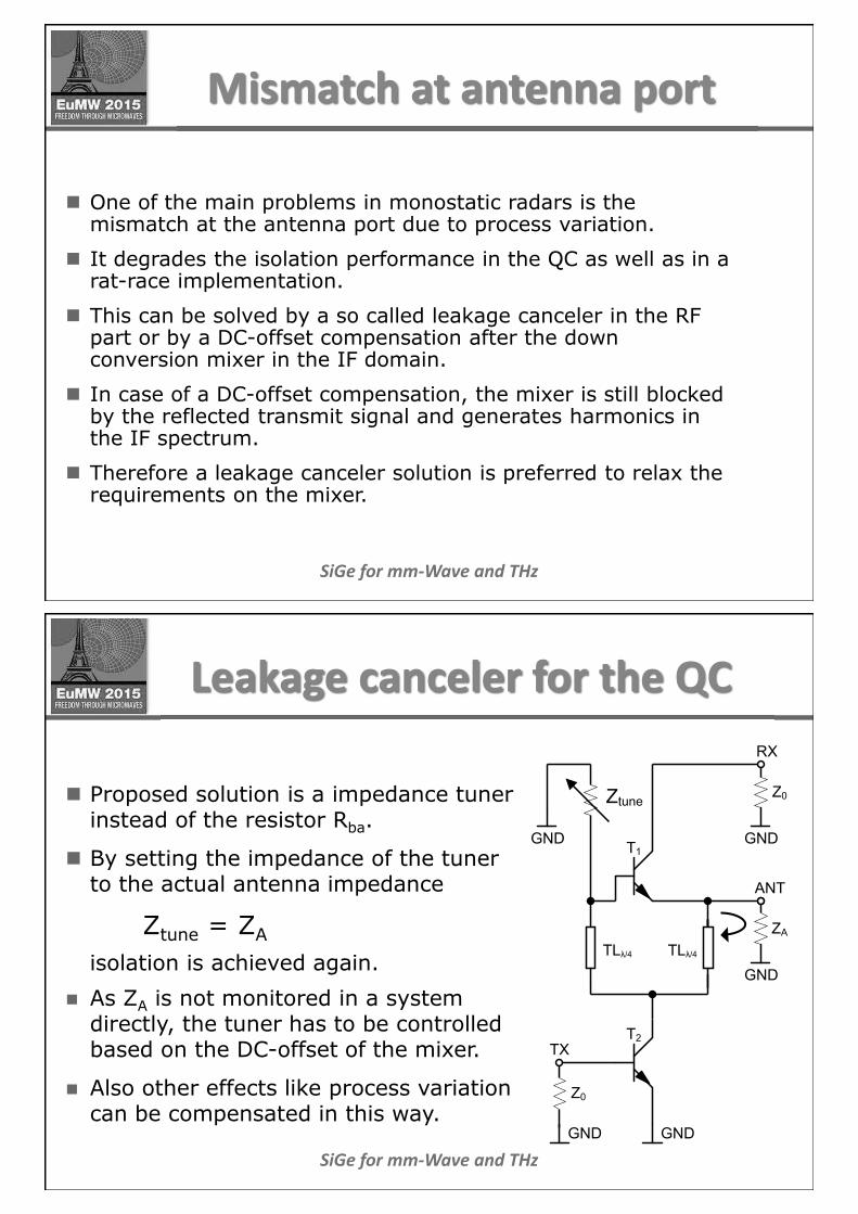
Mismatch at antenna port
n One of the main problems in monostatic radars is the mismatch at the antenna port due to process variation.
n It degrades the isolation performance in the QC as well as in a rat-race implementation.
n This can be solved by a so called leakage canceler in the RF part or by a DC-offset compensation after the down conversion mixer in the IF domain.
n In case of a DC-offset compensation, the mixer is still blocked by the reflected transmit signal and generates harmonics in the IF spectrum.
n Therefore a leakage canceler solution is preferred to relax the requirements on the mixer.
SiGe for mm-Wave and THz
Leakage canceler for the QC
n Proposed solution is a impedance tuner instead of the resistor Rba.
n By setting the impedance of the tuner to the actual antenna impedance
Ztune = ZA
isolation is achieved again.
n As ZA is not monitored in a system directly, the tuner has to be controlled based on the DC-offset of the mixer.
n Also other effects like process variation can be compensated in this way.
GND
T1GND
ANT
RX
TLλ/4TLλ/4
Z0
GND
ZA
GND
T2
Z0
GND
TX
Ztune

SiGe for mm-Wave and THz
Tuner implementation
n In a pure bipolar process, the impedance tuners usually are implemented with varactors, which require an additional digital/analog converter (DAC) for controlling them.
n A BiCMOS process offers the tuner implementation based on FET switches, which can be digitally controlled by conventional SPI interface.
n This makes the system compact and simple to control.
SiGe for mm-Wave and THz
Conclusion
n The monostatic concept is useful for applications in limited space
n The systematic penalty by using a passive coupler, e.g., a rat-race can be avoided with an active QC.
n Test circuits have already been implemented.
n New concepts for leakage cancelling are under investigation.
n A BiCMOS process facilitates the implementation of a compact system

SiGe for mm-Wave and THz
References
(1)S. Hara, T. Tokumitsu, and M. Aikawa, “Novel unilateral circuits for MMIC circulators,” IEEE Trans. Microw. Theory Tech., vol. 38, no. 10, pp. 1399–1406, Oct 1990.
(2)M. Porranzl, C. Wagner, H. Jaeger, and A. Stelzer, “An Active Quasi-Circulator for 77-GHz Automotive FMCW Radar Systems in SiGe Technology,” IEEE Microw. Wireless Compon. Lett., vol. 25, no. 5, pp. 313–135, 2015.
(3)C. Wagner, H. P. Forstner, G. Haider, A. Stelzer, and H. Jager, “A 79-GHz radar transceiver with switchable TX and LO feedthrough in a Silicon-Germanium technology,” in IEEE Bipolar/BiCMOS Circuits and Technology Meeting, Monterey, CA, Oct 2008, pp. 105–108.