contentcib-w18.com/sites/default/files/styles/pdf_small/public/sites...cib-w18 timber structures –...
TRANSCRIPT

CONTENT 3.1 BEAMS WITH HOLES ....................................................................... 9 3.2 BRACING ........................................................................................ 13 3.3 BRIDGES ........................................................................................ 19 3.4 COLUMNS ...................................................................................... 22 3.5 COMPOSITE BEAM FASTENERS ..................................................... 34 3.6 LATERAL INSTABILITY .................................................................... 40 3.7 MECHANICALLY JOINTED BEAMS .................................................. 41 3.8 NOTCHED BEAMS .......................................................................... 51 3.9 PLATE BUCKLING ........................................................................... 55 3.10 PRESTRESSING AND REINFORCING ............................................... 56 3.11 RESIDENTIAL FLOORS .................................................................... 63 3.12 ROBUSTNESS ................................................................................. 67 3.13 SERVICEABILITY ............................................................................. 72 3.14 SYSTEM EFFECTS ........................................................................... 76 3.15 TAPERED AND CURVED GLULAM MEMBERS ................................ 81 3.16 THIN-WALLED ELEMENTS ............................................................. 84 3.17 TIMBER BEAMS, GENERAL ............................................................ 86 3.18 TIMBER FRAME WALLS ................................................................. 87 3.19 TRUSSED RAFTERS ....................................................................... 111

CIB-W18 Timber Structures – A review of meeting 1-43 3 STRUCTURES page 3.2
3.1 BEAMS WITH HOLES 9
8-12-2 H Kolb, P Frech Instruction for the reinforcement of apertures in glulam beams 9
28-12-3 K Riipola Design of glulam beams with holes 10
35-12-1 S Aicher, L Höfflin Glulam beams with round holes - A comparison of different design approaches vs. test data 10
36-12-2 L Höfflin, S Aicher Weibull based design of round holes in glulam 11
41-12-4 H Danielsson, P J Gustafsson Strength of glulam beams with holes - tests of quadratic holes and literature test results compilation 12
42-12-1 S Aicher, L Höfflin Glulam beams with holes reinforced by steel bars 12
3.2 BRACING 13
7-2-1 J A Simon Lateral bracing of timber struts 13
16-15-1 H Brüninghoff Determination of bracing structures for compression members and beams 13
19-15-2 M H Kessel, J Natterer The bracing of trussed beams 14
23-15-2 T A C M van der Put Stability design and code rules for straight timber beams 14
26-15-1 C J Mettem, P J Moss Bracing requirements to prevent lateral buckling in trussed rafters 14
32-15-1 S Andreasson Three-dimensional interaction in stabilisation of multi-storey timber frame buildings 16
33-15-3 H J Larsen Eurocode 5 rules for bracing 16
37-15-4 J Munch-Andersen Bracing of timber members in compression 17
42-15-3 Xiaobin Song, F Lam, Hao Huang, Minjuan He Stability capacity and lateral bracing force of metal plate connected wood truss assemblies 17
42-15-4 Chun Ni, H Rainer, E Karacabeyli Improved method for determining braced wall requirements for conventional wood-frame buildings 18
3.3 BRIDGES 19
27-12-1 M A Ritte, T G Williamson State of the art report: glulam timber bridge design in the U.S. 19
27-12-2 C J Mettem, J P Marcroft, G Davis Common design practice for timber bridges in the United Kingdom 19
39-12-1 K Crews Recommended procedures for determination of distribution widths in the design of stress laminated timber plate decks 20
42-12-5 K Karlsson, R Crocetti, R Kliger Mechanical properties of stress laminated timber decks - experimental study 21
3.4 COLUMNS 22
2-2-1 H J Larsen The design of solid timber columns 22
3-2-1 H J Larsen The design of built-up timber columns 22
4-2-1 H J Larsen, S S Pedersen Tests with centrally loaded timber columns 22
4-2-2 B Johansson Lateral-torsional buckling of eccentrically loaded timber columns 22
5-9-1 B Källsner, B Norén Strength of a wood column in combined compression and bending with respect to creep 24
8-15-1 H J Larsen Laterally loaded timber columns: tests and theory 24
17-2-1 T Poutanen Model for timber strength under axial load and moment 24
18-2-1 A H Buchanan, K C Johns, B Madsen Column design methods for timber engineering 24
19-2-1 R H Leicester Creep buckling strength of timber beams and columns 25
19-12-2 H J Blass Strength model for glulam columns 26

CIB-W18 Timber Structures – A review of meeting 1-43 3 STRUCTURES page 3.3
20-2-2 H J Blass Design of timber columns 27
21-2-1 R H Leicester Format for buckling strength 27
21-2-2 R H Leicester Beam-column formulae for design codes 27
30-2-1 W Lau, F Lam and J D Barrett Beam-column formula for specific truss applications 28
31-2-1 P Becker, K Rautenstrauch Deformation and stability of columns of viscoelastic material wood 30
34-2-1 W Moorkamp, W Schelling, P Becker, K Rautenstrauch Long-term experiments with columns: results and possible consequences on column design 30
34-2-2 P Becker, K Rautenstrauch Proposal for compressive member design based on long-term simulation studies 30
35-2-1 R Hartnack, K-U Schober, K Rautenstrauch Computer simulations on the reliability of timber columns regarding hygrothermal effects 31
36-2-1 K Rautenstrauch, R Hartnack The reliability of timber columns based on stochastic principles 32
38-2-1 R Hartnack, K Rautenstrauch Long-term load bearing of wooden columns influenced by climate – view on code 32
3.5 COMPOSITE BEAM FASTENERS 34
34-7-5 M Grosse, S Lehmann, K Rautenstrauch Testing connector types for laminated timber-concrete composite elements 34
36-7-1 L Jorge, H Cruz, S Lopes Shear tests in timber-LWAC joints with screw-type connections 34
36-7-3 S Lehman, K Rautenstrauch Nail-laminated timber elements in natural surface-composite with mineral bound layer 34
36-7-4 A Dias, J W G van der Kuilen, H Cruz Mechanical properties of timber-concrete joints made with steel dowels 35
37-7-15 M Grosse, K Rautenstrauch Numerical modelling of timber and connection elements used in timber-concrete composite constructions 36
39-7-3 A Döhrer, K Rautenstrauch Connectors for timber-concrete composite-bridges 36
40-7-5 E Lukaszewska, M Fragiacomo, A Frangi Evaluation of the slip modulus for ultimate limit state verifications of timber-concrete composite structures 37
42-7-6 U Kuhlmann, P Aldi Prediction of the fatigue resistance of timber-concrete-composite connections 38
3.6 LATERAL INSTABILITY 40
4-2-2 B Johannesson Lateral-torsional buckling of eccentrically loaded timber columns 40
5-10-1 H J Larsen The design of timber beams 40
19-2-1 R H Leicester Creep buckling strength of timber beams and columns 40
21-2-2 R H Leicester Beam-column formulae for design codes 40
29-10-1 F Rouger Time dependent lateral buckling of timber beams 40
3.7 SYSTEM EFFECTS 76
22-8-1 F Rouger, J D Barrett, R O Foschi Reliability analysis of viscoelastic floors 76
25-10-2 T D G Canisius The influence of the elastic modulus on the simulated bending strength of hyperstatic timber beams 76
34-8-1 M Hansson, T Isaksson System effects in sheathed parallel timber beam structures 77
35-8-1 M Hansson, T Isaksson System effects in sheathed parallel timber beam structures part II 78
39-8-1 I Smith, Y H Chui, P Quenneville Overview of a new Canadian approach to handling system effects in timber structures 78
43-12-3 M Frese, H J Blass System effects in glued laminated timber in tension and bending 79
CIB-W18 Timber Structures – A review of meeting 1-43 3 STRUCTURES page 3.4
43-12-4 C Faye, F Rouger, P Garcia Experimental investigations on mechanical behaviour of glued solid timber 80
3.8 MECHANICALLY JOINTED BEAMS 41
3-2-1 H J Larsen The design of built-up timber columns 41
32-12-1 T Wolf, O Schäfer The bending stiffness of nail-laminated timber elements in transverse direction 41
34-12-5 V Krämer, H J Blass Load carrying capacity of nail-laminated timber under concentrated loads 42
34-12-7 H Kreuzinger Mechanically jointed beams: possibilities of analysis and some special problems 42
40-10-1 J Schänzlin, M Fragiacomo Extension of EC5 Annex B formulas for the design of timber-concrete composite structures 44
40-10-2 U A Girhammar Simplified design method for mechanically jointed beams 44
41-10-1 T G Williamson, B Yeh Composite action of i-joist floor systems 45
43-7-3 H J Larsen, H Riberholt, A Ceccotti Design of mechanically jointed composite concrete-timber beams taking into account the plastic behaviour of the fasteners 46
43-7-4 M Fragiacomo, D Yeoh Design of timber-concrete composite beams with notched connections 47
43-7-5 K Crews, C Gerber Development of design procedures for timber concrete composite floors in Australia and New Zealand. 49
3.9 NOTCHED BEAMS 51
21-10-1 P J Gustafsson A study of strength of notched beams 51
22-10-1 H J Larsen and P J Gustafsson Design of end notched beams 51
23-10-1 T A C M van der Put Tension perpendicular to the grain at notches and joints 52
23-10-2 K Riipola Dimensioning of beams with cracks, notches and holes. an application of fracture mechanics 52
38-6-1 R H Leicester Design specifications for notched beams in AS 1720 53
41-6-1 A Asiz, I Smith Design of inclined glulam members with an end notch on the tension face 53
41-6-2 K Rautenstrauch, B Franke, S Franke, K U Schober A new design approach for end-notched beams - view on code 53
3.10 PLATE BUCKLING 55
10-4-1 J Decker, J Kuipers. H Ploos van Amstel Buckling strength of plywood: results of tests and recommendations for calculation 55
17-4-2 R H Leicester, L Pham Ultimate strength of plywood webs 55
3.11 PRESTRESSING AND REINFORCING 56
22-12-4 R Candowicz, T Dziuba Ultimate strength of wooden beams with tension reinforcement as a function of random material properties 56
30-12-1 K Oiger Experimental investigation and analysis of reinforced glulam beams 56
34-12-3 M Romani, H J Blass Design model for FRP reinforced glulam beams 57
37-12-2 P Alam, M P Ansell, D Smedley Reinforcement of LVL beams with bonded-in plates and rods – Effect of placement of steel and FRP reinforcements on beam strength and stiffness 57
39-12-2 K U Schober, S Franke, K Rautenstrauch In-situ strengthening of timber structures with CFRP 58
41-10-2 M Fragiacomo, M Davies Evaluation of the prestressing losses in timber members prestressed with unbonded tendons 58
42-12-3 T G Williamson, B Yeh Laminating lumber and end joint properties for FRP-reinforced glulam beams 59
43-7-7 S Giorgini, A Neale, A Palermo, D Carradine, S Pampanin, A H Buchanan
CIB-W18 Timber Structures – A review of meeting 1-43 3 STRUCTURES page 3.5
Predicting time dependent effects in unbonded post-tensioned timber frames and beams 60
43-7-8 M Newcombe, M Cusiel, S Pampanin, A Palermo Simplified design of post-tensioned timber buildings 61
3.12 RESIDENTIAL FLOORS 63
19-8-1 I Smith, Y H Chui Predicting the natural frequencies of light-weight wooden floors 63
20-8-1 Y H Chui. I Smith Proposed code requirements for vibrational serviceability of timber floors 63
21-8-1 Y H Chui, I Smith An addendum to paper 20-8-1 - proposed code requirements for vibrational serviceability of timber floors 64
21-8-2 S Ohlsson Floor vibrational serviceability and the CIB model code 64
24-8-1 I Smith, Y H Chui On the possibility of applying neutral vibrational serviceability criteria to joisted wood floors 65
30-20-2 R J Bainbridge, C J Mettem Serviceability performance of timber floors – Eurocode 5 and full scale testing 65
32-20-1 B Mohr Floor vibrations 66
37-20-1 Lin J Hu, Y H Chui A new design method to control vibrations induced by foot steps in timber floors 66
3.13 ROBUSTNESS 67
22-15-6 C J Mettem, J P Marcroft The robustness of timber structures 67
23-15-6 C J Mettem, J P Marcroft Disproportionate collapse of timber structures 68
31-15-2 C J Mettem, M W Milner, R J Bainbridge, V. Enjily Robustness principles in the design of medium-rise timber-framed buildings 69
43-7-2 A Jorissen, M Fragiacomo Ductility in Timber Structures 69
3.14 TAPERED AND CURVED GLULAM MEMBERS 76
11-10-1 H Riberholt Tapered timber beams 81
14-12-3 H Riberholt Double tapered curved glulam beams 81
14-12-4 E Gehri Comment on CIB-W 18/14-12-3 81
24-12-2 J Ehlbeck, J Kurth Influence of perpendicular-to-grain stressed volume on the load-carrying capacity of curved and tapered glulam beams 82
3.15 THIN-WALLED ELEMENTS 84
11-4-1 I Smith Analysis of plywood stressed skin panels with rigid or semi-rigid connections 84
22-10-3 J König Thin-walled wood-based flanges in composite beams 84
3.16 TIMBER BEAMS, GENERAL 86
5-10-1 H J Larsen The design of timber beams 86
3.17 TIMBER FRAME WALLS 87
19-15-3 M Yasumura Racking resistance of wooden frame walls with various openings 87
25-15-1 U Korin Structural assessment of timber framed building systems 87
28-102-2 B Källsner Racking strength of wall diaphragms – discussion of the Eurocode 5 approach 88
29-15-1 F Lam, 1-1 G L Prion and M He Lateral resistance of wood based shear walls with oversized sheathing panels 88
29-15-3 D R Griffiths, C J Mettem, V Enjily, P J Steer The racking resistance of timber frame walls: design by test and calculation 88
30-15-1 Ming He, H Magnusson, F Lam, H G L Prion Cyclic performance of perforated wood shear walls with oversize oriented strand board panels 89
30-15-2 L Davenne, L Daudeville, N Kawai, M Yasumura A numerical analysis of shear walls structural performances 90
30-15-4 M Yasumura, N Kawai Evaluation of wood framed shear walls subjected to lateral load 90
CIB-W18 Timber Structures – A review of meeting 1-43 3 STRUCTURES page 3.6
32-15-3 C Ni, E Karacabeyli, A Ceccotti Design methods for shear walls with openings 91
32-15-4 K Komatsu, K H Hwang, Y Itou Static cyclic lateral loading tests on nailed plywood shear walls 91
33-15-1 C Ni, E Karacabeyli, A Ceccotti Lateral load capacities of horizontally sheathed unblocked shear walls 91
34-15-1 B Källsner, U A Girhammar, L Wu A simplified plastic model for design of partially anchored wood-framed shear walls 92
34-15-2 S Nakajima The effect of the moisture content on the performance of the shear walls 92
35-15-1 B Källsner, U A Girhammar, L Wu On test methods for determining racking strength and stiffness of wood-framed shear walls 93
35-15-2U A Girhammar, L Wu, B Källsner A plastic design model for partially anchored wood-framed shear walls with openings 94
35-15-3 S Nakajima Evaluation and estimation of the performance of the shear walls in humid climate 94
35-15-4 B Dujic, R Zarmic Influence of vertical load on lateral resistance of timber frame walls 95
35-15-8 N Kawai, H Okiura Design methods to prevent premature failure of joints at shear wall corners 96
36-15-2 N Kawai, H Isoda Applicability of design methods to prevent premature failure of joints at shear wall corners in case of post and beam construction 96
36-15-3 D M Carradine, J D Dolan, F E Woeste Effects of screw spacing and edge boards on the cyclic performance of timber frame and structural insulated panel roof systems 97
37-15-2 B Dujic, J Pucelj, R Zamic Testing of racking behavior of massive wooden wall panels 97
37-15-3 B Källsner, U A Girhammar Influence of framing joints on plastic capacity of partially anchored wood-framed shear walls 98
37-15-6 H Mi, Y-H Chui, I Smith, M Mohammad Predicting load paths in shearwalls 98
38-15-3 M Popovski, E Karacabeyli Framework for lateral load design provisions for engineered wood structures in Canada 98
38-15-4 C Ni, E Karacabeyli Design of shear walls without hold-downs 99
38-15-5 B Källsner, U A Girhammar Plastic design of partially anchored wood-framed wall diaphragms with and without openings 100
38-15-6 B Dujic, S Aicher, R Zarnic Racking of wooden walls exposed to different boundary conditions 100
38-15-8 J Leskeld Linear elastic design method for timber framed ceiling, floor and wall diaphragms 101
38-15-9 R Griffiths, B Källsner, H J Blass, V Enjily A Unified design method for the racking resistance of timber framed walls for inclusion in Eurocode 5 101
39-15-1 U A Girhammar, B Källsner Effect of transverse walls on capacity of wood-framed wall diaphragms 102
40-15-2 U A Girhammar, B Källsner Effect of transverse walls on capacity of wood-framed wall diaphragms – part 2 103
40-15-3 C Ni, M Popovski, E Karacabeyli, E Varoglu, S Stiemer Midply wood shear wall system: concept, performance and code implementation 103
40-15-5 M Yasumura, E Karacabeyli International standard development of lateral load test method for shear walls 104
40-15-6 B Dujic, S Klobcar, R Zarnic Influence of openings on shear capacity of wooden walls 105
41-15-2 B Källsner, U A Girhammar Plastic design of wood frame wall diaphragms in low and medium rise buildings 106
41-15-4 T G Williamson, B Yeh Combined shear and wind uplift resistance of wood structural panel shearwalls 106

CIB-W18 Timber Structures – A review of meeting 1-43 3 STRUCTURES page 3.7
42-15-1 U A Girhammar, B Källsner Design aspects on anchoring the bottom rail in partially anchored wood-framed shear walls 107
43-15-1 M Yasumura Influence of the boundary conditions on the racking strength of shear walls with an opening 107
43-15-3 T Skaggs, B Yeh, F Lam, D Rammer, J Wacker Full-scale shear wall tests for force transfer around openings 108
43-15-4 B Yeh, E Keith, T Skaggs Optimized anchor-bolt spacing for structural panel shear walls subjected to combined shear and wind uplift forces 109
3.18 TRUSSED RAFTERS 111
4-9-1 T Feldborg and M Johansen Long-term loading of trussed rafters with different connection systems 111
6-9-3 T Feldborg, M Johansen Deflection of trussed rafters under alternating loading during a year 111
14-14-1 T Feldborg, M Johansen Wood trussed rafter design 111
14-14-2 R O Foschi Truss-plate modelling in the analysis of trusses 112
15-14-1 H Riberholt Guidelines for static models of trussed rafters 112
15-14-2 F R P Pienaar The influence of various factors on the accuracy of the structural analysis of timber roof trusses 112
15-14-4 P O Reece The design of continuous members in timber trussed rafters with punched metal connector plates 113
16-14-1 V Picardo Full-scale tests on timber fink trusses made from Irish grown Sitka Spruce 113
17-14-1 V Picardo Data from full scale tests on prefabricated trussed rafters 114
17-14-2 H Riberholt Simplified static analysis and dimensioning of trussed rafters 114
17-14-3 B Källsner Simplified calculation method for W-trusses 114
18-14-1 B Källsner Simplified calculation method for W-trusses (Part 2) 114
18-14-2 T Poutanen Model for trussed rafter design 115
19-14-2 H Riberholt Simplified static analysis and dimensioning, part 2 115
19-14-3 T Poutanen Joint eccentricity in trussed rafters 115
20-14-1 T Poutanen Some notes about testing nail plates subjected to moment load 115
20-14-2 T Poutanen Moment distribution in trussed rafters 116
20-14-3 A R Egerup Practical design methods for trussed rafters 116
22-14-1 H Riberholt Guidelines for design of timber trussed rafters 116
23-14-1 H Riberholt Analysis of timber trussed rafters of the W type 119
24-14-1 A Kevarinmäki Capacity of support areas reinforced with nail plates in trussed rafters 120
25-14-1 A Kevarinmäki and J. Kangas Moment anchorage capacity of nail plates in shear tests 120
25-14-2 J Kangas, A Kevarinmäki Design values of anchorage strength of nail plate joints by 2- curve method and interpolation 121
26-14-1 E Aasheim Test of nail plates subjected to moment 121
26-14-2 A Kevarinmäki, J Kangas Moment anchorage capacity of nail plates 122
26-14-3 A Kevarinmäki, J Kangas Rotational stiffness of nail plates in moment anchorage 122
26-14-4 A Kevarinmäki Solution of plastic moment anchorage stress in nail plates 123
26-14-5 R Gupta Testing of metal-plate-connected wood-truss joints 123
26-14-6 C J Mettem, J P Marcroft Simulated accidental events on a trussed rafter roofed building 123

CIB-W18 Timber Structures – A review of meeting 1-43 3 STRUCTURES page 3.8
30-14-1 R J Bainbridge, C J Mettern, A Reffold, T Studer The stability behaviour of timber trussed rafter roofs - studies based on Eurocode 5 and full scale testing 125
32-14-1 J Nielsen Analysis of timber reinforced with punched metal plate fasteners 126
33-14-1 J Nielsen Moment capacity of timber beams loaded in four-point bending and reinforced with punched metal plate fasteners 127
36-14-1 P Ellegaard Effect of chord splice joints on force distribution in trusses with punched metal plate fasteners 127
36-14-2 M Hansson, P Ellegaard Monte Carlo Simulation and reliability analysis of roof trusses with punched metal plate fasteners 128
36-14-3 R H Leicester, J Goldfinch, P Paevere, G C Foliente Truss trouble 129
40-14-1 H J Blass Timber trusses with punched metal plate fasteners - design for transport and erection 129

CIB-W18 Timber Structures – A review of meeting 1-43 3 STRUCTURES page 3.9
3.1 BEAMS WITH HOLES 8-12-2 H Kolb, P Frech Instruction for the reinforcement of apertures in glulam beams (Recommendation on the basis of tests carried out by FMPA Stuttgart) Reinforcing must be done by beech plywood slabs. The total reinforcing thickness d (per side d/2) is determined according to the shear stress τ in the middle of the aperture and the beam width B. Shear stress τ N/mm
2 Total thickness d of the reinforce-ment as a function of the beam width B
0,0 10 % 0,4 35 % 0,8 50 % 1,2 65 % Intermediate values must be interpolated linearly. Slab thickness not less than10 mm. Grain direction of the face veneer parallel to the grain direction of the beam.
Gluing with resorcinol glue, pressure about 0,6 N/mm2
The corners have to be rounded with a radius of at least 25 mm. Nor-mally the apertures should be symmetrical to the longitudinal axis of the beam. But at least a distance of 0,3 H to the above or below border has to be observed.
In the region of the aperture and the reinforced zones no important sin-gle loads ought to be introduced into the beams. If ducts with media the temperature of which doesn't correspond to the room temperature are di-rected through the apertures, the ducts have to be carefully insulated. Cross-cut ends should be protected by appropriate coatings against uncon-trolled penetration of moisture.
If no appropriate press equipment is available for the gluing of the rein-forcing slabs, they can be mounted by nail gluing according to DIN 1052.
The holes in the veneer slabs have to be rough-drilled with 85 % of the nail diameter.
It is necessary that during gluing the moisture content of the slabs cor-responds to the expected compensating moisture.
Apertures are openings where at a shear stress 1,2 N/mm2 or 0.10b H
This instruction applies only to glulam beams which are mounted under the roof, thus not exposed to weather from one or all sides.
Size of apertures and openings

CIB-W18 Timber Structures – A review of meeting 1-43 3 STRUCTURES page 3.10
28-12-3 K Riipola Design of glulam beams with holes Abstract This paper compares three design methods for glulam beams with holes. The compared methods are the German method, the method of the Swe-dish Glulam Handbook, and the linear elastic fracture mechanics method presented by the author in Bordeaux 1992. The linear elastic fracture me-chanics method gives the best correspondence between the predicted and observed capacities. The density of the timber material is of importance for the prediction to be accurate. Conclusions Linear elastic fracture mechanics gives the best prediction also for such holes that have a minor effect on the capacity of the beam.
The method should apply also to other kind of holes that are not cen-tered with the neutral axis. An application to holes not in the shear region is, in principle, also possible. About these, however, there is not sufficient experimental material to demonstrate the validity.
0 20 40 60 80
predicted
The measured load versus the predicted one according to the fracture me-chanics method when characteristic fracture toughness values are used. Load values in kN.
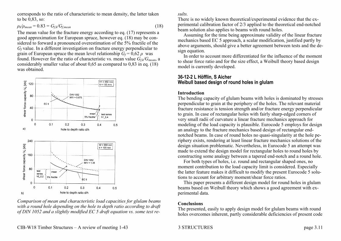
35-12-1 S Aicher, L Höfflin Glulam beams with round holes - A comparison of different design ap-proaches vs. test data Introduction The design of glulam beams with holes is treated considerably different in timber design codes. Examples are the latest drafts of Eurocode 5 and of the German timber design code DIN 1052. In the first case a solution based on a linear fracture mechanics approach is stated whereas in the lat-ter case a strength of materials design is given. In both cases the underly-ing mechanical models represent rather crude idealizations, especially when round holes are regarded.
The paper first shortly reveals the mechanical problem. Second, both mentioned design approaches are discussed and compared quantitatively. Thirdly, both approaches are evaluated vs. results of some recent experi-ments with different sized beam specimens. Some amendments of the de-sign approaches are proposed. Proposal for design equation changes Any scalar changes to the DIN approach improving the agreement with the test results for large beams produce a less good agreement for beams with small dimensions. The approach, method inherent, does not reflect the ex-perimentally obvious size effect of the fracture mechanism correctly, what is inline with former evaluations of the size effect problem (Aicher et al., 1995).
Looking at the reasons for the extreme load capacity overestimation by the EC 5 approach at least two points are important: Factor kn, according to
, 0,05
2,
1
3
f kn
v k
G Ek
f
depends on (characteristic) fracture energy Gf,k in tension perpendicular to grain. For the mean value of Gf the relationship
Gf = 0,65ρ (17)
was found by Larsen and Gustafson, For derivation of a characteristic val-ue it was assumed that the ratio of characteristic to mean fracture energy
CIB-W18 Timber Structures – A review of meeting 1-43 3 STRUCTURES page 3.11
corresponds to the ratio of characteristic to mean density, the latter taken to be 0,83, so:
ρk/ρmean = 0.83 = Gf,k/Gf,mean (18)
The mean value for the fracture energy according to eq. (17) represents a good approximation for European spruce, however eq. (18) may be con-sidered to forward a pronounced overestimation of the 5% fractile of the Gf value. In a different investigation on fracture energy perpendicular to grain of European spruce the mean level relationship Gf = 0,62 ρ was found. However for the ratio of characteristic vs. mean value Gf,k/Gmean, a considerably smaller value of about 0,65 as compared to 0,83 in eq. (18) was obtained.
Comparison of mean and characteristic load capacities for glulam beams with a round hole depending on the hole to depth ratio according to draft of DIN 1052 and a slightly modified EC 5 draft equation vs. some test re-
sults. There is no widely known theoretical/experimental evidence that the ex-perimental calibration factor of 2/3 applied to the theoretical end-notched beam solution also applies to beams with round holes.
Assuming for the time being approximate validity of the linear fracture mechanics based EC 5 approach, a scalar modification, justified partly by above arguments, should give a better agreement between tests and the de-sign equation.
In order to account more differentiated for the influence of the moment to shear force ratio and for the size effect, a Weibull theory based design model is currently developed. 36-12-2 L Höfflin, S Aicher Weibull based design of round holes in glulam Introduction The bending capacity of glulam beams with holes is dominated by stresses perpendicular to grain at the periphery of the holes. The relevant material fracture resistance is tension strength and/or fracture energy perpendicular to grain. In case of rectangular holes with fairly sharp-edged corners of very small radii of curvature a linear fracture mechanics approach for modeling of the load capacity is plausible. Eurocode 5 employs for design an analogy to the fracture mechanics based design of rectangular end-notched beams. In case of round holes no quasi-singularity at the hole pe-riphery exists, rendering at least linear fracture mechanics solutions of the design situation problematic. Nevertheless, in Eurocode 5 an attempt was made to extend the design model for rectangular holes to round holes by constructing some analogy between a tapered end-notch and a round hole.
For both types of holes, i.e. round and rectangular shaped ones, no moment contribution to the load capacity limit is considered. Especially the latter feature makes it difficult to modify the present Eurocode 5 solu-tions to account for arbitrary moment/shear force ratios.
This paper presents a different design model for round holes in glulam beams based on Weibull theory which shows a good agreement with ex-perimental data. Conclusions The presented, easily to apply design model for glulam beams with round holes overcomes inherent, partly considerable deficiencies of present code

CIB-W18 Timber Structures – A review of meeting 1-43 3 STRUCTURES page 3.12
design approaches. The model accounts for both, size effect and moment influence on load capacity in transparent manner. Hereby, it allows selec-tive calibrations to experimental results for all relevant influential parame-ters. 41-12-4 H Danielsson, P J Gustafsson Strength of glulam beams with holes - tests of quadratic holes and lit-erature test results compilation Background Looking at design recommendations for glulam beams with holes in Euro-pean timber engineering codes over the last decades, it can be seen that the strength design has been treated in many different ways. The theoretical backgrounds on which the recommendations are based shows fundamental differences and there are major discrepancies between the strength estima-tions according to the different codes as well as between tests and estima-tions according to codes. The contemporary version of Eurocode 5 does not state any equations concerning design of glulam beams with holes and the recommendations in the German code DIN 1052 concerning rectangu-lar holes were withdrawn during the fall of 2007. The absence of design recommendations indicates a need for further investigations of the subject. There are, however, several tests found in the literature concerning the strength of glulam beams with holes. Two of the most recent and more comprehensive studies were presented by Höfflin in 2005 and by Aicher and Mifflin in 2006. These studies dealt exclusively with beams with cir-cular holes. Although the test results found in literature all in all represent much work, important parameters such as mode of loading, beam size and hole placement have often been varied only within a very limit range. Among other limitations, it seems that all available test results relate to glulam beams with holes that are centrically placed with respect to the beam height. 42-12-1 S Aicher, L Höfflin Glulam beams with holes reinforced by steel bars Introduction
The placement of holes in glulam beams represents a frequent necessity in timber construction practice in order to enable the penetration of pipes, wirings and heating tubes. The disturbance of the stress flow around a hole creates tension stresses perpendicular to grain which reduce the load bear-ing capacity of beams with unreinforced holes, depending on the hole size, considerably. In general a hole reinforcement is inevitable to provide suf-ficient shear force capacity. Invisible internal reinforcements, such as glued-in steel rods and screws, especially self-tapping screws, are very of-ten preferable from architectural points of view.
The paper reports first on some basic aspects of the stress distribution in the timber and on the rod forces of reinforced holes at two loading stag-es: i) before crack development and ii) after cross-sectional cracking at the hole edge and subsequent progressive crack extension. Second, the design and construction rules for internal reinforcements, as specified in DIN 1052:2008, are given. Third, first experiments with internally reinforced holes in structural sized glulam beams are presented. The results are dis-cussed in comparison with experimental results on shear force capacities of beams with unreinforced holes and with regard to calculated shear ca-pacities. A preliminary assessment of the applied design rules is given. Conclusions The performed tests with glulam beams with reinforced holes proved that internal, invisible reinforcements by screws or glued-in rods provide a sig-nificant, well reproduceable increase of the static short term shear force capacity vs. glulam beams with unreinforced holes. However, the investi-gated reinforcement configurations did not forward completely the ex-pected load capacity level predicted by the applied DIN 1052 design mod-el. As the final failure mode is a shear failure, as in case of unreinforced beams, it seems worthwhile to attempt a fracture mechanics approach. In ongoing tests further reinforcement and beam size configurations are re-garded.
CIB-W18 Timber Structures – A review of meeting 1-43 3 STRUCTURES page 3.13
3.2 BRACING 7-2-1 J A Simon Lateral bracing of timber struts Synopsis Current codes of practice give little guidance on the design of bracing and its effect on the strength of struts. Available information on the variables affecting the behaviour of bracing is given, as well as results from a limited amount of analytical and test work done recently by the NTRI. Object of this paper The object of this paper is not to offer draft clauses on the design of brac-ing for inclusion in codes of practice, but rather to outline the problem are-as and to provide a description of the 'state-of-the-art' to be used as a basis for discussion and future research work. There appear to be conflicting re-sults on the effects of the variables involved, and considerable research ef-fort is required before a realistic code for the design of bracing can be compiled. In the near future, the NTRI hopes to commence a project which will be designed to investigate the problem in more detail. Conclusions Implicit in the design of braced struts are a number of assumptions on the degree of lateral restraint offered by the bracing members. The magnitude of this restraining force depends on factors such as initial eccentricity in the strut, number of restraints, and connection stiffness. In many cases connections between rafters and purlins or battens may not have a suffi-ciently high stiffness to validate the design assumptions. It is therefore possible that rafters and similar members do not always have the factor of safety suggested by the design calculations.
The analysis of the forces in bracing members is currently based on 'rule-of-thumb' calculations resulting in values which bear little resem-blance to those actually occurring in the erected roof. Although bracing which has been designed by experienced guesswork rather than by detailed calculation appears to have behaved adequately in the past, it is difficult to prove analytically that it is satisfactory. Some realistic design method,
based on the variables involved, must therefore be developed for inclusion in codes of practice.
16-15-1 H Brüninghoff Determination of bracing structures for compression members and beams Introduction To obtain a sufficient lateral stability of wooden structural members they get connected to walls, supports or bracing members being enough re-sistant. Those prevent too great lateral deflections rectangular to the main supporting direction of the components. Simultaneously they also can be taken to carry exterior loads such as wind.
Additional to the exterior loads there are no further forces to the brac-ing members as long as all parts are ideal straight and in a vertical position and if there is a perfect bringing in of loads, consequently the applied sur-charge has no components rectangular to the main supporting direction of the wooden parts. In practice deviations of the ideal position have to be accepted due to unavoidable manufacturing and assembling inaccuracies. They always occur as soon as lateral thrusts due to the wind or other from the outside attacking horizontal forces are led in the plane of the supports and bracings, and thus cause deformations. Resume Equations are given, which allow calculating the loadings of bracing struc-tures. The members with the risk of lateral deflection can be forced by compression forces and by bending moments. The favourable torsional ri-gidity of the beams is taken into consideration.
The lateral loads of compression members, e.g. flanges of trusses, and of glued laminated beams, subject to bending and of combined stressed parts can be calculated.
Simplified expressions are given for parts, subject to pure compression or bending. If the rigidity of the bracing structure is assumed, so that a given maximum of the deflection is not exceeded, very simple expressions are available.
CIB-W18 Timber Structures – A review of meeting 1-43 3 STRUCTURES page 3.14
19-15-2 M H Kessel, J Natterer The bracing of trussed beams Introduction The top chord of trussed beams vertically loaded normally works in com-pression. The bracing system has to stabilize the chord against lateral buckling. The subject of this paper is to determine the lateral loads which act between the chord and the bracing. Before investigating the complete 3 dimensional problem, ile shall start with the simple bar to show some basic effects. Conclusions The distribution of the lateral load for the bracing of trusses is much more complex than is assumed in the design codes. However, from the practical point of view it seems to be too expansive always to take the real distribu-tion of q into account when dimensioning the bracing. Therefore two strat-egies for dimensioning are left. The first is to determine the lateral loads by at least geometrically nonlinear finite elements, which is valid for large scale Systems only. The second is to use the code formulae and to bear in mind that a uniformly and even a sinusoidal distributed lateral load merely gives an estimation of the loads which are really applied to the bracing system. 23-15-2 T A C M van der Put Stability design and code rules for straight timber beams Introduction The stability design of the Eurocode is not general and consistent enough. For instance, in the Eurocode the warping rigidity is neglected for free beams without a horizontal bracing. For braced beams however the tor-sional rigidity is neglected. Further the initial eccentricities are regarded for braced beams and neglected for free beams although the reversed would have been better. The given influence of the point of application of the lateral loading on lef applies only for long beams. So a more general approach is necessary. However the known calculation methods for twist-bend buckling are incomplete and often mutually contradictory and need to be extended.
By Chen and Atsuta, general equations are given for thin walled beams. However solutions are only given for pure bending with compression (thus without lateral loading). The influence of lateral loading is given by Halasz and Cziesseilski, however without initial eccentricities and without normal loading. The influence of warping is also not regarded there and thus there is no distinction between I-beams and box-beams. Larsen and Theilgaard give general equations for the case of pure bending and com-pression, including the influence of initial eccentricities and the failure cri-terion. The warping rigidity is however neglected (as also is done by all authors for rectangular beams) although there is accounted for warping de-formation by the reduction of the torsional rigidity by the negative Wagner effect. This means that it is assumed that there is an unrestrained warping. However restraint warping and warping rigidity is always assumed to exist for thin-webbed beams and trusses (beams with low torsional rigidity), for instance in most regulations, because the twist-bend buckling of these pro-files is calculated from the column buckling of the compressed flange, what is equivalent to a dominating warping rigidity.
In Brüninghoff‘s dissertation, the influence of the eccentricity of the lateral loading and the initial eccentricities are regarded for high rectangu-lar beams. However the failure criterion is not regarded and also the warp-ing rigidity neglected, as is only right for long rectangular beams. Because comparable general equations, including the influence of warping and the failure criterion, for the general loading case are lacking for beams and for thin-webbed beams, the derivation is given here.
26-15-1 C J Mettem, P J Moss Bracing requirements to prevent lateral buckling in trussed rafters Introduction This paper describes a series of tests on trussed rafters, which were aimed at measuring their out-of-plane stiffness and hence determining directly the bracing stiffnesses and forces required to prevent their lateral buckling. The need for the work arose during a project on practical applications of bracing studies. This drew upon earlier research whose object had been to develop theories permitting calculations to be made in relation to topics such as the bracing of beams and columns, and the provision of discretely spaced braces for roof members. A series of design guides is being devel-oped relating to stability and bracing applications, and one of these is to

CIB-W18 Timber Structures – A review of meeting 1-43 3 STRUCTURES page 3.15
deal with the design of bracing for newly constructed trussed rafter roofs, as opposed to remedial bracing. It was realized that little or no experi-mental determinations of the out-of-plane stiffness of trussed rafters, for the purpose of confirming parameters for their stability bracing, had ever been carried out. Consequently, these tests were planned. It was intended to compare the measured lateral stiffnesses of the trusses with theoretical predictions. It was recognized that it would have been preferable to carry out more extensive practical testing, including measurements on whole-roof frameworks as three dimensional assemblies. However, this was not possible within the present scope.
The tests described were of a non-standard type. Forces representing various normal vertical design load cases were applied at the node points of the trusses. The trusses were in fact tested in a horizontal arrangement, for convenience, but these normal 'vertical' loads are described as such throughout this paper. Small loads at right angles to the plane of each truss were also applied, whilst the trusses were subjected to the main vertical loadings. These secondary loads were used, in conjunction with precise lateral deflection measurements, to evaluate the out-of-plane stiffness for each truss configuration, load case and restraint arrangement. Concluding remarks The experimental work described above was carried out on typical exam-ples of commercially available medium-span trussed rafters, of 35 mm thickness and M75 grade, such as are sold in tens of thousands by normal stockists. These were not specially fabricated components, manufactured by laboratory staff. They incorporated 'initial lack of straightness' typical of such lightweight trusses. The trusses also contained punched metal plate fastener joints, whose rigidity was not complete in planwise bending, or in buckling about the minor axis. In the section of this paper dealing with the tests, it has been explained how the actual lateral stiffnesses at two im-portant points on the rafters of the trusses were measured, whilst the com-ponents were subjected to a typical range of in-plane (vertical) design loadings.
The lateral buckling behaviour of the components under load was by no means as regular as is supposed in the normal theoretical treatments, where distinct 'second', 'third' and 'fourth' buckling modes, in discrete si-nusoidal waves, can always be recognized. In order to restrain the compo-nents to behave in a manner even approaching these more ideal, theoretical conditions, a variety of sprung clamps and negative and positive restoring
forces had to be applied on the test rig, through the cable-pulley system. Three of the trusses were re-tested inverted from their original positions, and the behaviour of the inverted component was not necessarily a mirror-image of the first arrangement.
As a basis for comparison, a series of linear elastic computer analyses were performed, in which the combined vertical and lateral loading ar-rangements were simulated. In general, these simulations indicated levels of lateral stiffness comparable to the test results, although in several in-stances they suggested that the tested components were in effect exhibiting one or two degrees of freedom from lateral restraint greater than was being aimed at through the test arrangement. Also, as mentioned above, the de-creasing stiffnesses with increasing truss pitch, suggested by the computer model, were not reflected in the tests. This was likely to be due in part at least to some of the 'real' effects that were not modelled, including incom-plete lateral stiffness of the truss plated joints, at the apex, and, for the tall-er trusses, at a rafter splice position.
A comparison with some simplified theoretical assumptions has been included, and this has shown that lateral stiffnesses can be predicted which again are of the same order of magnitude as both the test results and the three-dimensional model predictions. The result based on the classic Win-ter theory, together with assumptions regarding restraint at every third bat-ten position, should not be compared too closely with the computer model predictions, since it was not possible exactly to reconcile each of the as-sumptions. Nevertheless, it is reassuring that all three methods of assessing the lateral stiffness of trussed rafters under load yield results of a similar magnitude to one another.
The adaptation of the classical discrete bracing theory for 'real' timber members with imperfections used in the comparison with theory contains several assumptions based on judgement of what is accepted in current de-sign practice, and what codes permit, rather than being based soundly up-on measurements. Throughout the project which has reviewed existing stability and bracing work in timber, there has been found to be a marked absence of experimental data, other than some very thorough beam-column tests by Larsen and Theilgaard and some measurements of imper-fections in timber columns by Ehlbeck and Blass. There is a need for bet-ter experimental backing for assumptions regarding 'real' beam columns in components such as trusses, based upon careful measurements of individ-ual members, before going too far with whole-roof tests and with further extensions of theory.
CIB-W18 Timber Structures – A review of meeting 1-43 3 STRUCTURES page 3.16
At the same time, although the British trussed rafter code, BS 5268 : Part 3 gives guidance on ad hoc bracing for domestic-scale roofs, the de-signer is without advice on longer spans, which are increasingly important in the roofing of commercial and industrial properties. The tests described in this paper have highlighted the probable importance of several practical effects upon likely long-term bracing performance. These include initial lack of straightness of members and of the erected components as a whole, as well as the contributions of fastener slip and creep-buckling phenome-na.
As a consequence of this, a research proposal has recently been made to undertake full-scale tests to investigate the response of braced roofs to their lateral design loads, and to include an assessment of the likely long-term effectiveness of the same bracing, for stability purposes. 32-15-1 S Andreasson Three-dimensional interaction in stabilisation of multi-storey timber frame buildings Summary A study has been performed with a finite element model in order to inves-tigate the distribution of forces in multi-storey timber frame buildings un-der combined lateral and vertical loading. The model has been calibrated and verified against full-scale tests, performed on separate shear walls. During the tests, the vertical support forces have been monitored as well as the load and top displacement. The calibrated model has been used primar-ily to investigate the distribution of dead load when combined with lateral loads on shear walls and transverse walls with gypsum sheathing. The re-sults indicate that the in-plane stiffness of diaphragms in a lateral-force-resisting system is considerable, and imply that a great portion of the dead load can be utilised to counteract uplift forces caused by lateral loading. The conclusion is that the designers have great possibilities to take ad-vantage of dead load when stabilising the system by properly connecting the different diaphragms in order to achieve interaction in three dimen-sions. This is not always the practice in the current two-dimensional de-sign approach.
Conclusions The compression force at the end of a shear wall will always be below the sum of the dead load applied at the stud and the resultant vertical force caused by the horizontal load. On the uplift side of a shear wall, the dead load counteracting the uplift force is always greater than the dead load on that actual stud. The tributary area for the dead load counteracting the up-lift force increases slightly with the number of storeys and the wall length (within reasonable limits), and more obviously with the number of sheath-ing layers. An increase in the anchorage stiffness gives a decreased tribu-tary area for the dead load transferred to the point of uplift.
The possibility to take advantage of hold-downs in adjacent walls in or-der to counteract uplift forces in a shear wall is mainly governed by the stiffness of the connection between the walls. The capacity of the trans-verse walls necessary in order to transfer the uplift force from the uplift point to the anchorage is rarely a restriction in a conventionally designed system.
Dead load applied along a transverse wall can be effectively transferred to an adjacent shear wall if the shear wall is properly connected to the transverse wall and not anchored to the foundation. Hence, there is a pos-sibility to use dead load to counteract uplift forces also when the flooring joists are supported on the transverse walls and not on the shear wall. 33-15-3 H J Larsen Eurocode 5 rules for bracing Background The background for the rules for bracing in [Eurocode 5, 1993] was given in several CIB W 18-papers e.g. Paper 16-15-1 and Paper7-15-1. The present paper summarises briefly the background of the rules and gives a proposal for a modification.
CIB-W18 Timber Structures – A review of meeting 1-43 3 STRUCTURES page 3.17
37-15-4 J Munch-Andersen Bracing of timber members in compression Introduction Timber members or systems of members in compression often require lat-eral support at intermediate nodes to prevent stability failure of the beams. The requirements to strength and stiffness of a system that can provide this support are studied. The study was initiated in connection with the prepa-ration of a practical guideline for bracing of trusses in roof structures in accordance with the requirements in the first version from 1998 of a new generation of the Danish Code of Practice for the structural use of timber. This code has rules very similar to those in Eurocode 5. It appeared that no simple amendments to the traditional way of bracing small and medium-size roof structures for wind load would meet these requirements. Howev-er, there is no evidence that increased bracing would be necessary to avoid stability failure during snow load for normal span trusses. For long span trusses (about 20 m) made from 45 mm planks, problems have been seen that justify that sufficient bracing must be ensured.
The basis for the rules in Eurocode 5 were reviewed in order to find ar-guments for reducing the requirements to a level more in line with experi-ence from practice. It appeared that the rules were not at all conservative for a single member in compression, but for a series of members - like in roof structures – there are system effects that would warrant a significant reduction. A revised version of the Danish code from 2003 includes some of the findings in this paper regarding system effects. Conclusions The bracing requirements for systems of timber members in compression in Eurocode 5 section 9.2.5 are somewhat on the unsafe side, even when the most conservative factors suggested are chosen.
There is a fairly simple relationship between strength and stiffness re-quirements to the bracing system. The designer could easily be given the possibility of choosing a favourable set for the actual purpose. This could for example be relevant if other performance requirements call for a smaller deflection than that required for the bracing. Then the load could be reduced as well.
If the requirement to the stiffness of the lateral bracing at intermediate nodes is kept at C = 4N/a, the force should be increased from F = N/50 to
F = N/37,5. If the stiffness requirement is increased to C = 6N/a, then the present force F = N/50 is sufficient.
The present code value for uniform load on the bracing system for one member in compression is qd = N/(30l), which corresponds to a maximum deflection of less than l/1000. If the load is increased to qd = N/(24l), the permitted deflection increases to l/500. If other loads – like wind load – increase the deflection, the same deflection requirements should in princi-ple be met, and consequently the stiffness of the bracing system must be increased. Since the load combination factor for wind and snow is small, the practical impact low.
The reduction of the load, when the initial deflections are smaller, is al-so significant for the bracing system. Therefore, there should be differenti-ated requirements for structural timber and laminated timber.
Significant systems effects will reduce the accumulated loads both on a common bracing system for several parallel members in compression and on the lateral bracing at intermediate nodes. It is suggested to design the bracing system for 2 times the load q for one member in compression. The accumulated force in the lateral bracing is determined to be only 2 or 3 times the force F determined for one member.
There is also an unused stiffness and strength that can be used to trans-fer loads locally when simple bracing systems are used for smaller struc-tures.
42-15-3 Xiaobin Song, F Lam, Hao Huang, Minjuan He Stability capacity and lateral bracing force of metal plate connected wood truss assemblies Abstract This paper presents the results of experimental and numerical studies on the critical buckling load and lateral bracing force of metal plate connected wood truss assemblies. Material property tests and full-scale tests of indi-vidual trusses and truss assemblies were conducted. The material proper-ties test results were used as input parameters to finite element method based models, which were then verified based on the test results of indi-vidual trusses and truss assemblies. Good agreement was achieved. It was also found that the 2% design rule for the lateral bracing system overesti-mated the lateral bracing force in the tests. The generated database and the output of the models can be applied to more general structural configura-
CIB-W18 Timber Structures – A review of meeting 1-43 3 STRUCTURES page 3.18
tions, and contribute to the improvement of the design methods for lateral bracing system. Conclusion This paper presented the results of a study on the critical buckling load and lateral bracing force of MPC wood trusses and truss assemblies. Basic ma-terial property tests and full-scale tests of MPC wood trusses and assem-blies were conducted, of which the results were used as input parameter and verification for FEM based models. The following conclusions were made based on the results. – The stiffness of individual trusses was similar despite the variation in
material properties, truss plate placement and workmanship; however, the critical buckling loads of the trusses were influenced by the initial out-of-plane deformation and the out-of-plane rotational stiffness of the MPC connections of the compression members. It was also found the influence of the keeper nails on the test results of the individual trusses was immaterial.
– The 2% rule-of-thumb was found to overestimate the lateral bracing force, due to the out-of-plane rotational stiffness of the MPC connec-tions and the randomness in the initial out-of-plane deformation of the braced webs.
It should be kept in mind that these conclusions were based on the test re-sults of the particular truss configurations and load situations used in this study; however, this work provides a framework about how to test and evaluate the critical buckling load and lateral bracing force of MPC wood truss assemblies. 42-15-4 Chun Ni, H Rainer, E Karacabeyli Improved method for determining braced wall requirements for con-ventional wood-frame buildings Introduction Wood-frame construction is by far the most common structural system in North America for single-family houses and low-rise multi-family dwell-ings, constituting over 80 % of all residential housing. In North-America, wood-frame construction can be built either by following prescriptive codes or engineering design codes. Conventional wood-frame construction
refers to buildings that are designed and built according to the prescriptive rules such as those in Part 9 of National Building Code of Canada (NBCC) or the US International Residential Code (IRC). T he prescriptive rules in the codes are largely developed based on historical practice for housing and small buildings as well as pre-engineered solutions. Although build-ings designed and constructed with the prescriptive rules have performed well in past earthquakes and resulted in relatively few casualties, a very few wood-frame buildings have collapsed or suffered serious damage, par-ticularly where lack of adequate bracing created a weak first storey. In this paper, bracing requirements for conventional wood-frame con-struction in the current codes are discussed. An improved method to better rationalize the bracing requirements for conventional wood-frame con-struction is presented. The lateral load capacities of braced walls are also discussed. Summary and conclusions The potential shortcomings of the bracing requirements for conventional wood-frame construction were analysed on selected building scenerios where the lengths and locations of the braced wall panels were chosen to represent as much as possible the most unfavourable case for lateral load resistance. The results showed the imbalance between the required lengths of braced walls in short and long directions of a rectangular building. While the lateral load capacity in the long direction of the building is adequate for the twoand three-storey buildings and is in fact overly con-servative for the one-storey building, the lateral load capacity in the short direction of the building may not be sufficient to resist the base shear forc-es with the minimum bracing requirements in the codes. The results also showed that two-storey building has the largest discrepancies between the base shear and the lateral load capacity. This is because the required min-imum lengths of braced wall panels are the same for one-storey and two-storey buildings in the codes. A new method was proposed to better rationalize the bracing require-ments for conventional wood-frame construction in Canadian and the US building codes. Instead of specifying the minimum length of braced wall panels as a constant percentage of the length of a building parallel to the direction of loading considered, the new method specifies the minimum length of braced wall panels as a function of floor area of the building. This will address the imbalance between the required lengths of braced walls in the short and long directions of a rectangular building.

CIB-W18 Timber Structures – A review of meeting 1-43 3 STRUCTURES page 3.19
3.3 BRIDGES In general Eurocode 5 Part 1-1 applies also for the design of bridges. Eu-rocode 5 Part 2 covers however some topics that are special for bridges. Important examples are deck plates and fatigue. The members of the drafting groups for Eurocode bridges have, howev-er, not been very active in CIB-W18 and the few papers on bridges are general and not related to Eurocode 5. 27-12-1 M A Ritte, T G Williamson State of the art report: glulam timber bridge design in the U.S. Abstract Structural glued laminated timber has been successfully used as a highway bridge material in the United States for approximately 50 years. From the mid 1940's to the mid 1960's, virtually all of these bridges were longitudi-nal girder or arch type glulam superstructures with a nail-laminated wood deck or some form of composite concrete deck. The next evolution of the-se bridges occurred between the early 1970's and the late 1980s, when the large majority of these bridges were constructed using longitudinal glulam girders and transverse glulam decks or longitudinal glulam deck super-structures manufactured from conventional softwood lumber species. Re-cently, highway bridge applications employing glued laminated timber have been expanded to include alternative wood species and new designs utilizing the concept of stress-laminating. Additionally, current research using composite plastic materials in conjunction with glulam may lead to future innovations in timber highway bridges. Conclusions Beginning in the late 1960's, extensive research was undertaken in the U.S. to advance the technology for using glulam in highway bridge con-struction. This research, which has been ongoing since that time, has re-sulted in many innovative technologies that have been successfully incor-porated in numerous glulam highway bridge applications throughout the U.S. Continuing research will undoubtedly expand on existing technolo-gies and lead to new technologies which will create additional opportuni-ties for the use of glulam and other wood products in highway bridge con-struction.
It is further hoped that much of the glulam bridge technology developed in the U.S. over the past 25 years may have application in other countries where the use of timber in bridge construction is a design option. For ex-ample, although not located in the U.S., one of the most striking examples of the innovative use of glulam in highway bridge construction is the re-cently completed cable-stayed glulam bridge constructed near the airport in Hiroshima, Japan. This two lane wide bridge has a total length of 145 meters with a center dear span between support towers of 84 meters. This bridge uses a glulam truss configuration for the suspended superstructure. Although constructed in Japan, the glulam components for this unusual timber bridge were all manufactured, pre-fabricated for all connections and pressure preservative treated at manufacturing facilities in the U.S. 27-12-2 C J Mettem, J P Marcroft, G Davis Common design practice for timber bridges in the United Kingdom Introduction There is a well established history and a continued use of timber for bridg-es in the United Kingdom. In a recently initiated survey, a number of in-teresting designs were encountered, and the majority of these were found to be in good condition. TRADA and more recently TRADA Technology Ltd. (TTL) have a long record of encouraging, fostering, and advising on the use of timber in bridges. The often-mentioned advantages of timber, namely good appearance, low production energy, and weight saving, plus the good durability that can be achieved with correct design, are especially apparent in this high-profile application. TRADA also has longstanding and substantial experience in the use of timber for pre-fabricated modular bridges in developing countries. The first of a series of standard designs was prototyped in Kenya some twenty years ago. Modular wooden road bridges are still being produced in accordance with well-tried design man-uals and drawings, using local timbers and labour, to the great advantage of rural communities in more than two dozen countries in all of the tropi-cal continents.
Unfortunately, however, the official bridge design scene, viewed from the position of the average civil and structural consulting engineer in the United Kingdom, does nothing to encourage the use of timber for bridges. There is no British Standard dealing specifically with the design of timber bridges. The BS5400 series only covers steel, concrete, and steel-concrete
CIB-W18 Timber Structures – A review of meeting 1-43 3 STRUCTURES page 3.20
composite bridges. This absence of a British Standard is thought to have inhibited the specification of timber as the structural medium for many footbridges, as well as having resulted in a number of designs whose per-formance has not been entirely satisfactory. Although other authorities such as Department of Transport (DoT) have their own standards, recog-nising timber in footbridges to a small degree, the absence of a main code of practice is a deterrent.
TTL were extremely impressed by the manner in which the US Nation-al Timber Bridge Initiative was launched, and by its subsequent success. Their programme involves many demonstration timber bridges, together with research and technology transfer. Starting from a relatively small fi-nancial basis, it was difficult to see how anything comparable could possi-bly be started in the United Kingdom.
Recently however, two positive factors have emerged. Firstly, thanks to extremely understanding support from the Department of the Environment (DoE) Construction Sponsorship Directorate, work has been started which is partly sponsored by government and which is supported by industry through the Collaborative Research Programme. During 1993, this was preceded by a feasibility study which was arranged through an extra-mural contract with the Building Research Establishment (BRE). This led to two preliminary study reports. The second positive step is that active work has now been started on drafting Eurocode 5: Design of Timber Structures Part 2: Bridges. TTL is providing the engineer who is the UK representa-tive on the drafting team. It is to be hoped that through these concerted ef-forts, the enthusiastic use of timber in significant bridge structures which is to be seen in other parts of Europe will cross-fertilize in Britain. 39-12-1 K Crews Recommended procedures for determination of distribution widths in the design of stress laminated timber plate decks Synopsis Stress laminated timber (SLT) decks are constructed by laminating indi-vidual pieces of timber placed side by side (on edge), until a solid deck of the desired width is achieved. The laminating is achieved by compressing individual timber members together by applying a prestress in the trans-verse direction, which "squeezes" the individual pieces of timber together, creating an orthotropic plate.
A number of approaches have been adopted for modelling the ortho-tropic behaviour of SLT plate decks. BS EN 1995-2: 2004 presents three of these as basic methods for design of SLT plate decks –orthotropic plate methods, grid (or grillage) modelling and the so called simplified method, which uses the concept of distribution width, to design the deck as a "wide beam."
This paper discusses the basis for modelling deck behaviour adopted in North America, Australia and Europe and compares the various predic-tions of distribution width, for a given material. Modification to some as-pects of BS EN 1995-2: 2004 (Eurocode 5: Design of timber structures – Part 2: Bridges) are recommended that would lead to increased efficiencies in design using the "simplified method", based on the results of research in North America and Australia. Conclusions and recommendations Accurate prediction of the distribution width for design of an SLT plate deck has a major bearing on the economics of the structure, as well as be-ing important for providing realistic assumptions for modelling the struc-tural behaviour of the deck system. Iit can be concluded that the current simplified method for determining distribution width specified in BS EN1995-2: 2004, is conservative when compared with other international methods, which have been derived from load testing of prototype stress laminated timber bridge decks.
Both the Canadian and Australian methods for predicting the distribu-tion width are based on simple equations that have been found to have ac-ceptable levels of accuracy and reliability when compared with the results of full scale load testing. It is therefore recommended that these same equations be assessed for applicability for modelling the load responses of European stress laminated timber plate bridge decks. This assessment should ideally be undertaken by analysis (using the equations presented in Section 4 of this paper) of data obtained from load testing of suitable bridges constructed from European timber species. The applicability of the equations would then be determined and if necessary adjustments made to produce a simplified set of equations that replace the current provisions of Clause 5.1.3 of BS EN1995-2: 2004 for longitudinal SLT decks.

CIB-W18 Timber Structures – A review of meeting 1-43 3 STRUCTURES page 3.21
42-12-5 K Karlsson, R Crocetti, R Kliger Mechanical properties of stress laminated timber decks - experimental study Introduction Timber bridges for road traffic are often designed as stress laminated tim-ber (SLT) decks. SLT decks consist of several individual timber beams placed side by side and then stressed together. The friction generated by the prestress between the surfaces of the laminates makes it possible to consider the beams as a homogeneous timber plate. In EN 1995:2004 three models for analysis of timber bridges are suggested, namely:
Orthotropic plate theory Modelling the deck plate by a grid Simplified method, calculation with an effective width beff.
In order to analyze an orthotropic plate, knowledge about material proper-ties in the two main directions of the plate are required. Modulus of elas-ticity (MOE) and Poisson‟s ratio in both directions, as well as in-plane shear modulus are required. There is a significant difference between the material parameters of a single beam and the material parameters of sever-al beams acting as a structural system. It is of great importance that the material parameters of such a system are identified. These material param-eters for SLT decks have been studied over the last two decades mainly in North America and Australia, but also in Europe to some extent. Due to practical reasons, the transverse MOE and in-plane shear MOE are often expressed as a percentage of the longitudinal MOE. The MOE in the lon-gitudinal direction is commonly a known property for a given timber ma-terial. Modelling the deck plate by a grid also requires knowledge of the material parameters in two main directions of the plate, similar as for or-thotropic plate theory. The third alternative in EN 1995-2:2004 is to de-sign the SLT-deck with a simplified method based on the assumption of a beam with an effective width beff to carry the loads. This assumption is the basis for simplified hand calculation methods e.g. Ritter (1990), Crews (2002). The method suggested in EN 1995-2:2004 is significantly more conservative than similar international design methods (Crews, 2006).
There are several experimental methods for determining the material parameters of an SLT. Some methods include dynamic measurements, other require several test sequences. In this paper the results of a test series
according to a method first suggested by Stephan Tsai in 1965 is shown. Two square timber plates are needed together with knowledge of the lon-gitudinal MOE Ex. Plates are subjected to pure twisting and deflection is measured in the middle of the plate.
This paper is the first part of a larger study with the aim of revising suitable design methods for SLT bridges made of Swedish glulam and de-signed for Swedish requirements.
This is a pilot study for obtaining material parameters for SLT decks. Conclusion Material parameters for SLT-decks can be seen in Table 2 for different prestress levels.
The test specimens were constructed out of glulam beams made from of Norway spruce with rather large dimensions. In EN 1995-2:2004, various MC in timber is considered for the coefficient of friction but not for mate-rial parameters for orthotropic plate theory. The influence of various MC requires more research to fully understand its influence on SLT decks. MC in the test specimens were about 9%, which affected the decks perfor-mance and influenced the capability of comparing with other studies. However, it might give an indication to behaviour of SLT bridges in ex-tremely dry environments.
When comparing design methods, the influence of varying material pa-rameters as input data to an orthotropic model only produced an approxi-mate 5% difference between the high values suggested in EN 1995-2:2004 and low values obtained in this study. The difference between the simpli-fied analysis suggested in EN 1995-2:2004 and design methods suggested by Ritter and Crews is approximately 25-35%. The difference in required deck thickness between the two design-methods suggested in EN 1995-2:2004 is approximately 25-50%.

CIB-W18 Timber Structures – A review of meeting 1-43 3 STRUCTURES page 3.22
3.4 COLUMNS 2-2-1 H J Larsen The design of solid timber columns Synopsis This report has been prepared as the basis for discussions in CIB Working Group W 18 regarding the possibilities of formulating on a uniform tech-nical basis Codes for Timber Structures, so that differences only arise due to different loading and safety levels.
The report has been prepared on the basis of standards and supplemen-tary material received from participants in the Working Group. So far, on-ly solid columns have been dealt with, inter alia, because it is relatively easy – at any rate theoretically – to expand the calculation principles for solid columns to apply to composite columns as well. 3-2-1 H J Larsen The design of built-up timber columns See 3.7 Mechanically jointed beams 4-2-1 H J Larsen, S S Pedersen Tests with centrally loaded timber columns Summary 120 tests have been accomplished with columns of Nordic conifer, partly of normal structural grade (unclassified), partly of high grade (T-300). Cross-sections of 50 x 100 mm and 63 x 125 mm have been applied and tests in both principal axes have been made. Slenderness ratios ranged be-tween approx. 20 and 300.
The tests were carried out with special bearings ensuring that the col-umn was simply supported in the end cross-sections with a very slight fric-tion.
The main conclusion of the tests is that the theory given in section 2 is very satisfactory. The theory is based on the theory of elasticity and the as-sumption that in the middle cross-section the column force has an initial
eccentricity e, that – independent of timber grade and direction – can rea-sonably be put at
0,1 0,005e k
λ being the slenderness ratio and k the core radius. Reference is made to figures showing both test results and theoretical values. Further conclusions of the tests are that: – the Euler load-carrying capacity can be determined very satisfactorily
by the so-called Southwell-plot, – the accordance between the modulus of elasticity determined by edge-
wise bending tests and by the Euler formula is very satisfactory. On the other hand, the correlation between the modulus of elasticity in com-pression (determined on 200 mm long prisms) and the modulus of elas-ticity in bending is weak- the compression strength and the modulus of elasticity in bending were found equal for the two grades,
– the correlation between the initial deflection of the columns in the mid-dle and the initial eccentricity determined from the tests by the South-well-plot is weak
In all essentials the results are in accordance with those found by similar Dutch tests. 4-2-2 B Johansson Lateral-torsional buckling of eccentrically loaded timber columns Introduction The problem of lateral-torsional buckling of compression members in tim-ber structures has received little interest. As far as the writer knows there are no test results, published but for the related problem of lateral buckling of timber beams in bending, A brief summary of the results of these tests is that the theory of elastic lateral buckling is applicable on timber. If cor-rect valves of the elastic, conotants, arc inserted in the solutions, the theory will accurately predict the buckling load. Hence there are good reasons for expecting the theory of lateral-torsional buckling to render useful results as far, aselastic conditions are concerned.
Inelastic conditions have been reached in some of the above-mentioned tests but the results are of little use because the bending strength of the test

CIB-W18 Timber Structures – A review of meeting 1-43 3 STRUCTURES page 3.23
beams is not known. Accordingly, little is known about inelastic condi-tions. The influence of initial out-of-straightness is also a white spot as far as test results are concerned.
The present paper is intended to shed some light on the possibilities of lateral-torsional buckling to occur in timber structures to form a basis for a further discussion. Conclusions The study indicates that timber members subjected to bending and com-pression may fail by lateral-torsional buckling. However, in most timber structures the members are braced in lateral direction and hence he prob-lem is mostly avoided. In some large structures in which the main frames are braced by secondary members, the unbraced lengths may be long enough to make lateral-torsional buckling possible
Most design specifications do not cover lateral-torsional buckling. There is probably not too much danger to be expected from this, but the possibility of an unsuccessful design exists. If something goes wrong in this respect it is unfortunately most likely to happen on large structures. It is therefore felt justified to include a design criterion for lateral-torsional buckling in design specifications and this may be done in a simple way. Basic theory It is assumed that the member has a uniform doubly-symmetrical cross-section. The material is assumed to be elastic and the member to be straight immediately before the buckling takes place. The basic case of loading is a central thrust combined with a constant bending moment in the plane of maximum stiffness, see
Figure 1. If the member is free to deflect along the span, the theory predicts that the member becomes unstable for a certain load. The member will start de-flecting laterally in combination with twisting at this load. If the member is hinged at its ends in a way that prevents rotation around the longitudinal axis the critical combinations of bending moment M and thrust N are those satisfying the equation
2
1 1y t cr
N N M
N N M
(1)
in which Ny is Euler buckling load in the lateral direction Nt is torsional buckling load Mc e is lateral buckling moment in absence of thrust. For all practical cases t yN N and hence it is convenient to consider (1) as an interaction formula between yN N and crM M giving different curves for different y tN N as shown in Figure 2. For 1y tN N the in-teraction curve is a straight line and for 0y tN N it is a parabola with horizontal slope at the left end.
Figure 2 Interaction curves for bending moment and thrust

CIB-W18 Timber Structures – A review of meeting 1-43 3 STRUCTURES page 3.24
5-9-1 B Källsner, B Norén Strength of a wood column in combined compression and bending with respect to creep Introduction The purpose of this paper is principally to show the result of calculations of strength and deformation of initially curved homogeneous wood col-umns when creep is considered. Though the subject is not completely dealt with, the presented results will give an idea of the influence of creep on long-term strength. 8-15-1 H J Larsen Laterally loaded timber columns: tests and theory Introduction In the classical theory of centrally loaded columns and lateral buckling of beams it is assumed that the materials are ideal-elastic and that the mem-bers axes are straight up to a certain critical load by which the rupture oc-curs by sudden deflection of the structure. The rupture is thus considered a stability phenomenon only.
The correspondence between theory and practice is good for slender structures, but for non-slender structures there are great deviations which are traditionally explained by a stress dependent modulus of elasticity. For timber, at least, there is bad correspondence between the moduli of elasticity normally measured and those that must be assumed theoretically to explain the load-carrying capacities for columns that are found by tests. For columns the correspondence between theory and tests has proved much better if the columns are assumed to be elastic to rupture but with deviations from straightness.
In the present paper this view has been extended to comprise lateral buckling of beams with axial force under the assumption of pre-curvature in two directions and pre-torsion.
The theoretical load-carrying capacities have been derived. The expres-sions have been verified by tests described in the paper.
The load-carrying capacity expressions found are discussed and simple, approximated design expressions are set up.
17-2-1 T Poutanen Model for timber strength under axial load and moment Introduction It is known that the generally used linear interaction formula:
is conservative. The author has developed a timber strength model which is different. The model is presented to raise discussion and to get test results.
The author has no resources to make tests to verify the model. Conclusions 1. According to the model design formula 1 is 15-20 % conservative when
N,M 0. 2. Results can be derived from basic assumptions without any calibration
to test results. 3. According to the model bending strength can be calculated from com-
pression and tension strength. This calculation fits well with Finnish timber code and a test of 550 samples.
4. The N, M-interaction curve of the model is closely the same as that de-rived by Buchanan from completely different basic assumptions.
5. It is possible to derive equation for size effect from the model. This equation means that size effect can be practically completely explained by coefficient of variation of defect. Test information on size effect is limited but the model seems to fit into available tests.
6. The model defines clearly cross section deformations. This gives an op-portunity to unlinear analysis of timber structures.
18-2-1 A H Buchanan, K C Johns, B Madsen Column design methods for timber engineering Abstract Combined bending and axial loading is often encountered in lumber and timber members. Existing design methods are based on studies carried out many years ago, and are no longer appropriate because they do not recog-
1u u
N M
N M

CIB-W18 Timber Structures – A review of meeting 1-43 3 STRUCTURES page 3.25
nize that wood with defects behaves as a non-linear ductile material in compression, and as an elastic brittle material subject to size effects in ten-sion.
This paper summarizes the findings of a comprehensive investigation into the behaviour of lumber subjected to eccentric axial loading carried out at two Canadian universities. The study included analytical modelling, and an extensive experimental program using full size lumber.
The results of the investigation have been used in this paper to propose improved design methods, using design charts and approximate formulae for in-plane behaviour. The discussion is extended to general loading cases and biaxial behaviour. Input information required for the design process is also discussed. Introduction Combined bending and axial loading is encountered in many types of tim-ber structures. The most common are columns, chord and web members of trusses, and wall studs. Others include arches, domes and rigid frame structures.
Current design methods, developed in the 1920's, are not appropriate for modern timber engineering design. Major deficiencies include the fol-lowing: – they are mainly based on concentric loading tests on small clear wood
specimens, – they assume that realistic strength properties can be obtained from tests
on small clear specimens, – they assume that a member loaded in combined bending and compres-
sion will fail when a limiting elastic compression stress is reached. The possibility of a tension failure is ignored,
– non-linear stress-strain behaviour in compression is not considered, – the effect of stressed volume on the strength in tension is not recog-
nized, – they do not recognize that knots and material variability make it impos-
sible to load a member with perfectly concentric axial loads. Conclusions Four alternative design methods have been proposed for lumber and tim-ber members subjected to combined bending and axial loading. These methods are based on the results of experimental and analytical studies in-to the strength of lumber under eccentric axial loading.
The proposed design methods reflect the behaviour of real materials more accurately than existing methods. They offer potential for more effi-cient and economical design of certain types of timber structures.
This study has identified many areas with potential for further research, the most important being the biaxial behaviour of slender timber members at ultimate loads. 19-2-1 R H Leicester Creep buckling strength of timber beams and columns Summary A simple structural model is developed for predicting the strength of tim-ber beam-columns. The model includes the effects of initial crookedness and of creep. Two different material failure criteria are used. Numerical solutions are given to illustrate the predicted performance characteristics of beam-columns and to illustrate the influence of the various structural parameters. Introduction The recommendations in the draft Eurocode 5 for computing the design strength of timber beam-columns are based on a study by Larsen and Theilgaard (1979). In that study the effects of timber creep are neglected and the strength of timber is defined in terms of a linear criterion that re-lates bending and compression stress at failure.
It is the purpose of this paper to extend the original study to include the effects of creep, and also to examine the consequences of using an alterna-tive failure criterion. The creep model to be used is that applied in the first Australian Standard on timber engineering design AS CA65 and is also applied in the latest draft of that Standard, now AS 1720 (Standards Asso-ciation of Australia, 1986). The alternative failure criterion to be examined is a bilinear one, based on experimental data obtained in studies by Bu-chanan (1984).
In drafting design recommendations for creep buckling, a dominating consideration is that while there is little relevant experimental data availa-ble, buckling strength is a function of a great number of complex parame-ters; examples of these parameters include those used for material failure and creep criteria, material variability, nonlinear material characteristics, the random dispersion of defects and initial crookedness. Thus any struc-

CIB-W18 Timber Structures – A review of meeting 1-43 3 STRUCTURES page 3.26
tural model chosen will be either oversimplified or one in which there is considerable uncertainty concerning the appropriate values to be used for important parameters.
In the following, a relatively simple structural model is developed. Most of the equations are quite general in scope, but for clarity the dis-
cussion will be limited to the particular structural example. The structural element is a beam column of rectangular cross-section b × d ; the lateral restraints are arranged so that the effective buckling lengths about the ma-jor and minor axes are Lx and Ly respectively. The load is an axial load, denoted by N, applied with an eccentricity e in the y direction; this leads to an effective applied bending moment M given by
M = Ne
Concluding comment The equations derived herein provide a relatively simple method of calcu-lating predicted strengths for beam columns. The structural model used in-cludes sufficient parameters to permit an empirical fit with any data that may be obtained within the foreseeable future. Input parameters include creep, initial crookedness and failure criteria. In view of the limited data available on beam-columns, it is unlikely that use of a more complex model is warranted.
It is outside the scope of this paper to discuss appropriate values for model parameters. The data on long-term performance characteristics is extremely limited; some information is given in papers by Leicester (1971b, 1972) and Cheng and Schniewind (1985). Even for short-term characteristics, the data is not extensive. Summary For the design of timber compression members a new method is submit-ted, based on a non linear moment - normal force - interaction of the cross section. The method is derived from the results of extensive simulation calculations and applies to European spruce glulam and to European soft-wood timber columns. The material behaviour is taken into account better than in former methods. With this method a more economic design of col-umns is possible. The influence of moisture content and grading is shown for centrically loaded columns.
19-12-2 H J Blass Strength model for glulam columns Introduction The design specifications for compression members of the current stand-ard DIN 1052 "Holzbauwerke, Berechnung und AusfUhrung" (timber structures, design and construction) are based on a second order elastic analysis, which underlies the ultimate loads for timber compression mem-bers given by Möhler. In the CIB Structural Timber Design Code and in Eurocode 5 the verification of the compression member is also founded on the elastic theory.
More accurate methods of calculation for timber structural members under compressive stress - particularly a second order plastic analysis - could not lead to a more efficient utilization of timber as a building mate-rial, until the stochastic scatter of the dominant influencing variables en-tered into the calculation, since the advantage of a more realistic mechani-cal model had so far been compensated by uncertainties concerning the as-sumed basic material properties. The introduction of the concept of relia-bility in connection with a probabilistic safety principle then made it pos-sible to develop a mechanical model giving an accurate description of the member behaviour in the limit state, taking account of the statistic distri-bution functions of the basic variables. Whether a given level of reliability can be attained in an economical manner, depends on how exactly the me-chanical model describes the load-bearing behaviour and on how well the stochastic model of the basic variables is known.
Generally, the failure probability pf can be determined as a function of the random variables 'resistance R' (e.g. load-bearing capacity of a col-umn) and 'load effect S', as decribed in the following.
The literature provides comprehensive information on the load distribu-tion, whereas the resistance has been investigated only to some extent. The object of this work is to determine the resistance of glued laminated com-pression members taking account of the geometrically and physically non-linear behaviour of the structural components. A mechanical model of the
0
f S Rp f s F s ds
0 0
x
f S Rp f s f r drds

CIB-W18 Timber Structures – A review of meeting 1-43 3 STRUCTURES page 3.27
timber compression member is obtained by a second order plastic analysis, which directly yields the load-bearing capacity of a structural member. The stochastic model of the basic variables covers the distribution func-tions of all governing characteristic quantities including the respective pa-rameters of the distribution. 20-2-2 H J Blass Design of timber columns Introduction The design of timber columns in the draft Eurocode 5 (1986) and in the CIB Structural timber design code (1983) is based on the elastic theory with a linear failure criterion of the cross section: collapse of the column occurs when in the critical cross section an elastic limit stress is reached.
Some research results during the last years show that this is a conserva-tive failure criterion. Taking into account the plastic deformations of the timber when subjected to compression parallel to grain, the ultimate loads of timber compression members are considerably higher than under as-sumption of the elastic theory.
It is the objective of this paper to provide approximate functions for the characteristic strength of centrically and eccentrically loaded timber col-umns. 21-2-1 R H Leicester Format for buckling strength Introduction Buckling strength is a complex function of many parameters including the following, material properties (strength stiffness, failure criterion, defect dispersion, crookedness), climate (as it affects material properties, creep), member cross-section (area, section modulus, plywood and glulam lay-up, structure of built-up members), and structural geometry (member length, end fixity conditions, method of load application). Because of these com-plexities, a systematic and consistent approach should be used in the presentation of equations for buckling strength in a design code; if this is not done, the code users are likely to be confused and unclear as to the
type of structure being analysed and whether the results obtained are rea-sonable.
The following is a proposal for a code format to be applied uniformly for all types of buckling strength specifications. In so doing, it is well to bear in mind that to strive for a high degree of accuracy is inappropriate; many of the critical parameters that affect buckling strength are either un-known or vary significantly from one member to another; examples of such parameters are crookedness, defect dispersion and failure criteria. Conclusions The proposed format for buckling strength described by equations would appear to be applicable to define the buckling strengths of a wide range of structural members. 21-2-2 R H Leicester Beam-column formulae for design codes Introduction Analytical solutions of beam-column formulae can be extremely complex and are not very suitable for use in design codes. The complexities of these formulae are confusing to the designer and imply an accuracy that is not in line with the available knowledge for any specific real structural situation.
Usually data on the buckling strength of beams and columns can be ob-tained without too much difficulty through direct measurement on a spe-cific grade of a particular species of timber. From this data, the five-percentile value is extracted for design purposes. However data on the in-teraction between bending and axial compression strength is difficult to obtain and hence it is appropriate to use some simple empirical estimate of this interaction for design purposes.
In the following a simple interaction equation is proposed, and checked where feasible against analytical solutions and experimental data. Conclusions The beam-column interaction equations appear to be satisfactory for use in design codes.

CIB-W18 Timber Structures – A review of meeting 1-43 3 STRUCTURES page 3.28
30-2-1 W Lau, F Lam and J D Barrett Beam-column formula for specific truss applications Introduction In Canada, there are basically two typical residential roof structures – the traditional rafters and joists (usually cut and fabricated on site) and the metal plated wooden roof trusses (usually prefabricated). Whereas the former dominant the residential market before 1960s and are still used for roofs with unusual configurations, the latter has been playing a major role in the residential market since its introduction.
From structural theories, it is expected that lighter section can be used to fabricated roof trusses due to the load sharing effect. However, when prefabricated roof trusses were first studied in the 1960s, trusses designed according to the timber design codes resulted in member sizes larger than those obtained from the traditional rafters and joists method. A series of prefabricated roof trusses were then tested which showed satisfactory per-formance even though they did not meet the standard wood design proce-dures as set forth in CSA Standard 086.1 "Engineering Design in Wood". Consequently, the roof framing requirements in the code were rewritten stating that residential roof trusses no longer required to satisfy the wood engineering design code as long as they passed the test as described in CSA Standard S307 "Load Test Procedure for Wood Roof Trusses for Houses and Small Buildings." Since most roof trusses are different, it is impossible to test all possible truss configurations. As a result, the Truss Plate Institute of Canada (TPIC) developed a set of design procedures based on which trusses can be designed with confidence to pass the S307 procedures. According to the TPIC design procedures, an increase of 33 % of allowable stresses as specified in the working stress design version of CANS-086.1-M84 is allowed. This increase was explained as the load du-ration factor for structures supporting loads of 24 hours, which is the test duration of the S307 procedures. These ad hoc procedures were developed based on many years of experience and proven satisfactory in service per-formance.
In 1995, the Working Stress Design version of CANS-086-M84 was no longer referenced in the National Building Code of Canada (NBCC). The 1994 edition of the Limit States Design criteria in 086.1-94 did not pro-vide for a 33 percent increase in design properties for the one day load du-ration. Along with changes in characteristic strengths, the removal of the 33 percent increase for one day load duration resulted in the combined
stress indices of the top chords, designed using the TPIC procedures at the time, exceeding unity for trusses previously accepted in Part 9 of NBCC. Therefore, if the new Limit States Design criteria were used in designing residential trusses, member sizes would need to be increased significantly. These issues brought forth a research program engaged by the truss indus-try, Canadian Wood Council, Forintek Canada Corporation and University of British Columbia to develop new design procedures which are con-sistent with the modern limit states design philosophy and reflect the prov-en in-service performance of residential trusses. However, testing of two types of Part 9 trusses by Forintek Canada Corp. showed that the top chords of these two truss designs are adequate with sufficient reliability (Lum et at. 1996).
Currently, the TPIC procedures and the 086.1-94 assume a linear rela-tionship between the axial load and bending load. It has the form of
where Pf is the factored axial force, Mf is the factored bending moment, Mr, is the factored bending moment resistance, and Pr, is the factored compressive load resistance parallel to grain.
Many studies have shown that this linear interaction equation is con-servative when considering dimensional lumber under combined loading.
The factored bending moment resistance, Mr, was derived based on the Canadian Wood Council Lumber Properties in-grade testing program con-ducted during the 1980's from which characteristic values were obtained from third-point bending test results. Modification factors such as size and treatment factors were then applied to these characteristic values to devel-op this factored bending moment resistance. It has been shown by many researchers that loading conditions have a significant effect on member strengths and the derived characteristic values are test method dependent.
Usually beams with higher stressed volume are expected to fail in lower loads compared to beams with less stressed volume. This dependence of member strength on the loading conditions is called stress distribution ef-fect (or known as the load configuration effect). Madsen (1990) made a comparison of derived strengths based on different testing methods and reported a difference as much as 40%. Since the stress distribution factor was not included in the interaction equation of the current 086.1, there is a need to account for this factor to represent more realistic material behav-iour under combined loading.
1f f
r r
M P
M P

CIB-W18 Timber Structures – A review of meeting 1-43 3 STRUCTURES page 3.29
The objective of this paper is to provide the background and derivation to the new design procedures for wood trusses top chord members under axial compression and lateral loads which have been adopted by the 086 technical committee and will be included in the supplement No. I to 086.1-94 (1997) timber design standard. Verifications and Conclusions Extensive testing of columns and beam-columns were performed by Bu-chanan (1984). Based on his experimental results, interaction equations were developed and were compared with the size and stress distribution effects based theoretical interaction curves. Good agreement between ex-perimental data and stress distribution based strength model was observed. In addition, the linear interaction curve used in the previous engineering code has also been shown to be over conservative in most applications. Recent test results of columns under different eccentric axial compression also confirm the non-linear behaviour of the interaction curve.
Considering some typical truss configurations manufactured as given by TPIC, a comparison of the combined stress indices computed using dif-ferent criteria is shown. In general, designs based on the proposed proce-dures have combined stress indices that are similar to the indices comput-ed using the CSA-086-M84/ TPIC-88 procedures. In almost all cases, the CSA-086-M84/TPIC-88 procedures produce slightly smaller CSI than the proposed procedures.
The same trusses designed according to GSA-086.1-M94 give com-bined stress indices which are up to 60% higher than the GSA-O86.1/TPIC-88 procedures. However, results of typical Part 9 trusses (de-signed using current TPIC procedures) by Forintek Canada Corp. show that they have adequate short-term capacities. Clearly the GSA-086-M84/TPIC-88 procedures are too conservative and the new procedures are more reasonable.
The new interaction equation and the associated Km factors, which based on the stress distribution effect and experimental results, appear to better reflect the behaviour of structural lumber under combined bending and axial compression loading and thus it is appropriate for the design of top chord members of wood trusses
CIB-W18 Timber Structures – A review of meeting 1-43 3 STRUCTURES page 3.30
31-2-1 P Becker, K Rautenstrauch Deformation and stability of columns of viscoelastic material wood Introduction Assuming linear visco-elasticity, deformation calculation of bending ele-ments turns out to be very simple using a creep factor. The increase of the determined elastic deformation corresponds to the creep factor. Defor-mation calculation of columns proves to be involved with much more ef-fort. Considering the problem according to theory of second order, creep deformation leads to an increasing bending moment, which again results in further elastic deformation. Superposition of creep deflection considering different classes of loads also turns out to be problematic. The object of this paper is the derivation of simple formulary, which guarantee the relia-ble determination of column deformations and an easy prove of the long-term stability. Conclusion In this paper formulas are derived, which contribute to the determination of creep deflections of timber columns under permanent and variable load-ing. In addition stability aspects are considered. It has to be found out by some further discussion in which way the results should be included in the codes. A consequent application of the probabilistic design concept de-mands, that the described conditions are satisfied by the design values of material properties and actions including the creep factors. Verification according to the codes has to make sure, that not only the short-term load bearing capacity is guaranteed. 34-2-1 W Moorkamp, W Schelling, P Becker, K Rautenstrauch Long-term experiments with columns: results and possible conse-quences on column design Introduction Although the importance of finding out about consequences of time-dependent effects to compressive members has been repeatedly empha-sized, not many creep experiments have yet been performed with columns observing the time-dependent lateral deflection behaviour under axial load. Humphries/Schniewind (1982) and Cheng/Schniewind (1985) re-ported about tests with small clear slender (λ = 173) Douglas-fir speci-
mens under varying climatic conditions. Their intention was the evaluation of time-to-failure of columns under high axial loads. The loads corre-sponded to the 1,4 to 1,8-multiple of the valid service load according to a former American code. The authors registered high failure rates during a maximum test duration of 53 days. Itani & al (1986) performed tests with structural-size slender columns (λ = 121/156) in constant climate also us-ing Douglas-fir specimens. 70% of the individually determined Eulerload proved to be too much for the columns. None of the 60 test specimens sur-vived the duration time of 2000 hours, most of them failed within 200 hours. Itani & al (1986) stated that the use of a former design formula might lead to unacceptable large errors in column design. Fromhold / Frid-ley (1998) reported about experiments under combined beam-column loading in constant climate. They concluded, that considering the creep behaviour leads to a much better evaluation of carrying performance of a wooden structural member. Some further tests have been conducted by Härtel (2000). Härtel studied the behaviour of structural-size columns un-der defined variable climate. He applied the limit load in service range (German code DIN 1052) to his columns and concluded, that time effects are not adequately considered in column design. Some of his measured lateral defections exceeded the tolerable deflections by multiples.
It seems important, that for creep experiments, which are performed under variable environmental conditions, structural-size specimens are taken. Results of small clear specimens can't be simply transferred to structural-size members. In addition to a much more delayed reaction to humidity changes the in homogeneity of the natural grown material wood (varying knot density, annual ring width, etc.) becomes more significant. Structural-size specimens were therefore selected for creep tests with col-umns reported in this paper. 34-2-2 P Becker, K Rautenstrauch Proposal for compressive member design based on long-term simula-tion studies Introduction Results of long-term experimental studies with compressive members in-dicate that the influence of time-dependent deformation effects to the safe-ty of a structure is more severe than would be expected according to de-sign rules. This especially is the case, if the portion of permanent load is

CIB-W18 Timber Structures – A review of meeting 1-43 3 STRUCTURES page 3.31
high, resulting into creep deformation. researchers repeatedly emphasized this.
Creep experiments are extremely time- and money-consuming, which turns out to be problematic. There aren't any creep-tests with columns that have been conducted for more than half a year, simply too short of dura-tion to draw any conclusion about long-term reliability under service loads. Considering this, long-term simulation studies appear as an appro-priate method to observe the long-term behaviour and find out more about time-dependent effects to compressive members. Long-term simulation studies require a model, which reflects long-term material behaviour in a most possibly realistic way. As a consequence especially moist and time-dependent effects have to be covered. Conclusions Long-term simulation studies with compressive members have indicated, that intended reliability is not reflected by design rules. This especially ap-plies to service classes 2 and 3 where time-dependent deformations should be considered in design process. It has been shown, that there is a differ-ence between long-term capacity and the capacity after long-term use.
Long-term failure of compressive members is caused by different mechanisms depending, on slenderness degree: – For slender columns long-term stability behaviour is characteristic. Be-
cause of linearity of deformations of the low-loaded slender members, long-term stability behaviour can be easily covered.
– The long-term capacity of compact columns is exclusively affected by nonlinear creep behaviour. More research is necessary to account for the exact influence.
The kc-design-concept seems generally suitable for service class 1. For service classes 2 and 3 it is recommended not to exceed 50% of the kc-reduced design value of compression strength by design values of perma-nent and long-term acting loads.
The prove according to theory of second order is too conservative con-cerning initial pre-deflection and required reduction of E-modulus as given in the present code. Proposals for a more realistic coverage have been submitted. The verification should contain the consideration of creep de-formations. For service classes 2 and 3 the design requirements are not suitable in the present form because of possible nonlinear material behav-iour. The kc-method should then be taken instead.
35-2-1 R Hartnack, K-U Schober, K Rautenstrauch Computer simulations on the reliability of timber columns regarding hygrothermal effects Introduction The evaluation of the load-bearing, capacity of timber columns is based on the interaction of many effects. In particular, hygrothermal long-term ef-fects considerably influence the reliability depending on load and are a de-cisive criterion for the design of wooden struts.
Nowadays it is almost impossible to evaluate the load-bearing capacity under the influence of hygrothermal long-term effects, because of the long-term nature of such experiments. Furthermore, high costs speak against a purely experimental approach if we consider the dimensions rel-evant to buildings as well as the large number of specimens as a result of wide-spreading parameters. Computer simulations are a cost reducing and substantially faster alternative for determining long-term effects of the load-bearing capacity behaviour.
For this purpose, software was developed at the Bauhaus-University Weimar, Chair of Timber and Masonry Engineering, which is based on the theory of finite elements (isoparametric beam elements). It considers both geometrical and physical non-linearity. The influence of the hygrothermal long-term effects was taken into account with the help of a supplementa-tion to a computer simulations program. The adaptation of the underlying rheological model is a result of the simulation of internationally published test series. The results are consistent and verify the model sufficiently. Summary The wood moisture has a decisive influence on creep deformation of wooden building components and consequently on the load-bearing capac-ity when stability of the struts is endangered. The investigations point out, that in particular the course of the wood moisture in cross-section has a decisive influence, meaning that the values of the deformations are more dependent on the moisture fluctuations than on the level of the average wood moisture.
The actual values of the relative humidity and the resulting wood mois-ture are represented by approximated functions. It is apparent that the di-rect approximation of the climate does not match the real result very well because the fluctuation margin misses. After modifications, satisfying

CIB-W18 Timber Structures – A review of meeting 1-43 3 STRUCTURES page 3.32
agreements can be realised, and appropriate climate scenarios can be cre-ated for all service classes provided in ENV 1995-1. 36-2-1 K Rautenstrauch, R Hartnack The reliability of timber columns based on stochastic principles Introduction As already mentioned in publication Paper 35-2-1, the reliability of timber columns depends on a multitude of influencing variables and on the inter-action of these variables. Firstly, the sector of hygrothermal long-time ef-fects and basic principles of the calculating model was specified. In addi-tion to hygrothermal long-time effects described the spreading of influ-ences and of material parameters which are to be described on the basic of probabilistic principles, have a decisive influence on the evaluation of the reliability of timber columns.
Due to the multitude of influencing variables a procedure solely based on experiments is hardly possible, so that the computer simulations of the structural behaviour presented in this work represent a reasonable and an efficient alternative. Thus the parameter of the influencing sector and also the parameter of the resistance's sector could be taken into account, based on probabilistic principles. Consequentially the load-bearing capacities, calculated by the software ISOBEAM are also distributed probabilistically and they must be analysed accordingly.
The concepts of modern standards are also based on semi-probabilistic principles, so that the computer aided simulation models, presented in the following paper, could be made to verify or calibrate the semi-probabilistic methods of design. Summary A tool has been created which is in a position to calculate the load-bearing capacity of wooden columns with the help of virtual experiments. The ma-terial parameters of wood are determined on pure probabilistic principles and they are respectively allocated to the structural member. Action is treated in the same way, but it is partly estimated as deterministic on the basis of reasonable simplifications. According to measured values of Ger-man climate stations the climatic boundary conditions are taken into ac-count by approximated cyclic specifications.
The chosen approach by using computer simulations makes a confron-tation and a comparison to the load-bearing capacity of standard possible, so that you are able to state facts as to the actual safety. Furthermore, the influence of creep on the reliability of timber columns is investigated in this study. Especially in the constructional convenient regions of slender-ness ratio you can see a high influence. The influence of the load degree and the fractile are also investigated. The influence of hygrothermal long-time effects increases with an increasing load-degree and with a decreas-ing fractile value.
To evaluate the load-bearing capacity of timber columns, the presented procedure on the basis of a probabilistic simulation model is excellently suitable for an economic supply of results, because such investigations are always based on a long-term observation period. 38-2-1 R Hartnack, K Rautenstrauch Long-term load bearing of wooden columns influenced by climate – view on code Introduction As already mentioned in Paper 35-2-1 and Paper 36-2-1, the reliability of timber columns depends on an large number of influences and their inter-action. First of all the field of hygrothermal long-time effects and the prin-ciples of the simulation model was described in detail in [4]. Furthermore, the influence of the actions and the material parameters which spread on basis of stochastic principles, on the reliability of timber columns were ex-plained.
The wide spread of the material parameters of the construction material wood especially leads to a broad spectrum of investigations. Both the ex-pectable high costs, the great effort of time and great amount of specimens speak against a pure experimental procedure. Therefore virtual experi-ments were used. The objective of these investigations was to create a de-sign criterion under different boundary conditions to enable an easy use. In the following the development and the use will be explained in principle. Summary Virtual experiments represent an excellent alternative to real experiments if the used material model is sufficiently verified and a great amount of specimen is necessary because of stochastic aspects. Using the presented
CIB-W18 Timber Structures – A review of meeting 1-43 3 STRUCTURES page 3.33
computer programme ISOBEAM, variation investigations like these were done with the objective to compare the safety level demanded by Code with the safety level reached by virtual experiments. As a result of the vir-tual experiments it can generally be stated that the additional condition of DIN 1052 seems to be appropriate in order to take hygrothermal long-time effects for high load degrees into account. Furthermore, design proposals are discussed which can describe the mentioned long-term effects for de-signing with a minimum equal suitability alternative to the procedure of Code.

CIB-W18 Timber Structures – A review of meeting 1-43 3 STRUCTURES page 3.34
3.5 COMPOSITE BEAM FASTENERS 34-7-5 M Grosse, S Lehmann, K Rautenstrauch Testing connector types for laminated timber-concrete composite ele-ments Introduction The idea of combining the constructional favourable characteristics of concrete and timber is not new. The mainly tension-stressed timber and compression-stressed concrete offer good load-carrying behaviour. The connection between timber and concrete is of fundamental importance for stiffness and losd-carrying performance. Since these systems have usually been realised as timber-concrete composite beams which are mainly taken for bridges or revitalisation of timber beam floors, dowel type connectors were normally studied and taken for the transfer of shear forces.
At the Bauhaus-University Weimar a research program was initiated to develop new connectors for transferring shear forces in laminated timber-concrete-composite plates. In the context of this paper the joints with flat-steel-locks, punched steel sheets and concrete cams are introduced.
An overview of shear tests, performed to examine the load-slip charac-teristics and bending tests of full sized composite floor elements is also given. 36-7-1 L Jorge, H Cruz, S Lopes Shear tests in timber-LWAC joints with screw-type connections Introduction The use of timber-concrete slabs has been considered as a suitable alterna-tive to traditional timber pavements, in terms of structural behaviour, acoustic and thermal insulation and fire resistance.
Typically these structures are made with normal-weight concrete (NWC), very seldom using light-weight aggregates concrete (LWAC).
The use of LWAC will most likely imply a different performance of the timber-concrete slab, due to the expected different short term and long term behaviour of the joints. Although the accepted failure modes for the joints with NWC would involve fasteners and timber only, it should be checked whether the same is valid when LWAC is used. The interest and
relevance of developing further research work on the use of light-weight concrete in composite timber-concrete slabs has been pointed out by sev-eral authors.
The lower modulus of elasticity of this concrete, directly related to its lower density, will imply a higher global deformation of the composite structure, which has to be counterbalanced by its lower self weight. The self-weight reduction has other advantages, like less need for prop, a better fire performance and a higher acoustic insulation to impact sounds as compared to NWC composite slabs.
With the purpose to study the suitability of using LWAC in timber-concrete slabs, composite shear tests on composite specimens were carried out. Special screws were used to connect timber to concrete. Concluding remarks The tests carried out indicate that the use of LWAC, in timber-concrete joints without interlayer leads to a strength reduction of the joint capacity but to a similar stiffness than the use of NWC.
On the contrary, in the presence of the interlayer, the use of LWAC conducts to higher slip modulus and to similar strength than the use of NWC. This is particularly promising for repair works since the studied in-terlayer simulates the floor boards existing in most old buildings that would generally benefit from reduced dead loads.
The modification of the screw (by introducing the washer) did not work as expected. However, the results suggest that this may be of some help in the case of using concrete admixtures even less dense and less resistant than the ones considered in the present study.
For standard screws (no washer), the presence of interlayer did not af-fect joint strength Although resumed to one type of fastener only, test data suggest that the use of lightweight aggregates concrete may be suitable for timber-concrete composite slabs and perfectly competitive alternative to the use of normal-weight concrete.
36-7-3 S Lehman, K Rautenstrauch Nail-laminated timber elements in natural surface-composite with min-eral bound layer Introduction Recently the idea was focused on combining favourable characteristics of
CIB-W18 Timber Structures – A review of meeting 1-43 3 STRUCTURES page 3.35
mineral surface layer and timber in composite elements. Thereby tension-stressed timber and compression-stressed mineral surface layer, for in-stance concrete, offer good load behaviour. The connection between tim-ber and concrete is of fundamental importance for stiffness and load- car-rying performance. Since these systems have usually been realised as tim-ber-concrete composite beams mainly taken for bridges or revitalisation of timber beam floors, dowel type connectors were usually studied and taken for transfer of shear forces.
A research program was initiated at the Bauhaus-University Weimar, to test natural adhesion and modified timber surface structure for the transfer of shear forces in timber-mineral surface layer -composite slabs. It is a matter of saw-rough and additionally profiled lamellas of nail-laminated timber elements in combination with usual mineral surface layer. An over-view of shear tests („slip-block-tests") and tension tests, performed to ex-amine the load-slip is also given. Test data and figures are presented. Based on these test results the behaviour of the connection method is de-scribed. Summary Aim of the work was to examine by means of experiment the bond behav-iour of nail-laminated timber elements and mineral surface layer without additional connecting devices. With the simplest formation of the compo-site joint, already a typical normal concrete on rigid wood surface, shear stresses can be transferred by fv = 0.38 N/mm
2. The coefficient of friction
between wood and concrete with the value μ = 0,9 of normal concrete on even nail-laminated timber element well-known in the literature could be observed.
With normal concrete and profiled lamellas the shear stress amounted to fv = 0.42 N/mm
2. The adhesive tensile tests confirmed the realisations of
Griffith that the actual tensile strength is smaller than the theoretical ten-sile strength received by the shear tests. Particularly high tensile strength fjt supplied the nail-laminated timber elements variant of the type P with a concrete surface layer (HZ/BP). The average tensile strength for this vari-ant amounted about 0.18 N/mm
2. Compared with other bonds of material
the reached tensile strength approximately corresponds to those of bond by stone on mortar.
36-7-4 A Dias, J W G van der Kuilen, H Cruz Mechanical properties of timber-concrete joints made with steel dow-els Introduction The effectiveness of a timber-concrete composite structure is highly de-pendent on the stiffness of the joints that connect the timber and the con-crete. Many different types of joints have been developed and are already used in practice. One of the most used, for its simplicity and availability, are the dowel type fasteners. A research project was started in Coimbra University and Delft University of Technology to improve the knowledge on the mechanical behaviour of these joints. Part of that research project consists of timber-concrete shear tests with dowel type fasteners with dif-ferent conditions and materials. The results and analysis of those tests are presented. The results are also compared with the values computed using the equations given in EC5 part 1 and part 2. Conclusions The results presented here show that the load-carrying capacity of timber-concrete joints is, among others, affected by the compression strength of concrete, a parameter that until now has been disregarded. On the other hand, no indications were found of any influence of the concrete strength on the slip modulus of the joints.
Both slip modulus and load-carrying capacities are affected by the tim-ber density and embedding strength. However, the effect on slip modulus seems to be much higher.
The effect of an interlayer is again higher for the slip modulus than for the load carrying capacity. In both cases the mechanical properties de-crease if the interlayer is present.
This research found some indications that the effect of friction of smooth dowels may not be always negligible on these kind of joints, how-ever further research is needed to confirm it.
The models given in the EC5 for the load capacity of these joints seem to be able to evaluate their actual load-carrying capacities. The values from the models are always conservative when compared with the experi-mental data. Nevertheless these results also show that the properties of the concrete could be considered in the models, giving values with increased accuracy. Considering these results, the load carrying capacity of joints

CIB-W18 Timber Structures – A review of meeting 1-43 3 STRUCTURES page 3.36
with concretes of higher classes, for instance of strengths of 60 MPa and more, could benefit from an increase of up to 20 %.
The ability of the model presented in EC5 to evaluate the slip modulus also seems to be good. However the values given by those models are al-ways around 20% higher than the ones obtained from tests. That may indi-cate that the factor 2 given in EC5 part 2 (discarding the deformations of the concrete) is too high on this situation.
37-7-15 M Grosse, K Rautenstrauch Numerical modelling of timber and connection elements used in tim-ber-concrete composite constructions Introduction Experiments are an important basis of civil engineering. Experimental tests are needed to define physical properties of building materials as well as to make reliable statements concerning the structural safety of compo-nents considering scattering influences. It has to be noticed, that limited information can be gained from test with conventional measurement tech-niques. Most often only the applied load, deflections of few points relative to a reference and integral strains at some sections can be determined. In spite of the enormous effort in applying measurement techniques, the flux of forces within the member can not be determined directly. It can only be interpreted with an engineering understanding of the measuring data and the responses of a structure. Furthermore, the information won from the experimental test only apply to the fixed boundary conditions and are not transferable to real installation conditions without limitations. They are two alternatives that improve the meaningfulness of tests: 1. Increasing the concentration of measuring points: This can not be real-
ized with classic mechanical or electronic measurement techniques. Concentration of the measuring points is easily possible using contact-less methods, such as the close-range photogrammetry.
2. Accompanying numeric simulation of the tests: The distribution of forces, stresses and strains across the member can be calculated and visualized by verifying a mathematical model based on the experi-mental results. In the model it doesn't cause any difficulties to vary boundary conditions and material properties. With this procedure it is possible to improve the test programme and also to optimize the exam-ined member.
Summary A constitutive material model for softwood, based on time-independent multi-surface plasticity was introduced in the paper. This model is able to represent the effects of all nine material-specific micro-mechanical failure modes, mostly arising independently, on the stress deformation-relationship of wood. Furthermore a compression test was presented; de-termining the structural response to longitudinal compression and investi-gating the behaviour of contact connections and the fracture energy dissi-pated during kink-band formation. In addition a material model for con-crete, needed to simulate the load carrying behaviour of timber concrete-composite structures was introduced. The efficiency of FE-simulations us-ing these material-models was demonstrated by three examples. 39-7-3 A Döhrer, K Rautenstrauch Connectors for timber-concrete composite-bridges Introduction The construction method using timber-concrete composites has been de-veloped in the field of building engineering. This technology will also be interesting for bridge constructions in the future. Combining concrete in the compression zone with timber in the tension zone to a composite struc-ture, the favourable properties of both materials could be used efficiently. Especially the combination of log-glued laminated beams with concrete slabs will establish new opportunities for the building of road bridges.
Many problems occurring at timber road bridges could be solved by this new type of hybrid timber-concrete composite-bridges. The concrete deck provides an ideal constructive wood preservation. The distribution of high loads per axle and the transmission of horizontal loads can be realised much easier by the concrete deck. Construction details proved in building of concrete bridges and accepted by the national highway administrations could be transferred. In comparison to simple concrete bridges the super-structure is much lighter, so costs in the fields of foundations could be re-duced. Using precast concrete units a high prefabrication level could be realised.
The development and use of sufficient stiff connectors between timber and concrete is very important for those composite bridge constructions. EC5 previously only included regulations concerning bolted steel fasteners and grooves. Tests are demanded for other connections. For these tests it is
CIB-W18 Timber Structures – A review of meeting 1-43 3 STRUCTURES page 3.37
necessary to take the different time-, temperature- and moisture-dependent behaviour of both composite materials into consideration, especially under conditions of service class 2.
At the Bauhaus-University Weimar, short-time shear tests, long-time shear tests and push-out tests under cyclic loading with three different types of connectors were arranged. The paper will present the results of these tests. The decrease of the stiffness influenced by long-term loading under conditions of service class 2 and under cyclic loading will also be discussed. These results could contribute to verify the shear stiffness ap-proach of the connection between timber and concrete being the funda-mental construction parameter for this new type of hybrid road bridges. Discussion and conclusion The construction method using timber and concrete in a composite action is an expedient alternative to the conventional bridge building. To make this method negotiable further investigations are required in the fields of connectors being suitable for bridge building. The paper focused on sys-tematic tests on three types of suitable shear connectors. Shear tests have been arranged under short-time, long-time and dynamic loading. First the initial values of stiffness and ultimate loads were determined. Then the in-fluences of creeping under conditions of service class 2 and of more than 2 million load cycles were investigated. Based on the experimental research the following conclusions can be drawn:
All tested connectors are suitable for bridge building. They performed superior stiffness and higher ultimate loads in short-time shear tests in comparison to joints being well-known from building construction. Grooves and stud connectors behaved well under fatigue loading exhibit-ing no loss of ultimate loads and stiffness. Fatigue tests at X-connectors and long-time tests have still been running and will be analysed periodical-ly. However, the presented tests have only been done for orientation. More extensive tests are necessary to get statistically confirmed values of stiff-ness and ultimate loads. Such tests will be performed with the stud con-nector at the Bauhaus-University next month.
Finally, the tests results will be verified by a computation model using a complex 3-dimensional nonlinear material model for timber that had been developed at the Bauhaus-University Weimar.
40-7-5 E Lukaszewska, M Fragiacomo, A Frangi Evaluation of the slip modulus for ultimate limit state verifications of timber-concrete composite structures The timber-concrete composite structure consists of timber joists and beams effectively interconnected to a concrete slab cast on top of the tim-ber members. This type of structure was developed as an effective method for strength and stiffness upgrading of existing timber floors. Thanks to the several advantages over traditional timber floors such as increased strength and stiffness under gravity load, better seismic resistance, effec-tive acoustic separation and improved fire resistance, the composite struc-ture is also used in new construction.
The structural behaviour of timber-concrete composite members is mainly governed by the shear connection between timber and concrete. Almost all connection systems are flexible, i.e. they cannot prevent a rela-tive slip between the bottom fibre of the concrete slab and the top fibre of the timber beam. As a consequence of that, conventional principles of structural analysis cannot be applied to solve the composite beam. The Eu-rocode 5-Part 1-1, Annex B provides a simplified calculation method for mechanically jointed beams with flexible elastic connection. This method is based on the approximate solution of the differential equation for beams with partial composite action. As the shear connection is usually character-ised by non-linear load-slip relationship, two different slip moduli are con-sidered for design purposes: serk for the serviceability limit state (SLS) and
uk for the ultimate limit state (ULS) design. The slip modulus serk which corresponds to the secant value at 40% 0,4k of the load-carrying capacity of the connection is usually evaluated by push-out tests according to EN 26891. For the slip modulus uk , the use of the secant value at 60 % 0,6k is recommended. However, if experimental data are unavailable, the Euro-code 5-Part 1-1 suggests the use of the formulae for timber-to-timber con-nections by multiplying the corresponding values of slip modulus serk by two. The slip modulus uk may then be taken as 2/3 of serk . Depending on the type of connection, this assumption may or may not be adequate, lead-ing in some cases to too conservative or not conservative results. Ceccotti et al. for example, reported a significant (50 %) discrepancy between ex-perimental and analytical properties of the connection, and recommended the use of the actual connection properties obtained from push-out tests for the design of timber-concrete composite systems.

CIB-W18 Timber Structures – A review of meeting 1-43 3 STRUCTURES page 3.38
As shear connections markedly affect the efficiency of timber-concrete composite structures, a large number of shear tests on different connection systems as well as bending tests on composite beams have been performed worldwide. Test results can be used in conjunction with finite element (FE) numerical simulations to check whether the hypothesis of assuming the slip modulus for ULS as two-thirds of the slip modulus for SLS is ade-quate.
The first part of the paper presents the values of the slip moduli 0,4k and 0,6k as well as their ratios measured in experimental shear tests for different connection systems. The slip moduli are also compared with the analytical values computed using the approximate formulae suggested by Eurocode 5. In the second part of the paper, analytical calculations are compared with bending test results and numerical simulations for different timber-concrete composite beams. The analytical calculations are carried out for loads at SLS and ULS using the formulas in Annex B of Eurocode 5 and the slip moduli 0,4k and 0,6k , respectively. The aim of the analysis is to check whether the use of the aforementioned secant shear moduli leads to accurate results for SLS and ULS design. Finally, based on the values of the ratios calculated from experimental tests, the assumption of the Eurocode that uk may then be taken as 2/3 of serk is verified and if necessary improved. Concluding remarks The primary conclusions are reported in the following: – The ratios a between the experimental values of secant slip moduli 0,4k
and 0,6k for ULS and SLS verifications varied between 0.2 and 1.15, showing significant differences from the value of 2/3 recommended by the Eurocode 5 for timber joints.
– The ratio should be assumed equal to one for notched connection de-tails characterized by linear shear force-relative slip relationship, and in the range 0.9 to 1 for stiff connectors such as inclined screws. The val-ue of 2/3 seems to be appropriate for vertical screws and dowels, even though in some cases it may drop significantly.
– The use of the Eurocode 5 formulae for the evaluation of 0,4k and 0,6k may lead to significant underestimation (up to 90 %) or overestimation (up to 40 %) of the experimental values.
– The use of the Annex B formulas of Eurocode 5 for composite beam with flexible connections leads to reasonably accurate solutions when the slip moduli at 40 % and 60 % of the shear strength evaluated in
shear tests are used. The errors on deflection and stresses at both SLS and ULS design loads, in fact, do not generally exceed 10-20%. The slip and shear forces suffer from a larger error.
– The use in the Annex B formulas of the slip moduli 0,4k and 0,6k.analytically evaluated leads to larger differences (20-40 %, almost doubled) on deflection and stresses at both SLS and ULS.
Based on these outcomes, it is therefore recommended that the design of timber-concrete composite beams at SLS and ULS be carried out using the experimental values of the slip moduli at 40 % and 60 % of the shear strength, 0,4k and 0,6k . The latter values, in fact, could be significantly dif-ferent from the value of 2/3 0,4k recommended by the Eurocode 5 for con-nections between timber members. The analytical formulae for the evalua-tion of 0,4k and 0,6k should be used only for preliminary design since they leads to significant differences on the experimental values of slip moduli and, therefore, on the deflection, slip and stresses of the composite beam. 42-7-6 U Kuhlmann, P Aldi Prediction of the fatigue resistance of timber-concrete-composite con-nections Introduction Lack of knowledge about the fatigue behavior of the interface between timber and concrete may be regarded as one of the difficulties of the fur-ther spread of timber-concretecomposite structures (TCC-structures) for the construction of road bridges. The first objective of this study is an analysis of the fatigue strength of TCC-beams, in which the joint between the two single sections of timber and concrete is achieved by either grooved connections or crosswise glued-in rebars. These fastening meth-ods seem to be suitable for bridges due to their relative high stiffness as well as strength values. An investigation about the fatigue resistance of such kind of connections might also help to spread the application of TCC-beams for the construction of small or middle span composite bridges.
Load standards, like EN1991-2 [1] or the German DIN-FB 101, state a number of fatigue verifications for road bridges, which have to be included in the design calculation of bridges. For the timber parts of these struc-tures, certain information about fatigue strength is included in Annex A of EN 1995-2, or in DIN 1074, Anhang C. Within these codes the infor-

CIB-W18 Timber Structures – A review of meeting 1-43 3 STRUCTURES page 3.39
mation is limited to pure timber elements, timber-timber joints and steel-timber connections. There is no information about the fatigue resistance of connections between timber and concrete. Conclusions Neither S-N curves nor other analytical means are currently available to predict the lifetime of timber-concrete-composite structures under pulsat-ing load. Two new series of investigations based on shear fatigue tests have been carried out with the aim to obtain a sufficient number of data about the fatigue behavior of the timber-concrete shear interface in com-posite structures. A first preliminary S-N curve for the notch in grooved TCC structures, based on symmetrical push-out tests, has been presented. A number of composite beam tests were carried out to confirm the results obtained with the push-out tests. Furthermore a comparison with the rule given in EN 1995-2 indicates the possibility to use the available S-N line for timber shear faituge failure for grooved connections with the investi-gated geometry. This would lead to a safe prediction of the number of cy-cles to failure for the connection and will be useful for the fatigue verifica-tion of TCC structures in road bridges.

CIB-W18 Timber Structures – A review of meeting 1-43 3 STRUCTURES page 3.40
3.6 LATERAL INSTABILITY 4-2-2 B Johannesson Lateral-torsional buckling of eccentrically loaded timber columns See 3.4 Columns 5-10-1 H J Larsen The design of timber beams See 3.17 Timber beams, general 19-2-1 R H Leicester Creep buckling strength of timber beams and columns See 3.4 Columns 21-2-2 R H Leicester Beam-column formulae for design codes See 3.4 Columns 29-10-1 F Rouger Time dependent lateral buckling of timber beams Introduction. In Paper 27-20-4, Le Govic et al reported the results of a research pro-gram dealing with long term behavior of timber beams (solid timber and glulam). All along this program, beams had been tested in external pro-tected conditions at three stress levels (2 MPa, 5 MPa, 15 MPa) corre-sponding to three average stress ratios (10%, 20%, 60%) with respect to the average short term characteristic strength. Whereas for low stress rati-os (10%, 20%) the beams did not fail, a high percentage of failures due to lateral instabilities was observed at the highest stress level (60%). These
percentages ranged from 50% for solid timber to 100% for glulam. A sim-ple reliability calculation based on Eurocode 5 formulas lead to equivalent probabilities of failure ranging from 10% for solid timber to 25% for glu-lam. These calculated values were obviously much too low and justified further investigation.
In this paper, finite elements analysis combined with Eurocode 5 con-cepts have been done. In a first part, Timoshenko formulas are compared with finite elements results. They show a very good accordance and justify the use of finite elements concept for further analysis. In a second part, critical stresses are calculated for the tested specimens. They lead to the evaluation of probabilities of failure which are compared with the experi-mental values. In a third part, Eurocode 5 formulas are analysed and a new design proposal is given. Conclusions. A numerical method has been compared with the classical theory of Timo-shenko and shows a very good accordance. It was therefore applied for de-riving critical moments and subsequent critical stresses. From these re-sults, probabilities of failure have been calculated and show a very good agreement with the experiment. EC5 equations have been investigated. A revision is proposed in two points (1) Calculate the relative slenderness with the time dependant critical stress, (2) Use another equation for kinst versus λrel, This approach is easily applicable to columns behavior. In §5.2.1, ap-plication rule (2), equations (5.2.1c) and (5.2.1d), the MOE values should be divided by (1 + kdef). By adopting this approach, the long term instability problems can be easily solved.

CIB-W18 Timber Structures – A review of meeting 1-43 3 STRUCTURES page 3.41
3.7 MECHANICALLY JOINTED BEAMS 3-2-1 H J Larsen The design of built-up timber columns Summary The introduction in Section 2 reviews the general basis for the computa-tion of built-up structures where the individual components are connected by semi-rigid connections.
In Section 3 the load-carrying capacity of long perfect columns is de-termined. It is found that this can be expressed by the Euler formula by us-ing a reduced effective moment of inertia, I e. It is suggested that the load-carrying capacity can generally be based on the usual expression, but with the slenderness ratio determined from Ie and not from the total moment of inertia I. The justification for this is discussed.
Section 4 gives expressions for the effective moments of inertia for var-ious types of columns: continuously jointed columns, spaced columns with glued or nailed battens (Vierendeel columns) and glued or nailed lattice columns.
Section 5 describes a number of tests with the said types of columns, partly to assess the applicability of the proposed theoretical expressions and partly to determine the rigidity of the connections.
In Section 6 various approximations are mentioned and assessed, and Section 7 gives a brief proposal for design rules.
Section 8 consists of a summary of the literature to which direct refer-ence is made in the text. 32-12-1 T Wolf, O Schäfer The bending stiffness of nail-laminated timber elements in transverse direction Introduction The load bearing behaviour of nail-laminated timber elements is not ade-quately researched yet. In the design process of nail-laminated timber ele-ments analogies to ruled structural parts in timber work are searched to transfer familiar proves.
The transverse bending stiffness is a characteristic value, which is re-quired at different points. Existing approaches for the determination of the transverse bending stiff-ness found in literature do not reflect the real conditions.
In this paper a new analytical approach for the determination of the transverse bending stiffness is derived. Ina parameter study the resulting values of bending stiffness are examined for plausibility and the influence of the important parameters is presented. A final example shows the sig-nificance of this characteristic value in the design of nail-laminated timber elements. Conclusion The developed computational model enables the calculation of an analyti-cally detectable value for the transverse bending stiffness. The knowledge of the "withdrawal stiffness" of the applied nails is necessary. This charac-teristic value has to be determined by withdrawal tests.
The new approach results in a lower value for the bending stiffness than estimated in former publications. The transverse bending stiffness is very low and reaches only 0,01 to 0,1 % of the bending stiffness in span direc-tion.
It is obvious, that a sufficient transverse load distribution can not be based on the transverse bending stiffness. A sufficient transverse load dis-tribution can only be guaranteed by the shear stiffness of the nail connec-tion. Further investigations lead to the conclusion, that the assumption of sufficient transverse distribution concerning nail-laminated timber floors is not correct.
Assuming this conclusion, an additional prove with a point load of 1 kN in worst loading position, according to German code DIN 1055, is neces-sary. In this case the transverse distribution of a point load has to be known. This is why the importance of the transverse bending stiffness and the described computational model may overlap the shown prove of limit-ing vibration.

CIB-W18 Timber Structures – A review of meeting 1-43 3 STRUCTURES page 3.42
34-12-5 V Krämer, H J Blass Load carrying capacity of nail-laminated timber under concentrated loads Introduction A laminated timber element is a plane structural component composed of single, edgewise-oriented lamellas. These lamellas are mechanically joint-ed usually by nails, alternatively by dowels made of hardwood. In the fol-lowing, only nail-laminated timber elements are considered, which are mechanically jointed by nails and loaded by central concentrated loads.
The aim of a research project was to derive design-equations for the ef-fective bending stiffness, for the resulting bending stresses, and for the nail loads. It would have been quite expensive to obtain the design-equations by running a large number of tests. This is why the tests were simulated on the computer. For the simulations, the parameters l/h (span / height of the element), the nail diameter, and the nail spacing were varied. The simula-tions were conducted on the basis of realistic stiffness-values of the lamel-las and of the nails. The lamellas were generated on the basis of Görlacher, the nails on the basis of the deformation characteristics given in EC5. To guarantee statistically reliable results, 36 different systems of nail-laminated timber elements were simulated. Each system of the nail-laminated timber elements was simulated 500 times. The design equations were derived from the results of these 18,000 simulations.
The results of the design equations show a good agreement with the re-sults of 6 tests. Summary A mechanically laminated timber element is a plane structural component which is made of single, edgewise-oriented lamellas. The lamellas are mostly jointed by nails.
The aim of a research project was to derive design- equations for the bending stiffness, for the bending stresses of the lamellas, and for the ac-tion effects of the nails. The design-equations were derived from the simu-lation of thousands of nail-laminated timber elements. In these simula-tions, the parameters f/h (span / height of the element), the diameter of the nails, and the nail spacing were varied. The simulations were conducted on the basis of realistic stiffness-values of the lamellas and the nails. The la-mellas were generated on the basis of the work of Görlacher, the nails on the basis of the slip moduli given in EC5. To guarantee statistically relia-
ble results, 36 different systems of nail laminated timber elements were simulated. Each system of nail-laminated timber elements was simulated 500 times. The design equations were derived from the 95%-fractile-values and from the mean-values of 18,000 simulations.
The results of the design equations were compared with the test results and demonstrated good agreement with each other. 34-12-7 H Kreuzinger Mechanically jointed beams: possibilities of analysis and some special problems Introduction Mechanically jointed beams have a higher load capacity than the sum of the single beams. One beam must be situated over the other beam and the connectors must transport shear forces from one to the other beam. Figure 1 shows a simple bridge with a „flitch beam". The single beams may also be laminates, horizontally or vertically situated like shown in figure 2.
Figure 1: Flitch beam Figure 2: Mechanically jointed
laminates Regarding cross sections made of two parts - the situation is presented in figure 3: a) two beams jointed with shear connectors b) framework with two flanges, connected by the diagonals c) vertically situated laminates, jointed by nails or screws

CIB-W18 Timber Structures – A review of meeting 1-43 3 STRUCTURES page 3.43
If the bending stiffness of the single beams is zero there is the situation of framework with hinges. The connection is not only necessary to transport the shear forces from one part to the other but also to have the same deformation w of the two parts. Cross sections made of more than two parts are also possible. An example is the ribs of shells like those shown in the figures 4a and 4b. The formulas for an approximation of cross sections with more than two parts are given in E DIN 1052, May 2000.
Figure 3.a. cross sections
Figure 4a: ribbed timber shell /3/ Figure 4b: node /3/
Summary The connections of mechanically jointed beams are quite different. For ex-ample there are nails, screws or notches. They are arranged continuously or on single points along the length of the beam. The beam itself may be supported like a simple beam or may be part of a system. All these must be taken into account by calculation.
For calculation different methods are available: The analytic solution, given in the codes, is strongly valid only for single supported beams with constant cross section and connection along the length sinuslike load. Framework systems allow to calculate more compli-cated systems.
Regarding the deformation of the connectors as a shear deformation, it is possible to do the calculation with beams with bending- and shear stiff-ness (sandwich analogy).
To use the different methods and to interpret the results, the knowledge of the different distribution of shear forces over the cross section is neces-sary. The basic case is a beam with a shear flow as load. The shear flow in the direction of the axis acts in a distance to the axis.
There are also some peculiar problems with single loads or different boundary conditions. An example was shown using the calculation method with the sandwich analogy.
For cross sections built with two parts the sandwich analogy is theoreti-cal correct. For cross sections consisting of more than two parts, the sand-wich analogy is a good approximation calculation. The real system is also transformed in the two girders A and B like shown in figure 5. The bend-ing stiffness of beam A is the sum of the bending stiffness of the single beams, the bending stiffness of the beam B results from the stretching stiffness and the distance of the single beams. The shear stiffness S is cal-culated with the values of the stiffness of the connection and the shear module of the parts. The formulas are documented in E DIN 1052, May 2000.

CIB-W18 Timber Structures – A review of meeting 1-43 3 STRUCTURES page 3.44
40-10-1 J Schänzlin, M Fragiacomo Extension of EC5 Annex B formulas for the design of timber-concrete composite structures Abstract The design of timber concrete composite slabs is currently carried out us-ing the EC5 Annex B formulas for timber-timber composite beams with flexible connections. Since timber, concrete and connection are all charac-terised by time-dependent phenomena such as creep and inelastic strains due to different thermal expansion or shrinkage of concrete and timber, the most critical design condition is often the limitation of the deflection in the long-term. In order to determine the effect of inelastic strains in terms of deformation and eigenstresses, the design method based on the EC5 for-mulas has to be extended. Furthermore, the effective creep coefficients in the composite beam differ from the pure material creep coefficients due to the stress redistribution taking place over the service time. Some modified creep values for composite structures should therefore be proposed. The paper presents two possible approaches to extend the EC5 method in order to account for the aforementioned phenomena. The two approaches are compared to each other and with rigorous solutions. They can both be pro-posed for an improvement of the current design procedure of timber-concrete composite slabs and beams in accordance with the EC5 provi-sions. Concluding remarks
In this paper, two different design approaches for the evaluation of the influence of inelastic strains on the behaviour of timber-concrete compo-site beams have been introduced and discussed. One approach is directly linked to the EC5 Annex B and based on the evaluation of an external fic-titious load equivalent to the effect of inelastic strains. In the other pro-posal, the internal forces and deflections due to inelastic strains and verti-cal load are separately evaluated and then superimposed. Therefore such proposal can be used in conjunction with any design method for composite beams under vertical load accounting for the flexibility of the connection system.
In addition, effective creep coefficients have been introduced since the redistribution of the internal forces during the service life affects the rela-tionship between creep strain and elastic strains. The different temporal development of the creep strains has also to be considered, since normally
concrete creeps faster than timber. As a consequence of that, the stresses in timber can reach their maximum value within the period between 3 to 7 years, especially if concrete shrinkage is avoided or reduced by using spe-cial admixtures.
However several questions are still open for the design of timber-concrete composite structures, such as the value of the factored load coef-ficient γF for shrinkage to be used in ultimate limit state design. Only in DIN Fachbericht 104 (2003) on composite bridges a γF value of 1.0 is pro-posed. The use of this proposal for timber-concrete structures is question-able, since the steel profile provides a ductile behaviour for the steel-concrete composite beam. Additional stresses due to increasing concrete shrinkage can then be resisted by plasticization of the steel leading to an increase in deflection but with very little reduction in load-bearing capaci-ty. However timber is not as ductile as steel, and the increase in stresses due to concrete shrinkage and difference in creep coefficient may lead to brittle failure of the timber beam in tension. 40-10-2 U A Girhammar Simplified design method for mechanically jointed beams Abstract A simplified analysis and design method for composite beams with partial interaction that predicts the deflections and internal actions and stresses is proposed. The method is general in nature and can be applied to arbitrary boundary and loading conditions, and material and geometry parameters. A corresponding approximate method for mechanically jointed beams is given in Eurocode 5, Annex B. This method was originally developed on the basis of only simply supported end conditions. However, for other boundary conditions Eurocode 5 gives recommendations that generally are not as accurate as those obtained from the method presented in this paper. An effective bending stiffness is introduced that reflects the influence of the interlayer slip and depends on the partial composite action (or shear connector) parameter and the relative bending stiffness parameter, which also are defined in the paper. The effective beam length of the problem equals the buckling length for the corresponding column buckling prob-lem. The proposed method is applied to a number of practical cases and the approximate results are compared with the exact values. The results of the approximate analysis procedure are found to be extremely good for
CIB-W18 Timber Structures – A review of meeting 1-43 3 STRUCTURES page 3.45
beam deflections and usually very good for internal actions and stresses, except for interlayer slip forces. For the simply supported beam case where the Eurocode 5 method is applicable all values coincide. For other boundary conditions, the error in the Eurocode 5 procedure can be up to 36 % depending on the recommended value for the effective beam length.
The proposed method was derived independently and is presented in a somewhat different way, but is basically the same as the present Eurocode 5 method. Except for, in the author's opinion, being simpler to apply, the proposed method clarifies the "correct" way to choose, for different boundary conditions, the effective beam length to be used in either proce-dure. Summary and conclusions A simplified analysis and design method for composite members with par-tial interaction that predicts the deflections and internal actions and stress-es has been proposed. The principle of the approximate method for partial-ly composite beams is to replace the fully composite bending stiffness (EI ) with the partially (effective) composite bending stiffness ( effEI ) in the expressions for deflections and internal actions and stresses in the cor-responding fully composite beam. The effective bending stiffness reflects the influence of the interlayer slip and depends on the partial composite action (or shear connector) parameter (slip modulus, cross-section material and geometry, and beam length) and relative bending stiffness parameter (relation between the non- and fully composite bending stiffnesses of the beam). The effective beam length of the problem equals the buckling length for the corresponding column buckling problem. The methods are general in nature and can be applied to arbitrary support and loading con-ditions, and material and geometry parameters.
The proposed approximate method has been applied to a number of simple practical cases and the results obtained have been compared with the exact values. The applicability of the simplified analysis procedure was found to be very good (usually an error less than 5 %), except for the interlayer shear stresses (an error of about 10-20 %). The proposed method gives identical results for composite beams with interlayer slip as the ap-proximate method given in Eurocode 5 for simply supported members.
This approximate analysis procedure for designing composite beams with interlayer slip is well suited for designers and should be considered for inclusion in Eurocode 5. Specifically, the principle for the choice of the most accurate effective beam length should be introduced in the code.
The derived approximate analysis procedure can also be extended to in-clude multi-layered composite beams, in particular three-layered members, multiple stringer or joist systems with decking or sheathing, and to include gaps in the decking or sheathing. 41-10-1 T G Williamson, B Yeh Composite action of i-joist floor systems Abstract In 1968, APA conducted field-glued plywood-joist floor system tests and established floor composite action factors based on the research results that have subsequently been in use in the United States for 40 years. Those composite action factors were based on the use of a single layer plywood floor (underlayment) glue-nailed to sawn lumber joist systems to improve the stiffness of the floor and to minimize the impact of nail pull-out and associated squeaks. Prefabricated wood I-joists, while having been used in the United States and Canada for over 30 years, are now gaining ac-ceptance in Europe and other geographic regions such as Australasia for residential floor construction. In fact, approximately 45% of all raised wood floors constructed in North America now use 1-joists which repre-sent over 300 million lineal meters (984 x 106 lineal feet).
As a result, APA recently conducted a study to review the effect of glue-nailed assemblies on the stiffness capacity of I-joist floor systems with oriented strand board (OSB) floor sheathing since OSB is widely used in residential floor construction today. Bending tests on full scale-floor sections as well as T-beam sections with panels glue-nailed to the I-joist frame were conducted. Based on this research, a new composite ac-tion factor for glue-nailed I-joist floor systems was established.
APA also conducted an intensive testing program to assess the EA-perpendicular (axial stiffness) properties for OSB. An impact study was then conducted to investigate the effect of this new composite action factor on the allowable spans of I-joist floor systems when the axial stiffness of OSB floor sheathing in the direction perpendicular to the strength axis of the panel is reduced, as evidenced by these recent tests conducted by APA. This paper presents the results of these studies and provides recommenda-tions for determining the spans of wood I-joists used in floor systems.
CIB-W18 Timber Structures – A review of meeting 1-43 3 STRUCTURES page 3.46
Conclusions and Recommendations Results obtained from this limited study confirm that the composite action factor currently used by the wood 1-joist industry in the U.S. is conserva-tive. A composite action factor of 0.55 seems justifiable for glue-nailed I-joist floor systems with unglued T&G. While these molts are rational and as expected, additional floor assembly tests may be considered in the fu-ture to expand the database and gain more confidence in the results.
The increase in the composite action factor results in an increase of the 1-joist floor spans in residential floor applications up to 102 mm (4 in.). However, this increase needs to be considered in conjunction with other factors contributing to the composite floor stiffness, such as the recent re-duction in the EA-design value of OSB floor sheathing. The net effect supports the recommendation of the North American wood I-Joist industry that no changes to the existing allowable spans are required. However, if other factors that contribute to the composite floor stiffness are changed in the future, the I-Joist spans need to be re-evaluated, including the compo-site action factors.
43-7-3 H J Larsen, H Riberholt, A Ceccotti Design of mechanically jointed composite concrete-timber beams tak-ing into account the plastic behaviour of the fasteners Introduction Mechanically jointed built-up members were used to some extent until about 1950 but were then completely replaced by glued members, e.g. glu-lam and light I-beams with webs of panel materials. Mechanically jointed beams with traditional nail and screw connections have the disadvantage that the slip between the lamellas shall be rather big in order to achieve a composite effect and this typically results in large deflections.
The reason why there is still interest in the topic in CIB W18 is that the same theory applies to composite T-members with wooden web and con-crete flange, both in new structures (e.g. bridges) and especially in old buildings where a new concrete slab on top of existing beams can ensure an upgrading of strength, vibration characteristics and sound insulation.
The calculation of the internal forces and moments is generally made assuming elastic behaviour either by the method laid down in Eurocode 5 (beam theory) or by more advanced design methods, e.g. Finite element methods. When the internal forces and moments are determined it is tacitly
assumed that the load-carrying capacity may be found by using the usual elastic failure criteria for the individual members. It is shown in this paper that this assumption is in most cases very much on the safe side for the calculation of the shear load-carrying capacity and that a much better es-timate may be found by taking into account the plastic properties of most fasteners. A further advantage by the proposed design method is that it can be used to optimise the fastener pattern
This paper will describe the theory and verify it by comparing reported test results to the results from calculations. The requirements for using the method, e.g. fastener stiffness and deformation capacity will be deter-mined.
At the end a proposal for changes in Eurocode 5 is given. Conclusions There is good agreement between the measured and the elastic defor-mations calculated according to the linear-elastic method given in Euro-code 5, Annex B.
For stiff, brittle fasteners, there is good agreement between the load-carrying capacity found by testing and the smaller of the bending strength and the fastener shear capacity calculated according to Eurocode 5, Annex B.
For fasteners with plastic properties the predicted load-carrying capaci-ty – is smaller than the load found by an elastic calculation according to Eu-
rocode 5, Annex B assuming that failure takes place when the stress in the bottom of the web exceeds the bending strength;
– is greater (normally much greater) than found by an elastic calculation according to Eurocode 5 assuming that failure takes place when the shearing force per fastener between the timber web and the concrete web exceeds the fastener shear strength;
– corresponds to the load-carrying capacity calculated by the method de-scribed assuming that the behaviour of the fasteners is elasto-plastic. The slip at the fasteners shall be checked and shall correspond to the plastic part of the load-slip curve.

CIB-W18 Timber Structures – A review of meeting 1-43 3 STRUCTURES page 3.47
43-7-4 M Fragiacomo, D Yeoh Design of timber-concrete composite beams with notched connections Introduction on design of timber-concrete composite beam Timber-concrete composite (TCC) structures must be designed so as to satisfy both serviceability (SLS) and ultimate limit states (ULS) in the short- and long-term (the end of the service life). The ULS is checked by comparing the maximum shear force in the connection, the maximum stress in concrete, and the combination of axial force and bending moment in timber with the corresponding resisting design values. The most im-portant serviceability verification is the control of maximum deflection, which is used also for an indirect verification of the susceptibility of the floor to vibration, as suggested by Australian/New Zealand Standard 1170 Part 0. Two problems have to be addressed when evaluating stress and deflec-tion of a TCC beam: (1) the flexibility of connection, which leads to partial composite action and, in general, does not allow the use of the transformed section method in design; and (2) the timedependent behaviour of all component materi-als, i.e. creep, mechano-sorption, shrinkage/swelling, thermal and moisture strains of timber and concrete, and creep and mechano-sorption of the connection system. To account for the first problem, two approaches have been proposed: the linear-elastic method and the elasto-plastic method. The linear-elastic method is based on the assumption that all materials (concrete, timber and connection) remain within the linear elastic range until the first component (generally, either the timber beam or the connection) fails. This is appro-priate in many cases of technical interest, particularly for TCC with very strong and stiff connectors such as notches cut in the timber and filled with concrete. A linear-elastic analysis is generally carried out for the short-term (instantaneous) verifications according to the approach suggested by Ceccotti, which is based on the use of the gamma method recommended in the Annex B of the Eurocode 5. According to the gamma method, an ef-fective bending stiffness, (EI)ef, given by Eq (1), is used to account for the flexibility of the timber-concrete shear connection. A reduction factor γ, which ranges from 0 for no composite action between the timber and con-crete interlayers to 1 for fully composite action (and rigid connection), is used to evaluate the effective bending stiffness:
2 21 1 2 2 1 1 2 21 2ef
EI E I E I A a A a (1)
where subscripts 1 and 2 refer to concrete and timber elements, respective-ly; E is the Young‘s modulus of the material; A and I are the area and the second moment of area of the element cross-section; a is the distance from the centroid of the element to the neutral axis of the composite section; and γ is the shear connection reduction factor. Using the effective bending stiffness, the maximum stresses in bending, tension and compression for both the timber and concrete elements, and the shear force in the connec-tion can then be calculated [2]. In Eq. (1), γ1 is calculated from Eq. (2) and γ2 is taken as one:
1 21 1
2
1
1efE A s
Kl
(2)
γ2 = 1 (3)
where sef is the effective spacing of the connectors assumed as smeared along the span of the floor beam; l is the span of the TCC floor beam; and K is the slip modulus of the connector. For verifications at ULS and SLS, different values of slip moduli, Ku and Ks, are used, defined by Eqs. (4) and (5), respectively. Such a difference between Ku and Ks arise from the shear force-relative slip relationship of the connection, which is generally nonlinear. These stiffness properties of connector are evaluated through experimental push-out shear test (Figure 1) carried out as recommended in EN 26891
0,6 0,4
0,6 0,4
m mu s
F FK K
v v (4) (5)
where Fm is the mean shear strength obtained from a push-out test, v0.4 and v0.4 are the slips at the concrete-timber interface under a load of 40% and 60% of the mean shear strength Fm , respectively. Figure 1 displays a typi-cal experimental set-up of a push-out test, carried out at the University of Canterbury, New Zealand, to investigate the mechanical properties of notched connectors between LVL joists and concrete slabs. The elasto-plastic solution has been proposed specifically for cases where the failure of he TCC is attained after extensive plasticization of the connection system, so as to allow for redistribution of the shear force from

CIB-W18 Timber Structures – A review of meeting 1-43 3 STRUCTURES page 3.48
the most stressed to the less stressed connectors along the beam. This is fairly common where the connectors are low strength, low stiffness and
Figure 1: Symmetrical push-out test set-up (dimensions in mm) high ductility, such as for mechanical fasteners. The failure load is evalu-ated by assuming a rigid-perfectly plastic behaviour of the connection. The elasto-plastic solution has been proposed specifically for cases where the failure of he TCC is attained after extensive plasticization of the connection system, so as to allow for redistribution of the shear force from the most stressed to the less stressed connectors along the beam. This is fairly common where the connectors are low strength, low stiffness and high ductility, such as for mechanical fasteners. The failure load is evalu-ated by assuming a rigid-perfectly plastic behaviour of the connection. For verifications in the long-term, the ‗Effective Modulus Method‘ rec-ommended by Ceccotti is used to account for the effect of creep of the dif-ferent materials. The effective moduli of concrete, E1, and timber, E2; and slip modulus of connector, K in Eq. (1) are replaced with their respective effective moduli E1,eff, E2,eff and Keff given by:
1 2
1, 2,1 0 2 0 0
1 , 1 1
eff eff efff
E E KE E K
t t t t t t
(6,7,8)
where 1 0 2 0 0, , and ft t t t t t are, respectively, the creep coef-ficient of concrete, timber, and connector, t and t0 are, respectively, the fi-nal time of analysis (the end of the service life, usually 50 years) and the initial time of analysis (the time of application of the imposed load). The approach discussed above neglects the effect of environmental strains caused by the different thermal expansion and shrinkage of con-
crete and timber on the internal forces and the deflection of TCC, resulting in an underestimation of the deflection at the end of service life. To re-solve this issue, rigorous and approximated closed form solutions were de-rived to account for the effects of environmental strains and drying shrink-age of concrete on TCC. Such formulas were compared to each other showing good accuracy, and then used to estimate the influence of differ-ent environmental conditions, type of exposure, and size of the timber cross-section on the design of TCC beams. A significant influence on the design was found, particularly for TCC systems with solid timber decks and rigid connections, and for TCC floors with narrow tim-ber joists exposed to outdoor, sheltered environmental conditions. Conclusions and implications for future code developments This paper discusses the design of timber-concrete composite beams with notched connections. Analytical formulas for the prediction of the shear resistance of notched connectors were derived, based on four possible fail-ure mechanisms: (i) shearing of the concrete within the notch, (ii) compression of the concrete within the notch, (iii) shearing of the timber parallel to grain between two consecutive
notches or from the first notch to the end of the beam, and (iv) crushing of the timber parallel to the grain at the interface with the
concrete. The formulas, derived according to the New Zealand Standards and the Eurocodes, were validated against the results of an extensive experimental programme which involved several push-out specimens to failure carried out on small LVL-concrete composite blocks at the University of Canter-bury, New Zealand. Such formulas can therefore be proposed in the new versions of the aforementioned regulations. Based on an extensive experimental programme carried out at the Uni-versity of Canterbury which involved tests to failure of full-scale LVL-concrete composite beams with notched connections, it was found only a minor difference between the experimental deflection at serviceability lim-it state and the analytical value calculated using the transformed section method, i.e. by neglecting the flexibility of the connection. This suggests a

CIB-W18 Timber Structures – A review of meeting 1-43 3 STRUCTURES page 3.49
possible simplified procedure for design of timber-concrete composite beams with notched connections, i.e.: (1) calculation of the flexural stiffness (EI) of the composite section using
the transformed section method; (2) calculation of the shear strength demand of the notched connection at
ultimate limit using the flexural stiffness (EI); (3) comparison of the shear strength demand with the strength capacity of
the notched connection evaluated using the proposed analytical for-mulas;
(4) evaluation of the deflection at serviceability limit state by reducing the flexural stiffness (EI) by 13%;
(5) calculation of the stresses in concrete and timber at ultimate limit state by reducing the flexural stiffness (EI) by 13%.
Although the aforementioned procedure was derived and validated on a particular type of composite floor made from LVL joists with rectangular and triangular notched connections, the procedure is general and can be applied to any type of composite structure with notched connection. Fur-ther analytical-experimental comparisons are however warranted, in par-ticular to check the accuracy of the 13% reduction factor of the flexural stiffness used together with the method of the transformed section for dif-ferent types of composite floors (for example, with solid deck). 43-7-5 K Crews, C Gerber Development of design procedures for timber concrete composite floors in Australia and New Zealand. Part 1 – Design Methods Introduction Timber concrete composite (TCC) floor systems are relatively new to Aus-tralia and New Zealand and satisfactory performance requires a rigorous design procedure addressing both ultimate and serviceability limit states. TCC structures have a degree of complexity since they combine two mate-rials that have very different mechanical properties and respond in differ-ent ways to their environment. Furthermore, most TCC structures exhibit partial (not full) composite action and this adds to the complexity of the system.
Several design procedures are discussed in the literature. Amongst these, the Eurocode 5 C5) procedure (BSI 1991; European Committee for Stand-ardisation 1995) is relatively straightforward and has been successfully implemented in Europe. It utilises a simplification for modelling the com-plex timber - concrete interaction known as the ―Gamma coefficients‖ method, which manipulates the concrete member in order to predict the cross-section characteristics of the structure. Concluding Comments The design procedure presented in this paper is adapted from the design procedure of EC5 and modified to suit local practices and reflect research and development in Australia and New Zealand. The design methodology adequately addresses the complexity of TCC structures, including the partial composite action pro of strength checks on the cross-section components and serviceability checks with consideration to the long term performance of the structure. Adapting the design procedure to suit Australian practices has been a chal-lenging exercise and where assumptions have had to be made due to un-certainties, these have erred on being conservative. These assumptions are also areas for further research in order to address the uncertainties associ-ated with them. It is anticipated that further research will include: shear strength of the connection – size effect of the connection strength
and stiffness shear strength of the concrete notch – effect of the coach screw shear strength wood portions between the notches flexural shear strength of the beam – effect of deep notch and use of the
net area of the shear plane, short-term serviceability – initial deflection and effect of concrete cur-
ing, long-term deflection influence of wood portions between the notches Further work will also focus on making the design procedure more user-friendly wherever possible whilst preserving the safety and functionality of the design

CIB-W18 Timber Structures – A review of meeting 1-43 3 STRUCTURES page 3.50
Part 2 – Connection characterisation Introduction The approach adopted for design of timber concrete composite (TCC) floor systems in Australia and New Zealand is based upon extensive test-ing of the permitted connection types that are specified in the design pro-cedures, identifying strength, serviceability stiffness and so called ultimate stiffness characteristic properties that are required for utilisation of the "Gamma coefficients" method, which manipulates properties of the con-crete member in order to predict the cross-section characteristics of the structure. This paper presents an overview of testing undertaken to date and the derivation of characteristic properties (5th percentile for strength and 50th percentile or average for stiffness). Conclusions A number of shear connections have been tested using pull-out tests on full-scale specimens and load-deflection plots and stiffness for these con-nections have been determined. Parameters such as the type of connector, shape of notches, use of mechanical anchors and concrete properties have been investigated and analysis of this data has led to a number of conclu-sions Early research showed that use of nail plates alone as shear connectors
did not prove to be effective, whilst a combination of nail plates with either screws or concrete notches was more effective - especially incor-poration of concrete notches.
A number of concrete notch type shear connections were then tested such as trapezoidal, bird-mouth type and tri-angled notch and parame-ters such as slant angle, use of either coach screw or normal wood screw as mechanical fastener, inclination of the mechanical fastener, inclination of the slanting face and use of low shrinkage concrete were studied.
Use of coach screws has the advantage of deeper penetration depth in-side the concrete slab in comparison to normal wood screws due to their longer length. This resulted in a single coach screw providing higher shear capacity than a combination of four wood screws.
Interesting results were obtained from the bird-mouth type connections as these connections generally exhibited higher strength and stiffness than the trapezoidal notch connections and especially so for bird-mouth connections using 70-20 and 60-30 angle combinations.
Tri-angled notch connections were also found to be superior to the trap-ezoidal notch connections, however, the complex angle sequence makes such connections difficult to fabricate.
On the other hand, bird-mouth type connections are much easier to fab-ricate with a simple cutting sequence and do not need special tools for fabrication. Use of a slanted coach screw configuration in the bird-mouth notch connections provided higher stiffness; however, the effect on characteristic strength was not significant, while steel plate placed on top of the coach screw did not provide any additional strength or stiffness. It should however be noted that the coach screws in the bird-mouth notch provided only limited post peak plastic behaviour when compared to trapezoidal notch connections.
The depth of the notch has a significant effect on both the stiffness and strength of the connections. Connections with 60 mm deep notch had superior strength and stiffness compared to the connections with 90 mm deep notch. Test results also showed that widening the slot dimension had a positive effect on strength and stiffness of the connections.
The effect of the ratio of coach screw diameter to LVL thickness is one of the parameters that need to be further investigated. Table 1 high-lights the effect of the ratio of coach screw diameter to LVL thickness and suggests that there is no advantage to using 16mm diameter screws in 48mm thick LVL beams
Whilst the variability of maximum load (strength) is considered to be ac-ceptable, the variability of the characteristic stiffness properties highlights some of the uncertainty that is inherent in the performance of notched connections for TCC constructions. It is proposed to use the data generated to date, to refine connection performance and attempt to that stiffness vari-ability to lower levels that could lead to more efficient design of these types of floor structures.
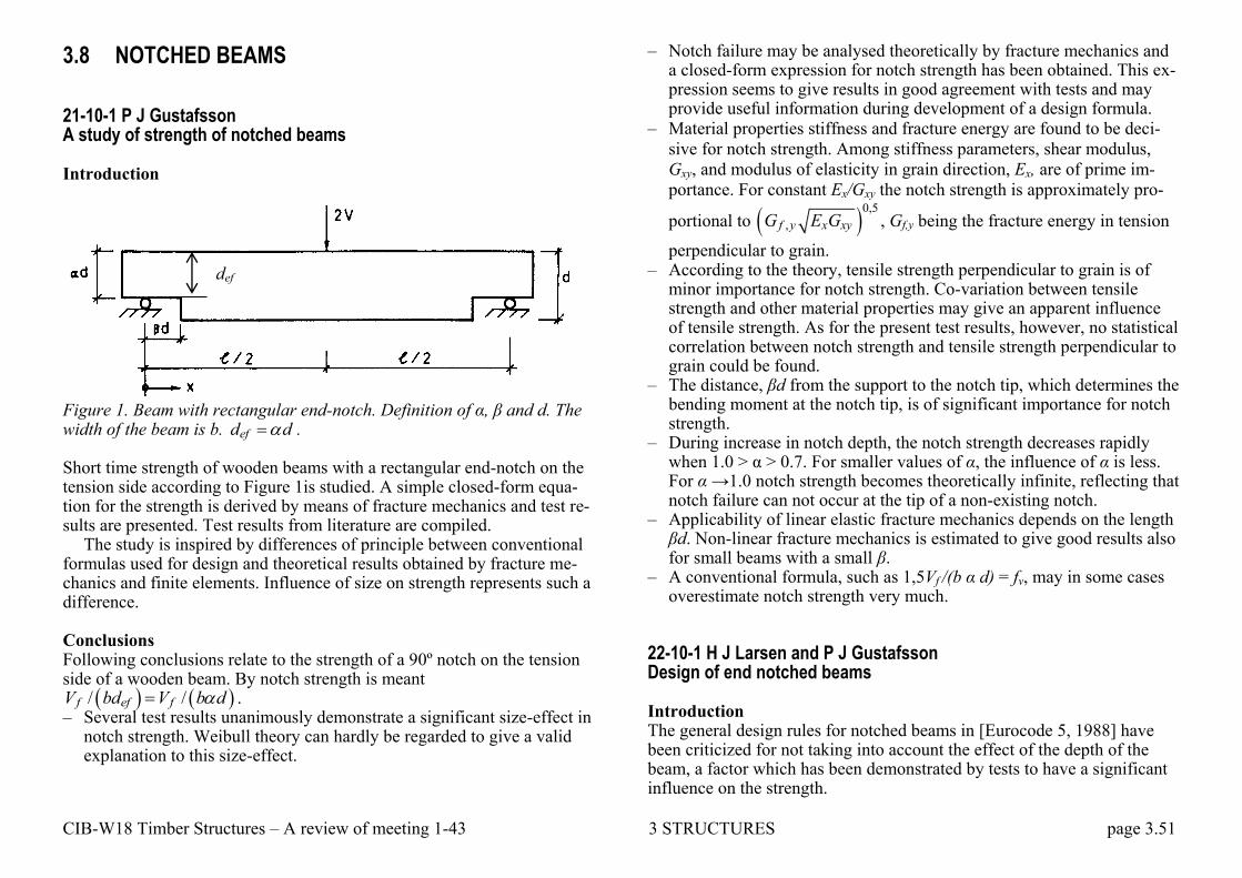
CIB-W18 Timber Structures – A review of meeting 1-43 3 STRUCTURES page 3.51
3.8 NOTCHED BEAMS 21-10-1 P J Gustafsson A study of strength of notched beams Introduction
Figure 1. Beam with rectangular end-notch. Definition of α, β and d. The width of the beam is b. efd d . Short time strength of wooden beams with a rectangular end-notch on the tension side according to Figure 1is studied. A simple closed-form equa-tion for the strength is derived by means of fracture mechanics and test re-sults are presented. Test results from literature are compiled.
The study is inspired by differences of principle between conventional formulas used for design and theoretical results obtained by fracture me-chanics and finite elements. Influence of size on strength represents such a difference. Conclusions Following conclusions relate to the strength of a 90º notch on the tension side of a wooden beam. By notch strength is meant
/ /f ef fV bd V b d . – Several test results unanimously demonstrate a significant size-effect in
notch strength. Weibull theory can hardly be regarded to give a valid explanation to this size-effect.
– Notch failure may be analysed theoretically by fracture mechanics and a closed-form expression for notch strength has been obtained. This ex-pression seems to give results in good agreement with tests and may provide useful information during development of a design formula.
– Material properties stiffness and fracture energy are found to be deci-
sive for notch strength. Among stiffness parameters, shear modulus,
Gxy, and modulus of elasticity in grain direction, Ex, are of prime im-
portance. For constant Ex/Gxy the notch strength is approximately pro-
portional to 0,5
,f y x xyG E G , Gf,y being the fracture energy in tension
perpendicular to grain. – According to the theory, tensile strength perpendicular to grain is of
minor importance for notch strength. Co-variation between tensile strength and other material properties may give an apparent influence of tensile strength. As for the present test results, however, no statistical correlation between notch strength and tensile strength perpendicular to grain could be found.
– The distance, βd from the support to the notch tip, which determines the bending moment at the notch tip, is of significant importance for notch strength.
– During increase in notch depth, the notch strength decreases rapidly when 1.0 > α > 0.7. For smaller values of α, the influence of α is less. For α →1.0 notch strength becomes theoretically infinite, reflecting that notch failure can not occur at the tip of a non-existing notch.
– Applicability of linear elastic fracture mechanics depends on the length βd. Non-linear fracture mechanics is estimated to give good results also for small beams with a small β.
– A conventional formula, such as 1,5Vf /(b α d) = fv, may in some cases overestimate notch strength very much.
22-10-1 H J Larsen and P J Gustafsson Design of end notched beams Introduction The general design rules for notched beams in [Eurocode 5, 1988] have been criticized for not taking into account the effect of the depth of the beam, a factor which has been demonstrated by tests to have a significant influence on the strength.
def
CIB-W18 Timber Structures – A review of meeting 1-43 3 STRUCTURES page 3.52
Further the special rules for glued laminated beams are criticized for mixing global design considerations (total beam volume, load distribution etc), and problems related to small local areas.
A consistent design method based on a simplified fracture analysis was presented in Paper 21-10-1. The paper was discussed at the CIB W18 meeting in September 1988, and it was agreed that it should be used as ba-sis for future versions of the CIB Structural Timber Design Code.
In the following is indicated how the code text could be formulated. The proposal only concerns the requirements for the notched part of the beams additional to the general requirements for the shear design of un-notched beams, and is thus independent of the method which might even-tually be codified for beams in general (i.e. for instance whether the effect of volume and load distribution will be taken into account).
Further a draft for a test method for determination of the determining factor – the fracture energy – is given. 23-10-1 T A C M van der Put Tension perpendicular to the grain at notches and joints Summary Constructive details as notches may cause high tension perpendicular to the grain and should not be applied. However rules are necessary if alter-native solutions are not possible and design rules are proposed for the Dutch Code TGB-1990 as a better alternative than the Eurocode rules.
Although the background of the design rules of the American Code for notched beams is not known it is possible to derive these rules and it is shown that they are only applicable for narrow span, high beams.
Design rules are derived using the simple fracture mechanics approach. Except for splitting along the grain the method is also used for crack prop-agation perpendicular to the grain. The same is applied for joints at the lower edge of a beam leading to an equivalent instable crack length. Sim-ple design rules appear to be possible based on a lowest upper bound of the strength leading to the equations of for notched beams and for eccen-tric joints.
23-10-2 K Riipola Dimensioning of beams with cracks, notches and holes. an application of fracture mechanics Abstract A dimensioning method based on fracture mechanics is presented. Frac-ture energy for a beam with an infinite crack is calculated with the beam theory and the energy principle. Mode separation is done by the definition of mode II and the superposition principle. The material is assumed to be orthotropic in the stress intensity calculations. A parabolic fracture criteri-on is used to predict failure. To evaluate the method, some experiments in the literature are re-analyzed. Conclusions A fracture mechanics based method for dimensioning of beams with cracks, notches, and holes is proposed to be included in the CIB code. Ac-cording to the proposal, capacity of a beam with a true or a supposed crack can be estimated as follows: – Consider the support conditions of the beam. If the lower part can
freely be separated from the upper part, a mixed mode case is present. Else, if the parts cannot be separated, (almost) pure mode II is present.
– Calculate the stress intensities according to the following equations:
0,52 3 2
2223 3 3
11 1 2
6 3
3 5
a a xI
xya
h hM M E hhK
th G hMh h h
0,5
1 2
3 31 2
2 2aII
M h hK
th h h
– Find out the fracture toughness values for the present modes and frac-ture systems. In the case of dimensioning, mode I system TL should be assumed, because it is weaker than mode I system RL.
– Use a suitable fracture criterion, as Wu‘s: 2
1I II
IC IIC
K K
K K
– Solve the equation to get the critical load.

CIB-W18 Timber Structures – A review of meeting 1-43 3 STRUCTURES page 3.53
38-6-1 R H Leicester Design specifications for notched beams in AS 1720 Abstract The design strength of notched beams has been in the Australian Standard AS 1720.1 for more than 30 years. In this paper these design rules are ex-amined through the use of elastic fracture mechanics. Both stress intensity factors and critical stress intensity factors are evaluated for three notch an-gles in a beam element. Discussion The information reported in this paper is of uncertain accuracy because there is limited published data available for calibration and comparison purposes. The size effect for notch slope g/a = 4 is less than expected and may be due either to the use of incorrect elastic parameters for the compu-tations or to the fact that the sizes of the beams tested may not be large enough to contain the critical eigenfield.
The critical stress intensity factors do not follow the expected relation-ship KAC,m = KAC,v or the linear interaction equation. It would be useful to use fundamental wood properties to derive an expected effect of the notch slope parameter g/a on the critical stress intensity factor KAC. 41-6-1 A Asiz, I Smith Design of inclined glulam members with an end notch on the tension face Introduction Notching glue laminated (glulam) timber beams at the tension side is a crucial decision that arguably should be avoided by design engineers be-cause of the high stress concentrations that develop around such notches inducing high tension perpendicular to grain and high shear parallel to grain stresses. However, it is done in practice to facilitate construction and to reduce the total necessary depth of floors and roofs. Most current design code provisions permit design of notches at the tension side providing that they are located close to the ends of members and at a simple structural support point. The key design process is normally done through modifica-tion terms that are part of assessing the shear capacity of members. Tradi-tional practices in this respect are empirical and of uncertain origin. Strict-
ly the problem requires a rational fracture mechanics analysis and that is done in a few related instances. For example, the notch design equation in Canada for sawn timber members is based on a simple fracture mechanics theory. However, the same practices are not adopted in design of notched glulam members, because of concern that a simple fracture theory might be inaccurate when notches remove only a small proportion of a member's depth. Moreover contemporary notch design provisions in codes were de-veloped mostly from empirical observations of how flat notched solid lumber beam behave. It is questionable that results apply to notching of large glulam members, particularly those with inclined configurations.
The objective of this study is to investigate the effects of small bird-mouth end-notches on failure behaviour and associated strength of in-clined glulam members subjected to short-term static load. Test result is compared with current design codes taking into account various possible failure mechanisms for glulam member loaded under statically determinate four-point bending arrangement. Simple design rule is proposed regarding whether there is a need to consider notching effect for small bird-mouth end-notches. Design recommendation The following recommendations are proposed to CSA086-01 Committee in respect of end notches on tension faces of inclined glulam members: – Stress concentrating effect for notches that remove not more than 8% of
member depth are negligible and can be neglected in structural design. – Stress concentrating effects of notches that remove more than 8% of
member depth (up to 25%) should not be ignored in structural design, and fracture mechanic check as per solid lumber must be performed in addition to shear checking on the residual cross-section.
41-6-2 K Rautenstrauch, B Franke, S Franke, K U Schober A new design approach for end-notched beams - view on code Introduction The determination of the load-carrying capacity of timber structures can be done by means of the theory of elasticity in most cases. This excludes are-as of high demanding loads and stress concentration, e.g. notches and holes. For these areas, different empirical approaches on the basis of the shear resistance and the theory of elasticity have been developed over the

CIB-W18 Timber Structures – A review of meeting 1-43 3 STRUCTURES page 3.54
past years and included in design codes. In the European and German Standard for the design of timber structures similar energy balanced ap-proaches can be found. The background for these design models was the proposal of Gustafsson, who estimates the material resistance against crack initiation in dependence of the energy release rate and the resilience of the structure. In his model, he is simplifying the mixed mode ratio of the total fracture energy is approximately equal to the fracture energy for transversal tension when fracture occurs. Recent experimental and numer-ical investigations of the strain condition around notches and holes lead to an extension of this theoretical approach, considering also fracture mode I and fracture mode II. Conclusions The overall loading situation in rectangular end-notched beams consisting of transverse tension and shear influence was considered for design issues by use of critical fracture parameters for mode I and II. The parameters de-rived from experimental and numerical data have been calculated inde-pendently from the numerical and test results of the same specimen. The measured strain fields correspond very well with the numerically obtained structural behavior. The presented results initialized a new revised and op-timized design proposal to estimate the load-carrying capacity of end-notched beams. The introduced solution and methodology to determine the capacity of rectangular end-notched beams can be easily extended to simi-lar problems with high stress singularities.

CIB-W18 Timber Structures – A review of meeting 1-43 3 STRUCTURES page 3.55
3.9 PLATE BUCKLING 10-4-1 J Decker, J Kuipers. H Ploos van Amstel Buckling strength of plywood: results of tests and recommendations for calculation Summary
Tests have been carried out on 100 specimens of Canadian Oregon Pine-plywood to verify that a reasonable good agreement exists between the buckling theories and the real behaviour of plywood. From load-deflection curves values for a critical buckling strength can be determined, which are in good agreement with theoretical values in the case of simply-supported edges. A clamped boundary condition could not be realised in such a way that the theoretical values were approximated. For design pur-poses this condition should not be presumed. Attention has been paid to combinations of normal and shear stresses on the basis of theoretical con-siderations. 17-4-2 R H Leicester, L Pham Ultimate strength of plywood webs Summary Methods are given for computing the strengths of both stiffened and un-stiffened plywood webs of glued I-beams. These methods, verified by ex-periments with radiate pine plywood webs, indicate that the ultimate strength of plywood webs can be considerably greater than the critical elastic load. The strength of plywood webs in I-beams, and box beams is rarely a critical design consideration. Nevertheless, in the interests of ensuring ad-equate reliability, it is useful to have a method for evaluating the ultimate strength of plywood webs. In the paper two specific problems are investi-gated: the buckling strength of an unstiffened web supporting a concen-trated flange load, and the ultimate shear capacity of a stiffened plywood panel. Simple procedures are given for estimating the critical elastic loads and the ultimate strength of both stiffened and unstiffened plywood webs for
glued I-beams. The methods are obviously relevant to the design of ply-wood webs of other types of structures. In practical terms, it is of interest to note that except for extreme de-signs it is difficult to induce failure in stiffened plywood webs of I-beams: it was also found that for many practical situations it is unnecessary to stiffen a plywood web. The reason being that once a plywood web has buckled, an I-beam will carry additional load through the action of tension membrane stresses, denoted by σα acting at an angle α to the beam axis as shown in the figure.

CIB-W18 Timber Structures – A review of meeting 1-43 3 STRUCTURES page 3.56
3.10 PRESTRESSING AND REINFORCING In analogy to steel reinforced concrete, many researchers have suggested to reinforce timber with steel or fibre materials (glass fibres or carbon fi-bres) although there is a vital difference: As opposed to concrete timber has excellent tension properties in the fibre direction. All the same there are numerous papers on the topic. Generally improvements are reported, mostly because of a reduction of variability, but in all cases the improve-ments are small and the production costly and it would have been much more effective and cheaper to use wood as reinforcement. An exception is repair of damaged structures by gluing on reinforcement.
The same applies to the proposals to prestress timber beams. An exception is timber bridge decks where prestressing perpendicular
to grain because of the low tensile strength perpendicular to grain may be effective or necessary. Eurocode 5-1-2 (bridges) describe several pre-stressed systems and gives rules for design and detailing.
Examples are shown below.
a) Nail-laminated b) Prestressed, not glued c) Prestressed and glued d) Prestressed glued laminated beams 22-12-4 R Candowicz, T Dziuba Ultimate strength of wooden beams with tension reinforcement as a function of random material properties Introduction Ultimate strength of wooden glue-laminated beams depends on many fac-tors mostly beefing random variables. This phenomenon results in an im-portant scatter of ultimate strength determined experimentally. This paper presents a further step in the analysis of the problem. The digital simula-tion methods were continuously used in our analysis. The paper deals with the ultimate strength of rectangular cross-sections reinforced with rods made of comparatively strong material. 30-12-1 K Oiger Experimental investigation and analysis of reinforced glulam beams This paper discusses the results of an experimental investigation and an analysis of reinforced and prestresssed glulam beams. During many years experimental investigations have been carried out on models in the labora-tory of Tallinn Technical University. The studies involved beams both, re-inforced with deformed bars and prestressed with steel cables. The results show that prestressed glulam beams are applicable in some cases (in par-ticular, by post-tensioning), though a relatively large portion of initial pre-stress disappears with time. Summary Reinforced and prestressed glulam beams could be effectively used when slender heavy loaded beams are needed. Nevertheless the long-term be-haviour of prestressed glulam beams needs further research. At present more reliable and simpler solution is given by reinforced glulam beams with glued-in deformed bars.
CIB-W18 Timber Structures – A review of meeting 1-43 3 STRUCTURES page 3.57
34-12-3 M Romani, H J Blass Design model for FRP reinforced glulam beams Abstract For several years possibilities to reinforce glulam beams parallel to the grain to increase bending and axial stiffness and ultimate load have been investigated. One method is to use Fibre-Reinforced Plastics (FRP) as a tensile reinforcement. Fibres used were glass fibres, aramid fibres and car-bon fibres.
At the University of Karlsruhe a research project was carried out where the load-deformation behaviour of reinforced glulam beams was studied. Thin carbon FRP and aramid FRP were used as reinforcements. Within this research project a design model was developed taking into account the plastic behaviour of timber loaded in compression parallel to the grain. This paper presents the design model and test results of beams loaded to failure to verify the design model. Summary For the calculation of the load-carrying capacity and stiffness of tensile re-inforced glulam beams a model is derived taking into account the plastic behaviour of glulam loaded in compression parallel to the grain. The mod-el is based on an analytic solution and allows a simple calculation without any iteration steps based on design values of non-reinforced glulam. Dif-ferent failure modes of FRP reinforced glulam beams are considered. Test results with reinforced beams loaded to failure show that the proposed model leads to conservative values of the load-carrying capacity. This is especially true considering the low quality of the timber used in the tests.
The test specimens mainly failed at the tension side. With a different cross-section set-up reinforced beams are possible failing in a more ductile way on the compression side. The test specimens mostly showed a signifi-cant load increase after failure of the timber facing. This was mainly caused by an effective reinforcement even after a bending failure above the FRP layer. Further research will quantify this effect and permit a more economic use of FRP reinforced glulam.
37-12-2 P Alam, M P Ansell, D Smedley Reinforcement of LVL beams with bonded-in plates and rods – Effect of placement of steel and FRP reinforcements on beam strength and stiffness Introduction Two metre long laminated veneer lumber (LVL) structural beams were re-inforced using four different geometrical configurations of reinforcement. Each configuration was reinforced using either grade 43 mild steel or one of three different types of pultruded fibre reinforced plastic (FRP) compo-site. The objective of the research is to determine the reinforcement capa-bilities of different reinforcing plates and rods as a function of (a) the rein-forcing materials, (b) the geometrical configurations of the four phases of reinforcement and (c) the volume fraction of reinforcement. Objectives (a) and (b) were reached by laboratory testing of reinforced beams for all four types of reinforcement and objective (c) was achieved by numerical simu-lations for the four phases of steel reinforcement. The paper concludes with design recommendations based on density and cost considerations for all of the experimentally tested reinforced beams. Conclusions – Grade 43 mild steel and FRP reinforcements were tested in four phases
with different geometrical configurations. – Examination of the flexural strength and stiffness data showed that
smaller volumes of plate and rod reinforcement at the outermost tension and compression fibres of the beam are as effective as full depth flitch plates for improving mechanical properties.
– Using the transformed section approach, it was found that lower modu-lus reinforcements such as GFRP and FULCRUM are as effective as higher modulus reinforcements such as mild steel and CFRP for im-proving the mechanical performance of reinforced LVL beams.
– Non-linear finite element models were developed for steel-LVL beams to predict the flexural modulus and the yield strength as a function of the reinforcement volume fraction.
– Finite element predictions for steel reinforcement showed that better flexural properties are attainable by locating small plates at the outer-most fibres than similarly located rod reinforcements with equal vol-ume fractions.

CIB-W18 Timber Structures – A review of meeting 1-43 3 STRUCTURES page 3.58
– Design recommendations regarding the geometrical arrangements of composite components and of reinforcing materials have been dis-cussed with respect to enhancement of mechanical properties, volume fraction, density and cost. Design recommendations are based on both numerical and experimental findings.
– Low cost, low modulus reinforcements strategically located within LVL beams have a great deal of potential for use in practical rein-forcement of structural timber.
39-12-2 K U Schober, S Franke, K Rautenstrauch In-situ strengthening of timber structures with CFRP Introduction Particularly old timber structures in residential houses are designed for lower live loads as specified in performance and design standards and need new technologies to increase the load-carrying capacity of the mem-bers for state-of-the-art housing conditions. Therefore, a study of rein-forcement techniques for restoration and strengthening of existing timber floors under bending loads has been carried out at the Bauhaus-University of Weimar, based on the use of carbon fibre reinforced plastics on the building site, whereby the removal of the overhanging part of the structure as well as the inserted ceiling is not necessary.
Reinforcement techniques for structural timber elements, based on the use of adhesives on site, have been applied for some decades as an exten-sion of procedures that became very common for the repair or the upgrad-ing of other structures. Some problems have prevented the wider use of adhesives, particularly in historical timber structures. One reason is that a life-long service life has not yet been fully proven for synthetic adhesives, since the oldest bonded joints are around sixty years and greater ages can-not be simulated by existing accelerated ageing tests. Although epoxy based adhesives have been used in most cases for on-site repair jobs, most formulations were developed for other materials. On-site application of adhesives is somewhat difficult and the consequent quality of adhesive bond is not easy to evaluate. Since properties of reinforced elements very much depend on the care put in the work, such difficulties have to be overcome and first procedures for applying and controlling were estab-lished (CEN TC 193/SCl/WGI 12003).
Conclusions The use of CFRP as a strengthening technique can be applied without
necessitating the removal of the overhanging part of the structure. This is very promising in many cases of reinforcement of old, historical structural wood parts. Upgrading traditional timber structures of old solid wood with carbon fibre reinforcement on different locations are described and dis-cussed here based on experimental investigations. For practice related in-vestigations effective cross-sectional data including existing cracks, knots and damages were used with a reduction of the initial bending stiffness and the moment of inertia respectively of about 17 % compared to the cross-sections without defects. The results of the experiments have high-lighted the limitations of the composite structure as well as the advantages of the various reinforcement positions and present numerous interesting aspects. The wood beams reinforced with CFRP lamellas revealed more ductile behaviour with compared to un-reinforced beams. The presence of CFRP reinforcement arrests crack opening, confines local rupture and bridges local defects in the timber especially for reinforcement types other than on the bottom face.
The various theories of bonding developed so far are not able to explain comprehensively the observed effects. Chemical bonding always has been seen as the optimal form of combining two surfaces with each other, but its contribution to the overall bonding mechanism is still unclear. The properties of the glue line can be described among other methods by the analysis of the microstructure of the bond surface. This includes the adhe-sive penetration into the wood surface, the effect of ageing of a glue bond as well as the description of the cohesive strength of the glue line in terms of an optimization of the brittle and elastic ratio of the glue line. These methods took into account by applying a numerical model for this rein-forcement types using finite element cohesive zone modelling. These in-vestigations are currently going on. 41-10-2 M Fragiacomo, M Davies Evaluation of the prestressing losses in timber members prestressed with unbonded tendons Introduction Applying prestressing to timber structures has been done in a number of cases; however, unlike concrete structures, it is not common practice. Un-

CIB-W18 Timber Structures – A review of meeting 1-43 3 STRUCTURES page 3.59
bonded prestressing tendons have been used to reduce the deflections of sawn timber beams, to laminate bridge decks from independent timber planks, and to reduce creep-induced deformations and provide increased strength for timber-concrete composite floors. Recently, a new construc-tion system for multi-storey timber buildings has been proposed at the University of Canterbury, New Zealand. This system consists of frames and walls made from LVL (laminated veneer lumber) prestressed with un-bonded tendons for earthquake resistance. Prestressing is mostly used to achieve connections that accommodate the inelastic seismic demand through rigid rocking motion of one member on the other, minimizing the residual damage at the end of the earthquake.
There is some scepticism among the scientific community regarding the possibility of prestressing timber members. The main issue is the behavior of the system in the long-term. The tendon relaxation, together with the time-dependent phenomena of timber such as creep, mechano-sorption, and shrinkage/swelling may in fact significantly reduce the effect of the prestressing in the long-term, particularly if the structure was built in an environment characterized by high relative humidity. A further problem is that codes of practice for timber design do not usually include specific provisions for the evaluation of the prestress losses in the long-term. The Eurocode 5 Part 2 only states that, for stress-laminated deck plates, the long-term residual prestressing stress may normally be assumed to be greater than 0.35 MPa, provided that the initial prestress is at least 1.0 MPa; the moisture content of the laminations at the time of prestressing is not more than 16%; and, the variation of the deck plate's in-service mois-ture content is limited by adequate protection. No formula such as that re-ported in the Eurocode 2 Part 1-1 (CEN 2003) for the loss of prestressing in post-tensioned concrete members is provided.
In order to address those issues, a research project was undertaken at the University of Canterbury, New Zealand. A number of LVL frames prestressed with unbonded tendons and subjected to different environmen-tal conditions were monitored over time with the purpose of evaluating the prestressing Concluding remarks The paper presents the derivation of a closed-form solution for the evalua-tion of the prestress losses of a timber frame in the long-term. The formu-las are obtained by simplifying the integral equations describing the time-dependent behavior of the prestressing steel and timber loaded parallel and
perpendicular to the grain. Allowance for relaxation, creep and inelastic strains was made. The age-adjusted effective modulus method was used to transform the integral equations into algebraic equations.
The closed-form solution was compared with the experimental results measured in a long-term test performed at the University of Canterbury, New Zealand. An acceptable approximation was found, bearing in mind the scatter of experimental values, particularly the Young's moduli and creep coefficients of LVL. The experimental-analytical comparison also allowed a calibration of some coefficients, the "aging coefficients", used in the analytical solution. Based on the outcomes of the parametric study, the analytical solution was simplified further and rewritten in non-dimensional form. Such formula, easy and similar to that used for prestressed concrete structures, can be recommended for design of prestressed timber frames. The formula also allows an easy understanding of the main parameters af-fecting the prestress losses in the long-term, which are: (i) the ratio be-tween the lengths of timber loaded perpendicular and parallel to the grain, and (ii) the ratio between the axial stiffness of the timber frame and the ax-ial stiffness of the steel tendon. 42-12-3 T G Williamson, B Yeh Laminating lumber and end joint properties for FRP-reinforced glulam beams Abstract Glulam beams reinforced with fibre-reinforced-polymer (FRP) are typical-ly manufactured using graded laminating lumber with FRP reinforcement in the tension zone and have been used in numerous construction projects worldwide. Unfortunately, the lay-up combinations currently used for manufacturing FRP-einforced glulam are all proprietary even though an FRP glulam standard, ASTM D 7199, Standard Practice for Establishing Characteristic Values for Reinforced Glued Laminated Timber (Glulam) Beams Using Mechanics-Based Models, was published in 2007. This standard resulted from years of joint effort by APA – The Engineered Wood Association and the Advanced Engineered Wood Composites Cen-ter (AEWC) of the University of Maine.
A mechanics-based computer model, called ReLam, has been devel-oped by the AEWC for predicting the performance of FRP-reinforced glu-lam beams in accordance with ASTM D 7199. This model can be used to
CIB-W18 Timber Structures – A review of meeting 1-43 3 STRUCTURES page 3.60
develop a range of layup combinations for FRP-reinforced glulam beams. As the first step toward the development of these glulam lay-up combina-tions, mechanical properties of laminating lumber, including the tensile and compressive strength and moduli, and the end joint tensile strength must be obtained.
While the lumber properties for these lumber grades have been pub-lished in glulam industry standards, such as AITC 407, Standard for Al-ternate Lumber Grades for Use in Structural Glued Laminated Timber, the basis of those data is more than 20 years old and was in need for an update and reaffirmation. While there are end joint tension data generated daily from the quality control records of each glulam plant, those data are con-sidered proprietary and typically unavailable for general use. In addition, the compressive strength and moduli data are not readily available. As a result, APA initiated a comprehensive study to evaluate four Douglas-fir (DF) laminating lumber grades; 302-24 tension lam, L1, L2, and L3, and two grades of end joints, 302-24 tension lam and L1, from a range of glu-lam plants in 2008 using current production resources in the U.S. These laminating lumber properties, including end joint data, not only confirm the historical data for these dominant DF lumber grades and end joints used in today‘s glulam production in the U.S., but also provide the re-quired data for the development of lay-up combinations using ReLam. This paper presents the laminating lumber and end joint properties. In ad-dition, the likely FRP-reinforced glulam beam layup combinations at char-acteristic bending strength and modulus of elasticity values of 43.4 N/mm
2
(6,300 psi) and 13800 N/mm2 (2.0 ∙ 106 psi), and 49.2 N/mm
2 (7,140 psi)
and 15200 N/mm2 (2.2 ∙ 106 psi), respectively, are also provided. These
FRP-reinforced glulam beams are expected to be highly competitive with steel in non-residential construction markets in the U.S. Conclusions and Recommendations Results obtained from this study provide the characteristic properties of Douglas-fir laminating lumber that can be used for the modelling of FRP-reinforced glulam in accordance with ASTM D 7199. These data also con-firm that the currently published laminating lumber properties are ade-quate albeit in some cases conservative. For the purpose of the glulam modelling using the bilinear compressive stress and strain curve, further investigation on the accuracy of the estimate for the downward slope after the compression failure will be conducted.
A model analysis was conducted for the development of candidate lay up combinations with a targeted characteristic bending strength of 48.3 N/mm2 (7000 psi) and mean bending modulus of elasticity of 14480 N/mm
2 (2.1 x 10⁶ psi) based on a reinforcement ratio of about 3% utiliz-
ing low-grade laminations. The confirmation of the properties for these layup combinations is pending the completion of full-scale beam tests.
Once the confirmation of the ReLam model is completed, APA will pursue obtaining a code evaluation report based on ICC-ES AC280 [13], Acceptance Criteria for Fiber-Reinforced-Polymer Glued Laminated Tim-ber Using Mechanics Based Models, on behalf of its manufacturing mem-bers. This will allow APA members to be listed on the code evaluation re-port and significantly expand the use of FRP-reinforced glulam in the U.S. 43-7-7 S Giorgini, A Neale, A Palermo, D Carradine, S Pampanin, A H Buchanan Predicting time dependent effects in unbonded post-tensioned timber frames and beams Introduction Development of engineered timber products such as Laminated Veneer Lumber (LVL) has caused a renewal in the development of heavy timber construction. A research programme on the application of unbonded post-tensioned construction techniques similar to concrete have been success-fully proven with LVL at the University of Canterbury. This technology has been applied firstly to earthquake resistant frames and then, given the advantages that this solution offers, extended to long span beams for gravi-ty loading. Extensive numerical and experimental research is continuing at the University of Canterbury supported by the Structural Timber Innova-tion Company (STIC).
Rocking connections in post-tensioned frames and walls allow discrete dissipative devices to be placed in specific locations in the structure, providing energy absorption during seismic loading, with no damage to structural members. This system has been developed throughout the last two decades for precast concrete structures, known as ―PRESSS‖ (Precast Seismic Structural Systems) and it has been successfully transferred to timber frames and walls known as ―Pres-Lam‖. Because the moment ca-pacity of post-tensioned timber connections depends on the level of post-tensioning force applied by tendon, losses must be accurately assessed to

CIB-W18 Timber Structures – A review of meeting 1-43 3 STRUCTURES page 3.61
ensure the structure maintains seismic integrity throughout its life. Gener-ally the largest components of the loss are the effects of creep in the wood and relaxation of the steel tendon. The problem is also complicated by the particular column-to-beam connection where post-tensioning tendons pass through the column, loading it perpendicular to the grain, where the stiff-ness of the wood is much lower than parallel to the grain, so this effect can lead to considerable losses. This issue has been investigated through ex-perimental tests.
While the Pres-Lam system developed for multi-storey timber buildings (Fig. 1a,b) uses straight tendons in the centroid of the section, the use of post-tensioning with draped or eccentric profiles becomes a suitable solu-tion for long span timber beams, either in post-tensioned frames or as stand-alone beams. Enhanced performance of this solution has been con-firmed through experimental investigations on two static schemes evaluat-ing different tendon profiles (Fig. 1c)). The major benefit was a displace-ment only 60% of that for the non-post-tensioned beam. In addition to this, a significant nonlinear stiffening effect due to tendon elongation has been identified. In order to properly quantify the benefits of this technology, long-term issues have to be evaluated. Recent preliminary studies have confirmed that post-tensioning losses can be estimated around 25% in the worst environmental scenario. In order to validate the analytical approach, long term tests are ongoing at the University of Canterbury.
Fig. 1: Unbonded post-tensioned timber frames and beams: a) Pres-Lam timber building tested for earthquake loads [9]; b) Rocking connection; c) Post-tensioned timber beam tested for vertical serviceability loads. The scope of this paper is to propose design procedures and simplified ex-pressions in order to accurately quantify post-tensioning losses in long span beams and timber frames (Pres-Lam system). Both instantaneous
elastic and long-term losses are investigated. By applying typical creep formulations to post-tensioned timber members with an eccentric force, some simplified expressions have been developed for beams in a form suitable for standardisation. The analytical formulation is carried out for a simply supported beam in the elastic and long-term ranges. The formula-tion uses a single dimensionless coefficient p in order to encompass all the involved geometric and mechanical parameters (material properties, beam geometry, steel area and the type of cable profile).
For frame systems, a simplified expression for straight concentric post-tensioning, validated through monitoring of a Pres-Lam timber building, is proposed as a viable tool for predicting post-tensioning losses taking into account column joint reinforcement. Simplified design charts are present-ed in order to facilitate the use of the proposed formula in a design proce-dure. Conclusions For design of post-tensioned timber beams, proper assessment of the post-tensioning losses is crucial for establishing the initial post-tensioning force and to maintain the long-term structural performance.
In this paper post-tensioning losses have been expressed for beams and frames in a common analytical formulation, expressed as function of a global mechanical parameter. Solutions based on this method have been proposed, to simplify the calculation of such complicated phenomena by practitioners.
In addition, for frames, the effect of the column reinforcement is taken into account and design charts have been created in order to further simpli-fy the calculations.
43-7-8 M Newcombe, M Cusiel, S Pampanin, A Palermo Simplified design of post-tensioned timber buildings Introduction A high performance solid timber frame system has been developed at the University of anterbury, in collaboration with the Structural Timber Inno-vation Company (STIC Ltd). The structural system uses post-tensioning tendons or bars to connect large timber sections (see Figure 1). The sec-tions are constructed from engineered wood product, such as Glulam, Laminated Veneer Lumber (LVL) or Cross Laminated Timber (CLT),

CIB-W18 Timber Structures – A review of meeting 1-43 3 STRUCTURES page 3.62
forming beams, columns, walls or floors. Post-tensioned timber is suitable for a wide range of building types, including commercial structures, and has the potential to compete with existing forms of construction in terms of cost, versatility and structural performance
The connection technique was adapted from post-tensioned pre-cast concrete systems. For seismic design, the combination of timber and post-tensioning is particularly efficient since it avoids potential brittle failure modes that can occur in traditional timber connections and prevents exces-sive frame elongation, avoiding damage to the floor system . Hence, the system fits well into recent Performance-Based Seismic Engineering (PBSE) design approaches because structural damage is minimized and, due to restoring action provided by the post-tensioning, residual defor-mations are insignificant.
Previous research has shown that simply designed post-tensioned tim-ber frames respond essentially elastically to even severe earthquake load-ing. In such cases, for code-based seismic design, the ultimate limit state lateral forces cannot be significantly reduced due to structural ductility or hysteretic damping, in contrast to well designed concrete and steel struc-tures. Even so, the serviceability limit state lateral load design usually governs the size of the members and the amount of post-tensioning, espe-cially if stringent displacement limitations, according to current code pro-visions, are imposed to protect non-structural partitions inside a building. For an elastic design, for service or ultimate conditions, either force-based or displacement-based design can be used to determine the lateral seismic forces for post-tensioned timber frames. However, for force-based design it is essential that the allowable displacements are used to determine the natural period of the frame
The lateral resistance of post-tensioned timber frames is highly depend-ent on the behaviour of the beam-column connections. Analytical models have been proposed to predict the moment-rota further validation as more experimental data is obtained. Recent research has demonstrated that the shear deformation of the timber columns in the joint panel region, between the beams, significantly contributes to the overall frame flexibility. Such considerations are not required for equivalent precast concrete connec-tions. To enable accurate design of post-tensioned timber frames, to meet specified displacement limitations, all deformation components must be quantified and accounted for.
In some situations additional non-prestressed reinforcement may be added to the beam-column connections (see Figure 1) creating what is
termed a ‗Hybrid‘ connection. With careful detailing, this reinforcement can improve the strength of the connections and the energy dissipation ca-pability of the frame at large displacements.
Figure 1. Post-tensioned timber frame concept While lateral load design methodologies for post-tensioned concrete and steel frames exist , these procedures are not directly applicable to timber frames. This paper describes a simplified design procedure for postten-sioned timber frames- The focus is given to characterisation of frame de-formation. For simplicity, hybrid connections are not considered here. Conclusions A simplified design procedure has been proposed for the lateral force de-sign of simple post-tensioned timber frames, responding within the elastic range. The procedure allows the determination of the required section siz-es and post-tensioning forces to achieve the lateral strength demand of the frame, without exceeding the total allowable displacements for either ser-viceability or ultimate limit states. All significant deformation components are accounted for using analytical expressions.
For predicting the moment-capacity of the beam-column connections, a refined methodology is proposed that, when compared to previously pub-lished procedures for post-tensioned timber connections, more accurately predicts the peak timber stresses within the connection and can avoid itera-tion. Empirical relationships have been proposed hich were calibrated from detailed finite element modelling and experimental data.

CIB-W18 Timber Structures – A review of meeting 1-43 3 STRUCTURES page 3.63
3.11 RESIDENTIAL FLOORS 19-8-1 I Smith, Y H Chui Predicting the natural frequencies of light-weight wooden floors Abstract This paper gives 'designer useable' methods for predicting the dynamical behaviour of light-weight wooden joisted floors covered with semi-rigidly attached wood based sheathings of materials such as chipboard or ply-wood. It is demonstrated that good approximations to the fundamental natural frequencies of floors with practical combinations of edge condi-tions can be obtained by assuming that a floor behaves as a simple compo-site beam. Guidance is given concerning the calculation of natural fre-quencies of floors simply supported at all four edges for higher order modes of vibration. Discussion and conclusions The objective of this paper is to give designer useable methods of predict-ing the dynamical response of light-weight wooden foisted floors. Howev-er, this is only one part of the overall equation needed to predict the likely acceptability of a particular design solution. The designer also requires a design criterion which relates parameters such as the fundamental natural frequency, or several of the lower natural frequencies, of a floor to the likely 'levels' of vibration that will be acceptable to the end-user(s), i.e. oc-cupant(s) of a building. Recent work by Chui has indicated that human perception of, and tolerance thresholds on, vertical vibrations are related to quantitative measures such as amplitude, velocity and damping of the vi-brations and qualitative factors related to use of a building or even a spe-cific part of it. Root means square acceleration, r.m.s., due to a defined impulse of a magnitude related to end use conditions appears to be the best criterion. The question of how to relate an acceptance threshold for r.m.s. to parameters that are easy to calculate such as natural frequencies is the topic of ongoing studies by the second author and will be reported else-where.
20-8-1 Y H Chui. I Smith Proposed code requirements for vibrational serviceability of timber floors Abstract This paper proposes how vibrational serviceability requirements for timber floors can be incorporated into a design code. Simple expressions are pre-sented for estimating the fundamental natural frequency and the mean magnitude of the response caused by human footfall impact. These two pa-rameters have been identified as the two governing parameters for as-sessing prospective design solutions. Limits are also given for these pa-rameters for ensuring satisfactory floor designs.
CIB-W18 Timber Structures – A review of meeting 1-43 3 STRUCTURES page 3.64
Conclusion It is proposed here that in future design of wooden floors should follow the procedures set out in Figure 1. In order to ensure that a floor is free from excessive vibration which causes discomfort to its occupants, its funda-mental natural frequency (fn) and frequency-weighted acceleration (Ar) of the response due to a human footfall impact shall be higher than 8 Hz and smaller than 0.45 m/s
2 respectively. These two parameters may be satis-
factorily estimated using the equations presented in this paper. 21-8-1 Y H Chui, I Smith An addendum to paper 20-8-1 - proposed code requirements for vibra-tional serviceability of timber floors Introduction At the 1987 CIB-W18A Meeting, the authors proposed a possible code approach for designing against poor vibrational serviceability for light-weight wooden floors in the domestic setting. Suggestions by certain par-ticipants of the meeting have led to further work by the authors. This mainly involved additional discussion with others, who are investigating or have investigated related problems, and conducting a comparison be-tween various design approaches.
Main differences between different design approaches are presented. Assessments of vibrational serviceability, using each approach, of a series of wooden floors covering a wide range of floor sizes, are presented.
In addition, possible extension of the proposed design equations in the previous paper (Paper 20-8-1) to include the stiffening effect due to a flooring with high bending stiffnesses is also discussed. Conclusion The additional information supports the previous contention that the de-sign method proposed by the authors should be accepted as suitable for in-clusion in future editions of the CIB Code.
21-8-2 S Ohlsson Floor vibrational serviceability and the CIB model code Introduction The aim of this paper is twofold: – To initiate a general discussion about to what extent and in which forms
floor serviceability related design methods and criteria should be pre-sented in international model codes.
– To comment upon a paper which was presented at the last meeting of CIB-Wl8A (Paper 20-8-1)
It has been a long time tradition in the structural design of houses and civil engineering structures to focus on the load-bearing capacity and to relate the design to different codes of practice. What to-day is known as the ser-viceability limit state is a rather modern concept in the construction area, relatively speaking. If we, for a moment, compare the situation with some other sector of engineering, we find that the corresponding words used of-ten are "performance" and "comfort", etc. This is for instance the case in the automotive industry, where the "serviceability" of the product is of main importance to the design, but is normally not regulated by codes. The serviceability criteria used in this sector, on the other hand, do stimulate the technical development of the car design. As examples of such devel-opment we nowdays have cars with smaller unsprung wheel masses, indi-vidual suspensions, etc. This may not have been the case if the serviceabil-ity criteria in use had been of the same type as we use for the structural de-sign of houses.
Research in the area of floor vibration and serviceability has been un-dertaken in several countries and is still going on. Reference 4 (Ohlsson, S: Springiness and Human-Induced Floor Vibrations; A Design Guide, 1988, Swedish Council for Building Research, Stockholm. ISBN 91-540-4901-6) is a design guide, which also includes a proposed design method. It has been in use among practicing engineers in Sweden and occasionally in Norway and Finland since 1984 and so far it seems to work reasonably well. Concluding words and suggestions Considering various aspects of the matter it is the author‘s opinion that a sound engineering development of floor structures will benefit if: – The design proposal (Paper 20-8-1) is not accepted for inclusion in the
CIB model timber code.
CIB-W18 Timber Structures – A review of meeting 1-43 3 STRUCTURES page 3.65
– The authors of the proposal contribute together with other specialists in the field of floor vibration in the process of international coordination aiming at design criteria that are independent of construction material and configuration.
– Scientists and engineers with special knowledge in any specific con-struction material contribute in research and development aiming to-wards recommendations about which structural configurations should be preferred, which detail designs that are most suitable, etc. Such work could preferably be based on the result of the abovementioned interna-tional coordination.
24-8-1 I Smith, Y H Chui On the possibility of applying neutral vibrational serviceability criteria to joisted wood floors Abstract Prior discussion in CIB-W18A has not clarified whether it is possible to apply vibrational serviceability criteria that are neutral with regard to con-struction material and structural configuration for floors. By means of ex-amples, it is demonstrated that responses of joisted wood floors are too complex for correct quantification, at the design stage, of parameters that indicate acceptability. Applying arbitrary conditions for imposed mass, excitation and response limits, designers have a means of assessing rela-tive suitabilities of candidate solutions. Candidates would satisfy other (static) design criteria. "Neutral" vibrational serviceability limits in design of joisted wood floors is an ideal that is not presently attainable. Conclusion It is beyond a designer‘s ability to make quantitative vibration response predictions for joisted wood floors-. Arbitrary choices must be made re-garding variables such as the amount of imposed mass, its distribution, and the excitation assumed in design. Arbitrary choices must also be made re-garding limits on response. Armed with this approach sensible choices can be made on the basis of relative behaviours of a range of candidate design solutions. The candidates would satisfy static design criteria for both strength and serviceability.
Although a worthy goal to which to aspire, material and structural con-figuration neutral vibrational response criteria for joisted floors are not valid for contemporary engineering design codes.
30-20-2 R J Bainbridge, C J Mettem Serviceability performance of timber floors – Eurocode 5 and full scale testing Abstract This paper describes recent research relating to the Serviceability Limit State (SLS) performance of timber floors.
The findings of full scale tests are summarised and related to Eurocode 5 based design of one-way spanning timber floor constructions. Conclusions SLS criteria related to deflections and vibration frequently govern the de-sign of horizontal timber elements, hence it is necessary to ensure that de-sign procedures are not unduly conservative, in order to promote efficient design and material usage.
The reasons for limiting deflections must be understood and defined by the designer, who, through modern code approaches, has greater discretion when considering serviceability.
This requires consideration of the action combinations and expected re-sultant consequences in terms of functionality, comfort and appearance.
It has been found that the floor design methods relating to SLS in tim-ber floors presented in EC5 can be applied to predict test floor behaviour to a reasonable degree of accuracy, provided certain factors are known or can be approximated for inclusion in the formulae.
Since strutting provides stability to joists and enhances overall service-ability performance, both in terms of static stiffness and influence upon the complex aspects of the dynamic vibration performance, its provision as di-rected by current guidance should be regarded as a minimum.
It is also clear that the contribution of decking and plasterboard ceilings to the behaviour of the floor should be considered in the design process, since it is currently ignored. Whilst it is accepted that ultimate limit state design should be based on the primary structural system (i.e. the joists alone), this has implications relating to design under both static and dy-namic aspects of serviceability.
CIB-W18 Timber Structures – A review of meeting 1-43 3 STRUCTURES page 3.66
32-20-1 B Mohr Floor vibrations Introduction The serviceability becomes more decisive nowadays because of the use of high strength materials, plain timber construction elements (e.g. nail lami-nated timber decks) and longer spans. Beside the deflection requirements the dynamic aspects must be considered.
Eurocode 5 requires for residential floors having a fundamental fre-quency below 8 Hz "a special investigation" which is not described there. Usual wooden floors having beams and boardings may be modelled as grill girders. Such a computation of the deflection because of a concentrat-ed static force for wooden floors is not contained in standard tables and requires a lot of time. A research project with this scope was performed in 1998 at the Technical University of Munich by Kreuzinger and Mohr. 37-20-1 Lin J Hu, Y H Chui A new design method to control vibrations induced by foot steps in timber floors Abstract Design methods contained in building codes and structural design stand-ards to prevent excessive vibration in timber floors have not been found to provide satisfactory solutions for the broad range of floor systems encoun-tered in contemporary timber construction. This paper describes the devel-opment of a new design method. The design method consists of a dual-parameter performance criterion and the associated calculation method for the performance criterion parameters. The derivation of the performance criterion was based on extensive field testing data and an occupant survey. The two parameters selected for design purpose are static deflection at floor centre under a point load and first natural frequency. The calculation method is based on the ribbed-plate theory and considers seimirigid con-nections between joist and sheathing, torsional rigidity of joists, sheathing stiffness in the span and across joist directions and the contribution of lat-eral performance enhancing elements such as between-joist bridging, strong-back and strapping. Comparison of predicted performance with recorded rating of a group of timber floors shows that the proposed design method works reasonably well. Only about 3 of the floors were slightly
mis-classified as acceptable by the method. A few acceptable floors were 'conservatively' classified as unacceptable. This has provided some confi-dence for adopting the proposed method for design use. Conclusion and Recommendation It can be concluded that the new design method shows great potential to provide rational vibration-controlled spans for a broad range of timber floor systems. The mechanics-based approach also lends itself to facilitate the acceptance of innovative building products. The new design method presented in this paper will provide a framework for the formulation of an acceptable design method for a broad range of timber floors. Additional calibration work may be required to apply the tentative design criterion to timber floor designs in other countries because it was calibrated to materi-al properties published in the Canadian literature.

CIB-W18 Timber Structures – A review of meeting 1-43 3 STRUCTURES page 3.67
3.12 ROBUSTNESS All structures are required to be reasonably robust, i.e. they should not be sensitive to unintended incidents or small deviations from the design as-sumptions e.g. small deviations from the intended geometry due to execu-tion errors, or foundation settlements.
Robustness (sometimes called safety against disproportionate or pro-gressive collapse) requirements are those that ensure that in case of an ac-cident the structure do not fail disproportionate to the cause of the acci-dent, i.e. failure in a small part of the structure must not result in failure of the whole structure .
Robustness may be ensured by the design of the statical system, e.g. by choosing statically indeterminate structures where there is more than one path for the loads to the supports, by choice of materials and joints and by control of the construction execution. It should be noted that increase of the safety factors rarely by itself has an important effect even though the Safety codes sometimes accept this as a possible way of compliance.
The codes are rather vague regarding implementation of the robustness requirements into practice and it is usually left to the designer. 22-15-6 C J Mettem, J P Marcroft The robustness of timber structures Introduction Structural timber is frequently used for clear spans in excess of nine me-tres in public buildings in Britain. Such applications are being actively promoted. For example, recreational activities and competitive sports are increasingly being enclosed by means of timber structures. This represents an ideal category of end-use for glulam. Also, with the trussed rafter mar-ket for domestic applications being largely saturated, that sector of the in-dustry is increasingly offering solutions for roofs for non-residential groups of building. In these, clear spans of up to twenty metres are not un-common. Glulam has far greater spanning potential, of course. Public buildings using glulam in excess of forty metres span do exist in Britain, although they are not at present commonplace.
On the continent of Europe, in Scandinavia and in North America, tim-ber structures in excess of sixty metres span are relatively frequently found. The structural advantages, including lightness during erection and
in foundation design, and good fire resistance, are well known to special-ists. These features of structural timber can readily be supported with am-ple documentation. The ability of a timber structure to resist misuse how-ever, and to remain stable after an accident which has affected its fabric, is less generally appreciated. In addition, the robustness of timber structures is a subject which is extremely sparsely documented. Yet it could probably be claimed that the majority of timber structures do possess an inherently high degree of robustness; or that robustness could be added with little ex-tra detailing costs. The excellent performance of timber structures in seis-mic regions is almost legendary.
In Britain, there is a perceived disadvantage for timber in the way that the particular Building Regulations requirements for robustness might be achieved. There is also a lack of clarity, or even a complete gap in infor-mation, as regards provisions for meeting the specific current requirements for avoidance of disproportionate collapse in public buildings with clear spans exceeding nine metres.
Furthermore, TRADA became aware that the concept of structural ro-bustness and the general principle of avoidance of damage disproportion-ate to the original cause were to be incorporated in Eurocode No 1 and in the individual material codes for Europe.
As a consequence, a three year research project was proposed to collate and to supplement information on the response of timber structures to forces leading to collapse. During the project, the ability of selected struc-tural timber forms to resist damage would be investigated. Finally, and as quite a major apportionment of the effort, improved design guidance on the subject would be drawn up. The proposal for such a project was ap-proved, and the work was commenced, with UK Government (DOE) par-tial sponsorship, in March 1989.
The purpose of this paper is to make CIB W-18 members aware of the initial studies which have been undertaken on structural robustness, with special reference to timber. In addition, the consultations and assessments being undertaken will be described, with a view to inviting further com-ment and suggestions. Information on the requirements and solutions, if any, in other countries which W18 members represent, would be particu-larly valued. Proposals It seems reasonable to assume that the robustness of timber structures and their ability to withstand accidents should be equal to that for other materi-

CIB-W18 Timber Structures – A review of meeting 1-43 3 STRUCTURES page 3.68
als. However, the comparison should be made in relation to building size and building occupancy class. Without major cost implications, code writ-ers and designers in steel and reinforced concrete can at least adopt ad hoc precautions which will provide some required additional degree of re-sistance. In timber, however, it is important not simply to mimic such measures, but to consider the requirements from first principles.
The imposition of new and unacceptable requirements upon timber structures arising merely for the sake of harmonization across materials would be most unfortunate. A consequence of the project might be a con-scious decision that for certain classes of structure, including small build-ings for example, the risk to life from accidental effects upon the building fabric is 'acceptably improbable'. Taking due account of the expense and effort in further reducing the risk of failure, it might be that design rules and details for such structures are unaltered. Nevertheless, it is important to demonstrate that this is so, rather than dismissing robustness as being of no consequence to timber structures.
In public buildings of some as yet undefined size or type, it seems un-likely that timber code writers and designers will be able to continue to evade the topic. The following steps are proposed, therefore: – categorize buildings in terms of purpose and end use. The purpose
groups included in the 'English' Building Regulations for fire regula-tions may provide a starting point;
– carry out a study of the availability of data and of the suitability of sta-tistical techniques which may be employed in taking into account the criteria for reliability laid down in EC1 (risk to life; economic losses; expense to reduce risk). In the end, it seems likely that it will be neces-sary to take best estimates and 'state of art' guidance upon effects of ac-cidental actions, and to apply these analytically to the common features of the forms of construction concerned.
Finally, it is felt that because of the frequently inherently robust nature of timber construction, the effects of a number of forms of accidental action can be provided for, without greatly adding to costs. This will entail ac-ceptance of the fact that a degree of localized damage is inevitable. How-ever, methods can be developed which should enable measures to be de-scribed to limit that damage in its extent and to ensure that there are not risks of progressive collapse.
23-15-6 C J Mettem, J P Marcroft Disproportionate collapse of timber structures Abstract Regulations and Codes of Practice are placing increasing emphasis on structures being planned and designed so that they are not unreasonably susceptible to the effects of accidents. The UK Building Regulations con-tain one such requirement entitled disproportionate collapse'' which is ap-plicable to two building categories. Only one of these is of relevance to UK timber building manufacturers, and it covers 'single storey public buildings having a clear span exceeding nine metres.'
This paper describes, with reference to a specific form of roof construc-tion, the differing ways in which the 'disproportionate collapse' require-ment has been interpreted. It gives the authors' preferred interpretation and outlines a procedure which designers can follow to satisfy the preferred in-terpretation of the requirement. The specific form of roof construction considered covers non-load-sharing parallel primary frameworks support-ed at wall-plate level, and supporting single-span secondary construction. Summary In order to ensure the avoidance of disproportionate collapse for parallel-framed structures, two tasks should be brought to the attention of the de-signer: – In the event that accidental loading causes local failure in a primary
frame, he should be required to ensure that the adjacent primary frames are not dragged down by the failed primary frame.
– His attention should be drawn to the necessity to ensure that the un-damaged areas on either side of the damaged zone retain sufficient sta-bility to be able to withstand appropriate wind and other horizontal loads.
Both steps require that bracing is placed in a minimum of two bays, and that normally the bracing is best placed in the two end bays of the build-ing. Step 1 could be satisfied for roof structures incorporating parallel pri-mary frames supported at wall-plate level and supporting single-span sec-ondary members.

CIB-W18 Timber Structures – A review of meeting 1-43 3 STRUCTURES page 3.69
31-15-2 C J Mettem, M W Milner, R J Bainbridge, V. Enjily Robustness principles in the design of medium-rise timber-framed buildings Abstract One of the general principles for the structural design of buildings, which is almost universally accepted, is that exceptional conditions should be considered. For example, ENV 1991-1 has the fundamental requirement that a structure shall be designed and executed in such a way that it will not be damaged by events such as fire, explosion, impact or consequences of human errors, to an extent disproportionate to the original cause. In terms of exceptional events other than fire, this is often termed the "Ro-bustness Requirement ".
For residential timber framed construction in the low-rise (1 to 3 storey) category, good robustness has been well established by experience, and has also been demonstrated by test. Such buildings are, by their very na-ture, cellular, lightweight, tied together and constructed using materials with broadly a good response to many of the forms of accidental event which are of a brief duration.
To address the concerns of the industry and regulatory authorities that better guidance is now required on what is to be expected in terms of ro-bustness for medium-rise timber-frame, and how it can be demonstrated, a pre-feasibility study and a Stage 1 Project was carried out. This led to the planning of a programme of physical tests on a six-storey structure, the aims of which are described in this paper. Conclusions Tests currently in progress will permit an evaluation of the actual behav-iour of a typical six storey medium-rise timber-framed structure when se-lected vertical load bearing wall panels are removed. It is hoped that this will verify that the inherent stiffness of cellular platform timber-frame construction can provide robustness, so that in the event of an accident, such buildings will not suffer collapse to an extent disproportionate to the cause.
This research will develop a basis for design guidance on the theoretical procedures required in the future. It is however recognised, that although these whole building tests will produce useful results, they will in some ways be restricted to buildings of a form similar to the test prototype. Therefore, if comprehensive authoritative guidance is to be produced,
from which other buildings could be designed/checked against dispropor-tionate collapse, then other tests may be required. These tests would ad-dress issues not covered in the current research, such as the comparative effects of removal of internal walls with doors and external walls with openings. Further studies to identify the strength of deep OSB and plaster-board sheathed panels would also be beneficial.
The wider-reaching impacts of such research include not only the per-meation of information into codes, standards and regulations, but also en-hancement of the fundamental appreciation of this form of structure that will be beneficial to future investigations of full structure and component behaviour, whether through physical test methods and procedures, or as a tool for representative numerical modelling or reliability based studies.
This subject not only has implications for design under accidental situa-tions, but also for appreciation and quantification of material interaction and structural system effects which are applicable to development and re-finement of many aspects of limit states design for timber structures as a whole.
43-7-2 A Jorissen, M Fragiacomo Ductility in Timber Structures General notes on ductility At ultimate limit state, timber structural elements generally fail in a brittle manner. Such behaviour is due to the elastic-brittle stress-strain relation-ship of the material in both tension and shear. Non-linear load-deformation relationships characterized by some plasticization can only be achieved in timber engineering by elements loaded in compression, both parallel and perpendicular to the grain, and through connections. In bending, the load-deformation relationship is generally close to linear due to the elasticbrittle stress-strain relationship in tension, which hinders extensive plasticization in compression.
Within COST Action E55, modelling of the performance of timber structures research has been undertaken into three main subjects:
(1) System identification and exposures; (2) Vulnerability of compo-nents; and (3) Robustness of systems. From probabilistic analyses it was demonstrated that ductile structural behaviour positively influences struc-tural robustness [2]. It is therefore of importance to investigate possible ductile behaviour of structural components for implementation into the
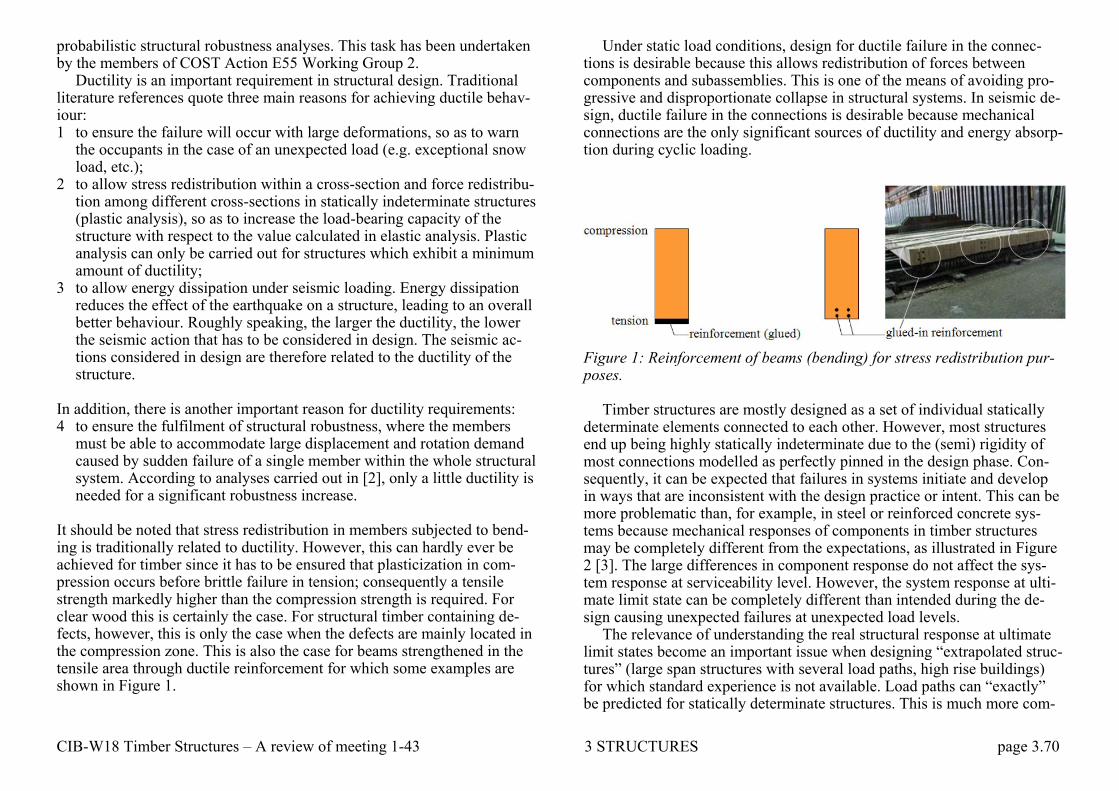
CIB-W18 Timber Structures – A review of meeting 1-43 3 STRUCTURES page 3.70
probabilistic structural robustness analyses. This task has been undertaken by the members of COST Action E55 Working Group 2.
Ductility is an important requirement in structural design. Traditional literature references quote three main reasons for achieving ductile behav-iour: 1 to ensure the failure will occur with large deformations, so as to warn
the occupants in the case of an unexpected load (e.g. exceptional snow load, etc.);
2 to allow stress redistribution within a cross-section and force redistribu-tion among different cross-sections in statically indeterminate structures (plastic analysis), so as to increase the load-bearing capacity of the structure with respect to the value calculated in elastic analysis. Plastic analysis can only be carried out for structures which exhibit a minimum amount of ductility;
3 to allow energy dissipation under seismic loading. Energy dissipation reduces the effect of the earthquake on a structure, leading to an overall better behaviour. Roughly speaking, the larger the ductility, the lower the seismic action that has to be considered in design. The seismic ac-tions considered in design are therefore related to the ductility of the structure.
In addition, there is another important reason for ductility requirements: 4 to ensure the fulfilment of structural robustness, where the members
must be able to accommodate large displacement and rotation demand caused by sudden failure of a single member within the whole structural system. According to analyses carried out in [2], only a little ductility is needed for a significant robustness increase.
It should be noted that stress redistribution in members subjected to bend-ing is traditionally related to ductility. However, this can hardly ever be achieved for timber since it has to be ensured that plasticization in com-pression occurs before brittle failure in tension; consequently a tensile strength markedly higher than the compression strength is required. For clear wood this is certainly the case. For structural timber containing de-fects, however, this is only the case when the defects are mainly located in the compression zone. This is also the case for beams strengthened in the tensile area through ductile reinforcement for which some examples are shown in Figure 1.
Under static load conditions, design for ductile failure in the connec-tions is desirable because this allows redistribution of forces between components and subassemblies. This is one of the means of avoiding pro-gressive and disproportionate collapse in structural systems. In seismic de-sign, ductile failure in the connections is desirable because mechanical connections are the only significant sources of ductility and energy absorp-tion during cyclic loading.
Figure 1: Reinforcement of beams (bending) for stress redistribution pur-poses.
Timber structures are mostly designed as a set of individual statically determinate elements connected to each other. However, most structures end up being highly statically indeterminate due to the (semi) rigidity of most connections modelled as perfectly pinned in the design phase. Con-sequently, it can be expected that failures in systems initiate and develop in ways that are inconsistent with the design practice or intent. This can be more problematic than, for example, in steel or reinforced concrete sys-tems because mechanical responses of components in timber structures may be completely different from the expectations, as illustrated in Figure 2 [3]. The large differences in component response do not affect the sys-tem response at serviceability level. However, the system response at ulti-mate limit state can be completely different than intended during the de-sign causing unexpected failures at unexpected load levels.
The relevance of understanding the real structural response at ultimate limit states become an important issue when designing ―extrapolated struc-tures‖ (large span structures with several load paths, high rise buildings) for which standard experience is not available. Load paths can ―exactly‖ be predicted for statically determinate structures. This is much more com-
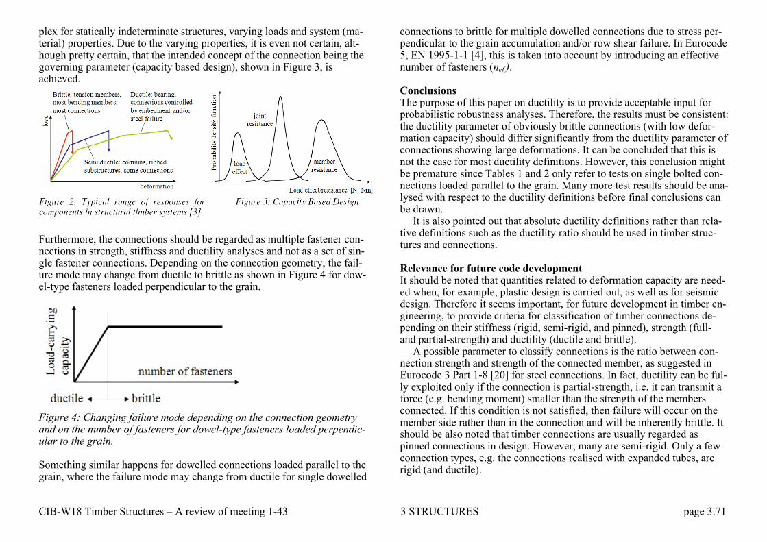
CIB-W18 Timber Structures – A review of meeting 1-43 3 STRUCTURES page 3.71
plex for statically indeterminate structures, varying loads and system (ma-terial) properties. Due to the varying properties, it is even not certain, alt-hough pretty certain, that the intended concept of the connection being the governing parameter (capacity based design), shown in Figure 3, is achieved.
Furthermore, the connections should be regarded as multiple fastener con-nections in strength, stiffness and ductility analyses and not as a set of sin-gle fastener connections. Depending on the connection geometry, the fail-ure mode may change from ductile to brittle as shown in Figure 4 for dow-el-type fasteners loaded perpendicular to the grain.
Figure 4: Changing failure mode depending on the connection geometry and on the number of fasteners for dowel-type fasteners loaded perpendic-ular to the grain. Something similar happens for dowelled connections loaded parallel to the grain, where the failure mode may change from ductile for single dowelled
connections to brittle for multiple dowelled connections due to stress per-pendicular to the grain accumulation and/or row shear failure. In Eurocode 5, EN 1995-1-1 [4], this is taken into account by introducing an effective number of fasteners (nef ). Conclusions The purpose of this paper on ductility is to provide acceptable input for probabilistic robustness analyses. Therefore, the results must be consistent: the ductility parameter of obviously brittle connections (with low defor-mation capacity) should differ significantly from the ductility parameter of connections showing large deformations. It can be concluded that this is not the case for most ductility definitions. However, this conclusion might be premature since Tables 1 and 2 only refer to tests on single bolted con-nections loaded parallel to the grain. Many more test results should be ana-lysed with respect to the ductility definitions before final conclusions can be drawn. It is also pointed out that absolute ductility definitions rather than rela-tive definitions such as the ductility ratio should be used in timber struc-tures and connections. Relevance for future code development It should be noted that quantities related to deformation capacity are need-ed when, for example, plastic design is carried out, as well as for seismic design. Therefore it seems important, for future development in timber en-gineering, to provide criteria for classification of timber connections de-pending on their stiffness (rigid, semi-rigid, and pinned), strength (full- and partial-strength) and ductility (ductile and brittle). A possible parameter to classify connections is the ratio between con-nection strength and strength of the connected member, as suggested in Eurocode 3 Part 1-8 [20] for steel connections. In fact, ductility can be ful-ly exploited only if the connection is partial-strength, i.e. it can transmit a force (e.g. bending moment) smaller than the strength of the members connected. If this condition is not satisfied, then failure will occur on the member side rather than in the connection and will be inherently brittle. It should be also noted that timber connections are usually regarded as pinned connections in design. However, many are semi-rigid. Only a few connection types, e.g. the connections realised with expanded tubes, are rigid (and ductile).

CIB-W18 Timber Structures – A review of meeting 1-43 3 STRUCTURES page 3.72
3.13 SERVICEABILITY 27-20-1 R H Leicester Codification of serviceability criteria Summary This paper presents a statistical model for the codification of serviceability criteria for both design codes and performance standards. This model is based on optimising cost functions. A key consideration is the complex na-ture of human response to structural unserviceability; it is highly variable and is affected by many non-structural parameters. General matters related to codification are also discussed. Conclusions The nature of structural unserviceability has been discussed, a statistical model presented for the quantification of design and performance criteria, and some procedures for codification suggested. Probably the most inter-esting aspects of this study are those concerning human response to unser-viceability; it was noted that this response is extremely variable, complex in nature and it is affected by many non-structural parameters. 27-20-2 S Capretti, A Ceccotti On the experimental determination of factor kdef and slip modulus kser from short-and long-term tests on a timber-concrete composite beam Abstract The factor kdef introduced by Furocode 5 to take into account the increase in deformation due to creep and moisture is determined from a long-term test (3 years duration) on a timber and concrete composite (TCC) beam in service class 3. The difference in kdef values for deflections and slips is discussed. The experimental deformation-time curves, combined with moisture and shrinkage/swelling measurements, show a high influence of a hygro-mechanical effect due to the differential shrinkage between timber and concrete.
Monitoring results of (lie service behaviour of a real structure (twin of the tested one) during three years in service class 1 is reported.
Finally, the instantaneous slip modulus Kser for TCC fasteners is deter-mined from previously performed short-term loading tests.
27-20-3 P Racher, F Rouger Serviceability limit states: A proposal for updating Eurocode 5 with re-spect to Eurocode 1 1ntroductiorn When drafting Eurocode 5, the code writers had to find a compromise for formulating the load combinations. Eurocode 1 which had to define load values and load combinations was delayed for different reasons. In 1994, National Application documents are being drafted, and Eurocode 1 has been voted, at least for load combinations. This paper intends to present the way to modify Eurocode 5 in order to get compatibility among Struc-tural Eurocodes. Basic examples illustrate this proposal. Conclusion. Despite an apparent complication from the basic load combinations, Euro-code 1 serviceability limit states definitions are much easier to undertake in a practical calculation. The numerical examples given in this paper show that a use of these formulas will not imply increased timber con-sumption. Therefore, the authors propose to incorporate these concepts in the final version of Eurocode 5, which would simplify also the table of de-formation factors (one line per material). Another advantage is also that timber calculations would be performed exactly in the same way as the steel or concrete calculations. 27-20-4 C Le Govic, F Rouger, T Toratti, P Morlier Creep behavior of timber under external conditions Introduction In 1990, Rouger & al. published a paper describing full scale experiments which had been initiated in order to give a basis for deformation factors given in Eurocode 5. The data corresponding to service classes I and 2 were fitted to a power law model, which allowed predicting the creep be-havior up to 50 years. This paper presents the work which has been carried out on service class 3, requiring a specific modeling to take into account the mechano-sorptive effects. A proposal for numerical values to be incor-porated in Eurocode 5 is given.
CIB-W18 Timber Structures – A review of meeting 1-43 3 STRUCTURES page 3.73
Conclusion When investigating the creep behavior under varying conditions, a number of failures have been recorded. They justify a probabilistic study to check the probabilities of failures. The creep limit concept has been shown to be applicable to test results, despite it was adjusted to clear wood specimens. The only part of the deformation which has been underestimated is the shrinkage deformation. The design proposal will tend to decrease the in-fluence of moisture content on creep, comparing it to the current version of EC5. 30-20-1 S Thelandersson, A Mårtensson Design principles for timber in compression perpendicular to grain Introduction In timber frame buildings the structural system is usually designed in such a way that load is transferred perpendicular to grain in joints between walls and floors. These joints are very important elements in timber frame building systems and their design is governed by a number of technical re-quirements beside the structural ones, such as fire safety, sound insulation, thermal insulation and air tightness. On top of that it is necessary that the joint is designed with respect to ease of assembly and economy. It is there-fore a challenge to find an optimum solution, since this detail is one of the most important factors for the competitiveness of a particular timber frame system concept.
From a structural point of view, the joint shall usually transfer vertical loads, and often also shear forces related to the horizontal stabilisation of the building. It is theoretically possible to design the joint so that load transfer perpendicular to the grain in wood elements is entirely avoided, but this is not feasible considering all other aspects of the design. The question therefore arises what kind of philosophy should be applied with respect to load transfer perpendicular to grain both from the point of view of structural safety and from the point of view of limiting the short and long term deformations in the joint. Deformations perpendicular to grain are crucial in such joints especially for multi-storey timber frame build-ings, where deformations at each level can add up to substantial move-ments over the building height.
The adverse consequences of deformations in a structural system are obvious. For example, non-structural elements, such as windows, doors
and partitions could become inoperable or damaged if primary structural elements deflect to a point where the non-structural element is part of the load path. Excessive deformations in the primary structural system may lead to damage to services and to costly deficiency corrections like e.g. re-pair of drywall cracks, floor and wall tile cracks, adjusting doors and paint touch ups. Another example is connections between timber frame and an exterior brick cladding, where excessive deformations in the timber struc-ture may cause damage. Uneven settlements of load-bearing walls in a sys-tem may cause sloping floors, which can be very expensive to correct.
In current practice, load transfer perpendicular to grain is mostly han-dled by limiting the bearing stress. In most codes, stresses perpendicular to grain are checked in the ultimate limit state against a design bearing strength. This is a simple approach which works well in many cases: – It gives a reasonable reduction of the risk that transversal crushing of a
wood member will lead to loss of stability of the structural system. – It will give an indirect limitation of deformations by limiting bearing
stress along the load path. It should be noted, however, that the deformation depends on several other factors than the bearing stress level, such as geometry along the load path, moisture changes and duration of the load.
In some situations, e.g. in timber framed structural systems, as de-scribed above, a more sophisticated philosophy is needed for the design of wood loaded perpendicular to grain. The following issues must be ad-dressed: Identification of those situations where design in the ultimate limit state is
necessary. – Formulation of design principles in the serviceability limit state for
loading perpendicular to grain. – Methods to estimate deformations under loading perpendicular to grain,
including long term and moisture effects. In this paper, design principles for compression perpendicular to grain in the ultimate as well as in the serviceability limit state are discussed. A general method to predict deformations in joints where wood is stressed perpendicular to grain is proposed. The method considers deformations in-duced by load as well as deformations induced by moisture variations.

CIB-W18 Timber Structures – A review of meeting 1-43 3 STRUCTURES page 3.74
Conclusions The current practice for design of timber in compression perpendicular to grain is not sufficient for some situations in practice, such as multi-storey timber framed buildings. The present investigation has lead to the follow-ing conclusions: – Design with respect to bearing in the ultimate limit state (ULS) need
only be made when bearing failure. may reduce the structural capacity of structural members or otherwise affect the safety of the structural system.
– The present design methods for bearing can be used in ULS, and the strength values for compression perpendicular to grain given in EN338 seem to be properly defined.
– In all cases where design in ULS is unnecessary, design should be made in the serviceability limit state.
– Estimates of deformations can be made by considering initial elastic, shrinkage and time-dependent deformation components in a rather sim-ple manner. It is proposed that calculation of deformation should be based on permanent and time averaged variable loads (quasi-permanent load combination).
– The EN 338 the value for modulus of elasticity E90 in compression perpendicular to grain seems to be too high. There can be reason to ad-just those values.
30-20-2 R J Bainbridge, C J Mettem Serviceability performance of timber floors - Eurocode 5 and full scale testing See 3.11 Residential floors 32-20-1 B Mohr Floor vibrations See 3.11 Residential floors
37-20-1 Lin J Hu, Y H Chui A new design method to control vibrations induced by foot steps in timber floors See 3.11 Residential floors 37-20-2 P Hamm Serviceability limit states of wooden footbridges. Vibrations caused by pedestrians. General This paper deals with Eurocode 5 – Design of timber structures, Part 2: Bridges, draft 2004. The verifications of vibrations of wooden footbridges caused by pedestrians in the serviceability limit state are explained and discussed.
Depending on the natural frequencies of the bridge the following verifi-cations of the bridge acceleration are recommended in Annex B (informa-tive), see figure 1. avert and ahor are the resulting accelerations of the bridge in the vertical and horizontal direction. If all vertical natural frequencies of the bridge are greater than 5 Hz and all horizontal natural frequencies are greater than 2,5 Hz no further verifications of the vibrations are needed.
Figure 1: Verifications of bridge vibrations caused by pedestrians.

CIB-W18 Timber Structures – A review of meeting 1-43 3 STRUCTURES page 3.75
Recognize that all these verifications are in the serviceability limit state. Although these criteria and formula are presented in a norm for timber structures EC5, they are valid for all materials, with exception of the damping factor. Results for the damping factor

CIB-W18 Timber Structures – A review of meeting 1-43 3 STRUCTURES page 3.76
3.14 SYSTEM EFFECTS 22-8-1 F Rouger, J D Barrett, R O Foschi Reliability analysis of viscoelastic floors Introduction This paper summarizes results of a project activity undertaken at the Uni-versity of British Columbia (Canada) in cooperation with the Centre Tech-nique du Bois et de 1‘Ameublement (France). The objective of this study is to analyze the effect of joist and panel viscoelastic behaviour on reliabil-ity of wood structural systems. Since previous work has not considered the influence of creep on structural performance, this study was initiated with the objective of undertaking initial studies of the influence of creep behav-iour on systems performance.
Recent studies by Foschi et al have shown that wood structural systems designed according to present codes have a somewhat lower average safe-ty level that rnight have been anticipated considering the performance rec-ord. Load sharing factors are incorporated into wood structural design codes to account to the addition safety developed by the structural interac-tion of parallel members in systems such as floors roofs and trusses. The additional safety develops in part due to the redistribution of framing member stresses and due to the interaction between framing members and the panels (or cover) material and the between member variation in modu-lus of elasticity. Studies of the elastic behaviour of redundant member wood structures have shown that the correlation between strength and modulus of elasticity of wood members contributes to a redistribution of stresses, in which the weaker member will be subjected to lower stresses and the stronger members will have higher than average stresses
Foschi et al investigated the long-term behaviour wood roof systems subjected cyclic snow loads System time-to-failure was calculated using damage accumulation models. Damage accumulation under simulated snow loads was evaluated using member stresses derived from an elastic stress analysis The time-to-failure distribution derived from the analysis formed the basis for system reliability studies using First Order Reliability Methods.
The creep of system framing members and panels product will affect the member and panel stresses. The purpose of this paper is describe a se-ries of analysis undertaken to assess the impact of viscoelastic behaviour
of roof joist and sheathing stresses for a roof system subjected to constant and cyclic snow loads. Conclusion Considering linear viscoelastic behaviour in floor calculations leads to some remarks – probabilities of failure are not affected – times-to-failure might be reduced by 10-20% – bending stresses are not affected. – deflection amplification factors are large and even larger than predicted
by the codes. This should be taken into account in further calibrations. The calculation required data for both lumber and panels had to be adapted from many different sources to generate the required input files. If viscoe-lastic studies should be pursued, it means that much more effort must be directed to obtaining the viscoelastic material property data for wood products.
The Monte-Carlo simulation was limited to a small number of replica-tions, the number of joists is small (3), the duration of load is short (10) years. All these limitations restrict the interpretation of the results: Addi-tional studies would need to be completed to establish the general applica-bility of the conclusions derived.
Even with these limitations we must remember that a few years ago this study could not have been performed. The evolution of computers is so fast that in near future more extensive studies will be possible and work should be continue develop analytical tools and material property data re-quired for viscoelastic behaviour studies. 25-10-2 T D G Canisius The influence of the elastic modulus on the simulated bending strength of hyperstatic timber beams Abstract In the design of a timber beam, its strength is assumed to be constant along the length and to be equal to the characteristic strength. This gives rise to an increase in the safety level of the member. In order to find this increase in safety, it is necessary to find the strengths of beams under different loading conditions. In the case of statically determinate beams, the struc-

CIB-W18 Timber Structures – A review of meeting 1-43 3 STRUCTURES page 3.77
tural analysis is not affected by the variations in the elasticity modulus. The importance of considering the lengthwise variation of the elasticity modulus in calculating the strengths of hyperstatic beams is investigated in this paper. The multivariate approach of Taylor and Bender is used in gen-erating beam properties. Finite elements are used for stress analysis. Sub-ject to the assumptions made, it is shown that in simulating the beam strengths, the correlated elasticity modulus needs to be considered in both the generation of properties and the analysis of problems if the desired ac-curacy is high. Conclusion Details of Monte Carlo simulations carried out on several beams to deter-mine their bending strengths were presented in this paper. The beam prop-erties were generated using the multivariate approach of Taylor and Bend-er. First order Markov processes were assumed for the strengths and the elasticity moduli of the property elements along the beam length. The hy-perstatic structures were analysed with a beam finite element programme.
Some of the beam property parameters were varied during the analyses to see their effect on the determined strengths. Also four types of analyses were carried out on the beams. These types depended on whether the lengthwise variation of the elasticity modulus was considered in the analy-sis or not and on whether the cross-correlation between the strength and stiffness was considered in the generation of beam properties or not.
The results indicate that the non-consideration of the cross-correlation between the strength and stiffness in property generation and/or the non-consideration of the elasticity modulus in structural analysis can give rise to large differences between the simulated strengths of hyperstatic beams. For example, for the clamped beam tinder a central concentrated load, the provided results show a maximum difference of 15.3% when the cross-correlation is not considered and the beam is assumed to be of uniform stiffness. This difference is with respect to an analysis that considered the non-uniformity of E and its cross-correlation with the strength. Analyses of some continuous beams showed that the differences between different types of analysis depend on both the structure and the applied loads.
Subject to the assumptions made, it can be concluded that the non-consideration of the cross-correlation coefficient and the lengthwise varia-tion of the elasticity modulus in the generation of beam element properties and the analysis of hyperstatic structures can result in errors as large as almost 15% in their simulated bending strengths. As the effect is negligi-
ble when the bending moment is constant along the length of a beam, a similar error can occur in the Moment Configuration Factor for a hyper-static structure. 34-8-1 M Hansson, T Isaksson System effects in sheathed parallel timber beam structures Abstract The paper presents a study on the system effect of sheathed timber struc-tures, such as roof elements. For such structures Eurocode 5 gives a sys-tem factor of 1.1. Using Monte Carlo simulations together with input from an experimental investigation of sheathed parallel timber beam structures, a parameter study of the system behaviour is performed. Parameters such as number and length of beams, type of connection between beam and sheathing and the variability in bending strength within and between members of the system are taken into account.
Systems are generated using Monte Carlo simulations and the system effect is evaluated by direct comparisons of strengths and by reliability methods, resulting in a calibration of the parameters in the code. Conclusions and further work The present study uses a statistical model of variability of bending strength within and between beams to investigate the magnitude of the system ef-fect for sheathed parallel timber beam structures.
Limited experimental investigations have shown that the failure criteri-on for a system corresponds to the failure of two neighbouring or any three beams.
The connector between the beam and sheathing influences the behav-iour of the system in such away that a nailed connection gives a higher co-efficient of variation of the system strength than a glued connection.
Compared to single beams where the coefficient of variation is around 20 %, the variation in strength of a system is around 10 %. The parameter study showed that the COV for the system is more or less independent of the studied parameters.
When calibrating the partial coefficient related to the material proper-ties, the low COV for the system results in a low γm. For a typical ratio be-tween variable load and total load, the results indicate that the system ef-fect factor ksys can be set equal to 1.15. This is based on the difference in

CIB-W18 Timber Structures – A review of meeting 1-43 3 STRUCTURES page 3.78
COV for the load carrying capacity for the single solid timber beam and the structural system.
In the calibration of the system effect factor the reliability index for the system is set to 4.3. However in the code the reliability index is defined as the safety of the single member in this case the solid timber beam. 35-8-1 M Hansson, T Isaksson System effects in sheathed parallel timber beam structures part II Abstract This is a continuation of Paper 34-8-1 In Eurocode 5 a factor of 1.1 is given for such systems. In the present study Monte Carlo simulations are used to generate systems and to evalu-ate the influence of different parameters on the system behaviour. The var-iability within and between timber elements is accounted for using a mod-el by Isaksson. The properties of the sheathing are assumed to be deter-ministic and the property of the joint between beam and sheathing is var-ied. Reliability theory is used to evaluate the system effect. For a given re-liability of a single member the reliability of a system is calculated. The reliability of a system is in general lower than for a single member. The study showed a system effect somewhere between 1.2 and 1.3, i.e. the load carrying capacity of a system is 20 to 30 % higher compared to the capaci-ty of a system when it is evaluated on a single member basis. Conclusions The codes generally accept that a system will have a lower reliability for the overall safety compared to the reliability of a single member. Using first order reliability method the reliability of a system based on the design of a single T-section can be compared to the reliability of a system using load sharing. Monte Carlo simulations are used to determine the load car-rying capacity of single beams and systems. The parameter study shows that the different parameters only have minor influence on the system ef-fect.
A general method based on reliability theory was used to evaluate the system effect factor. To quantify the effect, the statistical distribution of the variables in the failure function and the partial coefficients for the loads must be known. Using the Swedish code the system effect factor was found to be between 1.19 and 1.31. A simpler way to evaluate the system
effect is to determine the ratio between failure load of a system and the weakest T-section in each system. For the 5th percentile and the mean val-ue the system effect is in the interval 1.19-1.30 and 1.14-1.21 respectively. This can be compared to a factor of 1.1 given in Eurocode 5. 39-8-1 I Smith, Y H Chui, P Quenneville Overview of a new Canadian approach to handling system effects in timber structures Abstract In Canada ideas are being formulated about how system design can be im-plemented within the national timber design code. Momentum for this comes from need to address the changing nature of the construction indus-try and allied professional engineering practice. The end product needs to be something that can be seamlessly transitioned into design practice. Sys-tem design is not envisaged as an approach that will yield unfamiliar solu-tions for familiar problems. Rather it is seen as supporting creation of tim-ber solution in new situations. This paper attempts to identify the major framework issues, starting with the question of what the term system should mean. There is no attempt to follow faddish trends that fly under the same label. It is thought that landscape level changes will shape system design in Canada, and presumably elsewhere, and will concern evolution of architectural solutions, rapid broadening in the available range of struc-tural products (wood, non-wood and composite varieties), changing con-struction methods and practices, and evolution in regulatory regimes. De-tailed technical issues such as what constitute acceptable 'search tree' and 'structural reliability' algorithms will need to be addressed at some point, but that should be after framework issues have been resolved. Concluding Comments The authors do not imagine that they have identified all the relevant issues, nor do they imagine that the approaches suggested will meet with univer-sal support even in Canada. They hope that this "Aunt Sally" will promote debate on issues surrounding the introduction of systems level design into timber design codes. Not debating this creates the risk that such documents become obsolete and that a changing world passes them by.

CIB-W18 Timber Structures – A review of meeting 1-43 3 STRUCTURES page 3.79
43-12-3 M Frese, H J Blass System effects in glued laminated timber in tension and bending Introduction In 2005, bending tests on full size glulam beams showed that the bending strength values obtained, were far too low compared with the current product standard. For that reason, a new research on glulam was carried out involving a series of numerical studies on the glulam bending strength. This research resulted in a new strength model for the bending strength. The current paper aims at giving a comprehensive overview on recent de-velopments in simulating glulam strength parallel to grain. These devel-opments have arisen from the new research on glulam and a failure analy-sis on timber hall structures and now cover the tensile-to- bending-strength ratio as well as the size effect in members subject to tension and the load-carrying capacity of simple and continuous beams with up to 5 supports. Therefore, the current paper is a direct continuation of the author‘s CIB-W18 paper in 2008.
In general, the strength hereinafter refers to characteristic glulam bend-ing (fm,g,k) and characteristic glulam tensile strength (ft,0,g,k), respectively. Both values are associated with standardised member sizes: 0.6 m times 10.8 m (h·ℓm) in case of bending tests and 0.6 m times 5.4 m (h·ℓt) in case of tensile tests (Fig. 1).
Fig. 1 Test configurations in European test standard EN 408 (2003) with the terms of European standard EN 1194 (1999); bending test (top) and tensile test (bottom). Conclusions • Comparative simulations of tensile and bending tests were performed to
revise the tensile-to- bending-strength ratio. According to the study the
tensile-to-bending-strength ratio is 0.88. The ratio applies to character-istic values of homogeneous glulam, is independent of the material strength and refers to standardised specimen dimensions for tensile and bending tests. The new found ratio is about 25 % higher than the value of about 0.70 in the European standard EN 1194 (1999). This difference may benefit the glulam industry by increasing the reference value for the characteristic tensile strength.
• A wide range of length-depth-combinations was considered for simu-lated tension members to create a database describing the size effect in glulam members subject to tension. In the study, the length but not the depth was found to be the dominant factor affecting the tensile strength. The influence of a member depth between 120 and 600 mm on the ten-sile strength is negligible. Based on Weibull‘s theory, a non-dimensional length factor was obtained to fit the tensile-to-reference-tensile-strength ratio for characteristic values. The ratio decreases rap-idly with increasing length for short members, meaning the tensile strength shows a strong dependence on the length of short members. For a quasi-infinite member length the size effect wears off. The effec-tive strength of a tension member 150 mm in length is about 140% of the reference value whereas the remaining tensile strength for quasi-infinite member length is approximately 80% of the reference value. The consideration of a length-dependent glulam tensile strength may increase economical design of short tension members and the reliability of very long tension members.
• Comparative simulated bending tests on simple, 2-span, 3-span and 4-span beams show that the load-carrying capacity of continuous beams is 30 - 40% higher than of comparable simple beams. In regard to the design of continuous beams the effective (or apparent) characteristic bending strength of 2-span beams is 25%, of 3-span beams 8% and of 4-span beams 15% higher than the corresponding characteristic bending strength referring to simple beams. The 25% increase in case of 2-span beams is in good agreement with analytical results based on Weibull‘s theory [8][9]. In contrast to the current rule in the German timber de-sign code DIN 1052 (2008), where a 10% increase is allowed on the basis of moment redistribution, the findings of the present study may allow a more economical and consistent design of continuous beams.

CIB-W18 Timber Structures – A review of meeting 1-43 3 STRUCTURES page 3.80
43-12-4 C Faye, F Rouger, P Garcia Experimental investigations on mechanical behaviour of glued solid timber Context and objective: Glued Solid timber (GS) beams are structural elements with rectangular cross section formed by bonding together two, three, four or five lamina-tions having a thickness between 45 and 85 mm. Laminations can be fin-ger jointed.
GS beams are used in traditional carpentry, timber frame housing, or as bracing elements, etc. Even if this product is more expensive than solid timber, the use of GS beams is increasing due to the following advantages: a better dimensional stability, moisture content around 12% due to the manufacturing process, cross section until (260*320) mm2, directly com-patible with CNC machines.
Because their cross section is close to squared section (maximum cross section is L×H 260mm × 340 mm), GS beams can be loaded in flatwise (load is perpendicular to glue lines) or edgewise (load is parallel to glue lines) bending (cf. figure1)
Figure 1: GS beams with two (a) and four (b) laminations in edgewise
bending, GS with four (c) or five (d) laminations in flatwise bending, H×L
< 260mm×320mm .
In flatwise bending, due to the fact that GS beams are composed of few laminations with large thickness, their mechanical behaviour is different from glulam. Actually, laminations in GS beams loaded in flatwise bend-ing are not only stressed in tension but both in tension and bending. In edgewise bending, the mechanical behaviour involves system effect: lami-nations with higher stiffness are more stressed. Since these laminations al-
so have higher strength, this results in a composite product with higher strength.
In this context, the aim of this paper is to determine mechanical per-formances of GS beams and to propose beam lay ups for GS beams based on an experimental study carried on 180 beams in Spruce and Fir and Douglas Fir (in flatwise and edgewise bending) and on bending tests on finger joints and laminations. This work is the first part of research project of 2 years. These experimental investigations will be completed by addi-tional tests on GS beams with 4 and 5 laminations and a probabilistic finite element model taking into account the variability of the mechanical prop-erties of the laminations (presented in a future paper).
Conclusions Based on an experimental study carried on 180 GS beams, strength and stiffness were determined in flatwise and edgewise bending.
In edgewise bending, system effect induces an increase of strength for GS beams in comparison with laminations. This increase is less significant for high strength classes due to the weak strength of the finger joints tested in this study. System factor obtained from experiments is larger than the one given by Eurocode 5, namely ksys=1,03 for GS beams with 2 lamina-tions and ksys=1,06 for GS beams with 3 laminations. In flatwise, the cor-respondence between the strength of laminations and the strength of GS beams is given for a reference depth of 150 mm and a depth factor of 0,1, and it is similar than the correspondence existing for glulam with a refer-ence depth of 600 mm and a depth factor of 0,1.
The beam lays-up presented in paragraph 5 are actually discussed into working group WG3 of CEN TC124 in charge of the revision EN 14 080 which will integrate Glued Solid timber beams.
This first study will be completed by: Additional tests on GS beams with four and five laminations, A probabilistic finite element model taking into account the variability
of the mechanical properties of the laminations and finger joints.
CIB-W18 Timber Structures – A review of meeting 1-43 3 STRUCTURES page 3.81
3.15 TAPERED AND CURVED GLULAM MEMBERS 11-10-1 H Riberholt Tapered timber beams Summary There is proposed a method to calculate the stress distribution in tapered wood beams. The wood is assumed to be linear-elastic orthotropic.
The Norris interaction formula has been employed to compare meas-ured and predicted bending strengths of glulam and solid clear timber beams.
There was found a good agreement between measured and predicted bending strength of glulam beams. Conclusions It has been demonstrated that the load capacity of tapered glulam beams can be predicted by a linear-elastic orthotropic stress analysis combined with a rupture criterion based on the maximum stresses at a point. It was found, that the Norris interaction formula gave the best prediction of the strength of glulam.
Apparently it is not possible to predict the strength of tapered solid beams on the same basis. The test results with tapered glulam beams indicate that the Norris formula is not satisfactorily, since the basic strength parameters apparently are mu-tual dependent. It seems that "the shear strength is greater, when the stress perpendicular to the fibres is a compression stress than when it is a tension stress". This effect might be explained by assuming that rupture is trig-gered by cracks or flaws in the wood. 14-12-3 H Riberholt Double tapered curved glulam beams Preface The stress analysis of double tapered curved glulam beams can not be car-ried out by the usual beam formulas, instead more refined methods must be applied. Among the feasible methods one can mention partly the Point Matching Technique (a collocation method) and partly the Finite Element
Method. Some authors have employed the Point Matching Technique and others
have employed the Finite Element Method. Since objections may be arisen against the assumptions employed by the above mentioned authors, it is found reasonable to accomplish a stress analysis which allows for these objections. This stress analysis is carried out be means of the Finite Ele-ment Method, which is found most suitable due to its generality.
In Chapter 2 there is given a review of the differences between the methods, and in Chapter 3 the results are compared with measurements. In Chapter 4 a method for practical stress analysis is proposed.
This report aims at a stress analysis of a double tapered curved glulam beam simple supported and loaded with an uniformly distributed load. 14-12-4 E Gehri Comment on CIB-W 18/14-12-3 Dear Mr. Sunley, Unfortunately I will not be able to attend the CIB-meeting in Warsaw due to military service duties in my country.
I just received the paper of Riberholt on "Double tapered curved glulam beams". This work confirms the validity of the results of Foschi and Blumer. The difference shown between PPM and FEM was greater for the radial stress, but always smaller than 10 %. Riberholt's paper shows alt-hough the influence of a uniformly distributed load of the top of the beam. For bending stresses the influence is negligible for the whole practical range of L/H. For the perpendicular stresses a significant decrease was found for smaller L/H-ratios.
The influence of a direct applied load can although be found by a sim-ple static consideration, as explained in the sheet annexed.
The additional bending stresses due to direct local loading are very small, since they are depending on the factor (a/k)
2. The additional per-
pendicular stresses, which are proportional to the applied load, have larger influence. Assuming a linear distribution over the height of the girder, we can therefore assume that the perpendicular stress due to pure bending will be diminished by the half load direct applied. As has shown by Riberholt, for smaller L/H-ratios which would correspond to larger a/z-values there is an interest to consider the effect of direct loading.

CIB-W18 Timber Structures – A review of meeting 1-43 3 STRUCTURES page 3.82
Riberholt pointed newly out the advantages and disadvantages of present-ing the maximum stresses in function of the height of the apex or of a fic-tive curved beam with constant height. We know from experience that in case of radial failure mode an apex means a weakening of the girder. From the engineering point of view we should therefore avoid all kinds of curved beams with apex (or apex only nailed on girder) and therefore con-sider the curved beam as the basic case. In my opinion we should delete
the case with apex from the timber code (too big weight on this point) and make only references to corresponding publications.
With best regards, Yours very truly, p. p. E. Gehri
24-12-2 J Ehlbeck, J Kurth Influence of perpendicular-to-grain stressed volume on the load-carrying capacity of curved and tapered glulam beams Introduction According to Eurocode 5 -Draft (1987) the design of curved beams with constant depth and of double tapered beams has to take into account a vol-ume factor kvol., and a stress distribution factor kdis to satisfy the design conditions covering the perpendicular-to-grain tensile stresses:
,90, ,90,t d vol dis t dk k f (1)
In (1) is:
1/0
weik
volV
kV
(2)
assuming a 2-parameter Weibull distribution,
1/
1, ,
wei
wei
maxdis k
k
V
k
x y z dVV
(3)
taking into account the stress distribution, and
ft,90,d = kmod ft,90,k /γM (4)
This design method is based on the 2-parametric statistical distribution function for homogeneous and isotropic material with brittle fracture be-haviour developed by Weibull 1939. It takes into account the influence on the perpendicular-to-grain tensile strength – of the stressed volume by kvol, – of the stress distribution by kdis.
CIB-W18 Timber Structures – A review of meeting 1-43 3 STRUCTURES page 3.83
Proposals for design rules in EUROCODE 5 The method given in Eurocode 5 - draft (1987) is principally appropriate to design curved and double-tapered glued laminated timber beams. The advantage of this method is its simple application: – the maximum perpendicular-to-grain tensile stress is calculated accord-
ing to the application rules given in EC 5 or other relevant literature, – kvol is determined according to the application rules given in Eurocode 5
- draft (1987), – kdis is - for simplification - for all types of curved, double-tapered and
cambered beams for actions giving a constant or nearly constant mo-ment in the curved part of the beam taken as kdis = 1,4.
Using these rules, the product of kvol kdis leads to a realistic modification of the characteristic design strength. Furthermore, it should be discussed to modify or change the character-istic strength values for tension perpendicular-to-grain, given in prEN 338, e.g. from 0,40 N/mm
2 to 0,55 N/mm
2 when timber is used for glulam. In
case of changing the reference volume V0 from 0,02 m3 to a smaller vol-
ume (under discussion with respect to adequate test methods), the charac-teristic strength values should be modified accordingly.
CIB-W18 Timber Structures – A review of meeting 1-43 3 STRUCTURES page 3.84
3.16 THIN-WALLED ELEMENTS 11-4-1 I Smith Analysis of plywood stressed skin panels with rigid or semi-rigid con-nections Introduction Plywood stressed skin panels consist of plywood sheets glued or mechani-cally fastened to the top or to both top and bottom surfaces of longitudinal timber stringers. The whole assembly acts as an integral section to resist bending, provided that the joints between the plywood and stringers are sufficiently rigid to prevent excessive slip due to longitudinal shear force induced between the plywood and the stringers. Structural economies are made possible by the utilisation of both plywood and stringers to resist bending. The size of a stringer for a given span can be less than that re-quired for a simple joist, or a lower grade material can be used.
This paper presents a method of analysis for both single and double skin stressed skin panels, with either rigid or semi rigid connections, which is suitable for hand calculation using an electronic calculator. The analysis can be used to solve for panel deflections, and for stresses in the plywood skin(s) and timber stringers. Panels assembled by gluing are as-sumed to have rigid connections, and panels assembled using nails or sta-ples are assumed to have semi rigid connections.
Using numerical examples it is demonstrated that there is good agree-ment between the method of analysis presented and alternative methods of analysis formulated by other workers. Conclusions For most practical design purposes it is acceptable to approximate the above mentioned loading and displacement definitions for a beam simply supported at both ends which carries a uniformly distributed transverse load, by the corresponding loading and displacement definitions for a beam simply supported at both ends which carries a sinusoidally distribut-ed transverse load.
22-10-3 J König Thin-walled wood-based flanges in composite beams Summary The load-bearing capacity of thin-walled wood-based flanges in composite beams can be reduced due to shear lag, buckling and flange curling. How-ever, flanges in compression have considerable load-bearing capacity even after the flange has buckled. The effective width concept which is well es-tablished in the field of sheet metal construction can also be used in de-signing wood-based board material with respect to buckling. This is shown by an evaluation of tests carried out at Delft. Design formulae for the ef-fect of flange curling are derived, and design criteria are proposed. Introduction In the field of timber construction, structural elements comprising thin-walled components of wood-based board material have been used for some time. These structural elements are characteristic for lightweight construction, and it is expected that they will be used more extensively in the future.
Typical examples are composite sections comprising webs of solid wood and flanges of board material. The webs may also be made up of components of board material and solid wood, see figure 1. However, ow-ing to the small thickness of the board material, there are a number of properties which demand more accurate analysis if the material is to be utilised in the optimum manner. The flange often has the duty of distrib-uting load in the transverse direction. In floors, consideration must also be given to the stiffness requirement which determines the thickness of the flange. In these structures it is generally only the shear lag in the board material which limits the load-bearing capacity of the flange when the flanges are very wide in proportion to the span of the beam. In other struc-tures, for instance in roof cassettes, the load distribution task may be of subordinate importance and certain deformations may be tolerated. Final-ly, direct application of load on the flange can often be avoided, for in-stance by application of the load over the web of the composite section or on the bottom flange of the section. Flanges in compression may also be subject to buckling. When the beam is curved, or becomes curved owing to the external load, the flanges are deformed inwards towards the neutral axis of the cross section (flange curling), and the contribution of the flang-

CIB-W18 Timber Structures – A review of meeting 1-43 3 STRUCTURES page 3.85
es to the load-bearing capacity and stiffness of the box section is therefore reduced.
Figure 1. Examples of composite sections with thin walled components. It is well known that thin-walled plates in compression have considerable post-critical load-bearing capacity, i.e. the load can be further increased af-ter the critical buckling stress of the plate has been reached. This favoura-ble behaviour has been utilised for a long time, first in aeroplane construc-tion and since the end of the 1940s also in building construction, mainly in thin-walled structural elements of steel and aluminium sheeting. In the field of timber construction also the post-critical load-bearing capacity of buckled plate elements has been known. In order that this phenomenon may be utilised to some extent, the coefficient of safety is slightly reduced in the structural regulations for timber in most countries.
In accordance with the CIB Structural Timber Code, it is permissible to utilise the post-critical load-bearing capacity. The code lays down some values regarding the effective width of the flange, but these values are un-differentiated since neither the critical buckling load of the flange nor its compressive strength is taken into consideration. As far as the author is aware, the effect of these is reflected only in the Swiss timber code SIA 164. It is however not known whether the rules in the code had been veri-fied for wood-based board materials when the code was written. In /6/, which gives the background to the Swiss code, no reference is made to this.
The research reports which deal with the buckling of wood-based boards or thin-walled components in structural elements mainly confine them-selves to determination of the critical buckling load. While most structural regulations for timber structures take account of the fact that the load-bearing capacity of thin-walled flanges is limited due to shear lag in
the board material, there is no requirement, as far as the author is aware, that the effect of flange curling on the load-bearing capacity of the compo-site section should be checked.
It is shown that the effective width concept in utilising the post-critical region can also be applied to wood-based thin-walled flanges. Design rules are also given which take the effect of flange curling into consideration. The effect of shear lag in wood-based board materials is already well doc-umented and requires no further elucidation.
CIB-W18 Timber Structures – A review of meeting 1-43 3 STRUCTURES page 3.86
3.17 TIMBER BEAMS, GENERAL 5-10-1 H J Larsen The design of timber beams Introduction The present paper has been prepared as a background for the work of the CIB/W18-Timber Structures in setting up the basis for an international standard for timber structures.
The report deals with the design of beams of both solid timber and glu-lam, and glued thin-webbed or thin-flanged I- and box beams (flat stressed-skin panels).
A number of West European and North American timber codes have been studied in an attempt to clarify and evaluate the background for the regulations of the codes.
CIB-W18 Timber Structures – A review of meeting 1-43 3 STRUCTURES page 3.87
3.18 TIMBER FRAME WALLS 19-15-3 M Yasumura Racking resistance of wooden frame walls with various openings Introduction Wooden frame construction, practically used for only small dwellings in Japan, can be applied to various uses for a building if a rational design procedure on the basis of structural calculation is developed. Although several theoretical studies have been done on the racking strength of wooden frame wall panels, they are based on the analysis of blind walls and do not explain the mechanical properties of the entire wall panel with openings. A purpose of this study is to present the useful data for calculat-ing the lateral resistance of wooden frame construction. Twelve full-sized plywood-sheathed wall panels with various openings were subjected to the racking loads, and the influence of openings on the shear stiffness and strength was observed. Experimental results were compared with the cal-culated values on the basis of non-linear load-slip relation of a nail, and comparatively good agreement between experimental and calculated val-ues was obtained. Conclusions The results of this study lead to the following concluding statements: 1. The current design procedure is apt to overestimate the racking re-
sistance of a wall panel which consists of only slender blind walls and contains no small walls, and underestimate considerably the racking re-sistance of wall panels which contains only small openings.
2. Large vertical forces were concentrated at the studs arranged at the end of a wall panel or door openings. These studs should be connected tight-ly to the foundation and horizontal members when full nail action is ex-pected. Otherwise shear force of the nails which connect a sheathing sheet to the studs subjected to large drawing force should be neglected when the racking resistance of a wall panel is computed.
3. The shear stiffness and strength of a nail fastening estimated from rack-ing test of blind wall panels were approximately 10 to 20 percent small-er than those obtained from single shear test of nail fastenings. The ef-fects of the angle of the fibres of sheathing material and frame members on the shear stiffness and strength of nail fasteners and those of bending
deformation of frame members and the slip of the fastenings on the shear properties of wall panels should be studied more precisely to ap-ply the load-slip relation of a nail obtained from single shear test of nail fastenings directly to the computation of the racking resistance of wall panels.
4. The solution developed previously agreed comparatively well with the experimental results. However this method has the tendency to overes-timate slightly shear stiffness of wall panels having large openings of door type. This indicates that the effects of bending deformation of frame members should be considered to compute more precisely the shear stiffness of a wall panel having this type of openings. The ulti-mate load calculated from this solution however agreed well with the experimental results.
25-15-1 U Korin Structural assessment of timber framed building systems Scope The dominant methods for home construction in Israel are based on rein-forced concrete structures and block masonry. These methods are locally referred to as "conventional construction".
Socio-economical changes caused in the last few years an increase of the relative volume of low-rise home buildings. Timber framed houses, which dominate the solution for low-rise homes the world over, gradually began to penetrate the home market.
Today, timber homes account for about 10 percent of the low-rise home building (about 25 percent of the total volume of home construction). In terms of last year, we may speak of about 1500 home units of timber framed houses. Conclusions The enormous assessment process of building systems enable to provide the country with safe, functional and durable timber framed houses, in spite of the lack of previous experience in that type of construction. Some of the newly built timber framed houses very successfully withstood the extremely unusual heavy weather conditions the Middle East experi-enced last winter. The houses were found safe and provided the occupants with good living space.

CIB-W18 Timber Structures – A review of meeting 1-43 3 STRUCTURES page 3.88
28-102-2 B Källsner Racking strength of wall diaphragms – discussion of the Eurocode 5 approach Abstract The design of wall diaphragms according to Eurocode 5 is in some re-spects conservative and in other respects unsafe. To clarity the structural behaviour of wall diaphragms, a theoretical background is given. The de-sign rules in Eurocode 5 are discussed and improvements of the code text are suggested. It is shown that the capacity of shear wall is influenced by different factors like boundary conditions and edge distances of fasteners. 29-15-1 F Lam, 1-1 G L Prion and M He Lateral resistance of wood based shear walls with oversized sheathing panels Abstract This paper summarizes the results from the first phase of a study to devel-op a database comparing the structural performance of shear wall systems built with regular and 'nonstandard large dimension oriented strand board panels under monotonic and cyclic loading conditions. Different types of nail connectors have also been investigated. Conclusions A database comparing the structural performance of shear wall systems built with regular and nonstandard large dimension oriented strand board panels under monotonic and cyclic loading conditions was reported. Under monotonic loading, a substantial increase in both stiffness and lateral load carrying capacity was observed when comparing shear walls built with oversize and regular panels. Defining ductility as the ratio between wall displacements at maximum load and 50% of the maximum load during monotonic testing, a slight increase in ductility was observed comparing the shear walls built with oversize and regular panels. Examining the dis-sipated energy as the area under the load deformation curve, walls built with the regular panel dissipated more energy under cyclic loading as compared to walls built with oversized panels. The failure modes in the shear walls were substantially different under monotonic (nail withdrawal) and cyclic (nail fatigue) test conditions. Further investigation of the adopt-
ed cyclic load schedule in relation to the dynamic response of the shear wall is needed to fully understand and characterize the failure modes in shear walls. 29-15-3 D R Griffiths, C J Mettem, V Enjily, P J Steer The racking resistance of timber frame walls: design by test and calcu-lation Abstract This paper introduces work carried out over many years in the UK, on timber frame wall design. It explains why the work was necessary for the national acceptance of timber frame, and demonstrates how knowledge gained is now helping in considering designs for medium-rise timber frame buildings of up to six storeys. Alternative design and test methods are considered, and a justification is given for a top loading test, which leads to an empirically-based design method. This paper is written in prep-aration for a UK initiative to find a suitable design method for racking re-sistance to limit-state design principles. The importance of correctly mod-elling the timber frame behaviour under load is noted, and short design ex-amples are included. Summary and Conclusions – The principal wall racking test and design method used in the UK was
developed to meet a need for the structural appraisal of platform frame housing systems, which when the methods were instigated, represented a new form of domestic building construction. The limitation of deflec-tion was significant to the design objectives. A top-loading test was ac-cepted, after other methods had been seen to model inadequately the complex situation of the real timber frame wall.
– A detailed reduction procedure for the test results linked the test basis to a design method. This entailed the derivation of a single design val-ue, termed the "basic racking resistance" Rb (kN/m). The racking re-sistance was used with the total wall length, and with modification fac-tors for materials and wall form, to evaluate the safe racking capacity of any practical wall design desired.
– The design method was empirically based. However it was by no means ad hoc. Indeed, it was related to the test performance of nearly two hundred wall and panel units. It realistically modelled the timber
CIB-W18 Timber Structures – A review of meeting 1-43 3 STRUCTURES page 3.89
frame wall, and its practical restraints, but did not take full account of holding-down methods or of return walls, although it has been shown in research projects that these factors can in fact be modelled.
– The UK design approach has rules which allow for the combined use of structural sheathings, and semi-structural linings. These rules preclude the use of a fundamentally-based three dimensional design method, since the high stiffness and strength of internal semi-structurally lined walls must often be ignored.
– Although conceived for working stress design, the UK method could, and probably will be, adapted to a limit-state approach. This will need to look separately at serviceability and ultimate limit states. This will in turn require a comprehensive re-evaluation of the UK test data. There is a realisation that at present, design values are very much limited by de-flection considerations.
– The new EN 594 test reduces the significance of stiffness in design, but at the same time is fundamentally flawed in its evaluation of this pa-rameter. Whilst appealing in their design simplicity, the ASTM-based design methods use an unrealistic test model, and consider only wall strength. The EC5 design method concentrates on external forces, and seems not to consider the racking resistance of the wall itself. Certainly, it does not cover serviceability design, and is restrictive in its require-ments for panel fixings.
– It is becoming increasingly important that both timber frame research, and the ensuing design methods are acceptable throughout Europe. In order to take full advantage of the lead shown by the UK timber frame industry, a "Eurodiaphragms" project has just been initiated. This has the objective of preparing a wall racking design method which is com-prehensive in its coverage, yet simple. Most importantly, it seeks to es-tablish a basis which will be acceptable throughout Europe. This meth-od is to be prepared within the timetable for the revision of Eurocode 5.
– Completed research on the brickwork outer skin in the UK, both as a contributor to racking resistance, and as a wind shield, could with great benefit be transferred to a limit-state design approach. This would be a fairly substantial undertaking. However, the common between-materials safety format of the Eurocodes would help considerably in such an endeavour. Developments in medium-rise timber frame con-struction are stimulating a desire to investigate such masonry/timber composite action effects for taller buildings.
30-15-1 Ming He, H Magnusson, F Lam, H G L Prion Cyclic performance of perforated wood shear walls with oversize ori-ented strand board panels Abstract This paper reports the test results obtained from a study to investigate the influence of openings on the lateral resistance of wood based shear walls built with both standard and oversize oriented strand board panels under monotonic and cyclic loading conditions. Eight walls were tested, using ei-ther standard 1.2 x 2.4 m panels or one full size 2.4 x 7.3 m oriented strand board panel. Commonly used wood frame construction details were em-ployed, using 38 x 89 mm No. 2 and better Spruce Pine Fir framing com-ponents. Test results showed that the application of non-standard oversize panels significantly improved the performance of the perforated shear walls compared with standard 1.2 x 2.4 m panels. Door and window open-ings caused a significant decrease in the strength and stiffness of the walls and precipitated a change in failure mode, especially for walls with full size panels. While nail failure modes were commonly observed in walls without openings, a combination of nail and panel failures were observed in shear walls with openings. Final failures typically affected the wall per-formance once the plastic deformation region was reached, which was dis-played in the tests in the form of either panel buckling or panel tearing at the corners of door and window openings. A newly proposed cyclic test protocol was used which consisted of fewer but more severe displacement excursions, compared to many other test protocols. This was believed to better reflect typical earthquake excitation and avoid low cycle nail fatigue failures, which were observed previously with long cyclic test protocols. Conclusions Openings in wood based shear walls caused a significant decrease in shear strength and stiffness of shear walls, due to the reduction in the effective sheathing area. To strengthen the racking resistance of shear walls with openings, large non-standard panels were used. When shear walls with openings were built with these oversize panels, they presented a signifi-cant improvement in shear wall performance, obtaining shear strength and stiffness values even higher than for walls without openings built with regular panels. These results imply that the impact of openings on shear walls with oversize panel is more significant in contrast with the corre-sponding values in shear walls with regular panel. In addition, the ductility

CIB-W18 Timber Structures – A review of meeting 1-43 3 STRUCTURES page 3.90
ratios of the walls with openings were slightly lower than those without openings.
The failure modes of shear walls with openings differed from those without openings. The performance of the walls was not only governed by the behaviour of the nail connectors between panel and frame, but a com-bination of nail and panel failure. Panel failure modes occurred in the form of panel buckling and panel tearing around the corners of openings. Nail withdrawal was the dominant nail failure mode in the tests (except for one wall, in which nail low cycle fatigue occurred), which occurred mainly along the edges of the panels at the mid-height of the wall with regular panels and along the bottom edge of the panel in the wall with one over-size panel. Both panel and nail failure modes and locations were the same under monotonic and cyclic loading conditions. Considering the fact that panel failure locations were mainly concentrated in the corner areas of openings, localized reinforcement methods should be further investigated. 30-15-2 L Davenne, L Daudeville, N Kawai, M Yasumura A numerical analysis of shear walls structural performances Abstract This paper deals with the numerical analysis of wood based shear walls made of lumber framing members and with sheathing plywood panels connected with nails. A model is presented for the simulation of the non linear response of the nailed connection under static monotonic or reversed cyclic loading. It has been implemented in the finite element code CASTEM 2000. Three kind of walls with different openings are simulated. The responses are close from the experimental results made at the Build-ing Research Institute in Tsukuba, Japan. Conclusion The authors presented a finite element code to compute the response of wood frames with nailed plywood sheathing panels. A model to simulate the non linear response of joints under cyclic loading is proposed. It gives a good response in the case of static cyclic imposed displacements (CEN standard). The different strength degradations, and allowance apparitions are modeled. The response of the walls under static m loading is close to the results from the tests. The cyclic loading of walls is in progress.
The one dimensional model must now be checked in other loading cas-es and with other types of nail (for example, nail fatigue may appear with other kind of nails, the behaviour different than the Japanese nails tested here).
In a future work, a three dimension model with degradation couplings must be developed to better simulate the reality. 30-15-4 M Yasumura, N Kawai Evaluation of wood framed shear walls subjected to lateral load Abstract The purpose of this study is to establish the test method for evaluating the seismic performance of wood-framed shear walls. The quasi-static mono-tonic loading and the reversed cyclic loading were applied to the nailed joints and the wood-framed shear walls sheathed with the plywood, OSB and gypsum board. The yield load, ultimate load and the maximum dis-placement were determined by the several procedures, and the energy dis-sipation of the nailed joints and the shear walls is discussed. Conclusion The yield load of the shear walls determined by the proposed procedure in this gives appropriate values both for the true and apparent shear defor-mations, while the load determined by CEN standard procedure gives 20 to 40% higher value for the a shear deformation than that for the true shear deformation. The yield load determined by method agreed well with the yield strength calculated from the experimental results of nailed joints and that with the yield theory. It also agreed well with the load corresponding to the true shear deformation of 1/300.
The ultimate load and the maximum displacement under the reversed cyclic loading was respectively 10 to 15% and 10 to 30% smaller than those of the monotonic loading. The calculated ultimate load from that of the nailed joint under the reversed cyclic load test agreed well with the ex-perimental results.
The equivalent viscous damping of the nailed joints varied from 15 to 25% when the displacement was smaller than 1 mm and decreased to 15% in average when the displacement was larger than 5 mm in the plywood and OSB sheathed walls. This trend was not clear in the gypsum sheathed nailed joints. The equivalent viscous damping ratio of the shear walls was

CIB-W18 Timber Structures – A review of meeting 1-43 3 STRUCTURES page 3.91
almost constant regardless of the displacement within the range of 10 to 20%.
The sum of the total energy dissipated in the nailed joints agreed well with the total energy dissipation of a shear wall under the monotonic load-ing. Sum of the total energy dissipated in the nailed joints was 30 to 90% larger than the total energy dissipation of a shear wall under the reversed cyclic loading.
32-15-3 C Ni, E Karacabeyli, A Ceccotti Design methods for shear walls with openings Abstract Nailed shear wall systems provide the lateral load resistance for most wood-frame buildings. When designing shear walls containing openings, hold-down connections are normally required at the ends of each wall segment between openings. The shear wall containing openings is then de-signed as multiple shear wall segments. The design capacity of such a shear wall is generally determined by summing the capacities of all the shear wall segments. For applications where shear walls do not have hold down connections at the boundary of the openings, a method for determin-ing the capacity is needed. The empirical "perforated shear wall" approach developed in Japan has been shown by number of researchers to predict conservatively the capacity of such shear walls. In this study, an alterna-tive design method for the design of shear walls with openings is devel-oped, and verified against available test data obtained on full-size shear walls. Conclusion A method for the design of shear walls with openings is presented. The predicted capacities from this method are found to be in reasonable agreement with the test results. A simplified version of the method is pro-posed for code implementation.
32-15-4 K Komatsu, K H Hwang, Y Itou Static cyclic lateral loading tests on nailed plywood shear walls Abstract Simplified calculation method for predicting shear deformation of the model shear resistance system composed of semi-rigid jointed glulam por-tal frame with nailed plywood shear wall panel is proposed in this report. Conclusions Simplified calculation method for predicting shear deformation of the model shear resistance system in which semi-rigid jointed glulam portal frame with nailed plywood shear wall panel was proposed in this report. Load-slip relationship of nail joint, moment-rotation relationship of col-umn leg joints and beam-column joints were all expressed in the form of 3-parameters exponential function to make nonlinear calculation possible. Coincident between observed behavior with calculated ones were good with a few exceptions. As a whole, proposed calculation method was thought to be usable for practical design purposes. 33-15-1 C Ni, E Karacabeyli, A Ceccotti Lateral load capacities of horizontally sheathed unblocked shear walls Abstract Although design capacities for unblocked diaphragms are available in many design codes, capacities for unblocked shear walls are not. None the less, in applications such as exterior wall sheathing, the wood-based panels are, at times applied horizontally to the wall frame without blocking. There is a need, identified by the engineering community, for the determi-nation of lateral load carrying capacities of unblocked shear walls. Full-scale tests were performed on unblocked shear walls. The results showed that typical failures occur along the unblocked horizontal joint where the nails either withdraw from the framing members or pull through the panel. Based on the test results, strength adjustment factors for unblocked shear walls are proposed. It was found that the factored design shear strengths for unblocked shear walls were reasonably conservative when compared to test results obtained in this study and also to the test results available in the literature.
CIB-W18 Timber Structures – A review of meeting 1-43 3 STRUCTURES page 3.92
Conclusion Three types of unblocked shear walls were tested under ramp and reversed cyclic tests. A strength adjustment factor for unblocked shear walls is pro-posed to correlate specified shear strength of an unblocked shear wall to the specified shear strength of blocked shear wall of the same panel grade and thickness with 150 mm perimeter spacing. The strength adjustment factor is a function of the framing spacing and nail spacing at supported edges and at intermediate studs. Comparisons of test resin and factored de-sign shear strengths show that the factored design shear strengths for un-blocked shear walls are reasonably conservative. 34-15-1 B Källsner, U A Girhammar, L Wu A simplified plastic model for design of partially anchored wood-framed shear walls Abstract This is an introductory paper in which the structural behaviour and design of partially anchored wood-framed shear walls are studied.
A simplified plastic model is proposed for design in the ultimate limit state. The model covers only static loads and can only be applied when mechanical fasteners with plastic characteristics are used.
A few tests of shear walls have been conducted in which the influence of vertical loads and anchorage of bottom rail was investigated. A compar-ison between measured and calculated anchorage capacities indicates that the proposed model is suitable for design purposes. Conclusion The basic principles of a simplified plastic model for design of incom-pletely anchored wood framed shear walls have been presented. The mod-el can be used if the sheet material is fixed by mechanical fasteners and if these sheathing-to-timber joints show plastic behaviour. The model can only be applied on static loads in the ultimate limit state.
Some introductory tests of shear walls have been conducted where the bottom rail was completely fixed to the substrate or free with respect to vertical displacements. Some of the tests included vertical loads The test results indicate that there is a reasonable agreement between measured and calculated load-carrying capacities.
The model explains the structural behaviour of incompletely anchored wood-framed shear walls and is suitable for calculations by hand. The model can be used to analyse the influence of 3-dimensional load transfer within a building. 34-15-2 S Nakajima The effect of the moisture content on the performance of the shear walls Abstract Plywood sheathed or OSB sheathed shear walls were constructed by the 2x4-construction system and tested in two environments, 20°C, 65% R.H. and 20°C, 90% R.H. to clarify the effect of the moisture contents on the racking strength and stiffness of the shear walls. The nail joints of the shear walls and the sheathing materials were also tested in the two envi-ronments to clarify the effect of the moisture contents on the strength and deformation properties of the nail joints and the panel shear properties of the sheathing materials. The reduction of the yield strength of the plywood sheathed shear walls after being conditioned in the atmosphere of 20°C and 90% R.H. was 15% and that of the OSB sheathed shear walls was 10%. The test results suggested that the durability of the shear walls against water might not be adequately evaluated by the current evaluation method.
The yield strength and the initial stiffness of the shear walls were esti-mated from the strength and stiffness properties of the nail joints and the sheathing materials. The results of the calculation suggested that the sim-plified calculation method described in the 2x4 designers' manual does not sufficiently predict the effect of the moisture contents on the performance of the shear walls. Conclusion The reduction of the yield strength, ultimate strength and initial stiffness of the plywood sheathed shear walls after being conditioned in the atmos-phere of 20°C and 90% R.H. was 15%, 13% and 21%. The reduction of the yield strength and ultimate of the OSB sheathed shear walls after being conditioned in the atmosphere of 20°C and 90% R.H. was 10% and 9%. And the initial stiffness of the OSB sheathed shear walls increase 5% after conditioned in the atmosphere of 20°C and 90% R.H. The current modifi-
CIB-W18 Timber Structures – A review of meeting 1-43 3 STRUCTURES page 3.93
cation factor for the water durability issues of the shear walls should be reviewed as 1.00 for plywood seems to be too high and 0.85 for OSB seems to be too conservative.
The reduction of the panel shear modulus of rigidity due to the wet condition was 24% for plywood and 43% for OSB and the reduction of the panel shear strength was 24% for plywood and 23% for OSB. Both sheath-ing materials particularly OSB becomes more ductile when it is in a wet condition.
The yield shear strengths of the plywood nail joints and the OSB nailed joints in the wet condition were almost 10% higher than the yield shear strengths measured in the normal condition. Thickness swelling of the ma-terials or the physical changes of the materials is considered to be the rea-son for this but the conclusion should be based on further research works.
The reduction of the initial stiffness of the shear walls due to the wet condition could be predicted by the simplified calculation method but the reduction ratio was no well estimated. The reduction of the yield strength due to the wet condition could not be predicted by the simplified calcula-tion method. The simplified calculation method described in the 2x4 de-signers' manual seems not to be a good predictor to evaluate the effect of the moisture contents on the shear walls. 35-15-1 B Källsner, U A Girhammar, L Wu On test methods for determining racking strength and stiffness of wood-framed shear walls Abstract It is proposed that the present standard EN 594 is revised by using, as the main alternative, a test method that evaluates the strength and stiffness of the shear wall in a pure shearing mode. This mode will render boundary and loading conditions corresponding to a fully anchored shear wall. This pure shear mode is introduced in a rational way in the wall by applying a diagonal tensile load at the top corner of the wall. This method will render basic test results that have general applicability as far as the actual sheath-ing and fastener materials are concerned. Different materials can then easi-ly be compared. The necessary adjustment of the design value for shear walls applied in a specific construction with certain boundary and loading conditions is then proposed to be made either by supplementary testing or by using theoretical reduction factors that depend on these conditions and
that can be obtained by analytical models for partially anchored shear walls.
The mechanical properties of the sheathing-to-timber joints have a ma-jor influence on the stiffness and strength of shear walls. Therefore, the racking test standard would need to be supplemented by a relevant method for testing of the joint characteristics. The present standard for load bear-ing nailed joints is not appropriate. A revised test standard is needed that incorporate testing of the parameters of special interest, such as edge dis-tance of the fasteners and loading direction vis-a-vis the edge of the sheet. By such a test standard for joints, design values for shear walls can be evaluated using general calculation models and the results can be com-pared to full-scale tests.
By realising this proposal we open up for use of advanced methods in design of shear walls. Conclusions The design principles for shear walls given in Eurocode 5 are not satisfac-tory. There are shortcomings with respect to calculation of both stiffness and strength. It has been demonstrated that the structural behaviour of shear walls is very sensitive to wall geometry, boundary conditions and load configuration. The present European standard EN 594 for testing of shear walls recommends a test set-up that is very sensitive to the magni-tude the applied vertical load. Therefore, the test results obtained by this test standard are not unequivocally and generally applicable.
It is proposed that the present standard EN 594 is revised by using, as the main alternative, a test method that evaluates the strength and stiffness of the shear wall in a pure shearing mode. This mode will render boundary and loading conditions corresponding to a fully anchored shear wall. This pure shear mode is introduced in a rational way in the wall by applying a diagonal tensile load at the top corner of the wall. The vertical component of the diagonal load will hold down the leading stud so it will act as fully anchored. It is recommended that the bottom rail be anchored continuously to the rigid test base.
The proposed test method will render basic test results that have general applicability as far as the actual sheathing and fastener materials are con-cerned. Different materials can then easily be compared. The necessary ad-justment of the design value for shear walls applied in a specific construc-tion with certain boundary and loading conditions is then proposed to be made either by supplementary testing or by using theoretical reduction fac-
CIB-W18 Timber Structures – A review of meeting 1-43 3 STRUCTURES page 3.94
tors that depend on these conditions and that can be obtained by analytical models for partially anchored shear walls.
The mechanical properties of the sheathing-to-timber joints have a ma-jor influence on the stiffness and strength of shear walls. Therefore, the racking test standard would need to be supplemented by a relevant method for testing of the joint characteristics. The present standard for load bear-ing nailed joints is not appropriate. A new test standard is needed that in-corporate testing of the parameters of special interest, such as edge dis-tance of the fasteners and loading, direction vis-à-vis the edge of the sheet.
By such a test standard for joints, design values for shear walls can be evaluated using general calculation models and the results can be com-pared to full-scale tests. Proposal: 1) A new or revised test standard for determining basic stiffness and
strength properties of sheathing-to-timber joints should be developed. Influence of edge distance and force direction should be included in this standard.
2) The main load configuration in test standard EN 594 should be changed to pure shear. This load configuration is more neutral with respect to different boundary conditions and could serve as a reference value for comparison of test results.
3) EN 594 should also include rules for testing of other load configura-tions that may occur in practice (e.g. the present main alternative).
By realising this proposal we open up for use of advanced methods in de-sign of shear walls. 35-15-2U A Girhammar, L Wu, B Källsner A plastic design model for partially anchored wood-framed shear walls with openings Abstract Design of shear walls has been a topic of major discussions during the Eu-rocode 5 work. The main problem has been that shear walls are fastened to the substrate in different ways in different countries and that this fact must be reflected in the code.
In Paper 34-15-1, a simplified plastic model for design of partially an-chored wood-framed shear walls in the ultimate limit state was presented.
The method covers static loads and can be applied when mechanical fas-teners with plastic characteristics are used.
The main focus of the present paper is to extend this plastic model to design of partially anchored shear walls with openings. The method is ap-plied to a few typical wall configurations with openings.
A few introductory tests of shear walls with openings have been con-ducted where the bottom rail was completely fixed to the substrate. The test results indicate that the proposed basic theory should be somewhat modified in order to obtain good agreement between measured and calcu-lated load-carrying capacity. Conclusion A simplified plastic model for design of incompletely anchored wood-framed shear walls has been presented. The model can be used if the sheet material is fixed by mechanical fasteners and if these sheathing-to-timber joints show plastic behaviour. The model can only be applied on static loads in the ultimate limit state.
A few introductory tests of shear walls with openings have been con-ducted where the bottom rail was completely fixed to the substrate. The test results indicate that the proposed basic theory should be somewhat modified in order to obtain good agreement between measured and calcu-lated load-carrying capacity. 35-15-3 S Nakajima Evaluation and estimation of the performance of the shear walls in humid climate Abstract The effect of the moisture content of the lumbers and the sheathing mate-rials on the performance of the plywood or OSB sheathed shear walls was reported in Paper 34-15-2. And the effect of the moisture content on the panel shear properties of the sheathing materials and the performance of the nail joints was also reported. Additional test data for the nail joints were collected to evaluate the effect of the humid climate on the lateral re-sistance of the joints. Lateral nail tests were conducted for all possible combination of the surface grain direction of the wood pieces and the sheathing materials and the loading direction.

CIB-W18 Timber Structures – A review of meeting 1-43 3 STRUCTURES page 3.95
The strength reduction of the shear walls due to the high moisture con-tent of the composing materials was predicted by analyzing the character-istics of the nail joints and the sheathing panels under the humid condition. A numerical calculation was conducted to predict the strength reduction of the shear walls. The results of the analysis were compared to the test re-sults. Conclusion In most case the lateral nail resistance of the nail joints was reduced in the humid climate and the reduction level depended on the type of the sheath-ing materials and also the direction of the load and the assembly of the studs and sheathing panels. And the failure mode of the joints to also af-fected on the yield and ultimate strength of the nail joints.
And at least for the plywood sheathed shear walls the test results of the lacking test and the lateral nail resistance test indicated that the yield strength reduction of the shear walls due to the humid climate can be roughly predicted by looking at the strength reduction of the nail joints conditioned in the same humid climate. The yield strength reduction of the shear walls caused by the humid cli-mate was well predicted by the simplified model. This simplified model can be a good predictor to evaluate the effect of the moisture contents on the yield strength of the shear walls. 35-15-4 B Dujic, R Zarmic Influence of vertical load on lateral resistance of timber frame walls Abstract Laboratory tests are the most reliable source of information about the ac-tual response of the load-carrying walls loaded with combined vertical and horizontal load. The laboratory device, which enables testing of cantilever walls, was developed at the University of Ljubljana. Fourteen cyclic shear tests were carried out on full-scale double panel units with different timber framing (corner connectors, extra vertical stud along the vertical edge of each unit) and OSB sheathing plate. They were preloaded with different vertical loads. The research was focused on hysteretic behavior of sheath-ing to framing connections, lateral resistance of timber-framed panels, and mathematical modelling of their response to combined vertical and varied horizontal load.
The behavior of timber-framed walls was governed by the non-linear response of connectors and anchors. The influence of vertical load on cy-clic horizontally loaded panels was studied in details. It was found that the magnitude of vertical load has strong effect on lateral resistance of the wall. At small magnitudes of horizontal load the anchorage system in-creases the racking resistance of the wall. Fully anchored timber-framed shear walls with tie-downs at the leading stud have higher lateral re-sistance and load carrying capacity than partially anchored walls. At high-er magnitudes of vertical load, the anchorage system does not have much influence on lateral resistance of a shear wall. Conclusions The main conclusions derived from herein presented experimental re-search are that the shear tests on cantilever timber-framed walls are very sensitive to boundary conditions and the magnitude of vertical load. Very important is also the way of applying loading on the test specimens. The tests results show that moderate additional investment in slight variation of panel composition (anchors, tie-downs) can significantly upgrade the shear resistance of the wall at the same magnitude of vertical load. Due to weak connections of framing elements and unsuitable anchoring, the magnitude of vertical load has a beneficial influence on racking strength of the wall. The bearing wall preloaded with lower vertical load should be fully an-chored with the tie-downs on the exterior studs of the frame.
The proposed non-linear spring element is capable to simulate the be-haviour of all kinds of connectors and anchors with typical characteristics of hysteresis loops. The simulation of inelastic behaviour of nailed con-nection is of crucial importance for successful prediction of the behaviour of timber frame walls and timber structures on seismic excitation. The pre-sented mathematical model is also suitable for modelling the response of largely fenestrated panels. The whole layout of openings can be taken into account with real distribution and dimension of OSB sheathing, including the sheathing beneath the windows as well as sheathing and glued lami-nated timber beams above the openings. The comparison of calculated and experimentally obtained response of the tested timber frame wall shows excellent agreement even in the shape of hysteresis loops. For accurate analysis it is important to calibrate the mathematical model parameters for mechanical connectors with experimentally obtained results.
CIB-W18 Timber Structures – A review of meeting 1-43 3 STRUCTURES page 3.96
35-15-8 N Kawai, H Okiura Design methods to prevent premature failure of joints at shear wall corners Introduction In a simple method to confirm the structural performance of timber build-ings with shear walls against earthquake and wind forces, shear strength of each story in one direction is assumed to be equal to the summation of those of shear walls in the same direction. And each shear wall is regarded to have the same shear strength as is obtained by experiments with pre-venting uplift of the shear walls. However, this assumption is available at least when the premature failure of the joints at the corners of each shear wall is prevented.
Some calculation method to predict the tensile force and some design methods to prevent premature failure at these joints have been proposed, and one method was provided in a Notification under the Building Stand-ard Law of Japan in 2000.
First in this paper, these calculation methods are introduced. Next, the results of lateral loading test on two-storey structures with wood framed shear walls are summarized. Finally, the calculation results by these meth-ods are compared with the test results and numerical analysis results, and the applicability of these design methods is discussed. Conclusions Some design methods to calculate tensile forces of joints at the shear wall corner were introduced. To discuss the adequacy of these design method for wood frame construction, lateral loading test was conducted on a two-storey structure with plywood sheathed shear walls with openings, and the tensile forces at the joints obtained by these design methods, numerical analysis and test results were compared.
As the results, there are tendencies that numerical analysis gives larger values than the test results, and all design methods give still larger values than the numerical analysis especially for the tensile force at hold down bolts at the end of the frame. In the three design methods, precise model with rigid beam assumption seems to give nearer values to the analytical values.
There are some possible reasons for the difference, such as lack of con-sideration for the effect of nails from plywood to framing members, dis-
tance between hold down bolt and centre of stud, effect of suspended walls and waist-high walls. 36-15-2 N Kawai, H Isoda Applicability of design methods to prevent premature failure of joints at shear wall corners in case of post and beam construction Introduction In a simple method to confirm the structural performance of timber build-ings with shear walls against earthquake and wind forces, shear strength of each story in one direction is assumed to be equal to the summation of those of shear walls in the same direction. However, this assumption is available at least when the premature failure of the joints at the comers of each shear wall is prevented.
Some design methods to prevent premature failure have been proposed, and one method was provided in a Notification under the Building Stand-ard Law of Japan in 2000. In Paper 35-15-8 the author introduced these design methods, and reported the comparison between calculation results and test results in case of wood framed construction.
In this paper, the results of series of lateral loading tests are summa-rized, which were conducted on two one-storied structures and six two-storied structures by post-and-beam construction with plywood sheathed shear walls or braced frames. Next, the calculation results using the design methods are compared with the test results. Finally, the applicability of these design methods to post-and-beam construction is discussed. Conclusions There are some design methods to calculate tensile forces of joints at the shear wall comer. To discuss the adequacy of two of these design methods for post and beam construction, a series of lateral loading tests were con-ducted on two one-storied structures and six two-storied structures by post-and-beam construction with plywood sheathed shear walls or braced frames, and the tensile forces at the joints obtained by these design meth-ods and test results were compared.
As the results, there is a tendency that the two design methods give larger values than the test results in average, and the method using rigid beam assumption gives smaller values than the method using empirical factors. The difference between the calculation results and the test results

CIB-W18 Timber Structures – A review of meeting 1-43 3 STRUCTURES page 3.97
is larger for the inner posts of the frames, but it seems that both design methods are applicable for the design of joints at end posts of the frames.
There are some possible reasons for the difference, such as lack of con-sideration for the effect of nails from plywood to framing members and distance between hold down bolt and centre of post. 36-15-3 D M Carradine, J D Dolan, F E Woeste Effects of screw spacing and edge boards on the cyclic performance of timber frame and structural insulated panel roof systems Abstract Current understanding of the effects of screw spacing and installation of perimeter edge boards on behavior of timber frame and structural insulated panel (SIP) roof systems subject to earthquake loading is limited by a lack of test data on these systems. To assess the effects of screw spacing and edge boards on diaphragm stiffness, quasi-static cyclic stiffness tests were conducted on three 2.44 m (8 ft) deep and 7.32 in (24 ft) wide roof dia-phragm assemblies, and two 6.10 m (20 ft) deep and 7.32 m (24 ft) wide roof diaphragm assemblies. Data from tests were collected and analyzed in order to determine the effects of screw spacing and the installation of an edge board versus no edge board on cyclic stiffness, strain energy, hyster-etic energy, and equivalent viscous damping. A rationale for the cause of these effects was developed based on results of monotonic failure tests that provided data on fastener breakage at failure. Data from monotonic and cyclic tests were incorporated in order to make design recommendations for timber frame and SIP structures subject to earthquake forces. Summary and Conclusions Cyclic testing of timber frame and SIP roof systems provided data regard-ing ductility, strength and stiffness degradation, and energy dissipation of these assemblies. In general, timber frame and SIP roof assemblies proved to be extremely stiff structural systems that maintained their structural in-tegrity up to cyclic displacements which coincided approximately with de-sign loads. Cyclic characteristics of SIP and timber frame roof systems supported the assumption that SIPS create a very stiff plate that is con-nected to the flexible timber frame utilizing only the SIP screws. Timber frame and SIP roof assemblies tested cyclically within the elastic limit of the screws exhibited increases in cyclic stiffness and strain energy with
decreases in screw spacing and installation of perimeter edge boards. In addition to observed behavior of timber frame and SIP roof assem-
blies subject to cyclic loading, justification for estimating Response Modi-fication Coefficient, R, for use with IBC 2003 (ICC, 2003) seismic design procedures, was based on research conducted on SIP shear walls, research regarding timber frame and SIP shear walls, and comparisons with several other building systems including nailed shear walls, shear walls with adhe-sive attached sheathing and plain masonry shear walls. An R-value of 1.5 was recommended for calculating seismic forces on timber frame and SIP buildings as part of IBC 2003 seismic design procedures. This R-value is based on the assumption of a brittle, stiff vertical lateral load resisting sys-tem with relatively low energy dissipation and provides conservative val-ues for determining seismic forces on timber frame and SIP buildings. 37-15-2 B Dujic, J Pucelj, R Zamic Testing of racking behavior of massive wooden wall panels Abstract Massive wooden wall panels (SPF glued lamellate panel of size 244/244 cm), produced by Slovenian company RIKO HISS Ltd., were tested by monotonous and cyclic horizontal load in combination with constant verti-cal load. Monotonous horizontal load was applied following the EN 594 protocol. Testing by cyclic load followed the ATC-24 protocol for the test-ing of steel components. This protocol was applied because the main pur-pose of testing was to study the behavior of steel anchors. The influence of anchoring systems on shear stiffness and strength of timber wall panels was studied. The tested wooden panels have relatively high stiffness and load-bearing capacity. Therefore, the critical elements that govern the wooden shear cantilever response to earthquake excitations are anchors connecting panels with building foundation. The test results provided the basic data on stiffness and strength of the tested anchor systems that influ-ence the entire racking response of massive shear cantilever wall panels. These experimentally obtained mechanical properties make possible the seismic design of prefabricated system according to EC8. Conclusion Test results give insight in the possibilities of low cost improvement of wooden wall anchorage systems. By simple modification of anchorage a

CIB-W18 Timber Structures – A review of meeting 1-43 3 STRUCTURES page 3.98
significant stiffness increase can be achieved, while load bearing capacity is limited by material properties of anchorage components and by local strength of wood panel. The modified anchors have beneficial influence on the response of wooden houses exposed to strong earthquakes meeting the serviceability criteria. The failures of anchorages exposed to large defor-mations are repairable without involving high costs or labour efforts what makes post earthquake interventions less demanding.
The main conclusions derived from herein presented experimental re-search are that the racking behaviour of cantilever massive wood walls is very sensitive to the magnitude of vertical load and the type of anchorage system. The test results show that moderate additional investment in slight variation of anchorage system can significantly upgrade the racking re-sistance of the wall, especially at lower magnitude of the vertical load. By using unsuitable anchoring, the magnitude of vertical load has a beneficial influence on racking strength of the wall. 37-15-3 B Källsner, U A Girhammar Influence of framing joints on plastic capacity of partially anchored wood-framed shear walls Abstract In this paper a plastic lower bound method is used to study the influence of framing joints (stud-to-rail) on the load-carrying capacity of partially an-chored wood-framed shear walls. The calculations show that by consider-ing these, the load-carrying capacity can often be increased by 10 to 15 %.
As a consequence of the calculations an alternative method is presented in which the full vertical shear capacity of the wall is utilised, disregarding that the conditions of equilibrium are not always fulfilled. This method re-sults in a load-carrying capacity that is equal to or slightly higher than the capacity of the more complicated lower bound method. The great ad-vantage of the method is that the load-carrying capacity can be determined in a simple straightforward process without any additional checks of equi-librium conditions.
37-15-6 H Mi, Y-H Chui, I Smith, M Mohammad Predicting load paths in shearwalls Abstract This paper presents an evaluation of the use of two-dimensional finite el-ement shear wall models to predict load path in a shear wall under lateral and vertical load. Previous modeling attempts focused on predicting load-deformation response of shearwalls. Comparison is made between model predictions and test measurements of shear wall responses. The study shows that ability to accurately predict so-called racking deformations is in itself no guarantee of accurate internal force prediction. Conclusions Finite element models associated with different shear wall configurations were presented. These models can perform non-linear static analysis of the shear wall and are able to model the behavior of shearwalls after strength degradation. Multi-linear curves derived from tests were used to define the properties of sheathing-to-framing and framing-to-framing connections. They are suitable to model the non-linear properties of these connections, and in fact are desirable for modeling the post-peak portion of load-deformation curve. The comparison between the model predictions and test measurements indicates that the agreement of overall system load-deformation behavior is excellent. A reasonably accurate prediction of the vertical force was also achieved. But significant differences between pre-dicted and measured horizontal forces were also found. Research is re-quired to investigate this further. At this stage it cannot be concluded that accurate load-deformation system response implies that accurate member force prediction can be achieved using finite element model. 38-15-3 M Popovski, E Karacabeyli Framework for lateral load design provisions for engineered wood structures in Canada Introduction The main sources of lateral loads on buildings are either strong winds or earthquakes. Wind and earthquake loads, however, act in a different way on the building and impose different demands related to the strength, stiff-ness, and deformation properties of the building. For design purposes, a

CIB-W18 Timber Structures – A review of meeting 1-43 3 STRUCTURES page 3.99
building subjected to wind loads is assumed to remain within the linear elastic range, so the stiffness and strength of the lateral load resisting sys-tem are of outmost importance. On the other hand, a building subjected to earthquake loads is expected to undergo non-linear deformations. Conse-quently, the seismic design process should consider a careful balance of the strength, stiffness, ductility, and energy dissipation properties of the lateral load resisting system of the structure.
Basic procedures for the design of buildings subjected to seismic and wind loads are provided in the national and international model building codes and material standards. At this point, the seismic and wind design provisions for engineered wood structures have to be improved to be com-petitive with those already available for structures built according to the other material standards. Design provisions are also needed to ensure that wood-based lateral load resisting systems can be combined with reinforced concrete and steel systems in hybrid structures. This paper proposes a framework for development of such enhanced lateral load design provi-sions for engineered wood structures in Canada. Conclusions This paper proposes a framework for establishment of a new lateral load design section in the Canadian Standard for Engineering Design in Wood (CSA086) to respond to the changes already in place in the 2005 edition of the National Building Code of Canada (NBCC). The proposed section in-cludes subsections on structural systems such as shearwalls and dia-phragms, heavy frames (braced and moment resisting frames), and hybrid (mixed) systems, with their appropriate R-factors. The information on structural performance of the lateral load resisting systems should be linked to the performance of connections used in such systems. In order to better quantify the connection behaviour, design provisions for brittle and ductile failure modes for connection under static and dynamic loads should be developed in the corresponding design section for connections. Based on the connection performance, the connection section should also estab-lish ductility categories for connections. In principle, the design proce-dures should move towards adopting capacity design procedures for lateral load resisting systems. Finally, there should be an effort to find a way to implement innovative connection and structural system solutions in CSA086. This will provide designers with more options regarding the structural system when designing engineered wood-based or hybrid build-ings.
38-15-4 C Ni, E Karacabeyli Design of shear walls without hold-downs Abstract Hold-down connections are often used to resist the uplift loads induced by wind or earthquake loads in wood-frame construction. When there is ex-cess amount of walls available to resist these lateral loads, hold-down con-nections, are not always used in conventional wood-frame construction, particularly at the end of wall segments near door and window openings. In earlier editions of Canadian Standard for Engineering Design in Wood (CSA 086) and in other design codes, hold-down (or tie-down) connec-tions were required, in designing wood-frame nailed shear walls, at the ends and around openings of a shear wall to provide restraint against over-turning moment. To provide guidance for the design of shear walls without hold-downs, a mechanics-based approach was developed and implemented in the 2001 edition of the CSA 086. In this paper, this mechanics-based approach is presented. Implementation of the mechanics-based method with complete load path in the CSA 086 is also discussed. Conclusion A mechanics-based method to quantify the effect of overturning restraints on the lateral load capacity of a shear wall without hold-downs is present-ed. Predictions based on the mechanics-based method are in reasonable agreement with the test data. For all the cases, predictions based on the mechanics-based method are conservative when compared to the test re-sults.
By taking into consideration of dead load and shear walls without hold-downs, the design provisions give engineers more options in the design of shear walls. As it is compatible with traditional shear wall design method-ology, it is easier for design professionals to use the new method. This method will also shed light on explaining the superior performance of small wood buildings in past earthquakes, and on refining current design methodologies for shear walls in other wood design codes.

CIB-W18 Timber Structures – A review of meeting 1-43 3 STRUCTURES page 3.100
38-15-5 B Källsner, U A Girhammar Plastic design of partially anchored wood-framed wall diaphragms with and without openings Abstract In the European timber design code, Eurocode 5, two parallel methods for design of wood-framed wall diaphragms are given. In order to get rid of this situation a unified design method is needed.
This paper gives a theoretical and experimental background to a plastic design method that can serve as a basis for a new code proposal. The prin-ciple of the design method has previously been presented for walls without openings. In this paper the methodology is extended to wall diaphragms including openings and the method is also presented in a more straight-forward format. Conducted experiments show good agreement between measured and calculated load-carrying capacity. Conclusions An analytical plastic model for design of partially or fully anchored wood-framed wall diaphragms is presented. The model can only be applied on wall diaphragms where the sheet material is fixed by mechanical fasteners to the timber members and where these sheathing-to-timber joints show plastic behaviour. The model covers only static loads in the ultimate limit state.
The basic idea of the method is that the full vertical shear capacity of the wall diaphragm is utilised, disregarding that the conditions of equilib-rium are not always fulfilled. It has previously been shown that the method gives a load-carrying capacity that is equal to or slightly higher than the capacity obtained by means of a more complicated plastic lower bound method.
Some tests of wall diaphragms with openings have been conducted where the bottom rail was fixed to the substrate. The test results indicate good agreement between measured and calculated load-carrying capaci-ties.
The plastic design method may serve as a basis for a new revised de-sign method in Eurocode 5.
38-15-6 B Dujic, S Aicher, R Zarnic Racking of wooden walls exposed to different boundary conditions Introduction Post earthquake observations of damaged wooden houses and the analysis of experimentally tested structural elements have developed the worldwide knowledge about the response of wooden buildings on earthquake and strong wind. One of the major problems of understanding is related to boundary conditions and the influence of vertical loading on building ele-ments. Learning from experimental and on-site observations, researchers have developed different test protocols and test set-ups trying to simulate the natural behavior of buildings as realistically as possible. Some of these efforts are reflected in codes and standards.
Eurocode 5 (ENV 1995-1-1:1993) introduces two methods for the de-termination of the racking strength of cantilever wall diaphragms: i) an an-alytical approach and ii) an experimental approach using a test protocol according to EN 594. Both approaches are related exclusively to timber frame walls with sheathing plates. However, the current construction prac-tice introduces many other types of wall diaphragms. Among them, very popular are one or multi-layer boards or perforated glued panels and braced walls with different diagonal strengthening.
The Eurocode 5 calculation procedure is based on lower value of plastic capacity of the fasteners which connect the sheathing plates to the timber frame. The approach can estimate only the racking strength of panels hav-ing wood based sheathing plates where frame studs are fully restrained. In the cases of partially anchored studs and low magnitudes of vertical load-ing, the calculation may result in values that significantly overestimate the load-bearing capacity. The testing procedure according to EN 594 requires a partially anchored wall that does not necessarily represent the actual wall diaphragm used for construction of wooden buildings. The EN 594 load protocol does not use the cyclic horizontal load to simulate the earthquake loading. It is obvious that both analytical and experimental methods ad-dressed in Eurocode 5 need to be upgraded.
The experimental investigations on the racking behavior of different types of wall diaphragms recently carried out at University of Ljubljana justify the need for further development of test protocols and analytical methods. The above commented influences of boundary conditions and vertical load should be properly taken into account. In this paper the ex-perimentally obtained responses of wall panels exposed both to the EN
CIB-W18 Timber Structures – A review of meeting 1-43 3 STRUCTURES page 3.101
594 protocol and to cycling loading are presented. Three different cases of boundary conditions that may occur in real structures were applied and the magnitude of the constant vertical load was varied.
The intention of the presented research results is to support the discus-sion about potential needs for further development of relevant codes in-cluding Eurocode 5. Concluding remarks The importance of a proper taking into account of the boundary conditions and of the influence of vertical and type of horizontal loading is evident from the comparison of the behavior of differently tested panels. There is a need for further development of standard protocols for wooden wall dia-phragms used for structures located in earthquake prone areas. New stand-ards should implement the concept of performance-based earthquake engi-neering design to obtain experimental data needed for the evaluation of the behavior factor "q" and to set the values of story drifts defining the limit states of the story base shear diagram. 38-15-8 J Leskeld Linear elastic design method for timber framed ceiling, floor and wall diaphragms Abstract The objective of the paper is to present a linear elastic hand calculation de-sign method for timber framed ceiling, floor and wall diaphragms devel-oped in author's licentiate's thesis.
Fastening lay-out contributes significantly to the calculatory racking capacity and horizontal deflection of ceiling, floor and wall diaphragms. Fastening lay-out depends on the orientation of panels and frame members and on the spacing of frame members. The panels should be orientated parallel to the frame members in order to maximise the racking capacity and to minimise the horizontal deflection of blocked and unblocked dia-phragms.
Further research is recommended to experimentally analyse the fas-tening lay-out's contribution to the racking capacity and the horizontal de-flection of unblocked ceiling, floor and wall diaphragms.
Conclusion Simplified analysis for roof, floor and wall diaphragms given in Eurocode 5 is reviewed. Equations for wall diaphragm unit given in STEP 3 method are extended to wall diaphragms and further to ceiling and floor dia-phragms. Factors taking into account the fastening lay-out are tabulated for the most typical combinations of dimensions of a panel and spacing of fasteners.
Fastening lay-out's contribution to the racking capacity and the horizon-tal deflection of ceiling, floor and wall diaphragms is evaluated by com-paring the calculation results of different lay-outs. The accuracy of calcu-lations is enabled by cancelling the material properties causing inaccuracy. 38-15-9 R Griffiths, B Källsner, H J Blass, V Enjily A Unified design method for the racking resistance of timber framed walls for inclusion in Eurocode 5 Introduction A recent European research programme sponsored by Wood Focus OY identified a need for a unified approach in Europe to the design of timber framed walls for racking resistance. Such an approach should improve on and thereby make redundant current design methods viz: – Methods A and B in Eurocode 5 – Methods 6.1 and 6.2 in BS 5268. Work by Källsner et al was effective in linking the principles underlying the different design approaches and, following a number of early drafts, the method presented herein was proposed. It is written so as to be a direct substitution of Methods A and B in EC5 hence the numbering of the sec-tions. It is not viewed as a final draft since the detailed development and checks were cut short by the time scale of the research programme. How-ever the effectiveness of the method was checked by trials on a number of hypothetical wall units the results of which are reported.
The authors hope that the design approach will attract comment and de-velopment that could be incorporated prior to submission for adoption by both Code bodies in order that Europe should have a single design ap-proach supported by all parts of the timber frame industry because it of-fered advantages over existing methods. Although not an objective of the

CIB-W18 Timber Structures – A review of meeting 1-43 3 STRUCTURES page 3.102
research programme, the new approach can be more easily used with other similar frame type or sandwich panel systems. Conclusions 1. This project offered the opportunity for a more in depth study which
evaluated similarities and differences in national and Eurocode ap-proaches and built on them to derive a unified design approach that should find favour with the major protagonists.
2. With regard to timber frame walls it was quickly found that timber frame housing sold into different markets in different countries and that the market requirements were likely to have a much greater influence on the design of a building and the use of materials than the approach to design for wall racking.
3. The contributors to this project were specialists in the field of wall racking, representing wide experience in the two design approaches both from a practical and a regulatory viewpoint. Having identified the weaknesses in both methods and requirements that could in relative safety be discarded, they were able to call on recent research material which provided the key to unifying the methods. As a consequence the programme was able to progress to a higher goal and has developed a design method known as the Unified Design Method, for obvious rea-sons, which should be seen as sufficiently close to both original ap-proaches, whilst omitting their weaknesses, so as to obtain acceptance by all parties. The method also takes advantage of other research which has demonstrated the large reserves of inbuilt strength in timber frame construction in order to justify increased levels in performance com-pared with both previous methods. As a consequence the outcome of this work will improve the opportunities for timber frame against its competitors.
4. Overall the results show the Unified Design Method (Method C) is ca-pable of performing well in all the critical areas. Its use will significant-ly improve racking design values especially for typical walls with many openings where the short lengths of full height wall mean the current Method A is extremely conservative.
5. Unified Design Method (Method C) has been written in such a way that it could immediately be substituted into ENI 995-1 -1 to replace the current design methods A & B. Subsequent changes are envisaged in the detail only, covering: - Fastener shear values
- Allowable spread of racking load into window soffits - Extent of vertical restraint from adjacent windward edge wall com-ponent - Extent of zone of influence for vertical load These factors are more subjective in nature and it is therefore important that the design proposal is judged by a wider audience than the authors.
6. The method leaves open the debate on whether or not to include brick shielding and the racking contribution of brick and plasterboard. It is recommended that these factors be addressed in National Annexes.
39-15-1 U A Girhammar, B Källsner Effect of transverse walls on capacity of wood-framed wall diaphragms Abstract It is well known that the structural behaviour of a wood-framed wall dia-phragm is to a large extent dependent on the 3-dimensional behaviour of the whole building. In this connection the influence of transverse walls is an issue of special interest.
A plastic design method capable of analyzing the behaviour and capaci-ty of partially anchored wood-framed wall diaphragms has been presented in previous papers. In this paper the plastic model is applied to the case where a wall diaphragm is connected to a transverse wall. The tying-down effect of the transverse wall on the vertical uplift is studied and the effect on the horizontal load-bearing capacity of the wall diaphragm is analyzed. In an ongoing study, tests are being conducted to evaluate the strength and stiffness of these transverse walls.
The paper describes the theoretical analyses and the experimental re-sults for sheathed wood-framed transverse walls of different geometrical configurations and with different boundary conditions. Transverse walls are studied by varying the number of sheet segments and the horizontal fixing of the top rail. The extreme cases of horizontally fixed and free top rail are investigated. The effect of the tying-down action of transverse walls on the load-carrying capacity of wall diaphragms and the agreement between theoretical and experimental results are presented.
Conclusions A plastic lower bound method is used to study the effect of transverse walls on the load-carrying capacity of partially anchored wood-framed

CIB-W18 Timber Structures – A review of meeting 1-43 3 STRUCTURES page 3.103
wall diaphragms. The load-bearing capacity for transverse walls with vari-ous number of sheet segments subjected to a vertical uplifting force is de-rived.
The analytical values are compared to preliminary test results and are found to agree fairly well. A more comprehensive experimental study and evaluation need to be conducted to verify the analytical models.
The tying down effect of transverse walls with the same geometrical configurations as for the wall diaphragms is demonstrated for walls with one to four sheet segments. The effect is found to be very significant. 40-15-2 U A Girhammar, B Källsner Effect of transverse walls on capacity of wood-framed wall diaphragms – part 2 Abstract It is well known that the structural behaviour of a wood-framed wall dia-phragm is to a large extent dependent on the 3-dimensional behaviour of the whole building. In this connection the influence of transverse walls is an issue of special interest.
A plastic design method capable of analyzing the behavior and capacity of partially anchored wood-framed wall diaphragms has been presented in previous papers. In Paper 39-15-3, the plastic model was applied to the case where a wall diaphragm is connected to a transverse wall. The tying-down effect of the transverse wall on the vertical uplift was studied and the effect on the horizontal load-bearing capacity of the wall diaphragm was analyzed. Tests were conducted to evaluate the strength of these transverse walls when the top rail was free to displace horizontally. In this paper a corresponding study of transverse walls, but now when the top rail is fixed with respect to horizontal displacement, is presented. Also, a more general description of the analytical model is given.
The paper describes the theoretical analyses and the experimental re-sults for sheathed wood-framed transverse walls of different number of sheet segments and with fixed top rails. The effect of the tying-down ac-tion of transverse walls on the load-carrying capacity of wall diaphragms and the agreement between theoretical and experimental results is present-ed.
Conclusions A plastic lower bound method is used to study the effect of transverse walls on the loa carrying capacity of partially anchored wood-framed wall diaphragms. The load-beard capacity of transverse walls with various numbers of sheet segments and the top rail fix against horizontal dis-placement subjected to a vertical uplifting force is derived.
The analytical values are compared to preliminary test results and are found to agree well. A more comprehensive experimental study and evalu-ation need to be conducted to verify the analytical models. Also, the effect of the framing forces needs to be taken into account.
The tying down effect of transverse walls with the same geometrical configurations as for the wall diaphragms is demonstrated for walls with one and two sheet segments. The effect is found to be very significant. 40-15-3 C Ni, M Popovski, E Karacabeyli, E Varoglu, S Stiemer Midply wood shear wall system: concept, performance and code im-plementation Abstract This paper introduces a new shear wall system referred to as "midply wall". The new wall system uses the same wall sheathing and dimension lumber as standard shearwalls used in platform-frame construction in North America. In this wall, however, the sheathing is placed in the centre of the wall between a series of pairs of studs and plates placed on both sides of the wall sheathing. As a result, nails connecting the framing mem-bers to the sheathing work in double shear in contrast to single shear in standard shearwalls. This results in substantial improvements in the overall performance of midply walls. Test results for midply walls under mono-tonic, cyclic and dynamic loading conditions are presented and compared with those for standard shearwalls under similar loading conditions. Im-plementation of the midply wall in wood design codes in North America is proposed and issues related to the code implementation are discussed. Concluding Remarks A new shear wall construction system named Midply Wall System is in-troduced. The Midply Wall System is designed to provide superior re-sistance to earthquake and wind loads. The improved performance is achieved by rearrangement of wall framing components and sheathing
CIB-W18 Timber Structures – A review of meeting 1-43 3 STRUCTURES page 3.104
used in standard shearwalls. Comparison of the performance of midply and typical standard shear-
walls is presented. The average lateral load capacity of midply walls was more than three times higher than in typical standard shearwalls. Test re-sults showed that the stiffness values for midply walls were approximately two to three times the average stiffness values of typical standard shear-walls. Midply walls' energy dissipation was more than 3 times higher than in typical standard shearwalls.
Implementation of the midply walls in the Canadian wood design code CSA 086-01 is also discussed. The new wall system provides architects and engineers with more options in the design of wood frame construction in cases where the demand on the shearwalls exceeds the capacity of standard shearwalls. Besides narrow shearwalls in platform frame con-struction, the midply wall system can be used next to garage or window openings, in seismic upgrading of existing structures, and in prefabricated housing systems for application in areas with high risk of earthquakes and hurricanes.
40-15-5 M Yasumura, E Karacabeyli International standard development of lateral load test method for shear walls Introduction Shear walls are widely used for resisting member against wind and seismic load in timber structures. Evaluation of the structural performance of shear walls under static and reversed-cyclic loading has become a requirement of wind and seismic design. The working group 7 of ISO-TC 165 is pre-paring the International Standard to provide a test method for static and cyclic lateral loading as a basis for the development of characteristics of shear walls for use in wind and seismic design.
The standard is intended to provide static and cyclic test methods as a basis for the derivation of lateral load resisting parameters which are re-quired in the wind and seismic design of shear walls in timber structures. This standard can be used to determine those parameters under the condi-tions that; (1) the boundary conditions are designed to ensure that the full shear ca-
pacity of the wall is achieved (Method I), and
(2) the boundary conditions are designed to reflect the intended actual construction details (Method II).
In Method I, the full shear capacity of the wall specimen is achieved through application of sufficient vertical loads, and/or adequate hold-down connectors or tie-down rods (at both ends of the wall specimen in cyclic test). In Method II, the wall specimen is tested with representative bounda-ry conditions (e.g. anchorage, hold-down connector details), and the verti-cal (compressive or tensile) loads that are expected to be used in actual construction.
In this paper, a Finite Element Model with non-linear joint elements connecting sheathing panels to wooden frames was developed for wood-framed shear walls and the influence of the test methods including of the vertical restraint of the end of walls, vertical loads, and the length of walls on the shear capacity are studied.
The cyclic displacement schedule in ISO Standard 16670 which was developed for cyclic testing of connections in consultation with a group of international experts is also employed in this standard. The cyclic dis-placement schedule is intended to produce: (a) data that sufficiently de-scribe the elastic and inelastic cyclic properties of the wall specimen, and (b) demands representative of those imposed on the wall by earthquake, Conclusions The following conclusions are derived from the parameter study which employed Fnite Element Model that is verified against the static and re-versed cyclic lateral load tests of wood-framed shear walls performed ac-cording to the draft. (1) The vertical restraint of the wall with hold-down connectors, for ex-
ample, is the most influential factor on the test results of strength and ductility in racking tests
(2) The effect of vertical loads on the strength and ductility of one unit wall (L=910 mm) is comparatively small, and that of two and three unit walls (L=1820 mm and 2730mm) is more significant when no vertical restraints are applied.
(3) Maximum lateral loads of the wall without vertical restrains and verti-cal loads whose length is one, two and three units (L=910, 1820, 2730mm) are respectively 18%, 33% and 47% of the wall with full vertical restraint.
CIB-W18 Timber Structures – A review of meeting 1-43 3 STRUCTURES page 3.105
(4) Maximum lateral loads of the wall without vertical restrains and with the vertical loads of 6kN per stud (total vertical loads of 18kN, 30kN and 42kN, respectively) whose length is one, two and three units (L=910, 1820, 2730mm) are respectively 44%, 70% and 85% of the wall with full vertical restraint.
(5) Maximum lateral loads of wall with full vertical restraint is propor-tional to the wall length. The length of wall does not have an im-portant effect on the shear strength per wall length if they are tested with Method I.
(6) Maximum lateral load of wall without vertical restraint increases ex-ponentially with the wall length. The wall length of wall has an im-portant effect on the shear strength of wall if no vertical restrains are applied.
(7) Stiffness of loading beam has an influence on the test results when the length of walll is large and the vertical load is high. This should be noted especially when the racking test is conducted with Method II.
40-15-6 B Dujic, S Klobcar, R Zarnic Influence of openings on shear capacity of wooden walls Abstract The new generations of massive cross-laminated wooden structures are re-cently becoming more popular in European market. The new trends are al-so bringing multi-storey timber structures. Special attention is paid to buildings located in earthquake prone areas of middle and south Europe. Therefore, the appropriate guidelines for designing have to be set for exist-ing and new timber structural systems to assure their seismic resistance. In design of wood structures, the contribution of fenestrated wall segments usually is not taken into account when calculating the wall shear capacity. Some experimental and analytical studies have shown that fenestrated wall segments may contribute to the earthquake resistance of the wood-frame plywood sheathed walls. The load-bearing capacity and stiffness of fenes-trated wood walls are influenced mostly by the size and layout of the openings. To evaluate the shear strength and stiffness reduction for differ-ent size and placement of openings in the wall, development of a mathe-matical model verified against experimental tests, is of paramount im-portance.
The main goals of the experimental research and parametric study pre-sented in this paper are to provide information on how to estimate the racking strength and stiffness of cross-laminated solid wood walls with openings, and to recognize how the shape and the area of the openings in-fluence the shear capacity and stiffness of cross-laminated wood walls. Results form the preformed parametric study are summarised in diagrams that could serve as a practical tool for estimating the influence of fenestra-tion on the stiffness and load-bearing capacity of cross-laminated solid wood walls. The study has concluded that openings with a total area of up to 30 % of the entire wall surface do not significantly influence the load-bearing capacity of the wall. The stiffness in such case, though, is reduced for about 50 %. Conclusion Non-fenestrated cross-laminated wooden walls have relatively high stiff-ness and load-bearing capacity. Therefore, the critical elements that gov-ern the X-lam timber shear wall response to earthquake excitations are an-chors connecting the panels to the building foundation. X-lam panel with large openings has lower shear stiffness, but its load-bearing capacity is not reduced as much, because failures are mostly concentrated in anchor-ing areas and in the corners around openings with smashing and tearing of wood. To evaluate the trends of shear strength and stiffness reduction for different fenestrations a numerical model was utilised and verified with experimental tests on full-size X-lam walls. To reduce the number of tests a numerical parametric study was performed for 36 configurations of openings in the walls of three different lengths. The study resulted in dia-grams that could serve for simple engineering design of X-lam timber walls with openings using a reduction factor based on the ratio of the openings similar to light-frame walls. The parametric study showed that the openings with the area up to 30% of the wall surface do not reduce the load-bearing capacity significantly, while the stiffness is reduced for about 50%.
Additional experimental tests and numerical analyses will enlarge the knowledge related to lateral stiffness and stability of X-lam wooden walls with openings. Additional tests, already started at University in Ljubljana, Faculty of Civil and Geodetic Engineering, will serve the verification of the empirical equations presented herein.

CIB-W18 Timber Structures – A review of meeting 1-43 3 STRUCTURES page 3.106
41-15-2 B Källsner, U A Girhammar Plastic design of wood frame wall diaphragms in low and medium rise buildings Abstract Design of wall diaphragms has been a topic of major discussions during the development of the European timber design code, Eurocode 5. The main problem has been that wall diaphragms are fastened to the substrate in different ways in different countries and that this fact must be reflected in the code.
A plastic method for design of wood frame wall diaphragms is present-ed which can be used in case of partially or fully anchored studs and fully anchored bottom rail. In this paper the method is applied to walls that are more than one storey high. The principles of the method are demonstrated for walls with and without openings. The possibility of using transverse walls for anchoring with respect to vertical uplift is illustrated. Conclusions A plastic method for design of wood frame wall diaphragms is presented which can be used in case of partially or fully anchored studs and fully an-chored bottom rail. In this paper the method is applied to walls that are more than one storey high. The principles of the method are demonstrated for walls with and without openings. The possibility of using transverse walls for anchoring with respect to vertical uplift is illustrated. 41-15-4 T G Williamson, B Yeh Combined shear and wind uplift resistance of wood structural panel shearwalls Abstract Shearwalls constructed with wood structural panels, such as plywood and oriented strand board (OSB), have been used to resist combined shear and wind uplift forces for many years in the U.S. For example, the Southern Building Code Congress International published SSTD 10, Standard for Hurricane Resistant Residential Construction, in 1999, which provided the shear resistance table for wood structural panels. When wood structural panels are used in combined shear and wind uplift, SSTD 10-99 also tabu-lated the wind uplift resistance of wood structural panels with a minimum
thickness of 12 mm (15/32 in.) when used in conjunction with the shear resistance table.
Working with researchers at the National Home Builders Association Research Center (NAHB RC), Norbord Industries sponsored full-scale combined shear and uplift tests, showing that the cross-grain bending of the bottom plate, which is a brittle failure mode, could be avoided by using 5.8 x 76 x 76 mm (0.229 x 3 x 3 in.) plate washers with anchor bolts. The NAHB RC tests were conducted in lateral shear and tension (uplift) sepa-rately, and the effect of combined shear and uplift was evaluated based on an engineering analysis.
After reviewing the NAHB RC study, APA and Norbord jointly con-ducted full-scale combined shear and wind uplift tests at Clemson Univer-sity to gather more data on this subject. The test setup at Clemson Univer-sity was capable of increasing the shear and wind uplift forces simultane-ously until failure was reached by using a pulley system controlling the bi-axial forces in both lateral and vertical directions. Results of the Clemson study were used to support the development of engineering standards and changes to the national building code in the U.S., and are reported in this paper.
In 2007, APA constructed new combined shear and wind uplift test equipment that is capable of bi-axial loading in both lateral and vertical di-rections with independent but synchronized loading mechanisms. The ver-tical load can be applied as either an uplift force or a downward gravity load. Research results using this new equipment are utilized to enhance the understanding of the design on the bi-axial combined shear and wind up-lift. This paper describes the latest finding from this research. Conclusions and Recommendations Results obtained from these studies confirm the adequacy of using an en-gineering mechanics analysis to evaluate the resistance of shearwalls when subjected to combined shear and wind uplift provided that that 5.8 x 76 x 76 mm (0.229 x 3 x 3 in.) plate washers are installed with anchor bolts spaced at 406 mm (16 in.) or less on center so that the cross-grain bending of the bottom wall plate can be avoided. In the future, the anchor bolt spacing may be further optimized and the design values provided in this paper expanded to include other shearwall configurations.
CIB-W18 Timber Structures – A review of meeting 1-43 3 STRUCTURES page 3.107
42-15-1 U A Girhammar, B Källsner Design aspects on anchoring the bottom rail in partially anchored wood-framed shear walls Abstract A plastic design method capable of analyzing the load-bearing capacity of partially anchored wood-framed shear walls has been developed by the au-thors. In such walls the leading stud is not fully anchored against uplift and corresponding tying down forces are developed in the sheathing-to-framing joints along the bottom rail. These joint forces will introduce crosswise bending of the bottom rail with possible splitting failure along the bottom of the rail in line with the anchor bolts. If the bottom rail fails in a brittle manner, the applicability of the plastic method can be ques-tioned. Therefore, design recommendations with respect to the bottom rail need to be given as prerequisites for using the plastic method.
This paper deals with the design of the anchoring devices needed to tie down the bottom rail properly and to eliminate any possible brittle failure modes. It describes the experimental results for sheathed bottom rails of different designs subjected to vertical uplift forces. The effect of different washer sizes and location of the anchor bolts in the width direction on the failure load due to splitting of the bottom rail is presented. The experi-mental results indicate that the decisive design parameter is the distance from the edge of the washer to the loaded edge of the bottom rail. Conclusions The tests indicate that the failure load of the bottom rail • increases approximately linear with respect to the washer size for fixed
locations of the anchor bolts. This is valid for both single and double sided sheathing;
• increases approximately linear as the distance from the edge of the washer to the loaded edge of the bottom rail decreases, regardless of the location of the anchor bolts in single sided sheathing; and
• for double sided sheathing is twice that of single sided sheathing. The decisive design parameter seems to be the distance from the edge of the washer to the loaded edge of the bottom rail.
43-15-1 M Yasumura Influence of the boundary conditions on the racking strength of shear walls with an opening Introduction It is well known that the boundary conditions such as the vertical restraints of wall panel and the vertical loads due to live and dead loads, snow load, etc. have considerable effects on the mechanical properties of wooden shear walls. These effects are to be considered especially for the design of timber structures and the racking tests on shear walls. In this context, Draft International Standard on the static and reversed cyclic lateral loading test method proposes two boundary conditions that is designed to ensure the full shear capacity of the wall is achieved (Method I), and that to reflect the intended actual construction details (Method II). This study reviews the experimental results and Finite Element analysis of wood-framed shear walls with various opening configuration and aims at clarifying the effects of boundary condition and the vertical loads on the shear capacity of shear walls with opening to propose its design method. Conclusion The following conclusions are derived from the racking tests of plywood-sheathed wood framed shear walls and the Finite Element analysis. 1) Racking resistance of shear wall with an opening and full vertical re-straint can be estimated from that of the shear wall of the same size with-out openings by multiplying by a wall coefficient. 2) Restraints of studs (e.g. hold-down connections) besides the opening can be removed if the shear wall has an opening of window or door con-figuration with small walls above and/or under the opening and the end studs of the wall are connected tightly to the foundation and horizontal member above or below the shear wall. 3) Racking resistance of shear wall having an opening and partial vertical restraints (in which vertical restraints besides an opening are removed) can be estimated from that of the shear wall of the same size without openings by multiplying the reduction factor defined by the formula (4) . 4) It is important to consider the loading beam stiffness and the vertical compressive load over the wall if the wall has an opening and the studs be-sides the opening are not connected to the foundation or horizontal mem-bers, while these incidents do not affect on the mechanical properties of

CIB-W18 Timber Structures – A review of meeting 1-43 3 STRUCTURES page 3.108
shear walls if the studs are fully connected to the foundation and horizon-tal members. 5) Maximum tensile forces of the end stud of the wall with full restraints showed almost constant values of 30 kN regardless of the wall length, opening area and configuration. That of the wall with partial restraints de-creased slightly as the increase of the opening coefficient within the range of 29 to 31 kN. 43-15-3 T Skaggs, B Yeh, F Lam, D Rammer, J Wacker Full-scale shear wall tests for force transfer around openings Abstract Wood structural panel sheathed shear walls and diaphragms are the prima-ry lateral-load resisting elements in wood-frame construction. The histori-cal performance of light-frame structures in North America are very good due, in part, to model building codes that are designed to preserve life safety, as well as the inherent redundancy of wood-frame construction us-ing wood structural panel shear walls and diaphragms. As wood-frame construction is continuously evolving, designers in many parts of North America are optimizing, design solutions that require the understanding of force transfer between load-resisting elements.
The North American building codes provide three solutions to walls with openings. The first solution is to ignore the contribution of the wall segments above and below openings and only consider the full height segments in resisting forces, often referred to as segmented shear wall method. The second approach, which is to account for the effects of open-ings in the walls using an empirical reduction factor, is known as the "per-forated shear wall method". The final method, which has a long history of practical use with surprisingly little research and testing, is the "force transfer around openings method". This method is accepted as simply fol-lowing "rational analysis". Typically walls that are designed for force transfer around openings result in the walls being reinforced with nails, straps and blocking in the portions of the walls with openings. The authors are aware of at least three techniques which fall under the definition of ra-tional analysis. These techniques result in prediction of the internal forces in the walls as differing by as much as 800% in extreme cases. This varia-tion in predicted forces is resulting in either some structures being over-
built or some structures being less reliable than the intended performance objective.
A joint research project of APA — The Engineered Wood Association, the University of British Columbia (UBC), and the USDA Forest Products Laboratory (FPL) was initiated in 2009 to examine the variations of walls with code-allowable openings. This study examines the internal forces generated during these tests and evaluates the effects of size of openings, size of full-height piers, and different construction techniques by using the segmented method, the perforated shear wall method and the force transfer around openings method. Full-scale wall tests as well as analytical model-ling were performed. The research results obtained from this study will be used to support design methodologies in estimating the forces around the openings. This paper provides test results from 2.4 in x 3.6 in (8 feet x 12 feet) full-scale wall configurations, which will be used in conjunction with the analytical results from a computer model developed by UBC to devel-op rational design methodologies for adoption in the U.S. design codes and standards.
Summary and Conclusion Twelve different wall assemblies were tested to study the effects of open-ings on both the global and local response of walls. Several of these as-semblies were tested with multiple replications. The replications showed good agreement between each other, even when test duration was extend-ed to ten times greater the original duration. In terms of global response, the segmented wall approach resulted in walls with the lowest load factors (based on observed global load divided by allowable capacity of the walls), followed by walls built as perforated shear walls (i.e. no special de-tailing for forces around openings), and finally the walls specifically de-tailed for force transfer around openings. In general, as opening sizes in-creased, the wall strength and stiffness values were negatively impacted. An observation that was not expected is that for walls with typical window openings, the walls with the narrowest piers based on minimum pier width in North American codes, resulted in higher load factors than walls with full width piers (height-to-width ratio of 2:1).
Of the twelve walls tested, internal forces were collected on eight of the assemblies. For the walls tested, the measured forces at the bottom of the windows were greater than the measured forces at the top of the window. Also, as expected, as the window opening increased and as the pier width decreased, the strap forces increased relative to the global applied force to
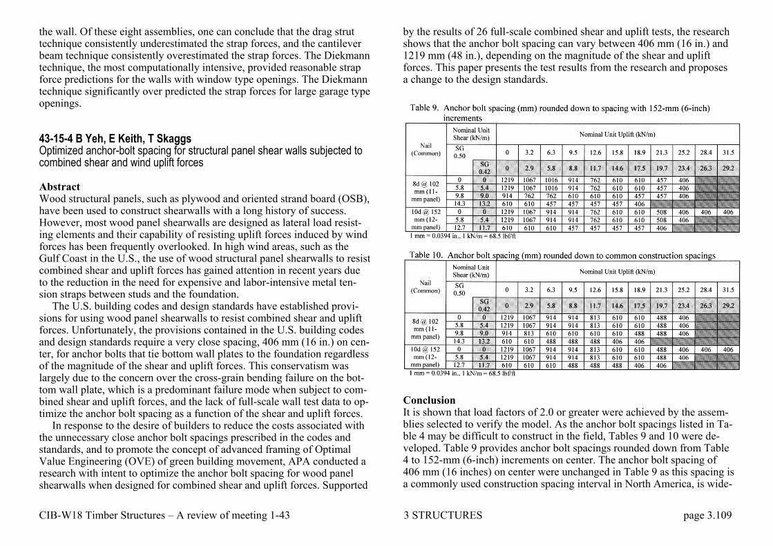
CIB-W18 Timber Structures – A review of meeting 1-43 3 STRUCTURES page 3.109
the wall. Of these eight assemblies, one can conclude that the drag strut technique consistently underestimated the strap forces, and the cantilever beam technique consistently overestimated the strap forces. The Diekmann technique, the most computationally intensive, provided reasonable strap force predictions for the walls with window type openings. The Diekmann technique significantly over predicted the strap forces for large garage type openings. 43-15-4 B Yeh, E Keith, T Skaggs Optimized anchor-bolt spacing for structural panel shear walls subjected to combined shear and wind uplift forces Abstract Wood structural panels, such as plywood and oriented strand board (OSB), have been used to construct shearwalls with a long history of success. However, most wood panel shearwalls are designed as lateral load resist-ing elements and their capability of resisting uplift forces induced by wind forces has been frequently overlooked. In high wind areas, such as the Gulf Coast in the U.S., the use of wood structural panel shearwalls to resist combined shear and uplift forces has gained attention in recent years due to the reduction in the need for expensive and labor-intensive metal ten-sion straps between studs and the foundation.
The U.S. building codes and design standards have established provi-sions for using wood panel shearwalls to resist combined shear and uplift forces. Unfortunately, the provisions contained in the U.S. building codes and design standards require a very close spacing, 406 mm (16 in.) on cen-ter, for anchor bolts that tie bottom wall plates to the foundation regardless of the magnitude of the shear and uplift forces. This conservatism was largely due to the concern over the cross-grain bending failure on the bot-tom wall plate, which is a predominant failure mode when subject to com-bined shear and uplift forces, and the lack of full-scale wall test data to op-timize the anchor bolt spacing as a function of the shear and uplift forces.
In response to the desire of builders to reduce the costs associated with the unnecessary close anchor bolt spacings prescribed in the codes and standards, and to promote the concept of advanced framing of Optimal Value Engineering (OVE) of green building movement, APA conducted a research with intent to optimize the anchor bolt spacing for wood panel shearwalls when designed for combined shear and uplift forces. Supported
by the results of 26 full-scale combined shear and uplift tests, the research shows that the anchor bolt spacing can vary between 406 mm (16 in.) and 1219 mm (48 in.), depending on the magnitude of the shear and uplift forces. This paper presents the test results from the research and proposes a change to the design standards.
Conclusion It is shown that load factors of 2.0 or greater were achieved by the assem-blies selected to verify the model. As the anchor bolt spacings listed in Ta-ble 4 may be difficult to construct in the field, Tables 9 and 10 were de-veloped. Table 9 provides anchor bolt spacings rounded down from Table 4 to 152-mm (6-inch) increments on center. The anchor bolt spacing of 406 mm (16 inches) on center were unchanged in Table 9 as this spacing is a commonly used construction spacing interval in North America, is wide-

CIB-W18 Timber Structures – A review of meeting 1-43 3 STRUCTURES page 3.110
ly published, and currently exclusively recommended for combined shear and uplift anchor bolt spacing. For practical use, Table 10 further rounds the anchor both spacing from Table 4 down to traditional spacing intervals of 406, 488, 610, 813, 914, 1067, and 1219 mm (16, 19.2, 24, 32, 36, 42, and 48 inches) used in the conventional construction in North America. Results presented in Table 10 have been incorporated into the APA Sys-tem Report SR-101, Design for Combined Shear and Uplift from Wind, which may be used by design engineers on a voluntary basis before the provisions can be adopted into the U.S. national design standards, such as the SDPWS and the ICC-600. Since the installation details are critical to the combined shear and uplift applications, APA SR-101 also provides many practical details to ensure the wall assemblies are properly designed and constructed. It would be prudent to follow the APA SR-101 construc-tion details closely when designing and constructing wood structural panel shearwalls for the combined shear and wind uplift applications.
While APA SR-101 still recommends the use of 15.9-mm (5/8-in.) an-chor bolts as specified in the SDPWS and the ICC-600, test results ob-tained from this study showed that the 12.7-mm (1/2-in.) diameter anchor bolts are adequate for use in the combined shear and uplift applications when the design loads are within the range permitted in the current U.S. national design standards.

CIB-W18 Timber Structures – A review of meeting 1-43 3 STRUCTURES page 3.111
3.19 TRUSSED RAFTERS Trussed rafters were right from the beginning a focus area for CIB-W18. Three topics were of special interest: – simplified design methods – bracing – the development of deflections over time under alternating loads Simplified design methods Trusses, especially with punched metal plate fasteners, are used extensive-ly in houses. They are complicated, statically indeterminate structures and until computers became generally available there was a great interest in simplified design methods making it possible to design them by hand. 4-9-1 T Feldborg and M Johansen Long-term loading of trussed rafters with different connection systems The long-term loading was started at the Building Research Instite in con-nection with short-term testing of the same truss types carried out by Mr. Arne Egerup at the Technical University.
The investigation comprises W-trusses made of 45 mm timber connect-ed by Hydro-Nail and TCT metal plates, nailed metal plates and plywood gussets, and trusses made of two layers of 25 mm boards connected by nailed metal plates between the boards.
The supports are arranged in 3 ways, 1: below the heel joint, 2: 0,6 m from the heel joint in both sides, and 3: 1,2 m from the heel joint in one side below an extra web member.
Each type is represented by 2 trusses. The load arrangement is shown in the figure. The trusses are designed
for light roof cladding. Some types are overloaded by dead load represent-ing heavy roof cladding.
So far the load has been varied between 8 week dead load and one week dead load + full design snow load. (Full design snow load is very ra-re in Denmark, and according to 30 years' measuring the duration does not exceed 5 days).
After 1 year of alternating loading it is planned to change to full design load for 4-5 years.
Deflection of the trusses is being measured at the joints and at the mid-dle of the members of the upper and lower chords.
Temperature and relative humidity are recorded and the moisture con-tent of wood samples placed with the trusses is measured. 6-9-3 T Feldborg, M Johansen Deflection of trussed rafters under alternating loading during a year Introduction Trussed rafters are used in the greatest part of building in Denmark. Most of the trussed rafters are now factory made and connected by toothed met-al plates, but also nailed connections are still used.
The common simple design calculations neglect the effect of rigidity and deformation of the joints. They therefore give a wrong picture of safe-ty and deflections. It often results in bad utilisation of the timber and sometimes in too great deflections of the trusses.
Therefore the Technical University and the Building Research Institute have started a research programme to form a basis for more accurate and economic calculations of trussed rafters.
At the Technical University Mr. A.R. Egerup has investigated the short-term stiffness and bearing capacity of 56 trussed rafters. At the Building Research Institute the short-term behavior of the heel joint and the lower chord splice are studied, and the long-term behavior of the trussed rafters will be studied within 5 years.
This report presents the results from one year during which the load has been alternating between dead load and dead load + design snow load. 14-14-1 T Feldborg, M Johansen Wood trussed rafter design Summary The tests described in this report are part of a Nordic co-operation on the development of more rational design methods for wood trussed rafters. Heel joints and splice joints made with two types of nail-plates and with nailed steel and plywood gussets were tested under short-term loading in laboratory climate. The same types of joints were used in long-term load-ing tests on rafters in an open pole building, in which the deformations,
CIB-W18 Timber Structures – A review of meeting 1-43 3 STRUCTURES page 3.112
climate and moisture content were registered for a period of 4,5 years. On the basis of these and other Nordic tests, methods are proposed for the de-sign of the joints and for the calculation of forces, moments and de-flections for wood trussed rafters.
The moisture content of the trussed rafters was higher and varied more than anticipated (from 0.12 to 0.21)
The deflections increased slightly each time the timber dried out. The deformations of the joints showed very big variation coefficients.
Under long-term loading and moisture variations the slips were 3-20 times greater than under short-term loading. The investigation showed that the slip stiffness of the joints has almost no influence on the normal forces but to some degree on the moments, and that it has a great influence on the deflections.
The rotational stiffness of a joint has a considerable effect on the mo-ments in the parts of the timber closest to the joint.
The rotational stiffness of a heel joint is almost independent of the rota-tional stiffnes of the connectors in the joint but depends on the length of the joint and the normal force of the rafter. 14-14-2 R O Foschi Truss-plate modelling in the analysis of trusses The structural analysis of a truss requires a realistic representation of the partial fixity provided by the truss-plate joints. This degree of fixity de-pends on the load-slip characteristics of the plate/lumber combination, on the orientation of the plate and the area of plate covering each of the joined members. Furthermore, joint stiffness is influenced by the presence of gaps between members, local plate buckling and/or yielding. This paper presents a method of analysis of truss-plate joints which is straightforward and takes into account all of the above factors, allowing the determination of maximum truss loads based on connection capacity. 15-14-1 H Riberholt Guidelines for static models of trussed rafters Object The object of the guidelines is to constitute a basis for the static modelling
of timber trussed rafters. The static models are intended used for analysis of stresses and deflections.
The scope of the guidelines is primarily plane trusses with nail plate connections. But they may be applied to trusses with other types of con-nectors with similar static behaviour. 15-14-2 F R P Pienaar The influence of various factors on the accuracy of the structural anal-ysis of timber roof trusses Introduction In this study, the influence of three factors on the structural analysis of timber roof trusses is investigated, namely: – stiffness of joints (e.g. rigid, hinged, or semi-rigid, rotational and axial) – second order effects i.e. additional bending moments which result from
the deflected shape of the structure – using wrong member sizes for the analysis. The stiffness of joints and the second order effects can only be taken into account by sophisticated methods of analysis. It is therefore important for the designer to know what the order of the error is when using simplifying assumptions.
Because most roof trusses are not statically determinate structures, the member sizes are only known after the design process has been completed. Therefore an assumption must be made for the original analysis. The in-fluence of incorrect member sizes on the analysis of the trusses is investi-gated. In the investigation, only the W-truss is used because it is the most common configuration of timber roof trusses. Alhough only one configuration is used, three different truss spans, (6 m, 9 m and 12 m) and four different roof pitches (100, 150, 200 and 300) are considered.
The load on the trusses is taken as that for a tiled roof, and sometimes as that of a sheeted roof. It is generally expected that, if the sizes of the rafters and the tie-beams change, but retain the same relationship to each other, the stress distribu-tion between the chords will change very little. However, the results given in Table 16 show that if both the tie-beam and the rafter is chosen, a size

CIB-W18 Timber Structures – A review of meeting 1-43 3 STRUCTURES page 3.113
too large or too small, the forces and moments change significantly. This is because the standard sizes do not change in the same proportion as the stresses in the chords. If the one chord is too large, and the other too small, the influence is even greater and can be as much as 73 per cent, as shown in Table 16. In general, it seems as though the effect on structural analyses of the wrong choice of size decreases with an increase in pitch.
Conclusions The use of the wrong size members in the structural analysis has a surpris-ingly large effect. It is therefore recommended that if member sizes are de-termined in a design process, it should be established that the analysis was carried out using those sizes. If not, the analysis and design process must be repeated. General conclusions and recommendations The influence of the following factors on the structural analysis was inves-tigated: – rigidity of joints – second order effects – incorrect assumptions of member sizes for the analysis It is more accurate to regard joints as completely rigid than hinged (with continuity of members taken into account), although the joint is in reality only semi-rigid. Static analyses are acceptable for standard cases, but should preferably not be used for spans over 12 m and slopes under 15º. Where axial rigidities of joints are low, (e.g. bolted joints) the influence is
great and must be taken into account. This can only be done using sophis-ticated methods of analysis which are not always readily available.
In general, the influence of the second order effects is quite small and may be ignored in ordinary design.
15-14-4 P O Reece The design of continuous members in timber trussed rafters with punched metal connector plates Synopsis On the principle of superposition, bays of continuous members are regard-ed as simply supported at the node points with end-couples superimposed to simulate the effects of continuity in an indeterminate structure subjected to the simultaneous action of axial and lateral forces.
From the generalised theorem of three moments an expression for the maximum bending moment is derived, and this is regarded as a function of the true bending moment induced under test conditions. Similarly, an expression is derived for the moment of resistance, and this also is regarded as a function of the true moment of resistance. By deter-mining from published span tables the ratio of the calculated bending mo-ment, to the calculated moment of resistance, factors are determined that represent permissible bending moment, per unit of moment of resistance as calculated.
An additional factor is introduced limiting the longitudinal strain to a fixed proportion of the strain induced at the Euler critical load in both ten-sion and compression. 16-14-1 V Picardo Full-scale tests on timber fink trusses made from Irish grown Sitka Spruce Scope Full size tests have been carried out on fifty eight trusses of the Fink con-figuration using home-grown (Irish) Sitka spruce timber. The timber was of the M75 grade. Metal plate fasteners with integral teeth were used at all joints using the sizes recommended by the plate manufacturers. Forty eight of the trusses were fabricated to the limiting spans for a higher Species

CIB-W18 Timber Structures – A review of meeting 1-43 3 STRUCTURES page 3.114
Group (S2 - M75). Except for three trusses all passed the acceptance criteria set in the Irish
Standard. The results obtained from the tests are not included in this paper. Only a brief summary of some of the analyses is shown in the tables at
the end of the paper. On the results obtained new limiting spans were pro-posed for Fink trusses made from home-grown timber.
17-14-1 V Picardo Data from full scale tests on prefabricated trussed rafters
The data shown in the following tables supplement CIB-W18 Paper 16-14-1 presented in Norway (June 1983) and is given here at the request of various members of the Group. Because of the volume of data it was nec-essary to present the data in 5 separate tables as follows Table A.1 Physical measurements of trusses Table A.2 Plate sizes Table A.3 Deflections from 24 hour deflection tests Table A.4 Deflections from strength tests Table A.5 Failure Loads and description of failure Table A.6 Deflection recovery and span/deflection ratios at long-term de-sign Load. 17-14-2 H Riberholt Simplified static analysis and dimensioning of trussed rafters Introduction In Paper 15-14-1 guidelines for static models of trussed rafters are given, and these are mainly thought applied to frame models. In this paper a sim-ple calculation method is forwarded for the static analysis and dimension-ing of trussed rafters.
It has been an object to forward a calculation method which is as simple as possible and still taking into account the essential effects.
Due to lack of time only W-trusses have been investigated, but it is ex-pected that later on other types of trusses will be dealt with in a similar manner.
17-14-3 B Källsner Simplified calculation method for W-trusses Introduction This paper presents a simplified calculation method for W-trusses. The method is applicable to heel joint constructions with or without wedges. The proposed construction of the heel joint with a wedge has some ad-vantages over other heel joint constructions since the magnitude of the bending moments in the heel joint and their distribution between upper and lower chords may be influenced by altering the length of the wedge.
The greatest difficulty in the calculation of W-trusses is to take into consideration the influence on the moment distribution of the displace-ments of the joints. Consequently the report concentrates on the determi-nation of the bending moments while the calculation of the axial forces has been left out. A more complete report will be published later in which dock W-trusses and WW-trusses will be treated.
18-14-1 B Källsner Simplified calculation method for W-trusses (Part 2) Introduction At the CIB-W18 meeting in 1984 the author presented in Paper 17-4-3 a calculation method for W-trusses". It was stated in this paper that a more complete report dealing with W- and WW-trusses would be published lat-er. This complete report is now under preparation.
The calculation method presented in Paper 17-4-3 dealt with the gen-eral case of a heel joint subjected to an eccentric support reaction. At the CIB-W18 meeting some participants suggested that the proposed analy-tical method was too complex for design application. The author's re-sponse to the suggestion was that it was possible to develop a simplified procedure based on the results of the study. This is demonstrated in this paper. The calculation method is simplified by neglecting some moment contributions which have only a small influence on the total bending mo-ment distribution in the truss, and which are thus not significant.
The calculation method is presented for two different cases, a W-truss without support eccentricity at the heels and a W-truss with support eccen-tricity at the heels.

CIB-W18 Timber Structures – A review of meeting 1-43 3 STRUCTURES page 3.115
18-14-2 T Poutanen Model for trussed rafter design Summary The paper describes a design model for trussed rafter with emphasis on stress analysis. The model is based on a two-dimensional nonlinear frame program. Special attention is paid to joint modeling. Joint eccentricities are calculated assuming that all forces are transferred through nail plates, which means no contact and friction between timber beams. The model is used in everyday trussed rafter design. Some design experience is de-scribed. 19-14-2 H Riberholt Simplified static analysis and dimensioning, part 2 Introduction In Paper17-14-2 a simple calculation method is forwarded for the deter-mination of the internal forces and moments in a W-truss. This paper con-tinues along the same line for WW-trusses, scissor trusses, King post trusses and pulpit trusses. These papers are based on the moment coefficient method. – the normal forces are calculated from a pinned joint truss model, where
the distributed loads are replaced by statically equivalent concentrated nodal forces
– the moments in the chords are determined taking their continuity in consideration.
For distributed loads over several bays this may be done by means of mo-ment coefficients momk , that are found by calibration to the results of frame programs. For minor distributed loads over a part of a bay or for a concentrated force in a bay the moment distribution in the chords may be found by modelling them as continuous beams over several spans with nodal mo-ments reduced in order to take into account the effect of the deflection of the truss nodes. Moment coefficients are given depending on – Slope of the roof – Slip in the connections
– Eccentricities in the connections between the diagonals and the chords – Eccentric support of the heel joint – The dimensions of the bottom and top chord, including the stiffness of
the chords – The span of the truss – The load on the top chord in proportion to the load on the bottom chord,
e.g. heavy or light roof – Attic load over a part of the bottom chord – Continuous or pinned jointed chords. The conclusion of the discussion of Paper19-14-2 was that the time had come to change the basis for Eurocode 5 from simplified design methods to computer based methods. The basis for these methods is to a large ex-tent established in a working group chaired by Hilmer Riberholt. 19-14-3 T Poutanen Joint eccentricity in trussed rafters The author has described the basic model in Paper 18-4-2. The model (computer program) is constantly under development. This paper describes the development level reached by August 1, 1986. 20-14-1 T Poutanen Some notes about testing nail plates subjected to moment load Introduction In the CIB-conference 19, Florence, Italy the author was asked to write a paper about testing nail plate joints subjected to moment load. This paper is a preliminary reply to the request. A research project has been estab-lished under the leadership of the author lasting 30.4.1989 having the aim to define guidelines for design of the moment loaded nail plate joint. However, three suggestions will be made and offered for a discussion. A more thorough report will be published later.
CIB-W18 Timber Structures – A review of meeting 1-43 3 STRUCTURES page 3.116
20-14-2 T Poutanen Moment distribution in trussed rafters Introduction A truss test procedure was developed in a thesis. 10 trusses were tested in full scale. All the trusses were quality control trusses, they came from dif-ferent plants and they were selected at random from a current production lot.
It was not realized to pay attention to joint gaps. The importance of the joint gap was revealed afterwards while analyzing the results (e.g. the raft-er 6 had apparently gaps with eccentric contact in several joints). These trusses were used as reference trusses in a study, which included the defi-nition of the moment distribution with 3 models: continuous beam, pin joint frame and rigid frame. The results have been copied into this paper. The author has developed an analysis model for trusses. The results of this model are presented. The author is continuing the study of moment distri-bution in trussed rafters 20-14-3 A R Egerup Practical design methods for trussed rafters Simplified methods often give the "right" result whereas complex methods often give a conservative solution. This can he proved by mathematics or energy methods and can be seen, for example, for different types of finite elements. The simplified method, such as moment coefficients, can more easily be adjusted to, say, full-scale tests by "adjusting" the moment coef-ficients or the buckling lengths. A complex method, for example a finite element model, is very rigid and members are more inter-related so that it difficult to adjust to full-scale testing''. The difference in the two types of method is that the complex method takes more effects into account. Most people agree that design method for trussed rafters must be based on a complex finite element model (frame model), but so far no one model has proved satisfactory over the whole range of trusses. Why does a complex model not give the right answer? This is because the model is still simplified and does not take all effects in-
to account. Among the more important effects are: 1. Slip in joints 2. Rotational stiffness in joints 3. Non-linear behaviour 4. Strength distribution in joints and members 5. Real buckling length 6. Redistribution of stresses in a non-determinte structure. 7. Probability of failure in a non-determinete structure 8. Interaction formula It is very difficult to take all these effects into account in a day-to-day de-sign method where speed is an important factor for the industry. For ex-ample, the strength distribution along members related to a failure criteri-on can only be determined with a probabilistic method which will be very time-consuming.
The non-linear behaviour of the model is different for trusses with low pitches and high pitches, mainly because of different slip behaviour in the heel-joint.
Any failure criterion, the inter-action formula has proved to be very poor for determinant structures.
A complex model which takes all important effects into account is im-possible to work with. However, a combination of a complex model and full-scale testing will often take all the effects into account in a more sim-ple way and produce a reliable design. 22-14-1 H Riberholt Guidelines for design of timber trussed rafters Scope The intention of this paper is to describe some methods applicable for the design of plane timber trusses. The paper gives a proposal for a structure and setting for a standard for design methods. The content of the individu-al sections must be considered further.
Such methods may be divided into three operations, but these do not need to be independent and they will in general not just be carried out as one sequence from the top to the bottom. 1. Static analysis of a truss.
CIB-W18 Timber Structures – A review of meeting 1-43 3 STRUCTURES page 3.117
2. Strength verification of the timber. 3. Strength verification of the connections The intention of this paper is to describe some methods applicable for the design of plane timber trusses. The paper gives a proposal for the structure and contents of a standard for design methods. The design may be divided into three operations: – Static analysis of a truss – Strength verification of the timber – Strength verification of the connections. The paper proposes a method which can be carried out with ordinary plane frame programs. The paper concentrates on plane timber trusses with nail plate connections, but the method can also be applied to trusses with other types of connectors, if the method is adapted to their static behaviour. Fur-ther some of the ideas can be used in more general models, which for ex-ample take into account spatial behaviour and non-linearity in the material or in the geometry. 1. Static analysis Paper 15-14-1 proposes general static models, which to a large extent have been used in succeeding CIB-papers on trusses. The paper gives val-uable guidelines on the modelling of trusses and joints, the use of fictitious elements and spring elements and their stiffnesses. . 2. Strength verification of the timber The main assumption is that this can be carried out as described in the timber codes, for example ―CIB, Structural timber design code‖ (No deci-sion on drafting Eurocode 5 was taken at that time). Some effects special for timber trusses are assumed accepted, e.g. the effect of the pronounced moment peaks in the chords, see the Annex at the end of this paper. 3. Strength verification of the connections. The strength verification of the connections is described in Paper 19-7-7 and in Paper 14-7-1 which describes the methods in details. Available static analysis methods and their application The prevailing analysis methods in practice at present and in the near fu-ture are based on plane frame programs. Their assumptions are typically: Linear elasticity, first order method (geometric non-linearity is not consid-
ered), straight beam elements. Further some programs have the option that deformations in the joints can be modelled by a prescribed slip or a spring element. More refined assumptions are not common in practical programs according to a survey carried out recently.
It is a scope of the paper to set up guidelines so that analyses with such plane frame programs reflect the real static behaviour of the truss as well as possible.
One of the parameters in the static model of a truss is the principle for modeling of the deformation in the connections. There exist the following two basic possibilities: Prescribed slip and Elastic spring element. A mix-ture of these two options could be favourable.
Prescribed slip The prescribed slip method has as the' basic idea, that the nail plate con-nections normally are dimensioned so that their strength capacity is fully utilized in the ultimate state. From tests the deformations (slips) are known at this state, and it is the impression that for a certain type of connection the slip close to failure has a fairly constant value independent of the size of the plate. So if this slip is prescribed in the connection the static model should reflect the actual static behaviour.
If the designer wishes to reduce this slip he only has to give the plate an oversize. Therefore the guidelines should comprise a description of how the slip depends on the relative strength utilization of the nail plate con-nection.
The objections against this method are that the designer for each load case must know the size and direction of the forces and moments in the connections (this knowledge could arise from a previous analysis or pre analysis in the iteration) and the slip is taken into account in a rather coarse manner.
Elastic spring element Due to the non-linear behaviour of the connections the stiffness constant must be determined as a secant-modulus. Depending on whether the anal-ysis is for the serviceability state or ultimate state the secant must be de-termined from a slip at a low or a high stress level.
The objections against this method are similar to those against the slip method: The designer must for each load case know the relative strength utilization in order to determine the secant modulus. The stiffness matrix must thus be updated for each load case. (Again this knowledge could

CIB-W18 Timber Structures – A review of meeting 1-43 3 STRUCTURES page 3.118
arise from a pre-analysis). The slip is taken into account in a rather coarse manner. For example the influence of the moment on the stiffness for a force will normally not be considered even though it is theoretically possi-ble to set up such a relation. Since both methods have advantages and disadvantages it is recommended to let the user make his own choice. So the necessary information and val-ues of slip and stiffness constants must be available. Some values are giv-en in literature, but it seems necessary to have the values in the nail plate certificates too.
For some special or extreme cases it would be advantageous if the guidelines could state that slip can be disregarded. This may not be so ex-treme, it could be sufficient to have a nail plate connection with a certain oversize (50%-100%). Annex. Effects of the distribution of the internal forces and moments. Since the normal forces normally are almost constant along the bay length and since shear is normally not decisive, it is proposed to disregard the dis-tribution effect on the tensile, compression and shear strength.
However the moment stresses will typically vary along the length of the timber parts in other ways than assumed at the determination of the bend-ing strength values given in the relevant standards. Since the bending ca-pacity of a timber part depends on the distribution along the length it is proposed to take this effect into account.
The research carried out in this area is scattered and how to deal with this effect has hardly found its final method of description.
The dependency between the bending strength and the distribution of the internal moment has been investigated by Madsen & Buchanan in Pa-per 18-6-4. The used theoretical description was Weibull's weakest link. The estimated values of the shape parameter k varied quite a lot. It is ex-pectable to have a variation in k between different species and grades be-cause k is related to the Coefficient of variation. The authors suggest a k-value of 3.5, which should give sufficient precision for engineering pur-poses for the type of timber in question.
In a paper from IUFRO in Oxford 1980 this dependency between bend-ing strength and M-distribution has been investigated too. Here it is chosen to describe the strength of timber by a probability distribution of cross sec-tions with such defects. The figure below shows the probability di-stribution for 3 beams with different moment distributions.
Figure. Timber beams with different supports, simple supported or clamped. It should be noticed that the difference between the beams which are sup-ported Simple-Clamped and Clamped-Clamped is relatively little, and for practical purposes it can be disregarded.
To illustrate the effect of using different theoretical descriptions, the ra-tios between the strength at max. moment of a simple-simple and a clamped-clamped beam loaded with a distributed load has been calculated based partly on a Poisson process partly on a Weibull distribution. The two ratios are 1,35 and 1,37 respectively for the 5-percentiles for a coeffi-cient of 0,20, i.e. negligible.
By using the Weibull theory the ratio between the strength of a refer-ence beam and any other beam can be calculated. As reference beam is chosen a simply supported beam with 2 concentrated forces in the third points. The ratios are given in the following table. Ratios fm/fm,ref for timber beams with different supports and load configu-rations.
Support: Simple or Clamped
Load type Coefficient of variation:
0.10 0.15 0.20 0.30
SS 2 concentrated a = 1/3 l 1.00 1.00 1.00 1.00
SS Distributed 1.04 0.14 1.03 1.03
CC 2 concentrated a = 1/3 l 1.23 1,30 1.35 1.44
CC Distributed 1.25 1.35 1.14 1.53

CIB-W18 Timber Structures – A review of meeting 1-43 3 STRUCTURES page 3.119
It can be seen that the difference in the ratios for different load types are small as long as the moment distributions are similar. The large difference occurs when the max. moment occurs at a peak, here at the supports. So as a practical simplification it could be acceptable to allow that for strength verification of cross sections at a moment peak the bending strength could be increased by the following factor depending on the Coefficient of Vari-ation (CoV) in per cent.
1 0,430
CoVk
23-14-1 H Riberholt Analysis of timber trussed rafters of the W type Two simplified frame models have been investigated. The simplification has resulted in a reduction of the number of nodes and thereby the number of degrees of freedom by approximately half. Only a truss with eccentric joints has been investigated. For centric joints it is very easy to set up a similar simple model, which is in agreement with the more detailed model. The slip in the joints can be modelled by a prescribed slip.
In the simple model the force transfer by the nail plate at the heel joint has been modelled by a pinned joint positioned at the joint between the timber parts, and the contact stresses between the chords has been mod-elled by a spring. The eccentric connections have been modelled in detail and at the ridge, there is introduced an eccentricity resulting in a negative moment at the ridge. The slip in the joints have been considered by a pre-scribed slip in the heel joint, the ridge and the splice plate with the values given in table 3.1, which are those found for a truss with normal stiffness. So the results should be compared with those in section 3.2 for a W-truss with normal joint stiffnesses.
In the extra simplified model the transfer of the internal forces at the heel joint has been modelled more crudely. In the T-joint of the top chord the eccentricity has been disregarded and so has the beneficial effect of the eccentricity in the ridge connection.
For both models analyses have been carried out for pinned joints as shown and for completely stiff joints. Further the slip in the joints have ei-ther been disregarded or taken into account by prescribed slips in the se-lected joints mentioned previously.
A comparison with the results for the detailed model with normal stiff-nesses shows that that the agreement in CSI-values is:
Best Poorer Pinned joints Simple model Slip in the joints
Completely stiff joints Extra simple model No slip
Relative deviations in CSI-values obtained by the simple models with Pinned eccentric joints as compared with the detailed model with normal joint stiffnesses. Simple model Extra simple model
No slip Slip No slip Slip Top chord -2% -3% -8% -9% Bottom chord -9% -5% -19% -9% Diagonals: Compressed -13% -20% -13% -20% Tensile -21% -23% -23% -26% The deviations given in the table should be acceptable for the simple mod-el when slip in the joints is considered. Comparison with the Present Danish hand calculation method The present Danish hand calculation method is presented in Paper17-14-2. The distributed loads are transformed to concentrated nodal forces so that the axial forces can be determined from a lattice model, while the moments in the chords can be determined by moment coefficients, here 0.1 in the top chord, 0.1 in the outer bay of the bottom chord and 0.08 in the middle bay of the bottom chord.
The results of this hand calculation method are in table 5.1 compared with those of the models dealt with in this paper. The comparison is car-ried out only for a W-truss with centric connections, since the hand calcu-lations have this as an assumption. The frame models have been analysed either by normal joint stiffnesses or by prescribed norms slips in the con-nections. It appears from table 5.1 that there is a reasonable agreement between the maximum CSI-values for the different timber parts. Further the frame model results are a little conservative compared with the present Danish hand calculation method. They should thus be applicable for practice, and can be employed for an optimal geometric design of the W-truss, which

CIB-W18 Timber Structures – A review of meeting 1-43 3 STRUCTURES page 3.120
the hand calculation method can't be used to, because it is limited by the geometric assumptions of equal bay length. Table 5.1 Combined Stress Index in some cross-sections calculated by 4 different models/methods. W-truss with centric connections. Hand calcu-
lation Detailed model
Simple model
Extra simple model
Top chord Low bay Up bay Low node
0,99
0,99
0,92 0,92 0,91
0,83 0,82 0,90
0,74 0,87 0,87
Bottom chord
K-node Mid bay
0,71
0,63 0,51
0,49 0,66
0,49 0,67
Diagonal Compression Tension
0,27 0,35
0,26 0,39
0,24 0,32
0,24 0,32
Conclusions For a W-truss it appears that the following conclusions are valid:
A If the rotational stiffness S of a joint fulfils the requirement below,
then it is a reasonable simplification to assume that the connection is
completely stiff for rotations if
3EI
Sl
where
EI
l is a stiffness measure for the adjacent timber members with length
l B The relative displacements (slip) between the timber parts in the joints
can be considered by spring elements or by prescribed slip. The max Combined Stress Index in the timber parts is relatively robust for prac-tical variations in the stiffness of the joints
C Even crude frame models of the truss give Combined Stress Indices similar to those obtained by more detailed models
D The proposal to increase the bending strength of the chords at moment peaks result in a decrease in the CSI-values of typically 5-10%, and it
results in truss designs, which have been used successfully over a long period
E The proposed frame models give Combined Stress Indices similar to those obtained by a Danish hand calculation method used for many years. The hand calculation method is a little more conservative.
24-14-1 A Kevarinmäki Capacity of support areas reinforced with nail plates in trussed rafters Summary A low-cost and easy way to reinforce the chord is to use nail plates at the support areas of the trussed rafter. The test results of load-carrying capaci-ty in compression perpendicular to the gain of the support areas reinforced with nail plates are shown in this paper. Although the supporting block is wooden, the bearing capacity will increase at least 30 % with nail plate re-inforcement of the chord at an end support because the bearing pressure is rail type in the supporting structure. If the supporting block is steel, con-crete or wood in compression parallel to the grain, the nail plate rein-forcement will improve the bearing capacity of the end or intermediate support even 2 times higher. 25-14-1 A Kevarinmäki and J. Kangas Moment anchorage capacity of nail plates in shear tests Introduction Eurocode 5 - draft of 1992 includes a design method for the moment an-chorage stress (τM) of the nail plate joints. The force, anchorage stress τF and the moment, anchorage stress τM are checked separately, but also the sum of them is checked. This method is used in Norway and it has been presented in Paper 23-7-1. In this method the moment anchorage stress τM is calculated according to elastic theory, but the plastification is taken into account with a certain coefficient in the failure criteria. Norén has present-ed a different τM design method for the nail plate joints in Paper 14-7-1. In Noréns theory stress τM is calculated with the plastic theory and only the combination of τF and τM is checked at the ultimate limit state. In proposed EC 5 method the direction angle of nail plates or the direction of the grain are not taken into account if τM is the critical factor. In the method present-
CIB-W18 Timber Structures – A review of meeting 1-43 3 STRUCTURES page 3.121
ed by Norén these factors have a clear influence in the failure criteria. Comparison of these calculation methods with the results of standard
shear tests is shown in this paper. The shear tests are the only standard tests of the nail plate joints where a clear combination of τF and τM occurs. The eccentricities are so big that usually τM is the critical factor in anchor-age capacity when EC 5 method is used. The results from testing of 11 dif-ferent nail plates are compared with these two theories. Altogether 220 shear tests where final failure mode was anchorage one have been ana-lyzed and presented in this paper.
25-14-2 J Kangas, A Kevarinmäki Design values of anchorage strength of nail plate joints by 2-curve method and interpolation Summary In this paper a method is presented which makes possible a more effective utilization of the anchorage capacity of nail plates than in Eurocode 5 draft 1991. The curve for design values in Eurocode 5 is taken as a minimum one, the curve drawn through the standard test results when loaded in grain direction is taken as a maximum one and a method of interpolation be-tween them is proposed. Test results to support the proposal are presented. Conclusions Test results of tests indicate, that angle γ has not an effect on the anchor-age strength as expected in Eurocode 5. Hence only angles α and β are needed when basic anchorage design values are calculated.
Test results in different combinations of direction angles indicate that also faαβ values can be given reliably based on standard test series. Sim-plest method is to interpolate between the maximum curve, when β = 0° and the lowest test value fa9090.
Interpolated values are on the safe side, if fa9090 is taken as a minimum value for all cases when β > 45° and the values are interpolated linearly between 0° < β < 45°.
26-14-1 E Aasheim Test of nail plates subjected to moment Introduction In the test standard ISO 8969 "Timber structures - Testing of unilateral punched metal plate fasteners and joints", no test specimen for determi-nation of moment resistance is defined. In order to model trusses, frames and other systems in a realistic way, the modelling of the joints are essen-tial. In this respect the rotational stiffness of the contact surface is funda-mental.
During CEN/TC 124/WG 1-meetings this subject has been discussed. In the document EN TC 124.116 (June 92-version) "Timber structures - Test methods - Joints made of punched metal plate fasteners" a method is introduced. The test specimen is subjected to a combination of moment and shear force, and the method includes complicated calculations to find the rotational stiffness. Objectives The basic objective of this paper is to introduce a test specimen for a "di-rect" measurement of the rotational stiffness of the contact surface of the plate and the timber. Conclusion In general, the results of this study show that the proposed test specimen may be used to find the rotational stiffness of the contact surface. It can be seen from table 3 that the results are in the same order of magnitude for the different test series, and the results are much more reliable than those found by specimens subjected to a combination of shear force and mo-ment. Concluding remarks More research and experience is needed to use this rotational-stiffness in practical design, but the introduction of a test piece in EN TC 124.116 is recommended. The gap between the joined parts should be reduced to 5 mm, and the plate size should be chosen to ensure that failure does not oc-cur in the plate.

CIB-W18 Timber Structures – A review of meeting 1-43 3 STRUCTURES page 3.122
26-14-2 A Kevarinmäki, J Kangas Moment anchorage capacity of nail plates Introduction The, analysis of the nail plate joints anchorage moment capacity with 220 standard shear test results was presented by the authors in Paper 25-14-1. Now 72 new shear tests, where also the angle between grain and force (b) was a variable, have been carried out. New bending tests done in Norway have also been analyzed for comparison. The analysis of these test results, where the failure mode was anchorage failure, has been presented in this paper. The anchorage moment capacities of these specimens have been calculated according to Eurocode, 5 (modified elastic method), with the simplified plastic design method (Norén‘s method) and with the accurate plastic theory solution. Conclusions This analysis, with the new kinds of shear and bending test pieces, sup-ports the authors‘ earlier conclusion, that the plastic theoretical τM design corresponds better with the test results and would be a better method than on the elastic theory based method given in ENV-Eurocode 5. The capaci-ties of the shear test pieces were almost identical to the values calculated by the accurate plastic theory. The simplified method presented by Norén is always on the safe side and it gives generally some percents additional safety. Same safety level is obtained also by the new simplified method, which does not have geometrical limitations, presented Paper 26-14-4. In pure bending case also the plastic theory was 17 - 33 % conservative (while it was 35 - 54 % by the EC 5 method). According to the bending test results the moment anchorage strength τM is higher than the tension anchorage strength in the direction α = β = 0° (fa,00).
The design is easier and clearer by the simplified plastic theory than by the method of ENV-EC 5. The geometrical values of the elastic method (IP and are rmax are more difficult to determine than the diagonal d needed for the plastic design. There are three design criteria that must be checked in the anchorage design of EC 5. In plastic design method only one design criteria is required:
2 2
, , ,00,/ / 1F a d M a df f .
This equation also has the same form as many other design formulas of Eurocode 5.
26-14-3 A Kevarinmäki, J Kangas Rotational stiffness of nail plates in moment anchorage Introduction Application of moment resisting rigid or semi-rigid nail plate joints in timber structures is missing at present. Including rotational stiffness and moment capacity into nail plate joint design opens following possibilities: – it will lead to material savings and more economical nail plate struc-
tures. – it will give more accurate and safer design in ordinary structures com-
pared to pin joint theory. – it enables the design of new kinds of structures, which will increase the
competitiveness of the timber structures. This kind of exact theory and design method is missing at present. In Fin-land the method where the moment rigidity of nail plate joints has been in-cluded is already in use, but it has simplified assumptions of material properties, which are on the safe side. ENV-Eurocode 5 is very general and insufficient. Concerning these matters measuring and determination of the nail plate joints rotational stiffness is not presented in any standard. That is the main obstacle in utilization of the nail plate joint rotational stiffness. The aim of this study was to develop a proposal for standard tests of nail plates rotational stiffness and a method for the determination of the rotational spring stiffness moduli. In this paper the rotational stiffness of shear and bending test results of 102 nail plate joints have been analysed. The deformations between timber and the nail plates in each shear test were measured by 10 gauges. The ro-tational spring stiffness moduli have been calculated from these measure-ments. Rotational stiffnesses have been determined also from the results of Norwegian bending tests. This study showed following: – the effect of the testing type, – the effect of direction angles a and – the dependence on the shape of effective nail plate areas and – the effect of the measuring point locations to the calculated results of
rotational stiffness. Based on this research a proposal for the standard test of nail plates rota-tional stiffness and a method for the determination of the rotational spring stiffness modulus ,serK from the test results are given.

CIB-W18 Timber Structures – A review of meeting 1-43 3 STRUCTURES page 3.123
26-14-4 A Kevarinmäki Solution of plastic moment anchorage stress in nail plates Introduction In Eurocode 5 the moment anchorage stress τM of nail plates are calculated according to the elastic theory. In the design criteria there are the factors (1.5 and 2) so the capacity is near to the plastic theoretical solution. The analysis of over 300 test pieces by the plastic theory calculation of τM -stresses showed that it gives much better results than the method of Euro-code 5 (Paper 25-14-1 and Paper 26-14-2). B. Norén has presented a simplified solution of the plastic theory for calculation of the plastic τM -stresses (Paper 14-7-1). The calculations of the geometrical values by the simplified plastic theory are easy compared to the elastic method. Also the design criteria become simpler by plastic theory, only one equation is needed. In Eurocode 5 three criteria's must be checked separately in the anchorage design.
The questions about the theoretical background, about differences be-tween Norén‘s simplification and the exact plastic theory and about the application of Norén‘s method for the different shapes of effective nail plate area have been presented. This paper deals with these problems. Ac-curate plastic theoretical solutions are calculated by numerical integration with a computer. Differences between the accurate plastic theory and Norén‘s method are determined. Another alternative approximate solution for the determination of the plastic τM -stress has also been developed. This new method is very simple and easy to use. The method is at the same safety level as Norén‘s method, but all shapes of effective nail plate area can be solved by it. Norén‘s method is limited only to the rectangles, the right-angled triangles or the quadrilaterals where two angles are 90 de-grees. Conclusions The comparison between Norén‘s simplification and the accurate plastic theory shows that Norén‘s method is always on the safe side in determin-ing the plastic τM anchorage stress of nail plate joint areas. With the rec-tangle shapes of the effective nail plate areas Norén‘s method is 0-8 % conservative. The biggest difference (28 %) from the theoretical solution occurs in the case of right-angled triangles where the sides are equal. Dif-ference between the theoretically and approximately calculated 'ENLPI stresses seems to be relatively high in some cases. The effect to the design
result however is quite small as the cm stress is only one part in the an-chorage design criteria. Usually the τF stress has a bigger effect on the an-chorage design.
Due to Norén‘s methods limitations, the new alternative approximate solution is presented. The nail plate surface may be replaced by the rec-tangle that has the same area and height perpendicular to the longest side as the original surface has. The plastic anchorage stress τM may then be calculated for this fictional rectangle. This method is at the same safety level as Norén‘s method and it is easy to use. The new method and its formulation suit very well together with the rules of the plastic τM anchor-age design to be included in design codes. 26-14-5 R Gupta Testing of metal-plate-connected wood-truss joints Abstract A testing apparatus with computerized data acquisition and control system was developed to test metal-plate-connected) wood-truss joints. The appa-ratus enabled testing of several different types of joints under various load-ing conditions without major modifications. The apparatus shows potential as an efficient testing procedure to assess joint behavior. 26-14-6 C J Mettem, J P Marcroft Simulated accidental events on a trussed rafter roofed building Introduction As discussed in previous papers (Paper 22-15-6 and Paper 23-15-6), work has been in hand for several years to address the issues arising from the ideal that timber structures should be planned and designed in such a way that they are not unreasonably susceptible to the effects of accidents. In 1989, the preliminary Paper 22-15-6 was submitted, stating the prob-lems in general terms, and suggesting that they are of concern to designers irrespective of whether timber or other materials are concerned, and also fundamentally irrespective of whether national or European-wide codes are to be followed. Potential disadvantages for timber were foreseen, if the fulfilment of such principles were to be deemed to be satisfied in certain ways. Naturally, this was of greatest concern to the authors with respect to the Approved Documents to the Building Regulations, which are pub-lished by the Department of the Environment in the UK, and which specif-
CIB-W18 Timber Structures – A review of meeting 1-43 3 STRUCTURES page 3.124
ically issue guidance on "disproportionate collapse" in this context. How-ever, it was realised that there were wider implications and that the subject is of more general interest.
The second CIB paper on the subject, presented in 1990, elaborated up-on the way in which regulatory, requirements were developing. It also de-scribed, with reference to a specific form of roof construction, ways in which the "disproportionate collapse" requirement might be interpreted in terms of the acceptable extent of damage, after an accident. The form of timber roof construction evaluated in this paper was parallel framed con-struction, where distinct principal beams, plus purlins and bracing existed. Two requirements were brought to the attention of the designer. Firstly, that of ensuring that in the event of a local failure of a primary frame, then the adjacent primary frames would not be dragged down. Secondly, the need to ensure that the undamaged areas on either side of the damaged zone would retain sufficient stability to remain standing.
Fortunately, and possibly in part as a consequence of this work, the more recent editions of the Building Regulations Approved Documents have included revised guidance on the acceptable extent of collapse in the event of a local failure in a roof structure or its supports, for low rise pub-lic buildings. This guidance can be met with reasonable economy by well-designed versions of existing timber engineered types of building and de-tailing.
The ENV version of EC5 has also adopted the principle of requiring design against the eventuality of collapse.
One of the fundamental requirements of the basis of design given in EC5 states: A structure shall also be designed in such a way that it will not be dam-aged by events like explosions, impacts or consequences of human errors, to an extent disproportionate to the original cause. "
However, in spite of the prominence of this principle, little or no de-tailed guidance is provided. Whilst the work by TRADA Technology Limited in earlier years of the project focused upon the parallel framed structures mentioned above, it was evident that, for reasons of commercial economics, it would be im-portant to include consideration of trussed rafter roofs. These occupy such a large proportion of the market for non-domestic roofs in the 9 to 15 me-tres range, that the project would have been incomplete if no account had been taken of them. It was felt necessary to address the assessment of the reaction of trussed rafter roofs to accidental events by experimental means
rather than analytically, as explained below. Concluding remarks A full-scale testing programme was conducted upon a trussed rafter roofed building, to assess its response to simulated accidental events. The test building which was constructed represented a typical non-domestic trussed rafter roofed low rise structure, of moderate span, using masonry walls. It was roofed in a conventional manner, with trussed rafters of 10 metres span at 600mm centres. A number of variations of detail in the secondary roof construction were incorporated in the building, and for each of these, a simulated "structural accident" was replicated. Standard bracing, and in some cases additional bracing, was included.
In the case of public buildings of the type which the test structure was intended to represent, there is a distinct requirement in the Building Regu-lations (England and Wales) to construct in a manner such that, in the event of a failure of the roof or its supports, the building will not collapse to an extent disproportionate to the cause. Since there is also a general re-quirement by EC5 to design in such a manner as to avoid disproportionate damage, then the results of this project are of further and more universal relevance. The type of accident envisaged in the simulations was the removal of a length of external load bearing masonry wall, through a vehicle impact.
As described above, the main series of tests involved the sudden re-moval of a 3.6 metre length of support wall, beneath the trussed rafter roof, with the ensuing gap appearing at the rnidlength of a longitudinal ex-ternal load bearing masonry wall. Four tests were carried out under these conditions, each with a progressively less robust degree of secondary and longitudinal construction incorporated in the roof detailing. However, un-der none of the construction detailing cases covered by these four simula-tions did any of the major parts of the roof structure collapse to the stage of reaching the ground. This was found to be the case both for the simulat-ed suspended ceiling arrangements and for a plasterboard ceiling. Even with interrupted wall plates, simulating unconnected butt joints over the gap, and with parts of the obligatory roof bracing removed, the roof framework remained stable, albeit with large deflections.
The four secondary components found to contribute most substantially to the robustness of the roof in resisting collapse were as follows: 1. The wall plates: Clearly their contribution depended greatly upon the
relative positions of the wall plate end joints and the removed length of

CIB-W18 Timber Structures – A review of meeting 1-43 3 STRUCTURES page 3.125
support wall, but if the wall plates were to remain spanning the gap af-ter the "accident", then they would seem to make a substantial contribu-tion to the support of the affected length of roof.
2. The "chevron" bracing: It was found that the two lines of chevron brac-ing made a significant contribution to the longitudinal structural rigidity of the roof, despite their incomplete triangulation. Ultimately, their ca-pacity was limited by the performance of their nailed end joints and, with better fixings it would be possible to extend this bracing concept to obtain even greater resistance, if required.
3. The longitudinal bracings: The top and bottom chord longitudinal brac-ings, acting in conjunction with the other elements of the roof frame-work, also contributed in a surprising degree to the support of the dam-aged framework.
4. Other wind bracing components: The flat longitudinal wind girders, and the plasterboard ceiling, where present, also contributed in a more mi-nor degree to the stiffness of the secondary construction.
By deduction, it was concluded that the "behaviour largely unknown" el-ements, particularly, the tiles, felt and battens, were contributing signifi-cantly to the ability of the damaged structure to resist collapse. This is dis-cussed further below.
The top chord roof cladding, consisting of interlocking tiles, was found to significantly increase the capacity of the timber secondary components to transfer loads from the unsupported zone of roof onto those trussed raft-ers still supported at both ends. This increase in resistance was between 20% and 60 Fr, depending upon which secondary timber components were present during the associated accidental event simulation. The longitudinal flexural rigidity of the tiles and underlying felt and battens was found to be broadly comparable to that of a diaphragm of continuous 20 mm thick GS grade timber boarding laid parallel to the ridge.
Following the main series of four simulations with progressively less material incorporated in the secondary roof construction, the test building remained essentially intact and, with small repairs, further testing was pos-sible.
Additional tests were conducted to assess: 1. The resistance to collapse of the roof, with another "accidental" gap
created at mid-wall length, but with the structural contribution of the tiles removed completely (their weight being simulated).
2. The behaviour of the structure when a gap was created by the sudden removal of a length of support wall close to a gable end.
3. Finally, the resistance to collapse when portions of the gable masonry itself were removed.
The roof did not collapse at all under the first condition described above. It was able to span a 3.6 metre void in the length of the support wall with structural resistance to collapse, provided in the longitudinal direction, on-ly by means of tiling battens and longitudinal and chevron bracing.
The final phases of testing showed most dramatically the robustness of this trussed rafter roof construction in resisting such simulated accidents. The roof showed a capacity to span a void in the support wall, close to the gable end, of over 4.3 metres. When collapse of the roof was eventually provoked, by removal of the entire half of a masonry gable wall to the side where the truss heels stood, plus the remaining gap in the longitudinal wall, then no part of the roof beyond the unsupported areas collapsed to the ground, and the damage was still considered proportionate to the origi-nal cause of the failure. Horizontal deflections of the adjacent, undamaged roof were very small in terms of such a dramatic incident.
The general conclusions are therefore that braced trussed rafter roofs of this form have been demonstrated to be very robust in the face of acci-dental events of the nature likely to be caused by vehicle impacts and simi-lar events. Large areas of roof support can apparently be removed without collapse occurring which is disproportionate to the cause of the foreseen structural damage. Such roofs are likely to satisfy the very specific re-quirements of the UK Building Regulations for avoidance of dispropor-tionate collapse in low rise public buildings of 9-metre span or greater. The evidence of these tests is also of a more universal relevance, in view of the principle of EC5 that disproportionate damage should be avoided in design.
30-14-1 R J Bainbridge, C J Mettern, A Reffold, T Studer The stability behaviour of timber trussed rafter roofs - studies based on Eurocode 5 and full scale testing Abstract This paper describes recent research into the stability behaviour of timber trussed rafter roofs of non-domestic scale, in the light of Eurocode 5 and
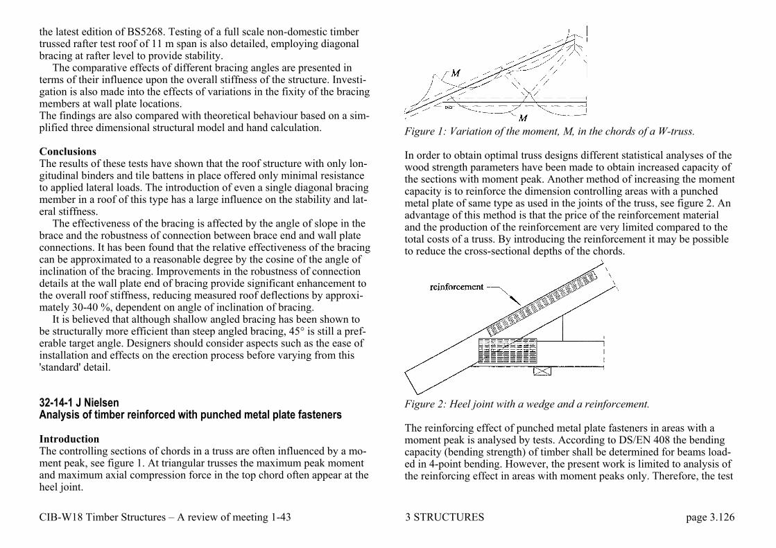
CIB-W18 Timber Structures – A review of meeting 1-43 3 STRUCTURES page 3.126
the latest edition of BS5268. Testing of a full scale non-domestic timber trussed rafter test roof of 11 m span is also detailed, employing diagonal bracing at rafter level to provide stability.
The comparative effects of different bracing angles are presented in terms of their influence upon the overall stiffness of the structure. Investi-gation is also made into the effects of variations in the fixity of the bracing members at wall plate locations. The findings are also compared with theoretical behaviour based on a sim-plified three dimensional structural model and hand calculation. Conclusions The results of these tests have shown that the roof structure with only lon-gitudinal binders and tile battens in place offered only minimal resistance to applied lateral loads. The introduction of even a single diagonal bracing member in a roof of this type has a large influence on the stability and lat-eral stiffness.
The effectiveness of the bracing is affected by the angle of slope in the brace and the robustness of connection between brace end and wall plate connections. It has been found that the relative effectiveness of the bracing can be approximated to a reasonable degree by the cosine of the angle of inclination of the bracing. Improvements in the robustness of connection details at the wall plate end of bracing provide significant enhancement to the overall roof stiffness, reducing measured roof deflections by approxi-mately 30-40 %, dependent on angle of inclination of bracing.
It is believed that although shallow angled bracing has been shown to be structurally more efficient than steep angled bracing, 45° is still a pref-erable target angle. Designers should consider aspects such as the ease of installation and effects on the erection process before varying from this 'standard' detail. 32-14-1 J Nielsen Analysis of timber reinforced with punched metal plate fasteners Introduction The controlling sections of chords in a truss are often influenced by a mo-ment peak, see figure 1. At triangular trusses the maximum peak moment and maximum axial compression force in the top chord often appear at the heel joint.
Figure 1: Variation of the moment, M, in the chords of a W-truss. In order to obtain optimal truss designs different statistical analyses of the wood strength parameters have been made to obtain increased capacity of the sections with moment peak. Another method of increasing the moment capacity is to reinforce the dimension controlling areas with a punched metal plate of same type as used in the joints of the truss, see figure 2. An advantage of this method is that the price of the reinforcement material and the production of the reinforcement are very limited compared to the total costs of a truss. By introducing the reinforcement it may be possible to reduce the cross-sectional depths of the chords.
Figure 2: Heel joint with a wedge and a reinforcement. The reinforcing effect of punched metal plate fasteners in areas with a moment peak is analysed by tests. According to DS/EN 408 the bending capacity (bending strength) of timber shall be determined for beams load-ed in 4-point bending. However, the present work is limited to analysis of the reinforcing effect in areas with moment peaks only. Therefore, the test

CIB-W18 Timber Structures – A review of meeting 1-43 3 STRUCTURES page 3.127
specimens are made with beams loaded in 3-point bending, as shown in figure 3.
The tests and the test results are described in this paper. The failure types are given and some load-displacement curves are shown. Further, the tests are compared to a numerical model.
Figure 3: Test arrangement for beams in 3-point bending. Dimensions in mm. Conclusion Based on the tests the following conclusions can be made: – The failure load and the stiffness of 120 mm beams with reinforcement
are increased by 20 to 30%. – The reinforcement has no effect on 170 mm beams. In further analyses
it is recommended to: – use a plate with high tensile capacity (thickness > 1 mm) in beams with
a cross-sectional depth of 170mm. – locate the reinforcement closer to the tensile edge of the timber (< 10
mm). – limit the width of the reinforcement (< 40 - 50 mm) – test beams with other cross-section depths and load conditions.
33-14-1 J Nielsen Moment capacity of timber beams loaded in four-point bending and re-inforced with punched metal plate fasteners Abstract Tests on timber beams reinforced with punched metal fasteners are contin-ued. The reinforced beams are loaded in four-point bending. The timber is Swedish spruce with cross sectional area of 45x 120 mm and 45x 170 mm. The reinforcement is from Gang-Nail Systems, types GNA20S and GNT150S. Beams with lateral reinforcement and beams with reinforce-ment located at the short edge are tested. The tests and the results are de-scribed. Conclusion Based on the tests the following conclusions can be made: – The reinforcement increases the strength and stiffness of 120 mm
beams in strength class K18 by 20%. – The reinforcement has no effect on the strength of 120 mm in strength
class K24. However, the stiffness increases by 5-20%. – The reinforcement has no effect on the strength of the 170 mm beams.
However, the stiffness increases by 20% for 170 mm beams in strength class K18.
In further analysis is it recommended to use reinforcing plates with a less teeth density. This will increase the strength and stiffness of the rein-forcement and it may also reduce the embedding difficulties as the needed embedding force is less. 36-14-1 P Ellegaard Effect of chord splice joints on force distribution in trusses with punched metal plate fasteners Abstract Splice joints in timber trusses with punched metal plate fasteners (nail plates) may be assumed rotationally stiff if their deformation has no signif-icant effect upon the distribution of member forces according to Eurocode 5: Design of Timber Structures.

CIB-W18 Timber Structures – A review of meeting 1-43 3 STRUCTURES page 3.128
Two simple guidelines for the design and location of splice joints are given in Eurocode 5 for treating the splice joints rotationally stiff. The rea-sonability of these guidelines is discussed in this paper.
A finite element program TrussLab where the splice joints are given semi-rigid properties is used to analyse two triangulated trusses with three and four splice joints, respectively. The influence of the splice joints on section forces, rotations in the splice joints and global displacements of the trusses is analysed.
Based on the results of the calculations it seems that the guidelines for treating splice joints rotationally stiff do not necessarily lead to more real-istic truss models. Conclusion As could be expected model S2 (splice joint near maximum moment and nail plates utilised up to 66%) leads to smaller rotations in the splice joints and smaller global displacements compared with model S1 (splice joint near maximum moment and nail plates utilised up to 100%). Due to the larger stiffness of the splice joints in model S2 the bending moments in the splice joints are also larger than for model S 1.
However, when the splice joints are located closer to sections with zero moment (S3) the rotations and displacements are often larger compared with model S 1. Moreover, it is not clear whether the influence on the bending moment distribution is larger for model S I than for S3.
Therefore, it seems that the guidelines (especially the second one in Eu-rocode 5) for treating splice joints rotationally stiff do not necessarily lead to more realistic truss models compared with a situation with no limita-tions to the splice joints.
There are relatively large deviations between the results (moment dis-tribution, rotations and displacements) achieved with the models S1-S3 compared with S4. To get a better agreement between real behaviour of a truss and the finite element models semi-rigidity of joints should be im-plemented. These joint models must include timber contact, since it is im-portant to the stiffness and distribution of the section forces.
From a simple splice joint it is found that the rotations are mainly caused by the anchorage of the nails and not by deformations in the joint line (for GNT150S plate type).
36-14-2 M Hansson, P Ellegaard Monte Carlo Simulation and reliability analysis of roof trusses with punched metal plate fasteners Abstract System effects are often found in timber structural systems e.g. due to transverse load distribution between different structural members. System effects are also related to the variation of strength within and between members. Most studies found in the literature have considered the variabil-ity between timber members, but the variability within members has been neglected mainly because of lack of data.
In this paper, Monte Carlo simulations of a W-truss are performed us-ing a model describing the strength parameters between and within timber members. The timber members are connected by punched metal plate fas-teners (nail plates). The variations in the properties of these joints have been estimated from experiments. The FE calculations are performed with TrussLab - a toolbox to MATLAB developed at Aalborg University. TrussLab takes contact between members and non-linear behaviour in the joints into account.
The system effect is estimated through a comparison of the simulations with a deterministic calculation of the roof truss using characteristic values as input to the model. The change of coefficient of variation also affects the reliability and is analysed. The total system effect is found to be be-tween 10-20 % when timber failure is predominant and less than 10% if the total failure is caused by failure in the plates or anchorage failure in the connection between nail plate and timber member. Summary In the simulations, the only failure that was observed was failure in the nail plates for this specific roof truss. Therefore, additional simulations were performed ignoring failure in the nail plates. The system effect was estimated through a comparison of the simulations with a deterministic calculation of the roof truss using characteristic values as input to the model. The change of coefficient of variation also affects the reliability and was analysed. The total system effect was found to be between 10-20 % when timber failure is predominant, but less than 10% if the total failure was caused by anchorage failure in the connection between nail plate and timber member. A more detailed study of the commercial software is desirable to deter-
CIB-W18 Timber Structures – A review of meeting 1-43 3 STRUCTURES page 3.129
mine if the joint models are accurate and if the engineering practice to in-crease bending strength at moment peaks is relevant. 36-14-3 R H Leicester, J Goldfinch, P Paevere, G C Foliente Truss trouble Abstract Following many decades of extensive and highly successful applications of nail plated trusses in Australia, several unexpected incidents involving plated trusses occurred recently which have caused some concern and trig-gered investigations into the performance of these trusses. Among matters investigated have been the mechano-sorptive behaviour and structural me-chanics of heel joints, creep buckling, brittle wood and quality control in fabrication and erection. Introduction Since the 1960s, nail plated timber roof trusses have been used extensively and successfully in Australia for housing, community halls and commer-cial buildings. However in 2002 the double girder truss of a golf clubhouse in Adelaide collapsed killing two persons and were it not for the fortunate placement of a side wall, would have killed another 30 people. The collapse occurred after 7 years in service, without warning and on a quiet windless day. The only loading at the time was the dead load of the roof. Following an investigation on this collapse, the South Australian government issued a general hazard alert related to work place buildings using nail plate truss roofs. As a result a program to inspect the service condition of roof trusses was initiated. It was discovered that many exist-ing trusses are either close to collapse, or appear to carry a risk of a col-lapse in the foreseeable future through teeth withdrawal due to mechano-sorptive and other effects. Since the "problem" trusses follow conventional and apparently suc-cessful design forms, it is important to assess if there are potential future problems. The findings of some of the investigations undertaken for this purpose are discussed in the following.
Recommendations On the basis of the investigations described herein the following recom-mendations can be made for the design and fabrication of nail plated tim-ber trusses that are intended for use as critical structures: – The strength of heel joints should be assessed by direct laboratory tests
to ensure that the correct failure mode is considered. – For girder trusses loaded on the tension chord, a formal engineering
analysis for the design of the system to laterally restrain the top chord should be undertaken.
– Special quality control checks should be undertaken to ensure that local slope-of-grain, brittle heart and gum veins are not present at connector plate locations.
– Heel joints should be designed so that the dead load in service does not exceed 0.15 of the short duration ultimate strength of the joint.
40-14-1 H J Blass Timber trusses with punched metal plate fasteners - design for transport and erection Introduction During transport and erection of trusses with punched metal plate fasteners unintentional forces and moments may occur which are difficult to quanti-fy but increase with increasing truss dimensions. Hence a careful handling during transport and erection becomes ever more important with increas-ing truss length. Eurocode 5 stipulates in 9.2.1 (8):
All joints should be capable of transferring a force Fr,d acting in any di-rection within the plane of the truss. Fr,d should be assumed to be of short-term duration, acting on timber in service class 2, with the value:
Fr,d = 1,0 + 0,1L
where Fr,d is in kN and L is the overall length of the truss, in m. However, this requirement does not take into account unintentional forces perpendicular to the truss plane. A design of members and connections for larger minimum forces leads to more robust members capable of better withstanding the exposure during transport and erection. This paper pre-

CIB-W18 Timber Structures – A review of meeting 1-43 3 STRUCTURES page 3.130
sents the background of a design method of trusses with punched metal plate fasteners for loads during transport and erection which is part of the German timber design code DIN 1052. Summary This paper presents a design proposal for the design situation transport and erection of trusses with punched metal plate fasteners. Although Eurocode 5 contains minimum loads within the truss plane for connections in trusses which are independent of the loads for the permanent design situation, the-se minimum loads are considered insufficient especially for larger span trusses. During transport and erection, unintentional loads occur, leading to bending moments and shear forces also perpendicular to the truss plane predominantly in the truss chord members.
The background of the proposed design is a situation, where a truss ly-ing on a horizontal basis is lifted at the apex. A simplified analysis of the chords as continuous beams on three supports leads to bending moments and shear forces perpendicular to the truss plane to be considered in truss design. Apart from significantly larger minimum loads for the truss con-nections in the upper and lower chords, a minimum timber member width results from the design proposal.
Since the plate and anchorage capacities in Eurocode 5 do not provide load-carrying capacities for loads perpendicular to the truss plane, a test method is shown for providing the necessary capacities. While the bending moment from loads perpendicular to the truss plane only cause stresses parallel to the punched metal plate fasteners and hence may be considered in design with the capacities listed in Eurocode 5, the shear forces perpen-dicular to the truss plane necessitate a new resistance property fax of punched metal plate fasteners which is to be determined by tests for each type of fastener.
For the design of the connections between diagonals and chords, the design rules in Eurocode 5 are considered sufficient.