contentdirectory:1 service template version 1 -...
TRANSCRIPT

EnergyManagement:1 Service
For UPnP Version 1.0
Status: Standardized DCP (SDCP)
Date: August 30, 2013
Document Version: 1.0
Service Template Version: 2.00
This Standardized DCP has been adopted as a Standardized DCP by the Steering
Committee of the UPnP Forum, pursuant to Section 2.1(c)(ii) of the UPnPForum
Membership Agreement. UPnP Forum Members have rights and licenses defined by
Section 3 of the UPnP Forum Membership Agreement to use and reproduce the
Standardized DCP in UPnP Compliant Devices. All such use is subject to all of the
provisions of the UPnP Forum Membership Agreement.
THE UPNP FORUM TAKES NO POSITION AS TO WHETHER ANY
INTELLECTUAL PROPERTY RIGHTS EXIST IN THE STANDARDIZED DCPS.
THE STANDARDIZED DCPS ARE PROVIDED "AS IS" AND "WITH ALL
FAULTS". THE UPNP FORUM MAKES NO WARRANTIES, EXPRESS,
IMPLIED, STATUTORY, OR OTHERWISE WITH RESPECT TO THE
STANDARDIZED DCPS, INCLUDING BUT NOT LIMITED TO ALL IMPLIED
WARRANTIES OF MERCHANTABILITY, NON-INFRINGEMENT AND
FITNESS FOR A PARTICULAR PURPOSE, OF REASONABLE CARE OR
WORKMANLIKE EFFORT, OR RESULTS OR OF LACK OF NEGLIGENCE.
Copyright UPnP Forum © 2013. All rights Reserved.
Authors Company
Sho Kou AllegroSoft
Barbara Stark AT&T
Stephen Palm Broadcom
Patrick Ladd Comcast
Bernard Peigne FT Orange
Richard Bardini Intel
YoungHwan Kwon LGE
Note: The UPnP Forum in no way guarantees the accuracy or completeness of this author list and in no way implies any rights for or support from those members listed. This list is not the specifications’ contributor list that is kept on the UPnP Forum’s website.

EnergyManagement:1 2
Copyright UPnP Forum © 2013. All rights Reserved.
CONTENTS
1 Scope ............................................................................................................................... 3
2 Normative references ....................................................................................................... 3
3 Terms, definitions, symbols and abbreviated terms .......................................................... 4
4 Notations and Conventions ............................................................................................... 5
4.1 Notation .................................................................................................................. 5
4.1.1 Data Types .................................................................................................. 5
4.2 Derived Data Types ................................................................................................. 5
4.3 Management of XML Namespaces in Standardized DCPs ....................................... 5
4.3.1 Namespace Prefix Requirements ................................................................. 7
4.3.2 Namespace Names, Namespace Versioning and Schema Versioning ................................................................................................... 8
4.3.3 Namespace Usage Examples .................................................................... 10
4.4 Vendor-defined Extensions.................................................................................... 10
4.4.1 Vendor-defined Action Names ................................................................... 10
4.4.2 Vendor-defined State Variable Names ....................................................... 10
4.4.3 Vendor-defined XML Elements and attributes ............................................ 11
4.4.4 Vendor-defined Property Names ................................................................ 11
5 Service modelling definitions .......................................................................................... 11
5.1 Service type .......................................................................................................... 11
5.2 Security feature ..................................................................................................... 11
5.2.1 Overview ................................................................................................... 11
5.2.2 Restrictable and non-restrictatable actions ................................................ 11
5.3 State variables ...................................................................................................... 12
5.3.1 General ..................................................................................................... 12
5.3.2 State variable overview ............................................................................. 12
5.3.3 NetworkInterfaceInfo ................................................................................. 12
5.3.4 ProxiedNetworkInterfaceInfo ..................................................................... 16
5.3.5 A_ARG_TYPE_Duration ............................................................................ 16
5.3.6 A_ARG_TYPE_ServiceSubscriptionID ....................................................... 16
5.3.7 A_ARG_TYPE_UniqueServiceName .......................................................... 16
5.3.8 A_ARG_TYPE_URI ................................................................................... 17
5.4 Eventing and moderation ....................................................................................... 17
5.5 Actions .................................................................................................................. 17
5.5.1 Overview ................................................................................................... 17
5.5.2 GetInterfaceInfo() ...................................................................................... 19
5.5.3 ServiceSubscription() ................................................................................ 19
5.5.4 ServiceRenewal() ...................................................................................... 21
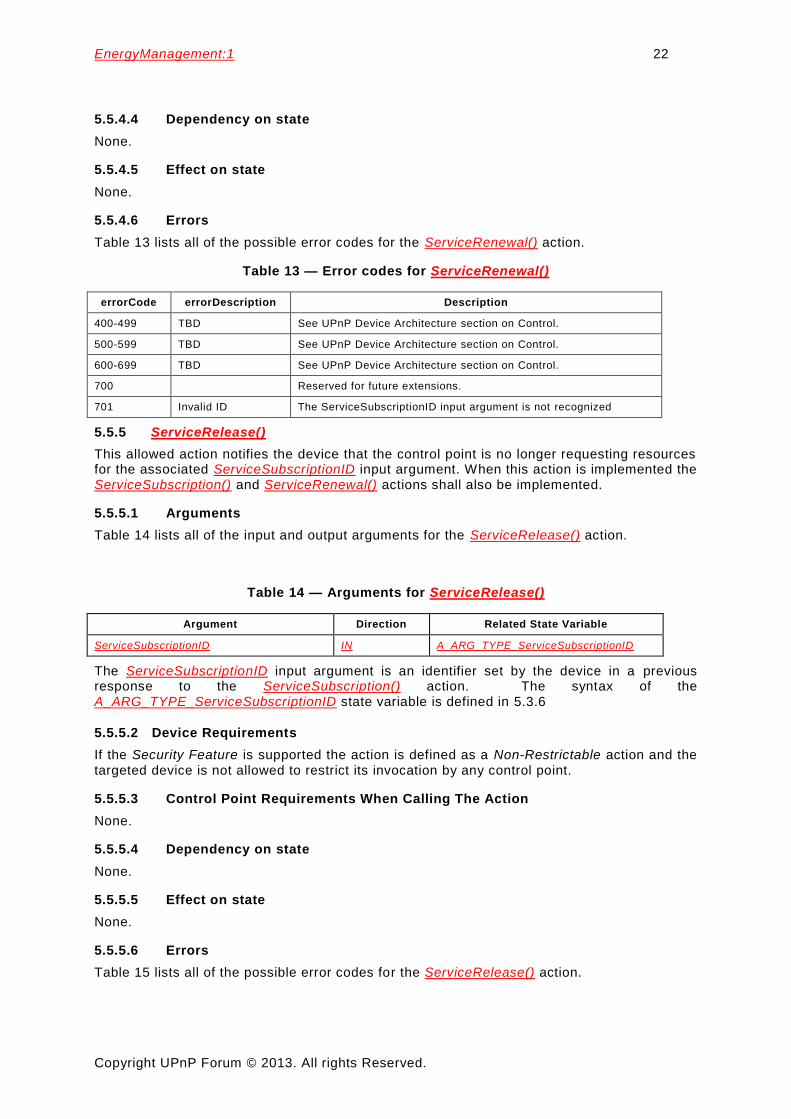
5.5.5 ServiceRelease() ....................................................................................... 22
6 Theory of operations ...................................................................................................... 23
6.1 Overview ............................................................................................................... 23
6.2 WakeOnPattern theory of operation ....................................................................... 23
6.2.1 Overview ................................................................................................... 23
6.2.2 EnergyManagement service operation ....................................................... 24
6.2.3 WakeOnPattern signaling operation ........................................................... 24

EnergyManagement:1 3
Copyright UPnP Forum © 2013. All rights Reserved.
6.2.4 Usability considerations ............................................................................. 24
6.3 Service subscription theory of operation ................................................................ 25
6.4 EnergyManagement service theory of operation .................................................... 26
6.5 EnergyManagement control point theory of operation ............................................ 26
6.6 Network Interface Mode of Operation .................................................................... 26
6.7 ProxiedNetworkInterfaceInfo theory of operation ................................................... 27
7 XML service description ................................................................................................. 27
Table 1 — Namespace Definitions .......................................................................................... 7
Table 2 — Schema-related Information ................................................................................... 7
Table 3 — Default Namespaces for the EnergyManagement Specifications ............................ 8
Table 4 — Assignment of Restrictable/Non-Restrictable Roles ............................................. 12
Table 5 — State variables ..................................................................................................... 12
Table 6 — Event moderation................................................................................................. 17
Table 7 — Actions ................................................................................................................ 18
Table 8 — Arguments for GetInterfaceInfo() ......................................................................... 19
Table 9 — Error codes for GetInterfaceInfo() ........................................................................ 19
Table 10 — Arguments for ServiceSubscription() .................................................................. 19
Table 11 — Error Codes for ServiceSubscription() ................................................................ 21
Table 12 — Arguments for ServiceRenewal() ........................................................................ 21
Table 13 — Error codes for ServiceRenewal() ...................................................................... 22
Table 14 — Arguments for ServiceRelease() ........................................................................ 22
Table 15 — Error codes for ServiceRelease() ....................................................................... 23
1 Scope
This specification is compliant with the UPnP Device Architecture version 1.0. It defines a service type named EnergyManagement service. It is scoped to any UPnP Device that needs to convey energy management functionality available for the UPnP Device and its services.
2 Normative references
The following documents, in whole or in part, are normatively referenced in this document and are indispensable for its application. For dated references, only the edition cited applies. For undated references, the latest edition of the referenced document (including any amendments) applies.
ISO/IEC 29341-1, Information Technology – UPnP Device Architecture – Part 1-1: UPnP Device Architecture Version 1.0
ISO/IEC 29341-4-12, Information Technology – UPnP Device Architecture – Part 4-12: Audio video Device Control Protocol – Level 2 – Content Directory Service
IETF RFC 1738, Uniform Resource Locators (URL) , Tim Berners-Lee, et. Al., December 1994. Available at: http://www.ietf.org/rfc/rfc1738.txt.
IETF RFC 2396, Uniform Resource Identifiers (URI): Generic Syntax, Tim Berners-Lee, et al, 1998. Available at: http://www.ietf.org/rfc/rfc2396.txt.

EnergyManagement:1 4
Copyright UPnP Forum © 2013. All rights Reserved.
IETF RFC 4291, IP Version 6 Addressing Architecture, February 2006
Available at: http://www.ietf.org/rfc/rfc4291.txt
IETF RFC 5952, A Recommendation for IPv6 Address Text Representation, August 2010 Available at: http:/www.ietf.org/rfc/rfc5952.txt
W3C XML, Extensible Markup Language (XML) 1.0 (Third Edition) , W3C Recommendation, February 4, 2004. Available at: http://www.w3.org/TR/2004/REC-xml-20040204.
W3C XML-NS, The “xml:” Namespace, October 26, 2009. Available at: http://www.w3.org/XML/1998/namespace.
W3C XML-XSD, XML Schema for the “xml:” Namespace. Available at: http://www.w3.org/2001/xml.xsd.
W3C XML-NMSP, Namespaces in XML, Tim Bray, Dave Hollander, Andrew Layman, eds., W3C Recommendation, January 14, 1999. Available at: http://www.w3.org/TR/1999/REC-xml-names-19990114.
W3C XML Schema-1, XML Schema Part1: Structures, Second Edition, Henry S. Thompson, David Beech, Murray Maloney, Noah Mendelsohn, W3C Recommendation, 28 October 2004. Available at: http://www.w3.org/TR/2004/REC-xmlschema-1-20041028.
W3C XML Schema-2, XML Schema Part 2:Data Types, Second Edition, Paul V. Biron, Ashok Malhotra, W3C Recommendation, 28 October 2004. Available at: http://www.w3.org/TR/2004/REC-xmlschema-2-20041028.
W3C XML Schema, XML Schema for XML Schema. Available at: http://www.w3.org/2001/XMLSchema.xsd.
UPnP DP, DeviceProtection:1, UPnP Forum, February 24, 2011. Available at: http://www.upnp.org/specs/gw/UPnP-gw-DeviceProtection-v1-Service-20110224.pdf. Latest version available at: http://www.upnp.org/specs/gw/UPnP-gw-DeviceProtection-v1-Service.pdf.
UPnP EM-NII-XSD, XML Schema for EnergyManagement NetworkInterfaceInfo, UPnP Forum, June 30, 2013. Available at: http://www.upnp.org/schemas/lp/em-NetworkInterfaceInfo-v1-20130830.xsd. Latest version available at: http://www.upnp.org/schemas/lp/ em-NetworkInterfaceInfo.xsd
3 Terms, definitions, symbols and abbreviated terms
For the purposes of this document, the terms and definitions given in ISO/IEC 29341-1 and the following apply.
3.1 Provisioning terms
3.1.1 conditionally allowed CA The definition or behavior depends on a condition. If the specified condition is met, then the definition or behavior is allowed, otherwise it is not allowed.

EnergyManagement:1 5
Copyright UPnP Forum © 2013. All rights Reserved.
3.1.2 conditionally required CR The definition or behavior depends on a condition. If the specified condition is met, then the definition or behavior is required, otherwise it is not allowed.
3.1.3 not allowed
The definition or behavior is prohibited by this specification. Opposite of required.
3.2 Abbreviated terms
3.2.1 A allowed
4 Notations and Conventions
4.1 Notation
Strings that are to be taken literally are enclosed in “double quotes”.
Words that are emphasized are printed in italic.
Keywords that are defined by the UPnP EnergyManagement Working Committee are printed using the forum character style.
Keywords that are defined by the UPnP Device Architecture specification [ISO/IEC 29341-1] are printed using the arch character style.
4.1.1 Data Types
This specification uses data type definitions from two different sources. The UPnP Device Architecture [ISO/IEC 29341-1] defined data types are used to define state variable and action argument data types. The XML Schema namespace is used to define property data types [W3C XML Schema-2].
For UPnP Device Architecture [ISO/IEC 29341-1] defined boolean data types, it is strongly recommended to use the value “0” for false, and the value “1” for true. However, when used as input arguments, the values “ false”, “no”, “true”, “yes” can also be encountered and shall be accepted. Nevertheless, it is strongly recommended that all boolean state variables and output arguments be represented as “0” and “1”.
For XML Schema [W3C XML Schema-2] defined Boolean data types, it is strongly recommended to use the value “0” for false, and the value “1” for true. However, when used as input properties, the values “ false”, “true” can also be encountered and shall be accepted. Nevertheless, it is strongly recommended that all Boolean properties be represented as “0” and “1”.
4.2 Derived Data Types
Subclause 4.2 defines a derived data type that is represented as a string data type with special syntax. This specification uses string data type definitions that originate from two different sources. The UPnP Device Architecture defined string data type is used to define state variable and action argument string data types. The XML Schema namespace is used to define property xsd:string data types. The following definition applies to both string data types.
4.3 Management of XML Namespaces in Standardized DCPs
UPnP specifications make extensive use of XML namespaces. This enables separate DCPs, and even separate components of an individual DCP, to be designed independently and still avoid name collisions when they share XML documents. Every name in an XML document belongs to exactly one namespace. In documents, XML names appear in one of two forms: qualified or unqualified. An unqualified name (or no-colon-name) contains no colon (“:”) characters. An unqualified name belongs to the

EnergyManagement:1 6
Copyright UPnP Forum © 2013. All rights Reserved.
document’s default namespace. A qualified name is two no -colon-names separated by one colon character. The no-colon-name before the colon is the qualified name’s namespace prefix, the no-colon-name after the colon is the qualified name’s “local” name (meaning local to the namespace identified by the namespace prefix). Similarly, the unqualified name is a local name in the default namespace.
The formal name of a namespace is a URI. The namespace prefix used in an XML document is not the name of the namespace. The namespace name shall be globally unique. It has a single definition that is accessible to anyone who uses the namespace. It has the same meaning anywhere that it is used, both inside and outside XML documents. The namespace prefix, however, in formal XML usage, is defined only in an XML document. It shall be locally unique to the document. Any valid XML no-colon-name may be used. And, in formal XML usage, different XML documents may use different namespace prefixes to refer to the same namespace. The creation and use of the namespace prefix was standardized by the W3C XML Committee in [W3C XML-NMSP] strictly as a convenient local shorthand replacement for the full URI name of a namespace in individual documents.
Some EnergyManagement state variables and action output parameters are represented in XML by element and attribute names, therefore, all property names belong to an XML namespace.
For the same reason that namespace prefixes are convenient in XML documents, it is convenient in specification text to refer to namespaces using a namespace prefix. Therefore, this specification declares a “standard” prefix for all XML namespaces used herein. In addition, this specification expands the scope where these prefixes have meaning, beyond a single XML document, to all of its text, XML examples, and certain string-valued properties. This expansion of scope does not supersede XML rules for usage in documents, it only augments and complements them in important contexts that are out-of-scope for the XML specifications.
All of the namespaces used in this specification are listed in Table 1 and Table 2. For each such namespace, Table 1 gives a brief description of it, its name (a URI) and its defined “standard” prefix name. The standard prefixes are also used in Table 2 to cross-reference additional namespace information. This second table includes each namespace’s valid XML document root element(s) (if any), its schema file name, versioning information (to be discussed in more detail below), and a link to the entry in Clause 2 for its associated schema.
The normative definitions for these namespaces are the documents referenced in Table 1. The schemas are designed to support these definitions for both human understanding and as test tools. However, limitations of the XML Schema language itself make it difficult for the UPnP-defined schemas to accurately represent all details of the namespace definitions. As a result, the schemas will validate many XML documents that are not valid according to the specifications.
The Working Committee expects to continue refining these schemas after specification release to reduce the number of documents that are validated by the schemas while violating the specifications; but the schemas will still be informative, supporting documents. Some schemas might become normative in future versions of the specifications.

EnergyManagement:1 7
Copyright UPnP Forum © 2013. All rights Reserved.
Table 1 — Namespace Definitions
Standard Name-space Prefix Namespace Name Namespace Description
Normative Definition Document Reference
LP Working Committee defined namespaces
em-nii urn:schemas-upnp-org:lp:em-NetworkInterfaceInfo
NetworkInterfaceInfo and ProxiedNetworkInterfaceInfo state variables
UPnP EM-NII-XSD
Externally defined namespaces
xsd http://www.w3.org/2001/XMLSchema XML Schema Language 1.0 W3C XML Schema-1 W3C XML Schema-2
xsi http://www.w3.org/2001/XMLSchema-instance
XML Schema Instance Document schema
W3C XML Schema-1 2.6 & 3.2.7
xml http://www.w3.org/XML/1998/namespace
The “xml:” Namespace W3C XML-NS
Table 2 — Schema-related Information
Standard Name-space Prefix
Relative URI and
File Name a
● Form 1, Form 2, Form3 Valid Root Element(s) Schema Reference
LP Working Committee Defined Namespaces
em-NetworkInterfaceInfo-vn-yyyymmdd.xsd
em-NetworkInterfaceInfo -vn.xsd
em-NetworkInterfaceInfo.xsd
<NetworkInterfaceInfo> UPnP EM-NII-XSD
Externally Defined Namespaces
xsd
n/a <schema> W3C XML Schema
xsi
n/a n/a
xml
n/a W3C XML-XSD
a Absolute URIs are generated by prefixing the relative URIs with "http://www.upnp.org/schemas/lp/"
4.3.1 Namespace Prefix Requirements
There are many occurrences in this specification of string data types that contain XML names (property names). These XML names in strings will not be processed under namespace-aware conditions. Therefore, all occurrences in instance documents of XML names in strings shall use the standard namespace prefixes as declared in Table 1. In order to properly process the XML documents described herein, control points and devices shall use namespace-aware XML processors [W3C XML-NMSP] for both reading and writing. As allowed by [W3C XML-NMSP], the namespace prefixes used in an instance document are at the sole discretion of the document creator. Therefore, the declared prefix for a namespace in a document may be different from the standard prefix. All devices shall be able to correctly process any valid XML instance document, even when it uses a non-standard prefix for ordinary XML names. However, it is strongly recommended that all devices use these standard prefixes for all instance documents to avoid confusion on the part of both human and machine readers. These standard prefixes are used in all descriptive text and all XML examples in this and related UPnP specifications. However, each individual specification may assume a default namespace for its descriptive text. In that case, names from that namespace may appear with no prefix.

EnergyManagement:1 8
Copyright UPnP Forum © 2013. All rights Reserved.
The assumed default namespace, if any, for the EnergyManagement specification is given in Table 3.
Note: all UPnP EnergyManagement schemas declare attributes to be “unqualified”, so namespace prefixes are never used with EnergyManagement Working Committee defined attribute names.
Table 3 — Default Namespaces for the EnergyManagement Specifications
Specification Name Default Namespace Prefix
EnergyManagement em
4.3.2 Namespace Names, Namespace Versioning and Schema Versioning
The UPnP EnergyManagement service specifications define several data structures (such as state variables and action arguments) whose format is an XML instance document that complies with one or more specific XML schemas, which define XML namespaces. Each namespace is uniquely identified by an assigned namespace name. The namespace names that are defined by the EnergyManagement Working Committee are URNs. See Table 1 for a current list of namespace names. Additionally, each namespace corresponds to an XML schema document that provides a machine-readable representation of the associated namespace to enable automated validation of the XML (state variable or action parameter) instance documents.
Within an XML schema and XML instance document, the name of each corresponding
namespace appears as the value of an xmlns attribute within the root element. Each
xmlns attribute also includes a namespace prefix that is associated with that
namespace in order to qualify and disambiguate element and attribute names that are defined within different namespaces. The schemas that correspond to the listed
namespaces are identified by URI values that are listed in the schemaLocation
attribute also within the root element. (See 4.3.3)
In order to enable both forward and backward compatibility, namespace names are permanently assigned and shall not change even when a new version of a specification changes the definition of a namespace. However, all changes to a namespace definition shall be backward-compatible. In other words, the updated definition of a namespace shall not invalidate any XML documents that comply with an earlier definition of that same namespace. This means, for example, that a namespace shall not be changed so that a new element or attribute becomes required in a conforming instance document. Although namespace names shall not change, namespaces still have version numbers that reflect a specific set of definitional changes. Each time the definition of a namespace is changed, the namespace’s version number is incremented by one.
Whenever a new namespace version is created, a new XML schema document (.xs d) is created and published so that the new namespace definition is represented in a machine-readable form. Since a XML schema document is just a representation of a namespace definition, translation errors can occur. Therefore, it is sometimes necessary to re-release a published schema in order to correct typos or other namespace representation errors. In order to easily identify the potential multiplicity of schema releases for the same namespace, the URI of each released schema shall conform to the following format (called Form 1):
Form 1: "http://www.upnp.org/schemas/lp/" schema-root-name "-v" ver "-" yyyymmdd where
schema-root-name is the name of the root element of the namespace that this schema represents.
ver corresponds to the version number of the namespace that is represented by the schema.

EnergyManagement:1 9
Copyright UPnP Forum © 2013. All rights Reserved.
yyyymmdd is the year, month and day (in the Gregorian calendar) that this schema was released.
Table 2 identifies the URI formats for each of the namespaces that are currently defined by the UPnP EnergyManagement Working Committee.
As an example, the original schema URI for the “em-nii” namespace (that was released with the original publication of the UPnP EnergyManagement service specification in the year 2013) was “http://www.upnp.org/schemas/lp/em-NetworkInterfaceInfo-v1-20130630.xsd”. When the UPnP EnergyManagement service specification is subsequently updated in the year 2014, the URI for the updated version of the “em-nii” namespace will be “http://www.upnp.org/schemas/lp/em-NetworkInterfaceInfo-v2-20140531.xsd”.
In addition to the dated schema URIs that are associated with each namespace, each namespace also has a set of undated schema URIs. These undated schema URIs have two distinct formats with slightly different meanings:
Form 2: “http://www.upnp.org/schemas/lp/” schema-root-name “-v” ver
where ver is described above.
Form 3: “http://www.upnp.org/schemas/lp/” schema-root-name
Form 2 of the undated schema URI is always linked to the most recent release of the schema that represents the version of the namespace indicated by ver. For example, the undated URI “…/lp/em-NetworkInterfaceInfo-v2.xsd” is linked to the most recent schema release of version 2 of the “em-nii” namespace. Therefore, on May 31, 2014 (20140531), the undated schema URI was linked to the schema that is otherwise known as “…/lp/em-NetworkInterfaceInfo-v2-20060531.xsd”. Furthermore, if the schema for version 2 of the “em-nii” namespace was ever re-released, for example to fix a typo in the 20060531 schema, then the same undated schema URI (“…/ lp/em-NetworkInterfaceInfo-v2.xsd”) would automatically be updated to link to the updated version 2 schema for the “em-nii” namespace.
Form 3 of the undated schema URI is always linked to the most recent release of the schema that represents the highest version of the namespace that has been published. For example, on June 30, 2013 (20130630), the undated schema URI “…/lp/em-NetworkInterfaceInfo.xsd” was linked to the schema that is otherwise known as “…/lp/em-NetworkInterfaceInfo-v1-20130630.xsd”. However, on May 31, 2014 (20140531), that same undated schema URI will link to the schema that is otherwise known as “…/lp/em-NetworkInterfaceInfo-v2-20140531.xsd”.
When referencing a schema URI within an XML instance document or a referencing XML schema document, the following usage rules apply:
All instance documents, whether generated by a service or a control point, shall use Form 3.
All UPnP EnergyManagement published schemas that reference other UPnP schemas shall also use Form 3.
Within an XML instance document, the definition for the schemaLocation attribute
comes from the XML Schema namespace “http://www.w3.org/2002/XMLSchema -instance”. A single occurrence of the attribute can declare the location of one or more
schemas. The schemaLocation attribute value consists of a whitespace separated
list of values that is interpreted as a namespace name followed by its schema location URL. This pair-sequence is repeated as necessary for the schemas that need to be located for this instance document.
In addition to the schema URI naming and usage rules described above, each
released schema shall contain a version attribute in the <schema> root element. Its
value shall correspond to the format:

EnergyManagement:1 10
Copyright UPnP Forum © 2013. All rights Reserved.
ver “-” yyyymmdd where ver and yyyymmdd are described above.
The version attribute provides self-identification of the namespace version and
release date of the schema itself. For example, within the original schema released
for the “rcs-event” namespace (…/rcs-event-v2-20020625.xsd), the <schema> root
element contains the following attribute: version="2-20020625".
4.3.3 Namespace Usage Examples
The schemaLocation attribute for XML instance documents comes from the XML
Schema instance namespace “http://www.w3.org/2002/XMLSchema -instance”. A single occurrence of the attribute can declare the location of one or more schemas.
The schemaLocation attribute value consists of a whitespace separated list of
values: namespace name followed by its schema location URL. This pair -sequence is repeated as necessary for the schemas that need to be located for this instance document.
Example 1:
Sample NetworkInterfaceInfo state variable XML Instance Document. Note that the references to the UPnP EnergyManagement schemas do not contain any version or release date information. In other words, the references follow Form 3 from above. Consequently, this example is valid for all releases of the UPnP EnergyManagement service specifications.
<?xml version="1.0" encoding="UTF-8"?>
< NetworkInterfaceInfo
xmlns ="urn:schemas-upnp-org:lp:em-NetworkInterfaceInfo"
xmlns:xsi="http://www.w3.org/2001/XMLSchema-instance">
xsi:schemaLocation="urn:schemas-upnp-org:lp:em-NetworkInterfaceInfo
http://www.upnp.org/schemas/lp/em-NetworkInterfaceInfo.xsd"
< DeviceInterface>
...
</ DeviceInterface>
</ NetworkInterfaceInfo>
4.4 Vendor-defined Extensions
Whenever vendors create additional vendor-defined state variables, actions or properties, their assigned names and XML representation shall follow the naming conventions and XML rules as specified below.
4.4.1 Vendor-defined Action Names
Vendor-defined action names shall begin with “X_”. Additionally, it should be followed by an ICANN assigned domain name owned by the vendor followed by the underscore character (“_”). It shall then be followed by the vendor-assigned action name. The vendor-assigned action name shall not contain a hyphen character (“-”, 2D Hex in UTF-8) nor a hash character (“#”, 23 Hex in UTF-8). Vendor-assigned action names are case sensitive. The first character of the name shall be a US-ASCII letter (“A”-“Z”, “a”-“z”), US-ASCII digit (“0”-“9”), an underscore (“_”), or a non-experimental Unicode letter or digit greater than U+007F. Succeeding characters shall be a US-ASCII letter (“A”-“Z”, “a”-“z”), US-ASCII digit (“0”-“9”), an underscore (“_”), a period (“.”), a Unicode combining char, an extender, or a non-experimental Unicode letter or digit greater than U+007F. The first three letters shall not be “XML” in any combination of case.
4.4.2 Vendor-defined State Variable Names
Vendor-defined state variable names shall begin with “X_”. Additionally, it should be followed by an ICANN assigned domain name owned by the vendor, followed by the underscore character (“_”). It shall then be followed by the vendor-assigned state variable name. The vendor-assigned state variable name shall not contain a hyphen character (“-”, 2D Hex in UTF-8). Vendor-assigned action names are case sensitive. The first character of the name shall be a US-ASCII letter (“A”-“Z”, “a”-“z”), US-ASCII digit (“0”-“9”), an underscore (“_”), or a non-experimental Unicode letter or digit

EnergyManagement:1 11
Copyright UPnP Forum © 2013. All rights Reserved.
greater than U+007F. Succeeding characters shall be a US-ASCII letter (“A”-“Z”, “a”-“z”), US-ASCII digit (“0”-“9”), an underscore (“_”), a period (“.”), a Unicode combining char, an extender, or a non-experimental Unicode letter or digit greater than U+007F. The first three letters shall not be “XML” in any combination of case.
4.4.3 Vendor-defined XML Elements and attributes
UPnP vendors may add non-standard elements and attributes to a UPnP standard XML document, such as a device or service description. Each addition shall be scoped by a vendor-owned XML namespace. Arbitrary XML shall be enclosed in an element that begins with “X_,” and this element shall be a sub element of a standard complex type. Non-standard attributes may be added to standard elements provided these attributes are scoped by a vendor-owned XML namespace and begin with “X_”.
4.4.4 Vendor-defined Property Names
UPnP vendors may add non-standard properties to the EnergyManagement service. Each property addition shall be scoped by a vendor-owned namespace. The vendor-assigned property name shall not contain a hyphen character (“-”, 2D Hex in UTF-8). Vendor-assigned property names are case sensitive. The first character of the name shall be a US-ASCII letter (“A”-“Z”, “a”-“z”), US-ASCII digit (“0”-“9”), an underscore (“_”), or a non-experimental Unicode letter or digit greater than U+007F. Succeeding characters shall be a US-ASCII letter (“A”-“Z”, “a”-“z”), US-ASCII digit (“0”-“9”), an underscore (“_”), a period (“.”), a Unicode combining char, an extender, or a non-experimental Unicode letter or digit greater than U+007F. The first three letters shall not be “XML” in any combination of case.
5 Service modelling definitions
5.1 Service type
The following service type identifies a service that is compliant with this template:
urn:schemas-upnp-org:service:EnergyManagement:1
EnergyManagement service is used herein to refer to this service type.
5.2 Security feature
5.2.1 Overview
In the specification, if support for the Security Feature is referenced, this indicates that the device implements the UPnP DeviceProtection service [UPnP DP].
5.2.2 Restrictable and non-restrictatable actions
The EnergyManagement service actions defined in this specification have the Restrictable, Non-Restrictable assignments as indicated in Table 4.

EnergyManagement:1 12
Copyright UPnP Forum © 2013. All rights Reserved.
Table 4 — Assignment of Restrictable/Non-Restrictable Roles
Action Name Restrictable/Non-Restricable to Indicated Rolea
Public Basic Admin Vendor Defined
GetInterfaceInfo() NO NO NO NO
ServiceSubscription() NO NO NO NO
ServiceRenewal() NO NO NO NO
ServiceRelease() NO NO NO NO
a A YES value in the table indicates that the action shall be Restrictable when the Security Feature is supported and a control point with only the Role indicated shall not have Action level access and shall receive an error code 606 (see UPnP Device Architecture [ISO/IEC 29341-1]) in response to the action invocation. A NO value in the table indicates that the action shall be Non-Restrictable, meaning that even if the Security Feature is supported all control points shall have Action level access when control point invoking the action and shall not receive an error code 606 based on the Security Feature.
5.3 State variables
5.3.1 General
For a first-time reader, it might be more helpful to read the action definitions before reading the state variable definitions.
5.3.2 State variable overview
Table 5 lists all of the state variables defined for the EnergyManagement service.
Table 5 — State variables
Variable Name R/A
a
Data Type Allowed Value Default Value
Eng. Units
NetworkInterfaceInfo R string (XML document)
See 5.3.3
ProxiedNetworkInterfaceInfo R string (XML document)
See 5.3.4
A_ARG_TYPE_Duration CR b string See 5.3.5
A_ARG_TYPE_ServiceSubscriptionID CR b ui4 See 5.3.6
A_ARG_TYPE_UniqueServiceName CR b string See 5.3.7
A_ARG_TYPE_URI CR b uri See 5.3.8
Non-standard state variables implemented by a UPnP vendor go here
X TBD TBD TBD TBD
a For a device this column indicates whether the state variable shall be implemented or not, where R = required, A = allowed, CR = conditionally required, CA = conditionally allowed, X = Non-standard, add -D when deprecated (e.g., R-D, A-D).
b CR = conditionally required. See referenced subclause for implementation requirements.
5.3.3 NetworkInterfaceInfo
This required state variable shall be supported for the EnergyManagement service GetInterfaceInfo() action. NetworkIntefaceInfo out argument in the EnergyManagement service GetInterfaceInfo() action shall represent information about one or more network interfaces for the device. The following is the XML template for the NetworkinterfaceInfo state variable:
<?xml version="1.0" encoding="UTF-8"?>

EnergyManagement:1 13
Copyright UPnP Forum © 2013. All rights Reserved.
<NetworkInterfaceInfo xsi:schemaLocation="urn:schemas-upnp-org:lp:em-
NetworkInterfaceInfo http://www.upnp.org/schemas/lp/em-
NetworkInterfaceInfo.xsd" xmlns="urn:schemas-upnp-org:lp:em-
NetworkInterfaceInfo" xmlns:xsi="http://www.w3.org/2001/XMLSchema-instance">
<DeviceInterface>
<DeviceUUID>UPnP device UUID</DeviceUUID>
<FriendlyName>UPnP device friendly name</FriendlyName>
<NetworkInterface>
<SystemName>Device network interface system name</SystemName>
<Description>Device network interface text
description</Description>
<MacAddress>Device network interface MAC address</MacAddress>
<InterfaceType>Device network Interface type</InterfaceType>
<NetworkInterfaceMode>Device network Interface
mode</NetworkInterfaceMode>
<AssociatedIpAddresses>
<Ipv4>Device network interface IPv4 address</Ipv4>
<Ipv6>Device network interface IPv6 address</Ipv6>
</AssociatedIpAddresses>
<WakeOnPattern>Device network interface wake on
pattern</WakeOnPattern>
<WakeSupportedTransport>Device network interface wake on pattern
transport</WakeSupportedTransport>
<MaxWakeOnDelay>Device network interface wake on pattern
delay</MaxWakeOnDelay>
<DozeDuration>Device network interface doze duration</DozeDuration>
</NetworkInterface>
<NetworkInterface>
. . . Additional <NetworkInterface> elements . . .
</NetworkInterface>
</DeviceInterface>
<DeviceInterface>
. . . Additional <DeviceInterface> elements . . .
</DeviceInterface>
</NetworkInterfaceInfo>
<?xml>
Allowed. Case sensitive.
<NetworkInterfaceInfo>
Required. <XML>. Shall include a namespace declaration for the EnergyManagement service
Common Datastructures Schema (“urn:schemas-upnp-org:em:nii-events”). This is the base wrapper
element for the state variable. Shall include one or more of the <DeviceInterface> elements for
each UPnP device network interfaces being described.
<DeviceInterface>
Required. <XML>. One or more elements. Shall include the following elements to describe
the network interfaces for a UPnP device:
<DeviceUUID>
Required. xsd:string. Maximum length 70 characters. Exactly one element. The UPnP device-UUID that is used by the UPnP Device containing this service ISO/IEC 29341-1. For proxied information the field contains the UPnP device-UUID of the proxied device.
<FriendlyName>
Required. xsd:string. Maximum length 64 characters. Exactly one element. This field contains the device’s friendlyName ISO/IEC 29341-1. For proxied information the field contains the friendlyName of the proxied device. If the friendlyName of the device is greater than 64 characters, it shall be truncated to 64 characters .
<NetworkInterface>
Required. <XML>. One or more elements. Each instance of the element is
to describe a network interface for a UPnP Device. Shall include the following elements to describe a physical network interface for a UPnP device:

EnergyManagement:1 14
Copyright UPnP Forum © 2013. All rights Reserved.
<SystemName>
Required. xsd:string. Unique name. Maximum length 64 characters. Exactly one element. This is the name provided by the underlying system to the network interface. The names are unique for a given interface on the device.
NOTE Examples: eth0, wlan2.
<Description>
Allowed. xsd:string. Maximum length 256 characters. Zero or one element. Textual description of the interface. It should contain the hardware description of the network interface. For example, it might include manufacturer name or model number. The format is specified in ISO/IEC 29341-4-12Appendix B.3.
<MACAddress>
Required. xsd:string. Exactly 17 characters. Exactly one element. The MAC-48 address of the physical interface in human-friendly form represented as a string in six groups of two hexadecimal digits, separated by colons (:), in transmission order.
<InterfaceType>
Required. xsd:NMTOKEN. Exactly one element. Type of this physical interface as an enumerated string. Values are:
“Ethernet”
“Wi-Fi”
“HPNAoverCoax”
“HomePlug”
“MoCA”
“1905”
“Other”
<NetworkInterfaceMode>
Required. xsd:NMTOKEN. Exactly one element. Operation mode of a network interface. Enumeration of string values and their definition are as follows:
“Unimplemented”: No information regarding any low power interface mode of this network interface;
“IP-up”: IP interface is fully operational. UPnP services may be available;
“IP-up-Periodic”: IP interface will be periodically unavailable for durations of 2 second or less when the physical interface is placed in a low power mode of operation;
"IP-down-no-Wake": IP interface is down;
"IP-down-with-WakeOn": IP interface is down. IP interface can be woken externally;
"IP-down-with-WakeAuto": IP interface is down in doze state for duration of more than 2 seconds. IP interface will be woken internally;
"IP-down-with-WakeOnAuto": IP interface is down in doze state for duration of more than 2 seconds. IP interface will be woken internally or can be woken externally.
<AssociatedIPAddresses>
Conditionally Required. xsd:string. Shall be included when at least one IP address is associated with the enclosing
<networkInterface> element (i.e. MAC address). A list of IP
addresses that use this network interface. Limit:17 addresses. In XML the list is a sequence of IP addresses. IP address may contain any combination of <Ipv4> or <Ipv6> elements. If the network interface has no IP addresses assigned, the
<AssociateIPAddresses> element should be absent.

EnergyManagement:1 15
Copyright UPnP Forum © 2013. All rights Reserved.
<Ipv4>
IPv4 address are of the form nnn.nnn.nnn.nnn where n is a decimal digit and leading zeros may be omitted.
<Ipv6>
IPv6 address of either the first or second form described in [IETF RFC 4291]. The first is the preferred form of x:x:x:x:x:x:x:x, where the 'x's are one to four hexadecimal digits of the eight 16-bit pieces of the address. The second is the special compressed syntax that uses "::" to indicate one or more groups of 16 bits of zeros. The additional restriction from IETF RFC 5952 that requires letters used in hex digits to be lowercase also applies.
<WakeOnPattern>
Allowed. xsd:hexBinary. Zero or one element. Length unlimited. Wake-up bit pattern, expressed in hex. This is the entire xsd:hexBinary that is expected by the network interface. If the expected pattern is a sequence of “1” bits followed by multiple iterations of the MAC address, then this parameter will include all bits, including all iterations of the MAC address. If a security string is expected after the MAC address iterations, those bits shall be included, as well.
<WakeSupportedTransport>
Allowed. xsd:NMTOKEN. Zero or one element. Supported
transport mechanisms for receipt of the <WakeOnPattern>
value as an enumerated string. Values are:
“UDP-Broadcast”
“UDP-Unicast”
“TCP-Unicast”
“Other”
<MaxWaitOnDelay>
Allowed. xsd:unsignedInt. Zero or one element. Estimate of maximum time in seconds it would take from time
<WakeOnPattern> value is received until ssdp:alive messages
are sent. A value of 0 (zero) indicates that no estimate is provided and the value is unknown.
<DozeDuration>
Allowed. xsd:unsignedInt. Zero or one element. Time in milliseconds that interface is configured to doze. This value is only meaningful if “IP-down-with-WakeAuto”, “IP-down-with-
WakeOnAuto”, or “IP-up-Periodic” <NetworkInterfaceMode>
values are supported.
If <NetworkInterfaceMode> is “IP-up”, this indicates the
internally-set duration of the next future-occurring doze state “IP-down-with-WakeAuto” or “IP-down-with-WakeOnAuto” operation mode.
If <NetworkInterfaceMode> is “IP-down-with-WakeAuto”
or “IP-down-with-WakeOnAuto”, this indicates the remaining time until the interface is automatically enabled.
If <NetworkInterfaceMode> is “IP-up-Periodic”, this
indicates the periodic sleep interval.
A 0 (zero) value means this parameter is not set.
An example XML for the NetworkinterfaceInfo state variable:
<?xml version="1.0" encoding="UTF-8"?>
<NetworkInterfaceInfo xsi:schemaLocation="urn:schemas-upnp-org:lp:em-
NetworkInterfaceInfo http://www.upnp.org/schemas/lp/em-
NetworkInterfaceInfo.xsd" xmlns="urn:schemas-upnp-org:lp:em-
NetworkInterfaceInfo" xmlns:xsi="http://www.w3.org/2001/XMLSchema-instance">
<DeviceInterface>
<DeviceUUID>uuid:00000000-0000-1010-8000-4424991A912</DeviceUUID>

EnergyManagement:1 16
Copyright UPnP Forum © 2013. All rights Reserved.
<FriendlyName>My Family Room TV</FriendlyName>
<NetworkInterface>
<SystemName>eth0</SystemName>
<Description>Ethernet 802.3 NIC</Description>
<MacAddress>54:42:49:91:A9:12</MacAddress>
<InterfaceType>Ethernet</InterfaceType>
<NetworkInterfaceMode>IP-up</NetworkInterfaceMode>
<AssociatedIpAddresses>
<Ipv4>192.168.1.125</Ipv4>
<Ipv6>805b:2d9d:dc28:0:0:fc57:d4c8:1fff</Ipv6>
</AssociatedIpAddresses>
<WakeOnPattern>
FFFFFFFFFFFF54424991A91254424991A91254424991A91254424991A91254424991A9125442
4991A91254424991A91254424991A91254424991A91254424991A91254424991A91254424991
A91254424991A91254424991A91254424991A91254424991A912</WakeOnPattern>
<WakeSupportedTransport>UDP-Broadcast</WakeSupportedTransport>
<MaxWakeOnDelay>5</MaxWakeOnDelay>
<DozeDuration>0</DozeDuration>
</NetworkInterface>
</DeviceInterface>
</NetworkInterfaceInfo>
5.3.4 ProxiedNetworkInterfaceInfo
This required state variable shall be supported for the EnergyManagement service GetInterfaceInfo() action. The ProxiedNetworkIntefaceInfo output argument in the EnergyManagement service GetInterfaceInfo() action shall represent information received from one or more EnergyManagement services in physical devices other than the one with this instance of the EnergyManagement service. The XML schema for the ProxiedNetworkInterfaceInfo state variable is identical to that of the NetworkinterfaceInfo state variable defined in 5.3.3, except it can contain zero <DeviceInterface> elements when it contains no proxied device information, but it supports proxying. If the service does not support prox ying, it shall be set to an empty XML element (i.e. contains no text between the start and end tags; e.g. <NetworkInterfaceInfo></NetworkInterfaceInfo>.
5.3.5 A_ARG_TYPE_Duration
This conditionally required state variable shall be supported if the EnergyManagement service implements the ServiceSubscription() and ServiceRenewal() actions. This state variable is introduced to provide type information for the Duration and DurationRequest arguments in various actions. DurationRequest input and Duration output arguments in EnergyManagement service actions shall represent the duration of time using the format of the res@duration proper ty as defined in ISO/IEC 29341-4-12. The format of this state variable is a string with a value of “0” indicating infinite time.
5.3.6 A_ARG_TYPE_ServiceSubscriptionID
This conditionally required state variable shall be supported if the EnergyManagement service implements the ServiceSubscription(), ServiceRenewal() or ServiceRelease() actions. This state variable is introduced to provide type information for the ServiceSubscriptionID argument in various actions. ServiceSubscriptionID input and output arguments in EnergyManagement service actions shall represent a numerical value that is unique across all service subscriptions created with the ServiceSubscription() action. The format of this state variable is a positive integer.
5.3.7 A_ARG_TYPE_UniqueServiceName
This conditionally required state variable shall be supported if the EnergyManagement service implements the ServiceSubscription() action. This state variable is introduced to provide type information for the UniqueServiceName argument in the ServiceSubscription() action. UniqueServiceName input argument in the EnergyManagement service actions shall indicate he specific service in the device to

EnergyManagement:1 17
Copyright UPnP Forum © 2013. All rights Reserved.
be subscribed. The format of this state variable is a string as defined in ISO/IEC 29341-1
5.3.8 A_ARG_TYPE_URI
This conditionally required state variable shall be supported if the EnergyManagement service implements the ServiceSubscription() action. This state variable is introduced to provide type information for the ResourceURI argument in the ServiceSubscription() action. ResourceURI input argument in the EnergyManagement service actions shall be properly escaped URIs as described in IETF RFC 2396. In addition, ResourceURI argument shall be escaped according to the requirements of IETF RFC 1738.
5.4 Eventing and moderation
Table 6 lists all of the state variables defined for the EnergyManagement service and which state variables are evented and whether they are moderated.
Table 6 — Event moderation
Variable Name Evented Moderated Event
Min Event
Interval a
(seconds)
Logical Combination
Min Delta
per Event b
NetworkInterfaceInfo YES NO
ProxiedNetworkInterfaceInfo NO NO
A_ARG_TYPE_Duration NO NO
A_ARG_TYPE_ServiceSubscriptionID NO NO
A_ARG_TYPE_UniqueServiceName NO NO
A_ARG_TYPE_URI NO NO
Non-standard state variables implemented by a UPnP vendor go here
TBD TBD TBD TBD TBD
a Max event rate is determined by N, where Rate = 1/N, where N is the Min Event Interval in seconds.
b (N) * (allowedValueRange Step)
5.5 Actions
5.5.1 Overview
The following subclauses define the various EnergyManagement service actions.
Except where noted, if an invoked action returns an error, the state of the device will be unaffected.
Table 7 lists all of the actions defined for the EnergyManagement service.

EnergyManagement:1 18
Copyright UPnP Forum © 2013. All rights Reserved.
Table 7 — Actions
Name R/A a Control
Point R/A b
GetInterfaceInfo() R R
ServiceSubscription() A A
ServiceRenewal() A A
ServiceRelease() A A
Non-standard actions implemented by an UPnP vendor go here. X X
a For a device this column indicates whether the action shall be implemented or not, where R = required, A = allowed, CR = conditionally required, CA = conditionally allowed, X = Non-standard, add -D when deprecated (e.g., R-D, A-D).
b For a control point this column indicates whether a control point shall be capable of invoking this action, where R = required, A = allowed, CR = conditionally required, CA = conditionally allowed, X = Non-standard, add -D when deprecated (e.g., R-D, A-D).

Non-standard actions shall be implemented in such a way that they do not interfere with the basic operation of the EnergyManagement service, that is: these actions shall be allowed and do not need to be invoked for the EnergyManagement service to operate normally.
5.5.2 GetInterfaceInfo()
This required action is used to get the current information and current mode of the power state for all of the network interfaces that the service can be discovered on. It can also supply information received from EnergyManagement services on other physical devices through the ProxiedNetworkInterfaceInfo parameter.
5.5.2.1 Arguments
Table 8 lists all of the input and output arguments for the GetInterfaceInfo() action.
Table 8 — Arguments for GetInterfaceInfo()
Argument Direction Related State Variable
NetworkInterfaceInfo OUT NetworkInterfaceInfo
ProxiedNetworkInterfaceInfo OUT ProxiedNetworkInterfaceInfo
5.5.2.2 Device Requirements
If the Security Feature is supported the action is defined as a Non-Restrictable action and the targeted device is not allowed to restrict its invocation by any control point.
5.5.2.3 Control Point Requirements When Calling The Action
None.
5.5.2.4 Dependency on state
Return values are dependent on current values of the NetworkInterfaceInfo and ProxiedNetworkInterfaceInfo state variables.
5.5.2.5 Effect on state
None.
Table 9 lists all of the possible error codes for the GetInterfaceInfo() action.
Table 9 — Error codes for GetInterfaceInfo()
errorCode errorDescription Description
400-499 TBD See UPnP Device Architecture section on Control.
500-599 TBD See UPnP Device Architecture section on Control.
600-699 TBD See UPnP Device Architecture section on Control.
5.5.3 ServiceSubscription()
This allowed action notifies the device that the control point is requesting resources for general or specific uses. When this action is implemented the ServiceRenewal() and ServiceRelease() actions shall also be implemented.
5.5.3.1 Arguments
Table 10 lists all of the input and output arguments for the ServiceSubscription() action.
Table 10 — Arguments for ServiceSubscription()
Argument Direction Related State Variable
UniqueServiceName IN A_ARG_TYPE_UniqueServiceName
ResourceURI IN A_ARG_TYPE_URI

EnergyManagement:1 20
Copyright UPnP Forum © 2013. All rights Reserved.
Argument Direction Related State Variable
DurationRequest IN A_ARG_TYPE_Duration
ServiceSubscriptionID OUT A_ARG_TYPE_ServiceSubscriptionID
Duration OUT A_ARG_TYPE_Duration
The UniqueServiceName input argument is used by the control point to indicate the specific service in the device to be subscribed. The information contained in the argument is the values of USN defined in ISO/IEC 29341-1.
The ResourceURI input argument is used by the control point to indicate a specific content binary of interest or empty. The A_ARG_TYPE_URI state variable is defined in 5.3.8.
The DurationRequest input argument indicates the duration the resources are requested for. A value of “0” requests a duration of infinite. The syntax of the A_ARG_TYPE_Duration state
variable is defined in 5.3.5.
The ServiceSubscriptionID output argument is an identifier set by the device that is unique to each service subscription request. The syntax of the A_ARG_TYPE_ServiceSubscriptionID
state variable is defined in 5.3.6.
The Duration output argument is the actual duration given to the subscription request by the device. The device may round the duration up or down to meet supported time increments. The syntax of the A_ARG_TYPE_Duration state variable is defined in 5.3.5.
5.5.3.2 Device Requirements
If the Security Feature is supported the action is defined as a Non-Restrictable action and the targeted device is not allowed to restrict its invocation by any control point.
5.5.3.3 Control Point Requirements When Calling The Action
None.
5.5.3.4 Dependency on state
None.
5.5.3.5 Effect on state
A device may associate specific resources with the request for a specific content binary indicated by A_ARG_TYPE_URI. If A_ARG_TYPE_URI is empty, service wide resources may be needed. For example, if a URI points to live content, the device may not need to keep storage resources awake. In contrast, if a URI points to pre-recorded content, the device may not need to keep tuner resources awake.
Even when the UPnP service identified by the UniqueServiceName input argument does not deal with content binaries, the device may still be able to identify all resources needed for that service and make those resources available. In all cases, the architecture is designed to give the device ultimate authority over its resources.
5.5.3.6 Errors
Table 11 lists all of the possible error codes for the ServiceSubscription() action.

EnergyManagement:1 21
Copyright UPnP Forum © 2013. All rights Reserved.
Table 11 — Error Codes for ServiceSubscription()
errorCode errorDescription Description
402 Invalid Args Not enough in args, no in arg by that name, one or more in args are of the wrong data type.
401, 403-499 TBD See UPnP Device Architecture section on Control.
501 Action Failed To indicate that the current state of service prevents invoking the action.
500, 502-599 TBD See UPnP Device Architecture section on Control.
600 The argument value is invalid
The argument value is invalid.
601 Argument Value Out of Range
An argument value is less than the minimum or more than the maximum value of the allowedValueRange, or is not in the allowedValueList.
603 Out of Memory To indicate that device does not have sufficient resources available to complete the action.
605 String Argument Too Long
A string argument is too long for the device to handle properly.
602, 604, 606-699
TBD See UPnP Device Architecture section on Control.
NOTE This action will always return a valid ServiceSubscriptionID even if no associated resources are going to change power status for the UniqueServiceName input argument. To the control point the request is always valid unless one the UPnP Device Architecture [ISO/IEC 29341-1] errors (errors 400-699) are generated.
5.5.4 ServiceRenewal()
This allowed action that notifies the device that the control point is renewing a resource request. When this action is implemented the ServiceSubscription() and ServiceRelease()
actions shall also be implemented.
5.5.4.1 Arguments
Table 12 lists all of the input and output arguments for the ServiceRenewal() action.
Table 12 — Arguments for ServiceRenewal()
Argument Direction Related State Variable
DurationRequest IN A_ARG_TYPE_Duration
ServiceSubscriptionID IN A_ARG_TYPE_ServiceSubscriptionID
Duration OUT A_ARG_TYPE_Duration
The DurationRequest input argument indicates the duration the resources are requested for. A duration value of “0” requests a duration of infinite. The syntax of the A_ARG_TYPE_Duration state variable is defined in 5.3.5.
The ServiceSubscriptionID input argument is an identifier set by the device in a previous response to the ServiceSubscription() action. The syntax of the ServiceSubscriptionID state
variable is defined in 5.3.6.
The Duration output argument is the actual duration given to the subscription request by the device. The device may round the duration up or down to meet supported time increments. The syntax of the A_ARG_TYPE_Duration state variable is defined in 5.3.5.
5.5.4.2 Device Requirements
If the Security Feature is supported the action is defined as a Non-Restrictable action and the
targeted device is not allowed to restrict its invocation by any control point.
5.5.4.3 Control Point Requirements When Calling The Action
None.
EnergyManagement:1 22
Copyright UPnP Forum © 2013. All rights Reserved.
5.5.4.4 Dependency on state
None.
5.5.4.5 Effect on state
None.
5.5.4.6 Errors
Table 13 lists all of the possible error codes for the ServiceRenewal() action.
Table 13 — Error codes for ServiceRenewal()
errorCode errorDescription Description
400-499 TBD See UPnP Device Architecture section on Control.
500-599 TBD See UPnP Device Architecture section on Control.
600-699 TBD See UPnP Device Architecture section on Control.
700 Reserved for future extensions.
701 Invalid ID The ServiceSubscriptionID input argument is not recognized
5.5.5 ServiceRelease()
This allowed action notifies the device that the control point is no longer requesting resources for the associated ServiceSubscriptionID input argument. When this action is implemented the ServiceSubscription() and ServiceRenewal() actions shall also be implemented.
5.5.5.1 Arguments
Table 14 lists all of the input and output arguments for the ServiceRelease() action.
Table 14 — Arguments for ServiceRelease()
Argument Direction Related State Variable
ServiceSubscriptionID IN A_ARG_TYPE_ServiceSubscriptionID
The ServiceSubscriptionID input argument is an identifier set by the device in a previous response to the ServiceSubscription() action. The syntax of the A_ARG_TYPE_ServiceSubscriptionID state variable is defined in 5.3.6
5.5.5.2 Device Requirements
If the Security Feature is supported the action is defined as a Non-Restrictable action and the targeted device is not allowed to restrict its invocation by any control point.
5.5.5.3 Control Point Requirements When Calling The Action
None.
5.5.5.4 Dependency on state
None.
5.5.5.5 Effect on state
None.
5.5.5.6 Errors
Table 15 lists all of the possible error codes for the ServiceRelease() action.

EnergyManagement:1 23
Copyright UPnP Forum © 2013. All rights Reserved.
Table 15 — Error codes for ServiceRelease()
errorCode errorDescription Description
400-499 TBD See UPnP Device Architecture section on Control.
500-599 TBD See UPnP Device Architecture section on Control.
600-699 TBD See UPnP Device Architecture section on Control.
700 Reserved for future extensions.
701 Invalid ID The ServiceSubscriptionID input argument is not recognized
6 Theory of operations
6.1 Overview
The EnergyManagement service functionality is built on two fundamental premises: 1) a physical device is the only entity capable of knowing all of its internal resources and considerations for management of energy and 2) a modern physical device implements multiple functionalities so it cannot be considered a monolithic entity that is either “on” or “off”. This is in stark contrast to the existing UPnP LowPower:1 service which attempted to only allow external control of a physical device considered to be monolithic.
If a physical device decides to reduce energy by placing one or more of its network interfaces in a reduced power state there are two implications to normal operations: 1) traditional discovery of the physical device could be impaired or unusable; and 2) the physical device could be unaware of the intentions of control points.
EnergyManagement service functionality does recognize and embrace that external entities (i.e. control points) desire to make requests of the resources of a physical device. External entities can make requests using WakeOnPatterns and service subscription. However, though control points may be able to make these requests, the architecture is designed to give the device ultimate authority over its resources.
The ProxiedNetworkInterfaceInfo state variable allows the resources of a physical device to
be discovered even if its network interfaces are currently unavailable.
6.2 WakeOnPattern theory of operation
6.2.1 Overview
Various physical network interface technologies support a mode of operation that has all functions of the network interface shut down, other than the ability to recognize bits that appear on the network interface. It is necessary for the network interface to be powered for this function to operate.
The most common reaction to a received bit pattern is to boot the operating system of the device. Other behaviors are also possible. These other behaviors are generally defined by the manufacturer of the network interface.
The most commonly used bit pattern is hex:FFFFFFFFFFFF (48 “1” bits) followed by multiple repetitions of the network interface’s MAC address. This is often referred to as a “magic packet”. Other bit patterns are also possible, and not uncommon. These other bit patterns are generally defined by the manufacturer of the network interface, and are often proprietary to that manufacturer’s products .
If another device wants to invoke the behavior that a bit pattern will cause when received by a particular network interface, it can transmit the bit pattern in such a way that the bit pattern is delivered by the intervening network to the network interface. Depending on the nature of the intervening network, this is not always a simple task. It is made particularly complex by the fact that the network interface often does not have an IP address. Since the network interface is only looking for a particular sequence of bits, any bits that come before or after the desired bit pattern are of no consequence to the network interface. They are only important to the transport of the bits across the intervening network. Whatever link or transport protocol, addresses, or mechanisms will allow for the bit pattern to successfully arrive at the network

EnergyManagement:1 24
Copyright UPnP Forum © 2013. All rights Reserved.
interface is a correct mechanism to use. The device receiving the bit pattern might have some idea as to what mechanisms might or might not work, since the nature of the physical networking technology used by the network interface is often a factor in the effectiveness of any particular mechanism.
Some known transmission mechanisms include:
Placing the bit pattern in the IP payload of a UDP/IP message sent to the limited broadcast destination IP address of 255.255.255.255 or to the subnet-specific broadcast destination IP address (defined by the subnet mask and IP address space used on th e LAN segment with the Network Interface), with port of 9;
Placing the bit pattern in the IP payload of a unicast UDP/IP message, to the last known IP address of the Network Interface;
Placing the bit pattern in the IP payload of a unicast TCP/IP message, to the last known IP address of the Network Interface.
Other variations exist.
6.2.2 EnergyManagement service operation
The EnergyManagement service provides information related to its support of the ability to have a network interface mode changed by receipt of a specific bit pattern. Parameters describing this ability are:
<NetworkInterfaceMode>;
<WakeOnPattern>;
<WakeSupportedTransport>;
<MaxWakeOnDelay>.
The <NetworkInterfaceMode> is an element of the evented NetworkInterfaceInfo state
variable. In order for eventing of this state variable to be meaningful, the changed value of the variable needs to be evented while the network interface has an IP address and is capable of sending UPnP event messages. If the new network interface modebe one of the “IP-down” modes, this would need to occur just prior to the actual change in network interface mode.
The <NetworkInterfaceMode> values of “IP-down-with-WakeOn” and “IP-down-with-
WakeOnAuto” are preferable only used to indicate a network interface mode that will allow UPnP functionality to become available across the network interface, if the WakeOnPattern is received.
6.2.3 WakeOnPattern signaling operation
If the device with the EnergyManagement control point also has a WakeOnPattern signaling function, then this signaling function can be used to send the WakeOnPattern bit pattern using any one (or multiple) of a variety of possible transmission mechanisms. The value of WakeSupportedTransport is intended to provide a hint as to which transmission mechanism to use. A robust WakeOnPattern signaling function will support multiple transmission mechanisms.
6.2.4 Usability considerations
Due to the unknown nature of the intervening network (between the control point and the UPnP device), the transmission of a WakeOnPattern is unreliable. Also, even if the bit pattern is received by the network interface, the operating system might not be configured to automatically make UPnP functionality available when the network interface receives the WakeOnPattern. When all is configured correctly, the device might not send ssdp:alive NOTIFY messages until some time has passed (for example, if it needed to boot its operating system).
For an improved user experience, the control point can track whether it has ever been successful in sending a pattern to a particular network interface, which transmission mechanism(s) are successful, and the average time elapsed before ssdp:alive messages are
EnergyManagement:1 25
Copyright UPnP Forum © 2013. All rights Reserved.
received from that network interface. The <MaxWakeOnDelay> value is intended to provide a
hint as to how long this might take. The control point can provide the user with information and options based on previous successful attempts.
The device might be configured to ensure that a received <WakeOnPattern> value will
cause UPnP functionality to become available on the network interface. The EnergyManagement service does not need to indicate “ IP-down-with-WakeOn” or “IP-down-with-WakeOnAuto” mode if UPnP (or the UPnP device with the EnergyManagement service)
will not become available when a WakeOnPattern is received.
6.3 Service subscription theory of operation
Network EnergyManagement Service functionality affords a level of modularity on the scale of UPnP services or UPnP devices within a physical device. Service subscription management is facilitated with three actions to request (ServiceSubscription()), renew (ServiceRenewal()) and release (ServiceRelease()). Of particular interest is the ability of an AV control point to utilize streaming services from an AV MediaServer in such a way as to reduce the AV MediaServer’s energy consumption by placing some or all of its streaming resources in a reduced energy state. This device might be able to serve several content binaries from a single medium with multiple resources such as tuners and hard disk drive (HDD) behind it. The device could decide to spin down the HDD or reduce the number of active tuners. Service subscription allows an AV MediaServer to be informed of an AV control point’s immediate and future usage intentions.
Control points request a physical device’s resources (i.e., UPnP Services) through the ServiceSubscription() action. This action input parameter includes the UniqueServiceName to be subscribed that a control point discovers from UPnP discovery (SSDP). Changes to the request use the ServiceRenewal() action. The ServiceRelease() action allows an external control point to indicate it no longer needs the resources. Each ServiceSubscription() action request is assigned a unique ServiceSubscriptionID for management purposes. That ServiceSubscriptionID is referenced in ServiceRenewal() and ServiceRelease() actions. A control point can provide an intended duration request using the DurationRequest input parameter in the ServiceSubscription() or ServiceRenewal() actions. The actual duration that is granted is replied in the Duration out argument to the ServiceSubscription() or ServiceRenewal() actions. If Duration out argument is 0 then no duration is configured and the service reservation ought to be closed by means of the ServiceRelease() action. Regardless of any remaining duration value, a device that receives a ServiceRelease() action for a reserved service should release the associated resources. A control point invokes the method ServiceSubscription() action (if the method is available on the server), before Play media operations are invoked. A control point calls the method ServiceRenewal() (if the method is available on the server), when the remaining duration is less than the intended media operations. A control point invokes the method ServiceRelease() action (if the method is
available on the server), after Play media operations have concluded.
Service subscriptions are useful for a control point to indicate its intentions so that a physical device can choose not to reduce available resources including plac ing network interfaces in non “IP-up” modes.
Note however that a device has ultimate authority over its resources. It can choose to autonomously reduce power and not fulfill requests (prior or current) at any time, due to other internal or external stimuli.
If a device does not know what resources are needed for a requested UniqueServiceName, it can choose to make all resources available and provide as Duration the value of the timer that will trigger resource unavailability if resources are unused. Alternately, a device might choose not to change the availability of any resources and provide an extremely short Duration, such as “1”. Control points are to interpret the parameters in a response as an indication that the device will try to make the needed resources available and not as a guarantee of resource availability. The device might need to modify resource availability in order to meet its energy constraints or for other reasons..

EnergyManagement:1 26
Copyright UPnP Forum © 2013. All rights Reserved.
6.4 EnergyManagement service theory of operation
The EnergyManagement service in its simplest form provides information that it is able to obtain from the underlying operating system (OS) about its network interfaces. The implementation is expected to populate as many of the elements in the NetworkInterfaceInfo state variable as possible. If the operating system provides the EnergyManagement service with knowledge as to whether this service will automatically start when the OS boots, this might allow for some improved functioning of the service. If it is known that the UPnP device will not start on reboot, then it would be best if the EnergyManagement service did not advertise a WakeOnPattern or claim to enter a " IP-down-with-WakeOn" or "IP-down-with-WakeOnAuto" mode. It would be best to express a " IP-down-no-Wake" mode in such a case. It would also be best for this EnergyManagement service not to expose Service Subscription actions if it has no knowledge of how to control physical resources of the physical device.
6.5 EnergyManagement control point theory of operation
The EnergyManagement control point (CP) cannot depend on information received from a EnergyManagement service to be completely accurate. If the EnergyManagement service
indicates support for a <WakeOnPattern> element, but sending of the <WakeOnPattern>
value produces no result (when the device does not appear to be available), then it might be
best for the CP to assume that use of the <WakeOnPattern> element is not a usable option.
Informing the user of failed attempts could be beneficial to the user. Similarly, it is unkno wn to the CP whether Service Subscription actions have any real effect on the resources of the physical device with an EnergyManagement service.
6.6 Network Interface Mode of Operation
EnergyManagement service defines the following allowed values for the
<NetworkInterfaceMode> parameter of the NetworkInterfaceInfo state variable.
"Unimplemented": No information regarding any low power interface mode of this network interface;
"IP-up": IP interface is fully operational. UPnP services may be available;
"IP-up-Periodic": IP interface will be periodically unavailable for durations of 2 second or less when the physical interface is placed in a low power mode of operation;
"IP-down-no-Wake": IP interface is down;
"IP-down-with-WakeOn": IP interface is down. IP interface can be woken externally;
"IP-down-with-WakeAuto": IP interface is down in doze state for duration of more than 2 seconds. IP interface will be woken internally only;
"IP-down-with-WakeOnAuto": IP interface is down in doze state for duration of more than 2 seconds. IP interface will be woken internally or can be woken externally.
The values of "IP-up-Periodic" and "IP-down-with-WakeAuto" are very similar, in that they describe modes where the interface is unavailable for some period of time, and then automatically (internally) brought back up again. This is referred to as dozing. When the duration of the unavailable time period (the doze interval) is very short, it is undesirable to have the EnergyManagement service send an event every time the
<NetworkInterfaceMode> value changes. Therefore, "IP-up-Periodic" is to be used when
the doze interval is less than 2 seconds. This mode of operation is very common on Wi -Fi interfaces on battery-constrained devices. The doze interval on such Wi-Fi interfaces generally tends to be in the range of a few hundred milliseconds.
Where the doze state is set to last for more than 2 seconds (before automatically being brought back up), "IP-down-with-WakeAuto" is to be used. Even if the IP address is maintained on the interface during the doze state, this value is to be used. From the perspective of external devices sending a message to such a dozing interface, the IP interface appears unavailable during the doze interval.
Where the doze state is set to last for more than 2 seconds, and has the option of being brought back up in response to either the internal timer or an external trigger, " IP-down-with-WakeOnAuto" is to be used.

EnergyManagement:1 27
Copyright UPnP Forum © 2013. All rights Reserved.
It is possible that the EnergyManagement service is unable to get information about the current mode of operation of a network interface. In this case, the service would use "Unimplemented".
If the EnergyManagement service will not automatically be brought up when a down interface is brought up by an internal or external trigger, the EnergyManagement se rvice can choose to report that interface as being in an "IP-down-no-Wake", rather than a "...with-Wake..." mode of operation. The preferred handling of this case is left to the discretion of the vendor. From the perspective of an EnergyManagement control point, it cannot be assumed that UPnP will become available when the network interface regains IP connectivity.
If EnergyManagement service is capable of sending messages out on an interface, that
interface's <NetworkInterfaceMode> will be either "IP-up", "IP-up-Periodic", or
"Unimplemented".
6.7 ProxiedNetworkInterfaceInfo theory of operation
Any UPnP device with an EnergyManagement service and an EnergyManagement control point can act as a proxy for network interface information received from an EnergyManagement service on a different physical device. In order to do this, the EnergyManagement control point would retrieve the network interface information from other EnergyManagement services by invoking the GetInterfaceInfo() action. This EnergyManagement control point can subscribe to events on the other physical device’s EnergyManagement service, in order to be notified when the NetworkInterfaceInfo state
variable changes.
The received network interface information is then sent by the co -located EnergyManagement service to other EnergyManagement control points by including the ProxiedNetworkInterfaceInfo state variable as an output to the GetInterfaceInfo() action.
This functionality allows an EnergyManagement service’s network interface information to be supplied to EnergyManagement control points even when the EnergyManagement service is unavailable (where unavailability may be caused by network interfaces entering a low power mode of operation).
7 XML service description
<?xml version="1.0"?>
<scpd xmlns="urn:schemas-upnp-org:service-1-0">
<specVersion>
<major>1</major>
<minor>0</minor>
</specVersion>
<actionList>
<action>
<name>GetInterfaceInfo</name>
<argumentList>
<argument>
<name>NetworkInterfaceInfo</name>
<direction>out</direction>
<relatedStateVariable>NetworkInterfaceInfo</relatedStateVariable>
</argument>
<argument>
<name>ProxiedNetworkInterfaceInfo</name>
<direction>out</direction>
<relatedStateVariable>ProxiedNetworkInterfaceInfo</relatedStateVariable>
</argument>
</argumentList>
</action>
<action>
<name>ServiceSubscription</name>
<argumentList>

EnergyManagement:1 28
Copyright UPnP Forum © 2013. All rights Reserved.
<argument>
<name>UniqueServiceName</name>
<direction>in</direction>
<relatedStateVariable>A_ARG_TYPE_UniqueServiceName</relatedStateVariable>
</argument>
<argument>
<name>ResourceURI</name>
<direction>in</direction>
<relatedStateVariable>A_ARG_TYPE_URI</relatedStateVariable>
</argument>
<argument>
<name>DurationRequest</name>
<direction>in</direction>
<relatedStateVariable>A_ARG_TYPE_Duration</relatedStateVariable>
</argument>
<argument>
<name>ServiceSubscriptionID</name>
<direction>out</direction>
<relatedStateVariable>A_ARG_TYPE_ServiceSubscriptionID</relatedStateVariable>
</argument>
<argument>
<name>Duration</name>
<direction>out</direction>
<relatedStateVariable>A_ARG_TYPE_Duration</relatedStateVariable>
</argument>
</argumentList>
</action>
<action>
<name>ServiceRenewal</name>
<argumentList>
<argument>
<name>DurationRequest</name>
<direction>in</direction>
<relatedStateVariable>A_ARG_TYPE_Duration</relatedStateVariable>
</argument>
<argument>
<name>ServiceSubscriptionID</name>
<direction>in</direction>
<relatedStateVariable>A_ARG_TYPE_ServiceSubscriptionID</relatedStateVariable>
</argument>
<argument>
<name>Duration</name>
<direction>out</direction>
<relatedStateVariable>A_ARG_TYPE_Duration</relatedStateVariable>
</argument>
</argumentList>
</action>
<action>
<name>ServiceRelease</name>
<argumentList>
<argument>
<name>ServiceSubscriptionID</name>
<direction>in</direction>
<relatedStateVariable>A_ARG_TYPE_ServiceSubscriptionID</relatedStateVariable>
</argument>
</argumentList>
</action>
</actionList>

EnergyManagement:1 29
Copyright UPnP Forum © 2013. All rights Reserved.
<serviceStateTable>
<stateVariable sendEvents="yes">
<name>NetworkInterfaceInfo</name>
<dataType>string</dataType>
</stateVariable>
<stateVariable sendEvents="no">
<name>ProxiedNetworkInterfaceInfo</name>
<dataType>string</dataType>
</stateVariable>
<stateVariable sendEvents="no">
<name>A_ARG_TYPE_Duration</name>
<dataType>string</dataType>
</stateVariable>
<stateVariable sendEvents="no">
<name>A_ARG_TYPE_ServiceSubscriptionID</name>
<dataType>ui4</dataType>
</stateVariable>
<stateVariable sendEvents="no">
<name>A_ARG_TYPE_UniqueServiceName</name>
<dataType>string</dataType>
</stateVariable>
<stateVariable sendEvents="no">
<name>A_ARG_TYPE_URI</name>
<dataType>string</dataType>
</stateVariable>
</serviceStateTable>
</scpd>