contents 1.0 t ransmitter o -...
TRANSCRIPT

11122 West Little York · Houston, Texas USA 77041 Tel: 713·466·3552 · Fax: 713·896·7386 www.norriseal.com12103-0210O — ©2010, February 2010 Page 1 of 24
OPERATING AND MAINTENANCE MANUALSeries 1210-LTM300 Magnetostrictive Level Transmitter
CONTENTSPAGE
1.0 TRANSMITTER OVERVIEW 11.1 GENERAL DESCRIPTION 11.2 LEVEL TRANSMITTER 11.3 GAUGE MOUNTED TRANSMITTER 1
2.0 INSTRUMENT DESCRIPTION2.1 TRANSMITTER DETAILED DESCRIPTION 22.2 THEORY OF OPERATION 22.2.1 PRIMARY LEVEL 22.2.2 LEVEL/ TEMPERATURE TRANSMITTER 32.2.3 LEVEL/ INTERFACE/ TEMPERATURE
TRANSMITTER 3
3.0 INSTALLATION AND WIRING 33.1 STRAP-ON TRANSMITTER
INSTALLATION 33.2 STANDALONE TRANSMITTER
INSTALLATION 43.3 RECOMMENDED WIRING,
SINGLE LOOP 4
4.0 SPECIFICATIONS 44.1 TRANSMITTER ELECTRICAL
SPECIFICATIONS 44.2 TRANSMITTER SENSOR TUBE 4
5.0 CALIBRATION 55.1 SINGLE LOOP CALIBRATION 55.2 ON-BOARD MENUS 5
6.0 TROUBLESHOOTING ANDMAINTENANCE 6
6.1 SELF DIAGNOSTICS (VIA HART) 66.2 CALIBRATION PROBLEMS 66.3 MAGNETIC INTERFERENCE 66.4 TROUBLESHOOTING POWER SUPPLY
PROBLEMS 66.5 START UP 6
7.0 FIELD INSULATION OF GAUGESWITH TRANSMITTERS
7.1 FIELD INSULATION 77.2 INSULATION JACKET WARNING LABEL 7
8.0 WARRANTY AND HARTPROTOCOL OPTION 8
8.1 STANDARD ISE/NORRISEALWARRANTY88.2 HART PROTOCOL OPTION
INFORMATION 8-23
1.0 TRANSMITTER OVERVIEW
1.1 GENERAL DESCRIPTIONThe Series 1210-LTM300 is an elec-tronic field instrument, suitable forinstallation in hazardous and non-hazardous areas. Testing and certifi-cation has been obtained fromdifferent agencies for installation inspecific areas.
This instrument is a two wire, looppowered smart transmitter, designedto measure and transmit an analog 4-20 mA signal and two digital out-puts (optional) proportional to liquidlevel in a tank. The optional tempera-ture output is configured via the HARTcommunicator. Interface is auto-detect.
N O T E :
Both floats have to be present for auto-detection. The complete assemblyincludes a dual compartment explosionproof enclosure, and attached sensor tube.
Optional Features of the Series 1210-LTM300 include:
• Second digital output proportionalto an interface level (requires a sec-ond float of different specific gravity)
• Digital temperature output gives theliquid temperature and is typicallyused for display and/or calculation ofmass.
• A variety of lengths and wettedmaterials to accommodate many dif-ferent applications.
• Mass or Volume Information
1.2 LEVEL TRANSMITTERIn its simplest configuration, a single-purpose float rides up and down thesensor tube, totally surrounding it. A multi-purpose float may also beused to activate the sensor, such a
float being placed inside a liquid iso-lation pipe (i.e. magnetic gauge), andstrategically located within a certainlongitudinal distance form the sensortube. In either case, the float has asomewhat lighter specific gravity thanthe liquid whose level is to be meas-ured, so that it is partially submergedat the interface of interest. As the tanklevel changes, the float tracks thechange and continuously activates thesensor in the tube. The electronics inthe housing process the changing sig-nal and update an analog 4-20 mAoutput. This analog output is preciselyproportional to the liquid level in thetank.
1.3 GAUGE MOUNTED TRANSMITTERThe Series 1210-LTM300 may bestrapped to the side of the NorrisealSeries 1200 magnetic level indicator. Insuch an installation, it is used as anaccessory transmitter for the visuallevel gauge. The same float used toactivate the magnetic gauge is alsoused to transmit a signal to the mag-netostrictive sensor of the Series 1210-LTM300.
Series 1210-LTM300 Mounting ConfigurationStyle B & C Series 1200 Gauge
6.0’’ Deadband
3.0’’ Deadband
Active SensorRegion

11122 West Little York · Houston, Texas USA 77041 Tel: 713·466·3552 · Fax: 713·896·7386 www.norriseal.com 12103-0210O — ©2010, February 2010
OPERATING AND MAINTENANCE MANUAL
Series 1210-LTM300 Magnetostrictive Level Transmitter
Page 2 of 24
In the above shown installations, thetransmitters may be calibrated for thesame range as the visual indicator onthe magnetic gauge, or for part of therange (See Section 3).
2.0 INSTRUMENTDESCRIPTION
2.1 TRANSMITTER DETAILEDDESCRIPTION
The Series 1210-LTM300 is an assem-bly of two major components:
• The Sensor Tube Assembly. This isa 5/8” diameter stainless steelprobe, sealed on one end, with the magnetostrictive waveguide in its center. In addition to the magnetostrictive waveguide, the tube also houses the optionaltemperature sensor and the detec-tor electronics.
• The Electronics Housing. Theextruded aluminum housing hastwo separate compartments. Oneside contains the microprocessorboard assembly and calibrationpush buttons. The other side con-tains the wiring termination board.The electronics module is con-nected to the detector board of the sensor tube assembly via aplug-in cable.
The main board is surface mountedcomponent construction utilizing thelatest in integrated circuit technology.It contains a high-speed micro con-troller with a HART modem, D/AConverters, A/D Converter (foroptional temperature) and all otheraccessory components.
2.2 THEORY OF OPERATIONIn a brief description, the magne-tostrictive principle consists of a wireextruded and heat treated under care-fully chosen conditions to retaindesired magnetic properties, whichis pulsed by a circuit with a relativelyhigh current pulse. The high currentpulse produces a circular magneticfield as it travels down the wire at thespeed of light. Another magnetic fieldgenerated by a permanent magnet,placed near or around the wire atsome distance from the point of entryof this pulse, interferes with the mag-netic field of the pulse and torsionalforce results at the collision point.The effect of this torsion force is totwist the wire at this point producinga torsion wave traveling towards bothends of the wire. The propagationtime of this wave is measured pre-cisely and, if the wire propertiesremain stable, it is very repeatable atabout 5-10 microseconds per inch,
which is approximately the speed ofsound in that medium. By measuringthe exact number of microseconds it took the torsion wave to reach a designated termination point of the wire, the distance to the magnetfrom this termination point can beeasily calculated.
A high-speed micro controller is utilized in the design to process andcalculate the elapsed time measure-ment. Accurate crystals are used forthe time base to resolve sub-microsecond timing increments. Thebinary number, equivalent to themicroseconds of the echo travel time,is written to an output D/A Converter
and subsequently converted to a 4-20 mA signal proportional to the itemmeasured. The larger the number ofmicroseconds there are, the greaterthe distance of the float from the headof the transmitter.
Calibration routines are included inthe software to scale the 4 and 20 mApoints for any distance desired. Evenreverse calibration is a simple taskusing the software routines. Reversecalibration is desirable if ullageinstead of full level is required, orwhen the probe is installed with bot-tom mount head. See Section onCalibration for further details.The Series 1210-LTM300 transmittercan have as many as three outputs.The first is a 4-20 mA output, the sec-ond and third are digital outputs. TheSeries 1210-LTM300 is available withthe following output configurations:
All Series 1210-LTM300 units haveHART as a standard.
1. Primary Level. Single output ver-sion with only one variable that willoutput a 4-20mA signal for level.
2. The second and third outputs aredigital and can be configured tomeasure temperature and/or inter-face level. The digital outputs areread via HART.
1. Primary Level Transmitter. Themost basic version of this trans-mitter, is that it computes the dis-tance between the float and thedetector from the elapsed timemeasurement. A specific time win-dow becomes active only for ashort time after the interrogationpulse is applied to the waveguide.Any feedback signal, receivedbefore and after this window, isrejected as noise. Even signalsreceived during the active windoware evaluated and filtered so thatonly high integrity data is accepted.
WaveGuideWire
Torsion ForcePulsed
HIghCurrentPulse
MagneticFloat
InductiveDetector

The conditioned signal is con-verted to a percent of full-scalenumber and written to the D/AConverter. The scale is defined bythe calibration procedure and itcorresponds to the output span (4-20mA) of 16.00 mA.
A deadband, corresponding toapproximately six inches next to thedetector, is fixed in the software andthe float is not per-mitted to enter thisarea. If this happens,readings may beerratic or the outputmay go to FAIL.
Facilities are providedto field-calibrate therange of the 4-20 mAoutput using the actual position of thefloat and pressing a pushbutton onthe front panel to set the 4-20 mApoint.
Accessed through HART or frontpanel, provision is made for a FAILmode to High (20.8 mA), Low (3.75mA) or “Hold last Value.”
A HART modem enables the trans-mitter to communicate serially overthe 4-20 mA DC signal with a hostcomputer or a handheld terminal.
2. Level/Temperature. An optionaltemperature sensor is embeddedinside the bottom tip of the probe,and it can be calibrated to give
the temperature of the liquid in the tank on the second or third digital output.
The sensor is a 1000 ohm platinumRTD type and its resistance is con-verted to a binary signal by a highresolutionA/D Converter. The tem-perature range is set to order andstored in non-volatile memorybefore shipment.
3. Level/Interface. A second floatmay be added below the first one,and the second output will be cali-brated automatically. The secondtime interval is measured in the samemanner as the first and added to thefirst to derive the position of the heav-ier float. The same six inch dead zoneapplies to the measurement of thesecond level although the reasonsare different. This will typically cor-respond to a physical separation ofthe two floats by approximately threeinches. The float size, geometry, mag-netic strength all play a factor in howclose the two floats can get withoutinterfering with each other.
3.0 INSTALLATION ANDWIRING
3.1 STRAP-ON TRANSMITTERINSTALLATION
C A U T I O N :
During installation, do not attempt to twistor turn the head of the transmitter.Damage to the detector assembly mayoccur if the head is rotated. If the head isloose, please notify the factory.
The Series 1210-LTM300 can bemounted to the side of a NorrisealSeries 1200 level gauge using a spe-cial mounting bracket and stainlesssteel hose clamps. When mountingthe transmitter to a Series 1200 gaugethe active sensor region of the probeshould fall within the centerline of theprocess connections on the gauge.If the transmitter deadband region isinside the centerline of the processconnections the transmitter will notoutput an accurate measurementbecause the active region of theprobe is too short. When placing anorder for a transmitter to accompanyan existing gauge it is important toindicate the style of the gauge, thetemperature and the center-to-cen-ter dimensions. Calibration of theprobe will be factory set along theactive region of the probe; however,a field calibration may have to be per-formed to match the probe to thedesired control room specifications.
If a transmitter is being purchased foran interface gauge, the calibration forthe probe should be done in the fieldto ensure a proper control room read-ing. For long transmitters it may bedesirable for the operator to have theelectronics housing mounted at thebottom of the gauge for easy access.THIS MUST BE SPECIFIED AT TIMEOF PURCHASE.
11122 West Little York · Houston, Texas USA 77041 Tel: 713·466·3552 · Fax: 713·896·7386 www.norriseal.com12103-0210O — ©2010, February 2010
OPERATING AND MAINTENANCE MANUAL
Series 1210-LTM300 Magnetostrictive Level Transmitter
Page 3 of 24
Preamp
uC
Modem
D/A
PS
4-20 mAWG Driver
Basic Level Transmitter Simplified Block Diagram
Preamp
WG Driver
RTD
A/D
A/DDigital
Temp RTD
PrimaryLoop
4-20 mA
uC
Modem
D/A
PSV+
11122 West Little York · Houston, Texas USA 77041 Tel: 713·466·3552 · Fax: 713·896·7386 www.norriseal.com 12103-0210O — ©2010, February 2010
OPERATING AND MAINTENANCE MANUAL
Series 1210-LTM300 Magnetostrictive Level Transmitter
Page 4 of 24
INSTALLATION NOTE (EUROPEAN):
The cable entry devices and blanking ele-ments of unused apertures shall be of acertified flameproof type, suitable for theconditions of use and correctly installed.
3.2 STANDALONE TRANSMITTERINSTALLATION
The LTM stand-alone transmittercomes equipped with a 3/4” com-pression fitting, mounted approxi-mately 6.00” below the electronicshousing. The fitting is placed in thisarea to ensure the transmitter is cal-ibrated in the sensor tubes activeregion. Refer to the stand-alonedrawings for a visual description ofthe transmitter features. Optionalmounting configurations are availableupon request.
The magnetic float used in the stand-alone unit is designed to travel up thesensor tube with the change in fluidlevel. if build-up of process or con-taminates should restrict the move-ment of the float, the transmittersensor tube will have to be cleaned orthe float may have to be replaced withone that has a wider inside diameter.The floats are designed to match thepressure and specific gravity for theprocess being measured and comein various materials ranging fromstainless steel to kynar.
The magnetic float can be changedout at any time to accommodate theprocesses being measured. The float
stop, located at the bottom of thetransmitter, can be removed to allowthe float to slide off the sensor tube.
P L E A S E N O T E :
If using a transmitter configured for duallevel output or interface measurements,remember to slide the float with the light-est gravity range first.
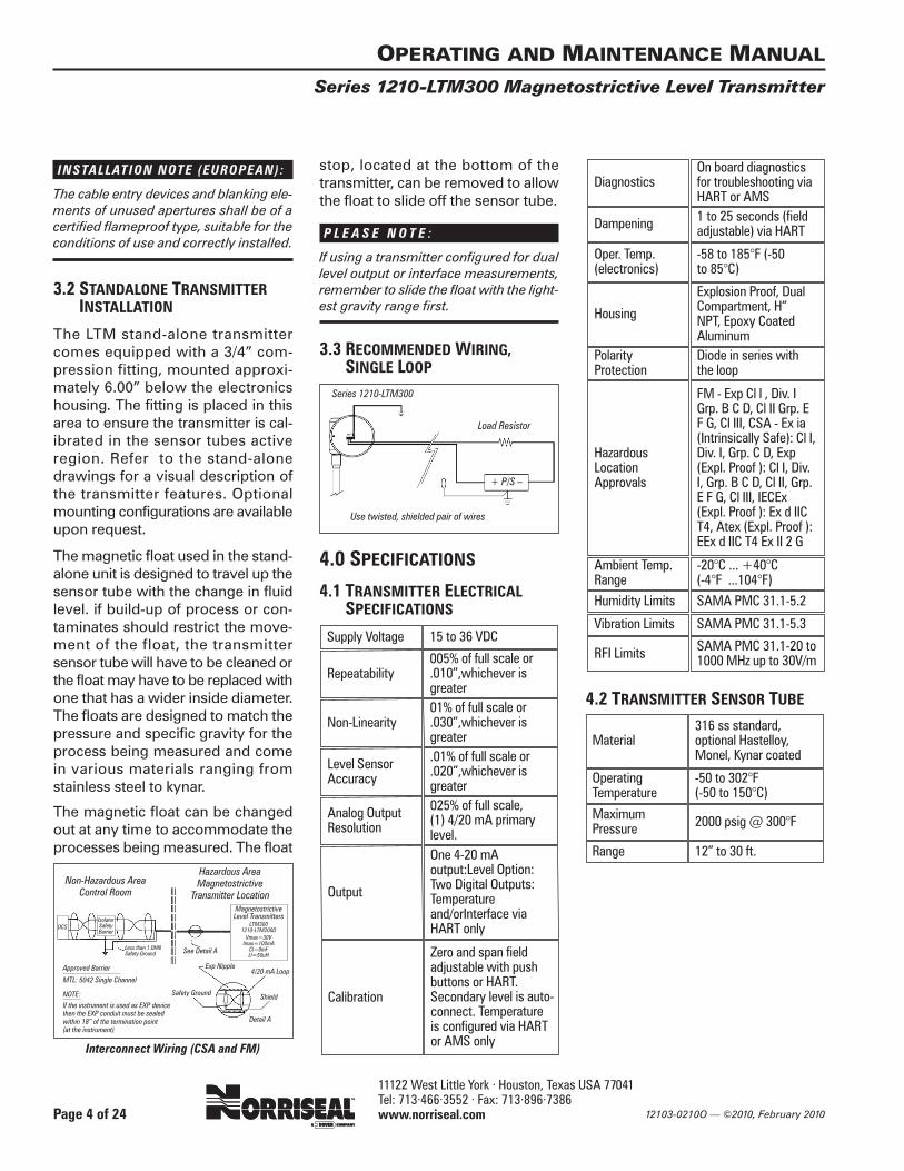
3.3 RECOMMENDED WIRING,SINGLE LOOP
4.0 SPECIFICATIONS4.1 TRANSMITTER ELECTRICAL
SPECIFICATIONS
4.2 TRANSMITTER SENSOR TUBE
Series 1210-LTM300
Load Resistor
Use twisted, shielded pair of wires
+ P/S –
Supply Voltage 15 to 36 VDC
Repeatability005% of full scale or.010”,whichever isgreater
Non-Linearity01% of full scale or.030”,whichever isgreater
Level SensorAccuracy
.01% of full scale or
.020”,whichever isgreater
Analog OutputResolution
025% of full scale, (1) 4/20 mA primarylevel.
Output
One 4-20 mAoutput:Level Option:Two Digital Outputs:Temperatureand/orInterface viaHART only
Calibration
Zero and span fieldadjustable with pushbuttons or HART.Secondary level is auto-connect. Temperature is configured via HARTor AMS only
DiagnosticsOn board diagnosticsfor troubleshooting viaHART or AMS
Dampening 1 to 25 seconds (fieldadjustable) via HART
Oper. Temp.(electronics)
-58 to 185°F (-50 to 85°C)
Housing
Explosion Proof, DualCompartment, H” NPT, Epoxy CoatedAluminum
PolarityProtection
Diode in series with the loop
HazardousLocationApprovals
FM - Exp Cl l , Div. IGrp. B C D, Cl II Grp. EF G, Cl III, CSA - Ex ia(Intrinsically Safe): Cl I,Div. I, Grp. C D, Exp(Expl. Proof ): Cl I, Div.I, Grp. B C D, Cl II, Grp.E F G, Cl III, IECEx(Expl. Proof ): Ex d IICT4, Atex (Expl. Proof ):EEx d IIC T4 Ex II 2 G
Ambient Temp.Range
-20°C ... +40°C (-4°F ...104°F)
Humidity Limits SAMA PMC 31.1-5.2
Vibration Limits SAMA PMC 31.1-5.3
RFI Limits SAMA PMC 31.1-20 to1000 MHz up to 30V/m
Material316 ss standard, optional Hastelloy,Monel, Kynar coated
OperatingTemperature
-50 to 302°F (-50 to 150°C)
MaximumPressure 2000 psig @ 300°F
Range 12” to 30 ft.
IsolatorSafetyBarrier
DCS
Less than 1 DHNSafety Ground
Non-Hazardous AreaControl Room
Magnetostrictive Level Transmitters
LTM3001210-LTM200DVmax=30VImax=100mA
Cl=0mFLl=50uH
Approved Barrier
MTL: 5042 Single Channel
Safety Ground
Exp Nipple4/20 mA Loop
Shield
Detail A
See Detail A
Hazardous AreaMagnetostrictive
Transmitter Location
Interconnect Wiring (CSA and FM)
NOTE:
If the instrument is used as EXP devicethen the EXP conduit must be sealedwithin 18” of the termination point(at the instrument)

11122 West Little York · Houston, Texas USA 77041 Tel: 713·466·3552 · Fax: 713·896·7386 www.norriseal.com
5.0 CALIBRATION
5.1 SINGLE LOOP CALIBRATIONThe Series 1210-LTM300 transmitteris available in three different config-urations: (1) single output version with onlyone variable that will output a 4-20mA signal for level; (2) a transmitterfitted with a second float to provide adigital output for interface level inaddition to the primary level output;(3) one 4-20 mA signal for primarylevel and two additional digital sig-nals with one for interface level andone for temperature output.
Configurations two and three haveindependent calibration as well asindependent outputs. These config-urations have the capability for cali-bration and measurement using a HART protocol communicationssystem. The HART specifications andconditions will be discussed in detailunder the HART COMMUNICATIONsection of the manual. The tempera-ture range is factory set from –50°Fto 300°F.
Pushbutton CalibrationStep 1- Move jumper to the write
enable position (see below)Step 2- Move your float or magnet
to the 4mA (0%) point on theprobe
Step 3- Press the ENTER button onthe display until “Trm Snsr”is displayed. Press the UParrow to display “Yes” andpress ENTER.
Step 4- The display will read “TrimZero”. Press ENTER.
Step 5- Move the float or magnet tothe 20mA (100%) point onthe probe.
Step 6- The display will read “TrimSpan” with a value above.Using the arrow buttons,input the correct distancefrom the zero point and pressEnter. Calibration is nowcompleted.
N O T E :
“Sel Lngth” value is factory set and shouldnot be changed. Doing so will cause alevel error indication.
FRONT PANEL
5.2 ON-BOARD MENUS
Level Measurement Display - in inches
Level Measurement Display - in centimeters
Level Measurement Display - in millimeters
Level Measurement Display - in feet
Level Measurement Display - in metersInterface Measurements Same decimal positions as Level Only if configuration set to Level+Interface or All
Temperature Measurements Same decimal positions for °F or °C Only if configuration set to Level+ Temper or All
Output Current
Percent of Range
Configuration Screens (Up / Down arrows choose options)Press Select to Enter.
Model Number
Select sensor lengthInput overall sensor length (Length = end to weld)
Level Unitsrotates starting at present units ( > ft<>m<>in<>cm<>mm>)
PVonly if Interface available - rotates starting at present PV ( >Level<>Interf> )
Alarmrotates starting at present alarm ( >High<>Low<>Hold Out>)
Range ChangeChoose Yes to Select Range - Display starts with NO
Lower Range Value
Upper Range Value
DampingFrom 1 to 25 - Will not allow 0 or negative numbers.
Sensor CalibrationChoose Yes to perform Sensor Trim (Display starts with No)
Zero TrimSet float to the 4 mA mark (0%) and then Select. Data not required.
Span TrimMove the float to the 20mA mark (100%) on the probe. Using the arrow buttons input the correct distance from the zero point and then Select.
Level OffsetEnter the desired value of the offset from the current zero and Press Enter. This will show a level offset at4mA. i.e. 4mA will be reported @ 5.0” if 5.0”was selected.
OPERATING AND MAINTENANCE MANUAL
Series 1210-LTM300 Magnetostrictive Level Transmitter
Page 5 of 24
Select/Enter
Note: Jumper in write potectpostion disablesthe push buttons
JumperScroll-Down
Scroll-Up
Write ProtectPosition
Write EnablePosition
123.45 inLevel
4567.8 cmLevel
90123. mmLevel
56.789 ftLevel
23.456 mLevel
123.4 SinIn
32 FTemper
12.34 mAOutput
56.78%% Range
Series 1210
xxx.x InSelLngth
InSel Unit
LevelSel PV
Hold OutSel Alrm
NoChgRnge?
12.34 inSel LRV
45.67 inSel URV
3. sSelDamp
NoTrnSnsr?
TrimZero
123.45 inTrimSpan
.00 inSet Off
12103-0210O — ©2010, February 2010
11122 West Little York · Houston, Texas USA 77041 Tel: 713·466·3552 · Fax: 713·896·7386 www.norriseal.com 12103-0210O — ©2010, February 2010
OPERATING AND MAINTENANCE MANUAL
Series 1210-LTM300 Magnetostrictive Level Transmitter
Page 6 of 24
Dac TrimChoose Yes to perform Dac Trim - Display starts with No
Dac Trim - 4mA PointPress raise or lower depending on value of loop current.
Dac Trim - 20mA PointPress raise or lower depending on value of loop current.
Loop Test - Input ValueThis will continuously vary the loop current as the user presses the Raise or Lower buttons. Exits when user depresses Select button.
Exit to Displays
6.0 TROUBLESHOOTING ANDMAINTENANCE
6.1 SELF DIAGNOSTICS AREVIA HART
6.2 CALIBRATION PROBLEMSIf the transmitter does not appear tocalibrate properly, or has an erraticoutput, check the deadband of thesensor tube and ensure that the floatis within the active region of theprobe. The active region of the sensortube is typically marked with 20mAand 4mA stickers when the unit is cal-ibrated before shipment.
If the output is still erratic, try dis-connecting the power momentarilyby unplugging and re-plugging-in theterminals. If a glitch was stored in RAM memory, this will generallyclear it.
6.3 MAGNETIC INTERFERENCEIt is possible for the Series 1210-LTM300 to be magnetically biased orhave residual magnetic energy storedalong the length of the waveguide.These magnetic anomalies can inter-fere with the signal-to-noise ratio andthe stability of the output signal itself.
If this appears to be the case, a gaugefloat magnet (or any magnet avail-able) may be run along the length ofthe sensor tube, past the head of thetransmitter, in an even motion andwithout stopping. This will usuallyclear all such magnetic anomalies.
C A U T I O N
Never move a magnet in a perpendicularmotion from along the sensor tube. Thiswill always leave a residual field in thewaveguide which will cause the trans-mitter to give an erratic output
6.4 TROUBLESHOOTING POWERSUPPLY PROBLEMS
The Series 1210-LTM300 is designedto operate with a supply voltage of15-36 vdc (at 20 mA) across its ter-minals without affecting the mA sig-nal. The most common loop supplyused is 24vdc. It is found sometimesthat additional resistance in the loopis necessary, either in the form of asecond load resistor or higher resist-ance safety barrier. This will appearto limit the maximum output of thetransmitter to below 20 mA. Thetransmitter will generally perform cor-rectly up to this point. To resolve thisproblem, the voltage of the loop sup-ply must be increased somewhat.Even a slight increase by one voltmay be sufficient and many supplieshave such an adjustment.
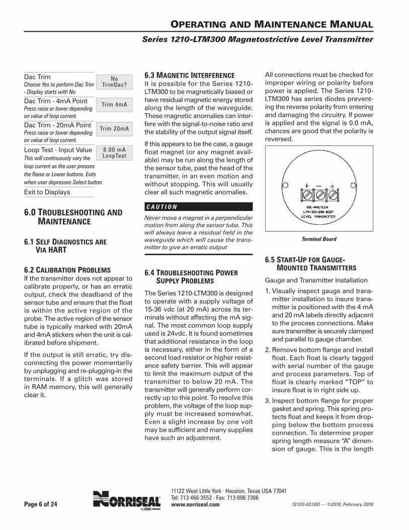
All connections must be checked forimproper wiring or polarity beforepower is applied. The Series 1210-LTM300 has series diodes prevent-ing the reverse polarity from enteringand damaging the circuitry. If poweris applied and the signal is 0.0 mA,chances are good that the polarity isreversed.
Terminal Board
6.5 START-UP FOR GAUGE-MOUNTED TRANSMITTERS
Gauge and Transmitter Installation
1. Visually inspect gauge and trans-mitter installation to insure trans-mitter is positioned with the 4 mAand 20 mA labels directly adjacentto the process connections. Makesure transmitter is securely clampedand parallel to gauge chamber.
2. Remove bottom flange and installfloat. Each float is clearly taggedwith serial number of the gaugeand process parameters. Top offloat is clearly marked “TOP” toinsure float is in right side up.
3. Inspect bottom flange for propergasket and spring. This spring pro-tects float and keeps it from drop-ping below the bottom processconnection. To determine properspring length measure “A” dimen-sion of gauge. This is the length
NoTrimDac?
Trim 4mA
Trim 20mA
8.00 mALoopTest

11122 West Little York · Houston, Texas USA 77041 Tel: 713·466·3552 · Fax: 713·896·7386 www.norriseal.com12103-0210O — ©2010, February 2010
OPERATING AND MAINTENANCE MANUAL
Series 1210-LTM300 Magnetostrictive Level Transmitter
Page 7 of 24
from the center of the bottom proc-ess connection to face of the bot-tom drain flange. Length of springshould be
(“A” DIMENSION) (-) Minus (Float Length +2 inches)
EXAMPLE: “A” Dimension is 14”, Floatlength is 12”, + 2” = 4” Spring Length 14 – 12 + 2 = 4” spring
4. Float is properly installed if the bot-tom 2-3 flippers on gauge indicatorhave flipped.
N O T E :
There is a top spring in the gauge to pro-tect the float and prevent it from passingthe top process connection. DO NOTREMOVE EITHER SPRING.
Transmitter Check-out andCalibrationNOTE: Series 1210-LTM300 transmitters are24VDC Loop powered (2- wire) and require aminimum of 15 Volts at 20 mA.
1. Using a HART compatible loop cal-ibrator, connect the “+” terminalon the LTM to positive lead of cal-ibrator and the “-” terminal on theLTM to negative lead of calibrator.
2. With float in the gauge at 4mA, theoutput of the LTM should be 4mA.Connect the HART Communicatorto the transmitter. Upon power up,the HART Communicator shouldread the LRV (lower range value)or 0 inches at 4mA.
3. With float in the gauge at 20mA,the output of the LTM should be20mA. HART should also displayURV (upper range value) or spanlength in inches at 20mA.
4. To insure complete functionality ofgauge and transmitter, fill thegauge chamber with liquid anddrain slowly to observe transmitterand gauge are tracking properly.
5. If no float is present, or magneticfield is lost, HART Communicatorwill display “LEVEL SIGNAL LOST”
6. For calibration using HART, or tochange range consult HART sec-tion of this manual.
N O T E :
In service over 400° F (204°C) gauges andtransmitters should be properly insulatedwith transmitter OUTSIDE the blanket.
Note: During the installation or calibration ofthe Series 1210-LTM300 level transmitter, thetechnician should be very careful not to movethe magnet perpendicular to the sensor tubeas this could leave magnetic indentation inthe sensor wire. The Series 1210-LTM300level transmitter has an inductor located insidethe bulkhead of the sensor tube. During oper-ation of the transmitter, this inductor emits amagnetic filed as current passes through thesensor wire. If an external magnet or the floatcomes in contact with the bulkhead, this cancause temporary magnetization of the coil,which means the coil is biased. In other words,the phase is reversed. If this occurs, the induc-tor should quickly recover. It may be manu-ally reversed or de-magnetized very simplyby “swiping” a magnet parallel to the bulk-head in an arching motion.
7.0 FIELD INSULATIONOF GAUGES WITHTRANSMITTERS
7.1 FIELD INSULATIONWe strongly recommend that expe-rienced Norriseal personnel performany insulation of the magnetic levelgauges with externally mountedtransmitters.
If cryogenic “Hard Skin” cold servicetype insulation is required, it MUSTbe done at the factory due to the cus-tom “TUBE in TUBE: design neces-sary for removal of the transmitter if
needed. If insulation is going to bedone in the field, then the followingguidelines MUST be followed:
1. Flexible type insulation jackets(NOT HARD SKIN) are required andmust be installed around the gaugechamber only. DO NOT cover theSeries 1210-LTM300 transmittertube, as this may burn up the sen-sor and possibly the electronics.
2. After the insulation jacket isinstalled, the Series 1210-LTM300sensor tube must be re-mountedat its factory-preset distance fromthe gauge chamber and must beparallel to the chamber as well.(Small cut-outs in the jacket arerequired to re-attach the transmit-ter properly).
3. Make sure the 4mA markings onthe sensor tube are re-aligned atthe centers of the process con-nections.
7.2 INSULATION WARNINGLABEL SUPPLIED
W A R N I N G (WHEN INSULATING GAUGES)
Norriseal level transmitters have a max-imum operating temperature of 300°F.When insulating a gauge and transmit-ter assembly in HOT service, keep thetransmitter OUTSIDE the insulating mate-rial. Special blankets for this type of insu-lation are available from Norriseal. Forfurther information consult Norriseal:713.466.3552

11122 West Little York · Houston, Texas USA 77041 Tel: 713·466·3552 · Fax: 713·896·7386 www.norriseal.com 12103-0210O — ©2010, February 2010
8.0 WARRANTY AND HARTPROTOCOL
8.1 WARRANTY
All Norriseal products are warrantedagainst defects in materials and work-manship of one year from date ofshipment. Floats are guaranteed fortwo years. Norriseal will repair orreplace at its discretion those products that fail to perform as specified, with the following exceptions:
1. Products repaired or modified bypersons that are not authorized byNorriseal.
2. Products subjected to misuse, neg-ligence or accidents.
3. Products that are connected,installed, or otherwise used in sucha way not in strict accordance withmanufacturer’s instructions.
This warranty is in lieu of any otherwarranty expressed or implied by anyparty other than Norriseal. Repairsand/or replacements shall be at thesole discretion of Norriseal based onthe terms and conditions of this war-ranty. Defective products shall bereturned to the factory prepaid by thebuyer after obtaining a ReturnAuthorization Number from Norriseal.All warranty repairs or replacementswill be preformed at the factory inHouston. Surface return freight willbe paid by Norriseal. Factory war-ranties do not include field service.Field service warranty repairs will beat the buyer’s expense. ConsultNorriseal for field service rates. Anymodifications to terms and conditionsof this warranty will not be bindingunless made in writing and signed byan authorized agent or official ofNorriseal.
N O T E :
All Norriseal gauges should be unpackedand thoroughly inspected upon receipt.Gauges are shipped FOB factory and arefully protected against damage or lossduring shipment. Any claims for partsdamaged during shipment should be sub-mitted within 15 days of receipt of goodsby customer.
8.2 HART PROTOCOL OPTIONINFORMATION
HART Communicator OverviewThis section presents the majorscreen selections available to the user.The HART Communicator screens areshown with a description of thescreen and user information below.
When the HART Communicator isconnected to the transmitter andturned on, the first screen that is seenby the user is the root menu screen.If the transmitter is configured asLevel Only or Level plus Temperature,the screen to the left shows the infor-mation displayed to the user.
However if the transmitter is config-ured as Level plus Interface or Levelplus Interface plus Temperature andInterface has been selected as thePrimary Variable (Interface controlsthe current output), the screen above
shows the information displayed tothe user.
When the user selects the top menuentry on the root menu, Device setup,by using the right arrow, the nextscreen displays five menu selections.Each of these menu selections willprovide detailed information about aspecific portion of the transmitter asdetailed in the following sections.
If the user selects the Process vari-ables menu from the Device setupscreen, the next screen displays thecurrent values for all of the dynamicvariables. If the transmitter is not con-figured for Interface, the entry “Interf”is not displayed. If the transmitter isnot configured for temperature, theentry “Temper” is not displayed.
If the user selects Diag/Service menufrom the Device setup screen, thenext screen displays further menuselections. These selections will bepresented in more detail in the sec-tion titled Diagnostics and Service onpage 9.
OPERATING AND MAINTENANCE MANUAL
Series 1210-LTM300 Magnetostrictive Level Transmitter
Page 8 of 24
11122 West Little York · Houston, Texas USA 77041 Tel: 713·466·3552 · Fax: 713·896·7386 www.norriseal.com12103-0210O — ©2010, February 2010
OPERATING AND MAINTENANCE MANUAL
Series 1210-LTM300 Magnetostrictive Level Transmitter
Page 9 of 24
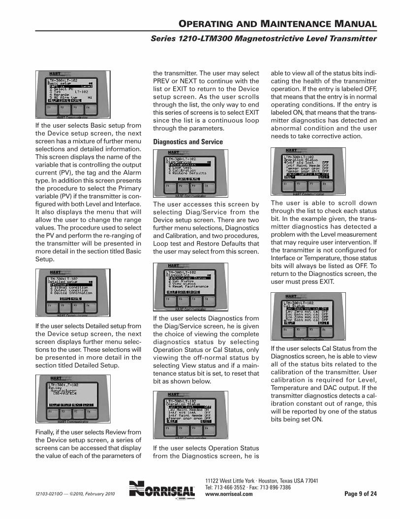
If the user selects Basic setup fromthe Device setup screen, the nextscreen has a mixture of further menuselections and detailed information.This screen displays the name of thevariable that is controlling the outputcurrent (PV), the tag and the Alarmtype. In addition this screen presentsthe procedure to select the Primaryvariable (PV) if the transmitter is con-figured with both Level and Interface.It also displays the menu that willallow the user to change the rangevalues. The procedure used to selectthe PV and perform the re-ranging ofthe transmitter will be presented inmore detail in the section titled BasicSetup.
If the user selects Detailed setup fromthe Device setup screen, the nextscreen displays further menu selec-tions to the user. These selections willbe presented in more detail in thesection titled Detailed Setup.
Finally, if the user selects Review fromthe Device setup screen, a series ofscreens can be accessed that displaythe value of each of the parameters of
the transmitter. The user may selectPREV or NEXT to continue with thelist or EXIT to return to the Devicesetup screen. As the user scrollsthrough the list, the only way to endthis series of screens is to select EXITsince the list is a continuous loopthrough the parameters.
Diagnostics and Service
The user accesses this screen byselecting Diag/Service from theDevice setup screen. There are twofurther menu selections, Diagnosticsand Calibration, and two procedures,Loop test and Restore Defaults thatthe user may select from this screen.
If the user selects Diagnostics fromthe Diag/Service screen, he is giventhe choice of viewing the completediagnostics status by selectingOperation Status or Cal Status, onlyviewing the off-normal status byselecting View status and if a main-tenance status bit is set, to reset thatbit as shown below.
If the user selects Operation Statusfrom the Diagnostics screen, he is
able to view all of the status bits indi-cating the health of the transmitteroperation. If the entry is labeled OFF,that means that the entry is in normaloperating conditions. If the entry islabeled ON, that means that the trans-mitter diagnostics has detected anabnormal condition and the userneeds to take corrective action.
The user is able to scroll downthrough the list to check each statusbit. In the example given, the trans-mitter diagnostics has detected aproblem with the Level measurementthat may require user intervention. Ifthe transmitter is not configured forInterface or Temperature, those statusbits will always be listed as OFF. Toreturn to the Diagnostics screen, theuser must press EXIT.
If the user selects Cal Status from theDiagnostics screen, he is able to viewall of the status bits related to the calibration of the transmitter. User calibration is required for Level,Temperature and DAC output. If thetransmitter diagnostics detects a cal-ibration constant out of range, thiswill be reported by one of the statusbits being set ON.
11122 West Little York · Houston, Texas USA 77041 Tel: 713·466·3552 · Fax: 713·896·7386 www.norriseal.com 12103-0210O — ©2010, February 2010
OPERATING AND MAINTENANCE MANUAL
Series 1210-LTM300 Magnetostrictive Level Transmitter
Page 10 of 24
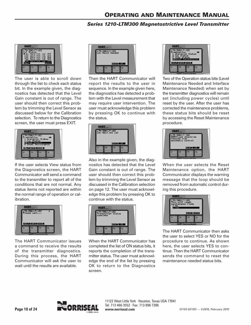
The user is able to scroll downthrough the list to check each statusbit. In the example given, the diag-nostics has detected that the LevelGain constant is out of range. Theuser should then correct this prob-lem by trimming the Level Sensor asdiscussed below for the Calibrationselection. To return to the Diagnosticsscreen, the user must press EXIT.
If the user selects View status fromthe Diagnostics screen, the HARTCommunicator will send a commandto the transmitter to report all of theconditions that are not normal. Anystatus items not reported are withinthe normal range of operation or cal-ibration.
The HART Communicator issues a command to receive the results of the transmitter diagnostics. During this process, the HARTCommunicator will ask the user towait until the results are available.
Then the HART Communicator willreport the results to the user insequence. In the example given here,the diagnostics has detected a prob-lem with the Level measurement thatmay require user intervention. Theuser must acknowledge this problemby pressing OK to continue with the status.
Also in the example given, the diag-nostics has detected that the LevelGain constant is out of range. Theuser should then correct this prob-lem by trimming the Level Sensor asdiscussed in the Calibration selectionon page 12. The user must acknowl-edge this problem by pressing OK tocontinue with the status.
When the HART Communicator hascompleted the list of ON status bits, itreports the completion of the trans-mitter status. The user must acknowl-edge the end of the list by pressingOK to return to the Diagnosticsscreen.
Two of the Operation status bits (LevelMaintenance Needed and InterfaceMaintenance Needed) when set bythe transmitter diagnostics will remainset (including power cycles) untilreset by the user. After the user hascorrected the maintenance problems,these status bits should be reset by accessing the Reset Maintenanceprocedure.
When the user selects the ResetMaintenance option, the HARTCommunicator displays the warningmessage that the loop should beremoved from automatic control dur-ing this procedure.
The HART Communicator then asksthe user to select YES or NO for theprocedure to continue. As shownhere, the user selects YES to con-tinue. Then the HART Communicatorsends the command to reset themaintenance needed status bits.
11122 West Little York · Houston, Texas USA 77041 Tel: 713·466·3552 · Fax: 713·896·7386 www.norriseal.com12103-0210O — ©2010, February 2010
OPERATING AND MAINTENANCE MANUAL
Series 1210-LTM300 Magnetostrictive Level Transmitter
Page 11 of 24
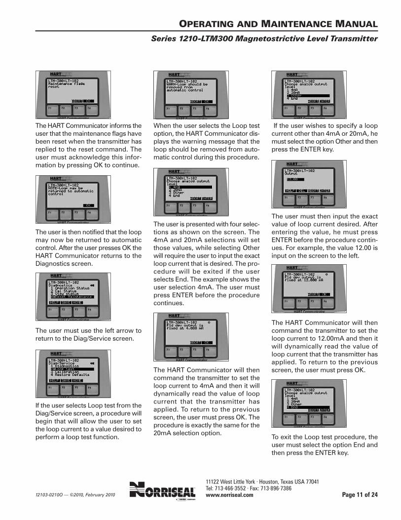
The HART Communicator informs theuser that the maintenance flags havebeen reset when the transmitter hasreplied to the reset command. Theuser must acknowledge this infor-mation by pressing OK to continue.
The user is then notified that the loopmay now be returned to automaticcontrol. After the user presses OK theHART Communicator returns to theDiagnostics screen.
The user must use the left arrow toreturn to the Diag/Service screen.
If the user selects Loop test from theDiag/Service screen, a procedure willbegin that will allow the user to setthe loop current to a value desired toperform a loop test function.
When the user selects the Loop testoption, the HART Communicator dis-plays the warning message that theloop should be removed from auto-matic control during this procedure.
The user is presented with four selec-tions as shown on the screen. The4mA and 20mA selections will setthose values, while selecting Otherwill require the user to input the exactloop current that is desired. The pro-cedure will be exited if the userselects End. The example shows theuser selection 4mA. The user mustpress ENTER before the procedurecontinues.
The HART Communicator will thencommand the transmitter to set theloop current to 4mA and then it willdynamically read the value of loopcurrent that the transmitter hasapplied. To return to the previousscreen, the user must press OK. Theprocedure is exactly the same for the20mA selection option.
If the user wishes to specify a loopcurrent other than 4mA or 20mA, hemust select the option Other and thenpress the ENTER key.
The user must then input the exactvalue of loop current desired. Afterentering the value, he must pressENTER before the procedure contin-ues. For example, the value 12.00 isinput on the screen to the left.
The HART Communicator will thencommand the transmitter to set theloop current to 12.00mA and then itwill dynamically read the value ofloop current that the transmitter hasapplied. To return to the previousscreen, the user must press OK.
To exit the Loop test procedure, theuser must select the option End andthen press the ENTER key.

11122 West Little York · Houston, Texas USA 77041 Tel: 713·466·3552 · Fax: 713·896·7386 www.norriseal.com 12103-0210O — ©2010, February 2010
The HART Communicator then issuesthe command to the transmitter toreturn to the measurement mode asit was before entering Loop test.
The user is then notified that the loopmay now be returned to automaticcontrol. After the user presses OK theHART Communicator returns to theDiag/Service screen.
If the user selects Calibration fromthe Diag/Service screen, a number ofmenu selections are available. Theuser must now select the type of cal-ibration he desires to perform. TheScaled D/A trim will adjust the trans-mitter so that its current output at the4.00mA and 20.00mA output valueswill agree with the plant standard cur-rent meter.
If it is desired to trim the digital levelvalue, he may select a single pointzero trim or a full level trim thatrequires the input of both the zerolevel value and some other level valuepreferably near the end of the levelmeasurement tube. If the transmitteris configured with temperature meas-urement, he may select a single tem-perature trim point at 0 deg C or a fulltemperature trim that requires trim-ming both at 0 deg C and some othertemperature point near the upper endof the operating temperature range.
Output Current (DAC) Calibration
If the user selects Scaled D/A trimfrom the Calibration screen, thisscreen will appear reminding the userthat the loop should be removed fromautomatic control before proceeding.When this has been done, the usermust press OK to continue.
The next screen informs the user thatthe rest of the procedure will use thevalues 4.000 to 20.000 in the instruc-tions if you are using a milliampmeter. If you are using a voltmeter
across a resistor, select change andprovide the values that you will beusing at the current end points. Theuser must press ENTER when ready.
The HART Communicator nowinstructs the user to connect the ref-erence meter that is to be used forthe current calibration. The user mustpress OK when ready.
The HART Communicator will nowcommand the transmitter to set thecurrent output to 4.000mA. The usermust press OK when ready to havethe current output set to 4.000mA.
When the device has set the currentoutput to 4.000mA, the user is toenter the reference meter reading.For example, if the meter actuallyreads 4.234mA, that value is inputwith the keypad. The user must pressENTER when the current value hasbeen entered.
OPERATING AND MAINTENANCE MANUAL
Series 1210-LTM300 Magnetostrictive Level Transmitter
Page 12 of 24

11122 West Little York · Houston, Texas USA 77041 Tel: 713·466·3552 · Fax: 713·896·7386 www.norriseal.com12103-0210O — ©2010, February 2010
The transmitter, based on the datafrom the reference meter, will calcu-late a new value for the DAC zero cal-ibration constant and change theoutput current based on the new con-stant. If the current read by the refer-ence meter is now 4.000mA, the usermust press ENTER. If not exact, theuser must select No and press ENTERto try again.
The HART Communicator will nowcommand the transmitter to set thecurrent output to 20.000mA. The usermust press OK when ready to havethe current output set to 20.000mA.
When the device has set the currentoutput to 20.000mA, the user is toenter the reference meter reading.For example, if the meter actuallyreads 19.975mA, that value is inputwith the keypad. The user must pressENTER when ready to proceed.
The transmitter, based on the datafrom the reference meter, will calcu-late a new value for the DAC gain cal-ibration constant and change theoutput current based on the new con-stant. If the current read by the refer-ence meter is now 20.000mA, theuser must press ENTER. If not exact,the user must select No and pressENTER to try again.
The Current Output calibration is nowcomplete. The HART Communicatorwill now return the current output ofthe transmitter to normal operation.
The user is then notified that the loopmay now be returned to automaticcontrol. After the user presses OK theHART Communicator returns to theCalibration screen.
The HART Communicator is now at thestarting screen for the Scaled D/A trim.
Zero Level Trim
Starting at the Calibration screen,select the Zero Level Trim procedure.This procedure trims the Level digitalvalue measurement at the positionthat the user desires to be the zeroreference position.
If the user selects Zero Level Trimfrom the Calibration screen, thisscreen will appear reminding the userthat the loop should be removed fromautomatic control before proceeding.When this has been done, the usermust press OK to continue.
This screen warns the user that pro-ceeding will affect the sensor cali-bration. The user must press OKwhen ready to proceed.
The HART Communicator nowrequests that the level float be set to
OPERATING AND MAINTENANCE MANUAL
Series 1210-LTM300 Magnetostrictive Level Transmitter
Page 13 of 24

11122 West Little York · Houston, Texas USA 77041 Tel: 713·466·3552 · Fax: 713·896·7386 www.norriseal.com 12103-0210O — ©2010, February 2010
the desired zero level trim point.When the float is at this position, thetransmitter will always report zero inthe user chosen units. The user mustpress OK when the float is at thatposition.
The transmitter will take several sec-onds to insure that the level signalhas stabilized. Once the measure-ment is stable, the procedure will con-tinue without user intervention. TheHART communicator will then sendthe command to the transmitter tocalculate the new Level zero calibra-tion constant.
When the transmitter has completedits calculation it will reply to the HARTCommunicator. Then the HARTCommunicator will inform the userthat the zero level point has beentrimmed.
The user is then notified that the loopmay now be returned to automaticcontrol. After the user presses OK theHART Communicator returns to theCalibration screen.
The HART Communicator is now at thestarting screen for the Zero Level Trim.
Full Level Trim
Starting at the Calibration screen,select the Full Level Trim procedure.This procedure trims the Level digitalvalue measurement at two points.The first point is the position that theuser desires to be the zero referenceposition. The second point is a Levelposition near the end of the sensor.
If the user selects Full Level Trim fromthe Calibration screen, this screen willappear reminding the user that theloop should be removed from auto-matic control before proceeding.When this has been done, the usermust press OK to continue.
This screen warns the user that pro-ceeding will affect the sensor cali-
bration. The user must press OKwhen ready to proceed.
The HART Communicator nowrequests that the level float be set tothe desired zero level trim point.When the float is at this position, thetransmitter will always report zero in the user chosen units. The usermust press OK when the float is at that position.
The transmitter will take several sec-onds to insure that the level signalhas stabilized. Once the measure-ment is stable, the procedure will con-tinue without user intervention. TheHART communicator will then sendthe command to the transmitter tocalculate the new Level zero calibra-tion constant.
When the transmitter has completedits calculation it will reply to the HARTCommunicator. Then the HARTCommunicator will inform the userthat the zero level point has beentrimmed.
OPERATING AND MAINTENANCE MANUAL
Series 1210-LTM300 Magnetostrictive Level Transmitter
Page 14 of 24

11122 West Little York · Houston, Texas USA 77041 Tel: 713·466·3552 · Fax: 713·896·7386 www.norriseal.com12103-0210O — ©2010, February 2010
The HART Communicator nowrequests that the level float be set tothe desired level upper trim point.The second trim point can be anyother level point but it is recom-mended that this point be as far awayfrom the zero point as possible. Whenthe float is at this position, the trans-mitter will always report the digitalvalue entered in the user chosenunits. The user must press OK whenthe float is at that position.
The transmitter will take several sec-onds to insure that the level signalhas stabilized. Once the measure-ment is stable, the procedure will con-tinue without user intervention. TheHART communicator will then sendthe command to the transmitter tocalculate the new Level gain calibra-tion constant.
The HART Communicator will nowrequest the user to enter the value atthe high trim point. The HARTCommunicator will display the lastupper trim point, for example 60 in,and the user will enter the new uppertrim point, for example 59.0 in. The
HART Communicator will now sendthis value to the transmitter.
When the transmitter has completedits calculation of the new Level gaincalibration constant, it will reply tothe HART Communicator. Then theHART Communicator will inform theuser that the level upper trim pointhas been trimmed.
The user is then notified that the loopmay now be returned to automaticcontrol. After the user presses OK theHART Communicator returns to theCalibration screen.
The HART Communicator is now atthe starting screen for the Full LevelTrim.
Zero Temperature Trim
Starting at the Calibration screen,select the Zero Temper Trim proce-dure. This procedure trims theTemperature digital value measure-ment at the reference value of theRTD (1000 ohms).
If the user selects Zero Temper Trimfrom the Calibration screen, thisscreen will appear reminding the userthat the loop should be removed fromautomatic control before proceeding.When this has been done, the usermust press OK to continue.
This screen warns the user that pro-ceeding will affect the sensor cali-bration. The user must press OKwhen ready to proceed.
The HART Communicator nowrequests that the temperature be setto the desired 0 deg C temperature
OPERATING AND MAINTENANCE MANUAL
Series 1210-LTM300 Magnetostrictive Level Transmitter
Page 15 of 24
11122 West Little York · Houston, Texas USA 77041 Tel: 713·466·3552 · Fax: 713·896·7386 www.norriseal.com 12103-0210O — ©2010, February 2010
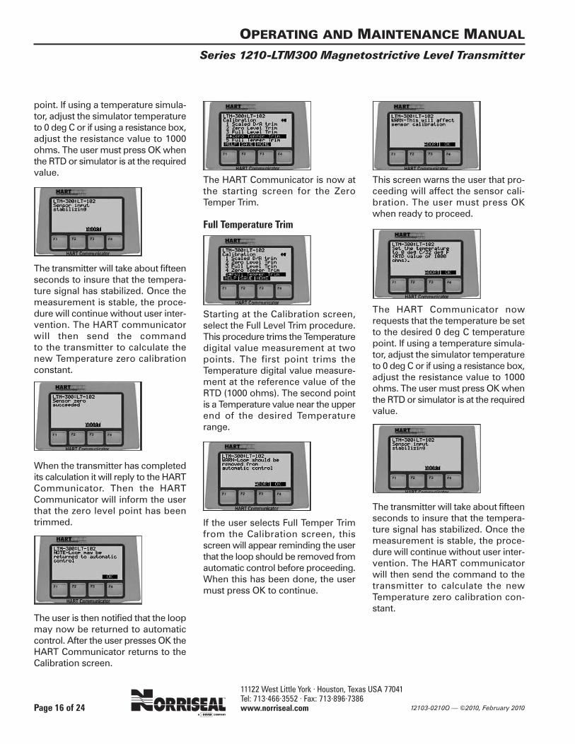
point. If using a temperature simula-tor, adjust the simulator temperatureto 0 deg C or if using a resistance box,adjust the resistance value to 1000ohms. The user must press OK whenthe RTD or simulator is at the requiredvalue.
The transmitter will take about fifteenseconds to insure that the tempera-ture signal has stabilized. Once themeasurement is stable, the proce-dure will continue without user inter-vention. The HART communicatorwill then send the command to the transmitter to calculate the new Temperature zero calibrationconstant.
When the transmitter has completedits calculation it will reply to the HARTCommunicator. Then the HARTCommunicator will inform the userthat the zero level point has beentrimmed.
The user is then notified that the loopmay now be returned to automaticcontrol. After the user presses OK theHART Communicator returns to theCalibration screen.
The HART Communicator is now atthe starting screen for the ZeroTemper Trim.
Full Temperature Trim
Starting at the Calibration screen,select the Full Level Trim procedure.This procedure trims the Temperaturedigital value measurement at twopoints. The first point trims theTemperature digital value measure-ment at the reference value of theRTD (1000 ohms). The second pointis a Temperature value near the upperend of the desired Temperaturerange.
If the user selects Full Temper Trimfrom the Calibration screen, thisscreen will appear reminding the userthat the loop should be removed fromautomatic control before proceeding.When this has been done, the usermust press OK to continue.
This screen warns the user that pro-ceeding will affect the sensor cali-bration. The user must press OKwhen ready to proceed.
The HART Communicator nowrequests that the temperature be setto the desired 0 deg C temperaturepoint. If using a temperature simula-tor, adjust the simulator temperatureto 0 deg C or if using a resistance box,adjust the resistance value to 1000ohms. The user must press OK whenthe RTD or simulator is at the requiredvalue.
The transmitter will take about fifteenseconds to insure that the tempera-ture signal has stabilized. Once themeasurement is stable, the proce-dure will continue without user inter-vention. The HART communicatorwill then send the command to thetransmitter to calculate the newTemperature zero calibration con-stant.
OPERATING AND MAINTENANCE MANUAL
Series 1210-LTM300 Magnetostrictive Level Transmitter
Page 16 of 24

11122 West Little York · Houston, Texas USA 77041 Tel: 713·466·3552 · Fax: 713·896·7386 www.norriseal.com12103-0210O — ©2010, February 2010
When the transmitter has completedits calculation it will reply to the HARTCommunicator. Then the HARTCommunicator will inform the userthat the zero level point has beentrimmed.
The HART Communicator nowrequests that the temperature be setto the desired temperature upper trimpoint. If using a temperature simula-tor, adjust the simulator temperatureto the desired temperature or if usinga resistance box, adjust it to the cor-responding resistance value for thistemperature. The user must press OKwhen the RTD or simulator is at therequired value.
The transmitter will take about fifteenseconds to insure that the tempera-ture signal has stabilized. Once the measurement is stable, the pro-cedure will continue without userintervention.
The HART Communicator will nowrequest the user to enter the value atthe high trim point. The HARTCommunicator will display the lastupper trim point, for example 100 degC, and the user will enter the newupper trim point, for example 75 degC. The HART Communicator will nowsend this value to the transmitter.
The HART communicator will thensend the command to the transmit-ter to calculate the new Temperaturegain calibration constant. When thetransmitter has completed its calcu-lation it will reply to the HARTCommunicator. Then the HARTCommunicator will inform the userthat the sensor upper temperaturetrim point has been trimmed.
The user is then notified that the loopmay now be returned to automaticcontrol. After the user presses OK theHART Communicator returns to theCalibration screen.
The HART Communicator is now at thestarting screen for the Full Temper Trim.
Basic Setup Procedures
If a transmitter has been configured tomeasure both Level and Interface, theBasic setup screen will display theprocedure Select PV on the secondline. If a transmitter has not been con-figured to measure Interface, the sec-ond line will not appear.
If the user chooses Select PV fromthe Basic setup screen, this screenwill appear reminding the user thatthe loop should be removed fromautomatic control before proceeding.When this has been done, the usermust press OK to continue.
The user must now select which vari-able, Level or Interface, will be thePrimary Variable. (In other words,
OPERATING AND MAINTENANCE MANUAL
Series 1210-LTM300 Magnetostrictive Level Transmitter
Page 17 of 24

11122 West Little York · Houston, Texas USA 77041 Tel: 713·466·3552 · Fax: 713·896·7386 www.norriseal.com 12103-0210O — ©2010, February 2010
which variable will control the loopcurrent output from the transmitter.)In this example, the user selects Interfand must press ENTER when ready toproceed.
The HART Communicator sends thecommand selecting the variable tobe the Primary variable and the trans-mitter will respond when the changehas been made. The user is then noti-fied that the loop may now bereturned to automatic control. Afterthe user presses OK the HARTCommunicator returns to the Basicsetup screen.
Reranging the Transmitter Setting the Measurement Value for4mA and 20mA by Keypad
If you desire to change the Levelvalue at which the Current output is4mA and 20mA when the Level is theselected Primary Variable, or changethe Interface value at which theCurrent output is 4mA and 20mAwhen the Interface is the selectedPrimary Variable, the following pro-cedure is used.
If the user selects Rerange from theBasic setup screen, a new menuscreen will appear with the twochoices Keypad rerange and ApplyValues. The user will select Keypadrerange to change the 4mA and20mA measurement values.
If the user selects Keypad rerangefrom the Rerange screen the usermay change the LRV (4mA measure-ment value), the URV (20mA meas-urement value) or the Unit ofmeasure. If Unit is selected by press-ing the right arrow, a selection of unitsis available to the user.
This screen will show the user that inis the current user units and the usermay select from ft, m, in or cm. Whenthe user has selected the units thathe desires by the up or down arrows,he must press ENTER to continue.
After the user has selected new units,he is warned that until he sends thenew units code to the transmitter, allvariables that use this units code willremain in the previous units code.The HART Communicator does notautomatically send the new unitscode to the transmitter. The user mustacknowledge this message by press-ing OK to continue.
The user is returned to the Keypadrerange screen. Note that the labelabove F2 is now SEND. The usermust press the SEND key for theHART Communicator to send thenew units code to the transmitter.
The HART Communicator will displaythis screen reminding the user thatthe loop should be removed fromautomatic control before proceeding.When this has been done, the usermust press OK to continue.
OPERATING AND MAINTENANCE MANUAL
Series 1210-LTM300 Magnetostrictive Level Transmitter
Page 18 of 24
11122 West Little York · Houston, Texas USA 77041 Tel: 713·466·3552 · Fax: 713·896·7386 www.norriseal.com12103-0210O — ©2010, February 2010
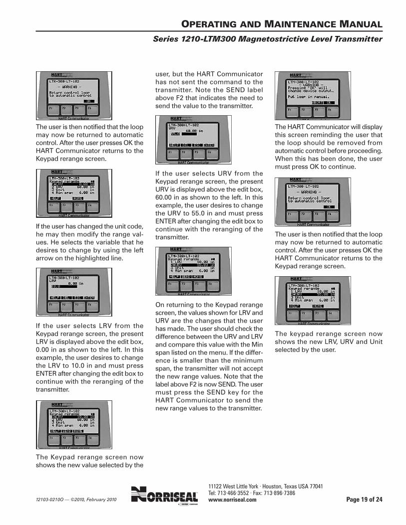
The user is then notified that the loopmay now be returned to automaticcontrol. After the user presses OK theHART Communicator returns to theKeypad rerange screen.
If the user has changed the unit code,he may then modify the range val-ues. He selects the variable that hedesires to change by using the leftarrow on the highlighted line.
If the user selects LRV from theKeypad rerange screen, the presentLRV is displayed above the edit box,0.00 in as shown to the left. In thisexample, the user desires to changethe LRV to 10.0 in and must pressENTER after changing the edit box tocontinue with the reranging of thetransmitter.
The Keypad rerange screen nowshows the new value selected by the
user, but the HART Communicatorhas not sent the command to thetransmitter. Note the SEND labelabove F2 that indicates the need tosend the value to the transmitter.
If the user selects URV from theKeypad rerange screen, the presentURV is displayed above the edit box,60.00 in as shown to the left. In thisexample, the user desires to changethe URV to 55.0 in and must pressENTER after changing the edit box tocontinue with the reranging of thetransmitter.
On returning to the Keypad rerangescreen, the values shown for LRV andURV are the changes that the userhas made. The user should check thedifference between the URV and LRVand compare this value with the Minspan listed on the menu. If the differ-ence is smaller than the minimumspan, the transmitter will not acceptthe new range values. Note that thelabel above F2 is now SEND. The usermust press the SEND key for theHART Communicator to send thenew range values to the transmitter.
The HART Communicator will displaythis screen reminding the user thatthe loop should be removed fromautomatic control before proceeding.When this has been done, the usermust press OK to continue.
The user is then notified that the loopmay now be returned to automaticcontrol. After the user presses OK theHART Communicator returns to theKeypad rerange screen.
The keypad rerange screen nowshows the new LRV, URV and Unitselected by the user.
OPERATING AND MAINTENANCE MANUAL
Series 1210-LTM300 Magnetostrictive Level Transmitter
Page 19 of 24
11122 West Little York · Houston, Texas USA 77041 Tel: 713·466·3552 · Fax: 713·896·7386 www.norriseal.com 12103-0210O — ©2010, February 2010
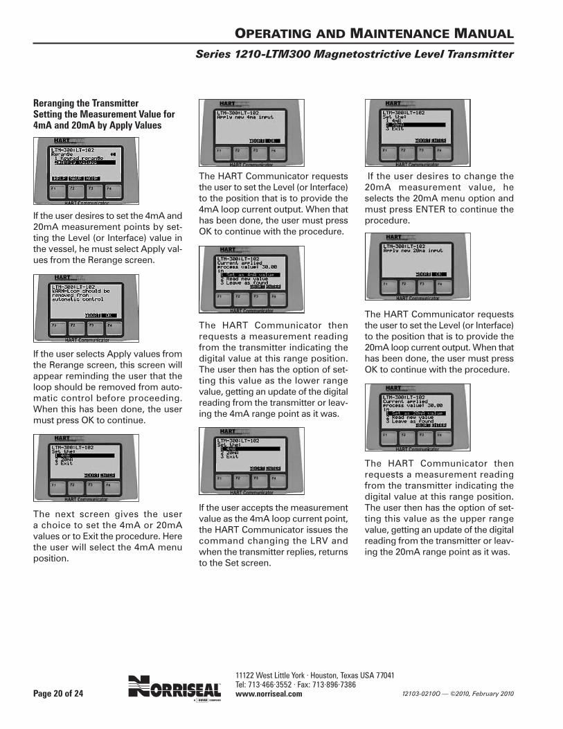
Reranging the TransmitterSetting the Measurement Value for4mA and 20mA by Apply Values
If the user desires to set the 4mA and20mA measurement points by set-ting the Level (or Interface) value inthe vessel, he must select Apply val-ues from the Rerange screen.
If the user selects Apply values fromthe Rerange screen, this screen willappear reminding the user that theloop should be removed from auto-matic control before proceeding.When this has been done, the usermust press OK to continue.
The next screen gives the user a choice to set the 4mA or 20mA values or to Exit the procedure. Herethe user will select the 4mA menuposition.
The HART Communicator requeststhe user to set the Level (or Interface)to the position that is to provide the4mA loop current output. When thathas been done, the user must pressOK to continue with the procedure.
The HART Communicator thenrequests a measurement readingfrom the transmitter indicating thedigital value at this range position.The user then has the option of set-ting this value as the lower rangevalue, getting an update of the digitalreading from the transmitter or leav-ing the 4mA range point as it was.
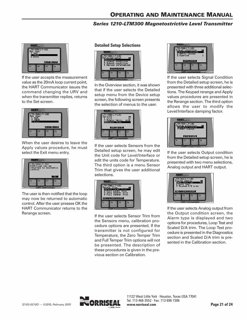
If the user accepts the measurementvalue as the 4mA loop current point,the HART Communicator issues thecommand changing the LRV andwhen the transmitter replies, returnsto the Set screen.
If the user desires to change the20mA measurement value, he selects the 20mA menu option andmust press ENTER to continue theprocedure.
The HART Communicator requeststhe user to set the Level (or Interface)to the position that is to provide the20mA loop current output. When thathas been done, the user must pressOK to continue with the procedure.
The HART Communicator thenrequests a measurement readingfrom the transmitter indicating thedigital value at this range position.The user then has the option of set-ting this value as the upper rangevalue, getting an update of the digitalreading from the transmitter or leav-ing the 20mA range point as it was.
OPERATING AND MAINTENANCE MANUAL
Series 1210-LTM300 Magnetostrictive Level Transmitter
Page 20 of 24
11122 West Little York · Houston, Texas USA 77041 Tel: 713·466·3552 · Fax: 713·896·7386 www.norriseal.com12103-0210O — ©2010, February 2010
If the user accepts the measurementvalue as the 20mA loop current point,the HART Communicator issues thecommand changing the URV andwhen the transmitter replies, returnsto the Set screen.
When the user desires to leave theApply values procedure, he mustselect the Exit menu entry.
The user is then notified that the loopmay now be returned to automaticcontrol. After the user presses OK theHART Communicator returns to theRerange screen.
Detailed Setup Selections
In the Overview section, it was shownthat if the user selects the Detailedsetup menu from the Device setupscreen, the following screen presentsthe selection of menus to the user.
If the user selects Sensors from theDetailed setup screen, he may editthe Unit code for Level/Interface oredit the units code for Temperature.The third option is a menu SensorTrim that gives the user additionalselections.
If the user selects Sensor Trim fromthe Sensors menu, calibration pro-cedure options are presented. If thetransmitter is not configured forTemperature, the Zero Temper Trimand Full Temper Trim options will notbe presented. The description ofthese procedures is given in the pre-vious section on Calibration.
If the user selects Signal Conditionfrom the Detailed setup screen, he ispresented with three additional selec-tions. The Keypad rerange and Applyvalues procedures are presented inthe Rerange section. The third optionallows the user to modify theLevel/Interface damping factor.
If the user selects Output conditionfrom the Detailed setup screen, he ispresented with two menu selections,Analog output and HART output.
If the user selects Analog output fromthe Output condition screen, theAlarm type is displayed and twooptions for procedures, Loop Test andScaled D/A trim. The Loop Test pro-cedure is presented in the Diagnosticssection and Scaled D/A trim is pre-sented in the Calibration section.
OPERATING AND MAINTENANCE MANUAL
Series 1210-LTM300 Magnetostrictive Level Transmitter
Page 21 of 24
11122 West Little York · Houston, Texas USA 77041 Tel: 713·466·3552 · Fax: 713·896·7386 www.norriseal.com 12103-0210O — ©2010, February 2010
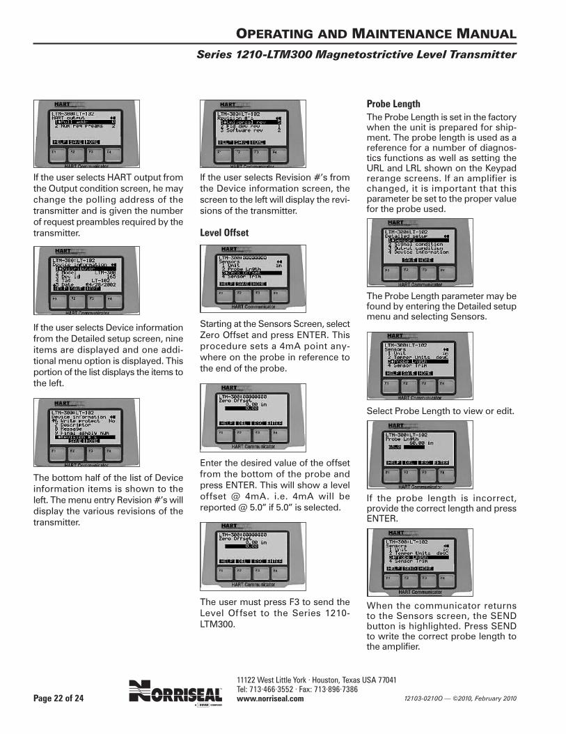
If the user selects HART output fromthe Output condition screen, he maychange the polling address of thetransmitter and is given the numberof request preambles required by thetransmitter.
If the user selects Device informationfrom the Detailed setup screen, nineitems are displayed and one addi-tional menu option is displayed. Thisportion of the list displays the items tothe left.
The bottom half of the list of Deviceinformation items is shown to the left. The menu entry Revision #’s willdisplay the various revisions of thetransmitter.
If the user selects Revision #’s fromthe Device information screen, thescreen to the left will display the revi-sions of the transmitter.
Level Offset
Starting at the Sensors Screen, selectZero Offset and press ENTER. Thisprocedure sets a 4mA point any-where on the probe in reference tothe end of the probe.
Enter the desired value of the offsetfrom the bottom of the probe andpress ENTER. This will show a leveloffset @ 4mA. i.e. 4mA will bereported @ 5.0” if 5.0” is selected.
The user must press F3 to send theLevel Of fset to the Series 1210-LTM300.
Probe LengthThe Probe Length is set in the factorywhen the unit is prepared for ship-ment. The probe length is used as areference for a number of diagnos-tics functions as well as setting theURL and LRL shown on the Keypadrerange screens. If an amplifier ischanged, it is important that thisparameter be set to the proper valuefor the probe used.
The Probe Length parameter may befound by entering the Detailed setupmenu and selecting Sensors.
Select Probe Length to view or edit.
If the probe length is incorrect, provide the correct length and pressENTER.
When the communicator returns to the Sensors screen, the SEND button is highlighted. Press SEND to write the correct probe length tothe amplifier.
OPERATING AND MAINTENANCE MANUAL
Series 1210-LTM300 Magnetostrictive Level Transmitter
Page 22 of 24

11122 West Little York · Houston, Texas USA 77041 Tel: 713·466·3552 · Fax: 713·896·7386 www.norriseal.com12103-0210O — ©2010, February 2010
The Series 1210-LTM300 complies with the following standards:
IEC 60079-0, IEC60079-1
EN 50014, EN 50018
LTM300IOM Rev. 6.1
OPERATING AND MAINTENANCE MANUAL
Series 1210-LTM300 Magnetostrictive Level Transmitter
Page 23 of 24
11122 West Little York · Houston, Texas USA 77041 Tel: 713·466·3552 · Fax: 713·896·7386 www.norriseal.com 12103-0210O — ©2010, February 2010
OPERATING AND MAINTENANCE MANUAL
Series 1210-LTM300 Magnetostrictive Level Transmitter
Page 24 of 24
H E A D Q U A R T E R S , M A N U F A C T U R I N G P L A N T A N D S A L E S
11122 West Little York • Houston, Texas USA 77441Tel: 713·466·3552 • Fax: 713·896·7386
www.norriseal.com
Due to the continuous improvement at Norriseal,specifications and/or prices are subject to change
without notice or obligation.
©2010 Norriseal. All rights reserved.™Norriseal is a mark of Dover Corporation.