contents · 12 the structure of osi management information, anne-grethe kåråsen 90 13 network...
TRANSCRIPT


Contents
Guest editorial, Tor M Jansen 3
Overview, Arve Meisingset 4
1 CHILL – the international standard language fortelecommunications programming,Kristen Rekdal 5
2 Human-machine interface design for large systems,Arve Meisingset 11
3 Reference models, Sigrid Steinholt Bygdås and Vigdis Houmb 21
4 Formal languages, Astrid Nyeng 29
5 Introduction to database systems,Ole Jørgen Anfindsen 37
6 Software development methods and life cyclemodels, Sigrid Steinholt Bygdås and Magne Jørgensen 44
7 A data flow approach to interoperability,Arve Meisingset 52
8 The draft CCITT formalism for specifying human-machine interfaces, Arve Meisingset 60
9 The CCITT specification and description language –SDL, Astrid Nyeng 67
10 SDL-92 as an object oriented notation,Birger Møller-Pedersen 71
11 An introduction to TMN, Ståle Wolland 84
12 The structure of OSI management information,Anne-Grethe Kåråsen 90
13 Network management systems in NorwegianTelecom, Knut Johannessen 97
14 Centralised network management,Einar Ludvigsen 100
15 The DATRAN and DIMAN tools, Cato Nordlund 104
16 DIBAS – a management system for distributeddatabases, Eirik Arne Dahle and Helge Berg 110
17 Data design for access control administration,Arve Meisingset 121
Telektronikk
Volume 89 No. 2/3 - 1993ISSN 0085-7130
Editor:Ola EspvikTel. + 47 63 80 98 83
Feature editor:Arve MeisingsetTel. + 47 63 80 91 15
Editorial assistant:Gunhild LukeTel. + 47 63 80 91 52
Editorial office:TelektronikkNorwegian Telecom ResearchP.O. Box 83N-2007 Kjeller, Norway
Editorial board:Ole P Håkonsen, Senior Executive Vice PresidentKarl Klingsheim, Vice President, ResearchBjørn Løken, Vice President, Market and Product Strategies
Graphic design:Design Consult AS
Layout and illustrations:Gunhild Luke, Britt Kjus, Åse AardalNorwegian Telecom Research
RESEARCH
1

This issue of Telektronikk isconcerned with software fortelecommunications applications.Since the early sixties, it has beenclear to all involved in both thecomputer industry and the telecom-munications industry that computertechnology will inevitably becomethe basis of telecommunicationsequipment and services. What wasnot foreseen was the enormouschallenge of making this happen.
There are three main areas wherecomputer technology is nowapplied. The first is in the networkelements. The second area isoperation and maintenance of thenetwork and the services. Thirdly,customer support and customerservice is an area of great competi-tive concern.
In the very early days of telecom-munications, the limited number ofsubscribers and the limited number and simplicity of the ser-vices, i.e. telephone and telegraph, made it possible for anoperator to handle most problems that emerged, such as networkmanagement and special services to the customer. The size ofthe operation was such that it could easily be handled manually.Today, in a world with many and complex and evolving ser-vices, hundreds of millions of customers, booming traffic, andfiercely increasing competition in new and old markets, thesituation has changed dramatically. Computer technology,especially software, at present seems to be the only way to copewith the problems and challenges.
The network itself is a good example of the role of computersand software. Previously, all functions relevant to communi-cations resided inside the network elements, be it for maint-enance or service provision. The network elements, i.e. switchesand transmission equipment, limited by their design, controlledwhat could be offered to the customer. The cost and lifetime oftelecom systems were such that introduction of new servicesand improvement of old services by necessity had to be slow.The first “improvements” came with digital switching anddigital transmission in the sixties and seventies. When computerprogrammers tried to design communications systems, andtelecom engineers tried to program computers, the results wereinvariably bad. After these first experiences, one realised thatthe problem area had to be approached much more systemati-cally and proactively.
It is often said that in the future, there will be fewer telecomequipment and systems suppliers world-wide than the scarcedozen we have today, because of the cost and complexity ofdeveloping new generations of systems. My view is different.With increased standardisation, the hardware will be boughtfrom vendors who can manufacture most effectively, and thus
sell to the lowest prices. Thesame will happen to basicsoftware, which will be modul-arised with standard interfaces.This will lead to the samesituation we have in the computerindustry today, with hundreds andhundreds of competing and, rela-tively speaking, small companies.The challenge is to plan thenetwork and implement the ser-vices in a cost effective way. Wewill at the same time see moreinternational co-operation, andalso a more competitive andclosed attitude of the actors in thebusiness.
For Norwegian Telecom Re-search, it is important to havea long term perspective, a med-ium term view, and also produceresults that are useful in the pre-sent situation. This means that wehave to watch the whole area of
informatics, but concentrate our work in selected areas.
Presently, we give special attention to
- Strategies for the use of information technology
- Languages, methods, and tools, both for system design andhuman interface design
- Database technology, especially aspects of real time per-formance, reliability, ease of application design, distributionand maintenance
- Standardisation of methods and languages for the use inTelecommunication Management Network (TMN) and alsoharmonisation with service creation and provisioning (IN)
- Implementation of computer based systems for optimalnetwork planning.
As a conclusion to this introduction, the importance of beingcompetent in informatics is becoming more and more obvious.This issue addresses fields that are being worked on byNorwegian Telecom Research now. However, we are aiming ata moving target. Awareness of the main areas of importance isessential, and future needs will be the guideline for the prioritis-ing.
3
Guest editorial
B Y T O R M J A N S E N
681.3

This issue of Telektronikk will provide both basic and newknowledge about information systems. We bring knowledgewhich we believe is important, but we do not aspire to give acomplete or representative overview of all relevant topics.
The magazine is organised into two sections; an overviewsection introducing central topics, and a technical section goinginto more detail about various topics. The numbers used refer tothe article numbers in the contents list.
The overview section addresses the following issues:
- (1) In the first article, ‘the father of CHILL’, Kristen Rekdahl,puts software development for telecommunication intoperspective. He surveys the status and history of the CHILLprogramming language and gives a short introduction to thelanguage and its programming environment.
- (2) Software is only valuable in so far as it is valuable to itsusers. The software and data are made available to the usersvia the Human-Machine Interface (HMI). The author putsforward some doubts about current metaphors for HMIs, hepresents a new framework for work on HMIs and outlines thechallenges involved.
- (3) Even if current software systems are becoming very large,current development techniques are mainly addressing pro-gramming on a small scale rather than programming of verylarge systems. In fact, the area of architecture for informationsystems is poorly developed. Therefore, we present this intro-ductory article on reference models for software systems.
- (4) At the core of automatic information systems lies thenotion of formal languages. Formal languages are used toinstruct the computer what to do, they define the interfaces tothe users, other subsystems and the outside world. Formallanguages are also used to specify – maybe in a non-executable way – the entire information system. The articlepresents the development from early programming languagesto modern specification languages and provides someexamples of these.
- (5) Programming language theory has traditionally beenconcerned with how to organise and state programs to beefficiently executed in the computer. However, newinformation systems and their development and maintenancewill become increasingly data centred. Therefore, we presentthis introductory article to database theory. Also, currentdevelopment and some challenges are outlined.
- (6) How to carry out and control software development isaddressed by development methods and life-cycle models.Different views on the software development process,characteristics of conventional and non-conventional softwaredevelopment and interests to be supported, are some of theissues in this overview article on software development met-hods and life-cycle models.
The technical section of this magazine goes into more technicaldetail than the articles of the overview section. The technicalsection is divided into three subsections:
- The first subsection presents work on formal languages goingon in the ITU – the International Telecommunication Union –Study Group 10 (Languages and Methods). (7) The firstarticle provides a theoretical background for and extensionsto the HMI reference model. (8) The second article introducesand explains the formalism of the Data Oriented HMI Speci-fication Technique. (9) The third article introduces the Speci-fication and Description Language, SDL. (10) The fourtharticle presents its object oriented extension OSDL. We areproud to observe that Norway has given key contributions tomany areas of SG10 work.
- The second subsection presents Telecommunications NetworkManagement (TMN). (11) The first article provides anoverview of the TMN functional architecture and introducesits basic terminology. (12) The second article introduces thenotions of the OSI (Open Systems Interconnection) Manage-ment information model. (13) The third article provides anoverview of most network support systems in NorwegianTelecom. (14) The last article presents key database appli-cations for central network management in NorwegianTelecom. TMN recommendations are becoming increasinglyimportant and are expected to gradually change the outlook ofsupport systems used by the operators.
- The third subsection presents some tools for database appli-cation development and usage in Norwegian Telecom. (15)The first article presents the Datran and Diman tools forapplication development and graphical presentations. (16)The second article presents the Dibas tool for distributeddatabase management. (17) The third article presents a speci-fication of (a database application for advanced) Access Con-trol Administration; this exemplifies the usage of the HMIformalism and provides some discussion of alternatives.
We hope that the information provided in this issue of Telek-tronikk is found to be valuable to its readers, and encouragereaders to give feedback to the editor of the magazine.
4
Overview
B Y A R V E M E I S I N G S E T

1 Software is important
in telecom
With the increasing use of software intelecommunication systems, programm-ing has become an important enablingtechnology for telecommunication ser-vices. The proportion of software costover hardware cost in the developmentand production of telecom systems hasbeen shifting rapidly. In 1970 thesoftware cost was practically 0 % of thetotal, in 1980 it was around 50 %, whilepresently it has risen to around 85 %.More and more the services earningmoney for the operating companies areimplemented in software.
This shift towards software in telecomwas realised by some pioneers already inthe late 1960’s when the CCITT madeinitial investigations into the impact ofcomputerised telephone exchanges.However, even when work on the CHILLlanguage started in 1975, nobody daredto predict the present extent andpervasiveness of software in telecom sys-tems.
Most of the basic technical problems tobe faced in telecom programming werealready at that time fairly well under-stood, and programming languages hadbeen developed or were being developedto cope with these problems. One maytherefore ask why CCITT should engagein making yet another programminglanguage, adding to the already abundantflora of such languages. There were threemajor reasons:
- to remedy weaknesses of existinglanguages when applied to telecomsystems, because such systems havespecial needs
- to consolidate, in one language, fea-tures only found in a variety of otherlanguages
- to provide one standard language cov-ering all producers and users of com-puterised telecom systems.
The standardisation aspect was motivatedby the fact that the telecommunicationscommunity was a very large one and dis-
tributed all over the world. Most produc-ers and operators of such equipmentwould somehow come into contact withsoftware. Thus, the benefits of stand-ardisation also in the field of softwarewere likely to be substantial.
2 Telecom software
is special
Experience has clearly taught us thatthere are many features of telecomsoftware which differentiate it from othertypes of software. Typically telecomsoftware exhibits some or all of thefollowing characteristics:
- Real-time, concurrent behaviour, timecritical response
- Very large size, e.g. 100,000 –10,000,000 lines of source code
- High complexity
- High performance requirements
- High quality requirements, e.g.reliability, availability, fault tolerance
- Use of multiple, heterogeneous,networked computers, e.g. host andtarget computers
- Long lifetime, e.g. 3 – 20 years
- Continuous development during thelifetime, spanning several technologygenerations in both software andhardware
- Large development teams, the samepersonnel rarely stays with the systemfor its lifetime
- No single person has full under-standing of the whole system
- Geographic separation of developmentactivities
- Delivered in many copies in severalvariants and generations
- Total lifetime cost much higher thaninitial development cost
- Strong influence from internationalstandards, e.g. CCITT, ISO.
CHILL was designed to meet the chall-enges of such software. In retrospect it
was clearly justified to develop a speciallanguage for telecom programming.
3 CHILL is a viable
language
Since its inception in 1975, CHILL hasgrown to become a major programminglanguage within telecom. There are nowat least 12,000 – 15,000 CHILL pro-grammers in the world. More than 1,000man-years have been invested in CHILLcompilers, support tools and training.Many of the most successful telecomswitching systems on the world markethave been engineered in CHILL. SeeTable 1.
Two other ways of illustrating the extentof CHILL usage are shown in the graphsbelow. Figure 1 shows that six of the topten world telecom equipment manu-facturers are using CHILL for their majorswitching products. The manufacturersare shown according to turnover in 1989for telecom products. The major CHILLusers are shown in black columns. Non-CHILL users are shown in whitecolumns. Partial users are shown inshaded columns.
Figure 2 shows which programminglanguages are actually most used in thetelecom industry for public switchingsystems. The volume measure is the per-centage of the total number of installedpublic digital local lines per year, for theyears 1985 to 1990. The figure for 1990is an estimate. The graph shows that theusage of CHILL has been steadilyincreasing. 45 % of the digital local linesinstalled in 1990 were supported bysoftware written in CHILL. This is upfrom 0 % in 1980. CHILL is the onlyprogramming language common to morethan one of the major public telecomswitching systems. The CHILL columnis the sum of the installed lines forEWSD, E10, D70, and System 12.
The second most used telecom pro-gramming language is Protel used byNorthern Telecom, while C, used byAT&T, is in third place.
5
CHILL – the International Standard Language
for Telecommunications Programming
B Y K R I S T E N R E K D A L
Abstract
Computer controlled telecommunication systems have proven tocontain some of the largest and most complex pieces of softwareever constructed. To master this complexity requires the use ofpowerful methods and tools. The CCITT High Level programm-ing Language – CHILL – is an enabling technology that has
contributed to making such systems possible. This paper surveysthe status and history of CHILL and gives a short introductionto the language. The Norwegian and Nordic activities sup-porting the CCITT work are described. Finally the developmentof the CHIPSY toolset for CHILL programming is summarised.
681.3.04

4 CHILL development
started in 1975
The groundwork for the development ofa high-level telecom programminglanguage started already in 1966. TheCCITT plenary assembly in 1968 in Mardel Plata, Argentina, decided that suchdevelopment should be handled by theCCITT. The necessity of standardising alanguage of this type for switchingfunctions was recognised, as was theneed for a unified language for bothdelivery and technical specifications.
In the study period between 1968 and1972 the CCITT mainly concerned itselfwith the definition of the material towhich the standards were to apply.Recommendations for software specifi-cations were looked for, as were unifieddescriptions of software-controlled sys-tems (or SPC – Stored Program Control –systems, as they were called at the time)so that the different telephone switchingsystems could more easily be comparedwith each other.
The new language to be developed wasrequired to be easy to read and learnwhile at the same time being open-endedand system-independent with regard totechnical innovations.
The outcome of the discussions was thatit was deemed necessary to standardisenot only one, but three types of language:
- a specification and descriptionlanguage, later to become SDL, fordefining descriptions of features,specifications and system designs
- a high-level programming language,later to become CHILL, for actual cod-ing, and also
- a man-machine command language,later to become MML, for operationand maintenance by the user of SPCswitching systems.
In the 1973-1976 Study Period, specificwork was started to create this family oflanguages for SPC use, CHILL, SDL andMML. SDL stands for the CCITT Speci-fication and Description Language (2).MML stands for the CCITT Man-Machine Language (3).
As the responsibility of CCITT was con-fined to public (telephone) switching sys-tems at the time, it is important to notethat the scope of the CCITT standards,including the languages, was confined tothat application domain.
6
System name System type Manufacturer Country
EWSD Public exchange Siemens Germany
PRXD Public exchange Philips Netherlands
System 12 Public exchange Alcatel Belgium/Germany
E10 Public exchange Alcatel France
D70 Public exchange NTT, NEC, Hitachi, Japan
Fujitsu, Oki
KBD70 Public exchange Oki Electric Japan
LINEA UT Public exchange Italtel Italy
RN64 Cross connect Telettra Italy
PABX PKI Germany
TDX-10 Public exchange Daewoo Telecom Korea
Tropico Public exchange Telebras Brazil
PXAJ-500/2000 Public exchange 10th Research Institute China
Levent Rural exchange Teletas Turkey
Nodal Switch PABX Alcatel Telecom Norway
HICOM PABX Siemens Germany
Saturn PABX Siemens USA
Amanda PABX Alcatel Austria
Sopho PABX Philips Netherlands
Focus PABX Fujitsu Japan
TTCF Teletex Ascom Hasler Switzerland
Table 1 Telecommunication switching systems programmed in CHILL
Alcatel AT&T Siemens NorthernTelecom
NEC Ericsson Motorola GPT Fujitsu Italtel
TurnoverBillion USD
0
2
4
6
8
10
12
14
16
CHILL users
Non-CHILL users
Figure 1 CHILL usage among major telecom manufacturers

The work of CCITT in 1973 started withan investigation and evaluation of 27existing languages. From this set a short-list of six languages was made. Theywere:
- DPL, made by NTT, Japan
- ESPL1, made by ITT (now Alcatel),USA and Belgium
- Mary, made by SINTEF/RUNIT,Norway
- PAPE, made by France Telecom/CNET
- PLEX, made by Ericsson, Sweden
- RTL2, made by the University ofEssex, UK.
The conclusion of this study was, how-ever, that none of the languages weresatisfactory for the intended applicationarea. In 1975 an ad hoc group of eightpeople called “The Team of Specialists”was formed to handle the development ofa new language. The team hadrepresentatives from
- Philips, Netherlands
- NTT, Japan
- Nordic telecom administrations
- Siemens, Germany
- Ellemtel, Sweden
- ITT (now Alcatel), USA
- British Telecom
- Swiss PTT.
A preliminary proposal for a new langu-age was ready in 1976. The language wasnamed CHILL – the CCITT High LevelLanguage.
In the following Study Period, starting in1977, it was decided that there was aneed for an evaluation of this proposal bypractical experience in order to completethe language. For this purpose the Teamof Specialists was replaced by “TheImplementors Forum”. Its task was toencourage and gather experience fromtrial implementations of CHILL. By theend of 1979 a language proposal wascompleted. The CCITT PlenaryAssembly approved the CHILL defini-tion in November 1980 to becomeCCITT Recommendation Z.200 (1).
CHILL inherited most of its traits formother high-level programming languages,drawing upon the best of the languagedevelopments of the 1970’s and 1980’s.CHILL became a truly state-of-the-artlanguage. Box one below shows theessential groups of constructs in CHILLwhile box two shows a program fragmentgiving a flavour of the appearance of thelanguage.
From 1977 many companies and organ-isations took up the challenge ofconstructing CHILL compilers. Until1987 more than 30 compilers had beenmade for many different computers.Several of the compilers were put to usein industrial product development. Mostof the systems listed in Table 1 were pro-grammed by means of compilers develo-ped in-house.
Since 1980 the CCITT has continued tosupport and maintain CHILL andupgrade the language according to needsfrom the industry and new technicaldevelopments. The main extensions tothe language have been:
1981-84 Piecewise programming,name qualification, input/output
1985-88 Time values and timingoperations
1991-92 Data objects for real numbers
1993-96 Work on object orientation isplanned.
In 1989 CHILL was recognised asISO/IEC Standard 9496.
5 Norwegian Telecom was
actively involved
Norwegian Telecom had the foresight toenter into the CCITT language work atan early point in time. When the CCITThad decided, in late 1974, that a newlanguage had to be developed,Norwegian Telecom Research (NTR)took an interest to participate actively.NTR managed to enlist the telecomadministrations of Denmark, Finland,Norway, and Sweden in a concertedNordic effort to sponsor an expert fromthe SINTEF research institute to partici-pate in the CHILL Team of Specialists.
This Nordic representative became thevice chairman of the group from 1976 to1980 and the chairman of CHILLdevelopment from 1980 to 1984. Thusthe Nordic effort in this development washighly visible.
In addition it was decided to establish aNordic support group covering the activi-ties of all the three CCITT languages.This group had representatives from thefour countries mentioned above plus Ice-land. Later also British Telecom joined.The group was very active and metseveral times a year from 1975 to 1984.
6 CHIPSY
– the CHILL Integrated
Programming System
One specific outcome initiated by theNordic co-operation on CHILL has beenCHIPSY – the CHILL Integrated Pro-
7
CHILL C PLEX CORAL PROTEL other0
5
10
15
20
25
30
35
40
45
1985
1986
1987
1988
1989
1990 est.
%
Figure 2 CHILL usage in terms of installed digital local lines per year
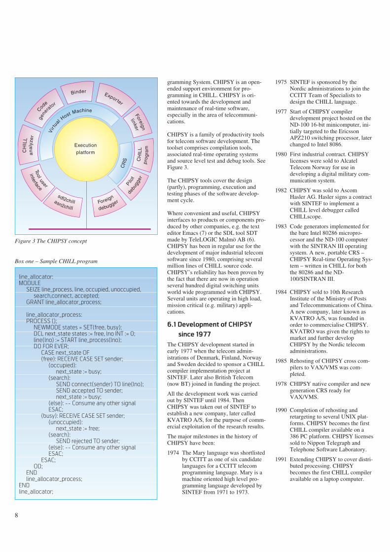
gramming System. CHIPSY is an open-ended support environment for pro-gramming in CHILL. CHIPSY is ori-ented towards the development andmaintenance of real-time software,especially in the area of telecommuni-cations.
CHIPSY is a family of productivity toolsfor telecom software development. Thetoolset comprises compilation tools,associated real-time operating systemsand source level test and debug tools. SeeFigure 3.
The CHIPSY tools cover the design(partly), programming, execution andtesting phases of the software develop-ment cycle.
Where convenient and useful, CHIPSYinterfaces to products or components pro-duced by other companies, e.g. the texteditor Emacs (7) or the SDL tool SDTmade by TeleLOGIC Malmö AB (6).CHIPSY has been in regular use for thedevelopment of major industrial telecomsoftware since 1980, comprising severalmillion lines of CHILL source code.CHIPSY’s reliability has been proven bythe fact that there are now in operationseveral hundred digital switching unitsworld wide programmed with CHIPSY.Several units are operating in high load,mission critical (e.g. military) appli-cations.
6.1 Development of CHIPSY
since 1977
The CHIPSY development started inearly 1977 when the telecom admin-istrations of Denmark, Finland, Norwayand Sweden decided to sponsor a CHILLcompiler implementation project atSINTEF. Later also British Telecom(now BT) joined in funding the project.
All the development work was carriedout by SINTEF until 1984. ThenCHIPSY was taken out of SINTEF toestablish a new company, later calledKVATRO A/S, for the purpose of comm-ercial exploitation of the research results.
The major milestones in the history ofCHIPSY have been:
1974 The Mary language was shortlistedby CCITT as one of six candidatelanguages for a CCITT telecomprogramming language. Mary is amachine oriented high level pro-gramming language developed bySINTEF from 1971 to 1973.
8
line_allocator:
MODULE
SEIZE line_process, line, occupied, unoccupied,
search,connect, accepted;
GRANT line_allocator_process;
line_allocator_process:
PROCESS ();
NEWMODE states = SET(free, busy);
DCL next_state states := free, lno INT := 0;
line(lno) := START line_process(lno);
DO FOR EVER;
CASE next_state OF
(free): RECEIVE CASE SET sender;
(occupied):
next_state := busy;
(search):
SEND connect(sender) TO line(lno);
SEND accepted TO sender;
next_state := busy;
(else): -- Consume any other signal
ESAC;
(busy): RECEIVE CASE SET sender;
(unoccupied):
next_state := free;
(search):
SEND rejected TO sender;
(else): -- Consume any other signal
ESAC;
ESAC;
OD;
END
line_allocator_process;
END
line_allocator;
Box one – Sample CHILL program
Binder
Foreign
linker
CR
S
Foreign
debugger
Pilot
CH
I LL
pro
gra
m
sdl2chillasn2chill
Cod
e
gene
rator
CH
ILL
an
aly
zer
Execution
platform
Vir
tu
al Host Machine
Exporter
debu
gger
Tool user
interface
Figure 3 The CHIPSY concept
1975 SINTEF is sponsored by theNordic administrations to join theCCITT Team of Specialists todesign the CHILL language.
1977 Start of CHIPSY compilerdevelopment project hosted on theND-100 16-bit minicomputer, ini-tially targeted to the EricssonAPZ210 switching processor, laterchanged to Intel 8086.
1980 First industrial contract. CHIPSYlicenses were sold to AlcatelTelecom Norway for use indeveloping a digital military com-munication system.
1982 CHIPSY was sold to AscomHasler AG. Hasler signs a contractwith SINTEF to implement aCHILL level debugger calledCHILLscope.
1983 Code generators implemented forthe bare Intel 80286 micropro-cessor and the ND-100 computerwith the SINTRAN III operatingsystem. A new, portable CRS –CHIPSY Real-time Operating Sys-tem – written in CHILL for boththe 80286 and the ND-100/SINTRAN III.
1984 CHIPSY sold to 10th ResearchInstitute of the Ministry of Postsand Telecommunications of China.A new company, later known asKVATRO A/S, was founded inorder to commercialise CHIPSY.KVATRO was given the rights tomarket and further developCHIPSY by the Nordic telecomadministrations.
1985 Rehosting of CHIPSY cross com-pilers to VAX/VMS was com-pleted.
1978 CHIPSY native compiler and newgeneration CRS ready forVAX/VMS.
1990 Completion of rehosting andretargeting to several UNIX plat-forms. CHIPSY becomes the firstCHILL compiler available on a386 PC platform. CHIPSY licensessold to Nippon Telegraph andTelephone Software Laboratory.
1991 Extending CHIPSY to cover distri-buted processing. CHIPSYbecomes the first CHILL compileravailable on a laptop computer.
9
Box two – CHILL Overview1992 Implementation of an ASN.1 toCHILL translator completed.Implementation of an SDL toCHILL translator completed. Firstimplementation of the Pilotdebugger for testing and debugg-ing in distributed real-time sys-tems.
1993 Full implementation of the Pilotdebugger. CHIPSY is ported toSPARC workstations.
6.2 CHIPSY is the outcome
of a co-operative effort
Until 1993 more than 100 million NOK(15 million USD) have been invested inthe development and maintenance ofCHIPSY. The investments constitute co-operative efforts with various partners.The main contributors to this develop-ment have been:
- Telecom administrations of Denmark,Finland, Norway, Sweden and UnitedKingdom acting in concert
- Telecom Norway
- Alcatel Telecom Norway
- Ascom Hasler
- SINTEF
- 10th Research Institute of MPT, China
- Norwegian Industrial Fund
- Nippon Telegraph and Telephone
- KVATRO A/S.
7 Conclusions
CHILL is unique because it is a stand-ardised programming language cateringfor the needs of the telecommunicationscommunity. It has already gained a solidacceptance within the industry worldwide, and has been used for theconstruction of some of the world’s mostsuccessful switching systems.
Because of the longevity of telecom sys-tems and the persistence of programminglanguages, CHILL will continue to havea strong impact in the world of telecom-munications well beyond the year 2000.
It is safe to say that CHILL has largelyachieved its original objective of becom-ing a standard language for the pro-gramming of public telecom switchingsystems.
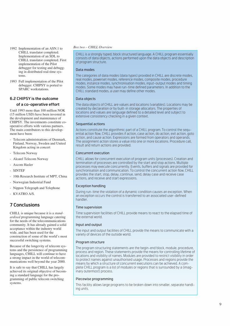
CHILL is a strongly typed, block structured language. A CHILL program essentially
consists of data objects, actions performed upon the data objects and description
of program structure.
Data modes
The categories of data modes (data types) provided in CHILL are discrete modes,
real modes, powerset modes, reference modes, composite modes, procedure
modes, instance modes, synchronisation modes, input-output modes and timing
modes. Some modes may have run-time defined parameters. In addition to the
CHILL standard modes, a user may define other modes.
Data objects
The data objects of CHILL are values and locations (variables). Locations may be
created by declaration or by built-in storage allocators. The properties of
locations and values are language defined to a detailed level and subject to
extensive consistency checking in a given context.
Sequential actions
Actions constitute the algorithmic part of a CHILL program. To control the sequ-
ential action flow, CHILL provides if action, case action, do action, exit action, goto
action, and cause action. Expressions are formed from operators and operands.
The assignment action stores a value into one or more locations. Procedure call,
result and return actions are provided.
Concurrent execution
CHILL allows for concurrent execution of program units (processes). Creation and
termination of processes are controlled by the start and stop actions. Multiple
processes may execute concurrently. Events, buffers and signals are provided for
synchronisation and communication. To control the concurrent action flow, CHILL
provides the start, stop, delay, continue, send, delay case and receive case
actions, and receive and start expressions.
Exception handling
During run-time the violation of a dynamic condition causes an exception. When
an exception occurs the control is transferred to an associated user-defined
handler.
Time supervision
Time supervision facilities of CHILL provide means to react to the elapsed time of
the external world.
Input and output
The input and output facilities of CHILL provide the means to communicate with a
variety of devices of the outside world.
Program structure
The program structuring statements are the begin-end block, module, procedure,
process and region. These statements provide the means for controlling lifetime of
locations and visibility of names. Modules are provided to restrict visibility in order
to protect names against unauthorised usage. Processes and regions provide the
means by which a structure of concurrent executions can be achieved. A com-
plete CHILL program is a list of modules or regions that is surrounded by a (imag-
inary outermost) process.
Piecewise programming
This facility allows large programs to be broken down into smaller, separate handl-
ing units.
10
CHILL has also spread beyond publicswitching and has been used for anumber of other telecom products likePABXs, non-voice equipment, etc.
CHILL has stood the test of time. Eventhough CHILL is now almost 20 yearsold, it has not been outdated. On the con-trary it is flexible enough to fit into newtechnological contexts. For example,experience has shown that:
- CHILL is well suited as a targetlanguage for translations from SDL (5)and ASN.1 (8)
- CHILL concurrency concepts are wellsuited for implementing distributedsystems (4).
CHILL has proven to be powerfulenough for implementing moderntelecom systems which are much largerand more sophisticated than could havebeen foreseen in the 1970’s, e.g. ISDN,IN and mobile communication systems.
Finally, the CHILL work has provided afoundation for commercial productdevelopments.
References
1 ITU. CCITT High Level Language(CHILL). Geneva, 1980-92.(Recommendation Z.200.)
2 ITU. Functional Specification andDescription Language (SDL).Geneva, 1976-92. (RecommendationZ.100.)
3 ITU. Man-Machine Language(MML). Geneva, 1976-92. (Recomm-endation Z.300.)
4 CHIPSY Reference Manual. Trond-heim, KVATRO A/S, 1993.
5 Botnevik, H. Developing TelecomSoftware with SDL and CHILL.Telecommunications, 25(9), 126-132,139, 1991.
6 SDT Reference Manual. Malmö,TeleLOGIC Malmö, June 1992.
7 GNU Emacs Manual. Free SoftwareFoundation, 1986.
8 ITU. Specification of Abstract SyntaxNotation One (ASN.1). Geneva,1988. (Recommendation X.208.)

Scope and objectives
The design of Human-Machine Inter-faces, HMIs, has great consequences fortheir users. The HMI, in the broad sense,is what matters when designinginformation systems. It has consequencesfor efficiency, flexibility and accept-ability. Therefore, the internal efficiencyand external sales of services of anyTelecommunication operator will bedependent on the HMI provided.
As applications are becoming increas-ingly data centred, this paper is focusingon HMI design for large database appli-cations. The term ‘Human-MachineInterfaces’ has been introduced by theConsultative Committee for InternationalTelegraph and Telephone, CCITT, StudyGroup X Working Party X/1 (2),(3), toreplace the older term ‘Man-MachineCommunication’. Except from replacingthe term ‘Man’ by the more general term‘Human’, the new word is also intendedto indicate an enlarged scope of HMIs, aswill be explained in a subsequent section.
The term ‘Interface’ indicates a nar-rowing in of the scope to the interfaceitself, without any concern about thesituation and tasks of the communicatingpartners, as indicated by the term ‘Com-munication’. This delimitation is notintended. However, this paper and thecurrent work of CCITT are focusing onthe formal aspects of the ‘languages’used on the interface itself.
Most work on HMIs have, so far, beenconcerned with the design of ‘small sys-tems’. The interface typically comprisesthe handset of a telephone or some screenpictures for a specific user group carry-
ing out a limited well defined task. How-ever, users of computer systems arenowadays not only carrying out routinework through their HMI. Users are oftenusing several divergent applicationssimultaneously, and one application cancomprise several hundred screenpictures, many of which are often used,others are hardly known. This usage oflarge systems imposes new requirementsto and new objectives of HMI designs.
The focus is no longer on enabling thecarrying out of one specific task in themost efficient and user friendly way. Theconcern will be to carry out a total set ofdivergent tasks in an efficient and userfriendly way. Hence, tailoring of HMIsto a specific task can be counterpro-ductive to the overall accessibility andproductivity goals.
To achieve the overall goals, we have toenforce harmonisation of HMIs acrosslarge application areas. The centralconcern will not be on ‘style guidelines’,but on linguistics – to ensure a common‘terminology and grammar’ of all HMIsacross one or more application areas.This co-ordination is much more funda-mental than providing guidelines forusage of ‘windows, icons and fonts’. Thenew issue can be likened with choosingand designing ‘French’ or ‘Norwegian’terms and word order. In a large systemthe user must be able to recognise andinterpret the information when he sees it.It does not help to be ‘user friendly’ inthe narrow task-oriented sense, if theusers do not recognise how data arestructured and related to each other. Inlarge systems, the users want to be ableto easily recognise the ‘language’ usedwhen the same data are presented mani-pulated on various screens.
In the quest for solutions to our veryappropriate needs, we will have toaddress approaches and techniques whichare not yet ‘state of the art’ for HMIdesign. We will have to addressquestions on architecture of HMIstowards information systems and formallanguage aspects of the HMIs. Beforedoing so, we will provide an overview ofwhat is HMI and what perspectives onHMIs can be taken. What then, is HMI?
HMI comprises all communicationbetween human users and computer sys-tems.
Some authors claim that the computer isjust an intermediate medium for com-munication between humans. Thismetaphor, to consider a database appli-cation to be a multi-sender multi-receiverelectronic mail system between humans,provides a powerful perspective on whatan automated information system is andcan be. In a real electronic mail system,however, we distinguish and record theindividual senders and receivers. In adatabase application usually the data onlyare of interest, while the user groups areonly discriminated by the access controlsystem.
In some applications this perspective ofmediating communication between hum-ans makes little sense. If data are auto-matically collected and recorded in adatabase, e.g. alarms from the telecom-munications network, it is of little use toclaim that the equipment in the very beg-inning was installed or designed by hum-ans. Therefore, we will consider the com-puter system to be a full-blown com-municating partner in its own right.
11
Human-Machine Interface design for large systems
B Y A R V E M E I S I N G S E T
Abstract
To read a good book on painting will not make you become aMichelangelo. Neither will the reading of this paper make youbecome a good Human Machine Interface (HMI) designer. But,if the reading makes you become a wiser HMI designer, then theobjective of writing this paper is met.
The paper identifies challenges imposed by design and use oflarge systems and outlines solutions to these problems. Anenlarged scope and alternative perspectives on HMIs are pro-posed. The scope of HMI is proposed to contain a large portionof the system specifications, which have traditionally beenconsidered to be the restricted domain of the developer. The enduser needs this information for on-line help and as a menu andtutorial to the system. Also, end user access to the specificationsputs strong requirements on how specifications are presented,
formulated, their structure, terminology used, and grammar.This leads the HMI developer into issues on deep structurelanguage design and fundamental questions about the role oflanguages and methods for their design. An encyclopaediametaphor is proposed for organising and managing data oflarge organisations. This leads to thoughts about what compet-ence is needed to develop and manage future information sys-tems.
Norwegian Telecom Research has contributed significantly tothe new draft CCITT Recommendations on the Data OrientedHuman-Machine Interface Specification Technique (1). Themajor experience for making these contributions arrives fromdevelopment of the DATRAN and DIMAN tools, which are alsopresented in this magazine.
681.327.2

To consider the computer to be a com-municating partner does not mean torequire that the computer system shouldact like or mimic a human. We all shareboth good and bad experiences from try-ing to communicate with humans. Theexperience is often that the more ‘intel-ligence’ possessed by the partner, themore screwed up the communication canbecome. A simple example is a copyingmachine. When you were using the oldmachines, you pressed the key for A4format and you got A4 copies. However,modern machines observe the size ofwhatever you put on the glass plate andprovides you with what it thinks you‘need’. If you put on a large book, it pro-vides you with A3 copies, even if youonly want A4 of one page. When using‘intelligent’ user interfaces, your problemeasily becomes how to bypass the ‘intel-ligence’. Therefore, we want ‘dumb’interfaces, where the information systemserves you as a tool. This does not meanthat the interface should be poor andimpoverished. We want interfaces thatprovide powerful features and appli-cations that undertakes complex analysisand enforcement of data. The point madehere about ‘intelligence’ is that we wantthe user to be able to predict how the sys-tem will react, that the system behaves‘consistently’ and does not changebehaviour as time passes. Also, we donot want the system to react very differ-ently on the same or a similar commandin a different state. This issue, to enforceconsistency of behaviour over a largeapplication area is a separate researchsubject within formal HMI (4).
The tool perspective on HMIs is import-ant, because it provides an alternative
approach to information systems design.Many existing methods, more preciselythe system theoretic school (5), considerinformation systems to be complexfactories, made up of humans andmachines, for producing and maintaininginformation. Also, most existing softwaredevelopment tools are based on thisparadigm. Tasks are separated betweenhumans and computers according tomaximum fitness for the task. The sloganfor this can be ‘to tailor the system to thetasks’. However, the end result can easilybecome ‘to tailor the human to the task’.This tradition goes back to Taylor’s Sci-entific management (1911). In somerestricted applications this approach canbe appropriate. However, in the ‘largesystems’ context it comes too short – dueto the diverse needs of different tasks tobe supported simultaneously.
An alternative to the system theoreticapproach is to consider the informationsystem to be a tool for recording, organ-ising, enforcing, deriving and presentinginformation. The ‘production’ primarilytakes place inside the software system.The end user supplies and uses data fromthe system, and he can control the pro-cessing and information handling, whichtakes place inside the system. The enduser is not considered to be a part of thesystem, but he is considered to controland use the system as a tool.
Unfortunately, the current practising sys-tem developer, or more specifically theHMI designer, is often not aware ofwhich approach he is using, whichperspective he is imposing and thereby,which work environment he is creating.Therefore, more reflection on impliciteffects of alternative system developmentmethods is needed.
Terminals
Hardware design is a compromise be-tween technology, price, functionality,ergonomics, aesthetics, history,knowledge, performance, security, andother factors.
Hardware design is outside the scope ofinterest and scope of freedom of mostreaders of this paper. However, there isone hardware factor which must beaddressed by every HMI designer: Thenumber one priority is availability of theterminal equipment to the users you wantto reach.
In most cases you cannot require that theusers acquire a new terminal when intro-ducing a new service. Most often youhave to accept existing terminals andcommunication networks, or only requiremodest extensions to these. On more rareoccasions you are responsible forpurchasing and evaluating terminals –seldom for one service only, but moreoften for general use of several services.
This consideration has too often beenneglected in expensive development pro-jects. It is of little help to develop anadvanced electronic directory systemrequiring powerful UNIX workstations,when most potential directory users haveaccess only to a telephone handset. Thisproblem is illustrated by the FrenchMinitel service. The terminals are simpleand cheap, and hence, affordable andwidely spread.
The alternatives to Minitel have providedgood graphics, require special communi-cation, are costly, and hence, unaf-fordable and hardly in use. The situationis illustrated by an intelligent guess aboutthe current population of terminal equip-ment in Norway:
12
John
Mary Mary
System
Mary
Database
Figure 1 The computer system can beconsidered being a multi-user mediumfor human-to-human communication.This is a powerful metaphor for systemdesign and supports a good toolperspective on HMIs
Figure 2 The computer system can beconsidered being a communicator in itsown right. This is the most generalmetaphor, but can easily mislead theHMI designer to mimic human communi-cation
Figure 3 The tool perspective providesthe user with full control over the systemshe is using. In this perspective the user isconsidered being outside the system andis not a part of it
Telephones 3,000,000Radios 4,000,000TV sets 2,000,000PCs 300,000Workstations 10,000
These figures have to be correlated towhat communication facilities areavailable, e.g. to PCs, use of supple-mentary equipment, such as a modem,tape recorder, video recorder, etc., andhow the equipment is available to theactual user group you want to reach. Nodoubt, the most widespread electronicdirectory service is achieved if a practicalservice can be offered on an ordinarytelephone or a simple extension of thisequipment. The competitors on otherequipment will just get a small fringe ofthe total market.
However, there are pitfalls. Manyexisting telephone services, e.g. Centrexservices, are hardly in use, due to a com-plex, difficult to learn, hard to overview,and tiring in use ‘human-machine inter-face’. Therefore, an alternative strategycan be to introduce a service for a smalland advanced user group. Also, thechoice of strategy can be dependent onwhether you want to provide a service orsell equipment. Or maybe the service off-ered is just a means for promoting otherservices, for example to promote a newbasic communication service. Also, theterminal and communication environ-ment may be settled by another and moreimportant service in an unrelated area.
However, there are many challenges leftto be addressed by the future hardwaredesigners. The most obvious challenge is
the design of the PC. The laptop is moreergonomic in transport, but not in use.You definitely want a ‘glass plate’ ter-minal with which you can lay down in asofa and read, like when reading a book.And, you definitely do not want to haveto use a keyboard when just reading. Thepen based terminals make up a move inthe right direction, but they are not theend. In the future, you are likely to see‘walkman terminals’, ‘mobile phone ter-minals’, ‘wall board terminals’, ‘magicstick terminals’, etc. appearing under lab-els like the ‘Telescreen’, the ‘Telestick’and the ‘Telegnome’. With the comingtechnology, there is no reason why youshould sit on an excavator to dig a ditch.Rather you could sit in a nearby orremote control room, controlling the grabby joy sticks, observe the digging byvideo cameras and remote sensing. Mostof the work could even be carried outautomatically, while you supervise theprocess and are consulted when somet-hing has to be decided. And, also theexcavator can be designed very differ-ently, when it is no more designed for ahuman driver. The excavator becomesyour ‘little busy gnome’. Tunnelconstruction, mining and other appli-cation environments where you prefernot to have humans, are obvious areas forthe introduction of this kind of services.Remote control of mini submarines is anearly, already existing, application of thistechnology. In the telecommunicationarea, the technicians are not typicallyreplaced by robots. Rather, control,repair, and switching functions are builtinto the telecommunication equipment.
The equipment is administrered and itsfunctions are activated as if managing adatabase.
Style guidelines
Both industry and standardisation bodieshave done a lot on providing guidelinesfor layout design on screens and key-boards. The International StandardisationOrganisation, ISO, is currently issuing a17 piece standard ISO 9241 (6) on HMIdesign, of which 3 has reached the statusof a Draft International Standard, DIS.The industry has provided products likeMS Windows (7) and Motif imple-mentations (8).
Obviously there are many good advisesin these guidelines. However, supposeyou compare these guidelines with thatof designing the layout and editing of abook. A Motif form looking like a frontpanel of an electronic instrument, whereeach field is put in a separate readingwindow, may not be so good after all.The push buttons look like that of a videorecorder – which you definitely are notable to use. All the windows popping upon the screen look like an unordered heapof reminder notes in metallic frames. Theframes and push buttons are filling upmost of the screen. The ones you needare often under those you have on thetop. Each window is so small that it canhardly present information, and you haveto click a lot of buttons in order to getwhat you want. In fact, it is more likelythat a book layout designer will be horri-fied rather than satisfied by the currentuse of style guidelines.
13
Parameter driven: E-SUBSCR SMITH,JON, 48.Question-answer: What is minimum height of x? 3;Menu: 1 Order 2 Cancellation 3 ChangeLimited nat. language: LIST ALL PERSONS WITH...Form-filling: Person-name:____Height:___Program. language like: LET R=X-Q*Y; IF R=0 THEN ..Mathematics like: PERS=(SUBSCR∪EMPLOYE)Function key basedIcon basedGraphics basedAnimation based
Goals Homogenity Flexibility Power Simplicity Efficiency Control IntegrationContexts Existing softw. Existing hardw. Avail. resources Softw. evaluationHuman factors Ergonomics Perception Efficiency Capability Background
Skills Trained Untrained
Job requirements Customer driven Catastr. man. Safety first Security Overview Freedom
Capasity requirem. Transaction freq. Inform. bandwidth
Bandwith Size Resolution Colour Refresh freq. Respon. time
Graphics Topology Surfaces Structure Placement Colour
Inputs Keyboard Funct. keys Mouse Voice
Outputs Alphanum. Graphics Sound Paper Animation
Text Fonts Rotation Structure Placement Size
Onerall design HMI concepts HMI principles Manip. mech. Presentat. style Machine control RetraceabilityApplication cont. Terminology Grammar Operations Functions AuthorisationGuidance Online help Messages Error correction DocumentationDial. tech. Fig. 4
HMIdesign
process
Classis of HMIs Inputs Outputs
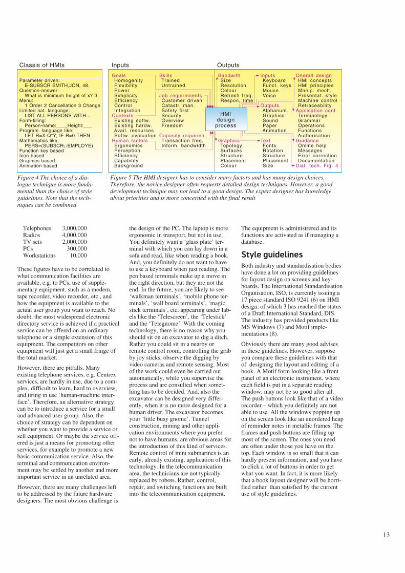
Figure 4 The choice of a dia-logue technique is more funda-mental than the choice of styleguidelines. Note that the tech-niques can be combined
Figure 5 The HMI designer has to consider many factors and has many design choices.Therefore, the novice designer often requests detailed design techniques. However, a gooddevelopment technique may not lead to a good design. The expert designer has knowledgeabout priorities and is more concerned with the final result

Desktopmetaphore
FunctionKeys
Icons withsize & page& presentindication
Globalbuttons
5 10 11
What about printing? If the form is putinto a Motif panel, it is likely that this isnot suited for printing on paper. You willhave to design another form for print out.However, this violates one of your morebasic requirements – to recognise theform and the data in different environ-ments. The recognition of data isachieved by having persistence of pre-sentation forms between different media.In order to get a clean work space forinformation, which the screen is for, youshould move the tools – the push buttons– out to the sides and arrange them in afixed order there – much like that of theearly drawing packages. Arrangements ofbuttons around each window and inseparate push button windows may not
be the best. Also, the use of tiledwindows distorts the whole view. Maybethe fixed arrangement of windows, likein the early Xerox Star, was a betterchoice? Use of shading, ‘perspective’,and colours are often a total misuse ofeffects.
There are several shortcomings of thecurrent desktop metaphors. For example,you may want to see the relative sizes ofthe documents and files when you seetheir icons. You may want to open theicons on any page or place withoutalways having to see the first page; youmay want to use slide bars on the iconsand not only inside the windows. Youmay want to open several pages simul-
taneously inside the same document. Youmay want to have a common overall indi-cation of which pages you have opened.In short, you want to have the same con-trol as when holding and paging througha book. You want to copy some pages toprint when others are opened. And, youwant all desktop tools to be available onthe desktop simultaneously, and not topop up as dialogue boxes in certainstates. Also, you want a clear distinctionbetween a book (an icon for its contents),alternative presentation forms (of thesame contents) and finally windows topresent the contents in a form. Therefore,iconification of windows is what youleast need.
We have all seen the bad results of pro-ducing papers by the current desktoppublishing products. The individual aut-hor lacks the competence of the profess-ional layout designer, but is provided
14
Satelitecommunication
The Telestick
Flat screen
Head set
The Telegnoom headingfor the shopping bag
Remote controlof the Telegnoom Talking head
Tele-screen
Data-base
Figure 6 The number one priority of hardware designis the availability of the terminals to the users. Toomany projects have failed because the design hasbeen made for workstations not available to the users.Much work remains to make terminals as ergonomicas a book; this concerns physiognomy, perception,controllability, etc. Also, new kinds of terminals arelikely to appear for existing and new applications
Figure 8 The current desktop metaphor can be impro-ved to provide better control to the user. Here sub-icons represent different presentation forms of adocument. Several pages are shown from the samedocument. A global slidebar indicates open pages
Figure 7 The Xerox Star workstation has been themodel for all desktop metaphors. The Star had a fixedset of function keys which applied to all kinds ofobjects. This way it provided a homogeneity not equ-alled by other products

with all the freedom he is not able to useappropriately. The provisioning offreedom requires the practising ofresponsibility. Therefore, the gooddesigner is often puritanical.
Our database applications are often veryexpensive ‘publications’. We spend largesums to develop them and large amountsto support and use them. For example adatabase containing information aboutresources and connections in thetelecommunication network costs moreto develop, maintain and use than mostexisting paper publications. Also, thedatabase is used by hundreds andthousands of users daily. We usually putmuch more emphasis on using qualifiedpersonnel when designing a paper publi-cation than when designing a databaseapplication. Database applications aremost often designed by programmershaving no layout competence. We needpersonnel to design large and complexapplications which can appear system-atic, comprehensible and typograhicallypleasant to the end user. Therefore, weshould spend just as much money onusing qualified personnel on HMI layoutdesign to database applications as wespend on paper publications of com-parable costs.
This definitely implies that the systemdevelopment departments have to beupgraded with the appropriate typo-graphic competence. Current technologyis no longer a limitation to the use of thiscompetence. A graphic terminal isbecoming the standard equipment ofmost office workers. Currently we auto-matically produce some simple graphs ofthe telecommunication network. How-ever, the challenge is to illustrate thisvery complex network in such a way thatthis provides overview and insight.Investment in competent personnel to
design systematic and illustrative graphsof the entire network for the differentuser groups can be paid back manifolds.
The challenge does not stop with turningdatabase applications into high qualitypublications of text and graphics. Newtechnology will provide a multi mediaenvironment. The future database appli-cation designer will have to become amulti art artist. He will create an artificial‘cyber space’ of his database, forexample for ‘travelling through’ thetelecommunication network database.And, he will integrate artificial speech,recorded sound and video. These featureshave their own strengths and possi-bilities, weaknesses and pitfalls. The useand integration of all this will requiresomewhat more than programming com-petence.
Contents
To design the layout of the data withoutbothering about the contents is like mak-ing a typographic design of a book wit-hout knowing what it is about and how itis structured. And, does it consist oftables, charts, free text or other? How canthese be arranged to best present theinformation?
Contents design of a screen picture com-prises: What information should beincluded in the picture? What statementsare used to express this information?Which arrangement of the statements ischosen? Also, the contents design com-prises: What pictures should exist? Howare pictures grouped together to provideoverview? What links, if any, shouldexist between pictures or groups ofpictures? We see that contents designcorresponds to organising a book intosections and writing the contents of eachsection. This topic is covered by the
‘contents structure’ of the Open Docu-ment Architecture ISO/CCITT (10),while style guidelines correspond to the‘layout structure’ of ODA.
When designing the contents structure ofa picture, the HMI designer also has todecide what operations (commands ordirectives) are permissible on theselected data items in this context.
Several design methods exist for contentsdesign. The system theoretic school hasbeen dominating. In this school thedesigner analyses the tasks undertaken bythe user. The tasks are identified in dataflow graphs. Some tasks are automatised,others are kept manual. The HMI isidentified on the boundary betweenmanual and automated tasks. One screenpicture is designed to include the dataflowing one way between the two tasks.The operations are limited to thoseneeded for this data exchange and thetransition to the needed picture for thenext exchange of data. This way, theHMI is tailored to the tasks and routinesof an organisation.
The system theoretic approach can beappropriate for undertaking well definedor routine tasks. However, the approachis not flexible for alternative ways ofundertaking the same tasks or differenttasks. Also, the approach does notaddress the harmonisation of the dialogueacross many tasks for a large applicationdomain. For this a modeless dialogue iswanted. This means that all screenpictures should be permissible and easilyaccessible in every conceivable sequ-ence. Also, the user should be allowed to
15
Write username&p.w.
Startterminal
Choosefunction
Chech username&p.w.
Create log-on screen
Startfunction
Createsyst. menu
User Screen SystemInterface engineering
User and task analysisHuman versus machine
Dialogue designScreen design
CodingUseability lab
Contextual observationHuman performance
Development phase
Requirements analysisRequirements allocation
Preliminary designDetailed designImplementation
Implementation testingSystem testingOptimatisation
Software engineering
Application designHardware versus softwareArchitectural designLogical designCodingUnit and integration testSystem testingMachine performance
Figure 9 Curtis and Hefley (9) present this as ‘A potential high-level mapping schemefor integrating phases of the interface- and software-engineering processes.’
As development tools become more high level, we should design systems as seen fromthe outside only. This implies a move towards the leftmost column
Figure 10 In the function oriented appro-ach, tasks are decomposed and finallygrouped to become manual or automaticprocesses. Screens and reports constitutethe HMI between these processes
Cursor qualities
Easy to find
Easy to track
Do not interfere
Do not distract
Be unique
Be stable
Presentation
Label information clearly
Keep display simple
Moderate highlighting
Moderate the use of colours
Keep layout consistent
Presentation of data
Use upper and lower case letters
Minimise use of codes
Maximum 5 characters in a group
Use standardised formats
Place related items together
Place figures in columns
Adjust integers to the right
Adjust figures around the decimal point
Adjust text to the left
Make only input fields accessible
Distinguish
Input fields
System response
Status information
User guidance
Menus
Response time
Psychologically acceptable
Uniform
User guidance
Keep guidance up-to-date
Ensure consistent presentation
Avoid abbreviations
Use action oriented sentences
Make help messages clear
Make help contextual
Do not guess what the user wants
Provide help for help
Use identical commands to that of the application
Errors
Where are they
What error
How to recover
Make error messages clear and polite
Report all errors together, prioritise presentation
Keep error information until corrected
Dialogue
Use direct information entry for experienced users
Use menus for causal users
Menus and forms
Keep the menu hierarchy low
Provide direct addressing of menus
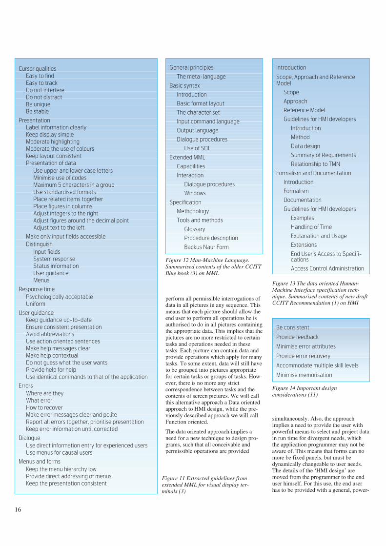
Keep the presentation consistentFigure 11 Extracted guidelines fromextended MML for visual display ter-minals (3)
perform all permissible interrogations ofdata in all pictures in any sequence. Thismeans that each picture should allow theend user to perform all operations he isauthorised to do in all pictures containingthe appropriate data. This implies that thepictures are no more restricted to certaintasks and operations needed in thesetasks. Each picture can contain data andprovide operations which apply for manytasks. To some extent, data will still haveto be grouped into pictures appropriatefor certain tasks or groups of tasks. How-ever, there is no more any strictcorrespondence between tasks and thecontents of screen pictures. We will callthis alternative approach a Data orientedapproach to HMI design, while the pre-viously described approach we will callFunction oriented.
The data oriented approach implies aneed for a new technique to design pro-grams, such that all conceivable andpermissible operations are provided
simultaneously. Also, the approachimplies a need to provide the user withpowerful means to select and project datain run time for divergent needs, whichthe application programmer may not beaware of. This means that forms can nomore be fixed panels, but must bedynamically changeable to user needs.The details of the ‘HMI design’ aremoved from the programmer to the enduser himself. For this use, the end userhas to be provided with a general, power-
16
General principles
The meta-language
Basic syntax
Introduction
Basic format layout
The character set
Input command language
Output language
Dialogue procedures
Use of SDL
Extended MML
Capabilities
Interaction
Dialogue procedures
Windows
Specification
Methodology
Tools and methods
Glossary
Procedure description
Backus Naur Form
Be consistent
Provide feedback
Minimise error attributes
Provide error recovery
Accommodate multiple skill levels
Minimise memorisation
Figure 12 Man-Machine Language.Summarised contents of the older CCITTBlue book (3) on MML
Introduction
Scope, Approach and Reference
Model
Scope
Approach
Reference Model
Guidelines for HMI developers
Introduction
Method
Data design
Summary of Requirements
Relationship to TMN
Formalism and Documentation
Introduction
Formalism
Documentation
Guidelines for HMI developers
Examples
Handling of Time
Explanation and Usage
Extensions
End User’s Access to Specifi-
cations
Access Control Administration
Figure 13 The data oriented Human-Machine Interface specification tech-nique. Summarised contents of new draftCCITT Recommendation (1) on HMI
Figure 14 Important designconsiderations (11)

ful and simple to use editor of the formand contents of all his screen pictures.
Preferably, this editor should allowalternative presentations of the samedata, e.g. both alphanumeric and graphicpresentations. However, this is not easilyachieved in practice. For example, inaddition to the pure contents, a graph of atelecommunication network will requirethe provisioning of appropriate icons forthe classes of data, e.g. for stations andcircuit groups. Also, information isneeded about where to place the icons,scaling, rotation, etc. And, if editing isallowed, information must be providedabout the topology of data, e.g. howcircuit groups are linked to stations.Also, these items have to be linked byappropriate routines. All this informationmay not be explicitly available in an alp-hanumeric screen picture, which the enduser intuitively believes contains thesame information. Therefore, meaningfulgraphs may not be easily derived frompictures not prepared for graphic pre-sentations. Rather, the user needs aseamless integration of graphic and alp-hanumeric dialogues, in a way whichappears to be integrated to the end user.
In the Function oriented approach theend user is considered to sit in the streamof information flow, entering informationfrom his environment or retrievinginformation to the environment. In theData oriented approach the informationflow can be considered to take placeinside the computer system, not to orfrom it through the terminal. The enduser supervises and controls this flow. Hecan retrieve data – from the flow –, insertnew data and redirect the flow. This way,
17
‘register handling’, ‘information flow’,as well as ‘process control’ can be under-taken by the Data oriented approach toHMI design.
Applications
To have a good contents structure of apublication is a must to get easy access toinformation. However, if the informationis not expressed in a consistent and und-erstandable language, then the end userwill be lost. A typical problem in manycurrent application designs is that head-ings and icons are inconsistently anduncoordinatedly used in differentpictures. Therefore, in large systems thedesigner needs methods and tools toensure the harmonisation of a commonterminology and grammar across largeapplication areas. By the term grammarwe mean the sequence in which data arepresented. The issue here is that if dataare presented in arbitrary order, forexample by interchangeable columns in atable, the user can misinterpret therelationships between items in the differ-ent columns. To achieve unambiguousinterpretation of data, the end usergrammar has to be defined by therelationships between the data.
To achieve the wanted harmonisation,the terminology and grammar have to beexpressed only once for each application.This central definition is called theApplication schema of the system. TheApplication schema will also contain allconstraints on and derivations from thedata.
The Application schema is not only thefocus of the developer. Once defined, the
definition of the common terms of a sys-tem is what the expert users need inorder to understand what the system isabout. In addition, they need thisinformation to validate and approve thedesign prior to implementation. Theordinary users need access to these speci-fications for on-line help, as a tutorialand a menu to the system. Therefore, theApplication schema is considered to beinside the scope of interest of the enduser’s HMI. Also, the end user has toknow which presentations are availableand which operations are permissible inthese presentations. Therefore, the speci-fication of external contents and layoutof each picture is inside the scope of theend user’s HMI. This way, a largeportion of the specification data areincluded in the scope of the HMI. Theimpact of this, is that these specificationshave to be presented in a way which isaccessible to the end user, using the enduser’s own terminology and grammar.Hence, the developer is not free tospecify the system in a way found con-venient only for the programmer and thecomputer, but he has to observe end userneeds both concerning what is specifiedand how this is specified.
There are many approaches to appli-cation design. Many schools takecontents schemata as their starting pointand merge these into one Applicationschema. So-called ‘normalisation’belongs to this group of schools. Thereare several problems with this approach:it presupposes that (1) contents schematacan be defined prior to having a unifiedApplication schema, (2) all data areappropriately used in all contents
Layoutschemata
Contentsschemata
Applicationschemata
Internalschemata
External schemata
Manager perspective
EnduserHMI
ACL
HM
Ipopula-
tionSystem processor Data
base
A
C
L
P
Figure 16 When designing data in the appli-cation schema (A), the HMI designer has toforesee permissible external contents (C), layo-uts (L) and instantiations (P)
Figure 15 If we take a black box approach to system design, we realise thatthe end user needs access to much the same information as the systemdeveloper.
The application schema (A) prescribes the terminology and grammar of theapplication. The external schemata prescribes contents (C) and layout(L)

18
schemata, and (3) all data are conveni-ently and consistently defined in allcontents schemata.
Experience with large systems designshows that these assumptions areregularly violated. In fact, to define aconsistent and efficient terminology andgrammar for an application area shouldbe the focus of all HMI design, whilemost current design techniques take curr-ent data designs for granted. However,no measures seem to have such a pro-found effect on overall efficiency andusability as data design. Therefore,CCITT Recommendation Z.352 containsa separate Appendix on data design forHMIs (1), (2).
Many current application design techni-ques are naivistically conceptualistic.This means that they disregard the formin which data are presented to the enduser. However, for the end user torecognise and understand his data, theforms of the data have to appear persist-ent throughout the system. Experienceshows that ‘conceptualistic’ designs,where the external forms are not takeninto account from the very start, have tobe redesigned when the external aspectsare taken into consideration. Therefore,HMI design is intrinsically concernedwith the definition of the form of dataacross large application areas (2).
The design of a harmonised and efficientterminology for a large application areais a complex task, requiring a lot ofexperience. The designer has to foresee
all conceivable presentations, i.e.contents and layouts, of his data designsand also foresee all conceivable instanti-ations of these presentation forms. There-fore, data design requires good skills togeneralise and systematise. The end usersare often not capable to foresee all conse-quences of the data design. Therefore,prototyping of the HMI is needed to val-idate the design. This prototyping mustbe realistic, i.e. allow the end users to useand report judgements about the design.
The end user has several subtle require-ments on the form of his data that haveprofound implications (1). Firstly, labels should be allowed to bereused in different contexts having differ-ent value sets and different meanings.For example, the label Group could meanan organisation unit in an administration,or a circuit group within the transmissionnetwork, or other. A label which isreused for different purposes in differentcontexts is called a local label to the labelof the context item. Secondly, identicallabels can be reused within the samecontext to mean different entities. Forexample, identical icons can be used torepresent different exchanges in anelectronic map, and the end user maynever see unique labels for each station.Therefore, the treatment of significantduplicates is needed. Lastly, specifi-cations have to be homomorphic to, i.e.have the same form as, the instantiateddata. The last requirement allows the enduser to recognise data classes for givendata instances and vice versa. Without
obeying this requirement, the end userwill easily get lost when traversingbetween specifications in the schemataand corresponding instances in the pop-ulations.
The consequence of the above require-ments is that the specification languageneeded for end user access to data, usingthe end user’s own terminology, will be acontext-sensitive language (12, 13, 14),having much in common with thecontext-sensitivity of natural languages.The required language will have featureswhich are distinctively different fromwidespread existing specificationlanguages.
Data are often considered to describesome Universe of Discourse. Maybe sur-prising to the reader, most designers havegreat difficulties in identifying the rightUoD. Most designers take an existing orhypothetical information system, e.g. of aTelecom operator, as their starting pointand extract and organise the data fromthis. However, the information systemusually administrates information aboutsome other system, e.g. the telecommuni-cation network. A designer should studythis network when designing aninformation system to manage it.
However, the designer should be warnedthat data often do not describe physicalentities in the naivistic sense. More oftendata are invented to provide overview ofother data, which provide overview of
Real Universe of discours Old or hypotheticalinformation system
Operator Real usersof data
UoD
No Ju.b Cab. Pair
Data design 1
Circ. Ju.b Cab. Pair
Data design 2
Phone no. Junction box CablePairsCircuit
Ph.n
Figure 17 Designers regularly confuse universes of discourse. Specificationtechniques often prescribe analysis of the information system rather than the UoDadministered by this system. This way, they prescribe the copying andconservation of previous designs, rather than contributing to creating alternativedesigns.
Also, user groups can be confused. Often the operators at the terminals are justcommunicators of data, while the real users of the data are outside theinformation system being analysed. Creative data design should focus on theneeds and usages of the real users
Figure 18 Depiction of alternative datadesigns to what was believed to be about thesame UoD. The first design stems from ‘norm-alising’ existing data. The second design takesa fresh look at the structure of the real UoD.Alternative data designs have great consequ-ences for their users

several smaller systems, which can bewanted both for overview and con-trollability. ‘Megastructures’ may not bethe ideal architecture.
Layering of systems can be anothermeans to provide overview and con-trollability. The already introduced appli-cation, contents and layout structures areexamples of this. If functionality is sortedinto layers, the data flow between thelayers also becomes more comprehen-sible. The flow between the layers isconcerned with undertaking one step inthe communication of data between twopeer media, while the internal flow insidea layer is related to constraint enforce-ment and derivations. This data flowarchitecture can be a very powerfulalternative to the control structures ofordinary programs.
Current thinking about information sys-tems has been focusing on the details ofthe HMI or the details of programmingstatements. Architecture of informationsystems in large has not evolved tobecome a separate discipline. Such adiscipline, however, is highly needed.
system to be a huge machine consistingof processes which exchange data bydata flow. As systems grow, this metap-hor has become too complex to copewith. Therefore alternative metaphors aresought after. The encyclopaedia metap-hor can be a convenient alternative. Thetotality of information systems can beconsidered being a library. Theinformation systems for one organisationis an encyclopaedia. Each system is abook, each function is a section, etc. Adirectory can provide an overview of thetotality. This metaphor can constitute theneeded overview and control to the user.The metaphor does neither exclude refer-ences to be maintained across severalbooks, nor that information is exchangedbetween books. However, normallyinformation is selected from severalbooks to one user, while exchangebetween books is minimised.
Some schools of data design put up a‘corporate database’ as the ideal goal,where the users see no distinction be-tween books or systems. However, thiscan become like having a large houserather than several small ones. The goalmay contradict the users’ wish of having
still other data, etc. Also, designers havebeen inclined to believe that the terminaloperator is the user of the data. Thisbelief may not be true. Quite often theoperators are just communicators of datato the real users, who can be customers,planners, managers, etc. Therefore,identification of UoDs and users areimportant, not trivial tasks.
Architecture
We realise that the complexity of largesystems implies a need for alternativeapproaches to HMI design. While currentform-filling dialogues have been appro-priate for presenting and manipulatingsmall groups of individual data items,they are not appropriate to provideoverview of large systems. The userwants to know what features areavailable, what data types can beinterrogated, how large are the pop-ulations, where is this item in this pop-ulation, etc.? The challenges for futureHMI designers are to provide easy to useand easy to recognise features for this.
Current metaphors for system designhave been considering the information
19
Data view
Processview
Life cycleview
Encyclopedia
Presentations
Mary
Figure 19 The current machine metaphorof information systems comprises a dataview, a processing view and a life cycleview. This metaphor seems not to providethe needed overview and control to usersand managers. The metaphor introducestoo much consistency to be controlled bythe developer and too little system-atisation. Rather than developing separ-ate specifications, which have to bechecked for consistency, a centralisedspecification (i.e. the applicationschema) should be developed, fromwhich all other specifications (i.e. theexternal and internal schemata) can bederived
Figure 20 The encyclopaedia metaphorcan provide simple overview and controlto the user. Each book corresponds to asystem. This metaphor can providemanageability to the manager. However,the metaphor is not complete, as it disre-gards communication between systems.But the details provided seem right fordiscussions with user departments aboutownership of and responsibility forwhich system
Figure 21 An advanced approach to pro-viding overview. Directory information isdepicted by the stellar map metaphor inthe top window. Object class icons makeup the system stars. The user can zoom inthe wanted ones. The corona depictsexternal screen pictures. The communi-cation links between systems are indi-cated by dotted lines. The space platformin perspective indicates the work station.Its icons indicate the extracted data types.Data instances are depicted in the bottomwindow. Colours indicate selected icons.The heights of the rectangles indicatesizes of the files. The icon instances areplaced in their appropriate placesaccording to an alphabetical sort
Education
From the discussion in this paper, itshould be evident that current teachingon HMI design and information systemsdesign in general, have distinctshortcomings: 1) HMI designers havebeen focusing too much on the surfacelayer style guidelines of HMI design andhave missed most aspects of the deeplanguage structure data design. 2) Thearchitectural aspects of information sys-tems in large need to be addressed. 3)Development methods for HMIs have tobe reconsidered in light of large systemsdesign. 4) The scope of HMIs has to bebroadened, and this will require anintegration of end user and developerperspectives. This will have significantimpact on formal languages for the speci-fication of information systems.
Pelle Ehn (15) quotes from Simon a pro-posal of a curriculum to redirect thefocus of information systems develop-ment:
- Social systems and design methods
- Theory of designing computer arte-facts
- Process-oriented software engineeringand prototyping
- History of design methodology
- Architectural and industrial design asparadigm examples
- Philosophy of design
- Practical design.
Teaching about HMIs can be undertakenin the perspectives of end users, develop-ers or scientists. This article has focusedon the perspective of the developer.However, the reader should be warnedthat the three perspectives can be entirelydifferent. An HMI can be easy to use,while it can be very difficult to design,e.g. the data designer has to foresee allimplications for all conceivable pre-sentations and instantiations of hisdesigns. The tasks of the scientist can beentirely different from those of thedeveloper. The scientist should be able tocategorise the approach used, e.g.according to which philosophy of sci-ence. He may identify the organisationtheory supported, the design principlesused, the underlying philosophy of art,etc. Occasionally he may also engage indeveloping tools and methods for HMIdesign and HMI usage.
References
1 CCITT. Draft RecommendationsZ.35x and Appendices to draftRecommendations, 1992. (COM X-R12-E.)
2 CCITT. Recommendations Z.35x andAppendices to Recommendations,1992. (COM X-R 24-E.)
3 CCITT. Man-Machine Language(MML). (Blue book. Recomm-endations Z.301-Z.341.)
4 Harrison, M, Thimbelby, H. Formalmethods in Human-ComputerInteraction. Cambridge, Mass., Cam-bridge University Press, 1990.
5 Bansler, J. System development inScandinavia: Three theoreticalschools. Scandinavian Journal ofInformation Systems, 1, 3-20, 1989.
6 ISO. Visual display terminals (VDTs)used for office tasks – Ergonomicrequirements. Part 3: Visual require-ments. 1989. (Draft InternationalStandard ISO/DIS 9241-3.)
7 Brukerhåndbok Microsoft Windows.Versjon 3.1. Microsoft corporation,1991.
8 Open Software Foundation.OSF/Motif Style Guide. Rev. 1.2.Englewood Cliffs, N.J., PrenticeHall, 1991.
9 Curtis, B, Hefley, B. Defining a placefor interface engineering. IEEESoftware, 9(2), 84-86, 1992.
10 ISO. Information processing – Textand office system – Office DocumentArchitecture (ODA) and interchangeformat, 1989. (ISO 8613).
11 Foley, J D et al. Computer Graphics:Principles and Practice. IBM Sys-tems Programming Series, secondedition. Reading, Mass., Addison-Wesley, 1990.
12 Meisingset, A. Perspectives on theCCITT Data Oriented Human-Machine Interface SpecificationTechnique. SDL Forum, Glasgow,1991. Kjeller, Norwegian TelecomResearch, 1991. (TF lecture F10/91.)
13 Meisingset, A. The CCITT Data Ori-ented Human-Machine InterfaceSpecification Technique. SETSSConference, Florence, 1992. Kjeller,Norwegian Telecom Research, 1992.(TF lecture F24/92.)
14 Meisingset, A. Specificationlanguages and environments. Kjeller,University Studies at Kjeller,Norway, 1991 (Version 3.0).
15 Ehn, P. The art and science ofdesigning computer artefacts. Scandi-navian Journal of Information Sys-tems, 1, 21-42, 1989.
20

Introduction
The notion reference models is oftenencountered in standards and otherliterature on information systems. In thispaper we want to focus on what a refer-ence model actually is, where and why itis needed and illustrate these ‘what’,‘where’ and ‘why’ of reference modelsthrough some examples of existing refer-ence models.
The term reference model is defined inthe literature (1) as a conceptual fra-mework for a subject area, i.e. “aconceptual framework whose purpose isto divide standardisation work intomanageable pieces, and to show, at ageneral level, how these pieces arerelated to one another. It provides a com-mon basis for the co-ordination of stand-ards development, while allowingexisting standards to be placed intoperspective within the overall referencemodel.”
For all practical purposes, however, areference model can be thought of as anidealised architectural model of a system(2). We thus consider the term referencemodel in the area of information systemsto be synonymous to the termsarchitecture, reference architecture andframework of information systems.These terms are all used throughout theliterature. Unfortunately, there is no com-mon understanding of either of theseterms.
Reference models are nevertheless ameans to decompose and structure thewhole or aspects of information systems.As size, complexity and costs ofinformation systems are increasing, refer-ence models are needed to handle thecomplexity of large information systems.
The field of information systems is quiteyoung compared to house building,which has existed for thousands of years.Lots of experience has been accumulatedthroughout these years, and it would onlybe natural if the field of information sys-
tems could gain from studying the pro-cess of building houses, towns, or evenaeroplanes. Zachman (3) has observedthe processes of building houses andaeroplanes and found that a generalisa-tion of these processes would be appro-priate for the process of buildinginformation systems as well.
Existing reference models
The currently best known referencemodel within the field of informationsystems is perhaps the reference modelfor open systems interconnection, theOSI reference model, standardised byISO. There are, however, several otherimportant areas of information systemsfor which reference models have been, orcurrently are being, developed.
According to Zachman (3) interpretationof the term architecture depends on theviewer. This is the case for referencemodels as well, i.e. interpretation of theterm reference model depends on theviewer. Different users have differentviewpoints, or different perspectives, ona reference model. These differentperspectives may be incorporated into asingle reference model or may result inquite different reference models, eachserving one particular perspective. Atypical example of different perspectivesthat might be incorporated into a singlereference model or in several referencemodels is development, use and manage-ment of an information system.
In the area of data management, i.e.definition and manipulation of an enter-prise’s information, several referencemodels are already being standardised.Examples are the ANSI/SPARC three-schema architecture, theANSI and ISO IRDS (InformationResource Dictionary System), and areference model for data managementbeing standardised by ISO. The three-schema architecture will be presentedlater in this paper.
The OSI reference model has alreadybeen mentioned as a standardised refer-ence model for communication. Thisreference model defines means for com-munication between two or more separ-ate systems. Two aspects of communi-cation that especially influence the co-operation between systems and systemparts are distribution and inter-operability. A distributed system is a sys-tem that supports distributed processingor distribution of data. Distributed pro-cessing may be done according to ODP(Open Distributed Processing) or the cli-ent-server model, and data may be distri-buted according to an extended three-schema architecture. Interoperabilitymeans that systems or system compon-ents co-operate to perform a commontask. Interoperation is essential e.g. fordatabase applications requestinginformation from each other.
In addition to the general referencemodels already mentioned, there existseveral reference models for specificapplication areas. Three application ori-ented reference models currently beingdeveloped in the area of telecommuni-cations are reference models for Intellig-ent Networks (IN) (4), Telecommuni-cations Management Network (TMN)(5), and Human Machine Interface(HMI) (6). They are all developed byCCITT.
Zachman’s framework for
information systems
architecture (ISA)
As we have already mentioned, Zachmanhas observed house building to see if theexperiences made there can be applied tothe process of building information sys-tems (3). The observations he maderesulted in a framework for informationsystems architecture called the ISA fra-mework.
21
Reference models
B Y S I G R I D S T E I N H O L T B Y G D Å S A N D V I G D I S H O U M B
Abstract
This paper explains what a reference model is and gives someexamples of reference models. The examples are the ISA frame-work, different database architectures like the 3-schemaarchitecture, the ISO OSI reference model and the client-serverarchitecture. Telecommunications operators, like other largeorganisations with administrative and technical informationsystems, need reference models. This is mainly due to theincreasing complexity of software systems and the need to pro-vide interoperability between software systems. Another aspect
is the necessity of organising the data of the organisation in aneffective way.
Some of the important challenges in the area of referencemodels are to unify related reference models, integratereference models across fields, make the standards precise andmake the information technology community aware of the bene-fits of widespread use of standardised reference models. It is ahope that in the long run unified, integrated and standardisedreference models will simplify education and systems develop-ment.
681.3.01

The ISA framework is based on thefollowing ideas:
- There is a set of architectural repre-sentations of the information systemrepresenting the different perspectivesof the different participants.
- The same product can be described, fordifferent purposes, in different ways,resulting in different types ofdescriptions.
The framework assumes that there existfive architectural representations, one foreach “player in the game”, i.e. theplanner, the owner, the designer, thebuilder, and the subcontractor. Each ofthese representations represents a differ-ent perspective.
Different types of descriptions are ori-ented to different aspects of an object
22
ProgrammingLanguage I
ProgrammingLanguage II
externalschema 1
externalschema 2
conceptualschema
DatabaseManagement
System
external-conceptualmapping
external-conceptualmapping
internalschema
conceptual-internalmapping
User
storage mapping
DatabaseAdministrator
Figure 1 Three-schema architecture (9)
The three-schema architecture consistsof three levels:- the exernal level- the conceptual level, being the central
level of the architecture defining theuniverse of discourse
- the internal level
List of thingsimportant tothe business
Entity/relation-ship diagram
Data model
Data design
Data definitiondescription
Data
List of processesthe businessperforms
Process flowdiagram
Data flowdiagram
Structure chart
Program
Function
List of loc-ations in whichthe businessoperates
Logisticsnetwork
Distributedsystemarchitecture
Systemarchitecture
Networkarchitecture
Network
List of organi-sations/agentsimportent tothe business
Organisationchart
Humaninterfacearchitecture
Human/technologyinterface
Security architecture
Organisation
List of eventssignificant tothe business
Masterschedule
Processingstructure
Controlstructure
Timingdefinition
Schedule
List of businessgoals/strategy
Business plan
Knowledgearchitecture
Knowledgedesign
Knowledgedefinition
Strategy
Scope
Enterprisemodel
Systemmodel
Technologymodel
Components
Functioningsystem
Data
(what)
Function
(how)
Network
(where)
People
(who)
Time
(when)
Motivation
(why)
Table 1 The ISA frameworkThe cells are filled with examples of the kind of representation that can be used by the combination of perspective and type ofdescription

being described. The aspects are data(what), function (how), network (where),people (who), time (when) and moti-vation (why).
The ISA framework combines the fiveperspectives with the different types ofdescriptions into a matrix consisting of30 cells (7). The framework, shown inTable 1, is thus a two-dimensional matrixwhere
- the columns state what aspect of aninformation system is described
- the rows state what perspective istaken
- the cells are filled with examples of thekind of representation which can beused by that particular combination ofperspective and type of description.
According to the ISA framework eachcell of the matrix is different from theothers, being one particular abstraction ofreality. There are, however, dependenciesbetween cells; between cells in the samerow and between adjacent cells in thesame column. The cells are considered asinformation systems architectures wherethe notion of architecture is viewed uponas relative, depending on perspective andtype of description.
Zachman’s matrix provides a valuableoverview of techniques used for systemsdevelopment and the relationshipsbetween such techniques. We believe,however, that a separate technique is notneeded for each cell in the matrix.
Database architectures
Traditional database management sys-tems (DBMSs) envision a two-levelorganisation of data: the data as seen bythe system and the data as seen by theuser, i.e. an end user or a programmer.The definition of data at the first level isoften termed (internal) schema andprescribes the organisation of the entiredatabase. The definition of data at thesecond level is often termed subschemaor view and specifies the subset and pre-sentation form of the data to the user.
ANSI/SPARC introduced the three-schema architecture for databasemanagement systems. This stand-ardisation effort started in 1972. The firstframework was published in 1978 (8)and a second report based on this fra-
mework was published in 1986 (9). Areport from ISO closely related to theANSI/SPARC framework is theconceptual schema report (10).
ANSI/SPARC focused its work on inter-faces, personal roles, processingfunctions and information flows withinthe DBMS. In this framework therequirements that must be satisfied by theinterfaces, are specified, not how com-ponents are to work.
In the three-schema architecture the twolevels of organisation of data correspond-ing to the traditional (internal) schema,and subschema or view, are termed
internal and external, respectively. Inaddition, a third level is introduced, theconceptual level. The conceptual levelrepresents the enterprise’s description ofthe information of interest. Thisdescription is recorded in what is calledthe conceptual schema.
The conceptual schema is the core of thethree-schema architecture. This schemadescribes all relevant general static anddynamic aspects, i.e. all rules andconstraints, of the universe of discourse.It describes only conceptual relevantaspects. These can among other things be
23
EnterpriseAdministrator
conceptualschema
processor
ApplicationAdministrator
1
33Database
Administrator
13 2 4
internalschema
processorMETADATA
externalschema
processor
514
storage-internal
transformer
conceptual-external
transformer
31
34
internal-conceptualtransformer
36 38
21 30
User
12
DATA
De
fin
itio
nU
se
Figure 2 The original ANSI/SPARC three-schema architecture (9)
This figure is a part of the original three-schema architecture from ANSI/SPARC (9), illustrating therelations between the different roles, processors, interfaces, schemata, and data. The external,conceptual, and internal schemata are part of the META DATA. The enterprise administrator, databaseadministrator, and application administrator manage META DATA through schema processors overspecific interfaces. The user accesses DATA

categorised as entities, properties, andrelationships.
Several external schemata, representingdifferent user views, will often exist forone single conceptual schema. Both theinternal and the external schemata mustbe consistent with and mappable to theconceptual schema. The three-schemaarchitecture is shown in Figure 1. Theoriginal three-schema architecture fromANSI/SPARC is shown in Figure 2,while the ISO three-schema architectureis illustrated in Figure 3.
Introducing the conceptual schema givessome major benefits to database manage-ment:
- the concepts are documented onlyonce, in the central conceptual schema
- data independence, i.e. both externalviews of the data and physical storageof data can be changed withoutnecessarily having to change theconceptual schema.
A schema is itself a collection of data(also called meta data) which can berecorded in a database. Figure 4 showshow the three-schema architecture can beused during both system developmentand use of database applications. A gen-eralisation of the use of meta data can befound in the newer framework fromANSI/SPARC (9).
The OSI refer-
ence model
ISO’s reference model foropen systems inter-connection is called theOSI reference model (11).This reference model pro-vides a framework forstandardising communi-cation between computersystems. It provides com-puter users with severalcommunications-basedservices. Computers fromdifferent vendors, con-forming to OSI, should beable to communicate witheach other.
OSI is a reference modelaccording to the definitiongiven earlier in this paper,i.e. a conceptual fra-mework for understandingcommunication betweencomputers. The problemof computer communi-cation is partitioned intomanageable pieces calledlayers. Each layer hasbeen subject to stand-ardisation activities, butthese standards are not,strictly speaking, part ofthe reference model (12).
The OSI reference modelconsists of seven layers.All the tasks or functionsinvolved in communi-cation are distributed be-tween these layers. Forcommunication to take
place, functions of several layers have tobe combined. Each layer therefore pro-vides services (through functions) to thenext higher layer. A service definitionspecifies the services of a layer and therules governing access to these services.The service definitions constitute theinterfaces between adjacent layers of theOSI reference model.
In (13) two communicating computersystems are called end systems. Animplementation of services of a layer onan end system is called a layer entity.The functionality of a layer is achievedby the exchange of messages betweenco-operating layer entities in co-operat-ing end systems. The functions of a layerand associated messages are defined in alayer protocol specification. The actionsto be taken by a layer entity when receiv-
24
informationprocessor
conceptualsub-
schema(ta)
conceptualschema
informationbase
externalprocessor
externalschema(ta)
externaldatabase
internalprocessor
physicaldatabase
internalschema
CONCEPTUAL LEVEL
EXTERNAL LEVEL INTERNAL LEVEL
message(meaning)
message(form)
Dotted lines indicate vir tual elements
Figure 3 The ISO three-schema architecture (10)
This figure illustrates that each level consists of schema(ta), processor(s), and population(s). A schema prescribespermissible data instances and all rules and constraints concerning these instances. A population contains data instanceswhich satisfy the structure and constraints specified in the corresponding schema. A processor is responsible forenforcing the schema on the population. The populations are here called the information base, the external database andthe physical database for the conceptual, external and internal populations, respectively. Only the physical database is areal database.
The conceptual schema comprises all application dependent logic, in opposition to the ANSI/SPARC three-schemaarchitecture where the application logic can be specified outside the external level. The ISO three-schema architecturedoes not state what is outside the external level

ing a certain message are defined here,too. A layer protocol constitutes theinterface between layer entities of thesame layer.
Figure 5 illustrates communicationaccording to OSI.
The client-server
architecture
The client-server architecture allowsseveral clients to use a common server,see Figure 6.
A client is an active module which has ahigh degree of autonomy. Nevertheless,it needs to communicate and shareresources like information, complex ser-vices or expensive hardware. A clientoften interfaces a human user. A typicalexample of a client is a workstationattached to a local area network usingsoftware located on a central computercalled server.
The server is a module providing ser-vices to one or more clients. The servicescan be management services as fordirectory and authentication servers, con-trol of shared resources as for databaseservers or file servers or user orientedservices like electronic mail (14). Aserver can provide more than one type ofservice.
The client-server relationship may beviewed as a “master-slave” relationship.The client has the role of the master,requesting services from the obeyingslave. Clients may, however, be serversfor other clients, and servers may be cli-ents of other servers.
The interface between a client and aserver is defined by a communicationprotocol.
General features of
reference models
The examples show that referencemodels are useful when dealing withcomplex problems in the area ofinformation systems. The ISA frameworkshows that architectures (or referencemodels) may represent differentperspectives of an information systemaccording to the perspectives of the dif-ferent actors in the system developmentprocess.
Reference models help splitting complexproblems into smaller parts that are
easier to understand and handle. Thesesmaller parts can be layers or compon-ents. The parts together make up the totalsystem. The interoperation between partstakes place over interfaces. It is favour-able to standardise such interfaces (pre-ferably internationally), because custom-ers will gain flexibility owing to anincreasing amount of plug-compatiblesystem components.
Standards often include conformancecriteria. These criteria usually indicatethe minimum set of services or functionsthat must be provided at particular inter-faces by an implementation of the refer-ence model, in order for the imple-mentation to conform to the standard. Inaddition a reference model might includeperformance criteria. The internal imple-mentation of each part of a system is
considered a black box, providing theoutward behaviour of the system is asrequired by the reference model.
Why do telecommunica-
tions operators need
reference models?
Telecommunications operators are usu-ally big organisations, having largeadministrative and technical informationsystems. Within both areas the operatorswill need reference models.
The telecommunications market is nowgetting more and more exposed to com-petition. In this market it is importantthat the operators are not bound tovendor specific systems. The operatorswill need the possibility to replace com-
25
DDEMP CMP IMP
external metaschema
conceptual metaschema
internal metaschema
EP CP IP
external
schema
conceptual
schema
internal
schema
DB
systemdeveloper
end user
IP
EMP
CMP
IMP
= Internal processor
= External meta processor
= Conceptual meta processor
= Internal meta processor
DB
DD
EP
CP
= Database
= Data dictionary
= External processor
= Conceptual processor
Figure 4 Three-schema architecture used both during development and use of databaseapplications
This figure shows how use and development of database applications can be supported bythe three-schema architecture.
The conceptual meta schema specifies all permissible data that can be found in the datadictionary (DD). Internal and external meta schema define the storage form and the pre-sentation form of these data respectively. The system developer works towards the externalform of the dictionary data when he specifies schemata for the database application.
Schemata for the final database application are thus stored as ordinary data in the datadictionary. These data may act as schemata for the database application directly or afterbeing compiled into a form appropriate for execution

26
Figure 5 Process communication according to the OSI reference model
The brackets ({ and }) in the figure illustrate that the functionality of a layer is achieved by co-operatinglayer entities in the same layer. A layer entity is an implementation of a layer’s service on an end system(13).
Human users have access to the application layer only. When an end user requests an application layerservice, the application layer entity has to co-operate with a corresponding application layer entity inanother end system (a peer entity) to carry out the service requested. To initiate this co-operation it trans-mits a message to this peer entity. To send the message, the application entity uses services provided byits next lower layer, the presentation layer. The local presentation layer entity adds some controlinformation (CI) for use by its peer entity, and uses the services provided by the next lower layer, to sendthe expanded message. This process continues until the message reaches the physical layer. This is theonly layer of the OSI reference model interfacing a real physical medium. Here the message is trans-mitted to the actual end system. When the message arrives at the remote system, each layer entity in turnpeels off the control information from its peer entity to read and act on it. The rest of the message is deliv-ered to the next higher layer
ponents from one vendor with compon-ents of another vendor if this vendor hasa better component. This is only possibleif the different components comply to acommon framework, i.e. a referencemodel.
A reference model can thus be a meansfor users to build an information systemfrom plug-compatible componentspossibly purchased from several vendors.The reference model will aid in compar-ing and selecting information systemsand system components, and in revi-
ewing, changing and introducing com-ponents into the organisation. Otherimportant benefits gained from usingreference models are increased inter-operation and data interchange betweensystems and system components.
Human productivity and training costswill be improved due to reduced trainingrequirements and potentially reducedcosts of products. The training costs maybe reduced because applications madeaccording to the same reference modelwill have a number of common features,thereby reducing what has to be learnedfor each new application.
Generally, telecommunications operatorswill need, and to some degree are alreadyusing, reference models for most of theareas mentioned in this paper. Telecom-munications operators have particularneeds in finding good reference modelsfor intelligent networks, and operationsand maintenance of telecommunicationsnetworks and services.
Another important task for telecommuni-cations operators to consider, is how toorganise the total amount of data withinthe organisation. Possible ways of organ-ising the data is according to function(e.g. operations and maintenance), sub-ject (e.g. personnel), chronology (e.g.planning vs. operations systems) ororganisation (e.g. divisions), or perhaps acombination of some of these. The issueof organising corporate data is discussedin (15).
Activities on reference
models within Norwegian
Telecom Research
Norwegian Telecom Research (NTR) hasbeen, and still is, participating in severalstandardisation organisations in the areaof reference models for information sys-tems. In addition, NTR is doing researchon reference models and is making pro-ducts based on existing reference models.
Within the database management sys-tems area the institute has participated inISO preparing the conceptual schemareport (10). Recently NTR prepared areference model for interoperability forETIS (16). NTR is also participating inCCITT developing specification techni-ques. This includes a reference model forhuman machine interfaces (6).
NTR early developed a tool based on thethree-schema architecture. This tool iscalled DATRAN and is described in (17).
Application
layer entity
Presentation
layer entity
Session
layer entity
Transport
layer entity
Network
layer entity
Link
layer entity
Physical
layer entity
Application
layer
Presentation
layer
Session
layer
Transport
layer
Network
layer
Link
layer
Physical
layer
Process
CI Data
CI Data
CI Data
CI Data
CI Data
CI Data
Bits
Application
layer entity
Presentation
layer entity
Session
layer entity
Transport
layer entity
Network
layer entity
Link
layer entity
Physical
layer entity
ProcessData
End system 1 End system 2
real physical medium
real data flow:
imaginary data flow (layer entity communication according to a protocol specification):

A research project within NTR is prepar-ing a reference model for database appli-cations. This reference model willinclude three perspectives of databaseapplications: use, development and inter-operability. The reference model is basedon the three-schema architecture.
NTR early made contributions to thedevelopment of reference models forTMN (Telecommunications ManagementNetwork). NTR proposed an interfacebetween the TMN system and thenetwork components as early as in 1983in NT-DV. This proposal has beenincorporated in various contributionsfrom NT-DV via CEPT/ETSI to CCITT. Now this interface isknown as Q3.
In connection with the work on TMNdone at NTR, a prototype distributeddatabase management system with afour-schema architecture has beendeveloped. This DBMS is called TelSQL(18). A current project is developinganother distributed database managementsystem, called Dibas (19), with a moremodest approach to distribution thanTelSQL.
Challenges and
perspectives
Reference models for information sys-tems comprise several challenges forresearch and standardisation organ-isations. Reference models exist inseveral fields, and some fields have manyreference models. Some of the referencemodels belonging to the same field areoverlapping, but still different. Anexample is the IRDS and the 3-schemaarchitecture in the field of data manage-ment. Unifying such reference models isa big challenge.
Another challenge is to integrate refer-ence models across fields. Referencemodels for distributed database systems,for instance, will incorporate elementsfrom reference models for communi-cations and data management. Technicalinformation systems in the areas of Intel-ligent Networks and Telecommuni-cations Management Network have theirown reference models. Integration ofreference models from these areas withreference models for administrative data-base applications and that of commercialCASE tools is another example. Makinguse of, or taking into account, existingreference models when developing newones, is another aspect of referencemodel integration. In an ongoing
EURESCOM project, the ODP referencemodel is examined in order to find out ifand how it can be useful for the develop-ment of the TMN reference model.
A challenge for standardisation organ-isations is to make their reference modelsprecise. Due to different views andobjectives of the participants of stand-ardisation committees, standards tend tobe rather general. A general referencemodel may lead to different interpre-tations and thereby incompatibility ofcomponents of different vendors, even ifthe components confirm to the samestandard.
Unified, integrated and standardisedreference models will simplify educationand systems development in the long run.When a reference model for the systemto be developed is chosen, everyoneinvolved immediately gets a lot ofinformation and has a common under-standing of the systems architecture, or atleast parts of it. Standardised referencemodels will lead to standardised ways ofdeveloping systems as well, and willthereby simplify education and trainingof system developers.
To make reference models the valuabletool they can be, another challenge has tobe dealt with. This is the challenge ofmaking the information technology com-munities aware of all the benefits ofstandardised reference models, and tomake them use such reference models ina greater extent than today.
Abbreviations
ANSI/SPARCAmerican National Standards Institute/ Standards Planning and Require-ments Committee
CCITTThe International Telegraph andTelephone Consultative Committee
CEPT/ETSIThe European Conference of Postaland Telecommunications Admini-strations / European Telecommuni-cations Standardisation Institute
ETISEuropean TelecommunicationsInformatics Services
EURESCOMEuropean institute for research andstrategic studies in telecommunicationsGmbh.
ISOInternational Standardisation Organ-isation
NT-DVNordtel O&M, i.e. the Nordic tele con-ference – operations and maintenance
27
Figure 6 The client-server architecture
A logical model of the client-server architecture (left) and a possible physical implementation of thisarchitecture in an office environment (right). The example shows workstations as clients supported by aserver. The clients communicate with the server over a local area network (LAN)
Client 1
Client 2
Client 3
Client 4
Server
Workstation 1 Workstation 2
Workstation 3 Workstation 4
LAN
Server

References
1 Fong, E N, Jefferson, D K. Referencemodels for standardization. Com-puter standards & interfaces, 5, 93-98, 1986.
2 Ozsu, M, Valduriez, P. Principles ofdistributed database systems.Englewood Cliffs, Prentice-Hall,1991. ISBN 0-13-715681-2.
3 Zachman, J A. A framework forinformation systems architecture.IBM systems journal, 26, 276-292,1987.
4 Skolt, E. Standardisation activities inthe intelligent network area. Telek-tronikk, 88 (2), 43-51, 1992.
5 Wolland, S. An introduction to TMN.Telektronikk, 89 (2/3), 84-89, 1993(this issue).
6 Meisingset, A. The draft CCITTformalism for specifying human-machine interfaces. Telektronikk, 89(2/3), 60-66, 1993 (this issue).
7 Sowa, J F, Zachman, J A. Extendingand formalizing the framework forinformation systems architecture.IBM systems journal, 31, 590-616,1992.
8 Tsichritzis, D, Klug, A (eds). TheANSI/X3/SPARC DBMS fra-mework. Information systems, 3,173-191, 1978.
9 Burns, T et al. Reference model forDBMS standardization. SIGMODRECORD, 15 (1), 19-58, 1986.
10 Griethuysen, J J van (ed). Conceptsand terminology for the conceptualschema and the information base.ISO/TC97, 1982. (ISO/TC97/SC5 -N 695.)
11 ISO. Information processing systems– open systems interconnection –basic reference model. Geneva 1984.(ISO 7498.)
12 Tanenbaum, A S. Computernetworks. 2nd ed. Englewood Cliffs,N.J., Prentice-Hall, 1989. ISBN 0-13-166836-6.
13 Henshall, J, Shaw, S. OSI Explained,end-to-end computer communicationstandards. New York, Wiley, 1988.ISBN 13-643404-5.
14 Svobodova L. Client/server model ofdistributed processing. In: GI/NTG-Fachtagung ‘Distributed databasesystems’. Heidelberg, Springer Ver-lag, 1985 (Informatik Fachberichte,95) 485-498.
15 Inmon, W H. Data architecture: theinformation paradigm. 2nd ed.Wellesley, QED Information Sci-ences, 1992. ISBN 0-89435-358-6.
16 Meisingset, A. A data flow approachto interoperability. Telektronikk, 89(2/3), 52-59, 1993 (this issue).
17 Nordlund, C. The DATRAN andDIMAN tools. Telektronikk, 89 (2/3),104-109, 1993 (this issue).
18 Risnes, O et al. TelSQL. A DBMSplatform for TMN applications.Kjeller, Norwegian Telecom Re-search, 1991. (Internal project note.)
19 Dahle, E, Berg, H. Dibas – amanagement system for distributeddatabases. Telektronikk, 89 (2/3),110-120, 1993 (this issue).
28

1 What is a formal
language?
The term language is often encounteredin the field of software engineering. Howthe term is defined depends on thecontext in which it is used. In IEEE’sStandard Glossary of Software Engineer-ing Terminology (1) a language isdefined as “A systematic means of com-municating ideas by the use of con-ventional signs, sounds, gestures, ormarks and rules for the formation ofadmissible expression.” This definitiondoes not state whether the communi-cation takes place between humanbeings, between human beings and com-puters, or between computer programs.In the same glossary the term computerlanguage is defined as “a languagedesigned to enable humans to communi-cate with computers”. The first definitionis closer to what is often called naturallanguages, i.e. languages like Norwegianand English, while the second definitionis closer to the notion of a programminglanguage or a man-machine language.This sharp distinction between naturallanguages and computer languages has,however, been blurred. It is now possibleto communicate with a computer in afairly “natural” way, either throughnatural written languages or even bymeans of speech. To call a languageformal, however, we require that thelanguage has a defined syntax andsemantics. By syntax we mean thegrammatic rules, which determinewhether a sentence is a permissible sent-ence in the language. Semantics deter-mine how one interprets these well-formed sentences, i. e. the semanticsdefine how an (abstract) machine willexecute and represent the sentenceswritten in the language.
In this paper we will concentrate onformal languages used to develop,maintain and operate a computer basedinformation system.
The reader should note that this is onlyan introduction to formal languages. Thetheme is a very broad one, and theliterature on the topic is overwhelming.
2 History and
fundamentals
All computer languages are based onmore or less explicitly stated models ofthe computer. These models influencethe language constructs offered toinstruct the machine. Figure 1 shows howthe machine can be viewed as a blackbox where input data and a program aregiven to the machine and the machineproduces output data. In this chapter wewill mention some of the importantmachine models, which influence thedesign of programming languages.
An initial attempt at modelling a com-puter begins with the observation that atany time the machine is in a certain stateand only changes this state as it processesinput (2). This is the so-called finite statemachine. Based on the current state andinput, the machine produces a new stateand possibly an output. The specificationlanguage SDL (3) assumes this machinemodel.
The basic von-Neuman machine is themodel for the overwhelming majority ofcomputers in use (4). This computermodel comprises a processor whichexecutes instructions and a memorywhich holds instructions and data. Oneinstruction is executed at a time, in sequ-ence. The von-Neuman model has influ-enced most of the current programminglanguages, like Pascal and C.
Languages based on logic offer the user aquite different machine model. Themachine (the inference engine) can sys-tematically search for a solution of a setof logical equations. The programmerdoes not have to state how a solutionshall be found. He only states the
requirements to the solutions. PROLOGis a language which assumes thismachine model (5).
Today people program their computersdifferently from how they used to severalyears ago. This development is of courseinfluenced by the development ofmachine models and the ability to abs-tract away from how the computerworks. The Figures 2a-2f illustrate stepsin the development. In the mid-1950’sthe computers had to be instructed bymeans of assembler code, i.e. a kind ofprogramming language whichcorresponds closely to the instruction setof a given computer, but allows symbolicnaming of operations and addresses, seeFigure 2a.
The so-called high level programminglanguages (3 GL) emerged in the early1960’s. These languages require littleknowledge of the computer on which aprogram will run and can be translatedinto several different assembler ormachine languages. Fortran and Pascalare examples of high level languages.See Figure 2b.
Functional programming emerged in thelate 1960’s. The idea was to free the pro-grammer even further from the worry ofthe steps a computer has to perform. Theessence of functional programming is tocombine functions in expressions to pro-
29
Formal languages
B Y A S T R I D N Y E N G
Abstract
This paper gives an introduction to formal languages used todevelop, maintain and operate computer based informationsystems. Historically, computer languages have developed fromlow level machine dependent languages to high level specifi-cation languages, where the system developer is freed from theworry of how things are executed by the computer. More emp-hasis is put on how to make programming feasible for non pro-grammers, for instance by the introduction of visual languages.As systems grow in complexity, languages become central tools
to manage this complexity, to provide overview and reduce theamount of programming needed. All languages are based oncertain ideas that will influence what the developed system willbe like. Research is needed to establish more knowledge abouthow different kinds of languages influence the finally developedsystem. Also, there is a need for a framework to be used whencomparing and evaluating languages. This framework shouldgive a rationale for selection of evaluation criteria as well.
681.3.04
Program
MachineInput Output
Figure 1 Abstract machineThe computer is a black box which pro-vides output from given input andinstructions (program)

30
READ R1, [BP].DATE1 % read from stack
READ R2, [BP].DATE2
SUB R1, R2 % compare the dates
CMP R1, 10
JG FOUND % DATE1 - DATE2 > 10?
% if greater, jump to FOUND
.....
FOUND: .....
Figure 2a Mid 1950s, assembler code; talking to a computerabout registers and jump addresses
( defstruct (PATIENT)
(NAME nil) (NO nil)
(DATE-DISCHARGED nil)
(DATE-ADMITTED nil))
( setq DATABASE (list (make-patient ...)
(make-patient...)...))
(defun select-patient (database)
(cond ((null database); empty
nil ); result if empty
((> ; match
(-
(patient-date-discharged (car database))
(patient-date-admitted (car database)))
10)
(cons ; result if match
(patient-no (car database))
(select-patient (cdr database )))
)
(t ; otherwise
; result if no match
(select-patient (cdr database ))))
Figure 2c Late 1960s functional programming, using LISP;programs are written by constructing complex functions frommore elementary ones
%% The database is defined to be a set of facts,
%% PATIENT (NAME, PATIENTNO,
DATE-ADMITTED, DATE-DISCHARGED)
person (johnson, 1001, 930115, 930126).
person (smith, 1002, 930116, 930128). %% and so on ...
all(X) :- output(X), fail.
list X,Y :- Y, all(X). % for all solutions of Y, output X.
:-list PATIENTNO, person(NAME, PATIENTNO, DATE1,
DATE2),
DATE2 - DATE1 > 10.
Figure 2d Late 1960s, logic programming; rules and queriesare stated as a set of facts (logical equations)
CREATE TABLE PATIENT
( NAME CHAR(30),
PATIENT-NO INTEGER, ...)
SELECT PATIENT-NO
FROM PATIENT
WHERE (DATA-DISCHARGED
- DATE-ADMITTED > 10)
Figure 2e 1970s, Fourth Generation Language (4 GL); SQL isused to query the database in a nonprocedural way
database: RECORD
nrentries: 0 ... max
patients.ARRAY [1...max] OF
RECORD
name: nametype;
patientno: notype;
dateadmitted: data;
datedischarged;
END;
END;
WITH database DO
REPEAT
WITH patients[index] do
IFdatedischarged - dataadmitted > 10 THEN
WRITELN (patientno);
index := index + 1;
UNTIL index > nrentries;
Figure 2b Early 1960s, high level programming language (PASCAL)allowing data structures and operations to be expressed in a moremachine independent way
Figure 2 Steps in the history of computer languages
NEWTYPE Patient
STRUCT
Name: CharString;
No: Integer;
DateDischarged: Integer;
DateAdmitted: Integer;
ENDNEWTYPE;
NEWTYPE PatientDatabase;
ARRAY (Patient, Integer);
ADDING
OPERATORS
moreThanTenDays:PatientDatabase->Boolean;
AXIOMS
FOR ALL p IN PatientDatabase
moreThanTenDays(p) ==
p!DateDischarged - p!DateAdmitted > 10;
ENDNEWTYPE;
Figure 2f 1980s, Formal Description Techniques; SDL Abstract DataTypes expressing database operations as operators on abstract types
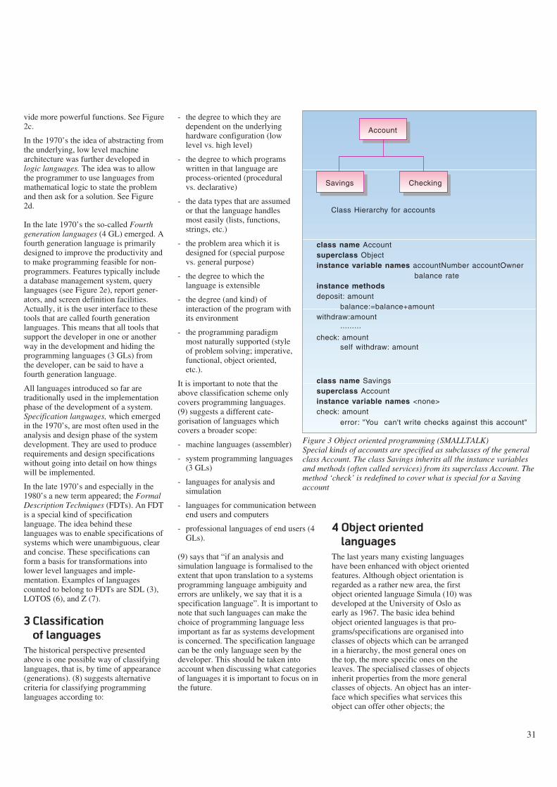
vide more powerful functions. See Figure2c.
In the 1970’s the idea of abstracting fromthe underlying, low level machinearchitecture was further developed inlogic languages. The idea was to allowthe programmer to use languages frommathematical logic to state the problemand then ask for a solution. See Figure2d.
In the late 1970’s the so-called Fourthgeneration languages (4 GL) emerged. Afourth generation language is primarilydesigned to improve the productivity andto make programming feasible for non-programmers. Features typically includea database management system, querylanguages (see Figure 2e), report gener-ators, and screen definition facilities.Actually, it is the user interface to thesetools that are called fourth generationlanguages. This means that all tools thatsupport the developer in one or anotherway in the development and hiding theprogramming languages (3 GLs) fromthe developer, can be said to have afourth generation language.
All languages introduced so far aretraditionally used in the implementationphase of the development of a system.Specification languages, which emergedin the 1970’s, are most often used in theanalysis and design phase of the systemdevelopment. They are used to producerequirements and design specificationswithout going into detail on how thingswill be implemented.
In the late 1970’s and especially in the1980’s a new term appeared; the FormalDescription Techniques (FDTs). An FDTis a special kind of specificationlanguage. The idea behind theselanguages was to enable specifications ofsystems which were unambiguous, clearand concise. These specifications canform a basis for transformations intolower level languages and imple-mentation. Examples of languagescounted to belong to FDTs are SDL (3),LOTOS (6), and Z (7).
3 Classification
of languages
The historical perspective presentedabove is one possible way of classifyinglanguages, that is, by time of appearance(generations). (8) suggests alternativecriteria for classifying programminglanguages according to:
- the degree to which they aredependent on the underlyinghardware configuration (lowlevel vs. high level)
- the degree to which programswritten in that language areprocess-oriented (proceduralvs. declarative)
- the data types that are assumedor that the language handlesmost easily (lists, functions,strings, etc.)
- the problem area which it isdesigned for (special purposevs. general purpose)
- the degree to which thelanguage is extensible
- the degree (and kind) ofinteraction of the program withits environment
- the programming paradigmmost naturally supported (styleof problem solving; imperative,functional, object oriented,etc.).
It is important to note that theabove classification scheme onlycovers programming languages.(9) suggests a different cate-gorisation of languages whichcovers a broader scope:
- machine languages (assembler)
- system programming languages(3 GLs)
- languages for analysis andsimulation
- languages for communication betweenend users and computers
- professional languages of end users (4GLs).
(9) says that “if an analysis andsimulation language is formalised to theextent that upon translation to a systemsprogramming language ambiguity anderrors are unlikely, we say that it is aspecification language”. It is important tonote that such languages can make thechoice of programming language lessimportant as far as systems developmentis concerned. The specification languagecan be the only language seen by thedeveloper. This should be taken intoaccount when discussing what categoriesof languages it is important to focus on inthe future.
4 Object oriented
languages
The last years many existing languageshave been enhanced with object orientedfeatures. Although object orientation isregarded as a rather new area, the firstobject oriented language Simula (10) wasdeveloped at the University of Oslo asearly as 1967. The basic idea behindobject oriented languages is that pro-grams/specifications are organised intoclasses of objects which can be arrangedin a hierarchy, the most general ones onthe top, the more specific ones on theleaves. The specialised classes of objectsinherit properties from the more generalclasses of objects. An object has an inter-face which specifies what services thisobject can offer other objects; the
31
Account
Savings Checking
Class Hierarchy for accounts
class name Accountsuperclass Objectinstance variable names accountNumber accountOwner balance rateinstance methodsdeposit: amount
withdraw:amount check: amount
balance:=balance+amount
self withdraw: amount
class name Savingssuperclass Accountinstance variable names <none>check: amount
error: "You can't write checks against this account"
.........
Figure 3 Object oriented programming (SMALLTALK)Special kinds of accounts are specified as subclasses of the generalclass Account. The class Savings inherits all the instance variablesand methods (often called services) from its superclass Account. Themethod ‘check’ is redefined to cover what is special for a Savingaccount

internal aspects of an object are hidden orencapsulated from the other objects. SeeFigure 3. In the beginning, object orient-ation was only applied in programminglanguages. Today we see that specifi-cation languages (see below) areenhanced with object oriented features.
5 Specification languages
The focus in language research hasshifted from programming languages towhat is often called specificationlanguages. There is no exact borderbetween these two categories oflanguages. However, it is often said thata specification language is used to definea system at a higher abstraction level. Aprogramming language is executable by amachine, while this is not always thecase for specification languages. A speci-fication language is primarily used in theanalysis or design phase of the system’slife cycle.
Specification languages can be dividedinto two groups, informal specificationlanguages and formal specificationlanguages. The informal ones have a longhistory in the field of software engineer-ing. They are mainly graphical techni-ques with a precise syntax such that theycan be handled by a tool, but most oftenhave loosely defined semantics, i.e. it isnot clear how a program should workbased on these specifications. Two dia-gram types are often used; entity-relationship diagrams and data flow dia-grams.
Entity relationship diagram (ER-dia-gram) is a popular graphic notation forshowing data entities, their attributes, andthe relations which connect them. Theyare suitable for showing certain kinds ofconstraints, but usually they cannot showall constraints, and they ignore theoperations performed by and on the enti-ties. ER-diagrams cannot be used torepresent actual instances of data in thedatabase (11). The diagram in Figure 4expresses that persons belong to organ-isations, one cannot express that a speci-fic person is an employee at a specificorganisation.
Data flow diagrams show the processes,data stores, and data flows into and out ofthe processes and the system, see Figure5.
6 Formal specification
languages
Formal specification languages are speci-fication languages whose vocabulary,syntax, and semantics are formallydefined (12). The vocabulary gives thefinite set of symbols that can be used tospecify sentences according to the rulesof combining the symbols (syntax rules).
Possible advantages of using a formallanguage for specifying the design of asystem are (12):
- it may be possible to prove that a pro-gram conforms to its specification
- it may be possible to animate thebehaviour of a formal system specifi-cation to provide a prototype system
32
Country
Locality
Organization
Person Unit RoleresidentialPerson
Figure 4 Graphical specifications of data definitions (ER-diagram)The example specifies the data model for a small directory. The graph depicts classesof entities (boxes) and relations (arrows) between them. The notation is a variant ofthe original ER notation
telephoneuser
D1 subscriber
1.2
procedurelistofsubscribers
1.1
find actualsubscribers
D2 subscriberlist
1.3
copyOnFloppy
physical flowdataflowdata store
process
external entity
floppy
title
Symbols:
Figure 5 Data flow diagramAn example of a data flow diagram for a directory system. The graph shows how dataflows between processes, data stores and external entities. The dashed line is the sys-tem border

- formal software specifications aremathematical entities and can bestudied and analysed usingmathematical methods
- the specification may be used as aguide to identify test cases.
Formal specifications should be regardedas complementary to more informalspecification techniques. End users willprobably have problems when readingformal specifications and need othermeans of getting an idea of whether thespecified system will meet their needs ornot. Formal specifications are moreimportant for other user groups, forinstance those who are going to imple-ment the system. They need to knowexactly what are the requirements to thesystem in order to ensure that they imple-ment the right system.
It is convenient to decompose a languagedefinition into several parts (13):
- the definition of the syntax rules
- the definition of the static semanticrules (so-called well-formednessconditions) such as which names areallowed at a given place, which kind ofvalues are allowed to be assigned tovariables, etc.
- the definition of the semantics of theconstructs in the language when theyare interpreted (the dynamic semantics,defining the abstract behaviour of thecomputer).
In the definition of a formal specificationlanguage all parts are specified in anotherlanguage, a meta language (in contrast toinformal languages where the semantic isonly stated in natural language). A metalanguage is a language suited fordefining other languages. An example ofsuch a language is the BNF (The BackusNaur Form). Figure 6 illustrates howBNF is used to specify a part of thetextual grammar of SDL.
As far as definition of semantics isconcerned, there are different approach-es. It is far beyond the scope of this paperto treat this subject in any detail. How-ever, we will briefly mention threeapproaches (14):
- operational semantics, where themeaning of language constructs arespecified by the computation it induceswhen it is executed on a machine
- denotational semantics, where themeanings are modelled bymathematical objects that represent theeffect of executing the constructs
- axiomatic semantics, where specificproperties of the effect of executingthe constructs are expressed as ass-ertions.
The formal definition of the static anddynamic semantics of the CCITT specifi-cation language SDL is written in Meta-IV (15) and defines a denotationalsemantics.
There are several categories of formalspecification languages. Here we willonly introduce two kinds; AlgebraicSpecification and Model based Specifi-cation.
Algebraic specification is a techniquewhereby an object is specified in terms ofthe relationships between operations thatact on that object (12). The relationshipsbetween operations that act on the typesare stated by equations. The equationsare used to indicate which terms denotethe same value. A term is an applicationof an operator on an argument. In theexample in Figure 7 it is stated that theapplication of not true produces the samevalue as false. Without these equations,all terms would be regarded as differentvalues of the type.
An algebraic specification consists norm-ally of four parts, see Figure 7:
- the sort of the entity being specified(Bool in Figure 7)
- an informal description of the sort andits operations
- a signature part, where the names ofthe operations on that object and thesort of the parameters are provided(operators in Figure 7)
- an axiom part, where the relationshipsbetween the operations are defined(axioms in Figure 7).
An algebraic specification is regardedhard to read for non mathematicians, andeven harder to write. The main problemis to know when you have given enoughaxioms to be sure that all operations areproperly defined.
The CCITT language SDL has adoptedthe algebraic approach for its data types.However, for reasons indicated above,this part of the language is not muchused.
Model based specification is anotherapproach chosen in some languages.Model based specification is a techniquethat relies on formulating a model of thesystem, using well understoodmathematical entities such as sets andfunctions. Operations are specified bydefining how they affect the overall sys-tem model (12).
One of the best known model-basedtechniques is Z (7), which is based on settheory.
33
<textual block reference> ::=
block <block name> referenced <end>
<end> ::= ;
Figure 6 Example use of BNFThe BNF meta language allows strings tobe replaced by strings in a hierarchy.The finally produced strings are calledterminals, the rest are non terminals.Non terminals are represented as stringssurrounded by ‘<’ and ‘>’, e.g. <end>.A production rule for a non terminalsymbol consists of the non terminal sym-bol on the left hand side of the symbol‘::=’, and one or more non terminals/ter-minals on the right hand side. Above,block and referenced are terminal sym-bols
Newtype Bool;
literals true, false;
operators
not: Bool -> Bool;
axioms
not (true) == false;
not (false) == true;
Endnewtype;
Figure 7 An SDL ADTAbstract data types define the result ofoperations on data objects withoutconstraining how this result is obtained.
Bool is a new sort with true and false asvalues. The operator part gives the signa-ture of the not operator. In the axiomspart the relations between not and theliterals true and false (which areoperators without arguments) are defined

7 Visual languages
While formal specifications are regardedto be suitable for highly trained people,the idea behind visual languages is tomake formal languages feasible for nonprogrammers. (16) gives a good tutorialon visual programming. Here we willonly briefly introduce the basic notions.
A visual language can be defined as “anysystem that allows the user to specify aprogram in a two- (or more) dimensionalfashion” (16).
In (16) four possible positive propertiesof visual languages are listed, which mayexplain why these languages are moreattractive to non programmers thantraditional programming:
- pictures can convey more informationin a more concise unit of expression
- pictures can help understanding andremembering
- pictures can make programming moreinteresting
- when properly designed, pictures canbe understood by people regardless ofwhat language they speak.
(16) introduces three broad categories ofvisual programming languages, dia-grammatic programming languages,iconic programming languages, and formoriented programming languages.
Diagrammatic programming languagesare based on the idea of making chartsexecutable. They are most often a supple-ment to a textual representation. Thespecification language SDL can becharacterised as a diagrammaticlanguage. SDL used at a low level of abs-traction is executable. It is possible to usethe graphical syntax as a kind of a flowchart for the code. SDL also has a textualsyntax. However, the graphical form isthe main reason why the language hasattracted large user groups.
Iconic languages use icons to representobjects and actions. Icons are specificallydesigned to be essential language ele-ments playing a central role. The XeroxStar system (17) is an example of aniconic system where icons and pointingdevices are used as a means to communi-cate with the computer. User interfacesusing icons are now commonplace inmany systems.
34
Iconic programming languages go a stepfurther than diagrammatic languages inmaking programming visual. Programsare written by selecting icons denotingthe various operations needed andplacing them in the program area of thescreen. These icons are then connectedby paths to denote the flow of control.Iconic programming appears to be moreexciting for novice programmers thantext based programming. It is, however,doubtful whether it will increase pro-ductivity in long terms.
Form oriented visual programminglanguages are more to be compared withgraphical user interfaces where the user“program” the computer by filling informs. They are designed for people whohave no desire to learn how to program.Database query is one application areawhere the form oriented approach isused. QBE (Query By Example) is aform language supporting relational data-bases (18). Spreadsheet is anotherexample.
8 Standardisation
of languages
Much work is being done on stand-ardisation of languages and their environ-ments. Standardised languages mayattract more users and make it worth-while for vendors to develop tools sup-porting the languages. There are, how-ever many examples of languages whichhave not been successful despite the factthat they have been issued as aninternational standard. Here, we will givean overview of the language work inCCITT (International Telegraph andTelephone Consultative Committee).CCITT is recommending languages inthe area of telecommunications.
CCITT Study Group X has been assignedthe responsibility for methods andlanguages. This group should support theother groups with needed expertise on afew recommended languages. CHILL(CCITT High Level Language) isrecommended as a high level programm-ing language, SDL as a specificationlanguage (FDT). SDL is used to specifyrecommendations in certain applicationareas, e.g. ISDN. Even if SDL provides ahigh level of formality, in practice mostrecommendations use it at a rather lowlevel of formality, as a means of com-munication between humans. SDL hasover the last four years been enhanced
with object oriented features. Also, SG Xhas developed a draft recommendationon a Data Oriented Human-MachineInterface Specification Technique.
During the last study period, severallanguages or notations were developedoutside Study Group X. Many groups feltit was needed to develop techniquesspecially suited for their applications. Inthe work on Message Handling Systems(X.400, electronic mail) the developersfelt a need for a more precise andunambiguous way of defining the data tobe exchanged. As a consequence of thisneed, they came up with ASN.1, AbstractSyntax Notation (19). ISO (InternationalStandardisations Organisation) andCCITT jointly defined the OSI Manage-ment Formalism (20), to be used in thefield of network management, TMN(Telecommunications ManagementNetwork). This formalism is based onusing templates for defining managedobjects and using ASN.1 to define theattributes. This formalism is more or lessdirectly adopted by those working onelectronic directories (X.500) with someadjustments for their specific needs.However, the directory technique hasbeen further developed such that it hasbecome a language on its own.
There is no sign that the work on langu-ages in the standardisation bodies willunify to one common language for allneeds. The new application areas such asODP (Open Distributed Processing)(21)and IN (Intelligent Network) (22) havetheir specific requirements on languages,although much work is done toinvestigate whether existing languagesmeet these requirements. In both areasthe developers are asking for object ori-ented techniques.
9 Why is work on
languages needed?
The research activities on languages havenot come to an end. The concern is howto develop and use new languages onnew application areas. The complexity ofapplications is rapidly growing and soare the costs of development and maint-enance. Languages are central tools tomanage the complexity; the systemdevelopers need powerful languages thatcan help them to express differentaspects of the system in a straightforwardway. Also, the chosen language(s) willinfluence what the developed system will

35
Figure 8 The architecture of the SDL translatorThe translator consists of an input part that reads SDL specification providing SDL/PR form and transforms this to an internal form(a wide spectrum language, WSL, not tied to a specific language). The transformation part supports the application of trans-formation rules to this internal form. An output part dresses the target program in the proper external syntax (C)
be like. All languages are based on cer-tain ideas, which reflect the languagedesigners’ point of view on systems andsystems development. The usage of aprocess-oriented language (a languagefocusing on functions/processes to beperformed in the system) and a data-ori-ented language (focusing on the data tobe handled by the system) will mostoften lead to different systems, evenwhen the requirements from the users arethe same. The resulting system willprobably be differently structured, havedifferent user interfaces, and differentproperties as far as maintenance isconcerned. The importance of thisobservation is that system developersneed to be conscious about the choice oflanguage, and also research is needed toestablish more knowledge about how dif-ferent kinds of languages influence theresulting system.
The work on languages is tightlyconnected to the work on referencemodels. A reference model is a means ofsplitting up the system into manageableparts where different people can look atthe system from different points of view
(interfaces). The different interfaces canrequire different features to be expressedand will put specific requirements on thelanguages used to define the interfaces.
10 Research activities at
Norwegian Telecom
Research
Norwegian Telecom Research (NTR) hasmuch experience in using, evaluating anddeveloping techniques for design of dataoriented information systems and theirhuman-machine interfaces (HMIs). Thiswork has resulted in the development ofthe HMI specification technique (23).This technique allows the specification ofthe data encountered on the screens,using the end-user’s own terminology.
NTR has for many years participated inthe standardisation of SDL. During theperiod from 1988 to 1992 a prototype ofa translator from SDL to C has beendeveloped. The objectives of the projectwere both to experiment with newtechnology, especially transformationalprogramming, and also to develop a use-
ful tool for SDL users. When the projectstarted, there was a rather big groupspecifying ISDN-services in SDL andimplementing them using C. The imple-mentation of the specifications was basedon a runtime support system whichimplemented the basic SDL constructs offinite states machines. SDL was appliedin a low level of abstraction, such thattranslation to C was rather straight-forward and possible to automate. It wasfelt that a code generator could free thedevelopers from much uncreative work.A tool called REFINE (24), was used todevelop a prototype code generator.Unlike most code generators, which aremore or less like an ordinary compiler,the SDLTranslator offered the possibilityto generate different code where differentaspects where taken into account. Optim-isation on execution speed can lead to adifferent implementation than if storageis the main concern. REFINE offers avery flexible environment. For instancean SDL grammar and a C grammar couldbe developed in short time and be used toparse and print SDL specifications and Ccode, respectively. The parsed SDL
interactive
transformer
transformationrules
user
parserinitialtrans-former
targetinter-face
SDL/PR SDL/PRparse tree
WSLabstractsyntax
tree
targetlanguageparse tree
targetlanguage
files
un-parser
36
specification was given an internal repre-sentation in REFINE’s knowledge baseand step by step transformed to a Crepresentation. For small specificationsthe ideas were promising, for large scaleprojects, however, the performanceturned out to be unsatisfactory. Figure 8shows the architecture of the SDLTrans-lator.
The 1992-version of SDL hasincorporated object oriented extensionsto the language. A small project has beenworking on applying these new featuresin the specification of IntelligentNetwork Services. The results showedthat types and subtyping made it possibleto compose services out of reusable com-ponents. The reusable components asdefined in the IN-recommendations were,however, not very well designed. Thework also illustrated the importance offormal specification of a recomm-endation. A lot of unclear points wherefound during the specification work.
In 1992 a project called Systemutvikling2000 (Systems Development 2000) wasinitiated by the Information TechnologyDepartment. The project was asked tocome up with the needed knowledge formaking decisions on strategies for whatkind of languages, tools, and referencemodels should be used for systemsdevelopment in the future (year 2000).So far, the work has focused on how toput requirements on languages. It is feltthat existing lists of such requirements(found in for instance recommendations)are more or less unmotivated. There is alack of rationale behind the selection ofevaluation criteria. A central objectivefor the work is therefore to develop a fra-mework for comparing languages.
References
1 IEEE. Standard Glossary of SoftwareEngineering Terminology. NewYork, IEEE, 1990.
2 Raymond-Smith, V J. AutomataTheory. In: Software Engineer’sReference Book (ed: J McDermid).Butterworth-Heinemann, 1991, 9/3 –9/15. ISBN 0-750-61040-9.
3 CCITT. CCITT Specification andDescription Language, March 1988.(Blue Book, Fascicle X.1-5,Recommendation Z.100.)
4 Ghezzi, C. Modern non-conventionalprogramming language concepts. In:Software Engineer’s Reference Book(ed: J McDermid). Butterworth-Heinemann, 1991, 44/3 – 44/16.ISBN 0-750-61040-9.
5 Clocksin, W F, Mellish, C S. Pro-gramming in Prolog. Second Edition.Berlin, Springer Verlag, 1984. ISBN0-387-15011-0.
6 ISO. LOTOS – A formal descriptiontechnique based on the temporal ord-ering of observational behaviour,1988. (ISO 8807.)
7 Spivey, J M. The Z notation: A refer-ence manual. Englewood Cliffs, N.J.,Prentice Hall, 1987. (InternationalSeries in Computer Science.)
8 Weiser Friedman, L. ComparativeProgramming Languages: general-izing the programming function.Prentice-Hall, 1991. ISBN 0-13-155714-9.
9 Schubert, W, Jungklaussen, H.Characteristics of programminglanguages and trends in development.Programming and computersoftware, 16, 196-201, 1990.
10 Kirkerud, B. Object-oriented pro-gramming with SIMULA. Reading,Mass., Addison-Wesley, 1989. ISBN0-201-17574-6.
11 Sowa, J F, Zachman, J A. Extendingand formalising the framework forinformation systems architecture.IBM Systems Journal, 31(3), 1992.
12 Sommerville, I. Software engineer-ing, third edition. Reading, Mass.,Addison-Wesley, 1990. ISBN 0-201-17568-1.
13 CCITT. CCITT Specification andDescription Language, SDL formaldefinition. Introduction. March 1988.(Blue Book, Fascicle X.1-5,Recommendation Z.100 – AnnexF.1.)
14 Nielson, H R, Nielson, F. Semanticswith applications, a formal intro-duction. New York, Wiley, 1992.ISBN 0-471-92980-8.
15 Bjørner, D, Jones, C B. Formalspecification and software develop-ment. Englewood Cliffs, N.J.,Prentice-Hall, 1992.
16 Shu, N C. Visual Programming:Perspectives and approaches, IBMSystems Journal, 28(4), 1989.
17 Smith, D C et al. The Star user inter-face: An overview. Proceedings ofthe National Computer Conference,515-528, 1982.
18 Zloof, M M. Query-by-example,AFIPS Conference Proceedings,National Computer Conference, 431-438, 1975.
19 CCITT. Information technology –Open Systems Interconnection – Abs-tract Syntax Notation One (ASN.1),March 1988. (Blue Book, FascicleVIII.4, Recommendation X.208.)
20 ISO. Final Text of DIS 10165-4,Information Technology – Open Sys-tems Interconnection – Structure ofManagement Information – Part 4:Guidelines for the Definition ofManaged Objects, 1991. (ISO/IECJTC 1/SC 21/ N 63009.)
21 ISO. Working Draft – Basic Refer-ence Model of Open Distributed Pro-cessing – Part 1: Overview andGuide to Use, 1992. (ISO/IEC JTC1/SC 21/N 7053.)
22 ETSI. Intelligent network: fra-mework. Draft Technical Report NA-6001, Version 2, 14 September 1990.
23 Meisingset, A. The draft CCITTformalism for specifying Human-Machine Interfaces, Telektronikk,89(2/3), 60-66, 1993 (this issue).
24 REFINETM User’s Guide. Palo Alto,CA., Reasoning Systems Inc., 1990.
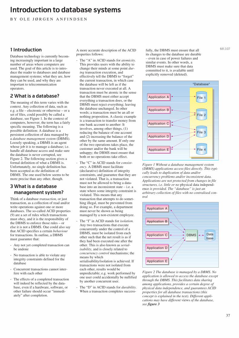
1 Introduction
Database technology is currently becom-ing increasingly important in a largenumber of areas where computers areused. The goal of this article is to intro-duce the reader to databases and databasemanagement systems; what they are, howthey can be used, and why they areimportant to telecommunicationoperators.
2 What is a database?
The meaning of this term varies with thecontext. Any collection of data, such ase.g. a file – electronic or otherwise – or aset of files, could possibly be called adatabase, see Figure 1. In the context ofcomputers, however, the term has a fairlyspecific meaning. The following is apossible definition: A database is apersistent collection of data managed bya database management system (DBMS).Loosely speaking, a DBMS is an agentwhose job it is to manage a database; i.e.handle all database access and make surethe database is never corrupted, seeFigure 2. The following section gives aformal definition of what a DBMS is.Unfortunately, no single definition hasbeen accepted as the definition ofDBMS. The one used below seems to bemore precise than any other, though.
3 What is a database
management system?
Think of a database transaction, or justtransaction, as a collection of read and/orwrite operations against one or moredatabases. The so-called ACID properties(9) are a set of rules which transactionsmust obey, and it is the responsibility ofthe DBMS to enforce those rules – orelse it is not a DBMS. One could also saythat ACID specifies a certain behaviourfor transactions. In outline, a DBMSmust guarantee that:
- Any not yet completed transaction canbe undone
- No transaction is able to violate anyintegrity constraints defined for thedatabase
- Concurrent transactions cannot inter-fere with each other
- The effects of a completed transactionwill indeed be reflected by the data-base, even if a hardware, software, orother failure should occur “immedi-ately” after completion.
A more accurate description of the ACIDproperties follows:
- The “A” in ACID stands for atomicity.This provides users with the ability tochange their minds at some point dur-ing transaction execution, andeffectively tell the DBMS to “forget”the current transaction, in which casethe database will be left as if thetransaction never executed at all. Atransaction must be atomic in the sensethat the DBMS must either accepteverything a transaction does, or theDBMS must reject everything; leavingthe database unchanged. In otherwords; a transaction must be an all ornothing proposition. A classic exampleis a transaction to transfer money fromone bank account to another: Itinvolves, among other things, (1)reducing the balance of one accountand (2) increasing the balance of theother by the same amount. If only oneof the two operations takes place, thecustomer and/or the bank will beunhappy; the DBMS must ensure thatboth or no operations take effect.
- The “C” in ACID stands for consist-ency. A DBMS must facilitate(declarative) definition of integrityconstraints, and guarantee that they arenot violated. That is, a transactionmust not be allowed to bring a data-base into an inconsistent state – i.e. astate where some integrity constraint isviolated. This means that anytransaction that attempts to do somet-hing illegal, must be prevented fromdoing so. For example, a departmentmust never be shown as beingmanaged by a non-existent employee.
- The “I” in ACID stands for isolation.Any two transactions that executeconcurrently under the control of aDBMS, must be isolated from eachother such that the net result is as ifthey had been executed one after theother. This is also known as serial-isability, and is closely related toconcurrency control mechanisms; themeans by whichserialisability/isolation is achieved. Iftransactions were not isolated fromeach other, results would beunpredictable; e.g. work performed byone user could accidentally be nullifiedby another concurrent user.
- The “D” in ACID stands for durability.When a transaction completes success-
fully, the DBMS must ensure that allits changes to the database are durable– even in case of power failures andsimilar events. In other words, aDBMS must make sure that datacommitted to it, is available untilexplicitly removed (deleted).
37
Introduction to database systems
B Y O L E J Ø R G E N A N F I N D S E N
681.3.07
Application A File 1
File 2
File 3
File 4
Application B
Application C
Application D
Application E
"Database"
Figure 1 Without a database management system(DBMS) applications access files directly. This typi-cally leads to duplication of data and/orconcurrency problems and/or inconsistent data.Applications are not protected from changes in filestructures, i.e. little or no physical data independ-ence is provided. The “database” is just anarbitrary collection of files with no centralised con-trol
Application A
DBMS
Application B
Application C
Application D
Application E
Database
Figure 2 The database is managed by a DBMS. Noapplication is allowed to access the database exceptthrough the DBMS. This facilitates data sharingamong applications, provides a certain degree ofphysical data independence, and guarantees ACIDproperties for all database transactions (thisconcept is explained in the text). Different appli-cations may have different views of the database,see figure 3

Definition: a DBMS is an informationstorage and retrieval system which pro-vides ACID properties for all databasetransactions.
This can be summed up – less formally –as follows. A database that is controlledby, and therefore accessed through, aDBMS, is a database that will behaveproperly. Even though the aboveexplanation of the ACID propertiesmight be hard to understand for peoplewho are not familiar with database sys-tems, they define behaviour that is intui-tively and obviously desirable.
Any decent DBMS product will haveadditional features, such as e.g. aut-horisation control, buffer pool manage-ment, parameter tuning, and trace facili-ties, as well as utilities for back-up,recovery, load, unload, reorganisation,and more.
DBMSs also provide physical data inde-pendence and makes data sharing amongapplications feasible; two extremelysignificant properties. An important termin this context is schema, see Figure 3.Although most people seem to agree thatthe three-schema architecture is a good
idea, few if any commercial DBMS pro-ducts fully support it; they typically donot clearly separate the internal andconceptual schemas, which has given riseto the ironic term two-and-a-half-schemaarchitecture. For the remainder of thisarticle, schema should be taken to meanconceptual schema.
4 Current usage of
database systems
In this section we mention some of themost common uses of database systems.The term “database system” is often usedto denote a DBMS; a DBMS and its data-base; a DBMS, its database, and theapplications that manipulate the data-base; or even a collection of databasesystems working together. Thus, thereader should be aware that the exactmeaning of the term may vary dependingon the context.
Database systems were first developed inthe 1960’s. They were then mostly usedfor business applications with largeamounts of structured data, typically inthe banking, insurance, and airline indus-tries. Today, virtually all largecorporations use database systems tokeep track of customers, suppliers,reservations, orders, deliveries, invoices,employees, etc.
As database systems became moreversatile, powerful, and user friendly,their use proliferated into a growingnumber of areas. For example manage-ment information systems (MIS), decis-ion support systems (DSS), ad hoc querysystems, inventory control systems, pointof sale systems (POS), and more.
Norwegian Telecom is a large user ofdatabase systems. We have been activelyinvolved with database technology formore than twenty years, our first majordatabase system (Telsis) went into pro-duction in 1975, and we currently havedatabase systems that cover most of theareas mentioned in the previous para-graphs. Also, information about ourtelecommunications networks is stored indatabase systems. And our modernpublic switches use database systems toprocess calls, define customer services,store billing information, produce inputdata to the invoice system, etc. As can beseen from the following section, databasetechnology will become even moreimportant in the future.
5 Emerging areas for
database systems
In principle, any system that needs tostore and retrieve data could benefit fromusing a DBMS. This is beneficialbecause the ACID properties (describedabove) are always an advantage. It isbeneficial because a DBMS has a welldefined interface – thus making appli-cations more portable. And it is bene-ficial because a DBMS, a modern one atleast, will allow users to combine data inalmost any conceivable way, thus enabl-ing discovery of previously unknowncorrelations (roaming about in a databaselooking for “new” information, is frequ-ently called database mining). There arealso other advantages of using a DBMS.However, the functionality and/or theperformance characteristics offered bycurrent DBMSs, are inadequate for anumber of application areas.
Research and industry are currentlyworking hard to provide database sys-tems that will meet the needs of thefollowing application areas: Computeraided design (CAD), computer aidedmanufacturing (CAM), computer aidedengineering (CAE), computer aidedsoftware engineering (CASE), computerintegrated manufacturing (CIM), geo-graphical information systems (GIS),multimedia systems, process control sys-tems, text search systems, word pro-cessors, office support systems, programdevelopment environments, and more. Inparticular, these application areas needsupport for:
- User defined types, e.g. Employee,Vehicle, or any other data type de-scribing entities within an applicationdomain
- Complex objects, i.e. objects that arenested inside other objects, to anarbitrary depth
- Versioning, i.e. the ability to letseveral versions of given objects existsimultaneously, and co-ordinate theiruse
- Long transactions, i.e. transactions thatmay last for days, weeks, or months,rather than seconds or minutes.
Other challenges come from new appli-cation areas that will depend on databasetechnology. Of particular interest totelecommunication operators, are intel-
38
Externalschema
Externalschema
Externalschema
Conceptualschema
Internalschema
Figure 3 The three-schema architecture. The conceptualschema may be thought of as the database schema,because it is a logical description of the entire database.The internal schema may be thought of as a descriptionof how the conceptual schema is to be realised or imple-mented, because it defines the physical properties of thedatabase. The external schemas are views throughwhich different applications or users may access thedatabase. An external view could be identical to theconceptual schema, it could be a proper subset of theconceptual schema, it could provide aggregation ofdata, it could join data instances and present them as asingle instance, etc

ligent networks (IN) and telecommuni-cations management networks (TMN).Database systems that are to be integra-ted with public networks, must havescalable capacity, low response times,and high availability – way beyond thatof today’s commercially available sys-tems. The HypRa project, primarilysponsored by Norwegian Telecom Rese-arch and carried out at the NorwegianInstitute of Technology (NTH) andSINTEF/DELAB, has produced interesting resultsin these areas. Further, it is conceivablethat new telecommunications serviceswill evolve that rely on database systems.These could be run by the public networkoperator (PNO) or by some third party.They could contain information thatusers would want to access, or they couldcontain information that would enablethe service in question.
Yet another research field is that of dis-tributed database systems, i.e. where twoor more DBMSs co-operate to form asingle database system. The DBMSs inquestion may run on separate computers,possible geographically remote. See thearticle on Dibas elsewhere in this issue.
6 Kinds of DBMS
Traditional DBMSs are usually given oneof the following three labels: hierarchic,network, or relational. These are not theonly ones, but they are by far the bestknown. Two new kinds of DBMS thatare beginning to have an impact on themarketplace, have the label object ori-ented and/or extended relational.
6.1 Hierarchic
A hierarchic – or hierarchical – DBMS(HDBMS) stores data in hierarchic
structures (also known as trees), withroot nodes and dependent nodes. A rootnode may have zero or more children,while a dependent node has exactly oneparent. The trees may be arbitrarily deep,i.e. children may have children, and soforth. Also, trees need not be balanced,i.e. siblings can be root nodes in unequ-ally sized subtrees. The archetype of anHDBMS is clearly the IBM product IMS,also known as IMS/DB, and sometimeseven referred to as DL/1. The latterstands for Data Language 1, which is thelanguage used to access IMS/DB. Theproduct has been around since 1968, andused to be the top mainframe DBMSboth in terms of number of installationsand also in terms of the number and sizeof applications that depend on it. It isprobably fair to say that most majorcorporations in the world –those who where majorduring the 1970’s at least –use IMS/DB.
For illustration purposes, aclassic database example ofcourses, prerequisites, off-erings, and teachers willnow be used. A possiblehierarchic schema for sucha database is shown inFigure 4. The root node inthis tree structure is Course,while Prerequisite and Off-ering are sibling dependentnodes. Figure 5 contains anoccurrence diagram.
An obvious weakness withthe chosen structure is thatteacher name appears as afield inside the Offeringsegments. This has disad-vantages, in particular:
- Storing redundant data. Assuming thata teacher may be involved in morethan one course offering in a givensemester, and that offerings fromseveral semesters are stored in thedatabase at any time, the same teachernames will occur multiple times. If thedatabase is to contain not only thenames of teachers, but also theiremployee numbers, addresses, phonenumbers, birth dates, etc., then such aschema soon becomes unacceptable.
To solve this problem one needs to createa separate hierarchy with Teacher as theroot node. The schema would then be asshown in Figure 6. Carefully note thatthe relationship between Teacher andOffering is different from that of Course
39
NameNo
Required No SemesterOffering Location TeacherPrerequisite
Course
Figure 4 The course-prerequisite-offering-teacher structure represented by a singlehierarchy. The two arrows indicate pointers from Course segments to Prerequisite andOffering segments. This means that it is possible to navigate from a given Course to allits dependent Prerequisites and Offerings. However, this does not preclude the pre-sence of other pointers, e.g. a pointer from every Offering to its parent Course
CalculusB2
AlgebraB1
PhysicsA1OsloS93
A93
Sue
JoeKjeller
B2
B1
OsloA93
S93
Sue
PeterOslo
S93 JoeKjeller
Figure 5 Occurrence diagram for the schema of figure 4
NameNo
Required No SemesterOffering LocationPrerequisite
Course
NameNoTeacher
Tree 1
Tree 2
Figure 6 An alternative to the schema of figure 4, with Teacher andCourse as root nodes in two separate hierarchies and with Offering as adependant of Course

with Offering. One could say that thenetwork structure needed in this case hasbeen achieved by combining two treestructures. It would also have beenpossible to define Offering as adependant of Teacher, as shown inFigure 7. The two schemas will have dif-ferent performance characteristics.
6.2 Network
The data structures supported by networkDBMSs (NDBMSs), also known asCODASYL-systems (see next para-graph), are an extension of those sup-ported by HDBMSs; a dependent node inan NDBMS data structure may havemore than one parent, i.e. it may be partof more than one parent-child relations-hip type. A well known example of anNDBMS is IDMS from ComputerAssociates.
The Database Task Group (DBTG) of theProgramming Language Committee (alsoknown as the Cobol committee) of theConference on Data Systems Languages(CODASYL) produced a report in 1971describing how the language interface ofan NDBMS should be. Hence, DBMSsthat implement these proposals, more orless, are often called CODASYL-sys-tems.
A network schema for the example data-base could be as shown in Figure 8. TheOffering segment now has two parentsegments, Course and Teacher, and thetwo parent-child relationships areequivalent. We now have a directedgraph instead of one or two treestructures. The occurrence diagram isshown in Figure 9.
Navigation between two or more treestructures in an HDBMS is limited to apredefined number of iterations, while nosuch limitation applies to an NDBMS.
Another feature that distinguishesNDBMSs from HDBMSs is the ability todefine a schema such that segments oftype C, say, should be dependent eitheron a segment of type A or a segment oftype B, but not both. For example, aChild could be a dependant of a Motheror a Father. This is claimed to be a usefulfeature by NDBMS proponents.
6.3 Relational
Relational DBMSs (RDBMSs) are radi-cally different from the two foregoingkinds of DBMS. Rather than performingexplicit navigation through tree ornetwork structures, an application mustsubmit search criteria to an RDBMSwhich will then return all data items thatsatisfy those criteria. This is known asquery access. It is common to say thatone specifies what one wants, not how to
get it. The latter is figured out by anRDBMS component called the optimiser.Another important difference is that H-and NDBMSs limit access to a singlenode at a time, while RDBMSs are set-oriented.
The following is an informal definitionof relational DBMS: the only datastructure supported at the user level by anRDBMS, is tables, also known asrelations – hence relational.
Most people find tables easy to under-stand; they have a fixed number ofcolumns and zero or more rows. Thissimplicity is both a strength and aweakness of the relational model of data;it provides ease of use, but also imposescertain drawbacks, such as e.g. having torepresent complex data structures by alarge number of tables – resulting in per-formance degradation.
The relational model was published byE.F. Codd – then of IBM – in 1970, forwhich he later received the Turing
40
NameNo
SemesterOffering Location
Course NameNo
Teacher
Tree 1
Tree 2
Required NoPrerequisite
Figure 7 An alternative to the schema of figure 6,still with Teacher and Course as root nodes in twoseparate hierarchies but with Offering as adependant of Teacher instead of Course
NameNo
SemesterOffering Location
Course NameNo Teacher
Required NoPrerequisite
Figure 8 A network schema for the course-prerequisite-offering-teacherdatabase. As with the hierarchic schema, arrows point from parent to childnodes but Offering is now a child of both Course and Teacher
CalculusB2
AlgebraB1
PhysicsA1
OsloS93
A93 Kjeller
B2
B1
S93 Kjeller
S93 Oslo
A93 Oslo
Joe15
22 Sue
24 Peter
Figure 9 Occurrence diagram for the schema of figure 8. This figure also serves toillustrate the term link (also known as co-set), which is central for NDBMSs. A linkdefinition involves a parent (or owner) node and a child (or member) node type. Thisschema has three link types; one with Teachers as parent and two with Courses asparent. As indicated by the arrows, Joe is the parent and A93-Kjeller and S93-Kjellerare the children in one such link type occurrence. Note that links are circularstructures

between segments in HDBMSs andNDBMSs are typically represented byphysical pointers, i.e. explicit referencesto the physical addresses where the seg-ments in question reside, no suchconstruct is allowed to be exposed at theprogramming interface of an RDBMS.
All references between two rows,whether they belong to the same table ornot, must be associative, i.e. based oncolumn values only. The relationalmechanism for inter-row references iscalled foreign key. There are four foreignkeys in the schema of Figure 10, eachrepresented by an arrow. For example,the Offering.TeacherNo is a foreign keywhose values point to Teacher.No, theprimary key of the Teacher table. Thismeans that every value ofOffering.TeacherNo must be present inTeacher.No, or else it would be possiblefor an offering to reference a non-
existent teacher, in which case thedatabase would be inconsistent. Aspointed out in the above discussionof ACID properties, it is the responsi-bility of the DBMS to ensure consist-ency.
But what if one needs to register anoffering for the next semester, say, and itis not yet known who will teach; how canthis be handled? Well, the relationalmodel allows the use of nil marks – alsoknown as null values – indicating e.g.“value not known”. Unless prohibited forOffering.TeacherNo, we can use a nil
Award. The DBMS marketplace is curr-ently dominated by relational products,of which some of the more well knownare Oracle, Sybase, Ingres, Informix,RDB, and DB2.
A relational schema for the exampledatabase, could be as shown in Figure 10.The relational model requires that alltables have a primary key, i.e. one ormore columns that contain enoughinformation to uniquely identify an indiv-idual row. Primary keys are indicated inFigure 10 by bold lines over the columnnames in question. While relationships
mark in that column to avoid referentialconstraint enforcement from the DBMSwhen necessary. The use of nil marks issomewhat controversial among databaseresearchers, see e.g. (4).
The de facto standard language forrelational data access is SQL. Sub- andsupersets of this language are also beingused by non-RDBMS products or proto-types. Its vast importance is summed upin the famous words “For better orworse, SQL is intergalactic dataspeak”(13). This is of course an exaggeration,but at least the language is worth havinga brief look at in this article. This will bedone by means of some examples, usingthe database of Figure 11, which is therelational schema of Figure 10 populatedwith now familiar values.
Example 1: SQL expression that will findall courses:
SELECT *FROM Course
Result:
No Name-----------------
B1 AlgebraB2 CalculusA1 Physics
Example 2: SQL expression that will findall offerings taught by teacher number15:
SELECT CourseNo,Semester,Location
FROM OfferingWHERE TeacherNo = 15
Result:
CourseNo SemesterLocation
--------------------------
A1 S93 KjellerB1 A93 Kjeller
Example 3: SQL expression that will findnames of courses taught at Kjeller:
SELECT A.NameFROM Course A, Offering
BWHERE A.No=B.CourseNoAND
B.Location='Kjeller'
Result:
Name-------
PhysicsAlgebra
41
NameNo
Course No SemesterOffering Location Teacher No
Prerequisite
Course NameNoTeacher
Course No Required No
Figure 10 A relational schema for the course-prerequisite-offering-teacher database.See discussion in text
Offering
Prerequisite
Course
Teacher
No
B1
B2
A1
Name
Algebra
Calculus
Physics
Required No
B1
B2
Course No
A1
A1
Name
Sue
Joe
Peter
No
22
15
24
Course No
A1
A1
A1
B1
B1
Semester
S93
S93
A93
S93
A93
Location
Kjeller
Oslo
Oslo
Oslo
Kjeller
Teacher No
15
24
22
22
15
Figure 11 Occurrence diagram for the schema of figure 10

Explanation: the latter SQL expression isknown as a join query; it joinsinformation from tables Course and Off-ering. Conceptually, the DBMS will scanthrough the Offering table, and for everyrow whose Location is Kjeller it will useits CourseNo value to access the Coursetable and find the Name of the coursewhose No value is equal to the currentCourseNo value.
6.4 Object oriented
Object oriented DBMSs (OODBMS orjust ODBMS) have only been commerci-ally available since the late 1980’s, andare therefore quite immature compared tothe other kinds of DBMS. ODBMSs havetheir roots in the object oriented pro-gramming paradigm, a certain way oforganising computer programs, first sup-ported by the programming languageSimula – invented in Norway during the1960’s – and later by Smalltalk,Objective-C, C++, Eiffel, and manymore. Distinctive features of object ori-ented programming languages (OOPLs)include support for classes, objects,inheritance, messages, methods, andencapsulation; which may informally beoutlined as follows:
- A class is a description of the prop-erties of objects of that class. Forexample, class Beagle could describethe properties of all beagles.
- An object is an instance (oroccurrence) of a class. Snoopy andFido could e.g. be instances of classBeagle.
- If class Beagle is defined as a subclassof Dog, Beagle will inherit all theproperties of Dog. This is very natural,since every beagle is a dog.
- All objects understand certainmessages. The set of messages thatobjects of a given class understand, iscalled its protocol or interface. Uponreceipt of a protocol message, acorresponding method will beexecuted by the receiver. Thus, amessage is a special kind of procedurecall, and a method is a procedure thatis local to an object.
- An object must be accessed through itsprotocol and will – in general – hide itsinternal structure from its surround-ings. This data hiding is known asencapsulation. If e.g. the message“age” is in the protocol of a given classand that class encapsulates its data,users cannot know whether age values
42
are explicitly stored inside objects orcalculated during execution – e.g. asthe difference between current dateand birth date.
It is common to say that objects are datathat exhibit a certain behaviour, and thereader has probably guessed by now thatobject oriented programming is focusedon defining the behaviour and imple-mentation of classes of objects, as well asmanipulating objects during programexecution. But what is an ODBMS?Unfortunately, there is no universalconsensus on that question. Very inform-ally, one could say that an ODBMS is aDBMS which is able to store and mani-pulate arbitrarily complex objects, or anagent that provides persistence forobjects.
In other words, and OODBMS is aDBMS that “understands objects”. TheObject-Oriented Database System Mani-festo (1) “attempts to define an object-oriented database system (and) describesthe main features and characteristics thata system must have to qualify as anobject-oriented system”. This manifestoseparates the characteristics into threegroups.
Quote:
- Mandatory, the ones the system mustsatisfy in order to be termed an object-oriented database system. These arecomplex objects, object identity,encapsulation, types or classes,inheritance, overriding combined withlate binding, extendibility, com-putational completeness, persistence,secondary storage management,concurrency, recovery, and an ad hocquery facility.
- Optional, the ones that can be added tomake the system better, but which arenot mandatory. These are multipleinheritance, type checking and inferen-cing, distribution, design transactions,and versions.
- Open, the points where the designercan make a number of choices. Theseare the programming paradigm, therepresentation system, the type system,and uniformity.
Unquote.
6.5 Extended relational
Several extensions to the relationalmodel of data has been proposed since itwas published in 1970. This article will
only briefly mention object orientedextensions, which are currently receivingconsiderable attention from the ISO andANSI committees responsible for theemerging SQL3-standard. Recall thatSQL is the de facto standard language forrelational data access. Several RDBMSvendors claim that future releases of theirproducts will have “complex object sup-port”, which obviously must include theability to store arbitrarily complexobjects “as they are”, and facilities fortraversal of object structures.Presumably, an extended RDBMS pro-duct may also involve e.g. inheritance fortable definitions, support for one or morepersistent languages, message passing toand among stored objects, and otherthings. The important point is that thisapproach attempts to provide facilitiesrequested by object oriented applications,while retaining the relational model ofdata.
The authors of The Third-generationData Base System Manifesto (13) “pre-sent the three basic tenets that shouldguide the development of third gener-ation systems (and) indicate 13 proposi-tions which discuss more detailedrequirements for such systems”. Thispaper classifies network and hierarchicDBMSs as first generation, classifiesrelational DBMSs as second generation,and uses third generation to denote futureDBMSs.
Quote:
- Tenet 1: Besides traditional datamanagement services, third generationDBMSs will provide support for richerobject structures and rules.
- Tenet 2: Third generation DBMSsmust subsume second generationDBMSs.
- Tenet 3: Third generation DBMSsmust be open to other subsystems.
Unquote.
Based on these tenets, thirteen proposi-tions are indicated (carefully note that thefirst part of any proposition numberbelow indicates the tenet to which itbelongs).
Quote:
- 1.1: A third generation DBMS musthave a rich type system.
- 1.2: Inheritance is a good idea.

- 1.3: Functions, including database pro-cedures and methods, and encap-sulation are a good idea.
- 1.4: Unique Identifiers (UIDs) forrecords should be assigned by theDBMS only if a user-defined primarykey is not available.
- 1.5: Rules (triggers, constraints) willbecome a major feature in future sys-tems. They should not be associatedwith a specific function or collection.
- 2.1: All programmatic access to a data-base should be through a non-proce-dural, high-level access language.
- 2.2: There should be at least two waysto specify collections, one usingenumeration of members and oneusing the query language to specifymembership.
- 2.3: Updatable views are essential.
- 2.4: Performance indicators havealmost nothing to do with data modelsand must not appear in them.
- 3.1: Third generation DBMSs must beaccessible from multiple high-levellanguages.
- 3.2: Persistent X for a variety of Xs isa good idea. They will all be supportedon top of a single DBMS by compilerextensions and a (more or less) com-plex run time system.
- 3.3: For better or worse, SQL is inter-galactic dataspeak.
- 3.4: Queries and their resulting an-swers should be the lowest level ofcommunication between a client and aserver.
Unquote.
6.6 Persistent languages
A concept closely related to that ofODBMS and ERDBMS, is persistentlanguages. In programs written intraditional OOPLs, objects – likeordinary program variables – cease toexist once program execution terminates.If objects are to be used by several (invo-cations of) programs, they must beexplicitly stored in and retrieved from adatabase or a file system. If, on the otherhand, the language is persistent, allobjects created during execution maymore or less automatically be stored inthe database. Thus, the program’saddress space and the database areconceived by the programmer as a single,contiguous object space. This is a very
powerful concept and a major vehicle forovercoming the so-called impedance mis-match between the two data spaces,which has to do with the different datamodels they support. There seems to be abroad consensus in the database com-munity that persistent languages are use-ful; see e.g. proposition 3.2 in the pre-vious section.
7 Conclusions
Database systems are important today,and are likely to become even more so inthe future, as an increasing number ofapplication areas require data sharing,ACID properties, and other good thingsoffered by DBMSs. The research anddevelopment efforts in the DBMS areaare considerable and growing (12). Data-base systems will be a vital part of futuretelecommunication systems. One way orthe other, next generation DBMS pro-ducts will support complex objects (1,13).
8 Further reading
For readers interested in a deeper under-standing of topics introduced in thisarticle, the following reading is sugge-sted:
- General database theory and relatedtopics: introductory (4); advanced (7)and (9)
- Relational database theory: (2), (4) and(7)
- Object oriented programming: (11)
- Object data management: introductory:(3); advanced (1), (6), (8), (13), and(14)
- The new SQL standards: (5), (8), and(10)
- Current and future importance of data-base systems: (12).
9 References
1 Atkinson, M et al. The object-ori-ented database system manifesto.Deductive and object-oriented data-bases, Amsterdam, Elsevier SciencePublishers, 1990.
2 Atzeni, P, De Antonellis, V. Rela-tional database theory. RedwoodCity, Calif., Benjamin/Cummings,1993.
3 Cattell, R G G. Object data manage-ment. Reading, Mass., Addison-Wes-ley, 1991.
4 Date, C J. An introduction to data-base systems, volume 1. Fifth edition.Reading, Mass., Addison-Wesley,1990.
5 Date, C J, Darwen, H. A guide to theSQL standard. Reading, Mass., Addi-son-Wesley, 1993.
6 Dittrich, K R, Dayal, U, Buchmann,A P (eds). On object-oriented data-base systems. Berlin, Springer-Ver-lag, 1991.
7 Elmasri, R, Navathe, S B. Funda-mentals of database systems.Redwood City, Calif., Benjamin/Cummings, 1989.
8 Gallagher, L. Object SQL: Languageextensions for object data manage-ment. In: Proceedings of the firstinternational conference oninformation and knowledge manage-ment, Baltimore, M.D., November1992.
9 Gray, J, Reuter, A. Transaction pro-cessing: concepts and techniques.San Mateo, Calif., Morgan Kauf-mann, 1993.
10 Melton, J, Simon, A R. Understand-ing the new SQL: a complete guide.San Mateo, Calif., Morgan Kauf-mann, 1993.
11 Meyer, B. Object-oriented softwareconstruction. London, Prentice Hall,1988.
12 Silberschatz et al. Database systems:achievements and opportunities.Communications of the ACM, 34(10),1991.
13 Stonebraker M et al (the committeefor advanced DBMS function).Third-generation database systemmanifesto. ACM SIGMOD Record,19, (3), 1990.
14 Zdonic, S B, Maier, D (eds). Read-ings in object-oriented database sys-tems. San Mateo, Calif., MorganKaufmann, 1990.
43

44
Software development methods and life cycle models
B Y S I G R I D S T E I N H O L T B Y G D Å S A N D M A G N E J Ø R G E N S E N
1 Introduction
“No methodology – no hope”, from Mak-ing CASE work (1)
The earliest view of software develop-ment was the programming view. Thisview had the implicit model of softwaredevelopment being a transcription from amental representation of a problem to anexecutable program. The developmentapproach of this view was: code & run(and, of course, debug and run again).The programmers were artists and pro-gramming was artistic work.
Later on, when the programming viewhad failed in large software development
projects, software development wasviewed as a sequential process from pro-blem understanding to executable code,i.e. analogous to the rather sequentialprocess of building a house. The sequ-ence of the steps was prescribed and theresult of each step was validated andverified. This view has resulted in forinstance the waterfall model and top-down design. Most of the models andmethods belonging to this view are inwidely use today.
After some years, the sequential and top-down views of the software developmentwere seriously questioned. The newview, software development as anexploratory activity emerged. Object ori-ented methods, evolutionary models andprototyping are results of this view. Thisview considers software development tobe rather opportunistic and emphasisesreuse and evolution. Software develop-ment based on exploration is typicallyless controllable than sequential develop-ment. Methods and life cycle modelsbased on this view are currently not verywide-spread.
Independent of development view,software projects often overspend anddeliver software too late with too lowquality. Also, the impact of the alterna-tive development views are not well und-erstood. Thus, the change of develop-ment view throughout the history hasprobably not been based on knowledgeof change in productivity and quality. Itis more probable that the change hasbeen driven by the lack of success of theprevious views.
2 Definitions
The term method is often confused withmethodology, model, technique, andtechnology. The definitions in Figure 1,taken from Collins dictionary (2), givesome clues in what the differences are.
This paper uses the underlined defini-tions in Figure 1. The relationship be-tween methods and life cycle models is
assumed to lay mainly in the scope andthe focus on needs. Life cycle modelscover the whole life cycle and have focuson project control, while methods some-times only cover parts of the life cycleand focus other needs than project con-trol.
Abstract
Different software development methods and life cycle modelsare based on different views on software development. Thispaper discusses some of these views and describes severalsoftware development methods and life cycle models in contextof these views. The methods and models described areStructured Systems Analysis and Design Method (SSADM), theESA Waterfall model, Coad and Yourdon’s Object Oriented
Analysis (OOA), verification oriented software development andtwo evolutionary life cycle models. In addition softwaredevelopment by Syntax Description, Operational Softwaredevelopment and the spiral model are briefly described. Moreresearch on the effects of using different software developmentmethods and life cycle models is needed. The advantages anddisadvantages of two different research strategies are thereforebriefly discussed.
681.3.06
Methodology: 1. the system of met-
hods and principles used in a
particular discipline. 2. the branch of
philosophy concerned with the sci-
ence of method or procedure.
Method: 1. a way of proceeding or
doing something, esp. a systematic
or regular one. 2. orderliness of
thought, action, etc. 3. (often pl.) the
techniques or arrangement of work
for a particular field or subject ...
Model: 1. a. a representation, usually
on a smaller scale, of a device,
structure, etc. ... 2. a. a standard to
be imitated ... 9. a simplified repre-
sentation or description of a system
or complex entity.
Technique: 1. a practical method,
skill, or art applied to a particular
task.
Technology: 1. the application of
practical or mechanical sciences to
industry or commerce. 2. the met-
hods, theory, and practices gov-
erning such application. 3. the total
knowledge and skills available to any
human society for industry, art, sci-
ence, etc.
Figure 1 Definitions from (2)
Understandingthe needs
(requirements)
Requirementspecification
Design
Implementation
Key: The horizontal arrows illus-trates inputs and outputs to thesystem, the vertical arrows showthe sequential progression fromphase to phase.
Figure 2 Conventional development

45
3 Conventional methods
and life cycle models
Figure 2 gives an overall picture of con-ventional software development from thesoftware developer’s point of view. Thefigure illustrates some typicalcharacteristics of conventional softwaredevelopment:
- The process of understanding is arather undisciplined and “fuzzy” pro-cess (illustrated by the “bubbles” in thefigure.) The output is not documented,but consist in increased understandingof the needs.
- Development of the requirementsspecification use “black box” methods,i.e. for use of methods describing theexternal behaviour (“what” in opposi-tion to “how”) of the system(illustrated by not drawing the arrowsinside the Requirement specificationbox).
- Development of the design specifi-cation makes use of “white box” met-hods, i.e. for methods describing theinternal behaviour of the system(illustrated by drawing the arrowsinside the Design box).
- The implementation methods focus onstructuredness and modularity.
- Life cycle models are rather sequential(like the water fall model), documentdriven and phase-oriented.
- Maintenance considerations in theearly phases are lacking.
- The methods used are top-down anduse a hierarchical decomposition.
It is not likely that real software develop-ment ever can or should be totally sequ-ential and purely top-down. However,methods and life cycle models based onthese assumptions have been rathersuccessful. A reason for this may be thatthe activities of the methods and lifecycle models are not really carried out asprescribed, they just act as guidelinestogether with common sense. This viewis defended in the famous paper “ARational Design Process: How and Whyto Fake it” (3). Another reason for thesuccess may be that the method enables arather high control of the softwaredevelopment process.
Table 1 gives an overview of the phasesand notations of some conventional met-hods. The rest of this chapter gives adescription of the software development
method SSADM and a variant of the“Waterfall model”, suggested by ESA(European Space Agency).
3.1 SSADM
SSADM is widely used, especially in theUK. It is the UK government’s standardmethod for developing informationtechnology systems. A modified versionof the method is used by NorwegianTelecom.
In this article we give a coarse overviewof the original method based on thedescriptions in (4) and (5).
The method covers the systems analysisand systems design phases of thesoftware life cycle. In addition, itincludes feasibility studies as a firstphase. It is an iterative method, i.e. it isallowed to redo phases or tasks in aphase, and to correct deliveries of aphase. Some activities can be performedin parallel.
The method contains the followingstages:
- Problem definition
- Project identification
- Analysis of systems operation andcurrent problems
Methods Life cycle phases Notations
SA/SD Analysis Data flow diagrams and structured English
Design
Implementation
SADT Analysis Data and activity diagrams
Design
ISAC Feasibility study Activity graphs, information precedence
Analysis graphs, component relation graphs,
Design design graphs and equipment graphs
JSD Design Control flow, process structure and data
Implementation flow diagrams
Sysdoc Design Entity relationship diagrams and a process
Implementation structure language
SSADM Feasibility study Data flow diagrams, logical data
Analysis structures, entity life histories, logical
Design dialogue outlines, relational data analysis,
and composite logical data design,
among others
Table 1 Some conventional methods
1) Examine each entry on the problem/requirement list. If the solution is to be
provided by the selected business system option ensure that any necessary
changes are made to the logical data structures and entity descriptions.
2) Complete the entity descriptions and ensure that they include volumes, key
attributes and other known attributes.
3) Update the datastore/entity cross reference.
4) Update the data dictionary.
Figure 3 This figure illustrates the size of the tasks in SSADM. It shows the four tasksof SSADM step 240, Create required data structure, which is step four of stage 2;Specification of requirements. Stage 2 belongs to phase 2; Systems analysis

46
- Specification of requirements
- Selection of technical options
- Data design
- Process design
- Physical design.
The first two stages belong to the feasi-bility study, the next three to the systemsanalysis phase and the last three to thesystems design phase.
Each stage is divided into steps and eachstep is divided into tasks. It is claimed in(4) that this results in higher productivitybecause the software developers alwayshandle tasks of the “right” size. Anexample of a step is “create required datastructure”. This step involves the fourtasks shown in Figure 3.
SSADM is characterised as data andfunction oriented. This is due to the threemain notations used during the feasibilitystudy and systems analysis. Thesenotations are data flow diagrams(function oriented), logical datastructures (data oriented) and entity lifehistory diagrams. Figure 4 gives anexample of a logical data structure, ahigh-level data flow diagram and a dia-gram of one of the entity’s life histories.
A high-level data flow diagram and alogical data structure are developed inparallel, or in arbitrary order. For everyentity in the data structure an entity lifehistory diagram is developed. Such dia-grams are used to explore the processingrequirements of each entity and toidentify state change transactions, errorsand special cases. Examination of entitylife history diagrams may result inchanges of both the data flow diagramsand the data structure.
The notations mentioned above are notthe only ones used when developing sys-tems according to SSADM. Othernotations are used when- defining user options
- designing dialogues
- performing relational data analysis(normalising)
- designing a composite logical datamodel
- making process outlines
- making first cut data design
- making first cut program design
- defining physical design control.
Logical Data Structure:
Person Participant Project
Hours
Person
option mark, e.g. a participant has to be a member or a leader of a project team
Personregistration
11
D1 person reg.
person info.
Projectregistration
2
D2 project reg.
project info.
Participantregistration
3
proj.nb.ss.nb.
D3 participant reg.
Hourregistration
4
part.info.
part.id.
D4 hour reg.hours, part.id, proj. nb
proj.nb.
Person
process externalentity
data store data flow systemborder
Data Flow Diagram:
Enity Life History:
Registration
Participant
End ofparticipation
Selectedas member
Participating
Selectedas leader
Keys:
Keys:
Figure 4 Examples of the three main notations in SSADM

47
There exists a micro version of the met-hod for the development of smaller sys-tems. A special maintenance version alsoexists.
3.2 ESA Waterfall model
The best known life cycle model isundoubtedly the “Waterfall model”. Itwas originally described in (6), but hassince been modified. A variant of the“Waterfall model” is described in theESA (European Space Agency) softwareengineering standard, (7). This standarddescribes the phases and activities whichmust occur in any software project atESA, and suggests how the standard canbe interpreted in a “Waterfall model”. Itis not a pure waterfall model, sinceiterations within a phase are allowed.
Figure 5 pictures the ESA variant of theWaterfall model and the verificationapproach suggested. The figure illustratesthe sequence and the phases of systemdevelopment. The verification arrows aredirected on the activity from which theresults are to be verified. The phases aredescribed below:
Problem Definition:- determination of operational environ-
ment
- identification of user requirements
Software Requirement:- construction of logical model
- identification of software requirements
Architectural design:- construction of physical model
- definition of major components
Detailed design:- module design
- coding
- unit tests
- integration tests
- system tests
Transfer:- installation
- provisional acceptance tests
Operations and Maintenance:- final acceptance tests
- operations
- maintenance of code and docu-mentation.
The unit, integration and system tests areexecuted in the detailed design phase andthe acceptance tests in the transfer andoperation phase. The standard requiresthat the acceptance tests are developed inthe problem definition phase, the systemtests in the software requirement phase,the integration tests in the architecturaldesign phase and the unit tests in thedetailed design phase.
The software development activitiesstandardised by ESA focus on reviews.Reviewing is a phase-independent me-thod of discovering errors, incomplet-eness, inconsistencies, etc., in specifi-cations, programs and other documents.The method of reviewing documents wasintroduced by Fagan (8) and is based onhuman reading of documents. It isbelieved that different errors, incomplet-eness, inconsistencies, etc., can be foundmore easily using this method than bytesting. Testing and reviews do, thus, notexclude each other.
4 Non-conventional
methods and life cycle
models
It is not easy for “new” methods and lifecycle models to become commonlyaccepted. The reasons for this may be theconservativeness of software managersand the large costs of teaching employeesa new method or a new life cycle model.In addition, the usefulness of many non-conventional methods and life cyclemodels has not been sufficiently valid-ated. In the following, we will give adescription of some non-conventionalsoftware development methods and lifecycle models; an object oriented method,a verification oriented method and anevolutionary life cycle model. Finally wewill briefly characterise a selection ofother non-conventional system develop-ment methods and life cycle models.
ProblemDefinition
(User req.)
SoftwareRequirement
ArchitecturalDesign
DetailedDesign
Transfer(Establish that
the req. are met)
Operations andMaintenance
UnitTests
IntegrationTests
SystemTests
AcceptanceTests
Activity
Verification activity
Transitions
Verification
Figure 5 ESA Waterfall model and verification approach

48
4.1 Object Oriented Analysis
(OOA)
“The objects are just there for the pick-ing” (9)
Object oriented programming was intro-duced in the late 1960’s by Simula. Mostof the principles used by current OOAmethods were known already then. Whilethe focus of object oriented programmingis on specifying the solution of a pro-blem, the focus of OOA methods is onunderstanding and specifying the pro-blem.
The following method, the Coad-Yourdon Object Oriented Analysis (10),is probably one of the best known OOA-methods. The method aims at develop-ment of an object oriented description.The method does only cover the analysisphase of software development and hasthe following five steps:
1 Identify Classes and Objects
2 Identify Structures
3 Identify Subjects
4 Define Attributes
5 Define Services.
The steps are carried out in parallel, i.e.based on the view of software develop-ment being an exploratory activity. Themethod has not a well defineddescription of the steps and sequences tobe performed. Instead, it offersguidelines, i.e. common sense rules of“where to look”, “what to look for”, and“what to consider and challenge”. Theproblem domain is explored throughidentification of classes and objects,structures (relations between classes orobjects), subjects (i.e. partitioning of theobject model), attributes and services(i.e. activities of the classes). Thenotations used together with the methodare simple and the semantics of theconstructs are rather informal.
The resulting problem specification, theobject oriented description, is presentedin five transparent layers, see Figure 6.
4.2 Verification oriented
software development
The view taken in verification orientedsoftware development is that programscan be treated as mathematical objects.This way, mathematical proofs can beapplied to verify that the programs are
“correct”. Program verification can beused to prove that a program is correctrelative to specification of the statebefore and after program execution.However, if the specification is incorrector incomplete, the proof may be of littlevalue.
Mathematical proofs on already develo-ped programs can be hard to develop. Aneasier approach seems to be to developthe program and the proof hand-in-hand.The method described below illustrateswhat a verification oriented developmentof a loop subprogram can look like. Themethod below is taken from (11), alt-hough not explicitly formulated there.
The method:
1 Develop a general description of thetask the program is to perform.
2 Develop a specification – consisting ofpre-conditions (V) and post-conditions(P), formulated as logical algebraicexpressions. Pre-conditions and post-conditions are conditions, e.g. x > 6,describing the state before and afterthe execution of the program.
3 Decide on the basic structures of theprogram; in this case a loop structure
4 Develop the loop invariant (I), i.e.conditions that will not be affectedthrough the execution of the program.Through the development of theinvariant, the initialisation part of theprogram is determined.
5 Develop the loop condition, based onthe difference between the post-condition and the loop invariant.
6 Using the loop invariant as a checklist, design the body of the loop.
7 Prove that the program is partially cor-rect, i.e. correct if it terminates.
8 Prove that the program terminates.
A more general method is described in(12).
The proof of partial correctness, step 7,will reflect closely the design steps, usingthe same pre- and post-conditions andinvariant. It is not in general possible toprove that a program will terminate, i.e.step 8, although in most cases it is rela-tively simple, according to (11).
In Figure 7 the first four steps of the met-hod are illustrated in the development of
a while loop subprogram. The example isextracted from an example in (11). Theexplanation is mainly ours.
4.3 Evolutionary life cycle
models
The evolutionary life cycle models arebased on the experience that often it isimpossible to get a full survey of the user
Subjectlayer
Class &Objectlayer
Structurelayer
Attributelayer
Servicelayer
OOAdescription
Figure 6 The five layers and an OOAdescription as seen through the transpar-ent layers

49
Linear search – verification oriented development
Step 1: Informal description of the task
The variable n, the array a(1), a(2), ... , a(n) and the variable x are given. The program to be designed is to determine whether the value of x is
present in the array A and if so, where it first occurs. The value of the result variable k should indicate which element of A was found to be equal
to x. If x is not equal to any element in A, k should be assigned the value n + 1.
Step 2: Specification
The task description leads to the following preconditions (V) and postconditions (P):
V: n ∈ Z ∧ 0 ≤ n
P: (k ∈ Z ∧ 1 ≤ k ≤ n+1)
∧ (∀ i < k | A(i) ≠ x) [all elements before the k-th ≠ x, i = {1,2, ...}]
∧ ((k ≤ n ∧ A(k) = x) ∨ (k = n+1))
(The values and indexes of the array A, should not be modified.)
Step 3: Decision on basic structure
The task requires that a repeated test is carried out on whether x is equal to an element in A. For this purpose a while loop is used. The while
loop has the general form:
initialisation; while B do S endwhile
where B is the loop condition and S the loop body (statements). The loop condition should have no side effects.
Step 4: Deciding on invariant (I) and initialisation
The invariant is developed through generalisation (weakening) of the postconditions. Choosing the initialisation k := 1, the two first par-
anthesised and-terms in the postconditions (see step 2) will always be true, i.e. true before entering the loop for the first time and true after
terminating the loop. The two first parantesised and-terms in the postconditions are thus chosen as the invariant I.
I: (k ∈ Z ∧ 1 ≤ k ≤ n+1)
∧ (∀ i < k | A(i) ≠ x)
Figure 7 Some of the steps in a verification oriented development method
requirements before the system is pre-sented to the users. This may be due tothe nature of the system or be due to thefact that the users’ opinions and require-ments change as more knowledge isacquired. In order to build the right pro-duct, it becomes necessary to getresponses from the users early in andthroughout the software developmentprocess.
The evolutionary model can be describedas follows:
- Deliver something to the users
- Receive and record user responses
- Adjust design and objectives based onthe responses.
Evolutionary prototyping and incre-mental development are two examples ofevolutionary models.
Prototyping is often used in conventionalsoftware development, during feasibilitystudies or requirement analysis. This
kind of prototyping is often called rapidprototyping. In evolutionary prototyping,however, the prototyping technique is thebasis of the total system developmentprocess (13). By applying this approachto development, it should be possible toincorporate all types of changes that arerequested both during development andduring system operation. This waymaintenance becomes an integrated partof the software life cycle, i.e. there is nosignificant difference between softwaredevelopment and maintenance. Figure 8shows what the software life cycle canlook like if evolutionary prototyping isused.
The goal of incremental development isto manage risk by developing small partsof the system at a time. A system skele-ton covering the basic functions of thesystem is developed first. Additionalfunctionality is then implemented inseveral partly overlapping sub-projects.During the system development process,users will have an executable system
most of the time, and be able to giveearly feedback to the developers.
In literature it is often argued that evo-lutionary methods can give flexiblesolutions, incorporate maintenance in thesoftware life cycle and simplify softwarereuse. In spite of these claims, there is astrong disagreement about the claims e.g.in (14) and (15), that these methodsreduce software development costs.
4.4 Other non-conventional
methods and life cycle
models
Software development by syntaxdescription is described in (16) and aimsat the development of syntax-directedprograms. Syntax directed software issoftware where the syntax of the inputplays a central role, e.g. text formattersand command interpreters. The maincharacteristics of this method is thedevelopment of a formal grammar of the
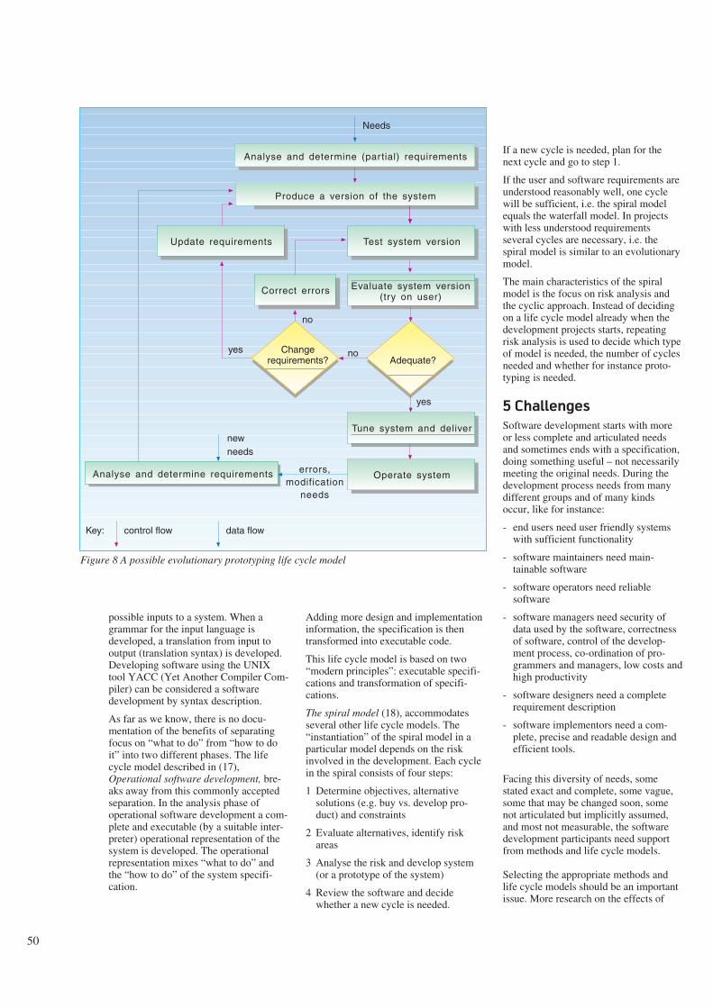
50
Figure 8 A possible evolutionary prototyping life cycle model
possible inputs to a system. When agrammar for the input language isdeveloped, a translation from input tooutput (translation syntax) is developed.Developing software using the UNIXtool YACC (Yet Another Compiler Com-piler) can be considered a softwaredevelopment by syntax description.
As far as we know, there is no docu-mentation of the benefits of separatingfocus on “what to do” from “how to doit” into two different phases. The lifecycle model described in (17),Operational software development, bre-aks away from this commonly acceptedseparation. In the analysis phase ofoperational software development a com-plete and executable (by a suitable inter-preter) operational representation of thesystem is developed. The operationalrepresentation mixes “what to do” andthe “how to do” of the system specifi-cation.
Adding more design and implementationinformation, the specification is thentransformed into executable code.
This life cycle model is based on two“modern principles”: executable specifi-cations and transformation of specifi-cations.
The spiral model (18), accommodatesseveral other life cycle models. The“instantiation” of the spiral model in aparticular model depends on the riskinvolved in the development. Each cyclein the spiral consists of four steps:
1 Determine objectives, alternativesolutions (e.g. buy vs. develop pro-duct) and constraints
2 Evaluate alternatives, identify riskareas
3 Analyse the risk and develop system(or a prototype of the system)
4 Review the software and decidewhether a new cycle is needed.
If a new cycle is needed, plan for thenext cycle and go to step 1.
If the user and software requirements areunderstood reasonably well, one cyclewill be sufficient, i.e. the spiral modelequals the waterfall model. In projectswith less understood requirementsseveral cycles are necessary, i.e. thespiral model is similar to an evolutionarymodel.
The main characteristics of the spiralmodel is the focus on risk analysis andthe cyclic approach. Instead of decidingon a life cycle model already when thedevelopment projects starts, repeatingrisk analysis is used to decide which typeof model is needed, the number of cyclesneeded and whether for instance proto-typing is needed.
5 Challenges
Software development starts with moreor less complete and articulated needsand sometimes ends with a specification,doing something useful – not necessarilymeeting the original needs. During thedevelopment process needs from manydifferent groups and of many kindsoccur, like for instance:
- end users need user friendly systemswith sufficient functionality
- software maintainers need main-tainable software
- software operators need reliablesoftware
- software managers need security ofdata used by the software, correctnessof software, control of the develop-ment process, co-ordination of pro-grammers and managers, low costs andhigh productivity
- software designers need a completerequirement description
- software implementors need a com-plete, precise and readable design andefficient tools.
Facing this diversity of needs, somestated exact and complete, some vague,some that may be changed soon, somenot articulated but implicitly assumed,and most not measurable, the softwaredevelopment participants need supportfrom methods and life cycle models.
Selecting the appropriate methods andlife cycle models should be an importantissue. More research on the effects of
Analyse and determine (partial) requirements
Needs
Produce a version of the system
Evaluate system version (try on user)
Test system version
Adequate?Change
requirements?
Update requirements
Correct errors
Tune system and deliver
Operate system
no
no
yes
Analyse and determine requirements errors,modification
needs
yes
newneeds
control flow data flowKey:

51
using different software developmentmethods and life cycle models is there-fore needed.
There are two main strategies for study-ing the effects of development methodsand life cycle models: experiments andobservation.
Experimental results are often, due to thecost and impracticality of realisticenvironments, not very applicable to realsoftware development. Typically,software systems developed in experi-ments are small, students are used asdevelopers and the developers are noviceusers of the methods and life cyclemodels. (19) gives some evidence thatuse of methods leads to more efficientprogramming than “ad hoc” approaches.However, it is not possible to apply theresults of (19) on large software projectwith professional and experienceddevelopers unless it is assumed that thebenefits of using methods on these pro-jects are at least as high as on small scaleprojects using students with little experi-ence.
Observational studies of implications ofmethods and life cycle models are oftenhard to apply on real software develop-ment, as well. This is mainly due to thelack of control of external variables. (20)gives an example illustrating this. Thisstudy found that the size of the floorspace in the office of a developer wasmore correlated with the developmentproductivity than use of a particularCASE tool. Important to note is thatobservational studies normally focus oncorrelations, not so much on cause-effectrelationships. (21) gives an example ofan observational study where use ofstructured methods correlate withincreased productivity. Application ofthis result on real software developmentmakes it necessary to assume that thestructured methods did not only correlatewith productivity, but was the cause ofthe increased productivity.
There are no evidence that a generally“best” method or a generally “best” lifecycle model exists, independently ofdevelopment environment. This suggeststhat methods and life cycle modelsshould be evaluated relative to at leastthe developers, end users and type of sys-tem to be developed. However, this waythe results may not be sufficiently gen-eral to be of any use.
The view of software development asexploration may imply that the develop-ment methods and life cycle models
should be rather pragmatic, supportreusability and incremental change. It isprobable that object oriented methodsand evolutionary life cycle models sup-port exploration better than conventionalmethods and life cycle models. However,the need of a controllable softwaredevelopment process seems to be inopposition to the view of softwaredevelopment as exploration. Can wehope for a next generation of methodsand life cycle models supporting bothcontrol and exploration?
References
1 Parkinson, J. Making CASE work.Proc. from CAiSE 1990, Stockholm.Springer Verlag, 21-41, 1990. ISBN3-540-52625-0.
2 Collins dictionary, Oxford, 1981.ISBN 0-00-433078-1.
3 Parnas, D L, Clements, P C. Arational design process: How andwhy to fake it. IEEE Trans. onSoftware Engineering, 12, 251-257,1986.
4 Downs, E, Clare, P, Coe, I.Structured Systems Analysis andDesign Method – application andcontext. Englewood Cliffs, N.J.,Prentice Hall, 1988. ISBN 0-13-854324-0.
5 Avison, D E, Fitzgerald, G.Information systems Development –Methodologies, Techniques andTools. Blackwell Scientific Publi-cations Ltd., 1988. ISBN 0-632-01645-0.
6 Royce, W W. Managing theDevelopment of Large Software Sys-tems: Concepts and Techniques.Wescon Proc., 1970.
7 ESA. ESA software engineeringstandard. February 1991. (ESA PSS-05-0 Issue 2.)
8 Fagan, M E. Design and codeinspection to reduce errors in pro-gram development, IBM SystemsJournal, 3(15), 182-211, 1976.
9 Meyer, B. Object-Oriented SoftwareConstruction. Englewood Cliffs,N.J., Prentice Hall, 1988.
10 Coad, P, Yourdon, E. Object-ori-ented analysis. Englewood Cliffs,N.J., Prentice-Hall, 1991. ISBN 0-13-629981-4.
11 Baber, R L. Error-free software,New York, Wiley, 1991. ISBN 0471-93016-4.
12 Baber, R L. The spine of software:designing provable correct software– theory and practice. Chichester,Wiley, 1987.
13 Ince, D. Prototyping. In: SoftwareEngineer’s Reference Book. J AMcDermid (ed). Butterworth, 3-12,1991. ISBN 0-7506-1040-9.
14 Gilb, T. Principles of software eng-ineering management. Reading,Mass., Addison-Wesley, 1988. ISBN0-201-19246-2.
15 Boehm, B W. Software life cyclefactors. In: Handbook of SoftwareEngineering. Ramamorthy (ed). VanNostrand Reinhold, 494-518, 1984.ISBN 0-442-26251-5.
16 Lewi, J et al. Software Developmentby LL(1) Syntax description.Chichester, Wiley, 1992. ISBN 0-471-93148-9.
17 Zawe, P. The operational versus theconventional approach to softwaredevelopment. Communication of theACM 2, 104-118, 1984.
18 Boehm, B W. A spiral model ofsoftware development and enhance-ment. IEEE Computer, 21(5), 61-72,1988.
19 Basili, V R, Reiter, W R Jr. A Con-trolled Experiment QuantitativelyComparing Software DevelopmentApproaches, IEEE Transaction onSoftware Engineering, 3, 299-320,1981.
20 Keyes, J. Gather a baseline to assescase impact. IEEE SoftwareMagazine, 30, 30-43, 1990.
21 Brooks, W D. Software TechnologyPayoff: Some Statistical Evidence,Journal of systems and software, 2,3-9, 1981.

52
A data flow approach to interoperability
B Y A R V E M E I S I N G S E T
Data flow
This section introduces some basicnotions needed for analysing inter-operation between software systems, orfunction blocks inside software systems.
A computer software system can receiveinput data and issue output data accord-ing to rules stated in a set of programstatements. This program code will com-prise data definitions, logic and controlstatements. See Figure 1a.
The control statements put constraints onthe sequence in which the logic is to beperformed. Most current computers (theso-called ‘von Neuman architecture’)require that the statements are performedin a strict sequence (allowing branchingand feedback) and allow no parallelism.This control flow together with the
logical (including arithmetical)operations are depicted in Figure 1b.
The data flow, in Figure 1c, depicts datato the logical operations and theiroutcome. We observe that the data flowstates what operations are to be per-formed on which data. The data flow per-mits parallelism and is not as restrictiveas the control flow.
Data definitions are data which declarethe permissible structure of datainstances. Logical operations are datawhich state constraints and derivationson these data. Control flow is a flow ofdata which is added to restrict the sequ-encing of the logical operations on thedata.
However, more ways exist to achieve thedesired computational result than what isstated in a chosen data flow, e.g. observethat the parenthesis in the shown formula
in Figure 1c can be changed without alt-ering the result.(X - 3) * 2 + (Y+1)=2 * X + Y - 5, etc.
A specification of what data are neededfor producing which data, is called a pre-cedence graph (4). This is shown infigure 2a. To avoid arbitrary introductionof unnecessary sequences, the preced-ence graphs are only detailed to a certainlevel. Decomposition is illustrated inFigure 2b. The functions needed areassociated with the leaf nodes of thegraphs. However, when carrying out thedecomposition, no association tofunctions is needed.
Precedence relations between data areidentified by asking what data are neededfor producing which data, starting fromthe output border, ending up on the inputborder of the analysed system. The con-verse succedence relations are found bystarting from the inputs asking what out-
Abstract
This paper provides basic language notions and motivation forunderstanding the ‘Draft Interoperability Reference Model’ (1,2, 3). This reference model identifies candidate interfaces forinteroperability extensively between databases, work stations,dictionaries, etc. This Abstract provides a technical summary,which may be found difficult to read and therefore can beskipped in a first reading.
The paper discusses language notions for data definition,logical operations and control. Different groupings of thesenotions are shown to lead to different computer softwarearchitectures. A data flow architecture for the communicationbetween processes is proposed. The processes are controlled byschemata which contain data definitions and logical operations.The contents of the schemata provide the application specificbehaviour of the system.
In order to avoid introducing implementation details, the notionof control flow is discarded altogether. Two-way mappings areused to state the combined precedence-succedence relationsbetween schemata. This allows data flow to be stated as mapp-ings between schemata without bothering about the existenceand functioning of processes. A mapping states permissible flowof data. The two-way mapping allows data flow in bothdirections between schemata, meaning that no distinction ismade between input and output to a system. Each collection ofdata can appear as both input and output.
All permissible forms of data in a system are specified inschemata. This introduces a layered architecture. For processesto be able to communicate, they have to share a commonlanguage. Each schema constitutes such a candidate set ofdefinitions that processes can share in order to be able to com-municate. The different kinds of schemata are:
- Layout schema- Contents schema- Terminology schema- Concept schema- Internal Terminology schema- Internal Distribution schema- Internal Physical schema.
This layering results in a basic interoperability referencemodel; the schemata constitute reference points which definecandidate interfaces for communication. The schema data arethemselves data. This implies that there are just as manycandidate forms of schema data as for any other data. Hence, anesting of the reference model is introduced. Therefore, we willhave to talk about the Layout form of the Layout schema, etc.
This proposed general reference model for information systemsis compared with the Telecommunications ManagementNetwork (TMN) functional architecture. The TMN functionalarchitecture defines interfaces between the TMN and the outsideworld. This may be appropriate for stating organisationalboundaries. However, when compared with the more generalreference model presented in this paper, it becomes evident thatthe TMN model is not clear on what reference points areintended, and that a better methodological approach is needed.A comparison with the Intelligent Network (IN) architecture ismade, as well. This architecture is better on the distribution andimplementation aspects. However, the IN architecture is notcapable of sorting the external interface to the manager fromthe services to the customer in an appropriate way. This is dueto the lack of nesting of the architecture.
This paper is based on experience obtained during thedevelopment of the DATRAN and DIMAN tools and previouscontributions to CCITT SG X ‘Languages and Methods’.
681.3.01

53
puts can be produced. When the graphthis way is made stable, the combinedprecedence and succedence analysis isreplaced by decomposition, called com-ponent analysis, of the data and nodes,and the analysis is repeated on a moredetailed level.
We observe that precedence graphs areless concerned with implementation thandata and control flow graphs. However,in practice, analysts are regularly confus-ing these issues. In complex systems theyare unconsciously introducing both dataflow and control flow in their analysis,which ideally should be concerned withprecedence relations only.
In order to separate data and control, wewill introduce direct precedence relationsbetween data. This is shown in Figure 2c.
Rather than associating the logicaloperations with control, we will associatethem with the data. The result is shownin Figure 2c. Here the logical operationsare depicted as being subordinate to thedata which initiate the processing. Otherapproaches are conceivable. However,the details of language design are outsidethe scope of this paper.
The processes associated with control areconsidered to be generic and to performthe following function:
For each data item appearing on theinput
- Check if its class exists
- Validate its stated references
- Enforce the stated logical constraintsand derive the prescribed data
- Issue the derived output.
In order to access input to the validationfunctions, precedence relations areneeded. In order to assign the result tooutput, succedence relations are needed.Therefore, two-way mappings are intro-duced. The resulting architecture iscalled a data flow architecture, becauseprocessing is initiated based on theappearance of input data.
Precedence relations are similar tofunctional dependencies used whennormalising data according to theRelational model. However, functionaldependencies are stated between indiv-idual data items, while precedencerelations are stated between data sets.
X
Y? ÷ + 1
u w
2
v
+
?
a
b
c
Process
Data
Z
X 3 Y
•
÷ + 1
u w
2 •
+
Z
X 3 Y
v
X
Y? ÷ + 1
2
+
?
3
•
Figure 1 Depiction of an example total pro-gram (a), control flow (b) and data flow (c).The function performed is:Z := (X - 3) * 2 + (Y + 1)
X 3 Y
Z
Z:=(X÷3)•2 +(Y+1)
X Y
Z
Z:=(X÷3)•2+(Y+1)
Z:=(X÷3)•2+(Y+1)
a
b
c
Data flow
Relation
Figure 2 Simple example precedence graph(a) and how it is identified by decomposition(b). In (c) data are associated with relationsand logic

54
Software in the Data flow architecture ispartitioned into:
- Schema, consisting of Datadeclarations and Logical statements tobe enforced on these data
- Processor, the mechanism whichimplements the control functions thatenforce the rules stated in the Schema.
This generic separation is depicted inFigure 3.
The collection of data instances whichare enforced according to the Schema ofthe software system are collectivelycalled the Population relative to theSchema. The Population data comprisesinput, output and intermediate data, e.g.u, v, w in Figure 1.
We recognise that, so far, all graphsillustrate data classes and not datainstances, except in Figure 2c. Here thedirect data flow arrows between the pro-cesses depict flow of data instances thatare enforced according to the rules statedamong the classes found in the Schema.There may be no absolute distinctionbetween Schema and Population data. Tobe schema data and population data arejust roles played by the data relative tothe processor and to each other. How-ever, this issue is outside the scope ofthis paper.
We will end this section with a lastremark about notation. The mappingbetween schemata states that there exist(two-way) references between data insidethe schemata. It is the references betweenthe data items that state the exact dataflow. The details of this is also outsidethe scope of this paper.
The notions introduced in this sectionallow the separation of data definitions,including logical operations, from controlflow. This again allows the system ana-lyst to concentrate on defining theschema part without bothering aboutimplementation. We will use thesenotions to identify candidate interfacesfor interoperation between softwarefunction blocks.
Layering
For two processors to be able to com-municate, they have to share a common‘language’, i.e. they must have the samedata definitions for the communicateddata. Therefore, in order to identify inter-
faces inside a software system, we haveto identify the data that can be communi-cated between software blocks andconstraints and derivation rules for thesedata. These rules make up the schemata.Hence, we will first identify thecandidate schemata.
Data on different media can be definedby separate schemata for each medium:
- External schemata define the externalpresentation and manipulation of data
- Internal schemata define the internalorganisation and behaviour of data.
See Figure 4. If we want to allow com-munication from all to all media, wehave to define mappings between everytwo schemata. Rather than mapping eachschema to every other schema, we intro-duce a common centralised schema, lab-elled the Application schema.
This Application schema
- defines the constraints and derivationswhich have to be enforced for all data,independently of which medium theyare presented on.
See Figure 5. Additional notions aredefined as follows:
- System schema contains, except fromthe External, Application, and Internalschemata:⋅ System security data, including data
for access control
⋅ System directory data, includingdata for configuration control
- System processor, includes theExternal, Application and Internal pro-cessors, administrates their inter-operation and undertakes directory andsecurity functions
- System population contains, exceptfrom the External, Application, andInternal populations, data instances ofthe System directory and Systemsecurity
- The notion of a Layer comprises agrouping of processors which enforcea set of schemata on correspondingpopulations, including these schemataand populations; no population canhave schemata outside the layer; theprocessors, schemata and populationsof one layer have similar functional-ities relative to their environment.
Inputa
Output
Processor Schema
Output
Input
Interm.data
Processor
Schema
Processor
Schema
Population
Pre-scrip-tion
Read
Write
b
c
Collection of data
Two-way mapping
Figure 3 Separation of Schema (a). Identifi-cation of Population (b). Unification ofSchema and Population data (c)

55
ES
ESIS
Processor
EPEP
Population
AS
IPAP
IPAPEP
ES ISAS
Er IrAr
System schema
System processor
ILALEL
System population
TS OS TS DS PS
Lr Cr Tr Or Tr Dr Pr
LS
CP TP OP TP DPIP
CS
LP PP
System schema
External schema Application schema Internal schema
External processor Application processor Internal processor
Mapping between sets of data
Two-way data flow
Set of data
Processor
Colours have
no significance
LS CSTS OS
Application schema
Presentation schema
PS
TS
DS
PS
CS
LSLS
Figure 8 Data flow between layers. The external and internal layers are unified intoPresentation (sub)layers around a common Application layer.Mappings between collections of data state the permissible data flow (both ways), wit-hout any concern of processors undertaking the communication.The use of Concept schema can be avoided by using one of the Terminology schemataas a substitute
ES
ESIS
Processor
EPEP
Population
IP
See Figure 6. Each layer can be de-composed into a sublayer, containingcorresponding component schemata:
- External schema (ES), is composed of⋅ Layout schemata (LS), which
defines the way data are presented tothe user
⋅ Contents schema (CS), whichdefines the contents and structure ofthe selected data and permissibleoperations on these data in a specificcontext
- Application schema (AS), is composedof
Figure 4 Depiction of presentationschemata for each medium. Mappings be-tween data are indicated by dashed lines.The sylinders indicate collections of data
Figure 5 Introduction of one centralisedApplication schema for each system.S = schema, P = population, E = external,A = application, I = internal
Figure 6 The 3-layered softwarearchitecture, consisting of the External(EL), Application (AL) and Internal layers(IL), r = processor
Figure 7 Data transformation architecture. Each layer contains schemata, corresponding populations and a processor.L = layout, C = contents, T = terminologyThe layered architecture can undertake transformation of data between any two media, here examplified by a screen and a database.O = concept, D = distribution, P = physical
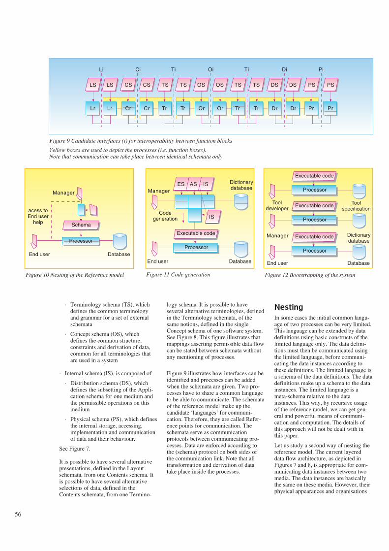
56
⋅ Terminology schema (TS), whichdefines the common terminologyand grammar for a set of externalschemata
⋅ Concept schema (OS), whichdefines the common structure,constraints and derivation of data,common for all terminologies thatare used in a system
- Internal schema (IS), is composed of
⋅ Distribution schema (DS), whichdefines the subsetting of the Appli-cation schema for one medium andthe permissible operations on thismedium
⋅ Physical schema (PS), which definesthe internal storage, accessing,implementation and communicationof data and their behaviour.
See Figure 7.
It is possible to have several alternativepresentations, defined in the Layoutschemata, from one Contents schema. Itis possible to have several alternativeselections of data, defined in theContents schemata, from one Termino-
logy schema. It is possible to haveseveral alternative terminologies, definedin the Terminology schemata, of thesame notions, defined in the singleConcept schema of one software system.See Figure 8. This figure illustrates thatmappings asserting permissible data flowcan be stated between schemata withoutany mentioning of processes.
Figure 9 illustrates how interfaces can beidentified and processes can be addedwhen the schemata are given. Two pro-cesses have to share a common languageto be able to communicate. The schemataof the reference model make up thecandidate ‘languages’ for communi-cation. Therefore, they are called Refer-ence points for communication. Theschemata serve as communicationprotocols between communicating pro-cesses. Data are enforced according tothe (schema) protocol on both sides ofthe communication link. Note that alltransformation and derivation of datatake place inside the processes.
Nesting
In some cases the initial common langu-age of two processes can be very limited.This language can be extended by datadefinitions using basic constructs of thelimited language only. The data defini-tions must then be communicated usingthe limited language, before communi-cating the data instances according tothese definitions. The limited language isa schema of the data definitions. The datadefinitions make up a schema to the datainstances. The limited language is ameta-schema relative to the datainstances. This way, by recursive usageof the reference model, we can get gen-eral and powerful means of communi-cation and computation. The details ofthis approach will not be dealt with inthis paper.
Let us study a second way of nesting thereference model. The current layereddata flow architecture, as depicted inFigures 7 and 8, is appropriate for com-municating data instances between twomedia. The data instances are basicallythe same on these media. However, theirphysical appearances and organisations
Lr Cr
LS CS
Cr Tr
CS TS
Tr Or
TS OS
Or Tr
OS TS
Tr Dr
TS DS
Dr Pr
DS PS
Pr
PS
Lr
LS
Li Ci Ti Oi Ti Di Pi
Figure 9 Candidate interfaces (i) for interoperability between function blocks
Yellow boxes are used to depict the processes (i.e. function boxes).Note that communication can take place between identical schemata only
Manager
DatabaseEnd user
acess toEnd user
help
Processor
Schema
Processor
IS
Executable code
ES AS ISManager
Dictionarydatabase
Codegeneration
DatabaseEnd user
Processor
Executable code
DatabaseEnd user
Processor
Executable code
Processor
Executable code
Tooldeveloper
Manager Dictionarydatabase
Toolspecification
Figure 12 Bootstrapping of the systemFigure 11 Code generationFigure 10 Nesting of the Reference model

57
and meta-schemata. The result is a verycomplex topic, labelled ‘The schemacube’. The main message in these figuresis that it is not sufficient to settle whatschema (or interface) to specify. Youalso have to choose what form (and whatinterfaces) to apply to this specification.For example, you may choose a Layoutform for the specification of the Layoutschema, or you may choose the internalTerminology form, for programming theLayout schema.
Comparisons
Figure 14 depicts the overall Telecom-munications Management Network refer-ence model (5). This reference modeldelimits the TMN from its outside world,and work is undertaken to define theinterfaces to this outside world. How-ever, this way, the TMN model is anorganisational model, which defines whatis inside and outside TMN, and is not areference model in the technical sense wehave been discussing reference models inthis paper. Exceptions can be made forthe f and g interfaces, which are
technical. However, no progress is madeon specifying these. Figure 9 depicts theavailable reference points from atechnical point of view. It is not clearwhich of these reference points areintended for any of the TMN interfaces.Also, even if TMN languages are definedfor some of the TMN interfaces, it is notclear what schema they correspond to,and the relevant requirements on theselanguages are not clearly identified.
The Intelligent Network architecture isshown in Figure 15 (6,7). Thisarchitecture has got a much moretechnical character than that of the TMNmodel. The bottom ‘planes’ correspondquite well to the internal layer of Figure7. But a minor warning must be made. InFigure 9, the users, terminals, subsys-tems, logical files, and physical resourcesare defined in the directory part of theSystem schema and not inside the Distri-bution schema. The Distribution schemastates just what contents is mapped to aphysical resource. This allows communi-cation and ‘distribution’ to take place onany of the interfaces. In the IN
Figure 13 The schema cube. The horizontal dimension illustrates usage, i.e. data flowbetween the HMI and the internal database. The vertical dimension illustratesmanagement, i.e. data flow from the manager to generated code.
The dimension going into the plane illustrates tool development. This defines themanager’s environment
can differ. Also, their classes, defined inthe schemata, can be different. Thisallows for substituting e.g. French head-ings with Norwegian ones. If, however,we want to replace one set of instances inone terminology with another set inanother terminology, the existence ofboth and the ‘synonymity’ referencesbetween them have to be persistentlyrecorded in a database. For example,John may correspond to 12345, Bill to54321, etc. This way, the referencesbetween data in different Terminologyschemata may not only state flow oftransient data, but can state referencesbetween persistent data. Since all persist-ent data are stored in a database, thereference model itself is needed tomanage these references of the referencemodel. This way, we get a nesting of thereference model.
A third way of nesting the referencemodel is shown in Figures 10 through 13.Since all schema data are ordinary data,these data can be managed using thereference model itself. This is illustratedboth for the management of schemata
IL IC IT IO IT ID IPIxx
LC LT LO LT LD LILL
Manager view
C
T
O
T
D
Tooldeveloper
view
System schema
Target processors
Populations
End userview
L L C C T T O O T T D D PP
OS
WSDCNF
Q/F/Q3
MD
Q3/F
DCN
Qx
NEQANEQA
Q
Qx
Q3 Q3
TMN
TMN
OSMDDCNWSNEQA
: Telecommunication Management Network: Operation System. Mediation Device: Data Communication Network: Work Station: Network Element: Q Adapter
Figure 14 The TMN physical architecture

58
architecture this seems to take place inthe Distribution plane only.
When we come to the top planes of theIN architecture, it diverges even morefrom the Interoperability reference modelpresented in this paper. The Functionplane may correspond to the Applicationschema. But the Service plane does notfit in. The reason is that what is specifiedinside the Service plane corresponds tothe External schema of the telecommuni-cation service user. Therefore, thisshould be at the same level as theFunction plane. For accessing both theFunction plane and Service plane weneed the Manager’s external schemata,i.e. of the TMN operator. This requires anesting of the reference model, as shownin Figures 10 through 13, which is notprovided in the IN architecture.
This comparison of reference models is afirst exposition of what kind of dif-ficulties will be encountered whenattempting to analyse and integrate dif-ferent systems developed according todifferent reference models. (8) provides acomparison of the TMN and IN referencemodels. The result is summarised inFigure 16. However, the paper lacks atechnical and methodological analysis, assuggested in this article. The methodo-logical problem with the two referencemodels and the comparison is that theystart with identifying function blocks,which necessarily must be imple-mentation oriented. As explained in thispaper, the analysis and design of refer-ence models should start with identifyingthe data and their relationships.
FE 1
PE 1
Physical Plane
FE 1
FE 3
PE 2
SIBFESFIFPOIFEA
: Service Independent Building Block: Functional Entity: Service Feature: Information Flow: Point Of Initiation: Functional Entity Action
PEEFPPORBCP
: Physical Entity: Elementary Function: Protocol: Point Of Return: Basic Call Process SIB: Pointer
P
EF
EF
EF
EF
EF
EF
IF
Information Flows (IF)
FE2
FE3
Distributed FunctionalPlane
F EA
F EA F
EA
SIB 1
SIB 2
SIB n
BCP
Global Functional Plane
POI
POR
SF1
SF2 SF3
Service 1 Service 2
Service Plane
Figure 15 IN conceptual model

59
Functional Architecture
&
Information Architecture
Physical Architecture Physical Plane
Distributed
Functional Plane
Global
Functional Plane
Service Plane
The TMN Architecture The IN Conceptual Model
Figure 16 Correspondence of the TMN architectures and the planes of the INCM
References
1 Meisingset, A. Draft interoperabilityreference model. NorwegianTelecom Research, Systemutvikling2000, D-3 (2). Also contributed asWorking document to ETIS, Berlin1993.
2 Meisingset, A. Identification of the finterface. Norwegian Telecom Rese-arch, Systemutvikling 2000, D-5 (2).Also contributed as Working docu-ment to ITU-TS SG 4, Bath 1993.
3 ITU. Draft Recommendations Z.35xand Appendixes to draft Recomm-endations, 1992. (COM X-R 12-E.)
4 Langefors, B. Theoretical Analysis ofInformation Systems. Studentlitt-eratur Lund, 1966. Philadelphia,Auerbach Publishers Inc., fourthedition, 1973.
5 ITU. Draft RecommendationsM.3010, 1991. (COM IV-R 28-E.)
6 ITU. Draft RecommendationsQ.1201, 1992. (COM XI-R 108-E.)
7 Skolt, E. Standardisation activities inthe intelligent network area. Telek-tronikk 88(2), 1992.
8 ETSI. Baseline document on theintegration of IN and TMN. EuropeanTelecommunications Standards Insti-tute, 1990.
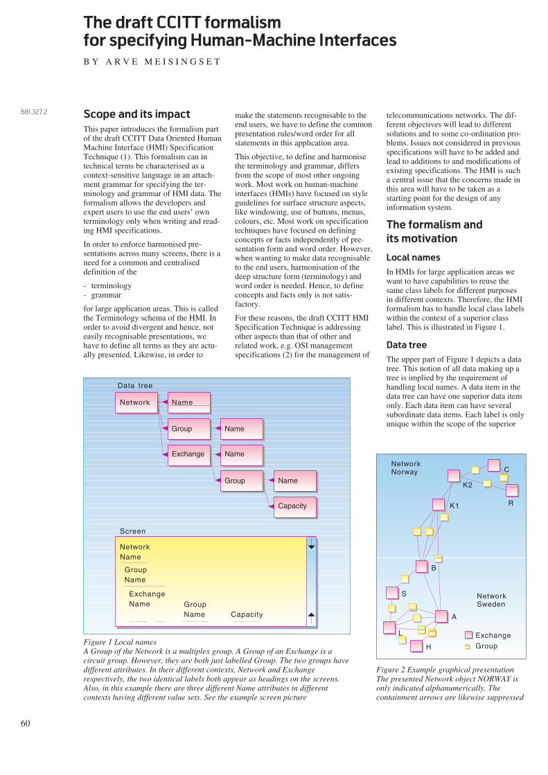
60
The draft CCITT formalism
for specifying Human-Machine Interfaces
B Y A R V E M E I S I N G S E T
Scope and its impact
This paper introduces the formalism partof the draft CCITT Data Oriented HumanMachine Interface (HMI) SpecificationTechnique (1). This formalism can intechnical terms be characterised as acontext-sensitive language in an attach-ment grammar for specifying the ter-minology and grammar of HMI data. Theformalism allows the developers andexpert users to use the end users’ ownterminology only when writing and read-ing HMI specifications.
In order to enforce harmonised pre-sentations across many screens, there is aneed for a common and centraliseddefinition of the
- terminology- grammar
for large application areas. This is calledthe Terminology schema of the HMI. Inorder to avoid divergent and hence, noteasily recognisable presentations, wehave to define all terms as they are actu-ally presented. Likewise, in order to
make the statements recognisable to theend users, we have to define the commonpresentation rules/word order for allstatements in this application area.
This objective, to define and harmonisethe terminology and grammar, differsfrom the scope of most other ongoingwork. Most work on human-machineinterfaces (HMIs) have focused on styleguidelines for surface structure aspects,like windowing, use of buttons, menus,colours, etc. Most work on specificationtechniques have focused on definingconcepts or facts independently of pre-sentation form and word order. However,when wanting to make data recognisableto the end users, harmonisation of thedeep structure form (terminology) andword order is needed. Hence, to defineconcepts and facts only is not satis-factory.
For these reasons, the draft CCITT HMISpecification Technique is addressingother aspects than that of other andrelated work, e.g. OSI managementspecifications (2) for the management of
Network Name
Group
Exchange
Name
Name
Group Name
Capacity
Data tree
NetworkName
GroupName
ExchangeName Group
Name Capacity
Screen
Figure 1 Local namesA Group of the Network is a multiplex group. A Group of an Exchange is acircuit group. However, they are both just labelled Group. The two groups havedifferent attributes. In their different contexts, Network and Exchangerespectively, the two identical labels both appear as headings on the screens.Also, in this example there are three different Name attributes in differentcontexts having different value sets. See the example screen picture
C
R
K2
K1
B
S
A
H
L
NetworkSweden
NetworkNorway
Exchange
Group
Figure 2 Example graphical presentationThe presented Network object NORWAY isonly indicated alphanumerically. Thecontainment arrows are likewise suppressed
telecommunications networks. The dif-ferent objectives will lead to differentsolutions and to some co-ordination pro-blems. Issues not considered in previousspecifications will have to be added andlead to additions to and modifications ofexisting specifications. The HMI is sucha central issue that the concerns made inthis area will have to be taken as astarting point for the design of anyinformation system.
The formalism and
its motivation
Local names
In HMIs for large application areas wewant to have capabilities to reuse thesame class labels for different purposesin different contexts. Therefore, the HMIformalism has to handle local class labelswithin the context of a superior classlabel. This is illustrated in Figure 1.
Data tree
The upper part of Figure 1 depicts a datatree. This notion of all data making up atree is implied by the requirement ofhandling local names. A data item in thedata tree can have one superior data itemonly. Each data item can have severalsubordinate data items. Each label is onlyunique within the scope of the superior
681.327.2

61
data item and hence cannot be addressedwithout traversing the data tree from theroot via all intermediate data items to thesearched data item. Hence, in the basicdata tree there is no relation notion, onlysubordinate and superior data items. Thiscontainment is indicated by a bird-footarrow.
Instance labels
Figure 2 depicts instances of Exchangesin a map. The Exchanges are connectedby Groups. The same icon is used for andis repeated for each Exchange andGroup. Hence, the Exchange label is notonly referring to the class, but theExchange label, here symbolised by theicon, is repeated for every Exchangeinstance. Hence, the class labels do notonly appear as intermediate ‘non-ter-
minal’ nodes in the specification‘grammar’, but the class labels are copiedinto every instance. This is illustrated inFigure 3.
In most alternative formalisms, only thevalues – the leaf nodes of the syntax tree– are left in the finally produced pop-ulation. In an HMI formalism we see thatthe superior labels are necessary to indi-cate the classes and the contexts of thedata instances. This is the way context-sensitivity is provided in the HMI form-alism.
Instantiation
In Figure 3 we observe that superiornodes always must appear, whilesubordinate nodes may be omitted – ifnot otherwise required. Therefore, wecall this formalism an attachmentgrammar, not a rewriting grammar. Notethat due to the use of local names, theterms cannot be listed independently ofthe grammar. The data tree is the HMIgrammar and lists the terms.
Since exactly the same notions appear inthe schema and the corresponding pop-ulation, we can use the same formalismfor both. This is also different from most
current approaches, which use separateclass templates in the schema and havedifferent or no notation for the instances.A benefit of using the same notions isthat the user can easily foresee thepermissible instances when reading theschema, or, when knowing someinstances, he can easily find his way in thecorresponding specifications (in theschema). Copying is the only trans-formation from classes to instances.
Significant duplicates
In Figures 2 and 3 we observe that manyGroups appear without a name assignedto them. In fact, in a graphical dialogueto a network planning system, the entirenetwork can be created without assigningnames. Therefore, the HMI must becapable of handling significant dupli-cates. The fact that the EDP system mayassign internal surrogates which uniquelyidentify each data item is outside thescope of our discussion on HMIs. Theimpact of this is that the HMI formalismitself must be capable of handling signifi-cant duplicates – in (nested) ordered lists.
Group
System
Network
Network
Name
Group
Name
NORWAY
Sch
Exchange
NamePop
GroupGroup
Group
ExchangeExchange
Exchange
Na-Na-Na-me
AB
C
Network SWEDENName
S
P
Figure 3 Correspondence betweenclasses and instancesAll classes are specified in a schema.This is indicated by the S at the end ofthe dashed two-way arrow. The datainstances are found in the population,indicated by the P. Note that the dataitems in the populations are exact copiesof data items in the schema branch. Inthis example, classes for the individualvalues are not illustrated. Also the refer-ences between Groups and Exchanges,shown in the map, are not illustrated
Group
System
Network
Network
Group
Term.group
Sch
Exchange
Pop Group
Group
Exchange
Exchange
TermTermTermTerm.group
S
P
Figure 4 ReferencesAccording to the schema, an Exchange can have subordinateTerminated groups, which refer (by an existential condition) toGroup. Terminated group is a Role of a Group as observed from anExchange. In the population one Exchange instance has threesubordinate Terminated groups, each referring to different Groups.However, the last Exchange has one Terminated group only,referring to the same Group as that of the last Terminated group ofthe previous Exchange. This way, it is stated that this Groupconnects two Exchanges

62
References
References between different nodes inthe data tree can be stated by introducingExistential conditions. See figure 4. Sucha condition states that the conditioneddata item can only exist if the referenceddata item exists. The conditioned dataitem is called a Role of the Referenceddata item.
Also, independent or mutually dependentreferences in opposite directions betweentwo data items can be introduced. This isillustrated in Figure 5.
Note that there can be several referencesbetween two data items, and the refer-ences may not necessarily be inter-dependent.
We see that the graphs are starting tobecome cluttered by all the details intro-duced. Later we shall introduce a simplershorthand notation. However, for thetime being we will stay with the currentnotation to show clearly some of thedetails involved.
Values
Values have been introduced informallyin Figures 2 and 3. Figure 6 illustrateshow we can specify a finite permissiblevalue set.
We observe that everything permissiblein the population first has to be stated inthe corresponding schema. The schemacontains the originals which the instancesare copies of.
Recursion
We are now ready to introduce recursion.The means for this is the schema-pop-ulation reference. We have already statedand shown that for HMIs we will use thesame formalism for instances andclasses. Therefore, the schema branch ofthe data tree, or parts of it, can be consid-ered instances of still other classes. Thisis illustrated in Figure 7.
When the schema-population referencesare applied recursively, we can considerthe schema data to be contained in adatabase in the same way as the pop-ulation data. The form of the schema datais controlled by a meta-schema. Theeffect of this is for the end user that hecan access population data and schemadata in exactly the same way, i.e. by thesame means. Also, he can navigatebetween these data without having tochange presentation style or dialogue. Infact, this has been a major objective ofthe CCITT Data Oriented HMI Specifi-cation Technique, to make all HMI speci-fications accessible and readable by end
Group
System
Network
Network
Group
Term.group
Sch
Exchange
Pop
Exchange
Exchange
Term.group
Term.group
S
P
Term.group
Term.Term.exchange
System
Person NameSch
Pop
S
P
John
John
Bill
Mary
Person Name
BillPerson Name
Figure 5 Mutually dependent referencesA Group has two Terminating exchanges. Each of the two referencedExchanges has a Terminating group referring to the Group. Theintention is that there should be a mutual dependency between twoopposite roles, Terminating exchange and Terminating group. We haveso far not introduced means to express this dependency
Figure 6 ValuesName in the schema has three subordinate data items: John,Bill, Mary. These can be instantiated in the same way asany other data item, like John and Bill as shown in the pop-ulation. In this case we have instantiated one data item onlysubordinate to each Name. Also, the two shown subordinateitems, John and Bill, of different Names of different Personsare different. However, there is nothing prohibitingmultivalues and significant duplicates if these are notexplicitly prohibited in the schema. Means for this are notyet fully introduced
System
Person NameSch
Pop
S
P
Person Name
Person Name
System A B C D Z
J O H N
B I L L
S
P
Figure 7 Recursive instantiationName of Person ‘inherits’ permissible subordinate valuesfrom its S(chema), which is Alpha. The subordinate dataitems of Alpha make up the alphabet extensively. There is norestriction on how many values can be contained in oneName. Hence, a Name can be any sequence of letterssubordinate to Alpha. Pop ‘inherits’ its classes from Sch,and we see the chosen instances John and Bill

63
Figure 8 Real recursionSch has a subordinate Network, which has another subordinate Network inaddition to Name and #subnet (number of subnets). Name and #subnetinherit their permissible values from Alpha and Num, in the ordinary way.The important construction here is the subordinate Network, which inheritsall (subordinate) properties from its superior Network. This way, even theinheritance mechanism is inherited. Therefore, this allows any Network inPop to contain Networks recursively in an arbitrarily large tree. Note thatthe subordinate Networks are identified locally to their superior Networksonly
Figure 9 CardinalityThe schema contains no constraint on the minimum ormaximum number of Persons in the Pop. The depicted Popcontains two Persons. However, for each Person there has to beexactly one Name. For each Name there can be minimum zeroand maximum one subordinate value (here indicated by a blankbox). Note the distinction between the cardinality constraints onthe Name itself relative to its superior Person and the cardinal-ity constraints on the value subordinate to the Name. The valuecan contain an arbitrarily long sequence of letters – inheritedfrom Alpha. Also, the value can contain significant duplicates,like the double l in Bill. Note that in this example the value itself(subordinate to Name) has no label
users. The purpose of this paper is tointroduce the formal apparatus for mak-ing this goal achievable.
The scope of the end users’ HMIs isdefined to comprise:
- HMI population data
- HMI Layout Schemata
- HMI Contents Schemata
- HMI Terminology Schema.
For explanations, see (1, 3, 4, 5). Thecontents of the Internal Schemata isnormally considered to be outside thescope of the HMI.
Since the same formalism is used forboth instances and classes, we do notneed to distinguish between classes (e.g.Name) and types (Alpha). We can usethe same formalism for instances, classesand meta-classes. ‘Inheritance’ of ‘code’from one of them to the other is stated byusing the schema-population references.Note that there is no strict hierarchy be-tween instances and classes. One dataitem can contain schema-references toseveral other data items, and classes caneven ‘inherit’ from their instances. Notealso that there is no distinction betweeninheritance and instantiation. This is dueto the required free formation of class
and instance labels, which makesordinary inheritance obsolete.
In the above example we have used theschema-population mechanism repeat-edly. However, this is not really recurs-ion. Real recursion we get when the sameclasses are used to define the contents ofthemselves. This is illustrated in Figure8.
Figure 8 should clearly exemplify that adata item is not defined extensionally byits component data items. Rather, severaldata items can be attached to an existingdata item.
System
Network NetworkSch
Pop
S
P
Alpha A B C Num
B
1 2
Name
#subnet
Network Network Name
NameNetwork
A
Name
#subnet
NameNetwork
A
2
B
S
S
P
P
P
System
Person NameSch
S
P
Alpha A B C D
P(1.1) (0.1)
S
Pop Person Name
Person Name
J O H N
B I L L
Z

64
Cardinality constraints
So far, we have introduced three notionsof constraints: all data make up a datatree, every data item is an instance of oneclass only, and we have existentialconditions. Now, we introduce thecardinality constraint on the minimumand maximum number of instances of adata item relative to its superior dataitem. See examples in Figure 9.
The formalism allows the HMI datadesigner to choose between multi-valuedattributes (i.e. several values in oneName) and repeating attributes (i.e.several Names of one Person) or thecombination or prohibition of theseoptions.
A unified language
The same formalism as already intro-duced can be used to state the detailedsyntax of the values. See Figure 10.
Observe in Figure 11 that the detailedstructure of the value remains availablein the instantiated data. This structurecan, of course, be suppressed in themapping to the final presentation on theend user’s screen. However, it can beimportant to make this structure availableto the user. This is analogous to the pre-sentation of control characters in docu-ment handling systems.
The strength of the HMI formalism is, asshown, that we can use exactly the samebasic notions to specify the overallstructure of the data as well as thedetailed syntactical structure of thevalues. Also, the formalism can expressthe required complex context-sensitive
System
Person NameSch
S
P
Alpha A B C D
P(1.1) (0.1)
S
Pop Person
Person
J O H N
B I L L
Z
P
S
-
-
System
CableSch
Pop
S
P
Alpha A B C Num
2
1 2
Name
Name
Pair
#subnet 2
Pair No.
S
P
P
CableA B C
No. 1
No.Pair
NameCable
B B C
No. 1Pair
S
Figure 10 Specification of syntax of valuesA Name is defined to consist of three parts: a first name, a blank(-) and a family name. The depicted Person’s Name is JohnGrey
Figure 11 Local codesPair being defined subordinate to Cable implies that uniqu-eness of the Pair identifying attribute No. is only controlledwithin the scope of the superior Cable
System
Network NetworkSch
Pop
S
P#subnet
Network Network
Network
#subnet
S
∆
∆
∆
2
P
Figure 12 Functions∆ is an incremental derivation Function. When asubordinate Network is inserted, the #subnet of its superiorNetwork is incremented by 1. The details of the navigationto the right #subnet is not covered by this paper. If asubordinate Network is deleted, the #subnet of its superiorNetwork is decremented by 1. The shown ∆ Function has noInput, only an Output. Inputs and Outputs use hookedarrows. Note that functions receiving data subordinate to#subnet are not illustrated
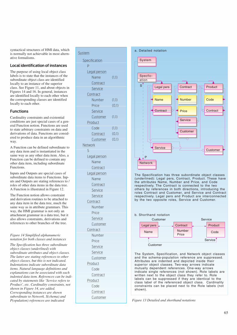
65
syntactical structures of HMI data, whichis normally not achievable in most altern-ative formalisms.
Local identification of instances
The purpose of using local object classlabels is to state that the instances of thesubordinate object class are identifiedlocally to an instance of the superiorclass. See Figure 11, and about objects inFigures 14 and 16. In general, instancesare identified locally to each other whenthe corresponding classes are identifiedlocally to each other.
Functions
Cardinality constraints and existentialconditions are just special cases of a gen-eral Function notion. Functions are usedto state arbitrary constraints on data andderivations of data. Functions are consid-ered to produce data in an algorithmicway.
A Function can be defined subordinate toany data item and is instantiated in thesame way as any other data item. Also, aFunction can be defined to contain anyother data item, including subordinateFunctions.
Inputs and Outputs are special cases ofsubordinate data items to Functions. Inp-uts and Outputs are stating references to /roles of other data items in the data tree.A Function is illustrated in Figure 12.
The Function notion allows constraintand derivation routines to be attached toany data item in the data tree, much thesame way as in attribute grammars. Thisway, the HMI grammar is not only anattachment grammar in a data tree, but italso allows constraints, derivations andreferences to other branches of the tree.
System
Specification
P
Legal person
Name (1,1)
Contract
Service
Contract
Number (1,1)
Price (0,1)
Service
Customer (1,1)
Product
Code (1,1)
Contract (0,1)
Customer (0,1)
Network
S
Legal person
Name
Contract
Legal person
Name
Contract
Service
Service
Contract
Number
Price
Service
Customer
Contract
Number
Price
Service
Service
Customer
Product
Code
Contract
Product
Code
Contract
Customer
Figure 14 Simplified alphanumericnotation for both classes and instances
The Specification has three subordinateobject classes (underlined) withsubordinate attributes and object classes.The latter are stating references to otherobject classes, but this is not indicated.Indentations indicate subordinate dataitems. Natural language definitions andexplanations can be associated with eachindented data item. References can be indi-cated by statements like ‘Service refers toProduct’, etc. Cardinality constraints, notshown in Figure 14, are added.Corresponding instances are shownsubordinate to Network. S(chema) andP(opulation) references are indicated
System
Legal pers Contract
Number Code
Price
Service
Specfic-ation
Product
Name
Contract
Customer
Contract
ServiceCustomer
Network
S
P
a. Detailed notation
The Specification has three subordinate object classes (underlined): Legal pers, Contract, Product. These have the attributes Name, Number and Price, and Code respectively. The Contract is connected to the two others by references in both directions, introducing the roles Contract and Customer, and Service and Contract respectively. Legal pers and Product are interconnected by the two opposite roles, Service and Customer.
Legal pers
Name
Contract
NumberPrice
Product
Code
Customer Service
Service
Customer
b. Shorthand notation
The System, Specification, and Network object classes and the schema-population reference are suppressed. Attributes are indented and depicted inside their superior object classes. Two-way arrows indicate mutually dependent references. One-way arrows indicate single references (not shown). Role labels are written next to the object class they refer to. Role labels can be suppressed if they are identical to the class label of the referenced object class. Cardinality constraints can be placed next to the Role labels (not shown).
Figure 13 Detailed and shorthand notations

66
Summary and comparison
In the previous section we have intro-duced some basic notions of the HMIformalism. However, we have not intro-duced the very primitive notions and nota complete set of notions. However, theset introduced should provide a goodunderstanding of how the formalism canbe used and rationales for introducingthese notions in an HMI formalism.
The examples shown, so far, contain a lotof details. In order to make the figuresmore compact and more readable, weintroduce a shorthand notation in Figure13. This shows that the graphicalnotation has similarities to that of theEntity-relationship formalism, but thedetails and the application area are dis-tinctively different.
Figure 14 provides an alphanumericalnotation for defining subordinate dataitems only. Both classes and instancesare shown. Typically, definitions andexplanations are associated with eachclass entry and are indented to the samelevel.
At this point a short comparison with theOSI Management formalism (2) is ofinterest. The OSI Management formalismrequires that all object class labels areglobally unique and does not allow use oflocal class labels. Hence, the formalismis not capable of defining the terms asthey appear on the HMI. Also, therestriction to the use of global class lab-els only, will make the data tree of theinstances different from the data tree oftheir classes, i.e. they will not be homo-morphic. This will make it difficult to theuser to foresee the structure of theinstances when the classes are knownand vice versa. In fact, the OSI Manage-ment formalism applies to classes onlyand not to instances. This shortcoming onhow to define class labels is even moreevident for attributes. The formalismallows attribute groups to be definedwhen attributes are given. However, itdoes not allow attributes to be definedlocally to other attributes and does notallow definition of repeating attributes,but allows for multi-values. The attri-butes are defined in separete packages,which make the specifications more dif-ficult to overview. The formalism is notapplicable to defining values, and use theASN.1 notation for this purpose. Signifi-cant duplicates are neither permitted forclasses nor for instances. The concretesyntaxes of the OSI Management formal-ism and ASN.1 are overloaded withtechnical and reserved words, which
make them inapplicable for HMI usage.This syntax is such that the formalismcannot be used to define the structure ofthe dictionary containing the specifica-tions, i.e. the formalism is not applicableto defining meta-schemata.
It is evident that the OSI Managementformalism is not appropriate as a useroriented specification language, but mustbe considered a candidate high level pro-gramming language, or an imple-mentation specification language, maybefor the internal Terminology schema (3).However, other object oriented languagesor other high level languages are moregeneral and powerful for this usage.Alternative formalisms exist for thespecification of HMI data, like theEntity-Relationship formalism and theRelational (Model) formalism. Thesehave similar and even more severe short-comings than the OSI Management form-alism.
Abbreviations
CCITT Consultative Committee forInternational Telegraph andTelephone
EDP Electronic Data Processing
HMI Human-Machine Interfaces
References
1 ITU. Draft Recommendations Z.35xand Appendices to Draft Recomm-endations. (CCITT COM X-R 12.)
2 Kåråsen, A G. The OSI managementformalism. Telektronikk, 89(2/3), 90-96, 1993 (this issue).
3 Meisingset, A. A data flow approachto interoperability. Telektronikk,89(2/3), 52-59, 1993 (this issue).
4 Meisingset, A. Perspectives on theCCITT Data Oriented Human-Machine Interface SpecificationTechnique. SDL Forum, Glasgow,1991. Kjeller, Norwegian TelecomResearch, 1991. (TF lecture F10/91.)
5 Meisingset, A. The CCITT data ori-ented Human-Machine Interfacespecification technique. SETSS,Florence, 1992. Kjeller, NorwegianTelecom Research, 1992. (TF lectureF24/92.)
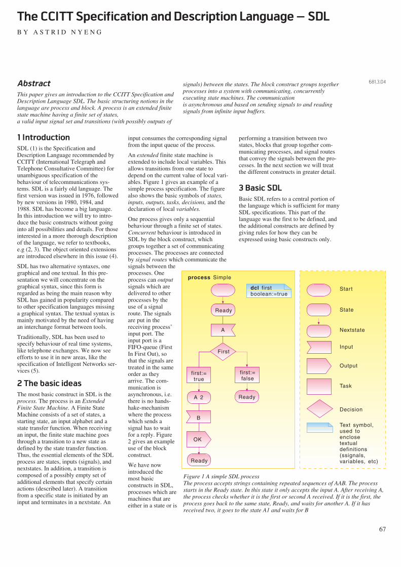
1 Introduction
SDL (1) is the Specification andDescription Language recommended byCCITT (International Telegraph andTelephone Consultative Committee) forunambiguous specification of thebehaviour of telecommunications sys-tems. SDL is a fairly old language. Thefirst version was issued in 1976, followedby new versions in 1980, 1984, and1988. SDL has become a big language.In this introduction we will try to intro-duce the basic constructs without goinginto all possibilities and details. For thoseinterested in a more thorough descriptionof the language, we refer to textbooks,e.g (2, 3). The object oriented extensionsare introduced elsewhere in this issue (4).
SDL has two alternative syntaxes, onegraphical and one textual. In this pre-sentation we will concentrate on thegraphical syntax, since this form isregarded as being the main reason whySDL has gained in popularity comparedto other specification languages missinga graphical syntax. The textual syntax ismainly motivated by the need of havingan interchange format between tools.
Traditionally, SDL has been used tospecify behaviour of real time systems,like telephone exchanges. We now seeefforts to use it in new areas, like thespecification of Intelligent Networks ser-vices (5).
2 The basic ideas
The most basic construct in SDL is theprocess. The process is an ExtendedFinite State Machine. A Finite StateMachine consists of a set of states, astarting state, an input alphabet and astate transfer function. When receivingan input, the finite state machine goesthrough a transition to a new state asdefined by the state transfer function.Thus, the essential elements of the SDLprocess are states, inputs (signals), andnextstates. In addition, a transition iscomposed of a possibly empty set ofadditional elements that specify certainactions (described later). A transitionfrom a specific state is initiated by aninput and terminates in a nextstate. An
input consumes the corresponding signalfrom the input queue of the process.
An extended finite state machine isextended to include local variables. Thisallows transitions from one state todepend on the current value of local vari-ables. Figure 1 gives an example of asimple process specification. The figurealso shows the basic symbols of states,inputs, outputs, tasks, decisions, and thedeclaration of local variables.
One process gives only a sequentialbehaviour through a finite set of states.Concurrent behaviour is introduced inSDL by the block construct, whichgroups together a set of communicatingprocesses. The processes are connectedby signal routes which communicate thesignals between theprocesses. Oneprocess can outputsignals which aredelivered to otherprocesses by theuse of a signalroute. The signalsare put in thereceiving process’input port. Theinput port is aFIFO-queue (FirstIn First Out), sothat the signals aretreated in the sameorder as theyarrive. The com-munication isasynchronous, i.e.there is no hands-hake-mechanismwhere the processwhich sends asignal has to waitfor a reply. Figure2 gives an exampleuse of the blockconstruct.
We have nowintroduced themost basicconstructs in SDL,processes which aremachines that areeither in a state or is
performing a transition between twostates, blocks that group together com-municating processes, and signal routesthat convey the signals between the pro-cesses. In the next section we will treatthe different constructs in greater detail.
3 Basic SDL
Basic SDL refers to a central portion ofthe language which is sufficient for manySDL specifications. This part of thelanguage was the first to be defined, andthe additional constructs are defined bygiving rules for how they can beexpressed using basic constructs only.
67
The CCITT Specification and Description Language – SDL
B Y A S T R I D N Y E N G
Abstract
This paper gives an introduction to the CCITT Specification andDescription Language SDL. The basic structuring notions in thelanguage are process and block. A process is an extended finitestate machine having a finite set of states, a valid input signal set and transitions (with possibly outputs of
signals) between the states. The block construct groups togetherprocesses into a system with communicating, concurrentlyexecuting state machines. The communication is asynchronous and based on sending signals to and readingsignals from infinite input buffers.
681.3.04
Ready
A
First
first:=false
first:=true
A 2 Ready
B
OK
Ready
dcl firstboolean:=true
process Simple
Start
State
Nextstate
Input
Output
Task
Decision
Text symbol,used toenclosetextualdefinitions(ssignals,variables, etc)
Figure 1 A simple SDL processThe process accepts strings containing repeated sequences of AAB. The processstarts in the Ready state. In this state it only accepts the input A. After receiving A,the process checks whether it is the first or second A received. If it is the first, theprocess goes back to the same state, Ready, and waits for another A. If it hasreceived two, it goes to the state A1 and waits for B

3.1 Specification of structure
SDL has several structuring concepts.The aim of this structuring is to managecomplexity by hiding details in one partof the specification from another part andalso to offer specifications of differentdetails.
The most important structuring conceptis the already mentioned block conceptwhich groups processes. An SDL system
can be partitioned into several blocks,connected by channels. The channels areeither bidirectional or unidirectionalcommunicating paths which convey thesignals from processes within one blockto processes within another block.
Figure 3 shows how the directory systemKAT-500 (6) is specified as an SDL-sys-tem consisting of the two blocks DUA(Directory User Agent) and DSA(Directory System Agent) connected bythe two channels DUA_DSA andDSA_DUA.
An SDL specification contains a hier-archy of components arranged in a tree-like structure. The system componentsare blocks, channels, data types, andsignal definitions. The specification of ablock can either be done locally, i.e. wit-hin the system, or be removed from thecontext and be referred to within the sys-tem. For real specifications of some size,the latter alternative is most frequentlyused. For the example in Figure 3, thismeans that the blocks DUA and DSA areonly referenced within the system KAT-500, their specification is elsewhere. Allspecifications of components (signals,data types, variables) are visible from thepoint where they are specified and downto the leaves of the hierarchy. At theblock level, processes, signals, datatypes, and signalroutes are defined, theprocesses can in addition contain vari-ables, timers, and procedures. The proce-dure construct is similar to proceduresfound in programming languages. Theprocedure construct can be used toembody parts of the process graph, suchthat it can be used in different places inthe process and also hide details in theprocess graph. A procedure is a statemachine that is created when the proce-dure is called and stops when the call isreturned. Figure 4 shows the main hier-archical levels in SDL.
3.2 Specification of behaviour
The process is probably the best knownand most used construct in SDL. Theprocesses deal with the dynamicbehaviour of the system. A processdefinition can have one or more instancesduring its lifetime. The number ofinstances is declared in the process head-ing and gives the initial number ofinstances, i.e. the number of instancescreated at system initialisation, and amaximum number of instances which canexist at the same time. New instances canbe created by other processes.
A process definition has a declarationpart and a process graph (see Figure 1).In the declaration part, local signals, datatypes and variables are specified. Theprocess graph is the specification of thestate machine, which defines the processbehaviour. The process graph contains astart transition which ends in some state.The start transition is the first transitionto be executed after the process is initiali-sed. The process graph has zero or morestates in which the process awaits arrivalof signals. In each state the processaccepts one or more signals which triggera possibly empty sequence of actionsfollowed by a nextstate. Figure 5 showsthe graphical symbols of the variousactions allowed in the transitions.
3.3 Specification of
communication
In the previous section we introduced thedifferent constructs used to specify oneprocess. We did not go into detail on howthe communication between the pro-cesses takes place. Every processinstance has an associated input queuewhere signals belonging to its so-calledcomplete valid input signal set is put.The complete valid input signal setdefines those signals that the process canaccept. The allowed signals can becarried on one or more signal routes lead-ing to the process. A signal can arrive atany time. Therefore every state shoulddefine what actions to perform for allsignals. For some combinations of statesand signals the transition can be emptyand the state unchanged. This is notspecified by the SDL user, since allsignals not mentioned in a state areconsumed and followed by an implicittransition back to the same state.
Outputs are used to send signals to otherprocesses. The signals may containvalues as parameters. There must alwaysbe a communication path between thesender and the receiver. If the receivingprocess does not exist when the signal issent, the signal is discarded. SDL pro-vides two possible ways to address thesignal receiver:
- Explicitly, by specifying a processidentifier (PId). In SDL, every processhas a unique address, of the predefinedsort PId. The SDL system manages allPIds and ensures that they are unique.There are four predefined expressionsgiving values of PId for each process.These are explained in Figure 6.
68
signal bind, bind_reply, keyboard, display, search, search_reply;
system KAT_500
User_DUA [keyboard]
DUA
DSA
DUA_User [display]
DSA_DUA[bind_reply, search_reply]
DUA_DSA[bind, search]
P1(1,1)
signal Sig1(integr);
block BL1
P2(1,1)R1
[Sig]
R2
[Sig1]
Signaldeclaration
R1 and R2are signal-routes.R1 conveysthe signal Sigdefined at thesystem level,R2 conveysthe signal Sig1.
P1and P2 are processes
Figure 2 Example use of the block and signal routeconstructsThe block BLI consists of the two processes P1 and P2. The two processes are concurrently executing machinescommunicating via the signal routes
Figure 3 Example use of the block and channel constructsto specify system structureThe system KAT-500 consists of the Directory User Agentblock (DUA) and the Directory System Agent block (DSA).The DUA can ask for a connection to the directory serviceby sending the signal bind via the channel DUA_DSA, andcan ask for the search operation by sending the signalsearch. Response is received via the channel DSA_DUA.The DUA communicates with the user of the directory ser-vice by sending signals to the environment using thechannel DUA_User, and receiving signals over the channelUser_DUA

Figure 6 shows an example of how twoprocesses can communicate sendingsignals on signalroutes by using differentaddressing mechanisms.
4 Additional concepts
For most specifications, the conceptsintroduced above are sufficient. The sys-tem consists of blocks connected bychannels, the blocks consist of processesconnected with signal routes, and pro-cesses are specified by a process graph.
system Example
Bl1
Channel3
Channel1
Bl2Channel2
P1(1,1)
signal A,B;block Bl1
P2(1,1)R1 R2
[A,B]R3
Pr1
State1
A
Pr1
process P2 procedure Pr1
- Implicitly, by omitting the address.Then the system structure and its com-munication paths are used to decidewhich process will receive the signal.It is possible to state explicitly onwhich signal routes to send the signal.
Signal routes may be uni- or bidirec-tional, just like the channels. Eachdirection has an attached signallist,which is a list of the names of the signalsthat can be carried on the signal route inthat direction.
SDL has a number of predefined datatypes (in SDL called sorts) andconstructs like struct and array which formost users are sufficient to declare theneeded variables.
Here we will briefly mention additionalconstructs which for the advanced SDLuser may add to the language power forspecifying large and complex systems.So far we have only seen three levels ofspecifications, the system level, the blocklevel and the process level. In addition, it
69
Proc(3)
S(2) to q
First
P(3)
i:=5
false true
Send the signal S with parameter 2 to the process with q as identifier
Decision
Create the process P with the actualparameter 3
Call procedure Proc with 3 as actualparameter
Task, assignment of variables
Figure 5 Actions in transitions
P1(1,1)
signal B,C;block B
P2(1,1)Sr1
[A,B]Sr2[A]
B A viaSr1
A tosender
A todest
process P1
Implicit addressing of out-put signals. B can only besent on the signalroute Sr1.Therefore the address of P2can be omitted. The signalA can be sent on both Sr1and Sr2. Therefore theaddress of the receivingprocess ("to" followed bya Pld value) or the signal-route to send the signalon (the "via" construct)has to be specified.
Explicit addressing of outputs.The signal receiver can be addressed by its Pld value. The keyword "to" is used in the output, and it is followed by an expression containing the address of the reciving process. The expression can be any of the predefined ones (self, sender, offspring, parent) or a variable declared by the SDL user (e.g. dest).For each process there are fourexpressions of sort PId:- self, giving the address of the process itself;
- sender, giving the address of the process which sent the last consumed signal;
- offspring, giving the address of the process which has been most recent created by the process;
- parent, giving the address of process which created this process.
Figure 6 Specification of communication and addressing ofsignals
Figure 4 The four main hierarchical levels in SDLSDL has four main hierarchical levels, the system, the block, the process, and theprocedure. In addition, SDL defines block substructures (block in blocks) and ser-vices (another way of structuring processes).
System Example consists of two blocks, the block Bl1 consists of two processes, theprocess P2 defines and calls the procedure Pr1

70
newtype Number
literals 0,1;
operators
“+”: Number,Number ->
Number;
axioms
for all a,b,c in Number (
a+0 == a;
a+b == b+a;
(a+b)+c == a+(b+c);)
endnewtype;
Figure 7 Example data type specificationThe declared newtype is Number. It isdefined to be composed of two literals, 0and 1. The operator ‘+’ allows a Numberto be generated from other numbers byrepeated applications of the operator.The axioms specify which terms repre-sent the same value. For instance, 1 + 0== 1, i.e. 1 + 0 and 1 represent the samevalue
is possible to define a block substructure,i.e. blocks within blocks in an unre-stricted number of levels. Processes canbe partitioned into services, each servicebeing a state machine itself and repre-senting a partial behaviour of the process.
SDL has a large number of so-called short-hands allowing users to express a specificbehaviour in a compact way. All theseconstructs can be expressed using moreprimitive constructs. An example of such aconstruct is export, which allows specifi-cation of exported variables, i.e. variablesowned by one process can be made visibleto another process. The export constructcan be expressed using signal exchangewhere the exporter sends the value of thevariable as a signal parameter to theimporting process. Another shorthand isthe asterisk concept, e.g. asterisk input. Anasterisk input is an input symbol with anasterisk as signal name. This represents arest list of signals, for which no transitionis specified elsewhere for the state inquestion. It is then possible to state that thesignals not explicitly mentioned will betreated the same way, e.g. for specifyingerror handling. For the rest of the short-hands, we refer to textbooks (2, 3).
5 Data definition
So far we have only seen declaration anduse of data. Variables in processes andprocedures are in SDL declared to be ofspecific types. These variables are usedin expressions in the tasks. We will nowbriefly present how to define data inSDL.
Data in SDL is based on the notion ofabstract data types (ADTs). This isprobably the most powerful part of thelanguage. Despite this fact, it is not muchused. This is because ADTs are regardedas difficult both to read and write by nonexperts. When we say that ADTs are notmuch used, we refer to user definedtypes. The language has a number of use-ful predefined data types (integer, real,boolean, etc.) and constructs like structsand arrays which are sufficient for manyusers.
A data type is called a sort in SDL. Thespecification of a sort has the followingcomponents:- a name of the sort
- a set of literals (value names)
- a set of operators on the values
- a set of axioms (or equations) definingthe operators.
Figure 7 gives an example of a data type.
The literals, which can be considered asoperators without parameters, define asubset of the values of a sort. In general,a sort may have many more values. Allthe values of a sort can be generated bythe repeated application of the operatorsto the values of the sort. A combinationof applications of operators is called aterm. The axioms are used to definewhich terms represent the same value.
6 The future of SDL
We have now given an overview of SDL,its structuring mechanisms, the behaviourpart, the communication aspects and theabstract data types. Hopefully, we havecommunicated the basic ideas and whatthey can express.
In addition to the constructs mentionedhere, there is an overwhelming numberof other concepts, some adding to thelanguage’s power, others to its flexibilityand complexity.
SDL is still a language in development.In the years 1988 to 1992 many new fea-tures have been added. These includeamong others object oriented concepts,
remote procedures, algorithmic datadefinition and a library concept. All thesenew features have even further added tothe complexity of the language.
In the future, simplification of SDL willbe essential. Work is initiated in CCITTSG 10 to harmonise the concepts andhopefully reduce the size of the language.
Another important work item is how tocombine the use of SDL and ASN.1 (7).ASN.1 is much used to specify andstandardise communication protocols.Those who are implementing suchprotocols do not want to specify alreadydefined ASN.1 types using SDL.
References
1 CCITT. CCITT Specification andDescription Language. Geneva,1988. (Blue Book, Fascicle X.1-5,Recommendation Z.100.)
2 Belina, F et al. SDL with Appli-cations from protocol specification.Englewood Cliffs, N.J., PrenticeHall, 1991. ISBN 0-13-785890-6.
3 Saracco, R et al. TelecommunicationsSystems Engineering using SDL.Amsterdam, North-Holland, 1989.ISBN 0-444-88084-4.
4 Møller-Pedersen, B. SDL-92 as anobject oriented notation, Telektron-ikk, 89(2/3), 71-83, 1993 (this issue).
5 Møller-Pedersen, B et al. SDL-92 inthe description of Intelligent Networkservices. Kjeller, NorwegianTelecom Research, 1992. (TF reportR44/92.)
6 Bechmann, T et al. KatalogsystemetKAT-500: Spesifikasjon av katalog-klienten DUA(PC) ved bruk av spesi-fikasjonsspraket SDL. Kjeller,Norwegian Telecom Research, 1991(TF report R37/91.)
7 CCITT. Recommendation X.208,Information technology – Open Sys-tems Interconnection – AbstractSyntax Notation One (ASN.1), March1988. (Blue Book, Fascicle VIII.4.)

71
1 Introduction
The last years have seen a lot of objectoriented analysis and specificationnotations emerge. They have emergedfrom converted Structured Analysisadvocates through many years, poppedup as extensions of ER notations, comeabout as projections of object orientedprogramming practice into analysis, orsimply sold as object oriented notationsbecause the keywords class and objectare used.
Many of these notations are simple-minded, with simple-minded objects thatare nothing but a collection of data attri-butes with associated operations, withmethods and message passing that is not-hing more than a remote procedure call,and few of them are real languages withreal semantics, with the implication thatderiving implementations from them ismore or less to do it all over again.
Behind the big scenes, in real-life pro-jects (and big projects), the communityof SDL users tend to see their own appli-cation of SDL as nothing to talk about.They are just making very complex sys-
tems consisting of real-time, interacting,concurrent processes, that really sendmessages.
In March 1992 the CCITT plenary issuedthe 1992 version of the CCITT recomm-ended language SDL for specificationand description of systems, and nowSDL92 is (yet another) member of the setof object oriented notations. The differ-ence from most other notations is that itis not just fancy graphics (in fact some ofthe most fancy are left to tools to pro-vide), but there is a real language behind,with a formal definition. As a stand-ardised language, it also has its weakpoints, but most of what will be expectedby an object oriented notation (and somemore) is supported.
This contribution aims at introducingSDL92 as an object oriented notation, byusing the same kind of gentle, informalintroduction to the concepts that is oftenseen in papers on object orientednotations, by providing a simple exampleand by giving some elements of a methodas the introduction goes along.
2 SDL systems and SDL
systems specifications
SDL is a language intended for use inanalysis and specification of systems.This is done by making SDL systems thatare models of the real world systems.The real world systems can either beexisting or be planned to come intoexistence. SDL systems are specified inSDL system specifications.
The identified components of the realworld systems are represented byinstances as part of the SDL systems.The classification of components intocategories and subcategories are repre-sented by types and subtypes ofinstances.
As part of the analysis and specification,sets of application specific concepts willoften be identified. These are in SDLrepresented by packages of type defini-tions.
SDL is a language which may be used indifferent ways – there is no specific met-hod of identifying components and theirproperties, or for identifying categoriesof components. In this respect, SDL isdifferent from most analysis notationsthat often come with a method. In thefollowing overview no attempt is madeto justify the choice of components andtheir properties in the example system –the intent is to introduce the main ele-ments of the language, and not a method.Figure 1 gives an informal sketch of theexample system being used here.
3 Processes, the main
objects of SDL Systems
In different notations there are differentapproaches to what the main elementsare. In extended Entity-Relationshipformalisms they are sets of entities, inscenario based notations (or in rolemodels) they are roles, and in object ori-ented notations they are either objects,classes of objects or mixtures of these.Often there is no hint on how thebehaviour of these elements are organ-ised, if they have behaviour at all.
An SDL system consists of a set ofinstances. Instances may be of differentkinds, and their properties may either bedirectly defined or they may be definedby means of a type. If it is important toexpress that a system has only oneinstance with a given set of properties,then the instance is specified directly,without introducing any type in addition.If the system has several instances with
SDL-92 as an object oriented notation
B Y B I R G E R M Ø L L E R - P E D E R S E N
681.3.04
AccountNo
BalanceCustomer
(1,NoOfCust)
[deposit,withdraw]
s1
[deposit,withdraw]
s2
Account(1,NoOfAcc)
BankAgent(1,NoOfAgents)
CustomerId AccountNo
Balance
Customer Account BankAgent
deposit,withdraw
deposit,withdraw
Figure 1 Elements of an example Bank SystemThe Bank System consists of the following components: Account, Customers, andBankAgents. The BankAgent requesting operations on an Account is supposed tomodel any automatic transaction on the Account, e.g. deposit of salary and wit-hdrawals in order to pay interest and repayment on loans in the bank. This is aninformal sketch of some of the attributes and of interactions between these objects; thiswould be the kind of specification supported by many object oriented analysis nota-tions
Figure 2 Process Sets representing the elements of the bank systemThe parentheses are stating the initial and the maximum number of process instancesin the sets. If these numbers are not known (or not interesting at this point), then theyare not specified. The implication will be that there will be initially 1 element, and thatthere is no limit on the number of instances. The Customer and BankAgent processesmay concurrently perform deposits and withdrawals on the same account. The signalson the signal routes (s1 and s2) indicate possible interaction by signal exchange. Thedeposit and withdraw signals will carry the amount to deposit and withdraw,respectively

72
the same set of properties, then a type isdefined, and instances are createdaccording to this.
The main kind of instances in SDL sys-tems are processes. A process ischaracterised by attributes in terms ofvariables and procedures, and by a cer-tain behaviour. Processes behaveconcurrently and interact by means ofasynchronous signal exchange. Thebehaviour of a process is represented byan Extended Finite State Machine. Attri-butes of processes can be variables andprocedures. Procedure attributes areexported so that other processes canrequest them to be performed. Variablesare of data types defining values with
associated operators or of Process Identi-fier types defining references to pro-cesses.
In a model of a bank system, where it isimportant to model that customers andbank agents may update an accountconcurrently, processes are obviouscandidates for the representation of thesecomponents of the model.
Processes are elements of process sets.When the components of the system havebeen identified, and they should be repre-sented by processes in the model SDLsystem, then they are contained in pro-cess sets. The notation for process sets isillustrated in Figure 2. The specification
of a process set includes the specificationof the initial number and the maximumnumber of instances in the set, i.e.cardinality constraints.
The simplest form of interaction betweenprocesses is exchange of signals. In orderto specify that processes may exchangesignals, the process set symbols areconnected by signal routes. The signalroutes between the process sets and thesignals associated with the signal routesspecify possible signal exchanges. Othernotations like Message Sequence Chartsare needed to illustrate the sequences ofsignals sent between two or more pro-cesses.
Signal routes indicate a combination ofcontrol and data flow. Processes executeindependently of each other, but the flowof control of a process may in a givenstate be influenced by the reception ofsignals sent from other processes. Signalsmay carry data values which the receiv-ing process may use in its furtherexecution.
The notation for specifying process setsis used to indicate that the system willhave sets of process instances; the prop-erties of the processes are described inseparate process diagrams, see Figure 3for examples.
4 Classification of pro-
cesses: Process types
Often there will be different sets ofobjects with the same properties in a sys-tem (e.g. a set of good and a set of badcustomers), or the same category ofobjects should be part of different sys-tems. In object oriented notations this isreflected by defining classes of objects.In SDL it is reflected by defining processtypes. These may either be specified aspart of the specification of a single SDLsystem, or as part of the specification of apackage.
Most object oriented methods will havean activity that from a dictionary of termswithin an application domain, (or bysome kind of analysis, or by experiencefrom other similar systems), identifiesapplication specific concepts. In SDL,these concepts are represented by typesof various kinds of instances, and for agiven application domain these may becollected into packages. Figure 4 givesan example on how a package of banksystem specific types is specified. Theadvantage of the package mechanism isthat it allows the definition of collectionsof related types without introducing arti-
process Customer
dcl CustomerId Identification;
process Account
dcl AccountNo Number;dcl Balance, amount BalanceType;
process BankAgent
goodStanding
deposit(amount)
Balance:=Balance +amount
withdraw(amount)
Balance:=Balance -amount
Figure 3 Process Diagrams specifying the properties of processesOnly the Account is (partially) specified: two variables (of types Number and BalanceType) and afragment of the process behaviour is specified: in the state goodStanding it will accept both depositand withdraw signals, and the Balance will be updated accordingly
newtype Number; ... ;newtype BalanceType; ... ;
signal new(Identification), close(Number), deposit(BalanceType), withdraw(BalanceType);
Customer Account BankAgent
package bankConcepts
Figure 4 Package of Type DefinitionsThe Process types Customer, Account, and BankAgent are specified aspart of a package, together with the types of attributes and signals used inbank systems. The process type symbols in the package diagram indicateonly that three process types are defined as part of the bankConceptspackage. The symbols are merely diagram refrences to process type dia-grams defining the properties of the process types

73
ficial types just for this purpose. Types inSDL are intended for the representationof common properties of instances ofsystems, and collections of types are notinstances.
The properties of process types are speci-fied by means of process type diagrams.Process type diagrams are similar to pro-cess diagrams: they specify the attributesand behaviour of types of processes. Theonly differences are the extra keywordtype and the gates at the border of thediagram frame, see Figure 5 forexamples. Different process sets of thesame process type may be connected bysignal routes to different other sets. Forthis purpose, the process type definesgates as connection points for signalroutes. The constraints on the gates (interms of ingoing and outgoing signals)make it possible to specify the behaviourof process types without knowing inwhich process set the instances of thetype will be and how the process sets areconnected to other sets. Gates can onlybe connected by signal routes whichcarry the signals of the constraint.
Process sets may be specified accordingto process types, as illustrated in Figure6. The process set specification willspecify the name of the set and the pro-cess type.
Note the distinction between processtypes, process sets and process instances.Process types only define the commonproperties of instances (of the type), whileprocess sets have cardinality. Variables ofProcess Identifier type identify processinstances, and not sets. Signal routesconnect process sets.
5 Grouping of objects:
Blocks of processes
Unlike most notations for object orientedanalysis and specification, SDL does notonly support the specification of classesand objects (by means of process typesand processes) with their interaction, butalso the grouping of objects into largerunits. This may either be used in order todecompose a large system into largefunctional units (if functional decomposi-tion is the preferred technique) or it maybe used to structure the SDL system intoparts that reflect parts of the real worldsystem.
Blocks in SDL are containers for eithersets of processes connected by signalroutes, or for a substructure of blocksconnected by channels. These blocks
may in turn consist of either process setsor a substructure of blocks. Figures 7 and8 give examples of both alternatives.There is no specific behaviour associatedwith a block, and blocks cannot haveattributes in terms of variables orexported procedures. Therefore, thebehaviour of a block is only thecombined behaviour of its processes.
In addition to containing processes orblocks, a block may have data typedefinitions and signal definitions. Signalsbeing used in the interaction between
processes in a block may therefore bedefined locally to this block (providing alocal name space).
Signals sent on channels between blockswill be split among the processes (orblocks) inside the outer blocks. Theconnected channels and signal routes givethe allowed signal paths. Blocks also pro-vide encapsulation, not only for signaldefinitions as mentioned above, but alsofor process instance creation. Apart fromthe initially created processes, all otherprocesses have to be created by some pro-
process type Customer
dcl CustomerId Identification;
process type Account
dcl AccountNo Number;dcl Balance, amound BalanceType;
process type BankAgent
goodStanding
deposit(amount)
Balance:=Balance +amount
withdraw(amount)
Balance:=Balance -amount
Exit [deposit,withdraw]
Exit [deposit,withdraw]
Entry [deposit,withdraw]
Figure 5 Process Type DiagramThe keyword type indicates that these are type diagrams. Entry and Exit at the border of the diagramare gates. Gates are connection points for signal routes. In Figure 6 these gates are connected bysignal routes
[deposit,withdraw]
s2
[deposit,withdraw]
s1
theCustomers(1,NoOfCust):
Customer
theBankAgents(1,NoOfAgents):
BankAgents
theAccounts(1,NoOfAcc):
Account
Exi
t
En
try
Exi
t
En
try
Figure 6 Process sets according to Process TypesIn the specification of a process set according to a type there is both a process setname (e.g. theBankAgents) and a type name (BankAgent). The gates are the onesdefined in corresponding process type diagrams
block theBankblock Customers
[(acc)]
s1
theCustomers(1,NoOfCust):
Customer
theBankAgents(1,NoOfAgents):
BankAgents
theAccounts(1,NoOfAcc):
Account
Exi
t
En
try
Exi
t
En
try[(acc)]
c1
[(acc)]
s1
[(acc)]
s2
Figure 7 Blocks of ProcessesBy using the block concept, it is indicated that Account and BankAgent processes arepart of the Bank, while Customer processes are not

74
SDL system assumes that the environ-ment has SDL processes which mayreceive signals from the system and sendsignals to the system. However, theseprocesses are not specified.
7 Specification of
properties of attributes:
Data types
Data types of variables define values interms of literals, operators with a signa-ture, and the behaviour of the operators.
In the example used here, only simplestructured data types are used:
newtype BalanceTypestruct
dollarsInteger;
centsInteger;endnewtype BalanceType;newtype Number
structcountrycode
Integer;bankcode
Integer;customercode
Integer;endnewtype Number
The operators may either be specified bymeans of axioms or by means of operatordiagrams that resemble procedure dia-grams.
8 Specification of
behaviour: States
and transitions
With respect to behaviour, a process is anExtended Finite State Machine: Whenstarted, a process executes its starttransition and enters the first state. Thereception of a signal triggers a transitionfrom one state to a next state. In transi-tions, a process may execute actions.Actions can assign values (of express-ions) to variables of the processes,branch on values of expressions, call pro-cedures, create new processes, and outputsignals to other processes. Figure 11 is abehaviour specification of a process type.
Each process receives (and keeps) signalsin a queue. When being in a state, theprocess takes from the queue the firstsignal that is of one of the types indicatedin the input symbols. Other signals in thequeue will be discarded, unless explicitlysaved in that state. Depending on whichsignal has arrived first, the correspondingtransition is executed and the next state isentered.
block theBankblock Customers
[(acc)]
s1
theCustomers(1,NoOfCust):
Customer
theDepartmentstheAccountsE
xit [(acc)]
c1
[(acc)]
c1
[(acc)]
s2
Figure 8 Block with SubblockstheBank block is further decomposed into two blocks. theDepartments may e.g. contain Bank-Agents, while the theAccounts may contain the Account processes (not shown here)
block theAccounts
c1 [deposit,withdraw]
theAccounts(1,NoOfAcc):Account
Entry Entry
Entryc2
AccountAdm(1,1)
[deposit,withdraw]
s12 s2
[close][new,close]
s11s
Figure 9 The Interior of theAccounts blockAccounts will not (and cannot) be createddirectly by Customers (outside the block), butby a special process, AccountAdm, which willassign a unique AccountNumber to theAccount. This process is part of the blockcontaining the Accounts. Note that the incom-ing signals are divided into (new,close) thatare directed to AccountAdm, and(deposit,withdraw) which are directed totheAccounts. The dashed line fromAccountAdm to theAccount indicates thatAccountAdm creates processes in theAccountprocess set
block theBankblock Customers
[(adm),(acc)]
s1
theCustomers(1,NoOfCust):
Customer
theDepartmentstheAccounts
Exi
t
[(adm),(acc)]
c1
[(adm),(acc)]
c1
[(acc)]
c2
signallist acc=deposit, withdraw; signalist adm=new, close;
system BankSystem
use bankConcepts;
Figure 10 System DiagramA complete specification of a Bank system. The specification uses the types defined in the packagebankConcepts. By incorporating the customers in the system, there is no interaction with theenvironment. If not incorporated, the c1 channel would just connect theBank block with the frame ofthe diagram, indicating interaction with the customer processes that are then supposed to be in theenvironment
cess (by the execution of a createrequest), and this may only take placewithin a block. The implication of this isthat creation of processes in a block fromprocesses outside this block must be mod-elled by sending special signals for thispurpose. See Figure 9 for an illustrationof both the splitting of channels andremote process creation.
6 Specification of sys-
tems: Set of blocks
connected by channels
Having identified the right set of blocksand processes and their connections, thewhole truth about a system is expressedin a system specification. The systemspecification delimits the system fromthe environment of the system. An SDLsystem consists of a set of blocksconnected by channels. Blocks may alsobe connected with the environment bymeans of channels. Figure 10 gives anexample on a system diagram.
If the system interacts with its environ-ment, then the signals used for that pur-pose is defined as part of the system. The

75
9 Attributes of potential
behaviour: (Remote)
procedures
The behaviour of a process or processtype may be structured by means ofpartial state/transition diagrams repre-sented by procedures. A proceduredefines behaviour by means of the sameelements as a process, i.e. states andtransitions, and a process follows thepattern of behaviour by calling the proce-dure.
Processes may export a procedure so thatother processes can request it (by remoteprocedure calls) to be executed by theprocess which exports it, see Figure 12for an example.
In simple cases, all exported proceduresare accepted in all states, but in general itis possible to specify that a procedurewill not be accepted in certain states, justas for signals.
While process communication by meansof signals is asynchronous, the processcalling a remote procedure issynchronised with the called party untilthe procedure has been executed. Whenthe called party executes the transitionassociated with the procedure input, thecaller may proceed on its own.
10 Classification of blocks:
Block types and
specialisation of these
by adding attributes
Types are used in order to modelconcepts from the application domainand to classify similar instances. The useof types when defining new instances ortypes has been illustrated above. Thenotions of generalised and specialisedconcepts are in SDL represented by(super)types and subtypes.
Blocks may be used either to group pro-cesses in different functional units orthey may be used to model directly“physical” entities in the system beingdescribed. In the BankSystem the blocksare used to model that the customers arenot part of the bank: there is a blockcontaining customers and a block thatrepresents the bank.
Suppose that the bank block shouldmodel the whole of a given bank, andthat it is important to model that itconsists of headquarters and a number ofbranches, see Figure 13. Each branch
will have departments and accounts, thesame will the headquarters. A branch willin addition have a bank manager, whilethe headquarters in addition will have aboard.
This classification is in SDL supportedby block types and by specialisation ofblock types. Figure 14 indicates the sub-type relation, while Figure 15 gives thedetails of the block subtype diagrams.
In general a (sub)type of any kind ofinstance (and not only blocks) can bedefined as a specialisation of another(super)type. A subtype inherits all theproperties defined in the supertype defini-tion. In addition it may add properties and
it may redefine virtual types and virtualtransitions. Added properties must notdefine entities with the same name asdefined in the supertype.
11 Specialisation of
behaviour I: Adding
attributes, states and
transitions
When classifying processes into processtypes, the need for organising the identi-fied process types in a subtype hierarchywill arise. Figure 16 illustrates a typicalprocess type hierarchy in the bankaccount context. The behaviour of the
process type Account
dcl AccountNo Number;dcl Balance BalanceType;
´initialize´
deposit(amount)
Balance:=Balance +amount
[deposit,withdraw] Exit [overdraw]Entry
WaitFirstDeposit
goodStanding
close
*
´close theaccount´
deposit(amount)
Balance:=Balance +amount
goodStandingBalance:=Balance -amount
virtualwithdraw(amount)
goodStanding
overdraw
amount >balance
-Balance:=Balance -amount
overDraw
balance >ZeroBalance
Balance:=Balance +amount
overDraw
deposit(amount)
overDrawgoodStanding
True False
True False
Figure 11 Specification of Behaviour (of Account processes) by States and TransitionsCompared to former sketches of the theAccount process type, this one also outputs the signal overdraw. Inall states it will accept the signal close (* means all states). In state goodStanding it will accept bothdeposit and withdraw, while in state overDrawn it will only accept deposit. As Account is specified here,withdraws in state overDrawn will be discarded (signals of type withdraw is not input in state over-Drawn); if they were saved, then they could have been handled in other states. The input transition wit-hdraw in state goodStanding is specified to be a virtual transition. This implies that the transition may beredefined in subtypes of Account. Non-virtual transition cannot be redefined in subtypes

76
Figure 12 Remote Procedures used to provide a new, unique account number, and to release the use of anumberThe procedure newNumber is a value returning procedure. This fact is used in the call of the procedure.The number obtained from the procedure (No) is given to the new process created in the process settheAccounts. The releaseNumber procedure is just called, with the number to be released as a parameter
Figure 13 Blocks according to Block TypesA bank with headquarters and a set of branches
Figure 14 Illustration of the Block Subtype HierarchyBlock subtype relation, with the Bank representing thecommon properties of BankHeadquarters and Bank-Branch. This is not formal SDL, but just an illustration
virtual transitions. The behaviour of aninstance of a subtype will follow theredefinitions of virtual types and transi-tions, also for the part of the behaviourspecified in the supertype definition. Asan example, calls of a virtual procedurewill be calls of the redefined procedure,also for calls being specified in the super-type.
The notion of virtual procedures that maybe redefined in subclasses is a well-known object oriented language mechan-ism for specialising behaviour. A moredirect way of specialising behaviour isprovided in SDL by means of virtualtransitions. Figure 18 illustrates the rede-finition of a virtual transition.
In addition to virtual input transitions, itis also possible to specify the start transi-tion to be virtual; and as for a virtualinput transition it may be redefined insubtypes. A virtual save can be redefinedto an input transition.
13 Specialisation of
behaviour III:
Redefining virtual
procedures and types
If it is not intended that a whole transi-tion shall be redefinable, then virtualprocedures is used. Figures 19 and 20give an example of the definition andredefinition of virtual procedures.
In order for the supertype with the virtualprocedures to ensure that redefinitionsare not redefinitions to just any proce-dures with the same name, virtual proce-dures may be constrained by a proce-dure. Redefinitions then have to be speci-alisations of this constraint procedure.The specialisation of procedures followsthe same pattern as for process types:adding variables, states and transitions,and redefining virtual transitions andvirtual procedures. The constraint proce-dure may be so simple that it only speci-fies the required parameters, but it mayalso specify behaviour. This behaviour isthen assured to be part of the redefini-tions.
Types in general (and not only proce-dures) may be defined as virtual types. Inaddition a virtual type may be given aconstraint, in terms of a type. Thisimplies that the redefinition cannot bejust any type, but it has to be a subtype ofthe constraint.
subtypes are supposed to inherit thebehaviour of the process supertype.
As for a block subtype, a process subtypeinherits all the properties defined in theprocess supertype, and it may add prop-erties. Not only attributes, like variablesand procedures, are inherited, but thebehaviour specification of the supertypeis inherited as well.
Transitions specified in a subtype aresimply added to the transitions specifiedin the supertype: the resulting (sub)typewill thereby inherit all the transitions ofthe supertype, see Figure 17 for anexample.
12 Specialisation of be-
haviour II: Redefining
virtual transitions
A general type intended to act as a sup-ertype will often have some propertiesthat should be defined differently in dif-ferent subtypes, while other propertiesshould remain the same for all subtypes.SDL supports the possibility of rede-fining local types and transitions. Typesand transitions which can be redefined insubtypes are called virtual types and
the Accounts(No)
idle
new
process AccountAdm
import newNumber result Number;import releaseNumver(Number)
close(AccNo)
releaseNumber(AccNo) toAccountNumbering
procedurenewNumber
idle
idle
No:= callnewNumber toAccountNumbering
idle
idle
exportedreleaseNumber
exportednewNumber
idle
procedurereleaseNumber
process AccountNumbering
block theBank
theBranches(NoOfBranches):BankBranchE
ntry theHeadQuarter:
BankHeadQuarter
[(adm),(acc)]
c1
BankHeadquarter BankBranch
Bank

77
theBankManager
block type BankBranch inherits Bank
block type BankHeadquarter inherits Bank
block type Bank
theAccounts theDepartment
[(adm),(acc)]
c1
[(adm),(acc)]
Entry
[(adm),(acc)]
c2
theBoard
Figure 15 Block Types inheriting from a common Block TypeThe common properties of a bank are modelled by a block type Bank. The block typeHeadquarters is a subtype of this, inheriting the properties of Bank and adding aBoard, while BankBranch is a subtype of Bank, adding the BankManager
ChequeAccount CreditAccount
Account
Figure 16 Illustration of Subtype Hierarchy of Pro-cess Types
The analysis of accounts in the bank system mayhave concluded that there are two special types ofaccounts: cheque accounts, which will allow wit-hdrawals based on cheques, and credit accounts,which have a limit on overdraw. Specifying thecorresponding process types as subtypes of Accountensures that they will have all the properties ofAccount. The figure is not formal SDL, but just anillustration
-
process type ChequeAccount inherits Account
chequedraw(chequeId,amount)
goodStanding
´chequecheckId´
amount >balance
Balance:=Balance +amount
rejectcheque
-
True False
[chequedraw]
Entry
[rejectcheque]
Exit
Figure 17 Adding Transitions in a SubtypeThe process type ChequeAccount inherits the prop-erties of process type Account, and adds the input of anew type of signal (chequedraw) in state goodStandingand a corresponding transition. The fact that the gatesEntry and Exit are inherited (and not added) is indi-cated by the gate symbols being dashed
-
process type CreditAccount inherits Account adding
redefinedwithdraw(amount)
goodStanding
amount >balance+
Limit
Balance:=Balance -amount
Reject
-
True False
dcl Limit BalanceType;
-
withdraw(amount)
overdrawn
amount >balance+
Limit
Balance:=Balance -amount
Reject
-
True False
Figure 18 Redefining a virtual Transition in a SubtypeThe virtual transition withdraw in state goodStanding is redefined in the subtypeCreditAccount, in order to express that for a credit account a withdraw is alloweduntil a certain Limit amount in addition to the balance. If not redefined, then wit-hdraw in state goodStanding would have the effect as specified in the supertypeAccount, i.e. just testing if amount is greater than balance. By adding a withdrawtransition in state overdrawn it is also specified that for a credit account it is alsopossible to withdraw from an overdrawn account. (Remember that Account simplyspecifies that withdraw in state overDrawn will be discarded)
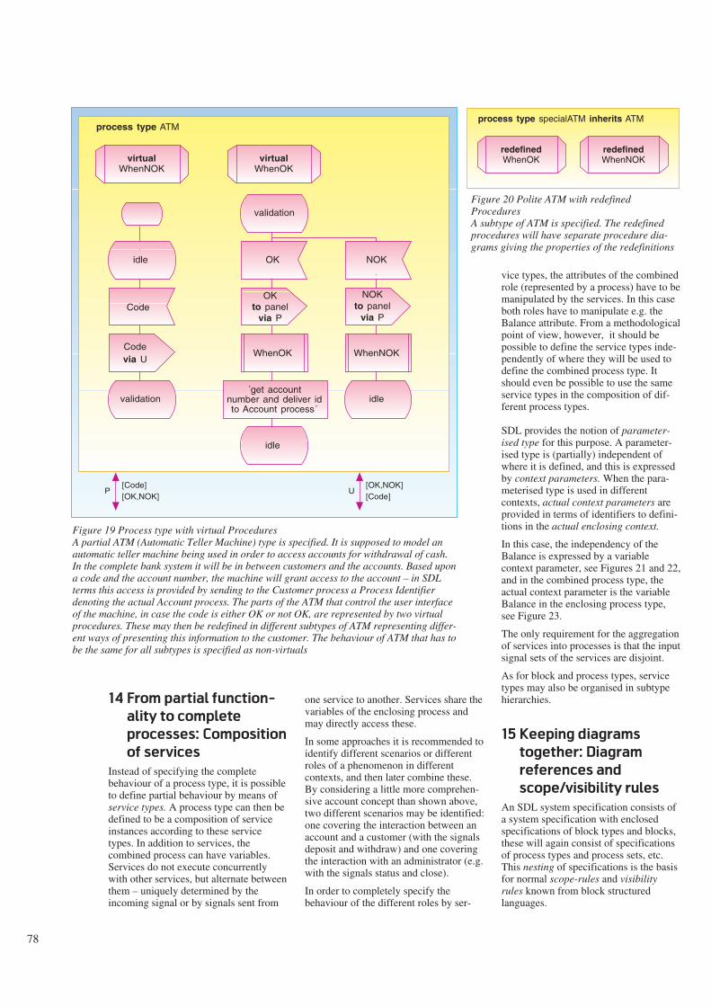
78
14 From partial function-
ality to complete
processes: Composition
of services
Instead of specifying the completebehaviour of a process type, it is possibleto define partial behaviour by means ofservice types. A process type can then bedefined to be a composition of serviceinstances according to these servicetypes. In addition to services, thecombined process can have variables.Services do not execute concurrentlywith other services, but alternate betweenthem – uniquely determined by theincoming signal or by signals sent from
one service to another. Services share thevariables of the enclosing process andmay directly access these.
In some approaches it is recommended toidentify different scenarios or differentroles of a phenomenon in differentcontexts, and then later combine these.By considering a little more comprehen-sive account concept than shown above,two different scenarios may be identified:one covering the interaction between anaccount and a customer (with the signalsdeposit and withdraw) and one coveringthe interaction with an administrator (e.g.with the signals status and close).
In order to completely specify thebehaviour of the different roles by ser-
vice types, the attributes of the combinedrole (represented by a process) have to bemanipulated by the services. In this caseboth roles have to manipulate e.g. theBalance attribute. From a methodologicalpoint of view, however, it should bepossible to define the service types inde-pendently of where they will be used todefine the combined process type. Itshould even be possible to use the sameservice types in the composition of dif-ferent process types.
SDL provides the notion of parameter-ised type for this purpose. A parameter-ised type is (partially) independent ofwhere it is defined, and this is expressedby context parameters. When the para-meterised type is used in differentcontexts, actual context parameters areprovided in terms of identifiers to defini-tions in the actual enclosing context.
In this case, the independency of theBalance is expressed by a variablecontext parameter, see Figures 21 and 22,and in the combined process type, theactual context parameter is the variableBalance in the enclosing process type,see Figure 23.
The only requirement for the aggregationof services into processes is that the inputsignal sets of the services are disjoint.
As for block and process types, servicetypes may also be organised in subtypehierarchies.
15 Keeping diagrams
together: Diagram
references and
scope/visibility rules
An SDL system specification consists ofa system specification with enclosedspecifications of block types and blocks,these will again consist of specificationsof process types and process sets, etc.This nesting of specifications is the basisfor normal scope-rules and visibilityrules known from block structuredlanguages.
Figure 19 Process type with virtual ProceduresA partial ATM (Automatic Teller Machine) type is specified. It is supposed to model anautomatic teller machine being used in order to access accounts for withdrawal of cash.In the complete bank system it will be in between customers and the accounts. Based upona code and the account number, the machine will grant access to the account – in SDLterms this access is provided by sending to the Customer process a Process Identifierdenoting the actual Account process. The parts of the ATM that control the user interfaceof the machine, in case the code is either OK or not OK, are represented by two virtualprocedures. These may then be redefined in different subtypes of ATM representing differ-ent ways of presenting this information to the customer. The behaviour of ATM that has tobe the same for all subtypes is specified as non-virtuals
process type ATM
Code
virtualWhenNOK
idle
validation
Codevia U
virtualWhenOK
OK
idle
OKto panel
via P
idle
validation
WhenOK
´get accountnumber and deliver idto Account process´
NOK
NOKto panel
via P
WhenNOK
[Code][OK,NOK]
P[OK,NOK][Code]
U
process type specialATM inherits ATM
redefinedWhenOK
redefinedWhenNOK
Figure 20 Polite ATM with redefinedProceduresA subtype of ATM is specified. The redefinedprocedures will have separate procedure dia-grams giving the properties of the redefinitions

79
In principle, the corresponding diagramscould be nested in order to provide thishierarchy of specifications within specifi-cations. For practical purposes (as e.g.paper size) it is, however, possible torepresent nested diagrams by so-calledreferences (in the enclosing diagram) toreferenced diagrams. As an example ablock type reference in a system diagramreference a block type diagram that isnested in the system diagram. Signalsdefined in the system diagram are therebyvisible in the block type diagram. Figure24 illustrates the principle.
A diagram may be split into a number ofpages. In that case each page is numbe-red in the rightmost upper corner of theframe symbol. The page numberingconsists of the page number followed bythe total number of pages enclosed by (),e.g. 1 (4), 2 (4), 3 (4), 4 (4).
16 SDL-92 in perspective
A recent survey of notations for objectoriented analysis, specification, anddesign concludes that most of them lacksmechanisms to support the followingcases:
- The number of objects and classes arelarge, and they have a natural groupingin some kind of units. These units arenot objects as supported by thenotations, and if they should beobjects, they would be objects of aspecial kind that may enclose otherobjects in a different way than part-objects.
Most notations are very good at de-scribing the attributes of objects orclasses in isolation, and the relationsbetween a limited set of these.
The notion of blocks in SDL providesa consistent grouping of processes.
- When most of the objects in a givensystem relies on the interaction with acommon resource object, thengraphical notations for expressing thiswill have problems.
SDL provides identifiers that mayidentify common processes by meansof names. Nesting of definitions, andscope-rules provides convenient identi-fication of common definitions.
In general terms, these problems stemfrom the fact that there is no languagebehind most of these notations. SDL is acomplete (even formal) language, wherethe graphical syntax is just one concrete
way of representing an SDL specifi-cation.
The following issues are often discussedin the evaluation of object orientednotations.
Multiple Inheritance is (almost)regarded as a must for notations that aimsat reflecting concept classification hier-archies, even though existing solutionson the problems with multipleinheritance are rather technical and adhoc. Some of the approaches give, how-ever, detailed advice on how to avoidmultiple inheritance if possible. The rea-son is that the technical solutions make itcomplicated to use the mechanism prop-erly.
SDL only supports single inheritance.The reason is that multiple inheritanceused for concept specialisation has not
reached a state-of-the-art understandingyet. As an example, no solutions providean answer to the problem involved if thesuperclasses of a class are not the finalclasses, but only superclasses for a set ofhierarchies.
Virtual procedures are in mostnotations not directly supported, in thesense that there is no distinction betweenvirtual and non-virtual procedures (calledmethods, operations, ...). In general it isassumed that all procedures may be rede-fined in subclasses, and for some of thenotations (or rather the accompanyingmethod) it is advocated that redefinitionsshould be extensions of the original pro-cedure in the superclass, without provid-ing language mechanisms for it.
SDL makes a distinction between virtualand non-virtual procedures (and types in
[deposit,withdraw] Exit [overdraw]Entry
service type CustomerAcc<dcl AccountNo Number; dcl Balance BalanceType>
´initialize´
deposit(amount)
Balance:=Balance +amount
WaitFirstDeposit
goodStanding
deposit(amount)
Balance:=Balance +amount
goodStandingBalance:=Balance -amount
virtualwithdraw(amount)
goodStanding
overdraw
amount >balance
-Balance:=Balance -amount -free
overDrawbalance >
ZeroBalance
Balance:=Balance +amount
overDraw
deposit(amount)
overDrawgoodStanding
True False
True False
Figure 21 Service Type representing the CustomerAcc role of an AccountNote that the variables AccountNo and Balance are context parameters (enclosed in < >). The reason forthis is that the final Account will be a composition of a service instance of this type with a service of aservice type representing another role. The combined process will have the variables representing theaccount number and the balance. The service type manipulates the context parameters as if they werevariables

80
general), and it enforces (syntactically)that redefinitions are extensions of thevirtuality constraint. The advantage ofthis distinction is that it is possible toexpress, for a general type, that some(crucial) procedures should not be rede-fined.
Polymorphism is regarded as one of thebig advantages of object orientation.There are many definitions on poly-morphism, so the following just gives thefacts for SDL:
- The same type of signal, e.g. S, may besent to processes of different types,and as variables of type Process Identi-fier are not typed, then the effect of an
output S to aP
where aP is a Process Type variable,depends on which process is identifiedby aP.
- Remote procedures may be virtual, soa remote call to such a virtual proce-dure vP of a supertype
call vP to aP
will depend on the subtype of the pro-cess identified by aP, and the redefinedprocedure for the actual subtype willbe performed.
17 Conclusion
The major language mechanisms of SDLsupporting object orientation has beengradually and informally introduced bymeans of one example system. Focus hasbeen on the structural aspects of SDL.The behaviour of processes, services andprocedures can be specified in moredetail than covered here. By using themechanisms presented here, it is possibleto sketch the structure of SDL systemsconsisting of blocks connected by chann-els, blocks consisting of blocks or pro-cesses, processes possibly consisting ofservices, and procedures being used forrepresenting patterns of behaviour. Byusing the full language, a complete,formal specification is obtained. Thisformal specification can then be used fordifferent kinds of analysis.
[close,givestatus] Exit [status]Entry
service type AdmAcc<dcl AccountNo Number; dcl Balance BalanceType>
close
´close theaccount´
*
´preparereport´
*
givestatus
-
status
Figure 22 Service Type representing the AdmAcc roleAlso here the variables AccountNo and Balance are context parameters (enclosed in < >)
process type Account
dcl AccountNo Number;dcl Balance BalanceType;
adm:AdmAcc
<AccountNo,Balance>
Entry Exit
custom:CustomerAcc<AccountNo,
Balance>
Entry Exit
Entry
[deposit,withdraw,
givestatus,close]
Exit
[overdraw,status]
[givestatus,close]
s1
s2
[deposit,withdraw]
[status]
[overdraw]
s3
s4
Figure 23 Composition of ServicesTwo service instances of type AdmAcc and CustomerAcc are composed into a processtype representing a complete Account. The actual context parameters are identifiers tothe variable definitions in the enclosing process type. Manipulations of the context para-meters in the service types will thereby become manipulations of the variables in theprocess. In this example the Entry gate of Account has been kept, with the implicationthat the incoming signals are split and directed to each of the services. Correspondinglyfor the Exit gate. Alternatively, the aggregated Account could have had one set of gatesfor the administrative interaction and one set of gates for the interaction with thecustomer

81
References
1 Belsnes, D, Dahle, H P, Møller-Ped-ersen, B. Definition of OSDL, anobject oriented extension of SDL.Mjølner Report Series N-EB-7, Janu-ary 1987.
2 Belsnes, D, Dahle, H P, Møller-Ped-ersen, B. Rationale and Tutorial onOSDL: an object oriented extensionof SDL. Mjølner Report Series N-EB-6, April 1987.
3 Belsnes, D, Dahle, H P, Møller-Ped-ersen, B. Rationale and Tutorial onOSDL: an object oriented extensionof SDL. In: SDL 87: State of the Artand Future Trends, Proceedings ofthe Third SDL Forum 1987. Amster-dam, North-Holland, 1987.
4 Belsnes, D, Dahle, H P, Møller-Ped-ersen, B. Rationale and Tutorial onOSDL: an object oriented extensionof SDL. Computer Networks andISDN Systems, 13(2), 1987.
5 Belsnes, D, Dahle, H P, Møller-Ped-ersen, B. Transformation of OSDL toSDL. Contract 700276.
6 Belsnes, D, Dahle, H P, Møller-Ped-ersen, B. Revised Rationale andTutorial on OSDL, an object orientedextension of SDL. Contract 700276.
7 Bræk, R, Haugen, Ø. EngineeringReal Time Systems: An Object-ori-ented Methodology using SDL.Englewood Cliffs, N.J., PrenticeHall, 1993. (BCS Practitioner Ser-ies.)
8 Haugen, Ø, Møller-Pedersen, B.Tutorial on Object-Oriented SDL.SPECS-SISU Report, Report No91002. SISU c/o Norwegian Com-puting Centre, P.O. Box 114 Blind-ern, N-0314 Oslo.
9 Hauge, T, Haugen, Ø. OST - AnObject-oriented SDL Tool. FourthSDL Forum, Lisbon, Portugal 9-13October 1989.
10 Haugen, Ø. Applying Object-Ori-ented SDL. Fifth SDL Forum, Glas-gow, UK, 29 September - 4 October1991.
11 Møller-Pedersen, B, Haugen, Ø,Belina, F. Object-Oriented SDL.Tele, 1, 1991.
12 Olsen, A et al. Systems Engineeringusing SDL-92. Amsterdam, North-Holland, 1993.
system bankSystem
theATMs
(NoOfATMs):ATMc
b
h
atheBranches
(NoOfBranches):BankBranch
h
ah
[bankTransActOK,bankTransActNOK]
hb
[withdraw]
[card,code,amount]
ac
[cast,receipt,failure]
1(1)
block type BankHeadQuarter: inherits Bank
block type BankBranch inherits Bank
block type ATM
[receipt,(failure)]
[card,code,amount]
s1
[card,code,amount]s2
[receipt,(failure)]
CashDispenser
Panel Controller
[cash]
s3
s4
[paycash][transactOK,[transactNOK,(failure)]
[verify,transaction]
1(1)
[transactOK, transactNOK,failure)]
[verify, transaction]
theHeadQuarter:
BankHeadQuarter
process Panel process CashDispenser process Controller 1(2)1(2)1(2)
ATMBankHeadQuarterBankBranch
Figure 24 Referenced DiagramThe three block type symbols in thesystem diagram indicate that threeblock types are defined locally tothe system, and they reference threeblock type diagrams. The blocksymbols with the names theATMs,theHeadQuarters and theBranchesare not references to block dia-grams, but simply specifications ofblock sets according to type. Thethree process symbols are alsospecifications of processes to beparts of blocks of type ATM, butthey are also references to diagramsdefining the properties of these pro-cess instances. Reference symbolsare used in the case where anenclosing diagram refers to dia-grams that logically are defined inthe enclosing diagram. In order toidentify diagrams that are defined insome enclosing diagram, identifiersare used; the examples here are theblock supertype identifier Bank inthe two block type diagrams Bank-HeadQuarters and BankBranch.Bank identifies a block type dia-gram defining the block type Bank

82
The story behind object orientation in
SDL-92
This version of the story is the version as seen from the
author, and it may therefore be biased towards Norwegian
contributions. If the complete story should be written it
would require some more work together with the many
people involved; time has not allowed that.
It all started in the sixties with the definition of SIMULA.
Developed in a setting where the problems were to make
operational models of complex systems, SIMULA became
not only a programming language, but also a modelling
language. Inspired by this use, the pure specification
language DELTA was developed, also at the Norwegian
Computing Centre. In the eighties, the combined experi-
ence with SIMULA and DELTA led to the definition of an
object oriented programming language, BETA (Norwegian
Computing Centre, University of Aarhus, University of Aal-
borg). The approach in this series of developments has
been called the Scandinavian approach to object orient-
ation.
For SDL it started in 1985 when EB Technology (now ABB
Corporate Research) started work on the design of a
graphical, object oriented specification language. With
background in the SIMULA tradition, the group at EB
Technology had no doubts that this was possible to do in
Norway. The Norwegian Computing Centre was engaged to
help in defining it. The first intentions were to design a
language from scratch.
This project triggered in 1986 the Møjlner Project, a 3 year
Nordic research project with participants from Denmark,
Norway, and Sweden, funded by the Nordic Industry Fund.
The theme of the project was object orientation, and it
should produce languages and tools for industrial use. At
that time, object orientation was still for the few and still
regarded as something useful for making toy systems in
isolated laboratories. Discussions early in the project reve-
aled that users of the project results would rather see an
object oriented extension of the CCITT recommended
language SDL, than a new language. The reason was that
SDL was widely used in some of the organisations. So,
while the Danish part of the project (Sysware Aps and Uni-
versity of Aarhus, Computer Science Dept.) made the first
implementation of BETA and elements of a programming
environment, and the Swedish part (TeleLOGIC and Uni-
versity of Lund) made an advanced programming environ-
ment for SIMULA, then the Norwegian part of the project
(EB Technology and Norwegian Computing Center) aimed
at defining an object oriented extension of SDL and imple-
menting a tool supporting this. The working title of the
extended language became OSDL.
The first proposal was made as part of the Mjølner Project
(1). It is dated January 12, 1987. The authors had no pre-
vious experience with SDL, which also meant that they had
no predefined attitudes towards what was possible or not.
The main ideas behind the proposal were based upon the
Scandinavian approach to object orientation. Two
examples may illustrate this: According to this approach,
objects shall have their own action sequence, and they
shall be able to act concurrently – this led to the choice of
SDL processes to be the primary objects. It shall also be
possible to specialise action sequences – this led to the
notion of virtual transitions. Virtual procedures is a well-
known and accepted mechanism in almost all object ori-
ented languages, so that was introduced as well.
Around this first proposal the Norwegian part of the project
had very valuable discussions with the Swedish partners in
the project, including Televerket. The first proposal was a
rewrite of the whole recommendation.
In light of object orientation, some of the (strange) differ-
ences between e.g. blocks and systems, were removed,
and processes and blocks were allowed to be at the same
level.
A separate proposal on remote procedures in SDL came at
the same time from Sweden. This notion was also part of
OSDL. At later stages these proposals were merged.
A tutorial on the extensions was ready April 30, 1987 (2).
This formed the basis for the paper at the SDL Forum in the
Hague, April 1987, where OSDL was presented for the first
time (3). The authors were rather new in this field, so they
were not aware that among the audience were most of the
people that were going to join the work on object oriented
SDL the next 5 years. These were especially people being
active in the Study Group X of CCITT, maintaining SDL.
A more comprehensive version of the conference paper
appeared later in Computer Networks (4).
A contract with Norwegian Telecom Research brought
about the important work on transforming OSDL to SDL
(5). In addition, specific language mechanisms as e.g.
virtual process types were asked for, and included (6). This
work turned out to be important when it was presented as a
proposal for CCITT.
The RACE I project SPECS started in 1988. The aim was to
reach a common semantic platform for SDL and LOTOS,
and to define corresponding methods for SDL and LOTOS.
EB Technology became partner of the project, with
Norwegian Computing Center, Kvatro, and DELAB as
subcontractors.
The project had to adhere to standard languages, so SDL-
88 was the language. On the other hand, for the methodo-
logy part the project studied mechanisms for component
composition and reuse. It was therefore natural to con-
tinue the work on object oriented SDl in the project.
Even though SPECS was an important vehicle for the
development of SDL-92, the final SPECS Book is based
upon SDL-88. The reason is that it was not possible to co-
ordinate the various methods and tools developed in the
project on SDL-92.

83
The SPECS project was financed by NTNF and NTR
The SISU Project started at almost the same time, with
participation from a series of Norwegian companies
involved in real-time systems engineering. The project
decided to base its methodology work on OSDL.
A requirement for using OSDL was that the extensions
became part of the CCITT Standard. The SISU project
therefore contributed to the work in CCITT.
The CCITT work on extending SDL started at the last mee-
ting of the 1984-1988 study period. The first document
describing the extensions as needed by CCITT is dated
December 23, 1988. The real work began at the CCITT
meeting in May, 1989.
The first question was whether the extensions should be
contained in a separate recommendation or incorporated
in Z.100. For the first 2 years the work was directed towards
a separate recommendation. When the work became more
detailed, it turned out that there would be many cross-
references between the two, so it was decided to merge
the extensions into Z.100 and at the same time organise
the document so that it would be easy to spot the extens-
ions.
During 1989 and first part of 1990, two proposals were
regarded as kind of competing: The OSDL proposal and a
Danish proposal on parameterised definitions, expected to
cover both context parameters, gates, and virtuals. At the
last meeting in 1989 it was decided to merge the two pro-
posals, and at the June CCITT meeting in Espoo, Finland,
the two proposals were merged into one written proposal.
The Danish proposal corresponds more or less to the
notion of context parameters, so they came in addition to
virtuals from the OSDL proposal. At one point in time, it
was investigated if the context parameters could also
cover gates, but it turned out that gates were of a different
nature: context parameters are parameters of definitions
(disappearing when given actual parameters), while
instances of types with gates will have the gates as
connection points.
Through a number of experts meetings and more formal
CCITT meetings during 1990 and 1991, the proposal was
re-worked several times, implications for the rest of SDL
was considered and a formal definition was given by trans-
formation to Basic SDL.
Even though it started in Norway, the work with the pro-
posal could not have been undertaken without the efforts
of the members of the Study Group X.
- The Chairman of the group and rapporteur for SDL
maintenance kept all the loose ends, ran very efficient
meetings, and as a last contribution in the study period,
he edited the final version of the SDL-92 standard.
- The formal definition rapporteur pin-pointed many
inconsistencies and points for discussions and clarifi-
cation.
- The rapporteur for the Methodology Guidelines
(and therefore engaged in what the users might think
about the new SDL) gave valuable contributions.
- Telia Research made a semantic checker for the new
SDL, thereby posing nasty questions, but also contri-
buting with possible answers.
- The UK delegation was always ready with a good
formulation and good choice of words – in addition to
representing all the good traditions of SDL.
The CCITT plenary meeting in Helsinki in March, 1993
recommended a new version of SDL with the extensions as
proposed by Study Group X.
In addition to the CCITT work, several of the people
involved have contributed to the spreading of the ideas to
established and potential users of SDL. Highlights in this
activities are (according to the knowledge of the author):
- OSDL courses held at EB as part of the Møjlner project
and OSDL as part of university courses, 1989-1992
- Numerous SISU courses, based on methodology work in
the SISU project, and leading to a book (7)
- Numerous talks by the Chairman of the study group
- Talk on tools for OSDL at the SDL Forum 1989, by EB
Technology (9)
- A combined SPECS-SISU tutorial (8)
- A talk on applying Object-oriented SDL (10)
- Tutorials at the FORTE 90 conference and at the SDL
Forum 91, based on the SPECS-SISU tutorial, by
Norwegian Computing Centre
- A joint talk at Telebras in Brazil, in conjunction with the
CCITT meeting in Recife, by Norwegian Computing Cen-
tre, TFL and Telia Research
- Various SDL-92 seminars at: TeleLOGIC, SPECS, ARISE,
GPT, BNR, ATT, by Norwegian Computing Centre
- Forthcoming book on SDL-92 (12).

84
An introduction to TMN
B Y S T Å L E W O L L A N D
Motivation, scope
and objectives
Management of telecommunicationsresources have up to now been a mixtureof manual, automated (or computer-sup-ported) and automatic functions. Thesehave usually been performed by stand-alone, ad-hoc procedures or systems. Thesystems have been equipment specificand vendor supplied. Or they have beendeveloped by the telecoms operators asstand-alone systems for a specific pur-pose.
The last few years have seen a growingeffort to specify the management aspectsof the various telecoms resources(network elements, networks and ser-vices) so as to present themselves to themanagement functions in a uniformmanner. This work has focused on har-monised management interfaces and gen-eric management functions. By stand-ardising the interfaces there is no longera need to duplicate large parts of thespecification and development work foreach operator and supplier.
The potential for re-using data defini-tions, registrations and repositories,management procedures and software orindeed management hardware resourceslike processors, storages or communi-cation channels have until recently onlybeen exploited to a small extent. The sav-ings in having a common set of manage-ment resources (people, data and proce-dures) all interacting using a commonmanagement network (physical orlogical) promise to be very great indeed.
Some of the benefits have been touchedupon already:
- Vendor independence
- Equipment, network and service inde-pendence
- Reusability of management data andfunctions
- Reusability of management personneland organisation (the choice of cen-tralised or distributed managementbecomes more flexible)
- Internationally standardised manage-ment interfaces
- Less costly specification and procure-ment of management applications
- Increased interoperability of nationaland international management resour-ces.
All these factors should lead to decreasedspecification, procurement andoperational costs for management. Otherbenefits are increased functionality andperformance including quality of service.
The possibility of allowing customers orother operators access to a restricted setof management functions is also beingexplored. The obvious threat is securityand integrity of potentially valuable andsensitive management data and functions.On the other hand, there are considerablesavings to be had for both providers andusers with such facilities.
TMN –Telecommunications Manage-ment Network – is the term adopted byETSI and CCITT for describing themeans to transport and processinformation related to the management oftelecoms resources. The term denotes anintegrated and interoperable approach todistributed management of these resour-ces. That is to say, the monitoring, co-ordination and control that is requiredfor smooth operation of all the telecomsmeans. There is a very similar notionwithin ISO/IEC for the management ofOSI (Open System Interconnection)resources. There it is called OSI Manage-ment. Work is going on to bring thesenotions in line. This harmonisation workis done by CCITT SG VII and ISO/IECJTC1/SC21/WG4. The two notions are now toa large extent identical.
Basic concepts of TMN
The basic ideas of TMN are inter-operability, re-use and standardisation ofmanagement capabilities together with anevolutionary approach to the introductionof TMN into the present network.
The basic concepts used for TMN areillustrated in Figures 1 and 6. A furtherdetailing of the concepts can be found inCCITT Recommendation M.3010,(1),ISO/IEC IS 7498-4 (2) and ISO/IEC IS10040 (3).
The functional view of TMN is describedin terms of function blocks and referencepoints between these. The purpose of thefunction blocks is to group relatedfunctionality together so that specifi-cation and implementation may besimpler. The interaction between thefunction blocks defines service bound-aries and they are described by referencepoints which are collections of data andoperations. The reference points arecandidates for implementation as inter-faces. There are five types of functionblocks. Operations Systems Function(OSF), Mediation Function (MF), WorkStation Function (WSF), Network Ele-ment Function (NEF) and Q AdapterFunction (QAF). The OSF processesinformation for the purpose of manage-ment of telecoms resources or othermanagement resources. The NEF com-municates with the TMN for the purposeof being managed. The WSF provides themeans to interpret and present the TMNinformation to the management end user.The MF acts on information passingbetween an OSF and an NEF or a QAFby storing, adapting, filtering, threshold-ing and condensing this information tofacilitate the communication. The QAFconnects non-TMN entities to the TMNby translating between a TMN referencepoint and a non-TMN (proprietary) refer-ence point.
The function blocks are interconnectedby reference points (RP). The referencepoints are conceptual points describingthe functional interaction or informationpassing between two function blocks.They define the service boundariesbetween the blocks.
The first type of RP is between the OSFs(where some of the managementcapability is implemented) and thetelecoms resources (Network Elements,Networks, Services). This is denoted q(q3 and qx; see Figure 6).
The second type of RP is between themanagement functions and the pre-sentation tool (in most cases a workstation). This RP is called f.
A third type of RP is between two OSFsin two different TMN domains, e.g. twotelecoms operators. This RP is foreseen
621.39.05:65
OSF WSF
NEFQAF
MF
TMNOSF -
WSF -
MF -
QAF -
NEF -
OperationsSystemFunction
Work StationFunction
MediationFunction
Q AdapterFunction
NetworkElementFunction
Legend:
Figure 1 TMN Basic concepts (functional view)

85
to have security attributes to enable thenegotiation of strict security functions inaddition to a (more restricted) set ofmanagement functions. This RP is calledx.
A reference point can be implemented byadopting a particular communicationprotocol and a particular communicationservice (message set). They are thencalled interfaces and capital letters areused to denote them. In TMN the RPs arecandidate interfaces. They become inter-faces in case the function blocks areimplemented in different physicallocations.
Functional block Functional components Associated messagecommunications functions
OSF MIB, OSF-MAF (A/M), HMA MCFx, MCFq3, MCFf
OSF subordinate(1) MIB, OSF-MAF (A/M), ICF, HMA MCFx, MCFq3, MCFf
WSF PF MCFf
NEFq3(2) MIB, NEF-MAF (A) MCFq3
NEFqx(2) MIB, NEF-MAF (A) MCFqx
MF MIB, MF-MAF (A/M), ICF, HMA MCFq3, MCFqx, MCFf
QAFq3(3)(4) MIB, QAF-MAF (A/M), ICF MCFq3, MCFm
QAFqx(4) MIB, QAF-MAF (A/M), ICF MCFqx, MCFm
Table 1 Relationship of functional blocks to functional components
Legend: PF = Presentation Function
MCF = Message Communications Function
MIB = Management Information Base
MAF = Management Application Function
ICF = Information Conversion Function
A/M = Agent/Manager
HMA = Human Machine Adapter
Note: MAF (A/M) means management application function in Agent or manager role.
(1) This is an OSF in the subordinate layer of the logical layered architecture.
(2) The NEFs also include Telecommunications and Support resources that are outside of the TMN.
(3) When QAFq3 is used in a manager role the q3 reference point lies between the QAF and an OSF.
(4) The use of QAF in the manager role is for further study.
In this table the subscripts indicate at which reference point the functional component applies. Individual functional com-
ponents may not appear or may appear multiple times in a given instance of a functional block. An example of multiple
occurrences is of several different management application functions (MAFs) in the same instance of a functional block.
PerformingManagement Operations
Emitting
Notifications
CommunicatingManagement Operations
Notifications
MIS-USER(manager
role)
MIS-USER(agentrole)
ManagedObjects
TelecomResources
Tele-service
MANAGING SYSTEM MANAGED SYSTEM
Figure 2 Basic TMN communication and processing

86
This is summed up in Figure 6, which isa functional representation of themanagement capabilities.
It is important to note that in TMN it isthe interfaces that are being standardisedinternationally and not the functionblocks. The status in 1993 is that the Q3interface is fairly well advanced on theway to being standardised. The X inter-face is at an early stage and the F inter-face is beginning to receive the firstattention.
The function blocks are composed of ele-mentary function blocks called functionalcomponents. There are six types offunctional components: ManagementApplication Function (MAF), Manage-ment Information Base (MIB),Information Conversion Function (ICF),Presentation Function (PF), HumanMachine Adaptation (HMA) andMessage Communication Function(MCF). MAFs perform the actualmanagement functions by processingManaged Objects (MO)(see below andalso separate article in this volume).MIBs are conceptual repositories for theMOs. The ICFs convert between the dif-ferent information models of two inter-faces. The HMAs perform the conversionof the information model of the MAF tothe information model of the PFs. ThePFs perform the translation between theTMN information model to the end userpresentation model. The MCFs are per-forming the physical exchange ofmanagement messages with peer entities.The definitions of these can be found inCCITT Rec. M.3010 (1). Table 1 givesthe relationship between the functionblocks and the functional components.
Basic management
communication and
processing
The basic TMN management communi-cation interactions and operations areshown in Figure 2.
The Management Information SystemUser (MIS-U) can either be a manage-ment application (OSF) in the Managerrole (which is a role that the managementprocess can play during one particularmanagement interaction in the communi-cation process) or in the Agent role. Thedefinition of the manager is that it candirect management operations to theremote agent and receive managementnotifications. The definition of the agent(which again is a role the process can
BusinessManagement
Layer
ServiceManagement
Layer
NetworkManagement
Layer
Network ElementManagement
Layer
NetworkElement
Layer
VASP 1
TMN 1
VASP N
TMN N
TMN Z
Service ProvidersTransportProvider
x
x
OSF OSF OSF
OSF
NEF
MF
OSF OSF
OSF
OSF
TMN 1 ...N -
TMN Z -
Service Provider
Transport Provider
Figure 3 Non-peer-to-peer interaction between management operators and layers(example)
BusinessManagement
Layer
ServiceManagement
Layer
NetworkManagement
Layer
Network ElementManagement
Layer
NetworkElement
Layer
VASP 3
TMN 3
VASP 2
TMN 2
VASP 1
TMN 1
Between Service ProvidersWithin
Administration
x
OSF OSF OSF
OSF
NEF
MF
OSF OSF
OSF
OSF
OSF
OSFx q
Figure 4 Peer-to-peer interaction between operators and layers (example)

87
have during one particular interaction)can perform management operations andreceive management notifications fromthe Managed Objects (MO) and receivedirectives for operations from and sendnotifications to the manager.
The MOs are elementary managementcapabilities seen from the MIS and theyrepresent an abstraction in the form of amanagement view of the telecomsresources. An MO is defined in terms ofattributes it possesses, operations thatmay be performed on it, notifications itmay issue and its relationships with otherMOs.
There are two things to note about theMOs. The first is that MOs are beingstandardised internationally. The secondis that MOs are specified in an object ori-ented fashion. The template for the speci-fication is the ISO/IEC OSI Guidelinesfor the Description of Managed Objects(GDMO) (4). For a further definition ofMOs, see separate article in this volume(6).
The managing and managed systemstogether are viewed as a distributedmanagement application. They interactvia standardised interfaces with protocolsthat reference the MOs. As already ment-ioned, these interfaces are essential forthe TMN concept.
The idea of a mediation function wasalready introduced above. From Figure 6and Figure 7, a further elaboration can bemade. As the name indicates, thisfunction takes care of a set of pre-pro-cessing tasks before the managementdata and operations are processed proper.Mediation is foreseen for communicationwith data concatenation (to reduce thevolume of data flows) and connectionconcentration (to reduce the number ofconnections between a potentially largenumber of network elements and asmaller number of operations systems(OS)). Other examples of managementmediation is decision making (forexample thresholding alarms), routing ofmanagement messages and conversionbetween different management inter-faces. The Mediation Device (MD) shallon the one hand interconnect telecomsresources to OSs via the mediationfunction and on the other hand inter-connect telecoms resources to OSs againvia the mediation function. The telecomsresources will in some cases support amore simple management interface thanthe OS. Hence, a mediation device will
have two TMN interfaces – one for theOS side and one for the NE side.
Adaptation is a management functionrequired in case the interface to atelecoms resource is not TMN standard.The adaptation function will either beperformed in the network element or in aseparate Adapter. The purpose is toconvert a proprietary interface of the NE
to a TMN interface. This will allow inter-connecting for example existing non-TMN NEs with a TMN. This will alsopermit internal, proprietary interfaces forinternal communication inside thetelecoms resources, while providing aTMN interface for external managementcommunication. Hence, an adapter willonly have one TMN interface.
Mgt. Appl.
(NE-MAF)
TelecomResource(service)
CMISE
2 5 6
7
1alarm
NE
CMISE
ACSE ROSE
3 4 1
8
OS
DB(MIB)
Mgt. Appl.
(OS-MAF)
ACSE ROSE
Figure 5 Example of management communication and processing (physical)
m
WSF
NEFQAF
WSF
NEF QAF
MF
OSF OSF
MF
g g
f f
ff
q3 q3
q3q3
q3 q3 q3q3
qx qxqxqx qx qx
m
x x
Figure 6 TMN interaction (functional view)

88
Logical layered
architecture
ISO categorises management into fivefunctional areas: Fault, performance,configuration, accounting, and security.CCITT and ETSI use a different cate-gorisation with more functional areaswhen seen from the management endoperator. This division is not important.The final management capability to beprovided at the operator interface is notfor standardisation, but will be decidedby the requirements of the individualtelecoms operators. Their needs willdepend on the business idea for their off-ering of the telecoms service, theirinvestment profile and their managementorganisational requirements. This offer-ing of management capability will be an
area open for competition between thetelecoms operators in the future. Thisdoes not, however, preclude someaspects of this interface to be stand-ardised.
Seen from the manager/agent view, themanagement capability can be dividedinto four areas with respect to whataspects of the telecoms resources theyaddress: Network Element, Network,Service, and Business. This grouping ofmanagement functionalities is called theLogical Layered Architecture (LLA) andis recommended for TMN. If these layersare implemented in different physicalresources or locations, there will be aninterface between the layers and the lay-ers will be implemented in different OSs.
How is management
performed?
Figure 5 shows an example of howmanagement interaction and processingtake place in the case of an alarm for atelecoms resource (NE).
The alarm causing event happens forsome reason inside the telecomsresource. The event is registered thereand is communicated through a non-TMN interface to an MO. There is anensuing state change of this object (attri-bute value change). For certain eventsthere is defined a certain behaviour forthe MO. In this case there is a notifi-cation emitted by the MO. The NE-MAFas an agent receives the alarm notifi-cation from the MO and decides to reportthis to the manager. The agent firstestablishes the connection over the TMNto the manager by invoking the com-munication service primitives of the ISOOSI ACSE (Association Control ServiceElement) which is always used for TMNcommunication. As a result of this invo-cation, an association (connection) is setup between the agent and the managermanagement processes. This is doneprior to the management data exchangeproper. Management data exchange isperformed by invoking the ISO/IEC OSIand CCITT CMISE (Common Manage-ment Service Element) (5) service primi-tives for communicating managementdata. The CMISE services basicallyreference the MOs for the purpose ofprocessing these. The CMISE makes useof the common ISO OSI ROSE (RemoteOperations Service Element) to com-municate its management operations anddata directives. By using these communi-cation services and protocols, themanagement functions can exchange
their operations on managed objects andreceive notifications. By processing theoperations on the MOs, the MAFs caneffect management of the telecomsresources in a generic and standardisedway.
Centralised or distributed
management?
TMN is a distributed concept for cen-tralised management!
TMN will allow centralised managementthrough the use of harmonised manage-ment interfaces to telecoms resources, aninteroperable management network,mediation devices and adapters.
TMN will allow an evolutionary app-roach (gradual introduction) by usingadapters that will allow co-existence ofpresent non-TMN management andtelecoms systems and new TMN sys-tems. Hence, the investment in manage-ment resources and equipment todayshould be well protected. A revolutionaryapproach would have been meaninglessin terms of economics.
Achieving centralised and standardisedmanagement for the different networkand service resources can potentially bevery cost-saving. A cost-reduction can beobtained from a decrease in the numberof required management personnel, apossible simplification in the trainingrequired due to the introduction of auto-mation (although potentially training canbecome more complex if more sophisti-cated management is undertaken), the re-use of management systems that requireto be specified, developed and procured,the re-use of the management data thatrequire to be defined, registered, pro-cessed and stored, the re-use of the pro-cessing platforms that the managementsystems run on, etc.
But TMN is a concept for distributedmanagement as well!
TMN encompasses concepts for peer-to-peer management communicationbetween managing systems and managedsystems. In a particular management dataexchange, the managed system acts as anagent and the managing system acts asthe manager. The agent is capable ofreceiving management directives fromthe manager and executing the directivesby accessing the managed objects, pro-cessing these and returning answers ifrequired. Hence, even if TMN is takingplace in an integrated fashion logically,
DCN
MD
OS
DCN
Q A NEQ A NE
WS
TMN
X
X/F/Q3
F
Q3/F
QxQ3Q3
Qx Qx
Interfaces
Figure 7 Simplified physical architecture (example)
Note 1: For this simplified example the building blocks areconsidered to contain only their mandatory functions (seeTable 1).
Note 2: The interfaces shown on either side of the DCN areactually a single interface between end systems for Layers 4and above. For Layers 1 to 3 they represent the physical,link, and network interface between an end system and theDCN

89
the management processing can be reali-sed as a distributed process.
This characteristic of logical integration,but optional physical centralisation ordistribution, allows a great degree offlexibility in the implementation of themanagement functions.
TMN functional
reference model
Figures 1 and 6 summarise the TMNfunctional reference model.
Here, the types of functional blocks andreference points that interconnect theseare identified for TMN.
Table 1 gives the relationships betweenthe TMN function blocks and the TMNfunctional components that can exist in aTMN.
From Figure 6 we notice that an operatoris capable of interacting directly over thenetwork both with the operations systemand the mediation device through the Finterface. This is not the case for thetelecoms resource (here represented bythe NE) and the adapter.
From Figures 3 and 4 we also notice thattwo telecoms operators (either serviceoperators or network operators) caninteract directly with each other throughthe X interface. We see that normallytwo service providers (in this case theyare value-added-service-providers,VASPs) are expected to interact via the xreference point at the service layer in apeer-to-peer fashion. However, in specialcases the interaction may take place viaan X interface other than the servicelayer. This is shown in Figure 3, wherethe interaction is not required to be peer-to-peer.
Conclusions
TMN is a wide and complex area, andinternational agreement has taken a longtime to emerge. Due to the wide scope ofTMN, it will take some time yet beforethe final shape can be seen. However,TMN is a concept for gradual intro-duction and enough of the specificationsare in place to allow early realisations atthis stage. Since the basic idea is to per-form generic, standardised managementover a large and diverse range of ele-ments, networks and services, it is notsurprising that the realisation will take itstime.
However, the status in 1993 for TMN isthat the first implementable and indeedimplemented functions are beginning toemerge. For management communi-cation, the ISO/IEC CMIS/CMIPprotocol has been standardised andimplementations can be obtained comm-ercially.
The proposed standards for the managedobjects are in many cases close to fin-alisation. In this area the work is goingon with full strength. The MOs fornetwork element management are fairlywell specified. The MOs for networklevel management and service manage-ment are yet at an early stage. Naturally,the generic aspects of management arespecified first. MOs describing a widespectre of common managementcapabilities like fault handling and per-formance handling, etc., are addressed ina series of emerging standards andrecommendations. In addition, managedobjects for specific areas such asmanagement of SDH (SynchronousDigital Hierarchy) and ATM(Asynchronous Transfer Mode) arereceiving a lot of attention. The first pro-posals have been available for some time.
References
1 CCITT. Principles for a Telecom-munications Management Network.(Recommendation M.3010.)
2 ISO. OSI Basic Reference ModelPart 4: Management Framework.(ISO/IEC IS 7498-4.)
3 ISO. OSI Systems ManagementOverview. (ISO/IEC IS 10040.)
4 ISO. OSI Structure of ManagementInformation – Part 4: Guidelines forthe Definition of Managed Objects.(ISO/IEC IS 10165-4.)
5 ISO. OSI Common ManagementInformation Service Definition/Com-mon Management Protocol Specifi-cation. (ISO/IEC IS 9595/9596.)
6 Kåråsen, A G. The structure of OSImanagement information. Telektron-ikk, 89(2/3), 90-96, 1993 (this issue).

90
The structure of OSI management information
B Y A N N E - G R E T H E K Å R Å S E N
1 Introduction
This article presents the structure of OSImanagement information. Detailsconcerning the notation used to expressthis information are not included. How-ever, the notation of the OSI manage-ment formalism is visualised by pre-senting some examples. First, the contextin which OSI management information isapplied, namely OSI management, willbe briefly described.
OSI is an abbreviation for Open SystemsInterconnection, which defines a fra-mework for interconnections betweensystems that are “open” to each other.When providing interconnection servicesbetween open systems, facilities areneeded to control, co-ordinate andmonitor the communications resourcesinvolved. Within an OSI environment,this is the concern of OSI management.
OSI management is required for severalpurposes, and covers the followingfunctional areas:
- fault management
- accounting management
- configuration management
- performance management
- security management.
OSI management is accomplishedthrough systems management, (N)-layermanagement and (N)-layer operations.Systems management provides thenormal management mechanisms withinan OSI environment.
The systems management model, de-scribed in (1), identifies the variousaspects of systems management. Theseaspects are:
- management information
- management functions
- management communications
- organisational aspects.
(2) introduces the OSI management fra-mework, and (1) gives a generaldescription of systems management. Thelogical structure used to describe systemsmanagement information, i.e. theinformation aspect of the systemsmanagement model, is the topic of thisarticle. The main source of informationon the topic is (3).
2 General
The management information model pro-vides methods to model the managementaspects of communications resources,and to structure the exchange of manage-ment information between systems. Theinformation model is object oriented, i.e.it is characterised by the definition ofobjects with specified properties. In gen-eral, these objects are abstractions ofphysical or logical entities. Objects thatrepresent communications resourcesbeing subject to management are termedmanaged objects, and are OSI manage-ment’s view of the resources in question.
Management of a communicationsenvironment is an information processingapplication. Management applicationsperform the management activities byestablishing associations between sys-tems management application entities.These application entities communicateusing systems management services andprotocols. Management applications aretermed MIS-users, and each interactiontakes place between two MIS-users,acting as manager and agent,respectively. Figure 1 illustrates systemsmanagement interactions and relatedterms.
Management has access to managedobject properties that are visible at themanaged object boundary, i.e. propertiesexposed through the object’s attributes,operations and notifications (see chapter3). The internal functioning of themanaged object and the resource beingrepresented are otherwise not visible tomanagement. This principle of encap-sulation serves to protect the integrity ofthe managed object and the resource itrepresents.
The set of managed objects within a sys-tem, together with their attributes, consti-tute the system’s ManagementInformation Base (MIB). The MIB com-prises all the information that may betransferred or affected through the use ofmanagement protocols within the system.
3 Managed object classes
Managed objects having the samedefined properties are instances of thesame managed object class. Specificationof a managed object class and its associ-ated properties is documented by using aset of templates (see chapter 9).
The managed object class definition, asspecified by templates, consists of:
- the position in the inheritance hier-archy (see chapter 4)
- a collection of mandatory packages(see section 3.1)
- a collection of conditional packages,and the condition under which eachpackage is included
- an object identifier (see chapter 6).
A package structure consists of thefollowing:
- attributes
- operations
- notifications
- behaviour.
Generic and specialised managed objectclasses are defined in several CCITTRecommendations, and are also definedby other international organisations, suchas ISO/IEC and ETSI. These organ-isations collaborate in the field of sys-tems management. Within OSI manage-ment, (4) defines the generic managedobject classes from which other classesare derived. To illustrate some of theterms introduced in this article, thedefinition of one of these genericmanaged object classes is shown inFigure 2. The logRecord managed object
681.327.8:006
MIS-user
(manager role)
MIS-user
(agent role)
performingmanagement
operations
emittingnotifications
managedobjects
communicating
notifications
management operations
Managing open system Managed open system
Figure 1 Systems management interactions

91
class definition is chosen as an examplebecause it is comparatively short andsimple.
3.1 Packages
The properties of managed objects,described through their attributes,operations, notifications and behaviour,are collected in packages within themanaged objects. This is primarily doneto ease the specification task. If apackage comprises some particular set ofproperties that are common to severalmanaged object classes, previouslydefined packages may be re-used in newclass definitions.
Packages are either mandatory orconditional when included in a specificmanaged object class definition. Attri-butes, operations, behaviour, and notifi-cations defined in mandatory packageswill be common to all instances of agiven class. Attributes, operations,behaviour, and notifications defined in aconditional package will be common tothose managed object instances thatsatisfy the conditions associated with thatparticular package.
Only one instance of a given packagemay be included in a managed object.For this reason, name bindings are notassigned to packages. Name bindings aredefined separately, and are not part of themanaged object class definition (seesection 5.2).
To ensure the integrity of managedobjects, operations are always performedon the managed object encapsulating thepackage, not on the package itself. Aspackages are an integral part of themanaged object, they cannot be instanti-ated by themselves. A package and themanaged object to which it belongs mustbe instantiated and deleted simul-taneously.
Managed objects include a separatePackages attribute that identifies allpackages being present in that particularmanaged object instance.
The logRecord managed object classincludes the mandatory packagelogRecordPackage, and the packagedefinition is directly included in themanaged object class definition. If thepackage in question had been definedseparately, using a complete packagetemplate as described in (5), the construct“CHARACTERIZED BY logRecord-Package” could have been used in themanaged object class definition, referen-cing the package.
3.2 Attributes
Attributes are properties of managedobjects. Attributes are formally definedby using an attribute template, describedin (5).
An attribute has an associated value, andthis value may have a simple or complexstructure. Attribute values may be visibleat the managed object boundary, and maydetermine or reflect the behaviour of themanaged object. Attribute values may beobserved and manipulated by attributeoriented operations, described in section8.3.
The syntax of an attribute is an ASN.1type (see chapter 11) that abstractly de-scribes how instances of the attributevalue are carried in communicationprotocols. The concrete transfer syntax isnot specified by the ASN.1 type.
A number of attribute properties are notdirectly included in the attribute defini-tion. These properties are listed whenreferencing the attribute in the managedobject class definition. Attribute valuerestrictions, default or initial attributevalues associated with the attribute, andoperations that may be performed on theattribute, are included in the property list.
Restrictions on attribute values may bedefined through the use of permittedand/or required value sets for the attri-bute. The permitted value set specifies allthe values that the attribute is permittedto take. The permitted value set will be asubset of the attribute syntax values. Therequired value set specifies all the valuesthat the attribute must be capable of tak-ing. The required value set will be a sub-set of the permitted value set.Restrictions on the attribute value setshould only be made if they are based onspecific features inherent in thesemantics of the attribute.
An attribute may be set-valued, i.e. itsvalue is an unordered set of members ofa given type. The size of the set is vari-able, and the set may be empty. How-ever, the cardinality of the set is subjectto restrictions. Members of set-valuedattributes may be added or removed byuse of defined operations.
Several attributes may be addressedcollectively by defining an attributegroup. An attribute group may be fixedor extensible. The attributes comprisingthe attribute group are specified individu-ally, and operations addressed to theattribute group will in fact be performedon each attribute in the group. Attributegroups do not have values of their own.
The attributes included in the logRecordmanaged object class are both singlevalued. No attribute value restrictions aredefined, and the attributes have nodefined initial or default values. Theproperty lists consist of “GET”, and thisindicates that both attributes are read-only. The logRecord managed objectclass does not include any attributegroups.
The logRecordId attribute definition andASN.1 syntax is shown in Figure 3.
3.3 Operations
Two types of operations are defined,namely operations that affect the attri-butes of a managed object and morecomplex operations that affect themanaged object as a whole. Create,Delete, and Action are operations of thelatter type. Operations are furtherdescribed in chapter 8.
3.4 Notifications
Managed objects may emit notificationsthat contain information relating tointernal or external events that have
logRecord MANAGED OBJECT CLASS
DERIVED FROM top;
CHARACTERIZED BY
logRecordPackage PACKAGE
BEHAVIOUR
logRecordBehaviour BEHAVIOUR
DEFINED AS “This managed object represents the information
stored in logs”;;
ATTRIBUTES
logRecordId GET,
loggingTime GET;;
REGISTERED AS {smi2MObjectClass 7};
Figure 2 The logRecord managed object class definition (from (4))

92
occurred. Notifications, and theinformation they contain, are part of themanaged object class definition. Thenotifications themselves are formallydefined by use of a notification template,described in (5).
3.5 Behaviour
Behaviour is a description of the way inwhich managed objects or associatedattributes, name bindings, notificationsand actions interact with the actualresources they model and with eachother. In particular, behaviour definitionsare necessary to describe semantics, e.g.constraints, that are of dynamical nature.
As of today, behaviour definitions aredocumented by use of natural languagetext. This causes several problems. Agiven behaviour description may often beinterpreted in different ways, and it can-not be automatically converted intoexecutable code.
The use of formal description techniquesfor the specification of behaviour, e.g.SDL and Z, is under study.
4 Specialisation
and inheritance
All managed object classes defined forthe purpose of OSI management are posi-tioned in a common inheritance hier-archy. The ultimate superclass in thisclass hierarchy is the managed objectclass “top”.
A managed object class is specialisedfrom another managed object class bydefining it as an extension of the othermanaged object class. Such extensionsare made by defining packages thatinclude some new properties in additionto those already present in the originalmanaged object class. The new managedobject class is a subclass of the originalmanaged object class, which in turn isthe superclass of the new class. The posi-tion in the inheritance hierarchy isincluded in every managed object classdefinition. The construct “DERIVEDFROM top;” in Figure 2 indicates thatthe logRecord managed object class isspecialised directly from “top”.
Some superclasses are defined solely forthe purpose of providing a common basefrom which to specialise subclasses.
These superclasses are never instantiated.Top is an uninstantiable superclass. (4)defines top and some other genericmanaged object classes from whichsubclasses are specialised. Figure 4shows an example of an inheritance hier-archy.
A subclass inherits all the properties ofthe superclass, i.e. all operations, attri-butes, notifications, and behaviour. Wit-hin OSI management, only strictinheritance is permitted. Every instanceof a subclass shall be compatible with itssuperclass, and specialisation by deletingany of the superclass properties is notallowed.
A subclass may be specialised from morethan one superclass. This is termed mul-tiple inheritance. Care must be taken toavoid contradictions in the subclassdefinition when it is specialised by mul-tiple inheritance. If the same propertiesare present in multiple superclasses,these properties will only be inheritedonce.
5 Containment
and naming
5.1 Containment
A managed object of one class maycontain other managed objects of thesame or different classes. This contain-ment relationship is between managedobject instances, not classes. A managedobject may only be contained in oneother managed object. A containingmanaged object may itself be containedin another managed object.
The containment relationship may beused to model physical or organisationalhierarchies. Figure 5 gives an example ofthe latter.
A contained managed object may be sub-ject to static or dynamic constraintsbecause of its position in the containmenthierarchy. If so, this must either be speci-fied in the containment relation definitionor in the class definition of the containedor containing managed object.
5.2 The naming tree
and name bindings
The containment relationship is used fornaming managed objects. A managedobject is named in terms of its containingmanaged object. Contained andcontaining managed objects are referredto as subordinate and superior objects,respectively.
logRecordId ATTRIBUTE
WITH ATTRIBUTE SYNTAX Attribute-ASN1Module.LogRecordId;
MATCHES FOR EQUALITY, ORDERING;
REGISTERED AS {smi2AttributeID 3};
LogRecordId ::= SimpleNameType (WITH COMPONENTS {number PRESENT,
string ABSENT})
SimpleNameType ::= CHOICE {number INTEGER,
string GraphicString}
Figure 3 The logRecordId attribute definition and ASN.1 syntax (from (4))
top
discriminator
eventForwarding
Discriminator
eventLog
Record
logRecordsystem
Figure 4 Illustration of an inheritance hierarchy (extract from (4))

93
The combination of the superior objectname and a Relative Distinguished Name(RDN) constitutes an unambiguous nameof the subordinate object. The RDN uni-quely identifies the subordinate object inrelation to its superior object. This nam-ing relationship is recursive, and allmanaged objects will have distinguishednames that are formed by the sequence ofRDNs of the object itself and each of itssuperior objects.
The complete naming structure withinOSI management is a hierarchy with asingle root. The hierarchy is referred toas the naming tree, and the top level istermed “root”. Root is an object that hasno associated properties, i.e. a nullobject, and it always exists.
When a managed object class is defined,rules have to be made for naminginstances of that class. A name bindingrelationship identifies a superior objectclass from which instances of themanaged object class may be named, andone or more attributes that may be usedfor RDN. Name bindings are not a prop-erty of the superior or subordinatemanaged object class. Multiple namebinding relationships may be defined fora given class, and the managed objectinstances may use different name bind-ings. To ensure unambiguous naming,each managed object instance is per-mitted to have only one name binding.
Certain rules in connection with objectcreation and deletion are also included inthe name binding definition.
Name binding relationships are formallyspecified by using a name bindingtemplate, described in (5). Figure 6shows a name binding defined for thelogRecord managed object class (andsubclasses). The superior object class isthe “log” managed object class (andsubclasses). The attribute logRecordId isto be used for RDN. The name bindingalso includes a rule that prohibits thedeletion of a logRecord managed objectif it contains other managed objects.
5.3 Name structure
The name binding specifies which attri-bute to use for RDN. Certain require-ments have to be satisfied in order to usean attribute for this purpose. The attributemust be included in a mandatorypackage, and it must be able to retain afixed value through the lifetime of themanaged object that uses it for naming. Itmust also be testable for equality.
(4) defines the managed object class“system”. A system managed objectrepresents the managed system, and ithas two attributes that may be used fornaming, systemId and systemTitle.
Within OSI systems management, eitherglobal or local name forms may be used.The global name form specifies the namewith respect to the global root. The localname form specifies the name withrespect to the system managed object,which will be the top level in the localnaming tree. The local name form doesnot provide identification that is globallyunique, but may be used within OSI sys-tems management.
6 Object identifiers
The definition of managed object classes,name bindings, actions, and notificationsare identified by use of object identifiers.Package and attribute definitions needobject identifier values if referenced in amanaged object class definition. Once anobject identifier value has been assigned,a definition must not be changed in anyway that alters the semantics of the itemdefined.
Object identifiers are globally unique.The object identifier type is a simpleASN.1 type, defined in (6). An objectidentifier will be a sequence of integers,and object identifiers constitute a hier-archy termed the object identifier tree.Although this hierarchical structure is notrelated to either the naming tree orcontainment tree, the principle of allo-cating global object identifiers is ana-logous to the global naming of managedobjects. All object identifier valuesregistered in systems managementRecommendations and Standards areallocated under the arc (joint-iso-ccittms(9)) in the object identifier tree. (5)defines the allocation of arcs below thislevel.
The construct “REGISTERED AS{smi2MObjectClass 7}” in Figure 2assigns an object identifier to thelogRecord managed object class defini-tion. The object identifier smi2MOb-jectClass is specified by the assignment:smi2MObjectClass OBJECT IDENTI-FIER ::= {joint-iso-ccitt ms(9) smi(3)part2(2) managed-ObjectClass(3)}.
containingmanaged
object
containedmanaged
object
legend
directory
sub-directory 1 sub-directory 2
file 2file 1
Figure 5 Illustration of containment relationship
logRecord-log NAME BINDING
SUBORDINATE OBJECT CLASS logRecord AND SUBCLASSES;
NAMED BY
SUPERIOR OBJECT CLASS log AND SUBCLASSES;
WITH ATTRIBUTE logRecordId;
DELETE
ONLY-IF-NO-CONTAINED-OBJECTS;
REGISTERED AS {smi2NameBinding 3};
Figure 6 A name binding definition for the logRecord managed object class (from (4))

94
7 Compatibility
and interoperability
7.1 Interoperability
When performing systems management,the managing and managed systems musthave a certain common knowledge ofrelevant management information. Thisprinciple of shared managementknowledge between managing andmanaged systems is described in (1).
Interoperability is required betweenmanaging and managed systems. For themanagement of a given managed object,this implies that a system must be able tomanage another system if the managedsystem has equal or less knowledge ofthe managed object class definition of theobject in question. To the extent feasible,a system must be able to manage anothersystem even if the managed system hasgreater knowledge of the managed objectclass definition of the object in question.This interoperability must be maintainedif the managed system is enhanced, or ifmanaged object definitions are extended.Shared management knowledge may notbe sufficient to ensure interoperabilitybetween systems.
7.2 Compatibility rules
Rules are defined for compatibility be-tween managed object classes, and thiscontributes to attaining interoperabilitybetween the managing and managed sys-tems. These rules ensure that a managedobject being an instance of one managedobject class (the extended managedobject), is compatible with the definitionof a second managed object class (the
compatible managed object class). Whilethis principle is used for defining strictinheritance, it may also apply to managedobject classes that are not related byinheritance.
In connection with extending managedobjects, rules for compatibility aredefined for the following:
- adding properties in general
- package conditions
- constraints on attribute values andattribute groups
- constraints on action and notificationparameters
- extensions to behaviour definitions.
The compatibility rules are described in(3).
7.3 Allomorphism
Allomorphism is a method the managedsystem may use to ensure inter-operability. Allomorphism is a propertyof managed objects. It entails that amanaged object may be managed as if itwere an instance of one or more managedobject classes other than its actual class.This is possible if the managed objectsupports allomorphism and is compatiblewith these other managed object classes.
An allomorphic class may be one of thesuperclasses of the managed object’sactual class, but this is not required. Onthe other hand, compatibility is anabsolute requirement for allomorphism.
If a managed object supports allomorph-ism, this must be considered when per-forming management operations and
emitting notifications. Allomorphicbehaviour, if any, is included inoperation and notification definitions.
If the managed system does not providethe capability of allomorphism, amanaged object will always respondaccording to its actual class definition. Inthis case, the managing system has tohandle any unexpected or unintelligibleinformation it receives from the managedsystem.
Some level of interoperability betweenthe managed and managing systems maybe achieved even if the compatibilityrules are not satisfied. However, thedegree of interoperability between thesystems is closely related to the degree ofcompatibility.
8 Systems management
operations
Management operations may be per-formed on managed objects if theoperations are part of the managed objectclass definition. The effect of suchoperations on the managed object and itsattributes, is also part of the definition. Ifan operation affects related managedobjects, this will be specified as well.
There are two types of managementoperations; those that apply to themanaged object attributes, and those thatapply to the managed object as a whole.In order for an operation to succeed, themanaging system invoking the operationmust have the necessary access rights,and no consistency constraints must beviolated. Such consistency constraints arepart of the attribute or managed objectclass definitions.
vehicle
car
wheel motor
bus
chassis
w2 w3w1
generalization
aggregation
classification
specialization
decomposition
instantiationinstances
subclass
superclass
superiorobject class
inheritance
subordinateobject class
containment
Figure 7 Illustration of terms for inheritance and containment (naming)

95
Some operations are always confirmed,i.e. the operation invoker requires feed-back on the result of the operation. Otheroperations may be confirmed or uncon-firmed as selected by the operationinvoker. The management operationsreferred to in sections 8.3 and 8.4 areprimitive operations visible at themanaged object boundary. For suchoperations, management has access tosome information, even if the operationmode is unconfirmed.
Figure 1 illustrates the interactions takingplace between manager and agent whenperforming management operations.
8.1 Scoping and filtering
Selecting managed objects for manage-ment operations involves two phases:scoping and filtering.
Scoping entails an identification of themanaged objects that may be eligible foran operation. Scoping is based on themanagement information tree concept,which denotes the hierarchical arrange-ment of names of managed objectinstances in a MIB. The managementinformation tree of a given system isidentical to the local naming tree of thatsystem. A base managed object is givenfor the scoping, and this object is definedto be the root of the (managementinformation) subtree where the search isto start. Four different scoping levels aredefined, the base object alone and thewhole subtree being the two extreme lev-els.
Filtering entails applying a set of tests(filters) to the scoped managed objects.Filters are expressed in terms of ass-ertions about the presence or values ofcertain attributes in the managed object.Attribute value assertions may begrouped together in a filter using logicaloperators. (3) describes the concept offiltering in more detail.
The subset of scoped managed objectsthat satisfy the filter is selected for themanagement operation in question.
Scoping and filtering is actually part ofthe management communications aspectof systems management. Facilitiesrequired to perform scoping and filteringare provided by CMIS (see chapter 10).
8.2 Synchronisation
When identical management operationsare performed on several managedobjects, synchronisation of theseoperations may be necessary. Two types
of synchronisation are defined: atomicand best effort.
Atomic synchronisation implies that theoperations shall succeed on all themanaged objects selected for theoperations. If that is not possible, theoperations shall not be performed at all.Each operation must have a definition ofsuccess. Atomic synchronisation does notapply to the Create operation.
Best effort synchronisation implies, asthe name indicates, that the operationsshall be performed on the selectedmanaged objects to the extent possible.
Operations synchronisation is actuallypart of the management communicationsaspect of systems management. Facilitiesrequired to perform operations synchron-isation are provided by CMIS (seechapter 10).
8.3 Attribute oriented
operations
Attribute oriented operations are definedto be performed on the managed object,not directly on the attributes. Thisenables the managed object to controlany manipulation of the attribute values,and thereby ensure internal consistency.
The managed object receiving theoperation request must determine if andhow the operation is to be performed.This is usually done by filtering, basedon information given in the operationrequest.
Attribute oriented operations operate on alist of attributes. This implies that all theattributes included in the attribute list ofan operation request will be part of asingle operation. The operation succeedsif it is performed successfully on all attri-butes in the list. After the operation,relevant information on attribute identifi-ers and values, and any error indications,will be available to management at themanaged object boundary.
Because of existing relationships in theunderlying resources, operations per-formed on attributes in a managed objectmay have indirect effects. Attributes wit-hin the same managed object may bemodified, and attributes in relatedmanaged objects may be affected as well.The behaviour of the managed objectmay change as its attributes are modified,and so may the behaviour of relatedmanaged objects.
The following attribute orientedoperations are defined:
- Get attribute value
- Replace attribute value
- Replace-with-default value
- Add member
- Remove member.
Descriptions of these operations aregiven in (3).
8.4 Object oriented operations
As opposed to attribute orientedoperations, some management operationsapply to the managed object as a whole.The effect of these operations is gener-ally not confined to modification of attri-bute values. The following primitiveoperations are defined:
- Create
- Delete
- Action.
The Create operation requests thecreation and initialisation of a managedobject instance. The Delete operationrequests the managed object to deleteitself, and may also entail the deletion ofcontained objects. The Action operationrequests the managed object to performsome specified action and to indicate theresult.
The managed object class definition shallinclude the semantics of these operations.Interactions with related managed objectsshall be specified, as well as the effectsthe operations may have on the resourcebeing represented.
Detailed descriptions of these operationsare given in (3).
9 Notational tools
The definition of managed object classes,packages, attributes, etc., have to beformally documented. (5) defines a set oftemplates for this purpose. The followingtemplates are defined:
- managed object class template
- package template
- parameter template
- name binding template
- attribute template
- attribute group template
- behaviour template
- action template
- notification template.

96
The templates define the constructs thatare to be included, mandatory orconditional, and the order in which theconstructs shall appear. The definitionsshown in Figures 2, 3, and 6 are madeaccording to the templates defined formanaged object classes, attributes andname bindings, respectively.
If attributes, operations, notifications,etc., are defined by the use of their owntemplates, and are assigned separateobject identifiers, they may be globallyreferenced in other managed object classdefinitions. In order to increase common-ality of definitions, possible re-use ofalready defined managed object prop-erties should always be considered whendefining new managed object classes.
10 CMIS and CMIP
The Common Management InformationService (CMIS) is an application serviceused by application processes toexchange systems managementinformation and commands within amanagement environment. Systemsmanagement communication takes placeat the application layer, ref. (7).
The CMIS definition includes the set ofservice primitives constituting each ser-vice element (CMISE), the parametersthat are passed in each service primitive,and the necessary semantic description ofthe service primitives.
As indicated in Figure 1, there are twotypes of information transfer, namelyoperations and notifications. CMIS pro-vides services accordingly; a manage-ment operation service and a manage-ment notification service. In addition tothis, CMIS provides facilities to enablelinking of multiple responses to a givenoperation. It also enables scoping, filter-ing, and operation synchronisation asdescribed in sections 8.1 and 8.2. It maybe noted that CMIS does not provideoperations synchronisation across mul-tiple attributes within a managed object.
The CMISE services are listed below:
- M-EVENT-REPORT
- M-GET
- M-SET
- M-ACTION
- M-CREATE
- M-DELETE.
Establishment and release of applicationassociations are controlled by usingACSE, defined in (8).
(9) defines CMIS, CMISE and theassociated service primitives and para-meters.
The Common Management InformationProtocol (CMIP) is a communicationprotocol used for exchanging manage-ment information between applicationlayer entities. CMIP supports CMIS.Information on CMIP and associatedsubjects is found in (10).
11 ASN.1
Instances of attribute values are carriedin management protocols. In order tointerpret these values correctly, theirsyntax has to be formally defined. Abs-tract Syntax Notation One (ASN.1)specifies a collection of data types forthis purpose. In addition to defining thetype of the attribute value, the ASN.1data type will define the type of the attri-bute itself, e.g. if the attribute is single-valued or set-valued. Once an ASN.1type has been assigned to an attribute,instances of this attribute will beassigned values of that given type.
ASN.1 data types may be specified inconnection with parameters, notificationsand actions as well. The ASN.1 type of aparameter may either be specifieddirectly or by referring to an attributewhose syntax is used. The syntax ofinformation and replies associated withactions and notifications may be speci-fied directly by including informationsyntax and/or reply syntax in the defini-tion of a given action or notification.
The topic of ASN.1 is rather extensive,and deserves a paper of its own. Refer-ence is given to (6) for details.
12 Abbreviations
ACSE Association Control ServiceElement
ASN.1 Abstract Syntax Notation One
CCITT The International Telegraph andTelephone ConsultativeCommittee
CMIP Common ManagementInformation Protocol
CMIS Common ManagementInformation Services
CMISE Common ManagementInformation Service Element
ETSI European TelecommunicationsStandards Institute
IEC International ElectrotechnicalCommission
ISO International Organisation forStandardisation
MIB Management Information Base
MIS Management Information Ser-vices
OSI Open Systems Interconnection
RDN Relative Distinguished Name
SDL Specification DescriptionLanguage.
References
1 CCITT. Recommendation X.701,1992.
2 CCITT. Recommendation X.700,1992.
3 CCITT. Recommendation X.720,1992.
4 CCITT. Recommendation X.721,1992.
5 CCITT. Recommendation X.722,1992.
6 CCITT. Draft RecommendationX.208-1, 1992.
7 CCITT. Recommendation X.200,1988.
8 CCITT. Recommendation X.217,1988.
9 CCITT. Recommendation X.710,1991.
10 CCITT. Recommendation X.711,1991.

Introduction
Norwegian Telecom has currentlyseveral network management systems.
In this article we will delimit the pre-sentation to technical support systemsoutside the network elements. Also, basicsystems to undertake and support com-munication to, from and betweennetwork management systems are leftout. Systems on Personal Computers, e.g.network planning systems, are left out aswell. Finally, reporting and statistics pro-duction systems are excluded. The list isdelimited to systems considered to becommonly used or recommended by theNetworks Division of NorwegianTelecom. This means that systems usedby other divisions or business units arenot covered.
The network management systems aregrouped into the categories common sys-tems, access and transport network,telephony and ISDN, service network,and a category of other networks. Thiscategorisation is not officiallyrecognised, but corresponds loosely tothe internal organisation of the NetworksDivision and helps to indicate whattechnology is managed. The systems arelisted alphabetically in each category,independently of size or importance.
From a functional point of view, networkmanagement is often divided into fourlevels: network element, network, ser-vice, and business. We will only considerthe first three of these. The first level istypically concerned with alarms andaspects of one network component. Thesecond level is concerned with resourceutilisation, resource management and thetopology of the network as a whole. Thethird level single out these aspects for asingle service or customer.
Table 1 provides an overview of networkmanagement systems. The overview usesthe three levels presented above, and usesa sub-categorisation of five applicationareas which are commonly known asfunctional areas of OSI management.
Common systems
Common systems are systems which sup-port several of the categories outlined inthe introduction.
AK is an alarm and command systemwhich collects operation and environ-ment alarms and communicatesinformation for remote control oftelecommunication equipment. The AKsystems also conveys alarms to alarm
97
Network management systems in Norwegian Telecom
B Y K N U T J O H A N N E S S E N
Abstract
This article provides an overview of software systems fornetwork management in Norwegian Telecom. A few words areneeded to explain what is meant by network management.
The digitalisation of the telecommunication network has intro-duced a large number of processors into the network. In manycases the processors constitute full-blown complex computers.The processors detect, process, communicate, and implementstatus, alarm and control information to and from the network.This information is managed in a separate set of computers andsoftware applications outside the network itself. These sup-porting systems we call Operation, Management and Admin-istration Systems (OM&A systems), or for short networkmanagement systems.
In this article we will concentrate on applications which supportthe management of the network. Below we will explain how wedelimit the scope of this presentation. Norwegian Telecom curr-ently has a long range of software systems for the managementof the network. Most of these are closely related to the networkelements, e.g. System 12 exchanges from Alcatel and AXEexchanges from Ericsson. Many of these systems have functionsfor the handling and configuration of equipment, while theapplications developed by NT itself are more concerned with theintegrative management of components and services. This com-prises charging, performance monitoring, alarm management,and administrative databases about resources and couplings inthe network.
621.39.05:65
AOEATMEAUTRAXCMASDKOLV/MeasurementMCC (DEC)NESSYNMASOPENVIEWSKUR
Service
Fault Configuration Accounting Performance Security
INFOSYS INFOSYSINSATELSIS-LKNUMSYS
MEAS INFOSYS
Network DGROKINSATMS
DGROKINKAINSANMS/DXXINTRANETCON-DTELSIS-LK
AUTRAXMEASTVPTVPM
Networkelement
AKALARM-S12BSCOPT/SSCCU/PDACMASDKOFBS/DIGIMUXINFOSYSMCC (DEC)NETCON-DNMASNMS (Sprint)OPENVIEWREVALSLMSSTRAXSSCTDT2TMSTPRF3TREF
AKCMASFBS/DIGIMUXINFOSYSINRACMBASMCC (DEC)NETCON-DNMASNMS/DXXNMS (Sprint)NUMSYSOPENVIEWRLPLANSALSASMASSYMKOMSTAREKSTRAX
NMASSMAS
FILTRANSNESSYNMASNMS (Sprint)OOBS/DEBOSMARTSPESREGNTCATELLVISDA
Table 1 Classification of systems
centres and security corporations (the Al-Tel service). The AK system is imple-mented on Norsk Data Computers, ND-100.
INSA is a database application for theadministration of the long lines and trunknetwork. A relatively new usage of INSAis the integrated analysis of alarms fromvarious network elements and graphicalpresentation of possible causes, resultingconsequences and rerouting alternatives.INSA runs on IBM mainframes andgraphics is provided on both PCs andUnix workstations.
INTRA is a database application for theadministration of equipment and crosscouplings inside transmission andswitching centres. INTRA runs on IBMmainframes.
TMOS is a family of Telecommunicationmanagement operation support systemsfrom Ericsson. Norwegian Telecom hasinstalled three sub-systems: NMAS,SMAS, and CMAS. These are shortlydescribed in subsequent sections. TMOSruns under SunOS on Sun computers.
TMS, Telecommunication ManagementSystem, is undertaking integration ofalarms from various sources (System 12,MTX and AK). The most importantfunction is alarm analysis providedtogether with INSA.
Access and
transport network
The access and transport network com-prises the common infrastructure of thenetwork. Most of the support systems inthis category are test and supervision sys-tems. These are based on measurementequipment close to the network elementsand central systems to manage themeasurements. Measurement equipmentand central equipment are oftenconnected by the circuit switchedDATEX network. The measurementequipment is not included in the list pro-vided below.
ATME is Automatic transmissionmeasuring equipment for measurementof the quality of the long lines network.The system runs on ND-100 computersin trunk exchanges all over the country.
BSCOPT provides graphical and alp-hanumerical presentations on PCs from asupport system for radio links.
CU/PDA is a PC-based system for theidentification of failures of 64 kbit/s
DIGITAL circuits. The system is used tocreate test loops on all parts of a circuit.
DGROK is a system which can switchhigh level multiplex systems to a reserve.This is a centralised system running on aVAX computer.
DKO provides supervision of 140 Mbit/smultiplex systems on radio links andoptical fibres.
FBS/Digimux provides alarminformation, reconfiguration and tests ofsubscriber modems in the Digital mul-tiplexing network. The system runs underSunOS.
INKA is a database application providingtopographic maps about the cablenetwork. INKA runs on AIX.
INRA is a database application providingdata about radio link and broadcastingstations and is communicating Autocaddrawings about these stations. The sys-tem runs on IBM mainframes.
LV/Measurement equipment is used insome regions for remote control of sub-scriber line measurements and tests ofsubscriber modems. These measurementsdo not include lines covered by SLMS ormeasurement systems inside the networkelements.
NETCON-D/DACS provides alarm andquality supervision and configurationcontrol of the DACS network. DACS is afirst-generation digital access and cross-connect equipment. The system runs onPC user terminals connected to an OS/2server.
NMS/DXX provides alarm supervisionand configuration control of the DXXnetwork. DXX is a second-generationdigital access and cross-connect equip-ment. The system uses both OS/2 termin-als and an OS/2 server.
RLPLAN is a database application aboutthe positioning of and equipment in radiostations and provides information aboutchannels and frequencies. The systemruns on IBM mainframes. Graphical pre-sentations of height curves is provided bythe Diman tool.
SSC, System and station control equip-ment, collects and presents alarms fromcountry wide radio links and broad-casting stations. The system runs on NECcomputers.
STAREK is a database applicationcontaining data about broadcasting sta-tions. The system runs on IBM mainfra-mes.
TELSIS-LK is a database applicationabout the subscriber network. TELSIS-LK is a subsystem of the TELSIS systemand runs on IBM mainframes.
Telephony and ISDN
Telephony and ISDN belongs to the cate-gory service network, but is treatedseparately, due to the size of the area.
Alarm-S12 is a system for presentingalarm information for all Alcatel S12exchanges controlled by a NetworkSwitching Centre. The system runs onND-500.
AOE is used to transfer data fromAUTRAX to Norsk Data computers. Thesystem runs on ND-100.
AUTRAX, Automatic traffic recordingterminal, provides traffic measurementson analogue exchanges, both foroperation and maintenance and pro-duction of statistics. The data are trans-ferred to MEAS on Norsk Data comput-ers.
FILTRANS is a set of small softwaresystems that are used for communicationand conversion of data files from Erics-son AXE phase 0 exchanges. FILTRANSutilises basic functions in NMAS release1.
MEAS provides measurements and stat-istics for operation and planning. Curr-ently the system runs on Norsk Datacomputers.
NESSY administrates file transfer be-tween S12 and its support systems. Thesystem runs on ND-500.
NMAS, Network management system,undertakes alarm, command and filemanagement of AXE and S12 exchanges.Norwegian Telecom has developed someminor systems to interconnect NMASwith existing administrative systems,such as RITEL for billing.
NUMSYS is a database applicationwhich manages subscriber data to S12and AXE phase 0 exchanges. The systemruns on ND-500 computers.
OOBS/DEBO, Originating observationsystem/Detailed billing observation, isused to handle bill complaints related toS12 exchanges. FILTRANS is used forthe same function related to AXE phase 0exchanges. SENTAX will be used forISDN.
REVAL, Report evaluation, is used toease the understanding of reports from
98

S12. The system runs on ND-500 com-puters.
SALSA is a system for inputting sub-scriber data to S12 and AXE exchangesand for the planning of cabling. The sys-tem runs on SunOS.
SKUR provides control of registers inanalogue exchanges. The data are ana-lysed on ND-100 computers.
SLMS is a Subscriber line measurementsystem for exchanges which do not havebuilt-in functions for this.
SMART, Subscriber monitoring andregistration terminal, is used to controlbilling information from analogueexchanges. The system runs on ND-100.
SPESREGN, Specified billing, convertsbilling information from S12 format toRITEL-FAKTURA, the common billingsystem for Norwegian Telecom.SENTAX will replace SPESREGN forS12 package 4. FILTRANS and a con-version program converts AXE data toS12 format. SPESREGN runs on ND-500.
SYMKOM is a new system whichconverts data from SKUTE (a new sys-tem for the management of customerdata) to Man-Machine Language com-mands towards S12 and AXE.SYMCOM runs under UNIX.
TCA, Telephone call analyser, registersdata from analogue exchanges for thehandling of billing complaints. The pre-sentation part of the system runs on ND-100.
TELL is used to supervise abnormalchanges in billing data. Currently thissystem is to a large extent replaced byTURBO-TELL and SUPER-TELL. Laterthese will be replaced by SENTAX. Thesystem runs on ND-500.
TREF is a system for registration andhandling of failures on subscriber linesconnected to both analogue and digitalexchanges. TREF has interfaces to a longrange of other computer systems. Thesystem runs on ND-500.
VISDA is used to collect large amountsof data from S12 and package 1-3 andAXE phase 0. VISDA will be replacedby SYMKOM for S12 package 4. Thesystem runs on ND-500.
Service networks
Service networks is a category ofnetworks and equipment which provideeither a single or a family of similar ser-vices (e.g. X.25 data communication).
CMAS, Cellular management system, isa subsystem of TMOS from Ericsson andis used for network management of theGSM mobile network.
INFOSYS provides customer access toinformation about the Datapak and theDatex networks. The system is imple-mented under IBM AIX.
MBAS is a database application aboutbase stations in the mobile network. Thesystem runs on IBM mainframes.
NMS, Sprint network management sys-tem, provides network management ofnetwork elements which provide inter-connection between the ISDN networkand Datapak.
STRAX provides alarm informationmainly from the Datex, Telex and Mobilenetwork exchanges in the Oslo region.The system runs under IBM AIX.
TDT2, Telenet diagnostic tool, is used tomonitor and control status, configurationand performance of Datapak exchanges.The system is implemented on Primecomputers.
TPRF3, Telenet processor reportingfacility, distributes alarms from thenetwork elements of the Datapaknetwork via a national centre to regionalcentres.
TVP is used to supervise the trafficcongestion and quality of service in theDatapak packet switched network. Thesystem consists of several remote unitsconnected to a central. Statistics is gener-ated on an ND-100 computer.
TVPM is a mobile network version ofTVP, mentioned above.
Other networks
This category includes networks and sys-tems not covered by previous categories.
HP Open view, Network node manager,is used for the management of internalARPA-IP networks.
MCC from DEC uses the SimpleNetwork Management Protocol tomanage broadband Supernet inter-connecting universities in Norway. Thesystem runs under Unix.
SMAS, Service management network, isa subsystem of TMOS from Ericsson andis used for network management of Intel-ligent Network services. The system alsoallows assembling of service componentsto create more complex services. Thesystem runs on SunOS.
99

100
Centralised network management
B Y E I N A R L U D V I G S E N
Situation assessment
The Telecommunications ManagementNetwork interface recommendations areregulatory rules for the outline of theNetwork Element boundaries to theOperation, Administration and Manage-ment systems. Also recommendations of
interfaces for the interchange of databetween applications are being develo-ped. However, the interface recomm-endations do not contain a design of theOA&M systems themselves and do notcurrently recommend their functioning –neither their detailed softwarearchitecture, nor their concrete human-
machine interfaces. So far, the OA&Msystems have to be designed and develo-ped by the telecommunication operatorsor vendors themselves. The need toadjust the OA&M systems to nationalterminologies, existing administrativesystems, organisation dependentregulations, competitive functions, etc.,can for a long time imply a need to adjustthe OA&M systems to the particularoperator’s organisation.
The TMN interface standardisation willrestrict the Network Element vendors tocompete on price, quality and service,while the technical specifications for theNE’s are rather fixed. However, the samemeans will provide a preparation andopening up of the market for generalisedor tailored OA&M systems.
Intelligent Network
management
The most important resource for intellig-ent network management is a networkeddatabase of all resources and connectionsin the telecommunications network. Sucha database will provide means to
- reason about the causes and consequ-ences of alarms and failures in thenetwork and provide rerouting alterna-tives
- automatically present different geo-graphic or schematic graphs of thenetwork, showing its current constitu-ent structure, plans, routing alterna-tives, sub-networks, etc.
A prerequisite to achieving intelligentnetwork management, is a database thatis a realistic model of the network itself,so precise that it can replace the networkfor all reasoning purposes. Some com-puter vendors have these kinds of tools
Abstract
This article gives a presentation of key tools for efficientcentralised network management in Norwegian Telecom. The following measures are identified as prerequisites forobtaining intelligent network management:- a realistic data model of the network- a detailed database of the network- analysis and derivation routines on the network data- automatic/semi automatic graphics from the network
database.
Norwegian Telecom has implemented intelligent networkmanagement through the following software tools:- the INSA database application for administering long lines
and trunk networks, including alarm handling and the provi-sioning of graphics
- the INTRA database application for transmission equipmentand cross couplings inside transmission centres, including re-lated applications
- the DATRAN tool for efficient development and usage ofdatabase applications
- the DIMAN tool for presenting, manipulating and communi-cating complex graphics to remote workstations vianarrowband wide area networks.
621.39.05:65
INSA
End users: 1620
Number of databases: 1
Database size (bto): 1.5 Gb
Data model - objects: 87, implemented through 207 record types
- relations: 312
- attributes: 2000
Screen pictures: ca. 100
INTRA
End users: 825
Number of databases: 7
Total database size (bto): 2.7 Gb
Data model - objects: 73, implemented through 96 record types
- relations: 214
- attributes: 570
Screen pictures: ca. 50
Figure 1 Key figures for INSA and INTRADATRAN allows for repeating attribute group(s). This is the main reason why 207record types are needed to implement 87 object classes in INSA. DATRAN allowsscreen pictures which are larger than the screen in both the horizontal and the verticaldimensions. Some empty screen pictures in INSA can take up 6 full screens each. Also,different kinds of editing is permitted in the same screen picture. This is why 2000attributes can be presented in different ways in several screens using 100 screenpictures only. Generic databases for dictionary, access control, electronic main andgraph management are not included in the above figures. The figures provide someinsight into the complexity of the INSA and INTRA applications

3
1. ALBERW O/F 192001 RES.LAGT2. CH/A SG/B S192003 FEIL3. M O/F 192001 RES.LAGT4. A CH/A S192002 FEIL
421
1
1
3
3
LSN
HM
O/O2
SB
M
TB
ÅRHW
O/F2
O/F1
O/O1
GK
LM
TD
ÅL
BR/A
SG/B
CH/A
A
SK
D
O/O TD 3004O/O TD 3005TD ØST24 92228294O/O TD 3006
TD ØKE 3004O/O TD 3001TB TD 8
D TD 1SK TD 1FG TD 4FG TD 5
SB TD 1SB TD 2SB TD 3TB TD 20015522
1234
1234
1234
1234
1234
O/O TD 48003
N
NN
N
O/O TD 12006
O/O TD 12012
O/O TD 12007
SB TD 12001
101
LØN
EM
VÅS
FLS
KNÆ
BRV
KSR
SKS
ÅR
SØS
FTS
ÅKR
HM
SYK
BYT
RÅH
JM
LSM
LØR
O/A
C
O/F
O/MC
NÅ
O/O
ØKE
3
1
1
3
1
1
1
1
3
10
9
3 25
3
54
4
3
3
4049
5111
5079
5102
5103
5104 25
5044
Ruting av samband i forh.nr:
RUT-RES 859SB: KSR ØKE 4011084SB: KSR ØKE 4011085
Figure 2 Routing of two circuits, required to have differentrouting, between two end stationsThe graph is provided automatically from the INSA database bythe use of DIMAN. The end user can move icons and otherwiseedit and transform the graph without destroying theconnections and references to the source data in the INSA data-base. Manual production of these graphs by using a commer-cial drawing package would have been unfeasible
Figure 3 Part of a multiplex hierarchyThe graph is provided automatically from theINSA database using DIMAN. The end usercan edit the graph and get the old editionsincluded in new versions, which are producedautomatically and contain new data. This way,DATRAN and DIMAN integrate manualediting and automatic production of graphs
Figure 4 The DGROK networkThe DGROK network allows automatic re-routing of digitalmultiplex groups. The graph shows free, occupied, fault,planned and reserved resources and is automatically updatedin real time when the state of a resource is changed. The graphis provided automatically from the INSA database usingDIMAN
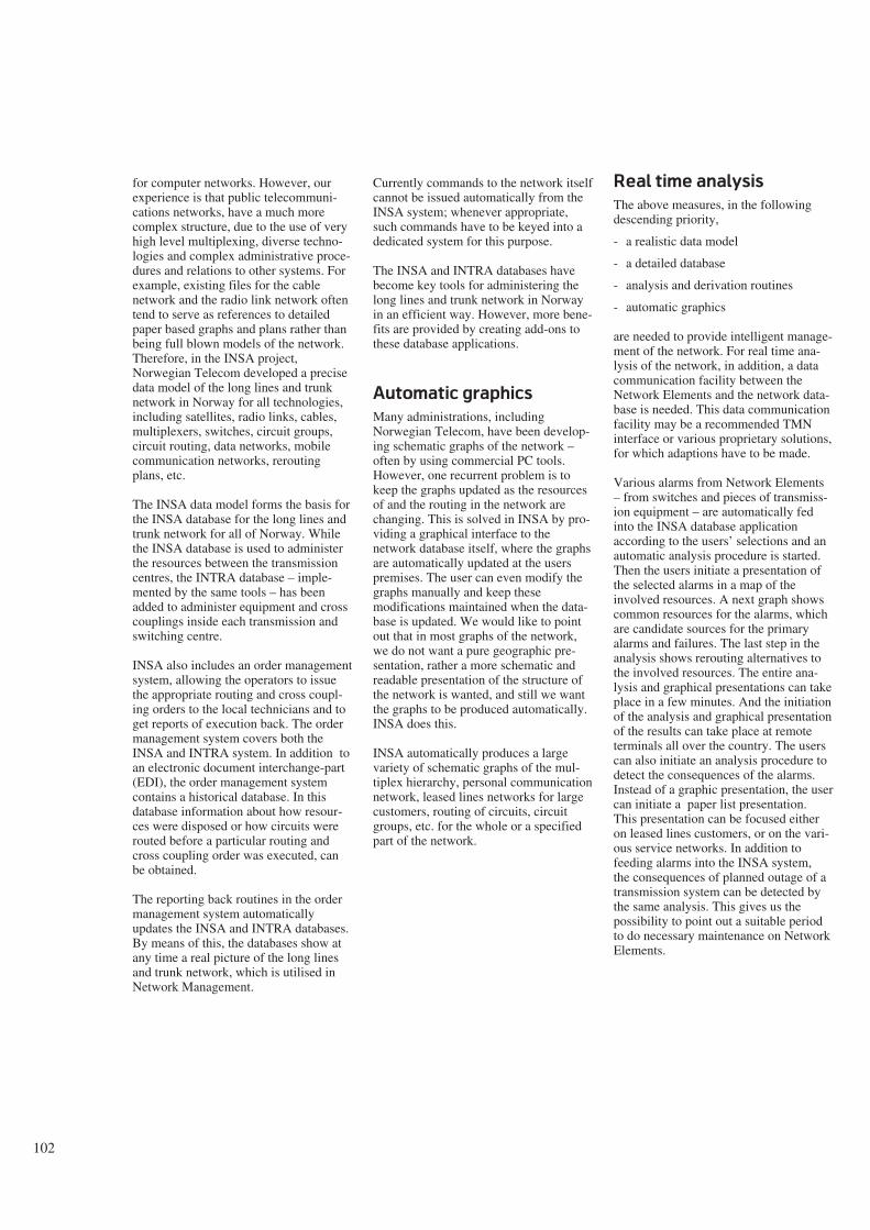
for computer networks. However, ourexperience is that public telecommuni-cations networks, have a much morecomplex structure, due to the use of veryhigh level multiplexing, diverse techno-logies and complex administrative proce-dures and relations to other systems. Forexample, existing files for the cablenetwork and the radio link network oftentend to serve as references to detailedpaper based graphs and plans rather thanbeing full blown models of the network.Therefore, in the INSA project,Norwegian Telecom developed a precisedata model of the long lines and trunknetwork in Norway for all technologies,including satellites, radio links, cables,multiplexers, switches, circuit groups,circuit routing, data networks, mobilecommunication networks, reroutingplans, etc.
The INSA data model forms the basis forthe INSA database for the long lines andtrunk network for all of Norway. Whilethe INSA database is used to administerthe resources between the transmissioncentres, the INTRA database – imple-mented by the same tools – has beenadded to administer equipment and crosscouplings inside each transmission andswitching centre.
INSA also includes an order managementsystem, allowing the operators to issuethe appropriate routing and cross coupl-ing orders to the local technicians and toget reports of execution back. The ordermanagement system covers both theINSA and INTRA system. In addition toan electronic document interchange-part(EDI), the order management systemcontains a historical database. In thisdatabase information about how resour-ces were disposed or how circuits wererouted before a particular routing andcross coupling order was executed, canbe obtained.
The reporting back routines in the ordermanagement system automaticallyupdates the INSA and INTRA databases.By means of this, the databases show atany time a real picture of the long linesand trunk network, which is utilised inNetwork Management.
Currently commands to the network itselfcannot be issued automatically from theINSA system; whenever appropriate,such commands have to be keyed into adedicated system for this purpose.
The INSA and INTRA databases havebecome key tools for administering thelong lines and trunk network in Norwayin an efficient way. However, more bene-fits are provided by creating add-ons tothese database applications.
Automatic graphics
Many administrations, includingNorwegian Telecom, have been develop-ing schematic graphs of the network –often by using commercial PC tools.However, one recurrent problem is tokeep the graphs updated as the resourcesof and the routing in the network arechanging. This is solved in INSA by pro-viding a graphical interface to thenetwork database itself, where the graphsare automatically updated at the userspremises. The user can even modify thegraphs manually and keep thesemodifications maintained when the data-base is updated. We would like to pointout that in most graphs of the network,we do not want a pure geographic pre-sentation, rather a more schematic andreadable presentation of the structure ofthe network is wanted, and still we wantthe graphs to be produced automatically.INSA does this.
INSA automatically produces a largevariety of schematic graphs of the mul-tiplex hierarchy, personal communicationnetwork, leased lines networks for largecustomers, routing of circuits, circuitgroups, etc. for the whole or a specifiedpart of the network.
Real time analysis
The above measures, in the followingdescending priority,
- a realistic data model
- a detailed database
- analysis and derivation routines
- automatic graphics
are needed to provide intelligent manage-ment of the network. For real time ana-lysis of the network, in addition, a datacommunication facility between theNetwork Elements and the network data-base is needed. This data communicationfacility may be a recommended TMNinterface or various proprietary solutions,for which adaptions have to be made.
Various alarms from Network Elements– from switches and pieces of transmiss-ion equipment – are automatically fedinto the INSA database applicationaccording to the users’ selections and anautomatic analysis procedure is started.Then the users initiate a presentation ofthe selected alarms in a map of theinvolved resources. A next graph showscommon resources for the alarms, whichare candidate sources for the primaryalarms and failures. The last step in theanalysis shows rerouting alternatives tothe involved resources. The entire ana-lysis and graphical presentations can takeplace in a few minutes. And the initiationof the analysis and graphical presentationof the results can take place at remoteterminals all over the country. The userscan also initiate an analysis procedure todetect the consequences of the alarms.Instead of a graphic presentation, the usercan initiate a paper list presentation.This presentation can be focused eitheron leased lines customers, or on the vari-ous service networks. In addition tofeeding alarms into the INSA system,the consequences of planned outage of atransmission system can be detected bythe same analysis. This gives us thepossibility to point out a suitable periodto do necessary maintenance on NetworkElements.
102

Past and present
Without these tools, the OA&Moperators previously spent hours anddays investigating the sources of thealarms, and taking the necessary actions.The knowledgeable OA&M reader isaware of the complexity of the tasksinvolved. If a large transmission centrehas a blackout, tens of thousands ofcircuits can be involved, making it justabout impossible to sort out all partiesinvolved and to create satisfactory altern-ative solutions in a short period of time.If a radio link to the western part of thecountry is involved, this can cause fallo-uts also in the northern and southern partof the country, due to complex mul-tiplexing and routing. Often the reservesfor the sub-groups can be unknowinglyrouted on the same fallen out link. Andoften we are not able to spot manually allrerouting alternatives existing as manystep paths of free resources in thenetwork. Therefore intelligent networkmanagement facilities are needed.
Norwegian Telecom has made attemptsto install commercial tools for automaticpresentation of alarms in pre-madegraphs. The problems with these toolshave been the manual updating of thegraphs and the lack of intelligence in theanalysis, due to the lack of access to thenetwork database itself. Furthermore,neither initiation nor utilisation of theanalysis were easily distributed all overthe country. The INSA system providesall this.
Future
A further development of the alarmhandling, in the INSA system, will be thedevelopment of a method to link detectedalarms to registered transmission systemsin the INSA database. This gives us apossibility to produce statistics, telling ussomething about the reliability andavailability of the different transmissionsystems.
In an earlier paragraph we described theanalysis which led to the detection ofconsequences of alarms from networkelements or planned outage of a trans-mission system. This consequence ana-lysis makes it possible for us to informimportant customers automatically whentheir connections are affected by networkfailure or planned outage. In principle, allcustomers having leased lines or dataconnections, can be informed.Norwegian Telecom has, however,decided that only strategic customers,that is, customers with a particular ser-vice contract, will receive this kind ofinformation.
The analysis starts with the alarms fedinto the INSA database. The results ofthe analysis are distributed to the custom-ers via the TELEMAX-400 network to atelefax machine, or to a PC. A test pro-ject, with very few (2 -3) customersinvolved, was started in December 1992.
In the digital multiplex network,Norwegian Telecom has introduced aDigital Rerouting System (DGROK).Today, when reserves for sub-groups areactivated, the INSA database has to beupdated by an operator to obtain a correctresult of the consequence analysis. In thefuture, an automatic updating of theINSA database from the DGROK systemwill be developed.
103

104
The DATRAN and DIMAN tools
B Y C A T O N O R D L U N D
Background
DATRAN is a general application whicheasily can be tailored to reading andwriting in different databases. DATRANhas been used to replace traditionaldevelopment for several large and com-plex applications. Each time costs anddevelopment time have been considera-bly reduced.
DIMAN is a dialogue manager for alp-hanumeric and graphic dialogues. Thisprovides an advanced graphical front-endto DATRAN applications.
This article gives an overview of thementioned products as well as theirusages.
The work with DATRAN started back inthe late seventies and was from the beg-inning connected to the INSA projectwithin Norwegian Telecom. The taskwas to develop a system for the admin-istration of the long lines and trunknetwork, a very complex application,with all kinds of telecommunicationtechnologies involved. The system wasto be on-line all the time, and its datashould be updated from terminals allover the country. Experiences fromseveral projects developing similar sys-tems, led to the conclusion that enoughEDP personnel was not available to solvethe task in a traditional way. Hence an
activity to develop the necessary tools toreduce significantly the programmingand testing efforts was established. Thiswork was conducted by NorwegianTelecom Research.
Even at that time software products forapplications like reporting, salaries, andaccounting were available. Also moregeneral programs for word processingand text editing existed, but tools forapplication development were scarce andpoor.
However, almost all programs in an on-line database application do very muchthe same: read some data from the data-base, present them to the user, receiveinput, validate it, update the database anddisplay some sort of confirmation. Com-plexity is added due to access control,where the program must consider usercategories versus function and data own-ership, and also when data is gatheredthrough several forms to assure complet-eness before updating. Much of the effortis spent to write and debug code eventu-ally not to be used, write and debugsimilar code for slightly different cases,propagate corrections and improvementsinto earlier written code, make user inter-face convenient and consistent, and soon.
If one could make one product doing allthese operations, controlled by paramet-
ers or a specification of the application,most of the repetitive and time consum-ing work could be removed from the sys-tem developing process. Also, since thesame code can be used by all appli-cations, the quality will increase for allusers. In addition, the same common userinterface will be provided for all appli-cations, and thereby greatly reduce theneed for user education concerning theEDP system. This is of course the sameadvantages as acquired for all generalisedsoftware, but which is unfortunately notso well focused in on-line database appli-cations.
And DATRAN was developed accordingto these guidelines. The name“DATRAN” is an abbreviation for “DAtaTRANsformation”, which accentuatesthe main idea of the product. Data areread from one medium and written onanother, and the whole process is con-trolled by rules specific for that particulartransformation. The rules are stated inapplication specific schemata and areremoved from the generic transformationprogram. The contents of the schemataare treated as ordinary data and arethemselves managed in an ordinaryDATRAN database.
DATRAN
DATRAN is based on a layeredarchitecture, commonly referred to as a 3schema architecture. Most important isthe application layer. Here the appli-cation is defined, with objects, relatedobjects, attributes and their valid values.The names used in the application layerare from the user terminology, not theprogramming or database terms. Oftenthe application layer is called a datamodel for the application, but what itreally is, is the complete set of names andrestrictions for the application system. Asthese definitions are readily available forusers as well as system developers, theyare often accompanied by textualexplanations not used by DATRANitself.
The internal layer of the architecturecontains the database entities. That isareas, records, sets, items, table spaces,tables, columns, keys, programs and soon, depending on the chosen databasesystem for storing the application data.Much of the content in the internal layercan be generated automatically from theapplication layer, but there will alwaysremain some choices and imple-mentations to be made by the databaseadministrator. The application layer is
Figure 1 DATRAN and DIMANDATRAN manages data, enforces data structure and application logic on central IBMmainframes. Presentations can be made on dumb terminals, PCs or workstations.DIMAN provides a seamless dialogue of alphanumerical and graphical presentations
681.3.01

105
mapped to the internal layer, so thatevery entity in the application layer has arepresentation in the internal layer. Theinternal layer specifies how the appli-cation data are stored.
The screen definitions of the systemconstitutes the external, or better – pre-sentation layer of the application. Each ofthe presentation forms consists merely ofa list of objects, related objects and attri-butes from the application layer. How-ever, the entities cannot be chosenarbitrarily, they must form a subset ofwhat is previously defined in the appli-cation layer. If a data item is allowed tobe updated through that particular form,it is provided with an operation code forinsertion, modification or deletion. Thedeveloper needs not bother with how theoperations are implemented. This way ofrealising a screen picture, approaches atheoretical minimum of effort involved.
The presentation of data in a formfollows a predefined grammar. It meansthat the context of the data item is signi-ficant. Related objects are placed close totheir origin object, and attributes areplaced so that it is clear to which objectthey belong. Any user aware of this fact
will understand a lot about the appli-cation merely by having a look at theform. The layout of data items in a formis automatically generated by the system,but may to some extent be controlled bythe developer, and even by the end userhimself. No traditional “ screen painting”is needed. The form may contain moredata than what can be seen within asingle screen simultaneously.
When DATRAN retrieves data from thedatabase, the items are arranged accord-ing to the actual form. Headings are pro-vided only when necessary. Thus theform is expanded when multipleoccurrences of the same data type are tobe presented. Not all the data in the data-base are necessarily retrieved in one step,only as much as what fills up a prede-fined or user defined work area isretrieved. Browsing of data outside theactual screen is possible, (up, down, left,right), and more data may be read fromthe database in a next retrieving step. Thevarious retrieving operations are initiatedby commands and retrieving criteriagiven by the user. The commands areindependent of the application, theybelong to DATRAN. Transitions arepossible to all data in the form, if there is
defined a suitable form for the itempointed at. There is no application codeinvolved to provide these operations.
When data are inserted or modified, thegiven input is controlled according towhat is defined as valid in the applicationschema, and default values are provided.Also the updating operations are initiatedby standard DATRAN commands andinvolve no application code. However,more complex operations involving cal-culations, derivations and wantedredundancy in the data system must beprovided as code in some form. InDATRAN these tasks are performed byCOBOL programs, automaticallyinvoked by DATRAN when the specifiedoperations are executed. These appli-cation dependent programs are written inaccordance with the rules in the appli-cation layer of the system, but areaddressing the entities in the internallayer. The programs do NOT contain anypresentation specific code, so typically ina DATRAN system there are far less pro-grams than objects. The centralisedapplication logic makes all objectsbehave in a consistent way independentof which context they are used in.
Db 2
Db 1
Internal
schemata
External
schemata
Application
schema
MEDA
Dialog
Job
Graph
Batch
Access
control
DATRAN
Controler
Dumb
terminal
Line
Printer/plotter
PC
Electr.mailBatch & graph
Access
Main reg.
Figure 2 The DATRAN environmentDATRAN is controlled by specifications of the application, contained in the 3-layered MEDA dictionary. The layers containExternal, Application and Internal schemata. All implementations (of control structures) are hidden from the developer insideDATRAN itself. The Dictionary is an ordinary DATRAN application. DATRAN contains an advanced access control system. Also,DATRAN contains pre-made subsystems for dialogue handling, job control, graph management and batch processing. Pre-madedatabases are provided for the dictionary, electronic mail, graph management and access control

The reason for coding in COBOL isobvious. The programming languagemust have a runtime system workingwith the commonly used transactionmonitors as well as in batch and againstthe chosen database system. Also thelanguage must be complete and pre-ferably in common use.
The dialogue itself is modeless. Everystep in the end user’s dialogue withDATRAN is a finished piece of work.All the work may not be done, but whatis done has updated the database and isavailable for that user later on and alsofor other users. The idea is that the usershall have full control overthe data processing sys-tem, not the other wayaround.
There are no traditionalfunctions in a DATRANapplication, only data.Thereby, not much work isdone to analyse and pro-gram organisation of work,tasks and their sequences,routines, and so on. As aconsequence of this, it isnot necessary to makechanges in the data systemif and when the mentionedconditions are changed.The functions inDATRAN consist ofscreen forms and serve thepurpose of access control.All the forms with thesame set of access rightsare gathered in the samefunction. When a userchooses a particular form,DATRAN checks in anaccess control databasewhether the user has theright to use the form. Ifnot, access is denied. It iseven possible to specifyfor which set of data occurrences accessright is granted. Thus, there is no needfor application code concerning accesscontrol.
In addition to these main functions of anyon-line database system, DATRAN pro-vides various means to facilitate the workfor the user. Many of the facilities wouldhave been far too expensive to imple-ment in most conventionally developedsystems. For instance, the user may on-line customise a screen form to serve hisparticular needs, remove data items thatare not needed, reduce or remove head-ings, retrieve related data satisfying
TDMO*READ, COMPANY, COMPANY, TELE 21/72 0001/1companySSLaddressSYSTEMSERVICES LMTD., OSLO NORWAYremark-CONSULTANTS IN ELECTRONIC DATA PROCESSING-DISTRIBUTORS OF DATRAN-OFFERS CUSTOMIZED COURSES IN DATRAN AND SYS.DEV.METHODSsales agentcodeRTSGJEJ
OLLTHEDwarehousecodeSSLOCW
nameRICARDO TOWERSSERGE GAMBIJOHN ERIC JACOBSEN
ODD LARSONLIV TORUNN HOPEEDWARD BERNARDO
name/addressWAREHOUSE 1OSLO CENTRAL WAREHOUSE
districtcode
STBJAPSTBLILBARPHI
telephone06 20202002 039303
telephone410120
IDMS7*IDMO, MESSAGE,, ROGERS, IDF0210, 92.0.131*14.08
statusA
01 1 002502 00 01401MORE NEXT PAGE01
106
given criteria, and cut and paste datafrom several forms. The screen may bedivided into several windows showingdifferent or the same form with appli-cation data. It is also possible to copydata within or between windows. Theform may be expanded at any point forinsertion of new data occurrences.
End users write DATRAN commandseither in particular command fields onthe screen or in a general command areato the left of where the application data ispresented. The most common commandshave an equivalent PF-key, and pointing
may be done by cursor positioning. Allthe items in the DATRAN screen, includ-ing the commands, are documented intheir own database, available through theDATRAN Help command or the PF-keyfor Help.
Maybe the most powerful dialoguefacility in DATRAN is how it handlesdialogues. On user request DATRANwill save all the data related to the actualscreen picture, briefly named a “dia-logue”. This makes it possible to re-invoke that picture or dialogue on requestat a later stage, and to continue the work
3a
Function Line
Physical Screen
Modus CommandField
Size value indicator ofthe Electronic sheet
window
Relative position indicatorof the Physical Windowwithin the Electronic Sheet
Picture Part
123
5
7
10
12
14
16
18
20
22
LineCommandFields
+m → (X)
These two lines consitute the Message Region
Scroll CommandField for the Message Region
Status Line DialogCommandField
23
24
25
3b

107
with that origin. A common transition isto access the documentation database forviewing valid attribute values, and thento return to the application. Also the usermay have a look at another object in thesame database, or leap to a different(DATRAN) application system, possiblyfor cutting and pasting data.
DATRAN provides some mechanisms toautomatically assign values to attributes.By choosing a particular form, insertionof an object will assure that the includedattributes for that object will get theirdefault values. If the form already pre-sents a suitable occurrence of an object,it is straight forward for the user just tomodify relevant attributes and in this wayinsert a similar object. Eventually, valuescan be inserted by an application pro-gram which may be invoked when thedatabase operations are executed.
Internally DATRAN is implementedwith the same structure as that of anyother transaction program. On the top, acontrol module is handling the terminalsand the DATRAN dialogues, as well asinvoking the other modules in theruntime system:
- a module for transformation of inputdata to DATRAN internal format
- a module for analysis of commandsand requests concerning the form in awindow
- a module for analysis of commandsacting on application data items andpreparation for updating of the data-base
- a module for access control
- a module for updating the database
- a module for retrieving data
- a module for processing selectioncriteria for the retrieved data, and fin-ally
- a module for transforming data fromthe DATRAN internal format to thescreen format.
Even if this is not a client-serverarchitecture, the separation of the varioustasks in the processing of a transactionwill facilitate a client-server like pro-cessing. See below about DIMAN.
The DATRAN system
family
The DATRAN environment containsseveral subsystems and utilities to bementioned:
MEDA, the MEta DAta system forDATRAN, is the system developer’stool. Specification data for the variousapplications are stored in the meta data-base, where they are updated andretrieved by MEDA, which is itself aDATRAN application. Via MEDA theapplication system is defined, with itsthree layers, as mentioned before. Thesemeta data form an on-line documentationdatabase, which is integrated with theapplication system. The meta data areused both by the end user and the systemdeveloper, as well as by DATRAN itself.However, when used by DATRAN, theyare transformed from the database to aload module form, due to performancereasons. It is important to point out thatthe screen layout, as well as the com-mands applied in MEDA, are just thesame in MEDA as in any otherDATRAN application.
ADAD, the ADmission ADministrationsystem for DATRAN, is used forupdating the access control database thatDATRAN uses to grant access. EvenADAD is a DATRAN application withall the common facilities. During accesscontrol database data are used in theiroriginal form, without any trans-formation. The ADAD database containsentities for users and user groups, termin-als and terminal groups, systems,(DATRAN) functions and ownership ofsets of data occurrences, calledDATRAN data areas, as well aspermissible combinations of these enti-ties. ADAD is very close to a draftCCITT recommendation for access con-trol administration, described elsewherein this book.
Figure 3 Figure (a) shows an ordinary alphanumeric picture from DATRAN. Figure(b) depicts the standard layout of a DATRAN picture. Figure (c) shows how datarelate to each other. Figure (d) shows a Help screen for a specific field, provided bydirect access to MEDA. The many pre-made dialogue features of DATRAN are notillustrated
company
sales agent
warehouse
warehouse
sales agent district
sales agent district
sales agent district
sales agent district
sales agent district
TDMO*READ. COMPANY. COMPANY. TELE 21/72 0001/1companySSLaddressSYSTEMSERVICES LMTD., OSLO NORWAY
attributeglo.nameIDMO COMPANY STATUSremarkTHE STATUS DEFINES WHETHER THE COMPANY IS DOINGACTIVE MARKETING OR NOTd value contents* A * P* -
statusA
01 1 0025
02 00 01401
IDMS7*IDMO, MESSAGE,, ROGERS, TDF0210, 92.0.131*14.08
MORE NEXT PAGE
MEDA*READ, ATT, ATTRIBUTE
01
telephone410120
remarkACTIVEPASSIVEUNKNOWN
3c
3d

108
JOBB is a third subsystem of DATRAN,and another DATRAN application. TheJOBB database has data about (batch)jobs, parameters, JCL, users, and everyt-hing that is necessary to start a prede-fined batch job, but it does not containany mechanism for supervision of theexecution or eventually the printout. Thisis to some extent undertaken by GRAF.
GRAF contains structures for storing andmaintaining graphical data and files. Inthis case the database serves more as adistribution means than an ordinary enduser data system. DATRAN provides therequired functions for transferring data toand from the database, and the recoverymechanisms in the database managementsystem assures consistent updating of thedata, as well as access by multiple users.The format of the graphical or file datastored in the GRAF database is unknownand of no interest to DATRAN, which inthis case operates only as a server for thisdatabase.
In addition to these DATRAN databaseapplications, there are a few tools andutilities:
SADA is a batch version of DATRAN,but only for data retrieval and printout.On the basis of an ordinary DATRANpresentation form, SADA selects oneparticular or any given number of objectoccurrences from the application data-base, retrieves the data specified, andpresents them to a file or for printing.
For debugging of application programsas well as of the DATRAN modules, sys-tem developers are provided with theDATRAN DEBUG system, which makesit possible to stop at any label in aCOBOL program and display the variousdata involved.
At last there is CDML, a ConversationalData Manipulation Language for quickand easy reading and writing in CODA-SYL databases. CDML has a shorthandnotation for the data manipulation state-ments and operates on the unformatteddatabase record. It needs no compilationor pre-processing and can access datathrough any existing sub-schema, ifpermission is granted by the databasemanagement system.
DATRAN is mainly written in CO-BOL.II, but there are a few minorassembler modules. The system runs onIBM mainframes in a pure IDMSenvironment or in a mixed CICStransaction and IDMS database set-up.Recently both the on-line and batch
runtime system have been expanded withfull access facility for DB2, and the mainsubsystems, MEDA and ADAD, havebeen given a DB2 implementation.
DATRAN applications
INSA was the first DATRAN appli-cation. This is an information system forthe trunk and long lines network, whichalso was the justification for DATRANitself. Since late 1983 INSA has grown inevery way, data types, data occurrences,number of users and functionality. It isthe most complex and one of the mostimportant databases in NorwegianTelecom.
In 1987 Norsk Hydro was licensed to useDATRAN, and their integrated pensionsystem, IPS, was operative less than ayear later, realised through DATRAN.
In 1989 a new major DATRAN appli-cation was put into operation, INTRA, asystem for managing the equipment andcross couplings in the transmission centrein the telecommunication network. Thissystem has a close relationship to INSA,but has a much larger amount of data.
The same year SIRIUS/R, the main sys-tem for general accounting, budgetingand reporting in Norwegian Telecom wasimplemented using DATRAN. A yearlater, SIRIUS/R was followed bySIRIUS/P, a system for project planningand supervising.
In addition to these, there are otherDATRAN applications:
- REGINA, instrument administration
- DATAKATT, data term catalogue
- STAREK, radio broadcasting stationadministration
- MARIT, marketing support system
- TIMEREG, internal activity reporting
- KATB, commercial telephone cata-logue announcements
- INFUTS, portable and spare teleequipment administration.
Several experimental DATRAN systemshave been developed. Among these areGEOINSA, a system for geographicaldata and map making related to INSA,TELEKAT, X.500 electronic directory,SDL, a CCITT specification database,JUDO, a journal and document handlingsystem. As already mentioned, most sub-systems of the DATRAN family arethemselves implemented by DATRAN.
The reason for choosing DATRAN forseveral of the above systems has been toreduce development costs and time. Noother tool could deliver the application indue time with the resources available.Application developers have been able touse DATRAN with very high productiv-ity after just a few days of training.
Currently about 5,000 end users utiliseDATRAN applications.
DIMAN
A separate product, but with a rela-tionship to DATRAN, is DIMAN. This isa dialogue manager for alphanumeric aswell as colour graphic dialogues.DIMAN was originally developed as aDOS PC-application, but is nowconverted to Windows and UNIXenvironments.
Most graphic applications require largeamounts of data to be transferred fromthe host computer to the terminal wherethe data are presented. For this usenarrowband lines are usually too timeconsuming or in practice impossible. Abasic idea behind DIMAN is to reducethe data transport to an extent thatordinary terminal connections are usablefor graphics. The terminal used is anordinary Personal Computer. Thereduction in data transport is achievedthrough the intensive use of inheritance.Only the significant, different data aretransferred for each occurrence of thegraphical objects.
Another feature that distinguishesDIMAN from most graphical systems isthat the drawings are composed ofinterrelated, graphical objects (icons). Itis not just the graphical primitives thatare communicated. In this way, objectscan be moved around without loosingtheir connections to other objects on thescreen. DIMAN also allows icons torepresent objects from an applicationdatabase, reference these objects andmake operations on them. This is takenadvantage of when DIMAN operates inconjugation with DATRAN. Data areretrieved from the application database,provided with the necessary graphicalinformation, and sent to DIMAN as ameta file containing data types as well asdata occurrences. DIMAN then makesthe presentation on the screen.
When more processing is necessary toproduce a drawing, the task is done as abatch job, and the result is stored in asuitable database, namely the DATRAN
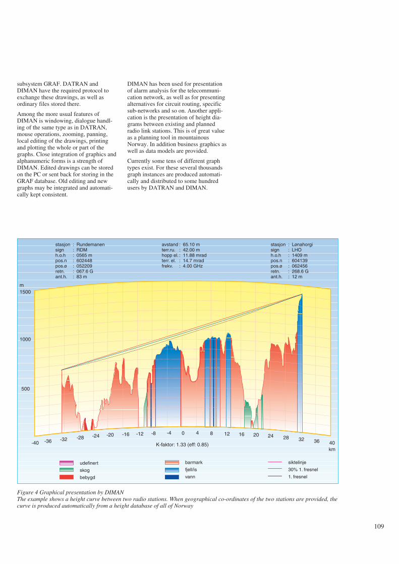
109
subsystem GRAF. DATRAN andDIMAN have the required protocol toexchange these drawings, as well asordinary files stored there.
Among the more usual features ofDIMAN is windowing, dialogue handl-ing of the same type as in DATRAN,mouse operations, zooming, panning,local editing of the drawings, printingand plotting the whole or part of thegraphs. Close integration of graphics andalphanumeric forms is a strength ofDIMAN. Edited drawings can be storedon the PC or sent back for storing in theGRAF database. Old editing and newgraphs may be integrated and automati-cally kept consistent.
DIMAN has been used for presentationof alarm analysis for the telecommuni-cation network, as well as for presentingalternatives for circuit routing, specificsub-networks and so on. Another appli-cation is the presentation of height dia-grams between existing and plannedradio link stations. This is of great valueas a planning tool in mountainousNorway. In addition business graphics aswell as data models are provided.
Currently some tens of different graphtypes exist. For these several thousandsgraph instances are produced automati-cally and distributed to some hundredusers by DATRAN and DIMAN.
Figure 4 Graphical presentation by DIMANThe example shows a height curve between two radio stations. When geographical co-ordinates of the two stations are provided, thecurve is produced automatically from a height database of all of Norway
stasjonsignh.o.hpos.npos.øretn.ant.h.
: Rundemanen: RDM: 0565 m: 602448: 052209: 067.6 G: 83 m
avstandterr.ru.hopp el.terr. el.frekv.
: 65.10 m: 42.00 m: 11.88 mrad: 14.7 mrad: 4.00 GHz
0 4 8 12 16 20 24 28 32 36 40
-4-8-12-16-20-24-28-32-36-40
500
1000
m1500
stasjonsignh.o.hpos.npos.øretn.ant.h.
: Lønahorgi: LHO: 1409 m: 604139: 062456: 268.6 G: 12 m
barmark
fjell/is
vann
siktelinje
30% 1. fresnel
1. fresnel
kmK-faktor: 1.33 (eff: 0.85)
udefinert
skog
bebygd

110
DIBAS – A management system for distributed databases
B Y E I R I K D A H L E A N D H E L G E B E R G
1 Distributed databases
1.1 What is a distributed
database?
Definition (2): “A distributed database isa collection of data which are distributedover different computers of a computernetwork. Each site of the network hasautonomous processing capability, andcan perform local applications. Each sitealso participates in the execution of atleast one global application, whichrequires accessing data at several sitesusing a communication subsystem.”Figure 1 illustrates this definition.
Each computer with its local databaseconstitutes one site which is an autono-mous database system. During normaloperation the applications which arerequested from the terminals at one sitemay only access the database at that site.These applications are called local appli-cations. The definition emphasises theexistence of some applications whichaccess data at more than one site. Theseapplications are called global appli-cations or distributed applications.
In this article only relational distributeddatabase systems are considered.
1.2 Fragmentation and
replication
Performance and availability enhance-ments in a distributed database is usuallyachieved by storing copies of data onsites where the data are frequently used.Each table in a relational database can besplit into several non-overlappingportions which are called fragments. Theprocess of defining the fragments iscalled fragmentation. There are two typesof fragmentation, horizontal frag-mentation and vertical fragmentation.Fragments can be located on one orseveral sites of the network.
Horizontal fragmentation means parti-tioning the tuples of a table into subsets,each subset being a fragment. This wayof partitioning is useful if the users/appli-cations at one site use one subset of thetuples of a table more frequently thanother tuples.
Vertical fragmentation is the subdivi-sioning of attributes of a table intogroups, each group is called a verticalfragment. Vertical fragments are definedwhen users/applications at different sitesaccess different groups of attributes of atable.
Abstract
The dramatic improvements in hardware, cost and performancefor data processing and communication permit rethinking ofwhere data, systems and computer hardware belong in theorganisation. So far, most database applications have beenimplemented as rather isolated systems having little or noexchange of data. However, users require data from several sys-tems. This implies that integration of data and systems has to beaddressed, and at the same time providing the local control andautonomy required by the users. Both intra-application integra-tion (integration of data stored on different geographical sitesfor the same application) and inter-application integration(integration of data from different applications possibly storedon different sites) are required. Organisational changes mayalso affect the way data, systems and hardware are organised,because of new requirements resulting from changes inresponsibility, management control, user control, etc. Thesolutions sought after must provide a trade-off between theintegration and the local control and flexibility for organ-isational changes. This article will discuss how distributed data-bases can contribute to this.
Distributed databases can provide feasible technicaloptions/solutions to the user requirements. They can increasedata sharing, local autonomy, availability and performance.Distribution transparency of data to applications is often want-ed. This means that the aspects related to distribution of dataare invisible to the application programs. Theory of distributeddatabases was developed in the late 70s and the 80s, but still
there are few commercial products that have implemented thewanted features suggested in theory. A distributed database sys-tem easily becomes very complex. Therefore, more modestapproaches are developed, which provide a selection of import-ant features.
Norwegian Telecom Research has several years of experiencewith developing distributed database management systems. TheTelstøtt project developed a prototype DDBMS, called TelSQL,which provided full integration of databases (1). The Dibas dis-tributed database management system takes a practical appro-ach to distributed databases. Dibas is based on the idea that theresponsibility for generation and maintenance of data are allo-cated to a number of organisational units located at differentgeographical sites, e.g. regions. Reflecting this responsibilitystructure, the tables of the database can be partitioned intoownership fragments, where updates of the data are allowedonly at the owner database site. The ownership fragments canbe fully or partially distributed to (i.e. replicated at) other sites,so that the other organisational units can read relevant data.The replicas are distributed asynchronously. This means thatconsistency of data is controlled, but is not enforced in realtime.
In this article, Dibas is presented in the perspective of distri-buted database theory. Two database applications, MEAS andTRANE, illustrate the feasibility of Dibas. MEAS will establishseven isolated regional databases and wants interconnection,while TRANE has a centralised database but considers distri-buting the data.
681.3.07
Local application
at site 1
Part of global
application at site 1
Local
database
at site 1
Computer at site 1
Part of global
application at site 2
Local
database
at site 2
Computer at site 2
Local application
at site 2
Figure 1 A distributed database. A global application accesses data at several sites
111
It is also possible to apply a combinationof both vertical and horisontal partition-ing. This is called mixed fragmentation.
Replication consists of locating identicalfragments at several sites of the networkin order to increase performance andavailability when the same data are fre-quently used at several sites. Replicationintroduces redundancy to the database.Note that in traditional databases redund-ancy is reduced as far as possible toavoid inconsistencies and save storagespace.
1.3 Distributed database
management system
Definition (2): A distributed databasemanagement system (DDBMS) supportsthe creation and maintenance of distri-buted databases.
What is the difference between aDDBMS and an ordinary Data BaseManagement System (DBMS)? Anordinary DBMS can offer remote accessto data in other DBMSs. But a DBMSusually does not provide fragmentationand replication and supports only a limi-ted degree of distribution transparency,while these capabilities usually are sup-ported properly by a DDBMS. ADDBMS typically uses DBMSs for stor-age of data on the local sites.
An important distinction between differ-ent types of DDBMSs is whether they arehomogeneous or heterogeneous. Theterm homogeneous refers to a DDBMSwith the same DBMS product on eachsite. Heterogeneous DDBMSs use atleast two different local DBMSs, and thisadds to the complexity. Interfacing ofdifferent DBMSs will be simplified byusing the SQL standard (3).
1.4 Distribution transparency
A central notion in database theory is thenotion of data independence, whichmeans that the physical organisation ofdata is hidden to the application pro-grams. Data independence is supportedby the three schema architecture ofANSI/SPARC, since the internal schemais hidden for the application programs. Indistributed databases we are concernedwith distribution transparency, whichmeans independence of application pro-grams from the distribution of data. Thedegree of transparency can vary in arange from complete transparency, pro-viding a single database image, to notransparency at all and thus providing amulti database image.
Analogous with distribution trans-parency, (4) states a fundamental prin-ciple of distributed databases; “To theuser, a distributed system should lookexactly like a non-distributed system”.From this principle, twelve objectives(analogous to transparency) for distri-buted databases have been derived:
1 Local autonomy. A database siteshould not depend on other sites inorder to function properly.
2 No reliance on central site. Theremust be no reliance of a master sitebecause of problems with bottlenecksand central site down time.
3 Continuous operation. Shutdown ofthe system should not be necessarywhen table definitions are changed ornew sites are added.
4 Location independence, also calledlocation transparency. This meansthat the location of data at varioussites should be hidden to the appli-cation program. This transparency issupported by the allocation schema ofthe proposed reference architecture insection 1.5.
5 Fragmentation independence, alsocalled fragmentation transparency.This means that application programsshould only relate to fullrelations/tables and that the actualfragmentation should be hidden. Thistransparency is supported by the frag-mentation schema in section 1.5.
6 Replication independence, also calledreplication transparency. This meansthat the replication of fragmentsshould be invisible to application pro-grams. Replication transparency ispart of the location transparencynotion, and is supported by the allo-cation schema in section 1.5. Thebasic problem with data replication isthat an update on an object must bepropagated to all stored copies (repli-cas) of that object. A strategy of pro-pagating updates synchronously wit-hin the same transaction to all copiesmay be unacceptable, since it requirestwo-phase-commit transactions (seesection 1.6) between nodes. Thisreduces performance and autonomy.This problem can be removed byrelaxing the up-to-date property ofstored copies, see section 1.7.
7 Distributed query processing. If theapplication program makes queriesabout data which are stored onanother site, the system must transpar-
ently process the query at theinvolved nodes and compose theresult as if it was a local query. Thisinvolves:
⋅ Translation of the “global” queryinto local queries on the fragmentsstored locally.
⋅ Query optimisation. Queriesaccessing several sites will result ina message overhead compared to acentralised database. Effectiveoptimisation strategies are crucialto avoid large amounts of databeing shuffled between sites. A“send the query to the location ofthe data” strategy will reduce thisproblem compared to a big-inhalestrategy. Replication of relevantdata so that global applications arenot necessary, can reduce this pro-blem.
8 Distributed transaction management.A distributed database transaction caninvolve execution of statements (e.g.updates) at several sites. A transactionis a unit of work which either shouldbe completely executed or rolled backto the initial state. Concurrency andrecovery issues must also be handled,see section 1.6.
9 Hardware independence.
10 Operating system independence. Thisis relevant in case of use of variousoperating systems.
11 Network independence. This isrelevant in case of use of severalnetworks.
12 DBMS independence, also calledlocal mapping transparency. Thismeans that the mapping to the localDBMS is hidden to the applicationprogram. This transparency is sup-ported by the local mapping schemain section 1.5.
1.5 A reference architecture
for distributed databases
The reference architecture depicted inFigure 2 only shows a possible organ-isation of schemata in a distributed data-base. A schema contains definitions ofthe data to be processed and rules for thedata. Communication aspects and imple-mentation aspects are not shown in thisarchitecture. The architecture is based onthe three schema architecture ofANSI/SPARC, developed for non-distri-buted databases, where the threefollowing kinds of schemata are covered:
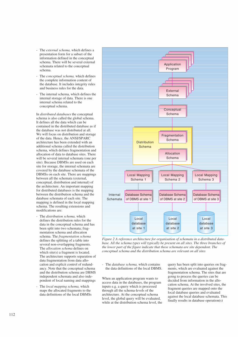
112
- The external schema, which defines apresentation form for a subset of theinformation defined in the conceptualschema. There will be several externalschemata related to the conceptualschema.
- The conceptual schema, which definesthe complete information content ofthe database. It includes integrity rulesand business rules for the data.
- The internal schema, which defines theinternal storage of data. There is oneinternal schema related to theconceptual schema.
In distributed databases the conceptualschema is also called the global schema.It defines all the data which can becontained in the distributed database as ifthe database was not distributed at all.We will focus on distribution and storageof the data. Hence, the ANSI/SPARCarchitecture has been extended with anadditional schema called the distributionschema, which defines fragmentation andallocation of data to database sites. Therewill be several internal schemata (one persite). Because DBMSs are used on eachsite for storage, the internal schemata arecovered by the database schemata of theDBMSs on each site. There are mappingsbetween all the schemata (external,conceptual, distribution and internal) ofthe architecture. An important mappingfor distributed databases is the mappingbetween the distribution schema and thedatabase schemata of each site. Themapping is defined in the local mappingschema. The resulting extensions andmodifications are:
- The distribution schema, whichdefines the distribution rules for thedata in the conceptual schema and hasbeen split into two schemata; frag-mentation schema and allocationschema. The fragmentation schemadefines the splitting of a table intoseveral non-overlapping fragments.The allocation schema defines onwhich site(s) a fragment is located.The architecture supports separation ofdata fragmentation from data allo-cation and explicit control of redund-ancy. Note that the conceptual schemaand the distribution schema are DBMSindependent schemata and also inde-pendent of local naming and mappings
- The local mapping schema, whichmaps the allocated fragments to thedata definitions of the local DBMSs
- The database schema, which containsthe data definitions of the local DBMS.
When an application program wants toaccess data in the databases, the programinputs e.g. a query which is processedthrough all the schema-levels of thearchitecture. At the conceptual schemalevel, the global query will be evaluated,while at the distribution schema level, the
query has been split into queries on frag-ments, which are evaluated against thefragmentation schema. The sites that aregoing to process the queries can bedecided from information in the allo-cation schema. At the involved sites, thefragment queries are mapped onto thelocal database queries and evaluatedagainst the local database schemata. Thisfinally results in database operation(s)
ApplicationProgram
Local
database
at site 1
ExternalSchema
ConceptualSchema
FragmentationSchema
AllocationSchema
DistributionSchema
Local MappingSchema 2
Local MappingSchema 3
Local MappingSchema 1
Database Schemaof DBMS at site 1
Database Schemaof DBMS at site 2
Database Schemaof DBMS at site 3
Local
database
at site 2
Local
database
at site 3
InternalSchemata
Figure 2 A reference architecture for organisation of schemata in a distributed data-base. All the schema types will typically be present on all sites. The three branches ofthe lower part of the figure indicate that these schemata are site dependent. Theconceptual schema and the distribution schema are relevant on all sites

113
against the database(s). On the way backfrom the databases to the application pro-gram, the results of the local databasequeries will be combined into one resultand given as output to the applicationprogram.
1.6 Distributed transaction
management
1.6.1 Transactions
Users/application programs usetransactions in order to access the data-base. A transaction is a logical unit ofwork and can consist of one or severaldatabase operations in a sequence. Atransaction has the following properties,called ACID-properties:
- Atomicity: All operations are executed(commitment) or none(rollback/abortion). This is true even ifthe transaction is interrupted by a sys-tem crash or an abortion. Transactionabortion typically stems from systemoverload and deadlocks.
- Consistency: If a transaction isexecuted, it will be correct with respectto integrity constraints of the appli-cation.
- Isolation: Processing units outside thetransaction will either see none or allof the transaction changes. If severaltransactions are executed concurrently,they must not interfere with each other,and the result must be the same as ifthey were executed serially in someorder. This is called serialisability oftransactions, and serialisability is acriterion for correctness. Concurrencycontrol maintains serialisability. Inorder to avoid that other transactionsread partial results of a transaction, thedata that have been read or updated bythe transaction, are locked. Othertransactions have to wait until thelocks are released before they canaccess these data. The locks arereleased once the execution of atransaction has finished. In certaincases the locking can lead to deadlocksituations, where transactions wait foreach other. Deadlock detection andresolution are usually handled by theDBMS.
- Durability: Once a transaction hasbeen committed, the changes are per-manent and survive all kinds offailures. The activity of ensuringdurability is called recovery.
So far, the discussion of this section hasbeen valid for both non-distributed anddistributed databases. In distributed data-bases there will be distributedtransactions as well as local transactions.A distributed transaction contains data-base operations that are executed atseveral different sites, and still theordinary transaction properties have to bemaintained.
1.6.2 Concurrency
The most common techniques forconcurrency control and recovery in adistributed database are the two-phase-locking (2PL) protocol and the two-phase-commitment (2PC) protocol.
The 2PL protocol have these two phases:
- In the first phase locks on the data tobe accessed are acquired before thedata are accessed.
- In the second phase all the locks arereleased. New locks must not beacquired.
The 2PL protocol guarantees serial-isability of transactions if the transactionshold all their locks until commitment.For distributed transactions, serial-isability is often called global serial-isability. The locking creates overheadcompared to a centralised database,because each lock needs to be communi-cated by a message. For replicated data,all the copies have to be locked. Analternative locking method for replicateddata is primary copy locking, where oneof the copies are privileged, see section1.7. Deadlocks are often called globaldeadlocks for distributed transactions.Deadlock detection and resolution ismore difficult in a distributed systembecause it involves several sites.
1.6.3 Recovery
A distributed transaction can be dividedinto a number of subtransactions, eachsubtransaction being the part of thetransaction that is executed on only onesite. The atomicity property requires thateach subtransaction is atomic and that allsubtransactions go the same way(commit or rollback) on each site also incase of system crashes or transactionabortion. The 2 PC-protocol ensuresatomicity. It has a co-ordinator whichsends messages to the participants andtakes the decision to commit or rollback.Roughly, the two phases are:
- In the first phase all the participatingsites get ready to go either way. Dataare stored on each site beforeexecution of the transaction and afterthe transaction has been executed. Thecoordinator asks prepare-to-commit,and the participants reply ready, if theyare ready to commit, or rollback, ifthey cannot support both the initial andthe final state of the data. When all theparticipants have answered, the co-ordinator can take the decision eitherto commit or to rollback.
- In the second phase the commit or roll-back decision is communicated to allthe participants, which bring the datato the right state (final or initial,respectively).
The 2PC-protocol means overhead andloss of autonomy, see section 1.7 foralternatives.
1.7 Increasing performance,
availability and autonomy
Maintenance of global consistency whenreplicated data are updated, may becomecostly. It is suggested in several papers(e.g. (1), (5) and (6)) that availability,autonomy and performance can beincreased in a distributed database if it isacceptable to relax consistency and dis-tribution transparency. Often the up-to-date requirement can be relaxed andasynchronous propagation of replicasfrom a master fragment will be sufficient.Asynchronous means that updates to themaster fragment will not be distributed tothe replicas within the same transaction,but later.
The approach proposed in (5) is to parti-tion the database into fragments andassign to each fragment a controllingentity called an agent. Data can only beupdated by the owner agent, which is adatabase site or a user. When a fragmenthas been updated, the updates are propa-gated asynchronously to other sites,transaction by transaction. Global serial-isability of transactions is not guaranteed.A less strict correctness criterion, frag-mentwise serialisability, is introduced:
- Transactions which exclusively updatea particular fragment are globally seri-alisable.
- Transactions which read the contentsof a fragment at a site never see apartial result of a transaction.

114
- There is no guarantee that transactionswhich references data in several frag-ments are globally serialisable.
2 The Dibas DDBMS
2.1 Introduction
The vendors of relational DBMSs alsohave products for distributed databases.They typically offer remote access todata, support for execution of distributedtransactions and some other features.Fragmentation and replication are usuallynot supported. Distribution transparencyis only partly supported. Support forcreation and maintenance of the distri-buted database are typically not good.
Dibas has been designed from the experi-ence of the Telstøtt project (1), from theideas of section 1.7 and from the appli-cation requirements of TRANE (seechapter 4).
2.2 Basic idea
Dibas is a homogeneous DDBMS, whichis rather general in the sense that it canbe used for various applications. A distri-buted database managed by Dibasconsists of a number of Sybase (7) data-bases containing distributed tables withcommon table definitions in all the data-bases. Dibas provides the following fea-tures for distributed tables (see (8) for amore comprehensive description):
1 A table can be partitioned into frag-ments. Each fragment is ownedexclusively by one database site,which means that updates to this frag-ment are only allowed by users at thissite. A distributed table will have own-ership fragments at all sites. An own-ership fragment can be empty, includesome tuples or contain all the tuples ofthe table.
2 Read access to fragments owned atother sites is provided by replication.Fragments can be fully or partiallyreplicated to other sites. Each site canreceive different subsets of the owners-hip fragment of a site. There is onlyread access to replicas.
3 Updates are propagatedasynchronously. A separate distri-bution program performsasynchronous propagation of repli-cated data. Only changes to the dataafter the last distribution of a copy, aredistributed. The distribution is initiatedperiodically and/or on request from theusers. Hence Dibas offers relaxed, butcontrolled consistency.
4 A distributed data definition languagecalled DSQL has been defined toexpress the ownership and distributionrules of a table, see section 2.3 and 2.4.The full set of rules for each table areequal at all sites.
Figure 3 illustrates the fragmentation andreplication of a distributed table in Dibas.It is also allowed to define local tables oneach site which can be read and updatedby users at the local site exclusively.
The result of 2 and 3 above is that theapplication programs on the local siteswill only execute as local applications.They do not require distributed queryprocessing and distributed transactions.There are no reliance on a central site.Therefore Dibas provides a high degreeof autonomy. Sybase mechanisms forconcurrency control and recovery can beutilised. This is a major simplification.Also, installations of the Dibas systemare equal at all sites.
Dibas has good support for distributiontransparency. This means that the appli-cations can be developed as if they wererunning on a centralised database,because they see the same tables andexpect to find the needed data. Each siteonly holds relevant data for its ownusers. Read transactions on these relevantdata are offered complete distributiontransparency except for reducedtimeliness of replicated data. Updatetransactions can only access owned data.If this restriction corresponds to definedresponsibility for data and needed accesscontrol, transparency will be offered forupdate transactions. Dibas can only runon Sun work stations under the UNIXoperating system at the moment.
Tuples importedto site A
from site B
Private tuplesof site B
Private tuplesof site A
Tuples importedto site B
from site A
Fragmentowned by
site B
Fragmentowned by
site A
Fragmentation of a global table
Tuples exportedto site A
Private tuplesof site B
Fragmentowned by
site B
Fragmentowned by
site A
Replication of fragmens on local sites
Tuples importedfrom site A
(ready-only access)
Site B
Tuples importedfrom site B
(read-only access)
Private tuplesof site A
Tuples exportedto site B
Site A
export/
import
export/
import
Figure 3 A distributed table in Dibas

115
2.3 Definition of ownership
fragments
In Dibas, there is one rule specifyingownership for each distributed table. Theownership rule together with data intables determine the partitioning intonon-overlapping fragments. Because dif-ferent tables will require different frag-mentation, several types of ownership fora table have been defined. These typesare presented below with the attachedDSQL syntax:
1 Entire table. The table is owned enti-rely by a given site. This ownershiptype is particularly useful for stand-ards/domain/type information whichshould be updated by one organ-isational unit at one site and be repli-cated to several/all other sites. Theowner site can be defined at com-pilation time (the expression BY<site>) or defined run-time in adictionary table:
[DEFINE] OWNERSHIP FOR<tables> [AS] OWNED ENTI-RELY [BY <site>]
2 Column value. Ownership is deter-mined by the value of a given columnwhich directly tells the ownership siteof each tuple:
[DEFINE] OWNERSHIP FOR<tables> [AS] OWNEDDIRECTLY GIVEN BY <attr>
3 Indirect through foreign key. Owner-ship for each tuple of the table is deter-mined indirectly through a foreign keyto another table. For applications it iscommon that ownership of tuples of atable can be derived from another tablein this way, see chapter 4.
[DEFINE] OWNERSHIP FOR<tables> [AS] OWNED
INDIRECTLY GIVEN BY<attrlist> VIA <table>
Usually the ownership of a tuple is thesame as the tuple it references througha foreign key. However, it is possibleto define a separate ownership rule forthe tables that references another table(column value ownership):
[DEFINE] INDIRECT OWNERS-HIP VIA <table> [GIVEN BY<attr>]
2.4 Definition of replication
Distribution rules specify the replicationof data. Distribution should also as far aspossible be determined without modifi-cations to the application’s databaseschema. The distribution fragments willalways be subset of the ownership frag-ment. The distribution types are:
1 Entire fragment. The entire ownershipfragment is distributed to all other sites(see the first DSQL expression) or tospecified sites (see the second DSQLexpression). In case of the latter, adictionary table will contain data aboutthe recipient sites. This makes itpossible to decide and modify the listof recipient sites at run time.
[DEFINE] DISTRIBUTION FOR<tables> [AS] DISTRIBUTETO ALL
[DEFINE] DISTRIBUTION FOR<tables> [AS] DISTRIBUTETO SOME
2 Indirect through foreign key. The dis-tribution fragment and the recipientsites are determined through a foreignkey to another table. This referencedtable is usually a dictionary tablewhich contains tuple identifiers and the
recipient sites for these particulartuples. See chapter 4 for examples.
[DEFINE] DISTRIBUTION FOR<tables> [AS] DISTRIBUTEINDIRECTLY GIVEN BY<attrlist> VIA <table>
3 Arbitrary restrictions. Sometimes it isnecessary to define arbitraryconditions for the distribution.Arbitrary restrictions are expressed inSQL and can be added to all the distri-bution types:
[WITH] [<tables>]RESTRICTION <cond>]
4 Combination of distribution types.There can be several distribution rulesfor each table.
2.5 Creation of the
distributed database
The ordinary application databaseschema (definitions of tables, indexes,triggers, etc.) and the additional owners-hip and distribution definitions for eachof the tables to be distributed are taken asinput to a definition tool, which parsesthe information and creates the defini-tions to be installed in the database, seeFigure 4.
For each table, the definition tool createsa trigger (a trigger is a database objectwhich is activated by operations on atable) and a log table. If there alreadyexists an application trigger, this triggerwill be extended. The purpose of thetrigger is to check correct ownershipbased on the defined ownership rule andto log changes to data including atimestamp for the time of the change inthe log table. This means that the own-ership rule in DSQL has been translatedinto an ownership SQL-expression.
For each table, the definition tool alsocreates an SQL-expression whichextracts the tuples to be distributed to therecipient sites from an owner site. Innormal operation, the SQL-expressiononly extracts changes to the data, i.e.tuples from the log tables. Initially, fullreplicas are extracted from the tablesthemselves. The SQL-expressions arecreated from the distribution rulesdefined for the tables.
Administration utilities install the data-base definitions generated by the Dibasdefinition tool, install owned data andinstall the Dibas distribution program.
SybaseDBMS
Application
tables TriggersLog
tables
Distribution
SQL-expression
Application
database schema
Dibas Definition Tool
Definitions of ownership
and distribution in DSQL
Figure 4 Creation of the distributed database

116
2.6 Run time system
components of Dibas
The application programs run as localapplications on each site and access theSybase DBMS directly. Sybase triggersare activated immediately by insert,delete and update operations on the data-base to verify ownership and to logchanges.
A separate distribution program propa-gates the updates which are to be repli-cated. The distribution fragments to bedistributed are selected by the distri-bution SQL-expressions which are storedin the Dibas dictionary.
Also a tool for run time administration ofDibas offers user initiation of the distri-bution program, information abouttimeliness of replicated data, parametersfor control of distribution, etc.
2.7 Dibas and the proposed
reference architecture for
distributed databases
Dibas mainly follows the previouslydescribed reference architecture. Theconceptual schema will be the ordinarydatabase schema of the application.
The distribution schema of Dibasconsists of ownership fragment defini-tions and distribution definitionsexpressed in DSQL for each distributedtable. The ownership fragments definesthe fragmentation and corresponds to thefragmentation schema, but it also definesthe allocation of the master copy of thefragment. Hence, it also has allocationschema information. The distributiondefinitions in DSQL defines replication,which belongs in the allocation schema.
Dibas is a homogeneous DDBMS withSybase as the local DBMS. There is nolocal naming or other mappings betweenthe tables of the conceptual schema andthe local database tables. Hence, thelocal mapping schema disappears fromthe architecture. Because Dibas and thedatabase applications are identical on allsites, the database schemata will beidentical as well.
2.8 Management of distributed
transactions in Dibas
The only global application in Dibas isthe distribution program, which transfersdata from one site to another. The Sybase2PC-protocol is used by this program. Incase of crashes and other failures,ordinary recovery of the local Sybasedatabases will be sufficient. Global dead-locks will not appear, because the pro-gram itself will do a time-out if it has towait for locks.
3 Advantages and
disadvantages of Dibas
The list of advantages and disadvantageshas been assembled from (2), (3), (4),(5), (6), (9), (10), and our own experi-ence.
3.1 Advantages of Dibas
3.1.1 Local autonomy and
economic reasons
Many organisations are decentralised anda distributed database fits more naturallyto the structure of the organisation. Dis-tribution allows individual organisationalunits to exercise local control over theirown data and the computers involved inthe operation.
Due to the closeness of data, it is ofteneasier to motivate users to feelresponsible for the timeliness andintegrity of the data. Thus, higher qualityof data may be achieved.
An organisational unit with responsibilityfor its own economic results prefers tocontrol its investments and costs. It cancontrol the cost of operating a local data-base, while expenses to be paid to a cen-tral computer division are harder to con-trol. In the past, hardware costs weresmaller for large mainframes than forsmaller hardware. Hardware was themost significant cost driver when a sys-tem was bought. Today the economy ofscale motivation for having large, cen-tralised computer centres has gone. Itmay be cheaper to assemble a network ofsmaller machines with a distributed data-base.
3.1.2 Interconnection of existing
databases: Data sharing
If several databases already exist in anorganisation and the necessity of per-forming global applications arises, thenDibas can provide integration of data inthe databases. This can be a smoothtransition to data sharing. The distributeddatabase will be created bottom-up fromthe existing local databases.
3.1.3 Performance
Data in a Dibas distributed database arestored in the databases where they areused. If only a small amount of the dataowned by the other sites are relevant fora local site, this means that the data vol-ume in the local database can be reducedconsiderably compared to a centraliseddatabase containing the sum of data forall organisational units. Reduced datavolume can improve the response time.
The existence of several database sitesdoing autonomous processing increasesthe performance through parallelism (thetransaction load is divided on a numberof database sites).
When running local applications, thecommunication is reduced compared to acentralised database and thus lead toreduced response time.
3.1.4 Local flexibility
A centralised database with access froma lot of users and with a heavytransaction load will require strict controlof the applications which access the data-base, development of additional appli-cations ,etc., and this prevents flexibility.For Dibas where each database site isautonomous and has fewer users andsmaller load, less control is required.This eases the usage of new tools,creation of additional tables, develop-ment of additional applications, andexperimenting in general.

117
3.2 Disadvantages of Dibas
3.2.1 Increased complexity
and economic reasons
Compared to a centralised database or toseveral isolated databases, the distributeddatabase adds to complexity and can addextra costs. The Dibas system compon-ents have to be installed, operated andmaintained. Also, the distribution of dataneeds to be managed.
However, since Dibas is a relativelysimple system, the complexity overheadand the economic overhead is kept low.
3.2.2 Timeliness and correctness
Disadvantages with Dibas are relaxedtimeliness and correctness. The cor-rectness of Dibas is less strict than theglobal serialisability (see section 1.6) andfragmentwise serialisability (see section1.7). Dibas offers local consistency andserialisability at each site (handled bySybase), which ensures that locallyowned data will be correct. Data are pro-pagated to other sites table by tableaccording to timestamps. Transactionsmay see inconsistent data because datawhich have been updated on other sitesmay not have been propagated yet.
3.2.3 Ownership restriction
Data can only be updated on the ownersite. This restriction cannot be acceptedfor some applications.
The potential security problems of distri-buted databases is avoided in Dibas.Users can only update data on their ownsite, and only relevant data are availablefrom other databases.
4 Application examples
In this chapter we present two databaseapplications, MEAS and TRANE, whichare candidates for a distributed databasesolution. The cases have different initialstates and therefore there are differentmotivations for a distributed solution.Examples of the suitability of the Dibasmechanisms are given for the MEAScase. Before presenting the applications,trends that will impact the applicationsand increase the need for data transfermechanisms are outlined.
4.1 Trends in traffic
measurements of
the telecom network
The text of this section is based on (11).New opportunities for traffic measure-ments emerge with the introduction ofdigital switches. This has revolutionisedthe possibility of conducting measure-ments of the traffic load on differentnetwork elements. These measurementswill give better data on which to basedecisions concerning utilisation, recon-figuration, extension and administrationof the telecom network. Measurementsshowing free capacity make possible amore dynamic utilisation of the telecomnetwork.
The increasing amount of measurementsdata are stored in files and then trans-formed from files to databases. All thenew measurements data give rise to anincreasing need for storage capacity.
New user groups take advantage of themeasurement data. Planners and admin-istrators of the telecom network havebeen the traditional users of the trafficmeasurement data. Today there is a trendthat economists need this kind of data,e.g. to find the price elasticity of differentservices. Also, marketing people andmanagers in general demand this kind ofdata.
Because of the increased use and import-ance of measurement data, high qualityand availability is of vital importance.The data quality should be improved.
The impact of the above trends is:
- The increasing volume of data gener-ated locally implies a need for increas-ing local storage capacity.
- Measurement data are actually gener-ated and stored locally. There is a needfor some mechanisms to transfer data.
- High quality data are demanded inboth regions and central offices to pro-vide a countrywide view.
4.2 MEAS
MEAS (MEasurements And Statistics) isan application for processing and storingincoming traffic measurements data fromdifferent types of switches. The primarygoal of the MEAS-application is to pro-duce data on which to base decisionsconcerning the addition of new equip-ment and optimal usage of existingequipment in the telecom network.
Mid-Norway
Oslo
SouthStavanger
Bjørgvin
Mid-Norway
Oslo
SouthStavanger
BjørgvinDibas
Centraldatabase
Figure 5 The MEAS system
a) The initial state consisting of “isolated” regional databases
b) Distributed database for MEAS with an additional central database
Cross border data can be exchanged between regions. Data can be distributed from the regional data-bases to the central database in order to provide a countrywide view of relevant data about the networkand measurement statistics. Selected measurements can also be provided to the central database. The fullset of measurement data is only stored locally. Replicated data have been indicated in yellow in the figure

118
Examples of different types of measure-ments:
- Traffic on trunks between switches
- Traffic on trunks to Remote SubscriberUnits (RSUs)
- Traffic on trunks to Private AutomaticBranch Exchange (PABXs)
- Utilisation of enhanced services
- Accounting data.
Measurements data are generated fromthe switches by the TMOS-system andother systems, see (12).
MEAS consists of seven isolated, regi-onal databases. The purpose of the distri-buted database solution will be to pro-vide exchange of relevant data betweenexisting regional databases and also tosupport the establishment of a centraldatabase with a countrywide view, seeFigure 5.
4.2.1 The regional structure of the
organisation and its influence
on the data
The network equipment is located inregions. Regional administrators areresponsible for maintaining the equip-
ment and the data about it. There are twoclasses of data: Network configurationdata, which describe available equipmentand the current configuration, andmeasurement data, which describe curr-ent load and performance of the equip-ment.
In Dibas tables can be fragmented intoownership fragments to support the regi-onal control. For example the tableSWITCH can be fragmented into regi-onal ownership fragments by using theexisting relation to the table ORGUNIT(organisational units). Ownership type 3of section 2.3, “Indirect through foreignkey”, can be used to define ownership forSWITCH.
A lot of equipment data and other data,like routing data, subscriber data, andmeasurements are related to the switch.Therefore, in most cases, these “related”data should be owned by the owner ofthe switch. There is already defined aforeign key to the table SWITCH fromthese related data in the data model. InDibas the ownership can be defined as“Indirect through foreign key” from therelated tables to the SWITCH-table. Thusthe ownership is transitively defined viaSWITCH to ORGUNIT.
Note that no extension of the MEASdatamodel is necessary.
4.2.2 From regional databases
to a central database
and vice versa
The central administration needs copiesof the regional network configurationdata and regional measurement data (e.g.busiest hour per day) for the entire coun-try in order to:
- Produce reports covering the completenetwork
- Check the quality of data
- Assure appropriate dimensioning ofthe telecom network.
Today, in order to produce the necessaryreports, a lot of manual procedures mustbe performed. Files must be transferredfrom regions, pre-processed and loadedinto an IBM-system called System410(see (13)) for further processing.
The disadvantages of the current solutionare (11):
- The need of manual routines andpeople in order to transfer and prepareMEAS data for System410. It takes a
long time to get data from the regions,to produce the reports and report backto the users in the regions
- 12 % of measurements are lost.
It would be preferable if the relevantmeasurement data and network con-figuration data automatically could betransferred from the regions to the centraladministration without a long time delay.The statistical data could then be trans-ferred back immediately after being pro-duced. In Dibas the distribution of allregional data for specified tables to thecentral administration can be defined byusing distribution type 1 of section 2.4,“Entire fragment”, and specify the cen-tral site as the recipient. This will resultin central tables consisting of replicas ofregional fragments.
The co-ordinator wants to order measure-ments on specified trunks and to get theresults as soon as possible. The trafficload measurements can be returned to theco-ordinator without a long time delay. Ifthere is an extraordinary situation, likethe olympic games, national co-ordination of network traffic can be done.This can be achieved by the Dibas sys-tem in a similar manner as mentionedpreviously.
Domain tables are tables that specifylegal values. The introduction of a centraldatabase makes it possible to have cen-tralised control over these domain tables.If the central administration is the onlyone which can update these domaintables and distribute them to the regions,this ensures consistency between thedomain data of all regional databases. InDibas this is achieved for all domaintables by specifying ownership type 1,“Entire table” (owned by central admin-istration) and distribution type 1, “Entirefragment” to all.
4.2.3 Exchange of data
between regions
Some resources cross regional borders,like trunks connecting switches locatedin different regions, see Figure 6. Inorder to improve the quality of data, it ispreferable to measure the load on a trunkfrom both switches, located in differentregions. Sometimes measurements fromthe switches are incorrect or do not existat all. Therefore, each region wants acopy of measurements conducted in otherregions to correlate these with their ownmeasurements on border crossing trunks.
switch
Databases
Region South Region Stavanger
TelecommunicationsCross-border trunk
trunk (between switches)
Figure 6 The telecommunications network and its databaserepresentation for two regions. Cross-border-trunks andconnected switches are replicated. Local switches andtrunks are stored only in the local database
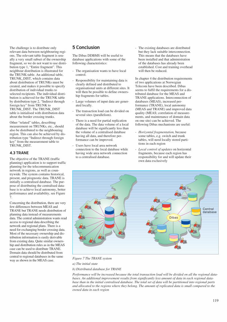
119
The challenge is to distribute onlyrelevant data between neighbouring regi-ons. The relevant table fragment is usu-ally a very small subset of the ownershipfragment, so we do not want to use distri-bution type 1, “Entire fragment”. Thisneighbour distribution is illustrated forthe TRUNK-table. An additional table,TRUNK_DIST, which contains dataabout distribution of TRUNKs must becreated, and makes it possible to specifydistribution of individual trunks toselected recipients. The individual distri-bution is achieved for the TRUNK tableby distribution type 2, “Indirect throughforeign key” from TRUNK toTRUNK_DIST. The TRUNK_DISTtable is initialised with distribution dataabout the border crossing trunks.
Other “related” tables, describingmeasurement on TRUNKs, etc., shouldalso be distributed to the neighbouringregion. This can also be achieved by dis-tribution type “Indirect through foreignkey” from the measurement table toTRUNK_DIST.
4.3 TRANE
The objective of the TRANE (trafficplanning) application is to support trafficplanning for the telecommunicationnetwork in regions, as well as coun-trywide. The system contains historical,present, and prognostic data. TRANE isinitially a centralised database. The pur-pose of distributing the centralised data-base is to achieve local autonomy, betterperformance and availability, see Figure7.
Concerning the distribution, there are veryfew differences between MEAS andTRANE but TRANE needs distribution ofplanning data instead of measurementsdata. The central administration wants readaccess to regional data describing thenetwork and regional plans. There is aneed for exchanging border crossing data.Most of the necessary ownership and dis-tribution information is easily derivablefrom existing data. Quite similar owners-hip and distribution rules as in the MEAScase can be used to distribute TRANE.Domain data should be distributed fromcentral to regional databases in the sameway as shown in the MEAS case.
5 Conclusion
The Dibas DDBMS will be useful todatabase applications with some of thefollowing characteristics:
- The organisation wants to have localcontrol.
- Responsibility for maintaining data isclearly defined and distributed toorganisational units at different sites. Itwill then be possible to define owners-hip fragments for tables.
- Large volumes of input data are gener-ated locally.
- The transaction load can be divided onseveral sites (parallelism).
- There is a need for partial replicationof the data. The data volume of a localdatabase will be significantly less thanthe volume of a centralised databasehaving all data, and therefore per-formance can be improved.
- Users have local area networkconnection to the local database whilehaving wide area network connectionto a centralised database.
- The existing databases are distributedbut they lack suitable interconnection.This means that the databases havebeen installed and that administrationof the databases has already beenestablished. Cost and training overheadwill then be reduced.
In chapter 4 the distribution requirementsof two applications at NorwegianTelecom have been described. Dibasseems to fulfil the requirements for a dis-tributed database for the MEAS andTRANE applications. Interconnection ofdatabases (MEAS), increased per-formance (TRANE), local autonomy(MEAS and TRANE) and improved dataquality (MEAS; correlation of measure-ments, and maintenance of domain dataon one site) can be achieved. Thefollowing Dibas mechanisms are useful:
- Horizontal fragmentation, becausesome tables, e.g. switch and trunktables, will need locally stored parti-tions in each region
- Local control of updates on horizontalfragments, because each region hasresponsibility for and will update theirown data exclusively
Figure 7 The TRANE system
a) The initial state
b) Distributed database for TRANE
Performance will be increased because the total transaction load will be divided on all the regional data-bases. An additional improvement results from significantly less amount of data in each regional data-base than in the initial centralised database. The total set of data will be partitioned into regional partsand allocated to the regions where they belong. The amount of replicated data is small compared to theowned data in each region
Dibas
Centraldatabase

120
- Replication of fragments or parts offragments which are owned by otherdatabase sites, because the users/-applications want
. Data from the regional databasesavailable in the central database
. Data from the central databaseavailable in the regional databases
. Exchange of cross border databetween regional databases.
Modifications to the application databaseto implement ownership and distributionare not needed. The definition languageDSQL is well suited.
References
1 Risnes, O (ed). TelSQL, A DBMSplatform for TMN applications.Telstøtt project document, March 14,1991.
2 Ceri, S, Pelagatti, G. Distributeddatabases, principles and systems.New York, McGraw-Hill, 1986.
3 Stonebreaker, M. Future trends indatabase systems.
4 Date, C J. An introduction to data-base systems, vol 1. Fifth edition.Reading, Mass., Addison-Wesley,1990.
5 Garcia-Molina, H, Kogan, B. Achie-ving high availability in distributeddatabases. IEEE Transactions onSoftware Engineering, 14, 886-896,1988.
6 Pu, C, Leff, A. Replica control in dis-tributed systems: An asynchronousapproach. Proceedings of the 1991ACM SIGMOD International Confer-ence on Management of Data, 377-423, October 1992.
7 Sybase Commands Reference, release4.2, Emeryville, Sybase Inc., May1990.
8 Didriksen, T. Dibas System Docu-mentation: Part 3. Implementation ofRun Time System. Kjeller, NorwegianTelecom Research, 1993. (TF paperN15/93.)
9 McKeney, J, McFarlan, W. Theinformation archipelago – gaps andbridges. A paper of Software State ofthe Art: Selected Papers, by TDeMarco and T Lister.
10 Korth, Silberschatz. Database systemconcepts. New York, McGraw-Hill,1986.
11 Nilsen, K. Trafikkmålinger og tra-fikkstatistikk i Televerket, 15 Jan1993. (Arbeidsdokument i Tele-verket.)
12 Johannesen, K. Network Manage-ment Systems in NorwegianTelecom, Telektronikk, 89(2/3), 97-99, 1993 (this issue).
13 Østlie, A, Edvardsen, J I. Trafikk-målinger i telefonnettet. Vektern, 1,1990.

Data design
(1) contains an Annex providing a me-thod and practical guidelines for datadesign for an application area. Theseissues will not be presented here. Rather,the development of an Applicationschema for Access Control Admin-istration will be used to exemplify datadesign.
The specification of the Access ControlAdministration application area is basedon the notion of an access control matrix.See Figure 1.
The matrix can be constructed by usingUsers corresponding to lines, Resourcescorresponding to rows and Access rightsas the elements of the matrix. The ele-ments indicate relationships betweenparticular Users and Resources. This isshown in Figure 2. See notation in (1, 2).An example access matrix is depicted inthe Population. The object classes for theaccess matrix are shown in the Schema.We observe that the relational objectclass Access right serves as the class forall the matrix elements. Note that there isno need for Access rights for non-existing elements, as would have beenthe case in a real matrix. If only oneAccess right between one User and oneResource is wanted, this uniquenessrequirement will have to be explicitlystated. Note that cardinality constraintswould not do for this. However, if oneAccess right can refer to only one Userand one Resource, this can be stated byusing the cardinality constraints (1,1)associated to the User and the Resourcereferences, respectively.
We also observe that in this simpleaccess matrix all Users, all Resources
and all Access rights have to be globallyand uniquely identified independently ofeach other. In particular this isunfortunate for the Access rights, as thiswill impose a vast amount of admin-istrative work to assign identifiers, insertthe Access rights and to state referencesto and from Users and Resources. There-fore, the Access rights could have beenreplaced by two-way references betweenUsers and Resources. However, this willnot allow attributes to be associated withthe Access rights.
Since an Access right can only exist if acorresponding User exists, we can avoidthe cumbersome administration ofglobally unique Access right identities bydefining Access rights locally to theUsers. This is shown in Figure 3. We seethat the Access right identities can be re-used within different Users. Also, sincethe number of Access rights per User isexpected to be small, usually ten or less,the Access right identities can bedropped altogether. This requires that theadministrator must be able to point at theappropriate Access rights at his HMI.This way, we have got a polarised (non-symmetrical) access matrix, whichallows one Access right to refer toseveral Resources. This makes the matrixvery compact, which means that theamount of data to read and to write willbe small and efficient to the access con-trol administrator.
We believe that many Users in an organ-isation will often have the same Accessrights. Then it will be very inefficient toinsert similar Access rights to each ofthese Users. Therefore, we can creategroups of Users having the same Accessrights. This is achieved by a two-wayreference from Users to Users. The
Member users inherit all rights from theirSet of users.
Similarly, the Resource side of the matrixcan be compressed by introducing groupsof Resources. The compression is intro-duced by recursive references in Figure4. The figure is extended from the pre-vious ones to illustrate the compression.
A two-dimensional matrix is a toosimplistic model for a realistic AccessControl Administration system. Alreadywe have allowed a fan out of referencesto several Resources from one Accessright. This will be used to state thataccess is granted to the disjunction of thelisted Resources, i.e. access is granted toeach of the listed Resources from thisAccess right.
However, we also need mechanisms tostate that access is granted to a con-junction of Resources. In particular thisis needed in order to state that a User can
121
Data design for access control administration
B Y A R V E M E I S I N G S E T
Abstract
The purpose of this paper is to
- illustrate use of the draft CCITT Human-Machine Interfaceformalism (1)
- illustrate some of the considerations undertaken whendesigning HMI data
- present a specification of an advanced Access ControlAdministration System (1)
- compare this with alternative models for Access Control.
The messages conveyed in this paper can be summarised asfollows:
- The HMI formalism provides more syntactical and expressivepower and precision than many alternative formalisms.
- The HMI formalism is used to define data as they appear onthe HMI, and this should not be confused with similar, e.g.internal or conceptual, specifications of databases.
- Data design is a complex task to undertake; alternativedesigns have great consequences to the end users; to foreseethese consequences requires much experience, and you haveno certain knowledge on how much the design can be impro-ved.
- Current models for access control have definite shortcomings,and improvements are proposed.
The proposed specification is an extract of (1) and is anextension of the Access Control Administration system ADAD,which has been used during more than ten years withinNorwegian Telecom.
681.327.2
Resources
Users
Matrix elements
Figure 1 Access matrixEach filled in matrix element states that aUser is granted access to the appointedResource
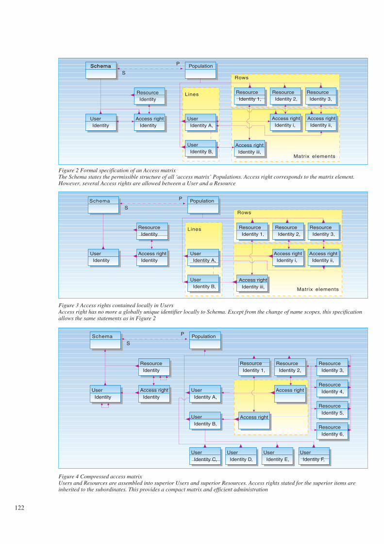
122
SchemaSchema Population
Resource Identity
Access right IdentityIdentity
User Identity A,
User Identity B,
Resource Identity 1,
Resource Identity 2,
Resource Identity 3,
Access right Identity i,
Access right Identity ii,
Access right Identity iii,
S
P
Lines
Rows
Matrix elements
User
Figure 2 Formal specification of an Access matrixThe Schema states the permissible structure of all ‘access matrix’ Populations. Access right corresponds to the matrix element.However, several Access rights are allowed between a User and a Resource
Schema Population
Resource Identity
Access right Identity
User Identity
User Identity A,
User Identity B,
Resource Identity 1,
Resource Identity 2,
Resource Identity 3,
Access right Identity i,
Access right Identity ii,
Access right Identity iii,
S
P
Lines
Rows
Matrix elements
Figure 3 Access rights contained locally in UsersAccess right has no more a globally unique identifier locally to Schema. Except from the change of name scopes, this specificationallows the same statements as in Figure 2
Schema Population
Resource Identity
Access right Identity
User Identity
User Identity A,
User Identity B,
Resource Identity 1,
Resource Identity 2,
Resource Identity 3,
Access right
Access right
S
P
Resource Identity 4,
Resource Identity 5,
Resource Identity 6,
User Identity C,
User Identity D,
User Identity E,
User Identity F,
Figure 4 Compressed access matrixUsers and Resources are assembled into superior Users and superior Resources. Access rights stated for the superior items areinherited to the subordinates. This provides a compact matrix and efficient administration

only apply a certain external Function,e.g. screens, or set of Functions to a cer-tain set of data. This set of data we call aData context. Note that a Data context isidentifying a set of Population data. Thisset can be whatever collection of data forwhich users need a specific access right.The set can be all data of a certain class,some instances of a class, some attributesof some object classes, etc. A three-dimensional polarised fanned out accessmatrix allowing to state access rights toboth disjunctions of similar resources andconjunctions of dissimilar resources isshown in Figure 5. A formal specifi-cation is shown in Figure 6.
Lastly, we will allow Users to be definedlocally to Users in a hierarchy. This isprovided by the two-way schema-pop-ulation reference (S-P) betweensubordinate User and superior User. Asimilar hierarchy is provided forFunctions. There are also many otheraspects of the final specification whichwe have no room to discuss in this paper.However, the resulting specification ofExample Recommendation YYY onAccess Control Administration followsbelow. This specification is organisedinto the following sections:
- Application area
- Application schema graph
- Textual documentation
- Remarks.
Roles and references are explicitly statedin the Application schema graph. TheTextual documentation includes the datatree only, without references, as they areonly expressed in the natural languagetext, which is left out here, due to lack ofspace. For the same reason, the Remarksare left out. Note that Time intervalappears in several of the object classes.The specification could have been mademore compact by the use of inheritance,i.e. a schema-reference, from a commonsource. However, this inheritance maynot be of relevance to the end user orexpert user reading the specification.
Example
Recommendation YYY
Access control administration
Application area
Access Control is the prevention ofunauthorised use of a resource, includingthe prevention of use of a resource in anunauthorised manner.
Access Control Administration, as definedhere, is delimited to the administration ofthe access rights of the users.
This recommendation is concerned withthe access to those resources which aredefined in the External layer, Applicationlayer and the Internal layer of theHuman-Machine Interface ReferenceModel (1, 3).
123
Data Contexts
Users
Matrix elements
Functions
Figure 5 Three-dimensional Access matrixThe resources are split into external Functions and Datacontexts. This allows for stating that a certain User can onlyaccess a Data context by using certain Functions. Arbitraryaccess is disallowed
Schema Population
Function Identity
Access right Identity
User Identity
User Identity A,
User Identity B,
Function Identity 1,
Function Identity 2,
Access right
Access right
S
P
Lines
Rows
Matrixelements
Data context Identity
Data context Identity 1,
Figure 6 Specification of access rights to conjunctions of Functions and Data contextsThis is a formal specification of the three-dimensional Access matrix in Figure 5. Several Access rights connecting a User and aparticular resource are allowed
This recommendation covers AccessControl Administration for all kinds ofusers, including human beings and com-puter systems.
This recommendation views the resour-ces from the perspective of an accesscontrol administrator. The resources areidentified within the scope of one AccessControl Administration system only. Theresources can be related to one appli-cation, a part of an application or severalapplications. This recommendation doesnot cover the co-ordination of severalAccess Control Administration systems.However, how this can be achieved isindicated in some of the Remarks –which are left out in this extract.

Application schema graph
The application schema graph is shownin Figure 7.
Textual documentation:
User. Identity (1,1). Transfer (0,1). . Yes, (0,1). . No, (0,1). . Possible, (0,1). Reception (0,1). . Yes, (0,1). . , (0,1). Time interval. . Start (0,1). . . Year (1, 1). . . Month (1, 1). . . Day (1, 1). . . Hour (1, 1). . . Minute (1, 1). . . Second (1, 1). . Stop (0,1). . . Year (1, 1). . . Month (1, 1). . . Day (1, 1). . . Hour (1, 1). . . Minute (1, 1). . . Second (1, 1). User
. . User (0,1)
. Member user
. Set of users
. Terminal
. Access right
. . Time interval
. . . Start (0,1)
. . . . Year (1, 1)
. . . . Month (1, 1)
. . . . Day (1, 1)
. . . . Hour (1, 1)
. . . . Minute (1, 1)
. . . . Second (1, 1)
. . . Stop(0,1)
. . . . Year (1, 1)
. . . . Month (1, 1)
. . . . Day (1, 1)
. . . . Hour (1, 1)
. . . . Minute (1, 1)
. . . . Second (1, 1)
. . User(0,1)
. . Function
. . . Action
. . . . Read, (0, 1)
. . . . Insert, (0, 1)
. . . . Modify, (0, 1)
. . . . Delete, (0, 1)
. . . Access right
. . Data context
. . . Action
. . . . Read, (0, 1)
. . . . Insert, (0, 1)
. . . . Modify, (0, 1)
. . . . Delete, (0, 1)
. . . Access right
. . TerminalFunction. Identity (1,1). Accessibility (0,1). . Public, (0,1). . , (0,1). Transfer (0,1). . Yes, (0,1). . No, (0,1). . Possible, (0,1). Reception (0,1). . Yes, (0,1). . , (0,1). Time interval. . Start (0,1). . . Year (1, 1). . . Month (1, 1). . . Day (1, 1). . . Hour (1, 1). . . Minute (1, 1). . . Second (1, 1). . Stop(0,1). . . Year (1, 1). . . Month (1, 1). . . Day (1, 1). . . Hour (1, 1). . . Minute (1, 1)
124
Figure 7 Application schema graph for access control administrationSubordinate User inherits (S-P) attributes from superior User. This allows for instantiation of a directory tree of Users. Similarly forFunctions. One User and one Data context may be grouped into several Set of users and Superior data contexts, respectively. Thesegroupings allow for inheritance of Access rights, but are independent of name scopes. Note that inheritance of Access rights is outsidethe scope of the Access Control Administration system. It concerns the Access Control system only and is therefore not stated here.The administrator has to know the implications for the Access Control system, but the inheritance statement is outside his scope. Thismay or may not be the case for inheritance of a common definition of Time interval, as well. Note that the class label Function is re-used for several purposes. Also, that permissible Actions can be associated with the Function and Data context roles. For furtherexplanation of the figure, see (1). Note all the details provided in this very compact specification
IdentityTransferReceptionTime interval
FunctionIdentityAccessibilityTransferReceptionTime interval
(1,1)(0,1)(0,1)(0,1)
S
P
Function
Subordinatedata
Superiordata context
Data contextIdentity (1,1)Time interval
Data context
Action
ActionFunction(1,1)
(0,1)(0,1)
S
P
Access right
Time intervalUser
Terminal contextIdentity (1,1)Time interval
Terminal
Terminal
Terminal
Terminal
Terminal group
Terminal
Set ofusersMember users
User

. . . Second (1, 1)
. Function
. . Function (0,1)
. Terminal
. FunctionData context. Identity. Time interval. . Start (0,1). . . Year (1, 1). . . Month (1, 1). . . Day (1, 1). . . Hour (1, 1). . . Minute (1, 1). . . Second (1, 1). . Stop (0,1). . . Year (1, 1). . . Month (1, 1). . . Day (1, 1). . . Hour (1, 1). . . Minute (1, 1). . . Second (1, 1). Subordinate data. Superior data context. Terminal. Data contextTerminal context. Identity (1,1). Time interval. . Start (0,1). . . Year (1, 1). . . Month (1, 1). . . Day (1, 1). . . Hour (1, 1). . . Minute (1, 1). . . Second (1, 1). . Stop (0,1). . . Year (1, 1). . . Month (1, 1). . . Day (1, 1). . . Hour (1, 1). . . Minute (1, 1). . . Second (1, 1). Terminal. Terminal group. Access right. User. Function. Data context
Bell-LaPadula
The Bell-LaPadula model (4) for accesscontrol introduces the notions of Clear-ance and Classification: Users areassigned a Clearance level. Resources areassigned a Classification level. If theClearance is greater or equal to theClassification, the user is granted accessto the resource.
This model can be interpreted using theApplication Schema in Figure 7. Some
instances of the user side are illustratedin Figure 8 . A ‘Member user’ inherits allthe access rights of its ‘Set of users’ inaddition to its own access rights.
Note that a hypothetical introduction ofan extra attribute ‘Clearance level’ of‘User’ would add no extra information,since the ordering of the values still hadto be defined to the Access Control sys-tem and to the Access Control Admin-istration authority. ‘Clearance levels’correspond to the Identities of the Users.Introduction of an extra attribute for thiswould imply introduction of an alterna-tive and redundant identifier, and nothingelse.
From the above, we realise that exactlythe same kind of reasoning applies forthe assignment of sensitivity Classifi-cation levels to the resources, e.g. to Datacontext and Function. Hence, we do notrepeat this argumentation, but concludethat sensitivity Classification level is asubset of the resource Identity values.
How Clearance levels relate to Classifi-cation levels is depicted in Figure 9.
We realise that the Clearance-Classifi-cation notion is just a trivial special caseof the Member user and Subordinate datacontext notions. The User and Datacontext notions are much more powerful,
as they allow inheritance from severalsuperiors and contain several subordinateitems. Also the User notion can be usedto denote real organisation units, ratherthen the artificial rewriting into “Clear-ance levels”. Similarly for the resources– Data context and Functions. Also theAccess right notion can state more com-plex references between the Users andthe Resources.
In particular the Clearance-Classificationnotion lacks the needed expressive powerto arrange the Actions Read, Insert,Modify, Delete, etc. into appropriatesensitivity Classes. For instance, a Usermay have access rights to Insert data intoa Data context, but not to Delete thesame data. Another User may have rightsto Delete the same data, but not to Insertnew data. Hence, the different Actionscannot be arranged in a Classificationhierarchy. Neither do we need the notionof sensitivity “Classification levels”,since we can express the access rightsdirectly from Users to the Resources,including statements about whichActions can be applied.
Finally, the Clearance-Classificationnotions introduces a strict and staticnumbering of levels which can be cumb-ersome to change when needed.
125
User Identity 1,
User Identity 2,
User Identity 3,
User Identity 4,
User Identity 5,
User Identity 6,
User Identity Secret,
User Identity Top secret,
Member user
Set of users
Set of users
Member user
Lower Clearance level
Higher Clearance level
Figure 8 Ordering of Clearance levelsThe two-way reference Set of users/Member user replaces the Clearance levels. In fact, theUser notion is a more general and flexible way to label user groups. The use of subordinateUser is not illustrated here
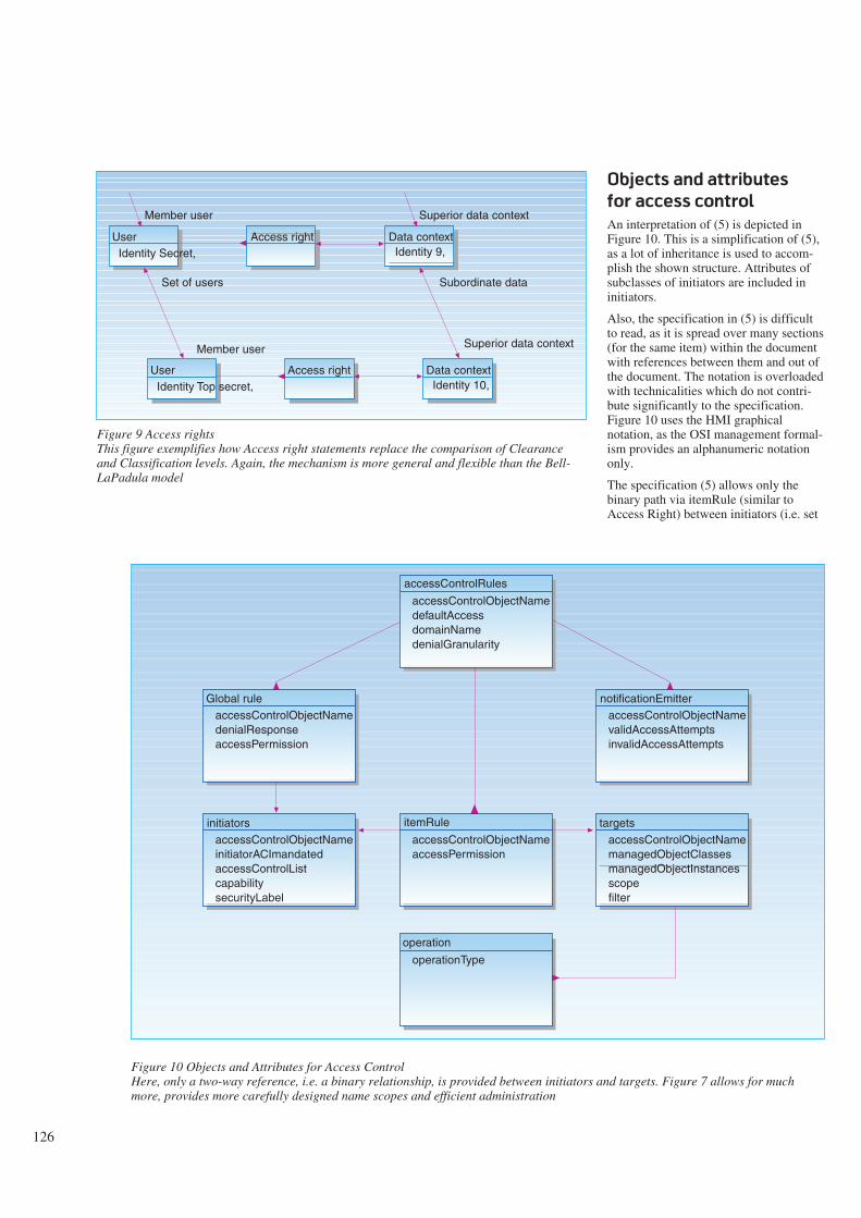
126
Figure 10 Objects and Attributes for Access ControlHere, only a two-way reference, i.e. a binary relationship, is provided between initiators and targets. Figure 7 allows for muchmore, provides more carefully designed name scopes and efficient administration
Objects and attributes
for access control
An interpretation of (5) is depicted inFigure 10. This is a simplification of (5),as a lot of inheritance is used to accom-plish the shown structure. Attributes ofsubclasses of initiators are included ininitiators.
Also, the specification in (5) is difficultto read, as it is spread over many sections(for the same item) within the documentwith references between them and out ofthe document. The notation is overloadedwith technicalities which do not contri-bute significantly to the specification.Figure 10 uses the HMI graphicalnotation, as the OSI management formal-ism provides an alphanumeric notationonly.
The specification (5) allows only thebinary path via itemRule (similar toAccess Right) between initiators (i.e. set
accessControlObjectNamedenialResponseaccessPermission
Global rule
accessControlObjectNameinitiatorACImandatedaccessControlListcapabilitysecurityLabel
initiators
accessControlObjectNamedefaultAccessdomainNamedenialGranularity
accessControlRules
accessControlObjectNamevalidAccessAttemptsinvalidAccessAttempts
notificationEmitter
accessControlObjectNamemanagedObjectClassesmanagedObjectInstancesscopefilter
targets
operationType
operation
accessControlObjectNameaccessPermission
itemRule
User Identity Secret,
User Identity Top secret,
Set of users
Member user
Member user
Access right Data context Identity 10,
Subordinate data
Superior data context
Superior data context
Access right Data context Identity 9,
Figure 9 Access rightsThis figure exemplifies how Access right statements replace the comparison of Clearanceand Classification levels. Again, the mechanism is more general and flexible than the Bell-LaPadula model

of users) and targets (i.e. set of resour-ces). However, there is a lot of intricacyabout this ‘relation’. The references toinitiators and targets are accomplished bythe multi-valued attributes initiatorListand targetsList (not shown), respectively.Hence, each itemRule can connectseveral initiators and targets items. EachitemRule maps to the accessPermissionattribute values deny or allow. Thismakes it difficult to overview the impli-cations of the total set of maybe con-flicting access right statements. EachitemRule has to be assigned a globallyunique name.
In addition, globalRule has an access-Permission attribute which allows accessfrom the referenced initiators to alltargets to which access are not explicitlydenied.
There is no explicit reference from ini-tiators and targets to itemRule. Thepermissions of one initiators item canonly be found by searching for it in theinitiatorList of all itemRules. However,inclusions in the initiatorList and targets-List require that the referenced initiatorsand target items already exist.
Individual users are listed in access-ControlLists of initiators. There is nomeans to list all initiators in which a useris listed, except via a global search of allinitiators for the given user name in theaccessControlList.
Also, the resources are listed within listsin targets. It is not clear how manage-dObjectClasses and managed-ObjectInstances relate to each other, i.e.how you specify certain instances of cer-tain classes only. This may be done(redundantly?) via the Filter.
The Filter attribute references a filtername. The contents of the filter can be acomplex ASN.1 expression.
There are no means to state access rightsfor individual users or resources withoutcreating an initiators and/or targets item.Also, the individual users and resourcesare assigned globally unique names, andthere are no means to define directorytrees, allow delegation of rights or toinherit rights from other users or resour-ces.
For each target item a finite set ofoperations can be specified. This meansthat if different users will have permiss-ion to perform different operations on the
same resource, then different targets haveto be defined for this resource.
No means is provided to state contextualaccess rights, e.g. that a particular user isgranted access only if he is using a cer-tain external function (e.g. program), acertain terminal and if the access is und-ertaken within a certain time interval.
Figure 10 can be interpreted to definedata as they are communicated from anAccess Control Administration system toan Access Control system. Ref. thenotion of an Access Control Certificate(5). There seems to be no simple meansto select the data which are needed forvalidating the access rights for aparticular request. Also, the data defini-tions seem to be neither appropriate norefficient for prescribing the data as seenby an access control administrator at hisHMI.
A model of authorisation
for next-generation data-
base systems
(6) presents a specification which isdefinitely more developed than the pre-vious two. However, this specificationhas also definite shortcomings.
The first problem is that (6) is based onSet theory, while the proposed specifi-cation in the current paper is based onlists within lists. Set theory disregards thedetails of data design and disallows manyof the designs used in this paper. Thispaper is concerned with the exact designof data, their labels and identifiers, tomake them manageable to the end users –in this case the access control admin-istrator.
A second problem is that (6) is based onthe algebraic theory of lattices. Asexplained in the section on the Bell-LaPadula model, this kind of ordering istoo restrictive and artificial in anadvanced access control administrationsystem.
Concluding observations
This paper indicates how a ratheradvanced specification of Access ControlAdministration can be developed, takingthe primitive notion of an access controlmatrix as the starting point. We observethat seemingly minor changes to thespecification can have comprehensiveconsequences for the end users. There-fore, the designer should carefully figureout the implications of his design choiceson the final presentations and instanti-ations to the end users. This study canconveniently be carried out by creatingexample instances in population graphs.
Experienced designers are likely to seemore problems and more opportunitiesthan novice designers. Users will havedifficulties foreseeing the impact of thespecifications and hence to validatethem, even if the users seem to under-stand when the specifications areexplained. The problem is to see thelimitations and alternatives, which arenot pointed out in the specification.Therefore, test usage of the resultinginformation system, allowing real usersto provide feedback, is essential toidentify problems and validate designs.
The specification technique allows andrequires generality, precision and detailswhich users are not likely to match intheir requirement texts. Therefore, mostof the data design is creative design workand is not like a compilation of end userrequirements. The designers’ responsi-bility is to create good and efficient datadesigns for their users. The task is not toorganise existing terms only.
Also, the way the work is carried out isno guarantee for success, even if thedevelopment procedure used – the met-hod – can provide some confidence aboutthe result. But, even if you apply ‘thesame procedure as Michelangelo’, it isnot likely that you can produce somet-hing which matches his quality. So alsofor data designs. The problem is thatthere is no objective measure on howoptimal is the current design and howmuch can be achieved by improvements.You only know this gain relative to thealternatives available.
It is likely that many choices will bemade on subjective grounds and that theywill cause disagreement. However, datadesigners should estimate costs ofconverting data to the proposed newdesign and estimate how much can be
127

gained, e.g. reduction of work, by usingthe new design. All concerns not quanti-fied should also clearly be spelled outbefore decisions are taken for each andevery data item.
The HMI formalism provides a verycompact specification and provides goodoverview. See Figure 7. The boxes andarrows can easily be used by end users asicons to access more detailedexplanations and specifications. Thegraph will become their ‘brain map’.
Also, the HMI formalism allows usageand specification of syntaxes that are notmatched by most other formalisms, e.g.the Entity-Relationship (ER) formalismand the OSI Management formalism. Wehave seen a tendency to use ER-diagramsas illustrations (bubble charts) rather thanformal specifications. It is essential thatknowledge is developed for making pro-fessional data designs. To design data forHMIs is more demanding than designingdatabases, from which data can be vari-ously extracted and presented. The HMIdata design prescribes the final pre-sentation.
The comparison between the data designfor Access Control Administration of thispaper and other specifications from theliterature indicates that much and chall-enging work remains to be done.
References
1 CCITT. Draft recommendationsZ.35x and Appendices to draftrecommendations, 1992. (COM X-R12-E).
2 Meisingset, A. The draft CCITTformalism for specifying Human-Machine Interfaces. Telektronikk,89(2/3), 60-66, 1993 (this issue).
3 Meisingset, A. A data flow approachto interoperability. Telektronikk,89(2/3), 52-59, 1993 (this issue).
4 Hoff, P, Mogstad, S-A. Tilgangskon-troll-policyer basert på Bell-LaPaluda-modellen. Kjeller,Norwegian Telecom Research, 1991.(TF paper N21/91.)
5 ISO, ITU-TS. Information Techno-logy – Open Systems Interconnection– Systems Management – Part 9:Objects and Attributes for AccessControl, 1993. (ISO/IEC JTC 1/SC21 N7661. X.741.)
6 Rabitti, F et al. A model of aut-horisation for next-generation data-base systems. ACM transactions ondatabase systems, 16(1), 1991.
128