contents · contents quick reference data ... cylinder leak down test power train steering frame...
TRANSCRIPT

CONTENTS
QUICK REFERENCE DATA . . . . . . . . • . . . • . • . . . . . . . . . . . . . . • . IX
CHAPTER ONE .GENERAL INFORMATION
Manual organizationNotes, cautions and warningsSafety firstCleaning partsHandling gasoline safelyService hintsTorque sped fica tion sFas tenersLubricantsThreadlocking compoundRTV gasket sealant
CHAPTER TWO . . . . .TROUBLESHOOTING
Operatin g requirement sTroubleshooting instrumentsStarting the engineStart ing diffi cultiesEngine is difficult to startEngine starting systemCharging systemIgnition systemElectronic throttle control
.. .. .. . 1
Expendable suppliesSerial numbersWarning and information labelsBasic hand toolsPrecision measuring toolsSpecial toolsFabricat ing toolsMechanic's tipsBeari ng rep lacementSealsStorage
.. 36
Fuel sys temEngine overheatingEngineEngine noisesCy linder leak down testPower tra inSteeringFrame noiseBrakes

CHAPTER THREE . .. .... .. .. • . •.. .LUBRICATION, MAINTENANCE AND TUNE-UP
Pre- ride check listTire s and whee lsBatteryBatt ery elec tr ica l cabl e connectorsPeriodic lubrication
CHAPTER FOUR .ENGINE TOP END
Eng ine princip lesEng ine coolingEng ine lubricationServicing the engine in the frameExha ust syst emCy linder head co verRocker ann assembl y
CHAPTER FIVE . . • .ENGINE LOWER END
EngineFlywheel and stator plateRecoi l starte rCra nkcaseCrankshaft inspec tionBalancer shaft inspection
CHAPTER SIX • . . . .FUEL SYSTEM
Carburetor operationCarburetorCarburetor cleaning and inspectionCarburetor tests and adj ustmentsThrottle cable replacemen t
CHAPTE R SEVEN. . . . . . . . . •COOLING SYSTEMS
Po laris va riabl e transmission (PVT)a ir cooling system
Eng ine cooling sys temSafety precauti onsHoses and hose clampsEngin e gaskets/sea ls
.... .. 53
Perio dic main tenanceUnsc heduled inspectionand maintenance
Engine tune-up
.. .. .. ...... 94
CamshaftCy linde r headValves and va lve componentsCy linder blockPiston and piston ringsCamshaft chain and sprocketsBreak-in procedure
. . . 137
Shan end float measurementand shim select ion
Oil pumrOil system one-way check valveBreak -in procedure
175
Stalling enr ichment (choke) cab leFue l tankFuel shutoff va lveAir fi lter air boxFu~l pllm p
.... 198
Coo ling sys tem inspect ionRadiatorCoo ling fanCoo lant pumpTherm ostatTemp erature se nsors

CHAPTER EIGHT .CLUTCH/DRIVE BELT SYSTEM
Drive unitDrive pulleySpecia l toolsDriven pulleyDrive belt
CHAPTER NINE .TRANSMISSION
TransmissionTransmission inspectionShift shaftsFront output shaft
CHAPTER TEN . . . . . . .FRONT DRIVE SYSTEM
Front hub and Hillard clutchFront drive axle, boots and CV
(constant velocity) joints
CHAPTER ELEVEN . .ELECTRICAL SYSTEM
Basic informat ionNegative battery terminalCharging systemAlternator statorVoltage regulator/rectificrCapacitordischarge ignitionIgnition coilIgnition stator coils
CHAPTER TWELVE .FRONT SUSPENSION AND STEERING
Front wheelFront hubFront strut cartridge and springFront strut/spindleControl arm
CHAPTER THIRTEEN .REAR SUSPENSION
Rear wheelsTire changing and tire repairsShock absorberRear hub and bearing carrierRearaxlesUpper control arm
. .. .. .. .... 213
Drive pulleyDriven pulleyClutch outer and inner cover
(all models)
. . 249
Transmission gearcase oil sealinspection and replacement
Shift selector linkage
..... .... 290
Front dr ive shaftFront drive unit
.. .. . 303
Electric starting systemStarter drive gearsStarter solenoidLighting systemElectrical componentsSwitchesWiring diagrams
. 337
HandlebarTie rodsSteerin g shaftTires and wheels
. 362
Lower control armUpper and lower control
arm inspectionStabilizer linkageStabilizer support
CHAPTER FOURTEEN.BRAKES
Disc brakesFront brake padreplacementFront cal iperOu tput shaft brake pad replacement
(1996-1997 models)O utput sha ll brake cal iper
( ]996- 1997 mode ls)Output sha ll brake pad repl acement
( I998- on models)Output shaft brake caliper
(I 998-on models)
CHAPTER FIFTEENBODY
SeatFront rack and grilleSide panelsFront fenderFront bum per (models so eq uipped )
SUPPLEMENT .2001-2003 SERVICE INFORMATION
Starting the engineIgnition systemPeriodic maintenanceEngine tUIl C- Up
Cy linde r blockPiston and piston ringsEngineFlywheel and stator plateCarburetor (Sportsman 500 H.G. models)Cleaning and inspectionCarburetor tests and adjustmentsDrive beltDriv en pulley (200 3 models bui lt
afte r 07/08102)
INDEX .
WIRING DIAGRAMS .
.. . .. . . 382
Front master cylinderRear master cylinderBrak e hose replacement
Rear brake peda lRem brake lever
( 1996 -1997 Sweden mod els)Foot brak e
(199 8-on Sweden model s)Brake d iscBleeding the sys tem
... .. .. .. . 425
Radiator guardRear rack
Rear fenderFootv..'e llsRear bumper (mode ls so eq uipped)
... ... .... . 437
TransmissionLighting systemElectrical componentsStee ring sha ll (2002-on models)Rear hub and bearing carrier (2003 models)Rear brake pad replacement
(2003 models)Rear ca lipers (200 3 mod els)Front master cylinderRear master cylinder (2003 models)Rear brake disc (200 3 mode ls)Brake hose replacemen t (2003 models)
.470
.476
QUICK REFERENCE DATA
ATV INFORMATIONMODEL: YEAR: _
VIN NUMBER:, _
ENGINE SERIAL NUMBER : _
CARBURETOR SERIAL NUMBER OR 1.0. MARK: _
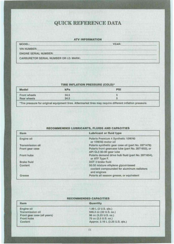
TIRE INFLATION PRESSURE (COLD)'
Model kPa PSI
Front wheels 34.5 5Rear wheels 34.5 5
"Tlre pressure for original equipment tires. Aftermarket tires may require different Inflation pressure.
RECOMMENDED LUBRICANTS, FLUIDS AND CAPACITIES
Item
Engine 011
Transmission allFront gear case
Front hubs
Brake fluidCoolant
Grease
Item
Engine allTransmission allFront gear case (all years)Front hubsCoolant
Lubricant or fluid type
Polaris Premium 4 Synthetic 10W/4Qor 10W/40 motor all
Polaris synthetic gear case 011 (part No. 2871478)Polaris front gearcase lube (part No. 2871653), orAPI GL5 80·90 gear lubePolaris demand drive hub fluid (part No. 2871654),or ATF Type F.
DOT 3 brake fluid50:50 mixture ethylene glycol·based
coolant compounded for aluminum radiatorsand engines
Polaris all season grease, or equivalent
RECOMMENDED CAPACITIES
Quantity
1.89 L (2 U.S. qts.)946.3 cc (32 U.S. oz.}96 cc (3.25 U.S. oz.)75 cc (2.5 U.S. oz.)Approx. 2.16 L (2.25 U.S. qts.)
IX

MAINTENANCE AND TUNE·UP TORQUE SPECIFICATIONS
Item N'm in...lb.
Crankcase oil drain plug 19Cylinder head cover screws 8.2 72Front gear case drain plug 9.4 83Handlebar up per holder bol ts 13·17 115-150Oi l tank drain plug 190 11 tank screen and fitting 20Valve adjuster locknuts 6-7 53-62Whee/lug nuts
Front 21Rear 21
MAINTENANCE AND TUNE·UP SPECIF ICAT IONS
ft .· lb.
14
1415
1515
Item
Disc brake pad thickness wear limit2003 Sportsman 500 & 500 H.O.
Rear brakeAll other models and years
Front and rear brakesValve clearance (cold)
Intake and exhaustSpark plug400 cc
Heat rangeGap
500 eeHeat range
1996-19971998-20012002·on
Gap1996· 19981999-20002001·on
Idle sp eed1996-1988 , 2001-on1997·2000
Carburetor pilot air screw (34 mm)19961997·19981999-20002001-on (400 ee)
Carburetor pilot air screw (40 mm )20012002-on
Item
HeadlightsGrill mounted lights
199619971998-on
TaillightBrake lightIndicator lights19961997-on
Specificat ion
4.6 mm (0.180 In.)
3.81 mm (0.150 In. )
0.15 mm (0.006 In.)
NGK BKR5E0.9 mm (0.036 in.)
NGK BKR5ESNGK BKR5ENGK BKR6E
0.6-0.7 mm (0.02 4-0.028 in .0.7 mm (0.028 In.)0.9 mm (0.036 in.)
1100-1300 rpm1000-1400 rpm
1 1/2 turns out2 turns out2 5/8 turns out23/4 turns out
2 1/2 turns out2 turns out
REPLACE MENT BULBS
Specificati on
12 volt , 60/60 watt Halogen
12 volt , 37.5 watt (2)12 volt, 35 watt (2)12 volt, 27 watt12 volt, 8.26 watt12 volt , 6 .9 watt
12 volt , 1.25 wa tt12 volt,l.0 watt
x

CHAPTER ONE
GENERAL INFORMATION
This detailed. comprehensive manual covers thePolaris Sportsman 400 , 500 and Xp lorer 500 4 x 4from I 996-on.
Keep this book hand y in the toolbox. Readin gand using it will help to better understand how theve hicle runs, lower repair cos ts and generally improve personal satisfaction with the vehicle.
The following tables are included at the end ofthis chapter:
Tahle 1 lists model year and number.Tahle 2 lists general dimensions .Ta ble 3 lists vehicle weight (dry) .Table 4 lists decimal and metric equivalents.Tab le 5 lists general torque specifications.Tab le 6 lists conversion tables .Ta ble 7 lists technical abbreviations.
Table 8 lists metric tap and drill sizes.
Tables 1-8 are at the end of this chapter.
M ANUAL ORGANIZATlO:'ll
All dimensions and capacities are expresse d inEnglish units familiar to U.S. mechanics. as well asin metric units.
This chapter provides general information anddiscusses equipment and too ls useful both for preventive maintenance and troubleshooting.
Chapter Two provides methods and suggestionsfor the quick and accurate diagnosis and repair ofproblems. Troubleshootingproceduresdiscuss typ-

2
ical sy mptoms and logical methods to pinpoin t thetrouble.
Chapter Th ree explains all pe rio di c lubricationand rou tine maint enance necessary to keep the vehi
cle funn ing wel l. Chapter Three also incl udes recommended tUIl C-Up procedu res , el imina ting theneed to co nstant ly consult chapte rs on the variousass emb lies .
Subsequent chapters describe specific sys te mssuch as the engi ne , clutch/drive belt sy stem, transmission, exhaust, coo ling, suspension and brakes.Each chapter pro vid es d isassembly, repair and assembly procedures in a simple s tep- by-step form .
Ifa repair is impract ica l for a ho me mechanic. it isso indicated. It is usually faster ami less expensiveto take such repairs to a dealer or com petent repairshop. Spec ifications concerning a particul ar systemarc included at the end of the appropriate chapter.
So me of the proced ures in this manual spec ifyspecial too ls. In most cases, the too l is illustrated either in actua l use or alone. We ll-equipped mec hanic s may find they ca n subs titute similar too lsalready on ha nd or ca n fabricate thei r own.
NOTES, CAUTIONS AND WARNINGS
T he terms NOTE, CA UT ION and WARNINGhave specific meanings in this ma nual. A NOTEpro vides add itio na l inform ation to make a step orprocedure eas ier o r clearer. Disregarding a NOTEcould cause inconvenience, bu t would not ca useeq uipment damage or personal injury.
A CAUTION emphasize, areas w here eq uipme ntda mage co uld result. Disregard ing a CA UT IONco uld cause permanent mechanica l damage ; hO\\Iever, personal inju ry is unli kely.
A WARN ING emphasize s area s where personalinjury or even death could resu lt from negligence.M ec hanica l da mage may also occur. WARNING Sare fa be taken seriously. In some cases , serious inj ut)' or death has resu lted from disregarding s imilarw arn ings .
SArETY FIRST
Pro fessional mechan ics can work for years andnever sustain a se rious inj ury. If a few rul es of co mmon sense and safe ty arc ob served. many safe hourscan be enjoyed serv ic ing the ATY. Ign or ing these
CHAPTER ONE
rules ca n inj ure so meone wor king on the vehicle. o rdam age the AT V.
I. Never lise gasoline o r any type of low flash po intso lve nt to clean pa rts , Se c Cleaning Parts and Handling Gasoline Safety in this chapter for add itionalinformat ion on parts c lea ning, gaso line usc andsafety.
NOTETheflash point is the lowest temperalure a t which the vaporsfrom a com
bustible liquid will ign ite when inopen ail: A lowjlash point solvent willignite at a lower temperature than ahiglzjlash point solvent.
2. Never smo ke or usc a to rch in the vici nity offlammable liquids in ope n co ntainers, such as gasoline or cleaning so lve nt.
3. lf wc lding or brazing is req uired on the vehicle.
re move the fue l rank , carburetor, and fron t and rea rshoc ks to a safe d istance at leas t 50 feet ( 15 m)awa y.
4. Use the pro per s ized wre nc hes to avoid damageto fa steners.
5. Wh en loose ning a tight or stuck nut , be guidedby wha t would happen if the wrench slips.
6. When rep lacing a fa stener, make sure to usc one
wi th the sa me measu rem ents and streng th as the o ldone. Inco rrect or m ism atched fasteners can result inda mage to the vehicle and possibl e personal inj ury.Beware of fastene r kits that are filled w ith chea pand poorly made nut s. bolt s , washe rs and co tterpins. Refer to Faste ners in thi s chapt er for add ition al inform ation.
7. Keep all hand and power tool s in go od condition.
Wipe greasy and o ily too ls after us ing the m. Dirtytoo ls arc d iffi c ult to ho ld and can cause injury. Replace or repair worn or damaged tools.
8. Kee p the work area c lea n and uncl uttered.
9 . Wear safety gogg lcs during all operations invo lving drilling , g r ind ing. the use of a co ld chisel,using che mica ls, c lea ning parts, wh en using compressed air or anytime the sa fe ty of eyes is invo lved.
10. Make sure to we ar the correct typ e of clothesfor the job. Long hair should be tied up or coveredwit h a cap so thai it canno t be caug ht by a piece ofmoving eq uipme nt or too l.

G ENE RAL INFORMATION
11. Keep an approved fire extinguisher nearby. Besure it is rated fur gasoline (C lass B) and electrical(Cla ss C) fires.
12. When drying bearings or other rotat ing pariswith compressed air, never allow the air jet to rotatethe bearing or pari. The air jet is capab le of rotatingthem at speeds ta r in exce ss o f those for which theywere designed . The bearin g or rotating part is verylikely to disintegrate and cause serious injury anddam age . To prevent bearing dam age whe n usingcom pressed air, hold the inner bearing race by hand.
WARNINGThe improper use ofcompressed air isvelJ' dangerous. Using compressedair to tlUSI off clothes, the ATV orworkbench can cause jly ing particlesto be blown into eyes or skill. Neve rdirect or blow compressed air in/askin or through any body openin g (including cuts) as this can cause severeinjury or death. Compressed air mustbe used care/idly; never allow children to lise or play with a ll)' compressed air equipment or hoses.
13. Never work on the upper part of the vehiclewhile someone is worki ng underneath it.14. When putting the vehicle on a stand, mak e surethe vehicle is secure before walking away from it.15. Never carry shar p tools in clothing pockets.
16. There is always a right and wrong way to usetools. Learn to use them the right way.
17. Do not start and run the ATV in an enclosedarea , The exhaust gases conta in carbon monox ide, acolorless, odorless , poisonous gas. Carbon monoxide levels build quickly in a small closed area andcan cause unconsciousness and death in a shorttime. When it is necessary to start and run the vehicle during a service procedure, always do so outside, or in a serv ice area equip ped with a ventilat ingsys tem.
CLEANING PARTS
Cleaning parts is one of the more ted ious and difficu lt serv ice jo bs performed in the home garage .While there are a nnmber of chemical cleaner s andsolvents availa ble for home and shop lise, most arcpoisonous and extremely flammable. To preve ntchemical overexposure, vapor buildup, tire and sc-
3
rious inju ry. obse rve all manufact urer 's direct ionsand warn ings while notin g the following,I. Read the entire product label befor e using thechem ical. Observe the precautions and warnings onthe labe l. Always know what type ofchem ica l is being used .2. If the chem ical product must be mixed, measurethe proper amount according to the direction s.3. Always pro vide sufficient ventilation whenworking with solvents or othe r chemicals. If achemica l can be sme lled, there is some vapor in theair. The stronger the smell, the stro nger the vaporconcent ration .4. If a prod uct is listed as combustib le, flammableor an extremely flammable Iiquid, the danger offi reincreases as the vapor collects and bui lds up in theshop.5. lf a produ ct is listed as a poison, the vapor is poisonous as well as the liquid.o. To prevent skin exposure, wear protectivegloves when cleaning parts. Select a pair of chemical-resistan t gloves suitable for the type of chernicals that w ill be used. Replace the gloves whcn theybecome thin, damaged, cha nge COIOf, or swe ll.7. Wear safety gog gles when using chemicals andcleaning par ts.8. Do not lise more than one type of clean ing solvent at a lime.9. If a pan must be heated to remove a bearing,clean it thoroughly to remove all oil , grease andcleaner residue. Then wash with soapy water andrinse with clear water,10. Wear a respirator if the instruction label says todo so.II . Keep chemical products out of reach of children and pets.12. To prevent sparks, usc a nylon bristle brushwhen cleaning paris.13. When using a commerc ial paris washer, readand follow the manufacturer 's instructions lo r selecting the type of so lvent to usc. Parts washersmust be equ ipped with a fusible link designed tomelt and drop the cover in the event of fire.14. Wash both hands and arms thoro ughly aftercleaning parts,
HANDLING GASOLINE SAFE LY
Gasoline, a vola tile flammable liquid, is one ofthe most dan gerou s items in the shop, However, be-
a

cause gasoline is used so often, many people forgetthat it is a da ngerous prod uct. Gasoline should beused only as fuel for internal-combustion engines.Never usc gas oline to clean parts, tools or to wa shhands. When working on an ATV. motorcycle orany other type of gasoline engine. gasoline will always be present in tbe fuel tank, fue l line and carburetor. To avoid a disastrous accident when workingaround gasoline or on the fuel system, carefully observe the following precautions:I. Never usc gasoline to clean parts. See CleaningParts in this chapter for additional information onpans cleaning and safety.
2. Wh en working on the fuel system, work outsideor in a well-ven tilated area.3. Do not add fuel to the fuel tank or serv ice the fue lsystem while the ATV is in the vic inity o f openflames, sparksor where someoneissmoking. Gasoline vapors arc actually more dangerous than liquidgasoline. Because these vapors are heavier than air.they collect in low areas and are easi ly ignited.
4 . Allow the engine to cool completely beforeworking on any fuel system component.5. When drai ning the car buretor, ca tch the gasolinein a plastic container and then pour it into asafety-approved gas can.6. Do not store gasoline in any type of glass container. If the glass shoold break . a serious explosionor fire could occur.7. Wipe up spilled gasoline immediately with dryrags. Store the rags in a metal container with a lidontil they can be properly disposed of. or put themoutside in a safe place to dry.8. Do not pour water onto a gasoline tire. Waterspreads the lire and makes it more difficult to putoot. Use a C lass B. BC. or AIlC fire extingu isher to
smother the names and put the fire out.
9. Always tum the engine off before refu eling. Usca wide-mouth funnel to prevent spilling gasolineonto the engine. exhaust pipe or muffler. Do notoverfill the fuel tank. Leaveanairspace at the topofthe fue l tank to prevent fue l from spi lling out wheninsta lling the cap.10. A lways refue l the ATV wh ile it is parked outside and away from all open flames and sparks.II . When transporting the ATV in another vehi cle.keep it upright with the fue l valve turned oiT.12. Do not perform a spark test (as described inChapter Two) if there is any gasoline leaking fromthe fuel tank, fuel line or carburetor.
CIIAI'TER O~E
FRONT
REAR
SERVICE HINTS
~..Iost of the service procedures covered arestraightforward and can be performed by anyonereasonably handy with too ls. It is suggested. howeve r. that the personal capabilities be carefully eon sidercd before attempting any operation involvingmajor disassembly of the engine.
Take time and do the job right. Do not forget thata newly rebuilt engine must be broken in the samewayas anew one. Refer to theEngineBreak-In proccdure listed in Chapter Four and Chapter Five .
J. Front, as used in this manual, refers to the fronto f the vehicle; the front ofany component is the endclosest to the front of the vehicle. The left and rightsides referto the position afth e parts as viewed byarider sitting 011 the seat rac ing forward. For example, the throttle control is on the right side. Theserules aresimple. butconfusion cancause a major inconvenience during service. Sec Figure 1.2. Whenever servicing an engine or suspensioncomponent, secure the vehicle in a safe manner.3. Tag all similar internal parts for location andmark all mating parts fo r position. Record number
GENERAL INFO RM AnON
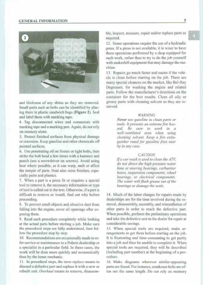
and thickness of any shims as they are removed.Small parts such as bolts can be identi fied by placing them in plastic sandw ich bags (F igu r e 2). Sealand label them with maskin g tape .4 . Tag disconnected wires and con nectors wit hmasking tape and a marking pen. Again, do not relyon memory alone.5. Protect finished surfaces from physical damageor corrosion. Keep gaso line and other chemicals offpain ted surfaces.6. Use penetrating oil on frozen or tight bolts, thenstrike the bolt head a few times with a hammer andpunch (use a screwdriver on screws). Avoid usingheat where possible, as it can warp, melt or affe ctthe temper of parts. Heat also ruins finishes, especia lly paint and plastics.7. When a part is a press fit or requires a specia ltool to remove it, the necessary informat ion or typeoftoo l is ca lled out in the text. Otherw ise, if a part isdifficult to remove or install , lind out why beforeproceedi ng.S. To prevent small obj ects and ab rasive dust fromfalling into the engine, cover all openings afte r exposing them.
9. Read each procedure complete ly while lookingat the actual parts before starting a job. Make surethe procedu ral steps are fully understood, then follow the procedure step by step.10. Recommendations are occas ionally made to refer service or maintenance to a Polaris dealership ora spec ialist in a particular field. In these cases, thework will be done more quickly and economica llythan by the home mechanic.11. In procedural steps, the term replace means todisc ard a defective part and replace it with a new orrebui lt unit. Overhaul means to remove, disassem -
5
ble, inspect, measure, repair and/or replace parts asrequired.
12 . Some operations require the usc of a hydraulicpress . If a press is not availab le, it is wiser to havethese ope ratio ns performed by a shop equipped forsuch work, rather than to try to do the job yourselfwith makeshift equipment that may damage the machine.
13. Repai rs go much faster and easier if the vehicle is clean before starting on the jo b. There aremany special cleaners on the mar ket, like Bel-RayDegrca scr, for wash ing the engine and relatedparts. Follow the manufacturer's direc tions on thecontainer for the best results. C lean all o ily orgreasy parts with cleani ng solvent as they are removed.
WARN INGNever use gasolin e to clean parts ortools. 11 presents all extreme fire hazani. Be sure 10 work in awell-ventilated area when usingcleaning solvent. Keep a fire extinguisher rated f or gasoline fires nearby in any case .
CAUTIONIf a car wash is used to clean tile Arv,do 1I0t direct tire high-pressure waterhose at steering hearings. carburetorhoses, suspension components, wheelbearings, or electrical components.The water wtllflusb grease out of thebearings or damage the seals.
14. Muc h of the labor charges for repai rs made bydealerships are for the time involved during the removal , disassembly, assembly, and reinsta llation ofothe r part s in order to reac h the defective part.When poss ible, perform the prel iminary operationsand take the defective unit to the dealer for repair atconsiderable savings.15. When special tools are required, make arrangcmcnts to get the m before starting on the job.It is frus trating and time-consuming to get partlyinto a job and the n be unable to com plete it. Whenspecial too ls are requ ired, they will be described(including part number) at the beginning of a procedure.16. Make diag rams wherever similar-appearingparts arc found. For instance, crankcase bolts arc often not the same length . Do not rely on memory
6
a lone to rep lace part s in their proper location. Thereis also the possibi lity of being side tracked and notable to return to wo rk for days or even wee ks, during whic h time the carefully la id out parts may become disturbed.17. Wh en assembling parts, make sure all shimsand wa shers are reins talled exac tly as they cam eout.18. Whenever a rotating part contacts a stationarypa rt , look for a shim or washer. Usc new gas kets ifthere is any doubt abou t the condition of the oldones. A thin coating of oil on non-pressure type gas kets may hel p them sca l morc effe ctive ly.19. Some components are he ld in p lace withse lf-loc king nut s. The locking ability of these nu tsis lessened every time they are insta lled or removed .
It is recommended that they be replaced every tim ethey are removed.20. Use co ld heavy greas e to hold sma ll part s inplace ifthcy tend to fa ll out during assembly. However, keep grease and oil away from electrical andbrake components.
TORQUE SPECIFICAT IONS
The materials used in the manufacture of the Pola ris may be subj ected to uneven stresses i f the fasten ers that hold the sub-a ssemblies are no t install edand tightened correctly. Loose or m issing fastenerscan ca use the cy linder head to warp. cra nkcaseleaks, and premature bearing and seal failure andsuspension failure from loose or m issing fa steners .Therefore, usc an accurat e torque wrench (described in this chapter) together with the torqu especifica tions listed at the end of mo st chapters.
Torque spec ifications throu ghout this manu a l nrcgiven in Ne wton-mete rs (Nsm). foot-po unds(f't.- lb.) and, where applicable, in inch- pounds( in.-Ib.).
Existin g torqu e wre nches calibrated in me ter kilograms can be used . Move the deci mal point oneplace to the right; for example, 3.5 mkg = 35 Nsm.The exact mathematica l convers ion is 3.5 mkg =
34.3 Nsm.To math emati cally convert foo t-pounds to New
ton meters mu ltiply the foot pounds spec ification by1.3558 to achieve a Nsrn equiva lent. For ex ample150 ft.- lb. x 1.3558 = 203 Nsrn .
Refer to Table 5 for general torque spec ificationsfor various size screws, bolt s and nuts not listed in
CHA PT ER ON E
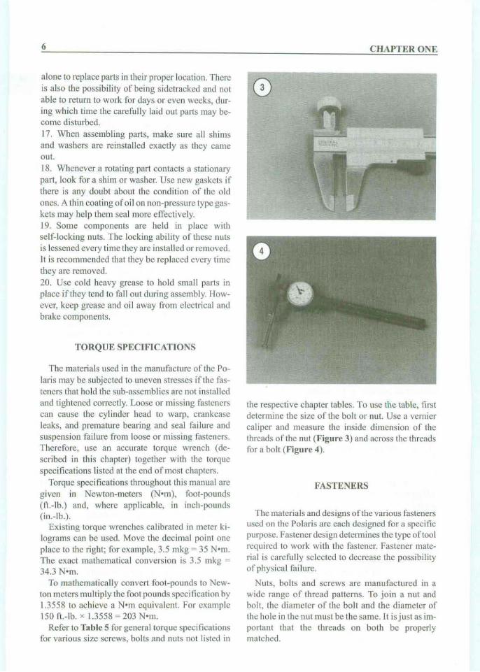
the respect ive chapter tables . To usc the tab le, firstdetermine the size of the bolt or nut. Use a vern ierca liper and measure the inside dimension of thethreads of the nul (F igur e 3) and across the threadsfor a bolt (F igure 4).
FAST ENERS
The mater ials and design s ofthe various fastenersuse d on the Polaris are each designed fe r a spec ificpurpose. Fas tene r des ign detennines: the type oftoo lrequ ired to wo rk with the fastener. Fas tener mat erial is carefu lly selec ted to decrease the possibilityof physical failure.
Nuts, bo lts and sc rews are manufactured in awide ran ge of thr ead pattern s. To join a nu t andbo lt, th e diameter of the bolt and the di am eter ofthe hole in the nut mu st be the same. It is j ust as important that the threads on both be pro perlymatched.
GENERAL INFORMATION
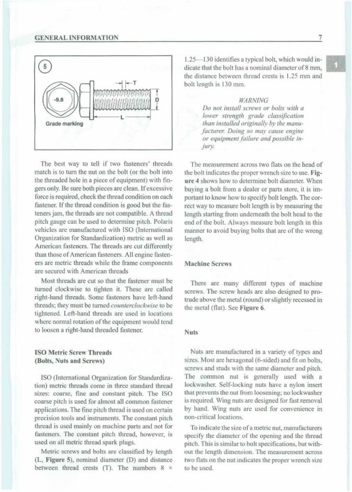
Grade marking
The best way to te ll if two fast ener s' threadsmatch is to turn the nut on the bolt (or the bo lt intothe threaded hole in a piece ofequipment) with fingers only. Be sure both pieces are clean. If excessiveforce is required, check the thread condition on eachfastener. If the thread condi tion is good but the fasteners jam, the thread s are not compatible. A threadpitch gauge can be used to de termi ne pitch. Polarisvehicles arc manufactured with ISO (InternationalOrganization for Standardization) metric as we ll asAmerican fasteners. The threads are cu t di fferent lythan those of American faste ner s. All engi ne fasteners are metr ic threads while the frame componentsare secured with American thread s
Mo st threads are cut so that the fasten er must beturned clockwise to tighten it These arc calledright-hand threads. Some fasteners have left-handthreads; they must be turned co unterclockwise to betightened. Left-hand threads are used in locat ionswhere normal rotation of the equipment would tendto loosen a right-hand threaded fastener.
ISO Metric Screw T hre ads(Bolls, Nu ts and Screws)
ISO (International Organization for Standa rdization) metri c threads come in three standa rd threadsizes: coarse, fine and constant pitch. The ISOcoarse pitch is used for almost all common fastenerapplications. The fine pitch thread is used on certainpreci sion tools and instrum ents. The constant pitchthread is used mainly on mac hine parts and not forfasteners . The constant pitch thread, however, isused on all metric thread spark plugs.
Metric screws and bolts are classified by length(L, Figure 5), nominal diameter (D) and distancebetween thread crests (T). The numbers 8 x
7
1.25-1 30 identifi es a typical bolt . which wou ld indicate tha t the bolt has a nomin al diameter of8 mm,the distance between thread crests is 1.25 111m andbolt length is 130 mm .
1I;·IRNINGDo not install screu-'s or bolts with alower strength grade classifica tionthan installed originally by the manufacturer. Doing so may calise engineor equ ipment failure and possible inj ury.
The mea surement acro ss two fl ats on the head ofthe bolt indi cates the prop er wrench size to use. Flgnrc 4 Sh O\\o'5 how to determine bolt diameter. Whenbuying a boll from a dealer or part s store, it is important to know how to spec ify bolt length . The correct way 10 measure bolt length is by measuring thelength starting from undernea th the bolt head to theend of the bolt. Always measure bolt length in thismanner to avoi d buy ing bolt s that are of the wronglength.
Machine Screws
There are man y different types of machin escrews . Th e screw head s arc also designed to pro trude above the metal (round) or slightly rece ssed inthe metal (flat) . See Figure 6.
Nuts
Nuts are manu factured in a variety o f types andsizes. Most are hexagonal (6-sided) and fit on bo lts,screws and studs with the same diamete r and pitch,The common nut is generally used with alockwasher. Self-locking nuts have a nylon inserttha t prevents the nu t from loosenin g; no lockwasheris requi red . Wing nut s are designed for fast removalby hand . Wing nuts are used for co nvenience innon -critica l locations.
To indicate the size ofa metric nut. man ufac turersspeci fy the d iameter of the ope ning and the threadpitch. Thi s is similar to bolt spec ifications. but with ou t the length dimension. The measurement acro sstwo flats on the nut indicates the proper wrench sizeto be used .

8
MACHINE SCREWS
CHAPTER ONE
Hex Flat Oval Fillister Round
Se lf-Locking Fasteners
Severa l types of bolts, sc rews and nuts incorporate a system that develops interference between thebo lt, screw, and nut or lapped hole threads. Interference is achieved in various ways: by distort ingthreads, coating threads with dry adhesive or nylon,distort ing the top of an all-metal nut, using a nyloninsert in the center orat the top of a nut.
Self-locking fasteners off er grea ter ho ldingstrength and better vibrati on resistance. These lf-locking fasteners used on the Po laris ATV cannot be reused. Others, like the nylon insertnut , forman initial lock ing condition when Lite nut is first insta lled; the nylon forms close ly 10 the bolt threadpattern, thus reducing any tendency for the nut toloosen . Always disca rd and replace selfClock ingfasteners after removal.
Washers
There arc two basic type s of wa shers: Ilat washers and lockwashers. Flat washers are simple discswith a hole to fit a screw or bolt. Lockwashers aredesigned to prevent a fastener fro m working loosedue to vibration. expansion and contraction.\Vashers can be used in the fo llowing functions:
I. As spacers.
2. To prevent galling or damage of the equipmentby the fastener.3. Tohelpdistribute fastener load during tightening.
4 . As seals.
Note that flat washers arc often used between alockwasher and a fastener to provide a smooth bearing surface. This a llows the fastener to be turnedeas ily with a tool.
NOTEAs much care should be given to theselection and purchase ofwashers asthat gi ven to bolts, nuts and other/asteners. Beware of washers that aremade 0/ thin and weak materials.These will deform and crush tile firs tlime they are used in a high-to rqueapplication.
Cotter Pins
Incertain applications. a fastener must be securedso it cannot possibly loosen. The rear hub on anATV is one of' these applications. Forthis purpose, acotterpin andslotted orcastellated nul is often used.To use a cotter pin. first make sure the pin fitssnugly, but not too light. Then align the slot in thefastener wi th thc hole in the bah or axlc .
Insert the cotter pin thro ugh the nul and bolt oraxle and bend the ends over to secure the cotter pintightly. If the holes do not align. tighten the nut j ustenough to obtain the proper alignment. Unless specifically instructed to do so. never loosen the fastcner 10 a lign thc slot and the hole. Because thecotter pin is weakened after installation and removal, never reuse a cott er pin. Cotter pins areavailable in several styles. lengths and diameters .Measur e the cott er pin length from the bottom of itshead to the lip of thc shortes t prong.
C irclips
Circlips can be internal or external in design.They are used to retain items on shafts (externaltype) or wit hin lubes (interna l type). In some app lications. circlips of varying thicknesses are used tocontrol the endplay of assemblies. These are often

GENE RA L II\'FORMATION
CD
Full'~~=;1;'7T s upportI" areas
j_ .... Rounded edges
1..tf111h Sharp edgesIf: ~'\ I
. ~m. ,"ru"
callcd selective circlips. Circl ips should bc rep lacedduring installation. as removal weakens and deforms them .
Two basic styles ofcirclips are ava ilable: machinedand stamped circlips. Machined circlips (F igure 7)can be installed in either direction (shaft or housing)because both faces are machined. thus creating twosharp edges. Stamped eircl ips (Figure 8) are manufactured with one sharp edge and one rounded edge.When installing stamped circlips in a thrust situationas on transmission shafts. the sharp edge must faceaway from the part producing the thrust. When installing circlips, observe the followin g:
I. Compress or expand circlips only enough to insta ll them .
2. After the circlip is installed, make sure it is completely seated within its groove.
3. Transmission circlips become W Ont with lise antiincrease sideplay. Forthis reason. always install newcirclips whenever a transmission is reassembled.
9
LUBRICANTS
Periodi c lubrication assures long Iifc for any typeof equipme nt. The type of lubricant used is just asimportant as the lubrication service itself, althoughin an emergency the wrong type of lubricant isbeller than none at all. The following para graphsdescribe the types of lubricants most often used forATVs. Be sure to follow the manufacturer's recommendations for lubricant types.
Genera lly a ll liquid lubricants are ca lled oil. Theymay be mineral-based (including petroleum bases) ,natural-based (vege table and animal bases). synthetic-based or emu lsions (mix tures ). Grease is oilto which a thickening base has been add ed so thatthe end prod uct is se mi-solid. Grease is often classified by the type ofthiekcner added; lithium soa p iscommonly used ,
Engine Oil
Engi ne oi l is classifi ed by two standards: theAmerican Petroleum Institute (API) service classification and the Society of Au tomotive Eng ineers(SA E) viscosity rating. Th is informat ion is on theoil co ntainer label. Two leiters indica te the API service c lassification. The number or sequence ofnumbers and leiter ( IOW-40 for exa mple} is the oil'sviscosity rating. The API service classification andthe SAE viscosity index are not indications of oilquality.
The service classification indicates that the oilmeets specific lubri cation standards. The first leiterin the c lassification S indicates that the oil is for gasolin e engines . The second leiter indicates the stan dard the oil satisfies . The classificat ion started withthe leite r A and is current ly at the lette r 1.
Always lise an oil wit h a classification recommended by the manufacturer. Using an oil with aclassification different than that recommended cancause engine damage.
Viscos ity is an indication of the oil's thickness.Thin oils have a lower number whil e thick oils havea higher number. Engine oils fall into the 5- to
50-we ight range for single-g rade oils.Most manufacturers recommend multigrade oil.
These oils perform efficiently across a wide rangeof operating conditions. Multigrade oil s are identified by a IV after the first number, which indicatesthe low-temperature viscosity.

10
Engine oils an: 1110 St commonly mineral (petroleum) based; howeversynthetic and semi-synthetictypes are used more frequently. When selecting engine oil, follow the manufacturer's recommendation for type, classifica tion and viscosity.
Grease
The National Lubricating Grease Institute(N LG I) grades greases . Grea ses arc grad ed by numberaccording to the consistency of the grease; theserange from No. 000 to No. 6, with No. 6 being themo st solid. Typica l multipurpose grease is NLGINo.2. For specifi c applications, equipment manufacturers may require grease with an additive suchas mo lybd enum disulfide.
T H REA Il LOC KI :'oIG CO M POU:'oIIl
A threadloc king co mpound should be used tohelp securemany of the fasteners used 0 11 the vehicle . A threadlock co mpound will lock fastenersagainst vibration loosening and seal against leaks.The followin g thread lockin g compounds are recommended for many threadlock requirements described in this manual.\. Thrcelsond TB1342 (b lue): low-stren gth , frequent repair.2. Loctit e No. 242 (b lue): low-stren gth , frequentrepair.3. ThreeBond T B13 60 (green) : medium-strength,high temp erat ure.4 . Threels ond No . 1333 B (red) : medi um-strength,bearing and stud lock .5. Three Bond TB1303 (orange) : high-strength , infrequent repair.6. Locti te No. 27 1 (red): high- stren gth, infrequentrepair.
There are other quality thrcadlock brands on themarket.
RTV GASKET SEA LANT
Room temperature vulcanizing (RTV) sealant isused on some preformed gaskets and to seal somecomponents. RTVis a silicone gel supplied in tubesand is available at motorcycle and automotive supplies stores and major hardware stores.
Moisture in the air causes the RTV to cure. Always place the cap on the tube as soon as possible
C HA PTE R ONE
whe n using RTV . RTV has a she lf life of approximately one yearand will not cureproperly when theshe lf life has expired. Check the expirat ion date onthe RTV tube prior to purchasing a new tube and onusing the sealant. Keep partially used tubes tightlyscaled and discard them after the expiration date.
A(lIJlying RT V Sealant
Clcan all o ld gask et residu e from all mating surfaces. Remov e all RTV gas ket material from blindthreaded holes; it can cause a hydraulic lock andaffect bolt torque. leading to the bo ll not be ing tightened to the correct torque specifi cation. Finally,spray the mating surfaces with an aerosol partscleaner and wipe with a lint-free cloth.
Apply RTV sealant in a continuous bead 2-3 ITIm
(0 .08-0 .12 in.) thick . Circle all mounting holes unless otherwi se spec ified. Do not allow an y sea lan t toenter these holes. Assemble and tighten the fasteners to the specified torque within 10 minutes afterapplication.
EXPEN IlA BLE SU PP LIES
Certa in expendable supplies are required duringmaintenance andrepairwork . These include grease,oil. and gasket cement, wiping rags and cleaningsolvent. Ask the dealership for the special lockingcompounds. silicone lubricants and other products,which make vehicle maintenance simpler and easier. Cleaning solvent or kerosene is available atsome service stat ions, paint or hardware stores.
Be sure to follow the manufacturer's instructionsand warn ings listed on the label of the product beingused, Some cleaning supplies arc very caustic andare dangerous ifn ot used properly.

GENERAL INFORMATIOI'O II
WARNI NGHa ring a stack ofclean shop rags Oil
hand is important when pel/armingengine and suspens ion service work.Ho we ver. a pile of solvent-soakedrags presents a f ire hazard. Storethem in a sealed metal container /lI1
til they can be washed or properlydisca rded.
NO TE70 p revent so lvent and other chemicals fro m being absorbed into theskin. Il'ear a pair of petroleum-resistant gloves when cleaningpa rts. These can be purchasedthrough industrial supply houses 01'
well-equipped hardware stores.
SERIAL NUMIlERS
Polaris makes frequent changes during a modelyear- some minor, some relatively major. Whenordering parts from the dealership or other parts distributor, always order by VIN and engine serialnumbers. The serial number locations arc as follows:
I. Model and YIN number (Figure 9) is stampedon the left lower frame rail near the rear portion ofthe front A-arm mount. On some models. a decalwith the YIN number is located on the front fendercover (Figure 10).
2. Engine serial number (Figure II) is stamped ona pad on the center top of thecrankcase beneath thecylinder coolant elbo w,
3. The transmission serial numberis locatedon topof the transmission case below the shin bell crankand on a label on the right side (Figure 12).
4. The carburetor serial number (Figure 13) is located on the left side of the carburetor body.
Enter these numbers on the chart in the QuickRefe rence Data table at the front of this book andkeep them for reference . Compare new parts to theold ones before huying them. If they are not alike,have the parts manager explain the difference. Table 1 lists the model numbers for the mode ls co vered in this manual.

12
WAR;;ING AND INFORMATION LABE LS
A number of warning labels (F igure 14) arc attachcd to the Polaris. These labels conta in information that is important to personal safety whenoperating. transporting and storing the vehicle. Alsorefer to the inform ative labels fastened to the various co mponents on the vehicle. as this informationis very useful. Referto the own er 's manual fora description and location of each label. If a label ismissing, order a replacement label from a Polarisdea lership.
BASI C llANO TOOLS
Many of the procedures in this manual can be carried out with simple handtools and test equipmentfamiliarto the home mechanic. Keep all tools cleanand in a toolbox. Keep them organi zed with thesockets and related drive s together, the open-endcombination wrenches together, etc. After using atool, wipe off dirt andgrease with a clean cloth andreturn the tool to itscorrect place.
Top qua lity tools are essential; they are also moreeconomical in the long run. Ifju st startingtobuild atool collection, stay away from the advertised specials featured at some parts houses, discount storesand chain drug stores. These are usually poor gradetools that arc made of inferior material. and arcthick , heavy and clumsy to use. Their rough finishmakes them difficult to clean and they usually donot last very long. The wrenches do not fit the headsof bolts and nuts correctly and may dama ge the fa stener.
Quality tools arc made of alloy stee l and archeat-treated for greater strength. They are lighterand better balanced than infer ior ones. Their surfaceis smooth.making them a pleasure to workwith andeasy to clean. The initial cost of good quality toolsmay be more, but they are more economical in thelong run. Do not try to buy everything in all sizes inthe beginning: buy a few at a time until all the necessary tools arcon hand.
Screwd rivers
The screwdriver is a very basic too l, but if usedimproperly it will do more damage than good. Theslot on a screw has a definite dimension and shape.A screwdriver must be selected to conform to that
CIIAPTER O;;E
shape. Use a small screwdriverforsmall screws anda large one for large screws, or the screw headwillbe damaged.
Two basic types of screwdrivers are required:common (flatblade) screwdrivers and Phillipsscrewdrivers.
Screwdrivers arc available in sets that oft en include an assortment ofcommon and Phillips blades.If purchased individually, buy at least the following:I. Common sc rewdriver- 5!16 x 6 in. blade.2. Common screwdriver-3/8 x 12 in. blade .
3. Phillips screwdriver-size 2 tip, 6 in. blade.
4. Phillips screwdriver-size 3 tip, 6 and 10 in.blade.
Use screwdrivers only fordriving screws. Neverusc a screwdriver for prying or chiseling metal. Donot try to remove a Phillips or Allen head screwwith a common screwdriver (unless the screw has aco mbination head that will accept either type); if thehead is damaged, the proper tool will be unable toremove it. Keep screwdrivers in the proper condition and they will last longer and perform better. Always keep the tip ofa common screwdriverin goodcondition.
Pliers
Pliers come in a wid e range of type s and sizes.Pliers are useful for cutt ing, bend ing and crimping.Do not usc them to cut hardened objects or to tumbolts or nuts. Each type of pliers has a speciali zedfunction. Slip-joint pliers are general purpose pliersand are used mainly for holding things and forbending.

GENE RAL INFORMATIO N 13
Circlip Pliers
Locking Pliers
Circ lip pliers (Fig ure 15) are made for removingand installing circ lips. Externa l pliers (spreading)are used to remove circlips that fit on the outs ide ofa shaft. Internal pliers (squeezing) are used to remove circlips which fit inside a gear or housing.
II
Box, O pen-End and Combination Wrenches
An adjustab le wrenc h (sometimes ca lled crescentwrenc h) ca n be adju sted to fit nearly any nut or bolthead that has clear access around its entire perimeter. Adjustable wrenches are best used as a backupwrench to keep a large nut or bolt from turningwhi le the other end is being loosencd or tightenedwith a box-end or socket wre nch,
Adjustab le wrenches have on ly two gripp ing surfaces which make them more subject to slipping ofTthe fastener and damaging the part and possibly
Adjustable Wrenches
WARNINGBecause circlips call sometimes slipamifly of]when removing and installing them. always wear safety glasseswhen using them.
Open-e nd, box-end and combination wrenchesare ava ilable in set s or separately in a variety ofsizes . On open and box end wrenches, the numberstamped near the end refers to the distance betweentwo parallel flats on the hex head bolt or nut. Oncombination wren ches, the number is stamped nearthe center.
Open-end wrenches (A, Figure 16) are speedyand wor k best in areas with limited overhead access. Their wide, flat j aws make them unstable forsituations where the bolt or nut is located in a boreor close to the edge of a casting. These wrenchesgrip only two flats of a fasten er; if either the fastenerhead or the wrenc h jaws are worn, the wrench mayslip ofT.
Box-end wrenches (B , Figu re 16) require clearoverhead acce ss to the fastener but can work well insituations where the fastener head is close to another pa rt. Th ey grip on all six edges of a fastenerfor a very secure grip. They are avai lable in either6-point or 12-po int. The 6-po int gives superiorholding flower and durab ility but requires a greaterswinging radiu s. The 12-po int works better in situations where the sw inging radius is limited.
Combination wrenches (C. Figure J6) haveopen-end on one s ide and box-end on the other withboth ends being the same size. Professional mechanics favor these wrenches because of thei r versatility.
o
:s K~...~~~
A
®o Q!
Locking pliers are used to hold objec ts verytightly like a vise. But avoid using them unless necessary since their sharp jaws will perm anently scarany objects that are held. Locking pliers are available in many types for more specifi c tasks.
Need lcnosc pliers are used to ho ld or bend smallobjects. Water pump pliers can be adjusted to holdvarious sizes of objects; the jaws remain parallel togrip arou nd objects such as pipe or tubing. There arcmany more types of pliers. The ones described hereare most suitable for vehicle repairs.

14
causing injury . The fact that one jaw is adjustableonly aggravates this shortcoming.
These wrenches are directional: the so lid jawmust be the one transmitt ing the force. If the adjustable jaw is used (0 transmit the force. it wi ll loosenand possibly slip o tT.
Socket Wrenc hes
®
CHA PT ER ONE
This type of wrenc h is undoubtedly the fastest,safes t and most convenient to use. Sockets. whichattac h to a ratchet handle. are avai lable with 6-point(A, Figure 17) or 12-point (B, Figure 17) openings (;;;\and 1/4, 3/8. 1/2 and 3/4 in. drives. The drive size ~indica tes the size of the square ho le which mateswith the ratchet handle.
Allen Wrenches
A B
Allen wrenches are available in sets or separatelyin a variety of sizes. These sets come in SAE andmetric sizes . Allen bolts arc sometimes calledsocket bolts. Sometimes the bolts are diffic ult toreach and it is suggested that a variety or Allenwrenches be purchased, such as the socke t driven.T-handle and extension type.
Torq ue Wrench
A torque \...Tench is used with a socket to measurehow tight ly a nut or bolt is insta lled. They comewith either 1/4.318 or 1/2 in. square drive (F igure18). The drive size indicates the size of the squaredrive that mates with the socket.
Impact Driver
This tool might have been designed with the ATVmechanic in mind. This tool makes removal of fasteners easy and eliminates damage to bolts andscrew slots. Impact drivers (Figure 19) and interchangeable bits are avai lable at most large hardware , vehicle or auto parts stores. Sockets can alsobe used wi th a hand impac t drive r; however, makesure that the socket is designed for use with an impact driver or air tool. Do not use regular hand sockets, as they 1113y shatter during use.
Hammers
The correct hammer is necessary for certain repairs. A hammer with a face (or head) of rubber orplastic or a soft-faced type tilled with bucksho t issometimes necessary in engine disassem bly. Neverusc a metal-fa ced hammer on engine or suspensionparts. as severe damage will result in most cases .The same amo unt of force can be produced with asoft-faced hammer. The shock of a metal -facedhammer, however, is required for using a hand impact driver or cold chisel.
Support Jacks
The correct type of support jack is necessary formany routine service or major component replacement procedures on the vehicle . The centerstandscissor ja ck is suitable for most service procedureson this serie s of vehicles. It is adjustable and is verystable for usc with the frame configurat ion of thisvehic le.
Also, the standard floor jack may be used forsome applications, To protect all engine and frame
G ENERA L INFORMAT IO N
®
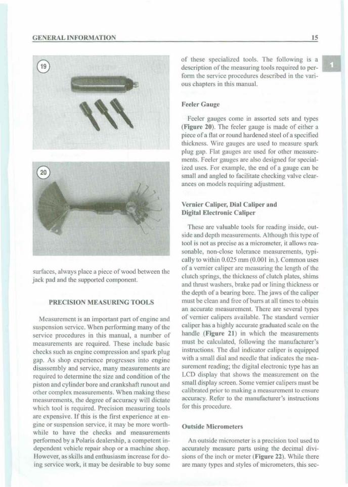
surfaces, always place a piece of woo d betwe en thejack pad and the supported compon ent.
PRECISION l\IEASURl:O;G TOOLS
Measurement is an important partofengine andsuspension service. When per formi ng many of theservice procedures in this manual, a number ofmeasurements are required. These include basicchecks such as engine compression and spark pluggap. As shop ex perience progresses into enginedisassembly and service. many measurements arcrequired to determine the size and condition of thepistonand cylinderbore and crankshaft runout andother complex measurement s. When making thesemeasurements, the degree of accuracy wi ll dictatewhich tool is required. Precision measuring toolsarc expensive. If this is the first experience at engine or suspension service, it may be more wo rth whi le to have the checks and measurementsperformed by a Polaris dealership. a competent independent vehicle repair shop or a machine shop.However, as skills and enthusiasm increase fordoing service work, it may be desirab le 10 buy some
15
of these spec iali zed too ls. The follow ing is adescription oft he measuring tools required to perform the service procedures described in the various chapters in this manual.
Feeler GauJ.:c
Feeler gauges come in assorted sets and types(Fig ure 20 ). The feeler gauge is made of either apiece ofa nat or round hardened steel ofa spec ifiedthickness. Wire gauges are used to measure sparkplug gap. Flat gauges arc used for other measurements. Feeler gauges are also designed for specialized uses. For example. the end of a gauge can besmall and angled to facilitate check ing valve clearances on models requiring adjustment.
Ver nier C aliper, Dia l C aliper andDigital Electronic Caliper
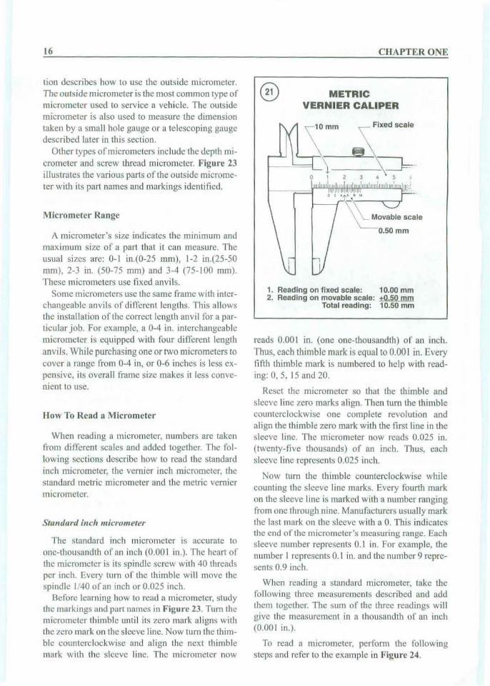
These arc valuable tools for reading inside, outside and depth measurements. Although this type oftool is not as precise as a micrometer. it allows reasonable, non-close tolerance measurements, typically to within 0.025 mrn (0.00 1 in.). Common usesof a vern ier caliper arc measuring the length of theclutch springs, the thickness ofclutch plates. shimsand thrust washers, brake pad or lining thickness orthe dcpth of a bearing borc. The jaws of the ca lipermust be c1can and frcc ofburrs at all times to obtainan accurate measurement. There are several typesof vernier calipers available. The standard vernierca liper has a highly accurate graduated scale on thehandl e (Figure 21) in which the measurementsmust be calc ulated, follow ing the manufacturer'sinstructions. Th e dial indicator ca liper is equippedwith a small dia l and needle that indicates the measurement reading; the digital electronic type has anLCD display that shows thc measurement Oil thcsmall display screen. Some vern iercalipersmust becalibrated prior to making a measurement to ensureaccuracy. Refer to the manufacturer's instructionsfor this procedure.
Outside l\l icrometcrs
An outside micrometer is a precision tool used toaccurately measure parts using the decimal divisions of the inch or meter (Figure 22). While thereare many types and styles of micrometers. this sec-
16 CHAPTER ONE
@ METRICVERNIER CALIPER
10.00 mm+0. 50 rom10.50 mm
o
1. Reading on fixed scale:2. Read ing on movable sca le:
Total reading:
'\10 mm ~Flxed scale
\ :-----"ief----"==l-) s:=J=-..
2 J 4 5 :
'!I""I""I"uli'- IlIII!':·::.I i lilt 'C:Jr
• , .\ ( Movable sc:',e
0.50 mm
reads 0.001 in. (o ne one-thousandth) of an inch.
Thus, eac h thi mb le mark is equal to 0.001 in. Everyfift h thimble mark is numbered to help with reading : 0, 5. 15 and 20.
Reset the mi crometer so that the th imbl e andsleeve line zero marks align . Then tum the thimblecounterc loc kwise one complete re volution andalign the thimbl e ze ro mark with the first line in thesleeve line. The micrometer now rea ds 0.025 in.(twenty- five thou sands) of an inc h. Thus, cachsleeve line represents 0.025 inch.
Now tum the thimble counterclockwise whilecounting the s leeve linc mark s. Every fourth markon the sleeve line is marked with a number rangingfrom one throu gh n ine. Manufacturers usuall y markthe last mark on the sleeve wit h a O. Thi s indi cat esthe end of the microme ter 's measuring range. Eachsleeve number rep resents 0.1 in. For exa mple, thenumber I represents 0.1 in. and the number 9 represents 0.9 inch.
When reading a sta ndard micrometer. tak e thefollowi ng three measurements described and addthem togeth er. The sum of the three rea ding s willg ive the measurem ent in a thousandth of an inch(0.00 1 in.).
To read a micro meter. perform the followingsteps and refer to the exam ple in Figure 24.
A micrometer 's size indicates the minimum andmaximum size of a part that it can measure. Theusual sizes are : 0- 1 in.(0-25 mm) , 1-2 in.(25-50mm), 2-3 in. (50- 75 mm) and 3-4 (75-100 mm ).
These mi crometers lise fixed anv ils.So me micrometers use the same frame with inter
cha ngeable anvils of di fferent leng ths. Thi s allowsthe installation of the correct length an vi l tor a particular j ob. For example, a 0-4 in. interchangeab lemicrometer is equipped with four different length
anvi ls. While purchasing one or tw o microm eters tocover a range from 0-4 in, or 0-6 inches is less expensiv e, its overa ll frame size makes it less conve nien t to usc.
The sta nda rd inch micro meter is uccuratc toone- tho usa ndth of an inch (0 .00 1 in.) . The heart ofthe micrometer is its spindle screw with 40 thread sper inch . Eve ry tum of the thi m ble will move thespindle 1/40 of an inch or 0.025 inch.
Before lea rn ing how 10 read a micrometer, studythe markings and part nam es in Figure 23. Tum themicrometer thimble until its zero mark aligns wi ththe ze ro mark on the sleeve line. Now tum the thimble counterclockwise and a lign the next thimblemark with the slee ve line. The micrometer now
lion describes how to usc the outs ide mi crometer.The outside micrometer is the mos t commo n type ofmicro meter used to service a vehicle, The outsidemicrometer is also used to measure the dimensiontak en by a small hole gauge or a tele scopi ng gaugedescrib ed later in this section.
Other types of m icrometers include the depth micrometer and screw thread micrometer. Figure 23illustrates the various pari s of the out sid e micrometer with its part names and markings identified .
How To Read a Micrometer
l\lic romcter Range
Sta ndard inch micrometer
When reading a micrometer, numbers are takenfrom di fferent scales and add ed together. Th e following sections describe how to read the standardinch mic rom eter, the vernie r inch microm eter, thestandard metr ic micro met er and the metr ic vern iermicrometer.
GE:'/ERAL INFOR:\lATlON 17
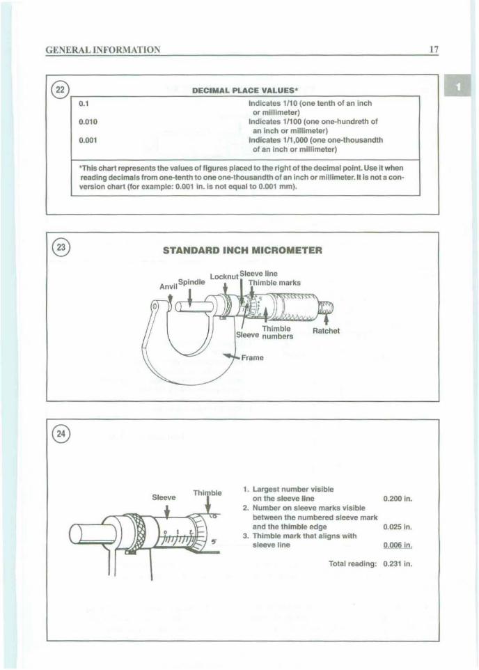
DECIMAL PLACE VALUES'
Indicates 1110(one tenth of an inchor millimeter)
Indicates 11100(one one-hundreth ofan Inch or millimeter)
Indicates 111,000 (one one-th ousandthof an inch or millimeter)
0.001
0.1
0.01 0
@r--------==:::...:...=:=.::...=-=--------,
*Thls chart represents the values of figures placed to the right of the decimal point. Use it whenreading dec ima ls from one-tenth to one one-thousandth of an Inch or millimeter. It Is not a conversion chart (for example: 0.001 in . Is not equal to 0.001 mm).
STANDARD INCH MICROMETER
Locknut Sleeve lineThimble marks
1. Largest number visibleon the sleeve line 0.200 In.
2. Number on sleeve marks visiblebetween the numbered sleeve markand the th imble edge 0.025 in.
3. Thimble mark that aligns withsleeve line Q.QO§Jn,
Total reading: 0.231 in.

18 CHAPTER ONE
VERNIER INCH MICROMETER
Vern ier sca le
,-0•'-
Vern ier sca le
Thimble
tvernier.scale
o --"t-
'" - - "t-O>,, _ _ r-o> - - .r-", __-r-- O
~ ==E0--"""'--_ 20
o
1. Largest num ber visi bleon sleeve lin e 0.100 In.
2. Number of sleeve marks vi siblebetween the nu mbered sleevemark and the thimble edge 0.050 In.
3. Thimble Is between O.D1S and0.019 in. on the sleeve line 0.018 In.
4. Vernier line coinciding withthimble line 0.0003 In.
Total readi ng : 0.1683 In.
Sleeve Th imble
I. Read the sleeve line to find the largest numhervisib le-each sleeve number mark equals 0.100inch.
2. Count the number of sleeve marks visible between the numbered sleeve mark and the thimbleedge-each sleeve mark equals 0.025 inch. If thereis no visible sleeve marks. continue to Step 3.
3. Read the thimble mark that lines up with thesleeve line-each thimble mark equals 0.00 I inch.
NOTEIf a thimble mark does not line up eractl y with the sleeve line but fa lls between two lilies. estimate the fra ctiona/decimal amount between the lines.