contents · pdf filecontents technical metal industrial co. l.l.c. ... we added new production...
TRANSCRIPT

R

Contents
Technical Metal Industrial Co. L.L.C.
Introduction3
4567
89
10111213
1415171819
202122
23
Concealed / Clip-In SystemsConcealed / Clip-In TilesMain SuspensionInstallation Method
Exposed Ceiling SystemsLay-In / Lay-On TilesTEE 15/24 Grid Main SuspensionFine Grid Main SuspensionEdge TrimInstallation Method
Ceiling TilesPlain / Decorative / Perforated TilesSpecial Decorative TilesGypsum TilesSound Absorption
Ceiling Strip SystemsCeiling StripCeiling Strip Main Suspension Self Supporting Ceiling StripInstallation Method
2425272829
303133
343539
40
42
44
45
Open Cell SystemsOpen Cell Systems Installation MethodOpen Cell with T-Grid Suspension SystemInstallation Method
Dryline Furring Channel SystemsDryline Furring Channel SystemsInstallation Method
Drywall Partitioning SystemsDrywall Partitioning SystemsInstallation Method
Additional Products
Accessories
Technical Speci�cations
Ordering Information
“We, at Technical Metal Industrial Co. L.L.C. take pride in declaring the company’s commitment to satisfy our customers by providing high quality products and promptly delivering them as per the agreed contractual requirements”.

TECHNICAL METAL INDUSTRIAL Co. L.L.C.R
R
Ceiling Suspension Systems & PartitionsIntroduction
3
Global GROUP Global GROUPOHSAS 18001
Reg. No. 18O08961
ISO 9001
UKASQUALITY
MANAGEMENT
Reg. No. 80Q08961
039
TMI is a privately owned company, established in 1997 in the Emirate of Abu Dhabi, United Arab Emirates and located on approximately 850,000 square feet in the Industrial City of Abu Dhabi (ICAD).
Specializes in metal processing and manufacturing of Expanded Metal & Plastering Accessories, Roll Formed Pro�les, Suspended Ceiling Systems, Cable Management Systems, Metal Doors & Frames, Industrial Shelving, Metal Cabinets, Gratings, Metal Ladders and specialized building material products. We are ISO 9001, 14001 & 18001 Certi�ed company. Our emphasis is on quality products catering to today’s competitive and demanding business environment. By introducing the latest, advanced technologies in our production lines, we ensure that our high production targets are achieved.
Furthermore, with deep knowledge in our manufacturing systems’ capabilities, our products have achieved a very high quality standards in this industry. Having earned a reputation as a manufacturer and supplier of quality products, we fully recognize that constant improvement is a vital requirement for our continued success.
Ceiling Suspension Systems are considered an important substitution for ordinary ceiling which is widely used in di�erent locations either indoor or outdoor. Through the last 30 years, Ceiling Systems have under gone a lot of improvements and developments, depending on the place of usage and the way of assembly.
We added new production lines of Ceiling Suspension Systems to meet the clients’ projects expectation by o�ering a wide range of choices with the highest standards and best quality. Our items conform to the British (BS) and American (ASTM) standards in all stages of manufacturing. Perforated and plain metal tiles, in both standard and tailor made sizes are available for both Concealed & Lay-In and variety of Exposed Grid Suspension System. We o�er the virtue of access with clean and crisp appearance that a metal ceiling provides.

R
TECHNICAL METAL INDUSTRIAL Co. L.L.C. R
4
System Description
A system where the grid is not visible specifically designed for metal tiles. The system comprises a “spring T” or ‘A spring” that supports the tiles. This system is fixed to and below a primary grid, usually a galvanized channel section. (Direct suspension of the tile carrying component is possible, but not common).
CONCEALED / CLIP-IN SYSTEMS

R
TECHNICAL METAL INDUSTRIAL Co. L.L.C.R
5
Concealed / Clip-In SystemsConcealed / Clip-In TilesMain SuspensionInstallation Method
Tile Description: Tiles are manufactured from Steel and Aluminium with Square or Bevelled edges. The tiles are usually painted (Pre-coated or powder coated) and the face may be plain, perforated or decorative. The holes of specified diameter can be in straight rows, on a diagonal pitch (skewed) or with different designs.
The tiles have on their upturned edges, an arrangement of ‘pips’ that locate into the tile supporting section. A method of controlling the level of the tile face when installed (referred to as the ‘stop’) will also be incorporated.
TCI-33 300 300 0.5/0.6/0.7 0.4/0.5 88TCI-36 300 600 0.5/0.6/0.7 0.4/0.5 44TCI-66 600 600 0.5/0.6/0.7 0.4/0.5 22TCI-612 600 1200 0.5/0.6/0.7 0.4/0.5 22TCI-618 600 1800 0.5/0.6/0.7 0.4/0.5 22
Reference Dimensions Thickness Qty / Box A B Aluminium Galvanized
Finish Coating: Pre-Coating Aluminium Tiles ECCA (European Coil Coating Association) conform to ASTM B-209M & European Norms: EN 485-4:1993 standards; Aluminium alloy / temper:3005 / H27 & 3105 / H25. Note: ECCA.
Powder Coating to BS 6497:1984; Aluminium alloy / temper: 3005 / H24 conform to ASTM B-209M & European Norms: EN 485-4:1993.
Bevelled Type Square Type
Special lengths required above 1800mm are available upon request.TCI (Tiles Clip-In) Note: All dimensions are in mm.
Edge Details: Bevelled / Square
Concealed / Clip-In Tiles
TECHNICAL METAL INDUSTRIAL Co. L.L.C. R
R
Concealed / Clip-In System
6
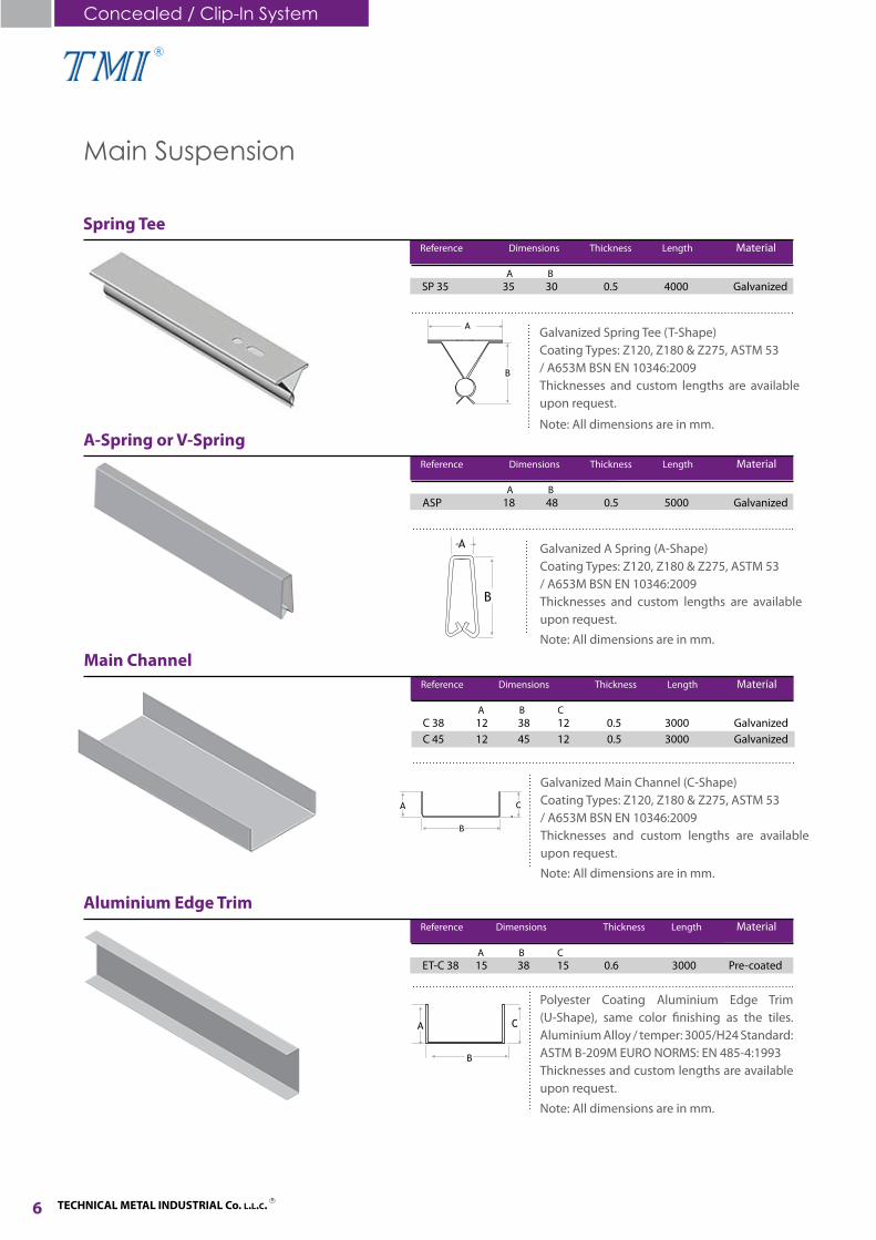
Galvanized Spring Tee (T-Shape)Coating Types: Z120, Z180 & Z275, ASTM 53/ A653M BSN EN 10346:2009Thicknesses and custom lengths are available upon request.
Spring Tee Reference Dimensions Thickness Length Material
SP 35 35 30 0.5 4000 Galvanized
Note: All dimensions are in mm.
A B
Galvanized A Spring (A-Shape)Coating Types: Z120, Z180 & Z275, ASTM 53/ A653M BSN EN 10346:2009Thicknesses and custom lengths are available upon request.
A-Spring or V-Spring Reference Dimensions Thickness Length Material
ASP 18 48 0.5 5000 Galvanized
Note: All dimensions are in mm.
A B
Main Suspension
A B C
Polyester Coating Aluminium Edge Trim (U-Shape), same color finishing as the tiles. Aluminium Alloy / temper: 3005/H24 Standard: ASTM B-209M EURO NORMS: EN 485-4:1993Thicknesses and custom lengths are available upon request.
Aluminium Edge Trim Reference Dimensions Thickness Length Material
ET-C 38 15 38 15 0.6 3000 Pre-coated
Note: All dimensions are in mm.
Galvanized Main Channel (C-Shape)Coating Types: Z120, Z180 & Z275, ASTM 53/ A653M BSN EN 10346:2009Thicknesses and custom lengths are available upon request.
Main Channel Reference Dimensions Thickness Length Material
C 38 12 38 12 0.5 3000 GalvanizedC 45 12 45 12 0.5 3000 Galvanized
Note: All dimensions are in mm.
A B C

TECHNICAL METAL INDUSTRIAL Co. L.L.C.R
R
300 / 600mm
600mm
Secondary System
Installation Method
Primary System
1. Level marking on wall using water level method or Laser method. 2. Fixing of Aluminium Edge Trim (U Shape) or W Angle with screws and nails.3. Fixing of AC-51 Hanging wires 3mm / 4mm, or channel support either threaded rod from soffit of slab with Ceiling Clip and Cartridge or screws or DBZ anchor. 4. Using of AC-50 Adjustable Spring Clips for Ceiling Adjustment of the AC-51 Hanger Wire, which should fit inside the Adjustable Clip hole or Channel Clamp in case of threaded rod use.5. Installation of Main Channel at every 1200mm and Spring Tee at every 600mm connected together with AC-54 preformed galvanized mild steel wire clip.6. AC-53 Main Channel bracket, to be inserted inside the Main Channel and to be hung from the upper part of it with the use of hanger wire which it will pass through AC-50 Adjustable Spring Clip for leveling. 7. Fixing of Aluminium Tiles in proper way taking into consideration the ceiling level & design pattern.8. Cut apertures for lights and other services where required. Cut trim for access opening for equipments, if required.
7
Black Fleece
Hanging Wire
Spring Tee
Adjustable Spring Clip
Aluminium Edge Trim
Aluminium Edge Trim
Hanging Wire
Black Fleece Spring Tee
Adjustable Spring Clip
Main Channel
Wire Clip
Spring Tee Hanger
R
TECHNICAL METAL INDUSTRIAL Co. L.L.C. R
8
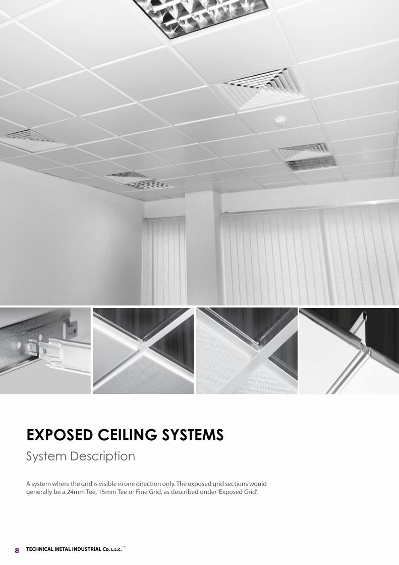
System Description
A system where the grid is visible in one direction only. The exposed grid sections would generally be a 24mm Tee, 15mm Tee or Fine Grid, as described under ‘Exposed Grid’.
EXPOSED CEILING SYSTEMS
R
TECHNICAL METAL INDUSTRIAL Co. L.L.C.R
Exposed Ceiling SystemsLay-In / Lay-On TilesTEE 15 / 24-Grid Main SuspensionFine Grid Main Suspension
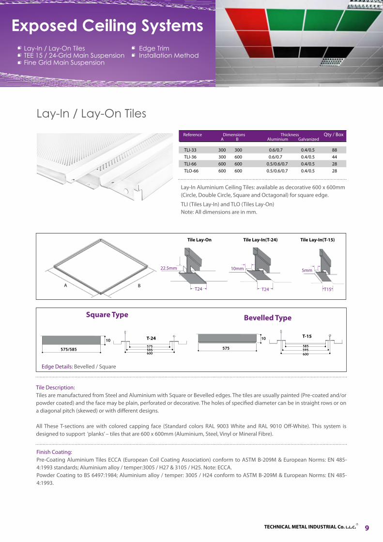
Tile Description: Tiles are manufactured from Steel and Aluminium with Square or Bevelled edges. The tiles are usually painted (Pre-coated and/or powder coated) and the face may be plain, perforated or decorative. The holes of specified diameter can be in straight rows or on a diagonal pitch (skewed) or with different designs.
All These T-sections are with colored capping face (Standard colors RAL 9003 White and RAL 9010 Off-White). This system is designed to support ‘planks’ – tiles that are 600 x 600mm (Aluminium, Steel, Vinyl or Mineral Fibre).
TLI-33 300 300 0.6/0.7 0.4/0.5 88TLI-36 300 600 0.6/0.7 0.4/0.5 44TLI-66 600 600 0.5/0.6/0.7 0.4/0.5 28TLO-66 600 600 0.5/0.6/0.7 0.4/0.5 28
Reference Dimensions Thickness Qty / Box A B Aluminium Galvanized
Finish Coating: Pre-Coating Aluminium Tiles ECCA (European Coil Coating Association) conform to ASTM B-209M & European Norms: EN 485-4:1993 standards; Aluminium alloy / temper:3005 / H27 & 3105 / H25. Note: ECCA.Powder Coating to BS 6497:1984; Aluminium alloy / temper: 3005 / H24 conform to ASTM B-209M & European Norms: EN 485-4:1993.
Edge TrimInstallation Method
9
TLI (Tiles Lay-In) and TLO (Tiles Lay-On) Note: All dimensions are in mm.
575/585
10575
600595 595575
10
585
600
Edge Details: Bevelled / Square
T-24 T-15
Bevelled TypeSquare Type
Lay-In Aluminium Ceiling Tiles: available as decorative 600 x 600mm (Circle, Double Circle, Square and Octagonal) for square edge.
Tile Lay-On Tile Lay-In(T-24) Tile Lay-In(T-15)
BA
22.5mm 10mm 5mm
T24T24 T15
Lay-In / Lay-On Tiles

TECHNICAL METAL INDUSTRIAL Co. L.L.C. R
R
10
TEE 15/24-Grid Main Suspension
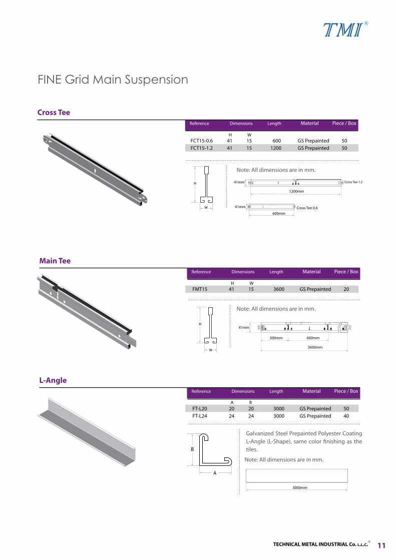
Cross Tee
Note: All dimensions are in mm.
Reference Dimensions Length Material Piece / Box
CT15-0.6 25 15 600 Galvanized 75 CT15-1.2 25 15 1200 Galvanized 50 CT24-0.6 25 24 600 Galvanized 75 CT24-1.2 25 24 1200 Galvanized 50
H W
Main Tee
Reference Dimensions Length Material Piece / Box
MT15 38 15 3600 Galvanized 25 MT24 38 24 3600 Galvanized 25
Note: All dimensions are in mm.
H W
L-Angle Reference Dimensions Length Material Piece / Box
ET-L20 20 20 3000 GS Prepainted 25 ET-L25 25 25 3000 GS Prepainted 25
Note: All dimensions are in mm.
Cross Tee 1.2
600mm1200mm
Cross Tee 0.6
600mm
3600mm
A B
Exposed Ceiling Systems
Galvanized Steel Prepainted Polyester Coating L-Angle (L-Shape), same color finishing as the tiles.
Consist of Galvanized Steel with Pre-painted Polyester Coating Aluminium or P.P.G.I. Capping.
Consist of Galvanized Steel with Pre-painted Polyester Coating Aluminium or P.P.G.I. Capping.
3000mm
TECHNICAL METAL INDUSTRIAL Co. L.L.C.R
R
11
Cross Tee
Note: All dimensions are in mm.
Reference Dimensions Length Material Piece / Box
FCT15-0.6 41 15 600 GS Prepainted 50 FCT15-1.2 41 15 1200 GS Prepainted 50
H W
Main Tee Reference Dimensions Length Material Piece / Box
FMT15 41 15 3600 GS Prepainted 20
Note: All dimensions are in mm.
H W
L-Angle Reference Dimensions Length Material Piece / Box
FT-L20 20 20 3000 GS Prepainted 50FT-L24 24 24 3000 GS Prepainted 40
FINE Grid Main Suspension
A B
Cross Tee 1.241mm
1200mm
Cross Tee 0.641mm
600mm
41mm
300mm 600mm
3600mm
Note: All dimensions are in mm.
Galvanized Steel Prepainted Polyester Coating L-Angle (L-Shape), same color finishing as the tiles.
3000mm
TECHNICAL METAL INDUSTRIAL Co. L.L.C. R
R
Edge Trim
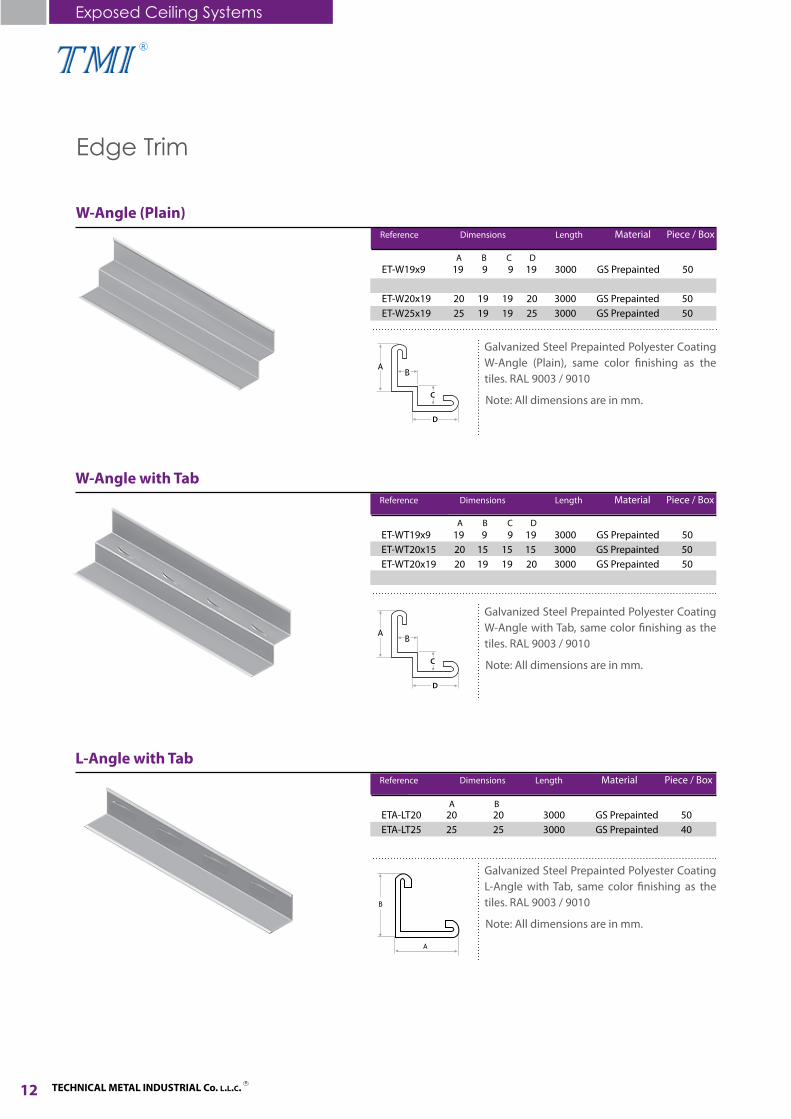
W-Angle (Plain) Reference Dimensions Length Material Piece / Box
ET-W19x9 19 9 9 19 3000 GS Prepainted 50ET-W20x15 20 15 15 15 3000 GS Prepainted 50ET-W20x19 20 19 19 20 3000 GS Prepainted 50 ET-W25x19 25 19 19 25 3000 GS Prepainted 50
A B C D
W-Angle with Tab Reference Dimensions Length Material Piece / Box
ET-WT19x9 19 9 9 19 3000 GS Prepainted 50ET-WT20x15 20 15 15 15 3000 GS Prepainted 50ET-WT20x19 20 19 19 20 3000 GS Prepainted 50 ET-WT25x19 25 19 19 25 3000 GS Prepainted 50
L-Angle with Tab Reference Dimensions Length Material Piece / Box
ETA-LT20 20 20 3000 GS Prepainted 50 ETA-LT25 25 25 3000 GS Prepainted 40
A B
12
Exposed Ceiling Systems
Note: All dimensions are in mm.
Galvanized Steel Prepainted Polyester Coating W-Angle (Plain), same color finishing as the tiles. RAL 9003 / 9010
Note: All dimensions are in mm.
Galvanized Steel Prepainted Polyester Coating W-Angle with Tab, same color finishing as the tiles. RAL 9003 / 9010
Note: All dimensions are in mm.
Galvanized Steel Prepainted Polyester Coating L-Angle with Tab, same color finishing as the tiles. RAL 9003 / 9010
A B C D
C
D
C
D

TECHNICAL METAL INDUSTRIAL Co. L.L.C.R
R
Installation Method
Types of Combination
1. Level marking on wall using water level method or Laser method. 2. Fixing of Wall Angle with screws and nails.3. Mark out & commence fixing of grid suspension system using Main Tee, Cross Tee’s according to the approved layout to make 600 x 600mm grid.4. Fixing of suspension system with 3mm / 4mm wires fixed to concrete with ceiling clips and cartridges and having adjustable clips to adjust the ceiling level.5. Installation of Lay-In/Lay-On 600 x 600mm tiles in a proper way taking into consideration the ceiling level and design pattern.6. Cut apertures for lights and other services where required.
Black Fleece
Hanging Wire
Edge TrimCross Tee
Adjustable Clip
Main Tee
Main Tee Span1220mm
(1200mm)
Main Tee Span1220mm
(1200mm)
Main Tee Span610mm
(600mm)
T15 / T24
Varies 600
Lay - In Tile
Varies
GT15
600
Lay - In Tile
600
Lay - In Tile
Varies
T15 / T24
W-Angle W-Angle with Tab L-Angle
13
According to the norm of ASTM C635 for the average loading capability and the degree of depression of Main Tee, the span of the tested Main Tees is 1.2m. Divide the main runners evenly to get four loading points, and raise the loading gradually to test the degree of depression of the Main Tees in carrying loads. According to the norm of ASTM C635, the degree of depression of Main Tees should be within 1/360 of the length of Main Tees (10mm).
Load Test Diagram of Main Tee
m
m mm

R
TECHNICAL METAL INDUSTRIAL Co. L.L.C. R
14
Tile Description
We offer a wide range of combinations that will definitely fit your requirements. We provide you with different colors and perforations. In addition, we also provide decorative tiles and various sizes of edge trim (angles).
CEILING TILES

R
TECHNICAL METAL INDUSTRIAL Co. L.L.C.R
15
Plain TilesFinish Coating
Standard colors RAL 9003 White and RAL 9010 Off-White. Other Colors are available upon request.
Decorative Designs
Four different types of Decorative Aluminium Tiles are available in either Clip-In or Lay-In systems (600 x 600 mm).
Perforated Tiles
Finish Coating
Standard colors RAL 9003 White and RAL 9010 Off-White. Other Colors are available upon request.
Perforated Types
Aluminium Tiles Perforation surface with hole of 1.5mm, 1.8mm & 2.5mm diameter can be obtained in different patterns as shown below. Acoustic black felt will be installed backside of the perforated tile.
Ceiling TilesPlain TilesDecorative TilesPerforated TilesSpecial Decorative Tiles
Gypsum TilesSound Absorption
Strip Column Type Square ColumnParallel SkewedTMI PRT-001 TMI PRT-002 TMI PRT-003 TMI PRT-004
Double Circle Single Circle
TMI PDT-001 TMI PDT-002
Square Octagonal
TMI PDT-003 TMI PDT-004
Decorative Tiles
Plain (Lay-In) Plain (Clip-In)
TMI PT-001 TMI PT-002

TECHNICAL METAL INDUSTRIAL Co. L.L.C. R
R
16
4 Small Square Corner
TMI PRT-016
4 Big Square Corner
TMI PRT-017
Perforated Tiles
Ceiling Tiles
Octagon Double Line Rectangular
Wave Shape I Shape 4 DotsTMI PRT-005 TMI PRT-006 TMI PRT-007 TMI PRT-008 TMI PRT-009
TMI PRT-011 TMI PRT-012 TMI PRT-013 TMI PRT-014TMI PRT-010
Skewed Rectangular Square Shape Double Line Square 8 Dots Diamond
TMI PRT-015
X Shape

TECHNICAL METAL INDUSTRIAL Co. L.L.C.R
R
17
Selinus SilverTMI DT-001
Selinus CopperTMI DT-002
Selinus Silver (PE)TMI DT-003
Selinus Red GoldTMI DT-004
Selinus White Silver
TMI DT-005
Pergamon Silver
TMI DT-009
Pergamon Pearl Copper
TMI DT-008
Selinus Red Silver
TMI DT-006
Selinus Blue Silver
TMI DT-007
PergamonGold
TMI DT-010
Mirror FinishTMI DT-014
WoodenTMI DT-013
Ephesus Pearl Copper
TMI DT-011
Woody Oak
TMI DT-012
Fake PerforatedTMI DT-015
Special Decorative Tiles

TECHNICAL METAL INDUSTRIAL Co. L.L.C. R
R
18
Description
Gypsum tiles are non-combustible laminated with special fire resistant vinyl finishes of various designs with aluminium foil of paper backing on premium quality gypsum board which is best quality.
Water Resistance Tiles
Gypsum Tiles are water resistant and suitable to use in areas like showers, kitchens, offices, etc.
OYB
ISLAMIC FISSURED FLORAL FLEXFOIL
PETALS YELLOW-FERN PINK-FERN DIAMOND CHAIN
Fire Resistance Tiles
Conform to BSI-British Standard as follows: BS 1230:part 1-1985 & BS 476:part 8-1972
DIAMOND SAFARI FIBER
Gypsum Tiles
TC-66 600 x 600 7,8,9,12 10
Reference Dimensions Thickness Qty / Box
Ceiling Tiles
Note: All dimensions are in mm.

TECHNICAL METAL INDUSTRIAL Co. L.L.C.R
R
19
DescriptionSound Absorption ratio has become an extremely important factor that should be considered before choosing the right tile depending on the application condition. With this in mind TMI provide different acoustic fleece layers to ensure getting the desired sound absorption requirement. “Sound Absorption” describes the reduction of noise within a room. Perforated ceiling tiles with an acoustic fleece overlay or mineral wool pad absorb energy and serve to control reverberation time. Different combinations of perforated open areas and acoustics pad density/thickness provide different levels of sound absorption. Noise Reduction Coefficient (NRC) and Sound Absorption Average (SAA) of the ceiling system.
Sound Absorptioncurve for Perforated Metal Tiles
Sound Absorptioncurve for Plain Metal Tiles
Sound Absorptioncurve for GypsumTiles
Sound Absorption
0
0.2
0.4
0.6
0.8
1
1.2
0 20 40 60 80 100 120Abs
orpt
ion
Coe
ffici
ent
( )
0
0.2
0.4
0.6
0.8
1
1.2
0 20 40 60 80 100 120
Abs
orpt
ion
Coe
ffici
ent
( )
( )
0
0.2
0.4
0.6
0.8
1
1.2
0 20 40 60 80 100 120Abs
orpt
ion
Coe
ffici
ent

R
TECHNICAL METAL INDUSTRIAL Co. L.L.C. R
20
System Description
This system can absorb high levels of noise and it can be used both internally and externally. Sets of clips, hanging wires & metal ceiling strips are used for installation. Ceiling Strip with Groove (CSG), Ceiling Strip without Groove (CS), Self Supporting with Groove (SSG) and Self Supporting without Groove (SS) Linear Strip Systems give decorative style and modernity with square edge strips.
CEILING STRIP SYSTEMS
R
TECHNICAL METAL INDUSTRIAL Co. L.L.C.R
21
Ceiling Strip SystemsCeiling Strip with GrooveCeiling Strip without GrooveCeiling Strip Main SuspensionSelf Supporting Ceiling StripInstallation Method
Ceiling Strip
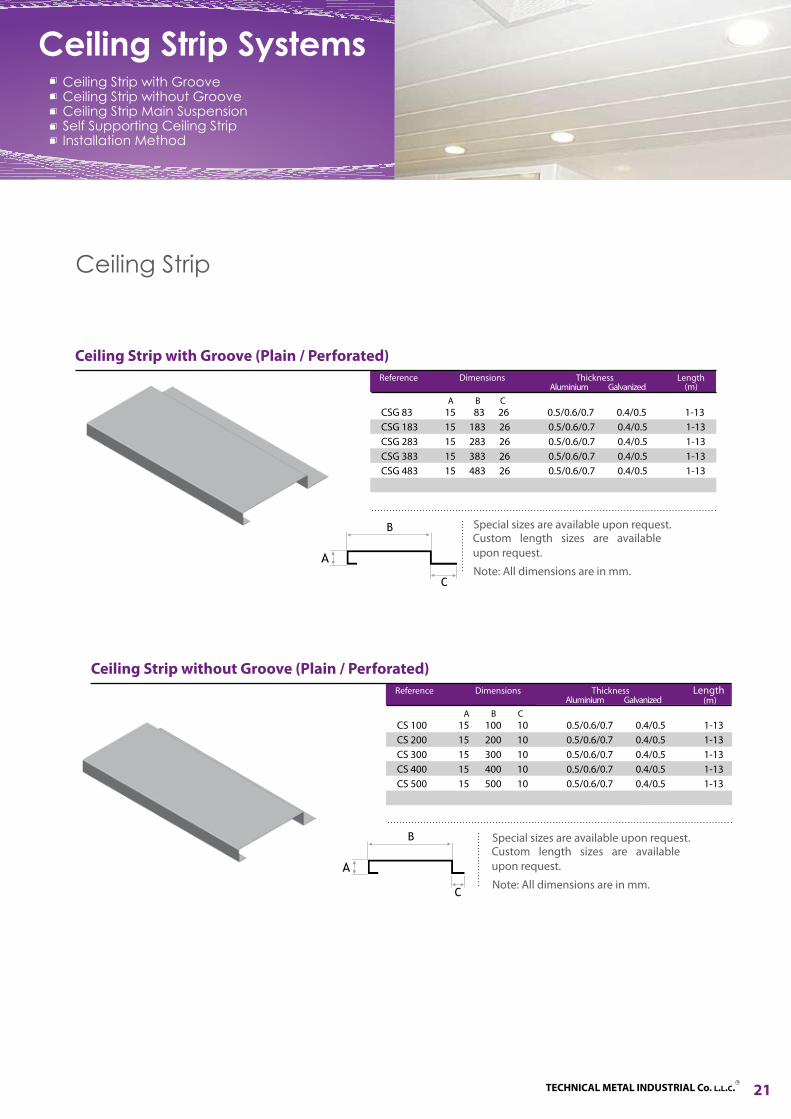
Ceiling Strip without Groove (Plain / Perforated)
Reference Dimensions Thickness Length Aluminium Galvanized
CS 100 15 100 10 0.5/0.6/0.7 0.4/0.5 1-13CS 200 15 200 10 0.5/0.6/0.7 0.4/0.5 1-13CS 300 15 300 10 0.5/0.6/0.7 0.4/0.5 1-13CS 400 15 400 10 0.5/0.6/0.7 0.4/0.5 1-13CS 500 15 500 10 0.5/0.6/0.7 0.4/0.5 1-13CS 600 15 600 10 0.5/0.6/0.7 0.4/0.5 1-13
A B C
(m)
Ceiling Strip with Groove (Plain / Perforated)
Reference Dimensions Thickness Length Aluminium Galvanized
CSG 83 15 83 26 0.5/0.6/0.7 0.4/0.5 1-13CSG 183 15 183 26 0.5/0.6/0.7 0.4/0.5 1-13CSG 283 15 283 26 0.5/0.6/0.7 0.4/0.5 1-13CSG 383 15 383 26 0.5/0.6/0.7 0.4/0.5 1-13CSG 483 15 483 26 0.5/0.6/0.7 0.4/0.5 1-13CSG 583 15 583 26 0.5/0.6/0.7 0.4/0.5 1-13
A B C
(m)
Note: All dimensions are in mm.
Special sizes are available upon request.Custom length sizes are available upon request.
Note: All dimensions are in mm.
Special sizes are available upon request.Custom length sizes are available upon request.

TECHNICAL METAL INDUSTRIAL Co. L.L.C. R
R
22
Ceiling Strip Systems
Self Supporting Ceiling Strip
Self Supporting Ceiling Strip
Note: All dimensions are in mm.
Reference Dimensions Thickness
SS 100 42.5 100 44 0.5/0.6/0.7 0.4/0.5 SS 200 42.5 200 44 0.5/0.6/0.7 0.4/0.5 SS 300 42.5 300 44 0.5/0.6/0.7 0.4/0.5 SS 400 42.5 400 44 0.5/0.6/0.7 0.4/0.5 SS 500 42.5 500 44 0.5/0.6/0.7 0.4/0.5 SS 600 42.5 600 44 0.5/0.6/0.7 0.4/0.5
A B C
Custom length sizes are available upon request. Powder Coating BS 6497:1984.Colors are made upon request to any RAL Code as per the architect’s choice.
Aluminium Galvanized
Ceiling Strip Main Suspension
Ceiling Strip C Carrier
Reference Length Material
CS-C Carrier 3000-4000 Galvanized Steel
Note: All dimensions are in mm.
Special sizes are available upon request.Custom length sizes are available upon request. Standard length of 3000mm to 4000mm according to SAE / AISI:1075or BS EN 42J.
A B C
Polyester Coating Aluminium Edge Trim (U-Shape), same color finishing as the tiles. Aluminium Alloy / temper: 3005/H24 Standard: ASTM B-209M EURO NORMS: EN 485-4:1993Custom Lengths are available upon request.
Aluminium Edge Trim Reference Dimensions Thickness Length Material
ET-C 20 20 20 20 0.6 3000 Pre-coated
Note: All dimensions are in mm.

TECHNICAL METAL INDUSTRIAL Co. L.L.C.R
R
23
Installation Method
Required suspension:• Carrier• Edge cover• Wire rod 3mm• Adjustment clips
The Strip Ceiling system should be installed as follows:1. Level marking on wall using water level or laser method.2. Fixing On the wall an edge cover U shaped (Aluminium Edge Trim 20 x 20 x 20mm) same color of strip panel with screws and nails3. Fixing of AC - 51 Hanging wires 3mm / 4mm, or channel support either threaded rod from soffit of slab with Ceiling Clip and Cartridge or screws or DBZ Anchor.4. Using of AC - 50 Adjustable Spring Clips for Ceiling Adjustment or Channel Clamp in case of threaded rod use.5. Installation of Main Carrier at every 1000mm or 1200mm.6. Fixing of Strip Ceiling in proper way taking into consideration the ceiling level and Strip form (with Groove or without) and the width of the strip.7. Cut apertures for lights and other services where required. Cut trim for access opening for equipments, if required.
Carrier
Hanging Wire
Edge Trim
Adjustable Clip
Ceiling Strip Panel
Ceiling Strip
Self Supporting without GrooveThe strip panel will be installed on a galvanized carrier every 1000-1200mm and can be dismantled separately.The carrier is supported with wire rod 3mm to the ceiling having an adjustable clip. On the wall an edge cover U shaped (Aluminium Edge Trim 20 x 20 x 20mm) same color of strip panel.
Self Supporting with Groove

R
TECHNICAL METAL INDUSTRIAL Co. L.L.C. R
24
System Description
This system is used for decorative and functional purposes. It also enhances the use of wide variety of lighting systems because of its high flexibility to add or remove any part of it without affecting the overall system. The Aluminium profile U-Shape blades, can be assembled in different methods to give different cell sizes.
OPEN CELL SYSTEMS

R
TECHNICAL METAL INDUSTRIAL Co. L.L.C.R
25
Open Cell SystemsOpen Cell PanelOpen Cell SuspensionOpen Cell Blade F(OCBF)Open Cell Blade M(OCBM)
Open Cell Panel
Material Used: AluminiumNote: All dimensions are in mm.
Reference Panel Size Cell Size Thickness Blade
OC50-10 600 x 600 / 600 x 1200 50 x 50 0.4 50 10OC100-10 600 x 600 / 600 x 1200 100 x 100 0.4 40 10OC50-24 600 x 600 / 600 x 1200 50 x 50 0.4 50 24OC100-24 600 x 600 / 600 x 1200 100 x 100 0.4 40 24
Open Cell Suspension
Other Suspension used: TEE 15/24 Exposed Grid. (see page 10)Note: All dimensions are in mm.
Reference Dimensions Thickness Length Material
Open Cell Suspension-Main Tee (OCS-MT)
Open Cell Suspension-Cross Tee (OCS-CT)
OCS-CT 0.6-10 10 40 0.4 600 AluminiumOCS-CT 1.2-10 10 40 0.4 1200 AluminiumOCS-MT1.8-10 10 40 0.4 1800 AluminiumOCS-CT 0.6-24 24 40 0.4 600 AluminiumOCS-CT 1.2-24 24 40 0.4 1200 AluminiumOCS-MT1.8-24 10 40 0.4 1800 Aluminium
A B
Height Width
Open Cell Blade F (OCBF)
Note: All dimensions are in mm.
Reference Dimensions Thickness Length Material
OCBF-10 10 40 0.4 600 AluminiumOCBF-24 24 40 0.4 600 Aluminium
A B
Open Cell AngleInstallation MethodOpen Cell with T-Grid Suspension SystemInstallation Method
50
50 100
100
Center to CenterCenter to Center
Open Cell Suspension-Main Tee (OCS-MT)
Open Cell Systems
TECHNICAL METAL INDUSTRIAL Co. L.L.C. R
R
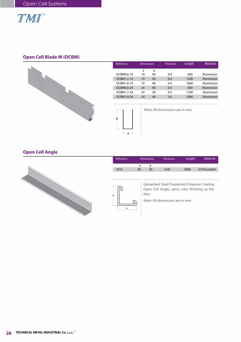
Open Cell Blade M (OCBM)
Note: All dimensions are in mm.
Reference Dimensions Thickness Length Material
OCBM0.6-10 10 40 0.4 600 Aluminium OCBM1.2-10 10 40 0.4 1200 Aluminium OCBM1.8-10 10 40 0.4 1800 AluminiumOCBM0.6-24 24 40 0.4 600 Aluminium OCBM1.2-24 24 40 0.4 1200 Aluminium OCBM1.8-24 24 40 0.4 1800 Aluminium
A B
Open Cell Angle
Reference Dimensions Thickness Length Material
OCA 20 20 0.45 3000 GI Precoated A B
Open Cell Systems
26
Note: All dimensions are in mm.
Galvanized Steel Prepainted Polyester Coating Open Cell Angle, same color finishing as the tiles.

TECHNICAL METAL INDUSTRIAL Co. L.L.C.R
R
Installation Method
All these items are with colored face (Standard color RAL 9003 White). Other colors available upon request.
Installation Procedure:
1. Level marking on walls using water level or laser method.2. Fixing of wall angle with screws and nails.3. Mark out & commence fixing of Grid Suspension System using: - OCS 1800mm to be installed at 1200 mm distance between each other. - OCS 1200mm to cross the OCS 1800 on 600mm distance. - OCS 600mm to cross the OCS 1200 on 600mm distance.4. Fixing of suspension system with 3mm / 4mm wires fixed to concrete with ceiling clips and cartridges and having adjustable clips to adjust the ceiling level.5. Installation of the Blade M (Male Type) on 100mm distance or 50mm with the intersection of the same installation distance of the Blade F (Female Type) in order to create the cell size form.
Open Cell Suspension-Main Tee (OCS-MT) 1800mm
27
Open Cell Suspension-Cross Tee(OCS-CT) 1200mm
Open Cell Suspension-Cross Tee(OCS-CT) 600mm
Open Cell Blade F
Open Cell Blade M

TECHNICAL METAL INDUSTRIAL Co. L.L.C. R
R
Open Cell Panel with T-Grid Suspension System
Material Used: AluminiumNote: All dimensions are in mm.
Reference Panel Size Cell Size Thickness Blade
OC50-10 600 x 600 / 600 x 1200 50 x 50 0.4 50 10OC100-10 600 x 600 / 600 x 1200 100 x 100 0.4 40 10OC50-24 600 x 600 / 600 x 1200 50 x 50 0.4 50 24OC100-24 600 x 600 / 600 x 1200 100 x 100 0.4 40 24
Height Width
OPEN CELL with T-GRID SUSPENSION SYSTEM
Specifications: Aluminium open cell ceilings 600 x 600 mm made up of “U” shaped profiles with a width of 10 mm / 24 mm and height of 40 mm and with thickness of 0.4 mm, which suitably coupled form a square cell.Specifically designed to fit into standard 15 or 24 mm wide T-Grids, they provide a trackless appearance of the ceiling.Open Cell Ceiling 600 x 600 mm with T-Grid System are high quality products for easiest placement and removal of the panels.The Standard color is white RAL 9003. Other colors can be provided as powder coating as per Jotun RAL Codes.
T- 15/24 Grid Main Suspension see page 10
Cross Tee Main Tee L-Angle
28
Open Cell Systems
50
50 100
100
Center to CenterCenter to Center

TECHNICAL METAL INDUSTRIAL Co. L.L.C.R
R
Installation Method
Open Cell 600 x 600mm are installed in the suspension grids formed by T-Profiles, 15 or 24mm wide, 3600, 1200 and 600mm long. When the panel is laid into the suspension grid, the structure results fully integrated in the cell ceiling. The modular panels 600 x 600mm are easily individually laid into and taken out of the standard T-grid, by lifting them upwards for simple access to the plenum.
1. Level marking on walls using water level or laser method.2. Fixing of wall angle with screws and nails.3. Mark out & commence fixing of Grid Suspension System using Main Tee on 600mm spacing, Cross Tees on 600mm spacing according to the approved layout to make 600 x 600mm grid.4. Fixing of suspension system with 3mm wires fixed to concrete with ceiling clips, cartridges and having adjustable clips to adjust the ceiling level.5. Installation of Lay-In 600 x 600mm tiles in a proper way taking into consideration the ceiling level and design pattern.6. Installation of the Blade M (Male Type) on 100 mm distance or 50mm with the intersection of the same installation distance of the Blade F (Female Type) in order to create the Cell size to form 600 x 600mm.7. Slit two pieces of Blade M to arrange a frame border for the tile.8. Open Cell 600 x 600mm form to be fit inside the open space of the T-Grid installed suspension system.
L-Angle
Cross Tee
Main Tee
29
Adjustable Spring Clip
Hanging Wire
Open Cell Panel

R
TECHNICAL METAL INDUSTRIAL Co. L.L.C. R30
System Description
This System is a versatile hat-shaped metal channel, designed for “Furring” out any surface for final finish application. Furring channel is used in conjunction with cold rolled channel, suspended steel frame cladded with gypsum board sheets. This system is ideal for smooth areas that is needed without joints or for concealing services.
DRYLINE FURRING CHANNEL SYSTEMS

TECHNICAL METAL INDUSTRIAL Co. L.L.C.R
R
31
Dryline Furring Channel SystemsFurring ChannelKnurling Furring ChannelMain ChannelStud Channel
W-Angle (Plain)W-Angle (Perforated)Wall AngleZ-TrimAluminium Extruded F ProfileInstallation Method
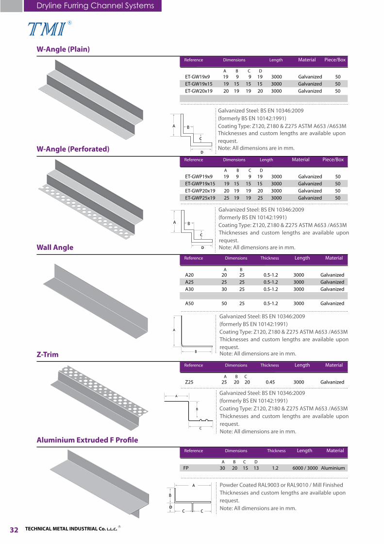
Furring Channel Reference Dimensions Thickness Length Material
FC30 30 22 70 0.5-1.2 3000 GalvanizedFC35 35 22 68 0.5-1.2 3000 GalvanizedFC50 50 22 81 0.5-1.2 3000 Galvanized
Galvanized Steel: BS EN 10346:2009 (formerly BS EN 10142:1991)Coating Type: Z120, Z180 & Z275 ASTM A653 /A653M
A B C
Thicknesses and custom lengths are available upon request.
Main Channel Reference Dimensions Thickness Length Material
C19 12 19 12 0.5-1.5 3000 GalvanizedC20 12 20 12 0.5-1.5 3000 GalvanizedC25 12 25 12 0.5-1.5 3000 GalvanizedC38 12 38 12 0.5-1.5 3000 GalvanizedC45 12 45 12 0.5-1.5 3000 GalvanizedC50 12 50 12 0.5-1.5 3000 Galvanized
Galvanized Steel: BS EN 10346:2009 (formerly BS EN 10142:1991)Coating Type: Z120, Z180 & Z275 ASTM A653 /A653M
A B C
Thicknesses and custom lengths are available upon request.
Stud Channel Reference Dimensions Thickness Length Material
SC35 35 15 15 0.5-0.7 3000 Galvanized
Galvanized Steel: BS EN 10346:2009 (formerly BS EN 10142:1991)Coating Type: Z120, Z180 & Z275 ASTM A653 /A653M
A B C
Thicknesses and custom lengths are available upon request.
Dryline Furring Channel Systems
Knurling Furring Channel Reference Dimensions Thickness Length Material
KFC35 35 22 68 0.5 3000 Galvanized
Galvanized Steel: BS EN 10346:2009 (formerly BS EN 10142:1991)Coating Type: Z120, Z180 & Z275 ASTM A653 /A653M
A B C
Thicknesses and custom lengths are available upon request.
Note: All dimensions are in mm.
Note: All dimensions are in mm.
Note: All dimensions are in mm.
Note: All dimensions are in mm.
TECHNICAL METAL INDUSTRIAL Co. L.L.C. R
R
Dryline Furring Channel Systems
32
D
W-Angle (Plain) Reference Dimensions Length Material Piece/Box
ET-GW19x9 19 9 9 19 3000 Galvanized 50ET-GW19x15 19 15 15 15 3000 Galvanized 50ET-GW20x19 20 19 19 20 3000 Galvanized 50 ET-GW25x19 25 19 19 25 3000 Galvanized 50
Galvanized Steel: BS EN 10346:2009 (formerly BS EN 10142:1991)Coating Type: Z120, Z180 & Z275 ASTM A653 /A653MThicknesses and custom lengths are available upon request.
A B C D
C
W-Angle (Perforated) Reference Dimensions Length Material Piece/Box
ET-GWP19x9 19 9 9 19 3000 Galvanized 50ET-GWP19x15 19 15 15 15 3000 Galvanized 50ET-GWP20x19 20 19 19 20 3000 Galvanized 50 ET-GWP25x19 25 19 19 25 3000 Galvanized 50
Galvanized Steel: BS EN 10346:2009 (formerly BS EN 10142:1991)Coating Type: Z120, Z180 & Z275 ASTM A653 /A653MThicknesses and custom lengths are available upon request.
A B C D
D
C
Wall Angle Reference Dimensions Thickness Length Material
A20 20 25 0.5-1.2 3000 GalvanizedA25 25 25 0.5-1.2 3000 GalvanizedA30 30 25 0.5-1.2 3000 GalvanizedA40 40 25 0.5-1.2 3000 GalvanizedA50 50 25 0.5-1.2 3000 Galvanized
Galvanized Steel: BS EN 10346:2009 (formerly BS EN 10142:1991)Coating Type: Z120, Z180 & Z275 ASTM A653 /A653M
A B
Thicknesses and custom lengths are available upon request.
Z-Trim Reference Dimensions Thickness Length Material
Z25 25 20 20 0.45 3000 Galvanized
Galvanized Steel: BS EN 10346:2009 (formerly BS EN 10142:1991)Coating Type: Z120, Z180 & Z275 ASTM A653 /A653M
A B C
Thicknesses and custom lengths are available upon request.
Aluminium Extruded F Profile Reference Dimensions Thickness Length Material
FP 30 20 15 13 1.2 6000 / 3000 Aluminium
Powder Coated RAL9003 or RAL9010 / Mill FinishedThicknesses and custom lengths are available upon request.Note: All dimensions are in mm.
A B C D
DD
Note: All dimensions are in mm.
Note: All dimensions are in mm.
Note: All dimensions are in mm.
Note: All dimensions are in mm.

TECHNICAL METAL INDUSTRIAL Co. L.L.C.R
R
Installation Method
Level marking on wall for suspended ceiling levels using water level or laser method as datum on walls. (Same method to be used for checking false ceiling gypsum board at corners and mid span of support system when fixed).Fix wall angle for suspended ceiling.Mark out and commence fixing of grid suspension system using Furring Channels at 600mm centers and Main Channels at 1,200mm centers not more than 900 mm from perimeter wall for both Furring and Main Channels.Suspension system to be with hanging wire and adjustable clip at 1,200 mm centers fixed to the soffit using ceiling clip and cartridge.Connecting Main Channel with Furring Channel using TMI approved wire clip.Installation of Main Channel and Furring Channel to be adjusted where required accommodating MEP services, light fittings, diffusers, etc…Gypsum board 12.50mm thickness to be screwed to Furring System with approved dry wall screws.Filling of board joint gaps with joint compound.Fixing of joint fiber tape on board joints and finishing with joint compound made ready to receive decoration.Cut apertures for lights, plenum boxes, etc... Cut holes of HVAC balancing and re-fix.Construct archway structure in angle system to required profile.
33
1.
2.3.
4.5.
6.7.8.9.10.

R
TECHNICAL METAL INDUSTRIAL Co. L.L.C. R
34
System Description
This system is used in conjunction with cold rolled channel, steel frames of stud and track, used for interior non load-bearing walls, which has to be cladded with gypsum board or other cladding sheets. This system in widely used in offices and residential buildings due to easy installations.
DRYWALL PARTITIONING SYSTEMS

R
TECHNICAL METAL INDUSTRIAL Co. L.L.C.R
Drywall Partitioning SystemsStudTrackDepth StudDeflection Track
Stud Reference Dimensions Thickness Length Material
S40 34 40 36 0.5-1.5 3000 GalvanizedS45 34 45 36 0.5-1.5 3000 GalvanizedS50 34 50 36 0.5-1.5 3000 GalvanizedS53 34 53 36 0.5-1.5 3000 GalvanizedS60 34 60 36 0.5-1.5 3000 GalvanizedS63 34 63 36 0.5-1.5 3000 GalvanizedS70 34 70 36 0.5-1.5 3000 GalvanizedS73 34 73 36 0.5-1.5 3000 GalvanizedS83 34 83 36 0.5-1.5 3000 GalvanizedS90 34 90 36 0.5-1.5 3000 Galvanized S92 34 92 36 0.5-1.5 3000 GalvanizedS98 34 98 36 0.5-1.5 3000 GalvanizedS123 34 123 36 0.5-1.5 3000 GalvanizedS148 34 148 36 0.5-1.5 3000 Galvanized
Other sizes of Thickness, Length, Depth & Flange can be made upon request.Material Standard: Galvanized Steel-BS EN 10346:2009 (formerly) BS EN 10142:1991) Coating Type: as per ASTM A653 / A653M.Note: All dimensions are in mm.
A B C
Track Reference Dimensions Thickness Length Material
T42 23 42 25 0.5-1.5 3000 GalvanizedT47 23 47 25 0.5-1.5 3000 GalvanizedT52 23 52 25 0.5-1.5 3000 GalvanizedT55 23 55 25 0.5-1.5 3000 GalvanizedT62 23 62 25 0.5-1.5 3000 GalvanizedT65 23 65 25 0.5-1.5 3000 GalvanizedT72 23 72 25 0.5-1.5 3000 GalvanizedT75 23 75 25 0.5-1.5 3000 GalvanizedT85 23 85 25 0.5-1.5 3000 GalvanizedT92 23 92 25 0.5-1.5 3000 GalvanizedT94 23 94 25 0.5-1.5 3000 GalvanizedT100 23 100 25 0.5-1.5 3000 GalvanizedT125 23 125 25 0.5-1.5 3000 GalvanizedT150 23 150 25 0.5-1.5 3000 Galvanized
Other sizes of Thickness, Length, Depth & Flange can be made upon request.Material Standard: Galvanized Steel-BS EN 10346:2009 (formerly) BS EN 10142:1991) Coating Type: as per ASTM A653 / A653M.Note: All dimensions are in mm.
A B C
Wall Cladding Furring ChannelResilient Furring ChannelDrywall Angle Bead Plain/PerforatedDrywall Edge Bead Plain/PerforatedStud (ST) Clip ConnectorInstallation Method
35
Drywall Partitioning Systems

TECHNICAL METAL INDUSTRIAL Co. L.L.C. R
R
Depth Stud Reference Dimensions Thickness Length Material
DS45 50 45 50 0.8-1.0 3000 GalvanizedDS50 50 50 50 0.8-1.0 3000 GalvanizedDS53 50 53 50 0.8-1.0 3000 GalvanizedDS60 50 60 50 0.8-1.0 3000 GalvanizedDS63 50 63 50 0.8-1.0 3000 GalvanizedDS70 50 70 50 0.8-1.0 3000 GalvanizedDS73 50 73 50 0.8-1.0 3000 GalvanizedDS92 50 92 50 0.8-1.0 3000 GalvanizedDS98 50 98 50 0.8-1.0 3000 Galvanized
Other sizes of Thickness, Length, Depth & Flange can be made upon request.Material Standard: Galvanized Steel-BS EN 10346:2009 (formerly) BS EN 10142:1991) Coating Type: as per ASTM A653 / A653MNote: All dimensions are in mm.
A B C
Deflection Track Reference Dimensions Thickness Length Material
DT47 50 47 50 0.8-1.0 3000 GalvanizedDT52 50 52 50 0.8-1.0 3000 GalvanizedDT55 50 55 50 0.8-1.0 3000 GalvanizedDT62 50 62 50 0.8-1.0 3000 GalvanizedDT65 50 65 50 0.8-1.0 3000 GalvanizedDT72 50 72 50 0.8-1.0 3000 GalvanizedDT75 50 75 50 0.8-1.0 3000 GalvanizedDT94 50 94 50 0.8-1.0 3000 GalvanizedDT100 50 100 50 0.8-1.0 3000 Galvanized
Thicknesses and custom lengths are available upon request.Material Standard: Galvanized Steel-BS EN 10346:2009 (formerly) BS EN 10142:1991) Coating Type: as per ASTM A653 / A653MNote: All dimensions are in mm.
A B C
Drywall Partitioning Systems
Wall Cladding Furring Channel Reference Dimensions Thickness Length Material
SC34 10 34 10 0.5-0.7 3000 Galvanized
Thicknesses and custom lengths are available upon request.Material Standard: Galvanized Steel-BS EN 10346:2009 (formerly) BS EN 10142:1991) Coating Type: as per ASTM A653 / A653MNote: All dimensions are in mm.
A B C
36

TECHNICAL METAL INDUSTRIAL Co. L.L.C.R
R
Resilient Furring Channel Reference Dimensions Thickness Length Material
DT47 30 22 57 13 0.4-0.6 3000 Galvanized
Thicknesses and custom lengths are availableupon request.Material Standard: Galvanized Steel-BS EN 10346:2009 (formerly) BS EN 10142:1991). Coating Type: as per ASTM A653 / A653M.Note: All dimensions are in mm.
A B C D
Drywall Angle Bead Plain Reference Dimensions Length Material
DAB28 28 28 2400/3000 GalvanizedDAB30 30 30 2400/3000 GalvanizedDAB32 32 32 2400/3000 Galvanized
Thicknesses and custom lengths are available upon request.Material Standard: Galvanized Steel-BS EN 10346:2009 (formerly) BS EN 10142:1991). Coating Type: as per ASTM A653 / A653M.Note: All dimensions are in mm.
A B
Drywall Angle Bead Perforated Reference Dimensions Length Material
DABP28 28 28 2400/3000 GalvanizedDABP30 30 30 2400/3000 GalvanizedDABP32 32 32 2400/3000 Galvanized
Thicknesses and custom lengths are available upon request.Material Standard: Galvanized Steel-BS EN 10346:2009 (formerly) BS EN 10142:1991). Coating Type: as per ASTM A653 / A653M.Note: All dimensions are in mm.
A B
37
D
TECHNICAL METAL INDUSTRIAL Co. L.L.C. R
R
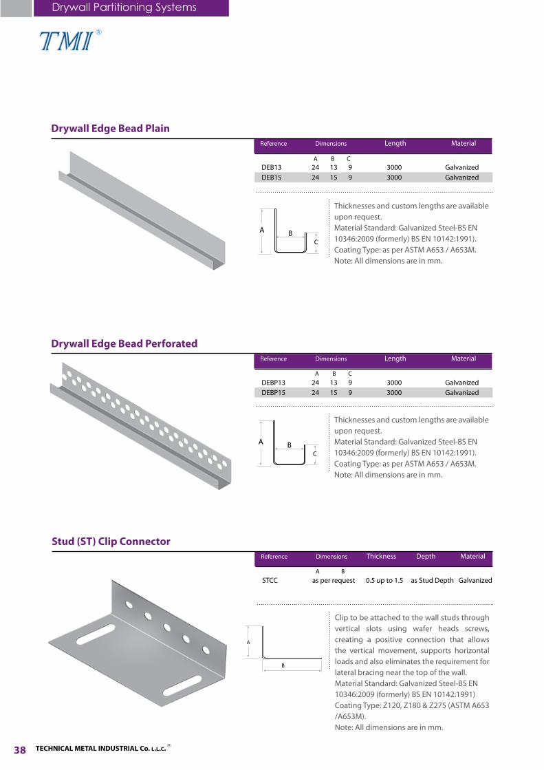
Drywall Edge Bead Plain Reference Dimensions Length Material
DEB13 24 13 9 3000 GalvanizedDEB15 24 15 9 3000 Galvanized
Thicknesses and custom lengths are available upon request.Material Standard: Galvanized Steel-BS EN 10346:2009 (formerly) BS EN 10142:1991). Coating Type: as per ASTM A653 / A653M.Note: All dimensions are in mm.
A B C
Drywall Edge Bead Perforated Reference Dimensions Length Material
DEBP13 24 13 9 3000 GalvanizedDEBP15 24 15 9 3000 Galvanized
Thicknesses and custom lengths are available upon request.Material Standard: Galvanized Steel-BS EN 10346:2009 (formerly) BS EN 10142:1991). Coating Type: as per ASTM A653 / A653M.Note: All dimensions are in mm.
Drywall Partitioning Systems
A B C
38
Stud (ST) Clip Connector Reference Dimensions Thickness Depth Material
STCC as per request 0.5 up to 1.5 as Stud Depth Galvanized
Clip to be attached to the wall studs through vertical slots using wafer heads screws, creating a positive connection that allows the vertical movement, supports horizontal loads and also eliminates the requirement for lateral bracing near the top of the wall.Material Standard: Galvanized Steel-BS EN 10346:2009 (formerly) BS EN 10142:1991) Coating Type: Z120, Z180 & Z275 (ASTM A653 /A653M).Note: All dimensions are in mm.
A B

TECHNICAL METAL INDUSTRIAL Co. L.L.C.R
R
Installation MethodA. Install tracks at floors, ceilings, structural walls and columns where gypsum board stud system abuts other construction.
B. Extend partition framing full height to structural supports or substrates above suspended ceilings, except where partitions are indicated to terminate at or just above suspended ceilings. Continue framing over frames for doors and openings and frame around ducts penetrating partitions above ceiling to provide support for gypsum boards.
C. Brace partition framing, not extending full height to structure above, with studs same size and thickness as partition framing. Provide bracing at:
D. Install steel studs in sizes and at spacing indicated.
E. Installation of Gypsum Board.
Single Stud Wall / Single Layer
Single Stud Wall / Double Layer
Gypsum Board
Track
Stud
39
Track
Install boards of the appropriate type applications.Install boards with the correct face side out to receive the scheduled finish.Use boards of the maximum practical size to minimize joints for the entire wall surfaces.Accurately align board surface to ensure visual continuity of the face design.Fix boards with self-drilling power driven screws to Studs and Tracks.Fix the boards from the center working towards the edges and corners.Provide angle beads at external corners ‘’J’’ shaped to cut edges and push boards fully into edge beads.Fill gaps between boards and cover joints with continuous lengths of jointing tape set on jointing compound.Apply additional coats of compound to concealed joints, the heads of fixings and imperfections in the board face and feather out the material to present a smooth and flush surface.Apply a coat of primer / sealer to surface, apply an additional coat where required to adjust absorbency of surface and prevent taped joints grinning through paint finishes.
1. 2.
3.
4.
5.
6.
7.
8.
9.
10.
For fire-resistance rated partitions that extend full height, install framing around structural members, as required to support gypsum board closures needed to make partitions continuous from floor to under side of structure above.Install bridging, if needed.
1.
2.
Double Stud Wall / Double Layer
15.24cm (6”) on center (o.c.) intervals along length of partitions.Not less than 15.24cm (6”) o.c. from partition ends and corners.Door and window openings.
1.
2.
3.
Single-Layer Construction: Maximum space studs 60.96cm (24”) o.c., unless otherwise indicated.Multiple-Layer Construction: Maximum space studs 60.96cm (24”) o.c., unless otherwise indicated.
1.
2.

TECHNICAL METAL INDUSTRIAL Co. L.L.C. R
R
The Classic Panel provides protected openings in ceilings and walls for access to building engineering services. The Access Panel frame is finished in powder coated white and can be over painted to blend with the surrounding surface. The Classic Panel is a high quality robust solution suitable for everyday use with all the discrete advantages the client demands of an access panel. Each panel is made to suit the individual tile and combination of tiles being used. This ensures no unsightly tile cuts or visible frames to disrupt the overall tiled finish. The design utilizes a continuous piano hinge that limits door sag to a minimum, thus avoiding chipped tiles caused by the door dropping as it is opened. Whether it is push open or sliding type, TMI is ready to make the access panel as per the client’s request. The Access Panel frame consists of powder coated aluminium frame with Regular, Fire Resistant or Moisture Resistant Gypsum Board with a thickness ranging from 12mm up to 15mm.
Additional Products
Access Panels Most Popular SizesTMI manufacture the most popular sizes of access panels, however, TMI is ready to make any size as per the customer and site requirements.
40
Additional Products
Access Panels

TECHNICAL METAL INDUSTRIAL Co. L.L.C.R
R
This system integrates with industry standard Lay-In & Clip-In light fixtures and air diffusers. Mesh Ceiling provide a perfect solution for a modern ceiling. Through its textile like structure, the material combines air permeability and acoustic neutrality with an optical consistency of appearance.
This system is an open ceiling design, this simple form makes it conducive to larger ceiling installation. It ties in with a wide range of design requirements, the installation of ceiling tube spacing and pattern design can be customized according to engineering requirements. Commonly used in airports, subways, car parks, restaurants, schools, offices and different places for decorative purposes.
41
Lay-In Mesh Suspension System Clip-In Mesh Suspension System
Standard Accessories:
Suspension Rod Round Pipe Profile Bolt Round Pipe Panel Side cover
12345
Mesh Ceiling
Pipe Ceiling

TECHNICAL METAL INDUSTRIAL Co. L.L.C. R
R
RawlplugSpring Tee Connector Spring Tee Hanger
AC-60 AC-61 AC-62
Auminium Ladders
Accessories
AC-49
Hanging Wires Adjustable Spring Clip
AC-50 AC-51
Ceiling Rail Connector Main Channel Bracket
AC-52 AC-53
Ceiling Clip NailWire Clip Ceiling Cartridge
AC-54 AC-55 AC-56
Aluminium Window ProfilesHold Down Clip C-Clamp Channel
AC-57 AC-58 AC-59
Accessories
42

TECHNICAL METAL INDUSTRIAL Co. L.L.C.R
R
Accessories
ScrewsWindow Profile Rubbers Steel Nails
AC-63 AC-64 AC-65
G.I. Metal TapeGypsum Compound Ready Mix Rubber Skirting
AC-66 AC-67 AC-68
Main Tee L Shape ConnectorFiber Tape Paper Tape
AC-69 AC-70 AC-71
Note: Custom made G.I. Fabricated Accessories available upon request.
Service Plate
AC-72
43
AC-73
Gypsum Boards Fixing Bracket
Main Bracket A Main Bracket B
AC-74
AC-75 AC-76

TECHNICAL METAL INDUSTRIAL Co. L.L.C. R
R
BS EN 573-3:2009, BS EN 485-2:2008 ASTM B209M
Aluminium
BS EN 10346:2009 (formerly BS EN 10142:1991)Coating Type: Z120,Z180 & Z275ASTM A653/A653M
Galvanized Steel
Technical Specifications
BS EN 10088-2:2005(formerly BS 1449:Part 2:1983)ASTM A240/A240M
Stainless Steel
Galvanized Steel Wire to BS EN 10244-2:2009ASTM A641/A641M
Preformed Wire Clip
Galvanized Steel Wire to BS EN 10244-2:2009ASTM A641/A641M
Hanging Wire
Carbon Steel Strip to BS EN 10132-4:2000Zinc Plated to BS EN ISO 2081:2008Phosphated to BS 7371-9:1996
Adjustable Spring Clip
Galvanized Steel Strip to BS EN 10346:2009,ASTM A653/A653M
Main Channel Bracket / Channel Clamp /Spring Tee Hanger / Spring Tee Connector / Ceiling Rail Connector / Main Tee L-Shape Connector & other G.I. Accessories
BS EN 10162:2003, BS 5234-1:1992,BS 7364:1990, BS EN 14195:2005 ASTM C645
Drywall Partitioning Systems & Dryline Ceiling Systems
ASTM C635-97
Ceiling Suspension Systems(Tee Grid System)
BS EN ISO 1461:1999 (formerly BS 729)ASTM A123/A123M
Hot Dip Galvanizing After Fabrication (HDGAF)
BS 6497:1984
Powder Coating
44
Raw Materials Standards: Manufacturing Standards:
Technical Specifications

TECHNICAL METAL INDUSTRIAL Co. L.L.C.R
R
Ordering InformationDear Customer, to respond more quickly to your needs through faster quotation respond and shorter delivery time, you are kindly requested to provide us with full details as follows:
Type of Material• Aluminium• Galvanized• Gypsum
Type of Coating• Pre-painted / Powder Coated with the RAL Color Code (Standard colors RAL 9003 White & RAL 9010 Off-White) • Galvanized (Zinc 120 / 180 / 275) Dimensions• Size• Height• Width• Thickness• Length
Specify the Ceiling System• Concealed or Clip-In System• Exposed Ceiling Systems (Lay-In / Lay-On) Tile• Gypsum Vinyl with T-Grid System 24 or 15mm• Ceiling Strip Systems / Self Supporting Strip• Open Cell Systems• Dryline Furring Channel Systems
Specify the Dry Wall Partitions with the sizes of the Stud and Track Runners with full dimensions. Also the type of Gypsum board to be notified with the dimensions. (Regular, Fire Rated or Moisture Resistance)
Accurate and better service requires precise information.
45

TECHNICAL METAL INDUSTRIAL Co. L.L.C. R
R
Manufacturers of:Ceiling Suspension Systems & PartitionsExpanded Mesh & Metal ProductsCable Management SystemsIndustrial GratingsStone FixturesMetal Doors & FramesIndustrial & IT CabinetsHighway GuardrailFencing & BarriersIndustrial Shelving SystemsAluminium Ladders
In House Services:Steel FabricationPowder CoatingHot Dip GalvanizingIndustrial Painting
46
TMI - Abu DhabiTel. : +971 (2) 5502025Fax : +971 (2) 5502024P.O. Box: 41558Abu Dhabi
TMI - Al AinTel. : +971 (3) 7224768Fax : +971 (3) 7224769P.O. Box: 99155Al Ain
TMI - DubaiTel. : +971 (4) 8852243Fax : +971 (4) 8852249 P.O. Box: 86029Dubai
TMI - Ras Al KhaimahTel. : +971 (7) 2282332Fax : +971 (7) 2282232P.O. Box: 33239Ras Al Khaimah
E-mail : [email protected]: www.tmi-co.com


ED 0
2 - 2
015