contextual generation of declarative workflows...
TRANSCRIPT

Contextual Generation of Declarative Workflows and their Application to Software Engineering Processes
Gregor Grambow and Roy Oberhauser Computer Science Department
Aalen University, Germany {gregor.grambow, roy.oberhauser}@htw-aalen.de
Manfred Reichert Institute for Databases and Information Systems
Ulm University, Germany [email protected]
Abstract—Process management can increase the efficiency and effectiveness of process activities by structuring and coordinating their execution. However, its application can become problematic in dynamic environments such as software engineering, since rigidly pre-specified process models are not capable of adequately handling dynamic aspects of the processes. Therefore, this work presents a declarative, problem-oriented process modeling technique that enables the modeling of dynamic sets of candidate activities from which a subset is automatically selected for execution. The system selects the subset based on the contextual properties of situations and subsequently utilizes it to build executable workflows. Thus, the same process model is used to generate various workflows matching the properties of different situations. Preliminary results suggest this technique can be beneficial in addressing both high workflow diversity and workflow modeling effort reduction while providing useable process guidance.
Keywords-application of semantic processing; domain-oriented semantic applications; automated workflow adaptation; situational method engineering; process-aware information systems; software engineering environments
I. INTRODUCTION This article extends previous work in [1] that describes a
solution for dynamically generating workflows according to situational properties extraneous to the SE process. Business process management (BPM) and automated human process guidance have been shown to be beneficial in various industries [2][3]. However, existing BPM technology is often based on rigid models making its application difficult in highly dynamic and possibly evolving domains with diverse workflows such as software engineering (SE) [4]. SE is characterized by multiform and divergent process models, unique projects, multifarious issues, a creative and intellectual process, and collaborative team interactions, all of which affect workflow models [5][6]. These challenges have hitherto hindered automated concrete process guidance and often relegated processes to generalized and rather abstract process models (e.g., Open Unified Process [7] and VM-XT [8]) with inanimate documentation for process guidance. Manual project-specific process model tailoring is typically done via documentation without investing in automated workflow guidance. While automated workflows could assist overburdened software engineers by providing
direct orientation and activity guidance, the latter must coincide with the reality of the situation or the guidance will be ignored, and may cause the entire system to be mistrusted or ignored. To further adopt automated workflow guidance in SE environments (SEEs), adaptation and pertinence to the dynamic and diverse SE situations is requisite.
A. Problem Statement While SE process models support development
efficiency [9], it remains difficult to provide comprehensive operational level guidance for activities. The reason is that process models often remain rather abstract, do not cover all executed activities, and do not reach the involved actors [10]. Another issue in this dynamic discipline stems from the fact that reality often diverges from rigidly pre-defined processes [11][5].
In this paper, we distinguish between two types of workflows to be processed in any SE project: Intrinsic Workflows denote workflows covered by the SE process model. Extrinsic Workflows, in turn, are not part of the process model, but cover issues that frequently recur in SE projects and are thus neither explicitly governed nor supported nor traceable. Examples of such intrinsic and extrinsic workflows are illustrated in Figure 1. As a fundamental part of a software development project, expected activities for source code development and testing are mostly covered by the SE process model. Other activities often related to maintenance like bug fixing, test failure analysis, or refactoring due to quality threshold violations often exemplify extrinsic workflows since they are unplanned and occur unpredictably.
Figure 1. Intrinsic vs. extrinsic workflows.
Intrinsic workflows may lend themselves to foreseeable
common workflows with conformant sequences because they are mostly planned. However, the diversity and ad-hoc

nature of extrinsic workflows presents a challenge in respect to their modeling and otherwise. Considering SE, guidance is desirable for issues such as specialized refactoring, fixing bugs, technology switches, customer support, etc., yet it is generally not feasible to pre-specify workflows for SE issue processing, since SE issue types can vary greatly (e.g., due to tool problems, API issues, test failure reproduction, component versioning, merge problems, documentation inconsistencies, etc.). Either one complex workflow model with many execution paths becomes necessary, taking all different use cases into account, or many workflow variants need to be modeled, adapted, and maintained for such dynamic environments [12]. The associated exorbitant expenditures thus limit workflow usage to well-known common sequences as typically seen with industrial BPM usage.
In this paper, we use a simplified example of an extrinsic workflow to demonstrate the problem as well as the developed solution.
Example 1 (Bug Fixing Issue): As mentioned before, SE issues that are not modeled in the standard process flow of defined SE processes (such as OpenUP [7] and VM-XT [8]) include bug fixing, refactoring, technology swapping, or infrastructural issues. Since there are so many different kinds of issues with ambiguous and subjective delineation, it is difficult and burdensome to universally and correctly model them in advance for acceptability and practicality. Many activities may appear in multiple issues but are not necessarily required, bloating different SE issue workflows with many conditional activities if pre-modeled. Figure 12 shows such a workflow for bug fixing that contains nearly 30 activities (i.e., steps), many of these being conditionally executed for accomplishing different tasks like testing or documentation. One example is static analysis activities that are eventually omitted for very urgent use cases. Furthermore, there are various reviewing activities with different parameters (such as effectiveness or efficiency) where the choice can be based on certain project parameters (e.g., risk or urgency). The same applies to different testing activities. Moreover, it has to be determined if a bug fix should be merged into various other version control branches.
The resulting workflow problems for environments such as SE are first that the exorbitant cost of modeling diverse workflows results in the absence of extrinsic workflow models and subsequently automated guidance for these types of workflows, yet these special use cases are often the ones where guidance is especially helpful and desirable. Second, rigid, pre-specified workflow models are limited in their adaptability, thus the workflows become situationally irrelevant and are ignored [13]. Third, entwining the complex modeling of situational property influences (e.g., risk or urgency) on workflows within the workflows themselves incorporates an implicit modeling that unduly increases their complexity and aggravates maintenance. The cognitive effort required to create and maintain large process models syntactically [14] can lower the attention towards the incorporated semantic problem-oriented content.
B. Contribution This paper contributes a more comprehensive support of
automation for SE. Since the terms of workflow and process will be used extensively throughout this paper, they are informally defined here and delimited against each other in alignment with other definitions, as the ones from Gartner Research [15] or the Workflow Management Coalition [16].
Business Process Management deals with the explicit identification, implementation, and governance of processes as well as their improvement and documentation. This incorporates different aspects such as organizational and business aspects or strategic alignment of the activities. Workflow Management, in turn, deals with the automation of business processes; i.e., a workflow is the technical implementation of a process.
Our previous work has described CoSEEEK (Context-aware Software Engineering Environment Event-driven frameworK), a holistic approach to support the SE process that includes semantic technologies for enabling SE lifecycles [17] and context-awareness [18]. On this basis, different approaches have been developed. For example, [19] presents a workflow modeling language for SE that supports the connection of abstract SE process models with concretely executed activities. Further, a combination of SE processes with SQA (software quality assurance) is described in [20][21][22], enabling the automated integration of software quality measures into executing SE workflows.
This article, focuses on engendering context-awareness by utilizing semantic processing and situational method engineering (SME) [23] for automatically adapting workflows executed by a process-aware information system [24]. Support is provided for both intrinsic and extrinsic workflows. The modeling of contextual property influences is transferred from the workflows themselves to an ontology, simplifying that modeling and making property effects explicit. Dynamic on-the-fly workflow generation and adaptation using contextual knowledge for a large set of diverse workflow variants is thus supported, enabling pertinent workflow guidance for workers in such environments. As SE workflows, and especially the extrinsic ones, are very dynamic, the traditional imperative way of modeling these might not always be appropriate for capturing their dynamic properties. Declarative approaches offer a way of modeling that integrates a certain amount of flexibility into the models [25]. This can be beneficial in situations, when the exact set of needed activities is not known prior to execution. Therefore, our work on declarative workflow modeling and automated generation [26] is also integrated and extended to form a holistic solution capable of the following features:
- Incorporating extrinsic workflows including automated
execution support, - Problem-oriented modeling of extrinsic workflows,
facilitating their systematic creation, - Support for the easy modeling and reuse of process
fragments, and

- Automated workflow generation and adaptation matching various situations using SME in alignment with the workflows.
The remainder of this paper is organized as follows:
Section II elicits the requirements for the approach we developed, whereas Section III describes the solution. In Section IV, the realization is portrayed followed by an evaluation in Section V. Related work is discussed in Section VI, followed by our conclusion in Section VII.
II. REQUIREMENTS This section presents detailed requirements that have to
be satisfied to enable comprehensive automated process support for SE as described in the preceding section. These requirements have been elicited based on experiences collected at industrial partner companies of this project supported by a literature study. The requirements have been split up into three areas: Process coverage, process modeling, and the modeling of contextual factors in alignment with the process.
Process coverage: To enable comprehensive process
support, a tool for process governance should cover the actual activities as closely as possible. This particularly includes extrinsic activities mostly unaddressed by standard process models.
Requirement R:CovInEx (Intrinsic / extrinsic support): There should be a facility to support both intrinsic and extrinsic activities by an automated system or framework.
Requirement R:CovU (Uniform workflow realization): Both intrinsic and extrinsic activities should be executed in a uniform way to support uniform assistance for the user and to enable easy tracking and analysis of executed workflows.
Modeling: To support the users not only at executing the
workflows but also at creating them, an easy way of modeling shall be provided that also accommodates the special properties of the extrinsic workflows.
Requirement R:ModDy (dynamic modeling): Compared to intrinsic workflows, extrinsic workflows are more dynamic and less foreseeable. Their modeling should enable coverage of various possible situations without bloating process models or making them too complex.
Requirement R:ModRe (modeling for reuse): The workflow modeling itself should remain easy and foster the reuse of modeled solutions or the parts thereof.
Requirement R:ModHi (hide complexity): The workflow modeling should hide the inherent complexity of the workflow models to assist the user with problem-oriented creation of the models.
Contextual modeling: To be able to generate workflows
matching various situations, a method of modeling contextual influences and connecting them to the workflow models is required. Facilities to gather contextual information is also necessary.
Requirement R:CtxGet (Gather contextual information): There should be facilities to automatically gather information
on the current situation from users or the development environment.
Requirement R:CtxInf (Model contextual influences): The modeling environment should be capable of modeling contextual influences to be able to use situational information directly.
Requirement R:CtxCon (Connect workflow and context): A facility to model the connections of contextual properties to workflow activities is required to enable their automated situational selection.
III. SOLUTION APPROACH This section describes the concepts we developed to
address the aforementioned requirements.
A. Solution Procedure The solution developed in this paper utilizes CoSEEEK.
It incorporates a set of sensors that enable the automatic gathering of contextual information as, e.g., state transitions of certain SE tools or SE artifacts (cf. R:CtxGet). In this paper, facilities are developed to model contextual properties that can be used to describe a situation as, e.g., ‘Risk’ or ‘Complexity’ (cf. R:CtxInf). These properties, in turn, have calculated values that can be derived from various sources as the skill level of a user executing an activity or the measured code complexity of a processed source code artifact. To be able to contextually integrate process execution into the projects and thus enable the process to be influenced by the properties of various situations, explicit connections of process management concepts to context properties are introduced (cf. R:CtxCon).
As concrete workflow execution is often relatively dynamic in SE, a rigid pre-planning of activity sequences is not always advantageous. Therefore, we provide a means of declaratively modeling candidate activities for a workflow at build-time that enables a system to automatically select appropriate activities for various situations at run-time (cf. R:ModDy). The modeling is designed to be hierarchical, separating workflow models into several nestable blocks. These blocks can be modularized and be logically treated as simple activities, fostering their reuse in multiple workflow models and simplifying these (cf. R:ModRe). To support process engineers in modeling declarative context-dependent workflows, an easy way of specifying context properties, workflows, contained blocks, and activities is provided (cf. R:ModHi).
Utilizing this modeling method, extrinsic workflows can be addressed (cf. R:CovInEx). To unite this with traditional imperative process modeling that is still useful for more predictable processes [24], our approach unites both ways of modeling under a common process management concept (cf. R:CovU). The succeeding sections will provide details on CoSEEEK and will introduce the different parts of the concept: contextual extensions to process models, modeling of contextual influences, gathering of contextual information, and declaratively modeling processes.

B. Software Engineering Environment To be able to provide the aforementioned features, a
system or framework must incorporate certain facilities:
A. A technical facility to automatically gather and process information from the development environment.
B. A facility to manage all contextual information and to relate it to process management.
C. A facility to govern workflows to support process execution.
D. Flexible and reliable data storage and communication to connect all modules of the framework and thus all parts of the solution.
This section gives a brief overview of CoSEEEK and
how it realizes these facilities. CoSEEEK is founded on a hybrid semantic computing approach towards improved context-aware SEEs [18]. Its conceptual architecture is shown in Figure 2.
The environment (cf. Facility A) in a SE project consists of artifacts and SE tool usage. The collection and processing of information concerning these items is realized by two CoSEEEK modules: Event Extraction provides sensors acquiring events of state changes from various SE tools like IDEs (Integrated Development Environments) or source control systems. Event Processing, in turn, is used to process the detected events. It enables the combination of multiple low-level events (e.g., switching to the debug perspective in an IDE) to derive higher-level events (e.g., the user is doing bug fixing).
The management of high-level contextual information is realized by Context Management (cf. B) that utilizes semantic web technologies such as an ontology and a reasoner.
Figure 2. CoSEEEK conceptual architecture.
Workflow governance and support (cf. Facility C) is done by Process Management. To respond to the dynamicity of SE workflow execution, this module enables dynamic workflow execution, meaning that it is capable of correctly and dynamically adapting running workflows.
Shared data (cf. Facility D) is provided by the Data Storage module, which is realized as a tuple space [27]. A loosely-coupled communication infrastructure is provided with each module able to store and receive events.
CoSEEEK provides comprehensive automated process support to address the aforementioned challenges. While the
automated support provided for intrinsic workflows is imperatively modeled and described in [28], both the support for extrinsic workflows as well as the method for their semantic, problem-oriented modeling (utilizing situational method engineering) are an emphasis of this paper.
C. Context-aware Business Process Management CoSEEEK aims to provide holistic infrastructural support
for SE projects concerning software development process execution. This is achieved by assisting project participants during their various activities. The process is tightly integrated with contextual information and the project environment. This section introduces the basic contextual extensions to process management on which most framework features rely. In our prior work [22][21] we developed these extensions for standard intrinsic workflow execution. Together with [1] and [26], this article now extends this approach with support for a greater degree of workflow dynamicity as well as for extrinsic workflows. To elucidate the overall concept, we first summarize how the contextual extension of process management concepts is realized.
To enable the contextual integration of process execution into SE projects, the Context Management module and the Process Management module are tightly integrated. The main responsibility of the Process Management module is to govern the activities in both intrinsic and extrinsic workflows. This includes dynamic adaptations to running workflows as well as correctness guarantees (e.g., absence of deadlocks and correct data flow) for both workflow execution and adaptation [29][30]. The Context Management module has three main responsibilities:
- It collects and aggregates contextual information
retrieved from users or SE tools. - It adds annotations to the process management concepts
and extends these. - It has high-level workflow governance authority,
connecting context information using the logical capabilities provided by semantic web technology and the functionalities of the Process Management module. This connection is illustrated in Figure 3.
The Process Management module shows three sample
workflows ‘A’, ‘B’, and ‘C’ which have been modeled based on standard workflow patterns such as AND- or XOR-gates (see [31][32][33] for readings on different kinds of workflow patterns). These three workflows as well as each of the contained activities have mappings in the Context Management module that are directly connected to them. A workflow is mapped by a so-called Work Unit Container, and an activity is mapped by a so-called Work Unit. Note that the horizontal governance (governance of the activities in a workflow) is handled by the Process Management module, while the vertical governance (governance of the connection between the different workflow levels) is managed by the Context Management module. This enhances connection flexibility as illustrated in Figure 3.
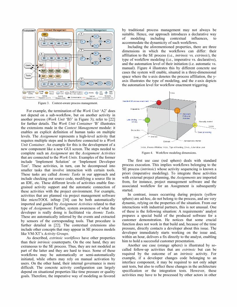
Figure 3. Context-aware process management.
For example, the termination of the Work Unit ‘A2’ does not depend on a sub-workflow, but on another activity in another process (Work Unit ‘B3’ in Figure 3); refer to [22] for further details. The Work Unit Container ‘B’ illustrates the extensions made in the Context Management module: it enables an explicit definition of human tasks on multiple levels. The Assignment represents a high-level activity that requires multiple steps and is therefore connected to a Work Unit Container. An example for this is the development of a new component like a new GUI screen. The steps needed to complete such an Assignment are the Assignment Activities that are connected to the Work Units. Examples of the former include ‘Implement Solution’ or ‘Implement Developer Test’. These activities, in turn, can be decomposed into smaller tasks that involve interaction with certain tools. These tasks are called Atomic Tasks in our approach and include checking out source code, modifying a source file in an IDE, etc. These different levels of activities enable fine-grained activity support and the automatic connection of these activities with the project environment. For example, activities that are planned via project management software like microTOOL inStep [34] can be both automatically imported and guided by Assignment Activities related to that type of Assignment. Further, system awareness of what the developer is really doing is facilitated via Atomic Tasks. These are automatically inferred by the events and extracted by sensors of the corresponding tools. That procedure is further detailed in [22]. The contextual extensions also include other concepts that may appear in SE process models like VM-XT’s Activity Groups.
As described, extrinsic workflows have other properties than their intrinsic counterparts. On the one hand, they are extraneous to the SE process. Thus, they are not modeled as part of the latter and they are hard to trace. Some of these workflows may be automatically or semi-automatically initiated, while others may rely on manual activation by users. On the other hand, their internal governance is more difficult. The concrete activity configuration can largely depend on situational properties like time pressure or quality goals. Therefore, the imperative way of modeling as favored
by traditional process management may not always be suitable. Hence, our approach introduces a declarative way of modeling including contextual influences, to accommodate the dynamicity of such workflows.
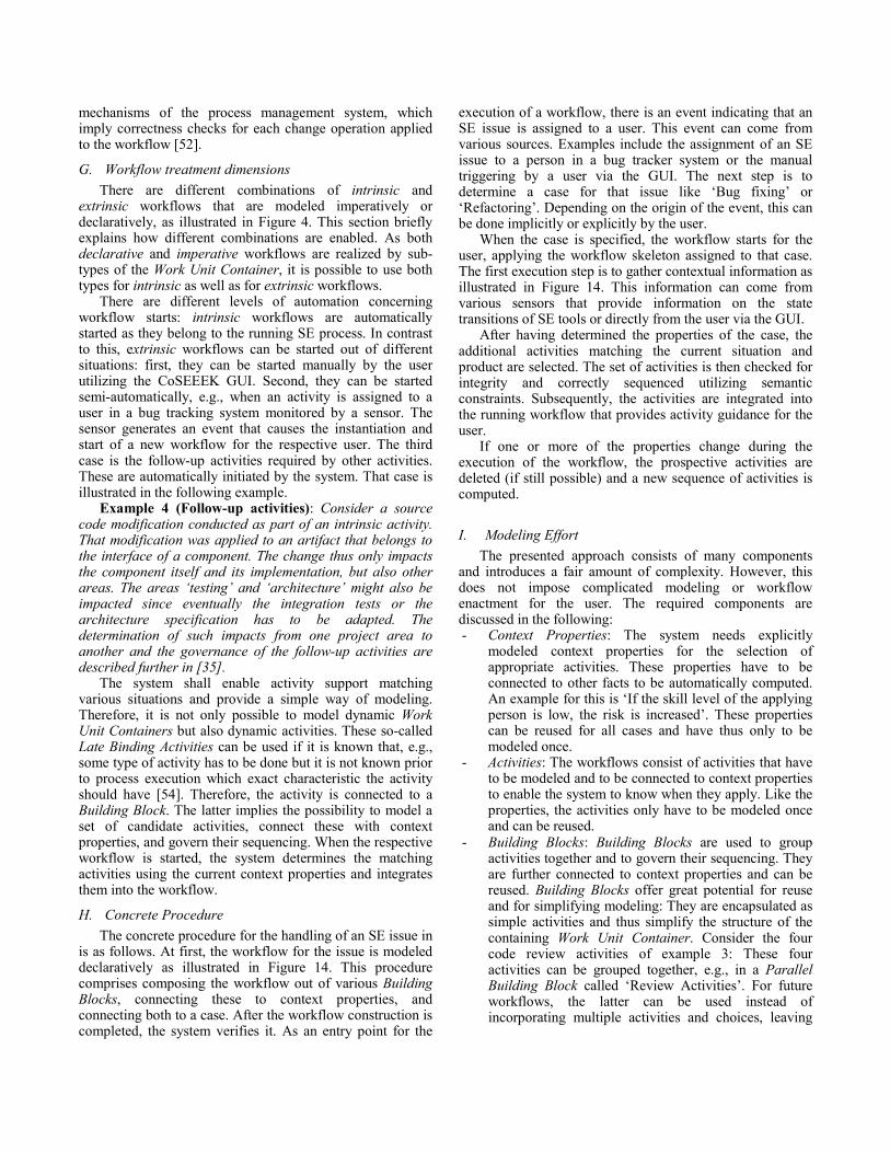
Including the aforementioned properties, there are three dimensions in which the workflows can differ: their affiliation to the SE process (i.e., intrinsic vs. extrinsic), the type of workflow modeling (i.e., imperative vs. declarative), and the automation level of their initiation (i.e. automatic vs. manual). Figure 4 illustrates this by different concrete use cases the system will enable, situated in a three-dimensional space where the x-axis denotes the process affiliation, the y-axis illustrates the type of modeling, and the z-axis depicts the automation level for workflow enactment triggering.
Figure 4. Workflow modeling dimensions.
The first use case (red sphere) deals with standard process execution. This implies workflows belonging to the SE process (intrinsic) whose activity sequencing is known a priori (imperative modeling). To integrate these activities with external project planning, the Assignments are imported from, for instance, project management software and the associated workflow for an Assignment is subsequently started.
In contrast, issues occurring during projects (yellow sphere) are ad-hoc, do not belong to the process, and are very dynamic, relying on the properties of the situation. From our interactions with industrial partners, this is not unusual. One of these is the following situation: A requirements’ analyst prepares a special build of the produced software for a customer demonstration. He notices that some crucial function does not work in that build and, because of the time pressure, directly contacts a developer about this issue. The developer immediately starts working on the issue and, within an hour, delivers a fix directly to the analyst, enabling him to hold a successful customer presentation.
Another use case (orange sphere) is illustrated by so-called follow-up activities that are extrinsic but can be required by the outcome of an intrinsic activity. For example, if a developer changes code belonging to an interface component, it may be required to not only adapt unit tests, but also to reflect these changes in the architecture specification or the integration tests. However, these activities may have to be processed by other actors in other

teams, like architects or the test team. [35] introduced a CoSEEEK facility to automatically reason about such coherences and to automatically initiate and govern the follow-up activities.
The last example (green sphere) is enabled by the combination of imperative and declarative modeling. Assume a situation where an activity sequence is clear and therefore imperatively pre-specified by a process engineer. Though the sequencing of the entire workflow might be deliberately rigid and most of the activities selected, it might nevertheless be useful to introduce limited dynamicity in that imperative workflow: at build-time, for some activities the category might be clear, but not the concrete characteristic. Consider review activities as an example. It might be clear that a review activity shall be integrated, but there are different variants in that category like ‘Peer Review’, ‘Code Review’, or ‘Code Inspection’. Each of them has different properties like effort, duration, or error detection rate. For such activities, a set of candidate activities can be defined, enabling the system to choose the corresponding one upon execution. For example, if there is significant schedule pressure when the workflow is executed, an activity will be chosen that has low duration. Of course, a variety of other combinations is possible as, e.g., semi-automatically started declarative, extrinsic workflows like bug fixing initiated by the import of new high priority defects from a defect tracking system.
D. Applying Situational Method Engineering Situational method engineering adapts generic methods
to the actual situation of a project [23]. This is done based on two different influence factors called process properties, which capture the impact of the current situation, and product properties that realize the impact of the product currently being processed (in this context the type of component, e.g., a GUI or database component). To strike a balance between rigidly pre-specified workflows and the absence of process guidance, the idea is to have a basic workflow for each use case that is then dynamically extended with activities matching the current situation. The construction of the workflows utilizes a so-called case base as well as a method repository. The case base contains a workflow skeleton of each of the use cases. In the following these use cases, which are associated to an SE issue and have an attributed workflow, will simply be called cases. The workflow skeleton belonging to a case only contains the fundamental activities always being executed for that case. The method repository contains all other activities whose execution is possible according to the case. To be able to choose the appropriate activities for the current artifact and situation, the activities are connected to properties that realize product and process properties of situational method engineering.
Each SE issue, such as refactoring or bug fixing, is mapped to exactly one case relating to exactly one workflow skeleton. To realize a pre-selection of activities (e.g., Create Branch or Code Review) which semantically match an issue, the issue is connected to the activity via an n-to-m relation. The activities are connected, in turn, to properties specifying
the dependencies among them. The selection of an activity can depend on various process as well as product properties. To model the characteristic of an issue leading to the selection of concrete activities, the issue is also connected to various properties. The properties have a computed value indicating the degree in which they apply to the current situation. Utilizing the connection of activity and property, selection rules for activities based on the values of the properties can be specified. The following example illustrates these concepts by means of an extremely simplified bug fixing workflow.
Example 2 (Situational workflow extension): Figure 5 shows different parts of our concept for a bug fixing issue. On the left side of the figure, the relating case and the skeleton workflow are shown. That skeleton workflow is then extended with activities that match the values of the properties: Activity B (could be e.g., ‘Run Regression Tests’) is added because of the property ‘Criticality’ and activity C (could be e.g., ‘Validation to Requirements’) is added because of the property ‘Complexity’.
ActivityWorkflow Instance / Work Unit Container
AND-Gate
OR-Gate
Communication
A B C
Case
Complexity
Criticality
Bug Fixing
User SensorContext Property
A
Bug Fixing
Figure 5. SME example
E. Information Gathering To leverage the automatic support for extrinsic
workflows, the computation of the property values constitutes a key factor. Our approach unifies process and product properties in the concept of the property, which can be influenced by a wide range of factors. The integration of different modules and applications as well as the unification of various project areas in CoSEEEK enable the automatic computation of the values comprising contextual knowledge. On the one hand, tool integration can provide meaningful information about the artifact being processed in the current case. For example, if the artifact is a source code file, static code analysis tools (such as PMD) can be used to execute various measurements on that file, revealing various potential problems. If a high coupling factor was detected, this would raise the product property ‘risk’ associated to that file. On the other hand, the integration of various project areas like resource planning entails contextual knowledge about the entire development process. An example is the raising of the process property ‘risk’ if the person processing the current case is a junior engineer.

Both of these aspects deal with implicit information gathering. Since not all aspects of a case are necessarily covered by implicit information, and not all options for gaining knowledge about the case are always present, the system utilizes explicit information gathering from the user processing the case. To enable and encourage the user to provide meaningful information, a simple response mechanism is integrated into the CoSEEEK GUI (shown in the next section). Via this mechanism, the user can directly influence process as well as product properties. To keep the number of adjustable parameters small, the concept of product category was introduced. The product category unites the product properties in a pre-specified way. An example of this would be a database component or a GUI component: the database component is likely to have more dependencies, whereas the GUI component presumably has more direct user impact. The influence of the product categories on the different properties is specified in advance and can be adapted to fit various projects. Selected process properties can be set directly. The computation of all other influences on the properties is explained in the following section.
F. Declarative Workflow Modeling After completing the computation of the property values,
activities must be selected and correctly sequenced to enable dynamic construction of the workflow for an SE issue. This is done utilizing the connection between properties and activities. An activity can depend on one or more properties. Examples include selection rules such as:
• ‘Choose activity code inspection if risk is very high,
criticality is high, and urgency is low’ or • ‘Choose activity code review if risk and criticality are
both high’. The sequencing of the chosen activities in our initial
approach [1] was very simple and did not allow for choices or the parallel execution of activities. Therefore, this section integrates our work from [26] and extends it. Declarative workflow modeling approaches incorporate a certain amount of flexibility in the workflow models [25] and thus enable the latter to be applicable for different situations. However, the declarative way of modeling can be difficult to understand [36] and can produce models that are hard to maintain [37]. Therefore, our declarative workflow modeling approach is based on very simple constraints and so called Building Blocks that enable further structuring of the workflow and structural nesting.
This modeling type is illustrated and compared to classical workflow modeling in Figure 13. The figure shows the modeling of the Work Unit Containers above and the derived workflows for execution below. ‘Work Unit Container 1’ shows a simple, imperatively modeled workflow that is also executed in that form (as ‘Workflow 1’). ‘Work Unit Container 2’ illustrates declarative modeling of the same workflow: the exact structure of the workflow is not rigidly pre-specified. There are only simple constraints connecting activities in the workflow. Examples in Figure 13
are ‘Requires’, expressing that one activity requires the presence of another, and ‘Parallel’, expressing that both activities should be executed in parallel. The generated workflow for these constraints looks exactly like the imperatively modeled ‘Work Unit Container 1’. Activities in the declarative approach also have relations to contextual properties in order to enable the system to select a subset of the pre-specified activities for the execution workflow. Finally, ‘Work Unit Container 3’ demonstrates the use of Building Blocks. These are used for further structuring the workflow. Three Building Blocks are shown for sequential, parallel, and repeated execution of the contained elements in Figure 13. ‘Workflow 3’ shows how a workflow is built based on constraints and the Building Blocks. Furthermore, it demonstrates contextual relations, in this case assuming that the contextual properties of the situation led the system to the selection of activities ‘1’, ‘2’, ‘3’, and ‘5’ while omitting activities ‘4’ and ‘6’.
In the following, all available constraints and Building Blocks are shown, as well as conditions to be fulfilled for declarative modeling and that are later checked by the framework.
The constraints were designed in a way such that they remain simple and facilitate basic workflow modeling. Structures that are more complex can be expressed using Building Blocks. The constraints are categorized into sequencing constraints and existence constraints. Existence constraints govern which activities should be present in a workflow, while sequencing constraints govern how they should be arranged in the workflow. The available constraints are shown in Table I.
TABLE I. DECLARATIVE CONSTRAINTS
Constraint Meaning Type
X hasSuccessor Y if X and Y are present, X should appear before Y sequencing
X hasParallel Y
if X and Y are present, they should appear parallel (like two branches that are connected by AND gates in classical process modeling)
sequencing
X requires Y if X is present, Y must also be present existence
X mutualExclusion Y if X is present, the presence of Y is prohibited existence
Utilizing these constraints, very basic workflows are
possible, specifying “should” / “should not” appear together and a sequence or parallel arrangement.
The Building Blocks that enable complex structures have been developed to mirror standard workflow patterns for block-structured workflows [38]. This way of structuring enables easy separation of the workflow into nested blocks. These blocks can be activities, patterns, or the workflow itself. Each block must have a unique start and end point [39][40][41]. The blocks can be regularly nested, meaning that they may not overlap [42][41][40]. For workflows that are not structured like this, in most cases a transformation to a block structured model can be applied [40][43][41]. For control flow modeling in workflows, the basic patterns are:

Sequence, AND-split, AND-join, XOR-split, XOR-join, and Loop [31]. With these patterns, most models that are used in practice can be covered since they are the basis of any process specification language [44][45][46]. They can also be easily transformed to formal languages like Petri Nets [29] and to other widespread process languages like WS-BPEL [47][48]. There also exist other control flow patterns like the Multi-Choice / OR-split [31]. This work presumes the sole usage of the basic control flow patterns, because the use of other patterns can complicate the process model and promote error-proneness [43][49][50]. Furthermore, it is possible to construct other control flow patterns using the basic ones like, e.g., composing an OR-split with XOR- and AND-splits [38][51]. The available Building Blocks and their relation to control flow patterns is shown in Table II.
TABLE II. BUILDING BLOCKS
Building Block Control Flow Pattern(s) Sequence Sequence Parallel AND-split, AND-join Loop Loop
Conditional XOR-split, XOR-join ‘Work Unit Container 3 / Execution Workflow 3’ in
Figure 13 demonstrates how nested Building Blocks are transformed into the control-flow structure of a workflow.
Compared to [26], the Building Block ‘Conditional’ has been added to cover all basic workflow patterns. This Building Block implies a deferred decision about the executed activities: At run-time, based on a certain variable, the XOR pattern chooses exactly one activity from a set of contained activities or, in case one empty branch exists in the XOR pattern, no activity might be chosen. Furthermore, for the decision made in the XOR pattern, the value range of the variable used for the decision should be completely covered to avoid deadlocks in execution [52][53]. This, combined with the fact that Building Blocks contain candidate activities from which a subset is to be chosen, makes it error-prone. The value range can become only partially covered, and it is possible that two or more activities (from which a selection was intended by the modeler) are omitted due to context properties, leaving no valid choice at run-time. In light of these problems, two options are supported in modeling a ‘Conditional’ Building Block: the first one contains no empty branch. For this variant, the system checks the coverage of the value range during construction and no activities can be omitted for that block. That way, run-time choices not dependent on context properties can be modeled. The second variant contains an empty branch. In that case omitting activities due to contextual factors is permitted. The system assigns all uncovered sections of the value range to the empty branch. That way it is possible to model a deferred decision that incorporates contextual factors including the case that none of the activities comes to execution.
However, the usage of Building Blocks not only enables the modeling of workflow structures containing all basic structural patterns, but also simplifies modeling since it fosters the reuse of different fragments of a workflow: in
traditional process management, reuse is limited to workflows or activities. In contrast, our declarative modeling approach supports the reuse of fragments of the workflows. These fragments, captured as Building Blocks, are encapsulated as simple activities, and thus simplify the workflow structure and hide its inherent complexity. Another factor supporting reuse is the relation to context properties: each simple activity and Building Block can have these context connections. That way a Building Block can be used in various different workflows for various situations. The following example illustrates this.
Example 3 (Building Block): A Building Block for different code review activities can be defined, containing review activities with different properties. These are for example ‘Peer Review’, ‘Code Review’, ‘Walkthrough’, or ‘Code Inspection’. Utilizing connections to context properties like ‘Urgency’ or ‘Risk’, these activities “know” the situations to which they apply, and the surrounding Building Block can thus be easily used for all of these situations without additional effort.
With this method of declarative modeling, one can model ‘candidate activities’ and relate them to context properties during build-time, while the system decides at run-time which of the activities will be used to construct the execution workflow matching the current situation. This implies that several activities may be omitted for a certain execution workflow. To ensure that proper workflows are still constructible out of a declarative workflow specification, the system conducts a so-called ‘auto-completion’ on the specified workflows as illustrated in Figure 6.
A
DC
B
A DC
B D
A: Auto completion B: Workflow Examples
Activity Successor Constraint Parallel Constraint
Figure 6. Workflow auto-completion example.
In Figure 6(A), the red-dashed constraints are added by the system. This enables the construction of workflows from subsets of the specified activities as exemplified in Figure 6(B). A set of conditions is verified by the system to ensure that correct basic modeling and all specified workflows are properly completed. These conditions concern the workflows as a whole as well as the different Building Blocks. An example of such a condition is shown in the following:
Condition C1: Each workflow shall have a unique start
and end point. This promotes simple and understandable models as suggested in [43].
The conditions and the auto completion feature are
further explained in [26]. Structural integrity of the workflows is guaranteed upon creation based on the built-in
mechanisms of the process management system, which imply correctness checks for each change operation applied to the workflow [52].
G. Workflow treatment dimensions There are different combinations of intrinsic and
extrinsic workflows that are modeled imperatively or declaratively, as illustrated in Figure 4. This section briefly explains how different combinations are enabled. As both declarative and imperative workflows are realized by sub-types of the Work Unit Container, it is possible to use both types for intrinsic as well as for extrinsic workflows.
There are different levels of automation concerning workflow starts: intrinsic workflows are automatically started as they belong to the running SE process. In contrast to this, extrinsic workflows can be started out of different situations: first, they can be started manually by the user utilizing the CoSEEEK GUI. Second, they can be started semi-automatically, e.g., when an activity is assigned to a user in a bug tracking system monitored by a sensor. The sensor generates an event that causes the instantiation and start of a new workflow for the respective user. The third case is the follow-up activities required by other activities. These are automatically initiated by the system. That case is illustrated in the following example.
Example 4 (Follow-up activities): Consider a source code modification conducted as part of an intrinsic activity. That modification was applied to an artifact that belongs to the interface of a component. The change thus only impacts the component itself and its implementation, but also other areas. The areas ‘testing’ and ‘architecture’ might also be impacted since eventually the integration tests or the architecture specification has to be adapted. The determination of such impacts from one project area to another and the governance of the follow-up activities are described further in [35].
The system shall enable activity support matching various situations and provide a simple way of modeling. Therefore, it is not only possible to model dynamic Work Unit Containers but also dynamic activities. These so-called Late Binding Activities can be used if it is known that, e.g., some type of activity has to be done but it is not known prior to process execution which exact characteristic the activity should have [54]. Therefore, the activity is connected to a Building Block. The latter implies the possibility to model a set of candidate activities, connect these with context properties, and govern their sequencing. When the respective workflow is started, the system determines the matching activities using the current context properties and integrates them into the workflow.
H. Concrete Procedure The concrete procedure for the handling of an SE issue in
is as follows. At first, the workflow for the issue is modeled declaratively as illustrated in Figure 14. This procedure comprises composing the workflow out of various Building Blocks, connecting these to context properties, and connecting both to a case. After the workflow construction is completed, the system verifies it. As an entry point for the
execution of a workflow, there is an event indicating that an SE issue is assigned to a user. This event can come from various sources. Examples include the assignment of an SE issue to a person in a bug tracker system or the manual triggering by a user via the GUI. The next step is to determine a case for that issue like ‘Bug fixing’ or ‘Refactoring’. Depending on the origin of the event, this can be done implicitly or explicitly by the user.
When the case is specified, the workflow starts for the user, applying the workflow skeleton assigned to that case. The first execution step is to gather contextual information as illustrated in Figure 14. This information can come from various sensors that provide information on the state transitions of SE tools or directly from the user via the GUI.
After having determined the properties of the case, the additional activities matching the current situation and product are selected. The set of activities is then checked for integrity and correctly sequenced utilizing semantic constraints. Subsequently, the activities are integrated into the running workflow that provides activity guidance for the user.
If one or more of the properties change during the execution of the workflow, the prospective activities are deleted (if still possible) and a new sequence of activities is computed.
I. Modeling Effort The presented approach consists of many components
and introduces a fair amount of complexity. However, this does not impose complicated modeling or workflow enactment for the user. The required components are discussed in the following: - Context Properties: The system needs explicitly
modeled context properties for the selection of appropriate activities. These properties have to be connected to other facts to be automatically computed. An example for this is ‘If the skill level of the applying person is low, the risk is increased’. These properties can be reused for all cases and have thus only to be modeled once.
- Activities: The workflows consist of activities that have to be modeled and to be connected to context properties to enable the system to know when they apply. Like the properties, the activities only have to be modeled once and can be reused.
- Building Blocks: Building Blocks are used to group activities together and to govern their sequencing. They are further connected to context properties and can be reused. Building Blocks offer great potential for reuse and for simplifying modeling: They are encapsulated as simple activities and thus simplify the structure of the containing Work Unit Container. Consider the four code review activities of example 3: These four activities can be grouped together, e.g., in a Parallel Building Block called ‘Review Activities’. For future workflows, the latter can be used instead of incorporating multiple activities and choices, leaving

the system responsible for selecting the matching activities for the current situation during run-time.
- Cases: For each concrete issue like ‘Bug Fixing’, one case is defined. The definition of a case is very simple since all defined activities, context properties, and Building Blocks can be reused. The structure of the cases is also very simple as there are only four constraints needed for connecting the activities or Building Blocks. More complex control flow modeling is handled and encapsulated by the Building Blocks.
IV. REALIZATION This section describes the concrete implementation of the
SE issue process introduced in the preceding section.
A. Technical component realization Before describing the procedural realization, the
technical realization of the participating components is briefly introduced as illustrated in Figure 7.
Figure 7. CoSEEEK realization architecture.
While various other Java (Mantis, inStep, PMD, xRadar, etc.) and .NET (Visual Studio 2010, Team Foundation Server) SE Tools are integrated, to exemplify the realization just a few will be described. Source code and test code Artifacts are processed via the version control management system Subversion and the IDE Eclipse. All communication between the modules is performed using a custom XML implementation of the Tuple Space paradigm [27] that uses the eXist XML database [55] for collaborative event storage and Apache CXF for web service communication. The Hackystat framework [56], which provides a rich set of sensors for various applications, is used for Event Extraction via its tool sensor components and for storage of high volume basic events in a relational database. Event Processing is performed via the complex event processing (CEP) [57] tool esper [58], that detects and triggers higher-order complex events from the multiple basic events.
The Process Management module requires an adaptable process-aware information system (PAIS) to cope with the dynamic nature of SE processes the current approach seeks to address. Therefore, the AristaFlow BPM suite (formerly ADEPT2) [52][39] was chosen for its realization. It allows authorized agents [59] to dynamically adapt and evolve the structure of process models during run-time. Such dynamic
process changes do not lead to unstable system behavior, i.e., none of the guarantees achieved by formal checks at build-time are violated due to the dynamic change at run-time [42]. Correctness is ensured in two stages. First, structural and behavioral soundness of the modified process model is guaranteed, independent from whether or not the change is applied at the process instance level. Second, when performing structural schema changes at the process instance level, this must not lead to inconsistent or erroneous process states afterwards. AristaFlow applies well-elaborated correctness principles in this context [60]. Despite its comprehensive support for dynamic process changes, ADEPT2 has not considered automated workflow adaptations so far.
The Context Management module has three main responsibilities: it realizes the case base, the method repository, and contains context information about the entire project. This information is stored in an OWL-DL [61] ontology to unify project knowledge and to enable reasoning over it. The use of an ontology reduces portability, flexibility, and information sharing problems that are often coupled to relational databases. Additionally, ontologies facilitate extensibility since they are, in contrast to relational databases, based on an open world assumption and thus allow the modeling of incomplete knowledge. To programmatically access the ontology, the Jena API [62] is used within the Context Module. Reasoning and classification of information is provided by the reasoner Pellet [63].
B. Concrete Procedure This section illustrates the communication of the modules
by means of a concrete example that is depicted in Figure 15. Basic event extraction and event processing is presumed. In that concrete case, the bug tracker Mantis is used in conjunction with a sensor that generates an ad hoc workflow event when an SE issue is assigned to a person (1) and is stored in the XML tuple space. That event contains information about the kind of issue for case selection and about the person. In case of a real ad hoc issue not recorded in a bug tracker, the event for instantiating a workflow can be triggered from the GUI as well, requiring the user to select a case manually (1). The GUI is a lightweight web interface developed in PHP that can be executed in a web browser as well as preferably directly in the users IDE. Figure 8(A) shows the GUI: in the upper area, contextual information is displayed while the lower area is reserved for workflow governance. The upper area also provides the option to start a case manually. The event is then automatically received by the Process Management module (cf. Figure 15(2)), which instantiates a workflow skeleton based on the template of the selected case (3). The activity components of AristaFlow (called environments) for these workflows are customized to communicate over the Tuple Space (4) and thus, enable user interaction during the execution of each activity. The first activity of each SE issue is ‘Analyze Issue’ to let the user gain knowledge about the issue and provide information about process and product properties to the system via the GUI (5). Figure 8(B) shows
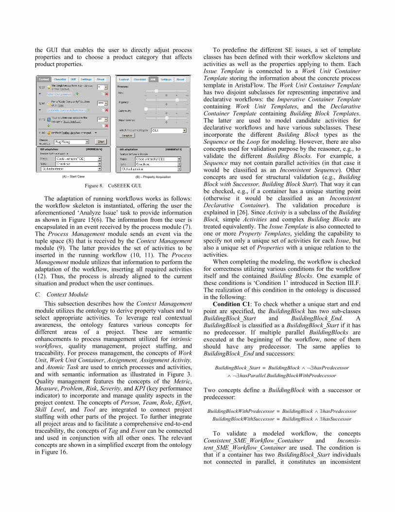
the GUI that enables the user to directly adjust process properties and to choose a product category that affects product properties.
(A) – Start Case (B) – Property Acquisition Figure 8. CoSEEEK GUI.
The adaptation of running workflows works as follows: the workflow skeleton is instantiated, offering the user the aforementioned ‘Analyze Issue’ task to provide information as shown in Figure 15(6). The information from the user is encapsulated in an event received by the process module (7). The Process Management module sends an event via the tuple space (8) that is received by the Context Management module (9). The latter provides the set of activities to be inserted in the running workflow (10, 11). The Process Management module utilizes that information to perform the adaptation of the workflow, inserting all required activities (12). Thus, the process is already aligned to the current situation and product when the user continues.
C. Context Module This subsection describes how the Context Management
module utilizes the ontology to derive property values and to select appropriate activities. To leverage real contextual awareness, the ontology features various concepts for different areas of a project. These are semantic enhancements to process management utilized for intrinsic workflows, quality management, project staffing, and traceability. For process management, the concepts of Work Unit, Work Unit Container, Assignment, Assignment Activity, and Atomic Task are used to enrich processes and activities, and with semantic information as illustrated in Figure 3. Quality management features the concepts of the Metric, Measure, Problem, Risk, Severity, and KPI (key performance indicator) to incorporate and manage quality aspects in the project context. The concepts of Person, Team, Role, Effort, Skill Level, and Tool are integrated to connect project staffing with other parts of the project. To further integrate all project areas and to facilitate a comprehensive end-to-end traceability, the concepts of Tag and Event can be connected and used in conjunction with all other ones. The relevant concepts are shown in a simplified excerpt from the ontology in Figure 16.
To predefine the different SE issues, a set of template classes has been defined with their workflow skeletons and activities as well as the properties applying to them. Each Issue Template is connected to a Work Unit Container Template storing the information about the concrete process template in AristaFlow. The Work Unit Container Template has two disjoint subclasses for representing imperative and declarative workflows: the Imperative Container Template containing Work Unit Templates, and the Declarative Container Template containing Building Block Templates. The latter are used to model candidate activities for declarative workflows and have various subclasses. These incorporate the different Building Block types as the Sequence or the Loop for modeling. However, there are also concepts used for validation purpose by the reasoner, e.g., to validate the different Building Blocks. For example, a Sequence may not contain parallel activities (in that case it would be classified as an Inconsistent Sequence). Other concepts are used for structural validation (e.g., Building Block with Successor, Building Block Start). That way it can be checked, e.g., if a container has a unique starting point (otherwise it would be classified as an Inconsistent Declarative Container). The validation procedure is explained in [26]. Since Activity is a subclass of the Building Block, simple Activities and complex Building Blocks are treated equivalently. The Issue Template is also connected to one or more Property Templates, yielding the capability to specify not only a unique set of activities for each Issue, but also a unique set of Properties with a unique relation to the activities.
When completing the modeling, the workflow is checked for correctness utilizing various conditions for the workflow itself and the contained Building Blocks. One example of these conditions is ‘Condition 1’ introduced in Section III.F. The realization of this condition in the ontology is discussed in the following:
Condition C1: To check whether a unique start and end point are specified, the BuildingBlock has two sub-classes BuildingBlock_Start and BuildingBlock_End. A BuildingBlock is classified as a BuildingBlock_Start if it has no predecessor. If multiple parallel BuildingBlocks are executed at the beginning of the workflow, none of them should have any predecessor. The same applies to BuildingBlock_End and successors:
redecessorBlockWithPl.BuildinghasParallessorhasPredeceockBuildingBlock_StartBuildingBl
¬∃∧¬∃∧≡
Two concepts define a BuildingBlock with a successor or predecessor:
orhasSuccessockBuildingBlcessorockWithSucBuildingBlssorhasPredeceockBuildingBldecessorockWithPreBuildingBl
∃∧≡∃∧≡
To validate a modeled workflow, the concepts
Consistent_SME_Workflow_Container and Inconsis-tent_SME_Workflow_Container are used. The condition is that if a container has two BuildingBlock_Start individuals not connected in parallel, it constitutes an inconsistent

container. Currently, the check is implemented programmatically via the Jena framework. After validating the workflow, the completion procedure also mentioned in Section III.F is conducted, enabling the system to construct consistent workflows out of subsets of the specified activities. We refer interested readers to [26] for further details.
When a new SE Issue is instantiated, it derives the Work Unit Container and the Properties from its associated Issue Template. Each Property holds a value indicating how much this Property applies to the current situation. These values can be influenced by various factors also defined by the Property Template. Figure 16 exemplifies three different kinds of influences currently used. Future work will include the integration of further concepts of the ontology that influence the Properties, as well as extending the ontology to fully leverage the context knowledge available to CoSEEEK.
The ProductCategory specified in the GUI has a direct influence on the product Properties. Furthermore, there can be Problems relating to the processed Artifact, e.g., indicated by violations of source code metrics. The Skill Level of the Person dealing with the SE Issue serves as example for an influence on the process properties here. There are four possible relations between entities affecting the Properties, and the Properties capture strong to weak negative as well as positive impacts. These are all used to compute the values of the Properties. The values are initialized with ‘0 (neutral)’ and are incremented / decremented by one or two based on the relations to the different influences. The values are limited to a range from ‘-2 (very low)’ to ‘2 (very high)’, thus representing five possible states of the degree to which the property applies to the current situation.
To select appropriate Building Blocks according to the current properties, six possible connections are utilized. These are ‘weaklyDependsOn’, ‘stronglyDependsOn’, and ‘dependsOn’, meaning the Activity is suitable if the value of the Property is ‘1 (high)’ or ‘2 (very high)’, or just positive and the other three connections for negative values. Each Building Block can be connected to multiple Properties. Based on an Issue, for each attributed ActivityTemplate a SPARQL query is dynamically generated which returns the corresponding Activity if the Properties of the current situation match. Listing 1 shows such a query for an Activity ‘act’ that is based on an ActivityTemplate ‘at’ and depends on two different Properties ‘prop1’ and ‘prop2’ which are, in turn, based on Property Templates ‘pt1’ and ‘pt2’.
Listing 1 Activity selection SPARQL query
PREFIX project: <http://www.htw-aalen.de/coseeek/context.owl#> SELECT ?act WHERE {
?act project:basedOnActivityTemplate ?at. ?at project:title "AT_CodeReview". ?issue project:title "CodeFixRequired". ?issue project:hasProperty ?prop. ?prop project:basedOnPropertyTemplate ?pt. ?at project:weaklyDependsOn ?pt. ?prop project:weight "1". ?issue project:hasProperty ?prop2.
?prop2 project:basedOnPropertyTemplate ?pt2. ?at project:stronglyDependsOn ?pt2. ?prop2 project:weight "2".}
Based on this activity selection, the Work Unit Container
comprises all applicable Building Blocks and Activities. Based upon this, the workflow skeleton is adapted and Work Units are generated for the Activities that are to be executed. This is described in detail in [18].
The significance of this contribution is, on the one hand, that workflows for SE issues, which are extrinsic to archetype SE processes, are not only explicitly modeled, but also dynamically adapted to the current issue and situation based on various properties derived from the current product, process, the context, and the user. Thus, it is possible to provide situational and tailored support as well as guidance for software engineers processing SE issues. On the other hand, the proposed approach shows promise for improving and simplifying process definition for extrinsic workflows. The initial effort to define all the activities, issues, properties, and workflow skeletons may not be less than predefining huge workflows for the issues, but the reuse of the different concepts is fostered. Thereafter, the creation of new issues is simplified since they only need to be connected to activities they should contain. The latter are later automatically inserted to match the current situation. Yet the main advantage is of semantic nature: the process of issue creation is much more problem-oriented using the concepts in the ontology versus creating immense process models. The process engineer can concentrate on activities matching the properties of different situations rather than investing cognitive efforts in the creation of huge rigid process models matching every possible situation. Likewise, the analysis of issues allows simple queries to the ontology returning problem-oriented knowledge such as ‘Which activities apply to which issues’ or ‘Which activities are applied to high-risk time critical situations’.
D. Modeling Effort This section provides further details about the real
modeling effort required for specifying declarative workflows including contextual properties. A web-based GUI was developed to support this kind of process modeling, multiple screenshots of which are shown in Figure 17. The screens on the left side depict the full GUI, while the ones on the right side show only selected relevant parts.
The GUI enables the easy creation of context properties, activities, Building Blocks, and cases. For each of these, one screen in the GUI enables the creating, editing, and deleting of these items. Figure 17(C) shows the screen containing the list of Building Blocks. From that list, the screen for editing / creating Building Blocks can be accessed, as shown in Figure 17. (B). It enables defining a name, a description, and a category for the Building Block. The type of Building Block can also be selected and, according to the type, the special properties of the block. Figure 17(B) shows this for a ‘Sequence’: on the left, the contained activities / Building Blocks can be specified, and on the right, the context properties to which the specified Building Block should

apply. Activities can be defined similarly as shown in Figure 17(D): A name, a description, and a category can be defined, as well as context properties to which the activity shall apply.
The definition of context properties is depicted in Figure 17(D). For them, a name, a description, and influences can be defined. The example shows the ‘Skill Level’ of the person processing the activity as influence, which is defined to enhance the context property ‘Risk’ when it is low. The definition of cases can be easily accomplished as well (cf. Figure 17(A)). Besides a name and a description, the user can define how Building Blocks or activities shall be included utilizing the four basic constraints.
E. Case learning Taking the variety of possible SE issues into account, it is
not likely that all of them will be modeled a priori. To support the integration of cases for new issues into the system, our approach features the so-called ‘Case learning’ functionality. It enables the user to start a new issue even if the latter is not known by the system. The user can then choose which activities to process for that issue and the system records it. The relevant part of the CoSEEEK GUI is shown in Figure 9. Via the lower part of that GUI, the user can name the issue he is processing and choose an activity category and activity to process. When he clicks ‘Process Activity’, the activity chosen is recorded for that new issue. When the issue is finished, the user clicks ‘Complete Issue’ to stop the issue recording.
Figure 9. GUI with case learning feature.
A process engineer can then utilize that information to model workflows for new cases. That way, if an unknown issue was recorded multiple times, the applicable Building Blocks to cover that various possibilities can be derived by a process engineer. Future work can even consider deriving new workflow templates automatically, similar to the approach shown in [46][64]. It considered the automatic generation of new process models from different instance variants derived from the same model to provide models that better match real execution.
V. EVALUATION This section illustrates the advantages of the proposed
approach via a synthetic, but concrete practical scenario generated in a lab environment. Future work will include analysis of currently ongoing industrial case studies utilizing CoSEEEK with partners of the research project.
A. Scenario Solved For the bug fix issue presented in Section I.A, the
concrete scenario considered two possible generated workflows. More precisely, for this scenario, a set of properties has been defined as well as activities and their dependencies on these properties. The first case deals with an urgent fix of a GUI component. That component is assumed to be part of a simple screen not often used by customers. The second case deals with a database component. The fix is assumed to have an impact on multiple tables in the database. Table III depicts the product and process properties that were selected for cases in this scenario as well as the values that were chosen for them by the developer via the CoSEEEK web GUI.
TABLE III. EXAMPLE SME PROPERTIES OF CASES
Component GUI (Case 1) DB (Case 2) Product criticality o +
Properties user impact ++ o dependencies - + complexity o + risk o +
Process risk - o Properties urgency + -
complexity - + dependencies o o
It is assumed that no other influences exist for the
properties. The activities being part of this scenario are shown in Figure 18. The figure illustrates different levels of encapsulated Building Blocks that foster easy modeling, while hiding the inherent complexity of the approach: on the top level, where the ‘Case’ is modeled, there is only a simple sequence consisting of activities and Building Blocks that realize the workflow structure. The scenario also shows the advanced flexibility of the approach. Activities can be flexibly integrated: the ‘Validation to Requirements’ activity will not always be required. Therefore it is simply integrated and connected to a very high value (++) of the complexity property. (This connection is not shown in Figure 18 to preserve better readability.) The testing activities were integrated, mutually excluding each other in the initial workflow. In the declarative specification, they are grouped in a Parallel Building Block and connected to different situational properties. Thus, the situation determines the execution of more than one or none of them. The two types of Conditional Building Blocks are also included. The review activities are mutually exclusive and it is possible that none of them comes to execution. Opposed to this, the ‘Integration’ Building Block requires one of the two mutually exclusive activities to be executed. To support better readability, Figure 18 shows only a selection of the mutual

connections between Building Blocks and the connections of Building Blocks to situational properties.
The chosen values lead to the selection of different activities for the different workflows as illustrated in Figure 10. Because of the low complexity of the GUI case, the bug fix needs no special preparation or design. Due to the direct user impact of the GUI component, a GUI test and the documentation in the change log has been chosen. The unit test activities have been modeled to be applicable only for cases that are not urgent and thus they were omitted. Due to the risk and complexity of the database component and the task relating to it, the creation of a separate branch as well as an explicit check for dependencies have been prescribed. In the given case, the ‘Design Solution’ activity was nevertheless omitted since it was modeled to be only applicable if ‘Complexity’ is very high (++). Unit as well as regression test activities were included because of low urgency and high criticality, whereas the creation of a regression test was conditionally integrated depending on the presence of regression tests. A code review has also been prescribed due to the complexity and criticality of the case. The higher dependencies of the database component also caused the inclusion of an activity to inform other team about the changes. The integration activities are also more complex here for working with multiple branches. A requirement constraint ensures the presence of the ‘Branch Integration’ activities if a separate branch was created.
Analyze Issue
ActivityEnd PointStart Point XOR-Gate
GUI Case Workflow
Database Case Workflow
Implement Solution GUI Test
Document in Change Log
Integrate and Build Close Issue
Analyze Issue
Close Issue
Create CR Branch
Check Dependencies
Implement Solution
Adapt Unit Test
Run Unit Test
Code Review
Check for other Branches
Integrate and Build
Create Patches
Run Regression Test
Run Unit Test
Create Regression Test
Inform other Team
Adapt Unit Test
Figure 10. Examples of generated workflows.
These workflows are much simpler than the pre-modeled example mentioned in the Problem Scenario section. Assuming the presence of an activity and Building Block library, the modeling is also simpler and more problem-oriented. The automated adaption supports workflow diversity, reducing complexity and maintenance compared to all-encompassing models. The scenario illustrates the usefulness of the guidance via the chosen activities by these two considerably different workflows containing tasks matching the situation as well as the processed artifact. Future case studies will be used to further evaluate the
practicality of the workflows and to refine the properties and their relation to the activities.
B. Further examples of use cases This section illustrates other use cases that typically
occur in SE projects to show the broader applicability of the approach and its reuse and simplicity capabilities. These use cases deal with technology swapping, migration, customer support, and infrastructural issues and are illustrated in Figure 11.
Development Cycle
Analyze Issue
Prepare Transfer Documentation Testing Integration Close Issue
Additional Cases
Technology Swap / Migration:
Infrastructural Issue:
Customer / 3rd Level Support:
Support Treatment
Analyze Issue
Contact Actuator Close Issue
Infrastructure Treatment
Analyze Issue
Contact Actuator Close Issue
Figure 11. Additionally modeled use cases.
‘Migration’ deals with the migration to a new software version of a supporting technology as, for instance, a web services framework. ‘Technology Swap’, in turn, deals with the replacement of a technology. Both of them are similar with the main difference being that ‘Technology Swapping’ is more complex and riskier. Therefore, they can be consolidated into one case. That use case includes a ‘Prepare Transfer’ Building Block containing activities to, e.g., analyze the new technology or technology version. Subsequently, the activities ‘Development Cycle’ and ‘Documentation’ are attached. The latter is extended to also include internal documentation, since in case of migrations or technology swaps internal documents of the developers may have to be adjusted. After that, the activities for testing and integration are included.
The case of ‘Customer / 3rd level Support’ deals with situations where developers provide direct support to customers and start with the receipt of a support request. At the top level it has a very simple workflow: the actuator of the support request is to be contacted and the support activity is to be executed. The ‘Contact Actuator’ Building Block therefore contains multiple conditional activities for contacting the customer by mail, telephone, or directly. The Building Block for the treatment, in turn, contains conditional activities for direct and deferred treatment. Direct treatment means the immediate fixing of a problem and contains the aforementioned activities for development, testing, etc. Deferred treatment, in turn, includes activities for creating a new entry in the bug tracking system. Both of the top level Building Blocks described here also contain the option not to execute any activity. That way various situations can be handled. For example, if the developer realizes that the problem was only caused by misunderstanding or customer misconduct, he can just contact the customer to sort out the problem and close the case.
The ‘Infrastructural Issue’ use case deals with problems relating to the infrastructure that are reported to the responsible person. For this case, the ‘Customer / 3rd level

Support’ case can almost be completely recycled since there may also be the necessity to contact the actuator of the request to gain additional info or to provide support on it. The second activity, the resolution of the issue, if required, contains slightly modified activities compared to the other cases. There is also the option for deferred treatment involving the creation of a new bug report. Immediate treatment is split into two activities: for simple cases such as a version change or simple compatibility issue, the issue can be directly resolved, but in more complex cases such as instability or licensing changes, further clarification, e.g., with the project manager might be required.
VI. RELATED WORK This section discusses work in different areas related to
the presented concept.
A. Contextual Integration of Process Management The combination of semantic technology and process
management technology has been used in various approaches. The concept described in [65] utilizes the combination of Petri Nets and an ontology to achieve machine-readable process models for better integration and automation. This is achieved creating direct mappings of Petri Net concepts in the ontology. The focus of the approach presented in [66] is the facilitation of process models across various model representations and languages. It features multiple levels of semantic annotations such as the meta-model annotation, the model content annotation, and the model profile annotation as well as a process template modeling language. The approach described in [67] presents a semantic business process repository to automate the business process lifecycle. Its features include checking in and out as well as locking capabilities and options for simple querying and reasoning that is more complex. Business process analysis is the focus of COBRA presented in [68]. It develops a core ontology for business process analysis with the aim to improve analysis of processes to comply with standards or laws like the Sarbanes-Oxley act. The approach described in [69] proposes the combination of semantic and agent technology to monitor business processes, yielding an effective method for managing and evaluating business processes. A similar approach is followed by SeaFlows [70]. While these approaches feature a process-management-centric use of semantic technology, CoSEEEK not only aims to further integrate process management with semantic technology, it also integrates contextual information on a semantic level to produce novel synergies alongside new opportunities for problem-oriented process management.
B. Automated Process Support With regard to automatic workflow support and
coordination, several approaches exist. CASDE [71] utilizes activity theory to provide a role-based awareness module managing mutual awareness of different roles in the project. CAISE [72], a collaborative SE framework, enables the integration of SE tools and the development of new SE tools based on collaboration patterns. Caramba [73] features support for ad-hoc workflows utilizing connections between
different artifacts, resources, and processes to provide coordination of virtual teams. UML activity diagram notation is used for pre-modeled workflows. For ad-hoc workflows not matching a template, an empty process is instantiated. In that case, work between different project members is coordinated via so-called Organizational Objects. Finally, EPOS [74] applies planning techniques to automatically adapt a process instance if certain goals are violated. These approaches primarily focus on the coordination of dependencies between different project members and do not provide unified, context-aware process guidance incorporating intrinsic as well as extrinsic workflows.
C. Flexible Process Models The problem of rigid processes unaligned to the actual
situation is addressed in different ways by approaches like Provop [12], WASA2 [75], ADEPT2 [52], Worklets [76], DECLARE [77], Agentwork [78], Alaska [79],Pockets of Flexibility (PoF) [80], ProCycle [81][82], and CAKE2 [83].
Provop provides an approach for the modeling and configuration of process variants; i.e., starting with a given process reference model, a particular process model variant can be configured taking contextual properties into account as well [84]. As opposed to our approach, however, the Provop context model is relatively simple and does not consider ontologies or semantic processing. A similar approach, which requires form-based user interaction when configuring a process model variant, is provided in [85].
WASA2 and ADEPT2 constitute examples of adaptive process management systems. Both enable dynamic process changes at the process type as well as the process instance level; e.g., to cope with organizational changes or to deal with exceptional situations when executing a certain workflow instance. In particular, ADEPT2 enables the common application of both kinds of changes [86]. A detailed overview of these and other adaptive process management systems can be found in [87].
Worklets feature the capability of binding sub-process fragments or services to activities at run-time, thus not enforcing concrete binding at design time. DECLARE, in turn, provides a constraint-based model that enables any sequencing of activities at run-time as long as no constraint is violated. Similarly, Alaska allows users to execute and complete declarative workflows. A combination of predefined process models and constraint-based declarative modeling has been proposed in [80], wherein at certain points in the defined process model (called Pockets of Flexibility) it is not exactly defined at design time which activities should be executed in which sequence. For such a PoF, a set of possible activities and a set of constraints are defined, enabling some run-time flexibility. However, the focus of DECLARE, Alaska and PoF is on the constraint-based composition and execution of workflows by end users, and less on automatic workflow adaptations.
Agentwork [78] features automatic process adaptations utilizing predefined but flexible process models, building upon ADEPT1 technology [88]. The adaptations are realized
via agent technology and are applied to cope with exceptions in the process at run-time.
Finally, ProCycle provides integrated and seamless process life cycle support enabling different kinds of flexibility support along the various lifecycle stages. In particular, ProCycle combines the ADEPT2 framework for dynamic process changes with concepts and methods provided by case-based reasoning (CBR) technology like CBRFlow [89]. More precisely, conversational case-based reasoning is applied to reuse process changes (e.g., ad-hoc changes of single process instances) in similar problem context [90]. A comparable approach is provided by CAKE2 [83].
As opposed to the CoSEEEK approach, all these approaches do not utilize semantic processing and do not incorporate a holistic project-context that unifies knowledge from various project areas. For a more in-depth discussion of flexibility issues in the process lifecycle, we refer to [91].
VII. CONCLUSION AND FUTURE WORK The SE domain epitomizes the challenge that automated
adaptive workflow systems face. Since SE is a relatively young discipline, automated process enactment in real projects is often not mature. One of the issues herein is the gap between the top-down abstract archetype SE process models that lack automated support and guidance for real enactment, and exactly the actual execution with its bottom-up nature. An important factor affecting this problem are activities belonging to specialized issues such as bug fixing or refactoring. These are on the one hand not covered by archetype SE processes and are on the other hand often so variegated that pre-modeling them is not feasible or currently cost-effective.
The approach presented in this article combines a set of features to support such dynamic process execution:
- Execution support is provided for both intrinsic and
extrinsic workflows. This includes a uniform way of execution for both although modeled differently.
- The higher level of dynamicity that is inherent to extrinsic workflows is accommodated by a declarative, problem-oriented method of modeling. The latter enables defining a dynamic set of candidate activities rather than modeling huge rigid workflow templates.
- The hierarchical structure of the declarative modeling approach featuring the concept of the Building Blocks supports the modeling in many ways: complexity is hidden at build-time as well as at run-time. Reuse is fostered as process models can be separated not only by sub-processes but also by separating them into logical blocks.
- Executable workflows are generated as the system automatically chooses a matching set of activities for various situations. This is enabled by the use of SME and the explicit modeling of contextual influences and the direct integration with process execution.
The broader application of this approach would be
beneficial in domains similar to SE that exhibit dynamics
and high workflow diversity with adaptable workflows for uncommon workflows. It provides useable context-relevant guidance while reducing workflow modeling efforts and maintenance by modeling influences separate from the workflows themselves.
Our future work will consider refinements and extensions to the modeling approach that are shown to be beneficial in our industrial studies. That includes the integration of further concepts to the ontology that influence the Properties, as well as extending the ontology to fully leverage the context knowledge available to CoSEEEK. Automated analysis of executed workflow instances and the automatic derivation and recommendation of new workflow templates are also planned.
ACKNOWLEDGMENTS The authors wish to acknowledge Stefan Lorenz for his
assistance with the implementation and evaluation. This work was sponsored by BMBF (Federal Ministry of Education and Research) of the Federal Republic of Germany under Contract No. 17N4809.
REFERENCES [1] Grambow, G., Oberhauser, R., and Reichert, M.: ‘Semantic workflow
adaption in support of workflow diversity’. Proc. 4th Int'l Conf. on Advances in Semantic Processing, 2010, SEMAPRO 2010, pp. 158-165
[2] Müller, D., Herbst, J., Hammori, M., and Reichert, M.: ‘IT support for release management processes in the automotive industry’. Proc. 4th Int'l Conf. on Business Process Management, 2006, pp. 368-377
[3] Lenz, R., and Reichert, M.: ‘IT support for healthcare processes-premises, challenges, perspectives’, Data & Knowledge Engineering, 61(1), 2007, pp. 39-58
[4] Jaccheri, M.L., and Conradi, R.: ‘Techniques for process model evolution in EPOS’, Software Engineering, IEEE Transactions on, 19(12), 1993, pp. 1145-1156
[5] Cugola, G., Di Nitto, E., Ghezzi, C., and Mantione, M.: ‘How to deal with deviations during process model enactment’. Proc. 17th Int'l Conf. on Software engineering, 1995, pp. 265-273
[6] Dellen, B., and Maurer, F.: ‘Integrating planning and execution in software development processes’. Proc. 5th Workshop on Enabling Technologies: Infrastructure for Collaborative Enterprises, 1996, pp. 170-176
[7] OpenUP, http://epf.eclipse.org/wikis/openup/ [Januray 2012] [8] Rausch, A., Bartelt, C., Ternité, T., and Kuhrmann, M.: ‘The V-
Modell XT Applied–Model-Driven and Document-Centric Development’. Proc. 3rd World Congress for Software Quality, VOLUME III, 2005, pp. 131-138
[9] Gibson, D.L., Goldenson, D.R., and Kost, K.: ‘Performance results of CMMI-based process improvement’. Technical Report. Software Engineering Institute, Carnegie-Mellon University, Pittsburgh, 2006
[10] Wallmüller, E.: ‘SPI-Software Process Improvement mit Cmmi und ISO 15504’ (Hanser Verlag, 2007)
[11] McConnell, S.: ‘The nine deadly sins of project planning’, IEEE Software, 18(5), 2001, pp. 5-7
[12] Hallerbach, A., Bauer, T., and Reichert, M.: ‘Capturing variability in business process models: the Provop approach’, Journal of Software Maintenance and Evolution: Research and Practice, 22(6 7), 2010, pp. 519-546
[13] Reichert, M., Rinderle-Ma, S., and Dadam, P.: ‘Flexibility in process-aware information systems’, Transactions on Petri Nets and Other Models of Concurrency II, LNCS, 5460, 2009, pp. 115-135
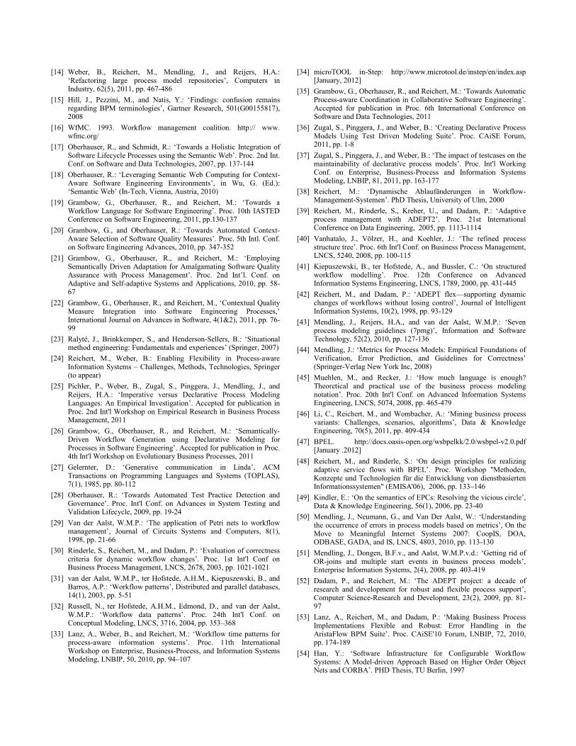
[14] Weber, B., Reichert, M., Mendling, J., and Reijers, H.A.: ‘Refactoring large process model repositories’, Computers in Industry, 62(5), 2011, pp. 467-486
[15] Hill, J., Pezzini, M., and Natis, Y.: ‘Findings: confusion remains regarding BPM terminologies’, Gartner Research, 501(G00155817), 2008
[16] WfMC. 1993. Workflow management coalition. http:// www. wfmc.org/
[17] Oberhauser, R., and Schmidt, R.: ‘Towards a Holistic Integration of Software Lifecycle Processes using the Semantic Web’. Proc. 2nd Int. Conf. on Software and Data Technologies, 2007, pp. 137-144
[18] Oberhauser, R.: ‘Leveraging Semantic Web Computing for Context-Aware Software Engineering Environments’, in Wu, G. (Ed.): ‘Semantic Web’ (In-Tech, Vienna, Austria, 2010)
[19] Grambow, G., Oberhauser, R., and Reichert, M.: ‘Towards a Workflow Language for Software Engineering’. Proc. 10th IASTED Conference on Software Engineering, 2011, pp.130-137
[20] Grambow, G., and Oberhauser, R.: ‘Towards Automated Context-Aware Selection of Software Quality Measures’. Proc. 5th Intl. Conf. on Software Engineering Advances, 2010, pp. 347-352
[21] Grambow, G., Oberhauser, R., and Reichert, M.: ‘Employing Semantically Driven Adaptation for Amalgamating Software Quality Assurance with Process Management’. Proc. 2nd Int’l. Conf. on Adaptive and Self-adaptive Systems and Applications, 2010, pp. 58-67
[22] Grambow, G., Oberhauser, R., and Reichert, M., ‘Contextual Quality Measure Integration into Software Engineering Processes,’ International Journal on Advances in Software, 4(1&2), 2011, pp. 76-99
[23] Ralyté, J., Brinkkemper, S., and Henderson-Sellers, B.: ‘Situational method engineering: Fundamentals and experiences’ (Springer, 2007)
[24] Reichert, M., Weber, B.: Enabling Flexibility in Process-aware Information Systems – Challenges, Methods, Technologies, Springer (to appear)
[25] Pichler, P., Weber, B., Zugal, S., Pinggera, J., Mendling, J., and Reijers, H.A.: ‘Imperative versus Declarative Process Modeling Languages: An Empirical Investigation’. Accepted for publication in Proc. 2nd Int'l Workshop on Empirical Research in Business Process Management, 2011
[26] Grambow, G., Oberhauser, R., and Reichert, M.: ‘Semantically-Driven Workflow Generation using Declarative Modeling for Processes in Software Engineering’. Accepted for publication in Proc. 4th Int'l Workshop on Evolutionary Business Processes, 2011
[27] Gelernter, D.: ‘Generative communication in Linda’, ACM Transactions on Programming Languages and Systems (TOPLAS), 7(1), 1985, pp. 80-112
[28] Oberhauser, R.: ‘Towards Automated Test Practice Detection and Governance’. Proc. Int'l Conf. on Advances in System Testing and Validation Lifecycle, 2009, pp. 19-24
[29] Van der Aalst, W.M.P.: ‘The application of Petri nets to workflow management’, Journal of Circuits Systems and Computers, 8(1), 1998, pp. 21-66
[30] Rinderle, S., Reichert, M., and Dadam, P.: ‘Evaluation of correctness criteria for dynamic workflow changes’. Proc. 1st Int'l Conf on Business Process Management, LNCS, 2678, 2003, pp. 1021-1021
[31] van der Aalst, W.M.P., ter Hofstede, A.H.M., Kiepuszewski, B., and Barros, A.P.: ‘Workflow patterns’, Distributed and parallel databases, 14(1), 2003, pp. 5-51
[32] Russell, N., ter Hofstede, A.H.M., Edmond, D., and van der Aalst, W.M.P.: ‘Workflow data patterns’. Proc. 24th Int'l Conf. on Conceptual Modeling, LNCS, 3716, 2004, pp. 353–368
[33] Lanz, A., Weber, B., and Reichert, M.: ‘Workflow time patterns for process-aware information systems’. Proc. 11th International Workshop on Enterprise, Business-Process, and Information Systems Modeling, LNBIP, 50, 2010, pp. 94–107
[34] microTOOL in-Step: http://www.microtool.de/instep/en/index.asp [January, 2012]
[35] Grambow, G., Oberhauser, R., and Reichert, M.: ‘Towards Automatic Process-aware Coordination in Collaborative Software Engineering’. Accepted for publication in Proc. 6th International Conference on Software and Data Technologies, 2011
[36] Zugal, S., Pinggera, J., and Weber, B.: ‘Creating Declarative Process Models Using Test Driven Modeling Suite’. Proc. CAiSE Forum, 2011, pp. 1-8
[37] Zugal, S., Pinggera, J., and Weber, B.: ‘The impact of testcases on the maintainability of declarative process models’. Proc. Int'l Working Conf. on Enterprise, Business-Process and Information Systems Modeling, LNBIP, 81, 2011, pp. 163-177
[38] Reichert, M.: ‘Dynamische Ablaufänderungen in Workflow-Management-Systemen’. PhD Thesis, University of Ulm, 2000
[39] Reichert, M., Rinderle, S., Kreher, U., and Dadam, P.: ‘Adaptive process management with ADEPT2’. Proc. 21st International Conference on Data Engineering, 2005, pp. 1113-1114
[40] Vanhatalo, J., Völzer, H., and Koehler, J.: ‘The refined process structure tree’. Proc. 6th Int'l Conf. on Business Process Management, LNCS, 5240, 2008, pp. 100-115
[41] Kiepuszewski, B., ter Hofstede, A., and Bussler, C.: ‘On structured workflow modelling’. Proc. 12th Conference on Advanced Information Systems Engineering, LNCS, 1789, 2000, pp. 431-445
[42] Reichert, M., and Dadam, P.: ‘ADEPT flex—supporting dynamic changes of workflows without losing control’, Journal of Intelligent Information Systems, 10(2), 1998, pp. 93-129
[43] Mendling, J., Reijers, H.A., and van der Aalst, W.M.P.: ‘Seven process modeling guidelines (7pmg)’, Information and Software Technology, 52(2), 2010, pp. 127-136
[44] Mendling, J.: ‘Metrics for Process Models: Empirical Foundations of Verification, Error Prediction, and Guidelines for Correctness’ (Springer-Verlag New York Inc, 2008)
[45] Muehlen, M., and Recker, J.: ‘How much language is enough? Theoretical and practical use of the business process modeling notation’. Proc. 20th Int'l Conf. on Advanced Information Systems Engineering, LNCS, 5074, 2008, pp. 465-479
[46] Li, C., Reichert, M., and Wombacher, A.: ‘Mining business process variants: Challenges, scenarios, algorithms’, Data & Knowledge Engineering, 70(5), 2011, pp. 409-434
[47] BPEL. http://docs.oasis-open.org/wsbpelkk/2.0/wsbpel-v2.0.pdf [January .2012]
[48] Reichert, M., and Rinderle, S.: ‘On design principles for realizing adaptive service flows with BPEL’. Proc. Workshop "Methoden, Konzepte und Technologien für die Entwicklung von dienstbasierten Informationssystemen" (EMISA'06), 2006, pp. 133–146
[49] Kindler, E.: ‘On the semantics of EPCs: Resolving the vicious circle’, Data & Knowledge Engineering, 56(1), 2006, pp. 23-40
[50] Mendling, J., Neumann, G., and Van Der Aalst, W.: ‘Understanding the occurrence of errors in process models based on metrics’, On the Move to Meaningful Internet Systems 2007: CoopIS, DOA, ODBASE, GADA, and IS, LNCS, 4803, 2010, pp. 113-130
[51] Mendling, J., Dongen, B.F.v., and Aalst, W.M.P.v.d.: ‘Getting rid of OR-joins and multiple start events in business process models’, Enterprise Information Systems, 2(4), 2008, pp. 403-419
[52] Dadam, P., and Reichert, M.: ‘The ADEPT project: a decade of research and development for robust and flexible process support’, Computer Science-Research and Development, 23(2), 2009, pp. 81-97
[53] Lanz, A., Reichert, M., and Dadam, P.: ‘Making Business Process Implementations Flexible and Robust: Error Handling in the AristaFlow BPM Suite’. Proc. CAiSE'10 Forum, LNBIP, 72, 2010, pp. 174-189
[54] Han, Y.: ‘Software Infrastructure for Configurable Workflow Systems: A Model-driven Approach Based on Higher Order Object Nets and CORBA’. PHD Thesis, TU Berlin, 1997

[55] Meier, W.: ‘eXist: An open source native XML database’, Web, Web-Services, and Database Systems, LNCS, 2593, 2009, pp. 169-183
[56] Johnson, P.M.: ‘Requirement and design trade-offs in Hackystat: An in-process software engineering measurement and analysis system’. Proc. 1st Int. Symp. on Empirical Software Engineering and Measurement, 2007, pp. 81-90
[57] Luckham, D.C.: ‘The power of events: an introduction to complex event processing in distributed enterprise systems’ (Addison-Wesley Longman Publishing Co., Inc. Boston, MA, USA, 2001)
[58] Esper: http://esper.codehaus.org/ [January 2012] [59] Weber, B., Reichert, M., Wild, W., and Rinderle, S.: ‘Balancing
flexibility and security in adaptive process management systems’, On the Move to Meaningful Internet Systems 2005: CoopIS, DOA, and ODBASE, LNCS, 3760, 2005, pp. 59-76
[60] Rinderle-Ma, S., Reichert, M., and Weber, B.: ‘Relaxed compliance notions in adaptive process management systems’. Proc. 27th Int'l Conf. on Conceptual Modeling, LNCS, 5231, 2008, pp. 232-247
[61] World Wide Web Consortium, ‘OWL Web Ontology Language Semantics and Abstract Syntax,’ (2004) [January 2012]
[62] McBride, B.: ‘Jena: A semantic web toolkit’, Internet Computing, IEEE, 6(6), 2002, pp. 55-59
[63] Sirin, E., Parsia, B., Grau, B.C., Kalyanpur, A., and Katz, Y.: ‘Pellet: A practical owl-dl reasoner’, Web Semantics: Science, Services and Agents on the World Wide Web, 5(2), 2007, pp. 51-53
[64] Li, C., Reichert, M., and Wombacher, A.: ‘The MinAdept Clustering Approach for Discovering Reference Process Models out of Process Variants’, International Journal of Cooperative Information Systems, 19(3 & 4), 2010, pp. 159-203
[65] Koschmider, A., and Oberweis, A.: ‘Ontology based business process description’. Proc. CAiSE´05 workshops, 2005, pp. 321-333
[66] Lin, Y., and Strasunskas, D.: ‘Ontology-based semantic annotation of process templates for reuse’. Proc. 10th International Workshop on Exploring Modeling Methods for Systems Analysis and Design, 2005, pp. 593-604
[67] Ma, Z., Wetzstein, B., Anicic, D., Heymans, S., and Leymann, F.: ‘Semantic business process repository’. Proc. Workshop on Semantic Business Process and Product Lifecycle Management, 2007, pp. 92–100
[68] Pedrinaci, C., Domingue, J., and Alves de Medeiros, A.: ‘A core ontology for business process analysis’, The Semantic Web: Research and Applications, LNCS, 5021, 2008, pp. 49-64
[69] Thomas, M., Redmond, R., Yoon, V., and Singh, R.: ‘A semantic approach to monitor business process’, Communications of the ACM, 48(12), 2005, pp. 55-59
[70] Ly, L.T., Knuplesch, D., Rinderle-Ma, S., Goeser, K., Reichert, M., and Dadam, P.: ‘SeaFlows Toolset-Compliance Verification Made Easy’. Proc. CAiSE'10 Forum, LNBIP, 2010, pp. 76-91
[71] Jiang, T., Ying, J., and Wu, M.: ‘CASDE: An Environment for Collaborative Software Development’, Computer Supported Cooperative Work in Design III, LNCS, 4402, 2007, pp. 367-376
[72] Cook, C., Churcher, N., and Irwin, W.: ‘Towards synchronous collaborative software engineering’. Proc. 11th Asia-Pacific Software Engineering Conference, 2004, pp. 230-239
[73] Dustdar, S.: ‘Caramba—a process-aware collaboration system supporting ad hoc and collaborative processes in virtual teams’, Distributed and parallel databases, 15(1), 2004, pp. 45-66
[74] Conradi, R., Liu, C., and Hagaseth, M.: ‘Planning support for cooperating transactions in EPOS’, Information Systems, 20(4), 1995, pp. 317-336
[75] Weske, M.: ‘Flexible modeling and execution of workflow activities’. Proc. 31st Hawaii Int'l Conf. on System Sciences, 1998, pp. 713-722
[76] Adams, M., ter Hofstede, A.H.M., Edmond, D., and van der Aalst, W.M.P.: ‘Worklets: A service-oriented implementation of dynamic flexibility in workflows’, On the Move to Meaningful Internet Systems 2006: CoopIS, DOA, GADA, and ODBASE, LNCS, 4275, 2006, pp. 291-308
[77] Pesic, M., Schonenberg, H., and van der Aalst, W.M.P.: ‘Declare: Full support for loosely-structured processes’. Proc. 11th IEEE International Enterprise Distributed Object Computing Conference 2007, pp. 287-298
[78] Müller, R., Greiner, U., and Rahm, E.: ‘AGENT WORK: a workflow system supporting rule-based workflow adaptation’, Data Knowlage Engineering, 51(2), 2004, pp. 223-256
[79] Weber, B., Pinggera, J., Zugal, S., and Wild, W.: ‘Alaska Simulator Toolset for Conducting Controlled Experiments on Process Flexibility’. Proc. CAiSE'10 Forum, LNBIP, 72, 2011, pp. 205-221
[80] Sadiq, S., Sadiq, W., and Orlowska, M.: ‘A framework for constraint specification and validation in flexible workflows’, Information Systems, 30(5), 2005, pp. 349-378
[81] Weber, B., Reichert, M., Wild, W., and Rinderle-Ma, S.: ‘Providing integrated life cycle support in process-aware information systems’, Int'l Journal of Cooperative Information Systems (IJCIS), 18(1), 2009, pp. 115-165
[82] Rinderle, S., Weber, B., Reichert, M., and Wild, W.: ‘Integrating process learning and process evolution–a semantics based approach’. Proc. 3rd International Conference on Business Process Management, LNCS, 3649, 2005, pp. 252-267
[83] Minor, M., Tartakovski, A., and Schmalen, D.: ‘Agile workflow technology and case-based change reuse for long-term processes’, International Journal of Intelligent Information Technologies (IJIIT), 4(1), 2008, pp. 80-98
[84] Hallerbach, A., Bauer, T., and Reichert, M.: ‘Context-based configuration of process variants’. Proc. 3rd Int’l Workshop on Technologies for Context-Aware Business Process Management, 2008, pp. 31-40
[85] La Rosa, M., Lux, J., Seidel, S., Dumas, M., and ter Hofstede, A.: ‘Questionnaire-driven configuration of reference process models’. Proc. 19th Int'l Conf. on Advanced Information Systems Engineering, LNCS, 4495, 2007, pp. 424-438
[86] Rinderle, S., Reichert, M., and Dadam, P.: ‘Disjoint and overlapping process changes: Challenges, solutions, applications’, On The Move to Meaningful Internet Systems 2004: CoopIS, DOA, and ODBASE, LNCS, 3290, 2004, pp. 101-120
[87] Rinderle, S., Reichert, M., and Dadam, P.: ‘Correctness criteria for dynamic changes in workflow systems--a survey’, Data & Knowledge Engineering, 50(1), 2004, pp. 9-34
[88] Reichert, M., Rinderle, S., and Dadam, P.: ‘ADEPT Workflow Management System: Flexible Support for Enterprise-Wide Business Processes’. Proc. 1st Int'l Conf. on Business Process Management, LNCS, 2678, 2003, pp. 371-379
[89] Weber, B., Wild, W., and Breu, R.: ‘CBRFlow: Enabling adaptive workflow management through conversational case-based reasoning’. Proc. European Conference on Case-Based Reasoning, LNCS, 3155, 2004, pp. 89-101
[90] Weber, B., Rinderle, S., Wild, W., and Reichert, M.: ‘CCBR–driven business process evolution’. Proc. Int'l Conf. on Cased based Reasoning, LNCS, 3620, 2005, pp. 610-624
[91] Weber, B., Sadiq, S., and Reichert, M.: ‘Beyond rigidity–dynamic process lifecycle support’, Computer Science-Research and Development, 23(2), 2009, pp. 47-65

Peer Review
Activity XOR-Gate
Code Review
Code Inspection
Walk through
Implement Solution
Document in Change
log
Inform User
Manual Team
Analyze Issue
Create CR Branch
Reproduce Error
Check Dependencies
Design Solution
Run Regression
Test
Create Regression
TestsRun Unit
Test
Adapt Unit Test
GUI TestRun
Static Analysis
Inform other Team
Smoke Test
Integration Test
Feature Test
Acceptance Test
Validation to Requirements
Integrate and Build
Check for other
Branches
Integrate and Build
Create Patches
Close Issue
Unit test needs
adaptation
Issue very urgent?
Has high complexity / Criticality?
No test in place
Has high user impact?
Start Point End Point
Has high risk / criticality?
Has high complexity?
Has dependencies?
Has high complexity?
Has dependencies?
Has high risk / user impact?
Has high user impact?
Has very high user impact?
Has high complexity?
Has high complexity?
Not too urgent?
Figure 12. Example of pre-modeled workflow for bug fixing.
Compare Files
Compare Files
Merge Files
Merge Files
Merge Files Compare Files
Parallel
Requires
Requires
Compare Files
Merge Files
ActivityAND-GateEnd PointStart Point
543
2
Sequence
ParallelLoop
61
Activity BuildingBlocks Successor Constraint Parallel Constraint
3
XOR-Gate
5
2
1
Work Unit Container 1 (imperative)
Compare Files
Merge Files
Workflow 1
Compare Files
Merge Files
Work Unit Container 2 (declarative) Work Unit Container 3 (declarative)
Workflow 2 Workflow 3
Context
Urgency Criticality Risk
Situaltional Property Context Connection
Figure 13. Declarative workflow modeling.
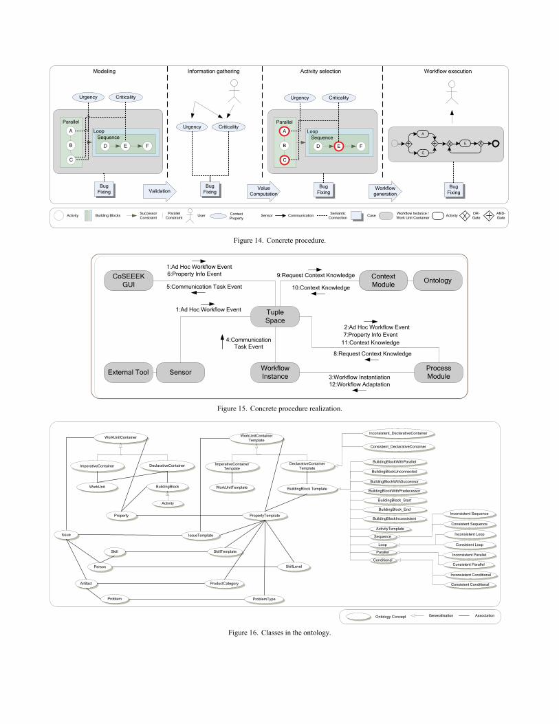
Modeling
Bug Fixing
Information gathering Activity selection Workflow execution
Bug Fixing
Urgency Criticality
FED
ASequence
Parallel
B
Loop
C
FED
ASequence
Parallel
B
Loop
C
ActivityWorkflow Instance / Work Unit Container
AND-Gate
SemanticConnection
OR-GateCommunication
A
C
E
Case
Urgency Criticality
Bug Fixing
Bug Fixing
Workflow generationValidation Value
Computation
Successor ConstraintActivity User SensorParallel
ConstraintContext Property
Urgency Criticality
Building Blocks
Figure 14. Concrete procedure.
External Tool Sensor
CoSEEEKGUI
TupleSpace
WorkflowInstance
Context Module Ontology
ProcessModule
1:Ad Hoc Workflow Event6:Property Info Event
5:Communication Task Event
4:Communication Task Event
9:Request Context Knowledge
10:Context Knowledge
8:Request Context Knowledge
2:Ad Hoc Workflow Event7:Property Info Event
11:Context Knowledge
3:Workflow Instantiation12:Workflow Adaptation
1:Ad Hoc Workflow Event
Figure 15. Concrete procedure realization.
DeclarativeContainerTemplate
BuildingBlock Template BuildingBlockWithPredecessor
BuildingBlockWithSuccessor
BuildingBlockUnconnected
BuildingBlockWithParallel
BuildingBlock_Start
BuildingBlock_End
BuildingBlockInconsistent
Sequence
ActivityTemplate
Loop
ParallelInconsistent Parallel
Consistent Parallel
Inconsistent Sequence
Consistent Sequence
Inconsistent Loop
Consistent Loop
Consistent_DeclarativeContainer
Inconsistent_DeclarativeContainer
PropertyTemplateProperty
IssueTemplateIssue
BuildingBlock
ImperativeContainerTemplate
WorkUnitContainerTemplate
DeclarativeContainerImperativeContainer
WorkUnitContainer
WorkUnit WorkUnitTemplate
Conditional
SkillTemplateSkill
SkillLevel
ProblemTypeProblem
ProductCategory
Person
Artifact
Ontology Concept Generalisation Association
Inconsistent Conditional
Consistent Conditional
Activity
Figure 16. Classes in the ontology.
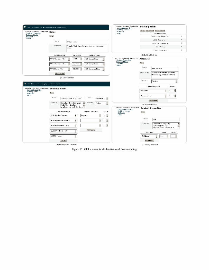
(C) Building Block List
(D) Activity Definition
(B) Building Block Definition
(A) Case Definition
(E) Building Block List Figure 17. GUI screens for declarative workflow modeling.
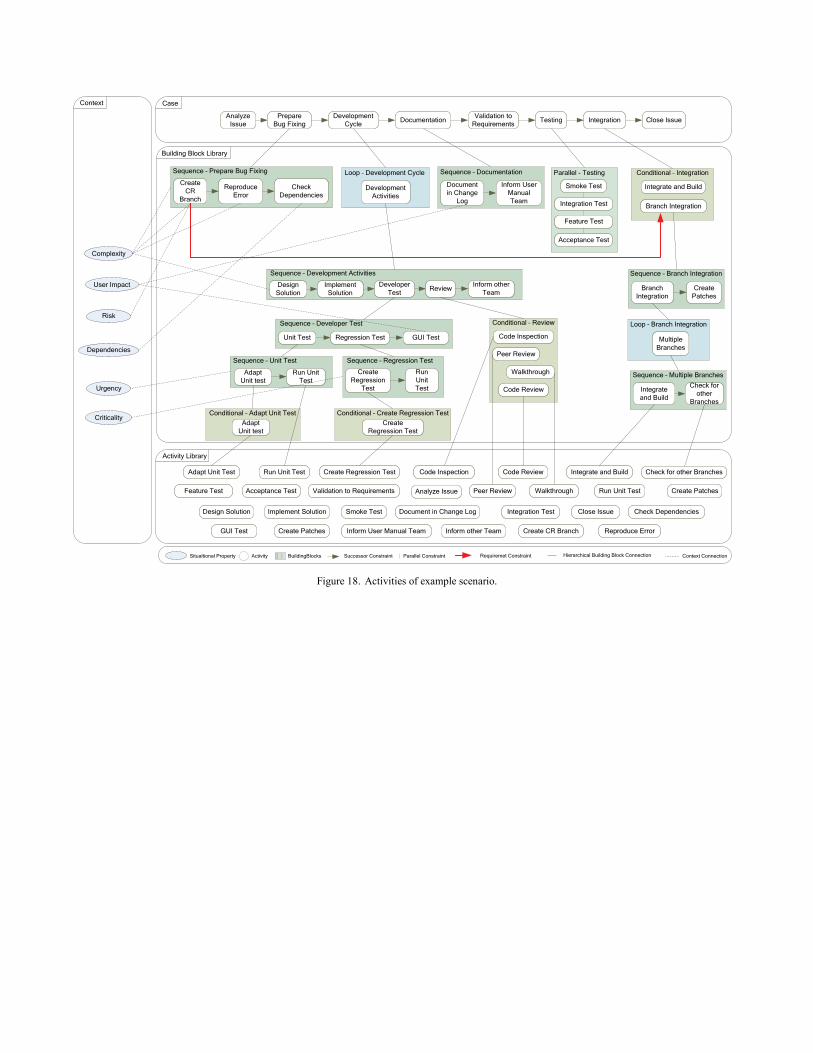
Activity BuildingBlocks Successor Constraint Parallel Constraint
Context
Urgency
Criticality
Risk
Situaltional Property Context Connection
Development Cycle
Sequence – Developer Test
Unit Test Regression Test
Sequence – Unit Test
Adapt Unit test
Run Unit Test
Conditional – Adapt Unit TestAdapt
Unit test
GUI Test
Adapt Unit Test Run Unit Test
GUI Test
Sequence – Regression Test
Create Regression
Test
Run Unit Test
Conditional – Create Regression TestCreate
Regression Test
Run Unit Test
Loop – Development Cycle Parallel - Testing
Smoke Test
Conditional – Review
Peer Review
Integration Test
Feature Test
Acceptance Test
Walkthrough
Code Inspection
Code Review
Sequence – Development Activities
Design Solution
Implement Solution
Inform other Team
Create Regression Test
Validation to Requirements
Close Issue
Multiple Branches
Create Patches
Integrate and Build
Integrate and Build
Loop – Branch Integration
Sequence – Branch Integration
Branch Integration
Create Patches
Conditional – Integration
Branch Integration
Building Block Library
Activity Library
Sequence – Documentation
Document in Change
Log
Inform User Manual Team
ReviewDeveloper Test
Development Activities
Analyze Issue
Analyze Issue
Prepare Bug Fixing Documentation
Sequence – Prepare Bug Fixing
Create CR
Branch
Reproduce Error
Check Dependencies
Validation to Requirements Testing Integration Close Issue
Peer Review Walkthrough
Code Inspection Code Review Check for other Branches
Create Patches
Smoke Test Integration Test
Feature Test Acceptance Test
Document in Change Log
Inform User Manual Team Create CR Branch Reproduce Error
Check DependenciesDesign Solution Implement Solution
Inform other Team
Case
Dependencies
Complexity
User Impact
Sequence – Multiple Branches
Integrate and Build
Check for other
Branches
Requiremet Constraint Hierarchical Building Block Connection
Figure 18. Activities of example scenario.