continued development of the advanced stirling …. includes compilations of signifi cant...
TRANSCRIPT
J. Gary Wood, Kyle Wilson, and Andrew BuffalinoSunpower, Inc., Athens, Ohio
Wayne A. WongGlenn Research Center, Cleveland, Ohio
Patrick Frye and Dan MatejczykPratt & Whitney Rocketdyne, Canoga Park, California
L.B. PenswickConsultant, Stevenson, Washington
Continued Development of the Advanced Stirling Convertor (ASC)
NASA/TM—2008-215021
December 2008
https://ntrs.nasa.gov/search.jsp?R=20090007962 2018-06-21T12:07:20+00:00Z

NASA STI Program . . . in Profi le
Since its founding, NASA has been dedicated to the advancement of aeronautics and space science. The NASA Scientifi c and Technical Information (STI) program plays a key part in helping NASA maintain this important role.
The NASA STI Program operates under the auspices of the Agency Chief Information Offi cer. It collects, organizes, provides for archiving, and disseminates NASA’s STI. The NASA STI program provides access to the NASA Aeronautics and Space Database and its public interface, the NASA Technical Reports Server, thus providing one of the largest collections of aeronautical and space science STI in the world. Results are published in both non-NASA channels and by NASA in the NASA STI Report Series, which includes the following report types: • TECHNICAL PUBLICATION. Reports of
completed research or a major signifi cant phase of research that present the results of NASA programs and include extensive data or theoretical analysis. Includes compilations of signifi cant scientifi c and technical data and information deemed to be of continuing reference value. NASA counterpart of peer-reviewed formal professional papers but has less stringent limitations on manuscript length and extent of graphic presentations.
• TECHNICAL MEMORANDUM. Scientifi c
and technical fi ndings that are preliminary or of specialized interest, e.g., quick release reports, working papers, and bibliographies that contain minimal annotation. Does not contain extensive analysis.
• CONTRACTOR REPORT. Scientifi c and
technical fi ndings by NASA-sponsored contractors and grantees.
• CONFERENCE PUBLICATION. Collected
papers from scientifi c and technical conferences, symposia, seminars, or other meetings sponsored or cosponsored by NASA.
• SPECIAL PUBLICATION. Scientifi c,
technical, or historical information from NASA programs, projects, and missions, often concerned with subjects having substantial public interest.
• TECHNICAL TRANSLATION. English-
language translations of foreign scientifi c and technical material pertinent to NASA’s mission.
Specialized services also include creating custom thesauri, building customized databases, organizing and publishing research results.
For more information about the NASA STI program, see the following:
• Access the NASA STI program home page at http://www.sti.nasa.gov
• E-mail your question via the Internet to help@
sti.nasa.gov • Fax your question to the NASA STI Help Desk
at 301–621–0134 • Telephone the NASA STI Help Desk at 301–621–0390 • Write to:
NASA Center for AeroSpace Information (CASI) 7115 Standard Drive Hanover, MD 21076–1320

J. Gary Wood, Kyle Wilson, and Andrew BuffalinoSunpower, Inc., Athens, Ohio
Wayne A. WongGlenn Research Center, Cleveland, Ohio
Patrick Frye and Dan MatejczykPratt & Whitney Rocketdyne, Canoga Park, California
L.B. PenswickConsultant, Stevenson, Washington
Continued Development of the Advanced Stirling Convertor (ASC)
NASA/TM—2008-215021
December 2008
National Aeronautics andSpace Administration
Glenn Research CenterCleveland, Ohio 44135
Prepared for theFifth International Energy Conversion Engineering Conference Exhibit (IECEC)sponsored by the American Institute of Aeronautics and AstronauticsSt. Louis, Missouri, June 25–27, 2007

Acknowledgments
We wish to acknowledge the support of NASA on this project “Development of a High Performance Next Generation Stirling Radioisotope Power Convertor,” Contract NAS3-03128. We wish to acknowledge Dr. Randy Bowman (GRC-materials) for his important contribution to this work. We wish to acknowledge the contribution to the effort by additional consultants on the ASC development effort: Dr. David Berchowitz, James Cairelli, and David Gedeon. We also wish to thank additional staff at Pratt & Whitney Rocketdyne that contributed signifi cantly to the success of the project: Guido Canzona, Greg Kayser, Cliff Carroll, and Andy Ketchum. At Sunpower we wish to thank Todd Cale, Aaron Courtney, Doug Keiter, Faith Knutsen, and Robi Unger who contributed signifi cantly to the project. We also wish to thank Terry Simon and Joshua Quinnell at the University of Minnesota for their contribution in regenerator research. This work was performed for NASA Science Mission Directorate (Code S) and was supported by the NASA Glenn Research Center Contract NAS3-03128.
Available from
NASA Center for Aerospace Information7115 Standard DriveHanover, MD 21076–1320
National Technical Information Service5285 Port Royal RoadSpringfi eld, VA 22161
Available electronically at http://gltrs.grc.nasa.gov
Level of Review: This material has been technically reviewed by technical management.
This report contains preliminary fi ndings, subject to revision as analysis proceeds.

Continued Development of the Advanced Stirling Convertor (ASC)
J. Gary Wood, Kyle Wilson, and Andrew Buffalino Sunpower, Inc.
Athens, Ohio 45701
Wayne A. Wong National Aeronautics and Space Administration
Glenn Research Center Cleveland, Ohio 44135
Patrick Frye and Dan Matejczyk
Pratt & Whitney Rocketdyne Canoga Park, California 91309
L.B. Penswick
Consultant Stevenson, Washington 98648
Abstract The Advanced Stirling Convertor (ASC) is being developed under contract with the NASA Glenn Research
Center (GRC) and is supported by NASA’s Science Mission Directorate for potential use in future radioisotope power systems having significantly increased efficiency and higher specific power compared to the current thermoelectric systems. An ASC with a lower temperature (~650 °C) Inconel heater head is currently being substituted into the DOE/Lockheed Martin Advanced Stirling Radioisotope Generator (ASRG) program with a predicted convertor efficiency of 34 percent (AC electrical out to heat input ) at a temperature ratio of 2.7 and is expected to deliver approximately 75 Wac. Continued development of the higher temperature (~850 °C) version using existing materials and fabrication techniques in the hot portions is reported on here. The higher temperature ASC is expected to have 38 percent efficiency (AC electrical out to heat input) at a temperature ratio of 3.1 and is expected to deliver approximately 88 Wac. The high temperature ASC also has approximately 30 °C higher rejection temperature, which allows for further reduced system mass because of the reduced radiator size. Six higher temperature and hermetically sealed convertors are being built under this effort for extended life testing at GRC.
Nomenclature ASC Advanced Stirling Convertor CSAF Cold Side Adaptor Flange FLDT Fast Linear Displacement Transducer FTB Frequency Test Bed GRC NASA Glenn Research Center HS Hermetically Sealed NRA NASA Research Announcement QA Quality Assurance PWR Pratt and Whitney Rocketdyne RPS Radioisotope Power System RTD Resistance Temperature Detector RHESSI Reuven Ramaty High Energy Solar Spectroscopic Imager We Watts electrical
I. Overall ASC Program Description Sunpower is developing the Advanced Stirling Convertor (ASC) under contract to NASA Glenn Research
Center (GRC) to support future advanced radioisotope power system (RPS) development as described by Wong.2 The goal of the ASC project, which is sponsored by NASA’s Science Mission Directorate, is to develop a safe, reliable, highly-efficient, low-mass Stirling convertor. The Stirling based RPS is considered an attractive alternative
NASA/TM—2008-215021 1

to the state of art Radioisotope Thermoelectric Generator which have previously flown and have significantly lower efficiency and power to mass ratio than possible with Stirling. The ASC would enable RPSs with very high specific power, greater than 8 W/kg. It is anticipated that a Stirling based RPS using two high efficiency ASC convertors would only require two General Purpose Heat Source (GPHS) modules, which is a factor of 4 less than that required for the MM-RTG which requires 8 GPHS modules. The reduction in GPHS modules provides a large cost savings as well as more prudent use of the limited plutonium fuel supply. The ASCs being developed are similar in design details and physical dimensions to Sunpower’s commercial cryocoolers and are therefore expected to have very high reliability. One Sunpower cryocooler is demonstrating reliable flight operation as it continues service aboard NASA’s RHESSI satellite which was launched on February 5, 2002.
Originally, three series of convertors were to be built under the ASC project. Phase I involved development of the Frequency Test Bed (FTB) convertor which was used to investigate performance at this power level (~80 We) of convertors operating at high frequency (>100 Hz.). Phase I was highly successful in that the FTB achieved a record setting 36 percent efficiency at a temperature ratio of 3.0. Phase II included the fabrication of four non-hermetic ASC-1 convertors, each of which use a MarM-247 high temperature heater head capable of reliable long-life (>17 year) operation at 850 °C. The current Phase III of the program was originally slated to concentrate on development of four ASC-2 units which have the same high temperature capability as the ASC-1 but would also be hermetically sealed and designed to be lightweight. Pratt and Whitney Rocketdyne (PWR), a subcontractor to Sunpower is responsible for supplying all the hot end components, except the regenerator, for 850 °C convertors
With the success of the ASC program through Phase II, NASA has significantly expanded Phase III to include seven additional convertors. GRC has ordered 4 additional hermetically sealed convertors, based principally on the non-hermetic ASC-1 design, to be placed on extended operation. Two of these convertors use an Inconel-718 heater head and are termed ASC-0 convertors. The other two convertors include the high temperature 850 °C heater head and are termed ASC-1HS convertors. Three additional hermetic convertors that also use Inconel-718 heater heads and that include interfaces suitable for integration to an RPS generator have been described by Chan.1 These units are labeled ASC-E convertors, two of which will be incorporated into an RPS Engineering Unit (EU) by Lockheed Martin Space Systems Company (LMSSC) under contract with the Department of Energy called the Advanced Stirling Radioisotope Generator EU (ASRG EU). The third ASC-E is a project spare.
The build of the added seven convertors has provided valuable experience in processing, burn-in testing, and hermetically sealing the convertors. Also input to the design from both LMSSC and GRC has resulted in design refinements to allow incorporation of the ASC into a system as well as to improve reliability. The final ASC-2 design which is now nearing completion will benefit from these efforts to result in a viable advanced convertor which meets all the program goals and is ready for incorporation into high performance advanced RPS.
II. Continued ASC-1 Convertor Testing The ASC convertors are currently being run to accumulate hours and operating experience as shown in table II.
During recent testing, priority has been given to support the ASC-E system design and thus much running has been done at 650 °C. ASC-1 #4 recently passed launch simulation vibration testing at PWR. This testing was performed at the levels shown in table III which includes Qualification level and Qualification plus 3 dB, and all levels were performed in both the axial and lateral directions. The convertor tested (ASC-1#4) has the inertia welded MarM-247 head and has been modified to include the internal piston position sensor which will be used in both the ASC-E and ASC-2 designs. Convertors ASC-1#3 and ASC-1#4 are now scheduled to be delivered to GRC to be placed on extended testing.
TABLE I.—DIFFERENT VERSIONS OF ASC MACHINES UNDER NRA PROJECT Units Head material Head temperature,
C Hermetic Additional design evolution
FTB 2 Stainless Steel 650 No ASC-1a 2 MarM-247 850 No ASC-1b 2 MarM-247/ IN-718 850 No Inertia welded
Head ASC-0 2 IN-718 650 Yes Brazed displacer dome/body joint ASC-1HS 2 MarM-247/ IN-718 850 Yes Improved piston/gas bearing/center
port configuration ASC-E 3 IN-718 650 Yes Improved piston sensor, Inconel
rejector pressure wall for reliability ASC-2 4 MarM-247/ IN-718 850 Yes Diffusion bonded external acceptor
NASA/TM—2008-215021 2

TABLE II.—ACCUMULATED RUNTIME ON ASC-1 CONVERTORS. ASC accumulated hours** as of April 16, 2007
Total >650 °C >750 °C >800 °C 850 °C Thermal cycles to
> 650 °C ASC-1 #1 126.0 97.5 46.5 46.5 44.5 35 ASC-1 #2* 86.0 64.5 17 ASC-1 #3 279.0 177.1 90.0 82.5 76.0 57 ASC-1 #4 135.0 83.9 37.2 36.2 32.1 42 ASC-0 #1 1151.0 876.0 55 ASC-0 #2 1155.0 880.0 52 Total 2932.0 2179.0 173.7 165.2 152.6 258 *Engine 2 has Inconel displacer. **Operating hours do not include time during heat leak tests
Thermal cycles include heat leak tests
TABLE III.—LAUNCH VIBRATION LEVELS DURING TESTING AT PWR
(IN BOTH AXIAL AND LATERAL DIRECTIONS). Level Time,
minutes Workmanship 6.8 grms random 1
Flight 8.7 grms random 1 Qualification 12.3 grms random 3
Qualification + 3 dB 17.5 grms random 1
III. ASC-0 and ASC-1HS Convertors As stated earlier, the ASC-0 and ASC-1HS are hermetically sealed convertors being built for extended operation at
GRC. These units incorporate the ASC-1 basic design features but are modified for hermetic sealing and to interface with GRC heat input, heat rejection, and mounting systems These units also include an external winding FLDT position sensor which is included as an extension to the main alternator enclosure. The two ASC-0 units were delivered at the end of 2006 and are now in extended operation testing in a thermal-vacuum chamber at GRC. The two ASC-1 HS units which will be the first hermetically sealed 850 °C convertors are slated for delivery in June 2007.
These units have been instrumental in working out the details of hermetically sealing the convertors. In particular the final welding of the heater head and alternator enclosure joints has been demonstrated successfully, as well as the final filling with helium. During fabrication of the ASC-0s an improved displacer joint was developed which will be used in all future ASC machines. Also during this build we experienced and solved problems in both the electrical feed-through design and in the piston centering system. These areas are described below.
Figure 1.—ASC-1 convertor. Figure 2.—ASC-1#4 on vibration table at PWR.
NASA/TM—2008-215021 3

A. Brazed Displacer Joint
In all earlier convertors (FTBs and ASC-1s) the joint between the displacer dome and body was an epoxy bond. The requirements of high reliability and extremely long life necessitated a change to a more robust and more predictable joint for the hermetic units. The ASC-0 displacer assemblies which were built first, used a high temperature nickel braze alloy for this joint. However this high temperature braze resulted in distortion in the body to rod alignment is some assemblies which made the parts non-usable, and several parts had to be made to get the two needed assemblies.
Dome Braze Joint Body Rod
Figure 3.—Displacer with different sections labeled.
For the upcoming ASC-1HS convertors, GRC has recommended a lower-temperature braze alloy. The lower temperature is desired not only due to a lower probability of part distortion but also because it better preserves the material properties of the Inconel parts by remaining below the material aging temperature. GRC performed coupon braze joint trials and also developed the heat cycle for the selected braze material. A set of test articles has shown excellent bond strength and demonstrated that the rod to body geometry does not change during the braze cycle, resolving the previous distortion issue. This braze alloy will be used for the ASC-1HS convertors and all future displacer assemblies.
B. Electrical Feed-Throughs
The original electrical feed-throughs on the ASC-0 convertors developed leaks after several rejection temperature cycles, combined with internal pressure. Experiments were conducted to determine the cause of the leak, and a coordinated FEA effort was performed by Sunpower and GRC. It became apparent that the leaks were related to the combination of temperature, pressure, and the particular mechanical configuration of the ASC-0. The GRC rejector flange is a large copper structure that is brazed all along its interface with the convertor transition. Experiments suggested that leaks only developed when loaded under this configuration. Because of schedule constraints, the ASC-0 feed-throughs were sealed with epoxy for delivery.
Identification of an improved feed through was necessary, thus five new feed-through designs, including different sealing materials, were chosen and tested along with the ASC-0 baseline design. Test articles which were fabricated by Sunpower, held five feed-throughs of a given design per article to gather statistical data. The test procedure which was developed and performed by GRC involved holding the samples at constant pressure and subjecting them to thermal cycles with continually increasing upper temperatures. The tests resulted in the selection of a feed-through design that showed superior robustness compared to the other candidate feed-throughs. The selected design failed at a temperature well beyond the manufacturers recommended temperature, which is also very much higher than will be experienced in service.
The initial test articles were more representative in geometry to the ASC-E structural configuration. A second series of test articles are being tested to confirm that the selected feed-through will operate with similar robustness in the ASC-0 and ASC-1HS structural configuration. GRC continues to test this design to determine the level of margin in the design. These improved feed-throughs are being used in the current ASC-1HS build, and are planned for all future convertor builds.
C Piston and Centerport System
During development of the ASC-0’s difficulties were encountered with some pistons not maintaining dynamic axial center as desired near the center of the linear alternator. To identify the issue and correct it, various configurations were fabricated, tested, and evaluated, and GRC CFD modeling results were studied. As a result, a new centerport system was developed and has since been demonstrated in operating convertors.
Another design change involved the material of construction of the pistons. There was a difference in the coefficients of thermal expansion (CTE) between the piston and the cylinder of the original design. Thus the running
NASA/TM—2008-215021 4

clearance would change with temperature and effect both centering and performance. The piston material has now been changed to an aluminum alloy recommended by GRC that more closely matches the CTE of the cylinder. Additionally other components associated with the overall piston/cylinder structure have changed material for the same reason.
Several convertors have been constructed with the new centerport and piston designs. These convertors have demonstrated very strong centering that maintains the piston dynamic center at its desired location within the linear alternator. Additionally the testing of these convertors across a range of reject temperatures has shown them to behave in a more consistent manner representing more uniform clearance seals.
D. Regenerators
The regenerators used in these hermetic convertors were all processed and supplied by Randy Bowman of GRC. The regenerators are made of a sintered, high porosity, small filament, high-temperature material. Bowman developed the fabrication, cleaning, and sintering techniques which have eliminated debris generation during convertor operation. These regenerators are designed to withstand corrosion for the stringent 17 year life requirement. These same regenerators are being retrofitted into the ASC-1 convertors and are planned to be used on future machines. Efforts are underway to transfer the manufacture of regenerators from GRC to Sunpower.
IV. ASC-E Convertors A. Rejector Wall
In the original ASC design, used for the ASC-1, ASC-0, and ASC-1HS, the rejector was all copper and functioned as both the heat rejection path and the pressure wall. This rejector was bonded to the heater head on one end and to the transition on the opposite end. This created a structure with high radial thermal conductance but included pressure joints at the two ends.
It was determined desirable from a reliability standpoint to eliminate these two pressure joints, and the design was therefore modified for the ASC-E design. This was accomplished be extending the Inconel of the transition axially through the rejector to meet the heater head. To this wall, copper is brazed both internally and externally. This creates a structure with lower thermal conductance but fewer joints in the pressure vessel. Essentially, the design replaces two pressure vessel joints with two less critical thermal joints.
This design change improves the reliability of the convertors. If a pressure vessel joint is imperfect or degrades over time, the resulting loss of working gas will rapidly degrade engine performance. However, if a thermal joint is imperfect or degrades over time, the reduced heat transfer will have a less drastic effect on performance.
B. CSAF Interference Fit
In the ASRG system the ASC-E is mounted and rejects its heat through the cold side adaptor flange (CSAF) provided by Lockheed Martin. Schedule constraints, including risk assessment, necessitated use of a semi-permanent attachment of the CSAF to the rejector for the ASC-E build. An interference fit was developed to provide an easily assembled, adjustable mechanical joint with high thermal effectiveness.
The mating parts are designed with a shallow taper angle. This allows the interference between the parts to be precisely controlled by adjusting the preshrink axial position of the CSAF relative to the rejector. The shallow angle also helps to improve the contact pressure and thereby reduces the thermal contact resistance. The thermal properties of the joint are further improved with an applied metallic surface.
Developmental trial assemblies were processed by Sunpower and placed under thermal test in vacuum at Lockheed Martin. The results of this testing showed an average temperature difference across the shrink fit of approximately 0.6 °C with a maximum value of approximately 1.2°. It is anticipated that future machines would replace the interference fit with a brazed joint.
NASA/TM—2008-215021 5

C. Internal FLDT
Sunpower is the originator of Fast Linear Displacement Transducer (FLDT) technology. The sensors exploit the skin effect to create a variable impedance, two-wire position transducer that is capable of operating at high frequency with minimal phase shift.
Previous Sunpower designs utilized for piston position sensor, a small diameter FLDT that was included on a small diameter extension of the main alternator enclosure. The large length-to-diameter ratio of the sensor contributed to a highly linear output. However, the small diameter of the sensor meant that the gain was relatively low, making the external FLDT sensitive to noise and temperature effects.
For the ASC-E design, a larger diameter FLDT has been developed. The sensor was designed such that part of the length of the sensor wraps around the outside of the outer alternator laminations. This allowed for a net reduction in the total length of the convertor. The overall sensor gain was improved by a factor of 30. However, the lower length-to-diameter ratio meant that the sensor is slightly non-linear. The output of the internal FLDT is compared to the output of a standard FLDT in figure 4. Overall the new internal sensor is much more robust, as it is less sensitive to noise and temperature effects and the nonlinearity of the sensor can be overcome with post processing. The internal sensor does require 2 additional electrical feed-throughs in the vessel of the convertor.
Figure 4.—Comparison of internal and external FLDT response.
NASA/TM—2008-215021 6

V. ASC-2 Continued Development and Design A. ASC-2 Design
The ASC-2 design is scheduled to be completed by summer 2007. The ASC-2 design will include all improvements and lessons learned from the build and testing of earlier convertors. Due to the valuable experience gained in the other builds the following improvements will now be incorporated into the ASC-2 design:
1) 1-piece transition (flat section of the convertor between the alternator enclosure and the rejector) that
eliminates the brazed cover plate of the ASC-1 design 2) Intermediate Inconel wall within the rejector to eliminate a pressure joint 3) Internal FLDT piston position sensor with much improved gain and results in a shorter overall convertor
length 4) Greatly improved electrical feed-through design 5) Diffusion bonded external acceptor/heat collector. 6) Brazed joint between the displacer dome and displacer body 7) More robust piston axial centering system 8) Improved gas bearing geometry 9) Better matched CTE between the piston and cylinder. 10) Modified regenerator wall profile to minimize long term performance degradation (described below)
As mentioned in earlier papers, Terry Simon and graduate student Joshua Quinnell at the University of
Minnesota are supporting the ASC effort by studying the influence of a localized gap on the periphery of the regenerator. The investigation will ascertain if such a gap could influence the performance of the ASC late in its life should the regenerator wall creep away from the regenerator resulting in a localized gap.
The regenerator wall profile is currently being redesigned to reduce the creep in this area to well below the originally designed one percent over the 17 year life of the machine. This effort is supported by creep testing being performed at GRC of the material used in the heater head described below.
Figure 5.—ASC-0 and ASC-1HS with external FLDT (top) compared to ASC-E (bottom).
NASA/TM—2008-215021 7

Figure 6.—External view of ASC-2.
Figure 7.—MarM-247 creep specimens machined from
heater head castings. To provide structure and process history matching that of ASC heater head walls.
B. Material Creep Testing at GRC
Creep testing is being carried out at GRC on MarM-247 samples replicating the heater head wall thickness, position within castings, and heater head thermal process history. Figure 7 shows an as-received MarM-247 cast bar, a cast bar with segments removed for creep samples, and one of the creep sample blanks.
Over 30 creep tests have been completed to date, characterizing a range of MarM-247 casting variables and specimen thicknesses. Heater head wall thickness is being designed based on conservative assessments of these data.
C. External Acceptor Diffusion Bond
MarM-247 heater heads incorporate nickel internal acceptor heat exchangers joined to the MarM-247 wall via diffusion bonding. Diffusion bonding was chosen to provide stability of this joint over long durations at elevated temperature, avoiding diffusion of braze alloy elements into the MarM-247 wall, and simplifying the assurance of heater head properties and life over long times at elevated temperature.
The external nickel acceptor on ASC-1 MarM-247 heater heads is brazed to the exterior side of the MarM-247 wall. Brazing was used to enable phased development of heater head fabrication processes. In the ASC-2 hardware this joint is being diffusion bonded, like the internal acceptor, to eliminate the potentially detrimental diffusion effects of braze alloy elements onto the heater head wall during long durations at elevated temperature.
NASA/TM—2008-215021 8
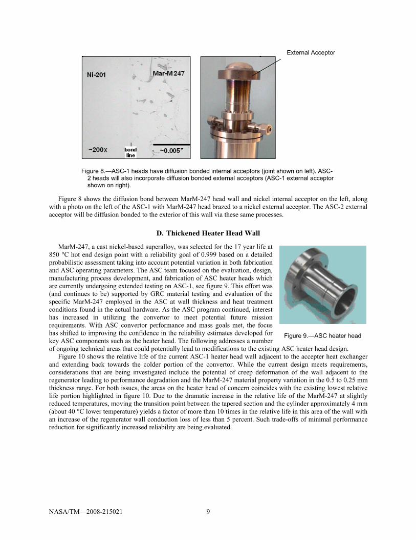
Figure 8 shows the diffusion bond between MarM-247 head wall and nickel internal acceptor on the left, along with a photo on the left of the ASC-1 with MarM-247 head brazed to a nickel external acceptor. The ASC-2 external acceptor will be diffusion bonded to the exterior of this wall via these same processes.
D. Thickened Heater Head Wall
MarM-247, a cast nickel-based superalloy, was selected for the 17 year life at 850 °C hot end design point with a reliability goal of 0.999 based on a detailed probabilistic assessment taking into account potential variation in both fabrication and ASC operating parameters. The ASC team focused on the evaluation, design, manufacturing process development, and fabrication of ASC heater heads which are currently undergoing extended testing on ASC-1, see figure 9. This effort was (and continues to be) supported by GRC material testing and evaluation of the specific MarM-247 employed in the ASC at wall thickness and heat treatment conditions found in the actual hardware. As the ASC program continued, interest has increased in utilizing the convertor to meet potential future mission requirements. With ASC convertor performance and mass goals met, the focus has shifted to improving the confidence in the reliability estimates developed for key ASC components such as the heater head. The following addresses a number of ongoing technical areas that could potentially lead to modifications to the existing ASC heater head design.
External Acceptor
Figure 8.—ASC-1 heads have diffusion bonded internal acceptors (joint shown on left). ASC-2 heads will also incorporate diffusion bonded external acceptors (ASC-1 external acceptor shown on right).
Figure 9.—ASC heater head
Figure 10 shows the relative life of the current ASC-1 heater head wall adjacent to the accepter heat exchanger and extending back towards the colder portion of the convertor. While the current design meets requirements, considerations that are being investigated include the potential of creep deformation of the wall adjacent to the regenerator leading to performance degradation and the MarM-247 material property variation in the 0.5 to 0.25 mm thickness range. For both issues, the areas on the heater head of concern coincides with the existing lowest relative life portion highlighted in figure 10. Due to the dramatic increase in the relative life of the MarM-247 at slightly reduced temperatures, moving the transition point between the tapered section and the cylinder approximately 4 mm (about 40 °C lower temperature) yields a factor of more than 10 times in the relative life in this area of the wall with an increase of the regenerator wall conduction loss of less than 5 percent. Such trade-offs of minimal performance reduction for significantly increased reliability are being evaluated.
NASA/TM—2008-215021 9

0
0.5
1
1.5
2
2.5
3
3.5
4
4.5
5
0 2 4 6 8 10 12 14 16 18 20 22 24
Distance from Hot Reference Point (mm)
Rel
ativ
e Li
feTapered
Cylinder
`
Figure 10.—ASC heater head relative life in regenerator wall near acceptor.
Another area under review is the knuckle region of the heater head dome. For the ASC-1 design, the somewhat
higher local stress in this region was assumed to decrease over time due to the mechanism of creep relaxation. However, from the viewpoint of overall heater head reliability the approach of reducing these initial stresses by locally thickening the wall in this area also has an advantage. Due to the minimal impact on heater head mass and no impact on convertor performance it is likely that this change in design for the ASC-2 will be incorporated.
A final element in the current ASC heater head review is an evaluation of the basic design assumptions / constraints employed since the start of the ASC heater head development process relative to more recent design “criteria” that have evolved at GRC. Key issues under review are:
1. Regenerator Wall Isolated or Interacting with the Regenerator The current design is based on the regenerator wall being thermally isolated from the regenerator and as such has
a temperature distribution defined by the end temperatures, wall geometry, and material thermal conductivity. In this case the wall temperature distribution adjacent to the regenerator section is considerably higher than that of the relatively linear temperature distribution of the regenerator. Limited wall temperature measurements taken on the FTB imply the wall temperature more closely tracks that of the regenerator. Using the isolated wall assumption therefore is extremely conservative.
2. Local Effects In areas adjacent to the internal and external heat acceptor the stress field conditions tend to reduce the stress in
the MarM-247 heater head compared to the simple membrane values employed in the current design. While the assumption employed in the current design is conservative, in nature these local effects should be further refined.
3. Design Pressure The current vessel design is based on the mean engine charge pressure. A change to utilizing the maximum cycle
pressure (approximately 15 percent higher) is being recommended for the ASC-2 design. The impact on the overall mass and thermal loss in the heater head and pressure vessel structure are small.
VI. Reliability Study While the ASC project is an advanced technology development effort, it was understood from the start that
reliability and lifetime performance would need to be adequately addressed to ensure potential users of the soundness of the basic technology. To accomplish this, a task was included in the project with the goal of ensuring
NASA/TM—2008-215021 10

that reliability / lifetime degradation concerns were addressed and resolved throughout the development effort. This ongoing reliability effort identified a number of issues during the Phase I, Phase II, and now Phase III that have been either incorporated in the current hardware or expected to be used in the design details of the ASC-2. Recent results and the focus of ongoing efforts in specific areas are briefly discussed in the following sections.
A. Fasteners
Figure 11.—Fastener size
example.
Compared to other small convertors the ASC employs a relatively small number of mechanical fasteners. However, they are still critical and in the case of three represent single failure points for the convertor. Throughout Phases I and II improvements in the fasteners and techniques for employing them have been incorporated into the design. As the ASC project expands, this topic has received renewed attention. Currently efforts are focused on both testing at Sunpower and detailed analysis by GRC. One important area is fully defining the loads the fasteners must carry during all phases of the ASC operating envelope along with developing potential failure criteria. An example of the latter is the definition of the minimum fastener preload required to ensure the fasteners holding the stator of the alternator do not allow the component to move under worst case loads leading to contact with the moving magnet assembly. Another aspect of the task is defining the fastener installation parameters (torque levels) to meet these defined preloads. A number of complicating factors in this include the very small size of the fasteners, see figure 11, the fact that many of the joints employ multiple materials with varying thermal expansion properties, that thread locking compounds are employed, and finally that the tools employed to apply torque to such small fasteners must be carefully specified and utilized. To provide a basis for defining the fastener parameters, a number of test fixtures have been developed that simulate various fastener / joint combinations which allow various tests, up to and including failure of the fastener to be carried out in a controlled manner. As an example figure 12 shows the test fixture simulating the cylinder clamping flange joint with the transition section of the outer vessel. Testing, evaluation, and recommended improvements of all the fasteners continue under direction of a joint GRC and Sunpower working group.
B. Planar Spring
The single planar spring employed in the ASC and shown in figure 13, provides the spring effect for the displacer and as such represents a possible single point failure for the convertor. Sunpower and its licensees have employed this type of spring in a large number of convertors and cooling machines. For example a similar sized spring is employed in a large number (>1000) of small cryocoolers, some of which have run continuously for more than 10 years. This provides a high degree of confidence in the design method employed for the planar spring, materials used, fabrication methods, and installation techniques. However, it is still necessary to better define the overall planar springs characteristics, limitations, and potential failure modes so as to evaluate its impact on the ASC system reliability. In addition, identifying the sensitivity of the spring’s reliability to various aspects of its design and use, will allow quality assurance efforts to focus on the areas providing the greatest return. Because of the unique nature of the planar spring in comparison to other mechanical springs this effort requires testing of statistically significant numbers (>100) of samples over sufficient time (years) in a controlled manner. This effort is planned at Sunpower and will employ a number of linear drive motor test rigs to resonate stacks made up of a number of planar springs, at a specified amplitude (stress level). It is important to note that in addition to this specific testing, the ASC project reliability task maintains, where possible, a running log of the number of planar springs, operating time, and causes of any failures (none identified to date during the ASC project) for a wide range of similar Sunpower (and its licensees) systems employing planar springs.
Figure 13.—Planar spring.
Figure 12.—Test setup
cylinder clamping flange interface.
NASA/TM—2008-215021 11

The basic approach to be employed in this process is shown schematically in figure 14 and takes into account a number of unique features of the ASC planar spring material. As noted in the figure, the parent material has a reasonably well-defined endurance strength based on its extensive use. In the process of fabricating the planar spring from this material (sheet) its endurance strength relationship likely will be somewhat degraded due to the more complex loading it experiences as noted in the figure as “parent material planar spring-”. To improve the material properties the spring is shot-peened, which yields a final planar spring with endurance properties greater than both the parent and as fabricated component. To provide an assessment of the statistical scatter in the final (and some intermediate stages of fabrication) testing will be carried out as noted with the goal being the development of a master curve for the planar spring which provides a statistical basis for the estimated reliability of the component for the extremely large number of cycles (on the order of 1010) that it will experience in use.
Figure 14.—Schematic representation of planar spring reliability testing.
C. Material Property Definition
The MarM-247 used for the ASC heater head is widely employed in the gas turbine industry and thus a reasonable material database exists. However, this information tends to emphasize directionally solidified materials and / or material thickness and grain size combinations that are significantly different that that employed in the ASC. Due to these factors a continuing effort at GRC, the start of which pre-dates the ASC project, is underway to better characterize the MarM-247 employed in the ASC heater head. Of particular interest has been the impact of material grain size and its spatial distribution on creep properties, changes in material properties due to the various heat treatments required in the current heater head manufacturing process, and the potential for degradation of material properties at the 0.25 mm used in the current hardware. To date the testing has shown that the current material meets or exceeds other MarM-247 materials properties at thickness of 0.5 mm and greater. Upcoming 0.25 mm tests and the use of advanced analysis techniques to investigate the distribution of the large grains within the test samples will provide further confidence in the material properties. The GRC evaluation includes MarM-247 material which has finer, more uniform grain size but has somewhat lower creep properties. Previous work included an evaluation of the impact of using this finer grain material. Throughout this entire process the probabilistic based reliability model for the heater head has been updated with the most current data developed by the on going GRC tests so as to ensure that the impact of newer material property data is captured in the reliability evaluation.
D. Displacer Hot Baffle
Figure 15.—Hot baffle to displacer dome braze joint.
Baffles are used within the displacer shell to reduce radiation losses in this component. Currently the baffles are brazed to the displacer cap. A concern is what impact the braze alloy constituents may have on the material properties over the ASC operating life at the expected higher temperature experienced by the hottest baffle. At these conditions the possibility exists that components of the braze alloy will diffuse into the very thin structure as shown in figure 15, possibly changing its fatigue properties. Currently GRC is evaluating the mechanical properties of the actual braze joints from test samples along with carrying out analysis of the braze joint and adjacent material to determine the diffusion rates of the various constituents. Results of this evaluation will provide information to determine if the current manufacturing process (brazing) will have to revert to the initially considered diffusion bonding approach which eliminates the braze alloy entirely. Since these
NASA/TM—2008-215021 12
NASA/TM—2008-215021 13
effects are highly temperature related, the concern is for only the hottest baffle but manufacturing constraints may require all of the baffles to be joined to the displacer cap in the same manner.
VII. Conclusion The ASC project has been successful in demonstrating the extremely high thermodynamic performance and low
mass possible with small high speed Stirling convertors. The reliability of the ASC convertor is anticipated to be high based on the similar design features and power levels compared to Sunpower’s proven cryocoolers and based on a variety of on-going reliability related tests and analysis. The current Phase III of the project includes several additional hermetic convertors, and the build of these units has been very valuable in providing experience resulting in design modifications. That combined with system design input from GRC and Lockheed Martin have resulted in an ASC-2 design well positioned to meet future needs for high specific power RPS requiring significantly less amounts of radioisotope fuel.
References 1Chan, J., Wood, J.G., Schreiber, J.G., “Development of Advanced Stirling Radioisotope Generator for Space
Exploration,” Space Technology and Applications International Forum-STAIF 2007, American Institute of Physics. 2Wong, W.A., Anderson, T.J., Tuttle, K.L., and Tew, R.C., “Status of NASA’s Advanced Radioisotope Power
Conversion Technology Research and Development,” NASA/TM—2006-214243, also published in Space Technology and Applications International Forum-STAIF 2006, American Institute of Physics
3Wood, J.G. et al, “Advanced Stirling Convertor (ASC) Phase III Progress Update,” Space Technology and Applications International Forum-STAIF 2007, American Institute of Physics.,

REPORT DOCUMENTATION PAGE Form Approved OMB No. 0704-0188
The public reporting burden for this collection of information is estimated to average 1 hour per response, including the time for reviewing instructions, searching existing data sources, gathering and maintaining the data needed, and completing and reviewing the collection of information. Send comments regarding this burden estimate or any other aspect of this collection of information, including suggestions for reducing this burden, to Department of Defense, Washington Headquarters Services, Directorate for Information Operations and Reports (0704-0188), 1215 Jefferson Davis Highway, Suite 1204, Arlington, VA 22202-4302. Respondents should be aware that notwithstanding any other provision of law, no person shall be subject to any penalty for failing to comply with a collection of information if it does not display a currently valid OMB control number. PLEASE DO NOT RETURN YOUR FORM TO THE ABOVE ADDRESS. 1. REPORT DATE (DD-MM-YYYY) 01-12-2008
2. REPORT TYPE Technical Memorandum
3. DATES COVERED (From - To)
4. TITLE AND SUBTITLE Continued Development of the Advanced Stirling Convertor (ASC)
5a. CONTRACT NUMBER
5b. GRANT NUMBER
5c. PROGRAM ELEMENT NUMBER
6. AUTHOR(S) Wood, J., Gary; Wilson, Kyle; Buffalino, Andrew; Wong, Wayne, A.; Frye, Patrick; Matejczyk, Dan; Penswick, L., B.
5d. PROJECT NUMBER
5e. TASK NUMBER
5f. WORK UNIT NUMBER WBS 138494.04.01.01
7. PERFORMING ORGANIZATION NAME(S) AND ADDRESS(ES) National Aeronautics and Space Administration John H. Glenn Research Center at Lewis Field Cleveland, Ohio 44135-3191
8. PERFORMING ORGANIZATION REPORT NUMBER E-16192
9. SPONSORING/MONITORING AGENCY NAME(S) AND ADDRESS(ES) National Aeronautics and Space Administration Washington, DC 20546-0001
10. SPONSORING/MONITORS ACRONYM(S) NASA
11. SPONSORING/MONITORING REPORT NUMBER NASA/TM-2008-215021
12. DISTRIBUTION/AVAILABILITY STATEMENT Unclassified-Unlimited Subject Category: 20 Available electronically at http://gltrs.grc.nasa.gov This publication is available from the NASA Center for AeroSpace Information, 301-621-0390
13. SUPPLEMENTARY NOTES
14. ABSTRACT The Advanced Stirling Convertor (ASC) is being developed under contract with the NASA Glenn Research Center (GRC) and is supported by NASA’s Science Mission Directorate for potential use in future radioisotope power systems having significantly increased efficiency and higher specific power compared to the current thermoelectric systems. An ASC with a lower temperature (~650 °C) Inconel heater head is currently being substituted into the DOE/Lockheed Martin Advanced Stirling Radioisotope Generator (ASRG) program with a predicted convertor efficiency of 34 percent (AC electrical out to heat input ) at a temperature ratio of 2.7 and is expected to deliver approximately 75 Wac. Continued development of the higher temperature (~850 °C) version using existing materials and fabrication techniques in the hot portions is reported on here. The higher temperature ASC is expected to have 38 percent efficiency (AC electrical out to heat input) at a temperature ratio of 3.1 and is expected to deliver approximately 88 Wac. The high temperature ASC also has approximately 30 °C higher rejection temperature, which allows for further reduced system mass because of the reduced radiator size. Six higher temperature and hermetically sealed convertors are being built under this effort for extended life testing at GRC. 15. SUBJECT TERMS Advanced Stirling Convertor; RPS power system; Radioisotope
16. SECURITY CLASSIFICATION OF: 17. LIMITATION OF ABSTRACT UU
18. NUMBER OF PAGES
19
19a. NAME OF RESPONSIBLE PERSON STI Help Desk (email:[email protected])
a. REPORT U
b. ABSTRACT U
c. THIS PAGE U
19b. TELEPHONE NUMBER (include area code) 301-621-0390
Standard Form 298 (Rev. 8-98)Prescribed by ANSI Std. Z39-18

