contour : a tile-based gridless router · contour: a tile-based gridless router jeremy dion ......
TRANSCRIPT

M A R C H 1 9 9 5
WRLResearch Report 95/3
Contour:A Tile-basedGridless Router
Jeremy DionLouis M. Monier
d i g i t a l Western Research Laboratory 250 University Avenue Palo Alto, California 94301 USA

The Western Research Laboratory (WRL) is a computer systems research group thatwas founded by Digital Equipment Corporation in 1982. Our focus is computer scienceresearch relevant to the design and application of high performance scientific computers.We test our ideas by designing, building, and using real systems. The systems we buildare research prototypes; they are not intended to become products.
There are two other research laboratories located in Palo Alto, the Network SystemsLab (NSL) and the Systems Research Center (SRC). Another Digital research group islocated in Cambridge, Massachusetts (CRL).
Our research is directed towards mainstream high-performance computer systems. Ourprototypes are intended to foreshadow the future computing environments used by manyDigital customers. The long-term goal of WRL is to aid and accelerate the developmentof high-performance uni- and multi-processors. The research projects within WRL willaddress various aspects of high-performance computing.
We believe that significant advances in computer systems do not come from any singletechnological advance. Technologies, both hardware and software, do not all advance atthe same pace. System design is the art of composing systems which use each level oftechnology in an appropriate balance. A major advance in overall system performancewill require reexamination of all aspects of the system.
We do work in the design, fabrication and packaging of hardware; language processingand scaling issues in system software design; and the exploration of new applicationsareas that are opening up with the advent of higher performance systems. Researchers atWRL cooperate closely and move freely among the various levels of system design. Thisallows us to explore a wide range of tradeoffs to meet system goals.
We publish the results of our work in a variety of journals, conferences, researchreports, and technical notes. This document is a research report. Research reports arenormally accounts of completed research and may include material from earlier technicalnotes. We use technical notes for rapid distribution of technical material; usually thisrepresents research in progress.
Research reports and technical notes may be ordered from us. You may mail yourorder to:
Technical Report DistributionDEC Western Research Laboratory, WRL-2250 University AvenuePalo Alto, California 94301 USA
Reports and technical notes may also be ordered by electronic mail. Use one of the fol-lowing addresses:
Digital E-net: JOVE::WRL-TECHREPORTS
Internet: [email protected]
UUCP: decpa!wrl-techreports
To obtain more details on ordering by electronic mail, send a message to one of theseaddresses with the word ‘‘help’’ in the Subject line; you will receive detailed instruc-tions.
Reports and technical notes may also be accessed via the World Wide Web:http://www.research.digital.com/wrl/home.html.

Contour: A Tile-based Gridless Router
Jeremy DionLouis M. Monier
March, 1995
Abstract
We present an automatic maze router based on a corner-stitching data structure.The router is gridless and can deal with arbitrary wire width and spacing rules inany number of layers. It is versatile enough to route dense VLSI chips automati-cally with results comparable in quality with hand layout.
d i g i t a l Western Research Laboratory 250 University Avenue Palo Alto, California 94301 USA

ii
Table of Contents1. Introduction 12. Tiles and Contours 1
2.1. Tiling planes 12.2. Contours 22.3. Memory requirements 3
3. The Routing Algorithm 53.1. Starting the Search 53.2. Cost Function 73.3. Paths and Path Heaps 73.4. Path Propagation 83.5. Finding the Centerline Route 93.6. Pruning Paths 103.7. Selecting a Solution 113.8. Design-Rule Errors in the Solution 12
4. Special Wiring Problems 124.1. Busses 124.2. Power Supplies and Clocks 13
5. Results 14
iii

iv

List of FiguresFigure 1: Finding a path by assembling space tiles can be expensive 2Figure 2: Two wire geometries and their contours 3Figure 3: Contour-based routing 4Figure 4: Space and contour tiles per solid tile for increasing numbers of con- 4
toursFigure 5: Starting With a Via 6Figure 6: Starting With a Wire 6Figure 7: Propagating Wires 8Figure 8: Minimal Cost Path Through a Sequence of Tiles 9Figure 9: Redundant Paths to a Tile 10Figure 10: An Unacceptably Expensive Solution 11Figure 11: Manhattan Ellipse of Path Completion 12Figure 12: BIPS-1 Floating-Point Divider routed with CONTOUR 14Figure 13: A synthesized cell; the 4-layer routing added by CONTOUR 14
v

vi

1. Introduction
Routing wires in VLSI circuits has been one of the most heavily studied problems incomputer-aided design. Most work has been in constrained sub-problems, such as channel andswitchbox routing, or routing with a limited number of layers, where a simplified model canyield simpler solutions. In this paper, we describe a router designed for fully automatic connec-tion of wires in dense custom VLSI circuits. It produces hand-quality layout fast enough to havebeen used to connect all the wires in a custom microprocessor chip without manual intervention[7]. The router is an integral part of a hierarchical VLSI design system [11, 2] in which layoutis assembled recursively from hand-crafted circuits and automatically synthesized cells. Thisdesign style requires an automatic router which can add wires on top of existing wires and logicon no particular grid, in any wire width, using any number of layers, with results comparable tohand quality over tens of thousands of wires, and without any manual intervention. We knew ofno available router which could accomplish this.
Routing a cell is done by breaking each net into a spanning tree of pairwise connections be-tween disconnected terminals. These connections are then ordered by likely difficulty in order toproduce a connection schedule for the cell. The connections are then attempted in order of in-creasing difficulty. Each connection is completed by finding a design-rule-correct path betweenits terminals. If a path can be found, the next connection is attempted. In case of blockage,previously made connections are removed and re-routed later.
Routers based on the corner-stitched data structure [15, 8] have been explored previously. Ar-nold and Scott [1] implemented an interactive router using contours to prevent design-rule errors.Tsai et al [16] described a router using both horizontal and vertical tiling planes for each layer.Margarino et al [9] combined all layers into a single tiling plane. None of the above solved theproblem of design-rule correct connections of new wires to arbitrary geometry. None have ex-plicitly represented multiple search paths through a single space tile.
2. Tiles and Contours
Early experiments with gridless maze routers taught us that two facts dominate the problem:the importance of local geometrical operations and the strong constraint of generating onlydesign-rule correct geometry.
2.1. Tiling planes
In the discrete geometrical world of VLSI chips, we need to represent hundreds of millions ofrectangles, but the local complexity of any neighborhood is limited. The local nature ofgeometrical operations is a direct consequence of the way a search operates: explore the neigh-borhood of a point in order to direct further searches. As a consequence, it is critical to use adata structure which implements local operations in a time related to the local complexity, in-stead of the total complexity. This excludes quad-trees and other sorted structures, and explainsour choice of corner-stitching [15] for the following reasons:
• all local operations are performed in near-constant time.
1

A Tile-based Gridless Router
• both geometry and space are explicitly represented; space rectangles are the basis ofthe search structure described in the next section.
• the memory requirements are linear in the number of rectangles represented.
A tiling (or corner-stitching) plane is a type of planar map restricted to orthogonal geometry; itis a partitioning of the 2D plane into rectangular tiles, with a preferred direction (horizontal orvertical) along which tiles have maximum length. A tile is a simple object described by itsorigin, four corner stitches (pointers towards neighboring tiles in the same plane), and a color;every point lies in exactly one tile. Once a maximal direction is chosen, the representation ofgeometry by a tiling plane is canonical. We represent integrated circuits by a collection of tilingplanes, one per layer. In an early version of this router, we used two planes with different orien-tations per layer as in [16], but we later found this to be unnecessary. Each tiling plane containstiles of two types: solid and clear.
• A solid tile describes actual geometry. Its color encodes the type of material, andthe connected component of a particular net it belongs to. Simple materials likepolysilicon or metals appear only on one layer. Materials for contacts and vias haverelated tiles on adjacent layers.
• A clear tile represents space between solid tiles. Instead of having a single spacecolor, we have several clear shades, each representing transparency to wires lessthan a particular width.
2.2. Contours
A gridless router must generate geometry satisfying the design rules. Any added wire musttouch its end points with at least a minimum width, and must stay a minimum spacing away fromany other geometry. This problem manifests itself not only when a new wire is drawn, but alsoduring the search, since any valid path must define a design-rule correct wire. For example, it isimportant to detect quickly that a local search is doomed by the lack of space to accommodatethe width and spacing requirements of the current wire.
Figure 1: Finding a path by assembling space tiles can be expensive
The brute force approach assembles enough space tiles to check the width and spacing re-quirements. This operation is critical as it is at the core of the search, and the local geometry canbe fragmented enough to make this extremely inefficient, as shown in Figure 1. We ex-perimented with this approach in an early version of the router and found two fundamental flaws:the cost of scanning the space tiles repeatedly was prohibitive, and we were unable to eliminateall design-rule errors.
2

A Tile-based Gridless Router
5 42 2
For width=4 spacing=3
For width=3 spacing=1
3 4 31 3 1
centerline wire1 1
actual wire
Figure 2: Two wire geometries and their contours
Instead, we opted to preprocess the geometry, bloating it by half the space needed for routinga wire (2⋅spacing+width−1) and transforming the problem into a unit-width centerline routing asin [1]. This greatly simplified the basic search step and the generation of design-rule correctgeometry. Figure 2 shows two examples of converting a wire width and space into a centerlinewire. The shading around each centerline wire defines a contour which is painted around eachsolid object, and guarantees that any centerline wire outside the contour bloated appropriatelysatisfies the spacing requirement. Where the total width 2⋅spacing+width is even, as in thesecond example in the figure, the bloat is asymmetric; we choose arbitrarily to bloat the right andtop side by one more unit (in this case 5 units) than the bottom and left (4 units).
Figure 3 shows that centerline routing, shown in (b) and (c) on the right column, is strictlyequivalent to routing with real widths and spacings, as shown in (a) and (d) on the left.
The general routing problem, however, is not limited to a single layer and a single set ofdesign rules: it usually involves routing wires with different width and spacing requirements onseveral layers. In order to capture all parameters for one routing problem, one must paint thecontours corresponding to all desired wire geometries. When routing a particular wire, contourscorresponding to smaller or equal design rules are opaque to the centerline, while others aretreated like space.
2.3. Memory requirements
The use of contours cuts down the time spent on the search, at the expense of preprocessingtime and storage for the contours. The explicit representation of space tiles in corner stitchingrequires on average one space tile per solid tile, with a worst case of 3⋅n+1 space tiles for nisolated solid tiles. Painting contours further fractures the space tiles, and increases the storagerequirements. This cost depends on the actual geometry involved. When the solid geometry iswidely spaced, each edge of the solid geometry requires a contour tile, for a worst case of fourcontour tiles per solid tile. When the solid geometry is packed at the minimum spacing, paintingcontours simply exchanges space tiles for contour tiles, and the overall cost is negligible. Anaverage routing problem on a VLSI circuit is tightly rather than loosely packed, and becomestighter as new wires are added.
As a practical but pessimistic example, consider the first metal layer for a 64-bit floating-pointdivider, consisting of 84K solid rectangles, and a family of wires each two units wider than itspredecessor. The storage costs for the contour representation are shown in figure 4. As eachcontour is added, some space tiles are replaced by tiles of the new contour but overall, a largemajority of tiles are contours tiles. For example, with 3 contours, each solid tile is associatedwith 0.566 space tiles, and 5.678 contour tiles, for a total of 6.244 non-solid tiles.
3

A Tile-based Gridless Router
(a) The original routing problem (b) Painting the contours
(c) Finding a unit-width path(d) Bloating the path to satisfy the design rules
Figure 3: Contour-based routing
# contours space/solid contour/solid non-solid/solid0 0.734 0 0.7341 0.967 2.269 3.2362 0.608 4.151 4.7593 0.566 5.678 6.2444 0.535 7.119 7.6545 0.507 8.503 9.0106 0.457 9.787 10.244
Figure 4: Space and contour tiles per solid tile for increasingnumbers of contours
4

A Tile-based Gridless Router
3. The Routing Algorithm
CONTOUR uses a routing algorithm which is a hybrid between maze routing [12] and linesearching [6]. A single principle underlies this algorithm; postpone arbitrary choices. Whensuch choices arise, such as "should the connection start with a wire or a via?", or "should we turnleft or right around this obstacle?", all the alternatives are explicitly represented, maintained andpropagated until there is enough information to discriminate between them. During early at-tempts to implement the router, we did not rigorously adhere to this principle, believing it to betoo complicated or too costly to implement. The result was always a router that would surpriseus by the paths it had chosen for some connections ("Why did it do that?"). Only when wefinally eliminated all arbitrary choices in the algorithm did the router choose exactly the paths aperson would. There are two parts to implementing this principle. First, a path is not a fixedcenterline path propagating in free space from a terminal. Instead, it represents a collection oftopologically equivalent paths which are resolved to a particular centerline path only when asolution is generated. Second, there may be many paths from a terminal to a particular clear tile.Each path to the tile represents a topologically distinct way of reaching a part of that tile withminimum cost.
In this algorithm, the two terminals are treated symmetrically. The router searches outwardfrom both terminals, and paths starting from each terminal head toward the other. There arethree reasons for this. First, as mentioned in [4, 5], it is faster to search from both ends than fromone end toward the other due to the smaller area covered by a successful search. Second,blockages are detected quickly, because when a connection fails, it is normally because only oneof the terminals is isolated. If a search started only from the unobstructed terminal, there wouldbe no easy way to detect that the obstructed terminal could not be reached. Third, finding legalstarting places for a path to leave a terminal is a hard problem. We chose to do this at both endsof the connection rather than solve the symmetrical problem of legal entry to a terminal frompaths in free space.
3.1. Starting the Search
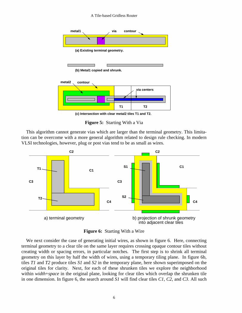
Postponing arbitrary choice, we start the search with all legal wires and vias. The terminalsneed not be simple rectangular pins, and are in general the result of previous routings. Any initialwire or via must touch the terminal geometry with at least a minimum width, and must not createa spacing violation with any other geometry. We begin with the case of starting with a via, asshown in figure 5.
The goal is to place the via inside the terminal geometry on this layer (L1), but in clear spaceon the second layer (L2). We copy the geometry for the terminal on L1 which can contain a viainto a temporary tiling plane (metal1 in figure 5), and shrink it by half the width of a via on thislayer (figure 5b). This shrunken geometry defines the centers of vias which lie entirely withinthe terminal geometry. Its intersection with via-clear tiles on L2 maps the location of legal vias,as shown in figure 5c. For each such intersection, we create a path data structure containing theidentity of the clear tile and the intersection, and insert it in the path heap. In the figure, pathswould be created for both T1 and T2. Because a true via occupies only one unit square in one ofthese rectangles, each path represents a collection of possible starting vias.
5
A Tile-based Gridless Router
metal1 via contour
(a) Existing terminal geometry.
(b) Metal1 copied and shrunk.
(c) Intersection with clear metal2 tiles T1 and T2.
T1 T2
via centers
metal2 contour
Figure 5: Starting With a Via
This algorithm cannot generate vias which are larger than the terminal geometry. This limita-tion can be overcome with a more general algorithm related to design rule checking. In modernVLSI technologies, however, plug or post vias tend to be as small as wires.
a) terminal geometry b) projection of shrunk geometry into adjacent clear tiles
C2
C1
C3
C4
C2
C1
C4
C3
T1
T2
S1
S2
Figure 6: Starting With a Wire
We next consider the case of generating initial wires, as shown in figure 6. Here, connectingterminal geometry to a clear tile on the same layer requires crossing opaque contour tiles withoutcreating width or spacing errors, in particular notches. The first step is to shrink all terminalgeometry on this layer by half the width of wires, using a temporary tiling plane. In figure 6b,tiles T1 and T2 produce tiles S1 and S2 in the temporary plane, here shown superimposed on theoriginal tiles for clarity. Next, for each of these shrunken tiles we explore the neighborhoodwithin width+space in the original plane, looking for clear tiles which overlap the shrunken tilein one dimension. In figure 6, the search around S1 will find clear tiles C1, C2, and C3. All such
6

A Tile-based Gridless Router
tiles will be within width/2+space of the terminal geometry. Between each of these tiles Ci andthe shrunken tile Sj, there is an intervening area covered by opaque tiles, and normally forbiddento wires. But any horizontal strip of height 1 starting in the shaded area of C3 and connecting C3to T1, for instance, will touch T1 with a full wire width, and will not create a design rule errorwith any other part of T1 or T2. These shaded areas in clear tiles abutting opaque tiles around theterminal define where the opaque tiles may be crossed legally. For each such clear tile, we createa path data structure containing the identity of the clear tile and the rectangle connecting it to theterminal geometry. Note that in the example, C1 has two paths created into it, one describing ahorizontal connection to T1, and one a vertical connection to T2.
3.2. Cost Function
It is our belief that the only good cost functions have a physical basis, usually related to theamount of material needed to complete the connection. We use the A* heuristic [3], where thecost of a path is the sum of the exact Manhattan distance from the source to the path (sourcecost), and a lower bound on the remaining distance to the destination (destination cost). Wemodify it by assigning a horizontal and vertical weight to each layer, which is multiplied bydistance travelled on this layer. Weights are used for the different materials and directions inorder to control the style of routing. For example, if one specifies that routing on metal1 has acost of 1 in the horizontal direction, and 10 in the vertical direction, and reverses these coef-ficient for metal2, routing will have a very strong directionality, similar to the results of a chan-nel router, where even the smallest vertical movement will require a layer change to metal2. Ifthe differences in relative cost is smaller, however, jogs or doglegs will be preferred to layerchanges for small distances.
3.3. Paths and Path Heaps
At the start of path propagation, we have two path heaps, one for each terminal, seeded withpaths for initial vias and wires. The heaps, or priority queues [14], are used to maintain all pathsin order of increasing cost. The paths stored in the path heaps describe the end points of design-rule correct paths in clear tiles leading from a terminal to a tile. More precisely, a path is a datastructure containing:
• a tile pointer to the clear tile in which the path ends.
• the source cost of getting to this tile from the starting terminal.
• the minimal cost rectangle in the tile which can be reached for the source cost. Thisdefines a sort of "equipotential" for source cost; by definition any unit square in therectangle can be reached for the source cost recorded in the path. The rectangle mayoften be a single unit square, but when it is not as in figure 7, it represents the endpoints of a collection of topologically equivalent paths with the same cost.
• the destination cost, a lower bound on the cost with which the path to the destinationcan be completed. This is simply the Manhattan distance from the minimal cost rec-tangle to the bounding box of the other terminal.
• a back pointer to the parent path. By following the chain of back pointers in a pathto previous paths, we can find the sequence of paths - and therefore of clear tiles -which lead from the current clear tile to the terminal.
7

A Tile-based Gridless Router
• a next pointer to the next path to the same tile. Each clear tile contains a path pointerto the head of the list of all paths to this tile, linked by the next path pointer. When anew path is generated, it is added to the path heap, and it is also linked to the chainfor its clear tile.
3.4. Path Propagation
The basic step during maze searching is path propagation, and it continues until either onepath heap is empty or an acceptable solution is found. If one path heap becomes empty with nosolution found, then all the accessible free space around one of the terminals has been explored,and no solution is possible.
The path heaps are processed alternately during the search, by removing the least cost pathfrom one heap, and then the other. The path removed from the heap is the one whose sum ofsource cost and destination cost is least. The least cost path defines a clear tile which can bereached from the terminal. To propagate the path, we must find all connected clear tiles on thisand adjacent layers, and generate new paths to them. A path to a neighboring tile on the samelayer corresponds to extending a wire on the layer. A path to a tile on an adjacent layer cor-responds to changing layers with a via. Following the principle of no arbitrary choices, wegenerate all such paths which reach their tiles with minimum source cost. These become thedescendents of the current path, and are inserted into the heap.
p4
p1
p5
p9
p2
p6 p8
p7
p3
p10 p11
T1 T2
T3
T4 T5
T6
OBSTACLE
TERMINAL
path
solid tile
contour tile
Figure 7: Propagating Wires
The case of propagating a wire is shown in figure 7. Paths are represented by their minimalcost rectangles within their tiles, and the back pointers from paths to the ones that generatedthem are represented by arrows. The figure illustrates that a tile in general has many paths to it;note that T3 has three paths, p2, p5, and p7. Suppose that p6 is the least cost path in its heap. Topropagate p6 from clear tile T4, we examine all tiles around the perimeter of T4. Any clear tilewhich shares a border of at least one unit with T4 is eligible - diagonal abutment at corners isnot. Of T4’s bordering tiles, only T6 and T3 are clear. Of these, p6 can generate a minimal-costpath only to T6 at p11. In the other clear tiles, paths from p6 are longer than paths from other
8

A Tile-based Gridless Router
sources, and they are discarded. Note that two paths survive in T6: p10-p9-p5-p1 and p11-p6-p2.This is correct; depending on the precise location of the destination geometry, either could be thebetter path. Note also that p6 is not a unit square, and so it defines a set of possible paths withequal cost. Again, depending on the precise geometry of a solution through p6, any one of thepossible unit squares could be the best center for the actual wire.
T1
T2T3
T4
V1
V2
V3
V4
H4H3
H2
H1
projectiononverticalaxis
projection onhorizontal axis
Figure 8: Minimal Cost Path Through a Sequence of Tiles
3.5. Finding the Centerline Route
Once a neighboring tile of a path is found, a new path must be generated for it. Figure 8 showshow the source cost and the minimal-cost rectangle for the new path is computed. The figureshows a sequence of clear tiles T1 to T4, and the minimal-length centerline path which connectsthem. Since the path lies entirely within the sequence of tiles, it would generate a design-rulecorrect wire when expanded to full width. The general case of this problem has been explored in[10].
The centerline path is generated by projecting the general two-dimensional problem onto thehorizontal and vertical axes, as shown below and on the left of the figure. Each tile becomes aline segment in both projections. For each projection, we solve the one-dimensional problem ofmoving a unit line segment from the nearest point in the H4 or V4 to the nearest point of H1 orV1. This is done by maintaining for each line segment an entry point, and by looking at succeed-ing segments for the exit point. The exit point is found when a successor segment does not over-lap the current segment, as for example, when H2 does not overlap H4. The exit point is thenfixed as the point in the current segment nearest the non-overlapping successor. Each interveningsegment is then trimmed to have the entry and exit points as ends. The entry point floats for thefirst segment. The exit point floats for the last segment.
This algorithm tries not to move the entry point into a segment until necessary. When the twoone-dimensional solutions are projected back into two dimensions, a centerline path with theminimal number of bends is generated. The algorithm yields the minimal cost rectangle for thepath directly, and its source cost is the sum of the horizontal and vertical distances weighted byhorizontal and vertical unit costs of this layer.
9

A Tile-based Gridless Router
The case for generating path descendants on adjacent layers involves simple extensions of thecase for a wire. Instead of searching the tiles bordering the clear tile on its own layer, we searchfor clear tiles intersecting it on a neighboring layer. Any areas of intersection of clear tiles on thetwo layers must be unobstructed on both layers and therefore legal places for the centers of vias.The centerline path generation algorithm for computing the source cost and minimal cost rec-tangle illustrated in figure 8 works just as well when the sequence of clear tiles lies on severallayers; some tiles in the sequence will properly intersect, rather than merely abut. The algorithmmust be generalized slightly to move preferentially on the horizontal and vertical line segmentshaving minimal unit cost.
3.6. Pruning Paths
In the previous section, we indicated that a path is added to a tile only if it has minimal cost.We now make this notion precise.
p1=10 p3=80p2=60
a) multiple paths to a tile
b) cost cones (one dimension)
p1
p3
p2
cost
horizontal distance10
60
80
Figure 9: Redundant Paths to a Tile
Figure 9a shows a single tile with three paths to it from the same terminal. Each path isrepresented by a rectangle and the cost of reaching any point in that rectangle. Suppose that thiswiring layer has unit cost in both dimensions. We can represent the paths by a cost versus dis-tance graph as shown in figure 9b. In this figure, each path defines a cone of the cost for whichany point in the tile can be reached. The lowest point in the cone is the source cost of the path;the interior of the minimal-cost rectangle can be reached for this cost. Points outside theminimal-cost rectangle can be reached for the additional cost of a wire in this tile. In the figure,we have drawn only the one-dimensional horizontal projections of these cones for simplicity,though they are in reality two-dimensional cost functions of x and y. The figure illustrates in onedimension the principle that we may eliminate any path whose cost cone lies entirely within thecone of another path. Thus, in the example, p3 is made redundant by p1, but p1 and p2 are notmutually redundant, since each can reach points in the tile for minimal cost.
10

A Tile-based Gridless Router
3.7. Selecting a Solution
A solution to the maze search is found when a path is added to a tile which already has a pathfrom the other terminal. When this happens, a connected sequence of clear tiles exists betweenthe source and destination. The algorithm for finding the minimal-cost centerline path describedabove will generate the cheapest path through these tiles, and its ’source cost’ is the actual costof the solution.
via into tilefrom source
via into tilefrom destination
x cost = dx * 1000
y cost = dy * 1
Figure 10: An Unacceptably Expensive Solution
Is the first solution found the best one? Often not, as shown in figure 10 where initial via pathsfrom both terminals are created in the same tile on a layer with expensive horizontal movement.The source cost of each via is small, and the estimated cost of completing the paths through thesevias is also small, because the estimate uses best-case costs. But since the direct solution con-necting these two vias requires horizontal movement on an unfavored layer, it is very expensive.
Even if the first solution is not the best, it gives useful upper bounds on the cost of any furthersolutions.
• If all paths in the heaps have a combined source and destination cost larger than thesolution cost, we stop the search since any future solution will be more expensive.This is an easy test, since heaps are sorted by this combined cost.
• A new path should be added to a heap only if its combined source and destinationcost is less than the current best solution. We may limit the area searched for neigh-boring tiles by using simple Manhattan distance as a lower bound on the estimatedcost: all paths whose Manhattan distance to the destination is larger than the bestsolution cost minus the path source cost are discarded. This defines a Manhattanellipse between the path’s minimum-cost rectangle and the destination terminal, asshown in figure 11.
As further solutions are generated, some may have lesser cost, and we continually retain thebest, further tightening our criterion for stopping the search.
Despite the additional pruning which can be done once the first solution is found, experienceshowed that most of the search is done to prove that a very good solution found early on isindeed optimal. For each solution, we define a cost ratio as the actual cost of the path divided bythe cost of a Manhattan path between the same endpoints on the cheapest layers. The cost ratio
11

A Tile-based Gridless Router
sourceterminal
destinationterminal
path of current best solution
clear tile
source path to clear tile
uselessneighbor
usefulneighbor
ellipse of destination pathswhich can improveon current best solution
Figure 11: Manhattan Ellipse of Path Completion
can never be less than 1. By stopping the search when the cost ratio of the current best solution isbelow a user-settable threshold (say 1.05), simple connections can be stopped early whileguaranteeing that the solution is within 5% of Manhattan length. This provides a large speedincrease for a limited loss in routing quality.
3.8. Design-Rule Errors in the Solution
The contour structure prevents design-rule errors of new geometry with existing geometry. Itcannot tell us whether a solution will have design rule errors with itself when converted into realgeometry. Width errors are not possible, because a centerline path always bloats into geometrytouching the terminals with legal width. Spacing errors on one layer are also not possible. Theyrequire two parallel edges of the geometry to be separated by less than a minimum spacing. Nolegal geometry can lie between these edges, and so they must form part of a U-shaped loop.Therefore there must be a shorter solution which does not contain the loop, and prolonging thesearch will find it. Vias are the remaining source of potential design-rule errors. A simple ex-ample is a solution requiring a change from first-level to third-level metal. It would be quite easyto create an illegal spacing between the second-metal images of the first-to-second and second-to-third vias. These are prevented by special-case code as mentioned in [1].
4. Special Wiring Problems
4.1. Busses
A feature obvious to the eye in VLSI circuits is the regular routing of large data busses con-sisting of tens or hundreds of wires. Maximum density dictates that when a wide bus is used toconnect different functional units on a chip, the individual wires in it should run in parallel andthat turns and layer changes should be done in a regular and stylized way. On one layer, thisstyle of routing is known as river routing [13].
We make no special provision for routing of many wires in parallel. Instead, we note thatregular wiring is by definition easy to describe, and we provide a mechanism to add segments of
12

A Tile-based Gridless Router
wire for particular nets during cell placement. Like all placement operations, this is done bywriting code, not by editing layout graphically. By making this relative to edge and corner align-ments, wiring can be added in a flexible way which will adapt to future layout changes. Anexample of such a wiring command might be "add a vertical metal2 bus for dataIn running on theleft of the data path and extending for its full height". Because the individual wires of the bus areassociated with the netlist, the router sees the bus as just another piece of geometry to be con-nected on each of the nets of the bus. By judiciously inserting wiring in this way during place-ment, we have found it extremely easy to direct the router to make the obvious right choiceswithout further assistance.
A second situation requiring regular wiring is busses embedded in data paths, where a track ineach repeated bit pitch is used to carry one bit of a bus over the length of the data path. Here, asabove, it is also possible to lay down explicitly the wire used for the bus in each bit pitch. Wehave also used a simple and more flexible strategy with success. Most nets are broken down intopairwise connections by repeatedly adding the shortest necessary connection in the normal span-ning tree algorithm. However, busses embedded in data paths are more optimally routed as longstraight tracks running the length of the data path with short spurs to the individual device ter-minals along the way. This can be easily described by beginning the spanning tree with the con-nection between the two most distant terminals, rather than the two nearest, and then finishingthe spanning tree normally. The most obvious choice for the router will then be to make the firstconnection with a single straight wire between the end points of the bus, and then to add shortstubs for all remaining connections.
When to use these bus routing strategies is at the discretion of the designer, not decidedautomatically. Layout is an iterative process of improvement, not perfect first time. The first timelayout is generated for a cell, the result may be an unroutable mess due to lack of regularity. Thesimplest strategy is then to select some nets in the cell to be routed with the bus spanning treealgorithm and try again. This may produce sufficient improvement to route the cell. If not, trackassignment can be done by hand, and segments of wire added by code during placement to leaveno room for error.
4.2. Power Supplies and Clocks
Power supply nets, voltage reference nets, and clock nets provide special problems for arouter, since their primary function is analog, not digital. Voltage, current, capacitance and resis-tance of these nets are critical issues, and they do not fit the model of a net in which all thecomponents may be connected by a spanning tree. Power and clock nets are often multiply con-nected in a grid pattern, for instance. In general, the geometry of these nets must largely bedesigned by hand as an integral part of the layout of a VLSI circuit, and automatic routing can beonly help with the details. For power nets, a useful routing primitive is to extend the ends ofpower bars of subcells to abut with matching power bars in adjacent subcells, so that when sub-cells do not abut perfectly along their boundaries, the gaps in the power routing are filled in.
In clock distribution trees, it is important to define the sources and sinks of clock signals ateach level in the tree so as to connect each sink to its source rather than to another nearer sink.
13

A Tile-based Gridless Router
5. Results
CONTOUR is part of a set of tools which has been under development for several years. Anearlier version was used to route BIPS-0, a bipolar processor [7]. The layout generation of thiscomplete 700,000-device circuit took 10 hours, most of which was spent in routing. This al-lowed one complete iteration per day. It has also been used for the layout of large sections ofBIPS-1, a 4,000,000-device BiCMOS microprocessor.
Figure 12: BIPS-1 Floating-Point Divider routed with CONTOUR
Figure 13: A synthesized cell; the 4-layer routing added by CONTOUR
The performance of CONTOUR is illustrated in the 64-bit floating-point divider of BIPS-1,shown in figure 12. The routing is done hierarchically in 118 unique cells, 97 of which aresynthesized gate-level cells like the one shown in figure 13. The wiring added by CONTOUR infigure 13, shown separately on the right, is on four layers (three metal layers plus polysilicon)and the routing was done in a few seconds on a DEC 3000/800. Another 21 cells in the divider arecomposite cells such as 56-bit registers, carry-lookahead adders, or blocks of control logic.Routing the 7495 connections of the divider takes 532 seconds on a DEC 3000/800 for an overallspeed of 14 connections per second. Considering all 118 cell routings as a whole, 20% of thetime is spent painting the contours before routing starts, and 80% actually doing the routing. Ofthis 80%, 38% of the time is spent generating the initial via and wire positions to start the search,and 42% of the time is spent in path propagation.
14

A Tile-based Gridless Router
The speed and quality of CONTOUR are based on the combination of contour-based routing andthe avoidance of arbitrary choices in the search algorithm. We believe that this approach is moreeffective than the restrictive channel model requiring an artificial partitioning of chip area, andwe see no reason to restrict routing to two or three layers at a time. In our design style,CONTOUR is the only router for gate-level synthesized cells, data paths, random logic blocks andglobal assembly; the conventional use of different algorithms at these levels seems a historicalaccident. We also see no reason why CONTOUR’S algorithms and data structures cannot beadapted in a straightforward way to gate arrays, printed circuit boards, and other routingproblems in electronic design.
th[1] M.H. Arnold , W.S. Scott. An Interactive Maze Router with Hints. In 25 DesignAutomation Conference, pages 672-676. June, 1988.
[2] Jeremy Dion, Louis Monier. Design Tools for BIPS-0. WRL Technical Note 32, DigitalEquipment Western Research Laboratory, December, 1992.
st[3] G.W. Clow. A Global Routing Algorithm for General Cells. In 21 Design AutomationConference, pages 45-51. June, 1984.
th[4] J. Dion. Fast Printed Circuit Board Routing. In 24 Design Automation Conference.June, 1987.
[5] J. Dion. Fast Printed Circuit Board Routing. WRL Research Report 88/1, DigitalEquipment Western Research Laboratory, 1988.
[6] Hightower D. A Solution to Line Routing Problems on the Continuous Plane. Proc.Design Automation Workshop :1-24, 1969.
[7] N.P. Jouppi, P. Boyle, J. Dion, M.J. Doherty, A. Eustace, R.W. Haddad, R. Mayo,S. Menon, L.M. Monier, D. Stark, S. Turrini, J.L. Yang, W.R. Hamburgen, J.S. Fitch,
R. Kao. A 300-MHz 115-W 32-b Bipolar ECL Microprocessor. In IEEE Journal of Solid-StateCircuits. November, 1993.
[8] J. Ousterhout, G. Hamachi, R. Mayo, W. Scott, and G.S. Taylor. The Magic VLSILayout System. IEEE Design and Test of Computers 2(1):19-30, February, 1985.
[9] A. Margarino, A. Romano, A. De Gloria, F. Curatelli, P. Antognetti. A Tile-ExpansionRouter. IEEE Transactions on Computer-Aided Design CAD-6(4):507-517, July, 1987.
[10] K.M. McDonald, J.G. Peters. Smallest Paths in Simple Rectilinear Polygons. IEEETransactions on Computer-Aided Design 11(7):864-875, July, 1992.
th[11] L.M. Monier, J. Dion. Recursive Layout Generation. In Proc. 16 Conference on Ad-vanced Research in VLSI, pages 172-184. IEEE Computer Society Press, March, 1995.
[12] Moore E.F. Shortest Path Through a Maze. In Annals of the Computation Laboratory ofHarvard University, pages 285-292. Harvard Univ. Press, Cambridge Mass., 1959.
[13] R.Y. Pinter. River routing: methodology and analysis. In 3rd Caltech conference onVLSI, pages 141-163. March, 1983.
[14] R. E. Tarjan. Data Structures and Network Algorithms. CMBS-Regional ConferenceSeries, Volume 44, 1983.
15

A Tile-based Gridless Router
[15] J.K. Ousterhout. Corner Stitching: A Data Structuring Technique for VLSI LayoutTools. IEEE Transactions on Computer-Aided Design CAD-3(1):87-89, January, 1984.
[16] Chia-Chun Tsai, Sao-Jie Chen, Wu-Shiung Feng. An H-V Alternating Router. IEEETransactions on Computer-Aided Design 11(8):976-991, August, 1992.
16

A Tile-based Gridless Router
WRL Research Reports
‘‘Titan System Manual.’’ ‘‘The USENET Cookbook: an Experiment in
Michael J. K. Nielsen. Electronic Publication.’’
WRL Research Report 86/1, September 1986. Brian K. Reid.
WRL Research Report 87/7, December 1987.‘‘Global Register Allocation at Link Time.’’
David W. Wall. ‘‘MultiTitan: Four Architecture Papers.’’
WRL Research Report 86/3, October 1986. Norman P. Jouppi, Jeremy Dion, David Boggs, Mich-
ael J. K. Nielsen.‘‘Optimal Finned Heat Sinks.’’ WRL Research Report 87/8, April 1988.William R. Hamburgen.
WRL Research Report 86/4, October 1986. ‘‘Fast Printed Circuit Board Routing.’’
Jeremy Dion.‘‘The Mahler Experience: Using an Intermediate WRL Research Report 88/1, March 1988.
Language as the Machine Description.’’
David W. Wall and Michael L. Powell. ‘‘Compacting Garbage Collection with Ambiguous
WRL Research Report 87/1, August 1987. Roots.’’
Joel F. Bartlett.‘‘The Packet Filter: An Efficient Mechanism for WRL Research Report 88/2, February 1988.
User-level Network Code.’’
Jeffrey C. Mogul, Richard F. Rashid, Michael ‘‘The Experimental Literature of The Internet: An
J. Accetta. Annotated Bibliography.’’
WRL Research Report 87/2, November 1987. Jeffrey C. Mogul.
WRL Research Report 88/3, August 1988.‘‘Fragmentation Considered Harmful.’’
Christopher A. Kent, Jeffrey C. Mogul. ‘‘Measured Capacity of an Ethernet: Myths and
WRL Research Report 87/3, December 1987. Reality.’’
David R. Boggs, Jeffrey C. Mogul, Christopher‘‘Cache Coherence in Distributed Systems.’’ A. Kent.Christopher A. Kent. WRL Research Report 88/4, September 1988.WRL Research Report 87/4, December 1987.
‘‘Visa Protocols for Controlling Inter-Organizational‘‘Register Windows vs. Register Allocation.’’ Datagram Flow: Extended Description.’’David W. Wall. Deborah Estrin, Jeffrey C. Mogul, Gene Tsudik,WRL Research Report 87/5, December 1987. Kamaljit Anand.
WRL Research Report 88/5, December 1988.‘‘Editing Graphical Objects Using Procedural
Representations.’’ ‘‘SCHEME->C A Portable Scheme-to-C Compiler.’’Paul J. Asente. Joel F. Bartlett.WRL Research Report 87/6, November 1987. WRL Research Report 89/1, January 1989.
17

A Tile-based Gridless Router
‘‘Optimal Group Distribution in Carry-Skip Ad- ‘‘The Distribution of Instruction-Level and Machine
ders.’’ Parallelism and Its Effect on Performance.’’
Silvio Turrini. Norman P. Jouppi.
WRL Research Report 89/2, February 1989. WRL Research Report 89/13, July 1989.
‘‘Precise Robotic Paste Dot Dispensing.’’ ‘‘Long Address Traces from RISC Machines:
William R. Hamburgen. Generation and Analysis.’’
WRL Research Report 89/3, February 1989. Anita Borg, R.E.Kessler, Georgia Lazana, and David
W. Wall.‘‘Simple and Flexible Datagram Access Controls for WRL Research Report 89/14, September 1989.
Unix-based Gateways.’’
Jeffrey C. Mogul. ‘‘Link-Time Code Modification.’’
WRL Research Report 89/4, March 1989. David W. Wall.
WRL Research Report 89/17, September 1989.‘‘Spritely NFS: Implementation and Performance of
Cache-Consistency Protocols.’’ ‘‘Noise Issues in the ECL Circuit Family.’’
V. Srinivasan and Jeffrey C. Mogul. Jeffrey Y.F. Tang and J. Leon Yang.
WRL Research Report 89/5, May 1989. WRL Research Report 90/1, January 1990.
‘‘Available Instruction-Level Parallelism for Super- ‘‘Efficient Generation of Test Patterns Using
scalar and Superpipelined Machines.’’ Boolean Satisfiablilty.’’
Norman P. Jouppi and David W. Wall. Tracy Larrabee.
WRL Research Report 89/7, July 1989. WRL Research Report 90/2, February 1990.
‘‘A Unified Vector/Scalar Floating-Point Architec- ‘‘Two Papers on Test Pattern Generation.’’
ture.’’ Tracy Larrabee.
Norman P. Jouppi, Jonathan Bertoni, and David WRL Research Report 90/3, March 1990.
W. Wall.‘‘Virtual Memory vs. The File System.’’WRL Research Report 89/8, July 1989.Michael N. Nelson.
‘‘Architectural and Organizational Tradeoffs in the WRL Research Report 90/4, March 1990.
Design of the MultiTitan CPU.’’‘‘Efficient Use of Workstations for Passive Monitor-Norman P. Jouppi.
ing of Local Area Networks.’’WRL Research Report 89/9, July 1989.Jeffrey C. Mogul.
‘‘Integration and Packaging Plateaus of Processor WRL Research Report 90/5, July 1990.
Performance.’’‘‘A One-Dimensional Thermal Model for the VAXNorman P. Jouppi.
9000 Multi Chip Units.’’WRL Research Report 89/10, July 1989.John S. Fitch.
‘‘A 20-MIPS Sustained 32-bit CMOS Microproces- WRL Research Report 90/6, July 1990.
sor with High Ratio of Sustained to Peak Perfor-‘‘1990 DECWRL/Livermore Magic Release.’’mance.’’Robert N. Mayo, Michael H. Arnold, Walter S. Scott,Norman P. Jouppi and Jeffrey Y. F. Tang.
Don Stark, Gordon T. Hamachi.WRL Research Report 89/11, July 1989.WRL Research Report 90/7, September 1990.
18

A Tile-based Gridless Router
‘‘Pool Boiling Enhancement Techniques for Water at ‘‘Interleaved Fin Thermal Connectors for Multichip
Low Pressure.’’ Modules.’’
Wade R. McGillis, John S. Fitch, William William R. Hamburgen.
R. Hamburgen, Van P. Carey. WRL Research Report 91/9, August 1991.
WRL Research Report 90/9, December 1990.‘‘Experience with a Software-defined Machine Ar-
‘‘Writing Fast X Servers for Dumb Color Frame Buf- chitecture.’’
fers.’’ David W. Wall.
Joel McCormack. WRL Research Report 91/10, August 1991.
WRL Research Report 91/1, February 1991.‘‘Network Locality at the Scale of Processes.’’
‘‘A Simulation Based Study of TLB Performance.’’ Jeffrey C. Mogul.
J. Bradley Chen, Anita Borg, Norman P. Jouppi. WRL Research Report 91/11, November 1991.
WRL Research Report 91/2, November 1991.‘‘Cache Write Policies and Performance.’’
‘‘Analysis of Power Supply Networks in VLSI Cir- Norman P. Jouppi.
cuits.’’ WRL Research Report 91/12, December 1991.
Don Stark.‘‘Packaging a 150 W Bipolar ECL Microprocessor.’’WRL Research Report 91/3, April 1991.William R. Hamburgen, John S. Fitch.
‘‘TurboChannel T1 Adapter.’’ WRL Research Report 92/1, March 1992.
David Boggs.‘‘Observing TCP Dynamics in Real Networks.’’WRL Research Report 91/4, April 1991.Jeffrey C. Mogul.
‘‘Procedure Merging with Instruction Caches.’’ WRL Research Report 92/2, April 1992.
Scott McFarling.‘‘Systems for Late Code Modification.’’WRL Research Report 91/5, March 1991.David W. Wall.
‘‘Don’t Fidget with Widgets, Draw!.’’ WRL Research Report 92/3, May 1992.
Joel Bartlett.‘‘Piecewise Linear Models for Switch-Level Simula-WRL Research Report 91/6, May 1991.
tion.’’
‘‘Pool Boiling on Small Heat Dissipating Elements in Russell Kao.
Water at Subatmospheric Pressure.’’ WRL Research Report 92/5, September 1992.
Wade R. McGillis, John S. Fitch, William‘‘A Practical System for Intermodule Code Optimiza-R. Hamburgen, Van P. Carey.
tion at Link-Time.’’WRL Research Report 91/7, June 1991.Amitabh Srivastava and David W. Wall.
‘‘Incremental, Generational Mostly-Copying Gar- WRL Research Report 92/6, December 1992.bage Collection in Uncooperative Environ-
‘‘A Smart Frame Buffer.’’ments.’’Joel McCormack & Bob McNamara.G. May Yip.WRL Research Report 93/1, January 1993.WRL Research Report 91/8, June 1991.
‘‘Recovery in Spritely NFS.’’Jeffrey C. Mogul.
WRL Research Report 93/2, June 1993.
19

A Tile-based Gridless Router
‘‘Tradeoffs in Two-Level On-Chip Caching.’’ ‘‘Complexity/Performance Tradeoffs with Non-
Norman P. Jouppi & Steven J.E. Wilton. Blocking Loads.’’
WRL Research Report 93/3, October 1993. Keith I. Farkas, Norman P. Jouppi.
WRL Research Report 94/3, March 1994.‘‘Unreachable Procedures in Object-oriented
Programing.’’ ‘‘A Better Update Policy.’’
Amitabh Srivastava. Jeffrey C. Mogul.
WRL Research Report 93/4, August 1993. WRL Research Report 94/4, April 1994.
‘‘An Enhanced Access and Cycle Time Model for ‘‘Boolean Matching for Full-Custom ECL Gates.’’
On-Chip Caches.’’ Robert N. Mayo, Herve Touati.
Steven J.E. Wilton and Norman P. Jouppi. WRL Research Report 94/5, April 1994.
WRL Research Report 93/5, July 1994.‘‘Software Methods for System Address Tracing:
‘‘Limits of Instruction-Level Parallelism.’’ Implementation and Validation.’’
David W. Wall. J. Bradley Chen, David W. Wall, and Anita Borg.
WRL Research Report 93/6, November 1993. WRL Research Report 94/6, September 1994.
‘‘Fluoroelastomer Pressure Pad Design for ‘‘Performance Implications of Multiple Pointer
Microelectronic Applications.’’ Sizes.’’
Alberto Makino, William R. Hamburgen, John Jeffrey C. Mogul, Joel F. Bartlett, Robert N. Mayo,
S. Fitch. and Amitabh Srivastava.
WRL Research Report 93/7, November 1993. WRL Research Report 94/7, December 1994.
‘‘A 300MHz 115W 32b Bipolar ECL Microproces- ‘‘How Useful Are Non-blocking Loads, Stream Buf-
sor.’’ fers, and Speculative Execution in Multiple Issue
Norman P. Jouppi, Patrick Boyle, Jeremy Dion, Mary Processors?.’’
Jo Doherty, Alan Eustace, Ramsey Haddad, Keith I. Farkas, Norman P. Jouppi, and Paul Chow.
Robert Mayo, Suresh Menon, Louis Monier, Don WRL Research Report 94/8, December 1994.
Stark, Silvio Turrini, Leon Yang, John Fitch, Wil-‘‘Recursive Layout Generation.’’liam Hamburgen, Russell Kao, and Richard Swan.Louis M. Monier, Jeremy Dion.WRL Research Report 93/8, December 1993.WRL Research Report 95/2, March 1995.
‘‘Link-Time Optimization of Address Calculation on‘‘Contour: A Tile-based Gridless Router.’’a 64-bit Architecture.’’Jeremy Dion, Louis M. Monier.Amitabh Srivastava, David W. Wall.WRL Research Report 95/3, March 1995.WRL Research Report 94/1, February 1994.
‘‘The Case for Persistent-Connection HTTP.’’‘‘ATOM: A System for Building CustomizedJeffrey C. Mogul.Program Analysis Tools.’’WRL Research Report 95/4, May 1995.Amitabh Srivastava, Alan Eustace.
WRL Research Report 94/2, March 1994.‘‘Network Behavior of a Busy Web Server and its
Clients.’’
Jeffrey C. Mogul.WRL Research Report 95/5, June 1995.
20

A Tile-based Gridless Router
WRL Technical Notes
‘‘TCP/IP PrintServer: Print Server Protocol.’’ ‘‘Boiling Binary Mixtures at Subatmospheric Pres-
Brian K. Reid and Christopher A. Kent. sures’’
WRL Technical Note TN-4, September 1988. Wade R. McGillis, John S. Fitch, William
R. Hamburgen, Van P. Carey.‘‘TCP/IP PrintServer: Server Architecture and Im- WRL Technical Note TN-23, January 1992.
plementation.’’
Christopher A. Kent. ‘‘A Comparison of Acoustic and Infrared Inspection
WRL Technical Note TN-7, November 1988. Techniques for Die Attach’’
John S. Fitch.‘‘Smart Code, Stupid Memory: A Fast X Server for a WRL Technical Note TN-24, January 1992.
Dumb Color Frame Buffer.’’
Joel McCormack. ‘‘TurboChannel Versatec Adapter’’
WRL Technical Note TN-9, September 1989. David Boggs.
WRL Technical Note TN-26, January 1992.‘‘Why Aren’t Operating Systems Getting Faster As
Fast As Hardware?’’ ‘‘A Recovery Protocol For Spritely NFS’’
John Ousterhout. Jeffrey C. Mogul.
WRL Technical Note TN-11, October 1989. WRL Technical Note TN-27, April 1992.
‘‘Mostly-Copying Garbage Collection Picks Up ‘‘Electrical Evaluation Of The BIPS-0 Package’’
Generations and C++.’’ Patrick D. Boyle.
Joel F. Bartlett. WRL Technical Note TN-29, July 1992.
WRL Technical Note TN-12, October 1989.‘‘Transparent Controls for Interactive Graphics’’
‘‘The Effect of Context Switches on Cache Perfor- Joel F. Bartlett.
mance.’’ WRL Technical Note TN-30, July 1992.
Jeffrey C. Mogul and Anita Borg.‘‘Design Tools for BIPS-0’’WRL Technical Note TN-16, December 1990.Jeremy Dion & Louis Monier.
‘‘MTOOL: A Method For Detecting Memory Bot- WRL Technical Note TN-32, December 1992.tlenecks.’’
‘‘Link-Time Optimization of Address Calculation onAaron Goldberg and John Hennessy.a 64-Bit Architecture’’WRL Technical Note TN-17, December 1990.
Amitabh Srivastava and David W. Wall.
‘‘Predicting Program Behavior Using Real or Es- WRL Technical Note TN-35, June 1993.
timated Profiles.’’‘‘Combining Branch Predictors’’David W. Wall.Scott McFarling.WRL Technical Note TN-18, December 1990.WRL Technical Note TN-36, June 1993.
‘‘Cache Replacement with Dynamic Exclusion’’‘‘Boolean Matching for Full-Custom ECL Gates’’Scott McFarling.Robert N. Mayo and Herve Touati.WRL Technical Note TN-22, November 1991.WRL Technical Note TN-37, June 1993.
21
A Tile-based Gridless Router
‘‘Ramonamap - An Example of Graphical Group-
ware’’
Joel F. Bartlett.
WRL Technical Note TN-43, December 1994.
‘‘Circuit and Process Directions for Low-Voltage
Swing Submicron BiCMOS’’
Norman P. Jouppi, Suresh Menon, and Stefanos
Sidiropoulos.
WRL Technical Note TN-45, March 1994.
‘‘Experience with a Wireless World Wide Web
Client’’
Joel F. Bartlett.
WRL Technical Note TN-46, March 1995.
‘‘I/O Component Characterization for I/O Cache
Designs’’
Kathy J. Richardson.
WRL Technical Note TN-47, April 1995.
‘‘Attribute caches’’
Kathy J. Richardson, Michael J. Flynn.
WRL Technical Note TN-48, April 1995.
‘‘Operating Systems Support for Busy Internet Ser-
vers’’
Jeffrey C. Mogul.
WRL Technical Note TN-49, May 1995.
22