contour and surface measuring machines - qs … and surface measuring machines i n d u s t r i a l m...
TRANSCRIPT

Contour and Surface Measuring Machines
I n d u s t r i a l M e t r o l o g y f r o m C a r l Z e i s s

Furthermore, Carl Zeiss also delivers first class
service. We help you get ahead – quickly and
without red tape – be it a metrology question or
maintenance and repair. Thanks to our
network of local offices,
you receive the expert help
you need within a short
time.
Key features
Measuring range
Measuring Machines from Carl ZeissFor your benefit
The right system for every measuring task
•• Surfcom 1500 The•comfortable•measuring•station•for•surface•measurements
•• Contourecord 1700/2700The•flexible•measuring•station•for•contour•measurements
•• Surfcom 1900/2900The•combined•measuring•station•for•surface•and•contour••measurements
•• Surfcom 2000The•system•for•surface•and•contour•measurements•in•one•pass
•• Surfcom 5000Contour•and•surface•technology•for•the•highest•demands
Sufficient range for the measuring task
The•base•plate•–•columns•–•tracer•driver•combination•can•be•adjusted•as•needed•
Surfcom•1500/1900/2000•and•Contourecord•1700/2700••Granite•base•plate•600•mm•x•320•mm•or•1000•mm•x•450•mm••Optional•column•height•250•mm,•450•mm,•650•mm••Tracer•driver•100•mm•or•200•mm•
Surfcom•5000••Fully•enclosed•DX•version•with•granite•base•plate•1000•mm•x•450•mm,•column•height•500•mm,•tracer•driver•200•mm
Carl Zeiss offers a complete product line
for industrial metrology. From the small
“handy surf” for surface measurements to
the systems required to measure large parts
– whatever your needs, Carl Zeiss has the
right measuring machine. Our product line
also provides you with highly accurate
measuring machines for form, contour and
surface measurements.
Maximum quality – from production to service
Specialists finish vital machine components.
Quality inspection of our products adheres to the
most stringent internal testing procedures which
are often significantly stricter than the specified
standards.
Overview
2

Modularity
Linear motor technology for the detector feed
Software
Precision
The•entire•line•of•ZEISS•contour•and•surface•measuring•machines••feature•a•modular•design:•
The•machines•are•comprised•of•a•base•plate•–•column•–•feeder.
The•systems•can•be•equipped•with•a•contour•or•roughness•stylus-•and-arm•system,•or•upgraded•later,•depending•on•the•measuring•task.•Furthermore,•Y•tables,•Y•driver•units•or•CNC•tables•can•be•mounted•for•fully•automatic•contour•and•surface•measurements,•enable•the•systems•to•better•meet•customer•needs.
The•systems•are•based•on•a•software•platform•which•can•be•adjusted•depending•on•the•modular•hardware•system.
ACCTee PRO – All in the Document
The•ACCTee•PRO•integrated•software•strategy•enables•the•simple•analysis•of•surface•quality,•form•and•geometry.
The•„All•in•the•Document“•strategy•ensures•a•seamless•transition•from•the•measurement•to•the•analysis•to•the•log•design.•The•docu-ment•contains•all•the•information•required,•including•measuring••conditions,•analysis•conditions,•measured•data,•log•and•CNC•pro-gram.•The•visualization•and•intuitive•operation•enables•even•easier•and•more•efficient•analysis•of•the•measured•data•and•evaluation•of•the•results.
Highly precise, calibrated reference standards from Carl Zeiss for acceptance testing and monitoring
These•surface•measuring•machines•are•inspected•and•accepted•using•reverse•engineered•grooved•reference•standards.
A•sphere•is•the•standard•reference•for•acceptance•testing•of••contour•measuring•machines.•The•Contour•Check•contour•standard••is•optionally•available.
Disadvantages of traditional systems
At•high•measuring•speeds,•the•vibrations•generated•by•the••motor,•gears•and•drive•spindle•influence•the•measuring•data.
Benefits of a linear system
•• Non-contact•and•zero•backlash•• Higher•accuracy•• Higher•measuring•and•travel•speed•• Low•vibration•• Easy•maintenance Linear motor
Carriage
Reference base
Carriage
Reference base
Feed screwGears
DC motor
3

Plan/actual
comparison and
best fit
Faster comparison
of measured data with
nominal profiles (IGES, DXF). The best-fit function
facilitates optimal alignment of the actual data to
the nominal data for the comparison. The asphere
analysis function is also available.
ACCTee PROAll in the document
Feature calculation
with icon support
When a new calcu-
lation is made, all
possibilities for feature
calculation are shown
in a selection window
with icons. The type
of calculation between
features can be intuitively selected.
Self diagnosis
When an error occurs,
the self-diagnosis
function immediately
shows the operator an
image of the cause,
thus helping them find
a solution to the
problem.
Repeat measurement
Contour and roughness
ACCTee PRO Help
Users can access the
help pages at any
time. Help information
can be shown based
on the work flow.
Help topics can also be
searched using search terms or based on key words
in the index.
4
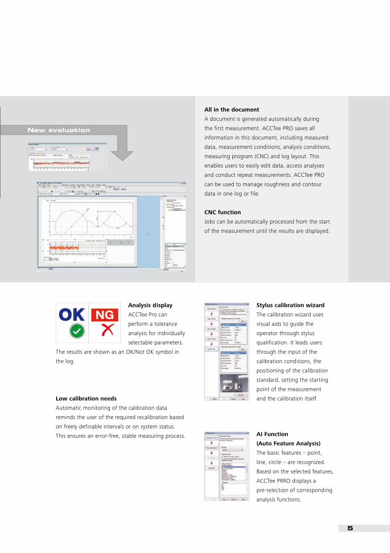
Stylus calibration wizard
The calibration wizard uses
visual aids to guide the
operator through stylus
qualification. It leads users
through the input of the
calibration conditions, the
positioning of the calibration
standard, setting the starting
point of the measurement
and the calibration itself.
AI Function
(Auto Feature Analysis)
The basic features – point,
line, circle – are recognized.
Based on the selected features,
ACCTee PRRO displays a
pre-selection of corresponding
analysis functions.
All in the document
A document is generated automatically during
the first measurement. ACCTee PRO saves all
information in this document, including measured
data, measurement conditions, analysis conditions,
measuring program (CNC) and log layout. This
enables users to easily edit data, access analyses
and conduct repeat measurements. ACCTee PRO
can be used to manage roughness and contour
data in one log or file.
CNC function
Jobs can be automatically processed from the start
of the measurement until the results are displayed.
New evaluation
Analysis display
ACCTee Pro can
perform a tolerance
analysis for individually
selectable parameters.
The results are shown as an OK/Not OK symbol in
the log.
Low calibration needs
Automatic monitoring of the calibration data
reminds the user of the required recalibration based
on freely definable intervals or on system status.
This ensures an error-free, stable measuring process.
5

•• Fast,•easy•and•precise•completion•of•contour•
measuring•tasks
•• Patented•linear•motor•technology
•• High•straightness•accuracy•and•glass•scale•in••
the•X•axis
•• Extensive•accessories•enable•a•large•range••
of•applications
•• All•axes•CNC•controlled
•• Automated•calibration•function
•• Software•compensates•for•sensing•arm••
and•stylus•tip•geometries
•• Upgradeable•using•modularly•adaptable••
CNC•tables
•• Also•expandable•for•2D•and•3D•surface••
measuring•tasks
•• Fully•enclosed•DX•version•with•integrated••
active•vibration•damping
•• Contourecord 1700 with•inductive•displace-
ment•transducer•(LVDT)•in•the•probing•system
•• Contourecord 2700•with•optical•diffraction•
scale•in•the•probing•system•(Z•axis)•for•maximum•
demands•on•accuracy
Contourecord 1700/2700
Contourecord 1700
Option: T-stylus
Contour
The flexible measuring station for contour measurementsEase of use for efficiency
6

Surfcom 1500
•• Fast,•easy•and•precise•completion•of•surface•
measuring•tasks
•• Patented•linear•motor•technology
•• Wide•range•of•accessories
•• All•axes•CNC•controlled
•• Upgradeable•using•modularly•adaptable••
CNC•tables
•• Also•expandable•for•contour•measuring•tasks
•• Topography•measurement•for•the•analysis•of••
3D•surface•data•with•optional•Y•feed•
•• Fully•enclosed•DX•version•with•integrated•active•
vibration•damping•for•the•highest•demands
Roughness measurement
Surfcom 1500
Roughness
The comfortable measuring station for surface measurementsMaximum performance, minimal effort
7

+
Surfcom 1500
Contourecord 1700
= Surfcom 1900
+
Surfcom 1500
Contourecord 2700
= Surfcom 2900
Surfcom 1900/2900
•• Fast,•easy•and•precise•completion•of•contour••
and•surface•measuring•tasks
•• Non-contact,•patented•linear•motor•technology
•• High•straightness•accuracy•and•glass•scale•in••
the•X•axis
•• Easy•change•of•the•probing•system•from••
contour•to•roughness•on•the•same•tracing•driver
•• Wide•range•of•accessories
•• Automated•calibration•function
•• Software•compensates•for•sensing•arm•and••
stylus•tip•geometries
•• All•axes•CNC•controlled
•• Upgradeable•using•modularly•adaptable••
CNC•tables
•• Also•expandable•for•2D•and•3D•surface••
measuring•tasks
•• Fully•enclosed•DX•version•with•integrated•active•
vibration•dampingSurfcom 1900
Contour & roughness
The combined measuring station for surface and contour measurements Easy to use
Roughness measurement
Contour measurement
8

Surfcom 2000
•• Contour•and•roughness•measurements•in••
one•run
•• Roughness•detector•with•5•mm•deflection,•
10 mm•with•doubled•stylus•length
•• Reduction•of•measuring•times•and•easy••
operation•of•the•system
•– No•changing•the•probing•system•
•– high•productivity
•• Friction-free,•patented•linear•motor•technology
•– Very•high•measuring•and•travel•speeds
•– High•straightness•accuracy
•– Low•background•noise
•– Low•maintenance•and•wear-and-tear
•• All•axes•CNC•controlled
•• Upgradeable•using•modularly•adaptable••
CNC•tables
•• Topography•measurement•for•the•analysis•of••
3D•surface•data•with•optional•Y•feed
•• Fully•enclosed•DX•version•with•integrated•active•
vibration•damping
Example application: asphere measure-ment on a lens
Surfcom 2000
Contour and surface measurements in one runShort measuring times – high productivity
9
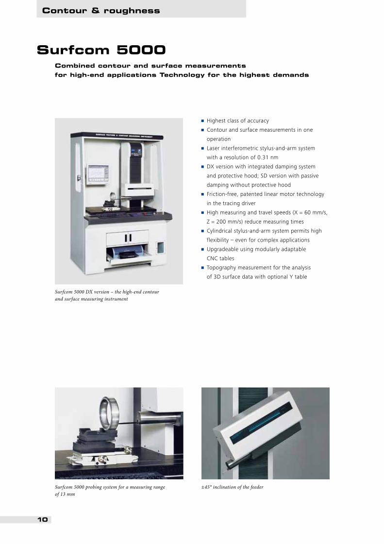
Surfcom 5000
•• Highest•class•of•accuracy
•• Contour•and•surface•measurements•in•one••
operation
•• Laser•interferometric•stylus-and-arm•system••
with•a•resolution•of•0.31•nm
•• DX•version•with•integrated•damping•system••
and•protective•hood;•SD•version•with•passive•
damping•without•protective•hood
•• Friction-free,•patented•linear•motor•technology•
in•the•tracing•driver
•• High•measuring•and•travel•speeds•(X•=•60•mm/s,•
Z•=•200•mm/s)•reduce•measuring•times
•• Cylindrical•stylus-and-arm•system•permits•high•
flexibility•–•even•for•complex•applications
•• Upgradeable•using•modularly•adaptable••
CNC•tables
•• Topography•measurement•for•the•analysis••
of•3D•surface•data•with•optional•Y•table
Surfcom 5000 probing system for a measuring range of 13 mm
Surfcom 5000 DX version – the high-end contour and surface measuring instrument
±45° inclination of the feeder
Combined contour and surface measurements for high-end applications Technology for the highest demands
Contour & roughness
10

+ + =+
+ =+
+ =
CNC tables, styli and accessories
The•“building•set”•contains•three•modules:••
the•positioning•stage•covers•the•Y•direction;••
two•additional•rotary•tables•are•used•to•position•
the•workpiece•in•the•XY•and•ZX•plane.•The•main•
advantage•is•the•combination•of•table•modules,•
depending•on•the•need,•to•achieve•motorization••
of•each•axis•to•the•alignment•and•positioning•of•
the•workpiece.
•• Can•be•modified•and•retrofitted•later
•• No•special•instruments•required
•• Can•be•combined•with•all•Contourecord••
and•Surfcom•systems
•• Programmable•using•Teach-in•and•system••
software
The modular system with different table modules for the automation of CNC measuring runs
Accessories for contour & roughness
Online shop for styli and accessories
www.probes.zeiss.com
Combination example
3-axis control
Y axis θ axis
(horizontal) + (vertical)
2-axis control
Y axis θ axis
(horizontal)
2-axis control
Y axis
11
CNC table modules Y table Horizontal rotary table Vertical rotary table
Traversing stroke 100 mm (200 mm) 360° 360°
Travel speed 50 mm/s 20°/s 20°/s
Position accuracy 20 µm 0.03° 0.03°
Max. load 30 kg 15 kg 5 kg
Weight approx. 19 kg (22 kg) 2.5 kg 3.2 kg

3D topography
Y table as external tracing driver for the acquisition
of 3D surface data
Y feed directly on tracing driver for the acquisition
of 3D surface data from over-sized workpieces
(only S1500/ S2000)
Software Surfcom Map:
• 3D display and analysis of topographical
measuring data
• Numerous evaluation possibilities: different
alignment functions, ISO-based standards,
3D roughness parameters, volume calculations,
form filter, 3D Fourier analysis, profile intersec-
tions, photo simulation, step height analysis
• Distance and angle measurements from freely
selectable profile points
• Fast and easy generation of measurement logs
• Tolerance input with automatic inspection
of the measuring results
• Various means of data output (SPC, Excel, etc.)
• Password protection
• Extensive help menu
• High measuring and travel speeds resulting
from patented linear motor technology
• Data acquisition by means of an external
Y table or with Y feed directly on the
tracing driver
3D topography software with a variety of evaluation possibilities for the visualization of specific surface features
Accessories for contour & roughness
12
Y table for 3D surface topography Y feed for 3D surface topography
Traversing stroke 50 mm (100 mm) 13 mm
Length of the measured distance 0.001 mm-10 mm
Number of single measured distances: 2–2000
Number of measuring points max. 64 million
Straightness accuracy (0.05 + 3L/1000) µm 0.5 μm
Table size 80 mm x 120 mm
Max. load 5 kg
Systems 50 mm: all except S5000 100 mm: S5000
S1500/ S2000

DX version fully enclosed
• Integrated, fully enclosed design requires
little space
• Integrated anti-vibration table
• Simple location change without additional
service expenses
• Modularly expandable
• Maximum performance
• Ergonomically correct design
• On all Contourecord and Surfcom systems
Integrated furniture strategy for SD version
• Flexible configuration thanks to modern design
• Integratable, active anti-vibration elements
• Ergonomic design
• Perfect design
• On all Contourecord and Surfcom systems
Furniture designDifferent system furniture for different demandsThe right strategy for each customer requirement
13

Technical data
SD version exterior dimensions
685 466
737
(-12
, -2
2)93
7 (-
13,
-23)
1035 645
587 1000
1110
962
14
Contour Contour Surface Contour Surface Contour Surface Contour/surface Contour/surface
Probing system Contourecord 1700 Contourecord 2700 Surfcom 1500 Surfcom 1900 Surfcom 1900 Surfcom 2900 Surfcom 2900 Surfcom 2000 Surfcom 5000
Measuring range 50 mm 50 mm 1000 µm sensing arm 50 mm 1000 µm standard sensing arm 50 mm 1000 µm standard sensing arm 5 mm standard sensing arm10 mm doubled length
13 mm standard sensing arm26 mm doubled length
Measuring principle Electro-mechanical measuring system Diffraction scale LVDT Electro-mechanical measuring system Inductive Diffraction scale Inductive Inductive Laser interferometer
Measuring error ±(1.8 + (2H)/100) µm ±(0.8 + (2H)/100) µm ± 2% bei 20 μm groove ±(1.8 + (2H)/100) µm ±2% with 20 μm groove ±(0.8 + (2H)/100) µm ±2% with 20 μm groove ±(2.5 + (2H)/100) µm ±(0.2 + H/1000) µm
Resolution 0.1 μm/ 5 mm range0.4 μm/20 mm range1 μm/50 mm range
0.025 μm/50 mm rangeContour 2900 similar
0.1 nm/ 6.4 μm range20 nm/1000 μm range
0.1 μm/ 5 mm range0.4 μm/20 mm range1 μm/50 mm range
0.1 nm/6.4 μm range 20 nm/1000 μm range
0.025 μm 0.1 nm/6.4 μm range20 nm/1000 μm range
8 nm/0.05 mm range80 nm/5 mm range
0.31 nm/13 mm range0.62 nm/26 mm range
X tracing driverTraversing stroke 100 mm (200 mm) 100 mm (200 mm) 100 mm (200 mm) 100 mm (200 mm) 100 mm (200 mm) 100 mm (200 mm) 100 mm (200 mm) 100 mm (200 mm) 200 mm
Straightness error 1 μm/100 mm 1 μm/100 mm 0.05 + (L/1000) µm 1 μm/100 mm 0.05 + (L/1000) µm 1 μm/100 mm 0.05 + (L/1000) µm 0.05 + (L/1000) µm 0.05 + (3L/10,000) µm0.11 μm/200 mm
Measuring speed 0.03-20 mm/s 0.03-20 mm/s 0.03–3 mm/s roughness0.03–20 mm/s waviness
0.03-20 mm/s 0.03–3 mm/s roughness 0.03–20 mm/s waviness
0.03-20 mm/s 0.03–3 mm/s roughness0.03–20 mm/s waviness
0.03–3 mm/s roughness0.03–20 mm/s waviness + contour
0.03–3 mm/s roughness0.03–20 mm/s waviness + contour
Travel speed 0.03-60 mm/s 0.03-60 mm/s 0.03-60 mm/s 0.03-60 mm/s 0.03-60 mm/s 0.03-60 mm/s 0.03-60 mm/s 0.03-60 mm/s 0.03-60 mm/s
Measuring principle Linear motor with glass scale Linear motor with glass scale Linear motor with glass scale Linear motor with glass scale Linear motor with glass scale Linear motor with glass scale Linear motor with glass scale Linear motor with glass scale Linear motor with glass scale
Accuracy ±(1 + 2 L/100) µm ±(1 + 2 L/100) µm – ±(1 + 2 L/100) µm – ±(1 + 2 L/100) µm – ±(1 + 2 L/100) µm ±(0.2 + L/1000) µm ±0.4 μm/200 mm
Resolution 0.016 μm 0.016 μm 0.016 μm 0.1 μm – 0.1 μm – 0.016 μm 0.54 nm
Max. number of measuring points 100,000 (max. 10 profiles) 100,000 (max. 10 profiles) 32.000 (without λs filter) 300.000 (with λs filter)
100,000 (max. 10 profiles) 32,000 100,000 (max. 10 profiles) 32,000 100,000 (max. 10 profiles) 150,000
Sensing armMeasuring force Max. 30 mN Max. 30 mN 0.75 mN Max. 30 mN 0.75 mN Max. 30 mN 0.75 mN 0.75 mN 0.75 mN
Stylus tip radius 25 μm (250 μm, 500 μm) 25 μm (250 μm, 500 μm) Standard 2 µm/60° 25 μm (250 μm, 500 μm) Standard 2 µm/60° 25 μm (250 μm, 500 μm) Standard 2 µm/60° Standard 2 µm/60° Standard 2 µm/60°
Stylus tip material Hard metal (ruby) Hard metal (ruby) Diamond Hard metal (ruby) Diamond Hard metal (ruby) Diamond Diamond Diamond
Follow-up angle 77° upwards/downwards 77° upwards/downwards – 77° upwards/downwards – 77° upwards/downwards – – –
Lifting of the sensing arm Automatic Automatic – Automatic – Automatic – Automatic Automatic
Z columnZ column height 450 mm (250 mm, 650 mm) 450 mm (250 mm, 650 mm) 450 mm (250 mm, 650 mm) 450 mm (250 mm, 650 mm) 450 mm (250 mm, 650 mm) 450 mm (250 mm, 650 mm) 450 mm (250 mm, 650 mm) 450 mm (250 mm, 650 mm) 500 mm
Travel speed max. 10 mm/s max. 10 mm/s max. 10 mm/s max. 10 mm/s max. 10 mm/s max. 10 mm/s max. 10 mm/s max. 10 mm/s max. 100 mm/s
Other InformationDimensions of the standard base plate 600 mm x 320 mm (small table)
1000 mm x 450 mm (large table) 600 mm x 320 mm (small table)1000 mm x 450 mm (large table)
600 mm x 320 mm (small table)1000 mm x 450 mm (large table)
600 mm x 320 mm (small table)1000 mm x 450 mm (large table)
600 mm x 320 mm (small table) 1000 mm x 450 mm (large table)
600 mm x 320 mm (small table)1000 mm x 450 mm (large table)
600 mm x 320 mm (small table)1000 mm x 450 mm (large table)
600 mm x 320 mm (small table)1000 mm x 450 mm (large table)
600 mm x 320 mm (small table)1000 mm x 450 mm (large table)
Material for standard base plate Granite Granite Granite Granite Granite Granite Granite Granite Granite
Max. base plate load 50 kg (small table)100 kg (large table)
50 kg (small table) 100 kg (large table)
50 kg (small table) 100 kg (large table)
50 kg (small table) 100 kg (large table)
50 kg (small table) 100 kg (large table)
50 kg (small table) 100 kg (large table)
50 kg (small table) 100 kg (large table)
50 kg (small table) 100 kg (large table)
50 kg (small table) 100 kg (large table)
Total weight 125 kg (small table) 250 kg (large table)
125 kg (small table) 250 kg (large table)
125 kg (small table) 250 kg (large table)
125 kg (small table) 250 kg (large table)
125 kg (small table) 250 kg (large table)
125 kg (small table) 250 kg (large table)
125 kg (small table) 250 kg (large table)
125 kg (small table) 250 kg (large table)
125 kg (small table) 250 kg (large table)
Power supply 220 (110) V AC ±10%, 50/60 Hz 220 (110) V AC ±10%, 50/60 Hz 220 (110) V AC ±10%, 50/60 Hz 220 (110) V AC ±10%, 50/60 Hz 100–240 V AC ±10%, 50/60 Hz 220 (110) V AC ±10%, 50/60 Hz 220 (110) V AC ±10%, 50/60 Hz 220 (110) V AC ±10%, 50/60 Hz 220 (110) V AC ±10%, 50/60 Hz
Air supply power consumption (DX version)
505 VA Air >0.4 MPa
505 VAAir >0.4 MPa
505 VAAir >0.4 MPa
505 VAAir >0.4 MPa
505 VAAir >0.4 MPa
505 VAAir >0.4 MPa
505 VAAir >0.4 MPa
505 VAAir >0.4 MPa
505 VAAir >0.4 MPa
Accuracy 20°C ±2°C 20°C ±2°C 20°C ±2°C 20°C ±2°C 20°C ±2°C 20°C ±2°C 20°C ±2°C 20°C ±2°C 20°C ±0.5°C <0-5°C/h
Operating temperature 10°C–30°C 10°C–30°C 10°C–30°C 10°C–30°C 10°C–30°C 10°C–30°C <0.1°C/measurement 10°C–30°C 10°C–30°C 10°C–30°C
Permissible relative humidity (without condensation)
40–80% 40–80% 40–80% 40–80% 40–80% 40–80% 40–80% 40–80% 40–80%
Subject to change as a result of technical modifications and required export licensesLVDT = Linear Variable Differential Transformer (inductive displacement transducer) L = measuring length in mm H = measuring height in mm
Z column height: 250 mm (-12, -22) 450 mm (-13, -23)
Small table: 600 x 320 mm Standard: SD-12, -22, -13, -23
Z column height: 450 mm Large table: 1000 x 450 mm Standard: SD-14, -24
Surfcom 5000 Z column height: 500 mmTable: 1000 x 480 mm

DX version exterior dimensions
866890 1224
1672 18
70
904 1304751
1472
(-1
2, -
22)
1672
(-1
3, -
23)
15
Contour Contour Surface Contour Surface Contour Surface Contour/surface Contour/surface
Probing system Contourecord 1700 Contourecord 2700 Surfcom 1500 Surfcom 1900 Surfcom 1900 Surfcom 2900 Surfcom 2900 Surfcom 2000 Surfcom 5000
Measuring range 50 mm 50 mm 1000 µm sensing arm 50 mm 1000 µm standard sensing arm 50 mm 1000 µm standard sensing arm 5 mm standard sensing arm10 mm doubled length
13 mm standard sensing arm26 mm doubled length
Measuring principle Electro-mechanical measuring system Diffraction scale LVDT Electro-mechanical measuring system Inductive Diffraction scale Inductive Inductive Laser interferometer
Measuring error ±(1.8 + (2H)/100) µm ±(0.8 + (2H)/100) µm ± 2% bei 20 μm groove ±(1.8 + (2H)/100) µm ±2% with 20 μm groove ±(0.8 + (2H)/100) µm ±2% with 20 μm groove ±(2.5 + (2H)/100) µm ±(0.2 + H/1000) µm
Resolution 0.1 μm/ 5 mm range0.4 μm/20 mm range1 μm/50 mm range
0.025 μm/50 mm rangeContour 2900 similar
0.1 nm/ 6.4 μm range20 nm/1000 μm range
0.1 μm/ 5 mm range0.4 μm/20 mm range1 μm/50 mm range
0.1 nm/6.4 μm range 20 nm/1000 μm range
0.025 μm 0.1 nm/6.4 μm range20 nm/1000 μm range
8 nm/0.05 mm range80 nm/5 mm range
0.31 nm/13 mm range0.62 nm/26 mm range
X tracing driverTraversing stroke 100 mm (200 mm) 100 mm (200 mm) 100 mm (200 mm) 100 mm (200 mm) 100 mm (200 mm) 100 mm (200 mm) 100 mm (200 mm) 100 mm (200 mm) 200 mm
Straightness error 1 μm/100 mm 1 μm/100 mm 0.05 + (L/1000) µm 1 μm/100 mm 0.05 + (L/1000) µm 1 μm/100 mm 0.05 + (L/1000) µm 0.05 + (L/1000) µm 0.05 + (3L/10,000) µm0.11 μm/200 mm
Measuring speed 0.03-20 mm/s 0.03-20 mm/s 0.03–3 mm/s roughness0.03–20 mm/s waviness
0.03-20 mm/s 0.03–3 mm/s roughness 0.03–20 mm/s waviness
0.03-20 mm/s 0.03–3 mm/s roughness0.03–20 mm/s waviness
0.03–3 mm/s roughness0.03–20 mm/s waviness + contour
0.03–3 mm/s roughness0.03–20 mm/s waviness + contour
Travel speed 0.03-60 mm/s 0.03-60 mm/s 0.03-60 mm/s 0.03-60 mm/s 0.03-60 mm/s 0.03-60 mm/s 0.03-60 mm/s 0.03-60 mm/s 0.03-60 mm/s
Measuring principle Linear motor with glass scale Linear motor with glass scale Linear motor with glass scale Linear motor with glass scale Linear motor with glass scale Linear motor with glass scale Linear motor with glass scale Linear motor with glass scale Linear motor with glass scale
Accuracy ±(1 + 2 L/100) µm ±(1 + 2 L/100) µm – ±(1 + 2 L/100) µm – ±(1 + 2 L/100) µm – ±(1 + 2 L/100) µm ±(0.2 + L/1000) µm ±0.4 μm/200 mm
Resolution 0.016 μm 0.016 μm 0.016 μm 0.1 μm – 0.1 μm – 0.016 μm 0.54 nm
Max. number of measuring points 100,000 (max. 10 profiles) 100,000 (max. 10 profiles) 32.000 (without λs filter) 300.000 (with λs filter)
100,000 (max. 10 profiles) 32,000 100,000 (max. 10 profiles) 32,000 100,000 (max. 10 profiles) 150,000
Sensing armMeasuring force Max. 30 mN Max. 30 mN 0.75 mN Max. 30 mN 0.75 mN Max. 30 mN 0.75 mN 0.75 mN 0.75 mN
Stylus tip radius 25 μm (250 μm, 500 μm) 25 μm (250 μm, 500 μm) Standard 2 µm/60° 25 μm (250 μm, 500 μm) Standard 2 µm/60° 25 μm (250 μm, 500 μm) Standard 2 µm/60° Standard 2 µm/60° Standard 2 µm/60°
Stylus tip material Hard metal (ruby) Hard metal (ruby) Diamond Hard metal (ruby) Diamond Hard metal (ruby) Diamond Diamond Diamond
Follow-up angle 77° upwards/downwards 77° upwards/downwards – 77° upwards/downwards – 77° upwards/downwards – – –
Lifting of the sensing arm Automatic Automatic – Automatic – Automatic – Automatic Automatic
Z columnZ column height 450 mm (250 mm, 650 mm) 450 mm (250 mm, 650 mm) 450 mm (250 mm, 650 mm) 450 mm (250 mm, 650 mm) 450 mm (250 mm, 650 mm) 450 mm (250 mm, 650 mm) 450 mm (250 mm, 650 mm) 450 mm (250 mm, 650 mm) 500 mm
Travel speed max. 10 mm/s max. 10 mm/s max. 10 mm/s max. 10 mm/s max. 10 mm/s max. 10 mm/s max. 10 mm/s max. 10 mm/s max. 100 mm/s
Other InformationDimensions of the standard base plate 600 mm x 320 mm (small table)
1000 mm x 450 mm (large table) 600 mm x 320 mm (small table)1000 mm x 450 mm (large table)
600 mm x 320 mm (small table)1000 mm x 450 mm (large table)
600 mm x 320 mm (small table)1000 mm x 450 mm (large table)
600 mm x 320 mm (small table) 1000 mm x 450 mm (large table)
600 mm x 320 mm (small table)1000 mm x 450 mm (large table)
600 mm x 320 mm (small table)1000 mm x 450 mm (large table)
600 mm x 320 mm (small table)1000 mm x 450 mm (large table)
600 mm x 320 mm (small table)1000 mm x 450 mm (large table)
Material for standard base plate Granite Granite Granite Granite Granite Granite Granite Granite Granite
Max. base plate load 50 kg (small table)100 kg (large table)
50 kg (small table) 100 kg (large table)
50 kg (small table) 100 kg (large table)
50 kg (small table) 100 kg (large table)
50 kg (small table) 100 kg (large table)
50 kg (small table) 100 kg (large table)
50 kg (small table) 100 kg (large table)
50 kg (small table) 100 kg (large table)
50 kg (small table) 100 kg (large table)
Total weight 125 kg (small table) 250 kg (large table)
125 kg (small table) 250 kg (large table)
125 kg (small table) 250 kg (large table)
125 kg (small table) 250 kg (large table)
125 kg (small table) 250 kg (large table)
125 kg (small table) 250 kg (large table)
125 kg (small table) 250 kg (large table)
125 kg (small table) 250 kg (large table)
125 kg (small table) 250 kg (large table)
Power supply 220 (110) V AC ±10%, 50/60 Hz 220 (110) V AC ±10%, 50/60 Hz 220 (110) V AC ±10%, 50/60 Hz 220 (110) V AC ±10%, 50/60 Hz 100–240 V AC ±10%, 50/60 Hz 220 (110) V AC ±10%, 50/60 Hz 220 (110) V AC ±10%, 50/60 Hz 220 (110) V AC ±10%, 50/60 Hz 220 (110) V AC ±10%, 50/60 Hz
Air supply power consumption (DX version)
505 VA Air >0.4 MPa
505 VAAir >0.4 MPa
505 VAAir >0.4 MPa
505 VAAir >0.4 MPa
505 VAAir >0.4 MPa
505 VAAir >0.4 MPa
505 VAAir >0.4 MPa
505 VAAir >0.4 MPa
505 VAAir >0.4 MPa
Accuracy 20°C ±2°C 20°C ±2°C 20°C ±2°C 20°C ±2°C 20°C ±2°C 20°C ±2°C 20°C ±2°C 20°C ±2°C 20°C ±0.5°C <0-5°C/h
Operating temperature 10°C–30°C 10°C–30°C 10°C–30°C 10°C–30°C 10°C–30°C 10°C–30°C <0.1°C/measurement 10°C–30°C 10°C–30°C 10°C–30°C
Permissible relative humidity (without condensation)
40–80% 40–80% 40–80% 40–80% 40–80% 40–80% 40–80% 40–80% 40–80%
Subject to change as a result of technical modifications and required export licensesLVDT = Linear Variable Differential Transformer (inductive displacement transducer) L = measuring length in mm H = measuring height in mm
Z column height: 250 mm (-12, -22) 450 mm (-13, -23)
Small table: 600 x 320 mm Standard: DX-12, -22, -13, -23
Z column height: 450 mmLarge table: 1000 x 450 mmStandard: DX-14, -24
Surfcom 5000 Z column height: 500 mmTable: 1000 x 480 mm

EN
_60
_02
0_7
05
I Pr
inte
d in
Ger
man
y C
Z-V
II/20
10
Prin
ted
on c
hlor
ine-
free
ble
ache
d pa
per.
Carl Zeiss
Industrielle Messtechnik GmbH
73446 Oberkochen Germany
Sales: +49 7364 20-6336
Service: +49 7364 20-6337
Fax: +49 7364 20-3870
Email: [email protected]
Internet: www.zeiss.de/imt