contract-based design and safety analysis of an aircraft ... · contract-based design and safety...
TRANSCRIPT

Contract-based design and safety analysis of an
aircraft wheel brake system:
Revisiting AIR6110 with formal methods
Marco Bozzano1 Alessandro Cimatti1 Anthony Fernandes Pires1
David H. Jones2 Greg Kimberly2 Tyler J. Petri2 Richard V. Robinson2
Stefano Tonetta1
1 Fondazione Bruno Kessler, Trento, Italy2 The Boeing Company, Seattle, USA
Version 2.002/06/2015

Version History
Version Date Author(s) Comment(s)1.0 07/18/2014 Marco Bozzano
Alessandro CimattiAnthony Fernandes PiresDavid H. JonesGreg KimberlyRichard V. RobinsonStefano Tonetta
First version of the report
1.1 08/05/2014 Alessandro CimattiAnthony Fernandes Pires
Revised version with update of theintroduction and corrections of cross-references
1.2 08/21/2014 Anthony Fernandes Pires Addition of a version history1.3 08/25/2014 Richard V Robinson Superficial edits1.4 08/27/2014 Anthony Fernandes Pires Modification of the title and correction
of misprints2.0 02/06/2015 Marco Bozzano
Alessandro CimattiAnthony Fernandes PiresDavid H. JonesGreg KimberlyTyler J. PetriRichard V. RobinsonStefano Tonetta
Version update of the technical report:
• Update of Section 1 with additionalinformation on the context and con-tributions
• Update of Section 2 with addi-tional information on the WBS andAIR6110
• Update of Section 3 by includingCBSA and MBSA description
• Update and rename of Section 4by including detailed descriptionsof the modeling of all architectures
• Update and rename of Section 5by including detailed descriptionsof the results for all architectures
• Removing former Section 6 and 7
• Conclusion section becomes Section6 with an update on the conclu-sion, lessons learned, related workand future work
• Update of the Appendix by includ-ing overview of all architectures,summary of all the results and re-moving contracts description andold diagrams
2
Copyright c© 2014, 2015 Fondazione Bruno Kessler and Boeing. All rights reserved.

Contents
1 Purpose of the document 9
2 The Wheel Brake System in AIR6110 122.1 Overview of the aircraft . . . . . . . . . . . . . . . . . . . . . . . . . . . . . . . . 122.2 Overview of the WBS . . . . . . . . . . . . . . . . . . . . . . . . . . . . . . . . . 12
2.2.1 Functions . . . . . . . . . . . . . . . . . . . . . . . . . . . . . . . . . . . . 122.2.2 Structure . . . . . . . . . . . . . . . . . . . . . . . . . . . . . . . . . . . . 13
2.3 Composition . . . . . . . . . . . . . . . . . . . . . . . . . . . . . . . . . . . . . . 132.3.1 Hydraulic supply . . . . . . . . . . . . . . . . . . . . . . . . . . . . . . . . 142.3.2 Controls . . . . . . . . . . . . . . . . . . . . . . . . . . . . . . . . . . . . . 142.3.3 Valves . . . . . . . . . . . . . . . . . . . . . . . . . . . . . . . . . . . . . . 152.3.4 Brakes . . . . . . . . . . . . . . . . . . . . . . . . . . . . . . . . . . . . . . 152.3.5 Wheels . . . . . . . . . . . . . . . . . . . . . . . . . . . . . . . . . . . . . 15
2.4 Expected behavior . . . . . . . . . . . . . . . . . . . . . . . . . . . . . . . . . . . 152.4.1 Modes . . . . . . . . . . . . . . . . . . . . . . . . . . . . . . . . . . . . . . 15
2.4.1.1 Normal mode . . . . . . . . . . . . . . . . . . . . . . . . . . . . . 162.4.1.2 Alternate mode . . . . . . . . . . . . . . . . . . . . . . . . . . . 162.4.1.3 Emergency mode . . . . . . . . . . . . . . . . . . . . . . . . . . . 16
2.4.2 Mode switching . . . . . . . . . . . . . . . . . . . . . . . . . . . . . . . . . 172.4.3 Braking capacity . . . . . . . . . . . . . . . . . . . . . . . . . . . . . . . . 17
2.5 WBS requirements . . . . . . . . . . . . . . . . . . . . . . . . . . . . . . . . . . . 172.6 WBS Architecture evolution . . . . . . . . . . . . . . . . . . . . . . . . . . . . . . 18
3 Formal process for the case study 203.1 Overview of the process . . . . . . . . . . . . . . . . . . . . . . . . . . . . . . . . 203.2 Definition and formal verification of the architectural decomposition . . . . . . . 203.3 Definition and formal verification of the behavioral implementation . . . . . . . . 223.4 Fault extension and safety assessment . . . . . . . . . . . . . . . . . . . . . . . . 22
3.4.1 Model-Based Safety Analysis (MBSA) . . . . . . . . . . . . . . . . . . . . 233.4.2 Contract-Based Safety Analysis (CBSA) . . . . . . . . . . . . . . . . . . . 23
4 Formal models 244.1 Modeling hypothesis . . . . . . . . . . . . . . . . . . . . . . . . . . . . . . . . . . 244.2 Basic components description . . . . . . . . . . . . . . . . . . . . . . . . . . . . . 25
4.2.1 FSM components . . . . . . . . . . . . . . . . . . . . . . . . . . . . . . . . 254.2.2 Faults . . . . . . . . . . . . . . . . . . . . . . . . . . . . . . . . . . . . . . 314.2.3 Fault probabilities . . . . . . . . . . . . . . . . . . . . . . . . . . . . . . . 32
4.3 Requirements translation . . . . . . . . . . . . . . . . . . . . . . . . . . . . . . . 344.4 Architecture specificities . . . . . . . . . . . . . . . . . . . . . . . . . . . . . . . . 34
4.4.1 Arch1 . . . . . . . . . . . . . . . . . . . . . . . . . . . . . . . . . . . . . 344.4.2 Arch2 . . . . . . . . . . . . . . . . . . . . . . . . . . . . . . . . . . . . . 394.4.3 Arch2bis . . . . . . . . . . . . . . . . . . . . . . . . . . . . . . . . . . . . 454.4.4 Arch3 . . . . . . . . . . . . . . . . . . . . . . . . . . . . . . . . . . . . . 46
4.4.4.1 Diagram overview . . . . . . . . . . . . . . . . . . . . . . . . . . 484.4.5 Arch4 . . . . . . . . . . . . . . . . . . . . . . . . . . . . . . . . . . . . . 49
4.5 Metrics about the architectures . . . . . . . . . . . . . . . . . . . . . . . . . . . . 49
3
Copyright c© 2014, 2015 Fondazione Bruno Kessler and Boeing. All rights reserved.

5 Analysis 505.1 Formal verification . . . . . . . . . . . . . . . . . . . . . . . . . . . . . . . . . . . 50
5.1.1 Summary . . . . . . . . . . . . . . . . . . . . . . . . . . . . . . . . . . . . 505.1.2 Arch1 . . . . . . . . . . . . . . . . . . . . . . . . . . . . . . . . . . . . . 515.1.3 Arch2 . . . . . . . . . . . . . . . . . . . . . . . . . . . . . . . . . . . . . 515.1.4 Arch2bis . . . . . . . . . . . . . . . . . . . . . . . . . . . . . . . . . . . . 545.1.5 Arch3 . . . . . . . . . . . . . . . . . . . . . . . . . . . . . . . . . . . . . 545.1.6 Arch4 . . . . . . . . . . . . . . . . . . . . . . . . . . . . . . . . . . . . . 54
5.2 Fault Tree Analysis . . . . . . . . . . . . . . . . . . . . . . . . . . . . . . . . . . . 545.2.1 Arch1 . . . . . . . . . . . . . . . . . . . . . . . . . . . . . . . . . . . . . 565.2.2 Arch2 . . . . . . . . . . . . . . . . . . . . . . . . . . . . . . . . . . . . . 595.2.3 Arch2bis . . . . . . . . . . . . . . . . . . . . . . . . . . . . . . . . . . . . 645.2.4 Arch3 . . . . . . . . . . . . . . . . . . . . . . . . . . . . . . . . . . . . . 695.2.5 Arch4 . . . . . . . . . . . . . . . . . . . . . . . . . . . . . . . . . . . . . 69
5.3 Architecture comparison . . . . . . . . . . . . . . . . . . . . . . . . . . . . . . . . 705.3.1 Arch1 with the rest of the architectures . . . . . . . . . . . . . . . . . . 705.3.2 Arch2 to Arch3 (Similarly Arch2bis to Arch4) . . . . . . . . . . . . . 715.3.3 Arch2 to Arch2bis (Similarly Arch3 to Arch4) . . . . . . . . . . . . . 71
6 Conclusion 73
A Additional information about the WBS 77A.1 Clarifications about the hydraulic circuit . . . . . . . . . . . . . . . . . . . . . . . 77A.2 Description of the hydraulic supply . . . . . . . . . . . . . . . . . . . . . . . . . . 78
A.2.1 Hydraulic pump . . . . . . . . . . . . . . . . . . . . . . . . . . . . . . . . 78A.2.2 Accumulator . . . . . . . . . . . . . . . . . . . . . . . . . . . . . . . . . . 78
A.3 Description of the controls . . . . . . . . . . . . . . . . . . . . . . . . . . . . . . . 78A.3.1 Brake pedals . . . . . . . . . . . . . . . . . . . . . . . . . . . . . . . . . . 78A.3.2 BSCU . . . . . . . . . . . . . . . . . . . . . . . . . . . . . . . . . . . . . . 78
A.4 Description of the valves . . . . . . . . . . . . . . . . . . . . . . . . . . . . . . . . 78A.4.1 Shutoff valve . . . . . . . . . . . . . . . . . . . . . . . . . . . . . . . . . . 78A.4.2 Isolation valve . . . . . . . . . . . . . . . . . . . . . . . . . . . . . . . . . 78A.4.3 Selector valve . . . . . . . . . . . . . . . . . . . . . . . . . . . . . . . . . . 79A.4.4 Antiskid shutoff valve . . . . . . . . . . . . . . . . . . . . . . . . . . . . . 79A.4.5 Meter valve . . . . . . . . . . . . . . . . . . . . . . . . . . . . . . . . . . . 79
B WBS Arch1 architecture decomposition 80B.1 Environment . . . . . . . . . . . . . . . . . . . . . . . . . . . . . . . . . . . . . . 80B.2 Wheel Brake System . . . . . . . . . . . . . . . . . . . . . . . . . . . . . . . . . . 81B.3 Control System . . . . . . . . . . . . . . . . . . . . . . . . . . . . . . . . . . . . . 82B.4 BSCU . . . . . . . . . . . . . . . . . . . . . . . . . . . . . . . . . . . . . . . . . . 83B.5 Command System . . . . . . . . . . . . . . . . . . . . . . . . . . . . . . . . . . . 84B.6 Wheel Pair Command System . . . . . . . . . . . . . . . . . . . . . . . . . . . . . 85B.7 Physical System . . . . . . . . . . . . . . . . . . . . . . . . . . . . . . . . . . . . 86B.8 Wheel Brake . . . . . . . . . . . . . . . . . . . . . . . . . . . . . . . . . . . . . . 87
4
Copyright c© 2014, 2015 Fondazione Bruno Kessler and Boeing. All rights reserved.

C WBS Arch2 architecture decomposition 88C.1 Environment . . . . . . . . . . . . . . . . . . . . . . . . . . . . . . . . . . . . . . 88C.2 Wheel Brake System . . . . . . . . . . . . . . . . . . . . . . . . . . . . . . . . . . 89C.3 Control System . . . . . . . . . . . . . . . . . . . . . . . . . . . . . . . . . . . . . 90C.4 BSCU . . . . . . . . . . . . . . . . . . . . . . . . . . . . . . . . . . . . . . . . . . 91C.5 Command System . . . . . . . . . . . . . . . . . . . . . . . . . . . . . . . . . . . 92C.6 Wheel Pair Command System . . . . . . . . . . . . . . . . . . . . . . . . . . . . . 93C.7 Physical System . . . . . . . . . . . . . . . . . . . . . . . . . . . . . . . . . . . . 94C.8 Normal Brake System . . . . . . . . . . . . . . . . . . . . . . . . . . . . . . . . . 95C.9 Alternate Brake System . . . . . . . . . . . . . . . . . . . . . . . . . . . . . . . . 96C.10 Wheel Brake . . . . . . . . . . . . . . . . . . . . . . . . . . . . . . . . . . . . . . 97
D WBS Arch2bis architecture decomposition 98D.1 Environment . . . . . . . . . . . . . . . . . . . . . . . . . . . . . . . . . . . . . . 98D.2 Wheel Brake System . . . . . . . . . . . . . . . . . . . . . . . . . . . . . . . . . . 99D.3 Control System . . . . . . . . . . . . . . . . . . . . . . . . . . . . . . . . . . . . . 100D.4 BSCU . . . . . . . . . . . . . . . . . . . . . . . . . . . . . . . . . . . . . . . . . . 101D.5 Command System . . . . . . . . . . . . . . . . . . . . . . . . . . . . . . . . . . . 102D.6 Wheel Pair Command System . . . . . . . . . . . . . . . . . . . . . . . . . . . . . 103D.7 Physical System . . . . . . . . . . . . . . . . . . . . . . . . . . . . . . . . . . . . 104D.8 Normal Brake System . . . . . . . . . . . . . . . . . . . . . . . . . . . . . . . . . 105D.9 Alternate Brake System . . . . . . . . . . . . . . . . . . . . . . . . . . . . . . . . 106D.10 Wheel Brake . . . . . . . . . . . . . . . . . . . . . . . . . . . . . . . . . . . . . . 107
E WBS Arch3 architecture decomposition 108E.1 Environment . . . . . . . . . . . . . . . . . . . . . . . . . . . . . . . . . . . . . . 108E.2 Wheel Brake System . . . . . . . . . . . . . . . . . . . . . . . . . . . . . . . . . . 109E.3 Control System . . . . . . . . . . . . . . . . . . . . . . . . . . . . . . . . . . . . . 110E.4 BSCU . . . . . . . . . . . . . . . . . . . . . . . . . . . . . . . . . . . . . . . . . . 111E.5 Channel . . . . . . . . . . . . . . . . . . . . . . . . . . . . . . . . . . . . . . . . . 112E.6 Command System . . . . . . . . . . . . . . . . . . . . . . . . . . . . . . . . . . . 113E.7 Wheel Pair Command System . . . . . . . . . . . . . . . . . . . . . . . . . . . . . 114E.8 Physical System . . . . . . . . . . . . . . . . . . . . . . . . . . . . . . . . . . . . 115E.9 Normal Brake System . . . . . . . . . . . . . . . . . . . . . . . . . . . . . . . . . 116E.10 Alternate Brake System . . . . . . . . . . . . . . . . . . . . . . . . . . . . . . . . 117E.11 Wheel Brake . . . . . . . . . . . . . . . . . . . . . . . . . . . . . . . . . . . . . . 118
F WBS Arch4 architecture decomposition 119F.1 Environment . . . . . . . . . . . . . . . . . . . . . . . . . . . . . . . . . . . . . . 119F.2 Wheel Brake System . . . . . . . . . . . . . . . . . . . . . . . . . . . . . . . . . . 120F.3 Control System . . . . . . . . . . . . . . . . . . . . . . . . . . . . . . . . . . . . . 121F.4 BSCU . . . . . . . . . . . . . . . . . . . . . . . . . . . . . . . . . . . . . . . . . . 122F.5 Channel . . . . . . . . . . . . . . . . . . . . . . . . . . . . . . . . . . . . . . . . . 123F.6 Command System . . . . . . . . . . . . . . . . . . . . . . . . . . . . . . . . . . . 124F.7 Wheel Pair Command System . . . . . . . . . . . . . . . . . . . . . . . . . . . . . 125F.8 Physical System . . . . . . . . . . . . . . . . . . . . . . . . . . . . . . . . . . . . 126F.9 Normal Brake System . . . . . . . . . . . . . . . . . . . . . . . . . . . . . . . . . 127F.10 Alternate Brake System . . . . . . . . . . . . . . . . . . . . . . . . . . . . . . . . 128F.11 Wheel Brake . . . . . . . . . . . . . . . . . . . . . . . . . . . . . . . . . . . . . . 129
5
Copyright c© 2014, 2015 Fondazione Bruno Kessler and Boeing. All rights reserved.
G Hierarchical Fault Tree example 130
H WBS Arch1 MBSA results 131
I WBS Arch2 MBSA results 133
J WBS Arch2bis MBSA results 135
K WBS Arch3 MBSA results 137
L WBS Arch4 MBSA results 139
6
Copyright c© 2014, 2015 Fondazione Bruno Kessler and Boeing. All rights reserved.

List of Figures
1 Functional decomposition of the case study . . . . . . . . . . . . . . . . . . . . . 132 WBS architecture overview (MV=Meter Valve ; ASV=AntiskidShutoff Valve ; W=Wheel) . . . 143 The four pairs of wheels configuration for the Alternate mode . . . . . . . . . . . 164 Braking capacity for each mode . . . . . . . . . . . . . . . . . . . . . . . . . . . . 175 Architecture evolution of the WBS . . . . . . . . . . . . . . . . . . . . . . . . . . 196 Steps of the process . . . . . . . . . . . . . . . . . . . . . . . . . . . . . . . . . . 207 Hydraulic Pump model . . . . . . . . . . . . . . . . . . . . . . . . . . . . . . . . 258 Selector valve model . . . . . . . . . . . . . . . . . . . . . . . . . . . . . . . . . . 259 Shutoff Valve model . . . . . . . . . . . . . . . . . . . . . . . . . . . . . . . . . . 2610 Meter valve model . . . . . . . . . . . . . . . . . . . . . . . . . . . . . . . . . . . 2611 Anti-skid Shutoff Valve model . . . . . . . . . . . . . . . . . . . . . . . . . . . . . 2612 Accumulator model . . . . . . . . . . . . . . . . . . . . . . . . . . . . . . . . . . . 2713 Sensor Pedal Position model . . . . . . . . . . . . . . . . . . . . . . . . . . . . . . 2714 Hydraulic Fuse model . . . . . . . . . . . . . . . . . . . . . . . . . . . . . . . . . 2715 Hydraulic Piston model . . . . . . . . . . . . . . . . . . . . . . . . . . . . . . . . 2716 Brake Actuator model . . . . . . . . . . . . . . . . . . . . . . . . . . . . . . . . . 2817 Wheel model . . . . . . . . . . . . . . . . . . . . . . . . . . . . . . . . . . . . . . 2818 Sensor model . . . . . . . . . . . . . . . . . . . . . . . . . . . . . . . . . . . . . . 2819 Monitor System model . . . . . . . . . . . . . . . . . . . . . . . . . . . . . . . . . 2920 Brake Command Facility model . . . . . . . . . . . . . . . . . . . . . . . . . . . . 2921 AntiSkid Command Facility model . . . . . . . . . . . . . . . . . . . . . . . . . . 3022 Normal Command Calculator model . . . . . . . . . . . . . . . . . . . . . . . . . 3023 Alternate Command Calculator model . . . . . . . . . . . . . . . . . . . . . . . . 3024 Switch Gate model . . . . . . . . . . . . . . . . . . . . . . . . . . . . . . . . . . . 3125 Addition Gate model . . . . . . . . . . . . . . . . . . . . . . . . . . . . . . . . . . 3126 Or Gate model . . . . . . . . . . . . . . . . . . . . . . . . . . . . . . . . . . . . . 3127 Arch1 environment interface . . . . . . . . . . . . . . . . . . . . . . . . . . . . . 3628 Arch1 WBS decomposition . . . . . . . . . . . . . . . . . . . . . . . . . . . . . . 3729 Arch1 Control system decomposition . . . . . . . . . . . . . . . . . . . . . . . . 3830 Arch1 Physical system decomposition . . . . . . . . . . . . . . . . . . . . . . . . 3931 Arch2 environment interface . . . . . . . . . . . . . . . . . . . . . . . . . . . . . 4232 Arch2 WBS decomposition . . . . . . . . . . . . . . . . . . . . . . . . . . . . . . 4333 Arch2 Control system decomposition . . . . . . . . . . . . . . . . . . . . . . . . 4434 Arch2 Physical system decomposition . . . . . . . . . . . . . . . . . . . . . . . . 4535 Modifications of the Physical system between Arch2 and Arch2bis, and be-
tween Arch3 and Arch4 . . . . . . . . . . . . . . . . . . . . . . . . . . . . . . . 4736 Arch3 Control system decomposition . . . . . . . . . . . . . . . . . . . . . . . . 4837 Arch3 BSCU decomposition . . . . . . . . . . . . . . . . . . . . . . . . . . . . . 4938 Detailed description of the architecture of the hydraulic circuit . . . . . . . . . . 7739 Environment of the Wheel Brake System . . . . . . . . . . . . . . . . . . . . . . . 8040 Wheel Brake System decomposition . . . . . . . . . . . . . . . . . . . . . . . . . 8141 Control System decomposition . . . . . . . . . . . . . . . . . . . . . . . . . . . . 8242 BSCU decomposition . . . . . . . . . . . . . . . . . . . . . . . . . . . . . . . . . . 8343 Command System decomposition . . . . . . . . . . . . . . . . . . . . . . . . . . . 8444 Wheel Command System decomposition . . . . . . . . . . . . . . . . . . . . . . . 8545 Physical System decomposition . . . . . . . . . . . . . . . . . . . . . . . . . . . . 8646 Wheel Brake decomposition . . . . . . . . . . . . . . . . . . . . . . . . . . . . . . 87
7
Copyright c© 2014, 2015 Fondazione Bruno Kessler and Boeing. All rights reserved.

47 Environment of the Wheel Brake System . . . . . . . . . . . . . . . . . . . . . . . 8848 Wheel Brake System decomposition . . . . . . . . . . . . . . . . . . . . . . . . . 8949 Control System decomposition . . . . . . . . . . . . . . . . . . . . . . . . . . . . 9050 BSCU decomposition . . . . . . . . . . . . . . . . . . . . . . . . . . . . . . . . . . 9151 Command System decomposition . . . . . . . . . . . . . . . . . . . . . . . . . . . 9252 Wheel Pair Command System decomposition . . . . . . . . . . . . . . . . . . . . 9353 Physical System decomposition . . . . . . . . . . . . . . . . . . . . . . . . . . . . 9454 Normal Brake System decomposition . . . . . . . . . . . . . . . . . . . . . . . . . 9555 Alternate Brake System decomposition . . . . . . . . . . . . . . . . . . . . . . . . 9656 Wheel Brake decomposition . . . . . . . . . . . . . . . . . . . . . . . . . . . . . . 9757 Environment of the Wheel Brake System . . . . . . . . . . . . . . . . . . . . . . . 9858 Wheel Brake System decomposition . . . . . . . . . . . . . . . . . . . . . . . . . 9959 Control System decomposition . . . . . . . . . . . . . . . . . . . . . . . . . . . . 10060 BSCU decomposition . . . . . . . . . . . . . . . . . . . . . . . . . . . . . . . . . . 10161 Command System decomposition . . . . . . . . . . . . . . . . . . . . . . . . . . . 10262 Wheel Pair Command System decomposition . . . . . . . . . . . . . . . . . . . . 10363 Physical System decomposition . . . . . . . . . . . . . . . . . . . . . . . . . . . . 10464 Normal Brake System decomposition . . . . . . . . . . . . . . . . . . . . . . . . . 10565 Alternate Brake System decomposition . . . . . . . . . . . . . . . . . . . . . . . . 10666 Wheel Brake decomposition . . . . . . . . . . . . . . . . . . . . . . . . . . . . . . 10767 Environment of the Wheel Brake System . . . . . . . . . . . . . . . . . . . . . . . 10868 Wheel Brake System decomposition . . . . . . . . . . . . . . . . . . . . . . . . . 10969 Control System decomposition . . . . . . . . . . . . . . . . . . . . . . . . . . . . 11070 BSCU decomposition . . . . . . . . . . . . . . . . . . . . . . . . . . . . . . . . . . 11171 Channel decomposition . . . . . . . . . . . . . . . . . . . . . . . . . . . . . . . . 11272 Command System decomposition . . . . . . . . . . . . . . . . . . . . . . . . . . . 11373 Wheel Pair Command System decomposition . . . . . . . . . . . . . . . . . . . . 11474 Physical System decomposition . . . . . . . . . . . . . . . . . . . . . . . . . . . . 11575 Normal Brake System decomposition . . . . . . . . . . . . . . . . . . . . . . . . . 11676 Alternate Brake System decomposition . . . . . . . . . . . . . . . . . . . . . . . . 11777 Wheel Brake decomposition . . . . . . . . . . . . . . . . . . . . . . . . . . . . . . 11878 Environment of the Wheel Brake System . . . . . . . . . . . . . . . . . . . . . . . 11979 Wheel Brake System decomposition . . . . . . . . . . . . . . . . . . . . . . . . . 12080 Control System decomposition . . . . . . . . . . . . . . . . . . . . . . . . . . . . 12181 BSCU decomposition . . . . . . . . . . . . . . . . . . . . . . . . . . . . . . . . . . 12282 Channel decomposition . . . . . . . . . . . . . . . . . . . . . . . . . . . . . . . . 12383 Command System decomposition . . . . . . . . . . . . . . . . . . . . . . . . . . . 12484 Wheel Pair Command System decomposition . . . . . . . . . . . . . . . . . . . . 12585 Physical System decomposition . . . . . . . . . . . . . . . . . . . . . . . . . . . . 12686 Normal Brake System decomposition . . . . . . . . . . . . . . . . . . . . . . . . . 12787 Alternate Brake System decomposition . . . . . . . . . . . . . . . . . . . . . . . . 12888 Wheel Brake decomposition . . . . . . . . . . . . . . . . . . . . . . . . . . . . . . 12989 Example of generated Hierarchical Fault Tree . . . . . . . . . . . . . . . . . . . . 130
8
Copyright c© 2014, 2015 Fondazione Bruno Kessler and Boeing. All rights reserved.

1 Purpose of the document
The purpose of this document is to report experiences and insights from a case study thatintegrates formal methods into an existing design process for safety critical systems. The casestudy and design process are based on the specification and design of an aircraft Wheel BrakeSystem (WBS), as described in Aerospace Information Report (AIR) AIR6110 [25].
Context As aerospace systems become more complex and integrated, it becomes increasinglyimportant that the development of these systems proceeds in a way that minimizes developmenterrors. Advisory Circular (AC) 20-174 [13] from the FAA specifies the Society for Automo-tive Engineering (SAE) guidance, Aerospace Recommended Practice (ARP) ARP4754A [24],“Guidelines for Development of Civil Aircraft and Systems,” as a method (but not the onlymethod) for developing complex systems. ARP4754A along with its companion ARP4761 [23],“Guidelines and Methods for Conducting the Safety Assessment Process on Civil Airborne Sys-tems and Equipment,” provide the guidance that Original equipment manufacturers (OEMs)such as Boeing and Airbus may utilize to demonstrate that adequate development and safetypractices were followed, and that final products meet performance and safety requirements whileminimizing development errors.
System safety is a development process compatible with ARP4761 which ensures that sys-tem architectures meet functional and safety requirements. Architecture decisions take systemfunctions and safety into account through the use of countermeasures to faults such as redun-dancy schemas, fault reporting, maintenance, and dynamic system reconfiguration based onfault detection, isolation, and recovery (FDIR). The role of safety assessment is to evaluatewhether a selected design is sufficiently robust with respect to the criticality of the functionand the probability of fault occurrence. For example, functions with catastrophic hazards mustnot have any single failure that can result in that hazard. Also, each level of hazard category(viz., catastrophic, hazardous, major, minor, or no safety effect) has an associated maximumprobability that must be ensured by the design. For all functions, the system architecture anddesign must support availability and integrity requirements commensurate with the functionalhazards. Among the various analyses, the construction of fault trees is an important practiceto compare different architectural solutions and ensure a compliant design.
The AIR6110 document AIR6110 [25] is an informational document issued by the SAEthat provides an example of the application of the ARP4754A and ARP4761 processes to aspecific aircraft function and implementing systems. The non-proprietary example of a wheelbrake system (WBS) in this AIR demonstrates the applicability of design and safety techniquesto a specific architecture. In this example, The WBS comprises a complex hydraulic plant man-aging two landing gears each with four wheels and controlled by a redundant computer systemwith different operation modes. The WBS provides symmetrical and asymmetrical braking andanti-skid capabilities. AIR6110 steps the reader through a manual process leading to the cre-ation of several architectural variants satisfying both functional and safety requirements, andcost constraints.
Contribution The work described in this technical report focuses on employing formal meth-ods in the context of a significant aircraft system, as described in the referenced standardsdocuments and with additional industrial requirements.
Specifically, the informal process employed in AIR6110 is examined and enhanced using athorough, formal methodology. We show how formal methods can be applied to model and ana-lyze the case study described in AIR6110. These formal methods support multiple phases of the
9
Copyright c© 2014, 2015 Fondazione Bruno Kessler and Boeing. All rights reserved.

process, explore the different architectural solutions, and compare them based on automaticallyproduced artifacts.
The approach integrates several formal techniques, including contract-based design, func-tional verification, fault extension and safety assessment. Integration of the formal techniquesis achieved through the use of corresponding support tools (OCRA [7], nuXmv [2], andxSAP [18]) developed by the Fondazione Bruno Kessler (FBK). The resulting analyses in-clude an assessment of the fidelity and effectiveness with which the formal approaches mimicand support the informal process, as well as the scalability of the formal methods to a real-worldapplication of some size and complexity.
The work is the result of a Boeing and FBK joint project, aimed at the evaluation andtransfer of automated formal methods in an industrial setting.
Distinguishing features The work described in this document is important for several rea-sons. First, it describes a fully-automated analysis of a complex case study, covering not only theformal modeling and the functional verification but also safety assessments. Second, we proposethe integration of different formal techniques (e.g., architectural decomposition, contract-baseddesign, model checking, model-based safety analysis, and contract-based safety analysis) withinan automated, unifying flow, which we analyze in terms of scalability and accuracy. Finally, wereport interesting results from the standpoint of the AIR6110. Specifically, we provide quali-tative and quantitative analyses of the WBS, through an examination of the respective meritsof the various architectures. We also show that a flaw affects more architectures than reportedin AIR6110.
Plan of the technical report This document is organized as follows. In Section 2 we presentan informal account of the Wheel Brake System (WBS) application. This includes the technicaldetails of the WBS and the informal process presented in [25]. The development process throughseveral architectural solutions is explained with justifications for design choices leading from eacharchitecture instantiation to the next. An overview of the architecture development, organizedaccording to the structure of the Control and of the Physical system, is depicted here (in blue):
Physical part
Control part
Unique one-channel BSCU
Redundant one-channel BSCUs
Unique dual-channels BSCU
A1
A2
A3 A4
Trade study
System requirements validation
Informal PSSAA2bis
- Redundant hyd.circuits- Acc. downstream
Selector Valve
- Redundant hyd.circuits- Acc. upstream Selector Valve
- Additional input for Selector Valve from
Control System ValidityUnique hyd.circuit
In Section 3 we describe the approach adopted to apply formal techniques to analysis ofselected architectures. First, contract-based design, supported by OCRA, was used to modelarchitectural decomposition, and to delegate the top-level requirements into contracts for thecomponents. Second, state machine implementations, expressed in nuXmv language, wereprovided for each of the components. The implementations proved to satisfy their respectivecontracts, thus obtaining a compositional proof of correctness. A monolithic behavioral im-plementation of the system was also obtained. Finally, instructions for fault extension wereprovided, and an extended model generated with xSAP.
In the remaining sections, we detail the modeling and analysis of the five architectures. InSection 4, we consider the modeling and the requirement translation of the architectures of
10
Copyright c© 2014, 2015 Fondazione Bruno Kessler and Boeing. All rights reserved.

the WBS. Then, in Section 5, we present the results of the formal verification and fault treegeneration from the different architectures.
In Section 6 we draw conclusions, lessons learned and outline the directions for future ac-tivity.
11
Copyright c© 2014, 2015 Fondazione Bruno Kessler and Boeing. All rights reserved.

2 The Wheel Brake System in AIR6110
ARP4754A [24] and ARP4761 [23] define recommended practices for development and safetyassessment processes for the avionics field. While these defined practices do not have the forceof law or regulation, the practices prescribed by these documents are recognized by the Fed-eral Aviation Administration (FAA) as acceptable means for showing compliance with federalregulations [13, 14], and have been used by the industry of the field for years.
The AIR6110 document was released by SAE in 2011. It describes the development of theWheel Brake System for a hypothetical aircraft following the principles defined in ARP4754A,and show the relationships with the ARP4761.
In this section we present the Wheel Brake System (WBS) case study, based on informationin the AIR6110 document and expert clarifications. In Section 2.1, we present an overview ofthe aircraft of which the WBS is a part. In Section 2.2, we present an overview of the WBS.In Section 2.3, we describe the components of the WBS and in Section 2.4 explain the behaviorof the system in more detail. In Section 2.6, we present the process followed by the WBSarchitecture as described in AIR6110.
2.1 Overview of the aircraft
The WBS is part of a hypothetical aircraft, designated model S18. The S18 is a passengeraircraft, with a capacity of 300-350 passengers, capable of a flight duration of approximatelyfive hours. The S18 comprises two engines, two main landing gears and a nose landing gear.Each main landing gear contains four wheels.
The S18 aircraft systems manage nine basic functions:
• provide structural integrity;
• provide stability and control;
• provide control of energy;
• provide operational awareness;
• provide a controlled environment;
• provide power generation and distribution;
• provide loading, maintenance, ground handling and occupant accommodation;
• provide control on the ground;
• provide control in the air.
2.2 Overview of the WBS
2.2.1 Functions
The WBS manages part of the “provide control on the ground” aspect of basic aircraft func-tion. In particular, it fully implements the subfunction “provide primary stopping force,” whichdecelerates the aircraft on the ground. The WBS must ensure the behavior of four leaf functions:
• decelerate using wheel braking;
• provide directional control on the ground through differential braking;
12
Copyright c© 2014, 2015 Fondazione Bruno Kessler and Boeing. All rights reserved.
• stop main landing gear wheel rotation upon gear retraction;
• prevent aircraft motion when parked.
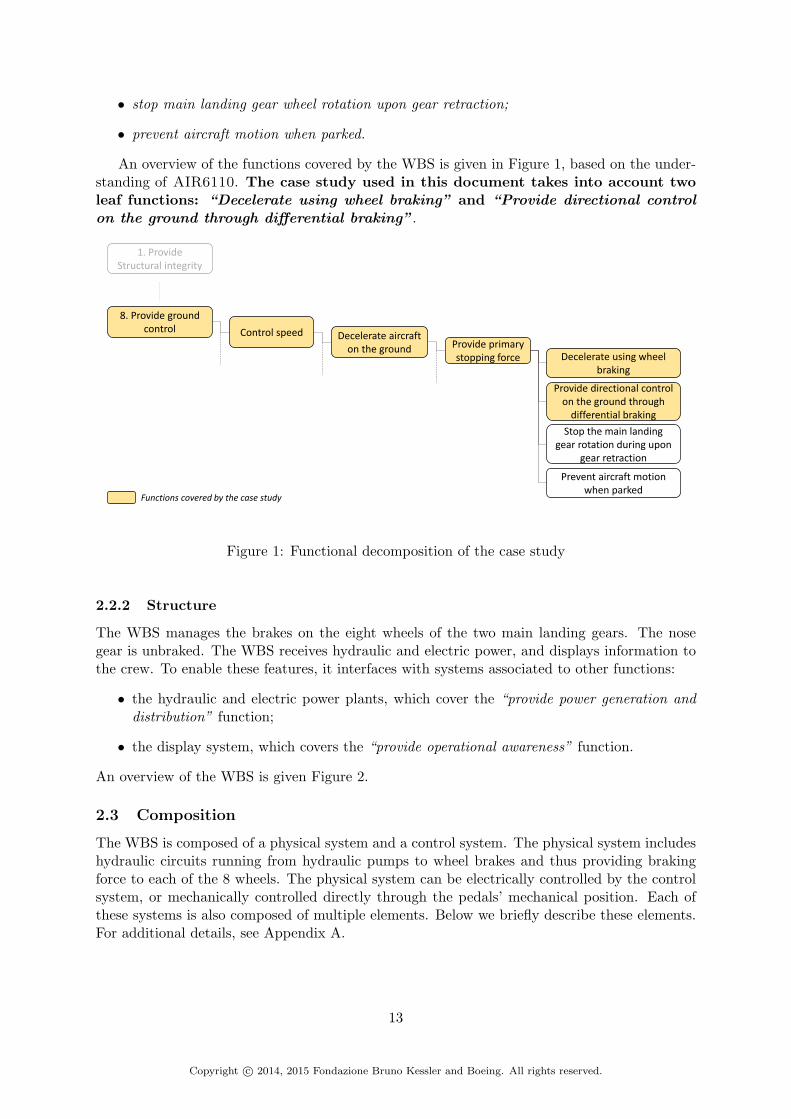
An overview of the functions covered by the WBS is given in Figure 1, based on the under-standing of AIR6110. The case study used in this document takes into account twoleaf functions: “Decelerate using wheel braking” and “Provide directional controlon the ground through differential braking”.
Prevent aircraft motion when parked
8. Provide ground control Control speed Decelerate aircraft
on the ground Provide primary stopping force
1. Provide Structural integrity
Decelerate using wheel braking
Provide directional control on the ground through
differential braking
Stop the main landing gear rotation during upon
gear retraction
Functions covered by the case study
Figure 1: Functional decomposition of the case study
2.2.2 Structure
The WBS manages the brakes on the eight wheels of the two main landing gears. The nosegear is unbraked. The WBS receives hydraulic and electric power, and displays information tothe crew. To enable these features, it interfaces with systems associated to other functions:
• the hydraulic and electric power plants, which cover the “provide power generation anddistribution” function;
• the display system, which covers the “provide operational awareness” function.
An overview of the WBS is given Figure 2.
2.3 Composition
The WBS is composed of a physical system and a control system. The physical system includeshydraulic circuits running from hydraulic pumps to wheel brakes and thus providing brakingforce to each of the 8 wheels. The physical system can be electrically controlled by the controlsystem, or mechanically controlled directly through the pedals’ mechanical position. Each ofthese systems is also composed of multiple elements. Below we briefly describe these elements.For additional details, see Appendix A.
13
Copyright c© 2014, 2015 Fondazione Bruno Kessler and Boeing. All rights reserved.
Green Hydraulic Pump
Blue Hydraulic Pump
Accumulator
Isolation ValveShutoff Valve
Selector Valve
Power
Left Electrical Pedal Position
Ground speed
Wheel 1 speed
Wheel 2 speed
Wheel 3 speed
Wheel 4 speed
Wheel 5 speed
Wheel 6 speed
Wheel 7 speed
Wheel 8 speed
W1
Wheel Brake 1
Right Electrical Pedal Position
MV
MV
ASV
W5
Wheel Brake 5
MV
W2
Wheel Brake 2
MV
MV
ASV
W6
Wheel Brake 6
MV
Left Mechanical Pedal Position
W3
Wheel Brake 3
MV
MV
ASV
W7
Wheel Brake 7
MV
W4
Wheel Brake 4
MV
MV
ASV
W8
Wheel Brake 8
MV
Right Mechanical Pedal Position
Control System(BSCU(s))
Anti-Skid cmd
Brake Anti-Skid cmd
System validity
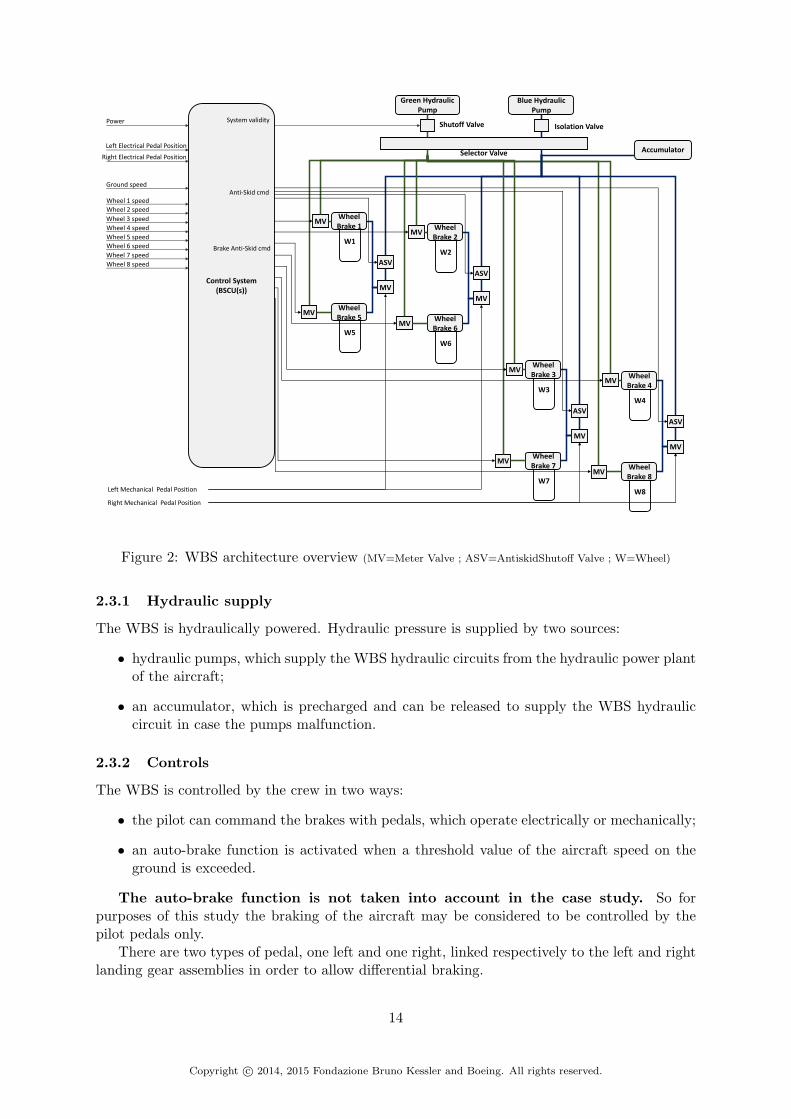
Figure 2: WBS architecture overview (MV=Meter Valve ; ASV=AntiskidShutoff Valve ; W=Wheel)
2.3.1 Hydraulic supply
The WBS is hydraulically powered. Hydraulic pressure is supplied by two sources:
• hydraulic pumps, which supply the WBS hydraulic circuits from the hydraulic power plantof the aircraft;
• an accumulator, which is precharged and can be released to supply the WBS hydrauliccircuit in case the pumps malfunction.
2.3.2 Controls
The WBS is controlled by the crew in two ways:
• the pilot can command the brakes with pedals, which operate electrically or mechanically;
• an auto-brake function is activated when a threshold value of the aircraft speed on theground is exceeded.
The auto-brake function is not taken into account in the case study. So forpurposes of this study the braking of the aircraft may be considered to be controlled by thepilot pedals only.
There are two types of pedal, one left and one right, linked respectively to the left and rightlanding gear assemblies in order to allow differential braking.
14
Copyright c© 2014, 2015 Fondazione Bruno Kessler and Boeing. All rights reserved.

There is a set of pedals each for the pilot and co-pilot, linked so that only one left and oneright pedal input is received by the WBS.
For each pedal, the mechanical pedal position is translated as an electric signal by a sensorwhich is used by a computer in the control system to generate an electrical command forbraking. Each pedal also produces a mechanical effect which directly controls the hydrauliccircuit through a valve, allowing mechanical braking in case of a failure of the electronic system.
The computer used in the WBS is called the Braking System Control Unit or BSCU. TheBSCU provides brake commands and anti-skid commands to the WBS, and directs informationto crew displays. Anti-skid (AS) is a command sent to the hydraulic circuit in order to inhibitskidding of the wheel due to too much braking force. The anti-skid command is computedbased on the aircraft speed and wheel angular speed. The BSCU also provides informationabout its validity status to the WBS. The BSCU is further decomposed into a monitor systemfor managing BSCU status and a command system which creates commands for braking.
2.3.3 Valves
The valves permit control of the hydraulic pressure supplied to the brakes in the circuit. Thereare five types of valve:
• shutoff valve: used to close the circuit;
• isolation valve: used to prevent flow back of hydraulic pressure in some systems;
• selector valve: used to switch from one targeted circuit to another, depending on thehydraulic pressure supplied at its inputs;
• antiskid shutoff valve: used to apply anti-skid function in the circuit. It is electricallycontrolled;
• meter valve: used to control outgoing hydraulic pressure. The meter valve can be electri-cally or mechanically controlled, and constitutes the main control on pressure routed tothe brake.
2.3.4 Brakes
The brake is the element which receives hydraulic pressure and transforms it to a braking forceto apply on the wheel. Each brake has three elements: The hydraulic fuse which prevents leaksin the system, the hydraulic piston which transforms incoming hydraulic pressure to an outgoingforce, and the brake actuator which transmitd the force from the piston to the wheel.
2.3.5 Wheels
Each wheel is linked to a sensor in order to measure angular speed to send to the BSCU forcomputing the anti-skid command.
2.4 Expected behavior
2.4.1 Modes
The WBS is in charge of braking the two main landing gears, which means the braking of eightwheels. Each wheel possesses its own brake. To avoid full loss of braking power, redundanciesare included in the system and different modes of functioning are employed, as described next.In this configuration, each wheel brake can be supplied by either of two distinct hydraulic
15
Copyright c© 2014, 2015 Fondazione Bruno Kessler and Boeing. All rights reserved.
w1 w2
w6w5
w3 w4
w8w7
Left Landing Gear Right Landing Gear
Pair 1 Pair 2 Pair 3 Pair 4
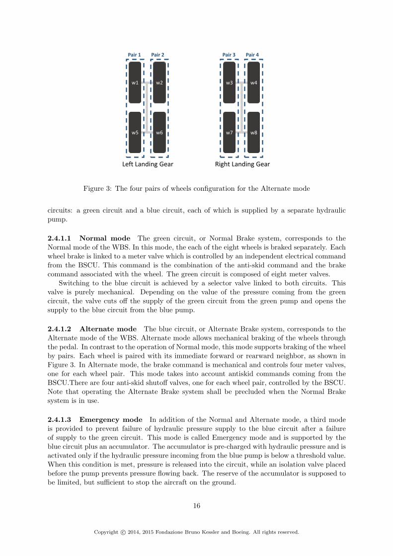
Figure 3: The four pairs of wheels configuration for the Alternate mode
circuits: a green circuit and a blue circuit, each of which is supplied by a separate hydraulicpump.
2.4.1.1 Normal mode The green circuit, or Normal Brake system, corresponds to theNormal mode of the WBS. In this mode, the each of the eight wheels is braked separately. Eachwheel brake is linked to a meter valve which is controlled by an independent electrical commandfrom the BSCU. This command is the combination of the anti-skid command and the brakecommand associated with the wheel. The green circuit is composed of eight meter valves.
Switching to the blue circuit is achieved by a selector valve linked to both circuits. Thisvalve is purely mechanical. Depending on the value of the pressure coming from the greencircuit, the valve cuts off the supply of the green circuit from the green pump and opens thesupply to the blue circuit from the blue pump.
2.4.1.2 Alternate mode The blue circuit, or Alternate Brake system, corresponds to theAlternate mode of the WBS. Alternate mode allows mechanical braking of the wheels throughthe pedal. In contrast to the operation of Normal mode, this mode supports braking of the wheelby pairs. Each wheel is paired with its immediate forward or rearward neighbor, as shown inFigure 3. In Alternate mode, the brake command is mechanical and controls four meter valves,one for each wheel pair. This mode takes into account antiskid commands coming from theBSCU.There are four anti-skid shutoff valves, one for each wheel pair, controlled by the BSCU.Note that operating the Alternate Brake system shall be precluded when the Normal Brakesystem is in use.
2.4.1.3 Emergency mode In addition of the Normal and Alternate mode, a third modeis provided to prevent failure of hydraulic pressure supply to the blue circuit after a failureof supply to the green circuit. This mode is called Emergency mode and is supported by theblue circuit plus an accumulator. The accumulator is pre-charged with hydraulic pressure and isactivated only if the hydraulic pressure incoming from the blue pump is below a threshold value.When this condition is met, pressure is released into the circuit, while an isolation valve placedbefore the pump prevents pressure flowing back. The reserve of the accumulator is supposed tobe limited, but sufficient to stop the aircraft on the ground.
16
Copyright c© 2014, 2015 Fondazione Bruno Kessler and Boeing. All rights reserved.

Wheel Brake System
Normal Alternate Emergency
BSCUsValid
BrakeEAntiSkid
BrakeEAntiSkid
BrakeEAntiSkid
Invalid N/A BrakeM BrakeM
Figure 4: Braking capacity for each mode
2.4.2 Mode switching
The switch from Normal to Alternate mode occurs under two conditions:
• The green pump fails to supply pressure. In this case the selector valve detects lowincoming pressure in the green circuit and automatically switches to the blue circuit.
• The BSCU is not valid, and thus the electrical brake commands are not valid. In this case,aircraft braking must be ensured by mechanical commands supported by the blue circuit.The selector valve automatically switches from the green circuit to the blue circuit whenit detects lack of pressure in the green one. In front of the selector valve, a shutoff valve isadded in the green circuit. This valve automatically cuts off pressure incoming from thegreen pump if the BSCU is not valid, forcing a switch to the blue circuit.
The switch from Alternate to Emergency mode is made under the condition that the bluepump fails to supply hydraulic pressure.
2.4.3 Braking capacity
The braking capacity of the WBS depends on the mode and the validity of the BSCU, assumingthat hydraulic supply is always available. In Normal mode, if the BSCU is valid then the pilotcan electrically brake and the anti-skid function is active. Otherwise, no braking capacity isavailable in Normal mode and the system must go into Alternate mode. In Alternate mode, ifthe BSCU is valid then the pilot can mechanically brake and the anti-skid function is active.Otherwise, only the possibility to brake is available. In the Emergency mode, if the BSCU isvalid then the pilot can brake and the anti-skid function is active. Otherwise, only the possibilityto mechanically brake is available. A summary is given Figure 4.
2.5 WBS requirements
The AIR6110 document contains several requirements for the WBS. These can be grouped intwo main categories: Requirements corresponding to safety, e.g., the loss of all wheel brakingshall be extremely remote, and others, e.g., the WBS shall have at least two hydraulic pressuresources.
Below we give five safety requirements we are particularly interested in:
S18-WBS-R-0321 Loss of all wheel braking (unannunciated or annunciated) during landingor RTO shall be extremely remote
S18-WBS-R-0322 Asymmetrical loss of wheel braking coupled with loss of rudder or nosewheel steering during landing or RTO shall be extremely remote
17
Copyright c© 2014, 2015 Fondazione Bruno Kessler and Boeing. All rights reserved.

S18-WBS-0323 Inadvertent wheel braking with all wheels locked during takeoff roll before V1shall be extremely remote
S18-WBS-R-0324 Inadvertent wheel braking of all wheels during takeoff roll after V1 shall beextremely improbable
S18-WBS-R-0325 Undetected inadvertent wheel braking on one wheel w/o locking during take-off shall be extremely improbable
Intuitively, a safety requirement associates the description of an undesirable behaviour orcondition (e.g. “inadvertent wheel braking”) with a lower bound on its likelihood, accordingto terminology (e.g. “extremely improbable”) that is precisely defined in [1] and a subsequentunreleased “Arsenal” version dated 6/10/2002. The term “extremely remote” corresponds toan average probability to happen per flight hour of order of 1.0e-7 or less and greater than orderof 1.0e-9. The term “extremely improbable” corresponds to an average probability to happenper flight hour of order of 1.0e-9 or less.
2.6 WBS Architecture evolution
The development of the WBS in the AIR6110 document is described through four evolutionarysteps, each step resulting in a specific architecture:
• Arch1: The highest view of the architecture of the WBS comprises one BSCU and onehydraulic circuit backed by an accumulator. This is the first step in the architecturedecomposition by defining the main functional elements of system.
• Arch2: This is the basic architecture of the WBS. It includes redundancy principles:There are two BSCUs, a green circuit and a blue circuit. At this step multiple brakingmodes are introduced.
• Arch3: This evolution of Arch2 replaces the two BSCUs of the control system by onedual channel BSCU.
• Arch4: This evolution of Arch3 modifies the placement of the accumulator and add alink from the control systme validity to the selector valve in the physical system.
Evolution from one architecture to the next occurs as a result of assessment activities duringthe development process. A summary of the evolution of the architecture is shown in Figure 5,based on the evolution of the control system and physical system.
The development of Arch2 from Arch1 is motivated by an analysis of safety requirementsduring an informal Preliminary System Safety Assessment (PSSA). The result of the analysisleads to the addition of two requirements based on service experience, which in turn motivatesthe presence of redundant design elements in Arch2:
• S18-WBS-R-0508: The wheel braking shall have at least two independent hydraulic pres-sure sources.
• S18-WBS-R-0509: WBS shall have dual channel BSCU and multimode brake operationsto provide the required redundancy.
The development of Arch3 from Arch2 is motivated by trade study results. Trade studiesshow that a dual BSCU is more cost effective and easier to install and maintain than two BSCUs.Note that both architectures Arch2 and Arch3 must ensure the same safety objectives.
18
Copyright c© 2014, 2015 Fondazione Bruno Kessler and Boeing. All rights reserved.

Physical part
Control part
Unique one-channel BSCU
Redundant one-channel BSCUs
Unique dual-channels BSCU
A1
A2
A3 A4
Trade study
System requirements validation
Informal PSSAA2bis
- Redundant hyd.circuits- Acc. downstream
Selector Valve
- Redundant hyd.circuits- Acc. upstream Selector Valve
- Additional input for Selector Valve from
Control System ValidityUnique hyd.circuit
Figure 5: Architecture evolution of the WBS
The development of Arch4 from Arch3 is motivated by system requirements validationusing simulation (model based analysis). The validation shows that the derived system require-ment from Arch3, “The accumulator shall be attached to the blue hydraulic line between theselector valve and the Anti-Skid Shutoff valve,” is in conflict with the pre-existing requirementS18-WBS-R-2973 “Operation of the alternate system shall be precluded when the NORMALsystem is in use”. This result triggers modifications leading to Arch4.
To this four basic architectures available in AIR6110, we add an architecture variant calledArch2bis which is based on the control system architecture of Arch2 and the physical systemarchitecture of Arch4. The purpose is to show that it is possible to detect the issue thatmotivated the change to Arch4 earlier in the design process at Arch2.
19
Copyright c© 2014, 2015 Fondazione Bruno Kessler and Boeing. All rights reserved.

3 Formal process for the case study
In this section, we present the formal approach to model and analyze the case study. In Sec-tion 3.1, we present an overview of the process that is applied and the tools employed. Then,we describe in Section 3.2, Section 3.3 and Section 3.4 the detailed steps.
3.1 Overview of the process
The process of applying formal methods to the design of the WBS is achieved through specificsteps, as shown in Figure 6.
Architecturedecomposition
& Contracts
Formal Verification Fault Extension Safety Assessment
• Automatic refinementverification
• Automatic fault extension • Automatic hierarchical fault tree generation
BehavioralImplementation
(Leaf components& System)
Formal Verification Fault Extension Safety Assessment
• Automatic compositional verification
• Automatic monolithicverification
• Failure modes defined by the user• Generation of the extended system
implementation
• Automatic flat fault tree generation
xSAP
OCRA
nuXmv xSAPOCRA
OCRA OCRASemi-automatic Generation
Figure 6: Steps of the process
The main steps are: component-based modeling of the system architecture, contract-basedspecification of the architectural decomposition and refinement verification; definition of thebehavioral implementation of components at the leaves of the architecture, generation of thefull system implementation and formal verification of the properties; extension of the implemen-tation with failures to include faulty behaviors of components; production of a safety analysisbased on fault-tree analysis.
The formal approach is supported by a set of tools developed by the Fondazione BrunoKessler, namely OCRA [7, 16, 9, 10] for contract-based specification, verification, and safetyanalysis of the architecture decomposition; nuXmv [2, 15] for formal verification of the behav-ioral implementation; and xSAP [3, 17, 4] for model-based safety analysis of the behavioralimplementation.
3.2 Definition and formal verification of the architectural decomposition
The architecture decomposition is expressed in the OCRA language. The system architecture ishierarchically decomposed into constituent components, until leaf components of the system arereached. Each component has an interface defining the boundary between the component imple-mentation and its environment. An interface consists of a set of input and output ports throughwhich the component implementation interacts with its environment. A composite componentis refined into a synchronous composition of instances of sub-components. The decompositionalso defines interconnections among the ports of the instances of the subcomponents and thecomposite component. The implementation of a composite component is given by the compo-sition of the implementations of the subcomponents instances. Similarly, the environment of asubcomponent is given by the composition of the other subcomponents.
20
Copyright c© 2014, 2015 Fondazione Bruno Kessler and Boeing. All rights reserved.

The specification of a leaf component is described in Listing 1. It is composed of the inputsand outputs of the component. The specification of a refined component is described in Listing 2.It is composed of the inputs and outputs of the component, the list of its sub-components, andthe connections between all component instances.
COMPONENT Component0INTERFACEINPUT PORT input1:type1;INPUT PORT inputN:typeN;OUTPUT PORT output1:type1;OUTPUT PORT outputN:typeN;
Listing 1: Specification of a leaf component
COMPONENT Component0INTERFACEINPUT PORT input1:type1;INPUT PORT inputN:typeN;OUTPUT PORT output1:type1;OUTPUT PORT outputN:typeN;
REFINEMENTSUB instance_Component1: Component1;SUB instance_ComponentN: ComponentN;
CONNECTION instance_Component1.input:=input1;CONNECTION instance_Component2.input:=inputN;CONNECTION output1:=instance_ComponentN.output;CONNECTION outputN:=instance_Component1.output;
Listing 2: Specification of a refined component
Each component is enriched with contracts that expresses its expected behavior. These spec-ifications contributes to the correct refinement and implementation of the system. A contractis composed of an assume clause, which represents the property that the environment of thecomponent must ensure, and a guarantee clause which describes the property that the com-ponent must ensure. The properties in component contracts are formalized into LTL formulasfollowing the Contract-Based Design supported by OCRA. Contracts of refined components arerefined by the contracts of their sub-components. It is also possible to write multiple contractsfor a given component.
An example of contract is shown in Listing 3. The component, Component0 has a contractnamed contract component0 and this contract is refined by contracts of the sub-componentof Component0.
COMPONENT Component0INTERFACEINPUT PORT input1:type1;INPUT PORT inputN:typeN;OUTPUT PORT output1:type1;OUTPUT PORT outputN:typeN;
CONTRACT contract_component0assume: property_1;guarantee: propert_2;
REFINEMENTSUB instance_Component1: Component1;SUB instance_ComponentN: ComponentN;
CONNECTION instance_Component1.input:=input1;CONNECTION instance_Component2.input:=inputN;CONNECTION output1:=instance_ComponentN.output;CONNECTION outputN:=instance_Component1.output;
21
Copyright c© 2014, 2015 Fondazione Bruno Kessler and Boeing. All rights reserved.

CONTRACT contract_component0 REFINEDBY instance_Component1.contract_component1,instance_ComponentN.contract_componentN;
Listing 3: example of contract in a component
The refinement of the architecture decomposition can be automatically checked by OCRAby generating and discharging a set of proof obligations that are validity problems for LTL.
3.3 Definition and formal verification of the behavioral implementation
OCRA can also automatically generate implementation templates for leaf components of thearchitecture 1. Implementation templates are generated in the SMV language [2]. The userneeds to provide only the implementations of leaf components in the template, i.e., the ASSIGNsection. An implementation describes how the outputs of a component are computed from itsinputs. An example is given Listing 4.
-- ===============================================================================MODULE main
VARComponent0_inst : Component0(input1, inputN);
VARoutput1 : type1;outputM : typeM;
DEFINEoutput1 := Component0_inst.output1;outputM := Component0_inst.outputM;
-- ===============================================================================-- End of module-- ===============================================================================
-- ===============================================================================MODULE Component0(input1, inputN)
VARoutput1 : type1;outputM : typeM;
ASSIGNoutput1 := <value or formula depending on inputs>;outputM := <value or formula depending on inputs>;
-- ===============================================================================-- End of module-- ===============================================================================
Listing 4: example of implementation of a component
Once done, OCRA can take into account these implementations to automatically generatea full system implementation in the SMV language, based on the architecture decomposition2.During this generation, the component contracts are automatically translated as LTL propertiesin the system implementation. Each leaf component implementation can be checked accordingto the component contracts defined in the architecture decomposition using the compositionalimplementation check available in OCRA. The full system implementation can also be mono-lithically checked using the symbolic model checker nuXmv.
3.4 Fault extension and safety assessment
The safety assessment can be conducted in two ways. The first, using Model Based SafetyAnalysis (MBSA), requires the definition of failure modes and model extension but gives precise
1with the OCRA command print implementation template2This is done with the OCRA command print system implementation
22
Copyright c© 2014, 2015 Fondazione Bruno Kessler and Boeing. All rights reserved.

results. The second, using Contract Based Safety Analysis (CBSA), does not require anyadditional input from the user but gives over-approximated results.
3.4.1 Model-Based Safety Analysis (MBSA)
The xSAP tool is used to support the extension a nominal model with failure modes providedby the user. A failure mode represents the behavior of a component in the context of a givenfailure. Failure modes can be defined from the xSAP fault library using a dedicated languagefor fault-extension.
An example of failure mode defined for a component is given Listing 5. The extension isdefined for each component (MODULE). The extension of a component is organized with SLICE,that represent a set of failure modes that affect the same output variable of the component. Afailure mode (MODE) is composed of a name (MeterValve FailedClosed in our example),a probability for the fault to occur(3.25e-6 in our example), a statement about its dynamic(permanent in our example) and its type name (StuckAtByValue I in our example). Foreach different type of failure mode, there are different data fields to fill (data). In the example,the field term corresponds to the value or the variable that will be used to modified the valueof the affected output variable. input and output are about the affected variable. eventallows the user to define a specific condition to specify global dynamics between different failuremodes. Note that the Common Cause Analysis (CCA) is also available through the extensionbut is not presented or used in this case study for the moment.
EXTENSION OF MODULE MeterValve
/-- Description of Fault Slice MeterValve_faults --/SLICE MeterValve_faults AFFECTS hyd_pressure_out WITH
/-- Description of fault mode MeterValve_FailedClosed --/MODE MeterValve_FailedClosed {3.25e-6} : Permanent StuckAtByValue_I(
data term << 0,data input << hyd_pressure_out,data varout >> hyd_pressure_out,event failure);
Listing 5: Example of failure mode for a component MeterValve
Once failure modes are defined for each component, xSAP can proceed to the fault extensionof the nominal model and generate a new SMV implementation taking into account failurebehaviors. This extended model is used to conduct Model-Based Safety Analysis on the systemwith the help of xSAP. More precisely, xSAP can generate flat fault trees based on thisextended model. The fault tree Top Level Events (TLE) are violations of the LTL propertiesinherited from the contracts provided in the architecture decomposition.
3.4.2 Contract-Based Safety Analysis (CBSA)
An alternative way to perform safety analysis is provided by OCRA given the contract-basedspecification of the architecture [5]. The architecture decomposition is automatically extendedwith failure modes based on the contracts. The TLEs of fault trees are violations of the systemtop-level contracts of the architecture. Hierarchical fault tree are generated, with intermediateevents being derived from violations of subcomponent contracts. The user does not need toprovide any further information beyoned the model itself. In comparison with the flat faulttrees generated by MBSA, the hierarchical fault trees are over-approximated.
23
Copyright c© 2014, 2015 Fondazione Bruno Kessler and Boeing. All rights reserved.

4 Formal models
In this section we present the formal modeling of the WBS. In Section 4.1 we present themodeling hypothesis and abstraction. In Section 4.2 we describe the modeling of the basiccomponents of the architectures. We describe their interfaces, their behavior and their failuremodes. In Section 4.3 we give the safety requirements defined in the modeling. We present howthey have been translated and we give information about the other properties. In Section 4.4,we describe in the decomposition of each architecture. In Section 4.5 we give metrics aboutthe architecture decompositions and the monolithic models generated from them. We also givemetrics about the extended models.
4.1 Modeling hypothesis
The WBS architectures presented in AIR6110 are modeled following the formal approach de-scribed in the previous section. As a first step to applying formal methods to the case study, wedefine some modeling hypotheses and we apply simplifying abstractions to the concrete system.First, we consider the hydraulic circuits as a unidirectional circuit, thus avoiding relational mod-eling of the circuit. As a consequence, the isolation valve present in Figure 2 is not relevant forthe modeling and is removed from our formal models. This convention reduces the complexityof the system representation while keeping a level of detail sufficient to express and to verifyproperties.
Another abstraction concerns the representation of hydraulic pressure in the hydraulic com-ponents, for example at the valve interfaces. All ports representing hydraulic pressure areexpressed as bounded integers between 0 and 10 (represented as enumeration), as are portsrepresenting braking force. The same representation is used for the aircraft ground speed. Asimilar abstraction is applied to commands sent by the BSCU. The system validity, the brakecommands and the antiskid commands are represented as boolean values. The pedal positionsare also treated similarly. The angular speed of a wheel is represented by a wheel status: stoppedor rolling. Under this representation, the wheel is considered to be skidding if the aircraft ismoving and the wheel is stopped. These choices were made to limit complexity of the modelswhile keeping a sufficient level of detail to obtain relevant results from the analysis.
In addition of these abstractions, we consider two behaviors for pressure supplied to hydrauliccircuits. First, a hydraulic pump supplies hydraulic pressure only if the pump is supplied byelectrical power and pressurized hydraulic fluid. This allows defining the different mode changesdefined in the WBS as depending on the pressure supply of each circuit. Second, the accumulatoris considered to have an infinite reserve of pressure. This choice is justified by the fact that themodel does not incorporate a concept of measuring “sufficient” pressure necessary to brake theaircraft.
We also consider that the recovery modes are multi-directional. For example, the physicalsystem is allowed to recover from the alternate or emergency mode to the normal mode. Thesame property is granted to the control system in case of redundancy.
Finally, all models are defined using discrete time and all component behaviors are instan-taneous, i.e. all inputs are computed at the same time step where inputs are provided. Thereis only one exception that concerns the wheel component: braking force applied on the wheeldetermines the status of the wheel at the next step.
24
Copyright c© 2014, 2015 Fondazione Bruno Kessler and Boeing. All rights reserved.
4.2 Basic components description
4.2.1 FSM components
There are 18 basic components that can be encountered through the different architectures
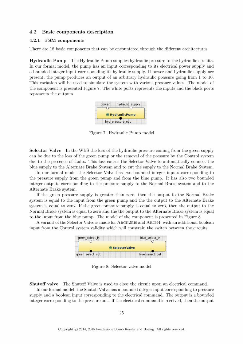
Hydraulic Pump The Hydraulic Pump supplies hydraulic pressure to the hydraulic circuits.In our formal model, the pump has an input corresponding to its electrical power supply anda bounded integer input corresponding its hydraulic supply. If power and hydraulic supply arepresent, the pump produces an output of an arbitrary hydraulic pressure going from 1 to 10.This variation will be used to simulate the system with various pressure values. The model ofthe component is presented Figure 7. The white ports represents the inputs and the black portsrepresents the outputs.
Figure 7: Hydraulic Pump model
Selector Valve In the WBS the loss of the hydraulic pressure coming from the green supplycan be due to the loss of the green pump or the removal of the pressure by the Control systemdue to the presence of faults. This loss causes the Selector Valve to automatically connect theblue supply to the Alternate Brake System and to cut the supply to the Normal Brake System.
In our formal model the Selector Valve has two bounded integer inputs corresponding tothe pressure supply from the green pump and from the blue pump. It has also two boundedinteger outputs corresponding to the pressure supply to the Normal Brake system and to theAlternate Brake system.
If the green pressure supply is greater than zero, then the output to the Normal Brakesystem is equal to the input from the green pump and the the output to the Alternate Brakesystem is equal to zero. If the green pressure supply is equal to zero, then the output to theNormal Brake system is equal to zero and the the output to the Alternate Brake system is equalto the input from the blue pump. The model of the component is presented in Figure 8.
A variant of the Selector Valve is made for Arch2bis and Arch4, with an additional booleaninput from the Control system validity which will constrain the switch between the circuits.
Figure 8: Selector valve model
Shutoff valve The Shutoff Valve is used to close the circuit upon an electrical command.In our formal model, the Shutoff Valve has a bounded integer input corresponding to pressure
supply and a boolean input corresponding to the electrical command. The output is a boundedinteger corresponding to the pressure out. If the electrical command is received, then the output
25
Copyright c© 2014, 2015 Fondazione Bruno Kessler and Boeing. All rights reserved.

pressure equals the input pressure. Otherwise, the pressure output equal to zero. The model ofthe component is presented in Figure 9.
Figure 9: Shutoff Valve model
Meter valve The Meter Valve must control pressure to the demanded level. In our formalmodel it is abstracted so it can only be open or closed. A Meter Valve has two boolean inputscorresponding to an electrical command and a mechanical command. It has one boundedinteger input corresponding to the pressure in input. And it has one bounded integer outputcorresponding to the output pressure.
If an electrical or a mechanical command is received, then the output pressure is equal tothe input pressure. If no command is received, the pressure output is equal to zero. The modelof the component is presented in Figure 10.
Figure 10: Meter valve model
Anti-skid shutoff valve The Antiskid Shutoff Valve is controlled by an electrical commandto control the hydraulic pressure. Technically, this valve is used to reduce hydraulic pressure tothe brakes in order to prevent locking of the wheels.
In our modeling, it is also abstracted so it can only be open or closed. An Antiskid ShutoffValve has a boolean input corresponding to an electrical command, a bounded integer inputcorresponding to the input pressure, and a bounded integer output corresponding to the outputpressure.
If an electrical command is received, then the output pressure is equal to zero, otherwisethe output pressure is equal to the input pressure. The model of the component is presented inFigure 11.
Figure 11: Anti-skid Shutoff Valve model
Accumulator In our formal model the Accumulator has a bounded integer input from theblue hydraulic pump and a bounded integer output for the release of the pressure. The pressureinput is here to check the pressure coming from the blue pump. If the pressure is equal tozero, then the output pressure of the accumulator is released with a value between 1 and the
26
Copyright c© 2014, 2015 Fondazione Bruno Kessler and Boeing. All rights reserved.

maximum (10 here). We assume in our formal model that the Accumulator has an infinitereserve. The model of the Accumulator is presented Figure 12.
Figure 12: Accumulator model
Pedal Position Sensor The Pedal Position Sensor is a sensor which takes in input a me-chanical pedal position and returns an electrical position in output. In our formal model it is adirect mapping between a boolean input, the mechanical pedal position, and a boolean output,the electrical pedal position. The model of the component is presented in Figure 13.
Figure 13: Sensor Pedal Position model
Hydraulic fuse The Hydraulic Fuse is here to prevent a leak. In our modeling it is abstractedand corresponds to a simple pipe. It has a bounded integer input corresponding to the inputpressure and a bounded integer output corresponding to the output pressure. There is a directmapping between the input and the output. The model of the component is presented inFigure 14.
Figure 14: Hydraulic Fuse model
Hydraulic Piston The Hydraulic Piston transforms hydraulic pressure into a force to applyto some other component. It has a bounded integer input corresponding to the input pressureand a bounded integer output corresponding to the force created in output. The value of theforce in output is equal to the value of the pressure in input. The model of the Hydraulic Pistonis presented in Figure 15.
Figure 15: Hydraulic Piston model
27
Copyright c© 2014, 2015 Fondazione Bruno Kessler and Boeing. All rights reserved.

Brake actuator The Brake Actuator applies the force received from the piston on the wheel:it creates the braking force. Depending on the architectures, it takes one or two bounded integerinputs corresponding to the force transferred by pistons and returns a bounded integer outputcorresponding to the braking force. The output braking force is equal to the input piston forcein case of one source, or is equal to the greater of multiple sources. The model of the componentis presented in Figure 16.
Figure 16: Brake Actuator model
Wheel The Wheel is the final component on which the WBS has an influence. It has twobounded integer inputs, the braking force and the aircraft ground speed, and one output corre-sponding to an enumeration variable indicating its status (rolling or stopped). The behavior ofthe Wheel in our formal modeling is the following: The Wheel will stop at the next step if thebraking force is greater than a threshold value (here 8, chosen arbitrarily) and the ground speedis greater than a minimal value (here 1, chosen arbitrarily); the Wheel will roll at the next stepif the braking force is lower or equal to a threshold value and the ground speed is greater thana minimal value; The Wheel will stop at the next step if the ground speed is under a minimalvalue. The model of the Wheel is presented Figure 17.
Figure 17: Wheel model
Wheel sensor The Wheel Sensor transforms the information received from the wheel intoinformation usable by the Control system. It takes in input an enumeration corresponding tothe wheel status (rolling or stopped) and returns a boolean output indicating if the wheel isrolling or not. If the wheel status is rolling, then the output is TRUE, otherwise the output isFALSE. The model of the component is presented in Figure 18.
Figure 18: Sensor model
Monitor System The Monitor System checks the validity of the commands created and theelectrical power supply for the command creation. It returns a boolean output corresponding tothe validity of the commands. It takes as inputs all the outputs of the command system (all thecommands represented as booleans) and all the inputs of the commands system used to compute
28
Copyright c© 2014, 2015 Fondazione Bruno Kessler and Boeing. All rights reserved.

these commands (status of each wheel, aircraft ground speed, electrical pedal signal, power) andcompares the computations of the commands system with the expected computation. If at leastone of these computations is false, the validity output is FALSE. The model of the componentis presented in Figure 19.
Figure 19: Monitor System model
Brake Command Facility This facility computes the brake command for each wheel. It hastwo boolean inputs corresponding to the power and electrical pedal position And has one booleanoutput corresponding to the brake command. The outputted brake command corresponds tothe conjunction of the power and the electrical pedal position. The model of the component ispresented in Figure 20.
Figure 20: Brake Command Facility model
AntiSkid Command Facility This facility computes the antiskid command for each wheel.It has two boolean inputs corresponding to the power and the wheel rolling status, a boundedinteger input corresponding to the aircraft ground speed and one boolean output correspondingto the antiskid command. The anti-skid command corresponds to the conjunction of power
29
Copyright c© 2014, 2015 Fondazione Bruno Kessler and Boeing. All rights reserved.

with a check that the wheel is not rolling and that the aircraft speed is greater than zero. Themodel of the component is presented in Figure 21.
Figure 21: AntiSkid Command Facility model
Normal Command Calculator The Normal Command Calculator computes the brake anti-skid command for each wheel and is needed for only some architectures. It takes in input threeboolean inputs, the power, the antiskid and the brake command of the wheel. It gives in outputa boolean value corresponding to the brake anti-skid command. The brake anti-skid commandcorresponds to the conjunction of the power, brake command and the negation of the anti-skidcommand to the wheel. The model of the component is presented in Figure 22.
Figure 22: Normal Command Calculator model
Alternate Command Calculator In case of a redundant architecture (Arch2, Arch2bis,Arch3, Arch4), this calculator computes the anti-skid commands to send to the alternatebrake system for a pair of wheels. It takes in three boolean inputs corresponding to the anti-skidcommand computed for each wheel and the power, and returns a boolean output correspondingto the anti-skid command to send to the physical system. The anti-skid command computedcorrespond to the conjunction of the power and the disjunction of the two anti-skid commandsreceived in inputs. The model of the component is presented in Figure 23.
Figure 23: Alternate Command Calculator model
Switch Gate The Switch Gate allows deciding between two commands received in inputs,which one to return in output. It takes as input four boolean variables, two corresponding tothe commands received in inputs, and two others corresponding to the validity of each source.It has one boolean output corresponding to the returned command. The decision is made asfollow: if the source 1 is valid, it is the command of the source 1 that is returned. If the source1 is invalid and the source 2 is valid, then it is the command of the source 2 that is returned. Ifboth sources are invalid, no command is available as output and the returned value is FALSE.The model of the Switch Gate is presented in Figure 24.
30
Copyright c© 2014, 2015 Fondazione Bruno Kessler and Boeing. All rights reserved.

Figure 24: Switch Gate model
In addition of these 18 basic components, we add two others for modeling purpose: AdditionGate and Or Gate.
Addition Gate The Addition Gate is a component which takes as input two bounded integerscorresponding to two pressure sources and returns a bounded integer output corresponding tothe addition of the two pressure sources if lower than or equal to 10 (The max value of all ourbounded integers).The model of the component is presented in Figure 25.
Figure 25: Addition Gate model
Or Gate The Or Gate takes as inputs two booleans and returns their disjunction. The modelis presented in Figure 26.
Figure 26: Or Gate model
4.2.2 Faults
Possible faults are defined for each leaf components:
• Hydraulic Pumps: Failed off
• Selector valve: Failed last position
• Shutoff valve: Failed open, Failed closed
• Meter valve: Failed open, Failed closed, Failed last commanded position, Failed erroneousposition (random)
• Anti-skid shutoff valve: Failed open, Failed closed, Failed last commanded position, Failederroneous position (random)
• Accumulator: Failed no pressure, Failed stuck open (on)
• Pedal position sensor Undetected erroneous data, no data
• Hydraulic fuse: Failed closed
31
Copyright c© 2014, 2015 Fondazione Bruno Kessler and Boeing. All rights reserved.
• Brake piston: Failed stuck at current position, Failed full off, Failed full on
• Brake actuator: Failed stuck at current position, Failed full off, Failed full on
• Wheel: No rotation
• Wheel sensor: Undetected erroneous data, no data
• Monitor System: Erroneous computation
• Normal Command Calculator: Erroneous computation
• Alternate Command Calculator: Erroneous computation
• Brake Command Facility: Erroneous computation
• AntiSkid Command Facility: Erroneous computation
• Switch Gate: Failed last position, Failed intermediate position
Each of these fault is modeled using failure modes from the xSAP fault library. The detailsare in the fei file of each architecture.
4.2.3 Fault probabilities
The probability for each component to be in fault are expressed in and divided for each fault(failure mode). These probabilities are defined based on materials extracted from the AIR6110and information provided by Boeing.
• Hydraulic Pump, 3.0e-5, only one failure mode
• Shutoff Valve: 1.0e-5, divided by 2 for each of its 2 failure modes (5e-6)
• Selector Valve: 1.0e-5, only one failure mode
• Meter Valve: 1.3e-5 (more complex component), divided by 4 for each of its 4 failuremodes (3.25e-6)
• Anti-skid shutoff Valve: 1.3e-5 (more complex component), divided by 4 for each of its 4failure modes (3.25e-6)
• Accumulator: 1.0e-4, divided by 2 for each of its 2 failure modes (5e-5)
• Hydraulic fuse: 1.0e-5, only one failure mode
• Hydraulic piston: 1.0e-4, divided by 3 for each of its 3 failure modes (3.3e-5)
• Brake actuator: 1.0e-5, divided by 3 for each of its 3 failure modes (3.3e-6)
• Wheel: 1.0e-5, only one failure mode
• All sensors: 1.0e-5, divided by 2 for each of its 2 failure modes (5e-6)
• Monitor System: 8.0e-7, only one failure mode
• Alternate Command Calculator: 9.0e-6, only one failure mode
• Normal Command Calculator: 9.0e-6, only one failure mode
32
Copyright c© 2014, 2015 Fondazione Bruno Kessler and Boeing. All rights reserved.

• Antiskid Command Facility: 9.0e-6, only one failure mode
• Brake Command Facility: 9.0e-6, only one failure mode
• SwitchGate: Failed last position: 1.30e-5; Failed intermediate position: 6.50e-7
The rationale to obtain these probabilities is described in the following paragraph.
Rationale to obtain the fault probabilities for the Physical system leaf componentsThe fault probabilities for the basic components of the Physical system are based on dataprovided by Boeing and data from AIR6110 [25, p. 49, Fig. 25], [25, p. 51, Fig. 27].
In particular, the probabilities for the Shutoff Valve, Selector Valve and Meter Valve arebased on an evaluation of the probabilities given in the fault trees of AIR6110 [25, p. 49,Fig. 25], [25, p. 51, Fig. 27].
We assume that the fault trees are given for one wheel in the Physical system. In these faulttrees the loss of the Green system has a probability of 3.30e-5. If we assume that the loss ofGreen system is characterized by the loss of the Shutoff Valve or the loss of Selector Valve orthe loss of the Meter Valve, we obtain 3.30e-5/3=1.10e-5. And if we consider the Meter Valveas a more complex component, we have the following probabilities for these three components:
• Shutoff Valve: 1.0e-5,
• Selector Valve: 1.0e-5
• Meter Valve: 1.3e-5
We make the assumption that the probability of the Antiskid Shutoff Valve to fail is thesame as the Meter Valve. All the other probabilities for the Physical system components havebeen provided by Boeing.
Rationale to obtain the fault probabilities for the Control system leaf componentsFor the BSCU, based on the probability information given in [25, p. 49, Fig. 25], [25, p. 51,Fig. 27] and our model, we made the following rationale to evaluate the reliability of each of itsleaf components : in [25, p. 51, Fig. 27], the loss of one BSCU has a probability of 2.17e-4 tohappen. We assume that the loss of the BSCU can happen if at least one of its leaf componentfails. There are 25 leaf component instances in our model for one BSCU. One of them is theMonitor System and if we follow the allocation given in Figure [25, p. 51, Fig. 27], it has aprobability of 8e-7 to fail. If the remaining credit is allocated equally between each instanceof the leaf components, we have a probability of 9e-6((2.17e-4 - 8e-7)/24) of failure for each ofthem:
• Alternate Command Calculator: 9.0e-6
• Normal Command Calculator: 9.0e-6
• Antiskid Command Facility: 9.0e-6
• Brake Command Facility: 9.0e-6
The probabilities for the Switch Gate and the Monitor System to fail are directly taken from[25, p. 51, Fig. 27].
33
Copyright c© 2014, 2015 Fondazione Bruno Kessler and Boeing. All rights reserved.

4.3 Requirements translation
The five safety requirements expressed in Section 2.5 are translated as contracts at the systemtop-level. They are modeled as follows: first, we remove flight phase and speed value from therequirements, as we do not have sufficiently detailed information about them in the models. Weonly kept that the speed value must be greater than 0. The treatment of the required likelihoodis ignored in the modeling, and is delayed to the phase of safety analysis. The undesirablecondition is instead stated never to occur. In addition, the requirements S18-WBS-R-0322 issplit into two different contracts one for the left side and one for the right side. The requirementS18-WBS-R-0325 is also split in eight contracts one for each wheel. Each requirement becomes:
• S18-WBS-R-0321: never loss of all wheel braking.
• S18-WBS-R-0322-left: never asymmetrical loss of wheel braking (left side).
• S18-WBS-R-0322-right: never asymmetrical loss of wheel braking (right side).
• S18-WBS-R-0323: never inadvertent braking with all wheels locked.
• S18-WBS-R-0324: never inadvertent braking of all wheels.
• S18-WBS-R-0325-wheelX: never inadvertent braking of wheel X without locking.
These properties are then translated in LTL form for the contract decomposition. Anexample of the translation for the property S18-WBS-R-0325-wheelX applied to wheel 1 isgiven in Listing 6.
CONTRACT never_inadvertent_braking_of_wheel_1assume: true;guarantee: never((not mechanical_pedal_pos_L) and ground_speed>0
and wheel_braking_force_1>0 and wheel_status_1=rolling);
Listing 6: Translation of the requirement S18-WBS-R-0325 in contract for wheel 1
In addition, we define sanity properties to validate our modeling at the system top-level. Forexample, for each wheel we define two properties: first, if there is a braking of the wheel, thena command has been received from the pilot and the anti-skid function has not been applied;second, if a command has been received from the pilot (with a dependency on the anti-skidfunction), then there is a braking of the wheel.
In the subsequent phase of contract decomposition, these safety requirements are in turnbroken down into contracts for sub-components. These contracts describe the properties theymust ensure based on the description provided in AIR6110 and clarifications provided bysubject matter experts. Additional contracts are also added to ensure the expected behaviorof each component (e.g., braking force is applied when commanded). The number of contractsdefined on each architecture is given in Table 1 at the end of this section and the contracts areavailable in the OCRA file of each architecture.
These contracts are then automatically translated into LTL properties in the system imple-mentation, as described in Section 3.3.
4.4 Architecture specificities
4.4.1 Arch1
Arch1 is the first version of the WBS. This is the most simple view of the system, without anyredundancy.
34
Copyright c© 2014, 2015 Fondazione Bruno Kessler and Boeing. All rights reserved.

We model Arch1 based on diagram shown inAIR6110 [25, p. 42, Fig. 20] in the Ap-pendix and given clarifications described in Appendix A, Figure 38. For a first look we identifyadditional sub-system hierarchies to the one defined in the diagrams. The advantages of incor-porating additional hierarchies in the system are improved modularity among components andease of reuse. For example, the decomposition of the Wheel Brake System in a Control systemand a Physical system is applicable for Arch2, Arch2bis and Arch3 and Arch4.
The root of the Wheel Brake System is then modeled by two main sub-systems, the Controlsystem and the Physical system. In addition the model includes sensors - 8 wheel sensors and2 pedal position sensors.
Control system The Control system is composed of one unique BSCU. The BSCU of Arch1create eight brake commands, one for the meter valve of each wheel, and eight anti-skid com-mands for each anti-skid shutoff valve. The BSCU also generates a validity command for theshutoff valve of the Physical system. The BSCU takes as input its dedicated power source, theelectrical pedal positions, the aircraft speed and the status of each wheel.
A BSCU is divided into two sub systems: A Monitor system and a Command system. TheMonitor system is in charge of delivering the status and thus the validity of the BSCU, dependingon the power consumption and the correctness of the commands computed by the CommandSystem. The Command system is in charge of creating brake and anti-skid commands. TheCommand system of Arch1 is divided into eight sub-systems, one for each wheel. Thesesystems, called Wheel Command systems, are in charge of creating the brake command and theanti-skid command for each wheel.
The Wheel Command system is decomposed into multiple leaf components, as follows:
• An Antiskid Command facility creates the antiskid command for the wheel, depending onthe wheel status and the aircraft speed.
• A Brake Command facility creates the brake command depending on the pedal position.
The type used for commands is boolean, to abstract every command and the presence ofelectrical power supply. Thus a brake command corresponds to the conjunction of the powerand the pedal position. The anti-skid command corresponds to the conjunction of power witha check that the wheel is not rolling and that the aircraft speed is greater than zero.
Physical system The Physical system is first composed of an hydraulic pump. This pumpsupplies the hydraulic circuit with pressure through a Shutoff valve controlled by the Controlsystem validity. An accumulator is placed in back up after the shutoff valve in case the hydraulicpump fails off (Output pressure goes to 0).
The hydraulic circuit is composed of eight Antiskid Shutoff valves that supply eight metervalves. Each pair of Antiskid Shutoff valves and Meter valves is dedicated to one wheel: TheAntiskid shutoff valve is commanded by the anti-skid command for the wheel and the meter valveis electrically commanded by the brake command for the wheel or directly by the mechanicalpedal position corresponding to the side of the wheel (left or right). Each meter valve thensupplies a wheel brake depending on these commands. There is one wheel brake per wheel.A wheel brake takes as inputs the hydraulic pressure coming from the Meter valve and as itsoutput applies a force on the wheel. The Wheel brake of Arch1 is composed of one hydraulicfuse, one hydraulic piston and one brake actuator which makes the link between the pistonsand the wheel. Each wheel returns its status and each wheel brake returns the braking forceapplied to the wheel.
35
Copyright c© 2014, 2015 Fondazione Bruno Kessler and Boeing. All rights reserved.

As explained previously, we choose to model a binary behavior for the valve. If the metervalve receives a brake command (electrical or mechanical), it opens and lets the hydraulicpressure supply the wheel brake. If not, it stays closed. If the antiskid shutoff valve receives ananti-skid command, it closes and cuts off hydraulic pressure to the meter valve. If not, it staysopened.
Sensors The Wheel sensors provide links between the Control system and the Physical systemby giving feedback about the status of each wheel.
The pedal position sensor transform a mechanical signal coming from each pedal into anelectrical signal transferring to the Control system.
Diagram overview An overview of the upper level decomposition of Arch1 is given inFigures 27, 28, 29 and 30. They describe the decomposition of the architecture from theWBS interface to the decomposition of the Control system and the Physical system. Thediagrams are obtained by importing the architecture oss file in the Autofocus3 tool. The ossfile is available in the archive file attached to this report.
A complete overview of the structure of each component of Arch1 are presented in Ap-pendix B.
Figure 27: Arch1 environment interface3https://es-static.fbk.eu/tools/autofocra/
36
Copyright c© 2014, 2015 Fondazione Bruno Kessler and Boeing. All rights reserved.

Figure 28: Arch1 WBS decomposition
37
Copyright c© 2014, 2015 Fondazione Bruno Kessler and Boeing. All rights reserved.

Figure 29: Arch1 Control system decomposition
38
Copyright c© 2014, 2015 Fondazione Bruno Kessler and Boeing. All rights reserved.

Figure 30: Arch1 Physical system decomposition
4.4.2 Arch2
As described in AIR6110 [25, p. 44, Fig. 22], Arch2 is the first version of architecture toinclude redundancy. Its Control system is composed of two BSCUs and the hydraulic circuit iscomposed of blue and green circuits as defined in Section 2.4 on the basic expected behavior ofthe Wheel Brake System.
We model Arch2 based on the diagram shown in AIR6110 [25, p. 44, Fig. 22], and alsobased on clarifications provided and summarized in Appendix A, Figure 38. We used similarsub-system hierarchies as the one in Arch1: the root of the WBS is modeled by two main sub-systems, the Control system and the Physical system, as well as the sensors, 8 wheel sensorsand 2 pedal position sensors.
39
Copyright c© 2014, 2015 Fondazione Bruno Kessler and Boeing. All rights reserved.

Control system The Control system is composed of two BSCUs and the gates that selectcommands between them. Each BSCU creates eight brake anti-skid commands, viz., one forthe meter valve of each wheel in the Normal Brake system, and four anti-skid commands for theanti-skid shutoff valve of each predefined pair of wheels4 in the Alternate Brake system. EachBSCU also generates a validity command for the shutoff valve of the green circuit and validitystatus output information for the crew. Each BSCU takes as input its dedicated power source,the electrical pedal positions, the aircraft speed and the wheel status of each wheel.
The BSCU of Arch2 is divided into two sub-systems, as in Arch1: a Monitor system anda Command system. The Monitor system is in charge of giving the status out and thus thevalidity of the BSCU. This validity state depends on the power consumption and the correctnessof the commands computed by the Command System. The Command system is in charge ofcreating brake and anti-skid commands. The Command system of Arch2 is different than theone of Arch1: it is divided into four sub-systems, one for each pair of wheels. These systems,called Wheel Pair Command systems, are in charge of creating the brake command and theanti-skid command for each pair of wheels.
The Wheel Pair Command system is decomposed into multiple leaf components as follows:
• An Antiskid Command facility creates the antiskid command for each wheel, based onthe wheel status and the aircraft speed.
• A Brake Command facility creates the brake command based on the pedal position.
• An Antiskid Command calculator creates antiskid commands for each pair of wheels inthe Alternate Brake system. An Antiskid command is created if at least an anti-skidcommand is available for one wheel of the pair.
• Two Brake Command calculators create brake/antiskid commands for each wheel.
Finally, the Or gates represented in AIR6110 [25, p. 44, Fig. 22] for merging the commandsof the two BSCUs are represented as Switch Gate components in the model. The switch betweeneach BSCU command is realized as following: if the BSCU 1 is valid, it is the commands ofBSCU 1 that are sent to the Physical system. If BSCU 1 is invalid and BSCU 2 is valid, thenthe commands of the BSCU 2 that are sent to the Physical system. If both BSCUs are invalid,no command is sent.
This choice is made to avoid having BSCUs continue to send bad commands if they fail.Indeed, it is not clear in the AIR6110 what happens to the command creation if a BSCU fails,and the basic Or Gate described in the diagram are not sufficient to prevent the Control systemto send erroneous commands from an invalid BSCU. This gap has been detected on previousversion of our modeling during safety assessment.
The Or gate for merging the two BSCU validity is kept as an Or Gate.
Physical system The first components of the Physical system of Arch2 are the hydraulicpumps that supply each circuit: the green pump and the blue pump. The green pump suppliesa shutoff valve controlled by the Control system. The shutoff valve is linked to a Selectorvalve which decides which system to supply. In the Normal mode, the Normal Brake system issupplied by the green pump. The Normal Brake system is divided into eight meter valves, onefor each wheel. In this system each of the meter valves are only commanded electrically, unlikein Arch1. The Normal Brake system takes as inputs the eight brake anti-skid commands andsupplies each wheel brake depending on these commands. There is one wheel brake per wheel.
4wheels 1 and 5, wheels 2 and 6, wheels 3 and 7, wheels 4 and 8
40
Copyright c© 2014, 2015 Fondazione Bruno Kessler and Boeing. All rights reserved.

A wheel brake takes as inputs the hydraulic pressure coming from the Normal Brake systemand from the Alternate Brake system and as its output applies a force on the wheel. The Wheelbrake is composed of one hydraulic fuse and one hydraulic piston for each hydraulic source(normal or alternate), and also one brake actuator which makes the link between the pistonsand the wheel. Each wheel returns its status and each wheel brake returns the braking forceapplied to the wheel.
The blue pump supplies the selector valve. If Normal mode is not available, the selectorvalve supplies the Alternate Brake system (we chose to model a selector valve which allowsreturn to the Normal mode if it becomes available again). The Alternate Brake system canalso be directly supplied by the accumulator if the blue pump cannot supply hydraulic pressure.To support this behavior, the accumulator takes as input the pressure value outgoing from theblue pump. The Alternate Brake system is composed of 4 meter valves and 4 anti-skid shutoffvalves. Each meter valve takes in inputs the mechanical pedal position corresponding to theside of the pair of wheels it is linked to (right landing gear or left landing gear), and no electricalcommand. The Alternate Brake system supplies the eight wheel brakes.
Note that we also define the output of the Physical system - the pressure at the entrance ofSelector Valve from the green pump (called green pressure in selector valve). As itis the value that will decide in which mode the WBS is, it allows us to define contracts at thetop level depending on the different functioning modes of the WBS.
Sensors Similarly to Arch1, the Wheel sensors provide links between the Control systemand the Physical system by giving feedback about the status of each wheel.
The pedal position sensor transforms a mechanical signal coming from each pedal into anelectrical signal transferring to the Control system.
Diagram overview An overview of the upper level decomposition of Arch2 is given inFigure 31, 32, 33 and 34. These figures describe the decomposition of the architecture fromthe WBS interface to the decomposition of the Control system and the Physical system. Thediagrams are obtained by importing the architecture oss file into the Autofocus5 tool. The ossfile is available in the archive file attached to this report.
A complete overview of the structure of each component of Arch2 are presented in Ap-pendix C.
5https://es-static.fbk.eu/tools/autofocra/
41
Copyright c© 2014, 2015 Fondazione Bruno Kessler and Boeing. All rights reserved.

Figure 31: Arch2 environment interface
42
Copyright c© 2014, 2015 Fondazione Bruno Kessler and Boeing. All rights reserved.

Figure 32: Arch2 WBS decomposition
43
Copyright c© 2014, 2015 Fondazione Bruno Kessler and Boeing. All rights reserved.

Figure 33: Arch2 Control system decomposition
44
Copyright c© 2014, 2015 Fondazione Bruno Kessler and Boeing. All rights reserved.

Figure 34: Arch2 Physical system decomposition
4.4.3 Arch2bis
Arch2bis is an additional architecture which does not appear in the AIR6110. The goal is toshow that a problem detected at the level of Arch3 could have been detected at the level ofArch2 and corrected with the same solutions that leads to Arch4.
The problem detected (in which Arch3 fails to guarantee mutual exclusion of Alternateand Normal Brake system operations) is due to the position of the accumulator in the bluecircuit in the Physical system. As the Physical system is the same in Arch2 the problem isalso present there. By applying the modification introduced by Arch4 in AIR6110 to Arch2,we create Arch2bis: repositioning the Accumulator output before the Selector Valve. In thisdesign the Accumulator should never release pressure into the Alternate Brake system if the
45
Copyright c© 2014, 2015 Fondazione Bruno Kessler and Boeing. All rights reserved.

Normal Brake system is available. This implies that the operations of the two systems mustbe mutually exclusive. In addition, the Selector Valve is upgraded with an input coming fromthe Control system validity, the very same that the one that commands the Shutoff Valve. Thebehavior of the Selector Valve is then modified. The switch to the blue circuit is now triggeredby a lack of pressure in the green circuit or the invalidity of the Control system.
The decomposition of Arch2bis closely parallels the decomposition of Arch2. The onlymodifications are the ones explained above. They are visible in Figure 35. An overview of thearchitecture model is available in Appendix D.
4.4.4 Arch3
Arch3 is an evolution of Arch2 based on a trade study of the BSCUs: the only difference onthe two architectures is in the Control system, all the others features (upper level hierarchy,Physical system, sensors position, leaf component implementations) remain the same. Themodeling is based on diagram shown in AIR6110 [25, p. 52, Fig. 28], and clarifications providedin Appendix A, Figure 38. An overview of the architecture modeling is available in Appendix E.
Control system The Control system of Arch3 is composed of a dual channel BSCU. TheBSCU is decomposed into two channels and the gates that select commands between them.Each channel produces the eight brake anti-skid commands for the Normal Brake system andthe four anti-skid commands for the Alternate Brake system. Each channel generates a validitycommand for the shutoff valve of the green circuit and validity status output information forthe crew. Each channel takes as input its dedicated power source, the electrical pedal positions,the aircraft speed and the wheel status of each wheel.
Each channel of the BSCU of Arch3 is similar to the structure of one BSCU of Arch2. Achannel is divided into two sub-systems: a Monitor system and a Command system. The Mon-itor system is in charge of giving the status out, and thus the validity of the channel, dependingon the power consumption and the correctness of the commands computed by the CommandSystem. The Command system is in charge of creating brake and anti-skid commands. It isdivided into four sub-systems, called Wheel Pair Command systems, one for each pair of wheels.These systems are in charge of creating the brake command and the anti-skid command for eachpair of wheels.
The Wheel Pair Command system is decomposed into multiple leaf components, as follows:
• An Antiskid Command facility creates the antiskid command for each wheel, dependingon the wheel status and the aircraft speed.
• A Brake Command facility creates the brake command depending on the pedal position.
• An Antiskid Command calculator creates antiskid commands for each pair of wheels inthe Alternate Brake system. An Antiskid command is created if at least an anti-skidcommand is available for one wheel of the pair.
• Two Brake Command calculators create brake/antiskid commands for each wheel.
The switch between each channel commands is realized thanks to the Switch Gates as inArch2: if channel 1 is valid, it is the commands of channel 1 that are sent to the Physicalsystem. If channel 1 is invalid and channel 2 is valid, then the commands of channel 2 are sentto the the Physical system. If both channel are invalid, no command is sent.
An Or Gate is used to merge the two channels validity.
46
Copyright c© 2014, 2015 Fondazione Bruno Kessler and Boeing. All rights reserved.

(a) Accumulator position and Selector valve in Arch2 and Arch3
(b) Accumulator position and Selector Valve in Arch2bis and Arch4
Figure 35: Modifications of the Physical system between Arch2 and Arch2bis, and betweenArch3 and Arch4
47
Copyright c© 2014, 2015 Fondazione Bruno Kessler and Boeing. All rights reserved.

Physical system Same as in Arch2.
Sensors Same as in Arch2.
4.4.4.1 Diagram overview An overview of the Control system and BSCU decompositionof Arch3 is given in Figure 36 and 37. A complete overview of the structure of each componentof Arch3 are presented in Appendix E.
Figure 36: Arch3 Control system decomposition
48
Copyright c© 2014, 2015 Fondazione Bruno Kessler and Boeing. All rights reserved.
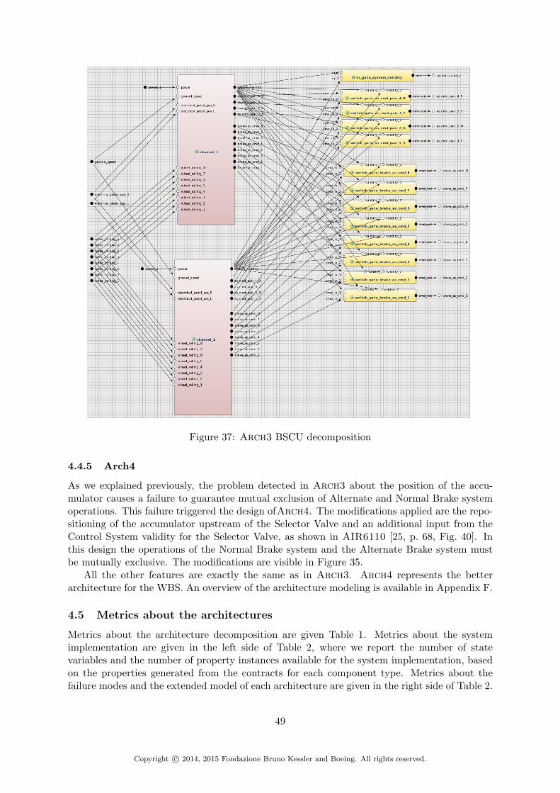
Figure 37: Arch3 BSCU decomposition
4.4.5 Arch4
As we explained previously, the problem detected in Arch3 about the position of the accu-mulator causes a failure to guarantee mutual exclusion of Alternate and Normal Brake systemoperations. This failure triggered the design ofArch4. The modifications applied are the repo-sitioning of the accumulator upstream of the Selector Valve and an additional input from theControl System validity for the Selector Valve, as shown in AIR6110 [25, p. 68, Fig. 40]. Inthis design the operations of the Normal Brake system and the Alternate Brake system mustbe mutually exclusive. The modifications are visible in Figure 35.
All the other features are exactly the same as in Arch3. Arch4 represents the betterarchitecture for the WBS. An overview of the architecture modeling is available in Appendix F.
4.5 Metrics about the architectures
Metrics about the architecture decomposition are given Table 1. Metrics about the systemimplementation are given in the left side of Table 2, where we report the number of statevariables and the number of property instances available for the system implementation, basedon the properties generated from the contracts for each component type. Metrics about thefailure modes and the extended model of each architecture are given in the right side of Table 2.
49
Copyright c© 2014, 2015 Fondazione Bruno Kessler and Boeing. All rights reserved.

Table 1: Architecture decomposition metrics
ArchitectureTotal
componenttypes
Leafcomponent
types
Totalcomponentinstances
Leafcomponentinstances
Max depth Contracts
Arch1 22 15 100 79 5 121Arch2 29 20 168 143 5 129
Arch2bis 29 20 168 143 5 129Arch3 30 20 169 143 6 142Arch4 30 20 169 143 6 142
Table 2: System implementation metrics
Sys. implementation Ext. Sys. implementation
Architecture PropertiesState vars State vars
Failure modes fault varsBool Enum Bool Enum
Arch1 199 31 55 74 184 28 170Arch2 291 79 88 156 311 33 261
Arch2bis 291 79 88 156 311 33 261Arch3 304 79 88 156 311 33 261Arch4 304 79 88 156 311 33 261
5 Analysis
In this section we present the results obtained from the different analyses making up our formalapproach. In Section 5.1, we describe the results of the formal verification, going from theanalysis of the architecture decomposition to the analysis of the monolithic model of eacharchitecture. In Section 5.2, we present the result of the Fault Tree Analysis from the MBSAand we compare them with the results of the Fault Tree Analysis from the CBSA for eacharchitecture. In Section 5.3, we compare the different architecture based on the results of thedifferent analyses.
5.1 Formal verification
5.1.1 Summary
The formal verification is first applied via a contract-based approach within OCRA. Thecontract-based verification process is based on the following steps: the top level propertiesare stated as contracts in the form of temporal logic formulae at the system level; each com-ponent is associated with corresponding contracts; the correctness of each contract refinementis proved by means of temporal entailment checks; the SMV module associated with each leafcomponent is proved to correctly implement the corresponding contracts.
The same results are also obtained via a monolithic approach. The monolithic models, inform of SMV files, are analyzed with respect to properties resulting from the contracts in thearchitecture. We use nuXmv, running different verification engines: BDD-based model checkingand IC3 [6].
All experiments are performed on a cluster of 64-bit Linux machines with 2.7 Ghz IntelXeon X5650 CPU, using one core with a memory limit set to 10Gb. The results are reported
50
Copyright c© 2014, 2015 Fondazione Bruno Kessler and Boeing. All rights reserved.

in Table 3. The columns Ref. and Impl. represent time taken for the contract refinement andimplementation checks. BDD-based model checking does not succeed in building the model. Torun it, we simplify the monolithic model6. The simplification automatically removes redundantstate variables exploiting functional dependencies among variables defined in the invariants.The execution time for this version of the model is tagged ’after simplification’ in the Table 3.We also apply IC3 engine on this simplified model. We observe that IC3 is the best engine toverify monolithic model. The difference between IC3 applied to the original monolithic modeland IC3 applied to the simplified model can be explained by the fact that the simplificationapplied to the model, a relational one, is not adapted to IC3 algorithm.
The results show that the compositional approach is often faster than the monolithic anal-ysis. Consider also that contract refinement and implementation checks are fully independentand localized, and can in principle be executed in parallel. For example, the VPar (Virtual Par-allelization) column in Table 3 reports maximum computation time across various individualchecks for the compositional approach, corresponding to the limit case where each check is runon a dedicated machine.
Aside from performance considerations, the most important result of the formal verificationis that the analysis of some sanity checks pinpointed a problem with Arch2 that is not reportedin AIR6110. The problem is caused by the fact that the accumulator is positioned downstreamof the selector valve, so that a fault in the accumulator can cause inadvertent braking. Theproblem is only reported for Arch3; Arch2bis was included in the analysis to correct theproblem. This result is described in detailed in 5.1.3.
Arch BDD (after simplification) IC3 (after simplification) IC3 Ref. Impl. Tot. VPar
Arch1 38.32 53.30 56.62 1422.24 6.07 1428.31 439.62
Arch2 2700.64 599.02 153.28 102.04 1.26 103.30 24.12
Arch2bis 3069.82 628.09 153.19 32.38 1.26 33.64 1.39
Arch3 2935.88 671.29 159.01 72.87 1.29 74.16 10.74
Arch4 3429.59 652.50 158.51 29.74 1.29 31.03 1.78
Table 3: Results of the formal verifications (all the times are in seconds)
5.1.2 Arch1
All the checks terminate successfully. However, we can observe that the execution times forArch1 are really different than in the other architectures. Arch1 is the most simple architec-ture, but also the less robust. The execution times of the monolithic analysis specifically reflectthis: it is 3 time faster with IC3 engine in comparison of the other architectures. However, theexecution time for the compositional approach is much worse. This may be explained by thefact that some of the contracts defined for Arch1 are too strong or their refinement are tooweak in comparison with the other architectures. More investigations are needed on this casein future work.
5.1.3 Arch2
All the checks terminate successfully. We can observe that the execution time for the composi-tional approach between Arch2 and Arch3 are in the same order.
Now we try to verify our assumption about the issue detected in Arch3 about the positionof the accumulator by strengthening some properties.
6nuXmv command write simplified model rel
51
Copyright c© 2014, 2015 Fondazione Bruno Kessler and Boeing. All rights reserved.

Requirements addition: mutual exclusion of Alternate and Normal Brake systemoperations In AIR6110, system requirements are defined for the Wheel Brake System. Wechose to apply one of these requirements to the model. We apply the requirement S18-WBS-R-2973 ”Alternate system operations shall be precluded during Normal operation”, extended withthis property: ”Normal system operations shall be precluded during Alternate operation”
This requirement is added in the contracts as follows: we add an assumption on the envi-ronment of each wheel brake and each brake actuator to the effect that it is never possible forhydraulic pressure supply from the Normal Brake system and from the Alternate Brake systemat the same time. The representation in OCRA language is given in Listing 7. This assump-tion is then kept at the level of the monolithic model thanks to the automatic translation ofthe contracts into LTL properties during the generation of the system implementation from thearchitecture decomposition.assume: always((normal_hyd_pressure_in>0 implies alternate_hyd_pressure_in=0)
and (alternate_hyd_pressure_in>0 implies normal_hyd_pressure_in=0));
Listing 7: Assumption for the mutual exclusion of Alternate and Normal Brake system opera-tions in OCRA contracts
The refinement check fails with the additional assumptions. The check takes 582.74 secondsand a problem is detected in the verification of the environment check of each wheel brake (i.e.the verification of the assumption), at the level of the Physical system. The time differencefor the refinement check between the version of Arch2 with the assumptions and without isdue to the check of additional assumes clauses. A counter-example generated for the wheelbrake of the wheel 8 is given in Listing 8. We see, in the second state, that the wheel brake issupplied by the Normal Brake system and by the Alternate Brake system in this example(normal sys.hyd pressure out 8 = 1 and alternate sys.hyd pressure out 4 =1). We can also see that the system is in the Normal mode but the Alternate Brake system is sup-plied by the accumulator (the normal mode is deduced by selector valve.green select out= 1 and selector valve.blue select out = 0, and accumulator.reserve out =7 indicating accumulator supply). As an initial observation, we can guess the problem mayoriginate from the position of the accumulator in the system, or the features of the accumulatorused are not sufficient for the expected behavior of the WBS.Checking the correct environment of "wheel_brake_8.supply_braking_force"...-- as demonstrated by the following execution sequenceTrace Description: LTL CounterexampleTrace Type: Counterexample
-- Loop starts here-> State Ports: 345.1 <-
hydraulic_supply_1 = 1hydraulic_supply_2 = 1pump_power_1 = TRUEpump_power_2 = TRUEsystem_validity = TRUEbrake_as_cmd_1 = FALSEbrake_as_cmd_2 = FALSEbrake_as_cmd_3 = FALSEbrake_as_cmd_4 = FALSEbrake_as_cmd_5 = FALSEbrake_as_cmd_6 = FALSEbrake_as_cmd_7 = FALSEbrake_as_cmd_8 = TRUEas_cmd_pair_1_5 = FALSEas_cmd_pair_2_6 = FALSEas_cmd_pair_3_7 = FALSEas_cmd_pair_4_8 = FALSEground_speed = 0mechanical_pedal_pos_L = FALSE
52
Copyright c© 2014, 2015 Fondazione Bruno Kessler and Boeing. All rights reserved.
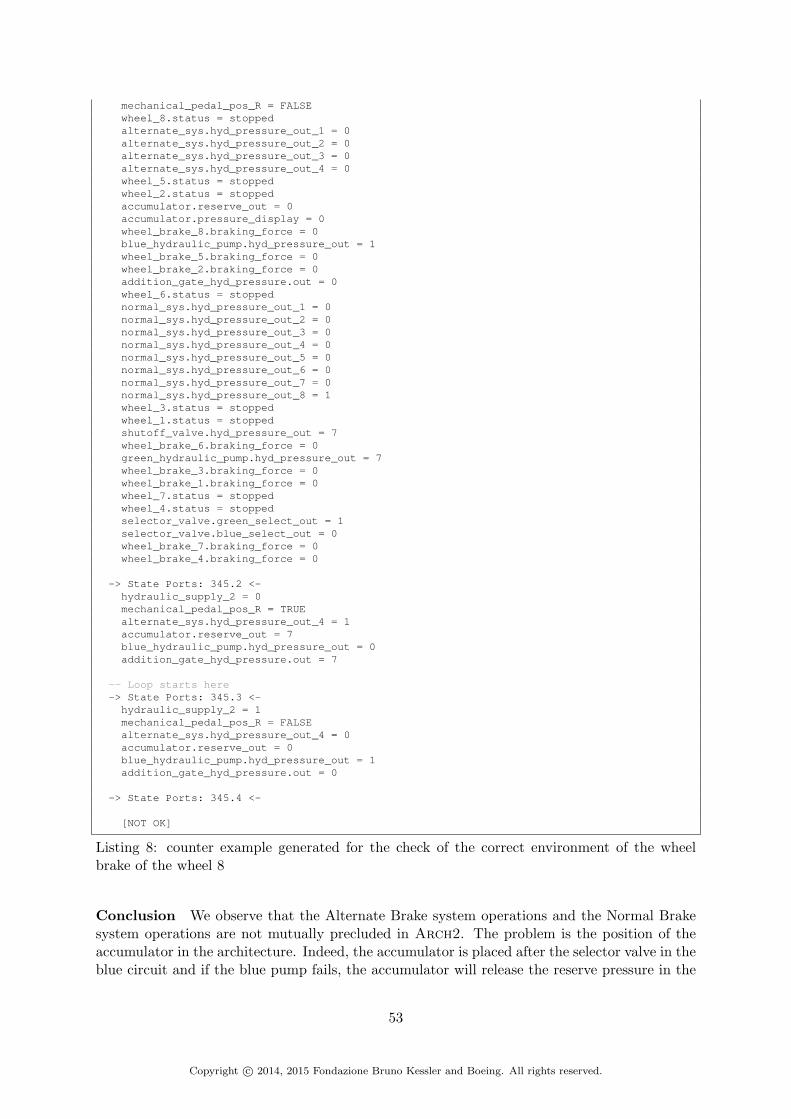
mechanical_pedal_pos_R = FALSEwheel_8.status = stoppedalternate_sys.hyd_pressure_out_1 = 0alternate_sys.hyd_pressure_out_2 = 0alternate_sys.hyd_pressure_out_3 = 0alternate_sys.hyd_pressure_out_4 = 0wheel_5.status = stoppedwheel_2.status = stoppedaccumulator.reserve_out = 0accumulator.pressure_display = 0wheel_brake_8.braking_force = 0blue_hydraulic_pump.hyd_pressure_out = 1wheel_brake_5.braking_force = 0wheel_brake_2.braking_force = 0addition_gate_hyd_pressure.out = 0wheel_6.status = stoppednormal_sys.hyd_pressure_out_1 = 0normal_sys.hyd_pressure_out_2 = 0normal_sys.hyd_pressure_out_3 = 0normal_sys.hyd_pressure_out_4 = 0normal_sys.hyd_pressure_out_5 = 0normal_sys.hyd_pressure_out_6 = 0normal_sys.hyd_pressure_out_7 = 0normal_sys.hyd_pressure_out_8 = 1wheel_3.status = stoppedwheel_1.status = stoppedshutoff_valve.hyd_pressure_out = 7wheel_brake_6.braking_force = 0green_hydraulic_pump.hyd_pressure_out = 7wheel_brake_3.braking_force = 0wheel_brake_1.braking_force = 0wheel_7.status = stoppedwheel_4.status = stoppedselector_valve.green_select_out = 1selector_valve.blue_select_out = 0wheel_brake_7.braking_force = 0wheel_brake_4.braking_force = 0
-> State Ports: 345.2 <-hydraulic_supply_2 = 0mechanical_pedal_pos_R = TRUEalternate_sys.hyd_pressure_out_4 = 1accumulator.reserve_out = 7blue_hydraulic_pump.hyd_pressure_out = 0addition_gate_hyd_pressure.out = 7
-- Loop starts here-> State Ports: 345.3 <-
hydraulic_supply_2 = 1mechanical_pedal_pos_R = FALSEalternate_sys.hyd_pressure_out_4 = 0accumulator.reserve_out = 0blue_hydraulic_pump.hyd_pressure_out = 1addition_gate_hyd_pressure.out = 0
-> State Ports: 345.4 <-
[NOT OK]
Listing 8: counter example generated for the check of the correct environment of the wheelbrake of the wheel 8
Conclusion We observe that the Alternate Brake system operations and the Normal Brakesystem operations are not mutually precluded in Arch2. The problem is the position of theaccumulator in the architecture. Indeed, the accumulator is placed after the selector valve in theblue circuit and if the blue pump fails, the accumulator will release the reserve pressure in the
53
Copyright c© 2014, 2015 Fondazione Bruno Kessler and Boeing. All rights reserved.

Alternate Brake system according to our model, even if the Normal Brake system is operating.Moreover, we can assume that even if the blue pump is still available, if the accumulator fails itcan release pressure in the Alternate Brake system while the Normal Brake system is operating.
The problem of the position of the accumulator is detected in Arch3 in the AIR6110document where it is the primary motivation for evoluting to Arch4. We proposed to applythe modification presented in Arch4 to Arch2 in order to obtain an intermediate architecture,and to verify the consequences of the modification. This leads to Arch2bis.
5.1.4 Arch2bis
All the checks terminate successfully. We can observe that the execution time for the compo-sitional approach between Arch2bis and Arch4, as between Arch2 and Arch3, are in thesame order.
The execution times given in Table 3 are the execution times without the additional as-sumptions in the properties for the wheel brakes. If we add the assumptions, all the checks arestill True but the execution time is higher than the one in Table 3 and closer to the executiontime for Arch2 with the assumptions.
These results make us confident about the solution developed on Arch4 for the position ofthe accumulator and its beneficial impact on the architecture.
5.1.5 Arch3
All the checks terminate successfully. We can observe that we have a similar execution timethan Arch2 for the compositional approach.
5.1.6 Arch4
All the checks terminate successfully. We can also observe that we have a similar executiontime as Arch2bis for the compositional approach.
5.2 Fault Tree Analysis
We now consider the construction of fault trees for each of the architectures and safety require-ments, from the models obtained with the model extension functionality of xSAP, as describedin Section 3.4. In order to cope with scalability issues, we limit the space of the problem intwo ways: restricting the set of faults, and limiting the cardinality of the cut sets. This followsa standard practice in traditional safety analysis: given the manual effort required, priority isgiven to cut sets of lower cardinality or greater likelihood.
The analyses are run on the five architectures, for all the safety properties and two additionalproperties, under the assumption that the WBS environment never fails (always electrical powerand always hydraulic supply to the WBS). We properties analyzed are:
• S18-WBS-R-0321: never loss of all wheel braking.
• S18-WBS-R-0322-left: never asymmetrical loss of wheel braking (left side).
• S18-WBS-R-0322-right: never asymmetrical loss of wheel braking (right side).
• S18-WBS-R-0323: never inadvertent braking of all wheels with all wheels locked (i.e.never inadvertent braking with all wheels locked).
• S18-WBS-R-0324: never inadvertent braking of all wheels.
54
Copyright c© 2014, 2015 Fondazione Bruno Kessler and Boeing. All rights reserved.

• S18-WBS-R-0325-wheel1: never inadvertent braking of one wheel without locking.
• S18-WBS-R-0325-wheel2: same as the previous property but for wheel 2. We checkthe property of each wheel to ensure that each wheel behaves in the same way for thesafety property.
• S18-WBS-R-0325-wheel3: same as the previous property but for wheel 3.
• S18-WBS-R-0325-wheel4: same as the previous property but for wheel 4.
• S18-WBS-R-0325-wheel5: same as the previous property but for wheel 5.
• S18-WBS-R-0325-wheel6: same as the previous property but for wheel 6.
• S18-WBS-R-0325-wheel7: same as the previous property but for wheel 7.
• S18-WBS-R-0325-wheel8: same as the previous property but for wheel 8.
• Braking implies cmd w1: This an additional property defined in the model to verifythe expected behavior of the system. It allows checking, for each wheel, that if the systemis braking, it means that the system has received a command from the pilot. Here weonly take the property for the wheel 1 (w1) as a control sample.
• Cmd implies braking w1: This a second additional property defined in the model toverify the expected behavior of the system. It allows checking, for each wheel, that if thesystem received a command from the pilot, the system is braking. Here again, we onlytake the property for the wheel 1 (w1) as a control sample.
For each of these properties, their violation is used as Top Level Events (TLE) for thefault tree computations (in the following paragraphs, we will use the name of the propertiesto reference the TLE). For each TLE, cardinality goes from 1 to 5, and then to no restriction.In addition to the complete set of faults, six different restricted sets of faults are defined andobserved:
• Set1 The components that can have faults in this set are : Hydraulic Pump, Accumulator,Shutoff Valve, Selector Valve, Meter Valve, Antiskid Shutoff Valve.
• Set2 The components that can have faults in this set are : Hydraulic Fuse, HydraulicPiston, Brake Actuator, Wheel.
• Set3 The components that can have faults in this set are : Brake Command Facility, An-tiskid Command Facility, Normal Command Calculator, Alternate Command Calculator,Monitor System.
• Set4 The components that can have faults in this set are : Switch Gate, Monitor System
• Set5 The components that can have faults in this set are : Sensor, Sensor Pedal Position
• Set6 The components that can have faults in this set are : Brake Command Facility, An-tiskid Command Facility, Normal Command Calculator, Alternate Command Calculator,Meter Valve, AntiSkid Shutoff Valve
In total, 3150 fault tree constructions have been launched. Overall the activity resulted in3089 computed fault trees and 61 computations timed out. The fault trees have minimal cutsets ranging from 0 to tens of thousands.
55
Copyright c© 2014, 2015 Fondazione Bruno Kessler and Boeing. All rights reserved.

Arch/Prop Prob. |mcs| = 1 |mcs| = 2 |mcs| = 3 |mcs| = 4 |mcs| = 5 Full
arch1
S18-WBS-R-0321 1.45e-04 17 2 0 0 0 NS18-WBS-R-0322-left 1.45e-04 17 2 0 28561 0 Y
S18-WBS-R-0322-right 1.45e-04 17 2 0 28561 0 YS18-WBS-R-0323 0.00e+00 0 0 0 0 0 NS18-WBS-R-0324 2.50e-11 0 1 0 0 8192 N
S18-WBS-R-0325-wheel1 9.63e-05 9 0 0 0 0 YS18-WBS-R-0325-wheel2 9.63e-05 9 0 0 0 0 YS18-WBS-R-0325-wheel3 9.63e-05 9 0 0 0 0 YS18-WBS-R-0325-wheel4 9.63e-05 9 0 0 0 0 YS18-WBS-R-0325-wheel5 9.63e-05 9 0 0 0 0 YS18-WBS-R-0325-wheel6 9.63e-05 9 0 0 0 0 YS18-WBS-R-0325-wheel7 9.63e-05 9 0 0 0 0 YS18-WBS-R-0325-wheel8 9.63e-05 9 0 0 0 0 Ybraking implies cmd w1 1.11e-04 13 1 0 0 0 Ycmd implies braking w1 2.57e-04 30 2 0 0 0 Y
Table 4: Fault trees results for arch1 for the full set of faults (- represents a timed out compu-tation)
All fault tree constructions are performed using IC3 engine on a cluster of 64-bit Linuxmachines with CPU going from 2.4 Ghz to 2.7 Ghz Intel Xeon, with a memory limit set to30Gb and a time limit of 10 hours (unless otherwise specified).
To ease the reading load, we only present in the following tables a sampling of the results:the results for the 15 chosen properties, for the full set of faults, with cardinality going from1 to 5. An overview of all the results for each architecture are found in Appendix H, I, J,K and L. In these tables, we give the number of minimal cut sets for cardinality 1 to 5. Forupper cardinality, we only indicates in the last column (Full) whether the computation has beencompleted (i.e. computed the minimal cut sets) without cardinality bound (Y) or if it timedout (N). We also report the probability (Prob.) for each of the TLE, for an association of thebasic faults with a probability, as given in Section 4.2.3 (in the ’N’ cases, the reported valueis a lower bound). The execution time required to compute the fault tree for a given propertyranges from seconds (for fault tree with dozens of minimal cut sets) to minutes or hours (forfault tree with thousands of minimal cut sets).
The problem has also been tackled by means of contract-based safety analysis [5]. Given theinherent scalability of the contract based approach, we are able to produce hierarchical faulttrees (HFT) from the architecture decompositions and the contracts. The hierarchical fault treesare produced in a dozen minutes for all top level properties without any cardinality bounds orfaults restrictions. An example is given in Appendix G. As discussed in [5], the compositionalapproach will produce hierarchical fault trees whose corresponding set of minimal cut sets is anover-approximation of the one obtained with the monolithic approach. This is confirmed in theexperiments: for each property, we make a comparison of the minimal cuts sets obtained forthe higher cardinality and for a full configurations of faults in the monolithic approach, withthe minimal cut sets obtained from the contract based approach. We also notice that over-approximation is a common practice in safety analysis. The two approaches can be consideredcomplementary.
5.2.1 Arch1
A sample of the results corresponding to the minimal cut sets (MCS) for each property atdifferent cardinality for the full set of faults for the MBSA is given Table 4 and presented inthe following paragraphs. The full results are given in Appendix H.
56
Copyright c© 2014, 2015 Fondazione Bruno Kessler and Boeing. All rights reserved.

S18-WBS-R-0321 At cardinality 1, there are 17 MCS. They correspond to the failure of eachBSCU leaf component (8 antiskid command facility, 8 brake command facility and 1 monitorsystem). These MCS are surprising but they are highlighting an important problem in Arch1:the Control system is expected to cut the commands sent to the Physical system in case offailure. The failure of the Control system is achieved if at least one of its leaf component failed.In the case of Arch1, there is nothing that prevents the Control system to continue to sendingcommands to the Physical system if it is invalid. Specifically, if the Control system can continueto send commands, then it can apply anti-skid function when the WBS does not expect it. Ifwe take the particular case where the Control system is invalid (because at least one of its leafcomponent fails) and the 8 wheels are skidding, the system expects to be able to brake withoutrestriction. But if the Control system can still send commands even if invalid, it can still applythe anti-skid function for the 8 wheels and prevent the braking of the wheels because of theirskidding. The system does not expect this behavior and sees it as a complete loss of wheelbraking, triggered by the failure of at least one Control system leaf component.
At cardinality 2, there are 2 MCS that correspond to the loss of all the hydraulic pressuresupplies, as expected: loss of the pump and loss of the accumulator or the shutoff valve failsclosed and loss of the accumulator.
For cardinality 3 to 5, there is no MCS.For the computation without restriction, the computation of the fault trees timed out.The probability is about 1.45e-04 but the fault tree computation does not complete without
restriction. It is not in agreement with the expected order for “extremely remote” (1.0e-7 orless) defined in [1]. Indeed, the single points of failure reflect an important problem of thisarchitecture and dictate the probability value.
S18-WBS-R-0322-left(right) At cardinality 1, there are 17 MCS. They correspond to thefailure of each BSCU leaf component (8 antiskid command facility, 8 brake command facilityand 1 monitor system). As for the previous TLE, these MCS are surprising but they highlightthe problem of the commands sent by an invalid Control system. In is case, the application ofthe anti-skid commands from the invalid Control system on one side when the system does notexpect to receive commands can be interpreted as an asymmetrical loss of wheel braking.
The MCS of cardinality 2 are also surprising. Indeed they correspond to the loss of thepressure supply to the hydraulic system (pump fails or shutoff valve fails closed and the accu-mulator fails off) which can cause a full loss of wheel braking. The cause of these 2 MCS is dueto our definition of the antiskid function and how we handle it in the top level property. Forexample, if one side is completely skidding and the other is supposed to brake, if we loss thepressure supply, we loose the capacity of braking on the side where we are supposed to brake,but as the other side is not supposed to brake due to the skidding of its wheels, there is noimpact on it. This corner case must be further investigated in future work.
At cardinality 3, there is no MCS.At cardinality 4, there are 28561 MCS. They correspond to the combinations of a component
in failure in the hydraulic circuit part of each wheel of the specific side (meter valve fails, antiskidshutoff valve fails, hydraulic fuse fails, hydraulic piston fails, brake actuator fails and/or wheelsensor fails).
For cardinality 5 or above, there is no MCS. The computation of the fault trees without anyrestriction is completed.
The probability is about 1.45e-04 which does not achieve the required level of “extremelyremote” (1.0e-7 or less) defined in [1]. The probability is dictated by the single points offailure which are, as in the previous TLE, due to an important issue in Arch1. But theoriginal requirement required an additional loss of rudder or nose wheel steering with the current
57
Copyright c© 2014, 2015 Fondazione Bruno Kessler and Boeing. All rights reserved.
property, which means an additional component in fault that is not represented in our model.The exact impact of this additional fault on the probability is unknown, and would requiremodeling of other systems external to the WBS.
S18-WBS-R-0323 The fault tree computation does not complete without restriction andthere is no minimal cut set up to cardinality 5 for the full set of faults.
As the fault tree computation does not terminate without restriction and there is no minimalcut set up to cardinality 5 for the full set of faults, the lower bound of the probability is 0 forthis TLE. But we can assume, based on the probability order of the failure modes of eachcomponent, that the probability for the minimal cut sets with a cardinality greater than 5 willbe much lower than the expected order (“extremely remote”, 1.0e-7 or less).
S18-WBS-R-0324 The lower cardinality of the MCS obtained is 2 with only one MCS, whichcorresponds to the combination of the two pedal position sensors sending erroneous commands(For example, sending an electrical signal when there is none).
There is no MCS at cardinality 3 and 4. At cardinality 5, there are more than 8192 MCS.They are combinations of one pedal position sensor of one side (left for example) sending erro-neous command, with a component in failure in the hydraulic circuit (meter valve or hydraulicpiston or brake actuator) of each of the four wheels in the other side (right for example), or thebrake command facility of each of these four wheels.
For cardinality greater than 5, the computation of the fault trees is timed out.The probability is about 2.50e-11 but here again the fault tree computation does not com-
plete without restriction. However, the computed probability is in agreement with the expectedorder for “extremely improbable” (1.0e-9 or less).
S18-WBS-R-0325-wheelX The lower cardinality of the MCS obtained is 1. At this car-dinality, there are 9 MCS: 3 about the meter valve (failed open, failed last position or failedrandom position), 2 about the brake actuator (failed open or failed at the last position), 2 aboutthe hydraulic piston (failed open or failed at the last position), 1 about the pedal position sen-sor sending an erroneous command and 1 about the brake command facility sending erroneouscommand. Except the brake command facility failure, all the MCS make sense: they correspondto a failure of a component in the hydraulic circuit leading to the inadvertent braking of thewheel. The presence of the failure of the brake command facility is due to the issue of theControl system which is able to send erroneous command even if invalid.
For cardinality 2 or above, there is no MCS. The computation of the fault trees terminatedwithout restriction.
The probability is about 9.63e-05. It is not in agreement with the expected order for “ex-tremely improbable” (1.0e-9 or less) defined in [1]. Apart from the problem of the MCS due toan issue in Arch1, the safety requirement used as TLE specified an “undetected” inadvertentbraking. This aspect is not taking into account in our modeling which means that it shouldneed another component to be in fault to cause the violation of the safety requirement. In thiscase, the probability should be lower than the one obtained.
Braking implies cmd w1 The lower cardinality of the MCS obtained is 1. At this cardinality,there are 13 MCS: 3 about the meter valve (failed open, failed last position or failed randomposition), 3 about the antiskid shutoff valve (failed open, failed last position or failed randomposition), 2 about the brake actuator (failed open or failed at the last position), 2 about thehydraulic piston (failed open or failed at the last position), 1 for the pedal position sensor sending
58
Copyright c© 2014, 2015 Fondazione Bruno Kessler and Boeing. All rights reserved.

an erroneous command and 1 for the brake command facility sending erroneous commands.Same as before: except the brake command facility failure, all the MCS make sense.
At cardinality 2, there is 1 MCS corresponding to the monitor system and the antiskidcommand facility of the wheel sending erroneous commands. In this specific case, the antiskidcommand facility of the wheel will send erroneous command and the monitor system will notdetect it, letting the system think that everything is ok. The antiskid command will not beproduced and the wheel which was not supposed to brake due to the antiskid command willbrake.
For cardinality 3 or above, there is no MCS. The computation of the fault trees terminateswithout restriction. The probability is about 1.11e-04. We do not have any reference to comparewith.
Cmd implies braking w1 At cardinality 1, there are 30 MCS: the failure of each BSCU leafcomponent (8 antiskid command facility, 8 brake command facility and 1 monitor system), 3about the meter valve (failed closed, failed last position or failed random position), 3 about theantiskid shutoff valve (failed closed, failed last position or failed random position), 2 about thebrake actuator (failed closed or failed at the last position), 2 about the hydraulic piston (failedclosed or failed at the last position), 2 about the wheel sensor (failed no data or erroneousdata) and one about the hydraulic fuse failed closed. Despite of the 17 MCS on the BSCU leafcomponent due to the issue of Arch1, the other computed MCS make sense.
At cardinality 2, there are 2 MCS that correspond to the loss of all the hydraulic pressuresupply: loss of the pump and loss of the accumulator or the shutoff valve fails closed and lossof the accumulator.
For cardinality 3 to 5, there is no MCS. The computation terminates without restriction.The probability is about 2.57e-04. We do not have any reference to compare with.
Summary and CBSA comparison The reviewed MCS pinpoints an important issue inArch1: the Control system (BSCU) do not cut off the sending of commands if it is invalid.Due to the single points of failure resulting from this issue, the probability for some of the TLEare too high(S18-WBS-R-0321,S18-WBS-R-0322).
The hierarchical fault tree generated from CBSA for each of the TLE have been confirmedto be an over-approximation of the fault trees generated by the MBSA. But the particular caseof the property S18-WBS-R-0323, where there is no MCS computed for the full set of faults,does not allow us to state anything about the result of this comparison for this property.
5.2.2 Arch2
A sample of the results corresponding to the minimal cut sets (MCS) for each property atdifferent cardinality for the full set of faults for the MBSA is given Table 5 and described in thefollowing paragraphs. The full results are given in Appendix I.
S18-WBS-R-0321 The lower cardinality of the MCS obtained is 2. There are 6 MCS at thiscardinality that are combinations of failures of the two pedal position sensors (4 of the MCS),and the failure of the selector valve in the last position associated to a failure causing the loss ofpressure in the green circuit (loss of the green hydraulic pump or the shutoff valve fails closed).They make sense: if the two pedal position sensors fails at the same time to transform themechanical position in an electrical signal, a loss of all wheel braking can happen; and if theselector valve is stuck in the Normal Brake system and no pressure is coming in, the brakingwill be impossible.
59
Copyright c© 2014, 2015 Fondazione Bruno Kessler and Boeing. All rights reserved.

Arch/Prop Prob. |mcs| = 1 |mcs| = 2 |mcs| = 3 |mcs| = 4 |mcs| = 5 Full
arch2
S18-WBS-R-0321 4.51e-10 0 6 1252 629 - NS18-WBS-R-0322-left 1.00e-05 2 2 732 47583 - N
S18-WBS-R-0322-right 1.00e-05 2 2 732 47583 - NS18-WBS-R-0323 0.00e+00 0 0 0 0 0 NS18-WBS-R-0324 2.50e-11 0 1 0 38 10859 N
S18-WBS-R-0325-wheel1 1.20e-04 9 19 2597 0 0 YS18-WBS-R-0325-wheel2 1.20e-04 9 19 2597 0 0 YS18-WBS-R-0325-wheel3 1.20e-04 9 19 2597 0 0 YS18-WBS-R-0325-wheel4 1.20e-04 9 19 2597 0 0 YS18-WBS-R-0325-wheel5 1.20e-04 9 19 2597 0 0 YS18-WBS-R-0325-wheel6 1.20e-04 9 19 2597 0 0 YS18-WBS-R-0325-wheel7 1.20e-04 9 19 2597 0 0 YS18-WBS-R-0325-wheel8 1.20e-04 9 19 2597 0 0 Ybraking implies cmd w1 1.25e-04 10 40 2651 7395 9636 Ycmd implies braking w1 1.13e-04 13 30 8053 3815 2873 Y
Table 5: Fault trees results for arch2 for the full set of faults (- represents a timed out compu-tation)
For cardinality 3, there are more than 1000 MCS. They are composed of the combination ofthe loss of all the hydraulic supply (loss of the two pumps and the accumulator, or the shutoffvalve fails closed and loss of the blue pump and the accumulator) and mainly two other kind ofMCS: one component of each BSCU fails (causing the validity of the Control system to be falseand the shutoff valve cutting the pressure going to the Normal Brake system) and the selectorsalve fails at last position, causing the WBS to be stuck in the Normal mode with no pressure;Or one component of each BSCU fails (Control system invalid) and the shutoff valve fails open,causing the WBS to be stuck in the Normal Brake system, but without any commands sent bythe Control system.
For cardinality 4, there are approximately 600 MCS. They are mainly combinations of failureof one component of each BSCU causing the WBS to go to the Alternate Brake system, anda loss of the blue pump and the accumulator, causing the WBS to be in the Alternate Brakesystem without pressure supply.
For cardinality 5 and above, the computation of the fault trees is timed out.The probability is about 4.51e-10 but the fault tree computation does not terminate without
restriction. Nevertheless, the probability is in agreement with the expected order for “extremelyremote” (1.0e-7 or less) but it is lower than the minimum bound (1.0e-9) defined in [1].
S18-WBS-R-0322-left(right) The lower cardinality of the MCS obtained is 1. The singlepoints of failure are the 2 failure modes of the pedal position sensor (no date or erroneous data)of the side of the property (left or right). Indeed, if only one of the pedal position sensor failsto convert the signal for the Control system, it can cause an asymmetrical loss of wheel brakingon the side of the pedal.
The MCS of cardinality 2 are more surprising. Indeed they correspond to the loss of thesupply of the Normal Brake system (loss of the green pump of shutoff valve failed closed ) andthe selector valve that fails stuck at this position, which can cause a full loss of wheel braking.The presence of these 2 MCS can be due to our definition of the antiskid function and howwe handle it in our property. For example, if one side is completely skidding and the other issupposed to brake, and in addition the pressure supply is lost without being able to changecircuit, the capacity of braking on the side where we are supposed to brake is lost, but as theother side is not supposed to brake due to the skidding of its wheels, there is no impact on it,causing an asymmetrical loss of wheel braking. This corner case must be investigated in futurework.
60
Copyright c© 2014, 2015 Fondazione Bruno Kessler and Boeing. All rights reserved.
For cardinality 3, there are about 700 MCS. They correspond to different combinations: lossof the pressure in the green circuit, causing the system going to the Alternate Brake system,and the loss of two components of the specific side causing the loss of the wheel braking (allpossible combinations of loss of two wheel sensors, loss of two alternate meter valves or loss oftwo antiskid shutoff valves or combination of each one of them). Indeed, as the braking of thewheels is managed by pair in the Alternate Brake system, a failure of one component of thehydraulic circuit of the sensor for each pair is sufficient to loose the braking on the four wheels.In addition, the other MCS are mainly combinations of one component of each BSCU failed(Control System invalid) and the shutoff salve fails open, causing the WBS to be stuck in theNormal Brake system, but without any command sent by the Control system. There are alsocombinations causing the full loss of pressure supply. In these cases, the same impact of theanti-skid function as in the MCS of cardinality 2 is observed.
For cardinality 4, there are dozens of thousands of MCS. There are mainly composed oftwo combinations of faults: first, one component of each BSCU failed causing the system tobe in the Alternate Brake system and the loss of two components of the specific side causingthe loss of the wheel braking ; second, the failure of a component in the hydraulic circuit orin the command chain of the braking of each wheel in the specific side. We also observe MCScomposed of combinations of failures of BSCU components where, one component of BSCU 1is in fault, causing the BSCU 1 to be invalid, with two components responsible for the brakecommands creation of the wheels in BSCU 2 for the specific side in faults plus the monitorsystem of BSCU 2 failing to detect the failures.
For cardinality 5 and above, the computation of the fault trees is timed out.The probability is about 1.00e-05 but the fault tree computation does not terminate without
restriction. The probability order is higher than the one expected for “extremely remote” (1.0e-7 or less). It may be explained because the original requirement required an additional loss ofrudder or nose wheel steering with the current property, which means an additional componentin fault that is not represented in our model. In this way, we should have no single point offailure (MCS of cardinality 1) and a lower probability.
For this TLE, the results for the left side and the right side are the same.
S18-WBS-R-0323 The fault tree computation does not complete without restriction andthere are no minimal cut sets up to cardinality 5 for the full set of faults. However, we observethat by restricting the set of faults, the fault tree computation can terminate without boundon the cardinality. For example, for the set6, we are able to find dozen of thousands MCS fromcardinality 6. One of the possible combination of faults is one component of each BSCU failedcausing the WBS to be in the Alternate mode without anti-skid function, and the 4 meter valvesof the Alternate Brake system failed open.
As the fault tree computation does not complete without restriction and there are no minimalcut sets up to cardinality 5 for the full set of faults, the lowest bound of the probability is 0for this TLE. But we can assume, based on the probability order of the failure modes of eachcomponent, that the probability for the minimal cut sets with a cardinality greater than 5 willbe much lower than the expected order (“extremely remote”, 1.0e-7 or less).
S18-WBS-R-0324 The lower cardinality of the MCS obtained is 2 only one MCS, whichcorresponds to the combination of the two pedal position sensors sending erroneous commands(For example, sending an electrical signal when pedals are not depressed).
There is no MCS at cardinality 3.At cardinality 4, there are 38 MCS. Two of them correspond to the combination of one
pedal position sensor of one side (left for example) sending wrong command, in addition of
61
Copyright c© 2014, 2015 Fondazione Bruno Kessler and Boeing. All rights reserved.

three failures in the Control system: The monitor system of BSCU 1 is sending a wrong validitysignal and the brake commands computed by the brake command facility of BSCU 1 for eachpair of wheels of the other side (right for example) sent wrong command too. The other MCSare more interesting. They are highlighting the wrong position of the accumulator: they arecombination of the accumulator failed opened or the blue pump failed off, as the WBS is still inthe Normal mode, with one pedal position sensor of one side (left for example) sending wrongcommand and the two alternate meter valves of the other side failed opened.
At cardinality 5, there are more than 10000 MCS. They are mainly combinations of one pedalposition sensor of one side (left for example) sending erroneous command, with a componentin failure in the green hydraulic circuit of each of the four wheels of the other side (right forexample). There are also, for example, combinations of the loss of the green hydraulic pump,causing the WBS to be in the Alternate mode, with a failure of the meter valve of each pair ofwheel. There is also a specific MCS composed of the failure of the monitor system of the BSCU1 plus the failure of the four brake command facility of BSCU 1 responsible for the creation ofthe brake commands for all the wheels. Finally, we can observe combinations due the wrongposition of the accumulator.
For cardinality greater than 5, the computation of the fault trees is timed out.The probability is about 2.50e-11 but the fault tree computation does not complete without
restriction. However, the computed probability is in agreement with the expected order for“extremely improbable” (1.0e-9 or less).
S18-WBS-R-0325-wheelX The lower cardinality of the MCS obtained is 1. There are 9MCS for this cardinality: 3 about the meter valve of the Normal Brake system (failed open,failed last position or failed random position), 2 about the brake actuator (failed open orfailed at the last position), 2 about the normal hydraulic piston (failed open or failed at thelast position), 1 for the pedal position sensor sending an erroneous command and finally 1for the alternate hydraulic piston failed open. However, the safety requirement specified an“undetected” inadvertent braking. This aspect is not taken into account in our modeling (nodetection of the braking force) which means that it would need another component to be infault to cause the violation of the safety requirement, so at least MCS of cardinality 2.
At cardinality 2, we have 19 MCS. 7 of them are due to the wrong position of the accumulatorand are a combination of the loss of the blue hydraulic pump or the accumulator failed openwith a failure of the alternate meter valve or alternate hydraulic piston of the specific wheel.The others are combinations of the loss of the pressure in the green circuit (loss of the greenpump or shutoff valve fails closed) with a failure of the alternate meter valve or alternatehydraulic piston. The last ones are combination of failure of the Control system components:the component responsible of the creation of the braking command for the normal system forthe BSCU 1 with a failure of the monitor system or the corresponding switch gate, causing theControl system to keep sending the braking command of the BSCU 1 for the specific wheel.
At cardinality 3, we have more than 2597 MCS. There are mainly a combination of onecomponent of each BSCU failed causing the WBS to be in the Alternate Brake system and thefailure of the meter valve or the hydraulic piston of the Alternate Brake system attached to thespecific wheel. There are also some combinations about failures of Control system componentslike one of the components of BSCU 1 failed, leading to the use of BSCU 2, plus the failure ofone of the components in BSCU 2 responsible for the creation of the brake command for thespecific wheel and the monitor system of BSCU 2 failing to detect the error.
For cardinality 4 and above, there is no MCS. The computation of the fault tree finishedwithout restriction.
The probability is about 1.20e-04 which is more than the one expected by the safety require-
62
Copyright c© 2014, 2015 Fondazione Bruno Kessler and Boeing. All rights reserved.

ment. The failure conditions should be extremely improbable, which means with a probabilityof 1.0e-9 or less. But the safety requirement specified an “undetected” inadvertent braking.As we said previously, this aspect is not taken into account in our model (no detection of thebraking force) which means that it should need another component to be in fault to cause theviolation of the safety requirement. As a result, the probability should be lower than the oneobtained. So we are still confident of the computed probability for the version of the safetyrequirement used.
For this TLE, the results for the 8 wheels are the same.
Braking implies cmd w1 For this TLE, there are 10 MCS of cardinality: 3 about the metervalve of the Normal Brake system (failed open, failed last position or failed random position),2 about the brake actuator (failed open or failed at the last position), 2 about the normalhydraulic piston (failed open or failed at the last position), 1 about the pedal position sensorsending an erroneous command, 1 about the alternate hydraulic piston failed open and 1 aboutthe sensor of the wheel sending erroneous data.
For cardinality 2, there are 40 MCS. They are mainly combinations of a failure leading tothe Alternate mode (Loss of the green pump or shutoff valve failed closed) with a failure of acomponent having an impact on the braking of the wheel in the Alternate Brake system (alter-nate meter valve, alternate antiskid shutoff valve, alternate hydraulic piston, sensor of the pairof the wheel,. . . ). There are also combinations about the failure of one of the BSCU 1 compo-nent responsible for the commands creation of the wheel plus the switch gate corresponding tothe command failed at last position (BSCU 1) or the monitor system of the BSCU 1 missingto detect the wrong command creation. In addition we have 16 minimal cut sets linked to thewrong position of the accumulator: loss of of the blue pump or accumulator failed open withwith a failure of a component having an impact on the braking of the wheel in the AlternateBrake system.
At cardinality 3, we observe 2651 MCS. They are mainly combinations of one componentof each BSCU failed, causing the WBS to be in the Alternate Brake system, and the failure ofthe meter valve or the hydraulic piston of the Alternate Brake system attached to the specificwheel. We can also see 4 MCS due to the wrong position of the accumulator: the blue pumpfailed off or accumulator failed open, plus the failure of a component responsible for the creationof the alternate commands in the BSCU 1 for the specific wheel, and a failure of the switchgate linked to this command or failure of the monitor system to detect the erroneous commandcreation.
At cardinality 4 and 5, there are thousands of MCS. We can observe a lot of MCS due tothe wrong position of the accumulator.
The fault tree computation terminates without restriction and generates MCS up to cardi-nality 8.
Concerning the probability, we do not have reference for this property but we can see thatits is of the same order than the probability about the inadvertent braking of one wheel withoutlocking (S18-WBS-R-0325-wheelX).
Cmd implies braking w1 There are 13 MCS of cardinality 1: 3 about the meter valve ofthe Normal Brake system (failed closed, failed last position or failed random position), 2 aboutthe brake actuator (failed full off or failed at the last position), 2 about the Normal hydraulicpiston (failed full off or failed at the last position), 2 about the pedal position sensor sendingan erroneous command or no data, 2 about the wheel sensor sending erroneous data or no data,1 about the normal hydraulic fuse failed closed and 1 about the switch gate responsible for
63
Copyright c© 2014, 2015 Fondazione Bruno Kessler and Boeing. All rights reserved.

the brake command of the wheel in the Normal mode failing at an intermediate position (nocommand sent).
At cardinality 2, the 30 MCS are mainly combinations of a failure leading to the Alternatemode (Loss of the green pump or shutoff valve failed closed) with a failure of a componenthaving an impact on the braking of the wheel in the Alternate Brake system (alternate metervalve, alternate antiskid shutoff valve, alternate hydraulic piston, sensor of the pair of the wheel,. . . ). There are also combinations about the failure of one of the BSCU component responsiblefor the commands creation of the pair of the wheel with the switch gate corresponding to thecommand failed at last position (BSCU 1) or the monitor system of the BSCU 1 missing todetect the wrong command creation.
For cardinality 3, there are thousands of MCS. They are mainly combinations that canlead the WBS to be stuck in the Normal Brake system without commands or without pressuresupply (one component of each BSCU failed with the shutoff valve failed open or the selectorvalve failed last position), or failures leading to the Alternate Brake system (one component ofeach BSCU failed) with failure of one component of it causing the loss of wheel braking for thespecific wheel (valve failed closed, piston or brake actuator failed full off, fuse failed closed, . . . ).
For cardinality 4 to 5, there are thousands of MCS which are mainly combinations composedof failure of Control system component, with some of them associated to a component of theAlternate Brake system for the specific wheel. Here too we can observe MCS due to the wrongposition of the accumulator.
The fault tree computation terminates without restriction and generates MCS up to cardi-nality 6.
Concerning the probability, it is about 1.13e-04 but we do not have any reference for thisproperty.
Summary and CBSA comparison The reviewed MCS make sense and the computed prob-abilities are approximately of a close order of the one required by the requirements, assuming thepart of the requirement we abstracted. One unexpected case is that we have MCS for the TLEabout the asymmetrical loss of wheel braking(S18-WBS-R-0322-left(right)) that correspond toa complete loss of hydraulic pressure or a complete loss of commands. As we explained, theymay be due to our definition of the antiskid function and how we handle it in the property.It will need a deeper investigation in future work. More interesting, the wrong position of theaccumulator is detected during the analysis and produced additional MCS for some TLEs.
The hierarchical fault tree generated from CBSA for each of the TLE have been confirmedto be an over-approximation of the fault trees generated by the MBSA. But the particular caseof the property S18-WBS-R-0323, where there is not MCS computed for the full set of faults,does not allow us to state anything about the result of this comparison for this property.
5.2.3 Arch2bis
A sample of the results corresponding to the minimal cut sets (MCS) for each property atdifferent cardinality for the full set of faults for the MBSA is given Table 6 and described in thefollowing paragraphs. The full results are given in Appendix J.
S18-WBS-R-0321 The lowest cardinality MCS is 2, as in Arch2. There are 6 MCS at thiscardinality: the combination of the two pedal position sensors failures (4 of the MCS), and thefailure of the selector valve in the last position associated to a failure causing the loss of pressurein the green circuit (loss of the green hydraulic pump or the shutoff valve failed closed).
64
Copyright c© 2014, 2015 Fondazione Bruno Kessler and Boeing. All rights reserved.

Arch/Prop Prob. |mcs| = 1 |mcs| = 2 |mcs| = 3 |mcs| = 4 |mcs| = 5 Full
arch2bis
S18-WBS-R-0321 4.51e-10 0 6 627 629 - NS18-WBS-R-0322-left 1.00e-05 2 2 203 46287 - N
S18-WBS-R-0322-right 1.00e-05 2 2 203 46287 - NS18-WBS-R-0323 0.00e+00 0 0 0 0 0 NS18-WBS-R-0324 2.50e-11 0 1 0 2 8729 N
S18-WBS-R-0325-wheel1 1.20e-04 9 12 2596 0 0 YS18-WBS-R-0325-wheel2 1.20e-04 9 12 2596 0 0 YS18-WBS-R-0325-wheel3 1.20e-04 9 12 2596 0 0 YS18-WBS-R-0325-wheel4 1.20e-04 9 12 2596 0 0 YS18-WBS-R-0325-wheel5 1.20e-04 9 12 2596 0 0 YS18-WBS-R-0325-wheel6 1.20e-04 9 12 2596 0 0 YS18-WBS-R-0325-wheel7 1.20e-04 9 12 2596 0 0 YS18-WBS-R-0325-wheel8 1.20e-04 9 12 2596 0 0 Ybraking implies cmd w1 1.25e-04 10 24 2647 4530 59 Ycmd implies braking w1 1.13e-04 13 30 7428 3815 1768 Y
Table 6: Fault trees results for arch2bis for the full set of faults (- represents a timed outcomputation)
For cardinality 3, there are 627 MCS. they are composed of the loss of all the hydraulicsupply (Loss of the two pumps and the accumulator, or the shutoff valve fails closed and lossof the blue pump and the accumulator) and mainly MCS with combinations of the form: onecomponent of each BSCU failed (causing the validity of the Control system to be false and theshutoff valve cutting the pressure going to the Normal Brake system) and the selector valvefails at last position causing the WBS to be stuck in the Normal mode with no pressure. Wedo not have the combinations of one component of each BSCU failed (Control System invalid)and the shutoff valve fails open as in Arch2, due to the modification of the selector valve inArch2bis. Indeed, the additional input from the Control system validity for the selector valveprevents the MCS implying the shutoff valve failed open at this cardinality.
For cardinality 4, there are approximately 600 MCS, as in Arch2. They are mainly combi-nations of failure of one component of each BSCU failed causing the WBS to go to the AlternateBrake system, and a loss of the blue pump and the accumulator, causing the WBS to be in theAlternate Brake system without pressure supply.
For cardinality 5 and above for the full set of faults, the computation of the fault trees timesout.
The probability is about 4.51e-10 but the fault tree computation does not complete withoutrestriction. Nevertheless, the probability is in agreement with the expected order for “extremelyremote” (1.0e-7 or less) but we are lower than the minimum bound (1.0e-9) defined in [1].
S18-WBS-R-0322-left(right) The lower cardinality of the MCS obtained is 1. The singlepoints of failure are the 2 failure modes of the pedal position sensor of the side of the property(left or right), as in Arch2. Indeed, if only one of the pedal position sensor fails to convert thesignal for the Control system, it can cause an asymmetrical loss of wheel braking on the side ofthe pedal.
The MCS of cardinality 2 correspond to the loss of the supply of the Normal Brake systemand the selector valve that fails stuck at this position, which can cause a full loss of wheelbraking. As in Arch2, the presence of these 2 MCS can be due to our definition of our antiskidfunction and how we handle it in our property. This corner case must be investigated in futurework.
For cardinality 3, there are 203 MCS, which is less than in Arch2. They correspond todifferent combinations: loss of the pressure in the green circuit, causing the system going to
65
Copyright c© 2014, 2015 Fondazione Bruno Kessler and Boeing. All rights reserved.

the Alternate Brake system, plus the loss of two components of the specific side causing theloss of the wheel braking (all possible combinations of loss of two wheel sensors, loss of twometer valves or loss of two antiskid shutoff valves or combination of each one of them).Thereare also combinations causing the full loss of pressure supply. In this case, the same impact ofthe anti-skid function as in the MCS of cardinality 2 is observed. In comparison with Arch2,the MCS implying the shutoff valve failed open are not present anymore.
For cardinality 4, there are dozens of thousands of MCS. There are mainly composed of twocombinations of faults: first, one component of each BSCU failed causing the system to be inthe Alternate Brake system plus the loss of two components of the wheel pairs of the specificside causing the loss of the wheel braking ; second, the failure of a component in the hydrauliccircuit or in the command chain for the braking of each of the four wheels of the specific side.We also observe MCS composed of combinations of failures of BSCU components where, onecomponent of BSCU 1 is in fault, causing the BSCU 1 to be invalid, with two componentsresponsible for the brake commands creation of the wheels in BSCU 2 for the specific side infaults plus the monitor system of BSCU 2 failing to detect the failures. There are less MCSthan in Arch2 (around 1200 less) due to the additional input from the Control system validityto the selector valve that prevents the MCS including the shutoff valve failed open.
For cardinality 5 and above, the computation of the fault trees is timed out.The probability is about 1.00e-05 but the fault tree computation does not complete without
restriction. The probability order is higher than the one expected for “extremely remote” (1.0e-7 or less). It may be explained because the original requirement required an additional loss ofrudder or nose wheel steering with the current property, which means an additional componentin fault that is not represented in our model. In this way, we should not have single point offailure (MCS of cardinality 1) but we should have a lower probability.
The results are the same for the properties applied on each side.
S18-WBS-R-0323 As in Arch2, the fault tree computation does not terminate withoutrestriction and there is no MCS up to cardinality 5 for the full set of faults. However, we cansee that by restricting the set of faults, we are able to terminate the fault tree computationwithout bound on the cardinality. For example, as in Arch2, for the set6, we are able to finddozen of thousands of MCS from cardinality 6.
The fault tree computation does not complete without restriction and there is no MCS upto cardinality 5. We can assume, based on the probability order of the failure modes of eachcomponent, that the probability for the MCS with a cardinality greater than 5 will be muchmore lower than the expected order (“extremely remote”, 1.0e-7 or less).
S18-WBS-R-0324 The lower cardinality of the MCS obtained is 2: there is one MCS whichcorresponds to the combination of the two pedal position sensors sending erroneous commands.
There is no MCS at cardinality 3.At cardinality 4, there are 2 MCS. They correspond to the combinations of one pedal position
sensor of one side (left for example) sending wrong command, in addition of three failures inthe Control system: The monitor system of BSCU 1 is sending a wrong validity signal andthe brake commands computed by the brake command facility of each pair of wheels of theother side (right for example) sent wrong command too. In comparison of Arch2, the 36 MCSdue to the wrong position of the accumulator are removed thanks to the correction applied inArch2bis.
At cardinality 5, there are around 8000 MCS, less than in Arch2. They are mainly com-binations of one pedal position sensor of one side (left for example) sending wrong command,with a component in failure for each of the four wheels of the other side (right for example)
66
Copyright c© 2014, 2015 Fondazione Bruno Kessler and Boeing. All rights reserved.

in the green hydraulic circuit. There are also combinations of the loss of the green hydraulicpump, causing the WBS to be in the Alternate mode, with a failure of the meter valve of eachpair of wheels. There is also a specific MCS composed of the failure of the monitor system ofthe BSCU 1 plus the failure of the four brake command facility of BSCU 1 responsible for thecreation of the brake commands for all the wheels. Same as previously, the difference with theMCS of Arch2 can be explained by the correction of the position of the accumulator.
For cardinality greater than 5, the computation of the fault trees is timed out.The probability is about 2.50e-11 but the fault tree computation does not terminate without
restriction. However, the computed probability is in agreement with the expected order for“extremely improbable” (1.0e-9 or less).
S18-WBS-R-0325-wheelX The lower cardinality of the MCS obtained is 1 for the full setof faults. There are 9 MCS for this cardinality: 3 about the meter valve of the Normal Brakesystem (failed open, failed last position or failed random position), 2 about the brake actuator(failed open or failed at the last position), 2 about the normal hydraulic piston (failed openor failed at the last position), 1 for the pedal position sensor sending an erroneous commandand 1 for the alternate hydraulic piston failed open. However, the safety requirement specifiedan “undetected” inadvertent braking. This aspect is not taken into account in our modeling(no detection of the braking or not) which means that it will require another component to bein fault to cause the violation of the safety requirement, so no single points of failure and atminimum MCS of cardinality 2.
At cardinality 2, we have 12 MCS. They are combinations of the loss of the pressure inthe green circuit (loss of the green pump or shutoff valve fails closed) with a failure of thealternate meter valve or alternate hydraulic piston. The others are combinations of failure ofthe Control system components: failure of the component responsible of the creation of thebraking command for the Normal Brake system for the BSCU 1 with a failure of the monitorsystem or the corresponding switch gate, causing the Control system sending erroneous brakingcommand for this wheel. In comparison with Arch2, there are 7 less MCS due to the correctionof the position of the accumulator.
At cardinality 3, we observe more than 2569 MCS. There are mainly combinations of onecomponent of each BSCU failed causing the WBS to be in the Alternate Brake system, inaddition with the failure of the meter valve or the hydraulic piston of the Alternate Brakesystem attached to the specific wheel. There are also some combinations about failures ofControl system components like one of the components of BSCU 1 failed, leading to the use ofBSCU 2, plus the failure of one of the components in BSCU 2 responsible for the creation of thebrake command for the specific wheel and the monitor system of BSCU 2 failing to detect theerror. There is one MCS less than in Arch2, due to the correction of the accumulator position.
For cardinality 4 and above, there is no MCS. The computation of the fault tree finishedwithout applying restriction.
The probability is about 1.20e-04 which is more than allowed by the safety requirement. Thefailure conditions should be extremely improbable, which means with a probability of 1.0e-9 orless. But the safety requirement specified an “undetected” inadvertent braking. This aspect isnot taken into account in our modeling (no detection of the braking force) which means that itwould need another component to be in fault to cause the violation of the safety requirement,like explained previously. In this case, the probability should be lower than the one obtained.
For this TLE, the results for the 8 wheels are the same.
Braking implies cmd w1 For this TLE, there are 10 MCS of cardinality 1: 3 about themeter valve of the Normal Brake system (failed open, failed last position or failed random
67
Copyright c© 2014, 2015 Fondazione Bruno Kessler and Boeing. All rights reserved.

position), 2 about the brake actuator (failed open or failed at the last position), 2 about thenormal hydraulic piston (failed open or failed at the last position), 1 about the pedal positionsensor sending an erroneous command, 1 about the alternate hydraulic piston failed open and1 about the sensor of the wheel sending erroneous data.
At cardinality 2, there are 24 MCS. They are mainly combinations of a failure leading tothe Alternate mode (Loss of the green pump or shutoff valve failed closed) with a failure of acomponent having an impact on the braking in the Alternate Brake system (alternate metervalve, alternate antiskid shutoff valve, alternate hydraulic piston, sensor of the pair of thewheel,. . . ). There are also combinations of failures of one of the BSCU 1 component responsiblefor the commands creation of the wheel plus the switch gate corresponding to the commandfailed at last position (BSCU 1) or the monitor system of the BSCU 1 failing to to detect thewrong command creation. There are 16 MCS less than in Arch2 due to the correction of theaccumulator position.
At cardinality 3, we observe 2647 MCS. There are mainly combinations of one component ofeach BSCU failed causing the WBS to be in the Alternate Brake system and the failure of themeter valve or the hydraulic piston of the Alternate Brake system attached to the specific wheel.Here too, there are fewer MCS (4) than in Arch2 due to the correction of the accumulatorposition.
At cardinality 4 and 5, there are thousands of MCS but less than in Arch2.The fault tree computation terminates without restriction and generates MCS up to cardi-
nality 5.Concerning the probability, we do not have probability requirement for this property but,
as in Arch2, we observe that its value is of the same order as the probability of inadvertentbraking of one wheel without skidding (S18-WBS-R-0325-wheelX).
Cmd implies braking w1 There are 13 MCS of cardinality 1: 3 about the meter valve ofthe Normal Brake system (failed closed, failed last position or failed random position), 2 aboutthe brake actuator (failed full off or failed at the last position), 2 about the Normal hydraulicpiston (failed full off or failed at the last position), 2 about the pedal position sensor sendingan erroneous command or no data, 2 about the wheel sensor sending erroneous data or no data,1 about the normal hydraulic fuse failed closed and 1 about the switch gate responsible for thebrake command in the Normal mode failing at an intermediate position (No command sent).
At cardinality 2, the 30 MCS are mainly combinations of a failure leading to the Alternatemode (Loss of the green pump or shutoff valve failed closed) with a failure of a component havingan impact on the Alternate Brake system and the braking of the wheel (alternate meter valve,alternate antiskid shutoff valve, alternate hydraulic piston, sensor of the pair of the wheel, . . . ).There are also combinations of the failure of one of the BSCU component responsible for thecommands creation of the pair of the wheel with the switch gate corresponding to the commandfailed at last position (BSCU 1) or the monitor system of the BSCU 1 failing to detect thewrong command creation.
For cardinality 3, there are thousands of MCS. They are mainly combinations that can leadthe WBS to be stuck in the Normal Brake system without commands or without pressure supply(one component of each BSCU failed with the shutoff valve failed closed or the selector valvefailed last position), or failures leading to the Alternate Brake system (one component of eachBSCU failed) with failure of one component of the Alternate Brake system causing the loss ofwheel braking for the specific wheel (valve failed closed, piston or brake actuator failed full off,fuse failed closed, . . . ). In comparison with Arch2, the MCS including the shutoff valve failedopen are not present here, due to the additional input of the selector valve.
For cardinality 4 to 5, there are thousands of MCS which are mainly combinations com-
68
Copyright c© 2014, 2015 Fondazione Bruno Kessler and Boeing. All rights reserved.

Arch/Prop Prob. |mcs| = 1 |mcs| = 2 |mcs| = 3 |mcs| = 4 |mcs| = 5 Full
arch3
S18-WBS-R-0321 4.51e-10 0 6 1252 629 - NS18-WBS-R-0322-left 1.00e-05 2 2 732 47583 - N
S18-WBS-R-0322-right 1.00e-05 2 2 732 47583 - NS18-WBS-R-0323 0.00e+00 0 0 0 0 0 NS18-WBS-R-0324 2.50e-11 0 1 0 38 10859 N
S18-WBS-R-0325-wheel1 1.20e-04 9 19 2597 0 0 YS18-WBS-R-0325-wheel2 1.20e-04 9 19 2597 0 0 YS18-WBS-R-0325-wheel3 1.20e-04 9 19 2597 0 0 YS18-WBS-R-0325-wheel4 1.20e-04 9 19 2597 0 0 YS18-WBS-R-0325-wheel5 1.20e-04 9 19 2597 0 0 YS18-WBS-R-0325-wheel6 1.20e-04 9 19 2597 0 0 YS18-WBS-R-0325-wheel7 1.20e-04 9 19 2597 0 0 YS18-WBS-R-0325-wheel8 1.20e-04 9 19 2597 0 0 Ybraking implies cmd w1 1.25e-04 10 40 2651 7395 9636 Ycmd implies braking w1 1.13e-04 13 30 8053 3815 2873 Y
Table 7: Fault trees results for arch3 for the full set of faults (- represents a timed out compu-tation)
posed of failure of Control system component with some of them including a component of theAlternate Brake system.
The fault tree computation terminates without restriction and generates MCS up to cardi-nality 6.
Concerning the probability, it is about 1.13e-04 but there is no probability requirement forthis property.
Summary and CBSA comparison The reviewed MCS are consistent with what is expectedand the computed probabilities are approximately is required by the requirements, adjustingfor any requirement abstraction that was done. The effect of the correction of the accumulatorposition and the addition input for the selector valve have a direct consequence on the numberof minimal cut sets in comparison of Arch2.
As in Arch2, the hierarchical fault tree generated from CBSA for each of the TLE havebeen confirmed to be an over-approximation of the fault trees generated by the MBSA. But theparticular case of the property S18-WBS-R-0323, where we do not have any MCS computedfor the full set of faults, we cannot state anything about the result of this comparison for thisproperty.
5.2.4 Arch3
A sample of the results corresponding to the minimal cut sets (MCS) for each property atdifferent cardinalities for the full set of faults for the MBSA is given in Table 7. The full resultsare given in Appendix K.
The observations are the same as in Arch2 7: the leaf components are the same and thePhysical system is the same. The modification of the architecture of the Control system doesnot seem to have an impact on the generated fault trees.
5.2.5 Arch4
A sample of the results corresponding to the minimal cut sets (MCS) for each property atdifferent cardinalities for the full set of faults for the MBSA is given in Table 8. The full results
7Note that the only difference is that we are talking about component of a specific BSCU channel in Arch3instead of the component of a specific BSCU in Arch2
69
Copyright c© 2014, 2015 Fondazione Bruno Kessler and Boeing. All rights reserved.

Arch/Prop Prob. |mcs| = 1 |mcs| = 2 |mcs| = 3 |mcs| = 4 |mcs| = 5 Full
arch4
S18-WBS-R-0321 4.51e-10 0 6 627 629 - NS18-WBS-R-0322-left 1.00e-05 2 2 203 46287 - N
S18-WBS-R-0322-right 1.00e-05 2 2 203 46287 - NS18-WBS-R-0323 0.00e+00 0 0 0 0 0 NS18-WBS-R-0324 2.50e-11 0 1 0 2 8729 N
S18-WBS-R-0325-wheel1 1.20e-04 9 12 2596 0 0 YS18-WBS-R-0325-wheel2 1.20e-04 9 12 2596 0 0 YS18-WBS-R-0325-wheel3 1.20e-04 9 12 2596 0 0 YS18-WBS-R-0325-wheel4 1.20e-04 9 12 2596 0 0 YS18-WBS-R-0325-wheel5 1.20e-04 9 12 2596 0 0 YS18-WBS-R-0325-wheel6 1.20e-04 9 12 2596 0 0 YS18-WBS-R-0325-wheel7 1.20e-04 9 12 2596 0 0 YS18-WBS-R-0325-wheel8 1.20e-04 9 12 2596 0 0 Ybraking implies cmd w1 1.25e-04 10 24 2647 4530 59 Ycmd implies braking w1 1.13e-04 13 30 7428 3815 1768 Y
Table 8: Fault trees results for arch4 for the full set of faults (- represents a timed out compu-tation)
are given in Appendix L.The observations are the same as in Arch2bis 8: the leaf components are the same and
the Physical system is the same. The difference of architecture of the Control system does notseem to have an impact on the generated fault trees.
5.3 Architecture comparison
5.3.1 Arch1 with the rest of the architectures
Basically, the findings confirmed the weaknesses of Arch1: its number of “single points offailure”, i.e. minimal cut sets of cardinality 1, is always greater, or equal what is computed forthe other architectures. For the TLEs concerning the loss of wheel braking (S18-WBS-R-0321,S18-WBS-R-0322-left, S18-WBS-R-0322-right), the single points of failure due to the issue ofthe Control system in Arch1 are the main difference at low cardinality. Another differenceconcerned the mechanical and the electrical command of the pedal linked to the same metervalve in Arch1: in comparison with the other architectures, it seems that the redundancy ofthe commands sent to the meter valve prevent the failure of the pedal position sensor fromappearing in the MCS, for the TLE about the loss of wheel braking. This is not the case forthe TLE about inadvertent braking (S18-WBS-R-0324, S18-WBS-R-0325-wheelX).
For the TLE concerning the inadvertent braking with all wheels locked(S18-WBS-R-0323),there is no difference up to cardinality 5. After this point, the computation times out for allthe architectures.
For the TLE concerning the inadvertent braking of all wheels (S18-WBS-R-0324), there isno difference up to cardinality 4 and the probability remains the same.
For the TLE concerning the inadvertent braking of one wheel without locking (S18-WBS-R-0325-wheelX), The MCS of Arch1 are only composed of single points of failure. There is thesame number as in the other architectures but they differ on one point: the failure of the brakecommand facility is not part of the MCS of the other architectures, due to the redundancy ofthe Control system. It is replaced by a MCS concerning the alternate hydraulic piston whichcan fail full-open and is not present in Arch1 (only one piston in Arch1).
Concerning the TLE about “braking implies cmd w1” and “cmd implies braking w1”, we8Note that the only difference is that we are talking about component of a specific BSCU channel in Arch4
instead of the component of a specific BSCU in Arch2bis
70
Copyright c© 2014, 2015 Fondazione Bruno Kessler and Boeing. All rights reserved.

also observe more single points of failure in Arch1 than in the other architectures. These aremainly due to the issue of the Control system and the lack of redundancy.
The probabilities associated with the TLEs about the loss of wheel braking (S18-WBS-R-0321, S18-WBS-R-0322-left, S18-WBS-R-0322-right) are also greater than in the other archi-tectures. But the probability associated with the inadvertent braking of one wheel withoutlocking (S18-WBS-R-0325-wheelX) is better in Arch1 than in the other architectures (9.63e-5in Arch1, 1.20e-4 in the other architectures). This is due to the fact that even if there isthe same number of minimal cut sets of cardinality 1, neither the components at fault nor thereliabilities are the same: In Arch1, at cardinality 1, we have 9 MCS, including one about thefailure of the brake command facility sending erroneous commands. In the other architectures,there are 9 MCS too, but the failure of the brake command facility is not part of them, dueto the redundancy of the Control system. There is an additional MCS about the Alternatehydraulic piston which can fail full-open. Since the probability of the hydraulic piston to failopen (3.3e-5) is greater that the brake command facility to fail (9.0e-6), the probability for thisTLE is greater in the other architectures than in Arch1 (9.63e-5 - 9.0e-6 + 3.3e-5 = 1.20e-4).The influence of the probability of the failure of the alternate hydraulic piston also has thesame kind of effect on the probability for the TLE “braking implies cmd w1” for the otherarchitectures.
5.3.2 Arch2 to Arch3 (Similarly Arch2bis to Arch4)
The fault trees for the pair Arch2 and Arch3 are the same, which suggests that the modifica-tion of the Control system (i.e. the difference between these two architectures) has no impacton the safety requirements. Similar observations hold for the pair Arch2bis and Arch4.
This is to be expected, since the change in the Control system between Arch2 and Arch3(similarly between Arch2bis and Arch4) is triggered by a trade study aiming at reducing thecost and easing the installation and the maintenance, but the two control systems are designedaccording to the same redundancy principles, i.e. double control unit. The difference is that inone case the two control units can be physically positioned in different places, i.e. two BSCUs,while in the other they are part of a unique sub-system, i.e. one BSCU, (which can, in very raresituations, break the assumption of independence of the two control units). Common CauseAnalysis (CCA), in particular Zonal Safety Analysis (ZSA), could confirm this point, and willbe part of future work.
5.3.3 Arch2 to Arch2bis (Similarly Arch3 to Arch4)
The superiority of Arch2bis on Arch2 (and similarly of Arch4 on Arch3) is demonstratedby a lower number of minimal cut sets with cardinality greater than 1.
For the TLEs about the loss of wheel braking (S18-WBS-R-0321, S18-WBS-R-0322-left,S18-WBS-R-0322-right), the lower number of minimal cut sets appears at cardinality 3. Thereare hundreds fewer MCS due to the additional input from the Control system validity for theselector valve in Arch2bis (similarly Arch4). This additional input prevents the consequencesof a failure of the shutoff valve failing open.
For the TLE about the inadvertent braking of all wheels with locking (S18-WBS-0323), thereis no difference up to cardinality 5 and the computation times out above 5. One observation isthat, for the set of faults set1 where the faults of the components of Physical system are implied(in particular the shutoff valve, the selector valve and the accumulator) we are able to finishthe computation of the fault tree for Arch2bis without restriction, but not for Arch2.
Concerning the inadvertent braking of all wheels (S18-WBS-R-0324), a lower number ofMCS starts appearing at cardinality 4 and 5. In these cases, the correction of the position of
71
Copyright c© 2014, 2015 Fondazione Bruno Kessler and Boeing. All rights reserved.

the accumulator is responsible for the decrease of MCS for Arch2bis (similarly Arch4).For the TLEs concerning the inadvertent braking of one wheel without locking (S18-WBS-
R-0325-wheelX) the lower number of MCS appears at cardinality 2. There is one MCS less inArch2bis, due to the correction of the position of the accumulator.
For the TLE “Braking implies cmd w1”, there are fewer MCS starting from cardinality 2 inArch2bis, due to the correction of the accumulator position.
For the TLE “Cmd implies braking w1”, there are fewer MCS startingfrom cardinality 3 inArch2bis due to the additional input of the selector valve from the Control system validity.
In conclusion, we can observe that the two modifications applied to Arch2bis (similarlyArch4) result in a reduction in the number of MCS for the different TLEs: the additionalinput of the selector valve in Arch2bis (similarly Arch4) has a beneficial impact on thenumber of MCS for the TLEs concerning the loss of wheel braking (S18-WBS-R-0321, S18-WBS-R-0322-left, S18-WBS-R-0322-right, Cmd implies braking w1 ) whereas the correction ofthe accumulator position in Arch2bis (similarly Arch4) has a beneficial impact on the numberof MCS for the TLEs concerning inadvertent wheel braking (S18-WBS-0324, S18-WBS-R-0325-wheelX, Braking implies cmd w1).
72
Copyright c© 2014, 2015 Fondazione Bruno Kessler and Boeing. All rights reserved.

6 Conclusion
We presented a complete formal analysis of the AIR6110 [25], a document describing theinformal design of a Wheel Brake System based on Aerospace Recommendation PracticesARP4754A and ARP4761. We covered all the main phases of the described process, andmodeled the case study by means of a combination of formal methods including contract-baseddesign, model checking and safety analysis. We were able to produce modular descriptions ofthe four architecture variants described in the AIR6110 plus an additional one, and to analyzetheir characteristics in terms of a set of five chosen safety requirements, automatically produc-ing over 3000 fault trees, as well as quantitative reliability measures. We demonstrated thatthe formal approach is effective in identifying issues in an architecture or implementation, andcan provide information through counter examples, traces or other means that can assist thedesigner in correcting those issues. We also demonstrated that a formal approach can in someinstances help detect issues earlier in the design cycle, and provide effective means for regres-sion testing. For instance, we remark that one of the analyzed architectures (Arch2bis) wasthe result of detecting an unexpected dependency in the phases of the AIR6110. Specifically,the trade study on the control system (leading from Arch2 to Arch3) was carried out on anarchitecture suffering from a misplaced position of the accumulator (fixed in Arch4). This flawwas detected both by formal verification and safety analysis means on Arch2. The results ofthe analyses also show that the modification of the Control system applied in Arch3 triggeredby trade study has no impact on the safety objectives of the WBS. Specifically, the five chosensafety requirements are still met, as expected in the AIR6110. In the following, we discusssome lessons learned, related work in the literature, and outline directions for future activities.
Lessons learned The value in going from an informal description to a formal model wasclearly recognized: the AIR6110 omits important information that is assumed to be back-ground knowledge. The ability to produce the artifacts of the traditional design flow (e.g.,architectural diagrams for visual inspection, fault trees) supported the interaction with subjectmatter experts, who were able to provide fundamental information to increase the accuracy ofthe models. As modelers, we also observed that the act of writing formal behavioral contractsin the model helps in reasoning about the architecture specification and informally detectingpossible errors.
Model-based safety analysis is a fundamental factor for this kind of application. First, itprovides for automated construction of models encompassing faults from models containingonly nominal behaviours. Second, traditional verification techniques, which allow to prove ordisprove properties, are not sufficient: the automated synthesis of the set of minimal cut sets(i.e. the configurations causing property violations) is required to support the informal processand to provide a suitable granularity for the comparison of various architectural solutions. Thisapproach also provides strong support for trade studies.
There is also a particular aspect to take into account in further version of our modelingconcerning how to validate the recovery modes designed in the architectures at early stages. Inthe nominal mode, if the components are not in failure, we should not be able to observe thefunctioning of the recovery modes of the system. Currently, we modeled some components, likethe BSCU components or the hydraulic pump, to react to the input of the environment in orderto be able to observe this functioning. For instance, if the pump is not supplied with hydraulicor power by the environment, it cannot supply pressure to the hydraulic circuit. If the pumpdoes not supply the hydraulic circuit, it can be considered as a loss of pressure in the circuit,and the selector valve can make the system evolve through the different recovery modes (Normalmode, Alternate mode, Emergency mode). As it is really convenient to observe the functioning
73
Copyright c© 2014, 2015 Fondazione Bruno Kessler and Boeing. All rights reserved.

of the different recovery modes earlier in the nominal model, it can be problematic for the nextphases. Indeed, to obtain consistent MCS for the MBSA, we must apply an assumption onthe properties saying that the environment always supplies power or hydraulic. Otherwise, thefailures of the components due to the inputs from the environment are not taken into account bythe tool as a failure, and the MCS are not consistent. One way of addressing this problem is todefine the environment as a component with its own failure modes. This results in a more preciseMCS that takes into account failures modes of the environment, but implies that validation ofthe recovery modes will be made in the safety assessment phase. Further investigation is neededon this point.
A key factor of this case study is the availability of automated and efficient analysis engines.The availability of IC3 and its extensions to the formal verification and to the computation ofminimal cut sets allows for the analysis of architectures that are completely out of reach forBDD-based algorithms. In particular, for the formal verification, the models must be simplifiedto obtain a result with BDD-based algorithms. Moreover, the IC3 engine remains faster thanBDD-based over a simplified model.
The use of an architectural modeling language, as proposed in the Contract Based approachsupported by OCRA (and its integration with nuXmv), allows reusing both models and con-tracts. For example, the similar architectures (e.g., Arch3 and Arch4) share a very large partof their models. This also makes it possible to analyze architectural variants with moderateeffort. Concerning the specification of the contracts in the architectures, we observed that theverification of the refinement is significantly more performant when the contracts are split. Forexample, as a first try, we specified the contracts for the eight wheels as one huge contract inthe Physical system. The verification of the refinement for Arch2 was longer than the splitversion of the contract. The split of the contracts for each wheel simplifies the verification andeases the review of traces (counter-example generated in case of invalid contract) for the user.
There is a fundamental role for contract-based design. Its key advantages are the ability tomimic the informal process, thus ensuring traceability, and to support proof reuse. Contract-based design also supports the construction of Hierarchical Fault Trees, which are a fundamentalartifact compared to the flat presentation of the set of minimal cut sets. The CBSA approachoutlined in [5] enables for hierarchical FT generation, which are much easier to compute, andexhibit more structure when compared to a flat presentation of minimal cut sets. The openproblem is how to evaluate the amount of approximation associated with the method.
Related work The WBS described in ARP4761 has been used in the past as a case studyfor techniques on formal verification, contract-based design and/or safety analyses (see, e.g.,[20, 21, 11, 9]). With respect to these works, this case study is much more comprehensive, andthe only one to automatically produce fault trees. In [5], contract-based fault-tree generationis applied to the ARP4761 WBS, but on a much smaller architecture than those considered inthis paper. The work presented in this report is unique in the literature, in that it takes intoaccount the process described in AIR6110 and analyzes the differences between the variousarchitectures.
There are many applications of formal methods in the industrial avionics process, e.g.ESACS [12], ISAAC [19], and MISSA [22] projects which pioneered the ideas of model extensionand model-based safety assessment, and proposed automatic generation of Fault trees/MCSs.But we are not aware of works combining contract-based design, formal verification, and model-based safety analysis (with automated fault tree generation) as in the methodology describedin this case study.
74
Copyright c© 2014, 2015 Fondazione Bruno Kessler and Boeing. All rights reserved.
Future work We will continue this work along the following directions, also driven by thefindings in the case study. We will explore the use of alternative and more expressive modelingformalisms that may be more adequate to describe systems at a higher level of detail. Forexample, we will consider the use of SMT and more expressive logics, both on discrete andhybrid traces [8]. We will also attempt to introduce delays in the behavior of the components,as currently they have all an instantaneous behavior.
We will try to refine the failure modes defined for the leaf components. We can extend themand include new ones based on expert clarifications. Concerning the probability, we can reviewtheir precision and try to make component bias explicit in their definition. For example, thebias of the meter valve component is to fail closed. This failure mode should be considered asthe high level loss of the component, and the high level probability of failure. The nominalratio of probabilities of loss to erroneous failure is approximately 10:1. Another lead will be todiscuss how it will be possible to take into account the exposure time of the components. Thedefinition of CCA for the WBS will also be an interesting lead. Finally, we can also think aboutextending xSAP fault library with new failure modes commonly encountered in the domain.
Contract-based design poses important challenges in terms of debugging. In particular,there is a need for suitable diagnostic information to support contract formulation (e.g., tounderstand why a certain contract refinement does not hold).
Another direction concerns increasing scalability for safety analysis. Realistic cases requirethe analysis of tens of thousands of minimal cut sets. We will investigate techniques to gainefficiency by introducing approximations (e.g., limiting cardinality and likelihood of cut sets);an important requirement will be the ability to calculate the degree of approximation of theresult. We will also work on ways to reduce the efforts in comparing MCS and fault trees ofdifferent architectures possessing the same leaf components and failure modes.
75
Copyright c© 2014, 2015 Fondazione Bruno Kessler and Boeing. All rights reserved.

Appendix

A Additional information about the WBS
Descriptions of the following elements are based on the understanding of descriptions fromAIR6110 and clarifications provided.
A.1 Clarifications about the hydraulic circuit
Figure 38: Detailed description of the architecture of the hydraulic circuit
77
Copyright c© 2014, 2015 Fondazione Bruno Kessler and Boeing. All rights reserved.

A.2 Description of the hydraulic supply
A.2.1 Hydraulic pump
The hydraulic pump supplies hydraulic pressure to the hydraulic circuits of the Wheel BrakeSystem. The pump is supplied with a power source and a hydraulic source.
A.2.2 Accumulator
The accumulator is a reserve of pressured hydraulic fluid, with pressure provide by a pre-chargedgas container. The reserve must be sufficient to provide enough pressure to apply braking forcefor the required number of presses of the braking pedal. In the WBS, the blue pump shouldcharge the accumulator with hydraulic fluid. The accumulator supplies the Alternate BrakeSystem in the Emergency mode when the blue pump is lost and the Normal mode is notavailable. In this case, the loss of the blue pump in Alternate mode will imply the use ofthe hydraulic fluid from the accumulator with the isolation valve preventing the accumulatorhydraulic fluid from traveling back to the blue pump.
The accumulator must indicate pressure available to the flight deck. One mechanism mightbe to report pressure through the BSCU and an electronic signal.
A.3 Description of the controls
A.3.1 Brake pedals
There is one brake pedal for the brakes on the left landing gear and another for the brakes onthe right landing gear. Each are connected electrically or mechanically to other parts of theWBS. Electrically, the pedals send a signal to the BSCU to activate braking. Mechanically, thepedals are linked directly to the meter valves of the Alternate Brake system.
A.3.2 BSCU
The BSCU must provide commands (Brake and anti-skid commands) to control the hydraulicpressure supplies to the brake of each wheel. It must also provide brake system annunciationfor display and provide health monitoring for the brakes to detect their fatigue prior to theirfailure. The BSCU is interfaced with other components of the WBS or aircraft system.
A.4 Description of the valves
A.4.1 Shutoff valve
The shutoff valve is used to close the circuit depending on an electrical command.In the WBS, the shutoff valve is provided in the NORMAL path to help meet the “no single
failure” requirement for unintended application of brakes. It is closed if the BSCU becomesinvalid.
A.4.2 Isolation valve
The isolation valve prevents fluid flow back to pump from the accumulator.
78
Copyright c© 2014, 2015 Fondazione Bruno Kessler and Boeing. All rights reserved.

A.4.3 Selector valve
The selector valve selects which hydraulic circuit (Normal, Alternate) will be connected to ahydraulic pressure source. It is a mechanical device9 with no feedback10 (i.e., no pump statussent to the BSCU).
In the WBS, the reduction of the hydraulic pressure coming from the green supply, dueto the loss of the green pump or from the removal of the pressure by the BSCU due to thepresence of faults, causes the valve to automatically connect the blue supply to the AlternateBrake System and to cut the supply to the Normal Brake System.
A.4.4 Antiskid shutoff valve
The antiskid shutoff valve is controlled by an electrical command to control the hydraulicpressure. This valve is used to reduce hydraulic pressure to the brakes in order to preventlocking of the wheels.
A.4.5 Meter valve
The meter valve must control pressure to the commanded level. In the WBS, the meter valvehas two roles:
• In the Normal mode, each meter valve is commanded only by an electrical command tocontrol pressure to the demanded level, taking into account the anti-skid function.
• In the Alternate mode, each meter valve is commanded only by the mechanical positionof the pedals.
9http://en.wikipedia.org/wiki/Shuttle_valve10An alternative design might incorporate “smart” selector valve with feedback from the pumps to the BSCU
to electronically pick the pump to be used. A comparison would illuminate differences among the respectivefailure modes
79
Copyright c© 2014, 2015 Fondazione Bruno Kessler and Boeing. All rights reserved.

B WBS Arch1 architecture decomposition
B.1 Environment
Figure 39: Environment of the Wheel Brake System
80
Copyright c© 2014, 2015 Fondazione Bruno Kessler and Boeing. All rights reserved.

B.2 Wheel Brake System
Figure 40: Wheel Brake System decomposition
81
Copyright c© 2014, 2015 Fondazione Bruno Kessler and Boeing. All rights reserved.

B.3 Control System
Figure 41: Control System decomposition
82
Copyright c© 2014, 2015 Fondazione Bruno Kessler and Boeing. All rights reserved.
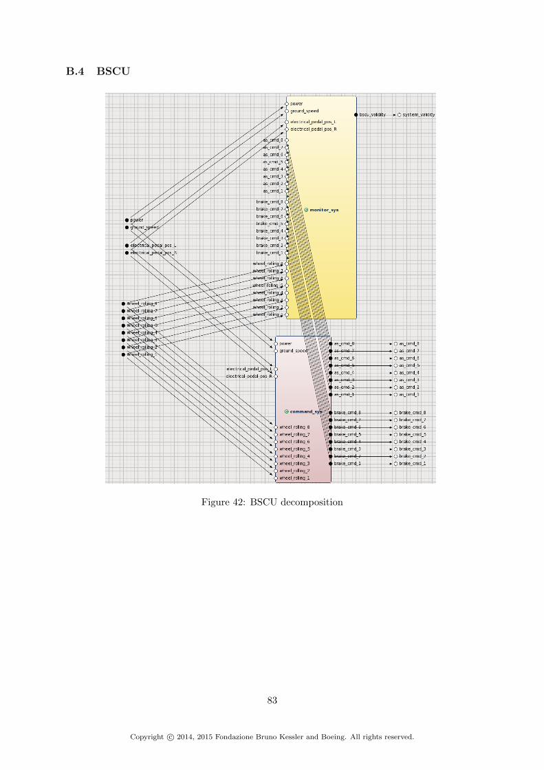
B.4 BSCU
Figure 42: BSCU decomposition
83
Copyright c© 2014, 2015 Fondazione Bruno Kessler and Boeing. All rights reserved.

B.5 Command System
Figure 43: Command System decomposition
84
Copyright c© 2014, 2015 Fondazione Bruno Kessler and Boeing. All rights reserved.

B.6 Wheel Pair Command System
Figure 44: Wheel Command System decomposition
85
Copyright c© 2014, 2015 Fondazione Bruno Kessler and Boeing. All rights reserved.

B.7 Physical System
Figure 45: Physical System decomposition
86
Copyright c© 2014, 2015 Fondazione Bruno Kessler and Boeing. All rights reserved.

B.8 Wheel Brake
Figure 46: Wheel Brake decomposition
87
Copyright c© 2014, 2015 Fondazione Bruno Kessler and Boeing. All rights reserved.

C WBS Arch2 architecture decomposition
C.1 Environment
Figure 47: Environment of the Wheel Brake System
88
Copyright c© 2014, 2015 Fondazione Bruno Kessler and Boeing. All rights reserved.

C.2 Wheel Brake System
Figure 48: Wheel Brake System decomposition
89
Copyright c© 2014, 2015 Fondazione Bruno Kessler and Boeing. All rights reserved.

C.3 Control System
Figure 49: Control System decomposition
90
Copyright c© 2014, 2015 Fondazione Bruno Kessler and Boeing. All rights reserved.

C.4 BSCU
Figure 50: BSCU decomposition
91
Copyright c© 2014, 2015 Fondazione Bruno Kessler and Boeing. All rights reserved.

C.5 Command System
Figure 51: Command System decomposition
92
Copyright c© 2014, 2015 Fondazione Bruno Kessler and Boeing. All rights reserved.

C.6 Wheel Pair Command System
Figure 52: Wheel Pair Command System decomposition
93
Copyright c© 2014, 2015 Fondazione Bruno Kessler and Boeing. All rights reserved.
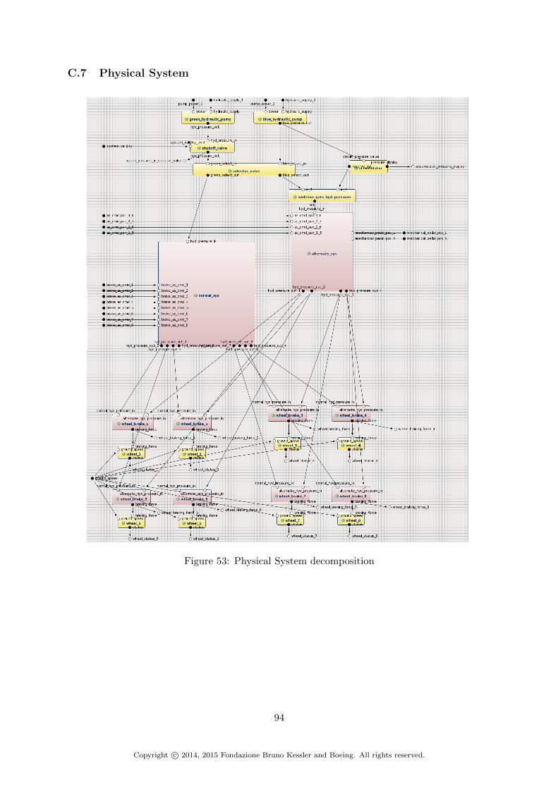
C.7 Physical System
Figure 53: Physical System decomposition
94
Copyright c© 2014, 2015 Fondazione Bruno Kessler and Boeing. All rights reserved.

C.8 Normal Brake System
Figure 54: Normal Brake System decomposition
95
Copyright c© 2014, 2015 Fondazione Bruno Kessler and Boeing. All rights reserved.

C.9 Alternate Brake System
Figure 55: Alternate Brake System decomposition
96
Copyright c© 2014, 2015 Fondazione Bruno Kessler and Boeing. All rights reserved.
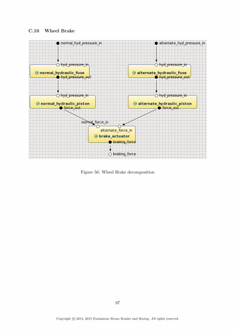
C.10 Wheel Brake
Figure 56: Wheel Brake decomposition
97
Copyright c© 2014, 2015 Fondazione Bruno Kessler and Boeing. All rights reserved.

D WBS Arch2bis architecture decomposition
D.1 Environment
Figure 57: Environment of the Wheel Brake System
98
Copyright c© 2014, 2015 Fondazione Bruno Kessler and Boeing. All rights reserved.
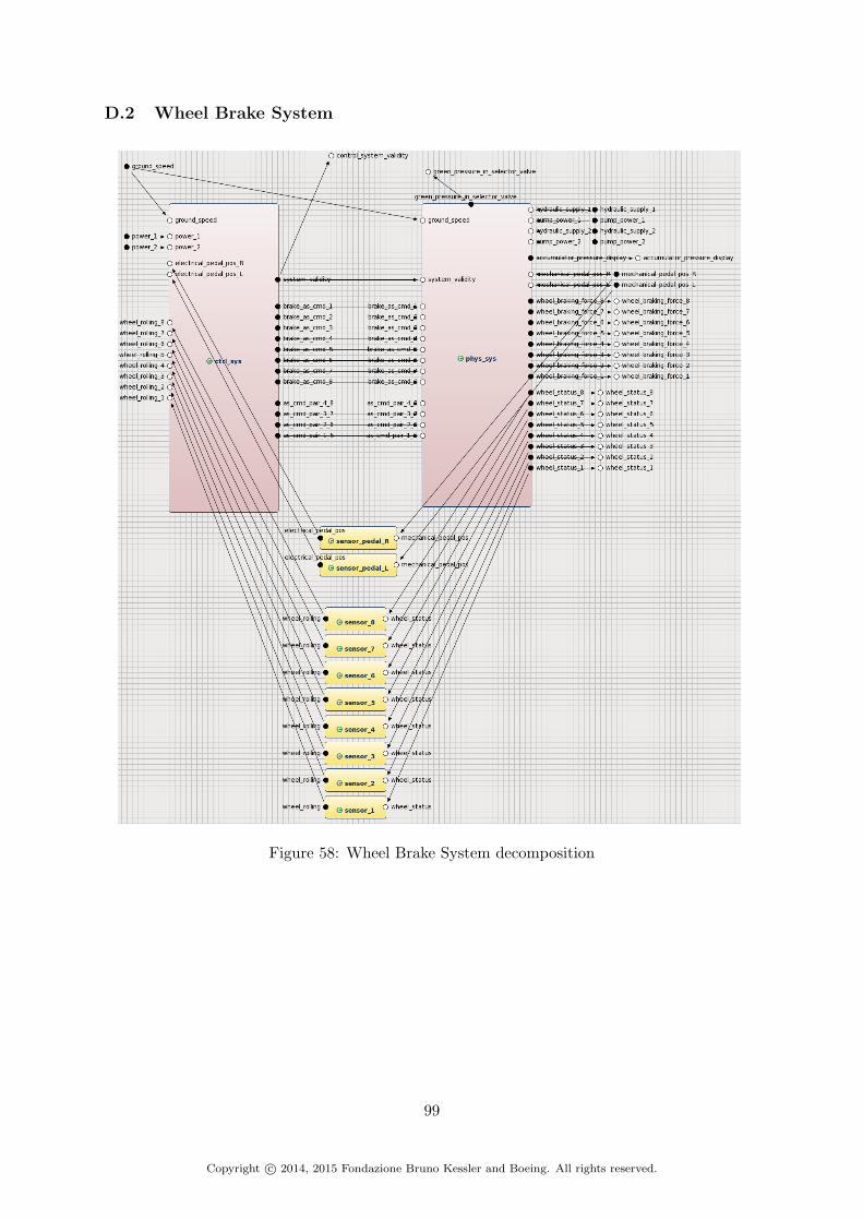
D.2 Wheel Brake System
Figure 58: Wheel Brake System decomposition
99
Copyright c© 2014, 2015 Fondazione Bruno Kessler and Boeing. All rights reserved.

D.3 Control System
Figure 59: Control System decomposition
100
Copyright c© 2014, 2015 Fondazione Bruno Kessler and Boeing. All rights reserved.

D.4 BSCU
Figure 60: BSCU decomposition
101
Copyright c© 2014, 2015 Fondazione Bruno Kessler and Boeing. All rights reserved.

D.5 Command System
Figure 61: Command System decomposition
102
Copyright c© 2014, 2015 Fondazione Bruno Kessler and Boeing. All rights reserved.

D.6 Wheel Pair Command System
Figure 62: Wheel Pair Command System decomposition
103
Copyright c© 2014, 2015 Fondazione Bruno Kessler and Boeing. All rights reserved.

D.7 Physical System
Figure 63: Physical System decomposition
104
Copyright c© 2014, 2015 Fondazione Bruno Kessler and Boeing. All rights reserved.

D.8 Normal Brake System
Figure 64: Normal Brake System decomposition
105
Copyright c© 2014, 2015 Fondazione Bruno Kessler and Boeing. All rights reserved.
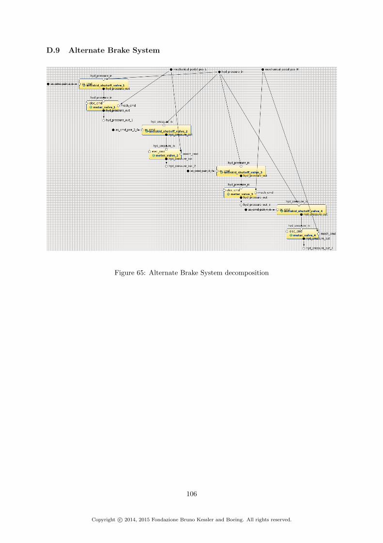
D.9 Alternate Brake System
Figure 65: Alternate Brake System decomposition
106
Copyright c© 2014, 2015 Fondazione Bruno Kessler and Boeing. All rights reserved.

D.10 Wheel Brake
Figure 66: Wheel Brake decomposition
107
Copyright c© 2014, 2015 Fondazione Bruno Kessler and Boeing. All rights reserved.

E WBS Arch3 architecture decomposition
E.1 Environment
Figure 67: Environment of the Wheel Brake System
108
Copyright c© 2014, 2015 Fondazione Bruno Kessler and Boeing. All rights reserved.

E.2 Wheel Brake System
Figure 68: Wheel Brake System decomposition
109
Copyright c© 2014, 2015 Fondazione Bruno Kessler and Boeing. All rights reserved.

E.3 Control System
Figure 69: Control System decomposition
110
Copyright c© 2014, 2015 Fondazione Bruno Kessler and Boeing. All rights reserved.

E.4 BSCU
Figure 70: BSCU decomposition
111
Copyright c© 2014, 2015 Fondazione Bruno Kessler and Boeing. All rights reserved.

E.5 Channel
Figure 71: Channel decomposition
112
Copyright c© 2014, 2015 Fondazione Bruno Kessler and Boeing. All rights reserved.

E.6 Command System
Figure 72: Command System decomposition
113
Copyright c© 2014, 2015 Fondazione Bruno Kessler and Boeing. All rights reserved.

E.7 Wheel Pair Command System
Figure 73: Wheel Pair Command System decomposition
114
Copyright c© 2014, 2015 Fondazione Bruno Kessler and Boeing. All rights reserved.

E.8 Physical System
Figure 74: Physical System decomposition
115
Copyright c© 2014, 2015 Fondazione Bruno Kessler and Boeing. All rights reserved.
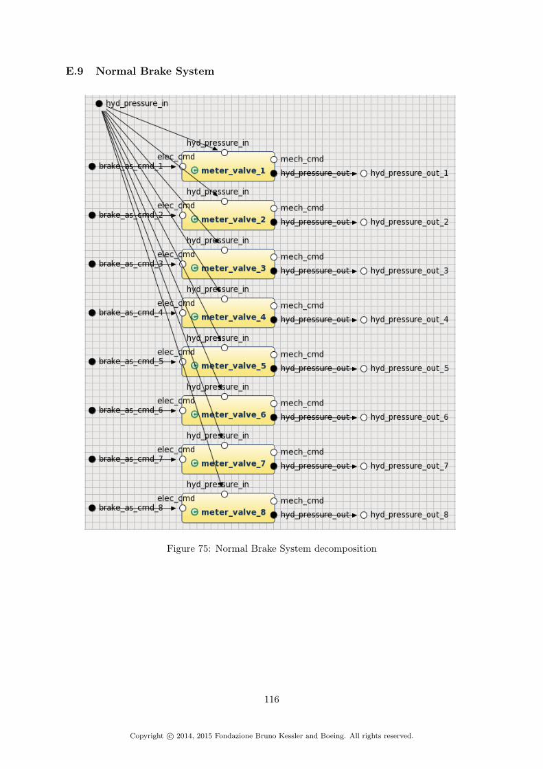
E.9 Normal Brake System
Figure 75: Normal Brake System decomposition
116
Copyright c© 2014, 2015 Fondazione Bruno Kessler and Boeing. All rights reserved.

E.10 Alternate Brake System
Figure 76: Alternate Brake System decomposition
117
Copyright c© 2014, 2015 Fondazione Bruno Kessler and Boeing. All rights reserved.
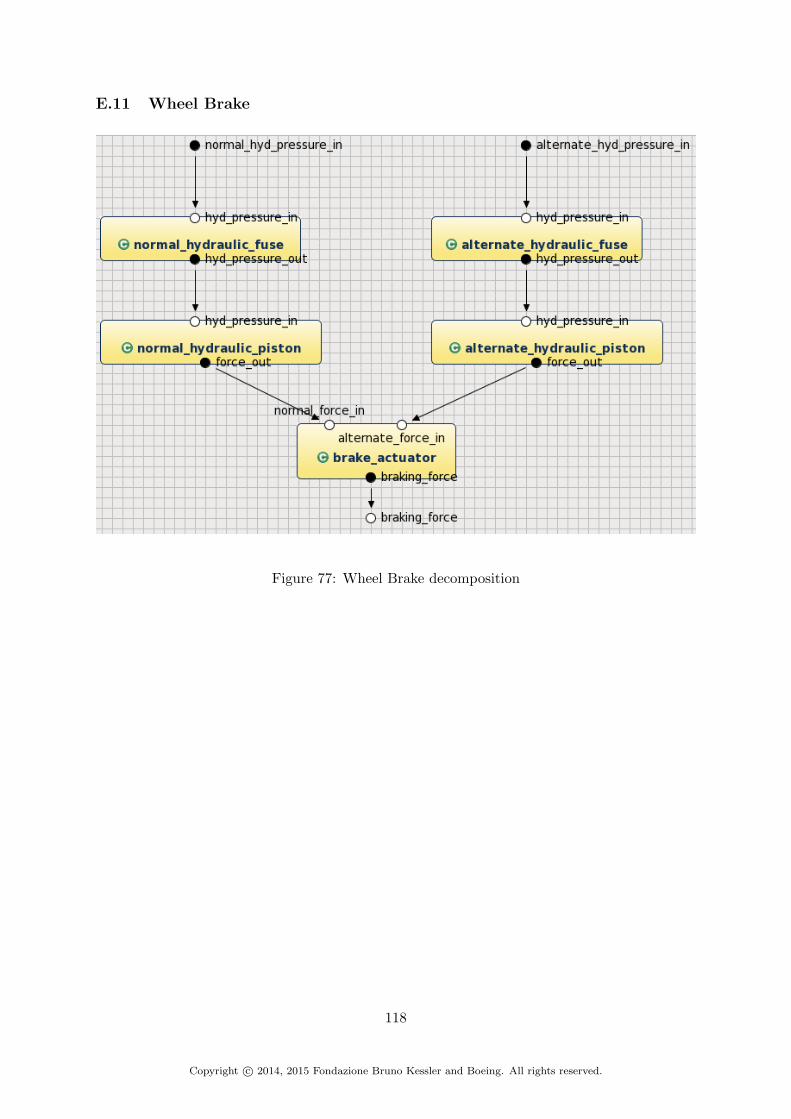
E.11 Wheel Brake
Figure 77: Wheel Brake decomposition
118
Copyright c© 2014, 2015 Fondazione Bruno Kessler and Boeing. All rights reserved.

F WBS Arch4 architecture decomposition
F.1 Environment
Figure 78: Environment of the Wheel Brake System
119
Copyright c© 2014, 2015 Fondazione Bruno Kessler and Boeing. All rights reserved.

F.2 Wheel Brake System
Figure 79: Wheel Brake System decomposition
120
Copyright c© 2014, 2015 Fondazione Bruno Kessler and Boeing. All rights reserved.

F.3 Control System
Figure 80: Control System decomposition
121
Copyright c© 2014, 2015 Fondazione Bruno Kessler and Boeing. All rights reserved.

F.4 BSCU
Figure 81: BSCU decomposition
122
Copyright c© 2014, 2015 Fondazione Bruno Kessler and Boeing. All rights reserved.

F.5 Channel
Figure 82: Channel decomposition
123
Copyright c© 2014, 2015 Fondazione Bruno Kessler and Boeing. All rights reserved.

F.6 Command System
Figure 83: Command System decomposition
124
Copyright c© 2014, 2015 Fondazione Bruno Kessler and Boeing. All rights reserved.

F.7 Wheel Pair Command System
Figure 84: Wheel Pair Command System decomposition
125
Copyright c© 2014, 2015 Fondazione Bruno Kessler and Boeing. All rights reserved.

F.8 Physical System
Figure 85: Physical System decomposition
126
Copyright c© 2014, 2015 Fondazione Bruno Kessler and Boeing. All rights reserved.

F.9 Normal Brake System
Figure 86: Normal Brake System decomposition
127
Copyright c© 2014, 2015 Fondazione Bruno Kessler and Boeing. All rights reserved.

F.10 Alternate Brake System
Figure 87: Alternate Brake System decomposition
128
Copyright c© 2014, 2015 Fondazione Bruno Kessler and Boeing. All rights reserved.

F.11 Wheel Brake
Figure 88: Wheel Brake decomposition
129
Copyright c© 2014, 2015 Fondazione Bruno Kessler and Boeing. All rights reserved.

G Hierarchical Fault Tree example
Figure 89: Example of generated Hierarchical Fault Tree
130
Copyright c© 2014, 2015 Fondazione Bruno Kessler and Boeing. All rights reserved.

H WBS Arch1 MBSA results
Arch/Prop/Faults Prob |mcs| = 1 |mcs| = 2 |mcs| = 3 |mcs| = 4 |mcs| = 5 full
arch1
S18-WBS-R-0321
full faults 1.45e-04 17 2 0 0 0 Nset1 1.75e-09 0 2 0 0 0 Nset2 0.00e+00 0 0 0 0 0 Nset3 1.45e-04 17 0 0 0 0 Yset4 8.00e-07 1 0 0 0 0 Yset5 1.00e-40 0 0 0 0 0 Yset6 1.44e-04 16 0 0 0 0 N
S18-WBS-R-0322-left
full faults 1.45e-04 17 2 0 28561 0 Yset1 1.75e-09 0 2 0 1296 0 Yset2 4.65e-17 0 0 0 625 0 Yset3 1.45e-04 17 0 0 0 0 Yset4 8.00e-07 1 0 0 0 0 Yset5 1.00e-20 0 0 0 16 0 Yset6 1.44e-04 16 0 0 1296 0 Y
S18-WBS-R-0322-right
full faults 1.45e-04 17 2 0 28561 0 Yset1 1.75e-09 0 2 0 1296 0 Yset2 4.65e-17 0 0 0 625 0 Yset3 1.45e-04 17 0 0 0 0 Yset4 8.00e-07 1 0 0 0 0 Yset5 1.00e-20 0 0 0 16 0 Yset6 1.44e-04 16 0 0 1296 0 Y
S18-WBS-R-0323
full faults 0.00e+00 0 0 0 0 0 Nset1 0.00e+00 0 0 0 0 0 Nset2 0.00e+00 0 0 0 0 0 Nset3 1.85e-81 0 0 0 0 0 Yset4 0.00e+00 0 0 0 0 0 Yset5 9.77e-54 0 0 0 0 0 Yset6 0.00e+00 0 0 0 0 0 N
S18-WBS-R-0324
full faults 2.50e-11 0 1 0 0 8192 Nset1 8.17e-41 0 0 0 0 0 Yset2 0.00e+00 0 0 0 0 0 Nset3 4.30e-41 0 0 0 0 0 Yset4 0.00e+00 0 0 0 0 0 Yset5 2.50e-11 0 1 0 0 0 Yset6 0.00e+00 0 0 0 0 0 N
S18-WBS-R-0325-wheel1
full faults 9.63e-05 9 0 0 0 0 Yset1 9.75e-06 3 0 0 0 0 Yset2 7.26e-05 4 0 0 0 0 Yset3 9.00e-06 1 0 0 0 0 Yset4 0.00e+00 0 0 0 0 0 Yset5 5.00e-06 1 0 0 0 0 Yset6 1.87e-05 4 0 0 0 0 Y
S18-WBS-R-0325-wheel2
full faults 9.63e-05 9 0 0 0 0 Yset1 9.75e-06 3 0 0 0 0 Yset2 7.26e-05 4 0 0 0 0 Yset3 9.00e-06 1 0 0 0 0 Yset4 0.00e+00 0 0 0 0 0 Yset5 5.00e-06 1 0 0 0 0 Yset6 1.87e-05 4 0 0 0 0 Y
S18-WBS-R-0325-wheel3
full faults 9.63e-05 9 0 0 0 0 Yset1 9.75e-06 3 0 0 0 0 Yset2 7.26e-05 4 0 0 0 0 Yset3 9.00e-06 1 0 0 0 0 Yset4 0.00e+00 0 0 0 0 0 Yset5 5.00e-06 1 0 0 0 0 Yset6 1.87e-05 4 0 0 0 0 Y
S18-WBS-R-0325-wheel4
full faults 9.63e-05 9 0 0 0 0 Yset1 9.75e-06 3 0 0 0 0 Yset2 7.26e-05 4 0 0 0 0 Yset3 9.00e-06 1 0 0 0 0 Yset4 0.00e+00 0 0 0 0 0 Yset5 5.00e-06 1 0 0 0 0 Yset6 1.87e-05 4 0 0 0 0 Y
S18-WBS-R-0325-wheel5
full faults 9.63e-05 9 0 0 0 0 Yset1 9.75e-06 3 0 0 0 0 Yset2 7.26e-05 4 0 0 0 0 Yset3 9.00e-06 1 0 0 0 0 Yset4 0.00e+00 0 0 0 0 0 Yset5 5.00e-06 1 0 0 0 0 Yset6 1.87e-05 4 0 0 0 0 Y
S18-WBS-R-0325-wheel6
full faults 9.63e-05 9 0 0 0 0 Yset1 9.75e-06 3 0 0 0 0 Yset2 7.26e-05 4 0 0 0 0 Yset3 9.00e-06 1 0 0 0 0 Yset4 0.00e+00 0 0 0 0 0 Yset5 5.00e-06 1 0 0 0 0 Yset6 1.87e-05 4 0 0 0 0 Y
S18-WBS-R-0325-wheel7
full faults 9.63e-05 9 0 0 0 0 Yset1 9.75e-06 3 0 0 0 0 Yset2 7.26e-05 4 0 0 0 0 Yset3 9.00e-06 1 0 0 0 0 Yset4 0.00e+00 0 0 0 0 0 Yset5 5.00e-06 1 0 0 0 0 Yset6 1.87e-05 4 0 0 0 0 Y
S18-WBS-R-0325-wheel8
full faults 9.63e-05 9 0 0 0 0 Yset1 9.75e-06 3 0 0 0 0 Yset2 7.26e-05 4 0 0 0 0 Yset3 9.00e-06 1 0 0 0 0 Yset4 0.00e+00 0 0 0 0 0 Yset5 5.00e-06 1 0 0 0 0 Y
131
Copyright c© 2014, 2015 Fondazione Bruno Kessler and Boeing. All rights reserved.
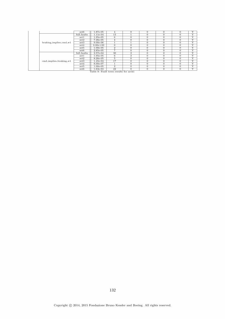
set6 1.87e-05 4 0 0 0 0 Y
braking implies cmd w1
full faults 1.11e-04 13 1 0 0 0 Yset1 1.95e-05 6 0 0 0 0 Yset2 7.26e-05 4 0 0 0 0 Yset3 9.00e-06 1 1 0 0 0 Yset4 0.00e+00 0 0 0 0 0 Yset5 1.00e-05 2 0 0 0 0 Yset6 2.85e-05 7 0 0 0 0 Y
cmd implies braking w1
full faults 2.57e-04 30 2 0 0 0 Yset1 1.95e-05 6 2 0 0 0 Yset2 8.26e-05 5 0 0 0 0 Yset3 1.45e-04 17 0 0 0 0 Yset4 8.00e-07 1 0 0 0 0 Yset5 1.00e-05 2 0 0 0 0 Yset6 1.63e-04 22 0 0 0 0 Y
Table 9: Fault trees results for arch1
132
Copyright c© 2014, 2015 Fondazione Bruno Kessler and Boeing. All rights reserved.

I WBS Arch2 MBSA results
Arch/Prop/Faults Prob |mcs| = 1 |mcs| = 2 |mcs| = 3 |mcs| = 4 |mcs| = 5 full
arch2
S18-WBS-R-0321
full faults 4.51e-10 0 6 1252 629 - Nset1 3.50e-10 0 2 2 0 2592 Yset2 0.00e+00 0 0 0 0 0 Nset3 5.25e-27 0 0 0 0 1 Yset4 1.83e-32 0 0 0 0 0 Yset5 1.00e-10 0 4 0 0 64 Yset6 0.00e+00 0 0 0 0 0 N
S18-WBS-R-0322-left
full faults 1.00e-05 2 2 732 47583 - Nset1 3.50e-10 0 2 74 81 0 Yset2 4.65e-17 0 0 0 625 0 Yset3 6.48e-17 0 0 1 33 216 Yset4 1.08e-22 0 0 0 2 0 Yset5 1.00e-05 2 0 0 16 0 Yset6 1.77e-17 0 0 0 20817 0 Y
S18-WBS-R-0322-right
full faults 1.00e-05 2 2 732 47583 - Nset1 3.50e-10 0 2 74 81 0 Yset2 4.65e-17 0 0 0 625 0 Yset3 6.48e-17 0 0 1 33 216 Yset4 1.08e-22 0 0 0 2 0 Yset5 1.00e-05 2 0 0 16 0 Yset6 1.77e-17 0 0 0 20817 0 Y
S18-WBS-R-0323
full faults 0.00e+00 0 0 0 0 0 Nset1 0.00e+00 0 0 0 0 0 Nset2 0.00e+00 0 0 0 0 0 Nset3 3.44e-47 0 0 0 0 0 Yset4 0.00e+00 0 0 0 0 0 Yset5 9.77e-54 0 0 0 0 0 Yset6 1.05e-28 0 0 0 0 0 Y
S18-WBS-R-0324
full faults 2.50e-11 0 1 0 38 10859 Nset1 1.04e-24 0 0 0 0 324 Yset2 0.00e+00 0 0 0 0 0 Nset3 5.25e-27 0 0 0 0 1 Yset4 0.00e+00 0 0 0 0 0 Yset5 2.50e-11 0 1 0 0 0 Yset6 4.22e-28 0 0 0 0 0 Y
S18-WBS-R-0325-wheel1
full faults 1.20e-04 9 19 2597 0 0 Yset1 9.75e-06 3 12 0 0 0 Yset2 1.06e-04 5 0 0 0 0 Yset3 1.44e-11 0 2 50 0 0 Yset4 0.00e+00 0 0 0 0 0 Yset5 5.00e-06 1 0 0 0 0 Yset6 9.75e-06 3 0 1728 0 0 Y
S18-WBS-R-0325-wheel2
full faults 1.20e-04 9 19 2597 0 0 Yset1 9.75e-06 3 12 0 0 0 Yset2 1.06e-04 5 0 0 0 0 Yset3 1.44e-11 0 2 50 0 0 Yset4 0.00e+00 0 0 0 0 0 Yset5 5.00e-06 1 0 0 0 0 Yset6 9.75e-06 3 0 1728 0 0 Y
S18-WBS-R-0325-wheel3
full faults 1.20e-04 9 19 2597 0 0 Yset1 9.75e-06 3 12 0 0 0 Yset2 1.06e-04 5 0 0 0 0 Yset3 1.44e-11 0 2 50 0 0 Yset4 0.00e+00 0 0 0 0 0 Yset5 5.00e-06 1 0 0 0 0 Yset6 9.75e-06 3 0 1728 0 0 Y
S18-WBS-R-0325-wheel4
full faults 1.20e-04 9 19 2597 0 0 Yset1 9.75e-06 3 12 0 0 0 Yset2 1.06e-04 5 0 0 0 0 Yset3 1.44e-11 0 2 50 0 0 Yset4 0.00e+00 0 0 0 0 0 Yset5 5.00e-06 1 0 0 0 0 Yset6 9.75e-06 3 0 1728 0 0 Y
S18-WBS-R-0325-wheel5
full faults 1.20e-04 9 19 2597 0 0 Yset1 9.75e-06 3 12 0 0 0 Yset2 1.06e-04 5 0 0 0 0 Yset3 1.44e-11 0 2 50 0 0 Yset4 0.00e+00 0 0 0 0 0 Yset5 5.00e-06 1 0 0 0 0 Yset6 9.75e-06 3 0 1728 0 0 Y
S18-WBS-R-0325-wheel6
full faults 1.20e-04 9 19 2597 0 0 Yset1 9.75e-06 3 12 0 0 0 Yset2 1.06e-04 5 0 0 0 0 Yset3 1.44e-11 0 2 50 0 0 Yset4 0.00e+00 0 0 0 0 0 Yset5 5.00e-06 1 0 0 0 0 Yset6 9.75e-06 3 0 1728 0 0 Y
S18-WBS-R-0325-wheel7
full faults 1.20e-04 9 19 2597 0 0 Yset1 9.75e-06 3 12 0 0 0 Yset2 1.06e-04 5 0 0 0 0 Yset3 1.44e-11 0 2 50 0 0 Yset4 0.00e+00 0 0 0 0 0 Yset5 5.00e-06 1 0 0 0 0 Yset6 9.75e-06 3 0 1728 0 0 Y
S18-WBS-R-0325-wheel8
full faults 1.20e-04 9 19 2597 0 0 Yset1 9.75e-06 3 12 0 0 0 Yset2 1.06e-04 5 0 0 0 0 Yset3 1.44e-11 0 2 50 0 0 Yset4 0.00e+00 0 0 0 0 0 Yset5 5.00e-06 1 0 0 0 0 Y
133
Copyright c© 2014, 2015 Fondazione Bruno Kessler and Boeing. All rights reserved.

set6 9.75e-06 3 0 1728 0 0 Y
braking implies cmd w1
full faults 1.25e-04 10 40 2651 7395 9636 Yset1 9.75e-06 3 24 0 0 0 Yset2 1.06e-04 5 0 0 0 0 Yset3 2.16e-11 0 3 75 0 0 Yset4 0.00e+00 0 0 0 0 0 Yset5 1.00e-05 2 0 0 0 0 Yset6 9.75e-06 3 0 1728 0 0 Y
cmd implies braking w1
full faults 1.13e-04 13 30 8053 3815 2873 Yset1 9.75e-06 3 14 2 0 0 Yset2 8.26e-05 5 0 0 0 0 Yset3 2.16e-11 0 3 75 0 0 Yset4 6.50e-07 1 0 2 0 0 Yset5 2.00e-05 4 0 0 0 0 Yset6 9.75e-06 3 0 3456 0 0 Y
Table 10: Fault trees results for arch2
134
Copyright c© 2014, 2015 Fondazione Bruno Kessler and Boeing. All rights reserved.

J WBS Arch2bis MBSA results
Arch/Prop/Faults Prob |mcs| = 1 |mcs| = 2 |mcs| = 3 |mcs| = 4 |mcs| = 5 full
arch2bis
S18-WBS-R-0321
full faults 4.51e-10 0 6 627 629 - Nset1 3.50e-10 0 2 2 0 2592 Yset2 0.00e+00 0 0 0 0 0 Nset3 5.25e-27 0 0 0 0 1 Yset4 1.83e-32 0 0 0 0 0 Yset5 1.00e-10 0 4 0 0 64 Yset6 0.00e+00 0 0 0 0 0 N
S18-WBS-R-0322-left
full faults 1.00e-05 2 2 203 46287 - Nset1 3.50e-10 0 2 74 81 0 Yset2 4.65e-17 0 0 0 625 0 Yset3 6.48e-17 0 0 1 33 216 Yset4 1.08e-22 0 0 0 2 0 Yset5 1.00e-05 2 0 0 16 0 Yset6 1.77e-17 0 0 0 20817 0 Y
S18-WBS-R-0322-right
full faults 1.00e-05 2 2 203 46287 - Nset1 3.50e-10 0 2 74 81 0 Yset2 4.65e-17 0 0 0 625 0 Yset3 6.48e-17 0 0 1 33 216 Yset4 1.08e-22 0 0 0 2 0 Yset5 1.00e-05 2 0 0 16 0 Yset6 1.77e-17 0 0 0 20817 0 Y
S18-WBS-R-0323
full faults 0.00e+00 0 0 0 0 0 Nset1 8.17e-41 0 0 0 0 0 Yset2 0.00e+00 0 0 0 0 0 Nset3 3.44e-47 0 0 0 0 0 Yset4 0.00e+00 0 0 0 0 0 Yset5 9.77e-54 0 0 0 0 0 Yset6 1.05e-28 0 0 0 0 0 Y
S18-WBS-R-0324
full faults 2.50e-11 0 1 0 2 8729 Nset1 3.16e-25 0 0 0 0 162 Yset2 0.00e+00 0 0 0 0 0 Nset3 5.25e-27 0 0 0 0 1 Yset4 0.00e+00 0 0 0 0 0 Yset5 2.50e-11 0 1 0 0 0 Yset6 4.22e-28 0 0 0 0 0 Y
S18-WBS-R-0325-wheel1
full faults 1.20e-04 9 12 2596 0 0 Yset1 9.75e-06 3 6 0 0 0 Yset2 1.06e-04 5 0 0 0 0 Yset3 1.44e-11 0 2 50 0 0 Yset4 0.00e+00 0 0 0 0 0 Yset5 5.00e-06 1 0 0 0 0 Yset6 9.75e-06 3 0 1728 0 0 Y
S18-WBS-R-0325-wheel2
full faults 1.20e-04 9 12 2596 0 0 Yset1 9.75e-06 3 6 0 0 0 Yset2 1.06e-04 5 0 0 0 0 Yset3 1.44e-11 0 2 50 0 0 Yset4 0.00e+00 0 0 0 0 0 Yset5 5.00e-06 1 0 0 0 0 Yset6 9.75e-06 3 0 1728 0 0 Y
S18-WBS-R-0325-wheel3
full faults 1.20e-04 9 12 2596 0 0 Yset1 9.75e-06 3 6 0 0 0 Yset2 1.06e-04 5 0 0 0 0 Yset3 1.44e-11 0 2 50 0 0 Yset4 0.00e+00 0 0 0 0 0 Yset5 5.00e-06 1 0 0 0 0 Yset6 9.75e-06 3 0 1728 0 0 Y
S18-WBS-R-0325-wheel4
full faults 1.20e-04 9 12 2596 0 0 Yset1 9.75e-06 3 6 0 0 0 Yset2 1.06e-04 5 0 0 0 0 Yset3 1.44e-11 0 2 50 0 0 Yset4 0.00e+00 0 0 0 0 0 Yset5 5.00e-06 1 0 0 0 0 Yset6 9.75e-06 3 0 1728 0 0 Y
S18-WBS-R-0325-wheel5
full faults 1.20e-04 9 12 2596 0 0 Yset1 9.75e-06 3 6 0 0 0 Yset2 1.06e-04 5 0 0 0 0 Yset3 1.44e-11 0 2 50 0 0 Yset4 0.00e+00 0 0 0 0 0 Yset5 5.00e-06 1 0 0 0 0 Yset6 9.75e-06 3 0 1728 0 0 Y
S18-WBS-R-0325-wheel6
full faults 1.20e-04 9 12 2596 0 0 Yset1 9.75e-06 3 6 0 0 0 Yset2 1.06e-04 5 0 0 0 0 Yset3 1.44e-11 0 2 50 0 0 Yset4 0.00e+00 0 0 0 0 0 Yset5 5.00e-06 1 0 0 0 0 Yset6 9.75e-06 3 0 1728 0 0 Y
S18-WBS-R-0325-wheel7
full faults 1.20e-04 9 12 2596 0 0 Yset1 9.75e-06 3 6 0 0 0 Yset2 1.06e-04 5 0 0 0 0 Yset3 1.44e-11 0 2 50 0 0 Yset4 0.00e+00 0 0 0 0 0 Yset5 5.00e-06 1 0 0 0 0 Yset6 9.75e-06 3 0 1728 0 0 Y
S18-WBS-R-0325-wheel8
full faults 1.20e-04 9 12 2596 0 0 Yset1 9.75e-06 3 6 0 0 0 Yset2 1.06e-04 5 0 0 0 0 Yset3 1.44e-11 0 2 50 0 0 Yset4 0.00e+00 0 0 0 0 0 Yset5 5.00e-06 1 0 0 0 0 Y
135
Copyright c© 2014, 2015 Fondazione Bruno Kessler and Boeing. All rights reserved.

set6 9.75e-06 3 0 1728 0 0 Y
braking implies cmd w1
full faults 1.25e-04 10 24 2647 4530 59 Yset1 9.75e-06 3 12 0 0 0 Yset2 1.06e-04 5 0 0 0 0 Yset3 2.16e-11 0 3 75 0 0 Yset4 0.00e+00 0 0 0 0 0 Yset5 1.00e-05 2 0 0 0 0 Yset6 9.75e-06 3 0 1728 0 0 Y
cmd implies braking w1
full faults 1.13e-04 13 30 7428 3815 1768 Yset1 9.75e-06 3 14 2 0 0 Yset2 8.26e-05 5 0 0 0 0 Yset3 2.16e-11 0 3 75 0 0 Yset4 6.50e-07 1 0 2 0 0 Yset5 2.00e-05 4 0 0 0 0 Yset6 9.75e-06 3 0 3456 0 0 Y
Table 11: Fault trees results for arch2bis
136
Copyright c© 2014, 2015 Fondazione Bruno Kessler and Boeing. All rights reserved.

K WBS Arch3 MBSA results
Arch/Prop/Faults Prob |mcs| = 1 |mcs| = 2 |mcs| = 3 |mcs| = 4 |mcs| = 5 full
arch3
S18-WBS-R-0321
full faults 4.51e-10 0 6 1252 629 - Nset1 3.50e-10 0 2 2 0 2592 Yset2 0.00e+00 0 0 0 0 0 Nset3 5.25e-27 0 0 0 0 1 Yset4 1.83e-32 0 0 0 0 0 Yset5 1.00e-10 0 4 0 0 64 Yset6 0.00e+00 0 0 0 0 0 N
S18-WBS-R-0322-left
full faults 1.00e-05 2 2 732 47583 - Nset1 3.50e-10 0 2 74 81 0 Yset2 4.65e-17 0 0 0 625 0 Yset3 6.48e-17 0 0 1 33 216 Yset4 1.08e-22 0 0 0 2 0 Yset5 1.00e-05 2 0 0 16 0 Yset6 1.77e-17 0 0 0 20817 0 Y
S18-WBS-R-0322-right
full faults 1.00e-05 2 2 732 47583 - Nset1 3.50e-10 0 2 74 81 0 Yset2 4.65e-17 0 0 0 625 0 Yset3 6.48e-17 0 0 1 33 216 Yset4 1.08e-22 0 0 0 2 0 Yset5 1.00e-05 2 0 0 16 0 Yset6 1.77e-17 0 0 0 20817 0 Y
S18-WBS-R-0323
full faults 0.00e+00 0 0 0 0 0 Nset1 0.00e+00 0 0 0 0 0 Nset2 0.00e+00 0 0 0 0 0 Nset3 3.44e-47 0 0 0 0 0 Yset4 0.00e+00 0 0 0 0 0 Yset5 9.77e-54 0 0 0 0 0 Yset6 1.05e-28 0 0 0 0 0 Y
S18-WBS-R-0324
full faults 2.50e-11 0 1 0 38 10859 Nset1 1.04e-24 0 0 0 0 324 Yset2 0.00e+00 0 0 0 0 0 Nset3 5.25e-27 0 0 0 0 1 Yset4 0.00e+00 0 0 0 0 0 Yset5 2.50e-11 0 1 0 0 0 Yset6 4.22e-28 0 0 0 0 0 Y
S18-WBS-R-0325-wheel1
full faults 1.20e-04 9 19 2597 0 0 Yset1 9.75e-06 3 12 0 0 0 Yset2 1.06e-04 5 0 0 0 0 Yset3 1.44e-11 0 2 50 0 0 Yset4 0.00e+00 0 0 0 0 0 Yset5 5.00e-06 1 0 0 0 0 Yset6 9.75e-06 3 0 1728 0 0 Y
S18-WBS-R-0325-wheel2
full faults 1.20e-04 9 19 2597 0 0 Yset1 9.75e-06 3 12 0 0 0 Yset2 1.06e-04 5 0 0 0 0 Yset3 1.44e-11 0 2 50 0 0 Yset4 0.00e+00 0 0 0 0 0 Yset5 5.00e-06 1 0 0 0 0 Yset6 9.75e-06 3 0 1728 0 0 Y
S18-WBS-R-0325-wheel3
full faults 1.20e-04 9 19 2597 0 0 Yset1 9.75e-06 3 12 0 0 0 Yset2 1.06e-04 5 0 0 0 0 Yset3 1.44e-11 0 2 50 0 0 Yset4 0.00e+00 0 0 0 0 0 Yset5 5.00e-06 1 0 0 0 0 Yset6 9.75e-06 3 0 1728 0 0 Y
S18-WBS-R-0325-wheel4
full faults 1.20e-04 9 19 2597 0 0 Yset1 9.75e-06 3 12 0 0 0 Yset2 1.06e-04 5 0 0 0 0 Yset3 1.44e-11 0 2 50 0 0 Yset4 0.00e+00 0 0 0 0 0 Yset5 5.00e-06 1 0 0 0 0 Yset6 9.75e-06 3 0 1728 0 0 Y
S18-WBS-R-0325-wheel5
full faults 1.20e-04 9 19 2597 0 0 Yset1 9.75e-06 3 12 0 0 0 Yset2 1.06e-04 5 0 0 0 0 Yset3 1.44e-11 0 2 50 0 0 Yset4 0.00e+00 0 0 0 0 0 Yset5 5.00e-06 1 0 0 0 0 Yset6 9.75e-06 3 0 1728 0 0 Y
S18-WBS-R-0325-wheel6
full faults 1.20e-04 9 19 2597 0 0 Yset1 9.75e-06 3 12 0 0 0 Yset2 1.06e-04 5 0 0 0 0 Yset3 1.44e-11 0 2 50 0 0 Yset4 0.00e+00 0 0 0 0 0 Yset5 5.00e-06 1 0 0 0 0 Yset6 9.75e-06 3 0 1728 0 0 Y
S18-WBS-R-0325-wheel7
full faults 1.20e-04 9 19 2597 0 0 Yset1 9.75e-06 3 12 0 0 0 Yset2 1.06e-04 5 0 0 0 0 Yset3 1.44e-11 0 2 50 0 0 Yset4 0.00e+00 0 0 0 0 0 Yset5 5.00e-06 1 0 0 0 0 Yset6 9.75e-06 3 0 1728 0 0 Y
S18-WBS-R-0325-wheel8
full faults 1.20e-04 9 19 2597 0 0 Yset1 9.75e-06 3 12 0 0 0 Yset2 1.06e-04 5 0 0 0 0 Yset3 1.44e-11 0 2 50 0 0 Yset4 0.00e+00 0 0 0 0 0 Yset5 5.00e-06 1 0 0 0 0 Y
137
Copyright c© 2014, 2015 Fondazione Bruno Kessler and Boeing. All rights reserved.

set6 9.75e-06 3 0 1728 0 0 Y
braking implies cmd w1
full faults 1.25e-04 10 40 2651 7395 9636 Yset1 9.75e-06 3 24 0 0 0 Yset2 1.06e-04 5 0 0 0 0 Yset3 2.16e-11 0 3 75 0 0 Yset4 0.00e+00 0 0 0 0 0 Yset5 1.00e-05 2 0 0 0 0 Yset6 9.75e-06 3 0 1728 0 0 Y
cmd implies braking w1
full faults 1.13e-04 13 30 8053 3815 2873 Yset1 9.75e-06 3 14 2 0 0 Yset2 8.26e-05 5 0 0 0 0 Yset3 2.16e-11 0 3 75 0 0 Yset4 6.50e-07 1 0 2 0 0 Yset5 2.00e-05 4 0 0 0 0 Yset6 9.75e-06 3 0 3456 0 0 Y
Table 12: Fault trees results for arch3
138
Copyright c© 2014, 2015 Fondazione Bruno Kessler and Boeing. All rights reserved.

L WBS Arch4 MBSA results
Arch/Prop/Faults Prob |mcs| = 1 |mcs| = 2 |mcs| = 3 |mcs| = 4 |mcs| = 5 full
arch4
S18-WBS-R-0321
full faults 4.51e-10 0 6 627 629 - Nset1 3.50e-10 0 2 2 0 2592 Yset2 0.00e+00 0 0 0 0 0 Nset3 5.25e-27 0 0 0 0 1 Yset4 1.83e-32 0 0 0 0 0 Yset5 1.00e-10 0 4 0 0 64 Yset6 0.00e+00 0 0 0 0 0 N
S18-WBS-R-0322-left
full faults 1.00e-05 2 2 203 46287 - Nset1 3.50e-10 0 2 74 81 0 Yset2 4.65e-17 0 0 0 625 0 Yset3 6.48e-17 0 0 1 33 216 Yset4 1.08e-22 0 0 0 2 0 Yset5 1.00e-05 2 0 0 16 0 Yset6 1.77e-17 0 0 0 20817 0 Y
S18-WBS-R-0322-right
full faults 1.00e-05 2 2 203 46287 - Nset1 3.50e-10 0 2 74 81 0 Yset2 4.65e-17 0 0 0 625 0 Yset3 6.48e-17 0 0 1 33 216 Yset4 1.08e-22 0 0 0 2 0 Yset5 1.00e-05 2 0 0 16 0 Yset6 1.77e-17 0 0 0 20817 0 Y
S18-WBS-R-0323
full faults 0.00e+00 0 0 0 0 0 Nset1 8.17e-41 0 0 0 0 0 Yset2 0.00e+00 0 0 0 0 0 Nset3 3.44e-47 0 0 0 0 0 Yset4 0.00e+00 0 0 0 0 0 Yset5 9.77e-54 0 0 0 0 0 Yset6 1.05e-28 0 0 0 0 0 Y
S18-WBS-R-0324
full faults 2.50e-11 0 1 0 2 8729 Nset1 3.16e-25 0 0 0 0 162 Yset2 0.00e+00 0 0 0 0 0 Nset3 5.25e-27 0 0 0 0 1 Yset4 0.00e+00 0 0 0 0 0 Yset5 2.50e-11 0 1 0 0 0 Yset6 4.22e-28 0 0 0 0 0 Y
S18-WBS-R-0325-wheel1
full faults 1.20e-04 9 12 2596 0 0 Yset1 9.75e-06 3 6 0 0 0 Yset2 1.06e-04 5 0 0 0 0 Yset3 1.44e-11 0 2 50 0 0 Yset4 0.00e+00 0 0 0 0 0 Yset5 5.00e-06 1 0 0 0 0 Yset6 9.75e-06 3 0 1728 0 0 Y
S18-WBS-R-0325-wheel2
full faults 1.20e-04 9 12 2596 0 0 Yset1 9.75e-06 3 6 0 0 0 Yset2 1.06e-04 5 0 0 0 0 Yset3 1.44e-11 0 2 50 0 0 Yset4 0.00e+00 0 0 0 0 0 Yset5 5.00e-06 1 0 0 0 0 Yset6 9.75e-06 3 0 1728 0 0 Y
S18-WBS-R-0325-wheel3
full faults 1.20e-04 9 12 2596 0 0 Yset1 9.75e-06 3 6 0 0 0 Yset2 1.06e-04 5 0 0 0 0 Yset3 1.44e-11 0 2 50 0 0 Yset4 0.00e+00 0 0 0 0 0 Yset5 5.00e-06 1 0 0 0 0 Yset6 9.75e-06 3 0 1728 0 0 Y
S18-WBS-R-0325-wheel4
full faults 1.20e-04 9 12 2596 0 0 Yset1 9.75e-06 3 6 0 0 0 Yset2 1.06e-04 5 0 0 0 0 Yset3 1.44e-11 0 2 50 0 0 Yset4 0.00e+00 0 0 0 0 0 Yset5 5.00e-06 1 0 0 0 0 Yset6 9.75e-06 3 0 1728 0 0 Y
S18-WBS-R-0325-wheel5
full faults 1.20e-04 9 12 2596 0 0 Yset1 9.75e-06 3 6 0 0 0 Yset2 1.06e-04 5 0 0 0 0 Yset3 1.44e-11 0 2 50 0 0 Yset4 0.00e+00 0 0 0 0 0 Yset5 5.00e-06 1 0 0 0 0 Yset6 9.75e-06 3 0 1728 0 0 Y
S18-WBS-R-0325-wheel6
full faults 1.20e-04 9 12 2596 0 0 Yset1 9.75e-06 3 6 0 0 0 Yset2 1.06e-04 5 0 0 0 0 Yset3 1.44e-11 0 2 50 0 0 Yset4 0.00e+00 0 0 0 0 0 Yset5 5.00e-06 1 0 0 0 0 Yset6 9.75e-06 3 0 1728 0 0 Y
S18-WBS-R-0325-wheel7
full faults 1.20e-04 9 12 2596 0 0 Yset1 9.75e-06 3 6 0 0 0 Yset2 1.06e-04 5 0 0 0 0 Yset3 1.44e-11 0 2 50 0 0 Yset4 0.00e+00 0 0 0 0 0 Yset5 5.00e-06 1 0 0 0 0 Yset6 9.75e-06 3 0 1728 0 0 Y
S18-WBS-R-0325-wheel8
full faults 1.20e-04 9 12 2596 0 0 Yset1 9.75e-06 3 6 0 0 0 Yset2 1.06e-04 5 0 0 0 0 Yset3 1.44e-11 0 2 50 0 0 Yset4 0.00e+00 0 0 0 0 0 Yset5 5.00e-06 1 0 0 0 0 Y
139
Copyright c© 2014, 2015 Fondazione Bruno Kessler and Boeing. All rights reserved.
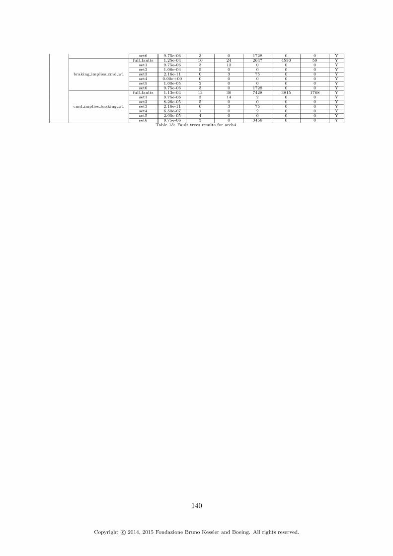
set6 9.75e-06 3 0 1728 0 0 Y
braking implies cmd w1
full faults 1.25e-04 10 24 2647 4530 59 Yset1 9.75e-06 3 12 0 0 0 Yset2 1.06e-04 5 0 0 0 0 Yset3 2.16e-11 0 3 75 0 0 Yset4 0.00e+00 0 0 0 0 0 Yset5 1.00e-05 2 0 0 0 0 Yset6 9.75e-06 3 0 1728 0 0 Y
cmd implies braking w1
full faults 1.13e-04 13 30 7428 3815 1768 Yset1 9.75e-06 3 14 2 0 0 Yset2 8.26e-05 5 0 0 0 0 Yset3 2.16e-11 0 3 75 0 0 Yset4 6.50e-07 1 0 2 0 0 Yset5 2.00e-05 4 0 0 0 0 Yset6 9.75e-06 3 0 3456 0 0 Y
Table 13: Fault trees results for arch4
140
Copyright c© 2014, 2015 Fondazione Bruno Kessler and Boeing. All rights reserved.

References
[1] Federal Aviation Administration. Advisory circular (ac) 25.1309-1a. http://rgl.faa.gov/Regulatory_and_Guidance_Library/rgAdvisoryCircular.nsf/list/AC%2025.1309-1A/$FILE/AC25.1309-1A.pdf, 1988.
[2] R. Cavada an A. Cimatti, M. Dorigatti, A. Griggio, A. Mariotti, A. Micheli, S. Mover,M. Roveri, and S. Tonetta. The nuXmv Symbolic Model Checker. In CAV. Springer, 2014.
[3] M. Bozzano and A. Villafiorita. The FSAP/NuSMV-SA Safety Analysis Platform. STTT,9(1):5–24, 2007.
[4] M. Bozzano and A. Villafiorita. Design and Safety Assessment of Critical Systems. CRCPress (Taylor and Francis), an Auerbach Book, 2010.
[5] Marco Bozzano, Alessandro Cimatti, Cristian Mattarei, and Stefano Tonetta. Formalsafety assessment via contract-based design. In Franck Cassez and Jean-Franois Raskin,editors, Automated Technology for Verification and Analysis, volume 8837 of Lecture Notesin Computer Science, pages 81–97. Springer International Publishing, 2014.
[6] Aaron R. Bradley. Sat-based model checking without unrolling. In Verification, ModelChecking, and Abstract Interpretation - 12th International Conference, VMCAI 2011,Austin, TX, USA, January 23-25, 2011. Proceedings, pages 70–87, 2011.
[7] A. Cimatti, M. Dorigatti, and S. Tonetta. Ocra: A tool for checking the refinement oftemporal contracts. In IEEE/ACM 28th International Conference on Automated SoftwareEngineering (ASE), pages 702–705, 2013.
[8] A. Cimatti, M. Roveri, and S. Tonetta. Requirements validation for hybrid systems. InComputer Aided Verification, pages 188–203. Springer, 2009.
[9] A. Cimatti and S. Tonetta. A property-based proof system for contract-based design. InSEAA, pages 21 –28, 2012.
[10] A. Cimatti and S. Tonetta. Contracts-refinement proof system for component-based em-bedded systems. Science of Computer Programming, 2014.
[11] W. Damm, H. Hungar, B. Josko, T. Peikenkamp, and I. Stierand. Using contract-basedcomponent specifications for virtual integration testing and architecture design. In DATE,pages 1023–1028, 2011.
[12] ESACS. The ESACS Project, Last retrieved on January 28, 2015. http://www.transport-research.info/web/projects/project_details.cfm?ID=2658.
[13] Federal Aviation Administration (FAA). Advisory Circular 20-174. http://www.faa.gov/documentLibrary/media/Advisory_Circular/AC%2020-174.pdf.
[14] Federal Aviation Administration (FAA). Advisory Circular 23-1309-1E. http://www.faa.gov/documentLibrary/media/Advisory_Circular/AC%2023.1309-1E.pdf.
[15] FBK. nuXmv: a new eXtended model verifier. Available at http://nuxmv.fbk.eu.
[16] FBK. OCRA: A tool for Contract-Based Analysis. Available at https://es.fbk.eu/tools/ocra/.
141
Copyright c© 2014, 2015 Fondazione Bruno Kessler and Boeing. All rights reserved.

[17] FBK. xSAP: eXtended Safety Analysis platform. Available at http://xsap.fbk.eu/.
[18] Embedded Systems Unit Fondazione Bruno Kessler (FBK). XSAP User Manual, 2014.
[19] ISAAC. The ISAAC Project, Last retrieved on January 28, 2015. http://ec.europa.eu/research/transport/projects/items/isaac_en.htm.
[20] A. Joshi and M.P.E. Heimdahl. Model-Based Safety Analysis of Simulink Models UsingSCADE Design Verifier. In R. Winther, B.A. Gran, and G. Dahll, editors, Proc. Conferenceon Computer Safety, Reliability and Security (SAFECOMP 2005), volume 3688 of LNCS,pages 122–135. Springer, 2005.
[21] A. Joshi, M.W. Whalen, and M.P.E. Heimdahl. Model-Based Safety Analysis Final Report.Technical Report NASA/CR-2006-213953, NASA, February 2006.
[22] MISSA. The MISSA Project, Last retrieved on January 28, 2015. http://www.missa-fp7.eu.
[23] Society of Automotive Engineers (SAE). ARP4761 Guidelines and Methods for Conductingthe Safety Assessment Process on Civil Airborne Systems and Equipment, December 1996.
[24] Society of Automotive Engineers (SAE). ARP 4754A, Guidelines for Development of CivilAircraft and Systems, December 2010.
[25] Society of Automotive Engineers (SAE). AIR 6110, Contiguous Aircraft/ System Devel-opment Process Example, December 2011.
142
Copyright c© 2014, 2015 Fondazione Bruno Kessler and Boeing. All rights reserved.