contract documents technical specifications for bid …
TRANSCRIPT

CONTRACT DOCUMENTS &
TECHNICAL SPECIFICATIONS FOR
BID 18-05 MUNICIPAL BUILDING FIRST FLOOR RENOVATION
FOR CITY OF KINGSVILLE, TEXAS
Jesus A Garza City Manager
Sam Fugate Mayor
Alfonso R Garcia Commissioner(s)
Noel Pena Arturo Pecos Edna Lopez
OCTOBER 30, 2017
Prepared by:
6262 Weber Road, Suite 310 Corpus Christi, Texas 78413
p: (361) 854-1471 f: (361) 854-1470

CITY OF KINGSVILLE MUNICIPAL BUILDING FIRST FLOOR RENOVATION
Table of Contents - Page 1 SNT Comm. No. 1609
10/31/17
TABLE OF CONTENTS
DIVISION 0 - BIDDING REQUIREMENTS
ADVERTISEMENT AND INVITATION FOR BIDDERS . . . . . . . . . . . . . . . . . . . . . . 1 INSTRUCTIONS TO BIDDERS . . . . . . . . . . . . . . . . . . . . . . . . . . . . . . . . . . . . . . . 4 COMPETITIVE SEALED PROPOSAL . . . . . . . . . . . . . . . . . . . . . . . . . . . . . . . . . . . . . . . . . 2 NON-COLLUSION AFFIDAVIT OF PRIME BIDDER . . . . . . . . . . . . . . . . . . . . . . . . 1 CERTIFICATION OF BIDDER REGARDING CIVIL RIGHT LAWS AND REGULATIONS . . . . . . . . . . . . . . . . . . . . . . . . . . 1
STANDARD FORM OF AGREEMENT . . . . . . . . . . . . . . . . . . . . . . . . . . . . . . . . . . . 5
EQUAL OPPORTUNITY CLAUSE . . . . . . . . . . . . . . . . . . . . . . . . . . . . . . . . . . . . . . 2 EQUAL OPPORTUNITY GUIDELINES FOR CONSTRUCTION CONTRACTORS . . . . . . . . 2 FEDERAL LABOR STANDARDS PROVISIONS (HUD-4010) . . . . . . . . . . . . . . . . . . . . . . . . 4 TITLE 29 PART 3 - LABOR . . . . . . . . . . . . . . . . . . . . . . . . . . . . . . . . . . . . . . . . . . . 6 SECTION 504 CERTIFICATION . . . . . . . . . . . . . . . . . . . . . . . . . . . . . . . . . . . . . . . . 1 CONCERNING LABOR STANDARDS AND PREVAILING WAGE REQUIREMENTS . . . . . 2 BID BOND . . . . . . . . . . . . . . . . . . . . . . . . . . . . . . . . . . . . . . . . . . . . . . . . . . . . . . . . . . . . . . 1 PAYMENT BOND . . . . . . . . . . . . . . . . . . . . . . . . . . . . . . . . . . . . . . . . . . . . . . . . . . . . 2 PERFORMANCE BOND . . . . . . . . . . . . . . . . . . . . . . . . . . . . . . . . . . . . . . . . . . . . . . 4 GENERAL CONDITIONS . . . . . . . . . . . . . . . . . . . . . . . . . . . . . . . . . . . . . . . . . . . . 18 SPECIAL CONDITIONS . . . . . . . . . . . . . . . . . . . . . . . . . . . . . . . . . . . . . . . . . . . . . 6 STATEMENT OF BIDDER’S QUALIFICATION . . . . . . . . . . . . . . . . . . . . . . . . . . . . 3 ATTORNEY’S REVIEW CERTIFICATION . . . . . . . . . . . . . . . . . . . . . . . . . . . . . . . 1
CONFLICT OF INTEREST QUESTIONNAIRE . . . . . . . . . . . . . . . . . . . . . . . . . . 3 CERTIFICATE OF INTERESTED PARTIES – FORM 1295 . . . . . . . . . . . . . . . . . . . . . . . 2
DIVISION 01 - GENERAL REQUIREMENTS
01 10 00 SUMMARY . . . . . . . . . . . . . . . . . . . . . . . . . . . . . . . . . . . . . . . . . . . . . . . . . . . . . . . . 3 01 20 00 PRICE AND PAYMENT PROCEDURES . . . . . . . . . . . . . . . . . . . . . . . . . . . . . . . . . 3 01 21 00 ALLOWANCES . . . . . . . . . . . . . . . . . . . . . . . . . . . . . . . . . . . . . . . . . . . . . . . . . . . . 2 01 23 00 ALTERNATES . . . . . . . . . . . . . . . . . . . . . . . . . . . . . . . . . . . . . . . . . . . . . . . . . . . . . 1 01 30 00 ADMINISTRATIVE REQUIREMENTS . . . . . . . . . . . . . . . . . . . . . . . . . . . . . . . . . . 4 01 40 00 QUALITY REQUIREMENTS . . . . . . . . . . . . . . . . . . . . . . . . . . . . . . . . . . . . . . . . . . 4 01 50 00 TEMPORARY FACILITIES AND CONTROLS . . . . . . . . . . . . . . . . . . . . . . . . . . . . . . . . . . 3 01 60 00 PRODUCT REQUIREMENTS . . . . . . . . . . . . . . . . . . . . . . . . . . . . . . . . . . . . . . . . 3
SUBSTITUTION REQUEST FORM . . . . . . . . . . . . . . . . . . . . . . . . . . . . . . . . . . . . . 2 01 70 00 EXECUTION AND CLOSEOUT REQUIREMENTS . . . . . . . . . . . . . . . . . . . . . . . . 7 01 78 00 CLOSEOUT SUBMITTALS . . . . . . . . . . . . . . . . . . . . . . . . . . . . . . . . . . . . . . . . . . . 4
EXHIBIT 1 – PROJECT CLOSEOUT CHECKLIST . . . . . . . . . . . . . . . . . . . . . . . . . 1

CITY OF KINGSVILLE MUNICIPAL BUILDING FIRST FLOOR RENOVATION
Table of Contents - Page 2 SNT Comm. No. 1609
10/31/17
DIVISION 02 – EXISTING CONDITIONS
02 11 33 ASBESTOS CONTAINING MATERIALS REMOVAL . . . . . . . . . . . . . . . . . . . . . . . 80 02 41 00 DEMOLITION . . . . . . . . . . . . . . . . . . . . . . . . . . . . . . . . . . . . . . . . . . . . . . . . . . . . . . 3
DIVISION 06 – WOOD, PLASTICS, AND COMPOSITES
06 10 00 ROUGH CARPENTRY . . . . . . . . . . . . . . . . . . . . . . . . . . . . . . . . . . . . . . . . . . . . . . . 4 06 20 00 FINISH CARPENTRY . . . . . . . . . . . . . . . . . . . . . . . . . . . . . . . . . . . . . . . . . . . . . . . . 2 06 41 00 CUSTOM CABINETS . . . . . . . . . . . . . . . . . . . . . . . . . . . . . . . . . . . . . . . . . . . . . . . . 4
DIVISION 07 - THERMAL AND MOISTURE PROTECTION
07 56 33 FLUID-APPLIED MEMBRANE FLASHING REPAIR . . . . . . . . . . . . . . . . . . . . . 5
07 62 00 SHEET METAL FLASHING AND TRIM . . . . . . . . . . . . . . . . . . . . . . . . . . . . . . . . . . 4
07 84 33 FIRESTOPPING . . . . . . . . . . . . . . . . . . . . . . . . . . . . . . . . . . . . . . . . . . . . . . . . . . . . . 3 07 90 33 JOINT SEALERS . . . . . . . . . . . . . . . . . . . . . . . . . . . . . . . . . . . . . . . . . . . . . . . . . . . . 3
DIVISION 08 - OPENINGS
08 12 17 PREFINISHED STEEL DOOR FRAMES . . . . . . . . . . . . . . . . . . . . . . . . . . . . . . . . . . 3 08 14 16 FLUSH WOOD DOORS . . . . . . . . . . . . . . . . . . . . . . . . . . . . . . . . . . . . . . . . . . . . . . 3
08 71 33 DOOR HARDWARE . . . . . . . . . . . . . . . . . . . . . . . . . . . . . . . . . . . . . . . . . . . . . . . . . 7
08 80 00 GLAZING . . . . . . . . . . . . . . . . . . . . . . . . . . . . . . . . . . . . . . . . . . . . . . . . . . . . . . . . . . 3
DIVISION 09 - FINISHES
09 21 16 GYPSUM BOARD ASSEMBLIES . . . . . . . . . . . . . . . . . . . . . . . . . . . . . . . . . . . . . . 4
09 30 00 TILE . . . . . . . . . . . . . . . . . . . . . . . . . . . . . . . . . . . . . . . . . . . . . . . . . . . . . . . . . . . . . 4
09 51 00 ACOUSTICAL CEILINGS . . . . . . . . . . . . . . . . . . . . . . . . . . . . . . . . . . . . . . . . . . . . 3
09 65 00 RESILIENT FLOORING . . . . . . . . . . . . . . . . . . . . . . . . . . . . . . . . . . . . . . . . . . . . . . 3
09 68 50 CARPET TILE . . . . . . . . . . . . . . . . . . . . . . . . . . . . . . . . . . . . . . . . . . . . . . . . . . . . . 2
09 90 33 PAINTING AND COATING . . . . . . . . . . . . . . . . . . . . . . . . . . . . . . . . . . . . . . . . . . . 5
DIVISION 10 - SPECIALTIES
10 14 33 SIGNAGE . . . . . . . . . . . . . . . . . . . . . . . . . . . . . . . . . . . . . . . . . . . . . . . . . . . . . . . . 2
10 28 00 TOILET, BATH, AND LAUNDRY ACCESSORIES . . . . . . . . . . . . . . . . . . . . . . . . . 3
10 44 33 FIRE EXTINGUISHERS . . . . . . . . . . . . . . . . . . . . . . . . . . . . . . . . . . . . . . . . . . . . . 2

CITY OF KINGSVILLE MUNICIPAL BUILDING FIRST FLOOR RENOVATION
Table of Contents - Page 3 SNT Comm. No. 1609
10/31/17
DIVISION 11 - EQUIPMENT
11 52 13 PROJECTION SCREENS . . . . . . . . . . . . . . . . . . . . . . . . . . . . . . . . . . . . . . . . . . . . . 3
DIVISION 13 – SPECIAL CONSTRUCTION
13 07 00 TRANSACTION WINDOW . . . . . . . . . . . . . . . . . . . . . . . . . . . . . . . . . . . . . . . . . . . . . 2
DIVISION 22 – PLUMBING
22 02 00 BASIC MATERIALS AND METHODS . . . . . . . . . . . . . . . . . . . . . . . . . . . . . . . . . . . . 18 22 03 00 PLUMBING DEMOLITION FOR REMODELING . . . . . . . . . . . . . . . . . . . . . . . . . . . 5 22 05 29 HANGERS AND SUPPORT FOR PLUMBING PIPING AND EQUIPMENT . . . . . . 5 22 05 48 VIBRATION AND SEISMIC CONTROLS FOR PLUMBING PIPING . . . . . . . . . . . . 2 22 05 53 IDENTIFICATION FOR PLUMBING PIPING AND EQUIPMENT . . . . . . . . . . . . . . 2 22 07 19 PLUMBING PIPING INSULATION . . . . . . . . . . . . . . . . . . . . . . . . . . . . . . . . . . . . . . 4 22 10 00 PLUMBING PIPING . . . . . . . . . . . . . . . . . . . . . . . . . . . . . . . . . . . . . . . . . . . . . . . . . 12 22 11 19 PLUMBING SPECIALTIES . . . . . . . . . . . . . . . . . . . . . . . . . . . . . . . . . . . . . . . . . . . . 6
22 40 00 PLUMBING FIXTURES . . . . . . . . . . . . . . . . . . . . . . . . . . . . . . . . . . . . . . . . . . . . . . 6
DIVISION 23 - HVAC
23 02 00 BASIC MATERIALS AND METHODS . . . . . . . . . . . . . . . . . . . . . . . . . . . . . . . . . . . 16 23 03 00 MECHANICAL DEMOLITION FOR REMODELING . . . . . . . . . . . . . . . . . . . . . . . . 4 23 05 13 COMMON MOTOR REQUIREMENTS FOR HVAC EQUIPMENT . . . . . . . . . . . . . . 5 23 05 29 HANGERS AND SUPPORT FOR PIPING AND EQUIPMENT HVAC . . . . . . . . . . 1 23 05 93 TESTING, ADJUSTING, AND BALANCING – FOR PUBLIC PROJECTS . . . . . . . 5 23 07 13 DUCT INSULATION . . . . . . . . . . . . . . . . . . . . . . . . . . . . . . . . . . . . . . . . . . . . . . . . 3 23 31 13 METAL DUCTWORK . . . . . . . . . . . . . . . . . . . . . . . . . . . . . . . . . . . . . . . . . . . . . . . . 4 23 33 00 DUCTWORK ACCESSORIES . . . . . . . . . . . . . . . . . . . . . . . . . . . . . . . . . . . . . . . . . 3 23 34 00 HVAC FANS . . . . . . . . . . . . . . . . . . . . . . . . . . . . . . . . . . . . . . . . . . . . . . . . . . . . . . . 3 23 41 00 AIR FILTERS . . . . . . . . . . . . . . . . . . . . . . . . . . . . . . . . . . . . . . . . . . . . . . . . . . . . . . 1 23 81 36 ROOFTOP HEATING AND COOLING UNITS ELECTRIC
COOLING-ELECTRIC HEAT . . . . . . . . . . . . . . . . . . . . . . . . . . . . . . . . . . . . . . . . . . . . . . . 5

CITY OF KINGSVILLE MUNICIPAL BUILDING FIRST FLOOR RENOVATION
Table of Contents - Page 4 SNT Comm. No. 1609
10/31/17
DIVISION 26 – ELECTRICAL
26 02 00 BASIC MATERIALS AND METHODS . . . . . . . . . . . . . . . . . . . . . . . . . . . . . . . . . . . . 16 26 03 13 ELECTRICAL DEMOLITION FOR REMODELING . . . . . . . . . . . . . . . . . . . . . . . . . 4 26 05 19 WIRE, CABLE, AND RELATED MATERIALS . . . . . . . . . . . . . . . . . . . . . . . . . . . . . 4 26 05 26 GROUNDING . . . . . . . . . . . . . . . . . . . . . . . . . . . . . . . . . . . . . . . . . . . . . . . . . . . . . . 2 26 05 33 RACEWAYS . . . . . . . . . . . . . . . . . . . . . . . . . . . . . . . . . . . . . . . . . . . . . . . . . . . . . . . 8 26 08 00 COMMISSIONING OF ELECTRICAL SYSTEMS . . . . . . . . . . . . . . . . . . . . . . . . . . . 6 26 24 16 PANELBOARDS . . . . . . . . . . . . . . . . . . . . . . . . . . . . . . . . . . . . . . . . . . . . . . . . . . . . 4 26 27 26 WIRING DEVICES . . . . . . . . . . . . . . . . . . . . . . . . . . . . . . . . . . . . . . . . . . . . . . . . . . 3 26 28 13 FUSES . . . . . . . . . . . . . . . . . . . . . . . . . . . . . . . . . . . . . . . . . . . . . . . . . . . . . . . . . . . 2 26 28 16 SAFETY AND DISCONNECT SWITCHES . . . . . . . . . . . . . . . . . . . . . . . . . . . . . . . 2
26 43 13.13 SURGE PROTECTIVE DEVICES (SPD) – STANDARD INTERRUPTING . . . . . . . 4 26 51 00 LIGHTING FIXTURES . . . . . . . . . . . . . . . . . . . . . . . . . . . . . . . . . . . . . . . . . . . . . . . 4
DIVISION 28 – ELECTRONIC SAFETY AND SECURITY
28 31 00 13 FIRE ALARM AND SMOKE DETECTION AND ALARM SYSTEM . . . . . . . . . . . . . . 11
DRAWINGS
1. G1.0 TITLE SHEET 2. G1.1 GENERAL INFORMATION 3. D1.0 FIRST FLOOR DEMOLITION FLOOR PLANS 4. A1.0 FIRST FLOOR PLAN - NEW WORK 5. A2.0 ROOM FINISH SCHEDULE 6. A2.1 OPENING SCHEDU LE 7. A5.0 INTERIOR ELEVATIONS AND DETAILS 8. A5.1 INTERIOR ELEVATIONS AND DETAILS 9. A5.2 INTERIOR ELEVATIONS AND DETAILS 10. A5.3 INTERIOR ELEVATIONS AND DETAILS 11. A5.4 INTERIOR ELEVATIONS AND DETAILS 12. A5.5 INTERIOR ELEVATIONS AND DETAILS 13. A6.0 OPENING DETAILS 14. A7.0 ROOF PLAN 15. A7.0 ROOF DETAILS 16. A8.0 FIRST FLOOR REFLECTED CEILING PLAN

CITY OF KINGSVILLE MUNICIPAL BUILDING FIRST FLOOR RENOVATION
Table of Contents - Page 5 SNT Comm. No. 1609
10/31/17
17. MEP1.0 MEP ROOF PLAN - DEMO 18. MEP2.0 MEP ROOF PLAN 19. M0.0 MECHANICAL SYMBOLS AND ABBREVIATIONS 20. M1.0 FIRST FLOOR MECHANICAL DEMO PLAN 21. M2.0 FIRST FLOOR MECHANICAL PLAN 22. M3.0 SECOND FLOOR MECHANICAL PLAN 23. M4.0 MECHANICAL DETAILS 24. M5.0 MECHANICAL SCHEDULES 25. E0.0 ELECTRICAL SYMBOL LEGEND 26. E1.0 FIRST FLOOR LIGHTING PLAN 27. E2.0 FIRST FLOOR ELECTRICAL POWER PLANS 28. E3.0 ELECTRICAL DETAILS 29. E4.0 ELECTRICAL DETAILS 30. P0.0 PLUMBING SYMBOLS AND ABBREVATIONS 31. P1.0 FIRST FLOOR PLUMBING DEMO PLAN 32. P2.0 FIRST FLOOR PLUMBING PLAN 33. P4.0 PLUMBING SPECIFICATIONS

TABLE OF CONTENTSCity of Kingsville – Municipal Building Renovation
179001.000
DBR Engineering Consultants, Inc.October 30, 2017
DIVISION 22 – PLUMBING PAGE NO
22 02 00 Basic Materials and Methods 1922 03 00 Plumbing Demolition for Remodeling 522 05 29 Hangers and Support for Plumbing Piping and Equipment 622 05 48 Vibration and Seismic Controls for Plumbing Piping 222 05 53 Identification for Plumbing Piping and Equipment 222 07 19 Plumbing Piping Insulation 422 10 00 Plumbing Piping 1322 11 19 Plumbing Specialties 722 40 00 Plumbing Fixtures 7
DIVISION 23 – MECHANICAL PAGE NO
23 02 00 Basic Materials and Methods 2023 03 00 Mechanical Demolition for Remodeling 5 23 05 13 Common Motor Requirements for HVAC Equipment 523 05 29 Hangers and Support for Piping and Equipment HVAC 623 05 93 Testing, Adjusting, and Balancing – For Public Projects 623 07 13 Duct Insulation 5 23 31 13 Metal Ductwork 1023 33 00 Ductwork Accessories 623 34 00 HVAC Fans 723 41 00 Air Filters 223 81 36 Rooftop Heating and Cooling Units Electric Cooling-Electric Heat 10
DIVISION 26 – ELECTRICAL PAGE NO
26 02 00 Basic Materials and Methods 1726 03 13 Electrical Demolition for Remodeling 426 05 19 Wire, Cable, and Related Materials 523 05 26 Grounding 326 05 33 Raceways 1026 08 00 Commissioning of Electrical Systems 626 24 16 Panelboards 526 27 26 Wiring Devices 926 28 13 Fuses 226 28 16 Safety and Disconnect Switches 326 43 13 13 Surge Protective Devices (SPD) – Standard Interrupting 426 51 00 Lighting Fixtures 7
DIVISION 28 – ELECTRONIC SAFETY AND SECURITY PAGE NO
28 31 00 13 Fire Alarm and Smoke Detection System 11

CONTRACT DOCUMENTS

ADVERTISEMENT AND INVITATION FOR BIDS The City of Kingsville, Texas will receive Competitive Sealed Proposals for BID 18-05 “Municipal Building First Floor Renovation” until 2:00 p.m. on Tuesday, November 14, 2017. Sealed proposals will be addressed to, Charley Sosa, Purchasing Manager, City of Kingsville, 400 W. King Ave., Kingsville, TX 78363. The bids will be publicly opened and read aloud immediately thereafter. A Pre-Bid Conference will be held on Tuesday, November 7, 2017 at 9:00 a.m. at the Kingsville City Hall Community Room, 400 W. King Ave., Kingsville, TX 78363 with an on-site visit being a portion of the proceedings.
Major items of work include the following:
This project consists of the interior renovation of the Municipal Building First Floor to include demolition, asbestos abatement, new partitions, finishes, HVAC, plumbing and electrical work. Owner occupancy will remain on the second floor of the building during the renovation project. Bid/Contract Documents, including Drawings and Technical Specifications can be found on the City of Kingsville website at the following web address. http://www.cityofkingsville.com/departments/purchasing/rfpbid-openings-fy-2017/ A bid bond by an acceptable surety, in the amount of 5% of the bid amount shall be submitted with each bid. Attention is called to the fact that not less than, the federally determined prevailing (Davis-Bacon and Related Acts) wage rate, as issued by the Texas Department of Agriculture Office of Rural Affairs and contained in the contract documents, must be paid on this project. In addition, the successful bidder must ensure that employees and applicants for employment are not discriminated against because of race, color, religion, sex, sexual identity, gender identity, or national origin. The City of Kingsville is an Affirmative Action/Equal Opportunity Employer that reserves the right to reject any and all bids and/ or waive any formalities in the bidding. Proposals may be held by the City for a period not to exceed 45 days from the date of the bid opening for the purpose of reviewing the bids and investigating the bidder’s qualifications prior to the contract award.
City of Kingsville, Texas

Page 1 of 4
INSTRUCTION TO BIDDERS Use of Separate Bid Forms
:
These contract documents include a complete set of bid and contract forms which are for the convenience of the bidders and are not to be detached from the contract document, completed or executed. Separate bid forms are provided and are to be used for preparation of the bid
.
Interpretations or Addenda
:
No oral interpretations will be made to any bidder. Each request for an interpretation shall be made in writing to the City of Kingsville Purchasing Department no less than four (4) days prior to the bid opening. Each interpretation made will be in the form of an Addendum to the contract documents and will be distributed to all parties holding contract documents no less than three (3) days prior to the bid opening. It is, however, the bidder's responsibility to make inquiry as to any addenda issued. All such addenda shall become part of the contract documents and all bidders shall be bound by such addenda, whether or not received by the bidders.
Inspection of Site:
Each bidder should visit the site of the proposed work and should become acquainted with the existing conditions and facilities, the difficulties and restrictions pertaining to the performance of the contract. A Pre-Bid conference will be held on Tuesday, November 7, 2017, at 9:00 a.m. at the City Hall Community Room, 400 W. King Ave., Kingsville, Texas 78363 with an on-site visit being a portion of the proceedings. The bidder should thoroughly examine and become familiar with the drawings, technical specifications and all other contract documents. The contractor by the execution of the contract shall in no way be relieved of any obligation under it due to failure to receive or examine any form or legal document or to visit the site or the conditions existing at the site. The City will be justified in rejecting any claim based on lack of inspection of the site prior to the bid.
Alternate Bid Items:
Alternate bids will be considered as shown in the Bid Proposal:
1. Additive Alternate No. 1
Bids:
A. All bids must be submitted on the forms provided and are subject to all requirements of the Contract Documents, including the Drawings.
B. All bids must be regular in every respect and no interlineation, excisions or special conditions may
be made or included by the bidder. C. Bid documents, including the bid, the bid bond, selection criteria and the statement of bidder's
qualifications shall be sealed in an envelope and clearly labeled with the words "Bid Documents", the project number, name of bidder and the date and time of bid opening.
D. The City may consider as irregular any bid on which there is an alteration of or departure from the
bid form and, at its option, may reject any irregular bid. E. If a contract is awarded, it will be awarded to a responsible bidder on the basis of the Competitive
Sealed Proposal Criteria and the selected alternate bid items, if any. The contract will require the completion of the work in accordance with the contract documents.
Page 2 of 4
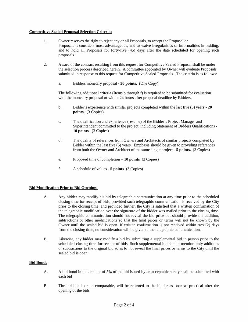
Competitive Sealed Proposal Selection Criteria:
1. Owner reserves the right to reject any or all Proposals, to accept the Proposal or Proposals it considers most advantageous, and to waive irregularities or informalities in bidding, and to hold all Proposals for forty-five (45) days after the date scheduled for opening such proposals.
2. Award of the contract resulting from this request for Competitive Sealed Proposal shall be under the selection process described herein. A committee appointed by Owner will evaluate Proposals submitted in response to this request for Competitive Sealed Proposals. The criteria is as follows:
a. Bidders monetary proposal - 50 points. (One Copy)
The following additional criteria (Items b through f) is required to be submitted for evaluation with the monetary proposal or within 24 hours after proposal deadline by Bidders.
b. Bidder’s experience with similar projects completed within the last five (5) years - 20 points. (3 Copies)
c. The qualification and experience (resume) of the Bidder’s Project Manager and Superintendent committed to the project, including Statement of Bidders Qualifications - 10 points. (3 Copies)
d. The quality of references from Owners and Architects of similar projects completed by Bidder within the last five (5) years. Emphasis should be given to providing references from both the Owner and Architect of the same single project - 5 points. (3 Copies)
e. Proposed time of completion – 10 points (3 Copies)
f. A schedule of values - 5 points (3 Copies)
Bid Modification Prior to Bid Opening:
A. Any bidder may modify his bid by telegraphic communication at any time prior to the scheduled closing time for receipt of bids, provided such telegraphic communication is received by the City prior to the closing time, and provided further, the City is satisfied that a written confirmation of the telegraphic modification over the signature of the bidder was mailed prior to the closing time. The telegraphic communication should not reveal the bid price but should provide the addition, subtractions or other modifications so that the final prices or terms will not be known by the Owner until the sealed bid is open. If written confirmation is not received within two (2) days from the closing time, no consideration will be given to the telegraphic communication.
B. Likewise, any bidder may modify a bid by submitting a supplemental bid in person prior to the
scheduled closing time for receipt of bids. Such supplemental bid should mention only additions or subtractions to the original bid so as to not reveal the final prices or terms to the City until the sealed bid is open.
Bid Bond:
A. A bid bond in the amount of 5% of the bid issued by an acceptable surety shall be submitted with each bid
B. The bid bond, or its comparable, will be returned to the bidder as soon as practical after the
opening of the bids.

Page 3 of 4
Statement of Bidder’s Qualifications
:
Each bidder shall submit on the form furnished for that purpose a statement of the bidder's qualifications. The City shall have the right to take such steps as it deems necessary to determine the ability of the bidder to perform his obligations under the contract, and the bidder shall furnish the City all such information and data for this purpose as it may request. The right is reserved to reject any bid where an investigation of the available data does not satisfy the City that the bidder is qualified to carry out properly the terms of the contract.
Unit Price:
N/A
Corrections:
Erasures or other corrections in the bid must be noted over the signature of the bidder. Time for Receiving Bids
:
Bids received prior to the advertised hour of opening shall be kept securely sealed. The officer appointed to open the bids shall decide when the specified time has arrived and no bid received thereafter will be considered; except that when a bid arrives by mail after the time fixed for opening, but before the reading of all other bids is completed, and it is shown to the satisfaction of the City that the late arrival of the bid was solely due to delay in the mail for which the bidder was not responsible, such bid will be received and considered.
Opening of Bids:
The City shall, at the time and place fixed for the opening of bids, open each bid and publicly read it aloud, irrespective of any irregularities therein. Bidders and other interested individuals may be present.
Withdrawal of Bids
:
Bidder may withdraw the bid before the time fixed for the opening of bids, by communicating his purpose in writing to the locality. Upon receipt of such notice, the unopened bid will be returned to the bidder. The bid guaranty of any bidder withdrawing his bid will be returned promptly.
Award of Contract/Rejection of Bids
:
A. The contract will be awarded to the responsive, responsible Bidder submitting a proposal that provides goods or services at the best value for the City. The bidder selected will be notified at the earliest possible date. The City reserves the right to reject any or all bids and to waive any informality in bids received where such rejection or waiver is in its interest.
B. The City reserves the right to consider as unqualified to do the work any bidder who does not
habitually perform with his own forces the major portions of the work involved in construction of the improvements embraced in this contract.

Page 4 of 4
Execution of Agreement/Performance and Payment Bonds:
A. Performance and Payment Bonds are required of all Prime Contractors which enter into a formal contract in excess of $50,000 with the State, any department, board, agency, municipality, county, school district, or any division or subdivision thereof, to obtain a Payment Bond in the amount of the contract before commencing with work and a performance bond for public works contracts in excess of $100,000.
B. The failure of the successful bidder to execute the agreement and supply the required bonds within
then (10) days after the prescribed forms are presented for signature, or within such extended period as the City may grant, shall constitute a default and the City may, at its option either award the contract to the next bidder to who provides goods or services at the best value for the City, or re-advertise for bids. In either case, the City may charge against the bidder the difference between the amount of the bid, and the amount for which a contract is subsequently executed irrespective of whether this difference exceeds the amount of the bid bond. If a more favorable bid is received through re-advertisement, the defaulting bidder shall have no claim against the City for a refund.
Equal Employment Opportunity
:
Attention is called to the requirements for ensuring that employees and applicants for employment are not discriminated against because of their race, color, creed, sex, or national origin.

Proposal - Page 1 of 2
COMPETITIVE SEALED PROPOSAL
CITY OF KINGSVILLE, TEXAS Gentlemen: This Proposal is submitted by , whose address is (hereafter called "Bidder"), for the construction of "Municipal Building First Floor Renovation", City of Kingsville, Texas, (hereafter called "Project"). BASE BID: Bidder agrees to furnish for the total sum of _____________________________________________________________________________ ______________________________Dollars ($_______________________), all labor, services, materials, tools, equipment and supervision necessary to the full and final completion of the project, and everything incidental thereto, as shown on the Drawings, stated in the Specifications, or properly inferable therefrom, all in accordance with the Contract Documents governing the construction of such project prepared by SolkaNavaTorno, LLC, (hereafter called the "Architect"). Allowances as specified in the amount of $33,000.00 are included in the Base Bid sum stipulated above. Additive Alternate No. 1 – Fire Alarm System Add: _____________________________________________________ ($_________________) Bidder agrees that if his Proposal is accepted by the Owner, he will substantially complete all new work called for in the Contract Documents as proposed. Completion Time: ________________________ Calendar Days The criteria for evaluation and selection of the successful Offeror, will be based upon the following:
1. The Bidder’s monetary proposal.
2. Additional criteria required to be submitted with monetary proposal or within 24 hours after Proposal closing time.
a. The Bidder’s experience with similar projects completed within the last five (5)
years.
b. The qualification and experience (resumes) of the Bidder’s key personnel committed to the Project, including Statement of Bidders Qualifications .
c. The quality of references from Owners and Architects of similar projects
completed by the Bidder within the last five (5) years. Emphasis should be given to providing references from both the Owner and Architect of the same single project.

Proposal - Page 2 of 2
d. Time of completion proposed. e. A schedule of values.
Bidder represents that, prior to preparing this Bid, he has carefully read the Contract Documents,
examined the site of the Project, and had made an investigation such that he is fully informed of the conditions, facilities, difficulties, restrictions and requirements which he will, or may encounter in the completion of the Project in accordance with the terms of the Contract Documents. Accompanying this Bid is a bid bond payable to the order of the City of Kingsville, Texas (hereafter called "Owner"), for not less than five percent (5%) of the largest amount for which a contract can be awarded under this proposal. Bidder agrees that if he is awarded the contract he will execute and deliver to Owner, within ten (10) days after he is notified of the acceptance of his proposal, a Contract for the construction of such Project, plus required project insurance and Bonds, in the forms acceptable to the Owner. Should bidder fail to execute such Bonds within the prescribed time, Bidder agrees to charges as indicated in the Instructions To Bidders. Bidder agrees that if his Proposal is accepted by the Owner, he will substantially complete all new work called for in the Contract Documents as proposed, and if the work is not completed by such time, he agrees to pay to Owner as liquidated damages, the sum of Two Hundred Dollars ($200.00) for each calendar day after such time that the work remains incomplete, calculated in accordance with the provisions of the Contract Documents. Bidder acknowledges receipt of Addenda No’s. ____ through ____. Executed on , 2017. Bidder (If Bidder is a Corporation complete the following:) Signed By Sole Owner, or ATTEST: Partner, or President of Whose Address is: (Corporate Seal)

Page 1 of 1
NONCOLLUSION AFFIDAVIT OF PRIME BIDDER State of ) County of ) , being first duly sworn, deposes and says that: (1) He is of , the Bidder that has submitted the attached Bid; (2) He is fully informed respecting the preparation and contents of the attached Bid and of all pertinent circumstances respecting such Bid; (3) Such Bid is genuine and is not a collusive or sham Bid; (4) Neither the said Bidder nor any of its officers, partners, owners, agents, representatives, employees or parties in interest, including this affiant, has in any way colluded, conspired, connived or agreed, directly or indirectly with another Bidder, firm or person to submit a collusive or sham Bid in connection with the Contract for which the attached Bid has been submitted or to refrain from bidding in connection with such Contract, or has in any manner, directly or indirectly, sought by agreement or collusion or communication or conference with any other Bidder, firm or person to fix the price or prices in the attached Bid or of any other Bidder, or to fix an overhead, profit or cost element of the Bid price or the Bid price of any other Bidder, or to secure through any collusion, conspiracy, connivance or unlawful agreement any advantage against the (Local Public Agency) or any person interested in the proposed Contract; and (5) The price or prices quoted in the attached Bid are fair and proper and are not tainted by any collusion, conspiracy, connivance or unlawful agreement on the part of the Bidder or any of its agents, representatives, owners, employees, or parties in interest, including this affiant. (Signed) Title Subscribed and sworn to me this day of . By: Notary Public My commission expires

Page 1 of 1
CONTRACTOR CERTIFICATIONS
U.S. Department of Housing and Urban Development
CERTIFICATION OF BIDDER REGARDING CIVIL RIGHTS LAWS AND REGULATIONS
INSTRUCTIONS
CERTIFICATION OF BIDDER REGARDING Executive Order 11246 and Federal Laws Requiring Federal Contractor to adopt and abide by equal employment opportunity and affirmative action in their hiring, firing, and promotion practices. This includes practices related to race, color, gender, religion, national origin, disability, and veterans’ rights. NAME AND ADDRESS OF BIDDER (include ZIP Code)
CERTIFICATION BY BIDDER
Bidder has participated in a previous contract or subcontract subject to Civil Rights Laws and Regulations. Yes No
The undersigned hereby certifies that:
The Provision of Local Training, Employment, and Business Opportunities
The
clause (Section 3 provision) is included in the Contract. A written Section 3 plan (Local Opportunity Plan) was prepared and submitted as part of the bid proceedings (if bid equals or exceeds $100,000).
Equal Opportunity
clause is included in the Contract (if bid equals or exceeds $10,000).
Have you ever been or are you being considered for sanction due to violation of Executive Order 11246, as amended? Yes No
NAME AND TITLE OF SIGNER (Please type) SIGNATURE DATE

Page 1 of 5
STANDARD FORM OF AGREEMENT BETWEEN CITY AND CONTRACTOR
ON THE BASIS OF A STIPULATED PRICE THIS AGREEMENT is dated as of the ______ day of ____________ in the year ________ by and between the City of Kingsville, 400 W. King Avenue, Kingsville, Texas 78363 (hereinafter called CITY) and __________________________________________________________________
CITY and CONTRACTOR, in consideration of the mutual covenants hereinafter set forth, agree as follows:
(hereinafter called CONTRACTOR).
Article 1. WORK:
CONTRACTOR shall complete all Work as specified or indicated in the Contract Documents. The Work is generally described as follows:
“City of Kingsville – BID 18-05 MUNICIPAL BUILDING FIRST FLOOR RENOVATION”
Article 2. ARCHITECT:
The Project has been designed by:
6262 Weber Road, Suite 310
Corpus Christi, TX 78413-4031
p: 361.854.1471
f: 361.854.1470
Who is hereinafter called ARCHITECT and who is to act as CITY’S representative, assume all duties and responsibilities and have the rights and authority assigned to ARCHITECT in the Contract Documents in connection with completion of the Work in accordance with the Contract Documents.
Article 3. CONTRACT TIME
3.1 The Work will be completed and ready for final payment in accordance with the General Conditions within ____ calendar days from the date when the Contract Time commences to run.
3.2 Liquidated Damages. CITY and CONTRACTOR recognize that time is of the essence of this Agreement and that CITY will suffer financial loss if the Work is not completed within the time specified in paragraph 3.1 above, plus any extensions thereof allowed in accordance with the General Conditions.
They also recognize the delays, expense and difficulties involved in proving in a legal or arbitration proceeding the actual loss suffered by CITY if the Work is not completed on time. Accordingly, instead of requiring any such proof, CITY and CONTRACTOR agree that as liquidated damages for delay (but not as a penalty) CONTRACTOR shall pay CITY two hundred & 00/100 dollars ($200.00) for each calendar day that expires after the time specified in Article 3.1 of this Agreement for Substantial Completion until the Work is substantially complete. After Substantial Completion if CONTRACTOR shall neglect, refuse or fail to complete the remaining Work within the Contract Time or any proper extension thereof granted by CITY, CONTRACTOR shall pay CITY two hundred

Page 2 of 5
dollars ($200.00) for each calendar day that expires after the time specified in Article 3.1 of this Agreement for completion and readiness for final payment.
Article 4. CONTRACT PRICE:
4.1 CITY shall pay CONTRACTOR for completion of Work in accordance with the Contract Documents in current funds as follows: Per Contractors Proposal dated ________, 2017 in the total base bid + total alternate No. 1 in the amount of $________________
Article 5. PAYMENT PROCEDURES:
, as attached and a part of this contract document.
CONTRACTOR shall submit Applications for Payment in accordance with the General Conditions. Applications for Payment will be processed by Architect as provided in the General Conditions.
Article 6. INTEREST:
All moneys not paid when due as provided in the General Conditions shall bear interest at the maximum rate allowed by law at the place of the Project.
Article 7. CONTRACTORS REPRESENTATIONS:
In order to induce CITY to enter into this Agreement CONTRACTOR makes the following representations:
7.1 CONTRACTOR has familiarized itself with the nature and extent of the Contract Documents, Work, site, locality, and all local conditions and Laws and Regulations that in any manner may affect cost, progress, performance or furnishing of the Work.
7.2 CONTRACTOR has obtained and carefully studied (or assumes responsibility for obtaining and carefully studying) all such examinations, investigations, explorations, tests, reports and studies which pertain to the subsurface or physical conditions at or contiguous to the site or otherwise may affect the cost, progress, performance or furnishing of the Work as CONTRACTOR considers necessary for the performance of furnishing of the Work at the Contract Price, within the Contract Time and in accordance with other terms and conditions of the Contract Documents, including specifically the provisions of the General Conditions; and no additional examinations, investigation, explorations, tests reports, studies or similar information or data are or will be required by CONTRACTOR for such purposes.
7.3 CONTRACTOR has reviewed and checked all information and data shown or indicated on the Contract Documents with respect to existing Underground Facilities at or contiguous to the site and assumes responsibility for the accurate location of said Underground Facilities. No additional examinations, investigations, explorations, tests, reports, studies or similar information or data in respect of said Underground Facilities are or will be required by CONTRACTOR in order to perform and furnish the Work at the Contract Price, within the Contract Time, and in accordance with the other terms and conditions of the Contract Documents, including specifically the provisions of the General and Special Conditions.
7.4 CONTRACTOR has correlated the results of all such observations, examinations, investigations, explorations, tests, reports and studies with the terms and conditions of the Contract Documents.

Page 3 of 5
7.5 CONTRACTOR has given ARCHITECT written notice of all conflicts, errors or discrepancies that he has discovered in the Contract Documents and the written resolution thereof by ARCHITECT is acceptable to CONTRACTOR.
Article 8. CONTRACT DOCUMENTS:
The Contract Documents which comprise the entire agreement between CITY and CONTRACTOR concerning the Work consists of the following:
8.1 A bound set of executed documents and specifications titled:
CONTRACT DOCUMENTS &
TECHNICAL SPECIFICATIONS FOR
BID 18-05 MUNICIPAL BUILDING FIRST FLOOR RENOVATION
FOR CITY OF KINGSVILLE, TEXAS
Jesus A Garza City Manager
Sam Fugate Mayor
Alfonso R Garcia Commissioner(s)
Noel Pena Arturo Pecos Edna Lopez
OCTOBER 30, 2017
Prepared by:
6262 Weber Road, Suite 310
Corpus Christi, TX 78413-4031
p: 361.854.1471
f: 361.854.1470 together with all of the items or sections listed in the Table of Contacts thereof.
8.2 A Notice of Award consisting of one page.
8.3 A Notice to Proceed with Construction consisting of one page which shall be executed at a later date.

Page 4 of 5
8.4 A set of Drawings consisting of xx (xx) sheets titled:
Description
1. COVER SHEET 2. 3. 4. 10. 11. 12. 13. 14. 15. 16. 17. 18. 19. 20. There are no Contract Documents other than those listed above in this Article 8. The Contract Documents may only be amended, modified or supplemented as provided in the General Conditions.
Article 9. MISCELLANEOUS
9.1 Terms used in this Agreement which are defined in the General Conditions will have the meanings indicated in the General Conditions.
9.2 No assignment by a party hereto of any rights or interests in the Contract Documents will be binding on another party hereto without the written consent of the party sought to be bound; and specifically but without limitation moneys that may become due and moneys that are due may not be assigned without such consent (except to the extent that the effect of this restriction may be limited by law), and unless specifically stated to the contrary in any written consent to an assignment no assignment will release or discharge the assignor from any duty or responsibility under the Contract Documents.
9.3 CITY and CONTRACTOR each binds itself, its partners, successors, assigns and legal representatives to the other party hereto, its partners, successors, assigns and legal representatives in respect of all covenants, agreements and obligations contained in the Contract Documents.
Article 10. OTHER PROVISIONS
10.1 The successful bidder who is awarded this bid will be required to complete and return a Conflict of Interest Questionnaire and a Form 1295 – Certificate of Interested Parties
10.2 This contract gives no rights or benefits to anyone other than the CITY and CONTRACTOR.
10.3 CONTRACTOR agrees to abide by all local, state, and federal nondiscrimination and fair wages, and all other laws applicable to this contract.

Page 5 of 5
IN WITNESS WHEREOF, CITY and CONTRACTOR have signed this Agreement in five counterparts. Two counterparts each have been delivered to CITY and CONTRACTOR and one counterpart to ARCHITECT. All portions of the Contract Documents have been signed or identified by CITY and CONTRACTOR or by ARCHITECT on their behalf.
This Agreement will be effective on _____________________, 2017
` CITY: CONTRACTOR: City of Kingsville, Texas ___________________________
By:_________________________ By:_________________________
Jesus, A. Garza, City Manager
Attest: ______________________ Attest: _______________________
Address for giving notices: Address for giving notices:
City of Kingsville 400 W. King Avenue Kingsville, Texas, 78363

Page 1 of 2
EQUAL OPPORTUNITY CLAUSE
(b) Federally assisted construction contracts. Except as otherwise provided, each administering agency shall require the inclusion of the following language as a condition of any grant, contract, loan, insurance, or guarantee involving federally assisted construction which is not exempt from the requirements of the equal opportunity clause: The applicant hereby agrees that it will incorporate or cause to be incorporated into any contract for construction work, or modification thereof, as defined in the regulations of the Secretary of Labor at 41 CFR chapter 60, which is paid for in whole or in part with funds obtained from the Federal Government or borrowed on the credit of the Federal Government pursuant to a grant, contract, loan, insurance, or guarantee, or undertaken pursuant to any Federal program involving such grant, contract, loan, insurance, or guarantee, the following equal opportunity clause:
During the performance of this contract, the contractor agrees as follows:
(1) The contractor will not discriminate against any employee or applicant for employment because of race, color, religion, sex, sexual orientation, gender identity, or national origin. The contractor will take affirmative action to ensure that applicants are employed, and that employees are treated during employment without regard to their race, color, religion, sex, sexual orientation, gender identity, or national origin. Such action shall include, but not be limited to the following: Employment, upgrading, demotion, or transfer; recruitment or recruitment advertising; layoff or termination; rates of pay or other forms of compensation; and selection for training, including apprenticeship. The contractor agrees to post in conspicuous places, available to employees and applicants for employment, notices to be provided setting forth the provisions of this nondiscrimination clause.
(2) The contractor will, in all solicitations or advertisements for employees placed by or on behalf of the contractor, state that all qualified applicants will receive considerations for employment without regard to race, color, religion, sex, sexual orientation, gender identity, or national origin.
(3) The contractor will not discourage or in any other manner discriminate against any employee or applicant for employment because such employee or applicant has inquired about, discussed, or disclosed the compensation of the employee or applicant or another employee or applicant. This provision shall not apply to instances in which an employee who has access to the compensation information of other employees or applicants as a part of such employee’s essential job functions discloses the compensation of such other employees or applicants to individuals who do not otherwise have access to such information, unless such disclosure is in response to a formal complaint or charge, in furtherance of an investigation, proceeding, hearing, or action, including an investigation conducted by the employer, or is consistent with the contractor’s legal duty to furnish information.
(4) The contractor will send to each labor union or representative of workers with which he has a collective bargaining agreement or other contract or understanding, a notice to be provided advising the said labor union or workers’ representatives of the contractor’s commitments under this section, and shall post copies of the notice in conspicuous places available to employees and applicants for employment.
(5) The contractor will comply with all provisions of Executive Order 11246 of September 24, 1965, and of the rules, regulations, and relevant orders of the Secretary of Labor.
(6) The contractor will furnish all information and reports required by Executive Order 11246 of September 24, 1965, and by rules, regulations, and orders of the Secretary of Labor, or pursuant thereto, and will permit access to his books, records, and accounts by the administering agency and the Secretary of Labor for purposes of investigation to ascertain compliance with such rules, regulations, and orders.

Page 2 of 2
(7) In the event of the contractor’s noncompliance with the nondiscrimination clauses of this contract or with any of the said rules, regulations, or orders, this contract may be canceled, terminated, or suspended in whole or in part and the contractor may be declared ineligible for further Government contracts or federally assisted construction the Executive order. In addition, the applicant agrees that if it fails or refuses to comply with these undertakings, the administering agency may take any or all of the following actions: Cancel, terminate, or suspend in whole or in part this grant (contract, loan, insurance, guarantee); refrain from extending any further assistance to the applicant under the program with respect to which the failure or refund occurred until satisfactory assurance of future compliance has been received from such applicant; and refer the case to the Department of Justice for appropriate legal proceedings.
(c) Subcontracts. Each nonexempt prime contractor or subcontractor shall include the equal opportunity clause in each of its nonexempt subcontracts. (d) Incorporation by reference. The equal opportunity clause may be incorporated by reference in all Government contracts and subcontracts, including Government bills of lading, transportation requests, contracts for deposit of Government funds, and contracts for issuing and paying U.S. savings bonds and notes, and such other contracts and subcontracts as the Deputy Assistant Secretary may designate. (e) Incorporation by operation of the order. By operation of the order, the equal opportunity clause shall be considered to be a part of every contract and subcontract required by the order and the regulations in this part to include such a clause whether or not it is physically incorporated in such contracts and whether or not the contract between the agency and the contractor is written. (f) Adaptation of language. Such necessary changes in language may be made in the equal opportunity clause as shall be appropriate to identify properly the parties and their undertakings. [43 FR 49240, Oct. 20, 1978, as amended at 62 FR 66971, Dec. 22, 1997; 79 FR 72993, Dec. 9, 2014; 80 FR 54934, September 11, 2015]

Page 1 of 2
A1001 Equal Opportunity Guidelines for Construction Contractors
Note: To be included in bid packet and distributed at the preconstruction conference (optional) 1. What are the responsibilities of the offeror or bidder to ensure equal employment
opportunity? For contracts over $ 10,000, the offeror or bidder must comply with the "Equal Opportunity Clause" and the "Standard Federal Equal Opportunity Construction Contract Specifications."
2. Are construction contractors required to ensure a legal working environment for all employees? Yes, it is the construction contractor's responsibility to provide an environment free of harassment, intimidation, and coercion to all employees and to notify all foremen and supervisors to carry out this obligation, with specific attention to minority or female individuals.
3. To alleviate developing separate facilities for men and women on all sites, can a construction contractor place all women employees on one site? No, two or more women should be assigned to each site when possible.
4. Are construction contractors required to make special outreach efforts to Section 3 or minority and female recruitment sources? Yes, construction contractors must establish a current list of Section 3, minority and female recruitment sources. Notification of employment opportunities, including the availability of on-the-job training and apprenticeship programs, should be given to these sources. The efforts of the construction contractors should be kept in file.
5. Should records be maintained on the number of Section 3 residents, minority and females applying for positions with construction contractors? Yes, records must be maintained to include a current list of names, addresses and telephone numbers of all Section 3, minority and female applicants. The documentation should also include the results of the applications submitted.
6. What happens if a woman or minority is sent to the union by the Contractor and is not referred back to the Contractor for employment? If the unions impede the construction contractor's responsibility to provide equal employment opportunity, a written notice should be submitted to TDA.
7. What efforts are made by construction contractors to create entry-level positions for Section 3 residents, women and minorities? Construction contractors are required to develop on-the-job training programs, or participate in training programs, especially those funded by the Department of Labor, to create positions for Section 3 residents, women and minorities and to meet employment needs.
8. Are any efforts made by the Contractor to publicize their Equal Employment Opportunity (EEO) policy? Yes, the construction contractor is responsible for notifying unions and sources of training programs of their equal employment opportunity policy. Unions should be requested to cooperate in the effort of equal opportunity. The policy should be included in any appropriate manuals, or collective bargaining agreements. The construction contractor is encouraged to publicize the equal employment opportunity policy in the company newspaper and annual report. The Contractor is also responsible to include the EEO policy in all media advertisement.

Page 2 of 2
9. Are any in-service training programs provided for staff to update the EEO policy? At least annually a review of the EEO policy and the affirmative action obligations are required of all personnel employees of a decision-making status. A record of the meeting including date, time, location, persons present, subject matter discussed, and disposition of the subject matter should be maintained.
10. What recruitment efforts are made for Section 3 residents, minorities and women? The construction contractor must notify both orally and in writing, Section 3, minority and female recruitment sources one month prior to the date of acceptance for apprenticeship or other training programs.
11. Are any measures taken to encourage promotions for minorities and women? Yes, an annual evaluation should be conducted for all minority and female personnel to encourage these employees to seek higher positions.
12. What efforts are taken to ensure that personnel policies are in accordance with the EEO policy? Personnel policies in regard to job practices, work assignments, etc. should be continually monitored to ensure that the EEO policy is carried out.
13. Can women be excluded from utilizing any facilities available to men? No, all facilities and company activities are non-segregated except for bathrooms or changing facilities to ensure privacy.
14. What efforts should be utilized to include minority and female contractors and suppliers? Take affirmative steps to ensure that small, minority, and women owned businesses are included on all lists for contractors/service providers. Solicit these businesses when issuing RFPs and RFQs and soliciting construction bids. Divide project activities into small tasks to allow participation. Keep records of all offers to minority and female construction contractors.
15. If a construction contractor participates in a business related association that does not comply with equal opportunity affirmative action standards, does that show his/her failure to comply? No, the construction contractor is responsible for its own compliance.
16. Can a construction contractor hire a subcontractor who has been debarred from government contracts pursuant to EEO? No. The construction contractor must suspend, terminate or cancel its contract with any Subcontractor who is in violation of the EEO policy.
17. What effort has been taken by the construction contractor to monitor all employment to insure the company EEO policy is being carried out? The construction contractor must designate a responsible individual to keep accurate records of all employees that includes specific information required by the government.

form HUD-4010 (07/2003)ref. Handbook 1344.1
Previous edition is obsolete Page 1 of 4
Applicability
The Project or Program to which the construction work coveredby this contract pertains is being assisted by the United States ofAmerica and the following Federal Labor Standards Provisionsare included in this Contract pursuant to the provisions applicableto such Federal assistance.
A. 1. (i) Minimum Wages. All laborers and mechanics em-ployed or working upon the site of the work will be paid uncondi-tionally and not less often than once a week, and without subse-quent deduction or rebate on any account (except such payrolldeductions as are permitted by regulations issued by the Secre-tary of Labor under the Copeland Act (29 CFR Part 3), the fullamount of wages and bona fide fringe benefits (or cash equiva-lents thereof) due at time of payment computed at rates not lessthan those contained in the wage determination of the Secretaryof Labor which is attached hereto and made a part hereof, re-gardless of any contractual relationship which may be alleged toexist between the contractor and such laborers and mechanics.Contributions made or costs reasonably anticipated for bona fidefringe benefits under Section l(b)(2) of the Davis-Bacon Act onbehalf of laborers or mechanics are considered wages paid tosuch laborers or mechanics, subject to the provisions of 29 CFR5.5(a)(1)(iv); also, regular contributions made or costs incurredfor more than a weekly period (but not less often than quarterly)under plans, funds, or programs, which cover the particular weeklyperiod, are deemed to be constructively made or incurred duringsuch weekly period.
Such laborers and mechanics shall be paid the appropriate wagerate and fringe benefits on the wage determination for the classi-fication of work actually performed, without regard to skill, exceptas provided in 29 CFR 5.5(a)(4). Laborers or mechanics per-forming work in more than one classification may be compensatedat the rate specified for each classification for the time actuallyworked therein: Provided, That the employer’s payroll recordsaccurately set forth the time spent in each classification in whichwork is performed. The wage determination (including any addi-tional classification and wage rates conformed under 29 CFR5.5(a)(1)(ii) and the Davis-Bacon poster (WH-1321) shall be postedat all times by the contractor and its subcontractors at the site ofthe work in a prominent and accessible, place where it can beeasily seen by the workers.
(ii) (a) Any class of laborers or mechanics which is not listed inthe wage determination and which is to be employed under thecontract shall be classified in conformance with the wage deter-mination. HUD shall approve an additional classification and wagerate and fringe benefits therefor only when the following criteriahave been met:
(1) The work to be performed by the classification requested isnot performed by a classification in the wage determination; and
(2) The classification is utilized in the area by the constructionindustry; and
(3) The proposed wage rate, including any bona fide fringe ben-efits, bears a reasonable relationship to the wage rates containedin the wage determination.
(b) If the contractor and the laborers and mechanics to be em-ployed in the classification (if known), or their representatives,and HUD or its designee agree on the classification and wagerate (including the amount designated for fringe benefits where
Federal Labor Standards Provisions U.S. Department of Housingand Urban DevelopmentOffice of Labor Relations
appropriate), a report of the action taken shall be sent by HUD orits designee to the Administrator of the Wage and Hour Division,Employment Standards Administration, U.S. Department of La-bor, Washington, D.C. 20210. The Administrator, or an authorizedrepresentative, will approve, modify, or disapprove every additionalclassification action within 30 days of receipt and so advise HUDor its designee or will notify HUD or its designee within the 30-dayperiod that additional time is necessary. (Approved by the Officeof Management and Budget under OMB control number 1215-0140.)
(c) In the event the contractor, the laborers or mechanics to beemployed in the classification or their representatives, and HUDor its designee do not agree on the proposed classification andwage rate (including the amount designated for fringe benefits,where appropriate), HUD or its designee shall refer the questions,including the views of all interested parties and the recommenda-tion of HUD or its designee, to the Administrator for determina-tion. The Administrator, or an authorized representative, will is-sue a determination within 30 days of receipt and so advise HUDor its designee or will notify HUD or its designee within the 30-dayperiod that additional time is necessary. (Approved by the Officeof Management and Budget under OMB Control Number 1215-0140.)
(d) The wage rate (including fringe benefits where appropriate)determined pursuant to subparagraphs (1)(ii)(b) or (c) of this para-graph, shall be paid to all workers performing work in the classifi-cation under this contract from the first day on which work is per-formed in the classification.
(iii) Whenever the minimum wage rate prescribed in the contractfor a class of laborers or mechanics includes a fringe benefit whichis not expressed as an hourly rate, the contractor shall either paythe benefit as stated in the wage determination or shall pay an-other bona fide fringe benefit or an hourly cash equivalent thereof.
(iv) If the contractor does not make payments to a trustee orother third person, the contractor may consider as part of thewages of any laborer or mechanic the amount of any costs rea-sonably anticipated in providing bona fide fringe benefits under aplan or program, Provided, That the Secretary of Labor has found,upon the written request of the contractor, that the applicable stan-dards of the Davis-Bacon Act have been met. The Secretary ofLabor may require the contractor to set aside in a separate ac-count assets for the meeting of obligations under the plan or pro-gram. (Approved by the Office of Management and Budget underOMB Control Number 1215-0140.)
2. Withholding. HUD or its designee shall upon its own action orupon written request of an authorized representative of the De-partment of Labor withhold or cause to be withheld from the con-tractor under this contract or any other Federal contract with thesame prime contractor, or any other Federally-assisted contractsubject to Davis-Bacon prevailing wage requirements, which isheld by the same prime contractor so much of the accrued pay-ments or advances as may be considered necessary to pay la-borers and mechanics, including apprentices, trainees and help-ers, employed by the contractor or any subcontractor the fullamount of wages required by the contract. In the event of failureto pay any laborer or mechanic, including any apprentice, traineeor helper, employed or working on the site of the work, all or part

form HUD-4010 (07/2003)ref. Handbook 1344.1
Previous edition is obsolete Page 2 of 4
of the wages required by the contract, HUD or its designee may,after written notice to the contractor, sponsor, applicant, or owner,take such action as may be necessary to cause the suspensionof any further payment, advance, or guarantee of funds until suchviolations have ceased. HUD or its designee may, after writtennotice to the contractor, disburse such amounts withheld for andon account of the contractor or subcontractor to the respectiveemployees to whom they are due. The Comptroller General shallmake such disbursements in the case of direct Davis-Bacon Actcontracts.
3. (i) Payrolls and basic records. Payrolls and basic recordsrelating thereto shall be maintained by the contractor during thecourse of the work preserved for a period of three years thereaf-ter for all laborers and mechanics working at the site of the work.Such records shall contain the name, address, and social secu-rity number of each such worker, his or her correct classification,hourly rates of wages paid (including rates of contributions or costsanticipated for bona fide fringe benefits or cash equivalents thereofof the types described in Section l(b)(2)(B) of the Davis-baconAct), daily and weekly number of hours worked, deductions madeand actual wages paid. Whenever the Secretary of Labor hasfound under 29 CFR 5.5 (a)(1)(iv) that the wages of any laborer ormechanic include the amount of any costs reasonably anticipatedin providing benefits under a plan or program described in Sec-tion l(b)(2)(B) of the Davis-Bacon Act, the contractor shall main-tain records which show that the commitment to provide suchbenefits is enforceable, that the plan or program is financially re-sponsible, and that the plan or program has been communicatedin writing to the laborers or mechanics affected, and records whichshow the costs anticipated or the actual cost incurred in providingsuch benefits. Contractors employing apprentices or traineesunder approved programs shall maintain written evidence of theregistration of apprenticeship programs and certification of traineeprograms, the registration of the apprentices and trainees, andthe ratios and wage rates prescribed in the applicable programs.(Approved by the Office of Management and Budget under OMBControl Numbers 1215-0140 and 1215-0017.)
(ii) (a) The contractor shall submit weekly for each week in whichany contract work is performed a copy of all payrolls to HUD or itsdesignee if the agency is a party to the contract, but if the agencyis not such a party, the contractor will submit the payrolls to theapplicant sponsor, or owner, as the case may be, for transmissionto HUD or its designee. The payrolls submitted shall set out ac-curately and completely all of the information required to be main-tained under 29 CFR 5.5(a)(3)(i). This information may be submit-ted in any form desired. Optional Form WH-347 is available forthis purpose and may be purchased from the Superintendent ofDocuments (Federal Stock Number 029-005-00014-1), U.S. Gov-ernment Printing Office, Washington, DC 20402. The prime con-tractor is responsible for the submission of copies of payrolls byall subcontractors. (Approved by the Office of Management andBudget under OMB Control Number 1215-0149.)
(b) Each payroll submitted shall be accompanied by a “State-ment of Compliance,” signed by the contractor or subcontractor orhis or her agent who pays or supervises the payment of the per-sons employed under the contract and shall certify the following:
(1) That the payroll for the payroll period contains the informationrequired to be maintained under 29 CFR 5.5 (a)(3)(i) and thatsuch information is correct and complete;
(2) That each laborer or mechanic (including each helper, ap-prentice, and trainee) employed on the contract during the payroll
period has been paid the full weekly wages earned, without re-bate, either directly or indirectly, and that no deductions have beenmade either directly or indirectly from the full wages earned, otherthan permissible deductions as set forth in 29 CFR Part 3;
(3) That each laborer or mechanic has been paid not less thanthe applicable wage rates and fringe benefits or cash equivalentsfor the classification of work performed, as specified in the appli-cable wage determination incorporated into the contract.
(c) The weekly submission of a properly executed certificationset forth on the reverse side of Optional Form WH-347 shall sat-isfy the requirement for submission of the “Statement of Compli-ance” required by subparagraph A.3.(ii)(b).
(d) The falsification of any of the above certifications may subjectthe contractor or subcontractor to civil or criminal prosecutionunder Section 1001 of Title 18 and Section 231 of Title 31 of theUnited States Code.
(iii) The contractor or subcontractor shall make the records re-quired under subparagraph A.3.(i) available for inspection, copy-ing, or transcription by authorized representatives of HUD or itsdesignee or the Department of Labor, and shall permit such rep-resentatives to interview employees during working hours on thejob. If the contractor or subcontractor fails to submit the requiredrecords or to make them available, HUD or its designee may, afterwritten notice to the contractor, sponsor, applicant or owner, takesuch action as may be necessary to cause the suspension of anyfurther payment, advance, or guarantee of funds. Furthermore,failure to submit the required records upon request or to makesuch records available may be grounds for debarment action pur-suant to 29 CFR 5.12.
4. Apprentices and Trainees.
(i) Apprentices. Apprentices will be permitted to work at lessthan the predetermined rate for the work they performed whenthey are employed pursuant to and individually registered in abona fide apprenticeship program registered with the U.S. De-partment of Labor, Employment and Training Administration, Of-fice of Apprenticeship Training, Employer and Labor Services, orwith a State Apprenticeship Agency recognized by the Office, or ifa person is employed in his or her first 90 days of probationaryemployment as an apprentice in such an apprenticeship program,who is not individually registered in the program, but who hasbeen certified by the Office of Apprenticeship Training, Employerand Labor Services or a State Apprenticeship Agency (whereappropriate) to be eligible for probationary employment as anapprentice. The allowable ratio of apprentices to journeymen onthe job site in any craft classification shall not be greater than theratio permitted to the contractor as to the entire work force underthe registered program. Any worker listed on a payroll at an ap-prentice wage rate, who is not registered or otherwise employedas stated above, shall be paid not less than the applicable wagerate on the wage determination for the classification of work actu-ally performed. In addition, any apprentice performing work onthe job site in excess of the ratio permitted under the registeredprogram shall be paid not less than the applicable wage rate onthe wage determination for the work actually performed. Where acontractor is performing construction on a project in a locality otherthan that in which its program is registered, the ratios and wagerates (expressed in percentages of the journeyman’s hourly rate)specified in the contractor’s or subcontractor’s registered programshall be observed. Every apprentice must be paid at not lessthan the rate specified in the registered program for theapprentice’s level of progress, expressed as a percentage of the

form HUD-4010 (07/2003)ref. Handbook 1344.1
Previous edition is obsolete Page 3 of 4
journeymen hourly rate specified in the applicable wage determi-nation. Apprentices shall be paid fringe benefits in accordancewith the provisions of the apprenticeship program. If the appren-ticeship program does not specify fringe benefits, apprentices mustbe paid the full amount of fringe benefits listed on the wage deter-mination for the applicable classification. If the Administrator de-termines that a different practice prevails for the applicable ap-prentice classification, fringes shall be paid in accordance withthat determination. In the event the Office of Apprenticeship Train-ing, Employer and Labor Services, or a State ApprenticeshipAgency recognized by the Office, withdraws approval of an ap-prenticeship program, the contractor will no longer be permittedto utilize apprentices at less than the applicable predeterminedrate for the work performed until an acceptable program is ap-proved.
(ii) Trainees. Except as provided in 29 CFR 5.16, trainees willnot be permitted to work at less than the predetermined rate forthe work performed unless they are employed pursuant to andindividually registered in a program which has received prior ap-proval, evidenced by formal certification by the U.S. Departmentof Labor, Employment and Training Administration. The ratio oftrainees to journeymen on the job site shall not be greater thanpermitted under the plan approved by the Employment and Train-ing Administration. Every trainee must be paid at not less thanthe rate specified in the approved program for the trainee’s levelof progress, expressed as a percentage of the journeyman hourlyrate specified in the applicable wage determination. Trainees shallbe paid fringe benefits in accordance with the provisions of thetrainee program. If the trainee program does not mention fringebenefits, trainees shall be paid the full amount of fringe benefitslisted on the wage determination unless the Administrator of theWage and Hour Division determines that there is an apprentice-ship program associated with the corresponding journeyman wagerate on the wage determination which provides for less than fullfringe benefits for apprentices. Any employee listed on the pay-roll at a trainee rate who is not registered and participating in atraining plan approved by the Employment and Training Adminis-tration shall be paid not less than the applicable wage rate on thewage determination for the work actually performed. In addition,any trainee performing work on the job site in excess of the ratiopermitted under the registered program shall be paid not less thanthe applicable wage rate on the wage determination for the workactually performed. In the event the Employment and TrainingAdministration withdraws approval of a training program, the con-tractor will no longer be permitted to utilize trainees at less thanthe applicable predetermined rate for the work performed until anacceptable program is approved.
(iii) Equal employment opportunity. The utilization of appren-tices, trainees and journeymen under 29 CFR Part 5 shall be inconformity with the equal employment opportunity requirementsof Executive Order 11246, as amended, and 29 CFR Part 30.
5. Compliance with Copeland Act requirements. The contrac-tor shall comply with the requirements of 29 CFR Part 3 which areincorporated by reference in this contract
6. Subcontracts. The contractor or subcontractor will insert inany subcontracts the clauses contained in subparagraphs 1through 11 of this paragraph A and such other clauses as HUD orits designee may by appropriate instructions require, and a copyof the applicable prevailing wage decision, and also a clause re-quiring the subcontractors to include these clauses in any lowertier subcontracts. The prime contractor shall be responsible forthe compliance by any subcontractor or lower tier subcontractorwith all the contract clauses in this paragraph.
7. Contract termination; debarment. A breach of the contractclauses in 29 CFR 5.5 may be grounds for termination of the con-tract and for debarment as a contractor and a subcontractor asprovided in 29 CFR 5.12.
8. Compliance with Davis-Bacon and Related Act Requirements.All rulings and interpretations of the Davis-Bacon and RelatedActs contained in 29 CFR Parts 1, 3, and 5 are herein incorpo-rated by reference in this contract
9. Disputes concerning labor standards. Disputes arising outof the labor standards provisions of this contract shall not be sub-ject to the general disputes clause of this contract. Such disputesshall be resolved in accordance with the procedures of the De-partment of Labor set forth in 29 CFR Parts 5, 6, and 7. Disputeswithin the meaning of this clause include disputes between thecontractor (or any of its subcontractors) and HUD or its designee,the U.S. Department of Labor, or the employees or their repre-sentatives.
10. (i) Certification of Eligibility. By entering into this contractthe contractor certifies that neither it (nor he or she) nor any per-son or firm who has an interest in the contractor’s firm is a personor firm ineligible to be awarded Government contracts by virtue ofSection 3(a) of the Davis-Bacon Act or 29 CFR 5.12(a)(1) or to beawarded HUD contracts or participate in HUD programs pursuantto 24 CFR Part 24.
(ii) No part of this contract shall be subcontracted to any personor firm ineligible for award of a Government contract by virtue ofSection 3(a) of the Davis-Bacon Act or 29 CFR 5.12(a)(1) or to beawarded HUD contracts or participate in HUD programs pursuantto 24 CFR Part 24.
(iii) The penalty for making false statements is prescribed in theU.S. Criminal Code, 18 U.S.C. 1001. Additionally, U.S. CriminalCode, Section 1 01 0, Title 18, U.S.C., “Federal Housing Adminis-tration transactions”, provides in part: “Whoever, for the purposeof . . . influencing in any way the action of such Administration.....makes, utters or publishes any statement knowing the same to befalse..... shall be fined not more than $5,000 or imprisoned notmore than two years, or both.”
11. Complaints, Proceedings, or Testimony by Employees.No laborer or mechanic to whom the wage, salary, or other laborstandards provisions of this Contract are applicable shall be dis-charged or in any other manner discriminated against by the Con-tractor or any subcontractor because such employee has filed anycomplaint or instituted or caused to be instituted any proceedingor has testified or is about to testify in any proceeding under orrelating to the labor standards applicable under this Contract tohis employer.
B. Contract Work Hours and Safety Standards Act. The provi-sions of this paragraph B are applicable only where the amount ofthe prime contract exceeds $100,000. As used in this paragraph, theterms “laborers” and “mechanics” include watchmen and guards.
(1) Overtime requirements. No contractor or subcontractor con-tracting for any part of the contract work which may require or involvethe employment of laborers or mechanics shall require or permit anysuch laborer or mechanic in any workweek in which he or she isemployed on such work to work in excess of 40 hours in such work-week unless such laborer or mechanic receives compensation at arate not less than one and one-half times the basic rate of pay for allhours worked in excess of 40 hours in such workweek.
(2) Violation; liability for unpaid wages; liquidated damages.In the event of any violation of the clause set forth in subpara-

form HUD-4010 (07/2003)ref. Handbook 1344.1
Previous edition is obsolete Page 4 of 4
graph (1) of this paragraph, the contractor and any subcontractorresponsible therefor shall be liable for the unpaid wages. In addi-tion, such contractor and subcontractor shall be liable to the UnitedStates (in the case of work done under contract for the District ofColumbia or a territory, to such District or to such territory), forliquidated damages. Such liquidated damages shall be computedwith respect to each individual laborer or mechanic, includingwatchmen and guards, employed in violation of the clause setforth in subparagraph (1) of this paragraph, in the sum of $10 foreach calendar day on which such individual was required or permit-ted to work in excess of the standard workweek of 40 hours withoutpayment of the overtime wages required by the clause set forth insub paragraph (1) of this paragraph.
(3) Withholding for unpaid wages and liquidated damages.HUD or its designee shall upon its own action or upon writtenrequest of an authorized representative of the Department of La-bor withhold or cause to be withheld, from any moneys payableon account of work performed by the contractor or subcontractorunder any such contract or any other Federal contract with thesame prime contract, or any other Federally-assisted contractsubject to the Contract Work Hours and Safety Standards Actwhich is held by the same prime contractor such sums as may bedetermined to be necessary to satisfy any liabilities of such con-tractor or subcontractor for unpaid wages and liquidated damagesas provided in the clause set forth in subparagraph (2) of thisparagraph.
(4) Subcontracts. The contractor or subcontractor shall insertin any subcontracts the clauses set forth in subparagraph (1)through (4) of this paragraph and also a clause requiring the sub-contractors to include these clauses in any lower tier subcontracts.The prime contractor shall be responsible for compliance by anysubcontractor or lower tier subcontractor with the clauses set forthin subparagraphs (1) through (4) of this paragraph.
C. Health and Safety. The provisions of this paragraph C are ap-plicable only where the amount of the prime contract exceeds$100,000.
(1) No laborer or mechanic shall be required to work in surround-ings or under working conditions which are unsanitary, hazard-ous, or dangerous to his health and safety as determined underconstruction safety and health standards promulgated by the Sec-retary of Labor by regulation.
(2) The Contractor shall comply with all regulations issued by theSecretary of Labor pursuant to Title 29 Part 1926 and failure tocomply may result in imposition of sanctions pursuant to the Con-tract Work Hours and Safety Standards Act, 40 USC 3701 et seq.
(3) The Contractor shall include the provisions of this para-graph in every subcontract so that such provisions will bebinding on each subcontractor. The Contractor shall take suchaction with respect to any subcontract as the Secretary ofHousing and Urban Development or the Secretary of Laborshall direct as a means of enforcing such provisions.

HUD 4010 (2-84) Page 1 of 6
Title 29 — LABOR
Subtitle A — Office of the Secretary of Labor PART 3 — CONTRACTORS AND SUBCONTRACTORS ON PUBLIC BUILDING OR
PUBLIC WORK FINANCED IN WHOLE OR IN PART BY LOANS OR GRANTS FROM THE UNITED STATES
Sec. 3.1 Purpose and scope 3.2 Definitions 3.3 Weekly statement with respect to
payment of wages 3.4 Submission of weekly statements
and the preservation and inspection of weekly payroll records.
3.5 Payroll deductions permissible without application to or approval of the Secretary of Labor.
3.6 Payroll deductions permissible with the approval of the Secretary of Labor.
3.7 Applications for the approval of the Secretary of Labor
3.8 Action by the Secretary of Labor upon applications.
3.9 Prohibited payroll deductions. 3.10 Methods of payment of wages. 3.11 Regulations part of contract. AUTHORITY: The provisions of this Part 3 issued under R.S. 161, sec. 2, 48 Stat. §48; Reorg. Plan No. 14 of 1950, 64 Stat. 1267, 5 U.S.C. Appendix; 5 U.S.C. 301; 40 U.S.C. 276c. SOURCE: The provisions of this Part 3 appear at 29 F.R. 97, Jan. 4, 1964, unless otherwise noted. Section 3.1 Purpose and Scope. This part prescribes “anti-kickback” regulations under section 2 of the Act of June 13, 1934, as amended (40 U.S.C.
276c), popularly known as the Copeland Act. This part applies to any contract which is subject to Federal wage standards and which is for the construction, prosecution, completion, or repair of public buildings, public works or buildings or works financed in whole or in part by loans or grants from the United States. The part is intended to aid in the enforcement of the minimum wage provisions of the Davis-Bacon Act and the various statutes dealing with Federally-assisted construction that contain similar minimum wage provisions, including those provisions which are not subject to Reorganization Plan No. 14 (e.g., the College Housing Act of 1950, the Federal Water Pollution Control Act, and the Housing Act of 1959), and in the enforcement of the overtime provisions of the Contract Work Hours Standards Act whenever they are applicable to construction work. The part details the obligation of contractors and subcontractors relative to the weekly submission of statements regarding the wages paid on work covered thereby; sets forth the circumstances and procedures governing the making of payroll deductions from the wages of those employed on such work; and delineates the methods of payment permissible on such work. Section 3.2 Definitions. As used in the regulations in this part: (a) The terms “building” or “work” generally include construction activity as

HUD 4010 (2-84) Page 2 of 6
distinguished from manufacturing, furnishing of materials, or servicing and maintenance work. The terms include, without limitation, buildings, structures, and improvements of all types, such as bridges, dams, plants, highways, parkways, streets, subways, tunnels, sewers, mains, powerlines, pumping stations, railways, airports, terminals, docks, piers, wharves, ways, lighthouses, buoys, jetties, breakwaters, levees, and canals; dredging, shoring, scaffolding, drilling, blasting, excavating, clearing, and landscaping. Unless conducted in connection with and at the site of such a building or work as is described in the foregoing sentence, the manufacture or furnishing of materials, articles, supplies, or equipment (whether or not a Federal or State agency acquires title to such materials, articles, supplies, or equipment during the course of the manufacture or furnishing, or owns the materials from which they are manufactured or furnished) is not a “building” or “work” within the meaning of the regulations in this part. (b) The terms “construction,” “prosecution,” “completion,” or “repair” mean all types of work done on a particular building or work at the site thereof, including, without limitation, altering, remodeling, painting and decorating, the transporting of materials and supplies to or from the building or work by the employees of the construction contractor or construction subcontractor, and the manufacturing or furnishing of materials, articles, supplies, or equipment on the site of the building or work, by persons employed at the site by the contractor or subcontractor. (c) The terms “public building” or “public work” include building or work for whose construction, prosecution, completion, or repair, as defined above, a Federal agency is a contracting party, regardless of whether title thereof is in a Federal agency.
(d) The term “building or work financed in whole or in part by loans or grants from the Unites States” includes building or work for whose construction, prosecution, completion, or repair, as defined above, payment or part payment is made directly or indirectly from funds provided by loans or grants by a Federal agency. The term includes building or work for which the Federal assistance granted is in the form of loan guarantees or insurance. (e) Every person paid by a contractor or subcontractor in any manner for his labor in the construction, prosecution, completion, or repair of a public building or public work or building or work financed in whole or in part by loans or grants from the United States is “employed” and receiving “wages,” regardless of any contractual relationship alleged to exist between him and the real employer. (f) The term “any affiliated person” includes a spouse, child, parent, or other close relative of the contractor or subcontractor; a partner or officer of the contractor or subcontractor; a corporation closely connected with the contractor or subcontractor as parent, subsidiary or otherwise, and an officer or agent of such corporation. (g) The term “Federal agency” means the United States, the District of Columbia, and all executive departments, independent establishments, administrative agencies, and instrumentality’s of the United States and of the District of Columbia, including corporations, all or substantially all of the stock of which is beneficially owned by the United States, by the District of Columbia, or any of the foregoing departments, establishments, agencies, and instrumentality’s.

HUD 4010 (2-84) Page 3 of 6
{29 FR 97, Jan. 4, 1964, as amended at 33 FR 32575, Nov. 27, 1973} Section 3.3 Weekly statement with respect to payment of wages. (a) As used in this section, the term “employee” shall not apply to persons in classifications higher than that of laborer or mechanic and those who are the immediate supervisors of such employees. (b) Each contractor or subcontractor engaged in the construction, prosecution, completion, or repair of any public building or public work, or building or work financed in whole or in part by loans or grants from the United States, shall furnish each week a statement with respect to the wages paid each of its employees engaged on work covered by 29 CFR Parts 3 and 5 during the preceding weekly payroll period. This statement shall be executed by the contractor or subcontractor or by an authorized officer of employee of the contractor or subcontractor who supervises the payment of wages, and shall be on form WH 348, “Statement of Compliance,” or on an identical form on the back of WH 347, “Payroll (For Contractors Optional Use)” or on any form with identical wording. Sample copies of WH 347 and WH 348 may be obtained from the Government contracting or sponsoring agency, and copies of these forms may be purchased at the Government Printing Office. (c) The requirements of this section shall not apply to any contract of $2,000 or less. (d) Upon a written finding by the head of a Federal agency, the Secretary of Labor may provide reasonable limitations, variations, tolerances, and exemptions from the requirements of this section subject to such
conditions as the Secretary of Labor may specify. {29 F.R. 95, Jan. 4, 1964, as amended at 33 F.R. 10186, July 17, 1968} Section 3.4 Submission of weekly statements and the preservation and inspection of weekly payroll records. (a) Each weekly statement required under §3.3 shall be delivered by the contractor or subcontractor, within seven days after the regular payment date of the payroll period, to a representative of a Federal or State agency in charge at the site of the building or work, or if there is no representative of a Federal or State agency at the site of the building or work, the statement shall be mailed by the contractor or subcontractor, within such time, to a Federal or State agency contracting for or financing the building or work. After such examination and check as may be made, such statement, or a copy thereof, shall be kept available, or shall be transmitted together with a report of any violation, in accordance with applicable procedures prescribed by the United States Department of Labor. (b) Each contractor or subcontractor shall preserve his weekly payroll records for a period of three years from date of completion of the contract. The payroll records shall set out accurately and completely the name and address of each laborer and mechanic, his correct classification, rate of pay, daily and weekly number of hours worked, deductions made, and actual wages paid. Such payroll records shall be made available at all times for inspection by the contracting officer or his authorized representative, and by authorized representatives of the Department of Labor.

HUD 4010 (2-84) Page 4 of 6
Section 3.5 Payroll deductions permissible without application to or approval of the Secretary of Labor. Deductions made under the circumstances or in the situations described in the paragraphs of this section may be made without application to and approval of the Secretary of Labor: (a) Any deduction made in compliance with the requirements of Federal, State, or local law, such as Federal or State withholding income taxes and Federal social security taxes. (b) Any deduction of sums previously paid to the employee as a bona fide prepayment of wages when such prepayment is made without discount or interest. A “bona fide prepayment of wages” is considered to have been made only when cash or its equivalent has been advanced to the person employed in such manner as to give him complete freedom of disposition of the advanced funds. (c) Any deduction of amounts required by court process to be paid to another, unless, the deduction is in favor of the contractor, subcontractor or any affiliated person, or when collusion or collaboration exists. (d) Any deduction constituting a contribution on behalf of the person employed to funds established by the employer or representatives of employees, or both, for the purpose of providing either from principal or income, or both, medical or hospital care, pensions, or annuities on retirement, death benefits, compensation for injuries, illness, accidents, sickness, or disability, or for insurance to provide any of the foregoing, or unemployment benefits, vacation pay, savings accounts, or similar payments for the benefit of employees, their
families and dependents: Provided, however, That the following standards are met: (1) The deduction is not otherwise prohibited by law; (2) it is either: (i) Voluntarily consented to by the employee in writing and in advance of the period in which the work is to be done and such consent is not a condition either for the obtaining of or for the continuation of employment, or (ii) provided for in a bona fide collective bargaining agreement between the contractor or subcontractor and representatives of its employees; (3) no profit or other benefit is otherwise obtained, directly or indirectly, by the contractor or subcontractor or any affiliated person in the form of commission, dividend, or otherwise; and (4) the deductions shall serve the convenience and interest of the employee. (e) Any deduction contributing toward the purchase of United States Defense Stamps and Bonds when voluntarily authorized by the employee. (f) Any deduction requested by the employee to enable him to repay loans to or to purchase shares in credit unions organized and operated in accordance with Federal and State credit union statutes. (g) Any deduction voluntarily authorized by the employee for the making of contributions to governmental or quasi-governmental agencies, such as the American Red Cross. (h) Any deduction voluntarily authorized by the employee for the making of contributions to Community Chests, United Givers Funds, and similar charitable organizations. (i) Any deductions to pay regular union initiation fees and membership dues, not including fines or special assessments:

HUD 4010 (2-84) Page 5 of 6
Provided, however, that a collective bargaining agreement between the contractor or subcontractor and representatives of its employees provides for such deductions and the deductions are not otherwise prohibited by law. (j) Any deduction not more than for the “reasonable cost” of board, lodging, or other facilities meeting the requirements of section 3(m) of the Fair Labor Standards Act of 1938, as amended, and Part 531 of this title. When such a deduction is made the additional records required under §516.27(a) of this title shall be kept. (k) Any deduction for the cost of safety equipment of nominal value purchased by the employee as his own property for his personal protection in his work, such as safety shoes, safety glasses, safety gloves, and hard hats, if such equipment is not required by law to be furnished by the employer, if such deduction is not violative of the Fair Labor Standards Act or prohibited by other law, if the cost on which the deduction is based does not exceed the actual cost to the employer where the equipment is purchased from him and does not include any direct or indirect monetary return to the employer where the equipment is purchased from a third person, and if the deduction is either (1) voluntarily consented to be the employee in writing and in advance of the period in which the work is to be done and such consent is not a condition either for the obtaining of employment or its continuance; or (2) provided for in a bona fide collective bargaining agreement between the contractor or subcontractor and representatives of its employees. {36 F.R. 9770, May 28, 1971.} Section 3.6 Payroll deductions permissible with the approval of the Secretary of Labor.
Any contractor or subcontractor may apply to the Secretary of Labor for permission to make any deduction not permitted under §3.5. The Secretary may grant permission whenever he finds that: (a) The contractor, subcontractor, or any affiliated person does not make a profit or benefit directly or indirectly from the deduction either in the form of a commission, dividend, or otherwise; (b) The deduction is not otherwise prohibited by law; (c) The deduction is either (1) voluntarily consented to by the employee in writing and in advance of the period in which the work is to be done and such consent is not a condition either for the obtaining of employment or its continuance, or (2) provided for in a bona fide collective bargaining agreement between the contractor or subcontractor and representatives of its employees; and (d) The deduction serves the convenience and interest of the employee. Section 3.7 Applications for the approval of the Secretary of Labor. Any application for the making of payroll deductions under §3.6 shall comply with the requirements prescribed in the following paragraphs of this section: (a) The application shall be in writing and shall be addressed to the Secretary of Labor. (b) The application need not identify the contract or contracts under which the work in question is to be performed. Permission will be given for deductions on all current and future contracts of the applicant for a period of 1 year. A renewal of permission to make such payroll deduction will be granted

HUD 4010 (2-84) Page 6 of 6
upon the submission of an application which makes reference to the original application, recites the date of the Secretary of Labor’s approval of such deductions, states affirmatively that there is continued compliance with the standards set forth in the provisions of §3.6, and specifies any conditions which have changed in regard to the payroll deductions. {36 F.R. 9770, May 28, 1971.} (c) The application shall state affirmatively that there is compliance with the standards set forth in the provisions of §3.6. The affirmation shall be accompanied by a full statement of the facts indicating such compliance. (d) The application shall include a description of the proposed deduction, the purpose to be served thereby, and the classes of laborers or mechanics from whose wages the proposed deduction would be made. (e) The application shall state the name and business of any third person to whom any funds obtained from the proposed deductions are to be transmitted and the affiliation of such person, if any, with the applicant. Section 3.8 Action by the Secretary of Labor upon applications. The Secretary of Labor shall decide whether or not the requested deduction is permissible under provisions of §3.6; and
shall notify the applicant in writing of his decision. Section 3.9 Prohibited payroll deductions. Deductions not elsewhere provided for by this part and which are not found to be permissible under §3.6 are prohibited. Section 3.10 Methods of payment of wages. The payment of wages shall be by cash, negotiable instruments payable on demand, or the additional forms of compensation for which deductions are permissible under this part. No other methods of payment shall be recognized on work subject to the Copeland Act. Section 3.11 Regulations part of contract. All contracts made with respect to the construction, prosecution, completion, or repair of any public building or public work or building or work financed in whole or in part by loans or grants from the United States covered by the regulations in this part shall expressly bind the contractor or subcontractor to comply with such of the regulations in this part as may be applicable. In this regard, see §5.5(a) of this subtitle.

Page 1 of 1
SECTION 504 CERTIFICATION
POLICY OF NONDISCRIMINATION ON THE BASIS OF DISABILITY
The ____________________________ does not discriminate on the basis of disability in
the admission or access to, or treatment or employment in, its federally assisted programs or
activities.
(Name) ________________________________
(Address) ________________________________
________________________________
City State Zip
Telephone Number ( ) ______ - ___________ Voice
( ) ______ - ___________ TDD
has been designated to coordinate compliance with the nondiscrimination requirements contained in the Department of Housing and Urban Development's (HUD) regulations implementing Section 504 (24 CFR Part 8. dated June 2, 1988).

Page 1 of 2
U.S. DEPARTMENT OF HOUSING AND URBAN DEVELOPMENT CONTRACTOR’S CERTIFICATION
CONCERNING LABOR STANDARDS AND PREVAILING WAGE REQUIREMENTS TO (appropriate recipient)
DATE
PROJECT NUMBER (if any)
C/O
PROJECT NAME
1. The undersigned, having executed a contract with
for the construction of the above-identified project, acknowledges that:
(a) The Labor Standards provisions are included in the aforesaid contract, (b) Correction of any infractions of the aforesaid conditions, including infractions by any subcontractors and any lower tier
subcontractors, is Contractor’s responsibility. 2. Certifies that: (a) Neither Contractor nor any firm, partnership or association in which it has substantial interest is designated as an
ineligible contractor by the Comptroller General of the United States pursuant to Section 5.6(b) of the Regulations of the Secretary of Labor, Part 5 (29 CFR, Part 5) or pursuant to Section 3(a) of the Davis-Bacon Act, as amended.
(b) No part of the aforementioned contract has been or will be subcontracted to any subcontractor if such subcontractor or
any firm, corporation, partnership or association in which such subcontractor has a substantial interest is designated as an ineligible contractor pursuant to any of the aforementioned regulatory or statutory provisions.
3. Contractor agrees to obtain and forward to the aforementioned recipient within ten days after the execution of any
subcontract, including those executed by subcontractors and any lower tier subcontractors, a Subcontractor’s Certification Concerning Labor Standards and Prevailing Wage Requirements executed by the subcontractors.
4. Certifies that: (a) The legal name and the business address of the undersigned are: (b) The undersigned is (choose one):
(1) A SINGLE PROPRIETORSHIP
(3) A CORPORATION ORGANIZED IN THE STATE OF
(2) A PARTNERSHIP
(4) OTHER ORGANIZATION (Describe)
(c) The name, title and address of the owner, partners or officers of the undersigned are:
NAME TITLE ADDRESS

Page 2 of 2
(d) The names and addresses of all other persons having a substantial interest in the undersigned, and the nature of the interest are:
NAME ADDRESS NATURE OF INTEREST
(e) The names, addresses and trade classifications of all other building construction contractors in which the undersigned has a substantial interest are:
NAME ADDRESS TRADE CLASSIFICATION
(Contractor)
Date
By

CITY OF KINGSVILLE BID BOND
KNOW ALL MEN BY THESE PRESENTS, That we,
(Name and Address of Bidder)
hereinafter called the Principal, and , (Surety), a corporation or firm duly authorized to transact surety business in the City of Kingsville and listed in the current notice of the Department of Treasury list of companies Holding Certificates of Authority as Acceptable Sureties on Federal Bonds and as Acceptable Reinsuring Companies, hereinafter called the Surety, are held and firmly bound unto the City of Kingsville hereinafter called the Obligee, in the sum of not less than five percent (5%) of the greatest total amount of the bidder’s proposal, as a proposal guarantee, the payment of which sum will and truly be made, the said Principal and the said Surety, bind ourselves, our heirs, executors, administrators, successors and assigns, jointly and severally, firmly by these presents.
WHEREAS, the Principal has submitted a bid for: Project Number:
(Full name and location of project)
NOW, THEREFORE, if the Obligee shall award the Contract to the Principal and the Principal shall enter into the Contract in writing with the Obligee in accordance with terms of such bid, and furnish such bonds and other instruments as may be specified in the Contract Documents with good and sufficient surety for the faithful performance of such Contract and for the prompt payment of labor and material furnished in the prosecution thereof, then this bond shall be null and void. If in the event of failure of the Principal to execute such contract and furnish such bonds and other instruments required by the Contract Documents to the Principal for execution, this bond shall become the property of the Obligee, without recourse of the Principal and/or Surety, not as a penalty but as liquidated damages.
Signed this day of , 2017.
By:
(Bidder)
*By: (Surety)
(Attorney-in Fact)
*Attach Power of Attorney (Surety) for Attorney-in-Fact. Surety Seal
DISCLOSURE OF GUARANTY FUND NONPARTICIPATION
In the event the insurer is unable to fulfill its contractual obligation under this policy or contract or application or certificate or evidence of coverage the policyholder or certificateholder is not protected by an insurance guaranty fund or other solvency protection arrangement.
Bid Bond

Page 1 of 2
PAYMENT BOND KNOW ALL MEN BY THESE PRESENTS that: (Name of Contractor or Company) (Address) a __________________________________________ , hereinafter called Principal, (Corporation / Partnership) and (Name of Surety Company) (Address) hereinafter called Surety, are held and firmly bound unto (Name of Recipient) (Recipient's Address) hereinafter called OWNER, in the penal sum of $ Dollars, $ in lawful money of the United States, for this payment of which sum well and truly to be made, we bind ourselves, successors, and assigns, jointly and severally, firmly by these presents. THE CONFIDENTIALITY OF THIS OBLIGATION is such that whereas, the Principal entered into a certain contract with the OWNER, dated the day of , a copy of which is hereto attached and made a part hereof for the construction of: (Project Name) NOW, THEREFORE, if the Principal shall promptly make payment to all persons, firms, SUB-CONTRACTORS, and corporations furnishing materials for or performing labor in the prosecution of the WORK provided for in such contract, and any authorized extension or modification thereof, including all amounts due for materials, lubricants, oil, gasoline, coal and coke, repairs on machinery, equipment and tools, consumed or used in connection with the construction of such WORK, and all insurance premiums on said WORK, and for all labor, performed in such WORK whether by SUB-CONTRACTOR or otherwise, then this obligation shall be void; otherwise to remain in full force and effect. PROVIDED, FURTHER, that the said Surety, for value received hereby stipulates and agrees that no change, extension of time, alteration or addition to the terms of the contract or to WORK to be performed

Page 2 of 2
thereunder or the SPECIFICATIONS accompanying the same shall in any way affect its obligation on this BOND, and it does hereby waive notice of any such change, extension of time, alteration or addition to the terms of the contract or to the WORK or to the SPECIFICATIONS. PROVIDED, FURTHER, that no final settlement between the OWNER and the CONTRACTOR shall abridge the right of any beneficiary hereunder, whose claim may be unsatisfied. IN WITNESS WHEREOF, this instrument is executed in ______________ counter-parts, each on of (Number) which shall be deemed an original, this the _______ day of . ATTEST:_____________________________________________ (Principal) By (s) (Principal Secretary) (SEAL) (Witness as to Principal) (Address) (Address) ATTEST: (Surety) By (Witness as to Surety (Attorney in Fact) (Address) (Address) NOTE: Date of BOND must not be prior to date of Contract. If CONTRACTOR is Partnership, all partners should execute BOND.

Page 1 of 4
PERFORMANCE BOND KNOW ALL MEN BY THESE PRESENTS that: (Name of Contractor or Company) (Address) a hereinafter called Principal, and (Name of Surety Company) (Address) hereinafter called Surety, are held and firmly bound unto (Name of Grant Recipient) (Grant Recipient's Address) hereinafter called OWNER, in the penal sum of $ Dollars ($ ) in lawful money of the United States, for the payment of which sum well and truly to be
made we bind ourselves, successors, and assigns, jointly and severally, firmly in these presents.
THE CONDITION OF THIS OBLIGATION is such that whereas, the Principal entered into a certain
contract with the OWNER dated the day of , a
copy of which is hereto attached and made a part hereof for the construction of:
NOW THEREFORE, if the Principal shall well, truly and faithfully perform its duties in all the undertakings, covenants, terms, conditions, and agreements of said contract during the original term thereof, and any extensions thereof which may be granted by the OWNER, with or without notice to the

Page 2 of 4
Surety and during the one year guaranty period, and if he shall satisfy all claims and demands incurred under such contract, and shall fully indemnify and save harmless the OWNER from all costs and damages which it may suffer by reason of failure to do so, and shall reimburse and repay the OWNER all outlay and expense which the OWNER may incur in making good any default, then this obligation shall be void, otherwise to remain in full force and effect. PROVIDED FURTHER, that the said Surety, for value received hereby stipulates and agrees that no change, extension of time, alteration or addition to the terms of the contract or to WORK to be performed thereunder or the SPECIFICATIONS accompanying the same shall in any way affect its obligation on this BOND, and it does hereby waive notice of any such change, extension of time, alteration or addition to the terms of the contract or to the WORK or to the SPECIFICATIONS. PROVIDED, FURTHER, that no final settlement between the OWNER and the Principal shall abridge the right of any beneficiary hereunder, whose claim may be unsatisfied. IN WITNESS WHEREOF, this instrument is executed in
counterparts, each one of which shall be deemed an original, this the
day of .
ATTEST: (Principal) By (s) (Principal Secretary) (SEAL) (Witness as to Principal) (Address) (Address) ATTEST: (Surety) By (Witness as to Surety) (Attorney in Fact) (Address) (Address)

Page 3 of 4
NOTE: Date of BOND must not be prior to date of Contract. If PRINCIPAL/CONTRACTOR is Partnership, all partners should execute BOND.
KNOW ALL MEN BY THESE PRESENTS, that we the undersigned,
as PRINCIPAL, and , as SURETY
are held and firmly bound unto (City of Kingsville, Texas)
hereinafter called the "Local Public
Agency”, in the penal sum of Dollars, ($ ),
lawful money of the United States, for the payment of which sum well and truly to be made, we
bind ourselves, our heirs, executors, administrators, successors, and assigns, jointly and
severally, firmly by these presents.
THE CONDITION OF THIS OBLIGATION IS SUCH, that whereas the Principal has submitted
the Accompanying Bid, dated , for
NOW, THEREFORE, the Principal shall not withdraw said Bid within the period specified therein after the opening of the same, or, if no period be specified, within thirty (30) days after the said opening, and shall within the period specified therefor, or if no period be specified, within ten (10) days after the prescribed forms are presented to him for signature, enter into a written contract with the Local Public Agency in accordance with the Bid as accepted, and give bond with good and sufficient surety or sureties, as may be required, for the faithful performance and proper fulfillment of such contract; or in the event of the withdrawal of said Bid within the period specified, or the failure to enter into such Contract and give such bond within the time specified, if the Principal shall pay the Local Public Agency the difference between the amount specified in said Bid and the amount for which the local Public Agency may procure the required work or supplies or both, if the latter be in excess of the former, then the above obligation shall be void and of no effect, otherwise to remain in full force and virtue. IN WITNESS THEREOF, the above parties have executed this instrument this day of , the name and corporate seal of each corporate party being hereto affixed and these present signed by its undersigned representative, pursuant to authority of its governing body.
(SEAL)
(SEAL)
Attest: By:

Page 4 of 4
Affix Corporate
Seal
Attest: By:
Affix Corporate
Seal
Attest: By:
Countersigned By * Attorney-in-Fact, State of Texas
CERTIFICATE AS TO CORPORATE PRINCIPAL
I, , certify that I am the Secretary of the Corporation named as Principal in
the bid bond; that , who signed the said bond on behalf of the Principal was
then of said corporation; that I know his/her signature, and his/her signature
thereto is genuine; and that said bond was duly signed, sealed, and attested to, on behalf of said
corporation by authority of its governing body.
Corporate
Seal
Title:
* Power-of-attorney for person signing for Surety Company must be attached to bond.
Page 1 of 18
GENERAL CONDITIONS

Page 2 of 18
GENERAL CONDITIONS FOR CONSTRUCTION
1.
Contract and Contract Documents
(a) The Plans, Specifications and Addenda shall form part of this contract and the provisions thereof shall be binding upon the parties as if they were herein fully set forth.
2.
Definitions
Whenever used in any of the Contract Documents, the following meanings shall be given to the terms here in defined: (a) The term "Contract" means the Contract executed between the City of Kingsville, hereinafter called
the “City” or “Owner” and (Name of Construction Co.)
, hereinafter called “Contractor”, of which these GENERAL CONDITIONS, form a part.
(b) The term "Project Area" means the area within the specified Contract limits of the Improvements contemplated to be constructed in whole or in part under this contract.
(c) The term "ARCHITECT" means the City of Kingsville Architect, Architect in charge, serving the
City with architectural or engineering services, his successor, or any other person or persons, employed by the City for the purpose of directing or having in charge the work embraced in this Contract.
(d) The term "Contract Documents" means and shall include the following: Executed Contract, Addenda
(if any), Invitation for Bids, Instructions to Bidders, Signed Copy of Bid, General Conditions, Special Conditions, Technical Specifications, and Drawings (as listed in the Schedule of Drawings).
3.
Supervision by Contractor
(a) Except where the Contractor is an individual and personally supervises the work, the Contractor shall provide a competent superintendent, satisfactory to the Architect, on the work at all times during working hours with full authority to act as Contractor’s agent. The Contractor shall also provide adequate staff for the proper coordination and expediting of his work.
(b) The Contractor shall be responsible for all work executed under the Contract. Contractor shall verify
all figures and elevations before proceeding with the work and will be held responsible for any error resulting from his failure to do so.
4.
Subcontracts
(a) No proposed subcontractor shall be disapproved by the City except for cause.
(b) The Contractor shall be as fully responsible to the City for the acts and omissions of his subcontractors, and of persons either directly or indirectly employed by them.
(c) Nothing contained in the Contract shall create any contractual relation between any subcontractor and
the City.

Page 3 of 18
5.
Fitting and Coordination of Work
The Contractor shall be responsible for the proper fitting of all work and for the coordination of the operations of all trades, subcontractors, or material suppliers engaged upon this Contract. 6.
Payments to Contractor
(a) Partial Payments
1) The Contractor shall prepare the requisition for partial payment as of the last day of the month and submit it, with the required number of copies, to the Engineer for approval. The amount of the payment due the Contractor shall be determined by adding to the total value of work completed to date, the value of materials properly stored on the site and deducting (1) ten percent (10%) of the total amount, to be retained until final payment, and (2) the amount of all previous payments. The total value of work completed to date shall be based on the estimated quantities of work completed and on the unit prices contained in the agreement. The value of materials properly stored on the site shall be based upon the estimated quantities of such materials and the invoice prices. Copies of all invoices shall be available for inspection of the Architect.
2) Monthly or partial payments made by the City to the Contractor are advanced for the purpose of
assisting the contractor to expedite the work of construction. The Contractor shall be responsible for the care and protection of all materials and work upon which payments have been made until final acceptance of such work and materials by the City. Such payments shall not constitute a waiver of the right of the City to require the fulfillment of all terms of the Contract and the delivery of all improvements embraced in this Contract complete and satisfactory to the City in all details.
(b) Final Payment
1) After final inspection and the acceptance by the City of all work under the Contract, the
Contractor shall prepare the requisition for final payment which shall be based upon the careful inspection of each item of work at the applicable unit prices stipulated in the Contract. The total amount of the final payment due the Contractor under this Contract shall be the amount computed as described above less all previous payments.
2) Before paying the final estimate, City shall require the Contractor to furnish releases or receipts
from all subcontractors having performed any work and all persons having supplied materials, equipment (installed on the Project) and services to the Contractor. The City may make payment in part or in full to the Contractor without requiring the furnishing of such releases or receipts and any payments made shall in no way impair the obligations of any surety or sureties furnished under this Contract.
3) Any amount due the City under Liquidated Damages shall be deducted from the final payment due the contractor.
(c) Payments Subject to Submission of Certificates
Each payment to the Contractor by the City shall be made subject to submission by the Contractor of all written certifications required of it and its subcontractors.

Page 4 of 18
(d) Withholding Payments
The City may withhold any payment due the Contractor as deemed necessary to protect the City, and if so elects, may also withhold any amounts due from the Contractor to any subcontractors or material dealers, for work performed or material furnished by them. The foregoing provisions shall be construed solely for the benefit of the City and will not require the City to determine or adjust any claims or disputes between the Contractor and its subcontractors or material dealers, or to withhold any moneys for their protection unless the City elects to do so. The failure or refusal of the City to withhold any moneys from the Contractor shall in no way impair the obligations of any surety or sureties under any bond or bonds furnished under this Contract.
7.
Changes in the Work
(a) The City may make changes in the scope of work required to be performed by the Contractor under the Contract without relieving or releasing the Contractor from any obligations under the Contract or any guarantee given pursuant to the Contract provisions, and without affecting the validity of the guaranty bonds, and without relieving or releasing the surety or sureties of said bonds. All such work shall be executed under the terms of the original Contract unless it is expressly provided otherwise.
(b) Except for the purpose of affording protection against any emergency endangering health, life, limb
or property, the Contractor shall make no change in the materials used or in the specified manner of constructing and/or installing the improvements or supply additional labor, services or materials beyond that actually required for the execution of the Contract, unless in pursuance of a written order from the City authorizing the Contractor to proceed with the change. No claim for an adjustment of the Contract Price will be valid unless so ordered.
(c) If applicable unit prices are contained in the Contract, the City may order the Contractor to proceed
with desired unit prices specified in the Contract; provided that in case of a unit price contract the net value of all changes does not increase the original total amount of the agreement by more than twenty-five percent (25%) or decrease the original the total amount by eighteen percent (18%).
(d) Each change order shall include in its final form:
1) A detailed description of the change in the work.
2) The Contractor's proposal (if any) or a confirmed copy thereof.
3) A definite statement as to the resulting change in the contract price and/or time.
4) The statement that all work involved in the change shall be performed in accordance with
contract requirements except as modified by the change order.
5) The procedures as outlined in this Section for a unit price contract also apply in any lump sum contract.
8.
Claims for Extra Cost
(a) If the Contractor claims that any instructions by Drawings or otherwise involve extra cost or extension of time, he shall, within ten days after the receipt of such instructions, and in any event before proceeding to execute the work, submit his protest thereto in writing to the City, stating clearly and in detail the basis of his objections. No such claim will be considered unless so made.

Page 5 of 18
(b) Claims for additional compensation for extra work, due to alleged errors in elevations, contour lines,
or bench marks, will not be recognized unless accompanied by certified survey data, made prior to the time the original ground was disturbed, clearly showing that errors exist which resulted, or would result, in handling more material, or performing more work, than would be reasonably estimated from the Drawings and maps issued.
(c) Any discrepancies which may be discovered between actual conditions and those represented by the
Drawings and maps shall be reported at once to the City and work shall not proceed except at the Contractor's risk, until written instructions have been received from the City.
(d) If, on the basis of the available evidence, the City determines that an adjustment of the Contract Price
and/or time is justifiable, a change order shall be executed.
9.
Termination, Delays, and Liquidated Damages
(a) Right of the City to Terminate Contract for Convenience City may at any time and for any reasons terminate Contractor’s services and work at City's convenience upon providing written notice to the Contractor specifying the extent of termination and the effective date. Upon receipt of such notice, Contractor shall, unless the notice directs otherwise, immediately discontinue the work and placing of orders for materials, facilities and supplies in connection with the performance of this Agreement. Upon such termination, Contractor shall be entitled to payment only as follows: (1) the actual cost of the work completed in conformity with this Agreement; plus, (2) such other costs actually incurred by Contractor as are permitted by the prime contract and approved by City; (3) plus ten percent (10%) of the cost of the work referred to in subparagraph (1) above for overhead and profit. There shall be deducted from such sums as provided in this subparagraph the amount of any payments made to Contractor prior to the date of the termination of this Agreement. Contractor shall not be entitled to any claim or claim of lien against City for any additional compensation or damages in the event of such termination and payment.
(b) Right of the City to Terminate Contract for Cause
In the event that any of the provisions of this contract are violated by the Contractor, or by any subcontractors, the City may serve written notice upon the Contractor and the Surety of its intention to terminate the contract. The notices shall contain the reasons for such intention to terminate the contract, and unless such violation or delay shall cease and satisfactory arrangement of correction be made within ten days, the contract shall, upon the expiration of said ten (10) days, cease and terminate. In the event of any such termination, the City shall immediately serve notice thereof upon the Surety and the Contractor. The Surety shall have the right to take over and perform the contract. Provided, however, that if the Surety does not commence performance thereof within ten (10) days from the date of the mailing to such Surety of notice of termination, the City may take over the work and complete the project by bid/contract or by force account at the expense of the Contractor and his Surety shall be liable to the City for any excess cost incurred. In such event the City may take possession of and utilize in completing the work, such materials, appliances, and plant as may be on the site of the work and necessary therefore.

Page 6 of 18
(c) Liquidated Damages for Delays.
If the work is not completed within the time stipulated in the applicable bid for Lump Sum or Unit Price Contract provided, the Contractor shall pay to the City as fixed, agreed, and liquidated damages (it being impossible to determine the actual damages occasioned by the delay) the amount of $200.00
for each calendar day of delay, until the work is completed. The Contractor and Contractor’s sureties shall be liable to the City for the amount thereof.
(d) Excusable Delays.
1) The right of the Contractor to proceed shall not be terminated nor shall the Contractor be charged with liquidated damages for any delays in the completion of the work due to:
2) Any acts of the Government, including controls or restrictions upon or requisitioning of materials,
equipment, tools, or labor by reason of war, national defense, or any other national emergency;
3) Any acts of the City;
4) Causes not reasonably foreseeable by the parties to this Contract at the time of execution which are beyond the control and without the fault or negligence of the Contractor, including, but not restricted to, acts of God, terrorism, war, acts of another Contractor in the performance of some other contract with the City, fires, floods, epidemics, quarantine, restrictions, strikes, freight embargoes, and weather of unusual severity such as hurricanes, tornadoes, cyclones and other extreme weather conditions.
5) Provided, however, that the Contractor promptly notifies the City within ten (10) days in writing
of the cause of the delay. Upon receipt of such notification, the City shall ascertain the facts and the cause and extent of delay. If, upon the basis of the facts and the terms of this contract, the delay is properly excusable, the City shall extend the time for completing the work for a period of time commensurate with the period of excusable delay.
10.
Assignment or Novation
The Contractor shall not assign nor transfer, whether by assignment or novation, any of its rights, duties, benefits, obligations, liabilities, or responsibilities under this Contract without the written consent of the City. No assignment or novation of this Contract shall be valid unless the assignment or novation expressly provides that the assignment of any of the Contractor's rights or benefits under the Contract is subject to a prior lien for labor performed, services rendered, and materials, tools, and equipment supplied for the performance of the work under this Contract in favor of all persons, Contractors, or corporations rendering such labor or services or supplying such materials, tools, or equipment. 11.
Technical Specifications and Drawings
Anything mentioned in the Technical Specifications and not shown on the Drawings or vice versa shall be of like effect as if shown on or mentioned in both. In case of difference between Drawings and Technical Specifications, the Technical Specifications shall govern. In case of any discrepancy in Drawings, or Technical Specifications, the matter shall be immediately submitted to the City for review. Contractor shall be liable for any issues or expenses in the event the discrepancy is not submitted to the City.

Page 7 of 18
12.
Shop Drawings
(a) All required shop drawings, machinery details, layout drawings, etc. shall be submitted to the Engineer in hard copies for approval sufficiently in advance of requirements to afford ample time for checking, including time for correcting, resubmitting and rechecking if necessary. The Contractor may proceed, only at Contractor’s own risk, with manufacture or installation of any equipment or work covered by said shop drawings, etc. until they are approved and no claim, by the Contractor, for extension of the contract time shall be granted by reason of his failure in this respect.
(b) Any drawings submitted without the Contractor's stamp of approval will not be considered and will
be returned to him for proper resubmission. If any drawings show variations from the requirements of the Contract because of standard shop practice or other reason, the Contractor shall make specific mention of such variation in his letter of transmittal in order that, if acceptable, suitable action may be taken for proper adjustment of contract price and/or time, otherwise the Contractor will not be relieved of the responsibility for executing the work in accordance with the Contract even though the drawings have been approved.
(c) If a shop drawing is in accordance with the contract or involves only minor adjustment in the interest
of the City not involving a change in contract price or time, the engineer may approve the drawing. The approval shall not relieve the Contractor from responsibility to adhere to the contract or for any error in the drawing.
13.
Requests for Supplementary Information
It shall be the responsibility of the Contractor to make timely requests of the City for any additional information which should be furnished by the City under the terms of this Contract, and which is required in the planning and execution of the work. Such requests may be submitted from time to time as the need approaches, but each shall be filed in ample time to permit appropriate action to be taken by all parties involved so as to avoid delay. Each request shall be in writing, and list the various items and the latest date by which each will be required by the Contractor. The first list shall be submitted within two weeks after Contract award and shall be as complete as possible at that time. The Contractor shall, if requested, furnish promptly any assistance and information the Engineer may require in responding to these requests of the Contractor. The Contractor shall be fully responsible for any delay in his work or to others arising from his failure to comply fully with the provision of this section. 14.
Materials and Workmanship
(a) Unless otherwise specifically provided for in the technical specifications, all workmanship, equipment, materials and articles incorporated in the work shall be new and the best grade of the respective kinds for the purpose. Where equipment, materials, articles or workmanship are referred to in the technical specifications as "equal to" any particular standard, the Engineer shall decide the question of equality.
(b) The Contractor shall furnish to the City for approval the manufacturer's detailed specifications for all
machinery, mechanical and other special equipment, which he contemplates installing together with full information as to type, performance characteristics, and all other pertinent information as required, and shall likewise submit for approval full information concerning all other materials or articles which he proposes to incorporate.
(c) Machinery, mechanical and other equipment, materials or articles installed or used without such prior
approval shall be at the risk of subsequent rejection.
Page 8 of 18
(d) Materials specified by reference to the number or symbol of a specific standard, shall comply with requirements in the latest revision thereof and any amendment or supplement thereto in effect on the date of the Invitation for Bids, except as limited to type, class or grade, or modified in the technical specifications shall have full force and effect as though printed therein.
(e) The City may require the Contractor to dismiss from the work such employee or employees as the
City or the Engineer may deem unqualified.
15.
Samples, Certificates and Tests
(a) The Contractor shall submit all material or equipment samples, certificates, affidavits, etc., as called for in the contract documents or required by the Engineer, promptly after award of the contract and acceptance of the Contractor's bond. No such material or equipment shall be manufactured or delivered to the site, except at the Contractor's own risk, until the required samples or certificates have been approved in writing by the Engineer. Any delay in the work caused by late or improper submission of samples or certificates for approval shall not be considered just cause for an extension of the contract time.
(b) Each sample submitted by the Contractor shall carry a label giving the name of the Contractor, the
project for which it is intended, and the name of the producer. The accompanying certificate or letter from the Contractor shall state that the sample complies with contract requirements, shall give the name and brand of the product, its place of origin, the name and address of the producer and all specifications or other detailed information which will assist the Engineer in making a prompt decision regarding the acceptability of the sample. It shall also include the statement that all materials or equipment furnished for use in the project will comply with the samples and/or certified statements.
(c) Approval of any materials shall be general only and shall not constitute a waiver of the City's right to
demand full compliance with Contract requirements. After actual deliveries, the Architect will have such check tests made as he deems necessary in each instance and may reject materials and equipment and accessories for cause, even though such materials and articles have been given general approval. If materials, equipment or accessories which fail to meet check tests have been incorporated in the work, the Architect will have the right to cause their removal and replacement by proper materials or to demand and secure such reparation by the Contractor as is equitable.
(d) Except as otherwise specifically stated in the Contract, the costs of sampling and testing will be
divided as follows:
1) The Contractor shall furnish without extra cost, including packing and delivery charges, all samples required for testing purposes, except those samples taken on the project by the Architect;
2) The Contractor shall assume all costs of re-testing materials which fail to meet contract
requirements;
3) The Contractor shall assume all costs of testing materials offered in substitution for those found deficient;
4) The City will pay all other expenses.

Page 9 of 18
16.
Permits and Codes
(a) The Contractor shall give all notices required by and comply with all applicable federal and state laws, ordinances, and codes of the Local Government. All construction work and/or utility installations shall comply with all applicable ordinances, and codes including all written waivers. Before installing any work, the Contractor shall examine the drawings and technical specifications for compliance with applicable ordinances and codes and shall immediately report any discrepancy to the City. Where the requirements of the drawings and technical specifications fail to comply with such applicable ordinances or codes, the City will adjust the Contract by Change Order to conform to such ordinances or codes (unless waivers in writing covering the difference have been granted by the governing body or department) and make appropriate adjustment in the Contract Price or stipulated unit prices.
(b) Should the Contractor fail to observe the foregoing provisions and proceed with the construction
and/or install any utility at variance with any applicable ordinance or code, including any written waivers (notwithstanding the fact that such installation is in compliance with the drawings and technical specifications), the Contractor shall remove such work without cost to the City.
(c) The Contractor shall at his own expense, secure and pay for all permits for street pavement,
sidewalks, shed, removal of abandoned water taps, sealing of house connection drains, pavement cuts, buildings, electrical, plumbing, water, gas and sewer permits required by the local regulatory body or any of its agencies.
(d) The Contractor shall comply with applicable local laws and ordinances governing the disposal of
surplus excavation, materials, debris and rubbish on or off the Project Area and commit no trespass on any public or private property in any operation due to or connected with the Improvements contained in this Contract.
(e) The Contractor will be required to make arrangements for and pay the water, electrical power, or any
other utilities required during construction. (f) During construction of this project, the Contractor shall use every means possible to control the
amount of dust created by construction. Prior to the close of a day's work, the Contractor, if directed by the City, shall clear the surrounding area to prevent a dusty condition.
17.
Care of Work
(a) The Contractor shall be responsible for all damages to person or property that occur as a result of its fault or negligence in connection with the prosecution of the work and shall be responsible for the proper care and protection of all materials delivered and work performed until completion and final acceptance.
(b) In an emergency affecting the safety of life, limb or property, including adjoining property, the
Contractor, without special instructions or authorization from the City is authorized to act to prevent such threatened loss or injury. Contractor shall follow all instructions of City.
(c) The Contractor shall avoid damage as a result of his operations to existing sidewalks, streets, curbs,
pavements, utilities (except those which are to be replaced or removed), adjoining property, etc., and shall be responsible for completely repairing any damage thereto caused by the operations.

Page 10 of 18
(d) The Contractor shall shore up, brace, underpin, secure, and protect as maybe necessary, all foundations and other parts of existing structures adjacent to, adjoining, and in the vicinity of the site, which may be in any way affected by the excavations or other operations connected with the construction of the improvements included in this Contract. The Contractor shall be responsible for the giving of any and all required notices to any adjoining or adjacent property owner or other party before the commencement of any work. The Contractor shall indemnify and save harmless the City from any damages on account of settlements or the loss of lateral support of adjoining property and from all loss or expense and all damages for which the City may become liable in consequence of such injury or damage to adjoining and adjacent structures and their premises.
18.
Accident Prevention
(a) No laborer or mechanic employed in the performance of this Contract shall be required to work in surroundings or under working conditions which are unsanitary, hazardous, or dangerous to his health or safety as determined under construction safety and health standards promulgated by the Department of Labor.
(b) The Contractor shall exercise proper precaution at all times for the protection of persons and property
and shall be responsible for all damages to persons or property, either on or off the site, which occur as a result of his prosecution of the work.
(c) The Contractor shall maintain an accurate record of all cases of death, occupational disease, or injury
requiring medical attention or causing loss of time from work, arising out of and in the course of employment on work under the Contract. The Contractor shall promptly furnish the City with reports concerning these matters.
(d) The Contractor shall indemnify and hold harmless the City from any claims for damages resulting
from property damage, personal injury and/or death suffered or alleged to have been suffered by any person as a result of any work conducted under this contract.
(e) The Contractor shall provide trench safety for all excavations more than five feet deep prior to
excavation. All OSHA Standards for trench safety must be adhered to by the Contractor.
(f) The contractor shall at all time conduct work in such a manner as to ensure the least possible inconvenience to vehicular and pedestrian traffic. At the close of the work each day, all streets where possible in the opinion of the City, shall be opened to the public in order that persons living in the area may have access to their homes or businesses by the use of the streets. Barricades, warning signs, and necessary lighting shall be provided to the satisfaction of the City at the expense of the Contractor.
19.
Sanitary Facilities
The Contractor shall furnish, install and maintain ample sanitary facilities for laborers. As the needs arise, a sufficient number of enclosed temporary toilets shall be conveniently placed as required. Drinking water shall be provided from an approved source, so piped or transported as to keep it safe and fresh and served from single service containers or satisfactory types of sanitary drinking stands or fountains. All such facilities and services shall be furnished in strict accordance with existing and governing health regulations.

Page 11 of 18
20.
Use of Premises
(a) The Contractor shall confine equipment, storage of materials, and construction operations to the contract limits as shown on the drawings and as prescribed by ordinances or permits, or as may be desired by the City, and shall not unreasonably encumber the site or public rights of way with materials and construction equipment.
(b) The Contractor shall comply with all reasonable instructions of the City and all existing federal, state
and local regulations regarding signs, advertising, traffic, fires, explosives, danger signals, and barricades.
21.
Removal of Debris, Cleaning, Etc.
The Contractor shall, periodically or as directed during the progress of the work, remove and legally dispose of all surplus excavated material and debris, and keep the Project Area and public rights of way reasonably clear. Upon completion of the work, he shall remove all temporary construction facilities, debris and unused materials provided for work, and put the whole site of the work and public rights of way in a neat and clean condition. 22.
Inspection
(a) All materials and workmanship shall be subject to inspection, examination, or test by the City and Architect at any and all times during manufacture or construction and at any and all places where such manufacture or construction occurs. The City shall have the right to reject defective material and workmanship or require its correction. Unacceptable workmanship shall be satisfactorily corrected. Rejected material shall be promptly segregated and removed from the Project Area and replaced with material of specified quality without charge. If the Contractor fails to proceed at once with the correction of rejected workmanship or defective material, the City may by contract or otherwise have the defects remedied or rejected materials removed from the Project Area and charge the cost of the same against any Monies which may be due the Contractor, without prejudice to any other rights or remedies of the City.
(b) The Contractor shall furnish promptly all materials reasonably necessary for any tests which may be
required. All tests by the City will be performed in such manner as not to delay the work unnecessarily and will be made in accordance with the provisions of the technical specifications.
(c) The Contractor shall notify the City sufficiently in advance of back filling or concealing any facilities
to permit proper inspection. If any facilities are concealed without approval or consent of the City, the Contractor shall uncover for inspection and recover such facilities at Contractor’s expense, when so requested by the City.
(d) Should it be considered necessary or advisable by the City at any time before final acceptance of the
entire work to make an examination of work already completed, the Contractor shall on request promptly furnish all necessary facilities, labor, and material. If such work is found to be defective in any important or essential respect, due to fault of the Contractor or subcontractors, the Contractor shall defray all the expenses of such examination and of satisfactory reconstruction. If, however, such work is found to meet the requirements of the Contract, the actual cost of labor and material necessarily involved in the examination and replacement, shall be reimbursable and if completion of the work of the entire Contract has been delayed, a suitable extension of time will be approved.

Page 12 of 18
(e) Inspection of materials and appurtenances to be incorporated in the improvements included in this Contract may be made at the place of production, manufacture or shipment, whenever the quantity justifies it, and such inspection and acceptance, unless otherwise stated in the technical specifications, shall be final, except as regards to: (1) latent defects, (2) departures from specific requirements of the Contract, (3) damage or loss in transit, or (4) fraud or such gross mistakes as amount to fraud. Subject to the requirements contained in the preceding sentence, the inspection of materials as a whole or in part will be made at the Project Site.
(f) Neither inspection, testing, approval nor acceptance of the work in whole or in part, by the City or its
agents shall relieve the Contractor or its sureties of full responsibility for materials furnished or work performed not in strict accordance with the Contract.
23.
Review by City
The City and its authorized representatives and agents shall have access to and be permitted to observe and review all work, materials, equipment, payrolls, personnel records, employment conditions, material invoices, and other relevant data and records pertaining to this Contract, provided, however that all instructions and approval with respect to the work will be given to the Contractor only by the City through its authorized representatives or agents. 24.
Final Inspection
When the Improvements included in this Contract are substantially completed, the Contractor shall notify the City in writing that the work will be ready for final inspection on a definite date which shall be stated in the notice. The City will make the arrangements necessary to have final inspection commenced on the date stated in the notice, or as soon thereafter as is practicable. 25.
Deduction for Uncorrected Work
If the City deems it not expedient to require the Contractor to correct work not done in accordance with the Contract Documents, an equitable deduction from the Contract Price will be made by agreement between the Contractor and the City and subject to settlement, in case of dispute, as herein provided. 26.
Insurance
The Contractor shall not commence work under this contract until all required insurance under this paragraph has been secured and approved by the City. (a) Worker’s Compensation Insurance: The Contractor shall procure and shall maintain during the life of
this contract Worker's Compensation Insurance as required by the State of Texas for all of his employees to be engaged in work at the site of the project under this contract and, in case of any such work sublet, the Contractor shall require the subcontractor similarly to provide Worker's Compensation Insurance for all of the employees to be engaged in such work unless such employees are covered by the protection afforded by the Contractor's Worker's Compensation Insurance.
(b) Contractor's Public Liability and Property Damage Insurance and Vehicle Liability Insurance:
Please see the following Exhibit for the City of Kingsville’s Insurance Requirements:

Page 13 of 18
EXHIBIT
INSURANCE REQUIREMENTS I.
CONTRACTOR’S LIABILITY INSURANCE
A. Contractor must not commence work under this contract until all insurance required has been obtained and such insurance has been approved by the City. Contractor must not allow any subcontractor to commence work until all similar insurance required of any subcontractor has been obtained.
B. Contractor must furnish to the City’s Risk Manager and Public Works Director, 1 copy of
Certificates of Insurance (COI) with applicable policy endorsements showing the following minimum coverage by an insurance company(s) acceptable to the City’s Risk Manager. The City of Kingsville must be listed as an additional insured on the General Liability and Auto Liability policies by endorsement, and a waiver of subrogation is required on all applicable policies including Workers’ Compensation. Endorsements must be provided with COI. Project name and or number must be listed in Description Box of COI.
TYPE OF INSURANCE MINIMUM INSURANCE COVERAGE
30-written day notice of cancellation, required on all certificates or by applicable policy endorsements
Bodily Injury and Property Damage Per occurrence - aggregate
Commercial General Liability including: 1. Commercial Broad Form 2. Premises – Operations 3. Products/ Completed Operations 4. Contractual Liability 5. Independent Contractors
$1,000,000 Per Occurrence $2,000,000 Aggregate
AUTO LIABILITY (including) 1. Owned 2. Hired and Non-Owned 3. Rented/Leased
$1,000,000 Combined Single Limit
WORKERS’ COMPENSATION EMPLOYER’S LIABILITY
Statutory $500,000 /$500,000 /$500,000
C. In the event of accidents of any kind related to this agreement, Contractor must furnish the Risk
Manager with copies of all reports of any accidents within 10 days of the accident. II.
ADDITIONAL REQUIREMENTS
A. Applicable for paid employees, Contractor must obtain workers’ compensation coverage through a licensed insurance company. The coverage must be written on a policy and endorsements approved by the Texas Department of Insurance. The workers’ compensation coverage provided

Page 14 of 18
must be in an amount sufficient to assure that all workers’ compensation obligations incurred by the Contractor will be promptly met.
B. Contractor shall obtain and maintain in full force and effect for the duration of this Contract, and
any extension hereof, at Contractor's sole expense, insurance coverage written on an occurrence basis, by companies authorized and admitted to do business in the State of Texas and with an A.M. Best's rating of no less than A- VII.
C. Contractor shall be required to submit a copy of the replacement certificate of insurance to City at
the address provided below within 10 days of the requested change. Contractor shall pay any costs incurred resulting from said changes. All notices required by this exhibit shall be given to City at the following address:
City of Kingsville Attn: Risk Manager P.O. Box 1458 Kingsville, TX 78364 D. Contractor agrees that with respect to the above required insurance, all insurance policies
are to contain or be endorsed to contain the following required provisions:
• List the City of Kingsville and its officers, officials, employees, volunteers, and elected representatives as additional insured by endorsement, as respects operations, completed operation and activities of, or on behalf of, the named insured performed under contract with the City, with the exception of the workers' compensation policy;
• Provide for an endorsement that the "other insurance" clause shall not apply to the City of
Kingsville where the City is an additional insured shown on the policy;
• Workers' compensation and employers' liability policies will provide a waiver of subrogation in favor of the City. An All States Endorsement will be required for companies not domiciled in Texas; and
• Provide thirty (30) calendar days advance written notice directly to City of any suspension,
cancellation, non-renewal or material change in coverage, and not less than ten (10) calendar days advance written notice for nonpayment of premium.
E. Within five (5) calendar days of a suspension, cancellation, or non-renewal of coverage,
Contractor shall provide a replacement Certificate of Insurance and applicable endorsements to City. City shall have the option to suspend Contractor's work should there be a lapse in coverage at any time during this contract. Failure to provide and to maintain the required insurance shall constitute a material breach of this contract.
F. In addition to any other remedies the City may have upon Contractor's failure to provide and
maintain any insurance or policy endorsements to the extent and within the time herein required, the City shall have the right to order Contractor to stop work hereunder, and/or withhold any payment(s) if any, which become due to Contractor hereunder until Contractor demonstrates compliance with the requirements hereof.

Page 15 of 18
G. Nothing herein contained shall be construed as limiting in any way the extent to which Contractor may be held responsible for payments of damages to persons or property resulting from Contractor's or its subcontractor’s performance of the work covered under this contract.
H. It is agreed that Contractor's insurance shall be deemed primary and non-contributory with
respect to any insurance or self-insurance carried by the City of Kingsville for liability arising out of operations under this contract.
I. It is understood and agreed that the insurance required is in addition to and separate from any
other obligation contained in this contract.
(c) Proof of Insurance: The Contractor shall furnish the City with certificates showing the type, amount, class of operations covered, effective dates and date of expiration of policies. Such certificates shall also contain substantially the following statement: "The insurance covered by this certificate will not be canceled or materially altered, except after ten (10) days written notice has been received by the City."
27.
Warranty of Title
No material, supplies, or equipment to be installed or furnished under this Contract shall be purchased subject to any chattel mortgage or under a conditional sale, lease-purchase or other agreement by which an interest is retained by the seller or supplier. The Contractor shall warrant good title to all materials, supplies, and equipment installed or incorporated in the work and upon completion of all work, shall deliver the same, together with all improvements and appurtenances constructed or placed by Contractor, to the City free from any claims, liens, or charges. Neither the Contractor nor any person, firm, or corporation furnishing any material or labor for any work covered by this Contract shall have any right to a lien upon any improvement or appurtenance. Nothing contained in this paragraph, however, shall defeat or impair the right of persons furnishing materials or labor to recover under any law permitting such persons to look to funds due the Contractor. The provisions of this paragraph shall be inserted in all subcontracts and material contracts and notice of its provisions shall be given to all persons furnishing materials for the work when no formal contract is entered into for such materials. 28.
Warranty of Workmanship and Materials
Neither the final certificate of payment nor any provision in the Contract nor partial or entire use of the improvements included in this Contract by the City or the public shall constitute an acceptance of work not done in accordance with the Contract or relieve the Contractor of liability in respect to any express warranties or responsibility for faulty materials or workmanship. The Contractor shall promptly remedy any defects in the work and pay for any damage to other work resulting therefrom which shall appear within a period of 3 months from the date of final acceptance of the work. 29.
Job Offices
(a) The Contractor and its subcontractors may maintain such office and storage facilities on the site as are necessary for the proper conduct of the work. These shall be located so as to cause no interference to any work to be performed on the site. The City shall be consulted with regard to locations.
(b) Upon completion of the improvements, or as directed by the City, the Contractor shall remove all
such temporary structures and facilities from the site, and leave the site of the work in the condition required by the Contract.

Page 16 of 18
30.
Partial Use of Site Improvements
The City may give notice to the Contractor and place in use those sections of the improvements which have been completed, inspected and can be accepted as complying with the technical specifications and if in its opinion, each such section is reasonably safe, fit, and convenient for the use and accommodation for which it was intended, provided: (a) The use of such sections of the Improvements shall in no way impede the completion of the
remainder of the work by the Contractor.
(b) The Contractor shall not be responsible for any damages or maintenance costs due directly to the use of such sections.
31. Local Program LiaisonFor purposes of this Agreement, the City’s Architect or equivalent authorized person will serve as the Local Program Liaison and primary point of contact for the Contractor. All required progress reports and communication regarding the project shall be directed to this liaison and other local personnel as appropriate.
32. (a) The Contractor shall retain all required records for three years after the City makes its final payment and
all pending matters are closed.
Records Retention
(b) Contractor shall include the substance of this clause in all subcontracts it awards. 33. Conflicts of interest
.
(a) Governing Body
. No member of the governing body of the City and no other officer, employee, or agent of the City, who exercises any functions or responsibilities in connection with administration, construction, engineering, or implementation of this award, shall have any personal financial interest, direct or indirect, in the Contractor or this Contract; and the Firm shall take appropriate steps to assure compliance.
(b) Other Local Public Officials
. No other public official, who exercises any functions or responsibilities in connection with the planning and carrying out of administration, construction, engineering or implementation of this award, shall have any personal financial interest, direct or indirect, in the Contractor or this Contract; and the Contractor shall take appropriate steps to assure compliance.
34.
Debarment and Suspension (Executive Orders 12549 and 12689)
The Contractor certifies, by entering into this Contract, that neither it nor its principals are presently debarred, suspended, or otherwise excluded from or ineligible for participation in federally-assisted programs under Executive Orders 12549 (1986) and 12689 (1989). The term “principal” for purposes of this Contract is defined as an officer, director, owner, partner, key employee, or other person with primary management or supervisory responsibilities, or a person who has a critical influence on or substantive control over the operations of the Contractor. The Contractor understands that it must not make any award or permit any award (or contract) at any tier to any party which is debarred or suspended or is otherwise

Page 17 of 18
excluded from or ineligible for participation in Federal assistance programs under Executive Order 12549, “Debarment and Suspension.” 35.
Procurement of Recovered Materials
The Contractor shall comply with section 6002 of the Solid Waste Act, as amended by the Resource Conservation and Recovery Act, procuring only items designated in guidelines of the Environmental Protection Agency (EPA) at 40 CFR part 247 that contain the highest percentage of recovered materials practicable, consistent with maintaining a satisfactory level of competition, where the purchase price of the item exceeds $10,000 or the value of the quantity acquired by the preceding fiscal year exceeded $10,000 as long as such procurement is economically feasible. 36. [
For Contracts > $100K] Overtime Requirements
No Contractor or subcontractor contracting for any part of the Contract work which may require or involve the employment of laborers or mechanics, including watchmen and guards, shall require or permit any laborer or mechanic in any workweek in which he is employed on such work to work in excess of 40 hours in such work week unless such laborer or mechanic receives compensation at a rate not less than one and one-half times his basic rate of pay for all hours worked in excess of 40 hours in such work week, as the case may be. 37.
[For Contracts > $150K] Clean Air Act and the Federal Water Pollution Control Act
The Contractor or subcontractor shall comply with all applicable standards, orders or regulations issued pursuant to the Clean Air Act (42 U.S.C. 7401–7671q) and the Federal Water Pollution Control Act as amended (33 U.S.C. 1251–1387). Violations must be reported to the Federal awarding agency and the Regional Office of the Environmental Protection Agency (EPA). 38.
Contract Documents and Drawings
The City will furnish the Contractor without charge 5 copies of the Contract Documents, including Technical Specifications and Drawings. Additional copies requested by the Contractor will be furnished at cost. 39.
Contract Period
The work to be performed under this contract shall commence within the time stipulated by the City in the Notice to Proceed, and shall be fully completed within 180
calendar days thereafter.
40.
Liquidated Damages
Since the actual damages for any delay in completion of the work under this contract are impossible to determine, the Contractor and his Sureties shall be liable for and shall pay to the City the sum of Two-Hundred
Dollars ($200) as fixed, agreed and liquidated damages for each calendar day of delay from the above stipulated time for completion.

Page 18 of 18
41. CERTIFICATE OF INTERESTED PARTIES A new law in the state of Texas went into effect on January 1, 2016, which requires your firm to submit a Form 1295 (Certificate of Interested Parties attached) through the Texas Ethics Commission's website, and a notarized original form as printed from the website to the City after award by the City Commission and prior to approval of the contract. More information can be found at the following link: https://www.ethics.state.tx.us/whatsnew/elf_info_form1295.htm. This form must be notarized according to state law, and submitted with your bid response.

Page 1 of 6
SPECIAL CONDITIONS

Page 2 of 6
SPECIAL CONDITIONS
DESCRIPTION OF WORK
:
“MUNICIPAL BUILDING FIRST FLOOR RENOVATION”
The Contractor shall furnish all labor, materials, equipment, tools, services and supervision necessary to perform all the work as described in the Proposal and shall deliver the work complete in all respects and in full accordance with the Contract Documents. All incidental services and materials which may be reasonably inferred as necessary to accomplish the intended end result shall be provided by the Contractor whether or not specifically shown on the Drawings or itemized in the Specifications.
CONSTRUCTION SEQUENCE
:
Within ten (10) days after receiving a written “Notice to Proceed” the Contractor will be expected to pursue continuous progress of the overall Project from beginning of the work to completion. The Contractor will, in general, be left to schedule his work as he sees fit in so far as the Owner remains satisfied that an orderly progress is being made on the project to the extent of finishing within the stated contract time.
The Contractor will, however, be required to coordinate the sequencing of this work with the Owner and various utility companies, and any other individual or entity which may suffer inconvenience or damage as a result of a lack of cooperation in the construction of the project.
TIME OF COMPLETION
:
Construction time is to start ten (10) days after receipt of a written “Notice to Proceed”. All items of work contemplated in these Specifications and the accompanying drawings are to be fully complete in the number of days specified in the bid proposal. After the notification of final completion and a final inspection, Contractor shall have thirty (30) days to remedy any incomplete or defective work.
PROJECT MEETINGS
:
Prior to starting work, the Contractor shall attend a pre-construction conference to review the Contractor’s schedules, to establish procedures for processing applications for payment, and to establish a working understanding between Owner, Engineer and Contractor. Representatives of all parties shall be in attendance. Other meetings will be scheduled during the construction as need dictates.
LIQUIDATED DAMAGES FOR DELAY
:
The Contractor agrees that a delay in substantial completion of the project beyond the total number of days anticipated for substantial completion plus such extensions to the allotted time as may be provided for in the General Conditions shall cause a damage to the Owner and that the Owner may withhold, permanently, from the Contractor’s total compensation a sum of two hundred dollars ($200.00) per calendar day as the stipulated damages for such delay.
GUARANTEES
:
The Contractor shall provide a warranty which shall guarantee work against defective materials and workmanship for a period of one (1) year from the date of issue of certificate of acceptance. Neither final acceptance nor final payment or any provision in the contract documents will relieve Contractor of above guarantee. Failure to repair or replace defect upon notice entitles Owner to repair or replace same and recover reasonable cost thereof from the Contractor and/or his surety.

Page 3 of 6
CERTIFICATION TO NOT BOYCOTT ISRAEL:
Pursuant to Texas Government Code 2270.002, the City must include a provision a written verification that the Contractor does not boycott Israel and will not boycott Israel during the term of the contract, the Contractor certifies that it does not boycott Israel and will not boycott Israel during the term of this contract. Violation of this certification may result in action by the City.
PERMITS AND RIGHT-OF-WAY
:
The Owner will provide right-of-way for the purpose of construction without cost to the Contractor by securing permits in areas of public dedication or by obtaining easements across privately owned property. It shall be the responsibility of the Contractor prior to the initiation of construction on easements through private property, or upon areas of public dedication, to familiarize himself with the requirements of the pertinent easement or permit and to abide by all of the stated terms of such easements or permits. The Contractor shall give notice of intent to begin construction on privately owned property or permitted areas as required by the relevant easement or permit but in no case less than 48 hours before commencing work.
MATERIALS AND EQUIPMENT
:
Incorporate into work only new materials and equipment of domestic manufacture unless otherwise designated. Store these materials and equipment in manner to protect them from damage.
REPAIR OF DAMAGE
:
Driveways, curbs, culverts, yards or items of private or public ownership, if damaged during the course of construction of this project, shall be, to the greatest extent practicable, repaired or replaced to the condition of such items before their being damaged, at no cost.
SITE MAINTENANCE AND CLEAN-UP
:
Maintain work site during construction neat and free of trash, rubbish or other debris. In cleanup operations, remove from site temporary structures, rubbish and waste materials, and leave site in a neat and presentable condition throughout. Dispose of excavated material beyond that which is needed to bring site to required final elevations.
MEASUREMENT AND PAYMENT
:
Estimated quantities shown in the Contract Documents are provided solely for the purpose of allowing a uniform comparison of submitted bids. Payment will be made on either the basis of actual measured quantities or a lump sum as may be relevant to the particular item. For those items for which payment is based on actual measured quantities, the Contractor shall verify all measurements at the site and shall be responsible for the correctness of same. Unit prices shall then be used to calculate payment. Methods of measurement shall be given in the Technical Specifications for each measured item.
RETAINAGE
:
The Owner will retain from the Contractor’s monthly estimate and request for payment an amount equal to 10% of the invoice amount. This 10% shall be retained by the Owner until final acceptance of the total project and then paid to the Contractor.
PAYMENT FOR MATERIALS ON SITE
:
Contractor shall present to the Owner with his monthly estimate of production and request for payment a list of all material delivered to the project site, but not installed, with the total invoice cost of that material and the Owner shall pay to the Contractor the invoice cost of such material as has been verified by the Engineer

Page 4 of 6
to be “on site”, less a 10% retainage. “On site” shall mean on or immediately adjacent to the work area or point of material installation, or a central storage yard or office area which has been set up for the project in the immediate project area. This does not include material in transit to the job site, material stored in yards or areas located in other towns, or materials stored in a manufacturer’s warehouse, even though Contractor may have been invoiced for such material. Materials considered as consumables, i.e. chlorine for disinfection, testing pipe and equipment, etc., shall not be considered as material on-site, and only principle material items shall be considered for payment for material on-site.
STATE SALES TAX
:
The improvements proposed for construction under the terms of these Contract Documents shall become a part of the utility system of the Owner. The Owner qualifies as an exempt organization under the Limited Sales Excise Tax Rules and Regulations of the State of Texas. Since the Owner and the Contractor shall be exempt from the state sales tax, the state sales tax shall not be included in the Bid.
Prior to the execution of the Contract, the Contractor shall obtain a Limited Sales Tax Permit and shall show evidence of this permit when signing the Contract. The Contractor shall then issue Resale Certificates in lieu of payment of the sales tax, on material purchased for incorporation into the project. These instructions are in strict compliance with the State Sales Tax Code, Section 151.311. The Contractor is assumed to be fully aware of the sales tax regulations and agrees to cooperate fully with the Owner claiming its lawful exemption from the state sales tax.
TRAFFIC CONTROL
:
It will be the Contractor’s responsibility to adequately provide for the safety of the public during the course of the construction of the project to include flagmen. No separate compensation will be paid to the Contractor for traffic control.
MATERIALS TESTING
:
The Owner will provide for the initial testing of materials to be incorporated into the project to such extent as may be desired including the testing of concrete samples taken at the time of concrete placement. The Contractor shall be responsible for supplying samples of materials as may be required for testing. Any re-testing required shall be at the Contractor’s expense as stated in the General Conditions.
WATER FOR CONSTRUCTION
:
Water used for the mixing of concrete, jetting or flooding trenches, or testing, or any other purposes incidental to this project, will be furnished by the Contractor. If water is obtained from the Owner’s water supply, the Contractor shall make the necessary arrangements for securing and transporting such water and shall take such water in a manner and at such times that will not produce a harmful drain or decrease pressure in the Owner’s water system. There will be no charge to Contractor for water used in the construction of this project.
LINES AND GRADES
:
Detailed construction staking shall be the full responsibility of the Contractor. LOCATION OF AND DAMAGE TO EXISTING UTILITIES
:
The Contractor shall be solely responsible for all above ground utilities, structures, and appurtenances in regard to protection and replacement or repair of same. The Contractor shall also be solely responsible for visible below ground utilities, structures and appurtenances that may be accurately located by removing manhole covers, valve box covers, and other access point coverings, with a reasonable effort on the part of two workmen, using hand tools for such removal and inspection. The cost of protecting, replacing, or
Page 5 of 6
repairing the utilities, structures, and appurtenances covered by this paragraph shall be borne solely by the Contractor and shall be included in the prices bid for the various affected items in the Contract.
The Contractor shall notify all private and public utilities 48 hours prior to performing any work in the vicinity of said utilities. Such 48-hour notice shall not include Saturdays, Sundays and holidays.
In those instances where faults, caverns or subsidence zones are encountered during construction, the design engineer will make the necessary adjustments and/or modifications to ensure proper installation. This subject is further defined in the detailed specification list which governs this project.
CONTRACTOR’S FIELD ADMINISTRATION STAFF
:
The Contractor shall employ for this project, as its field administration staff, superintendents and foremen who are careful and competent and acceptable to the Owner. The criteria upon which the Owner shall make this determination shall include the following:
A. The superintendent shall have at least five (5) years experience in the day-to-day field
management and oversight of projects of a similar size and complexity to the project which is the subject of this Contract. This experience shall include, but is not limited to, scheduling of manpower and materials, safety, coordination of subcontractors, and familiarity with the submittal process, federal and state wage rate requirements, and contract close-out procedures.
B. The foreman shall have at least five (5) years experience in oversight and management of the work
of various subcontractors and crafts. Should the scope of the project be such that a foreman is not required, the Contractor’s superintendent shall assume the responsibilities of a foreman.
Documentation concerning these matters shall be reviewed by the Owner. The Contractor’s field administration staff, and any subsequent substitutions or replacements thereto, shall be approved by the Owner in writing prior to such superintendent or foreman assuming responsibilities on the project.
Such written approval of field administration staff is a prerequisite to the Owner’s obligation to execute a contract for this project. If such approval is not obtained, the award may be rescinded. Further, such written approval is also necessary prior to a change in field administration staff during the term of this Contract. If the Contractor fails to obtain prior written approval of the Owner concerning any substitutions or replacements in its field administration staff for this project, the award may be rescinded. Further, such written approval is also necessary prior to a change in field administration staff during the term of this Contract. If the Contractor fails to obtain prior written approval of the Owner concerning any substitutions or replacements in its field administration staff for this project during the term of the Contract, such a failure will constitute a basis to annul the Contract.
CHARACTER OF WORKMEN AND CONDITION OF EQUIPMENT
:
The Contractor shall employ such superintendents, foremen, and workmen as are careful and competent and the Engineer may demand the dismissal of any person or persons employed by the Contractor, in, about or on the work who shall misconduct himself or be incompetent or negligent in the proper performance of his or their duties or neglect or refuse to comply with the directions of the Engineer, and such person or persons shall not be employed thereon again without the written consent of the Engineer. All workmen shall have sufficient skill and experience to perform properly the work assigned them.
The Contractor shall furnish such equipment as is considered necessary for the prosecution of the work in an acceptable manner and at a satisfactory rate of progress. All equipment, tools and machinery used for handling materials and executing any part of the work shall be subject to the approval of the Engineer and shall be maintained in a satisfactory working condition. Equipment on any portion of the work shall be such that no injury to the work or adjacent property will result from its use.

Page 6 of 6
AS-BUILT DRAWINGS
:
Contractor shall maintain daily a set of “As-Built” drawings detailing the location and depths of new and existing utilities. The completed set of “As-Builts” shall be submitted to the ARCHITECT at the completion of the project.

Page 1 of 3
STATEMENT OF BIDDER'S QUALIFICATIONS
All questions must be answered and the data given must be clear and comprehensive. This statement must be notarized. If necessary, questions may be answered on separate attached sheets. The Bidder may submit any additional information it desires. Date: ________________________________ Bidder (Legal Name of Firm): Date Organized: Address :
:
Date Incorporated
Federal ID Number: ____________________________
Number of Years in contracting business under present name List all other names under which your business has operated in the last 10 years: Work Presently Under Contract: Contract Amount $ Completion Date Type of work performed by your company:
Total Staff employed by Firm (Break down by Managers and Trades on separate sheet):
Have you ever failed to complete any work awarded to you?(If yes, please attach summary of details on a separate sheet. Include brief explanation of cause and resolution)
Yes No
Have you ever defaulted on a contract? Yes No (If yes, please attach summary of details on a separate sheet.) Has your organization had any disbarments or suspensions that have been imposed in the past five years or that was still in effect during the five-year period or is still in effect? Yes No

Page 2 of 3
(If yes, list and explain; such list must include disbarments and suspensions of officers, principals, partners, members, and employees of your organization.) List the projects most recently completed by your firm (include project of similar importance): Project Amount $ Mo/Yr. Completed Major equipment available for this contract: Are you in compliance with all applicable EEO requirements? Yes No (If no, please attach summary of details on a separate sheet.)) Bank References Address: __________________________________ Contact Name: _______________ City & State: _____________________Zip: ____________________Phone Number: _______________ Credit available: $ Has the firm or predecessor firm been involved in a bankruptcy or reorganization? Yes No (If yes, please attach summary of details on a separate sheet.) List on a sheet attached hereto all judgements, claims, arbitration proceedings, or suits pending or outstanding against bidder over the last five (5) years with amount of claim and brief description. List on a sheet attached hereto all lawsuits or requested arbitration with regard to construction contracts which bidder has initiated within the last five (5) years and brief explanation of claim and outcome. Attach resume(s) for the principal member(s) of your organization, including the officers as well as the proposed superintendent for the project. Signed this ______ day of _______________________, 20____. _____________________________ Signature _____________________________ Printed Name and Title

Page 3 of 3
_____________________________ Company Name Notary Statement: ______________________________, being duly sworn, says that he/she is the _________Position/Title____________of________________________ (Firm Name), and hereby swears that the answers to the foregoing questions and all statements therein contained are true and correct. He/she hereby authorizes and requests any person, firm, or corporation to furnish any information requested City of _____________________ in verification of the recitals comprising this Statement of Bidder's Qualifications. Subscribed and sworn before me this _________day of __________, 2017. Notary Public _____________________________
Signature
_____________________________
Printed Name
My Commission Expires: _______________,
The penalty for making false statements is prescribed in the U. S. Criminal Code, 18 U.S.C. 1001.

Page 1 of 1
ATTORNEY'S REVIEW CERTIFICATION I, the undersigned, , the duly authorized and
acting legal representative of the , do hereby
certify as follows:
I have examined the attached contract(s) and surety bonds and am of the opinion that
each of the agreements may be duly executed by the proper parties, acting through
their duly authorized representatives; that said representatives have full power and
authority to execute said agreements on behalf of the respective parties; and that the
agreements shall constitute valid and legally binding obligations upon the parties
executing the same in accordance with terms, conditions and provisions thereof.
Attorney's signature: Date:
Print Attorney's Name:
Texas State Bar Number:

1
CONFLICT OF INTEREST QUESTIONNAIRE
Effective January 1, 2006, Chapter 176 of the Texas Local Government Code went into effect which requires that any vendor or person considering doing business with a local government entity disclose in the Questionnaire Form CIQ (Conflict of Interest Questionnaire), the vendor or person’s affiliation or business relationship that might cause a conflict of interest with a local government entity. By law, this questionnaire must be filed with the City Secretary of the City of Kingsville not less than the 7th business day after the person becomes aware of facts that require the statement to be filed. A recent amendment to this state law that went into effect on September 1, 2007 now allows for two changes to the original statute:
1. The Conflict of Interest Questionnaire only needs to be filled out and returned with your bid if you or your company are aware of a conflict, and,
2. If the amount of the conflict exceeds $2,500 It is the responsibility of every vendor filling out and returning this bid to determine if there is a conflict meeting the parameters listed above. If so, the City of Kingsville requires that this Questionnaire be completed and turned in with your bid
. If there is no conflict, or if the amount of the conflict is less than $2,500, then you are not required to submit the Questionnaire with your bid. However, upon award, if a conflict arises then a Questionnaire Form must be completed and timely submitted to the City Secretary.
See Section 176.006, Local Government Code which reads “A person commits an offense if the person violates Section 176.006, Local Government Code. An offense under this section is a Class C misdemeanor.”

2
CONFLICT OF INTEREST QUESTIONNAIRE FORM CIQ For vendor or other person doing business with local governmental entity
This questionnaire is being filed in accordance with chapter 176 of the Local Government Code by a person doing business with the governmental entity. By law this questionnaire must be filed with the records administrator of the local government not later than the 7th business day after the date the person becomes aware of facts that require the statement to be filed. See Section 176.006, Local Government Code. A person commits an offense if the person violates Section 176.006, Local Government Code. An Offense under this section is a Class C misdemeanor.
OFFICE USE ONLY
Date Received
1 Name of person doing business with local governmental entity.
2 Check this box if you are filing an update to a previously filed questionnaire. (The law requires that you file an updated completed questionnaire with the appropriate filing authority not later than September 1 of the year for which an activity described in Section 176.006(a), Local Government Code, is pending and not later than the 7th business day after the date the originally filed questionnaire becomes incomplete or inaccurate.)
3 Name each employee or contractor of the local government entity who makes recommendations to a local government officer of the governmental entity with respect to expenditures of money AND describe the affiliation or business relationship.
4 Name each local government officer who appoints or employs local government officers of the governmental entity for which this questionnaire is filed AND describe the affiliation or business relationship.

3
CONFLICT OF INTEREST QUESTIONNAIRE FORM CIQ Page 2 For vendor or other person doing business with local governmental entity
5 Name of local government officer with whom filer has affiliation or business relationship. (Complete this section only if the answer to A, B, or C is YES. This section, item 5 including subparts A, B, C & D, must be completed for each officer with whom the filer has affiliation or other relationship. Attach additional pages to this Form CIQ as necessary. A. Is the local government officer named in this section receiving or likely to receive taxable income from the filer of the questionnaire? Yes No B. Is the filer of the questionnaire receiving or likely to receive taxable income from or at the direction of the local government Officer named in this section AND the taxable income is not from the local governmental entity? Yes No C. Is the filer of this questionnaire affiliated with a corporation or other business entity that the local government officer serves As an officer or director, or holds an ownership of 10 percent or more? Yes No D. Describe each affiliation or business relationship. 6 ___________________________________________________ _________________ Signature of person doing business with the governmental entity Date

1
CERTIFICATE OF INTERESTED PARTIES
A new law in the state of Texas went into effect on January 1, 2016, which requires your firm to submit a Form 1295 (Certificate of Interested Parties attached) through the Texas Ethics Commission's website, and a notarized original form as printed from the website to the City after award by the City Commission and prior to approval of the contract. More information can be found at the following link:
https://www.ethics.state.tx.us/whatsnew/elf_info_form1295.htm.
This form must be notarized according to state law, and submitted with your bid response
.

2
TECHNICAL SPECIFICATIONS

CITY OF KINGSVILLEMUNICIPAL BUILDING FIRST FLOOR RENOVATION
01 10 00 - 1SNT Comm. No 1609 10/31/2017
SECTION 01 10 00SUMMARY
PART 1 GENERAL1.01 PROJECT
A. Project Name: Municipal Building First Floor Renovation.B. Owner's Name: City of Kingsville.C. Architect's Name: SolkaNavaTorno, LLC.D. The Project consists of the Municipal Building first floor interior renovation to include demolition, new
partitions, floor, wall and ceiling finishes, mechanical and electrical work. Limited second floor workand asbestos abatement is included in the project.
1.02 CONTRACT DESCRIPTIONA. Contract Type: A single prime contract based on a Stipulated Price as described in the Contract
Documents.1.03 DESCRIPTION OF ALTERATIONS WORK
A. Scope of demolition and removal work is shown on Drawings.B. Scope of alterations work is shown on Drawings.C. Renovate the following areas, complete including operational mechanical and electrical work and
finishes:D. Plumbing: Alter existing system and add new construction, keeping existing in operation.E. HVAC: Alter existing system and add new construction, keeping existing in operation.F. Electrical Power and Lighting: Alter existing system and add new construction, keeping existing in
operation.G. Fire Alarm: Add new construction.H. Telephone: Alter existing system and add new construction, keeping existing in operation.
1.04 WORK BY OWNERA. Owner will award separate contracts for the following .
1. Security surveillence and access devices and system.2. Data/communications cabling and devices. Contractor to furnish raceways and boxes as
indicated.3. Contractor shall coordinate and schedule for Owner work.
B. Owner will supply the following for installation by Contractor:1. Toilet accessories as scheduled..
1.05 OWNER OCCUPANCYA. Owner intends to continue to occupy the second floor of the existing building during the entire
construction period.1. Refer to building access requirements at end of this section.
B. Owner intends to occupy the Project upon Substantial Completion.C. Cooperate with Owner to minimize conflict and to facilitate Owner's operations.D. Schedule the Work to accommodate Owner occupancy.
1.06 CONTRACTOR USE OF SITE AND PREMISESA. Construction Operations: Limited lay down area will be permitted at existing parking lot serving
building, for Contractor staging. Public parking will remain in use at the same parking lot. Refer tofencing requirements.1. Coordinate and schedule work to permit Owner and public access to second floor during specific
days, such as Court dates.B. Parking: Limited construction vehicle parking will be available at existing parkign lot. A remote
parking lot will be available for construction workers, as permitted by Owner.

CITY OF KINGSVILLEMUNICIPAL BUILDING FIRST FLOOR RENOVATION
01 10 00 - 2SNT Comm. No 1609 10/31/2017
C. Arrange use of site and premises to allow:1. Owner occupancy.2. Work by Others.3. Work by Owner.4. Use of site and premises by the public.
D. Provide access to and from site as required by law and by Owner:1. Emergency Building Exits During Construction: Keep all exits required by code open during
construction period; provide temporary exit signs if exit routes are temporarily altered.2. Do not obstruct roadways, sidewalks, or other public ways without permit.
E. Time Restrictions:1. Cooperate with Owner as directed during specified work day periods.
F. Utility Outages and Shutdown:1. Limit disruption of utility services to hours the building is unoccupied.2. Do not disrupt or shut down life safety systems, without 7 days notice to Owner and authorities
having jurisdiction.1.07 WORK SEQUENCE
A. Coordinate construction schedule and operations with Owner.PART 2 PRODUCTS - NOT USEDPART 3 EXECUTION3.01 BUILDING ACCESS
A. Contractor shall provide barricades and/or barriers to allow for public/employee access to the secondfloor. Tape barriers are not acceptable for public/employee access routes.
B. Public/Employee access into building shall occur from 7:00 a.m. until 6:00 p.m., Monday thru Friday.C. Refer to Exhibit 01 10 00-A for proposed public/employee access route at first floor.
3.02 POST CONSTRUCTION WORKA. Contractor shall retain the original Owner-approved on-site superintendent as the responsible party for
post construction work.END OF SECTION

SECTION 01 10 00 EXHIBIT 01 10 00-A

CITY OF KINGSVILLEMUNICIPAL BUILDING FIRST FLOOR RENOVATION
01 20 00 - 1SNT Comm. No 1609 10/31/2017
SECTION 01 20 00PRICE AND PAYMENT PROCEDURES
PART 1 GENERAL1.01 SECTION INCLUDES
A. Procedures for preparation and submittal of applications for progress payments.B. Documentation of changes in Contract Sum and Contract Time.C. Change procedures.D. Correlation of Contractor submittals based on changes.E. Procedures for preparation and submittal of application for final payment.
1.02 RELATED REQUIREMENTSA. Section 01 21 00 - Allowances: Payment procedures relating to allowances.
1.03 SCHEDULE OF VALUESA. Form To Be Used: AIA Form G703.B. Forms filled out by hand will not be accepted.C. Submit Schedule of Values within 15 days after date of Owner-Contractor Agreement.D. Format: Utilize the Table of Contents of this Project Manual. Identify each line item with number and
title of the specification Section. Identify site mobilization and bonds and insurance.E. Revise schedule to list approved Change Orders, with each Application For Payment.
1.04 APPLICATIONS FOR PROGRESS PAYMENTSA. Payment Period: Monthly.B. Form To Be Used: AIA Form G702.C. For Each Item, Provide a Column for Listing Each of the Following:
1. Item Number.2. Description of work.3. Scheduled Values.4. Previous Applications.5. Work in Place and Stored Materials under this Application.6. Authorized Change Orders.7. Total Completed and Stored to Date of Application.8. Percentage of Completion.9. Balance to Finish.10. Retainage.
D. Execute certification by signature of authorized officer.E. Use data from approved Schedule of Values. Provide dollar value in each column for each line item
for portion of work performed and for stored products.F. List each authorized Change Order as a separate line item, listing Change Order number and dollar
amount as for an original item of Work.G. Submit four copies of each Application for Payment.H. Include the following with the application:
1. Transmittal letter as specified for Submittals in Section 01 30 00.2. Construction progress schedule, revised and current.3. Project record documents as specified in Section 01 78 00, for review by Architect which will be
returned to the Contractor.4. Affidavits attesting to off-site stored products, if approved.
I. When Architect requires substantiating information, submit data justifying dollar amounts in question. J. Monthly payment requests by the Contractor for work in place will not be approved by the Architect
until all current record drawings and specifications have been reviewed with the Architect.

CITY OF KINGSVILLEMUNICIPAL BUILDING FIRST FLOOR RENOVATION
01 20 00 - 2SNT Comm. No 1609 10/31/2017
K. The Owner will pay to Contractor the sum equal to 95% of the cost to Owner of the labor performed,materials suitably stored on the site, and materials built into the Project during the preceding calendarmonth based on estimates certified by Contractor and approved by the Architect. In no event, shallOwner pay to Contractor partial payments totaling more than 95% of the Contract Sum until the finalcompletion and acceptance of the Project.
1.05 MODIFICATION PROCEDURESA. Submit name of the individual authorized to receive change documents and who will be responsible for
informing others in Contractor's employ or subcontractors of changes to the Contract Documents.B. For minor changes not involving an adjustment to the Contract Sum or Contract Time, Architect will
issue instructions directly to Contractor.C. For other required changes, Architect will issue a document signed by Architect instructing Contractor
to proceed with the change, for subsequent inclusion in a Change Order.1. The document will describe the required changes and will designate method of determining any
change in Contract Sum or Contract Time.2. Promptly execute the change.
D. For changes for which advance pricing is desired, Architect will issue a document that includes adetailed description of a proposed change with supplementary or revised drawings and specifications,a change in Contract Time for executing the change. Contractor shall prepare and submit a fixedprice quotation within the requested days.
E. Contractor may propose a change by submitting a request for change to Architect, describing theproposed change and its full effect on the Work, with a statement describing the reason for thechange, and the effect on the Contract Sum and Contract Time with full documentation and astatement describing the effect on Work by separate or other contractors. Document any requestedsubstitutions in accordance with Section 01 60 00.
F. Computation of Change in Contract Amount: As specified in the Agreement and Conditions of theContract.1. For change requested by Architect for work falling under a fixed price contract, the amount will be
based on Contractor's price quotation.2. For change requested by Contractor, the amount will be based on the Contractor's request for a
Change Order as approved by Architect.3. For pre-determined unit prices and quantities, the amount will based on the fixed unit prices.4. For change ordered by Architect without a quotation from Contractor, the amount will be
determined by Architect based on the Contractor's substantiation of costs.G. Substantiation of Change Order Costs: Provide full information required for evaluation.
1. Provide Following Data:a. Quantities of products, labor, and equipment.b. Taxes, insurance, and bonds.c. Overhead and profit.d. Justification for any change in Contract Time.e. Credit for deletions from Contract, similarly documented.
2. Support each claim for additional costs with additional information:a. Origin and date of claim.b. Dates and times work was performed, and by whom.c. Invoices and receipts for products, equipment, and subcontracts, similarly documented.
H. Execution of Change Orders: Architect will issue Change Orders for signatures of parties as providedin the Conditions of the Contract.
I. After execution of Change Order, promptly revise Schedule of Values and Application for Paymentforms to record each authorized Change Order as a separate line item and adjust the Contract Sum.
J. Promptly revise progress schedules to reflect any change in Contract Time, revise sub-schedules toadjust times for other items of work affected by the change, and resubmit.
K. Promptly enter changes in Project Record Documents.L. Refer to Section 01 21 00 for additional procedures.

CITY OF KINGSVILLEMUNICIPAL BUILDING FIRST FLOOR RENOVATION
01 20 00 - 3SNT Comm. No 1609 10/31/2017
1.06 APPLICATION FOR FINAL PAYMENTA. Prepare Application for Final Payment as specified for progress payments, identifying total adjusted
Contract Sum, previous payments, and sum remaining due.B. Application for Final Payment will not be considered until the following have been accomplished:
1. All closeout procedures specified in Section 01 70 00.PART 2 PRODUCTS - NOT USEDPART 3 EXECUTION - NOT USED
END OF SECTION

CITY OF KINGSVILLEMUNICIPAL BUILDING FIRST FLOOR RENOVATION
01 21 00 - 1SNT Comm. No 1609 10/31/2017
SECTION 01 21 00ALLOWANCES
PART 1 GENERAL1.01 SECTION INCLUDES
A. Cash allowances.B. Contingency allowance.C. Allowances schedule.
1.02 RELATED REQUIREMENTSA. Section 01 20 00 - Price and Payment Procedures: Additional payment and modification procedures.
1.03 CASH ALLOWANCES - GENERALA. Architect Responsibilities:
1. Consult with Contractor for consideration and selection of products, suppliers, and installers.2. Select products in consultation with Owner and transmit decision to Contractor.
B. Contractor Responsibilities:1. Assist Architect in selection of products, suppliers, and installers.2. Obtain proposals from suppliers and installers and offer recommendations.3. On notification of which products have been selected, execute purchase agreement with
designated supplier and installer.4. Arrange for and process shop drawings, product data, and samples. Arrange for delivery.5. Promptly inspect products upon delivery for completeness, damage, and defects. Submit claims
for transportation damage.1.04 CONTINGENCY ALLOWANCE
A. Contractor's costs for products, delivery, installation, labor, taxes will be included in ContingencyAllowance Modification authorizing expenditure of funds from this Contingency Allowance.1. Cost Not Included in Allowance: Contractor General Conditions, Overhead and Profit for
allowance sum. Refer to Item D below for closeout credit.B. Substantiation of Costs: Provide full information required for evaluation.
1. Provide following data:a. Quantities of products, labor, and equipment.b. Taxes.c. Justification for any change in Contract Time.
C. Funds will be drawn from the Contingency Allowance only by Contingency Allowance Modificationform.1. Adjustments in Contract Time shall require execution of a Change Order to revise contract terms.
D. At closeout of Contract, funds remaining in Contingency Allowance, as well as a fee of 6% of theremaining allowance sum for General Contractor overhead and profit, will be credited to Owner byChange Order.
E. Execution of Contingency Allowance Modification: Contractor will prepare Contingency AllowanceModification for signatures of parties as provided in the Conditions of the Contract.
F. After execution of Contingency Allowance Modification, promptly revise Schedule of Values andApplication for Payment forms to record each authorized Contingency Allowance Modification as aseparate line item and adjust the Contract Sum.
G. Promptly revise progress schedules to reflect any change in Contract Time, revise sub-schedules toadjust times for other items of work affected by the change, and resubmit.
H. Promptly enter changes in Project Record Documents.1.05 ALLOWANCES SCHEDULE
A. Contingency Allowance: Include the stipulated sum of $30,000.00 for use upon Owner's instructions.B. Signage Allowance: Include the stipulated sum of $3,000.00 for interior signage.

CITY OF KINGSVILLEMUNICIPAL BUILDING FIRST FLOOR RENOVATION
01 21 00 - 2SNT Comm. No 1609 10/31/2017
PART 2 PRODUCTS - NOT USEDPART 3 EXECUTION - NOT USED
END OF SECTION

CITY OF KINGSVILLEMUNICIPAL BUILDING FIRST FLOOR RENOVATION
01 23 00 - 1SNT Comm. No 1609 10/31/2017
SECTION 01 23 00ALTERNATES
PART 1 GENERAL1.01 SECTION INCLUDES
A. Description of Alternates.B. Procedures for pricing Alternates.C. Documentation of changes to Contract Price and Contract Time.
1.02 ACCEPTANCE OF ALTERNATESA. Alternates quoted on Bid Forms will be reviewed and accepted or rejected at Owner's option.
Accepted Alternates will be identified in the Owner-Contractor Agreement.B. Coordinate related work and modify surrounding work to integrate the Work of each Alternate.
1.03 SCHEDULE OF ALTERNATESA. Additive Alternate No. 1 - Fire Alarm System:
1. Provide a complete fire alarm system as specified in Section 28 31 00. Base Bid does notinclude any fire alarm systems.
PART 2 PRODUCTS - NOT USEDPART 3 EXECUTION - NOT USED
END OF SECTION

CITY OF KINGSVILLEMUNICIPAL BUILDING FIRST FLOOR RENOVATION
01 30 00 - 1SNT Comm. No 1609 10/31/2017
SECTION 01 30 00ADMINISTRATIVE REQUIREMENTS
PART 1 GENERAL1.01 SECTION INCLUDES
A. Architect's and Engineer's Submittal Review Action.B. Building permit review.C. Preconstruction meeting.D. Progress meetings.E. Construction progress schedule.F. Submittals for review, information, and project closeout.G. Number of copies of submittals.H. Submittal procedures.
1.02 RELATED REQUIREMENTSA. Section 01 78 00 - Closeout Submittals: Project record documents.
1.03 PROJECT COORDINATIONA. Cooperate with the Owner in allocation of mobilization areas of site; for field offices and sheds, for site
access, traffic, and parking facilities.B. During construction, coordinate use of site and facilities through the Architect.C. Comply with project procedures for intra-project communications; submittals, reports and records,
schedules, coordination drawings, and recommendations; and resolution of ambiguities and conflicts.D. Comply with instructions for use of temporary utilities and construction facilities.E. Coordinate field engineering and layout work.F. Make the following types of submittals to Architect:
1. Requests for interpretation.2. Requests for substitution.3. Shop drawings, product data, and samples.4. Test and inspection reports.5. Design data.6. Manufacturer's instructions and field reports.7. Applications for payment and change order requests.8. Progress schedules.9. Coordination drawings.10. Closeout submittals.
1.04 ARCHITECT'S AND ENGINEER'S SUBMITTAL REVIEW ACTIONA. Submittals, such as Shop Drawings, Product Data and Samples are reviewed and approved for the
limited purpose of checking for conformance with information given and the design concept expressedin the Contract Documents. Submittals shall not modify the Contract Documents.
B. Review of such submittals is not conducted for the purpose of determining the accuracy andcompleteness of other details such as dimensions and quantities, or for substantiating instructions forinstallation or performance of equipment or systems, all of which remain the responsibility of theContractor as required by the Contract.
C. It is contemplated that the Architect or Engineers shall make no more than two submittal reviews ofeach transmitted submittal. If upon completion of the second submittal review by the Architect orEngineers, the submittal is not approved, the cost for performing additional submittal reviews by thedesign team shall be charged to and borne by the Contractor.
D. Shop Drawings, Product Data, Samples and similar submittals are not Contract Documents.

CITY OF KINGSVILLEMUNICIPAL BUILDING FIRST FLOOR RENOVATION
01 30 00 - 2SNT Comm. No 1609 10/31/2017
E. Upon receipt of submittals requiring review, the Architect will review submittals and return them to theContractor with results of the review indicated as follows:1. APPROVED: Submittal has been reviewed for the limited purpose of checking for conformance
information given and design concept expressed in the Contract Documents and no exceptionsare taken; Contractor may proceed with work represented in submittal, provided no deviation toContract Documents.
2. MAKE CORRECTIONS NOTED: RESUBMITTAL NOT REQUIRED: Submittal has beenreviewed as stated above and certain exceptions are noted. Contractor may proceed with workrepresented in submittal, unless otherwise noted.
3. REJECTED; REVISE AND RESUBMIT: Submittal has been reviewed as stated in paragraph 1above, Contractor may not proceed with work represented in submittal, and submittal is notacceptable for one of the following reasons:a. Not enough information is provided to make a determination.b. Submittal contains too many errors or omissions to make a determination.c. Information provided does not conform with the information given in the Contract
Documents.Revise submittal, incorporating exceptions noted, and resubmit to A/E until "Approved" status isgiven.
PART 2 PRODUCTS - NOT USEDPART 3 EXECUTION3.01 BUILDING PERMIT REVIEW
A. Contractor shall review with the Architect, the Drawings and Specifications and all other documentsrelating to the Building Permit issued by the authorities having jurisdiction and all notations, commentsor exceptions record on any of these documents shall be resolved prior to start of construction.
3.02 PRECONSTRUCTION MEETINGA. Owner will schedule a meeting after Notice of Award.B. Attendance Required:
1. Owner.2. Architect.3. Contractor.4. Major subcontractors.5. Project Superintendent.
C. Agenda:1. Submission of list of Subcontractors, schedule of values, and progress schedule.2. Designation of personnel representing the parties to Contract and Architect.3. Procedures and processing of field decisions, submittals, substitutions, applications for
payments, proposal request, Change Orders, and Contract closeout procedures.4. Scheduling.
D. Contractor to record minutes and distribute copies within two days after meeting to participants, with copies to Architect, Owner, participants, and those affected by decisions made.
3.03 PROGRESS MEETINGSA. Contractor to make arrangements for meetings, prepare agenda with copies for participants, preside
at meetings.B. Attendance Required:
1. Contractor.2. Owner.3. Architect.4. Contractor's Superintendent.5. Major Subcontractors.
C. Agenda:1. Review minutes of previous meetings.2. Review of Work progress.

CITY OF KINGSVILLEMUNICIPAL BUILDING FIRST FLOOR RENOVATION
01 30 00 - 3SNT Comm. No 1609 10/31/2017
3. Field observations, problems, and decisions.4. Identification of problems that impede, or will impede, planned progress.5. Review of submittals schedule and status of submittals.6. Review of off-site fabrication and delivery schedules.7. Maintenance of progress schedule.8. Corrective measures to regain projected schedules.9. Planned progress during succeeding work period.10. Coordination of projected progress.11. Maintenance of quality and work standards.12. Effect of proposed changes on progress schedule and coordination.13. Other business relating to Work.
D. Contractor to record minutes and distribute copies within two days after meeting to participants, with copies to Architect, Owner, participants, and those affected by decisions made.
3.04 CONSTRUCTION PROGRESS SCHEDULEA. Within 10 days after date of the Agreement, submit preliminary schedule defining planned operations
for the first 60 days of Work, with a general outline for remainder of Work.B. If preliminary schedule requires revision after review, submit revised schedule within 10 days.C. Within 10 days after review of preliminary schedule, submit draft of proposed complete schedule for
review.D. Within 10 days after joint review, submit complete schedule.E. Submit updated schedule with each Application for Payment.
3.05 SUBMITTALS FOR REVIEWA. When the following are specified in individual sections, submit them for review:
1. Product data.2. Shop drawings.3. Samples for selection.4. Samples for verification.
B. Submit to Architect for review for the limited purpose of checking for conformance with informationgiven and the design concept expressed in the contract documents.
C. Samples will be reviewed only for aesthetic, color, or finish selection.D. After review, provide copies and distribute in accordance with SUBMITTAL PROCEDURES article
below and for record documents purposes described in Section 01 78 00 - Closeout Submittals.3.06 SUBMITTALS FOR INFORMATION
A. When the following are specified in individual sections, submit them for information:1. Design data.2. Certificates.3. Test reports.4. Inspection reports.5. Manufacturer's instructions.6. Manufacturer's field reports.7. Other types indicated.
B. Submit for Architect's knowledge as contract administrator or for Owner. No action will be taken.3.07 SUBMITTALS FOR PROJECT CLOSEOUT
A. Submit Correction Punch List for Substantial Completion.B. Submit Final Correction Punch List for Substantial Completion.C. When the following are specified in individual sections, submit them at project closeout:
1. Project record documents.2. Operation and maintenance data.3. Warranties.4. Other types as indicated.

CITY OF KINGSVILLEMUNICIPAL BUILDING FIRST FLOOR RENOVATION
01 30 00 - 4SNT Comm. No 1609 10/31/2017
D. Submit for Owner's benefit during and after project completion.3.08 NUMBER OF COPIES OF SUBMITTALS
A. Documents for Review:1. Small Size Sheets, Not Larger Than 8-1/2 x 11 inches: Submit the number of copies that
Contractor requires, plus two copies that will be retained by Architect.2. Larger Sheets, Not Larger Than 30 x 42 inches: Submit the number of opaque reproductions
that Contractor requires, plus two copies that will be retained by Architect.3. Architect will consider electronic copy in PDF format for specific items, as approved.
B. Documents for Information: Submit one copy.C. Extra Copies at Project Closeout: See Section 01 78 00.D. Samples: Submit the number specified in individual specification sections; all of which will be retained
by Architect.1. After review, produce duplicates.2. Retained samples will not be returned to Contractor unless specifically so stated.
3.09 SUBMITTAL PROCEDURESA. Shop Drawing Procedures:
1. Prepare accurate, drawn-to-scale, original shop drawing documentation by interpreting theContract Documents and coordinating related Work.
2. Generic, non-project specific information submitted as shop drawings do not meet therequirements for shop drawings.
B. Transmit each submittal with a copy of approved submittal form.C. Transmit each submittal with Contractor's form.D. Sequentially number the transmittal form. Revise submittals with original number and a sequential
alphabetic suffix.E. Identify Project, Contractor, Subcontractor or supplier; pertinent drawing and detail number, and
specification section number, as appropriate on each copy.F. Apply Contractor's stamp, signed or initialed certifying that review, approval, verification of Products
required, field dimensions, adjacent construction Work, and coordination of information is inaccordance with the requirements of the Work and Contract Documents.
G. Deliver submittals to Architect at business address.H. Schedule submittals to expedite the Project, and coordinate submission of related items.I. For each submittal for review, allow 15 days excluding delivery time to and from the Contractor.J. Identify variations from Contract Documents and Product or system limitations that may be detrimental
to successful performance of the completed Work.K. Provide space for Contractor and Architect review stamps.L. When revised for resubmission, identify all changes made since previous submission.M. Distribute reviewed submittals as appropriate. Instruct parties to promptly report any inability to
comply with requirements.N. Submittals not requested will not be recognized or processed.
END OF SECTION

CITY OF KINGSVILLEMUNICIPAL BUILDING FIRST FLOOR RENOVATION
01 40 00 - 1SNT Comm. No 1609 10/31/2017
SECTION 01 40 00QUALITY REQUIREMENTS
PART 1 GENERAL1.01 SECTION INCLUDES
A. References Standards.B. Submittals.C. References and Standards.D. Testing and Inspection Agencies..E. Control of installation.F. Tolerances.G. Testing and Inspection.H. Manufacturers' field services.I. Defect Assessment.
1.02 RELATED REQUIREMENTSA. Section 01 21 00 - Allowances: Allowance for payment of specified scope.B. Section 01 30 00 - Administrative Requirements: Submittal procedures.C. Section 01 60 00 - Product Requirements: Requirements for material and product quality.
1.03 REFERENCE STANDARDSA. ASTM C1021 - Standard Practice for Laboratories Engaged in Testing of Building Sealants; 2008
(Reapproved 2014).B. ASTM C1077 - Standard Practice for Laboratories Testing Concrete and Concrete Aggregates for Use
in Construction and Criteria for Laboratory Evaluation; 2014.C. ASTM C1093 - Standard Practice for Accreditation of Testing Agencies for Masonry; 2013.D. ASTM D3740 - Standard Practice for Minimum Requirements for Agencies Engaged in the Testing
and/or Inspection of Soil and Rock as Used in Engineering Design and Construction; 2012a.E. ASTM E329 - Standard Specification for Agencies Engaged in Construction Inspection and/or Testing;
2014a.F. ASTM E543 - Standard Specification for Agencies Performing Nondestructive Testing; 2013.G. IAS AC89 - Accreditation Criteria for Testing Laboratories; 2010.
1.04 SUBMITTALSA. See Section 01 30 00 for submittal procedures.B. Testing Agency Qualifications:
1. Prior to start of Work, submit agency name, address, and telephone number, and names of fulltime registered Engineer and responsible officer.
2. Submit copy of report of laboratory facilities inspection made by NIST Construction MaterialsReference Laboratory during most recent inspection, with memorandum of remedies of anydeficiencies reported by the inspection.
3. Qualification Statement: Provide documentation showing testing laboratory is accredited underIAS AC89.
C. Design Data: Submit for Architect's knowledge as contract administrator for the limited purpose ofassessing conformance with information given and the design concept expressed in the contractdocuments, or for Owner's information.
D. Test Reports: After each test/inspection, promptly submit two copies of report to Architect and toContractor.1. Include:
a. Date issued.b. Project title and number.

CITY OF KINGSVILLEMUNICIPAL BUILDING FIRST FLOOR RENOVATION
01 40 00 - 2SNT Comm. No 1609 10/31/2017
c. Name of inspector.d. Date and time of sampling or inspection.e. Identification of product and specifications section.f. Location in the Project.g. Type of test/inspection.h. Date of test/inspection.i. Results of test/inspection.j. Conformance with Contract Documents.k. When requested by Architect, provide interpretation of results.
2. Test report submittals are for Architect's knowledge as contract administrator for the limitedpurpose of assessing conformance with information given and the design concept expressed inthe contract documents, or for Owner's information.
E. Certificates: When specified in individual specification sections, submit certification by themanufacturer and Contractor to Architect, in quantities specified for Product Data.1. Indicate material or product conforms to or exceeds specified requirements. Submit supporting
reference data, affidavits, and certifications as appropriate.2. Certificates may be recent or previous test results on material or product, but must be acceptable
to Architect.F. Manufacturer's Instructions: When specified in individual specification sections, submit printed
instructions for delivery, storage, assembly, installation, start-up, adjusting, and finishing, for theOwner's information. Indicate special procedures, perimeter conditions requiring special attention, andspecial environmental criteria required for application or installation.
G. Manufacturer's Field Reports: Submit reports for Architect's benefit as contract administrator or forOwner.1. Submit report within 7 days of observation to Architect for information.2. Submit for information for the limited purpose of assessing conformance with information given
and the design concept expressed in the contract documents.1.05 REFERENCES AND STANDARDS
A. For products and workmanship specified by reference to a document or documents not included in theProject Manual, also referred to as reference standards, comply with requirements of the standard,except when more rigid requirements are specified or are required by applicable codes.
B. Conform to reference standard of date of issue current on date of Contract Documents, except wherea specific date is established by applicable code.
C. Obtain copies of standards where required by product specification sections.D. Maintain copy at project site during submittals, planning, and progress of the specific work, until
Substantial Completion.E. Should specified reference standards conflict with Contract Documents, request clarification from
Architect before proceeding.F. Neither the contractual relationships, duties, or responsibilities of the parties in Contract nor those of
Architect shall be altered from the Contract Documents by mention or inference otherwise in anyreference document.
1.06 TESTING AND INSPECTION AGENCIESA. Contractor shall employ and pay for services of an independent testing agency to perform specified
testing.B. Employment of agency in no way relieves Contractor of obligation to perform Work in accordance with
requirements of Contract Documents.C. Contractor Employed Agency:
1. Testing Agency: Comply with requirements of ASTM E329, ASTM E543, ASTM C1021, ASTMC1077, and ASTM C1093.
2. Inspection Agency: Comply with requirements of ASTM D3740 and ASTM E329.3. Laboratory Qualifications: Accredited by IAS according to IAS AC89.4. Laboratory: Authorized to operate in the State in which the Project is located.

CITY OF KINGSVILLEMUNICIPAL BUILDING FIRST FLOOR RENOVATION
01 40 00 - 3SNT Comm. No 1609 10/31/2017
5. Laboratory Staff: Maintain a full time registered Engineer on staff to review services.6. Testing Equipment: Calibrated at reasonable intervals either by NIST or using an NIST
established Measurement Assurance Program, under a laboratory measurement qualityassurance program.
PART 2 PRODUCTS - NOT USEDPART 3 EXECUTION3.01 CONTROL OF INSTALLATION
A. Monitor quality control over suppliers, manufacturers, products, services, site conditions, andworkmanship, to produce Work of specified quality.
B. Comply with manufacturers' instructions, including each step in sequence.C. Should manufacturers' instructions conflict with Contract Documents, request clarification from
Architect before proceeding.D. Comply with specified standards as minimum quality for the Work except where more stringent
tolerances, codes, or specified requirements indicate higher standards or more precise workmanship.E. Have Work performed by persons qualified to produce required and specified quality.F. Verify that field measurements are as indicated on shop drawings or as instructed by the
manufacturer.G. Secure products in place with positive anchorage devices designed and sized to withstand stresses,
vibration, physical distortion, and disfigurement.3.02 TOLERANCES
A. Monitor fabrication and installation tolerance control of products to produce acceptable Work. Do notpermit tolerances to accumulate.
B. Comply with manufacturers' tolerances. Should manufacturers' tolerances conflict with ContractDocuments, request clarification from Architect before proceeding.
C. Adjust products to appropriate dimensions; position before securing products in place.3.03 TESTING AND INSPECTION
A. See individual specification sections for testing and inspection required.B. Testing Agency Duties:
1. Test samples of mixes submitted by Contractor.2. Provide qualified personnel at site. Cooperate with Architect and Contractor in performance of
services.3. Perform specified sampling and testing of products in accordance with specified standards.4. Ascertain compliance of materials and mixes with requirements of Contract Documents.5. Promptly notify Architect and Contractor of observed irregularities or non-conformance of Work
or products.6. Perform additional tests and inspections required by Architect.7. Attend preconstruction meetings and progress meetings.8. Submit reports of all tests/inspections specified.
C. Limits on Testing/Inspection Agency Authority:1. Agency may not release, revoke, alter, or enlarge on requirements of Contract Documents.2. Agency may not approve or accept any portion of the Work.3. Agency may not assume any duties of Contractor.4. Agency has no authority to stop the Work.
D. Contractor Responsibilities:1. Deliver to agency at designated location, adequate samples of materials proposed to be used
that require testing, along with proposed mix designs.2. Cooperate with laboratory personnel, and provide access to the Work .3. Provide incidental labor and facilities:
a. To provide access to Work to be tested/inspected.b. To obtain and handle samples at the site or at source of Products to be tested/inspected.

CITY OF KINGSVILLEMUNICIPAL BUILDING FIRST FLOOR RENOVATION
01 40 00 - 4SNT Comm. No 1609 10/31/2017
c. To facilitate tests/inspections.d. To provide storage and curing of test samples.
4. Notify Architect and laboratory 48 hours prior to expected time for operations requiringtesting/inspection services.
5. Employ services of an independent qualified testing laboratory and pay for additional samples,tests, and inspections required by Contractor beyond specified requirements.
6. Arrange with Owner's agency and pay for additional samples, tests, and inspections required byContractor beyond specified requirements.
E. Re-testing required because of non-conformance to specified requirements shall be performed by thesame agency on instructions by Architect.
F. Re-testing required because of non-conformance to specified requirements shall be paid for byContractor.
3.04 MANUFACTURERS' FIELD SERVICESA. When specified in individual specification sections, require material or product suppliers or
manufacturers to provide qualified staff personnel to observe site conditions, conditions of surfacesand installation, quality of workmanship, start-up of equipment, test, adjust and balance of equipmentas applicable, and to initiate instructions when necessary.
B. Report observations and site decisions or instructions given to applicators or installers that aresupplemental or contrary to manufacturers' written instructions.
3.05 DEFECT ASSESSMENTA. Replace Work or portions of the Work not conforming to specified requirements.
END OF SECTION

CITY OF KINGSVILLEMUNICIPAL BUILDING FIRST FLOOR RENOVATION
01 50 00 - 1SNT Comm. No 1609 10/31/2017
SECTION 01 50 00TEMPORARY FACILITIES AND CONTROLS
PART 1 GENERAL1.01 SECTION INCLUDES
A. Temporary utilities.B. Telecommunications services.C. Temporary sanitary facilities.D. Barriers and fencing.E. Fencing.F. Enclosures.G. Security.H. Vehicular access and parking.I. Waste removal.J. Project identification.K. Field offices.L. Removal of utilities, facilities, and controls.
1.02 RELATED REQUIREMENTSA. Section 01 70 00 - Execution and Closeout Requirements
1.03 TEMPORARY UTILITIESA. Owner will provide the following:
1. Electrical power and metering, consisting of existing facilities.2. Water supply, consisting of existing facilities.
B. Provide and pay for all electrical power, lighting, water, heating and cooling, and ventilation required forconstruction purposes, including portable electric generator use.
C. Existing facilities may be used.D. New permanent facilities may not be used.E. Use trigger-operated nozzles for water hoses, to avoid waste of water.
1.04 TELECOMMUNICATIONS SERVICESA. Provide, maintain, and pay for cellular telecommunications services to superintendent at time of
project mobilization.1.05 TEMPORARY SANITARY FACILITIES
A. Provide and maintain required facilities and enclosures. Provide at time of project mobilization.B. Use of existing facilities is not permitted.C. New permanent facilities may not be used during construction operations.D. Maintain daily in clean and sanitary condition.E. At end of construction, return facilities to same or better condition as originally found.
1.06 BARRIERSA. Provide barriers to prevent unauthorized entry to construction areas, to prevent access to areas that
could be hazardous to workers or the public, to allow for owner's use of site and to protect existingfacilities and adjacent properties from damage from construction operations and demolition.1. Refer to Section 01 10 00 for building access requirements.
B. Provide barricades and covered walkways required by governing authorities for public rights-of-wayand for public access to existing building.
C. Protect non-owned vehicular traffic, stored materials, site, and structures from damage.

CITY OF KINGSVILLEMUNICIPAL BUILDING FIRST FLOOR RENOVATION
01 50 00 - 2SNT Comm. No 1609 10/31/2017
1.07 FENCINGA. Construction: Commercial grade chain link fence.B. Provide 6 foot high fence around Contractor's staging area; equip with vehicular gates with locks.
1.08 EXTERIOR ENCLOSURESA. Provide temporary weather tight closure of exterior openings to accommodate acceptable working
conditions and protection for Products, to allow for temporary heating and maintenance of requiredambient temperatures identified in individual specification sections, and to prevent entry ofunauthorized persons. Provide access doors with self-closing hardware and locks.
1.09 INTERIOR ENCLOSURESA. Provide temporary partitions as indicated to separate work areas from Owner-occupied areas, to
prevent penetration of dust and moisture into Owner-occupied areas, and to prevent damage toexisting materials and equipment.1. Refer to Section 01 10 00 for building access requirements.
B. Construction: Framing and reinforced polyethylene or plywood sheet materials with closed joints andsealed edges at intersections with existing surfaces.
1.10 SECURITY A. No smoking or tobacco products are allowed on project site.B. Provide security and facilities to protect Work, existing facilities, and Owner's operations from
unauthorized entry, vandalism, or theft.1.11 VEHICULAR ACCESS AND PARKING
A. Comply with regulations relating to use of streets and sidewalks, access to emergency facilities, andaccess for emergency vehicles.
B. Coordinate access and haul routes with governing authorities and Owner.C. Provide and maintain access to fire hydrants, free of obstructions.D. Designated existing on-site roadways may be used for construction traffic as authorized by Owner.E. Provide temporary parking areas to accommodate construction personnel where permitted by Owner.
When site space is not adequate, provide additional off-site parking.1.12 WASTE REMOVAL
A. Provide waste removal facilities and services as required to maintain the site in clean and orderlycondition.
B. Provide containers with lids. Remove trash from site periodically.C. If materials to be re-used on the project must be stored on-site, provide suitable non-combustible
containers; locate containers holding flammable material outside the structure unless otherwiseapproved by the authorities having jurisdiction.
D. Open free-fall chutes are not permitted. Terminate closed chutes into appropriate containers with lids.1.13 PROJECT IDENTIFICATION
A. None required.B. No other signs are allowed without Owner permission except those required by law.
1.14 FIELD OFFICES (NA)1.15 REMOVAL OF UTILITIES, FACILITIES, AND CONTROLS
A. Remove temporary utilities, equipment, facilities, materials, prior to Date of Substantial Completioninspection.
B. Remove underground installations to a minimum depth of 2 feet. Grade and/or patch site as indicated.C. Clean and repair damage caused by installation or use of temporary work.D. Restore existing facilities used during construction to original condition.E. Restore new permanent facilities used during construction to specified condition.

CITY OF KINGSVILLEMUNICIPAL BUILDING FIRST FLOOR RENOVATION
01 50 00 - 3SNT Comm. No 1609 10/31/2017
PART 2 PRODUCTS - NOT USEDPART 3 EXECUTION - NOT USED
END OF SECTION

CITY OF KINGSVILLEMUNICIPAL BUILDING FIRST FLOOR RENOVATION
01 60 00 - 1SNT Comm. No 1609 10/31/2017
SECTION 01 60 00PRODUCT REQUIREMENTS
PART 1 GENERAL1.01 SECTION INCLUDES
A. General product requirements.B. Re-use of existing products.C. Transportation, handling, storage and protection.D. Product option requirements.E. Substitution limitations and procedures.F. Procedures for Owner-supplied products.G. Maintenance materials, including extra materials, spare parts, tools, and software.
1.02 REFERENCE STANDARDSA. NFPA 70 - National Electrical Code; Most Recent Edition Adopted by Authority Having Jurisdiction,
Including All Applicable Amendments and Supplements.PART 2 PRODUCTS2.01 EXISTING PRODUCTS
A. Do not use materials and equipment removed from existing premises unless specifically required orpermitted by the Contract Documents.
B. Existing materials and equipment indicated to be removed, but not to be re-used, relocated,reinstalled, delivered to the Owner, or otherwise indicated as to remain the property of the Owner,become the property of the Contractor; remove from site.
2.02 NEW PRODUCTSA. Provide new products unless specifically required or permitted by the Contract Documents.B. DO NOT USE products having any of the following characteristics:
1. Made using or containing CFC's or HCFC's.2. Made using asbestos containing materials.
C. Provide interchangeable components of the same manufacture for components being replaced.D. Wiring Terminations: Provide terminal lugs to match branch circuit conductor quantities, sizes, and
materials indicated. Size terminal lugs to NFPA 70, include lugs for terminal box.E. Cord and Plug: Provide minimum 6 foot cord and plug including grounding connector for connection to
electric wiring system. Cord of longer length is specified in individual specification sections.2.03 PRODUCT OPTIONS
A. Products Specified by Reference Standards or by Description Only: Use any product meeting thosestandards or description.
B. Products Specified by Naming One or More Manufacturers: Use a product of one of themanufacturers named and meeting specifications, no options or substitutions allowed.
C. Products Specified by Naming One or More Manufacturers with a Provision for Substitutions: Submita request for substitution for any manufacturer not named.
2.04 MAINTENANCE MATERIALSA. Furnish extra materials, spare parts, tools, and software of types and in quantities specified in
individual specification sections.B. Deliver and place in location as directed; obtain receipt prior to final payment.
PART 3 EXECUTION3.01 SUBSTITUTION PROCEDURES
A. Architect will consider requests for substitutions only within 7 days prior to Proposal date.

CITY OF KINGSVILLEMUNICIPAL BUILDING FIRST FLOOR RENOVATION
01 60 00 - 2SNT Comm. No 1609 10/31/2017
B. Substitutions may be considered when a product becomes unavailable through no fault of theContractor.
C. Document each request with complete data substantiating compliance of proposed substitution withContract Documents.
D. A request for substitution constitutes a representation that the submitter:1. Has investigated proposed product and determined that it meets or exceeds the quality level of
the specified product.2. Agrees to provide the same warranty for the substitution as for the specified product.3. Agrees to coordinate installation and make changes to other Work that may be required for the
Work to be complete with no additional cost to Owner.4. Waives claims for additional costs or time extension that may subsequently become apparent.5. Agrees to reimburse Owner and Architect for review or redesign services associated with
re-approval by authorities.E. Substitutions will not be considered when they are indicated or implied on shop drawing or product
data submittals, without separate written request, or when acceptance will require revision to theContract Documents.
F. Substitution Submittal Procedure:1. Submit one copy of request for substitution for consideration. Limit each request to one
proposed substitution.2. Use Substitution Request form attached.3. Submit shop drawings, product data, and certified test results attesting to the proposed product
equivalence. Burden of proof is on proposer.4. The Architect will notify Contractor in writing of decision to accept or reject request.
3.02 OWNER-SUPPLIED PRODUCTSA. Owner's Responsibilities:
1. Arrange for and deliver Owner reviewed shop drawings, product data, and samples, toContractor.
2. Arrange and pay for product delivery to site.3. On delivery, inspect products jointly with Contractor.4. Submit claims for transportation damage and replace damaged, defective, or deficient items.5. Arrange for manufacturers' warranties, inspections, and service.
B. Contractor's Responsibilities:1. Review Owner reviewed shop drawings, product data, and samples.2. Receive and unload products at site; inspect for completeness or damage jointly with Owner.3. Handle, store, install and finish products.4. Repair or replace items damaged after receipt.
3.03 TRANSPORTATION AND HANDLINGA. Package products for shipment in manner to prevent damage; for equipment, package to avoid loss of
factory calibration.B. If special precautions are required, attach instructions prominently and legibly on outside of packaging.C. Coordinate schedule of product delivery to designated prepared areas in order to minimize site storage
time and potential damage to stored materials.D. Transport and handle products in accordance with manufacturer's instructions.E. Transport materials in covered trucks to prevent contamination of product and littering of surrounding
areas.F. Promptly inspect shipments to ensure that products comply with requirements, quantities are correct,
and products are undamaged.G. Provide equipment and personnel to handle products by methods to prevent soiling, disfigurement, or
damage, and to minimize handling.H. Arrange for the return of packing materials, such as wood pallets, where economically feasible.

CITY OF KINGSVILLEMUNICIPAL BUILDING FIRST FLOOR RENOVATION
01 60 00 - 3SNT Comm. No 1609 10/31/2017
3.04 STORAGE AND PROTECTIONA. Designate receiving/storage areas for incoming products so that they are delivered according to
installation schedule and placed convenient to work area in order to minimize waste due to excessivematerials handling and misapplication.
B. Store and protect products in accordance with manufacturers' instructions.C. Store with seals and labels intact and legible.D. Store sensitive products in weather tight, climate controlled, enclosures in an environment favorable to
product.E. For exterior storage of fabricated products, place on sloped supports above ground.F. Provide bonded off-site storage and protection when site does not permit on-site storage or protection.G. Protect products from damage or deterioration due to construction operations, weather, precipitation,
humidity, temperature, sunlight and ultraviolet light, dirt, dust, and other contaminants.H. Comply with manufacturer's warranty conditions, if any.I. Cover products subject to deterioration with impervious sheet covering. Provide ventilation to prevent
condensation and degradation of products.J. Store loose granular materials on solid flat surfaces in a well-drained area. Prevent mixing with
foreign matter.K. Prevent contact with material that may cause corrosion, discoloration, or staining.L. Provide equipment and personnel to store products by methods to prevent soiling, disfigurement, or
damage.M. Arrange storage of products to permit access for inspection. Periodically inspect to verify products are
undamaged and are maintained in acceptable condition.END OF SECTION

SUBSTITUTION REQUEST FORM PROJECT: City of Kingsville SNT PROJECT NO.: 1609 Municipal Building First Floor Renovation
TO (ARCHITECT): Mr. Jay Porterfield, AIA FROM (BIDDER):
SolkaNavaTorno, LLC 6262 Weber Road, Suite 310 Corpus Christi, Texas 78413 DATE: (361) 854-1471, Fax (361) 854-1470 Email: [email protected]
BIDDER/SUPPLIER HEREBY REQUESTS ACCEPTANCE OF THE FOLLOWING PRODUCT OR SYSTEM AS A SUBSTITUTION IN ACCORDANCE WITH PROVISIONS OF DIVISION ONE OF THE BIDDING DOCUMENTS: 1. SPECIFIED PRODUCT OR SYSTEM:
Substitution request for (Generic Description): _____________________________________ Specification Section No. Article(s) Para.(s) _________________________
2. SUPPORTING DATA:
Product data for proposed substitution is attached (description of product, reference standards, performance and test data).
Sample is attached Sample will be sent if requested
3. QUALITY COMPARISON:
SPECIFIED PRODUCT SUBSTITUTION Name, brand: ___________________________ Catalog No.: ___________________________ Manufacturer: ___________________________ Vendor: ___________________________ Significant Variations ___________________________ Maintenance Service Available: Yes No
Spare Parts Source: __________________________________________________________
4. PREVIOUS INSTALLATIONS:
Identification of similar projects on which proposed substitution was used: Project: Architect:___________________ Address: Owner: ____________________
Date Installed: ______________ 5. REASON FOR NOT GIVING PRIORITY TO SPECIFIED ITEMS: __________________________________________________________________________ __________________________________________________________________________

6. EFFECT OF SUBSTITUTION:
Proposed substitution affects other parts of Work: No Yes (If yes, explain) ________________________________________________________________________________ ________________________________________________________________________________
Substitution requires dimensional revision or redesign of structure or Mechanical & Electrical work:
No Yes (If yes, attach complete data.) 7. BIDDER'S/SUPPLIER'S STATEMENT OF CONFORMANCE OF PROPOSED SUBSTITUTION TO
CONTRACT REQUIREMENTS: I/we have investigated the proposed substitution. I/we:
state that it is equal or superior in all respects to specified product, except as indicated above; will provide the same warranty as specified for specified product; have included complete implications of the substitution; will pay redesign and other costs caused by the substitution which subsequently become apparent; will pay costs to modify other parts of the Work as may be needed, to make all parts of the Work
complete and functioning resulting from the substitution.
Bidder/Supplier: Date: (Signature Required)
Answer all questions and complete all blanks - use "NA" if not applicable. __________________________________________________________________________ REVIEW AND ACTION:
Resubmit substitution request: Provide more information in following categories: ______________________
_____________________________________________________________
Sign Bidder's/Supplier's Statement of Conformance. ___________________
Substitution is acceptable for bidding.
Substitution is acceptable for bidding, with the following comments: ___________________ _________________________________________________________________________
No Action Taken: Substitution Request received less than 7 days prior to date set for receipt of bids.
No Action Taken: Insufficient data presented for evaluation.
Substitution is not acceptable for bidding.
Architect: Date: (Reviewer’s Signature)

CITY OF KINGSVILLEMUNICIPAL BUILDING FIRST FLOOR RENOVATION
01 70 00 - 1SNT Comm. No 1609 10/31/2017
SECTION 01 70 00EXECUTION AND CLOSEOUT REQUIREMENTS
PART 1 GENERAL1.01 SECTION INCLUDES
A. Examination, preparation, and general installation procedures.B. Requirements for alterations work, including selective demolition, including removal, disposal, and/or
remediation of hazardous materials and toxic substances.C. Pre-installation meetings.D. Cutting and patching.E. Cleaning and protection.F. Starting of systems and equipment.G. Demonstration and instruction of Owner personnel.H. Closeout procedures, including Contractor's Correction Punch List, except payment procedures.I. General requirements for maintenance service.
1.02 RELATED REQUIREMENTSA. Section 01 10 00 - Summary: Limitations on working in existing building; continued occupancy; work
sequence.B. Section 01 40 00 - Quality Requirements: Testing and inspection procedures.C. Section 01 50 00 - Temporary Facilities and Controls: Temporary exterior enclosures and interior
partitions.D. Section 01 78 00 - Closeout Submittals: Project record documents, operation and maintenance data,
and warranties.1.03 REFERENCE STANDARDS
A. NFPA 241 - Standard for Safeguarding Construction, Alteration, and Demolition Operations; 2013.1.04 SUBMITTALS
A. See Section 01 30 00 for submittal procedures.B. Project Record Documents: Accurately record actual locations of capped and active utilities.
1.05 PROJECT CONDITIONSA. Use of explosives is not permitted.B. Ventilate enclosed areas to assist cure of materials, to dissipate humidity, and to prevent accumulation
of dust, fumes, vapors, or gases.C. Dust Control: Execute work by methods to minimize raising dust from construction operations.
Provide positive means to prevent air-borne dust from dispersing into atmosphere and over adjacentproperty.1. Provide dust-proof enclosures to prevent entry of dust generated outdoors.2. Provide dust-proof barriers between construction areas and areas continuing to be occupied by
Owner.D. Noise Control: Provide methods, means, and facilities to minimize noise produced by construction
operations.1. Excessively noisy tools and operations shall be scheduled and coordinated with Owner's
occupancy activities.E. Pest and Rodent Control: Provide methods, means, and facilities to prevent pests and insects from
damaging the work.1. Pest Control Service: Monthly treatments.
F. Rodent Control: Provide methods, means, and facilities to prevent rodents from accessing or invadingpremises.

CITY OF KINGSVILLEMUNICIPAL BUILDING FIRST FLOOR RENOVATION
01 70 00 - 2SNT Comm. No 1609 10/31/2017
G. Pollution Control: Provide methods, means, and facilities to prevent contamination of soil, water, andatmosphere from discharge of noxious, toxic substances, and pollutants produced by constructionoperations. Comply with federal, state, and local regulations.
1.06 COORDINATIONA. See Section 01 10 00 for occupancy-related requirements.B. Coordinate scheduling, submittals, and work of the various sections of the Project Manual to ensure
efficient and orderly sequence of installation of interdependent construction elements, with provisionsfor accommodating items installed later.
C. Notify affected utility companies and comply with their requirements.D. Verify that utility requirements and characteristics of new operating equipment are compatible with
building utilities. Coordinate work of various sections having interdependent responsibilities forinstalling, connecting to, and placing in service, such equipment.
E. Coordinate space requirements, supports, and installation of mechanical and electrical work that areindicated diagrammatically on Drawings. Follow routing shown for pipes, ducts, and conduit, asclosely as practicable; place runs parallel with lines of building. Utilize spaces efficiently to maximizeaccessibility for other installations, for maintenance, and for repairs.
F. In finished areas except as otherwise indicated, conceal pipes, ducts, and wiring within theconstruction. Coordinate locations of fixtures and outlets with finish elements.
G. Coordinate completion and clean-up of work of separate sections.H. After Owner occupancy of premises, coordinate access to site for correction of defective work and
work not in accordance with Contract Documents, to minimize disruption of Owner's activities.PART 2 PRODUCTS - NOT USEDPART 3 EXECUTION3.01 EXAMINATION
A. Verify that existing site conditions and substrate surfaces are acceptable for subsequent work. Start ofwork means acceptance of existing conditions.
B. Verify that existing substrate is capable of structural support or attachment of new work being appliedor attached.
C. Examine and verify specific conditions described in individual specification sections.D. Take field measurements before confirming product orders or beginning fabrication, to minimize waste
due to over-ordering or misfabrication.E. Verify that utility services are available, of the correct characteristics, and in the correct locations.F. Prior to Cutting: Examine existing conditions prior to commencing work, including elements subject to
damage or movement during cutting and patching. After uncovering existing work, assess conditionsaffecting performance of work. Beginning of cutting or patching means acceptance of existingconditions.
3.02 PREPARATIONA. Clean substrate surfaces prior to applying next material or substance.B. Seal cracks or openings of substrate prior to applying next material or substance.C. Apply manufacturer required or recommended substrate primer, sealer, or conditioner prior to applying
any new material or substance in contact or bond.3.03 PREINSTALLATION MEETINGS
A. When required in individual specification sections, convene a preinstallation meeting at the site prior tocommencing work of the section.
B. Submittal review process for that portion of the Work under discussion must have been completedprior to scheduling of the pre-installation meeting.
C. Require attendance of parties directly affecting, or affected by, work of the specific section.D. Notify Architect five days in advance of meeting date.

CITY OF KINGSVILLEMUNICIPAL BUILDING FIRST FLOOR RENOVATION
01 70 00 - 3SNT Comm. No 1609 10/31/2017
E. Contractor shall prepare agenda and preside at meeting:1. Review conditions of examination, preparation and installation procedures.2. Review coordination with related work.
F. Contractor shall record minutes and distribute copies within two days after meeting to participants, withone copy to Architect, Owner, participants, and those affected by decisions made.
3.04 GENERAL INSTALLATION REQUIREMENTSA. In addition to compliance with regulatory requirements, conduct construction operations in compliance
with NFPA 241, including applicable recommendations in NFPA Appendix A.B. Install products as specified in individual sections, in accordance with manufacturer's instructions and
recommendations, and so as to avoid waste due to necessity for replacement.C. Make vertical elements plumb and horizontal elements level, unless otherwise indicated.D. Install equipment and fittings plumb and level, neatly aligned with adjacent vertical and horizontal lines,
unless otherwise indicated.E. Make consistent texture on surfaces, with seamless transitions, unless otherwise indicated.F. Make neat transitions between different surfaces, maintaining texture and appearance.
3.05 ALTERATIONSA. Drawings showing existing construction and utilities are based on casual field observation only.
1. Verify that construction and utility arrangements are as shown.2. Report discrepancies to Architect before disturbing existing installation.3. Beginning of alterations work constitutes acceptance of existing conditions.
B. Keep areas in which alterations are being conducted separated from other areas that are stilloccupied.1. Provide, erect, and maintain temporary dustproof partitions.
C. Maintain weatherproof exterior building enclosure except for interruptions required for replacement ormodifications; take care to prevent water and humidity damage.1. Where openings in exterior enclosure exist, provide construction to make exterior enclosure
weatherproof.2. Insulate existing ducts or pipes that are exposed to outdoor ambient temperatures by alterations
work.D. Remove existing work as indicated and as required to accomplish new work.
1. Remove rotted wood, corroded metals, and deteriorated masonry and concrete; replace with newconstruction specified.
2. Remove items indicated on Drawings.3. Relocate items indicated on Drawings.4. Where new surface finishes are to be applied to existing work, perform removals, patch, and
prepare existing surfaces as required to receive new finish; remove existing finish if necessary forsuccessful application of new finish.
5. Where new surface finishes are not specified or indicated, patch holes and damaged surfaces tomatch adjacent finished surfaces as closely as possible.
E. Services (Including but not limited to HVAC, Plumbing, Electrical, and Telecommunications): Remove,relocate, and extend existing systems to accommodate new construction.1. Maintain existing active systems that are to remain in operation; maintain access to equipment
and operational components; if necessary, modify installation to allow access or provide accesspanel.
2. Where existing systems or equipment are not active and Contract Documents requirereactivation, put back into operational condition; repair supply, distribution, and equipment asrequired.
3. Where existing active systems serve occupied facilities but are to be replaced with new services,maintain existing systems in service until new systems are complete and ready for service.a. Disable existing systems only to make switchovers and connections; minimize duration of
outages.b. See Section 01 10 00 for other limitations on outages and required notifications.
CITY OF KINGSVILLEMUNICIPAL BUILDING FIRST FLOOR RENOVATION
01 70 00 - 4SNT Comm. No 1609 10/31/2017
c. Provide temporary connections as required to maintain existing systems in service.4. Verify that abandoned services serve only abandoned facilities.5. Remove abandoned pipe, ducts, conduits, and equipment, including those above accessible
ceilings; remove back to source of supply where possible, otherwise cap stub and tag withidentification; patch holes left by removal using materials specified for new construction.
F. Protect existing work to remain.1. Prevent movement of structure; provide shoring and bracing if necessary.2. Perform cutting to accomplish removals neatly and as specified for cutting new work.3. Repair adjacent construction and finishes damaged during removal work.
G. Adapt existing work to fit new work: Make as neat and smooth transition as possible.1. When existing finished surfaces are cut so that a smooth transition with new work is not possible,
terminate existing surface along a straight line at a natural line of division and makerecommendation to Architect.
2. Where removal of partitions or walls results in adjacent spaces becoming one, rework floors,walls, and ceilings to a smooth plane without breaks, steps, or bulkheads.
3. Where a change of plane of 1/4 inch or more occurs in existing work, submit recommendation forproviding a smooth transition for Architect review and request instructions.
4. Trim existing wood doors as necessary to clear new floor finish. Refinish trim as required.H. Patching: Where the existing surface is not indicated to be refinished, patch to match the surface
finish that existed prior to cutting. Where the surface is indicated to be refinished, patch so that thesubstrate is ready for the new finish.
I. Refinish existing surfaces as indicated:1. Where rooms or spaces are indicated to be refinished, refinish all visible existing surfaces to
remain to the specified condition for each material, with a neat transition to adjacent finishes.2. If mechanical or electrical work is exposed accidentally during the work, re-cover and refinish to
match.J. Clean existing systems and equipment.K. Remove demolition debris and abandoned items from alterations areas and dispose of off-site; do not
burn or bury.L. Do not begin new construction in alterations areas before demolition is complete.M. Comply with all other applicable requirements of this section.
3.06 CUTTING AND PATCHINGA. Whenever possible, execute the work by methods that avoid cutting or patching.B. See Alterations article above for additional requirements.C. Perform whatever cutting and patching is necessary to:
1. Complete the work.2. Fit products together to integrate with other work.3. Provide openings for penetration of mechanical, electrical, and other services.4. Match work that has been cut to adjacent work.5. Repair areas adjacent to cuts to required condition.6. Repair new work damaged by subsequent work.7. Remove samples of installed work for testing when requested.8. Remove and replace defective and non-conforming work.
D. Execute work by methods that avoid damage to other work and that will provide appropriate surfacesto receive patching and finishing. In existing work, minimize damage and restore to original condition.
E. Employ skilled and experienced installer to perform cutting for weather exposed and moisture resistantelements, and sight exposed surfaces.
F. Cut rigid materials using masonry saw or core drill. Pneumatic tools not allowed without priorapproval.
G. Restore work with new products in accordance with requirements of Contract Documents.H. Fit work air tight to pipes, sleeves, ducts, conduit, and other penetrations through surfaces.

CITY OF KINGSVILLEMUNICIPAL BUILDING FIRST FLOOR RENOVATION
01 70 00 - 5SNT Comm. No 1609 10/31/2017
I. At penetrations of fire rated walls, partitions, ceiling, or floor construction, completely seal voids withfire rated material in accordance with Section 07 84 33, to full thickness of the penetrated element.
J. Patching:1. Finish patched surfaces to match finish that existed prior to patching. On continuous surfaces,
refinish to nearest intersection or natural break. For an assembly, refinish entire unit.2. Match color, texture, and appearance.3. Repair patched surfaces that are damaged, lifted, discolored, or showing other imperfections due
to patching work. If defects are due to condition of substrate, repair substrate prior to repairingfinish.
3.07 PROGRESS CLEANINGA. Maintain areas free of waste materials, debris, and rubbish. Maintain site in a clean and orderly
condition.B. Remove debris and rubbish from pipe chases, plenums, attics, crawl spaces, and other closed or
remote spaces, prior to enclosing the space.C. Broom and vacuum clean interior areas prior to start of surface finishing, and continue cleaning to
eliminate dust.D. Collect and remove waste materials, debris, and trash/rubbish from site periodically and dispose
off-site; do not burn or bury.3.08 PROTECTION OF INSTALLED WORK
A. Protect installed work from damage by construction operations.B. Provide special protection where specified in individual specification sections.C. Provide temporary and removable protection for installed products. Control activity in immediate work
area to prevent damage.D. Provide protective coverings at walls, projections, jambs, sills, and soffits of openings.E. Protect finished floors, stairs, and other surfaces from traffic, dirt, wear, damage, or movement of
heavy objects, by protecting with durable sheet materials.F. Prohibit traffic or storage upon waterproofed or roofed surfaces. If traffic or activity is necessary,
obtain recommendations for protection from waterproofing or roofing material manufacturer.G. Prohibit traffic from landscaped areas.H. Remove protective coverings when no longer needed; reuse or recycle coverings if possible.
3.09 SYSTEM STARTUPA. Coordinate schedule for start-up of various equipment and systems.B. Notify Architect and Owner seven days prior to start-up of each item.C. Verify that each piece of equipment or system has been checked for proper lubrication, drive rotation,
belt tension, control sequence, and for conditions that may cause damage.D. Verify tests, meter readings, and specified electrical characteristics agree with those required by the
equipment or system manufacturer.E. Verify that wiring and support components for equipment are complete and tested.F. Execute start-up under supervision of applicable Contractor personnel and manufacturer's
representative in accordance with manufacturers' instructions.G. When specified in individual specification sections, require manufacturer to provide authorized
representative to be present at site to inspect, check, and approve equipment or system installationprior to start-up, and to supervise placing equipment or system in operation.
H. Submit a written report that equipment or system has been properly installed and is functioningcorrectly.
3.10 DEMONSTRATION AND INSTRUCTIONA. Demonstrate operation and maintenance of products to Owner's personnel one week prior to date of
Substantial Completion.

CITY OF KINGSVILLEMUNICIPAL BUILDING FIRST FLOOR RENOVATION
01 70 00 - 6SNT Comm. No 1609 10/31/2017
B. Demonstrate start-up, operation, control, adjustment, trouble-shooting, servicing, maintenance, andshutdown of each item of equipment at scheduled time, at equipment location.
C. For equipment or systems requiring seasonal operation, perform demonstration for other seasonwithin six months.
D. Provide a qualified manufacturer's representative who is knowledgeable about the Project to performdemonstration and instruction of owner personnel.
E. Perform instruction in a classroom environment.F. Utilize operation and maintenance manuals as basis for instruction. Review contents of manual with
Owner's personnel in detail to explain all aspects of operation and maintenance.G. Prepare and insert additional data in operations and maintenance manuals when need for additional
data becomes apparent during instruction.H. The amount of time required for instruction on each item of equipment and system is that specified in
individual sections.3.11 ADJUSTING
A. Adjust operating products and equipment to ensure smooth and unhindered operation.B. Testing, adjusting, and balancing HVAC systems: See Section 23 05 93 - Testing, Adjusting, and
Balancing for HVAC.3.12 FINAL CLEANING
A. Execute final cleaning prior to Substantial Completion.1. Clean areas to be occupied by Owner prior to final completion before Owner occupancy.
B. Use cleaning materials that are nonhazardous.C. Clean interior and exterior glass, surfaces exposed to view; remove temporary labels, stains and
foreign substances, polish transparent and glossy surfaces, vacuum carpeted and soft surfaces.D. Remove all labels that are not permanent. Do not paint or otherwise cover fire test labels or
nameplates on mechanical and electrical equipment.E. Clean equipment and fixtures to a sanitary condition with cleaning materials appropriate to the surface
and material being cleaned.F. Replace filters of operating equipment.G. Clean debris from roofs, downspouts, scuppers, overflow drains, area drains, and drainage systems.H. Clean site; sweep paved areas.I. Remove waste, surplus materials, trash/rubbish, and construction facilities from the site; dispose of in
legal manner; do not burn or bury.J. Clean Owner-occupied areas of work.
3.13 CLOSEOUT PROCEDURESA. Make submittals that are required by governing or other authorities.
1. Provide copies to Architect and Owner.B. Accompany Architect on preliminary inspection to determine items to be listed for completion or
correction in the Contractor's Correction Punch List for Contractor's Notice of Substantial Completion.C. Notify Architect when work is considered ready for Architect's Substantial Completion inspection.D. Submit written certification containing Contractor's Correction Punch List, that Contract Documents
have been reviewed, work has been inspected, and that work is complete in accordance with ContractDocuments and ready for Architect's Substantial Completion inspection.
E. Conduct Substantial Completion inspection and create Final Correction Punch List containingArchitect's and Contractor's comprehensive list of items identified to be completed or corrected andsubmit to Architect.
F. Correct items of work listed in Final Correction Punch List and comply with requirements for access toOwner-occupied areas.

CITY OF KINGSVILLEMUNICIPAL BUILDING FIRST FLOOR RENOVATION
01 70 00 - 7SNT Comm. No 1609 10/31/2017
G. Contractor's Superintendent shall supervise the correction of work listed in executed Certificates ofSubstantial Completion and comply with requirements for access to project areas.
H. Contractor's Superintendent shall accompany Architect on preliminary final inspection.I. Contractor's Superintendent shall notify Architect when work is considered finally complete.J. Refer to Section 01 78 00 for additional specific closeout submittals and for Owner's Project Closeout
Checklist.K. Notify Architect when work is considered finally complete and ready for Architect's Substantial
Completion final inspection.L. Complete items of work determined by Architect listed in executed Certificate of Substantial
Completion.3.14 MAINTENANCE
A. Provide service and maintenance of components indicated in specification sections.B. Maintenance Period: As indicated in specification sections.C. Maintenance service shall not be assigned or transferred to any agent or subcontractor without prior
written consent of the Owner.END OF SECTION

CITY OF KINGSVILLEMUNICIPAL BUILDING FIRST FLOOR RENOVATION
01 78 00 - 1SNT Comm. No 1609 10/31/2017
SECTION 01 78 00CLOSEOUT SUBMITTALS
PART 1 GENERAL1.01 SECTION INCLUDES
A. Project Record Documents.B. Operation and Maintenance Data.C. Warranties.D. Project Closeout Checklist.
1.02 RELATED REQUIREMENTSA. Section 01 30 00 - Administrative Requirements: Submittals procedures, shop drawings, product data,
and samples.B. Section 01 70 00 - Execution and Closeout Requirements: Contract closeout procedures.C. Individual Product Sections: Specific requirements for operation and maintenance data, and
warranties required for specific products or Work.1.03 SUBMITTALS
A. Project Record Documents: Submit documents to Architect with claim for final Application forPayment.
B. Project Closeout Checklist: Refer to Exhibit 1, attached herein, for Project Closeout Checklist fordocumentation required as part of closeout procedures.
C. Operation and Maintenance Data:1. For equipment, or component parts of equipment put into service during construction and
operated by Owner, submit completed documents within ten days after acceptance.2. Submit one copy of completed documents 15 days prior to substantial completion inspection.
This copy will be reviewed and returned, with Architect comments. Revise content of alldocument sets as required prior to final submission.
3. Submit two sets of revised final documents in final form within 10 days after final inspection.D. Warranties:
1. For equipment or component parts of equipment put into service during construction withOwner's permission, submit documents within 10 days after acceptance.
2. Make other submittals within 10 days after Date of Substantial Completion, prior to finalApplication for Payment.
3. For items of Work for which acceptance is delayed beyond Date of Substantial Completion,submit within 10 days after acceptance, listing the date of acceptance as the beginning of thewarranty period.
PART 2 PRODUCTS - NOT USEDPART 3 EXECUTION3.01 PROJECT RECORD DOCUMENTS
A. Maintain on site one set of the following record documents; record actual revisions to the Work:1. Drawings.2. Specifications.3. Addenda.4. Change Orders and other modifications to the Contract.5. Reviewed shop drawings, product data, and samples.6. Manufacturer's instruction for assembly, installation, and adjusting.
B. Ensure entries are complete and accurate, enabling future reference by Owner.C. Store record documents separate from documents used for construction.D. Record information concurrent with construction progress.

CITY OF KINGSVILLEMUNICIPAL BUILDING FIRST FLOOR RENOVATION
01 78 00 - 2SNT Comm. No 1609 10/31/2017
E. Specifications: Legibly mark and record at each product section description of actual productsinstalled, including the following:1. Manufacturer's name and product model and number.2. Product substitutions or alternates utilized.3. Changes made by Addenda and modifications.
F. Record Drawings and Shop Drawings: Legibly mark each item to record actual construction including:1. Measured horizontal and vertical locations of underground utilities and appurtenances,
referenced to permanent surface improvements.2. Measured locations of internal utilities and appurtenances concealed in construction, referenced
to visible and accessible features of the Work.3. Field changes of dimension and detail.4. Details not on original Contract drawings.
3.02 OPERATION AND MAINTENANCE DATAA. Source Data: For each product or system, list names, addresses and telephone numbers of
Subcontractors and suppliers, including local source of supplies and replacement parts.B. Product Data: Mark each sheet to clearly identify specific products and component parts, and data
applicable to installation. Delete inapplicable information.C. Drawings: Supplement product data to illustrate relations of component parts of equipment and
systems, to show control and flow diagrams. Do not use Project Record Documents as maintenancedrawings.
D. Typed Text: As required to supplement product data. Provide logical sequence of instructions foreach procedure, incorporating manufacturer's instructions.
3.03 OPERATION AND MAINTENANCE DATA FOR MATERIALS AND FINISHESA. For Each Product, Applied Material, and Finish:
1. Product data, with catalog number, size, composition, and color and texture designations.2. Information for re-ordering custom manufactured products.
B. Instructions for Care and Maintenance: Manufacturer's recommendations for cleaning agents andmethods, precautions against detrimental cleaning agents and methods, and recommended schedulefor cleaning and maintenance.
C. Moisture protection and weather-exposed products: Include product data listing applicable referencestandards, chemical composition, and details of installation. Provide recommendations forinspections, maintenance, and repair.
D. Additional information as specified in individual product specification sections.E. Where additional instructions are required, beyond the manufacturer's standard printed instructions,
have instructions prepared by personnel experienced in the operation and maintenance of the specificproducts.
3.04 OPERATION AND MAINTENANCE DATA FOR EQUIPMENT AND SYSTEMSA. For Each Item of Equipment and Each System:
1. Description of unit or system, and component parts.2. Identify function, normal operating characteristics, and limiting conditions.3. Include performance curves, with engineering data and tests.4. Complete nomenclature and model number of replaceable parts.
B. Panelboard Circuit Directories: Provide electrical service characteristics, controls, andcommunications; typed.
C. Include color coded wiring diagrams as installed.D. Operating Procedures: Include start-up, break-in, and routine normal operating instructions and
sequences. Include regulation, control, stopping, shut-down, and emergency instructions. Includesummer, winter, and any special operating instructions.

CITY OF KINGSVILLEMUNICIPAL BUILDING FIRST FLOOR RENOVATION
01 78 00 - 3SNT Comm. No 1609 10/31/2017
E. Maintenance Requirements: Include routine procedures and guide for preventative maintenance andtrouble shooting; disassembly, repair, and reassembly instructions; and alignment, adjusting,balancing, and checking instructions.
F. Provide servicing and lubrication schedule, and list of lubricants required.G. Include manufacturer's printed operation and maintenance instructions.H. Include sequence of operation by controls manufacturer.I. Provide original manufacturer's parts list, illustrations, assembly drawings, and diagrams required for
maintenance.J. Provide control diagrams by controls manufacturer as installed.K. Provide list of original manufacturer's spare parts, current prices, and recommended quantities to be
maintained in storage.L. Include test and balancing reports.M. Additional Requirements: As specified in individual product specification sections.
3.05 ASSEMBLY OF OPERATION AND MAINTENANCE MANUALSA. Assemble operation and maintenance data into durable manuals for Owner's personnel use, with data
arranged in the same sequence as, and identified by, the specification sections.1. Provide separate manuals for each school building.
B. Binders: Commercial quality, 8-1/2 by 11 inch three D side ring binders with durable plastic covers; 3inch maximum ring size. When multiple binders are used, correlate data into related consistentgroupings.
C. Cover: Identify each binder with typed or printed title OPERATION AND MAINTENANCEINSTRUCTIONS; identify title of Project; identify subject matter of contents.
D. Project Directory: Title and address of Project; names, addresses, and telephone numbers ofArchitect, Consultants,Contractorand subcontractors, with names of responsible parties.
E. Tables of Contents: List every item separated by a divider, using the same identification as on thedivider tab; where multiple volumes are required, include all volumes Tables of Contents in eachvolume, with the current volume clearly identified.
F. Dividers: Provide tabbed dividers for each separate product and system; identify the contents on thedivider tab; immediately following the divider tab include a description of product and major componentparts of equipment.
G. Text: Manufacturer's printed data, or typewritten data on 20 pound paper.H. Drawings: Provide with reinforced punched binder tab. Bind in with text; fold larger drawings to size of
text pages.I. Arrangement of Contents: Organize each volume in parts as follows:
1. Project Directory.2. Table of Contents, of all volumes, and of this volume.3. Operation and Maintenance Data: Arranged by system, then by product category.
a. Source data.b. Product data, shop drawings, and other submittals.c. Operation and maintenance data.d. Field quality control data.e. Photocopies of warranties.
3.06 WARRANTIESA. Obtain warranties, executed in duplicate by responsible Subcontractors, suppliers, and manufacturers,
within 10 days after completion of the applicable item of work. Except for items put into use withOwner's permission, leave date of beginning of time of warranty until the Date of Substantialcompletion is determined.
B. Verify that documents are in proper form, contain full information, and are notarized.C. Co-execute submittals when required.

CITY OF KINGSVILLEMUNICIPAL BUILDING FIRST FLOOR RENOVATION
01 78 00 - 4SNT Comm. No 1609 10/31/2017
D. Retain warranties until time specified for submittal.E. Include originals of each in operation and maintenance manuals, indexed separately on Table of
Contents.END OF SECTION

EXHIBIT 1
Project Closeout Checklist
Project
Project No.
# of Copies
Date Received By Architect
Date Transmitted to Owner
1. Certificate of Substantial Completion
2. City Inspections
3. Final Building Inspection - City Certificate
4. TDLR Final Inspection
5. Training/Demonstration
6. Letter of Final Acceptance by A/E
7. O&M Manuals (Paper and Electronic)
8. Warranties (Paper and Electronic)
9. Contactor's Affidavit of Release of Liens
10. Record Documents - Drawings & Specifications
11. Return & Check-In Building Keys
12. Windstorm Certification
13. Final Application for Payment from Contractor
14. Change Order to Zero Out Contingency Fund
15. Final Inspection List Completion Verification
16. Code Required Commissioning Documentation

CITY OF KINGSVILLEMUNICIPAL BUILDING FIRST FLOOR RENOVATION
02 11 33 - 1SNT Comm. No 1609 10/31/2017
SECTION 02 11 33ASBESTOS-CONTAINING MATERIALS REMOVAL
PART 1 GENERAL1.01 SECTION INCLUDES
A. Specifications for Asbestos Abatement (Exhibit A).1. Location: City of Kingsville, Municipal Building, 200 East Kleberg2. Prepared By: Envirotest, Ltd.; Project No. 17-10771.
B. Limited Asbestos Inspection Report (Exhibit B)1. Prepared BY: Envirotest, Ltd.; Project 17-9152
1.02 RELATED SECTIONSA. Section 02 41 00 - Demolition.
1.03 PRE-INSTALLATION MEETINGA. Follow Section 01 70 00 for pre-installation meetings.B. Convene minimum one week prior to commencing work of this section.
PART 2 PRODUCTS - (NOT USED)PART 3 EXECUTION3.01 SCOPE OF WORK
A. Provide removal of asbestos-containing materials in accordance with Exhibit A scope requirements.B. State Notifications and Monitoring Fees:
1. Owner will pay state notification fees, and area and clearance air monitoring costs (except forrepeat tests).
C. Amount of Asbestos Containing Material: Any square footages are indicated for Owner's use only. Contractor is responsible for independent verification of all areas and quantities.
END OF SECTION

17-10771 DSHS #: 10-5629: Expires: 4/7/2019
SPECIFICATIONS FOR
ASBESTOS ABATEMENT
City of Kingsville
Municipal Building – First Floor
200 East Kleberg Avenue
Kingsville, Texas 78363
PROJECT NUMBER: 17-10771
Prepared by:
Alex Fuhrmann, Envirotest, LLC
DSHS Consultant License Number: 10-5629
Expiration Date: 4/7/2019
SECTION 02 11 33 - EXHIBIT A

TABLE OF CONTENTS
PROJECT SYNOPSIS ------------------------------------------------------------------------------------- 1
CONTRACTOR’S SUPERVISORS AND WORKERS --------------------------------------------- 2
SUBMITTALS AND SITE REQUIREMENTS -------------------------------------------------------- 2
GENERAL INFORMATION ------------------------------------------------------------------------------- 3
REQUIREMENTS ------------------------------------------------------------------------------------------------------------- 3 A. Site Investigation --------------------------------------------------------------------------------------------------------- 3 B. Discrepancies -------------------------------------------------------------------------------------------------------------- 3 C. Insurance, Bonding, and Liquidated Damages ----------------------------------------------------------------------- 4
II. POST AWARD SUBMITTALS AND NOTICES----------------------------------------------------------------- 4 A. Prior to Commencement of Work -------------------------------------------------------------------------------------- 4
III. SITE SECURITY ---------------------------------------------------------------------------------------------------- 5 A. Site Requirements -------------------------------------------------------------------------------------------------------- 5
IV. EMERGENCY PLANNING -------------------------------------------------------------------------------------- 6 A. Requirements -------------------------------------------------------------------------------------------------------------- 6
V. PRE-CONSTRUCTION MEETING -------------------------------------------------------------------------------- 7 A. Requirements -------------------------------------------------------------------------------------------------------------- 7
VI. SUPPORT FROM OWNER -------------------------------------------------------------------------------------- 8 A. Asbestos Program Manager --------------------------------------------------------------------------------------------- 8 B. Air Sampling Professional ---------------------------------------------------------------------------------------------- 8
VII. OSHA MONITORING --------------------------------------------------------------------------------------------- 9 A. Requirements -------------------------------------------------------------------------------------------------------------- 9
VIII. AREA MONITORING --------------------------------------------------------------------------------------------- 9
IX. Clearance Procedures --------------------------------------------------------------------------------------------- 10
DETAILED SCOPE OF WORK ------------------------------------------------------------------------ 11
PROJECT DRAWING ------------------------------------------------------------------------------------ 15
SECTION 02 11 33 - EXHIBIT A

MATERIALS AND EQUIPMENT ---------------------------------------------------------------------- 16
I. Materials ----------------------------------------------------------------------------------------------------------------- 16 A. General -------------------------------------------------------------------------------------------------------------------- 16 B. Surfactants & Encapsulants -------------------------------------------------------------------------------------------- 17
II. Equipment --------------------------------------------------------------------------------------------------------------- 18 A. General -------------------------------------------------------------------------------------------------------------------- 18 B. Substitutions -------------------------------------------------------------------------------------------------------------- 20
TECHNICAL SPECIFICATIONS ---------------------------------------------------------------------- 22
I. PREPARATION ------------------------------------------------------------------------------------------------------- 22 A. General -------------------------------------------------------------------------------------------------------------------- 22 B. Worker Decontamination ----------------------------------------------------------------------------------------------- 25 C. Waste Container Airlock ----------------------------------------------------------------------------------------------- 27 D. Emergency Exits --------------------------------------------------------------------------------------------------------- 27 E. Barrier Inspection -------------------------------------------------------------------------------------------------------- 27 F. Barrier Testing ----------------------------------------------------------------------------------------------------------- 28 G. Prerequisites to the Commencement Of Work ---------------------------------------------------------------------- 29 H. Alternative Procedures -------------------------------------------------------------------------------------------------- 29 I. Workplace Entry and Exit Procedures ------------------------------------------------------------------------------- 30
II. PERSONNEL PROTECTION REQUIREMENTS ------------------------------------------------------------- 31 A. Training ------------------------------------------------------------------------------------------------------------------- 31 B. Respiratory Protection -------------------------------------------------------------------------------------------------- 31 C. Fit Testing----------------------------------------------------------------------------------------------------------------- 32 D. Protective Clothing ------------------------------------------------------------------------------------------------------ 32
III. REMOVAL PROCEDURES ------------------------------------------------------------------------------------- 33 A. General -------------------------------------------------------------------------------------------------------------------- 33
IV. CLEAN-UP PROCEDURES ------------------------------------------------------------------------------------- 34 A. General -------------------------------------------------------------------------------------------------------------------- 34
V. CLEARANCE AIR MONITORING ------------------------------------------------------------------------------- 36 A. General -------------------------------------------------------------------------------------------------------------------- 36
VI. GLOVEBAG PROCEDURE ------------------------------------------------------------------------------------- 37 A. General -------------------------------------------------------------------------------------------------------------------- 37 B. Procedure ----------------------------------------------------------------------------------------------------------------- 37
VII. FLOOR TILE REMOVAL PROCEDURE ------------------------------------------------------------------- 39 A. General RFCI Method Only ------------------------------------------------------------------------------------------- 39 B. Procedures ---------------------------------------------------------------------------------------------------------------- 39
SECTION 02 11 33 - EXHIBIT A

VIII. DISPOSAL PROCEDURES ------------------------------------------------------------------------------------- 40 A. Staging Waste ------------------------------------------------------------------------------------------------------------ 40 B. Disposal Site -------------------------------------------------------------------------------------------------------------- 40 C. Transportation To The Landfill --------------------------------------------------------------------------------------- 40 D. Disposal At The Landfill ----------------------------------------------------------------------------------------------- 41
IX. PROJECT COMPLETION -------------------------------------------------------------------------------------- 42 A. General Requirements -------------------------------------------------------------------------------------------------- 42
APPENDIX A: DEFINITIONS
APPENDIX B: APPLICABLE STANDARDS AND GUIDELINES
SECTION 02 11 33 - EXHIBIT A

17-10771 DSHS #: 10-5629: Expires: 4/7/2019 1
PROJECT SYNOPSIS
Project Location: Municipal Building, First Floor, 200 East Kleberg Avenue, Kingsville, Texas 78363
Owner’s Name: City of Kingsville Designated Consultant: Envirotest, LLC
Project Overview: Removal and/or disposal of asbestos-containing materials for the purpose of building renovation
Notification responsibility of: Asbestos Abatement Contractor
Respiratory protection: Half-face air purifying respirator, minimum
Method of removal: See Detailed Scope of Work
Time constraints: Per City of Kingsville Requirements
OSHA monitoring is provided by: Contractor
Non-friable ACM disposal: All non-friable ACM must be disposed of as regulated asbestos waste.
SECTION 02 11 33 - EXHIBIT A

17-10771 DSHS #: 10-5629: Expires: 4/7/2019 2
CONTRACTOR’S SUPERVISORS AND WORKERS
Envirotest reserves the right to remove any of the Contractor’s workers or supervisors from the project. If requested by Envirotest, the Contractor will immediately remove and replace any worker or supervisor. If the supervisor is removed from the site, all work will stop until a replacement supervisor is on-site. By bidding the work identified in these specifications, the Contractor agrees that Envirotest, LLC has the sole right, without any recourse by the Contractor, to designate persons for replacement.
SUBMITTALS AND SITE REQUIREMENTS
If the Contractor fails to submit all requested information or provide all requested materials or site preparation, work may not begin and/ or all work will be stopped. The Contractor will receive no additional time to complete the project for any work stoppages for any reason by the Designated Consultant or Owner.
SECTION 02 11 33 - EXHIBIT A

17-10771 DSHS #: 10-5629: Expires: 4/7/2019 3
GENERAL INFORMATION
REQUIREMENTS
A. Site Investigation
1. By starting this project, the Contractor acknowledges that he has investigated and satisfied himself as to:
a. The conditions affecting the work, including but not limited to physical conditions of the site that may bear upon site access, handling and storage of tools and materials, access to water, electric or other utilities that might otherwise affect performance of required activities.
b. The character and quantity of all surface and subsurface materials or obstacles to be encountered in so far as this information is reasonably ascertainable from an inspection of the site, including exploratory work done by the Owner or Designated Consultant, as well as information presented in drawings and specifications included with this contract.
c. Federal, State, and local laws and regulations that may affect cost, progress and performance of the work.
B. Discrepancies
1. Explanations desired by a prospective Bidder regarding the contract, drawing, specifications or other bid documents shall be requested in writing from the Owner's Designated Consultant.
2. ORAL EXPLANATIONS OR INSTRUCTION WILL NOT BE BINDING. ONLY WRITTEN ADDENDA ARE BINDING. The Bidder shall acknowledge the receipt of all addenda.
3. Once the contract is awarded and signed, if the Owner or Designated Consultant permits the Contractor to use any of the Owner's equipment, tools, or facilities, such use will be gratuitous and the Contractor shall release the Owner from any and all liability or responsibility arising from claims for personal injuries, including death, arising out of the use of such equipment, tools, or facilities irrespective of the condition thereof or any negligence
SECTION 02 11 33 - EXHIBIT A

17-10771 DSHS #: 10-5629: Expires: 4/7/2019 4
(alleged or real) on the part of the Owner or Designated Consultant in permitting said use.
C. Insurance, Bonding, and Liquidated Damages
1. Insurance - requirements are, as a minimum, those required by the State of Texas Department of Health for asbestos contractor license requirements as defined in the Texas Asbestos Health Protection Rules, Texas Civil Statutes, Article 4477-3a (as amended), Section 12. A certificate of insurance naming the Owner and the Designated Consultant as additional insured's (with waiver of subrogation rights) shall be issued to the Owner and the Designated Consultant three working days prior to the start of work. The certificate of insurance should have a 10-day notice of cancellation and be signed by your insurance agent.
Additionally this project requires:
General Liability - Bodily Injury & Property Damage - $ 1,000,000.00 limits.
Automobile Liability - Bodily Injury & Property Damage - $1,000,000.00
Workmen's Compensation - Statutory limits.
Umbrella Policy - $ 2,000,000.00 limits.
Specific coverage for asbestos liability (occurrence form) $1,000,000.00
2. Bid Bond – Per City of Kingsville Requirements
3. Payment and Performance Bonds – Per City of Kingsville Requirements
II. POST AWARD SUBMITTALS AND NOTICES
A. Prior to Commencement of Work
1. Contractor shall submit documentation satisfactory to the Designated Consultant all of the Contractor’s work force is properly trained, licensed, and have current medical examinations.
SECTION 02 11 33 - EXHIBIT A

17-10771 DSHS #: 10-5629: Expires: 4/7/2019 5
2. When rental equipment is to be used in abatement areas, a written notification concerning intended use of the rental equipment must be provided to the rental agency with a copy submitted to the Designated Consultant prior to rental of said equipment.
3. Submit, to the Designated Consultant, documentation of respirator fit testing for all Contractor employees and visitors who must enter the work area. This fit testing shall be in accordance with quantitative procedures as detailed in the OSHA 29 CFR 1926.1101, Qualitative and Quantitative Fit Test Procedures.
B. Following Abatement Activities
1. Submit, to the Owner, copies of all transport manifests, trip tickets, and disposal receipts for all asbestos waste materials removed from the work area during the abatement process.
2. Submit, to the Owner, daily copies of worksite entry logbooks with information on worker and visitor access.
3. Submit, to the Owner, logs documenting filter changes on respirators, HEPA vacuums, negative pressure ventilation units, and other engineering controls.
4. Submit results of OSHA air sampling data collected by Contractor during the course of the abatement.
III. SITE SECURITY
A. Site Requirements
1. The work area is restricted and only authorized, trained, medically fit and protected personnel may enter the work area. These may include the Contractor's employees, approved Owner representatives, State and local inspectors and any other Owner-designated individuals. A list of authorized personnel shall be established prior to commencement of job and be posted in the clean room of the worker decontamination facility or at the work site documentation desk.
2. Entry into the work area by unauthorized individuals is prohibited. Any attempt at unauthorized entry shall be reported immediately to the Owner and/or Designated Consultant by Contractor.
SECTION 02 11 33 - EXHIBIT A

17-10771 DSHS #: 10-5629: Expires: 4/7/2019 6
3. A logbook shall be maintained in the clean-room area outside the containment. Those who enter the work area must record name, work affiliation, time in, time out, respiratory fit test, and purpose of entry and be pre-approved for entry.
4. Access to the work area shall be through a single worker decontamination system located at the entrance to the containment area. All other means of access (doors, windows, hallways, etc.) shall be blocked, or locked, and have proper signage so as to prevent entry to or from the work area. The only exceptions are the waste pass-out airlock, which shall be sealed except during the removal of containerized asbestos waste from the work area, and EMERGENCY EXITS IN CASE OF FIRE OR ACCIDENT. Emergency exits shall NOT be locked from the inside. However, they shall be sealed with polyethylene sheeting and taped on the outside and inside until needed. Emergency exits will be clearly marked as such.
5. Contractor shall control work site security during abatement actions whenever possible in order to protect work efforts and equipment.
IV. EMERGENCY PLANNING
A. Requirements
1. Emergency planning shall be developed prior to abatement initiation.
2. Emergency procedures for Contractor's employees shall be in written form and prominently posted in a clean area. Prior to entering the work area, each individual must read and sign these procedures, acknowledging receipt and understanding of work site layout, location of emergency exits, and emergency procedures.
3. Emergency planning shall include consideration of fire, explosion, toxic atmospheres, electrical hazards, slips, trips and falls, confined spaces, and heat related injuries. Written procedures shall be developed and employee training in procedures shall be provided by the Contractor in a manner to satisfy OSHA, EPA, state and local Health Departments.
4. Employees shall be trained in evacuation procedures in the event of workplace emergencies. For non-life threatening situations,
SECTION 02 11 33 - EXHIBIT A

17-10771 DSHS #: 10-5629: Expires: 4/7/2019 7
employees injured or otherwise incapacitated, shall decontaminate following normal procedures with assistance from fellow workers, if necessary, before exiting the workplace to obtain proper medical treatment. For life-threatening injury or illness, worker decontamination shall take least priority after measures to stabilize the injured worker, remove him from the workplace and secure proper medical treatment.
5. Telephone numbers of all emergency response personnel shall be prominently posted in a clean area and equipment room, along with the location of the nearest telephone. Contractor must have on site, a complete first-aid medical kit that can stabilize burns, cuts, punctures and other injuries.
V. PRE-CONSTRUCTION MEETING
A. Requirements
1. The successful Bidder shall attend a pre-construction meeting at the time and place designated by the Owner. Attending this meeting will be representatives of both the Owner and the Designated Consultant.
2. The Contractor and all supervisory personnel who will provide on-site direction of the abatement activities must attend.
3. The Contractor shall be prepared to provide detailed information, drawings and documentation concerning:
a. Preparation of work area.
b. Personal protective equipment, including respiratory protection and protective clothing.
c. Employees who will participate in the project, including delineation of experience, training, and assigned responsibilities during the project, current medical certification, and current training certificates from a fully EPA accredited training facility.
d. Decontamination procedures for personnel, work area and equipment.
e. Abatement methods and procedures to be utilized.
SECTION 02 11 33 - EXHIBIT A

17-10771 DSHS #: 10-5629: Expires: 4/7/2019 8
f. Procedures for handling transportation and disposal of waste materials.
g. Procedures for final decontamination and cleanup prior to requesting clean air testing from Owner’s designated representative.
h. A sequence of work and performance schedule in a bar chart style.
i. Procedures for dealing with heat stress.
j. Emergency procedures and contingency plans.
k. A copy of Contractor's current asbestos abatement contractor’s license from the State of Texas must be on the job site at all times.
l. No work will be performed if current license is not on site.
VI. SUPPORT FROM OWNER
A. Asbestos Program Manager
An Asbestos Program Manager shall be provided by the Owner to oversee the abatement project and to observe compliance with all contract specifications. The Asbestos Program Manager shall have the authority to stop any job activities not being performed in accordance with applicable regulations or guidelines, or the requirements of this specification, or if work is judged to be improperly or unsafely performed by the Contractor. These shall be reported to the Owner with a description of the activity, the reason for stopping work and alternatives for correcting the problem. No additional time to complete the contract will be granted because of work stoppages.
B. Air Sampling Professional
An Air Sampling Professional shall be provided by the Owner to conduct all area and clearance air monitoring as required by Federal Regulations and in accordance with NIOSH Method 7400, Phase Contrast Microscopy (PCM) air monitoring, and aggressive Transmission Electron Microscopy (TEM) final clearance air monitoring, where applicable. Costs of repeat
SECTION 02 11 33 - EXHIBIT A

17-10771 DSHS #: 10-5629: Expires: 4/7/2019 9
testing due to the failure of the Contractor to meet the project criteria will be back-charged to the Contractor.
VII. OSHA MONITORING
A. Requirements
1. The Contractor will ensure that a minimum of 25% of his work force is monitored daily. No suspension of monitoring is allowed.
2. All samples will be analyzed and posted within 24 hours of collection. Calculations will include 8-hour time weighted averages. Short-term excursion limit samples (30 minute) will be collected daily.
VIII. AREA MONITORING
Air samples will be collected, at a minimum, from the following locations:
Baseline samples: minimum of three; greater than 1250 liters in air volume.
Area samples during abatement:
1) Negative air unit discharge(s).
2) Immediately outside the entrance to the decontamination unit.
3) Inside containment.
4) Outside containment but inside the building (if applicable).
Area samples must be collected at flow rates sufficiently high to obtain volumes in excess of 500 liters when possible.
Clearance samples: (Containment areas for renovation purposes)
After visual inspection has passed, five (5) PCM clearance air samples will be collected and analyzed for each containment. Small containments less than one hundred sixty (160) square feet may be cleared with only three (3) PCM clearance air samples.
Samples will be collected using aggressive air with greater than 1250 liters of air being sampled. For all air samples, flow rate must not equal or exceed 16 LPM. Clearance level is less than <0.01 fibers/cc (all samples).
SECTION 02 11 33 - EXHIBIT A

17-10771 DSHS #: 10-5629: Expires: 4/7/2019 10
Post Remediation samples: (RFCI removal)
Post remediation sampling for RFCI removal is suggested. After a visual inspection has passed, a minimum of three (3) PCM clearance air samples will be collected and analyzed for each containment. Samples will be collected using aggressive air techniques with greater than 1250 liters of being sampled. For all air samples, flow rate must not equal or exceed 16 LPM. Clearance level is less than <0.01 fibers/cc (all samples).
IX. Clearance Procedures The following procedures will be followed for the Clearance Visual and Clearance Air Monitoring:
1. The containment must continue to have negative pressure maintained, only one layer of poly remaining, and the encapsulant shall not have been applied.
2. The Contractor’s supervisor will perform a visual inspection to ensure that all ACM has been removed, the containment and all surfaces are free of all visible debris, and all tools, materials, and bags have been removed from the containment.
3. The Contractor’s supervisor will ask the Designated Consultant or Designated Consultant’s representative for a visual inspection.
4. The Contractor’s supervisor will perform the final visual inspection with the Designated Consultant. If debris is found, a second cleaning of the entire containment is required. Repeat steps 1 through 4 until the visual inspection passes.
5. Upon passing the visual inspection, the Contractor will apply an encapsulant. The encapsulant will be colored. Final air sampling will not be started until all encapsulant is dry. The Designated Consultant or Designated Consultant’s representative may require a waiting period of up to 24 hours after encapsulant has been applied and before the start of clearance samples.
6. If the containment does not pass specified clearance levels, start clearance procedures again. Following passing results for the clearance samples, the containment will be removed. During the removal process, the Contractor’s supervisor will directly observe the removal of all poly and check all areas for the possibility of debris behind the poly. Amended water and HEPA vacuums will be used to remove any debris. The Designated Consultant or Designated Consultant’s representative will be immediately notified of any debris.
SECTION 02 11 33 - EXHIBIT A

17-10771 DSHS #: 10-5629: Expires: 4/7/2019 11
DETAILED SCOPE OF WORK
Summary of Asbestos-Containing Materials and Removal Methods
ASBESTOS-CONTAINING
MATERIAL
MATERIAL LOCATION
REMOVAL METHODS
Floor Tile and Mastic Custodial Closet, Select locations beneath carpet
throughout first floor including, but not limited to, Judge’s Office, Collections Office, Conference
Room
1 or 2 or 3
Removal Procedures
The abatement project consists of the removal of the asbestos-containing materials. All black flooring mastic should be assumed to contain asbestos unless testing proves otherwise. All flooring materials and flooring float contaminated with black mastic shall be treated and disposed of as asbestos-containing materials. Additional suspect materials may be assumed to contain asbestos, but an accredited asbestos inspector should evaluate the condition and friability of the materials to determine the proper removal techniques. The summary of the asbestos-containing materials to be removed is detailed above. Please reference Envirotest Asbestos Inspection Report 17-9152, dated 2-3-17, for a complete list of the tested materials.
This project will be completed under the guidelines of all federal, state and local regulations regarding the removal of asbestos-containing materials. Final clearance for this project will utilize Phase Contrast Microscopy (PCM) with aggressive sampling techniques. OSHA Compliance Air Monitoring will be the responsibility of the Contractor, per the OSHA monitoring section of this document. All removal methods are listed below.
1) Full Containment Method
Prior to removal activities, critical barriers are to be erected. Floors not requiring abatement are to be covered with a minimum of 2 layers of 6-mil true thickness poly. Non-moveable objects are to be wrapped in a minimum of one layer of 6-mil true thickness poly. Walls not requiring abatement are to be covered with a minimum of 2 layers of 4-mil true thickness
SECTION 02 11 33 - EXHIBIT A

17-10771 DSHS #: 10-5629: Expires: 4/7/2019 12
poly. All walls erected as critical barriers are to be a minimum of 2 layers of 6-mil true thickness poly.
Ceiling poly used as a critical barrier over an existing ceiling surface may be one layer of 6-mil true thickness poly. An attached wet decontamination unit with negative pressure HEPA filtration should be utilized for each containment, unless site conditions require a remote decontamination unit. No additional wall poly or ceiling poly is required if greater than 0.02 inches of water column pressure differential is obtained and maintained by manometric measurements. For detailed explanation of ceiling preparation requirements, please refer to the Technical Specifications Section I, A. 22-23 of this document. If a solvent is used for floor tile mastic removal, it must have a flash point greater than 140 degrees Fahrenheit. MSDS for this material must be on-site. Respiratory requirements for this material must be followed (organic cartridges).
2) Mini-Containment Method
Critical barriers will be erected. Floors not requiring abatement, should be covered with two (2) layers of 6 mil poly. All walls and ceilings which are erected as critical air barrier walls must consist of two (2) layers of 6-mil true thickness poly. Wet methods are to be utilized and no visible emissions shall be permitted. Poly should be placed on all egress floor areas associated with mini-containments. A remote decon unit may be used for the mini-containments. Workers should double suit, remove the outside suit when finishing the first mini-containment, the don new disposable coveralls when egressing from one mini-containment area to the next. Tools may be bagged for transport to the next containment in lieu of decontamination. All poly should be wet wiped and disposed of at the end of the work shift. Mini-containments will be cleared utilizing three PCM air samples unless the air inside can be evacuated and the containment collapsed. A HEPA vacuum may be used for negative pressure when utilizing a mini-containment.
3) RFCI Methods
RFCI removal methods may be used on areas with single layered flooring and/or mastic only. Asbestos flooring must not be damaged and must remain intact during this removal process. RFCI removal may not be used on damaged flooring, flooring float, or multiple-layered flooring systems. If rotary machines are used for the mastic removal, then splashguards should be utilized on walls and adjoining floors. HEPA machine ventilation exhausted to the exterior of the building is recommended for odor control during RFCI removal of mastics. In addition, if a solvent is used for floor tile mastic removal, it must have a flash point greater than 140 degrees Fahrenheit. MSDS for this material must be on-site. Respiratory requirements for this material must be followed (organic cartridges). Proper respiratory protection for all workers is required. A copy of the 1998 RFCI removal methods must be on site. All workers and the supervisor must have the proper RFCI training documentation on site. RFCI removal must also be listed on the 10-day notification. Carpeting which shows evidence of floor mastic contamination should be disposed of as asbestos contaminated material. Air monitoring must be performed on the crew during RFCI removal activities to ensure that all exposure levels are below the
SECTION 02 11 33 - EXHIBIT A

17-10771 DSHS #: 10-5629: Expires: 4/7/2019 13
OSHA P.E.L. of 0.10 f/cc. If at any time the fiber concentrations exceed the OSHA permissible exposure limit, then RFCI removal must stop, and removal must be completed utilizing a full negative pressure containment. HEPA machines should be used during removal activities to minimize the odors, and the air flow exhausted to the exterior of the building if possible. Post remediation air sampling will be conducted upon completion. After visual inspection has passed, a minimum of three (3) PCM clearance air samples will be collected and analyzed for each work area. Clearance level is less than <0.01 fibers/cc (all samples).
Remote Decontamination Unit A remote decontamination unit may be used if a full decontamination unit cannot be attached to each individual containment work area. Each work area should have at minimum an equipment room. This equipment room must be equipped with a HEPA vacuum which can be used to clean off all loose and visible debris from the worker’s clothing. Wet towels or spray devices must also be available for the exterior wet wiping of respirators, hard hats, boots, and other safety equipment. After wet wiping and cleaning of all loose visible debris, the workers shall don a “clean” suit over their “dirty” suit before egressing to the remote decontamination unit for full decontamination procedures. Workers may also wear two layers of disposable suits during abatement activities, and then remove the outer suit in lieu of the HEPA vacuum cleaning. The workers would then don the “clean” suit over the remaining suit before exiting the equipment room and traveling to the remote decontamination unit. A water catch basin is also recommended for the equipment room. This remote decon unit may also be used for all open air removal activities. Additional Requirements An Envirotest Project Manager must be present at this project site whenever abatement activity work is performed. This includes, but is not limited to, preparation work and work area teardown after achieving final air clearance. The Asbestos Consultant for this project may delegate the visual inspections to a licensed project manager assigned to the abatement project. Negative air machines that are utilized for the purpose of HEPA filtration shall be placed directly in the wall of the containment. If this is not feasible, then flex duct, which may have unfiltered airflow extending to and/or from negative air machines, shall be entirely wrapped in 2 layers of 6-mil true thickness poly and sealed with duct tape.
Fire-resistant poly is recommended for this project. Ground fault circuit interrupters are required for all electrical equipment used in the asbestos abatement work area. Grinders or sharpening wheels used to sharpen spud bars and/or floor chipping blades must be used outside of work area isolated away from all flammable materials.
A DSHS licensed supervisor must be present at this project site whenever abatement activity work is performed. This includes, but is not limited to, preparation work and work area teardown after achieving final air clearance.
SECTION 02 11 33 - EXHIBIT A

17-10771 DSHS #: 10-5629: Expires: 4/7/2019 14
The Contractor shall supply the Designated Consultant’s representative and any visitors who need access to the regulated area with the proper PPE (tyvek suits and air purifying respirators).
The Asbestos Consultant for this project delegates the visual inspections to the following Envirotest Project Managers: Paul Kass, Richard Rowland, Stacy Kraatz, John Altieri, Carlos Garza, Chris Villarreal, Wayne Pflughaupt, Moses Friday, Jose Rico, Noe Garcia, Jonathan Garza, Ruby Garcia, and/or David Flores.
SECTION 02 11 33 - EXHIBIT A

17-10771 DSHS #: 10-5629: Expires: 4/7/2019 15
PROJECT DRAWING
Contractor is to submit a proposed site map drawing showing locations of decontamination facilities, HEPA-filtered negative air machine (sizes and locations), and bag out facility locations. Designated Consultant will review the drawings and sign off on an agreed to version. Alternatively, the Project Manager assigned to the project may also perform this function. He shall call the Designated Consultant and confer with him before signing the drawing on his behalf. This applies to modifications of drawings as well.
SECTION 02 11 33 - EXHIBIT A

17-10771 DSHS #: 10-5629: Expires: 4/7/2019 16
MATERIALS AND EQUIPMENT
I. Materials
A. General
1. Deliver all materials in the original packages, containers or bundles bearing the name of the manufacturer and the brand name (where applicable and practical).
2. Damaged, deteriorating or previously used materials shall not be used and shall be removed from the worksite and disposed of properly.
3. Polyethylene sheeting for walls and stationary objects, at least two layers, shall be a minimum of 4-mil thick unless prior approval from Designated Consultant has been received by Contractor. For floors and all other uses, sheeting of at least 6-mil thickness shall be used in widths selected to minimize the frequency of joints. The Contractor should consider utilizing additional layers of poly if flooring consists of carpet and/or hard wood.
4. Polyethylene sheeting utilized for worker decontamination enclosure shall be opaque white or black in color.
5. Disposal bags shall be of 6 mil polyethylene, preprinted with labels as required by EPA regulation 40 CFR 61.152 (b) or OSHA requirements 29 CFR 1910.1001 (j) and 29 CFR 1926.1101 (k) or latest ruling.
6. Provide Danger signs as required by OSHA 29 CFR 1910.1001 (j) or 29 CFR 1926.1101 (k) or latest rule.
SECTION 02 11 33 - EXHIBIT A

17-10771 DSHS #: 10-5629: Expires: 4/7/2019 17
B. Surfactants & Encapsulants
1. Surfactant (wetting agent) shall be a commercially available product specifically formulated for the asbestos industry, or a non-carcinogenic equivalent.
2. Following removal of asbestos-containing materials, the cleaned surface will be sprayed with a bridging type encapsulant, which shall conform to at least the following characteristics:
a. Encapsulants shall NOT BE SOLVENT-BASED or utilize a vehicle (the liquid in which the solid parts of the encapsulant are suspended) consisting of hydrocarbons. NO PETROLEUM BASED PRODUCTS ARE ALLOWED.
b. Encapsulants shall be non-flammable.
c. Encapsulation materials shall be bridging type unless prior written approval is obtained from the Designated Consultant.
d. Encapsulants shall be sprayed using airless spray equipment.
e. The nature of the encapsulant may affect the requirements for respiratory protection. Vapors that may be given off during encapsulant application must be taken into account when selecting respirators.
f. It is the Contractor's responsibility to ensure that the encapsulant utilized will be compatible with materials later applied to the same surface.
SECTION 02 11 33 - EXHIBIT A

17-10771 DSHS #: 10-5629: Expires: 4/7/2019 18
II. Equipment
A. General
1. A sufficient quantity of negative pressure ventilation units equipped with HEPA filters and operated in accordance with ANSI 29.2-79 (local exhaust ventilation requirements) and EPA Guidance Document, EPA 560/5-85-024, Guidance for Controlling Friable Asbestos-Containing Materials in Buildings: Recommended Specifications and Operating Procedures For the Use of Negative Pressure Systems for Asbestos Abatement shall be utilized so as to provide a minimum of one workplace air change every 15 minutes.
2. Air-purifying respirators with dual high-efficiency (HEPA) filters may be utilized during work area preparation activities. Powered-air-purifying respirators equipped with HEPA filter(s) and full-face piece will be used for abatement work until the completion of final clearance sampling. If the fiber concentration in the workers masks exceeds 0.01 f/cc, then the required respirator protection will be full-face Type-C respirators. Respirators that have been tested and approved by the National Institute of Occupational Safety and Health (NIOSH) and MSHA for use in asbestos contaminated atmospheres shall be provided. The Designated Consultant may vary from this requirement.
3. Compressed air system shall be designed to provide air volumes and pressure to accommodate respirator manufacturer's specifications. The compressed air system shall have a receiver of adequate capacity to allow at least fifteen (15) minutes escape time from contaminated areas for all respirator users in the event of compressor failure. Compressors must have an in-line carbon monoxide monitor and alarm and high temperature alarm. Periodic inspection of the carbon monoxide monitor must be evidenced and documented at least twice per shift. Documentation of adequacy of compressed air systems/respiratory protection system must be retained on site. This documentation shall include a list of compatible components with the maximum number and type of
SECTION 02 11 33 - EXHIBIT A

17-10771 DSHS #: 10-5629: Expires: 4/7/2019 19
respirators that may be used with the system. Periodic testing of compressed air shall insure that systems provide air of sufficient quality (Grade D breathing air) as described in Compressed Gas Association Commodity Specifications.
4. Full body disposable protective clothing, including head, body and foot coverings consisting of material impenetrable by asbestos fibers (Tyvek or equivalent) shall be provided to all workers and authorized visitors in sizes adequate to accommodate movement without tearing. Other products may be substituted only with written approval of Designated Consultant.
5. Additional safety equipment (e.g., hard hats meeting the requirements of ANSI Standard Z89.1-1981, eye protection meeting the requirements of ANSI Standard Z87.1-1967, safety shoes meeting the requirements of ANSI Standard Z41.1-1967, disposable PVC gloves), as necessary, shall be provided to all workers and authorized visitors.
6. Disposable clothing shall be adequately sealed to the footwear to prevent body contamination, tripping or other hazards.
7. A sufficient supply of disposable mops, rags and sponges for work area decontamination shall be available.
8. A sufficient supply of scaffolds, ladders, lifts, and hand tools (e.g., scrapers, wire cutters, brushes, utility knives, wire saws, etc.) shall be provided as needed and maintained on site.
9. Sprayers with pumps capable of providing adequate wetting agent.
10. Rubber dustpans and squeegees shall be provided for cleanup.
11. Plastic or rubber scoops or shovels may be used.
12. Brushes utilized for removing loose asbestos-containing material shall have nylon or fiber bristles, NOT METAL.
13. A sufficient supply of HEPA filtered vacuum systems shall be available at all times.
SECTION 02 11 33 - EXHIBIT A

17-10771 DSHS #: 10-5629: Expires: 4/7/2019 20
14. Electrical extension cords must have grounds attached. The insulation on the cords must be in excellent condition, no splices will be allowed because of the shock hazard they present.
15. Lockout tagout devices will be supplied. This work should be performed by tradesmen licensed as required by the local authority.
16. Each electrical circuit entering the containment (including decontamination areas) shall be protected by a ground fault circuit interrupter (GFCI).
17. Temporary lighting will be supplied as needed.
18. Battery operated emergency lighting should be provided to allow workers to safely exit the work area in the event temporary power is lost.
19. Provide as a minimum one 10BC fire extinguisher for every 3,000 square feet of containment or fraction thereof.
B. Substitutions
1. Approval Required:
a. The Contract is based on the materials, equipment and methods described in the Contract Documents.
b. The Designated Consultant will consider proposals for substitutions of materials, equipment and methods only when such proposals are accompanied by FULL AND COMPLETE technical data and all other information required by the Designated Consultant to evaluate the proposed substitution.
c. Do not substitute materials, equipment or methods unless such substitution has been specifically approved in writing for this project by the Designated Consultant.
2. Or Equal:
Where the phrase "or equal" or "or equal as approved by the Designated Consultant" occurs in the Contract Document,
SECTION 02 11 33 - EXHIBIT A

17-10771 DSHS #: 10-5629: Expires: 4/7/2019 21
Contractor cannot assume that materials, equipment or methods will be approved by the Owner or Designated Consultant.
3. Non-Availability Of Specified Items:
a. Contractor shall verify, prior to bidding, that all specified items will be available in time for installation in order to provide orderly and timely progress of the work.
b. In the event that specified items will not be so available, Contractor shall notify the Owner or Designated Consultant in writing at least three (3) days prior to bid opening.
SECTION 02 11 33 - EXHIBIT A

17-10771 DSHS #: 10-5629: Expires: 4/7/2019 22
TECHNICAL SPECIFICATIONS
I. PREPARATION
A. General
1. Post in all the entrances to the work area, a list containing the names, addresses, and telephone numbers of the Contractor, the Owner and/or Designated Consultant, the Asbestos Project Manager, the Contractor's Superintendent, the Air Sampling Professionals, the testing laboratory and any other personnel who may be required to assist during abatement activities (e.g. Safety Director, etc.) THE SAME LIST SHALL BE KEPT IN CLEAN WORK AREA IN A NOTEBOOK FOR DOCUMENTATION. Signs with current warning against breathing asbestos dust shall also be prominently posted at all possible entrances.
2. Post Danger signs meeting the specifications of OSHA 29 CFR 1910.1001 (k) at all locations and approaches to a location where airborne concentrations of asbestos may exceed ambient background levels. Signs shall be posted at a distance sufficiently far away from the work area to permit an employee to read the sign and take necessary protective measures to avoid exposure. Additional signs may need to be posted following construction of work place enclosure barriers.
3. Be responsible for shut down and lock out of electrical power to all work areas through coordination with the Owner's Engineering Services Department.
4. Provide temporary power and lighting. Insure safe installation (including ground faulting) of temporary power sources and equipment and OSHA requirements for temporary electrical systems. Costs for electric power usage (not hook-up) shall be paid by the Owner, except in cases of abuse by the Contractor.
5. Shut down and lock out all heating, cooling and air conditioning system (HVAC) components that are in, supply, or pass through the work area.
6. Investigate the work area and agree on pre-abatement condition with Designated Consultant.
SECTION 02 11 33 - EXHIBIT A

17-10771 DSHS #: 10-5629: Expires: 4/7/2019 23
7. Pre-clean, then seal all intake and exhaust vents in the work area with tape and 2 layers of 6-mil polyethylene. Remove HVAC filters and dispose of them as ACM. Decontaminate the filter housing using HEPA vacuums and wet techniques.
8. Seal all seams in system components that pass through the work area. Remove all HVAC system filters and place in labeled 6-mil polyethylene bags for staging and eventual disposal as asbestos-contaminated waste.
9. The Contractor shall provide sanitary facilities for abatement personnel outside of the enclosed work area and maintain them in a clean and sanitary condition throughout the project.
10. The Owner shall provide water for construction purposes. (Contractor shall connect to existing system and Contractor is responsible for all connection costs).
11. If applicable, pre-clean all movable objects within the work area using a HEPA filtered vacuum and/or wet cleaning methods as appropriate. After cleaning, these objects shall be removed from the work area and carefully stored in an uncontaminated location.
12. Pre-Clean all fixed objects in the work area using HEPA filtered vacuums and/or wet cleaning techniques as appropriate. CAREFUL ATTENTION SHALL BE PAID TO MACHINERY BEHIND GRILLS OR GRATINGS WHERE ACCESS MAY BE DIFFICULT, BUT CONTAMINATION SIGNIFICANT. Pay particular attention to wall, floor and ceiling penetrations behind fixed items. After pre-cleaning, enclose fixed objects in 6-mil polyethylene sheeting and seal securely in place with tape.
13. Pre-clean all surfaces in the work area using HEPA filtered vacuums and/or wet cleaning methods as appropriate. Do not use methods that would raise dust such as dry sweeping or vacuuming with equipment not equipped with HEPA filters. Do not disturb asbestos-containing materials that may contaminate the air during the pre-cleaning phase.
14. Seal all windows, doors, elevator openings, corridor entrances, drains, ducts, grills, grates, diffusers, skylights and any other openings between the work area and uncontaminated areas outside the work area (including the outside of the building, tunnels and crawl spaces, if needed) with 6 mil polyethylene sheeting and tape.
SECTION 02 11 33 - EXHIBIT A

17-10771 DSHS #: 10-5629: Expires: 4/7/2019 24
15. Floor shall be covered with a minimum of two layers of 6 mil or 10-mil polyethylene sheeting as instructed by Designated Consultant. Additional layers of sheeting may be utilized as dropcloths to aid in cleanup of bulk materials.
16. Plastic shall be sized to minimize seams. If the floor area necessitates seams, those on successive layers of sheeting shall be staggered to reduce the potential for water to penetrate to the flooring material. A distance of at least 6 feet between seams is sufficient. Do not locate seams at wall/floor joints.
17 Floor sheeting shall extend at least 12" up the sidewalls of the work area.
18. Sheeting shall be installed in a fashion so as to prevent slippage between successive layers of material. (Vinyl sheeting may be used for improved traction on floors).
19. Walls shall be covered with at least two layers of 4-mil poly sheeting.
20. Wall sheeting shall overlap floor sheeting by at least 12 inches beyond the wall/floor joint to provide a better seal against water damage and for negative pressure.
21. Wall sheeting shall be secured adequately to prevent it from falling from the walls during the course of the work. This may require additional support/attachment when negative pressure ventilation systems are utilized.
22. Suspended ceilings and suspended ceiling tiles must be prepped with poly if these ceiling systems are being used as a critical barrier for a negative pressure containment. When the removal of friable materials occurs below a ceiling surface, that ceiling surface must be prepped with poly or cleaned during the detail cleaning phase of the project. In addition, ceilings must be prepped with poly if the ceiling system is porous, textured, or if the nature of the ceiling materials does not allow for effective wet-wiping and/or HEPA vacuuming. Additionally, ceilings located above the removal of friable flooring materials must be prepped with poly. Examples of friable flooring removal would include mechanical blasting of tile and/or mastic, grinding of tile and/or mastic, dry removal of tile and/or mastic, or any removal method which creates visible dust.
23. If wet methods are used during the removal of flooring materials, and/or if daily air monitoring shows that the fiber concentration of
SECTION 02 11 33 - EXHIBIT A

17-10771 DSHS #: 10-5629: Expires: 4/7/2019 25
the air adjacent to the ceiling remains below 0.01 fibers per cubic centimeter during removal activities, then poly prep of the ceiling is not required. Smooth (non-porous) ceilings may be wet wiped and/or cleaned with HEPA vacuum instead of poly prepping. Porous ceilings may be encapsulated with a spray-applied encapsulant after the removal process in lieu of cleaning if the building is scheduled for demolition.
B. Worker Decontamination
1. Worker decontamination enclosure systems shall be provided at all locations where workers will enter or exit the work area. One system at a single location for each contained work area is preferred. These systems shall consist of existing rooms outside the work area, if the layout is appropriate, that can be enclosed in poly and are accessible from the work area. If worker decontamination enclosure system is on the exterior of the building it's exterior must be made of 3/8" plywood (minimum) and be weather tight.
2. Worker decontamination enclosure systems constructed at the worksite shall utilize 6-mil opaque black or white polyethylene sheeting or other acceptable materials for privacy.
3. The worker decontamination enclosure system shall consist of at least a clean room, a shower room, and an equipment room, each separated from each other and from the work area by airlocks.
4. Entry to and exit from all airlocks and decontamination enclosure system chambers shall be through curtained doorways consisting of two sheets of overlapping polyethylene sheeting. One sheet shall be secured at the top and left side, the other sheet at the top and right side. Both sheets shall have weights attached to the bottom to insure that they hang straight and maintain a seal over the doorway when not in use. Doorway designs providing equivalent protection and acceptable to the Designated Consultant may be utilized.
5. Pathways into (from clean to contaminated) and out of (contaminated to clean) the work area shall be clearly designated.
6. Clean room shall be sized to adequately accommodate the work crew. Benches and lockers shall be provided. Shelves for storing respirators shall also be provided in this area. Clean work clothes, clean disposable clothing, replacement filters for respirators,
SECTION 02 11 33 - EXHIBIT A

17-10771 DSHS #: 10-5629: Expires: 4/7/2019 26
towels and other necessary items shall be provided in adequate supply in this area. A location for postings shall be provided in this area. Whenever possible, a lockable door shall be used to limit access into the clean room from outside the work area. Lighting, heat, electricity, and hot water, shall be provided as necessary for comfort to the workers. This space shall not be used for storage of tools, equipment or materials (except as specifically designated), and shall not be used as office space.
7. Shower room shall contain one or more showers as necessary to adequately accommodate workers. Each showerhead shall be supplied with hot and cold water adjustable at the tap. The shower enclosure shall be constructed to ensure against leakage of any kind. An adequate supply of soap, shampoo and towels shall be supplied by the Contractor and be available at all times. Shower water shall be drained, collected and filtered through a system with at least 0.5 micron particle size collection capability. (Note: A system containing a series of several filters with progressively smaller pore sized is recommend to avoid clogging of filtration system by large particles.)
8. The equipment room shall be used for storage of equipment and tools at the end of a shift after they have been decontaminated using a HEPA filtered vacuum and/or wet cleaning techniques as appropriate. Replacement filters (in sealed containers until used) for HEPA vacuums and negative pressure ventilation equipment, extra tools, containers of surfactant and other materials and equipment that may be required during the abatement may also be stored here as needed. A drum lined with a labeled 6-mil polyethylene bag for collection of disposable clothing shall be located in the equipment room or adjoining airlock. Contaminated footwear (e.g., rubber boots or other reusable footwear) shall be stored in this area for reuse the following workday.
9. Piping will be PVC for cold water and CPVC for hot water. No water hoses will be used for conducting water to the shower unit. The PVC piping will run from the water source (spicket) and will terminate at the decontamination unit. All water entering the containment will have PVC source runs with a shut-off valve on the clean side of the containment. Water hoses may be attached at this point for inside the containment only. The shut-off valve will be secured in the off position at the end of each work shift. Water hoses may be substituted for PVC; however, the Contractor is responsible for any damage caused by water leakage.
SECTION 02 11 33 - EXHIBIT A

17-10771 DSHS #: 10-5629: Expires: 4/7/2019 27
10. The electric hot water heater shall be protected by a ground fault circuit interrupter.
C. Waste Container Airlock
The waste container pass-out airlock shall be constructed at a designated location away from the worker decontamination enclosure system, wherever possible. This shall be located where there is reasonably direct access from the work area to the outside of the building.
1. This airlock system shall consist of an airlock, a container staging area, and another airlock with access to the outside of the work area.
2. The waste container pass-out airlock shall be constructed in similar fashion to the worker decontamination enclosure system using similar materials and airlock and curtain doorway designs.
3. This airlock system shall not be used to enter or exit the worksite.
D. Emergency Exits
Emergency exits shall be established and clearly marked with duct tape arrows or other effective designations to permit easy location from anywhere within the work area. They shall be secured to prevent access from uncontaminated areas and still permit emergency exiting. These exits shall be properly sealed with polyethylene sheeting, which can be cut to permit egress if needed. These exits may be the worker decontamination enclosure, the waste pass-out airlock and/or other alternative exits satisfactory to local fire officials.
E. Barrier Inspection
All polyethylene barriers inside the work place, in the worker decontamination enclosure system, in the waste container pass-out airlock and at partitions constructed to isolate the work area from occupied areas shall be inspected at least four (4) times daily by the job supervisor as follows:
1. prior to beginning each day's abatement activities.
2. before each break (assuming 2 breaks).
SECTION 02 11 33 - EXHIBIT A

17-10771 DSHS #: 10-5629: Expires: 4/7/2019 28
3. following the completion of the day's abatement activities. Document inspections and observations in the daily project log and repair all defects immediately.
4. damage and defects in the enclosure system are to be repaired immediately upon discovery, regardless of time.
F. Barrier Testing
1. Use smoke tubes to test the effectiveness of the barrier system. Contractor shall have a supply of at least 24 smoke tubes on-site for use by the Contractor or Designated Consultant for testing airflow.
2. At any time during the abatement activities after barriers have been erected, if visible material is observed outside the work area, or if damage occurs to barriers, work shall immediately stop, repairs made to barriers, and debris/residue cleaned, using appropriate HEPA vacuuming and wet mopping procedures.
3. If air samples collected outside the work area during abatement activities indicate airborne fiber concentrations equal to or greater then 0.01 f/cc or pre-measured background levels (whichever is greater), work shall immediately stop for inspection and repair of barriers. Clean up of surfaces outside the work area using HEPA vacuums or wet cleaning techniques may be necessary.
4. Install and initiate operation of negative pressure ventilation equipment as needed to provide at least one air change in the work area every 10 minutes. Openings made in the enclosure system to accommodate these units shall be made airtight with tape and/or caulking as needed. If more than one unit is installed, they shall be turned on one unit at a time, checking the integrity of wall barriers for secure attachment and the need for additional reinforcement. Insure that adequate power supply is available to satisfy the requirements of the ventilating units. Negative pressure ventilation units shall be exhausted to the outside of the building where feasible. Under no circumstances can the units be exhausted into occupied areas of the building. Twelve inch (12") extension ducting shall be used to reach from the work area to the outside when possible. Careful installation, air monitoring and daily inspections shall be done to insure that the ducting does not release fibers into uncontaminated areas. The negative pressure
SECTION 02 11 33 - EXHIBIT A

17-10771 DSHS #: 10-5629: Expires: 4/7/2019 29
ventilation equipment shall remain operating until the project is completed.
5. When constructed and reinforced as necessary, with negative pressure ventilation units in operation as required, test enclosure for leakage, utilizing smoke tubes. Repair or reconstruct as needed.
6. The Contractor shall be responsible for any royalties owed if the negative pressure system he chooses to use is patented.
G. Prerequisites to the Commencement Of Work
1. Enclosure systems have been constructed, tested, inspected.
2. Negative pressure ventilation systems are functioning adequately, have been tested, approved and reinspected at least six (6) times per shift.
3. All pre-abatement submittals, notifications, postings, and permits are provided and found satisfactory to the Owner's Representative.
4. All equipment for abatement, cleanup and disposal are on the premises.
5. All worker training is completed and certificates and licenses provided and on the site.
6. Lock out all electrical and HVAC.
7. Fans in fan room are de-energized and air plenum is sealed, when applicable.
H. Alternative Procedures
1. Procedures described in this specification shall be utilized at all times unless written permission to deviate is received from the Designated Consultant.
2. If specified procedures cannot be utilized, a request must be made in writing to the Designated Consultant providing details of the problem encountered and recommended alternatives.
SECTION 02 11 33 - EXHIBIT A

17-10771 DSHS #: 10-5629: Expires: 4/7/2019 30
3. Alternative procedures shall provide equivalent or greater protection than procedures that they replace.
4. Any alternative procedure shall be approved in writing by the Designated Consultant, prior to implementation.
I. Workplace Entry and Exit Procedures
1. Personnel entry and exit shall be clearly marked.
2. All workers and authorized personnel shall enter the work area through the worker decontamination enclosure system only.
3. All personnel who enter the work area shall sign the entry log located in the clean room or office, prior to entry and after exiting.
4. All personnel, before entering the work area, shall read and be familiar with all regulations, personal protection equipment (including workplace entry and exit procedures) and emergency procedures. A sign-off sheet shall be used to acknowledge that these items have been reviewed and understood by all personnel prior to entry.
5. All personnel shall proceed first to the clean room, remove all street clothes, and appropriately don respiratory protection (as deemed adequate for the job conditions) and disposable coveralls, head covering and foot covering. Hard hats, eye protection and gloves shall also be utilized if required. Clean respirators and protective clothing shall be provided and utilized by each person for each separate entry into the work area.
6. Personnel wearing designated personal protective equipment shall proceed from the clean room through the shower room and equipment room to the main work area.
7. Before leaving the work area all personnel shall remove gross contamination from the outside of respirators and protective clothing by brushing and/or wet wiping procedures.
8. Personnel shall proceed to equipment room where they remove all protective equipment except respirators and deposit disposable clothing in proper containers.
9. Reusable, contaminated footwear shall be stored in the equipment room when not in use in the work area. Upon completion of
SECTION 02 11 33 - EXHIBIT A

17-10771 DSHS #: 10-5629: Expires: 4/7/2019 31
abatement project, they shall be disposed of as asbestos-contaminated waste. (Rubber boots may be decontaminated at the completion of the abatement for reuse).
10. Still wearing respirators, personnel shall proceed to the shower area, clean the outside of the respirators and the exposed face area under running water prior to removal of respirators.
11. After showering and drying, proceed to the clean room and don clean disposable clothing if there will be later re-entry into the work area, or street clothes if it is the end of the work shift or lunch time.
12 These procedures shall be posted in the clean room and equipment room for study by all personnel.
II. PERSONNEL PROTECTION REQUIREMENTS
A. Training
1. Prior to commencement of abatement activities all personnel who will be required to enter the work area or handle containerized asbestos-containing materials must have received adequate training by a fully accredited EPA training institute (or Texas Approved Training Institute) and a copy of the certificate must be on the work site for every person who will work on the project.
2. Special on-site training on equipment and procedures unique to this job site shall be performed as required for all workers.
3. Training in emergency response and evacuation procedures shall be provided.
4. Each worker and supervisor shall be registered/licensed in the State of Texas and a copy shall be on the job site at all times.
B. Respiratory Protection
1. All respiratory protection and training shall be provided to workers in accordance with the submitted written Respiratory Protection Program, which includes all items in OSHA 29 CFR 1910.134 (b) (1-11) or latest rule. This program shall be posted in the clean
SECTION 02 11 33 - EXHIBIT A

17-10771 DSHS #: 10-5629: Expires: 4/7/2019 32
room of the worker decontamination enclosure system or on the bulletin board.
2. Workers shall be provided with personally issued, individually identified (marked with waterproof designations) respirators.
3. Respirators that meet the level of protection requirements based on criteria according to OSHA requirements shall be utilized. When preparing the work area (and not disturbing ACM) dual cartridge air purifying respirators may be utilized. For work disturbing suspect ACM, full-face PAPR or full-face Type C respirators operated in continuous flow or pressure demand mode will be utilized.
C. Fit Testing
1. Workers shall perform positive and negative air pressure fit tests each time a respirator is put on, whenever the respirator design so permits. Powered-air-purifying respirators shall be tested for adequate flow as specified by the manufacturer.
2. Workers shall be given a quantitative fit test in accordance with procedures detailed in the OSHA Standard (29 CFR 1926.1101) for all respirators to be used on this abatement project.
3. No one with a beard shall be permitted to don a respirator and enter the work area.
4. Additional respirators (minimum of 2 of each type) and training on their donning and use shall be available at the work site for authorized visitors who may be required and authorized to enter the work area.
D. Protective Clothing
1. Disposable clothing including head, foot and full body protection shall be provided in sufficient quantities and adequate sizes for all workers and authorized visitors.
2. Hard hats, protective eyewear, gloves, rubber boots and/or other footwear shall be provided as required for workers and authorized visitors. Safety shoes may be required for some activities.
SECTION 02 11 33 - EXHIBIT A

17-10771 DSHS #: 10-5629: Expires: 4/7/2019 33
III. REMOVAL PROCEDURES
A. General
1. Clean and isolate the work area as previously described herein.
2. Wet all asbestos-containing material with an amended water solution using equipment capable of providing a fine spray mist, in order to reduce airborne fiber concentrations when the material is disturbed. Saturate the material to the substrate; however, do not allow excessive water to accumulate in the work area. Keep all removed material wet enough to prevent fiber release until it can be containerized for disposal. If work area temperature is below 32 degrees F and amended water may be subject to freezing, dry removal permits and procedures must be utilized, and authorized by the Designated Consultant, the EPA, and the Texas Department of Health. Maintain a high humidity in the work area by misting or spraying to assist in fiber settling and reduce airborne concentrations. Wetting procedures are not equally effective on all types of asbestos-containing materials, but shall be used in all cases unless otherwise specifically exempt.
3. Saturated asbestos-containing material shall be removed in manageable sections. Removed material shall be containerized before moving to a new location for continuance of work. Surrounding areas shall be periodically sprayed and maintained in a wet condition until removed material is cleaned up.
4. Material removed from building structures or components shall not be dropped or thrown to the floor. Material shall be removed as intact sections or components whenever possible and carefully lowered to the floor. If this cannot be done for materials greater than 15 feet above the floor, a dust-tight chute shall be constructed to transport the material to containers on the floor or the material may be containerized at elevated levels (e.g., on scaffolds) and carefully lowered to the ground by mechanical means. Materials between 15 and 50 feet above the ground may be containerized at elevated levels or dropped onto inclined chutes or scaffolding for subsequent collection and containerization.
5. Containers (6-mil polyethylene bags or approved drums) shall be sealed when full. Double bagging of waste material is necessary as wet material can be exceedingly heavy. Bags shall not be overfilled. They shall be securely sealed to prevent accidental
SECTION 02 11 33 - EXHIBIT A

17-10771 DSHS #: 10-5629: Expires: 4/7/2019 34
opening and leakage by tying tops of bags in an overhand knot and by taping in gooseneck fashion.
6. Large components removed intact may be wrapped in at least two (2) layers of 6-mil polyethylene sheeting secured with tape and labeled as asbestos waste, per 29 CFR 1926.1101 or latest rule change, for transport to the landfill.
7. Asbestos-containing waste with sharp components (e.g., nails, screws, metal lath, tin sheeting) shall be wrapped in burlap.
8. After completion of all stripping work, surfaces from which asbestos-containing materials have been removed shall be wet brushed and sponged or cleaned by some equivalent method to remove all visible residue.
IV. CLEAN-UP PROCEDURES
A. General
1. Remove and containerize all visible accumulations of asbestos-containing material and asbestos contaminated debris utilizing rubber dust pans and rubber squeegees to move material. Do not use metal shovels to pick up or move accumulated waste. Special care shall be taken to minimize damage to floor sheeting.
2. Wet clean all surfaces in the work area using rags, mops and sponges as appropriate. Note: Some HEPA vacuums may not be wet-dry vacuums. Only HEPA wet-dry vacuums are permitted.
3. Remove the cleaned outer layer of plastic sheeting from walls and floors. Windows, doors, HVAC system vents and all other openings shall remain sealed. The negative pressure ventilation units shall remain in continuous operation. Decontamination enclosure systems shall remain in place and be utilized.
4. Clean the work area again to remove any ACM that may have penetrated the first layer of polyethylene sheeting. After HEPA vacuuming and wet cleaning all objects and surfaces in the work area, apply another layer of lockdown encapsulant to all surfaces in the work area and allow it to dry.
5. Decontaminate all tools and equipment and remove at the appropriate time in the cleaning sequence.
SECTION 02 11 33 - EXHIBIT A

17-10771 DSHS #: 10-5629: Expires: 4/7/2019 35
6. Inspect the work area for visible residue. IF ANY ACCUMULATION OF RESIDUE IS OBSERVED, IT WILL BE ASSUMED TO BE ASBESTOS AND THE CLEANING CYCLE WILL BE REPEATED.
7 Apply a lock-down encapsulate to the surfaces in the work area and allow it to dry.
8. The work area shall be cleaned until no visible ACM is present and air-monitoring clearance has been obtained as per section III. (A.)(14). Additional cleaning cycles shall be provided, as necessary, at no cost to the Owner until these criteria have been met.
9. Once the Contractor's Competent Person decides that the area is clean enough for final air sample testing he will give notice to the Designated Consultant.
10. Following the satisfactory completion of clearance air monitoring the remaining barriers may be removed and properly disposed. A final visual inspection by the Designated Consultant shall insure that no contamination remains in the work area. Unsatisfactory conditions shall require additional cleaning and air monitoring. These additional consultant and testing fees and expenses shall be paid by the Contractor. Each additional testing shall be paid for by the Contractor.
SECTION 02 11 33 - EXHIBIT A

17-10771 DSHS #: 10-5629: Expires: 4/7/2019 36
V. CLEARANCE AIR MONITORING
A. General
1. Following the completion of clean-up operations, the Contractor shall notify the Designated Consultant that work areas are ready for visual inspection and clearance air monitoring.
2. The Owner shall arrange for an Air Monitoring Professional to sample the air in the work area for airborne fiber concentrations.
3. Aggressive sampling followed by Phase Contrast Microscopy or Transmission Electron Microscopy analysis will be used for final clearance air monitoring.
4. All samples (at all locations in the containment) shall indicate concentrations of airborne fibers less than 0.008 f/cc using Phase Contrast Microscopy prior to TEM sample collection. All TEM samples must be less than 70 structures per square millimeter
5. Areas exceeding this level shall be re-cleaned using procedures herein described and retested until satisfactory levels are obtained. CONTRACTOR SHALL PAY FOR EACH SAMPLING AND TEST THAT FAILS AS WELL AS ALL COSTS INCIDENTAL TO RECLEANING AND RETESTING.
SECTION 02 11 33 - EXHIBIT A

17-10771 DSHS #: 10-5629: Expires: 4/7/2019 37
VI. GLOVEBAG PROCEDURE
A. General
Personnel required: Two
Personnel Protection: Dual cartridge air-purifying respirator with high efficiency cartridges, disposal coveralls.
Minimum Equipment: Vertical and/or horizontal glovebags in sufficient quantity, duct tape, razor knife, amended water sprayer, encapsulant sprayer, paper towels, HEPA filtered vacuum cleaner, 6-mil polyethylene disposal bags, ladders and/or scaffold, asbestos warning signs, temporary work lights, extension cords, tin snips, air filtration unit, 6-mil polyethylene sheeting.
Note: No sliding or reuse of glovebags will be allowed. The temperature of the pipe to be abated must be below 140 degrees Fahrenheit.
B. Procedure
1. Shutdown the HVAC system for the work area.
2. Place tools and equipment in the work area. Establish electricity for work-lights, HEPA vacuum and air filtration unit. The air filtration unit shall exhaust in the work area.
3. Seal off the work area with 6-mil polyethylene critical barriers. Leave a curtained doorway for egress. Post warning signs at the entrance to the work area.
4. Pre-clean the floor and place a layer of 6-mil polyethylene under the work area and extending 5 feet from the glove bag work.
5. Establish ladders and scaffolds adjacent to pipe as needed.
6. Pre-clean the pipe insulation a few feet beyond the immediate work area with the HEPA vacuum cleaner.
7. Wrap duct tape on the pipe insulation where the glove bag is anticipated to be attached. Make the band of duct tape large enough to extend beyond the anticipated work area a few inches.
SECTION 02 11 33 - EXHIBIT A

17-10771 DSHS #: 10-5629: Expires: 4/7/2019 38
8. Load the tool pouch and securely attach the glove bag to the pipe.
9. Cut holes in the glove bag for spray nozzle wand and vacuum hose. Seal the holes with duct tape.
10. Have the glove bag inspected, prior to removal, by the Designated Consultant or on-site representative.
11. One worker shall remove the ACM while the other sprays amended water and operates the vacuum cleaner.
12. When the gross removal is complete, clean the pipe such that no visible ACM is present. At this point have the Designated Consultant or on-site representative perform a visual inspection. When directed to do so, spray encapsulant on the pipe and adjacent exposed insulation in the bag.
13. Remove the tools from the glove bag through one sleeve and glove. Twist the sleeve, tape the sleeve and cut on the tape. Seal the ends with additional duct tape. The tools may now be placed, unopened, in another glove bag.
14. Evacuate the air from the glovebag with the vacuum cleaner. Remove the spray nozzle wand and vacuum hose, sealing hole with duct tape. Twist the bag, tape, cut and seal. The bag is to be placed in a 6-mil polyethylene disposal bag and sealed.
15. Repeat this process for each glove bag used in the work area. At the completion of glove bagging the tools are to be placed in a bucket of water, opened and cleaned.
16. For pipes with insulation in damaged condition, the on-site Owner’s representative may require that the entire pipe be wrapped and sealed in 4 mil poly prior to glove bagging.
SECTION 02 11 33 - EXHIBIT A

17-10771 DSHS #: 10-5629: Expires: 4/7/2019 39
VII. FLOOR TILE REMOVAL PROCEDURE
A. General RFCI Method Only
Air filtration equipment exhausting out of the containment to the outside of the building will be necessary. If mastic remover is required, solvent filters may be required on the negative air equipment.
A full decontamination unit must be utilized. The preparation will consist of 6-mil polyethylene critical barriers and splashguards four feet up the walls.
B. Procedures
1. Place equipment in work area. Post warning signs and construct decontamination unit, set up air filtration units and put up critical barriers and splashguards. Set up temporary lighting and plumbing to worker decontamination unit and work area. Clean the floor with a HEPA vacuum.
2. When ready to start removing floor tile, contact the Designated Consultant or on-site representative for an inspection of the work area. Repair any deficiencies, if any, and start removing floor tile. Remove in areas of least traffic first Utilize wet techniques in the removal process. Do not flood the floor with water such that the water migrates from the containment. Tiles are to be removed in whole pieces. Breakage must be kept to a minimum. A heat gun may be used with no water only if written permission is provided from the TDH. All removal must be in small areas (maximum of 10 by 30 feet) and must be cleaned up prior to additional removal.
3. If the mastic is to be removed utilizing a solvent, the solvent must not be flammable. All material safety data sheets for mastic removal chemicals must be presented at the preconstruction meeting. If the solvent's material data sheet recommends organic filter cartridges these must be worn piggyback with the asbestos high efficiency filters. The containment's air filtration units must also be equipped with an organic filter, in addition to the HEPA filter.
SECTION 02 11 33 - EXHIBIT A

17-10771 DSHS #: 10-5629: Expires: 4/7/2019 40
VIII. DISPOSAL PROCEDURES
A. Staging Waste
1. As the work progresses, to prevent exceeding available storage capacity on site, sealed and labeled containers of asbestos-containing waste shall be removed and transported to the prearranged approved disposal location. If dumpsters are utilized they must meet the following requirements:
a. They must be prepped with two layers of 6-mil polyethylene.
c. The dumpsters must be closeable and secured with a lock.
B. Disposal Site
1. Disposal must occur at an authorized site in accordance with regulatory requirements of NESHAP and applicable State and Local guidelines and regulations.
2. All landfill receipts, trip tickets, transportation manifests, or other documentation of disposal shall be delivered to the Designated Consultant for their records and documentation.
A recommended record keeping format utilizes a chain-of-custody form, which includes the names and addresses of the Generator (Owner), Contractor, pickup site, disposal site, the estimated quantity of the asbestos waste by weight or volume and the type of containers used. The form shall be signed by the Generator, the Contractor, and the Disposal Site Operator, as the waste material changes hands.
C. Transportation To The Landfill
1. After bags and wrapped components have been removed from the work area, they shall be loaded into an enclosed truck or enclosed trailer for transportation.
2. The enclosed cargo area of the truck or trailer shall be free of debris and lined with 6-mil polyethylene sheeting to prevent
SECTION 02 11 33 - EXHIBIT A

17-10771 DSHS #: 10-5629: Expires: 4/7/2019 41
contamination from leaking or spilled containers. Floor sheeting shall be installed first and extend up the sidewalls. Wall sheeting shall be overlapped, taped, and spray adhesive used to hold poly in place. Ceiling and floors shall be sealed and inspected by Designated Consultant and approved prior to loading.
3. Bags shall be placed on level surfaces in the cargo area, packed together tightly, and secured to prevent shifting and tipping. Large structural components shall be secured to prevent shifting and bags shall be placed on top. Containers shall not be thrown into the truck cargo area.
4. Personnel loading asbestos-containing waste shall be protected by disposable clothing including head, body and foot protection, and half-face dual cartridge respirators equipped with high efficiency filters at a minimum.
5. Any debris or residue observed on containers or surfaces outside the work area resulting from clean up or disposal activities shall be immediately cleaned-up using HEPA filtered vacuum equipment and/or wet methods as appropriate.
D. Disposal At The Landfill
1. Upon reaching the landfill, trucks shall approach the dump location as closely as possible for unloading of the asbestos-containing waste. Landfill must be notified 24 hours in advance prior to waste being delivered to site to assure the material is disposed immediately (versus being staged). Designated Consultant may observe and document this procedure.
2. Bags shall be inspected as they are off-loaded at the disposal site. Material in damaged containers shall be repacked in empty bags as necessary.
3. Waste containers shall be placed on the ground at the disposal site, not pushed or thrown out of trucks (weight of wet material could rupture containers).
4. Personnel off-loading containers at the disposal site shall wear protective equipment consisting of disposable head, body and foot protection and half-face, air purifying, dual cartridge respirators equipped with high efficiency filters at a minimum.
SECTION 02 11 33 - EXHIBIT A

17-10771 DSHS #: 10-5629: Expires: 4/7/2019 42
5. Following the removal of all containerized waste, the truck or cargo trailer shall be decontaminated using HEPA vacuums and wet methods to meet the no visible emissions criteria. An inspection from the Designated Consultant is required. Polyethylene sheeting shall be removed and discarded along with contaminated cleaning materials and protective clothing, in bags at the disposal site. Polyethylene sheeting in the transport vehicle may remain attached until the final trip to the landfill from this project.
IX. PROJECT COMPLETION
A. General Requirements
1. Re-occupancy of the work area shall occur only after the completion of clean-up procedures and clearance air monitoring has been performed and documented to the satisfaction of the Owner or Designated Consultant.
2. Polyethylene barriers shall be removed from walls and floors at this time, maintaining decontamination enclosure systems and critical barriers over doors, windows, etc., as required.
3. The Contractor, and Designated Consultant shall visually inspect the work area for any remaining visible residue including, but not limited to spray adhesive, tape, water, and ACM. Evidence of contamination will necessitate additional cleaning.
4. Following satisfactory clearance of the work area, remaining polyethylene barriers shall be removed and disposed of as asbestos-contaminated waste.
5. Re-secure mounted objects removed from their former positions during area preparation activities; for example, air vents, doors and lights, clean when necessary.
6. Return temporarily removed objects to their original locations.
7. Re-establish HVAC, mechanical and electrical systems in proper working order. Install new filters in HVAC systems.
8. Repair all areas of damage that occurred as a result of abatement activities.
SECTION 02 11 33 - EXHIBIT A

APPENDIX A – DEFINITIONS
SECTION 02 11 33 - EXHIBIT A

1. ABATEMENT - Procedures to control fiber release from asbestos-containing materials. Includes, but may not be limited to, removal, encapsulation, enclosure, repair, demolition and renovation activities.
2. ACGIH - American Conference of Governmental Industrial Hygienists – 1330 Kemper Meadow Drive, Cincinnati, Ohio 45240
3. AIHA - American Industrial Hygiene Association – 3141 Fairview Park Drive, Suite 777, Falls Church, VA 22042
4. AIR LOCK SYSTEM - A system for permitting ingress and egress with minimum air movement between a contaminated area and an uncontaminated area, typically consisting of four (4) curtained doorways separated by a distance of at least three (3) feet such that one passes through one doorway into the airlock, allowing the doorway sheeting to overlap and close off the opening proceeding through the second doorway, thereby preventing flow-through contamination.
5. AIR MONITORING - NIOSH 582 or equivalent certification. The process of measuring the fiber content of a known volume of air collected during a specific period of time. The procedure normally utilized for asbestos follows the NIOSH Standard Analytical Method for Asbestos sampling, Method 7400. For clearance air monitoring, transmission electron microscopy (TEM) method may be utilized for lower detectability and specific fiber identifications.
6. AIR SAMPLING PROFESSIONAL - The professional contracted or employed by the Owner to supervise and/or conduct air monitoring and analysis schemes. This individual may also function as the Asbestos Project Manager. Supervision of air sampling and evaluation of results will be performed by an individual who has successfully completed NIOSH 582 and having specialized experience in air sampling for asbestos projects. Other acceptable Air Sampling Professionals may include environmental engineers, chemists and environmental scientists or others with equivalent experience in asbestos air monitoring. The Air Sampling Profes-sional shall have successfully completed an EPA approved training program in Supervision of Asbestos Abatement Projects" and shall provide documentation of previous experience in asbestos projects. This person must be licensed with the TDH as at the least an asbestos air-monitoring technician.
7. AMENDED WATER - Water to which a surfactant has been added.
8. ANSI - American National Standards Institute – 25 West 43rd Street, 4th Floor, New York, NY 10036
SECTION 02 11 33 - EXHIBIT A

9. ASBESTOS - The asbestiform varieties of serpentine (chrysotile), riebeckite (crocidolite), cummingtonite, grunerite (amosite), anthophyllite, actinolite, and tremolite
10. ASBESTOS-CONTAINING MATERIAL (ACM) - Material composed of asbestos of any type in an amount greater than 1% by weight, either alone or mixed with other fibrous or non-fibrous materials.
11. ASBESTOS-CONTAINING WASTE MATERIAL - Asbestos-containing material or asbestos contaminated objects requiring disposal.
12. ASBESTOS PROJECT MANAGER - An individual qualified by virtue of experience and education, designated as the Owner's representative and responsible for overseeing the asbestos abatement project.
13. ASTM - American Society for Testing and Materials – 100 Barr Harbor Drive, West Conshohocken, PA 19428
14. AUTHORIZED VISITOR - The Owner, any designated representative and any representative of a regulatory or other agency having jurisdiction over the project. All medical records must be submitted to the Owner's representative prior to gaining entry into the work area.
15. BREATHING ZONE - An area two feet in diameter about the mouth.
16. CLEAN ROOM - Uncontaminated area or room which is a part of the worker decontamination enclosure system with provisions for storage of worker's street clothes and clean protective equipment.
17. COMPETENT PERSON - OSHA required individual who has successfully completed EPA approved training within the last twelve (12) months in Supervi-sion of Asbestos Abatement Projects. Applicable state and local requirements shall be enforced. The certificates for each competent person who may work on this job must be included in the bid submittal. A COMPETENT PERSON MUST BE AT THE WORK SITE AT ALL TIMES WHILE WORK IS BEING PERFORMED.
18. CONTRACTOR - The individual and/or business with which the Owner arranges to perform the asbestos abatement.
19. CONTAINMENT – An enclosed area with a negative pressure atmosphere consisting of poly walls and floors of various thickness, where asbestos is to be removed or is likely to be disturbed.
SECTION 02 11 33 - EXHIBIT A

20. CURTAINED DOORWAY - A device to allow ingress or egress from one room to another while permitting minimal air movement between the rooms, typically constructed by placing three (3) overlapping sheets of poly over an existing or temporarily framed doorway, securing each along the top of the doorway, securing the vertical edge of one sheet along one vertical side of the doorway and securing the vertical edge of the other sheet along the opposite vertical side of the doorway. Other effective designs are permissible only if prior written consent is given by the Owner and Designated Consultant.
21. DECONTAMINATION ENCLOSURE SYSTEM - A series of connected rooms separated from the work area and from each other by air locks, for the decontamination of workers and equipment.
22. DEMOLITION - The wrecking or removal of any load-supporting structural member of a facility, together with any related handling operations.
23. ENCAPSULANT - A liquid applied to asbestos-containing material which controls the possible release of asbestos fibers from the material either by creating a membrane over the surface (bridging encapsulant) or by penetrating into the material and binding its components together (penetrating encapsulant).
24. ENCAPSULATION - The application of an encapsulant to asbestos-containing materials to control the release of asbestos fibers into the air.
25. ENCLOSURE - The construction of an airtight, impermeable, permanent barrier around asbestos-containing material to control the release of asbestos fibers into the air.
26. EPA - United States Environmental Protection Agency – 1200 Pennsylvania Avenue, N.W., Mail Code 1101A, Washington, DC 20460, Region VI: 1445 Ross Avenue, Dallas, Texas 75202
27. EQUIPMENT DECONTAMINATION ENCLOSURE SYSTEM - That portion of a decontamination enclosure system designed for controlled transfer of materials and equipment into or out of the work area, typically consisting of shower room, clean room, and equipment room.
28. DOCUMENTATION SYSTEM - Log and register detailing the activities during the abatement project, including visitor logs, respiratory fit logs, waste manifests, air monitoring results, worker physicals, accident reports, worker training certificates and any other documents pertaining to the project.
SECTION 02 11 33 - EXHIBIT A

29. EQUIPMENT ROOM - A contaminated area or room, which is part of the worker decontamination enclosure system with provisions for storage of contaminated clothing and equipment.
31. FIXED OBJECT - A piece of equipment or furniture in the work area, which cannot be removed from the work area.
32. FRIABLE ASBESTOS - Asbestos-containing material, which can be crumbled, to dust, when dry, under hand pressure.
33. GLOVEBAG TECHNIQUE - A method with limited applications for removing small amounts of friable asbestos-containing material on HVAC ducts, short piping runs, valves, joints, elbows, and other non-planar surfaces in a non-contained work area. The glovebag is typically constructed of 6 mil transparent polyethylene or polyvinyl chloride plastic, two inward projecting long sleeves, an internal tool pouch, and an attached, labeled receptacle for asbestos waste. The glovebag is constructed and installed in such a manner that it surrounds the object or material to be removed and contains all asbestos fibers released during the process. All workers who are permitted to use the glovebag technique shall be trained, experienced and skilled in the use of this technique.
34. HVAC - Heating, ventilation and air conditioning system.
35. HEPA FILTER - A high efficiency particulate air filter capable of removing particles 0.3 microns in diameter with 99.97% efficiency.
36. HEPA VACUUM - A vacuum system equipped with an approved HEPA filtration system.
37. HOLDING AREA - A chamber in the equipment decontamination enclosure located between the washroom and an uncontaminated area. The holding area comprises an airlock.
38. MOVABLE OBJECT - A piece of equipment or furniture in the work area, which can be removed from the work area.
39. NEGATIVE PRESSURE VENTILATION SYSTEM - A portable exhaust system equipped with HEPA filtration and capable of maintaining a constant low velocity air flow into contaminated areas from adjacent uncontaminated areas.
40. NEGATIVE PRESSURE - An atmosphere created in a work area enclosure such that airborne fibers will tend to be drawn through the filtration system rather than leak out into the surrounding areas. The air pressure inside the work area is less than that outside the work area.
SECTION 02 11 33 - EXHIBIT A
41. NIOSH - The National Institute for Occupational Safety and Health-CDC-NIOSH – 1600 Clifton Road, Room 4505, Atlanta, GA 30333
42. OSHA - The Occupational Safety and Health Administration- 200 Constitution Avenue-Washington, DC 20210 Region IV: 555 Griffin Plaza, Rm. 602, Dallas, TX 75202
43. OUTSIDE AIR - The air outside buildings and structures.
44. PERSONAL MONITORING - An air sample taken with the sampling pump directly attached to the worker with the collecting filter placed in the worker's breathing zone. Representative samples are collected of one quarter of the worker population.
45. PLASTICIZE - To cover floors and walls with plastic sheeting as herein specified.
46. POLY - Polyethylene plastic sheeting which is light, flexible and resistant to chemicals used in abatement for protection and in containment construction.
47. PRIOR EXPERIENCE - Experience required of the bidding contractor and supervisors on asbestos projects of similar nature and scope to assure capability of performing the asbestos abatement in a satisfactory manner. Similarities shall be in areas related to material composition, project size, abatement methods required, number of employees, engineering, work practice and personal protection controls required. Attendance and successful completion of an EPA approved training program and appropriate certification for all personnel is required. Copies of current employee medical exams are required.
48. PROTECTION FACTOR - (PF) - Protection factor as provided by a respirator is determined by dividing the airborne fiber concentration outside of the mask by the concentration inside the mask.
49. REMOVAL - The stripping of any asbestos-containing materials from surfaces or components of a facility.
50. RENOVATION - Altering in any way, one or more facility components in which load-supporting structural members are not wrecked or removed.
51. RESPIRATOR - A device worn over the nose and mouth to prevent inhaling harmful substances. Each respirator has an assigned protection factor.
52. SHOWER ROOM - Room between the clean room and the equipment room in worker decontamination enclosure, with hot and cold or warm running water controllable at the tap, and suitably arranged for complete showering during
SECTION 02 11 33 - EXHIBIT A

decontamination. Shower water must be filtered to remove fibers greater than 5 microns.
53. STAGING AREA - The holding area or an Owner approved area near the waste transfer airlock where containerized asbestos waste has been placed prior to removal from the work area.
54. STRIP - To remove friable asbestos materials.
55. TIME WEIGHTED AVERAGE (TWA) - The average airborne fiber concentration to which a person is exposed over an eight-hour period.
56. VISIBLE EMISSIONS - Any emissions containing particulate material that are visually detectable without the aid of instruments. This does not include condensed uncombined water vapor.
57. WASTE DISPOSAL BAG - 6-mil poly bag printed with danger label.
58. WASTE TRANSFER AIRLOCK - A decontamination system utilized for transferring containerized waste from inside to outside of the work area. Wastewater from this operation must have a filtration system to remove fibers greater than 5 microns.
59. WET CLEANING - The process of eliminating asbestos contamination from building surfaces and objects by using cloths, mops, or other cleaning utensils which have been dampened with amended water and afterwards thoroughly decontaminated or disposed of as asbestos contaminated waste.
60. WORK AREA - Designated rooms, spaces, or areas in which asbestos abatement actions are to be undertaken or which may become contaminated as a result of such abatement actions. A contained work area is a work area, which has been sealed, polyed, and equipped with an approved decontamination enclosure system. A non-contained work area is an isolated or controlled-access work area which has not been polyed nor equipped with a decontamination system.
SECTION 02 11 33 - EXHIBIT A

61. WORKER DECONTAMINATION ENCLOSURE - A decontamination system consisting of a clean room, a shower room and an equipment room separated from each other and from the work area by airlocks and contained doorways. This system is used for all worker ingress and egress to and from the work area and for equipment and waste removal for small jobs.
62. WORK DAY - Monday through Friday, excluding holidays.
SECTION 02 11 33 - EXHIBIT A

APPENDIX B: APPLICABLE STANDARDS AND GUIDELINES
SECTION 02 11 33 - EXHIBIT A

General Requirements:
a.) The Contractor shall be solely responsible for the safety, and efficiency, and adequacy of his plant, appliances, methods, and for any damages which may result from their improper construction, maintenance, or operations. The Contractor shall be responsible for initiating, maintaining, and supervising all safety precautions and programs in connection with the work. The Contractor shall give all notices and comply with all applicable laws, ordinances, rules, regulations and lawful orders of any public authority bearing on the safety of persons or property or their protection from damage, injury or loss. The Contractor shall erect and maintain at all times, as required by the condition and progress of the work, proper safeguards for safety and protection of the workers and the public, including posting danger signs and other warnings against hazards around the site.
b.) All work under this contract shall be done in strict accordance with all applicable Federal, State and Local regulations, standards and codes governing asbestos abatement and any other trade work done in conjunction with the abatement. The Contractor shall be responsible for the payment of all permits and fees required by all Federal, State, and Local authorities. The Contractor shall hold the Owner and the Owner's representative harmless for failure to comply with any applicable work, hauling, disposal, safety, health or other regulations on the part of himself, his employees, or his subcontractors.
c.) The most recent edition of any relevant regulation, standard, document or code shall be in effect. WHERE CONFLICT AMONG THE REQUIREMENTS OR WITH THESE SPECIFICATIONS EXISTS, THE MOST STRINGENT REQUIREMENTS SHALL BE UTILIZED.
d.) Copies of all standards, regulations, codes and other applicable documents, including, but not limited to, this specification, medical records and training records shall be available in a clean area at the worksite. A stop work order may be issued for continued non-compliance.
SECTION 02 11 33 - EXHIBIT A

e.) General Applicability of Codes and Regulations, and Standards: All applicable codes, regulations and standards have the same force and effect (and are made a part of the contract documents by reference) as if copied directly into the contract documents or as if bound herewith.
1. OCCUPATIONAL SAFETY AND HEALTH ADMINISTRATION (OSHA):
a. Title 29 Code of Federal Regulations, Section 1910.1001 - General Industry Standard for Asbestos.
b. Title 29 Code of Federal Regulations, Section 1910.134 - General Industry Standard for Respiratory Protection.
c. Title 29 Code of Federal Regulations, Section 1926.1101 - Construction Industry.
d. Title 29 Code of Federal Regulations, Section 1910.20-Access to Employee Exposure and Medical Records.
e. Title 29 Code of Federal Regulations, Section 1910.1200- Hazard Communication. Prevention Signs and Tags.
2. ENVIRONMENTAL PROTECTION AGENCY (EPA):
a. Title 40 Code of Federal Regulations, Part 763, Sub-part G –Asbestos Abatement Projects; Worker Protection Rule.
b. Title 40 Code of Federal Regulations, Part 763, Sub-part E –Asbestos Hazard Emergency Response Act (AHERA) Regulation Asbestos-Containing Materials in Schools Final Rule & Notice.
c. Title 40 Code of Federal Regulations, Part 763, Sub-part E, Appendix C - Training Requirements of AHERA) Regulation Asbestos-Containing Materials in Schools Final Rule & Notice.
d. Title 40 Code of Federal Regulations, Part 61, Subparts A and M (Revised Subpart B) - National Emission Standard for Asbestos.
3. STATE OF TEXAS (TEXAS DEPARTMENT OF HEALTH):
a. Texas Civil Statutes, Article 5182b-Hazard Communication Act.
SECTION 02 11 33 - EXHIBIT A

b. Section 25 Texas Administrative Code Chapter 289, Asbestos Exposure Abatement in Public Buildings.
4. US DEPARTMENT OF TRANSPORTATION:
Title 29 Code of Federal Regulations Parts 171 &172 - Hazardous Substances. (b) Title 49 Code of Federal Regulations Parts 171 - 180 -Hazardous Material Regulations.
5. NATIONAL FIRE PROTECTION ASSOCIATION (NFPA):
Section 101 - Life Safety Code
6. ALL FEDERAL, STATE, COUNTY, AND LOCAL REGULATIONS, CODES AND ORDINANCES AS APPLICABLE.
SECTION 02 11 33 - EXHIBIT A

HOUSTON • CORPUS CHRISTI
CORPORATE OFFICE: 3902 Braxton Drive • Houston, TX 77063 • Voice 713-782-4411 • Toll Free 1-800-460-1736 • Fax 713-782-3428 • www.envirotestllc.com - 1 -
February 3, 2017 Mr. Erasmo Nava Solka Nava Torno Architects 6262 Weber Rd Suite 310 Corpus Christi, Texas 78413 RE: Limited Asbestos Inspection City of Kingsville Municipal Building 200 E. Kleberg Kingsville, Texas Envirotest Project Number: 17-9152 Dear Mr. Nava:
Enclosed is the report for the Limited Asbestos Inspection performed at 200 E. Kleberg in Kingsville, Texas. The sampling was performed on January 30, 2017 by Mr. Paul Kass of Envirotest, LLC. Mr. Kass is licensed by the Texas Department of State Health Services as an Asbestos Inspector (#60-2824).
SCOPE OF WORK The scope of this project was limited to client designated materials associated with the interior of the structure at the above-referenced address. Fifty-four (54) samples of suspect asbestos-containing materials were collected and analyzed. Samples of the following materials were found to contain greater than one percent (>1%) asbestos: 1) Floor tile 2) Floor tile mastic 3) HVAC Mastic 4) HVAC Sealant Suspect Materials Tested
During the inspection, sampled materials were assigned a sample number and a homogenous area number. Samples were collected of each area and the friability and condition of the suspect material was assessed. Table 1 contains the sample number, homogenous area numbers, material types, material descriptions, material locations, sample location, condition assessments, and a summary of the analytical results. Analytical results can be found following the text of this report.
SECTION 02 11 33 - EXHIBIT B

HOUSTON • CORPUS CHRISTI
CORPORATE OFFICE: 3902 Braxton Drive • Houston, TX 77063 • Voice 713-782-4411 • Toll Free 1-800-460-1736 • Fax 713-782-3428 • www.envirotestllc.com - 2 -
RECOMMENDATIONS Recommendations concerning the Asbestos-Containing Materials (ACM) identified in this limited inspection are based on the following: 1. Condition 2. Friability 3. Potential for disturbance Condition and Friability
The asbestos-containing floor tile mastic was in good condition and considered non-friable.
Response Actions
Envirotest, LLC recommends that the condition of this asbestos-containing material should be monitored. If this material becomes damaged or it will be disturbed during renovations, then this material should be removed. Response Actions for Renovation
According to NESHAPS 40 CFR 61 Subpart M, 61.145 and DSHS Texas Asbestos Health Protection Rules, 295.60, friable or potentially friable ACM which will be disturbed, or has the potential to be disturbed during renovation, must be removed. A licensed asbestos consultant should be consulted prior to any renovation operations in a building or other structure containing ACM. In DSHS regulated structures, a licensed asbestos abatement contractor must be used. The project must be designed by a DSHS licensed asbestos consultant and monitored by a DSHS licensed company. Use of Licensed Contractors
According to the DSHS Texas Asbestos Health Protection Rules, 295.34, the removal of asbestos in projects covered by the regulations require asbestos abatement specifications to be written by a DSHS licensed asbestos consultant and air monitoring be performed by a DSHS licensed air monitoring firm. Additionally, a DSHS licensed asbestos abatement contractor must perform the removal. Analytical Methods
All analyses were performed at our Houston laboratory using standard oil immersion and optical staining techniques. Envirotest, LLC is an American Industrial Hygiene Association (AIHA) accredited laboratory (ID #10643), a National Institute of Standards and Technology NVLAP-accredited laboratory (#101595), and licensed by the Department of State Health Services (#30-0005) for asbestos laboratory analysis.
LIMITATIONS This sampling report does not guarantee that additional ACM is not present. The scope of this project was limited to the materials sampled within this report. All areas and materials not inspected or sampled are specifically excluded. These areas included but are not limited to, all flooring, behind mirrors, interior of all
SECTION 02 11 33 - EXHIBIT B

HOUSTON • CORPUS CHRISTI
CORPORATE OFFICE: 3902 Braxton Drive • Houston, TX 77063 • Voice 713-782-4411 • Toll Free 1-800-460-1736 • Fax 713-782-3428 • www.envirotestllc.com - 3 -
ductwork, interior of all equipment, interior of all electrical components, materials between walls, all exterior finish materials including window and door caulking, exterior wall finishes, all roofing materials, drive thru porticos, and all other portions of the building not designated in the Scope of Work, including below grade materials were specifically excluded. The following analytical results pertain to only the samples analyzed and may not reflect the actual composition of the entire homogeneous area. Envirotest, LLC assumes no responsibility for any subsequent use or interpretations of these analytical results. This report must not be used to claim product endorsement by NVLAP or any other state or federal government agency. If you have any questions regarding the inspection report, please call. We appreciate the opportunity to be of service to you. Sincerely,
Alex Fuhrmann Paul Kass Asbestos Consultant (#10-5629) Asbestos Inspector (#60-2824) Envirotest, LLC Envirotest, LLC
SECTION 02 11 33 - EXHIBIT B

HOUSTON • CORPUS CHRISTI
CORPORATE OFFICE: 3902 Braxton Drive • Houston, TX 77063 • Voice 713-782-4411 • Toll Free 1-800-460-1736 • Fax 713-782-3428 • www.envirotestllc.com - 4 -
Table I
Polarized Light Microscopy Laboratory Analytical Results
SECTION 02 11 33 - EXHIBIT B

HO
UST
ON
• C
OR
PUS
CH
RIS
TI
CO
RPO
RA
TE
OFF
ICE
: 39
02 B
raxt
on D
rive
• H
oust
on, T
X 7
7063
• V
oice
713
-782
-441
1 •
Tol
l Fre
e 1
-800
-460
-173
6 •
Fax
713
-782
-342
8 •
ww
w.e
nviro
test
llc.c
om
- 5
-
TABL
E 1
- SAM
PLE
MAT
ERIA
L SU
MM
ARY
City
of K
ings
ville
Mun
icip
al B
uild
ing,
200
E. K
lebe
rg, K
ings
ville
, TX
SA
MPL
E #
*H.A
. M
ATE
RIA
L N
AM
E M
ATE
RIA
L D
ESC
RIP
TIO
N
MA
TER
IAL
LOC
ATI
ON
SA
MPL
E LO
CA
TIO
N
CO
ND
ITIO
N
FRIA
BLE
A
SBES
TOS-
CO
NTA
ININ
G
MA
TER
IAL
1 1
Dryw
all
Whi
te P
owde
r W
/Bro
wn
Fibe
r Va
rious
Inte
r Wal
ls of
1st
Fl
oor
Men
’s R
estr
oom
Go
od
Yes
No
2 1
Dryw
all
Whi
te P
owde
r W
/Bro
wn
Fibe
r Va
rious
Inte
r Wal
ls of
1st
Fl
oor
Wom
en’s
Rest
room
Go
od
Yes
No
3 1
Dryw
all
Whi
te P
owde
r W
/Bro
wn
Fibe
r Va
rious
Inte
r Wal
ls of
1st
Fl
oor
Jani
tor’s
Clo
set
Good
Ye
s N
o
4 2
Join
t Com
poun
d W
hite
Pow
der
Vario
us In
ter W
alls
of 1
st
Floo
r M
en’s
Res
troo
m
Good
Ye
s N
o
5 2
Join
t Com
poun
d W
hite
Pow
der
Vario
us In
ter W
alls
of 1
st
Floo
r W
omen
’s Re
stro
om
Good
Ye
s N
o
6 2
Join
t Com
poun
d W
hite
Pow
der
Vario
us In
ter W
alls
of 1
st
Floo
r Ja
nito
r’s C
lose
t Go
od
Yes
No
7 3
Wal
l Mor
tar
Whi
te C
emen
t Ex
terio
r and
Var
ious
In
terio
r Wal
ls of
1st
& 2
nd
Floo
r
War
rant
Are
a Go
od
No
No
SE
CTI
ON
02
11 3
3 - E
XH
IBIT
B

HO
UST
ON
• C
OR
PUS
CH
RIS
TI
CO
RPO
RA
TE
OFF
ICE
: 39
02 B
raxt
on D
rive
• H
oust
on, T
X 7
7063
• V
oice
713
-782
-441
1 •
Tol
l Fre
e 1
-800
-460
-173
6 •
Fax
713
-782
-342
8 •
ww
w.e
nviro
test
llc.c
om
- 6
-
TABL
E 1
- SAM
PLE
MAT
ERIA
L SU
MM
ARY
City
of K
ings
ville
Mun
icip
al B
uild
ing,
200
E. K
lebe
rg, K
ings
ville
, TX
SA
MPL
E #
*H.A
. M
ATE
RIA
L N
AM
E M
ATE
RIA
L D
ESC
RIP
TIO
N
MA
TER
IAL
LOC
ATI
ON
SA
MPL
E LO
CA
TIO
N
CO
ND
ITIO
N
FRIA
BLE
A
SBES
TOS-
CO
NTA
ININ
G
MA
TER
IAL
8 3
Wal
l Mor
tar
Whi
te C
emen
t Ex
terio
r and
Var
ious
In
terio
r Wal
ls of
1st
& 2
nd
Floo
r
Lobb
y Ha
llway
Go
od
No
No
9 3
Wal
l Mor
tar
Whi
te C
emen
t Ex
terio
r and
Var
ious
In
terio
r Wal
ls of
1st
& 2
nd
Floo
r
Brea
k Ro
om
Good
N
o N
o
10
4 Fl
oor T
ile a
nd
Mas
tic
12”x
12”
Whi
te T
ile
W/B
row
n St
reak
s W
/Bro
wn
Mas
tic
Colle
ctio
n O
ffice
Lob
by
and
War
rant
Are
a Co
llect
ion
Offi
ce
Lobb
y Go
od
No
No
11
4 Fl
oor T
ile a
nd
Mas
tic
12”x
12”
Whi
te T
ile
W/B
row
n St
reak
s W
/Bro
wn
Mas
tic
Colle
ctio
n O
ffice
Lob
by
and
War
rant
Are
a W
arra
nt A
rea
Good
N
o N
o
12
4 Fl
oor T
ile a
nd
Mas
tic
12”x
12”
Whi
te T
ile
W/B
row
n St
reak
s W
/Bro
wn
Mas
tic
Colle
ctio
n O
ffice
Lob
by
and
War
rant
Are
a W
arra
nt A
rea
Good
N
o N
o
13
5 Fl
oor T
ile a
nd
9”x9
” Br
own
Tile
U
nder
Car
pet i
n 1st
Flo
or
Judg
e’s O
ffice
Go
od
No
Yes
SE
CTI
ON
02
11 3
3 - E
XH
IBIT
B

HO
UST
ON
• C
OR
PUS
CH
RIS
TI
CO
RPO
RA
TE
OFF
ICE
: 39
02 B
raxt
on D
rive
• H
oust
on, T
X 7
7063
• V
oice
713
-782
-441
1 •
Tol
l Fre
e 1
-800
-460
-173
6 •
Fax
713
-782
-342
8 •
ww
w.e
nviro
test
llc.c
om
- 7
-
TABL
E 1
- SAM
PLE
MAT
ERIA
L SU
MM
ARY
City
of K
ings
ville
Mun
icip
al B
uild
ing,
200
E. K
lebe
rg, K
ings
ville
, TX
SA
MPL
E #
*H.A
. M
ATE
RIA
L N
AM
E M
ATE
RIA
L D
ESC
RIP
TIO
N
MA
TER
IAL
LOC
ATI
ON
SA
MPL
E LO
CA
TIO
N
CO
ND
ITIO
N
FRIA
BLE
A
SBES
TOS-
CO
NTA
ININ
G
MA
TER
IAL
Mas
tic
W/T
an S
trea
ks O
ver
Blac
k M
astic
(t
ile &
mas
tic)
14
5 Fl
oor T
ile a
nd
Mas
tic
9”x9
” Br
own
Tile
W
/Tan
Str
eaks
Ove
r Bl
ack
Mas
tic
Und
er C
arpe
t in
1st F
loor
Co
llect
ion
Offi
ce
Good
N
o Ye
s
(t
ile &
mas
tic)
15
5 Fl
oor T
ile a
nd
Mas
tic
9”x9
” Br
own
Tile
W
/Tan
Str
eaks
Ove
r Bl
ack
Mas
tic
Und
er C
arpe
t in
1st F
loor
Co
nfer
ence
Roo
m
Good
N
o Ye
s
(t
ile &
mas
tic)
16
6 Fl
oor T
ile a
nd
Mas
tic
9”x9
” Re
d Ti
le W
/Tan
St
reak
s Ove
r Bla
ck
Mas
tic
Cust
odia
l Clo
set
Cust
odia
l Clo
set
Good
N
o Ye
s
(t
ile &
mas
tic)
17
6 Fl
oor T
ile a
nd
Mas
tic
9”x9
” Re
d Ti
le W
/Tan
St
reak
s Ove
r Bla
ck
Mas
tic
Cust
odia
l Clo
set
Cust
odia
l Clo
set
Good
N
o Ye
s
(t
ile &
mas
tic)
18
6 Fl
oor T
ile a
nd
Mas
tic
9”x9
” Re
d Ti
le W
/Tan
St
reak
s Ove
r Bla
ck
Cust
odia
l Clo
set
Cust
odia
l Clo
set
Good
N
o Ye
s
(t
ile &
mas
tic)
SE
CTI
ON
02
11 3
3 - E
XH
IBIT
B

HO
UST
ON
• C
OR
PUS
CH
RIS
TI
CO
RPO
RA
TE
OFF
ICE
: 39
02 B
raxt
on D
rive
• H
oust
on, T
X 7
7063
• V
oice
713
-782
-441
1 •
Tol
l Fre
e 1
-800
-460
-173
6 •
Fax
713
-782
-342
8 •
ww
w.e
nviro
test
llc.c
om
- 8
-
TABL
E 1
- SAM
PLE
MAT
ERIA
L SU
MM
ARY
City
of K
ings
ville
Mun
icip
al B
uild
ing,
200
E. K
lebe
rg, K
ings
ville
, TX
SA
MPL
E #
*H.A
. M
ATE
RIA
L N
AM
E M
ATE
RIA
L D
ESC
RIP
TIO
N
MA
TER
IAL
LOC
ATI
ON
SA
MPL
E LO
CA
TIO
N
CO
ND
ITIO
N
FRIA
BLE
A
SBES
TOS-
CO
NTA
ININ
G
MA
TER
IAL
Mas
tic
19
7 Co
ve B
ase
Mas
tic
Tan
Mas
tic
Perim
eter
of f
loor
of 1
st
Floo
r Ju
dge’
s Offi
ce
Good
N
o N
o
20
7 Co
ve B
ase
Mas
tic
Tan
Mas
tic
Perim
eter
of f
loor
of 1
st
Floo
r Co
llect
ion
Offi
ce
Good
N
o N
o
21
7 Co
ve B
ase
Mas
tic
Tan
Mas
tic
Perim
eter
of f
loor
of 1
st
Floo
r Co
nfer
ence
Roo
m
Good
N
o N
o
22
8 Ce
iling
Tile
and
M
astic
1’
x1’ W
hite
Fib
rous
M
ater
ial W
/Bro
wn
Mas
tic
Vaul
t Cei
ling
Vaul
t Cei
ling
Good
Ye
s N
o
23
8 Ce
iling
Tile
and
M
astic
1’
x1’ W
hite
Fib
rous
M
ater
ial W
/Bro
wn
Mas
tic
Vaul
t Cei
ling
Vaul
t Cei
ling
Good
Ye
s N
o
24
8 Ce
iling
Tile
and
M
astic
1’
x1’ W
hite
Fib
rous
M
ater
ial W
/Bro
wn
Vaul
t Cei
ling
Vaul
t Cei
ling
Good
Ye
s N
o
SE
CTI
ON
02
11 3
3 - E
XH
IBIT
B

HO
UST
ON
• C
OR
PUS
CH
RIS
TI
CO
RPO
RA
TE
OFF
ICE
: 39
02 B
raxt
on D
rive
• H
oust
on, T
X 7
7063
• V
oice
713
-782
-441
1 •
Tol
l Fre
e 1
-800
-460
-173
6 •
Fax
713
-782
-342
8 •
ww
w.e
nviro
test
llc.c
om
- 9
-
TABL
E 1
- SAM
PLE
MAT
ERIA
L SU
MM
ARY
City
of K
ings
ville
Mun
icip
al B
uild
ing,
200
E. K
lebe
rg, K
ings
ville
, TX
SA
MPL
E #
*H.A
. M
ATE
RIA
L N
AM
E M
ATE
RIA
L D
ESC
RIP
TIO
N
MA
TER
IAL
LOC
ATI
ON
SA
MPL
E LO
CA
TIO
N
CO
ND
ITIO
N
FRIA
BLE
A
SBES
TOS-
CO
NTA
ININ
G
MA
TER
IAL
Mas
tic
25
9 Ce
iling
Tile
2’
x4’ G
rey
Fibr
ous
Mat
eria
l W/W
hite
Pa
int
War
rant
Are
a St
orag
e W
arra
nt A
rea
Stor
age
Good
Ye
s N
o
26
9 Ce
iling
Tile
2’
x4’ G
rey
Fibr
ous
Mat
eria
l W/W
hite
Pa
int
War
rant
Are
a St
orag
e W
arra
nt A
rea
Stor
age
Good
Ye
s N
o
27
9 Ce
iling
Tile
2’
x4’ G
rey
Fibr
ous
Mat
eria
l W/W
hite
Pa
int
War
rant
Are
a St
orag
e W
arra
nt A
rea
Stor
age
Good
Ye
s N
o
28
10
Ceili
ng T
ile a
nd
Mas
tic
1’x1
’ Gre
y Fi
brou
s M
ater
ial W
/Whi
te
Pain
t and
Bro
wn
Mas
tic
Ceili
ng o
f 1st
Flo
or
War
rant
Are
a
Good
Ye
s N
o
29
10
Ceili
ng T
ile a
nd
Mas
tic
1’x1
’ Gre
y Fi
brou
s M
ater
ial W
/Whi
te
Ceili
ng o
f 1st
Flo
or
Cou
rt H
allw
ay
Good
Ye
s N
o
SE
CTI
ON
02
11 3
3 - E
XH
IBIT
B

HO
UST
ON
• C
OR
PUS
CH
RIS
TI
CO
RPO
RA
TE
OFF
ICE
: 39
02 B
raxt
on D
rive
• H
oust
on, T
X 7
7063
• V
oice
713
-782
-441
1 •
Tol
l Fre
e 1
-800
-460
-173
6 •
Fax
713
-782
-342
8 •
ww
w.e
nviro
test
llc.c
om
- 1
0 -
TABL
E 1
- SAM
PLE
MAT
ERIA
L SU
MM
ARY
City
of K
ings
ville
Mun
icip
al B
uild
ing,
200
E. K
lebe
rg, K
ings
ville
, TX
SA
MPL
E #
*H.A
. M
ATE
RIA
L N
AM
E M
ATE
RIA
L D
ESC
RIP
TIO
N
MA
TER
IAL
LOC
ATI
ON
SA
MPL
E LO
CA
TIO
N
CO
ND
ITIO
N
FRIA
BLE
A
SBES
TOS-
CO
NTA
ININ
G
MA
TER
IAL
Pain
t and
Bro
wn
Mas
tic
30
10
Ceili
ng T
ile a
nd
Mas
tic
1’x1
’ Gre
y Fi
brou
s M
ater
ial W
/Whi
te
Pain
t and
Bro
wn
Mas
tic
Ceili
ng o
f 1st
Flo
or
Per
mitt
ing
Area
Go
od
Yes
No
31
11
HVAC
Mas
tic
Whi
te M
astic
Ab
ove
Ceili
ng o
f 1st
Flo
or
Stor
age
Mec
hani
cal
Room
Go
od
No
No
32
11
HVAC
Mas
tic
Whi
te M
astic
Ab
ove
Ceili
ng o
f 1st
Flo
or
Stor
age
Mec
hani
cal
Room
Go
od
No
No
33
11
HVAC
Mas
tic
Whi
te M
astic
Ab
ove
Ceili
ng o
f 1st
Flo
or
Stor
age
Mec
hani
cal
Room
Go
od
No
No
34
12
HVAC
Mas
tic
Blac
k M
astic
Ab
ove
Ceili
ng o
f 1st
Flo
or
Stor
age
Mec
hani
cal
Room
Go
od
No
Yes
35
12
HVAC
Mas
tic
Blac
k M
astic
Ab
ove
Ceili
ng o
f 1st
Flo
or
Stor
age
Mec
hani
cal
Good
N
o Ye
s
SE
CTI
ON
02
11 3
3 - E
XH
IBIT
B

HO
UST
ON
• C
OR
PUS
CH
RIS
TI
CO
RPO
RA
TE
OFF
ICE
: 39
02 B
raxt
on D
rive
• H
oust
on, T
X 7
7063
• V
oice
713
-782
-441
1 •
Tol
l Fre
e 1
-800
-460
-173
6 •
Fax
713
-782
-342
8 •
ww
w.e
nviro
test
llc.c
om
- 1
1 -
TABL
E 1
- SAM
PLE
MAT
ERIA
L SU
MM
ARY
City
of K
ings
ville
Mun
icip
al B
uild
ing,
200
E. K
lebe
rg, K
ings
ville
, TX
SA
MPL
E #
*H.A
. M
ATE
RIA
L N
AM
E M
ATE
RIA
L D
ESC
RIP
TIO
N
MA
TER
IAL
LOC
ATI
ON
SA
MPL
E LO
CA
TIO
N
CO
ND
ITIO
N
FRIA
BLE
A
SBES
TOS-
CO
NTA
ININ
G
MA
TER
IAL
Room
36
12
HVAC
Mas
tic
Blac
k M
astic
Ab
ove
Ceili
ng o
f 1st
Flo
or
Stor
age
Mec
hani
cal
Room
Go
od
No
Yes
37
13
Floo
r Tile
and
M
astic
9”
x9”
Tan
Tile
W
/Bro
wn
and
Grey
St
reak
s W/B
lack
Mas
tic
Und
er C
arpe
t of 2
nd F
loor
Pu
rcha
sing
Depa
rtm
ent
Good
N
o Ye
s
(t
ile &
mas
tic)
38
13
Floo
r Tile
and
M
astic
9”
x9”
Tan
Tile
W
/Bro
wn
and
Grey
St
reak
s W/B
lack
Mas
tic
Und
er C
arpe
t of 2
nd F
loor
En
gine
erin
g De
part
men
t Go
od
No
Yes
(tile
& m
astic
)
39
13
Floo
r Tile
and
M
astic
9”
x9”
Tan
Tile
W
/Bro
wn
and
Grey
St
reak
s W/B
lack
Mas
tic
Und
er C
arpe
t of 2
nd F
loor
Pl
anni
ng D
epar
tmen
t Go
od
No
Yes
(tile
& m
astic
)
40
14
Floo
r Tile
and
M
astic
12
”x12
” Gr
een
Tile
W
/Dar
k Gr
een
Stea
ks
W/B
lack
Mas
tic
RR B
y M
echa
nica
l Roo
m
and
Brea
k Ro
om o
f 2nd
Fl
oor
Rest
room
Go
od
No
No
SE
CTI
ON
02
11 3
3 - E
XH
IBIT
B

HO
UST
ON
• C
OR
PUS
CH
RIS
TI
CO
RPO
RA
TE
OFF
ICE
: 39
02 B
raxt
on D
rive
• H
oust
on, T
X 7
7063
• V
oice
713
-782
-441
1 •
Tol
l Fre
e 1
-800
-460
-173
6 •
Fax
713
-782
-342
8 •
ww
w.e
nviro
test
llc.c
om
- 1
2 -
TABL
E 1
- SAM
PLE
MAT
ERIA
L SU
MM
ARY
City
of K
ings
ville
Mun
icip
al B
uild
ing,
200
E. K
lebe
rg, K
ings
ville
, TX
SA
MPL
E #
*H.A
. M
ATE
RIA
L N
AM
E M
ATE
RIA
L D
ESC
RIP
TIO
N
MA
TER
IAL
LOC
ATI
ON
SA
MPL
E LO
CA
TIO
N
CO
ND
ITIO
N
FRIA
BLE
A
SBES
TOS-
CO
NTA
ININ
G
MA
TER
IAL
41
14
Floo
r Tile
and
M
astic
12
”x12
” Gr
een
Tile
W
/Dar
k Gr
een
Stea
ks
W/B
lack
Mas
tic
RR B
y M
echa
nica
l Roo
m
and
Brea
k Ro
om o
f 2nd
Fl
oor
Rest
room
Go
od
No
No
42
14
Floo
r Tile
and
M
astic
12
”x12
” Gr
een
Tile
W
/Dar
k Gr
een
Stea
ks
W/B
lack
Mas
tic
RR B
y M
echa
nica
l Roo
m
and
Brea
k Ro
om o
f 2nd
Fl
oor
Rest
room
Go
od
No
No
43
15
Floo
r Tile
and
M
astic
12
”x12
” Gr
ey T
ile
W/B
lue
and
Ora
nge
Stre
aks W
/Bla
ck M
astic
Purc
hasin
g De
part
men
t St
orag
e of
2nd
Flo
or
Purc
hasin
g De
part
men
t Sto
rage
Go
od
No
Yes
(bla
ck m
astic
)
44
15
Floo
r Tile
and
M
astic
12
”x12
” Gr
ey T
ile
W/B
lue
and
Ora
nge
Stre
aks W
/Bla
ck M
astic
Purc
hasin
g De
part
men
t St
orag
e of
2nd
Flo
or
Purc
hasin
g De
part
men
t Sto
rage
Go
od
No
Yes
(bla
ck m
astic
)
45
15
Floo
r Tile
and
M
astic
12
”x12
” Gr
ey T
ile
W/B
lue
and
Ora
nge
Stre
aks W
/Bla
ck M
astic
Purc
hasin
g De
part
men
t St
orag
e of
2nd
Flo
or
Purc
hasin
g De
part
men
t Sto
rage
Go
od
No
Yes
(bla
ck m
astic
)
46
16
HVAC
Duc
t 3”
Whi
te F
ibro
us
HVAC
Duc
ting
Seam
s of
Mec
hani
cal R
oom
of
Good
Ye
s Ye
s
SE
CTI
ON
02
11 3
3 - E
XH
IBIT
B

HO
UST
ON
• C
OR
PUS
CH
RIS
TI
CO
RPO
RA
TE
OFF
ICE
: 39
02 B
raxt
on D
rive
• H
oust
on, T
X 7
7063
• V
oice
713
-782
-441
1 •
Tol
l Fre
e 1
-800
-460
-173
6 •
Fax
713
-782
-342
8 •
ww
w.e
nviro
test
llc.c
om
- 1
3 -
TABL
E 1
- SAM
PLE
MAT
ERIA
L SU
MM
ARY
City
of K
ings
ville
Mun
icip
al B
uild
ing,
200
E. K
lebe
rg, K
ings
ville
, TX
SA
MPL
E #
*H.A
. M
ATE
RIA
L N
AM
E M
ATE
RIA
L D
ESC
RIP
TIO
N
MA
TER
IAL
LOC
ATI
ON
SA
MPL
E LO
CA
TIO
N
CO
ND
ITIO
N
FRIA
BLE
A
SBES
TOS-
CO
NTA
ININ
G
MA
TER
IAL
Seal
ant
Mat
eria
l 2nd
Flo
or
Lega
l Dep
artm
ent
47
16
HVAC
Duc
t Se
alan
t 3”
Whi
te F
ibro
us
Mat
eria
l HV
AC D
uctin
g Se
ams o
f 2nd
Flo
or
Mec
hani
cal R
oom
of
Lega
l Dep
artm
ent
Good
Ye
s Ye
s
48
16
HVAC
Duc
t Se
alan
t 3”
Whi
te F
ibro
us
Mat
eria
l HV
AC D
uctin
g Se
ams o
f 2nd
Flo
or
Mec
hani
cal R
oom
of
Lega
l Dep
artm
ent
Good
Ye
s Ye
s
49
17
Ceili
ng T
ile a
nd
Mas
tic
1’x1
’ Bro
wn
Fibr
ous
Mat
eria
l W/B
row
n M
astic
2nd F
loor
Cei
ling
@ R
oof
Deck
Pu
rcha
sing
Depa
rtm
ent
Good
Ye
s N
o
50
17
Ceili
ng T
ile a
nd
Mas
tic
1’x1
’ Bro
wn
Fibr
ous
Mat
eria
l W/B
row
n M
astic
2nd F
loor
Cei
ling
@ R
oof
Deck
Pl
anni
ng D
epar
tmen
t Go
od
Yes
No
51
17
Ceili
ng T
ile a
nd
Mas
tic
1’x1
’ Bro
wn
Fibr
ous
Mat
eria
l W/B
row
n M
astic
2nd F
loor
Cei
ling
@ R
oof
Deck
Fi
nanc
e De
part
men
t Go
od
Yes
No
52
18
HVAC
Duc
t Bl
ack
Mas
tic
HVAC
Duc
ting
of 2
nd F
loor
M
echa
nica
l Roo
m b
y Co
mpu
ter
Good
N
o N
o
SE
CTI
ON
02
11 3
3 - E
XH
IBIT
B

HO
UST
ON
• C
OR
PUS
CH
RIS
TI
CO
RPO
RA
TE
OFF
ICE
: 39
02 B
raxt
on D
rive
• H
oust
on, T
X 7
7063
• V
oice
713
-782
-441
1 •
Tol
l Fre
e 1
-800
-460
-173
6 •
Fax
713
-782
-342
8 •
ww
w.e
nviro
test
llc.c
om
- 1
4 -
TABL
E 1
- SAM
PLE
MAT
ERIA
L SU
MM
ARY
City
of K
ings
ville
Mun
icip
al B
uild
ing,
200
E. K
lebe
rg, K
ings
ville
, TX
SA
MPL
E #
*H.A
. M
ATE
RIA
L N
AM
E M
ATE
RIA
L D
ESC
RIP
TIO
N
MA
TER
IAL
LOC
ATI
ON
SA
MPL
E LO
CA
TIO
N
CO
ND
ITIO
N
FRIA
BLE
A
SBES
TOS-
CO
NTA
ININ
G
MA
TER
IAL
Mas
tic
Ope
ratio
ns
53
18
HVAC
Duc
t M
astic
Bl
ack
Mas
tic
HVAC
Duc
ting
of 2
nd F
loor
M
echa
nica
l Roo
m b
y Co
mpu
ter
Ope
ratio
ns
Good
N
o N
o
54
18
HVAC
Duc
t M
astic
Bl
ack
Mas
tic
HVAC
Duc
ting
of 2
nd F
loor
M
echa
nica
l Roo
m b
y Co
mpu
ter
Ope
ratio
ns
Good
N
o N
o
*=Ho
mog
eneo
us A
rea
SE
CTI
ON
02
11 3
3 - E
XH
IBIT
B

Envirotest, Ltd. Polarized Light Microscopy Report
Project: 17-9152 SolkaNava Torno Architects : Asb Insp Kingsville Municipal Building
Analytical Method: EPA 600 / R-93 / 116 Analyst Name: Rabb, Logan Analyst's Initials: Client Name: SolkaNava Torno Architects Client Reference: Kingsville Municipal Building 1st & 2nd Floor Batch Number: 4022
NVLAP# 101595-0 Page 1 of 4 TDSHS License # 30-0005
Layer ID
Date Analyzed
Client Sample #
Layer #
Layer Description Asbestos Present
Asbestos Type
% Non-Asb./Matrix Fiber Type
%
43168 2/1/2017 1 1 Brown Fibrous Material No Cellulose 70% 43169 2/1/2017 1 2 White Chalky Material No Cellulose
Fiberglass <1% 5%
43170 2/1/2017 2 1 Brown Fibrous Material No Cellulose 70% 43171 2/1/2017 2 2 White Chalky Material No Cellulose
Fiberglass <1% 5%
43172 2/1/2017 3 1 Brown Fibrous Material No Cellulose 70% 43173 2/1/2017 3 2 White Chalky Material No Cellulose
Fiberglass <1% 5%
43174 2/1/2017 4 1 White Powder No Cellulose <1% 43176 2/1/2017 5 1 White Powder No Cellulose <1% 43177 2/1/2017 6 1 White Powder No Cellulose <1% 43178 2/1/2017 7 1 Soft White Material No Cellulose <1% 43179 2/1/2017 7 2 White Grainy Material No Cellulose <1% 43180 2/1/2017 8 1 Soft White Material No Cellulose <1% 43181 2/1/2017 9 1 Soft White Material No Cellulose <1% 43182 2/1/2017 9 2 White Grainy Material No Cellulose <1% 43183 2/1/2017 10 1 White Tile No Cellulose <1% 43184 2/1/2017 10 2 Brown Mastic No Cellulose <1% 43185 2/1/2017 11 1 White Tile No Cellulose <1% 43186 2/1/2017 11 2 Brown Mastic No Cellulose <1% 43187 2/1/2017 12 1 White Tile No Cellulose <1% 43188 2/1/2017 12 2 Brown Mastic No Cellulose <1% 43189 2/1/2017 13 1 Brown Tile Yes Chrysotile 5% Cellulose <1% 43190 2/1/2017 13 2 Black Mastic Yes Chrysotile 10% Cellulose <1% 43193 2/1/2017 14 1 Tan Mastic No Cellulose <1% 43194 2/1/2017 14 2 Brown Tile Yes Chrysotile 5% Cellulose <1% 43195 2/1/2017 14 3 Black Mastic Yes Chrysotile 10% Cellulose <1% 43196 2/1/2017 15 1 Tan Mastic No Cellulose 2% 43197 2/1/2017 15 2 Brown Tile Yes Chrysotile 5% Cellulose <1% 43198 2/1/2017 15 3 Black Mastic Yes Chrysotile 10% Cellulose <1% 43199 2/2/2017 16 1 Red Tile Yes Chrysotile 5% Cellulose <1% 43200 2/2/2017 16 2 Black Mastic Yes Chrysotile 10% Cellulose <1% 43201 2/2/2017 17 1 Red Tile Yes Chrysotile 5% Cellulose <1% 43202 2/2/2017 17 2 Black Mastic Yes Chrysotile 10% Cellulose <1% 43203 2/2/2017 18 1 Red Tile Yes Chrysotile 5% Cellulose <1% 43204 2/2/2017 18 2 Black Mastic Yes Chrysotile 10% Cellulose 2% 43205 2/2/2017 19 1 Brown Rubbery Material No Cellulose <1% 43206 2/2/2017 19 2 Tan Mastic No Cellulose
Synthetic/Textiles 2% 2%
43207 2/2/2017 20 1 Brown Rubbery Material No Cellulose <1% 43208 2/2/2017 20 2 Tan Mastic No Cellulose
Synthetic/Textiles 2% 2%
43209 2/2/2017 21 1 Brown Rubbery Material No Cellulose <1% 43210 2/2/2017 21 2 Tan Mastic No Cellulose
Synthetic/Textiles 2% 2%
SECTION 02 11 33 - EXHIBIT B

Envirotest, Ltd. Polarized Light Microscopy Report
Project: 17-9152 SolkaNava Torno Architects : Asb Insp Kingsville Municipal Building
Analytical Method: EPA 600 / R-93 / 116 Analyst Name: Rabb, Logan Analyst's Initials: Client Name: SolkaNava Torno Architects Client Reference: Kingsville Municipal Building 1st & 2nd Floor Batch Number: 4022
NVLAP# 101595-0 Page 2 of 4 TDSHS License # 30-0005
Layer ID
Date Analyzed
Client Sample #
Layer #
Layer Description Asbestos Present
Asbestos Type
% Non-Asb./Matrix Fiber Type
%
43211 2/2/2017 22 1 White Fibrous Material No Cellulose Mineral/Glass Wool
<1% 50%
43212 2/2/2017 22 2 Brown Mastic No Cellulose <1% 43213 2/2/2017 23 1 White Fibrous Material No Cellulose
Mineral/Glass Wool <1% 50%
43214 2/2/2017 23 2 Brown Mastic No Cellulose <1% 43215 2/2/2017 24 1 White Fibrous Material No Cellulose
Mineral/Glass Wool <1% 50%
43216 2/2/2017 24 2 Brown Mastic No Cellulose <1% 43217 2/2/2017 25 1 White Paint / Gray Fibrous
Material No Cellulose
Mineral/Glass Wool 60% 10%
43218 2/2/2017 26 1 White Paint / Gray Fibrous Material
No Cellulose Mineral/Glass Wool
60% 10%
43219 2/2/2017 27 1 White Paint / Gray Fibrous Material
No Cellulose Mineral/Glass Wool
60% 10%
43220 2/2/2017 28 1 White Paint / Gray Fibrous Material
No Cellulose Mineral/Glass Wool
50% 20%
43221 2/2/2017 29 1 White Paint / Gray Fibrous Material
No Cellulose Mineral/Glass Wool
50% 20%
43222 2/2/2017 30 1 White Paint / Gray Fibrous Material
No Cellulose Mineral/Glass Wool
50% 20%
43232 2/2/2017 31 1 White Mastic No Cellulose 15% 43233 2/2/2017 31 2 Silver Metal / Brown
Fibrous Material No Cellulose 70%
43234 2/2/2017 31 3 White Fibrous Material No Cellulose Fiberglass
<1% 80%
43238 2/2/2017 32 1 White Mastic No Cellulose 15% 43239 2/2/2017 32 2 Silver Metal / Brown
Fibrous Material No Cellulose 70%
43240 2/2/2017 32 3 White Fibrous Material No Cellulose Fiberglass
<1% 80%
43241 2/2/2017 33 1 White Mastic No Cellulose 15% 43242 2/2/2017 33 2 Silver Metal / Brown
Fibrous Material No Cellulose 70%
43243 2/2/2017 33 3 White Fibrous Material No Cellulose Fiberglass
<1% 80%
43244 2/2/2017 34 1 Silver Metal / Black Mastic Yes Chrysotile 15% Cellulose <1% 43245 2/2/2017 34 2 Black / Brown Fibrous
Material No Cellulose 70%
43246 2/2/2017 35 1 Silver Metal / Black Mastic Yes Chrysotile 15% Cellulose <1% 43248 2/2/2017 36 1 Silver Metal / Black Mastic Yes Chrysotile 15% Cellulose <1% 43249 2/2/2017 36 2 Black / Brown Fibrous
Material No Cellulose 70%
43250 2/2/2017 36 3 Orange Fibrous Material No Cellulose Fiberglass
<1% 80%
43251 2/2/2017 37 1 Tan Tile Yes Chrysotile 5% Cellulose Wollastonite
<1% <1%
43252 2/2/2017 37 2 Black Mastic Yes Chrysotile 10% Cellulose <1%
SECTION 02 11 33 - EXHIBIT B

Envirotest, Ltd. Polarized Light Microscopy Report
Project: 17-9152 SolkaNava Torno Architects : Asb Insp Kingsville Municipal Building
Analytical Method: EPA 600 / R-93 / 116 Analyst Name: Rabb, Logan Analyst's Initials: Client Name: SolkaNava Torno Architects Client Reference: Kingsville Municipal Building 1st & 2nd Floor Batch Number: 4022
NVLAP# 101595-0 Page 3 of 4 TDSHS License # 30-0005
Layer ID
Date Analyzed
Client Sample #
Layer #
Layer Description Asbestos Present
Asbestos Type
% Non-Asb./Matrix Fiber Type
%
43253 2/2/2017 38 1 Tan Tile Yes Chrysotile 5% Cellulose <1% 43254 2/2/2017 38 2 Black Mastic Yes Chrysotile 10% Cellulose <1% 43255 2/2/2017 39 1 Tan Tile Yes Chrysotile 5% Cellulose <1% 43256 2/2/2017 39 2 Black Mastic Yes Chrysotile 10% Cellulose <1% 43257 2/2/2017 40 1 Green Tile No Cellulose
Wollastonite <1% <1%
43258 2/2/2017 40 2 Black Mastic No Cellulose <1% 43259 2/2/2017 41 1 Green Tile No Cellulose <1% 43260 2/2/2017 41 2 Brown / Black Mastic No Cellulose <1% 43261 2/2/2017 42 1 Green Tile No Cellulose <1% 43286 2/3/2017 43 1 Gray Tile No Cellulose <1% 43287 2/3/2017 43 2 Black Mastic Yes Chrysotile 7% Cellulose 2% 43288 2/3/2017 44 1 Gray Tile No Cellulose <1% 43289 2/3/2017 44 2 Black Mastic Yes Chrysotile 7% Cellulose <1% 43290 2/3/2017 45 1 Gray Tile No Cellulose <1% 43291 2/3/2017 45 2 Black Mastic Yes Chrysotile 10% Cellulose <1% 43292 2/3/2017 46 1 White Fibrous Material Yes Chrysotile 40% Cellulose 10% 43293 2/3/2017 47 1 White Fibrous Material Yes Chrysotile 40% Cellulose 10% 43294 2/3/2017 48 1 White Fibrous Material Yes Chrysotile 40% Cellulose 10% 43295 2/3/2017 49 1 Brown Fibrous Material No Cellulose 60% 43296 2/3/2017 49 2 Brown Mastic No Cellulose <1% 43297 2/3/2017 50 1 Brown Fibrous Material No Cellulose 60% 43298 2/3/2017 50 2 Brown Mastic No Cellulose <1% 43299 2/3/2017 51 1 Brown Fibrous Material No Cellulose 60% 43300 2/3/2017 51 2 Brown Mastic No Cellulose <1% 43301 2/3/2017 52 1 Silver Metal / Black Mastic No Cellulose <1% 43302 2/3/2017 52 2 Orange Fibrous Material No Cellulose
Fiberglass <1% 80%
43303 2/3/2017 53 1 Silver Metal / Black Mastic No Cellulose <1% 43304 2/3/2017 53 2 Orange Fibrous Material No Cellulose
Fiberglass <1% 80%
43305 2/3/2017 54 1 Silver Metal / Black Mastic No Cellulose <1% 43306 2/3/2017 54 2 Orange Fibrous Material No Cellulose
Fiberglass <1% 80%
SECTION 02 11 33 - EXHIBIT B

Envirotest, Ltd. Polarized Light Microscopy Report
Project: 17-9152 SolkaNava Torno Architects : Asb Insp Kingsville Municipal Building
Analytical Method: EPA 600 / R-93 / 116 Analyst Name: Rabb, Logan Analyst's Initials: Client Name: SolkaNava Torno Architects Client Reference: Kingsville Municipal Building 1st & 2nd Floor Batch Number: 4022
NVLAP# 101595-0 Page 4 of 4 TDSHS License # 30-0005
Asbestos content percentages are reported by area percent estimation. < = less than, > = greater than. Conversion of area percent to dry weight is not feasible unless the specific gravities and relative volumes of the different matrix materials are known. Accuracy and precision of the analysis is dependent upon the following items: quantity of sample analyzed, homogeneity of the sample, nature of matrix interference, sample preparation techniques, fiber size, material type, and the percent of asbestos involved. Asbestos may be detected in concentrations of <1% by area if sufficient material is analyzed. The minimum detection limit for asbestos analysis is less than one percent by area visual estimation. Inhomogeneous samples are separated into sub-samples and each layer is analyzed and reported separately, where applicable. Job notes / analytical problems / method departures:
Reviewed By:
SECTION 02 11 33 - EXHIBIT B

SECTION 02 11 33 - EXHIBIT B

SE
CTI
ON
02
11 3
3 - E
XH
IBIT
B

SE
CTI
ON
02
11 3
3 - E
XH
IBIT
B

CITY OF KINGSVILLEMUNICIPAL BUILDING FIRST FLOOR RENOVATION
02 41 00 - 1SNT Comm. No 1609 10/31/2017
SECTION 02 41 00DEMOLITION
PART 1 GENERAL1.01 SECTION INCLUDES
A. Selective demolition including removal of hazardous materials and toxic substances.1.02 RELATED REQUIREMENTS
A. Section 01 10 00 - Summary: Limitations on Contractor's use of site and premises.B. Section 01 50 00 - Temporary Facilities and Controls: Security, protective barriers, and waste
removal.1.03 REFERENCE STANDARDS
A. 29 CFR 1926 - U.S. Occupational Safety and Health Standards; current edition.B. NFPA 241 - Standard for Safeguarding Construction, Alteration, and Demolition Operations; 2013.
1.04 SUBMITTALSA. See Section 01 30 00 for submittal procedures.B. Project Record Documents: Accurately record actual locations of capped and active utilities and
subsurface construction.1.05 QUALITY ASSURANCE
A. Demolition Firm Qualifications: Company specializing in the type of work required.1. Minimum of 5 years of documented experience.
PART 2 PRODUCTS -- NOT USEDPART 3 EXECUTION3.01 GENERAL PROCEDURES AND PROJECT CONDITIONS
A. Comply with other requirements specified in Section 01 70 00.B. Comply with applicable codes and regulations for demolition operations and safety of adjacent
structures and the public.1. Obtain required permits.2. Comply with applicable requirements of NFPA 241.3. Use of explosives is not permitted.4. Provide, erect, and maintain temporary barriers and security devices.5. Use physical barriers to prevent access to areas that could be hazardous to workers or the
public.6. Conduct operations to minimize effects on and interference with adjacent structures and
occupants.7. Do not close or obstruct roadways or sidewalks without permit.8. Conduct operations to minimize obstruction of public and private entrances and exits; do not
obstruct required exits at any time; protect persons using entrances and exits from removaloperations.
9. Obtain written permission from owners of adjacent properties when demolition equipment willtraverse, infringe upon or limit access to their property.
C. Do not begin removal until receipt of notification to proceed from Owner.D. Do not begin removal until built elements to be salvaged or relocated have been removed.E. Protect existing structures and other elements that are not to be removed.
1. Provide bracing and shoring.2. Prevent movement or settlement of adjacent structures.3. Stop work immediately if adjacent structures appear to be in danger.
F. Minimize production of dust due to demolition operations.

CITY OF KINGSVILLEMUNICIPAL BUILDING FIRST FLOOR RENOVATION
02 41 00 - 2SNT Comm. No 1609 10/31/2017
G. If hazardous materials are discovered during removal operations, stop work and notify Architect andOwner; hazardous materials include regulated asbestos containing materials, lead, PCB's, andmercury.
H. Hazardous Materials: Comply with 29 CFR 1926 and state and local regulations.3.02 EXISTING UTILITIES
A. Coordinate work with utility companies; notify before starting work and comply with their requirements;obtain required permits.
B. Protect existing utilities to remain from damage.C. Do not disrupt public utilities without permit from authority having jurisdiction.D. Do not close, shut off, or disrupt existing life safety systems that are in use without at least 7 days prior
written notification to Owner.E. Do not close, shut off, or disrupt existing utility branches or take-offs that are in use without at least 7
days prior written notification to Owner.F. Locate and mark utilities to remain; mark using highly visible tags or flags, with identification of utility
type; protect from damage due to subsequent construction, using substantial barricades if necessary.G. Remove abandoned piping, valves, equipment, and supports of disconnected and abandoned utilities.
3.03 SELECTIVE DEMOLITION FOR ALTERATIONSA. Drawings showing existing construction and utilities are based on casual field observation only.
1. Verify that construction and utility arrangements are as indicated.2. Report discrepancies to Architect before disturbing existing installation.3. Beginning of demolition work constitutes acceptance of existing conditions that would be
apparent upon examination prior to starting demolition.B. Separate areas in which demolition is being conducted from other areas that are still occupied.
1. Provide, erect, and maintain temporary dustproof partitions of construction.C. Maintain weatherproof exterior building enclosure except for interruptions required for replacement or
modifications; take care to prevent water and humidity damage.D. Remove existing work as indicated and as required to accomplish new work.
1. Remove rotted wood, corroded metals, and deteriorated masonry and concrete; replace with newconstruction specified.
2. Remove items indicated on Drawings.E. Services (Including but not limited to HVAC, Plumbing, Electrical, and Telecommunications): Remove
existing systems and equipment as indicated.1. Maintain existing active systems that are to remain in operation; maintain access to equipment
and operational components.2. Where existing active systems serve occupied facilities but are to be replaced with new services,
maintain existing systems in service until new systems are complete and ready for service.3. See Section 01 10 00 for other limitations on outages and required notifications.4. Verify that abandoned services serve only abandoned facilities before removal.5. Remove abandoned pipe, ducts, conduits, and equipment, including those above accessible
ceilings; remove back to source of supply where possible, otherwise cap stub and tag withidentification.
F. Protect existing work to remain.1. Prevent movement of structure; provide shoring and bracing if necessary.2. Perform cutting to accomplish removals neatly and as specified for cutting new work.3. Repair adjacent construction and finishes damaged during removal work.4. Patch as specified for patching new work.
3.04 DEBRIS AND WASTE REMOVALA. Remove debris, junk, and trash from site.B. Leave site in clean condition, ready for subsequent work.

CITY OF KINGSVILLEMUNICIPAL BUILDING FIRST FLOOR RENOVATION
02 41 00 - 3SNT Comm. No 1609 10/31/2017
C. Clean up spillage and wind-blown debris from public and private lands.END OF SECTION

CITY OF KINGSVILLEMUNICIPAL BUILDING FIRST FLOOR RENOVATION
06 10 00 - 1SNT Comm. No 1609 10/31/2017
SECTION 06 10 00ROUGH CARPENTRY
PART 1 GENERAL1.01 SECTION INCLUDES
A. Dimension lumber framing.B. Rough opening framing for doors, and roof openings.C. Preservative treated wood materials.D. Miscellaneous framing and sheathing.E. Wall sheathing; concealed wood blocking, nailers, and supports.F. Miscellaneous wood nailers, furring, and grounds.G. Cement grout.
1.02 REFERENCE STANDARDSA. ASTM C 1177/C 1177M - Standard Specification for Glass Mat Gypsum Substrate for Use as
Sheathing; 2006.B. ASTM E 84 - Standard Test Method for Surface Burning Characteristics of Building Materials; 2008.C. AWPA C2 - Lumber, Timber, Bridge Ties and Mine Ties -- Preservative Treatment by Pressure
Processes; American Wood-Preservers' Association; 2003.D. AWPA C9 - Plywood -- Preservative Treatment by Pressure Processes; American Wood-Preservers'
Association; 2003.E. AWPA U1 - Use Category System: User Specification for Treated Wood; American Wood-Preservers'
Association; 2007.F. PS 1 - Structural Plywood; 2007.G. PS 20 - American Softwood Lumber Standard; National Institute of Standards and Technology
(Department of Commerce); 2005.H. SPIB (GR) - Grading Rules; Southern Pine Inspection Bureau, Inc.; 2002.
1.03 SUBMITTALSA. See Section 01 30 00 for submittal procedures.B. Product Data: Provide technical data on wood preservative materials and application instructions, and
specified materials.1.04 DELIVERY, STORAGE, AND HANDLING
A. General: Cover wood products to protect against moisture. Support stacked products to preventdeformation and to allow air circulation.
PART 2 PRODUCTS2.01 GENERAL REQUIREMENTS
A. Dimension Lumber: Comply with PS 20 and requirements of specified grading agencies.1. Species: Douglas Fir or Southern Yellow Pine, unless otherwise indicated.2. Grading Agency: Any grading agency whose rules are approved by the Board of Review,
American Lumber Standard Committee (www.alsc.org) and who provides grading service for thespecies and grade specified; provide lumber stamped with grade mark unless otherwiseindicated.
3. Lumber of other species or grades is acceptable provided structural and appearancecharacteristics are equivalent to or better than products specified.
2.02 DIMENSION LUMBER FOR CONCEALED APPLICATIONSA. Grading Agency: Southern Pine Inspection Bureau, Inc. (SPIB).B. Sizes: Nominal sizes as indicated on Drawings, S4S.C. Moisture Content: MC19.

CITY OF KINGSVILLEMUNICIPAL BUILDING FIRST FLOOR RENOVATION
06 10 00 - 2SNT Comm. No 1609 10/31/2017
D. Stud Framing (2 by 2 through 2 by 12):1. Species: Douglas Fir; Southern Pine.2. Grade: No. 1.
E. Miscellaneous Framing, Blocking, Nailers, Grounds, and Furring:1. Lumber: S4S, No. 2 or Standard Grade.2. Boards: No. 2 or Standard Grade.
F. Roof Concealed Blocking and Nailers: 2 x 4 inches and wider, Southern Yellow Pine species, Utilitygrade 19 percent maximum moisture content after pressure preservative treat.
2.03 CONSTRUCTION PANELSA. Plywood Wall Sheathing: Plywood, PS 1, Grade C-D, Exposure I; treated, 1/2 and 3/4 inches.B. Communications and Electrical Room Mounting Boards: PS 1 A-D plywood, or medium density
fiberboard; 3/4 inch thick; flame spread index of 25 or less, smoke developed index of 450 or less,when tested in accordance with ASTM E84.
2.04 ACCESSORIESA. Fasteners and Anchors:
1. General Requirements:a. All types of “Powder-actuated” fastening systems, “Hammer drive” fastening systems,
“Ram-Set” systems and similar type fastening systems are strictly prohibited from use on theproject for permanent or temporary fasteners into permanent building components, exceptas indicated on Drawings.
b. All types of permanent or temporary fastening systems or components which are notremovable without damage to permanent building components are strictly prohibited fromuse (example: concrete nails, clinched double nails in concrete pilot holes, rawl spikes,zemac nailins, etc.)
c. Wedge type expansion anchors are prohibited at all locations where wedging action wouldcause spalling or damage to permanent building components, except as indicated onDrawings.
d. Plastic or nylon sleeves, nailins, plugs, cores, etc. are not acceptable as fastenercomponents where exposed to weather.
e. All fasteners, and other components exposed to weather or in exterior locations must behot-dip galvanized steel, stainless steel, monel or other approved corrosion - resistantmaterial or finish. Cadium - plated or electro - galvanized finishes are not acceptable.
f. All fasteners installed in or in contact with type ACQ treated lumber (Yellawood) must betype 304 or Type 316 stainless steel or be specifically approved for installation in ACQtreated materials.
g. Regardless of fastening system utilized, the Contractor is responsible for sizing, frequencyand spacing of fasteners according to substrate, load conditions and acceptable engineeringpractices.
2. Bolts, Nuts, and Washers: ASTM A325, galvanized to ASTM A153 for galvanized components.3. Hardened Steel Self-Threading Screw Anchor (“Tapcon” Anchors): Anchorage to solid or hollow
masonry and concrete.4. Epoxy Resin Adhesive Type: Threaded studs in concrete, brick or concrete masonry.5. Buildex TEKs self-drilling screws or type required for anchorage to steel.6. Drywall Screws: Bugle head, hardened steel, power driven type, length three times thickness of
sheathing.B. Contact Separation Sheet: Self-adhesive bituminous sheet membrane flashing to isolate preservative
treated wood members from contact with steel surfaces or substrates; Bituthene 3000.C. Cement Grout: Two component polymer modified concrete repair material; portland cement based
mix; high solids content acrylic polymer; trowelable consistency, with 6,000 psi 28-day compressivestrength. Product: Shep Patch Plus.

CITY OF KINGSVILLEMUNICIPAL BUILDING FIRST FLOOR RENOVATION
06 10 00 - 3SNT Comm. No 1609 10/31/2017
2.05 FACTORY WOOD TREATMENTA. Treated Lumber and Plywood: Comply with requirements of AWPA U1 - Use Category System for
wood treatments determined by use categories, expected service conditions, and specific applications.1. Preservative-Treated Wood: Provide lumber and plywood marked or stamped by an
ALSC-accredited testing agency, certifying level and type of treatment in accordance with AWPAstandards.
B. Preservative Treatment:1. Manufacturers:
a. Arch Wood Protection, Inc: www.wolmanizedwood.com.b. Chemical Specialties, Inc: www.treatedwood.com.c. Osmose, Inc: www.osmose.com.d. Substitutions: See Section 01 60 00 - Product Requirements.
2. Preservative Pressure Treatment of Lumber Above Grade: AWPA Use Category UC3B,Commodity Specification A (Treatment C2) using waterborne preservative.a. Kiln dry lumber after treatment to maximum moisture content of 19 percent.b. Treat lumber in contact with masonry or concrete.c. Treat lumber in other locations as indicated.
3. Preservative Pressure Treatment of Plywood Above Grade: AWPA Use Category UC2 andUC3B, Commodity Specification F (Treatment C9) using waterborne preservative.a. Kiln dry plywood after treatment to maximum moisture content of 19 percent.b. Treat plywood in contact with masonry or concrete.c. Treat plywood in other locations as indicated.
PART 3 EXECUTION3.01 PREPARATION
A. Coordinate installation of rough carpentry members specified in other sections.3.02 INSTALLATION - GENERAL
A. Select material sizes to minimize waste.B. Reuse scrap to the greatest extent possible; clearly separate scrap for use on site as accessory
components, including: shims, bracing, and blocking.C. Where treated wood is used on interior, provide temporary ventilation during and immediately after
installation sufficient to remove indoor air contaminants.3.03 BLOCKING, NAILERS, AND SUPPORTS
A. Provide framing and blocking members as indicated or as required to support finishes, fixtures,specialty items, and trim.
B. Where ceiling-mounting is indicated, provide fire retardant treated blocking and supplementarysupports above ceiling, unless other method of support is explicitly indicated.
3.04 ROOF-RELATED CARPENTRYA. Coordinate installation of roofing carpentry with deck construction, framing of roof openings, and
roofing assembly installation.B. Provide wood curb at all roof openings except where prefabricated curbs are specified and where
specifically indicated otherwise. Form corners by alternating lapping side members.3.05 TOLERANCES
A. Framing Members: 1/4 inch from true position, maximum.B. Variation from Plane (Other than Floors): 1/4 inch in 10 feet maximum, and 1/2 inch in 30 feet
maximum.3.06 CLEANING
A. Waste Disposal:1. Comply with applicable regulations.2. Do not burn scrap on project site.3. Do not burn scraps that have been pressure treated.

CITY OF KINGSVILLEMUNICIPAL BUILDING FIRST FLOOR RENOVATION
06 10 00 - 4SNT Comm. No 1609 10/31/2017
4. Do not send materials treated with pentachlorophenol, CCA, or ACA to co-generation facilities or“waste-to-energy” facilities.
B. Do not leave any wood, shavings, sawdust, etc. on the ground or buried in fill.C. Prevent sawdust and wood shavings from entering the storm drainage system.
END OF SECTION

CITY OF KINGSVILLEMUNICIPAL BUILDING FIRST FLOOR RENOVATION
06 20 00 - 1SNT Comm. No 1609 10/31/2017
SECTION 06 20 00FINISH CARPENTRY
PART 1 GENERAL1.01 SECTION INCLUDES
A. Finish carpentry items.B. Wood casings and moldings.
1.02 RELATED REQUIREMENTSA. Section 06 10 00 - Rough Carpentry: Support framing, grounds, and concealed blocking.B. Section 09 91 23 - Interior Painting: Painting and finishing of finish carpentry items.
1.03 REFERENCE STANDARDSA. AWI/AWMAC/WI (AWS) - Architectural Woodwork Standards; 2014.B. AWMAC/WI (NAAWS) - North American Architectural Woodwork Standards, U.S. Version 3.0; 2016.
1.04 ADMINISTRATIVE REQUIREMENTSA. Coordinate the work with electrical rough-in and installation of associated and adjacent components.B. Sequence installation to ensure utility connections are achieved in an orderly and expeditious manner.
1.05 SUBMITTALSA. See Section 01 30 00 - Administrative Requirements for submittal procedures.B. Product Data:C. Shop Drawings: Indicate materials, component profiles, fastening methods, jointing details, and
accessories.1. Scale of Drawings: 1-1/2 inch to 1 foot, minimum.
D. Samples: Submit two samples of finish plywood, in size illustrating wood grain and specified finish.E. Samples: Submit two samples of wood trim 6 inch long.
1.06 QUALITY ASSURANCEA. Fabricator Qualifications: Company specializing in fabricating the products specified in this section
with minimum five years of documented experience.1.07 DELIVERY, STORAGE, AND HANDLING
A. Protect work from moisture damage.PART 2 PRODUCTS2.01 FINISH CARPENTRY ITEMS
A. Quality Standard: Custom Grade, in accordance with AWI/AWMAC/WI (AWS) or AWMAC/WI(NAAWS), unless noted otherwise.
B. Interior Woodwork Items:1. Moldings, Bases, Casings, and Miscellaneous Trim: White Oak to match existing; prepare for
stain finish.2.02 LUMBER MATERIALS
A. Hardwood Lumber: Maximum moisture content of 6 percent; with vertical grain, of quality suitable fortransparent finish.
2.03 SHEET MATERIALSA. Hardwood Plywood: Face species, White Oak to match existing, rotary cut, slip match, veneer core,
glue type as recommended for application.2.04 FASTENINGS
A. Fasteners: Of size and type to suit application.2.05 FABRICATION
A. Shop assemble work for delivery to site, permitting passage through building openings.

CITY OF KINGSVILLEMUNICIPAL BUILDING FIRST FLOOR RENOVATION
06 20 00 - 2SNT Comm. No 1609 10/31/2017
B. When necessary to cut and fit on site, provide materials with ample allowance for cutting. Provide trimfor scribing and site cutting.
PART 3 EXECUTION3.01 EXAMINATION
A. Verify adequacy of backing and support framing.B. Verify mechanical, electrical, and building items affecting work of this section are placed and ready to
receive this work.3.02 INSTALLATION
A. Install work in accordance with AWI/AWMAC/WI (AWS) or AWMAC/WI (NAAWS) requirements forgrade indicated.
B. Set and secure materials and components in place, plumb and level.C. Carefully scribe work abutting other components, with maximum gaps of 1/32 inch. Do not use
additional overlay trim to conceal larger gaps.3.03 PREPARATION FOR SITE FINISHING
A. Set exposed fasteners. Apply wood filler in exposed fastener indentations. Sand work smooth.B. Before installation, prime paint surfaces of items or assemblies to be in contact with cementitious
materials.3.04 TOLERANCES
A. Maximum Variation from True Position: 1/16 inch.B. Maximum Offset from True Alignment with Abutting Materials: 1/32 inch.
END OF SECTION

CITY OF KINGSVILLEMUNICIPAL BUILDING FIRST FLOOR RENOVATION
06 41 00 - 1SNT Comm. No 1609 10/31/2017
SECTION 06 41 00CUSTOM CABINETS
PART 1 GENERAL1.01 SECTION INCLUDES
A. Specially fabricated cabinet units; plastic laminate clad.B. Countertops.C. Cabinet hardware and accessories.D. Preparation for installing utilities.E. Wood trim.
1.02 RELATED REQUIREMENTSA. Section 06 10 00 - Rough Carpentry: Support framing, and grounds.
1.03 REFERENCE STANDARDSA. ANSI A208.2 - American National Standard for Medium Density Fiberboard for Interior Use; 2002.B. AWI/AWMAC (QSI) - Architectural Woodwork Quality Standards Illustrated; Architectural Woodwork
Institute and Architectural Woodwork Manufacturers Association of Canada; 2005, 8th Ed., Version2.0.
C. BHMA A156.9 - American National Standard for Cabinet Hardware; Builders Hardware ManufacturersAssociation; 2003 (ANSI/BHMA A156.9).
D. NEMA LD 3 - High-Pressure Decorative Laminates; National Electrical Manufacturers Association;2005.
E. PS 20 - American Softwood Lumber Standard; National Institute of Standards and Technology(Department of Commerce); 2005.
1.04 PRE-INSTALLATION MEETINGA. Follow Section 01 70 00 for pre-installation meetings.B. Convene a preinstallation meeting not less than one week before starting work of this section; require
attendance by all affected fabricators or installers.1.05 SUBMITTALS
A. See Section 01 30 00 for submittal procedures.B. Shop Drawings: Indicate materials, component plan views, profiles and elevations, dimensions,
assembly methods, location of access panels, provision for wiring and cabling, joint details, jointlocations, fastening methods, accessory listings, hardware location and schedule of finishes.
C. Product Data: Provide data for hardware accessories, and samples, if required by Architect.D. Samples: Submit plastic laminate samples illustrating color and texture, for initial selection. Color
charts are not acceptable. Provide wood trim sample.E. Direct reproduction of Architect's Contract Documents will not suffice for shop drawing submittal
requirements.1.06 QUALITY ASSURANCE
A. Perform work in accordance with AWI/AWMAC Architectural Woodwork Quality Standards Illustrated,Custom quality, and as required herein.
B. Perform cabinet construction in accordance with AWI/AWMAC Architectural Woodwork QualityStandards Illustrated, Custom quality, and as required herein.
C. Manufacturer Qualifications: Company specializing in manufacturing the products specified in thissection with minimum five years of documented experience.
1.07 DELIVERY, STORAGE, AND HANDLINGA. Protect units from moisture damage.

CITY OF KINGSVILLEMUNICIPAL BUILDING FIRST FLOOR RENOVATION
06 41 00 - 2SNT Comm. No 1609 10/31/2017
1.08 FIELD CONDITIONSA. During and after installation of custom cabinets, maintain temperature and humidity conditions in
building spaces at same levels planned for occupancy.PART 2 PRODUCTS2.01 MANUFACTURERS
A. The Hoffman Company (361) 882-9281.B. K. F. Kabinets; Cuero, Tx, (361) 275-8472.C. Goebel Woodwork (361) 277-5520.D. Substitutions: See Section 01 60 00 - Product Requirements.
2.02 LUMBER MATERIALSA. Softwood Lumber: NIST PS 20; Graded in accordance with AWI/AWMAC Architectural Woodwork
Quality Standards Illustrated, Grade II/Custom; average moisture content of 8-13 percent; species asrecommended by manufacturer.
2.03 PANEL MATERIALSA. Medium Density Fiberboard (MDF): ANSI A208.2; type as specified in AWI/AWMAC Architectural
Woodwork Quality Standards Illustrated; composed of wood fibers pressure bonded with interior gradeadhesive to suit application; sanded faces; 3/4 inch thickness.1. Use as backing for plastic laminate unless otherwise indicated.2. Provide moisture resistant MDF at lavatory tops; Product, Medex or equal.
B. Plywood for Non-Decorative Purposes: NIST PS 1, Interior rated adhesives, core of wood plies fromlisted species unless otherwise indicated, thickness as indicated or as required by application.
C. Particle board is not acceptable.2.04 LAMINATE MATERIALS
A. Manufacturers:1. Formica Corporation: www.formica.com.2. Panolam Industries International, Inc: www.nevamar.com.3. Wilsonart International, Inc: www.wilsonart.com.4. Substitutions: See Section 01 60 00 - Product Requirements.
B. High Pressure Decorative Laminate (HPDL): NEMA LD 3, types as recommended for specificapplications.1. Laminate finish selected from Wilsonart 60 Matte Finish Series; patterns as selected.
C. Provide Specific Types as Follows:1. Horizontal Surfaces: HGS, 0.048 inch nominal thickness, color as selected, finish as selected.2. Post-Formed Horizontal Surfaces: HGP, 0.039 inch nominal thickness, color as selected, finish
as selected.3. Post-Formed Vertical Surfaces: VGP, 0.039 inch nominal thickness, color as selected, finish as
selected.4. Cabinet Liner: CLS, 0.020 inch nominal thickness, color as selected, finish as selected.5. Laminate Backer: BKL, 0.020 inch nominal thickness, undecorated; for application to concealed
backside of panels faced with high pressure decorative laminate.2.05 COUNTERTOPS
A. Plastic Laminate Countertops: Moisture resistant, medium density fiberboard substrate covered withHPDL, conventionally fabricated, with decorative HPDL edge, with coved integral backsplash.
2.06 ACCESSORIESA. Adhesive: Type recommended by fabricator to suit application.B. Fasteners: Size and type to suit application, corrosion-resistant.C. Bolts, Nuts, Washers, Lags, Pins, and Screws: Of size and type to suit application; galvanized finish in
concealed locations and chrome-plated finish in exposed locations.

CITY OF KINGSVILLEMUNICIPAL BUILDING FIRST FLOOR RENOVATION
06 41 00 - 3SNT Comm. No 1609 10/31/2017
D. Concealed Joint Fasteners: Threaded steel.E. Countertop Angle Brackets: As indicated on Drawings.F. Cup Washers: Stainless steel or chrome-plated brass for exposed fasteners at ADA removable
access panels. Screws to be oval head phillips, chrome plated or stainless steel.G. Grommets: As indicated on Drawings.
2.07 HARDWAREA. Hardware: BHMA A156.9, types as follows for quality grade specified.B. Adjustable Shelf Supports: Recessed metal shelf standards; KV 255 steel with KV 256R shelving
supports with rubber cushion, white finish (WH) with white nails.C. Drawer and Door Pulls: Aluminum wire pull.
1. Product: MC427 manufactured by EPCO. Provide associated with ADA workstations. Supply as+10% of total quantity.
2. Product: MC405-4-SL manufactured by EPCO. Provide for typical installations. Supply as +90%of total quantity
D. Drawer Slides:1. Type: Full extension.2. Static Load Capacity: Heavy Duty grade; as required by drawer size.3. Manufacturers:
a. Blum Metabox System.b. Substitutions: See Section 01 60 00 - Product Requirements.
E. Drawer Slides (Contractor Option):1. Type: Side mounting with ball bearings; full extension; hold-in anti-rebound feature.2. Load Rating: As specified below.3. Finish: Anochrome.4. Slide Type 1: K&V 8500; 150 lb. rating (all all drawers except at deep low drawers indicated).5. Slide Type 2: K&V 8520; 175 lb. rating (at deep low drawers indicated).6. Substitutions: See Section 01 60 00 - Product Requirements.
F. Hinges: 5-knuckle overlay hinge; hospital tips; Rockford #376-26D.G. Cabinet Catches: EPCO 592.H. Elbow Catch (Double Doors): EPCO 1016-N, Bright Nickel.
2.08 FABRICATIONA. Cabinet Style: Flush overlay.B. Cabinet Bases: Provide treated 2x wood lumber base at all cabinets. MDF and plywood bases are
not allowed.C. Cabinet Doors and Drawer Fronts: Flush overlay.D. Drawer Construction Technique: Blum Metabox System or Contractor Option specified.
1. Drawer Construction (Contractor Option):a. Provide AWI Custom Grade drawer construction to include the following:
1) Drawer Fronts: Plastic laminate over MDF.2) Drawer Sides and Backs: AWI Custom Grade components, excluding particle board
material.3) Drawer Bottoms: AWI thermoset decorative overlay panels.4) Drawer Technique: Lock shoulder, glued and pin nailed joints.
E. Assembly: Shop assemble cabinets for delivery to site in units easily handled and to permit passagethrough building openings.
F. Edging: Fit shelves, doors, and exposed edges with plastic laminate finish. Do not use more than onepiece for any single length.
G. Fitting: When necessary to cut and fit on site, provide materials with ample allowance for cutting. Provide matching trim for scribing and site cutting.

CITY OF KINGSVILLEMUNICIPAL BUILDING FIRST FLOOR RENOVATION
06 41 00 - 4SNT Comm. No 1609 10/31/2017
H. Plastic Laminate: Apply plastic laminate finish in full uninterrupted sheets consistent withmanufactured sizes. Fit corners and joints hairline; secure with concealed fasteners. Slightly bevelarises. Locate counter butt joints minimum 2 feet from sink cut-outs.1. Apply laminate backing sheet to reverse side of plastic laminate finished surfaces.2. Cap exposed plastic laminate finish edges with material of same finish and pattern.3. Apply laminate to underside of all upper cabinets and cabinet topsides.
I. Provide cutouts for plumbing fixtures, inserts, appliances, outlet boxes, and fixtures and fittings. Verifylocations of cutouts from on-site dimensions. Seal cut edges.1. Provide cabinet filler at upper cabinets, adjacent to side walls. Fillers shall be provided across
top surfaces and soffits at all locations.J. Provide plastic laminate clad fillers at underside of all upper cabinets and cabinet topsides.
PART 3 EXECUTION3.01 EXAMINATION
A. Verify adequacy of backing and support framing.B. Verify location and sizes of utility rough-in associated with work of this section.
3.02 INSTALLATIONA. Set and secure custom cabinets in place, assuring that they are rigid, plumb, and level.B. Use fixture attachments in concealed locations for wall mounted components.C. Use concealed joint fasteners to align and secure adjoining cabinet units and countertops.D. Carefully scribe casework abutting other components, with maximum gaps of 1/32 inch. Do not use
additional overlay trim for this purpose.E. Secure cabinets, and counter bases to floor using appropriate concealed angles and anchorages and
as detailed.F. Countersink anchorage devices at exposed locations.G. Secure countertops to cabinet base with concealed fasteners.H. Provide sealant in joint between top of backsplash and wall or backedge of curb cap and wall.I. Provide melamine "dots" or other acceptable cover over anchors or screws exposed to view inside
cabinets.3.03 ADJUSTING
A. Adjust installed work.B. Adjust moving or operating parts to function smoothly and correctly.
3.04 CLEANINGA. Clean casework, counters, shelves, hardware, fittings, and fixtures.
3.05 SCHEDULESA. As shown on Drawings.
END OF SECTION

CITY OF KINGSVILLEMUNICIPAL BUILDING FIRST FLOOR RENOVATION
07 56 33 - 1SNT Comm. No 1609 10/31/2017
SECTION 07 56 33FLUID-APPLIED MEMBRANE FLASHING REPAIR
PART 1 - GENERAL1.01 SECTION INCLUDES
A. Preparation of Substrate to Receive Roofing Materials.B. PMMA-based Roof Flashing Application.
1.02 REFERENCE STANDARDSA. ASTM American Society for Testing and Materials
1. Philadelphia, PAB. FM Factory Mutual Engineering and Research
1. Norwood, MAC. NRCA National Roofing Contractors Association
1. Rosemont, ILD. OSHA Occupational Safety and Health Administration
1. Washington, DCE. UL Underwriters Laboratories
1. Northbrook, ILF. ACI American Concrete Institute
1. Hills, MIG. ICRI International Concrete Repair Institute
1. Des Plaines, IL1.03 REGULATORY REQUIREMENTS
A. Roof Assembly Classification: FM Class 1 Construction, windstorm classification in accordance withFM DS 1-28 and as follows.1. Design Wind Speed: 120 mph, 3 second gust.
B. Underwriters Laboratories, Inc.: Class A Fire Classification.C. Submit written certification that installed built-up roofing system meets specified Underwriter's
Laboratories and FM requirements.D. Provide all roof covering, insulation and materials, bearing classification markings UL and FM on
bundles, containers or packages, indicating that materials have been produced and tested under ULand FM classification and follow-up service.
1.04 SUBMITTALSA. Follow Section 01 30 00 for submittal procedures.B. Submit product data for PMMA coating and flashing system primers, patching materials, reducers,
coatings, reinforcement fleece, and all other roofing components and accessories.C. Submit a letter from the membrane manufacturer referencing the project by name indicating that the
applicator is a currently approved roofing contractor for the PMMA system provided.D. Submit manufacturer's installation instructions.E. Submit UL Class A Fire Hazard Classification test data for the system proposed to be installed.F. Submit material safety data sheets on a specified product, Form OSHA-20, as required by the
Occupational Safety and Health Administration.G. Submit written confirmation from the roofing system manufacturer that on site training and progress
inspections will be provided. Identify the person(s) authorized to conduct the testing and make theinspections.
1.05 QUALITY ASSURANCEA. Acceptable Contractor: Contractor shall be certified in writing by the roofing materials manufacturer to
install the primary roofing products.

CITY OF KINGSVILLEMUNICIPAL BUILDING FIRST FLOOR RENOVATION
07 56 33 - 2SNT Comm. No 1609 10/31/2017
B. Product Quality Assurance Program: Primary roofing materials shall be manufactured under a qualitymanagement system that is monitored regularly by a third party auditor under the ISO 9001 auditprocess.
C. Scope of Work: The work to be performed under this specification shall include but is not limited tothe following: Attend necessary job meetings and furnish competent and full time supervision,experienced roof mechanics, all materials, tools, and equipment necessary to complete, in anacceptable manner, the roof membrane/flashing system installation in accordance with thisspecification. Comply with the latest written application instructions of the manufacturer of the primaryroofing products.
D. Local Regulations: Conform to regulations of public agencies, including any specific requirements ofthe city and/or state of jurisdiction.
E. Manufacturer Requirements: The membrane/flashing system manufacturer shall provide directtrained company personnel to attend necessary job meetings, perform periodic inspections asnecessary, and conduct a final inspection upon successful completion of the project.
1.06 PRODUCT DELIVERY STORAGE AND HANDLINGA. Delivery: Deliver materials in the manufacturer's original sealed and labeled containers and in
quantities required to allow continuity of application.B. Storage: Store closed containers in a cool, dry area away from heat, direct sunlight, oxidizing agents,
strong acids, and strong alkalis. Do not store resins or catalyst at temperatures below 32°F or above85°F. Keep away from open fire, flame or any ignition source. Store in a well ventilated area.
C. Handling: Handle all materials in such a manner as to preclude damage and contamination withmoisture or foreign matter. Keep away from open fire, flame, or any ignition source. Vapors may formexplosive mixtures with air. Avoid skin and eye contact with this material. Avoid breathing fumeswhen above the Threshold Limit Value (TLV). Do not eat, drink, or smoke in areas where roofingmaterials are stored or applied.
D. Damaged Material: Any materials that are found to be damaged or stored in any manner other thanstated above shall be automatically rejected, removed and replaced at the Contractor's expense.
1.07 PROJECT/SITE CONDITIONSA. Requirements Prior to Job Start:
1. Notification: Give a minimum of 5 days notice to the Owner and manufacturer prior tocommencing any work and notify both parties on a daily basis of any change in work schedule.
2. Permits: Obtain all permits required by local agencies and pay all fees which may be required forthe performance of the work.
3. Safety: Familiarize every member of the application crew with all fire and safety regulationsrecommended by OSHA, NIOSH, NRCA and other industry or local governmental groups. Workers shall wear a long sleeve shirt with long pants and work boots. Workers shall use onlybutyl rubber or nitrile gloves when mixing or applying PMMA products. Safety glasses with sideshields are required for eye protection. Use local exhaust ventilation to maintain workerexposure below the published Threshold Limit Value (TLV). If the airborne concentration poses ahealth hazard, becomes irritating or exceeds recommended limits, use a NIOSH approvedrespirator in accordance with OSHA Respirator Protection requirements published under 29 CFR1910.134. The specific type of respirator will depend on the airborne concentration. A filteringface piece or dust mask is not appropriate for use with this product if TLV filtering levels havebeen exceeded.
B. Environmental Requirements:1. Precipitation: Do not apply roofing materials during precipitation or in the event there is a
probability of precipitation during application. Take adequate precautions to ensure thatmaterials, applied roofing, and building interiors are protected from possible moisture damage orcontamination.
2. Temperature Restrictions - PMMA-based Materials: Do not apply catalyzed resin materials ifthere is a threat of inclement weather. Follow the resin manufacturer's specifications forminimum and maximum ambient, material and substrate temperatures. Do not apply catalyzed

CITY OF KINGSVILLEMUNICIPAL BUILDING FIRST FLOOR RENOVATION
07 56 33 - 3SNT Comm. No 1609 10/31/2017
resin materials unless ambient and substrate temperatures fall within the resin manufacturer'spublished range.
C. Protection Requirements:1. Membrane Protection: Provide protection against staining and mechanical damage for newly
applied roofing and adjacent surfaces.PART 2 - PRODUCTS2.01 GENERAL
A. No products containing asbestos shall be used.B. Substitutions: See Section 01 60 00 - Product Requirements.
2.02 ACCEPTABLE MANUFACTURER - FLUID-APPLIED ROOFING AND FLASHING SYSTEMA. Siplast, Inc.B. Substitutions: See Section 01 60 00 - Product Requirements.
2.03 ROOFING SYSTEM ACCESSORIESA. Resin Accessories:
1. Cleaning Solution/Solvent: A clear solvent used to clean and prepare transition areas of in-placecatalyzed resin to receive subsequent coats of resin and to clean substrate materials to receiveresin.a. Pro Prep by Siplast; Irving, TXb. Preparation Paste: A PMMA-based paste used for remediation of depressions in substrate
surfaces or other irregularities.1) Pro Paste Resin by Siplast; Irving, TX
c. Repair Mortar: A two-component, PMMA-based, aggregate filled mortar used for patchingconcrete substrates.1) Pro Mortar by Siplast; Irving, TX
d. Thixotropic Agent: A liquid additive used to increase the viscosity of the PMMA-based resinproducts, allowing the resins to be applied over sloped substrates.1) Pro Thixo by Siplast; Irving, TX
e. Catalyst: A peroxide-based reactive agent used to induce curing of PMMA-based resins.1) Pro Catalyst Powder by Siplast; Irving, TX
2.04 FLASHING REPAIR SYSTEM COMPONENTSA. Flashing Membrane Assembly: A flashing membrane assembly consisting of a liquid applied, flexible,
monolithic membrane formed by the combination of PMMA-based resin and fleece fabric.1. Siplast Parapro 123 Flashing System2. Resin for Flashing Applications: A flexible, PMMA-based resin combined with a thixotropic agent
for use in combination with non-woven, 110 g/m², needle-punched polyester fabric reinforcementto form a monolithic, reinforced flashing membrane.a. Parapro Flashing Resin by Siplast; Irving, TX
3. Fleece for Flashing Reinforcement: A non-woven, 110 g/m², needle-punched polyester fabricreinforcement as supplied by the membrane system manufacturer.a. Pro Fleece by Siplast; Irving, TX
PART 3 - EXECUTION3.01 MIXING OF RESIN PRODUCTS
A. Preparation/Mixing/Catalyzing Resin Products: Pour the desired quantity of resin into a cleancontainer and using a spiral mixer or mixing paddle, stir the liquid for the time period specified by theresin manufacturer. Calculate the amount of catalyst powder needed using the manufacturer'sguidelines and add the pre-measured catalyst to the resin component. Mix again for the time periodspecified by the resin manufacturer, ensuring that the product is free from swirls and bubbles. Toavoid aeration, do not use a spiral mixer unless the spiral section of the mixer can be fully contained inthe liquid during the mixing process. Mix only enough product to ensure that it can be applied beforepot life expires.

CITY OF KINGSVILLEMUNICIPAL BUILDING FIRST FLOOR RENOVATION
07 56 33 - 4SNT Comm. No 1609 10/31/2017
3.02 PREPARATION PASTE AND PRIMER MIXING/APPLICATIONA. Primer Application: Apply primer resin using a roller or brush at the rate specified by the primer
manufacturer over qualified and prepared substrates. Apply primer resin at the increased ratespecified by the primer manufacturer over other porous substrates. Do not let resin pool or pond. Donot under-apply or over-apply primers as this may interfere with proper primer catalyzation. Makeallowances for waste, including saturation of roller covers and application equipment.
B. Paste Application: Apply catalyzed preparation paste using a trowel over prepared and primedsubstrates. Before application of any resin product over cured paste, wipe the surface of the pasteusing the specified cleaner/solvent and allow to dry. Treat the surface again if not followed up by resinapplication within 60 minutes.
3.03 FLASHING AND FIELD MEMBRANE APPLICATIONA. Base Flashing Application:
1. Using masking tape, mask the perimeter of the area to receive the flashing system. Apply resinprimer to substrates requiring additional preparation and allow primer to cure.
2. Pre-cut fleece to ensure a proper fit at transitions and corners prior to membrane application.3. Apply an even, generous base coat of flashing resin to prepared surfaces using a roller at the
rate specified by the resin manufacturer. Work the fleece into the wet, catalyzed resin using abrush or roller to fully embed the fleece in the resin and remove trapped air. Lap fleece layers aminimum of 2 inch and apply an additional coat of catalyzed resin between layers of overlappingfleece. Again using a roller, apply an even top coat of catalyzed resin immediately followingembedment of the fleece at the rate specified by the resin manufacturer, ensuring that the fleeceis fully saturated. Ensure that the flashing resin is applied to extend beyond the fleece (maximum¼-inch). Remove the tape before the catalyzed resin cures. Make allowances for waste,including saturation of roller covers and application equipment.
4. Should work be interrupted for more than 12 hours or the surface of the cured resin becomesdirty or contaminated by the elements, wipe the surface to be lapped with new flashing resinusing the specified cleaner/solvent. Allow the surface to dry for a minimum 20 minutes and amaximum 60 minutes before continuing work.
B. Field Membrane Application:1. Using the specified cleaner/solvent, wipe flashing membrane surfaces to be lapped with field
membrane. Allow the surface to dry for a minimum 20 minutes before continuing work.2. Apply an even, generous base coat of field membrane resin to prepared surfaces using a roller at
the rate specified by the resin manufacturer. Work the fleece into the wet, catalyzed resin usinga brush or roller to fully embed the fleece in the resin and remove trapped air. Lap fleece layers aminimum of 2 inch and apply an additional coat of catalyzed resin between layers of overlappingfleece. Again using a roller, apply an even top coat of catalyzed resin immediately followingembedment of the fleece at the rate specified by the resin manufacturer, ensuring that the fleeceis fully saturated. Ensure that the flashing resin is applied to extend beyond the fleece (maximum¼-inch). Make allowances for waste, including saturation of roller covers and applicationequipment. Allow 2 hours cure time prior to exposing the membrane to foot traffic.
C. Color Finish Application:1. Ensure that the field and flashing membrane and has been in place for a minimum 2 hours.
Using the specified cleaner/solvent, wipe field membrane surfaces to receive the color finishlayer. Allow the surface to dry for a minimum 20 minutes before continuing work.
2. Apply an even top coat of catalyzed color finish resin at the rate specified by the resinmanufacturer. Allow 2 hours cure time prior to exposing the membrane to foot traffic.
3.04 FIELD QUALITY CONTROL AND INSPECTIONSA. Site Condition: Leave all areas around job site free of debris, roofing materials, equipment and related
items after completion of job.B. Notification of Completion: Notify the manufacturer by means of manufacturer's printed Notification of
Completion form of job completion in order to schedule a final inspection date.C. Final Inspection:

CITY OF KINGSVILLEMUNICIPAL BUILDING FIRST FLOOR RENOVATION
07 56 33 - 5SNT Comm. No 1609 10/31/2017
1. Post-Installation Meeting: Hold a meeting at the completion of the project, attended by all partiesthat were present at the pre-job conference. A punch list of items required for completion shallbe compiled by the Contractor and the manufacturer's representative. Complete, sign, and mailthe punch list form to the manufacturer's headquarters.
END OF SECTION

CITY OF KINGSVILLEMUNICIPAL BUILDING FIRST FLOOR RENOVATION
07 62 00 - 1SNT Comm. No 1609 10/31/2017
SECTION 07 62 00SHEET METAL FLASHING AND TRIM
PART 1 - GENERAL1.01 SECTION INCLUDES
A. Fabricated sheet metal items indicated in Schedule and shown on Drawings.B. Provide fasteners and accessories.
1.02 RELATED REQUIREMENTSA. Section 07 56 33 - Fluid-Applied Membrane Flashing Repair.B. Section 07 90 00 - Joint Sealers.
1.03 REFERENCE STANDARDSA. American Society for Testing and Materials (ASTM):
1. A 153 - Standard Specification for Zinc Coating (Hot-Dip) on Iron and Steel Hardware.2. A 325 - Standard Specification for Structural Bolts, Steel, Heat Treated, 120/105 ksi Minimum
Tensile Strength.3. A 653 - Steel Sheet, Zinc Coated, (Galvanized) or Zinc-Iron Alloy-Coated (Galvannealed) by the
Hot-Dip process, Structural (Physical) Quality Property.4. A 666 - Annealed or Cold-Worked Austenitic Stainless Steel Sheet, Strip, Plate and Flat Bar.5. A 755 - Steel Sheet, Metallic Coated by the Hot-Dip Process and Prepainted by the Coil-Coating
Process for Exterior Exposed Building Products.6. B 32B - Solder Metal.7. B 749B - Lead and Lead Alloy Strip, Sheet, and Plate Products.8. D 4586 - Standard Specification for Asphalt Roof Cement, Asbestos-Free.
B. National Roofing Contractors Association (NRCA): Roofing and Waterproofing Manual.C. Sheet Metal and Air Conditioning Contractor's National Association (SMACNA): Architectural Sheet
Metal Manual.D. National Association of Architectural Metal Manufacturers (NAAMM): Metal Finishes Manual for
Architectural and Metal Products.1.04 PERFORMANCE REQUIREMENTS
A. General: Install sheet metal flashing and trim to withstand wind loads, structural movement, thermallyinduced movement, and exposure to weather without failing, rattling, leaking, and fastenerdisengagement.
B. Thermal Movements: Provide sheet metal flashing and trim that allow for thermal movementsresulting from following maximum change (range) in ambient and surface temperatures by preventingbuckling, opening of joints, hole elongation, overstressing of components, failure of joint sealants,failure of connections, and other detrimental effects. Provide clips that resist rotation and avoid shearstress as a result of sheet metal and trim thermal movements. Base engineering calculation onsurface temperatures of materials due to both solar heat gain and night time-sky heat loss.1. Temperature Change (Range): 120 degrees F, ambient; 180 degrees F, material surfaces.
C. Water Infiltration: Provide sheet metal flashing and trim that do not allow water infiltration to buildinginterior.
1.05 SUBMITTALSA. Follow Section 01 30 00 for submittal procedures.B. Shop Drawings: Indicate material profile, jointing pattern, jointing details, fastening methods,
flashings, terminations, and installation details.C. Product Data: Submit data on sheet metal material and manufactured components including metal
types, finishes and characteristics.D. Samples: Submit one sample, maximum 12 x 12 inch in size illustrating typical external corner,
parapet cap, continuous cleat, cover plate joint, expansion joint cover, counterflashing, scuppersleeve, conductor head, and overflow downspouts and any other components requested.

CITY OF KINGSVILLEMUNICIPAL BUILDING FIRST FLOOR RENOVATION
07 62 00 - 2SNT Comm. No 1609 10/31/2017
1.06 QUALITY ASSURANCEA. Perform work in accordance with SMACNA Architectural Sheet Metal Manual requirements and
standard details, except as otherwise indicated.B. Fabricator and Installer Qualifications: Company specializing in sheet metal work with three years of
documented experience.C. Comply with Texas Department of Insurance Windstorm Requirements, including fasteners.D. Cooperate with Owner's Windstorm Engineer for required inspections.
1.07 PRE-INSTALLATION MEETINGSA. Convene minimum one week prior to commencing Work of this section.B. Review installation procedures and coordination required with related Work.C. Require attendance of parties directly affecting work of this section and related sections, including
authorized representative of roofing system manufacturer.D. Submittal review process must be completed prior to scheduling of pre-installation meetings.
1.08 DELIVERY, STORAGE, AND HANDLINGA. Stack material to prevent twisting, bending, and abrasion, and to provide ventilation. Slope metal
sheets to ensure drainage.B. Prevent contact with materials that could cause discoloration or staining.
PART 2 - PRODUCTS2.01 SHEET METAL FLASHING AND TRIM
A. Manufacturers:1. Berridge.2. MBCI.3. Substitutions: Follow Section 01 60 00 - Product Requirements.
B. Galvanized Steel Sheet: ASTM A755/A755M or ASTM A653; structural steel sheet, G90 zinc coating;16 gage and 24 gage core steel.
C. Lead Flashing Boots: Size indicated or required, minimum sheet weight 4 pounds per square foot;prefabricated vent flashings with factory welded and seal joints, minimum 4" wide base flanges.
2.02 ACCESSORIESA. Fasteners and Anchors:
1. General Requirements:a. All types of “Powder-actuated” fastening systems, “Hammer drive” fastening systems,
“Ram-Set” systems and similar type fastening systems are strictly prohibited from use on theproject for permanent or temporary fasteners into permanent building components, exceptas indicated on Drawings or as specifically approved by Engineer.
b. All types of permanent or temporary fastening systems or components which are notremovable without damage to permanent building components are strictly prohibited fromuse, except as indicated (example: concrete nails, clinched double nails in concrete pilotholes, rawl spikes, zemac nailins, etc.)
c. Wedge type expansion anchors are prohibited at all locations where wedging action couldcause spalling or damage to permanent building components.
d. Plastic or nylon sleeves, nailins, plugs, cores, etc. are not acceptable as fastenercomponents where exposed to weather.
e. All fasteners, and other components exposed to weather or in exterior locations must bestainless steel, monel or other approved corrosion - resistant material or finish. Cadium -plated or electro - galvanized finishes are not acceptable.
f. All fasteners installed in or in contact with type ACQ treated lumber (Yellawood) must betype 304 or Type 316 stainless steel or be specifically approved for installation in ACQtreated materials.

CITY OF KINGSVILLEMUNICIPAL BUILDING FIRST FLOOR RENOVATION
07 62 00 - 3SNT Comm. No 1609 10/31/2017
g. Regardless of fastening system utilized, the Contractor is responsible for sizing, frequencyand spacing of fasteners according to substrate, load conditions and acceptable engineeringpractices and Texas Department of Insurance Windstorm Requirements.
2. Bolts, Nuts, and Washers: ASTM A325, galvanized to ASTM A153 for galvanized components.3. Hardened Steel Self-Threading Screw Anchor (“Tapcon” Anchors): Anchorage to solid or hollow
masonry and concrete.4. Epoxy Resin Adhesive Type: Threaded studs in concrete, brick or concrete masonry.5. Buildex TEKS self-drilling screws or type required for anchorage to steel.6. Drywall Screws: Bugle head, hardened steel, power driven type, length three times thickness of
sheathing.B. Regardless of indications shown or not shown on Drawings, all fastener and anchor types, size, and
frequency shall be as required by Windstorm Engineer for Windstorm Certification.C. Underlayment Self-Adhesive Flashing Membrane: PolyStick MTS High Temperature self-adhesive
membrane.D. Sealant: Polyurethane sealant Type 1 specified in Section 07 90 33.E. Plastic Cement: ASTM D4586, Type I, compatible with roofing membrane.F. Solder: ASTM B 32; 50/50 type.
2.03 FABRICATIONA. Form sections to shape indicated on Drawings, accurate in size, square, and free from distortion or
defects.B. Fabricate cleats of same material as sheet, interlocking with sheet.C. Form pieces in longest possible lengths.D. Hem exposed edges on underside 1/2 inch; miter and seam corners.E. Form material with cover plate seams, except where otherwise indicated. At moving joints, use sealed
lapped, bayonet-type, interlocking hooked seams or standing seam joints.F. Solder shop formed metal joints. After soldering, remove flux. Wipe and wash solder joints clean.
Weather seal joints.G. Fabricate corners from one piece with minimum 18 inch long legs; seam for rigidity, seal with sealant.H. Fabricate vertical faces with bottom edge formed outward 1/4 inch and hemmed to form drip.I. Fabricate flashings to allow toe to extend 2 inches over roofing. Return and brake edges.J. Seal metal joints.
PART 3 - EXECUTION3.01 EXAMINATION
A. Verify roof openings, curbs, pipes, sleeves, ducts, and vents through roof are solidly set, reglets inplace, and nailing strips located.
B. Verify roofing termination and base flashings are in place, sealed, and secure.3.02 PREPARATION
A. Field measure site conditions prior to fabricating work.B. Secure flashings in place using concealed fasteners. Use exposed fasteners only in locations
approved by Engineer.C. Cover plate seam and seal all joints unless noted otherwise.D. Apply asphalt cement compound between metal flashings and regular bituminous felt flashings.E. Apply matrix cement between metal flashings and modified bituminous membrane materials.F. Prime surfaces of metal flashings which will be covered with flashing membrane.G. Fit flashings tight in place. Make corners square, surfaces true and straight in planes, and lines
accurate to profiles.H. Seal metal joints watertight.

CITY OF KINGSVILLEMUNICIPAL BUILDING FIRST FLOOR RENOVATION
07 62 00 - 4SNT Comm. No 1609 10/31/2017
3.03 INSTALLATIONA. Conform to Drawing Details and SMACNA Architectural Sheet Metal Manual and NRCA Manual.B. Insert counterflashings into reglets to form tight fit. Secure in place with stainless steel sheet metal
screws. Seal flashings into reglets with sealant.C. Use exposed fasteners only where permitted.D. Apply bituminous cement compound between metal flashings and felt flashings.E. Fit flashings tight in place. Make corners square, surfaces true and straight in planes, and lines
accurate to profiles.F. Seal metal joints watertight.G. Remove sheet metal shavings, clippings and drill residue from sheet metal surfaces immediately by
vacuum or through wipe down.H. Rusty metal residue and rust discoloration shall be cause for rejection of sheet metal components.
3.04 FIELD QUALITY CONTROLA. Inspection will involve surveillance of work during installation to ascertain compliance with specified
requirements.3.05 SCHEDULE
A. Wall Flashing and Counterflashings:1. Galvanized steel, 24 gage minimum.
B. HVAC Equipment Curb Counterflashing:1. Galvanized steel, 16 gage minimum.
C. Roofing Penetration Flashing for Pipes: Lead boots, 4 lbs/s.f.D. Any Items Not Listed in Schedule: Material to be determined by Architect.
END OF SECTION

CITY OF KINGSVILLEMUNICIPAL BUILDING FIRST FLOOR RENOVATION
07 84 33 - 1SNT Comm. No 1609 10/31/2017
SECTION 07 84 33FIRESTOPPING
PART 1 GENERAL1.01 SECTION INCLUDES
A. Firestopping and through-penetration protection system materials and accessories; and firestoppingtops of fire rated walls.
1.02 RELATED REQUIREMENTSA. Divisions 22 and 23 - Mechanical: Mechanical work requiring firestopping.B. Division 26 - Electrical: Electrical work requiring firestopping.
1.03 REFERENCESA. ASTM International:
1. ASTM E84 - Standard Test Method for Surface Burning Characteristics of Building Materials.2. ASTM E119 - Standard Test Methods for Fire Tests of Building Construction and Materials.3. ASTM E814 - Standard Test Method for Fire Tests of Through-Penetration Fire Stops.4. ASTM E1966 - Standard Test Method for Fire-Resistive Joint Systems.
B. Intertek Testing Services (Warnock Hersey Listed):1. WH - Certification Listings.
C. National Fire Protection Association:1. NFPA 255 - Standard Method of Test of Surface Burning Characteristics of Building Materials.
D. Underwriters Laboratories Inc.:1. UL 263 - Fire Tests of Building Construction and Materials.2. UL 723 - Tests for Surface Burning Characteristics of Building Materials.3. UL 1479 - Fire Tests of Through-Penetration Firestops.4. UL 2079 - Tests for Fire Resistance of Building Joint Systems.5. UL - Fire Resistance Directory.
1.04 DEFINITIONSA. Firestopping (Through-Penetration Protection System): Sealing or stuffing material or assembly
placed in spaces between and penetrations through building materials to arrest movement of fire,smoke, heat, and hot gases through fire rated construction.
1.05 PERFORMANCE REQUIREMENTSA. Conform to UL for fire resistance ratings and surface burning characteristics.
1.06 SUBMITTALSA. Follow Section 01 30 00 - Administrative Requirements: Submittal procedures.B. Product Data: Submit data on product characteristics, performance and limitation criteria.C. Schedule: Submit schedule of opening locations and sizes, penetrating items, and required listed
design numbers to seal openings to maintain fire resistance rating of adjacent assembly.D. Manufacturer's Installation Instructions: Submit preparation and installation instructions.
1.07 QUALITY ASSURANCEA. Through Penetration Firestopping of Fire Rated Assemblies: UL 1479 or ASTM E814 with 0.10 inch
water gage minimum positive pressure differential to achieve fire F-Ratings.1. Wall Penetrations: Fire ratings as indicated on Drawings.
B. Fire Resistant Joints in Fire Rated Wall Assemblies: ASTM E1966 or UL 2079 to achieve fire resistantrating as indicated on Drawings for assembly in which joint is installed.
C. Surface Burning Characteristics: Maximum 25/450 flame spread/smoke developed index when testedin accordance with ASTM E84.
1.08 QUALIFICATIONSA. Manufacturer: Company specializing in manufacturing products specified in this section with minimum
five years documented experience.

CITY OF KINGSVILLEMUNICIPAL BUILDING FIRST FLOOR RENOVATION
07 84 33 - 2SNT Comm. No 1609 10/31/2017
B. Applicator: Company specializing in performing Work of this section with minimum five yearsdocumented experience.
1.09 ENVIRONMENTAL REQUIREMENTSA. Follow Section 01 60 00 - Product Requirements.B. Do not apply materials when temperature of substrate material and ambient air is below 60 degrees F.C. Maintain this minimum temperature before, during, and for minimum 3 days after installation of
materials.D. Provide ventilation in areas to receive solvent cured materials.
PART 2 PRODUCTS2.01 FIRESTOPPING
A. Manufacturers:1. A/D Fire Protection Systems, Inc.2. Dow Corning Corp.3. 3M fire Protection Products.4. Specified Technologies, Inc. (STI).5. Substitutions: Follow Section 01 60 00 - Product Requirements.
B. Product Description: Different types of products by multiple manufacturers are acceptable as requiredto meet specified system description and performance requirements; provide only one type for eachsimilar application.1. Silicone Firestopping Elastomeric Firestopping: Single component silicone elastomeric
compound and compatible silicone sealant.2. Foam Firestopping Compounds: Single component foam compound.3. Formulated Firestopping Compound of Incombustible Fibers: Formulated compound mixed with
incombustible non-asbestos fibers.4. Fiber Stuffing and Sealant Firestopping: Composite of mineral or ceramic fiber stuffing insulation
with silicone elastomer for smoke stopping.5. Mechanical Firestopping Device with Fillers: Mechanical device with incombustible fillers and
silicone elastomer, covered with sheet stainless steel jacket, joined with collars, penetrationsealed with flanged stops.
6. Intumescent Firestopping: Intumescent putty compound which expands on exposure to surfaceheat gain.
C. Color: As selected from manufacturer's full range of colors.2.02 ACCESSORIES
A. Primer: Type recommended by firestopping manufacturer for specific substrate surfaces and suitablefor required fire ratings.
B. Installation Accessories: Provide clips, collars, fasteners, temporary stops or dams, and other devicesrequired to position and retain materials in place.
PART 3 EXECUTION3.01 EXAMINATION
A. Section 01 70 00 - Execution Requirements: Coordination and project conditions.B. Verify openings are ready to receive firestopping.
3.02 PREPARATIONA. Clean substrate surfaces of dirt, dust, grease, oil, loose material, or other matter affecting bond of
firestopping material.B. Remove incompatible materials affecting bond.
3.03 APPLICATIONA. Install material at fire rated construction perimeters and openings containing penetrating sleeves,
piping, ductwork, conduit and other items, requiring firestopping.

CITY OF KINGSVILLEMUNICIPAL BUILDING FIRST FLOOR RENOVATION
07 84 33 - 3SNT Comm. No 1609 10/31/2017
B. Apply primer where recommended by manufacturer for type of firestopping material and substrateinvolved, and as required for compliance with required fire ratings.
C. Apply firestopping material in sufficient thickness to achieve required fire rating, to uniform density andtexture.
3.04 FIELD QUALITY CONTROLA. Inspect installed firestopping for compliance with specifications and submitted schedule.
3.05 CLEANINGA. Clean adjacent surfaces of firestopping materials.B. Protect adjacent surfaces from damage by material installation.
END OF SECTION

CITY OF KINGSVILLEMUNICIPAL BUILDING FIRST FLOOR RENOVATION
07 90 33 - 1SNT Comm. No 1609 10/31/2017
SECTION 07 90 33JOINT SEALERS
PART 1 GENERAL1.01 SECTION INCLUDES
A. Sealants and joint backing, and accessories.B. Related Sections:
1. Section 08 80 00 - Glazing: Glazing sealants and accessories.2. Section 09 21 16 - Gypsum Board Assemblies: Acoustic sealant.3. Section 09 30 00 - Tile: Sealant used as tile grout.
1.02 REFERENCESA. ASTM International:
1. ASTM C834 - Standard Specification for Latex Sealants.2. ASTM C919 - Standard Practice for Use of Sealants in Acoustical Applications.3. ASTM C920 - Standard Specification for Elastomeric Joint Sealants.4. ASTM C1193 - Standard Guide for Use of Joint Sealants.
1.03 SUBMITTALSA. Follow Section 01 30 00 for submittal procedures.B. Products Data: Submit data indicating sealant chemical characteristics, performance criteria,
substrate preparation, limitations, and color availability.C. Samples: Submit one sample, 1/4 x 1 inch in size illustrating sealant colors for selection.D. Manufacturer's Installation Instructions: Submit special procedures, surface preparation, and
perimeter conditions requiring special attention.E. Warranty: Include coverage for installed sealants and accessories failing to achieve airtight seal,
watertight seal, exhibit loss of adhesion or cohesion, and sealants which do not cure.1.04 QUALIFICATIONS
A. Manufacturer: Company specializing in manufacturing products specified in this section with minimumthree years experience.
B. Applicator: Company specializing in performing Work of this section with minimum five yearsexperience.
1.05 ENVIRONMENTAL REQUIREMENTSA. Maintain temperature and humidity recommended by sealant manufacturer during and after
installation.1.06 COORDINATION
A. Coordinate Work with sections referencing this section.1.07 PRE-INSTALLATION MEETING
A. Follow Section 01 70 00 for pre-installation meetings.B. Convene minimum one week prior to commencing work of this section.C. Submittal review process for that portion of the Work under discussion must have been completed
prior to scheduling of the pre-installation meeting.PART 2 PRODUCTS2.01 JOINT SEALERS
A. Manufacturers:1. Dow Corning Corp.2. GE Silicones.3. Tremco.4. Pecora Corp.5. Sika Corp.6. Master Seal.

CITY OF KINGSVILLEMUNICIPAL BUILDING FIRST FLOOR RENOVATION
07 90 33 - 2SNT Comm. No 1609 10/31/2017
7. Substitutions: Follow Section 01 60 00 - Products Requirements.8. Products Description:
a. Type 1: Acrylic Sealant; single component, solvent curing, non-staining, non-bleeding,non-sagging; color as selected, Sonolac by Master Seal.
b. Type 2: Polyurethane Sealant; single component, chemical curing, non-staining,non-bleeding, capable of continuous water immersion, non-sagging type, NP-1 by MasterSeal.
c. Type 3: Butyl Sealant; single component, solvent release, non-skinning, non-sagging,BC-158 by Pecora.
d. Type 4: Silicone Sealant; single component, atmospheric curing, non-sagging, non-staining,fungus and mildew resistant, non-bleeding.
e. Type 5: Tape-Type, butyl sealant; single component, solvent release, non-skinning,non-sagging, double release paper; 1/2 inch wide x 3/32 inch thick, 50 foot rolls.
f. Type 6: Premium-grade high performance one-part silyl-terminated non-sag elastomericsealant, Sololastic 150 by Master Seal.
g. Sealant Colors: Provide sealant color samples for color selection.2.02 ACCESSORIES
A. Primer: Non-staining type, recommended by sealant manufacturer to suit application. Coppersurfaces must be primed using primer recommended by sealant manufacturer including when usingself-primer or non-priming general use sealants.
B. Joint Cleaner: Non-corrosive and non-staining type, recommended by sealant manufacturer;compatible with joint forming materials.
C. Joint Backing: Round foam rod compatible with sealant; ASTM D1056, sponge or expanded rubberD1667, closed cell PVC; oversized 30 to 50 percent larger than joint width.
D. Bond Breaker: Pressure sensitive tape recommended by sealant manufacturer to suit application.PART 3 EXECUTION3.01 EXAMINATION
A. Verify substrate surfaces and joint openings are ready to receive work.B. Verify joint backing and release tapes are compatible with sealant.
3.02 PREPARATIONA. Remove loose materials and foreign matter impairing adhesion of sealant.B. Clean and prime joints.C. Perform preparation in accordance with ASTM C1193.D. Protect elements surrounding Work of this section from damage or disfiguration.
3.03 INSTALLATIONA. Perform installation in accordance with ASTM C1193.B. Perform acoustical sealant application work in accordance with ASTM C919.C. Measure joint dimensions and size joint backers to achieve the following, unless otherwise indicated:
1. Width/depth ratio of 2: 1.2. Neck dimension no greater than 1/2 of joint width.3. Surface bond area on each side not less than 75 percent of joint width.
D. Install bond breaker where joint backing is not used.E. Install sealant free of air pockets, foreign embedded matter, ridges, and sags.F. Apply sealant within recommended application temperature ranges. Consult manufacturer when
sealant cannot be applied within these temperature ranges.G. Tool joints concave.
3.04 CLEANINGA. Follow Section 01 70 00 - Execution Requirements: Final cleaning.

CITY OF KINGSVILLEMUNICIPAL BUILDING FIRST FLOOR RENOVATION
07 90 33 - 3SNT Comm. No 1609 10/31/2017
B. Clean adjacent soiled surfaces.3.05 PROTECTION OF INSTALLED CONSTRUCTION
A. Follow Section 01 70 00 - Execution Requirements: Protecting installed construction.B. Protect sealants until cured.
3.06 SCHEDULEA. Sheet Metal Trim, Roof Polyurethane, single component Type 2
AccessoriesB. Exterior Side of Aluminum
Storefront, Steel DoorFrames and otherOpening at Perimeterof Frames Polyurethane, single component Type 2
C. Interior Side of AluminumStorefront, Steel DoorFrames and other Openings Polyurethane, single component Type 2
D. Under Thresholds Butyl Type 3E. Ceramic Tile and Perimeter
of Plumbing Fixtures Silicone Type 4F. Interior Joints not otherwise
scheduled Acrylic sealant Type 1G. Exterior Masonry Control
Joints Polyurethane, single component Type 2H. Interior Masonry Control
Joints (Paintable) As selected by Archtitect ---END OF SECTION

CITY OF KINGSVILLEMUNICIPAL BUILDING FIRST FLOOR RENOVATION
08 12 17 - 1SNT Comm. No 1609 10/31/2017
SECTION 08 12 17PREFINISHED STEEL DOOR FRAMES
PART 1 GENERAL1.01 SECTION INCLUDES
A. Knocked down, site assembled pre-finished steel door frames non-rated and rated.B. Knocked down, site assembled sidelight.
1.02 RELATED SECTIONSA. Section 08 14 16 - Flush Wood Doors.B. Section 08 71 33 - Hardware.C. Section 08 80 00 - Glazing.
1.03 REFERENCESA. ASTM A1008M - Standard for Cold Rolled Steel Material.B. NFPA-101 - Life Safety Codes (Latest Edition).C. ASTM D2197 - Standard Test Method for Adhesion of Organic Coatings by Scrape Adhesion.D. ASTM D2247 - Practice for Testing Water Resistance of Coatings in 100% Relative Humidity.E. ASTM D2794 - Standard Test Method for Resistance of Organic Coatings to the Effects of Rapid
Deformation (Impact).F. ASTM D3361 - Standard Practice for Unfiltered Open-Flame Carbon-Arc exposures of Paint and
Related Coatings.G. ASTM B117 - Standard Test for Salt Spray Testing.H. NFPA 80 - Standard for Fire Doors and Other Opening Protectives. 2016.
1.04 SUBMITTALSA. Follow Section 01 30 00 for submittal procedures.B. Product Data: Indicate frame material, gage, configuration and finishes.C. Shop Drawings: Indicate frame elevations, details of frame anchorage, reinforcements required,
rough opening requirements, location of hardware embosses, and finishes.D. Samples: Submit 4 frame trim sample sets, illustrating factory finished frame colors.E. Manufacturer's Installation Instructions: Provide installation instructions for all products under this
section.1.05 QUALITY ASSURANCE
A. Quality Standards:1. Material free from defects in material and according to project specifications for pre-engineered
opening systems2. Proven durability of factory finishes allowing for bending and shaping of material after finish is
applied.3. Fire Rated Frame Construction, Conform to ASTM E152, NFPA 252, UL 10B and 10C.
1.06 DELIVERY, STORAGE AND HANDLINGA. Section 01 60 00: Transport, handle, store, and protect products in a dry area off the ground.B. Accept frames on site in manufacturer's box packaging with identification labels intact. Inspect for
damage.C. Do not open individual boxes until installation is to begin.D. Coordinate work with frame opening construction, door and hardware installation.
1.07 PRE-INSTALLATION MEETINGA. Follow Section 01 70 00 for pre-installation meeting.B. Convene minimum one week prior to commencing work of this section.

CITY OF KINGSVILLEMUNICIPAL BUILDING FIRST FLOOR RENOVATION
08 12 17 - 2SNT Comm. No 1609 10/31/2017
1.08 WARRANTYA. Manufacturer's Warranty: Submit manufacturer's standard warranty document executed by authorized
company official, commencing on date of substantial completion.PART 2 PRODUCTS2.01 ACCEPTABLE MANUFACTURERS
A. Timely Industries, A Division of SDS Industries, Inc., 10241 Norris Avenue, Pacoima, CA, 91331-2292;Phone toll free: 800-247-6242; Fax: 818-492-3530. Web site: www.timelyframes.com.
B. Substitutions: Follow Section 01 60 00 - Product Requirements.2.02 FRAMES
A. Frame Material: Electro galvanized steel for all frames.B. Frame Throat Opening: To suit finished wall thickness as indicated on Drawings.C. Frame Profile - Unequal Rabbet Profile, Standard with Manufacturer: "C" Series.
1. Series: 18 gage thick.2. Series: 18 gage thick, adjustable.3. Fire rated frames frames to be CK series with kerf formed into frame profile with factory installed,
pre-mitered smoke/sound control gasket.D. Side Light Frames: 18 gage, verify glass dimensions for sidelights and borrowed lights.E. Frame Casings:
1. Material: Steel casings with corner alignment clips.2. Type:
a. Standard 22 Gage Steel Type: Model TA-8 with 1/4 inch reveal, on steel frames. Fit factoryassembled units with MiterGard corner alignment clips.
b. Standard 22 Gage Steel Type: Model TA-8 at sidelights and sills as required.2.03 FRAME REINFORCEMENT AND ACCESSORIES
A. Provide reinforcements shipped loose to project site for hardware application.1. TA-10 - Regular arm closers, casing mounted door guards and coordinators.2. TA-12 - Parallel arm closers, Rim Exit device strikes, other stop mounted surface hardware.3. TA-47 - For CK frame, Parallel arm closers, Rim Exit device strikes, other stop mounted surface
hardware.4. TA-25 - Double acting spring hinges, continuous hinges, other surface mounted hardware on
door rabbet or cased opening frame.5. Provide hinge reinforcement (TA-11) of 14 gage steel pierced to create depth of thread for hinge
screws equal to or exceeding 10 gage steel.6. Provide cut-outs and reinforcement for mortised hardware - see section 08 71 33.7. Provide sub-framing channel for masonry openings as detailed.
B. Refer to 08 71 33 for hardware specified.C. Silencers: TA-5 vinyl, clear stick-on type. Silencers not required on Kerfed frames or frames
scheduled to receive stop mounted gasket or weatherstripD. Glass Stops: TA-14 removable rolled steel, shape, butted ends. Pre-punch and countersink for flat
head tek screws.E. Prepare frames for ASA 4-7/8” strikes where required. Provide minimum 1/4” depth of threads in
factory tapped screw holes. Coordinate with 08 71 33.F. Installation Fasteners (Provided by others):
1. Interior Frames: #6 Drywall type - length sufficient to penetrate studs or structure at least 1/2”.G. Weatherstrip/Smoke Gasket: TA-46 (QDS500) 90 minute rated gasket for kerfed frames. All pieces
factory mitered to assure perfect corner alignment. Color: as selected.2.04 FABRICATION
A. Openings for single swing, pair, borrowed light and sidelight frames to be pre-cut, notched andfabricated at the manufacturer’s facility.
CITY OF KINGSVILLEMUNICIPAL BUILDING FIRST FLOOR RENOVATION
08 12 17 - 3SNT Comm. No 1609 10/31/2017
B. Provide hinge reinforcement (TA-11) of 14 gage steel pierced to create depth of thread for hingescrews equal to or exceeding 7 gage steel. Hinge plate to be mechanically attached to hinge embosson frame.
C. Casing Clips: Fabricate frames with factory applied, heat treated clips to ensure no deflection in theclip upon application or removal of casing. Attachment clips may not be of same material as frame.
D. Provide notches, tabs and/or stops for positive alignment of frame parts at all corners.E. Mullions to be notched as required to provide tight joints.F. Provide manufacturer’s standard mullion brackets for positive connection of frame and mullion parts.G. Provide manufacturer’s standard steel glass stop pre-cut to exact length.H. Provide insert channel full width of borrowed lights installed on finish floor. Provide full width head
channel for ceiling height units.I. Provide adequate structural support (by others) for ceiling insert channel for ceiling height frames.J. Transoms bars fixed type with same profiles as jamb and head.
2.05 FINISHINGA. Frame Units: Pre-finished with factory applied impact resistant, polyester baked enamel finish paint
system.B. Frames to be electro galvanized prior to pre-finishing.C. Casing Finishes:
1. Steel: Prefinished with factory applied impact resistant, polyester baked enamel finish.D. Colors: Manufacturer's; as selected by Architect.
1. Standard Finishes: Browntone (SC101) or Western White (SC107), Autumn Brown (SC102),Black (SC103), Alumatone (SC108), or Stone Gray (SC106).
PART 3 EXECUTION3.01 EXAMINATION
A. Verify acceptability of existing conditions before starting work.B. Verify that opening sizes and wall thicknesses are within specified tolerances. Verify that all finished
walls are in plane to ensure proper door alignment.3.02 INSTALLATION:
A. Install frames in accordance with manufacturer’s requirements and approved shop drawings.1. Install fire rated frames in accordance with NFPA 80.
B. Anchor frames with screws located at every casing clip or every 11” as shown on manufacturer’sinstructions. Field verify quantity and location of fasteners prior to installing casing.
C. Install pre-finished frames near end of the project after wall painting.D. Install frames using qualified installers familiar with installation of pre-finished drywall frames.E. Coordinate installation of glass and glazing in glazed units.F. Coordinate installation of frames with installation of hardware specified in Section 08 71 33 and doors
in Section 08 14 16.G. Blemishes on finished frames are not acceptable. Factory finish damaged components shall be
replaced with undamaged component.END OF SECTION

CITY OF KINGSVILLEMUNICIPAL BUILDING FIRST FLOOR RENOVATION
08 14 16 - 1SNT Comm. No 1609 10/31/2017
SECTION 08 14 16FLUSH WOOD DOORS
PART 1 GENERAL1.01 SECTION INCLUDES
A. Flush wood doors; flush and flush glazed configuration; non-rated and rated.1.02 RELATED REQUIREMENTS
A. Section 08 12 17 - Prefinished Steel Door Frames.B. Section 08 71 33 - Door Hardware.C. Section 08 80 00 - Glazing.
1.03 REFERENCE STANDARDSA. ASTM E413 - Classification for Rating Sound Insulation; 2010.B. ASTM E1408 - Standard Test Method for Laboratory Measurement of the Sound Transmission Loss of
Door Panels and Door Systems; 1991 (Reapproved 2000).C. AWI/AWMAC/WI (AWS) - Architectural Woodwork Standards; 2009.D. NEMA LD 3 - High-Pressure Decorative Laminates; National Electrical Manufacturers Association;
2005.E. NFPA 80 - Standard for Fire Doors and other Opening Protectives; 2016.
1.04 SUBMITTALSA. See Section 01 30 00 for submittal procedures.B. Product Data: Indicate door core materials and construction; cladding, type and characteristics.C. Shop Drawings: Show doors and frames, elevations, sizes, types, swings, undercuts, beveling,
blocking for hardware, factory machining, factory finishing, cutouts for glazing and other details.1. Provide the information required by AWI/AWMAC/WI Architectural Woodwork Standards.
D. Specimen warranty.E. Samples: Submit one sample set of veneer pattern.F. Manufacturer's Installation Instructions: Indicate special installation instructions.
1.05 QUALITY ASSURANCEA. Manufacturer Qualifications: Company specializing in manufacturing the products specified in this
section with minimum five years of documented experience.1.06 PRE-INSTALLATION MEETING
A. Follow Section 01 70 00 for pre-installation meetings.B. Convene minimum one week prior to commencing work of this section.
1.07 DELIVERY, STORAGE, AND HANDLINGA. Package, deliver and store doors in accordance with specified quality standard.B. Accept doors on site in manufacturer's packaging. Inspect for damage.
1.08 WARRANTYA. See Section 01 78 00 for additional warranty requirements.B. Interior Doors: Provide manufacturer's warranty for the life of the installation.C. Include coverage for delamination of veneer, warping beyond specified installation tolerances,
defective materials, and telegraphing core construction.PART 2 PRODUCTS2.01 MANUFACTURERS
A. High Pressure Decorative Laminate Faced Doors:1. Graham.2. Marshfield Door systems.

CITY OF KINGSVILLEMUNICIPAL BUILDING FIRST FLOOR RENOVATION
08 14 16 - 2SNT Comm. No 1609 10/31/2017
3. Vancouver.4. Oshkosh Door Company.5. Substitutions: See Section 01 60 00 - Product Requirements.
2.02 DOORSA. All Doors:.
1. Quality Level: Custom Grade, in accordance with AWI/AWMAC/WI Architectural WoodworkStandards, AWI Section 1300.
2. Birch Veneer, Rotary Cut Faced Doors: 5-ply. Match existing building doors.3. Type: Heavy duty with blocking.
B. Interior Doors: 1-3/4 inches thick unless otherwise indicated; flush construction.1. Provide solid core doors at all locations.2. Fire Rated Doors: Tested to ratings indicated on drawings in accordance with UL 10C - Positive
Pressure; Underwriters Laboratories Inc (UL) or Intertek/Warnock Hersey (WHI) labeled2.03 DOOR AND PANEL CORES
A. Non-Rated Solid Core and 20 Minute Rated Doors: Type particleboard core (PC), plies and faces asindicated above.
B. Fire-Rated Doors: Mineral core type, with fire resistant composite core (FD), plies and faces asindicated above; with core blocking as required to provide adequate anchorage of hardware withoutthrough-bolting.
2.04 DOOR FACINGSA. Rotary cut natural birch wood veneer, running match.B. Cross Banding Behind Wood Veneer: Manufacturer's standard construction for plies specified.
2.05 ACCESSORIESA. Vision Light Kit: Rolled steel, mitered corners; prepared for countersink style screws.
1. Manufacturers:2. Anemostat.3. Product: (Non-rated) Anemostat; LoPro, Lo-Profile; color, baked enamel as selected.
B. Glass: Refer to Section 08 80 00.2.06 DOOR CONSTRUCTION
A. Fabricate doors in accordance with door quality standard specified.B. Cores Constructed with Stiles and Rails:
1. Provide solid blocks at lock edge and top of door for closer for hardware reinforcement.2. Provide solid blocking for other throughbolted hardware.
C. Vertical Exposed Edge of Stiles: Hardwood for factory paint finish as selected to coordinate with colorof door facing.
D. Bond edge banding to cores.E. Factory machine doors for hardware other than surface-mounted hardware, in accordance with
hardware requirements and dimensions.F. Factory fit doors for frame opening dimensions identified on shop drawings, with edge clearances in
accordance with specified quality standard.1. See 08 12 17 - for frames.
G. Provide edge clearances in accordance with the quality standard specified.PART 3 EXECUTION3.01 EXAMINATION
A. Verify existing conditions before starting work.B. Verify that opening sizes and tolerances are acceptable.C. Do not install doors in frame openings that are not plumb or are out-of-tolerance for size or alignment.

CITY OF KINGSVILLEMUNICIPAL BUILDING FIRST FLOOR RENOVATION
08 14 16 - 3SNT Comm. No 1609 10/31/2017
3.02 INSTALLATIONA. Install doors in accordance with manufacturer's instructions and AWI Quality Standards.
1. Field apply tinted sealer to top and bottom edges, in addition to specified shop finishing.2. Install fire-rated doors in accordance with NFPA 80 requirements.
B. Field-Finished Doors: Trimming to fit is acceptable.1. Adjust width of non-rated doors by cutting equally on both jamb edges.2. Trim maximum of 3/4 inch off bottom edges.
C. Use machine tools to cut or drill for hardware.D. Coordinate installation of doors with installation of frames and hardware.E. Coordinate installation of glazing.
3.03 TOLERANCESA. Conform to AWI Quality Standards for fit and clearance tolerances.B. Conform to AWI Quality Standards for telegraphing, warp, and squareness.
3.04 ADJUSTINGA. Adjust doors for smooth and balanced door movement.B. Adjust closers for full closure.
3.05 SCHEDULE - SEE DRAWINGSEND OF SECTION

CITY OF KINGSVILLE MUNICIPAL BUILDING FIRST FLOOR RENOVATION
08 71 33 - 1 SNT Comm. No 1609
10/25/2017
SECTION 08 71 33 DOOR HARDWARE
PART 1 GENERAL 1.01 SECTION INCLUDES
A. Hardware for wood doors. B. Electrically operated and controlled hardware. C. Thresholds. D. Weatherstripping, seals and door gaskets.
1.02 RELATED REQUIREMENTS A. Section 08 12 17 - Prefinished Steel Door Frames.
1.03 REFERENCE STANDARDS A. DHI (LOCS) - Recommended Locations for Architectural Hardware for Standard Steel Doors and
Frames; Door and Hardware Institute; 2004. B. DHI WDHS.3 - Recommended Locations for Architectural Hardware for Flush Wood Doors; Door and
Hardware Institute; 1993; also in WDHS-1/WDHS-5 Series, 1996. C. NFPA 80 - Standard for Fire Doors and Other Opening Protectives; 2013. D. UL (BMD) - Building Materials Directory; Underwriters Laboratories Inc.; current edition.
1.04 ADMINISTRATIVE REQUIREMENTS A. Coordinate the manufacture, fabrication, and installation of products onto which door hardware will be
installed. B. Furnish templates for door and frame preparation to manufacturers and fabricators of products
requiring internal reinforcement for door hardware. C. Convey Owner's keying requirements to manufacturers. D. Preinstallation Meeting: Convene a preinstallation meeting one week prior to commencing work of
this section; require attendance by all affected installers. E. Sequence installation to ensure utility connections are achieved in an orderly and expeditious manner.
1.05 PERFORMANCE REQUIREMENTS A. Fire Rated Openings: Provide door hardware listed by UL or Intertek Testing Services (Warnock
Hersey Listed), or other testing laboratory approved by applicable authorities. 1. Hardware: Tested in accordance with NFPA 252.
1.06 SUBMITTALS A. See Section 01 30 00 for submittal procedures. B. Product Data: Manufacturer's catalog literature for each type of hardware, marked to clearly show
products to be furnished for this project. C. Hardware Schedule: Detailed listing of each item of hardware to be installed on each door. Use door
numbering scheme as included in the Contract Documents. D. Keying Schedule: Submit for approval of Owner. E. Manufacturer's Installation Instructions: Indicate special procedures, perimeter conditions requiring
special attention. F. Submit certification by the Architectural Hardware Consultant that he has reviewed the Drawings and
Specifications, has reviewed field conditions of existing openings, and that the hardware listed in the schedule submitted is compatible with the intended purpose of the hardware scheduled in the specifications and meets all applicable codes. Further, certify that any discrepancies between the hardware schedule in the specifications, and the hardware schedule submitted by the supplier have been noted and resolved prior to submission of the final schedule to the Architect for approval.

CITY OF KINGSVILLE MUNICIPAL BUILDING FIRST FLOOR RENOVATION
08 71 33 - 2 SNT Comm. No 1609
10/25/2017
G. Maintenance Data: Include data on operating hardware, lubrication requirements, and inspection procedures related to preventative maintenance.
H. Warranty: Submit manufacturer's warranty and ensure that forms have been completed in Owner's name and registered with manufacturer.
1.07 CLOSEOUT SUBMITTALS A. Section 01 70 00 for closeout procedures. B. Project Record Documents: Record actual locations of installed cylinders and their master key code. C. Operation and Maintenance Data: Submit data on operating hardware, lubrication requirements, and
inspection procedures related to preventative maintenance. D. Keys: Deliver with identifying tags to Owner by security shipment direct from hardware supplier.
1.08 QUALITY ASSURANCE A. Standards for Fire-Rated Doors: Maintain one copy of each referenced standard on site, for use by
Architect and Contractor. B. Manufacturer Qualifications: Company specializing in manufacturing the products specified in this
section with minimum five years of documented experience. C. Hardware Supplier Qualifications: Company specializing in supplying commercial door hardware with
five years of experience. D. Hardware Supplier Personnel: Employ an Architectural Hardware Consultant (AHC) to assist in the
work of this section. E. Products Requiring Electrical Connection: Listed and classified by Underwriters' Laboratories, Inc. as
suitable for purpose specified and indicated. 1.09 WARRANTY
A. All finish hardware shall be supplied with a Two- (2) year warranty against defects in materials and workmanship, commencing with substantial completion of the project except as follows: 1. All Closers are to have a ten- (10) year written warranty. 2. All Exit Devices are to have a three- (3) year written warranty. 3. All Locksets are to have a seven- (7) year written warranty. 4. All Continuous Hinges are to have a ten- (10) year written warranty.
PART 2 PRODUCTS 2.01 DOOR HARDWARE - GENERAL
A. Provide all hardware specified or required to make doors fully functional, compliant with applicable codes, and secure to the extent indicated.
B. Provide all items of a single type of the same model by the same manufacturer. C. Provide products that comply with the following:
1. Applicable provisions of federal, state, and local codes. 2. Fire-Rated Doors: NFPA 80. 3. All Hardware on Fire-Rated Doors: Listed and classified by UL as suitable for the purpose
specified and indicated. 2.02 COMPONENTS
A. General Hardware Requirements: Where not specifically indicated, comply with applicable ANSI A156 standard for type of hardware required. Furnish each type of hardware with accessories as required for applications indicated and for complete, finished, operational doors. 1. Templates: Furnish templates or physical hardware items to door and frame manufacturers
sufficiently in advance to avoid delay in Work. 2. Reinforcing Units: Furnished by door and frame manufacturers; coordinated by hardware
supplier or hardware manufacturer. 3. Fasteners: Furnish as recommended by hardware manufacturer and as required to secure
hardware. a. Finish: Match hardware item being fastened.

CITY OF KINGSVILLE MUNICIPAL BUILDING FIRST FLOOR RENOVATION
08 71 33 - 3 SNT Comm. No 1609
10/25/2017
4. Fire Ratings: Provide hardware with UL or Intertek Testing Services (Warnock Hersey Listed) listings for type of application involved.
5. Electrical Devices: Make provisions and coordinate requirements for electrical devices and connections for hardware.
B. Hinges: ANSI A156.1, full mortise type, template type, ANSI A156.7, complying with following general requirements unless otherwise scheduled. 1. Widths: Sufficient to clear trim projection when door swings 180 degrees. 2. Number: Furnish minimum three hinges to 90 inches high, four hinges to 120 inches high for
each door leaf. a. Fire Rated Doors To 86 inches High: Minimum three hinges.
3. Size and Weight: 4-1/2 inch heavy weight typical for 1-3/4 inch doors. a. Doors Over 40 inches Wide: Extra heavy weight ball or oilite bearing hinges.
4. Pins: Furnish nonferrous hinges with non-removable pins (NRP) at exterior and locked outswinging doors, non-rising pins at interior doors.
5. Tips: Flat button tips with matching plug. C. Locksets: Furnish locksets compatible with specified cylinders. Typical 2-3/4 inch backset. Furnish
standard strikes with extended lips to protect trim from being marred by latch bolt verify type of cutouts provided in metal frames. 1. Bored (Cylindrical) Locksets: ANSI A156.2, Series 4000, Grade 1 unless otherwise indicated.
D. Exit Devices: ANSI A156.3, Grade 1 rim type, with push pad, unless otherwise indicated. Furnish standard strikes with extended lips to protect trim from being marred by latch bolt verify type of cutouts provided in metal frames. 1. Types: Suitable for doors requiring exit devices.
E. Electric Strikes: ANSI A156.5 mortised electric strikes. F. Cylinders: ANSI A156.5, Grade 1, 6 pin type interchangeable core type cylinders. Match existing
building cylinders. 1. Keying: Keyed as directed by Owner. 2. Include construction keying. 3. Keys: Nickel silver. Stamp keys with “DO NOT DUPLICATE”. 4. Supply keys in the following minimum quantities:
a. 5 master keys. b. 3 construction keys. c. 3 change keys for each bitting.
G. Closers: ANSI A156.4 modern type with cover, surface mounted closers; full rack and pinion type with steel spring and non-freezing hydraulic fluid; closers required for fire rated doors unless otherwise indicated. 1. Adjustability: Furnish controls for regulating closing, latching, speeds, and back checking. 2. Arms: Type to suit individual condition; parallel-arm closers at reverse bevel doors and where
doors swing full 180 degrees. 3. Location: Mount closers on inside of exterior doors, room side of interior doors typical; mount on
pull side of other doors. 4. Operating Pressure: Maximum operating pressure as follows. 5. Interior Doors: Maximum 5 pounds.
a. Exterior Doors: Maximum 8.5 pound. b. Fire Rated Doors: As required for fire rating, maximum 15 pounds.
2.03 ACCESSORIES A. Lock Trim: Furnish levers with rose as selected from manufacturer's full range of levers and roses. B. Through Bolts: Provide through bolts and grommet nuts on door faces in occupied areas where
approved by Architect. C. Furnish wrought strike boxes at all door strikes and deadbolt latch locations.

CITY OF KINGSVILLE MUNICIPAL BUILDING FIRST FLOOR RENOVATION
08 71 33 - 4 SNT Comm. No 1609
10/25/2017
PART 3 EXECUTION 3.01 EXAMINATION
A. Verify that doors and frames are ready to receive work; labeled, fire-rated doors and frames are present and properly installed, and dimensions are as indicated on shop drawings.
B. Verify that electric power is available to power operated devices and of the correct characteristics. 3.02 INSTALLATION
A. Install hardware in accordance with manufacturer's instructions and applicable codes. B. Use templates provided by hardware item manufacturer. C. Install hardware on fire-rated doors and frames in accordance with code and NFPA 80. D. Mounting heights for hardware from finished floor to center line of hardware item: As listed in
Schedule, unless otherwise noted: 1. For Steel Doors and Frames: Comply with DHI "Recommended Locations for Architectural
Hardware for Steel Doors and Frames." 2. For Wood Doors: Comply with DHI "Recommended Locations for Architectural Hardware for
Wood Flush Doors." 3.03 FIELD QUALITY CONTROL
A. Provide an Architectural Hardware Consultant to inspect installation and certify that hardware and installation has been furnished and installed in accordance with manufacturer's instructions and as specified.
3.04 ADJUSTING A. Adjust work under provisions of Section 01 70 00. B. Adjust hardware for smooth operation.
3.05 CLEANING A. Clean adjacent surfaces soiled by hardware installation. Clean finished hardware per manufacturer's
instructions after final adjustments has been made. Replace items that cannot be cleaned to manufacturer's level of finish quality at no additional cost.
3.06 PROTECTION A. Protect finished Work under provisions of Section 01 70 00. B. Do not permit adjacent work to damage hardware or finish.
3.07 SCHEDULE
Doors: 102, 104A, 116A, 117A, 120-1, 122, 123, and 125 HDWE SET 1
Description: Office, Storage 3 Hinges TB2714 4-1/2" x 4-1/2" 626 McKinney 1 Office Lock ND50 RD-RHO 626 Schlage 1 Wall Stop 409 626 Rockwood Note: Door 125 – Delete Wall Stop.
Doors: 104B-1 HDWE SET 1A
Description: Offices 3 Hinges TB2714 4-1/2" x 4-1/2" 626 McKinney 1 Office Lock ND50 RD-RHO 626 Schlage
1 Floor Stop 445H 626 Rockwood

CITY OF KINGSVILLE MUNICIPAL BUILDING FIRST FLOOR RENOVATION
08 71 33 - 5 SNT Comm. No 1609
10/25/2017
Door: 101 HDWE SET2
Description: Mail 3 Hinges TB2714 4-1/2" x 4-1/2" 626 McKinney 1 Office Lock ND50 RD-RHO 626 Schlage
1 Closer 1461-FC-PA 689 LCN 1 Wall Stop 409 626 Rockwood
2 Gasket Set S-88 (jmb/hd.) 2 Sets DB Pemko 1 Door Bottom 411ARL ALUM Pemko
Door: 103 HDWE SET3
Description: Conference 3 Hinges TB2714 4-1/2" x 4-1/2" 626 McKinney 1 Office Lock ND50 RD-RHO 626 Schlage
1 Closer 1461-FC-PA 689 LCN 1 Wall Stop 409 626 Rockwood
1 Gasket Set S-88 (jmb/hd.) 2 Sets DB Pemko
Doors: 106 and 124 HDWE SET 4
Description: Restroom 3 Hinges TB2714 4-1/2" x 4-1/2" 626 McKinney 1 Privacy Lock ND40S-RHO 626 Schlage 1 Closer 1461-FC-PA 689 LCN 1 Wall Stop 409 626 Rockwood
1 Gasket Set S-88 (jmb/hd.) DB Pemko
Doors: 119-1 and 121-1 HDWE SET 5
Description: Offices 3 Hinges TB2714 4-1/2" x 4-1/2" 626 McKinney 1 Classroom Lock ND70 RD-RHO 626 Schlage 1 Electric Strike 6200-FSE-24 630 Von Duprin 1 Elect. Strike Power PS902-FA Power Supply As Req’d - Von Duprin
1 Closer 1461-FC-PA 689 LCN 1 Wall Stop 409 626 Rockwood
Note: Owner to install Access Control devices, 1) Door controller, 2) Card Reader. Coordinate hardware compatibility.

CITY OF KINGSVILLE MUNICIPAL BUILDING FIRST FLOOR RENOVATION
08 71 33 - 6 SNT Comm. No 1609
10/25/2017
Door: 121-2 (Fire-rated) HDWE SET 6
Description: North Stair 3 Hinges TB2714 4-1/2" x 4-1/2" 626 McKinney 1 Classroom Lock ND70 RD-RHO 626 Schlage 1 Electric Strike 6200-FSE-24 630 Von Duprin 1 Elect. Strike Power PS902-FA Power Supply As Req’d - Von Duprin 1 Closer 1461-FC-PA 689 LCN
1 Wall Stop 409 626 Rockwood Note: Owner to install Access Control devices, 1) Door controller, 2) Card Reader. Coordinate
hardware compatibility.
Door: 104-5 HDWE SET 7
Description: Collections 1 Electric Strike 6200-FSE-24 630 Von Duprin
1 Elect. Strike Power PS902-FA Power Supply As Req’d - Von Duprin Note: A) Existing frame; B) Owner to install Access Control devices, 1) Door controller, 2) Card
Reader. Coordinate hardware compatibility. Balance of existing hardware reused.
Door: 116-1 HDWE SET 8
Description: Courtroom 6 Hinges TB2714 4-1/2" x 4-1/2" 626 McKinney 1 Classroom Deadbolt B663P 626 Schlage 2 Flush Bolts 555-12” 626 Rockwood
2 Push Plate 30S-6 x 16 – BE 630 Hager 2 Pull Plate 39G-6 X 16 630 Hager
2 Closer 1461-FC-PA - Hold Open 689 LCN 2 Wall Stop 409 626 Rockwood
Doors: 108 and 111 HDWE SET 9
Description: Stairs 1 Electromechanical Closer 7705 PTDO-120 689 Norton 1 Power Source As Required -- Norton Balance of existing hardware to be reused.

CITY OF KINGSVILLE MUNICIPAL BUILDING FIRST FLOOR RENOVATION
08 71 33 - 7 SNT Comm. No 1609
10/25/2017
Doors: 104-1, 110 and 112A HDWE SET 10
Description: Offices 1 Office Lock ND50 RD-RHO 626 Schlage Balance of existing hardware to be reused.
Doors: 109A and 116-2 HDWE SET 11
Description: Offices 1 Office Lock ND50 RD-RHO 626 Schlage 1 Wall Stop 409 626 Rockwood Balance of existing hardware to be reused.
Door: 120-2 HDWE SET 12
Description: Office (Pocket Door) 1 Pocket Frame Kit PF28200Axx / PF134KIT / PFAS88 / PFKIT-4 Pemko 1 Door Lockset Kit (ADA) 2001ADAP-5 / 2001SDL-7200ADA-7200ER 7200P(2 back to back) 626 Accurate
Notes: a. Refer to Accessories Article 2.03.
END OF SECTION

CITY OF KINGSVILLEMUNICIPAL BUILDING FIRST FLOOR RENOVATION
08 80 00 - 1SNT Comm. No 1609 10/31/2017
SECTION 08 80 00GLAZING
PART 1 GENERAL1.01 SECTION INCLUDES
A. Glass.B. Glazing compounds and accessories.
1.02 RELATED REQUIREMENTSA. Section 07 90 33 - Joint Sealers: Sealant and back-up material.B. Section 08 12 17 - Prefinished Steel Door Frames: Interior side lites.C. Section 08 14 16 - Flush Wood Doors.
1.03 REFERENCE STANDARDSA. 16 CFR 1201 - Safety Standard for Architectural Glazing Materials; current edition.B. ASTM C 864 - Standard Specification for Dense Elastomeric Compression Seal Gaskets, Setting
Blocks, and Spacers; 2005 (Reapproved 2011).C. ASTM C 920 - Standard Specification for Elastomeric Joint Sealants; 2014.D. ASTM C 1036 - Standard Specification for Flat Glass; 2011e1.E. ASTM C 1048 - Standard Specification for Heat-Strengthened and Fully Tempered Flat Glass; 2012.F. ASTM C 1172 - Standard Specification for Laminated Architectural Flat Glass; 2009e1.G. ASTM C 1193 - Standard Guide for Use of Joint Sealants; 2013.H. ASTM E 2190 - Standard Specification for Insulating Glass Unit Performance and Evaluation; 2010.I. GANA (GM) - GANA Glazing Manual; Glass Association of North America; 2009.J. GANA (SM) - FGMA Sealant Manual; Glass Association of North America; 1990.K. GANA (LGDG) - Laminated Glazing Reference Manual; Glass Association of North America; 2006.
1.04 PRE-INSTALLATION MEETINGA. Follow Section 01 70 00.B. Convene a preinstallation meeting one week before starting work of this section; require attendance by
all affected installers.1.05 SUBMITTALS
A. See Section 01 30 00 for submittal procedures.B. Product Data on Glass Types: Provide structural, physical and environmental characteristics, size
limitations, special handling or installation requirements.C. Product Data on Glazing Compounds: Provide chemical, functional, and environmental
characteristics, limitations, special application requirements. Identify available colors.D. Samples: Submit two samples 6 x 6 inch in size of each glass unit.E. Samples: Submit 6 inch long bead of glazing sealant, color as selected.F. Certificates: Certify that products meet or exceed specified requirements.
1.06 QUALITY ASSURANCEA. Perform Work in accordance with GANA Glazing Manual and GANA Laminated Glazing Reference
Manual for glazing installation methods.B. Installer Qualifications: Company specializing in performing the work of this section with minimum five
years documented experience.1.07 FIELD CONDITIONS
A. Do not install glazing when ambient temperature is less than 50 degrees F.B. Maintain minimum ambient temperature before, during and 24 hours after installation of glazing
compounds.

CITY OF KINGSVILLEMUNICIPAL BUILDING FIRST FLOOR RENOVATION
08 80 00 - 2SNT Comm. No 1609 10/31/2017
1.08 WARRANTYA. See Section 01 78 00 for additional warranty requirements.
PART 2 PRODUCTS2.01 GLAZING TYPES
A. Glass Type 1 (Clear): Non-rated interior door vision lights, sidelights and windows.1. Float Glass: Fully tempered, ASTM C1048, Kind FT.2. Size: 1/4" thick.
2.02 GLAZING COMPOUNDSA. Manufacturers:
1. Momentive Performance Materials, Inc (formerly GE Silicones): www.momentive.com.2. Pecora Corporation: www.pecora.com.3. BASF Construction Chemicals-Building Systems: www.chemrex.com.4. Substitutions: Refer to Section 01 60 00.
B. Polyurethane Sealant: Single component, chemical curing, non-staining, non-bleeding; ASTM C 920,Type S, Grade NS, Class 25, Uses M, A, and G; Shore A Hardness Range 20 to 35; color as selectedby Architect.
C. Silicone Sealant: Single component; neutral curing; capable of water immersion without loss ofproperties; non-bleeding, non-staining; ASTM C 920, Type S, Grade NS, Class 25, Uses M, A, and G;cured Shore A hardness of 15 to 25; color as selected by Architect.
2.03 GLAZING ACCESSORIESA. Setting Blocks: Neoprene, 80 to 90 Shore A durometer hardness, ASTM C 864 Option I. Length of 0.1
inch for each square foot of glazing or minimum 4 inch x width of glazing rabbet space minus 1/16 inchx height to suit glazing method and pane weight and area.
B. Spacer Shims: Neoprene, 50 to 60; Shore A durometer hardness, ASTM C 864 Option I. Minimum 3inch long x one half the height of the glazing stop x thickness to suit application, self adhesive on oneface.
C. Glazing Gaskets: Resilient silicone extruded shape to suit glazing channel retaining slot; ASTM C 864Option I; black color.
D. Glazing Clips: Manufacturer's standard type.PART 3 EXECUTION3.01 EXAMINATION
A. Verify that openings for glazing are correctly sized and within tolerance.B. Verify that surfaces of glazing channels or recesses are clean, free of obstructions that may impede
moisture movement, weeps are clear, and ready to receive glazing.3.02 PREPARATION
A. Clean contact surfaces with solvent and wipe dry.B. Seal porous glazing channels or recesses with substrate compatible primer or sealer.C. Prime surfaces scheduled to receive sealant.D. Install sealants in accordance with ASTM C 1193 and FGMA Sealant Manual.E. Install sealant in accordance with manufacturer's instructions.
3.03 INSTALLATIONA. Perform installation in accordance with GANA Glazing Manual.
1. Glazing Sealants: Comply with ASTM C 1193.B. Install safety glass where required by Code.
3.04 CLEANINGA. Follow Section 01 70 00.B. Remove glazing materials from finish surfaces.
CITY OF KINGSVILLEMUNICIPAL BUILDING FIRST FLOOR RENOVATION
08 80 00 - 3SNT Comm. No 1609 10/31/2017
C. Remove labels after Work is complete.D. Clean glass and adjacent surfaces.
3.05 PROTECTIONA. After installation, mark pane with an 'X' by using removable plastic tape or paste; do not mark heat
absorbing or reflective glass units.END OF SECTION

CITY OF KINGSVILLEMUNICIPAL BUILDING FIRST FLOOR RENOVATION
09 21 16 - 1SNT Comm. No 1609 10/31/2017
SECTION 09 21 16GYPSUM BOARD ASSEMBLIES
PART 1 GENERAL1.01 SECTION INCLUDES
A. Metal stud wall framing.B. Metal channel ceiling framing.C. Acoustic insulation and safing insulation.D. Gypsum wallboard.E. Joint treatment and accessories.F. Textured finish system.
1.02 RELATED REQUIREMENTSA. Section 06 10 00 - Rough Carpentry: Wood blocking product and execution requirements.B. Section 09 30 00 - Tile: Gypsum board substrate to ceramic tile installation in accordance with TCNA.
1.03 REFERENCE STANDARDSA. ASTM C475/C475M - Standard Specification for Joint Compound and Joint Tape for Finishing
Gypsum Board; 2002 (Reapproved 2007).B. ASTM C645 - Standard Specification for Nonstructural Steel Framing Members; 2009a.C. ASTM C665 - Standard Specification for Mineral-Fiber Blanket Thermal Insulation for Light Frame
Construction and Manufactured Housing; 2006.D. ASTM C754 - Standard Specification for Installation of Steel Framing Members to Receive
Screw-Attached Gypsum Panel Products; 2009a.E. ASTM C840 - Standard Specification for Application and Finishing of Gypsum Board; 2008.F. ASTM C954 - Standard Specification for Steel Drill Screws for the Application of Gypsum Panel
Products or Metal Plaster Bases to Steel Studs From 0.033 in. (0.84 mm) to 0.112 in. (2.84 mm) inThickness; 2010.
G. ASTM C1002 - Standard Specification for Steel Self-Piercing Tapping Screws for the Application ofGypsum Panel Products or Metal Plaster Bases to Wood Studs or Steel Studs; 2007.
H. ASTM C1047 - Standard Specification for Accessories for Gypsum Wallboard and Gypsum VeneerBase; 2010a.
I. GA-216 - Application and Finishing of Gypsum Board; Gypsum Association; 2010.1.04 SUBMITTALS
A. See Section 01 30 00 - Administrative Requirements, for submittal procedures.B. Product Data: Provide data on metal framing, gypsum board, accessories, and joint finishing system.C. Product Data: Provide manufacturer's data on partition head to structure connectors, showing
compliance with requirements.D. Samples: Submit four samples of gypsum board finished with proposed texture application, 12 by 12
inches in size, illustrating finish color and texture, for selection.1.05 QUALITY ASSURANCE
A. Installer Qualifications: Company specializing in performing gypsum board application and finishing,with minimum five years of documented experience.
PART 2 PRODUCTS2.01 METAL FRAMING MATERIALS
A. Manufacturers - Metal Framing, Connectors, and Accessories:1. Clarkwestern Dietrich Building Systems LLC: www.clarkdietrich.com.2. Marino: www.marinoware.com.3. Phillips Manufacturing Company: www.phillipsmfg.com.

CITY OF KINGSVILLEMUNICIPAL BUILDING FIRST FLOOR RENOVATION
09 21 16 - 2SNT Comm. No 1609 10/31/2017
4. Substitutions: See Section 01 60 00 - Product Requirements.B. Non-Loadbearing Framing System Components: ASTM C645; galvanized sheet steel, of size and
properties necessary to comply with ASTM C754 for the spacing indicated, with maximum deflection ofwall framing of L/240 at 5 psf and as specified.1. Studs: "C" shaped with flat or formed webs. 25 gage minimum, all locations. Size: 3-5/8" and 6".
Provide 20 gage at new restroom partitions for ceramic tile finishes.2. Runners: U shaped, sized to match studs.3. Ceiling Channels: C shaped.4. Slip Tracks: Galvanized sheet steel, 20 gage, 2-1/2 inch legs, slotted; MaxTrak, SLP-TRK.5. Top Track Plates: Galvanized sheet steel, 20 gage, width as required.
C. Ceiling Hangers: Type and size as specified in ASTM C754 for spacing required.D. Partition Head to Structure Connections: Provide mechanical anchorage devices that accommodate
deflection using slotted holes, screws and anti-friction bushings, preventing rotation of studs whilemaintaining structural performance of partition.
2.02 BOARD MATERIALSA. Manufacturers - Gypsum-Based Board:
1. CertainTeed Corporation: www.certainteed.com.2. Georgia-Pacific Gypsum LLC: www.gp.com/gypsum.3. National Gypsum Company: www.nationalgypsum.com.4. Temple-Inland Inc: www.templeinland.com.5. USG Corporation: www.usg.com.6. Substitutions: See Section 01 60 00 - Product Requirements.
B. Gypsum Wallboard: Paper-faced gypsum panels as defined in ASTM C1396/C1396M; sizes tominimize joints in place; ends square cut.1. Glass mat faced gypsum panels as defined in ASTM C1658/C1658M, suitable for paint finish, of
the same core type and thickness may be substituted for paper-faced board.2. Unfaced fiber-reinforced gypsum panels as defined in ASTM C1278/C1278M, suitable for paint
finish, of the same core type and thickness may be substituted for paper-faced board.3. Thickness:
a. Vertical Surfaces: 5/8 inch.b. Ceilings: 5/8 inch.c. Multi-Layer Assemblies: Thicknesses as indicated on drawings.
4. Paper-Faced Products:a. CertainTeed Corporation; ProRoc Brand Gypsum Board.b. Georgia-Pacific Gypsum LLC; ToughRock Gypsum Wallboard.c. National Gypsum Company; Gold Bond Brand Gypsum Wallboard.d. Temple-Inland Inc; Gypsumboard and Gypsum Board Fire Resistant Panels Type X and
Type TGC.e. USG Corporation; Sheetrock Brand Gypsum Panels.f. Substitutions: See Section 01 60 00 - Product Requirements.
C. Bullet Resistant Composite Panel: Woven roving multi-ply, ballastic grade fiberglass cloth withthermoset polyester resin; comply with UL 752 Level 3.1. Size: 1/2 inch thickness; panel size as required.2. Product:
a. Armortex Opaque Fiberglassb. Total Security Solutions TA-3
2.03 ACCESSORIESA. Acoustic Insulation: ASTM C665; preformed glass fiber, friction fit type, unfaced. Thickness: 3-1/2.B. Acoustic Sealant: Non-hardening, non-skinning, for use in conjunction with gypsum board.C. Finishing Accessories: ASTM C1047, galvanized steel, unless otherwise indicated.
1. Types: As detailed or required for finished appearance.

CITY OF KINGSVILLEMUNICIPAL BUILDING FIRST FLOOR RENOVATION
09 21 16 - 3SNT Comm. No 1609 10/31/2017
2. Special Shapes: In addition to conventional cornerbead and control joints, provide U-bead,L-bead, and LC-bead at exposed panel edges.
3. Control Joints: USG 093; zinc; 1/4 inch opening with removable material.D. Joint Materials: ASTM C475 and as recommended by gypsum board manufacturer for project
conditions.1. Tape: 2 inch wide, coated glass fiber tape for joints and corners.2. Ready-mixed vinyl-based joint compound.
E. Textured Finish Materials: Latex- or Vinyl-based compound; plain.F. Screws for Attachment to Steel Members Less Than 0.03 inch In Thickness, to Wood Members, and
to Gypsum Board: ASTM C1002; self-piercing tapping type.G. Screws for Attachment to Steel Members From 0.033 to 0.112 inch in Thickness: ASTM C954; steel
drill screws for application of gypsum board to loadbearing steel studs.H. Anchorage to Substrate: Tie wire, nails, screws, and other metal supports, of type and size to suit
application; to rigidly secure materials in place.I. Safing Insulation: ASTM E136, unfaced, 4 inch thick, mineral wood; Owens Corning Safing
Insulation/MW.J. Partition Bracing: U-Channel with clip angles; 16 gage; 3/4 inch size; 4'-0" o.c. minimum in all
partitions and partial partitions.K. Z-Furring: 1-1/2" size; 1-1/4" wide flange; 25 gage; ZF-Series.L. Furring Channels: 7/8"; 25 gage; FC-Series.
PART 3 EXECUTION3.01 EXAMINATION
A. Verify that project conditions are appropriate for work of this section to commence.3.02 FRAMING INSTALLATION
A. Metal Framing: Install in accordance with ASTM C754 and manufacturer's instructions.B. Suspended Ceilings and Soffits: Space framing and furring members at 16 inches on center.
1. Level ceiling and soffit system to a tolerance of 1/1200.2. Laterally brace entire suspension system.
C. Studs: Space studs at 16 inches on center.1. Extend partition framing to structure where indicated and to above ceiling in other locations.2. Partitions Terminating at Structure: Attach top runner to structure, maintain clearance between
top of studs and structure, and connect studs to track using specified mechanical devices inaccordance with manufacturer's instructions; verify free movement of top of stud connections; donot leave studs unattached to track.
D. Openings: Reinforce openings as required for weight of doors, using not less than double studs atjambs.
E. Blocking: Install wood blocking for support of:1. Framed openings.2. Wall mounted cabinets.3. Plumbing fixtures.4. Toilet accessories.
3.03 ACOUSTIC ACCESSORIES INSTALLATIONA. Acoustic Insulation: Place tightly within spaces, around cut openings, behind and around electrical
and mechanical items within partitions, and tight to items passing through partitions.B. Acoustic Sealant: Install in accordance with manufacturer's instructions, and as indicated on
Drawings.3.04 BOARD INSTALLATION
A. Comply with ASTM C 840 and GA-216.

CITY OF KINGSVILLEMUNICIPAL BUILDING FIRST FLOOR RENOVATION
09 21 16 - 4SNT Comm. No 1609 10/31/2017
B. Single-Layer Non-Rated and Rated: Install gypsum board parallel to framing, with ends and edgesoccurring over firm bearing.1. Exception: Tapered edges to receive joint treatment at right angles to framing.
C. Installation on Metal Framing: Use screws for attachment of all gypsum board.3.05 INSTALLATION OF TRIM AND ACCESSORIES
A. Control Joints: Place control joints consistent with lines of building spaces and as directed.1. Not more than 30 feet apart on walls and ceilings over 50 feet long, and as directed.
B. Corner Beads: Install at external corners, using longest practical lengths.C. Edge Trim: Install at locations where gypsum board abuts dissimilar materials and as indicated.
3.06 JOINT TREATMENTA. Gypsum Board: Use joint tape, bedded with joint compound and finished with joint compound.B. Finish gypsum board in accordance with levels defined in ASTM C840, as follows:
1. Level 4: Walls and ceilings to receive paint finish or wall coverings, unless otherwise indicated.2. Level 1: Wall areas above finished ceilings, whether or not accessible in the completed
construction.3. GA-214 Summaires:
a. Level 1: All joints and interior angles shall have tape set in joint compound. Surface shall befree of excess joint compound. Tool marks and ridges are acceptable.
b. Level 4: All joints and interior angles shall have tape embedded in joint compound and twoseparate coats of joint compound applied over all flat joints and one separate coat of jointcompound applied over interior angles. Fastener heads and accessories shall be coveredwith three separate coats of joint compound. All joint compound shall be smooth and free oftool marks and ridges. Note: It is recommended that the prepared surface be coated with adrywall primer prior to the application of final finishes. See painting/wallcoveringspecification in this regard.
C. Tape, fill, and sand exposed joints, edges, and corners to produce smooth surface ready to receivefinishes.1. Feather coats of joint compound so that camber is maximum 1/32 inch.2. Taping, filling and sanding is not required at base layer of double layer applications.
3.07 TEXTURE FINISHA. Apply finish texture coating by means of spraying apparatus in accordance with manufacturer's
instructions and to match approved sample.3.08 TOLERANCES
A. Maximum Variation of Finished Gypsum Board Surface from True Flatness: 1/8 inch in 10 feet in anydirection.
END OF SECTION

CITY OF KINGSVILLEMUNICIPAL BUILDING FIRST FLOOR RENOVATION
09 30 00 - 1SNT Comm. No 1609 10/31/2017
SECTION 09 30 00TILE
PART 1 GENERAL1.01 SECTION INCLUDES
A. Tile for floor applications.B. Tile for wall applications.C. Stone thresholds.
1.02 RELATED REQUIREMENTSA. Section 07 90 33 - Joint Sealers.
1.03 REFERENCE STANDARDSA. ANSI A108.1a - American National Standard Specifications for Installation of Ceramic Tile in the
Wet-Set Method, with Portland Cement Mortar; 2010.B. ANSI A108.1b - American National Standard Specifications for Installation of Ceramic Tile on a Cured
Portland Cement Mortar Setting Bed with Dry-Set or Latex Portland Cement Mortar; 1999 (R2010).C. ANSI A108.1c - Specifications for Contractors Option: Installation of Ceramic Tile in the Wet-Set
Method with Portland Cement Mortar or Installation of Ceramic Tile on a Cured Portland CementMortar Bed with Dry-Set or Latex Portland Cement Mortar; 1999 (R2010).
D. ANSI A108.4 - American National Standard Specifications for Installation of Ceramic Tile with OrganicAdhesives or Water Cleanable Tile-Setting Epoxy Adhesive; 2009.
E. ANSI A108.5 - American National Standard Specifications for Installation of Ceramic Tile with Dry-SetPortland Cement Mortar or Latex-Portland Cement Mortar; 1999 (R2010).
F. ANSI A108.6 - American National Standard Specifications for Installation of Ceramic Tile withChemical Resistant, Water Cleanable Tile-Setting and -Grouting Epoxy; 1999 (R2010).
G. ANSI A108.8 - American National Standard Specifications for Installation of Ceramic Tile withChemical Resistant Furan Resin Mortar and Grout; 1999 (R2010).
H. ANSI A108.9 - American National Standard Specifications for Installation of Ceramic Tile with ModifiedEpoxy Emulsion Mortar/Grout; 1999 (R2010).
I. ANSI A108.10 - American National Standard Specifications for Installation of Grout in Tilework; 1999(R2010).
J. ANSI A118.4 - American National Standard Specifications for Latex-Portland Cement Mortar; 2010.K. ANSI A118.6 - American National Standard Specifications for Standard Cement Grouts for Tile
Installation; 2010.L. ASTM C1178/C1178M - Standard Specification for Coated Glass Mat Water-Resistant Gypsum
Backing Panel; 2008.M. TCNA (HB) - Handbook for Ceramic Tile Installation; 2017.
1.04 PRE-INSTALLATION MEETINGA. Follow Section 01 70 00.B. Pre-installation Meeting: Convene a preinstallation meeting one week before starting work of this
section; require attendance by all affected installers.1.05 SUBMITTALS
A. See Section 01 30 00 - Administrative Requirements, for submittal procedures.B. Product Data: Provide manufacturers' data sheets on tile, mortar, grout, and accessories. Include
instructions for using grouts and adhesives.1. Submit specified TCNA installation description method for floor and walls.
C. Samples: Submit tile threshold and grout samples in size illustrating pattern, color variations, andgrout joint size variations for initial selection.

CITY OF KINGSVILLEMUNICIPAL BUILDING FIRST FLOOR RENOVATION
09 30 00 - 2SNT Comm. No 1609 10/31/2017
D. Maintenance Data: Include recommended cleaning methods, cleaning materials, stain removalmethods.
1.06 QUALITY ASSURANCEA. Manufacturer Qualifications: Company specializing in manufacturing the types of products specified in
this section, with minimum 5 years of documented experience.B. Installer Qualifications: Company specializing in performing tile installation, with minimum of 5 years
of documented experience.1.07 DELIVERY, STORAGE, AND HANDLING
A. Protect adhesives from freezing or overheating in accordance with manufacturer's instructions.1.08 FIELD CONDITIONS
A. Do not install adhesives in an unventilated environment.B. Maintain ambient and substrate temperature of 50 degrees F during installation of mortar materials.
PART 2 PRODUCTS2.01 TILE
A. Manufacturers:1. Dal-Tile Corporation2. Interceramics3. American Olean4. Substitutions: See Section 01 60 00 - Product Requirements.
B. Ceramic Floor Tile: ANSI A137.1, conforming to the following:1. Moisture Absorption: Less than 3 percent.2. Size: 3 x 3 x 8.8 mm, typical, unless scheduled otherwise.3. Shape: Hexagon.4. Edge: Square.5. Surface Finish: Variations in shade and color: Moderate STS type.6. Color: As selected.7. Product: Interceramic Durabody Cotto Casale.
C. Ceramic Wall Tile: ANSI A137.1, conforming to the following:1. Moisture Absorption: Less than 3 percent.2. Size: 16 x 16 inch; 8.8 mm thick.3. Shape: Square.4. Edge: Square.5. Surface Finish: Variations in shade and color: Moderate STS type.6. Trim: Bullnosed edges; 3 x 16 inches.7. Colors: As selected.8. Tile Joint: 1/8 inch maximum.9. Product: Interceramic Durabody Cotto Casale.
2.02 TRIM AND ACCESSORIESA. Thresholds: Marble, color as selected, honed finish; 2 inches wide by full width of wall or frame
opening; 1/2 inch thick; beveled one long edge with radiused corners on top side; without holes,cracks, or open seams.1. Applications: Provide at the following locations:
a. Where indicated on Drawings.b. Flooring material transitions.
2.03 SETTING MATERIALSA. Latex-Portland Cement Mortar Bond Coat: ANSI A118.4.
1. Application(s): Use this type of bond coat where indicated and where no other type of bond coatis indicated.
2. Products:a. Ardex Engineered Cements

CITY OF KINGSVILLEMUNICIPAL BUILDING FIRST FLOOR RENOVATION
09 30 00 - 3SNT Comm. No 1609 10/31/2017
b. AVM Industries, Inc.c. Custom Building Products.d. LATICRETE International, Inc.e. Parex USA, Inc.f. ProSpec, an Oldcastle brand.g. Substitutions: See Section 01 60 00 - Product Requirements.
2.04 GROUTSA. Standard Grout: ANSI A118.6 standard cement grout.
1. Applications: Use this type of grout where indicated and where no other type of grout isindicated.
2. Use sanded grout for joints 1/8 inch wide and larger; use unsanded grout for joints less than 1/8inch wide.
3. Color(s): As selected by Architect from manufacturer's full line.4. Products:
a. Bostik Inc.b. Custom Building Products.c. LATICRETE International, Inc.d. Parex USA, Inc.e. ProSpec, an Oldcastle brand.f. Substitutions: See Section 01 60 00 - Product Requirements.
2.05 THIN-SET ACCESSORY MATERIALSA. Floor Grout Cleaner: TileLab Heavy-Duty Cleaner & Stripper.B. Floor Grout Sealer: TileLab Surface Gard Stone, Grout & Tile Sealer.
PART 3 EXECUTION3.01 EXAMINATION
A. Verify that sub-floor surfaces are smooth and flat within the tolerances specified for that type of workand are ready to receive tile.
B. Verify that wall surfaces are smooth and flat within the tolerances specified for that type of work, aredust-free, and are ready to receive tile.
C. Verify that sub-floor surfaces are dust-free and free of substances that could impair bonding of settingmaterials to sub-floor surfaces.
D. Verify that concrete sub-floor surfaces are ready for tile installation by testing for moisture emissionrate and alkalinity; obtain instructions if test results are not within limits recommended by tilemanufacturer and setting materials manufacturer.
3.02 PREPARATIONA. Protect surrounding work from damage.B. Vacuum clean surfaces and damp clean.C. Seal substrate surface cracks with filler.D. Prepare substrate surfaces for adhesive installation in accordance with adhesive manufacturer's
instructions.3.03 INSTALLATION - GENERAL
A. Install tile thresholds and grout in accordance with applicable requirements of ANSI A108.1 throughA108.13, manufacturer's instructions, and The Tile Council of North America Handbookrecommendations.
B. Request tile pattern. Do not interrupt tile pattern through openings.C. Cut and fit tile to penetrations through tile, leaving sealant joint space. Form corners and bases neatly.
Align floor, base, and wall joints.D. Place tile joints uniform in width, subject to variance in tolerance allowed in tile size. Make joints
watertight, without voids, cracks, excess mortar, or excess grout.

CITY OF KINGSVILLEMUNICIPAL BUILDING FIRST FLOOR RENOVATION
09 30 00 - 4SNT Comm. No 1609 10/31/2017
E. Form internal angles square and external angles bullnosed.F. Install thresholds where indicated.G. Sound tile after setting. Replace hollow sounding units.H. Keep expansion or control joints free of adhesive or grout. Apply sealant to joints.I. Allow tile to set for a minimum of 48 hours prior to grouting.J. Grout tile joints. Use standard grout unless otherwise indicated.K. Apply sealant to junction of tile and dissimilar materials and junction of dissimilar planes.
3.04 INSTALLATION - FLOORS - THIN-SET METHODSA. Over interior concrete substrates, install in accordance with The Tile Council of North America
Handbook (TCNA) Method F113, latex-Portland cement bond coat, with standard grout.3.05 INSTALLATION - WALL TILE
A. Over gypsum wallboard on metal studs, install in accordance with TCNA Method W243, thin-set withlatex-Portland cement bond coat.
3.06 CLEANINGA. Clean tile and grout surfaces.B. Apply floor grout cleaner to floor tile in accordance to manufacturer's instructions.C. Apply floor grout sealer to floor tile in accordance with manufacturer's instructions.
3.07 PROTECTIONA. Do not permit traffic over finished floor surface for 4 days after installation.
3.08 SCHEDULEA. Refer to Drawings.
END OF SECTION

CITY OF KINGSVILLEMUNICIPAL BUILDING FIRST FLOOR RENOVATION
09 51 00 - 1SNT Comm. No 1609 10/31/2017
SECTION 09 51 00ACOUSTICAL CEILINGS
PART 1 GENERAL1.01 SECTION INCLUDES
A. Suspended metal grid ceiling system.B. Acoustical units.C. Suspension system framing and furring for gypsum board assemblies.
1.02 RELATED REQUIREMENTSA. Section 26 51 00 - Lighting Fixtures: Light fixtures in ceiling system.B. Section 28 31 00 - Fire Alarm and Smoke Detection System: Fire alarm components in ceiling
system.1.03 REFERENCE STANDARDS
A. ASTM C635/C635M - Standard Specification for the Manufacture, Performance, and Testing of MetalSuspension Systems for Acoustical Tile and Lay-in Panel Ceilings; 2013a.
B. ASTM C636/C636M - Standard Practice for Installation of Metal Ceiling Suspension Systems forAcoustical Tile and Lay-in Panels; 2008.
C. ASTM E1264 - Standard Classification for Acoustical Ceiling Products; 2008e1.1.04 ADMINISTRATIVE REQUIREMENTS
A. Sequence work to ensure acoustical ceilings are not installed until building is enclosed, sufficient heatis provided, dust generating activities have terminated, and overhead work is completed, tested, andapproved.
B. Do not install acoustical units until after interior wet work is dry.1.05 SUBMITTALS
A. See Section 01 30 00 for submittal procedures.B. Product Data: Provide data on suspension system components, acoustical units, and accessories.C. Samples: Submit 3 samples in size illustrating material and finish of each acoustical units.D. Manufacturer's Installation Instructions: Indicate special procedures and perimeter conditions
requiring special attention.E. Maintenance Materials: Furnish the following for Owner's use in maintenance of project.
1. See Section 01 60 00 for additional provisions.2. Extra Acoustical Units: Quantity equal to 3 complete boxes; same lot and run.3. Maintenance material stock shall not be used for defective work repairs.
1.06 PRE-INSTALLATION MEETINGA. Follow Section 01 70 00 for pre-installation meetings.B. Convene minimum one week prior to commencing work of this section.
1.07 FIELD CONDITIONSA. Maintain uniform temperature of minimum 60 degrees F, and maximum humidity of 50 percent prior
to, during, and after acoustical unit installation.PART 2 PRODUCTS2.01 ACOUSTICAL UNITS
A. Manufacturers:1. Armstrong World Industries, Inc: www.armstrong.com.2. CertainTeed Corporation: www.certainteed.com.3. USG: www.usg.com.4. Substitutions: See Section 01 60 00 - Product Requirements.

CITY OF KINGSVILLEMUNICIPAL BUILDING FIRST FLOOR RENOVATION
09 51 00 - 2SNT Comm. No 1609 10/31/2017
B. Acoustical Tile Type 1: Painted mineral fiber, ASTM E1264 Type III, Class A with the followingcharacteristics:1. Size: 24 x 24 inches.2. Thickness: 5/8 inches.3. Composition: Mineral; humidity/sag resistant; Anti-mold and mildew protection.4. Light Reflectance: 0.85 percent, determined as specified in ASTM E1264.5. NRC Range: .55 min., determined as specified in ASTM E1264.6. Edge: Square.7. Surface Color: White.8. Surface Pattern: Non-directional fissured.9. Product: #1728, Fine Fissured by Armstrong.
2.02 SUSPENSION SYSTEMA. Manufacturers:
1. Same as for acoustical units.2. Armstrong World Industries, Inc: www.armstrong.com.3. CertainTeed Corporation: www.certainteed.com.4. Chicago Metallic Corporation: www.chicagometallic.com.5. USG: www.usg.com.6. Substitutions: See Section 01 60 00 - Product Requirements.
B. Suspension Systems - General: Complying with ASTM C635/C635M; die cut and interlockingcomponents, with stabilizer bars, clips, splices, perimeter moldings, and hold down clips as required.
C. Exposed Steel Suspension System: Formed galvanized steel, commercial quality cold rolled;intermediate-duty.1. Profile: Tee; 15/16 inch wide face.2. Construction: Double web.3. Grid Height: 1-11/16 inch main runner and 1-1/2 inch cross tees.4. Finish: White painted.5. Product: Prelude ML by Armstrong.
2.03 ACCESSORIESA. Support Channels and Hangers: Galvanized steel; size and type to suit application, seismic
requirements, and ceiling system flatness requirement specified.B. Perimeter Moldings: Same material and finish as grid.
1. At Exposed Grid: Provide L-shaped molding for mounting at same elevation as face of grid.C. Touch-up Paint: Type and color to match acoustical and grid units.
PART 3 EXECUTION3.01 EXAMINATION
A. Verify existing conditions before starting work.B. Verify that layout of hangers will not interfere with other work.
3.02 INSTALLATION - SUSPENSION SYSTEMA. Install suspension system in accordance with ASTM C636/C636M and manufacturer's instructions and
as supplemented in this section.B. Rigidly secure system, including integral mechanical and electrical components, for maximum
deflection of 1:360.C. Lay out system to a balanced grid design with edge units no less than 50 percent of acoustical unit
size.D. Locate system on room axis according to reflected plan.E. Install after major above-ceiling work is complete. Coordinate the location of hangers with other work.F. Hang suspension system independent of walls, columns, ducts, pipes and conduit. Where carrying
members are spliced, avoid visible displacement of face plane of adjacent members.

CITY OF KINGSVILLEMUNICIPAL BUILDING FIRST FLOOR RENOVATION
09 51 00 - 3SNT Comm. No 1609 10/31/2017
G. Where ducts or other equipment prevent the regular spacing of hangers, reinforce the nearest affectedhangers and related carrying channels to span the extra distance.
H. Do not support components on main runners or cross runners if weight causes total dead load toexceed deflection capability.
I. Support fixture loads using supplementary hangers located within 6 inches of each corner, or supportcomponents independently.
J. Do not eccentrically load system or induce rotation of runners.K. Perimeter Molding: Install at intersection of ceiling and vertical surfaces and at junctions with other
interruptions.1. Use longest practical lengths.2. Overlap corners.
3.03 INSTALLATION - ACOUSTICAL UNITSA. Install acoustical units in accordance with manufacturer's instructions.B. Fit acoustical units in place, free from damaged edges or other defects detrimental to appearance and
function.C. Lay directional patterned units in basket weave pattern.D. Fit border trim neatly against abutting surfaces.E. Install units after above-ceiling work is complete.F. Install acoustical units level, in uniform plane, and free from twist, warp, and dents.G. Cutting Acoustical Units:
1. Cut to fit irregular grid and perimeter edge trim.2. Make field cut edges of same profile as factory edges.
H. Where cut concrete block corners occur, provide preformed closures to match perimeter molding.3.04 TOLERANCES
A. Maximum Variation from Flat and Level Surface: 1/8 inch in 10 feet.B. Maximum Variation from Plumb of Grid Members Caused by Eccentric Loads: 2 degrees.
END OF SECTION

CITY OF KINGSVILLEMUNICIPAL BUILDING FIRST FLOOR RENOVATION
09 65 00 - 1SNT Comm. No 1609 10/31/2017
SECTION 09 65 00RESILIENT FLOORING
PART 1 GENERAL1.01 SECTION INCLUDES
A. Resilient tile flooring.B. Resilient base.C. Crack repair.D. Installation accessories.
1.02 REFERENCE STANDARDSA. ASTM F710 - Standard Practice for Preparing Concrete Floors to Receive Resilient Flooring; 2011.B. ASTM F1066 - Standard Specification for Vinyl Composition Floor Tile; 2004 (Reapproved 2010)e1.C. ASTM F1344 - Standard Specification for Rubber Floor Tile; 2012.D. ASTM F1861 - Standard Specification for Resilient Wall Base; 2008 (Reapproved 2012).E. BAAQMD 8-51 - Bay Area Air Quality Management District Regulation 8, Rule 51, Adhesive and
Sealant Products; www.baaqmd.gov; 2002.F. SCAQMD 1168 - South Coast Air Quality Management District Rule No.1168; current edition;
www.aqmd.gov.1.03 SUBMITTALS
A. See Section 01 30 00 for submittal procedures.B. Product Data: Provide data on specified products, describing physical and performance
characteristics; including sizes, patterns and colors available; and installation instructions.C. Selection Samples: Submit manufacturer's complete set of color samples for Architect's initial
selection.D. Maintenance Data: Include maintenance procedures, recommended maintenance materials, and
suggested schedule for cleaning, stripping, and re-waxing.E. Maintenance Materials: Furnish the following for Owner's use in maintenance of project.
1. See Section 01 60 00 for additional provisions.2. Extra Flooring Material: 50 square feet of each type and color.3. Extra Wall Base: 25 linear feet of each type and color.4. Same lot and run as installed.
1.04 PRE-INSTALLATION MEETINGA. Follow Section 01 70 00.B. Convene a pre-installation meeting one week prior to commencing work of this section and notify
Architect of date and time of meeting.1.05 DELIVERY, STORAGE, AND HANDLING
A. Protect roll materials from damage by storing on end.1.06 FIELD CONDITIONS
A. Maintain temperature in storage area between 55 degrees F and 90 degrees F.B. Store materials for not less than 48 hours prior to installation in area of installation at a temperature of
70 degrees F to achieve temperature stability. Thereafter, maintain conditions above 55 degrees F.PART 2 PRODUCTS2.01 TILE FLOORING
A. Vinyl Composition Tile: Homogeneous, with color extending throughout thickness.1. Minimum Requirements: Comply with ASTM F1066, of Class corresponding to type specified.2. Size: 12 x 12 inch.3. Thickness: 0.125 inch.

CITY OF KINGSVILLEMUNICIPAL BUILDING FIRST FLOOR RENOVATION
09 65 00 - 2SNT Comm. No 1609 10/31/2017
4. Colors: As selected.5. Product: Azrock VCT, full color series less premium solids.6. Manufacturers:
a. Armstrong World Industries, Inc: www.armstrong.com.b. Mannington Mills, Inc: www.mannington.com.c. Johnsonite, a Tarkett Company: www.johnsonite.com.d. Substitutions: See Section 01 60 00 - Product Requirements.
B. Luxury Vinyl Tile (LVT): Plank flooring1. Minimum Requirements: Comply with ASTM F1700, of Class corresponding to type specified.2. Size: 48 x 7 inch or as selected.3. Thickness: 0.125 inch.4. Patterns: As selected.5. Product: Van Gogh; Opus by Karndean Design Flooring.6. Substitutions: See Section 01 60 00 - Product Requirements.
2.02 RESILIENT BASEA. Resilient Base: ASTM F1861, Type TS, rubber, 100% PVC free; top set Style B, Cove, and as follows:
1. Height: 4 inch and 6 inch.2. Thickness: 0.125 inch thick.3. Finish: Satin.4. Length: Roll.5. Color: Color as selected from manufacturer's standards.6. Roppe Pinnacle Wall Base.7. Manufacturers:
a. Flexco, Inc: www.flexcofloors.com.b. Johnsonite, a Tarkett Company: www.johnsonite.com.c. Roppe Corp: www.roppe.com.d. Substitutions: See Section 01 60 00 - Product Requirements.
2.03 ACCESSORIESA. Subfloor Filler: Ardex Feather Finish Self-Drying Cement-Based finishing underlayment.B. Primers, Adhesives, and Seaming Materials: Waterproof; types recommended by flooring
manufacturer.1. Provide only products having lower volatile organic compound (VOC) content than required by
the more stringent of the South Coast Air Quality Management District Rule No.1168 and the BayArea Air Quality Management District Regulation 8, Rule 51.
C. Moldings, Transition and Edge Strips: Same material as flooring.D. Crack Repair: Redguard anti-fracture membrane with mesh reinforcement for all floor cracks greater
than "hairline" width.E. Nosing: Rubber; Roppe #13 Single Flange Carpet Stair nosing; color as selected; where indicated.
PART 3 EXECUTION3.01 EXAMINATION
A. Verify that surfaces are flat to tolerances acceptable to flooring manufacturer, free of cracks that mighttelegraph through flooring, clean, dry, and free of curing compounds, surface hardeners, and otherchemicals that might interfere with bonding of flooring to substrate.
B. Verify that wall surfaces are smooth and flat within the tolerances specified for that type of work, aredust-free, and are ready to receive resilient base.
C. Cementitious Sub-floor Surfaces: Verify that substrates are dry enough and ready for resilient flooringinstallation by testing for moisture and pH.
D. Verify that required floor-mounted utilities are in correct location.3.02 PREPARATION
A. Prepare floor substrates as recommended by flooring and adhesive manufacturers.

CITY OF KINGSVILLEMUNICIPAL BUILDING FIRST FLOOR RENOVATION
09 65 00 - 3SNT Comm. No 1609 10/31/2017
B. Remove sub-floor ridges and bumps. Fill minor low spots, cracks, joints, holes, and other defects withsub-floor filler to achieve smooth, flat, hard surface.1. Repair all floor cracks greater than "hairline" width.
C. Prohibit traffic until filler is cured.D. Clean substrate.E. Apply primer as required to prevent "bleed-through" or interference with adhesion by substances that
cannot be removed.3.03 INSTALLATION
A. Starting installation constitutes acceptance of sub-floor conditions.B. Install in accordance with manufacturer's instructions.
1. Install floor patterns as directed by Architect.C. Spread only enough adhesive to permit installation of materials before initial set.D. Fit joints tightly.E. Set flooring in place, press with heavy roller to attain full adhesion.F. Where type of floor finish, pattern, or color are different on opposite sides of door, terminate flooring
under centerline of door.G. Install edge strips at unprotected or exposed edges, where flooring terminates, and where indicated.
1. Resilient Strips: Attach to substrate using adhesive.H. Scribe flooring to walls, cabinets, floor outlets, and other appurtenances to produce tight joints.
3.04 TILE FLOORINGA. Mix tile from container to ensure shade variations are consistent when tile is placed, unless
manufacturer's instructions say otherwise.B. Lay flooring with joints parallel to building lines to produce symmetrical tile pattern.C. Install tile to ashlar pattern as directed. Allow minimum 1/2 full size tile width at room or area
perimeter.3.05 RESILIENT BASE
A. Fit joints tightly and make vertical. Maintain minimum dimension of 18 inches between joints.B. Miter internal corners. At external corners, 'V' cut back of base strip to 2/3 of its thickness and fold.
Set in full coverage of contact cement.C. Install base on solid backing. Bond tightly to wall and floor surfaces.D. Scribe and fit to door frames and other interruptions.E. Set internal corners, external corners and exposed ends in heavy duty contact cement.
3.06 CLEANINGA. Remove excess adhesive from floor, base, and wall surfaces without damage.B. Mop clean in accordance with manufacturer's instructions.C. Owner will prepare and wax flooring, upon final acceptance.
3.07 PROTECTIONA. Prohibit traffic on resilient flooring for 48 hours after installation.
END OF SECTION

CITY OF KINGSVILLEMUNICIPAL BUILDING FIRST FLOOR RENOVATION
09 68 50 - 1SNT Comm. No 1609 10/31/2017
SECTION 09 68 50CARPET TILE
PART 1 GENERAL1.01 SECTION INCLUDES
A. Carpet tile, fully adhered.1.02 REFERENCE STANDARDS
A. ASTM D2859 - Standard Test Method for Ignition Characteristics of Finished Textile Floor CoveringMaterials; 2006 (Reapproved 2011).
B. ASTM E648 - Standard Test Method for Critical Radiant Flux of Floor-Covering Systems Using aRadiant Heat Energy Source; 2010e1.
C. CRI (CIS) - Carpet Installation Standard; Carpet and Rug Institute; 2009.D. CRI (GLA) - Green Label Testing Program - Approved Adhesive Products; Carpet and Rug Institute;
Current Edition.E. NFPA 253 - Standard Method of Test for Critical Radiant Flux of Floor Covering Systems Using a
Radiant Heat Energy Source; National Fire Protection Association; 2011.1.03 SUBMITTALS
A. See Section 01 30 00 for submittal procedures.B. Product Data: Provide data on specified products, describing physical and performance
characteristics; sizes, patterns, colors available, and method of installation.C. Samples: Submit two carpet tiles illustrating color and pattern design for each carpet color selected.D. Manufacturer's Installation Instructions: Indicate special procedures.E. Maintenance Data: Include maintenance procedures, recommended maintenance materials, and
suggested schedule for cleaning.F. Maintenance Materials: Furnish the following for Owner's use in maintenance of project.
1. See Section 01 60 00 for additional provisions.2. Extra Carpet Tiles: Quantity equal to 10 percent of total installed; same lot and run as installed.
1.04 QUALITY ASSURANCEA. Manufacturer Qualifications: Company specializing in manufacturing specified carpet tile with
minimum five years documented experience.B. Installer Qualifications: Company specializing in installing carpet with minimum five years experience.
1.05 FIELD CONDITIONSA. Store materials in area of installation for minimum period of 24 hours prior to installation.
PART 2 PRODUCTS2.01 MANUFACTURERS
A. Acceptable Manufacturers:1. Mohawk Group.2. J & J Industries.3. Mannington Commercial.4. Interface, Inc: www.interfaceinc.com.5. Substitutions: See Section 01 60 00 - Product Requirements.
2.02 MATERIALSA. Carpet Tile: Textured multi-color loop, tufted construction, manufactured in one color dye lot.
1. Product:a. Bigelow, Sketch Pad / BT296 (Pattern).
2. Tile Size: 24 x 24 inch, nominal.3. Colors: As selected.4. Solution dyed method.5. Max. Electrostatic Charge: Under 3.5 Kv. at 20 percent relative humidity.

CITY OF KINGSVILLEMUNICIPAL BUILDING FIRST FLOOR RENOVATION
09 68 50 - 2SNT Comm. No 1609 10/31/2017
6. Gage: 1/10 inch.7. Primary Backing Material: Manufacturer's.8. Secondary Backing Material: Manufacturer's.
2.03 ACCESSORIESA. Sub-Floor Filler: Ardex Feather Finish Self-Drying Cement-Based finishing underlayment.B. Edge Strips: Rubber, color as selected.C. Adhesives: Acceptable to carpet tile manufacturer, compatible with materials being adhered;
maximum VOC of 50 g/L; CRI Green Label certified.D. Crack Repair: Redguard anti-fracture membrane with mesh reinforcement for all floor cracks greater
than "hairline" width.PART 3 EXECUTION3.01 EXAMINATION
A. Verify that sub-floor surfaces are smooth and flat within tolerances specified for that type of work andare ready to receive carpet tile.
B. Verify that sub-floor surfaces are dust-free and free of substances that could impair bonding ofadhesive materials to sub-floor surfaces.
C. Cementitious Sub-floor Surfaces: Verify that substrates are dry enough and ready for flooringinstallation by testing for moisture and pH.1. Obtain instructions if test results are not within limits recommended by flooring material
manufacturer and adhesive materials manufacturer.D. Verify that required floor-mounted utilities are in correct location.
3.02 PREPARATIONA. Remove sub-floor ridges and bumps. Fill minor low spots, cracks, joints, holes, and other defects with
sub-floor filler to achieve smooth, flat, hard surface.1. Repair all floor cracks greater than "hairline" width.
B. Apply, trowel, and float filler to achieve smooth, flat, hard surface. Prohibit traffic until filler is cured.C. Vacuum clean substrate.
3.03 INSTALLATIONA. Starting installation constitutes acceptance of sub-floor conditions.B. Install carpet tile in accordance with manufacturer's instructions and CRI Carpet Installation Standard.C. Blend carpet from different cartons to ensure minimal variation in color match.D. Cut carpet tile clean. Fit carpet tight to intersection with vertical surfaces without gaps.E. Lay carpet tile in square pattern, with pile direction parallel to next unit, set parallel to building lines.F. Fully adhere carpet tile to substrate.G. Trim carpet tile neatly at walls and around interruptions.H. Complete installation of edge strips, concealing exposed edges.
3.04 CLEANINGA. Remove excess adhesive without damage, from floor, base, and wall surfaces.B. Clean and vacuum carpet surfaces.
END OF SECTION

CITY OF KINGSVILLEMUNICIPAL BUILDING FIRST FLOOR RENOVATION
09 90 33 - 1SNT Comm. No 1609 10/31/2017
SECTION 09 90 33PAINTING AND COATING
PART 1 GENERAL1.01 SECTION INCLUDES
A. Surface preparation.B. Field application of paints, stains, varnishes, and other coatings.C. Materials for backpriming woodwork.D. Scope: Finish all interior and exterior surfaces exposed to view, unless fully factory-finished and
unless otherwise indicated, including the following:1. Mechanical and Electrical:
a. In finished areas, paint all insulated and exposed pipes, conduit, boxes, insulated andexposed ducts, hangers, brackets, collars and supports, mechanical equipment, andelectrical equipment, unless otherwise indicated.
b. In finished areas, paint shop-primed items.c. Paint interior surfaces of air ducts that are visible through grilles and louvers with one coat of
flat black paint to visible surfaces.d. Paint dampers exposed behind louvers, grilles, to match face panels.
E. Do Not Paint or Finish the Following Items:1. Items fully factory-finished unless specifically so indicated; materials and products having
factory-applied primers are not considered factory finished.2. Items indicated to receive other finishes.3. Items indicated to remain unfinished.4. Fire rating labels, equipment serial number and capacity labels, and operating parts of
equipment.5. Non-metallic roofing and flashing.6. Stainless steel, anodized aluminum, bronze, terne, and lead items.7. Marble, granite, slate, and other natural stones.8. Floors, unless specifically so indicated.9. Ceramic and other tiles.10. Brick, architectural concrete, cast stone, integrally colored plaster and stucco.11. Glass.12. Acoustical materials, unless specifically so indicated.13. Concealed pipes, ducts, and conduits.
1.02 REFERENCE STANDARDSA. 40 CFR 59, Subpart D - National Volatile Organic Compound Emission Standards for Architectural
Coatings; U.S. Environmental Protection Agency; current edition.B. ASTM D4442 - Standard Test Methods for Direct Moisture Content Measurement of Wood and
Wood-Base Materials; 2007.1.03 SUBMITTALS
A. See Section 01 30 00 for submittal procedures.B. Product Data: Provide data on all finishing products, including VOC content.C. Samples: Submit paper chip samples, in size illustrating range of colors available.D. Manufacturer's Instructions: Indicate special surface preparation procedures.E. Maintenance Data: Submit data on cleaning, touch-up, and repair of painted and coated surfaces.
1.04 QUALITY ASSURANCEA. Manufacturer Qualifications: Company specializing in manufacturing the products specified, with
minimum five years documented experience.B. Applicator Qualifications: Company specializing in performing the type of work specified with minimum
five years experience.

CITY OF KINGSVILLEMUNICIPAL BUILDING FIRST FLOOR RENOVATION
09 90 33 - 2SNT Comm. No 1609 10/31/2017
1.05 DELIVERY, STORAGE, AND HANDLINGA. Deliver products to site in sealed and labeled containers; inspect to verify acceptability.B. Container Label: Include manufacturer's name, type of paint, brand name, lot number, brand code,
coverage, surface preparation, drying time, cleanup requirements, color designation, and instructionsfor mixing and reducing.
C. Paint Materials: Store at minimum ambient temperature of 45 degrees F and a maximum of 90degrees F, in ventilated area, and as required by manufacturer's instructions.
1.06 FIELD CONDITIONSA. Do not apply materials when surface and ambient temperatures are outside the temperature ranges
required by the paint product manufacturer.B. Follow manufacturer's recommended procedures for producing best results, including testing of
substrates, moisture in substrates, and humidity and temperature limitations.C. Minimum Application Temperatures for Latex Paints: 45 degrees F for interiors; 50 degrees F for
exterior; unless required otherwise by manufacturer's instructions.D. Minimum Application Temperature for Varnish Finishes: 65 degrees F for interior or exterior, unless
required otherwise by manufacturer's instructions.E. Provide lighting level of 80 ft candles measured mid-height at substrate surface.
PART 2 PRODUCTS2.01 MANUFACTURERS
A. Provide all paint and coating products used in any individual system from the same manufacturer; noexceptions.
B. Provide all paint and coating products from the same manufacturer to the greatest extent possible.C. Paints:
1. Sherwin-Williams Company: www.sherwin-williams.com.2. Benjamin Moore & Co: www.benjaminmoore.com.3. PPG Architectural Finishes, Inc: www.ppgaf.com.
2.02 PAINTS AND COATINGS - GENERALA. Paints and Coatings: Ready mixed, unless intended to be a field-catalyzed coating.
1. Provide paints and coatings of a soft paste consistency, capable of being readily and uniformlydispersed to a homogeneous coating, with good flow and brushing properties, and capable ofdrying or curing free of streaks or sags.
2. Provide materials that are compatible with one another and the substrates indicated underconditions of service and application, as demonstrated by manufacturer based on testing andfield experience.
3. For opaque finishes, tint each coat including primer coat and intermediate coats, one-half shadelighter than succeeding coat, with final finish coat as base color.
4. Supply each coating material in quantity required to complete entire project's work from a singleproduction run.
5. Do not reduce, thin, or dilute coatings or add materials to coatings unless such procedure isspecifically described in manufacturer's product instructions.
B. Primers: Where the manufacturer offers options on primers for a particular substrate, use primercategorized as "best" by the manufacturer.
C. Volatile Organic Compound (VOC) Content: 1. Provide coatings that comply with the most stringent requirements specified in the following:
a. 40 CFR 59, Subpart D--National Volatile Organic Compound Emission Standards forArchitectural Coatings.
b. Ozone Transport Commission (OTC) Model Rule, Architectural, Industrial, and MaintenanceCoatings; www.otcair.org; specifically:1) Opaque, Flat: 50 g/L, maximum.2) Opaque, Nonflat: 150 g/L, maximum.

CITY OF KINGSVILLEMUNICIPAL BUILDING FIRST FLOOR RENOVATION
09 90 33 - 3SNT Comm. No 1609 10/31/2017
3) Opaque, High Gloss: 250 g/L, maximum.4) Varnishes: 350 g/L, maximum.
D. Chemical Content: The following compounds are prohibited:1. Aromatic Compounds: In excess of 1.0 percent by weight of total aromatic compounds
(hydrocarbon compounds containing one or more benzene rings).2. Acrolein, acrylonitrile, antimony, benzene, butyl benzyl phthalate, cadmium, di (2-ethylhexyl)
phthalate, di-n-butyl phthalate, di-n-octyl phthalate, 1,2-dichlorobenzene, diethyl phthalate,dimethyl phthalate, ethylbenzene, formaldehyde, hexavalent chromium, isophorone, lead,mercury, methyl ethyl ketone, methyl isobutyl ketone, methylene chloride, naphthalene, toluene(methylbenzene), 1,1,1-trichloroethane, vinyl chloride.
E. Flammability: Comply with applicable code for surface burning characteristics.F. Colors:
1. Allow for minimum of three colors for each system, unless otherwise indicated, without additionalcost to Owner.
2. Extend colors to surface edges; colors may change at any edge as directed by Architect.3. In finished areas, finish pipes, ducts, conduit, and equipment the same color as the wall/ceiling
they are mounted on/under.4. In utility areas, finish equipment, piping, conduit, and exposed duct work in colors according to
the color coding scheme indicated.2.03 ACCESSORY MATERIALS
A. Accessory Materials: Provide all primers, sealers, cleaning agents, cleaning cloths, sanding materials,and clean-up materials required to achieve the finishes specified whether specifically indicated or not;commercial quality.
B. Patching Material: Latex filler.C. Fastener Head Cover Material: Latex filler.
PART 3 EXECUTION3.01 EXAMINATION
A. Do not begin application of coatings until substrates have been properly prepared.B. Verify that surfaces are ready to receive work as instructed by the product manufacturer.C. Examine surfaces scheduled to be finished prior to commencement of work. Report any condition that
may potentially affect proper application.D. If substrate preparation is the responsibility of another installer, notify Architect of unsatisfactory
preparation before proceeding.E. Test shop-applied primer for compatibility with subsequent cover materials.F. Measure moisture content of surfaces using an electronic moisture meter. Do not apply finishes
unless moisture content of surfaces are below the following maximums:1. Gypsum Wallboard: 12 percent.2. Plaster and Stucco: 12 percent.3. Masonry, Concrete, and Concrete Unit Masonry: 12 percent.4. Interior Wood: 15 percent, measured in accordance with ASTM D4442.
3.02 PREPARATIONA. Clean surfaces thoroughly and correct defects prior to coating application.B. Prepare surfaces using the methods recommended by the manufacturer for achieving the best result
for the substrate under the project conditions.C. Remove or repair existing coatings that exhibit surface defects.D. Remove or mask surface appurtenances, including electrical plates, hardware, light fixture trim,
escutcheons, and fittings, prior to preparing surfaces or finishing.E. Seal surfaces that might cause bleed through or staining of topcoat.

CITY OF KINGSVILLEMUNICIPAL BUILDING FIRST FLOOR RENOVATION
09 90 33 - 4SNT Comm. No 1609 10/31/2017
F. Remove mildew from impervious surfaces by scrubbing with solution of tetra-sodium phosphate andbleach. Rinse with clean water and allow surface to dry.
G. Concrete and Unit Masonry Surfaces to be Painted: Remove dirt, loose mortar, scale, salt or alkalipowder, and other foreign matter. Remove oil and grease with a solution of tri-sodium phosphate;rinse well and allow to dry. Remove stains caused by weathering of corroding metals with a solution ofsodium metasilicate after thoroughly wetting with water. Allow to dry.
H. Gypsum Board Surfaces to be Painted: Fill minor defects with filler compound. Spot prime defectsafter repair.
I. Plaster Surfaces to be Painted: Fill hairline cracks, small holes, and imperfections with latex patchingplaster. Make smooth and flush with adjacent surfaces. Wash and neutralize high alkali surfaces.
J. Concrete Floors and Traffic Surfaces to be Painted: Remove contamination, acid etch, and rinsefloors with clear water. Verify required acid-alkali balance is achieved. Allow to dry.
K. Galvanized Surfaces to be Painted: Remove surface contamination and oils and wash with solvent. Apply coat of etching primer.
L. Corroded Steel and Iron Surfaces to be Painted: Prepare using at least SSPC-PC 2 (hand toolcleaning) or SSPC-SP 3 (power tool cleaning) followed by SSPC-SP 1 (solvent cleaning).
M. Uncorroded Uncoated Steel and Iron Surfaces to be Painted: Remove grease, mill scale, weldsplatter, dirt, and rust. Where heavy coatings of scale are evident, remove by hand or power tool wirebrushing or sandblasting; clean by washing with solvent. Apply a treatment of phosphoric acidsolution, ensuring weld joints, bolts, and nuts are similarly cleaned. Prime paint entire surface; spotprime after repairs.
N. Shop-Primed Steel Surfaces to be Finish Painted: Sand and scrape to remove loose primer and rust. Feather edges to make touch-up patches inconspicuous. Clean surfaces with solvent. Prime baresteel surfaces. Re-prime entire shop-primed item.
O. Interior Wood Surfaces to Receive Opaque Finish: Wipe off dust and grit prior to priming. Seal knots,pitch streaks, and sappy sections with sealer. Fill nail holes and cracks after primer has dried; sandbetween coats. Back prime concealed surfaces before installation.
P. Interior Wood Surfaces to Receive Transparent Finish: Wipe off dust and grit prior to sealing, sealknots, pitch streaks, and sappy sections with sealer. Fill nail holes and cracks after sealer has dried;sand lightly between coats. Prime concealed surfaces with gloss varnish reduced 25 percent withthinner.
Q. Wood Doors to be Field-Finished: Seal wood door top and bottom edge surfaces with clear sealer.R. Metal Doors to be Painted: Prime metal door top and bottom edge surfaces.
3.03 APPLICATIONA. Remove unfinished louvers, grilles, covers, and access panels on mechanical and electrical
components and paint separately.B. Apply products in accordance with manufacturer's instructions.C. Where adjacent sealant is to be painted, do not apply finish coats until sealant is applied.D. Do not apply finishes to surfaces that are not dry. Allow applied coats to dry before next coat is
applied.E. Apply each coat to uniform appearance.F. Dark Colors and Deep Clear Colors: Regardless of number of coats specified, apply as many coats
as necessary for complete hide.G. Sand wood and metal surfaces lightly between coats to achieve required finish.H. Vacuum clean surfaces of loose particles. Use tack cloth to remove dust and particles just prior to
applying next coat.I. Wood to Receive Transparent Finishes: Tint fillers to match wood. Work fillers into the grain before
set. Wipe excess from surface.

CITY OF KINGSVILLEMUNICIPAL BUILDING FIRST FLOOR RENOVATION
09 90 33 - 5SNT Comm. No 1609 10/31/2017
J. Reinstall electrical cover plates, hardware, light fixture trim, escutcheons, and fittings removed prior tofinishing.
3.04 PAINTING SCHEDULE NOTESA. Items above finish ceilings, in chases and similar concealed locations shall not be field painted.B. Items imbedded in or on floor surfaces, subject to foot or vehicular traffic shall not be painted, unless
indicated otherwise.C. Paint vision panel frames and stops in metal and/or wood frames including door vision panels prior to
installation of glass.D. Seal top and bottom door edges of all wood doors with tinted sealer. Provide two coats of sealer.E. All miscellaneous items in finished interior spaces shall be field painted in addition to factory-applied
prime coat or finish coat, unless specified to be pre-finished in their respective section.F. Replace identification markings on mechanical or electrical equipment when painted accidentally.G. Replace electrical cover plates, hardware, light fixture trim, and fittings removed prior to finishing.H. Factory applied paint on interior electrical panel covers, disconnect switches and similar items are
considered to be factory-primed and such items shall be field painted.I. Interior exposed pipe, insulated pipe, electrical and data conduit and similar items shall be field
painted, unless indicated otherwise.3.05 CLEANING
A. Collect waste material that could constitute a fire hazard, place in closed metal containers, andremove daily from site.
3.06 PROTECTIONA. Protect finished coatings until completion of project.B. Touch-up damaged coatings after Substantial Completion.
3.07 SCHEDULEA. Gypsum Board Walls, Ceilings and Furr-Downs (Semi-Gloss Finish):
1. 1st Coat: S-W High Build Interior Latex Primer, B282. 2nd/3rd Coats: S-W Pro Industrial High Performance Acrylic, B66
a. (12 mils wet, 4 mils dry per coat)B. Concrete Floor Sealer: Euclid Chemical Company “Super Aqua-Cure Vox”.C. Existing painted wall and ceiling surfaces, and building components indicated on Drawings.
1. 1st Coat: S-W PrepRite Bonding Primer, B51W50.2. 2nd/3rd Coats: S-W Pro Industrial High Performance Acrylic, B66-650 Series
a. (12 mils wet, 4 mils dry per coat)D. Steel - Shop Primed (Semi-Gloss Finish):
1. 1st Coat: Touch-up Shop Primer2. 2nd/3rd Coats: S-W Pro Industrial High Performance Acrylic, Semi-Gloss, B66-650 Series
a. (12 mils wet, 4 mils dry per coat)E. Factory Painted Components - Electrical Panels, Fire Hose Cabinets, etc. (Semi-Gloss Finish):
1. 1st Coat: S-W Pro Industrial Pro-Cryl Universal Acrylic Primer, B66-3102. 2nd/3rd Coats: S-W Pro Industrial High Performance Acrylic, B66-650 Series
a. (12 mils wet, 4 mils dry per coat)F. Electrical Backboards (Semi-Gloss Finish):
1. 1st Coat: Primer coat.2. 2nd/3rd Coats: Fire resistant top coats.
G. Wood Doors ( Match Existing ):1. 1st Coat: SW Wood Classics Interior Wood Stain.2. 2nd/3rd Coats: SW Wood Classics Polyurethane Varnish.
END OF SECTION

CITY OF KINGSVILLEMUNICIPAL BUILDING FIRST FLOOR RENOVATION
10 14 33 - 1SNT Comm. No 1609 10/31/2017
SECTION 10 14 33SIGNAGE
PART 1 GENERAL1.01 SECTION INCLUDES
A. Room signs (Base Bid)1.02 RELATED SECTIONS
A. Section 01 21 00 - Allowances: Interior signage allowance, for separate signage not part of base bid.1.03 REFERENCES
A. ANSI/ICC A117.1 - American National Standard for Accessible and Usable Buildings and Facilities;International Code Council; 2003.
B. ATBCB ADAAG - Americans with Disabilities Act Accessibility Guidelines; 2004.C. TAS - Texas Accessibility Standards.
1.04 SUBMITTALSA. Follow Section 01 30 00 for submittal procedures.B. Product Data: Manufacturer's printed product literature for each type of sign, indicating sign styles,
font, foreground and background colors, locations, overall dimensions of each sign.C. Signage Schedule: Provide information sufficient to completely define each sign for fabrication,
including room number, room name, other text to be applied, sign and letter sizes, fonts, and colors.1. When room numbers to appear on signs differ from those on the Drawings, include the drawing
room number on schedule.2. When content of signs is indicated to be determined later, request such information from Owner
through Architect; upon request, submit preliminary schedule.3. Submit for approval by Owner through Architect prior to fabrication.
D. Samples: Submit one sample of sign, of size similar to that required for project, illustrating sign style,font, and method of attachment.
E. Selection Samples: Submit two sets of color selection chips. Color cards are not acceptable.F. Manufacturer's Installation Instructions: Include installation templates and attachment devices.
1.05 QUALITY ASSURANCEA. Manufacturer Qualifications: Company specializing in manufacturing the products specified in this
section with minimum five years of documented experience.1.06 PRE-INSTALLATION MEETING
A. Follow Section 01 70 00 for pre-installation meetings.B. Convene minimum one week prior to commencing work of this section.
1.07 DELIVERY, STORAGE, AND PROTECTIONA. Package signs as required to prevent damage before installation.B. Package room signs in sequential order of installation.C. Store tape adhesive at normal room temperature.
1.08 ENVIRONMENTAL REQUIREMENTSA. Do not install tape adhesive when ambient temperature is lower than recommended by manufacturer.B. Maintain this minimum temperature during and after installation of signs.
PART 2 PRODUCTS2.01 MANUFACTURERS
A. Signs:1. Corpus Christi Stamp Works (CCSW).2. Substitutions: See Section 01 60 00 - Product Requirements.

CITY OF KINGSVILLEMUNICIPAL BUILDING FIRST FLOOR RENOVATION
10 14 33 - 2SNT Comm. No 1609 10/31/2017
2.02 SIGNAGE TYPES (BASE BID)A. Accessibility Compliance: All signs are required to comply with TAS, ADAAG and ANSI/ICC A 117.1,
unless otherwise indicated; in the event of conflicting requirements, comply with the mostcomprehensive and specific requirements.
B. Room Signs:1. CCSW VisiTouch DuraDot ADA Sign System constructed of 1/8 inch thick clear subsurface
acrylic, back painted, with inlaid plastic laminate, raised text/braille; topically applied RowmarkVisiTouch; Grade II Braille translations of names by means of VisiTouch DuraDot System.a. Colors: As selected; painted edges.b. Sign Text: Room name and number as indicated on Drawings, and as requested.c. Text Style: Helvetica, upper case only or as required.d. Size and Configuration: Custom as indicated.
2. Restrooms: Identify with pictograms, the names "BOYS", "GIRLS" and "RESTROOM", roomnumbers, and braille.
3. Occupancy Load: Provide one sign in Court Room - 125 as directed; 8" x 8"; text as required.2.03 INTERIOR ACCESSORIES
A. Construction Adhesive: Commercial grade.B. Tape Adhesive: Double sided tape, permanent adhesive.C. Room Sign Backer Plate: Blank plastic laminate face back-up panel. Same as room sign
construction; at glass sidelights location; as indicated on Drawings or as required. Colors as selected.PART 3 EXECUTION3.01 EXAMINATION
A. Verify that substrate surfaces are ready to receive work.3.02 INSTALLATION
A. Install signs in accordance with manufacturer's instructions and approved shop drawings.B. Install neatly, with horizontal edges level.C. Install interior signs with both construction adhesive and tape adhesive.D. Locate signs where indicated in accordance with TDLR criteria:
1. Room Signs: Locate on wall at latch side of door with centerline of sign at 60 inches abovefinished floor. Refer to Drawings.
2. If no location is indicated, obtain Architect's instructions.E. Protect from damage until Substantial Completion; repair or replace damage items.
3.03 SCHEDULEA. Refer to Drawings.
END OF SECTION

CITY OF KINGSVILLEMUNICIPAL BUILDING FIRST FLOOR RENOVATION
10 28 00 - 1SNT Comm. No 1609 10/31/2017
SECTION 10 28 00TOILET, BATH, AND LAUNDRY ACCESSORIES
PART 1 GENERAL1.01 SECTION INCLUDES
A. Accessories for toilet rooms, and utility rooms.1.02 REFERENCE STANDARDS
A. ASTM A123/A123M - Standard Specification for Zinc (Hot-Dip Galvanized) Coatings on Iron and SteelProducts; 2013.
B. ASTM A269 - Standard Specification for Seamless and Welded Austenitic Stainless Steel Tubing forGeneral Service; 2013.
C. ASTM A653/A653M - Standard Specification for Steel Sheet, Zinc-Coated (Galvanized) or Zinc-IronAlloy-Coated (Galvannealed) by the Hot-Dip Process; 2013.
D. ASTM A666 - Standard Specification for Annealed or Cold-Worked Austenitic Stainless Steel Sheet,Strip, Plate, and Flat Bar; 2010.
E. ASTM B456 - Standard Specification for Electrodeposited Coatings of Copper Plus Nickel PlusChromium and Nickel Plus Chromium; 2011e1.
F. ASTM C1036 - Standard Specification for Flat Glass; 2011e1.G. ASTM C1503 - Standard Specification for Silvered Flat Glass Mirror; 2008.
1.03 SUBMITTALSA. See Section 01 30 00 for submittal procedures.B. Product Data: Provide data on accessories describing size, finish, details of function, attachment
methods.C. Manufacturer's Installation Instructions: Indicate special procedures and conditions requiring special
attention.1.04 PRE-INSTALLATION MEETING
A. See Section 01 70 00.B. Convene one week before starting work of this section.
PART 2 PRODUCTS2.01 MANUFACTURERS
A. Toilet Accessories:1. A & J Washroom Accessories Inc: www.ajwashroom.com.2. American Specialties, Inc: www.americanspecialties.com.3. Bradley Corporation: www.bradleycorp.com.4. Substitutions: Section 01 60 00 - Product Requirements.
2.02 MATERIALSA. Accessories - General: Shop assembled, free of dents and scratches and packaged complete with
anchors and fittings, steel anchor plates, adapters, and anchor components for installation.1. Grind welded joints smooth.2. Fabricate units made of metal sheet of seamless sheets, with flat surfaces.
B. Keys: Provide 2 keys for each accessory to Owner.C. Stainless Steel Sheet: ASTM A666, Type 304.D. Stainless Steel Tubing: ASTM A269, Type 304 or 316.E. Galvanized Sheet Steel: Hot-dipped galvanized steel sheet, ASTM A653/A653M, with G90/Z275
coating.F. Mirror Glass: Float glass, ASTM C1036 Type I, Class 1, Quality Q2, with silvering, protective and
physical characteristics complying with ASTM C1503.G. Adhesive: Two component epoxy type, waterproof.

CITY OF KINGSVILLEMUNICIPAL BUILDING FIRST FLOOR RENOVATION
10 28 00 - 2SNT Comm. No 1609 10/31/2017
H. Fasteners, Screws, and Bolts: Hot dip galvanized, tamper-proof.I. Expansion Shields: Fiber, lead, or rubber as recommended by accessory manufacturer for
component and substrate, as approved by Architect. Obtain approval prior to start of work.2.03 FINISHES
A. Stainless Steel: No. 4 satin brushed finish.B. Chrome/Nickel Plating: ASTM B456, SC 2, satin finish, unless otherwise noted.C. Baked Enamel: Pretreat to clean condition, apply one coat primer and minimum two coats epoxy
baked enamel.D. Galvanizing for Items Other than Sheet: Comply with ASTM A123/A123M; galvanize ferrous metal
and fastening devices.E. Shop Primed Ferrous Metals: Pretreat and clean, spray apply one coat primer and bake.F. Back paint components where contact is made with building finishes to prevent electrolysis.
2.04 TOILET ROOM ACCESSORIESA. Grab Bars (TA-2/TA-3): Stainless steel, 1-1/4 inches outside diameter, minimum 0.05 inch wall
thickness, nonslip grasping surface finish, concealed flange mounting; 1-1/2 inches clearance betweenwall and inside of grab bar.1. Length and Configuration: As indicated on Drawings.2. Length: 36 and 42 inches.3. Product: 3101-36 and 3101-42 manufactured by ASI.
B. Toilet Tissue Dispenser (TA-4): Furnished by Owner and installed by Contractor.C. Soap Dispenser (TA-6): Furnished by Owner and installed by Contractor.D. Paper Towel Dispenser (TA-5): Furnished by Owner and installed by Contractor.E. Mirrors (TA-1): Stainless steel framed, 6 mm thick tempered glass mirror.
1. Size: 24 inches x 36 inches.2. Frame: 1/2 inch channel shapes, with mitered corners, and tamperproof hanging system; No. 4
finish.3. Backing: Full-mirror sized, galvanized steel sheet and nonabsorptive filler material.4. Product: 0620B manufactured by ASI.
F. Sanitary Napkin Disposal Receptacle (TA-7): Stainless steel cabinet, sloped top, piano hinge.1. Product: 0852 manufactured by ASI.
PART 3 EXECUTION3.01 EXAMINATION
A. Verify existing conditions before starting work.B. Verify exact location of accessories for installation.C. Verify that field measurements are as indicated on product data.
3.02 PREPARATIONA. Deliver inserts and rough-in frames to site for timely installation.B. Provide templates and rough-in measurements as required.
3.03 INSTALLATIONA. Install accessories in accordance with manufacturers' instructions in locations indicated on the
Drawings.B. Install plumb and level, securely and rigidly anchored to substrate.C. Mounting Heights: As required by accessibility regulations, unless otherwise indicated on the
Drawings.

CITY OF KINGSVILLEMUNICIPAL BUILDING FIRST FLOOR RENOVATION
10 28 00 - 3SNT Comm. No 1609 10/31/2017
3.04 PROTECTIONA. Protect installed accessories from damage due to subsequent construction operations.
END OF SECTION
CITY OF KINGSVILLEMUNICIPAL BUILDING FIRST FLOOR RENOVATION
10 44 33 - 1SNT Comm. No 1609 10/31/2017
SECTION 10 44 33FIRE EXTINGUISHERS
PART 1 GENERAL1.01 SECTION INCLUDES
A. Fire extinguishers, fire extinguisher cabinets; and brackets for wall mounting.1.02 REFERENCES
A. National Fire Protection Association:1. NFPA 10 - Standard for Portable Fire Extinguishers; 2013.
B. Underwriters Laboratories Inc.:1. UL - Fire Protection Equipment Directory; current edition.
1.03 PERFORMANCE REQUIREMENTSA. Conform to NFPA 10.B. Provide extinguishers classified and labeled by Underwriters Laboratories Inc. for purpose specified
and indicated.1.04 SUBMITTALS
A. Section 01 30 00 for submittal procedures.B. Shop Drawings: Indicate cabinet physical dimensions; rough-in measurements for recessed cabinets;
wall bracket mounted measurements, and location.C. Product Data: Submit extinguisher operational features, color and finish, and anchorage details.D. Manufacturer's Installation Instructions: Submit special criteria and wall opening coordination
requirements.E. Maintenance Data: Include test, refill or recharge schedules and re-certification requirements.
1.05 CLOSEOUT SUBMITTALSA. Section 01 78 00 - Closeout Submittals: Closeout procedures.B. Operation and Maintenance Data: Submit test, refill or recharge schedules and re-certification
requirements.C. Provide fire extinguisher inspection at closeout in accordance with NFPA 10.D. Provide fire extinguisher inspections performed by local company acceptable to authority having
jurisdiction. Provide inspection tags attached to extinguisher when placed in service.PART 2 PRODUCTS2.01 FIRE EXTINGUISHERS
A. Manufacturers:1. Larsen’s Manufacturing Co.2. Substitutions: See Section 01 60 00.
B. Multi-Purpose Dry Chemical Type: Tank, with pressure gage; 5 pound; MP5; 2A-10B:C.C. Carbon Dioxide Type: Tank, 5 pound; CD5; 5-B:C.D. Extinguisher Finish: Steel, enamel red color.
2.02 FIRE EXTINGUISHER CABINETSA. Metal: Formed steel sheet.B. Cabinet Configuration: Semi-recessed type.
1. Product: Larsen 2409-6R; Architectural Series type.2. Form cabinet enclosure with right angle inside corners and seams. Form perimeter trim and door
stiles.C. Door: Full panel door style, reinforced for flatness and rigidity; Larsen-Loc latch. Hinge doors for 180
degree opening with continuous piano hinge. Provide roller catch.1. Door Glazing: Glass, clear, tempered.
CITY OF KINGSVILLEMUNICIPAL BUILDING FIRST FLOOR RENOVATION
10 44 33 - 2SNT Comm. No 1609 10/31/2017
D. Cabinet Mounting Hardware: Appropriate to cabinet. Pre-drill for anchors.E. Weld, fill, and grind components smooth.F. Cabinet Finish: Baked enamel; field painted exterior.
2.03 ACCESSORIESA. Cabinet Signage: Die cut lettering; vertical; red; text, "Fire Extinguisher".
2.04 ACCESSORIESA. Extinguisher Brackets: Larsen 821 (for MP5); Larsen 862 (for CD5).
PART 3 EXECUTION3.01 EXAMINATION
A. Section 01 70 00 - Execution Requirements: Coordination and project conditions.3.02 INSTALLATION
A. Install in accordance with manufacturer's instructions.B. Install cabinets plumb and level as indicated on Drawings, maximum 48 inches from finish floor to top
of extinguisher inside cabinet.C. Install wall brackets, maximum 48 inches from finish floor to top of estinguisher handle.D. Secure rigidly in place.E. Field paint cabinet door and cabinet exterior as scheduled in color selections.F. Place new extinguishers in cabinets or on wall brackets.G. Position cabinet signage.
END OF SECTION

CITY OF KINGSVILLEMUNICIPAL BUILDING FIRST FLOOR RENOVATION
11 52 13 - 1SNT Comm. No 1609 10/31/2017
SECTION 11 52 13PROJECTION SCREENS
PART 1 GENERAL1.01 SECTION INCLUDES
A. Front projection screen assemblies.1.02 RELATED REQUIREMENTS
A. Section 09 21 16 - Gypsum Board Assemblies: Suspended gypsum board ceilings for recessedscreens.
B. Section 09 51 00 - Acoustical Ceilings: Suspended panel ceilings for recessed screens.C. Section 26 05 83 - Wiring Connections: Electrical supply, conduit, and wiring for electric motor
operated projection screens.1.03 SUBMITTALS
A. See Section 01 30 00 - Administrative Requirements, for submittal procedures.B. Product Data: Manufacturer's catalog cuts and descriptive information on each product to be used,
including:1. Preparation instructions and recommendations.2. Storage and handling requirements and recommendations.3. Installation methods.4. Wiring diagrams for motor operators and actuators, and controls and switches.
C. Shop Drawings: For custom installations, indicate dimensions, verified field measurements, mountingdetails, and interface with adjacent construction.
D. Operation and Maintenance Data: Provide manufacturer's operation and maintenance instructions.E. Warranty: Submit manufacturer warranty and ensure that forms have been completed in Owner's
name and registered with manufacturer.1.04 QUALITY ASSURANCE
A. Manufacturer Qualifications: Company specializing in manufacturing products specified in this section,with not less than five years of documented experience.
B. Installer Qualifications: Company specializing in performing work of the type specified and with atleast five years of documented experience.
1.05 DELIVERY, STORAGE, AND HANDLINGA. Deliver projection screens to project site in manufacturer's original unopened packaging, and inspect
for damage and proper size before accepting delivery.B. Store in a protected, clean, dry area with temperature maintained above 50 degrees F, and stack in
accordance with manufacturer's recommendations.C. Acclimate screens to building temperatures for 24 hours prior to installation, in accordance with
manufacturer's recommendations.1.06 WARRANTY
A. See Section 01 78 00 - Closeout Submittals, for additional warranty requirements.B. Provide five year manufacturer warranty for projection screen fabric.
PART 2 PRODUCTS2.01 MANUFACTURERS
A. Da-Lite Screen Company: www.da-lite.com.B. Draper, Inc: www.draperinc.com.C. Substitutions: See Section 01 60 00 - Product Requirements.
2.02 FRONT PROJECTION SCREENSA. Front Projection Screens: Factory assembled unless otherwise indicated.
1. Type: Motorized, matte light diffusing fabric screen, horizontally tensioned, wall mounted.

CITY OF KINGSVILLEMUNICIPAL BUILDING FIRST FLOOR RENOVATION
11 52 13 - 2SNT Comm. No 1609 10/31/2017
a. Screen Viewing Area: 52 inch high x 92 inch wide.b. Products: Tensioned Advantage Electrol manufactured by Da-Lite.
B. Matte Light Diffusing Fabric: Light diffusing screen fabric; washable, flame retardant and mildewresistant; Da-Lite HD Progressive 0.9 Series.
C. Extra Drops: Black; 12 inch wide.D. Concealed-in-Ceiling Screen Cases: Steel, with integral roller brackets.
1. Screen Slot: Self trim opening.2. Case Finish: Baked enamel.3. Case Color: White.4. End Caps: Steel; finished to match case.
E. Electrically-Operated Screens:1. Roller: Steel, 2 inch in diameter, with locking device.2. Vertical Tensioning: Screen fabric weighted at bottom with steel bar and plastic end caps.
F. Provide mounting hardware, brackets, supports, fasteners, and other mounting accessories requiredfor a complete installation, in accordance with manufacturer's recommendations for specifiedsubstrates and mountings.
2.03 ELECTRICAL COMPONENTSA. Electrical Components: Listed and classified by UL as suitable for the purpose specified and
indicated.B. Motors: Direct drive, 120 V, 60 Hz.
1. Screen Motor: Mounted inside roller; three wire with ground; quick reverse type and lifetimelubricated; equipped with thermal overload cut-off, internal junction box, electric brake, andpre-set accessible limit switches.a. Electrical Characteristics: 2.4 amps.b. Motor mounted on sound absorber. c. Da-Lite Silent Drive System.d. Low Voltage Control (LVC)e. Da-Lite SCB-100 control board.
C. Controls: Three (3) position control switch with plate.PART 3 EXECUTION3.01 EXAMINATION
A. Verify that substrate is finished and ready to accept screen installation.B. If substrate preparation is the responsibility of another installer, notify Architect of unsatisfactory
preparation before proceeding.C. Verify that openings for recessed screens are correctly sized.D. Verify type and location of electrical connections.E. Do not install projection screens until climate control systems are in place and interior painting and
other finishes are completed.3.02 PREPARATION
A. Coordinate screen installation with installation of projection systems.B. Coordinate installation with adjacent construction and fixtures, including ceilings, walls, lighting, fire
suppression, and registers and grilles. 3.03 INSTALLATION
A. Install in accordance with manufacturer's instructions, using manufacturer's recommended hardwarefor relevant substrates.
B. Do not field cut screens.C. Install screens in mountings as specified and as indicated on drawings.D. Install plumb and level.

CITY OF KINGSVILLEMUNICIPAL BUILDING FIRST FLOOR RENOVATION
11 52 13 - 3SNT Comm. No 1609 10/31/2017
E. Install electrically operated screens ready for connection to power and control systems by others.F. Adjust projection screens and related hardware in accordance with manufacturer's instructions for
proper placement and operation.G. Test electrical screens for proper working condition. Adjust as needed.
3.04 PROTECTIONA. Protect installed products until completion of project.B. Touch up, repair, or replace damaged products before Date of Substantial Completion.
END OF SECTION

CITY OF KINGSVILLEMUNICIPAL BUILDING FIRST FLOOR RENOVATION
13 07 00 - 1SNT Comm. No 1609 10/31/2017
SECTION 13 07 00TRANSACTION WINDOW
PART 1 GENERAL1.01 SECTION INCLUDES
A. Transaction window with pass-through device; bullet resistant.1.02 REFERENCE
A. Underwriters Laboratory UL 752-Standard for Bullet Resisting Equipment.B. ASTM E119-98- Standard Test Methods for Fire Tests of Building Construction and Materials.C. NIJ Standard 0108.01-(National Institute of Justice) Standard for Ballistic Resistant Protective
Materials.D. ASTM B 209/B 209M- Standard Specification for Aluminum and Aluminum Alloy Sheet and Plate.E. ASTM A 666-Standard Specification for Annealed or Cold-Worked Austenitic Stainless Steel Sheet,
Strip, Plate and Flat Bar.1.03 SUBMITTALS
A. See Section 01 30 00 for submittal procedures.B. Product Data: Submit manufacturer's product data for specified products indicating materials,
operation, glazing, finishes, and installation instructions.C. Shop Drawings: Indicate configuration, sizes, rough-in, mounting, anchors and fasteners, and
installation clearances.D. Test Data: Test reports for specific window model and glazing to be furnished, showing compliance
with all specified requirements.E. Samples of Finishes:
1. Color Anodized Finishes: Submit two samples, 4 inches by 4 inches in size illustrating metalfinishes for finish specified.
1.04 DESIGN PERFORMANCEA. The Transaction Window shall be of the “non-ricochet” type. This design is intended to permit the
encapture and retention of an attacking projectile lessening the potential of a random injury or lateralpenetration.
B. Design shall employ a spacer within the frame to allow for natural sound transmission. Eachtransaction position shall have a stainless-steel dip tray as shown on the Drawings.
C. Components must be manufactured in strict accordance with the specifications, design and details. All vision panels shall be cut to size with all exposed edges polished. Necessary holes shall bepre-drilled and tapped where required.
D. Stainless steel assembly screws and acrylic spacers shall be provided. Frame and channel shall beprovided. Anchor screws shall be provided by the installer.
E. No field alterations to the construction of the units fabricated shall be allowed. Standardmanufacturing tolerances shall be +/- 1/16".
F. Materials shall meet or exceed UL 752 requirements.1.05 QUALITY ASSURANCE
A. Manufacturer shall be a Company that specializes in manufacturing products of the specified type witha minimum of five years experience.
B. Installer shall be a Company that specializes in product type specified.1.06 DELIVERY, STORAGE & HANDLING
A. Handle the materials with care to prevent damage. Store materials inside and under cover, stack flatand off floor.

CITY OF KINGSVILLEMUNICIPAL BUILDING FIRST FLOOR RENOVATION
13 07 00 - 2SNT Comm. No 1609 10/31/2017
B. Project conditions (temperature, humidity, and ventilation) shall be within the maximum limitrecommendations set by manufacturer. Do not install products that are under conditions outside theselimits.
1.07 WARRANTYA. All materials shall be warranted against defects for a period of 1 year for the date of substantial
completion. Certificates of manufacturer’s standard limited warranty shall be provided.PART 2 PRODUCTS2.01 ACCEPTABLE MANUFACTURER
A. Total Security Solutions, Inc, 170 National Park Drive, Fowlerville, MI 48836, 800-513-1468.www.tssbulletproof.com.
B. Substitutions: See Section 01 60 00.2.02 BULLET RESISTANT NATURAL VOICE RAILS TRANSACTION WINDOW
A. Product: TSS Natural Voice Rails Transaction Window.1. The window system consists of custom prefabricated bullet resistant glazing section with secure
air passage through frames with black foam & wood spacers as required for natural voicetransmission. Includes frame with plastic laminate base and recessed cash tray. All accessoriesfor installation are included. Fabricated as a complete unit.
B. Glazing:1. Bullet-Resisting Glazing Material: Bullet Resistant Level 3; 1-1/4" LP 1250 BR.
C. Cash Tray: Brushed Stainless Steel, Counter Recessed; 18 ga. stainless steel, # 4 finish 16" x 10"from the outside edge of flanges with a clear opening.
D. Provide a shelf with millwork section.E. Frame: Aluminum sections to be manufactured in accordance with ASTM B209; extruded aluminum
alloy 6063 T5; Anodized Dark Bronze Finish; free of sharp edges or burrs when in place.F. Glazing Channel: U-Channel specifically designed for securing transparencies tightly in place. Angles
and stops are only acceptable for top attachment.1. The bottom of the glazing to be capped with corresponding material on the frame.
G. Size: As indicated on Drawings.PART 3 EXECUTION3.01 PREPARATION
A. Prior to installing the bullet resistant material, the contractor shall verify that all supports have beeninstalled as required by the contract documents, and approved shop drawings. Installer shall notifyArchitect of any unsatisfactory preparation.
B. Clean and prepare all surfaces per manufacturer’s recommendations for achieving the best results forthe substrate under the project conditions.
3.02 INSTALLATIONA. Do not begin installation until openings have been verified and surfaces properly prepared in
accordance with Drawings.B. Install in accordance with manufacturer’s instructions, UL 752 and approved shop drawings.C. Set all equipment plumb.D. All products shall be installed per instructions provided by manufacturer, including adhering to
anchoring and finishing details.E. Transaction window shall arrive on site as a completed unit. Unit shall be installed in provided opening
wall, secured to structure.F. Inspection and Cleaning: Verify installation is complete and complies with manufacturer’s
requirements. Clean product and accessories, removing excess sealant, labels and protective covers.G. Touch-up, repair or replace damaged products before Substantial Completion.
END OF SECTION

CITY OF KINGSVILLE MUNICIPAL BUILDING FIRST FLOOR RENOVATION
22 02 00 - 1 SNT Comm. No 1609 10/30/17
SECTION 22 02 00 BASIC MATERIALS AND METHODS
PART 1 - GENERAL 1.01 GENERAL REQUIREMENTS
A. The requirements of the General Conditions and Supplementary Conditions apply to all
Work herein.
B. The Contract Drawings indicate the extent and general arrangement of the systems. If any departure from the Contract Drawings are deemed necessary by the Contractor, details of such departures and the reasons therefore, shall be submitted to the Architect for approval as soon as practicable. No such departures shall be made without the prior written approval of the Architect.
C. Notwithstanding any reference in the Specifications to any article, device, product,
material, fixture, form or type of construction by name, make or catalog number, such reference shall not be construed as limiting competition; and the Contractor, in such cases, may at his option use any article, device, product, material, fixture, form or type of construction which in the judgment of the Architect, expressed in writing, is equal to that specified.
1.02 SCOPE OF WORK
A. The Work included under this Contract consists of the furnishing and installation of all equipment and material necessary and required to form the complete and functioning systems in all of its various phases, all as shown on the accompanying Drawings and/or described in these Specifications. The contractor shall review all pertinent drawings, including those of other contracts prior to commencement of Work.
B. This Division requires the furnishing and installing of all items Specified herein, indicated
on the Drawings or reasonably inferred as necessary for safe and proper operation; including every article, device or accessory (whether or not specifically called for by item) reasonably necessary to facilitate each system's functioning as indicated by the design and the equipment specified. Elements of the work include, but are not limited to, materials, labor, supervision, transportation, storage, equipment, utilities, all required permits, licenses and inspections. All work performed under this Section shall be in accordance with the Project Manual, Drawings and Specifications and is subject to the terms and conditions of the Contract.
C. The approximate locations of Mechanical (HVAC) and Plumbing items are indicated on
the Drawings. These Drawings are not intended to give complete and accurate details in regard to location of outlets, apparatus, etc. Exact locations are to be determined by actual measurements at the building, and will in all cases be subject to the Review of the Owner or Engineer, who reserves the right to make any reasonable changes in the locations indicated without additional cost to the Owner.
D. Items specifically mentioned in the Specifications but not shown on the Drawings and/or
items shown on Drawings but not specifically mentioned in the Specifications shall be installed by the Contractor under the appropriate section of work as if they were both specified and shown.
E. All discrepancies between the Contract Documents and actual job-site conditions shall be
reported to the Owner or Engineer so that they will be resolved prior to the bidding, where this cannot be done at least 7 working days prior to bid; the greater or more costly of the discrepancy shall be bid. All labor and materials required to perform the work described shall be included as part of this Contract.

CITY OF KINGSVILLE MUNICIPAL BUILDING FIRST FLOOR RENOVATION
22 02 00 - 2 SNT Comm. No 1609 10/30/17
F. It is the intention of this Section of the Specifications to outline minimum requirements to
furnish the Owner with a turn-key and fully operating system in cooperation with other trades.
G. It is the intent of the above "Scope" to give the Contractor a general outline of the extent
of the Work involved; however, it is not intended to include each and every item required for the Work. Anything omitted from the "Scope" but shown on the Drawings, or specified later, or necessary for a complete and functioning heating, ventilating and air conditioning system shall be considered a part of the overall "Scope".
H. The Contractor shall rough-in fixtures and equipment furnished by others from rough-in
and placement drawings furnished by others. The Contractor shall make final connection to fixtures and equipment furnished by others.
I. The Contractor shall participate in the commissioning process as required. Including, but
not limited to meeting attendance, completion of checklists and participation in functional testing.
1.03 SCHEMATIC NATURE OF CONTRACT DOCUMENTS
A. The contract documents are schematic in nature in that they are only to establish scope and a minimum level of quality. They are not to be used as actual working construction drawings. The actual working construction drawings shall be the approved shop drawings.
B. All piping or equipment locations as indicated on the documents do not indicate every
transition, offset, or exact location. All transitions, offsets clearances and exact locations shall be established by actual field measurements, coordination with the structural, architectural and reflected ceiling plans, and other trades. Submit shop drawings for approval.
C. All transitions, offsets and relocations as required by actual field conditions shall be
performed by the contractor at no additional cost to the owner. D. Additional coordination with electrical contractor may be required to allow adequate
clearances of electrical equipment, fixtures and associated appurtenances. Contractor to notify Architect and Engineer of unresolved clearances, conflicts or equipment locations.
1.04 SITE VISIT AND FAMILIARIZATION
A. Before submitting a bid, it will be necessary for each Contractor whose work is involved to visit the site and ascertain for himself the conditions to be met therein in installing his work and make due provision for same in his bid. It will be assumed that this Contractor in submitting his bid has visited the premises and that his bid covers all work necessary to properly install the equipment shown. Failure on the part of the Contractor to comply with this requirement shall not be considered justification for the omission or faulty installation of any work covered by these Specifications and Drawings.
B. Understand the existing utilities from which services will be supplied; verify locations of
utility services, and determine requirements for connections.
C. Determine in advance that equipment and materials proposed for installation fit into the confines indicated.
1.05 WORK SPECIFIED IN OTHER SECTIONS
A. Finish painting is specified. Prime and protective painting are included in the work of this Division.

CITY OF KINGSVILLE MUNICIPAL BUILDING FIRST FLOOR RENOVATION
22 02 00 - 3 SNT Comm. No 1609 10/30/17
B. Owner and General Contractor furnished equipment shall be properly connected to
Plumbing systems.
C. Furnishing and installing all required Plumbing equipment control relays and electrical interlock devices, conduit, wire and J-boxes are included in the Work of this Division.
1.06 PERMITS, TESTS, INSPECTIONS
A. Arrange and pay for all permits, fees, tests, and all inspections as required by governmental authorities.
1.07 DATE OF FINAL ACCEPTANCE
A. The date of final acceptance shall be the date of owner occupancy, or the date all punch list items have been completed or final payment has been received. Refer to Division 01 for additional requirements.
B. The date of final acceptance shall be documented in writing and signed by the architect,
owner and contractor. 1.08 DELIVERY, STORAGE, AND HANDLING
A. Deliver products to the project properly identified with names, model numbers, types, grades, compliance labels, and other information needed for identification.
B. Deliver products to the project at such time as the project is ready to receive the
equipment, pipe or valves properly protected from incidental damage and weather damage.
C. Damaged equipment, valves or pipe shall be promptly removed from the site and new,
undamaged equipment, pipe and valves shall be installed in its place promptly with no additional charge to the Owner.
1.09 NOISE AND VIBRATION
A. The pumping systems and the component parts thereof, shall be guaranteed to operate without objectionable noise and vibration.
B. Provide foundations, supports and isolators as specified or indicated, properly adjusted to
prevent transmission of vibration to the Building structure, piping and other items.
C. Carefully fabricate pipe and fittings with smooth interior finish to prevent turbulence and generation or regeneration of noise.
D. All equipment shall be selected to operate with minimum of noise and vibration. If, in the
opinion of the Architect, objectionable noise or vibration is produced or transmitted to or through the building structure by equipment, piping or other parts of the Work, the Contractor shall rectify such conditions without extra cost to the Owner.
1.10 APPLICABLE CODES
A. Obtain all required permits and inspections for all work required by the Contract Documents and pay all required fees in connection thereof.
B. Arrange with the serving utility companies for the connection of all required utilities and
pay all charges, meter charges, connection fees and inspection fees, if required.
C. Comply with all applicable codes, specifications, local ordinances, industry standards, utility company regulations and the applicable requirements of the following nationally accepted codes and standards:

CITY OF KINGSVILLE MUNICIPAL BUILDING FIRST FLOOR RENOVATION
22 02 00 - 4 SNT Comm. No 1609 10/30/17
1. American Society of Plumbing Engineers, ASPE. 2. American Standards Association, ASA. 3. American Society of Heating, Refrigerating, and Air-Conditioning Engineers, Inc.,
ASHRAE. 4. American Society of Mechanical Engineers, ASME. 5. American Society of Plumbing Engineers, ASPE. 6. American Society of Testing Materials, ASTM. 7. American Water Works Association, AWWA. 8. National Fire Protection Association, NFPA. 9. Underwriters' Laboratories, Inc., UL. 10. International Energy Conservation Code, IECC.
D. Where differences existing between the Contract Documents and applicable state or city
building codes, state and local ordinances, industry standards, utility company regulations and the applicable requirements of the above listed nationally accepted codes and standards, the more stringent or costly application shall govern. Promptly notify the Engineer in writing of all differences.
E. When directed in writing by the Engineer, remove all work installed that does not comply
with the Contract Documents and applicable state or city building codes, state and local ordinances, industry standards, utility company regulations and the applicable requirements of the above listed nationally accepted codes and standards, correct the deficiencies, and complete the work at no additional cost to the Owner.
1.11 DEFINITIONS AND SYMBOLS
A. General Explanation: A substantial amount of construction and Specification language constitutes definitions for terms found in other Contract Documents, including Drawings which must be recognized as diagrammatic and schematic in nature and not completely descriptive of requirements indicated thereon. Certain terms used in Contract Documents are defined generally in this article, unless defined otherwise in Division 01.
B. Definitions and explanations of this Section are not necessarily either complete or exclusive, but are general for work to the extent not stated more explicitly in another provision of the Contract Documents.
C. Indicated: The term "Indicated" is a cross-reference to details, notes or schedules on the
Drawings, to other paragraphs or schedules in the Specifications and to similar means of recording requirements in Contract Documents. Where such terms as "Shown", "Noted", "Scheduled", "Specified" and "Detailed" are used in lieu of "Indicated", it is for the purpose of helping the reader locate cross-reference material, and no limitation of location is intended except as specifically shown.
D. Directed: Where not otherwise explained, terms such as "Directed", "Requested",
"Accepted", and "Permitted" mean by the Architect or Engineer. However, no such implied meaning will be interpreted to extend the Architect's or Engineer's responsibility into the Contractor's area of construction supervision.
E. Reviewed: Where used in conjunction with the Engineer's response to submittals,
requests for information, applications, inquiries, reports and claims by the Contractor the meaning of the term "Reviewed" will be held to limitations of Architect's and Engineer's responsibilities and duties as specified in the General and Supplemental Conditions. In no case will "Reviewed" by Engineer be interpreted as a release of the Contractor from responsibility to fulfill the terms and requirements of the Contract Documents.

CITY OF KINGSVILLE MUNICIPAL BUILDING FIRST FLOOR RENOVATION
22 02 00 - 5 SNT Comm. No 1609 10/30/17
F. Furnish: Except as otherwise defined in greater detail, the term "Furnish" is used to mean supply and deliver to the project site, ready for unloading, unpacking, assembly, installation, etc., as applicable in each instance.
G. Install: Except as otherwise defined in greater detail, the term "Install" is used to describe
operations at the project site including unloading, unpacking, assembly, erection, placing, anchoring, applying, working to dimension, finishing, curing, protection, cleaning and similar operations, as applicable in each instance.
H. Provide: Except as otherwise defined in greater detail, the term "Provide" is used to mean
"Furnish and Install", complete and ready for intended use, as applicable in each instance.
I. Installer: Entity person or firm engaged by the Contractor or its subcontractor or
Sub-contractor for performance of a particular unit of work at the project site, including unloading, unpacking, assembly, erection, placing, anchoring, applying, working to dimension, finishing, curing, protection, cleaning and similar operations, as applicable in each instance. It is a general requirement that such entities (Installers) be expert in the operations they are engaged to perform.
J. Imperative Language: Used generally in Specifications. Except as otherwise indicated,
requirements expressed imperatively are to be performed by the Contractor. For clarity of reading at certain locations, contrasting subjective language is used to describe responsibilities that must be fulfilled indirectly by the Contractor, or when so noted by other identified installers or entities.
K. Minimum Quality/Quantity: In every instance, the quality level or quantity shown or
specified is intended as minimum quality level or quantity of work to be performed or provided. Except as otherwise specifically indicated, the actual work may either comply exactly with that minimum (within specified tolerances), or may exceed that minimum within reasonable tolerance limits. In complying with requirements, indicated or scheduled numeric values are either minimums or maximums as noted or as appropriate for the context of the requirements. Refer instances of uncertainty to Owner or Engineer via a request for information (RFI) for decision before proceeding.
L. Abbreviations and Symbols: The language of Specifications and other Contract
Documents including Drawings is of an abbreviated type in certain instances, and implies words and meanings which will be appropriately interpreted. Actual word abbreviations of a self-explanatory nature have been included in text of Specifications and Drawings. Specific abbreviations and symbols have been established, principally for lengthy technical terminology and primarily in conjunction with coordination of Specification requirements with notations on Drawings and in Schedules. These are frequently defined in Section at first instance of use or on a Legend and Symbol Drawing. Trade and industry association names and titles of generally recognized industry standards are frequently abbreviated. Singular words will be interpreted as plural and plural words will be interpreted as singular where applicable and where full context of Contract Documents so indicate. Except as otherwise indicated, graphic symbols and abbreviations used on Drawings and in Specifications are those recognized in construction industry for indicated purposes. Where not otherwise noted symbols and abbreviations are defined by 2009 ASHRAE Fundamentals Handbook, chapter 34 "Abbreviations and Symbols", ASME and ASPE published standards.
1.12 DRAWINGS AND SPECIFICATIONS
A. These Specifications are intended to supplement the Drawings and it will not be the province of the Specifications to mention any part of the work which the Drawings are

CITY OF KINGSVILLE MUNICIPAL BUILDING FIRST FLOOR RENOVATION
22 02 00 - 6 SNT Comm. No 1609 10/30/17
competent to fully explain in every particular and such omission is not to relieve the Contractor from carrying out portions indicated on the Drawings only.
B. Should items be required by these Specifications and not indicated on the Drawings, they
are to be supplied even if of such nature that they could have been indicated thereon. In case of disagreement between Drawings and Specifications, or within either Drawings or Specifications, the better quality or greater quantity of work shall be estimated and the matter referred to the Architect or Engineer for review with a request for information and clarification at least 7 working days prior to bid opening date for issuance of an addendum.
C. The listing of product manufacturers, materials and methods in the various sections of the
Specifications, and indicated on the Drawings, is intended to establish a standard of quality only. It is not the intention of the Owner or Engineer to discriminate against any product, material or method that is equal to the standards as indicated and/or specified, nor is it intended to preclude open, competitive bidding. The fact that a specific manufacturer is listed as an acceptable manufacturer should not be interpreted to mean that the manufacturers' standard product will meet the requirements of the project design, Drawings, Specifications and space constraints.
D. The Architect or Engineer and Owner shall be the sole judge of quality and equivalence
of equipment, materials and methods.
E. Products by other reliable manufacturers, other materials, and other methods, will be accepted as outlined, provided they have equal capacity, construction, and performance. However, under no circumstances shall any substitution by made without the written permission of the Architect or Engineer and Owner. Request for prior approval must be made in writing 10 days prior to the bid date without fail.
F. Wherever a definite product, material or method is specified and there is not a statement
that another product, material or method will be acceptable, it is the intention of the Owner or Engineer that the specified product, material or method is the only one that shall be used without prior approval.
G. Wherever a definite material or manufacturer's product is specified and the Specification
states that products of similar design and equal construction from the specified list of manufacturers may be substituted, it is the intention of the Owner or Engineer that products of manufacturers that are specified are the only products that will be acceptable and that products of other manufacturers will not be considered for substitution without approval.
H. Wherever a definite product, material or method is specified and there is a statement that
"OR EQUAL" product, material or method will be acceptable, it is the intention of the Owner or Engineer that the specified product, material or method or an "OR EQUAL" product, material or method may be used if it complies with the specifications and is submitted for review to the Engineer as outline herein.
I. Where permission to use substituted or alternative equipment on the project is granted by
the Owner or Engineer in writing, it shall be the responsibility of the Contractor or Subcontractor involved to verify that the equipment will fit in the space available which includes allowances for all required Code and maintenance clearances, and to coordinate all equipment structural support, plumbing and electrical requirements and provisions with the Mechanical and Plumbing Design Documents and all other trades, including Division 26.
J. Changes in architectural, structural, electrical, mechanical, and plumbing requirements

CITY OF KINGSVILLE MUNICIPAL BUILDING FIRST FLOOR RENOVATION
22 02 00 - 7 SNT Comm. No 1609 10/30/17
for the substitution shall be the responsibility of the bidder wishing to make the substitution. This shall include the cost of redesign by the affected designer(s). Any additional cost incurred by affected subcontractors shall be the responsibility of this bidder and not the owner.
K. If any request for a substitution of product, material or method is rejected, the Contractor
will automatically be required to furnish the product, material or method named in the Specifications. Repetitive requests for substitutions will not be considered.
L. The Owner or Engineer will investigate all requests for substitutions when submitted in
accordance with above and if accepted, will issue a letter allowing the substitutions. M. Where equipment other than that used in the design as specified or shown on the
Drawings is substituted (either from an approved manufacturers list or by submittal review), it shall be the responsibility of the substituting Contractor to coordinate space requirements, building provisions and connection requirements with his trades and all other trades and pay all additional costs to other trades, the Owner, the Architect or Engineer, if any, due to the substitutions.
1.13 SUBMITTALS
A. Coordinate with Division 01 for submittal timetable requirements, unless noted otherwise within thirty (30) days after the Contract is awarded. The Contractor shall submit an electronic copy of a complete set of shop drawings and complete data covering each item of equipment or material. The submittal of each item requiring a submittal must be received by the Architect or Engineer within the above thirty-day period. The Architect or Engineer shall not be responsible for any delays or costs incurred due to excessive shop drawing review time for submittals received after the thirty (30) day time limit. The Architect and Engineer will retain a copy of all shop drawings for their files. All literature pertaining to items subject to Shop Drawing submittal shall be submitted at one time. Submittals shall be placed in one electronic file in PDF 8.0 format and bookmarked for individual specification sections. Individual electronic files of submittals for individual specifications shall not be permitted. Each submittal shall include the following items: 1. A cover sheet with the names and addresses of the Project, Architect, MEP
Engineer, General Contractor and the Subcontractor making the submittal. The cover sheet shall also contain the section number covering the item or items submitted and the item nomenclature or description.
2. An index page with a listing of all data included in the Submittal. 3. A list of variations page with a listing all variations, including unfurnished or
additional required accessories, items or other features, between the submitted equipment and the specified equipment. If there are no variations, then this page shall state "NO VARIATIONS". Where variations affect the work of other Contractors, then the Contractor shall certify on this page that these variations have been fully coordinated with the affected Contractors and that all expenses associated with the variations will be paid by the submitting Contractor. This page will be signed by the submitting Contractor.
4. Equipment information including manufacturer's name and designation, size, performance and capacity data as applicable. All applicable Listings, Labels, Approvals and Standards shall be clearly indicated.
5. Dimensional data and scaled drawings as applicable to show that the submitted equipment will fit the space available with all required Code and maintenance clearances clearly indicated and labeled at a minimum scale of 1/4" = 1'-0", as required to demonstrate that the alternate or substituted product will fit in the space available.
6. Identification of each item of material or equipment matching that indicated on the Drawings.

CITY OF KINGSVILLE MUNICIPAL BUILDING FIRST FLOOR RENOVATION
22 02 00 - 8 SNT Comm. No 1609 10/30/17
7. Sufficient pictorial, descriptive and diagrammatic data on each item to show its conformance with the Drawings and Specifications. Any options or special requirements or accessories shall be so indicated. All applicable information shall be clearly indicated with arrows or another approved method.
8. Additional information as required in other Sections of this Division. 9. Certification by the General Contractor and Subcontractor that the material
submitted is in accordance with the Drawings and Specifications, signed and dated in long hand. Submittals that do not comply with the above requirements shall be returned to the Contractor and shall be marked "REVISE AND RESUBMIT".
B. Refer to Division 01 for additional information on shop drawings and submittals.
C. Equipment and materials submittals and shop drawings will be reviewed for compliance
with design concept only. It will be assumed that the submitting Contractor has verified that all items submitted can be installed in the space allotted. Review of shop drawings and submittals shall not be considered as a verification or guarantee of measurements or building conditions.
D. Where shop drawings and submittals are marked "REVIEWED", the review of the
submittal does not indicate that submittals have been checked in detail nor does it in any way relieve the Contractor from his responsibility to furnish material and perform work as required by the Contract Documents.
E. Shop drawings shall be reviewed and returned to the Contractor with one of the following
categories indicated: 1. REVIEWED: Contractor need take no further submittal action, shall include this
submittal in the O&M manual and may order the equipment submitted on. 2. REVIEWED AS NOTED: Contractor shall submit a letter verifying that required
exceptions to the submittal have been received and complied with including additional accessories or coordination action as noted, and shall include this submittal and compliance letter in the O&M manual. The contractor may order the equipment submitted on at the time of the returned submittal providing the Contractor complies with the exceptions noted.
3. NOT APPROVED: Contractor shall resubmit new submittal on material, equipment or method of installation when the alternate or substitute is not approved, the Contractor will automatically be required to furnish the product, material or method named in the Specifications and/or drawings. Contractor shall not order equipment that is not approved. Repetitive requests for substitutions will not be considered.
4. REVISE AND RESUBMIT: Contractor shall resubmit new submittal on material, equipment or method of installation when the alternate or substitute is marked revise and resubmit, the Contractor will automatically be required to furnish the product, material or method named in the Specifications and/or provide as noted on previous shop drawings. Contractor shall not order equipment marked revise and resubmit. Repetitive requests for substitutions will not be considered.
5. CONTRACTOR’S CERTIFICATION REQUIRED: Contractor shall resubmit submittal on material, equipment or method of installation. The Contractor’s stamp is required stating the submittal meets all conditions of the contract documents. The stamp shall be signed by the General Contractor. The submittal will not be reviewed if the stamp is not placed and signed on all shop drawings.
6. MANUFACTURER NOT AS SPECIFIED: Contractor shall resubmit new submittal on material, equipment or method of installation when the alternate or substitute is marked manufacturer not as specified, the Contractor will automatically be required to furnish the product, material or method named in the

CITY OF KINGSVILLE MUNICIPAL BUILDING FIRST FLOOR RENOVATION
22 02 00 - 9 SNT Comm. No 1609 10/30/17
specifications. Contractor shall not order equipment where submittal is marked manufacturer not as specified. Repetitive requests for substitutions will not be considered.
F. Materials and equipment which are purchased or installed without shop drawing review
shall be at the risk of the Contractor and the cost for removal and replacement of such materials and equipment and related work which is judged unsatisfactory by the Owner or Engineer for any reason shall be at the expense of the Contractor. The responsible Contractor shall remove the material and equipment noted above and replace with specified equipment or material at his own expense when directed in writing by the Architect or Engineer.
G. Shop Drawing Submittals shall be complete and checked prior to submission to the
Engineer for review.
H. Submittals are required for, but not limited to, the following items:
1. Basic Materials. 2. Plumbing Fixture and Valves. 3. Support and Couriers. 4. Floor Drain, Roof Drain and Cleanouts. 5. Interceptors/Traps (All Types). 6. Water Heaters 7. Plumbing Piping. 8. Expansion Compensation. 9. Noise and Vibration Controls. 10. Portable Pipe Hanger and Equipment Supports. 11. Plumbing Specialties. 12. Coordination Drawings.
I. Refer to Division 26 sections for additional shop drawing requirements. Provide samples
of actual materials and/or equipment to be used on the Project upon request of the Owner or Engineer.
1.14 COORDINATION DRAWINGS
A. Prepare coordination drawings to a scale of 1/4"=1'-0" or larger; detailing major elements, components, and systems of mechanical equipment and materials in relationship with other systems, installations, and building components. Indicate locations where space is limited for installation and access and where sequencing and coordination of installations are of importance to the efficient flow of the Work, including (but not necessarily limited to) the following:
1. Indicate the proposed locations of pipe, equipment, and other materials. Include
the following: a. Wall and type locations. b. Clearances for installing and maintaining insulation. c. Locations of light fixtures and sprinkler heads. d. Clearances for servicing and maintaining equipment, including tube
removal and space for equipment disassembly required for periodic maintenance.
e. Equipment connections and support details. f. Exterior wall and foundation penetrations. g. Routing of storm, sanitary sewer piping and plumbing piping. h. Fire-rated wall and floor penetrations. i. Sizes and location of required concrete pads and bases. j. Valve stem movement.

CITY OF KINGSVILLE MUNICIPAL BUILDING FIRST FLOOR RENOVATION
22 02 00 - 10 SNT Comm. No 1609 10/30/17
k. Structural floor, wall and roof opening sizes and details. 2. Indicate scheduling, sequencing, movement, and positioning of large equipment
into the building during construction. 3. Prepare floor plans, elevations, and details to indicate penetrations in floors,
walls, and ceilings and their relationship to other penetrations and installations.
B. This Contractor shall be responsible for coordination of all items that will affect the installation of the work of this Division. This coordination shall include, but not be limited to: voltage, ampacity, capacity, electrical and piping connections, space requirements, sequence of construction, building requirements and special conditions.
C. By submitting shop drawings on the project, this Contractor is indicating that all
necessary coordination has been completed and that the systems, products and equipment submitted can be installed in the building and will operate as specified and intended, in full coordination with all other Contractors and Subcontractors.
1.15 RECORD DOCUMENTS
A. Prepare record documents in accordance with the requirements in Special Project Requirements, in addition to the requirements specified in Division 23, indicate the following installed conditions:
1. Mains and branches of piping systems, with valves and control devices located
and numbered, concealed unions located, and with items requiring maintenance located (i.e., traps, strainers, expansion compensators, tanks, etc.). Valve location diagrams, complete with valve tag chart. Indicate actual inverts and horizontal locations of underground piping.
2. Equipment locations (exposed and concealed), dimensioned from prominent building lines.
3. Approved substitutions, Contract Modifications, and actual equipment and materials installed.
4. Contract Modifications, actual equipment and materials installed.
B. Engage the services of a Land Surveyor or Professional Engineer registered in the state in which the project is located as specified herein to record the locations and invert elevations of underground installations.
C. The Contractor shall maintain a set of clearly marked black line record "AS-BUILT" prints
on the job site on which he shall mark all work details, alterations to meet site conditions and changes made by "Change Order" notices. These shall be kept available for inspection by the Owner, Architect or Engineer at all times.
D. Refer to Division 01 for additional requirements concerning record drawings. If the
Contractor does not keep an accurate set of as-built drawings, the pay request may be altered or delayed at the request of the Architect. Mark the drawings with a colored pencil. Delivery of as-built prints and reproducibles is a condition of final acceptance.
E. The record prints shall be updated on a daily basis and shall indicate accurate
dimensions for all buried or concealed work, precise locations of all concealed pipe or duct, locations of all concealed valves, controls and devices and any deviations from the work shown on the Construction Documents which are required for coordination. All dimensions shall include at least two dimensions to permanent structure points.
F. Submit three prints of the tracings for approval. Make corrections to tracings as directed
and delivered "Auto Positive Tracings" to the architect. "As-Built" drawings shall be furnished in addition to shop drawings.

CITY OF KINGSVILLE MUNICIPAL BUILDING FIRST FLOOR RENOVATION
22 02 00 - 11 SNT Comm. No 1609 10/30/17
G. When the option described in paragraph F., above is not exercised then upon completion of the work, the Contractor shall transfer all marks from the submit a set of clear concise set of reproducible record "AS-BUILT" drawings and shall submit the reproducible drawings with corrections made by a competent draftsman and three (3) sets of black line prints to the Architect or Engineer for review prior to scheduling the final inspection at the completion of the work. The reproducible record "AS-BUILT" drawings shall have the Engineers Name and Seal removed or blanked out and shall be clearly marked and signed on each sheet as follows:
CERTIFIED RECORD DRAWINGS
DATE:
(NAME OF GENERAL CONTRACTOR)
BY:_______________________________
(SIGNATURE)
(NAME OF SUBCONTRACTOR)
BY:_______________________________ (SIGNATURE)
1.16 OPERATING MANUALS
A. Prepare maintenance manuals in accordance with Division 01 and in addition to the requirements specified in Division 01, include the following information for equipment items:
1. Description of function, normal operating characteristics and limitations,
performance curves, engineering data and tests, and complete nomenclature and commercial numbers of replacement parts.
2. Manufacturer's printed operating procedures to include start-up, break-in, and routine and normal operating instructions; regulation, control, stopping, shutdown, and emergency instructions; and summer and winter operating instructions.
3. Maintenance procedures for routine preventative maintenance and troubleshooting; disassembly, repair, and reassembly; aligning and adjusting instructions.
4. Servicing instructions and lubrication charts and schedules. 1.17 CERTIFICATIONS AND TEST REPORTS
A. Submit a detailed schedule for completion and testing of each system indicating scheduled dates for completion of system installation and outlining tests to be performed and schedule date for each test. This detailed completion and test schedule shall be submittal at least 90 days before the projected Project completion date.
B. Test result reporting forms shall be submitted for review no later than the date of the
detailed schedule submitted.
C. Submit 4 copies of all certifications and test reports to the Architect or Engineer for review adequately in advance of completion of the Work to allow for remedial action as required to correct deficiencies discovered in equipment and systems.
D. Certifications and test reports to be submitted shall include, but not be limited to those
items outlined in Section of Division 22.

CITY OF KINGSVILLE MUNICIPAL BUILDING FIRST FLOOR RENOVATION
22 02 00 - 12 SNT Comm. No 1609 10/30/17
1.18 MAINTENANCE MANUALS
A. Coordinate with Division 01 for maintenance manual requirements, unless noted otherwise bind together in “D ring type” binders by National model no. 79-883 or equal, binders shall be large enough to allow ¼” of spare capacity. Three (3) sets of all approved shop drawing submittals, fabrication drawings, bulletins, maintenance instructions, operating instructions and parts exploded views and lists for each and every piece of equipment furnished under this Specification. All sections shall be typed and indexed into sections and labeled for easy reference and shall utilize the individual specification section numbers shown in the Plumbing Specifications as an organization guideline. Bulletins containing information about equipment that is not installed on the project shall be properly marked up or stripped and reassembled. All pertinent information required by the Owner for proper operation and maintenance of equipment supplied by Division 22 shall be clearly and legibly set forth in memoranda that shall, likewise, be bound with bulletins.
B. Prepare maintenance manuals in accordance with Special Project Conditions, in addition
to the requirements specified in Division 22, include the following information for equipment items:
1. Identifying names, name tags designations and locations for all equipment. 2. Valve tag lists with valve number, type, color coding, location and function. 3. Reviewed shop drawing submittals with exceptions noted compliance letter. 4. Fabrication drawings. 5. Equipment and device bulletins and data sheets clearly highlighted to show
equipment installed on the project and including performance curves and data as applicable, i.e., description of function, normal operating characteristics and limitations, performance curves, engineering data and tests, and complete nomenclature and model numbers of replacement parts.
6. Manufacturer's printed operating procedures to include start-up, break-in, and routine and normal operating instructions; regulation, control, stopping, shutdown, and emergency instructions; and summer and winter operating instructions.
7. Maintenance procedures for routine preventative maintenance and troubleshooting; disassembly, repair, and reassembly; aligning and adjusting instructions, servicing instructions and lubrication charts and schedules.
8. Equipment and motor name plate data. 9. Wiring diagrams. 10. Exploded parts views and parts lists for all equipment and devices. 11. Color coding charts for all painted equipment and conduit. 12. Location and listing of all spare parts and special keys and tools furnished to the
Owner. 13. Furnish recommended lubrication schedule for all required lubrication points with
listing of type and approximate amount of lubricant required. C. Refer to Division 1 for additional information on Operating and Maintenance Manuals. D. Operating and Maintenance Manuals shall be turned over to the Owner or Engineer a
minimum of 14 working days prior to the beginning of the operator training period. 1.19 OPERATOR TRAINING
A. The Contractor shall furnish the services of factory trained specialists to instruct the Owner's operating personnel. The Owner's operator training shall include 12 hours of on-site training in three 4-hour shifts.

CITY OF KINGSVILLE MUNICIPAL BUILDING FIRST FLOOR RENOVATION
22 02 00 - 13 SNT Comm. No 1609 10/30/17
B. Before proceeding with the instruction of Owner Personnel, prepare a typed outline in triplicate, listing the subjects that will be covered in this instruction, and submit the outline for review by the Owner. At the conclusion of the instruction period obtain the signature of each person being instructed on each copy of the reviewed outline to signify that he has a proper understanding of the operation and maintenance of the systems and resubmit the signed outlines.
C. Refer to other Division 22 Sections for additional Operator Training requirements.
1.20 FINAL COMPLETION
A. At the completion of the work, all equipment and systems shall be tested and faulty equipment and material shall be repaired or replaced. Refer to Sections of Division 26 for additional requirements.
B. Clean and adjust all valves and operational devices and replace faulty parts immediately
prior to final acceptance.
C. Touch up and/or refinish all scratched equipment and devices immediately prior to final acceptance.
1.21 CONTRACTOR'S GUARANTEE
A. Use of the Plumbing systems to provide temporary service during construction period will not be allowed without permission from the Owner in writing and if granted shall not be cause warranty period to start, except as defined below.
B. Contractor shall guarantee to keep the entire installation in repair and perfect working
order for a period of one year after its completion and final acceptance, and shall furnish free of additional cost to the Owner all materials and labor necessary to comply with the above guarantee throughout the year beginning from the date of issue of Substantial Completion, Beneficial Occupancy by the Owner or the Certificate of Final Payment as agreed upon by all parties.
C. This guarantee shall not include cleaning or changing equipment except as required by
testing, adjusting and balancing. D. Refer to Sections in Division 22 for additional guarantee or warranty requirements.
1.22 TRANSFER OF ELECTRONIC FILES
A. Project documents are not intended or represented to be suitable for reuse by Architect/Owner or others on extensions of this project or on any other project. Any such reuse or modification without written verification or adaptation by Engineer, as appropriate for the specific purpose intended, will be at Architect/Owner’s risk and without liability or legal exposure to Engineer or its consultants from all claims, damages, losses and expense, including attorney’s fees arising out of or resulting thereof.
B. Because data stored in electric media format can deteriorate or be modified inadvertently,
or otherwise without authorization of the data’s creator, the party receiving the electronic files agrees that it will perform acceptance tests or procedures within sixty (60) days of receipt, after which time the receiving party shall be deemed to have accepted the data thus transferred to be acceptable. Any errors detected within the sixty (60) day acceptance period will be corrected by the party delivering the electronic files. Engineer is not responsible for maintaining documents stored in electronic media format after acceptance by the Architect/Owner.
C. When transferring documents in electronic media format, Engineer makes no
representations as to the long-term compatibility, usability or readability of documents

CITY OF KINGSVILLE MUNICIPAL BUILDING FIRST FLOOR RENOVATION
22 02 00 - 14 SNT Comm. No 1609 10/30/17
resulting from the use of software application packages, operating systems, or computer hardware differing from those used by Engineer at the beginning of the Project.
D. Any reuse or modifications will be Contractor’s sole risk and without liability or legal
exposure to Architect, Engineer or any consultant. E. The Texas Board of Architectural Examiners (TBAE) has stated that it is in violation of
Texas law for persons other than the Architect of record to revise the Architectural drawings without the Architect’s written consent. It is agreed that “MEP” hard copy or computer-generated documents will not be issued to any other party except directly to the Architect/Owner. The contract documents are contractually copyrighted and cannot be used for any other project or purpose except as specifically indicated in AIA B-141 Standard Form of Agreement Between Architect and Owner. If the client, Architect/Owner, or developer of the project requires electronic media for “record purposes”, then an AutoCAD based compact disc (“CD”) will be prepared. The “CD” will be submitted with all title block references intact and will be formatted in a “plot” format to permit the end user to only view and plot the drawings. Revisions will not be permitted in this configuration.
F. At the Architect/Owner’s request, Engineer will prepare one “CD” of electronic media to assist the contractor in the preparation of submittals. The Engineer will prepare and submit the “CD” to the Architect/Owner for distribution to the contractor. All copies of the “CD” will be reproduced for a cost of reproduction fee of Five Hundred Dollars ($500.00) per “CD”. The “CD” will be prepared and all title blocks, names and dates will be removed. The “CD” will be prepared in a “.dwg” format to permit the end user to revise the drawings.
G. This Five Hundred Dollars ($500.00) per “CD” cost of reproduction will be paid directly from the Contractor to the Engineer. The “CD” will be prepared only after receipt of the Five Hundred Dollars ($500.00). The Five Hundred Dollars ($500.00) per “CD” cost of reproduction is to only recover the cost of the man-hours necessary to reproduce the documents. It is not a contractual agreement between the Contractor and Engineer to provide any engineering services, nor any other service.
PART 2 - PRODUCTS 2.01 MATERIALS
A. Provide materials and equipment manufactured by a domestic United States manufacturer.
B. Access Doors: Provide access doors as required for access to equipment, valves,
controls, cleanouts and other apparatus where concealed. Access doors shall have concealed hinges and screw driver cam locks.
C. All access panels located in wet areas such as restrooms, locker rooms, shower rooms,
kitchen and any other wet areas shall be constructed of stainless steel.
D. Access Doors: shall be as follows:
1. Plastic Surfaces: Milcor Style K. 2. Ceramic Tile Surface: Milcor Style M. 3. Drywall Surfaces: Milcor Style DW. 4. Install panels only in locations approved by the Architect.
PART 3 - EXECUTION 3.01 ROUGH-IN

CITY OF KINGSVILLE MUNICIPAL BUILDING FIRST FLOOR RENOVATION
22 02 00 - 15 SNT Comm. No 1609 10/30/17
A. Verify final locations for rough-ins with field measurements and with the requirements of the actual equipment to be connected via reviewed submittals.
B. Refer to equipment specifications in Divisions 21 through 22 for additional rough-in
requirements. 3.02 PLUMBING INSTALLATIONS
A. General: Sequence, coordinate, and integrate the various elements of plumbing and fire systems, materials, and equipment. Comply with the following requirements:
1. Coordinate plumbing systems, equipment, and materials installation with other
building components. 2. Verify all dimensions by field measurements. 3. Arrange for chases, slots, and openings in other building components during
progress of construction, to allow for plumbing installations. 4. Coordinate the installation of required supporting devices and sleeves to be set
in poured-in-place concrete and other structural components, as they are constructed.
5. Sequence, coordinate, and integrate installations of plumbing materials and equipment for efficient flow of the Work. Give particular attention to large equipment requiring positioning prior to closing in the building.
6. Where mounting heights are not detailed or dimensioned, install systems, materials, and equipment to provide the maximum headroom possible.
7. Coordinate connection of plumbing systems with exterior underground and overhead utilities and services. Comply with requirements of governing regulations, franchised service companies, and controlling agencies. Provide required connection for each service.
8. Install systems, materials, and equipment to conform with architectural action markings on submittal, including coordination drawings, to greatest extent possible. Conform to arrangements indicated by the Contract Documents, recognizing that portions of the Work are shown only in diagrammatic form. Where coordination requirements conflict with individual system requirements, resolve conflicts and route proposed solution to the Architect for review.
9. Install systems, materials, and equipment level and plumb, parallel and perpendicular to other building systems and components, where installed exposed in finished spaces.
10. Install mechanical equipment to facilitate servicing, maintenance, and repair or replacement of equipment components. As much as practical, connect equipment for ease of disconnecting, with minimum of interference with other installations. Extend grease fittings to an accessible location and label.
11. Install access panel or doors where valves and equipment are concealed behind finished surfaces. Access panels and doors are specified.
12. Install systems, materials, and equipment giving right-of-way priority to systems required to be installed at a specified slope.
13. Provide roof curbs for all roof mounted equipment. Coordinate with roof construction for pitched roof. Provide roof curb to match roof slope. Refer to architectural drawings and details.
14. The equipment to be furnished under this Specification shall be essentially the standard product of the manufacturer. Where two or more units of the same class of equipment are required, these units shall be products of a single manufacturer; however, the component parts of the system need not be the product of the same manufacturer.
15. The architectural and structural features of the building and the space limitations shall be considered in selection of all equipment. No equipment shall be furnished which will not suit the arrangement and space limitations indicated.

CITY OF KINGSVILLE MUNICIPAL BUILDING FIRST FLOOR RENOVATION
22 02 00 - 16 SNT Comm. No 1609 10/30/17
16. Lubrication: Prior to start-up, check and properly lubricate all bearings as recommended by the manufacturer.
17. Where the word "Concealed" is used in these Specifications in connection with insulating, painting, piping, ducts, etc., it shall be understood to mean hidden from sight as in chases, furred spaces or suspended ceilings. "Exposed" shall be understood to mean the opposite of concealed.
18. Identification of Plumbing Equipment: a. Plumbing equipment shall be identified by means of nameplates
permanently attached to the equipment. Nameplates shall be engraved laminated plastic or etched metal. Shop drawings shall include dimensions and lettering format for approval. Attachments shall be with escutcheon pins, self-tapping screws, or machine screws.
b. Tags shall be attached to all valves, including control valves, with nonferrous chain. Tags shall be brass and at least 1-1/2 inches in diameter. Nameplate and tag symbols shall correspond to the identification symbols on the temperature control submittal and the "as-built" drawings.
3.03 CUTTING AND PATCHING
A. Protection of Installed Work: During cutting and patching operations, protect adjacent installations.
B. Perform cutting, fitting, and patching of plumbing equipment and materials required to:
1. Uncover Work to provide for installation of ill-timed Work. 2. Remove and replace defective Work. 3. Remove and replace Work not conforming to requirements of the Contract
Documents. 4. Remove samples of installed Work as specified for testing. 5. Install equipment and materials in existing structures. 6. Upon written instructions from the Engineer, uncover and restore Work to provide
for Engineer/Owner's observation of concealed Work, without additional cost to the Owner.
7. Patch existing finished surfaces and building components using new materials matching existing materials and experienced Installers. Patch finished surfaces and building components using new materials specified for the original installation and experienced Installers; refer to the materials and methods required for the surface and building components being patched; Refer to Section "DEFINITIONS" for definition of "Installer."
C. Cut, remove and legally dispose of selected plumbing equipment, components, and
materials as indicated, including but not limited to removal of plumbing piping, equipment, plumbing fixtures and trim, and other plumbing items made obsolete by the new Work.
D. Protect the structure, furnishings, finishes, and adjacent materials not indicated or
scheduled to be removed. E. Provide and maintain temporary partitions or dust barriers adequate to prevent the
spread of dust and dirt to adjacent areas. 3.04 WORK SEQUENCE, TIMING, COORDINATION WITH OWNER
A. The Owner will cooperate with the Contractor, however, the following provisions must be observed: 1. A meeting will be held at the project site, prior to any construction, between the
Owner's Representative, the General Contractor, the Sub-Contractors and the

CITY OF KINGSVILLE MUNICIPAL BUILDING FIRST FLOOR RENOVATION
22 02 00 - 17 SNT Comm. No 1609 10/30/17
Engineer to discuss Contractor's employee parking space, access, storage of equipment or materials, and use of the Owner's facilities or utilities. The Owner's decisions regarding such matters shall be final.
2. During the construction of this project, normal facility activities will continue in existing buildings until renovated areas are completed. Plumbing, fire protection, lighting, electrical, communications, heating, air conditioning, and ventilation systems will have to be maintained in service within the occupied spaces of the existing building.
3.05 DEMOLITION AND WORK WITHIN EXISTING BUILDINGS A. In the preparation of these documents every effort has been made to show the
approximate locations of, and connections to the existing piping, duct, equipment and other apparatus related to this phase of the work. However, this Contractor shall be responsible for verifying all of the above information. This Contractor shall visit the existing site to inspect the facilities and related areas. This Contractor shall inspect and verify all details and requirements of all the Contract Documents, prior to the submission of a proposal. All discrepancies between the Contract Documents and actual job-site conditions shall be resolved by his contractor, who shall produce drawings that shall be submitted to the Architect/Engineer for review. All labor and materials required to perform the work described shall be a part of this Contract.
B. All equipment and/or systems noted on the Drawings "To Remain" shall be inspected and
tested on site to certify its working condition. A written report on the condition of all equipment to remain, including a copy of the test results and recommended remedial actions and costs shall be made by this Contractor to the Architect/Engineer for review.
C. All equipment and/or systems noted on the Drawings "To Be Removed" shall be removed
including, associated pipe and duct pipe and duct hangers and/or line supports. Where duct or pipe is to be capped for future or end of line use, it shall be properly tagged with its function or service appropriately identified. Where existing equipment is to be removed or relocated and has an electric motor or connection, the Electrical Contractor shall disconnect motor or connection, remove wiring to a safe point and this Contractor shall remove or relocate motor or connection along with the equipment.
D. During the construction and remodeling, portions of the Project shall remain in service.
Construction equipment, material tools, extension cords, etc., shall be arranged so as to present minimum hazard or interruption to the occupants of the building. None of the construction work shall interfere with the proper operation of the existing facility or be so conducted as to cause harm or danger to persons on the premises. All fire exits, stairs or corridors required for proper access, circulation or exit shall remain clear of equipment, materials or debris. The General Contractor shall maintain barricades, other separations in corridors and other spaces where work is conducted.
E. Certain work during the demolition phase of construction may require overtime or night
time shifts or temporary evacuation of the occupants. Coordinate and schedule all proposed down time at least seventy-two (72) hours in advance in writing.
F. Any salvageable equipment as determined by the Owner, shall be delivered to the
Owner, and placed in storage at the location of his choice. All other debris shall be removed from the site immediately.
G. Equipment, piping or other potential hazards to the working occupants of the building
shall not be left overnight outside of the designated working or construction area.
H. Make every effort to minimize damage to the existing building and the owner's property. Repair, patch or replace as required any damage that might occur as a result of work at

CITY OF KINGSVILLE MUNICIPAL BUILDING FIRST FLOOR RENOVATION
22 02 00 - 18 SNT Comm. No 1609 10/30/17
the site. Care shall be taken to minimize interference with the Owner's activities during construction and to keep construction disrupted areas to a minimum. Corporate with the Owner and other trades in scheduling and performance of the work.
I. Include in the contract price all rerouting of existing pipe, duct, etc., and the reconnecting
of the existing equipment and plumbing fixtures as necessitated by field conditions to allow the installation of the new systems regardless of whether or not such rerouting, reconnecting or relocating is shown on the drawings. Furnish all temporary pipe, duct, controls, etc., as required to maintain heating, cooling, ventilation and plumbing services for the existing areas with a minimum of interruption.
J. All existing plumbing fixtures, pipe, duct, materials, equipment, controls and
appurtenances not included in the remodel or alteration areas are to remain in place.
K. Pipe, duct, equipment and controls serving mechanical, plumbing and owner's equipment, etc., which is to remain but which is served by pipe, duct, equipment and controls that are disturbed by the remodeling work, shall be reconnected in such a manner as to leave this equipment in proper operating condition.
L. It is the intention of this Section of the Specifications to outline minimum requirements to
furnish the Owner with a turn-key and operating system in cooperation with other trades with a minimum of disruption or downtime.
M. Refer to Architectural "Demolition and/or Alteration" plans for actual location of walls,
ceiling, etc., being removed and/or remodeled.
END OF SECTION

CITY OF KINGSVILLE MUNICIPAL BUILDING FIRST FLOOR RENOVATION
22 03 00 - 1 SNT Comm. No 1609 10/30/17
SECTION 22 03 00 PLUMBING DEMOLITION FOR REMODELING
PART 1 - GENERAL 1.01 SECTION INCLUDES
A. Mechanical demolition. B. The drawings do not show all demolition work required. The contractor shall make
himself familiar with the required scope of work to accomplish the work required by these documents. All demolition work implied or required shall be included in the scope of this contract.
C. Outages of services as required by the new installation will be permitted but only at a
time approved by the Owner. The contractor shall allow the Owner 2 weeks in order to schedule required outages. The time allowed for outages will not be during normal working hours unless otherwise approved by the Owner. All costs of outages, including overtime charges, shall be included in the contract amount.
1.02 RELATED SECTIONS
A. Section 02 41 00 – Demolition. 1.03 WORK SEQUENCE, TIMING, COORDINATION WITH OWNER
A. The Owner will corporate with the Contractor, however, the following provisions must be observed:
1. During the construction of this project, normal facility activities will continue in
existing buildings until new buildings or renovated areas are completed. Plumbing, fire protection, lighting, electrical, communications, heating, air conditioning, and ventilation systems will have to be maintained in service within the occupied spaces of the existing building.
2. A meeting will be held at the project site, prior to any construction, between the Owner's Representative, the General Contractor, the Sub-Contractors and the Engineer to discuss Contractor's employee parking space, access, storage of equipment or materials, and use of the Owner's facilities or utilities. The Owner's decisions regarding such matters shall be final.
1.04 DEMOLITION AND WORK WITHIN EXISTING BUILDINGS
A. In the preparation of these documents every effort has been made to show the approximate locations of, and connections to the existing piping, duct, equipment and other apparatus related to this phase of the work. However, this Contractor shall be responsible for verifying all of the above information. This Contractor shall visit the existing site to inspect the facilities and related areas. This Contractor shall inspect and verify all details and requirements of all the Contract Documents, prior to the submission of a proposal. All discrepancies between the Contract Documents and actual job-site conditions shall be resolved by his contractor, who shall produce drawings which shall be submitted to the Architect/Engineer for review. All labor and materials required to perform the work described shall be a part of this Contract.
B. All equipment and/or systems noted on the Drawings "To Remain" shall be inspected and
tested on site to certify its working condition. A written report on the condition of all equipment to remain, including a copy of the test results and recommended remedial actions and costs shall be made by this Contractor to the Architect/Engineer for review.
C. All equipment and/or systems noted on the Drawings "To Be Removed" should be
removed including, associated pipe and duct pipe and duct hangers and/or line supports. Where duct or pipe is to be capped for future or end of line use, it shall be properly

CITY OF KINGSVILLE MUNICIPAL BUILDING FIRST FLOOR RENOVATION
22 03 00 - 2 SNT Comm. No 1609 10/30/17
tagged with its function or service appropriately identified. Where existing equipment is to be removed or relocated and has an electric motor or connection, the Electrical Contractor shall disconnect motor or connection, remove wiring to a safe point and this Contractor shall remove or relocate motor or connection along with the equipment.
D. During the construction and remodeling, portions of the Project shall remain in service.
Construction equipment, material tools, extension cords, etc., shall be arranged so as to present minimum hazard or interruption to the occupants of the building. None of the construction work shall interfere with the proper operation of the existing facility or be so conducted as to cause harm or danger to persons on the premises. All fire exits, stairs or corridors required for proper access, circulation or exit shall remain clear of equipment, materials or debris. The General Contractor shall maintain barricades, other separations in corridors and other spaces where work is conducted.
E. Certain work during the demolition and construction phases of construction may require
overtime or night time shifts or temporary evacuation of the occupants. Coordinate and schedule all proposed down time with the Project Administrator at least seventy-two (72) hours in advance in writing.
F. Any salvageable equipment as determined by the Owner, shall be delivered to the
Owner, and placed in storage at the location of his choice. All other debris shall be removed from the site immediately.
G. Equipment, piping or other potential hazards to the occupants of the building shall not be
left overnight outside of the designated working or construction area.
H. Make every effort to minimize damage to the existing building and the owner's property. Repair, patch or replace as required any damage which might occur as a result of work at the site. Care shall be taken to minimize interference with the Owner's activities during construction and to keep construction disrupted areas to a minimum. Corporate with the Owner and other trades in scheduling and performance of the work.
I. Include in the contract price all rerouting of existing pipe, duct, etc., and the reconnecting
of the existing equipment and plumbing fixtures as necessitated by field conditions to allow the installation of the new systems regardless of whether or not such rerouting, reconnecting or relocating is shown on the drawings. Furnish all temporary pipe, duct, controls, etc., as required to maintain heating, cooling, ventilation and plumbing services for the existing areas with a minimum of interruption.
J. All existing plumbing fixtures, pipe, duct, materials, equipment, controls and
appurtenances not included in the remodel or alteration areas are to remain in place.
K. Pipe, duct, equipment and controls serving mechanical, plumbing and owner's equipment, etc., which is to remain but which is served by pipe, duct, equipment and controls that are disturbed by the remodeling work, shall be reconnected in such a manner as to leave this equipment in proper operating condition.
L. No portion of the fire protection systems shall be turned off, modified or changed in any
way without the express knowledge and written permission of the Owner's representative in order to protect systems that shall remain in service.
M. It is the intention of this Section of the Specifications to outline minimum requirements to furnish the Owner with a turn-key and operating system in cooperation with other trades with a minimum of disruption or downtime.
N. Refer to Architectural "Demolition and/or Alteration" plans for actual location of walls,
ceiling, etc., being removed and/or remodeled.

CITY OF KINGSVILLE MUNICIPAL BUILDING FIRST FLOOR RENOVATION
22 03 00 - 3 SNT Comm. No 1609 10/30/17
PART 2 - PRODUCTS 2.01 MATERIALS AND EQUIPMENT
A. Materials and equipment for patching and extending work: As specified in individual Sections.
PART 3 - EXECUTION 3.01 EXAMINATION
A. Field verify measurements and piping arrangements are as shown on Drawings.
B. Verify that abandoned piping and equipment serve only abandoned facilities.
C. Demolition Drawings are based on casual field observation and existing record documents. Report discrepancies to Owner before disturbing existing installation.
D. Beginning of demolition means installer accepts existing conditions.
3.02 PREPARATION
A. Disconnect plumbing systems in walls, floors, and ceilings scheduled for removal.
B. Coordinate utility service outages with Utility Company.
C. Provide temporary connections to maintain existing systems in service during construction. When work must be performed on energized equipment, use personnel experienced in such operations.
D. Existing Service: Maintain existing system in service until new system is complete and
ready for service. Disable system only to make switchovers and connections. Obtain permission from Owner at least 24 hours before partially or completely disabling system. Minimize outage duration. Make temporary connections to maintain service in areas adjacent to work area.
3.03 DEMOLITION AND EXTENSION OF EXISTING MECHANICAL WORK
A. Demolish and extend existing mechanical work under provisions of Section 02 41 00 and this Section.
B. Remove, relocate, and extend existing installations to accommodate new construction.
C. Remove abandoned piping to source of supply.
D. Remove exposed abandoned piping systems, including abandoned systems above
accessible ceiling finishes. Cut systems flush with walls and floors, and patch surfaces.
E. Repair adjacent construction and finishes damaged during demolition and extension work.
F. Maintain access to existing installations which remain active. Modify installation or
provide access panels as appropriate.
G. Extend existing installations using materials and methods compatible with existing installations, or as specified.
3.04 CLEANING AND REPAIR
A. Clean and repair existing materials and equipment which remain or are to be reused. 3.05 INSTALLATION

CITY OF KINGSVILLE MUNICIPAL BUILDING FIRST FLOOR RENOVATION
22 03 00 - 4 SNT Comm. No 1609 10/30/17
A. Install relocated materials and equipment under the provisions of Section 01 60 00. 3.06 REMOVAL OF MATERIALS
A. The contractor shall modify, remove, and/or relocate all materials and items so indicated on the drawings or required by the installation of new facilities. All removals and/or dismantling shall be conducted in a manner as to produce maximum salvage. Salvage materials shall remain the property of the Owner, and shall be delivered to such destination as directed by the Owner. Materials and/or items scheduled for relocation and which are damaged during dismantling or reassembly operations shall be repaired and restored to good operative condition. The contractor may, at his discretion and upon the approval of the Owner, substitute new materials and/or items of like design and quality in lieu of materials and/or items to be relocated.
B. All items which are to be relocated shall be carefully removed in reverse to original
assembly or placement and protected until relocated. The contractor shall clean and repair and provide all new materials, fittings, and appurtenances required to complete the relocations and to restore to good operative order. All relocations shall be performed by workmen skilled in the work and in accordance with standard practice of the trades involved.
C. When items scheduled for relocation are found to be in damaged condition before work
has been started on dismantling, the contractor shall call the attention of the Owner to such items and receive further instructions before removal. Items damaged in repositioning operations are the contractor's responsibility and shall be repaired or replaced by the contractor as approved by the Owner, at no additional cost to the Owner.
D. Service lines and wiring to items to be removed, salvaged, or relocated shall be removed
to points indicated on the drawings, specified, or acceptable to the Owner. Service lines and wiring not scheduled for reuse shall be removed to the points at which reuse is to be continued or service is to remain. Such services shall be sealed, capped, or otherwise tied-off or disconnected in a safe manner acceptable to the Owner. All disconnections or connections into the existing facilities shall be done in such a manner as to result in minimum interruption of services to adjacent occupied areas. Services to existing areas or facilities which must remain in operation during the construction period shall not be interrupted without prior specific approval of the Owner as hereinbefore specified.
E. Certain work during the demolition phase of construction may require overtime or
nighttime shifts or temporary evacuation of the occupants. Coordinate and schedule all proposed down time with the Owner's Representative at least 72 hours in advance.
F. Make every effort to minimize damage to the existing building and the Owner's property.
Repair, patch, or replace as required any damage which might occur as a result of work at the site. Care shall be taken to minimize interference with the Owner's activities during construction. Cooperate with the Owner and other trades in scheduling and performance of the work.
G. Include in the contract price all rerouting of existing conduits, wiring, outlet boxes,
fixtures, etc., and the reconnecting of existing fixtures as necessitated by field conditions to allow the installation of the new systems. Furnish all temporary conduit, wiring, boxes, etc., as required to maintain lighting and power service for the existing areas with a minimum of interruption. Remove wire and conduit back to nearest accessible active junction box and extend to existing homeruns as required.
H. The contractor shall be responsible for loss or damage to the existing facilities caused by
him and his workmen, and shall be responsible for repairing such loss or damage. The contractor shall send proper notices, make necessary arrangements, and perform other

CITY OF KINGSVILLE MUNICIPAL BUILDING FIRST FLOOR RENOVATION
22 03 00 - 5 SNT Comm. No 1609 10/30/17
services required for the care, protection and in-service maintenance of all electrical services for the new and existing facilities. The contractor shall erect temporary barricades, with necessary safety devices, as required to protect personnel from injury, removing all such temporary protection upon completion of the work.
I. Where existing construction is removed to provide working and extension access to
existing utilities, contractor shall remove doors, piping, conduit, outlet boxes, wiring, light fixtures, air conditioning ductwork and equipment, etc., to provide this access and shall reinstall same upon completion of work in the areas affected.
J. Where partitions, walls, floors, or ceilings of existing construction are being removed, all
contractors shall remove and reinstall in locations approved by the Architect all devices required for the operation of the various systems installed in the existing construction.
END OF SECTION

CITY OF KINGSVILLE MUNICIPAL BUILDING FIRST FLOOR RENOVATION
22 05 29 - 1 SNT Comm. No 1609 10/30/17
SECTION 22 05 29 HANGERS AND SUPPORT FOR PLUMBING PIPING AND EQUIPMENT
PART 1 - GENERAL 1.01 WORK INCLUDED
A. Pipe, and equipment hangers, supports, and associated anchors.
B. Sleeves and seals.
C. Flashing and sealing equipment and pipe stacks. 1.02 RELATED WORK
A. Section 22 05 29 – Hangers and Support for Plumbing Piping and Equipment.
B. Section 22 07 19 – Plumbing Piping Insulation.
C. Section 22 10 00 - Plumbing System. 1.03 REFERENCES
A. ANSI/ASME B31.1 - Power Piping.
B. NFPA 13 - Standard for the Installation of Sprinkler Systems.
C. NFPA 14 - Standard for the Installation of Standpipe and Hose Systems. 1.04 SUBMITTALS
A. Submit shop drawings and product data under provisions of Division One.
B. Indicate hanger and support framing and attachment methods. PART 2 - PRODUCTS 2.01 PIPE HANGERS AND SUPPORTS
A. Hangers for Pipe Sizes 1/2 to 1-1/2 Inch Malleable iron, adjustable swivel, split ring.
B. Hangers for Pipe Sizes 2 to 4 Inches Carbon steel, adjustable, clevis.
C. Hangers for Pipe Sizes 6 Inches and Over: Adjustable steel yoke, cast iron roll, double hanger.
D. Multiple or Trapeze Hangers: Steel channels with welded spacers and hanger rods; cast
iron roll and stand for pipe sizes 6 inches and over.
E. Wall Support for Pipe Sizes to 3 Inches: Cast iron hook.
F. Wall Support for Pipe Sizes 4 Inches and Over: adjustable steel yoke and cast iron roll.
G. Vertical Support: Steel riser clamp.
H. Floor Support for Pipe Sizes to 4 Inches: Cast iron adjustable pipe saddle, locknut nipple, floor flange, and concrete pier or steel support.
I. Floor Support for Pipe Sizes 6 Inches and Over: Adjustable cast iron roll and stand, steel
screws, and concrete pier or steel support. J. Roof Pipe Supports and Hangers: Galvanized Steel Channel System as manufactured by

CITY OF KINGSVILLE MUNICIPAL BUILDING FIRST FLOOR RENOVATION
22 05 29 - 2 SNT Comm. No 1609 10/30/17
Portable Pipe Hangers, Inc. or approved equal. For pipes 2-1/2” and smaller – Type PP10 with roller For pipes 3” through 8” – Type PS For multiple pipes – Type PSE - Custom K. Copper Pipe Support and Hangers: Electro-galvanized with thermoplastic elastomer
cushions; Unistrut “Cush-A-Clamp” or equal. Hangers: Plastic coated; Unistrut or equal.
L. For installation of protective shields refer to specification section 22 07 19 -3.03.
M. Shields for Vertical Copper Pipe Risers: Sheet lead.
N. Pipe Rough-In Supports in Walls/Chases: Provide preformed plastic pipe supports, Sioux Chief “Pipe Titan” hold rite or equal.
2.02 HANGER RODS
A. Galvanized Hanger Rods: Threaded both ends, threaded one end, or continuous threaded.
2.03 INSERTS
A. Inserts: Malleable iron case of galvanized steel shell and expander plug for threaded connection with lateral adjustment, top slot for reinforcing rods, lugs for attaching to forms; size inserts to suit threaded hanger rods.
2.04 FLASHING
A. Metal Flashing: 20 gage galvanized steel.
B. Lead Flashing: 4 lb./sq. ft. sheet lead for waterproofing; 1 lb./sq. ft. sheet lead for soundproofing.
C. Caps: Steel, 20 gage minimum; 16 gage at fire resistant elements. D. Coordinate with roofing contractor/architect for type of flashing on metal roofs.
2.05 EQUIPMENT CURBS A. Fabricate curbs of hot dipped galvanized steel.
2.06 SLEEVES
A. Sleeves for Pipes Through Non-fire Rated Floors: Form with 18 gage galvanized steel, tack welded to form a uniform sleeve.
B. Sleeves for Pipes Through Non-fire Rated Beams, Walls, Footings, and Potentially Wet
Floors: Form with steel pipe, schedule 40.
C. Sleeves for Pipes Through Fire Rated and Fire Resistive Floors and Walls, and Fireproofing: Prefabricated fire rated steel sleeves including seals, UL listed.
D. Sleeves for Round Ductwork: Form with galvanized steel.
E. Sleeves for Rectangular Ductwork: Form with galvanized steel.
F. Fire Stopping Insulation: Glass fiber type, non-combustible, U.L. listed.
G. Caulk: Paintable 25-year acrylic sealant.

CITY OF KINGSVILLE MUNICIPAL BUILDING FIRST FLOOR RENOVATION
22 05 29 - 3 SNT Comm. No 1609 10/30/17
H. Pipe Alignment Guides: Factory fabricated, of cast semi-steel or heavy fabricated steel, consisting of bolted, two-section outer cylinder and base with two-section guiding spider that bolts tightly to pipe. Length of guides shall be as recommended by manufacturer to allow indicated travel.
2.07 FABRICATION
A. Size sleeves large enough to allow for movement due to expansion and contraction. Provide for continuous insulation wrapping.
B. Design hangers without disengagement of supported pipe.
C. Design roof supports without roof penetrations, flashing or damage to the roofing
material. 2.08 FINISH
A. Prime coat exposed steel hangers and supports. Hangers and supports located in crawl spaces, pipe shafts, and suspended ceiling spaces are not considered exposed.
PART 3 - EXECUTION 3.01 INSERTS
A. Provide inserts for suspending hangers from reinforced concrete slabs and sides of reinforced concrete beams. Coordinate with structural engineer for placement of inserts.
B. Provide hooked rod to concrete reinforcement section for inserts carrying pipe over 4
inches.
C. Where concrete slabs form finished ceiling, provide inserts to be flush with slab surface.
D. Where inserts are omitted, drill through concrete slab from below and provide thru-bolt with recessed square steel plate and nut recessed into and grouted flush with slab. Verify with structural engineer prior to start of work.
3.02 PIPE HANGERS AND SUPPORTS
A. Support horizontal piping as follows:
PIPE SIZE MAX. HANGER SPACING HANGER DIAMETER (Steel Pipe) 1/2 to 1-1/4 inch 7’-0” 3/8" 1-1/2 to 3 inch 10'-0" 3/8" 4 to 6 inch 10'-0" 1/2" 8 to 10 inch 10'-0" 5/8" 12 to 14 inch 10'-0" 3/4" 15 inch and over 10'-0" 7/8" (Copper Pipe) 1/2 to 1-1/4 inch 5'-0" 3/8" 1-1/2 to 2-1/2 inch 8'-0" 3/8" 3 to 4 inch 10'-0" 3/8" 6 to 8 inch 10'-0" 1/2" (Cast Iron) 2 to 3 inch 5'-0" 3/8" 4 to 6 inch 10'-0" 1/2" 8 to 10 inch 10'-0" 5/8" 12 to 14 inch 10'-0" 3/4" 15 inch and over 10'-0" 7/8" (PVC Pipe)

CITY OF KINGSVILLE MUNICIPAL BUILDING FIRST FLOOR RENOVATION
22 05 29 - 4 SNT Comm. No 1609 10/30/17
1-1/2 to 4 inch 4'-0" 3/8" 6 to 8 inch 4'-0" 1/2" 10 and over 4'-0" 5/8"
B. Install hangers to provide minimum 1/2 inch space between finished covering and
adjacent work.
C. Place a hanger within 12 inches of each horizontal elbow and at the vertical horizontal transition.
D. Use hangers with 1-1/2 inch minimum vertical adjustment. E. Support horizontal cast iron pipe adjacent to each hub, with 5 feet maximum spacing
between hangers. F. Support vertical piping at every floor. Support vertical cast iron pipe at each floor at hub. G. Where several pipes can be installed in parallel and at same elevation, provide multiple
or trapeze hangers. H. Support riser piping independently of connected horizontal piping. I. Install hangers with nut at base and above hanger; tighten upper nut to hanger after final
installation adjustments. J. Portable pipe hanger systems shall be installed per manufactures instructions.
3.03 Insulated Piping: Comply with the following installation requirements.
A. Clamps: Attach galvanized clamps, including spacers (if any), to piping with clamps projecting through insulation; do not exceed pipe stresses allowed by ASME B31.9.
B. Saddles: Install galvanized protection saddles MSS Type 39 where insulation without vapor
barrier is indicated. Fill interior voids with segments of insulation that match adjoining pipe insulation.
C. Shields: Install protective shields MSS Type 40 on cold and chilled water piping that has
vapor barrier. Shields shall span an arc of 180 degrees and shall have dimensions in inches not less than the following:
NPS LENGTH THICKNESS 1/4 THROUGH 3-1/2 12 0.048 4 12 0.060 5 & 6 18 0.060 8 THROUGH 14 24 0.075 16 THROUGH 24 24 0.105
D. Piping 2” and larger provide galvanized sheet metal shields with calcium silicate at
hangers/supports. E. Insert material shall be at least as long as the protective shield. F. Thermal Hanger Shields: Install where indicated, with insulation of same thickness as
piping.

CITY OF KINGSVILLE MUNICIPAL BUILDING FIRST FLOOR RENOVATION
22 05 29 - 5 SNT Comm. No 1609 10/30/17
3.04 EQUIPMENT BASES AND SUPPORTS A. Provide equipment bases of concrete.
B. Provide templates, anchor bolts, and accessories for mounting and anchoring equipment.
C. Construct support of steel members. Brace and fasten with flanges bolted to structure.
D. Provide rigid anchors for pipes after vibration isolation components are installed.
3.05 FLASHING
A. Provide flexible flashing and metal counter flashing where piping and ductwork penetrate weather or waterproofed walls, floors, and roofs.
B. Flash vent and soil pipes projecting 8 inches minimum above finished roof surface with
lead worked one inch minimum into hub, 8 inches minimum clear on sides with 24 x 24 inches sheet size. For pipes through outside walls, turn flanges back into wall and caulk, metal counter flash and seal.
C. Flash floor drains in floors with topping over finished areas with lead, 10 inches clear on
sides with minimum 36 x 36 inch sheet size. Fasten flashing to drain clamp device.
D. Seal floor shower mop sink and all other drains watertight to adjacent materials.
E. Provide curbs for mechanical roof installations 8 inches minimum high above roofing surface. Contact architect for all flashing details and roof construction. Seal penetrations watertight.
3.06 SLEEVES
A. Set sleeves in position in formwork. Provide reinforcing around sleeves.
B. Extend sleeves through floors minimum one inch above finished floor level. Caulk sleeves full depth with fire rated thermfiber and 3M caulking and provide floor plate.
C. Where piping or ductwork penetrates floor, ceiling, or wall, close off space between pipe
or duct and adjacent work with U.L. listed fire stopping insulation and caulk seal air tight. Provide close fitting metal collar or escutcheon covers at both sides of penetration.
D. Fire protection sleeves may be flush with floor of stairways.
END OF SECTION

CITY OF KINGSVILLE MUNICIPAL BUILDING FIRST FLOOR RENOVATION
22 05 48 - 1 SNT Comm. No 1609 10/30/17
SECTION 22 05 48 VIBRATION AND SEISMIC CONTROLS FOR PLUMBING PIPING
PART 1 - GENERAL 1.01 WORK INCLUDED
A. Vibration and sound control products. 1.02 RELATED DOCUMENTS
A. Drawings and general provisions of Contract including General and Supplementary Conditions and Division One specification sections, apply to work of this section
B. This section is Division-22 Basic Materials and Methods section, and is part of each
Division-22 section making reference to vibration control products specified herein. 1.03 QUALITY ASSURANCE
A. Manufacturer’s Qualifications: Firms regularly engaged in manufacture of vibration control products, of type, size, and capacity required, whose products have been in satisfactory use in similar service for not less than 5 years.
B. Vibration and sound control products shall conform to ASHRAE criteria for average noise
criteria curves for all equipment at full load conditions. C. Except as otherwise indicated, sound and vibration control products shall be provided by
a single manufacturer.
1.04 SUBMITTALS A. SHOP DRAWINGS: Indicate size, material, and finish. Show locations and installation
procedures. Include details of joints, attachments, and clearances.
B. PRODUCT DATA: Submit schedules, charts, literature, and illustrations to indicate the performance, fabrication procedures, product variations, and accessories.
PART 2 - PRODUCTS 2.01 ACCEPTABLE MANUFACTURERS
A. Amber/Booth Company, Inc. B. Mason Industries, Inc. C. Noise Control, Inc.
2.02 GENERAL
A. Provide vibration isolation supports for equipment, piping and ductwork, to prevent transmission of vibration and noise to the building structures that may cause discomfort to the occupants.
B. Model numbers of Amber/Booth products are included for identification. Products of the additional manufacturers will be acceptable provided they comply with all of the requirements of this specification.
2.03 BASE MOUNTED PUMPS
A. Amber/Booth type SP-NR style E flexplate pad isolators consisting of two layers of 3/8’’ thick alternate ribbed neoprene pad bonded to a 16 gage galvanized steel separator plate.
B. Pads shall be sized for approximately 40 PSI loading and 1/8’’ deflection.

CITY OF KINGSVILLE MUNICIPAL BUILDING FIRST FLOOR RENOVATION
22 05 48 - 2 SNT Comm. No 1609 10/30/17
2.04 PIPING A. Furnish line size flexible connectors at supply and return of pumps, amber/booth style
2800 single sphere EPDM construction, connector shall include 150 lb. cadmium plated carbon steel floating flanges.
2.05 CORROSION PROTECTION
A. All vibration isolators shall be designed and treated for resistance to corrosion. B. Steel components: PVC coated or phosphated and painted with industrial grade enamel.
Nuts, bolts, and washers: zinc-electroplated. PART 3 - EXECUTION 3.01 All equipment shall be installed in accordance with the manufacturers recommendations and
printed installation instructions. 3.02 All items required for a complete and proper installation are not necessarily indicated on the plans
or in the specifications. Provide all items required as per manufacturers requirements. 3.03 The vibration isolation supplier shall certify in writing that he has inspected the installation and
that all external isolation materials and devices are installed correctly and functioning properly. END OF SECTION

CITY OF KINGSVILLE MUNICIPAL BUILDING FIRST FLOOR RENOVATION
22 05 53 - 1 SNT Comm. No 1609 10/30/17
SECTION 22 05 53 IDENTIFICATION FOR PLUMBING PIPING AND EQUIPMENT
PART 1 - GENERAL 1.01 GENERAL REQUIREMENTS
A. The requirements of the General Conditions and Supplementary Conditions apply to all work herein.
B. The Basic Materials and Methods, Section 22 02 00, are included as a part of this
Section as though written in full in this document. 1.02 SCOPE
Scope of the Work shall include the furnishing and complete installation of the equipment covered by this Section, with all auxiliaries, ready for owner's use.
1.03 Refer to Architectural Sections for additional requirements. PART 2 - PRODUCTS 2.01 VALVE AND PIPE IDENTIFICATION
A. Valves:
1. All valves shall be identified with a 1-1/2" diameter brass disc wired onto the handle. The disc shall be stamped with 1/2" high depressed black filled identifying numbers. These numbers shall be numerically sequenced for all valves on the job.
2. The number and description indicating make, size, model number and service of each valve shall be listed in proper operational sequence, properly typewritten. Three copies to be turned over to Owner at completion.
3. Tags shall be fastened with approved meter seal and 4 ply 0.018 smooth copper wire. Tags and fastenings shall be manufactured by the Seton Name Plate Company or approved equal.
4. All valves shall be numbered serially with all valves of any one system and/or trade grouped together.
B. Pipe Marking:
1. All interior visible piping located in accessible spaces such as above accessible
ceilings, equipment rooms, attic space, under floor spaces, etc., shall be identified with all temperature pipe markers as manufactured by W.H. Brady Company, 431 West Rock Ave., New Haven, Connecticut, or approved equal.
2. All exterior visible piping shall be identified with UV and acid resistant outdoor grade acrylic plastic markers as manufactured by Set Mark distributed by Seton nameplate company. Factory location 20 Thompson Road, Branford, Connecticut, or approved equal.
3. Generally, markers shall be located on each side of each partition, on each side of each tee, on each side of each valve and/or valve group, on each side of each piece of equipment, and, for straight runs, at equally spaced intervals not to exceed 75 feet. In congested area, marks shall be placed on each pipe at the points where it enters and leaves the area and at the point of connection of each piece of equipment and automatic control valve. All markers shall have directional arrows.
4. Markers shall be installed after final painting of all piping and equipment and in such a manner that they are visible from the normal maintenance position. Manufacturer's installation instructions shall be closely followed.

CITY OF KINGSVILLE MUNICIPAL BUILDING FIRST FLOOR RENOVATION
22 05 53 - 2 SNT Comm. No 1609 10/30/17
5. Markers shall be colored as indicated below per ANSI/OSHA Standards:
SYSTEM COLOR LEGEND Sanitary Sewer Green Vent
Sanitary Sewer Storm Drain Green Storm Drain Domestic Water Green Domestic Water Domestic Hot Water Yellow Domestic Hot Supply Water Supply Domestic Hot Water Yellow Domestic Hot Recirculating Water Return Fire Protection Red Fire Protection Automatic Red Fire Sprinkler Sprinkler Gas Yellow Natural Gas Compressed Air Blue Compressed Air Oxygen Yellow Oxygen Nitrogen Green Nitrogen Deionized Water Green Deionized Water
C. Pipe Painting:
1. All piping exposed to view shall be painted as indicated or as directed by the Architect in the field. Confirm all color selections with Architect prior to installation.
2. All piping located in mechanical rooms and exterior piping shall be painted as indicated below:
System Color Storm Sewer White Sanitary Sewer Waste and Vent Light Gray Domestic Cold Water Dark Blue Domestic Hot Water Supply and Return Orange
PART 3 - EXECUTION 3.01 All labeling equipment shall be installed as per manufacturers printed installation instructions. 3.02 All items required for a complete and proper installation are not necessarily indicated on the plans
or in the specifications. Contractor’s price shall include all items required as per manufacturers' requirements.
3.03 All piping shall be cleaned of rust, dirt, oil and all other contaminants prior to painting. Install
primer and a quality latex paint over all surfaces of pipe.
END OF SECTION

CITY OF KINGSVILLE MUNICIPAL BUILDING FIRST FLOOR RENOVATION
22 07 19 - 1
SNT Comm. No 1609 10/30/17
SECTION 22 07 19 PLUMBING PIPING INSULATION
PART 1 - GENERAL 1.01 GENERAL REQUIREMENTS
A. The requirements of the General Conditions and Supplementary Conditions apply to all work herein.
B. The Basic Materials and Methods, Section 22 02 00, are included as a part of this
Section as though written in full in this document. 1.02 SCOPE
A. Scope of the Work shall include the furnishing and complete installation of the equipment covered by this Section, with all auxiliaries, ready for owner's use.
B. Furnish and install piping insulation to:
1. Interior domestic hot water and hot water return piping. 2. Interior domestic cold water piping. 3. Exterior domestic cold water piping. 4. Drain bodies and associated piping. 5. Condensate drainage piping. 6. All pipes subject to freezing conditions shall be insulated.
C. Work specified elsewhere.
1. Painting. 2. Pipe hangers and supports.
D. For insulation purposes, piping is defined as the complete piping system including
supplies and returns, pipes, valves, automatic control valve bodies, fittings, flanges, strainers, thermometer wells, unions, pressure reducing stations, and orifice assemblies.
1.03 WARRANTY
A. Warrant the Work specified herein for one year against becoming unserviceable or causing an objectionable appearance resulting from either defective or nonconforming materials or workmanship.
B. Defects shall include, but not be limited to, the following:
1. Mildewing. 2. Peeling, cracking, and blistering. 3. Condensation on exterior surfaces.
1.04 SUBMITTALS
A. SHOP DRAWINGS: Indicate size, material, and finish. Show locations and installation procedures. Include details of joints, attachments, and clearances.
B. PRODUCT DATA: Submit schedules, charts, literature, and illustrations to indicate the
performance, fabrication procedures, project variations, and accessories. 1.05 DELIVERY AND STORAGE
A. DELIVERY: Deliver undamaged materials in the manufacturer's unopened containers. Containers shall be clearly labeled with the insulation's flame and smoke ratings.
PART 2 - PRODUCTS

CITY OF KINGSVILLE MUNICIPAL BUILDING FIRST FLOOR RENOVATION
22 07 19 - 2
SNT Comm. No 1609 10/30/17
2.01 It is the intent of these specifications to secure superior quality workmanship resulting in an
absolutely satisfactory installation of insulation from the standpoint of both function and appearance. Particular attention shall be given to valves, fittings, pumps, etc., requiring low temperature insulation to insure full thickness of insulation and proper application of the vapor seal. All flaps of vapor barrier jackets and/or canvas covering must be neatly and securely smoothed and sealed down.
2.02 The type of insulation and its installation shall be in strict accordance with these specifications for
each service, and the application technique shall be as recommended by the manufacturer. All insulation types, together with adhesives and finishes shall be submitted and approved prior to installation.
2.03 A sample quantity of each type of insulation and each type application shall be installed and
approval secured prior to proceeding with the main body of the work. Condensation caused by improper installation of insulation shall be corrected by Installing Contractor. Any damage caused by condensation shall be made good at no cost to the Owner or Architect/Engineer.
2.04 All insulation shall have composite (insulation, jacket or facing, and adhesive used to adhere the
facing or jacket to insulation) fire and smoke hazard as tested by Procedure ASTM E084, NFPA 255 and UL 723 not exceeding:
Flame Spread 25
Smoke Developed 50 2.05 Accessories, such as adhesives, mastics and cements shall have the same component ratings as
listed above. 2.06 All products or their shipping cartons shall have a label affixed, indicating flame and smoke
ratings do not exceed the above requirements. 2.07 APPROVED MANUFACTURERS
A. Calcium silicate materials shall be as manufactured by Johns Manville.
B. Glass fiber materials shall be as manufactured by Johns Manville or Owens-Corning and shall have the same thermal properties, density, fire rating, vapor barrier, etc., as the types specified herein, subject to review by the Engineer.
C. Adhesives shall be as manufactured by Childers, Foster, HB Fuller or Armstrong, and
shall have the same adhesive properties, fire rating, vapor seal, etc., as the types specified herein, subject to review by the Engineer.
D. Armaflex elastomeric cellular thermal insulation by Armstrong.
E. Phenolic foam insulation shall be as manufactured by Kooltherm Insulation (Koolphen).
F. Metal jacketing and fitting covers shall be as manufactured by Childers or RPR Products,
Inc. 2.08 MATERIALS
A. INTERIOR DOMESTIC WATER PIPE: provide fiberglass pipe insulation with all service jackets with self sealing lap joint.
B. EXTERIOR DOMESTIC WATER PIPE: Provide elastomeric cellular thermal, or
preformed phenolic foam pipe insulation with secured aluminum jacketing.

CITY OF KINGSVILLE MUNICIPAL BUILDING FIRST FLOOR RENOVATION
22 07 19 - 3
SNT Comm. No 1609 10/30/17
C. DRAIN BODIES AND DOWNSPOUTS: Insulate underside of roof and overflow drain
bodies, associated horizontal piping, including first turn down to vertical conductor. Insulate chilled water waste lines from drinking fountain to junction with main waste stacks. Insulate branch lines including traps and exposed underside of floor drains receiving cooling coil condensate, same as water piping where exposed to building occupant view. When concealed, insulation may be same as specified for external duct wrap.
D. CONDENSATE DRAINAGE PIPING: Fire resistant fiberglass insulation; insulation not
required when piping is exposed on roof.
E. ALUMINUM OR STAINLESS STEEL JACKETING: Utilize strap-on type jacketing, banding, and accessories. Provide pre-formed fitting covers for all elbows and tees.
PART 3 - EXECUTION 3.01 All insulation shall be installed in accordance with the manufacturers’ recommendations and
printed installation instructions, including high density inserts at all hangers and pipe supports to prevent compression of insulation.
3.02 All items required for a complete and proper installation are not necessarily indicated on the plans
or in the specifications. Provide all items required as per manufacturers requirements. 3.03 Pipes located outdoors or in tunnels shall be insulated same as concealed piping; and in addition
shall have a jacket of 0.016 inch thick, smooth aluminum with longitudinal modified Pittsburg Z-Lock seam and 2 inch overlap. Jacketing shall be easily removed and replaced without damage. All butt joints shall be sealed with gray silicone. Galvanized banding is not acceptable.
3.04 All insulated piping located over driveways shall have an aluminum shield permanently banded
over insulation to protect it from damage from car antennas. 3.05 WATER PIPE INSULATION INSTALLATION
A. The insulation shall be applied to clean, dry pipes with all joints firmly butted together. Where piping is interrupted by fittings, flanges, valves or hangers and at intervals not to exceed 25 feet on straight runs, an isolating seal shall be formed between the vapor barrier jacket and the bare pipe. The seal shall be by the applications of adhesive to the exposed insulation joint faces, carried continuously down to and along 4 inches of pipe and up to and along 2 inches of jacket.
B. Pipe fittings and valves shall be insulated with pre-molded or shop fabricated glass fiber covers finished with two brush coats of vapor barrier mastic reinforced with glass fabric.
C. All under lap surfaces shall be clean and free of dust, etc. before the SSL is sealed.
These laps shall be firmly rubbed to insure a positive seal. A brush coat of vapor retarder shall be applied to all edges of the vapor barrier jacket.
D. At hangers and supports, provide a high density foam insulation insert that extends 2”
beyond the shield on each side and a protective shield/saddle to prevent compression/damage. Secure shield/saddle to insulation using mastic or strapping tape.
3.06 FIRE RATED INSULATION
A. All pipe penetrations through walls and concrete floors shall be fire rated by applying USG Thermafiber in the space between the concrete and the pipe.
B. The fire rating shall be additionally sealed by using 3M brand model CP 25 or 303 fire
barrier caulk and putty.

CITY OF KINGSVILLE MUNICIPAL BUILDING FIRST FLOOR RENOVATION
22 07 19 - 4
SNT Comm. No 1609 10/30/17
C. All fire rating material shall be insulated in accordance with manufacturer's printed
instructions. PART 4 - SCHEDULES 4.01 LOW TEMPERATURE SURFACES MINIMUM INSULATION THICKNESS
BASED ON FIBERGLASS
A. Exposed exterior domestic water pipe: 1½ inch
B. Condensate drain lines: ¾ inch
C. Drains receiving condensate: 1 inch
D. Concealed piping from roof drains: 1½ inch blanket wrap
E. Exposed piping from roof drains: 1 inch thick rigid with all service jacket
4.02 HIGH TEMPERATURE SURFACES MINIMUM INSULATION
THICKNESS
A. Domestic Hot Water and Domestic Hot Water Return Piping
1. Pipe sizes 1-1/4 inch and smaller with Operating temperatures of 140°F or less 1 inch
2. Pipe sizes 1-1/2 inch and larger with
Operating temperatures of 140°F or less 1-1/2 inch
3. Pipe sizes 1-1/4 inch and smaller with Operating temperatures greater than 140°F 1-1/2 inch
4. Pipe sizes 1-1/2 inch and larger with
Operating temperatures greater than 140°F 2 inch
END OF SECTION

CITY OF KINGSVILLE MUNICIPAL BUILDING FIRST FLOOR RENOVATION
22 10 00 - 1 SNT Comm. No 1609 10/30/17
SECTION 22 10 00 PLUMBING PIPING
PART 1 - GENERAL 1.01 SECTION INCLUDES
A. Pipe and pipe fittings.
B. Valves.
C. Sanitary sewer piping system.
D. Storm water piping system.
E. Domestic water piping system.
F. Excavation and backfill. 1.02 RELATED SECTIONS
A. Section 22 05 29 – Hangers and Support for Plumbing Piping and Equipment.
B. Section 22 05 48 – Vibration and Seismic Controls for Plumbing Piping.
C. Section 22 05 53 – Identification for Plumbing Piping and Equipment.
D. Section 22 07 19 – Plumbing Piping Insulation.
E. Section 22 11 19 - Plumbing Specialties.
F. Section 22 40 00 - Plumbing Fixtures. 1.03 REFERENCES
A. ANSI B31.1 - Power Piping.
B. ANSI B31.9 - Building Service Piping.
C. ASME - Boiler and Pressure Vessel Code.
D. ASME Sec. 9 - Welding and Brazing Qualifications.
E. ASME B16.1 - Cast Iron Pipe Flanges and Flanged Fittings Class 25, 125, 250 and 800.
F. ASME B16.3 - Malleable Iron Threaded Fittings. G. ASME B16.4 - Cast Iron Threaded Fittings Class 125 and 250.
H. ASME B16.22 - Wrought Copper and Bronze Solder-Joint Pressure Fittings
I. ASTM A47 - Ferritic Malleable Iron Castings.
J. ASTM A53 - Pipe, Steel, Black and Hot-Dipped Zinc Coated, Welded and Seamless.
K. ASTM A74 - Cast Iron Soil Pipe and Fittings.
L. ASTM B32 - Solder Metal.

CITY OF KINGSVILLE MUNICIPAL BUILDING FIRST FLOOR RENOVATION
22 10 00 - 2 SNT Comm. No 1609 10/30/17
M. ASTM B42 - Seamless Copper Pipe.
N. ASTM B306 - Copper Drainage Tube (DWV).
O. ASTM D1785 - Poly (Vinyl Chloride) (PVC) Plastic Pipe, Schedule 40, 80, and 120.
P. ASTM D2241 - Poly (Vinyl Chloride) (PVC) Plastic Pipe (SDR-PR).
Q. ASTM D2466 - Poly (Vinyl Chloride) (PVC) Plastic Pipe Fittings, Schedule 40.
R. ASTM D2564 - Solvent Cements for Poly (Vinyl Chloride) (PVC) Plastic Pipe and Fittings.
S. ASTM D2729 - Poly (Vinyl Chloride) (PVC) Sewer Pipe and Fittings.
T. ASTM D2846 - Chlorinated Polyvinyl Chloride (CPVC) Pipe, Fittings, Solvent Cements and Adhesives for Potable Hot Water Systems.
U. ASTM F493 - Solvent Cements for Chlorinated Poly (Vinyl Chloride) (CPVC) Plastic Pipe
and Fittings.
V. AWWA C111- Rubber-Gasket Joints for Ductile Iron and Gray-Iron Pressure Pipe and Fittings.
W. AWWA C651 - Disinfecting Water Mains.
X. CISPI 301 - Cast Iron Soil Pipe and Fittings for Hubless Cast Iron Sanitary Systems.
Y. CISPI 310 - Joints for Hubless Cast Iron Sanitary Systems.
Z. ASSE 1003 Performance Requirements for Water Pressure Reducing Valves for
Domestic Water Distribution Systems. 1.04 SUBMITTALS
A. Submit under provisions of Division One.
B. Product Data: Provide data on pipe materials, Pipe fittings, valves, and accessories. Provide manufacturers catalog information. Indicate valve data and ratings.
1.05 PROJECT RECORD DOCUMENTS
A. Submit under provisions of Division One.
B. Record actual locations of valves. 1.06 OPERATION AND MAINTENANCE DATA
A. Submit under provisions of Division One.
B. Maintenance Data: Include installation instructions, spare parts lists, exploded assembly views.
1.07 QUALITY ASSURANCE
A. Valves: Manufacturer's name and pressure rating cast or marked on valve body.
B. Welding Materials and Procedures: Conform to ASME Code and applicable state labor regulations.

CITY OF KINGSVILLE MUNICIPAL BUILDING FIRST FLOOR RENOVATION
22 10 00 - 3 SNT Comm. No 1609 10/30/17
C. Welders Certification: In accordance with ASME Sec 9.
D. Foreign pipe, fittings or valves are unacceptable. All cast iron soil pipe and fittings shall be marked with the collective trademark of the Cast Iron Soil Pipe Institute and shall be listed by NSF International.
E. Piping shall be labeled along entire length indicating size, class, material specification,
manufacturers name and country of origin. 1.08 QUALIFICATIONS
A. Manufacturer: Company specializing in manufacturing the Products specified in this section with minimum 5 years documented experience and must be a domestic manufacturer.
B. Installer: Company specializing in performing the work of this section with minimum 5
years documented experience. 1.09 REGULATORY REQUIREMENTS
A. Perform Work in accordance with plumbing and building codes having jurisdiction.
B. Conform to applicable codes for the provision and installation of all required backflow prevention devices.
C. Provide certificate of compliance from authority having jurisdiction indicating approval of
installation of backflow prevention devices.
D. No PVC pipe or fittings will be allowed for any areas where pipe is to penetrate a fire rated assembly or to be installed in a return air plenum unless the entire length of all such piping is encased within a minimum 2-hour fire rated enclosure.
E. Provide a pressure regulating valve assembly at the service entry where incoming water
supply pressure is greater than 70 psi.
1.10 DELIVERY, STORAGE, AND HANDLING A. Deliver, store, protect and handle products to site under provisions of Division One.
B. Accept valves on site in shipping containers with labeling in place. Inspect for damage.
C. Provide temporary protective coating on cast iron and steel valves.
D. Provide temporary end caps and closures on piping and fittings. Maintain in place until
installation. E. Protect piping systems from entry of foreign materials by temporary covers, completing
sections of the work, and isolating parts of completed system. Tape will not be allowed as an acceptable end cover.
1.11 EXTRA MATERIALS
A. Furnish under provisions of Division One.
B. Provide two repacking kits for each size valve. PART 2 - PRODUCTS 2.01 SANITARY SOIL, WASTE AND VENT PIPING, BURIED WITHIN 5 FEET OF BUILDING,
BELOW GRADE A. PVC Pipe: ASTM D 1785/D 2665 schedule 40

CITY OF KINGSVILLE MUNICIPAL BUILDING FIRST FLOOR RENOVATION
22 10 00 - 4 SNT Comm. No 1609 10/30/17
1. Fittings: PVC, ASTM D 3311/D 2665 drainage pattern, with bell and spigot ends
to be furnished by the same manufacturer as pipe or approved equal. 2. Joints: solvent weld with ASTM D 2564 solvent cement, clear, medium bodied,
for sizes 3" and smaller and gray, heavy bodied, for sizes 4" and larger, mating surfaces shall be prepared with ASTM F 656 purple primer immediately prior to cement application.
2.02 SANITARY SOIL, WASTE AND VENT PIPING, WITHIN BUILDING, ABOVE GRADE
A. PVC Pipe: ASTM D 1785/D 2665 schedule 40 1. Fittings: PVC, ASTM D 3311/D 2665 drainage pattern, with bell and spigot ends
to be furnished by the same manufacturer as pipe or approved equal. 2. Joints: ASTM D 2855, solvent weld with ASTM D 2564 solvent cement.
2.03 DOMESTIC WATER PIPE, BURIED WITHIN 5 FEET OF BUILDING, BELOW GRADE
A. Copper Tubing: ASTM B 88, Type K, soft annealed. 1. Fittings: ASME B 16.18, cast bronze, ASTM B 16.22 wrought copper alloy or
ASTM B 16.26 cast bronze for flared fittings. 2. Joints: Sweat solder or flared. Note: No joints will be permitted in pressure water
pipe below slab on grade. All such piping must be brought up above finished floor line a minimum of 12" before joining. Exception may be taken when pipe is fully enclosed in pressure rated sleeve and pre-approved by the Architect and Engineer.
B. Ductile Iron Pipe: ANSI/AWWA C151.
1. Fittings: Ductile or gray cast iron, standard thickness. 2. Joints: ANSI/AWWA C111, rubber gasket with 3/4 inch diameter rods. Note: No
joints are to be permitted in pressure water pipe below slab on grade except at exterior wall pipe entry from below floor.
2.04 DOMESTIC WATER PIPING, WITHIN BUILDING, ABOVE GRADE
A. Copper Tubing: ASTM B 88, Type L, hard drawn. 1. Fittings: ASME B 16.18, cast bronze, or ASTM B 16.22 wrought copper alloy. 2. Joints: ASTM B 32, solder.
2.05 EXCAVATION, BEDDING AND BACKFILL
A. This section shall govern for all excavation and soil testing for the construction and laying of all sewers.
B. Excavation:
1. Excavate trenches for underground piping to the required depth to ensure 2 foot
minimum coverage over piping unless noted otherwise. 2. The bottom of the trench or excavation shall be cut to a uniform grade. 3. Should rock be encountered, excavate 6 inches below grade, fill with bedding
material and tamp to existing density. 4. Coordinate alignment of pipe trenches to avoid obstructions. Assure that
proposed routing of pipe will not interfere with building foundation before any trenching has begun. Should conflicts occur, contact Architect/Engineer before proceeding.

CITY OF KINGSVILLE MUNICIPAL BUILDING FIRST FLOOR RENOVATION
22 10 00 - 5 SNT Comm. No 1609 10/30/17
C. Bedding and Backfill:
1. Backfill shall not be placed until the work has been inspected, tested and approved. Complete backfill to the surface of natural ground or to the lines and grades indicated on drawings. Provide 6-inch stabilized sand bed with 4 inch stabilized sand cover around each pipe. Provide select fill up to finished surface or grade, unless stated otherwise by project geotechnical report or specified otherwise in Division 02.
2. Compacting Backfill: Place material in uniform layers of 8 inches maximum, loose measure and compact to not less than 95% of maximum soil density as determined by ASTM D-698 Standard Proctor.
3. Restoration: Compact backfill , where trenching or excavation is required in improved areas such as pavements, walks and similar areas, to a condition equal to the adjacent undisturbed earth and restore surface of the area to the condition existing prior to trenching or excavating operation.
4. A clay fill “trench plug” extending 3 feet inside the building line and 5 feet outside the building line shall be placed to completely surround utility lines passing beneath the foundation and grade beam. The materials shall consist of on-site soils with a plasticity index (PI) between 30 and 40 percent compacted to at least 95 percent of the Standard Proctor and maximum dry density as determined by ASTM D-698.
2.06 FLANGES, UNIONS AND COUPLINGS
A. Pipe size 2 inches and under: 1. Ferrous pipe: ANSI B16.39, 150 psig malleable iron threaded unions. 2. Copper tube and pipe: 150 psig bronze unions with soldered ends. 3. Ferrous pipe: ANSI B16.5, 150 psig forged steel flanges; screwed neck, 1/16"
thick preformed neoprene gaskets.
B. Pipe size 2-1/2 inches and larger: 1. Ferrous pipe: 150 psig forged steel slip-on flanges; weld neck, 1/16" thick
preformed neoprene gaskets. 2. Copper tube and pipe: 150 psig slip-on bronze flanges; 1/16" thick preformed
neoprene gaskets.
C. Dielectric Connections: 1. Pipe size 2 inches and under: Union with galvanized or plated steel threaded
end, copper solder end, water impervious isolation barrier. 2. Pipe size 2-1/2 inch and larger: flange, connection as above, with water
impervious isolation barrier. 3. Pipe sizes 1 inch to 8 inches: Dielectric waterway grooved, plain end, or thread
end. ASTMA-53 carbon steel or ASTMA-536 ductile iron body, zinc electroplated, with LTHS high temperature stabilized polyolefin polymer linear Victulic style 47.
D. Mechanical Couplings:
1. Grooved mechanical pipe couplings, fittings, valves and other grooved components may be used as an option to soldered or braised methods. Fittings shall be cast of bronze for copper tubing systems. All grooved components shall be of one domestic manufacturer, and conform to local code approval and/or as listed by ANSI-B-31, B-31.3M B-31.9, ASME, UL/ULC, FM, IAPMO OR BOCA. Grooved end manufacturer to be ISO-9001 certified. Grooved couplings shall

CITY OF KINGSVILLE MUNICIPAL BUILDING FIRST FLOOR RENOVATION
22 10 00 - 6 SNT Comm. No 1609 10/30/17
meet the requirements of ASTM F-1476. Manufacturer shall be Victaulic or approved equal.
2.07 GATE VALVES
A. Manufacturers: 1. Nibco No. T-111 up to 2-1/2"; F-617-O 3" and over. 2. Other acceptable manufacturers offering equivalent products.
a. Crane No. 428 up to 2-1/2"; 465-1/2 3" and over. b. Stockham No. B-100 up to 2-1/2"; G-623 3" and over. c. Milwaukee valve UP148 up to 2”, F-2885A 2 ½” and over. d. Kitz No. 24 1/2"-3”; No. 72 Flanged 2”-14”
B. Up to and including 2-1/2" Inches: Bronze body – (ASTM B584 C89833), bronze trim –
(ASTM B584 C89833), rising stem, handwheel, inside screw, solid wedge threaded ends. C. Over 3" Inches: Iron body, bronze trim, rising stem, handwheel, OS&Y, solid wedge,
flanged ends.
D. Provide bronze tee or cast iron square nut operator for all valves installed below ground. 1. Valves 2-1/2" and smaller shall be equipped with ASTM B62 solid red bronze tee
securely affixed to the valve stem. 2. Valves 3" and larger shall be equipped with a standard 2" square combination
nut/socket securely affixed to the valve stem. 3. Provide owner with two extended tee handle operating wrenches for each type of
valve head installed. 2.08 BALL VALVES
A. Manufacturers: 1. Nibco No. T-585-66-LF 2. Other acceptable manufacturers offering equivalent products.
a. Crane No. 9303-B b. Stockham Model S-216BR-1R-T c. Milwaukee valve UPBA-400S d. Kitz No. 68M
B. Up to and including 2 Inches: Bronze – (ASTM B584 C8933), two 600 PSI piece body full
port, stainless steel ball and stem, Teflon seats and stuffing box ring, lever handle and balancing stops, threaded ends with union.
C. Ball valves used for balancing shall have memory stops.
2.09 SWING CHECK VALVES
A. Manufacturers: 1. Nibco No. T-413-B up to 2-1/2"; F-918 3" and over. 2. Other acceptable manufacturers offering equivalent products.
a. Crane No. 37 up to 2-1/2"; 372 3" and over. b. Stockham No. B-319; up to 2-1/2"; G931 3" and over. c. Kitz No. 22 up to 3”; No. 78 2”-10”.
3. Victualic (for grooved systems only). 4. Milwaukee valve UP509 up to 2”, F-2974A 2 ½” and over.

CITY OF KINGSVILLE MUNICIPAL BUILDING FIRST FLOOR RENOVATION
22 10 00 - 7 SNT Comm. No 1609 10/30/17
B. Up to and including 2-1/2 Inches: Bronze body ASTM B584 C89833, Bronze swing disc, screwed ends.
C. Over 2-1/2 Inches: Iron body, bronze trim, swing disc, renewable disc and seat, flanged
ends. Include outside lever and adjustable weight where required for quiet operation. 2.10 SPRING LOADED (SILENT) CHECK VALVES
A. Manufacturers: 1. Nibco No. W-910
2. Other acceptable manufacturers offering equivalent products. a. Grinnell No. 402
3. Victualic (for grooved systems only). 4. Milwaukee valve 1400 LF.
B. Iron body, bronze trim, stainless steel spring, renewable composition disc, screwed,
wafer, grooved, or flanged ends. 2.11 REGULATING VALVES
A. Manufacturers: 1. Watts No. 223-S up to 2-1/2” size valve. 2. Watts No. F127W for 3” and Watts No. F127W-WR for 4” size valve. 3. Other acceptable manufacturers offering equivalent products.
B. Bronze body, teflon seat, stainless steel stem and springs, automatic, direct pressure
actuated, capacities ASME certified and labeled.
C. Provide and install pressure regulating valves with inlet strainer and union fittings individually or as integral components of regulator.
D. Install pressure regulating valve within building immediately downstream of building shut-
off valve and prior to any building service branch connection. Each building service PRV installation shall include an integral permanent bypass assembly with a normally closed bypass throttling globe or ball valve.
2.12 SOLDER
A. 95.5% tin, 4% copper, 0.5% silver.
B. Lead free, antimony free, zinc-free.
C. Silvabrite 100, by Engelhard Corporation or approved equal. PART 3 - EXECUTION 3.01 EXAMINATION
A. Coordinate and verify excavations under provisions of Division Two.
B. Verify that all excavations are to the required grade, dry, and not over-excavated. 3.02 PREPARATION
A. Ream pipe and tube ends. Remove burrs. Bevel plain end ferrous pipe.

CITY OF KINGSVILLE MUNICIPAL BUILDING FIRST FLOOR RENOVATION
22 10 00 - 8 SNT Comm. No 1609 10/30/17
B. Remove scale, oil and dirt, on inside and outside, before assembly.
C. Prepare piping connections to equipment with flanges or unions. 3.03 INSTALLATION
A. Install all materials in accordance with manufacturer's published instructions.
B. All exposed sewer and water pipe in toilet rooms or other finished areas of the building shall be chromium plated.
C. Provide non-conducting dielectric connections wherever jointing dissimilar metals.
D. Route piping in orderly manner, parallel and perpendicular to building column grid lines,
unless indicated otherwise on drawings, and maintain gradients.
E. Install piping to conserve building space and not conflict with other trades or interfere with intended use of space.
F. Group piping whenever practical at common elevations.
G. Install piping to allow for expansion and contraction without stressing pipe, joints, or
connected equipment.
H. Provide clearance for installation of insulation and access to valves and fittings. Valves installed beyond reasonable reach shall be provided with chain operator.
I. Provide access doors where valves and operable fittings are not exposed. Access doors
shall be of approved types set in locations pre-approved by submittal to the Architect.
J. Establish elevations of buried piping outside the building to ensure not less than 2 feet of cover, or maximum depth of frost penetration, which ever is the greater.
K. Where pipe support members are welded to structural building framing, scrape, brush
clean, and apply one coat of zinc rich primer to welding.
L. Provide encasement for and support of utility meters in accordance with requirements of utility companies.
M. Gate valves installed below grade shall be covered with an adjustable cast iron roadway
box extended to grade. Cover shall be cast iron with 'water' cast on top and set flush to finished paving or 2" above finished earthen grade. Box shall be supported from undisturbed soil or concrete base and shall not introduce any stress to piping under all traffic conditions.
N. Prepare pipe, fittings, supports, and accessories not pre-finished, ready for finish
painting.
O. Excavate in accordance with Division 22.
P. Backfill in accordance with Division 22.
Q. Install bell and spigot pipe with bell end upstream.
R. Maintain uniformity in the installation of piping materials and joining methods. Do not mix materials types.

CITY OF KINGSVILLE MUNICIPAL BUILDING FIRST FLOOR RENOVATION
22 10 00 - 9 SNT Comm. No 1609 10/30/17
S. Install valves with stems upright or horizontal, not inverted.
T. Solder joints shall be wiped clean at each joint, remove excess metal while molten and
flux residue when cooled.
U. No PVC pipe or fittings will be allowed for any areas where pipe is installed in return air plenum unless the entire length of all such piping is encased within a minimum 2 hour fire rated enclosure.
V. Provide minimum 18-gauge copper tracer wire laid six inches directly above all
underground non-metallic pipe.
W. Installations of thermoplastic piping systems shall be in strict conformity to the manufacturers published instructions. Underground drainage pipe installations shall be in conformity to ASTM D 2321.
X. Installation of solvent cement joints for PVC piping shall be in strict conformity to the
requirements outlined in ASTM D 2855.
Y. Waste nipple from wall to tapped tee shall be schedule 40 threaded galvanized steel pipe or brass or copper with threaded adapter.
Z. Provide approved PVC slip by cast iron no hub adaptor at each transition from
underground PVC piping to above ground cast iron pipe using heavy duty wide bodied no hub couplings as specified elsewhere in this section. Transition shall be made as close as possible to floor for sanitary DWV piping systems and at test tee “minimum 12 in. A.F.F.” for storm drainage piping. Support vertical cast iron pipe from floor anchors using riser clamp and galvanized all thread rod as specified in section 15140.
AA. Provide bracing to prevent axial movement for all storm drainage piping above ground
floor. Provide restraints for all drainage piping at al changes in direction and at all diameter changes greater than two pipe sizes. Braces blocks, rodding and other permanent methods as prescribed by cast iron soil pipe institute.
BB. All grooved components (couplings, fittings, valves, gaskets and specialties) shall be of
one domestic manufacturer.
CC. Grooved manufacturer shall provide on-site training for contractor’s field personnel by a factory trained representative in the proper use of grooving tools, application of groove, and product installation. Factory trained representative shall periodically visit the job site and inspect installation. Contractor shall remove and replace any improperly installed products.
3.04 APPLICATION
A. Install union downstream of all valves at equipment or apparatus connections.
B. Install male adapters each side of threaded valves in copper piped system. Sweat solder adapters to tube prior to make-up of threaded connections.
C. Install ball valves for shut-off and to isolate all equipment items, distinct parts of systems,
or vertical risers.
D. Each plumbing fixture shall have a shut-off valve on each hot water and cold water supply line.

CITY OF KINGSVILLE MUNICIPAL BUILDING FIRST FLOOR RENOVATION
22 10 00 - 10 SNT Comm. No 1609 10/30/17
E. Each plumbing water rough-in stub out shall be fitted with a shut off valve. F. Install globe, ball or butterfly valves for throttling, bypass, or balancing (manual flow
control) services.
G. Ball valves installed in insulated piping shall be fitted with extended lever operators of sufficient length to raise handle above the insulation jacket material. Where valve is used for throttling service valve handle shall be equipped with adjustable memory stop device.
H. Provide spring loaded, non-slam, check valves on discharge of water pumps.
3.05 ERECTION TOLERANCES
A. All drainage lines in the building shall have 1/4 inch to the foot fall where possible and not less than 1/8 inch to the foot fall toward the main sewer. Pipe must be so laid that the slope will be uniform and continuous. Permission shall be secured from the Architect and Engineer before proceeding with any Work where existing conditions prevent the installation at minimum grade specified.
B. Slope all water piping and arrange to drain at low points. Provide loose key operated,
polished chrome, sill cock flush to wall where fixture stop will not suffice for this requirement.
3.06 DISINFECTION OF DOMESTIC WATER PIPING SYSTEM
A. Prior to starting work, all domestic water systems shall be complete, thoroughly flushed clean and free of all foreign matter or erection residue.
B. Ensure PH of water to be treated is between 7.4 and 7.6 by adding alkali (caustic soda or
soda ash) or acid (hydrochloric).
C. On building side of the main shut off valve, provide a 3/4" connection through which chlorine can be introduced into the water piping
D. Inject disinfectant, free chlorine in liquid, powder, tablet or gas form, in sufficient quantity
to obtain 50 to 80 mg/L residual free chlorine solution throughout the entire domestic water piping systems.
E. Bleed water from outlets as required to ensure complete distribution and test for
disinfectant residual at a minimum 15 percent of total outlets.
F. Maintain disinfectant in system for 24 hours.
G. If final disinfectant residual tests less than 25 mg/L, repeat treatment.
H. Flush disinfectant from system until residual equal to that of incoming water or 1.0 mg/L.
I. Take samples no sooner than 24 hours after flushing, from 5 percent of outlets and from water entry, and analyze in accordance with AWWA C651.
3.07 SERVICE CONNECTIONS
A. Provide new sanitary and storm sewer services connecting to existing building services or utility lines as shown on the drawings.

CITY OF KINGSVILLE MUNICIPAL BUILDING FIRST FLOOR RENOVATION
22 10 00 - 11 SNT Comm. No 1609 10/30/17
B. Before commencing work, field verify invert elevations required for sewer connections, confirm inverts and ensure that these can be properly connected with slope for drainage and cover as required.
C. Provide new domestic water service connecting to existing building services or utility lines
as shown on plans. Assure connections are in compliance with requirements of the jurisdiction having authority.
D. Extension of services to the building shall be fabricated from the same materials as the
utility service lines or those materials specified herein.
E. Should points of connection vary from those indicated on the drawings contractor shall properly allow for this in the actual connections field fabricated.
3.08 RODDING SEWERS
A. All sanitary soil and waste lines, both in the building and out, shall be rodded out after completion of the installation.
B. This Work shall be done, as part of the contract, to make certain that all lines are clear,
and any obstruction that may be discovered shall be removed immediately. Rodding shall be accomplished by utilizing a rotary cutter, which shall be full size of pipe being cleaned.
3.09 TESTING OF PLUMBING PIPING SYSTEMS
A. During the progress of the work and upon completion, tests shall be made as specified herein and as required by Authorities Having Jurisdiction, including Inspectors, Owner or Architect. The Architect or duly authorized Construction Inspector shall be notified in writing at least 2 working days prior to each test or other Specification requirement which requires action on the part of the Construction Inspector.
B. Tests shall be conducted as part of this work and shall include all necessary instruments,
equipment, apparatus, and service as required to perform the tests with qualified personnel. Submit proposed test procedures, recording forms, and test equipment for approval prior to the execution of testing.
C. Tests shall be performed before piping of various systems have been covered or furred-
in. For insulated piping systems testing shall be accomplished prior to the application of insulation.
D. All piping systems shall be tested and proved absolutely tight for a period of not less than
24 hours. Tests shall be witnessed by the Architect or an authorized representative and pronounced satisfactory before pressure is removed or any water drawn off.
E. Leaks, damage or defects discovered or resulting from test shall be repaired or replaced
to a like new condition. Leaking pipe joints, or defective pipe, shall be removed and replaced with acceptable materials. Test shall be repeated after repairs are completed and shall continue until such time as the entire test period expires without the discovery of any leaks.
F. Wherever conditions permit, each piping system shall thereafter be subjected to its
normal operating pressure and temperature for a period of no less than five 5 days. During that period, it shall be kept under the most careful observation. The piping systems must demonstrate the propriety of their installation by remaining absolutely tight during this period.
G. Domestic Water:

CITY OF KINGSVILLE MUNICIPAL BUILDING FIRST FLOOR RENOVATION
22 10 00 - 12 SNT Comm. No 1609 10/30/17
1. Pressure test at one and one-half times the normal working pressure or 125 psig,
whichever is the greater, for 24 hours. H. Sanitary Soil, Waste and Vents and Storm Sewer:
1. After the rough-in soil, waste and vent and other parts of the sanitary sewer including branch laterals have been set from the lowest level, at point of connection to existing utility lines, to above the floor line, all outlets shall be temporarily plugged or capped, except as are required for testing as described herein. Ground work shall not permit the backfill of trenches to cover any joints until the completion of testing. Back fill shall be limited to mid sections of full joints of piping only. For pipe in ground the piping shall be readied as described herein and filled with water to a verifiable and visible level to 10' above the lowest portions of the system being tested.
2. On multi-level buildings only one floor level shall be tested at a time. Each floor shall be tested from a level below the structure of the floor, or the outlet of the building in the case of the lowest level, to a level of 12 inches above the floor immediately above the floor being tested, or the top of the highest vent in the case of the highest building level. The pipes for the level being tested shall be filled with water to a verifiable and visible level as described above and be allowed to remain so for 24 hours. If after 24 hours the level of the water has been lowered by leakage, the leaks must be found and stopped, and the water level shall again be raised to the level described, and the test repeated until, after a 24 hour retention period, there shall be no perceptible lowering of the water level in the system being tested.
3. Should the completion of these tests leave any reasonable question or doubt of the integrity of the installation, additional tests including peppermint smoke, or other measures shall be performed to demonstrate the reliability of these systems to the complete satisfaction of the Owner's duly authorized representative. Such tests shall be conducted and completed before any joints in plumbing are concealed or made inaccessible.
3.10 COMPLETE FUNCTIONING OF WORK
A. All work fairly implied as essential to the complete functioning of the systems shown on the Drawings and Specification shall be completed as part of the work of this Division unless specifically stated otherwise. It is the intention of the Drawings and Specification to establish the type and function of systems but not to set forth each item essential to the functioning of any system. In case of doubt as to the work intended or in the event of amplification or clarification thereof, the Contractor shall call upon the Architect for Supplementary Instructions and Drawings, etc.
END OF SECTION

CITY OF KINGSVILLE MUNICIPAL BUILDING FIRST FLOOR RENOVATION
22 11 19 - 1 SNT Comm. No 1609 10/30/17
SECTION 22 11 19 PLUMBING SPECIALTIES
PART 1 - GENERAL 1.01 GENERAL REQUIREMENTS
A. The requirements of the General Conditions and Supplementary Conditions apply to all work herein.
B. The Basic Materials and Methods, Section 22 02 00, are included as a part of this
Section as though written in full in this document. 1.02 SCOPE
A. The scope of the work shall include the furnishing and complete installation of the specialties covered by this Section, with all appurtenances, ready for the Owner’s use.
B. Include the following work in addition to items normally part of this Section:
1. Water Hammer Arresters
2. Strainers and Filters
3. Thermostatic Mixing Valves
4. Digital Mixing Valves
5. Floor Drains and Floor Sinks
6. Cleanouts
7. Trap Primers
1.03 RELATED WORK
A. Section 22 05 29 – Hangers and Support for Plumbing Piping and Equipment
B. Section 22 10 00 – Plumbing Piping
C. Section 22 40 00 – Plumbing Fixtures 1.04 REFERENCES
A. ANSI/ASSE 1010 – Performance Requirements for Water Hammer Arresters
B. ANSI/ASSE 1011 – Performance Requirements for Hose Connection Vacuum Breakers
C. ANSI/ASSE 1012 – Performance Requirements for Backflow Preventers with an Intermediate Atmospheric Vent
D. ANSI/ASSE 1013 –- Performance Requirements for Reduced Pressure Principle
Backflow Preventers and Reduced Pressure Principle Fire Protection Backflow Preventers
E. ANSI/ASSE 1015 – Performance Requirements for Double Check Backflow Prevention
Assemblies and Double Check Fire Protection Backflow Prevention Assemblies
F. ANSI/ASSE 1019 – Performance Requirements for Wall Hydrants with Backflow Protection and Freeze Resistance
CITY OF KINGSVILLE MUNICIPAL BUILDING FIRST FLOOR RENOVATION
22 11 19 - 2 SNT Comm. No 1609 10/30/17
G. ANSI/ASSE 1057 – Performance Requirements for Freeze Resistant Sanitary Yard Hydrants with Backflow Protection
H. ASME A112.6.3 – Floor Drains and Trench Drains
I. ASME A112.6.7 – Sanitary Floor Sinks
J. ASME A112.6.4 – Roof, Deck, and Balcony Drains
K. ASME A112.14.1 – Backwater Valves
L. ASME A112.14.3 – Grease Interceptors
M. ASME/ANSI A112.26.1 – Water Hammer Arresters
N. PDI WH-201 Water Hammer Arresters
O. AWWA C506 – Standard for Backflow Prevention Devices – Reduced Pressure Principle
and Double Check Valve Types
P. AWWA C510 – Standard for Double Check Valve Backflow Prevention Assembly
Q. ASSE 1069 – Performance Requirements for Automatic Temperature Control Mixing Valves
R. ASSE 1070 – Performance Requirements for Water Temperature Limiting Devices
S. PDI G-101 – Testing and Rating Procedure for Hydro Mechanical Grease Interceptors
1.05 QUALITY ASSURANCE
A. Manufacturer: For each product specified, provide components by the same manufacturer throughout.
1.06 SUBMITTALS
A. Submit under provisions of Division One.
B. Submit shop drawings and product data under provisions of Division One.
C. Include component sizes, rough-in requirements, service sizes, and finishes.
D. Manufacturer's Installation Instructions: Indicate assembly and support requirements. 1.07 PROJECT RECORD DOCUMENTS
A. Submit under provisions of Division One.
B. Record actual locations of equipment and backflow preventers. 1.08 OPERATION AND MAINTENANCE DATA
A. Submit under provisions of Division One.
B. Operation Data: Indicate frequency of treatment required for interceptors and separators.
C. Maintenance Data: Include installation instructions, spare parts lists, exploded assembly views.
1.09 DELIVERY, STORAGE, AND HANDLING

CITY OF KINGSVILLE MUNICIPAL BUILDING FIRST FLOOR RENOVATION
22 11 19 - 3 SNT Comm. No 1609 10/30/17
A. DELIVERY: Deliver clearly labeled specialties to; and store, protect and handle products on site in accordance with the provisions of Division One.
B. TIMING AND COORDINATION: Arrange for delivery of materials to allow for minimum
storage time at the project site. Coordinate with the scheduled time of installation.
C. ACCEPTANCE: Accept specialties on site in original factory packaging. Inspect for damage. Damaged specialties shall not be acceptable.
D. STORAGE: Store materials in a clean, dry location, protected from weather and damage.
1.10 EXTRA MATERIALS
A. Furnish under provisions of Division One.
B. Provide two loose keys for hose bibbs and hydrants and spare hose end vacuum breakers.
1.11 REGULATORY REQUIREMENTS
A. Conform to applicable codes for the provision and installation of all required backflow prevention devices.
B. Provide certificate of compliance from authority having jurisdiction indicating approval of
installation of backflow prevention devices.
C. Provide backflow prevention assembly test and maintenance report for all devices. A printed and signed form by the licensed tester that performed the work shall be provided both to the Owner and to the Public Water System in accordance with TCEQ (Texas Commission on Environmental Quality) requirements.
PART 2 - PRODUCTS 2.01 WATER HAMMER ARRESTERS
A. ASSE 1010; sized and located in accordance with PDI WH-201; pre-charged, approved mechanical devices suitable for operation in temperature range -100 to 300 degrees F and maximum 250 psig (1700 kPa) working pressure.
B. ACCEPTABLE MANUFACTURERS:
1. J.R. Smith 2. Zurn 3. Mifab 4. Watts 5. Wade 6. Josam 7. P.P.P. 8. Sioux Chief
2.02 THERMOSTATIC MIXING VALVES
A. Provide thermostatic mixing valves in accordance with manufacturer’s recommendations and as indicated and scheduled on Drawings. 1. Unless scheduled otherwise, all units other than under-counter point of use units
shall be provided complete in lockable cabinet of 16 gage (1.5 mm) prime coated steel when located in finished areas.
2. All under-counter point of use units shall be provided complete with integral checks and dual stainless steel strainers on inlets for protection against fouling.
B. ACCEPTABLE MANUFACTURERS:

CITY OF KINGSVILLE MUNICIPAL BUILDING FIRST FLOOR RENOVATION
22 11 19 - 4 SNT Comm. No 1609 10/30/17
1. Bradley 2. Powers 3. Symmons 4. Acorn
2.03 DIGITAL MIXING VALVES
A. Provide digital mixing valves in accordance with manufacturer’s recommendations and as indicated and scheduled on Drawings
B. Valve assembly shall include, but not necessarily be limited to, the following features:
1. Pre-piped, wired, and tested complete from the manufacturer, on a rack suited for wall-mounted installation.
2. Electronic based temperature and pressure sensor elements continuously monitoring hot and cold water inlet supplies, mixed water outlet, and tempered water return.
3. Continuously modulating high-speed actuator located external to the associated three-way mixing valve where it is not subject to potential water leakage from the valve.
4. Certified to ASSE 1017 and capable of ± 2 degrees F temperature regulation. 5. Type L copper and lead-free valves, both full port stainless steel ball quarter turn
and check type. 6. UL listed and lead-free listed to NSF 372. 7. Bronze-fitted, integrated hot water return circulating pump operated by the
control module based on pre-set return temperature offset. 8. Smart controller interface with full-color, user selectable touch screen display
complete with NEMA 3 enclosure and user programmable high temperature alarm and security pass code.
9. Built-in BAS compatibility. 10. Five (5) year manufacturer warranty.
C. ACCEPTABLE MANUFACTURERS:
1. Powers 2. Armstrong
2.04 FLOOR DRAINS AND FLOOR SINKS
A. Provide floor drains and floor sinks in accordance with manufacturer’s recommendations, as appropriate for floor construction, and as indicated and scheduled on Drawings.
B. Provide clamping devices for all drains in membrane floor areas.
C. ACCEPTABLE MANUFACTURERS:
1. J.R. Smith 2. Zurn 3. Mifab 4. Watts 5. Wade 6. Josam
D. Provide drains of suitable and compatible material for specialized piping systems
conveying acid waste. 2.05 CLEANOUTS

CITY OF KINGSVILLE MUNICIPAL BUILDING FIRST FLOOR RENOVATION
22 11 19 - 5 SNT Comm. No 1609 10/30/17
A. General: Provide cleanouts as indicated and scheduled on Drawings and also as required by the prevailing code, whether shown on the Drawings or not.
B. Construction: All cleanouts shall have tapered bronze plugs.
C. Provide clamping devices for all cleanouts in membrane floor areas.
D. Provide cleanouts of suitable and compatible material for specialized piping systems
conveying acid waste.
E. Types:
1. Finished floor cleanouts: Provide cast iron body, with adjustable floor level assembly, and round nickel bronze scoriated top.
2. Resilient or tile finished floor cleanouts: Provide cast iron body, with adjustable floor level assembly, and round nickel-bronze top with gasketed water tight cover and depressed top to receive flooring finish material.
3. Interior finished wall cleanouts: Provide cast iron tee body or cleanout ferrule as required for wall construction and provide counter-sunk bronze plug with stainless steel access cover and securing screw(s).
4. Interior unfinished accessible cleanouts: Calked or threaded type. Provide bolted stack cleanouts on vertical rainwater leaders.
F. ACCEPTABLE MANUFACTURERS:
1. J.R. Smith 2. Zurn 3. Mifab 4. Watts 5. Wade 6. Josam
2.06 TRAP PRIMERS
A. General: Provide trap primers as indicated and scheduled on Drawings and in accordance with manufacturer’s recommendations.
B. ACCEPTABLE MANUFACTURERS:
3. J.R. Smith 4. Zurn 5. Mifab 6. Watts 7. Wade 8. Josam 9. P.P.P. 10. Sioux Chief
PART 3 - EXECUTION 3.01 INSTALLATION AND APPLICATION
A. Install specialties in accordance with manufacturer's instructions to provide intended performance.
B. The contractor shall provide water hammer arresters as shown on Drawings and also in
accordance with PDI Standard WH-201, whether shown on Drawings or not. Water hammer arresters shall be PDI certified and sized and placed as recommended by

CITY OF KINGSVILLE MUNICIPAL BUILDING FIRST FLOOR RENOVATION
22 11 19 - 6 SNT Comm. No 1609 10/30/17
manufacturer. Provide above ceiling or otherwise accessible location complete with isolation valve to facilitate replacement.
C. The use of air chambers for the control of water hammer shock shall not be acceptable.
D. Provide strainers at all backflow preventers.
E. Contractor shall certify all newly installed backflow preventers and provide proof of
certification to the Owner.
F. Pipe relief line from backflow preventer via manufacturer’s air gap assembly, full size to nearest drain. Such routing shall not pose a trip hazard.
G. All backflow preventers shall be securely supported with wall supports and/or pipe stands
as appropriate for the size and weight of the unit and shall be installed with sufficient access and clearance for testing and maintenance. Unless specifically noted otherwise on Drawings, all backflow preventers shall be installed at 48”-60” above finished floor.
H. Extend cleanouts to finished floor or wall surface. Lubricate threaded cleanout plugs with
mixture of graphite and linseed oil. Ensure clearance at cleanouts for rodding of drainage system.
I. All cleanouts outside of building on grade shall be set in an 18" x 18" x 4" thick concrete
pad, flush with final grade/paving.
J. All cleanouts shall be the same nominal size as the pipe they serve, up to 4 inches. For pipes larger than 4 inches, provide a 4 inch cleanout.
K. Coordinate with casework to ensure that all interceptors are readily accessible and
removable for servicing and cleaning.
L. Coordinate with casework to ensure that all point of use interceptors do not interfere with required accessibility requirements. Provide offset(s) as required and in accordance with code.
M. Provide approved sampling well downstream of centralized interceptors and separators.
END OF SECTION

CITY OF KINGSVILLE MUNICIPAL BUILDING FIRST FLOOR RENOVATION
22 40 00 - 1 SNT Comm. No 1609 10/30/17
SECTION 22 40 00 PLUMBING FIXTURES
PART 1 - GENERAL 1.01 GENERAL REQUIREMENTS
A. The requirements of the General Conditions and Supplementary Conditions apply to all work herein.
B. The Basic Materials and Methods, Section 22 02 00, are included as a part of this Section
as though written in full in this document. 1.02 SCOPE
A. The scope of the work shall include the furnishing and complete installation of the fixtures covered by this Section, with all appurtenances, ready for the Owner’s use.
B. Include the following work in addition to items normally part of this Section:
1. Plumbing Fixtures
2. Fixture Carriers
3. Faucets, Supplies, and Trim
4. Flushometers
1.03 RELATED WORK
A. Section 22 05 29 – Hangers and Support for Plumbing Piping and Equipment
B. Section 22 10 00 – Plumbing Piping
C. Section 22 11 19 – Plumbing Specialties 1.04 REFERENCES
A. ASME A112.4.3 – Plastic Fittings for Connecting Water Closets to the Sanitary Drainage System
B. ASME A112.6.1M – Floor Affixed Supports for Off-the-Floor Plumbing Fixtures for Public
Use
C. ASME A112.18.1 – Plumbing Supply Fittings
D. ASME A112.18.2 – Plumbing Waste Fittings
E. ASME A112.18.9 – Protectors/Insulators for Exposed Waste and Supplies on Accessible Fixtures
F. ASME A112.19.1 – Enameled Cast Iron and Enameled Steel Plumbing Fixtures
G. ASME A112.19.2 – Ceramic Plumbing Fixtures
H. ASME A112.19.3 – Stainless Steel Plumbing Fixtures
I. ASME A112.19.7 – Hydromassage Bathtub Systems
J. NSF/ANSI 61 – Drinking Water System Components – Health Effects

CITY OF KINGSVILLE MUNICIPAL BUILDING FIRST FLOOR RENOVATION
22 40 00 - 2 SNT Comm. No 1609 10/30/17
K. ANSI Z358.1 – Emergency Eyewash and Shower Equipment
L. ASSE 1016 – Performance Requirements for Individual Thermostatic, Pressure Balancing, and Combination Pressure Balancing and Thermostatic Control Valves for Individual Fixture Fittings.
M. ASSE 1037 – Performance Requirements for Pressurized Flushing Devices for Plumbing
Fixtures
N. ADA (Americans with Disabilities Act)
O. TAS (Texas Accessibility Standards) 1.05 QUALITY ASSURANCE
A. Manufacturer: For each product specified, provide components by the same manufacturer throughout.
B. Warranty: Warrant the work specified herein for one year against becoming unserviceable
or causing an objectionable appearance resulting from defective or non-conforming materials and workmanship.
C. Defects shall include, but not necessarily be limited to, the following:
1. Noisy operation. 2. Noticeable deterioration of finish. 3. Leakage of water.
1.06 SUBMITTALS
A. Submit under provisions of Division One.
B. Submit product data under provisions of Division One.
C. Include component sizes, rough-in requirements, service sizes, finishes, materials, dimensions, performance information, and accessories.
D. Manufacturer’s Installation Instructions: Indicate assembly and support requirements.
1.07 OPERATION AND MAINTENANCE DATA
A. Submit under provisions of Division One.
B. Provide pre-printed operating and maintenance instructions for each item specified. Instruct and demonstrate the proper operation and maintenance to the Owner's designated representative.
1.08 DELIVERY, STORAGE, AND HANDLING
A. DELIVERY: Deliver clearly labeled specialties to; and store, protect and handle products on site in accordance with the provisions of Division One.
B. TIMING AND COORDINATION: Arrange for delivery of materials to allow for minimum
storage time at the project site. Coordinate with the scheduled time of installation.
C. ACCEPTANCE: Accept specialties on site in original factory packaging. Inspect for damage. Damaged specialties shall not be acceptable.
D. STORAGE: Store materials in a clean, dry location, protected from weather and damage.

CITY OF KINGSVILLE MUNICIPAL BUILDING FIRST FLOOR RENOVATION
22 40 00 - 3 SNT Comm. No 1609 10/30/17
1.09 FIELD MEASUREMENTS A. Verify that field measurements are as indicated on the Contract Documents.
B. Confirm and field coordinate that millwork is constructed with adequate provisions for the
installation of counter top lavatories and sinks. PART 2 - PRODUCTS 2.01 PLUMBING FIXTURES
A. GENERAL: Provide plumbing fixtures in accordance with manufacturer’s recommendations and as indicated and scheduled on Drawings. Acceptable manufacturers of each fixture type are as indicated below.
1. Provide floor-affixed fixture carriers as appropriate for all wall-hung plumbing fixtures
unless specifically noted otherwise. 2. Fixture drilling shall match faucet spread and match any related trim and accessories.
B. WATER CLOSETS, URINALS, LAVATORIES (Vitreous China)
1. American Standard 2. Kohler 3. Toto
C. DRINKING FOUNTAINS AND WATER COOLERS
1. Halsey Taylor 2. Elkay 3. Haws 4. Oasis
2.02 FAUCETS, SUPPLIES, AND TRIM
A. GENERAL: Provide faucets, supplies, and trim in accordance with manufacturer’s recommendations, as appropriate for fixtures to be served, and as indicated and scheduled on Drawings. Acceptable manufacturers for each type of appurtenance are as indicated below.
1. Flushometer flush rate shall match gallon-per-flush criteria of fixtures served. 2. Strainers shall be heavy cast brass chrome plated with matching grid type strainer,
with or without overflow as required, 17 gauge seamless brass tailpiece of length determined by installation requirements. Provide complete with washers and brass locknut.
3. P-traps shall be 17 gauge seamless chrome plated brass, adjustable type. Provide complete with cleanout plug, chrome plated brass slip nuts, wall bend, and wrought brass escutcheon of depth determined by installation requirements.
4. Angle stops shall be lead-free commercial pattern chrome plated brass, quarter turn ball type with loose key handles. Provide complete with chrome plated copper supply risers and wrought brass escutcheon of depth determined by installation requirements.
5. Toilet seats shall be commercial grade and provided complete with stainless steel posts and self-sustaining check hinges.
6. Pipe trim insulation shall be compliant, white molded vinyl, fade/discoloration-resistant, bacteria/fungal-resistant insulation.
B. FAUCETS
1. Chicago 2. T&S Brass 3. Moen Commercial

CITY OF KINGSVILLE MUNICIPAL BUILDING FIRST FLOOR RENOVATION
22 40 00 - 4 SNT Comm. No 1609 10/30/17
4. Delta Commercial 5. American Standard 6. Kohler 7. Symmons Commercial
C. SUPPLY STOPS
1. McGuire 2. Zurn 3. Chicago
D. CHROME PLATED TUBULAR BRASS
1. McGuire 2. Zurn 3. Kohler
E. TOILET SEATS
1. Church 2. Bemis 3. American Standard 4. Zurn 5. Toto
F. PIPE TRIM INSULATION
1. Truebro 2. McGuire 3. Plumberex
2.03 FIXTURE CARRIERS
A. GENERAL: ANSI/ ASME A112.6.1M; Provide floor-affixed fixture carriers as appropriate for all wall-hung plumbing fixtures unless specifically noted otherwise. Fixture carrier foot supports shall be securely anchored to the floor with 1/2” bolts and anchors at all locations.
1. Chair type carriers shall be adjustable, with coated cast iron body with integral no hub
waste and vent connections, complete with gasketed adjustable faceplate assembly, adjustable nipple with test cap, neoprene bowl gasket, lugs for floor and wall attachment, threaded fixture studs, and hardware. Provide single or double type of vertical or horizontal configuration as required and with auxiliary inlet as required.
2. Lavatory carriers shall be adjustable, with steel uprights and welded base feet, coated cast iron support brackets, cast or ductile iron concealed support arms, alignment rod, complete with leveling and support hardware. Provide single or back to back configuration as required.
3. Drinking fountain and urinal carriers shall be adjustable, with steel uprights and welded base feet, upper and lower bearing plates, threaded rods, and mounting hardware. Provide single or side-by-side configuration as required
B. ACCEPTABLE MANUFACTURERS
1. J.R. Smith 2. Zurn 3. Mifab 4. Watts 5. Wade

CITY OF KINGSVILLE MUNICIPAL BUILDING FIRST FLOOR RENOVATION
22 40 00 - 5 SNT Comm. No 1609 10/30/17
6. Josam PART 3 - EXECUTION 3.01 PREPARATION
A. EXAMINATION OF CONDITIONS: Examine conditions affecting this work. Report unsatisfactory conditions to the proper authority and do not proceed until those conditions have been corrected. Commencing work implies acceptance of existing conditions as satisfactory to the outcome of this work.
B. Coordinate forming of floor construction to receive drains to required invert elevations.
3.02 INSTALLATION
A. Install fixtures in locations and heights as shown on Drawings and as directed by the Architect.
B. Install materials plumb, level, securely, and in accordance with manufacturer's
recommendations.
C. All rough-in pipe openings for final connections with supply, waste, vent, and storm systems shall be closed with caps or plugs during early stages of construction and installation. Tape shall not be considered sufficient protection.
D. Rough-in fixture piping connections in accordance with minimum sizes indicated in fixture
rough-in schedule for particular fixtures.
E. Provide ball valves in piping serving batteries of fixtures. Label stops "Hot" and "Cold." Valves shall be located above accessible ceilings. If ceilings are not accessible, provide access panels of adequate size to ensure valves are fully accessible and can be fully operated.
F. Provide lockable ball valves in piping serving emergency safety fixtures and clearly label
such valves as to the fixtures served.
G. Plumbing fixtures shall be supported by a concealed carrier where required to properly support the fixture specified. All carriers to be securely mounted, bolted and checked prior to concealment.
H. Caulk around fixtures with best grade white silicone caulking. Do not use grout.
I. All handles on supply and drainage fittings or other brass items shall be properly lined up
and adjusted. Fittings shall not be left in any haphazard manner.
J. All fixtures shall have individual chrome plated heavy pattern loose key quarter-turn cutoff stops on supply lines, complete with escutcheons. Where same are not specified as a part of the fixture trim, they shall be installed as close to fixtures as possible in the hot and cold water supply.
K. Install each fixture with trap, easily removable for servicing and cleaning.
L. All showers and similar installations shall be installed with type “L” copper pipe between
shower valve and shower head rough-in. The termination point shall have a brass drop ear elbow for shower head arm connection. Contractor shall provide proper anchoring support.
3.03 INTERFACE WITH OTHER PRODUCTS

CITY OF KINGSVILLE MUNICIPAL BUILDING FIRST FLOOR RENOVATION
22 40 00 - 6 SNT Comm. No 1609 10/30/17
A. Review millwork shop drawings. Confirm location and size of fixtures and openings before rough-in and installation.
B. Review architectural drawings. Confirm configuration and orientation of shower controls
and trim prior to rough-in and installation. 3.04 ADJUSTING
A. Adjust work under provisions of Division One.
B. Adjust stops or valves for intended water flow rate to fixtures without splashing, noise, or overflow.
3.05 CLEANING
A. Clean work under provisions of Division One.
B. At completion clean plumbing fixtures and appurtenances. 3.06 PROTECTION OF FINISHED WORK
A. Protect finished Work under provisions of Division One.
B. Do not permit use of fixtures. 3.07 ADA ACCESSIBLE FIXTURES
A. At all locations required to be accessible, such fixtures, controls, and final installations shall comply with the requirements of ADA and any applicable state accessibility standards. Install fixtures to heights, indicated on architectural drawings.
B. All exposed water supply and drain pipes under accessible lavatories and sinks shall be
insulated with securely fastened pipe trim insulation kits of the proper model for the fixtures specified.
C. Wall mounted drinking fountains and coolers which protrude into passages or corridor
space, whether single or paired with an adjacent accessible fixture, shall be supplied with a matching skirt or apron to lower the underside clearance of the non-accessible fixture equal to that required for accessible fixture.
END OF SECTION

CITY OF KINGSVILLE MUNICIPAL BUILDING FIRST FLOOR RENOVATION
23 02 00 - 1 SNT Comm. No 1609 10/30/17
SECTION 23 02 00 BASIC MATERIALS AND METHODS
GENERAL 1.01 GENERAL REQUIREMENTS
A. The requirements of the General Conditions and Supplementary Conditions apply to all Work herein.
B. The Contract Drawings indicate the extent and general arrangement of the systems. If any departure from the Contract Drawings is deemed necessary by the Contractor, details of such departures and the reasons therefore, shall be submitted to the Architect/Engineer for review as soon as practicable. No such departures shall be made without the prior written approval of the Architect/Engineer.
C. Notwithstanding any reference in the Specifications to any article, device, product, material, fixture, form or type of construction by name, make or catalog number, such reference shall not be construed as limiting competition; and the Contractor, in such cases, may at his option use any article, device, product, material, fixture, form or type of construction which in the judgment of the Architect/Engineer, expressed in writing, is the equivalent of that specified.
1.02 SCOPE OF WORK A. The Work included under this Contract consists of the furnishing and installation of all
equipment and material necessary and required to form complete and functioning systems in all of their various phases, all as shown on the accompanying Drawings and/or described in these Specifications. The Contractor shall review all pertinent drawings, including those of other contracts, prior to commencement of Work.
B. This Division requires the furnishing and installing of all items as specified herein, indicated on the Drawings or reasonably inferred as necessary for safe and proper operation; including every article, device or accessory (whether or not specifically called for by item) reasonably necessary to facilitate each system's functioning as indicated by the design and the equipment specified. Elements of the work include, but are not limited to, materials, labor, supervision, transportation, storage, equipment, utilities, all required permits, licenses and inspections. All work performed under this Section shall be in accordance with the Project Manual, Drawings and Specifications and is subject to the terms and conditions of the Contract.
C. The approximate locations of Mechanical (HVAC) items are indicated on the Drawings. These Drawings are not intended to give complete and accurate details in regard to location of outlets, apparatus, etc. Exact locations are to be determined by actual measurements at the building, and will in all cases be subject to the review of the Owner or Engineer, who reserves the right to make any reasonable changes in the locations indicated without additional cost to the Owner.
D. Items specifically mentioned in the Specifications but not shown on the Drawings and/or items shown on Drawings but not specifically mentioned in the Specifications shall be installed by the Contractor under the appropriate section of work as if they were both specified and shown.
E. All discrepancies between the Contract Documents and actual job-site conditions shall be reported to the Owner or Engineer so that they will be resolved prior to bidding. Where this cannot be done at least 7 working days prior to bid; the greater or more costly of the discrepancy shall be bid. All labor and materials required to perform the work described shall be included as part of this Contract.
F. It is the intention of this Section of the Specifications to outline minimum requirements to furnish the Owner with a turn-key and fully operating system in cooperation with other trades.
G. It is the intent of the above "Scope" to give the Contractor a general outline of the extent of the Work involved; however, it is not intended to include each and every item required for the Work. Anything omitted from the "Scope" but shown on the Drawings, or specified later, or necessary for a complete and functioning heating, ventilating and air conditioning

CITY OF KINGSVILLE MUNICIPAL BUILDING FIRST FLOOR RENOVATION
23 02 00 - 2 SNT Comm. No 1609 10/30/17
system shall be considered a part of the overall "Scope". H. The Contractor shall rough-in fixtures and equipment furnished by others from rough-in
and placement drawings furnished by others. The Contractor shall make final connection to fixtures and equipment furnished by others.
I. The Contractor shall participate in the commissioning process as required; including, but not limited to, meeting attendance, completion of checklists, and participation in functional testing.
1.03 SCHEMATIC NATURE OF CONTRACT DOCUMENTS A. The Contract Documents are schematic in nature in that they are only to establish scope
and a minimum level of quality. They are not to be used as actual working construction drawings. The actual working construction drawings shall be the reviewed shop drawings.
B. All duct or pipe or equipment locations as indicated on the documents do not indicate every transition, offset, or exact location. All transitions, offsets, clearances and exact locations shall be established by actual field measurements, coordination with the structural, architectural and reflected ceiling plans, and other trades. Submit shop drawings for review.
C. All transitions, offsets and relocations as required by actual field conditions shall be performed by the Contractor at no additional cost to the Owner.
D. Additional coordination with electrical contractor may be required to allow adequate clearances of electrical equipment, fixtures and associated appurtenances. Contractor to notify Architect and Engineer of unresolved clearances, conflicts or equipment locations.
1.04 SITE VISIT AND FAMILIARIZATION A. Before submitting a bid, it will be necessary for each Contractor whose work is involved
to visit the site and ascertain for himself the conditions to be met therein in installing his work and make due provision for same in his bid. It will be assumed that this Contractor in submitting his bid has visited the premises and that his bid covers all work necessary to properly install the equipment shown. Failure on the part of the Contractor to comply with this requirement shall not be considered justification for the omission or faulty installation of any work covered by these Specifications and Drawings.
B. Understand the existing utilities from which services will be supplied; verify locations of utility services, and determine requirements for connections.
C. Determine in advance that equipment and materials proposed for installation fit into the confines indicated.
1.05 WORK SPECIFIED IN OTHER SECTIONS A. Finish painting is specified. Prime and protective painting are included in the work of this
Division. B. Owner and General Contractor furnished equipment shall be properly connected to
Mechanical (HVAC) systems. C. Furnishing and installing all required Mechanical (HVAC) equipment control relays and
electrical interlock devices, conduit, wire and J-boxes are included in the Work of this Division.
1.06 PERMITS, TESTS, INSPECTIONS A. Arrange and pay for all permits, fees, tests, and all inspections as required by
governmental authorities.
1.07 DATE OF FINAL ACCEPTANCE A. The date of final acceptance shall be the date of Owner occupancy, or the date all punch
list items have been completed, or the date final payment has been received. Refer to Division One for additional requirements.
B. The date of final acceptance shall be documented in writing and signed by the Architect, Owner and Contractor.

CITY OF KINGSVILLE MUNICIPAL BUILDING FIRST FLOOR RENOVATION
23 02 00 - 3 SNT Comm. No 1609 10/30/17
1.08 DELIVERY, STORAGE, AND HANDLING A. Deliver products to the project properly identified with names, model numbers, types,
grades, compliance labels, and other information needed for identification. B. Deliver products to the project at such time as the project is ready to receive the
equipment, pipe or duct - properly protected from incidental damage and weather damage.
C. Damaged equipment, duct or pipe shall be promptly removed from the site and new, undamaged equipment, pipe or duct shall be installed in its place promptly with no additional charge to the Owner.
1.09 NOISE AND VIBRATION A. The heating, ventilating and air conditioning systems, and the component parts thereof,
shall be guaranteed to operate without objectionable noise and vibration. B. Provide foundations, supports and isolators as specified or indicated, properly adjusted to
prevent transmission of vibration to the building structure, piping and other items. C. Carefully fabricate ductwork and fittings with smooth interior finish to prevent turbulence
and generation or regeneration of noise. D. All equipment shall be selected to operate with minimum of noise and vibration. If, in the
opinion of the Architect, objectionable noise or vibration is produced or transmitted to or through the building structure by equipment, piping, ducts or other parts of the Work, the Contractor shall rectify such conditions without extra cost to the Owner.
1.10 APPLICABLE CODES A. Obtain all required permits and inspections for all work required by the Contract
Documents and pay all required fees in connection thereof. B. Arrange with the serving utility companies for the connection of all required utilities and
pay all charges, meter charges, connection fees and inspection fees, if required. C. Comply with all applicable codes, specifications, local ordinances, industry standards,
utility company regulations and the applicable requirements which includes and is not limited to the following nationally accepted codes and standards: 1. Air Moving & Conditioning Association, AMCA. 2. American Standards Association, ASA. 3. American Society of Heating, Refrigerating, and Air-Conditioning Engineers, Inc.,
ASHRAE. 4. American Society of Mechanical Engineers, ASME. 5. American Society of Plumbing Engineers, ASPE. 6. American Society of Testing Materials, ASTM. 7. American Water Works Association, AWWA. 8. National Bureau of Standards, NBS. 9. National Fire Protection Association, NFPA. 10. Sheet Metal & Air Conditioning Contractors' National Association, SMACNA. 11. Underwriters' Laboratories, Inc., UL. 12. International Energy Conservation Code, IECC. 13. International Fire Code. 14. International Gas Code.
D. Where differences existing between the Contract Documents and applicable state or city building codes, state and local ordinances, industry standards, utility company regulations and the applicable requirements of the nationally accepted codes and standards, the more stringent or costly application shall govern. Promptly notify the Engineer in writing of all differences.
E. When directed in writing by the Engineer, remove all work installed that does not comply with the Contract Documents and applicable state or city building codes, state and local ordinances, industry standards, utility company regulations and the applicable requirements of the above listed nationally accepted codes and standards, correct the deficiencies, and complete the work at no additional cost to the Owner.

CITY OF KINGSVILLE MUNICIPAL BUILDING FIRST FLOOR RENOVATION
23 02 00 - 4 SNT Comm. No 1609 10/30/17
1.11 DEFINITIONS AND SYMBOLS A. General Explanation: A substantial amount of construction and Specification language
constitutes definitions for terms found in other Contract Documents, including Drawings which must be recognized as diagrammatic and schematic in nature and not completely descriptive of requirements indicated thereon. Certain terms used in Contract Documents are defined generally in this article, unless defined otherwise in Division 01.
B. Definitions and explanations of this Section are not necessarily either complete or exclusive, but are general for work to the extent not stated more explicitly in another provision of the Contract Documents.
C. Indicated: The term "Indicated" is a cross-reference to details, notes or schedules on the Drawings, to other paragraphs or schedules in the Specifications and to similar means of recording requirements in Contract Documents. Where such terms as "Shown", "Noted", "Scheduled", "Specified" and "Detailed" are used in lieu of "Indicated", it is for the purpose of helping the reader locate cross-reference material, and no limitation of location is intended except as specifically shown.
D. Directed: Where not otherwise explained, terms such as "Directed", "Requested", "Accepted", and "Permitted" mean by the Architect or Engineer. However, no such implied meaning will be interpreted to extend the Architect's or Engineer's responsibility into the Contractor's area of construction supervision.
E. Reviewed: Where used in conjunction with the Engineer's response to submittals, requests for information, applications, inquiries, reports and claims by the Contractor the meaning of the term "Reviewed" will be held to limitations of Architect's and Engineer's responsibilities and duties as specified in the General and Supplemental Conditions. In no case will "Reviewed" by Engineer be interpreted as a release of the Contractor from responsibility to fulfill the terms and requirements of the Contract Documents.
F. Furnish: Except as otherwise defined in greater detail, the term "Furnish" is used to mean supply and deliver to the project site, ready for unloading, unpacking, assembly, installation, etc., as applicable in each instance.
G. Install: Except as otherwise defined in greater detail, the term "Install" is used to describe operations at the project site including unloading, unpacking, assembly, erection, placing, anchoring, applying, working to dimension, finishing, curing, protection, cleaning and similar operations, as applicable in each instance.
H. Provide: Except as otherwise defined in greater detail, the term "Provide" is used to mean "Furnish and Install", complete and ready for intended use, as applicable in each instance.
I. Installer: Entity (person or firm) engaged by the Contractor, or its Subcontractor or Sub-subcontractor for performance of a particular unit of work at the project site, including unloading, unpacking, assembly, erection, placing, anchoring, applying, working to dimension, finishing, curing, protection, cleaning and similar operations, as applicable in each instance. It is a general requirement that such entities (Installers) be expert in the operations they are engaged to perform.
J. Imperative Language: Used generally in Specifications. Except as otherwise indicated, requirements expressed imperatively are to be performed by the Contractor. For clarity of reading at certain locations, contrasting subjective language is used to describe responsibilities that must be fulfilled indirectly by the Contractor or, when so noted, by other identified installers or entities.
K. Minimum Quality/Quantity: In every instance, the quality level or quantity shown or specified is intended as minimum quality level or quantity of work to be performed or provided. Except as otherwise specifically indicated, the actual work may either comply exactly with that minimum (within specified tolerances), or may exceed that minimum within reasonable tolerance limits. In complying with requirements, indicated or scheduled numeric values are either minimums or maximums as noted or as appropriate for the context of the requirements. Refer instances of uncertainty to Owner or Engineer via a request for information (RFI) for decision before proceeding.
L. Abbreviations and Symbols: The language of Specifications and other Contract Documents including Drawings is of an abbreviated type in certain instances, and implies

CITY OF KINGSVILLE MUNICIPAL BUILDING FIRST FLOOR RENOVATION
23 02 00 - 5 SNT Comm. No 1609 10/30/17
words and meanings which will be appropriately interpreted. Actual word abbreviations of a self-explanatory nature have been included in text of Specifications and Drawings. Specific abbreviations and symbols have been established, principally for lengthy technical terminology and primarily in conjunction with coordination of Specification requirements with notations on Drawings and in Schedules. These are frequently defined in Section at first instance of use or on a Legend and Symbol Drawing. Trade and industry association names and titles of generally recognized industry standards are frequently abbreviated. Singular words will be interpreted as plural and plural words will be interpreted as singular where applicable and where full context of Contract Documents so indicate. Except as otherwise indicated, graphic symbols and abbreviations used on Drawings and in Specifications are those recognized in construction industry for indicated purposes. Where not otherwise noted symbols and abbreviations are defined by the latest ASHRAE Fundamentals Handbook, chapter 34 "Abbreviations and Symbols", ASME and ASPE published standards.
1.12 DRAWINGS AND SPECIFICATIONS A. These Specifications are intended to supplement the Drawings and it will not be the
province of the Specifications to mention any part of the Work which the Drawings are competent to fully explain in every particular and such omission is not to relieve the Contractor from carrying out portions indicated on the Drawings only.
B. Should items be required by these Specifications and not indicated on the Drawings, they are to be supplied even if of such nature that they could have been indicated thereon. In case of disagreement between Drawings and Specifications, or within either Drawings or Specifications, the better quality or greater quantity of work shall be estimated and the matter referred to the Architect or Engineer for review with a request for information and clarification at least 7 working days prior to bid opening date for issuance of an addendum.
C. The listing of product manufacturers, materials and methods in the various sections of the Specifications, and indicated on the Drawings, is intended to establish a standard of quality only. It is not the intention of the Owner or Engineer to discriminate against any product, material or method that is the equivalent of the standards as indicated and/or specified, nor is it intended to preclude open, competitive bidding. The fact that a specific manufacturer is listed as an acceptable manufacturer should not be interpreted to mean that the manufacturer’s standard product will meet the requirements of the project design, Drawings, Specifications and space constraints.
D. The Architect or Engineer and Owner shall be the sole judge of quality and equivalence of equipment, materials and methods.
E. Products by other reliable manufacturers, other materials, and other methods, will be accepted as outlined, provided they have equivalent capacity, construction, and performance. However, under no circumstances shall any substitution be made without the written permission of the Architect or Engineer and Owner. Request for prior approval must be made in writing 10 days prior to the bid date without fail.
F. Wherever a definite product, material or method is specified and there is not a statement that another product, material or method will be acceptable, it is the intention of the Owner or Engineer that the specified product, material or method is the only one that shall be used without prior approval.
G. Wherever a definite material or manufacturer's product is specified and the Specification states that products of similar design and equivalent construction from the specified list of manufacturers may be substituted, it is the intention of the Owner or Engineer that products of manufacturers that are specified are the only products that will be acceptable and that products of other manufacturers will not be considered for substitution without approval.
H. Wherever a definite product, material or method is specified and there is a statement that "OR EQUIVALENT" product, material or method will be acceptable, it is the intention of the Owner or Engineer that the specified product, material or method or an "OR EQUIVALENT" product, material or method may be used if it complies with the

CITY OF KINGSVILLE MUNICIPAL BUILDING FIRST FLOOR RENOVATION
23 02 00 - 6 SNT Comm. No 1609 10/30/17
Specifications and is submitted for review to the Engineer as outline herein. I. Where permission to use substituted or alternative equipment on the project is granted by
the Owner or Engineer in writing, it shall be the responsibility of the Contractor or Subcontractor involved to verify that the equipment will fit in the space available which includes allowances for all required Code and maintenance clearances, and to coordinate all equipment structural support, plumbing and electrical requirements and provisions with the Mechanical (HVAC) Design Documents and all other trades, including Division 26.
J. Changes in architectural, structural, electrical, mechanical, and plumbing requirements for the substitution shall be the responsibility of the bidder wishing to make the substitution. This shall include the cost of redesign by the affected designer(s). Any additional cost incurred by affected Subcontractors shall be the responsibility of this bidder and not the Owner.
K. If any request for a substitution of product, material or method is rejected, the Contractor will automatically be required to furnish the product, material or method named in the Specifications. Repetitive requests for substitutions will not be considered.
L. The Owner or Engineer will investigate all requests for substitutions when submitted in accordance with the requirements listed above; and if accepted, will issue a letter allowing the substitutions.
M. Where equipment other than that used in the design as specified or shown on the Drawings is substituted (either from an approved manufacturers list or by submittal review), it shall be the responsibility of the substituting Contractor to coordinate space requirements, building provisions and connection requirements with his trades and all other trades; and to pay all additional costs to other trades, the Owner, the Architect or Engineer, if any, due to the substitutions.
1.13 SUBMITTALS A. Coordinate with Division 01 for submittal timetable requirements, unless noted otherwise
within thirty (30) days after the Contract is awarded. The Contractor shall submit an electronic copy of a complete set of shop drawings and complete data covering each item of equipment or material. The submittal of each item requiring a submittal must be received by the Architect or Engineer within the above thirty day period. The Architect or Engineer shall not be responsible for any delays or costs incurred due to excessive shop drawing review time for submittals received after the thirty (30) day time limit. The Architect and Engineer will retain a copy of all shop drawings for their files. All literature pertaining to items subject to Shop Drawing submittal shall be submitted at one time. Submittals shall be placed in one electronic file in PDF 8.0 format and bookmarked for individual specification sections. Individual electronic files of submittals for individual specifications shall not be permitted. Each submittal shall include the following items: 1. A cover sheet with the names and addresses of the Project, Architect, MEP
Engineer, General Contractor and the Subcontractor making the submittal. The cover sheet shall also contain the section number covering the item or items submitted and the item nomenclature or description.
2. An index page with a listing of all data included in the Submittal. 3. A list of variations page with a listing of all variations, including unfurnished or
additional required accessories, items or other features, between the submitted equipment and the specified equipment. If there are no variations, then this page shall state "NO VARIATIONS". Where variations affect the work of other Contractors, then the Contractor shall certify on this page that these variations have been fully coordinated with the affected Contractors and that all expenses associated with the variations will be paid by the submitting Contractor. This page will be signed by the submitting Contractor.
4. Equipment information including manufacturer's name and designation, size, performance and capacity data as applicable. All applicable Listings, Labels, Approvals and Standards shall be clearly indicated.
5. Dimensional data and scaled drawings as applicable to show that the submitted

CITY OF KINGSVILLE MUNICIPAL BUILDING FIRST FLOOR RENOVATION
23 02 00 - 7 SNT Comm. No 1609 10/30/17
equipment will fit the space available with all required Code and maintenance clearances clearly indicated and labeled at a minimum scale of 1/4" = 1'-0", as required to demonstrate that the alternate or substituted product will fit in the space available.
6. Identification of each item of material or equipment matching that indicated on the Drawings.
7. Sufficient pictorial, descriptive and diagrammatic data on each item to show its conformance with the Drawings and Specifications. Any options or special requirements or accessories shall be so indicated. All applicable information shall be clearly indicated with arrows or another approved method.
8. Additional information as required in other Sections of this Division. 9. Certification by the General Contractor and Subcontractor that the material
submitted is in accordance with the Drawings and Specifications, signed and dated in long hand. Submittals that do not comply with the above requirements shall be returned to the Contractor and shall be marked "REVISE AND RESUBMIT".
B. Refer to Division 00 and Division 01 for additional information on shop drawings and submittals.
C. Equipment and materials submittals and shop drawings will be reviewed for compliance with design concept only. It will be assumed that the submitting Contractor has verified that all items submitted can be installed in the space allotted. Review of shop drawings and submittals shall not be considered as a verification or guarantee of measurements or building conditions.
D. Where shop drawings and submittals are marked "REVIEWED", the review of the submittal does not indicate that submittals have been checked in detail nor does it in any way relieve the Contractor from his responsibility to furnish material and perform work as required by the Contract Documents.
E. Shop drawings shall be reviewed and returned to the Contractor with one of the following categories indicated: 1. REVIEWED: Contractor need take no further submittal action, shall include this
submittal in the O&M manual and may order the equipment submitted on. 2. REVIEWED AS NOTED: Contractor shall submit a letter verifying that required
exceptions to the submittal have been received and complied with including additional accessories or coordination action as noted, and shall include this submittal and compliance letter in the O&M manual. The contractor may order the equipment submitted on at the time of the returned submittal providing the Contractor complies with the exceptions noted.
3. NOT APPROVED: Contractor shall resubmit new submittal on material, equipment or method of installation when the alternate or substitute is not approved. The Contractor will automatically be required to furnish the product, material or method named in the Specifications and/or Drawings. Contractor shall not order equipment that is not approved. Repetitive requests for substitutions will not be considered.
4. REVISE AND RESUBMIT: Contractor shall resubmit new submittal on material, equipment or method of installation when the alternate or substitute is marked revise and resubmit. The Contractor will automatically be required to furnish the product, material or method named in the Specifications and/or provide as noted on previous shop drawings. Contractor shall not order equipment marked revise and resubmit. Repetitive requests for substitutions will not be considered.
5. CONTRACTOR’S CERTIFICATION REQUIRED: Contractor shall resubmit submittal on material, equipment or method of installation. The Contractor’s stamp is required stating that the submittal meets all conditions of the Contract Documents. The stamp shall be signed by the General Contractor. The submittal will not be reviewed if the stamp is not placed and signed on all shop drawings.
6. MANUFACTURER NOT AS SPECIFIED: Contractor shall resubmit new

CITY OF KINGSVILLE MUNICIPAL BUILDING FIRST FLOOR RENOVATION
23 02 00 - 8 SNT Comm. No 1609 10/30/17
submittal on material, equipment or method of installation when the alternate or substitute is marked manufacturer not as specified. The Contractor will automatically be required to furnish the product, material or method named in the Specifications. Contractor shall not order equipment when submittal is marked manufacturer not as specified. Repetitive requests for substitutions will not be considered.
F. Materials and equipment which are purchased or installed without submittal review shall be at the risk of the Contractor and the cost for removal and replacement of such materials and equipment and related work which is judged unsatisfactory by the Owner or Engineer for any reason shall be at the expense of the Contractor. The responsible Contractor shall remove the material and equipment noted above and replace with specified equipment or material at his own expense when directed in writing by the Architect or Engineer.
G. Shop Drawing Submittals shall be complete and checked prior to submission to the Engineer for review.
H. Submittals are required for, but not limited to, the following items subject to project requirements: 1. Coordination Drawings 2. Common Motor Requirements for HVAC Equipment 3. Hangers and Support for Piping and Equipment HVAC 4. Vibration and Seismic Controls for HVAC Piping and Equipment 5. Testing, Adjusting, and Balancing 6. Duct Insulation 7. HVAC Equipment Insulation 8. HVAC Piping Insulation 9. Metal Ductwork 10. Ductwork Accessories 11. HVAC Fans 12. Air Distribution Devices 13. Air Filters 14. Rooftop Heating and Cooling Units Electric Cooling-Electric Heat
I. Refer to other Division 23 sections for additional submittal requirements. Provide samples of actual materials and/or equipment to be used on the Project upon request of the Owner or Engineer.
1.14 COORDINATION DRAWINGS A. Prepare coordination drawings to a scale of 1/4"=1'-0" or larger; detailing major elements,
components, and systems of mechanical equipment and materials in relationship with other systems, installations, and building components. Indicate locations where space is limited for installation and access, and where sequencing and coordination of installations are of importance to the efficient flow of the Work, including (but not necessarily limited to) the following: 1. Indicate the proposed locations of pipe, duct, equipment, and other materials.
Include the following: a. Wall and type locations. b. Clearances for installing and maintaining insulation. c. Locations of light fixtures and sprinkler heads. d. Clearances for servicing and maintaining equipment, including tube
removal, filter removal, and space for equipment disassembly required for periodic maintenance.
e. Equipment connections and support details. f. Exterior wall and foundation penetrations. g. Routing of storm and sanitary sewer piping. h. Fire-rated wall and floor penetrations. i. Sizes and location of required concrete pads and bases. j. Valve stem movement.

CITY OF KINGSVILLE MUNICIPAL BUILDING FIRST FLOOR RENOVATION
23 02 00 - 9 SNT Comm. No 1609 10/30/17
k. Structural floor, wall and roof opening sizes and details. 2. Indicate scheduling, sequencing, movement, and positioning of large equipment
into the building during construction. 3. Prepare floor plans, elevations, and details to indicate penetrations in floors,
walls, and ceilings and their relationship to other penetrations and installations. 4. Prepare reflected ceiling plans to coordinate and integrate installations, air
distribution devices, light fixtures, communication systems components, and other ceiling-mounted items.
B. This Contractor shall be responsible for coordination of all items that will affect the installation of the work of this Division. This coordination shall include, but not be limited to: voltage, ampacity, capacity, electrical and piping connections, space requirements, sequence of construction, building requirements and special conditions.
C. By submitting coordination drawings on the project, this Contractor is indicating that all necessary coordination has been completed and that the systems, products and equipment submitted can be installed in the building and will operate as specified and intended, in full coordination with all other Contractors and Subcontractors.
1.15 RECORD DOCUMENTS A. Prepare Record Documents in accordance with the requirements in Special Project
Requirements, in addition to the requirements specified in Division 23, indicate the following installed conditions: 1. Duct mains and branches, size and location, for both exterior and interior;
locations of dampers, fire dampers, duct access panels, and other control devices; filters, fuel fired heaters, fan coils, condensing units, and roof-top A/C units requiring periodic maintenance or repair.
2. Mains and branches of piping systems, with valves and control devices located and numbered, concealed unions located, and with items requiring maintenance located (i.e., traps, strainers, expansion compensators, tanks, etc.). Valve location diagrams, complete with valve tag chart. Indicate actual inverts and horizontal locations of underground piping.
3. Equipment locations (exposed and concealed), dimensioned from prominent building lines.
4. Approved substitutions, Contract Modifications, and actual equipment and materials installed.
5. Contract Modifications, actual equipment and materials installed. B. Engage the services of a Land Surveyor or Professional Engineer registered in the state
in which the project is located as specified herein to record the locations and invert elevations of underground installations.
C. The Contractor shall maintain a set of clearly marked black line record "AS-BUILT" prints on the job site on which he shall mark all work details, alterations to meet site conditions and changes made by "Change Order" notices. These shall be kept available for inspection by the Owner, Architect or Engineer at all times.
D. Refer to Division 00 and Division 01 for additional requirements concerning Record Drawings. If the Contractor does not keep an accurate set of as-built drawings, the pay request may be altered or delayed at the request of the Architect. Mark the drawings with a colored pencil. Delivery of as-built prints and re-producibles is a condition of substantial completion.
E. The record prints shall be updated on a daily basis and shall indicate accurate dimensions for all buried or concealed work, precise locations of all concealed pipe or duct, locations of all concealed valves, controls and devices and any deviations from the work shown on the Construction Documents which are required for coordination. All dimensions shall include at least two dimensions to permanent structure points.
F. Submit three prints of the tracings for review. Make corrections to tracings as directed and deliver "Auto Positive Tracings" to the Architect. "As-Built" drawings shall be furnished in addition to submittals.
G. When the option described in paragraph F above is not exercised, then upon completion

CITY OF KINGSVILLE MUNICIPAL BUILDING FIRST FLOOR RENOVATION
23 02 00 - 10 SNT Comm. No 1609 10/30/17
of the Work, the Contractor shall transfer all marks from the tracings and submit a set of clear concise reproducible record "AS-BUILT" drawings and shall submit the reproducible drawings with corrections made by a competent draftsman and three (3) sets of black line prints to the Architect or Engineer for review prior to scheduling the final inspection at the completion of the Work. The reproducible record "AS-BUILT" drawings shall have the Engineer’s Name and Seal removed or blanked out and shall be clearly marked and signed on each sheet as follows:
CERTIFIED RECORD DRAWINGS
DATE:
(NAME OF GENERAL CONTRACTOR)
BY:_______________________________ (SIGNATURE)
(NAME OF SUBCONTRACTOR)
BY:_______________________________
(SIGNATURE) 1.16 OPERATING AND MAINTENANCE MANUALS
A. Prepare operating and maintenance manuals in accordance with Division 00 and Division 01 and, in addition to the requirements specified in those Divisions, include the following information for equipment items: 1. Description of function, normal operating characteristics and limitations,
performance curves, engineering data and tests, and complete nomenclature and commercial numbers of replacement parts.
2. Manufacturer's printed operating procedures to include start-up, break-in, and routine and normal operating instructions; regulation, control, stopping, shutdown, and emergency instructions; and summer and winter operating instructions.
3. Maintenance procedures for routine preventative maintenance and troubleshooting; disassembly, repair, and reassembly; aligning and adjusting instructions.
4. Servicing instructions and lubrication charts and schedules.
1.17 CERTIFICATIONS AND TEST REPORTS A. Submit a detailed schedule for completion and testing of each system indicating
scheduled dates for completion of system installation and outlining tests to be performed and scheduled date for each test. This detailed completion and test schedule shall be submitted at least 90 days before the projected substantial completion date.
B. Test result reporting forms shall be submitted for review no later than the date of the detailed schedule.
C. Submit 4 copies of all certifications and test reports to the Architect or Engineer for review adequately in advance of substantial completion of the Work to allow for remedial action as required to correct deficiencies discovered in equipment and systems.
D. Certifications and test reports to be submitted shall include, but not be limited to, those items outlined in Section 23 02 00.
1.18 OPERATING AND MAINTENANCE MANUALS A. Coordinate with Division 00 and Division 01 for operating and maintenance manual
requirements. Unless noted otherwise, bind together in “D ring type” binders (National model no. 79-883 or equal). Binders shall be large enough to allow ¼” of spare capacity. Three (3) sets of all reviewed submittals, fabrication drawings, bulletins, maintenance instructions, operating instructions and parts exploded views and lists for each and every

CITY OF KINGSVILLE MUNICIPAL BUILDING FIRST FLOOR RENOVATION
23 02 00 - 11 SNT Comm. No 1609 10/30/17
piece of equipment furnished under these Specifications. All sections shall be typed and indexed into sections and labeled for easy reference and shall utilize the individual specification section numbers shown in the Mechanical Specifications as an organization guideline. Bulletins containing information about equipment that is not installed on the project shall be properly marked up or stripped and reassembled. All pertinent information required by the Owner for proper operation and maintenance of equipment supplied by Division 23 shall be clearly and legibly set forth in memoranda that shall, likewise, be bound with bulletins.
B. Prepare maintenance manuals in accordance with Special Project Conditions. In addition to the requirements specified in Division 23, include the following information for equipment items: 1. Identifying names, name tag designations and locations for all equipment. 2. Valve tag lists with valve number, type, color coding, location and function. 3. Reviewed submittals with exceptions noted compliance letter. 4. Fabrication drawings. 5. Equipment and device bulletins and data sheets clearly highlighted to show
equipment installed on the project and including performance curves and data as applicable (i.e., description of function, normal operating characteristics and limitations, performance curves, engineering data and tests, and complete nomenclature and model numbers of replacement parts).
6. Manufacturer's printed operating procedures to include start-up, break-in, and routine and normal operating instructions; regulation, control, stopping, shutdown, and emergency instructions; and summer and winter operating instructions.
7. Maintenance procedures for routine preventative maintenance and troubleshooting; disassembly, repair, and reassembly; aligning and adjusting instructions, servicing instructions and lubrication charts and schedules.
8. Equipment and motor name plate data. 9. Wiring diagrams. 10. Exploded parts views and parts lists for all equipment and devices. 11. Color coding charts for all painted equipment and piping. 12. Location and listing of all spare parts and special keys and tools furnished to the
Owner. 13. Furnish recommended lubrication schedule for all required lubrication points with
listing of type and approximate amount of lubricant required. C. Refer to Division 00 and Division 01 for additional information on Operating and
Maintenance Manuals. D. Operating and Maintenance Manuals shall be turned over to the Owner or Engineer for
review a minimum of 14 working days prior to the beginning of the operator training period.
1.19 OPERATOR TRAINING A. Before proceeding with the instruction of Owner Personnel, prepare a typed outline in
triplicate, listing the subjects that will be covered in this instruction, and submit the outline for review by the Owner. At the conclusion of the instruction period, obtain the signature of each person being instructed on each copy of the reviewed outline to signify that he has a proper understanding of the operation and maintenance of the systems and resubmit the signed outlines.
B. Refer to other Division 23 Sections for additional Operator Training requirements.
1.20 FINAL COMPLETION A. At the completion of the Work, all equipment and systems shall be tested and faulty
equipment and material shall be repaired or replaced. Refer to Sections of Division 23 for additional requirements.
B. Clean and adjust all air distribution devices and replace all air filters immediately prior to Substantial Completion.

CITY OF KINGSVILLE MUNICIPAL BUILDING FIRST FLOOR RENOVATION
23 02 00 - 12 SNT Comm. No 1609 10/30/17
C. Touch up and/or refinish all scratched equipment and devices immediately prior to Substantial Completion.
1.21 CONTRACTOR'S GUARANTEE A. Use of the HVAC systems to provide temporary service during construction period will not
be allowed without permission from the Owner in writing; and, if granted, shall not cause the warranty period to start, except as defined below.
B. Contractor shall guarantee to keep the entire installation in repair and perfect working order for a period of one year after the date of the Substantial Completion, and shall furnish (free of additional cost to the Owner) all materials and labor necessary to comply with the above guarantee throughout the year beginning from the date of Substantial Completion, Beneficial Occupancy by the Owner, or the Certificate of Final Payment as agreed upon by all parties.
C. This guarantee shall not include cleaning or changing filters except as required by testing, adjusting and balancing.
D. All air conditioning compressors shall have parts and labor guarantees for a period of not less than 5 years beyond the date of Substantial Completion.
E. Refer to Sections in Division 23 for additional guarantee or warranty requirements.
1.22 TRANSFER OF ELECTRONIC FILES A. Project documents are not intended or represented to be suitable for reuse by
Architect/Owner or others on extensions of this project or on any other project. Any such reuse or modification without written verification or adaptation by Engineer, as appropriate for the specific purpose intended, will be at Architect/Owner’s risk and without liability or legal exposure to Engineer or its consultants from all claims, damages, losses and expense, including attorney’s fees arising out of or resulting thereof.
B. Because data stored in electronic media format can deteriorate or be modified inadvertently, or otherwise, without authorization of the data’s creator, the party receiving the electronic files agrees that it will perform acceptance tests or procedures within sixty (60) days of receipt, after which time the receiving party shall be deemed to have accepted the data thus transferred to be acceptable. Any errors detected within the sixty (60) day acceptance period will be corrected by the party delivering the electronic files. Engineer is not responsible for maintaining documents stored in electronic media format after acceptance by the Architect/Owner.
C. When transferring documents in electronic media format, Engineer makes no representations as to the long term compatibility, usability or readability of documents resulting from the use of software application packages, operating systems, or computer hardware differing from those used by Engineer at the beginning of the Project.
D. Any reuse or modifications will be at the Contractor’s sole risk and without liability or legal exposure to Architect, Engineer or any consultant.
E. The Texas Board of Architectural Examiners (TBAE) has stated that it is in violation of Texas law for persons other than the Architect of record to revise the Architectural drawings without the Architect’s written consent. 1. It is agreed that “MEP” hard copy or computer-generated documents will not be
issued to any other party except directly to the Architect/Owner. The Contract Documents are contractually copyrighted and cannot be used for any other project or purpose except as specifically indicated in AIA B-141 Standard Form of Agreement Between Architect and Owner.
2. If the client, Architect/Owner, or developer of the project requires electronic media for “record purposes”, then an AutoCAD based compact disc (“CD”) will be prepared. The “CD” will be submitted with all title block references intact and will be formatted in a “plot” format to permit the end user to only view and plot the drawings. Revisions will not be permitted in this configuration.
F. At the Architect/Owner’s request, Engineer will prepare one “CD” of electronic media to assist the Contractor in the preparation of submittals. The Engineer will prepare and submit the “CD” to the Architect/Owner for distribution to the Contractor.

CITY OF KINGSVILLE MUNICIPAL BUILDING FIRST FLOOR RENOVATION
23 02 00 - 13 SNT Comm. No 1609 10/30/17
1. The “CD” will be prepared and all title blocks, names and dates will be removed. The “CD” will be prepared in a “.dwg” format to permit the end user to revise the drawings.
PRODUCTS 1.23 MATERIALS
A. Access Doors: Provide access doors as required for access to equipment, valves, controls, cleanouts and other apparatus where concealed. Access doors shall have concealed hinges and screw driver cam locks.
B. All access doors located in wet areas such as restrooms, locker rooms, shower rooms, kitchen and any other wet areas shall be constructed of stainless steel.
C. Access Doors: shall be as follows: 1. Plaster Surfaces: Milcor Style K. 2. Ceramic Tile Surface: Milcor Style M. 3. Drywall Surfaces: Milcor Style DW. 4. Install doors only in locations approved by the Architect.
EXECUTION 1.24 ROUGH-IN
A. Verify final locations for rough-ins with field measurements and with the requirements of the actual equipment to be connected via reviewed submittals.
B. Refer to equipment specifications in Divisions 2 through 48 for additional rough-in requirements.
1.25 MECHANICAL INSTALLATIONS A. General: Sequence, coordinate, and integrate the various elements of mechanical
systems, materials, and equipment. Comply with the following requirements: 1. Coordinate mechanical systems, equipment, and materials installation with other
building components. 2. Verify all dimensions by field measurements. 3. Arrange for chases, slots, and openings in other building components during
progress of construction, to allow for mechanical installations. 4. Coordinate the installation of required supporting devices and sleeves to be set
in poured-in-place concrete and other structural components, as they are constructed.
5. Sequence, coordinate, and integrate installations of mechanical materials and equipment for efficient flow of the Work. Give particular attention to large equipment requiring positioning prior to closing in the building.
6. Where mounting heights are not detailed or dimensioned, install systems, materials, and equipment to provide the maximum headroom possible.
7. Coordinate connection of mechanical systems with exterior underground and overhead utilities and services. Comply with requirements of governing regulations, franchised service companies, and controlling agencies. Provide required connection for each service.
8. Install systems, materials, and equipment to conform with architectural action markings on submittal, including coordination drawings, to greatest extent possible. Conform to arrangements indicated by the Contract Documents, recognizing that portions of the Work are shown only in diagrammatic form. Where coordination requirements conflict with individual system requirements, resolve conflicts and submit proposed solution to the Architect for review.
9. Install systems, materials, and equipment level and plumb, parallel and perpendicular to other building systems and components, where installed exposed in finished spaces.
10. Install mechanical equipment to facilitate servicing, maintenance, and repair or replacement of equipment components. As much as possible, connect equipment for ease of disconnecting, with minimum of interference with other

CITY OF KINGSVILLE MUNICIPAL BUILDING FIRST FLOOR RENOVATION
23 02 00 - 14 SNT Comm. No 1609 10/30/17
installations. Extend grease fittings to an accessible location and label. 11. Install access doors where units are concealed behind finished surfaces. Refer
to paragraph 2.01 in this section and architect for access doors specifications and location.
12. Install systems, materials, and equipment giving right-of-way priority to systems required to be installed at a specified slope.
13. Provide roof curbs for all roof mounted equipment. Coordinate with roof construction for pitched roof. Provide roof curbs which match the roof slope and provides a level top for equipment installation. Refer to Architectural drawings and details.
14. The equipment to be furnished under these Specifications shall be essentially the standard product of the manufacturer. Where two or more units of the same class of equipment are required, these units shall be products of a single manufacturer; however, the component parts of the system need not be the product of the same manufacturer.
15. The Architectural and Structural features of the building and the space limitations shall be considered in selection of all equipment. No equipment shall be furnished which will not suit the arrangement and space limitations indicated.
16. Lubrication: Prior to start-up, check and properly lubricate all bearings as recommended by the manufacturer.
17. Where the word "Concealed" is used in these Specifications in connection with insulating, painting, piping, ducts, etc., it shall be understood to mean hidden from sight as in chases, furred spaces or suspended ceilings. "Exposed" shall be understood to mean the opposite of concealed.
18. Identification of Mechanical Equipment: a. Mechanical equipment shall be identified by means of nameplates
permanently attached to the equipment. Nameplates shall be engraved laminated plastic or etched metal. Submittals shall include dimensions and lettering format for approval. Attachment shall be with escutcheon pins, self-tapping screws, or machine screws.
b. Tags shall be attached to all valves, including control valves, with nonferrous chain. Tags shall be brass and at least 1-1/2 inches in diameter. Nameplate and tag symbols shall correspond to the identification symbols on the temperature control submittal and the "as-built" drawings.
19. Provide construction filters for all air handling units, fain coil unit, UAV boxes, and all other air handling equipment during the entire construction period.
1.26 CUTTING AND PATCHING A. Protection of Installed Work: During cutting and patching operations, protect adjacent
installations. B. Perform cutting, fitting, and patching of mechanical equipment and materials required to:
1. Uncover Work to provide for installation of ill-timed Work. 2. Remove and replace defective Work. 3. Remove and replace Work not conforming to requirements of the Contract
Documents. 4. Remove samples of installed Work as specified for testing. 5. Install equipment and materials in existing structures. 6. Upon written instructions from the Engineer, uncover and restore Work to provide
for Engineer/Owner's observation of concealed Work, without additional cost to the Owner.
7. Patch existing finished surfaces and building components using new materials matching existing materials and experienced Installers. Patch finished surfaces and building components using new materials specified for the original installation and experienced Installers; refer to the materials and methods required for the surface and building components being patched; Refer to Paragraph 1.11 I for definition of "Installer."

CITY OF KINGSVILLE MUNICIPAL BUILDING FIRST FLOOR RENOVATION
23 02 00 - 15 SNT Comm. No 1609 10/30/17
C. Cut, remove and legally dispose of selected mechanical equipment, components, and materials as indicated, including but not limited to removal of mechanical piping, mechanical ducts and HVAC units, and other mechanical items made obsolete by the new Work.
D. Protect the structure, furnishings, finishes, and adjacent materials not indicated or scheduled to be removed.
E. Provide and maintain temporary partitions or dust barriers adequate to prevent the spread of dust and dirt to adjacent areas.
1.27 WORK SEQUENCE, TIMING, COORDINATION WITH OWNER, ARCHITECT AND ENGINEER A. The Owner will cooperate with the Contractor, however, the following provisions must be
observed: 1. A meeting will be held at the project site, prior to any construction, between the
Owner's Representative, the General Contractor, the Sub-Contractors and the Engineer to discuss Contractor's employee parking space, access, storage of equipment or materials, and use of the Owner's facilities or utilities. The Owner's decisions regarding such matters shall be final.
2. During the construction of this project, normal facility activities will continue in existing buildings until renovated areas are completed. Plumbing, fire protection, lighting, electrical, communications, heating, air conditioning, and ventilation systems shall be maintained in service within the occupied spaces of the existing building.
3. Contractor shall not start-up any of the HVAC equipment unless the Owner, Architect and Engineer are signed off.
1.28 DEMOLITION AND WORK WITHIN EXISTING BUILDINGS A. In the preparation of these documents every effort has been made to show the
approximate locations of, and connections to, the existing piping, duct, equipment and other apparatus related to this phase of the Work. However, this Contractor shall be responsible for verifying all of the above information. This Contractor shall visit the existing site to inspect the facilities and related areas. This Contractor shall inspect and verify all details and requirements of all the Contract Documents, prior to the submission of a proposal. All discrepancies between the Contract Documents and actual job-site conditions shall be resolved by the contractor, who shall produce drawings that shall be submitted to the Architect/Engineer for review. All labor and materials required to perform the work described shall be a part of this Contract.
B. All equipment and/or systems noted on the Drawings "To Remain" shall be inspected and tested on site to certify its working condition. A written report on the condition of all equipment to remain, including a copy of the test results and recommended remedial actions and costs shall be made by this Contractor to the Architect/Engineer for review.
C. All equipment and/or systems noted on the Drawings "To Be Removed" shall be removed including, associated pipe and duct, pipe and duct hangers and/or line supports. Where duct or pipe is to be capped for future or end of line use, it shall be properly tagged with its function or service appropriately identified. Where existing equipment is to be removed or relocated and has an electric motor or connection, the Electrical Contractor shall disconnect motor or connection, remove wiring to a safe point and this Contractor shall remove or relocate motor or connection along with the equipment.
D. During construction and remodeling, portions of the Project shall remain in service. Construction equipment, material, tools, extension cords, etc., shall be arranged so as to present minimum hazard or interruption to the occupants of the building. None of the construction work shall interfere with the proper operation of the existing facility; or be so conducted as to cause harm or danger to persons on the premises. All fire exits, stairs or corridors required for proper access, circulation or exit shall remain clear of equipment, materials or debris. The General Contractor shall maintain barricades, other separations in corridors and other spaces where work is conducted.
E. Certain work during the demolition and construction phases may require overtime or night

CITY OF KINGSVILLE MUNICIPAL BUILDING FIRST FLOOR RENOVATION
23 02 00 - 16 SNT Comm. No 1609 10/30/17
time shifts or temporary evacuation of the occupants. Coordinate and schedule all proposed down time with the Owner at least seventy-two (72) hours in advance in writing.
F. Any salvageable equipment as determined by the Owner, shall be delivered to the Owner, and placed in storage at the location of his choice. All other debris shall be removed from the site immediately.
G. Equipment, piping or other potential hazards to the occupants of the building shall not be left overnight outside of the designated working or construction area.
H. Make every effort to minimize damage to the existing building and the Owner's property. Repair, patch or replace as required any damage that occurs as a result of work at the site. Care shall be taken to minimize interference with the Owner's activities during construction and to keep construction disrupted areas to a minimum. Coordinate with the Owner and other trades in scheduling and performance of the work.
I. Include in the contract price all rerouting of existing pipe, duct, etc., and the reconnecting of the existing equipment as necessitated by field conditions to allow the installation of the new systems regardless of whether or not such rerouting, reconnecting or relocating is shown on the Drawings. Furnish all temporary pipe, duct, controls, etc., as required to maintain heating, cooling, and ventilation services for the existing areas with a minimum of interruption.
J. All existing pipe, duct, materials, equipment, controls and appurtenances not included in the remodel or alteration areas are to remain in place.
K. Pipe, duct, equipment and controls serving mechanical and other Owner's equipment, etc., which is to remain but is served by pipe, duct, equipment and controls that are disturbed by the remodeling work, shall be reconnected in such a manner as to leave this equipment in proper operating condition.
L. No portion of the fire protection systems shall be turned off, modified or changed in any way without the express knowledge and written permission of the Owner’s representative in order to protect systems that shall remain in service.
M. It is the intention of this Section of the Specifications to outline minimum requirements to furnish the Owner with a turn-key and operating system in cooperation with other trades with a minimum of disruption or downtime.
N. Refer to Architectural Demolition and/or Alteration plans for actual location of walls, ceilings, etc., being removed and/or remodeled.
END OF SECTION

CITY OF KINGSVILLE MUNICIPAL BUILDING FIRST FLOOR RENOVATION
23 03 00 - 1 SNT Comm. No 1609 10/30/17
SECTION 23 03 00 MECHANICAL DEMOLITION FOR REMODELING
PART 1 - GENERAL 1.01 SECTION INCLUDES
A. Mechanical demolition. B. The Drawings do not show all demolition work required. The Contractor shall make
himself familiar with the required scope of work to accomplish the work required by these documents. All demolition work implied or required shall be included in the scope of this contract.
C. Utility service outages required by the new installation will be permitted but only at a time approved by the Owner. The Contractor shall allow the Owner 2 weeks in order to schedule required outages. The time allowed for outages will not be during normal working hours unless otherwise approved by the Owner. All costs of outages, including overtime charges, shall be included in the contract amount.
1.02 WORK SEQUENCE, TIMING, COORDINATION WITH OWNER A. The Owner will cooperate with the Contractor; however, the following provisions must be
observed: 1. During the construction of this project, normal facility activities will continue in
existing buildings until new buildings or renovated areas are completed. Plumbing, lighting, electrical, communications, heating, air conditioning, and ventilation systems shall be maintained in service within the occupied spaces of the existing building.
2. A meeting will be held at the project site, prior to any construction, between the Owner's Representative, the General Contractor, the Subcontractors and Sub-subcontractors, and the Engineer to discuss Contractor's employee parking space, access, storage of equipment or materials, and use of the Owner's facilities or utilities. The Owner's decisions regarding such matters shall be final.
1.03 DEMOLITION AND WORK WITHIN EXISTING BUILDINGS A. In the preparation of these documents every effort has been made to show the
approximate locations of, and connections to the existing piping, duct, equipment and other apparatus related to this phase of the Work. However, this Contractor shall be responsible for verifying all of the above information. This Contractor shall visit the existing site to inspect the facilities and related areas. This Contractor shall inspect and verify all details and requirements of all the Contract Documents, prior to the submission of a proposal. All discrepancies between the Contract Documents and actual job-site conditions shall be resolved by the contractor, who shall produce drawings which shall be submitted to the Architect/Engineer for review. All labor and materials required to perform the work described shall be a part of this Contract.
B. All equipment and/or systems noted on the Drawings "To Remain" shall be inspected and tested on site to certify its working condition. A written report on the condition of all equipment to remain, including a copy of the test results and recommended remedial actions and costs shall be made by this Contractor to the Architect/Engineer for review.
C. All equipment and/or systems noted on the Drawings "To Be Removed" should be removed including, associated pipe and duct, pipe and duct hangers and/or line supports. Where duct or pipe is to be capped for future or end of line use, it shall be properly tagged with its function or service appropriately identified. Where existing equipment is to be removed or relocated and has an electric motor or connection, the Electrical Contractor shall disconnect motor or connection, remove wiring to a safe point and this Contractor shall remove or relocate motor or connection along with the equipment.
D. During construction and remodeling, portions of the Project shall remain in service. Construction equipment, material, tools, extension cords, etc., shall be arranged so as to present minimum hazard or interruption to the occupants of the building. None of the construction work shall interfere with the proper operation of the existing facility; or be so conducted as to cause harm or danger to persons on the premises. All fire exits, stairs or

CITY OF KINGSVILLE MUNICIPAL BUILDING FIRST FLOOR RENOVATION
23 03 00 - 2 SNT Comm. No 1609 10/30/17
corridors required for proper access, circulation or exit shall remain clear of equipment, materials or debris. The General Contractor shall maintain barricades, other separations in corridors and other spaces where work is conducted.
E. Certain work during the demolition and construction phases may require overtime or night time shifts or temporary evacuation of the occupants. Coordinate and schedule all proposed down time with the Owner at least seventy-two (72) hours in advance in writing.
F. Any salvageable equipment as determined by the Owner, shall be delivered to the Owner, and placed in storage at the location of his choice. All other debris shall be removed from the site immediately.
G. Equipment, piping or other potential hazards to the occupants of the building shall not be left overnight outside of the designated working or construction area.
H. Make every effort to minimize damage to the existing building and the Owner's property. Repair, patch or replace as required any damage which occurs as a result of work at the site. Care shall be taken to minimize interference with the Owner's activities during construction and to keep construction disrupted areas to a minimum. Coordinate with the Owner and other trades in scheduling and performance of the work.
I. Include in the contract price all rerouting of existing pipe, duct, etc., and the reconnecting of the existing equipment as necessitated by field conditions to allow the installation of the new systems regardless of whether or not such rerouting, reconnecting or relocating is shown on the drawings. Furnish all temporary pipe, duct, controls, etc., as required to maintain heating, cooling, and ventilation services for the existing areas with a minimum of interruption.
J. All existing pipe, duct, materials, equipment, controls and appurtenances not included in the remodel or alteration areas are to remain in place.
K. Pipe, duct, equipment and controls serving mechanical and other Owner's equipment, etc., which is to remain but which is served by pipe, duct, equipment and controls that are disturbed by the remodeling work, shall be reconnected in such a manner as to leave this equipment in proper operating condition.
L. It is the intention of this Section of the Specifications to outline minimum requirements to furnish the Owner with a turn-key and operating system in cooperation with other trades with a minimum of disruption or downtime.
M. Refer to Architectural Demolition and/or Alteration plans for actual location of walls, ceilings, etc., being removed and/or remodeled.
PART 2 - PRODUCTS 2.01 MATERIALS AND EQUIPMENT
A. Materials and equipment for patching and extending work: As specified in individual Sections.
PART 3 - EXECUTION 3.01 EXAMINATION
A. Field verify measurements, and piping arrangements are as shown on Drawings. B. Verify that abandoned piping and equipment serve only abandoned facilities. C. Demolition Drawings are based on casual field observation and existing Record
Documents. Report discrepancies to Architect and Engineer before disturbing existing installation.
D. Beginning of demolition means that the contractor accepts existing conditions.
3.02 PREPARATION A. Disconnect mechanical systems in walls, floors, and ceilings scheduled for removal. B. Coordinate utility service outages with Utility Company. C. Provide temporary connections, if required, to maintain existing systems in service during
construction. When work must be performed on energized equipment, use personnel experienced in such operations.
D. Existing Service: Maintain existing system in service until new system is complete and ready for service. Disable system only to make switchovers and connections. Obtain

CITY OF KINGSVILLE MUNICIPAL BUILDING FIRST FLOOR RENOVATION
23 03 00 - 3 SNT Comm. No 1609 10/30/17
permission from Owner at least 24 hours before partially or completely disabling system. Minimize outage duration. Make temporary connections to maintain service in areas adjacent to work area.
3.03 DEMOLITION AND EXTENSION OF EXISTING MECHANICAL WORK A. Demolish and extend existing mechanical work under provisions of Division 02 and this
Section. B. Remove, relocate, and extend existing systems to accommodate new construction. C. Remove abandoned piping to source of supply. D. Remove exposed abandoned piping systems, including abandoned systems above
accessible ceiling finishes. Cut systems flush with walls and floors, and patch surfaces. E. Repair adjacent construction and finishes damaged during demolition and extension
work. F. Maintain access to existing systems which remain active. Modify installation or provide
access doors as appropriate. G. Extend existing systems using materials and methods compatible with existing systems,
or as specified.
3.04 CLEANING AND REPAIR A. Clean and repair existing materials and equipment which remain or are to be reused.
3.05 INSTALLATION
A. Install relocated materials and equipment under the provisions of Division 02.
3.06 REMOVAL OF MATERIALS A. The Contractor shall modify, remove, and/or relocate all materials and items so indicated
on the Drawings or required by the installation of new facilities. All removals and/or dismantling shall be conducted in a manner as to produce maximum salvage. Salvage materials shall remain the property of the Owner, and shall be delivered to such destination as directed by the Owner. Materials and/or items scheduled for relocation and which are damaged during dismantling or reassembly operations shall be repaired and restored to good operating condition. The Contractor may, at his discretion and upon the approval of the Owner, substitute new materials and/or items of like design and quality in lieu of materials and/or items to be relocated.
B. All items which are to be relocated shall be carefully removed in reverse to original assembly or placement and protected until relocated. The contractor shall clean and repair and provide all new materials, fittings, and appurtenances required to complete the relocations and to restore to good operative order. All relocations shall be performed by workmen skilled in the work and in accordance with standard practice of the trades involved.
C. When items scheduled for relocation are found to be in damaged condition before work has been started on dismantling, the Contractor shall call the attention of the Owner to such items and receive further instructions before removal. Items damaged in repositioning operations are the Contractor's responsibility and shall be repaired or replaced by the Contractor as approved by the Owner, at no additional cost to the Owner.
D. Service lines and wiring to items to be removed, salvaged, or relocated shall be removed to points indicated on the Drawings, specified, or acceptable to the Owner. Service lines and wiring not scheduled for reuse shall be removed to the points at which reuse is to be continued or service is to remain. Such services shall be sealed, capped, or otherwise tied-off or disconnected in a safe manner acceptable to the Owner. All disconnections or connections into the existing facilities shall be done in such a manner as to result in minimum interruption of services to adjacent occupied areas. Services to existing areas or facilities which must remain in operation during the construction period shall not be interrupted without prior specific approval of the Owner as hereinbefore specified.
E. Certain work during the demolition and construction phases may require overtime or nighttime shifts or temporary evacuation of the occupants. Coordinate and schedule all

CITY OF KINGSVILLE MUNICIPAL BUILDING FIRST FLOOR RENOVATION
23 03 00 - 4 SNT Comm. No 1609 10/30/17
proposed down time with the Owner's Representative at least 72 hours in advance in writing.
F. Make every effort to minimize damage to the existing building and the Owner's property. Repair, patch, or replace as required any damage which occurs as a result of work at the site. Care shall be taken to minimize interference with the Owner's activities during construction. Cooperate with the Owner and other trades in scheduling and performance of the work.
G. The Contractor shall be responsible for loss or damage to the existing facilities caused by him and his workmen, and shall be responsible for repairing such loss or damage. The Contractor shall send proper notices, make necessary arrangements, and perform other services required for the care, protection and in-service maintenance of all electrical services for the new and existing facilities. The Contractor shall erect temporary barricades, with necessary safety devices, as required to protect personnel from injury, removing all such temporary protection upon completion of the work.
H. Where existing construction is removed to provide working and extension access to existing utilities, Contractor shall remove doors, piping, conduit, outlet boxes, wiring, light fixtures, air conditioning ductwork and equipment, etc., to provide this access and shall reinstall same upon completion of work in the areas affected.
I. Where partitions, walls, floors, or ceilings of existing construction are being removed, all contractors shall remove and reinstall in locations approved by the Architect all devices required for the operation of the various systems installed in the existing construction.
END OF SECTION
CITY OF KINGSVILLE MUNICIPAL BUILDING FIRST FLOOR RENOVATION
23 05 13 - 1 SNT Comm. No 1609 10/30/17
SECTION 23 05 13 COMMON MOTOR REQUIREMENTS FOR HVAC EQUIPMENT
PART 1 - GENERAL 1.01 GENERAL REQUIREMENTS
A. The requirements of the General Conditions and Supplementary Conditions apply to all work herein.
B. The Basic Materials and Methods, Section 23 02 00, are included as a part of this
Section as though written in full in this document. 1.02 SCOPE
A. Scope of the Work shall include the furnishing and complete installation of the equipment covered by this Section, with all auxiliaries, ready for owner's use.
B. WORK SPECIFIED ELSEWHERE:
1. Painting 2. Automatic temperature controls. 3. Power control wiring to motors and equipment.
1.03 WARRANTY
Warrant the Work specified herein for one year and motors for five years beginning on the date of substantial completion against becoming unserviceable or causing an objectionable appearance resulting from either defective or nonconforming materials and workmanship.
1.04 SUBMITTALS
A. SHOP DRAWINGS: Indicate size material, and finish. Show locations and installation procedures. Include details of joints, attachments, and clearances.
B. PRODUCT DATA: Submit schedules, charts, literature, and illustrations to indicate the
performance, fabrication procedures variations, and accessories.
C. MOTOR NAMEPLATE INFORMATION: Manufacturer's name, address, utility and operating data.
D. Refer to Division One for additional information.
1.05 DELIVERY AND STORAGE
A. DELIVERY: Deliver clearly labeled, undamaged materials in the manufacturers' unopened containers.
B. TIME AND COORDINATION: Deliver materials to allow for minimum storage time at the
project site. Coordinate delivery with the scheduled time of installation.
C. STORAGE: Store materials in a clean, dry location, protected from weather and abuse. PART 2 - PRODUCTS 2.01 ELECTRIC MOTORS
A. APPROVED MANUFACTURERS: Provide motors by a single manufacturer as much as possible. 1. Baldor 2. Marathon 3. Siemens-Allis 4. General Electric

CITY OF KINGSVILLE MUNICIPAL BUILDING FIRST FLOOR RENOVATION
23 05 13 - 2 SNT Comm. No 1609 10/30/17
5. U.S. Motor
B. TEMPERATURE RATING: Provide insulation as follows: 1. CLASS B: 40 degrees C maximum. 2. CLASS F:
a. Between 40 degrees C and 65 degrees C maximum. b. Totally enclosed motors.
C. STARTING CAPABILITY: As required for service indicated five starts minimum per hour. D. PHASES AND CURRENT: Verify electrical service compatibility with motors to be used.
1. UP TO 1/2 HP: Provide permanent split, capacitor-start single phase with
inherent overload protection. 2. 3/4 HP AND LARGER: Provide squirrel-cage induction polyphone. 3. Provide two separate windings on 2-speed polyphone motors. 4. Name plate voltage shall be the same as the circuit's normal voltage, serving the
motor.
E. SERVICE FACTOR: 1.15 for polyphase; 1.35 for single phase. F. FRAMES: U-frames 1.5 hp. and larger. G. BEARINGS: Provide sealed re-greaseable ball bearings; with top mounted zerc
lubrication fittings and bottom side drains minimum average life 100,000 hours typically, and others as follows: 1. Design for thrust where applicable. 2. PERMANENTLY SEALED: Where not accessible for greasing. 3. SLEEVE-TYPE WITH OIL CUPS: Light duty fractional hp. motors or polyphase
requiring minimum noise level.
H. ENCLOSURE TYPE: Provide enclosures as follows: 1. CONCEALED INDOOR: ODP (Open Drip Proof). 2. EXPOSED INDOOR: Guard Protected. 3. OUTDOOR TYPICAL: Type II. TEFC. 4. OUTDOOR WEATHER PROTECTED: Type I. WPI. 5. EXPLOSION PROOF, XP: For use in hazardous locations.
I. OVERLOAD PROTECTION: Built-in sensing device for stopping motor in all phase legs
and signaling where indicated for fractional horse power motors. J. NOISE RATING: "Quiet" except where otherwise indicated. K. EFFICIENCY: Minimum full load efficiency listed in the following table, when tested in
accordance with IEEE Test Procedure 112A, Method B, including stray load loss measure.
NEMA Efficiency
Motor Horsepower INDEX Letter Minimum Efficiency %
1800 RPM Synchronous Speed 3-5 G 89.5 7.5 G 91.0

CITY OF KINGSVILLE MUNICIPAL BUILDING FIRST FLOOR RENOVATION
23 05 13 - 3 SNT Comm. No 1609 10/30/17
10 F 91.7 15-20 E 93.0 25-30 E 93.6 40 D 94.1 50 C 94.5 60 C 95.0 75 C 95.0 100-125 B 95.4 150-200 B 95.8
1200 RPM Synchronous Speed
3-5 G 89.5 7.5 G 90.2 10 F 91.7 15 F 91.7 20 E 92.4 25-30 E 93.6 40-50 D 94.1 60 D 94.5 75 C 94.5 100-125 C 95.0 150-200 B 95.4
2.02 MOTOR CONTROLLERS (STARTERS)
A. All motor controllers (for equipment furnished under Division 23) shall be furnished under Division 23 and installed under Division 26 unless otherwise noted on the plans.
1. Starters shall be provided for 3 phase motors 3/4 horsepower and greater.
B. Motor starters shall be furnished as follows.
1. GENERAL: Motor starters shall be Square D Company Class 8536 across-the-
line magnetic type, full-voltage, non-reversing (FAVOR) starter. All starters shall be constructed and tested in accordance with the latest NEMA standards, sizes and horsepower. ICE sizes are not acceptable. Starters shall be mounted in a general purpose dead front, painted steel enclosure and surface-mounted. Provide size and number of poles as shown and required by equipment served. Provide two speed, two winding or two speed, single winding motor starter as required for two speed motors.
2. CONTACTS: Magnetic starter contacts shall be double break solid silver alloy. All contacts shall be replaceable without removing power wiring or removing starter from panel. The starter shall have straight-through wiring.
3. OPERATING COILS: Operating coils shall be 120 volts and shall be of molded construction. When the coil fails, the starter shall open and shall not lock in the closed position.
4. OVERLOAD RELAYS: Provide manual reset, trip-free Class 20 overload relays in each phase conductor in of all starters. Overload relays shall be melting alloy type with visual trip indication. All 3 phase and single phase starters shall have one overload relay in each underground conductor. Relay shall not be field adjustable from manual to automatic reset. Provide 6 overload relays for two speed motor starters.
5. PILOT LIGHTS: Provide a red running pilot light for all motor starters. Pilot lights shall be mounted in the starter enclosure cover. Pilot lights shall be operated from an interlock on the motor starter and shall not be wired across the operating coil.
6. CONTROLS: Provide starters with HAND-OFF-AUTOMATIC switches.

CITY OF KINGSVILLE MUNICIPAL BUILDING FIRST FLOOR RENOVATION
23 05 13 - 4 SNT Comm. No 1609 10/30/17
Coordinate additional motor starter controls with the requirements of Division 23. Motor starter controls shall be mounted in the starter enclosure cover.
7. CONTROL POWER TRANSFORMER: Provide a single-phase 480 volt control power transformer with each starter for 120 volt control power. Connect the primary side to the line side of the motor starter. The primary side shall be protected by a fuse for each conductor. The secondary side shall have one leg fused and one leg grounded. Arrange transformer terminals so that wiring to terminals will not be located above the transformer.
8. AUXILIARY CONTACTS: Each starter shall have one normally open and one normally closed convertible auxiliary contact in addition to the number of contacts required for the "holding interlock", remote monitoring, and control wiring. In addition, it shall be possible to field-install three more additional auxiliary contacts without removing existing wiring or removing the starter from its enclosure.
9. UNIT WIRING: Unit shall be completely pre-wired to terminals to eliminate any interior field wiring except for line and load power wiring and HVAC control wiring.
10. ENCLOSURES: All motor starter enclosures shall be NEMA 1, general purpose enclosures or NEMA-3R if mounted exposed to high moisture conditions. Provide NEMA 4X when located by cooling towers.
11. POWER MONITOR: Provide a square "D" 8430 MPS phase failure and under-voltage relay, base and wiring required for starters serving all 3 phase motors. Set the under-voltage setting according to minimum voltage required for the motor to operate within its range.
C. APPROVED MANUFACTURERS: Controller numbers are based on first named
manufacturer. Provide one of the following manufacturer's. 1. Siemens. 2. Square D. 3. General Electric. 4. Eaton.
2.03 COMBINATION MOTOR STARTERS
A. GENERAL: Combination motor starters shall consist of a magnetic starter and a fusible or non-fusible disconnect switch in a dead front, painted steel NEMA 1 enclosure unless otherwise noted and shall be surface-mounted. Size and number of poles shall as shown and required by equipment served. Combination motor starters shall be as specified for motor starters in Paragraph 2.01/B, except as modified herein.
B. DISCONNECT SWITCH: Disconnect switches shall be as specified in Section 26 28 16.
C. APPROVED MANUFACTURERS: Controller numbers are based on first named
manufacturer. Provide one of the following manufacturer's. 1. Siemens. 2. Square D. 3. General Electric.
PART 3 - EXECUTION 3.01 All equipment shall be installed in accordance with the manufacturers’ recommendations and
printed installation instructions. 3.02 All items required for a complete and proper installation are not necessarily indicated on the plans
or in the specifications. Contractors’ price shall include all items required as per manufacturers’ requirements.

CITY OF KINGSVILLE MUNICIPAL BUILDING FIRST FLOOR RENOVATION
23 05 13 - 5 SNT Comm. No 1609 10/30/17
3.03 INSTALLATION A. GENERAL: Install in a professional manner. Any part or parts not meeting this
requirement shall be replaced or rebuilt without extra expense to Owner.
B. Install rotating equipment in static and dynamic balance.
C. Provide foundations, supports, and isolators properly adjusted to allow minimum vibration transmission within the building.
D. Correct objectionable noise or vibration transmission in order to operate equipment
satisfactorily as determined by the Engineer.
END OF SECTION

CITY OF KINGSVILLE MUNICIPAL BUILDING FIRST FLOOR RENOVATION
23 05 29 - 1 SNT Comm. No 1609 10/30/17
SECTION 23 05 29 HANGERS AND SUPPORTS FOR PIPING AND EQUIPMENT – HVAC
PART 1 - GENERAL 1.01 GENERAL REQUIREMENTS
A. The requirements of the General Conditions and Supplementary Conditions apply to all work herein.
B. Section 23 02 00 - Basic Materials and Methods is included as a part of this Section as though written in full in this document.
1.02 WORK INCLUDED A. Pipe, and equipment hangers, supports and associated anchors. B. Sleeves and seals. C. Flashing and sealing equipment and pipe stacks.
1.03 REFERENCES
A. ANSI/ASME B31.1 - Power Piping. B. NFPA 13 - Standard for the Installation of Sprinkler Systems. C. NFPA 14 - Standard for the Installation of Standpipe and Hose Systems.
1.04 SUBMITTALS
A. Submit shop drawings and product data under provisions of Division One. B. Indicate hanger and support framing and attachment methods.
PART 2 - PRODUCTS 2.01 PIPE HANGERS AND SUPPORTS
A. Roof Pipe Supports and Hangers: Galvanized Steel Channel System as manufactured by Portable Pipe Hangers, Inc. or approved equal. 1. For pipes 2-1/2” and smaller – Type PP10 with roller 2. For pipes 3” through 8” – Type PS 3. For multiple pipes – Type PSE - Custom
B. Copper Pipe Support and Hangers: Electro-galvanized with thermoplastic elastomer cushions; Unistrut “Cush-A-Clamp” or equal. Hangers: Plastic coated; Unistrut or equal.
2.02 FLASHING A. Metal Flashing: 20 gage galvanized steel. B. Lead Flashing: 4 lb. /sq. ft. sheet lead for waterproofing; 1 lb. /sq. ft. sheet lead for
soundproofing. C. Caps: Steel, 20 gage minimum; 16 gage at fire resistant elements. D. Coordinate with roofing contractor/Architect for type of flashing on metal roofs.
2.03 FABRICATION
A. Design hangers without disengagement of supported pipe. B. Design roof supports without roof penetrations, flashing or damage to the roofing material.
2.04 FINISH
A. Prime coat exposed steel hangers and supports. Hangers and supports located in crawl spaces, pipe shafts, and suspended ceiling spaces are not considered exposed.
PART 3 - EXECUTION A. Portable pipe hanger systems shall be installed per manufacturer’s instructions. B. Distances between supports are maximum distance. Supports shall be provided to carry
the pipe/equipment load. END OF SECTION

CITY OF KINGSVILLE MUNICIPAL BUILDING FIRST FLOOR RENOVATION
23 05 93 - 1 SNT Comm. No 1609 10/30/17
SECTION 23 05 93 TESTING, ADJUSTING, AND BALANCING
PART 1 - GENERAL 1.01 GENERAL REQUIREMENTS
A. The requirements of the General Conditions and Supplementary Conditions apply to all work herein.
B. Section 23 02 00 – Basic Materials and Methods is included as a part of this Section as
though written in full in this document. 1.02 RELATED DOCUMENTS
Approved submittal date on equipment installed, to accomplish the test procedures, outlined under paragraph 3.01 of this Section, will be provided by the Contractor.
1.03 DESCRIPTION
A. The TAB of the air conditioning systems shall be performed by an impartial technical firm whose operations are limited only to the field of professional TAB. The TAB work will be done under the direct supervision of a qualified engineer employed by the TAB firm.
B. The TAB firm will be responsible for inspecting, adjusting, balancing, and logging the date
on the performance of fans, dampers in the duct system, and air distribution devices. The Contractor and the various Subcontractors of the equipment installed shall cooperate with the TAB firm to furnish necessary data on the design and proper applications of the system components and provide labor and material required to eliminate deficiencies or malperformance.
C. The TAB firm shall be subcontractor reporting directly to the general contractor.
The TAB firm shall not be a subcontractor of the mechanical contractor. 1.04 QUALITY ASSURANCE
A. QUALIFICATIONS OF CONTRACTOR PERSONNEL: Submit evidence to show that the personnel who shall be in charge of correcting deficiencies for balancing the systems are qualified. The Owner and Engineer reserve the right to require that the originally approved personnel be replaced with other qualified personnel if, in the Owner and Engineer's opinion, the original personnel are not qualified to properly place the system in condition for balancing.
B. QUALIFICATIONS OF TAB FIRM PERSONNEL:
1. A minimum of one registered Professional Engineer licensed in the State, is required to be in permanent employment of the firm.
2. Personnel used on the jobsite shall be either Professional Engineers or technicians, who shall have been permanent, full time employees of the firm for a minimum of six months prior to the start of Work for that specified project.
3. Evidence shall be submitted to show that the personnel who actually balance the systems are qualified. Evidence showing that the personnel have passed the tests required by the Associated Air Balance Council (AABC) shall be required.
C. CALIBRATION LIST: Submit to the Engineer for approval, a list of the gauges,
thermometers, velometer, and other balancing devices to be used in balancing the system. Submit evidence to show that the balancing devices are properly calibrated before proceeding with system balancing.
PART 2 - PRODUCTS (NOT USED)

CITY OF KINGSVILLE MUNICIPAL BUILDING FIRST FLOOR RENOVATION
23 05 93 - 2 SNT Comm. No 1609 10/30/17
PART 3 - EXECUTION 3.01 SERVICES OF THE CONTRACTOR
A. The Drawings and Specifications have indicated valves, dampers, and miscellaneous adjustment devices for the purpose of adjustment to obtain optimum operating conditions. Install these devices in a manner that leaves them accessible, and provide access as requested by the TAB firm.
B. Have systems complete and in operational readiness prior to notifying the TAB firm that
the project is ready for their services, and certify in writing to the Architect and Owner that such a condition exists.
C. As a part of the Work of this Section, make changes in the sheaves, belts, and dampers
or the addition of dampers required for correct balance of the new work as required by the TAB firm, at no additional cost to the Owner.
D. Fully examine the existing system to be balanced, to determine whether or not sufficient
volume dampers, balancing valves, thermometers, gauges, pressure and temperature taps, means of reading static pressure and total pressure in duct systems, means of determining water flow, and other means of taking data needed for proper water and air balancing are existing. Submit to the Engineer in writing a listing of omitted items considered necessary to balance existing systems. Submit the list and proposal as a cost add item.
E. Verify that fresh air louvers are free of blockage, coils are clean and fresh air ducts to
each air handling unit have individually adjustable volume regulating dampers.
F. Provide, correct, repair, or replace deficient items or conditions found during the testing, adjusting, and balancing period.
G. In order that systems may be properly tested, balanced, and adjusted as specified,
operate the systems at no expense to the Owner for the length of time necessary to properly verify their completion and readiness for TAB period.
H. Project construction schedules shall provide time to permit the successful completion of
TAB services prior to Substantial Completion. Complete, operational readiness, prior to commencement of TAB services, shall include the following services of the Contractor: 1. Construction status of building shall permit the closing of doors, windows, ceilings
installed and penetrations complete, to obtain project operating conditions. 2. AIR DISTRIBUTION SYSTEMS:
a. Verify installation for conformity to design. Supply, return, and exhaust ducts terminated and pressure tested for leakage as specified.
b. Volume and fire dampers properly located and functional. Dampers serving requirements of minimum and maximum outside air, return and relief shall provide tight closure and full opening, smooth and free operation.
c. Supply, return, exhaust and transfer grilles, registers and diffusers shall be installed.
d. Air handling systems, units and associated apparatus, such as heating and cooling coils, filter sections, access doors, etc., shall be blanked and sealed to eliminate excessive bypass or leakage of air.
e. Fans (supply and exhaust) operating and verified for freedom from vibrations, proper fan rotation and belt tension; overload heater elements shall be of proper size and rating; record motor amperage and voltage and verify that these functions do not exceed nameplate ratings.
f. Furnish or revise fan drives or motors as necessary to attain the specified

CITY OF KINGSVILLE MUNICIPAL BUILDING FIRST FLOOR RENOVATION
23 05 93 - 3 SNT Comm. No 1609 10/30/17
air volumes.
3. AUTOMATIC CONTROLS: a. Verify that control components are installed in accordance with project
documents and functional, electrical interlocks, damper sequences, air and water resets, fire and freeze stats.
b. Controlling instruments shall be functional and set for design operating conditions. Factory precalibration of room thermostats and pneumatic equipment will not be acceptable.
c. The temperature regulation shall be adjusted for proper relationship between the controlling instruments and calibrated by the TAB Contractor. Advise Engineer of deficiencies or malfunctions.
I. Contractor shall repair any insulation removed from piping system by TAB Contractor during water balancing.
3.02 SERVICES OF THE TAB FIRM
A. The TAB firm will act as liaison between the Owner, Engineer, and the Contractor and inspect the installation of mechanical piping system, sheet metal work, temperature controls and other component parts of the heating, air conditioning and ventilating systems being retrofitted, repaired, or added under this Contract. The reinspection of the Work will cover that part related to proper arrangement and adequate provision for the testing and balancing and will be done when the Work is 80 percent complete.
B. Upon completion of the installation and start-up of the mechanical equipment, to check,
adjust, and balance system components to obtain optimum conditions in each conditioned space in the building. Prepare and submit to the Engineer complete reports on the balance and operations of the systems.
C. Measurements and recorded readings of air, water, and electricity that appear in the
reports will be done by the permanently employed technicians or engineers of the TAB firm.
D. Make an inspection in the building during the opposite season from that in which the initial
adjustments were made. At the time, make necessary modifications to the initial adjustments required to produce optimum operation of system components to affect the proper conditions as indicated on the Drawings. At time of opposite season check-out, the Owner's representative will be notified before readings or adjustments are made.
E. In fan systems, the air quantities indicated on the Drawings may be varied as required to
secure a maximum temperature variation of two degrees within each separately controlled space, but the total air quantity indicated for each zone must be obtained. It shall be the obligation of the Contractor to furnish or revise fan drive and motors if necessary, without cost to the Owner, to attain the specified air volumes.
F. Contractor shall utilize ultrasonic flow meter to balance water flow of existing water
system if the original pressure drop data is not available. Contractor shall remove insulation as necessary to use flow meter.
3.03 PROFESSIONAL REPORT
A. Before the final acceptance of the report is made, the TAB firm will furnish the Engineer the following data to be approved by the Owner and Engineer: 1. Summary of main supply, return and exhaust duct pitot tube traverses and fan
settings indicating minimum value required to achieve specified air volumes. 2. A listing of the measured air quantities at each outlet corresponding to the

CITY OF KINGSVILLE MUNICIPAL BUILDING FIRST FLOOR RENOVATION
23 05 93 - 4 SNT Comm. No 1609 10/30/17
temperature tabulation as developed by the Engineer and TAB firm. 3. Air quantities at each return and exhaust air handling device. 4. Static pressure readings entering and leaving each supply fan, exhaust fan, filter,
coil, balancing dampers and other components of the systems. Including the retrofit Work. These readings will be related to performance curves in terms of the CFM handled if available.
5. Motor current readings at each equipment motor on load side of capacitors. The voltages at the time of the reading shall be listed.
6. The final report shall certify test methods and instrumentation used, final velocity reading obtained, temperatures, pressure drops, RPM of equipment, amperage of motors, air balancing problems encountered, recommendations and uncompleted punch list items. The test results will be recorded on standard forms.
7. A summary of actual operating conditions shall be included with each system outlining normal and ventilation cycles of operation. the final report will act as a reference of actual operating conditions for the Owner's operating personnel.
3.04 BALANCING AIR CONDITIONING SYSTEM
A. GENERAL: 1. Place all equipment into full operation, and continue operating during each
working day of balancing and testing. If the air conditioning system is balanced during Off-Peak cooling season Contractor shall return to rebalance air side system as required to put system in proper balance at that season.
2. The Contractor shall submit detailed balancing and recording forms for approval. After approval by the Engineer, prepare complete set of forms for recording test data on each system. All Work shall be done under the supervision of a Registered Professional Engineer. All instruments used shall be accurately calibrated to within 1% of scale and maintained in good working order.
3. Upon completion of the balancing and testing, the TAB Contractor shall compile the test data in report forms, and forward five copies to the Engineer for evaluation.
4. The final report shall contain logged results of all tests, including such data as: a. Tabulation of air volume at each outlet. b. Outside dry bulb and wet bulb temperature. c. Inside dry bulb and wet bulb temperatures in each conditioned space
room or area. d. Actual fan capacities and static pressures. Motor current and voltage
readings at each fan.
B. AIR SYSTEMS: Perform the following operations as applicable to balance and test systems: 1. Check fan rotation. 2. Check filters (balancing shall be done with clean filters). 3. Test and adjust blower rpm to design requirements. 4. Test and record motor full load amperes. 5. Test and record system static pressures, suction and discharge. 6. Test and adjust system for design cfm, return air and outside air (±2%). Change-
out fan sheaves as required to balance system. 7. Test and record entering air temperatures, db and wb. 8. Test and record leaving air temperatures, db and wb. 9. Adjust all zones to design cfm (±2%). 10. Test and adjust each diffuser, grille, and register to within 5% of design.
C. DX SYSTEMS:

CITY OF KINGSVILLE MUNICIPAL BUILDING FIRST FLOOR RENOVATION
23 05 93 - 5 SNT Comm. No 1609 10/30/17
1. Test and record suction and discharge pressures at each compressor and record
ambient air temperature entering the condensing coils. 2. Test and record unit full load amps and voltage. 3. Test and record staging and unloading of unit required by sequence of operation
or drawing schedule.
D. Automatic temperature controls shall be calibrated; and all thermostats and dampers adjusted so that the control system is in proper operating condition, subject to the approval of the Engineer/Owner.
E. The TAB Contractor shall report to Engineer all air distribution devices or other equipment
that operate noisily so that corrective measures may be implemented by the Contractor at no additional cost to the Owner or Architect/Engineer.
END OF SECTION

CITY OF KINGSVILLE MUNICIPAL BUILDING FIRST FLOOR RENOVATION
23 07 13 - 1 SNT Comm. No 1609 10/30/17
SECTION 23 07 13 DUCT INSULATION
PART 1 - GENERAL 1.01 GENERAL REQUIREMENTS
A. The requirements of the General Conditions and Supplementary Conditions apply to all work herein.
B. Section 23 02 00 - Basic Materials and Methods is included as a part of this Section as though written in full in this document.
1.02 WORK INCLUDED
A. Ductwork system insulation. 1.03 QUALITY ASSURANCE
A. Installer’s Qualifications: Firm with at least 5 years successful installation experience on projects with mechanical insulations similar to that required for this project.
B. Flame/Smoke Ratings: Provide composite mechanical insulation (insulation, jackets, coverings, sealers, mastics and adhesives) with flame-spread index of 25 or less, and smoke-developed index of 50 or less, as tested by ASTM E 84 (NFPA 255) method.
1. Exception: Outdoor mechanical insulation may have flame spread index of 75
and smoke developed index of 150.
C. Duct and plenum insulation shall comply with minimum R-value requirements of 2015 International Energy Conservation Code.
D. Adhesive and other material shall comply with NFPA and NBFU Standards No. 90A and
90B. 1.04 WARRANTY
A. Warrant the Work specified herein for one year against becoming unserviceable or causing an objectionable appearance resulting from either defective, or nonconforming materials and workmanship.
B. Defects shall include, but not be limited to, the following:
1. Mildewing. 2. Peeling, cracking, and blistering. 3. Condensation on exterior surfaces.
1.05 SUBMITTALS
A. SHOP DRAWINGS: Indicate size, material, and finish. Show locations and installation procedures. Include details of joints, attachments, and clearances.
B. PRODUCT DATA: Submit schedules, charts, literature, and illustrations to indicate the performance, fabrication procedures, product variations, and accessories.
1.06 DELIVERY, STORAGE AND HANDLING
A. Deliver insulation, coverings, cements, adhesives, and coatings to site in unopened containers with manufacturer’s stamp, clearly labeled with flame and smoke rating, affixed showing fire hazard indexes of products.
B. Protect insulation against dirt, water and chemical and mechanical damage. Do not install damaged or wet insulation; remove such from project site.

CITY OF KINGSVILLE MUNICIPAL BUILDING FIRST FLOOR RENOVATION
23 07 13 - 2 SNT Comm. No 1609 10/30/17
PART 2 - PRODUCTS 2.01 GENERAL DESCRIPTION
A. The type of insulation and its installation shall be in strict accordance with these specifications for each service, and the application technique shall be as recommended by the manufacturer. All insulation types, together with adhesives and finishes shall be submitted and approved before any insulation is installed.
B. A sample quantity of each type of insulation and each type of application shall be installed and approval secured prior to proceeding with the main body of the Work.
2.02 ACCEPTABLE MANUFACTURERS
A. Glass fiber materials shall be as manufactured by Knauf, Certain-Teed, Johns-Manville or Owens-Corning and shall have the same thermal properties, density, fire rating, vapor barrier, etc., as the types specified herein, subject to review by the Engineer.
B. Adhesives shall be as manufactured by Minnesota Mining, Arabol, Benjamin-Foster, Armstrong or Insulmastic, Inc., and shall have the same adhesive properties, fire rating, vapor seal, etc., as the types specified herein, subject to review by the Engineer.
C. Ceramic fiber materials shall be as manufactured by Primer Refractories, A.P. Green
Refractories or approved equal. PART 3 - EXECUTION 3.01 GENERAL
A. All insulation shall be installed in accordance with the manufacturer's recommendations and printed installation instructions.
B. All items required for a complete and proper installation are not necessarily indicated on
the plans or in the specifications. Provide all items required as per manufacturer's requirements.
3.02 EXTERNAL DUCT INSULATION
A. Fasten all longitudinal and circumferential laps with outward clinching staples 3" on center. On rectangular ducts over 24" wide apply as above and hold insulation in place on bottom side with mechanical pins and clips on 12" centers.
B. Seal all joints, fastener penetrations and other breaks in vapor barrier with 3 inch wide strips of white glass fabric embedded between two coats of vapor barrier mastic, Childers CP-30 or approved equal.
C. All external duct insulation shall be Johns Manville Microlite EQ or Microlite XG fiberglass
duct wrap insulation with reinforced aluminum facing or approved equal. D. External duct wrap is required on all supply and return air ducts as follows:
1. 1½” thick, 1.0 PCF density minimum when ducts are located in conditioned
spaces. 2. 2” thick with a minimum installed R-value of 6 when ducts are located in
unconditioned spaces, such as ceiling plenum space.
3.03 EXPOSED DUCT LOCATED OUTDOORS A. All duct located outdoors shall be internally lined as specified and shall have a 2" thick, 6
lb. density rigid board external duct insulation, finished with aluminum jacketing. B. Paint non-insulated duct. Coordinate color with Architect.
CITY OF KINGSVILLE MUNICIPAL BUILDING FIRST FLOOR RENOVATION
23 07 13 - 3 SNT Comm. No 1609 10/30/17
3.04 AIR DEVICE AND MISCELLANEOUS DUCT INSULATION A. The backside of all supply air devices shall be insulated with taped and sealed 1½ inch
thick external duct wrap.
B. The contractor shall install an additional layer of 1½ inch thick external fiberglass duct wrap on any portion of the supply air, return air, outside air, or exhaust air system that has condensation forming during any period of operation. The insulation shall be taped and sealed and located until all evidence of the condensation has been eliminated, at no additional cost to the Owner.
END OF SECTION

CITY OF KINGSVILLE MUNICIPAL BUILDING FIRST FLOOR RENOVATION
23 31 13 - 1 SNT Comm. No 1609 10/30/17
SECTION 23 31 13 METAL DUCTWORK
PART 1 - GENERAL 1.01 WORK INCLUDED
A. Low pressure ductwork.
B. Duct cleaning. 1.02 QUALITY ASSURANCE
A. Manufacturer’s Qualifications: Firms regularly engaged in manufacture of metal ductwork products of types, materials and sizes required, whose products have been in satisfactory use in similar service for not less than 5 years.
B. Installer’s Qualifications: Firms with least 3 years of successful installation experience on
projects with metal ductwork systems similar to that required for project.
C. Codes and Standards:
1. SMACNA Standards: Comply with latest SMACNA’s “HVAC Duct Construction Standards, Metal and Flexible” for fabrication and installation of metal ductwork.
2. ASHRAE Standards: Comply with ASHRAE Handbook, Equipment Volume, Chapter 1 “Duct Construction”, for fabrication and installation of metal ductwork.
3. NFPA Compliance: Comply with NFPA 90A “Standard for the Installation of Air Conditioning and Ventilating Systems”, NFPA 90B “Standard for the Installation of Warm Air Heating and Air Conditioning Systems”, and NFPA 96 Standard.
4. IECC 2000: Comply with 2000 International Energy Conservation Code. 1.03 GENERAL DESCRIPTION
A. Extent of metal ductwork is indicated on drawings and in schedules, and by requirements of this section.
1.04 SUBMITTALS
A. Submit shop drawings, duct fabrication standards and product data under provisions of Division One.
B. Indicate duct fittings, particulars such as gauges, sizes, welds, and configuration prior to
start of work.
C. The contract documents are schematic in nature and are to be used only for design intent. The contractor shall prepare sheet metal shop drawings, fully detailed and drawn to scale, indicating all structural conditions, all plumbing pipe and light fixture coordination, and all offsets and transitions as required to permit the duct to fit in the space allocated and built. All duct revisions required as a result of the contractor not preparing fully detailed shop drawings will be performed at no additional cost.
1.05 DEFINITIONS
A. Duct Sizes: Inside clear dimensions. For lined ducts, maintain indicated clear size inside lining. Where offsets or transitions are required, the duct shall be the equivalent size based on constant friction rate.
B. Low Pressure: Low pressure ductwork shall be rated for an operating pressure of 2”.
Low pressure ductwork shall be defined as all return, exhaust, and outside air ducts, all supply ductwork associated with constant volume air handling units with a scheduled external static pressure of less than 2”, and all supply ductwork downstream of terminal units in variable volume systems.

CITY OF KINGSVILLE MUNICIPAL BUILDING FIRST FLOOR RENOVATION
23 31 13 - 2 SNT Comm. No 1609 10/30/17
1.06 DELIVERY, STORAGE, AND HANDLING
A. Protection: Protect shop-fabricated and factory-fabricated ductwork, accessories and purchased products from damage during shipping, storage and handling. Prevent end damage and prevent dirt and moisture from entering ducts and fittings, use sheet metal end caps on any lined duct exposed to the weather.
B. Storage: Where possible, store ductwork inside and protect from weather. Where
necessary to store outside, store above grade and enclose with waterproof wrapping. PART 2 - PRODUCTS 2.01 DUCTWORK MATERIALS
A. Exposed Ductwork Materials: Where ductwork is indicated to be exposed to view in occupied spaces, provide materials which are free from visual imperfections including pitting, seam marks, roller marks, stains and discolorations, and other imperfections, including those which would impair painting.
B. Sheet Metal.: Except as otherwise indicated, fabricate ductwork from galvanized sheet
steel complying with ASTM A 527, lockforming quality, with G 90 zinc coating in accordance with ASTM A 525; and mill phosphatized for exposed locations.
2.02 MISCELLANEOUS DUCTWORK MATERIALS
A. General: Non-combustible and conforming to UL 181, Class 1 air duct materials.
B. Flexible Ducts: Flexmaster U.S.A., Inc. Type 3M or approved equal, corrosive resistant galvanized steel formed and mechanically locked to inner fabric with 1” thick insulation when flexible ducts are located in conditioned spaces and with R-5 insulation when located in unconditioned spaces. Flexible duct shall have reinforced metalized outer jacket comply with UL 181, Class 1 air duct.
C. Sealants: Hard-Cast “iron grip” or approved equal, non-hardening, water resistant, fire
resistive and shall not be a solvent curing product. Sealants shall be compatible with mating materials, liquid used alone or with tape or heavy mastic.
D. Ductwork Support Materials: Except as otherwise indicated, provide hot-dipped
galvanized steel fasteners, anchors, rods, straps, trim and angles for support of ductwork. 2.03 LOW PRESSURE DUCTWORK
A. Fabricate and support in accordance with latest SMACNA Duct Construction Standards and ASHRAE handbooks, except as indicated. Provide duct material, gauges, reinforcing, and sealing for operating pressures indicated.
B. Size round ducts installed in place of rectangular ducts in accordance with ASHRAE table
of equivalent rectangular and round ducts. No variation of duct configuration or sizes permitted except by approved shop drawings. Obtain engineer’s approval prior to using round duct in lieu of rectangular duct.
C. Construct T's, bends, and elbows with radius of not less than 1-1/2 times width of duct on
centerline. Where not possible and where rectangular elbows are used, provide airfoil-turning vanes. Where acoustical lining is indicated, provide turning vanes of perforated metal with glass fiber insulation.
D. Increase duct sizes gradually, not exceeding 15 degrees divergence wherever possible.
Divergence upstream of equipment shall not exceed 30 degrees; convergence downstream shall not exceed 45 degrees.

CITY OF KINGSVILLE MUNICIPAL BUILDING FIRST FLOOR RENOVATION
23 31 13 - 3 SNT Comm. No 1609 10/30/17
E. Use crimp joints with bead for joining round duct sizes 6 inch smaller with crimp in
direction of airflow.
F. Use double nuts and lock washers on threaded rod supports. PART 3 - EXECUTION 3.01 GENERAL INSTALLATION REQUIREMENTS
A. Obtain manufacturer's inspection and acceptance of fabrication and installation of ductwork at beginning of installation.
B. Provide openings in ductwork where required to accommodate thermometers and
controllers. Provide pitot tube openings where required for testing of systems, complete with metal can with spring device or screw to ensure against air leakage. Where openings are provided in insulated ductwork, install insulation material inside a metal ring.
C. Locate ducts with sufficient space around equipment to allow normal operating and
maintenance activities.
D. Connect diffusers or troffer boots to low pressure ducts with 6 feet maximum, 4 feet minimum, length of flexible duct. Hold in place with strap or clamp.
E. During construction provide temporary closures of metal or taped polyethylene on open
ductwork to prevent construction dust from entering ductwork system.
F. The interior surface of all ductwork shall be smooth. No sheet metal parts, tabs, angles, or anything else may project into the ducts for any reason, except as specified to be so. All seams and joints shall be external.
G. All ductwork located exposed on roof shall be "crowned" to prevent water from ponding.
Ref: Insulation for additional requirements.
H. Where ducts pass through floors, provide structural angles for duct support. Where ducts pass through walls in exposed areas, install suitable sheet metal escutcheons as closers.
I. All angles shall be carried around all four sides of the duct or group of ducts. Angles
shall overlap corners and be welded or riveted.
J. All ductwork shall be fabricated in a manner to prevent the seams or joints being cut for the installation of grilles, registers, or ceiling outlets.
K. All duct hangers shall be attached to building structure. Cutting slots in roof or floor decking for hanger straps to be cast in concrete is not acceptable.
3.02 INSTALLATION OF FLEXIBLE DUCTS
A. Maximum Length: For any duct run using flexible ductwork, do not exceed 6'-0" extended length.
B. Installation: Install in accordance with Section III of SMACNA’s, “HVAC Duct Construction Standards, Metal and Flexible”.
3.03 DUCTWORK APPLICATION SCHEDULE
AIR SYSTEM MATERIAL

CITY OF KINGSVILLE MUNICIPAL BUILDING FIRST FLOOR RENOVATION
23 31 13 - 4 SNT Comm. No 1609 10/30/17
Low Pressure Supply Galvanized Steel Return and Relief Galvanized Steel General Exhaust Galvanized Steel
3.04 DUCTWORK HANGERS AND SUPPORTS
A. All ductwork shall be properly suspended or supported from the building structure. Hangers shall be galvanized steel straps or hot-dipped galvanized rod with threads pointed after installation. Strap hanger shall be attached to the bottom of the ductwork, provide a minimum of two screws one at the bottom and one in the side of each strap on metal ductwork. The spacing, size and installation of hangers shall be in accordance with the recommendations of the latest SMACNA edition.
B. All duct risers shall be supported by angles or channels secured to the sides of the ducts
at each floor with sheet metal screws or rivets. The floor supports may also be secured to ducts by rods, angles or flat bar to the duct joint or reinforcing. Structural steel supports for duct risers shall be provided under this Division.
3.05 DUCT JOINTS AND SEAMS
A. Seal all non-welded duct joints with duct sealant as indicated.
END OF SECTION

CITY OF KINGSVILLE MUNICIPAL BUILDING FIRST FLOOR RENOVATION
23 33 00 - 1 SNT Comm. No 1609 10/30/17
SECTION 23 33 00 DUCTWORK ACCESSORIES
PART 1 – GENERAL 1.01 WORK INCLUDED
A. Volume control dampers.
B. Round Duct Taps.
C. Air turning devices.
D. Duct test holes.
1.02 REFERENCES
A. NFPA 90A - Installation of Air Conditioning and Ventilating Systems.
B. SMACNA - Low Pressure Duct Construction Standards. 1.03 SUBMITTALS
A. Submit shop drawings and product data under provisions of Division One.
B. Provide shop drawings for shop fabricated assemblies indicated, including volume control dampers duct access doors duct test holes. Provide product data for hardware used.
C. Submit manufacturer's installation instructions under provisions of Division 1, for fire
dampers and combination fire and smoke dampers. PART 2 - PRODUCTS 2.01 VOLUME CONTROL DAMPERS
A. Fabricate in accordance with SMACNA Low Pressure Duct Construction Standards, and as indicated.
B. Fabricate splitter dampers of material same gauge as duct to 24 inches size in either direction, and two gauges heavier for sizes over 24 inches.
C. Fabricate splitter dampers of double thickness sheet metal to streamline shape. Secure
blade with continuous hinge or rod. Operate with minimum 1/2 inch diameter rod in self aligning, universal joint, action flanged bushing, with set screw.
D. Fabricate single blade dampers for duct sizes to 9-1/2 x 24 inch.
E. Fabricate multi-blade damper of opposed blade pattern with maximum blade sizes 12 x
72 inch. 1. Assemble center and edge crimped blades in prime coated or galvanized
channel frame with suitable hardware. 2. On outside air, return air, and all other dampers required to be low leakage type,
provide galvanized blades and frames, seven inches wide maximum, with replaceable vinyl, EPDM, silicone rubber seals on blade edges and stainless steel side seals. Provide blades in a double sheet corrugated type construction for extra strength. Provide hat channel shape frames for strength and blade linkage enclosure to keep linkage out of the air stream. Construction leakage not to exceed 1/2%, based on 2,000 fpm and 4 inch static pressure.
F. Except in round ductwork 12 inches and smaller, provide end bearings. On multiple
blade dampers, provide oil-impregnated nylon or sintered bronze bearings.

CITY OF KINGSVILLE MUNICIPAL BUILDING FIRST FLOOR RENOVATION
23 33 00 - 2 SNT Comm. No 1609 10/30/17
G. Provide locking, indicating quadrant regulators on single and multi-blade dampers.
Where rod lengths exceed 30 inches provide regulator at both ends.
H. On insulated ducts mount quadrant regulators on stand-off mounting brackets, bases, or adapters.
2.02 ROUND DUCT TAPS
A. Taps to trunk duct for round flexible duct shall be spin-in fitting with locking quadrant butterfly damper, model no. FLD-B03 by Flexmaster or approved equal.
2.03 ACCEPTABLE MANUFACTURERS – AIR TURNING DEVICES
A. Young Regulator.
B. Titus.
C. Tuttle and Bailey.
D. Substitutions: Under provisions of Division One. 2.04 AIR TURNING DEVICES
A. On duct sizes less than 12 x 12, multi-blade device with blades aligned in short dimension; steel or aluminum construction; with individually adjustable blades, mounting straps.
B. Multi-blade device with radius blades attached to pivoting frame and bracket, steel or
aluminum construction, with worm drive mechanism with 18 inch long removable key operator.
2.05 DUCT TEST HOLES
A. Cut or drill temporary test holes in ducts as required. Cap with neat patches, neoprene plugs, threaded plugs, or threaded or twist-on metal caps.
B. Permanent test holes shall be factory fabricated, air tight flanged fittings with screw cap.
Provide extended neck fittings to clear insulation. PART 3 – EXECUTION 3.01 INSTALLATION
A. Install accessories in accordance with manufacturer's instructions.
B. Balancing Dampers
1. Provide at points on low pressure supply, return, and exhaust systems where branches are taken from larger ducts and as required for air balancing. Use splitter dampers only where indicated.
2. All regulators mounted on externally insulated ductwork shall have 16 gauge elevated platforms at least 1/8 inch higher than the thickness of the insulation. Damper shaft shall have Ventlock No. 607 bearing mounted on ductwork within elevated platform. If duct is inaccessible the operating handle shall be extended and the regulator installed on the face of the wall or ceiling. Where regulators are exposed in finished parts of the building, they shall be flush type, Ventlock No. 666. All regulators shall be manufactured by Ventlock, or approved equal.
3. All dampers in lined ductwork shall have bushing to prevent damper damage to liner.
C. Provide flexible duct connections immediately adjacent to equipment in ducts associated

CITY OF KINGSVILLE MUNICIPAL BUILDING FIRST FLOOR RENOVATION
23 33 00 - 3 SNT Comm. No 1609 10/30/17
with fans and motorized equipment. Provide at least one inch slack at all flexible duct connections.
D. Provide duct access doors for inspection and cleaning before and after filters, coils, fans,
automatic dampers, at fire dampers, and elsewhere as indicated. Provide minimum 8 x 8 inch size for hand access, 18 x 18 inch size for shoulder access, and as indicated.
E. Provide duct test holes where indicated and required for testing and balancing purposes.
END OF SECTION

CITY OF KINGSVILLE MUNICIPAL BUILDING FIRST FLOOR RENOVATION
23 34 00 - 1 SNT Comm. No 1609 10/30/17
SECTION 23 34 00 HVAC FANS
PART 1 - GENERAL 1.01 GENERAL REQUIREMENTS
A. The requirements of the General Conditions and Supplementary Conditions apply to all work herein.
B. Section 23 02 00 - Basic Materials and Methods is included as a part of this Section as
though written in full in this document.
1.02 WORK INCLUDED A. Ceiling and inline ventilators.
1.03 QUALITY ASSURANCE
A. UL Compliance: Fans shall be designed, manufactured, and tested in accordance with UL 705 "Power Ventilators."
B. UL Compliance: Fans and components shall be UL listed and labeled.
C. Nationally Recognized Testing Laboratory Compliance (NRTL): Fans and components
shall be NRTL listed and labeled. The term "NRTL" shall be as defined in OSHA Regulation 1910.7.
D. NEMA Compliance: Motors and electrical accessories shall comply with NEMA standards.
E. Electrical Component Standard: Components and installation shall comply with NFPA 70
"National Electrical Code."
F. Sound Power Level Ratings: Comply with AMCA Standard 301 "Method for Calculating Fan Sound Ratings From Laboratory Test Data." Test fans in accordance with AMCA Standard 300 "Test Code for Sound Rating." Fans shall be licensed to bear the AMCA Certified Sound Ratings Seal.
G. Fan Performance Ratings: Establish flow rate, pressure, power, air density, speed of
rotation, and efficiency by factory tests and ratings in accordance with AMCA Standard 210/ASHRAE Standard 51 - Laboratory Methods of Testing Fans for Rating.
1.04 SUBMITTALS A. General: Submit the following in accordance with Conditions of Contract and Division 1
Specification Sections:
B. Product data for selected models, including specialties, accessories, and the following:
1. Certified fan performance curves with system operating conditions indicated. 2. Certified fan sound power ratings. 3. Motor ratings and electrical characteristics plus motor and fan accessories. 4. Materials, gages and finishes, include color charts. 5. Dampers, including housings, linkages, and operators. 6. Full color paint samples.
C. Shop drawings from manufacturer detailing equipment assemblies and indicating
dimensions, weights, required clearances, components, and location and size of field connections.

CITY OF KINGSVILLE MUNICIPAL BUILDING FIRST FLOOR RENOVATION
23 34 00 - 2 SNT Comm. No 1609 10/30/17
D. Coordination drawings, in accordance with Division 23, Section "Basic Materials and Methods", for roof penetration requirements and for reflected ceiling plans drawn accurately to scale and coordinating penetrations and units mounted above ceiling. Show the following:
1. Roof framing and support members relative to duct penetrations. 2. Ceiling suspension members. 3. Method of attaching hangers to building structure. 4. Size and location of initial access modules for acoustical tile. 5. Ceiling-mounted items including light fixtures, diffusers, grilles, speakers, sprinkler
heads, access panels, and special moldings.
F. Wiring diagrams that detail power, signal, and control wiring. Differentiate between manufacturer installed wiring and field installed wiring.
G. Product certificates, signed by manufacturer, certifying that their products comply with specified requirements.
H. Maintenance data for inclusion in Operating and Maintenance Manual specified in Division 1 and Division 23, Section "Basic Materials and Methods".
1.05 DELIVERY, STORAGE, AND HANDLING
A. Fans shall be stored and handled in accordance with the unit manufacturer’s instructions.
B. Lift and support units with the manufacturer's designated lifting or supporting points.
C. Disassemble and reassemble units as required for movement into the final location following manufacturer's written instructions.
D. Deliver fan units as a factory-assembled unit to the extent allowable by shipping limitations,
with protective crating and covering. 1.06 ENVIRONMENTAL REQUIREMENTS
A. Do not operate units for any purpose, temporary or permanent, until ductwork is clean, filters are in place, bearings lubricated, and fan has been test run under observation.
1.07 OPERATIONS PERSONNEL TRAINING
A. Provide a training session for the owner’s operations personnel. Training session shall be performed by a qualified person who is knowledgeable in the subject system/equipment. Submit a training agenda two (2) weeks prior to the proposed training session for review and approval. Training session shall include at the minimum: 1. Purpose of equipment. 2. Principle of how the equipment works. 3. Important parts and assemblies. 4. How the equipment achieves its purpose and necessary operating conditions. 5. Most likely failure modes, causes and corrections. 6. On site demonstration.
PART 2 - PRODUCTS 2.01 ACCEPTABLE MANUFACTURERS
A. PennBarry
B. Loren Cook Company C. Greenheck Fan Corporation

CITY OF KINGSVILLE MUNICIPAL BUILDING FIRST FLOOR RENOVATION
23 34 00 - 3 SNT Comm. No 1609 10/30/17
D. ACME E. Twin City Fan and Blower
2.02 GENERAL DESCRIPTION
A. Provide fans that are factory fabricated and assembled, factory tested, and factory finished with indicated capacities and characteristics.
B. Fans and Shafts shall be statically and dynamically balanced and designed for continuous
operation at the maximum rated fan speed and motor horsepower. C. Provide factory baked-enamel finish coat after assembly. Color for roof mounted fans shall
be chosen by Architect during the submittal process. 2.03 CEILING AND INLINE VENTILATORS
A. Ceiling and inline ventilators shall be direct drive or belt drive as indicated, centrifugal blower type. Fan wheel shall be constructed of galvanized steel and shall be dynamically balanced. The housing shall be constructed of minimum 20 gauge corrosion resistant galvanized steel and acoustically insulated for quiet operation. Blower and motor assembly shall be easily removable from the housing without disturbing the ductwork. The motor shall be permanently lubricated with built-in thermal overload protection and shall be factory tested prior to shipment. The ceiling ventilators shall be furnished standard with a powder-painted white steel grille.
B. Ventilators shall be certified and licensed to bear the AMCA Seal for Air and Sound Performance. Ventilator performance shall be based on tests and procedures performed in accordance with AMCA publication 211 and comply with the requirements of the AMCA Certified Ratings Program. Fan sound power level ratings shall be based on tests and procedures performed in accordance with AMCA publication 311 and comply with the requirements of the AMCA Certified Ratings Program. Ventilators shall be UL listed and CSA certified.
C. Accessories: The following accessories are required.
1. Dampers: a. Aluminum backdraft damper. b. U.L. listed ceiling radiation damper for ceiling fans comply with NFPA
Standard 90A rated for 3 hours. 2. Disconnect Switch: Nonfusible type with thermal overload protection. 3. Speed Controls: Fan mounted, solid state speed controller.
PART 3 – EXECUTION 3.01 Install in accordance with manufacturer’s instructions. 3.02 All items required for a complete and proper installation are not necessarily indicated on the plans
or in the specifications. Provide all items required as per manufacturer’s requirements.
END OF SECTION

CITY OF KINGSVILLE MUNICIPAL BUILDING FIRST FLOOR RENOVATION
23 41 00 - 1 SNT Comm. No 1609 10/30/17
SECTION 23 41 00 AIR FILTERS
PART 1 - GENERAL 1.01 GENERAL REQUIREMENTS
A. The requirements of the General Conditions and Supplementary Conditions apply to all work herein.
B. The Basic Materials and Methods, Section 23 02 00, are included as a part of this
Section as though written in full in this document. 1.02 SCOPE
Scope of the Work shall include the furnishing and complete installation of the equipment covered by this Section, with all auxiliaries, ready for owner's use.
PART 2 - PRODUCTS 2.01 FILTERS
A. The filters shall be FARR 30/30 2 inch thick or approved equal.
B. APPROVED MANUFACTURERS: The following manufacturers are approved subject to specification compliance.
1. American Air Filter. 2. Airguard Industries, Inc. 3. Cambridge. 4. Filtration Group
2.02 LOW VELOCITY FILTER SECTION
A. Filters shall be of the throwaway cartridge type in 2 inch frames. When installing multiple filters into slide-in frames tape adjacent filters together with duct tape to prevent bypassing of air around the filter. Media shall be rated at 500 feet per minute.
B. Filtering media shall be formed of non-woven reinforced cotton fabric type filtering media
bonded to 96% open area media support grid folded into a non-creased radial pleat design. The filter pack shall be bonded to the inclosing frame to prevent air bypass. Average efficiency shall be 25-30% on ASHRAE test standard 52-76. Initial resistance shall not exceed 0.20 inches water gauge at 350 FPM face velocity.
PART 3 - EXECUTION 3.01 INSTALLATION
A. Install and relocate filters in the mechanical or the storage room in accordance with manufacturer's recommendations.
B. Refer to Section 23 02 00 for additional filter information.
END OF SECTION

CITY OF KINGSVILLE MUNICIPAL BUILDING FIRST FLOOR RENOVATION
23 81 36 - 1 SNT Comm. No 1609 10/30/17
SECTION 23 81 36 ROOFTOP HEATING & COOLING UNITS ELECTRIC COOLING – ELECTRIC HEAT
PART 1 - GENERAL 1.01 GENERAL REQUIREMENTS
A. The requirements of the general conditions and supplementary conditions apply to all work herein.
B. Section 23 02 00 – Basic Materials and Methods is included as part of this section as though written in full in this document.
1.02 WORK INCLUDED A. Commercial packaged rooftop air conditioners.
1.03 QUALITY ASSURANCE
A. NFPA 90 A & B - Installation of Air Conditioning and Ventilation Systems and Installation of Warm Air Heating and Air Conditioning Systems.
B. ANSI/ASHRAE 15 - Safety Code for Mechanical Refrigeration. C. ARI 360 - Commercial and Industrial Unitary Air Conditioning Equipment testing and rating
standard. D. ANSI/ASHRAE/IES 90 A - Energy Conservation in New Building Design Standard provides
performance requirements to improve the utilization of energy in new buildings. E. ARI 410 - Forced Circulation Air-Cooling and Air- Heating Coils Standard for establishing
requirements for testing, rating and certification of ratings. F. ANSI/UL 465 - Central Cooling Air Conditioners Standard for safety requirements. G. AMCA 300 - Reverberant room method for sound testing of fans. H. ANS S1.32 - Precision methods for the determination of sound power levels of discrete
frequency and narrow band noise sources in reverberation rooms.
1.04 SUBMITTALS A. Submit Shop drawings and product data under provisions of Division One. B. Shop drawings shall indicate components, dimensions, weights, required service
clearances, and location and sizes of field connections. Indicate equipment, piping and connections and valves required for complete system.
C. Product data shall include rated capacities, weights, specialties and accessories, electrical requirements and wiring diagrams.
D. Provide fan curves with specified operating point clearly identified. E. Submit manufacturer's installation instructions.
1.05 OPERATION AND MAINTENANCE DATA
A. Submit operation data. B. Include start-up instructions, maintenance data, controls, and accessories. Include
trouble-shooting guide. C. Submit maintenance data.
1.06 DELIVERY, STORAGE AND HANDLING
A. Deliver, store, protect and handle products to site. Comply with manufacturer's installation instructions for rigging, unloading and transporting units.
B. Accept products on site and inspect for damage. C. Protect units from physical damage. Factory shipping covers and skids shall be kept in
place until installation. Store in a clean dry place and protect from weather and construction traffic.
1.07 WARRANTY A. Provide a full parts and labor warranty for one year from substantial completion. B. Provide five-year warranty for compressors materials and labor.
1.08 OPERATIONS PERSONNEL TRAINING

CITY OF KINGSVILLE MUNICIPAL BUILDING FIRST FLOOR RENOVATION
23 81 36 - 2 SNT Comm. No 1609 10/30/17
A. Provide a training session for the owner’s operations personnel. Training session shall be performed by a qualified person who is knowledgeable in the subject system/equipment. Submit a training agenda two (2) weeks prior to the proposed training session for review and approval. Training session shall include at the minimum: 1. Purpose of equipment. 2. Principle of how the equipment works. 3. Important parts and assemblies. 4. How the equipment achieves its purpose and necessary operating conditions. 5. Most likely failure modes, causes and corrections. 6. On site demonstration.
PART 2 - PRODUCTS 2.01 SUMMARY
A. The contractor shall furnish and install Self Contained units as shown and scheduled in the plans.
B. Approved manufacturers: 1. Trane 2. Carrier 3. York/JCI 4. Approved Equal
2.02 CABINET, CASING, AND FRAME
A. Panel construction shall be double-wall construction for all panels. All floor panels shall have a solid galvanized steel inner liner on the air stream side of the unit to protect insulation during service and maintenance. Insulation shall be a minimum of 1" thick with an R-value of 7.0, and shall be 2 part injected foam. Panel design shall include no exposed insulation edges. Unit cabinet shall be designed to operate at total static pressures up to 5.0 inches w.g.
B. Exterior surfaces shall be constructed of pre-painted galvanized steel for aesthetics and long-term durability. Paint finish to include a base primer with a high quality, polyester resin topcoat of a neutral beige color. Finished panel surfaces to withstand a minimum 750-hour salt spray test in accordance with ASTM B117 standard for salt spray resistance.
C. Service doors shall be provided on the fan section, filter section, economizer section, control panel section, and heating vestibule in order to provide user access to unit components. All service access doors shall be mounted on multiple, stainless steel hinges and shall be secured by a latch system. Removable service panels secured by multiple mechanical fasteners are not acceptable.
D. The unit base shall overhang the roof curb for positive water runoff and shall seat on the roof curb gasket to provide a positive, weathertight seal. Lifting brackets shall be provided on the unit base to accept cable or chain hooks for rigging the equipment.
2.03 FILTERS A. Unit shall be provided with a draw-through filter section. The filter rack shall be designed
to accept a 2” prefilter. The unit design shall have a hinged access door for the filter section. The manufacturer shall ship the rooftop unit with 2” MERV 8 construction filters. The contractor shall furnish and install, at building occupancy, the final set of filters per the contract documents.
2.04 COOLING COIL A. The indoor coil section shall be installed in a draw through configuration, upstream of the
supply air fan. The coil section shall be complete with a factory piped cooling coil and an ASHRAE 62.1 compliant double sloped drain pan.
B. The direct expansion (DX) cooling coils shall be fabricated of seamless high efficiency copper tubing that is mechanically expanded into high efficiency aluminum plate fins. Coils shall be a multi-row, staggered tube design with a minimum of 3 rows. All cooling coils shall have an interlaced coil circuiting that keeps the full coil face active at all load

CITY OF KINGSVILLE MUNICIPAL BUILDING FIRST FLOOR RENOVATION
23 81 36 - 3 SNT Comm. No 1609 10/30/17
conditions. All coils shall be factory leak tested with high pressure air under water. C. The cooling coil shall have an electronic controlled expansion valve. The unit controller
shall control the expansion valve to maintain liquid subcooling and the superheat of the refrigerant system.
D. The refrigerant suction lines shall be fully insulated from the expansion valve to the compressors.
E. The drain pan shall be stainless steel and positively sloped. The slope of the drain pan shall be in two directions and comply with ASHRAE Standard 62.1. The drain pan shall have a minimum slope of 1/8" per foot to provide positive draining. The drain pan shall extend beyond the leaving side of the coil. The drain pan shall have a threaded drain connection extending through the unit base.
2.05 HOT GAS REHEAT A. Unit shall be equipped with a fully modulating hot gas reheat coil with hot gas coming from
the unit condenser B. Hot gas reheat coil shall be a Micro Channel design. The aluminum tube shall be a micro
channel design with high efficiency aluminum fins. Fins shall be brazed to the tubing for a direct bond. The capacity of the reheat coil shall allow for a 20°F temperature rise at all operating conditions.
C. The modulating hot gas reheat systems shall allow for independent control of the cooling coil leaving air temperature and the reheat coil leaving air temperature. The cooling coil and reheat coil leaving air temperature setpoints shall be adjustable through the unit controller. During the dehumidification cycle the unit shall be capable of 100% of the cooling capacity. The hot gas reheat coil shall provide discharge temperature control within +/- 2°F.
D. Each coil shall be factory leak tested with high-pressure air under water.
2.06 SUPPLY FAN A. Supply fan shall be a single width, single inlet (SWSI) airfoil centrifugal fan. The fan wheel
shall be Class II construction with fan blades that are continuously welded to the hub plate and end rim. The supply fan shall be a direct drive fan mounted to the motor shaft. Belts and sheaves are not acceptable.
B. All fan assemblies shall be statically and dynamically balanced at the factory, including a final trim balance, prior to shipment.
C. Supply fan and motor assembly combinations larger than 8 hp or 22” diameter shall be internally isolated on 1” deflection, spring isolators and include removable shipping tie downs.
D. The fan motor shall be a totally enclosed EC motor that is speed controlled by the rooftop unit controller. The motor shall include thermal overload protection and protect the motor in the case of excessive motor temperatures. The motor shall have phase failure protection and prevent the motor from operation in the event of a loss of phase. Motors shall be premium efficiency.
E. The supply fan shall be capable of airflow modulation from 30% to 100% of the scheduled designed airflow. The fan shall not operate in a state of surge at any point within the modulation range.
2.07 HEATING SECTION A. All electric heat models shall be completely assembled and have wired electric heating
system integral within the rooftop unit. Heavy duty nickel chromium elements internally wired with a maximum density of 40 watts per square inch shall be provided. Heater circuits shall be 48 amps or less, each individually fused. Automatic reset high limit control shall operate through heater backup contractors. The 460 and 575 volt electric units shall have optional factory mounted non-fused disconnect switch located in the main control panel to serve the entire unit. Minimum 4 stages of electric heat.
B. Electric heating units shall be provided with proof of air flow interlock switch to prevent electric heat from operating if air low is not present.

CITY OF KINGSVILLE MUNICIPAL BUILDING FIRST FLOOR RENOVATION
23 81 36 - 4 SNT Comm. No 1609 10/30/17
2.08 CONDENSING SECTION
A. Outdoor coils shall be cast aluminum, micro-channel coils. Plate fins shall be protected and brazed between adjoining flat tubes such that they shall not extend outside the tubes. A sub-cooling coil shall be an integral part of the main outdoor air coil. Each outdoor air coil shall be factory leak tested with high-pressure air under water.
B. Fan motors shall be an ECM type motor for proportional control. The unit controller shall proportionally control the speed of the condenser fan motors to maintain the head pressure of the refrigerant circuit from ambient condition of 0~120°F. Mechanical cooling shall be provided to 25º F. The motor shall include thermal overload protection and protect the motor in the case of excessive motor temperatures. The motor shall have phase failure protection and prevent the motor from operation in the event of a loss of phase.
C. The condenser fan shall be low noise blade design. Fan blade design shall be a dynamic profile for low tip speed. Fan blade shall be of a composite material.
D. The unit shall have scroll compressors. One of the compressors shall be an inverter compressor providing proportional control. The unit controller shall control the speed of the compressor to maintain the discharge air temperature. The inverter compressor shall have a separate oil pump and an oil separator for each compressor that routes oil back to the compressor instead of through the discharge line.
E. Pressure transducers shall be provided for the suction pressure and head pressure. Temperature sensor shall be provided for the suction temperature and the refrigerant discharge temperature of the compressors. All of the above devices shall be an input to the unit controller and the values be displayed at the unit controller.
F. Refrigerant circuit shall have a bypass valve between the suction and discharge refrigerant lines for low head pressure compressor starting and increased compressor reliability. When there is a call for mechanical cooling the bypass valve shall open to equalizing the suction and discharge pressures. When pressures are equalized the bypass valve shall close and the compressor shall be allowed to start.
G. Each circuit shall be dehydrated, and factory charged with R-410A Refrigerant and oil.
2.09 ELECTRICAL A. Unit wiring shall comply with NEC requirements and with all applicable UL standards. All
electrical components shall be UL recognized where applicable. All wiring and electrical components provided with the unit shall be number and color-coded and labeled according to the electrical diagram provided for easy identification. The unit shall be provided with a factory wired weatherproof control panel. Unit shall have a single point power terminal block for main power connection. A terminal board shall be provided for low voltage control wiring. Branch short circuit protection, 115-volt control circuit transformer and fuse, system switches, and a high temperature sensor shall also be provided with the unit. Each compressor and condenser fan motor shall be furnished with contactors and inherent thermal overload protection. Supply fan motors shall have contactors and external overload protection. Knockouts shall be provided in the bottom of the main control panels for field wiring entrance.
2.10 ROOF CURB A. A prefabricated heavy gauge galvanized steel, mounting curb shall be provided for field
assembly on the roof decking prior to unit shipment. The roof curb shall be a full perimeter type with complete perimeter support of the air handling section and condensing section. The curb shall be a minimum of 14" high and include a nominal 2" x 4" wood nailing strip. Gasket shall be provided for field mounting between the unit base and roof curb.
2.11 Windstorm Criteria
A. The cabinet and roof curb shall meet high windstorm rating of gulf coast area.

CITY OF KINGSVILLE MUNICIPAL BUILDING FIRST FLOOR RENOVATION
23 81 36 - 5 SNT Comm. No 1609 10/30/17
PART 3 - EXECUTION 3.01 INSTALLATION
A. Handle, rig and install the unit in accordance with manufacturer's installation instructions and approved shop drawings.
B. Provide for single point main unit power connection to electrical service. All electrical work performed in the installation of the system as described in this specification shall be per the National Electrical Code (NEC) and per applicable state and local codes.
C. Install field mounted accessories described in this specification. D. Pipe drain pan condensate with appropriately sized P-trap. E. Provide authorized representative of the manufacturer to inspect the assembly and
installation of each unit. Perform no start-up, tests, or adjustments on a unit until the representative determines that the unit has been properly assembled and installed.
F. The representative shall start-up, test, and adjust units. The representative shall perform operational checks to make certain that all equipment and controls of the systems are operating properly. If defects or improper adjustments are found, they shall be corrected and tests repeated.
G. The representative shall prepare and provide a written start-up report to include any measurements taken, test results obtained, or corrective actions required.
END OF SECTION
CITY OF KINGSVILLE MUNICIPAL BUILDING FIRST FLOOR RENOVATION
26 02 00 - 1 SNT Comm. No 1609 10/30/17
SECTION 26 02 00 BASIC MATERIALS AND METHODS
PART 1 - GENERAL 1.01 GENERAL REQUIREMENTS
A. The requirements of the General Conditions and Supplementary Conditions apply to all Work herein.
B. The Contract Drawings indicate the extent and general arrangement of the systems. If any departure from the Contract Drawings are deemed necessary by the Contractor, details of such departures and the reasons therefore, shall be submitted to the Architect for approval as soon as practicable. No such departures shall be made without the prior written approval of the Architect.
1.02 SCOPE OF WORK
A. The Work included under this Contract consists of the furnishing and installation of all equipment and material necessary and required to form the complete and functioning systems in all of its various phases, all as shown on the accompanying Drawings and/or described in these Specifications. The contractor shall review all pertinent drawings, including those of other contracts prior to commencement of Work.
B. This Division requires the furnishing and installing of all items Specified herein, indicated
on the Drawings or reasonably inferred as necessary for safe and proper operation; including every article, device or accessory (whether or not specifically called for by item) reasonably necessary to facilitate each system's functioning as indicated by the design and the equipment specified. Elements of the work include, but are not limited to, materials, labor, supervision, transportation, storage, equipment, utilities, all required permits, licenses and inspections. All work performed under this Section shall be in accordance with the Project Manual, Drawings and Specifications and is subject to the terms and conditions of the Contract.
C. The approximate locations of Electrical items are indicated on the Drawings. These
Drawings are not intended to give complete and accurate details in regard to location of outlets, apparatus, etc. Exact locations are to be determined by actual measurements at the building, and will in all cases be subject to the Review of the Owner or Engineer, who reserves the right to make any reasonable changes in the locations indicated without additional cost to the Owner.
D. Items specifically mentioned in the Specifications but not shown on the Drawings and/or
items shown on Drawings but not specifically mentioned in the Specifications shall be installed by the Contractor under the appropriate section of work as if they were both specified and shown.
E. All discrepancies within the Contract Documents discrepancies between the Contract
Documents and actual job-site conditions shall be reported to the Owner or Engineer so that they will be resolved prior to the bidding, where this cannot be done at least 7 working days prior to bid; the greater or more costly of the discrepancy shall be bid. All labor and materials required to perform the work described shall be included as part of this Contract.
F. It is the intention of this Section of the Specifications to outline minimum requirements to
furnish the Owner with a turn-key and fully operating system in cooperation with other trades.
G. It is the intent of the above "Scope" to give the Contractor a general outline of the extent
of the Work involved; however, it is not intended to include each and every item required

CITY OF KINGSVILLE MUNICIPAL BUILDING FIRST FLOOR RENOVATION
26 02 00 - 2 SNT Comm. No 1609 10/30/17
for the Work. Anything omitted from the "Scope" but shown on the Drawings, or specified later, or necessary for a complete and functioning heating, ventilating and air conditioning system shall be considered a part of the overall "Scope".
H. The Contractor shall rough-in fixtures and equipment furnished by others from rough-in
and placement drawings furnished by others. The Contractor shall make final connection to fixtures and equipment furnished by others.
I. Contractor shall participate in the commissioning process; including but not limited to
meeting attendance, completion of checklists and participation in functional testing. 1.03 RELATED SECTIONS
A. General Conditions B. Supplementary Conditions C. Division One
1.04 COOPERATION WITH TRADES:
A. Cooperation with trades of adjacent, related, or affected materials or operations shall be considered a part of this work in order to affect timely and accurate placing of work and bring together in proper and correct sequence, the work of such trades.
1.05 REFERENCES
A. National Electrical Code (NEC) B. American Society for Testing and Materials (ASTM) C. Underwriter's Laboratories, Inc. (UL) D. Insulated Cable Engineer's Association (ICEA). E. National Electrical Manufacturer's Association (NEMA). F. Institute of Electrical and Electronic's Engineers (IEEE). G. American National Standards Institute (ANSI). H. National Fire Protection Association (NFPA).
I. International Energy Conservation Code (IECC).
1.06 COMPLETE FUNCTIONING OF WORK:
A. All work fairly implied as essential to the complete functioning of the electrical systems shown on the Drawings and Specifications shall be completed as part of the work of this Division unless specifically stated otherwise. It is the intention of the Drawings and Specifications to establish the types of the systems, but not set forth each item essential to the functioning of the system. In case of doubt as to the work intended, or in the event of amplification or clarification thereof, the Contractor shall call upon the Architect for supplementary instructions, Drawings, etc.
B. Contractor shall review all pertinent Drawings and adjust his work to all conditions shown
there on. Discrepancies between Plans, Specifications, and actual field conditions shall be brought to the prompt attention of the Architect.
1. Approximate location of transformers, feeders, branch circuits, outlets, lighting

CITY OF KINGSVILLE MUNICIPAL BUILDING FIRST FLOOR RENOVATION
26 02 00 - 3 SNT Comm. No 1609 10/30/17
and power panels, outlets for special systems, etc., are indicated on the Drawings. However, the Drawings, do not give complete and accurate detailed locations of such outlets, conduit runs, etc., and exact locations must be determined by actual field measurement. Such locations will, at all times, be subject to the approval of the Architect.
2. Communicate with the Architect and secure his approval of any outlet (light fixture, receptacle, switch, etc.) location about which there may be the least question. Outlets obviously placed in a location not suitable to the finished room or without specific approval, shall be removed and relocated when so directed by the Architect. Location of light fixtures shall be coordinated with reflected ceiling plans.
C. Additional coordination with mechanical contractor may be required to allow adequate
clearances of mechanical equipment, fixtures and associated appurtenances. Contractor to notify Architect and Engineer of unresolved clearances, conflicts or equipment locations.
1.07 SCHEMATIC NATURE OF CONTRACT DOCUMENTS
A. The contract documents are schematic in nature in that they are only to establish scope and a minimum level of quality. They are not to be used as actual working construction drawings. The actual working construction drawings shall be the approved shop drawings.
1.08 CONTRACTOR’S QUALIFICATIONS
A. An approved contractor for the work under this division shall be:
1. A specialist in this field and have the personnel, experience, training, and skill, and the organization to provide a practical working system.
2. Able to furnish evidence of having contracted for and installed not less than 3 systems of comparable size and type that have served their Owners satisfactorily for not less than 3 years.
3. Perform work by persons qualified to produce workmanship of specified quality. Persons performing electrical work shall be required to be licensed. Onsite supervision, journeyman shall have minimum of journeyman license. Helpers, apprentices shall have minimum of apprentice license.
1.09 DATE OF FINAL ACCEPTANCE
A. The date of final acceptance shall be the date of owner occupancy, or the date all punch list items have been completed or final payment has been received. Refer to Division One for additional requirements.
B. The date of final acceptance shall be documented in writing and signed by the architect,
owner and contractor. 1.10 DEFINITIONS AND SYMBOLS
A. General Explanation: A substantial amount of construction and Specification language constitutes definitions for terms found in other Contract Documents, including Drawings which must be recognized as diagrammatic and schematic in nature and not completely descriptive of requirements indicated thereon. Certain terms used in Contract Documents are defined generally in this article, unless defined otherwise in Division 1.
B. Definitions and explanations of this Section are not necessarily either complete or exclusive, but are general for work to the extent not stated more explicitly in another provision of the Contract Documents.

CITY OF KINGSVILLE MUNICIPAL BUILDING FIRST FLOOR RENOVATION
26 02 00 - 4 SNT Comm. No 1609 10/30/17
C. Indicated: The term "Indicated" is a cross-reference to details, notes or schedules on the Drawings, to other paragraphs or schedules in the Specifications and to similar means of recording requirements in Contract Documents. Where such terms as "Shown", "Noted", "Scheduled", "Specified" and "Detailed" are used in lieu of "Indicated", it is for the purpose of helping the reader locate cross-reference material, and no limitation of location is intended except as specifically shown.
D. Directed: Where not otherwise explained, terms such as "Directed", "Requested",
"Accepted", and "Permitted" mean by the Architect or Engineer. However, no such implied meaning will be interpreted to extend the Architect's or Engineer's responsibility into the Contractor's area of construction supervision.
E. Reviewed: Where used in conjunction with the Engineer's response to submittals,
requests for information, applications, inquiries, reports and claims by the Contractor the meaning of the term "Reviewed" will be held to limitations of Architect's and Engineer's responsibilities and duties as specified in the General and Supplemental Conditions. In no case will "Reviewed" by Engineer be interpreted as a release of the Contractor from responsibility to fulfill the terms and requirements of the Contract Documents.
F. Furnish: Except as otherwise defined in greater detail, the term "Furnish" is used to
mean supply and deliver to the project site, ready for unloading, unpacking, assembly, installation, etc., as applicable in each instance.
G. Install: Except as otherwise defined in greater detail, the term "Install" is used to describe
operations at the project site including unloading, unpacking, assembly, erection, placing, anchoring, applying, working to dimension, finishing, curing, protection, cleaning and similar operations, as applicable in each instance.
H. Provide: Except as otherwise defined in greater detail, the term "Provide" is used to
mean "Furnish and Install", complete and ready for intended use, as applicable in each instance.
I. Installer: Entity (person or firm) engaged by the Contractor or its subcontractor or
Sub-contractor for performance of a particular unit of work at the project site, including unloading, unpacking, assembly, erection, placing, anchoring, applying, working to dimension, finishing, curing, protection, cleaning and similar operations, as applicable in each instance. It is a general requirement that such entities (Installers) be expert in the operations they are engaged to perform.
J. Imperative Language: Used generally in Specifications. Except as otherwise indicated,
requirements expressed imperatively are to be performed by the Contractor. For clarity of reading at certain locations, contrasting subjective language is used to describe responsibilities that must be fulfilled indirectly by the Contractor, or when so noted by other identified installers or entities.
K. Minimum Quality/Quantity: In every instance, the quality level or quantity shown or
specified is intended as minimum quality level or quantity of work to be performed or provided. Except as otherwise specifically indicated, the actual work may either comply exactly with that minimum (within specified tolerances), or may exceed that minimum within reasonable tolerance limits. In complying with requirements, indicated or scheduled numeric values are either minimums or maximums as noted or as appropriate for the context of the requirements. Refer instances of uncertainty to Owner or Engineer via a request for information (RFI) for decision before proceeding.
L. Abbreviations and Symbols: The language of Specifications and other Contract
Documents including Drawings is of an abbreviated type in certain instances, and implies

CITY OF KINGSVILLE MUNICIPAL BUILDING FIRST FLOOR RENOVATION
26 02 00 - 5 SNT Comm. No 1609 10/30/17
words and meanings which will be appropriately interpreted. Actual word abbreviations of a self explanatory nature have been included in text of Specifications and Drawings. Specific abbreviations and symbols have been established, principally for lengthy technical terminology and primarily in conjunction with coordination of Specification requirements with notations on Drawings and in Schedules. These are frequently defined in Section at first instance of use or on a Legend and Symbol Drawing. Trade and industry association names and titles of generally recognized industry standards are frequently abbreviated. Singular words will be interpreted as plural and plural words will be interpreted as singular where applicable and where full context of Contract Documents so indicate. Except as otherwise indicated, graphic symbols and abbreviations used on Drawings and in Specifications are those recognized in construction industry for indicated purposes. Where not otherwise noted symbols and abbreviations are defined by 1993 ASHRAE Fundamentals Handbook, chapter 34 "Abbreviations and Symbols", ASME and ASPE published standards.
1.11 DELIVERY, STORAGE, AND HANDLING
A. Deliver products to the project properly identified with names, model numbers, types, grades, compliance labels, and other information needed for identification.
B. Deliver products to the project at such time as the project is ready to receive the
equipment, pipe or duct properly protected from incidental damage and weather damage. C. Damaged equipment shall be promptly removed from the site and new, undamaged
equipment shall be installed in its place promptly with no additional charge to the Owner. 1.12 SUBMITTALS
A. Coordinate with Division 01 for submittal timetable requirements, unless noted otherwise within thirty (30) days after the Contract is awarded. The Contractor shall submit an electronic copy of a complete set of shop drawings and complete data covering each item of equipment or material. The submittal of each item requiring a submittal must be received by the Architect or Engineer within the above thirty day period. The Architect or Engineer shall not be responsible for any delays or costs incurred due to excessive shop drawing review time for submittals received after the thirty (30) day time limit. The Architect and Engineer will retain a copy of all shop drawings for their files. All literature pertaining to items subject to Shop Drawing submittal shall be submitted at one time. Submittals shall be placed in one electronic file in PDF 8.0 format and bookmarked for individual specification sections. Individual electronic files of submittals for individual specifications shall not be permitted. Each submittal shall include the following items: 1. A cover sheet with the names and addresses of the Project, Architect, MEP
Engineer, General Contractor and the Subcontractor making the submittal. The cover sheet shall also contain the section number covering the item or items submitted and the item nomenclature or description.
2. An index page with a listing of all data included in the Submittal. 3. A list of variations page with a listing all variations, including unfurnished or
additional required accessories, items or other features, between the submitted equipment and the specified equipment. If there are no variations, then this page shall state "NO VARIATIONS". Where variations affect the work of other Contractors, then the Contractor shall certify on this page that these variations have been fully coordinated with the affected Contractors and that all expenses associated with the variations will be paid by the submitting Contractor. This page will be signed by the submitting Contractor.
4. Equipment information including manufacturer's name and designation, size, performance and capacity data as applicable. All applicable Listings, Labels, Approvals and Standards shall be clearly indicated.

CITY OF KINGSVILLE MUNICIPAL BUILDING FIRST FLOOR RENOVATION
26 02 00 - 6 SNT Comm. No 1609 10/30/17
5. Dimensional data and scaled drawings as applicable to show that the submitted equipment will fit the space available with all required Code and maintenance clearances clearly indicated and labeled at a minimum scale of 1/4" = 1'-0", as required to demonstrate that the alternate or substituted product will fit in the space available.
6. Identification of each item of material or equipment matching that indicated on the Drawings.
7. Sufficient pictorial, descriptive and diagrammatic data on each item to show its conformance with the Drawings and Specifications. Any options or special requirements or accessories shall be so indicated. All applicable information shall be clearly indicated with arrows or another approved method.
8. Additional information as required in other Sections of this Division. 9. Certification by the General Contractor and Subcontractor that the material
submitted is in accordance with the Drawings and Specifications, signed and dated in long hand. Submittals that do not comply with the above requirements shall be returned to the Contractor and shall be marked "REVISE AND
RESUBMIT".
B. Refer to Division 1 for additional information on shop drawings and submittals. C. Equipment and materials submittals and shop drawings will be reviewed for compliance
with design concept only. It will be assumed that the submitting Contractor has verified that all items submitted can be installed in the space allotted. Review of shop drawings and submittals shall not be considered as a verification or guarantee of measurements or building conditions.
D. Where shop drawings and submittals are marked "REVIEWED", the review of the
submittal does not indicate that submittals have been checked in detail nor does it in any way relieve the Contractor from his responsibility to furnish material and perform work as required by the Contract Documents.
E. Shop drawings shall be reviewed and returned to the Contractor with one of the following
categories indicated: 1. REVIEWED: Contractor need take no further submittal action, shall include this
submittal in the O&M manual and may order the equipment submitted on. 2. REVIEWED AS NOTED: Contractor shall submit a letter verifying that required
exceptions to the submittal have been received and complied with including additional accessories or coordination action as noted, and shall include this submittal and compliance letter in the O&M manual. The contractor may order the equipment submitted on at the time of the returned submittal providing the Contractor complies with the exceptions noted.
3. NOT APPROVED: Contractor shall resubmit new submittal on material, equipment or method of installation when the alternate or substitute is not approved, the Contractor will automatically be required to furnish the product, material or method named in the Specifications and/or drawings. Contractor shall not order equipment that is not approved. Repetitive requests for substitutions will not be considered.
4. REVISE AND RESUBMIT: Contractor shall resubmit new submittal on material, equipment or method of installation when the alternate or substitute is marked revise and resubmit, the Contractor will automatically be required to furnish the product, material or method named in the Specifications and/or provide as noted on previous shop drawings. Contractor shall not order equipment marked revise and resubmit. Repetitive requests for substitutions will not be considered.
5. CONTRACTOR’S CERTIFICATION REQUIRED: Contractor shall resubmit submittal on material, equipment or method of installation. The Contractor’s

CITY OF KINGSVILLE MUNICIPAL BUILDING FIRST FLOOR RENOVATION
26 02 00 - 7 SNT Comm. No 1609 10/30/17
stamp is required stating the submittal meets all conditions of the contract documents. The stamp shall be signed by the General Contractor. The submittal will not be reviewed if the stamp is not placed and signed on all shop drawings.
6. MANUFACTURER NOT AS SPECIFIED: Contractor shall resubmit new submittal on material, equipment or method of installation when the alternate or substitute is marked manufacturer not as specified, the Contractor will automatically be required to furnish the product, material or method named in the specifications. Contractor shall not order equipment where submittal is marked manufacturer not as specified. Repetitive requests for substitutions will not be considered.
F. Materials and equipment which are purchased or installed without shop drawing review
shall be at the risk of the Contractor and the cost for removal and replacement of such materials and equipment and related work which is judged unsatisfactory by the Owner or Engineer for any reason shall be at the expense of the Contractor. The responsible Contractor shall remove the material and equipment noted above and replace with specified equipment or material at his own expense when directed in writing by the Architect or Engineer.
G. Shop Drawing Submittals shall be complete and checked prior to submission to the
Engineer for review. H. Furnish detailed shop drawings, descriptive literature, physical data and a specification
critique for each section indicating "compliance" and/or "variations" for the following items:
Lighting and Appliance Panelboards Heavy Duty Disconnect Switches Lighting Fixtures Lighting Control System Wiring Devices and Plates Conduit and Fittings Wire Surge Protection Device (SPD)
I. Refer to each specification section for additional requirements.
1.13 OPERATION AND MAINTENANCE MANUALS
A. Prepare maintenance manuals in accordance with Division 1 and in addition to the requirements specified in Division 1, include the following information for equipment items:
1. Description of function, normal operating characteristics and limitations,
performance curves, engineering data and tests, and complete nomenclature and commercial numbers of replacement parts.
2. Manufacturer's printed operating procedures to include start-up, break-in, and routine and normal operating instructions; regulation, control, stopping, shutdown, and emergency instructions; and summer and winter operating instructions.
3. Maintenance procedures for routine preventative maintenance and troubleshooting; disassembly, repair, and reassembly; aligning and adjusting instructions.
4. Servicing instructions and lubrication charts and schedules.
1.14 COORDINATION DRAWINGS

CITY OF KINGSVILLE MUNICIPAL BUILDING FIRST FLOOR RENOVATION
26 02 00 - 8 SNT Comm. No 1609 10/30/17
A. Prepare coordination drawings to a scale of 1/4"=1'-0" or larger; detailing major elements, components, and systems of mechanical equipment and materials in relationship with other systems, installations, and building components. Indicate locations where space is limited for installation and access and where sequencing and coordination of installations are of importance to the efficient flow of the Work, including (but not necessarily limited to) the following:
1. Indicate the proposed locations of pipe, duct, equipment, and other materials.
Include the following: a. Wall and type locations. b. Clearances for installing and maintaining insulation. c. Locations of light fixtures and sprinkler heads. d. Clearances for servicing and maintaining equipment, including tube
removal, filter removal, and space for equipment disassembly required for periodic maintenance.
e. Equipment connections and support details. f. Exterior wall and foundation penetrations. g. Routing of storm and sanitary sewer piping. h. Fire-rated wall and floor penetrations. i. Sizes and location of required concrete pads and bases. j. Valve stem movement. k. Structural floor, wall and roof opening sizes and details.
2. Indicate scheduling, sequencing, movement, and positioning of large equipment into the building during construction.
3. Prepare floor plans, elevations, and details to indicate penetrations in floors, walls, and ceilings and their relationship to other penetrations and installations.
4. Prepare reflected ceiling plans to coordinate and integrate installations, air distribution devices, light fixtures, communication systems components, and other ceiling-mounted items.
B. This Contractor shall be responsible for coordination of all items that will affect the
installation of the work of this Division. This coordination shall include, but not be limited to: voltage, ampacity, capacity, electrical and piping connections, space requirements, sequence of construction, building requirements and special conditions.
C. By submitting shop drawings on the project, this Contractor is indicating that all
necessary coordination has been completed and that the systems, products and equipment submitted can be installed in the building and will operate as specified and intended, in full coordination with all other Contractors and Subcontractors.
1.15 RECORD DRAWINGS
A. Maintain a continuous record during the course of construction of all changes and deviations in the work from the contract drawings. Upon completion of the work, purchase a set of "Auto Positive Tracings" on vellum and make corrections as required to reflect the electrical systems as installed. Location and size of all conduit shall be accurately shown to dimension. Submit three prints of the tracings for approval. Make corrections to tracings as directed and deliver "Auto Positive Tracings" to the Architect. Record drawings shall be furnished in addition to shop drawings. Symbols on the Record drawings shall correspond to the identification symbols on the contract drawings and equipment identification plates and tags.
B. The Contractor shall maintain a set of clearly marked black line record "AS-BUILT" prints
on the job site on which he shall mark all work details, alterations to meet site conditions and changes made by "Change Order" notices. These shall be kept available for inspection by the Owner, Architect or Engineer at all times.

CITY OF KINGSVILLE MUNICIPAL BUILDING FIRST FLOOR RENOVATION
26 02 00 - 9 SNT Comm. No 1609 10/30/17
C. Refer to Division 1 for additional requirements concerning record drawings. If the Contractor does not keep an accurate set of as-built drawings, the pay request may be altered or delayed at the request of the Architect. Mark the drawings with a colored pencil. Delivery of as-built prints and reproducibles is a condition of final acceptance.
D. The record prints shall be updated on a daily basis and shall indicate accurate
dimensions for all buried or concealed work, precise locations of all concealed pipe or duct, locations of all concealed valves, controls and devices and any deviations from the work shown on the Construction Documents which are required for coordination. All dimensions shall include at least two dimensions to permanent structure points.
E. Submit three prints of the tracings for approval. Make corrections to tracings as directed
and delivered "Auto Positive Tracings" to the architect. "As-Built" drawings shall be furnished in addition to shop drawings.
F. When the option described in paragraph F., above is not exercised then upon completion
of the work, the Contractor shall transfer all marks from the submit a set of clear concise set of reproducible record "AS-BUILT" drawings and shall submit the reproducible drawings with corrections made by a competent draftsman and three (3) sets of black line prints to the Architect or Engineer for review prior to scheduling the final inspection at the completion of the work. The reproducible record "AS-BUILT" drawings shall have the Engineers Name and Seal removed or blanked out and shall be clearly marked and signed on each sheet as follows:
CERTIFIED RECORD DRAWINGS
DATE:
(NAME OF GENERAL CONTRACTOR)
BY:_______________________________
(SIGNATURE)
(NAME OF SUBCONTRACTOR)
BY:_______________________________ (SIGNATURE)
1.16 CERTIFICATIONS AND TEST REPORTS
A. Submit a detailed schedule for completion and testing of each system indicating scheduled dates for completion of system installation and outlining tests to be performed and schedule date for each test. This detailed completion and test schedule shall be submittal at least 90 days before the projected Project completion date.
B. Test result reporting forms shall be submitted for review no later than the date of the
detailed schedule submitted.
C. Submit 4 copies of all certifications and test reports to the Architect or Engineer for review adequately in advance of completion of the Work to allow for remedial action as required to correct deficiencies discovered in equipment and systems.
D. Certifications and test reports to be submitted shall include, but not be limited to those
items outlined in Section of Division 26. 1.17 MAINTENANCE MANUALS

CITY OF KINGSVILLE MUNICIPAL BUILDING FIRST FLOOR RENOVATION
26 02 00 - 10 SNT Comm. No 1609 10/30/17
A. Coordinate with Division 1 for maintenance manual requirements, unless noted otherwise bind together in “D ring type” binders by National model no. 79-883 or equal, binders shall be large enough to allow ¼” of spare capacity. Three (3) sets of all approved shop drawing submittals, fabrication drawings, bulletins, maintenance instructions, operating instructions and parts exploded views and lists for each and every piece of equipment furnished under this Specification. All sections shall be typed and indexed into sections and labeled for easy reference and shall utilize the individual specification section numbers shown in the Electrical Specifications as an organization guideline. Bulletins containing information about equipment that is not installed on the project shall be properly marked up or stripped and reassembled. All pertinent information required by the Owner for proper operation and maintenance of equipment supplied by Division 26 shall be clearly and legibly set forth in memoranda that shall, likewise, be bound with bulletins.
B. Prepare maintenance manuals in accordance with Special Project Conditions, in addition
to the requirements specified in Division 26, include the following information for equipment items:
1. Identifying names, name tags designations and locations for all equipment. 2. Fault Current calculations and Coordination Study. 3. Reviewed shop drawing submittals with exceptions noted compliance letter. 4. Fabrication drawings. 5. Equipment and device bulletins and data sheets clearly highlighted to show
equipment installed on the project and including performance curves and data as applicable, i.e., description of function, normal operating characteristics and limitations, performance curves, engineering data and tests, and complete nomenclature and model numbers of replacement parts.
6. Manufacturer's printed operating procedures to include start-up, break-in, and routine and normal operating instructions; regulation, control, stopping, shutdown, and emergency instructions; and summer and winter operating instructions.
7. Maintenance procedures for routine preventative maintenance and troubleshooting; disassembly, repair, and reassembly; aligning and adjusting instructions, servicing instructions and lubrication charts and schedules.
8. Equipment name plate data. 9. Wiring diagrams. 10. Exploded parts views and parts lists for all equipment and devices. 11. Color coding charts for all painted equipment and conduit. 12. Location and listing of all spare parts and special keys and tools furnished to the
Owner. 13. Furnish recommended lubrication schedule for all required lubrication points with
listing of type and approximate amount of lubricant required. C. Refer to Division 1 for additional information on Operating and Maintenance Manuals. D. Operating and Maintenance Manuals shall be turned over to the Owner or Engineer a
minimum of 14 working days prior to the beginning of the operator training period. 1.18 OPERATOR TRAINING
A. The Contractor shall furnish the services of factory trained specialists to instruct the Owner's operating personnel. The Owner's operator training shall include 12 hours of onsite training in three 4 hour shifts.
B. Before proceeding with the instruction of Owner Personnel, prepare a typed outline in
triplicate, listing the subjects that will be covered in this instruction, and submit the outline for review by the Owner. At the conclusion of the instruction period obtain the signature

CITY OF KINGSVILLE MUNICIPAL BUILDING FIRST FLOOR RENOVATION
26 02 00 - 11 SNT Comm. No 1609 10/30/17
of each person being instructed on each copy of the reviewed outline to signify that he has a proper understanding of the operation and maintenance of the systems and resubmit the signed outlines.
C. Refer to other Division 26 Sections for additional Operator Training requirements.
1.19 SITE VISITATION
A. Visit the site of the proposed construction in order to fully understand the facilities, difficulties and restriction attending the execution of the work.
B. Before submitting a bid, it will be necessary for each Contractor whose work is involved
to visit the site and ascertain for himself the conditions to be met therein in installing his work and make due provision for same in his bid. It will be assumed that this Contractor in submitting his bid has visited the premises and that his bid covers all work necessary to properly install the equipment shown. Failure on the part of the Contractor to comply with this requirement shall not be considered justification for the omission or faulty installation of any work covered by these Specifications and Drawings.
C. Understand the existing utilities from which services will be supplied; verify locations of
utility services, and determine requirements for connections.
D. Determine in advance that equipment and materials proposed for installation fit into the confines indicated.
1.20 WARRANTY
A. The undertaking of the work described in this Division shall be considered equivalent to the issuance, as part of this work, of a specific guarantee extending one year beyond the date of completion of work and acceptance by Owner, against defects in materials and workmanship. Materials, appliances and labor necessary to effect repairs and replacement so as to maintain said work in good functioning order shall be provided as required. Replacements necessitated by normal wear in use or by Owner's abuse are not included under this guarantee.
B. All normal and extended warranties shall include parts, labor, miscellaneous materials,
travel time, incidental expenses, freight/shipping, refrigerant, oils, lubricants, belts, filters and any expenses related to service call required to diagnose warranty problems.
1.21 TRANSFER OF ELECTRONIC FILES
A. Project documents are not intended or represented to be suitable for reuse by Architect/Owner or others on extensions of this project or on any other project. Any such reuse or modification without written verification or adaptation by Engineer, as appropriate for the specific purpose intended, will be at Architect/Owner’s risk and without liability or legal exposure to Engineer or its consultants from all claims, damages, losses and expense, including attorney’s fees arising out of or resulting thereof.
B. Because data stored in electric media format can deteriorate or be modified inadvertently, or otherwise without authorization of the data’s creator, the party receiving the electronic files agrees that it will perform acceptance tests or procedures within sixty (60) days of receipt, after which time the receiving party shall be deemed to have accepted the data thus transferred to be acceptable. Any errors detected within the sixty (60) day acceptance period will be corrected by the party delivering the electronic files. Engineer is not responsible for maintaining documents stored in electronic media format after acceptance by the Architect/Owner.
C. When transferring documents in electronic media format, Engineer makes no
representations as to the long term compatibility, usability or readability of documents
CITY OF KINGSVILLE MUNICIPAL BUILDING FIRST FLOOR RENOVATION
26 02 00 - 12 SNT Comm. No 1609 10/30/17
resulting from the use of software application packages, operating systems, or computer hardware differing from those used by Engineer at the beginning of the Project.
D. Any reuse or modifications will be Contractor’s sole risk and without liability or legal
exposure to Architect, Engineer or any consultant. E. The Texas Board of Architectural Examiners (TBAE) has stated that it is in violation of
Texas law for persons other than the Architect of record to revise the Architectural drawings without the Architect’s written consent.
It is agreed that “MEP” hard copy or computer-generated documents will not be issued to any other party except directly to the Architect/Owner. The contract documents are contractually copyrighted and cannot be used for any other project or purpose except as specifically indicated in AIA B-141 Standard Form of Agreement Between Architect and Owner.
If the client, Architect/Owner, or developer of the project requires electronic media for “record purposes”, then an AutoCAD based compact disc (“CD”) will be prepared. The “CD” will be submitted with all title block references intact and will be formatted in a “plot” format to permit the end user to only view and plot the drawings. Revisions will not be permitted in this configuration.
F. At the Architect/Owner’s request, Engineer will prepare one “CD” of electronic media to
assist the contractor in the preparation of submittals. The Engineer will prepare and submit the “CD” to the Architect/Owner for distribution to the contractor. All copies of the “CD” will be reproduced for a cost of reproduction fee of Five Hundred Dollars ($500.00) per “CD”. The “CD” will be prepared and all title blocks, names and dates will be removed. The “CD” will be prepared in a “.dwg” format to permit the end user to revise the drawings.
G. This Five Hundred Dollars ($500.00) per “CD” cost of reproduction will be paid directly
from the Contractor to the Engineer. The “CD” will be prepared only after receipt of the Five Hundred Dollars ($500.00). The Five Hundred Dollars ($500.00) per “CD” cost of reproduction is to only recover the cost of the manhours necessary to reproduce the documents. It is not a contractual agreement between the Contractor and Engineer to provide any engineering services, nor any other service.
PART 2 - PRODUCTS 2.01 SUBSTITUTIONS
A. The names and manufacturers and model numbers have been used in the Contract documents to establish types of equipment and standards of quality. Where more than one manufacturer is named for a specific item of equipment, only one of the specified manufacturers will be considered for approval. Where only one manufacturer is mentioned with the phrase "or approved equal", Contractor may submit an alternate manufacturer for consideration, provided the following conditions are met:
1. Submit alternate equipment with complete descriptive data in shop drawing form.
Provide sample of equipment upon request for review by Architect. Samples will be returned if requested in writing.
2. Alternate equipment must be equal from the standpoint of materials, construction and performance.
3. Alternate submittal must be presented to the Engineer/Architect ten (10) days prior to bid date for approval.
B. The Architect and Engineer shall be the sole judge of quality and equivalence of

CITY OF KINGSVILLE MUNICIPAL BUILDING FIRST FLOOR RENOVATION
26 02 00 - 13 SNT Comm. No 1609 10/30/17
equipment, materials and methods. 2.02 All materials and products used on this project shall be listed by Underwriters' Laboratories. 2.03 ACCESS DOORS
A. Wherever access is required in walls or ceilings to concealed junction boxes, pull boxes, equipment, etc., installed under this Division, furnish a hinged access door and frame with flush latch handle to another Division for installation. Doors shall be as follows:
1. Plaster Surfaces: Milcor Style K. 2. Ceramic Tile Surfaces: Milcor Style M. 3. Drywall Surfaces: Milcor Style DW. 4. Install panels only in locations approved by the Architect.
2.04 EQUIPMENT PADS
A. Unless noted otherwise 4" high concrete pads for floor mounted equipment shall be installed under Division 3. Pads shall conform to the shape of the equipment with a minimum of 3" margin at equipment supports. Top and sides of pads shall be troweled to a smooth finish, equal to floor. External corners shall be bullnosed to a 3/4" radius, unless shown otherwise.
2.05 ESCUTCHEONS
A. Provide heavy chrome or nickel plated plates, of approved pattern, on conduit passing through walls, floors and ceilings in finished areas. Where conduit passes through a sleeve, no point of the conduit shall touch the building construction. Caulk around such conduit with sufficient layers of two hour rated firesafing by Thermafiber 4.0 P.C.F. density, U.S.G. fire test 4/11/78 and seal off openings between conduit and sleeves with non-hardening mastic prior to application of escutcheon plate. Escutcheons shall be Gravler Sure-Lock, or approved equal.
2.06 SPACE LIMITATIONS
A. Equipment shall be chosen which shall properly fit into the physical space provided and shown on the drawings, allowing ample room for access, servicing, removal and replacement of parts, etc. Adequate space shall be allowed for clearances in accordance with Code requirements. Physical dimensions and arrangement of equipment shall be subject to the approval of the Architect.
2.07 PAINTING
A. All factory assembled equipment for electrical work, except light fixtures, that normally is delivered with a factory applied finish shall be delivered with a hard surface factory applied finish such as baked-on machinery enamel which will not require additional field painting. The finish shall consist of not less than 2 coats of medium gray color paint USA No. 61 Munsell Notation 8-3G, 6. 10/0.54 enamel. This Contractor shall protect this finish from damage due to construction operations until acceptance of the building. He shall be responsible for satisfactorily restoring any such finishes or replacing equipment that becomes stained or damaged.
2.08 ELECTRICAL SYSTEM IDENTIFICATION
A. Conduit Systems: Provide adequate marking of major conduit which is exposed or concealed in accessible spaces to distinguish each run as either a power or signal/communication conduit. Except as otherwise indicated, use orange banding with black lettering. Provide self-adhesive or snap-on type plastic markers. Indicate voltage for that raceway. Locate markers at ends of conduit runs, on pull boxes, on junction boxes, near switches and other control devices, near items of equipment served by the conductors, at points where conduit passes through walls or floors, or enters non-accessible construction and at spacings of not more than 50 feet along each run of

CITY OF KINGSVILLE MUNICIPAL BUILDING FIRST FLOOR RENOVATION
26 02 00 - 14 SNT Comm. No 1609 10/30/17
conduit. Switch-leg conduit and short branches for power connections do not have to be marked, except where conduit is larger than ¾ inch. Branch circuit conduits, junction boxes and pull boxes shall be marked with a permanent marker indicating panel name and branch circuit numbers.
B. Underground Cable Identification: Bury a continuous, preprinted, bright colored plastic ribbon cable marker with each underground cable (or group of cables), regardless of whether conductors are in conduit, duct bank, or direct buried. Locate each directly over cables, 6 to 8 inches below finished grade.
C. Identification of Equipment:
1. All major equipment shall have a manufacturer’s label identifying the manufacturer’s address, equipment model and serial numbers, equipment size, and other pertinent data. Care shall be taken not to obliterate this nameplate in any way.
2. A black-white-black laminated plastic engraved identifying nameplate shall be secured by stainless steel screws to each automatic transfer switch, switchboard, distribution panel, motor control center, motor starter panels and panelboards. a. Identifying nameplates shall have ¼ inch high engraved letters and shall
contain the following information: 1) Name 2) Voltage 3) Phase 4) “3” or “4” wire, and 5) Where it is fed from.
b. An example of a panelboard nameplate is: Center Panel – 1HB 480/277 volt, 3 phase, 4 wire Center Fed from DP2
c. An example of an automatic transfer switch nameplate is: Center ATS #2 480/277 volt, 3 phase, 4 wire, 4 pole Center Fed from MSB and DPE
3. Each feeder device in a switchboard, distribution panel, and motor control center device shall have a nameplate showing the load served in ½ inch high engraved letters.
4. A black-white-black laminated plastic engraved identifying nameplate shall be secured by screws to each safety switch, disconnect switch, individual motor starter, enclosed circuit breaker, wireway, and terminal cabinet. a. Identifying nameplates shall have ¼ inch high engraved letters and shall
indicate the equipment served. b. An example if a disconnect switch is: AHU-1.
5. Cardholders and directory cards shall be furnished for circuit identification in panelboards. Cardholder shall be located on inside of panel door and shall be in a metal frame with clear plastic front. Circuit lists shall be typewritten. Circuit descriptions shall include location and name of each item of equipment served. Spares and spaces shall be written in erasable pencil for future use. Circuit directory shall show the room served by each circuit. The final graphs/signage room numbers shall be used. Do not use Architectural numbering on plans.
6. Prohibited Markings: Markings which are intended to identify the manufacturer, vendor, or other source from which the material has been obtained are prohibited for installation within public, tenant, or common areas within the project. Also, prohibited are materials or devices which bear evidence that markings or insignias have been removed. Certification, testing (example, Underwriters’ Laboratories, Inc.), and approval labels are exceptions to this requirement.

CITY OF KINGSVILLE MUNICIPAL BUILDING FIRST FLOOR RENOVATION
26 02 00 - 15 SNT Comm. No 1609 10/30/17
7. Warning Signs: Provide warning signs where there is hazardous exposure associated with access to or operation of electrical facilities. Provide text of sufficient clarity and lettering of sufficient size to convey adequate information at each location; mount permanently in an appropriate and effective location. Comply with recognized industry standards for color and design.
8. Operational Tags: Where needed for proper and adequate information on operation and maintenance of electrical system, provide tags of plasticized card stock, either preprinted or hand printed. Tags shall convey the message, example: “DO NOT OPEN THIS SWITCH WHEN BURNER IS OPERATING.”
PART 3 - EXECUTION 3.01 WORKMANSHIP AND CONCEALMENT
A. The work of this Section shall be performed by workman skilled in their trade. Installation shall be consistent in completeness whether concealed or exposed. Each item of electrical work shall be concealed in walls, chases, under floors and above ceilings except:
1. Where shown to be exposed. 2. Where exposure is necessary to the proper function.
3.02 SLEEVES, CUTTING AND PATCHING
A. This section shall be responsible for placing sleeves for all conduit passing through walls, partitions, sound walls, beams, floors, roof, etc. Sleeves through below-grade walls shall use water-tight fitting manufactured by O-Z/Gedney.
B. All cutting and patching will be done under another Division, but this Section will be
responsible for timely performance of this work and layout of holes and setting sleeves.
C. All un-used sleeves shall be sealed with 2 hour UL approved fire sealant manufactured by “3M” or approved equal.
D. Refer to 26 05 33 for additional requirements.
3.03 ELECTRICAL GEAR
A. Install all electrical equipment in accordance with the National Electrical Code and as shown on the drawings.
B. Lighting contractors, time clocks, disconnect switches, etc. mounted in
mechanical/electrical rooms shall be mounted at a working height not requiring a ladder, when wall space is available. Installation of these devices at greater elevations shall be approved by the Engineer. Contractor shall provide a coordination sketch of each mechanical/electrical room noting locations and mounting heights of all electrical devices(note bottom and top elevations) shown to be installed. Sketches shall be provided to the Engineer for review and the general contractor for coordination with other trades working in these rooms.
3.04 CLEANING
A. Clean lighting fixtures and equipment. B. Touch-up and refinish scratches and marred surfaces on panels, switches, starters, and
transformers. 3.05 CORROSIVE AREAS
A. In areas of a corrosive nature, which include but are not limited to the following: pool equipment rooms, cooling towers and areas subject to salt air, etc., provide NEMA 4 X stainless steel or fiberglass reinforced enclosures for contactors, panel boards,

CITY OF KINGSVILLE MUNICIPAL BUILDING FIRST FLOOR RENOVATION
26 02 00 - 16 SNT Comm. No 1609 10/30/17
controllers, starters, disconnects and materials used as supporting means (i.e. plastibond unistrut, pipe, fittings). The use of spray on coating may be acceptable in some applications.
3.06 TESTS AND INSPECTIONS
A. Tests and inspection requirements shall be coordinated with Division I.
B. Date for final acceptance test shall be sufficiently in advance of completion date of contract to permit alterations or adjustments necessary to achieve proper functioning of equipment prior to contract completion date.
C. Conduct re-tests as directed by Architect on portions of work or equipment altered or
adjusted as determined to be necessary by final acceptance test. No resultant delay or consumption of time as a result of such necessary re-test beyond contract completion date shall relieve Contractor of his responsibility under contract.
D. Put circuits and equipment into service under normal conditions, collectively and
separately, as may be required to determine satisfactory operation. Demonstrate equipment to operate in accordance with requirements of these specifications. Perform tests in the presence of Architect. Furnish instruments and personnel required for tests.
E. Final Inspection:
1. At the time designated by the Architect, the entire system shall be inspected by
the Architect and Engineer. The contractor or his representative shall be present at this inspection.
2. Panelboards, switches, fixtures, etc., shall be cleaned and in operating condition. 3. Certificates and documents required hereinbefore shall be in order and
presented to the Architect prior to inspection. 4. Panel covers, junction box covers, etc., shall be removed for visual inspection of
the wire, bus bars, etc. 5. After the inspection, any items which are noted as needing to be changed or
corrected in order to comply with these specifications and the drawings shall be accomplished without delay.
END OF SECTION

CITY OF KINGSVILLE MUNICIPAL BUILDING FIRST FLOOR RENOVATION
26 03 13 - 1 SNT Comm. No 1609 10/30/17
SECTION 26 03 13 ELECTRICAL DEMOLITION FOR REMODELING
PART 1 – GENERAL 1.01 SECTION INCLUDES
A. Electrical demolition.
B. The contractor shall be responsible for loss or damage to the existing facilities caused by him and his workmen, and shall be responsible for repairing such loss or damage. The contractor shall send proper notices, make necessary arrangements, and perform other services required for the care, protection and in-service maintenance of all electrical services for the new and existing facilities. The contractor shall erect temporary barricades, with necessary safety devices, as required to protect personnel from injury, removing all such temporary protection upon completion of the work.
C. Outages of services as required by the new installation will be permitted but only at a
time approved by the Owner. The contractor shall allow the Owner 2 weeks in order to schedule required outages. The time allowed for outages will not be during normal working hours unless otherwise approved by the Owner. All costs of outages, including overtime charges, shall be included in the contract amount.
D. The contractor shall provide temporary or new services to all existing facilities as required
to maintain their proper operation when normal services are disrupted as a result of the work being accomplished under this project.
1.02 RELATED SECTIONS
A. Section 02 41 00 – Demolition PART 2 – PRODUCTS 2.01 MATERIALS AND EQUIPMENT
A. Materials and equipment for patching and extending work: As specified in individual Sections.
B. Include in the contract price all rerouting of existing conduits, wiring, outlet boxes,
fixtures, etc., and the reconnecting of existing fixtures as necessitated by field conditions to allow the installation of the new systems. Furnish all temporary conduit, wiring, boxes, etc., as required to maintain lighting and power service for the existing areas with a minimum of interruption. Remove wire and conduit back to nearest accessible active junction box and extend to existing homeruns as required.
PART 3 – EXECUTION 3.01 EXAMINATION
A. Verify field measurements and circuiting arrangements are as shown on Drawings. B. Verify that abandoned wiring and equipment serve only abandoned facilities.
C. Demolition Drawings are based on casual field observation. Report discrepancies to
Owner before disturbing existing installation. D. Beginning of demolition means installer accepts existing conditions.
3.02 PREPARATION A. Disconnect electrical systems in walls, floors, and ceilings scheduled for removal. B. Coordinate utility service outages with Utility Company.
C. Provide temporary wiring and connections to maintain existing systems in service during

CITY OF KINGSVILLE MUNICIPAL BUILDING FIRST FLOOR RENOVATION
26 03 13 - 2 SNT Comm. No 1609 10/30/17
construction. When work must be performed on energized equipment or circuits use personnel experienced in such operations.
D. Existing Electrical Service: Maintain existing system in service until new system is
complete and ready for service. Disable system only to make switchovers and connections. Obtain permission from Owner at least 24 hours before partially or completely disabling system. Minimize outage duration. Make temporary connections to maintain service in areas adjacent to work area.
E. Existing Telephone System: Maintain existing system in service until new system is
complete and ready for service. Disable system only to make switchovers and connections. Notify Owner and Telephone Utility Company at least 24 hours before partially or completely disabling system. Minimize outage duration. Make temporary connections to maintain service in areas adjacent to work area.
F. Existing Public Address System: Maintain existing system in service until new system is
complete and ready for service. Disable system only to make switchovers and connections. Obtain permission from the Owner and at least 24 hours before partially or completely disabling system. Minimize outage duration. Make temporary connections to maintain service in areas adjacent to work area.
3.03 DEMOLITION AND EXTENSION OF EXISTING ELECTRICAL WORK
A. Demolish and extend existing electrical work under provisions of Section 02072, and this Section.
B. Remove, relocate, and extend existing installations to accommodate new construction.
C. Remove abandoned wiring to source of supply.
D. Remove exposed abandoned conduit, including abandoned conduit above accessible
ceiling finishes. Cut conduit flush with walls and floors, and patch surfaces.
E. Disconnect abandoned outlets and remove devices. Remove abandoned outlets if conduit servicing them is abandoned and removed. Provide blank cover for abandoned outlets, which are not removed.
F. Disconnect and remove abandoned panelboards and distribution equipment.
G. Disconnect and remove electrical devices and equipment serving utilization equipment
that has been removed. H. Disconnect and remove abandoned luminaires. Remove brackets, stems, hangers, and
other accessories.
I. Repair adjacent construction and finishes damaged during demolition and extension work.
J. Maintain access to existing electrical installations which remain active. Modify installation
or provide access panel as appropriate.
K. Extend existing installations using materials and methods compatible with existing electrical installations, or as specified.
L. Where existing construction is removed to provide working and extension access to
existing utilities, contractor shall remove doors, piping, conduit, outlet boxes, wiring, light fixtures, air conditioning ductwork and equipment, etc., to provide this access and shall reinstall same upon completion of work in the areas affected.

CITY OF KINGSVILLE MUNICIPAL BUILDING FIRST FLOOR RENOVATION
26 03 13 - 3 SNT Comm. No 1609 10/30/17
M. Where partitions, walls, floors, or ceilings of existing construction are being removed, all
contractors shall remove and reinstall in locations approved by the Architect all devices required for the operation of the various systems installed in the existing construction.
N. During the construction and remodeling, portions of the project shall remain in service.
Construction equipment, materials, tools, extension cords, etc., shall be arranged so as to present minimum hazard or interruption to the occupants of the building.
O. Certain work during the demolition phase of construction may require overtime or
nighttime shifts or temporary evacuation of the occupants. Coordinate and schedule all proposed down time with the Owner's Representative at least 72 hours in advance.
P. All existing lighting fixtures, switches, outlets, speakers, materials, equipment and
appurtenances not included in the remodel or alteration areas are to remain in place and shall remain in service.
Q. Electrical equipment, outlets, speakers, circuits to mechanical and building systems
equipment, etc., which are to remain but which are served by conduit and/or circuiting that is disturbed by the remodeling work, shall be reconnected in such as manner as to leave it in proper operating condition.
R. Existing branch circuit wiring which is to be removed, shall be pulled from the raceways
and the empty conduit shall be removed to a point of permanent concealment.
S. Within the remodeled or alteration areas where existing walls are being removed, all existing lighting fixtures, switches, receptacles, other materials and equipment and their appurtenances shall be removed, where required by the remodel work either shown or specified.
T. New circuiting indicated to be connected to existing panels shall be connected to
"spares" and/or "released" breakers as applicable, or new breakers provided where space is available. Contractor shall verify the existing panel load and feeder capacity prior to adding any additional loads.
U. In all the remodeled areas where existing ceilings are being removed and reinstalled, all
existing lighting fixtures, other ceiling mounted devices (i.e. smoked detectors, speakers, etc.) and their appurtenances shall be removed and reinstalled, unless otherwise shown or specified. This also applies to new ceiling installations.
3.04 CLEANING AND REPAIR
A. Clean and repair existing materials and equipment which remain or are to be reused.
B. Panelboards: Clean exposed surfaces and check tightness of electrical connections. Replace damaged circuit breakers and provide closure plates for vacant positions. Provide typed circuit directory showing revised circuiting arrangement.
3.05 INSTALLATION
A. Install relocated materials and equipment under the provisions of Section 01120. 3.06 REMOVAL OF MATERIALS
A. The contractor shall modify, remove, and/or relocate all materials and items so indicated on the drawings or required by the installation of new facilities. All removals and/or dismantling shall be conducted in a manner as to produce maximum salvage. Salvage materials shall remain the property of the Owner, and shall be delivered to such destination as directed by the Owner. Materials and/or items scheduled for relocation

CITY OF KINGSVILLE MUNICIPAL BUILDING FIRST FLOOR RENOVATION
26 03 13 - 4 SNT Comm. No 1609 10/30/17
and which are damaged during dismantling or reassembly operations shall be repaired and restored to good operative condition. The contractor may, at his discretion and upon the approval of the Owner, substitute new materials and/or items of like design and quality in lieu of materials and/or items to be relocated.
B. All items which are to be relocated shall be carefully removed in reverse to original
assembly or placement and protected until relocated. The contractor shall clean, repair, and provide all new materials, fittings, and appurtenances required to complete the relocations and to restore to good operative order. All relocations shall be performed by workmen skilled in the work and in accordance with standard practice of the trades involved.
C. When items scheduled for relocation are found to be in damaged condition before work
has been started on dismantling, the contractor shall call the attention of the Owner to such items and receive further instructions before removal. Items damaged in repositioning operations are the contractor's responsibility and shall be repaired or replaced by the contractor as approved by the Owner, at no additional cost to the Owner.
D. Service lines and wiring to items to be removed, salvaged, or relocated shall be removed
to points indicated on the drawings, specified, or acceptable to the Owner. Service lines and wiring not scheduled for reuse shall be removed to the points at which reuse is to be continued or service is to remain. Such services shall be sealed, capped, or otherwise tied-off or disconnected in a safe manner acceptable to the Owner. All disconnections or connections into the existing facilities shall be done in such a manner as to result in minimum interruption of services to adjacent occupied areas. Services to existing areas or facilities which must remain in operation during the construction period shall not be interrupted without prior specific approval of the Owner as hereinbefore specified.
END OF SECTION

CITY OF KINGSVILLE MUNICIPAL BUILDING FIRST FLOOR RENOVATION
26 05 19 - 1 SNT Comm. No 1609 10/30/17
SECTION 26 05 19 WIRE, CABLE AND RELATED MATERIALS
PART 1 - GENERAL 1.01 SCOPE
A. Provide 600 volt building wire, cable and connectors and 300 volt wire, cable and connectors.
B. WORK INCLUDED: Include the following Work in addition to items normally part of this
Section.
1. Wiring for lighting and power. 2. Automatic Control Wiring. 3. Connection of equipment shown.
C. WORK SPECIFIED ELSEWHERE:
1. Heating, ventilating, and air conditioning equipment. 2. Structured cabling system. 3. Coaxial cables
1.02 STANDARDS
A. UL83 B. ASTM B-3
C. All wire cable and connectors shall be UL approved.
1.03 ACCEPTABLE MANUFACTURERS
A. 600 VOLT WIRE AND CABLE
1. Southwire 2. Encore 3. Cerro
B. 300 VOLT WIRE AND CABLE
1. Westpenn 2. Beldon 3. Alpha 4. Tappan - Southwire
C. FLEXIBLE CABLE SYSTEMS
1. AFC Modular Cable Systems
D. CONNECTORS
1. Ilsco 2. Cooper 3. AMP - TYCO 4. Burndy 5. Ideal 6. 3M 7. O.Z. Gedney 8. Thomas & Betts

CITY OF KINGSVILLE MUNICIPAL BUILDING FIRST FLOOR RENOVATION
26 05 19 - 2 SNT Comm. No 1609 10/30/17
9. Buchanan 1.04 SUBMITTALS
A. Shop drawings shall include, but not limited to:
1. Cutsheets of wire, cable and connectors to indicate the performance, fabrication procedures, product variations, and accessories.
1.05 REQUIREMENTS OF REGULATORY AGENCIES WORK IN ACCORDANCE WITH:
A. National Electrical Code.
B. Local, municipal, or state codes that have jurisdiction. PART 2 - PRODUCTS 2.01 WIRING
A. All wire shall be new and continuous without weld, splice, or joints throughout its length. It must be uniform in cross-section, free from flaws, scales and other imperfections.
B. WIRE MATERIAL: Conductors shall be soft drawn, annealed copper. Aluminum wiring
is not acceptable unless otherwise noted on drawings.
C. TYPES:
1. Provide type “THHN/THWN-2” insulation for all branch circuits and above grade feeders.
2. All wire No. 8 and larger shall be stranded. All wire No. 10 and smaller shall be stranded or solid.
3. Provide type "XHHW" or other 90 degrees insulation wiring for branch circuit wiring installed through continuous rows of fluorescent fixture bodies.
4. All 300-volt cable including but not limited to telephone, fire alarm, data, CATV and security shall be UL listed for use in return air plenums.
D. CONDUCTOR SIZES
1. Feeder conductors shall be sized for a maximum of 2% drop in rated voltage at
scheduled load. 2. Branch circuit conductors shall be sized for a maximum 3% drop in the rated
voltage to the longest outlet on the circuit. 3. Minimum wire shall be No. 12, unless otherwise shown on Drawings or required
by Code.
E. COLOR CODING: No. 6 or larger shall use tape for color coding. No. 8 and smaller wire shall be color coded in accordance with the governing authority requirements or as follows:
120/208 Volt 277/480 Volt 120/240 Volt Neutral: White Neutral: Gray Neutral: White Phase A: Black Phase A: Brown Phase A: Black Phase B: Red Phase B: Purple Phase B: Orange Phase C: Blue Phase C: Yellow Phase C: Blue Ground: Green Ground: Green Ground: Green

CITY OF KINGSVILLE MUNICIPAL BUILDING FIRST FLOOR RENOVATION
26 05 19 - 3 SNT Comm. No 1609 10/30/17
2.02 GROUNDING Permanently connect all conduit work, motors, starters, and other electrical equipment to grounding system in accordance with the National Electrical Code.
2.03 METAL CLAD CABLE - TYPE MC
At the contractor’s option, metal clad cable (MC) may be used if approved by the authority having jurisdiction. The cable shall contain an insulated green grounding conductor (3 wire) and shall be the same size as the phase conductor. Conductors shall be solid copper and the armor shall be flexible galvanized steel.
PART 3 - EXECUTION 3.01 WIRE
A. Do not pull wire into conduit until Work of an injurious nature is completed. Where two or more circuits run to a single outlet box, each circuit shall be properly tagged. Wyreze or approved equal may be used as a lubricant where necessary.
B. Splices shall be fully made up in outlet boxes with compression crimp-on type splice
connectors. C. Joints and splices will not be permitted in service entrance or in feeders. Joints in branch
circuits will be permitted where branch circuits divide, and then shall consist of one through-circuit to which the branch shall be spliced. Joints shall not be left for the fixture hanger to make. Connect joints and splices with Buchanan Series "2000" solderless connectors complete with insulating caps or properly sized twist on wire nuts. “Wago” push-in connectors are not acceptable.
D. All stranded conductors shall be furnished with lugs or connectors. E. Connectors furnished with circuit breakers or switches shall be suitable for copper wire
termination.
F. “Sta-Cons” shall be used to terminate stranded conductors on all switches and receptacles.
G. Metal Clad Cable - Type MC
1. Metal clad cable shall not be used for homeruns. Metal clad cable shall only be used for branch circuit drops from ceiling mounted junction boxes to outlets and for horizontal runs in a common wall from outlet to outlet. Do not route to outlets to adjacent walls. Metal clad cable may be looped from outlet to outlet in areas where non-accessible ceilings are used. Metal clad cable shall only be used in air-conditioned areas and shall not be run exposed.
2. Metal clad cable shall be UL approved connectors and shall be used and installed per Article 334 of the National Electrical Code. The cable shall be supported at intervals not exceeding 6 feet and within 12 inches of every box.
3. Provide anti-short bushing at cable ends. 4. Refer to electrical details for additional information and restrictions. 5. Metal clad cable shall not be installed in concrete.
H. All stranded #10 and small conductors shall be terminated with an approved solderless
terminal if the device or light fixture does not have provisions for clamp type securing of the conductor.
I. The jacket for all travelers used on 3-way and 4-way switches shall be pink.
CITY OF KINGSVILLE MUNICIPAL BUILDING FIRST FLOOR RENOVATION
26 05 19 - 4 SNT Comm. No 1609 10/30/17
3.02 BALANCING SYSTEM
The load on each distribution and lighting panel shall be balanced to within 10% by proper arrangement of branch circuits on the different phase legs. Provide written documentation showing results. Submit with O & M manuals.
3.03 LOW VOLTAGE WIRING
A. Low voltage wiring shall be plenum rated. All wiring in mechanical rooms, electrical rooms, drywall ceiling, inaccessible areas, underground, plaster ceiling, inside concealed walls areas exposed to occupant view, and other areas subject to physical damage shall be run in conduit.
B. Low voltage wiring shall be routed in separate raceways from power wiring systems.
C. Sleeves shall be placed in the forms of concrete, masonry and fire rated walls, floor slabs
and beams, for the passage of wiring. Sleeves should be set in place a sufficient time ahead of the concrete work so as not to delay the work. Sleeves shall be rigid galvanized steel.
D. Provide Caddy J-hooks supported independently from other system to support cable at 4-
foot on center or closer if required by manufacture. 3.04 CABLE SUPPORTS
A. Provide cable supports in all vertical raceways in accordance with Article 300-19 of the NEC.
3.05 DEFECTS
A. Defects shall include, but are not to limited to, the following:
1. Tripping circuit breakers under normal operation. 2. Improperly connected equipment. 3. Damaged, torn, or skinned insulation.
END OF SECTION

CITY OF KINGSVILLE MUNICIPAL BUILDING FIRST FLOOR RENOVATION
26 05 26 - 1 SNT Comm. No 1609 10/30/17
SECTION 26 05 26 GROUNDING
PART 1 - GENERAL 1.01 GENERAL REQUIREMENTS
A. The requirements of the General Conditions and Supplementary Conditions apply to all work herein.
1.02 SCOPE
A. WORK COMBINED WITH OTHER SECTIONS: Combine the work specified herein with the following Sections to form a single responsibility for the Work:
1. Electrical. 2. Basic materials and methods.
B. Provide electrical service, equipment and wiring device grounding as shown, scheduled
and as specified.
C. The types of grounding include, but not limited to, the grounding bonding of all equipment devices, building steel piping, and as required by the National Electrical Code, Local Inspection Department and Power Company.
1.03 STANDARDS
A. NATIONAL ELECTRICAL CODE (NFPA-70)
B. Local municipal and State codes that have jurisdiction.
C. NECA 1.04 ACCEPTABLE MANUFACTURES
A. Provide grounding products manufactured by Copperweld and Cadweld. 1.05 SUBMITTALS
A. Shop drawings shall include, but not limited to the following:
1. Cut sheets of ground rods, clamps and connectors. 2. Grounding system diagram.
PART 2 - PRODUCTS
A. GENERAL: Provide all materials required to construct a complete grounded electrical system.
B. GROUND RODS: Ground rods shall be 3/4" inch diameter by 10 feet long construction
with copper jacket and a steel core. C. CLAMPS: Ground clamps shall be copper except for steel or iron pipes in which the
clamps shall be galvanized iron. D. CONDUCTORS: Conductors shall be connected by means of an approved pressure
connector or clamp. PART 3 - EXECUTION 3.01 INSTALLATION
A. GENERAL: Install grounding system as shown and specified to ensure a properly grounded system.

CITY OF KINGSVILLE MUNICIPAL BUILDING FIRST FLOOR RENOVATION
26 05 26 - 2 SNT Comm. No 1609 10/30/17
B. BUILDING STEEL AND PIPING SYSTEM: Install a bonding jumper between building steel and metallic piping systems to bond them to the electrical grounding system.
C. NEUTRAL: The neutral shall be grounded only at the service entrance and other
separately derived systems. The neutral shall be kept separate from the grounding system and shall not be used as a ground.
D. GROUNDING CONDUCTOR: A grounding conductor and metallic conduit system shall
bond all equipment served by the electrical system. Provide a flexible bonding jumper for isolated metallic piping and ductwork and around expansion fittings and joints.
E. CONDUIT GROUNDING BUSHING:
Conduit terminating in equipment that has a ground bus such as switchboards, panelboards, etc., shall have grounding bushings installed. Ground each conduit by means of a grounding bushing and to the ground bus in the equipment.
F. MOTORS: The frame of all motors shall be grounded.
G. SPECIAL GROUNDING: Provide a #6 AWG copper grounding conductor for each
telephone board, television system, etc. Terminate the grounding conductor on ground bus and to the building electrical grounding system. Refer to 800-40(d) and 820-40(d) of the NEC.
H. REMOTE PANELBOARDS: Provide a grounding electrode conductor all remote panels
as required by the NEC and shown on drawings.
I. LIGHTING FIXTURES: Flexible fixture whips containing a green grounding conductor shall be used to connect light fixtures. Flexible fixture whips shall not exceed ten feet.
J. RECEPTACLES: All receptacles shall be grounded using the branch circuit grounding
conductor. Receptacles shall use an approved grounding yoke. 3.02 TESTING: Perform a ground resistance test using a biddle analog or digital portable
earth/ground resistance tester. The system resistance shall not exceed 5 OHMS. Provide additional electrodes as required (refer to 250-84 of the NEC or the most current edition 250-56). Test shall not be conducted following wet weather. Provide personal instruments to conduct these tests and submit certified test for review. Test shall be verified by Engineer.
END OF SECTION

CITY OF KINGSVILLE MUNICIPAL BUILDING FIRST FLOOR RENOVATION
26 05 33 - 1 SNT Comm. No 1609 10/30/17
SECTION 26 05 33 RACEWAYS
PART 1 - GENERAL 1.01 SCOPE
A. Provide electrical raceways and fittings as shown, scheduled and specified.
B. The types of raceways and fittings required are as follows:
1. Rigid hot-dipped galvanized steel conduit (GRC) (RMC) 2. Intermediate hot-dipped galvanized steel conduit (IMC) 3. Electrical metallic tubing (EMT) 4. PVC (Sch. 40 & 80) 5. Flexible metal conduit (FMC) 6. Liquid-tight flexible metal conduit (LFMC) 7. PVC coated rigid galvanized steel conduit 8. Rigid Aluminum Conduit (RAC)
1.02 STANDARDS
A. ANSI, C80.1 & C80.3 B. NEMA FB-1 C. NEMA TC3 D. UL, 6, 797 & 1242
1.03 ACCEPTABLE MANUFACTURERS
A. Raceways
1. Allied 3. Republic 2. Prime Conduit (Carlon) 3. Wheatland Tube 4. Cantex 5. Western Tube 6. Robroy Industries
B. Fittings
1. Appleton 2. Crouse Hinds 3. Steel City 4. O.Z. Gedney 5. Carlon 6. Raco, Inc. 7. Bridgeport
C. Boxes
1. RACO 2. Thomas and Betts 3. EATON 4. Crouse-Hinds 5. Appleton

CITY OF KINGSVILLE MUNICIPAL BUILDING FIRST FLOOR RENOVATION
26 05 33 - 2 SNT Comm. No 1609 10/30/17
D. Surface
1. Hubbell 2. Wiremold
1.04 SUBMITTALS
A. Product data shall include but not be limited to:
1. Cutsheets for raceways, fitting, solvents, primers, etc. 1.05 REQUIREMENTS OF REGULATORY AGENCIES WORK IN ACCORDANCE WITH:
A. National Electrical Code.
B. Local, municipal, or state codes that have jurisdiction.
PART 2 – PRODUCTS 2.01 CONDUIT AND FITTINGS:
A. Rigid Galvanized Steel Conduit.
1. Hot-dip galvanized rigid steel conduit, galvanized after fabrication. Products shall comply with UL6 and ANSI C80.1. All threads shall be galvanized after cutting. A uniform zinc coating shall be applied to the inner and outer walls.
2. Fittings shall be threaded and shipped with thread protectors.
B. Aluminum Rigid Conduit
1. Rigid aluminum (alloy 6063-T1) conduit shall be manufactured using 606 3 Alloy
in temper designation T-1. Products shall comply with UL6A and ANSI 680.5 2. Fittings for rigid aluminum conduit shall be threaded aluminum shipped with thread
protectors.
C. PVC Coated Rigid Galvanized Steel Conduit.
1. Conduit shall be same as rigid metal conduit with a factory-applied 40-mil-thick covering of polyvinyl chloride (PVC) bonded to the metal.
2. Fittings shall be the same as rigid metal conduit fittings with a factory-applied,
40-mil-thick covering of polyvinyl chloride (PVC) bonded to the metal
D. Intermediate Metal Conduit (IMC).
1. Conduit shall be similar to rigid steel conduit except thinner wall.
3. Fittings shall be threaded hot-dipped galvanized and shipped with thread protectors.
E. Electrical Metallic Tubing (EMT).
1. EMT shall be made of hot-dip galvanized strip steel. The interior shall be coated
with a corrosion-resistant lubricant for ease of wiring pulling.
F. Rigid Nonmetallic Conduit (PVC).
1. Conduit shall be schedule 40 or 80 polyvinyl chloride (PVC), UV stabilized, rated

CITY OF KINGSVILLE MUNICIPAL BUILDING FIRST FLOOR RENOVATION
26 05 33 - 3 SNT Comm. No 1609 10/30/17
for 90°C conductors. 2. Fittings shall be solvent weld socket type.
G. Flexible Metal Conduit (Greenfield).
1. Spirally wound continuously interlocked zinc coated strip steel.
2. Fittings shall be one screw for smaller than 1-1/2-inch, two screw for 1-1/2-inch
and larger, double clamp steel or malleable iron, either cadmium plated or hot-dip galvanized.
H. Liquid-Tight Flexible Steel Conduit (Seal Tite).
1. Spirally wound continuously interlocked zinc coated strip steel with a UV stabilized
polyvinyl chloride (PVC) outer jacket bonded to the conduit.
2. Fittings shall be compression type, malleable iron, with insulated throat, either cadmium plated or hot-dip galvanized.
2.02 WIREWAYS
A. Wireways shall be made of not less than 16-gauge sheet steel for 4 inch and 6 inch square sizes and 14 gauge steel for 8 inch and 12 inch square sizes. Couplings end plates, and knockouts shall be furnished as required. Each section of wireways shall be rigidly supported.
B. The finish shall be ANSI-49 gray epoxy paint applied by a cathodic electrode position paint
process over a corrosion resistant phosphate preparation for NEMA 1 wireways. Provide galvanized steel for NEMA 3R wireways. NEMA 3R wireways and auxiliary gutters are for horizontal mounting only.
2.03 FITTINGS
A. Couplings for rigid steel or intermediate conduit shall be hot dipped galvanized steel. Set screw type is not acceptable.
B. Steel or malleable iron fittings shall be used on all other raceway types except for PVC.
Die-cast fittings are not allowed.
C. Couplings for aluminum raceways shall be threaded aluminum. D. EMT systems shall utilize steel insulated throat, set screw connectors and steel set screw
couplings in all indoor conditioned spaces. EMT system shall utilize steel insulated throat, threadless, watertight compression type connectors and steel threadless watertight compression type coupling in all non-conditioned spaces.
E. Coupling and connectors accessories and fittings for PVC coated rigid galvanized steel
shall be PVC coated. F. Liquidtight Flexible Metal Conduit (LFMC) fittings shall be steel. Plastic is not acceptable. G. Provide nylon bushing on end of all low voltage cabling system conduits (sleeves, rough-
ins, etc.).
PART 3 - EXECUTION 3.01 PROVIDE CONDUIT AS FOLLOWS:

CITY OF KINGSVILLE MUNICIPAL BUILDING FIRST FLOOR RENOVATION
26 05 33 - 4 SNT Comm. No 1609 10/30/17
A. GENERAL The Drawings are diagrammatic, and are intended to show the general location of outlets, devices, fixtures, and arrangement and control of circuits. The Contractor shall determine exact locations by actual measurement of the building or by reference to the Architectural Drawings.
B. Except as noted or otherwise specified, all wiring shall be installed in galvanized rigid steel,
rigid aluminum conduit or electrical steel tube (EMT) of the proper size to contain the number of conductors required in accordance with the latest edition of the N.E.C. Where conduit sizes are shown on the drawings, these shall take preference. Contractor shall epoxy coat galvanized rigid steel conduit for use in natatoriums.
C. EMT in sizes up to 4 inches when concealed or not exposed to damage and located indoors
only. (EMT is not acceptable in wet and damp location.)
D. PVC coated rigid galvanized steel shall be used for all penetrations of slab on grade.
E. Rigid galvanized steel where embedded in concrete or masonry construction, mechanical yard or in exterior/interior applications where subject to damage.
F. Rigid aluminum shall be used in exterior applications. (i.e. roof, top of canopies)
G. PVC schedule 40 and 80 may be utilized underground, in or below slab where shown on
the construction documents.
H. MINIMUM SIZE: 1/2 inch. All homeruns shall be 3/4" minimum. ½” conduit may be used for drops down walls to a single receptacle or switch.
I. PVC coated rigid galvanized steel conduit shall be coated inside and outside.
J. PVC coated rigid galvanized steel conduit shall be used at cooling towers, corrosive areas
and pool pump rooms.
K. Fixture whips: Refer to 26 51 00 for additional information.
L. Flexible metal shall be used for connecting rotating equipment installed in conditioned spaces.
M. Liquidtight Flexible Metal Conduit (LFMC) shall be used for connecting rotating equipment
installed in non-conditioned spaces and outside. N. Of such size, and so installed that conductors may be drawn in without injury or excessive
strain.
O. Where entering panels, pull boxes, junction boxes, or outlet boxes, shall be secured in place with lock nuts inside and outside, and insulated bushings inside.
P. Have Red seal type VCC or approved equal cable supports in risers, as required by N.E.C.
Q. Have ends reamed after cutting and application of die.
R. Keep conduit corked and dry during construction, and swab out before conductors are
pulled.

CITY OF KINGSVILLE MUNICIPAL BUILDING FIRST FLOOR RENOVATION
26 05 33 - 5 SNT Comm. No 1609 10/30/17
S. Have bends and offsets made with approved tools. Bends or offsets in which the pipe is crushed or deformed shall not be installed.
T. Where not embedded in concrete or masonry, be firmly secured by approved clamps, half-
straps or hangers.
U. Have O.Z. Gedney or approved equal expansion fittings where crossing building expansion joints.
V. Except in the mechanical equipment rooms, run conduit concealed, and by the shortest
practicable route between outlets. Install risers, drops, and offsets necessary to avoid conflict with ductwork, piping, structural members, and similar items.
W. Install exposed conduit in mechanical rooms, and elsewhere as indicated, parallel to
horizontal and vertical lines of walls, ceilings, and floors.
X. Fixtures in finished areas having suspended acoustical ceilings shall be connected to outlet boxes of lighting grid by flexible metal conduit; length not to exceed ten feet (six feet if using 3/8” manufactured fixture “whips”).
Y. Outlet boxes in partitions shall never be set back to back. They shall be offset to prevent
undue noise transmission from room to room.
Z. Concealed conduit shall run in as direct manner as possible using long bends. Exposed conduit shall be run parallel with or at right angles to the lines of the building; and all bends shall be made with standard conduit elbows or conduit benders. Not more than equivalent of four quarter bends shall be used in any run between terminals and cabinet, of between outlet or junction boxes. Approved condulets shall be used in lieu of conduit elbows where ease of installation and appearance warrants their use and approved by the engineer. Conduit joints shall be made with approved couplings and unions.
AA. Conduits shall be continuous from outlet to outlet and from outlets to cabinets, junction or
pull boxes and shall be electrically continuous throughout. Terminals of all conduits shall be provided with double lock nuts and bushing or terminated on conduit hubs. Use of running threads is prohibited.
BB. Each entire conduit system shall be installed complete before any conductors are drawn
in. Every run of conduit shall be finished before covering up to guard against obstructions and omissions.
CC. Sleeves shall be placed in the forms of concrete, masonry and fire rated walls, floor slabs
and beams, for the passage of conduits. Sleeves should be set in place a sufficient time ahead of the concrete work so as not to delay the work. Sleeves shall be rigid galvanized steel with a minimum thickness of 1.07MM and set to extend 4” above slab.
DD. All pipe penetrations through walls and concrete floors shall be fire rated by applying USG
Thermafiber in the space between the concrete and the pipe. The fire rating shall be additionally sealed by using 3M brand model CP 25 or 303 fire barrier caulk and putty. All fire rating material shall be installed in accordance with manufacturer's printed instructions.
EE. All conduit shall be cleaned and swabbed to remove all foreign matter and moisture prior
to pulling wire and cable. All boxes in which conduits terminate shall be cleaned of all concrete mortar and other foreign matter.
FF. Provide #30 nylon pulling line in all conduits in which permanent wiring is not installed.

CITY OF KINGSVILLE MUNICIPAL BUILDING FIRST FLOOR RENOVATION
26 05 33 - 6 SNT Comm. No 1609 10/30/17
GG. All conduit shall be securely fastened and supported using hot galvanized malleable iron one-hole pipe straps, clamps, hanger or other means approved by the engineer. Supports shall be as required per NEC. Tie wire shall not be used as support or securing means. Support conduit independently of ceiling hanger wire. Use all thread rods to support outlet boxes, junction boxes and conduit.
HH. When PVC conduit is routed underground, all stub-up's and bends 15° and greater shall
be PVC coated rigid galvanized steel. Use PVC coated rigid galvanized steel when penetrating concrete on grade.
II. Flexible and liquid-tight flexible steel conduit shall be used for final connections to utilization
equipment. Liquid-tight flexible steel conduit shall be used for all exterior locations and all interior locations subject to moisture, vibrations, rotating equipment and dry-type transformers. Refer to Section 26 02 00 for additional information concerning flexible steel conduit
JJ. Route all conduit above grade unless otherwise noted on the construction documents.
KK. Contact the Architect and Engineer for an installation review before covering any below
grade or above grade conduit. LL. All new outlets shall be flush mounted. In remodeled areas where wall construction
prohibits flush mounting, provide Hubbell 2400 series, unless noted otherwise. Verify exact location and routing with architect before installation.
MM. Contractor shall not penetrate water proof barriers without using proper fitting to maintain
barriers. This shall include exterior walls and slabs. Coordinate with Architect for proper methods.
3.02 CONDUIT CORROSION PROTECTION
A. At locations where, metallic conduits pass through slabs on grade or transitions below grade, PVC coated rigid galvanized conduit shall be used
B. Conduit installed in the air gap between the water-resistant barrier and finish brick shall not exceed 2ft in length.
3.03 EXPANSION JOINTS
A. Install approved expansion fitting in all conduit runs in excess of 150 feet or when crossing building expansion joints.
3.04 OUTLET AND JUNCTION BOXES
A. Provide an approved galvanized outlet box with adequate volume for number of conductors installed.
B. Provide standard galvanized switch boxes of the required number of gangs. Switch boxes
where conduit is exposed shall be handy boxes or approved equal.
C. Outlet boxes for receptacles shall be similar to Universal 52151 with suitable raised cover. Receptacle boxes where conduit is exposed shall be handy boxes or approved equal.
D. Weatherproof boxes shall be FS or FD. Provide these boxes in all non-conditioned areas,
exterior areas and natatoriums.
E. Outdoor boxes shall be NEMA 3R, with conduit connections made by Myers Hubs.
F. See notes and details on Drawings for special box requirements.

CITY OF KINGSVILLE MUNICIPAL BUILDING FIRST FLOOR RENOVATION
26 05 33 - 7 SNT Comm. No 1609 10/30/17
G. Provide junction boxes required to facilitate installation of the various conduit systems.
Provide support boxes required for risers, each complete with approved cable supports as described elsewhere in this Division.
H. Outlet boxes for drywall shall be standard galvanized 4" square boxes with the appropriate device cover.
I. Provide floor outlet fittings for telephone to match fittings for duplex floor receptacles.
J. Provide 3-1/2” deep gangable masonry boxes in all masonry wall (CMU). Steel City GW-
135-G or approved equal.
K. Provide shallow 4”x4” boxes in all demountable partitions.
L. Metallic boxes located in fire rated walls or partitions shall be separated by a minimum horizontal distance of 24 in. This minimum separation distance between metallic boxes may be reduced when “ Wall Opening Protective Materials” (CLIV) are installed according to the requirements of their Classification. Metallic boxes shall not be installed on opposite side of walls or partitions of staggered stud construction unless “Wall Opening Protective Materials” are installed with the metallic boxes in accordance with Classification requirements for the protective materials.
M. Junction, pull boxes, condulets, gutters, disconnects, contactors, etc., above 2-foot x 2-foot
grid ceilings shall be mounted within 18-inches of ceiling grid. Above 2-foot x 4 – foot grid ceiling they shall be mounted within 30-inches of ceiling grid. All junction box, pull box, gutter openings shall be side or bottom accessible.
3.05 THRU-WALL SEALS
A. Provide O.Z. Gedney “Thru-wall” seals for all conduits passing through concrete structure below grade, above grade, and floor penetrations below grade. These prevent moisture from entering the building.
B. Straight sleeves are not acceptable.
3.06 PULL BOXES
A. Interior Pull boxes shall be provided for conduit systems as required and shall be constructed of galvanized steel of not less than gauge and size specified by National Electrical Code. Size pull boxes per NEC 314.28.
B. Where two or more feeders pass through a common pull box, they shall be tagged to
indicate clearly their electrical characteristics, circuit number, and panel designation. C. Exterior in-ground pull boxes shall have open bottoms with sand and rock beds below box
for drainage of water. Provide closed bottom boxes where specified. Closed bottom boxes shall be provided with sumps for portable pump to allow for extracting water. Refer to details on the drawings.
D. Pull boxes mounted in pole bases shall be coordinated with the pour of the pole base and
shall be flush with finished footing. 3.07 WIREWAYS
A. Wireways shall be installed as indicated or required and locations shall be coordinated with architect.
B. Wiring in wireways shall be neatly bundled, tied and suitably tagged.

CITY OF KINGSVILLE MUNICIPAL BUILDING FIRST FLOOR RENOVATION
26 05 33 - 8 SNT Comm. No 1609 10/30/17
END OF SECTION

CITY OF KINGSVILLE MUNICIPAL BUILDING FIRST FLOOR RENOVATION
26 08 00 - 1 SNT Comm. No 1609 10/30/17
SECTION 26 08 00 COMMISSIONING OF ELECTRICAL SYSTEMS
PART 1 – GENERAL 1.01 RELATED DOCUMENTS
A. Drawings and general provisions of the Contract Documents, including General and Supplementary Conditions and Division 01 Specifications, apply to this section.
1.02 SUMMARY A. The commissioning of the lighting system and associated controls shall be performed by
the installing contractor if the owner has not hired a commissioning firm. The commissioning provider shall be certified under one or more of the following certifications:
1. CxA – Certified Commissioning Authority – ACG 2. CBCP – Certified Building Commissioning Professional – AEE 3. CCP – Certified Commissioning Professional – BCA 4. CPMP – Certified Process Management Professional – ASHRAE 5. BSC – Building System Commissioning Certification – NEBB
B. The commissioning provider (Commissioning authority) shall be responsible for leading
the entire construction team through the commissioning process including, but not limited to, conducting the commissioning kick-off meeting, preparing the commissioning plan, preparing pre-functional checklists, preparing functional test scripts, participation in functional testing and preparation of required documentation and reports.
1.03 RESPONSIBILITIES
A. Contractor: Responsibilities of the Contractor as relate to Commissioning Process include, but are not limited to the following:
1. Facilitate coordination of Commissioning work by Commissioning authority. 2. Attend Commissioning meetings or other meetings called by Commissioning
authority to facilitate the Commissioning Process. 3. Review Functional Performance Test procedures for feasibility, safety, and impact
on warranty, and provide Commissioning authority with written comment on same. 4. Provide all documentation relating to manufacturer’s recommended performance
testing of equipment and systems. 5. Provide Operations & Maintenance data to Commissioning authority for
preparation of checklists and training manuals. 6. Provide As-built drawings and documentation to facilitate Testing. 7. Assure and facilitate participation and cooperation of Sub Contractors and
equipment suppliers as required for the Commissioning Process. 8. Certify to Commissioning authority that installation work listed in Pre-Functional
Checklists has been completed. 9. Install systems and equipment in strict conformance with project specifications,
manufacturer’s recommended installation procedures, and Pre-Functional Checklists.
10. Provide data concerning performance, installation, and start-up of systems. 11. Provide copy of manufacturers filled-out start-up forms for equipment and systems. 12. Ensure systems have been started and fully checked for proper operation prior to
arranging for Testing with Commissioning authority. Prepare and submit to Commissioning authority written certification that each piece of equipment and/or system has been started according to manufacturer’s recommended procedure, and that system has been tested for compliance with operational requirements. a. Contractor shall carry out manufacturer’s recommended start-up and
testing procedures, regardless of whether or not they are specifically listed in Pre-Functional Checklists.

CITY OF KINGSVILLE MUNICIPAL BUILDING FIRST FLOOR RENOVATION
26 08 00 - 2 SNT Comm. No 1609 10/30/17
b. Contractor is not relieved of obligation for systems/equipment demonstration where performance testing is required by specifications, but a Functional Performance Test is not specifically designated by Commissioning authority.
13. Coordinate with Commissioning authority to determine mutually acceptable date of Functional Performance Tests.
14. Provide qualified personnel to assist and participate in Commissioning. 15. Provide test instruments and communications devices, as prescribed by
Commissioning authority, required for carrying out Testing of systems. 16. Proprietary test equipment required by the manufacturer, whether specified or not,
shall be provided by the manufacturer of the equipment. Manufacturer shall provide the test equipment, demonstrate its use, and assist in the commissioning process. Proprietary test equipment shall become the property of the Owner upon completion of commissioning.
17. Ensure deficiencies found in the Commissioning Issues Log are corrected within the time schedule shown in the Commissioning Plan.
18. Provide Commissioning authority with all submittals, start-up instructions manuals, operating parameters, and other pertinent information related to Commissioning Process. This information shall be routed through Architect.
19. Prepare and submit to Commissioning authority proposed Training Program outline for each system.
20. Coordinate and provide training of Owner’s personnel. 21. Prepare Operation & Maintenance Manuals and As-Built drawings in accordance
with specifications; submit copy to Commissioning authority in addition to other contractually required submissions. Revise and resubmit manuals in accordance with Design Professionals and Commissioning authority’s comments.
22. Commissioning requires participation of this Division Subcontractors to ensure that systems are operating in manner consistent with Contract Documents. All costs associated with the participation of Contractor, Sub-Contractors, Design Professionals, and Equipment Vendors in the Commissioning Process shall be included as part of the Construction Contract.
B. Subcontractors and vendors shall prepare and submit to Commissioning Agent proposed
Startup procedures to demonstrate proper installation of systems, according to these specifications and checklists prepared by Commissioning authority.
C. Electrical contractor shall provide a letter certifying the installed lighting controls meet documented performance criteria specified in the commissioning plan within 7 days of substantial completion.
1.04 COMMISSIONING PLAN
A. Commissioning Process tasks and activities:
1. Commissioning kick-off meeting: Conducted by commissioning authority and attended by construction team and design team.
2. Pre-functional checklists: Prepared by the commissioning authority and filled out by subcontractors performing the work that is applicable.
3. Site visits to review installation of applicable systems and progress of checklist documentation performed and reported by commissioning authority.
4. Functional testing: Commissioning authority shall conduct functional testing with assistance of applicable subcontractors and document successful results as well as deficiencies (issues). Functional performance testing shall demonstrate the installation and operation of components, systems, and system-to-system interfacing in accordance with plans and specifications.
5. Preliminary commissioning report: Commissioning authority shall issue a preliminary commissioning report to the owner that has results of the first round of

CITY OF KINGSVILLE MUNICIPAL BUILDING FIRST FLOOR RENOVATION
26 08 00 - 3 SNT Comm. No 1609 10/30/17
functional testing including deficiencies discovered. 6. Systems manual: Commissioning authority shall compile the systems manual
using submittal data provided by the general contractor and applicable subcontractors.
7. Final commissioning report: Commissioning authority shall issue final commissioning report documenting the entire process and final results of functional testing. Report shall include final testing and balancing report.
B. Electrical System Equipment to be tested
1. Occupancy sensors.
2. Time switch controls
3. Daylighting controls.
C. Testing functions and conditions
1. Daylighting control devices
1. Verify the devices have been calibrated, properly located and adjusted.
2. Loads adjust to light level set points in response to daylight.
3. Location of calibration equipment is accessible to authorized personnel
only.
2. Time switches
1. Verify schedule, time, date and programming is accurate.
2. Verify override time limit is set, battery is installed and switch operates
the lights that are specified in the design documents.
3. All specified lights can be turned on and off by area control switch.
4. Manual override switch allows only the lights in the space where the
switch is located turn on or remain on until next scheduled shut off.
3. Occupant sensors:
1. Certify the sensor has been located and aimed in accordance with
manufacturer recommendations.
2. For projects with fewer than seven sensors, each sensor shall be tested.
3. Fore projects with more than seven occupant sensors, testing shall be
done for each unique combination of sensor type and space geometry.
Where multiples of each combination are provided not less than 10
percent shall be tested.
4. Verify correct operation of status indicators.
5. Controlled lights turn off or down to the permitted level with in the
required time.
6. For auto-on sensor, the lights turn-on to the permitted level when an
occupant enters space.
7. Verify the lights are not incorrectly turned-on by movement in adjacent
areas or by HVAC operation.
D. Performance criteria
1. Daylighting controls shall maintain specified light levels within 5% of
design.
2. All time switches shall be accurate to time on cellular network devices.
PART 2 – PRODUCTS 2.01 NO PRODUCTS SUPPLIED PART 3 – EXECUTION

CITY OF KINGSVILLE MUNICIPAL BUILDING FIRST FLOOR RENOVATION
26 08 00 - 4 SNT Comm. No 1609 10/30/17
3.01 GENERAL A. This Division has startup responsibilities and are required to complete sub-systems so
COMPLETE SYSTEMS are fully functional. Insuring they meet design requirements of Contract Documents. Commissioning procedures and testing do not relieve or lessen this responsibility or shift this responsibility, in whole or in part, to Commissioning Agent or Owner.
B. Coordinate with other Sub-Contractors and equipment vendors to set aside adequate time to address Pre-Functional Checklists, Functional Performance Tests, Operations & Maintenance Manual creation, Owner Training, and associated coordination meetings.
C. Commissioning authority will also conduct site inspections at critical times and issue Cx
Field Reports with observations on installation deficiencies so that they may be issued by Architect as deemed appropriate.
3.02 WORK PRIOR TO COMMISSIONING
A. Complete all phases of the work so the systems can be started, adjusted, balanced and otherwise tested.
B. See pertinent specification sections in this Division, which outline responsibilities for start-
up of equipment with obligations to complete systems, including all sub-systems so that they are fully functional.
C. Assist Commissioning Agent with all information pertaining to actual equipment and
installation as required complete the full commissioning scope. D. Contractor shall prepare startup procedures to demonstrate compliance with pre-functional
checklists, and coordinate scheduling for completion of these checklists. E. A minimum of 7 days prior to date of system startup, submit to Commissioning Agent for
review, detailed description of equipment start-up procedures which contractor proposes to perform to demonstrate conformance of systems to specifications and Checklists.
3.03 PARTICIPATION IN COMMISSIONING
A. Attend meetings related to the Commissioning Process; arrange for attendance by personnel and vendors directly involved in the project, prior to testing of their systems.
B. Provide skilled technicians to startup and test all systems, and place systems in complete
and fully functioning service in accordance with Contract Documents. C. Provide skilled technicians, experienced and familiar with systems being commissioned, to
assist Commissioning authority in commissioning process. 3.04 WORK TO RESOLVE DEFICIENCIES
A. Complete corrective work in a timely manner to allow expeditious completion of Commissioning Process. If deadlines pass without resolution of identified problems, Owner reserves the right to obtain supplementary services and/or equipment to resolve the problem. Costs thus incurred will be Contractor’s responsibility.
3.05 PRE-FUNCTIONAL CHECKLISTS (PFC)
A. Contractor shall complete Pre-Functional Checklists to validate compliance with Contract Documents installation and start-up requirements, for this Division’s systems.
B. Refer to commissioning plan for detailed list of equipment to be commissioned.

CITY OF KINGSVILLE MUNICIPAL BUILDING FIRST FLOOR RENOVATION
26 08 00 - 5 SNT Comm. No 1609 10/30/17
3.06 FUNCTIONAL PERFORMANCE TESTING (FPT) A. Contractor, in cooperation with Commissioning Agent, shall conduct Functional
Performance Testing to validate compliance with Contract Documents.
C. Refer to commissioning plan for detailed list of equipment to be commissioned. B. Assist Commissioning authority in Functional Testing by removing equipment covers,
opening access panels, etc. Furnish ladders, flashlights, meters, gauges, or other inspection equipment as necessary.
3.07 TRAINING
A. The following requirements are in addition to Operations & Maintenance requirements specified elsewhere in this specifications manual.
B. Contractor shall be responsible for training coordination and scheduling, and ultimately to
ensure that training is completed.
C. The training agenda (plan) shall include, at a minimum, the following elements:
1. Purpose of equipment. 2. Principle of how the equipment works. 3. Important parts and assemblies. 4. How the equipment achieves its purpose and necessary operating conditions. 5. Most likely failure modes, causes and corrections. 6. On site demonstration.
D. Commissioning Agent shall be responsible for overseeing and approving content and adequacy of training of Owner personnel for all installed systems. Provide Commissioning Agent with training plan two weeks before planned training.
3.08 OPERATIONS & MAINTENANCE MANUALS A. The following requirements are in addition to Operations & Maintenance requirements
specified elsewhere in this specifications manual. B. Contractor shall compile and prepare documentation for equipment and systems specified
in this Division, and shall deliver documentation to Contractor for inclusion in Operation & Maintenance Manuals, in accordance with requirements of Division 01, prior to training Owner personnel.
C. Provide Commissioning authority with a single, electronic copy of Operation & Maintenance
Manuals for review. Commissioning authority’s copy of O&M manuals shall be submitted through Architect.
D. Operation and maintenance manuals shall include, service agency contact information, maintenance requirements, controls system settings and a narrative of how each system is intended to operate, including set points.
3.09 DOCUMENTATION
A. Commissioning authority shall provide documentation of process as follows:
1. Preliminary commissioning report including test procedures, results of testing, itemization of deficiencies, deferred tests and climatic conditions required for performance of deferred tests. Preliminary commissioning report shall be issued to owner to demonstrate the first pass of testing has occurred and to demonstrate

CITY OF KINGSVILLE MUNICIPAL BUILDING FIRST FLOOR RENOVATION
26 08 00 - 6 SNT Comm. No 1609 10/30/17
compliance with applicable codes.
2. Final commissioning report shall include the final test and balance report, final results of functional testing, disposition of deficiencies discovered during testing, including the details of corrective measures used and functional testing procedures used for repeatability of testing in the future.
END OF SECTION

CITY OF KINGSVILLE MUNICIPAL BUILDING FIRST FLOOR RENOVATION
26 24 16 - 1 SNT Comm. No 1609 10/30/17
SECTION 26 24 16 PANELBOARDS
PART 1 - GENERAL 1.01 SCOPE
A. Provide panelboards as shown, scheduled and as specified herein.
B. The types of panelboards include:
1. Panelboards. 1.02 STANDARDS
A. Products shall be designed, manufactured, tested and installed in compliance with applicable standards.
B. Products shall conform to all applicable UL standards and shall be UL-labeled.
1.03 ACCEPTABLE MANUFACTURERS
A. Provide one of the following manufacturers:
1. General Electric Company 2. Square D Company 3. Siemens 4. Eaton
1.04 SUBMITTALS
A. Shop drawings shall include, but not be limited to:
1. Cutsheets of all enclosures, circuit breakers, fusible switches, bussing, rating, schedules and all accessories clearly labeled.
1.05 REQUIREMENTS OF REGULATORY AGENCIES
A. WORK IN ACCORDANCE WITH:
1. National Electrical Code. 2. Local, municipal, or state codes that have jurisdiction.
PART 2 - PRODUCTS 2.01 MATERIALS AND COMPONENTS
A. General
Furnish and install lighting and appliance panelboards as indicated in the panelboard schedule and as shown on the plans. Power distribution panelboards shall be equipped with fusible switches or circuit breakers as shown on the schedule. Panelboards shall be equipped with thermal-magnetic, molded case circuit breakers of frame and trip ratings as shown on the schedule.
B. Busing Assembly and Temperature Rise
Panelboard bus structure and main lugs or main breaker shall have current ratings as shown on the panelboard schedule. Such ratings shall be established by heat rise tests with maximum hot spot temperature on any connector or bus bar not to exceed 50ºC. rise above 40ºC ambient. Heat rise test shall be conducted in accordance with Underwriters Laboratories Standard UL 67. The use of conductor dimensions will not be accepted in lieu of actual heat tests. All current carrying parts of the bus shall be tin or silver plated copper.

CITY OF KINGSVILLE MUNICIPAL BUILDING FIRST FLOOR RENOVATION
26 24 16 - 2 SNT Comm. No 1609 10/30/17
1. Bus structure shall be insulated. Bus bar connections to the branch circuit
breakers shall be distributed phase or phase sequence type and shall accept bolt-on circuit breakers for lighting and appliance panelboards.
Provide a bare uninsulated and/or insulated ground bus and full size neutral bus as required and indicated in each panelboard enclosure.
C. Distribution Panelboards
1. Circuit breakers shall be equipped with individually insulated, braced and
protected connectors. The front faces of all circuit breakers shall be flush with each other. Large, permanent, individual circuit numbers shall be affixed to each breaker in a uniform position. Tripped indication shall be clearly shown by the breaker handle taking a position between “ON” and “OFF”. Provisions for additional breakers shall be such that no additional connectors will be required to add breakers. Circuit breakers shall be of the frame size, trip setting and interrupting capacity as indicated on the drawings.
Current limiting circuit breakers shall be equal to Square D Company “I-Limiter” Series. Circuit breakers shall be conventional interrupting capacity but in no case be less than the following symmetrical amperes RMS.
CONVENTIONAL HIGH FRAME SIZE/ INTERRUPTING INTERRUPTING CURRENT VOLTAGE CAPACITY CAPACITY LIMITING
100AF/240V 10,000 AIC 65,000 AIC 200,000 AIC 225AF/240V 10,000 AIC 65,000 AIC 200,000 AIC 400AF/240V 42,000 AIC 65,000 AIC 200,000 AIC 600AF/240V 42,000 AIC 65,000 AIC 200,000 AIC 800AF/240V 42,000 AIC 65,000 AIC 200,000 AIC 1000AF/240V 42,000 AIC 65,000 AIC 200,000 AIC 1200AF/240V 42,000 AIC 65,000 AIC 200,000 AIC 100AF/480V 14,000 AIC 25,000 AIC 200,000 AIC 225AF/480V 22,000 AIC 65,000 AIC 200,000 AIC 400AF/480V 30,000 AIC 35,000 AIC 200,000 AIC 600AF/480V 30,000 AIC 65,000 AIC 200,000 AIC 800AF/480V 30,000 AIC 65,000 AIC 200,000 AIC 1000AF/480V 30,000 AIC 65,000 AIC 200,000 AIC 1200AF/480V 50,000 AIC 65,000 AIC 200,000 AIC D. 240 Volt Lighting and Appliance Panelboard
Main breakers shall be vertically mounted. Horizontally mounted main breakers are not acceptable.
Circuit breakers shall be bolt-on thermal-magnetic, molded case circuit breakers. Breakers shall be 1, 2, or 3 pole with an integral crossbar to assure simultaneous opening of all poles in multiple circuit breakers. Breakers shall have an overcenter, trip-free, toggle-type operating mechanism with quick-make, quick-break action and positive handle indication. Handles shall have "ON", "OFF" and "TRIPPED" positions.
Circuit breakers shall be UL listed in accordance with UL standard 489 and shall be rated
CITY OF KINGSVILLE MUNICIPAL BUILDING FIRST FLOOR RENOVATION
26 24 16 - 3 SNT Comm. No 1609 10/30/17
240 volts ac maximum with continuous current rating as noted on the plans.
Branch circuit breakers feeding convenience outlets shall have sensitive instantaneous trip settings of not more than 10 times the trip settings of the breaker to prevent repeated arcing short resulting from frayed appliance cords. Single pole 15 and 20 ampere circuit breakers shall be UL listed as "Switching Breakers" at 120V ac and carry the SWD marking. UL Class A ground fault circuit protection shall be provided on all receptacle circuits serving wet areas and on all 120V ac branch circuits as specified on the plans or panelboard schedule. This protection shall be an integral part of the branch circuit breaker which also provides overload and short circuit protection for branch circuit wiring. Tripping of a branch circuit breaker containing ground fault circuit interruption shall not disturb the feeder circuit to the panelboard. A single pole circuit breaker with integral ground fault circuit interruption shall require no more panelboard branch circuit space than a conventional circuit breaker. Circuit breakers shall be rated 10,000 AIC at 240V unless otherwise noted on plans. Provide double sized neutral bus with panels served from a non-linear transformer or when indicated on drawings. This shall be a UL approved assembly.
E. Cabinets and Fronts
The panelboard bus assembly shall be enclosed in a steel cabinet with multiple knockouts. The rigidity and gauge of steel to be as specified in UL Standard 50 for cabinets. Wiring gutter space shall be in accordance with UL Standard 67 for panelboards. The box shall be fabricated from galvanized steel or equivalent rust resistant steel. All NEMA-1 lighting and receptacle panels shall have hinged front covers. The front cover shall have a door with hinges, latch and a lock. The hinged front covers shall allow full access to the circuit breaker gutter area without having to remove the entire front cover. All panelboard lock shall be keyed alike. Circuit breaker and fusible distribution panels shall have four-piece trims. A circuit directory frame and card with a clear plastic covering shall be provided on the inside of the door. Provide NEMA 1 enclosure where installed indoors unless otherwise noted. Provide NEMA 3R enclosure where installed outside or in a sprinkled area.
F. Safety Barrier
The distribution panelboard interior assembly shall be dead front with panelboard front removed. Main lugs or main breakers shall have barriers on five sides. The barrier in front of the main lugs shall be hinged to a fixed part of the interior. The end of the bus structure opposite the mains shall have barriers.
G. Integrated Equipment Short Circuit Rating
Each panelboard, as a complete unit, shall have a short circuit current rating equal to or greater than the integrated equipment rating shown on the panelboard schedule or on the plans. This rating shall be established by testing with the over-current devices mounted in the panelboard. The short circuit tests on the over-current devices and on the panelboard structure shall be made simultaneously by connecting the fault to each over-current device with the panelboard connected to its rated voltage source. Method of testing shall be per Underwriters Laboratories Standard UL 67. The source shall be capable of supplying the specified panelboard short circuit current or greater. Testing of panelboard over-current devices for short circuit rating only while individually mounted is not acceptable. Also, testing of the bus structure alone is not acceptable. Panelboards shall be marked with their maximum short circuit current rating at the supply voltage and

CITY OF KINGSVILLE MUNICIPAL BUILDING FIRST FLOOR RENOVATION
26 24 16 - 4 SNT Comm. No 1609 10/30/17
shall be UL listed. PART 3 - EXECUTION 3.01 INSTALLATION
A. General: Install panelboards, including electrical connections, in accordance with manufacturers written instructions, NEC and recognized industry practices.
B. Housekeeping Pads: Mount floor mounted panelboards on 4 inch high concrete
housekeeping pads.
C. Fuses: Install fuses of the rating and class as shown in each fusible distribution panel scheduled on drawings.
D. Conduits: Stub up three one inch conduits to an accessible location above the ceiling for
each recessed panelboard. 3.02 IDENTIFICATION
A. Nameplate: Each panelboard shall have an engraved bakelite nameplate. Nameplates shall be white with black letters and show panel designation. Nameplates shall be attached with stainless steel screws.
B. Directory Card: Place a neat, carefully typewritten directory card identifying the load
served by each branch circuit in the frame on the panel door, under a clear plastic cover. Spares and spaces shall be written with erasable pencil for future use.
C. Replacement Components: Where circuit breakers or fuses are applied in compliance
with the series combination ratings marked on the equipment by the manufacturers, the equipment enclosure(s) shall be legibly marked in the field to indicate the equipment has been applied with a series combination rating. The marking shall be readily visible and state "caution - Series Rated System." (NEC 110-22). Nameplate shall also identify replacement components.
END OF SECTION

CITY OF KINGSVILLE MUNICIPAL BUILDING FIRST FLOOR RENOVATION
26 27 26 - 1 SNT Comm. No 1609 10/30/17
SECTION 26 27 26 WIRING DEVICES
PART 1 – GENERAL 1.1 SCOPE
A. Provide wiring devices as shown; scheduled, required and as specified.
B. The types of wiring devices required include:
1. Receptacles 2. Switches 3. Coverplates
1.2 STANDARDS
A. NEMAWD-1
B. NEMA WD-5
C. UL
D. Federal Spec WC-596-F and WS-896 1.3 ACCEPTABLE MANUFACTURERS
A. Hubbell
B. Leviton
C. Pass & Seymour D. Lutron
1.4 SUBMITTALS
A. Shop drawings shall include but not be limited to:
1. Cut sheets of all devices indicating NEMA configuration, rating, materials, color, and all accessories.
2. Cut sheets of all coverplates indicating materials, color and any engraving specified on drawing or in the specifications.
1.5 REQUIREMENTS OF REGULATORY AGENCIES WORK IN ACCORDANCE WITH:
A. National Electric Code.
B. Local, municipal, or state codes that have jurisdiction. PART 2 – PRODUCTS 2.1 MATERIALS AND COMPONENTS
A. GENERAL 1. Provide factory assemble wiring devices with the rating type and color as
required and specified for the service indicated. 2. Provide matching one-piece multiple gang plates where switches are ganged. 3. Provide wall plates for each receptacle furnished. 4. Architect reserves the right to select wiring device styles and colors to match wall
finish. 5. Wall plates shall be of same manufacturer as devices.
2.2 SWITCHES

CITY OF KINGSVILLE MUNICIPAL BUILDING FIRST FLOOR RENOVATION
26 27 26 - 2 SNT Comm. No 1609 10/30/17
A. Provide specification grade Ivory toggle switches where indicated on the Drawings. Coordinate exact locations with architect.
B. Wall switches shall be 20 amp, 120-277 volt and shall be Hubbell, Leviton or P&S as follows:
1. SINGLE POLE SWITCHES: Hubbell HBL1221, Leviton 1221-2, P&S PS20AC1
C. Dimmers: Provide dimmers as shown on drawings.
2.3 RECEPTACLES A. Provide specification grade Ivory receptacles where indicated on the drawings.
Coordinate exact location with architect.
B. Receptacles shall be Hubbell, Leviton or Pass & Seymour as follows:
1. Duplex 20A-125V-self grounding:with Brass mounting yoke (NEMA configuration 5-20R):
Hubbell HBL5352, Leviton 5362, P&S 5362A 2. Simplex 20A-125V-Self Grounding with Brass mounting yoke
(NEMA configuration 5-20R): Hubbell HBL5361, Leviton 5361, P&S 5361 with Brass mounting yoke
3. Isolated ground duplex, 20A-125V: (Orange, NEMA configuration 5-
20R)
Hubbell IG5352, Leviton 5362IG , P&S IG5362 4. Clock hanger receptacle 15A-125V: (Brown with stainless steel plate with
hanger, NEMA configuration 5-15R). Leviton 5361-CH, Hubbell 5235, P&S S3733-SS
5. Ground fault circuit interrupter (GFCI) receptacle 20A-125V; (NEMA
Configuration 5-20R, shall incorporate self-test, auto monitoring technology and
features which will lock-out or render the device incapable of being reset if
ground fault protection is compromised, with "Feed through" connectors capable
of protecting connected downstream receptacles on a single circuit, and of
being installed in a 2-3/4" deep outlet box without adapter, Hubbell GFRST20,
Leviton GFNT2 or P & S 2097 [Install Hubbell GFTRST20, Leviton GFTR2 or P&S 2097TR Tamper Resistant
type for locations requiring Tamper Resistant installations]
[Install Hubbell GFTWRST20, Leviton GFWR2 or P&S 2097TRWR Weather
Resistant type for installations in damp or wet locations]. 6. Tamper resistant receptacles 20A-125V (NEMA configuration 5-20R):
Hubbell HBL8300SGA, Leviton 8300-SG, P&S TR63-H. 7. Surge Protection Duplex Receptacles 20A-125V, (NEMA 5-20R) Hospital grade
to include LED light and audible alarm: Hubbell HBL8362SA, Leviton 8380, P&S 8300SP
8. Equipment receptacles shall be coordinated with owner/manufacturer requirements and the correct and appropriate receptacle and coverplate shall be installed.
9. USB Charger types receptacles shall be Hubbell, 20A, 125V AC Hospital Grade, Tamper Resistant, with two USB Type 2.0 Ports 5.0 Amp, 5V DC, Decorator Type duplex receptacle. Hubbell USB8300A5 or equal by other approved wiring device manufacturers.
10. Ground fault circuit interrupter/ARC Fault dual function receptacles shall be Hubbell AFGF20TR.
2.4 OCCUPANCY SENSORS
A. Provide lighting controls as shown on drawings.

CITY OF KINGSVILLE MUNICIPAL BUILDING FIRST FLOOR RENOVATION
26 27 26 - 3 SNT Comm. No 1609 10/30/17
2.5 PLATES A. Furnish and install plates on all outlet boxes. Oversize (Jumbo) plates are not acceptable.
Plates shall be smooth nylon.
B. Provide Hubbell WP Series, Bell, Carlon or Leviton NEMA 3R weatherproof coverplates on all exterior wiring devices. Enclosure shall be suitable for wet locations when in use.
PART 3 – EXECUTION
3.1 WIRING DEVICE MOUNTING HEIGHTS
A. Unless noted to the contrary on plans, or directed otherwise during the progress of the Work, wiring devices shall be set as follows:
1. Switches 42" above finished floor. 2. Wall mounted receptacles shall be installed vertically at 15 inches to the bottom
outlet above finished floor unless otherwise noted or as required by local codes. 3. Wall telephone outlets shall be mounted 15 inches to the bottom above finished
floor unless otherwise noted. Mount even with wall mounted receptacles. 4. At locations above counters, set devices at 6 inches above to the centerline
counter tops, verify exact mounting height with the architect.
3.2 INSTALLATION (Refer to 26 05 33 for outlet box specifications).
A. Wall switches shall be set in a suitable steel box and shall be installed on the strike side of the door as finally hung, whether so indicated on the Drawings or not.
B. Receptacles shall be installed in a suitable steel box.
C. The Architect reserves the right to relocate wiring device up to a distance of 5 feet from the location shown, before rough-in, without additional cost.
D. Provide multi-gang device covers at locations where devices gang together. E. Device locations are indicated schematically on the drawings along with the type and
mounting height. Final locations and mounting heights shall be coordinated with the Architect on the jobsite, and with shop drawings of equipment; including equipment to be furnished and installed by the Owner. Devices installed in walls covered with vinyl, fabric wallpaper or other special finishes shall be coordinated and verified with the Architect on the job-site.
F. Stranded wire termination to switches, receptacles, devices and miscellaneous control
devices shall be with an approved solderless terminal if clamp type securing is not possible (i.e. Sta-Con crimp on fork tongue connectors; Burndy Type TP-F).
G. All 20A, 120V receptacles in food service areas shall be GFCI.
H. All circuit breaker serving electric drinking fountains shall be GFCI.
I. Provide ground fault circuit interrupter (GFCI)/ARC Fault circuit interrupter (AFCI) dual
function receptacles to comply with 210.8, 210.12 and 406.4 of the N.E.C.
END OF SECTION

CITY OF KINGSVILLEMUNICIPAL BUILDING FIRST FLOOR RENOVATION
26 28 13 - 1SNT Comm. No 1609 10/30/17
SECTION 26 28 13 FUSES
PART 1 - GENERAL1.01 SCOPE
A. Provide fuses as shown and scheduled and indicate by this specification section and other specifications sections.
B. The type of fuses include:
1. 250 volt current limiting.
1.02 STANDARDSA. ANSI
B. UL
1.03 ACCEPTABLE MANUFACTURERSProvide fuses manufactured by Bussmann manufacturing.
1.04 SUBMITTALSA. Shop drawings shall include, but not be limited to:
1. Cutsheets of all fuses showing ratings and fuse curves.
1.05 REQUIREMENTS OF REGULATORY AGENCIES
A. WORK IN ACCORDANCE WITH:
1. National Electrical Code.2. Local, municipal, or state codes that have jurisdiction.
PART 2 - PRODUCTS2.01 CURRENT - LIMITING FUSES
A. General: Provide 200,000 amp interrupting capacity current limiting fuses of the ampacity and voltage indicated and scheduled.
B. Mains, Feeders and Branch Circuits
1. Circuits 0 to 600 ampere shall be protected by current limiting BUSSMANN LOW-PEAK Dual Element Fuses LPN-RK (250 volts) or LPS-RK (600 volts). All dual-element fuses shall have separate overload and short-circuit elements. Fuse shall incorporate a spring activated thermal overload element having a 284 degree Fahrenheit melting point alloy and shall be independent of the short-circuited clearing chamber. The fuse must hold 500% of rated current for a minimum of 10 seconds and listed by Underwriters' Laboratories Inc., with an interrupting rating of 200,000 amperes r.m.s. symmetrical. The fuses shall be UL Class RK1.
2. Motor Circuits - All individual motor circuits rated 600 amperes or less shall be protected by BUSSMANN LOW-PEAK Dual Element Fuses LPN-RK (250 volts) or LPS-RK (600 volts). The fuses for 1.15 service factor motors shall be installed in ratings approximately 125% of motor full current except where high ambient temperatures prevail, or where the motor drives a heavy revolving part which cannot be brought up to full speed quickly, such as large fans. Under such

CITY OF KINGSVILLEMUNICIPAL BUILDING FIRST FLOOR RENOVATION
26 28 13 - 2SNT Comm. No 1609 10/30/17
conditions the fuse should be 150% to 200% of the motor full load current. Larger H.P. Motor shall be protected by BUSSMANN Type KRP-C HI-CAP Time-Delay Fuses of the rating shown on the drawings. 1.0 service factor motors shall be protected by BUSSMANN LOW-PEAK Dual-Element Fuses LPN-RK (250 volts) or LPS-RK (600 volts) installed in ratings approximately 115% of the motor full load current except as noted above. The fuses shall be UL Class RK1 or L.
3. Circuit breaker panels shall be protected by BUSSMANN LOW-PEAK Dual-Element LPN-RK (250 volts) or LPS-RK (600 volts) as shown on the drawings. The fuses shall be UL Class RK1.
2.02 SPARESUpon completion of the building the contractor shall provide the owner with spare fuses as shown below.
A. 10% (minimum of 3) of each type and rating of installed fuses shall be supplied as spares.
B. BUSSMANN spare fuse cabinets - Catalog No. SFC - shall be provided to store the above spares.
PART 3 - EXECUTION3.01 INSTALLATION
A. Fuses: Fuses shall not be installed until equipment is ready to be energized. This measure prevents fuse damage during shipment of the equipment from the manufacturer to the job-site or from installation. All fuses shall be furnished and installed by the electrical contractor. All fuses shall be of the same manufacturer.
B. All fuses shall be installed in fuse holders.
END OF SECTION

CITY OF KINGSVILLE MUNICIPAL BUILDING FIRST FLOOR RENOVATION
26 28 16 - 1 SNT Comm. No 1609 10/30/17
SECTION 26 28 16 SAFETY AND DISCONNECT SWITCHES
PART 1 - GENERAL 1.01 SCOPE
A. Provide safety and disconnect switches as shown, scheduled and as specified herein. 1.02 STANDARDS
A. Products shall be designed, manufactured, tested and installed in compliance with applicable standards. 1. NEMA KS1 - Enclosed switches 2. Federal specification W-S-865C-Heavy duty switches
B. Products shall conform all applicable UL standards, including UL98 (standard for safety,
enclosed and dead front switches) and shall be UL-labeled. 1.03 ACCEPTABLE MANUFACTURERS
A. Provide one of the following manufacturers: 1. General Electric Company 2. Square D Company 3. Siemens 4. Eaton
1.04 SUBMITTALS
A. Shop drawings shall include, but not be limited to: 1. Cutsheets of switches with ratings, physical dimensions and all accessories
clearly labeled. 1.05 REQUIREMENTS OF REGULATORY AGENCIES
A. WORK IN ACCORDANCE WITH: 1. National Electrical Code. 2. Local, municipal, or state codes that have jurisdiction.
PART 2 - PRODUCTS 2.01 GENERAL
A. Furnish and install heavy duty type safety switches with the number of switched poles as indicated on the plans and specifications. All safety switches shall be NEMA Heavy Duty Type HD, and Underwriters Laboratories listed.
2.02 MATERIALS AND COMPONENTS
A. Switch Interior
All switches shall have switch blades that are fully visible in the "OFF" position when the door is open. Switches shall have removable arc suppressor where necessary, to permit easy access to line side lugs. Lugs shall be front removable and UL listed for 60ºC and 75ºC copper or aluminum cables. All switches blades and contacts shall be plated copper. Adjust fuse block to accept Class J fuses.
B. Switch Mechanism
Switches shall have a quick-make and quick-break operating handle and mechanism, which shall be an integral part of the box, not the cover. Padlocking provisions shall be

CITY OF KINGSVILLE MUNICIPAL BUILDING FIRST FLOOR RENOVATION
26 28 16 - 2 SNT Comm. No 1609 10/30/17
provided for locking in the "OFF" position with at least three padlocks. Switches shall have a dual cover interlock to prevent unauthorized opening of the switch door when the handle is in the "ON" position, and to prevent closing of the switch mechanism with the door open. A means shall be provided to permit authorized personnel to release the interlock for inspection purposes. Handle position shall indicate if switch is "ON" or "OFF".
C. Neutral
Provide a solid neutral with the safety switch where a neutral is present in the circuit.
D. Ratings
Switches shall be horsepower rated for ac and/or dc as indicated by the plans. The fused switches shall have Class R rejection fuse clips or adjusted for Class J fuses. UL listed short circuit ratings of the switches, when equipped with Class R fuses, shall be 200,000 symmetrical amperes.
E. Enclosures
1. Indoor switches shall be furnished in NEMA 1 enclosures. 2. Outdoor switches, switches located in wet areas or sprinkled areas shall be
furnished in NEMA 3R enclosures. 3. Switches installed in wet areas such as cooling tower areas shall be NEMA 4X
stainless steel or fiberglass reinforced polyester. 4. Switches installed in kitchens shall be stainless steel. 5. Switches installed in areas of a corrosive nature and subjected to salt air shall be
NEMA 4X stainless steel or fiberglass reinforced polyester.
F. Electrical Interlock Contacts Provide electrical interlock contacts on all disconnect switches serving motors in which remote VFDs are serving the motor. Provide conductors from contacts to the safe circuit inside the VFD. De-energizing the disconnect switch shall signal VFD to stop.
G. Service Entrance
Switch shall be suitable for use as service entrance equipment when installed in accordance with the National Electrical Code.
PART 3 - EXECUTION 3.01 GENERAL
A. Install safety and disconnect switches, including electrical connections, and fuses in accordance with manufacturer’s written instructions, NEC and recognized industry practices.
B. Location: Install switches within sight of controllers.
C. Hubs: Provide bolt-on hubs for rainproof or wet area applications.
3.02 IDENTIFICATION
A. Nameplate: Each disconnect switch shall have an engraved bakelite nameplate. Nameplates shall be white with black letters and show equipment served. Nameplates shall be attached with stainless steel screws.
END OF SECTION

CITY OF KINGSVILLE MUNICIPAL BUILDING FIRST FLOOR RENOVATION
26 43 13.13 - 1 SNT Comm. No 1609 10/30/17
SECTION 26 43 13.13 SURGE PROTECTIVE DEVICES (SPD) – STANDARD INTERRUPTING
PART 1 - GENERAL 1.01 SCOPE
A. Specify the electrical and mechanical requirements for a modular high-energy surge protective device system (SPD). The specified system shall provide effective high energy surge current diversion and be suitable for application in ANSI/IEEE C62.41 Category A, B and C3 environments, as tested by ANSI/IEEE C62.11, C62.45.
B. The system shall be constructed using multiple surge current diversion modules utilizing
metal oxide varistors (MOV) computer matched to +/- 1-volt variance and tested for manufacturer’s defects. The modules shall be designed and constructed in a manner that ensures surge current sharing. Use of gas tubes, silicon avalanche diodes or selenium cells are unacceptable. Devices using less than 14 MOV’s/fuse links per phase will not be accepted.
C. Third Party Test Report verifying surge current rating, longevity, testing, and filtering
capabilities
1.02 STANDARDS A. The specified system shall be designed, manufactured, tested and installed in
compliance with the following codes and standards:
Canadian Standards Association (CSA) American National Standards Institute and Institute of Electrical and Electronic Engineers (ANSI/IEEE C62.11, C62.41, C62.45) Institute of Electrical and Electronic Engineers 1100 Emerald Book Federal Information Processing Standards Publication 94 (FIBS PUB 94) National Electrical Manufacturer Association (NEMA LS-1 1992) National Fire Protection Association (NFPA 20, 70, 75 and 780) National Electric Code Underwriters Laboratories (UL 1449 and UL 1283) (Third Edition 2006) Revisions (June 1, 2009) International Electrotechnical Commission (IEC 801) International Standards Organization (ISO) Company certified ISO 9001 for manufacturing, design and service EMC Directive 89/336/EEC - CE compliant
B. The systems individual units shall be UL Listed and labeled under UL 1449 (Fourth
Edition) Standard for Surge Protection Devices Type 1 20kA with a nominal discharge current of 20kA and the surge ratings shall be permanently affixed to the SPD. The units shall also be listed and labeled to UL1283 for type 2 locations Standard for Electromagnetic Interference Filters, and CSA Listed.
1.03 ACCEPTABLE MANUFACTURERS
A. ASCO (Liebert) 1.04 SUBMITTALS
A. Shop drawings shall include, but not be limited to: 1. Cutsheets of surge protection devices with ratings, physical dimensions and all
accessories clearly labeled. 2. Device labels shall be clearly indicated in cutsheets. 3. All standards and listings, as specified in section 1.2A-B, shall be clearly labeled
in cutsheets provided.

CITY OF KINGSVILLE MUNICIPAL BUILDING FIRST FLOOR RENOVATION
26 43 13.13 - 2 SNT Comm. No 1609 10/30/17
4. Cutsheets shall clearly outline that design requirements of this specification have been met.
1.05 QUALITY ASSURANCE
A. The manufacturer shall be ISO 9001 certified. The specified system shall be tested at the component and fully assembled level, under surge conditions with AC power applied for a minimum of 1 hour. Testing shall include but not be limited to quality control checks, dielectric voltage withstand test per UL and CSA requirements, UL ground continuity tests and operational and calibration tests.
B. The unit shall be designed and manufactured in the USA by a qualified manufacturer of
line conditioning equipment and Active Tracking Filters. The manufacturer shall have been engaged in the design and manufacture of such products for a minimum of 10 years.
PART 2 - PRODUCTS 2.01 ENCLOSURE
A. The specified system shall be provided in a heavy duty NEMA 4 or better dust-tight, drip-tight enclosure with no ventilation openings.
2.02 OVERCURRENT PROTECTION (FUSING)
A. All components, including suppression, filtering, and monitoring components, shall be individually fused and rated to allow maximum specified surge current capacity. For every 100 K amps of Surge Current Capacity, 120 amps RMS of internal, integral fusing shall be required.
B. Individual surge components shall be sand packed and fused at a maximum of 7 1/2
amps to prevent violent failure. The fusing shall be UL listed to be capable of interrupting up to 300 kA symmetrical fault current with 600VAC applied. Replaceable fusing is unacceptable. Overcurrent protection that limits specified surge currents is not acceptable.
2.03 DESIGN REQUIREMENTS
A. Protection Modes The SPD shall provide protection as follows: All modes, L-N or L-L, L-G and N-G (where applicable) Note: L = Line, G = Ground, N = Neutral
B. UL 1449 Ratings The maximum UL 1449 listed surge ratings for each and/or all of the specified protection
modes shall not exceed the following in any mode of protection: System voltage Voltage Protection Rating L-L 120/208 or 120/240 volt 900 volts 277/480 volt 1800 volts
C. Noise Attenuation
The unit shall be UL 1283 Listed as an electromagnetic interference filter in type 2 locations. The filter shall provide insertion loss with a maximum of 60 dB from 100 KHz to 100 MHz per 50 Ohm Insertion Loss Methodology from MIL 220A. The system shall provide up to 120 dB insertion loss from 100 KHz to 100 MHz when used in a coordinated facility system.
D. Life Cycle Testing
The SPD system shall be duty life cycle tested to survive 16,000 20kV, 10kA Surges, per IEEE C62.41 Category C3 surge current with less than 5% degradation of clamping voltage.

CITY OF KINGSVILLE MUNICIPAL BUILDING FIRST FLOOR RENOVATION
26 43 13.13 - 3 SNT Comm. No 1609 10/30/17
2.04 CONNECTIONS A. The terminals shall be provided to accommodate wire sizes up to #10 AWG.
2.05 ACCESSORIES
A. Unit Status Indicators: Red and green solid state indicators with printed labels shall be provided on the front cover to redundantly indicate on-line unit status including N-G monitoring. The absence of the green light and the presence of the red light shall reliably indicate that surge protection is reduced and service is needed to restore full operation.
B. Dry Contacts for remote monitoring:
Electrically isolated Form C dry contacts, one normally open and one normally closed set standard on all units for remote monitoring.
C. Undervoltage detection:
Unit shall be equipped with 70% undervoltage detection capability. D. Phase Loss Monitoring:
Unit shall be equipped with phase loss monitoring. E. Power Loss Monitoring:
Unit shall be equipped with power loss monitoring. 2.06 TESTING
A. Component Testing and Monitoring Unit shall include an on-line circuit which tests and redundantly monitors individual components in all protection modes including neutral to ground (where applicable). Units that require external test sets or equipment are unacceptable.
2.07 ENVIRONMENTAL REQUIREMENTS
A. Storage Temperature: -55 to +85 C (-67 to +187 F)
B. Operating Temperature: -40 to +60 C (-40 to 140 F) C. Relative Humidity: 0% to 95% D. Audible Noise: less than 45 dBa at 5 feet (1.5 m). E. Operating Altitude: 0 to 18,000 feet above sea level.
2.08 WARRANTY
A. The manufacturer shall provide a full 10 year parts and a 5 year labor warranty from date of shipment against any part failure when installed in compliance with manufacturer’s written instructions, UL Listing requirements and any applicable national, state or local electrical codes. Direct, factory trained, ISO 9001 certified employees must be available for 48 hour assessment. A 24 hour 800 number must be available to support warranty.
PART 3 - EXECUTION 3.01 INSTALLATION
A. Install the parallel SPD with short and straight conductors as practically possible. Locate adjacent to the switchboard or panel it is serving. The contractor shall twist the SPD input conductors together to reduce input conductor inductance. The contractor shall follow the SPD manufacturer’s recommended installation practices as found in the installation, operation and maintenance manual and comply with all applicable codes. Provide Emerson/Liebert Accuguide cable if the cable length exceeds 5 feet from the circuit breaker servicing the SPD.

CITY OF KINGSVILLE MUNICIPAL BUILDING FIRST FLOOR RENOVATION
26 43 13.13 - 4 SNT Comm. No 1609 10/30/17
END OF SECTION

CITY OF KINGSVILLE MUNICIPAL BUILDING FIRST FLOOR RENOVATION
26 51 00 - 1 SNT Comm. No 1609 10/30/17
SECTION 26 51 00 LIGHTING FIXTURES
PART 1 - GENERAL 1.01 SCOPE
A. Furnish and install general and emergency lighting fixtures as noted on the drawings. Fixtures shall be completely wired with lamps installed and shall be in perfect operating condition at the time of substantial completion.
B. The types of lighting fixtures required for this project include:
1. LED 1.02 STANDARDS
A. All fixtures shall conform to all applicable UL standards and shall be UL label including damp and wet location ratings. “ETL listed” is an acceptable listing.
B. NFPA 101
C. ANSI C82.1
D. NEMA-LE
E. IEEE Publication 587 Category "A" (Electronic Ballast) F. All LED drivers shall be UL recognized Class 2 per UL1310 or non-Class 2 per UL 1012
as applicable. G. All LED drivers shall comply with applicable requirements of the Federal Communications
Commission (FCC) rules and regulations, Title 47 CFR part 15, for Non-Consumer Equipment.
H. All LED drivers shall be RoHS compliant. I. TM-21 J. LM-80 K. LM-79 L. L70 M. DLC
1.03 ACCEPTABLE MANUFACTURERS
A. Provide lighting fixtures produced by manufacturers as shown and scheduled. 1.04 SUBMITTALS
A. Shop drawings shall include a brochure with a separate cut sheet for each fixture type arranged in alphabetical order with fixture and all accessories/options clearly labeled. Provide performance data for each fixture. Provide an independent test lab report for each fixture if requested by the Architect/Engineer.
B. Furnish air handling and heat removal data for light fixtures specified with these
requirements.

CITY OF KINGSVILLE MUNICIPAL BUILDING FIRST FLOOR RENOVATION
26 51 00 - 2 SNT Comm. No 1609 10/30/17
1.05 REQUIREMENTS OF REGULATORY AGENCIES A. WORK IN ACCORDANCE WITH:
1. National Electrical Code. 2. Local, municipal, or state codes that have jurisdiction. 3. UL fire resistance directory.
PART 2 - PRODUCTS 2.01 MATERIALS AND COMPONENTS
A. General:
Provide the size, type and rating of each light fixture shown and scheduled. All light fixtures shall complete with reflectors, lens, trim rings, flanges, lamps, lamp holders, ballast, starters, fuses, wiring, earthquake clips, etc. to provide a complete functioning light fixture.
B. Lighting Fixture Types:
1. LED Fixtures
a. Fixtures shall be pre-wired with frame-in kit and integral thermal protection required by UL for recessed fixtures. Driver shall be encased in metal-can construction for optimal thermal performance.
b. Total fixture lumen output is dependent on the chip, thermal management, driver current and optical system. LED fixtures shall be tested as a complete unit or system. Only DOE recognized CALiPER testing laboratory results shall be utilized.
c. LED fixtures shall have integral common mode and differential mode
surge protection of 3kV(1.2/50µs, 2 ohm combination wave).
2. Exit signs a. Exit signs shall meet all federal, state and local codes. b. Provide fire alarm interface relay when required to flash exit signs. c. Provide battery packs for emergency operation when not connected to
emergency generator power.
2.02 DRIVERS - COORDINATE WITH LIGHT FIXTURE SCHEDULE
A. LED 1. Driver manufacturer shall have a 10-year history producing electronic drivers for
the North American market. 2. Driver shall carry a five year limited warranty from date of manufacture against
defects in material or workmanship (including replacement) for operation at a maximum case temperature of 80 degrees Celsius.
3. Drivers shall not contain any Polychlorinated Biphenyl (PCB). 4. Provide driver with integral color-coded leads. 5. Driver shall operate from 50/60 Hz input source of 120 Volt through 277 Volt or
347 Volt through 480 Volt with sustained variations of +/- 10% (voltage) with no damage to the driver.
6. Driver output shall be regulated to +/- 5% across published load range. And shall have a power factor greater than .90 for primary application to 50% of full load rating with an input current Total Harmonic Distortion (THD) of less than 20% to 50% of full load rating.
7. Provide drivers with a Class A sound rating. 8. Provide LED drivers for outdoor fixtures with a minimum operating temperature of
-40 degrees Celsius (-40 F). Provide LED drivers for indoor fixtures with a minimum operating temperature of -20 degrees Celsius (-2F).

CITY OF KINGSVILLE MUNICIPAL BUILDING FIRST FLOOR RENOVATION
26 51 00 - 3 SNT Comm. No 1609 10/30/17
9. Drivers shall tolerate sustained open circuit and short circuit output conditions without fail and auto-resetting without need for external fuses or trip devices.
10. Driver output ripple current shall be less than 15% measured peak-to-average, with ripple frequency being greater than 100Hz.
11. Driver performance requirements shall be met when operated to 50% of full load rating.
12. Driver shall have integral thermal foldback to reduce driver power above rated case temperature to protect the driver if temperatures reach unacceptable levels.
13. Drivers shall comply with NEMA 410 for in-rush current limits. 14. Dimmable drivers shall be controlled by a Class 2 low voltage 0-10VDC controller
with dimming range controlled between 1 and 8VDC with source current 150µA.
PART 3 - EXECUTION 3.01 INSTALLATIONS
A. General 1. Install the type of light fixture where shown and indicated in accordance with
manufacturer's written instructions. 2. Provide earthquake clips on all recessed lay-in light fixtures as required by
building code. 3. Adjust all adjustable light fixtures, as directed by the Architect.
B. Coordination
1. The contractor shall verify the type of fixtures with the ceiling types as indicated
on the drawings. Any discrepancies shall immediately be brought to the architect's attention before the contractor places his order and accepts delivery. Fixtures shall fit exact in the type of ceiling scheduled. Provide plaster frames, trim rings and other accessories required for a correct fit.
2. Provide supports attached to structural member to support fixtures when the ceiling system cannot maintain support. Provide separate supports for all recessed ceiling mounted HID fixtures.
3. Refer to architectural reflected ceiling plan for the exact location of all light fixtures. Notify the architect for any discrepancies or conflicts with structural, architectural, mechanical piping or ductwork before installation.
C. Mounting
1. Provide support channels to support outlet boxes used support surface mounted
light fixtures such as exit signs or downlights. 2. Pendant or surface mounted fixture shall be provided with required mounting
devices and accessories, including hickeys and stud-extensions, ball-aligners, canopies and stems. Locations of fixtures in mechanical areas shall be coordinated with mechanical contractor. Mounting stems of pendant fixtures shall be of the correct length to uniformly maintain the fixture heights shown on the drawings or established in the field. The allowable variation tolerance in mounting individual fixtures shall not exceed 1/4 inch and shall not vary more than 1/2 inch from the floor mounting height shown on the Drawings. Fixtures hung in continuous runs shall be installed absolutely level and in line with each other. Hanging devices shall comply with Code requirements. Fixtures shall employ single - not twin - stem hangers unless otherwise noted.
3. All structure mounted fixtures (i.e. bracket mounted, pipe mounted and surface mounted) shall be provided with cables of suitable size and weight to support the weight of the fixture. Cables shall be fastened around or fastened to the housing of the fixture. On pendant fixtures, one safety cable of suitable size and weight to support the weight of the fixture assembly shall connect the top of the pendant to

CITY OF KINGSVILLE MUNICIPAL BUILDING FIRST FLOOR RENOVATION
26 51 00 - 4 SNT Comm. No 1609 10/30/17
the supporting structure by means of welding or bolting, and one safety cable shall connect the housing of the fixture to the bottom of the pendant. Where more than one pendant per fixture occurs, only one pendant must be cabled. Track fixtures for pendant mounted track shall also be supplied with clip-on safety cables of suitable size and weight to support the weight of the fixture.
4. Provide secondary support wires from all four (4) corners of the lay-in fixtures to the structure above. Do not support fixtures from ceiling grid wire supports, piping, conduit, side walls, or mechanical equipment. Ceiling specifications do not supersede this requirement.
D. Electrical Connection
1. All light fixtures installed in an accessible suspended ceiling shall be connected
from a branch circuit junction box using 1/2" flexible metal conduit or MC cable fixture pigtails not exceeding 8'- 0". Provide #12 AWG conductors. All fixtures must be grounded by using a grounding conductor. Fixture to fixture wiring of fixtures installed in an accessible ceiling is not permitted. Fixture whips shall not lay-on ceiling tile or grid. Provide caddy clips to provide additional support.
E. Fire Rated Ceiling
1. Provide fire rated canopy or enclosure for all fixtures recessed in a fire rated
ceiling. The fire rated canopy or enclosure shall be as required by the UL design number listed in the UL fire resistance directory. Refer to architectural drawing for the UL design number. Coordinate with ceiling installer and manufacturer.
3.02 FINAL INSPECTION
A. Remove all plastic and protective coating from all fixtures. Fixtures shall be thoroughly cleaned. Replace any damaged fixture or fixture parts including reflectors, louvers, lens and metal parts that show signs of corrosion.
B. Demonstrate proper operation of all fixtures and controls.
END OF SECTION

CITY OF KINGSVILLE MUNICIPAL BUILDING FIRST FLOOR RENOVATION
28 31 00 13 - 1 SNT Comm. No 1609 10/30/17
SECTION 28 31 00 13
FIRE ALARM AND SMOKE DETCTION SYSTEM PART 1 - GENERAL 1.01 SCOPE
A. The contractor shall design, furnish and install a complete microprocessor based 24VDC, electrically supervised, analog intelligent fire alarm system as specified herein and provide drawings. The system shall be designed for the entire 1st floor only, the 2nd floor shall not be included in scope, however the FACP control panel shall be sized to accommodate the addition of the 2nd floor devices in the future. Contractor shall provide one empty 1 ½” conduit, routed concealed, from the FACP to the second floor for future wiring. The system shall include, but not be limited to, all control equipment, power supplies, signal initiating and signaling devices, conduit, wire, fittings, and all other accessories required to provide a complete and operable system.
B. The system shall operate as a non-coded, continuous sounding system, which will sound alarm devices until manually silenced, as herein specified.
C. The system shall be wired as a style B and style 4 supervised system for all circuits.
1.02 CODES AND STANDARDS A. The system shall comply with the applicable Codes and Standards as follows:
1. National Electrical Code - Article 760. 2. National Fire Protection Association Standards: NFPA 70 NEC
a. NFPA 72 Protective Signaling Systems (current State adopted version) NFPA 90A Air Conditioning
b. NFPA 101 Life Safety Code UL 1971 Visual Devices ANSI 117.1 Visual Devices
3. Local & State Building Codes 4. Requirements of Local Authorities having Jurisdiction. If local authorities design
requirements differ substantially from contract drawings, the design engineer shall be notified no less than 10 days prior to bid date, to allow time for addendum to be provided to all contractors. Contractor to provide additional devices as required by local authorities in bid pricing.
5. Underwriters Laboratory Requirements and Listings for use in Fire Protective B. Signaling Systems as follows:
1. UL 864 Control Panels 9th Edition UL 268 Smoke Detectors - Systems UL 268A Duct Smoke Detectors
2. UL 521 Heat Detectors 3. UL 228 Door Holder-Closers 4. UL 464 Audible Signaling Appliances UL 1971 Visual Signaling Appliances UL 38
Manual Alarm Stations
1.03 ACCEPTABLE MANUFACTURERS A. To establish the type, quality, and features of system required, the equipment specified is
that of the Notifier Fire Systems. B. All equipment, materials, accessories, devices, etc. covered by the specifications and/or
noted on the contract drawings shall be new and unused and be U.L. listed for their intended use.
C. All references to manufacturer or supplier's model numbers and other pertinent information herein is intended to establish a minimum standard of quality, performance and features required. All equipment proposed as an EQUAL to that specified shall COMPLETELY conform to the specifications herein.
D. Equipment of other manufacturer's or supplier's may be considered as an equal to that

CITY OF KINGSVILLE MUNICIPAL BUILDING FIRST FLOOR RENOVATION
28 31 00 13 - 2 SNT Comm. No 1609 10/30/17
specified provided that completely marked and identified catalog sheets of all proposed equipment is provided to the architect/ engineer for review ten (10) days prior to the date of bid for evaluation. In addition, a list of the contractor's qualifications and any exceptions to the specifications must be provided for review. Approval for any such substitution of equipment must be obtained in writing from the architect/engineer five (5) days prior to bid.
1.04 GENERAL REQUIREMENTS A. Contractor Qualifications:
1. The equipment supplier shall be an authorized and designated representative of the Fire Alarm Manufacturer to sell, install, and service the proposed manufacturer’s equipment. The equipment supplier and installing contractor shall be licensed by the
StateFire Marshall to sell, install, and service fire alarm systems as required by Article 5.43-2 of the Texas Insurance Code.
2. The installing contractor and/or equipment supplier shall have on his staff a minimum of three (3) installation superintendents who are licensed by the State Fire Marshall’s office for such purpose and under whose supervision installation, final connections, and check out will take place as required by the Texas Insurance Code.
3. The installing contractor or equipment supplier shall have on staff a minimum of one (1) certified NICET Level III state licensed fire alarm planner under whose supervision system design shall take place.
4. The installing contractor shall provide 24 hour, 365 days per year emergency service with qualified and state licensed service technicians.
5. The installing contractor shall have been actively engaged in the business of selling, installing, and servicing fire alarm systems for at least ten (10) years.
1.05 SUBMITTALS A. The installing contractor and/or equipment manufacturer shall provide complete and
detailed shop drawings and include: 1. Control panel configuration including wiring and interconnection schematics. 2. Complete point to point wiring diagram showing terminal connections to all
system devices. 3. Riser wiring diagram and associated zoning/addressing configurations with
associated conduit sizes. 4. Complete floor plan drawings locating all devices associated with the fire alarm
system. Floor plan drawings shall include conduit and wiring routing complete with conduit sizing and number of conductors by type.
5. Factory data sheets on each piece of equipment to be used and so marked as to model, dimensions, size, voltage, and configuration.
6. Detailed system description in this specification format describing system functions and operation. All specification variations and deviations shall be clearly noted and marked.
7. Complete Bill of Material for reference. 8. Programming matrix defining all input/output functions and zoning. 9. Power supply and battery calculations. 10. A letter from the manufacturer stating that the fire alarm system contractor is
authorized to sell, service and install the submitted equipment. B. Submittal shall include documentation confirming all qualifications in 1.04-A have been
met. Submittals without qualification documentation shall be rejected. C. All submittal data will be in bound form with contractor’s name, supplier’s name, project
name, and state fire alarm license number adequately identified. D. Only basic equipment devices have been shown on the contract drawings. Specific wiring

CITY OF KINGSVILLE MUNICIPAL BUILDING FIRST FLOOR RENOVATION
28 31 00 13 - 3 SNT Comm. No 1609 10/30/17
between equipment/devices has not been shown. It is the contractor’s responsibility to submit for approval the COMPLETE ENGINEERED system configuration and layout showing all devices, wiring, conduit, and locations along with other required information as specified herein.
1.06 COORDINATION A. It shall be the responsibility of the installing contractor to coordinate all requirements
surrounding installation of the fire alarm system with all trades including, but, not exclusive of: electrical contractor, sprinkler contractor, and HVAC/controls contractor and intercom system. Adequate coordination shall be provided to insure proper installation and interface to all peripheral items required to interact with the fire alarm and communication system to provide a complete and functional life safety system.
PART 2 - PRODUCTS 2.01 SYSTEM FUNCTIONAL OPERATION
A. Alarm Detection 1. When a fire alarm condition is detected by any of the system alarm initiating
devices, the following functions shall occur: a. The system common alarm LED on the CPU Module shall flash. The
internal audible trouble device shall sound. Acknowledgement or silencing the alarm condition shall silence the alarm signals and cause flashing alarm LED’s to illuminate steady.
b. An 80 character back-lit LCD display shall indicate all applicable information associated with the alarm condition including: zone, device type, divide location, and time of alarm. Location and zoning messages shall be custom field programmed to respective premises.
c. Any remote or local annunciator LED’s associated with the alarm zone shall be illuminated as herein specified.
d. A three-channel digital alarm communicator shall be integrally provided and transmit trouble and alarm signals to an approved remote station (remote station connection and service provided by Owner).
e. All automatic events programmed to the alarm point shall be executed and the associated indicating devices and/or outputs activated.
f. Activate all audible and visual alarm notification devices. g. De-activate HVAC systems over 2,000 CFM. h. Display system status changes on the remote annunciators. i. Release all smoke doors, fire doors, fire coiling doors, fire smoke dampers
and fire shutters. B. System Trouble Detection
1. When a trouble condition is detected by the CPU, one of the system initiating, alarm or SLC circuits, the following functions shall immediately occur: a. The system trouble LED on the CPU module shall flash and the internal
audible trouble device shall sound. Acknowledgement of the trouble condition shall silence the audible trouble device and cause all trouble LED's to illuminate steady.
b. The 80-character alphanumeric LCD annunciator shall display all applicable information via the alphanumeric display associated with the respective trouble condition and its location.
C. Auxiliary Control 1. All designated "non-silenceable" auxiliary control functions shall remain in
operation (even upon silencing of audible alarms) until such time as the control panel is cleared and reset manually (i.e. fan control outputs, central station interface, elevator recall interface, etc.).
2. Activation of duct smoke detectors associated fans shall shutdown their respective units immediately in addition to identifying the condition as herein
CITY OF KINGSVILLE MUNICIPAL BUILDING FIRST FLOOR RENOVATION
28 31 00 13 - 4 SNT Comm. No 1609 10/30/17
specified. Duct detectors shall be programmed as a supervisory condition per NFPA 72.
D. System Supervisory Detection 1. When a supervisory condition is detected by the fire alarm control panel, the
following functions shall occur: a. The fire alarm control panel supervisory indicator shall flash and the
internal audible device shall sound. Acknowledgment of the supervisory condition shall silence the audible device and cause the supervisory indicator to illuminate steady.
b. The 80-character liquid crystal display shall display all applicable c. information associated with the respective supervisory condition. d. Activate a supervisory contact closure to interface with the owner provided
central station monitoring service. e. Print the status change messages on the system printer. f. Display the system status change on the remote annunciators.
E. Fire Drill Control 1. Provide a fire drill switch located on the Fire Alarm Control Panel. When
activated, this switch will activate all horn/strobes and speakers for a fire drill. It shall not release fire shutter, shut down air handling equipment or recall elevators. If a fire alarm condition is detected, the system shall operate as defined in part 2.01A of this section.
2.02 ZONING A. The system shall have the inherent capability to employ "Intelligent' smoke detectors and
addressable interface devices capable of being recognized and annunciated at the main control panel on an individual basis. All zoning/device location information shall be totally field programmable to exact job requirements as approved by the Architect/Engineer.
2.03 FIRE ALARM CONTROL PANEL A. The fire alarm control panel shall be Notifier series NFS2-640. The control panel shall
utilize DISTRIBUTED solid-state MICROPROCESSORS. The microprocessor based CPU shall be completely FIELD PROGRAMMABLE. CPU module shall provide for programmable non-volatile EEPROM memory. All circuitry shall be U.L. listed for power-limited application. System shall be sized to accommodate the capacity of the system specified and shown on the drawings. System shall be capable of being networked for future expansion.
B. Central Processing Unit Module (CPU) 1. The CPU shall contain and execute all custom time control functions or control-
by-event programs for specified events including 'Holiday' exceptions. Time control event/programs shall be automatically overridden by priority fire alarm events. All programs shall be held in non-volatile programmable EEPROM memory, and shall be lost if both system primary and secondary power failure occurs
2. System CPU shall also provide for non-alarm points for non-fire, low priority building functions. The CPU shall provide capability of multi-stage signaling, tornado warning, positive alarm sequencing as well as remote control system operation.
C. Display 1. The DIA shall provide an 80-character backlit, supertwist Liquid Crystal Display
(LCD). It shall provide Light-Emitting Diodes (LED's) for AC POWER; SYSTEM ALARM; SYSTEM TROUBLE; SUPERVISORY; CPU FAIL; and ALARM SILENCED.
2. The display shall provide power to a 21-key membrane keypad with control capability to command all system functions, status readouts, manual control

CITY OF KINGSVILLE MUNICIPAL BUILDING FIRST FLOOR RENOVATION
28 31 00 13 - 5 SNT Comm. No 1609 10/30/17
action, and entry of any alphanumeric or numeric information. The keypad shall include means to enter multiple five-digit passwords to prevent unauthorized manual control programming.
D. Control Switches 1. Acknowledge/Step Switch 2. Signal Silence Switch 3. Evacuate 4. Lamp Test/Reset
E. System Outputs 1. The system shall provide the following outputs:
a. One port for CRT, modem, and/or printer (RS-232c) b. One port for supervised remote LCD annunciators (RS-485) c. Four notification appliance circuits (NAC) F. Loop Interface (SLC) d. The CPU shall communicate and provide power to all devices on its loop
over a single pair of wires. The CPU shall receive digital/ANALOG information from all "intelligent" detectors and shall process this information to determine normal, alarm, trouble, and sensitivity conditions. The analog information may be used for automatic test and determination of maintenance requirements, and be U.L. listed for such use. The CPU module shall individually monitor all "intelligent" detectors for sensitivity variation initiating a trouble condition should detector sensitivity "drift" become excessive. The system control unit shall have the capability to remotely read each detector's sensitivity in % obscuration, and if need be, electronically adjust the detector sensitivity as required for existing conditions within U.L. recommended limits. In addition, the system shall incorporate a "day/night" sensitivity feature. The system shall provide capability to program each individual detector for multiple 'pre-alarm' conditions. Each 'pre-alarm' level shall be field programmable as a function of the programmed alarm level. The system shall allow designated control-by-event actions to occur as may be required prior to any sensor reaching the designated alarm point.
F. Non-Lock Walk Test 1. The system shall include a special non-lock "walk test" mode. The walk test
mode shall incorporate a one-hour time-out feature to return system to normal. Test results shall be capable of being generated and displayed on LCD annunciator or printed out on system printer.
G. Automatic Detector Test 1. The system shall include a special automatic detector test feature, which permits
reading and adjustment of the sensitivity of all intelligent detectors from the main control panel. In addition, the automatic test feature shall also permit the functional testing of any "intelligent" detector or addressable interface device individually from the main control panel. An automatic detector test shall occur automatically a minimum of every two-hour period or be initiated manually from the FACP as desired. Automatic detector test sequencing shall be terminated upon receipt of a true alarm condition.
H. Special System Reports 1. The system shall have the ability to generate and print, upon command, system
and point status reports. Selection of 'system' read status provides the operator with global system programming information as well as providing the operator with all individual point programming data. The system shall also provide the capability to print out a detailed 'history' report from system history file upon command.
I. Field Programming 1. The system shall be 100% field programmable without the need for external

CITY OF KINGSVILLE MUNICIPAL BUILDING FIRST FLOOR RENOVATION
28 31 00 13 - 6 SNT Comm. No 1609 10/30/17
computers or, PROM programmers, and shall NOT require replacement of memory IC's. All programs shall be stored in non-volatile EEPROM memory. Programming shall be accomplished only after entering an appropriate and pre-selected five-digit password security code. System programming mode shall NOT require the system to be taken off-line nor prohibit the system from performing its normal operations and routines. The system shall be capable of revising/changing programmed functions or system expansion at any time subsequent to initialization as described herein without factory modifications or factory programming. Field programming via the use of external computers may be considered provided programming can be accomplished on-site and the owner is permanently furnished with the required programming apparatus and software as part of this contract.
J. Event History 1. The main fire alarm panel shall have the resident ability to store a minimum of
600 system events in chronological order of occurrence. Event history shall include all system alarms, troubles, operator actions, unverified alarms, circuit/point alterations, and component failures. Events shall be time and date stamped. Events shall be stored in non-volatile buffer memory. Access to history buffer shall be secured via five-digit password security code. Systems not employing event history memory storage shall be required to furnish a printer/recorder for recording system events.
K. Power Supply 1. The power supply shall provide all control panel and peripheral power needs with
filtered power as well as rectified 24VDC power for external audio-visual devices. All power supplies shall be designated to meet UL and NFPA requirements for POWER-LIMITED operation on all external signaling lines, including initiating circuits and indicating circuits.
2. Input power shall be 120VAC 60Hz. The power supply shall provide internal supervised batteries and automatic charger. The power supply shall provide both positive and negative ground fault supervision, battery/charger fail condition, A.C. power fail indicators. The power supply shall also provide supervision of modular expansion power supplies as may be required.
2.04 FIELD DEVICES A. Multi sensor Detector (Smoke and Heat)
1. Provide Notifier FAPT-851 intelligent multi sensor smoke detectors. The multi sensor analog detector shall use a light scattering type photoelectric smoke sensor, a unipolar ionization smoke sensor and an ambient temperature sensor to sense changes in air samples from its surroundings. The integral microprocessor shall employ time based algorithms to dynamically examine data. The Multi sensor shall be capable of adapting to ambient environmental conditions. The temperature sensor shall self-adjust to the ambient temperature of the surrounding air and input an alarm when there is a change of 65° F in ambient temperature. Systems using central intelligence for alarm decisions shall not be acceptable. The detector shall continually monitor any changes in sensitivity due to the environmental effects of dirt, smoke, temperature, age and humidity. The information shall be stored in the integral processor and transferred to the analog loop controller for retrieval using a laptop PC. Separately mounted photoelectric detectors, ionization detectors and heat detectors in the same location are not acceptable alternatives.
2. The Multi sensor smoke detector shall be rated for ceiling installation at minimum of 30 ft. (9.1m) centers and suitable for wall mount applications. The Multi sensor shall be suitable for direct insertion into air ducts up to 3 ft. (0.91m) high and 3 ft. (0.91m) wide and air velocities up to 500 ft./min. (0-2.54m/sec) without

CITY OF KINGSVILLE MUNICIPAL BUILDING FIRST FLOOR RENOVATION
28 31 00 13 - 7 SNT Comm. No 1609 10/30/17
requiring specific duct detector housings or supply tubes. The percent smoke obscuration per foot alarm set point shall be field selectable to any of five sensitivity settings ranging from 1.0% to 3.5%. The integral heat sensor shall cause an alarm when it senses a change in ambient temperature of 65° F or reaches it fixed temperature alarm set point of 135° F nominal. The Multi sensor detector shall be suitable for operation in the following environment: a. Temperature: 32° F to 100° F (0° C to 38° C) b. Humidity 0-93% RH, non-condensing c. Elevation: Up to 6,000 ft.
(1828m) B. Intelligent Duct Detector
1. Notifier model DNR series duct mounted “intelligent” photoelectric smoke detectors shall be provided per applicable codes. Detectors shall operate on the same principles and exhibit the same basic characteristics as area type “intelligent” smoke sensors. The unit shall be capable of interchanging/accepting either photo-electronic or ionization type sensors. The detector shall operate in air velocities of 300 FPM to 4,000 FPM. Each detector shall interface directly to the system SLC loop without the use of zone modules.
2. The unit shall consist of a clear noryl molded plastic enclosure with integral conduit knockouts. The unit shall be provided with clear faceplate cover to provide visual viewing of detector/sensor for monitoring sensor operation and chamber condition. The duct housing shall be provided with gasket seals to insure proper seating of the housing to the associated ductwork. Each unit’s sampling tubes shall extend the width of the duct and be provided with porosity filters to reduce sensor/chamber contamination. Detectors shall be installed per NFPA 90A, and be listed with the fire alarm control panel. A remote LED shall be located on the corridor ceiling adjacent to the respective detector where detectors are not plainly viible or concealed from view.
C. Intelligent Thermal Detectors 1. Notifier Model FST-851R analog, fixed temperature and rate of rise thermal
detectors shall be provided where indicated on the drawings. The detectors shall use dual electronic thermostats to measure temperature levels in the chamber and shall, on command from the control panel, send data to the panel representing the analog temperature level.
2. The detectors shall provide address-setting means on the detector heat using rotary decimal switches. No binary coding shall be required. Systems requiring separate detector programming apparatus will be unacceptable.
3. The detectors shall provide dual alarm and power/status LED's. Status LED's shall flash under normal conditions, indicating that the detector is operational and in regular communication with the control panel. Both LED's may be placed into steady illumination by the control panel, indicating that an alarm condition has been detected. An output connection shall also be provided in the base to connect an external remote alarm LED.
4. The detector shall be semi-flush ceiling mounted and be provided with modular detector head with twist-lock base.
5. Provide weatherproof heat detectors in the Garage Areas or other non-airconditioned areas where detection is required.
D. Addressable Manual Pull Stations 1. Notifier Model NBG-12LX manual stations shall be provided where indicated on
the drawings. The manual station shall provide address-setting means using rotary decimal switches. No binary coding shall be required.
2. Manual stations shall be designed for semi-flush mounting on standard electrical box. The station shall be constructed of hi-impact red molded Lexan with instructions for station operation in raised white letters. Stations shall be of the dual action type.

CITY OF KINGSVILLE MUNICIPAL BUILDING FIRST FLOOR RENOVATION
28 31 00 13 - 8 SNT Comm. No 1609 10/30/17
3. All manual pull stations shall be provided with an STI-1100 series clear plastic cover with integral horn.
E. Monitor Module 1. Notifier model FMM-101 addressable monitor modules shall be provided where
required to interface to contact alarm devices. The monitor module shall be used to connect a supervised zone of conventional initiating devices to an intelligent SLC loop.
2. The monitor module shall provide address-setting means using rotary decimal switches. No binary coding shall be required.
F. Control Module 1. Notifier model FCM-1 or FRM-1 control and relay modules shall be provided
where required to provide audible alarm interface and/or relay control interface. The control module shall be used to connect a supervised zone of conventional indicating devices to an intelligent loop. The zone may be wired class A or class B - field selected. The control module may be optionally wired as dry contact (form C) relay.
2. The control module shall provide address-setting means using rotary decimal switches. No binary coding shall be required. A status LED shall be provided which shall flash under normal conditions, indicating that the control module is operational and in regular communication with the control panel. The LED shall illuminate steady when the device is actuated via the fire alarm control panel.
G. Electronic Audio Visual Devices 1. Audible/Visual alarm devices shall be Notifier “P” Series SpectrAlert Advance
electronic horn/strobe units, to be located where indicated on the drawings. Devices shall be wall or ceiling mounted as indicated on the drawings. AV devices shall be provided with the ability to provide multiple candela settings. Units shall operate at 24VDC and be polarized supervised. Each unit shall provide a choice of three difference audible tones capable of being field selected. Preferred alarm signal shall be a temporal tone producing a sound pressure level of 84 dBA. The visual device shall use Xenon strobe type producing a minimum of 15 candela on a 24 VDC limited energy supervised circuit and meet the requirements of ADA and TAS. Strobe unit shall automatically flash upon operation of the horn. Horn/strobe unit shall be provided in textured white finish and be flush mounted. All visual devices shall be synchronized.
H. Electronic Alarm Horn 1. Provide Notifier H Series solid state electronic alarm device where indicated on
the contract drawings. Units shall operate at 24 VDC and be polarized supervised. Each unit shall provide a choice of three different audible tones capable of being field selected. Preferred alarm signal shall be a temporal tone producing a sound pressure level of 84 dBA. Units shall be flush mounted and molded of high-impact white plastic.
I. Exterior Audio-Visual Devices 1. All audiovisual devices located outside or labeled weatherproof shall be
weatherproof. Provide the following devices: a. SpectrAlert Advance “PK” Series for audio/visual devices. b. SpectrAlert Advance for “SK” Series for visual devices c. All devices shall be provided with a weather proof type back box.
J. High Intensity Visual Signals 1. Provide a Notifier “S” Series SpectrAlert Advance visual signal device. High
intensity visual signals shall be installed where shown on the drawings and as may be required by the Americans with Disabilities Act (Public Law 101-336) and TAS.
2. High intensity visual alarms shall be Xenon strobe type producing a minimum of 15 candela on a 24 VDC limited energy supervised circuit. Alarm devices shall

CITY OF KINGSVILLE MUNICIPAL BUILDING FIRST FLOOR RENOVATION
28 31 00 13 - 9 SNT Comm. No 1609 10/30/17
be designated to be wall or ceiling mounted as indicated on the drawings. Signals shall operate in unison with audible alarm appliances. All visual devices shall be synchronized. Units shall be flush mounted and shall be provided in textured white.
K. Auxiliary AHU Relays 1. Notifier/Air Products model MR-101/C relays or approved equal shall be provided
for HVAC and AHU control and interface. Relays shall be heavy duty type and rated up to 10 amps at 24 VDC, 60 HZ. Relays shall be provided with NEMA I dust cover assembly and be provided with SPDT contacts as well as (fail safe) so that if the cable is broken, disconnected etc., the AHU will automatically shut down.
L. Field Charging Power Supplies 1. Provide Notifier FCPS-24 power supplies with battery backup as required.
Provide 120 volts dedicated circuit to each power supply. M. Remote LCD Alpha-Numeric Annunciators
1. Provide where indicated on the drawings, a Notifier FDU-80 remote LCD alpha-numeric annunciator to annunciate all system events and duplicate the displayed status at the main FACP. The annunciator shall be a backlit eighty-character LCD display and operate via the system RS485 and RS232 serial output terminal from main FACP. The LCD display shall automatically illuminate upon receipt of an alarm or trouble condition. The luminary source shall extinguish during normal/standby model to conserve power. The unit shall operate from FACP 24VDC power and function during system power failure while the system resides on standby batteries. The remote LCD annunciator shall include: • Integral time-date clock • System reset • Time-date select clock • System silence • Time-date/contrast adjust • System acknowledge • Display/step switch • Integral trouble buzzer
2. Annunciator shall upon command display the first system alarm, last alarm, and system alarm count. The unit shall be equipped with an integral lamp test feature. The unit shall be semi flush mounted where shown.
PART 3 - EXECUTION 3.01 DESIGN CRITERIA
A. The contractor shall provide drawings for Owner, Engineer and Fire Marshall’s approval. B. Drawings shall be prepared by a state licensed alarm planning superintendent. C. Drawings shall comply with all local, state and federal code. These include but not limited
to N.E.C., U.L., NFPA 101, Etc. D. Additional items required above minimum codes include the following:
1. Pull Stations – All exits including exit stair wells on multi story buildings and at the FACP.
2. Smoke Detectors – Paths of egress, electrical rooms, mechanical rooms, MDF, IDF, storage rooms, top of stairs, elevator machine room, top of elevator shaft, above each fire alarm panel and remote power supplies terminal cabinets.
3. Duct type smoke detectors – all air handling units over 2000 CFM in duct work or return air paths.
4. Heat Detectors – Shops, kitchens, coffee bars, central plants, boiler room and truck bays.
5. Flow switches – Sprinkler riser. 6. Horn - throughout the building. 7. Strobes – throughout the building. 8. Remote Power supplies: Locate in mechanical rooms, electrical rooms, MDF or
other areas approved by Owner.

CITY OF KINGSVILLE MUNICIPAL BUILDING FIRST FLOOR RENOVATION
28 31 00 13 - 10 SNT Comm. No 1609 10/30/17
9. Smoke Detectors with low frequency sounder bases in all sleeping rooms.
3.02 INSTALLATION A. Wiring:
1. All wiring shall be in accordance with NFPA 72 and the National Electrical Code, Local Codes, and article 760 of NFPA Standard 70. All wiring sizes shall conform to recommendations of the equipment manufacturer, and as indicated on the engineered shop drawings.
2. All wire shall be U.L. Listed, limited energy (300 volt) FPLP or MPP wire and shall be run open in return air ceiling plenums. The wire shall be listed to U.L. TEST 910 for such applications and is of the low smoke producing fluorocarbon type and complies with NEC Article 760 if so approved by the local authority having jurisdiction. Provide conduit in all inaccessible locations, inside concealed wall, all mechanical/electrical rooms, or other areas where wiring might be exposed and subject to damage.
3. Support wire clear of knock out panels, access panels, and maintenance spaces for equipment. Wire and cable shall be run using wire management techniques supporting cable as close as possible to within one foot of the floor or roof rafters. Wire supports shall be directly fastened to the structure on a maximum of five-foot centers. Wire routing shall be parallel and perpendicular to building lines. The wire and cable shall be secured with tie wraps or carrier wire. Sagging more than three inches will not be allowed nor will bending of the supporting ring structure.
4. All wiring for SLC signaling circuits shall be of the twisted low capacitance type to guard against outside RF and EMF interference and induced noise.
5. All wiring shall be run in a supervised fashion (i.e. no branch wiring or dog-legged wiring) per NFPA requirements such that any wiring disarrangement will initiate the appropriate trouble signals via the main control panel per NFPA and U.L. requirements.
6. Wiring splices shall be kept to a minimum with required splices to be made in designated terminal boxes or at field device junction boxes. Transposing or color code changes of wiring will not be permitted. End-of-line supervisory devices shall be installed with the last device on the respective circuit. Said device shall be appropriately marked designating it as the terminating device on the respective circuit.
7. No A.C. wiring or any other wiring shall be run in the same conduit as fire alarm wiring.
B. Conduit/Raceway 1. All wire shall be installed in an approved conduit/raceway system (except where
permitted by NEC and the local authority having jurisdiction). Maximum conduit "fill" shall not exceed 40% per NEC.
2. Conduit and raceway system shall be installed as specified under the general electrical section of the specifications, and per NEC.
3. Minimum conduit size shall be 3/4" EMT. Install conduit per engineered shop drawings.
C. Minimum Wire Sizes Shall Be as Follows: 1. Signaling Line Circuit: 18 AWG 2. Notification Appliance Circuit: 14 AWG 3. Relay Control Circuits: 18 AWG
3.03 NOTIFICATION APPLIANCE CIRCUITS SYNCHRONIZATION
A. All visual and audible devices shall be synchronized per the current state adopted version of NFPA 72. Provide all components required.

CITY OF KINGSVILLE MUNICIPAL BUILDING FIRST FLOOR RENOVATION
28 31 00 13 - 11 SNT Comm. No 1609 10/30/17
3.04 TEST AND REPORTS A. A state licensed factory trained technical representative of the manufacturer shall perform
the final control panel connections and supervise testing of the system and it shall be subject to the approval of the responsible engineer and owner. Upon completion of the acceptance tests, the owner and/or his representatives shall be instructed in the proper operation of the system.
B. The installing contractor shall functionally test each and every device in the entire system for proper operation and response. In addition, each circuit in the system shall be fully tested for wiring supervision to insure proper wiring installation. Any items found not properly installed or non-functioning shall be replaced or repaired and re-tested. All testing shall be supervised by a licensed fire alarm superintendent.
C. The installing contractor shall provide a complete written report on the functional test of the entire system. The test and report shall verify the function of each device in the system, operation of all auxiliary control functions, and the proper operation of the main fire alarm control panel. A copy of the test report shall be provided with maintenance manuals. The test report shall be signed and dated by the licensed fire alarm superintendent responsible for supervising the final system test and checkout.
D. The installing contractor's fire alarm superintendent shall test the entire system in the presence of the local authorities having jurisdiction.
3.05 SPARE DEVICES A. Provide 5% spare field devices including labor to install them. Devices not used shall be
given to the Owner at completion of the job.
3.06 WARRANTY A. The fire alarm system shall be free from defects in workmanship and materials, under
normal use and service, for a period of one year from the date of acceptance or beneficial occupancy, whichever shall occur first. Any equipment shown to be defective shall be repaired, replaced or adjusted during normal working hours at no cost to the owner.
3.07 GRAPHIC FLOOR PLANS A. Provide 1/16” = 1’-0” floor plan showing all devices and zoning. Zoning shall correspond
to the zone on the fire alarm control panel. The floor plans shall be framed with a glass cover and located by the fire alarm control panel. This graphic floor plan shall use the actual room numbers based on the architectural graphics package. Verify specific requirements with Owner. Provide a sample for approval.
END OF SECTION