contractor specifications manual - dodge city, ks
TRANSCRIPT
DIVISION ONEGENERAL CONDITIONS
101-0

101 DEFINITIONS AND ABBREVIATION
101.1.00 Definitions
101.2.00 Abbreviations
101-1
101 DEFINITIONS AND ABBREVIATIONS
Unless otherwise defined in the contract documents, the following definitions and abbreviationsshall apply whenever used.
The words directed, required, permitted, ordered, requested, instructed, designated, considerednecessary, prescribed, approved, acceptable, satisfactory, or words of like import, refer toactions, expressions and prerogative of the Engineer.
Command type sentences are used throughout the contract documents. In all cases, thecommand expressed or implied is directed to the Contractor.
101.1.00 DEFINITIONS
Acts of God: An act of God is to be construed to mean an earthquake, flood, cloudburst,tornado, hurricane or other phenomenon of nature or catastrophic proportions or intensity.
Addendum: A written or telegraphic amendment or revision to the contract documents ordrawings issued to bidders prior to the opening of bids.
Advertisement: The public announcement inviting bids for work to be performed or materialsto be furnished.
Approved Equal: A product, component or process whose use in or on a particular project isspecified as a standard for comparison purposes only. The “equal” product, component orprocess shall be the same or better than that named in function, performance, reliability, qualityand general configuration. Determination of equality in reference to the project designrequirements will be made by the Engineer, pursuant to subsection 106.7.00.
Attorney: The attorney representing the Owner.
Bid Bond: The bond required to be submitted with each proposal as described in section102.5.00 as a proposal guarantee.
Bidder: An individual, firm, co-partnership or corporation submitting a proposal in response tothe advertisement calling for bids on the work, items or products contemplated.
Calendar Day: Any day shown on the calendar beginning and ending at midnight.
Change Order: A written order, approved by the Owner, and issued by the Engineer to theContractor, covering changes in either the plans, specifications, or quantities within the scope ofthe contract and as further described in subsections 104.5.00 and 104.6.00.
101-2
101.1.00 DEFINITIONS, Continued
Contract: A part of the contract documents which stipulates conditions on which the work isagreed to be performed, executed by the Owner and the Contractor.
Contract Price: The aggregate amount of price promised to be paid by the Owner to theContractor upon fulfillment of the contract.
Contract Documents: The written agreement covering the performance of the work, theadvertisement calling for bids, the proposal, plans, all specifications, addenda, permits, contract,contract bonds, change orders in the course of the work, and any approved revisions made duringthe performance of the work to any of the above listed documents.
Contract Item: A specific unit of work for which a price or basis of payment is provided in thecontract.
Contracting Agency: The legal entity for which the work is being performed.
Contractor: Any individual, firm, co-partnership, corporation or any combination thereof whohas entered into the contract with the Owner. In the case of work being done under permit issuedby the Owner, the permittee shall be construed to be the Contractor.
Easement: The right to use a defined area of property for a specific purpose or purposes as setforth in a document which has been accepted, obtained or otherwise acquired by the Owner orother authorized agency and which has been filed and is of record.
Engineer: The Engineer who represents the Owner either directly or through his authorizedrepresentatives and designated by the contracting agency to supervise the work during itsexecution.
Extra Work: An item of work not provided for in the contract as awarded but determined bythe Engineer as essential to the proper completion of the contract within its intended scope.
Highway: The whole area within the boundaries of a public right of way which is reserved forand secured for public use in constructing and maintaining a roadway and it appurtenances.
Inspector: The authorized representative of the Engineer entrusted with making detailedinspections of the work or materials.
101-3
101.1.00 DEFINITIONS, Continued
KDOT Standard Specifications: The latest edition of the specification document published bythe State of Kansas Department of Transportation entitled “Standard Specifications for StateRoad and Bridge Construction”, available from the Kansas Department of Transportation,Topeka, Kansas.
Legal Holiday: The following, subject to subsequent change by law, are legal holidays:Sunday; New Years Day, January 1; Lincoln’s Birthday, February 12; Washington’s Birthday,the third Monday in February; Memorial Day, the last Monday in May; Independence Day, July4th; Labor Day, the first Monday in September; Columbus Day, the second Monday in October;Veterans Day, the eleventh day of November; Thanksgiving Day, the fourth Thursday inNovember; Christmas Day, December 25th. When a legal holiday falls on Sunday, other thanSunday, and is not already described as a Monday holiday, the immediately following Monday isa legal holiday.
Lump Sum: A method of payment providing for one all-inclusive cost for the work or for aparticular portion of the work.
Notice: A written communication delivered to the authorized individual, member of the firm orofficer of the corporation for which it is intended. If delivered or sent by mail, it shall beaddressed to the last known business address of the individual, firm or corporation. In the caseof a contract with two (2) or more persons, firms or corporations, notice to one shall be deemedas notice to all.
Notice to Proceed: A written notice to the Contractor from the Engineer or Owner, designatingthe date the contract term is begun and the date for final completion of the contract.
Owner: The legal entity or contracting agency for which the work is being performed.
Performance Bond: The form of security approved by the Owner, furnished by the Contractorand his surety, guaranteeing the complete and faithful performance of all the obligations andconditions placed upon the Contractor by the contract.
Plans: The official plans, profiles, cross sections, elevations, details and other working,supplementary and detail drawings, or reproductions thereof, signed by the Engineer, whichshow the location, character, dimension and details of the work to be performed. Plans mayeither be bound in the same book as the balance of the contract documents or bound in separatesets, and are a part of the contract documents, regardless of the method of binding.
101-4
101.1.00 DEFINITIONS, Continued
Prequalifications: See definition and provisions, subsection 102.1.00.
Project: The specific work together with all appurtenances and construction to be performedthereon under the contract.
Proposal: The offer of the bidder to perform work at the prices quoted, submitted on theOwner’s official proposal form, properly signed and guaranteed.
Proposal Guaranty: The security furnished with a proposal to assure that the bidder will enterinto the contract if the proposal is accepted.
Provide: When related to an item of work, provide shall be understood to mean furnish andinstall the work complete in place.
Reference Specifications: Bulletins, standards, rules, methods of analysis or test, codes andspecifications of other agencies, Engineering societies, or industrial associations referred to inthe contract documents. All such references specified herein refer to the latest edition thereof,including any amendments thereto, which are in effect and published at the time of advertisingfor bids.
Right of Way: A general term denoting land, property, or interest therein, acquired for ordevoted to public use.
Road: Every road or roadway, thoroughfare, and place including bridges, viaducts and otherstructures used or intended for use of vehicles.
Shown: As used herein, the work shown, or as shown, shall be understood to refer to workshown on the plans in the contract documents.
Special Specifications or Special Provisions: Requirements peculiar to the project and changesand modifications of the standard specifications. Special specifications are used interchangeablywith special provisions.
Specified: As used herein the work specified, or as specified, means as required by the contractdocuments.
Standard Plans or Drawings: Details of structures, devices, or instructions adopted by theOwner as a standard and referred to in the contract documents by title or number.
101-5
101.1.00 DEFINITIONS, Continued
Standard Specifications: The terms, directions, provisions and requirements set forth in thisdocument, together with all subsequent addenda and supplements thereto identified as such.
Station: A distance of 100 feet measured horizontally along a surveyed centerline.
Statutory Bond: In addition to a Performance Bond, as required in General Conditions, theContractor shall furnish a Statutory Bond to the State of Kansas in an amount equal to 100percent of the Contract Price.
Street: Any road, highway, parkway, freeway, avenue, alley, walk, or way, including sidewalks,parking strips and all other structures including utilities above and below the surface, land andimprovements within the public right of way between property lines.
Subcontractor: An individual, partnership, firm, corporation, or any acceptable combinationthereof, or joint venture to whom the Contractor, with the written consent of the Owner, subletspart of the contract.
Surety: The corporate body which is bound with and for the Contractor, for the acceptableperformance of the contract, and for his payment of all obligations arising out of the contract.Where applying to the “Proposal Guaranty”, it refers to the corporate body which engages to beresponsible for the bidder’s execution of a satisfactory contract when and if his bid is acceptedby the Owner.
Ton: The short ton of 2,000 pounds avoirdupois.
Unit Price: A contract item of work providing for payment based on a specified unit ofmeasurement; e.g. linear foot or cubic yard.
Utility: Tracks, overhead or underground wires, pipelines, conduits, ducts, or structures, owned,operated, or maintained in or across a public or private right-of-way or easement.
Work: That which is proposed to be constructed or performed under the contract or permit,including the furnishing of all material, labor, tools, machinery and appurtenances necessary tocomplete the contract.
Working Day: Any and every calendar day excluding Saturdays and legal holidays.
101-6
101.1.00 DEFINITIONS, Continued
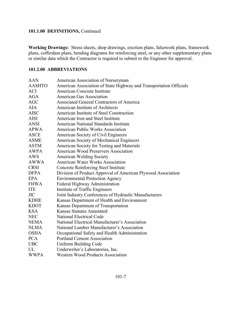
Working Drawings: Stress sheets, shop drawings, erection plans, falsework plans, frameworkplans, cofferdam plans, bending diagrams for reinforcing steel, or any other supplementary plansor similar data which the Contractor is required to submit to the Engineer for approval.
101.2.00 ABBREVIATIONS
AAN American Association of NurserymanAASHTO American Association of State Highway and Transportation OfficialsACI American Concrete InstituteAGA American Gas AssociationAGC Associated General Contractors of AmericaAIA American Institute of ArchitectsAISC American Institute of Steel ConstructionAISI American Iron and Steel InstituteANSI American National Standards InstituteAPWA American Public Works AssociationASCE American Society of Civil EngineersASME American Society of Mechanical EngineersASTM American Society for Testing and MaterialsAWPA American Wood Preservers AssociationAWS American Welding SocietyAWWA American Water Works AssociationCRSI Concrete Reinforcing Steel InstituteDFPA Division of Product Approval of American Plywood AssociationEPA Environmental Protection AgencyFHWA Federal Highway AdministrationITE Institute of Traffic EngineersJIC Joint Industry Conferences of Hydraulic ManufacturersKDHE Kansas Department of Health and EnvironmentKDOT Kansas Department of TransportationKSA Kansas Statutes AnnotatedNEC National Electrical CodeNEMA National Electrical Manufacturer’s AssociationNLMA National Lumber Manufacturer’s AssociationOSHA Occupational Safety and Health AdministrationPCA Portland Cement AssociationUBC Uniform Building CodeUL Underwriter’s Laboratories, Inc.WWPA Western Wood Products Association
101-7
102 PROPOSAL REQUIREMENTS
102.1.00 Prequalification of Bidders
102.1.00 Form of Proposal
102.3.00 Withdrawal, Modification or Alteration of Proposal
102.4.00 Late Proposal
102.5.00 Proposal Guaranty
102.6.0 Examination of Plans, Standard Plans or Drawings, Specifications and Site ofWork
102.7.00 Interpretation of Contract Documents
102.8.00 Addenda to Contract Documents
102.9.00 Familiarity with Laws and Ordinances
102.10.00 Amount of Work to Be Done
102.11.00 Bid Prices to Cover Entire Work
102.12.00 Rejection of Proposals
102-1
102 PROPOSAL REQUIREMENTS
102.1.00 Prequalification of Bidders: Each bidder, when requested, shall furnish the Ownersatisfactory evidence of his competency to perform the proposed work. Such evidence ofcompetency, unless otherwise specified, shall consist of statements covering the bidder’s pastexperience on similar work, a list of equipment that would be available for the work, and a list ofkey personnel that would be available. In addition, each bidder shall furnish the Ownersatisfactory evidence of his financial responsibility. Such evidence of financial responsibility,unless otherwise specified, shall consist of a confidential statement or report of the bidder’sfinancial resources and liabilities as of the last calendar year or the Contractor’s last fiscal year.Such statements or reports shall be certified by a public accountant. At the time of submittingsuch financial statements or reports, the bidder shall further certify whether his financialresponsibility is approximately the same as stated or reported by the public accountant. If thebidder’s financial responsibility has changed, the bidder shall qualify the public accountant’sstatement or report to reflect his (bidder’s) true financial condition at the time such qualifiedstatement or report is submitted to the Owner.
Unless otherwise specified, a bidder may submit evidence that he is prequalified with the StateHighway Division and is on the current “Bidder’s List” of the State in which the proposed workis located. Such evidence of State Highway Division prequalification may be submitted asevidence or financial responsibility in lieu of the certified statements or reports hereinbeforespecified.
102.2.00 Form of Proposal: Bidders shall enclose the proposal, bid bond, or certified check orcashier’s check in a sealed envelope, labeled and addressed and file as required.
All proposals shall be clearly and distinctly typed or written. Changes may be made, providedthe change is initialed.
All proposals shall be on the form furnished by the Owner, and in addition to the necessary unitprice items and total prices in the column of totals to make a complete bid, all applicable blanksgiving general information must be filled in and the bid signed by the Contractor or a dulyauthorized agent. Any statement accompanying and tending to qualify a bid may cause rejectionof such bid, unless such statement is required or permitted.
102-2
102.2.00 Form of Proposal, Continued
Unless otherwise specified, bidders shall bid on all bid items included in the proposal and thelower bidder shall be determined in accordance with subsection 103.1.00
102.3.00 Withdrawal, Modification or Alteration of Proposal: A proposal may bewithdrawn upon written request of the bidder prior to the scheduled closing time for filing bids.Negligence on the part of the bidder in preparing his proposal confers no right to withdraw hisproposal after the scheduled closing time for filing bids.
Change in a delivered proposal will be permitted only if a request for making such modificationis made in writing, signed by the bidder, and the specific modification is stated and receivedprior to the scheduled closing time for filing bids.
102.4.00 Late Proposals: Proposals received after the scheduled closing time for filing bidswill not be opened or considered by the Owner unless such bid, if sent through the mails, showsa legible postmark or post office cancellation proving the time of mailing was at least 48 hoursprior to the scheduled closing time for filing bids, and such proposal is received before the awardhas been made.
102.5.00 Proposal Guaranty: Unless covered by an annual bid bond in an unencumberedamount sufficient to cover all pending bids which is filed with the Owner, all proposals must beaccompanied by a proposal guarantee in the form of a certified check payable to the order of theOwner, or a bidder’s bond for the single bid submitted, in an amount as specified in the proposal.Such proposal guarantee may be forfeited as liquidated damages in case the bidder shall fail orneglect to furnish a performance bond and insurance, as required, or to execute the contractwithin ten days after receiving said contract from the Owner for execution.
102.6.00 Examination of Plans, Standard Plans or Drawings, Specifications and Site ofWork: Bidders shall determine for themselves all the conditions and circumstances affecting theproject or the cost of the proposed work by personal examination of the site, the ContractDocuments, and by such other means as they may choose. It is understood and agreed thatinformation regarding underground or other conditions or obstructions indicated in the ContractDocuments has been obtained by the Owner from data at hand. There is no express or impliedagreement that such conditions are fully or correctly shown and the bidder must take intoconsideration the possibility that conditions affecting the cost or quantity of work may differfrom those indicated.
102-3
102.7.00 Interpretation of Contract Documents: If it should appear to a bidder that the workto be done or matters relative thereto are not sufficiently described or explained in the ContractDocuments or that the Contract Documents are not definite and clear, the bidder may makewritten inquiry regarding same to the Engineer at least five (5) days before the scheduled closingtime for filing bids. Then, if in the judgement of the Engineer, additional information orinterpretation is necessary such information will be supplied in the form of an addendum whichwill be delivered to all individuals, firms and corporations who have taken out ContractDocuments. Such addendum shall have the same binding affect as though contained in the mainbody of the Contract Documents. ORAL INSTRUCTIONS OR INFORMATIONCONCERNING THE CONTRACT DOCUMENTS OR THE PROJECT GIVEN OUT BYOFFICERS, EMPLOYEES OR AGENTS OF THE OWNER TO PROSPECTIVE BIDDERSSHALL NOT BIND THE OWNER.
102.8.00 Addenda to Contract Documents: Any addendum or addenda issued by theEngineer which may include changes, corrections, additions, interpretations or information, andissued seventy-two (72) hours or more before the scheduled closing time for filing bids,Saturday, Sunday and legal holidays not included, shall be binding upon the bidder. The Ownershall send copies of such addenda to all Contractors who have obtained copies of the ContractDocuments for the purpose of bidding. Receipt of any such addendum shall be signed by thebidder and submitted with the bid proposal or acknowledged on the bid proposal forms.
102.9.00 Familiarity with Laws and Ordinances: The bidder is assumed to be familiar withall Federal, State and local laws, ordinances, and regulations which in any manner affect thoseengaged or employed in the work or the materials or equipment used in the proposedconstruction, or which in any way affect the conduct of the work, and no plea ofmisunderstanding will be considered on account of ignorance thereof. If the bidder, orContractor shall discover any provision in the Contract Documents which is contrary to orinconsistent with any law, ordinance, or regulation, he shall forthwith report it to the Owner inwriting.
102.10.00 Amount of Work to be Done: The Owner reserves the right to increase or decreasethe amount of any class or portion of the work. No such change in the work shall be consideredas a waiver of any condition of the contract nor shall such change invalidate any of theprovisions thereof.
The estimate of quantities of work to be done under unit price bids is approximate and is givenonly as a basis of calculation for comparison of bids and award of the contract. The Owner doesnot by implication agree that the actual amount of the work will correspond precisely to theamount as shown or estimated.
102-4
102.10.00 Amount of Work to be Done, Continued
The scheduled quantities of work to be done and materials to be furnished may each beincreased, decreased, or omitted. Payment will be made at the unit prices under the contract onlyfor the work performed or materials furnished except as specified in subsection 104.5.00.
102.11.00 Bid Prices to Cover Entire Work: Bidders must include in their bid prices theentire cost of each item of work set forth in the proposal, and it is understood and agreed thatthere is included in each lump sum or unit price bid the entire cost of materials and laborincidental or necessary to the completion of that portion of the work covered, unless suchincidental work is expressly included in other lump sum or unit price bids in the proposal.
102.12.00 Rejection of Proposals: The Owner reserves the right to reject all bid proposals.
102-5
103 AWARD AND EXECUTION OF CONTRACT
103.1.00 Award of Contract
103.2.00 Execution of Contract
103.3.00 Failure to Execute Contract
103.4.00 Return of Proposal Guaranty
103.5.00 Assignments
103.6.00 Performance Bond
103.7.00 Owners Immunity from Liability
103.8.00 Proof of Carriage of Insurance
103.9.00 Certificates of Compliance
103-1
103 AWARD AND EXECUTION OF CONTRACT
103.1.00 Award of Contract: The award will be made by the Owner to the bidder submittingthe lowest acceptable bid, discounts if any, the time of completion or delivery proposed ascompared to equal bids, the relative merits and performance of any item specifically proposed bythe bidder, any variation in maintenance and guaranty period specially proposed by the bidder inexcess of any minimums specified, the realistic balance of prices in the proposals for variousparts or units of the work, and the experience and ability of the bidder to perform the work. TheOwner reserves the right to waive any informalities and/or irregularities in said proposals.
While price extensions are required as a matter of convenience, in the event of error inextensions, the unit prices bid shall govern. In the event of discrepancy between the written andnumerical amounts, the written prices will govern.
Determination of the lowest acceptable bidder and award may be subject to review anddetermination by the attorney as to legal sufficiency of any bid submitted.
The award of contract, if it be awarded, shall be made within thirty (30) calendar days after thedate of opening of bids, and shall be a notice in writing mailed or delivered at the officedesignated on the proposals.
Existing State Law (KSA 75-3740a) requires that to the extent permitted by federal law andregulations the Owner, when letting contracts for bids, must require any successful Bidder-Contractor domiciled outside the State of Kansas to submit a bid the same percent less than thelowest bid submitted by a responsible Kansas Contractor as would be required of such Kansasdomiciled Contractor to succeed over the bidding Contractor domiciled outside Kansas on a likeContract let in the foreign bidder’s domiciled state. All bids are received on this condition and ifit is determined by the Owner that the apparent lowest and best bidder is a foreign domiciledContractor who has failed to comply with this State requirement, such bid shall be rejected.
103.2.00 Execution of Contract: Within ten (10) days after the date the bidder receivesnotification of award of contract as evidenced by receipt from the Owner of properly preparedcontract documents, the bidder to whom award is made shall execute and return the contract inthe required number of copies, and shall furnish a performance bond and other required bondsand insurance satisfactory to the Owner.
103.3.00 Failure to Execute Contract: Failure on the part of the bidder to whom the contractis awarded to execute the contract and to deliver the contract and required performance
103-2
103.3.00 Failure to Execute Contract, Continued
bond as described in subsection 103.6.00, shall be just cause for cancellation of the award, withdrawal of the contract and forfeiture of the proposal guaranty. The forfeited proposal guaranty shall become the property of the Owner. Award may then be made to the next lowest acceptable bidder, or the work may be readvertised, or it may be constructed under contract or otherwise, as the Owner may decide.
103.4.00 Return of Proposal Guaranty: Upon execution of the contract and bond by the successful bidder, his proposal guaranty shall be returned to him. The bidder who has a contract awarded to him and who fails promptly and properly to execute the contract or bond shall forfeit the proposal guaranty that accompanied his bid. The proposal guaranty shall be taken and considered as liquidated damages and not as a penalty for failure of the bidder to execute the contract and bond. The proposal guaranty of unsuccessful bidders will be returned after the bids have been opened and the contract has been awarded, and shall not be retained after the contract has been duly signed. The Owner reserves the right to retain the bid security of the three (3) lowest bidders until the awarded contract has been signed and returned.
103.5.00 Assignments: Neither the contract nor any interest therein shall be transferred to any other party or parties without the prior written consent of the Owner. In case of such attempted transfer without permission, the Owner may refuse to carry out the contract either with the transferor or the transferee, but all rights of action for any breach of the contract by said Contractor are reserved to the Owner. No person employed in the Owner’s service, is or shall be permitted any share or part of the contract or is or shall be entitled to any benefit which may arise therefrom.
103.6.00 Performance Bond (Revised 7-2016): The successful Bidder shall furnish a contract, performance, payment, and guarantee bond within ten (10) days on the forms furnished by the City, unless the contract for public improvements, constructing of public building, or repairing the same, is in a sum less than $50,000. If said contract is in a sum less than $50,000, the requirement of furnishing appropriate bonds may be imposed at the discretion of the City. When a bond is required it shall be for the full amount of the contract. The bond shall be a security for the faithful performance of the contract, payment of personnel and materials, and the work guarantee required by the contract. A corporation authorized to contract as a Surety in the State of Kansas and satisfactory to the City must execute any bonds.
103.7.00 Owner’s Immunity from Liability: The Contractor shall save, keep and hold harmless and defend, the Owner, the Engineer and his consultants, and all employees, officers and agents thereof from all damages, costs or expenses in law or equity that may at any time arise or be set up because of damages to property or of personal injury received either by reason of or in the course of performing said work which may be occasioned by employees, or any Subcontractor performing any of the work.
103-3A (Revised 2016 07)
103.7.00 Owner’s Immunity from Liability, Continued
The Owner shall not be liable or responsible for any accident, loss or damage happening to thework referred to in the contract prior to the completion and acceptance thereof.
103.8.00 Proof of Carriage of Insurance: Work shall not commence until all insurancerequired in the contract has been obtained nor until such insurance has been approved by theOwner, nor shall any Subcontractor commence work until he also has first obtained insuranceapplicable to such work. The Contractor shall maintain insurance throughout the life of thecontract which will hold the Owner harmless and shall indemnify the Owner for any and alllosses to third persons or to the Owner arising out of the operations, including any contingentliability arising therefrom.
The Owner will only accept coverage from an insurance carrier who offers proof that it islicensed to do business in the State of Kansas.
103.9.00 Certificates of Compliance: Prior to the acceptance of the work, the Owner mayrequire a certificate in form substantially as follows: “I (We) hereby certify that all work hasbeen performed and materials supplied in accordance with the Contract Documents for the abovework, and that:
1. Not less than the prevailing rates of wages has been paid to laborers, workers andmechanics employed on those projects required by Federal or State regulation orif specifically required by the Special Provisions;
2. There have been no unauthorized substitutions; nor have any subcontracts beenentered into without the names of the Subcontractors having been submitted to theEngineer prior to the start of such subcontracted work;
3. No subcontract was assigned or transferred or performed by any Subcontractorother than the original Subcontractor, without prior notice having been submittedto the Engineer together with the names of all Subcontractors;
4. All claims for material and labor and other service performed in connection withthese specifications have been paid;
5. All monies due the State of Kansas, or any kind or character have been paid, andhospital associations and/or others have been paid.”
103-4

104 SCOPE OF WORK
104.1.00 Intent of Contract
104.2.00 Plans and Specifications
104.3.00 Precedence of Contract Documents
104.4.00 Shop Drawings
104.5.00 Changes in Work104.5.01 Changes Requested by the Contractor104.5.02 Changes Initiated by the Owner
104.6.00 Changed Conditions
104.7.00 Disputed Work
104.8.00 Records
104.9.0 Extra Work104.9.01 General104.9.02 Payment104.9.02A Labor104.9.02B Materials104.9.02C Equipment Rental
104-1
104.1.00 Intent of Contract: The intent of the contract is to provide for the construction andcompletion of the work described. The Contractor shall furnish all labor, materials, equipment,tools, transportation and supplies required to complete the work in accordance with the plans,specifications and terms of the contract.
The Contractor shall perform all work in accordance with the lines, grades, typical crosssections, dimensions and other data shown on the plans or as modified by written orders of theEngineer, and all other work determined by the Engineer as necessary to proper prosecution andcompletion of the project.
104.2.00 Plans and Specifications: The plans, specifications and other contract documents willgovern the work. The contract documents are intended to be complementary and cooperativeand to describe and provide for a complete project. Anything in the specifications and not on theplans, or on the plans and not in the specifications, shall be as though shown or mentioned inboth. Reference specifications and standard plans are a part of the contract documents.
While it is believed that much of the information pertaining to conditions which may affect thecost of the proposed work will be shown on the plans or indicated in the specifications, theOwner does not warrant the completeness or accuracy of such information. It is the Contractor’sresponsibility to ascertain the existence of any conditions affecting the cost of the work whichwould have been disclosed by reasonable examination of the site.
The Contractor shall, upon discovering any error or omission in the plans or specifications,immediately call it to the attention of the Engineer.
104.3.00 Precedence of Contract Documents: If there is a conflict between contractdocuments, the document highest in precedence shall control. The precedence shall be:
1. Permits from other agencies as may be required by law.2. Special Provisions.3. Plans4. Standard plans5. Standard specifications6. Reference specifications
Change orders, supplemental agreements and approved revisions to plans and specifications willtake precedence over documents listed above. Detailed plans shall have precedence over generalplans.
104-2
104.4.00 Shop Drawings: When shop drawings are required by the Engineer, they shall beprepared in accordance with current modern Engineering practice and at the Contractor’sexpense. Drawings shall be of a size and scale to show clearly all necessary details and shall betransmitted by letter to the Engineer for approval or correction before commencing the work.
Materials shall not be furnished or fabricated nor any work done for which drawings arerequired, before approval of the drawings.
Approval of drawings by the Engineer shall not relieve the Contractor from the responsibility forerrors or omissions in the drawings or from deviations from the contract documents unless suchdeviations were specifically called to the attention of the Engineer in the letter of transmittalsubmitted with the drawings. The Contractor shall be responsible for the corrections of thedrawings, for shop fits and field connections, and for the results obtained by use of suchdrawings.
104.5.00 Changes in Work
104.5.01 Changes Requested by the Contractor: Changes in specified methods ofconstruction may be made at the Contractor’s request when approved in writing by the Engineer.
Changes in the plans and specifications, requested in writing by the Contractor, which do notmaterially affect the work and which are not detrimental to the work or to the interests of theOwner, may be granted by the Engineer. Payment to be made per Section 109 of thesespecifications.
104.5.02 Changes Initiated by the Owner: The Owner reserves the right to make suchalterations in the plans or in the quantities of work as may be considered necessary. Suchalterations shall be in writing by the Engineer and shall not be considered as a waiver of anyconditions of the contract nor to invalidate any of the provisions thereof; provided, however, thatthe execution of a supplemental agreement acceptable to both parties of the contract will benecessary before any alteration is made which involves (1) an extension or shortening of thelength of the project by more than 25%, (2) an increase or decrease of more than 25% of the totalcost of the work calculated from the original proposal quantities and the unit contract prices, or(3) an increase or decrease of more than 25% in the quantity of any one major contract item. Forcondition (3) above, a major item is defined as any item, unless otherwise indicated on the plansor designated in the special provisions, the contract price for which amounts to 5% or more ofthe total contract price as determined by the original unit contract prices.
Alterations involving an increase of more than 25% in the net of any one minor contract itemwill not require a supplemental agreement.
104-3
104.5.02 Changes Initiated by the Owner, Continued
Change orders shall be in writing and state the dollar value of the change or established methodof payment, any adjustments in contract time and, when negotiated prices are involved, shallprovide for the Contractor’s signature indicating acceptance.
Payment for all work to be made per Section 109 of these specifications.
104.6.00 Changed Conditions: The Contractor shall notify the Engineer in writing of thefollowing work site conditions, hereinafter called changed conditions, promptly upon theirdiscovery and before they are disturbed:
(a) Subsurface or latent physical conditions differing materially from thoserepresented in the contract; and
(b) Unknown physical conditions of an unusual nature differing materially from thoseordinarily encountered and generally recognized as inherent in work of thecharacter being performed.
The Engineer will promptly investigate conditions of which notified or any conditionsdiscovered by the Engineer which appear to be changed conditions. If it is determined that theconditions are changed conditions and that they will materially increase or decrease the costs orany portion of work, a change order will be issued by the Engineer adjusting the compensationfor such portion of the work. If the Engineer determines that conditions of which notified by theContractor do not justify an adjustment in compensation, the Contractor will be so advised inwriting. Should the Contractor disagree with such determination, a notice of potential claim maybe submitted to the Engineer.
104.7.00 Disputed Work: If unable to reach agreement under any of the foregoing procedures,the Owner may direct the Contractor to proceed with the work. Payment shall be as laterdetermined by an appeals board when such a procedure is provided for by the Owner, or as fixedin a court of law.
Although not to be construed as proceeding under extra work provisions, the Contractor shallkeep and furnish records or all disputed work.
104-4

104.8.00 Records: The Contractor shall maintain records in such a manner as to provide a cleardistinction between the direct cost of extra work paid for on the force account basis and the costsof other operations performed in connection with the contract.
The Contractor shall furnish to the Engineer daily reports in duplicate of the extra work to bepaid for on a force account basis. The reports shall itemize the materials used and shall set forththe direct cost of labor and the charges for equipment rental whether furnished by the Contractor,or Subcontractor. The reports shall provide the names or identifications and classifications ofworkers, the hourly rate of pay and hours worked together with the size, type and identificationnumber of equipment and hours of equipment operations.
Failure to present claims on extra work in proper form within thirty (30) days after the close ofthe month in which the work covered was performed shall constitute a waiver on the part of theContractor of his right to present such claim thereafter or to receive payment thereof.
All reports shall be signed by the Contractor or an authorized representative.
The Engineer will compare records with the reports furnished by the Contractor, make anynecessary adjustments and then compile the costs of extra work paid for on a force account basison forms furnished by the contracting agency. When these extra work reports are agreed uponand signed by both parties, they shall become the basis of payment for the work performed.
104.9.00 Extra Work
104.9.01 General: New or unforeseen work will be classed as “extra work” when the Engineerdetermines that it is not covered by contract unit prices or stipulated unit prices and the characterof such work is substantially different from than on which the Contractor bid.
104.9.02 Payment: Payment for extra work will be established by agreement between theContractor and the Owner. If no agreement can be reached, payment will be made on the basisof Section 109.6.00 Payment for Force Account Work.
The Contractor shall maintain records sufficient to distinguish the direct cost of extra work fromthe cost of other operations.
The Contractor shall furnish daily reports of extra work. The reports shall itemize all costs forlabor, materials, and equipment rental. The reports shall include for workers hours worked, ratesof pay, names and classifications; and for equipment, shall include size, type, identificationnumber and hours of operation.
104-5
104.9.02 Payment, Continued
All records and reports shall be made immediately available to the Engineer upon request.
All reports shall be signed by the Contractor or an authorized representative.
The Engineer’s records will be compared with the Contractor’s report, and the necessaryadjustments and compilation of the costs of extra work will be made. When extra work reportsare agreed upon and signed by both parties, they shall become the basis of payment.
104.9.02A Labor: On those projects required by Federal or State regulations to pay prevailingwage scales, labor costs shall be based on the prevailing wage scale for each craft or type ofworker. On projects where regulations do not require the payment of wage scales established byFederal or State agencies, labor costs shall be based on the rate normally paid by the Contractor.Each worker will be paid for the classification of work being done. Over-classification will notbe permitted or paid for. Employer payments for payroll taxes and insurance, health and welfare,pension, vacation and other direct labor costs shall be included.
104.9.02B Materials: The cost of materials incorporated in the work will be the cost to thepurchaser, whether Contractor, Subcontractor or other forces, from the supplier thereof, except asfollows:
(a) If materials are procured by the purchaser by any method which is not a directpurchase from and a direct billing by the actual supplier to such purchaser, thecost of such materials shall be deemed to be the price paid the actual supplier asdetermined by the Engineer. No markup except, for actual costs incurred in thehandling of such materials will be permitted.
(b) If the materials are obtained from a supplier or source owned wholly or in part bythe purchaser, payment therefor will not exceed the price paid by the purchaserfor similar materials furnished from said source on contract items or the currentprice of such materials delivered to the job site, whichever price is lower.
(c) The Owner reserves the right to furnish such materials as it deems advisable, andthe Contractor shall have no claims for costs and profit on such furnishedmaterials.
104.9.02C Equipment Rental: The Contractor will be paid for the use of equipment on thebasis of, but not exceeding the prevailing hourly rental rates established by the KansasDepartment of Transportation and recognized by the Associated General Contractors for the areawhere such equipment is required to be operated.
104-6
104.9.02C Equipment Rental, Continued
On any equipment for which no rental rate has been established by the Kansas Department ofTransportation, or where the required operation of the equipment is less than four hours or inexcess of one week, rental rates shall be proposed by the Contractor and agreed upon in writingby the Engineer prior to the start of force account work.
Equipment that is in operational condition and is standing by with the Engineer’s approval forparticipation in force account work, will be paid for at 50 percent of the agreed upon rental rate.All equipment to be used for extra work shall be approved by the Engineer.
Rental time will not be allowed while equipment is inoperative due to breakdowns for periods inexcess of 30 minutes. Rental time shall be computed in ½ hour increments. In computing rentaltime of equipment in actual operation, less than 30 minutes will be considered ½ hour.
The rental rates paid, as above provided, shall include the cost of fuel, oil, lubrication, supplies,small tools, necessary attachments, repair and maintenance of any kind, depreciation, storage,insurance and all incidentals.
All equipment shall, in the opinion of the Engineer, be in good working condition and suitablefor the purpose for which the equipment is to be used.
Unless otherwise specified, manufacturer’s ratings and manufacturer approved modificationsshall be used to classify equipment for the determination of applicable rental rates. Equipmentwhich has no direct power unit shall be powered by a unit of at least the minimum ratingrecommended by the manufacturer.
Individual pieces of equipment or tools having a replacement value of $100.00 or less, whetheror not consumed by use, shall be considered to be small tools and no payment will be madetherefor.
The rental time to be paid for equipment on the work shall be the time the equipment is inoperation on the extra work being performed and, in addition, shall include the time required tomove the equipment to be used at the site of the extra work on other than such extra work.Loading and transporting costs will be allowed, in lieu of moving time, when the equipment ismoved by means other than its own power, except that no payment will be made if the equipmentis used at the site of the extra work on other than such extra work.
The rental period shall begin at the time the equipment is unloaded at the site of the extra work,shall include each day that the equipment is at the site of the extra work, excluding Saturdays andlegal holidays unless the extra work is perform on such days, and shall terminate at the end of theday on which the Engineer directs the Contractor to discontinue the use of such equipment. Themaximum rental time to be paid per day will not exceed eight hours unless the equipment is inoperation for a longer time.
104-7
105 CONTROL OF WORK
105.1.00 Authority of the Engineer
105.2.00 Authority and Duties of Inspectors
105.3.00 Disputed Work
105.4.00 Responsibility of the Contractor
105.5.00 Notifications Relative to Contractor’s Activities
105.6.00 Utilities and Existing Improvements
105.7.00 Survey Service
105.8.00 Protection of Survey Markers
105.9.00 Other Surveyors
105.10.00 Protection of Property
105.11.00 Temporary Traffic Control
105.12.00 Protection of Work
105.13.00 Maintenance of Work after Acceptance
105.14.00 Use of Light, Power, and Water
105.15.00 Subsurface Data
105.16.00 Verbal Agreements
105.17.00 Dust Control
105.18.00 Removal of Defective or Unauthorized Work
105.19.00 Cleanup
105.20.00 Final Inspection
105-1
105 CONTROL OF WORK
105.1.00 Authority of the Engineer: Subject to such authority as is delegated by the Owner,the Engineer will decide all questions which may arise as to the quantity, quality andacceptability of materials furnished and work performed, the rate of progress of the work; changeorders and time extensions; interpretation of the plans and specifications; the measurement of allquantities; the acceptable fulfillment of the contract on the part of the Contractor. TheEngineer’s estimates and decisions in these matters shall be final, binding and conclusive uponall parties of the contract.
It is further understood that all work to be done under the contract will not be consideredcompleted until it has passed final inspection by the Engineer and is accepted by the Owner. It isfurther understood that the authority of the Engineer is such that the Contractor shall at all timescarry out and fulfill the instructions and directions of the Engineer insofar as they concern thework to be done under the contract.
Upon failure on the part of the Contractor to comply with any order made under the provisions ofthis subsection, the Engineer shall have the authority to suspend the work for cause as set forth inSection 108, particularly subsection 108.5.00.
Approval by the Engineer signifies favorable opinion and qualified consent; it does not carrywith it certifications, nor assurance of completeness nor assurance of quality nor assurance ofaccuracy concerning details, dimensions and quantities. Such approval will not relieve theContractor from responsibility for errors, for improper fabrication, for nonconformance torequirements or for deficiencies within his control.
105.2.00 Authority and Duties of Inspectors: The Engineer may appoint assistants to inspectall materials used and all work done. Such inspection may extend to any or all parts of the workand to the preparation or manufacture of the materials to be used. The inspectors will not beauthorized to revoke, alter, enlarge or relax the provisions of these specifications. An inspectoris placed on the work to set the necessary lines and grades and to keep the Engineer informed asto the process of the work and the manner in which it is being done; also to call the attention ofthe Contractor to any infringements upon plans or specifications, but failure of the inspection orthe Engineer to call the attention of the Contractor to faulty work or infringements upon plans orspecifications shall not constitute acceptance of said work.
105-2
105.2.00 Authority and Duties of Inspectors, Continued
An inspector will not be authorized to approve or accept any portion of the work or to issueinstructions contrary to the plans and specifications. The inspector will have the authority toreject defective material and to suspend any work that is being improperly done, subject to thefinal decision of the Engineer. The inspector will exercise such additional authority as may,from time to time, be especially delegated to him by the Engineer.
105.3.00 Disputed Work: If the Contractor considers any work demanded of him to be outsidehe scope of the contract or considers any ruling of the Engineer to be unfair, upon such workbeing demanded or such ruling being made, the Contractor shall proceed without delay toperform the work or to conform to the ruling. The Contractor shall within ten days after the dateof receipt of the instructions or ruling, file a written protest with the Engineer, stating clearly andin detail the basis of objection, and include an itemized statement of any extra costs which mayhave resulted. Except for such protests or objections as are made of record in the manner hereinspecified and within the time limit stated, the records, rulings, instructions or decisions of theEngineer will be final and conclusive.
105.4.00 Responsibility of the Contractor: The Contractor shall do all the work and furnishall labor, materials, equipment, tools and machines necessary for the performance andcompletion of the project in accordance with the contract documents within the specified time.
Material and construction details of plants, forms, shoring, falsework and other structures builtby the Contractor but not a part of the permanent project shall meet the approval of the Engineer,but such approval shall not relieve the Contractor from responsibility for their safety andsufficiency.
The Contractor shall be responsible for all expense involved in making any required changes inthe plans or specifications to accommodate a substitution approved by the Engineer for theconvenience of the Contractor or to circumvent an unforeseen difficulty in obtaining a specifiedarticle.
The Contractor shall assume all responsibility for the work. As between him and the Owner, theContractor shall bear all losses and damages directly or indirectly resulting to him, to the Owneror to others on account of the character of performance of the work, unforeseen difficulties,accidents or any other cause whatsoever. The Contractor shall assume the duty to defend,
105-3
105.4.00 Responsibility of the Contractor, Continued
Indemnify and save harmless the Owner, its officers and employees from all claims, liability,loss, damage and injury of every kind, nature and description, directly or indirectly resultingfrom the Contractor’s activities in the performance of the contract, the Ownership, maintenanceor use of motor vehicles in connection herewith, or the acts, omissions, operations, or conduct ofthe Contractor or any Subcontractor under the contract, or in any way arising out of the contract,irrespective of whether fault is the basis of the liability of claim, and irrespective of whether anyact, omission or conduct of the Owner connected with the contract is a condition or contributorycause of the claimed liability, loss, damage or injury and irrespective of whether act, omission orconduct of the Contractor of Subcontractor is merely a condition rather than a cause of the claim,liability, loss, damage or injury. The Contractor shall not be liable for, nor be required to defendor indemnify the Owner relative to claims for damage or damages resulting solely from acts oromissions of the Owner, its officers, agents, or employees.
The Contractor shall be responsible to notify the Engineer 24 hours in advance for inspection ofall portions of the work, and all forms shall be inspected prior to placement of concrete.
105.5.00 Notifications Relative to Contractor’s Activities: The Contractor shall obtain priorapproval from the Engineer for the closing or partial closing of any road, street, alley or otherpublic thoroughfare. The Contractor shall give at least 24 hour advance notice of such closure toall agencies providing emergency services, including, but not limited to, the sheriff, police, fireand ambulance services.
The Contractor shall notify all utilities before commencing work including, but not limited to,gas, communications, power, water, sewerage and drainage.
Utilities may not be located as shown or marked as the location may have been established fromrecords and not from on-site inspection. The Contractor shall notify utilities at least two workingdays prior to commencing work of the date on which work will commence, in order to give theutilities a reasonable opportunity to establish the location of utilities by on-site examination priorto commencing the work. The Contractor shall adhere to the above notification requirementsduring the progress of the work where the work is such that location of utilities is necessary asthe work progresses.
The Contractor shall notify all agencies involved by the operations so as to properly coordinateand expedite the work in such a manner as to cause the least amount of conflict and interferencebetween such operations and those of other agencies.
105-4
105.5.00 Notifications Relative to Contractor’s Activities, Continued
Notification shall include, but not be limited to, the time of commencement and completion ofwork, names of streets or location of alleys to be closed, schedule of operations and routes ofdetours where possible.
Damages or claims resulting from improper or insufficient notification of the affected agenciesshall be the responsibility of the Contractor.
105.6.00 Utilities and Existing Improvements: Any information shown as to the location ofexisting water courses, drains, sewer lines or utility lines which cross or are adjacent to theproject has been compiled from the best available sources, but is not guaranteed to be accurate.
The Contractor shall provide for the flow of sewers, drains or water courses interrupted duringthe progress of the work, and shall restore such drains or water courses as approved by theEngineer. The Contractor shall make excavations and borings ahead of the work as necessary, todetermine the exact location of interfering utilities or underground structures.
Ordinarily, utility companies responsible for facilities located with the right-of-way will berequired to complete any installation, relocation, repair, or replacement prior to thecommencement of work by the Contractor. However, when this is not feasible or practicable orthe need for such work was not foreseen, such utility owners or the Owner shall have the right toenter upon the right-of-way and upon any structure therein for the purpose of making newinstallations, changes or repairs. The Contractor shall conduct operations so as to provide thetime needed for such work to be accomplished during the progress of the improvement.
The Contractor shall be responsible for all costs for the repair of damage to the contract work orto any utility, previously known or disclosed during the work, as may be caused by operations.The Contractor shall maintain in place utilities not shown on the drawing to be relocated oraltered by others and shall maintain utilities which are relocated by others in their relocatedpositions in order to avoid interference with structures which cross the project work. All costsfor such work shall be included in the prices bid for the various items or work.
105-5
105.7.00 Survey Service: The Contractor shall give notice to the Engineer not less than twoworking days in advance of when survey services will be required in connection with the layingout of any portion of the work.
The Owner will furnish and set construction stakes establishing lines and grades as determinednecessary by the Engineer for all work under the contract, including lines and grades for streetexcavation and fill, finished subgrade, finished base material, curbs and gutters, walks, structuresand utilities, and will furnish the Contractor all the necessary information relative to the lines andgrades.
The Owner will furnish appropriate offset lines and grades for all projects.
Any errors found shall be brought to the attention of the Engineer immediately. Such stakes andmarkings, as the Engineer may set for either his own or the Contractor’s guidance, shall becarefully preserved by the Contractor. In case of negligence on the part of the Contractor or hisemployees, resulting in the destruction of such stakes or markings, they shall be replaced by theEngineer at the Contractor’s expense.
The Contractor shall be responsible for the transfer of the line and grade from the stakes to thework and the method of transfer shall be acceptable to the Engineer and adequate to insureconstruction within allowable tolerances.
All grades indicated in the field and on the drawings, unless otherwise stated, shall be as follows:
1. Streets Top back of curb2. Alleys Finish grade at the outside margin.3. Sidewalks Finish grade nearest street.4. Sewers and Pipes Invert elevation at centerline of pipe.
105.8.00 Protection of Survey Markers
105.8.01 Permanent Survey Markers: The Contractor shall notify the Engineer not less thanseven days prior to starting work in order that the Engineer may take necessary measures toinsure the preservation of survey monuments, stakes and bench marks. The Contractor shall notdisturb permanent survey monuments, stakes, or bench marks without the consent of theEngineer, and shall notify the Engineer and bear the expense of replacing any that may bedisturbed without permission. Replacement shall be done by a registered land surveyor at noexpense to the Owner.
When a change is made in the finished elevation of the pavement of any roadway in which apermanent survey monument is located, the monument cover shall be adjusted to the new grade.
105-6
105.8.02 Lines and Grades: The Contractor shall preserve construction survey stakes andmarks for the duration of their usefulness during construction. If any construction survey stakesare lost or disturbed, and in the judgement of the Engineer need to be replaced, such replacementshall be by the Engineer at no expense to the Owner. The cost of replacement shall be chargedagainst, and shall be deducted from, the payment of the work.
105.8.03 Lot Stakes and Monuments: Unless otherwise directed by the Engineer or shown inthe plans, the Contractor shall preserve existing survey stakes or monuments that mark propertylines and corners. Any stakes or monuments that become lost or disturbed by his operationsshall be replaced by a registered land surveyor at no expense to the Owner.
105.9.00 Other Surveyors: Surveying by private land surveyors on permit projects or anyother work under the control of the Owner shall conform in all respects to the quality andpractice required of the Owner’s surveyors as set forth in subsection 105.7.00.
105.10.00 Protection of Property: The Contractor shall protect all public and private propertyinsofar as it may be endangered by operations and take every reasonable precaution to avoiddamage to such property.
The Contractor shall restore and bear the cost of any public or private improvement, facility orstructure within the right-of-way which is damaged or injured directly or indirectly by or onaccount of any act, omission or neglect in the execution of the work and which is not designatedfor removal and is visibly evident or correctly shown on the plans. The Contractor shall restoreto a condition substantially equivalent to that existing before such damage or injury occurred, byrepairing, rebuilding or otherwise affecting restoration thereof, or if this is not feasible, make asuitable settlement with the owner of the damaged property, all at no expense to the Owner.
The Contractor shall give reasonable notice to occupants of buildings on property adjacent to thework to permit the occupants to remove vehicles, trailers and other possessions as well assalvage or relocate plants, trees, fences, sprinkler systems or other improvements in the right-of-way which are designated for removal or which might be destroyed or damaged by workoperations. All depressions or holes below subgrade, whether caused by grubbing or otherwise,shall be backfilled with suitable compacted material to subgrade level.
The Contractor shall protect all designated trees and planted areas within the right-of-wayeasements, and shall exercise care and conduct operations so as to minimize damages to otherplanted areas.
105-7
105.10.00 Protection of Property, Continued
The Contractor shall review with the Engineer the location, limits and methods to be used priorto clearing work. Clearing and grubbing shall be performed in strict compliance with all local,state and federal laws and requirements pertaining to cleaning and burning.
Mail boxes to be removed during the course of construction shall be temporarily relocated inaccordance with the Postal Department requirements at the expense of the Contractor. Uponcompletion of the project, the mail boxes shall be returned to their original location by theContractor in as good or better condition than existed prior to removal and in accordance withthe Postal Department regulations. Unless shown as being a pay item, such work shall beconsidered as incidental work for which no additional payment will be made.
105.11.00 Temporary Traffic Control: The Contractor shall provide and be responsible at alltimes for such flagmen, signs and other devices not otherwise specified to be furnished by theOwner. The Contractor shall erect and maintain all barricades, guards, standard constructionsigns, warning signs and detour signs, as are necessary to warn and protect the public at all timesfrom injury or damage as a result of the work operations on highways, roads or streets affectedby such operations.
Upon failure to immediately provide the necessary flagmen or to provide, erect, maintain andremove barricades, lights and standard signs when so ordered, the Engineer shall be at liberty,without further notice to the Contractor or the Contractor’s surety, to do so and deduct all of thecosts thereof from any payments due or coming due the Contractor.
Refer to section 202, in the General Specifications for the City of Dodge City, Kansas,TEMPORARY TRAFFIC CONTROL for additional requirements.
105.12.00 Protection of Work: Until acceptance of the project, the Contractor shall at all timesprotect from damage all public property and private property which may be affected by the workand preserve all materials, supplies, equipment of any description, and all work alreadyperformed, from the conduct of the work, the actions of the elements, and damage by any personor persons or from any other cause whatsoever.
105.13.00 Maintenance of Work After Acceptance: Upon the request of the Contractor andwith the approval of the Engineer, or upon the order of the Engineer, the Contractor will berelieved of the duty of maintaining and protecting certain portions of the work which areapproved to be placed in service and which have been completed in accordance with the contractdocuments, including cleanup.
105-8
105.13.00 Maintenance of Work After Acceptance, Continued
In addition, such action by the Engineer will relieve the Contractor of the responsibility forinjury or damage to said completed portions of the work resulting from use by public traffic orfrom the action of the elements or from any other cause, excepting injury or damage resultingfrom the Contractor’s own operations or negligence. The Contractor will not be required toagain clean up such portions of the improvement prior to field acceptance, excepting for suchitems of work as result from the Contractor’s operations. However, nothing in this section shallbe construed as relieving the Contractor from full responsibility for making good defective workor materials found to be defective.
105.14.00 Use of Light, Power and Water: The Contractor shall furnish temporary light,power and water complete with connecting piping, wiring, lamps and similar equipmentnecessary for the work as approved. The Contractor shall install, maintain and removetemporary lines upon completion of the work. The Contractor shall obtain all permits and bearall costs in connection with the temporary services and facilities at no expense to the Owner.
105.15.00 Subsurface Data: All information obtained by the Engineer regarding subsurfaceinformation and groundwater elevations will be available for inspection at the office of theEngineer upon request. Known utilities and structures expected to be adjacent to or encounteredin the work are shown on the plans. Such information is offered as supplementary informationonly. Neither the Engineer nor the Owner assumes any responsibility for the completeness orinterpretation of such supplementary information.
Logs of test holes, test pits, soils reports, groundwater levels and other supplementary subsurfaceinformation are offered as the best available information of underlying materials and conditionsat the locations actually tested. The Owner will not be liable for any loss sustained by theContractor as a result of any variance between conditions contained in or interpretations of testreports and the actual conditions encountered during progress of work.
The Contractor shall examine the site and available records, as set forth in subsection 102.6.00.The submission of a proposal shall be conclusive evidence that the bidder has investigated and issatisfied as to the subsurface conditions to be encountered, as to the character, quality andquantities of work to be performed and materials to be furnished and as to the requirements ofthe contract documents.
105-9
105.15.00 Subsurface Data, Continued
The Contractor shall contact all utility companies as to underground utilities in the area of workas set forth in section 105.5.00. Relocation of underground utilities which lie within theconstruction area or trench width necessary to complete the work shall be the responsibility ofthe Owner. Damage to existing utilities shall be the responsibility of the Contractor.
105.16.00 Verbal Agreements: No verbal agreement or conversation with any officer, agent oremployee of the Owner, either before or after execution of the contract, shall affect or modifyany of the terms or obligations contained in any of the documents comprising the contract. Anysuch verbal agreement or conversation shall be considered as unofficial information and in noway binding upon the Owner.
105.17.00 Dust Control: During all phases of the construction work, and when directed, theContractor shall take precautions to abate dust nuisance by cleaning up, sweeping, sprinklingwith water, or other means as necessary to accomplish the suppression of dust.
105.18.00 Removal of Defective or Unauthorized Work: All work which does not conformto the requirements of the contract shall be considered as unacceptable.
The Contractor shall remove all unacceptable and defective work. The Contractor shall performreplacement by work and materials which conform to the contract documents, or remedyotherwise in an approved manner. The provision shall have full effect regardless of the fact thatthe unacceptable work may have been done or the defective materials used with the fullknowledge of the inspector. The fact that the inspector in charge may have previouslyoverlooked such defective work shall not constitute an acceptance of any part of such work.Correction of all defective work shall be at no expense to the Owner.
The Contractor shall do no work without lines and grades having been given by the Engineer.Work done contrary to or regardless of the instructions of the Engineer, work done beyond thelines shown or as directed, except as herein provided, or any extra work done without authority,will be considered as unauthorized and will not be paid for under the provisions of the contract.Work so done may be ordered removed or replaced at no expense to the Owner.
105-10
105.18.00 Removal of Defective or Unauthorized Work, Continued
In the event any defect in work is of a minor nature and the Engineer determines that it is not ofsuch consequence as to result in a dangerous or undesirable condition, the Owner shall have theright to retain such work and make such deductions in the payment therefore as determinedreasonable and in the public interest. Such determinations by the Owner shall be final.
105.19.00 Cleanup: During all phases of construction, the Contractor shall keep the site freeand clean from all rubbish and debris and shall promptly clean up all or any portion of the sitewhen notified to do so by the Engineer. Care shall be taken to prevent spillage on the streetsover which hauling is done, and any such spillage debris deposited on streets due to theContractor’s operations shall immediately be cleaned up. Upon failure to do so within 24 hoursafter directed, the work may be done by the Owner and the cost thereof be deducted from anypayment due the Contractor. All costs of cleanup including all charges for water, are to beabsorbed in the prices bid for the various bid items.
After all other work embraced in the contract is completed and before final acceptance of thecontract, the entire right-of-way and easement area including the roadbed, planting, sidewalk,shoulders, driveways, alley and side street approaches, slopes, ditches, utility trenches, andconstruction areas shall be neatly finished to the lines, grades and cross sections shown and asspecified.
As a condition precedent to final acceptance of the project, the Contractor shall remove allequipment and temporary structures, and all rubbish, waste and generally clean up the right-of-way and premises to conform substantially to conditions as they existed before thecommencement of work.
105.20.00 Final Inspection: At such time as all construction work on the project is completeand all extra work bills, forms and documents required under the contract are submitted, theContractor shall so notify the Engineer in writing. The Engineer will make an inspection of theproject and project records within fifteen days of receiving said notice. If, at such inspection, allconstruction provided for and ordered under the contract is found completed and satisfactory andall certificates, bills, forms and documents have been properly submitted, such inspection shallconstitute the final inspection.
If any work in whole or in part is found unsatisfactory, or it is found that all certificates, bills,forms, and documents have not been properly submitted, the Engineer will give the Contractor
105-11
105.20.00 Final Inspection, Continued
The necessary instructions as to replacement of material and performance or reperformance ofconstruction work necessary and prerequisite to satisfactory final completion or constructionwork and will give the Contractor the necessary instructions for submission of bills, forms anddocuments, and the Contractor forthwith shall comply with and execute such instructions.
When the Contractor receives the notification he will have seven calendar days in which tocomplete the instructions from the Engineer. At the end of seven days, the day count willresume and will continue until all instructions have been complied with and executed.
105-12
106 CONTROL OF MATERIALS
106.1.00 Quality of Materials
106.2.00 Sampling and Testing
106.3.00 Certification
106.4.00 Inspection Requirements
106.5.00 Inspection by Others
106.6.00 Storage and Protection of Materials
106.7.00 Trade Names, Approved Equals and Substitutions
106.8.00 Mineral Deposits
106.9.00 Owner Furnished Material
106-1
106 CONTROL OF MATERIALS
106.1.00 Quality of Materials: The Contractor shall use only new materials, parts, productsand equipment in the work which conform to the specified requirements. The Contractor shalldetermine the kind of work, amount of work and other factors that may be necessary or involvedin furnishing the specified products and materials. Materials and products which, after approval,have become unsuitable or unacceptable for use, regardless of cause, will be rejected by theEngineer and shall not be used.
106.2.00 Sampling and Testing: Tests of materials will be made by the Owner in accordancewith the methods described or designated in the applicable specifications, and at any time duringthe production, fabrication, preparation and use of the materials.
The Owner reserves the right to require samples and to test products for compliance withpertinent requirements irrespective of prior certification of the products by the manufacturerthereof as set forth in Section 106.3.00.
When tests of materials are necessary, as determined by the Engineer, such tests will be made by,and at the expense of, the Owner unless otherwise specified. The Contractor shall afford suchfacilities as required for collecting and forwarding samples where practical and withhold fromuse the materials represented by the samples until tests have been made and the materials foundequal to the requirements of the specifications or to approved samples. In all cases, theContractor shall furnish and make available the required samples without charge. Samples shallbe made available in ample time to permit testing of the materials prior to use, and no claim willbe allowed for any delay caused by awaiting test results. To facilitate and make safe thesampling of materials at plants, the Contractor shall provide safety measures and devices toprotect those who take the samples.
In absence of any reference specification, it shall be understood that such materials shall meet thespecifications and requirements of the American Society for Testing and Materials (ASTM).When there is no pertinent coverage under ASTM, the material concerned shall meetspecifications and requirements of applicable commercial standards of the Commodity StandardsDivision of the US Department of Commerce. Lacking such coverage, the materials shall meetrequirements established by reputable industry for a high quality product of the kind involved.
All testing shall be performed by or handled through the testing laboratory of the Owner, or asdirected by the Engineer.
106-2
106.2.00 Sampling and Testing, Continued
In the event the Owner requests tests and materials fail, the Contractor shall bear all costs for allsubsequent testing necessary to meet the specified requirements.
106.3.00 Certification: For commercial products inclusive of industry standardized products,in lieu of normal sampling and testing procedures by the Contractor and the Owner, the Engineermay accept from the Contractor the manufacturer’s certification with respect to the productinvolved, under the conditions set forth as follows:
1. The certification shall state that the named product conforms to the Owner’srequirements and the representative samples thereof have been sampled and testedas specified.
2. The certification shall either be accompanied with a certified copy of the testresults, or certify that such test results are on file with the manufacturer and willbe furnished to the Engineer upon request.
3. The certification shall give the name and address of the manufacturer and thetesting agency and the date of tests; and shall set forth the means of identificationwhich will permit field determination of the product delivered to the project asbeing the product covered by the certification.
4. The certification shall be in duplicate with one copy to be sent with the shipmentof the covered product to the Engineer, and with one copy sent to the Owner.
5. The Owner will not be responsible for any costs of certification or for any costs ofthe sampling and testing of products in connection therewith.
106.4.00 Inspection Requirements: The Contractor shall allow access to the Engineer or theEngineer’s representative to all parts of the work and to the plants of producers and fabricators atall times and will furnish them with every reasonable facility for ascertaining whether or not thework is in accordance with the requirements and intent of the contract documents. TheContractor shall furnish such samples as are customarily required for testing purposes at noexpense to the Owner.
106.5.00 Inspection by Others: Inspection of the work by persons other than representatives ofthe Owner will not constitute inspection by the Owner, except as set forth in section 106.3.00.
106-3
106.6.00 Storage and Protection of Materials: Materials shall be stored so as to assure thepreservation of their quality and fitness for the work. Stored materials, even though approvedbefore storage, may again be inspected prior to their use in the work. Stored materials shall belocated so as to facilitate their prompt inspection. Approved portions of the right-of-way may beused for storage purposes and for the placing of the Contractor’s plant and equipment, but anyadditional space required therefor shall be provided by the Contractor at his expense. TheContractor shall not use private property for storage purposes without written permission of theproperty owner or lessee. When requested, the Contractor shall furnish copies of such writtenpermission to the Engineer.
106.7.00 Trade Names, Approved Equals or Substitutions: In order to establish a basis ofquality, certain processes, types of machinery and equipment, or kinds of materials may bespecified either by description or process or by designating a manufacturer by name and referringto that brand or product designation, or by specifying a kind of material. It is not the intent of thespecifications to exclude other processes, equipment or materials of equal value, utility or merit.
Whenever a process is designated, or a manufacturer’s name, brand or item designation is given,or whenever a process or material covered by patent is designated or described, it shall beunderstood that the words “or approved equal” follow such name, designation or description,whether in fact they do so or not.
If it is desirable to furnish items of equipment by manufacturers other than those specified, as asubstitute after the contract is executed, the Contractor shall secure approval prior to placing apurchase order or furnishing the same.
If the proposal includes a list of equipment, materials, or articles for which the Contractor mustname the manufacturer at the time of submission of the bid, no substitutions therefor will bepermitted after a proposal has been accepted without the express consent of the Owner.
106.8.00 Mineral Deposits: The quality of material in specified mineral deposits will beacceptable in general, but the Contractor shall determine for himself the amount of equipmentand work required to produce a material meeting the specifications. It shall be understood that itis not feasible to ascertain from samples the limit for an entire deposit, and that variations shallbe considered as usual and are to be expected. The Engineer may order procurement of materialfrom any portion of a deposit and may reject portions of the deposit as unacceptable.
106-4
106.8.00 Mineral Deposits, Continued
Unless otherwise specified, the Owner will acquire and make available to the Contractor theright to take materials from the sources shown or described, together with the right to use suchproperty for plant site, stockpiles and hauling roads.
If the Contractor elects to use material from sources other than those shown or described, theContractor shall acquire the necessary rights to take materials from the sources and shall bear allcosts related thereto including those for development and exploration and any costs which mayresult from an increase in length of haul. The use of material from such sources will not bepermitted until the Engineer determines, from representative samples obtained and tested at theexpense of the Contractor, that an adequate amount of satisfactory materials are available in thesource. Additional samples may be required of the Contractor for inspection and testing prior toapproval of and authorization to use the source.
If crushed aggregate is produced from local gravel pits or quarries, all material encounteredtherein with diameter of 12 inches or less shall be crushed and used.
When work areas, gravel pits or other than commercially operated borrow pits are located in oradjacent to live streams or other bodies of water, operations at the sites shall be so controlled,both during and after completion of the work, that erosion will be minimized and sediment willnot enter streams of other bodies of water. This may require segregating such areas by a dike orother barrier, treatment of pollutants by filtration, a settling basin or other means sufficient toreduce the sediment content to not more than that of the body of water into which it isdischarged.
106.9.00 Owner Furnished Materials: Any material furnished by the Owner will be deliveredor made available to the Contractor at the locations specified or shown. The cost of handling andplacing such materials after they are delivered to the Contractor will be considered as included inthe contract price for the item in connection with which they are used. The Contractor will beheld responsible for all material delivered to the Contractor by the Owner and deductions will bemade from any monies due to make good any shortages, deficiencies, and damages which mayoccur after such delivery, and for any demurrage charges.
106-5

107 LEGAL RELATIONS AND RESPONSIBILITIES
107.1.00 Performance Bond and Statutory Bond
107.2.00 Laws and Regulations
107.3.00 Assignment of Contract and Subletting
107.4.00 Subcontractors
107.5.00 No Waiver of Legal Rights
107.6.00 Other Contracts
107.7.00 Insurance
107.8.00 Royalties and Patents
107.9.0 Permits, Licenses, and Taxes107.9.01 State Taxes
107.10.00 Wage Rates
107.11.00 Employers’ Contract for Medical Care of Employees
107.12.00 Payment of Obligations
107.13.00 Protection of Other Governmental Authorities
107.14.00 Public Safety and Convenience
107.15.00 Personal Safety
107.16.00 Detours
107.17.00 Labor
107.18.00 Working Conditions
107.19.00 Use of Explosives
107.20.00 Railroad Crossings or Right-of-Way
107.21.00 Rights-of-Way and Easements
107.22.00 Waste Sites
107.23.00 Vermin Control
107.24.00 Warrantee and Maintenance
107.25.00 Indemnification
107-1
107 LEGAL RELATIONS AND RESPONSIBILITIES
107.1.00 Performance and Statutory Bond: The Contractor shall provide and maintainperformance bonds and statutory bonds as set forth in subsection 103.6.00.
107.2.00 Laws and Regulations: The Contractor shall keep fully informed of all federal, stateand local laws, ordinances and regulations and all orders and decrees of bodies or tribunalshaving any jurisdiction or authority, which in any manner affects the conduct of the work. TheContractor shall at all times observe and comply with all such laws, ordinances, regulations,order and decrees. The Contractor shall protect and indemnify the Owner and his representativesagainst any claim or liability arising from or based on the violation of any such law, ordinance,regulation, order or decree, whether by the Contractor, his Subcontractors, suppliers or materialsor services, or others engaged by the Contractor or the employees of any of them.
The Contractor’s attention is directed to the statutes of the State of Kansas for public workscontracts, Kansas Statutes Annotated, as amended or superseded, including the latest additionsand revisions, are incorporated by reference as a part of the contract documents.
Federal and state agencies normally having a responsibility relating to the environment include,but are not limited to, the following:
U.S. Environmental Protection AgencyU.S. Corps of EngineersKansas Department of Health and EnvironmentKansas State Bureau of Mines
107.3.00 Assignment of Contract and Subletting: No contract or any portion thereof may beassigned or sublet without consent of the Owner except that money due the Contractor may beassigned as specified below.
The Contractor may assign money due or to become due him under the contract and suchassignment will be recognized by the Owner, if given written notice thereof, to the extentpermitted by law, but any assignment of money shall be subject to all proper setoffs andwithholdings in favor of the Owner and to all deductions provided for in the contract, andparticularly all money withheld, whether assigned or not, shall be subject to being used by theOwner for completion of the work in the event the Contractor should be in default therein.
107-2
107.4.00 Subcontractors: No part of the work shall be transferred or subcontracted withoutprior written consent of the Owner, or approval at the time of award, and no such consent orapproval shall release the Contractor from any obligation to the Owner or to persons employedby the Subcontractors, or to those supplying materials to the Subcontractors. In all cases,Subcontractors will be considered by the Owner as an employee and liable to be replaced forincompetency, neglect of duty or misconduct.
107.5.00 No Waiver of Legal Rights: The Owner shall not be precluded or estopped by anymeasurement, estimate, or certificate made either before or after the completion and acceptanceof the work or payment therefore, from showing the true amount and character of the workperformed and materials furnished by the Contractor, or from showing that any suchmeasurement, estimate, or certificate is untrue or incorrectly made, or that the work or materialsdo not conform in fact to the contract. The Owner shall not be precluded or estopped, notwithstanding any such measurement, estimate or certificate, or payment in accordance therewith,from recovering from the Contractor and the Contractor’s sureties such damages as may besustained by reason of failure to comply with the terms of the contract, or from enforcingcompliance with the contract. Neither the acceptance by the Owner, nor any payment for all orany part of the project, shall operate as a waiver of any portion of the contract or of any powerherein reserved, or any right to damages herein provided. A waiver of any breach of the contractshall not be held to be a waiver of any other subsequent breach.
107.6.00 Other Contracts: The Owner shall have the right to let other contracts be coordinatedwith this contract. The Contractor shall cooperate with and afford such other Contractorsreasonable opportunity for introduction and storage of materials and for execution of their work.Any matter of dispute shall be decided by the Engineer, and that decision shall be binding. Ifany part of the work depends for its proper execution upon the work of any such otherContractor, the Contractor shall inspect and promptly report to the Engineer any defects thataffect the subsequent work. Failure to do so shall constitute an acceptance of such otherContractor’s work as fit and proper for the reception and attachment of the Contractor’s ownwork and equipment.
107.7.00 Insurance: The Contractor shall provide and maintain insurance as set forth insubsection 103.8.00.
WORKER’S COMPENSATION AND EMPLOYER’S LIABILITY: This insurance shallprotect the Contractor against all claims under applicable state worker’s compensation laws. TheContractor shall also be protected against claims for injury, disease, or death of employeeswhich, for any reason, may not fall within the provisions of a worker’s compensation law. Thispolicy shall include an “all states” endorsement.
107-3
107.7.00 Insurance, Continued
The liability limits shall be not less than:
Worker’s Compensation StatutoryEmployer’s Liability $100,000 each occurrence
COMPREHENSIVE AUTOMOBILE LIABILITY: This insurance shall be written incomprehensive form and shall protect the Contractor against all claims for injuries to members ofthe public and damage to property of others arising from the use of motor vehicles, and shallcover operation on or off the site of all motor vehicles licensed for highway use, whether they areowned, nonowned, or hired.
The liability limits shall not be less than:
Bodily Injury $250,000 each person$500,000 each occurrence
Property Damage $250,000 each occurrence$500,000 aggregate
COMPREHENSIVE GENERAL LIABILITY: This insurance shall be written in comprehensiveform and shall protect the Contractor against all claims arising from injuries to persons otherthan his employees or damage to property of the Owner or others arising out of any act oromission of the Contractor or his agents, employees, or Subcontractors. The policy shall alsoinclude protection against claims insured by usual personal injury liability coverage, a“protective liability” endorsement to insure the contractual liability assumed by the Contractorunder the indemnification provisions in General Conditions, and “Completed Operations andProducts Liability” coverage which shall remain in force during the correction period.
To the extent that the Contractor’s work, or work under his direction, may require blasting,explosive conditions, or underground operations, the comprehensive general liability coverageshall contain no exclusion relative to blasting, explosion, collapse of buildings, or damage tounderground property.
107-4
107.7.00 Insurance, Continued
The liability limits shall be not less than:
Bodily Injury $250,000 each person$500,000 each occurrence
Property Damage $500,000 each occurrence$1,000,000 aggregate
UMBRELLA LIABILITY POLICY: This insurance shall protect the Contractor against allclaims in excess of the limits provided under the workmen’s compensation and employer’sliability, comprehensive automobile liability, and general liability policies. The liability limits ofthe umbrella liability policy shall not be less than $1,000,000.
SETTLEMENT OF INSURANCE CLAIMS: Losses insured under policies that include theOwner as a named insured shall be adjusted with the Owner and made payable to the Owner astrustee for the insureds, as their interests may appear.
The Owner and Contractor waive all rights against each other for damages caused by fire orother perils to the extent covered by insurance, except such rights as they may have insuranceproceeds held by the Owner as trustee. The Contractor shall require similar waivers bySubcontractors as provided in the General Conditions.
For contracts involving work at railroad crossings, the Contractor shall provide and carryadditional insurance as required by Special Provisions included in Proposals and contracts forsuch work.
107.8.00 Royalties and Patents: The Contractor shall be liable for all suits brought against theOwner by reason of infringement of patent rights on any material, machine or appliance that maybe used on the work or incorporated into the finish job, except where specifically exempted bythe special provision. Unit prices named in the proposal shall include payment of royalties, ifany.
107.9.00 Permits, Licenses and Taxes: The Contractor shall procure all permits and licenses,pay all charges, fees and taxes and give all notices necessary and incidental to the due and lawfulprosecution of the work except that the Owner will retain and pay for the following:
1. All permits required by the Coast Guard for crossing navigable streams.
107-5
107.9.00 Permits, Licenses and Taxes, Continued
2. All permits required by the Corps of Engineers for encroachments on navigablestreams where such encroachments are called for the by plans for the project.
3. All permits required by the State of Kansas for removal of materials from ordepositing materials in waterways where such work is specifically required by theState for operations in any Owner controlled source of materials listed in thespecial provisions.
4. All permits required by the State Bureau of Mines for operations in any Ownercontrolled source of materials or any disposal area listed in the special provisions.
5. All permits required from local agencies for construction of buildings where suchwork is required by the plans for the project.
107.9.01 State Taxes: It is the intent of the City to supply the Contractor, whenever necessaryor appropriate, with a Sales and Compensating Tax Exemption Certificate for use in purchasingmaterials and supplies used on City projects. The Contractor shall, in preparing his proposal,omit from his computed costs all appropriate Sales and Compensation Taxes. If in doubt as towhether such Exemption Certificate is appropriate, inquiries should be directed to the City Clerk.
After the award of the bid, it shall be the responsibility of the Contractor to notify the City Clerkthat he needs an Exemption Certificate. The City Clerk will, when appropriate, obtain a taxexemption number for the Contractor.
Upon completion of the project, two copies of the Project Completion Certification must besigned by the Contractor and returned to the City Clerk. The Clerk will forward one copy of theCompletion Certification to the Kansas Department of Revenue and retain one copy. Allinvoices must be retained by the Contractor for a period of five years and are subject to audit bythe Kansas Department of Revenue. Final payment will not be made to the Contractor until theCity has received the Completion Certificate from the Contractor.
107.10.00 Wage Rates: Minimum wage rates applicable to work done under the contract shallbe based upon payment by the Contractor and his Subcontractors of wage rates not less than theprevailing hourly wage rate for each craft or classification of workmen engaged on the work. Onprojects where State or Federal regulations require, prevailing wage rates shall be provided inKSA Chapter 44, Article 2, and amendments thereto or where applicable, by the United StatesSecretary of Labor.
107-6
107.10.00 Wage Rates, Continued
The regulations do not prohibit payment of more than the prevailing rate of wages.
107.11.00 Employer’s Contract for Medical Care of Employees: The Contractor shall makepayment promptly, as due, to any person, co-partnership, association or corporation furnishingmedical, surgical and hospital care, or other needed care and attention, incident to sickness orinjury, to employees, of all sums which have been agreed to by paid for such services and allmoneys and sums which: (1) may or shall be deducted from the wages of employees for suchservices pursuant to the terms of any contract entered into; or, (2) are collected or deducted fromthe wages of employees pursuant to any law, contract or agreement for the purpose of providingor paying for such services.
107.12.00 Payment of Obligations: The Contractor shall make payment promptly as due, to allpersons supplying labor or materials for the prosecution of work under the contract. TheContractor shall not permit any lien or claim to be filed or prosecuted against the Owner onaccount of any labor or material furnished. Contractor shall pay to the State Department ofRevenue sums withheld from employees pursuant to Kansas Statutes Annotated.
Failure to make prompt payment of any claim when due, for labor or services supplied for theprosecution of work under the contract, including labor or material supplied to Subcontractors,may necessitate Owner paying such claim to the person furnishing the labor or services andcharging the amount of payment against funds due or to become due to the Contractor by reasonof his contract. Such payment shall not relieve the Contractor or his surety from obligations withrespect to any unpaid claims.
107.13.00 Protection of Other Governmental Authorities: Whenever work under thecontract affects or may affect public property owned by or under the jurisdiction of anygovernmental authority, agency or district, including a governmental subdivision other than theOwner’s, the Contractor shall indemnify and save harmless such governmental authority, itsofficers, agents and employees from any loss, damage or claim of loss or damage to suchproperty or the use thereof, arising from work under the contract. The Contractor shall supplyany bond or insurance and make any special guarantee deposit required by such governmentalauthority, before beginning any portion of the work which affects or may affect the property ofsuch governmental authority or the use thereof.
107.14.00 Public Safety and Convenience: The Contractor shall conduct the project withproper regard for the safety and convenience of the public. When the project involves the use ofpublic ways, the Contractor shall provide flagmen when directed and install
107-7
107.14.00 Public Safety and Convenience, Continued
and maintain means of free access to all fire hydrants, service stations, warehouses, stores,houses, garages, and other property.
Private residential driveways shall be closed only with approval of the Engineer or specificpermission of the property owner. The Contractor shall not interfere with normal operation ofpublic transit vehicles unless otherwise authorized. The Contractor shall not obstruct or interferewith travel over any public street or sidewalk without approval. Where detours are necessary,they shall be maintained with good surface and shall be clearly marked. The Contractor shallprovide open trenches and excavations with adequate barricades of an approved type which canbe seen from a reasonable distance. At night, the Contractor shall mark all open work andobstructions by lights. The Contractor shall install and maintain all necessary signs, lights,flares, barricades, railings, runways, stairs, bridges and facilities. The Contractor shall observeall safety instructions received from the Engineer or governmental authorities, but following ofsuch instructions shall not relieve the Contractor from the responsibility or liability for accidentsto workers or damage or injury to person or property.
Emergency traffic such as police, fire and disaster units shall be provided reasonable access tothe work area at all times.
The Contractor shall be liable for any damages which may result from failure to provide suchreasonable access or failure to notify the appropriate authority.
107.15.00 Personal Safety: The Contractor shall be responsible for conditions of the job site,including safety of all persons and property during performance of the work. This requirementwill apply continuously and not be limited to normal working hours. Safety provisions shallconform to the applicable federal, state, county and local laws, ordinances and codes. Where anyof these are in conflict, the more stringent requirement shall be followed.
The Contractor shall maintain at the office or other well-known place at the job site, all articlesnecessary for giving first aid to the injured and establish the procedure for the immediateremoval to a hospital or a doctor’s care of employees and other persons who may be injured onthe job site.
The Contractor shall provide an maintain in a neat and sanitary condition such accommodationsfor the use of his employees as may be necessary to comply with requirements and regulations ofthe State Department of Health and Environment and of other bodies or officers havingjurisdiction thereover. He shall permit no public nuisance.
107-8
107.15.00 Personal Safety, Continued
The duty of the Engineer to conduct construction reviews of the Contractor’s performance is notintended to include a review of the adequacy of the Contractor’s safety measures in, on or nearthe construction site.
All accidents causing death or serious injuries or damages shall be reported immediately bytelephone or messenger to both the Engineer and the Owner. In addition, the Contractor shallpromptly report in writing to the Engineer all accidents whatsoever arising out of, or inconnection with, the performance of the work, whether on or adjacent to the site, giving fulldetails and statements of witnesses.
If any claim is made by anyone against the Contractor or any Subcontractor on account of anyaccident, the Contractor shall promptly report the facts in writing to the Engineer, giving fulldetails of the claim.
107.16.00 Detours: Detours outside the limits of the project shall be the sole responsibility ofthe Contractor unless otherwise provided in the special provisions. Detours within the limits ofthe project such as side street crossings, temporary bridges over freshly placed concrete,utilization of one or more lanes of the construction area for maintenance of traffic and suchrelated facilities for the maintenance of traffic shall be the responsibility of the Contractor, thecosts for which shall be included in the unit contract prices unless otherwise provided in thespecial provisions.
Upon failure to immediately provide, maintain or remove suitable detours or detour bridgeswhen ordered to do so by the Engineer, the Owner may without notice to the Contractor or hissurety, provide, maintain or remove the detour and deduct the costs thereof from any paymentdue the Contractor.
The Contractor shall construct and maintain temporary detours to provide adequate passage ofpublic traffic and protection of the work at all times.
If, if the judgement of the Engineer, one-way piloted traffic is necessary, it shall be provided foras set forth in Section 202. In the event that flagging and piloting are required after workinghours, such piloting and flagging shall be provided by the Contractor at no expense to the Owner.
107-9
107.16.00 Detours, Continued
The Contractor shall protect the work and traffic at all times regardless of flagging and pilot carservices furnished by the Owner.
107.17.00 Labor: Upon notification in writing from the Engineer, the Contractor shall removeimmediately from the job for its duration any laborer, worker, mechanic, foreperson,superintendent or other person employed who is found to be incompetent, intemperate,troublesome, disorderly or otherwise objectionable, or who fails or refuses to perform workproperly and acceptably.
Attention is directed to provisions regarding Equal Opportunity Programs and certificationthereunder, and to the provisions of K.S.A. relative to unlawful employment practices anddiscrimination by employers against any employee or applicant for employment because of race,religion, color, sex or national origin. Particular reference is made to provisions which state thatit is an unlawful employment practice for an employer, because of race, religion, color, sex ornational origin of any individual to refuse to hire or employ or to bar or discharge fromemployment such individual or to discriminate against such individual in compensation or interms, conditions or privileges of employment.
If the event of the Contractor’s noncompliance with the non-discrimination clauses of a contractso funded, or with any such rules, regulations or orders, the contract may be cancelled,terminated or suspended in whole or in part and the Contractor may be declared ineligible forfurther government contracts or federally assisted construction contracts in accordance withprocedures authorized in Executive Order number 11246, and such other sanctions may beimposed and remedies invoked as provided in Executive Order number 11246, or by rule,regulation or order of the Secretary of Labor, or as otherwise provided by law.
The Contractor shall not employ or use workers below the age of sixteen (16). In any event,compliance with local, State, and Federal requirements regarding employment of underageworkers shall be observed by the Contractor and his subcontractors.
107.18.00 Working Conditions: The Contractor agrees that no person shall be employed formore than 40 hours in any one week, except in case of necessity, emergency, or where the publicpolicy absolutely requires it, and in such cases the worker shall be paid at least time and a halffor all overtime in excess of 40 hours per week and for work performed on any legal holidayspecified, except Veteran’s Day, unless time and a half payment for work over 8 hours per day isrequired by State or Federal Regulation. However, when specifically agreed to under a written
107-10
107.18.00 Working Conditions, Continued
labor-management negotiated labor agreement, a worker may be paid at least time and a half payfor work performed on Veteran’s Day or on any legal holiday specified. This paragraph does notapply to labor performed in the manufacture or fabrication of any material ordered by theContractor or manufactured or fabricated in any plant or place other than the place where themain contract is to be performed.
107.19.00 Use of Explosives: Any blasting or use of explosives on any of the Owner’s projectsrequires a permit and is subject to all the provisions, laws, orders and regulations of any othergovernmental authority in whose jurisdiction such work may be done.
107.20.00 Railroad Crossings or Right-of-Way: Whenever the project or work thereunderinvolves the crossing of any railroad line or the encroachment of any railroad right-of-way, theContractor shall submit a program of proposed operations within the railroad right-of-way areawhich shall be approved by the appropriate officials and the Engineer before the work is startedwithin such area. The Contractor shall pay for services of flagmen and/or watchmen furnishedby the railroad company and provide drive piling, set cribbing, build bridges or tunnels, installenclosing pipe and do all other work required by the railroad company or necessary for the safetyor maintenance of railroad traffic. The Contractor shall furnish any bond or insurance requiredof the Owner by the railroad company as a result of such intended operations and indemnify theOwner for any and all expenses incurred by the Owner, and assume any and all liability or claimsthereof imposed on the Owner as a result of operations in the railroad right-of-way area. TheContractor shall bear all costs resulting from interferences, obstructions or liabilities set forth inthis specification, whether or not herein specifically mentioned.
107.21.00 Right-of-Way and Easements: The Contractor shall confine construction activitieswithin property lines, limits of easements and limits of construction permits as shown orspecified in the contract documents, unless arrangements are made with Owner(s) of adjacentprivate property. Prior to the use of any private property outside these specified boundaries, theContractor shall file with the Engineer a written permission of the property Owner(s), and uponterminating such usage, file with the Engineer a release from all damages, signed by the propertyOwner(s).
The Contractor shall not unreasonably encumber the specified work areas with materials andequipment, and shall obtain and bear the cost of permits for special occupancy and the use of thespecified work areas from the proper agencies. The Contractor shall comply with the Engineer’sdirections regarding signs, advertisements, fires and smoking.
107-11
107.22.00 Waste Sites: Excavated materials not suitable or not required for backfill orembankment shall be deposited on one or both of the following waste sites: (1) predesignatedwaste sites contained in the contract documents, and (2) waste sites provided by the Contractor.All costs for disposing of this excess material shall be incidental to other items of work containedin the proposal.
The Contractor shall operate either type of waste site in such a manner as to meet all safety andhealth requirements of state and local agencies. Sites, operations or the result of such operationswhich create a nuisance problem, or which result in damage to public or private properties willnot be permitted.
The Owner will provide permits for dumping at waste sites designated in the contract documents.The Contractor will be responsible for obtaining the necessary permits for dumping at waste sitesprovided by the Contractor.
107.23.00 Vermin Control: At the time of occupancy by the Owner, any structure or structuresentirely constructed under the contract shall be free of rodents, insects, vermin or pests. TheContractor shall arrange and pay for extermination work as may be necessary as part of thecontract work within the contract time. Work shall be performed by a licensed agency inaccordance with the requirements of governing authorities. The Contractor shall assumeresponsibility for any injury to persons or property resulting from extermination work and for theelimination of any offensive odors resulting from extermination operations.
107.24.00 Warranty and Maintenance: The Contractor shall make all necessary repairs andreplacements to remedy, in a manner satisfactory to the Engineer and at no cost to the Owner,any and all defects, breaks, or failures of the work occurring within one (1) year following thedate of acceptance of the work due to: faulty or inadequate materials or workmanship, and fordamage or disturbances to other improvements under, within, or adjacent to the work, whether ornot caused by settling, washing or slipping when such damage or disturbance is caused, in wholeor in part, from activities of the Contractor in performing the duties and obligations under thiscontract.
The Owner shall notify the Contractor, in writing, of any defective work that requires correction.If, within twenty days after notification, the Contractor fails to perform the work, the Owner maydo the work, and the Contractor and his surety shall be liable for all the costs thereof.
107.25.00 Indemnification: In case any action in court is brought against the Owner orOwner’s Representatives, or any officer or agent of either of them, for the failure, omission, or
107-12
107.25.00 Indemnification, Continued
Neglect of the Contractor to perform any of the covenants, acts, matters or things of this Contactundertaken; or for injury or damage caused by the alleged negligence of the Contractor or hisSubcontractors or his or their agents; or in connection with any claim based on lawful demandsof Subcontractors, workmen, materials or suppliers; the Contractor shall indemnify and saveharmless the Owner and Owner’s Representatives and their officers and agents, from all losses,damages, costs, expenses, judgements, or decrees arising out of such action.
107-13
108 PROSECUTION AND PROGRESS OF WORK
108.1.00 Contractors Construction Schedule
108.2.00 Preconstruction Conference
108.3.00 Notice to Proceed
108.4.00 Contract Time
108.5.00 Suspension of Work
108.6.00 Delays and Extensions
108.7.00 Liquidated Damages
108.8.00 Contractor’s Representative
108.9.00 Contractor’s Equipment
108.10.00 Conflicts, Errors, and Omissions
108.11.00 Owner’s Right to Do Work
108.12.00 Use of Improvement During Construction
108.13.00 Termination of Contract
108.14.00 Default by Contractor
108.15.00 Completion and Acceptance
108.16.00 Dispute Settlement
108-1

108 PROSECUTION AND PROGRESS OF WORK
108.1.00 Contractor’s Construction Schedule: Prior to beginning any work, the Engineermay require the Contractor to submit a written schedule to the Engineer showing the proposedorder of work and indicating the time required for completion of the major items of work.
The schedule shall be in bar graph form or other form approved by the Engineer. This workingschedule shall take into account the passage or handling of traffic with the least practicableinterference therewith and the orderly, timely and efficient prosecution of the work.
The Engineer shall approve or disapprove the submitted schedule within five (5) days afterreceipt from the Contractor, excluding Saturdays and legal holidays.
Disapproved or unacceptable schedules shall be revised and resubmitted for approval and nowork shall commence until such schedule is approved as stated above.
The construction schedule, when approved by the Engineer, but without responsibility for itsadequacy or accuracy, shall become the basis for determination of delays as provided for underthe Contract.
The Contractor shall not deviate from the sequence of construction shown on the approvedschedule. Should a deviation become necessary, the Contractor shall prepare a revised schedulefor the Engineer’s approval; and, if accepted by the Engineer the new schedule will then becomethe new basis for determination of delays as provided under the contract.
108.2.00 Preconstruction Conference: A preconstruction conference may be scheduled by theContractor or the Owner prior to the commencement of any work. The meeting may include, butnot necessarily be limited to, representatives of the following groups: Owner or Engineer,Contractor and Subcontractor, and affected utility companies.
The purpose of the conference will be to discuss the construction schedule set forth in subsection108.1.00 and items of the work which require special coordination.
108.3.00 Notice to Proceed: Written notice to proceed will be given after the contract has beenexecuted and the performance bond and all required insurances have been filed with andapproved by the Owner.
The Contractor shall notify the Owner of the time and location that the work will begin at least48 hours prior to beginning work.
108-2
108.4.00 Contract Time: The contract time, unless otherwise specified, will begin with thetenth calendar day (excluding legal holidays) following the date upon which the notice toproceed is mailed.
The contract time shall be in terms of either calendar days or work days, and shall be in calendardays unless otherwise specified.
Work days shall be defined as every day except Saturdays, and legal holidays observed by theState of Kansas subject to the exclusions hereinafter described.
Exclusions to the definitions of calendar days and work days will be those days to the nearestone half day when the Contractor is prevented from performing work under the contract for oneor another of the causes or reasons:
1. Acts of God as such are defined in subsection 101.1.00.
2. Epidemics, quarantine restrictions, strikes, labor disputes, freight embargoes andacts of the public enemy.
3. Periods when the work is temporarily suspended upon written order of theEngineer.
108.5.00 Suspension of Work: The Owner may, for good and sufficient reason, temporarilysuspend the Contractor’s operations on the project or upon any part of it. In the event of suchsuspension, the Owner shall, except in emergency, give the Contractor three (3) days notice andthe work shall be resumed within five (5) days after notice has been given by the Owner to theContractor to do so. The Owner shall allow the Contractor an extension of time for completioncorresponding to the total period of the temporary suspension, and shall reimburse the Contractorfor necessary rental and unused equipment, services of watchmen, and other unavoidableexpenses accruing by reason of the suspension without fault of Contractor. The Contractor shallnot be entitled to damages, intangible or overhead costs, or anticipated profits arising from suchtemporary suspension.
Pursuant to sections 105.1.00 and 105.2.00, the Engineer shall have the authority to suspend thework wholly or in part for cause. The Engineer will have the authority to suspend the workwholly or in part due to: failure of the Contractor to correct conditions unsafe for the workers,the general public or the Owner’s employees; for failure to carry out the provisions of thecontract; for failure to carry out orders; for such periods as
108-3
108.5.00 Suspension of Work, Continued
The Engineer may deem necessary due to conditions considered unsuitable for the performanceof the work or for any reason deemed to be in the public interest.
Pursuant to subsection 108.6.00, if the Contractor voluntarily suspends operations because ofseasonal conditions or other unsuitable conditions, an order to suspend the work may not berequired or issued. However, in all cases of suspension of construction operations, the workshall not again be resumed until permitted by order of the Engineer.
At the commencement of and during any suspension of the work, the Contractor shall beresponsible for the care of the work performed and take every precaution to prevent any damageor deterioration of the work including temporary protection devices to warn, safeguard, protect,guide and inform traffic, during suspension the same as though its performance had beencontinuous and without interferences.
If the suspension of the work is due to failure on the part of the Contractor to correct conditionsunsafe for workers or the general public, or to carry out orders given, or to perform anyprovisions of the contract, then and in such event, the Contractor shall be solely responsible formaking suitable provisions for necessary traffic and bear the costs of maintaining the work underthe contract during the period of suspension. If the Contractor at any time fails to provide fortraffic and to maintain the work, the Engineer may immediately proceed to maintain such workand the entire cost of this maintenance will be deducted from monies due or to become due theContractor on the contract.
The Contractor’s voluntary or involuntary suspension or slowdown, with or without the approvalof the Engineer, and suspension of the work ordered by the Engineer will not be grounds forclaims by the Contractor for damages, idle equipment or labor, or extra compensations. Noallowance or compensation will be made on account of such suspension or work except asprovided hereinbefore and as provided in subsections 108.4.00 and 108.6.00.
The Contractor shall be responsible for damage to the work that may occur during suspensions ofwork the same as though the damage had occurred while the work was in progress.
108.6.00 Delays and Extensions: The Owner may grant extensions of time to the extent itfinds reasonable and justified when the delay is due solely to causes beyond the control of theContractor and Subcontractor and without any fault or negligence or participation by them.
108-4
108.6.00 Delays and Extensions, Continued
Causes which will be given consideration for an extension of contract time include, but are notlimited to, the following:
1. Errors, changes or omission in the plans, or errors or changes in the specifications.
2. Failure of the Owner, its representatives and its other Contractors to act promptlyin carrying out obligations and duties.
3. Failure of the Owner to submit the contract and bond to the Contractor forexecution.
4. Performance of Extra Work as described in subsection 104.9.00.
5. Court orders enjoining the prosecution of the project or an act of the Owner notauthorized by the contract or permitted by law.
The Owner will not consider an extension of contract time based on shortage or inadequacy oflabor and equipment, negligence or fault of the Contractor, and other deficiencies or lacks whichare within the province of the Contractor’s control or responsibility. Nor will the Ownerconsider an extension of contract time due to seasonal weather or seasonal inclement weather.
If, in the judgement of the Engineer, insufficient force is being employed, or inadequateequipment and methods are used, or if progress is for any reason unduly delayed, the Engineermay instruct the Contractor in writing to increase the force or equipment, or adopt improvedmethods to expedite the work, and the Contractor shall heed and follow such instructions, butconformity to the Engineer’s instructions shall not relieve the Contractor of any responsibilitiesunder this contract.
An extension of contract time will be considered only if the Contractor has given written noticeto the Owner of the cause of delay, and makes claim for such extension not more than 30 daysafter the beginning of such delay, unless the Owner shall grant a further period of time prior tothe date of final completion of the contract. The decision by the Owner of the term of anyextension or denial thereof shall be final.
108.7.00 Liquidated Damages: It is hereby understood and mutually agreed, by and betweenthe Contractor and Owner, that time shall be considered the essence of the contract and that thetime for the completion of the work described herein is a reasonable time for the completion ofthe same, taking into consideration the average climatic range and usual conditions prevailing inthis locality.
108-5
108.7.00 Liquidated Damages, Continued
If the Contractor shall neglect, fail or refuse to complete the work within the time hereinspecified, or any proper extension thereof granted by the Owner, then the Contractor does herebyagree, as part consideration for the awarding of this contract, to pay to the Owner the amountspecified in the contract, not as a penalty but as liquidated damages for such breech of contract ashereinafter set forth, for each and every calendar day that the Contractor shall be in default afterthe time stipulated in the contract for completing the work.
SCHEDULE FOR LIQUIDATED DAMAGESOriginal Amount of Contract Per Diem Amount of Liquidated Damages
For More Than Up to and Including Calendar Day* Workday$ 0 $ 25,000 $30 $42
25,000 50,000 $50 $7050,000 100,000 $75 $105
100,000 500,000 $100 $140500,000 1,000,000 $150 $210
1,000,000 2,000,000 $200 $2802,000,000 Over 2,000,000 $300 $420
*Calendar day amounts are applicable when the contract time is expressed on the calendar day,or fixed date basis.
The said amount is fixed and agreed upon by the between the Contractor and the Owner becauseof the impracticability and extreme difficulty of fixing and ascertaining the actual damages theOwner would in such event sustain, and said amount is agreed to be the amount of damageswhich the Owner would sustain and said amount shall be retained from time to time by theOwner from current partial payments.
Permitting the Contractor to continue and finish the work or any part thereof after the contracttime or adjusted contract time, as pertinent, has expired shall in no way operate as a waiver onthe part of the Owner to any of its rights under the contract.
It is further agreed that time is of the essence of each and every portion of this contract and of thespecifications wherein a definite and certain length of time is fixed for the performance of anyact whatsoever; and where under the contract an additional
108-6
108.7.00 Liquidated Damages, Continued
Time is allowed for the completion of any work, the new time limit fixed by such extension shallbe of the essence of this contract. PROVIDED, that the Contractor shall not be charged withliquidated damages or any excess cost when the Owner determines that the Contractor is withoutfault and the Contractor’s reasons for the time extension are acceptable to the Owner.PROVIDED, FURTHER, that the Contractor shall not be charged with liquidated damages orany excess cost when the delay in completion of the work is due:
1. To any preference, priority or allocation order duly issued by Federal or StateGovernment.
2. To unforeseeable cause beyond the control and without the fault or negligence ofthe Contractor, including, but not restricted to, acts of God, or of the publicenemy, acts of the Owner, acts of another Contractor in the performance of acontract with the Owner, fires, floods, epidemics, quarantine restrictions, strikes,freight embargoes, and unseasonable weather, and
3. To any delays of Subcontractors or suppliers occasioned by any of the causesspecified in subsection (1) and (2) of this article.
Payment of liquidated damages shall not release the Contractor from obligations in respect to thefulfillment of the entire contract, nor shall the payment of such liquidated damages constitute awaiver of the Owner’s right to collect any additional damages which may be sustained by failureof the Contractor to carry out the terms of the contract, it being the intent of the parties that saidliquidated damages be full and complete payment only for failure of the Contractor to completethe work on time.
108.8.00 Contractor’s Representative: The Contractor shall designate in writing beforestarting work an authorized representative, who shall have complete authority to represent and toact for the Contractor in his absence from the work site, in all directions given to him by theEngineer. The Contractor or the authorized representative shall give efficient supervision to thework, using his best skill and personal attention to the prosecution of the work, and shall bepresent on the site continually during its progress.
If called for in the contract documents, the Contractor shall maintain an office on or adjacent tothe site of the project. The Contractor shall keep a complete copy of the plans and specificationson or near the site at all times. If the Contractor and the authorized representative are not presenton any part of the work where it may be necessary to give instructions, directions may be given
108-7
108.8.00 Contractor’s Representative, Continued
By the Engineer to the superintendent or foreperson who may have charge of that particular partof the project, and such order shall be received and followed. Such directions shall not bedeemed to change the status of Contractor or Subcontractor, nor to make the Owner an employer,nor to give the Owner direct responsibility for the methods and manner of the work. Suchdirections of major importance will be confirmed in writing. Any direction will be so confirmedin each case on written request from the Contractor.
Incompetent, careless or negligent employees or agents shall be forthwith discharged by theContractor upon written request of the Engineer, and failure to comply with such request shall besufficient grounds for termination of the contract.
108.9.00 Contractor’s Equipment: The Contractor shall at all times employ sufficient andsuitable equipment for prosecuting the work to full completion in the manner and time requiredby the terms of the contract.
On force account work the equipment and tools used shall be adequate in all respects for efficientperformance of the force account work. The Engineer shall have the authority to refuse the useof equipment and tools on force account work which, in the Engineer’s judgement are unsuitablefor the work.
Should the Contractor fail to furnish suitable and sufficient equipment for the proper prosecutionof the work, the Engineer may suspend the work by written notice until such orders are compliedwith and such deficiencies are corrected as provided in subsection 108.5.00.
108.10.00 Conflicts, Errors and Omissions: The Contractor shall check and compare all plansprior to construction and notify the Engineer of any discrepancies or omissions in order to permitcorrection by the Engineer. Coordination of plans and specifications is intended. The Contractorshall furnish labor and materials required for the work if indicated on one and not the other asfully as if mentioned or indicated on both; and should any work or materials be reasonablyrequired or intended for carrying the project to completion which are inadvertently omitted onthe plans or specifications, the Contractor shall furnish the same as fully as if particularlydelineated or described.
It is understood to be the intent of the plans and specifications to show and describe a completeproject within the limits shown. Dimensions shown on the plans shall be used rather than scaledmeasurements. Whenever it may appear that the contract plans are not sufficiently detailed or
108-8
108.10.00 Conflicts, Errors and Omissions, Continued
Explicit, the Engineer may furnish additional detail drawings or written instructions and theContractor shall perform the work to such additional details or instructions. In case of conflictbetween the requirements set forth in the contract documents, the provisions for order ofprecedence in subsection 104.3.00 shall apply.
108.11.00 Owner’s Right to Do Work: If the Contractor should neglect to prosecute theproject properly, or fail or refuse to perform any of the terms or conditions of the contract, theOwner may, without prejudice to any other remedy, supply or correct any deficiency or defect.Such action by the Owner shall be taken only after three days notice by the Engineer to theContractor and his surety, unless in the judgement of the Engineer an emergency or danger to thework or to the public exists, in which event action of the Owner as set forth above may be takenwithout any notice whatsoever. The cost of such action by the Owner shall be deducted from thepayment, then or thereafter due the Contractor. The Contractor shall pay to the Owner anyexcess of cost over such payment due.
108.12.00 Use of Improvement During Construction: The Owner shall have the right to takepossession of, and use any completed or partially completed portions of the work. Such use shallnot be considered as final acceptance of any portion of the work. If such prior use increases thecost of, or delays the work, the Contractor shall be entitled to such extra compensation orextension of time, or both, as the Engineer may determine.
108.13.00 Termination of Contract: All terms and conditions of the contract are consideredmaterial, and failure by the Contractor to comply with any of said terms or conditions shall, atthe Owner’s option, be deemed a breach of the contract. Upon such failure, the Owner shallhave the right, whether an alternative right is provided or not, to declare the contract terminated.The issuance by the Owner or by the Engineer of an order stating that the contract is terminated,and service of a copy of said order upon the Contractor and the Contractor’s surety shall bedeemed a complete termination of the contract. Upon the contract being so terminated, theOwner may retain all sums due under the contract and both the Contractor and his sureties shallbe liable under the bond for all losses, expenses and damages caused to the Owner by reason offailure to complete the contract and the surety shall be required, at the Owner’s option, tocomplete the project. Not withstanding such termination, the Contractor and the Contractor’ssureties shall remain liable under the terms of the contract for work performed prior to suchtermination.
108-9
108.13.00 Termination of Contract, Continued
The Owner and Contractor may agree to terminate the contract:
1. If work under the contract is suspended by an order of a public agency for anyreason considered to be in the public interest other than by a labor dispute or byreason of any third party judicial proceeding relating to the work other than a suitor action filed in regards to a labor dispute; and
2. If the circumstances or conditions are such that it is impracticable within areasonable time to proceed with a substantial portion of the work.
In the event of termination of a public contract, provision shall be made for the payment ofcompensation to the Contractor. In addition to a reasonable amount of compensation forpreparatory work and for all costs and expenses arising out of termination, the amount to be paidto the Contractor:
1. Shall be determined on the basis of the contract price in the case of any fullycompleted separate item or portion of the work for which there is a separate orunit contract price; and
2. May, with respect to any other order, be a percent of the contract price equal tothe percentage of the work completed.
108.14.00 Default by Contractor: If the Contractor fails to begin work as required by thecontract, or be adjudged bankrupt, or make a general assignment for the benefit of his creditors,or a receiver is appointed on account of insolvency, or if at any time when work has beenresumed after a Suspension of Work (pursuant to subsection 108.5.00) the Contractor refuses,neglects or fails to correct the deficiency(s) or reason(s) for the suspension, or if the Contractorabandons the work, the Engineer may give written notice of default to the Contractor and theContractor’s surety, and shall discontinue or not begin the work, and any or all payment due orthat may become due the Contractor may be withheld by the Owner until the completion by theOwner, surety, or another person of all work included in the contract, and until expiration of anymaintenance and/or warranty period.
After service on the Contractor of such order to desist from work or part thereof, or notice oftermination as set forth in subsection 108.13.00, the Owner may take possession of the project orsuch designated part thereof, and may use all or any part of the Contractor’s plant, tools,equipment, materials or other property on the project, none of which shall be removed by theContractor as long as they may be required for the work, and the Owner may, by contract orotherwise, provide supervision of workers, materials, appliances and equipment necessary for thecompletion of, and may complete the project or such designated part thereof.
108-10
108.14.00 Default by Contractor, Continued
The expense so incurred for completion of the project or part thereof, together with all damages,liquidated or otherwise sustained or to be sustained by the Owner shall be deducted from thefund or appropriation set aside for the purpose of the contract and shall be charged to theContractor as if paid. In case the amount of such expenses and damages exceeds the sum whichwould have been payable under the contract if completed entirely by the Contractor, the amountof such excess shall be paid to the Owner by the Contractor and both the Contractor and theContractor’s sureties shall be liable to the Owner therefore; in case the amount of such expensesand damages shall be less than the sum which would have been payable under the contract thedifference will be paid to the Contractor, subject to written consent by the surety. If completedentirely by the Contractor, he shall be entitled only to payment in accordance with contract termsfor the work the Contractor actually performed, subject, however, to all terms of said contract.
The Contractor shall complete all work unless an order to desist as provided above has beenreceived, and shall cooperate with and in no way hinder or interfere with forces employed by theOwner or others.
Upon completion of the project by others, the Contractor shall be entitled to the return of allmaterial which has not been used in the work or which has not been paid for, and for all plant,tools, equipment and other property, provided, however, that no claim will be allowed because ofusual and ordinary depreciation, loss, wear and tear.
None of the foregoing provisions, or the provisions in subsection 108.13.00 shall be construed torequire the Owner to complete the work, nor to waive or in any way limit or modify theprovisions of the contract relating to the fixed and liquidated damages suffered by the Owner onaccount of the failure of the Contractor to complete the project within the time prescribed.
108.15.00 Completion and Acceptance: After completion of all items or work specified in thecontract, and completion of final inspection as set forth in subsection 105.20.00, the Engineerwill recommend to the Owner that the work be accepted and payment be made as provided for insubsection 109.11.00.
It is mutually agreed between the parties to the contract that a certificate of completion of theproject, submitted by the Engineer or other officer of the Owner and approved by the governingbody of the Owner, shall constitute final acceptance of the work and materials included in thecontract on the date of such approval. It is provided further that such approval shall notconstitute an acceptance of any authorized work, that no payment made under the contract except
108-11
108.15.00 Completion and Acceptance, Continued
The final payment shall be evidence of the performance of the contract, either wholly or in part,and that no payment shall constitute and acceptance of unauthorized for defective work orimproper material.
The acceptance of the contract work shall not prevent the Owner from making claim against theContractor for any defective work if same is discovered with the guaranty period.
All work shall be and is guaranteed by the Contractor for a period as specified after the date offinal acceptance of all the work by the Owner.
If, within said guaranty period, repairs or changes are required in connection with guaranteedwork, which, in the opinion of the Engineer, is rendered necessary as the result of the use ofmaterials, equipment or workmanship which are inferior, defective, or not in accordance with theterms of the contract, the Contractor shall, promptly upon receipt of notice from the Owner, andwithout expense to the Owner, (a) place in satisfactory condition in every particular all of suchguaranteed work, correct all defects therein, and (b) make good all damage to the building orsite, or equipment or contents thereof, which in the opinion of the Engineer, is the result of theuse of materials, equipment or workmanship which are inferior, defective, or not in accordancewith the terms of the contract; and (c) make good any work or material, or the equipment andcontents of building, structure or site disturbed in fulfilling any such guarantee.
If the Contractor, after notice, fails within ten (10) days to proceed to comply with the terms ofthis guaranty, the Owner may have the defects corrected, and the Contractor and his surety shallbe liable for all expense incurred, provided, however, that in case of an emergency where, in theopinion of the Engineer, delay would cause serious loss or damage, repairs may be made withoutnotice being given to the Contractor and the Contractor shall pay the cost thereof.
108.16.00 Dispute Settlement: All claims, disputes and other matters in question arising out ofor relating to the contract documents, the work contemplated by the contract documents or atanytime arising during the terms of this agreement, except for claims which have been waived bythe making and acceptance of final payment shall be litigated only in the District Court of FordCounty, Kansas, and the Contractor waives the right to bring any action against Owner arisingout of their contact relationship in any other court than said court, and specifically, waives theright to bring any action in any Federal court.
Both parties waive their right to trial by jury and agree that any dispute arising out of thisagreement shall be submitted to a judge sitting without a jury.
108-12
109 MEASUREMENT AND PAYMENT
109.1.00 Measurement and Quantities
109.2.00 Scope of Payment
109.3.00 Compensation for Alteration of Contract
109.4.00 Eliminated Items
109.5.00 Payment for Extra Work
109.6.00 Payment for Force Account Work
109.7.00 Advances on Materials
109.8.00 Allowance for Materials Left on Hand
109.9.00 Progress Payments
109.10.00 Deferment of Payments
109.11.00 Final Estimate and Payment
109.12.00 Acceptance of Final Payment
109.13.00 Final Guaranty
109-1
109 MEASUREMENT AND PAYMENT
109.1.00 Measurement of Quantities: Payments shall be based on measurements of thecompleted work in accordance with United States Standard Measures. The units of measurementfor payment shall be as shown or specified. In calculating quantities, all lengths and areas willbe based on horizontal and vertical measurements, unless otherwise specified.
Basis is defined as the particular standard unit of measurement which will be applied to aparticular item of work as shown.
Each basis of measurement herein set forth is generally applicable and will be in effect.
Linear measurement of pay lengths will be by the linear foot, measured along the line and gradeof the item involved as actually placed and accepted.
Volume of earthwork, particularly excavation and embankment, will be computed by the averageend area method or by other methods of equivalent accuracy.
Volumes of materials measured in the vehicles by which they are transported, termed VehicleMeasurement, will require computing of the volume of the vehicle to the nearest 0.1 cubic yardfor its approved capacity, and identification of the vehicle and its capacity. Pay quantities will bedetermined by vehicle measurement at the point of delivery with no allowance of settlement ofmaterial during transit. Loads shall be level and uniform. Measurement will not be made formaterial in excess of the approved capacity of the vehicle and deductions will be made for loadsbelow the approved capacity.
Volumes of concrete and masonry in structures will be measured according to neat lines asshown on the plans or as altered on order of the Engineer.
When requested by the Contractor and approved by the Engineer in writing, material specified tobe measured by the cubic yard may be weighed and such weights will be converted to cubicyards for payment purposes. Factors for conversion from weight measurement to volumemeasurement will be determined by the Engineer and shall be agreed to by the Contractor beforesuch method of measurement of pay quantities is used.
When payment for materials other than bituminous cements is on a weight basis and unlessotherwise set forth in the specification under which the materials is to be furnished, the payquantities will be determined by weighing the material on weigh scales provided by theContractor as set forth hereinafter.
109-2
109.1.00 Measurement of Quantities, Continued
Such weighing is to be of material in the hauling vehicle as loaded for delivery of the material tothe place of its incorporation in the work. The determination of tare weights and the weight ofloaded vehicles will be to the nearest ten pounds. Tare weights will be determined by weightingempty vehicles at intervals of such frequency as the Engineer deems necessary to insure accuracyof pay load weights.
Portland cement will be measured by the pound, hundredweight, ton, sack, bag or barrel. Theterm Barrel of cement will mean 376 pounds, avoirdupois. The terms Sack and Bag of cementwill mean 94 pounds, avoirdupois.
The quantities of asphalt cements, liquid asphalt materials and other bituminous cementsnormally shipped in tank cars or tank trucks, when they are to be paid for by the gallon (USStandard) or by the ton, will be determined from volume computations of the materials when at atemperature of 60 degrees F, with standard recognized correction factors applied when thematerials are measured at any temperature other than 60 degrees F. Net certified scale weightsbased on certified volumes in the case of rail shipments will be used as a basis of measurement,subject to correction when bituminous material has been lost from the car or the distributor,wasted, or otherwise not incorporated in the work. When bituminous materials are shipped bytruck or transport, net certified weights or volume, subject to correction for loss of foaming, maybe used for computing quantities.
Weights of materials and of metallic coatings will be determined on the basis as set forth in thespecification under which their use is required.
The term “Lump Sum” when used as the basis of payment will mean complete payment for thework described to be done, complete and accepted without further measurement, as such work iscovered under the applicable lump sum pay item.
The term “All Required” when used as the item of payment will mean that measurement for theitem of work is to be on an All Required basis and that the corresponding payment is to be at alump sum bid price. It is understood that the lump sum payment will be in effect without furthermeasurement unless changes are ordered in writing by the Engineer. Under the All Requiredbasis, the estimated quantities of the work to be performed thereunder will be listed in theSpecial Provisions for the purpose of providing a basis for adjustment of payment, as set forth insubsection 109.3.00, in the event changes in the work are ordered by the Engineer. Theseestimated quantities are to be considered as approximately only and are made on a reasonableinterpretation of plans and intent, and no guarantee is made that computations based on thedetails and dimension shown on the plans will equal the estimated quantities.
109-3
109.1.00 Measurement of Quantities, Continued
If no changes are made in the work, no allowance will be made in the event the quantities basedon the Contractor’s computations overrun or underrun the estimated quantities.
When the contract specifies for materials which are to be measured by weighing on scales, theContractor shall provide the scales at no expense to the Owner and shall transport the materialsso they can be weighed on the scales provided.
The scales shall be of a size, capacity, kind and type suitable for the weighing to be done, andshall be properly and adequately installed. Before use of scales is commenced, and as frequentlythereafter as the Engineer may deem necessary to insure accuracy, the Contractor shall, at theContractor’s expense, have the scales certified by an approved scale company or the Weights andMeasures Division of the Kansas State Board of Agriculture.
The Contractor shall be responsible for maintaining the scales in an accurate condition at alltimes.
The Contractor shall furnish scales and so locate the scales so that the amount of haulinginvolved in the delivering of the materials is no greater than if no weighing were required. Ifhauling of materials is to be paid for as a separate pay item, the pay distance shall include onlythe distance via the most direct practicable route from the place of loading to the place of depositand no allowance will be made for any extra hauling required to reach the scales.
109.2.00 Scope of Payment: The Contractor shall accept the compensations, as hereinprovided, in full payment for furnishing all materials, labor, tools and equipment necessary to thecompleted work and for performing all work contemplated and embraced under the contract; alsofor loss or damage arising from the nature of the work, or from the action of the elements, orfrom any unforeseen difficulties which may be encountered during the prosecution of the workuntil the final acceptance by the Owner, and for all risks of every description connected with theprosecution of the work; also for expenses incurred in consequence of the suspension ordiscontinuance of the work as herein specified; and for completing the work according to theplans and specifications.
Neither the payment of any estimate nor of any retained percentage shall relieve the Contractorof any obligation to make good any defective work or material.
The unit contract prices for the various bid items of the contract shall be full compensation for alllabor, materials, supplies, equipment, tools and all things of whatsoever nature required for thecomplete incorporation of the item into the work the same as though the item were to read “InPlace”, unless the plans and special provisions shall provide otherwise.
109-4

109.3.00 Compensation for Alteration of Contract: When the character of the work or theunit costs thereof are materially changed, pursuant to subsection 104.6.00, compensation for suchwork will be made on such basis as may have been agreed to in advance of the performance ofthe work. When no such basis has been previously agreed upon, then an allowance may bemade, either for or against the Contractor, in such amount as the Engineer may determine to befair and equitable.
109.4.00 Eliminated Items: The Engineer shall have the right to eliminate, omit or cancel(herein collectively termed elimination) the portions of the contract relating to the constructionof any item or part of any item herein by payment to the Contractor of a fair and equitableamount covering all items of actual cost incurred directly in connection with the eliminated workand prior to the date of elimination of the work by order of the Engineer. Where practicable, thework completed before elimination shall be paid for at unit prices, otherwise the Contractor willbe allowed a profit percentage on the materials used and construction work actually performed atrates as provided in subsection 109.6.00 for force account work, but no allowance will be madefor anticipated profits. Acceptable materials ordered by the Contractor, delivered on the work orproperly stored at sites approved by the Engineer prior to the date of elimination of the work byorder of the Engineer, will be purchased from the Contractor by the Owner at actual cost, andthereupon shall become the property of the Owner.
109.5.00 Payment for Extra Work: Upon written order by the Engineer, the Contractor shallcarry out such work at prices agreed upon between the Contractor and the Owner, but in no eventexceeding the unit prices established in the contract. When such order pertains to work of a classor classes for which no unit prices are so established, then the agreed adjustment shall be basedeither on unit prices decided on fair and equitable grounds or shall be a lump sum similarlydecided, as the Owner may determine, or such work may be done on a force account basis. In nocase shall be Contractor make any claim for extra work unless ordered as such.
109.6.00 Payment for Force Account Work: When extra work is ordered to be done on aforce account basis, such work will be paid for on the basis of cost plus certain percentageallowances.
109-5
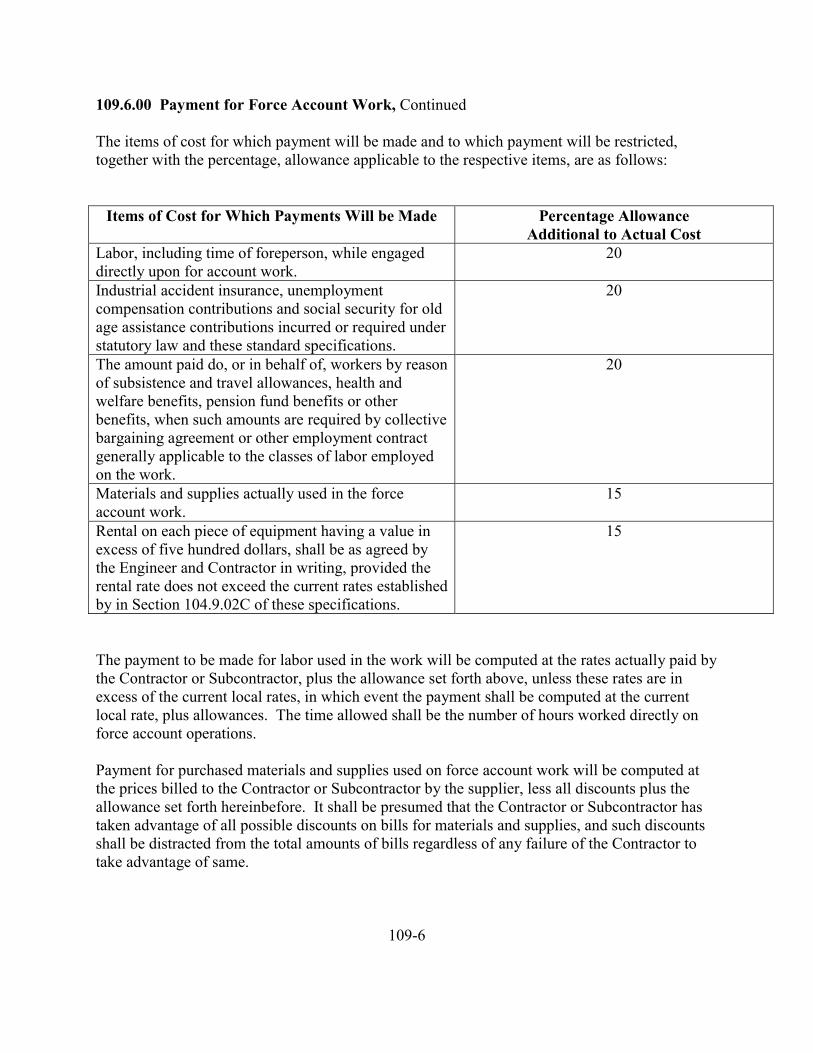
109.6.00 Payment for Force Account Work, Continued
The items of cost for which payment will be made and to which payment will be restricted,together with the percentage, allowance applicable to the respective items, are as follows:
Items of Cost for Which Payments Will be Made Percentage AllowanceAdditional to Actual Cost
Labor, including time of foreperson, while engageddirectly upon for account work.
20
Industrial accident insurance, unemploymentcompensation contributions and social security for oldage assistance contributions incurred or required understatutory law and these standard specifications.
20
The amount paid do, or in behalf of, workers by reasonof subsistence and travel allowances, health andwelfare benefits, pension fund benefits or otherbenefits, when such amounts are required by collectivebargaining agreement or other employment contractgenerally applicable to the classes of labor employedon the work.
20
Materials and supplies actually used in the forceaccount work.
15
Rental on each piece of equipment having a value inexcess of five hundred dollars, shall be as agreed bythe Engineer and Contractor in writing, provided therental rate does not exceed the current rates establishedby in Section 104.9.02C of these specifications.
15
The payment to be made for labor used in the work will be computed at the rates actually paid bythe Contractor or Subcontractor, plus the allowance set forth above, unless these rates are inexcess of the current local rates, in which event the payment shall be computed at the currentlocal rate, plus allowances. The time allowed shall be the number of hours worked directly onforce account operations.
Payment for purchased materials and supplies used on force account work will be computed atthe prices billed to the Contractor or Subcontractor by the supplier, less all discounts plus theallowance set forth hereinbefore. It shall be presumed that the Contractor or Subcontractor hastaken advantage of all possible discounts on bills for materials and supplies, and such discountsshall be distracted from the total amounts of bills regardless of any failure of the Contractor totake advantage of same.
109-6

109.6.00 Payment for Force Account Work, Continued
Freight and express on material and supplies will be considered to be a part of the cost of thematerials and supplies and will be paid for as materials and supplies.
Materials and supplies produced by the Contractor or a Subcontractor will be paid for at prices tobe agreed upon between the Contractor and the Engineer.
Rental on equipment used will be computed at the rates actually paid by the Contractor orSubcontractor plus the allowance unless these rates are in excess of the current local rates, orunless the equipment is owned by the Contractor or Subcontractor. In either of which eventspayments shall be computed at rates to be agreed upon between the Contractor and the Engineerprior to beginning work, which rates shall in no case be greater than the current local rates.
When a piece of equipment and the operators thereof are hired, rented, or furnished as a unit, theadditional percentage to be allowed shall be 5 percent, and the Contractor shall not be entitled to15 percent on the time of the operators of such equipment. Neither shall the Contractor beentitled to payment for contributions made under the terms of the Workman’s CompensationAct, the Unemployment Compensation Act, or the Social Security Act to cover the time ofoperators of equipment hired, rented or furnished on this basis.
For equipment rented on a day or hour basis, rental will be allowed for only those days or hoursduring which the equipment is in actual use. For equipment rented on a monthly basis, straighttime rental will be allowed from the day the equipment is first used on the particular piece offorce account work until and including the last day on which it is used on that particular work,excluding, however, the time during which the equipment is used on other work during theperiod, and further excluding the time that the equipment is idle for a continuous period of morethan six days.
The rentals allowed for equipment will in all cases be understood to cover all fuel, supplies,repairs, and renewals, and no further allowances will be made for those items unless specificagreement to that affect is made in writing before the work is commenced. Individual pieces ofequipment having a value of one hundred dollars or less will be considered to be tools or smallequipment, and no rental shall be allowed on such.
The percentage allowances made to the Contractor in accordance with the terms outlined abovewill be understood to be reimbursement and compensation for all superintendence, use of toolsand small equipment, overhead expense, bond cost, insurance premiums, profits, indirect costsand losses of all kinds, and all other items or cost not specifically designated herein as items forwhich payment is to be made, whether the services, costs and other items involved are furnishedor incurred by the Contractor or by the Subcontractor. No other reimbursement, compensation orpayment shall be made for any such services, costs or other items.
109-7
109.6.00 Payment for Force Account Work, Continued
Should any percentage allowance or other corresponding allowance be made by the Contractor toa Subcontractor in connection with force account work, such allowance shall be at the soleexpense of the Contractor and the Contractor shall not be reimbursed or otherwise compensatedfor the same by the Owner.
All claims for extra work done in any month shall be filed in writing by the Contractor with theEngineer before the fifth of the following month, and such claims shall show the names andnumber of each worker employed thereon, the date and the number of hours so employed, thecharacter of the work, an the wages paid or to be paid; also the claim shall show the materialsdelivered for the extra work, the quantity and character of such materials, from whom purchased,and the net amount paid, or to be paid therefore.
109.7.00 Advances of Materials: Allowances will be made in the partial payments to theContractor for acceptable nonperishable materials which are to become an integral part of thecompleted project, subject to the following conditions:
Aggregates must be those specifically produced for the project and must be acceptablystockpiled on property acceptable to the Engineer.
Materials must have a value, as determined by the Engineer, of not less than $2,500.
Allowances will be made in the partial payments to the Contractor for precast structural concretemembers acceptably stored in the fabricator’s yard or at a site acceptable to the Engineer.
The above allowances shall be in amounts not exceeding the net cost to the Contractor of thematerial f.o.b. the work or approved site, and from such allowances there shall be retained thepercentages regularly provided for in connection with partial payments.
As a basis for estimating materials on hand and the cost thereof, the Contractor shall makeavailable to the Engineer paid invoices, freight bills, and other information concerning thematerials in question, as the Engineer may request.
Payment for materials on hand shall be issued with the next regular scheduled payment followingthe receipt of the request for material reimbursement. Reimbursement for materials on handshall be a one-time payment, and shall not be reflected in subsequent partial payments.
109-8

109.7.00 Advances of Materials, Continued
In the event the contract is terminated or cancelled and the Owner elects to terminate theemployment of the Contractor, as provided in subsection 108.13.00, the Contractor or his suretyshall provide the Owner with immediate and peaceful possession of all materials on which theContractor has received any partial payments as above provided and if, for any reason, theContractor or the Contractor’s surety cannot provide peaceful possession of the said materials,then the Contractor or the Contractor’s surety shall immediately refund to the Owner the totalamount of all the partial payments which have been advanced to the Contractor by the Owner forthe said materials.
109.8.00 Progress of Payments: The Contractor shall submit pay requests to the Engineer 13days prior to the first Monday of the following month. Pay requests shall included the quantityof completed work and supporting documents for cost reimbursement of materials on hand as setforth in subsection 109.7.00.
The sum of these values will hereinafter be collectively referred to in this subsection as the“value of completed work”. With these estimates as a base, a partial payment will be made tothe Contractor, which partial payment shall be equal to the value of completed work, less suchamounts as may have been previously paid, less such other amounts as may be deductible or asmay be owing and due to the Owner for any cause, and less an amount to be retained inprotection of the Owner’s interests.
The minimum amount to be retained from any given partial payment will be such that whenadded to the sum of amounts previously retained will bring the total of amounts retained equal toten percent of the value of completed work. After the work is at least 50% complete, and subjectto the satisfactory progress and compliance with the provisions of the Contract Documents, theOWNER may, at its discretion, elect to reduce the retainage to a minimum of not less than fivepercent of the value of the completed work.
Such amount of retainage shall be withheld and retained by Owner until it is included in and paidto Contractor as part of the final payment of the contract amount.
If the Contractor fails to complete the project within the specified contract time, or any extensionthereof, liquidated damages will be deducted from the payments in the amount specified in thecontract.
The making of progress payments shall, under no circumstances, be construed as an acceptanceof any of the work or materials under the contract.
109-9
109.8.00 Progress of Payments, Continued
When the progress estimate indicates that the progress payment would be less than five hundreddollars, no progress payment will be made for that estimate period.
Payments for all work under the contract will be made at the price or prices bid therefore, and theprices shall include full compensation for all incidental work.
109.9.00 Deferment of Payments: No payment will be made until all orders made by theEngineer to the Contractor in accordance with the specifications are complied with, nor until allclaims or liens filed or prosecuted against the Owner, its officers or employees contrary to theprovisions of the contract are satisfied.
In the event a complaint or charge of unlawful employment practices pursuant to the provisionsof KSA Chapter 44 is filed against the Contractor resulting in the issuance of a cease and desistorder, no further payments will be made on the contract until such time as all of the provisions ofthe cease and desist order have been complied with by the Contractor.
109.10.00 Final Estimate and Payment: The Contractor shall notify the Engineer when workis considered complete and the Engineer shall, within fifteen (15) days after receiving the notice,either accept the work or notify the Contractor of work yet to be performed on the contract. Ifaccepted, the Engineer shall so notify the Contractor and will make a final estimate andrecommend acceptance of the work as of a certain date. Upon approval and acceptance by theOwner, the Contractor will be paid a total payment equal to the amount due under the contractincluding all retainage.
Prior to final payment, the Contractor shall deliver to the Owner, a receipt for all amounts paid orpayable to the Contractor and a release and waiver of all claims against the Owner arising fromor connected with the contract and shall furnish satisfactory evidence that all amounts due forlabor, materials and all other obligations have been full and finally settled, or are fully coveredby insurance.
109.11.00 Acceptance of Final Payment: The acceptance by the Contractor of the finalpayment shall release the Owner and the Engineer as agent of the Owner from all claims and allliability to the Contractor for all things done or furnished in connection with the work, and everyact of the Owner and others relating to or arising out of the work. No payment, however, final orotherwise, shall operate to release the Contractor or the Contractor’s sureties from obligationsunder the contract and the performance, payment and other bonds and warranties, as hereinprovided.
109-10
109.12.00 Final Guaranty: All work shall be and is guaranteed by the Contractor for aspecified period from and after the date of final acceptance of all the work by the Owner.
If, within said guaranty period, repairs or changes are required in connection with guaranteedwork, which, in the opinion of the Engineer is rendered necessary as the result of the use ofmaterials, equipment or workmanship which are inferior, defective, or not in accordance with theterms of the contract, the Contractor shall promptly upon receipt of notice from the Owner, andwithout expense to the Owner; (a) place in satisfactory condition in every particular all of suchguaranteed work, correct all defects therein; (b) make good all damage to the building or site, orequipment or contents thereof, which in the opinion of the Engineer, is the result of the use ofmaterials, equipment, or workmanship which are inferior, defective, or not in accordance withthe terms of the contract; and (c) make good any work or material, or the equipment and contentsof building, structure or site disturbed in fulfilling any such guarantee.
If the Contractor, after notice, fails within 20 days to proceed to comply with the terms of thisguaranty, the Owner may have the defects corrected, and the Contractor and the Contractor’ssurety shall be liable for all expenses incurred, provided, however, that in case of an emergencywhere, in the opinion of the Engineer, delay would cause serious loss or damage, repairs may bemade without notice being given to the Contractor and the Contractor shall pay the cost thereof.
109-11
DIVISION TWOSTREETS AND RELATED WORK
201-0
201 MOBILIZATION
201.1.00 Description
201.2.00 Materials
201.3.00 Construction201.3.01 General
201.4.00 Measurement and Payment201.4.01 Lump Sum Basis201.4.02 Incidental Basis
201-1
201 MOBILIZATION
201.1.00 Description: This section covers the work necessary to move in personnel andequipment, set up all offices, building and facilities, and prepare for construction.
201.2.00 Materials: The Contractor shall provide all materials required to accomplish the workas specified.
201.3.00 Construction
201.3.01 General: The Contractor shall set up construction facilities in a neat and orderlymanner within designated or approved work areas.
201.4.0 Measurement and Payment
201.4.01 Lump Sum Basis: When listed in the proposal as a pay item, payment formobilization will be made on a lump sum basis.
201.4.02 Incidental Basis: When neither specified nor listed in the proposal for separatepayment, mobilization will be considered incidental work for which no separate payment will bemade.
201-2
202 TEMPORARY TRAFFIC CONTROL
202.1.00 Description
202.2.00 Materials202.2.01 Uniform Traffic Control Devices
202.3.00 Construction202.3.01 General202.3.02 Traffic Control with the Project202.3.03 Construction and Maintenance of Detours202.3.04 One Way Piloted Traffic Control
202.4.00 Measurement and Payment202.4.01 Lump Sum Basis202.4.02 Incidental Basis
202-1
202 TEMPORARY TRAFFIC CONTROL
202.1.00 Description: This section covers all work necessary to conduct constructionoperations so as to offer the least possible obstruction and inconvenience to the public and toprotect pedestrian and vehicular traffic.
202.2.00 Materials:
202.2.01 Uniform Traffic Control Devices: Flagmen, barricades, signs and traffic controldevices shall conform to the Manual on Uniform Traffic Control Devices, published by the U.S.Department of Transportation. Copies may be purchased from the Superintendent ofDocuments, U.S. Government Printing Office, Washington, DC 20402.
202.3.00 Construction:
202.3.01 General: The Contractor shall provide and maintain such signs, barricades andwarning lights as are necessary to warn and protect the public at all times on highways, roads orstreets affected by the work operations. In addition, the Contractor shall also provide all flagmenand guards necessary to warn and protect the public.
The Contractor shall patrol the traffic control area and reset all disturbed signs and traffic controldevices immediately, and will remove or cover all nonapplicable signs during periods notneeded.
202.3.02 Traffic Control Within the Project: Public traffic shall be permitted to pass throughthe work area, or on an approved detour, with as little inconvenience and delay as possible.
The Contractor shall provide access to private properties at all times except during urgent stagesof construction when it is impractical to carry on the construction and maintain trafficsimultaneously.
The Contractor shall give occupants of property fronting a street at least 24 hours notice beforemore than half the street is closed to vehicular traffic.
When, in the judgement of the Engineer, vehicular parking is a hazard to through traffic or to thework, the Contractor shall furnish and place no parking signs on any street which is directlyinvolved in the construction work.
202.3.03 Construction and Maintenance of Detours: The Contractor shall construct andmaintain approved temporary detours for the protection of the work and the safe passage oftraffic through, and/or around the work area.
202-2
202.3.04 One Way Piloted Traffic Control: When detours are not available, the Contractorshall confine operations to a width which provides for the safe passage of traffic. If, in thejudgement of the Engineer, one way piloted traffic is necessary, the Contractor shall provide atleast two (2) flagpersons to control traffic, one flagperson being stationed at each end of theroadway being limited to restricted use and furnish a pilot car and driver to lead traffic. All pilotcars shall be identified with an appropriate information sign mounted on the rear of the vehicle.At the end of each day, the Contractor shall leave work in such condition that it can be traveledwithout damage to the work and without danger to the public.
202.4.00 Measurement and Payment:
202.4.01 Lump Sum Basis: When listed in the proposal as a separate pay item, payment forTemporary Traffic Control will be made on a lump sum basis.
202.4.02 Incidental Basis: When neither specified nor listed in the proposal as a separate payitem, Temporary Traffic Control will be considered incidental work for which no separatepayment will be made.
202-3

203 CLEARING AND GRUBBING
203.1.00 Description
203.2.00 Materials
203.3.00 Construction203.3.01 Disposal203.3.02 Merchantable Trees or Timber203.3.03 Clearing203.3.04 Grubbing203.3.04A Excavation Areas203.3.04B Embankment Areas
203.4.00 Measurement and Payment203.4.01 Acreage Basis203.4.02 Lump Sum Basis203.4.03 Incidental Basis
203-1
203 CLEARING AND GRUBBING
203.1.00 Description: This section covers the work necessary to clear, remove and dispose ofall debris and vegetation such as stumps, trees, logs, roots, shrubs, vines, grass and weeds withinthe designated limits, and to preserve from injury or defacement such objects and vegetation asare designated to remain in place.
Clearing is defined as the cutting and removal of trees, bushes, vines and other vegetative growthat or above the surface of the ground.
Grubbing is defined as the removal of vegetative growth and wood items remaining at or belowthe ground surface following the clearing operation.
203.2.00 Materials: None required.
203.3.00 Construction
203.3.01 Disposal: Clearing and grubbing vegetation, unless otherwise specified, shall bedisposed of by the Contractor in a manner satisfactory to the Engineer and in compliance withfederal, state, and local laws and ordinances.
203.3.02 Merchantable Trees or Timber: Merchantable trees or timer shall become theproperty of the Contractor unless otherwise specified.
203.3.03 Clearing: Trees and brush shall be cut such that no stump extends above the groundsurface more than six inches.
203.3.04 Grubbing:
203.3.04A Excavation Areas: All roots and embedded wood shall be removed to a depth notless than six inches below the subgrade or slope surface to which the excavation is constructed.All stumps shall be completely removed.
203.3.04B Embankment Areas: All stumps, roots, and embedded wood shall be removed to adepth not less than one foot below the subgrade or slope surface to which the embankment is tobe constructed.
203.4.00 Measurement and Payment
203.4.01 Acreage Basis: Measurement and payment for clearing and grubbing will be made onan acreage basis for the area cleared and grubbed within the limits specified; measured to thenearest 0.1 acre.
203-2
203.4.02 Lump Sum Basis: Measurement and payment for clearing and grubbing will be madeon a lump sum basis for the area cleared and grubbed within the limits specified.
203.4.03 Incidental Basis: When not specified for payment, clearing and grubbing will beconsidered incidental work for which no separate payment will be made.
203-3
204 EARTHWORK
204.1.00 Description204.1.01 General204.1.02 Unclassified Excavation204.1.03 Classified Excavation204.1.03A Rock Excavation204.1.03B Common Excavation204.1.04 Borrow Excavation
204.2.00 Materials204.2.01 Borrow and Embankment Materials
204.3.00 Construction204.3.01 Preservation of Existing Improvement204.3.02 Excavation of Existing Improvements and Miscellaneous204.3.03 Disposition of Excavated Materials204.3.04 Over-Excavation204.3.05 Use of Explosives204.3.06 Preparation of Embankment Foundations204.3.07 Embankment Construction204.3.08 Compaction and Density Requirements204.3.09 Slide Removal and Repair204.3.10 Finishing Roadbed and Slopes
204.4.00 Measurement and Payment204.4.01 Unclassified and Classified Excavation204.4.02 Embankment204.4.03 Finish Roadbed and Slopes204.4.04 Payment
204-1
204 EARTHWORK
204.1.00 Description
204.1.01 General: This section covers the work necessary for excavating and grading theroadway, side streets, sidewalk and planting areas, alleys, cuts, embankments, slopes, roadwayditches, side streets, driveway and alley approaches and all other earth-moving work required inthe construction of the project including disposal of all surplus material.
When specifically included and provided for as incidental work for particular items or parts ofwork covered and included under other sections, such excavation and grading will not beincluded in this section.
204.1.02 Unclassified Excavation: Unclassified excavation is defined as all excavationregardless of the type, nature, or condition of the materials encountered. The Contractor shallassume full responsibility to estimate the kind and extent of the various materials to beencountered in order to accomplish the work.
204.1.03 Classified Excavation
204.1.03A Rock Excavation: Rock excavation is defined as the removal of all material whichby actual demonstration cannot be reasonable excavated with a D8 dozer with ripper orequivalent grading equipment which is, in fact, systematically drilled and blasted or broken bypower operated hand tools. The Engineer may waive the demonstration if the materialencountered is well defined rock. The term “Rock Excavation” shall be understood to indicate amethod of removal and not a geological formation.
If material which would be classified as rock by the above definition is mechanically removedwith grading equipment of a larger size than specified, it shall be understood that any added costsfor the removal of the material by this method shall be included in the unit price for commonexcavation.
204.1.03B Common Excavation: Common excavation is defined as removal of all material notclassified as rock excavation.
204.1.04 Borrow Excavation: Borrow material is defined as material obtained from borrowsources lying outside of, separated from and independent of, planned roadbed excavation orother required excavation occurring within the project limits.
204-2
204.2.00 Material
204.2.01 Borrow and Embankment Materials: The Contractor shall provide embankmentand borrow materials of approved earth, sand, gravel, rock or combination thereof, free of peat,humus, muck, vegetative matter, organic matter or other materials detrimental to the constructionof firm, dense and sound embankment.
The Contractor shall use all approved materials originating from the required excavations as faras practicable in the formation of embankments and subgrade, and for bedding, backfilling andother work as shown or directed.
204.3.00 Construction
204.3.01 Preservation of Existing Improvements: The Contractor shall conduct operations insuch a manner that existing highway facilities, utilities, railroad tracks and other non-highwayfacilities which are to remain in place will not be damaged as specified in “Control of Work” inthe general requirements. The Contractor shall furnish and install sheet piling, cribbing,bulkheads, shores or whatever means may be necessary to support material carrying existingfacilities or to support the facilities themselves, and maintain such supports until no longerneeded. The Contractor shall protect temporary pavements, facilities, utilities and installationsuntil they are no longer required. When temporary supports and other protective means are nolonger required, the Contractor shall remove and dispose of them as directed.
204.3.02 Excavation of Existing Improvements and Miscellaneous: Earthwork includesexcavating, hauling and depositing existing pavements, walks, driveways, surfacings, slabs,curbs, gutters and similar cement concrete structures or bituminous materials and of all rock orgravel road surfacing materials when such materials are within the limits of the excavation.
The Contractor shall remove and dispose of sewers, pipes, conduits, logs, timbers, concrete andother structures, materials, objects and matter encountered in the excavations, excepting onlyitems for which removal is otherwise specifically provided, as a part of the earthwork. Thevolumes of such items from within the excavation areas shown will be included in the excavationquantities.
The Contractor shall remove the remaining ends of abandoned pipes or portions of other itemspartially removed under this work which would be left exposed on side slopes or at subgrade to aminimum of one (1) foot of the finished slope or below subgrade.
The Contractor shall plug or seal the ends of abandoned pipes in embankment areas as approved.
204-3
204.3.02 Excavation of Existing Improvements and Miscellaneous, Continued
If possible, existing culvert pipe shall be salvaged during the course of construction and becomesthe property of the abutting property owner; or the City of Dodge City. The Contractor shallcontact the Owners of the culvert pipe and the City. If the Owners and the City do not want thepipe, it shall become the property of the Contractor.
204.3.03 Disposition of Excavated Materials: Excavated material in excess of that needed tocomplete the work shall be disposed of at no expense to the Owner. The Contractor shall replaceany shortage of material caused by premature disposal at no expense to the Owner.
204.3.04 Over-Excavation: The Contractor shall remove unapproved subgrade material tosuch depths as directed. Excavation below subgrade shall be of the same classification as thatabove subgrade provided it is removed in the same operation as the excavation above subgrade.When the roadway excavation has been completed and it is required to move equipment back into excavate the unsuitable material, or where additional excavation depth requires specialequipment because of the presence of shallow utilities or other unforeseen conditions, the workshall be performed as directed and payment for excavation below grade will be made on the basisof extra work as provided in the general requirements.
The Contractor shall excavate below grade and backfill as required to restore the surface asdirected at no expense to the Owner, when required by negligence in work operations.
Overbreak is defined as that portion of any materials which is excavated, displaced or loosenedoutside and beyond the slopes, lines or grades as staked or reestablished, with the exception ofslides as defined in Subsection 204.3.09, regardless of whether the overbreak is due to blasting,to the inherent character of any formation encountered, or to any other cause. Removal anddisposal of all overbreak will be by the Contractor at no expense to the Owner.
204.3.05 Use of Explosives: The use and security of explosives shall conform to the applicableprovisions of “Legal Relations and Responsibilities” in the general requirements.
The use of explosives shall be avoided as far as practicable, and in no case shall tunnel blastingmethods be used. Such blasting as must be done shall be controlled in a manner which willavoid possible shattering or loosening of materials back of the slope lines to which theexcavations are to be made.
204-4
204.3.05 Use of Explosives, Continued
Where excavations in hard, solid rock are to be made to depths of 10 feet or more, the blastingthereof shall be done by the pre-splitting or pre-shearing method unless other methods areapproved by the Engineer. The pre-splitting shall be by line drilling relief holes of 2 ½ to 4 inchdiameter at uniform intervals of 2 ½ feet along the top line and along the specified slope line tosubgrade depth, but not to exceed a vertical depth of 30 feet in any instance.
Explosive charges of predetermined amount and at predetermined spacings shall be attached to asection of primacord placed in each line hole to the full depth thereof and the hole filled orstemmed with fine stone chips or gravel. A primacord trunk line shall be attached to a series ofthe line hole primacords and detonated with an electric blasting cap. Detonation may be prior toor following other blasting of the rock but in no case shall other drilling and blasting occur closerthan 10 feet from the line drilling nor shall it disturb material at or beyond specified neat sideslope and subgrade lines.
The Contractor shall provide a state certified powderman to supervise the drilling and blastingoperations.
No separate or additional measurement or payment will be allowed for any extra operationsinvolved in the performance of controlled blasting as herein specified, it being understood thatthe extra costs thereof are covered and included in the pay quantities of excavation measured inoriginal position (position prior to excavation) and the applicable contract unit price set forth inthe bid schedule.
204.3.06 Preparation of Embankment Foundations: Prior to the constructing ofembankments, the Contractor shall excavate unstable material or unsuitable foundation materialand dispose of it as directed. The Contractor shall limit excavation to the lines, grades and crosssections shown or approved. The Contractor shall backfill basements, trenches and holes whichoccur within the embankment limits with approved material which may include small pieces ofbroken concrete and masonry. The Contractor shall break concrete floors of basements asapproved prior to backfill. The Contractor shall break up and roughen the ground surface beforeembankment material is placed, as approved. The Contractor shall compact the natural groundunderlying embankments to the depth of the grubbing or a minimum of 12 inches, to the densityspecified for the embankment material to be placed.
204.3.07 Embankment Construction: The Contractor shall place embankments and fills of allkinds in approximately horizontal layers of a maximum of 8 inches in thickness and compacteach layer separately and thoroughly to the density specified.
In the immediate vicinity of curbs, walks, driveways, inlets, manholes and similar structures, inholes and where embankment and fill materials cannot be reached by the normal compactingequipment, the Contractor shall compact to specified density by approved methods.
204-5
204.3.07 Embankment Construction, Continued
Where embankments are constructed predominantly of rock fragments, the Contractor shall placematerial in layers of the thickness as directed, but not greater than 3 feet. Placing of individualrock fragments having dimensions greater than 3 feet will be permitted provided that they haveno dimension greater than 6 feet, that clearances between adjacent fragments provide adequatespace for the placing and compacting of material in horizontal layers as specified, and that nopart comes within 4 feet of subgrade. The Contractor shall distribute and manipulate rock so thatthe interstices between the larger pieces are filled with smaller pieces, forming a dense andcompact mass.
The Contractor shall exercise precaution to insure that embankment construction and fill doesnot move, endanger or overstress any structure. The Contractor shall place and compactembankments at the end of bridges prior to the time that work begins on the bridge.
Embankments shall not be constructed when the embankment material, the foundation, or theembankment on which it would be placed is frozen.
204.3.08 Compaction and Density Requirements: The density of compacted materials inplace will be determined by AASHTO T191, T205 or T238 and the maximum density byAASHTO T99 or T180.
The Contractor shall compact all embankments, fills and backfills within 3 feet of establishedsubgrade elevation to a minimum density in place of 95 percent of maximum density. Belowsaid 3 foot limit, compaction shall be a minimum density in place of 90 percent of maximumdensity.
Roadbed cuts and foundations for structures to a depth of 1 foot below established subgrade orfoundation elevation shall be 3 inch maximum material and shall be compacted to a minimumdensity in place of 95 percent of maximum density.
The Contractor shall backfill holes resulting from grubbing, removal work, basements andtrenches which lie outside the limits of required excavation or embankment construction withapproved roadbed excavation material. The Contractor shall smooth and shape to blend with thesurrounding area.
Embankment or backfill materials shall not be placed in final position until moisture in excess ofoptimum moisture has been removed.
204-6
204.3.09 Slide Removal and Repair: Side slopes shall be made as staked or re-established. Incase a slope finished to the lines as staked or re-established slides back of the established slopeinto the roadway prism or out of an embankment before final acceptance of the work, theContractor shall remove slide material from the roadway, or replace in the embankment andrefinish slope as directed. The resloping will be paid for as extra work.
The Contractor shall obtain materials to replace embankment slides from an approved source.The Contractor shall repair slopes undercut at the base or destroyed in any manner due tonegligence during the work by resloping parallel to the damaged slope or as approved at noexpense to the Owner.
204.3.10 Finishing Roadbed and Slopes: After the main excavation in rock or rocky cuts iscompleted, the Contractor shall test slopes of the cuts thoroughly with bars, or by other approvedmeans, and remove all loose, detached, broken or otherwise unstable rock. The Contractor shallremove jutting points and bring the entire cut slope to a safe, trim and neat condition asapproved. The Contractor shall dispose of the materials removed under this provision in thesame manner as other excavated material.
As a part of the earthwork, the Contractor shall perform special grading on areas which areshown as planting areas. The Contractor shall finish planting areas to smooth flowing lines andto the grades and cross sections established or approved. Rock, boulders, vegetative matter anddebris determined objectionable to intended development shall be removed from the areas asdirected.
The Contractor shall blend the tops of cutbanks with the adjacent terrain by rounding of the topof cutbanks as shown. When rock extends to the top of cuts making rounding impractical, it willnot be required.
The Contractor shall trim all roadbeds, ditches and other excavations and embankmentsreasonably close to the established lines, grades and cross sections. The Contractor shall leaveall surface features in a neat and well finished condition prior to the time the project is completedand accepted.
Immediately prior to completion of the earthwork, the Contractor shall clean the entire right-of-way area of debris and foreign matter of all kinds and dispose of as directed.
204.4.00 Measurement and Payment
204.4.01 Unclassified and Classified Excavation: Quantities for unclassified and classifiedexcavation work will be measured on a cubic yard basis in original position prior to excavation.Pay quantities shall be computed to the neat lines of the cross sections as staked.
When shown in the proposal, this work will be measured and paid on a lump sum basis.
204-7
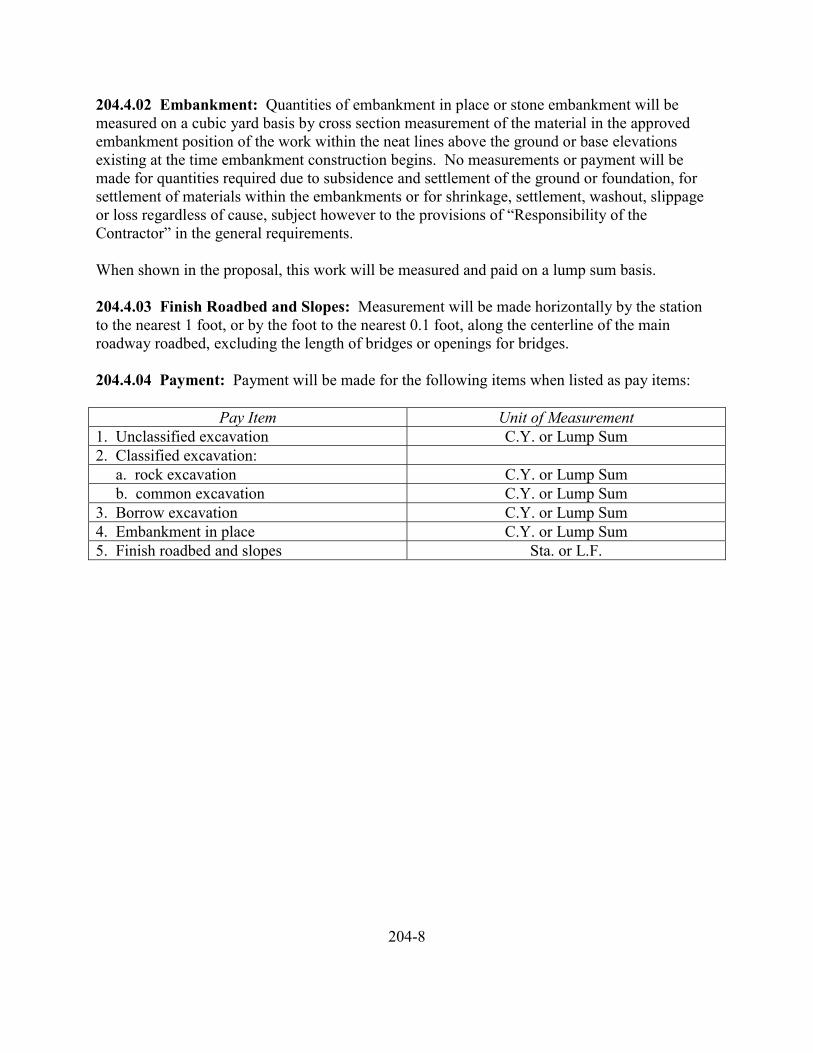
204.4.02 Embankment: Quantities of embankment in place or stone embankment will bemeasured on a cubic yard basis by cross section measurement of the material in the approvedembankment position of the work within the neat lines above the ground or base elevationsexisting at the time embankment construction begins. No measurements or payment will bemade for quantities required due to subsidence and settlement of the ground or foundation, forsettlement of materials within the embankments or for shrinkage, settlement, washout, slippageor loss regardless of cause, subject however to the provisions of “Responsibility of theContractor” in the general requirements.
When shown in the proposal, this work will be measured and paid on a lump sum basis.
204.4.03 Finish Roadbed and Slopes: Measurement will be made horizontally by the stationto the nearest 1 foot, or by the foot to the nearest 0.1 foot, along the centerline of the mainroadway roadbed, excluding the length of bridges or openings for bridges.
204.4.04 Payment: Payment will be made for the following items when listed as pay items:
Pay Item Unit of Measurement1. Unclassified excavation C.Y. or Lump Sum2. Classified excavation: a. rock excavation C.Y. or Lump Sum b. common excavation C.Y. or Lump Sum3. Borrow excavation C.Y. or Lump Sum4. Embankment in place C.Y. or Lump Sum5. Finish roadbed and slopes Sta. or L.F.
204-8

205 WATERING
205.1.00 Description
205.2.00 Materials205.2.01 Water205.2.02 Binders and Additives
205.3.00 Construction
205.4.00 Measurement and Payment205.4.01 Measurement205.4.01A Water by Volume205.4.01B Water by Weight205.4.01C Binders and Additives205.4.02 Payment205.4.02A Water on Incidental Basis205.4.02B Water by Volume205.4.02C Water by Weight205.4.02D Binders and Additives
205-1
205 WATERING
205.1.00 Description: This section covers the work necessary to furnish and apply water orcombinations of water and compatible binders or additives for roadway excavations,embankments, subgrades, roadbeds, backfills, subbases, bases and surfacings and water for thealleviation or prevention of dust nuisance within the project limits as directed.
Excluded from this section is watering used in connection with Portland cement concreteconstruction, wetting foundations preparatory to placing concrete thereon, curing concrete andwatering which is specified as incidental to particular items or parts of the work in other sections.
205.2.00 Materials:
205.2.01 Water: Water used in the work shall be free of silts and other matter deleterious to thequality of the material to which it is applied or with which it is mixed. The Contractor shallmake all necessary arrangements for obtaining water and pay all costs involved in itsprocurement. The Contractor shall maintain an adequate supply of water at all times.
205.2.02 Binders and Additives: When shown, specified or directed, the Contractor shall use amixture of water and an approved compatible binder or additive material.
205.3.00 Construction: Watering work shall at all times be under the direction and control ofthe Engineer.
The Contractor shall water by means of tank trucks equipped with spray bars, by hose and nozzleor by other approved equal means which insures uniform and controlled application. The use ofsplash boards will not be permitted without prior approval.
The Contractor shall perform watering at any hour of the day and on any day of the weeknecessary for proper performance or protection of the work and for adequate alleviation of dustnuisance. The Contractor shall sprinkle directly on the road only at night or in the early morninghours when loss by evaporation is at a minimum, unless otherwise directed.
When compatible binder material or additive is combined with water in the work, the Contractorshall mix it in conformance with the manufacturer’s directions or as directed.
The Contractor shall avoid wastage of water or watering which is detrimental to other items ofwork.
205-2
205.4.00 Measurement and Payment
205.4.01A Water by Volume: Quantities of water determined by volume will be measured inunits of 1,000 gallons (M-gals.) to the nearest 0.1 unit, exclusive of binders and additives mixedtherewith. Measurement will be made in tanks or tank trucks of predetermined and approvedcapacities or by reliable approved meters provided by the Contractor. Measurement andpayment will be made only for quantities as are approved for use in the work.
205.4.01B Water by Weight: Quantities of water determined by weight will be measured intons so the nearest 0.1 ton. Measurement will be the actual tons used based on weight ticketsfrom state certified scales presented for approval on the day the water is delivered. Nomeasurement or payment will be allowed on tickets not so delivered and approved.
205.4.01C Binders and Additives: Quantities of compatible binders or additives combinedwith water for watering purposes will be determined separately from the water and will bemeasured as specified and shown in the proposal.
205.4.02 Payment
205.4.02A Water on Incidental Basis: When neither specified nor shown in the proposal forseparate payment, all water will be considered incidental to the other items of work and noseparate payment will be made.
205.4.02B Water by Volume: Payment for water will be made on a 1,000 gallon (M-gal.)basis.
205.4.02C Water by Weight: Payment for water will be made on a ton basis.
205.4.02D Binders and Additives: Payment for compatible binders or additives combinedwith water for watering purposes will be paid for at the applicable contract unit price as set forthin the proposal. Payment shall constitute full compensation for the binder material or additive,for the combining of it with the water and for all extra costs involved in the use of the bindermaterial or additive in the watering work.
205-3

206 SUBGRADE
206.1.00 Description206.1.01 Untreated Subgrade206.1.02 Treated Subgrade
206.2.00 Materials206.2.01 Soil Stabilizing Materials206.2.02 Water
206.3.00 Construction206.3.01 Preparation206.3.02 Untreated Subgrade206.3.03 Treated Subgrade206.3.03A General206.3.03B Addition of Stabilizing Material206.3.03C Mixing206.3.04 Compaction206.3.05 Tolerances206.3.06 Curing Treated Subgrade
206.4.00 Measurement and Payment206.4.01 Measurement206.4.01A Incidental Work206.4.01B Work Paid in Other Sections206.4.01C Untreated Subgrade206.4.01D Soil Stabilizing Materials206.4.01E Treated Subgrade206.4.02 Payment206.4.02A Soil Stabilizing Materials206.4.02B Treated Subgrade
206-1
206 SUBGRADE
206.1.00 Description: This section covers the work necessary for the preparation of thesubgrade. Subgrade is defined as the area of new or existing roads, streets, alleys, driveways,sidewalks, or other public places upon which additional materials are to be placed as a part of thework covered in other sections or by future work. Where applicable, subgrade is considered toextend over the full width of the specified base course. Subgrade is classified as untreated ortreated.
206.1.01 Untreated Subgrade: The uppermost material placed in embankments or unmovedfrom cuts in the normal grading of the roadbed and which is brought to true line and grade,shaped and compacted as necessary to provide a foundation for the pavement structureconstitutes untreated subgrade.
206.1.02 Treated Subgrade: Subgrade which is improved by the addition of stabilizers andprepared as in untreated subgrade constitutes treated subgrade.
206.2.00 Materials
206.2.01 Soil Stabilizing Materials: Soil stabilizing materials shall conform to the followingrequirements:
Material Type GradeHydrated Lime AASHTO M 216, Type a Grade AGranular Quicklime (Ca0) AASHTO T 27 and T 219 for
grading and hydroxidecontent, with minimum 85%calcium hydroxide
100% passing 3/8” sieve,maximum 15% passing 100sieve
Calcium Chloride AASHTO M 144, sample andtesting in accordance withAASHTO T 143
206-2
206.2.01 Soil Stabilizing Materials, Continued
Aggregates for subgrade stabilization shall be of the types shown in the following table and shallmeet the following requirements:
TYPE AND MATERIALSieve Size SR-3 Crushed
StoneScreening*
SR-5 Sand** SR-7Sand/Gravel
SR-8 Chat SR-9Sand/Gravel
PERCENT RETAINED¾ 0 0 0 0 --
3/8 0-5 -- -- -- --4 -- -- -- 35+ --8 -- -- -- 60+ 30-10016 -- -- 5-50 -- --30 -- -- -- 85+ --50 -- -- 85-100 -- --200 See “material passing 200 sieve”
* This material shall not contain more than 7% moisture when delivered.** This material shall not contain more than 10% moisture when delivered.
(a) Deleterious Substances: The deleterious substances shall not exceed thefollowing percentages by weight:
(1) For crushed limestone, sand-gravel, and chatSoft or friable particles 5.0Clay lumps 3.0Sticks (wet) 1.0Shale or shale-like material 3.0Material Passing No. 200 sieve 15.0
No combination of these substances shall exceed 15.0%
(2) For sand (blow, jig, etc.)Sticks 1.0Materials passing No. 200 sieve 15.0Clay lumps 5.0
No combination of these substances shall exceed 15.0%
Storage of materials shall conform to the requirements of Subsection 106.7.00.
206-3
206.2.02 Water: Shall conform to the requirements of Section 205.
206.3.00 Construction
206.3.01 Preparation: In advance of setting line and grade, the Contractor shall clear anddispose of brush, weeds, vegetation, grass and debris from the subgrade. The Contractor shalldrain all depressions or ruts which contain water. The Contractor shall blade and shape subgradeto remove irregularities and secure a uniform surface.
Prior to starting subgrade work, including backfill, all underground work contemplated in thearea of the subgrade shall be completed. This requirement includes work in the contract, andwork to be performed by the Owner, or by others.
206.3.02 Untreated Subgrade: The Contractor shall excavate and shape subgrade to line,grade and cross section and compact to not less than 95 percent of maximum density asdetermined by AASHTO T99. Testing methods for density requirements shall be determined byAASHTO T 191, T 205, or T238.
The Contractor shall remove all soft or otherwise unsuitable material as directed and replace withapproved material from the excavation. The Contractor shall compact to a line one foot beyondthe edge of paving, curb or form.
Subgrade areas which cannot be compacted to specified density, but in the judgement of theEngineer otherwise meet the requirements herein, shall be scarified and aerated to provide anoptimum moisture content all at no additional expense to the Owner. If required, the Engineermay authorize the removal and/or stabilizing of material as an extra work item.
206.3.03 Treated Subgrade
206.3.03A General: The Contractor shall blade, disc, harrow or otherwise scarify andthoroughly break up surfaces of areas to be treated or aerated to the full depth and width asshown. The Contractor shall dry and reduce the cemented soil clods to the moisture content andsize specified. The Contractor shall shape and size the subgrade material blanket to the size thatcan pass through the mixing machine. The Contractor shall apply stabilizing materials onlywhen the temperature is above freezing, or when wind or other weather conditions are notdetrimental to the work or to the public. The Contractor shall take all precautions necessary toprevent injury to persons, livestock or property. Any material which is spilled or deposited atplaces other than on areas designated to be treated shall be immediately picked up, buried ormade harmless at the expense of the Contractor.
206-4
206.3.03B Construction Requirements: The quantity of aggregate for subgrade modification,shown on the Plans, shall be hauled, windrowed, and the windrow brought to a uniform crosssection. The windrowed material shall be mixed with the binder materials obtained from the topportion of the roadbed or from the shoulder, slopes, ditches, and back slopes. If the Plans requirethat the binder be obtained from the roadbed, the roadbed shall be scarified to the width anddepth shown on the Plans. The material thus obtained should be pulverized and mixed until notmore than five (5) percent of the material is retained on the 2-inch sieve and until the aggregatefor the subgrade modification and the roadbed soil are thoroughly mixed together. If lime orcalcium chloride is designated on the plans to be added to the mixture, it shall be added at therate shown on the Plans. The lime or calcium chloride shall be thoroughly and uniformly mixedwith the aggregate and roadbed materials.
After thoroughly mixing, the mixed material shall be brought to the specified moisture content.If required by the Engineer, the surface of the prepared subgrade shall be thoroughly sprinkledbefore spreading the material to insure an adequate bond between the subgrade and themodification materials.
If called for on the Plans, a second application of calcium chloride at the rate shown on the Plans,shall be applied uniformly over the surface. The surface shall then be sprinkled lightly, ifnecessary, as directed.
206.3.04 Compaction: Immediately after mixing of a treated subgrade, the Contractor shallspread the mixture to specified line, grade and cross section and compact the entire depth of themixture to not less than 95 percent of maximum density as determined by AASHTO T 99.Testing methods for density requirements shall be determined by AASHTO T 191, T 205, and T238.
The Contractor shall compact and finish the surface within 12 hours after compaction begins. Ifnot compacted and finished after 12 hours, the Contractor shall loosen the mixture and addstabilizing material and water as directed, remix the freshened materials, relay and compact all atno additional expense to the Owner. During compaction, the Contractor shall maintain thesurface of the mixture at proper grade and cross section and lightly water if necessary to retainoptimum moisture content.
The Contractor shall accomplish final finishing by rolling accompanied by light watering andreshaping as required.
206.3.05 Tolerances: The Contractor shall rework areas found to be deficient in thickness bymore than 0.04 foot, except that fresh stabilizing material shall be added in an amount equal toone half of the original amount, as above specified. The Contractor shall accomplish allreworking at no expense to the Owner.
206-5
206.3.05 Tolerances, Continued
The finished surface of treated and untreated subgrade shall not vary more than 0.04 foot fromthe established grade and cross section at any point. The finished surface, when tested with a 10-foot straightedge shall not vary from the testing edge by more than 0.04 foot at any point.
206.3.06 Curing Treated Subgrade: The Contractor shall limit traffic over treated subgrade towheel loads which do not cause any damage to the subgrade and which do not visibly deflect,ravel or wear the surface. The Contractor shall keep the finished surface moist and protectedfrom rutting, spalling, displacement and disfiguration for a period of 7 days or until a subsequentcourse of planned construction which will prevent drying of the mixture by evaporation orabsorption is placed thereon.
206.3.07 Soil Sterilant: Unless otherwise noted, all subgrade for both rigid and flexiblepavement shall be treated to eliminate growth of vegetation. Soil sterilant shall be commerciallyavailable agricultural grade sterilant, and shall be approved by the Engineer prior to itsapplication on the subgrade. Application rates shall be in accordance with the manufacturer’srecommendations. As verification of the application, the Contractor shall save the sterilantcontainers for the Engineer.
206.4.00 Measurement and Payment
206.4.01 Measurement
206.4.01A Incidental Work: No measurement will be made for work involved in clearing thesubgrade of vegetation and other debris, draining water from the subgrade, smoothing thesubgrade in preparation for staking, blading, shaping, and compacting the subgrade includingroadbed materials to a depth of one foot below the subgrade, to final line, grade and crosssection. All work involved in these processes will be considered incidental to the other items orwork.
206.4.01B Work Paid in Other Sections: Additional materials required for completing thesubgrade will be measured and paid for at the unit price for the type of material furnished asprovided in Section 204.
Excavation of soft, spongy or yielding spots, when directed, will be measured and paid for asprovided in Section 204.
Suitable backfill material, when furnished and placed as directed, will be measured and paid atthe unit price for the type of material involved as provided in Section 204.
Water used in the work will be measured and paid for as provided in Section 205.
206-6
206.4.01C Untreated Subgrade: No measurement and payment will be made for preparationof untreated subgrade unless otherwise specified.
206.4.01D Soil Stabilizing Materials: Quantities for soil stabilizing materials will be measuredby the ton, dry weight, or the nearest 0.01 ton, for the materials incorporated in the work at therate and in the quantity specified or directed. Measurement and payment of stabilizing materialswill not include any which are lost, displaced, used in reworking, used in restoration work orused contrary to direction. Packaged materials will be accepted at the net weight shown by themanufacturer, subject to periodic verification and approval. The Contractor shall provide acertificate with each shipment together with a certified copy of the weight of each delivery.
206.4.02 Payment
206.4.02A Soil Stabilizing Materials: Payment for soil stabilizing materials will be made on aton basis for the type or types specified and used in the work.
206.4.02B Treated Subgrade: Payment for treated subgrade will be made on a square yardbasis for the type or types specified and used in the work.
206-7
207 AGGREGATE BASES
207.1.00 Description
207.2.00 Material207.2.01 Fracture of Gravel207.2.02 Durability207.2.03 Sand Equivalent207.2.04 Liquid Limit and Plasticity207.2.05 Grading Requirements207.2.06 Acceptance
207.3.00 Crushing207.3.01 Stockpile207.3.02 Mixing207.3.03 Placing207.3.03A Weather Limitations207.3.03B Equipment207.3.03C Thickness of Lifts207.3.04 Compaction207.3.04A Equipment207.3.04B Density Requirements207.3.05 Surface Finish
207.4.00 Measurement and Payment207.4.01 Measurement207.4.01A Square Yard Basis207.4.01B Cubic Yard In-Place Basis207.4.01C Cubic Yard Vehicle Measure Basis207.4.01D Cubic Yard in Stockpile207.4.01E Ton Basis207.4.02 Payment
207-1
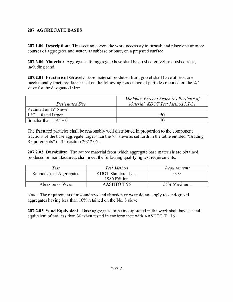
207 AGGREGATE BASES
207.1.00 Description: This section covers the work necessary to furnish and place one or morecourses of aggregates and water, as subbase or base, on a prepared surface.
207.2.00 Material: Aggregates for aggregate base shall be crushed gravel or crushed rock,including sand.
207.2.01 Fracture of Gravel: Base material produced from gravel shall have at least onemechanically fractured face based on the following percentage of particles retained on the ¼”sieve for the designated size:
Designated SizeMinimum Percent Fractures Particles of
Material, KDOT Test Method KT-31Retained on ¼” Sieve1 ½” – 0 and larger 50Smaller than 1 ½” – 0 70
The fractured particles shall be reasonably well distributed in proportion to the componentfractions of the base aggregate larger than the ¼” sieve as set forth in the table entitled “GradingRequirements” in Subsection 207.2.05.
207.2.02 Durability: The source material from which aggregate base materials are obtained,produced or manufactured, shall meet the following qualifying test requirements:
Test Test Method RequirementsSoundness of Aggregates KDOT Standard Test,
1980 Edition0.75
Abrasion or Wear AASHTO T 96 35% Maximum
Note: The requirements for soundness and abrasion or wear do not apply to sand-gravelaggregates having less than 10% retained on the No. 8 sieve.
207.2.03 Sand Equivalent: Base aggregates to be incorporated in the work shall have a sandequivalent of not less than 30 when tested in conformance with AASHTO T 176.
207-2
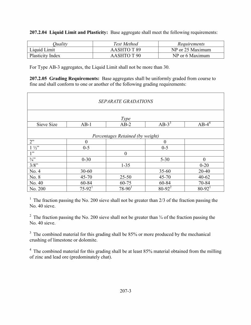
207.2.04 Liquid Limit and Plasticity: Base aggregate shall meet the following requirements:
Quality Test Method RequirementsLiquid Limit AASHTO T 89 NP or 25 MaximumPlasticity Index AASHTO T 90 NP or 6 Maximum
For Type AB-3 aggregates, the Liquid Limit shall not be more than 30.
207.2.05 Grading Requirements: Base aggregates shall be uniformly graded from course tofine and shall conform to one or another of the following grading requirements:
SEPARATE GRADATIONS
TypeSieve Size AB-1 AB-2 AB-33 AB-44
Percentages Retained (by weight)2” 0 01 ½” 0-5 0-51” 0¾” 0-30 5-30 03/8” 1-35 0-20No. 4 30-60 35-60 20-40No. 8 45-70 25-50 45-70 40-62No. 40 60-84 60-75 60-84 70-84No. 200 75-921 78-901 80-922 80-921
1 The fraction passing the No. 200 sieve shall not be greater than 2/3 of the fraction passing theNo. 40 sieve.
2 The fraction passing the No. 200 sieve shall not be greater than ¾ of the fraction passing theNo. 40 sieve.
3 The combined material for this grading shall be 85% or more produced by the mechanicalcrushing of limestone or dolomite.
4 The combined material for this grading shall be at least 85% material obtained from the millingof zinc and lead ore (predominately chat).
207-3
207.2.05 Grading Requirements, Continued
Where a tolerance range is set forth in the above grading requirements, it shall be understood thatthe midpoint of the tolerance range is the target value and the product shall conform as closely asrealistically possible to this target value. The purpose of the tolerance range is only to permitoccasional minor variations from the target values that are, for practical reasons, unavoidable.
The determination of sizes and grading shall be in conformance with AASHTO T 27.
207.2.06 Acceptance: Materials will be subject to acceptance as specified by one of thefollowing methods:
A. In its final state on the roadbed after all processing and prior to the placement ofsubsequent surfacing materials.
B. In the stockpile after all shaping work has been completed.
C. Immediately after crushing.
207.3.00 Crushing
207.3.01 Stockpiling: Stockpiling shall consist of the furnishing of crushed rock, crushedgravel or other aggregate in stockpiles at the places and in the manner hereinafter specified.Wherever in this specification the terms material or materials are used, it shall be understood torefer to crushed rock, crushed gravel or other aggregates.
The materials to be furnished in stockpiles shall be of the kinds, sizes and quality as stated in thecontract documents. Sampling and testing of materials for determination of compliance withspecified requirements may be at the point of manufacture, at the stockpile, or both, as theEngineer may elect.
The materials shall be placed in stockpiles at locations approved by the Owner. The quantities ofeach designated size of material to be furnished in the stockpiles shall be as specified in thecontract documents.
Each designated size of material shall be placed in a separate stockpile, with no intermingling ofmaterials.
The method used in placing the material in the stockpile shall be such as to minimize segregationof the aggregate particles.
207-4
207.3.02 Mixing: Mixing shall provide a mixture of unsegregated materials. The Contractorshall add water during mixing in an amount sufficient to provide optimum moisture content plusor minus two percentage points.
The Contractor shall mix the subbase or base course material by any one of the followingmethods:
Stationary Plant Method – Materials mixed by means of a pug mill or other type of mixer,transported to the project at proper moisture content and placed by an aggregate spreader.
Travel Plant Method – Materials mixed and placed on the project in a continuous operation.
Road Mix Method – Materials mixed on the project by motor graders or other acceptableequipment.
207.3.03 Placing
207.3.03A Weather Limitations: When, in the judgement of the Engineer, the weather is suchthat satisfactory results cannot be secured, the Contractor shall suspend operations until theweather is favorable. No surfacing materials shall be placed in the snow or on a soft, muddy orfrozen subgrade. The Owner shall not be liable for damages or claims of any kind or descriptionby reason of operations suspended by the Engineer.
207.3.03B Equipment: Equipment necessary for construction of aggregate base will varydepending upon method of mixing chosen by the Contractor, however, equipment furnished shallprovide for efficient and continuous operations insofar as is practicable.
Equipment used shall conform to the following requirements:
Hauling Equipment – Vehicles for hauling aggregate or mixture of aggregate and water shall becapable of depositing the material within the receiving hopper of spreading equipment orwindrowing device or in windrows of reasonably uniform size in front of spreading equipmentwith minimum of mix segregation.
Spreading Equipment – Spreading equipment shall have an adjustable screed or strike-offassembly and it may have a receiving, mixing and distribution system. It may be a complete andintegral unit, self-propelled and powered; a crawler-track or wheeled type tractor intimatelycombined with a receiving, mixing, spreading and screeding unit attached thereto; or a heavy-duty self-propelled grader, equipped with at least an 8-foot blade. Equipment used shall becapable of spreading and striking off material to the designated line, grade and transverse slopewith surface texture of uniform appearance without excessive segregation or fracture of material.
207-5
207.3.03C Thickness of Lifts: If the required compacted depth of the subbase or base courseexceeds 6 inches, it shall be constructed in two or more layers of approximately equal thickness.The maximum compacted thickness of any one layer shall not exceed 6 inches. Each layer shallbe placed in spreads as wide as practicable and to the full width of the course before asucceeding layer is placed.
207.3.04 Compaction
207.3.04A Equipment: Equipment used to compact aggregate bases shall be self-propelledsteel wheel or pneumatic tire rollers. Rollers shall be capable of compacting materials to a firm,even surface. Steel wheel rollers shall be capable of providing a weight of not less than 200pounds per inch width of the compression roll. Pneumatic tire rollers shall be capable ofexerting a ground pressure of not less than 80 pounds per square inch of tire contact area.Vibratory rollers shall provide compaction of demonstrated equivalency to that of prescribedsteel wheel or pneumatic tire rollers.
207.3.04B Density Requirements: At the time the compacting begins, the materials shall be atthe moisture content specified or directed within a tolerance of plus or minus two percent. TheContractor shall begin compaction of each layer as soon as practicable after the material isspread and continue until a density of not less than 95 percent of the maximum density has beenachieved. Maximum density will be determined by AASHTO T 99. In-place density will bedetermined by AASHTO T 191, T 205, T 238 or in accordance with such other methods as maybe specified.
The Contractor shall maintain the surface of each layer during compaction operations in such amanner that a uniform texture is produced and the aggregates are firmly keyed. When neededfor proper compaction, the Contractor shall apply water to the materials.
207.3.05 Surface Finish: The aggregate base surface shall parallel the cross section and gradeof the finished surface within 0.05 foot, and when tested with a 10 foot straightedge, shall notvary from the testing edge by more than 0.04 foot at any point.
207.4.00 Measurement and Payment
207.4.01 Measurement
207.4.01A Square Yard Basis: Measurement of aggregate base will be made on a square yardbasis. Measurement will be made of width and length of each separately constructed strip ofaggregate base incorporated in the work and accepted, wherein the width is the design width oredge-to-edge width of aggregate base, whichever is the lesser, and the length is from end to endalong the center of the strip. Measurement shall be on the surface of the aggregate base to thenearest 0.1 foot and the square yardage shall be to the nearest full square yard.
207-6
207.4.01B Cubic Yard in Place Basis: Measurement of aggregate base will be made on acubic yard in-place basis. Depth tests or cores will be taken, as directed, at the rate of one depthtest for each 300 square yards of base course, or by means of average end areas on the completedwork computed from elevations to the nearest 0.01 foot. On individual depth measurements,thicknesses more than ½ inch in excess of that shown shall be considered as specified thickness,plus ½ inch in computing the yardage for payment.
207.4.01C Cubic Yard Vehicle Measure Basis: Measurement of aggregate base will be madeon a cubic yard basis. Measurement of the materials will be made in the hauling vehicle at thepoints of deposit, with no allowance for settlement of material during transit. Loads shall bemade level or uniform in shape as necessary to assure accurate measurement thereof. Tofacilitate measurement in this manner, the Contractor, by striking off or other suitable means,shall bring the top of each load to a level surface with all corners filled.
207.4.01D Cubic Yard in Stockpile: Measurement of aggregates will be made on a cubic yardin-place basis. Measurement will be by cross section measurement of the completed stockpilecomputed to the nearest 0.1 curb yard. No allowance will be made for settlement or shrinkage.
207.4.01E Ton Basis: Measurement of aggregates will be made on a ton basis for the numberof tons aggregate as weighed on approved and tested scales. Weight scales are to be furnishedby the Contractor. The determination of the weights and the weight of the loaded vehicles willbe to the nearest 10 pounds. Tare weights will be determined by weighing empty vehicles atintervals of such frequency as the Engineer deems necessary to insure the accuracy of pay loadweights.
207.4.02 Payment: Payment will be made on a square yard, cubic yard, or ton basis asspecified.
207-7

208 ASPHALT TREATED BASES
STANDARDS NOT COMPLETE AT THIS TIME
208-1

209 CEMENT TREATED BASES
STANDARDS NOT COMPLETE AT THIS TIME
209-1
210 ASPHALT SURFACE TREATMENTS
210.1.00 Description210.1.01 Cutback Asphalt210.1.02 Emulsified Asphalt210.1.03 Mineral Filler210.1.04 Asphalt Aggregate210.1.04A Fine Aggregate210.1.04B Coarse Aggregate210.1.05 Asphalt Macadam210.1.06 Prime Coat210.1.07 Tack Coat210.1.08 Seal Coats210.1.08A Aggregate Seal210.1.08B Emulsion Slurry Seal
210.2.00 Materials210.2.01 Asphalt Concrete210.2.02 Asphalt Macadam210.2.02A Asphalt210.2.02B Aggregate210.2.03 Prime Coat210.2.03A Asphalt210.2.03B Aggregate210.2.04 Tack Coat Asphalt210.2.05 Aggregate Seal210.2.05A Asphalt210.2.05B Aggregate210.2.06 Emulsion Slurry Seal210.2.06A Asphalt210.2.06B Aggregate
210.3.00 Construction210.3.01 Asphalt Concrete210.3.02 Asphalt Macadam210.3.02A Weather and Seasonal Limitation210.3.02B Equipment210.3.02C Sequence of Operations210.3.02D Shaping and Compacting210.3.02E Application of Asphalt210.3.02F Hauling and Spreading Aggregates210.3.02G Surface Tolerance210.3.02H Provision for Traffic210.3.02I Establishment210.3.03 Prime Coat
210.3.03A Application Rates210.3.03B Establishment210.3.04 Tack Coat210.3.04A Application210.3.05 Seal Coats210.3.06 Emulsion Slurry Seal
210.4.00 Measurement and Payment210.4.01 Asphalt Concrete210.4.02 Asphalt Macadam210.4.02A Aggregate210.4.02B Asphalt210.4.03 Prime Coat210.4.04 Tack Coat210.4.05 Seal Coat210.4.06 Payment
210-2
210 ASPHALT SURFACE TREATMENTS
210.1.00 Description: This section covers the work necessary for the application of asphaltmaterials to a prepared roadway surface with or without aggregate cover materials to obtain asurface thoroughly bonded to the roadway and constructed to the cross section shown.
210.1.01 Cutback Asphalt: Cutback asphalt is an asphalt which has been rendered liquid bymixing it with naphtha or kerosene.
210.1.02 Emulsified Asphalt: Emulsified asphalt is a mixture of asphalt and water in which theasphalt is finely dispersed and is held in suspension by an emulsifying agent.
210.1.03 Mineral Filler: Mineral filler consists of a finely divided mineral product at least 65%of which will pass a No. 200 sieve. It normally consists of pulverized limestone, stone dust,hydrated lime or Portland cement.
210.1.04 Asphalt Aggregate: Asphalt aggregate may be either crushed quarry stone, crushedgravel, screenings, chat and sand-gravel.
210.1.04A Fine Aggregate: Fine aggregate consists of crushed aggregate that passes a No. 8sieve.
210.1.04B Coarse Aggregate: Coarse aggregate consists of crushed aggregate that is retainedon a No. 8 sieve.
210.1.05 Asphalt Macadam: Asphalt macadam consists of multiple applications of asphalt andgraded aggregate in successive spreads to bind the aggregates together into a firm surfacing.
210.1.06 Prime Coat: A prime coat is a single application of cutback or emulsified asphalt to aprepared aggregate base. It may also include the placing of cover aggregate.
210.1.07 Tack Coat: A tack coat is a single light application of emulsified asphalt to anexisting pavement prior to placing an overlying course of asphalt paving.
210.1.08 Seal Coats: A seal coat is one or more applications of emulsified asphalt to anexisting pavement with or without aggregate cover.
210.1.08A Aggregate Seal: An aggregate seal consists of one or more applications ofemulsified asphalt followed by an aggregate cover as specified in the Special Provisions or onthe Plans.
210.1.08B Emulsion Slurry Seal: An emulsion slurry seal is a mixture of emulsified asphalt,fine aggregate and mineral filler applied to an existing pavement surface.
210-3
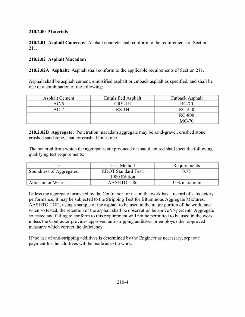
210.2.00 Materials
210.2.01 Asphalt Concrete: Asphalt concrete shall conform to the requirements of Section211.
210.2.02 Asphalt Macadam
210.2.02A Asphalt: Asphalt shall conform to the applicable requirements of Section 211.
Asphalt shall be asphalt cement, emulsified asphalt or cutback asphalt as specified, and shall beone or a combination of the following:
Asphalt Cement Emulsified Asphalt Cutback AsphaltAC-5 CRS-1H RC-70AC-7 RS-1H RC-250
RC-800MC-70
210.2.02B Aggregate: Penetration macadam aggregate may be sand-gravel, crushed stone,crushed sandstone, chat, or crushed limestone.
The material from which the aggregates are produced or manufactured shall meet the followingqualifying test requirements:
Test Test Method RequirementsSoundness of Aggregates KDOT Standard Test,
1980 Edition0.75
Abrasion or Wear AASHTO T 86 35% maximum
Unless the aggregate furnished by the Contractor for use in the work has a record of satisfactoryperformance, it may be subjected to the Stripping Test for Bituminous Aggregate Mixtures,AASHTO T182, using a sample of the asphalt to be used in the major portion of the work, andwhen so tested, the retention of the asphalt shall be observation be above 95 percent. Aggregateso tested and failing to conform to this requirement will not be permitted to be used in the workunless the Contractor provides approved anti-stripping additives or employs other approvedmeasures which correct the deficiency.
If the use of anti-stripping additives is determined by the Engineer as necessary, separatepayment for the additives will be made as extra work.
210-4
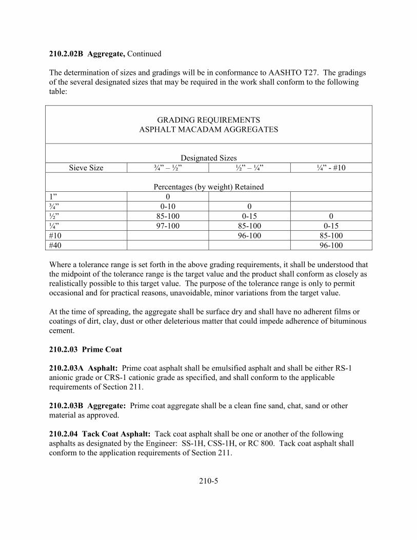
210.2.02B Aggregate, Continued
The determination of sizes and gradings will be in conformance to AASHTO T27. The gradingsof the several designated sizes that may be required in the work shall conform to the followingtable:
GRADING REQUIREMENTSASPHALT MACADAM AGGREGATES
Designated SizesSieve Size ¾” – ½” ½” – ¼” ¼” - #10
Percentages (by weight) Retained1” 0¾” 0-10 0½” 85-100 0-15 0¼” 97-100 85-100 0-15#10 96-100 85-100#40 96-100
Where a tolerance range is set forth in the above grading requirements, it shall be understood thatthe midpoint of the tolerance range is the target value and the product shall conform as closely asrealistically possible to this target value. The purpose of the tolerance range is only to permitoccasional and for practical reasons, unavoidable, minor variations from the target value.
At the time of spreading, the aggregate shall be surface dry and shall have no adherent films orcoatings of dirt, clay, dust or other deleterious matter that could impede adherence of bituminouscement.
210.2.03 Prime Coat
210.2.03A Asphalt: Prime coat asphalt shall be emulsified asphalt and shall be either RS-1anionic grade or CRS-1 cationic grade as specified, and shall conform to the applicablerequirements of Section 211.
210.2.03B Aggregate: Prime coat aggregate shall be a clean fine sand, chat, sand or othermaterial as approved.
210.2.04 Tack Coat Asphalt: Tack coat asphalt shall be one or another of the followingasphalts as designated by the Engineer: SS-1H, CSS-1H, or RC 800. Tack coat asphalt shallconform to the application requirements of Section 211.
210-5
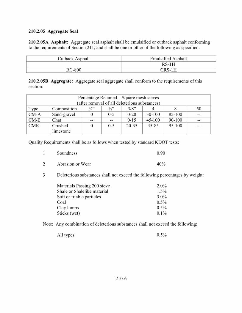
210.2.05 Aggregate Seal
210.2.05A Asphalt: Aggregate seal asphalt shall be emulsified or cutback asphalt conformingto the requirements of Section 211, and shall be one or other of the following as specified:
Cutback Asphalt Emulsified AsphaltRS-1H
RC-800 CRS-1H
210.2.05B Aggregate: Aggregate seal aggregate shall conform to the requirements of thissection:
Percentage Retained – Square mesh sieves(after removal of all deleterious substances)
Type Composition ¾” ½” 3/8” 4 8 50CM-A Sand-gravel 0 0-5 0-20 30-100 85-100 --CM-E Chat -- -- 0-15 45-100 90-100 --CMK Crushed
limestone0 0-5 20-35 45-85 95-100 --
Quality Requirements shall be as follows when tested by standard KDOT tests:
1 Soundness 0.90
2 Abrasion or Wear 40%
3 Deleterious substances shall not exceed the following percentages by weight:
Materials Passing 200 sieve 2.0%Shale or Shalelike material 1.5%Soft or friable particles 3.0%Coal 0.5%Clay lumps 0.5%Sticks (wet) 0.1%
Note: Any combination of deleterious substances shall not exceed the following:
All types 0.5%
210-6
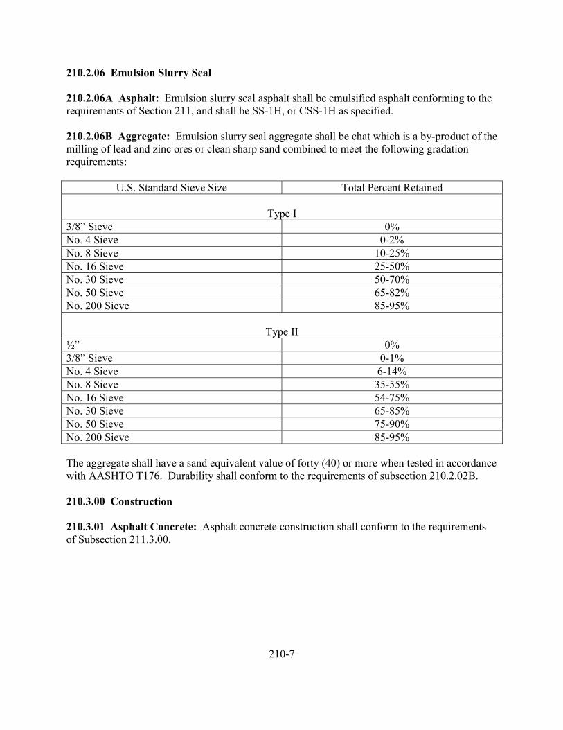
210.2.06 Emulsion Slurry Seal
210.2.06A Asphalt: Emulsion slurry seal asphalt shall be emulsified asphalt conforming to therequirements of Section 211, and shall be SS-1H, or CSS-1H as specified.
210.2.06B Aggregate: Emulsion slurry seal aggregate shall be chat which is a by-product of themilling of lead and zinc ores or clean sharp sand combined to meet the following gradationrequirements:
U.S. Standard Sieve Size Total Percent Retained
Type I3/8” Sieve 0%No. 4 Sieve 0-2%No. 8 Sieve 10-25%No. 16 Sieve 25-50%No. 30 Sieve 50-70%No. 50 Sieve 65-82%No. 200 Sieve 85-95%
Type II½” 0%3/8” Sieve 0-1%No. 4 Sieve 6-14%No. 8 Sieve 35-55%No. 16 Sieve 54-75%No. 30 Sieve 65-85%No. 50 Sieve 75-90%No. 200 Sieve 85-95%
The aggregate shall have a sand equivalent value of forty (40) or more when tested in accordancewith AASHTO T176. Durability shall conform to the requirements of subsection 210.2.02B.
210.3.00 Construction
210.3.01 Asphalt Concrete: Asphalt concrete construction shall conform to the requirementsof Subsection 211.3.00.
210-7
210.3.02 Asphalt Macadam
210.3.02A Weather and Seasonal Limitations: Asphalt macadam shall not be placed on anywet surface, or when the air temperature is below 60 degrees F, or when the Engineer determinesthat weather conditions are detrimental to proper construction.
Normally, the work shall be done between May 1 and October 15. After September 15 and uponwritten order of the Engineer, the asphalt material may be changed from an emulsion to acutback asphalt.
210.3.02B Equipment: The equipment to be used shall include power broom, self-propelledmechanical aggregate spreader, asphalt pressure distributor, roller, heating equipment, haulingvehicles, hand spreading, spotting and patching equipment, power graders and tools; all asnecessary for efficient operations and construction to meet specified results. Power brooms, self-propelled aggregate spreaders, asphalt distributor and hauling vehicles shall be pneumatic tired.Equipment shall be provided in such number and capacities as will provide coordinated anduniform progress.
Mechanical spreaders for spreading aggregate of less than one inch in maximum size shall be ofa design which will place the larger fraction ahead of the finer fraction of the aggregate.
Asphalt distributor shall be so designed, equipped, maintained and operated that asphalt at evenheat may be applied uniformly on variable widths of surface up to 15 feet at readily determinableand controlled rates from 0.05 to 2.0 gallons per square yard, with uniform pressure, and with anallowable variation from any specified rate not to exceed 0.02 gallon per square yard.Distributor equipment shall include a tachometer, pressure gauges, accurate volume measuringdevices or a calibrated tank, and a thermometer for measuring temperature of the tank contents.Distributors shall have a power unit for the pump and full circulation spray bards adjustablelaterally and vertically.
Rollers shall be self-propelled steel wheel or pneumatic tire type. They shall be capable ofcompacting the materials to a firm, even surface. Steel wheel rollers shall be capable ofproviding a weight of not less than 200 pound per inch width of the compression roll or rolls.Pneumatic tire rollers shall be capable of exerting a ground pressure of no less than 80 poundsper square inch of tire contact area. Vibratory rollers shall provide compaction of demonstratedequivalency to that of prescribed steel wheel or pneumatic tire rollers.
210.3.02C Sequence of Operations: The order of the several spreads of aggregates and asphaltshall be as specified. Spreads of aggregate shall be placed while the immediately precedingspread of bituminous material is at or near its application temperature. Each spread ofdesignated size aggregate shall be shaped and compacted and shall be at established line andgrade use prior to being covered. The seal coat spread of bituminous material and aggregateshall not be applied until the underlying spreads have been in place for at least three days andhave become stabilized.
210-8
210.3.02D Shaping and Compacting: Each spread of each designated size of aggregate shallbe shaped to prescribed line, grade and cross section and shall then be dry rolled until thematerial is interlocked, firm, partially bound with underlying asphalt, and until the aggregatedoes not creep or wave ahead of the roller.
Rolling shall normally commence at the low side of the prescribed cross section and progresswith passes parallel to the roadway center line and each pass shall overlap the preceding pass byat least one half of the width of the roller.
Along curbs, walls and at all places not accessible to or not compacted by specified rollers, theaggregate shall be tamped thoroughly with mechanical tampers or with hand tampers.
Irregularities in surface smoothness, non-uniformity of texture, segregation of materials, dirtpockets, spots of excess asphalt and other deficiencies and defects shall be corrected by removal,replacement, addition or material, repetition of construction operations or other suitable means,as directed or approved by the Engineer.
210.3.02E Application of Asphalt: Each spread of asphalt shall be uniformly applied at therate specified. Building paper shall be placed over the end areas of previously place spreads andthe adjoining application shall start on the paper, after which the paper shall be removed anddisposed of.
Rates of application shall not vary from prescribed rates by more than 10 percent. Misses andthinnesses shall be corrected by approved means. The Contractor shall protect structures andvegetation from being spattered, stained or marred, and shall remove stains and remedydisfigurements.
Hand application or other approved means shall be used on areas inaccessible to the distributor.
210.3.02F Hauling and Spreading Aggregates: Hauling and spreading equipment shall not beoperated on uncovered asphalt. Hand spreading shall be done to correct deficiencies or on areasinaccessible to mechanical equipment. Hauling over aggregate-covered asphalt shall be held to apracticable minimum until the surface has become firm. All hauling on asphalt macadam shallbe at moderate speeds which do not create loss of or hazardous movement of materials. Haulingshall be routed as uniformly as is practicable over the full width of material in place.
210.3.02G Surface Tolerance: The surface of the course, when finished and established, willbe tested by the Engineer for trueness to specified grade and transverse slope at selectedlocations. Testing will be with a 10-foot straightedge. The variation of the surface from thetesting edge of the straightedge between any two contact points with the surface shall at no pointexceed 0.03 foot.
210-9
210.3.02H Provision for Traffic: In addition to other required provisions for traffic, thefollowing shall apply: Traffic shall be permitted to travel over any spread of aggregate after ithas been shaped and compacted. During application of asphalt and until it is covered withaggregate, traffic shall be controlled by flagmen or pilot cars.
210.3.02I Establishment: During the period preceding construction of the seal coat, duringperiods when partial construction is open to traffic and for one calendar week following theoriginal completion of the course throughout the length of the project, which periods will becollectively referred to herein as “the curing period,” the Contractor shall perform the followingoperations:
A. The course shall be bladed or broomed to correct bleeding of asphalt, to providecoverage with aggregates, to keep the surface free of ravel, traffic grooves, holesand other deformations and to eliminate other defects that may appear.
B. Rolling and compacting of materials shall be performed to maintain or restorefirmness and stability to the materials.
C. Abutting shoulders shall be trimmed and materials which come into side ditchesshall be removed and wasted in a manner satisfactory to the Engineer.
The above operations shall be performed under traffic and at frequencies which the Engineerdetermines as being necessary to develop and establish the course to uniform firmness andstability throughout.
210.3.03 Prime Coat: Except as herein otherwise set firth, the prime coat shall be constructedin conformance to the requirements of Subsections 210.3.02A through 210.3.02H.
210.3.03A Application Rates: The prime coat shall be constructed with single spread ofasphalt following immediately with a single spread of aggregate cover material.
Asphalt shall be spread at a uniform rate normally within a range of 0.25 to 0.40 gallon ofresidual asphalt per square yard of surface.
Cover aggregate shall be spread at a uniform rate normally within a range of 0.006 to 0.009cubic yards, inclusive, per square yard of surface. The cover aggregate may be spread byspreader boxes, provided no part of the spreading equipment contacts the liquid asphalt prior toplacement of cover aggregate.
The actual rates of spread, both asphalt and aggregate, shall be as directed by the Engineer.
210-10
210.3.03B Establishment: Following construction of the prime coat, it shall be allowed to cureand harden for a period of up to three days, as directed by the Engineer, before a succeedingcourse is placed upon it. If so directed by the Engineer, traffic shall be permitted to travel overthe prime coat at any time after its construction. During the curing period, when in use bytraffic, and until it is covered by a succeeding course, the prime coat shall be maintained by theContractor to the specified shape and condition, as directed by the Engineer.
210.3.04 Tack Coat: Tack coat shall be applied in accordance with the requirements ofSubsection 210.3.02E. The surface upon which the tack coat is applied shall be dry and shall bemade free of dirt, dust or other matter foreign to the surface or detrimental to the adherence ofasphalt thereto.
210.3.04A Application: The asphalt shall be spread by means of pressure-spray equipmentwhich will provide uniformity of application at prescribed rates. Normally, asphalt shall beapplied to the prepared surface at a rate within a range of 0.02 to 0.06 gallon of residual asphaltper square yard of surface, the actual rate to be as directed by the Engineer. The tack coat shallnot be applied during wet or cold weather or during darkness and shall be constructed only so farin advance as is appropriate to insure a tacky, sticky condition of the asphalt at the time ofplacing a course thereon. The tack coat shall be applied in such a manner to offer the leastinterference to traffic and to permit one-way traffic without pickup or tracking of the asphalt.
210.3.05 Seal Coats: Except as herein otherwise set forth, seal coats shall be constructed inconformance to the requirements of Subsections 210.3.02A through 210.3.02H. The applicationrates of asphalt and aggregate shall be within the tolerance ranges specified in the followingtable. The exact rates shall be as directed.
Rates of Application Per Square Yard
Type Composition Emulsion Type CY of AggregateResidual
Asphalt, GallonsCM-A Sand-gravel CRS-1H 0.0090 0.24CM-E Chat CRS-1H 0.0085 0.30CM-K Crushed
LimestoneCRS-1H 0.0090 0.24
210-11
210.3.05A Emulsion Slurry Seal: Asphalt emulsion slurry treatment shall be placed only whenthe temperature is 60 degrees F or above. The mixture shall not be placed if the weather is foggyor rainy.
Materials shall be combined in the following proportions to provide a mixture of the desiredconsistency:
1. Aggregate – 100 pounds.2. Asphalt emulsion (as directed by the Engineer) – 2.5 – 3.0 gallons.3. Water – as required for proper consistency.
Immediately prior to the application of the slurry seal, the surface of the pavement and all crackfaces shall be wetted thoroughly with water. All surfaces shall be in a uniformly damp conditionand no free water will be allowed on the surface or in the cracks when the slurry seal is applied.
The slurry mixture shall be prepared in a slurry machine. The mixture shall be charged withmaterials in the proportions specified and the following order.
1. Water2. Aggregate3. Asphalt Emulsion
When mineral filler is required to obtain the desired gradation, it shall be added slowly to theother aggregate prior to the addition of the asphalt emulsion.
Variations from the above sequence of charging may be permitted by the Engineer provided aslurry of creamy, uniform consistency is obtained.
The mixing cycle shall be sufficient to produce a uniform coating of the aggregate. It shallcontinue until the slurry mixture is discharged into the spreader box. The entire batch shall bediscarded if there is evidence that the emulsion has broken.
The slurry mixture shall be chuted into the moving spreader box at a sufficient rate to maintainan ample supply of the mixture across the full width of the strike-off squeegee at all times. Thestrike-off squeegee shall be adjusted to provide a slurry thickness of the depth specified by theEngineer, but not to exceed ¼ inch for a single course.
Weighted burlap, or carpeting (face down) trailing behind the spreader box, may be required bythe Engineer if necessary to smooth joints between lanes. The burlap or carpeting shall be hosedoff thoroughly or immersed in water after each use to maintain its flexibility.
210-12
210.3.05A Emulsion Slurry Seal, Continued
In restricted areas where hand spreading is necessary, the slurry mixture shall be poured into asmall windrow along one edge of the surface to be covered. The mixture then shall be spreaduniformly by a hand squeegee.
All traffic shall be kept off the slurry seal until it has cured to a firm condition that will preventpick-up of the mixture. Where two applications of the slurry seal mixture are required, the initialtreatment shall be cured thoroughly prior to placing the succeeding application.
When extensive scaled areas are filled with emulsion slurry, each application shall be rolled witha pneumatic-tired roller after the slurry has cured.
On old, dry bituminous pavements and on rigid pavements, a tack coat shall be applied prior toplacing the slurry seal. The tack coat shall be a diluted asphalt emulsion of the same type andgrade specified for the slurry mix. The ratio of asphalt emulsion to water shall be 1:3 and thediluted material shall be applied uniformly with a pressure distributor at the rate of 0.05 to 0.10gallon per square yard, as directed by the Engineer.
The tack coat shall be cured thoroughly prior to the application of the slurry seal.
210.4.00 Measurement and Payment
210.4.01 Asphalt Concrete: Measurement and payment for asphalt concrete shall conform tothe requirements of Section 211.
210.4.02 Asphalt Macadam
210.4.02A Aggregate: Measurement of aggregate will be made on a cubic yard basis.Measurement of the materials will be made in the hauling vehicle at the points of deposit, withno allowance for settlement of material during transit. Loads shall be made level or uniform inshape as necessary to assure accurate measurement thereof. To facilitate measurement in thismanner, the Contractor, by striking off or other suitable means, shall bring the top of each load toa level surface with all corners filled.
210.4.02B Asphalt: Measurement of asphalt will be made on a ton basis. Quantities will bedetermined from volume computations of the materials when at a temperature of 60 degrees F,with standard recognized correction factors applied when the materials are measured at anytemperature other than 60 degrees F. When asphalt materials are shipped by truck or transport,net certified weights or volume, subject to correction for loss or foaming, may be used forcomputing quantities.
210-13
210.4.02B Asphalt, Continued
Water added to emulsion will not be paid for as emulsified asphalt. The pay quantity shall be theamount of undiluted emulsion used.
210.4.03 Prime Coat: Measurement and payment of prime coat shall be in accordance with therequirements of Subsection 210.1.02.
210.4.04 Tack Coat: Measurement and payment for tack coat shall be in accordance with therequirements of Subsection 210.4.02B.
210.4.05 Seal Coat: Measurement and payment for seal coat shall be in accordance with therequirements of Subsection 210.4.02.
210.4.06 Payment: Payment will be made for the following items when listed as pay items:
1. Asphalt MacadamAggregate (size) C.Y.Asphalt (type) Ton
2. Prime CoatAggregate (size) C.Y.Asphalt (type) Ton
3. Tack CoatAsphalt (type) Ton
4. Seal CoatAggregate (size) C.Y.Asphalt (type) Ton
210-14
211 ASPHALT CONCRETE PAVEMENT
211.1.00 Description211.1.02 Asphalt Concrete211.1.02 Tack Coat
211.2.00 Materials211.2.01 General211.2.02 Asphalt211.2.03 Aggregate211.2.04 Mineral Filler211.2.05 Additives211.2.06 Classes of Concrete and Proportions of Mixtures211.2.07 Prime Coat Asphalt211.2.08 Prime Coat Aggregate211.2.09 Tack Coat Asphalt
211.3.00 Construction211.3.01 Preparation of Foundation211.3.02 Reconditioning Old Roadbed211.3.02A Subgrade211.3.02B Aggregate Bases211.3.02C Pavement Surfaces211.3.03 Prime Coat211.3.04 Tack Coat211.3.05 Asphalt Concrete211.3.05A Placing211.3.05B Compaction
211.4.00 Measurement and Payment211.4.01 Payment
211-1
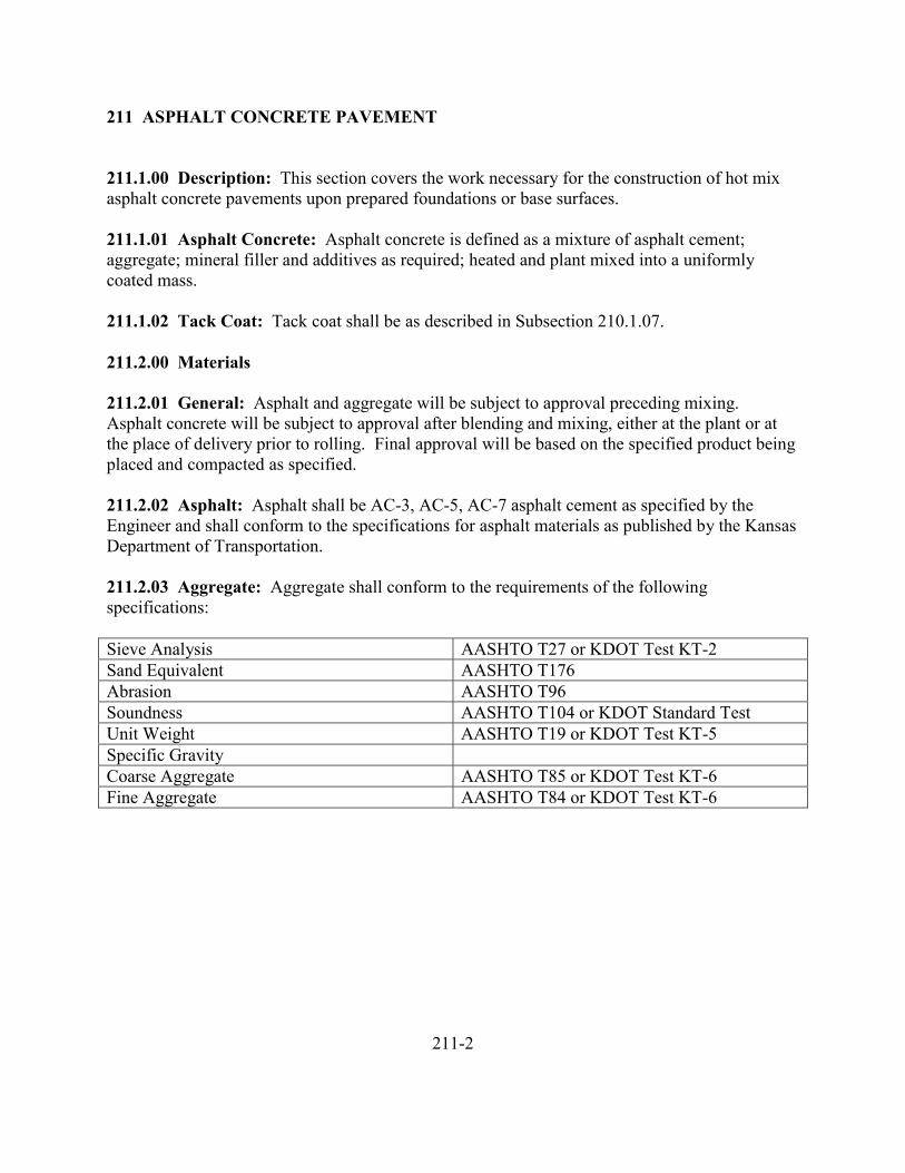
211 ASPHALT CONCRETE PAVEMENT
211.1.00 Description: This section covers the work necessary for the construction of hot mixasphalt concrete pavements upon prepared foundations or base surfaces.
211.1.01 Asphalt Concrete: Asphalt concrete is defined as a mixture of asphalt cement;aggregate; mineral filler and additives as required; heated and plant mixed into a uniformlycoated mass.
211.1.02 Tack Coat: Tack coat shall be as described in Subsection 210.1.07.
211.2.00 Materials
211.2.01 General: Asphalt and aggregate will be subject to approval preceding mixing.Asphalt concrete will be subject to approval after blending and mixing, either at the plant or atthe place of delivery prior to rolling. Final approval will be based on the specified product beingplaced and compacted as specified.
211.2.02 Asphalt: Asphalt shall be AC-3, AC-5, AC-7 asphalt cement as specified by theEngineer and shall conform to the specifications for asphalt materials as published by the KansasDepartment of Transportation.
211.2.03 Aggregate: Aggregate shall conform to the requirements of the followingspecifications:
Sieve Analysis AASHTO T27 or KDOT Test KT-2Sand Equivalent AASHTO T176Abrasion AASHTO T96Soundness AASHTO T104 or KDOT Standard TestUnit Weight AASHTO T19 or KDOT Test KT-5Specific GravityCoarse Aggregate AASHTO T85 or KDOT Test KT-6Fine Aggregate AASHTO T84 or KDOT Test KT-6
211-2
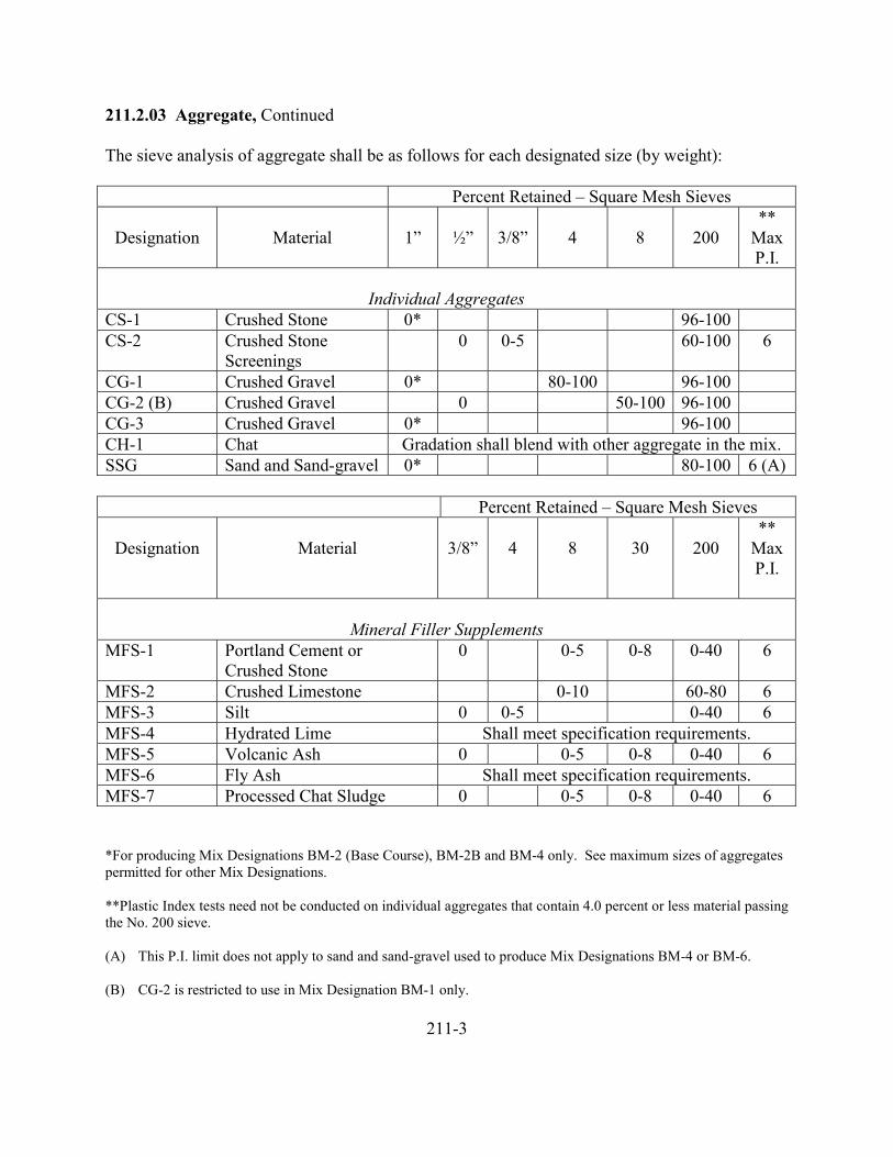
211.2.03 Aggregate, Continued
The sieve analysis of aggregate shall be as follows for each designated size (by weight):
Percent Retained – Square Mesh Sieves
Designation Material 1” ½” 3/8” 4 8 200**
MaxP.I.
Individual AggregatesCS-1 Crushed Stone 0* 96-100CS-2 Crushed Stone
Screenings0 0-5 60-100 6
CG-1 Crushed Gravel 0* 80-100 96-100CG-2 (B) Crushed Gravel 0 50-100 96-100CG-3 Crushed Gravel 0* 96-100CH-1 Chat Gradation shall blend with other aggregate in the mix.SSG Sand and Sand-gravel 0* 80-100 6 (A)
Percent Retained – Square Mesh Sieves
Designation Material 3/8” 4 8 30 200**
MaxP.I.
Mineral Filler SupplementsMFS-1 Portland Cement or
Crushed Stone0 0-5 0-8 0-40 6
MFS-2 Crushed Limestone 0-10 60-80 6MFS-3 Silt 0 0-5 0-40 6MFS-4 Hydrated Lime Shall meet specification requirements.MFS-5 Volcanic Ash 0 0-5 0-8 0-40 6MFS-6 Fly Ash Shall meet specification requirements.MFS-7 Processed Chat Sludge 0 0-5 0-8 0-40 6
*For producing Mix Designations BM-2 (Base Course), BM-2B and BM-4 only. See maximum sizes of aggregatespermitted for other Mix Designations.
**Plastic Index tests need not be conducted on individual aggregates that contain 4.0 percent or less material passingthe No. 200 sieve.
(A) This P.I. limit does not apply to sand and sand-gravel used to produce Mix Designations BM-4 or BM-6.
(B) CG-2 is restricted to use in Mix Designation BM-1 only.
211-3
211.2.03 Aggregates, Continued
Where a tolerance range is set forth, it shall be understood that the midpoint of the tolerancerange is the target value and the product shall conform as closely as realistically possible to thistarget value. The purpose of the tolerance range is only to permit occasional minor variationsfrom the value that are, for practical reasons, unavoidable.
The respective sizes and gradings of the aggregate shall be such that when mixed, the respectiveresultant mixtures will be of the sizes and gradings specified in Subsection 211.2.06.
211.2.04 Mineral Filler: Mineral filler shall conform to the requirements of AASHTO M17.
Collector dust may be used as mineral filler, in whole or in part, provided the dust or theresultant mineral filler mixture conforms to the above requirements.
211.2.05 Additives: Additives and admixtures may be used to prevent stripping or separationof bituminous coatings for aggregates, and to aid in the mixing or use of bituminous mixes or forexperimental purposes. Admixtures and additives shall be standard recognized products ofknown value for the intended purpose and shall be approved by the Engineer on the basis oflaboratory tests prior to their use in the work. They shall have no deleterious effect on thebituminous material and shall be completely miscible.
211.2.06 Classes of Concrete and Proportions of Mixtures: The class of asphalt concrete tobe used shall be as shown and shall conform to the following requirements:
211-4
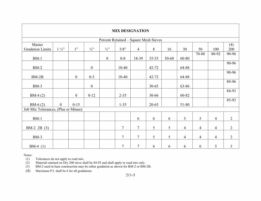
MIX DESIGNATION
Percent Retained – Square Mesh SievesMaster
Gradation Limits 1 ½” 1” ¾” ½” 3/8” 4 8 16 30 50 100(4)200
BM-1 0 0-8 18-39 35-53 50-68 60-8070-88 80-92 90-96
BM-2 0 10-40 42-72 64-8890-96
BM-2B 0 0-5 10-40 42-72 64-8890-96
BM-3 0 30-65 63-8689-96
BM-4 (2) 0 0-12 2-35 30-66 60-8284-93
BM-6 (2) 0 0-15 1-35 20-65 51-8085-93
Job Mix Tolerances, (Plus or Minus):
BM-1 6 6 6 5 5 4 2
BM-2 2B (3) 7 7 5 5 4 4 4 2
BM-3 7 7 5 5 4 4 4 2
BM-4 (1) 7 7 6 6 6 6 5 3
Notes:(1) Tolerances do not apply to road mix.(2) Material retained on Dry 200 sieve shall be 84-95 and shall apply to road mix only.(3) BM-2 used in base construction may be either gradation as shown for BM-2 or BM-2B.(4) Maximum P.I. shall be 6 for all gradations.
211-5
211.2.06 Classes of Concrete and Proportions of Mixtures, Continued
No less than two weeks before the beginning of plant mix operations, the Contractor shall submitthe following to the Engineer:
1. Source, approximate gradation, gradation limits, and percentage of eachindividual aggregate and mineral filler supplement that is to be used in producingthe final mix.
2. A proposed design job-mix grading that is within the master grading limits andwhich establishes a single percentage of material to be retained on each sieve.The grading shall be such that when the job-mix tolerances are applied, theresulting band will be wholly within the Master Grading Limits.
Changes in the individual limits or proportions may be made only with theapproval of the Engineer.
3. The Engineer shall have the right to require the Contractor to provide a sufficientquantity of each asphalt, aggregate and mineral filler supplement that he proposesto use to a certified testing laboratory so that tests can be conducted on individualand combined materials to determine whether the Contractor’s design job-mixgrading will meet the project requirements.
No asphaltic materials shall be delivered to the project until the necessary tests arecompleted and the Contractor’s design job-mix gradation has been tentativelyapproved by the Engineer. If test results show that the mix meets projectrequirements at an asphalt content that will provide an adequately coated mixture,the Contractor’s design job-mix grading will be tentatively approved and anasphalt percentage will be established by the Engineer. The Contractor may thenbegin delivery of the bituminous mixture to the project. The cost of the necessarytests shall be at the expense of the City, however, should it be necessary to runmore than one evaluation on materials or on portions of materials, such duplicateevaluations shall be at the expense of the Contractor.
Revisions to the job-mix formula may require new laboratory evaluations prior toapproval. Such evaluations shall be at the expense of the Contractor.
211.2.07 Prime Coat Asphalt: Prime coat asphalt shall be emulsified asphalt and shall beeither RS-1 anionic grade or CRS-1 cationic grade as specified.
211.2.08 Prime Coat Aggregate: Prime coat aggregate shall be a clean fine sand, chat sand orother material as approved.
211-6
211.2.09 Tack Coat Asphalt: Tack coat asphalt shall be one or another of the followingemulsified asphalt or cutback asphalts as designated by the Engineer: SS-1H, CSS-1H or RC-800.
211.3.00 Construction
211.3.01 Preparation of Foundation: All bases and foundations shall be constructed to thecondition prescribed under the applicable specification.
If so directed by the Engineer or the specifications, depressed areas of existing pavements orbituminous surfaces shall receive a tack coat in conformance with the applicable requirements ofSection 210, then filled with asphalt concrete and compacted to the prescribed density.
Broken or ragged edges of existing Portland cement concrete or bituminous surfaces underlyingor abutting the new pavement shall be trimmed back to firm material. Contact surfaces ofstructures, including curbs, in the paving area shall be treated with an asphalt tack coat prior toplacing the asphalt concrete.
Underlying surfaces of Portland cement concrete and designated areas of asphalt-deficient, fine-cracked or spalled bituminous material shall be treated with an asphalt tack coat prior to placingthe asphalt concrete.
211.3.02 Reconditioning Old Roadbed: This work shall consist of the reconditioning ofpreviously constructed roadbed subgrades, aggregate bases, and pavement surfaces upon whichmaterial is to be placed, as stated in the contract.
Where unstable or unsuitable materials are encountered, they shall be removed and disposed ofas directed by the Engineer and replaced with material as specified by the Engineer. Thereplacement materials shall be placed, compacted and finished in accordance with therequirements of the appropriate section of these specifications.
Removing, disposing of, and replacing unstable or unsuitable materials shall be extra work andpayment will be in accordance with the requirements of Subsection 104.9.01.
211.3.02A Subgrade: Existing roadbed subgrades shall be bladed, leveled, loosened, reshapedand otherwise brought in reasonably close conformity to the line, grade, slope and cross sectionestablished by the Engineer. While the above work is underway, the materials shall be wateredand rolled and the reconditioned and prepared subgrade shall be compacted to densities requiredfor similar new work.
211-7

211.3.02B Aggregate Bases: Existing aggregate bases shall be bladed, scarified and shaped asthe Engineer may determine to be necessary to bring the surface thereof in reasonably closeconformity to lines, grades and cross section established by the Engineer. The materials shall bewatered and compacted as necessary to obtain densities required for similar new work.
211.3.02C Pavement Surfaces: Existing pavements surfaces shall be cleaned of all loosematerial, dirt and dust by brooming, by flushing with water or by other approved methods.
211.3.03 Prime Coat: Prime coat shall be applied at a rate normally within a range of 0.25 to0.40 gallons per square yard of surface. Cover aggregate if required shall be applied at a rate of0.006 to 0.009 cubic yards per square yard of surface.
The temperature of the asphalt material at the time of application shall be within the limits forthe type and grade being used, as shown in the following table:
Type and Grade of Asphalt Distributor Spraying TemperatureMinimum Maximum
RS-1, RS-1H 100 180CRS-1, CRS-1H 100 180
Asphalt shall not be applied on any wet surfaces, or when the air temperature is less than 60degrees F.
Prior to starting operations, the asphalt distributor spray bar shall be checked and adjusted, ifnecessary, to assure that all nozzles are properly adjusted and the bar height set for a double ortriple overlap. Each application of asphalt shall commence on building paper placed across thewidth of the spread to ensure proper operation of the bar and provide precise meet lines attransverse junctions in the spreading operation.
The asphalt distributor shall have controls for regulating and monitoring the spread of asphalt ata uniform temperature on variable widths of surface up to 15 feet and at rates from 0.05 to 2.0gallons per square yard with uniform pressure. The variation from the specified rate ofapplication shall not exceed 0.02 gallons per square yard. Spray bards shall be full circulatingand be adjustable both laterally and vertically.
Rollers shall be self-propelled pneumatic tire type capable of exerting a ground pressure of notless than 80 pounds per square inch of tire contact area.
Operation of the asphalt distributor and aggregate spreader shall be carefully controlled to ensurethat the asphalt is covered with aggregate as soon as possible. Asphalt cements shall be coveredwithin two minutes of application and emulsified asphalts before any breaking of the emulsionoccurs.
211-8
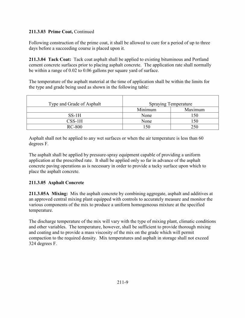
211.3.03 Prime Coat, Continued
Following construction of the prime coat, it shall be allowed to cure for a period of up to threedays before a succeeding course is placed upon it.
211.3.04 Tack Coat: Tack coat asphalt shall be applied to existing bituminous and Portlandcement concrete surfaces prior to placing asphalt concrete. The application rate shall normallybe within a range of 0.02 to 0.06 gallons per square yard of surface.
The temperature of the asphalt material at the time of application shall be within the limits forthe type and grade being used as shown in the following table:
Type and Grade of Asphalt Spraying TemperatureMinimum Maximum
SS-1H None 150CSS-1H None 150RC-800 150 250
Asphalt shall not be applied to any wet surfaces or when the air temperature is less than 60degrees F.
The asphalt shall be applied by pressure-spray equipment capable of providing a uniformapplication at the prescribed rate. It shall be applied only so far in advance of the asphaltconcrete paving operations as is necessary in order to provide a tacky surface upon which toplace the asphalt concrete.
211.3.05 Asphalt Concrete
211.3.05A Mixing: Mix the asphalt concrete by combining aggregate, asphalt and additives atan approved central mixing plant equipped with controls to accurately measure and monitor thevarious components of the mix to produce a uniform homogeneous mixture at the specifiedtemperature.
The discharge temperature of the mix will vary with the type of mixing plant, climatic conditionsand other variables. The temperature, however, shall be sufficient to provide thorough mixingand coating and to provide a mass viscosity of the mix on the grade which will permitcompaction to the required density. Mix temperatures and asphalt in storage shall not exceed324 degrees F.
211-9
211.3.05B Placing: Asphalt concrete shall be at a temperature of between 250 and 300 degreesF at the time it is placed. It shall normally be placed on dry prepared surfaces and when the airtemperature in the shade is 40 degrees F or warmer. Placing during rain or other adverse weatherconditions normally will not be permitted, except that material in transit at the time adverseconditions may occur may be placed provided it is of proper temperature, has been coveredduring transit, and is placed on a foundation free from pools or flow of water.
Asphalt concrete shall be placed in panels of such width as to hold a practical minimum thenumber of longitudinal joints required. The longitudinal joints in any panel shall offset thosejoints in underneath panels by not less than six inches. Special care shall be taken at longitudinaljoints to provide the required bond and density.
The placing of asphalt concrete shall be a continuous operation as nearly as practicable. If thecapacity of the paving machine exceeds the capacity of the hauling vehicles, the paving machineshall be operated at a reduced uniform speed so as to maintain a continuous operation.
211.3.05C Compaction: Unless otherwise specified, the degree of compaction shall be 92% ofrelative maximum density, as determined by AASHTO T230. Rollers shall be capable oftransmitting sufficient static or dynamic force necessary to compact the material to the specifieddegree of compaction.
Longitudinal joints shall be rolled directly behind the paving machine. The first panel shall havevertical edges, and the abutting panel shall be tightly crowded against its edge. Material from thesecond panel shall be pushed over the surface of the first panel so as to develop an overlay offrom three to six inches.
Breakdown rolling shall immediately follow the rolling of the longitudinal joint and edges.Rollers shall be operated as close to the paving machine as necessary to obtain adequate densitywithout causing undue displacement. The breakdown roller shall be operated with the drive rollor wheels nearest the paving machine. Exceptions may be made when working on steep slopesor super-elevated curves.
Pneumatic-tired rolling will be allowed after breakdown rolling as occurred. This rolling shallfollow the breakdown rolling as closely as possible and while the material is at a temperature thatwill result in the specified degree of compaction being achieved.
Roller wheels shall be kept moist with only enough water to avoid picking up the material.Rollers shall move at a uniform speed not to exceed 3 mph for steel-wheeled rollers or 5 mph forpneumatic tired rollers. Rollers shall be in good condition and capable of being reversed withoutbacklash. The line of rolling shall not be suddenly changed nor the direction of rolling suddenlyreversed. Any pronounced change in the direction of the roller shall be made on stable material.If rolling causes displacement of the material, the affected areas shall be loosened and restored tothe original grade with loose material before being rerolled. Heavy equipment, including rollers,shall not be allowed to stand on the finished surface before it has thoroughly cooled or set.
211-10
211.3.05C Compaction, Continued
The finished surface shall be true to line and grade, free of irregularities and roller wheel tracks.
211.3.05D Tolerance: The surface shall not vary more than 0.02 of a foot when tested with a10-foot straightedge applied parallel with the centerline, and/or perpendicular to the centerline.
211.4.00 Measurement and Payment: Unless otherwise specified, measurement and paymentfor asphalt concrete will be made on a ton basis for the class of asphalt concrete specified.
211.4.01 Payment:
Class (Specify) Unit of Measure
Asphalt Concrete Ton
Should the scale weight tonnage exceed the theoretical tonnage the Engineer may increase thequantity for payment, but not to exceed 10% of the theoretical tonnage.
In the event the total scale weight tonnage is less than that determined by the paragraph above,the Contractor shall determine the cause therefore to the satisfaction of the Engineer.
A. If it is determined that the cause will not weaken or in any way shorten the life ofthe structure, then the structure may be accepted and payment be made for theconstructed thickness of asphalt actually in the structure.
B. Should it be determined that the cause of low tonnage might weaken and shortenthe life of the pavement structure, then the Contractor shall properly rectify the structurein accordance with these specifications and to the satisfaction of the Engineer.
211-11
212 PORTLAND CEMENT CONCRETE PAVEMENT
212.1.00 Description
212.2.00 Materials
212.3.00 Construction212.3.01 General212.3.02 Hauling212.3.03 Reinforcement, Forms, Handling, and Placing212.3.04 Slip Form Paving212.3.05 Tamping and Screeding212.3.06 Roadway and Alley Finishing212.3.07 Joints212.3.08 Tolerances212.3.09 Curing212.3.10 Protection
212.4.00 Measurement and Payment212.4.01 Measurement212.4.02 Payment
212-1
212 PORTLAND CEMENT CONCRETE PAVEMENT
212.1.00 Description: This section covers the work necessary for construction of Portlandcement concrete pavements, with or without reinforcement, on a prepared subgrade or basecourse, complete.
212.2.00 Materials: Portland cement concrete, joint materials and curing materials shallconform to the applicable requirements of Section 503. Reinforcement shall conform to theapplicable requirements of Section 504.
212.3.00 Construction
212.3.01 General: The plant, equipment and tools required in the performance of the workmust be approved as to design, capacity and condition to efficiently perform their respectivefunctions of the work. The Contractor shall coordinate all operations involved in constructingthe pavement so that regardless of the daily or seasonal variations in weather, temperature andhumidity under which the work is permitted to proceed, such work will result in a finishedpavement conforming in all respects to specified requirements. The Contractor shall provide andhave available at all times adequate equipment, tools, materials and labor to achieve these resultsand failure to so provide will be cause for discontinuance of the work upon order of theEngineer. All procedures shall conform to the applicable requirements of concrete constructionin Section 503, CONCRETE STRUCTURES.
212.3.02 Hauling: Hauling of Portland cement concrete shall conform to the provisions ofAASHTO M 157.
212.3.03 Reinforcement, Forms, Handling and Placing: Reinforcement shall conform to theapplicable requirements of Section 504. Forms, handling and placing shall conform to theapplicable requirements of Section 503.
212.3.04 Slip Form Paving: The Contractor shall place the concrete uniformly in its finalposition by the slip form method in one complete pass in such a manner that a minimum offinishing will be necessary to provide a dense and homogeneous pavement in conformance totrue grade and cross section. The machine shall vibrate the concrete for the full width of thepavement being placed. Such vibration shall be accomplished with the vibrating tubes or armsworking in the concrete. The sliding forms shall be rigidly held together to prevent spreading ofthe forms. Forms of sufficient length shall be used so that no appreciable slumping of theconcrete will occur.
212-2
212.3.04 Slip Form Paving. Continued
The Contractor shall operate the slip form paver with as nearly continuous forward movement aspossible and coordinate all operations of mixing, delivery and spreading concrete to provideuniform progress. Stopping and starting of the paving machine shall be held to an absoluteminimum. If for any reason it is necessary to stop the forward motion of the paver, the vibratoryand tamping elements shall be stopped immediately. No tractive force shall be applied to themachine, except that which is controlled from the machine.
The Contractor shall ensure that supports of the slip form paver and other equipment which rideson previously placed pavement is offset over that pavement sufficiently to prevent breakage ofthe edge thereof and provide such supports with suitable protective means to avoid marring orchipping of the previously placed pavement.
212.3.05 Tamping and Screeding: The Contractor shall compact the concrete pavement bymeans of vibratory screeds, mechanical tampers, tamping templates and such other implementsas approved. A vibrating screed or an automatic screeding and tamping machine may besubstituted for a tamping template, subject to approval. The Contractor shall operate theequipment in such a manner that a satisfactory compaction of the concrete is produced and thesurface of the pavement is uniform, true to grade and cross section.
Immediately after placing concrete upon the subgrade and before initial set has occurred, theContractor shall strike off the concrete and tamp by means of a tamping template, used at rightangles to the centerline of the street, until the concrete is thoroughly consolidated to specifiedgrade and crown section and sufficient mortar is brought to the surface for finishing purposes. Ifthe design or location of the base is such as to preclude the possibility of tamping as previouslydescribed, such as a variable crown section, curb being constructed monolithic with base, inalleys, or where the grade exceeds 10 percent, the Contractor shall employ other approvedmethods to obtain the prescribed results.
212.3.06 Roadway and Alley Finishing: After the concrete is placed and compacted, theContractor shall strike it true to line, grade and cross section as shown and float to a smooth,even texture with an approved long handled wood float having a troweling and smoothingsurface from 6 to 12 inches wide, or other approved floating device. The Contractor shall applythe float to the surface of the concrete with its length parallel to the centerline of the street andoperate it from bridges, planing off high places and filling the low places. Precedingapplications of the float shall be lapped by at least one-half its length. If, after such planing, lowplaces are discovered in the surface of the concrete, the Contractor shall add additional concreteto fill in and bring such low places to grade, as approved. Floating shall leave the surface finishat specified grade, cross section and surface tolerance with a surface free from laitance, soupymortar, marks or irregularities.
212-3
212.3.06 Roadway and Alley Finishing, Continued
Following the float finish and at the proper set, the surface shall be broom finished. TheContractor shall draw the broom transversely across the pavement with not more than one strokeper width of broom. Any areas of minor honeycomb or other minor defect in composition of theconcrete shall be filled along the exposed edges with a stiff mortar or cement and fine aggregateapplied to the moistened concrete in a professional manner. Areas showing serious defects incomposition shall be cause for removal of the affected pavement and replacement with pavementof specified quality for the full width of strip between longitudinal joints or edges and for alength not less than 10 feet.
The Contractor shall tool the free edges of the new pavement and joints with previously placedPortland cement concrete with an approved edging tool to remove laitance and mortar resultingfrom finished operations and to provide a clean rounded edge to the new pavement. Toolingshall not form ridges on the surface of the concrete. Tooling of edges at transverse joints shall beperformed as directed.
212.3.07 Joints
General – Joints shall be of the respective kinds called for by the plans and shall be constructedwhere called for by the plans or where directed by the Engineer. Joints in pavement will beclassed and refereed to as longitudinal contraction, construction and expansion; any of whichmay be transversely or longitudinally with the pavement as called for by the plans or as directedby the Engineer. All joints and joint filler shall extend clearly to pavement edges or to eachother, as the case may be.
All transverse joints shall be constructed normally to the surface of the pavement. Joints shallnot vary from specified or indicated line by more than ¼ inch. The tops of joint filler, whenrequired, shall be true to pavement cross section within 1/8 inch. Top edges of filler shall beprotected from damage to concreting operations.
All joints, including load transfer devices and tie bars in conjunction therewith, shall be subjectto inspection after installation but prior to the hardening of the concrete and shall be replaced intheir entirety together with disturbed areas of concrete if found faulty in any respect. TheContractor shall expose such joints as are to be inspected by removing and replacing materials asrequired. If the joint is found faulty, the costs of removing and replacing of materials will bepaid for as extra work.
Normally, all joints which contained preformed filler are to be constructed prior to the finalfloating and surface finishing of the concrete.
Longitudinal Joints – Longitudinally joints shall be the contact type or weakened plane type ascalled for by the plans.
212-4
212.3.07 Joints, Continued
Longitudinal Contact Joints – Longitudinal contact joints shall be constructed when freshconcrete is poured against hardened concrete, between strips of pavement or between a strip ofpavement and a concrete gutter. Such joints shall be saw cut and sealed in the same manner asweakened plane-type joints.
Longitudinal Weakened Plane Type Joints – Weakened plane type joints shall be constructed bysawing to the depth and maximum width called for by the plans without tearing, raveling oruncontrolled cracking of the concrete. Sawing shall be performed as soon as the concrete has setenough to permit sawing without tearing. Saws may be single or tandem as the Contractor mayelect and shall be controlled by guides to true line.
If full conformance with all requirements is not obtained, joint sawing shall be abandoned andpavement areas containing uncontrolled cracks shall be removed and replaced by the Contractorat the Contractor’s expense, at the direction of the Engineer. Curing agents broken or damagedby the sawing operations shall be restored.
The joint shall be filled with a preformed joint filler, or with approved filled, with the top thereofestablished slightly but not more than 1/8 inch below and paralleling finished pavement gradeand cross section.
Contraction Joints – Contraction joints shall be constructed by sawing to the depths, widths andat the locations called for by the plans. Sawing of contraction joints shall be performed inconformance with the requirements hereinbefore set forth for sawed longitudinal joints exceptthat they shall be sawed with a gang saw assembly incorporating not less than two separate sawsfor each traffic lane width of pavement being sawed and each separate saw shall saw aproportionate length of joint as a nearly simultaneous operation.
Transverse contraction joints of the weakened plane or dummy type shall be constructed at suchlocations as are required to confide the contraction joint spacing to a maximum of 15 feet. Thejoints shall be formed to a depth of 1/3 of the thickness of concrete and to a width ofapproximately ¼ inch.
Construction Joints – Construction joints shall be constructed when there is an interruption ofmore than 30 minutes in the concreting operations. No construction joint shall be constructedwithin 10 feet of an expansion joint or contraction joint. If sufficient concrete has not beenmixed at the time of interruption to form a slab at least 10 feet long, the excess concrete back tothe last preceding joint shall be removed an disposed of as directed.
212-5
212.3.07 Joints, Continued
With continuously reinforced pavement, construction joints shall be formed with a special headerboard. Care shall be exercised in the forming of construction joints to assure that thereinforcement and its supports are not displaced, distorted or otherwise disturbed in any way. Atthe recommencement of concreting, the header board shall be carefully removed in a mannerwhich will not in any way disturb the reinforcement and which will not disturb the bond betweenthe reinforcement and the previously placed concrete.
Any debris at and beyond the joint shall be cleaned out, spilled concrete removed, and thereinforcement supported in proper position. The new concrete place contiguous to the joint shallclosely conform to the proportions and consistency of the previously placed concrete and shall bevibrated and consolidated to a greater degree and with more care than is usual in normalconstruction.
Expansion Joints – Preformed expansion joint filler shall be provided in lengths requiring aminimum number of pieces, and in widths and thicknesses called for by the plans or as directed.Joints in the filler shall be clipped or laced butt type, and openings shall be made in the filler toprovide for load transfer devices when required. The support of the filler while concrete is beingplaced adjacent to and in contact with it shall be firm and adequate to insure specified permanentposition, and the top of the filler shall be set below and paralleling finished pavement surface at adepth equal to the width of the performed joint filler.
Expansion joints shall be a right angles to the alignment, vertical to the surface, and shall providecomplete separation of the Portland cement concrete. Expansion joints shall be constructedopposite existing expansion joints.
212.3.08 Tolerances: At the conclusion of the finishing operation, the surface of the pavementshall not vary from a true surface when tested with a 10-foot testing straightedge, more than .01foot in 10 feet.
The finished surface shall not vary more than 0.03 foot from the plan elevations at any point.
If the surface smoothness of the pavement after curing is found to exceed the tolerancepermitted, the high spots shall be ground until they meet the tolerance. The practicable extent ofgrinding shall not exceed 0.5 inch, shall not create spalling of aggregate and shall not createdeficiencies in pavement thickness. All grinding shall be at no expense to the Owner.
212-6
212.3.09 Curing: Immediately after the final floating, surface finishing and edging has beencompleted and while the concrete surface is still moist, the entire exposed surface of the newlylaid concrete shall be covered and cured in accordance with one or another of the followingprovisions as the Contractor may elect:
A. Liquid Membrane-Forming Compounds – Membrane-forming compound shall beof the white pigmented type and shall be applied uniformly to damp concrete bypressure-spray methods at a rate which will form an impervious membrane whentested in accordance with AASHTO T155.
B. White Polyethylene Sheeting – The white polyethylene sheeting shall be appliedto damp concrete as soon as the sheeting can be placed without marring thesurface. The sheeting shall be placed in intimate contact with the surface, shallextend over and beyond the sides or edges of the slabs or forms and shall beweighted as required to hold it in position as a waterproof and moisture proofcovering. Laps shall be of dimensions and design in place to maintain tightnessequivalent to the sheeting.
C. Waterproof paper – Waterproof paper shall be applied to damp concrete as soonas it can be placed without marring the surface. The paper shall be placed inintimate contact with the surface, shall extend over and beyond the sides or edgesof the slabs or forms and shall be weighted as required to hold it in position as awaterproof and moisture proof covering. Transverse laps shall be at least 18inches and longitudinal seams shall be cemented.
D. Cotton or Jute Mats – Cotton or jute mats shall be applied to damp concrete assoon as the surface has set sufficiently to prevent marring thereof. Just prior toplacing, the mats shall be saturated with water and shall be kept fully wettedduring the curing period. The mats shall be maintained in intimate contact withthe concrete surface and shall be extended over the edges and beyond sufficientlyto be well weighted down alongside the pavement edges.
212.3.10 Protection: The Contractor shall erect and maintain suitable barriers to protect theconcrete from traffic or other detrimental trespass until the pavement is opened to traffic. Ifnecessary, the Contractor shall maintain watchmen to insure that barriers are not removed ordestroyed and that trespass upon the pavement does not occur.
Whenever it is necessary that traffic, including Contractor’s vehicle and equipment, be carriedfrom one side of the pavement to the other, the Contractor shall construct and maintain suitablebridges over the pavement as directed.
212-7
212.3.10 Protection, Continued
The concrete shall have attained the specified compressive strength and shall be free fromscarring, abrasion, stones, loose mortar and other matter apt to be deleterious to the concreteprior to allowing equipment to use the new surface. All equipment shall be operated withoutdamage to the new concrete.
The Contractor shall repair or replace any part of the pavement, as directed, which has beendamaged by traffic or from any other cause prior to its official acceptance, at no expense to theOwner.
Traffic shall not be allowed to travel on the concrete until it has obtained 65 percent of its 28-daydesign strength.
212.4.00 Measurement and Payment
212.4.01 Measurement: Measurement of Portland cement concrete pavement will be made ona square yard basis for the payment complete in place as specified and accepted. Measurementwill be made of width and length of each separately constructed strip of pavement, whichever isthe lesser, and the length is from end to end of pavement to the nearest 0.1 foot and the squareyardage shall be to the nearest square yard.
Extra thickness of pavement, when shown or specifically directed to be placed, will be measuredby conversion on a proportionate volume basis to an equivalent number of square yards ofspecified standard thickness pavement.
212.4.02 Payment: Payment will be made for the following items when listed as pay items:
Payment Item Unit of Measure
1. Continuous Reinforced Concrete Pavement(specify class, thickness, reinforcing steel) Per S.Y.
2. Reinforced Concrete Pavement (specify class,thickness, reinforcing steel) Per S.Y.
3. Plain Concrete Pavement (specify class,thickness) Per S.Y.
Payment for concrete pavement, whether continuously reinforced, reinforced, or plain, shall befull compensation for furnishing and placing all materials including water, reinforcement, jointmaterials, dowels, tie-bars, and performing all work specified to complete the item includingpreparation of the base.
212-8
213 CURBS AND GUTTERS
213.1.00 Description
213.2.00 Materials213.2.01 Portland Cement Concrete213.2.02 Asphalt Concrete213.2.03 Aggregate213.2.04 Metal Reinforcement213.2.05 Dowels213.2.06 Preformed Expansion Joint Filler213.2.07 Epoxy Cement213.2.08 Curing Materials
213.3.00 Construction213.3.01 Preparation of Base213.3.01A Earthwork213.3.01B Aggregate Foundation or Bedding213.3.01C Base for Portland Cement Concrete213.3.01D Base for Asphalt Concrete213.3.02 Forms and Equipment213.3.02A Forms213.3.02B Equipment213.3.03 Placing, Finishing, and Curing213.3.03A General213.3.03B Asphalt Concrete Structures213.3.03C Portland Cement Concrete Structures213.3.04 Transverse Joints213.3.05 Dowels, Tie-Bars, Reinforcement
213.4.00 Measurement and Payment213.4.01 Measurement213.4.01A Curb213.4.01B Curb and Gutter213.4.01C Curb, Gutter, and Sidewalk213.4.01D Pre-cast Concrete Curb213.4.01E Concrete Valley Gutter213.4.01F Traffic Islands213.4.02 Payment
213-1
213 CURBS AND GUTTERS
213.1.00 Description: This section covers the work necessary for the construction of curbs,gutters, combination curb and gutter, combination curb, gutter, and sidewalk, islands, and trafficseparators, hereinafter referred to collectively as structures.
213.2.00 Materials
213.2.01 Portland Cement Concrete: Portland cement concrete shall conform to theapplicable requirements of Section 503.
Portland cement concrete in formed or extruded structures shall attain a compressive strength ofnot less than 3,000 pounds per square inch when tested at 28 days.
Portland cement concrete in pre-cast units shall attain a compressive strength of not less than4,000 pounds per square inch when tested at 28 days.
213.2.02 Asphalt Concrete: Asphalt concrete shall conform to the applicable requirements ofSection 211, and shall be of the class specified.
213.2.03 Aggregate: Aggregate materials for base, foundation courses, leveling courses orbedding shall conform to the applicable requirements of Section 207.
213.2.04 Metal Reinforcement: Metal reinforcement shall conform to the applicablerequirements of Section 504.
213.2.05 Dowels: Dowels shall conform to the requirements of Subsection 504.2.04.
213.2.06 Preformed Expansion Joint Filler: Preformed expansion joint filler shall conform tothe requirements of Subsection 503.2.06A.
213.2.07 Epoxy Cement: Epoxy cement shall be a two-compound epoxy resin adhesiveconforming to the requirements of AASHTO M235.
213.2.08 Curing Materials: Curing materials shall conform to the requirements of Subsection503.2.05.
213.3.00 Construction
213.3.01 Preparation of Base
213.3.01A Earthwork: When roadway earthwork is called for in connection with other itemsof work under the same contract which includes structure construction under this section, all
213-2
213.3.01A Earthwork, Continued
excavation, backfilling and berm construction for the structures and in the vicinities thereof asrequired or as shown, shall conform to the applicable requirements of Section 204. When thecontract which includes structure construction under this section does not call for roadwayearthwork to be performed as set forth in Section 204, the Contractor shall perform requiredearthwork as follows: Make excavations for the structures to required depth and widths and thebottoms thereof to a firm, even surface. Remove all soft and unsuitable material and replacewith material as directed. Backfill prior excavations at sites and in the vicinity of the newstructures with approved material placed and compacted in successive layers to a dense and firmcondition. Areas adjacent to the work shall be trimmed and shaped to a neat condition anddisturbed areas restored to their original condition.
213.3.01B Aggregate Foundation or Bedding: Curb structures will not require aggregatefoundation unless specified.
When structures are to be constructed on areas where approved aggregate materials is already inplace, such materials may be salvaged and reused as bedding, at no cost to the Owner.
Foundation courses or beddings involving the furnishing of new material shall be constructed inconformance to the applicable requirements of Section 207.
213.3.01C Base for Portland Cement Concrete: All bases upon which new cement concretestructures are to be constructed shall be firm and free of all extraneous matter. Thoroughlydampen surfaces upon which new cement concrete is to be placed prior to placement of concrete.No payment will be made for water and the work for placing base materials. The cost ofpreparing bases shall be considered as incidental.
When concrete is placed by the mechanical extrusion method, vertical dowel fastening tounderlying concrete or asphalt may be eliminated and the bond between new concrete andunderlying concrete or asphalt may be provided with epoxy cement applied in conformance withthe manufacturer’s recommendations.
213.3.01D Base for Asphalt Concrete: The Contractor shall construct the base of asphaltconcrete structures to proper grade, firm, dry and free of extraneous matter.
Where asphalt concrete is to come in contact with previously placed Portland cement concrete,asphalt concrete or bituminous surfaces, the area of contact shall be given an application ofepoxy cement as herein specified for use with Portland cement concrete or a light coating ofemulsified asphalt of the type designated by the Engineer and conforming to the requirements forTack Coat in Section 211.
213-3
213.3.01D Base for Asphalt Concrete, Continued
Where dowel fastenings between new asphalt concrete and the underlying foundation are shown,the dowels may be eliminated when the asphalt concrete is placed by the mechanical extrusionmethod provided an application of epoxy cement, as set forth herein for use with Portlandcement concrete, is used to provide positive bond between the new and old materials.
213.3.02 Forms and Equipment
213.3.02A Forms: All materials and procedures shall conform to the applicable requirementsof Section 503.
213.3.02B Equipment: Equipment as described in Section 211 and Section 212, may bemodified as approved by the Engineer.
The machine for extruding Portland cement concrete curb or asphalt concrete curb shall be of theself-propelled type equipped with a material hopper, distributing screw and adjustable curbforming devices capable of placing and compacting cement concrete or asphalt concrete to thelines, grades and cross section as shown, in an even homogeneous manner.
The forming tube portion of the extrusion machine shall be readily adjustable vertically duringthe forward motion of the machine to provide, when necessary, a variable height of curbconforming to the predetermined curb grade. A grade line gauge or pointer shall be attached tothe machine in such a manner that a continual comparison can be made between the curb beingplaced and the established curb grade as indicated by the offset guide line.
213.3.03 Placing, Finishing and Curing
213.3.03A General: The top and face of finished curb shall be true and straight and the topsurface of curbs shall be of uniform width, free from humps, sags, honeycombs, or otherirregularities. When a straightedge 10 feet long is laid on the top or face of the curb or on thesurface of gutters, the surface shall not vary more than 0.02 foot from the edge of thestraightedge, except at grade changes or vertical curves.
The Contractor shall construct all structures within 0.02 foot of true line, within 0.02 foot ofestablished surface grade, cross section and slope, and within 0.01 foot of specified thickness.
No asphalt or concrete shall be placed until the surface and forms, where used, have beeninspected and approved by the Engineer.
213-4
213.3.03B Asphalt Concrete Structures: Asphalt concrete structures may be placed either bymechanical extrusion methods or between suitable forms, as the Contractor may elect.
The Contractor shall furnish and place asphalt concrete in conformance with the applicablerequirements of Section 211.
213.3.03C Portland Cement Concrete Structures: Portland cement concrete structures maybe placed either by mechanical extrusion methods or between suitable forms, as the Contractormay elect.
If the structures are constructed by mechanical extrusion methods, the slump shall be betweenone and two inches. The Contractor shall feed the concrete into the extruding machine at auniform rate and operate the machine under sufficient restraint in a forward motion to produce awell-compacted mass of concrete.
If forms are used, the slump of concrete shall be between two and four inches. The Contractorshall remove forms from formed structures after the concrete has taken initial set and while theconcrete is still green. Minor defects shall be repaired with mortar containing one part Portlandcement and two parts sand. Plastering will not be permitted on the faces and exposed surfaces.Honeycombed and other structurally defective concrete shall be removed and replaced at noexpense to the Owner. While the concrete is still green, the Contractor shall finish exposedsurfaces as required to provide a uniform texture and smooth surface.
After the concrete has been placed and finished, it shall be cured by application of a whitepigmented liquid membrane-forming compound applied uniformly to the damp concrete bypressure spray methods, or by keeping the concrete protected and moist for at least 72 hours.The concrete structure shall be kept from contact and strain for at least seven days.
When constructing pre-cast concrete curbs, the proportions of sand, gravel and cement, the typeof forms used, and the method of compacting the concrete in the forms shall all be such that adense, smooth and uniform surface is obtained on the finished units. The faces that are to beexposed shall be free from chips, cracks, air holes, honeycomb or other imperfections except thatif there are no more than five percent of the curb units having slight cracks, small chips notlarger than ½ inch in diameter or depth, the imperfections will not be deemed grounds forrejection.
213.3.04 Transverse Joints: Transverse expansion joints in Portland cement concrete curbshall be provided opposite abutting expansion joints, over expansion joints in underlyingconcrete, and at the end of curved portions of curbs and at connections to existing curbs.Additional transverse expansion joints shall be provided at other locations as required to confinethe expansion joint spacing to a maximum distance of 45 feet for formed curb. Extrudedconcrete curb will not have a maximum distance. The width of joints and thickness of filler shall
213-5
213.3.04 Transverse Joints, Continued
match those of the joints in abutting or underlying concrete; elsewhere, the filler thickness shallbe not less than ½ inch. Each expansion joint shall be at right angles to the structure alignment,vertical to the structure surface, and shall provide complete separation of new cement concrete.
Expansion joints shall be provided between driveways and Portland cement concrete pavements;transversely in walks at corners as shown, transversely in walks opposite expansion joints inadjoining curbs; and elsewhere at such locations so that the distance between transverseexpansion joints does not exceed 45 feet; around poles, posts, boxes and other fixtures whichprotrude through, into to against the structures.
Transverse contraction joints of the weakened plane or dummy type shall be formed in theexposed surfaces of the Portland cement concrete structures opposite contraction joints inconcrete underlying the new concrete and at other locations in the new structures as required toconfine the contraction joint spacing to a maximum of 15 feet. The joints shall be formed bygrooving, by insertion and removal of plates or other devices, by the insertion and leaving inplace of preformed bituminous filler, by sawing or by other means approved by the Engineer.The top width of the joint shall be not less than 1/8 inch, not greater than ¼ inch, and the depthof the joint shall be severed. The edges of joints shall be tooled, unfilled grooves shall be cleanand neat, and joint filler shall be even and flush with the surface of the concrete. If the joints areconstructed by sawing, the sawing shall be performed as soon as practicable after pouring andprior to the occurrence of any uncontrolled cracking.
Existing curbs, walks, driveways and other such structures shall be cut back to permit the newconstruction and where the new structure are to be constructed against or within four inches ofthe end, edge or side of other structures, the new construction shall include the construction ofapproved connections therewith, using the same kind of concrete as is used in the newconstruction. The joint between the old and new material shall be made with a saw cut. In thiswork, preformed expansion joint filler, minimum ½ inch thickness, shall be furnished and placedbetween the old and new Portland cement concrete.
213.3.05 Dowels, Tie-Bars, Reinforcement: The Contractor shall provide metal reinforcementwhen and as shown. When shown, provide and place dowels with “slip sleeves” as load transfermediums. Provide and place dowels, but without “slip sleeves”, as fastenings or ties betweennew concrete and existing underlying concrete when shown. Place reinforcement, dowels, andtie-bars in conformance to the applicable requirements of Section 504.
213.3.06 Weep Holes: Weep holes may be required at all points where natural drainage flow isimpaired by the curb and opposite house down spouts and subsurface drainage. When required,at least 1 weep hole shall be provided per lot unless otherwise noted. Weep holes shall beformed with 3 inch plastic drain pipe or equal, as approved by the Engineer. Flow lines of weep
213-6
213.3.03 Weep Holes, Continued
holes shall be ½ inch above the gutter flow line. Concrete which laps over the weep holes shallbe broken away and grouted smooth. The ends of the pipe shall be cut with a cutter which leavesno frayed edge or jagged edges.
A contraction joint shall be constructed at each weep hole and to the required depth in theadjacent gutter.
Weep holes shall be constructed only when specifically required and shall be considered asincidental to the construction of curb and gutter.
213.4.00 Measurement and Payment
213.4.01 Measurement
213.4.01A Curb: Curb will be measured on a linear foot basis along the face of the curb for theactual length constructed.
213.4.01B Curb and Gutter: Curb and Gutter will be measured on a linear foot basis along theface of the curb for the actual length constructed.
213.4.01C Curb, Gutter and Sidewalk: For purposes of measurement and payment, thecombined curb, gutter and sidewalk will be considered as two component sections.
The first component, sidewalk, shall comprise that portion of the combined section beginning sixinches behind the face of the curb and shall be measured on a square yard basis for the actualsquare yards of sidewalk constructed.
The second component, curb and gutter, shall comprise that portion of the combined sectionbeginning at the back of curb and through the gutter section, and shall be measured on a linearfoot basis along the face of the curb for the actual linear feet of curb and gutter constructed.
213.4.01D Pre-cast Concrete Curb: Pre-cast concrete curb will be measured on a linear footbasis along the face of the curb constructed, or on a per each basis for the actual number of pre-cast concrete curb sections constructed.
213.4.01E Concrete Valley Gutter: Concrete valley gutter will be measured on a square yardbasis and shall include the related concrete fillets if appropriate.
213.4.01F Traffic Islands: Traffic islands will be measured by component parts of curb andsidewalk.
213-7
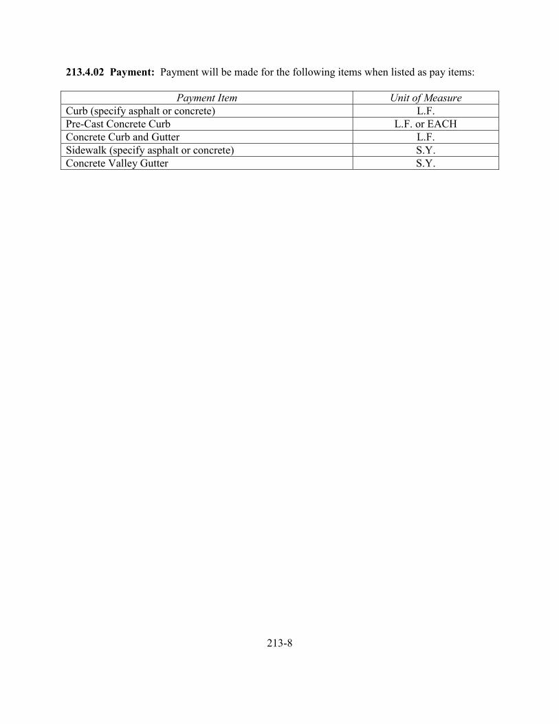
213.4.02 Payment: Payment will be made for the following items when listed as pay items:
Payment Item Unit of MeasureCurb (specify asphalt or concrete) L.F.Pre-Cast Concrete Curb L.F. or EACHConcrete Curb and Gutter L.F.Sidewalk (specify asphalt or concrete) S.Y.Concrete Valley Gutter S.Y.
213-8
214 DRIVEWAYS AND APPROACHES
214.1.00 Description
214.2.00 Materials214.2.01 Portland Cement Concrete214.2.02 Asphalt Concrete214.2.03 Aggregate214.2.04 Reinforcement214.2.05 Dowels214.2.06 Preformed Expansion Joint Filler214.2.07 Epoxy Cement214.2.08 Curing Materials
214.3.00 Construction214.3.01 Preparation of Subgrade and Base Including Grading214.3.02 Forming214.3.03 Joints214.3.04 Placing Surfacing214.3.05 Finishing Portland Cement Concrete214.3.06 Curing Portland Cement Concrete214.3.07 Dowels, Tie-Bars, Reinforcement
214.4.00 Measurement and Payment214.4.01 Measurement214.4.01A Driveways214.4.01B Sawed Joints214.4.01C Aggregate Base214.4.02 Measurement and Payment, Incidental214.4.03 Payment
214-1
214 DRIVEWAYS AND APPROACHES
214.1.00 Description: This section covers the work necessary for the construction of asphaltconcrete or Portland cement concrete paved driveways and approaches.
214.2.00 Materials:
214.2.01 Portland Cement Concrete: Shall conform to the applicable requirements of Section503.
214.2.02 Asphalt Concrete: Shall conform to the applicable requirements of Section 211.Unless otherwise specified, asphalt concrete shall be Class BM-2 or BM-4 as specified.
214.2.03 Aggregate: Materials for base, foundation and leveling courses or bedding shallconform to the requirements of Section 207 or as specified on the Plans or in the SpecialProvisions.
214.2.04 Reinforcement: Shall conform to the applicable requirements of Section 504.
214.2.05 Dowels: Shall conform to the requirements of Subsection 504.2.04.
214.2.06 Preformed Expansion Joint Filler: Shall conform to the requirements of Subsection503.2.06A.
214.2.07 Epoxy Cement: Epoxy cement shall be a two-compound epoxy resin adhesiveconforming to the requirements of AASHTO M235.
214.2.08 Curing Materials: Shall conform to the requirements of Subsection 503.2.05.
214.3.00 Construction
214.3.01 Preparation of Subgrade and Base Including Grading: Preparation work shallconform to the requirements of Section 215.
214.3.02 Forming: Forming shall conform to the requirements of Subsection 215.3.03, exceptas herein specified in Dowels, Tie-Bars, and Reinforcement.
214.3.03 Joints: Joints shall conform to the requirements of Subsection 215.3.04.
214.3.04 Placing and Surfacing: The placing of Portland cement concrete and asphalt concretesurfacing shall conform to the applicable requirements of Section 215.
214-2
214.3.05 Finishing Portland Cement Concrete: The concrete shall be floated with woodfloats and finished at the proper time with a steel float. Joints shall be edged with ¼ inch radiusedger and the driveway return edges shall be tooled with ½ inch radius edger or as shown on theplans.
The surface shall be brushed in a transverse direction in relation to the centerline of the drivewaywith a brush of approved type.
Driveways shall not be constructed at the same time the pavement is placed, unless authorized bythe Engineer.
Finished surfaces shall be free from humps, sags, or other irregularities and shall be constructedwithin ¼ inch of true line, grade, cross section and slope, and within 1/8 inch of the specifiedthickness.
214.3.06 Curing Portland Cement Concrete: Curing shall conform to the requirements ofSubsection 215.3.08, in addition thereto, vehicular traffic shall be kept off the surface for at leastseven days, and longer if so directed.
214.3.07 Dowels, Tie-Bars, Reinforcement: The Contractor shall provide dowels, tie-bars, andreinforcement as shown. Dowels with slip sleeves shall be placed as load transfer mediums innew concrete. Dowels without slip sleeves shall be placed as fasteners or ties between new andexisting underlying concrete as shown. The placement of dowels, tie-bars, and reinforcementshall conform to the requirements of Subsection 504.3.03.
214.4.00 Measurement and Payment:
214.4.01 Measurement
214.4.01A Driveways: Measurement for driveways will be made on a square yard basis, or ona per each basis.
If on a square yard basis, measurement will be made of the surface of the Portland cementconcrete or asphalt concrete driveways and computed to the nearest 0.1 square yard.
If on a per each basis, measurement will be made on the number of driveways constructed.
214.4.01B Sawed Joints: Sawed joints shall be considered incidental work for which noseparate payment will be made.
214.4.01C Aggregate Base: Pay quantities of aggregate base materials will be measured on asquare yard basis for the thickness bid, in place.
214-3
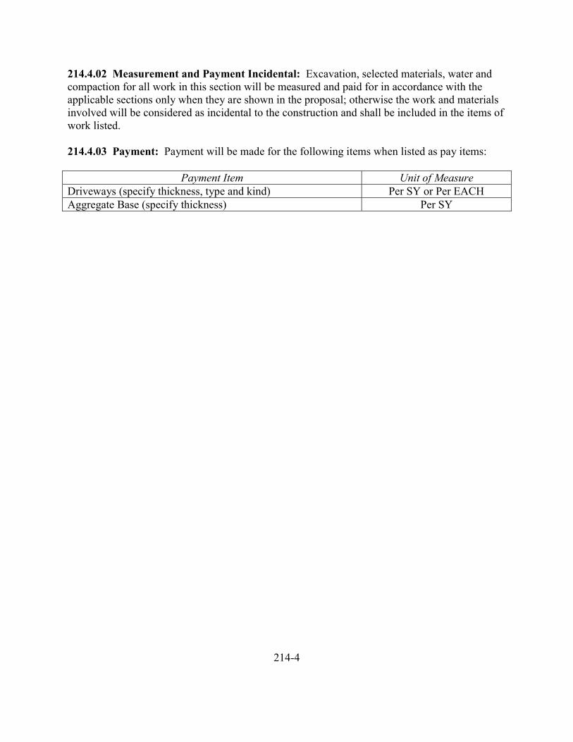
214.4.02 Measurement and Payment Incidental: Excavation, selected materials, water andcompaction for all work in this section will be measured and paid for in accordance with theapplicable sections only when they are shown in the proposal; otherwise the work and materialsinvolved will be considered as incidental to the construction and shall be included in the items ofwork listed.
214.4.03 Payment: Payment will be made for the following items when listed as pay items:
Payment Item Unit of MeasureDriveways (specify thickness, type and kind) Per SY or Per EACHAggregate Base (specify thickness) Per SY
214-4
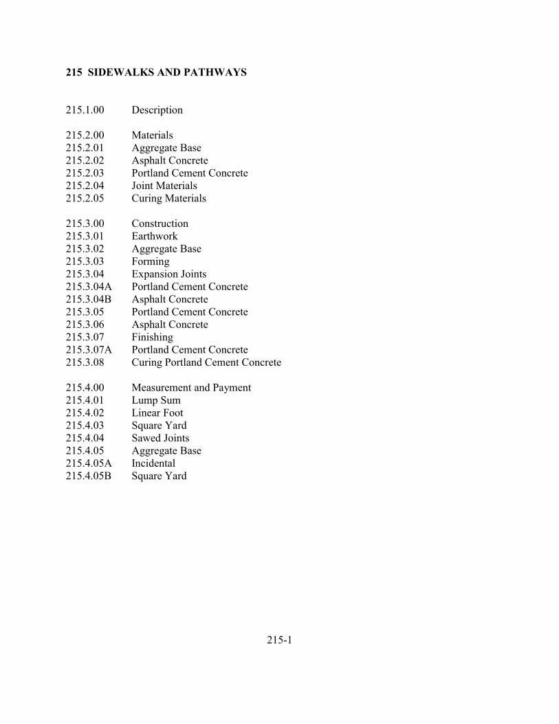
215 SIDEWALKS AND PATHWAYS
215.1.00 Description
215.2.00 Materials215.2.01 Aggregate Base215.2.02 Asphalt Concrete215.2.03 Portland Cement Concrete215.2.04 Joint Materials215.2.05 Curing Materials
215.3.00 Construction215.3.01 Earthwork215.3.02 Aggregate Base215.3.03 Forming215.3.04 Expansion Joints215.3.04A Portland Cement Concrete215.3.04B Asphalt Concrete215.3.05 Portland Cement Concrete215.3.06 Asphalt Concrete215.3.07 Finishing215.3.07A Portland Cement Concrete215.3.08 Curing Portland Cement Concrete
215.4.00 Measurement and Payment215.4.01 Lump Sum215.4.02 Linear Foot215.4.03 Square Yard215.4.04 Sawed Joints215.4.05 Aggregate Base215.4.05A Incidental215.4.05B Square Yard
215-1
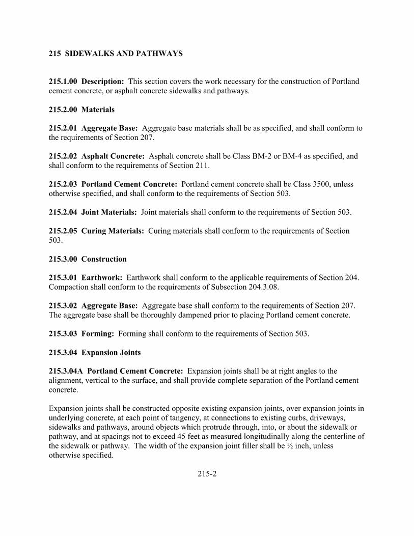
215 SIDEWALKS AND PATHWAYS
215.1.00 Description: This section covers the work necessary for the construction of Portlandcement concrete, or asphalt concrete sidewalks and pathways.
215.2.00 Materials
215.2.01 Aggregate Base: Aggregate base materials shall be as specified, and shall conform tothe requirements of Section 207.
215.2.02 Asphalt Concrete: Asphalt concrete shall be Class BM-2 or BM-4 as specified, andshall conform to the requirements of Section 211.
215.2.03 Portland Cement Concrete: Portland cement concrete shall be Class 3500, unlessotherwise specified, and shall conform to the requirements of Section 503.
215.2.04 Joint Materials: Joint materials shall conform to the requirements of Section 503.
215.2.05 Curing Materials: Curing materials shall conform to the requirements of Section503.
215.3.00 Construction
215.3.01 Earthwork: Earthwork shall conform to the applicable requirements of Section 204.Compaction shall conform to the requirements of Subsection 204.3.08.
215.3.02 Aggregate Base: Aggregate base shall conform to the requirements of Section 207.The aggregate base shall be thoroughly dampened prior to placing Portland cement concrete.
215.3.03 Forming: Forming shall conform to the requirements of Section 503.
215.3.04 Expansion Joints
215.3.04A Portland Cement Concrete: Expansion joints shall be at right angles to thealignment, vertical to the surface, and shall provide complete separation of the Portland cementconcrete.
Expansion joints shall be constructed opposite existing expansion joints, over expansion joints inunderlying concrete, at each point of tangency, at connections to existing curbs, driveways,sidewalks and pathways, around objects which protrude through, into, or about the sidewalk orpathway, and at spacings not to exceed 45 feet as measured longitudinally along the centerline ofthe sidewalk or pathway. The width of the expansion joint filler shall be ½ inch, unlessotherwise specified.
215-2
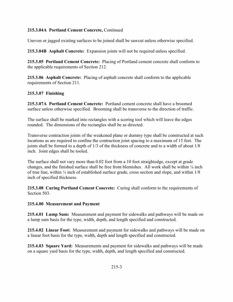
215.3.04A Portland Cement Concrete, Continued
Uneven or jagged existing surfaces to be joined shall be sawcut unless otherwise specified.
215.3.04B Asphalt Concrete: Expansion joints will not be required unless specified.
215.3.05 Portland Cement Concrete: Placing of Portland cement concrete shall conform tothe applicable requirements of Section 212.
215.3.06 Asphalt Concrete: Placing of asphalt concrete shall conform to the applicablerequirements of Section 211.
215.3.07 Finishing
215.3.07A Portland Cement Concrete: Portland cement concrete shall have a broomedsurface unless otherwise specified. Brooming shall be transverse to the direction of traffic.
The surface shall be marked into rectangles with a scoring tool which will leave the edgesrounded. The dimensions of the rectangles shall be as directed.
Transverse contraction joints of the weakened plane or dummy type shall be constructed at suchlocations as are required to confine the contraction joint spacing to a maximum of 15 feet. Thejoints shall be formed to a depth of 1/3 of the thickness of concrete and to a width of about 1/8inch. Joint edges shall be tooled.
The surface shall not vary more than 0.02 foot from a 10 foot straightedge, except at gradechanges, and the finished surface shall be free from blemishes. All work shall be within ¼ inchof true line, within ¼ inch of established surface grade, cross section and slope, and within 1/8inch of specified thickness.
215.3.08 Curing Portland Cement Concrete: Curing shall conform to the requirements ofSection 503.
215.4.00 Measurement and Payment
215.4.01 Lump Sum: Measurement and payment for sidewalks and pathways will be made ona lump sum basis for the type, width, depth, and length specified and constructed.
215.4.02 Linear Foot: Measurement and payment for sidewalks and pathways will be made ona linear foot basis for the type, width, depth and length specified and constructed.
215.4.03 Square Yard: Measurements and payment for sidewalks and pathways will be madeon a square yard basis for the type, width, depth, and length specified and constructed.
215-3
215.4.04 Sawed Joints: Sawed joints shall be considered as incidental work for which noseparate payment will be made.
215.4.05 Aggregate Base
215.4.05A Incidental: Unless otherwise specified, no separate payment will be made foraggregate base, it being considered incidental to the other items of work.
215.4.05B Square Yard: When shown as a pay item, measurement and payment for aggregatebase will be made on a square yard basis for the various depths specified and placed.
215-4
216 ADJUSTMENT OF INCIDENTAL STRUCTURES TO GRADE
216.1.00 Description
216.2.00 Materials216.2.01 General216.2.02 Portland Cement Concrete216.2.03 Asphalt Concrete216.2.04 Aggregate Base216.2.05 Tack Coat216.2.06 Seal Coat216.2.07 Precast Concrete Manhole Sections216.2.08 Frames, Grates and Covers216.2.09 Mortar216.2.10 Metal Reinforcement
216.3.00 Construction216.3.01 Excavation and Backfill216.3.02 Frames, Grates and Covers216.3.03 Raising Tops of Masonry Structures216.3.04 Lowering Topes of Masonry Structures216.3.05 Adjusting Metal Structures
216.4.00 Measurement and Payment216.4.01 Incidental216.4.02 Per Each
216-1
216 ADJUSTMENT OF INCIDENTAL STRUCTURES TO GRADE
216.1.00 Description: This section covers the work necessary for adjusting the tops ofmanholes, sumps, catch basins, inlets, valve boxes, meter boxes, monument boxes and similarstructures to the required elevation and/or horizontal alignment.
216.2.00 Materials
216.2.01 General: Materials used in the adjustment of incidental structures may be materialssalvaged from the existing installation and brought to a condition approved for reuse, newmaterials as listed herein, or materials conforming to the requirements of related work referred toherein.
216.2.02 Portland Cement Concrete: Portland cement concrete shall conform to therequirements of Section 503.
216.2.03 Asphalt Concrete: Asphalt concrete shall conform to the requirements of Section211.
216.2.04 Aggregate Base: Aggregate base shall conform to the requirements of Section 207.
216.2.05 Tack Coat: Tack coat shall conform to the requirements of Section 211.
216.2.06 Seal Coat: Seal coat shall conform to the requirements of Section 210.
216.2.07 Precast Concrete Manhole Sections: Precast concrete manhole sections shallconform to the requirements of ASTM C478.
216.2.08 Frames, Grates and Covers: Frames, grates and covers shall conform to therequirements of Section 307.
216.2.09 Mortar: Mortar shall conform to the requirements of ASTM C387 or proportionedone part Portland cement to two parts clean, well-graded sand which will pass a 1/8 inch screen.Admixtures may be used not exceeding the following percentages of weight of cement: hydratedlime, 10 percent; diatomaceous earth or other inert materials, 5 percent.
216.2.10 Metal Reinforcement: Metal reinforcement shall conform to the requirements ofSection 504.
216-2
216.3.00 Construction
216.3.01 Excavation and Backfill: Excavation and backfill shall conform to the requirementsof Section 301.
Excavation shall be unclassified and shall include whatever materials are encountered to thedepths shown.
216.3.02 Frames, Grates and Covers: Frames, grates and covers may be salvaged fromstructures to be adjusted and, if of suitable size and condition, may be reused in the work, andsuch as are damaged or which are unfit for reuse, as determined by the Engineer, shall bereplaced with similar items which are comparable in all respects to those which they are toreplace and which are adequate for the intended purpose.
Salvaged components to be reused shall be cleaned of foreign material by methods that will notharm the component but will restore it to a nearly new condition.
216.3.03 Raising Tops of Masonry Structures: After existing frames, covers and grates havebeen removed, the exposed top surface on which new mortar or concrete is to be placed, shall bechipped away to a depth of at least ¼ inch to expose firm concrete and the new surface shall becleaned by brushing and shall be moistened with water at the time of placing new concretethereon. New concrete shall be placed to the required grade and cured at least three days, afterwhich the frame shall be seated in fresh mortar and brought to the proper grade. Masonry ofbricks or concrete blocks shall be raised with new bricks, blocks, mortar or combinations thereofor with Portland cement concrete or with precast concrete risers, as conditions may require orpermit. Concrete boxes may be lifted and placed on precast concrete box extensions on newbrick or on cast-in-place concrete as may be suitable.
Mortar for building up existing masonry shall not be placed to a depth more than two inches.Concrete shall not be placed to a depth of less than 3 ½ inches. To conform to theserequirements, the existing shells or walls of structures to be raised shall be cut down as necessaryto provide space for the new construction.
Fabricated metal rings or plates may be furnished and used in the adjustment work, provided themetal and its fabrication design is at least equal to the pertinent characteristics of strength andsupport required of the covers or grates to be placed, that uniform bearing surfaces is assured,and positive provision is afforded against displacement when in service.
216.3.04 Lowering Tops of Masonry Structures: Where the top of an existing masonrystructure construction is to be lowered, the masonry portion of the structure shall be exposed torequired depth, cut off or removed to an elevation below that established for the bottom of themetal frame or cover which is to be reset on masonry and shall then be built up with mortar,concrete, brick, concrete blocks, precast concrete risers, or with metal rings or places to requiredelevation and top design. The joining of new material to old, the minimum thickness of newmortar and concrete, the limitations, the curing and other details shall be as specified inSubsection 216.3.03.
216.3.05 Adjustment Metal Structures: Metal inlets, valve boxes, meter boxes, monumentboxes and other like structures shall normally be raised or lowered to grade by resetting theentire structure on a firm foundation. In the case of raising the structure to a point where itwould not enclose or protect its contents, the Contractor shall add metal extensions of like designbelow the original structure. The Contractor may replace the structure with a new structure ofadequate design as approved. Salvaged structures not re-used on the project shall remain theproperty of the Owner, unless otherwise specified.
216.3.06 Precast Manholes: Precast manholes within the area to be paved and those within thepublic right-of-way so designated will be adjusted to the finished street or sidewalk grade.
Minor manhole adjustment shall consist of the adjustments required with 24-inch diameterprecast concrete risers and/or mortared joints.
Major manhole adjustment shall consist of the adjustments in cases where lowering or raisinginfringes into the cone section. The cone shall be removed and precast concrete risers of theproper diameter added or removed and the cone replaced. Twenty-four inch diameter risers maythen be used to attain desired grade. In cases where the adjustment precludes the use or reuse ofthe cone, a precast, flat top slab shall be used. Twenty-four inch diameter precast risers may thenbe used to attain the desired grade.
The maximum height of 24-inch diameter raisers that may be used shall be 24 inches whether inminor or major adjustments. The Contractor shall adjust manhole tops after final paving bycutting a 5 foot square portion of the pavement, centered on the manhole casting, adjust thecasting as required, place four number 4 rebars 4 ½ feet long, place Class 3300 Portland cementconcrete, and finish according to Section 214.3.05.
Valve boxes and monument boxes shall be adjusted after paving as with manhole tops exceptthat the portion of the pavement cut, removed and replaced with concrete shall be 30 inchessquare with number 4 rebars 2 feet long.
216.4.00 Measurement and Payment
216.4.01 Incidental: When not specified for payment, adjustment of incidental structures tograde will be considered incidental work for which no separate payment will be made.
216.4.02 Per Each: Measurement and payment for adjusting incidental structures to grade willbe made on a per each basis for the number and type of structure adjusted to grade.
216-4
217 ILLUMINATION
217.1.00 Description217.1.01 General
217.2.00 Materials217.2.01 Portland Cement Concrete217.2.02 Metal Reinforcement217.2.03 Nuts, Bolts and Washers217.2.04 Anchor Rods217.2.05 Poles217.2.05A Wood217.2.05B Steel217.2.05C Aluminum217.2.06 Conduit217.2.06A Metallic217.2.06B Non-Metallic217.2.06C Fittings217.2.07 Electrical Wire217.2.08 Direct Burial Cable217.2.09 Splice Materials217.2.10 Junction Boxes217.2.10A Metallic217.2.10B Concrete217.2.11 Cabinets
217.3.00 Construction217.3.01 Shop Drawings217.3.02 Excavation217.3.03 Portland Cement Concrete217.3.04 Metal Reinforcement217.3.05 Poles217.3.05A Wood217.3.05B Metal217.3.06 Conduit217.3.07 Electrical Service217.3.08 Grounding217.3.09 Wiring217.3.10 Luminaries217.3.11 Cabinets
217.4.00 Measurement and Payment217.4.01 Lump Sum Basis217.4.02 Incidental Basis
217-1
217 ILLUMINATION
217.1.00 Description: This section covers the work necessary for furnishing and installingillumination equipment and materials and removing or modifying existing facilities.
217.1.01 General: Electrical materials, equipment and workmanship shall conform to therequirements of the National Electrical Manufacturers Association, the UnderwritersLaboratories, Inc., The National Electrical Code, the National Electrical Safety Code, theAmerican National Standards Institute, and local ordinances as applicable.
217.2.00 Materials
217.2.01 Portland Cement Concrete: Portland cement concrete shall conform to therequirements of Section 503 and shall be Class 3000, unless otherwise specified.
217.2.02 Metal Reinforcement: Metal reinforcement shall conform to the requirements ofSection 504. Bar reinforcement shall be Grade 40, unless otherwise specified.
217.2.03 Nuts, Bolts and Washers: Nuts, bolts and washers shall conform to the requirementsof ASTM A325, and shall be galvanized in accordance with the requirements of ASTM A153,unless otherwise specified.
217.2.04 Anchor Rods: Anchor rods shall conform to the requirements of ASTM A449, A687or A354, Grade BC, unless otherwise specified.
217.2.05 Poles
217.2.05A Wood: Wood poles shall be treated and shall conform to the requirements of ANSIspecification 05.1 for Class 4 machine shaved Pacific Coast Douglas Fir, Southern Pine orapproved equal. Treatment shall conform to the requirements of AWPA standards C1 and C4.Treatment shall be with oilborne pentachlorophenol with a minimum retention of 0.4 P.S.F. ofdry salt. Poles shall be round, sound, well proportioned from butt to tip, without short kinks orcrooks and of the dimensions specified by ANSI.
217.2.05B Steel: Steel pole material shall conform to the requirements of ASTM 283 Grade D,or approved equal. Steel plate material shall conform to the requirements of ASTM A36 orapproved equal. Steel members shall be galvanized in accordance with the requirements ofASTM A123 unless otherwise specified.
217.2.05C Aluminum: Aluminum poles shall be fabricated from one piece of seamlessaluminum alloy tapered tubing conforming to the requirements of ASTM B429, alloy 6061-T6.
217-2
217.2.06 Conduit
217.2.06A Metallic: Metallic conduit shall be galvanized rigid metal manufactured of mildsteel conforming to the requirements of Underwriters Laboratory standard for Rigid MetalConduit, publication UL 6.
Galvanizing shall conform to the requirements of ASTM A123.
217.2.06B Non-Metallic: Non-metallic conduit shall be heavy wall, extruded, rigid PVC(polyvinyl chloride) conforming to the requirements of Underwriters Laboratories, Inc. standardfor Rigid Non-metallic Conduit, publication UL 651 for 90 degrees C wire rated conduit.
217.2.06C Fittings: Expansion fittings shall be weatherproof, malleable iron expansion headand body with a hot-dipped galvanized finish. Where plans do not specify an equipment groundwire in the conduit run, fitting shall be furnished with external bonding jumpers.
Expansion-Deflection fittings shall be watertight in conformance with NEMA 4 for rigid metallicconduit and shall be furnished with an integral bonding jumper.
Condulets shall be corrosion resistant with a zinc coating and lacquer dip finish. Covers forcondulets shall be furnished with a moisture-proof gasket.
217.2.07 Electrical Wire: Electrical wire shall be standard copper meeting the requirements ofASTM B3 and ASTM B8, unless otherwise specified.
Insulation shall be 600-volt plasticized polyvinyl chloride, polyethylene or chemically crosslinked polyethylene, conforming to the applicable portions of ASTM D2219, D2220, D1351,D2655 and D2656. Polyethylene compounds shall not be used where exposed to sunlight.Where TW grade is selected, it shall be “extra heavy wall” as follows:
No. 10 AWG and smaller, 4/64 inch thick.
No. 8 AWG to No. 2 AWG, 5/64 inch thick.
The wire size shall be as specified.
Color coding shall conform to the wiring color code specified.
Where certain colors are not readily available, the Contractor shall have the striping applied bycommercial methods or apply the stripe using striping tape made for that purpose. Such stripingshall be clearly visible for the length of wire wherever exposed.
217-3
217.2.08 Direct Burial Cable: Direct-burial cable shall be approved by the UL and labeled asType USE. Type USE wire shall be solid or stranded conductors. Type UF cable may besubstituted where permitted by the Code.
217.2.09 Splice Materials: Plastic electrical tape shall conform to the requirements of ASTMD2301, Type 2.
Friction tape shall conform to the requirements of ASTM D69. Electrical insulating varnishshall conform to the requirements of Federal Specification Mil-V-1137A, Type AW, Grade CA.
217.2.10 Junction Boxes
217.2.10A Metallic: Metallic junction boxes shall be constructed of cast iron or 1/8 inch thicknominal welded sheet steel. Sheet steel shall be of commercial quality. Metallic boxes andcovers shall be hot-dip galvanized after fabrication in accordance with the requirements ofASTM A385 and ASTM A386. Each box shall have a cover gasket that will, with cover inplace, for a NEMA 4 watertight fit. Covers shall be provided with brass, tamper-proof screws.Screw heads shall be recessed in the cover.
217.2.10B Concrete: Concrete junction boxes shall be precast concrete, water meter type, withcast iron cover held down by brass bolts and hexagon head nuts recessed in the cover.
217.2.11 Cabinets: Cabinets shall be constructed of 10 gauge sheet steel and shall be got-dipgalvanized after fabrication in accordance with the requirements of ASTM A385 and ASTMA386, unless otherwise specified.
217.3.00 Construction
217.3.01 Shop Drawings: Shop drawings shall be submitted in accordance with therequirements of Subsection 104. Two sets of drawings will be required unless otherwisespecified.
Shop drawings are construed to include brochures, technical bulletins, parts lists, instructions,wiring diagrams and working drawings providing information relative to the materials andequipment. It shall also include isocandela diagrams indicating the vertical light distribution,vertical control limits and the lateral light distribution classifications for each type of luminairesubmitted for approval.
217-4
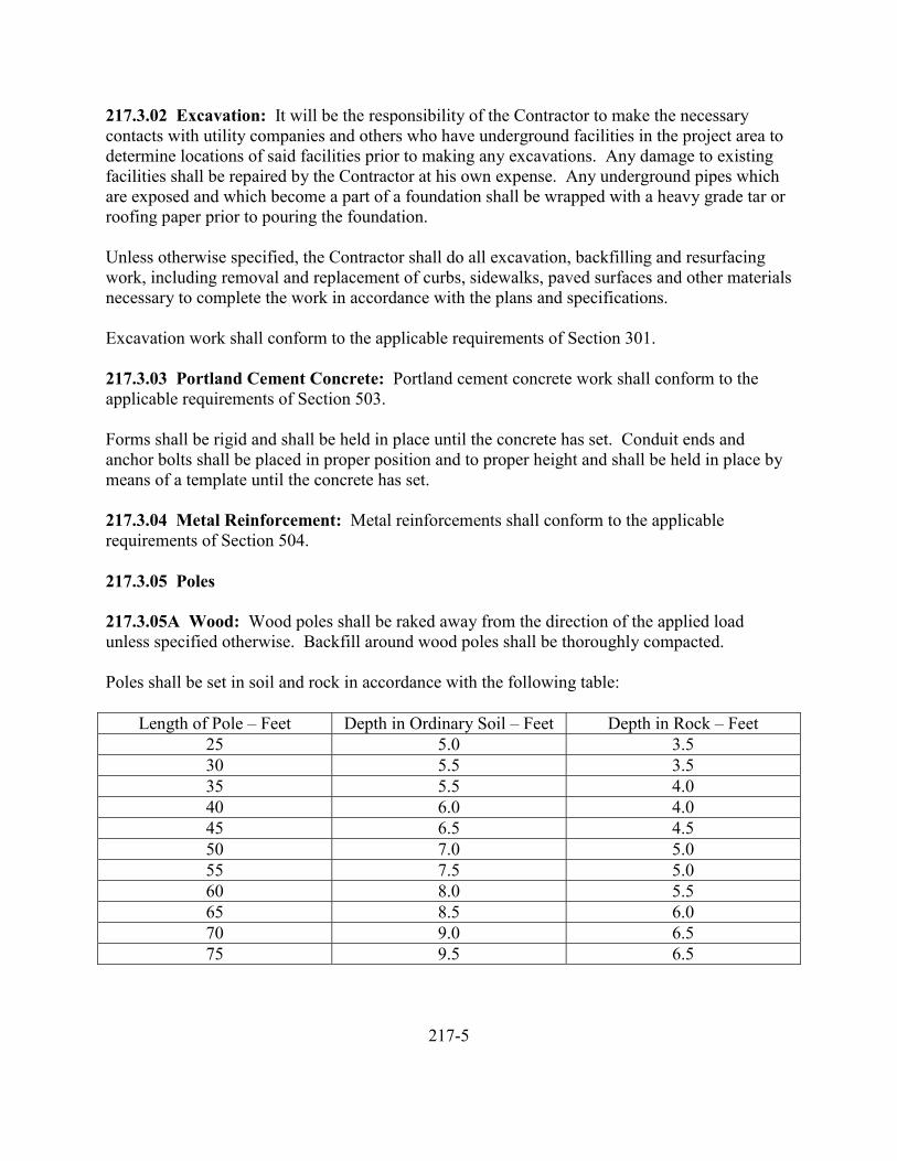
217.3.02 Excavation: It will be the responsibility of the Contractor to make the necessarycontacts with utility companies and others who have underground facilities in the project area todetermine locations of said facilities prior to making any excavations. Any damage to existingfacilities shall be repaired by the Contractor at his own expense. Any underground pipes whichare exposed and which become a part of a foundation shall be wrapped with a heavy grade tar orroofing paper prior to pouring the foundation.
Unless otherwise specified, the Contractor shall do all excavation, backfilling and resurfacingwork, including removal and replacement of curbs, sidewalks, paved surfaces and other materialsnecessary to complete the work in accordance with the plans and specifications.
Excavation work shall conform to the applicable requirements of Section 301.
217.3.03 Portland Cement Concrete: Portland cement concrete work shall conform to theapplicable requirements of Section 503.
Forms shall be rigid and shall be held in place until the concrete has set. Conduit ends andanchor bolts shall be placed in proper position and to proper height and shall be held in place bymeans of a template until the concrete has set.
217.3.04 Metal Reinforcement: Metal reinforcements shall conform to the applicablerequirements of Section 504.
217.3.05 Poles
217.3.05A Wood: Wood poles shall be raked away from the direction of the applied loadunless specified otherwise. Backfill around wood poles shall be thoroughly compacted.
Poles shall be set in soil and rock in accordance with the following table:
Length of Pole – Feet Depth in Ordinary Soil – Feet Depth in Rock – Feet25 5.0 3.530 5.5 3.535 5.5 4.040 6.0 4.045 6.5 4.550 7.0 5.055 7.5 5.060 8.0 5.565 8.5 6.070 9.0 6.575 9.5 6.5
217-5
217.3.05A Wood, Continued
Where ordinary soil is underlaid with rock, the depth of hole in the rock portion is to be 0.7 ofthe depth required if it were soil, except that depth in rock should not be more than for the fullrock setting.
Example: 50 ft pole – Soil 2 feet over rock
Required depth of hole for all soil setting = 7.0 ft.
Actual soil depth = 2.0 ft
Difference = 5.0 ft
X 0.7
Depth of hole required in rock portion = 3.5 ft
Depth of hole through soil = 2.0 ft
Total depth of hole = 5.5 ft
Where poles are located on other than level areas, the setting depths shall be measured from thelow side of the hole.
217.3.05B Metal: Metal poles shall be erected on concrete foundations. Poles shall be erectedwith sufficient rake as to assume a substantially vertical position after all attachments andappurtenances are in place.
Leveling nuts shall be used on all poles. After all appurtenances have been attached, the polewill be leveled and grouted. A nominal ¾ inch diameter weep hole shall be left in the grout.
After leveling of poles and mast arms has been completed, any bolt protruding above the nutshall be cut off to provide a minimum height of 1 inch and a maximum height of 1 ¼ inchesabove the nut. Sharp edges due to cutting shall be filed smooth and the top of steel bolts shall bepainted with two coats of zinc dust-zinc oxide primer as specified in Subsection 513.2.01D.Breakaway or frangible pole bases with embedded shafts shall be raked as necessary prior to theconcrete foundation setting up.
217-6
217.3.06 Conduit: Metal conduit may be installed by jacking or drilling methods or the opentrench method as the Contractor may elect.
If the Contractor elects to install by jacking or drilling, jacking or drilling pits shall be kept aminimum of two feet from the edge of the pavement wherever possible. Excessive use of water,such that the pavement might be undermined or subgrade softened, will not be permitted. If theContractor elects to install conduit by the open trench method, the following conditions shall bemet:
1. The trench shall be held to a practicable minimum width.
2. Cuts in the existing pavement shall be clean, straight, and vertical.
3. The trench shall be backfilled with granular materials to an elevation six inchesbelow the top of the existing pavement and the top six inches of the trench shallbe filled with asphalt concrete or Portland cement concrete paving materialscompacted and finished to provide a smooth riding surface.
Installation of nonmetallic type conduit under existing pavement will be permitted if a holelarger than the conduit is predrilled and this conduit installed by hand.
Work shall be scheduled to permit placing of conduit prior to paving or landscaping operations.
If the trench is not backfilled the same day the conduit is placed, one end of the conduit run shallbe left free until backfilling is started, or a nonmetallic conduit expansion joint shall be installedin the conduit run.
Metal conduit shall have a minimum of 24 inches of cover in roadway areas and 18 inches inother areas, except that 12 inches of cover will be permitted under sidewalks or paved, curbedmedians.
Nonmetallic conduit shall have a minimum of 30 inches of cover in roadway areas and 18 inchesin other areas.
Where a conduit bend is required, it shall normally be a standard factory bend. Where factoryconduit bend sizes are not commercially available, or at those locations requiring special bends,bends performed on the job or in the shops shall have a radius of not less than six times theinside diameter of the conduit. The conduit shall be bent without crimping or flattening.
A galvanized steel conduit elbow shall be used where converting from an undergroundnonmetallic conduit to an aboveground run or extension.
217-7
217.3.06 Conduit, Continued
A conduit run must be continuous between any two poles or junction boxes. It shall be theoption of the Contractor, at the Contractor’s expense, to use conduit of larger size than specified.If used, it shall be for the entire length of the run from outlet to outlet. No reducer couplings willbe permitted.
Conduits placed in foundations shall be so grouped that, with pole in place, it is possible to placean insulated bushing on each conduit end.
In the event the conduit run terminating in the pole base is of the metallic type, without a groundwire, the bushing shall be of the grounding type.
Where more than one piece of equipment is on the same pole, the Contractor shall place in thefoundation the conduit for all electrical circuits as required by the plans and specifications.
Conduit entrances into junction boxes shall be drilled and tapped a minimum number of threads.Bosses shall be provided where the wall thickness is not sufficient for the minimum number ofthreads.
Conduit entering through the bottom of the junction boxes shall be located near the end walls toleave the major portion of the box clear. At all outlets, conduits shall enter from the direction ofthe run.
The ends of all conduits, whether shop or field cut, shall be reamed to remove burrs and roughedges. Cuts shall be made square and true so that the ends will butt or come together for the fullcircumference thereof. Slip joints or running threads will not be permitted for coupling conduit.When a standard coupling cannot be used for coupling metal type conduit, an approved threadedunion coupling shall be used. The threads on all ferrous metal conduit shall be painted with rustpreventative paint before couplings are made up. All couplings for metal conduit shall betightened until the ends of the conduits are brought together, providing a good electricalconnection throughout the entire length of the conduit run. Where the coating on metal conduithas been damaged to the extent that underlying metal is exposed, the damaged areas shall bepainted with rust preventive paint.
All metal conduit ends shall be threaded and shall be capped with standard pipe caps until wiringis started. When caps are removed, the threaded ends shall be provided with conduit bushings.Nonmetallic conduit ends shall be capped until wiring is started.
Nonmetallic conduit fittings for connecting nonmetallic conduit to metal conduit shall bethreaded on the metal conduit side.
217-8
217.3.06 Conduit, Continued
Conduit to be mounted on wood poles shall be mounted by use of two-hole malleable conduitclamps spaced a maximum of three feet apart, unless otherwise specified.
Conduit to be mounted on metal poles shall be mounted by use of ¾ inch stainless steel bandstraps. After steel bands have been drawn tight, the ends shall be cut and folded under toeliminate protruding edges. Bands shall be placed a maximum of three feet apart.
217.3.07 Electrical Services: As a part of each service installation, a meter base, approved bythe serving utility, shall be furnished and installed by the Contractor unless otherwise specified.
Each service cabinet shall contain a solid copper neutral bus and the number and size of switchesor circuit breakers as required by the plans or in the special provisions. All overcurrentprotection and relays shall be installed in accordance with the plans using best common practicewith materials and installation meeting all applicable requirements of the National ElectricalCode.
The Contractor shall notify the local serving utility prior to installing any service equipment.
Circuit breakers shall be installed in the upper left side of the cabinet. The neutral block shall beinstalled in the lower part of the cabinet and all contactors shall be installed in the right side ofthe cabinet.
Circuit breakers shall be of the unenclosed molded case bolt-on type with end conductorterminals, suitable for surface mounting in the cabinet on a false back or bracket.
Circuit breakers shall conform to the Federal Specifications W-C-375a. All 100 ampere framebreakers shall be Class 2; 225 ampere frame breakers shall be Class 3; 400 ampere framebreakers shall be Class 4; 800 ampere frame breakers shall be Class 5.
Circuit breakers shall be labeled to indicate the circuit controlled. Labels shall be stampedplastic or metal as approved by the Engineer.
Overcurrent protection and relay equipment shall be installed according to the best commonpractice, with materials and installation meeting all applicable requirements of the NationalElectrical Code.
Contactors shall be “lighting” type specifically rated for tungsten, fluorescent and mercury lamploads, electrically held.
217-9
217.3.08 Grounding: Metallic conduit, metal poles, nonmetallic conduit grounding wire,metallic junction boxes and cabinets shall be made mechanically and electrically secure to form acontinuous system and shall be effectively grounded.
The Contractor shall ground the neutral conductor, the control cabinets and meter base to agrounding electrode in conformance with the National Electrical Code.
Ground rods shall be 5/8” x 8’ nonrusting copper covered steel with bronze grounding wireclamp.
The grounding wire shall be bare No. 6 solid copper wire.
Grounding electrodes shall not have a resistance to ground of more than 25 ohms.
A grounding electrode shall be installed at each pole unless otherwise specified.
Ground rods shall be driven full length with the top approximately six inches below the finishedgrade. In rock locations that prevent full length driving, the Contractor may install, with theapproval of the Engineer, a buried iron or copper plate.
On wood poles, all metallic components, mounted less than eight feet above ground surface shallbe grounded.
217.3.09 Wiring: Wiring within cabinets and junction boxes shall be neatly arranged.Powdered soapstone, talc, or other approved lubricants shall be used when inserting conductorsin conduit. Before pulling wires through underground conduit runs, the Contractor shallascertain that the conduits are free from dirt or accumulation of moisture. Wire shall be installedso as to prevent damage to the insulation.
Prewired factory equipment shall be installed in accordance with the manufacturer’s instructions.All wire and cable shall consist of copper conductors. Wire may be solid or stranded.
Any underground utility or underground circuits paralleling or crossing illumination circuitsshall be physically separated as directed by the Engineer.
217.3.10 Luminaires: Luminaires shall be leveled in both the transverse and the longitudinaldirection as recommended by the manufacturer. The luminaire and fitting shall provide for aminimum of three degrees adjustment in both transverse and longitudinal directions.
217.3.11 Cabinets: Cabinets shall be constructed so as to be weatherproof.
217-10
217.4.00 Measurement and Payment
217.4.01 Lump Sum Basis: When shown as a contract bid item, measurement and payment forillumination will be made on a lump sum basis as shown.
217.4.02 Incidental Basis: When not specified or shown as a pay item, payment forillumination shall be considered to be incidental to the work and no separate payment will bemade.
217-11

218 UNASSIGNED
219 SIGNING AND PAVEMENT MARKINGS
219.1.00 Description
219.2.00 Materials219.2.01 Portland Cement Concrete219.2.02 Metal Reinforcement219.2.03 Wood Posts219.2.03A Douglas Fir219.2.03B West Coast Hemlock219.2.03C Cedar219.2.04 Metal Sign Supports219.2.04A Aluminum219.2.04B Steel219.2.05 Sign Material219.2.05A Plywood219.2.05B Aluminum219.2.05C Reflective Sheeting219.2.05D Nonreflective Sheeting219.2.05E Porcelain Enamel Finish219.2.05F Hinac Finish219.2.06 Hardware219.2.07 Pavement Marking Material219.2.07A Thermoplastic, Type A219.2.07B Thermoplastic, Type B219.2.07C Primers219.2.07D Striping Paint
219.3.00 Construction219.3.01 Shop Drawings219.3.02 Portland Cement Concrete219.3.03 Excavation219.3.04 Metal Reinforcement219.3.05 Posts219.3.06 Signs219.3.06A Plywood219.3.06B Aluminum219.3.06C Reflective and Nonreflective Sheeting219.3.07 Pavement Marking219.3.07A Thermoplastic, General219.3.07B Thermoplastic, Type A219.3.07C Thermoplastic, Type B219.3.07D Painting
219-1
219 SIGNING AND PAVEMENT MARKINGS, Continued
219.4.00 Measurement and Payment219.4.01 Lump Sum Basis219.4.02 Incidental Basis219.4.03 Unit Price Basis219.4.03A Signing and Pavement Markings219.4.03B Striping and Pavement Markings
219-2
219 SIGNING AND PAVEMENT MARKINGS
219.1.00 Description: This section covers the work necessary for furnishing, fabricating,erecting and removal of signs and sign structures and furnishing and installing striping andpavement markings.
219.2.00 Materials
219.2.01 Portland Cement Concrete: Portland cement concrete shall conform to therequirements of Section 503 and shall be Class 3000, unless otherwise specified.
219.2.02 Metal Reinforcement: Metal reinforcement shall conform to the requirements ofSection 504. Bar reinforcement shall be Grade 40, unless otherwise specified.
219.2.03 Wood Posts: Wood posts shall be surfaced four sides, free of heart center and of thegrades specified.
219.2.03A Coast Douglas Fir and Southern Yellow Pine: Coast Douglas fir and SouthernYellow Pine posts shall be pressure treated after fabrication in accordance with AWPA standardsC-1 and C-2 pertinent to the kind of preservative used. The minimum net retention shall be 0.5lbs. for all preservatives except for chromated copper arsenate, which shall be 0.75 lbs.Minimum penetration shall be 3/8 inch.
The preservative shall be one or another of the following:
(a) Ammoniacal copper arsenate, ACA(b) Chromated copper arsenate, CCA, Type A(c) Fluor chrome arsenate phenol, FCAP, Type A or B(d) Pentachlorophenol-volatile petroleum solvent (LPG) solution
The preservative to be used in treating cuts, abrasions and boltholes shall be the same as thatoriginally used to treat the post, except if the post was originally treated with pentachlorophenol-volatile petroleum solvent (LPG) solution, cuts, abrasions and boltholes shall be treated withpentachlorophenol-mineral spirits solvent solution.
The strength of salt solutions used in treating cuts, abrasions, boltholes, etc., for field repair ofpressure-treated surfaces shall be a concentrate not less than three times and not greater than fivetimes the strength of the original treating solution.
219.2.03B West Coast Hemlock and Lodge Pole Pine: West Coast Hemlock and Lodge PolePine posts shall be pressure treated in conformance with the requirements of Subsection219.2.03A.
219-3
219.2.03C Redwood: Redwood posts may be untreated.
219.3.04 Metal Sign Supports
219.2.04A Aluminum: Aluminum sign support materials shall conform to the requirements ofthe following:
Extruded Aluminum Shapes ASTM B 221Rolled or Extruded Structural Shapes ASTM B 308Aluminum Bars or Rods ASTM B 211Aluminum Sand Castings ASTM B 26
219.2.04B Steel: Steel sign support materials shall conform to the requirements of Subsection217.2.05B, unless otherwise specified.
219.2.05 Sign Material
219.2.05A Plywood: Plywood shall be Douglas fir, Grade B-B exterior or better, conforming tothe requirements of “Product Standard PS-1 for Douglas Fir Plywood”, published by the USDepartment of Commerce. Plywood shall be ¾ inch, high-density overlay, unless otherwisespecified. Plywood signs will not be permitted unless specifically called for at certain locations.
219.2.05B Aluminum: Aluminum shall conform to the requirements of ASTM B209, allow6061-T6, unless otherwise specified.
219.2.05C Reflective Sheeting: Reflective sheeting shall consist of spherical lens elementsembedded within a transparent plastic having a smooth, flat outer surface. The sheeting shall beweather resistant and have a protected precoated adhesive backing and shall conform to thefollowing requirements:
(1) Photometrics-Reflective sheeting shall have the following minimum brightnessvalues at 0.2 degrees and 0.5 degrees and 1.5 degrees divergence angle expressedas average candlepower per foot – candle per square foot of material.Measurements shall be conducted in accordance with standard testing proceduresfor reflex reflectors of Federal Specification L-S-300A, “Sheeting and Tape,Reflective; Non-exposed Lens Adhesive Backing”. The brightness of thereflective sheeting, totally wet by rain, shall not be less than 90 percent of thevalues in the following table:
219-4
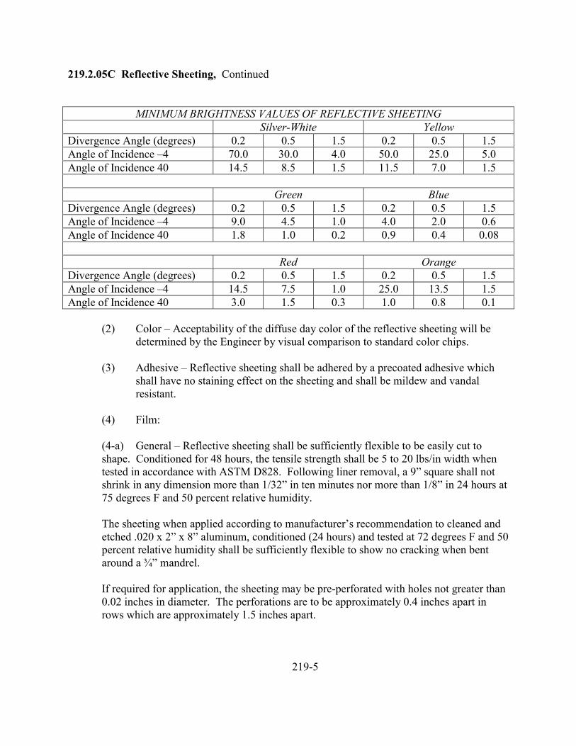
219.2.05C Reflective Sheeting, Continued
MINIMUM BRIGHTNESS VALUES OF REFLECTIVE SHEETINGSilver-White Yellow
Divergence Angle (degrees) 0.2 0.5 1.5 0.2 0.5 1.5Angle of Incidence –4 70.0 30.0 4.0 50.0 25.0 5.0Angle of Incidence 40 14.5 8.5 1.5 11.5 7.0 1.5
Green BlueDivergence Angle (degrees) 0.2 0.5 1.5 0.2 0.5 1.5Angle of Incidence –4 9.0 4.5 1.0 4.0 2.0 0.6Angle of Incidence 40 1.8 1.0 0.2 0.9 0.4 0.08
Red OrangeDivergence Angle (degrees) 0.2 0.5 1.5 0.2 0.5 1.5Angle of Incidence –4 14.5 7.5 1.0 25.0 13.5 1.5Angle of Incidence 40 3.0 1.5 0.3 1.0 0.8 0.1
(2) Color – Acceptability of the diffuse day color of the reflective sheeting will bedetermined by the Engineer by visual comparison to standard color chips.
(3) Adhesive – Reflective sheeting shall be adhered by a precoated adhesive whichshall have no staining effect on the sheeting and shall be mildew and vandalresistant.
(4) Film:
(4-a) General – Reflective sheeting shall be sufficiently flexible to be easily cut toshape. Conditioned for 48 hours, the tensile strength shall be 5 to 20 lbs/in width whentested in accordance with ASTM D828. Following liner removal, a 9” square shall notshrink in any dimension more than 1/32” in ten minutes nor more than 1/8” in 24 hours at75 degrees F and 50 percent relative humidity.
The sheeting when applied according to manufacturer’s recommendation to cleaned andetched .020 x 2” x 8” aluminum, conditioned (24 hours) and tested at 72 degrees F and 50percent relative humidity shall be sufficiently flexible to show no cracking when bentaround a ¾” mandrel.
If required for application, the sheeting may be pre-perforated with holes not greater than0.02 inches in diameter. The perforations are to be approximately 0.4 inches apart inrows which are approximately 1.5 inches apart.
219-5
219.2.05C Reflective Sheeting, Continued
(4-b) Surface – The sheeting surface shall be smooth and flat, facilitate cleaning andwet performance and exhibit 85 degrees glossmeter rating of not less than 40 (ASTMD523). The sheeting surface shall be readily processed and compatible withrecommended transparent and opaque process colors and show no loss of the color coatwith normal handling, cutting and application.
The sheeting shall permit cutting and color processing at temperatures of 60 degrees –100 degrees F, and relative humidities of 20-80 percent. The sheeting shall be heatresistant and permit force curing without staining of unapplied sheeting at temperaturesup to 150 degrees F and up to 200 degrees F on applied sheeting. Cleaning shall be donein accordance with the manufacturer’s recommendation.
(4-c) Lens Elements – The reflective sheeting shall contain stable and durable sphericallens elements.
(5) Durability – Processed and applied in accordance with recommended procedures,the reflective material shall be weather resistant, and following cleaning shallshow (1) no appreciable discoloration, cracking, crazing, blistering or dimensionalchange and (2) not less than 80 percent of the specified minimum brightnessvalues when exposed to 1,200 hours Atlas Twin Arc Weathering in accordancewith ASTM D822. The sheeting surface shall be capable to being readilyrefurbished by cleaning and clear over-coating in accordance with themanufacturer’s recommendations.
(6) Certification – The Contractor shall furnish certification from the manufacturerthat all reflective sheeting furnished for the project meets the above requirements,except that certification for Orange will be required only upon specific request ofthe Engineer.
219.2.05D Nonreflective Sheeting: Nonreflective sheeting shall be durable, gloss plastic film.The sheeting shall be weather resistant and have a protected precoated adhesive backing andshall conform to the following requirements:
(1) Color – Acceptability of the color will be determined by the Engineer by visualcomparison by standard color chips. The Contractor shall submit to the Engineerfor testing a 4” x 4” sample of the background color for each color called for.
(2) Adhesive – Nonreflective sheeting shall be adhered by a pre-coated adhesivewhich shall have no staining effect on the sheeting and shall be mildew andvandal resistant.
219-6
219.2.05D Nonreflective Sheeting, Continued
(3) Film:
(3-a) General – Nonreflective sheeting shall be flexible and easily cut to shape. Theminimum tensile strength shall be 5 lb/inch width.
(3-b) Surface – The sheeting surface shall be smooth and flat, facilitate cleaning andwet performance. The sheeting surface shall be readily processed and compatible withrecommended transparent and opaque process inks.
The sheeting shall permit cutting and color processing at minimum temperatures of 60degrees F. The sheeting shall be heat resistant and shall permit force curing of appliedsheeting at temperatures up to 150 degrees F. The sheeting surface shall be solventresistant. Cleaning shall be done in accordance with the manufacturer’srecommendation.
(4) Durability – Processed and applied in accordance with recommended procedures,the material shall be weather resistant and following cleaning shall show noappreciable discoloration, cracking, crazing, blistering or dimensional change.
The sheeting surface shall be capable of being readily refurbished by cleaning andclear over-coating in accordance with the manufacturer’s recommendations.
(5) Finish – The finishing clear coat applied to sign faces shall be compatible with thesheeting and shall conform to the requirements of the manufacturer of thesheeting.
(6) Certification – The Contractor shall furnish certification from the manufacturerthat the sheeting furnished for use on the contract meets all the aboverequirements.
219.2.05E Porcelain Enamel Finish: Porcelain enameled signs shall have a base or groundcoat, designed to develop maximum adherence, applied to all surfaces which are to beporcelainized. At least one separately fired cover coat, in addition to the base or ground coat,shall be applied to all surfaces being porcelainized. Reflector button legends fabricated fromaluminum shall have one enamel cover coat applied to the surfaces prior to being porcelainized.
All porcelainized enamel shall conform to the Porcelain Enamel Institute’s Specifications ALS105.
219-7
219.2.05E Porcelain Enamel Finish, Continued
The porcelain enamel sign faces shall have a permanent imprint on the back of each individualpanel which shall give the year of manufacture, the manufacturer’s name and the manufacture’slot number.
(1) Gloss – Porcelain enameled sign backgrounds shall have a gloss reading of 50-70units at an angle of 45 degrees when measured on the Photovolt meter. Porcelainenameled sign legends shall have a gloss reading of 60-80 units at an angle of 60degrees when measured on the Photovolt meter. Tests for gloss shall be incomplete conformance to ASTM C346.
(2) Surface – The porcelain enamel on all sign faces and legends shall be free ofblemishes in the coating. Visual defects and manufacturing blemishes in theporcelain enamel surface will be cause for rejection.
(3) Test – Porcelain enamel finished will be tested by the Engineer in accordancewith ASTM C283. The porcelain enamel finish, when tested, shall show a weightloss not greater than 20.0 mg per square inch. If any sample tested exceeds thisweight loss, it shall be considered sufficient cause for rejection of all porcelainenamel panels, or that color, supplied under the contract.
(4) Test Samples – Samples shall be furnished to the Engineer for the above testswhich shall be a minimum size of 12” x 12” and shall be production run samples.One sample of each color shall be taken for each 500 square feet of production.
219.2.05F Hinac Finish: Hinac coating shall be a single fired coat 0.35 mil to 0.80 mil in totalthickness. All hinac shall be applied in accordance with the recommendations of themanufacturer of the coating materials. Subsequent to curing, the hinac coating shall contain achromate matrix, not as a pigment and whereby at least 65 percent of the chromium is present astrivalent chromium.
The hinac sign faces shall have a permanent imprint in the back of each individual panel whichshall give the year of manufacturer, the manufacturer’s name and the manufacture’s lot number.
The hinac coating shall be free of blemishes. Visual defects and manufacturing blemishes in thesurface will be cause for rejection.
219.2.06 Hardware: Bolts, nuts and washers used to fabricate and erect signs shall bealuminum alloy, stainless steel or galvanized steel. Aluminum for bolts and nuts shall conformto the requirements of ASTM B211, alloys 2024-T4 or 6061-T6 as the Contractor may elect.
219-8
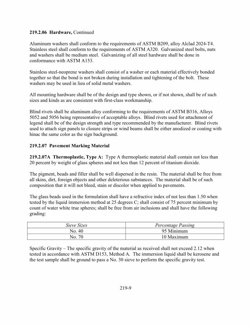
219.2.06 Hardware, Continued
Aluminum washers shall conform to the requirements of ASTM B209, alloy Alclad 2024-T4.Stainless steel shall conform to the requirements of ASTM A320. Galvanized steel bolts, nutsand washers shall be medium steel. Galvanizing of all steel hardware shall be done inconformance with ASTM A153.
Stainless steel-neoprene washers shall consist of a washer or each material effectively bondedtogether so that the bond is not broken during installation and tightening of the bolt. Thesewashers may be used in lieu of solid metal washers.
All mounting hardware shall be of the design and type shown, or if not shown, shall be of suchsizes and kinds as are consistent with first-class workmanship.
Blind rivets shall be aluminum alloy conforming to the requirements of ASTM B316, Alloys5052 and 5056 being representative of acceptable alloys. Blind rivets used for attachment oflegend shall be of the design strength and type recommended by the manufacturer. Blind rivetsused to attach sign panels to closure strips or wind beams shall be either anodized or coating withhinac the same color as the sign background.
219.2.07 Pavement Marking Material
219.2.07A Thermoplastic, Type A: Type A thermoplastic material shall contain not less than20 percent by weight of glass spheres and not less than 12 percent of titanium dioxide.
The pigment, beads and filler shall be well dispersed in the resin. The material shall be free fromall skins, dirt, foreign objects and other deleterious substances. The material shall be of suchcomposition that it will not bleed, stain or discolor when applied to pavements.
The glass beads used in the formulation shall have a refractive index of not less than 1.50 whentested by the liquid immersion method at 25 degrees C; shall consist of 75 percent minimum bycount of water white true spheres; shall be free from air inclusions and shall have the followinggrading:
Sieve Sizes Percentage PassingNo. 40 95 MinimumNo. 70 10 Maximum
Specific Gravity – The specific gravity of the material as received shall not exceed 2.12 whentested in accordance with ASTM D153, Method A. The immersion liquid shall be kerosene andthe test sample shall be ground to pass a No. 30 sieve to perform the specific gravity test.
219-9
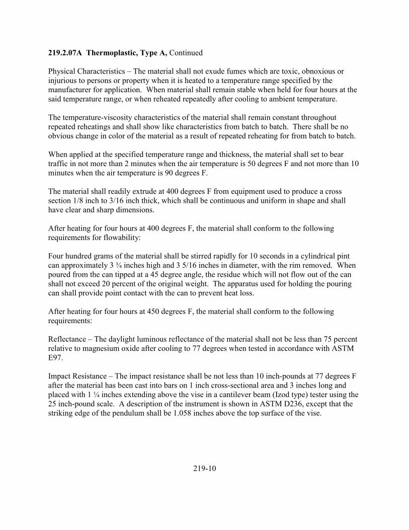
219.2.07A Thermoplastic, Type A, Continued
Physical Characteristics – The material shall not exude fumes which are toxic, obnoxious orinjurious to persons or property when it is heated to a temperature range specified by themanufacturer for application. When material shall remain stable when held for four hours at thesaid temperature range, or when reheated repeatedly after cooling to ambient temperature.
The temperature-viscosity characteristics of the material shall remain constant throughoutrepeated reheatings and shall show like characteristics from batch to batch. There shall be noobvious change in color of the material as a result of repeated reheating for from batch to batch.
When applied at the specified temperature range and thickness, the material shall set to beartraffic in not more than 2 minutes when the air temperature is 50 degrees F and not more than 10minutes when the air temperature is 90 degrees F.
The material shall readily extrude at 400 degrees F from equipment used to produce a crosssection 1/8 inch to 3/16 inch thick, which shall be continuous and uniform in shape and shallhave clear and sharp dimensions.
After heating for four hours at 400 degrees F, the material shall conform to the followingrequirements for flowability:
Four hundred grams of the material shall be stirred rapidly for 10 seconds in a cylindrical pintcan approximately 3 ¾ inches high and 3 5/16 inches in diameter, with the rim removed. Whenpoured from the can tipped at a 45 degree angle, the residue which will not flow out of the canshall not exceed 20 percent of the original weight. The apparatus used for holding the pouringcan shall provide point contact with the can to prevent heat loss.
After heating for four hours at 450 degrees F, the material shall conform to the followingrequirements:
Reflectance – The daylight luminous reflectance of the material shall not be less than 75 percentrelative to magnesium oxide after cooling to 77 degrees when tested in accordance with ASTME97.
Impact Resistance – The impact resistance shall be not less than 10 inch-pounds at 77 degrees Fafter the material has been cast into bars on 1 inch cross-sectional area and 3 inches long andplaced with 1 ¼ inches extending above the vise in a cantilever beam (Izod type) tester using the25 inch-pound scale. A description of the instrument is shown in ASTM D236, except that thestriking edge of the pendulum shall be 1.058 inches above the top surface of the vise.
219-10
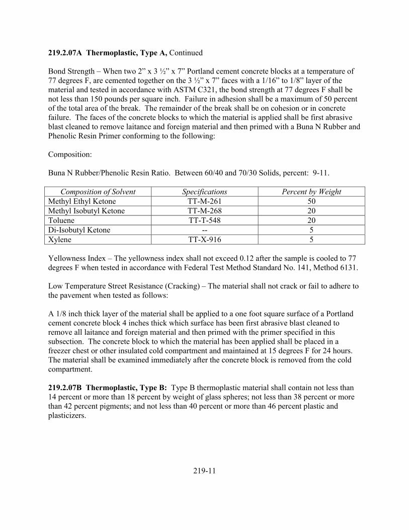
219.2.07A Thermoplastic, Type A, Continued
Bond Strength – When two 2” x 3 ½” x 7” Portland cement concrete blocks at a temperature of77 degrees F, are cemented together on the 3 ½” x 7” faces with a 1/16” to 1/8” layer of thematerial and tested in accordance with ASTM C321, the bond strength at 77 degrees F shall benot less than 150 pounds per square inch. Failure in adhesion shall be a maximum of 50 percentof the total area of the break. The remainder of the break shall be on cohesion or in concretefailure. The faces of the concrete blocks to which the material is applied shall be first abrasiveblast cleaned to remove laitance and foreign material and then primed with a Buna N Rubber andPhenolic Resin Primer conforming to the following:
Composition:
Buna N Rubber/Phenolic Resin Ratio. Between 60/40 and 70/30 Solids, percent: 9-11.
Composition of Solvent Specifications Percent by WeightMethyl Ethyl Ketone TT-M-261 50Methyl Isobutyl Ketone TT-M-268 20Toluene TT-T-548 20Di-Isobutyl Ketone -- 5Xylene TT-X-916 5
Yellowness Index – The yellowness index shall not exceed 0.12 after the sample is cooled to 77degrees F when tested in accordance with Federal Test Method Standard No. 141, Method 6131.
Low Temperature Street Resistance (Cracking) – The material shall not crack or fail to adhere tothe pavement when tested as follows:
A 1/8 inch thick layer of the material shall be applied to a one foot square surface of a Portlandcement concrete block 4 inches thick which surface has been first abrasive blast cleaned toremove all laitance and foreign material and then primed with the primer specified in thissubsection. The concrete block to which the material has been applied shall be placed in afreezer chest or other insulated cold compartment and maintained at 15 degrees F for 24 hours.The material shall be examined immediately after the concrete block is removed from the coldcompartment.
219.2.07B Thermoplastic, Type B: Type B thermoplastic material shall contain not less than14 percent or more than 18 percent by weight of glass spheres; not less than 38 percent or morethan 42 percent pigments; and not less than 40 percent or more than 46 percent plastic andplasticizers.
219-11
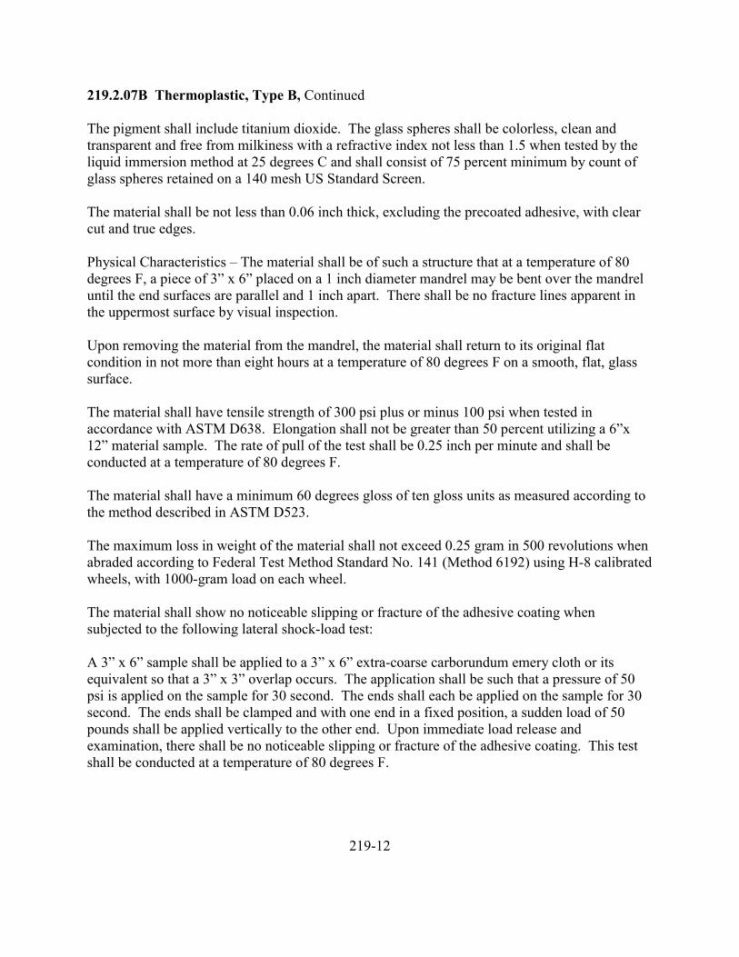
219.2.07B Thermoplastic, Type B, Continued
The pigment shall include titanium dioxide. The glass spheres shall be colorless, clean andtransparent and free from milkiness with a refractive index not less than 1.5 when tested by theliquid immersion method at 25 degrees C and shall consist of 75 percent minimum by count ofglass spheres retained on a 140 mesh US Standard Screen.
The material shall be not less than 0.06 inch thick, excluding the precoated adhesive, with clearcut and true edges.
Physical Characteristics – The material shall be of such a structure that at a temperature of 80degrees F, a piece of 3” x 6” placed on a 1 inch diameter mandrel may be bent over the mandreluntil the end surfaces are parallel and 1 inch apart. There shall be no fracture lines apparent inthe uppermost surface by visual inspection.
Upon removing the material from the mandrel, the material shall return to its original flatcondition in not more than eight hours at a temperature of 80 degrees F on a smooth, flat, glasssurface.
The material shall have tensile strength of 300 psi plus or minus 100 psi when tested inaccordance with ASTM D638. Elongation shall not be greater than 50 percent utilizing a 6”x12” material sample. The rate of pull of the test shall be 0.25 inch per minute and shall beconducted at a temperature of 80 degrees F.
The material shall have a minimum 60 degrees gloss of ten gloss units as measured according tothe method described in ASTM D523.
The maximum loss in weight of the material shall not exceed 0.25 gram in 500 revolutions whenabraded according to Federal Test Method Standard No. 141 (Method 6192) using H-8 calibratedwheels, with 1000-gram load on each wheel.
The material shall show no noticeable slipping or fracture of the adhesive coating whensubjected to the following lateral shock-load test:
A 3” x 6” sample shall be applied to a 3” x 6” extra-coarse carborundum emery cloth or itsequivalent so that a 3” x 3” overlap occurs. The application shall be such that a pressure of 50psi is applied on the sample for 30 second. The ends shall each be applied on the sample for 30second. The ends shall be clamped and with one end in a fixed position, a sudden load of 50pounds shall be applied vertically to the other end. Upon immediate load release andexamination, there shall be no noticeable slipping or fracture of the adhesive coating. This testshall be conducted at a temperature of 80 degrees F.
219-12
219.2.07B Thermoplastic, Type B, Continued
The precoated adhesive backing shall be pressure sensitive and shall remain stable with acontrolled degree of flexibility and flow. A 3” x 6” sample shall withstand a static load of fourpounds for a period of 30 minutes, as described in ASTM D816 (Method A). The slippagebetween the sample and the emery cloth shall not exceed 1 inch. This test shall be conducted at atemperature of 80 degrees F.
The material shall pass the following adhesive shear strength test according to ASTM D638 asmodified below. The sample shall be prepared as follows:
Samples 6” x 1” shall have applied to the adhesive face of a 1” x 3” piece of carborundum extra-coarse emery cloth or its equivalent so that there is one square inch overlap. A pressure of 50 psishall be applied over this area for a period of 30 seconds. Load is applied by gripping each endof the test piece in a suitable tensile test machine such as a Dillon or Scott Tester. The averageof the load required to break the adhesive bond from three such tests shall not be less than one-fourth of the load required to break a 1 inch strip of the sample. The speed of testing shall be0.25 inch per minute and the test shall be conducted at a temperature of 80 degrees F.
219.2.07C Primers: The primer used on concrete or asphalt pavements shall be a materialdesigned to increase the bond of the thermoplastic material to the pavement. The primer shall becompatible for use with concrete and thermoplastic material or asphalt and thermoplasticmaterial.
219.2.07D Striping Paint: Striping paint shall be the alkyd resin type, ready-mixed white oryellow, Type I, II, or III, conforming to the requirements of AASHTO M248. Glass beads shallconform to the requirements of AASHTO M247, Type I or II. The type of paint, paint color andtype of glass beads to be used shall be as specified.
219.3.00 Construction
219.3.01 Shop Drawings: Shop drawings shall be submitted in accordance with therequirements of Subsection 104. Two sets of drawings will be required, unless otherwisespecified.
219.3.02 Portland Cement Concrete: Portland cement concrete work shall conform to theapplicable requirements of Section 503. Forms shall be rigid and shall be held in place until theconcrete has set. Conduit ends and anchor bolts shall be placed in proper position and to properheight and shall be held in place by means of a template until the concrete has set.
219.3.03 Excavation: Excavation work shall conform to the applicable requirements of Section301.
219-13
219.3.04 Metal Reinforcement: Metal reinforcement shall conform to the applicablerequirements of Section 504.
219.3.05 Posts: Posts shall be of the length specified and set to the depths specified.
219.3.06 Signs: Sign backgrounds shall be either reflectorized or nonreflectorized as specified.The colors used for sign backgrounds shall match the “color chips” in the AASHTO Manual forSigning and Pavement Marking of the National System of Interstate and Defense Highways“Standard Interstate Colors”. Where required, the colors shall conform to the color coordinatesspecified. If color coordinates are not specified, the color sample called for shall be subject tovisual matching to determine the acceptability of the color.
In addition, all colors for which color coordinates are specified shall be subject to visualmatching by the Engineer to determine that all panels in any one sign match.
219.3.06A Plywood: Plywood sign fabrication shall be done with saw blades that do not tearplywood grain and all holes shall be cut clean and uniform. Splicing will not be permitted unlesscalled for in the Special Provisions. Mounting holes shall be located so that the mountinghardware will not cover any portion of the legend. Signs having a vertical dimension of 48inches or greater shall have three mounting holes. The minimum number of mounting holes forany one plywood sign shall be two.
After fabrication and before the application of reflective or nonreflective sheeting (if required),all edges shall be sealed with plywood sealer that is tinted to match the color of the panel overlaymaterial. Where reflective or nonreflective sheeting is to be applied, the surface of the face sideof the sign shall be prepared in conformance with the recommendations of the sheetingmanufacturer.
219.3.06B Aluminum: Aluminum signs shall be cut to size and shape and shall be free ofbuckles, warps, dents, cockles, burrs and defects resulting from fabrication.
Before application of reflective or nonreflective sheeting, the entire surface of the sign shall betreated with a conversion film. Such treatment shall be in strict conformance with therecommendations of the manufacturer of the sheeting.
Mounting holes – The number, size and location of mounting holes is dependent upon the signand support to which it is attached as follows:
Signs mounted on wood and metal posts shall be provided with at least two mounting holes.Signs having a vertical dimension of 48 inches or greater shall have three mounting holes. Thethird mounting hole shall be fabricated near the center of the sign. Mounting holes shall belocated so that the mounting hardware will not cover any portion of the legend unless otherwisespecified.
219-14
219.3.06C Reflective and Nonreflective Sheeting: The application process shall be incomplete conformance with the recommendations of the sheeting manufacturer. Splicing ofsheeting will be permitted only at locations specified.
The sheeting for aluminum panel or plywood panel (if permitted) signs shall be applied in such amanner that the panels may be assembled so that there will be no noticeable difference, day ornight, in color at the panel butt joints.
219.3.07 Pavement Marking
219.3.07A Thermoplastic, General: Prior to application of the thermoplastic pavementmarkings, the pavement shall be cleaned to remove old pavement markings, paint, recentlyapplied curing compounds and all loose material. Paint or curing compounds shall be removedas the Contractor elects, either by sandblasting or the use of chemical strippers. The methodused shall not adversely affect the pavement surface to a depth or of a width greater than thatrequired to afford adequate bond between the pavement and thermoplastic pavement markings.The cleaning operation shall remove all material which would reduce the bond of thethermoplastic to the pavement. All existing painted pavement markings shall be removed andthe area shall pass inspection of the Engineer prior to application of the primer coat.
After the pavement surface is cleaned, a primer shall be applied to the area receiving thethermoplastic pavement markings as required to properly bond the materials. The primerapplication shall effect a continuous, solid film over the pavement surface. The primer shall beapplied in strict conformance to the recommendations of the primer manufacturer and themanufacturer of the thermoplastic material.
The thermoplastic pavement markings shall be applied to an initially dry pavement surface aftersufficient time has elapsed to insure the primer has adequately dried and further curing of theprimer will not adversely affect the thermoplastic.
219.3.07B Thermoplastic, Type A: Type A hot-laid thermoplastic material shall be applied tothe pavement by an extrusion method. The pavement temperature at the time of application shallbe as recommended by the manufacturer of the thermoplastic material. The width of pavementmarkings specified shall be applied in one or two applications. If the stripe width is obtained bytwo applications, they shall be made so that the adjacent applications fuse together with noapparent overlap or gap permitted. When completed, the pavement marking shall not be lessthan 1/8 inch nor more than 3/16 inch in thickness, exclusive of projecting surface-applied glassbeads, and it shall have a continuous and uniform cross-sectional configuration with the uppersurface slightly arched. The thermoplastic material shall be installed in a molten state at atemperature between 380 degrees and 420 degrees F. The ambient air temperature shall be aminimum of 50 degrees F during application.
219-15
219.3.07B Thermoplastic, Type A, Continued
Glass beads shall be separately applied to the material as it is being placed.
The glass bead dispenser shall be so designed and operated as to uniformly and properlydistribute the glass beads upon the Type A material so that objectionable irregularities in thematerial’s reflectorization will not be present. This independent application of beads shall beapplied uniformly at the rate of one pound for each 50 square feet of pavement marking. Thedispenser shall be located about 18 inches behind and controlled simultaneously with thepavement marking extrusion die. The beads shall be embedded in the pavement marking to adepth of at least one-half their diameters.
Workmanship shall be first-class throughout the project. Only competent workers experiencedin placing thermoplastic shall be employed.
219.3.07C Thermoplastic, Type B: Type B thermoplastic material shall be applied to thepavement by a machine capable of applying the pressure-sensitive plastic material uniformlyover the various widths as required. At application, the ambient air temperature shall be at least60 degrees F. When completed, the pavement markings shall not be less than 0.06 inch inthickness, exclusive of any precoated adhesive material and shall have a uniform cross-sectionalconfiguration. If the required pavement marking is 12 or more inches wide, it may be fabricatedfrom 12 inch or 6 inch wide material. Longitudinal splices will be permitted, provided the gap atany splice does not exceed 1/16 inch.
Application of thermoplastic pavement markings shall be performed in a professional manner.Any error shall be corrected prior to continuing the application. Excess thermoplastic materialleft on the pavement shall be cleaned up prior to continuation of the operation.
219.3.07D Painting: The area to be painted shall be dry, clean and free of loose particles. Thepaint machine shall be of the spray type capable of satisfactorily applying the paint underpressure with a uniformity of feed through nozzles spraying directly upon the pavement. Eachmachine shall be capable of applying two separate stripes, either solid or skip, at the same time.Each paint tank shall be equipped with a mechanical agitator. Each nozzle shall be equippedwith satisfactory cutoff valves which will apply broken or skip lines automatically. Each nozzleshall have a mechanical bead dispenser that is located directly behind and synchronized with thespray nozzle which will distribute the beads in a uniform pattern at the rate specified. Eachnozzle shall also be equipped with suitable line guides consisting of metallic shrouds or airblasts.
The Contractor shall be responsible for preliminary spotting of the lines to be painted andapproval of the Engineer must be obtained before striping may begin.
219-16
219.3.07D Painting, Continued
Stripes shall be four inches wide. Broken line segments (Dashed or Skip Traffic Stripe) shall be16 feet in length with 25-foot gaps, or 4 feet in length with 4-foot gaps as shown on thedrawings.
The paint shall be thoroughly mixed prior to application and shall be applied when the airtemperature is above 40 degrees F.
The minimum rate of application for four-inch width solid traffic stripes shall be 16.5 gallons permiles. For broken traffic striping, the minimum rate of application shall be 6.2 gallons per mile.
For narrower or wider striping, paint shall be applied at a rate in proportion with the four-inchstripes.
219.4.00 Measurement and Payment
219.4.01 Lump Sum Basis: Measurement and payment for signing, striping and pavementmarkings will be made on a lump sum basis as shown.
219.4.02 Incidental Basis: When not shown as a pay item, payment for signing, striping andpavement markings shall be considered to be incidental to the work and no separate paymentshall be made.
219.4.03 Unit Price Basis
219.4.03A Signing and Pavement Markings: Measurement and payment for signing andpavement markings will be made on a unit price per square foot basis as shown for the number,type and kind of signing and pavement markings furnished and installed.
219.4.03B Striping and Pavement Markings: Measurement and payment for stripingpavement markings will be made on a unit price per lineal foot basis for the type of striping andpavement markings furnished and installed.
219-17
220 SAFETY STRUCTURES
220.1.00 Description
220.2.00 Materials220.2.01 Metal Beam Rail220.2.02 Guardrail Posts220.2.02A Concrete220.2.02B Steel220.2.02C Wood220.2.03 Guardrail Blocks220.2.04 Hardware220.2.04A Pins and Dowels220.2.04B Anchor Cable220.2.04C Anchor Rods220.2.04D Nuts, Bolts and Washers220.2.05 Premolded Joint Filler220.2.06 Grout220.2.07 Portland Cement Concrete220.2.08 Asphalt Concrete220.2.09 Impact Attenuators220.2.09A Liquid Cell220.2.09B Sand Cell220.2.10 Guide Posts220.2.10A Posts220.2.10B Reflector Targets220.2.10C Reflectors
220.3.00 Construction220.3.01 Guardrail220.3.02 Concrete Barrier220.3.03 Impact Attenuators220.3.04 Guide Posts
220.4.00 Construction220.4.01 Guardrail220.4.02 Guardrail End Pieces220.4.03 Guardrail Terminal Anchors220.4.04 Median Barrier220.4.05 Shoulder Barrier220.4.06 Impact Attenuators220.4.07 Guide Posts
220-1
220 SAFETY STRUCTURES
220.1.00 Description: This section covers the work necessary for the construction of guardrail,median, shoulder barrier, impact attenuators, guide posts and other safety structures.
220.2.00 Materials
220.2.01 Metal Beam Rail: Metal beam rail shall be galvanized steel conforming to therequirements of AASHTO M180, Class A, Type 1, unless otherwise specified.
220.2.02 Guardrail Posts
220.2.02A Concrete: Concrete shall be Class 4500 and shall conform to the requirements ofSection 503. Metal reinforcement shall be bar reinforcement or welded wire fabric conformingto the requirements of Section 504.
220.2.02B Steel: Steel posts shall conform to the requirements of ASTM A36 and shall begalvanized in accordance with the requirements of ASTM A123.
220.2.02C Wood: Wood posts shall be pressure treated Coast Douglas Fir, West CoastHemlock, Southern Yellow Pine, or Lodgepole Pine.
Posts shall be surfaced four sides. Pressure treatment shall conform to the requirements ofAASHTO M133 and shall be one of the following:
A. CreosoteB. Creosote-petroleum solutionC. Pentachlorophenol
Posts shall be incised on all faces a minimum depth of ¾ inch and shall be treated inconformance with the American Wood Products Association Standards C1 and C2, except theminimum retention (empty-cell process) of preservative shall be 10 pounds per cubic foot ofwood (0.50 pound pentachlorophenol dry salt). The minimum penetration shall be not less than¾ inch and 90 percent of sapwood.
220.2.03 Guardrail Blocks: Guardrail blocks shall be of wood conforming to the requirementsof Subsection 220.2.02C, except for the following:
Incising will not be required and the minimum retention of preservative, determined by assay,shall be 6 lbs. per cubic foot of wood for creosote or creosote-petroleum solution or 0.30 lb. percubic foot of pentachlorophenol dry salt. The preservative shall penetrate not less than 90percent of sapwood, and shall penetrate not less than two inches longitudinally from block endsand bolt holes.
220-2
220.2.04 Hardware
220.2.04A Pins and Dowels: Pins and dowels shall conform to the requirements of ASTM A36and shall be galvanized in conformance with the requirements of ASTM A153.
220.2.04B Anchor Cable: Anchor cable shall conform to the requirements of AASHTO M30,and shall be Type 1, unless otherwise specified.
220.2.04C Anchor Rods: Anchor rods shall conform to the requirements of ASTM A36 andgalvanized in accordance with the requirements of ASTM A123.
220.2.04D Nuts, Bolts and Washers: Nuts, bolts, and washers shall be galvanized steel and ofa quality to develop the specified strength of the splices and connections. Galvanizing shallconform to the requirements of ASTM A153.
220.2.05 Premolded Joint Filler: Premolded joint filler shall conform to the requirements ofAASHTO M153 or AASHTO M213.
220.2.06 Grout: Grout shall conform to the requirements of Section 503.
220.2.07 Portland Cement Concrete: Portland cement concrete shall conform to therequirements of Section 503.
220.2.08 Asphalt Concrete: Asphalt concrete shall conform to the requirements of Section211.
220.2.09 Impact Attenuators
220.2.09A Liquid Cell: Cells shall be vinyl plastic specially formulated from high molecularweight homopolymer vinyl resins combined with totally primary plasticizing systems. Theplasticizers shall be chosen so as to produce a vinyl possessing high strengths and remainingflexible in both high and low temperatures. Ultra-violet stabilizers, heat stabilizers, anti-bacteriological agents and other additives shall be utilized to give maximum protection and longlife in outdoor environments.
Cells shall have a nominal outside diameter of six inches with ¼ inch thick walls. The lengthshall be as specified. Cells shall be capped at both ends and furnished with an orifice near oneend in order to facilitate filling and controlled release upon impact. The orifice diameter shall beas specified.
Metal shall be galvanized steel conforming to the requirements of ASTM A36, unless otherwisespecified. Galvanizing shall conform to the requirements of ASTM A123.
220-3
220.2.09A Liquid Cell, Continued
Fender panels shall be fiberglassed plywood. The grade and thickness of plywood shall be asspecified.
Interior panels shall be of plastic overlaid plywood. The grade and thickness shall be asspecified.
220.2.09B Sand Cell: Cells shall be of high density expanded polyethylene. Metal and panelsshall conform to the requirements of Subsection 220.2.09A, unless otherwise specified.
220.2.10 Guide Posts
220.2.10A Posts: Guide posts shall be of galvanized steel having a minimum yield strength of40,000 psi and a minimum ultimate strength of 70,000 psi. Galvanizing shall conform to therequirements of ASTM A123.
220.2.10B Reflector Targets: Reflector target material shall be aluminum alloy conforming tothe requirements of ASTM B209 and of a series suitable for enameling by continuous roller orother acceptable method. The aluminum sheets from which targets are fabricated shall have anominal thickness of 0.050 inch subject to standard manufacturer’s tolerances.
Target surfaces shall be cleaned and prepared for enameling in accordance with one of theappropriate methods conforming to the requirements of ASTM D1730.
Enamel shall be Class B baking enamel conforming to the requirements of Federal SpecificationTT-E-489C or acceptable equivalent.
Enameling shall consist of two coats of enamel, each coat being properly baked and with thefinal coat baked to a hard finish, or a coat of an inhibitive and compatible primer having a dryfilm thickness of about 0.3 mil, followed by one heavy coat of enamel baked to a hard finish.The baked enamel shall be uniform in color, smooth and free from flow lines, streaks, blisters orother surface imperfections.
The baked enamel finish shall be white or standard interstate yellow, as specified.
220.2.10C Reflectors: Reflectors shall consist of sealed, acrylic plastic, prismatic reflex unitsapproximately three inches in diameter with centered mounting hole, conforming to thefollowing requirements:
The reflective color or reflectors shall be either white or standard interstate yellow to correspondwith the color of the target member on which they are mounted.
220-4
220.2.10C Reflectors, Continued
The reflector lens shall be of a methacrylate compound conforming to the requirements ofASTM D788, Grade 8.
Each reflector shall have a clear and transparent face, with a minimum of 6 square inches ofreflective area (lens) sealed with either a metallic foil back or an opaque back of materialidentical to the face, fused to the lens around its perimeter and mounting hole to form a unitpermanently sealed against dust, water and water vapor. When the back is a metal foil it shall beprotected with an aluminum or tough plastic casing covering the back and edges of the lens. Themounting hole in the lens shall have an aluminum grommet expanded therein, or when the lenshas a protective casing the grommet may be of aluminum or plastic molded integral with thecasing.
The grommet shall have an inside diameter sufficient and proper to receive a 3/16 inch blindrivet.
The lens shall consist of a rear surface bearing a prismatic configuration such that it will effecttotal internal reflection of light and it shall have a smooth front surface free from projections orindentations other than for a central mounting hole and for identification. The manufacturer’strademark shall be molded legibly into the face of the lens.
220.3.00 Construction
220.3.01 Guardrail: Excavations through paved surfaces shall be made in such a way so as notto disturb the adjacent paved surface areas. Excavations through surfacing or base materialsshall be backfilled with like materials and compacted to the density of the adjacent material.Excavations in other areas shall be backfilled with granular material.
All backfill shall be placed in layers not exceeding six inches and each layer shall be compactedto a firm, dense condition.
Adjoining areas which become misshapen or disturbed during excavating and backfillingoperations shall be removed, replaced, repaired or restored, as directed. Excess materials shallbe disposed of in an approved manner.
Materials which are damaged during installation shall be removed and replaced. The cut ends ofgalvanized bolts, rail elements and back-up plates and any holes drilled or punched aftergalvanizing shall be coated with an approved galvanizing substitute.
All bolts, except adjustment bolts, shall be drawn tight. Bolts shall be of sufficient length toextend slightly beyond the nuts.
220-5
220.3.02 Concrete Barrier: Portland cement concrete shall be Class 4500.
Concrete barrier may be either cast in place or precast.
Curing and finishing shall conform to the requirements of Section 503.
The top and faces of barriers shall be true and uniform and free of humps, sags or otherirregularities. When a straightedge ten feet long is laid on the top or face of the barrier, thesurface shall not vary more than 0.02 foot from the edge of the straightedge, except at gradechanges or curves. To compensate for variations in grade, the Contractor shall adjust the heightof cast-in-place barrier and adjust the depth of the grout leveling bed under precast sections.
220.3.03 Impact Attenuators: Impact attenuators shall be installed in conformance with themanufacturer’s recommendations and as specified.
220.3.04 Guide Posts: Guide posts may be driven or set. Normally guide posts shall beinstalled to the lines, grades and spacings specified. To avoid unusually difficult installation atany individual post site, the spacing may be varied to 5 percent in either direction and deviationfrom line may be varied up to six inches in either direction, as approved by the Engineer. Thepost sites shall be made free and clear of vegetative growth, litter and debris.
Guide posts set in rock may be shortened and set to depths of not less than 18 inches in a drilledhole 1 inch greater in diameter than the large dimension of the post and backfilled with finegranular material, or grouted in place. In final position, the guide posts shall be vertical andfirm. Damaged guide posts shall be replaced.
Excess excavated materials and all debris shall be removed and disposed of by the Contractor.
220.4.00 Measurement and Payment
220.4.01 Guardrail: Measurement and payment for guardrail will be on a linear foot basis forthe type of guardrail specified and constructed.
220.4.02 Guardrail End Pieces: Measurement and payment for guardrail end pieces will be ona per each basis for the type of end pieces specified and constructed.
220.4.03 Guardrail Terminal Anchors: Measurement and payment for guardrail terminalanchors will be on a per each basis for the type of terminal anchors specified and constructed.
220.4.04 Median Barrier: Measurement and payment for median barrier will be on a linearfoot basis for the type and kind of median barrier specified and constructed.
220-6
220.4.05 Shoulder Barrier: Measurement and payment for shoulder barrier will be on a linearfoot basis for the type and kind of shoulder barrier specified and constructed.
220.4.06 Impact Attenuators: Measurement and payment for impact attenuators will be on aper each basis for the type of impact attenuators specified and constructed.
220.4.07 Guide Posts: Measurement and payment for guide posts will be on a per each basisfor the type of guide posts specified and installed.
220-7
221 LANDSCAPING
221.1.00 Description
221.2.00 Materials221.2.01 Seed221.2.02 Mulch221.2.02A Straw Mulch221.2.02B Peat Moss Mulch221.2.02C Sawdust Mulch221.2.02D Bark Mulch221.2.02E Wood Cellulose Fiber Mulch221.2.02F Pulverized Corn Cobs221.2.03 Matting221.2.03A Jute Matting221.2.03B Excelsior Matting221.2.03C Burlap221.2.04 Topsoil221.2.05 Sod221.2.06 Agricultural Limestone221.2.07 Fertilizer221.2.07A Organic221.2.07B Inorganic221.2.08 Plants221.2.09 Pipe221.2.09A Galvanized Steel221.2.09B Copper221.2.09C Polyvinylchloride221.2.10 Valves221.2.10A Gate Valves221.2.10B Globe Valves221.2.10C Pressure Reducing Valves221.2.10D Swing-Check Valves221.2.10E Quick-Coupling Valves221.2.11 Backflow221.2.12 Water Meters221.2.13 Sprinkler Heads221.2.13A Stationary Sprinkler Heads221.2.13B Pop-up Non-Revolving Sprinkler Heads221.2.13C Pop-up Rotary Sprinkler Heads221.2.13D Agricultural Rotary Sprinkler Heads221.2.14 Electrical Conductors and Conduit221.2.15 Valve Boxes221.2.16 Soil Sterilant
221-1
221 LANDSCAPING, Continued
221.3.00 Construction221.3.01 Seeded Lawn221.3.02 Sod Lawn221.3.03 Seeding and Mulching221.3.04 Trees, Shrubs and Plants
221.4.00 Measurement and Payment221.4.01 Lawn221.4.02 Seeding and Mulching221.4.03 Trees, Shrubs and Plants221.4.04 Irrigation Pipe221.4.05 Sprinklers221.4.06 Valves221.4.07 Meters221.4.08 Fertilizer221.4.09 Valve Boxes221.4.10 Agricultural Limestone221.4.11 Soil Sterilant221.4.12 Matting221.4.13 Topsoil221.4.13A Native Topsoil221.4.13B Imported Topsoil221.4.14 Electrical Components
221-2
221 LANDSCAPE
221.1.00 Description: This section covers the work necessary to construct lawn, grass, shruband tree areas.
221.2.00 Materials
221.2.01 Seed: Seed shall be from blue tag stock and from the latest crop available. Eachvariety shall be from tested seed and shall be delivered in standard sealed containers labeled inaccordance with Kansas State laws and US Department of Agriculture rules and regulationsunder the Federal Seed Act in effect on the date of invitation of bids. The percentage of purity,germination and maximum weed content shall be as set forth in the state seed laws of Kansas andsubsequent revisions. The label shall show the variety of seed, the percentage of germination,purity and weed content, and the date of test. The seed shall have been tested within nine monthsof the date of delivery and shall not be moldy, or show evidence of having been wet or otherwisedamaged.
Each lot of seed shall be subject to inspection, sampling and testing on delivery to the project.Seed not meeting the requirements of these specifications or not labeled as specified, will berejected and shall be replaced with seed conforming to the specifications.
Grass seed may be delivered to the project as a mixture providing each variety of grass seed inthe mixture is identified and labeled as specified or a certification from the supplier is attachedgiving the percentage of each variety of grass seed in the mixture and the percentage of purity,germination, and weed content.
221.2.02 Mulch
221.2.02A Straw Mulch: Straw mulch shall consist of wheat straws, oat straws, other smallstemmed straws meeting the approval of the Engineer; sweet clover hay, prairie hay, smoothbromegrass hay, cane and sorghum hay, soybean hay or sudan grass hay or excelsior mulchsingly or in combination. Straw mulch shall not be musty, moldy, caked, decayed or ofotherwise low quality, and shall be free of noxious weeds or noxious weed seeds.
221.2.02B Peat Moss Mulch: Peat moss mulch shall be horticultural grade natural peat mossfurnished in bales or bags, in air-dry condition, and free from woody substances. The bales orbags shall carry identification of contents and volume.
221.2.02C Sawdust Mulch: Sawdust mulch shall be free of chips, strips and splinters. It shallhave no toxic substances injurious to plants.
221-3
221.2.02D Bark Mulch: Bark mulch shall be ground, shredded or broken particles from thebark of fir, pine or hemlock trees and shall be free from weed seeds, harmful bacteria or diseasespores and substances toxic to plant growth. The much shall be of the size commonly known inthe trade as “medium bark mulch”. A 15-pound sample shall be submitted to the Engineer forvisual inspection and approval prior to delivery of the material to the project, and the approvedsample will be used as a reference for acceptability of the material used in the work.
221.2.02E Wood Cellulose Fiber Mulch: Wood cellulose fiber mulch shall consist of aspecially prepared wood fiber processed to contain no growth or germination inhibiting factors.The fiber mulch shall be manufactured and processed in such a manner that the wood cellulosefibers will remain in uniform suspension in water under agitation and will blend with grass seed,fertilizer and other additives to form a homogeneous slurry. The processed mulch material shallhave characteristics to form a blotter-like ground cover on application, having moistureabsorption and percolation properties and the ability to cover and hold grass seed in contact withsoil. The wood cellulose fiber mulch material shall be shipped in packages of uniform weight(plus or minus 5 percent) and bearing the name of the manufacturer and the air-dry weightcontent.
221.2.02F Pulverized Corn Cobs: Pulverized corn cobs may be used by permission of theEngineer.
221.2.03 Matting
221.2.03A Jute Matting: Jute matting shall consist of a uniform open plain weave of singlejute yarn. The yarn shall be of loosely twisted construction and shall not vary in thickness bymore than one half of its normal diameter. The weave shall provide openings approximately 1-inch square. The matting shall be in widths of 45 inches or more and shall weigh not less than0.9 pound per square yard. It shall be furnished in continuous lengths of not less than 150 feet.Staples for use with jute matting shall be of 12-gauge or heavier steel wire bent U-shapedapproximately 1 ½ to 2 inches in width and shall be not less than 12 inches long unless hard pansoil conditions dictate the use of shorter lengths and this length is approved by the Engineer.
221.2.03B Excelsior Matting: Excelsior matting shall consist of a machine produced blanketof curled wood fibers, 80 percent of which shall be of consistent thickness with fiber evenlydistributed over the entire area of the blanket. The top side of the matting shall be covered with a3” x 1” weave of twisted kraft paper having a high wet strength, or a 2” x 1” biodegradableextended plastic mesh.
The excelsior matting shall have a minimum dry weight of 0.8 pound per square yard plus orminus 10 percent. The width of the matting shall be a minimum of 36 inches. Wire staples forexcelsior matting shall be the same as specified for jute matting.
221-4
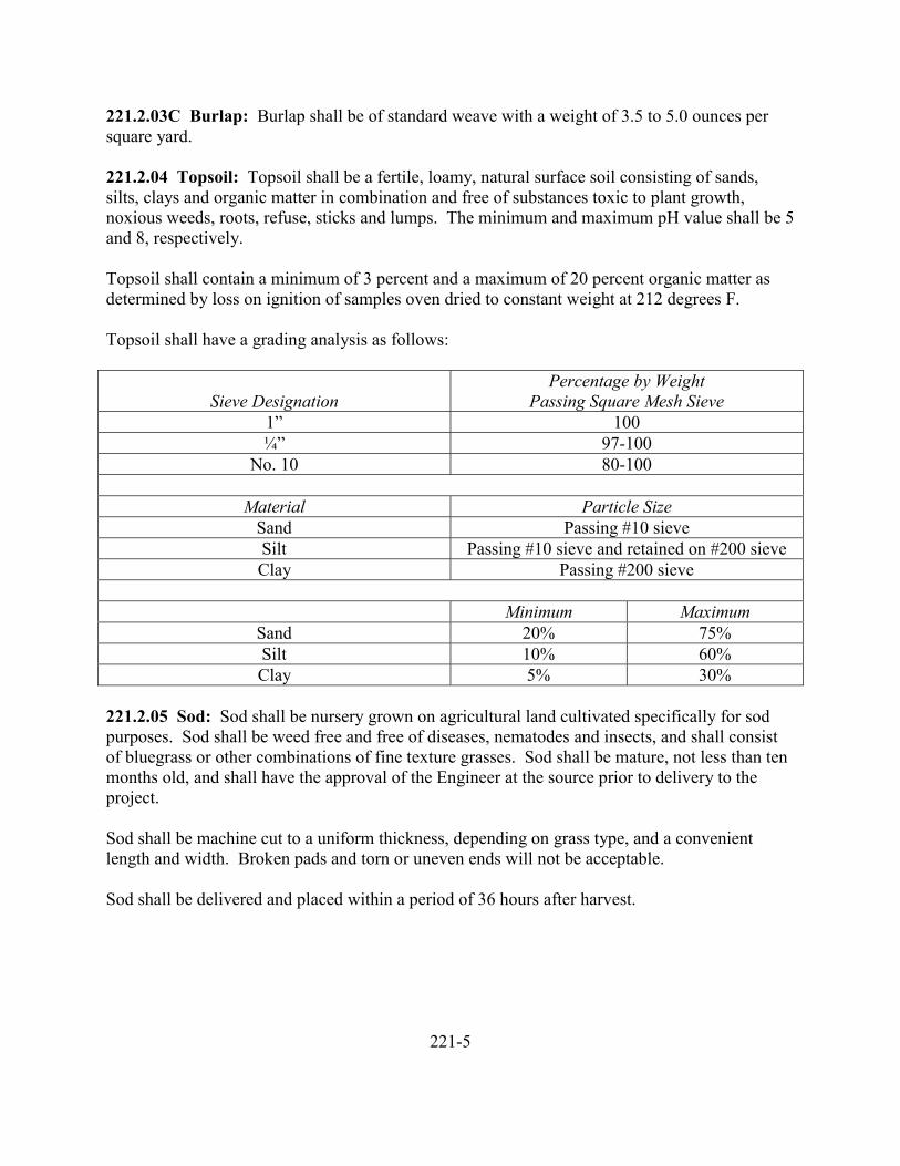
221.2.03C Burlap: Burlap shall be of standard weave with a weight of 3.5 to 5.0 ounces persquare yard.
221.2.04 Topsoil: Topsoil shall be a fertile, loamy, natural surface soil consisting of sands,silts, clays and organic matter in combination and free of substances toxic to plant growth,noxious weeds, roots, refuse, sticks and lumps. The minimum and maximum pH value shall be 5and 8, respectively.
Topsoil shall contain a minimum of 3 percent and a maximum of 20 percent organic matter asdetermined by loss on ignition of samples oven dried to constant weight at 212 degrees F.
Topsoil shall have a grading analysis as follows:
Sieve DesignationPercentage by Weight
Passing Square Mesh Sieve1” 100¼” 97-100
No. 10 80-100
Material Particle SizeSand Passing #10 sieveSilt Passing #10 sieve and retained on #200 sieveClay Passing #200 sieve
Minimum MaximumSand 20% 75%Silt 10% 60%Clay 5% 30%
221.2.05 Sod: Sod shall be nursery grown on agricultural land cultivated specifically for sodpurposes. Sod shall be weed free and free of diseases, nematodes and insects, and shall consistof bluegrass or other combinations of fine texture grasses. Sod shall be mature, not less than tenmonths old, and shall have the approval of the Engineer at the source prior to delivery to theproject.
Sod shall be machine cut to a uniform thickness, depending on grass type, and a convenientlength and width. Broken pads and torn or uneven ends will not be acceptable.
Sod shall be delivered and placed within a period of 36 hours after harvest.
221-5
221.2.06 Agricultural Limestone: Agricultural limestone shall be a calcic or dolomitic groundlimestone containing not less than 85 percent of total (Calcium and Magnesium) carbonates.Limestone shall conform to the standards of the Association of Official Analytical Chemists andshall comply with all existing State and Federal regulations.
Limestone shall meet the following sieve analysis: At least 40 percent passing a No. 100 sieve,and at least 95 percent passing a No. 8 sieve.
Granulated slag or other approved natural sources of lime may be used, subject to approval bythe Engineer of an adjusted application rate that will equal the total neutralizing power of thespecified ground limestone.
221.2.07 Fertilizer: Fertilizer shall be furnished in moisture proof bags. Each bag shall bemarked with the weight and with the manufacturer’s analysis of the contents showing thepercentage for each ingredient contained herein. Fertilizer shall be furnished in a dry conditionfree from lumps and caking, in granular, or pelletized form. Fertilizer shall be standardcommercial grade and shall be manufactured by firms, registered by the Kansas State Board ofAgriculture. Bagged or bulk fertilizers shall be delivered with the appropriate labels orcertificates providing the information required by Section 2-1204 of the “Kansas CommercialFertilizer Law” as amended.
221.2.07A Organic: Organic fertilizer, shall consist of cottonseed meal, blood meal, bonemeal, fish meal, tankage or other similar organic substances. The chemical composition shall beas specified.
221.2.07B Inorganic: The requirement for each inorganic fertilizer shall be as shown on theplans or specified in the Special Provisions, and in the Proposal. In a fertilizer grade as shown,the first number shall represent the percentage of nitrogen required (expressed as available N),the second number shall represent the percentage of phosphorous required (expressed as thepercent of available P2O5) and the third number shall represent the percentage of potassiumrequired (expressed as the percent of available K2O). A mixed fertilizer such as 12-24-12 shouldcontain 12% N, 24% P2O5 and 12% K2O.
A minus tolerance of 0.5 of one percent will be permitted for each of the designated ingredientsin inorganic fertilizers.
221.2.08 Plants: Plants shall be first-class representatives of their normal species or varietiesunless otherwise specified as “street-tree”, “extra heavy”, “clump”, and other, or like import,according to the particular exception. Unless otherwise specified, all plants shall be nursery-grown stock that has been transplanted or root-trimmed two or more times, according to the kindand size of plants. The branch system shall be normal development and free from disfiguringknots, sun-scald, injuries, abrasions of the bark, dead or dry wood, broken terminal growth, orother objectionable disfigurements. Trees shall have reasonably straight stems and shall be wellbranched and symmetrical in accordance with their natural habits of growth.
221-6
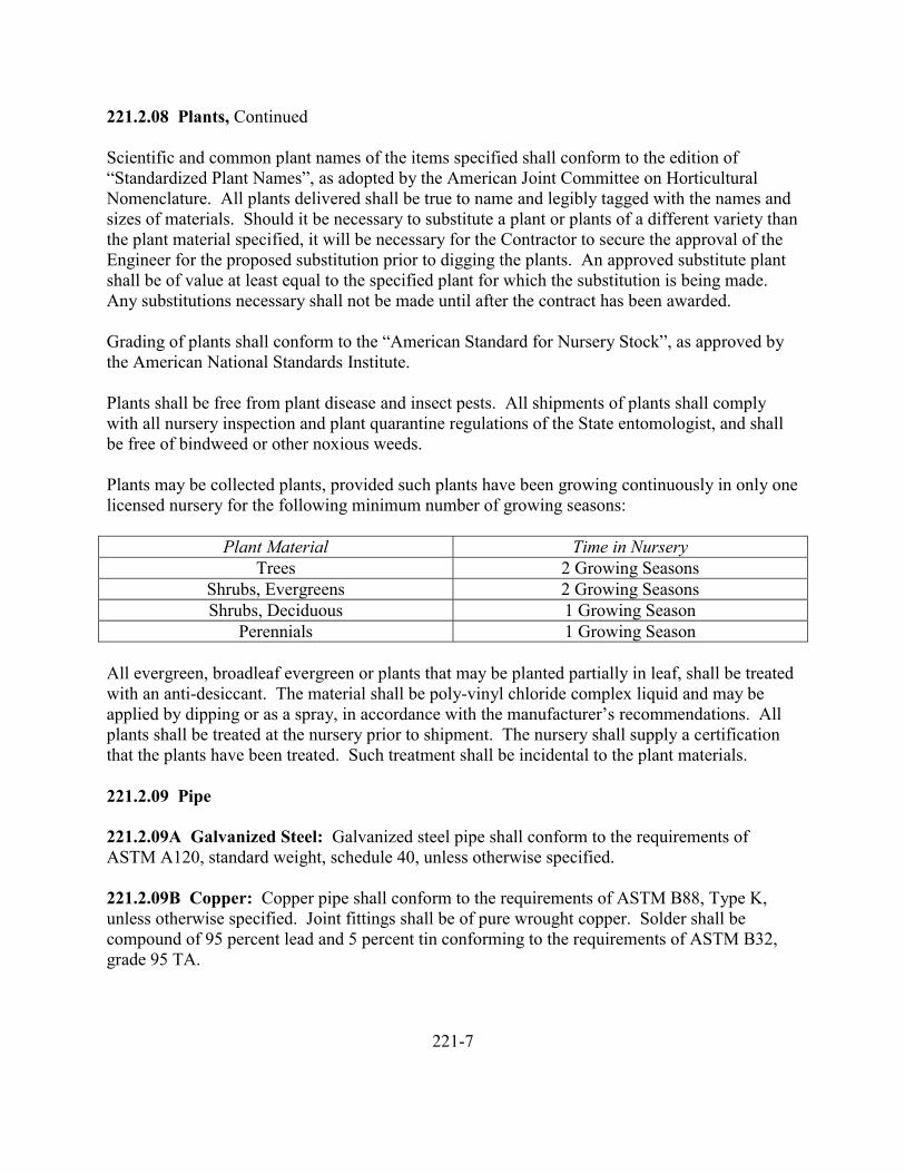
221.2.08 Plants, Continued
Scientific and common plant names of the items specified shall conform to the edition of“Standardized Plant Names”, as adopted by the American Joint Committee on HorticulturalNomenclature. All plants delivered shall be true to name and legibly tagged with the names andsizes of materials. Should it be necessary to substitute a plant or plants of a different variety thanthe plant material specified, it will be necessary for the Contractor to secure the approval of theEngineer for the proposed substitution prior to digging the plants. An approved substitute plantshall be of value at least equal to the specified plant for which the substitution is being made.Any substitutions necessary shall not be made until after the contract has been awarded.
Grading of plants shall conform to the “American Standard for Nursery Stock”, as approved bythe American National Standards Institute.
Plants shall be free from plant disease and insect pests. All shipments of plants shall complywith all nursery inspection and plant quarantine regulations of the State entomologist, and shallbe free of bindweed or other noxious weeds.
Plants may be collected plants, provided such plants have been growing continuously in only onelicensed nursery for the following minimum number of growing seasons:
Plant Material Time in NurseryTrees 2 Growing Seasons
Shrubs, Evergreens 2 Growing SeasonsShrubs, Deciduous 1 Growing Season
Perennials 1 Growing Season
All evergreen, broadleaf evergreen or plants that may be planted partially in leaf, shall be treatedwith an anti-desiccant. The material shall be poly-vinyl chloride complex liquid and may beapplied by dipping or as a spray, in accordance with the manufacturer’s recommendations. Allplants shall be treated at the nursery prior to shipment. The nursery shall supply a certificationthat the plants have been treated. Such treatment shall be incidental to the plant materials.
221.2.09 Pipe
221.2.09A Galvanized Steel: Galvanized steel pipe shall conform to the requirements ofASTM A120, standard weight, schedule 40, unless otherwise specified.
221.2.09B Copper: Copper pipe shall conform to the requirements of ASTM B88, Type K,unless otherwise specified. Joint fittings shall be of pure wrought copper. Solder shall becompound of 95 percent lead and 5 percent tin conforming to the requirements of ASTM B32,grade 95 TA.
221-7
221.2.09C Polyvinylchloride: Polyvinylchloride (PVC) pipe shall conform to the requirementsof ASTM D2241. Fittings shall conform to the requirements of ASTM D2455.Polyvinylchloride pipe shall have a Standard Thermoplastic Pipe Dimension Radio (SDR) of 21.The pipe and fittings shall be made from PVC compounds conforming to the requirements ofASTM D1784, Class 12454-B or Class 12454-C. Plastic pipe shall be of the solvent-cementjoint design.
Cements and primers shall be compatible with and of the kind recognized by the industry asproper for use with the kind of plastic pipe and fittings involved. Primer shall be colored.
Plastic pipe shall conform to the requirements of the National Sanitation Foundation TestingLaboratories, Inc., or other accredited laboratory and shall be marked with the “NSF” mark atintervals along the pipe, together with the manufacturer’s trademark, PSI and PVC compounddesignation.
221.2.10 Valves
221.2.10A Gate Valves: Gate valves up to and including the three-inch size shall have bronzebodies. Valves of four inch size and larger may have either bronze or iron bodies. All valvesshall have bronze stems, bronze seat rings and bronze disc faces. Material in bronze bodies shallconform to the requirements of ASTM B62 or approved equal. All valves shall be service rated(non-shock cold water) at not less than 200 psi. The valves shall be of the double disc, risingstem type, with union bonnets. Valves shall be of the screw type with wheel-handle.
221.2.10B Globe Valves: Globe calves shall be manufactured of bronze conforming to therequirements of ASTM B61. The valves shall be of the rising stem, metal disc, plug type withunion bonnets, having wheel handles and be service rated (non-shock cold water) at not less than200 psi.
221.2.10C Pressure Reducing Valves: Pressure reducing valves shall be manufactured ofheavy-duty bronze with either an integral or independent stainless steel or monel strainer. Thevalve shall permit quick and easy cleaning or replacement of the strainer or its parts withoutdismantling or removing the valves from the line. The valves shall be adjustable as shown on theplans or Special Provisions. The valves shall have an integral or independent union.
221.2.10D Swing-Check Valves: Swing-check valves shall be manufactured of bronzeconforming to the requirements of ASTM B62. The valves shall be of the screwed cap,removable disc type, have bronze or brass discs and be service rated (non-shock cold water) atnot less than 200 psi.
221-8
221.2.10E Quick-Coupling Valves: Quick-coupling valves may be either one-piece or two-piece body type, with locking cap. The body shall be heavy-duty brass (ASTM B145, 81-3-7-9type is acceptable), or of heavy-duty bronze. The cap may be of brass, bronze or othernoncorrosive metal. Quick-coupling valves shall be watertight both before and after the coupleris inserted. The valve mechanism shall be so designed that the valve seat is closed before thecoupler is removed. Each valve shall have the manufacturer’s identification cast or stamped onthe valve.
Couplers or keys for use with quick-coupling valves shall provide for attachment of portablesprinkler heads or hose swivels. The couplers or keys shall be of brass, bronze, stainless steel,other approved highly corrosion-resistant metal or combinations thereof, and shall be of a designexpressly intended for use with quick-coupling valves. The couplers or keys shall be of bayonettype. Lugs shall be of a durable brass, bronze, stainless steel or other approved metal.
Hose swivels shall be of brass, bronze or other approved metal, of ¾ inch size, with 90 degreesswivel ell, and shall be free turning through a 360-degree swing. The swivel spindle shall bewatertight in service.
Two couplers and two hose swivels for operation of the valves and two keys for the lock capsshall be furnished to the Engineer on each project requiring quick-coupling valves.
221.2.11 Backflow Prevention Devices: Backflow prevention devices shall conform to therequirements of AWWA C506.
221.2.12 Water Meters: Water meters shall conform to the applicable requirements ofSubsection 403.2.08.
221.2.13 Sprinkler Heads: Sprinkler heads and the working parts shall be precision machinedand free of burrs. They shall be brass, bronze, stainless steel, other durable and highly corrosionand wear resistant metal, or compatible combinations thereof. Sprinkler heads shall have servicerecords of efficient performance over a period of at least two years. Sprinkler heads shall giveuniform coverage when operating at the specified pressures.
221.2.13A Stationary Sprinkler Heads: Stationary sprinkler heads shall be of shrubbery two-piece type, consisting of body and adaptor, and shall be provided with volume control.
221.2.13B Pop-Up Nonrevolving Sprinkler Heads: Pop-up nonrevolving sprinkler headsshall be full or part circle.
The top flange or plate shall be not less than 2 3/8 inches in diameter. The pop-up portion of thehead shall return freely to its closed position when the head, in dry condition, is inclined at anangle of 30 degrees from horizontal. The heads shall have adjustment for volume and areacoverage and shall be accessible from the top without disturbance of the body of the head.Nozzles shall be removable and interchangeable from the top of the head.
221-9
221.2.13C Pop-Up Rotary Sprinkler Heads: Pop-up rotary heads shall be full or part circle.The heads shall be designed for heavy-duty, and all working parts shall be highly resistant towear and shall operate smoothly without stalling of the rotary action while under specifiedoperating pressure. The working assembly shall be removable from above the ground as a unitto permit adjustment and servicing. The orifices or nozzles shall be interchangeable andreplaceable from the top of the head without disturbances of the assembly or body of the head.The heads shall be such that various sizes of orifices or nozzles may be used interchangeably.
Part circle heads shall be adjustable to any part of a circle from 45 degrees to 315 degrees, orgreater range, while in operation.
Pop-up rotary sprinkler heads shall be rotated by means of a horizontal oscillating arm drive.The sprinkler shall make a positive closing of the plate when in off position. Part circle rotaryheads shall have an anti-backsplash device.
The rotary sprinkler heads, both part circle and full circle, shall be adjustable for stream breakupand distance control.
221.2.13D Agricultural Rotary Sprinkler Heads: Agricultural rotary sprinkler heads shall beconstructed basically of brass, bronze, stainless steel or combinations thereof. Nozzles shall beconstructed of brass, bronze, stainless steel or other sturdy, durable material. All materials usedmust be highly resistant to corrosion. All working parts shall be precision machined and allbearings and other moving parts shall be highly resistant to wear. The sprinkler heads shall be ofsuch design that at least three different sizes of nozzles may be used interchangeably. Part circleheads shall have an anti-backsplash device.
221.2.14 Electrical Conductors and Conduit: Electrical conductors from the power source tothe controller, or timer, shall be copper, minimum size No. 10, type TW, consisting of twoconductors and a bare copper ground wire of the same size conforming to the requirements of theNational Electrical Code. These wires shall be encased in conduit from the source to thecontroller or timer.
Electrical conductors from the controllers or timers to the valves shall be standard copper “UF”irrigation control wire conforming to the size and other requirements of the National ElectricalCode, current edition.
All aboveground conduit shall be galvanized rigid steel electrical type and all undergroundconduit shall be Schedule 40 PVC electrical type. All conduit shall conform to the requirementsof the National Electrical Code, current edition.
221-10
221.2.15 Valve Boxes: Valve boxes shall be of precast concrete or other approved materialsconforming to the requirements of Section 503. Concrete shall be Class 3000-CA-5 or Class3000-MA-1, unless otherwise specified.
Valve boxes shall be furnished with a metal cover capable of being locked with a padlock. Themetal cover shall be of galvanized steel, unless otherwise specified.
221.2.16 Soil Sterilant: Soil sterilant may be granular calcium cynamid, manufactured for useas a herbicide, or other approved sterilant.
221.3.00 Construction
221.3.01 Seeded Lawn: Seeded lawn construction shall be performed only at times when localweather and other conditions are favorable to the preparation of the soil and to the germinationand growth of grass seed, generally between February 15 and April 20, or August 15 toSeptember 30.
Areas on which seeded lawn is to be established shall be in a loose, friable condition for aminimum depth of six inches. The area shall be made substantially free of vegetative matter,stones, clods, roots, sticks, debris and other matter detrimental to the preparation of a good seedbed, or toxic to the growth of grass.
Each area shall be at the established grades and shall be finished to provide good drainage. Thefinished grade of lawn area shall be approximately ½” below the grades of adjacent walks,driveways and pavements.
Soil conditioners, soil amendments and fertilizers shall be spread evenly over the surface of thearea to be seeded, at the rates specified, and shall be thoroughly and uniformly incorporated intothe upper six inches of the soil. The surface shall then be fine-graded to specified grades andbrought to a fine-textured, smooth and firm condition horticulturally recognized as providing aseed bed favorable to the germination and growth of lawn grasses.
At the end of the establishment period, all lawn areas will be inspected by the Engineer. Thelawn shall be freshly cut and shall present the appearance of a healthy and well cared for lawn. Itshall have uniform green color and texture, and shall be free of weeds. The judgement of theEngineer as to conformance to these requirements shall be final.
221.3.02 Sod Lawn: Sod lawn work shall be performed only at times when local weather andother conditions are favorable to the preparation of the soil and placing of sod. Placement of thesod shall not be done between November 15 and March 1, without written approval of theEngineer.
221-11
221.3.02 Sod Lawn, Continued
Soil conditioner, lime, gypsum and fertilizer shall be spread uniformly over the area andthoroughly cultivated into the soil to a depth of six inches. Rates of applications shall be asfollows, unless otherwise specified:
Material Rate per 1,000 Sq. Ft.Soil Conditioner 6 CY (2” Depth)
Limestone 100 lbs.Gypsum 5 lbs.Fertilizer 10 lbs. (each Application)
After cultivation, the area shall be carefully fine graded and roller to provide a fine textured,smooth and firm surface, free of any undulations or irregularities. The finish grade of the sodbed shall be 1 inch below the finished grade of the walks and sod shall be placed to final grade ¼inch below the finish grade of the walks.
Immediately prior to placing sod, the sod bed shall be thoroughly watered to prevent drying ofgrass roots. The first row of sod shall be laid in a straight line and subsequent rows placedparallel thereto and tightly against each other. Lateral joints shall be staggered. Care shall beexercised to insure that the sod is not stretched or overlapped, and that all joints are tightlybutted. Sod segments containing less than two square feet of surface area shall not beincorporated in the work.
After placing sod, the lawn shall be adequately rolled diagonally and watered heavily. Thesecond application of fertilizer shall be applied and watered in thoroughly.
The establishment period for the sod lawn shall end two weeks after completion and acceptanceof all of the sod lawn on the project.
During the establishment period, all lawn areas shall be adequately watered and be kept mowedto a height of 1 ½ to 2 inches.
Areas which settle and collect water shall be regraded and resodded.
Protective fences and signs shall be used at the discretion of the Contractor, at his own expense,and if used shall be removed at such times as meets with the approval of the Engineer.
221-12
221.3.02 Sod Lawn, Continued
Grass clippings, weeds, noxious vegetation, litter, debris, clods, stones, surplus soil, and allextraneous matter shall be removed from the areas at appropriate times and shall be disposed ofby the Contractor in a satisfactory manner.
The first mowing shall not be attempted until the sod is firmly rooted and secure in place. Notmore than 1/3 of the grass leaf shall be removed during the initial or subsequent cuttings.
Acceptance of the sod lawn will be contingent upon the grass being uniform in color and height.
221.3.03 Seeding and Mulching: Unless otherwise specified, this work is to be performedduring either the spring season, between February 15 and April 20, or the fall season, betweenAugust 15 and September 30. The work shall be performed only at times when local weatherand other conditions affecting the work are favorable to proper prosecution within the specifiedseasons.
The work under this specification shall not be undertaken when wind velocities would preventuniform application of the materials involved or when winds would drift the materials to areas onwhich they are not desired.
The work under this specification shall be done as soon as practicable after areas to be seededand mulched are completed.
Those areas to be seeded shall be at established grades, cross sections and finish specified at thetime of seeding.
Misshapen or eroded areas shall be restored to specified condition or to cross section, grade andslope as directed just prior to seeding.
All areas to be seeded shall be made substantially clear and free of weeds, briers, burrs, sticks,debris and other matter inimical, detrimental or toxic to growth of grass. If topsoil is specified,the existing ground surface shall be cultivated to a depth of four to six inches prior to placing thetopsoil. On areas to be seeded which have slopes of 3:1 or flatter, all loose stones having anydimension greater than two inches shall be removed. The material so removed shall be disposedof by the Contractor is a satisfactory manner and at satisfactory locations.
Such trees, shrubs and ground covers which are designated by the Engineer or indicated on thePlans to be left in place on areas to be seeded or adjacent thereto shall be protected from damage,and the preparation work shall be performed around and between them as directed. Nativegrasses or turf may be left undisturbed at the discretion of the Engineer.
The surface soil on all areas to be seeded shall be in a condition favorable for the germinationand growth of grass seed. A minimum of ½ inch of surface soil shall be in a loose condition.
221-13
221.3.03 Seeding and Mulching, Continued
Soil preparation operations shall be directional along the contours of the areas involved. Onroadbed cut and fill slopes, the operations shall closely parallel the roadbed centerline to formminor ridges and irregularities thereon to retard erosion, retain seed and favor germination.
Fertilizer and seed shall be applied uniformly at the rates specified.
The several kinds of seed, when more than one kind is to be used, may be mixed together in therequired proportions and used as a seed mixture. Fertilizer and seed may be combined in waterfor application by hydraulic means. When fertilizer and seed are to be applied separately andsuccessively, they shall be applied in dry condition. If applied from separate compartments, theapplication may be done in one operation.
Fertilizer and seed normally shall be placed prior to the placing of mulch. However, fertilizer andseed may be applied after mulching under the following conditions: (1) when the mulch ispunched into the soil by mechanized means such as modified sheepsfoot rollers or serrated flatblade discs, (2) when it is necessary to hold down the mulch with wire netting or like material,and (3) on slopes steeper than 1 ½ horizontal and 1 vertical where a slurry containing seed,fertilizer and water applied directly to the soil would tend to run down the slope.
Fertilizer and seed shall not be allowed to fall upon areas where they are not desired. Specialcare shall be exercised to prevent their falling or drifting upon areas occupied by stone base,stone shoulders, planting areas and other areas where, in the opinion of the Engineer, grass isconsidered detrimental.
On areas having slopes of 3:1 or flatter, the fertilizing and seeding shall be done with grass seeddrills or seeders.
Regardless of the equipment and methods used, due care shall be exercised to prevent drift anddisplacement of fertilizer and seed. If the equipment used and the method of application result inwaste of material, other equipment and method shall be substituted therefore and shall meet theapproval of the Engineer.
The fertilizing and seeding operations shall be conducted to avoid disturbance and areaspreviously prepared, fertilized, seeded or mulched, and if any such areas do become disturbedthey shall be again prepared, fertilized, seeded and mulched as the Engineer may direct, withoutadditional compensation.
Mulch material shall be spread uniformly at the rates specified.
Mulch material on seeded areas shall be placed not later than two workdays after the seeding.
221-14
221.3.03 Seeding and Mulching, Continued
Mulch material shall be maintained in place by whatever means may be appropriate. TheContractor shall be responsible for the replacement of any material which becomes displaced(other than by earth slides) prior to acceptance of the work.
The placing of the several kinds of mulch materials shall be in conformance to the requirementsset forth in the numbered paragraphs which follow, as applicable:
(1) Straw mulch material shall be placed to a reasonably uniform thickness, within the rangeof 1 ½ to 2 ½ inches, and averaging approximately 2 inches in loose condition. This raterequires approximately two tons of dry mulch per acre. The mulch shall be loose enoughfor sunlight to penetrate and air to circulate; but dense enough to shade the ground, reducethe rate of water evaporation, and prevent or materially reduce erosion of underlying soil.Straw mulch shall be retained in place by appropriate means which may include, but arenot limited to the following: Light spraying with a nontoxic bituminous material at a rateof about 100 gallons per acre, discing or punching the straw partially into the soil, coveringthe straw lightly with soil, covering with open-mesh fabric or wire netting fastened to thesoil, or by the prior “pegging” of the slopes with small stakes, pegs, arrow shaft material,etc., set in the ground at about two foot spacings and protruding about 3 inches. Themethod of placing and retaining grass straw mulch shall be at the option of the Contractor.
(2) Wood cellulose fiber shall be applied either as a waterborne material wherein the fibers areuniformly suspended in water and applied to seeded areas, or as a part of a homogeneousmixture containing fertilizer, seed and the fiber mulch in suspension in water anduniformly applied to prepared areas at the respective specified rates of application. Woodcellulose fiber shall be applied by hydraulic pressure equipment and methods which deliverthe water-borne fiber, or homogeneous mixture containing the fiber.
Unless otherwise specified, the rate at which the wood cellulose fiber is applied shall be aminimum of 2000 pounds per acre, which rate shall be based on the dry weight of the fiber.
(3) Jute or excelsior matting shall be laid out flat on the areas to be protected in singlethickness strips paralleling the direction of probable flow of water. Multiple strips of jutematting shall lap in shingle fashion. Overlapping of adjacent excelsior matting will not berequired. The jute or excelsior matting shall be in intimate contact with the soil at allpoints and shall be held in place with wire staples driven through the matting into the soilas necessary to provide a secure fastening under any adverse conditions normal to thelocation. The minimum width of laps for jute matting, the minimum spacing of wirestaples, and other installation details shall be as shown on the Plans.
221-15
221.3.03 Seeding and Mulching, Continued
Care shall be exercised in the mulching operations to prevent displacement of soil,fertilizer and seed in place and to prevent disfigurement or damage to the areas on whichthe mulching is performed. Mulch material which comes upon adjacent trees and shrubs,roadways, in drain ditches, on structures, upon areas where mulching is not specified orwhich collects at the ends of culverts or accumulates to excessive depths on mulched areasshall be removed therefrom and shall be spread lightly on specified areas, restored to thinlymulched areas or wasted as conditions warrant and as the Engineer may approve or direct.Mulch materials which are deposited in a matted condition or in clumps shall be loosenedand spread uniformly over the areas.
If liquid asphalt is used with grass straw mulch, protective covering shall be used onstructures and objects where asphalt stains would be objectionable, as necessary to avoidsuch discoloration and stain; and care shall be taken to protect the traveling public andvehicles from damage by drifting spray.
Damage caused by earth slides shall be repaired as extra work. Seeded and mulched areaswhich become damaged from causes other than earth slides shall be repaired at the expenseof the Contractor.
221.3.04 Trees, Shrubs and Plants: Planting shall be done either prior to April 15 or afterNovember 15. Upon approval of the Engineer, plants established and growing in containers maybe planted in other than the normal planting seasons.
The planting area shall be cultivated to a depth of six inches prior to placing topsoil.
Soil conditioners, if specified, shall be mixed completely and thoroughly with the topsoil. Thekind, quality and quantity of the soil conditioner to be incorporated in the work shall be asspecified.
Pits for trees shall be at least 24 inches greater in diameter than that of the earth ball, or thespread root system of bare root trees. Depths of pits for trees shall be not less than two feet andas much deeper as may be necessary to provide a depth of 12 inches below the bottom of the ballor the spread root system of the tree.
Pits for shrubs shall be at least 12 inches greater in diameter than that of the earth ball, or thespread root system of bare root shrubs. Depths of pits for shrubs shall be not less than one footand as much deeper as may be necessary to provide a depth at least 6 inches below the bottom ofball or spread root system of the shrub.
Pits, pockets or trenches for vines, ground covers and similar types of plants shall be of suchdimensions as will provide a space of not less than six inches around and beneath the bare root orball.
221-16
221.3.04 Trees, Shrubs and Plants, Continued
All planting work, including backfilling, shall be in accordance with good horticultural practices.Plants of upright growth shall be set plumb and plants of prostrate type shall be set normal to theslope or ground surface. Plants shall be set at such a level or elevation that after settlement andplacing of mulch materials they will bear the same relation to the level of the surrounding groundas they bore to the ground from which they were dug. The topsoil used in backfilling around theplants shall be firmly and carefully tamped around the roots or ball to eliminate air pockets.
Backfilling shall not be done when conditions are such that planting could not be done inaccordance with good horticultural practices.
If balled and burlapped plants are furnished with a burlap wrapping which has been impregnatedwith plastic or other nondecomposable material, the wrapping shall be completely removed afterplants are placed in the holes. Otherwise, balled and burlapped plants (except those of theEricaceous family) shall be placed with the burlap wrapping intact, but with ties or strings cut.
Bare root plants shall have their roots spread out in a natural position equally distributed aroundthe pit. Any roots which are broken or frayed shall be cut off.
The determination of the suitability of topsoil obtained from planting area preparation will bemade by the Engineer.
Soil in excess of the amounts required for backfilling work in the planting area shall be disposedof by the Contractor is a satisfactory manner.
Watering shall be performed at such intervals as is required to maintain and promote growth.
Trees, shrubs and plants shall be “watered in” during the planting as required to eliminate airpockets, to insure the adherence of the soil to the roots or ball of the plants, and to remove voidsand minimize settlement of the backfill.
In watering planter areas adjacent to lawn areas, the Contractor is warned to avoid excessivewatering which would tend to leach any applied herbicide to the lawn areas. The Contractorshall repair any lawn area so damaged at the Contractor’s own expense.
Pruning shall be done at or before the time of planting in accordance with good horticulturalpractice appropriate to the type of plant. Pruning shall be such as will remove all dead anddamaged twigs and branches and compensate for loss of roots during planting operations.Crossed or rubbing branches may be removed providing the natural shape of the tree ispreserved. Cuts shall be made as close to the parent stem so that healing may start readily. Cutsover ¾ inch in diameter shall be treated with an approved tree wound dressing.
The “Plant Establishment” shall be understood to be a part of the planting work to assure asatisfactory growth of the planted material by the end of a specified period of time.
221-17
221.3.04 Trees, Shrubs and Plants, Continued
Prior to the beginning of the establishment period, all plants which are dead, partially dead orwhich do not otherwise meet specifications, shall be removed and replaced with healthy plants.These plants will be classed as a part of the original planting and will be subject to establishment.
The plant establishment period will begin when the original planting and all construction itemsunder the contract has been completed and approved.
The establishment period will end 10 days following the end of the planting season or anyextension of the planting period approved by the Engineer. A final inspection will be held within10 days after the end of the establishment period. All rejected plants shall be removed andreplaced with healthy plants of the size and type required by the contract during the followingplanting season. All costs of replacement will be borne by the Contractor.
During the establishment period and until final acceptance, the Contractor shall be responsiblefor the care of the planting to maintain it in a vigorous growing condition.
Prior to the end of the establishment period, the planted areas and other facilities of the projectwill be inspected by the Engineer jointly with the Contractor. Any work which, in the opinion ofthe Engineer, does not comply with the specifications, shall be corrected prior to acceptance.
221.4.00 Measurement and Payment
221.4.01 Lawn: Measurement and payment for lawn will be made on a square foot, square yardor acre basis for the type of lawn specified and constructed.
221.4.02 Seeding and Mulching: Measurement and payment for seeding and mulching will bemade on a square foot, square yard or acre basis for the type of seeding and mulching specifiedand constructed.
221.4.03 Trees, Shrubs and Plants: Measurement and payment for trees, shrubs and plantswill be made on a per each basis for the number and type planted and accepted at the end of theestablishment period.
221.4.04 Irrigation Pipe: Measurement and payment for irrigation pipe will be made on alinear foot basis for the size and type of irrigation pipe specified and installed.
221.4.05 Sprinklers: Measurement and payment for sprinklers will be made on a per each basisfor the size and type of sprinklers specified and installed.
221-18
221.4.06 Valves: Measurement and payment for valves will be made on a per each basis for thesize and type of valves specified and installed.
221.4.07 Meters: Measurement and payment for meters will be made on a per each basis forthe size and type of meters specified and installed.
221.4.08 Fertilizer: Measurement and payment for fertilizer will be made on a pound or tonbasis for the kind of fertilizer specified and placed.
221.4.09 Valve Boxes: Measurement and payment for valve boxes will be made on a per eachbasis for the size and type of valve boxes specified and installed.
221.4.10 Agricultural Limestone: Measurement and payment for agricultural limestone willbe on a pound or ton basis for the area specified and placed.
221.4.11 Soil Sterilant: Measurement and payment for soil sterilant will be made on a squarefoot basis for the area specified and sterilized.
221.4.12 Matting: Measurement and payment for matting will be made on a square foot or acrebasis for the type of matting specified and placed.
221.4.13 Topsoil
221.4.13A Native Topsoil: No measurement and payment will be made for native topsoil.
221.4.13B Imported Topsoil: Measurement and payment for imported topsoil will be made ona cubic yard basis for the amount of imported topsoil specified and placed.
221.4.14 Electrical Components: Measurement and payment for electrical components will bemade in accordance with the applicable portions of Subsection 217.4.00.
221-19

222 UNASSIGNED
222-1
223 CLEANUP
223.1.00 Description
223.2.00 Materials
223.3.00 Construction223.3.01 Surface Dressing223.3.02 Disposal of Waste Material223.3.03 Cleaning Drains223.3.04 Cleaning Paved Surfaces and Appurtenances223.3.05 Restoring Planted Areas223.3.06 Restoring Mobilization, Borrow and Disposal Areas223.3.07 Removal of Signs
223.4.00 Measurement and Payment223.4.01 Lump Sum Basis223.4.02 Incidental Basis
223-1

223 CLEANUP
223.1.00 Description: This section covers the work necessary to clean up and remove all refuseand unused materials of any kind resulting from the work.
223.2.00 Materials: Provide all materials required to accomplish the work as specified.
223.3.00 Construction: Perform all necessary work as described herein and in Subsection105.19.00.
223.3.01 Surface Dressing: Slopes, sidewalk areas, planting areas and roadway shall besmoothed and dressed to the required cross section and grade by means of a grading machineinsofar as it is possible to do so without damaging the work or existing improvements, trees andshrubs. Supplement machine dressing by hand work as necessary.
Upon completion of the cleanup, the project shall appear uniform in all respects. Grade all areastrue to line and grade as shown and as directed. Where the existing planting is below sidewalkand curb, fill and dress the area to the sidewalk. Wherever fill material is required in a plantingarea, fill the area high enough to allow for final settlement.
223.3.02 Disposal of Waste Material: Remove all excess excavated or construction materialand trash of all kinds resulting from the work and dispose of off the site as approved. Wherebrush and trees beyond the limits of the project have been disturbed, remove and dispose of orrestore same as directed at no expense to the Owner.
223.3.03 Cleaning Drains: Clean all drainage facilities such as inlets, catch basins, culvertsand open ditches of all excess material or debris which is the result of the work.
223.3.04 Cleaning Paved Surfaces and Appurtenances: Clean all pavement surfaces withinthe limits of the project as directed. Clean existing improvements such as curbs, curbs andgutters, walls, sidewalks, manhole covers, monuments, poles, vaults, signs and other items asdirected.
223.3.05 Restoring Planted Areas: Hand rake and drag all former grassed and/or planted areasleaving disturbed areas free from rocks, gravel, clay or any other foreign material, and ready inall respects for seeding.
The finished surface shall conform to the original surface, be free draining and free from holes,rough spots, or other surface features detrimental to a seeded area.
223-2
223.3.06 Restoring Mobilization, Borrow and Disposal Areas: Dispose of all uprootedstumps, felled trees, brush, excess excavation, rock, discarded materials, rubbish and debris.Remove all equipment, tools and supplies and restore the areas to a neat and orderly condition.
223.3.07 Removal of Signs: Do not remove warning, regulatory, guide or project signs prior toformal acceptance, except as directed.
223.4.00 Measurement and Payment
223.4.01 Lump Sum Basis: When listed in the proposal as a pay item, payment for cleanupwill be made on a lump sum basis.
223.4.02 Incidental Basis: When neither specified nor shown in the proposal for payment, allcleanup will be considered incidental work for which no separate payment will be made.
223-3

DIVISION THREESANITARY SEWERS AND STORM DRAINS
301-0
301 TRENCH EXCAVATION, BEDDING AND BACKFILL
301.1.00 Description301.1.01 Trench Excavation301.1.02 Trench Foundation301.1.03 Pipe Bedding301.1.04 Pipe Zone301.1.05 Trench Backfill301.1.06 Embankment301.1.07 Surface Removal and Replacement
301.2.00 Materials301.2.01 Trench Foundation301.2.02 Pipe Bedding301.2.03 Pipe Zone301.2.04 Trench Backfill301.2.04A Class A Backfill301.2.04B Class B Backfill301.2.04C Class C Backfill301.2.04D Class D Backfill301.2.05 Embankment301.2.06 Surface Removal and Replacement301.2.06A Topsoil301.2.06B Other Material
301.3.00 Construction301.3.01 Trench Excavation301.3.01A General301.3.01B Clearing the Right of Way301.3.01C Open Trench Limit301.3.01D Trench Width301.3.01E Grade301.3.01F Disposal of Excess Material301.3.01G Shoring301.3.01H Location of Excavated Material301.3.01I Existing Abandoned Facilities301.3.02 Rock Excavation301.3.03 Dewatering301.3.04 Trench Foundation301.3.05 Pipe Bedding301.3.06 Pipe Zone301.3.07 Trench Backfill301.3.08 Embankments301.3.08A Structural Embankments301.3.08B Additional Pipe Cover
301 TRENCH EXCAVATION, BEDDING AND BACKFILL, Continued
301.3.09 Surface Removal and Replacement301.3.09A Topsoil301.3.09B Pavement, Curb and Sidewalk
301.4.00 Measurement and Payment301.4.01 Trench Excavation301.4.01A Measurement by Linear Foot301.4.01B Measurement by Linear Foot (Depth Method)301.4.01C Measurement by the Cubic Yard301.4.02 Measurement of Rock Excavation301.4.03 Measurement of Trench Foundation301.4.03A Measurement by Ton301.4.03B Measurement by the Cubic Yard301.4.04 Measurement for Pipe Bedding301.4.04A Measurement by Linear Foot301.4.04B Measurement by the Cubic Yard301.4.05 Measurement of Pipe Zone Material301.4.06 Measurement of Backfill Material301.4.06A Measurement by Ton301.4.06B Measurement by the Cubic Yard301.4.07 Measurement of Embankment301.4.08 Measurement of Imported Topsoil301.4.09 Payment
301-2
301 TRENCH EXCAVATION, BEDDING AND BACKFILL
301.1.00 Description: This section covers trench excavation, trench foundation, pipe bedding,pipe zone, trench backfill, embankment and surface removal and replacement.
301.1.01 Trench Excavation: Trench excavation is defined as the removal of all materialencountered in the trench to the depths as shown or as directed. Trench excavation shall beclassified as either common or rock excavation.
Common excavation is defined as the removal of all material which is not classified as rockexcavation.
Rock excavation is defined as boulders and pieces of concrete or masonry exceeding ½ cubicyard in size or solid ledge rock, which in the opinion of the Engineer, requires for its removaldrilling and blasting, wedging, sledging, barring, or breaking up with a power operated tool. Nosoft or disintegrated rock, or hard pan or cemented gravel that can be removed with a hand pickor power operated excavator or shovel; no loose, shaken, or previously blasted rock or brokenstone in rock fillings or elsewhere; and no rock exterior to the minimum limits of measurementallowed which may fall into the excavation will be measured or allowed.
301.1.02 Trench Foundation: Trench foundation is defined as the bottom of the trench onwhich the pipe bedding is to lay and is responsible for the support of the pipe.
301.1.03 Pipe Bedding: Pipe bedding is defined as the furnishing and placing of specifiedmaterials on the trench foundation so as to uniformly support the barrel of the pipe. The totalbedding depth shall be as specified.
301.1.04 Pipe Zone: The pipe zone is defined as the full width of the trench from the top of thebedding to a point six inches above the top outside surface of the barrel of the pipe.
301.1.05 Trench Backfill: Trench backfill is defined as the furnishing, placing and compactingof material in the trench between the top of the pipe zone material and the bottom of thepavement base, ground surface, or surface material as directed.
301.1.06 Embankment: Embankment is defined as furnishing, placing and compacting of theembankment material to the depth and configuration as specified.
301.1.07 Surface Removal and Replacement: Surface removal and replacement is defined asthe removal and/or replacement of surface material such as topsoil, sod, pavement, sidewalks,gravel, etc. which requires special consideration in order to accomplish and restore the trenchexcavation area as specified.
301-3
301.2.00 Material
301.2.01 Trench Foundation: The trench foundation shall be native material in all areasexcept where ground water or other conditions exist, and in the opinion of the Engineer, thenative material is such that it cannot support the pipe. In those conditions, excavation shall beincluded to additional depths as required and backfilled with gravel, granular aggregate, or pipebedding material as directed.
301.2.02 Pipe Bedding: Pipe bedding material as may be required in all instances shall beclean pea gravel or other approved granular material with a maximum size of ¾ inch, uniformlygraded from coarse to fine. Clean, pit-run, or reject crusher run sand, or other materials may besubstituted for gravel in trenches with no groundwater in the pipe zone. All pipe beddingmaterials shall be submitted for the Engineer’s approval prior to utilization.
301.2.03 Pipe Zone: The pipe zone material shall consist of bedding material, as described inSubsection 301.2.02, or sand, gravel, rock or combination thereof, free of humus, organic matter,vegetative matter, frozen material, clods, sticks and debris and containing no stone having adimension greater than 1 ½ inches. The materials shall predominate in the fine sizes and inplace, shall present no isolated points or areas or larger stones which would cause fracture ordenting of the structure or subject it to undue stress. All pipe zone materials shall be subject tothe Engineer’s approval.
301.2.04 Trench Backfill: Trench backfill shall consist of the following material:
301.2.04A Class A Backfill: Class A backfill shall be native or common material which, in theopinion of the Engineer, meets the desired characteristics required for the specific surfaceloading or other criteria of the backfill zone.
301.2.04B Class B Backfill: Class B backfill shall be granular material consisting of gravel orcrushed rock meeting the requirements of Section 207. Designated size shall be ¾” – 0, unlessotherwise specified.
301.2.04C Class C Backfill: Class C backfill shall be clean sand with no particle size largerthan ¼ inch.
301.2.04D Class D Backfill: Special types (cinders, clinkers, pea gravel or other acceptablematerials local to the area).
301.2.05 Embankment: All embankment materials shall be as shown on the plans.
301-4
301.2.06 Surface Removal and Replacement
301.2.06A Topsoil: Topsoil shall be fertile, loamy, natural surface soil consisting of sand, silts,clays and organic matter in combination and free from substances toxic to plant growth, noxiousweeds, roots, refuse, sticks and lumps.
301.2.06B Other Material: All other materials to be used in this section shall be in accordancewith their respective standard specifications herewithin contained. All special material requiredshall be designated in the contract documents.
301.3.00 Construction
301.3.01 Trench Excavation
301.3.01A General: All trench excavation and backfill shall conform to any and allspecifications of any controlling regulatory agency under which the work is being performed.
301.3.01B Clearing the Right of Way: Where clearing of the right of way is necessary, it shallbe completed prior to the start of the trenching. Brush shall be cut as near to the surface of theground as practicable and removed to a disposal site approved by the Engineer.
The Contractor shall observe all federal and state laws relating to fire permits and localregulations relating to burning materials. Under no conditions shall excavated materials bepermitted to cover brush prior to clearing and disposal of same.
301.3.01C Open Trench Limit: The length of the trench excavated shall always be kept to aminimum. The Engineer shall be the sole judge of the amount of open trench allowed basedupon work conditions in the area. In normal cases, the open trench length shall not exceed 100feet. Related trench construction such as pavement, road gravel, concrete restoration, etc. shallalso be completed within 800 feet of the open trench limit unless otherwise authorized.
301.3.01D Trench Width: It is the intent of these specifications that the trench width at thesurface of the ground be kept to a minimum necessary to install the pipe in a safe manner. In allcases, trenches must be of sufficient width to allow for shoring and permit proper jointing of thepipe and backfilling of material along the sides of the pipe. The minimum trench width, in thepipe zone, must provide a clear working space of six inches outside the maximum outsidediameter of the pipe.
No maximum width of trench at the top of the pipe will be specified herein. When required bydesign, it will be shown on the plans. If the maximum width shown is exceeded by theContractor without written authorization, the Contractor will be required, at no expense to theOwner, to provide pipe of a higher strength designation, a higher class of bedding, or both, asapproved.
301-5
301.3.01D Trench Width, Continued
Excavation for manholes and other structures shall be wide enough to provide a minimum 12inches between the structure surface and the sides of the excavation.
The Contractor shall confine the top width of the trench to right-of-ways or easements. Specialwritten agreements to extend the width may be made with the affected property owner, providedsuch agreement is first approved by the Engineer.
301.3.01E Grade: The Contractor shall excavate the trench to the lines and grades shown or asestablished by the Engineer, with proper allowance for pipe thickness, pipe bedding andfoundation stabilization as required. The subgrade upon which the bedding is to be placed shallbe firm, undisturbed and true to grade. If the trench is over-excavated, the Contractor shallrestore to grade with material of the type specified for pipe bedding at no expense to the Ownerand place the material over the full width of the trench in compacted layers not exceeding sixinches deep to the established grade with allowance of the pipe bedding.
301.3.01F Disposal of Excess Material: The Contractor shall dispose of all excess material notused or required elsewhere on the project, make arrangements for disposal and bear all costrelated thereto.
301.3.01G Shoring: Unless otherwise provided in the Special Provisions, the Contractor shallprovide all materials, labor and equipment necessary to adequately shore trenches to protect thework, existing property, utilities, pavement, etc. and to protect the working conditions in thetrench. The method of shoring shall be according to the Contractor’s design. The Contractormay elect to use a combination of shoring and overbreak, tunneling, boring, sliding trenchshields or other methods of accomplishing the work, provided the method meets with theapproval of all applicable local, state and federal safety codes.
Removal of any cribbing and sheeting from the trench shall be accomplished in such a manner asto fulfill the above requirements.
Damages resulting from the improper cribbing or from failure to crib shall be the soleresponsibility of the Contractor. Cribbing will not be a pay item and the cost thereof shall beincluded in the unit contract price for “Trench Excavation” of the particular class of trenchexcavation required, unless otherwise provided in the Special Provisions.
That portion of cribbing or sheeting extending below the springline of rigid pipe or below thecrown elevation of flexible pipe shall be left in place unless satisfactory means of reconsolidatingbedding or side support, disturbed by cribbing or sheeting removal, can be demonstrated. If amoveable box is used in lieu of cribbing or sheeting and the bottom cannot be kept above thespringline of rigid pipe or the crown elevation of flexible pipe, the bedding or side support shallbe carefully reconsolidated behind the movable box prior to placing backfill.
301-6
301.3.01G Shoring, Continued
The use of horizontal strutting below the barrel of pipe or the use of the pipe as support fortrench bracing will not be permitted.
301.3.01H Location of Excavated Material: Excavated material shall be placed at locationsand in such a manner that it does not create a hazard to pedestrian or vehicular traffic, norinterfere with the function of existing drainage facilities.
301.3.01I Existing Facilities: The Contractor shall remove and dispose of existing abandonedsewer pipe, structures, and other facilities necessary to construct the sewer. The cost of suchremoval will be considered incidental to the item Trench Excavation and Backfill.
Other existing facilities which may be located during construction, and of which records are notavailable shall be restored to their original condition, if directed by the Engineer, at no additionalcost to the Owner.
301.3.02 Rock Excavation: Where the bottom of the trench encounters ledge rock and/orboulders and large stones which meet the definition of “rock” as described in Subsection301.1.01, said rock shall be removed to provide six inches of clearance to each side and below allpipe and accessories.
Excavations below subgrade in rock shall be backfilled to subgrade with approved beddingmaterial and thoroughly compacted.
Where trench rock is anticipated or encountered, the Contractor will be required to excavate andremove the over-burden exposing the rock surface, thus allowing the Engineer to profile or crosssection the excavated trench or area for rock measurement. The profiling or cross sectioning ofthe exposed rock surface shall be done prior to commencement of removal activities.
The Contractor shall comply with the requirements for the use and security of explosives asspecified in Subsection 107.19.
The Contractor shall provide all necessary approved types of tools and devices required forloading and using explosives, blasting caps and accessories, and conform to and obey all federal,state and local laws that may be imposed by any public authority, or to directions that may begiven from time to time by the Engineer relative to the handling, placing, and firing ofexplosives.
301-7

301.3.02 Rock Excavation, Continued
When blasting rock in trenches, cover the area to be shot with blasting mats or other approvedtype of protective material that will prevent the scattering of rock fragments outside theexcavation. The Contractor shall give ample warning to all persons within the vicinity beforeblasting, station people and provide signals of danger in suitable places to warn people andvehicles before firing any blasts. Fire all blasts with an electric blasting machine which shall beconnected to the circuit immediately prior to the time for firing and only then by the person whowill operate the blasting machine.
The Contractor shall assume all liability and responsibility connected with or accruing fromblasting, or the use of explosives or dangerous material of any kind whatsoever. Such liabilityshall extend to include, but not be limited to damage to work or adjacent property, injuries,lawsuits, complaints and all other adverse results, actual, alleged, inferred or implied.
301.3.03 Dewatering: The Contractor shall provide and maintain ample means and deviceswith which to promptly remove and dispose of all water entering the trench excavation duringthe time the trench is being prepared for the pipe laying, during the laying of the pipe and untilthe backfill at the pipe zone has been completed. The Contractor shall dispose of the water in asuitable manner without damage to adjacent property.
Groundwater shall be controlled such that softening of the bottom of excavations or formation of“quick” conditions or “boils” during excavation shall be prevented. Dewatering systems shall bedesigned and operated so as to prevent removal of the natural soils and so that the groundwaterlevel outside the excavation is not reduced to the extent that would damage or endanger adjacentstructures or property.
Dewatering of the trench shall be considered as incidental to, and all costs included in, thevarious contract pay items in the Proposal.
301.3.04 Trench Foundation: When, in the judgement of the Engineer, the existing material inthe bottom of the trench is unsuitable for supporting the pipe, the Contractor shall excavatebelow the pipe, as directed. The Contractor shall backfill the trench to subgrade of the pipebedding, with trench foundation material over the full width of the trench and compact in layersnot exceeding six inches deep to the required grade.
301.3.05 Pipe Bedding: Pipe bedding consists of leveling the bottom of the trench or the top ofthe foundation material and placing bedding material to the horizontal centerline of the pipe.Bedding material shall be as specified hereinabove and as shown on the plan and placed in atleast two lifts. Place the first lift to provide the minimum six inch depth of bedding material asshown on the plan before the pipe is installed.
301-8
301.3.05 Pipe Bedding, Continued
The Contractor shall spread the bedding smooth to proper grade so that the pipe is uniformlysupported along the barrel and excavate bell holes at each joint to permit proper assembly andinspection of the entire joint. Bedding under the pipe shall provide a firm, unyielding supportalong the entire pipe length. The Contractor shall place subsequent lifts of not more than sixinches in thickness up to the horizontal centerline of the pipe, bring lifts up together on bothsides of the pipe and carefully work under the pipe haunches by slicing with a shovel, tamping orother approved procedure.
Particular attention must be given to the area from the flow line to the horizontal centerline of thepipe or top of bedding to insure that firm support is obtained to prevent any lateral movement ofthe pipe during the final backfilling of the pipe zone.
Pipe bedding shall be placed the full width of the trench.
301.3.06 Pipe Zone: The Contractor shall place the specified pipe zone material carefullyaround the pipe in six inch layers and thoroughly hand tamp with approved tamping stickssupplemented by “Walking In” and slicing with a shovel. The Contractor shall prevent pipefrom movement either horizontally or vertically during placement and compaction of pipe zonematerial. Mechanical compactors shall not be utilized in placement of the pipe zone material.
301.3.07 Trench Backfill: The Engineer will sample excavated material to determine thesuitability of the Class A material for backfill use. If the Class A backfill is found to becompatible and within the tolerance range of the moisture content, the Contractor will berequired to use it for backfill. The Contractor shall take reasonable precautions to preventexcavated material from becoming saturated beyond the critical moisture limits and replace anysaturated Class A material with Class B, C or D material, as specified and at no expense to theOwner.
Only when directed and when Class A material is not approved or available for backfill shallClass B, C or D material be used as backfill.
The Contractor shall backfill the trench above the pipe zone to within eight inches of the finalsurface grade, or as shown on the plans, in lifts not to exceed eight inch loose depth. TheContractor shall compact each lift to a minimum of 95 percent of the maximum density asdetermined by AASHTO T99, Method D, with mechanical vibrators or impact tampers. TheContractor shall then place the proper surface replacement as required.
Backfill shall not be placed in the trench in such a way as to permit free fall of the material untilat least two feet of cover is provided over the top of the pipe. Under no circumstances shall theContractor allow sharp, heavy materials to drop directly onto the pipe or pipe zone materialaround the pipe.
301-9
301.3.07 Trench Backfill, Continued
If the required compaction density has not been obtained, the Contractor shall remove thebackfill from the trench and recompact. This process shall be repeated until the Contractor hasestablished a procedure that will provide the required field density. The Contractor will then bepermitted to proceed with backfilling and compacting the remainder of the pipeline under theapproved compaction procedure.
If the routine field densities taken during the course of construction shown the specifiedcompaction is not being obtained because of changes in soil types or for any other reason, theContractor will be required to modify the compaction procedure. In no case will excavation andpipelaying operations be allowed to proceed until the specified compaction is attained. TheEngineer shall have the right to change methods and limits to accommodate changes in soilconditions.
When in the judgement of the Engineer, either common material or granular material is approvedas noncohesive soil, the Contractor may substitute water settling as an alternate compactionmethod. Water settling shall be done only with approved jetting equipment and methods. Watersettlement will not relieve the Contractor of the responsibility for compaction of trench backfillas specified herein for standard compaction methods.
The location and extent of trench water settling will be determined by the Engineer. TheContractor shall backfill the trench as specified to a point level with or slightly above therequired grade to allow for settlement. After all structures are completed and all subsurfaceutilities have been restored to their original condition, the Contractor shall place water in thetrench section in such quantities and in such a manner that all portions of the backfill for theentire trench depth become saturated.
The Contractor shall determine the procedures and provide the quantity of water required inevery case to affect complete water settlement of the backfilled materials. Under nocircumstances will the jetting pipe be inserted closer than two feet above the top of the pipeline.
Any subsequent settlement of the trench during the warranty period shall be considered to be theresult of improper water settlement or compaction and shall be promptly corrected as specified inSubsection 107.24.00.
Where topsoil conditions exist, the Contractor shall replace topsoil in the top 12 inches of thetrench and remove all boulders and stones two inches in diameter and larger from material usedfor backfill in the upper 12 inches of the backfill.
The Contractor shall also compact and rake the soil to match the ground surface adjacent to thetrench and maintain the surface of the backfilled trench level with the existing grade until theentire project is accepted by the Owner.
301-10
301.3.07 Trench Backfill, Continued
In paved or graveled areas, the Contractor shall maintain the surface of the backfill trench levelwith the existing grade with approved granular materials or asphalt concrete, if directed, untilfinal pavement replacement is completed on the entire project, and is accepted by the Owner.The Contractor shall place asphalt concrete in conformance with the requirements of Section211.
Maintenance of backfilled trenches is considered as incidental to this item of work, and paymentfor such maintenance will be considered included in payment for Trench Excavation andBackfill.
Water settling of backfilled trenches shall be included as part of the backfilling procedure, andpayment will be considered to be incidental to the item for Trench Excavation and Backfill.
301.3.08 Embankments
301.3.08A Structural Embankments: The Contractor shall construct embankment to supportthe pipeline in accordance with the details shown on the Plans. The Contractor shall spreadexcess excavated trench material suitable for embankment, or approved imported material whendirected, in maximum one foot lifts for the full width of the embankment cross section andcompact to a minimum of 95 percent of maximum density for the full depth of the fill asdetermined by AASHTO T99.
The Contractor shall moisten or dry layers of fill as required to obtain the compaction specifiedand compact the embankment to its final cross section before the trench excavation for the pipeis made.
301.3.08B Additional Pipe Cover: In locations where insufficient pipe cover exists, theContractor shall place excess excavated trench material suitable for embankment over the pipe asshown on the plan and compact as required.
301.3.09 Surface Removal and Replacement
301.3.09A Topsoil: Where trenches cross lawns, garden areas, pasturelands, cultivated fields,or other areas on which reasonable topsoil conditions exist, the Contractor shall remove thetopsoil to a depth as specified for the full width of the trench to be excavated and stockpile thetopsoil. The Contractor shall not mix the topsoil with other excavated material. Contractor shallreplace the same in the top of the trench, as specified.
301-11
301.3.09A Topsoil, Continued
The Contractor shall maintain the finished grade of the topsoil level with the area adjacent to thetrench until final acceptance by the Engineer and repair damage to adjacent topsoil caused bywork operations. The Contractor shall remove all rock, gravel, clay and any other foreignmaterials from the surface; regrade, and add topsoil as required.
In lieu of stockpiling the topsoil, approved topsoil as defined herein, may be substituted to thedepth as specified at no expense to the Owner.
301.3.09B Pavement, Curb and Sidewalk: All bituminous pavement, regardless of thickness,shall be cut by an approved method prior to excavation of trenches.
Portland cement concrete pavement, curbs and sidewalks, regardless of thickness, shall be cutwith a pavement saw. Width of cut shall be the minimum width necessary for the excavation andshall follow lines parallel to the pipe centerline. The use of any machine or device that, duringthe course of operation, results in damage to adjacent pavement, existing utilities, adjacentstructures or improvements, shall not be permitted.
Replacement of these items shall be as specified in Section 309.
301.4.00 Measurement and Payment
301.4.01 Trench Excavation
301.4.01A Measurement by Linear Foot: The length of the trench shall be measuredhorizontally from centerline to centerline of the manholes or to the end of the pipe, whichever isapplicable. No consideration under this method will be given for the depth of the trench.
Measurement for the trench excavation will include all work specified herein, which is notspecifically paid for in other pay items.
301.4.01B Measurement by Linear Foot (Depth Method): Quantities for trench excavationand backfill will be measured on a linear foot basis for the type of backfill installed and for thedepth of the trench from the original ground surface to the invert of the pipe. The depth figuresshown in the proposal are inclusive to the nearest 0.1 foot, that is, a trench depth measured as11.9 feet will be paid for at the unit price for excavation 10 to 12 feet deep. A trench depthmeasured as 12.0 feet will be paid for at the unit price for excavation 12 to 14 feet deep. Depthsmeasured at less than 6 feet will be included in the base depth range of 0 to 6 feet.
301-12
301.4.01B Measurement by Linear Foot (Depth Method), Continued
The length of trench will be measured horizontally from center to center of manholes or to theend of the pipe, whichever is applicable. The depth of trench will be measured at intervals of 25feet or other intervals as necessary to adequately and accurately portray the ground profile, alongthe centerline of the trench, beginning at the center of the downstream manhole, and the averagedepth between measuring points will be the depth used for computing the depth of trenchbetween measuring points.
Measurement for trench excavation and backfill shall include all work specified herein which isnot specifically paid for in other pay items.
301.4.01C Measurement by the Cubic Yard: Work under this item for trench excavation andbackfill will be measured on a cubic yard basis. The volume will be computed upon thefollowing basis for length, width and depth of trench:
Length: The length will be the entire horizontal distance on a linear foot basis measured alongthe centerline of the trench, including measurement through manhole or structure locations,except that the measurement through such structure will be deducted if the proposal carries aseparate pay item of structure excavation that is applicable to the manhole and terminate at thecenter of the most upstream manhole or end of pipe, whichever is applicable.
Width: The width upon which excavation will be calculated will be the maximum outsidediameter of the pipe plus 12 inches.
Depth: The depth of the vertical measurement from the invert of the pipe to the original groundor paved surface. The depth of trench will be measured at intervals of 25 feet or other intervalsas necessary to adequately and accurately portray the ground profile, along the centerline of thetrench, beginning at the center of the downstream manhole, and the average depth betweenmeasuring points will be the depth used for computing the depth of trench between measuringpoints.
301.4.01D Incidental Work: Measurement for trench excavation may be considered incidentalto other pay items.
301.4.02 Measurement of Rock Excavation: Rock excavation will be measured on a cubicyard basis as follows:
Length: The length will be the entire horizontal distance measured on a linear foot basis alongthe centerline of the trench, excluding manholes and other structures, which will be measuredseparately.
301-13
301.4.02 Measurement of Rock Excavation, Continued
Width: The width for measurement purposes shall be 12 inches greater than the maximumoutside diameter of the pipe.
Depth: The measurement for depth will be the vertical distance from the top of the rock to thedepth shown on the plan. The depth will be measured at intervals of 25 feet or other intervals asnecessary to adequately and accurately portray the ground profile along the centerline of thetrench and the average depth between measuring points will be the depth used for computing thedepth of rock.
Measurement and payment for rock excavation will be in addition to the payment for trenchexcavation and backfill. Measurement for rock excavation shall include full compensation for allwork necessary to excavate the rock material.
Rock excavation quantities for manholes and other structures shall be computed from the actualprofile depth as above, times the area within a line parallel to and one foot outside of the actualdimensions of the manhole or structure base.
301.4.03 Measurement of Trench Foundation:
301.4.03A Measurement by the Ton: Measurement for this item will be made on a ton basis.Measurement will be the actual tons used and shall be based on weight tickets from statecertified scales. Weight tickets shall be presented to the Engineer or his representative forsignature on the day the material is delivered.
301.4.03B Measurement by the Cubic Yard: Measurement for this item will be made on acubic yard basis. The volume will be computed upon the following basis for length, width anddepth of trench:
Length: The length will be the entire horizontal distance on a linear foot basis along thecenterline of the trench, including that measurement through manhole or structure locations,except that the measurement through such structures will be deducted if the proposal carries aseparate item of structure excavation that is applicable to the structure.
Width: The width upon which trench foundation will be calculated shall be the maximumoutside diameter of the pipe plus 12 inches.
Depth: The depth measured will be the actual depth placed as directed below the level of thebottom of bedding. The depth will be measured at intervals of 25 feet or other intervals asnecessary to adequately and accurately portray the ground profile along the centerline of thetrench, beginning at the downstream beginning of the trench foundation and the average depthbetween measuring points will be the depth used for computing the depth of trench foundationbetween the measuring points.
301-14
301.4.03B Measurement by the Cubic Yard, Continued
Payment for this item shall constitute full compensation for all work necessary to furnishmaterials at trench side; for placing and compacting it in the trench; and for the extra depth oftrench excavation required below the pipe bedding grade to provide for a stable foundation forthe pipe.
301.4.03C Incidental Work: Measurement for trench foundation may be considered incidentalto other pay items.
301.4.04 Measurement for Pipe Bedding:
301.4.04A Measurement by Linear Foot: Quantities for bedding will be measured on a linearfoot basis for the class of bedding and size of pipe installed at the depth shown on the plans. Thelength of bedding will be measured horizontally from center to center of manholes or to the endof pipe, whichever is applicable.
301.4.04B Measurement by the Cubic Yard: The work under this item of bedding for rigidconduits will be measured on a cubic yard basis. The volume will be computed upon thefollowing basis for length, width and depth of bedding:
Length: The length will be the entire horizontal distance on a linear foot basis along thecenterline of the trench, including measurement through manhole or structure locations, except ifthe proposal carries a separate item of structure base rock that is applicable to the structures.Measurement will commence at the center of the downstream manhole and terminate at thecenter of the most upstream manhole or end of pipe, whichever is applicable.
Width: The width upon which the bedding shall be calculated, shall be the maximum outsidediameter of the pipe plus 12 inches.
Depth: The depth of bedding will be calculated on the depth shown on the plans.
Measurement of the volume calculated from the outside barrel of the pipe installed will bededucted from the calculated volume to determine the final pay quantity of cubic yards.Measurement and payment shall include full compensation for over-excavation to allow forplacement of bedding material below the pipe invert and all work necessary to place andcompact the bedding, complete as specified.
301.4.04C Incidental Work: Measurement for pipe bedding may be considered incidental toother pay items.
301-15
301.4.05 Measurement of Pipe Zone Backfill: Payment for pipe zone backfill is included inthe bid item, Trench Excavation, and no further compensation will be made unless insufficient orunsuitable material for pipe zone backfill exists at the trench side as determined by the Engineer.
When approved, pipe zone backfill material shall be imported and measured and paid for underthe bid item, Class B Backfill.
301.4.06 Measurement of Backfill Material: Measurement of backfill material shall beconsidered incidental unless otherwise specified.
301.4.06A Measurement by the Ton: Measurement for this item will be made on a ton basis.Measurement will be the actual tons used and shall be based on weight tickets from statecertified scales. Weight tickets shall be presented to the Engineer for signature on the day thematerial is delivered. Measurement for this item shall constitute full compensation for all worknecessary to furnish materials at trench side, for placing and compacting it in the trench, and forremoval from the site and disposal of all unsuitable material.
301.4.06B Measurement by the Cubic Yard: The work under this item for backfill materialwill be measured on a cubic yard basis. The volume will be computed upon the following basisfor length, width and depth of the backfill:
Length: The length will be the entire horizontal distance on a linear foot basis along thecenterline of the trench, including measurement through manhole or structure locations, except ifthe proposal carries a separate item of structure backfill that is applicable to the structures.
Width: The width upon which the Class B, C or D backfill shall be calculated shall be themaximum outside diameter of the pipe plus 12 inches.
Depth: The depth of the backfill will be the actual vertical depth placed as directed.
Measurement of the volume calculated from the outside barrel of the pipe installed will bededucted from the calculated volume to determine the final pay quantity of cubic yards whereapplicable.
301.4.07 Measurement of Embankment: Measurement for embankment in place will be madeon a cubic yard basis. Computation of the volume for payment will be based on fieldmeasurement of the actual number of cubic yards constructed and accepted, complete within thelimits shown or directed.
Payment shall constitute full compensation for all work and all materials used, whether obtainedfrom the site of work or imported, complete as specified.
301-16
302 TUNNELING, BORING, JACKING
302.1.00 Description302.1.01 Tunneling302.1.02 Boring302.1.03 Jacking
302.2.00 Materials302.2.01 Pipe Bedding and Pipe Zone Material302.2.02 Pipe302.2.03 Casing302.2.04 Portland Cement Concrete302.2.05 Grout
302.3.00 Construction302.3.01 General302.3.02 Excavation302.3.03 Tunneling Details Required302.3.04 Jacking and Boring Details Required302.3.05 Tunneling302.3.06 Alternate of Jacking or Boring302.3.07 Jacking and Boring302.3.08 Concrete Pipe and Box Sections302.3.09 Smooth Steel Casing302.3.10 Grouting Voids Outside Casing302.3.11 Cased or Tunneled Pipe302.3.12 Placing Fill In Casing302.3.13 Railroad Crossings
302.4.00 Measurement and Payment302.4.01 Tunneling, Boring and Jacking302.4.02 Jacking and Boring302.4.03 Jacking or Boring In Lieu of Tunneling302.4.04 Tunneling, Jacking, or Boring In Lieu of Open Trench302.4.05 Tees and Wyes
302-1
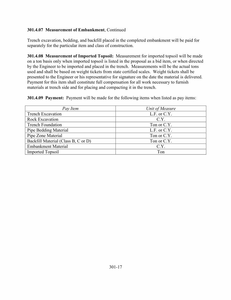
301.4.07 Measurement of Embankment, Continued
Trench excavation, bedding, and backfill placed in the completed embankment will be paid forseparately for the particular item and class of construction.
301.4.08 Measurement of Imported Topsoil: Measurement for imported topsoil will be madeon a ton basis only when imported topsoil is listed in the proposal as a bid item, or when directedby the Engineer to be imported and placed in the trench. Measurements will be the actual tonsused and shall be based on weight tickets from state certified scales. Weight tickets shall bepresented to the Engineer or his representative for signature on the date the material is delivered.Payment for this item shall constitute full compensation for all work necessary to furnishmaterials at trench side and for placing and compacting it in the trench.
301.4.09 Payment: Payment will be made for the following items when listed as pay items:
Pay Item Unit of MeasureTrench Excavation L.F. or C.Y.Rock Excavation C.Y.Trench Foundation Ton or C.Y.Pipe Bedding Material L.F. or C.Y.Pipe Zone Material Ton or C.Y.Backfill Material (Class B, C or D) Ton or C.Y.Embankment Material C.Y.Imported Topsoil Ton
301-17
302 TUNNELING, BORING AND JACKING
302.1.00 Description
302.1.01 Tunneling: Tunneling shall include all methods by which the undergroundpassageway is first excavated and by which the lining materials are brought in and placed.
302.1.02 Boring: Boring shall include all methods by which a conduit is pushed or pulled intoplace and by which the excavation method precludes the stationing of a worker within theconduit without stopping or removing the excavation equipment.
302.1.03 Jacking: Jacking shall include all methods by which a conduit is pushed or pulled intoplace with one or more workers inside to excavate and assist in keeping the conduit on therequired grade and alignment.
302.2.00 Materials
302.2.01 Pipe Bedding and Pipe Zone Material: If required, pipe bedding and pipe zonematerial shall conform to the requirements of Section 301.
302.2.02 Pipe: Pipe materials shall conform to the strength, class and type as specified.
302.2.03 Casing: Corrugated metal pipe may be used in cased open-cut trenches and for casingin tunneled, bored or jacked applications where specified or approved. Coupling bands withgalvanized or cadmium plated bolts and nuts shall be of material similar to the casing pipe andprovided by the same manufacturer. Corrugated metal pipe shall conform to the requirements ofSection 305.
The Contractor shall provide casing of a size to permit proper construction to the required linesand grades. Casing shall be the type shown in the table below.
The minimum gauge or wall thickness shall correspond to the size of casing selected from thefollowing table. However, the Contractor shall be responsible for selecting the gauge consistentwith his operation and the requirements of the permitter.
Diameter, Inches
AASHTO M36Corrugated Metal Pipe
US Standard GaugeSmooth Steel Pipe
Minimum ThicknessUp to 16 14 0.188” (3/16”)18 to 22 12 0.250” (1/4”)24 to 26 12 0.281” (9/32”)28 to 34 10 0.321” (5/16”)36 to 48 8 0.344” (11/32”)Over 48 8 Not Allowable
302.2.03 Casing, Continued
Jacked casings shall be equipped with nipples at the spring line and crown at 10-foot centerswhen pressure grouting is specified.
Optionally, the casing may be constructed of galvanized standard, offset tunnel liner plate withgauge and section modulus as approved. Nipples for pressure grouting, when specified, shall beinstalled at the spring line and crown at 10-foot centers.
302.2.04 Portland Cement Concrete: Portland cement concrete shall conform to therequirements of ASTM C94, Alternate 2, Class 2,500, with slump between two and four inches.
302.2.05 Grout: Grout for filling the annular space between the carrier pipe and casing pipeshall be proportioned one part Portland cement, five parts sand, seven parts pea gravel (byvolume), or as approved.
Grout for pressure grouting outside jacked carrier or casing pipe shall be one part Portlandcement and three parts sand (by volume), or as approved.
302.3.00 Construction
302.3.01 General: The work shall conform to all federal, state and local laws and regulationspertaining to tunneling and specifically to the standards set forth in the Kansas StatutesAnnotated or other applicable statutes.
302.3.02 Excavation: Excavation shall be classified and shall include whatever materials areencountered to the depths as shown or as required. The Contractor shall make an estimate of thekind and extent of the various materials which will be encountered in the excavation.
302.3.03 Tunneling Details Required: The Contractor shall submit details of the following tothe Engineer for approval before beginning the tunnel construction:
1. Tunnel shaft bracing and dimensions.2. Tunnel supports.3. Method of backpacking tunnel supports.4. Bracing to prevent lining from shifting and flotation.5. Backfill material or pressure concrete mix design, placement method, and
equipment.6. Poling plate dimensions and details (if employed).
302-3
302.3.04 Jacking and Boring Details Required: The Contractor shall submit details of thefollowing to the Engineer for approval before beginning the jacking or boring construction:
1. Jacking pit construction (including bracing and dimensions).2. Jacking pit bracing.3. Casing or conduit.4. Jacking head.5. Excavation method.6. Tee or wye installation.7. A substitute design for any part of the system that must be changed as a result of
the jacking or boring operation (manhole, headwall, etc.).8. Any structure that is required because of the particular method or procedure used
by the Contractor.9. If placed in a casing, bracing to prevent pipe shifting and flotation, backfilling
material, method and equipment.10. Backfill material or pressure grout mix, placement method and equipment.
302.3.05 Tunneling: Tunneling will be permitted only where shown, specified or approved.
Before the start of the work, the Contractor shall submit satisfactory evidence to the Engineerthat all insurance coverage requirements called for by the permitter have been complied with.All proposed construction methods and materials shall be approved by the Engineer andpermitter before the start of construction. Written approval to proceed from the permitter shallbe submitted to the Engineer before the start of construction.
The subgrade upon which the pipe is to be constructed shall be firm, thoroughly compacted, trueto grade and with at least six inches of approved bedding material under the pipe. If the materialin the bottom of the tunnel is ledge rock, excavation of the tunnel shall extend to a depth belowthe bottom of the pipe and a bedding of crushed aggregate or concrete shall be provided asspecified in Section 301. Excavation below grade, which is made inadvertently or withoutauthority, shall be restored to grade by backfilling with approved bedding material at no expenseto the Owner.
302.3.06 Alternate of Jacking or Boring: Jacking or boring may be allowed in lieu of theopen trench method or tunneling. However, written approval by the Engineer must first beobtained. The Engineer retains the right to reject either the jacking or boring method withoutrejecting the other.
Approval by the Engineer shall in no way relieve the Contractor of the responsibility for makinga satisfactory installation meeting the requirements set forth herein.
302-4
302.3.07 Jacking and Boring: The leading section of conduit shall be equipped with a jackinghead securely anchored thereto to prevent any wobble or alignment variation during the jackingor boring operation. For jacking, all excavation shall be carried out entirely within the jackinghead, and no excavation in advance thereof shall be permitted. For jacking, every effort shall bemade to avoid any loss of earth outside the jacking head. Excavated material shall be removedfrom the conduit as excavation progresses and no accumulation of such material within theconduit will be permitted.
All conduit shall be jacked or bored to the required line and grade. The method shall bemodified to correct any deviation therefrom. Should any deviation from line and grade beconsidered excessive in the Engineer’s judgement, that portion of the conduit shall be taken upand repositioned at no expense to the Owner.
Should appreciable loss of surrounding material occur during the jacking or boring operation, thevoids shall be backpacked or grouted promptly before the completion of the shift. Oncompletion, all voids shall be filled. Filling or backpacking shall be with grout or granularmaterial as approved.
It shall be understood that were any pipe is to be placed by jacking or boring in a tunnel or opentrench, the design of such pipe is based upon the superimposed loads and not upon the loadsresulting from the jacking or boring operations. Any increase in pipe strength to withstandjacking or boring loads shall be the responsibility of the Contractor.
302.3.08 Concrete Pipe and Box Sections: The Contractor shall protect the driving ends ofconcrete conduit against spalling and other damage. Intermediate joints shall be similarlyprotected by the installation of sufficient bearing shims to properly distribute the bearingstresses. Any section of conduit showing signs of failure shall be removed and replaced with anew section of conduit or with a cast-in-place section which, in the judgement of the Engineer, isadequate to carry the loads imposed upon it.
302.3.09 Smooth Steel Casing: Sections of smooth steel casing to be jacked or bored shall bejoined by welding the joints with a continuous weld for full circumference or by other approvedmeans. The Contractor shall provide joints which are capable of resisting the jacking or boringforces.
Pipe installed in a casing shall be braced to prevent shifting and flotation. Fill the void betweenthe casing with grout or other material as specified or approved.
If not shown or specified, the casing diameter shall be the option of the Contractor. TheContractor shall provide casing of such strength as to withstand the jacking or boring loads andof such diameter as to allow filling the void between the pipe and casing with the approvedmaterial.
302-5
302.3.10 Grouting Voids Outside Casing: When grouting is specified, the void space betweenthe tunnel and casing or liner plate shall be completely filled with approved grout. After thecasing or carrier pipe has been jacked or tunneled into position, grout will be pressured throughthe grout holes provided to fill all voids outside the pipe. Grouting will be started at the springline hole at one end and will be pumped in until it appears in the grout hole at the crown. Groutwill them be started through the opposite spring line hole until it appears at the hole in the crown.The hole at the crown will then be grouted until grout appears in the next set of holes along thepipe. The holes at the starting point shall then be plugged. This process shall be repeated withthe next set of holes and until the full length of jacked, bored or tunneled pipe has been grouted.
302.3.11 Cased or Tunneled Pipe: Where timber cradles are shown, the Contractor shallprovide a strapped timber cradle under the barrel of the pipe, join pipe and slide into casing.Pipe barrel shall bear continuously on cradles. Pipe installation shall conform to the applicablerequirements of hydrostatic or air testing and line and grade.
302.3.12 Placing Fill in Casing: Where shown, the Contractor shall completely fill the annularspace between the casing, tunnel liner or tunnel wall and the pipe with approved grout or sand toprevent pipe flotation. The Contractor shall accomplish grout or sand filling by pouring orpumping the grout from the two ends and such intermediate points as may be necessary.Grouting, once commenced at any one point, shall be completed without stopping usingapproved low pressure grouting equipment. The Contractor shall accomplish sand filling bysimilar methods using a gunite machine or other approved equipment. The Contractor shalldispose of excess excavated material in a manner satisfactory to the Engineer.
302.3.13 Railroad Crossings: All work to be performed by the Contractor in construction onthe railroad right-of-way shall be performed at such times and in such a manner as not tounnecessarily interfere with the movement of trains or traffic upon the track of the railwaycompany. The Contractor shall use all care and precaution in order to avoid accidents, damageor unnecessary delay or interference with the railway company’s trains or other property. Whenrequired by the railway company, the Contractor shall make arrangements for and pay the cost ofall flagpersons required by the railway company. Such costs shall be considered incidental toother work and which no additional payment will be made.
Railroad liability insurance shall be obtained by the Contractor as provided in the contractdocuments. The cost of such insurance shall be considered as incidental to other work and noadditional payment shall be made.
302.4.00 Measurement and Payment
302.4.01 Tunneling, Boring and Jacking: Measurement and payment for tunneled, bored andjacked conduit will be made on a linear foot basis. Payment will include compensation for allexcavation, shafts, portals, jacking pits, backfill, lubricant, grouting and appurtenances.
302-6
302.4.01 Tunneling, Boring and Jacking, Continued
Where casing is shown or is used at the option of the Contractor, the casing and the backfillbetween the pipe and the casing shall be included in the pay item for the pipe installed within thecasing and no separate payment will be made therefore.
302.4.02 Jacking and Boring: Measurement and payment for jacking and boring will be madeon a linear foot basis along the centerline of the conduit between portals. Jacking and boringextension beyond the limits shown shall be considered to be for the Contractor’s convenience,unless ordered in writing.
302.4.03 Jacking or Boring in Lieu of Tunneling: Where jacking or boring of a conduit isapproved in lieu of tunneling, measurement and payment will be made as though the tunnelingmethod has been used and will include the pay items for tunnel, for pipe in tunnel and for tunnelbackfill complete, as specified. No additional payment will be made for stabilization and pipebedding materials.
302.4.04 Tunneling, Jacking, or Boring in Lieu of Open Trench: Where tunneling, jackingor boring of a conduit is approved in lieu of open trench construction, measurement and paymentwill be made as though the open trench method had been used and will include the pay items forspecified excavation and backfill, the required conduit in place and for curbs, sidewalk,pavement and pavement base courses whether cut or not. Payment will be made for bedding andbackfill only if they are shown and specified.
302.4.05 Tees and Wyes: Measurement and payment for tees and wyes in a tunneled, jacked orbored conduit will be made at the unit bid price for tees and wyes installed in an open trench.
302-7
303 PIPE AND FITTINGS (SANITARY SEWER)
303.1.00 Description
303.2.00 Materials303.2.01 General303.2.02 Nonreinforced Concrete Pipe303.2.03 Reinforced Concrete Pipe303.2.04 Vitrified Clay Pipe303.2.05 Cast Iron Pipe303.2.06 Ductile Iron Pipe303.2.07 Polyvinyl Chloride Pipe (PVC)303.2.08 Jointing Materials303.2.08A Concrete Pipe303.2.08B Vitrified Clay Pipe303.2.08C Cast Iron and Ductile Iron Pipe303.2.08D Polyvinyl Chloride Pipe (PVC)303.2.09 Proof Tests303.2.09A General303.2.09B Concrete Pipe303.2.09C Clay Pipe303.2.09D Cast Iron Pipe and Ductile Iron Pipe303.2.09E PVC Pipe303.2.10 Fittings303.2.10A General303.2.10B Concrete Pipe303.2.10C Clay Pipe303.2.10D Cast Iron and Ductile Pipe303.2.10E PVC Pipe303.2.11 Mechanical Couplings303.2.12 Material Certification
303.3.00 Construction303.3.01 Line and Grade303.3.02 Pipe Distribution and Handling303.3.03 Laying Pipe on Curves303.3.04 Concrete Closure Collars303.3.05 Installation of Service Tees and Wyes303.3.06 Reinforced Concrete Pipe Core Tests303.3.07 Concrete Pipe Field Permeability Tests303.3.08 Concrete Pipe Plant Air Test303.3.09 Pipe Placing and Jointing303.3.09A Concrete and Clay Pipe303.3.09B Cast Iron and Ductile Iron Pipe303.3.09C PVC and ABS Pipe
303.3.09D Solvent Welded Joints303.3.10 Deflection at Joints303.3.11 Water and Equipment for Tests303.3.12 Cleaning Prior to Test303.3.13 Requirements Prior to Tests303.3.13A General303.3.13B Plugging of Tees, Wyes, Stubs and Service Connections303.3.13C Testing of Equipment and Procedure303.3.13D Time of Test303.3.14 Repairs303.3.15 Infiltration-Exfiltration Testing303.3.16 Air Testing303.3.16A General303.3.16B Safety Precautions303.3.16C Ground Water303.3.16D Methods303.3.16E Acceptance303.3.17 Deflection Test for PVC and ABS Pipe303.3.18 Television Inspection of Sanitary Sewers
303.4.00 Measurement and Payment303.4.01 Sewer Pipe303.4.02 Tee and Wye Fittings303.4.03 Concrete Tee and Wye Encasement303.4.04 Concrete Closure Collars303.4.05 Television Inspection
303-2
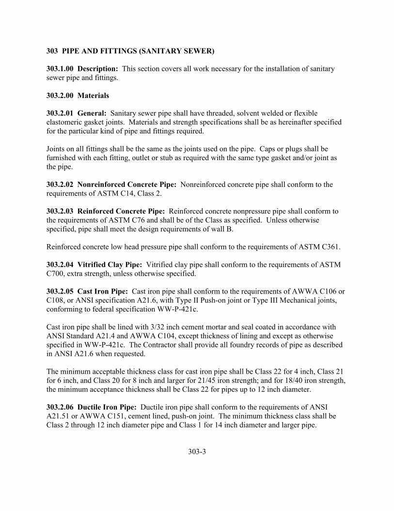
303 PIPE AND FITTINGS (SANITARY SEWER)
303.1.00 Description: This section covers all work necessary for the installation of sanitarysewer pipe and fittings.
303.2.00 Materials
303.2.01 General: Sanitary sewer pipe shall have threaded, solvent welded or flexibleelastomeric gasket joints. Materials and strength specifications shall be as hereinafter specifiedfor the particular kind of pipe and fittings required.
Joints on all fittings shall be the same as the joints used on the pipe. Caps or plugs shall befurnished with each fitting, outlet or stub as required with the same type gasket and/or joint asthe pipe.
303.2.02 Nonreinforced Concrete Pipe: Nonreinforced concrete pipe shall conform to therequirements of ASTM C14, Class 2.
303.2.03 Reinforced Concrete Pipe: Reinforced concrete nonpressure pipe shall conform tothe requirements of ASTM C76 and shall be of the Class as specified. Unless otherwisespecified, pipe shall meet the design requirements of wall B.
Reinforced concrete low head pressure pipe shall conform to the requirements of ASTM C361.
303.2.04 Vitrified Clay Pipe: Vitrified clay pipe shall conform to the requirements of ASTMC700, extra strength, unless otherwise specified.
303.2.05 Cast Iron Pipe: Cast iron pipe shall conform to the requirements of AWWA C106 orC108, or ANSI specification A21.6, with Type II Push-on joint or Type III Mechanical joints,conforming to federal specification WW-P-421c.
Cast iron pipe shall be lined with 3/32 inch cement mortar and seal coated in accordance withANSI Standard A21.4 and AWWA C104, except thickness of lining and except as otherwisespecified in WW-P-421c. The Contractor shall provide all foundry records of pipe as describedin ANSI A21.6 when requested.
The minimum acceptable thickness class for cast iron pipe shall be Class 22 for 4 inch, Class 21for 6 inch, and Class 20 for 8 inch and larger for 21/45 iron strength; and for 18/40 iron strength,the minimum acceptance thickness shall be Class 22 for pipes up to 12 inch diameter.
303.2.06 Ductile Iron Pipe: Ductile iron pipe shall conform to the requirements of ANSIA21.51 or AWWA C151, cement lined, push-on joint. The minimum thickness class shall beClass 2 through 12 inch diameter pipe and Class 1 for 14 inch diameter and larger pipe.
303-3

303.2.07 Polyvinyl Chloride Pipe (PVC): Type PSM polyvinyl chloride pipe and fittings shallconform to ASTM D3034.
Type PSP polyvinyl chloride pipe and fittings shall conform to ASTM D3033.
Polyvinyl chloride pipe Schedule 40 and 80 shall conform to ASTM D1785, and fittings shallconform to ASTM D2466 or D2467.
303.2.08 Jointing Materials
303.2.08A Concrete Pipe: Gaskets shall conform to the requirements of ASTM C443.
303.2.08B Vitrified Clay Pipe: Gaskets shall conform to the requirements of ASTM C425.
303.2.08C Cast Iron and Ductile Iron Pipe: Push-on joints shall conform to the requirementsof federal specification WW-P-421c.
Mechanical joints shall conform to the requirements of ANSI A21.11.
303.2.08D Polyvinyl Chloride Pipe (PVC): Gaskets shall conform to the requirements ofASTM F477.
Threaded connections shall conform to the requirements of ASTM D2464 for Schedule 80 pipe.
Solvent welded joints shall conform to the applicable requirements of ASTM D2466 and ASTMD2467.
303.2.09 Proof Tests
303.2.09A General: The intent of this requirement is to prequalify a joint system, componentsof which meet the joint requirements, as to the water tightness capability of that joint system.These tests do not replace the acceptance testing required in Section 303.3.13 through 303.3.18.This proof test shall be understood to apply to sanitary sewers which are to be tested for watertightness prior to acceptance. Material and test equipment for proof testing shall be provided bythe manufacturer. When approved, internal hydrostatic pressure may be applied by a suitablejoint tested. In general, each pipe material and joint assembly shall be subject to the followingthree proof tests at the discretion of the Engineer.
1. Pipe in Straight Alignment. No less than three nor more than five pipes selectedfrom stock by the Engineer shall be assembled according to the manufacture’sinstallation instructions with the ends suitably plugged and restrained against
303-4
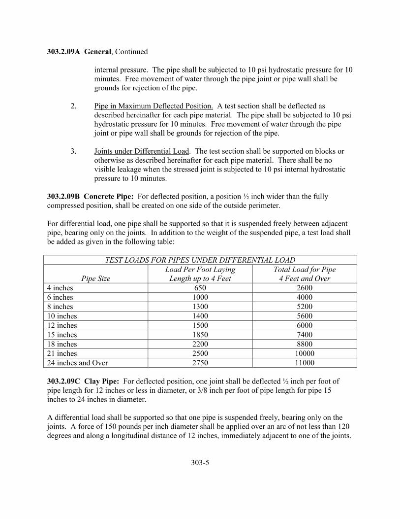
303.2.09A General, Continued
internal pressure. The pipe shall be subjected to 10 psi hydrostatic pressure for 10minutes. Free movement of water through the pipe joint or pipe wall shall begrounds for rejection of the pipe.
2. Pipe in Maximum Deflected Position. A test section shall be deflected asdescribed hereinafter for each pipe material. The pipe shall be subjected to 10 psihydrostatic pressure for 10 minutes. Free movement of water through the pipejoint or pipe wall shall be grounds for rejection of the pipe.
3. Joints under Differential Load. The test section shall be supported on blocks orotherwise as described hereinafter for each pipe material. There shall be novisible leakage when the stressed joint is subjected to 10 psi internal hydrostaticpressure to 10 minutes.
303.2.09B Concrete Pipe: For deflected position, a position ½ inch wider than the fullycompressed position, shall be created on one side of the outside perimeter.
For differential load, one pipe shall be supported so that it is suspended freely between adjacentpipe, bearing only on the joints. In addition to the weight of the suspended pipe, a test load shallbe added as given in the following table:
TEST LOADS FOR PIPES UNDER DIFFERENTIAL LOAD
Pipe SizeLoad Per Foot Laying
Length up to 4 FeetTotal Load for Pipe
4 Feet and Over4 inches 650 26006 inches 1000 40008 inches 1300 520010 inches 1400 560012 inches 1500 600015 inches 1850 740018 inches 2200 880021 inches 2500 1000024 inches and Over 2750 11000
303.2.09C Clay Pipe: For deflected position, one joint shall be deflected ½ inch per foot ofpipe length for 12 inches or less in diameter, or 3/8 inch per foot of pipe length for pipe 15inches to 24 inches in diameter.
A differential load shall be supported so that one pipe is suspended freely, bearing only on thejoints. A force of 150 pounds per inch diameter shall be applied over an arc of not less than 120degrees and along a longitudinal distance of 12 inches, immediately adjacent to one of the joints.
303-5
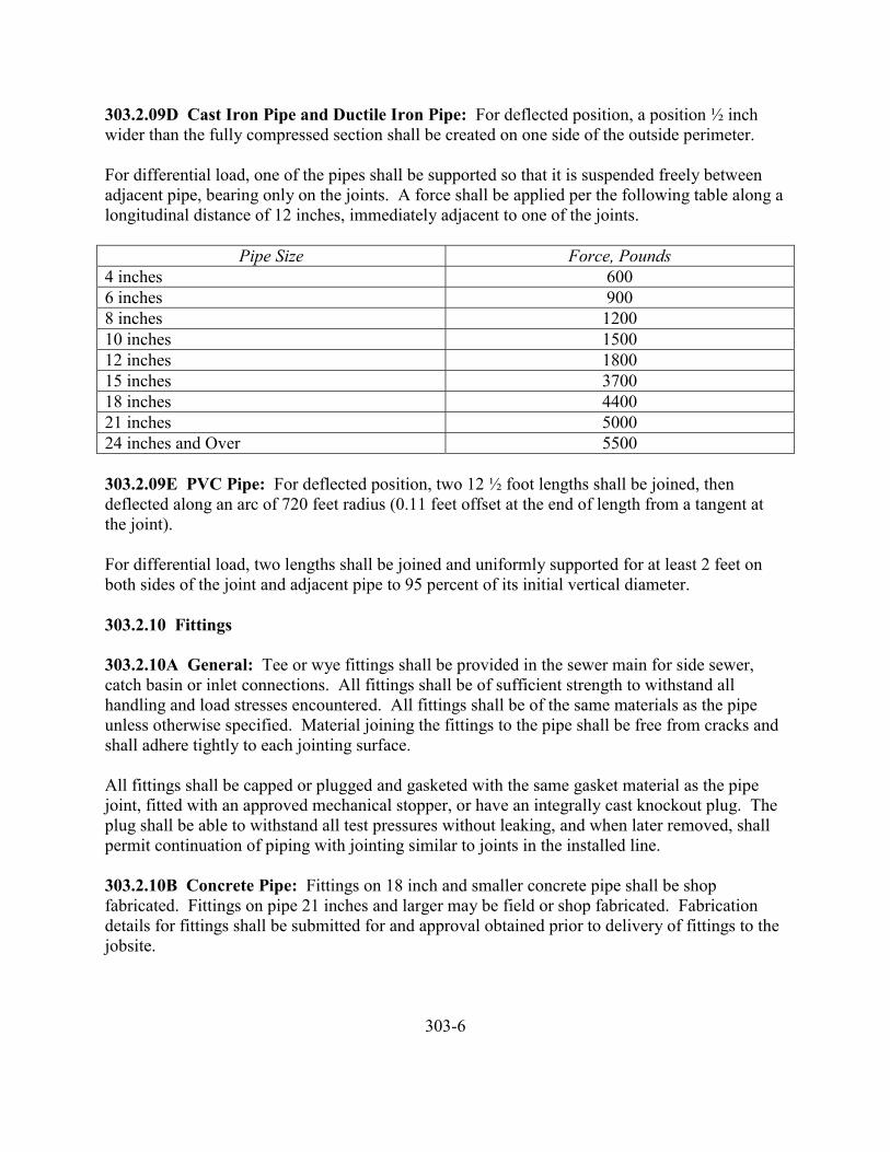
303.2.09D Cast Iron Pipe and Ductile Iron Pipe: For deflected position, a position ½ inchwider than the fully compressed section shall be created on one side of the outside perimeter.
For differential load, one of the pipes shall be supported so that it is suspended freely betweenadjacent pipe, bearing only on the joints. A force shall be applied per the following table along alongitudinal distance of 12 inches, immediately adjacent to one of the joints.
Pipe Size Force, Pounds4 inches 6006 inches 9008 inches 120010 inches 150012 inches 180015 inches 370018 inches 440021 inches 500024 inches and Over 5500
303.2.09E PVC Pipe: For deflected position, two 12 ½ foot lengths shall be joined, thendeflected along an arc of 720 feet radius (0.11 feet offset at the end of length from a tangent atthe joint).
For differential load, two lengths shall be joined and uniformly supported for at least 2 feet onboth sides of the joint and adjacent pipe to 95 percent of its initial vertical diameter.
303.2.10 Fittings
303.2.10A General: Tee or wye fittings shall be provided in the sewer main for side sewer,catch basin or inlet connections. All fittings shall be of sufficient strength to withstand allhandling and load stresses encountered. All fittings shall be of the same materials as the pipeunless otherwise specified. Material joining the fittings to the pipe shall be free from cracks andshall adhere tightly to each jointing surface.
All fittings shall be capped or plugged and gasketed with the same gasket material as the pipejoint, fitted with an approved mechanical stopper, or have an integrally cast knockout plug. Theplug shall be able to withstand all test pressures without leaking, and when later removed, shallpermit continuation of piping with jointing similar to joints in the installed line.
303.2.10B Concrete Pipe: Fittings on 18 inch and smaller concrete pipe shall be shopfabricated. Fittings on pipe 21 inches and larger may be field or shop fabricated. Fabricationdetails for fittings shall be submitted for and approval obtained prior to delivery of fittings to thejobsite.
303-6
303.2.10B Concrete Pipe, Continued
Fittings fabricated by inserting a stub into a hole cut in the pipe shall be grouted with anonshrinking grout. Surfaces to receive grout shall be coated with an epoxy bonding agent priorto grouting. Fitting stubs shall not protrude inside the sewer pipe.
303.2.10C Clay Pipe: Fittings shall conform to the requirements of ASTM C425.
303.2.10D Cast Iron and Ductile Pipe: Fittings shall be mechanical or push-on of the class asspecified. Mechanical joint cast iron fittings shall conform to AWWA C110 and shall be of aclass at least equal to that of the adjacent pipe. Push-on joint fittings shall be gray iron with bodythickness and radii of curvature conforming to ANSI A21.10.
303.2.10E PVC Pipe: Fittings shall conform to the applicable portions of the followingspecifications: ASTM D3033 and ASTM D3034. Fitting joint shall be the same as the pipejoints.
303.2.11 Mechanical Couplings: Mechanical couplings shall be wrought steel or cast iron.The diameter of the pipe shall be used to connect the pipeline to existing steel pipelines. Caststyle mechanical couplings shall be used in the pipeline or to connect the pipeline to existing castiron pipelines.
303.2.12 Material Certification: The manufacturer or fabricator shall furnish appropriatecertification, based on manufacturer’s routine quality control tests, that the materials in the pipemeet the requirements specified therein.
303.3.00 Construction
303.3.01 Line and Grade: Survey line and grade control hubs will be provided by the Engineerin a manner consistent with accepted practices.
Variance from established line and grade shall not be greater than one thirty-second (1/32) of aninch per inch of pipe diameter and not to exceed one-half (1/2) inch, provided that such variationdoes not result in a level or reverse sloping invert; provided also, that variation in the invertelevation between adjoining ends of pipe, due to nonconcentricity of joining surface and pipeinterior surfaces, does not exceed one sixty-fourth (1/64) per inch of pipe in diameter, or one-half(1/2) inch maximum.
The Contractor shall established line and grade for pipe by the use of lasers or by transferring thecut from the offset stakes to the trench at whatever intervals necessary to maintain the line andgrade.
303-7
303.3.01 Line and Grade, Continued
The Contractor shall constantly check line and grade in the event they do not meet the limitsdescribed, the work shall be immediately stopped, the Engineer notified, and the cause remediedbefore proceeding with the work.
303.3.02 Pipe Distribution and Handling: The Contractor shall not distribute material on thejob faster than it can be used to good advantage. The Contractor shall unload pipe only byapproved means. Pipe will not be unloaded by dropping to the ground. More than one week’ssupply of material in advance of laying will not be distributed unless approved.
The Contractor shall inspect all pipe and fittings prior to lowering into trench to ensure nocracked, broken, or otherwise defective materials are used. The Contractor shall clean ends ofpipe thoroughly and remove foreign matter and dirt from inside of pipe and keep it clean duringlaying and joining.
The Contractor shall use approved implements, tools, and facilities for the safe and properprotection of the work. The Contractor shall lower pipe into trench in such a manner as to avoidany physical damage to the pipe. The Contractor shall remove all damaged pipe from the jobsite.Pipe will not be dropped or dumped into trenches.
303.3.03 Laying Pipe on Curves: The Contractor shall lay pipe on horizontal or vertical curvesin accordance with the manufacturer’s recommendations.
303.3.04 Concrete Closure Collars: The Contractor shall use concrete collars only whenapproved, and then only to make connections between dissimilar pipe or where standard rubbergasketed joints are impractical. The Contractor shall construct in conformance with the detailsshown. The Contractor shall wash pipe to remove all loose material and soil from the surface onwhich the concrete will be placed.
The Contractor shall moisten nonmetallic pipe thoroughly prior to pouring the collars. TheContractor shall wrap and securely fasten a light gauge of sheet metal or building felt around thepipe to insure that no concrete shall enter the line. The entire collar shall be constructed in oneconcrete pour. Collars will not be poured in water. After the collars are poured and have takentheir initial set, the Contractor shall cure by an approved method.
303.3.05 Installation of Service Tees and Wyes: The Contractor shall provide a compactedapproved granular base of pipe bedding material under all tees and wyes and branched fittings,extending to the springline of the fittings. The Contractor shall place bases on undisturbed nativematerial or compacted foundation stabilization material.
303-8
303.3.05 Installation of Service Tees and Wyes, Continued
Maximum deflection permissible with any one fitting shall not exceed 45 degrees and shall beaccomplished with long radius curves or bends, except when approved.
The Contractor shall connect service lines to manholes only when directed. The Contractor shallmake the connection so that the standard pipe joint is located not more than 1.5 feet from thestructure.
The Contractor shall provide ends of all service lines and fittings with approved watertight plugs,caps, or stoppers, suitably braced to prevent blowoff during internal hydrostatic or air testing.Such plugs or caps shall be removable and their removal shall provide a socket suitable formaking a flexible joint lateral connection or extension.
303.3.06 Reinforced Concrete Pipe Core Tests: Acceptance for reinforced concrete pipe 60inches in diameter and smaller shall conform to paragraph 4.1.1 of ASTM C76. Acceptance ofpipe larger than 60 inches may, at the option of the Owner, conform to paragraph 4.1.2 of ASTMC76. Under this basis of acceptance, at least three 3 ½ inch minimum diameter core samplesshall be taken from each pipe section tested. Pipe must have a 14 day or greater strength beforecore drilling. Cores will be taken and tested in conformance with ASTM C497. When coresmeet the test requirements, the core holes shall be plugged and sealed in a manner such that thepipe section will meet all test requirements. Pipe sections so sealed shall be consideredsatisfactory for use.
Specimens for tests will be selected by the Engineer in accordance with the applicable ASTMspecifications from pipe in the pipe manufacturer’s yard or at the point of delivery to the job.The provisions of the applicable ASTM standards shall apply, except as modified herein. Thetests for joint performed under ASTM C443 shall also be used as a basis for rejection of pipe.
303.3.07 Concrete Pipe Field Permeability Tests: In addition to the tests specified in theapplicable ASTM specifications, the Owner will require permeability tests on a maximum of 5percent of each lot, class or size of pipe in conformance with ASTM C497 on pipe 24 inchdiameter and smaller.
The Contractor shall provide all the necessary labor, equipment, water and materials at the sitewhere the pipe is to be unloaded for performing field permeability tests. Damp spots on theoutside of the wall which appear during these tests shall not be cause of rejection unless actualmovement of water through the pipe wall can be detected. Acceptance or rejection shall be inaccordance with item 4.4 of ASTM C14, except that if over 20 percent of the group representedby the samples tested fails to pass, then the entire size, class and lot represented by the samplestested shall be rejected.
At the option of the pipe supplier, the individual field permeability tests as specified herein maybe performed at the point of manufacture if the testing equipment, scheduling of tests andmethod of recording and documenting the test results are approved by the Engineer.
303.3.08 Concrete Pipe Plant Air Test: At the option of the Engineer, each length of concretepipe 12 inch diameter and smaller shall be given an individual air test at the point ofmanufacture. Test equipment shall be approved by the Engineer and the test pressure shall be aminimum of 10 psi. Each length shall show no appreciable loss of air after 5 second.
When individual air testing is performed, no field or shop permeability tests will be required.
303.3.09 Pipe Placing and Jointing: Trench excavation, bedding and backfill shall be inaccordance with Section 301, unless otherwise specified.
303.3.09A Concrete and Clay Pipe: Pipe laying shall proceed upgrade with spigot ends in thedirection of flow. After a section of pipe has been lowered into the prepared trench, the end ofthe pipe to be joined will be cleaned as will the inside of the joint and the rubber ring,immediately before joining the pipe. The joint will be assembled in accordance with therecommendations of the manufacturer of the type of joint used. All special tools andappurtenances required for the jointing assembly will be provided by the Contractor.
After the joint has been made, pipe will be checked for alignment and grade. The trench bottomshall form a continuous and uniform bearing and support for the pipe at every point betweenjoints. Sufficient pressure will be applied in making the joint to assure that the joint is “home”,as defined in the standard installation instruction provided by the pipe manufacturer. Sufficientbedding material will be placed to secure the pipe from movement before the next joint isinstalled to assure proper alignment and joint make-up.
Pipe 21 inches and smaller shall be laid so the inside joint space does not exceed 3/8 inch inwidth. If interior joints on 24 inch and larger pipe are greater than 3/8 inch, they shall be filledand sealed with premixed mortar conforming to ASTM C387 and troweled smooth on the insidesurface.
When the pipe is laid within a movable trench shield, all necessary precautions will be taken toprevent pipe joints from pulling apart when the shield is moved ahead.
Elliptical reinforced pipe shall be laid so that the top or bottom marks are not more than 5degrees from a vertical plane.
The Contractor shall take the necessary precautions required to prevent excavated or otherforeign material from getting into the pipe during the laying operation. At all times, when layingoperations are not in progress, at the close of the day’s work, or whenever the workers are absentfrom the job, the open end of the last laid section of pipe will be closed and blocked to prevententry of foreign material or creep of the gasketed joints.
The Contractor shall plug or close off pipes which are stubbed off for manhole construction orfor connection by others, with temporary plugs as specified in Subsection 306.2.11.
303-10
303.3.09A Concrete and Clay Pipe, Continued
The Contractor shall take all precautions necessary to prevent the uplift or floating of the lineprior to the completion of the backfilling operation.
Where nonreinforced pipe is connected to manholes or concrete structures, the connection willbe constructed so that the standard pipe joint is located not more than 1.5 feet from the outsideedge of the structure.
When cutting and/or machining of the pipe is necessary, the Contractor shall use only the toolsand methods recommended by the pipe manufacturer.
303.3.09B Cast Iron and Ductile Iron Pipe: The Contractor shall conform to the applicableprocedures described hereinbefore for concrete, and clay pipe. Foreign material will not beallowed to enter the pipe while it is being placed in the trench. After the first length of pipe isinstalled in the trench, pipe will be secured in place with approved bedding material tampedunder and along sides to prevent movement. The Contractor shall keep ends clear of backfill.After each section is jointed, bedding or pipe zone material will be placed as specified to preventmovement.
303.3.09C PVC and ABS Pipe: The Contractor shall join the pipe in conformance with themanufacturer’s recommendations. Joints or pipe will not be deflected more than recommendedby the manufacturer.
The Contractor shall, when necessary, cut the pipe in a neat and professional manner withoutdamaging the pipe. The Contractor shall cut the pipe so as to leave a smooth end at right anglesto the axis of the pipe. The Contractor shall dress the cut end in conformance with the pipemanufacturer’s recommendations.
303.3.09D Solvent Welded Joints: Solvent welded joints shall be made in accordance withmanufacture’s instruction, generally as follows:
1. Wipe the bell or inside of sleeve coupling and the spigot end clean.2. Apply primer liberally to the inside of the sleeve coupling and the outside of the
spigot end.3. Immediately apply the cement over the primer to the inside of the sleeve coupling
and the outside of the spigot end.4. Immediately insert the spigot end into the sleeve coupling with a slight
circumferential twist.
303-11
303.3.10 Deflection at Joints: When deflecting the pipe from a straight line, either in thevertical or horizontal plane, or when long radius curves are shown, the amount of deflectionallowed shall not exceed that recommended by the pipe manufacturer.
303.3.11 Water and Equipment for Test: The Contractor shall make all arrangements forfurnishing water for testing purposes. The Contractor shall perform the tests and provide allhoses, tank trucks, plugs and other necessary equipment to complete the tests.
303.3.12 Cleaning Prior to Test: Prior to the internal pressure testing and inspection of thesystem by the Engineer, the Contractor shall flush and clean all parts of the system. TheContractor shall remove all accumulated construction debris, rocks, gravel, sand, silt and otherforeign material from the system at or near the closest downstream manhole. If necessary, theContractor shall use high pressure water jet, ball flushing, or equipment approved by theEngineer.
Upon the Engineer’s inspection of the system, if any foreign matter is still present, the sectionsand portions of the system will be re-flushed and cleaned as required.
303.3.13 Requirements Prior to Tests:
303.3.13A General: All gravity systems and appurtenances shall successfully pass ahydrostatic or air test prior to acceptance and shall be free of visible leakage, using either methodof testing. Information regarding air testing may be obtained from the Engineer. Manholes shallbe tested as specified in Subsection 306.3.01C.
On pipe 54 inch in diameter and larger, individual joints may be tested by an approved jointtesting device. All details of testing procedure shall be subject to approval of the Engineer.
303.3.13B Plugging of Tees, Wyes, Stubs and Service Connections: The Contractor shallplug all wyes, tees, stubs and service connections with gasketed caps or plugs securely fastenedor blocked to withstand the internal test pressure. Such plugs or caps shall be removable, andtheir removal shall provide a socket suitable for making a flexible jointed lateral connection orextension.
303.3.13C Testing Equipment and Procedure: The Contractor shall furnish all necessarytesting equipment and perform the tests in a manner satisfactory to the Engineer. Gauges shallbe calibrated and certified at the direction of the Engineer. The certification shall be availablewith the gauge.
303.3.13D Time of Test: The Contractor shall test the system during the normal work day,scheduling the plugging, capping and other preparatory work so as to conduct the test duringdaylight hours.
303-12
303.3.14 Repairs: The Contractor shall repair or replace, in a manner approved by theEngineer, any portion of the system not passing the air or hydrostatic test.
Infiltration of ground water in an amount greater than specified, following a successfulhydrostatic or air test, shall be considered as evidence that the original test was in error or thatfailure of the system has occurred. The Contractor shall correct such failures occurring withinthe warranty period in a manner approved by the Engineer and at no expense to the Owner.
303.3.15 Infiltration-Exfiltration Testing: Hydrostatic or air pressure tests shall be conductedon sewers before acceptance. For sewers with a diameter less than 24 inches, the infiltration-exfiltration shall not exceed 250 gallons per day per inch of nominal pipe diameter per mile ofsewer line for any section of the system. For sewers with a diameter 24 inches or greater,infiltration-exfiltration shall not exceed 6000 gallons per day per mile of pipe.
303.3.15A For hydrostatic tests where sewers are laid above the groundwater table, exfiltrationtests shall be conducted. Where sewers are laid within the groundwater table, infiltration testingshall be conducted. Exfiltration tests must be conducted with a minimum of four feet of staticwater head above the invert of the sewer at the upstream manhole. Manholes shall be testedusing internal or intermal hydrostatic pressure. A minimum hydrostatic head of 4 feet is requiredfor the test. Infiltration-exfiltration shall be less than 1.14 gallons per day per vertical foot ofmanhole (equals 6,000 gallons per day per vertical mile).
303.3.15B Low pressure air testing may be conducted on any pipe of 8 inch to 12 inch diameterpipe. Testing methods and air leakage rates shall conform with ASTM C828-76T or the latestrevision thereof as a minimum.
303.3.16 Air Testing
303.3.16A General: The Contractor has the option after completion of the system, includingservice connections, and backfilling and compaction, of conducting a low pressure air test in lieuof the hydrostatic test required herein. The Owner may require testing of manhole sections asthey are completed in order to expedite the acceptance of the system and allow connectionsbefore the entire system is complete.
The test shall be conducted at no expense to the Owner. The Contractor shall provide allequipment and personnel for the test.
The method, equipment and personnel shall be subject to the approval of the Engineer. TheEngineer may, at any time, require a calibration check of the instrumentation used. The pressuregauge used shall have minimum divisions of 0.10 psi and have an accuracy of 0.0625 psi (oneounce per square inch). All air used shall pass through a single control panel.
303-13
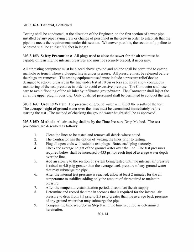
303.3.16A General, Continued
Testing shall be conducted, at the direction of the Engineer, on the first section of sewer pipeinstalled by any pipe laying crew or change of personnel in the crew in order to establish that thepipeline meets the requirements under this section. Whenever possible, the section of pipeline tobe tested shall be at least 300 feet in length.
303.3.16B Safety Precautions: All plugs used to close the sewer for the air test must becapable of resisting the internal pressures and must be securely braced, if necessary.
All air testing equipment must be placed above ground and no one shall be permitted to enter amanhole or trench where a plugged line is under pressure. All pressure must be released beforethe plugs are removed. The testing equipment used must include a pressure relief devicedesigned to relieve pressure in the line under test at 10 psi or less and must allow continuousmonitoring of the test pressures in order to avoid excessive pressure. The Contractor shall usecare to avoid flooding of the air inlet by infiltrated groundwater. The Contractor shall inject theair at the upper plug, if possible. Only qualified personnel shall be permitted to conduct the test.
303.3.16C Ground Water: The presence of ground water will affect the results of the test.The average height of ground water over the lines must be determined immediately beforestarting the test. The method of checking the ground water height shall be as approved.
303.3.16D Method: All air testing shall be by the Time Pressure Drop Method. The testprocedures are described as follows:
1. Clean the lines to be tested and remove all debris where noted.2. The Contractor has the option of wetting the lines prior to testing.3. Plug all open ends with suitable test plugs. Brace each plug securely.4. Check the average height of the ground water over the line. The test pressures
required below shall be increased 0.433 psi for each foot of average water depthover the line.
5. Add air slowly to the section of system being tested until the internal air pressureis raised to 4.0 psig greater than the average back pressure of any ground waterthat may submerge the pipe.
6. After the internal test pressure is reached, allow at least 2 minutes for the airtemperature to stabilize adding only the amount of air required to maintainpressure.
7. After the temperature stabilization period, disconnect the air supply.8. Determine and record the time in seconds that is required for the internal air
pressure to drop from 3.5 psig to 2.5 psig greater than the average back pressureof any ground water that may submerge the pipe.
9. Compare the time recorded in Step 8 with the time required as determinedhereinafter.
303-14
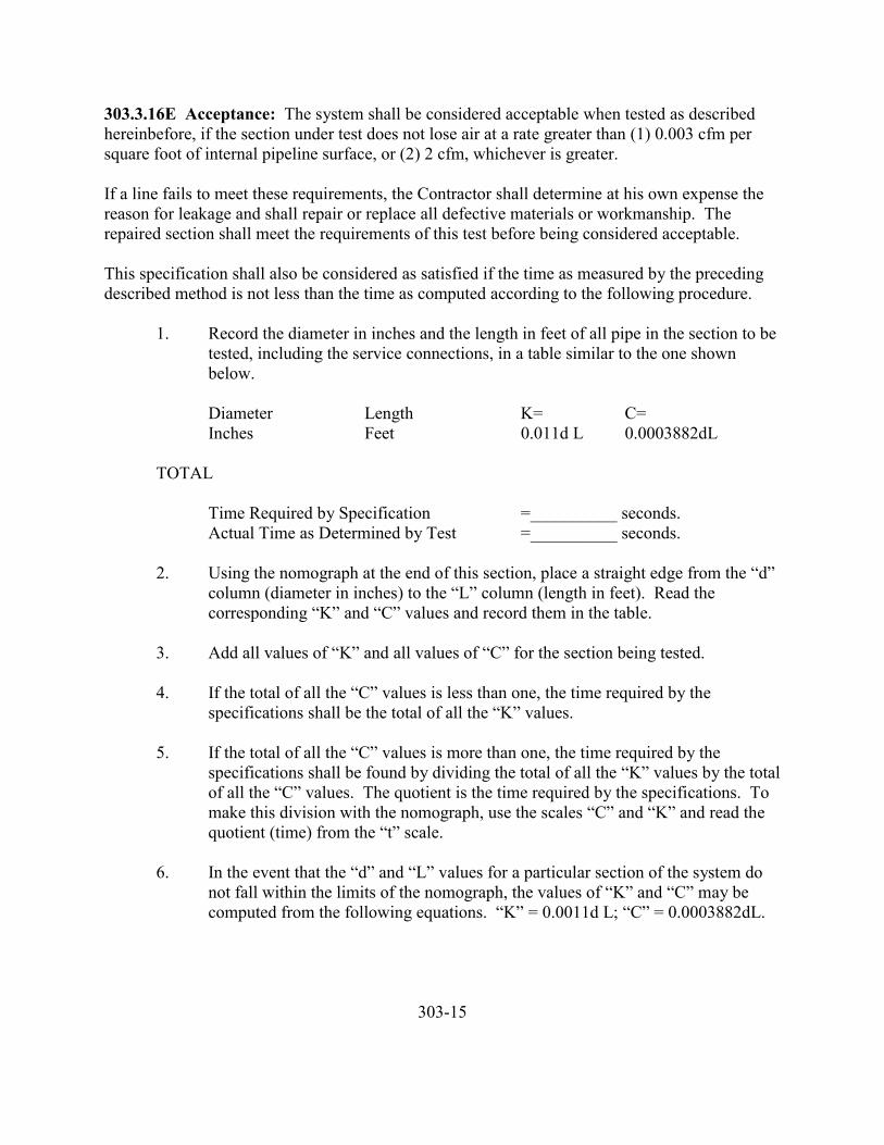
303.3.16E Acceptance: The system shall be considered acceptable when tested as describedhereinbefore, if the section under test does not lose air at a rate greater than (1) 0.003 cfm persquare foot of internal pipeline surface, or (2) 2 cfm, whichever is greater.
If a line fails to meet these requirements, the Contractor shall determine at his own expense thereason for leakage and shall repair or replace all defective materials or workmanship. Therepaired section shall meet the requirements of this test before being considered acceptable.
This specification shall also be considered as satisfied if the time as measured by the precedingdescribed method is not less than the time as computed according to the following procedure.
1. Record the diameter in inches and the length in feet of all pipe in the section to betested, including the service connections, in a table similar to the one shownbelow.
Diameter Length K= C=Inches Feet 0.011d L 0.0003882dL
TOTAL
Time Required by Specification =__________ seconds.Actual Time as Determined by Test =__________ seconds.
2. Using the nomograph at the end of this section, place a straight edge from the “d”column (diameter in inches) to the “L” column (length in feet). Read thecorresponding “K” and “C” values and record them in the table.
3. Add all values of “K” and all values of “C” for the section being tested.
4. If the total of all the “C” values is less than one, the time required by thespecifications shall be the total of all the “K” values.
5. If the total of all the “C” values is more than one, the time required by thespecifications shall be found by dividing the total of all the “K” values by the totalof all the “C” values. The quotient is the time required by the specifications. Tomake this division with the nomograph, use the scales “C” and “K” and read thequotient (time) from the “t” scale.
6. In the event that the “d” and “L” values for a particular section of the system donot fall within the limits of the nomograph, the values of “K” and “C” may becomputed from the following equations. “K” = 0.0011d L; “C” = 0.0003882dL.
303-15
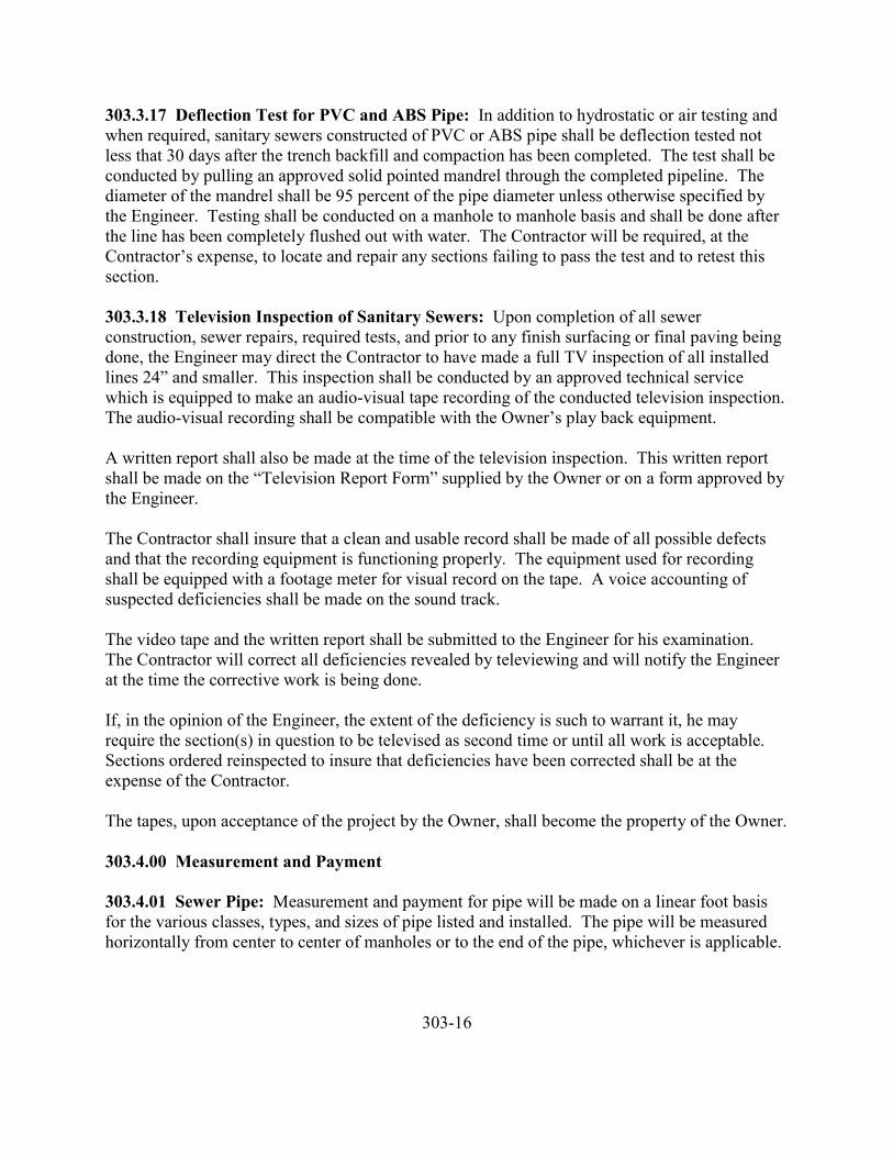
303.3.17 Deflection Test for PVC and ABS Pipe: In addition to hydrostatic or air testing andwhen required, sanitary sewers constructed of PVC or ABS pipe shall be deflection tested notless that 30 days after the trench backfill and compaction has been completed. The test shall beconducted by pulling an approved solid pointed mandrel through the completed pipeline. Thediameter of the mandrel shall be 95 percent of the pipe diameter unless otherwise specified bythe Engineer. Testing shall be conducted on a manhole to manhole basis and shall be done afterthe line has been completely flushed out with water. The Contractor will be required, at theContractor’s expense, to locate and repair any sections failing to pass the test and to retest thissection.
303.3.18 Television Inspection of Sanitary Sewers: Upon completion of all sewerconstruction, sewer repairs, required tests, and prior to any finish surfacing or final paving beingdone, the Engineer may direct the Contractor to have made a full TV inspection of all installedlines 24” and smaller. This inspection shall be conducted by an approved technical servicewhich is equipped to make an audio-visual tape recording of the conducted television inspection.The audio-visual recording shall be compatible with the Owner’s play back equipment.
A written report shall also be made at the time of the television inspection. This written reportshall be made on the “Television Report Form” supplied by the Owner or on a form approved bythe Engineer.
The Contractor shall insure that a clean and usable record shall be made of all possible defectsand that the recording equipment is functioning properly. The equipment used for recordingshall be equipped with a footage meter for visual record on the tape. A voice accounting ofsuspected deficiencies shall be made on the sound track.
The video tape and the written report shall be submitted to the Engineer for his examination.The Contractor will correct all deficiencies revealed by televiewing and will notify the Engineerat the time the corrective work is being done.
If, in the opinion of the Engineer, the extent of the deficiency is such to warrant it, he mayrequire the section(s) in question to be televised as second time or until all work is acceptable.Sections ordered reinspected to insure that deficiencies have been corrected shall be at theexpense of the Contractor.
The tapes, upon acceptance of the project by the Owner, shall become the property of the Owner.
303.4.00 Measurement and Payment
303.4.01 Sewer Pipe: Measurement and payment for pipe will be made on a linear foot basisfor the various classes, types, and sizes of pipe listed and installed. The pipe will be measuredhorizontally from center to center of manholes or to the end of the pipe, whichever is applicable.
303-16
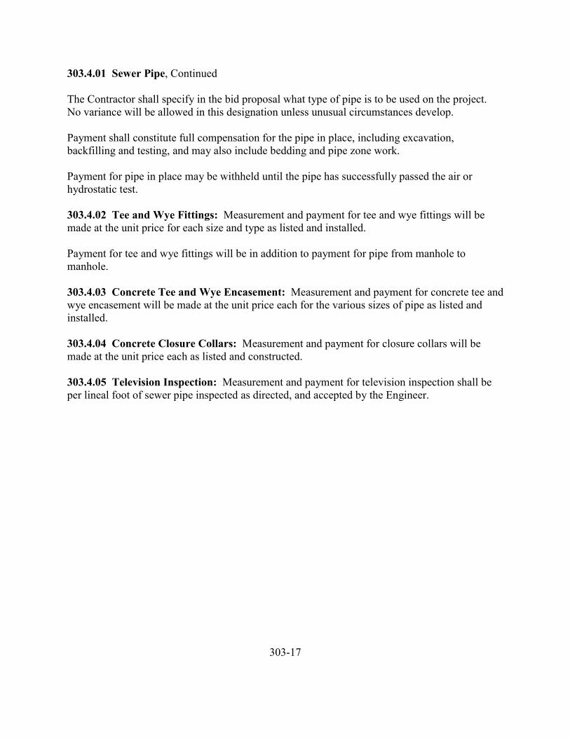
303.4.01 Sewer Pipe, Continued
The Contractor shall specify in the bid proposal what type of pipe is to be used on the project.No variance will be allowed in this designation unless unusual circumstances develop.
Payment shall constitute full compensation for the pipe in place, including excavation,backfilling and testing, and may also include bedding and pipe zone work.
Payment for pipe in place may be withheld until the pipe has successfully passed the air orhydrostatic test.
303.4.02 Tee and Wye Fittings: Measurement and payment for tee and wye fittings will bemade at the unit price for each size and type as listed and installed.
Payment for tee and wye fittings will be in addition to payment for pipe from manhole tomanhole.
303.4.03 Concrete Tee and Wye Encasement: Measurement and payment for concrete tee andwye encasement will be made at the unit price each for the various sizes of pipe as listed andinstalled.
303.4.04 Concrete Closure Collars: Measurement and payment for closure collars will bemade at the unit price each as listed and constructed.
303.4.05 Television Inspection: Measurement and payment for television inspection shall beper lineal foot of sewer pipe inspected as directed, and accepted by the Engineer.
303-17
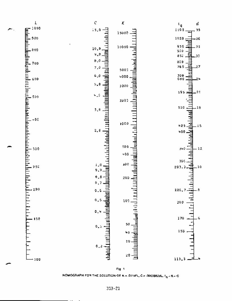
304 SERVICE LINE SEWERS
304.1.00 Description
304.2.00 Materials304.2.01 Excavation and Backfill304.2.02 Rock Excavation304.2.03 Pipe and Fittings for Service Lines and Cleanouts304.2.03A General304.2.03B Asbestos Cement Pipe304.2.03C Vitrified Clay Pipe304.2.03D Concrete Pipe304.2.03E Cast Iron Pipe304.2.03F Ductile Iron Pipe304.2.03G Acrylonitrile Butadiene Styrene Pipe (ABS)304.2.03H Polyvinyl Chloride Pipe (PVC)304.2.04 Pipe Joints304.2.05 Imported Pipe Zone and Pipe Bedding Material304.2.06 Service Connection Markers
304.3.00 Construction304.3.01 General304.3.02 Imported Pipe Zone and Pipe Bedding304.3.03 Trench Backfill304.3.04 Disposal of Excess Material304.3.05 Dewatering304.3.06 Installation of Pipe and Fittings304.3.07 Deep Connections304.3.08 Culverts304.3.09 Existing Service Lines304.3.10 Service Connection Markers304.3.11 Testing
304.4.00 Measurement and Payment304.4.01 Service Lines304.4.02 Deep Connections
304-1
304 SERVICE LINE SEWERS
304.1.00 Description: This section covers the work necessary for the installation of sewerservice lines, connections and cleanouts. In general, service lines will extend from the sewermain to the street or alley right-of-way line.
304.2.00 Materials
304.2.01 Excavation and Backfill: The Contractor shall conform to the applicablerequirements of Section 301.
304.2.02 Rock Excavation: The Contractor shall conform to the requirements of Section 301.
304.2.03 Pipe and Fittings for Service Lines and Cleanouts
304.2.03A General: Pipe and fittings for service lines shall be of one type of materialthroughout and no interchanging of pipe and fittings will be allowed except at cleanouts or asapproved by the Engineer. Residential services shall normally be 4 inches in diameter. Largerservice lines shall be a shown or specified.
304.2.03B Asbestos Cement Pipe: Asbestos cement pipe shall conform to the requirements ofASTM C644, Type II. The Contractor shall furnish pipe in the manufacture’s standard lengths,half-lengths, and random lengths as required. The Contractor shall provide all tools for fieldcutting the pipe to the required lengths, and machine the ends as required. The pipe shall beClass 2400, unless otherwise specified.
304.2.03C Vitrified Clay Pipe: Vitrified clay pipe shall conform to the requirements of ASTMC700 and shall be extra strength, unless otherwise specified.
304.2.03D Concrete Pipe: Concrete pipe shall conform to the requirements of ASTM C14 andshall be Class 2, unless otherwise specified.
304.2.03E Cast Iron Pipe: Cast iron pipe shall conform to the requirements of ASTM A74 andshall be Class 150, unless otherwise specified.
304.2.03F Ductile Iron Pipe: Ductile iron pipe shall conform to the requirements of ANSIA21.51 or AWWA C151, with push-on joint or mechanical joints as specified, conforming tofederal specification WWP421C and ANSI specifications A21.11. Ductile iron pipe shall belined with cement mortar and seal coated in accordance with ANSI standard A21.4 and AWWAC104.
304-2
304.2.03G Acrylonitrile Butadiene Styrene Pipe (ABS): Acrylonitrile butadiene styrene pipeshall conform to the requirements of ASTM D2751.
304.2.03H Polyvinyl Chloride Pipe (PVC): Polyvinyl chloride pipe shall conform to therequirements of ASTM D1785, Schedule 40 pipe, as required by the plans and specifications.
304.2.04 Pipe Joints: Pipe joint materials shall conform to the requirements of Subsection303.2.13.
304.2.05 Imported Pipe Zone and Pipe Bedding Material: Imported pipe zone and pipebedding material shall conform to the requirements of Subsection 301.2.03.
304.2.06 Service Connection Markers: Service connection markers shall be new, one pieceDouglas Fir, Southern Pine or cedar, 2 x 4, utility grade or better.
304.2.07 Portland Cement Concrete: Concrete shall conform to the requirements ofSubsection 306.2.04 for cleanouts.
304.3.00 Construction
304.3.01 General: Construction shall conform to the applicable portions of Sections 301 and303.
The Contractor shall install the sewer tee or wye so as to locate the service connection pipewithin a horizontal distance of one foot either side of the plan location.
The Contractor shall install the pipe on a uniform grade between the tee and wye and the stake.Minimum slope shall be ¼ inch per foot, unless otherwise permitted by the Engineer.
304.3.02 Imported Pipe Zone and Pipe Bedding: Imported pipe zone and pipe beddingmaterial will be furnished and placed in accordance with Subsection 301.3.02 and 301.2.03.Construction shall be in accordance with the requirements of Subsections 301.3.05 and 301.3.06.
304.3.03 Trench Backfill: Construction shall be in accordance with the requirements ofSubsection 301.3.07.
304.3.04 Disposal of Excess Material: The Contractor shall dispose of excess material inaccordance with the requirements of Subsection 301.3.01F.
304.3.05 Dewatering: Dewatering shall be in accordance with Subsection 301.3.03.
304-3
304.3.06 Installation of Pipe and Fittings: Install the service line pipe upgrade from itsconnection to the lateral or main with bell or coupling ends upgrade.
Where directed, the Contractor shall install a cleanout at the termination of the lines, as shown onthe drawing(s). Cleanouts shall include, but not be limited to: Excavation and backfill, carrierpipe containing wye, 1/8 bends, riser pipe, mechanical plugs on carrier pipe, mechanical plugs onriser pipe, and cast iron ring and cover when specified. When specified, all pipe and pipe fittingsshall be manufactured from Portland cement concrete C-14, Class 3.
Connect the service line to manholes only when directed. When such connection is permitted,make the connection so that the first pipe joint is located not more than 1.5 feet from themanhole.
Provide the ends of all service lines and fittings with approved watertight plugs, caps, andstopper, suitably braced to prevent blowoff during internal hydrostatic or air testing.
Maximum deflection permission with any one fitting shall not exceed 45 degrees and shall beaccomplished with long radius curves or bends.
If foundation stabilization material is required, it shall be furnished, placed and paid for inaccordance with Section 301.
304.3.07 Deep Connections: Where the slope of a service line is required by the Engineer to begreater than 45 degrees, a deep connection exists and shall be constructed in conformance withthe details shown.
304.3.08 Culverts: If removed, the replacement of culvert pipe shall conform to therequirements of Section 305 at no additional cost to the Owner.
304.3.09 Existing Service Lines: The Contractor shall disconnect existing service lines fromsewers to be abandoned and reconnect them to the new sewers. It shall be the Contractor’sresponsibility to locate the existing service lines prior to installing the tee or wye in the newsewer line.
304.3.10 Service Connection Markers: The Contractor shall install markers at the ends ofthose service lines not scheduled for user connection under the contract.
The markers shall be installed so as to extend from the end of the service line to 12 inches abovethe ground surface.
The Contractor shall determine the distance in feet and inches from the ground surface to the topof the service line and paint it on the marker. If the marker is broken or displaced prior toacceptance of the work, the Contractor shall reposition or replace the marker.
304-4
304.3.11 Testing: Testing of the service line shall be included in the test of the sewer lines andshall conform to the requirements of Section 303.
304.4.00 Measurement and Payment
304.4.01 Service Lines: Measurement and payment for pipe will be made on a linear foot basisfor the various sizes, classes, types listed and installed. The measurement will be the horizontaldistance along the pipe from center of manholes or center of main line to the end of the pipe,whichever is applicable, and to the nearest foot. All fittings, other than those used in cleanoutsor mainline tees or wyes, shall be considered as being included in said horizontal measurement.
The Contractor shall specify in the bid proposal what type of pipe is to be used on the project.No variance will be allowed in this designation, unless unusual circumstances develop.
Payment shall constitute full compensation for the pipe in place, including excavations, bedding,pipe zone, backfill and testing.
Payment may be withheld for pipe in place until the pipe has successfully passed the air orhydrostatic test.
304.4.02 Deep Connections: Measurement and payment for deep connections shall be perlinear foot as specified in Section 304.4.01.
304.4.03 Existing Service Lines: Measurement and payment for disconnecting andreconnecting existing services lines will be made on the unit price for each as shown.
304.4.04 Cleanouts: Measurement and payment for cleanouts will be made at the unit price foreach.
304-5
305 PIPE AND FITTINGS (STORM DRAINS)
305.1.00 Description
305.2.00 Materials305.2.01 Galvanized Corrugated Steel Pipe305.2.01A Bituminous Coating305.2.01B Asbestos Bonded305.2.02 Corrugated Aluminum Alloy Pipe305.2.03 Asbestos Cement Pipe305.2.04 Nonreinforced Concrete Pipe305.2.05 Reinforced Concrete Pipe305.2.06 Vitrified Clay Pipe305.2.07 Polyvinyl Chloride Pipe (PVC)305.2.08 Acrylonitrile Butadiene Styrene Pipe (ABS)305.2.09 Galvanized Corrugated Steel Pipe Arches305.2.10 Corrugated Aluminum Alloy Pipe Arches305.2.11 Galvanized Corrugated Structural Plate Pipe, Arches and Pipe Arches305.2.12 Cast Iron Pipe305.2.13 Ductile Iron Pipe305.2.14 Clay Drain Tile305.2.15 Concrete Drain Tile305.2.16 Perforated Galvanized Corrugated Steel Pipe305.2.17 Perforated Corrugated Aluminum Alloy Pipe305.2.18 Perforated Asbestos Cement Pipe305.2.19 Perforated Concrete Pipe305.2.20 Perforated Vitrified Clay Pipe305.2.21 Perforated Polyvinyl Chloride Pipe (PVC)305.2.22 Perforated Acrylonitrile Butadiene Styrene Pipe (ABS)305.2.23 Perforated Clay Drain Tile305.2.24 Cement Mortar305.2.25 Joints and Fittings305.2.26 End Sections305.2.26A Galvanized Corrugated Steel Pipe305.2.26B Corrugated Aluminum Alloy Pipe305.2.26C Reinforced Concrete Pipe305.2.27 Tee and Wye Fittings305.2.28 Foundation Stabilization305.2.29 Filter Material
305.3.00 Construction305.3.01 Trench Excavation, Bedding and Backfill305.3.02 Foundation Stabilization305.3.03 Installation305.3.04 Pipe Zone Backfill

305.3.05 Trench Backfill305.3.06 Filter Material305.3.07 Television Inspection
305.4.00 Measurement and Payment305.4.01 Storm Drain Pipe305.4.02 Foundation Stabilization305.4.03 End Sections305.4.04 Tee and Wye Fittings305.4.05 Existing Service Lines305.4.06 Television Inspection
305-2
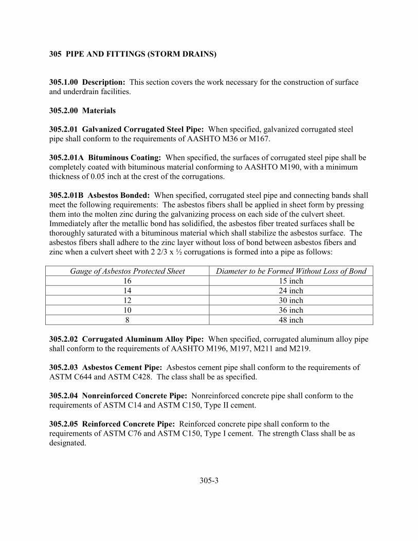
305 PIPE AND FITTINGS (STORM DRAINS)
305.1.00 Description: This section covers the work necessary for the construction of surfaceand underdrain facilities.
305.2.00 Materials
305.2.01 Galvanized Corrugated Steel Pipe: When specified, galvanized corrugated steelpipe shall conform to the requirements of AASHTO M36 or M167.
305.2.01A Bituminous Coating: When specified, the surfaces of corrugated steel pipe shall becompletely coated with bituminous material conforming to AASHTO M190, with a minimumthickness of 0.05 inch at the crest of the corrugations.
305.2.01B Asbestos Bonded: When specified, corrugated steel pipe and connecting bands shallmeet the following requirements: The asbestos fibers shall be applied in sheet form by pressingthem into the molten zinc during the galvanizing process on each side of the culvert sheet.Immediately after the metallic bond has solidified, the asbestos fiber treated surfaces shall bethoroughly saturated with a bituminous material which shall stabilize the asbestos surface. Theasbestos fibers shall adhere to the zinc layer without loss of bond between asbestos fibers andzinc when a culvert sheet with 2 2/3 x ½ corrugations is formed into a pipe as follows:
Gauge of Asbestos Protected Sheet Diameter to be Formed Without Loss of Bond16 15 inch14 24 inch12 30 inch10 36 inch8 48 inch
305.2.02 Corrugated Aluminum Alloy Pipe: When specified, corrugated aluminum alloy pipeshall conform to the requirements of AASHTO M196, M197, M211 and M219.
305.2.03 Asbestos Cement Pipe: Asbestos cement pipe shall conform to the requirements ofASTM C644 and ASTM C428. The class shall be as specified.
305.2.04 Nonreinforced Concrete Pipe: Nonreinforced concrete pipe shall conform to therequirements of ASTM C14 and ASTM C150, Type II cement.
305.2.05 Reinforced Concrete Pipe: Reinforced concrete pipe shall conform to therequirements of ASTM C76 and ASTM C150, Type I cement. The strength Class shall be asdesignated.
305-3
305.2.06 Vitrified Clay Pipe: Vitrified clay pipe shall conform to the requirements of ASTMC700.
305.2.07 Polyvinyl Chloride Pipe (PVC): Polyvinyl chloride pipe shall conform to therequirements of ASTM D3033 or ASTM D3034.
305.2.08 Acrylonitrile Butadiene Styrene Pipe (ABS): Acrylonitrile butadiene styrene pipeshall conform to the requirements of ASTM D2751.
305.2.09 Galvanized Corrugated Steel Pipe Arches: When specified, galvanized corrugatedsteel pipe arches shall conform to the requirements of AASHTO M36 and AASHTO M136.
305.2.10 Corrugated Aluminum Alloy Pipe Arches: When specified, corrugated aluminumalloy pipe arches shall conform to the requirements of AASHTO M196 and AASHTO M197.
305.2.11 Galvanized Corrugated Structural Plate Pipe, Arches, and Pipe Arches: Whenspecified, galvanized corrugated structural plate pipe, arches and pipe arches shall conform to therequirements of AASHTO M167, except there shall be no limitation to the weight of a singleplate. After galvanizing and corrugating, the base metal for structural plate shall also conform tothe following mechanical requirements:
Tensile Strength 45,000 psi minimumYield Point 33,000 psi minimumElongation in 2 inches 20% minimum
Tension test specimens shall be prepared and tested in accordance with ASTM A446, exceptspecimens shall be cut from the flat test portion of the roll with the specimen length parallel tothe corrugation.
The gages of structural plates will be in accordance with the following:
Each installation will be designated by size and symbol indicating the number and gage of platesrequired. Thus, 412-18 will be used to designate an installation for one plate length composed offour 12 gage plates and one 8 gage plate, the heaviest gage to be placed in the invert.
305.2.12 Cast Iron Pipe: Cast iron pipe shall conform to the requirements of AWWA C106 orC108, or ANSI specification A21.6 with Type II push on joint or Type III mechanical joints,manufactured in accordance with federal specifications WW-P-421c.
The cast iron pipe shall be lined with 3/32 inch thin cement mortar and seal coated in accordancewith ANSI standard A21.4 and AWWA C104, except thickness of lining and except as otherwisespecified in WW-P-421c. The Contractor shall provide all foundry records of pipe as describedin Section 6-6 of ANSI A21.6, when requested by the Engineer.
305-4
305.2.12 Cast Iron Pipe, Continued
Unless otherwise specified, the minimum thickness class for cast iron pipe shall be Class 22 for 4inch pipe, Class 21 for 6 inch and Class 20 for 8 inch and larger for 21/45 iron strength. For18/40 iron strength, the minimum acceptable thickness shall be Class 22 for pipes up to 12 inchdiameter.
305.2.13 Ductile Iron Pipe: Ductile iron pipe shall conform to the requirements of ANSIA21.51, or AWWA C151 and shall be cement lined, push on joint, unless otherwise specified.The minimum thickness class shall be Class 2 up through 12 inch diameter pipe and Class 1 for14 inch diameter and larger pipe unless specified otherwise by the Engineer.
305.2.14 Clay Drain Tile: Clay drain tile shall conform to the requirements of ASTM C4.
305.2.15 Concrete Drain Tile: Concrete drain tile shall conform to the requirements of ASTMC412.
305.2.16 Perforated Galvanized Corrugated Steel Pipe: Perforated galvanized corrugatedsteel pipe shall conform to the requirements of AASHTO M36 or AASHTO M197.
305.2.17 Perforated Corrugated Aluminum Alloy Pipe: Perforated corrugated aluminumalloy pipe shall conform to the requirements of AASHTO M197.
305.2.18 Perforated Asbestos Cement Pipe: Perforated asbestos cement pipe shall conform tothe requirements of ASTM C508.
305.2.19 Perforated Concrete Pipe: Perforated concrete pipe shall conform to therequirements of ASTM C444.
305.2.20 Perforated Vitrified Clay Pipe: Perforated vitrified clay pipe shall conform to therequirements of ASTM C700.
305.2.21 Perforated Polyvinyl Chloride Pipe (PVC): Perforated polyvinyl chloride pipe shallconform to the requirements of ASTM D3033 and ASTM D3034. The perforations shall consistof two rows of 3/8 inch holes along each side approximately 90 degrees apart.
305.2.22 Perforated Acrylonitrile Butadiene Styrene Pipe (ABS): Perforated acrylonitrilebutadiene styrene pipe shall conform to the requirements of ASTM D2751. The perforationsshall consist of the following: Pipes less than 4 inches in diameter shall have one row of 3/8 inchholes in a straight line, 3 inches on centers along the axis of the pipe; four inch diameter pipeshall have one row of 3/8 inch holes along each side approximately 90 degrees apart; pipes largerthan 4 inches in diameter shall have two rows along each side approximately 90 degrees apart.
305-5
305.2.23 Perforated Clay Drain Tile: Perforated clay drain tile shall conform to therequirements of ASTM C498.
305.2.24 Cement Mortar: Cement mortar shall conform to the requirements of ASTM C387,or be proportioned 1 part Portland cement to 2 parts clean, well-graded sand which will pass a1/8 inch sieve. Admixtures may be used not exceeding the following percentages by weight ofcement: hydrated lime, 10 percent; diatomaceous earth or other inert material, 5 percent.Consistency of mortar shall be such that it will adhere readily to the pipe. Mortar mixed forlonger than 30 minutes shall not be used.
305.2.25 Joints and Fittings: Joint materials and fittings shall conform to the applicablerequirements of Section 303.
305.2.26 End Sections
305.2.26A Galvanized Corrugated Steel Pipe: When specified, end sections shall conform tothe requirements of AASHTO M36.
305.2.26B Corrugated Aluminum Alloy Pipe: When specified, end sections shall conform tothe requirements of AASHTO M196 and AASHTO M211.
305.2.26C Reinforced Concrete Pipe: End sections shall conform to the requirements ofAASHTO M170.
305.2.27 Tee and Wye Fittings: Where required by the plans or specifications, the Contractorshall furnish tee and wye fittings of the same or compatible materials for the pipe proposed orspecified for use.
305.2.28 Foundation Stabilization: Foundation stabilization materials shall conform to therequirements of Subsection 301.2.01.
305.2.29 Filter Material: Filter material shall be coarse sand, crushed or uncrushed gravel,rock or combinations thereof, and shall meet the following requirements:
SIEVE ANALYSISSieve Size Retained
(Type UD-1) Percent by Weight¾ inch 03/8 inch 0-15No. 8 sieve 40-60No. 30 sieve 70-95No. 100 sieve, not less than 98
Filter materials shall be crushed or natural granular material and shall contain not more than 3%by weight of clay lumps, nor more than 1% of sticks (wet).
305.3.00 Construction
305.3.01 Trench Excavation, Bedding and Backfill: Trench excavation, pipe bedding andbackfill shall conform to the applicable requirements of Section 301.
305.3.02 Foundation Stabilization: Foundation stabilization work shall be in accordance withthe requirements of Section 301.
305.3.03 Installation: Pipe installation shall be in accordance with the manufacture’srecommendations.
Normally pipe laying shall begin at the downstream end of the pipe line. The lower segment ofthe pipe shall be in contact with the shaped bedding throughout its full length. Bell or grooveends of rigid pipe and outside circumferential laps of flexible pipe shall be placed facingupstream. Flexible pipe shall be placed with longitudinal laps or seams at the sides.
Paved invert or partially lined pipe shall be laid so that the longitudinal center line of the pavedsegment coincides with the flow line. Elliptical and elliptically reinforced pipe shall be placedwith the major axis within 5 degrees of a vertical plane through the longitudinal axis of the pipe.
All field joints made in the joining of sections of pipe to form culverts and sewers and to connectto structures and special sections shall be closely fitted and tight, shall provide a smooth anduniform interior surface, shall secure and hold adjoining sections to each other and shall fastensecurely to adjoining structures and special sections.
Perforated pipe shall be securely fastened together with couplings, fittings or bands as specifiedby the manufacturer for the type of pipe used. Upgrade ends of all subsurface drain pipe shall beclosed with approved plugs.
All perforated pipe shall be placed with the perforations facing down, unless otherwise specifiedor directed. Cement mortar joints will be required when using reinforced or nonreinforcedconcrete pipe, unless otherwise specified.
Tees, wyes or other fittings shall be placed accurately and positioned so that lateral pipes may beinstalled without unnecessary deflection or stress.
All pipe shall be inspected prior to lowering into the trench and, if necessary, cleaned of anymaterial tending to plug the perforations of the pipe.
The Contractor shall have available the proper tools, labor and equipment for efficient executionof the work. All pipe and fittings shall be carefully lowered into the trench to avoid anycontamination of the filter material.
305-7
305.3.04 Pipe Zone Backfill: Pipe zone backfill material shall be placed in accordance with therequirements of Subsection 301.3.06.
305.3.05 Trench Backfill: Trench backfill shall be placed in accordance with the requirementsof Subsection 301.3.07.
305.3.06 Filter Material: The Contractor shall place a minimum of 4 inches of filter materialunder perforated pipes. The placed material shall provide a firm unyielding support along theentire pipe length. Additional filter material will then be placed as specified in the plans or othercontract documents.
305.3.07 Television Inspection: Should the plans or specifications require television inspectionof the system, such inspection shall comply with the provisions of Section 303.3.18.
305.4.00 Measurement and Payment
305.4.01 Storm Drain Pipe: Measurement and payment for storm drain pipe will be made on alinear foot basis for the various classes, types and sizes of pipe listed and installed. Measurementwill be the horizontal pipe length along the centerline from center to center of manholes or to theend of the pipe, whichever is applicable, and to the nearest foot.
The Contractor shall specify in the bid proposal what type of pipe is to be used on the project.No variance will be allowed in this designation, unless unusual circumstances develop.
Payment for trench excavation and backfill will be in conformance with Section 301, if sospecified.
If so specified, payment shall constitute full compensation for the pipe in place, includingexcavation, bedding, pipe zone material, backfill and testing.
305.4.02 Foundation Stabilization: Measurement and payment for foundation stabilizationwill be in accordance with Section 301.
305.4.03 End Sections: Measurement and payment for end sections will be made on a unitprice basis for each type and size installed as shown. The limits of payment for end sectionsshall be as shown.
305.4.04 Tee and Wye Fittings: Measurement and payment for tee and wye fittings will bemade at the unit price for each size and type as listed and installed. Payment for tee and wyefittings will be in addition to payment for pipe from manhole to manhole or to the end of thepipe.
305-8
305.4.05 Existing Service Lines: Measurement and payment for disconnecting andreconnecting existing service lines will be made on the unit price for each as shown.
305.4.06 Television Inspection: Measurement and payment for TV inspection shall be perlineal foot of drain line inspected as directed and accepted by the Engineer.
305-9
306 MANHOLES
306.1.00 Description
306.2.00 Materials306.2.01 Aggregates306.2.02 Portland Cement306.2.03 Metal Reinforcement306.2.04 Concrete306.2.05 Brick306.2.06 Forms306.2.07 Metal Castings306.2.07A Ferric Castings306.2.07B Aluminum Castings306.2.07C Machined Surfaces and Fit306.2.07D Identification306.2.08 Cap Screws306.2.09 Manholes306.2.09A Precast Concrete Manholes306.2.09B Precast Bases306.2.09C Brick Manholes306.2.09D Mortar306.2.10 Pipe and Fittings306.2.11 Pipe Stubouts for Service Connections306.2.12 Pipe Stubouts for Future Sewer Connections
306.3.00 Construction306.3.01 General306.3.01A Foundation Stabilization306.3.01B Pipe Connections306.3.02 Precast Concrete Manholes306.3.02A Bases306.3.02B Risers306.3.02C Grates, Frames and Covers306.3.03 Manhole Testing306.3.03A Hydrostatic Testing306.3.03B Vacuum Testing
306.4.00 Measurement and Payment306.4.01 Manholes
306-1
306 MANHOLES
306.1.00 Description: This section covers the work necessary for the construction of manholes.
306.2.00 Materials
306.2.01 Aggregates: Aggregates shall conform to the requirements of Subsection 503.2.02.
306.2.02 Portland Cement: Portland cement shall conform to the requirements of Subsection503.2.01.
306.2.03 Metal Reinforcement: Metal reinforcement shall conform to the requirements ofASTM A615, Grade 40, deformed bars.
306.2.04 Concrete: Concrete shall conform to the requirements of ASTM C94, Alternate 2.Compressive field strength for manhole bases and miscellaneous concrete structures shall be notless than 3,000 psi at 28 days. Maximum size of aggregate shall be 1 inch. Slump shall bebetween 2 and 4 inches.
306.2.05 Brick: Brick for construction of manholes shall conform to the requirements ofASTM C-32, latest revision, Grade M.A. for sewer brick, and ASTM C-126.
306.2.06 Forms: Exterior surfaces shall be formed with steel or plywood. Other surfaces shallbe formed with matched boards, plywood, or other approved materials. Trench walls, rock, orearth will not be acceptable form material, unless approved by the Engineer.
306.2.07 Metal Castings
306.2.07A Ferric Castings: Metal casting materials shall conform to the requirements ofASTM A48, Class 30B, with the following revisions:
Tensile Strength 30,000 psiTransverse Strength: (1.2” diameter bar – 18” centers) Load – pounds 2,600 – 3,000 Deflection – inches 0.22 – 0.34Brinell Hardness (as cast) 173 – 200
The foundry shall certify as to the tensile and transverse properties and the Brinell Hardness.The Owner reserves the right to require a rough transverse bar (size of bar 1.2” diameter by 20”long) and/or a tensile bar as per ASTM A48 for each 20 castings or heat when less than 20castings are made.
306-2
306.2.07B Aluminum Castings: All manhole frames and covers shall be of the size and shapedetailed in the standard drawings.
Aluminum manhole frames and covers shall be cast of an aluminum alloy of sufficient physicalproperties to meet the Federal Specifications RR-F-621B, dated September 14, 1967, for 20,000lb. loading. Dimensions shall be that specified by the standard drawings or as approved by theEngineer.
All castings shall be free of any porosity, shrinks, cracks or other defects characteristic ofaluminum castings.
Covers shall have the necessary appurtenance to secure them to the frame, so that removalcannot be made without a special tool.
A fixed locking lug shall be cast as an integral part of the cover and of a design that will allowthe lock to be positioned at any location on the circumference of the frame flange.
The lock shall be of cam design with the cam being of the same aluminum alloy as frame andcover and of such a design to secure the cover to the frame by turning one-half to full turn.
The cam shall be operated by a bolt, securely screwed through the cam, with an ESNA stop nutlocking it in place. The cam shall have sufficient applied tension so it will not vibrate looseunder traffic. The bolt shall be a ¾ inch socket head cap screw with a hexagon socket and shallbe made of ASTM 18-8 stainless steel.
306.2.07C Machined Surfaces and Fit: All covers, both ferric or aluminum, shall havematching surfaces that are flat to prevent any rocking when covers are installed in the frame.
Covers and frames shall be inter-changeable within type.
306.2.07D Identification: When specified, covers shall have “SEWER” or “STORM” stampedon it, as appropriate.
306.2.08 Cap Screws: Cap screws and washers for watertight manhole covers shall be stainlesssteel with 60,000 psi minimum tensile strength conforming to the requirements of ASTM A453.
306.2.09 Manholes
306.2.09A Precast Concrete Manholes: Materials shall conform to the requirements of ASTMC478. Minimum wall thickness shall be 4 inches for 0-16 feet and 5 inches for greater than 16’depth. Cones shall have the same wall thickness and reinforcement as riser sections. Joints shallbe tongue-and-groove or keylock type. Cones shall be eccentric unless otherwise specified.
306-3
306.2.09A Precast Concrete Manholes, Continued
Prior to the delivery of any size of precast manhole section to the job site, the Engineer mayrequire yard permeability tests to be conducted at the point of manufacture. The precast sectionsto be tested will be selected at random from the stockpile material which is to be supplied to theproject. All test specimens will be mat tested, and shall meet the permeability test requirementsof ASTM C14.
Joints between precast reinforced concrete sections shall be of such design that leakage andinfiltration can satisfactorily be reduced to a minimum. The use of rubber gaskets or mastics willbe required per the Contractor’s choice. If mastic is utilized, the joint must be protected on theexterior of the manhole from the degradating action of the soil.
306.2.09B Precast Bases: At the option of the Contractor, precast base sections or manholebases may be used provided all the details of construction are approved prior to construction.Pouring three to four inches of concrete up along the inside of the riser will is required forsealing purposes.
306.2.09C Brick Manholes: When so indicated on the plans or if approved by the Engineer,brick masonry may be used for the walls of manholes. The designer and Contractor arecautioned that this type of manhole must meet the same type of watertightness requirements asother manholes. Such masonry walls shall be 8 inches in thickness for depths up to andincluding 16 feet, and 12 inches for depths over 16 feet. Masonry manholes shall be circularwith a clear inside diameter of 48 inches, unless the plans call for alternate shapes or dimensions.
Bricks shall be clean and thoroughly wetted shortly before they are laid. The brick shall be laidin a full bed of mortar with best end exposed on the inside and with sufficient header courses totie the masonry together. Inside vertical face-joints shall be not more than ¼ inch wide,horizontal joints shall be not more than ½ inch wide. All voids between bricks and holes incored bricks shall be filled with mortar. Exposed mortar joints shall be pointed with mortar andstruck flush. The outside of brick manholes shall be plastered with a minimum of ½ inch ormortar and trowelled smooth. The plastering of manholes shall be placed progressively as themanhole is constructed. One coating of a bituminous or other similar waterproofing compoundwill be applied prior to backfilling.
Manhole steps shall be embedded half their length and spaces as shown on the drawings.
306.2.09D Mortar: Mortar for use with brick manholes shall conform to the requirements ofASTM C387, or be proportioned 1 part Portland cement to 2 parts clean, well-graded sand whichwill pass a 1/8 inch screen. Admixtures may be used not exceeding the following percentages ofweight of cement: hydrated lime, 10 percent; diatomaceous earth or other inert materials, 5percent. Consistency of mortar shall be such that it will readily adhere to the precast concrete ifusing the standard tongue-and-groove type joint. Mortar mixed for longer than 30 minutes shallnot be used.
306-4
306.2.10 Pipe Fittings: Pipe and fittings shall conform to the applicable portions of Sections303 and 305.
Tees, wyes, ells and other fittings for drop manholes shall be of the same material as the pipe inthe adjacent trench unless specified otherwise.
306.2.11 Pipe Stubouts for Service Connections: Pipe stubouts for service connections shallconform to the applicable portions of Section 304 and are to be of the same size and kind ofmaterial as the service connection pipes.
306.2.12 Pipe Stubouts for Future Sewer Connections: Pipe stubouts shall be the same typeas approved for use in the lateral, main or trunk sewer construction. Strength classifications shallbe the same class as in adjacent trenches. Where there are two different classes of pipe at amanhole, the higher strength pipe will govern strength classification. Rubber-gasketedwatertight plugs shall be furnished with each stubout adequately braced against hydrostatic or airtest pressures.
306.3.00 Construction
306.3.01 General
306.3.01A Foundation Stabilization: If, in the opinion of the Engineer, unstable materialexists that will not support the manhole or other structure, the Contractor shall excavate belowgrade and backfill with foundation stabilization material in accordance with Subsection 301.3.04.
306.3.01B Pipe Connections: All pipes entering or leaving the manhole shall be provided withflexible joints within 1 ½ feet of the manhole structure and shall be placed on firmly compactedbedding. Special care shall be taken to see that the openings through which pipes enter thestructure are completely watertight. All pipe shall be connected to manholes according to themanufacturer’s recommendations. The Contractor shall furnish shop drawings showing themethod of connections for the Engineer’s approval.
306.3.02 Precast Concrete Manholes: Precast manhole components may be used to constructstandard, drop or carry-through manholes. All manholes shall be constructed in conformancewith the drawings.
306.3.02A Bases: If bases are cast in place, the concrete shall be consolidated by mechanicalvibration. The concrete shall be screeded off in a manner such that the first manhole section tobe placed has a level, uniform bearing for the full circumference.
If bases are precast, the base section shall be carefully placed on the prepared bedding so as to befully and uniformly supported in true alignment, and making sure that all entering pipes can beinserted on proper grade.
306-5
306.3.02A Bases, Continued
In all cases, the first riser pipe section shall be imbedded in the base so that 3” – 4” of concreteextends above the bottom of the riser pipe wall.
The invert shall be constructed to a section identical with that of the sewer pipe. Where size ofsewer pipe is changed at the manhole, the invert shall be constructed in the form of a smoothtransition without abrupt breaks or unevenness of the invert surfaces. Where a full section ofsewer pipe is laid through the manhole, the top shall be broken or cut out to the spring line of thepipe for the full width of the manhole and the exposed edge of the pipe made smooth bymortaring or other approved methods. During construction of the invert section and for a periodof not less than 24 hours following placing of concrete or mortar in the invert sections, theContractor shall temporarily divert existing flows of ground water or sewage from new concreteor mortar surfaces to prevent damage within the manhole until initial set has been achieved.
306.3.02B Risers: Risers and cone sections shall be 48 inches inside diameter. Other sectionsshall be 24-inch diameter riser and flattop sections.
In precast manhole sections where steel loops are provided in lieu of lift holes, the loops shall beremoved flush with the inside wall surface after the manhole has been completed. No sharpcutoff protrusions will be permitted. If concrete spalling occurs as a result of the loop removal,the spalled area shall be restored in a neat, professional manner with mortar to a uniform smoothsurface.
All lift holes and all joints between precast elements shall be thoroughly wetted and thencompletely filled with mortar, smoothed and pointed both inside and out, to ensurewatertightness, except that rubber-gasketed or those manholes using preformed plastic gasketsneed not be mortared.
Preformed plastic gaskets shall be used on all sanitary manholes. Mortar will be allowed onstorm manholes, and on 24-inch extension rings above the cone. On unimproved or proposedstreet grades, a minimum of one 4 inch x 24 inch precast riser will be required between the coneand iron ring.
Where the sewer line crosses open fields, the top of the cone section of manholes shall be held aminimum of 2 feet below existing ground surface, except as designated on the plans or by theEngineer. The remaining 2 feet of manhole shall be constructed with 24 inch diameter risersections so that the top of the manhole cover will be approximately 6 inches above the finishedbackfilled surface.
When sanitary sewer manholes are constructed within the wetted section of any ditch or drainageway, the manhole shall be so constructed that the top of the cover is at least 6 inches above anypossible water elevation within the ditch or drainage way, as determined by the Engineer.
306-6
306.3.02B Risers, Continued
Manhole frames, grates and covers shall be placed at the top of the manhole as shown on thedrawings and set to the elevation required, and in such a manner as to prevent infiltration of anysurface or groundwater into the manhole between the frame and the concrete of the manholesection. Mortar placed to provide this seal shall be placed in the form of a smooth, uniformfillet.
306.3.03 Manhole Testing: The Contractor shall be responsible for process testing of manholesand may conduct such tests as necessary during the construction process. The tests required inthis subsection are for the information of the Engineer. The results of the tests shall notindemnify the Contractor of responsibility for defects in the construction.
The first three sanitary sewer manholes built by each manhole construction crew on the projectshall immediately be proof tested. No additional manholes shall be constructed until threesuccessful proof tests have demonstrated satisfactory workmanship and materials.
Acceptance tests shall be conducted on all manholes constructed. The manholes shall be testedafter completion of backfilling, compaction and surface restoration.
306.3.03A Hydrostatic Testing: The hydrostatic test shall consist of plugging all inlets andoutlets and filling the manhole to the top with water. Each manhole shall be filled to the rim atthe start of the test.
Leakage in each manhole shall not exceed 1.14 gallons per vertical foot per day. Leakage shallbe determined by refilling to the rim using a calibrated known-volume container.
Manholes may be filled 24 hours prior to the time of testing to permit normal absorption into themanhole walls.
306.3.03B Vacuum Testing: The vacuum test shall consist of plugging all lift holes with anapproved non-shrink grout, plugging all inlets and outlets, taking care that the plugs are securelybraced to prevent the plug from being drawn into the manhole.
The vacuum test head shall be placed at the inside of the top of the cone section and the sealinflated in accordance with the manufacturer’s recommendations. A vacuum of 10 inches ofmercury shall be drawn and the vacuum pump shut off. With the valves closed, the time for thevacuum to drop to 9 inches of mercury shall be accurately measured.
The manhole shall be deemed to have passed the test if the time to drop 1.0 inch of mercury isgreater than 60 seconds, 75 seconds and 90 seconds for 48 inch, 72 inch, and 80 inch manholes,respectively.
306-7
306.3.03B Vacuum Testing, Continued
If the manhole fails the initial test, the necessary repairs shall be made with non-shrink groutwhile the vacuum is still being drawn. Re-testing shall proceed until a satisfactory test isobtained.
The Contractor may wish to have his/her field personnel seal the exterior of the joints with ahydraulic cement in addition to using the standard joint mastic during installation.
306.4.00 Measurement and Payment
306.4.01 Manholes: Measurement and payment for manholes will be made on a per each basisfor each type and size shown.
Payment shall include all materials and work necessary to construct all service connectionsshown.
306-8
307 CATCH BASINS AND INLETS
307.1.00 Description
307.2.00 Materials307.2.01 Concrete307.2.02 Forms307.2.03 Metal Reinforcement307.2.04 Mortar307.2.05 Cast Iron Frames and Grades307.2.06 Welded Frame and Grates307.2.07 Precast Concrete Units
307.3.00 Construction307.3.01 Excavation and Backfill307.3.02 Forming, Pouring and Curing307.3.03 Precast Concrete Units307.3.04 Frames and Grates
307.4.00 Measurement and Payment307.1.01 Catch Basins and Inlets
307-1
307 CATCH BASINS AND INLETS
307.1.00 Description: This section covers the work necessary for the construction of catchbasins and inlets of the types and sizes shown.
307.2.00 Materials
307.2.01 Concrete: Concrete shall conform to the requirements of Section 503.
307.2.02 Forms: Forms shall conform to the requirements of Subsection 306.2.06.
307.2.03 Metal Reinforcement: Metal reinforcement shall conform to the requirements ofSection 306.2.03.
307.2.04 Mortar: Mortar shall conform to the requirements of Subsection 306.2.09D.
307.2.05 Cast Iron Frames and Grates: Cast iron frames and grates shall conform to therequirements of Subsection 306.2.07.
307.2.06 Welded Frames and Grates: Welded frames and grates shall be fabricated of steelconforming to ASTM A7, A36, or A373 in accordance with the details shown.
307.2.07 Precast Concrete Units: At the option of the Contractor, approved precast units maybe substituted for cast-in-place units. Precast units shall conform to the requirements of ASTMC478.
307.3.00 Construction
307.3.01 Excavation and Backfill: Excavation and backfill shall conform to the applicablerequirements of Section 301.
307.3.02 Forming, Pouring and Curing: Forms shall be tight and well braced. Chamfercorners of forms. Prior to placing the concrete, remove all water and debris from the forms.Moisten forms just prior to placing the concrete. Handle concrete to prevent segregation or lossof ingredients. Immediately after placing, consolidate concrete with an approved vibrator. Limitvibration to the time necessary to produce satisfactory consolidation without causing segregation.Screed the top surface of exposed surfaces and trowel to a smooth finish free from marks orirregularities. Finish exposed edges with a steel edging tool. Cure concrete for a period of sevendays with an approved curing compound. Apply the curing compound immediately after
307-2
307.3.02 Forming, Pouring and Curing, Continued
removal of forms or finishing. Protect concrete from damage during the seven day curingperiod. Remove forms and patch any defects in the concrete with mortar mixed in the sameproportions as the original concrete mix.
307.3.03 Precast Concrete Units: At the option of the Contractor, precast catch basins andinlets may be used provided all the details of construction are approved prior to construction.
307.3.04 Frames and Grates: Frames and grates shall be of the type and placed as shown onthe plans.
307.4.00 Measurement and Payment
307.4.01 Catch Basin and Inlets: Measurement and payment for catch basins and inlets will bemade on a per each basis for the number and type shown.
307-3
308 WORK ON EXISTING SEWERS AND STRUCTURES
308.1.00 Description
308.2.00 Materials
308.3.00 Construction308.3.01 Excavation, Bedding and Backfill308.3.02 Manholes Over Existing Sewers308.3.03 Manhole Connections308.3.04 Pipe, Manhole and Catch Basin Removal308.3.05 Filling Abandoned Manholes and Catch Basins308.3.06 Salvaging Manhole Frames and Covers308.3.07 Capping Abandoned Pipes308.3.08 Manhole Adjustments308.3.08A Masonry Manholes308.3.08B Metal Manholes308.3.08C Fiberglass Reinforced Polyester Resin Manholes308.3.08D Reinforced Plastic Mortar Manholes308.3.09 Catch Basin and Inlet Adjustment308.3.10 Manhole Base Reconstruction308.3.11 Catch Basin Connections
308.4.00 Measurement and Payment308.4.01 Manholes Over Existing Sewers308.4.02 Manhole Connections308.4.03 Filling Abandoned Manholes308.4.04 Capping Abandoned Pipes308.4.05 Catch Basin and Inlet Adjustment308.4.06 Manhole Base Reconstruction308.4.07 Catch Basin Connections308.4.08 Manhole Adjustment
308-1
308 WORK ON EXISTING SEWERS AND STRUCTURES
308.1.00 Description: This section covers the work necessary for joining new work to existing,the abandoning of sewerlines and structures, and the adjustment of existing utility structures.
308.2.00 Materials: Materials shall conform to the requirements for the related work referredto herein.
308.3.00 Construction
308.3.01 Excavation, Bedding and Backfill: Excavation, bedding and backfill shall conformto the requirements of Section 301.
308.3.02 Manholes Over Existing Sewers: Construction shall be in accordance with theapplicable portions of Section 306.
After completion of the manhole, the Contractor shall sever the existing pipe with the manhole,smooth the edges with mortar or otherwise finish the edges of the cut pipe to provide smooth,finished edges in the manhole.
The Contractor shall prevent broken material or debris from entering the line.
Flow shall be maintained at all times. Prior approval by the Engineer will be required prior todiverting flows.
308.3.03 Manhole Connections: The Contractor shall construct openings in the existingmanhole base or barrel as required and construct connections that are watertight and that willprovide a smooth flow into and through the manhole.
The Contractor shall provide all diversion facilities and perform all work necessary to maintainflow in existing lines during the connection to the manhole.
308.3.04 Pipe, Manhole and Catch Basin Removal: Pipes, manholes and catch basinsscheduled for removal shall be removed and disposed of in accordance with Section 204.3.02.
308.3.05 Filling Abandoned Manholes and Catch Basins: Manholes and catch basinsscheduled to be abandoned shall have all connecting pipes capped or plugged and the manholebarrel filled with granular material meeting the requirements of Subsection 301.2.02.
308.3.06 Salvaging Manhole Frames and Covers: Manhole frames and covers scheduled forsalvage shall be removed by the Contractor and stored for pickup by the Owner.
308-2
308.3.07 Capping Abandoned Pipes: Abandoned pipes shall be capped or plugged inaccordance with the pipe manufacturer’s recommendations or as specified. All ends shall bewatertight.
308.3.08 Manhole Adjustment: Manhole adjustment can be found in Section 216.3.06.
308.3.08A Masonry Manholes: Masonry manholes shall be raised or lowered by removing theexisting frames, grates and covers and adjusting the height as necessary to correspond to grade.Manholes may be raised or lowered by any of the following or combination of methods when noparticular method is specified.
The manhole neck may be extended by the use of precast extension rings or by reconstructing theneck except that the total distance from the top of metal cover at its new adjusted grade to thebottom of the neck shall not exceed 2 feet.
Manhole necks are defined as that upper portion of a manhole having vertical walls and auniform diameter or dimensions just sufficient to receive and support the metal frame.
The dome or cone portions of manholes may be cut down and rebuilt provided the batter or slopeof the cone does not exceed 6 inches horizontal per 12 inches vertical.
Manhole barrels of brick, block, or concrete shall be extended in kind unless otherwise specified.
Precast sections and rings removed in the adjusting work may be reused in other adjusting workor in new construction if in good condition, and such precast items which are not reused in thework will become the property of the Contractor.
Metal rings may be used in the adjustment work, provided: (1) the metal and its fabricationdesign shall be such that it will at least equal the pertinent characteristics of strength and supportrequired of the covers or grates to be placed thereon; (2) that uniform bearing or bearing surfacesis assured; and (3) that positive provision is afforded against displacement when in service.
Mortar for building up existing masonry shall not be placed to a depth of more than 2 inches.Concrete shall not be placed to a depth of less than 3 ½ inches. To conform to theserequirements, the existing shells or wall of structures to be raised shall be cut down as necessaryto provide space for the new construction.
The exposed top surface of monolithic concrete on which new mortar or concrete is to be placedshall be chipped away to a depth of at least ¼ inch to expose firm concrete, and the new surfaceshall be cleaned by brushing and shall be moistened with water at the time of placing newconcrete thereon. The new concrete shall then be placed to required grade and cured at leastthree days, after which the frame shall be seated in fresh mortar and brought to proper grade.
308-3
308.3.08B Metal Manholes: Metal manholes shall be adjusted to grade by resetting the entirestructure on a firm foundation, by adding extensions of like design and material or by severingthe barrel in an acceptable manner. Salvaged structures not reused on the project shall becomethe property of the Contractor.
308.3.08C Fiberglass Reinforced Polyester Resin Manholes: Fiberglass reinforced polyesterresin manholes shall be adjusted to grade in accordance with the requirements of Subsection308.3.08B.
308.3.08D Reinforced Plastic Mortar Manholes: Reinforced plastic mortar manholes shall beadjusted to grade in accordance with the requirements of Subsection 308.3.08B.
308.3.09 Catch Basin and Inlet Adjustment: Catch basins and inlets will be adjusted inaccordance with the applicable portions of Section 307 and Subsection 308.3.08B.
308.3.10 Manhole Base Reconstruction: Manhole base reconstruction shall be in accordancewith the applicable portions of Section 306.
308.3.11 Catch Basin Connections: Catch basin connections, unless otherwise specified, shallbe constructed in conformance with the pipe manufacturer’s recommended practice for the typeof piping and catch basin combination under consideration.
308.4.00 Measurement and Payment
308.4.01 Manholes Over Existing Sewers: Measurement and payment for manholes overexisting sewers will be made on a lump sum per each basis. No differentiation will be made formanhole depth.
308.4.02 Manhole Connections: Measurement and payment for connections to existingmanholes will be made on a per each basis.
308.4.03 Filling Abandoned Manholes and Catch Basins: No separate or additional paymentwill be made for filling manholes and catch basins. This work shall be considered as incidental.
308.4.04 Capping Abandoned Pipes: No separate or additional payment will be made forcapping abandoned pipes. Payment for this work will be made under one or more of the otherbid items.
308.4.05 Catch Basin and Inlet Adjustment: Measurement and payment for adjusting catchbasins and inlets will be made on a per each basis for each type and size shown.
308.4.06 Manhole Base Reconstruction: Measurement and payment for reconstructingmanhole bases will be made on a per each basis.
308-4
308.4.07 Catch Basin Connections: Measurement and payment for catch basin connectionswill be made on a per each basis.
308.4.08 Manhole Adjustment: Measurement and payment will be made in accordance withSection 216.4.02.
308-5
309 RESURFACING
309.1.00 Description
309.2.00 Materials309.2.01 Asphalt Concrete Pavement309.2.02 Portland Cement Concrete Pavement309.2.03 Brick Pavement309.2.04 Aggregate Base309.2.05 Curbs309.2.06 Driveways and Sidewalks309.2.07 Metal Reinforcement309.2.08 Epoxy Cement
309.3.00 Construction309.3.01 Work Area Maintenance309.3.02 Trench Excavation309.3.03 Asphalt Concrete Pavement309.3.04 Portland Cement Concrete Paving309.3.05 Brick Pavement309.3.06 Aggregate Base309.3.07 Curbs309.3.08 Driveways and Sidewalks309.3.09 Metal Reinforcement
309.4.00 Measurement and Payment309.4.01 Trench Excavation309.4.02 Asphalt Concrete Pavement309.4.03 Portland Cement Concrete Pavement309.4.04 Brick Pavement309.4.05 Aggregate Base309.4.06 Curbs309.4.07 Driveways and Sidewalks309.4.08 Jacking, Boring and Tunneling309.4.09 Payment
309-1
309 RESURFACING
309.1.00 Description: This section covers the work necessary to replace pavement, curbs,sidewalks, rock surfacing and other features damaged either directly or indirectly by theoperations related to the construction of all facilities.
309.2.00 Materials
309.2.01 Asphalt Concrete Pavement: Asphalt concrete pavement materials shall conform tothe applicable requirements of Subsection 211.2.00. Asphalt concrete shall be Class BM-2,unless otherwise specified.
309.2.02 Portland Cement Concrete Pavement: Portland cement concrete materials shallconform to the requirements of Subsection 212.2.00.
309.2.03 Brick Pavement: Brick paving materials shall be paving brick salvaged from the jobsite or brick furnished by the City of Dodge City from stock and a Portland cement concretebase, conforming to Subsection 212.2.00.
309.2.04 Aggregate Base: Aggregate base materials shall conform to the requirements ofSubsection 207.2.00.
309.2.05 Curbs: Curb materials shall conform to the requirements of Subsection 213.2.00.
309.2.06 Driveways and Sidewalks: Driveway and sidewalk materials shall conform to therequirements of Subsections 214.2.00 and 215.2.00.
309.2.07 Metal Reinforcement: Metal reinforcement materials shall conform to therequirements of Subsections 212.2.00, 213.2.00, and 214.2.00.
309.2.08 Epoxy Cement: Epoxy cement shall be a two-compound epoxy resin adhesiveconforming to the requirements of AASHTO M235.
309.3.00 Construction
309.3.01 Work Area Maintenance: The Contractor shall maintain the work area inconformance with the applicable requirements of Subsection 301.3.00.
309.3.02 Trench Excavation: The trench edges in paved areas shall be sawed or cut bymethods satisfactory to the Engineer to a depth sufficient to permit removal of pavement withoutdamage to pavement to be left in place. Pavement within the cutting limits together with allother excavated material shall be removed and disposed of.
309-2
309.3.02 Trench Excavation, Continued
The trench edges in rock surfaced areas shall be made vertical where soil and depth conditionspermit, and if that is not possible, sloped outwardly from the trench.
In trenching across the roads or streets, no more than one-half of the traveled way is to be openedat one time without authorization from the Engineer. The opened half shall be completelybackfilled before opening the other half.
Closure of intersecting streets, road approaches, or other access points will not be permittedunless authorized by the Engineer. Upon trenching across such facilities, steel running plates,planks, or other satisfactory methods shall be used to provide for traffic to enter or leave theroad, streets, or adjacent property.
Pavement patching shall be scheduled to accommodate the demands of traffic and shall beperformed as rapidly as possible to provide maximum safety and convenience to public travel.
Isolated trenches which cross vehicular, pedestrian or bicycle lanes shall be resurfacedimmediately.
309.3.03 Asphalt Concrete Pavement: The Contractor shall apply a tack coat to the verticalfaces of the existing pavement prior to placing asphalt concrete pavement.
The edges shall be clean and dry prior to applying the tack coat.
The asphalt concrete shall be placed to a compacted thickness of four inches or the thickness ofthe removed pavement, whichever is greater.
The finished surface of the placed asphalt concrete shall match the surface of the existingpavement. The surface shall not be subjected to traffic until the material has been properlycompacted and cured. Construction shall conform to the applicable requirements of Section211.3.00.
309.3.04 Portland Cement Concrete Paving: Trench edges shall be saw-cut unless otherwisespecified. The Contractor shall apply either an approved bonding agent or neat cement grout tothe saw-cut faces of the existing pavement prior to placing the fresh concrete.
The edges shall be clean prior to applying the bonding agent or neat cement.
The Portland cement concrete shall be placed to a thickness of six inches or the thickness of theremoved pavement, whichever is greater.
309-3
309.3.04 Portland Cement Concrete Paving, Continued
The finished surface of the placed Portland cement concrete paving shall match the surface of theexisting pavement.
The surface shall not be subjected to traffic until the material has been properly cured.
309.3.05 Brick Pavement: Paving brick shall be removed in such a manner that will permitmaximum salvage and reuse of the brick. All brick and parts of brick having full thickness shallbe considered reusable. Paving brick which are to be removed shall be reused for construction ofthe new pavement.
Brick to be reused shall be thoroughly cleaned before being placed in the new pavement. Shouldit be necessary to add to the brick from a City stockpile, those bricks shall also be thoroughlycleaned before reused.
No usable brick shall be wasted. Paving brick removed and not used in the new work shall bestockpiled for the City.
Brick pavement shall be constructed on a base course consisting of 6 inches of Portland cementconcrete placed on a compacted granular subgrade. The concrete shall be Class 3000, asspecified in Subsection 503.3.01A.
After construction of the concrete base, a one inch sand cushion or leveling course shall beplaced and compacted.
The paving brick shall then be laid using the same pattern as the existing pavement. Jointsbetween bricks shall be as tight as possible.
After the brick has been placed, all joints or interstices shall be filled completely with anapproved asphaltic filler. Filler material shall contain no pitch and after curing shall beimpervious to street liquids. Filler material shall remain pliable at all climatic conditions towhich it will be subjected. The brick shall be dry when the filler material is forced into the jointsby using a squeegee to distribute the material evenly. After the filler has set, excess materialshall be removed from the brick surface.
309.3.06 Aggregate or Granular Base: Base materials shall be placed in lifts not to exceed sixinches. Compaction shall conform to the requirements of Subsection 207.3.04B. The aggregatesize shall be 1” – 0, or ¾” – 0 unless otherwise specified.
The compacted thickness shall be 12 inches or the thickness of the removed base, whichever isgreater.
309-4
309.3.07 Curbs: Curbs shall be saw-cut unless otherwise specified. Construction shallconform to the applicable requirements of Subsection 213.3.00.
The Contractor shall apply either an approved bonding agent or neat cement grout to the saw-cutfaces of existing Portland cement concrete curbs prior to placing the fresh concrete.
The materials, dimensions, and geometry of the constructed curb shall match that of the existingcurb.
309.3.08 Driveways and Sidewalks: Driveways and sidewalks shall be removed to linesconforming to the transverse scoring lines or joint lines of the existing sidewalk, unlessotherwise specified.
Construction shall conform to the applicable requirements of Subsection 215.3.00 and 309.3.04.
309.3.09 Metal Reinforcement: Metal reinforcement will be placed in the material beingreplaced in the same amounts and location as was in the removed material, unless otherwisespecified.
Lapped splices shall be 20 diameters, unless otherwise specified.
Placing of metal reinforcement shall conform to the applicable requirements of Subsection504.3.03.
309.4.00 Measurement and Payment: Measurement and payment for the following items willbe considered incidental, unless specified otherwise.
309.4.01 Trench Excavation: There will be no separate or additional payment for trenchexcavation unless specified. When specified, measurement and payment shall conform to therequirements of Subsection 301.4.00, as specified.
309.4.02 Asphalt Concrete Pavement: Measurement and payment for asphalt concretepavement, when specified, shall be on a square yard basis for the amount of surface area replacedwithin the limits shown. No additional payment will be made for replacement outside the limitsshown.
309.4.03 Portland Cement Concrete Pavement: Measurements and payment, when specified,shall conform to the requirements of Subsection 309.4.02.
309.4.04 Brick Pavement: Measurement and payment, when specified, shall be on a squareyard basis for the amount of surface replaced within the limits shown, and shall include all costsfor construction of the Portland cement concrete base, sand cushion, placing brick, filling jointsand cleaning.
309-5
309.4.05 Aggregate Base: Measurement and payment, when specified, shall conform to therequirements of Subsection 309.4.02.
309.4.06 Curbs: Measurement and payment, when specified, shall conform to the requirementsof Section 213.4.01A.
309.4.07 Driveways and Sidewalks: Measurement and payment, when specified, shallconform to the requirements of Subsection 309.4.02.
309.4.08 Jacking, Boring and Tunneling: If the Contractor elects to jack, bore or tunnel inlieu of removal and replacement, measurement and payment will be made as though the itemswere removed and replaced, as specified.
309.4.09 Payment: Payment will be made for the following items listed as pay items:
Pay Item Unit of MeasureTrench Excavation LFAsphalt Concrete Pavement SYPortland Cement Concrete Pavement SYBrick Pavement SYAggregate Base SYCurbs LFDriveways and Sidewalks SY
309-6
DIVISION FOURWATER DISTRIBUTION
401-0
401 WATER SYSTEM TRENCH EXCAVATION, BEDDING AND BACKFILL
401.1.00 Description
401.2.00 Materials
401.3.00 Construction
401.4.00 Measurement and Payment
401-1
401 WATER SYSTEM TRENCH EXCAVATION, BEDDING AND BACKFILL
401.1.00 Description: The work necessary to excavate, bed and backfill water pipelines shallconform to the requirements of Section 301.
401.2.00 Materials: Materials shall conform to the requirements of Subsection 301.2.00.
401.3.00 Construction: Construction shall conform to the requirements of Subsection301.3.00.
401.4.00 Measurement and Payment: Measurement and payment shall conform to therequirements of Subsection 301.4.00.
401-2
402 WATER PIPE AND FITTINGS
402.1.00 Description402.1.01 General402.1.02 Certification402.1.03 Corrosion Protection
402.2.00 Materials402.2.01 Ductile Iron Pipe402.2.02 Polyvinyl Chloride (PVC) Class Pressure Pipe402.2.03 Reinforced Concrete Steel Cylinder Pipe402.2.04 Prestressed Concrete Steel Cylinder Pipe402.2.05 Reinforced Concrete Pipe402.2.06 Pretensioned Reinforced Concrete Steel Cylinder Pipe402.2.07 Steel Pipe402.2.08 Galvanized Steel Pipe402.2.09 Service Line Pipe402.2.10 Pipe Fittings402.2.10A Polyvinyl Chloride (PVC) Class Pressure Pipe402.2.11 Joint Lubricant402.2.12 Nuts, Bolts and Washers402.2.13 Thrust Blocks402.2.14 Pipe Locating Material402.2.15 Valve Boxes and Vaults402.2.15A Cast Iron402.2.15B Portland Cement Concrete Blocks402.2.15C Portland Cement Concrete402.2.15D Mortar402.2.15E Concrete Block
402.3.00 Construction402.3.01 Handling and Storage402.3.02 Alignment and Grade402.3.03 Installation402.3.03A Cast and Ductile Iron Pipe402.3.03B Polyvinyl Chloride Pipe402.3.03C Concrete Steel Cylinder Pipe402.3.03D Reinforced Concrete Pipe402.3.03E Steel Pipe402.3.03F Valves, Fittings, Plugs and Caps402.3.03G Valve Boxes and Vaults402.3.04 Pressure Testing402.3.04A Polyvinyl Chloride Pipe
402-1
402 WATER PIPE AND FITTINGS, Continued
402.4.00 Service Taps and Lines402.4.01 Tapping402.4.02 Corporation Stops402.4.03 Copper Service Lines402.4.04 Curb Stops
402.5.00 Measurement and Payment402.5.01 Pipe402.5.02 Fittings402.5.03 Thrust Blocks402.5.04 Testing402.5.05 Service Taps
402-2
402 WATER PIPE AND FITTINGS
402.1.00 Description
402.1.01 General: This section covers the work necessary for furnishing and installing waterpipe and fittings normally used for water distribution systems.
402.1.02 Certification: The Contractor shall furnish materials certifications in accordance withthe requirements of Subsection 106.04.
402.1.03 Corrosion Protection: The method of corrosion protection shall be as specified in thecontract documents.
402.2.00 Materials
402.2.01 Ductile Iron Pipe: Ductile iron pipe shall be cement-mortar lined and seal coated andshall conform to the requirements of ASTM 536, ANSI A21.51 (AWWA C151) ANSI A21.4(AWWA C104) and ANSI A2.1.11 (AWWA C111).
402.2.02 Polyvinyl Chloride (PVC) Class Pressure Pipe: Polyvinyl chloride class pressurepipe with diameters of 4 inches through 12 inches shall conform to the requirements of AWWAC900. Joints shall be either elastomeric gasketed or solvent cement welded and shall conform tothe requirements of ASTM D3139. Gaskets shall conform to the requirements of ASTM F477and ASTM D1869. The pressure class shall be as specified.
402.2.03 Reinforced Concrete Steel Cylinder Pipe: Reinforced concrete steel cylinder pipeshall conform to the requirements of AWWA C300.
Before starting fabrication, the Contractor shall furnish the Engineer with two sets of shopdrawings. The drawings shall include a laying plan and details of a standard pipe section, specialfittings, and bends. Dimensions, coating and lining, and other pertinent information shall beshown. The laying plan shall show the location of each pipe section and each special length witheach piece numbered or otherwise designated in sequence.
402.2.04 Prestressed Concrete Steel Cylinder Pipe: Prestressed concrete steel cylinder pipeshall conform to the requirements of AWWA C301.
402.2.05 Reinforced Concrete Pipe: Reinforced concrete pipe shall conform to therequirements of AWWA C 302.
402-3
402.2.06 Pretensioned Reinforced Concrete Steel Cylinder Pipe: Pretensioned reinforcedconcrete steel cylinder pipe shall conform to the requirements of AWWA C303.
Shop drawings shall be furnished in accordance with Subsection 402.2.03.
402.2.07 Steel Pipe: Steel pipe six inches and larger in diameter shall conform to therequirements of AWWA C200.
Protective coatings and linings shall be as specified and shall conform to the applicable portionsof AWWA C203, AWWA C205, and AWWA C210.
Field welding shall be in conformance with the requirements of AWWA C206.
402.2.08 Galvanized Steel Pipe: Galvanized steel pipe shall conform to the requirements ofAWWA A53.
402.2.09 Service Line Pipe: Service line pipe shall be as specified and shall conform to theapplicable requirements of AWWA C800.
402.2.10 Pipe Fittings: Pipe fittings shall be of a class and rating at least equal to the adjacentpipe, unless specified otherwise. Joint materials shall be compatible with the adjacent pipe.
402.2.10A Polyvinyl Chloride (PVC) Class Pressure Pipe: Fittings for polyvinyl chlorideclass pressure pipe shall be cast or ductile iron and shall be elastomeric gasketed (rubber ring)push-on type specifically made for cast and ductile iron. Polyvinyl chloride class pressure pipefittings shall conform to the requirements of AWWA C110 and AWWA C111.
Cement mortar lining and seal coating, when required, shall conform to the requirements ofANSI A21.4 and AWWA C104.
Joint materials for jointing valves to polyvinyl chloride pipe shall conform to the applicablerequirements of ASTM F477, ASTM D1869, and AWWA C111.
402.2.11 Joint Lubricant: Joint lubricant, when required, shall be in accordance with the pipeor joint manufacturer’s recommendations and shall be water-soluble and non-toxic.
402.2.12 Nuts, Bolts and Washers: Nuts, bolts and washers, unless otherwise specified, shallbe of ductile iron or zinc coated steel. If of zinc coated steel, the zinc coating shall be by the hot-dip process and shall conform to the requirements of ASTM B6.
402-4
402.2.13 Thrust Blocks: Portland cement concrete shall conform to the requirements ofSubsection 306.2.04.
Metal reinforcement shall conform to the requirements of Subsection 306.2.03.
402.2.14 Pipe Locating Material: Pipe locating material shall be provided and installed whenspecified and shown.
402.2.15 Valve Boxes and Vaults
402.2.15A Cast Iron: Cast iron boxes and box components shall conform to the requirementsof ASTM A48.
402.2.15B Portland Cement Concrete Blocks: Portland cement concrete blocks shall conformto the requirements of ASTM C149. Overall thickness of blocks shall be six inches withoptional lengths and widths. Curved manhole blocks shall be used for round valve chambers.
402.2.15C Portland Cement Concrete: Portland cement concrete shall conform to therequirements of Subsection 306.2.04.
402.2.15D Mortar: Mortar shall conform to the requirements of Subsection 305.2.08C.
402.2.15E Concrete Brick: Concrete brick shall conform to the requirements of ASTM C55,Grade A.
402.3.00 Construction
402.3.01 Handling and Storage: All material shall be handled with care to avoid damage.Whether moved by hand, skidways or hoists, material shall not be dropped, bumped or allowedto impact.
The Contractor shall provide safe storage for material until it has been incorporated into thecompleted project. The interior of all pipe, couplings, rings, fittings and other accessories shallbe kept free from dirt and other foreign matter at all times. Valves and hydrants shall be drainedand stored in a manner that will protect them from damage by freezing. Material that is suppliedby the Contractor and is rejected at the point of delivery because of defects or damage shall bereplaced by the Contractor. Material damaged subsequent to acceptance by the Engineer shall bereplaced by the Contractor.
402.3.02 Alignment and Grade: All pipe shall be laid to and maintained at the lines andgrades required by the Engineer. Fittings, valves, air vents and hydrants shall be installed at therequired locations with joints centered, spigots home and valve and hydrant stems plumb. Nodeviation shall be made from the required line or grade without approval from the Engineer orhis representative.
402-5
402.3.03 Installation
402.3.03A Cast and Ductile Iron Pipe: Installation shall conform to the requirements ofAWWA C600.
402.3.03B Polyvinyl Chloride Pipe: Installation shall be in accordance with themanufacturer’s recommendations unless otherwise specified.
402.3.03C Concrete Steel Cylinder Pipe: Installation shall be in accordance with themanufacturer’s recommendations unless otherwise specified.
402.3.03D Reinforced Concrete Pipe: Installation shall be in accordance with themanufacturer’s recommendations unless otherwise specified.
402.3.03E Steel Pipe: Installation shall be in accordance with the manufacturer’srecommendations unless otherwise specified.
402.3.03F Valves, Fittings, Plugs and Caps: Valves, fittings, plugs and caps shall be set andjoined to the pipe in the manner specified. Valves 12 inches and larger shall be provided withspecial support, such as crushed stone, concrete pads or sufficiently tamped trench bottom so thatthe pipe will not be required to support the weight of the valve. In no case shall valves be usedto bring misaligned pipe into alignment during installation. Pipe shall be supported in such amanner as to prevent stress on the valve. All dead ends on new mains shall be closed with plugsor caps that are suitably restrained to prevent blowing off under test pressure. If a blowoff valveprecedes the plug or cap, it too shall be restrained against blowing off. All dead ends shall beequipped with suitable blowoff facilities.
402.3.03G Valve Boxes and Vaults: Valve boxes and vaults shall be installed so as not totransmit shock or stress to the valve with the box cover flush with the surface of the finished areaor such other level as may be specified. The valve operating nut shall be readily accessible foroperation through the opening in the box or vault.
402.3.04 Pressure Testing: Testing shall be by the hydrostatic method and shall conform to therequirements of Section 4, AWWA C600, unless otherwise specified herein or in the contractdocuments.
402.3.04A Polyvinyl Chloride Pipe: Contrary to the first sentence of Section 4.1, AWWAC600, the test pressure shall be as specified and shall not exceed the rated operating pressure ofthe lowest rated component in the system by more than 1 ½ times. The testing of polyvinylchloride pipe may, at the option of the Contractor, consist of two tests, an initial optional lowpressure test and a mandatory high pressure test. The low pressure test shall be conducted beforethe pipe is completely backfilled. This test shall be conducted at a pressure of 25 to 50 psigauge, no testing shall commence for at least 24 hours after the last joint is welded.
402-6
402.3.04A Polyvinyl Chloride Pipe, Continued
Upon completion of the low pressure test and repair of any leaks, the pipeline shall be highpressure tested for a duration of two (2) hours.
Prior to testing, the pipeline shall be partially backfilled or otherwise sufficiently anchored toprevent any movement during the test.
402.4.00 Service Taps and Lines
402.4.01 Tapping: Corporation stops may be installed either before or after pipe installation.Generally, they may be located at ten or two o’clock on the circumference of the pipe and maybe screwed directly into the tapped and threaded main without any additional appurtenances.When more than one tap in an existing gray cast-iron pipe is necessary to deliver the requiredflow, they shall be staggered around the circumference at least 12 inches (30 cm) apart (not in astraight line). Ductile iron pipe in all classes may be directly tapped with standard corporationstops; however, torque requirement for the installation may be effectively reduced by theapplication of two layers of 3-mil (0.1 mm) TFE tape to the male threads of the corporation stop.
402.4.02 Corporation Stops: Corporation stops shall be Mueller Ground key or Ford Groundkey corporation stops or approved equal.
402.4.03 Copper Service Lines: Copper service lines from the main to the curb stop shall beType K copper of the size and length specified on the plans or in the Special Provisions.
402.4.04 Curb Stops: Curb stops shall be Mueller or Ford ball valve curb stops, or approvedequal.
402.5.00 Measurement and Payment
402.5.01 Pipe: Measurement and payment for pipe will be made on a linear foot basis for thetype and size of pipe installed. No reduction in length will be made for valves and fittings unlessspecified.
402.5.02 Fittings: Measurement and payment for fittings will be made on a per each basis forthe type, kind and size specified and installed. No separate or additional payment will be madefor couplings, joint lubricant, nuts, bolts, washers and other fitting related hardware or supplies.
402.5.03 Thrust Blocks
402.5.03A If specified or shown as a bid item in the proposal forms, measurement and paymentfor thrust blocks will be made on a per each basis for each thrust block installed.
402-7

402.5.03B If not specified or shown as a bid item, thrust blocks shall be considered as incidentalwork for which no additional payment will be made.
402.5.04 Pressure Testing: Unless specified otherwise, pressure testing shall be considered asincidental work for which no additional payment will be made.
402.5.05 Service Taps and Lines: Service taps and lines will be measured and payment madeon the basis of each service actually constructed.
402-8
403 VALVES AND METERS
403.1.00 Description403.1.01 General403.1.02 Certification
403.2.00 Materials403.2.01 Gate Valves, 3 Through 48 Inch Diameter403.2.02 Butterfly Valves403.2.03 Ball Valves403.2.04 Check Valves403.2.04A Swing Check Type403.2.04B Spring Load Plug or Disc Type403.2.04C Hydraulic Cushion Type403.2.05 Hydraulically-Operated Valves403.2.06 Combination Air and Vacuum Release Valves403.2.07 Backflow Prevention Devices403.2.08 Meters403.2.08A Displacement Type403.2.08B Turbine Type403.2.08C Compound Type403.2.08D Fire Service Type403.2.08E Propeller Type403.2.08F Multi-Jet Type403.2.09 Remote Registration Systems403.2.09A Direct Reading Type403.2.09B Encoder Type403.2.10 Sluice Gates403.2.11 Valve Shaft Enclosures
403-1
403 VALVES AND METERS
403.1.00 Description
403.1.01 General: This section covers the work necessary for furnishing and installing valvesand meters.
403.1.02 Certification: The Contractor shall furnish materials certifications in accordance withthe requirements of Subsection 106.04.
403.2.00 Materials
403.2.01 Gate Valves, 3 Inches Through 48 Inch Diameter: Gate valves, 3 inches through 48inches in diameter shall be Mueller Centurion, unless specified otherwise, conforming to therequirements of AWWA C500, unless otherwise specified. Valves shall open when the stem isrotated counterclockwise.
403.2.02 Butterfly Valves: Butterfly valves shall be Mueller or approved equal, and shallconform to the requirements of AWWA C504. Valves shall be Class 150B, unless otherwisespecified.
403.2.03 Ball Valves: Ball valves shall be Mueller or approved equal, and shall conform to therequirements of AWWA C507. The Class and kind of body material shall be as specified.
403.2.04 Check Valves
403.2.04A Swing Check Type: Swing check valves shall be Mueller or approved equal andshall be bronze mounted with cast or ductile iron body with outside lever and spring unlessotherwise specified.
403.2.04B Spring Loaded Plug or Disc Type: Spring loaded plug or disc type check valvesshall be bronze mounted with bronze, cast or ductile iron body, bronze plug or disc, stainlesssteel spring and resilient seating suitable for clear cold water service. The plug or disc of thecheck valves shall be easily removable and replaceable.
403.2.04C Hydraulic Cushion Type: Hydraulic cushion type check valves shall be of bronze,cast or ductile iron, with bronze disc and disc faces, seat rings and pivot pins. The valve shallprovide drop-tight sealing. The valve shall be provided with an adjustable speed, integrallymounted, oil dashpot mechanical snubber system.
403-2
403.2.05 Hydraulically-Operated Valves: Hydraulically-operated valves shall be pilotcontrolled and diaphragm-operated. Valves shall be suitable for 175 psi operation and shall beglobe or angle valves. Closing speed shall be adjustable on all valves. Self-cleaning strainers forpilot water supply and valve position indicators shall be provided.
403.2.06 Combination Air and Vacuum Release Valves: Combination air and vacuumrelease valves shall be constructed to permit the escape of large volumes of air when the pipelineis being filled with water, so that smaller amounts of accumulated air will be released undernormal operating conditions, and so that air may re-enter the line to break any vacuum caused bythe water leaving the pipeline rapidly. Valves shall have cast iron bodies and covers andstainless steel floats. Float guides, bushings and lever pins shall be stainless steel or bronze.Valves shall be designed for operating service to 300 psi.
403.2.07 Backflow Prevention Devices: Backflow prevention devices shall conform to therequirements of AWWA C506.
403.2.08 Meters: Meters shall be Neptune, unless specified otherwise. The units of measureshall be shown in US gallons, unless otherwise specified.
403.2.08A Displacement Type: Displacement type meters shall conform to the requirements ofAWWA C700.
403.2.08B Turbine Type: Turbine type meters shall conform to the requirements of AWWAC701.
403.2.08C Compound Type: Compound type meters shall conform to the requirements ofAWWA C702.
403.2.08D Fire Service Type: Fire service type meters shall conform to the requirements ofAWWA C703.
403.2.08E Propeller Type: Propeller type meters shall conform to the requirements of AWWAC708.
403.2.08F Multi-Jet Type: Multi-Jet type meters shall conform to the requirements of AWWAC708.
403.2.09 Remote Registration Systems
403.2.09A Direct Reading Type: Direct reading remote registration systems for meters shallconform to the requirements of AWWA C706.
403-3
403.2.09B Encoder Type: Encoder type remote registration systems for meters shall conformto the requirements of AWWA C707.
403.2.10 Sluice Gates: Sluice gates shall conform to the requirements of AWWA C501, or themanufacturer’s specifications.
403.2.11 Valve Shaft Enclosures: Valve shaft enclosures shall be Road Way No. 564-F withscrew tops or approved equal, and shall consist of a top section, cover and extension section.The cover shall have the word “water” cast in its top. The length shall be that necessary toproperly enclose the valve shaft at each particular location or as shown in the Special Provisionsor shown on the plans.
403.3.00 Construction
403.3.01 Valves: Valves shall be installed so that the shafts are vertical, unless otherwisedirected. Jointing procedures shall conform to the applicable AWWA specifications or asspecified.
403.3.02 Meters: Meters shall be installed in conformance with the manufacturer’srecommendations.
403.3.03 Remote Registration System: Remote registration systems shall be installed inconformance with the manufacturer’s recommendations.
403.3.04 Sluice Gates: Sluice gates shall be installed in conformance with the requirements ofAWWA C501 or the manufacturer’s recommendations.
403.3.05 Back Flow Prevention Devices: Backflow prevention devices shall be installed inconformance with the manufacture’s recommendations.
403.3.06 Valve Shaft Enclosures: Valve shaft enclosures shall be centered on the valve shaft.Construction shall conform to the requirements of Subsection 402.3.03I.
403.4.00 Measurement and Payment
403.4.01 Valves: Measurement and payment for valves will be made on a per each basis for thetype, kind and size specified and installed.
403.4.02 Backflow Prevention Devices: Measurement and payment for backflow preventiondevices will be made on a per each basis for the type, kind and size specified and installed.
403.4.03 Meters: Measurement and payment for meters will be made on a per each basis forthe type, kind and size specified and installed.
403-4
403.4.04 Remote Registration Systems: Measurement and payment for remote registrationsystems will be made on a per each basis for the type, kind and size specified and installed.
403.4.05 Sluice Gates: Measurement and payment for sluice gates will be made on a per eachbasis for the type, kind and size specified and installed.
403.4.06 Valve Shaft Enclosures: Measurement and payment for valve shaft enclosures willbe made on one of the methods specified hereinbelow.
403.4.06A Where so indicated in the Special Provisions or shown as a bid item on the proposal,measurement and payment for valve shaft enclosures will be made on a per each basis asspecified and installed.
403.4.06B If not indicated in the Special Provisions or in the Proposal, valve shaft enclosuresshall be considered incidental work for which no extra payment will be made.
403-5
404 FIRE HYDRANTS
404.1.00 Description404.1.01 General404.1.02 Certification
404.2.00 Materials404.2.01 Hydrants404.2.01A Dry-Barrel Type404.2.01B Wet-Barrel Type
404.3.00 Construction404.3.01 Hydrants
404.4.00 Measurement and Payment
404-1
404 FIRE HYDRANTS
404.1.00 Description
404.1.01 General: This section covers the work necessary for furnishing and installing firehydrants.
404.1.02 Certification: The Contractor shall furnish materials certifications in accordance withthe requirements of Subsection 106.04.
404.2.00 Materials
404.2.01 Hydrants: Hydrants shall be of the dry-barrel type unless otherwise specified. Thebury length shall be a minimum of 3 ½ feet, unless otherwise specified. Outlet nozzle threadsshall conform to the requirements of NFPA 194. (Appendix A)
Hydrants shall be furnished with two 2 ½ inch hose outlet nozzles and one 4 ½ inch pumpernozzle, unless otherwise specified. The nominal diameter of the main valve opening shall be 5 ¼inches, unless otherwise specified.
The base of the hydrant shall be provided with a mechanical joint connection unless otherwisespecified. Gaskets, nuts and bolts for this connection shall be furnished by the Contractor.
The drain outlet shall be tapped to receive a drain pipe.
404.2.01A Dry-Barrel Type: Dry-barrel hydrants shall be Mueller Centurion, unless specifiedotherwise.
404.2.01B Hydrant Barrel Extensions: Hydrant barrel extension shall be standard for thehydrants furnished.
404.3.00 Construction
404.3.01 Hydrants: Installation shall conform to the requirements of AWWA Manual M17 andAWWA C600. Hydrants shall be set at the elevations shown on the plans or with the sidewalkflange approximately 2 inches above an elevation which is ¼ inch per foot above the curb orcurb grade opposite the point of installation.
404.3.02 Hydrant Barrel Extensions: Hydrant barrel extensions shall be installed in strictconformance with the manufacture’s specifications. Unless specified otherwise by the Engineer,the barrel extension shall permit the hydrant to be installed at the elevation specified inSubsection 404.3.01.
404-2
404.4.00 Measurement and Payment
404.4.01 Hydrants: Measurement and payment for hydrants will be made on a per each basisfor the type of hydrant specified and installed.
404.4.02 Hydrant Barrel Extensions: Measurement and payment for hydrant barrel extensionswill be made on a linear foot basis for extensions specified and installed.
404-3
405 DISINFECTION
405.1.00 Disinfection
405.2.00 Chlorine405.2.01 Forms of Chlorine and Disinfection405.2.02 Liquid Chlorine405.2.03 Sodium Hypochlorite405.2.04 Calcium Hypochlorite
405.3.00 Preventative and Corrective Measures During Construction405.3.01 General405.3.02 Keeping Pipe Clean and Dry405.3.03 Joints405.3.04 Sealing Materials405.3.05 Cleaning and Swabbing405.3.06 Wet-Trench Construction405.3.07 Flooding During Construction
405.4.00 Methods of Chlorination405.4.01 General405.4.02 Tablet Method405.4.02A Placing of Calcium Hypochlorite Granules405.4.02B Placing of Calcium Hypochlorite Tablets405.4.02C Filling and Contact405.4.03 Continuous Feed Method405.4.03A Placing of Calcium Hypochlorite Granules405.4.03B Preliminary Flushing405.4.03C Chlorinating the Main405.4.04 Slug Method405.4.04A Placing Calcium Hypochlorite Granules405.4.04B Preliminary Flushing405.4.04C Chlorinating the Main
405.5.00 Final Flushing405.5.01 Cleaning Main of Heavily Chlorinated Water405.5.02 Disposing of Heavily Chlorinated Water
405.6.00 Bacteriological Tests405.6.01 Standard Conditions405.6.02 Special Conditions405.6.03 Sampling Procedure
405-1
405 DISINFECTION
405.7.00 Redisinfection405.7.01 Disinfection When Cutting Into or Replacing Existing Mains405.7.02 Trench Treatment405.7.03 Swabbing with Hypochlorite Solution405.7.04 Flushing405.7.05 Slug Chlorination405.7.06 Sampling and Bacteriological Testing
405.8.00 Measurement and Payment405.8.01 Disinfection405.8.02 Sampling and Bacteriological Testing
405-2
405 DISINFECTION
405.1.00 Description: This standard presents essential procedures for disinfecting new andrepaired water mains. All new water mains shall be disinfected before they are placed in service.All water mains taken out of service for inspecting, repairing or other activity which light lead tocontamination of water shall be disinfected before they are returned to service.
405.2.00 Chlorine
405.2.01 Forms of Chlorine for Disinfection: The forms of chlorine that may be used in thedisinfection operations are liquid chlorine, sodium hypochlorite solution, and calciumhypochlorite granules or tablets.
405.2.02 Liquid Chlorine: Liquid chlorine contains 100 percent available chlorine and ispackaged in steel containers usually of 100 lb., 150 lb., or 1 ton net chlorine weight. Liquidchlorine shall be used only (1) in combination with appropriate gas-flow chlorinators andejectors to provide a controlled high-concentration solution feed to the water to be chlorinated;(2) under the direct supervision of a person who is familiar with the physiological, chemical andphysical properties of liquid chlorine, and who is trained and equipped to handle any emergencythat may arise; and (3) when appropriate safety practices are observed to protect workingpersonnel and the public.
405.2.03 Sodium Hypochlorite: Sodium hypochlorite is available in liquid form in glass,rubber-lined or plastic containers typically ranging in size from 1 qt. to 4 gal.; containers of 30gal. or larger sizes may be available in some areas. Sodium hypochlorite contains approximately5 percent to 15 percent available chlorine, but care must be used in control of conditions andlength of storage to minimize its deterioration. (Note: Available chlorine is expressed as apercent of weight when the concentration is 5 percent or less, and usually as a percent of thevolume for higher concentrations. Percent x 10 = grams of available chlorine per liter ofhypochlorite.)
405.2.04 Calcium Hypochlorite: Calcium hypochlorite is available in granular form or in 5-gtablets, and contains approximately 65 percent available chlorine by weight. The material shouldbe stored in a cool, dry and dark environment to minimize its deterioration.
405.3.00 Preventative and Corrective Measures During Construction
405.3.01 General: Heavy particulates generally will contain bacteria, and will prevent evenvery high concentrations of chlorine from contacting and killing such organisms. It is thereforeessential that the procedures of this section be observed to assure that a water main and itsappurtenances are thoroughly clean for the final disinfection by chlorination.
405-3
405.3.02 Keeping Pipe Clean and Dry: Precautions shall be taken to protect the interiors ofpipes, fittings and valves against contamination. Pipe delivered for construction shall be strungso as to minimize entrance of foreign material. All openings in the pipeline shall be closed withwatertight plugs when pipelaying is stopped at the close of the day’s work or for other reasons,such as rest breaks or meal periods. Rodent-proof plugs may be used where it is determined thatwatertight plugs are not practicable and where thorough cleaning will be performed by flushingor other means.
NOTE: Delay in placement of delivered pipe invites contamination. The more closelythe rate of delivery is correlated to the rate of pipelaying, the less likelihood ofcontamination.
405.3.03 Joints: Joints of all pipe in the trench shall be completed before work is stopped. Ifwater accumulates in the trench, the plugs shall remain in place until the trench is dry.
405.3.04 Sealing Materials: No contaminated material or any material capable of supportingprolific growth of microorganisms shall be used for sealing joints. Sealing material or gasketsshall be handled in a manner which avoids contamination. The lubricant used in the installationof sealing gaskets shall be suitable for use in potable water. It shall be delivered to the job inclosed containers and shall be kept clean.
405.3.05 Cleaning and Swabbing: If dirt enters the pipe that, in the opinion of the Owner’sEngineer or Job Superintendent, will not be removed by the flushing operation, the interior of thepipe shall be cleaned by mechanical means and then shall be swabbed with a 10 percenthypochlorite disinfecting solution. Cleaning with the use of a pig, swab or “go devil” should beundertaken only when the Engineer has determined that such operation will not force mud ordebris into pipe joint spaces.
405.3.06 Wet-Trench Construction: If it is not possible to keep the pipe and fittings dryduring installation, every effort shall be made to assure that any of the water that may enter thepipe joint spaces contains an available chlorine concentration of approximately 25 mg/L. Thismay be accomplished by adding calcium hypochlorite granules or tablets to each length of pipebefore it is lowered into a wet trench, or by treating the trench water with hypochlorite tablets.
405.3.07 Flooding by Storm or Accident During Construction: If the main is flooded duringconstruction, it shall be cleared of the flood water by draining and by flushing with potable wateruntil clean. The section exposed to the flood water shall then be filled with a chlorinated potablewater which at the end of a holding period will have a free chlorine residual of not less than 10mg/L. The chlorinated water may then be drained or flushed from the main. After constructionis completed, the main shall be disinfected using the continuous feed or slug method.
405-4
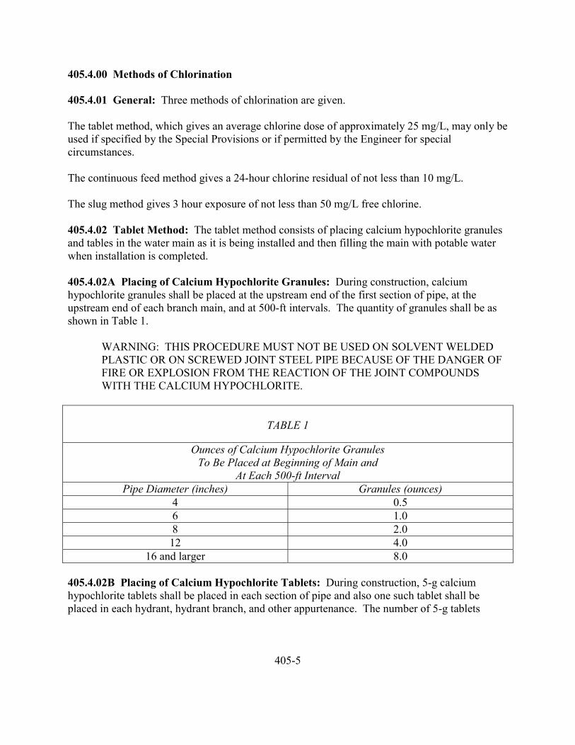
405.4.00 Methods of Chlorination
405.4.01 General: Three methods of chlorination are given.
The tablet method, which gives an average chlorine dose of approximately 25 mg/L, may only beused if specified by the Special Provisions or if permitted by the Engineer for specialcircumstances.
The continuous feed method gives a 24-hour chlorine residual of not less than 10 mg/L.
The slug method gives 3 hour exposure of not less than 50 mg/L free chlorine.
405.4.02 Tablet Method: The tablet method consists of placing calcium hypochlorite granulesand tables in the water main as it is being installed and then filling the main with potable waterwhen installation is completed.
405.4.02A Placing of Calcium Hypochlorite Granules: During construction, calciumhypochlorite granules shall be placed at the upstream end of the first section of pipe, at theupstream end of each branch main, and at 500-ft intervals. The quantity of granules shall be asshown in Table 1.
WARNING: THIS PROCEDURE MUST NOT BE USED ON SOLVENT WELDEDPLASTIC OR ON SCREWED JOINT STEEL PIPE BECAUSE OF THE DANGER OFFIRE OR EXPLOSION FROM THE REACTION OF THE JOINT COMPOUNDSWITH THE CALCIUM HYPOCHLORITE.
TABLE 1
Ounces of Calcium Hypochlorite GranulesTo Be Placed at Beginning of Main and
At Each 500-ft IntervalPipe Diameter (inches) Granules (ounces)
4 0.56 1.08 2.012 4.0
16 and larger 8.0
405.4.02B Placing of Calcium Hypochlorite Tablets: During construction, 5-g calciumhypochlorite tablets shall be placed in each section of pipe and also one such tablet shall beplaced in each hydrant, hydrant branch, and other appurtenance. The number of 5-g tablets
405-5
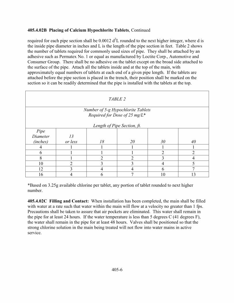
405.4.02B Placing of Calcium Hypochlorite Tablets, Continued
required for each pipe section shall be 0.0012 d2L rounded to the next higher integer, where d isthe inside pipe diameter in inches and L is the length of the pipe section in feet. Table 2 showsthe number of tablets required for commonly used sizes of pipe. They shall be attached by anadhesive such as Permatex No. 1 or equal as manufactured by Loctite Corp., Automotive andConsumer Group. There shall be no adhesive on the tablet except on the broad side attached tothe surface of the pipe. Attach all the tablets inside and at the top of the main, withapproximately equal numbers of tablets at each end of a given pipe length. If the tablets areattached before the pipe section is placed in the trench, their position shall be marked on thesection so it can be readily determined that the pipe is installed with the tablets at the top.
TABLE 2
Number of 5-g Hypochlorite TabletsRequired for Dose of 25 mg/L*
Length of Pipe Section, ft.Pipe
Diameter(inches)
13or less 18 20 30 40
4 1 1 1 1 16 1 1 1 2 28 1 2 2 3 410 2 3 3 4 512 3 4 4 6 716 4 6 7 10 13
*Based on 3.25g available chlorine per tablet, any portion of tablet rounded to next highernumber.
405.4.02C Filling and Contact: When installation has been completed, the main shall be filledwith water at a rate such that water within the main will flow at a velocity no greater than 1 fps.Precautions shall be taken to assure that air pockets are eliminated. This water shall remain inthe pipe for at least 24 hours. If the water temperature is less than 5 degrees C (41 degrees F),the water shall remain in the pipe for at least 48 hours. Valves shall be positioned so that thestrong chlorine solution in the main being treated will not flow into water mains in activeservice.
405-6
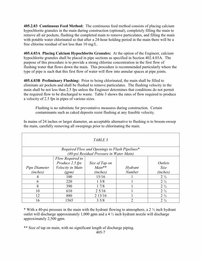
405.2.03 Continuous Feed Method: The continuous feed method consists of placing calciumhypochlorite granules in the main during construction (optional), completely filling the main toremove all air pockets, flushing the completed main to remove particulates, and filling the mainwith potable water chlorinated so that after a 24-hour holding period in the main there will be afree chlorine residual of not less than 10 mg/L.
405.4.03A Placing Calcium Hypochlorite Granules: At the option of the Engineer, calciumhypochlorite granules shall be placed in pipe sections as specified in Section 402.4.03A. Thepurpose of this procedure is to provide a strong chlorine concentration in the first flow offlushing water that flows down the main. This procedure is recommended particularly where thetype of pipe is such that this first flow of water will flow into annular spaces at pipe joints.
405.4.03B Preliminary Flushing: Prior to being chlorinated, the main shall be filled toeliminate air pockets and shall be flushed to remove particulates. The flushing velocity in themain shall be not less than 2.5 fps unless the Engineer determines that conditions do not permitthe required flow to be discharged to waste. Table 3 shows the rates of flow required to producea velocity of 2.5 fps in pipes of various sizes.
Flushing is no substitute for preventative measures during construction. Certaincontaminants such as caked deposits resist flushing at any feasible velocity.
In mains of 24 inches or larger diameter, an acceptable alternative to flushing is to broom-sweepthe main, carefully removing all sweepings prior to chlorinating the main.
TABLE 3
Required Flow and Openings to Flush Pipelines*(40-psi Residual Pressure in Water Main)
Pipe Diameter(inches)
Flow Required toProduce 2.5 fpsVelocity in Main
(gpm)
Size of Tap onMain**(inches)
HydrantNumber
OutletsSize
(inches)4 100 15/16 1 2 ½6 220 1 3/8 1 2 ½8 390 1 7/8 1 2 ½10 610 2 5/16 1 2 ½12 880 2 13/16 1 2 ½16 1565 3 5/8 2 2 ½
* With a 40-psi pressure in the main with the hydrant flowing to atmosphere, a 2 ½ inch hydrantoutlet will discharge approximately 1,000 gpm and a 4 ½ inch hydrant nozzle will dischargeapproximately 2,500 gpm.
** Size of tap on main, with no significant length of discharge piping.405-7
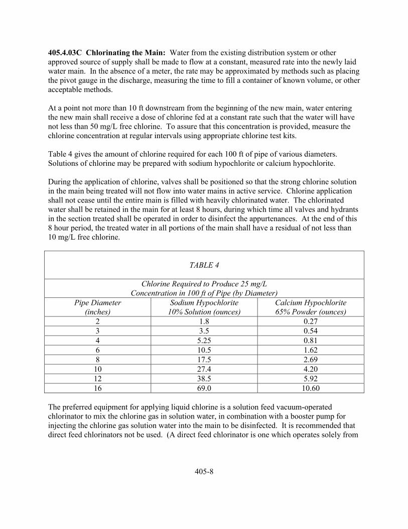
405.4.03C Chlorinating the Main: Water from the existing distribution system or otherapproved source of supply shall be made to flow at a constant, measured rate into the newly laidwater main. In the absence of a meter, the rate may be approximated by methods such as placingthe pivot gauge in the discharge, measuring the time to fill a container of known volume, or otheracceptable methods.
At a point not more than 10 ft downstream from the beginning of the new main, water enteringthe new main shall receive a dose of chlorine fed at a constant rate such that the water will havenot less than 50 mg/L free chlorine. To assure that this concentration is provided, measure thechlorine concentration at regular intervals using appropriate chlorine test kits.
Table 4 gives the amount of chlorine required for each 100 ft of pipe of various diameters.Solutions of chlorine may be prepared with sodium hypochlorite or calcium hypochlorite.
During the application of chlorine, valves shall be positioned so that the strong chlorine solutionin the main being treated will not flow into water mains in active service. Chlorine applicationshall not cease until the entire main is filled with heavily chlorinated water. The chlorinatedwater shall be retained in the main for at least 8 hours, during which time all valves and hydrantsin the section treated shall be operated in order to disinfect the appurtenances. At the end of this8 hour period, the treated water in all portions of the main shall have a residual of not less than10 mg/L free chlorine.
TABLE 4
Chlorine Required to Produce 25 mg/LConcentration in 100 ft of Pipe (by Diameter)
Pipe Diameter(inches)
Sodium Hypochlorite10% Solution (ounces)
Calcium Hypochlorite65% Powder (ounces)
2 1.8 0.273 3.5 0.544 5.25 0.816 10.5 1.628 17.5 2.6910 27.4 4.2012 38.5 5.9216 69.0 10.60
The preferred equipment for applying liquid chlorine is a solution feed vacuum-operatedchlorinator to mix the chlorine gas in solution water, in combination with a booster pump forinjecting the chlorine gas solution water into the main to be disinfected. It is recommended thatdirect feed chlorinators not be used. (A direct feed chlorinator is one which operates solely from
405-8
405.4.03C Chlorinating the Main, Continued
the pressure in the chlorine cylinder.) Hypochlorite solutions may be applied to the water mainwith a gasoline or electrically powered chemical feed pump designed for feeding chlorinesolutions. Feed lines shall be of such material and strength as to withstand safely the corrosioncaused by the concentrated chlorine solutions and the maximum pressures that may be created bythe pumps. All connections shall be checked for tightness before the solution is applied to themain.
405.4.04 Slug Method: The slug method consists of placing calcium hypochlorite granules inthe main during construction, completely filling the main to eliminate all air pockets, flushing themain to remove particulates, and slowly flowing through the main a slug of water dosed withchlorine to a concentration of 300 mg/L in order that all parts of the main and its appurtenanceswill be exposed to the highly chlorinated water for a period of not less than 3 hours.
405.4.04A Placing Calcium Hypochlorite Granules: Same as 405.4.02A.
405.4.04B Preliminary Flushing: Same as 405.4.02B.
405.4.04C Chlorinating the Main: At a point not more than 10 feet downstream from thebeginning of the new main, water entering the new main shall receive a dose of chlorine fed at aconstant rate such that the water will have not less than 300 mg/L free chlorine. To assure thatthis concentration is provided, the chlorine concentration should be measured at regular intervals.The chlorine shall be applied continuously and for a sufficient period to develop a solid columnof “slug” of chlorinated water that will, as it moves through the main, expose all interior surfacesto a concentration of approximately 300 mg/L for at least 3 hours.
The free chlorine residual shall be measured in the slug as it moves through the main. If at anytime it drops below 50 mg/L, the flow shall be stopped, chlorination equipment shall be relocatedat the head of the slug, and as flow is resumed, chlorine shall be applied to restore the freechlorine in the slug to not less than 300 mg/L.
As the chlorinated water flows past fittings in valves, related valves and hydrants shall beoperated so as to disinfect appurtenances and pipe branches.
405.5.00 Final Flushing
405.5.01 Clearing the Main of Heavily Chlorinated Water: After the applicable retentionperiod, the heavily chlorinated water shall be flushed from the main until the chlorinemeasurements show that the concentration in the water leaving the main is no higher than thatgenerally prevailing in the system or is acceptable for domestic use.
405-9
405.5.02 Disposing of Heavily Chlorinated Water: The environment to which the chlorinatedwater is to be discharged shall be inspected and if there is any question that the chlorinateddischarge will cause damage to the environment, then a reducing agent shall be applied to thewater to be wasted to neutralize thoroughly the chlorine residual remaining in the water. Wherenecessary, federal, state, and local regulatory agencies should be contacted to determine specialprovisions for the disposal of heavily chlorinated water.
405.6.00 Bacteriological Tests
405.6.01 Standard Conditions: After final flushing and before the water main is replaced inservice, a sample or samples shall be collected from the end of the line, shall be tested forbacteriological quality in accordance with Standard Methods, and shall show the absence ofcoliform organisms. A standard plate count may be required at the option of the Engineer. Atleast one sample shall be collected from the new main and one from each branch. In the case ofextremely long mains, it is desirable that samples be collected along the length of the line as wellas its end.
405.6.02 Special Conditions: If, during construction, trench water has entered the main, or if inthe opinion of the Engineer, excessive quantities of dirt or debris have entered the main,bacteriological samples shall be taken at intervals of approximately 200 ft and shall be identifiedas to location. Samples shall be taken of water that has stood in the main for at least 16 hoursafter final flushing has been completed.
405.6.03 Sampling Procedure: Samples for bacteriological analysis shall be collected in sterilebottles treated with sodium thiosulfate as required by Standard Methods. No hose or fire hydrantshall be used in collection of samples. A corporation cock shall be installed in the main withcopper tube gooseneck assembly. After samples have been collected, the gooseneck assemblyshall be removed.
405.7.00 Redisinfection: If the initial disinfection fails to produce satisfactory bacteriologicalsamples, the main may be reflushed and shall be resampled. If check samples show the presenceof coliform organisms, then the main shall be rechlorinated by the continuous feed or slugmethod of chlorination until satisfactory results are obtained.
405.7.01 Disinfection When Cutting Into or Repairing Existing Mains: The followingprocedures apply primarily when mains are wholly or partially dewatered. After the appropriateprocedures have been completed, the main may be returned to service prior to completion ofbacteriological testing in order to minimize the time customers are out of water. Leaks or breaksthat are repaired with clamping devices while the mains remain full of water under pressurepresent little danger of contamination and require no disinfection.
405-10
405.7.02 Trench Treatment: When an old main is opened, either by accident or by design, theexcavation will likely be wet and may be badly contaminated from nearby sewers. Liberalquantities of hypochlorite applied to open trench areas will lessen the danger from suchpollution. Tablets have the advantage in such a situation because they dissolve slowly andcontinue to release hypochlorite as water is pumped from the excavation.
405.7.03 Swabbing with Hypochlorite Solution: The interior of all pipe and fittings used inmaking the repair (particularly couplings and sleeves) shall be swabbed or sprayed with a onepercent hypochlorite solution before they are installed.
405.7.04 Flushing: Thorough flushing is the most practical means of removing contaminationintroduced during repairs. If valve and hydrant locations permit, flushing toward the worklocation from both directions is recommended. Flushing shall be started as soon as the repairsare completed and shall be continued until discolored water is eliminated.
405.7.05 Slug Chlorination: Where practical in addition to the procedures above, a section ofmain in which the break is located shall be isolated, all service connections shut off, and thesection flushed and chlorinated as described in Section 402.4.03C, except that the contact timemay be reduced to as little as 15 minutes. After chlorination, flushing shall be resumed andcontinued until discolored water is eliminated and the water is free of noticeable chlorine odor.
405.7.06 Sampling and Bacteriological Testing: Bacteriological samples shall be taken afterrepairs to provide a record by which the effectiveness of the procedures used can be determined.If the direction of the flow is unknown, samples shall be taken on each side of the main break.
If positive samples are recorded, daily sampling shall be continued until two consecutivenegative samples are recorded. Positive samples shall be evaluated by the Engineer forcorrective action.
405.8.00 Measurement and Payment
405.8.01 Disinfection: Unless specified otherwise, disinfection shall be considered asincidental work for which no additional payment will be made.
405.8.02 Sampling and Bacteriological Testing: Unless specified otherwise, sampling andbacteriological testing will be considered as incidental work for which no additional paymentwill be made.
405-11
406 PROTECTION OF WATER SUPPLIES
406.1.00 Description
406.2.00 Separation of mains from Pollution Sources406.2.01 Types of Pollution Sources406.2.01A Septic Tanks, Waste Stabilization Ponds, and Open Sewage Discharge Locations406.2.02 Absorption Fields and Feedlots406.2.03 Sewer Drain Crossings406.2.04 Encasement
406.3.00 Separation of Potable Water Mains and Sanitary Sewers406.3.01 Parallel Water and Sewer Lines406.3.02 Water Services and Building Sewers
406.4.00 Sewer Connections
406-1
406 PROTECTION OF WATER SUPPLIES
406.1.00 Description
406.4.01 General: This section describes the requirements for protecting water supplies frompollution sources.
406.2.00 Separation of Water Mains from Pollution Sources
406.2.01 Types of Pollution Sources: It is of utmost importance that potable water lines beprotected from any source of pollution. The following shall pertain to instances where individualor industrial septic tanks and tile absorption fields, waste stabilization ponds, waste water linesdischarging into roadside ditches, feedlots or other sources of pollution are encountered.
406.2.01A Septic Tanks, Waste Stabilization Ponds and Open Sewage DischargeLocations: A minimum distance of 25 feet shall be maintained between all potable water linesand all septic tanks, waste stabilization ponds or open sewage discharge locations.
406.2.02 Absorption Fields and Feedlots: Under no circumstances shall a water line extendthrough a septic tank tile absorption field or feedlot. All water lines shall be located a minimumof 25 feet from the farthest known extent of any sewage absorption.
406.2.03 Sewer Drain Crossing: When it is necessary for any water line to cross a sewer drain,including an open drain ditch, the sewage flow shall be encased in a cast iron or approved plasticpipe for at least 10 feet of each side of the water main.
406.2.04 Encasement: Under no condition will it be considered that encasement of the watermain through an area of real or potential pollution would provide the protection needed to thewater supply.
406.3.00 Separation of Potable Water Mains and Sanitary Sewers
406.3.01 Parallel Water and Sewer Lines: When potable water pipes and sanitary sewers arelaid parallel to each other, the horizontal distance between them shall be not less than 10 feet.The laying of water pipes and sanitary sewers shall be in separate trenches with undisturbedearth between them.
When a water pipe and a sanitary sewer cross and the sewer is 2 feet or more (clear space) belowthe water pipe, no extra protection to the latter is needed. At all other crossings, the sewer is tobe constructed of either cast iron pipe with leaded joints or approved plastic pipe with bondedjoints for a distance of 10 feet in either direction from the crossing. Joints are not to be in the
406-2
406.3.01 Parallel Water and Sewer Lines, Continued
immediately vicinity of the water main and as far from it as practicable. Where water mains arelaid across or through an area where there are existing sewers and the extra protection is needed,the existing sewers may be encased in concrete with a minimum of 7 inches thickness for therequired distance on each side of the crossing.
406.3.02 Water Services and Building Sewers: The same horizontal separation requirementsas listed above apply to water service lines and building sewers. The same vertical distanceseparations and the extra protections as required above for potable water mains and sanitarysewers apply in the same manner to water service pipes and building sewers.
406.4.00 Sewer Connections: There shall be no physical connection between any part of thepotable water supply with any building sewer, building lateral or house lateral, or with anysanitary sewer or waste water treatment facility by means of which it would be possible forsewage, even under exceptional circumstances, to reach the wells, storage reservoirs ordistribution system and thus contaminate the water supply.
406-3

DIVISION FIVESTRUCTURES
501-0
501 EARTHWORK
501.1.00 Description
501.2.00 Materials501.2.01 Material Approval501.2.02 Structure Excavation501.2.03 General Backfill501.2.04 Special Backfill501.2.04A Granular Backfill501.2.04B Sand Backfill501.2.04C Impervious Backfill501.2.05 Foundation Stabilization501.2.06 Topsoil501.2.07 Water
501.3.00 Construction501.3.01 Excavation501.3.02 Limits of Excavation501.3.03 Shoring and Cribbing501.3.04 Dewatering501.3.05 Disposal of Excavated Material501.3.06 Backfill501.3.06A Backfill Around Structures501.3.06B Granular Backfill Around Structures501.3.06C Granular Backfill Under Footings and Slabs501.3.06D Granular Backfill Under Facilities501.3.06E Sand Backfill501.3.06F Impervious Backfill501.3.07 Compaction Equipment501.3.08 Foundation Stabilization501.3.09 Embankment Construction
501.4.00 Measurement and Payment501.4.01 Shoring and Cribbing501.4.02 Structure Excavation501.4.03 Excavation Below Elevations Shown501.4.04 Backfill501.4.05 Foundation Stabilization501.4.06 Dewatering501.4.07 Topsoil501.4.08 Embankment501.4.09 Payment
501-1
501 EARTHWORK
501.1.00 Description: This section covers the work necessary for excavation, backfilling,embankment construction and disposal of materials in connection with the construction ofstructures.
501.2.00 Materials
501.2.01 Material Approval: Samples of all fabricated materials shall be submitted to theEngineer for approval prior to placing orders. Samples shall be representative and clearlymarked to indicate the source of the material and its intended use on the project.
501.2.02 Structure Excavation: Structure excavation shall include the removal of allmaterials, of whatever nature, necessary for the construction of foundations and substructures inaccordance with the plans or as directed by the Engineer. It shall include the furnishing of allnecessary equipment and the construction of all cribs, cofferdams, caissons and all dewatering,etc., which may be necessary for the execution of the work. It shall also include the subsequentremoval of cofferdams and cribs and the placement of all backfill. It shall also include thewasting of excavated material which is not required for backfill.
501.2.03 General Backfill: General backfill shall be excavated material free from roots, debrisand other deleterious materials.
501.2.04 Special Backfill
501.2.04A Granular Backfill: Granular backfill shall conform to the requirements of Sections301.2.04B and 301.3.07 as specified.
501.2.04B Sand Backfill: Sand backfill shall conform to the requirements of Subsection301.2.04C.
501.2.04C Impervious Backfill: Impervious backfill material shall be composed of particles atleast 95 percent of which will pass the No. 200 sieve, and with a plasticity index not less than 20.
501.2.05 Foundation Stabilization: When a firm foundation is not encountered due to soft,spongy or other unsuitable soil, all such unsuitable soil under the structure shall be removed andreplaced with a suitable granular material. If a suitable granular material is not available on thejob site for this backfill, the Contractor shall, after approval from the Engineer, furnish granularmaterial which shall be paid for as foundation stabilization. The granular material shall bedeposited in lifts not exceeding eight inches loose thickness. Each lift shall be compacted to atleast 95 percent of its maximum density at optimum moisture content as determined by theapplicable method of ASTN D698, before placing the next lift. Jetting or puddling will not bepermitted.
501-2
501.2.06 Topsoil: Topsoil shall conform to the requirements of Subsection 221.2.04.
501.2.07 Water: Water shall conform to the requirements of Subsection 205.2.01.
501.3.00 Construction
501.3.01 Excavation: Excavation shall consist of the excavation, removal, and disposal of allformations and materials, natural or man made, irrespective of nature or condition, encounteredwithin the limits hereinafter defined, necessary for the construction of footings, foundations,slabs, retaining walls, cribbing, culverts or other similar structures.
501.3.02 Limits of Excavation: The limits of excavation for pay quantities shall be as shown.
When the limits are not shown, the limits for pay quantities will be lines parallel to and one footoutside the neat lines of the footings or bases of the structure.
The lower limit shall be the elevation shown on the plans for the bottoms of footings or bases forthe structure.
The upper limit shall be the ground surface at the site of the work immediately prior to thebeginning of the work; except that where the excavation for the structure comes within the limitsof roadway or channel change excavation areas, the upper limits shall be the planes of thebottoms and side slopes of those areas, and where the excavation for the structure comes withinthe limits of embankment to be constructed as a part of the contract, such embankment shall beconstructed prior to construction or installation of the structure and the upper limit shall be theplanes of the new embankment at the elevation specified or established by the Engineer for theembankment construction.
Excavation outside or below the limits for purposes of forming, shoring, or other activities, willnot be considered for payment.
In the event of excavation occurring below the elevations shown, the area will be backfilled tothe proper grade as the Engineer may direct, at no cost to the Owner.
No measurement or payment will be considered for material forced up between foundation pilesduring driving nor of material used in backfilling around piles should compaction occur duringdriving.
501.3.03 Shoring and Cribbing: Shoring and cribbing of excavations will not be requiredwhen open excavation would not be detrimental to adjacent structures, roadways, etc.; otherwiseexcavation shall be shored, braced or protected by cofferdams in accordance with approvedmethods. When footings can be placed in the dry without the use of cribs or cofferdams,backforms may be omitted with the approval of the Engineer and the entire excavation filledwith concrete to the required elevation of the top of the footing.
501-3
501.3.03 Shoring and Cribbing, Continued
Cofferdams or cribs shall be constructed so as to protect green concrete against damage from asudden rising of the stream and to prevent damage to the foundation by erosion. No timber orbracing shall be left in cofferdams or cribs in such a way as to extend into the substructureconcrete, without written permission from the Engineer.
Unless otherwise provided, cofferdams or cribs including all sheeting and bracing shall beremoved after the completion of the substructure, care being taken not to disturb or otherwiseinjure the finished concrete.
Shoring and cribbing shall be designed and constructed as necessary for the proper performanceof the work which must be done inside them. The interior dimensions of cofferdams and cribsshall be such as to give sufficient clearance for the inspection of forms.
501.3.04 Dewatering: The Contractor shall provide and maintain ample means and deviceswith which to promptly remove and dispose of all water entering the excavation during theexcavation, forming, placing of metal reinforcement and concrete and backfilling activities. TheContractor shall dispose of the water in a suitable manner without damage to adjacent property.
Ground water shall be controlled such that softening of the bottom of excavations or formationof “quick” conditions or “boils” during excavation shall be prevented. Dewatering systems shallbe designed and operated so as to prevent removal of the natural soils and so that the groundwater level outside the excavation is not reduced to the extent that would damage or endangeradjacent structures or property.
501.3.05 Disposal of Excavated Materials: Disposal of excavated material shall conform tothe requirements of Subsection 204.3.03.
501.3.06 Backfill: All spaces excavated and not occupied by structures or other permanentwork shall be backfilled with excavated native material unless otherwise specified. The topsurface shall be neatly graded.
Backfill which becomes a part of the roadway embankment or which is to support a roadway,rock slope protection or slope paving shall be in conformance to the requirements of Subsection204.3.02.
501.3.06A Backfill Around Structures: Backfill around concrete structures shall be placedonly after the concrete has attained two-thirds of its specified compressive strength. All formmaterials and trash shall be removed from the excavation before placing any backfill.
501-4
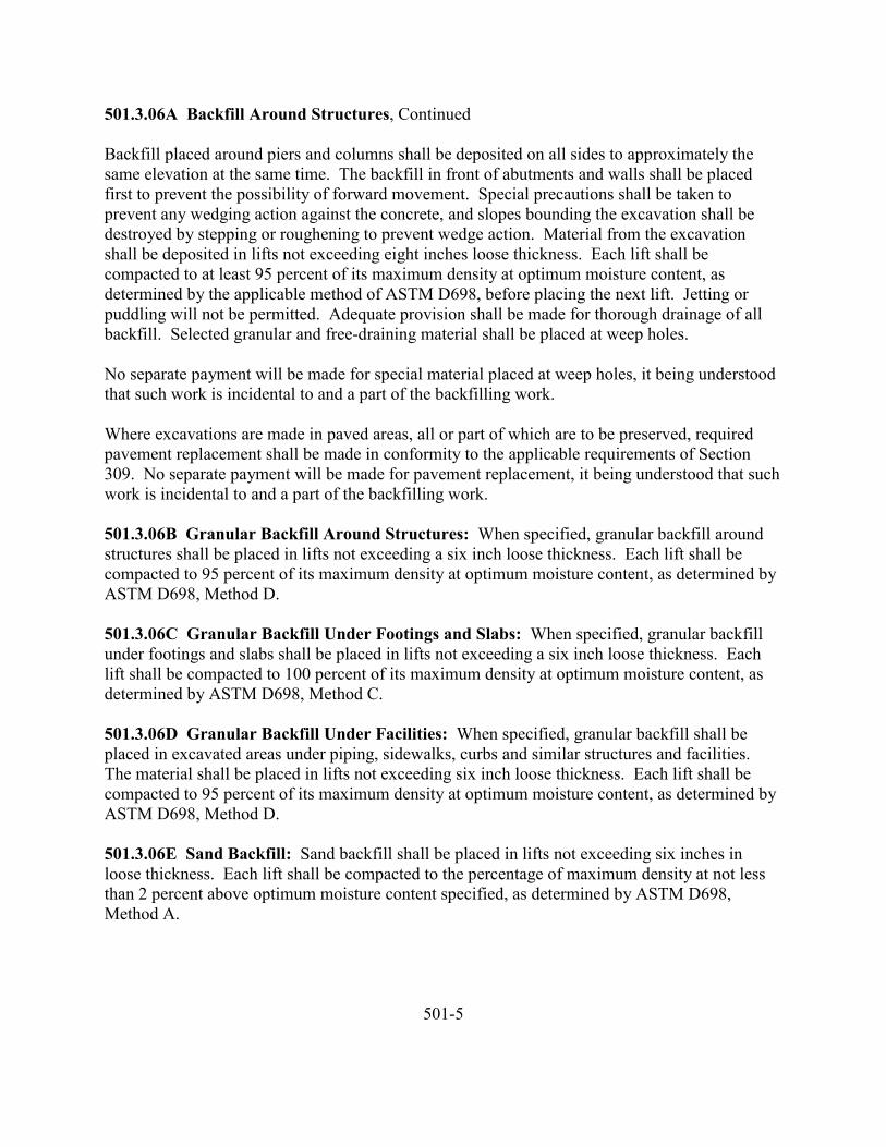
501.3.06A Backfill Around Structures, Continued
Backfill placed around piers and columns shall be deposited on all sides to approximately thesame elevation at the same time. The backfill in front of abutments and walls shall be placedfirst to prevent the possibility of forward movement. Special precautions shall be taken toprevent any wedging action against the concrete, and slopes bounding the excavation shall bedestroyed by stepping or roughening to prevent wedge action. Material from the excavationshall be deposited in lifts not exceeding eight inches loose thickness. Each lift shall becompacted to at least 95 percent of its maximum density at optimum moisture content, asdetermined by the applicable method of ASTM D698, before placing the next lift. Jetting orpuddling will not be permitted. Adequate provision shall be made for thorough drainage of allbackfill. Selected granular and free-draining material shall be placed at weep holes.
No separate payment will be made for special material placed at weep holes, it being understoodthat such work is incidental to and a part of the backfilling work.
Where excavations are made in paved areas, all or part of which are to be preserved, requiredpavement replacement shall be made in conformity to the applicable requirements of Section309. No separate payment will be made for pavement replacement, it being understood that suchwork is incidental to and a part of the backfilling work.
501.3.06B Granular Backfill Around Structures: When specified, granular backfill aroundstructures shall be placed in lifts not exceeding a six inch loose thickness. Each lift shall becompacted to 95 percent of its maximum density at optimum moisture content, as determined byASTM D698, Method D.
501.3.06C Granular Backfill Under Footings and Slabs: When specified, granular backfillunder footings and slabs shall be placed in lifts not exceeding a six inch loose thickness. Eachlift shall be compacted to 100 percent of its maximum density at optimum moisture content, asdetermined by ASTM D698, Method C.
501.3.06D Granular Backfill Under Facilities: When specified, granular backfill shall beplaced in excavated areas under piping, sidewalks, curbs and similar structures and facilities.The material shall be placed in lifts not exceeding six inch loose thickness. Each lift shall becompacted to 95 percent of its maximum density at optimum moisture content, as determined byASTM D698, Method D.
501.3.06E Sand Backfill: Sand backfill shall be placed in lifts not exceeding six inches inloose thickness. Each lift shall be compacted to the percentage of maximum density at not lessthan 2 percent above optimum moisture content specified, as determined by ASTM D698,Method A.
501-5
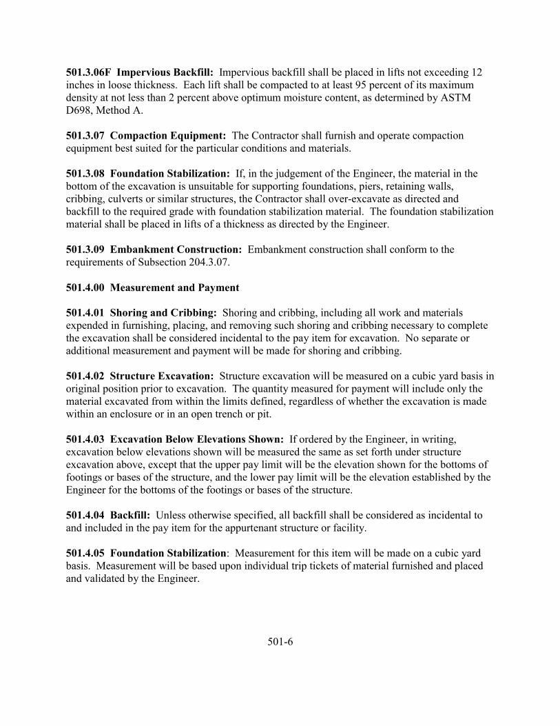
501.3.06F Impervious Backfill: Impervious backfill shall be placed in lifts not exceeding 12inches in loose thickness. Each lift shall be compacted to at least 95 percent of its maximumdensity at not less than 2 percent above optimum moisture content, as determined by ASTMD698, Method A.
501.3.07 Compaction Equipment: The Contractor shall furnish and operate compactionequipment best suited for the particular conditions and materials.
501.3.08 Foundation Stabilization: If, in the judgement of the Engineer, the material in thebottom of the excavation is unsuitable for supporting foundations, piers, retaining walls,cribbing, culverts or similar structures, the Contractor shall over-excavate as directed andbackfill to the required grade with foundation stabilization material. The foundation stabilizationmaterial shall be placed in lifts of a thickness as directed by the Engineer.
501.3.09 Embankment Construction: Embankment construction shall conform to therequirements of Subsection 204.3.07.
501.4.00 Measurement and Payment
501.4.01 Shoring and Cribbing: Shoring and cribbing, including all work and materialsexpended in furnishing, placing, and removing such shoring and cribbing necessary to completethe excavation shall be considered incidental to the pay item for excavation. No separate oradditional measurement and payment will be made for shoring and cribbing.
501.4.02 Structure Excavation: Structure excavation will be measured on a cubic yard basis inoriginal position prior to excavation. The quantity measured for payment will include only thematerial excavated from within the limits defined, regardless of whether the excavation is madewithin an enclosure or in an open trench or pit.
501.4.03 Excavation Below Elevations Shown: If ordered by the Engineer, in writing,excavation below elevations shown will be measured the same as set forth under structureexcavation above, except that the upper pay limit will be the elevation shown for the bottoms offootings or bases of the structure, and the lower pay limit will be the elevation established by theEngineer for the bottoms of the footings or bases of the structure.
501.4.04 Backfill: Unless otherwise specified, all backfill shall be considered as incidental toand included in the pay item for the appurtenant structure or facility.
501.4.05 Foundation Stabilization: Measurement for this item will be made on a cubic yardbasis. Measurement will be based upon individual trip tickets of material furnished and placedand validated by the Engineer.
501-6
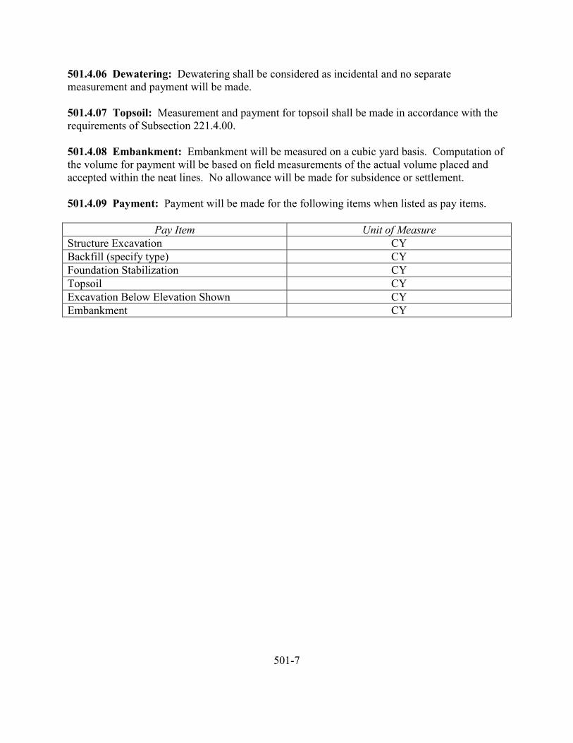
501.4.06 Dewatering: Dewatering shall be considered as incidental and no separatemeasurement and payment will be made.
501.4.07 Topsoil: Measurement and payment for topsoil shall be made in accordance with therequirements of Subsection 221.4.00.
501.4.08 Embankment: Embankment will be measured on a cubic yard basis. Computation ofthe volume for payment will be based on field measurements of the actual volume placed andaccepted within the neat lines. No allowance will be made for subsidence or settlement.
501.4.09 Payment: Payment will be made for the following items when listed as pay items.
Pay Item Unit of MeasureStructure Excavation CYBackfill (specify type) CYFoundation Stabilization CYTopsoil CYExcavation Below Elevation Shown CYEmbankment CY
501-7

502 PILING
STANDARDS NOT COMPLETE AT THIS TIME
502-1
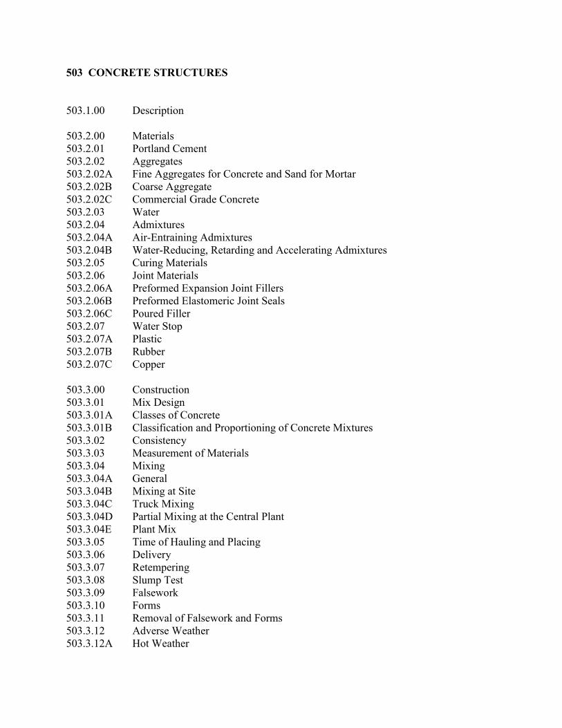
503 CONCRETE STRUCTURES
503.1.00 Description
503.2.00 Materials503.2.01 Portland Cement503.2.02 Aggregates503.2.02A Fine Aggregates for Concrete and Sand for Mortar503.2.02B Coarse Aggregate503.2.02C Commercial Grade Concrete503.2.03 Water503.2.04 Admixtures503.2.04A Air-Entraining Admixtures503.2.04B Water-Reducing, Retarding and Accelerating Admixtures503.2.05 Curing Materials503.2.06 Joint Materials503.2.06A Preformed Expansion Joint Fillers503.2.06B Preformed Elastomeric Joint Seals503.2.06C Poured Filler503.2.07 Water Stop503.2.07A Plastic503.2.07B Rubber503.2.07C Copper
503.3.00 Construction503.3.01 Mix Design503.3.01A Classes of Concrete503.3.01B Classification and Proportioning of Concrete Mixtures503.3.02 Consistency503.3.03 Measurement of Materials503.3.04 Mixing503.3.04A General503.3.04B Mixing at Site503.3.04C Truck Mixing503.3.04D Partial Mixing at the Central Plant503.3.04E Plant Mix503.3.05 Time of Hauling and Placing503.3.06 Delivery503.3.07 Retempering503.3.08 Slump Test503.3.09 Falsework503.3.10 Forms503.3.11 Removal of Falsework and Forms503.3.12 Adverse Weather503.3.12A Hot Weather
503.3.12B Cold Weather503.3.13 Measuring, Mixing, Hauling and Placing503.3.13A General503.3.13B Culverts503.3.13C Girders, Slabs and Columns503.3.13D Pumping503.3.13E Depositing Concrete Under Water503.3.14 Construction Joints503.3.14A General503.3.14B Bonding503.3.15 Expansion and Fixed Joints and Bearings503.3.16 Surface Finishing503.3.16A Formed Surfaces503.3.16B Unformed Surfaces503.3.17 Curing503.3.18 Pneumatically Applied Mortar
503.4.00 Measurement and Payment503.4.01 Concrete503.4.01A Lump Sum Basis503.4.01B Cubic Yard Basis503.4.02 Pneumatically Applied Mortar503.4.03 Payment
503-2
503 CONCRETE STRUCTURES
503.1.00 Description: This section covers the work necessary for concrete, reinforced ornonreinforced, precast or cast-in-place, in bridges, box culverts, retaining walls and otherconcrete structures.
503.2.00 Materials
503.2.01 Portland Cement: Portland cement shall conform to the following types as specified:
Type I – For use when the special properties of other cements are not required.
Type IA – Air-entraining cement for the same uses as Type I, where air entrainment is desired.
Type II – For general use, especially when moderate sulfate resistance or moderate hear ofhydration is desired.
Type IIA – Air-entraining cement for the same uses as Type II, where air entrainment is desired.
Type III – For use when high early strength is desired.
Type IIIA – Air-entraining cement for the same use as Type II, where air-entrainment is desired.
Portland cement shall conform to the requirements of AASHTO M 85 for low alkali cementexcept as follows:
1. Cement shall have a total alkali content (sodium and potassium oxide calculatedas Na20 + 0.658 K20) not exceeding 0.6 percent.
2. Types I, IA, III or IIIA shall contain a maximum of 10 percent tricalciumaluminate.
3. For Types II and IIA, tricalcium silicate and tricalcium aluminate shall have amaximum total percentage of 58.
When not otherwise specified, Type I shall be used. When approved in writing, Type IIIPortland cement may be used in lieu of Type I in the identical quantity specified for Type I.
Differing brands or types of cement, or the same brand or type of cement from different millsshall not be mixed during use nor shall they be used alternately without prior written approval.
503-3
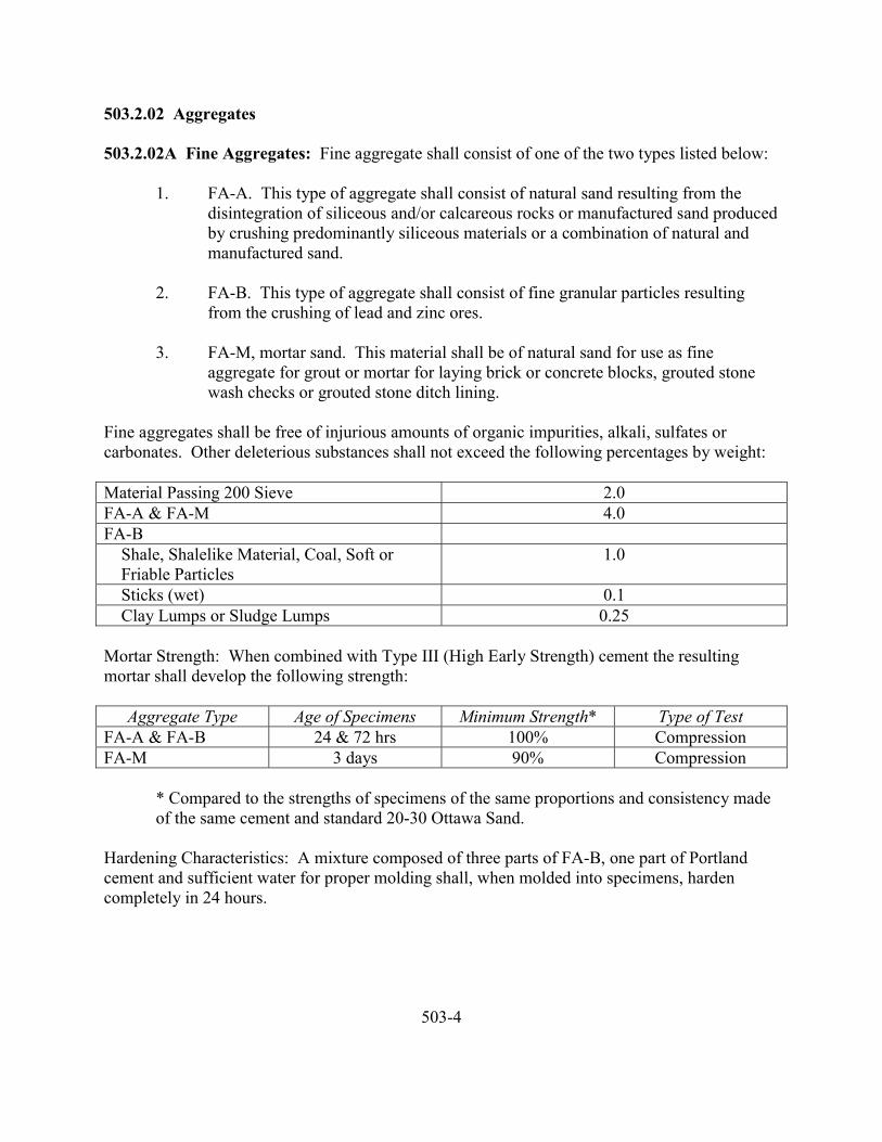
503.2.02 Aggregates
503.2.02A Fine Aggregates: Fine aggregate shall consist of one of the two types listed below:
1. FA-A. This type of aggregate shall consist of natural sand resulting from thedisintegration of siliceous and/or calcareous rocks or manufactured sand producedby crushing predominantly siliceous materials or a combination of natural andmanufactured sand.
2. FA-B. This type of aggregate shall consist of fine granular particles resultingfrom the crushing of lead and zinc ores.
3. FA-M, mortar sand. This material shall be of natural sand for use as fineaggregate for grout or mortar for laying brick or concrete blocks, grouted stonewash checks or grouted stone ditch lining.
Fine aggregates shall be free of injurious amounts of organic impurities, alkali, sulfates orcarbonates. Other deleterious substances shall not exceed the following percentages by weight:
Material Passing 200 Sieve 2.0FA-A & FA-M 4.0FA-B Shale, Shalelike Material, Coal, Soft or Friable Particles
1.0
Sticks (wet) 0.1 Clay Lumps or Sludge Lumps 0.25
Mortar Strength: When combined with Type III (High Early Strength) cement the resultingmortar shall develop the following strength:
Aggregate Type Age of Specimens Minimum Strength* Type of TestFA-A & FA-B 24 & 72 hrs 100% CompressionFA-M 3 days 90% Compression
* Compared to the strengths of specimens of the same proportions and consistency madeof the same cement and standard 20-30 Ottawa Sand.
Hardening Characteristics: A mixture composed of three parts of FA-B, one part of Portlandcement and sufficient water for proper molding shall, when molded into specimens, hardencompletely in 24 hours.
503-4
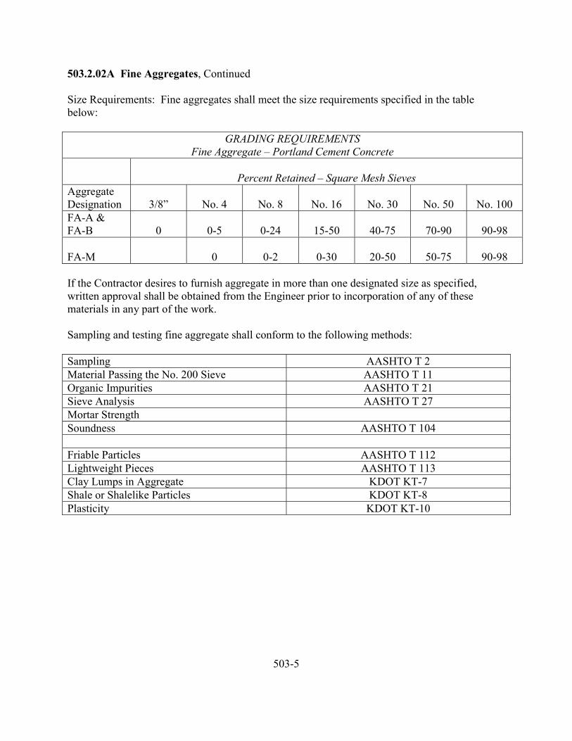
503.2.02A Fine Aggregates, Continued
Size Requirements: Fine aggregates shall meet the size requirements specified in the tablebelow:
GRADING REQUIREMENTSFine Aggregate – Portland Cement Concrete
Percent Retained – Square Mesh SievesAggregateDesignation 3/8” No. 4 No. 8 No. 16 No. 30 No. 50 No. 100FA-A &FA-B 0 0-5 0-24 15-50 40-75 70-90 90-98
FA-M 0 0-2 0-30 20-50 50-75 90-98
If the Contractor desires to furnish aggregate in more than one designated size as specified,written approval shall be obtained from the Engineer prior to incorporation of any of thesematerials in any part of the work.
Sampling and testing fine aggregate shall conform to the following methods:
Sampling AASHTO T 2Material Passing the No. 200 Sieve AASHTO T 11Organic Impurities AASHTO T 21Sieve Analysis AASHTO T 27Mortar StrengthSoundness AASHTO T 104
Friable Particles AASHTO T 112Lightweight Pieces AASHTO T 113Clay Lumps in Aggregate KDOT KT-7Shale or Shalelike Particles KDOT KT-8Plasticity KDOT KT-10
503-5
503.2.02B Coarse Aggregate and Mixed Aggregate: Coarse aggregate shall consist of rock,gravel, or other approved inert material of similar characteristics or combinations thereof, havinghard, strong, durable pieces free from adherent coatings.
The amount of deleterious substances shall not exceed the following percentages by weight:
Material Passing No. 200 Sieve 2.0Shale or Shale-Like Material 0.5Soft or Friable Particles 2.5Sticks (wet) 0.1Coal 0.5Clay Lumps 0.5
No one of the above percentages shall be exceeded when taken separately. In addition, anycombination of shale, soft or friable particles, sticks, coal, clay or clay lumps shall not exceed 3.0percent.
Quality:
Soundness, minimum 0.90Wear, Maximum 50%
The material shall also be reasonably free from all other deleterious substance.
The grading of each of the specified sizes of coarse aggregate shall be in accordance with thefollowing table.
503-6
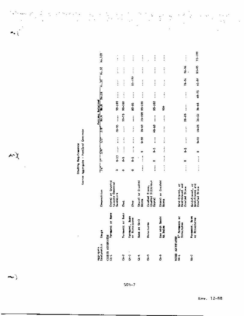
503.2.02B Coarse Aggregate and Mixed Aggregate, Continued
When a tolerance range is set forth in the above grading requirements, it shall be understood thatthe midpoint of the tolerance range is the target value and the product shall conform as closely asrealistically possible to this target value. The purpose of the tolerance range is only to permitoccasional minor variations from the target value that are, for practical reasons, unavoidable.
If gravel is used in the manufacture of aggregate for Portland cement concrete pavement, thematerial shall contain in each designated separated size not less than 60 percent by weight offragments which have at least one fractured face produced by mechanical crushing.
Sampling and testing of coarse aggregate shall conform to the following:
Sampling AASHTO T 2Materials Passing the No. 200 Sieve AASHTO T 11Organic Impurities AASHTO T 21Sieve Analysis AASHTO T 27Abrasion AASHTO T 96Soundness AASHTO T 104Friable Particles AASHTO T 112Lightweight Pieces AASHTO T 113Fracture KDOT KT-21
The sampling and testing of Portland cement concrete shall conform to the following:
Sampling AASHTO T 141Cement Content AASHTO T 121Consistency AASHTO T 183Slump AASHTO T 119Air Content AASHTO T 152Bulk Specific Gravity and Absorption AASHTO T 84 & T 85Molding Test Cylinders AASHTO T 23Compressive Strength of Cylinders AASHTO T 22
503.2.02C Commercial Grade Concrete: Commercial grade concrete may be used on itemsdesignated on the Plans or if approved in writing by the Engineer. When commercial gradeconcrete is used, Subsection 502.2.02A and 502.2.02B of these specifications shall bedisregarded and the following stipulations shall govern:
1. Materials: The commercial grade concrete mix shall be approved by theEngineer. This approval will in general be based on the following conditions:
503-8
503.2.02C Commercial Grade Concrete, Continued
All materials shall be those normally used for the production and sale of concretein the vicinity of the project.
The mixture produced shall have a minimum cement content of six sacks ofcement per cubic yard of concrete and shall be Class 3000 as hereinafter definedin Subsection 503.3.01A. The water-cement ratio will be designated by theEngineer but in no case be less than 5 ½ (gallons of water per 94 lb sack ofcement).
Type I, II or III cement may be used unless otherwise designated.
No additives other than air-entraining agent will be allowed.
503.2.03 Water: Water used in mixing Portland cement concrete shall be clean and free of soil,salt, acid, alkali, sugar, vegetable matter, or other deleterious substances, and shall conform tothe requirements of AASHTO T 26. Water of approved potable quality may be used withouttest.
503.2.04 Admixtures
503.2.04A Air-Entraining Admixtures: Air-entraining admixtures shall conform to therequirements of ASTM C260 using one or another of the several tests as directed by theEngineer. Chloride content of the admixture shall not exceed 0.5 percent by weight.
503.2.04B Water-Reducing, Retarding and Accelerating Admixtures: Water-reducing,retarding and accelerating admixtures shall conform to the requirements of ASTM C 494, usingone or other of the several tests as the Engineer may direct. Chloride content of the admixtureshall not exceed 0.5 percent by weight.
503.2.05 Curing Materials: Curing materials shall conform to the following requirements asspecified:
White Burlap-Polyethylene Sheets for Curing Concrete AASHTO M 171Waterproof Paper for Curing Concrete AASHTO M 171Liquid Membrane-Forming Compounds for Curing Concrete*(white pigmented) AASHTO M 148White Polyethylene (Film) for Curing Concrete AASHTO M 171Burlap Cloth (Jute or Kenaf) AASHTO M 182Linseed Oil-Mineral Spirits Mixture for Curing Concrete AASHTO M 233
* Not permitted on bridges and box culverts
503-9
503.2.06 Joint Materials
503.2.06A Preformed Expansion Joint Fillers: Preformed expansion joint fillers for concreteshall conform to the requirements of AASHTO M 153 or AASHTO M 213 except that thosefurnished under AASHTO M 213 shall be tested in conformance to ASTM D 1751. Fillersconforming to AASHTO M 213, except the binder if other than bituminous material, may also beused provided that they otherwise meet this specification and provided further that they havebeen demonstrated to be rot and vermin proof for a period of at least 5 years.
503.2.06B Preformed Elastomeric Joint Seals: Preformed elastomeric joint seals shallconform to the requirements of AASHTO M 220.
503.2.06C Poured Filler: Poured filler for concrete joints shall conform to the requirements ofASTM D 1190.
503.2.07 Water Stop
503.2.07A Plastic: Plastic water stops shall be fabricated with a uniform cross section, freefrom porosity or other defects, to the nominal dimensions shown on the Plans. An equivalentstandard shape may be furnished, if approved by the Engineer.
The material from which the water stop is fabricated shall be a homogeneous, elastomeric,plastic compound of basic polyvinyl chloride and other material which, after fabrication, willmeet the requirements tabulated herein. No reclaimed material shall be used. The Contractorshall furnish a certificate from the producer, showing values for the designated properties. TheContractor shall furnish samples, in lengths adequate for making designated tests, as ordered bythe Engineer.
503-10
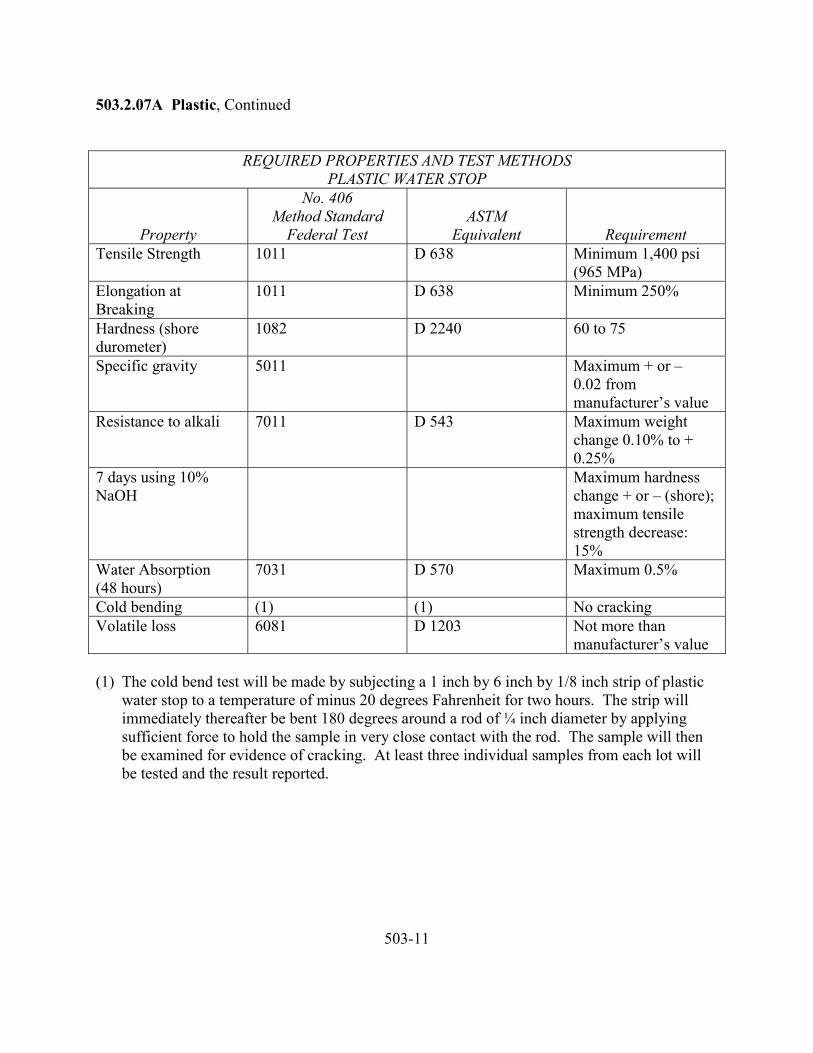
503.2.07A Plastic, Continued
REQUIRED PROPERTIES AND TEST METHODSPLASTIC WATER STOP
Property
No. 406Method Standard
Federal TestASTM
Equivalent RequirementTensile Strength 1011 D 638 Minimum 1,400 psi
(965 MPa)Elongation atBreaking
1011 D 638 Minimum 250%
Hardness (shoredurometer)
1082 D 2240 60 to 75
Specific gravity 5011 Maximum + or –0.02 frommanufacturer’s value
Resistance to alkali 7011 D 543 Maximum weightchange 0.10% to +0.25%
7 days using 10%NaOH
Maximum hardnesschange + or – (shore);maximum tensilestrength decrease:15%
Water Absorption(48 hours)
7031 D 570 Maximum 0.5%
Cold bending (1) (1) No crackingVolatile loss 6081 D 1203 Not more than
manufacturer’s value
(1) The cold bend test will be made by subjecting a 1 inch by 6 inch by 1/8 inch strip of plasticwater stop to a temperature of minus 20 degrees Fahrenheit for two hours. The strip willimmediately thereafter be bent 180 degrees around a rod of ¼ inch diameter by applyingsufficient force to hold the sample in very close contact with the rod. The sample will thenbe examined for evidence of cracking. At least three individual samples from each lot willbe tested and the result reported.
503-11
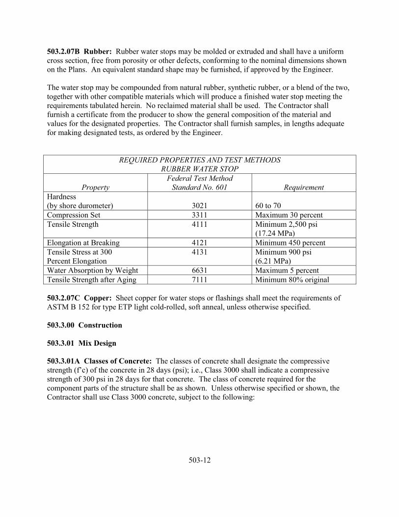
503.2.07B Rubber: Rubber water stops may be molded or extruded and shall have a uniformcross section, free from porosity or other defects, conforming to the nominal dimensions shownon the Plans. An equivalent standard shape may be furnished, if approved by the Engineer.
The water stop may be compounded from natural rubber, synthetic rubber, or a blend of the two,together with other compatible materials which will produce a finished water stop meeting therequirements tabulated herein. No reclaimed material shall be used. The Contractor shallfurnish a certificate from the producer to show the general composition of the material andvalues for the designated properties. The Contractor shall furnish samples, in lengths adequatefor making designated tests, as ordered by the Engineer.
REQUIRED PROPERTIES AND TEST METHODSRUBBER WATER STOP
PropertyFederal Test Method
Standard No. 601 RequirementHardness(by shore durometer) 3021 60 to 70Compression Set 3311 Maximum 30 percentTensile Strength 4111 Minimum 2,500 psi
(17.24 MPa)Elongation at Breaking 4121 Minimum 450 percentTensile Stress at 300Percent Elongation
4131 Minimum 900 psi(6.21 MPa)
Water Absorption by Weight 6631 Maximum 5 percentTensile Strength after Aging 7111 Minimum 80% original
503.2.07C Copper: Sheet copper for water stops or flashings shall meet the requirements ofASTM B 152 for type ETP light cold-rolled, soft anneal, unless otherwise specified.
503.3.00 Construction
503.3.01 Mix Design
503.3.01A Classes of Concrete: The classes of concrete shall designate the compressivestrength (f’c) of the concrete in 28 days (psi); i.e., Class 3000 shall indicate a compressivestrength of 300 psi in 28 days for that concrete. The class of concrete required for thecomponent parts of the structure shall be as shown. Unless otherwise specified or shown, theContractor shall use Class 3000 concrete, subject to the following:
503-12
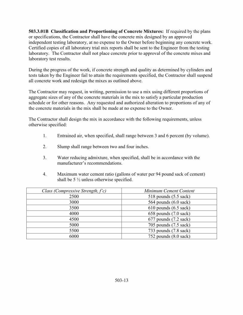
503.3.01B Classification and Proportioning of Concrete Mixtures: If required by the plansor specifications, the Contractor shall have the concrete mix designed by an approvedindependent testing laboratory, at no expense to the Owner before beginning any concrete work.Certified copies of all laboratory trial mix reports shall be sent to the Engineer from the testinglaboratory. The Contractor shall not place concrete prior to approval of the concrete mixes andlaboratory test results.
During the progress of the work, if concrete strength and quality as determined by cylinders andtests taken by the Engineer fail to attain the requirements specified, the Contractor shall suspendall concrete work and redesign the mixes as outlined above.
The Contractor may request, in writing, permission to use a mix using different proportions ofaggregate sizes of any of the concrete materials in the mix to satisfy a particular productionschedule or for other reasons. Any requested and authorized alteration to proportions of any ofthe concrete materials in the mix shall be made at no expense to the Owner.
The Contractor shall design the mix in accordance with the following requirements, unlessotherwise specified:
1. Entrained air, when specified, shall range between 3 and 6 percent (by volume).
2. Slump shall range between two and four inches.
3. Water reducing admixture, when specified, shall be in accordance with themanufacturer’s recommendations.
4. Maximum water cement ratio (gallons of water per 94 pound sack of cement)shall be 5 ½ unless otherwise specified.
Class (Compressive Strength, f’c) Minimum Cement Content2500 518 pounds (5.5 sack)3000 564 pounds (6.0 sack)3500 610 pounds (6.5 sack)4000 658 pounds (7.0 sack)4500 677 pounds (7.2 sack)5000 705 pounds (7.5 sack)5500 733 pounds (7.8 sack)6000 752 pounds (8.0 sack)
503-13
503.3.01B Classification and Proportioning of Concrete Mixtures, Continued
Tests for strength shall be made in accordance with the following:
Molding Concrete Specimens in the Field AASHTO T 23Compressive Strength of Molded Cylinders AASHTO T 22
The curing of cylinders shall conform to the requirements of AASHTO T 23, except as modifiedherein.
503.3.02 Consistency: The quality of mixing water to be used shall be determined from thelaboratory tests and fixed with the proportions of other materials, and no changes shall be madewithout approval. In general, a mixture shall be used which contains the minimum amount ofwater consistent with the required workability. The consistency of concrete shall be gauged bythe ability of the equipment to properly place it and not by the difficulty in mixing ortransporting.
503.3.03 Measurement of Materials: All of the materials, except water, in the batches ofconcrete shall be measured by weight. Facilities for accurately weighing the cement for eachbatch shall be provided. Fine and coarse aggregates shall be weighed separately. Representativesamples shall be taken and the moisture content determined for each kind of aggregate. Theaggregates shall be stored and handled so that their water content remains reasonably constantduring any day’s run. The equipment for weighing materials shall provide convenient andpositive means for the addition or removal of shall quantities of materials to obtain the exactweight per batch. The device for measuring water shall show accurately the quantity in gallonsand be so designated that the water supply will be automatically cut off while water is beingdischarged into the mixer. Water shall be assumed to weigh 8.34 pounds per gallon.
503.3.04 Mixing
503.3.04A General: Concrete shall be machine mixed.
503.3.04B Mixing at Site: Concrete shall be mixed in a batch mixer of an approved size andtype which will ensure a uniform distribution of the materials throughout the mass.
The mixer shall be equipped with adequate water storage and a device for accurately measuringand automatically controlling the amount of water used in each batch. Preferably, mechanicalmeans shall be provided for recording the number of revolutions of each batch and automaticallypreventing the discharge of the mixer until the materials have been mixed in the specifiedminimum time.
503-14

503.3.04B Mixing at Site, Continued
The entire contents of the mixer shall be removed from the drum before materials for asucceeding batch are placed therein. The materials composing a batch shall be depositedsimultaneously in the mixer. No mixer having a rated capacity of less than a one-sack batchshall be used nor shall a mixer be charged in excess of its rated capacity.
All concrete shall be mixed for a period of not less than 1 ½ minutes after all materials, includingeater, are in the mixer. During the period of mixing, the mixer shall operate at a design speed ofnot less than 14 nor more than 20 revolutions per minute.
The first batch of concrete materials placed in the mixer shall contain a sufficient excess ofcement, sand and water to coat the inside of the drum without reducing the required mortarcontent of the mix. Upon the cessation of mixing for a considerable period, the mixer shall bethoroughly cleaned.
The above specification contemplates the use of conventional revolving drum type mixers.Other types may be used with the written permission of the Engineer.
503.3.04C Truck Mixing: Truck mixers, unless otherwise authorized by the Engineer, shall beof the revolving drum type, watertight and so constructed that the concrete can be mixed toensure a uniform distribution of materials throughout the mass. All solid materials for theconcrete shall be accurately measured in accordance with Subsection 503.3.04 and charged intothe drum at the proportioning plant. Except as subsequently provided, the truck mixer shall beequipped with a tank for carrying mixing water. Only the prescribed amount of water shall beplaced in the tank unless the tank is equipped with a device by which the quantity of water addedcan be readily verified. The mixing water may be added directly to the batch in which case atank will not be required. Truck mixers may be required to be provided with means by which themixing time can be readily verified by the Engineer.
The maximum size of batch in truck mixers shall not exceed the maximum rated capacity of themixer as stated by the manufacturer and stamped in metal on the mixer. Truck mixing shall becontinued for not less than 70 revolutions nor more than 100 revolutions of the drum at the rateof rotation designated by the manufacturer. Mixing shall commence after all ingredients,including water, are in the drum. Additional mixing, if any, shall be at the rate of rotation asdesignated by the manufacturer at agitating speed. Mixing shall begin within 30 minutes afterthe cement has been added to either the water or aggregate. When cement is charged into amixer drum containing water or surface-wet aggregate and when the temperature is above 90degrees F, or when high-early strength Portland cement is used, this limit shall be reduced to 15minutes.
503-15
503.3.04C Truck Mixing, Continued
The limitation on time between the introduction of the cement to the aggregates and thebeginning of the mixing may be waived when, in the judgement of the Engineer, the aggregatesare sufficiently free from moisture so that there will be no harmful effects on the cement.
503.3.04D Partial Mixing at the Central Plant: When a stationary mixer is used for partialmixing of concrete (shrink-mixing), the mixing time in the stationary mixer may be more than isrequired to intermingle the ingredients. After transfer to a truck mixer, further mixing at adesignated mixing speed will be required only as necessary to meet the requirements foruniformity of concrete as specified for truck mixing.
503.3.04E Plant Mix: Mixing at a central plant shall conform to the requirements for mixing atthe site.
503.3.05 Time of Hauling and Placing: Concrete transported in a truck mixer, agitator orother transportation device shall be discharged at the job and placed in its final position in theforms within 1 ½ hours after the introduction of the mixing water to the cement and aggregate orthe cement to the aggregate, except that in hot weather or under other conditions contributing toquick stiffening of the concrete, the maximum allowable time may be reduced. The maximumvolume of mixed concrete transported in an agitator shall be in accordance with the specifiedrating.
503.3.06 Delivery: The plant capacity and transporting apparatus shall be adequate to insurecontinuous delivery of concrete during concreting operations and shall be such as to provide forthe proper handling, placing and finishing of the concrete. The rate of delivery shall be such thatthe interval between batches shall not exceed 20 minutes. The methods of delivering andhandling the concrete shall be such as will facilitate placing with a minimum of rehandling andwithout damage to the structure or the concrete. The time interval may be reduced when deckconcrete is being placed. Concrete for decks shall be delivered so that the deck pour willprogress at a rate of not less than 20 feet per hour unless some other rate of pour is approved.
503.3.07 Retempering: The concrete shall be mixed only in such quantities as are required forimmediate use and any which has developed initial set shall not be used. Concrete which haspartially hardened shall not be retempered or remixed.
503.3.08 Slump Test: The slump of concrete shall be determined in accordance with therequirements of AASHTO T 119.
503.3.09 Falsework: For bridge structures requiring poured-in-place superstructures, workingdrawings and calculations for falsework prepared by an Engineer registered to practice in theState of Kansas may be required to be submitted for approval.
503-16
503.3.09 Falsework, Continued
For designing falsework a weight of 150 pounds per cubic foot shall be assumed for greenconcrete. All falsework shall be designed and constructed to support the total applied loads witha deflection not to exceed 1/500 in any falsework span. The Contractor shall employ screw jacksor hardwood wedges to take up any settlement in the formwork either before or during theplacing of concrete when directed. Falsework shall be set to give the finished structure thecamber specified or shown. Falsework for post-tensioned structures shall be designed to carrythe full dead load of any additional vertical or horizontal loads caused by the prestressingoperation.
The Contractor’s attention is directed to the fact that the design of post-tensioned structures issuch that the structure is not self-supporting until post-tensioning is complete and it shall beunderstood that the Contractor has considered this fact in the design, maintenance and protectionof falsework.
503.3.10 Forms: All forms shall be mortar-tight and of sufficient rigidity to prevent distortiondue to the pressure of the concrete and other loads incidental to the construction operations.Forms shall be constructed and maintained to prevent warping and the opening of joints.
The forms shall be substantial and unyielding and shall be so designed that the finished concretewill conform to the proper dimensions and contours. Forms shall be designed and constructed soas to withstand the effect of vibration of concrete as it is placed. All forms used for curbs,sidewalks, alleys, etc. shall be placed within ½ inch of the thickness of the concrete section beingplaced.
Deck forms for concrete box girder spans shall be supported by the girder stems. Posts or othersupports for deck forms will not be permitted to come in contact with the bottom slab of the boxgirder.
Wood forms for concrete surfaces not subject to backfill shall be made of dressed lumber ofuniform thickness with a form liner of an approved type and mortar-tight. Wood forms for theinterior of cells of box girders may be made with or without a form liner. Shiplap or S45 boardsare acceptable, provided the forms are mortar-tight.
Plywood will be acceptable as a form liner if supported in an approved manner. Metal ties oranchorages within the forms shall be so constructed as to permit their removal to a depth of atleast 1 inch from the face without injury to the concrete. In case ordinary wire tires arepermitted, all wires, upon removal of the forms, shall be cut back at least ¼ inch from the face ofthe concrete with chisels or nippers; for green concrete, nippers are necessary. All fittings formetal ties shall be of such design that, upon their removal, the cavities which are left will be thesmallest possible size. The cavities shall be filled with cement mortar and the surface left sound,smooth, even and uniform in color.
503-17
503.3.10 Forms, Continued
All forms shall be set and maintained true to the line designated until the concrete is sufficientlyhardened. Forms shall remain in place for periods which shall be determined as hereinafterspecified. When forms appear to be unsatisfactory in any way, either before or during theplacing of concrete, the work may be ordered stopped until the defects have been corrected.
The shape, strength, rigidity, watertightness and surface smoothness of reused forms shall bemaintained at all times. Any warped or bulged lumber shall be resized before being reused. TheContractor shall not reuse forms which are unsatisfactory in any respect.
For narrow walls and columns, where the bottom of the form is inaccessible, openings near thebottom shall be provided for cleaning out extraneous material immediately before placing theconcrete.
All forms shall be treated with an approved form oil immediately before placing the concrete.Material which will adhere to or discolor the concrete shall not be used.
503.3.11 Removal of Falsework and Forms: The Contractor shall be responsible for alldamage resulting from premature removal of forms.
If field operations are controlled by cylinder tests, forms and shoring for structural slabs orbeams shall remain in place until the concrete has reached a compressive strength equal to 75percent of the specified 28-day compressive strength as determined by test cylinders. TheContractor shall not place earth backfill against walls below grade until the concrete has obtaineda compressive strength equal to 75 percent of the specified 28-day compressive strength. Fieldcured cylinders shall be cured under conditions which are equivalent to the most unfavorableconditions for the portions of the concrete which the cylinders represent.
If field operations are not controlled by cylinder tests, the following intervals, exclusive of dayswhen the temperature is below 40 degrees F, may be used as a guide for removal of forms andsupports.
Part of Structure IntervalSupports under Beams 14 daysFloor Slabs 7-14 daysWalls 12-24 hoursColumns 1-7 daysSides of Beams and All Other Parts 12-24 hours
503-18
503.3.11 Removal of Falsework and Forms, Continued
Methods of form removal likely to cause over-stressing of the concrete shall not be used. Ingeneral, the forms shall be removed from the bottom upwards. Do not remove forms and theirsupports without approval. Supports shall be removed in such a manner as to permit the concreteto uniformly and gradually take the stresses due to its own weight.
All formwork shall be removed from the cells of concrete box girders to which access isprovided, and all formwork except that necessary to support the deck slab shall be removed fromthe remaining cells of the box girder.
All wood formwork and all form supports and braces shall be removed from the interior ofstructural steel box girders.
503.3.12 Adverse Weather
503.3.12A Hot Weather: Concreting during hot weather shall conform to the requirements ofACI 305.
The temperature of the concrete shall not be allowed to exceed 75 degrees F prior to beingplaced.
Crushed ice in lieu of water will be acceptable to maintain the temperature of the concrete.
503.3.12B Cold Weather: Concreting during cold weather shall conform to the requirementsof ACI 306.
No concrete shall be placed when the ambient temperature is below 35 degrees F without writtenpermission of the Engineer. When directed by the Engineer, the Contractor shall enclose thestructure in such a way that the concrete and air within the enclosure can be kept above 60degrees F for a period of seven days after placing concrete. When enclosures are used tomaintain specified temperatures, the Contractor shall furnish a 24-hour temperature recordingthermometer to record air temperature within the enclosure.
The Contractor shall supply heating equipment and the necessary fuel. When dry heat is used,means of maintaining atmospheric moisture shall be provided.
All aggregates and mixing water shall be heated to a temperature of at least 60 degrees but notmore than 150 degrees F; the aggregates may be heated by either steam or dry heat. Thetemperature of the concrete shall be not less than 50 degrees F at the time of placing in the forms.In case extremely low temperatures the minimum limiting temperatures for water, aggregatesand mixed concrete may be raised at the discretion of the Engineer.
503-19
503.3.12B Cold Weather, Continued
Where practical, insulated forms capable of maintaining the surface of the concrete at no lessthan 50 degrees F may be used in lieu of other protection of concrete involving housing andheating. When forms are insulated, exposed horizontal surfaces shall be protected. If theinsulated forms do not maintain the proper temperature at the surface of the concrete, auxiliaryprotection and heat shall be used.
503.3.13 Measuring, Mixing, Hauling and Placing
503.3.13A General: Measuring, mixing, hauling and placing shall conform to the requirementsof ACI 304.
Consolidation of concrete shall conform to the requirements of ACI 309.
In preparation for the placing of concrete, all sawdust, chips, and other construction debris andextraneous matter shall be removed from the interior of forms. Struts, stays and braces, servingtemporarily to hold the forms in correct shape and alignment prior to the placing of concrete,shall be removed when the concrete placing has reached an elevation rendering their serviceunnecessary.
Concrete shall be placed in horizontal layers not more than 12 inches thick except as hereinafterprovided. When less than a complete layer is placed in one operation, it shall be terminated in avertical bulkhead. Each layer shall be placed and consolidated as heretofore described before thepreceding layer has taken initial set to avoid surfaces of separation between the layers. Eachlayer shall be consolidated so as to avoid the formation of a surface of separation with apreceding layer.
When the placing of concrete is temporarily discontinued, the concrete, after becoming firmenough to retain its form, shall be cleaned of laitance and other objectionable material to asufficient depth to expose sound concrete. The top surface of the concrete adjacent to the formsshall be smoothed with a trowel. Where a “feather edge” might be produced at a constructionjoint, as in the sloped top surface of a wing wall, inset formwork shall be used to produce ablocked out portion in the preceding layer which shall produce an edge thickness of not less than6 inches in the succeeding layer. Work shall not be discontinued within 18 inches of the top ofany face, unless provision has been made for a coping, in which case, a construction joint shallbe made at the underside of the coping.
503-20
503.3.13B Culverts: In general, the base slab or footings of box culverts shall be placed andallowed to set before the remainder of the culvert is constructed. In this case, suitable provisionshall be made for bonding the sidewalls to the culvert base, preferably by means of raisedlongitudinal keys so constructed as to prevent, as far as possible, the percolation of water throughthe construction joint.
Before concrete is placed in the sidewalls, the culvert footings shall be thoroughly cleaned of allshavings, sticks, sawdust or other extraneous material and the surface carefully chipped androughened in accordance with the method of bonding construction joints as specified herein.
In the construction of box culverts 4 feet or less in height, the sidewalls and top slab may beconstructed as a monolith. When this method of construction is used, any necessary constructionjoints shall be vertical and at right angles to the axis of the culvert.
In the construction of box culverts more than 4 feet in height, the concrete in the walls shall beplaced and allowed to set before the top slab is placed. In this case, appropriate keys shall be leftin the sidewalls for anchoring the cover slab.
Each wing wall shall be constructed, if possible, as a monolith. Construction joints, whereunavoidable, shall be horizontal and so located that no joint will be visible in the exposed face ofthe wing wall above the ground line.
503.3.13C Girders, Slabs and Columns: Concrete shall be deposited by beginning at thecenter of the span and working from the center toward the ends unless otherwise permitted.Concrete in girders shall be deposited uniformly for the full length of the girder and brought upevenly in horizontal layers.
Concrete pours in columns and abutments or walls shall be stopped at the bottom of caps, cross-beams, girders or any widened portion of the column or wall, and the concrete allowed to obtainits full shrinkage and settlement before the pour is continued. For pours over four feet in height,this delay shall not be less than 12 hours. Mechanical shear keys shall be formed in allconstruction joints in columns. Shear keys shall be approximately two inches in depth, and shallbe approximately one-third the width of the column in both directions, centered in the column.
Concrete pours in T-beams and box girders shall be stopped at the bottom of the deck or deckfillet and the concrete allowed to obtain its full shrinkage and settlement before the pour iscontinued. If the beams or girders are over four feet in height, the delay shall be not less than 12hours. Similar delays shall be incorporated into concrete pours at the intersection of anystructural members where concrete settlement could cause cracking at the intersection.Mechanical shear keys shall be formed between girder stems and slabs, and in verticalconstruction joints where permitted. In general, suitable keys may be formed by the use oftimber blocks approximately two inches by four inches in cross-section and having a length of
503-21
503.3.13C Girders, Slabs and Columns, Continued
four inches less than the width of the girder stem. The keys shall be spaced along the girder stemas required, but the spacing shall not exceed one foot center to center. These key blocks shall bebeveled and oiled as to insure their ready removal and they shall be removed as soon as theconcrete has set sufficiently to retain its shape.
Concrete in the bottom slab of box girder structures shall be poured to the bottoms of beamstems or stem fillets. Before the stems are poured, the bottom slab concrete shall be allowed tocure a minimum of three days at ambient temperatures of 40 degrees F or above, or for at leastfive days at ambient temperatures below 40 degrees F.
In box girder spans, construction joints shall be placed at locations called for on the Plans.
Concrete in columns shall be allowed to set at least 12 hours before the caps are placed.
No concrete shall be placed in the superstructure until the column forms have been strippedsufficiently to determine the character of the concrete in columns. The load of the superstructureshall not be allowed to come upon the bends until they have been in place at least 14 days, unlessotherwise permitted by the Engineer.
503.3.13D Pumping: Placement of concrete by pumping will be permitted provided theContractor finishes and uses clean equipment of sufficient size and capacity to satisfactorilyhandle the concrete mix specified for the project or adjusted by the Engineer. The discharge lineof the pump shall be steel or rubber pipe. Any extra costs involved for additional cement oradditives required to obtain a pumpable mix shall be at the expense of the Contractor.
Where concrete is placed by pumping, the operation of the pump shall produce a continuousstream of concrete without air pockets. When pumping is completed, the concrete remaining inthe pipeline, if it is to be used, shall be ejected in a manner that will not cause contamination orthe concrete or separation of the ingredients.
503.3.13E Depositing Concrete Under Water: Concrete shall be deposited in water only withthe approval of the Engineer and under the Engineer’s immediate inspection. The method ofplacing shall be as hereinafter designated.
Concrete deposited in water shall be carefully placed in a compact mass, in its final position, bymeans of a tremie and shall not be disturbed after being deposited. Still water shall bemaintained at the point of deposit.
Concrete seals shall be placed continuously from start to finish; the surface of the concrete shallbe kept as nearly horizontal as practicable at all times. To insure thorough bonding, eachsucceeding layer of a seal shall be placed before the preceding layer has taken initial set.
503-22
503.3.13E Depositing Concrete Under Water, Continued
A tremie shall consist of a tube having a minimum diameter of 10 inches, of sufficient length toreach from the bottom of the excavation up to concrete placing elevation above water line withan attached receptacle or hopper for receiving concrete. A jointed tremie will be permitted,provided joints are of the flanged and gasketed type and waterproof. The tremies shall besupported to permit free movement of the discharge end over the entire top surface of the workand to permit rapid lowering when necessary to retard or stop the flow of concrete. At the startof the work and on any withdrawal of the pipe for moving to a new location, the discharge endshall be closed to prevent water from entering the pipe. During the progress of the work the pipeshall be entirely sealed at all times and kept full of concrete to the bottom of the hopper. When abatch is dumped into the hopper, the flow of concrete shall be induced by slightly raising thedischarge end, always keeping it in the deposited concrete. The placing of concrete shall becontinuous until the work is completed.
Unwatering may proceed when the concrete seal is sufficiently hard and strong. All laitance orother unsatisfactory material shall be removed from the exposed surface by scraping, chipping orother means which will not injure the surface of the concrete.
503.3.14 Construction Joints
503.3.14A General: Construction joints shall be made only where located on the Plans orshown in the pouring schedule, unless otherwise approved by the Engineer.
If not detailed on the Plans, or in the case of emergency, construction joints shall be placed asdirected by the Engineer. Shear keys or inclined reinforcement shall be used where necessary totransmit shear or bond the two sections together.
503.3.14B Bonding: Before depositing new concrete on or against concrete which hashardened, the forms shall be retightened. The surface of the hardened concrete shall beroughened as required by the Engineer, in a manner that will not leave loosened particles ofaggregate or damaged concrete at the surface. It shall be thoroughly cleaned of foreign matterand laitance and saturated with water. At the juncture of the hardened and the newly depositedconcrete, the cleaned and saturated surfaces (including vertical and inclined surfaces) shall firstbe thoroughly covered with a coating of mortar or neat cement grout against which the newconcrete shall be placed before the grout has attained its initial set.
The placing of concrete shall be continuous from joint to joint. The face edges of all jointswhich are exposed to view shall be carefully finished true to line and elevation.
503-23
503.3.15 Expansion and Fixed Joints and Bearings
503.3.15A Open Joints: Construction shall be by the insertion and subsequent removal of atemplate or approved material without chipping or breaking the corners of the concrete.Reinforcement shall not extend across an open joint unless so shown.
503.3.15B Poured Joints: Poured expansion joints shall be constructed similar to open joints.When premolded types are specified, the filler shall be placed in correct position as the concreteon one side of the joint is placed. When the form is removed, the concrete on the other side shallbe placed.
503.3.15C Steel Joints: The plates, angles or other structural shapes shall be accurately shapedat the shop, to conform to the section of the concrete deck. The fabrication and painting shallconform to the requirements of these specifications. Care shall be taken to insure that the surfacein the finished plane is true and free of warping. Positive methods shall be employed in placingthe joints to keep them in correct position during the placing of the concrete. The opening atexpansion joints at normal temperature shall be as shown, and care shall be taken to avoidimpairment of the clearance in any manner.
503.3.15D Water Stops: Water stops shall be placed as shown on the Plans. Where movementat the joint is provided for, the water stops shall be of a type permitting such movement withoutinjury. They shall be spliced, welded or soldered to form continuous watertight joints, exceptplastic, rubber or neoprene stops which shall be full roadway width without shop or field splices.
503.3.15E Bearing Devices: Bearing plates, rockers and other expansion devices shall beconstructed according to details shown on the Plans. Unless set in the plastic concrete otherwisespecified, they shall be set in grout to insure uniform bearing. The rockers or other expansiondevices shall be set to conform to the temperature at the time of erection. No separate paymentwill be made for rocker assemblies. Payment therefore shall be understood to be included in thecontract price for the item “Reinforcement”.
503.3.15F Preformed Elastomeric Joint Seals: Preformed elastomeric joint seals shall be inthe longest practicable lengths for longitudinal joints. In transverse joints, one factory splice willbe permitted in joint seals where the required length of material in any one joint exceedsmanufacturer’s standard stock lengths. Such splices shall be true and smooth on the outsidesurfaces with no offsets of abutting sections and with the complete bond on all abutting surfaces.Joints shall be clean and dry and shall be made free of spalls and irregularities which wouldimpair a tight seal in service. Seals shall be placed in the joint under compression, asrecommended by the manufacturer, using a lubricant-adhesive as a covering film applied to bothsides of the seal just prior to its installation.
503-24
503.3.15F Preformed Elastomeric Joint Seals, Continued
Lubricant-adhesive material shall be a compound consisting of the same base polymer as thejoint seal with which it is used, blended with a suitable volatile solvent. The lubricant-adhesiveshall be compatible with the joint seal and concrete, and shall be relatively unaffected by thenormal moisture in the concrete. It shall maintain a suitable consistency at the temperature atwhich the joint seal is installed.
The seal shall be set as shown and shall contact the walls of the joint throughout its length.Longitudinal elongation of an installed seal by three percent or more of its original length will because for its removal and reinstallation.
All lubricant-adhesive which comes upon the top of an installed seal shall be removed before itdries, and all seals which show twist, curl, nicks or other malformation, as installed, shall beremoved and discarded. All ends or preformed elastomeric joint seals shall be sealed with awatertight plug prior to installation of the joint seal. The plug shall be foam rubber or otheracceptable closed cell cellular material which is compressible to 15 percent of its uncompressedthickness. The plug shall be a minimum of two inches in length and shall be secured in theelastomeric joint seal with an adhesive which will insure a watertight plug.
503.3.16 Surface Finishing
503.3.16A Formed Surfaces: Unless otherwise authorized, the surface of the concrete shall befinished immediately after form removal.
All formed concrete surfaces shall be given a Class 1 finish. If further finishing is required,exposed surfaces shall be given a Class 2 finish. Other finish classes may be specified on theplans for designated surfaces. All roadway surfaces shall be given a float finish in accordancewith the requirements of Subsection 503.3.16B.
Class 1, Ordinary Surface Finish: As soon as the forms are removed, the projecting wire ormetal devices that have been used for holding the forms in place and which pass through thebody of the concrete, shall be removed or cut back at least one inch beneath the surface of theconcrete. Lips of mortar and all irregularities caused by form joints shall be removed.
All small holes, depressions and voids that show upon the removal of forms shall be filled withcement mortar mixed in the same proportions as that used in the body of the work. In patchinglarger holes and honeycombs, all coarse or broken materials shall be chipped away until a denseuniform surface of concrete exposing solid coarse aggregate is obtained. Feathered edges shallbe cut away to form faces perpendicular to the surface. All surfaces of the cavity shall besaturated thoroughly with water, after which a thin layer of neat cement mortar shall be applied.
503-25
503.3.16A Formed Surfaces, Continued
The cavity shall then be filled with stiff mortar composed of one part of Portland cement and twoparts sand, which shall be thoroughly tamped into placed. The mortar shall be preshrunk bymixing it approximately 30 minutes before using. The length of time may be varies inaccordance with brand of cement used, temperature, humidity, and other local conditions. Thesurface of this mortar shall be floated with a wooden float before initial set takes place and shallbe neat in appearance.
For patching large or deep areas, coarse aggregate shall be added to the patching material andspecial precautions shall be taken to insure a dense, well-bonded and properly cured patch.
Areas of excessive honeycomb, as determined by the Engineer, may be considered sufficientcause for rejection of a structure. Upon written notice from the Engineer that a given structurehas been rejected, the Contractor shall remove and rebuild the structure, in part or wholly asspecified, at the Contractor’s own expense.
The mortar patches shall be cured as specified in subsection 503.3.17. All construction andexpansion joints in the completed work shall be left carefully tooled and free of all mortar andconcrete. The joint filler shall be left exposed for its full length with clean and true edges.
All surfaces which cannot be repaired to the satisfaction of the Engineer shall be “rubbed” asspecified for a Class 2 finish.
Class 2, Rubbed Finish: After removal of forms, the rubbing of concrete shall be started as soonas its condition will permit. Immediately before starting this work, the concrete shall be keptthoroughly saturated with water. Sufficient time shall have elapsed to allow the mortar used inthe pointing to thoroughly set. Surfaces to be finished shall be rubbed with a medium coarsecarborundum stone, using a small amount of mortar on its face. The mortar shall be composedof cement and fine sand mixed in proportions used in the concrete being finished. Rubbing shallbe continued until all form marks, projections and irregularities have been removed, all voidsfilled and a uniform surface has been obtained. The paste produced by this rubbing shall be leftin place.
After all concrete above the surface being treated as been case, the final finish shall be obtainedby rubbing with a fine carborundum stone and water. This rubbing shall be continued until theentire surface is of a smooth texture and uniform color.
After the final rubbing is completed and the surface has dried, it shall be rubbed with burlap toremove loose powder and shall be left free from all unsound patches, paste, powder andobjectionable marks.
503-26
503.3.16B Unformed Surfaces: Bridge Decks: On bridge decks, a smooth riding surface ofuniform texture, true to the required grade and cross section, shall be obtained. The Contractormay use hand tools, finishing machines or a combination of both, conforming to therequirements specified herein for finishing bridge roadway deck concrete.
Finishing of concrete placed in bridge decks shall consist essentially of striking off the surface ofthe concrete as placed and floating the surface so struck off.
The placing of concrete in bridge roadway decks will not be permitted until the Engineer issatisfied that the rate of producing and placing concrete will be sufficient to complete theproposed placing and finishing operations within the scheduled time, that experienced finishingmachine operators and concrete finishers are employed to finish the deck, that foggingequipment and all necessary finishing tools and equipment are on hand at the site of the workand in satisfactory condition for use. A finishing machine shall be set up sufficiently in advanceof use to permit inspection by the Engineer during the daylight hours before each pour.
Rails for the support and operation of finishing machines and headers for hand-operated strikeoff devices shall be completely in place and firmly secured for the schedule length for concreteplacement before placing of concrete will be permitted. Rails for finishing machines shallextend beyond both ends of the scheduled length for concrete placement a distance that willpermit the float of the finishing machine to fully clear the concrete to be placed unless otherwiseapproved by the Engineer. Rails or headers shall be adjustable for elevation and shall be set toelevations, with allowance for anticipated settlement, camber and deflection of falsework, asrequired to obtain a bridge roadway deck true to the required grade and cross section. Rails orheaders shall be of a type and shall be so installed that no springing or deflection will occurunder the weight of the finishing equipment and shall be so located that finishing equipment mayoperate without interruption over the entire bridge roadway deck being finished. Rails orheaders shall be adjusted as necessary to correct for unanticipated settlement or deflection whichmay occur during finishing operations.
Immediately prior to placing bridge deck concrete, the Contractor shall check all falsework andwedges and shall make all necessary adjustments. Care shall be exercised to insure thatsettlement and deflection due to the added weight of the bridge deck concrete will be aminimum. Suitable means such as telltales shall be provided by the Contractor to readily permitmeasurement by the Engineer of settlement and deflection as it occurs.
Should settlement of other unanticipated events occur which in the opinion of the Engineerwould prevent obtaining a bridge deck conforming to the requirements of these specialprovisions, placing of deck concrete shall be discontinued until corrective measures satisfactoryto the Engineer are provided. In the event satisfactory measures are not provided prior to initialset of the concrete in the affected area, the placing of concrete shall be discontinued and abulkhead installed at a location determined by the Engineer. All concrete in place beyond thebulkhead shall be removed.
503-27
503.3.16B Unformed Surfaces, Continued
Concrete for bridge decks shall be placed in a uniform heading approximately normal to thestructure centerline or, in the case of screeds, supported on transverse headers, parallel to thecenterline as directed by the Engineer. The rate of placing concrete shall be limited to that whichcan be finished before the beginning of initial set.
Immediately after the concrete has been placed and consolidated, the surface shall be struck offwith the finishing machine or hand-operated screed until the required surface is obtained.
The strike off method and equipment shall be subject to approval by the Engineer. Approvalshall be withdrawn if performance is not satisfactory. The equipment shall be capable offinishing roadway decks within the surface tolerances set forth in these specifications. Improperadjustment and operation which results in unsatisfactory consolidation and smoothness shall becorrected immediately. Unsatisfactory performance may be cause for rejection of the equipmentand removal of the in-place concrete.
Following the completion of the strike off by hand methods, the roadway slab surface shall befloated to a smooth uniform surface by means of floats 10 feet or more in length. When afinishing machine is used, the finished surface shall be floated in a similar manner unlessotherwise directed by the Engineer. Adequate floats shall be used to remove roughness andminor irregularities left by the strike board or finishing machine and to seal the concrete surface.Excessive working of the concrete surface is not desired. All floats shall be used in such amanner that each transverse pass overlaps the previous pass by a distance equal to or at least one-half the length of the float.
When hand-operated float boards are used, they shall be from 12 feet to 16 feet long, ribbed andtrussed as necessary to provide a rigid float and shall be equipped with adjustable handles at eachend. The float shall be wood, not less than 1 inch thick and a minimum of 8 inches wide.Adjusting screws spaced at not to exceed 24 inches on centers shall be provided between thefloat and the rib. The float board shall be maintained free of twist and true at all times.
Hand-operated float boards shall be operated from transverse finishing bridges. The finishingbridges shall span completely the roadway area being floated and a sufficient number offinishing bridges shall be provided when hand-operated float boards are used. When a finishingmachine is used for longitudinal floating, one finishing bridge equivalent to the transversefinishing bridge specified herein shall be furnished for use by the Engineer.
All finishing bridges shall be of rigid construction and shall be free of wobble and springingwhen used by the operators of longitudinal floats and shall be easily moved.
In advance of curing operations, the surface of the concrete shall be textured by brooming with astiff bristled broom or by other suitable devices which will result in uniform scoring. Broomingshall be performed transversely from the finishing bridge. The operation shall be performed at atime and in a manner to produce a hardened surface having a uniform texture.
503.3.16B Unformed Surfaces, Continued
Fogging equipment to be furnished shall be capable of applying water to the concrete in the formof a fine fog mist in sufficient quantity to curb the effects of rapid evaporation of the mixingwater from the concrete on the deck, resulting from wind, high temperature or low humidity, or acombination of these factors. The fog mist shall be applied at the times and in the mannerdirected by the Engineer.
After floating has been completed and the excess water removed, but while the concrete is stillplastic, the surface of the concrete shall be tested for trueness with a 10 foot straightedge.
As soon as the concrete has hardened sufficiently, the surface shall be given a further test fortrueness using a 10 foot straightedge or other specified device. Areas showing high spots ofmore than 1/8 inch shall be marked and ground down with a diamond-faced saw-type cuttingmachine, capable of cutting through mortar and aggregate without breaking or dislodging theaggregate or causing spalls, to an elevation where the area or spot will not show surfacedeviations in excess of 1/8 inch when tested with a 10 foot straightedge.
The 10 foot straightedge shall be provided by the Contractor and the straightedge testing shall beperformed by the Contractor’s personnel under the supervision of the Engineer.
Floors and Slabs: Floors and slabs shall be finished in accordance with the applicablerequirements of ACI 302, for the type of floor or slab being constructed.
Bridge Sidewalks: The surface of bridge sidewalks shall have a granular texture which will notbe slippery when wet. An edging tool shall be used on all edges and at all expansion joints.
503.3.19 Curing: All newly-placed concrete shall be cured and curing shall be begunimmediately after finishing and continued for at least seven days. Curing shall be done so thatthe moisture is always present and shall be an integral part of the concreting operation.Improperly cured concrete will be considered defective and the Engineer will stop all of theContractor’s placing operation until proper procedures are put into effect.
When the air temperature is expected to fall below 35 degrees F, the Contractor shall providesuitable measures to maintain the concrete surface temperature between 50 degrees F and 90degrees F.
One of the following methods of curing, or a combination thereof, shall be used.
Supplying Additional Moisture: This method shall include supplying additional moisture byponding, sprinkling or fogging. Coverings such as burlap shall be used to retain water sosupplied. The use of sawdust will not be allowed and coverings which cause unsightly
503-29
503.3.19 Curing, Continued
discoloration of concrete shall not be used. Any method which results on the concrete beingalternately wet and dry will be considered an improper curing procedure. Coverings shall beplaced as soon as possible after finishing operations have been completed and there is no dangerof surface damage. They shall be kept continuously moist.
Preventing Moisture Loss: This method shall consist of preventing moisture loss from theconcrete by the use of approved waterproof paper, plastic sheets or liquid membrane curingcompounds except where other requirements prohibit the use of the compounds. If a formedsurface is to be rubbed, the concrete shall be kept moist before and during the rubbing, and thecuring shall be initiated immediately following the first rub while the concrete surface is stillmoist. Bridge decks, approach slabs, sidewalks and curbs shall be covered with burlap or sandblankets as soon as the concrete is sufficiently set to support this material without damage to thefinish. This moisture-retaining material shall then be saturated with water and the entire areacovered with waterproof paper or plastic sheeting.
Waterproof Paper: The paper shall be the widest practicable width and adjacent sheets shalloverlap a minimum of 6 inches and shall be tightly sealed with pressure sensitive tape, mastic,glue or other approved methods to form a complete waterproof cover of the entire concretesurface. The paper shall be secured so that wind will not displace it. Should any portion of thesheets be broken or damaged before expiration of the curing period, the broken or damagedportions shall be immediately repaired. Sections which have list their waterproof qualities shallnot be used.
Plastic Sheets: The sheets shall be used in the same manner as required above for waterproofpaper.
Curing Compounds: Type 1 or Type 2 liquid membrane curing compounds, as specified inAASHTO M 148, may be used as the initial and final curing agents on structural concrete subjectto the following limitations:
If the membrane film is broken or damaged at any time during the curing period, the area orareas shall be re-coated to the original requirements.
Curing compounds shall be applied to unformed areas as soon as the water sheen has practicallydisappeared from the concrete, or as soon as the forms have been removed from surfaces not tobe rubbed.
Areas receiving a rubbed finish shall be cured with Type 1 curing compound only as specified inAASHTO M 148.
If there is to be any delay in applying curing compound, the surface can receive moist curinguntil the compound can be applied.
503.3.19 Curing, Continued
Curing compound shall be applied with equipment which will produce a fine spray, and allcompounds shall be thoroughly agitated just prior to use. The surface shall be sprayed againimmediately at right angles to the first application. The rate of each application shall be not lessthan one gallon for each 150 square feet of surface. Care shall be taken to prevent application tojoints where concrete bond is required to reinforcement steel and to joints where joint sealer is tobe placed.
Curing shall conform to the applicable requirements of ACI 302, 305, 306, and 308.
503.3.20 Pneumatically Applied Mortar: Pneumatically applied mortar is an intimate mixtureof Portland cement, sand and water, shot into place by means of compressed air.
The proportion of cement to sand shall be based on dry and loose volumes and shall not be lessthan 1 to 4 for encasement of steel members, 1 to 3 for concrete repair, and 1 to 4 ½ for speciallinings. The water-cement ratio of the fresh mortar in place shall not exceed 0.57.
The sand shall contain not less than three no more than six percent moisture by weight.
When coatings 1 inch or more in thickness are to be applied to vertical or overhand surfaces, themortar shall be applied in layers of not more than three-quarters inch in thickness. For level orslightly sloping surfaces, the thickness of a single layer shall not exceed 3 ½ inches. There willbe a minimum time interval of 30 minutes between layers.
Surfaces to which pneumatically applied mortar is to be bonded shall be thoroughly cleaned ofdirt, paint, grease, organic matter and loose particles. Absorptive surfaces shall be wetted beforethe application of the mortar.
Pneumatically applied mortar shall be applied only with the approval of the Engineer if theambient temperature is 50 degrees F or less.
503.4.00 Measurement and Payment
503.4.01 Concrete
503.4.01A Lump Sum Basis: Measurement and payment for Portland cement concrete will bemade on a lump sum basis for the class of concrete specified and will include all labor andmaterials, including metal reinforcement, bearing assemblies and other metal items.
503.4.01B Cubic Yard Basis: Measurement and payment for Portland cement concrete will bemade on a cubic yard basis for the class of concrete specified and will include all labor andmaterials, including metal reinforcement, bearing assemblies and other metal items
503-31
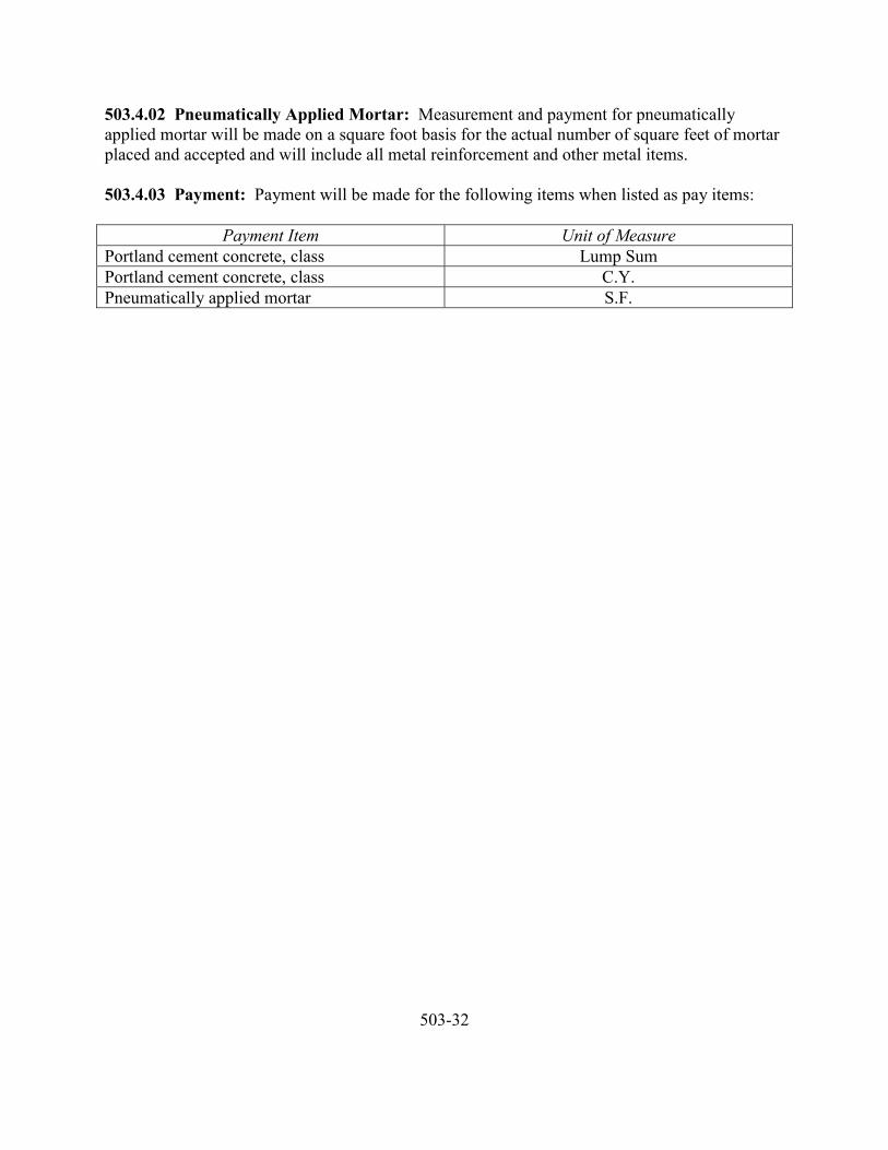
503.4.02 Pneumatically Applied Mortar: Measurement and payment for pneumaticallyapplied mortar will be made on a square foot basis for the actual number of square feet of mortarplaced and accepted and will include all metal reinforcement and other metal items.
503.4.03 Payment: Payment will be made for the following items when listed as pay items:
Payment Item Unit of MeasurePortland cement concrete, class Lump SumPortland cement concrete, class C.Y.Pneumatically applied mortar S.F.
503-32
504 REINFORCEMENT
504.1.00 Description
504.2.00 Materials504.2.01 Bars504.2.02 Mats504.2.03 Welded Wire Fabric504.2.04 Dowels504.2.05 Wire504.2.06 Supports504.2.07 Certification504.2.08 Identification
504.3.00 Construction504.3.01 Shop Drawings504.3.02 Fabrication504.3.03 Placing504.3.03A Splicing
504.4.00 Measurement and Payment504.4.01 Incidental Basis504.4.02 Lump Sum Basis504.4.03 Unit Price Basis
504-1
504 REINFORCEMENT
504.1.00 Description: This section covers the work necessary for the furnishing and placing ofmetal reinforcement and accessories.
504.2.00 Materials
504.2.01 Bars: Bars shall be deformed and shall be of billet-steel conforming to therequirements of ASTM A615 or rail-steel conforming to the requirements of ASTM A616, or ofaxle-steel conforming to the requirements of ASTM A617. Longitudinal bars in continuouslyreinforced concrete pavement shall be Grade 60.
All other bars shall be Grade 40, unless otherwise specified.
504.2.02 Mats: Steel for bar or rod mats shall conform to the requirements of ASTM A184.
504.2.03 Welded Wire Fabric: Welded wire fabric shall conform to the requirements ofASTM A185.
504.2.04 Dowels: Dowels shall conform to the requirements of ASTM A306. Dowels shall beGrade 70, unless otherwise specified.
504.2.05 Wire: Wire shall conform to the requirements of AASHTO M32.
504.2.06 Supports: Bar supports and their placement shall conform to Chapter 3 of the Manualof Standard Practice, Concrete Reinforcing Steel Institute. Bar supports in areas exposed to viewafter stripping shall be of galvanized or plastic coated steel, or of concrete, as directed by theEngineer.
504.2.07 Certification: Certification of bar reinforcement will identify the reinforcement asthat composed of the heat numbers indicated and is represented by the samples tested.
The certification shall also contain the weight, number of pieces, and dimensions of each size ofmaterial of each heat number shipped, the project identification and the date of shipment. If acolor code is used for identification, the heat number and color combinations are also to beshown.
504.2.08 Identification: Each piece of bar reinforcement shall be identified in a manner suchthat the heat number can be determined by the Engineer prior to its placement. Reinforcementshall be tagged and marked in accordance with the Manual of Standard Practice of the ConcreteReinforcing Steel Institute.
504-2
504.3.00 Construction
504.3.01 Shop Drawings: Shop drawings shall be submitted in accordance with therequirements of Subsection 104.4.00. Two sets of drawings will be required, unless otherwisespecified. Shop drawing details for bar reinforcement shall conform to Chapter Six of theManual of Standard Practice, Concrete Reinforcing Steel Institute. Shop drawing details forwelded wire fabric shall conform to Chapter Two of the same manual.
504.3.02 Fabrication: Fabrication shall conform to Chapter Seven of the Manual of StandardPractice, Concrete Reinforcing Steel Institute.
504.3.03 Placing: Reinforcement shall be accurately placed in positions shown on the Plansand firmly held during the placing of concrete. Bars in top mats of footings and deck slabs shallbe tied at all intersections, all other bars shall be tied at all intersections except where spacing isless than one foot in each direction where alternate intersections shall be tied.
Distance from the forms shall be maintained by means of stays, blocks, ties, hangers or otherapproved supports. Blocks for holding reinforcement from contract with the forms shall beprecast blocks of approved shape and dimensions and shall have the same compressive strengthas the concrete in which they are placed. Layers of bars shall be separated by precast mortarblocks or by equally suitable devices. The use of pebbles, pieces of broken stone or brick, metalpipe and wooden blocks will not be permitted. Reinforcement in any member shall be placedand then inspected and approved by the Engineer before the placing of concrete begins.Concrete placed in violation of this provision may be rejected and removal required.
The placing of bar reinforcement shall conform to the requirements of Chapter Eight of theManual of Standard Practice, Concrete Reinforcing Steel Institute.
504.3.03A Splicing: Bar reinforcement shall be furnished in the lengths indicated on the Plans.Splicing of bars, except when shown on the Plans, will not be permitted without written approvalof the Engineer.
504.4.00 Measurement and Payment
504.4.01 Incidental Basis: When not shown as a pay item, reinforcement shall be considered tobe incidental to the work and no separate payment will be made.
504.4.02 Lump Sum Basis: Measurement and payment for reinforcement will be made on alump sum basis.
504-3
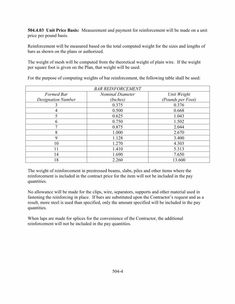
504.4.03 Unit Price Basis: Measurement and payment for reinforcement will be made on a unitprice per pound basis.
Reinforcement will be measured based on the total computed weight for the sizes and lengths ofbars as shown on the plans or authorized.
The weight of mesh will be computed from the theoretical weight of plain wire. If the weightper square foot is given on the Plan, that weight will be used.
For the purpose of computing weights of bar reinforcement, the following table shall be used:
BAR REINFORCEMENTFormed Bar
Designation NumberNominal Diameter
(Inches)Unit Weight
(Pounds per Foot)3 0.375 0.3764 0.500 0.6685 0.625 1.0436 0.750 1.5027 0.875 2.0448 1.000 2.6709 1.128 3.40010 1.270 4.30311 1.410 5.31314 1.690 7.65018 2.260 13.600
The weight of reinforcement in prestressed beams, slabs, piles and other items where thereinforcement is included in the contract price for the item will not be included in the payquantities.
No allowance will be made for the clips, wire, separators, supports and other material used infastening the reinforcing in place. If bars are substituted upon the Contractor’s request and as aresult, more steel is used than specified, only the amount specified will be included in the payquantities.
When laps are made for splices for the convenience of the Contractor, the additionalreinforcement will not be included in the pay quantities.
504-4

505 PRESTRESSED CONCRETE MEMBERS
STANDARDS NOT COMPLETE AT THIS TIME
505-1

506 STEEL STRUCTURES
STANDARDS NOT COMPLETE AT THIS TIME
506-1
507 TIMBER STRUCTURES
STANDARDS NOT COMPLETE AT THIS TIME
507-1

508 METAL RETAINING WALLS
STANDARDS NOT COMPLETE AT THIS TIME
508-1

509 UNASSIGNED
509-1

510 MISCELLANEOUS METALS
STANDARDS NOT COMPLETE AT THIS TIME
510-1

511 BEARING AND EXPANSION DEVICES
STANDARDS NOT COMPLETE AT THIS TIME
511-1

512 RAILING, FENCING, GATES AND CATTLE GUARDS
STANDARDS NOT COMPLETE AT THIS TIME
512-1

513 PAINTING, GALVANIZING AND ANODIZING
STANDARDS NOT COMPLETE AT THIS TIME
513-1
514 SLOPE PROTECTION
514.1.00 Description514.1.01 Slope Paving514.1.02 Riprap514.1.03 Gabions514.1.04 Filter Blanket
514.2.00 Materials514.2.01 Slope Paving Blocks514.2.02 Grout514.2.03 Portland Cement Concrete514.2.04 Metal Reinforcement514.2.05 Asphalt Concrete514.2.06 Broken Stone514.2.07 Broken Concrete514.2.08 Wire Enclosed Stone514.2.09 Filter Blanket514.2.10 Sacked Concrete514.2.11 Wire Enclosures514.2.11A Chain-Link Fence Fabric514.2.11B Welded Wire Fabric514.2.11C Lacing and Tie Wire
514.3.00 Construction514.3.01 Preparation514.3.02 Slope Paving Blocks514.3.03 Portland Cement Concrete514.3.04 Pneumatically Placed Mortar514.3.05 Loose Riprap514.3.06 Grouted Riprap514.3.07 Filter Blanket514.3.08 Wire Enclosed Stone Riprap
514.4.00 Measurement and Payment514.4.01 Measurement by the Cubic Yard514.4.02 Measurement by the Ton514.4.03 Lump Sum
514-1
514 SLOPE PROTECTION
514.1.00 Description: This section covers the work necessary for slope paving, riprap, or otherslope protection as specified.
514.1.01 Slope Paving: Slope paving shall consist of cement concrete blocks, poured cementconcrete, pneumatically placed cement concrete or asphalt concrete paving.
514.1.02 Riprap: Riprap shall consist of broken stone, wire enclosed stone, broken Portlandcement concrete or sacked concrete.
514.1.03 Gabions: Gabions shall consist of rectangular compartments of wire mesh materialfilled with stones or broken Portland cement concrete.
514.1.04 Filter Blankets: Filter blankets shall consist of one or more layers of graded materialplaced on a prepared slope prior to placing the riprap thereon to prevent underlying materialfrom passing through the riprap.
514.2.00 Materials
514.2.01 Slope Paving Blocks: Slope paving blocks shall conform to the requirements ofSection 503.
514.2.02 Grout: Grout shall consist of one part Portland cement and three parts sand,thoroughly mixed with water to produce thick, creamy consistency.
514.2.03 Portland Cement Concrete: Portland cement concrete shall conform to therequirements of Section 503, and shall be Class 3000, unless otherwise specified. The maximumaggregate size shall be as specified on the Plans, in the Special Provisions or on the Proposal.
514.2.04 Metal Reinforcement: Metal reinforcement shall be welded wire fabric conformingto the requirements of ASTM A185, unless otherwise specified.
514.2.05 Asphalt Concrete: Asphalt concrete shall conform to the requirements of Section211.
514.2.06 Broken Stone: Broken stone shall be hard, durable, angular in shape, resistant toweathering and shall meet the gradation requirements of the class specified. Neither breadth northickness of a single stone should be less than one-third its length. The acceptability of the stonewill be determined by the previous use records or by tests as the Engineer determines to beappropriate. If testing is required, suitable samples of stone shall be furnished by the Contractorand taken in the presence of the Engineer at least 25 days in advance of the time when the
514-2
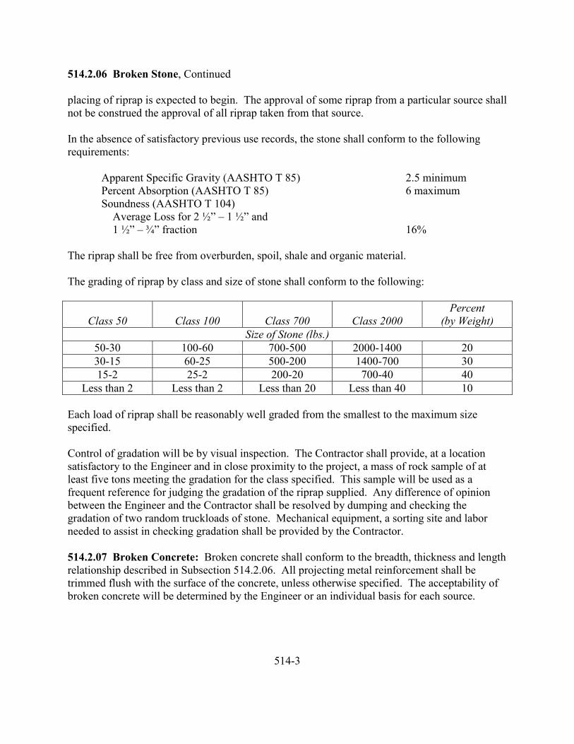
514.2.06 Broken Stone, Continued
placing of riprap is expected to begin. The approval of some riprap from a particular source shallnot be construed the approval of all riprap taken from that source.
In the absence of satisfactory previous use records, the stone shall conform to the followingrequirements:
Apparent Specific Gravity (AASHTO T 85) 2.5 minimumPercent Absorption (AASHTO T 85) 6 maximumSoundness (AASHTO T 104) Average Loss for 2 ½” – 1 ½” and 1 ½” – ¾” fraction 16%
The riprap shall be free from overburden, spoil, shale and organic material.
The grading of riprap by class and size of stone shall conform to the following:
Class 50 Class 100 Class 700 Class 2000Percent
(by Weight)Size of Stone (lbs.)
50-30 100-60 700-500 2000-1400 2030-15 60-25 500-200 1400-700 3015-2 25-2 200-20 700-40 40
Less than 2 Less than 2 Less than 20 Less than 40 10
Each load of riprap shall be reasonably well graded from the smallest to the maximum sizespecified.
Control of gradation will be by visual inspection. The Contractor shall provide, at a locationsatisfactory to the Engineer and in close proximity to the project, a mass of rock sample of atleast five tons meeting the gradation for the class specified. This sample will be used as afrequent reference for judging the gradation of the riprap supplied. Any difference of opinionbetween the Engineer and the Contractor shall be resolved by dumping and checking thegradation of two random truckloads of stone. Mechanical equipment, a sorting site and laborneeded to assist in checking gradation shall be provided by the Contractor.
514.2.07 Broken Concrete: Broken concrete shall conform to the breadth, thickness and lengthrelationship described in Subsection 514.2.06. All projecting metal reinforcement shall betrimmed flush with the surface of the concrete, unless otherwise specified. The acceptability ofbroken concrete will be determined by the Engineer or an individual basis for each source.
514-3
514.2.08 Wire Enclosed Stone: Wire enclosed stone shall be hard, durable, crushed, quarried,or natural stone, or broken concrete having an apparent specific gravity of not less than 2.4. Theabsorption shall not exceed four percent, unless otherwise specified. It shall be free of weaklaminations and cleavages and shall be of a quality that will not disintegrate on exposure to wateror weathering. The size shall be as specified.
514.2.09 Filter Blanket: Filter blanket material shall be composed of tough, durable particles,reasonably free from thin, flat and elongated pieces and shall contain no organic matter nor soft,friable particles in quantities in excess of those specified.
514.2.10 Sacked Concrete: Sacked concrete shall consist of Portland cement concrete placedin loosely woven burlap sacks.
514.2.11 Wire Enclosures: Wire enclosure material shall consist of one of the following:
514.2.11A Chain-Link Fence Fabric: Chain-link fence fabric shall conform to therequirements of AASHTO M181. The fabric shall be 11 gauge, two inch mesh with Class Icoating meeting the requirements of ASTM A392.
514.2.11B Welded Wire Fabric: Welded wire fabric shall conform to the requirements ofAASHTO M55. The fabric shall be 11 gauge, two inch mesh with Class I coating meeting therequirements of ASTM A116.
514.2.11C Lacing and Tie Wire: Lacing and tire wire shall be galvanized, 12 ½ gauge smoothsteel wire. In lieu of lacing, 9-gauge, galvanized hog rings at four inch spacings may be used forfastening ends, sides and top panels.
514.3.00 Construction
514.3.01 Preparation: Slope and foundation areas shall be cleared of all organic material andshaped to a smooth surface. All soft or spongy material shall be removed to the depth shown oras directed and replaced with approved material and compacted to the specified density.
514.3.02 Slope Paving Blocks: Slope paving blocks shall be placed in such a manner that theyrest firmly and evenly against the slope. The blocks shall be placed in horizontal parallel coursesand successive course shall break joints with the preceding course to form a running bond.Joints between blocks shall be grouted.
514.3.03 Portland Cement Concrete: Portland cement concrete shall be placed in such amanner so as to form a dense, impervious and uniform surface. The thickness shall be aminimum of four inches, unless otherwise specified. Portland cement concrete shall haveformed or sawed joints constructed as shown on the Plans.
514-4
514.3.04 Pneumatically Placed Mortar: Pneumatically placed mortar shall be placed inaccordance with the requirements of Section 503.
514.3.05 Loose Riprap: Loose riprap shall be placed in such a manner so as to produce areasonably well graded uniform mass.
514.3.06 Grouted Riprap: Grouted riprap shall be thoroughly moistened prior to grouting.The grout shall completely fill the voids. The surface texture shall be as specified.
514.3.07 Filter Blanket: Filter blanket material shall be placed such that segregation of particlesizes shall not occur. The finished surface of the blanket shall be free of irregularities.
514.3.08 Wire Enclosed Stone Riprap: Wire enclosures shall be connected together at allcontacting edges at six inch intervals.
514.4.00 Measurement and Payment
514.4.01 Measurement by the Cubic Yard: Measurement will be based on the number ofcubic yards of slope protection material constructed and accepted.
514.4.02 Measurement by the Ton: Measurement will be based on the number of tons ofslope protection material constructed and accepted.
514.4.03 Lump Sum: Measurement and payment will be based on a lump sum basis for thetype and size of slope protection constructed and accepted.
514-5
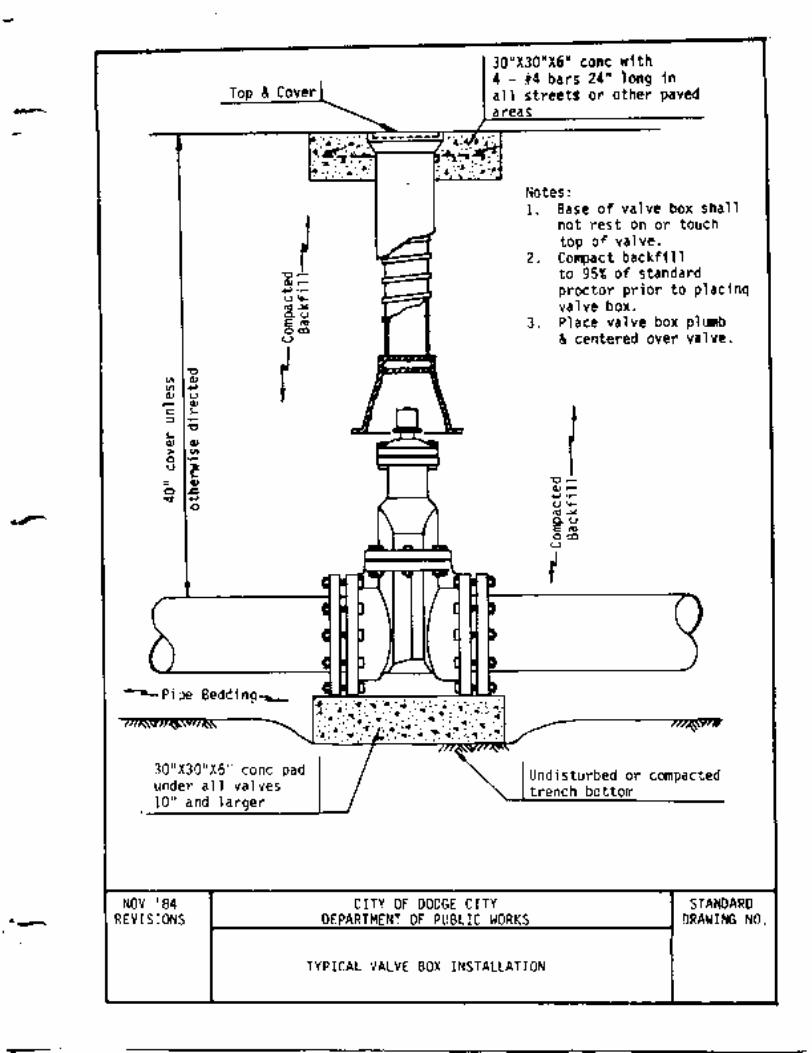
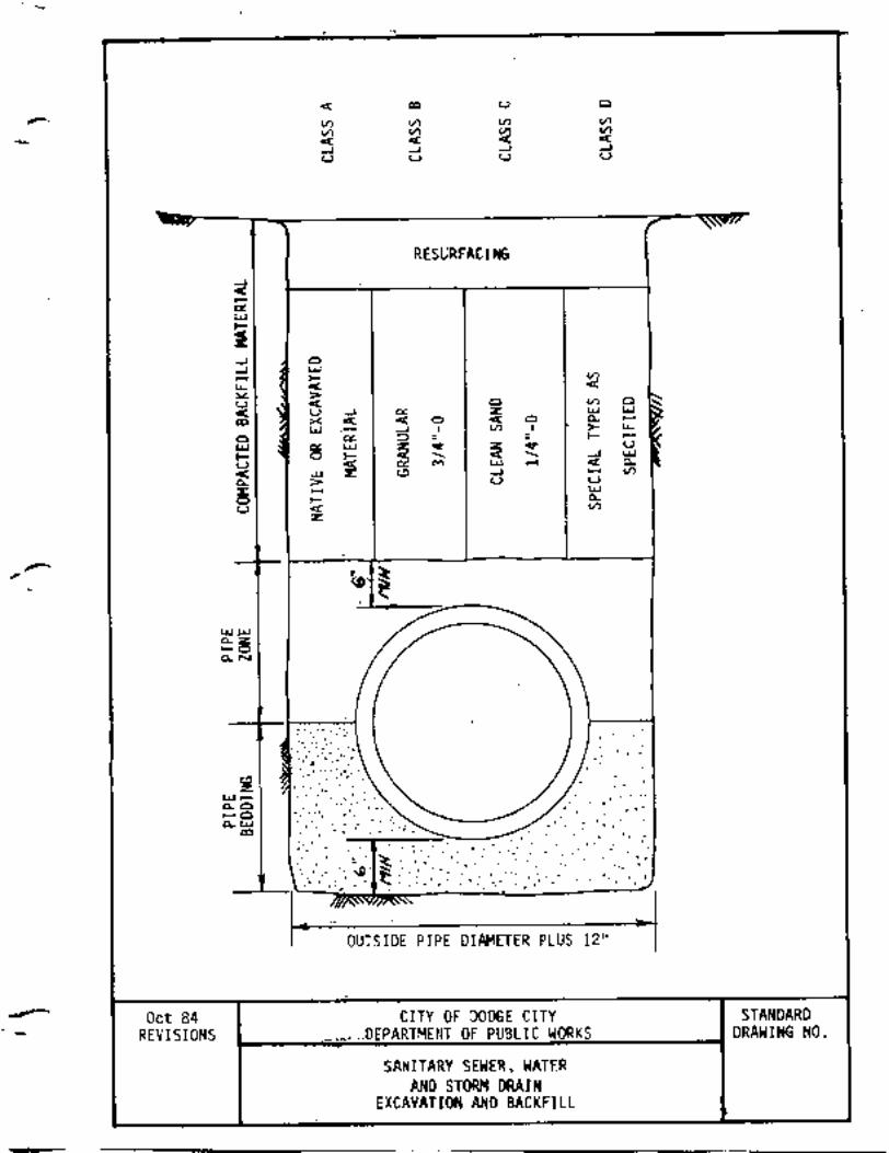
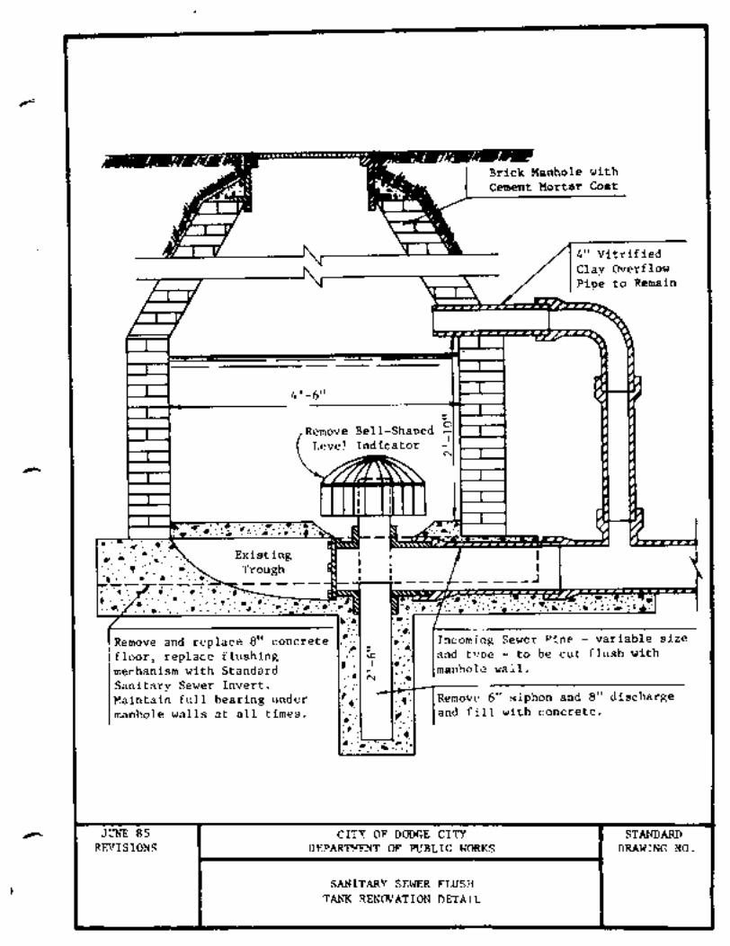
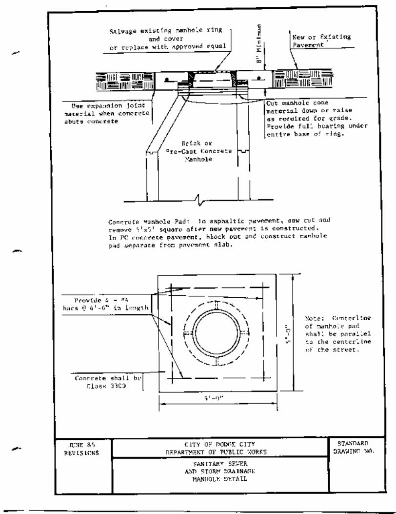
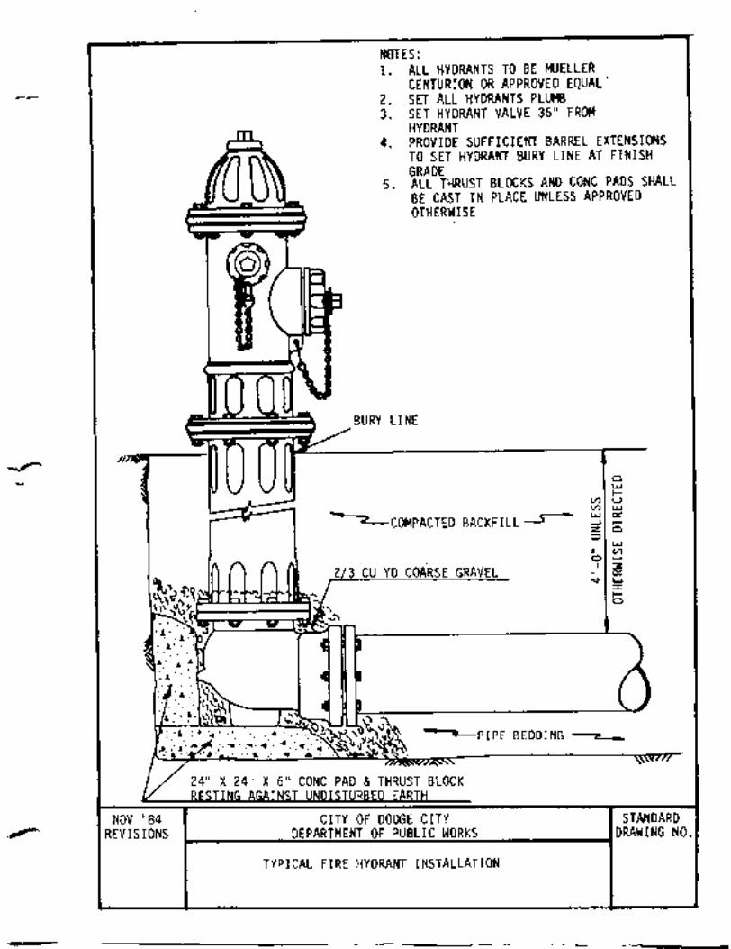
SUPPLEMENTALSTANDARD SPECIFICATIONS
1.0 GENERAL REQUIREMENTS:
1.1 INTENT: The purpose of the Supplemental Standard Specifications is to make alterations tothe STANDARD SPECIFICATIONS as may be necessary from time to time, as constructionmethods change or as certain projects may require special considerations. Anything that isrequired in these Supplemental Standard Specifications will supersede what is required in theCity's STANDARD SPECIFICATIONS.
1.2 STANDARD SPECIFICATIONS: All Bidders shall have a copy of the City of DodgeCity STANDARD SPECIFICATIONS FOR PUBLIC WORKS CONSTRUCTION, 1995Edition. Failure to obtain said STANDARD SPECIFICATIONS shall disqualify any firm frombidding until these specifications are in their possession.
Copies of the STANDARD SPECIFICATIONS FOR PUBLIC WORKS CONSTRUCTION,1995 Edition, may be obtained from the Engineering Division, City of Dodge City, 806 SecondAvenue, P.O. Box 880, Dodge City, Kansas 67801-0880. The cost is $25.00 per copy.
1.3 INSURANCE REQUIREMENTS: The Contractor shall provide proof ofinsurance coverage complying with Section 107.7.00 of the STANDARD SPECIFICATIONS. Attention is called specifically to the requirement for liability limits and umbrella limits of notlessthan $1,000,000. Proof of coverage shall be in the form of a standard insurance certificateprovided by the insurance carrier or the carrier's agent, and shall specifically show the projectname and number.
1.4 SCHEDULING OF WORK: The Contractor, upon notification of award of the contract,shall prepare a construction schedule in accordance with Section 108.1.00 of the STANDARDSPECIFICATIONS. Said schedule shall be approved by the Engineer prior to the issuanceof the Notice to Proceed.
If the Contractor plans on doing any work after normal daytime working hours or on weekends, itshall be noted in the schedule or phasing plan and approved by the Engineer.
The Contractor shall submit a revised construction schedule along with each monthly partial payrequest. The City reserves the right to withhold partial payments if said schedule is notsubmitted.
1.5 PROTECTION OF WORK: Until acceptance of the project, the Contractor shall, at alltimes, protect from damage all public and private property which may be affected by the workand preserve all materials, supplies, equipment of any description, and all work alreadyperformed from his work activities, the action of the elements, and damage by any person orpersons, or from any other cause whatsoever.
-1-
SUPPLEMENTAL STANDARD SPECIFICATIONSGENERAL REQUIREMENTS
1.6 COORDINATION WITH EXISTING UTILITIES: The Contractor shall coordinate hisactivities with those of the power, telephone, gas, cable televisions, water, and sanitary sewerutilities. In addition, the location of the electric, telephone, natural gas, water, sewer, and cableTV lines shall be verified by the Contractor prior to construction.
1.7 NOTIFICATION OF EMERGENCY SERVICES: It shall be the responsibility of theContractor to provide 48-hour advance notice to all emergency services, including police, fire,and ambulance, of the status of the work or of any street closure so that they are fully informedat all times. If the project is located on a school bus route, the Contractor shall also notify theUSD #443 Transportation Division. When work has been completed, the Contractor shallinform emergency services of work completion.
1.8 ACCESS TO PRIVATE PROPERTY: In general, access to private property shall beprovided by the Contractor during evenings and weekends or other times as long as such accessdoes not jeopardize portions of the work. The Contractor shall give occupants and businesses,which will be affected by the project, not less than 48 hours written notice before beginning workwhich will in any way limit access to private property.
1.9 INSPECTION/TESTING: The City of Dodge City will provide the construction inspectionand materials testing services on this project. However, due to manpower limitations, the City ofDodge City expressly reserves the right to hire consultants to perform the construction inspectionservices and consultants or testing laboratories to provide the required testing services.
The Contractor will be responsible for providing asphalt or concrete cores as required in theseSupplemental Standard Specifications or in the project Special Provisions.
The Contractor will be charged $50.00 for each failing subgrade compaction tests. The chargewill be $75.00 if taken before 8:00 a.m. or after 5:00 p.m.
The Contractor will reimburse the City of Dodge City for the total cost of any compaction teststaken that do not pass. The City will not charge the Contractor for tests that do pass. Alltesting will be done in accordance with these Specifications.
1.10 PRE-BID CONFERENCE: All bidders are required to attend a Pre-BidConference at the designated date, time, and location as indicated in the Advertisement/Notice toBidders, if specified. The purpose of the pre-bid conference is to familiarize prospective bidderswith the site and scope of the work. Additionally, this conference affords prospective bidders anopportunity to get answers to their questions and seek clarifications, which, if not provided couldhave a significant effect on the difficulty and cost of the work.
Failure to have a representative attend said Pre-Bid Conference shall be considerednonresponsive and may be grounds for rejection of Proposal.
-2-
SUPPLEMENTAL STANDARD SPECIFICATIONSGENERAL REQUIREMENTS
1.11 PRE-CONSTRUCTION CONFERENCE: The successful bidders will be required toattend a pre-construction conference which is to be held at least one week prior to the start ofwork. At that time, the Contractor will submit the following for the City's review:
A. Construction ScheduleB. Applicable mix design information/material tests.C. Names of Contractors job site representative that is authorized to receive instruction and
make decisions on the Contractor's behalf.D. After hours telephone numbers for a Contractor's representative that can handle emergency
situations or repair warning signs.
1.12 WARRANTY AND MAINTENANCE: The Contractor shall note the requirements ofSection 107.24.00 of the STANDARD SPECIFICATIONS concerning the one year warranty andmaintenance period. All performance bonds shall cover this one year period.
-3-
2.0 GENERAL CONSTRUCTION:
2.1 TEMPORARY TRAFFIC CONTROL: Temporary traffic control shall be planned andprovided by the Contractor and shall be in accordance with the Manual on Uniform TrafficControl Devices (MUTCD) and in accordance with Section 202 of the STANDARDSPECIFICATIONS. Yellow warning lights will be provided when required by theMUTCD.
Traffic control plans shall be provided in writing to the Engineer for approval at least seven (7)days prior to starting work. Said plan will include the name and telephone number of aperson that can be contacted after hours should the need arise.
The plan shall provide details and locations of barricades, construction and warning signs, anddetours. Included in the plan shall be a description of the progression of the work, hownotice to abutting properties is to be given, and person(s) responsible for notices andcommunications.
All signs and barricades shall be maintained in a clean, well maintained, attractive condition. Failure to properly maintain barricades/signs will be grounds for no payment for this item.The Contractor shall provide and be responsible at all times for flagpersons, signs, and otherdevices not otherwise specified by the Owner. The Contractor shall erect and maintain allbarricades, guards, standard construction signs, warning signs as are necessary to warn andprotect the public at all times from injury or damage as a result of the work operations.
Upon failure to immediately provide the necessary flagpersons or to provide, erect, maintain andremove barricades, lights and signs when so ordered, the Engineer shall have the right, withoutfurther notice to the Contractor or the Contractor's Surety, to cause the condition to be remediedand deducted from all costs thereof from any payments due, or coming due to the Contractor.
2.2 SURVEYING AND CONSTRUCTION STAKING: The Contractor shall be responsible forproviding all required surveying and construction staking for this project. When required, theCity will provide the horizontal and vertical control reference points. Sufficient staking will beprovided to ensure the Engineer that line and grade are proper.
2.3 PROJECT SIGNS: The Contractor shall be responsible for furnishing, installing, andmaintaining project signs. Each sign shall be placed at the ends of each project limits, or asdesignated by the Engineer. Specifications governing the sign are shown on the Details Sheets ofthese SUPPLEMENTAL STANDARD SPECIFICATIONS.
Deviation from information specified and shown shall not be allowed. It shall be responsibilityof the Contractor to clarify and coordinate information to be contained on the sign with theEngineer prior to its placement. The City will not pay for these signs if they are not installedprior to 25% of the work being completed.
-4-
SUPPLEMENTAL STANDARD SPECIFICATIONSGENERAL CONSTRUCTION
2.4 SUBGRADE PREPARATION: After removal of the existing pavement, theContractor shall prepare the subgrade for the new pavement in compliance with Section 206 ofthe STANDARD SPECIFICATIONS.
2.4.1 COMPACTION AND GRADING: After the subgrade has been brought to grade,the Contractor shall compact the top six (6) inches to 95% standard proctor density.
The subgrade shall be accurately shaped by blading, and the finished surface compacted to atight, smooth surface, suitable for construction of the pavement. This shall be completed prior tofinal density testing.
When the Contractor has completed a portion of the subgrade and is ready to begin constructionof the new pavement, he shall give the Engineer at least 4 hours notice so the subgrade can bechecked and approved. Any areas found to be not to grade in accordance with Section 206.3.05shall be reworked until the required grades and/or densities are achieved. Sand will not beused to fine grade the subgrade if the subgrade is ½" or more out of tolerance. Should densitytests not pass, the Contractor will be billed for the cost of the test. The City will not bill forpassing tests.
2.5 SUBGRADE REPAIR: Subgrade repair shall provide a means to accommodate unsuitablesubgrade material encountered after the removal of existing pavement. Unsuitable subgraderefers to soil quality only, not to moisture content. A wet soil, properly worked and dried, is notnecessarily unsuitable. Quantities of unsuitable subgrade material shall be calculated bymeasuring the limits of excavations necessary to remove unsuitable subgrade. Payment forsubgrade repair shall be based on measured quantities and shall include all costs ofover-excavation, backfill, andcompaction of the imported material necessary to complete the subgrade. Material proposed foruse as backfill shall be submitted to the Engineer and written approval received beforeuse in the project.
The quantity of subgrade repair in the Proposal is an estimated quantity intended to establish aunit cost for repair of unsuitable subgrade material. Any attempt by the Contractor to unbalancethis, or any other bid item, may result in rejection of the bid proposal. Prior to beginning anysubgrade repair work, the Contractor shall obtain written approval from the Engineer.
2.6 RESEAL JOINTS: The Contractor shall be responsible for cleaningand resealing joints and cracks in the existing street or adjacent curb and gutter, as indicated onthe plans or in the project Special Provisions.
Joint sealing material shall be Dow Corning 888, or approved equal.
-5-
SUPPLEMENTAL STANDARD SPECIFICATIONSGENERAL CONSTRUCTION
2.7 MANHOLE AND WATER VALVE ADJUSTMENTS: Manhole and valve box tops shallbe adjusted to the new pavement grade, as necessary. The Contractor shall call for an inspectionof each individual manhole or valve box prior to placing the surfacing around them to enable theEngineer to check conformance to both transverse and lateral grade.
The provisions of Section 216 of the STANDARD SPECIFICATIONS not withstanding,concrete aprons separate from new concrete pavements will not be required, however, theContractor shall install the 1/2 inch reinforcing around each manhole or valve box as required bySection 216 of the STANDARD SPECIFICATIONS. This 1/2 inch reinforcing shall be inaddition to the normal pavement reinforcing.
On asphalt streets, concrete aprons with reinforcing will be required around all such castings. Concrete shall be 3500 psi high-early strength, capable of supporting normal traffic loads withinsix (6) hours of installation.
Excavations necessary to adjust manholes or valve boxes to grade shall be backfilled withflowable fill to the top of the subgrade. This shall be incidental to the bid item of both manholeand/or water valve adjustments. All manholes, valve covers, and similar utility covers shall be protected during the paving inorder to keep from coating them with asphalt cement or asphaltic concrete. Should any of thesecovers need cleaning, the Contractor shall clean them without damage to adjacent property orstreet surface and without permitting his solvents to run into any sanitary sewer or storm drain. Any cover castings or valve stems damaged by the Contractor during his operations will bereplaced by the Contractor at no cost to the City. Any such items already broken shall bereplaced by the City. Contact the City Water Department.
The Contractor shall not allow foreign material to fall into sewers and stone, broken asphalt orconcrete pieces which fall into manholes or into valve boxes or similar structures shall beremoved by the Contractor.
The City of Dodge City considers the completion of adjustment of manholes and water valves ofsuch importance that should these adjustments not be completed within fourteen (14) calendardays after paving operations on each street are completed, then the City shall withhold $35.00 perday per incomplete adjustment, as liquidated damages.
Further, should the City have a water or sewer problem that requires it to open a manhole orvalve box prior to the adjustment being made, the Contractor shall reimburse the City for its costto open the manhole and barricade it.
-6-
SUPPLEMENTAL STANDARD SPECIFICATIONSGENERAL CONSTRUCTION
2.8 REMOVAL AND REPLACEMENT OF CONCRETE CURB AND GUTTER: Curb andgutter work shall comply with Section 213 of the STANDARD SPECIFICATIONS. Concreteshall be Class 3500. Removal of curb and gutter shall be done in such a manner so as tominimize damage to adjacent curb and gutter, pavement, sidewalks, or other facilities.
When existing curb and gutter is adjacent to brick pavement, a minimum of two rows of bricksshall be removed in order to form the new curb and gutter. The underlying concrete base mayremain and used as a form for the new curb and gutter. The Contractor shall replace the sandbedding and brick adjacent to the new curb and gutter, matching the gutter grade, After thebricks have been placed, a light application of sand and cement slurry shall be squeegeed orbroomed into the spaces between the bricks to seal the pavement surface. Care shall be taken touse only the amount of slurry necessary to accomplish a seal. Excess material on the horizontalsurface shall be removed prior to opening the work to traffic. Removal and replacement of thebrick along the curb toe shall be considered as incidental to the curb and gutter bid for which noadditional payment shall be made.
When existing curb and gutter is adjacent to asphaltic or concrete pavement, the existingpavement may be used as a form for the new curb and gutter. If the pavement is damaged duringconstruction, it shall be saw cut to form a smooth vertical edge and then replaced at no expenseto the City.
The Contractor is also responsible for replacing in-kind any material removed or disturbed backof curb during removal and replacement of curb and gutter. There shall be no direct pay for thisreplacement.
New curb and gutter shall be doweled and grouted to the existing curb and gutter by using #4 x18" rebar (See Detail).
The cost of any excavation or subgrade preparation required for the removal and/or replacementof curb and gutter will be considered incidental to the bid item for which no additional paymentwill be made.
2.9 REMOVAL AND REPLACEMENT OF SIDEWALKS, DRIVEWAYS ANDAPPROACHES: Driveway and sidewalk approach work shall comply with Section 214 and 215of the STANDARD SPECIFICATIONS. Concrete shall be Class 3500.
2.10 4" CONCRETE ADA CURB RAMPS: Sidewalk work shall comply with Section 215of the STANDARD SPECIFICATIONS. Concrete shall be Class 3500. Curb ramps shall meetthe 1990 American with Disabilities Act (ADA) uniform Federal accessibility standards (SeeDetail). The limits of pay for the ADA curb ramps is as shown of the Detail.
-7-
SUPPLEMENTAL STANDARD SPECIFICATIONSGENERAL CONSTRUCTION
2.11 PLASTIC PAVEMENT MARKINGS: Pavement marking shall be a cold plastic materialmanufactured by 3M Company, or approved equal.
2.11.1 METHODS OF TEST: Unless otherwise stated, tests will be conducted using methodsestablished by the Research-Materials Laboratory, Kansas Department of Transportation.
2.11.2 BASIS OF ACCEPTANCE: Acceptance of this material may be based onsatisfactory results of tests conducted on representative samples submitted to a laboratoryselected by the City of Dodge City.
2.11.3 MATERIAL SPECIFICATIONS: The Contractor shall furnish a specificationshowing the physical properties and detailed installation instructions for the materials which areproposed.
2.11.4 CONFORMANCE TO MANUAL ON UNIFORM TRAFFIC CONTROL DEVICES: When specified, pavement arrows and legends shall conform closely in shape and size to thosespecified in the Manual on Uniform Traffic Control Devices. Exceptions to sizes and shapesshall be clearly specified at the time of bidding. Failure to meet the manual size and shapespecifications without giving exceptions may be grounds for rejecting the work.
2.11.5 DESCRIPTION: Cold plastic marking materials shall be a conformable ribbon or otherflat shape as specified, and shall be fabricated of a plastic material, suitable pigments, plasticizersand reflective glass beads distributed evenly throughout, suitable for application to asphalt,concrete, and brick. The marking material shall be so formulated that the applied lines andshapes will show a high visibility which will remain during the effective life of the material. Amaterial which permits or promotes adherence of excessive amounts of road film so as todecrease markedly visual impact shall not be acceptable, regardless of compliance with otherprovisions of this specification.
The marking shall be supplied complete with a precoated, factory applied adhesive, to makepossible immediate application to pavement. When the adhesive backing is supplemented by asolvent, or other type of adhesive, the material used and application shall be in accordance withthe manufacturer's recommendation. Items recommended for special handling may be appliedutilizing an adhesive recommended and supplied by the manufacturer of the pavement markingmaterial.
2.11.5.1 CLASS AND TYPE: The marking material shall be furnished in twoclasses as follows: Class W - White Class Y - Yellow
It shall further be furnish in one type as follows: Type I - 60 mils thick (Nominal)
-8-
SUPPLEMENTAL STANDARD SPECIFICATIONSGENERAL CONSTRUCTION
2.11.5.2 ADHESIVE ACTIVATOR OR SOLVENT: The Contractor shall furnish and use anadhesive activator or solvent as recommended by the manufacturer of the plastic markingmaterial suitable for portland cement concrete, asphaltic concrete, or brick depending uponwhich pavement it is to be applied on.
The Contractor shall take special care to remove any materials from the surface to which thepavement markings are to be applied which might inhibit the adhesive or the activator.
2.11.6 REQUIREMENTS: Length, width, shape, and type shall be as designated on the plans,or as specified in the Special Provisions.
2.11.6.1 DIMENSIONAL REQUIREMENTS AND COMPOSITION: Type I – Thickness shallbe not less than 0.055 inch or more than 0.070 inch exclusive of the adhesive. Composition shallconform to the following by weight:
Glass spheres retained on a No. 325 sieve…………………………..30% Min. Plastic material and pigments..........………………………………...Remainder
2.11.6.2 COLOR AND DAYLIGHT REFLECTANCE: Daylight reflectance (ASTM E97) ofClass W (White) shall be not less than 50%. The color of Class Y (Yellow) shall be within thered and green tolerance limits of the Highway Yellow Color Tolerance Chart, issued by the U.S.Department of Transportation.
2.11.6.3 FLEXIBILITY: Flexibility of the material shall be such that it can be applied at atemperature of 75 degrees F, or more, without cracking or breaking.
2.11.6.4 REFLECTIVITY: The white and yellow material shall be retroreflective, reflectingwhite and yellow respectively, and shall be readily visible when viewed with automobileheadlamps at night from a distance of at least 300 feet.
2.11.6.5 INSTALLATION: Prior to installing any pavement markings, the surface of thepavement shall be thoroughly cleaned to remove grit, grease, and other substances that wouldprevent the markings from adhering to the pavement. The Contractor shall comply with therecommended manufacturer's specifications. Once installed, all plastic pavement markings willbe cut at all joints.
2.12 PAVEMENT SMOOTHNESS: The smoothness of the surface will be measured by theprofilograph method, in accordance with KDOT Special Provision 90P-111-R1 (rigidpavements) and Special Provision 90P-39-R4 (flexible pavements). Copies of the KDOT SpecialProvisions are attached to these Supplemental Standard Specifications.
-9-
SUPPLEMENTAL STANDARD SPECIFICATIONSGENERAL CONSTRUCTION
2.12 PAVEMENT SMOOTHNESS, Continued
In reducing the profilograph tracings, all Contractors should note that a zero blanking band willbe used, so as to include the effects of chatter in the profile index.
Prior to determining the final punch list on any given street, the Contractor will furnish theEngineer one (1) tracing per traveled lane, to be taken at the lane centerline. The Engineer andthe Contractor will jointly review the tracings to determine bump or excessive chatter locations. The Contractor will take corrective actions to remove bumps and chatter. A profile index will becalculated, however, no penalty or bonus will be assessed based on this index. This index is forthe City's information only on this project.
2.13 MEASUREMENT AND PAYMENT:
2.13.1 METHOD OF MEASUREMENT: Quantities shall be measured as provided forunder the various unit items which constitute the completed and accepted work according to theplans and specifications for each bid item. Any attempt by the Contractor to unbalance any biditem may result in the rejection of the bid proposal.
A submittal form shall be completed by the Contractor in order to process a project payment. Allpay requests shall be submitted by the Contractor not less than 13 days prior to the first Mondayof the month to allow adequate time for processing.
Payment shall be based on work completed at 5:00 p.m. on the Friday prior to submittals. TheEngineer will review the Contractor’s submittals for accuracy with the City’s measurements. The Contractor will be notified of any changes. Should the Contractor disagree with the City’smeasurements, the Contractor will be required to submit scaled drawings, complete with hismeasurements and calculations for review by the City’s Inspector.
2.13.2 BASIS OF PAYMENT: Quantities shall be paid for at the contract unit price for each biditem. Payment will be full compensation for furnishing and placing all materials, and for alllabor,equipment, tools, and incidentals necessary to complete the work in accordance with theseSupplemental Standard Specifications and the STANDARD SPECIFICATIONS for the City ofDodge City.
2.13.3 PAYMENT FOR ADDITIONAL WORK: Payment for additional work shall be inaccordance with Section 109.5.00 of the STANDARD SPECIFICATIONS. Extra work, whenrequired, shall be approved in writing prior to beginning the work.
-10-
SUPPLEMENTAL STANDARD SPECIFICATIONSGENERAL CONSTRUCTION
2.13.4 PAYMENT FOR MATERIALS ON HAND: Payment for materials on hand shall beissued upon receipt of paid invoices and inspection of materials delivered to the Project site. Payment for materials on hand will be a one-time payment and will not be carried forward insubsequent partial payments. Should the Contractor fail or be prevented from incorporatingsufficient materials into the work prior to the next partial payment and such failure results in azero or a negative balance, in the pay requests, no payments will be made until the work hasprogressed to the point where a positive balance results.
-11-
3.0 ASPHALT CONSTRUCTION:
3.1 TYPES OF CONSTRUCTION:
3.1.1 TYPE A-1: 3" ASPHALT SURFACE: This type of construction essentially places a 3"asphalt mat on a prepared subgrade with soil support fabric between the subgrade and the bottomof the asphalt mat. This type of construction will be done on those streets where so indicated onthe Proposal form.
The existing surface of the street will be removed by milling and windrowing the asphalt materialadjacent to one curb for use in the base course. After the surfacing is windrowed, the existingbase will be excavated to the depth necessary to allow for the construction of a 3" asphaltpavement of BM-2 asphaltic concrete.
After excavation, the milled asphalt material shall be uniformly spread across the entire streetand thoroughly mixed or scarified with the top 6" of subgrade material. When the mixingprocess iscomplete, the subgrade shall be compacted to not less than 95% of Standard Proctor Density. Once this process is completed, the elevation of the subgrade shall be at the proper line andgrade,with crown.
After the paving fabric, if called for, has been placed and secured, the street will be paved with 3"of BM-2 asphaltic concrete. This asphalt mix shall meet the specifications indicated below.
3.1.2 TYPE A-2: ASPHALT SURFACE: The general intent of this construction is to providefor a specified asphalt mat over a prepared subgrade with a soil support fabric between thesubgrade and the bottom of the asphalt mat.
On this type of construction, the existing asphalt pavement will be removed by the process that isindicated in the Special Provisions. If milling is specified as the method of removal, theContractor will haul the milled material to the City Animal Shelter, which is located in SouthDodge, east of S. US Hwy 283. If milling is not specified, then the Contractor may use themethod of his choice to remove the existing asphalt mat. In this situation, unless specifiedotherwise in the Special Provisions, this material will become the Contractor's property and willbe disposed of by him by some legal means.
After the asphalt surfacing has been removed, the remainder of the existing subgrade shall beexcavated to provide for a full 6" of paving. The top 6" of the subgrade shall be thoroughlyworked and remixed by means of disks, tilling, or other suitable methods, shaped, and compactedto a minimum of 95% of Standard Proctor Density. After mixing, the street shall be regraded,crowned, and compacted to meet these requirements. After this work is completed, the soilsupport fabric will be installed and the streets shall be paved with the specified thicknesses ofBM-4 base and BM-1B surface course material. Said specified thicknesses will be stated in theSpecial Provisions.
-12-
SUPPLEMENTAL STANDARD SPECIFICATIONSASPHALT CONSTRUCTION
3.1.2 TYPE A-2: ASPHALT SURFACE, Continued
In determining the calculated asphalt quantity for yield determinations, the actual square yardsreconstructed and the actual asphalt unit weights will be used. Adjustments will be made, ifnecessary, for unusual irregularities in either the subgrade or within the pavement mat.
The thickness of the BM-4 and BM-1B surfaces are just as important as the total mat thickness. The surface course will be 2 inches minimum in thickness and will be continuously checked bythe Engineer. Corrections will be made immediately in the field. No cores will be required onthe BM-1B surface.
Cores will be required on the BM-4 base course. See Supplemental Standard SpecificationsSection 3.15 modifications below. Cores will be furnished to the Engineer at least two (2)working days prior to the placement of the surface course.
3.1.3 TYPE A-3: MILL AND ASPHALT OVERLAY: This type of work will be performed onthose streets where so indicated by the Proposal. The general intent of this type of construction isto mill asphalt off an existing asphalt street and replace it with a new asphalt overlay. Thethickness of this construction will be indicated in the Special Provisions. Prior to placing theasphalt overlay, cracks in the existing street surface will be repaired as indicated in theseSupplemental Standard Specifications or the Special Provisions.
Once the cracks are repaired as specified, the street surface will be thoroughly broomed toremove all loose and foreign materials. A tack coat shall then be applied as specified in Section3.10 of the Supplemental Standard Specifications. The overlay will consist of either BM-1Basphalt or BM-2 asphalt, as may be specified in the Special Provisions for the project.
3.2 ASPHALT CONCRETE PAVEMENT: Asphalt concrete pavement shall comply withSection 211 of the STANDARD SPECIFICATIONS. Specific mix composition requirementsshall comply with Section 1103.02 (1) BM-1B, Section 1103.02 (2) BM-2, and Section 1103.02(4) BM-4 of the Kansas Department of Transportation (KDOT) Standard Specifications, 1990Edition.
3.3 MIX DESIGNS: The Contractor shall submit the complete mix designs and materials foreach type of asphaltic concrete he proposes to use for review and approval by the City'slaboratories at least two weeks prior to the planned production date.
-13-
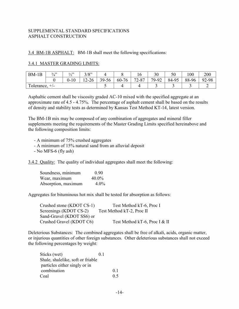
SUPPLEMENTAL STANDARD SPECIFICATIONSASPHALT CONSTRUCTION
3.4 BM-1B ASPHALT: BM-1B shall meet the following specifications:
3.4.1 MASTER GRADING LIMITS:
¾” ½” 3/8” 4 8 16 30 50 100 200BM-1B0 0-10 12-26 39-56 60-76 72-87 79-92 84-95 88-96 92-98
Tolerance, +/- 5 4 4 3 3 3 2
Asphaltic cement shall be viscosity graded AC-10 mixed with the specified aggregate at anapproximate rate of 4.5 - 4.75%. The percentage of asphalt cement shall be based on the resultsof density and stability tests as determined by Kansas Test Method KT-14, latest version.
The BM-1B mix may be composed of any combination of aggregates and mineral fillersupplements meeting the requirements of the Master Grading Limits specified hereinabove andthe following composition limits:
- A minimum of 75% crushed aggregates - A minimum of 15% natural sand from an alluvial deposit - No MFS-6 (fly ash)
3.4.2 Quality: The quality of individual aggregates shall meet the following:
Soundness, minimum 0.90 Wear, maximum 40.0% Absorption, maximum 4.0%
Aggregates for bituminous hot mix shall be tested for absorption as follows: Crushed stone (KDOT CS-1) Test Method kT-6, Proc I Screenings (KDOT CS-2) Test Method kT-2, Proc II Sand-Gravel (KDOT SS6) or Crushed Gravel (KDOT C6) Test Method kT-6, Proc I & II
Deleterious Substances: The combined aggregates shall be free of alkali, acids, organic matter,or injurious quantities of other foreign substances. Other deleterious substances shall not exceedthe following percentages by weight:
Sticks (wet) 0.1 Shale, shalelike, soft or friable particles either singly or in combination 0.1 Coal 0.5
-14-
SUPPLEMENTAL STANDARD SPECIFICATIONSASPHALT CONSTRUCTION
3.4.3 Crushed Material: A minimum of 98% of the particles retained on the No. 30 sieve aftercrushing shall have one or more crushed faces as determined microscopically at the testinglaboratory.
Failure to comply with the above requirement shall result in the reduction in contract payment asshown below:
Percent with Crushed Face Contract Price Reduction* 97.0 to 97.9 $1.00/ton 96.0 to 96.9 $2.25/ton 95.0 to 95.9 $3.50/ton 94.0 to 94.9 $5.00/ton
Less than 94.0 The material may be used at a $7.00/ton contract reduction or rejected at the Engineer's option.
* The above contract price reduction values shall be applied at the same percentage rate that thenon-complying crushed gravel is used in the mix. For example, in a mix having 50% KDOTCG-5 with 97.0 to 97.9% crushed faces, the contract price reduction to be applied shall be $1.00x 0.5 = $0.50. The dollar value derived for the appropriate category of percent crushed facesshall be assessed for each ton of asphaltic mixture in which the material was used.
3.4.4 General Mix Composition Requirements: Not more than 30% of the material passing theNo. 200 sieve shall be present in the uncrushed aggregate. The remaining mineral filler shall bepresent in crushed aggregate or shall be obtained by the addition of materials meeting therequirements for KDOT defined wet bottom slag or any mineral filler supplement except KDOTMFS-3.
The gradation, plasticity index (P.I.) and moisture content shall comply with the applicablerequirements of KDOT specifications, page 1103, Table 6, except that the Master Grading Limitsprovided hereinabove shall apply.
At least 15% of the crushed aggregate passing the 3/8" sieve shall consist of crushed limestone. The Contractor may choose to use 1% KDOT MFS-4 (hydrated lime) in lieu of the aboverequirement. If MFS-4 is selected, then it shall be added to the combined aggregate as dryhydrated lime and shall be mixed in a pug mill or other approved device to ensure adequatecoating of the combined aggregates. The combined aggregate shall be moistened to at least 3%above the saturated surface dry condition prior to or during the addition of the hydrated lime. This requirement shall not apply to a mix containing 50% or more calcite cemented sandstone.
-15-
SUPPLEMENTAL STANDARD SPECIFICATIONSASPHALT CONSTRUCTION
3.4.5 Process Control: During production, the Engineer shall conduct tests for gradation. Aminimum of two samples of materials for a 1,000 ton lot shall be tested to verify compliancewith the approved mix design. Non-compliance shall be subject to rejection or a priceadjustment for the entire lot or portion of the lot represented by the test results.
The process shall be considered in non-compliance when one or both test results on any sieve(s)fall outside the Master Grading Limits for BM-1B. When this occurs, the lot shall be terminated,accepted at a reduced pay or rejected by the Engineer. Production shall be suspended pendingthe satisfactory results of a new pre-production sample.
The combined cold feed samples shall be taken at times designated by the Engineer and analyzedin the Contractor's laboratory.
3.4.6 Basis of Acceptance: Calculated values for acceptance test results for gradations shall beshown to the nearest 0.01%
3.5 BM-2 ASPHALT: Asphaltic concrete mixes meeting KDOT specifications, edition of1990, for BM-2 shall be furnished as called for by the plans and specifications.
Asphaltic cement content, density, and stability tests shall be based on the results of Kansas TestMethod KT-14, the latest version.
3.6 BM-4 ASPHALT: Asphaltic concrete mixes meeting KDOT specifications, edition of1990, for BM-4 shall be furnished as called for by the plans and specifications.
Asphaltic cement content, density, and stability tests shall be based on the results of Kansas TestMethod KT-14, the latest version.
3.7 SOIL SUPPORT FABRIC: If a paving fabric is called for, it shall be spread on the basecourse after the crown is approved for grade.
The paving fabric shall be Amoco 4546, or an approved equal. The Contractor shall beResponsible for installing the fabric and restraining it with staples, large headed spikes or othersuitable methods to keep the fabric in close contact with the base during paving operations. Should the fabric become displaced in any way, whether by the Contractor's equipment or windor other causes, paving shall be discontinued until the fabric is properly re-spread and secured. No more fabric than can be covered by the surface course shall be placed ahead of the pavingmachine. Placing of the fabric shall be by means of a piece of equipment specifically designed tolay or spread the fabric and capable of handling full rolls. Such equipment shall lay the materialsmoothly, without excess wrinkles or folds. All wrinkles severe enough to allow a fold shall beslit, layed flat, and secured with staples or large headed nails.
-16-
SUPPLEMENTAL STANDARD SPECIFICATIONSASPHALT CONSTRUCTION
3.7 SOIL SUPPORT FABRIC, Continued
Hand placing of fabric will not be approved except for special need and for small, irregular areas.
The fabric shall be overlapped a minimum of 3 inch and a maximum of 6 inches. All transversejoints shall be "shingled" in the direction of paving machine travel.
3.8 CONTACT SURFACES: Contact surfaces of curbing, gutters, manholes, and similarstructures shall be painted with a thin, uniform coating of asphaltic cement material. Any asphaltmaterial in excess of this shall be removed without damage to the new pavement. TheContractor may use any means he chooses to apply the asphalt material, but coverage shall becomplete and uniform. A "bead" of asphalt from a spray nozzle shall not be acceptable.
The asphaltic concrete shall be placed uniformly high at the contact surfaces so that aftercompaction, the finished surface will be approximately 1/4 inch above the edge of suchstructures. 3.9 PAVEMENT MEMBRANE FABRIC: A pavement membrane fabric shall be installedbetween or below the various layers of asphalt mat, as may be indicated in the Special Provisionsfor the particular project. This fabric shall be "Petromat", as manufactured by Phillips Fibers, oran approved equal. The Petromat will be installed in place with mechanical lay down equipment,capable of handling the rolls of fabric and shall be capable of laying the fabric smoothly, withoutexcessive wrinkles and/or folds. When manual laydown is required, a length of standard 1" pipe,together with suitable roll tension devices, is required for proper roll handling.
The surface upon which the fabric is placed shall be free of dirt, water, and vegetation. Cracksshall be repaired as indicated in the crack repair or filling specifications.
Prior to the installation of the Petromat, a tack coat on the roadway surface will be required. Thecorrect tack coat application rate should be based on the quantity of residual asphalt in the tackmaterial specified and the porosity of the surface to the covered. Generally, this willapproximate 0.25 gallons per square yard residual asphalt; but depending on pavementconditions, the rate may vary between 0.20 to 0.30 gallons per square yard (See SpecialProvisions for individual project). If asphalt emulsion is used, a greater amount of the emulsionmust be applied to result in a cured 0.25 gallons per square yards of residual asphalt.
In general, the Contractor shall comply with any manufacture recommendations concerning theproper installation of this pavement membrane fabric.
-17-
SUPPLEMENTAL STANDARD SPECIFICATIONSASPHALT CONSTRUCTION
3.10 TACK COAT: This work shall conform to Section 211.3.04 of the STANDARDSPECIFICATIONS. The tack coat shall be applied at a rate of 0.04 gallons per square yard. Sufficient time shall be provided to allow the tack coat to cure before laying the surfacecoarse.
If the Engineer determines that the tack coat is unnecessary, the Engineer reserves the right towaive this item of work from the project.
3.11 PRIME COAT: A prime coat shall be required whenever an asphalt mat is placed over anysoil or rock base. The prime coat shall meet the requirements as specified in Section 211.3.03 ofthe STANDARD SPECIFICATIONS. The type of asphalt to be used, along with the requiredapplication rate, will be as indicated in the Special Provisions for the particular project inquestion.
3.12 MILLING OPERATIONS: When the method of removal of all or a portion of an asphaltmat is by milling, the Contractor is expected to use a milling machine that is manufactured forthatpurpose to accomplish this removal. Unless otherwise specified in the Special Provisions, themilled materials will be loaded on trucks supplied by the Contractor and hauled to a site withintheCity of Dodge City, as specified in the Special Provisions for the project. During millingoperations, care will be taken not to damage any passing motor vehicles.
The site of the milling operations will be signed in accordance with the requirements of theManual on Uniform Traffic Control Devices (MUTCD). Flagmen will be provided whererequired. In addition, all temporary drop offs resulting from the milling operations will beadequately signed. Upon completion of the milling operations, the street shall be swept toremove any remaining loose materials and temporary pavement markings applied to indicated thelanes as they existed prior to the milling operations. Should an asphalt overlay follow closely tothe milling operations, the need for temporary pavement markings may be waived by theEngineer. See any Special Provisions for a discussion on required temporary pavementmarkings.
3.13 TEMPERATURE LIMITATION: Base course asphalt (BM-4) will not be placed if theambient air temperature is below 40o F. Surface course asphalt (BM-1B) will not be placed if theambient air temperature is below 50o F. Asphalt paving operations will be suspended when thetemperature falls below minimum. No asphalt will be laid on wet pavements or subgrade nor onfrozen subgrades or bases. Otherwise, comply with Section 211.3.05B of the STANDARDSPECIFICATIONS.
3.14 COMPACTION: Final compaction record testing will be done on the BM-4 base using thecore densities. The Contractor shall be solely responsible for meeting the compaction specifiedin Section 211.3.05 C of the STANDARD SPECIFICATIONS. The use of nuclear gauges orrolling patterns will be acceptable for the surface course.
-18-
SUPPLEMENTAL STANDARD SPECIFICATIONSASPHALT CONSTRUCTION
3.15 THICKNESS: The Contractor shall furnish a minimum of two cores per 500 ton lot or twocores per block, whichever is less, of asphalt base course (BM-4) to be used to assess compliancewith thickness requirements. Core locations shall be chosen by the Engineer or hisrepresentative. Cores will not be required in the surface course.
Should the average core thickness for the two cores be found to be less than the specifiedthickness by less than 1/4 inch, the pavement lot will be paid for as being full thickness.
Should the average core thickness for the two cores be found to be less than the specifiedthickness by more than 1/4 inch, the Contractor shall provide three additional cores fromlocationswithin the same lot or block at locations chosen by the Engineer.
Should the average of the 5 cores be found to be under specification by 1/4 inch or less, thespecified thickness of the pavement lot will be paid for as being full thickness.
If, however, the average of the 5 cores is less than the specified thickness by more than 1/4 inch,a deduction in unit cost shall be made. Such adjustment shall be as specified in the followingtable:
Deviation from Specified Thickness % Price Adjustment
> 1/4" to 1/2" 6.25 > 1/2" to 3/4" 12.5 > 3/4" to 1" 18.75 > 1" Reject
3.16 MINOR CRACK FILLING: The work covered by this specification consists of furnishingall labor, equipment, materials and performing all operations necessary for the application ofcrack sealant in accordance with the following specifications.
3.16.1 DESCRIPTION: This work shall consist of the application of a hot-pumped cracksealant in accordance with these specifications which consists of the cleaning and sealing ofjoints and cracks 1/8" in width or greater. Sealant shall be Koch 9001 or Crafco Roadsaver 211.
3.16.2 PREPARATION OF SURFACE: All cracks to be sealed shall be cleaned of all foreignmaterial with oil-free compressed air. Compressed air shall be 90 psi minimum at the nozzle. Contaminants on the surface adjacent to the joint and cracks shall also be removed, along with allcontaminants on the sides of the cracks. At the time of placement of the sealant, surfaces to besealed shall be dry and the ambient temperature shall be above 40 degrees Fahrenheit.
-19-
SUPPLEMENTAL STANDARD SPECIFICATIONSASPHALT CONSTRUCTION
3.16.3 EQUIPMENT: All equipment, tools, and machines used in the performance of this workshall be maintained in a satisfactory working order at all times. The equipment used to apply thecrack filler shall conform with that recommended by the manufacturer of the crack filler material. The Contractor shall furnish literature on the crack filler for review by the Engineer prior tousing it.
3.16.4 MIXING AND APPLYING MATERIALS: This mixing and application of the crackfilling material shall comply with the manufacturers specifications.
Traffic shall not be allowed under normal conditions on the sealant until it is cured and thepossibility of tracking does not exist. Blotting with fine aggregate may be permitted, ifnecessary, to prevent tracking of the sealant. The Engineer will determine, in conjunction withthe Contractor, when this condition exists. Material necessary for blotting purposes shall beincidental to the joint sealing process for which no additional payment will be made.
3.16.5 WEATHER LIMITATIONS: No material shall be applied unless the atmospherictemperature is 40 degrees F and rising, nor when the temperature has been below 35 degrees F inthe preceding 24 hours. No material shall be applied while the surface is wet, nor when theimpending weather conditions are such that proper curing may not be obtained.
3.17 MAJOR CRACK REPAIR:
3.17.1 DESCRIPTION: The work covered by this shall consist of repairing cracks locatedwithin the project limits which are wide and/or show evidence of settlement or heaving, whichimpacts the ride quality of the pavement. The Engineer will, in conjunction with the Contractor,establish which cracks shall receive the following repair treatment. The work included under thisspecification shall consist of removing the pavement surrounding the crack to a width of 24" andfull depth.
The preferred method of removal is to saw cut the existing asphalt and removing the old asphaltbetween the cuts. Milling the asphalt will be allowed if preceded by saw cutting at the removallines for a depth of at least two (2) inches. The removal operation shall be centered as nearly aspossible over the crack being repaired.
Following the completion of the removal operation, the trough shall be cleaned, prepared, andtacked with SS-1H emulsified asphalt at the rate of 0.10 gallons per square yard. Care shall betaken to tack both the bottom and vertical surfaces for the trough.
-20-
SUPPLEMENTAL STANDARD SPECIFICATIONSASPHALT CONSTRUCTION
3.17.1 DESCRIPTION, Continued
Following completion of the tacking operation, the trough shall be filled with BM-2 asphalt, orapproved equal. Paving work shall comply with Section 211 of the STANDARDSPECIFICATIONS. Specific mix composition requirements shall comply with Section1103.02(b)(1.1) of the Kansas Department of Transportation (KDOT) Standard Specifications,1990 Edition. The Contractor shall submit the complete mix design and materials for each typeof asphaltic concrete he proposes to use for review and approval by the City Engineer at least twoweeks prior to the planned production date. Care shall be taken to complete the installationprocedure and provide sufficient material to eliminate the possibility of depressions in thefinished surface. Rolling of the patch material shall be accomplished perpendicular to the streetcurb and shall be compacted to 95% of marshall density of the mix material, in a maximum of 2inch lifts.
Compaction of the asphalt will be critical to prevent the top of the patches from sinking laterunder traffic. To provide the best ride possible, the finished surface will be checked with astraight edge. A maximum of 1/8 inch will be allowed for settlement.
3.18 MEASUREMENT AND PAYMENT:
3.18.1 METHOD OF MEASUREMENT: Quantities shall be measured as provided for underthe various unit items which constitute the completed and accepted work according to the plansand specifications for each bid item. Any attempt by the Contractor to unbalance any bid itemmay result in the rejection of the bid proposal.
A submittal form shall be completed by the Contractor in order to process a project payment. Allpay requests shall be submitted by the Contractor not less than 13 days prior to the first Mondayof the month to allow adequate time for processing.
Payment shall be based on work completed at 5:00 p.m. on the Friday prior to submittals. TheEngineer will review the Contractor’s submittals for accuracy with the City’s measurements. The Contractor will be notified of any changes. Should the Contractor disagree with the City’smeasurements, the Contractor will be required to submit scaled drawings, complete with hismeasurements and calculations for review by the City’s Inspector.
3.18.2 BASIS OF PAYMENT: Quantities shall be paid for at the contract unit price for eachbid item. Payment will be full compensation for furnishing and placing all materials, and for alllabor, equipment, tools, and incidentals necessary to complete the work in accordance with theseSupplemental Standard Specifications and the STANDARD SPECIFICATIONS for the City ofDodge City.
-21-
SUPPLEMENTAL STANDARD SPECIFICATIONSASPHALT CONSTRUCTION
3.18.3 PAYMENT FOR ADDITIONAL WORK: Payment for additional work shall be inaccordance with Section 109.5.00 of the STANDARD SPECIFICATIONS. Extra work, whenrequired, shall be approved in writing prior to beginning the work.
3.18.4 PAYMENT FOR MATERIALS ON HAND: Payment for materials on hand shall beissued upon receipt of paid invoices and inspection of materials delivered to the Project site. Payment for materials on hand will be a one-time payment and will not be carried forward insubsequent partial payments. Should the Contractor fail or be prevented from incorporatingsufficient materials into the work prior to the next partial payment and such failure results in azero or a negative balance, in the pay requests, no payments will be made until the work hasprogressed to the point where a positive balance results.
-22-
4.0 CONCRETE CONSTRUCTION:
4.1 TYPES OF CONSTRUCTION: Work shall comply with Section 212 of the STANDARDSPECIFICATIONS. Concrete shall be Class 3500. The type of construction shall be asindicated on the bid form and as described below.
4.1.1 Type C-1: Reinforced P.C.C. Pavements: This type of construction includes placingreinforced portland cement concrete slab on a prepared subgrade. The thickness of the concretepaving shall be as indicated in the project Special Provisions. On reinforced concrete pavements,transverse joints shall contain dowel bars on baskets as indicated in the paving details. Longitudinal joints will contain tie-bars with or without a keyway. The pavement will becontinuously reinforced with wire mesh as specified in the details and in the STANDARDSPECIFICATIONS. This pavement will not contain any fiber reinforcement. See Joint Detailsheet.
4.1.2 Type C-2: Plain P.C.C. Pavement: This type of construction will place a plain portlandcement concrete pavement on a prepared subgrade. In plain concrete pavements, the transversejoints will contain dowel bars on baskets and the longitudinal joints will contain tie bars, all asshown in the Joint Details Sheets. No continuous mesh reinforcement will be required. Thispavement will not contain fiber reinforcement.
4.1.3 Type C-3: Fiber Reinforced P.C.C. Pavements: This type of construction will result in theplacement of a fiber reinforced portland cement concrete pavement on a prepared subgrade. Thethickness of the concrete pavement will be as indicated in the Special Provisions. The fiberreinforced concrete itself shall be as specified below. Transverse joints will contain dowel barsand longitudinal joints will contain tie-bars, all as shown on the Joint Detail Sheet.
Fibers shall be fibrillated polypropylene fibers as manufactured by W.R. Grace & Company, oran approved equal. Manufacturer's specifications and certifications shall be made available onrequest. Standard ACI 302 procedures for placing, finishing, and curing shall be followed whenusing fibers. The amount of fiber reinforcing to be used shall be one and one-half pounds (1½lbs) per cubic yard of concrete or the amount shall comply with the manufacturer'srecommendations.
4.2 CONCRETE: Concrete shall be 30% coarse aggregate, 6.5 sack and 6% entrained air. Theminimum 28 day compressive strength shall be 3500 psi complying with the provisions ofSection 503 of the STANDARD SPECIFICATIONS. Slump of the ready mixed concrete shallnot exceed 3" when tested in accordance with AASHTO T-119 designation. For Type C-1pavement, reinforcing steel shall be 6" x 6" x 4 gauge wire mesh. Joints shall conform to thedetails shown on the Detail Sheet.
4.3 THICKNESS TOLERANCE: The thickness tolerance of concrete pavements will bedetermined by Caliper measurements of cores, unless otherwise directed by the Engineer. Coresfor thickness determination shall be provided by the Contractor at random locations chosen bythe Engineer. The Contractor shall fill core holes with an approved non-shrink grout. Coresshall be taken prior to opening the street to public traffic.
-23-
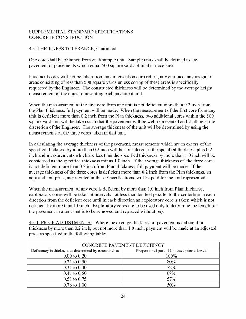
SUPPLEMENTAL STANDARD SPECIFICATIONSCONCRETE CONSTRUCTION
4.3 THICKNESS TOLERANCE, Continued
One core shall be obtained from each sample unit. Sample units shall be defined as anypavement or placements which equal 500 square yards of total surface area.
Pavement cores will not be taken from any intersection curb return, any entrance, any irregularareas consisting of less than 500 square yards unless coring of these areas is specificallyrequested by the Engineer. The constructed thickness will be determined by the average heightmeasurement of the cores representing each pavement unit.
When the measurement of the first core from any unit is not deficient more than 0.2 inch fromthe Plan thickness, full payment will be made. When the measurement of the first core from anyunit is deficient more than 0.2 inch from the Plan thickness, two additional cores within the 500square yard unit will be taken such that the pavement will be well represented and shall be at thediscretion of the Engineer. The average thickness of the unit will be determined by using themeasurements of the three cores taken in that unit.
In calculating the average thickness of the pavement, measurements which are in excess of thespecified thickness by more than 0.2 inch will be considered as the specified thickness plus 0.2inch and measurements which are less than the specified thickness by more than 1.0 inch will beconsidered as the specified thickness minus 1.0 inch. If the average thickness of the three coresis not deficient more than 0.2 inch from Plan thickness, full payment will be made. If theaverage thickness of the three cores is deficient more than 0.2 inch from the Plan thickness, anadjusted unit price, as provided in these Specifications, will be paid for the unit represented.
When the measurement of any core is deficient by more than 1.0 inch from Plan thickness,exploratory cores will be taken at intervals not less than ten feet parallel to the centerline in eachdirection from the deficient core until in each direction an exploratory core is taken which is notdeficient by more than 1.0 inch. Exploratory cores are to be used only to determine the length ofthe pavement in a unit that is to be removed and replaced without pay.
4.3.1 PRICE ADJUSTMENTS: Where the average thickness of pavement is deficient inthickness by more than 0.2 inch, but not more than 1.0 inch, payment will be made at an adjustedprice as specified in the following table:
CONCRETE PAVEMENT DEFICIENCYDeficiency in thickness as determined by cores, inches Proportioned part of Contract price allowed
0.00 to 0.20 100%0.21 to 0.30 80%0.31 to 0.40 72%0.41 to 0.50 68%0.51 to 0.75 57%0.76 to 1.00 50%
-24-
SUPPLEMENTAL STANDARD SPECIFICATIONSCONCRETE CONSTRUCTION
4.3.1 PRICE ADJUSTMENTS, Continued
When the pavement is more than one inch deficient in thickness, the Contractor will be requiredto remove such deficient areas and to replace them with pavement of satisfactory quality andthickness.
When it is necessary to remove and replace a length of pavement and one end of the deficientpavement is less than ten feet from an expansion, contraction or construction joint, the entirepavement up to the joint shall be removed and replaced at the Contractor's expense.
4.4 REPAIR OF DEFECTIVE PAVEMENT SLABS: It shall be the responsibility of theContractor, regardless of reason, to repair or replace any broken panels, as specified hereinafter atno cost to the City. The work shall be accomplished prior to completion of the joint sealing. Slabs that crack during the one year guarantee period shall also be replaced at the Contractor'sexpense.
When a single full depth transverse crack falls within the middle one-third of the panel, the crackshall be routed and sealed. The top of the crack shall be routed to a minimum depth of ¾ inchand to a width not less than 3/8 inch nor more than 5/8 inch by means of an approved routingmachine. The routing machine shall be of the vertical rotary-cutting type and shall be capableof following closely the path of the crack and of widening the top of the crack to the requiredsection without spauling or otherwise damaging the concrete. Loose and fractured concreteshall be removed, and the routed crack shall be thoroughly cleaned and sealed as specified inSection 2.6 of these Supplemental Standard Specifications.
When any portion of a full depth crack falls outside the middle one third of the panel, the portionof panel between the planned joints and middle or center of the cracked panel shall be sawedfull depth, removed and replaced. Joints created by such replacement shall be dowelled andsealed as specified hereinabove.
Pavement panels (area between planned joints) containing multiple cracks through the full depthof the slab separating the panel into three or more parts, shall be entirely removed and replacedat the Contractor's expense.
4.5 JOINTS: Joints shall be constructed as specified and in the approximate locations shown oras described on the Detail Sheets. The joints shall be thoroughly cleaned by approved methodsprior to the placing of the joint material. All sawn joints shall be filled with approved jointsealant compounds as shown on the Detail Sheets. Joint sealant shall be DOW Corning 888, oran approved equal, meeting ASTM D3405-78.
-25-
SUPPLEMENTAL STANDARD SPECIFICATIONSCONCRETE CONSTRUCTION
4.5 JOINTS, Continued
Where called for, backer rods shall be inserted in the joint prior to applying the sealingcompound. The Contractor shall provide the specifications for the sealant and backer rods andmethods of application of both to the Engineer for approval at least ten (10) days prior to its useto allow time for review and written approval. The manufacturer's recommended specificationswill be followed in sealing joints.
4.6 CONCRETE HEADER: At the project limits, when matching any existing pavement, theContractor shall construct a concrete header by trenching an 18" deep by 8" wide trough. Trenchdepth shall be measured from the top of the new concrete pavement. Concrete for this headershall be placed monolithically with the pavement.
At all locations where new construction parallels and abuts existing gutter or pavement, a saw cutshall be made to provide a smooth interface and form the new construction. After constructingthe new pavement, this joint shall be routed, cleaned, and sealed with an approved joint sealant. All saw cuts and sealing work shall be considered incidental to the project for which noadditional payment shall be made.
When the new pavement matches an existing asphalt pavement, the Contractor shall construct afull depth asphalt transition strip between the new header and the existing asphalt pavement. Thewidth of the transition strip will be as shown on the Plans or indicated in the Special Provisions.
All headers shall be measured and paid for on a per square yard basis, at the contract unit pricefor the new concrete pavement being placed. All asphalt transitions will be paid for on a per tonbasis (in-place) at the contract unit price for asphaltic concrete.
4.7 HOT/COLD WEATHER CONCRETING: The Contractor shall comply with ACISpecifications 305R-89 (hot weather concreting) and 306R-88 (cold weather concreting).
4.8 OPENING TO TRAFFIC: No traffic of any kind will be allowed on any new slab until theconcrete has cured for four (4) days and has reached a flexural strength of 375 psi. Constructiontraffic shall not be allowed on the new pavement until all joints are sealed or until a temporarybacker-rod is installed in the joints, at the Contractor's expense. Public traffic shall not beallowed on the slabs until joints are fully sealed.
4.9 FORMS: Forms shall be metal forms manufactured for the purpose of concrete paving. Atleast two pins shall be put in each form. Forms shall be placed on solid base and not on abuilt-up mound. Forms shall be set true to line and grade. Forms that are bent or dirty will berejected by the Engineer. Wooden forms will be allowed only when the standard metal formscannot be used.
-26-
SUPPLEMENTAL STANDARD SPECIFICATIONSCONCRETE CONSTRUCTION
4.10 CONCRETE DELIVERY RATE: Prior to pouring any main line concrete paving(excluding small side pours, returns, driveways, tie-ins, etc.), the Contractor shall specify hisminimum concrete delivery rate for each pour. This rate must be approved by the City prior topouring. A pour will not be made when an acceptable delivery rate cannot be maintained tominimize the starting/stopping of the paving machine.
4.11 MEASUREMENT AND PAYMENT:
4.11.1 METHOD OF MEASUREMENT: Quantities shall be measured as provided forunder the various unit items which constitute the completed and accepted work according to theplans and specifications for each bid item. Any attempt by the Contractor to unbalance any biditem may result in the rejection of the bid proposal.
A submittal form shall be completed by the Contractor in order to process a project payment. Allpay requests shall be submitted by the Contractor not less than 13 days prior to the first Mondayof the month to allow adequate time for processing.
Payment shall be based on work completed at 5:00 p.m. on the Friday prior to submittals. TheEngineer will review the Contractor’s submittals for accuracy with the City’s measurements. The Contractor will be notified of any changes. Should the Contractor disagree with the City’smeasurements, the Contractor will be required to submit scaled drawings, complete with hismeasurements and calculations for review by the City’s Inspector.
4.11.2 BASIS OF PAYMENT: Quantities shall be paid for at the contract unit price for eachbid item. Payment will be full compensation for furnishing and placing all materials, and for alllabor, equipment, tools, and incidentals necessary to complete the work in accordance with theseSupplemental Standard Specifications and the STANDARD SPECIFICATIONS for the City ofDodge City.
4.11.3 PAYMENT FOR ADDITIONAL WORK: Payment for additional work shall be inaccordance with Section 109.5.00 of the STANDARD SPECIFICATIONS. Extra work, whenrequired, shall be approved in writing prior to beginning the work.
4.11.4 PAYMENT FOR MATERIALS ON HAND: Payment for materials on hand shall beissued upon receipt of paid invoices and inspection of materials delivered to the Project site. Payment for materials on hand will be a one-time payment and will not be carried forward insubsequent partial payments. Should the Contractor fail or be prevented from incorporatingsufficient materials into the work prior to the next partial payment and such failure results in azero or a negative balance, in the pay requests, no payments will be made until the work hasprogressed to the point where a positive balance results.
-27-
5.0 DETAILS:
Standard Concrete Joints
Standard Pavement Sections
Standard Curb & Gutter
Standard Handicap Ramp
Standard Alley and Driveway Approach
Standard Manhole Cover
Standard Water Valve and Box
-28-