contribution to the design, implementation and...
TRANSCRIPT

Universidad Politécnica de Madrid
Escuela Técnica Superior de Ingeniería
y Sistemas de Telecomunicación
CONTRIBUTION TO THE DESIGN, IMPLEMENTATION AND
STANDARDIZATION OF SEMANTIC MIDDLEWARE
ARCHITECTURES FOR THE SMART GRID
DOCTORAL THESIS
Jesús Rodríguez Molina
Master in Systems and Services Engineering
for the Information Society
2017


Centro de Investigación en Tecnologías de Software y
Sistemas Multimedia para la Sostenibilidad
Escuela Técnica Superior de Ingeniería y Sistemas de Telecomunicación
CONTRIBUTION TO THE DESIGN, IMPLEMENTATION AND
STANDARDIZATION OF SEMANTIC MIDDLEWARE
ARCHITECTURES FOR THE SMART GRID
DOCTORAL THESIS
Jesús Rodríguez Molina
Master in Systems and Services Engineering
for the Information Society
Supervisor:
Prof. PhD. José-Fernán Martínez Ortega
Universidad Politécnica de Madrid
2017

DOCTORADO EN INGENIERÍA DE SISTEMAS Y SERVICIOS
PARA LA SOCIEDAD DE LA INFORMACIÓN
Tesis Doctoral
Título
Contribution to the design, implementation and
standardization of semantic middleware architectures for the
Smart Grid
Autor Jesús Rodríguez Molina
Director Dr. José-Fernán Martínez Ortega VoB
o.
Tribunal
Presidente
Secretario
Vocal 1º
Vocal 2º
Vocal 3º
Suplente
Suplente
Lugar y fecha
de lectura
Fecha de lectura
E.T.S.I. y Sistemas de Telecomunicación (U.P.M.)
Calificación
El Presidente El secretario Los vocales
Tesis Doctoral para la obtención del título de Doctor
por la Universidad Politécnica de Madrid
2017


A happy life is impossible; the best a man can attain is a heroic life, such as is lived by one who
struggles against overwhelming odds in some way and some affair that will benefit the whole
of mankind, and who in the end triumphs, although he obtains a poor reward or none at all
Arthur Schopenhauer
You promised me Mars colonies. Instead, I got Facebook
Buzz Aldrin
Now I must go to war. We must all believe we have a future. We must fight for those who
aren't even born yet!
Terra Branford


i
Table of contents
List of figures ................................................................................................................ v
List of tables ................................................................................................................ ix
Acknowledgments ........................................................................................................ xi
Abstract ...................................................................................................................... xiii
Resumen .................................................................................................................... xv
1. Introduction and objectives .................................................................................... 1
1.1. Motivation ....................................................................................................... 3
1.2. Objectives ....................................................................................................... 8
1.3. Thesis framework and background ............................................................... 12
1.4. Dissertation outline ....................................................................................... 13
2. State of the art ..................................................................................................... 15
2.1. Introduction ................................................................................................... 17
2.2. State of the art in middleware architectures for the Smart Grid ..................... 18
2.2.1. Service availability ................................................................................. 20
2.2.2. Computational capabilities of deployment hardware .............................. 21
2.2.3. Coupling level ........................................................................................ 22
2.2.4. Middleware distribution .......................................................................... 23
2.2.5. Taxonomy for middleware in distributed systems ................................... 24
2.2.6. GridStat ................................................................................................. 26
2.2.7. Service-Oriented Middleware for Smart Grid.......................................... 28
2.2.8. Ubiquitous Sensor Network Middleware (USN) ...................................... 30
2.2.9. OSHNet (Object-Based Middleware for Smart Home Network) ............. 32
2.2.10. Meter Data Integration (MDI) ................................................................. 34
2.2.11. IEC 61850 and DPWS Integration ......................................................... 36
2.2.12. Intelligent Agents Platform ..................................................................... 38
2.2.13. Self-Organizing Smart Grid Services ..................................................... 40
2.2.14. Secure Decentralized Data-Centric Information Infrastructure ............... 42
2.2.15. A cloud optimization perspective ............................................................ 44
2.2.16. KT Smart Grid Architecture and Open Platform ..................................... 46
2.2.17. Smart microgrid monitoring with DDS .................................................... 48
2.2.18. ETSI M2M ............................................................................................. 51
2.2.19. Smart Middleware Device for Smart Grid Integration ............................. 53
2.2.20. WAMPAC-based Smart Grid communications ....................................... 55

ii
2.2.21. C-DAX ................................................................................................... 57
2.2.22. Building as a Service (BaaS) ................................................................. 59
2.2.23. Middleware-based management for the Smart Grid ............................... 61
2.2.24. OpenNode Smart Grid architecture ........................................................ 63
2.2.25. DIRECTOR ............................................................................................ 65
2.2.26. DDS interoperability for the Smart Grid .................................................. 67
2.3. State of the art in Enterprise Service Bus solutions....................................... 70
2.3.1. OpenESB .............................................................................................. 72
2.3.2. WSO2 ESB ............................................................................................ 74
2.3.3. JBoss Fuse ............................................................................................ 75
2.3.4. Apache ServiceMix ................................................................................ 77
2.3.5. Petals ESB ............................................................................................ 78
2.3.6. Mule ESB .............................................................................................. 81
2.3.7. Talend ESB ........................................................................................... 82
2.3.8. Zato ESB ............................................................................................... 83
2.4. Open issues and challenges ......................................................................... 85
2.5. Section summary .......................................................................................... 86
3. Proposal for a Common Middleware Architecture ................................................ 89
3.1. Introduction ................................................................................................... 91
3.2. Common Middleware Architecture: purpose and scope ................................ 92
3.3. Computational analysis ................................................................................. 96
3.3.1. Functional requirements ........................................................................ 97
3.3.2. Subsystem diagram ............................................................................. 103
3.3.3. Component diagrams .......................................................................... 104
3.3.4. Use case diagram ................................................................................ 106
3.3.5. State diagrams .................................................................................... 130
3.3.6. Activity diagrams ................................................................................. 133
3.3.7. Deployment diagram ............................................................................ 135
3.4. Architecture Description for ISO/IEC/IEEE 42010 ....................................... 136
3.4.1. Identifying information .......................................................................... 137
3.4.2. Supplementary information .................................................................. 137
3.4.3. Other information ................................................................................. 137
3.4.4. Overview ............................................................................................. 138
3.4.5. Architecture evaluations ...................................................................... 139
3.4.6. Rationale for key decisions .................................................................. 139
iii
3.4.7. Stakeholders, concerns and concern–stakeholder traceability ............. 139
3.4.8. Viewpoint names ................................................................................. 142
3.4.9. Overview for viewpoints ....................................................................... 142
3.4.10. Stakeholders, concerns and “anti-concerns” for viewpoints ................. 143
3.4.11. Operations on views ............................................................................ 144
3.4.12. Views and views name ........................................................................ 145
3.4.13. Models and model name ..................................................................... 145
3.4.14. Known issues with views ..................................................................... 147
3.4.15. Consistency and correspondences ...................................................... 147
3.4.16. Known inconsistencies ........................................................................ 148
3.4.17. Correspondences in the Architecture Description ................................ 148
3.4.18. Correspondence rules ......................................................................... 148
3.4.19. Architecture decisions and rationale .................................................... 149
3.5. Protocol Data Units ..................................................................................... 149
3.5.1. Generic PDU format ............................................................................ 150
3.5.2. Low level PDU formats ........................................................................ 151
3.6. Business models and middleware exploitation ............................................ 152
3.6.1. Offline model without the Smart Grid ....................................................... 153
3.6.2. Offline model within the Smart Grid ......................................................... 154
3.6.3. Online model without the Smart Grid ....................................................... 155
3.6.4. Online model within the Smart Grid ......................................................... 156
3.7. Section summary ........................................................................................ 156
4. Validation of the proposal and results ................................................................ 159
4.1. Introduction ................................................................................................. 161
4.2. Framework for the Common Middleware Architecture ................................ 163
4.2.1. Enterprise Service Bus ........................................................................ 164
4.2.2. Programming language and Integrated Development Environment ..... 165
4.2.3. High level interfaces ............................................................................ 166
4.2.4. Low level interfaces ............................................................................. 173
4.2.5. Interconnectivity of software components ............................................ 181
4.2.6. CMA ontology implementation ............................................................. 184
4.3. Implementation works ................................................................................. 187
4.4. Demonstrator tests ..................................................................................... 193
4.4.1. Preliminary tests .................................................................................. 193
4.4.2. Laboratory scenario ............................................................................. 196

iv
4.4.3. Ylivieska scenario ................................................................................ 210
4.4.4. Steinkjer scenario ................................................................................ 211
4.4.5. Smart Grid scenario test results ........................................................... 213
4.5. Section summary ........................................................................................ 213
5. Conclusions and future works ............................................................................ 217
5.1. Original contributions of the thesis .............................................................. 219
5.2. Conclusions ................................................................................................ 220
5.3. Future works ............................................................................................... 221
5.4. Publications and projects ............................................................................ 222
5.4.1. SCI-indexed journals ........................................................................... 222
5.4.2. Conferences ........................................................................................ 224
5.4.3. Book chapters ...................................................................................... 225
5.4.4. Research projects ................................................................................ 226
5.4.5. Other produced results ........................................................................ 227
Appendix A: development procedures ...................................................................... 231
Appendix B: Application Programming Interface ....................................................... 245
6. Bibliography ....................................................................................................... 251
6.1. References ................................................................................................. 253
6.2. List of acronyms ......................................................................................... 269

v
List of figures
Figure 1. Graphical comparison between the conventional power grid and the Smart
Grid, inspired from [11] ................................................................................................. 5
Figure 2. Energy market value chain focused on the prosumer, as represented in [11]. 7
Figure 3. Middleware location in a distributed system ................................................... 8
Figure 4. Comparison between common elements in the IoT and the Smart Grid ....... 11
Figure 5. Area of interest of the thesis ........................................................................ 12
Figure 6. Project logos where middleware-related research activities have been carried
out .............................................................................................................................. 13
Figure 7. Levels of service availability for middleware ................................................. 21
Figure 8. Levels of computational capabilities for middleware ..................................... 22
Figure 9. Levels of message coupling ......................................................................... 23
Figure 10. Levels of middleware distribution ............................................................... 23
Figure 11. Taxonomy for middleware classification ..................................................... 24
Figure 12. Matrix for Smart Grid middleware taxonomy .............................................. 25
Figure 13. Gridstat proposal, as described in [43] ....................................................... 26
Figure 14. Service-Oriented Middleware proposal, as described in [47] ...................... 29
Figure 15. USN middleware proposal, as described in [48] ......................................... 31
Figure 16. OSHNet architecture, as described in [50] ................................................. 33
Figure 17. Meter Data Integration Proposal, as described in [51] ................................ 35
Figure 18. Protocol stack of DPWS, as described in [54] ............................................ 37
Figure 19. IAP-INMS appearance, as described in [56] ............................................... 39
Figure 20. Solution structure (a) and main levels of the proposal (b), as described in
[57] ............................................................................................................................. 41
Figure 21. Data-Centric Information Infrastructure, as described in [58] ...................... 43
Figure 22. Main components of the cloud optimisation service, as shown in [59] ........ 45
Figure 23. Main components of the Open Service Platform, as described in [64] ........ 47
Figure 24. Main features of a DDS deployment, as described in [65] .......................... 50
Figure 25. Structure of the ETSI M2M proposal, as described in [76] .......................... 52
Figure 26. Smart Middleware Device, as described in [78] .......................................... 54
Figure 27. WAMPAC controller location, as described in [79] ..................................... 56
Figure 28. C-DAX middleware appearance, as described in [81] ................................ 58
Figure 29. High level architecture of the BaaS system part of the proposal, as
described in [83] ......................................................................................................... 60
Figure 30. Block diagram of the EMD structure, as described in [85] .......................... 62
Figure 31. Middleware high level location in the proposal, as described in [88] ........... 64
Figure 32. Location of the DIRECTOR proposal in a Smart Grid deployment, as stated
in [90] .......................................................................................................................... 66
Figure 33. Testbed for the DDS infrastructure, as described in [92] ............................ 67
Figure 34. ESB location and most usual services in a Cyber-Physical System ........... 71
Figure 35. Legacy and standalone required software components, as described in [99]
................................................................................................................................... 73
Figure 36. Facilities offered by WSO2 Enterprise Service Bus and their relationships,
as described in [101] ................................................................................................... 75

vi
Figure 37. JBoss Fuse layers and services as described in [105] ............................... 77
Figure 38. Petals ESB software components, as described in [126] ............................ 80
Figure 39. Mule ESB main software components, as described in [128] ..................... 81
Figure 40. Main architectural functional blocks in Talen, as described in [131]............ 83
Figure 41. Location of Common Middleware Architecture ........................................... 94
Figure 42. SGAM Framework, as depicted in [153] ..................................................... 95
Figure 43. Comparison between the scope of SGAM and CMA. ................................. 96
Figure 44. High level appearance of the Common Middleware Architecture ............. 101
Figure 45. Common Middleware Architecture location in Smart Grid devices ........... 103
Figure 46. CMA subsystem diagram with all the groups of services represented ...... 104
Figure 47. Components diagram from the High Level MW services subsystem ........ 105
Figure 48. Components diagram from the General Purpose Services subsystem ..... 105
Figure 49. Components diagram from the General Purpose Services subsystem ..... 106
Figure 50. Use case diagram for Common Middleware Architecture ......................... 107
Figure 51. Use case diagram for further Middleware Management Information
representation ........................................................................................................... 109
Figure 52. Sequence diagram for device registration started by a human operator ... 110
Figure 53. Sequence diagram for device registration started by a device.................. 111
Figure 54. Sequence diagram for device registration started by a middleware service
................................................................................................................................. 112
Figure 55. Use case diagram for further Central Controller Support representation .. 113
Figure 56. Data requests done in the Central Controller support (Middleware Access
Point) ........................................................................................................................ 114
Figure 57. Data requests done in the Central Controller support (Middleware
Autonomous Service) ................................................................................................ 114
Figure 58. Use case diagram for further Local Controller Support representation ..... 116
Figure 59. Sequence of a data request done to the Local Controller support ............ 117
Figure 60. Use case diagram for service discovery representation ........................... 118
Figure 61. Sequence of a data request done to the Local Controller support ............ 119
Figure 62. Use case diagram for service discovery representation ........................... 120
Figure 63. Sequence diagram with data collection and securitization ........................ 122
Figure 64. Class diagram from the Middleware Access Point component ................. 123
Figure 65. Class diagram from a Middleware Autonomous Service component ........ 124
Figure 66. Class diagram of the Registration component .......................................... 125
Figure 67. Class diagram of the Context Awareness component .............................. 126
Figure 68. Class diagram of the semantic capabilities component ............................ 127
Figure 69. Class diagram of the Hardware Abstractor component ............................ 128
Figure 70. Class diagram of the Service Composition component ............................ 129
Figure 71. Class diagram of the Securitization component ....................................... 130
Figure 72. State diagram for service registration ....................................................... 131
Figure 73. State diagram for service request and answer ......................................... 132
Figure 74. State diagram for service listing ............................................................... 132
Figure 75. Activity diagram for device registration ..................................................... 133
Figure 76. Activity diagram for service requests ........................................................ 134
Figure 77. Activity diagram for service list request .................................................... 135
Figure 78. Deployment diagram of a system with the Common Middleware Architecture
installed .................................................................................................................... 136
vii
Figure 79. PDU format for a high level data request ................................................. 150
Figure 80. PDU for registration failure…………………………………………………….151
Figure 81. PDU for registration requests ................................................................... 151
Figure 82. PDU for registration answer ..................................................................... 152
Figure 83. PDU for data response............................................................................. 152
Figure 84. High-level view of component deployments ............................................. 157
Figure 85. Theoretical and actual implementations of the middleware and its adjacent
layers ........................................................................................................................ 161
Figure 86. Waterfall model (enhanced with feedback and incremental prototyping) for
middleware development .......................................................................................... 163
Figure 87. Connectivity among elements of an ESB, as depicted in [154]. ................ 165
Figure 88. Web service dependencies location ......................................................... 167
Figure 89. URIs for available middleware high level components.............................. 173
Figure 90. Device registration with the intervention of the ontology of the middleware,
as developed in the e-GOTHAM project………………………………………………….180
Figure 91. Conceived CMA ontology ......................................................................... 186
Figure 92. Running JBoss Fuse with the list of active bundles .................................. 188
Figure 93. Empty services list ................................................................................... 188
Figure 94: registration message with the identifier. ................................................... 189
Figure 95. Middleware bundles and the new one created during registration ............ 189
Figure 96. Features of the device that has become registered .................................. 190
Figure 97. Security sequence of steps, as shown in [154] ......................................... 192
Figure 98. Time used to answer temperature requests done to nodes, as described in
[177] ......................................................................................................................... 194
Figure 99. Time used to answer to obtain data from a composed service, as described
in [177] ...................................................................................................................... 194
Figure 100. Performance results for simple (high graph) and composed (low graph)
service requests, as described in [178]…………………………………………………...195
Figure 101. Deployment made in Ylivieska. Middleware is at the centre of the
deployment ............................................................................................................... 210
Figure 102. Steinjker deployment with the middleware solution, as depicted in [34] .. 211
Figure 103. Middleware tests results, as shown in [34] ............................................. 212
Figure 104. Different areas of knowledge and projects used for the conception of CMA
................................................................................................................................. 215
Figure 105. Cash prize certificate for Middlegrid (Spanish) ....................................... 228
Figure 106. Chronological summarization of all the outputs resulting in the thesis .... 229
Figure 107. Maven project access in Eclipse IDE for Ubuntu .................................... 233
Figure 108. Creation of a maven project for Eclipse in Ubuntu .................................. 233
Figure 109. Location of the activemq broker and deploy directories .......................... 234
Figure 110. Web interface of the JBoss Fuse ........................................................... 234
Figure 111. User.properties file in JBoss Fuse .......................................................... 235
Figure 112. Software bundles from the middleware .................................................. 236
Figure 113. Virtual Private Network settings for remote connections to the Vitrociset
laboratory .................................................................................................................. 236
Figure 114. Example of ESB and components deployed in Vitrociset facilities .......... 237
Figure 115. API from the SupportREST class ........................................................... 248
Figure 116. API from the Support class .................................................................... 248

viii
Figure 117. API of the ContextAwarenessController class ........................................ 249
Figure 118. API of the CompositionController class .................................................. 250
Figure 119. API of the HALController class ............................................................... 250
ix
List of tables
Table 1. Main characteristics of the studied middleware solutions .............................. 68
Table 2. Main characteristics of the studied open source ESB solutions ..................... 84
Table 3. Actions taken to tackle open issues .............................................................. 96
Table 4. Functional and Non-functional requirements for middleware ......................... 99
Table 5. Software components defined from the requirements ................................... 99
Table 6. Actions taken to satisfy non-functional requirements and their justification .. 100
Table 7. Description of Middleware Management Information ................................... 107
Table 8. Description of Central Controller support use case...................................... 112
Table 9. Description of Local Controller support use case ........................................ 115
Table 10. Description of Service Discovery use case ................................................ 117
Table 11. Description of Information Security use case ............................................. 119
Table 12. Traceability for the concerns of the stakeholders ...................................... 141
Table 13. Viewpoints and their associated views and architecture models ................ 147
Table 14. Main concepts for ISO/IEC/IEEE 42010 standardization ........................... 158
Table 15. Device information table filled by e-GOTHAM partners ............................. 177
Table 16. Support middleware component testing .................................................... 197
Table 17. Device registration testing activities........................................................... 207

x

xi
Acknowledgments
This thesis is the culmination of a collection of works and efforts shared with many people in
the Next Generation Networks and Services Group (GRyS) who have been true comrades in
arms during the good and the bad times that I have gone through there. It is when trouble and
stress happen that the true nature of a person is revealed, and I am grateful to have found
workmates that have helped me through thick and thin, regardless of my opinions or
comments.
I would like to start by thanking the supervisor of my thesis, Professor José-Fernán Martínez
Ortega. He has given me lots of motivation and encouragement during all the stages of my
education, from the Bachelor thesis to my doctoral studies.
I would also like to thank Pedro Castillejo for all the support that he has provided me during all
these years. It has been a pleasure and a privilege working with him all this time, and it is great
being able to count on such a knowledgeable and patient person. I also want to thank David
Gómez for his positivity and good spirit. He has been a firm source of tranquillity in moments
of utter chaos.
I would also like to thank Alexandra Cuerva, Carlos Estévez, Esther Moreno and José Antonio
Sánchez for the times we have spent together, either working, writing papers or just sharing a
laugh in the cafeteria of the university. I am sure that whatever is ahead for them in their lives
will be great. I also want to mention the strong inspiration that the hard work that my Chinese
colleagues Xin Li, Ning Li, and Xin Yuan give me. As for the newest additions to the group, I am
sure that Yuwen Chen and Zhaoyu Zhai are on their way to become great researchers.
Thanks to the combined efforts of my supervisor, Professor José-Fernán Martínez Ortega, and
Doctor Geir Mathisen I did a three month stay in the Information and Communication
Technologies department of SINTEF, a large research institution located in Norway, where I
made part of my thesis and learnt a bit about how things are done in that country. I got to
meet brilliant researchers with very impressive backgrounds, and I am very grateful for that
too.
I want to thank my girlfriend Corianne for her unconditional love during all this time, no matter
how harsh circumstances have been for us sometimes. Also, I would like to use these lines to
thank my parents for their positivity, regardless of how bad things looked.
Last but not least, I want to mention all my friends and people that are part of my life outside
work: my friend Javiii, my university friends César, Félix, Adriana, Álvaro, Esther, Carlos, Diego,
Guille, Randa, Fran, my little nieces Alejandra and Olivia, my brother-in-law José Carlos and my
sister Mónica.
Thank you all and let us hope we have a bright future. Tomorrow never knows.

xii

xiii
Abstract
The Smart Grid, conceived as the power grid enhanced with Information and Communication
Technologies aimed to optimizing electricity consumption, enabling a bidirectional
participation in the energy provided and improving the power grid with features like Demand
Response, Demand Side Management or Optimal Power Flow, is becoming one of the most
compelling Cyber-Physical Systems that is being currently developed. Its capacity to increase
usable energy in a sustainable manner, along with collect more information about its actual
usefulness, makes possible the improvement of living standards for many people all around
the world in a more transparent and open way. What is more, since it is able to integrate the
comparatively small power supplied by the Renewable Energy Sources provided by the end
users that participate in the Smart Grid (which become “prosumers”, as they both produce and
consume electricity), it democratizes access to energy and enables a higher degree of
competitiveness between traditional actors in the energy markets and newcomers, thus
granting the overall improvement of the services that can be provided by the utility
companies.
However, there are still many open issues that must be solved before completely using the
Smart Grid to our advantage. Among these open issues, interoperability of its installed devices
is a major one. The equipment that is used in deployments of this kind (Advanced Metering
Infrastructure, Phasor Measurement Units, Remote Terminal Units, etc.) is manufactured by
different companies with different backgrounds and interests. Therefore, the implementation
of their products has usually different ways to transmit information or even proprietary
solutions with a low degree of compatibility with other pieces of hardware. In a way, the status
quo is similar to the situation of computer networks before the first standards were released: a
plethora of manufacturers offer their own solutions to provide services and connectivity, but
they struggle to work cooperatively with developments of other equipment vendors that may
have different perspectives on the technologies that can be used for data transmission.
In addition to that, the services that should be available for either a Smart Grid or one of its
smaller scale counterparts (microgrids, nanogrids) are not made clear, neither in terms of what
services they should be or where they should be located. While there are some high level
functionalities that are usually regarded as almost mandatory (the aforementioned Demand
Side Management, device registration, Demand Response, Optimal Power Flow), other more
data-centric facilities are often portrayed in a way vaguer manner. Security specifications, the
existence of semantic capabilities, how to access the capabilities in a specific deployment or
even how the hardware devices become integrated is not described with enough detail. That
issue jeopardizes the main purpose of installing and developing components in this area of
knowledge, because it makes difficult a further integration of both legacy systems that may
have been used by large utility companies for a long time and new developments done by
smaller companies that want to play a role in the Smart Grid.
Fortunately, many of these challenges can be solved by implementing a software layer located
between the applications that can be included for the benefit of the end users and the
xiv
hardware and network infrastructure installed for package and binary data interchange. This
software layer, commonly referred as middleware, has as its main purpose abstracting the
heterogeneity and complexity of the underlying distributed hardware components, so that it
will offer to the high, more application-based layer a collection of facilities of homogeneous,
centralized appearance, usually shaped as an Application Programming Interface that can be
accessed by the application developers. Middleware is a very useful software tool for Cyber-
Physical Systems and distributed solutions because it grants the integration of almost any kind
of device, either by adding software components in the device itself or in another part of the
system, which must be open enough to have the components installed or have the required
computational capabilities to have those components installed.
The main original contribution to knowledge of this doctoral thesis is offering a proposal for a
model of a semantic middleware architecture for the Smart Grid, based on software
components for distributed solutions. This model is aimed to be used in any kind of
deployment related to the Smart Grid, as well as providing a common set of components and
interfaces to be observed in future implementations. This architecture has been called
Common Middleware Architecture (CMA), as it aims to provide the necessary software
components for middleware development under any imaginable use case within this
application domain. It has been designed based on the experience accumulated from several
research projects where the implementation of a middleware layer was one of the main
achievements. CMA has been designed with the main needs of a middleware solution in mind,
such as hardware abstraction, context awareness, device registration, interfaces for the upper
level, securitization and device integration. While the main domain of CMA is the Smart Grid,
and demonstrators based on the Smart Grid have been used to validate it, CMA can also be
adapted to other environments.
All in all, the main objective of this thesis is creating a reliable framework for the development
of middleware solutions for the Smart Grid, which can be used in other application domains
where there are requirements of hardware abstraction and service availability resembling the
ones that can be found in this area of knowledge. Another major objective of this thesis is
making contributions to the standardization of middleware development for the Smart Grid, so
that there will be a specific set of services to be developed in order to comply with the most
important functionalities of middleware (hardware abstraction, homogeneous set of services
for applications, encasing services based on semantic capabilities and security). These two
objectives have been achieved with the contributions done in the study of the State of the Art,
the inference of open issues and challenges, the establishment of a list of functional and non-
functional requirements and the validation of the proposal put forward in this manuscript. The
solutions developed can be regarded as the background of the architecture described here,
and therefore its performance should be good enough for the functionalities carried out for
this kind of software layer, which should be present in any distributed or Cyber-Physical
System that uses a collection of deployed pieces of equipment with different capabilities.
Besides, since this is a middleware solution solves problems for issues present in other
distributed and/or Cyber-Physical Systems (the Internet of Things, underwater robotics) it can
be ported to other domains with ease, as services as high level interface access or device
registration are used in those situations as well.
xv
Resumen
La Red Eléctrica Inteligente, concebida como el tendido eléctrico mejorado con las Tecnologías
de la Información y las Comunicaciones dirigidas a optimizar el consumo de electricidad,
permitir una participación bidireccional en la energía suministrada y mejorar la red eléctrica
con características como la Respuesta ante la Demanda, Gestión de la Demanda o el Flujo de
Potencia Óptimo, se está convirtiendo en uno de los sistemas ciberfísicos más convincentes
desarrollado actualmente. Su capacidad para aumentar la energía utilizable de manera
sostenible, así como obtener más información sobre su utilidad real, hace posible la mejora del
nivel de vida de muchas personas en todo el mundo de una manera más transparente y
abierta. Además, al poder integrar la relativamente pequeña potencia suministrada por
fuentes de energía renovable aportadas por los usuarios finales que participan en la Red
Eléctrica Inteligente (que se convierten en "prosumidores", ya que ambos producen y
consumen electricidad), democratiza el acceso a la energía y permite un mayor grado de
competitividad entre los actores tradicionales de los mercados energéticos y los recién
llegados, garantizando así la mejora general de los servicios que pueden aportar las empresas
de utilidades.
Sin embargo, todavía hay muchas cuestiones abiertas que deben ser resueltas antes de utilizar
completamente el potencial de la Red Eléctrica Inteligente en nuestro beneficio. Entre estas
cuestiones, la interoperabilidad de los dispositivos instalados es una de los principales. El
equipo que se utiliza en los despliegues de este tipo (Infraestructura de Medición Avanzada,
Unidades de Medida de Fasores, Unidades Terminales Remotas, etc.) es fabricado por
diferentes compañías con diferentes conocimientos e intereses. Por tanto, la implementación
de sus productos tiene a menudo diferentes formas de transmitir información o incluso
soluciones propietarias con un bajo grado de compatibilidad con otros dispositivos. De alguna
manera, el statu quo es similar a la situación de las redes de ordenadores antes de que se
publicaran los primeros estándares: un conjunto de fabricantes ofrecen sus propias soluciones
para proporcionar servicios y conectividad, pero tienen problemas al cooperar con los
desarrolladores de otros fabricantes de equipos que pueden tener diferentes perspectivas
sobre las tecnologías que se pueden utilizar para la transmisión de datos.
Aparte de eso, los servicios que deberían estar disponibles para una Red Eléctrica Inteligente o
una de sus contrapartes de menor escala (microrred, nanorred) no están claros, ni en términos
de qué servicios deben ser o dónde deben estar ubicados. Si bien hay algunas funcionalidades
de alto nivel que generalmente se consideran casi obligatorias (las anteriormente
mencionadas Gestión de Lado de la Demanda, registro de dispositivos, Respuesta a la
Demanda, Flujo Óptimo de Potencia), otras facilidades centradas en datos se describen de una
manera más vaga. Las especificaciones de seguridad, la existencia de capacidades semánticas,
cómo acceder a las capacidades en un despliegue específico o incluso cómo los dispositivos de
hardware se integran no se describen con suficiente detalle. Esta cuestión pone en peligro el
objetivo principal de instalar y desarrollar componentes en esta área de conocimiento, ya que
dificulta una mayor integración de tanto sistemas heredados que pueden haber sido utilizados
xvi
por las grandes empresas de utilidades durante mucho tiempo como nuevos desarrollos
realizados por empresas más pequeñas que quieren desempeñar un papel en la Smart Grid.
Afortunadamente, muchos de estos retos pueden resolverse mediante la implementación de
una capa de software ubicada entre las aplicaciones que se pueden incluir para el beneficio de
los usuarios finales y el hardware y la infraestructura de red instalada para el intercambio de
datos binarios y de paquetes. Esta capa de software, comúnmente referida como middleware,
tiene como objetivo principal abstraer la heterogeneidad y complejidad de los componentes
de hardware distribuidos subyacentes, de manera que ofrecerá a la capa alta y más basada en
aplicaciones una colección de facilidades de aspecto homogéneo y centralizado, comúnmente
conformada como una Interfaz de Programación de Aplicaciones a la que pueden acceder los
desarrolladores de aplicaciones. El middleware es una herramienta de software muy útil para
sistemas distribuidos y ciberfísicos porque permite la integración de casi cualquier tipo de
dispositivo, ya sea añadiendo componentes de software en el propio dispositivo o en otra
parte del sistema, la cual debe ser lo suficientemente abierta para tener los componentes
instalados, o bien debe tener las capacidades de computación necesarias para tener esos
componentes instalados.
La principal contribución original al conocimiento de esta tesis doctoral es ofrecer una
propuesta para un modelo de arquitectura de middleware semántico para la Red Eléctrica
Inteligente, basado en componentes software para soluciones distribuidas. Este modelo está
destinado a ser utilizado en cualquier tipo de despliegue relacionado con la Red Eléctrica
Inteligente, así como a proporcionar un conjunto común de componentes e interfaces a ser
tenidos en cuenta en futuras implementaciones. Esta arquitectura se ha denominado Common
Middleware Architecture (CMA), ya que tiene como objetivo proporcionar los componentes de
software necesarios para el desarrollo de middleware en cualquier caso de uso imaginable
dentro de este dominio de aplicación. Se ha diseñado contando con la experiencia acumulada
en varios proyectos de investigación en los que la implementación de una capa de middleware
fue uno de los principales logros. La CMA ha sido diseñada teniendo en cuenta las principales
necesidades de una solución middleware, como abstracción de hardware, conocimiento del
contexto, registro de dispositivos, interfaces para el nivel superior, securización e integración
de dispositivos. Aunque el dominio principal de la CMA es la Red Eléctrica Inteligente, y se han
utilizado demostradores basados en la Red Eléctrica Inteligente para validarla, la CMA también
puede adaptarse a otros entornos.
En general, el objetivo general de esta tesis es crear un marco fiable para el desarrollo de
soluciones de middleware para la Red Eléctrica Inteligente que pueda ser utilizado en otros
dominios de aplicaciones donde existen requisitos de abstracción de hardware y disponibilidad
de servicio similares a los que se pueden encontrar en esta área del conocimiento. Otro
objetivo principal de esta tesis es contribuir a la estandarización del desarrollo de middleware
para la Red Eléctrica Inteligente, de modo que habrá un conjunto específico de servicios
desarrollados para poder cumplir con las funcionalidades más importantes del middleware
(abstracción del hardware, conjunto homogéneo de servicios para aplicaciones, encapsulación
de servicios basados en capacidades semánticas y seguridad). Estos dos objetivos se han
logrado con las aportaciones realizadas en el estudio del estado del arte, la inferencia de

xvii
cuestiones y temas abiertos, el establecimiento de una lista de requisitos funcionales y no
funcionales y la validación de la propuesta presentada en este manuscrito. Las soluciones
desarrolladas pueden ser consideradas como los antecedentes de la arquitectura aquí descrita,
por lo que su rendimiento debe ser lo suficientemente bueno para las funcionalidades
realizadas para este tipo de capa de software, la cual debería estar presente en cualquier
sistema ciberfísico o distribuido que use un grupo de equipos de diferentes capacidades que
haya sido desplegado. Además, puesto que se trata de una solución de middleware que
resuelve problemas para cuestiones presentes en otros sistemas distribuidos y / o ciberfísicos
(Internet de las Cosas, robótica subacuática), puede ser portado a otros dominios con facilidad,
ya que servicios como interfaces de acceso a alto nivel o registro de dispositivos también se
utilizan en esas situaciones.

xviii

1. Introduction and
objectives

Chapter 1. Introduction and objectives
2
Chapter 1. Introduction and objectives
3
This chapter offers information about the historical context where the Smart Grid and
middleware started off and were developed. In addition to that, a description of the objectives
that were established at the start of the thesis is present in this section as well. Finally, the
background used for research activities and the outlines of the dissertation have been included
as well.
1.1. Motivation
Electricity is pivotal in the development of all the goods and services that are manufactured,
developed and traded since the Second Industrial Revolution, which happened around more
than one hundred years ago [1]. It was during that time when fossil fuels began to be burned
in an intensive manner to obtain electricity as an output, rather than using the generated heat
to move mechanical parts of steam-powered machinery. While electricity generation was
being crafted, the development of infrastructures that made possible its supply to the
production centres where it was being used was also required. Later on, as standards of living
improved, electricity became a service demanded in dwells and households. Consequently, a
power grid was built to transport electricity from its production facilities to the clients and end
users. Typically, a power grid will work by transferring high voltage electricity originated in a
power plant (usually of an order of magnitude ranging in the hundreds of thousand Volts; High
Voltage Direct Current or HVDC is the most common way to transport electricity at this stage
[2]), which is better suited for travelling long distances, and it will be progressively converted
to lower voltages until it is delivered to its consumption location, where voltage gets scaled
down to a range from 125 to 240 Volts, depending on factors as the country or the age of
electric infrastructure owned by the end user. Power lines will have different characteristics
depending on the voltage they are expected to work with. In this kind of system, there are
several actors that, while presenting some differences depending on the country and their
legislation, play a role in the development and exploitation of such a system. These actors are:
Distribution System Operator (DSO): it is responsible for electricity generation in the
system. Commonly, DSOs own the power plants required for electricity generation,
that may use renewable (hydropower, photovoltaic or thermal solar power, etc.) or
fossil fuels (coal, oil, natural gas). Thus, a DSO plays a more important role in electricity
generation rather than distribution.
Transmission System Operator (TSO): it provides the required infrastructure to transfer
electricity from the power plant to the consumption points. Power lines used for that
purpose are usually property of the TSO.
Aggregator/Retailer: it is the entity that purchases electricity from the DSO and sells it
to the end users. Depending on how “smart” the power grid is, it will either carry out
functionalities related to aggregation or it will be solely focused on electricity trade.
End user/Client: it is the entity that purchases the electricity offered by the former
actor and consumes it. As far as the conventional power grid is concerned, this is
where the electricity flow ends, as the energy it carries is often transformed into other
kinds (luminous, mechanical, thermal, etc.).

Chapter 1. Introduction and objectives
4
Overall, these actors tend to be the same in most of the world, even though there might be
some major differences depending on the countries (in Spain, for example, it is common that
the Distribution System Operator or DSO will also play an active role in the commercialization
of electricity to end users via second party companies, so the DSO is also present as a retailer).
The principles of the currently used power grid are based on the theoretical and practical work
performed by researchers such as Nikola Tesla [3] [4] and its implementation and installation
makes use of techniques that date back to at least the 1960s [5] [6]. As a direct consequence
of the latter fact, the regular power grid has become outdated in many ways, revealing itself
incapable of keeping pace with several technological innovations that have taken place during
the last decades. To begin with, renewable energies are increasingly used to produce
electricity as an alternative to non-renewable, fossil-based energy sources. Despite some
issues such as its intermittent availability or aesthetic impact [7] [8], its friendliness towards
the environment and availability for comparatively small users forecast a growing utilization of
these resources in the immediate and distant future, even in the worst case scenarios that
have been devised [9]. Secondly, the availability of Renewable Energy Sources (RESs) for the
small users as Distributed Energy Resources (DERs) has the potential of significantly changing
the traditional, one-way flow of the electricity that has been traditionally implemented. Last
but not least, by means of using means of energy storage (such as home batteries), electric
energy does not need to be consumed as it is received and can be turned into other kinds of
energy (for example, chemical energy), stored and used during a more suitable time, which
may be when it is actually needed (in case of blackouts or power failures) or when trade
opportunities appear in the electricity market, if the user has technology capable of interacting
with them. Consequently, the end user can be not just a consumer of energy, but an actor
capable of producing its own electricity, thus becoming enabled to either use it for themselves
or obtaining a profit from its trade; hence the term prosumer, which is heavily linked to the
Smart Grid and is referred to an end user capable of producing and consuming energy at the
same time (producer and consumer are merged as prosumer).
It is due to these facts that the conventional power grid can be turned into a Smart Grid. The
Smart Grid can be defined as the power grid after becoming enhanced with Information and
Communication Technology (ICT) with the aim of providing a rationalized usage of energy,
more oriented to the supplied resources (thus attempting to make use of what is available at a
particular moment) rather than solely taking demand into account (which can be satisfied by
adding more power plants and energy resources, but not at a sustainable pace in a finite
world). As stated in [10], “Smart Grids increase the connectivity, automation and coordination
between suppliers, consumers and network by modernizing grid features like demand side
management, generation, real-time pricing, and automated meter activation and reading”.
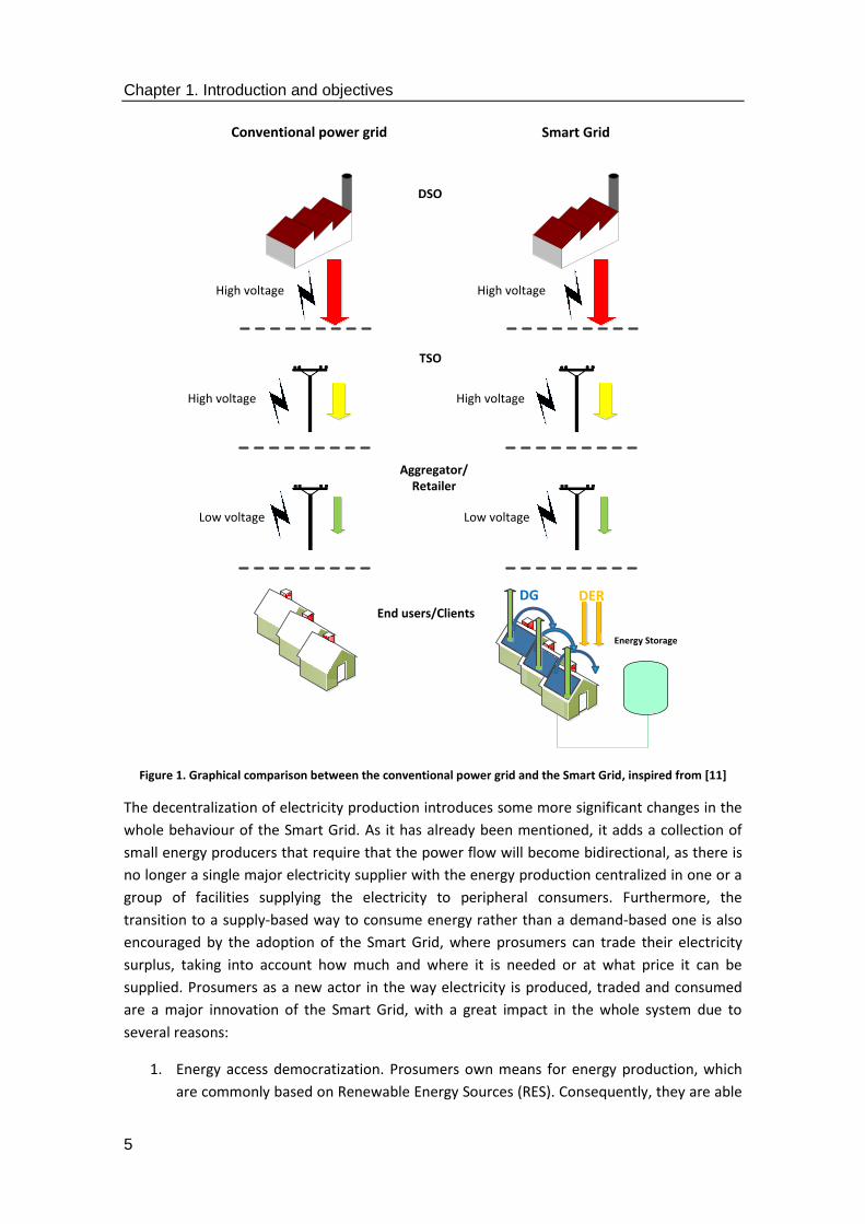
Figure 1 shows the changes that are introduced by adding Smart Grid capabilities to the overall
system. As it can be seen, while many of the actors and roles participating in the Smart Grid
are still the same, there are major changes in the functionalities performed by end users (or
more accurately said, prosumers).
Chapter 1. Introduction and objectives
5
Figure 1. Graphical comparison between the conventional power grid and the Smart Grid, inspired from [11]
The decentralization of electricity production introduces some more significant changes in the
whole behaviour of the Smart Grid. As it has already been mentioned, it adds a collection of
small energy producers that require that the power flow will become bidirectional, as there is
no longer a single major electricity supplier with the energy production centralized in one or a
group of facilities supplying the electricity to peripheral consumers. Furthermore, the
transition to a supply-based way to consume energy rather than a demand-based one is also
encouraged by the adoption of the Smart Grid, where prosumers can trade their electricity
surplus, taking into account how much and where it is needed or at what price it can be
supplied. Prosumers as a new actor in the way electricity is produced, traded and consumed
are a major innovation of the Smart Grid, with a great impact in the whole system due to
several reasons:
1. Energy access democratization. Prosumers own means for energy production, which
are commonly based on Renewable Energy Sources (RES). Consequently, they are able
TSO
Aggregator/Retailer
DSO
High voltage
Low voltage
End users/Clients
DG DER
Energy Storage
High voltage
High voltage
Low voltage
High voltage
Conventional power grid Smart Grid
Chapter 1. Introduction and objectives
6
to meet their power demands to an extent, depending on the extension of their
available RESs and the energy they consume, and do not depend on DSOs as heavily as
regular consumers. In this way, energy becomes available in a way that was not
possible before.
2. Energy consumption patterns. Prosumers integrated in the power grid alter power
consumption patterns dramatically; depending on the time of the day, month of the
year and their consumption history, they will either inject power to the grid or will
demand less than a regular consumer. Those two actions will greatly change how
energy is consumed in a specific area, regardless of its geographical limits (nanogrid,
microgrid or larger).
3. Trade for small users. Prosumers could be willing to trade their produced electricity as
if it was any other commodity. Depending on their willingness or knowledge, trading
algorithms could be used in the development of business models based on energy
storage and delivery according to the demands of other prosumers, regular consumers
or even the DSOs.
4. Environment-friendliness. Since the overwhelming majority of the prosumers use to
produce electricity infrastructures based on renewable energies, more energy is
available in an environment-friendly manner, with all the positive consequences that it
carries (lower amount of carbon dioxide released to the atmosphere, less pollution,
etc.).
5. Impact in other partners involved in the power grid. The integration of this new actor
with the power grid will force a redefinition of the roles of other entities involved in
the production, transfer and consumption of electricity, as they will require to adapt
their offer to what prosumers can provide (DSOs) or gather information about
consumption patterns (aggregators).
Overall, and as stated in [11], prosumers will be fully involved in the economic and
technological parts of energy consumption, as well as creating new value for the enhanced
power grid. A mathematical analysis that models the potential profitability of their activities
has been included in the next chapter. The integration of prosumers in the Smart Grid is one of
the benefits of enabling middleware in this application domain, for it will enable the necessary
mechanisms for data transmission among the different hardware elements of a deployment
where prosumers are contributing to the power flow with their own Renewable Energy
Sources.
Figure 2 summarizes that new paradigm in the Smart Grid once prosumers have been fully
integrated, along with the possible cooperation between entities that they offer: they are
capable of receiving and providing assets (either electricity or information) to the Energy
Services Company (ESCO) or to other prosumers, which can be organized as a cluster in a
Virtual Power Plant (VPP) style. At the same time, DSOs can trade electricity with prosumers
(either as a way to have energy or have it as a complementary resource) and with the
aggregator in order to offer its resources and information. All these relations are included in
the generation of electricity rather than its mere consumption (as regular end users do) and its
transmission by means of the infrastructure owned by the Transmission System Operator.

Chapter 1. Introduction and objectives
7
Figure 2. Energy market value chain focused on the prosumer, as represented in [11]
The integration of prosumers and their small scale facilities used to generate electricity is a
critical task for the Smart Grid, especially if all the changes that have to be made to guarantee
it are taken into account. These latter can be defined by two different categories:
1. Technical: there are several activities that must be undertaken to offer integration at
several layers, such as the physical one (providing all the necessary connections to the
power grid and the information transferred from one piece of equipment to the other
at the bit level), the network (so as to interchange packages between the existing
prosumers, which will effectively behave as a distributed system) and the data-based
ones (in order to exchange information about the services and features of the system
that will be mutually understood by all the ends involved in the communication).
2. Legislative: prosumers are different from the entities traditionally involved in the
generation of energy in the sense that their infrastructure is small-sized and is
scattered in a certain area rather than centralized in a position. That would require the
rearrangement of the legislative framework used to include the prosumers into the
energy markets. For example, the European Energy Exchange includes, among other
preconditions for admission, liable equity of at least 50,000 € [12]. This and other
requirements might be challenging to be met by individual prosumers. Nevertheless,
they could be offered an alternative, such as federating themselves into a larger
cluster of energy providers making use of an aggregator.
Information and Communication Technologies must also be described. The Smart Grid makes
use of very different appliances with a huge disparity regarding their features, manufacturers
or data formats used to transfer data throughout the system. The lack of standardized
procedures specific to the software in the Smart Grid or software solutions to interoperate
these devices at the data level is one of the major challenges that are faced in this application
domain, as interoperability of the devices used cannot be guaranteed and there is a chance for
them to become isolated from the other devices used for data transmissions. Fortunately, this
issue can be solved by means of middleware. Whereas middleware is of more recent
conception than the power grid, it was firstly referenced in a NATO document that dates back
to 1968 [13], so it is still almost 50 years old. Popularity of middleware grew at a slowly pace
during a time where distributed systems were underdeveloped and mainframes were the most
common location of most of the computational and logical resources in the firstly available

Chapter 1. Introduction and objectives
8
computer networks (thus having a central hardware component providing most of the
services, instead of a collection of computers). By the 1980s, though, middleware was being
increasingly used as a way to interconnect legacy systems with new ones. As it will be
described in subsequent chapters of this thesis, this functionality is still satisfied by
middleware for distributed systems. Its usability and utility became greatly expanded during
the late 1990s and early 2000s with the uprising of Internet usage, the first developments
dealing with the Internet of Things (IoT) and mobile computing, as those are systems that are
by definition distributed and heterogeneous [14] [15]. It was during that time that middleware
for distributed systems was definitely established as the software entity capable of abstracting
heterogeneity from an underlying collection of hardware devices in order to offer a set of
homogenous, centralized-looking facilities (typically, an Application Programming Interface or
API) to the application layer [16] [17]. Further developments, such as Cloud Computing, have
made middleware a software entity of critical importance in the development of distributed
systems [18] [19]. Figure 2 illustrates the typical location of middleware in the latter; due to
this and how it is accessed by the application layer it effectively withholds the different (and
quite often, opposite) hardware components present in a deployment, as well as their local
firmware and operating systems. Even though these systems usually interconnect with each
other by interchanging messages at the network layer, they still are lacking data formats that
can be apprehended by a human being, as middleware does when sending information
upwards.
Figure 3. Middleware location in a distributed system
Since the Smart Grid can be regarded as a distributed system that must cope with most of its
defined issues, the importance of having a middleware architecture that a) abstracts the
heterogeneity of the appliances present in the Smart Grid, b) provides a collection of services
that can be used by every entity making use of them, c) offers a way to access those services
from the application layer in a homogeneous way and d) allows interoperability and scalability
for all the parties involved in a deployment, becomes capital for the reasonable development
and deployment of hardware, services and applications.
1.2. Objectives
There are several objectives that have been set for this thesis; all of them are related to a great
extent to middleware as a software component of the Smart Grid. They have been listed as
follows:

Chapter 1. Introduction and objectives
9
1. Providing a study on the state of the art with regards to existing middleware solutions
for the Smart Grid where their strengths and weaknesses are acknowledged and
assessed. It will be made clear during this thesis that the existence of a semantic
middleware in this application domain makes possible not only the abstraction of
hardware heterogeneity (thus easing the integration of Renewable Energy Sources –
referred to as RESs- in the Smart Grid) but also adding other services (semantic
capabilities, security, context awareness, service composition) that result in the
improvement of the information and applications that can be included at higher levels.
However, an evaluation of the existing middleware solutions for the Smart Grid must be
carried out in order to know how optimal the current solutions are. This step is required so
as to know how the current status quo with regards to the scope of the thesis is looking
like, and contributions can be focused in the areas where they are most needed, which
have been identified as open issues to be dealt with.
2. Contributing to the standardization of design and implementation of semantic
middleware architectures for the Smart Grid. A proposal for a standard in semantic
middleware architectures for the Smart Grid is put forward in this thesis; it has been called
Common Middleware Architecture (CMA). The contributions that are made by CMA are
mostly focused on a) the establishment of a collection of functional and non-functional
requirements that can be regarded as mandatory for a good design of a semantic
middleware architecture for the Smart Grid, b) listing a set of software components that
must be present in any semantic middleware implementation that is planned to be used in
this application domain, c) how these components must interact with each other in order
to guarantee the expected services that a middleware for the Smart grid should provide
and d) the steps to be carried out during implementation activities where software
components are codified. In a more detailed way, contributions have been made in order
to establish a collection of characteristics, software modules, interfaces and technologies
that can be applied for efficient middleware implementation activities. These contributions
are based on the developed middleware works that have been made in different European
projects. While these works have been done following the waterfall software development
cycle (analysis, design, implementation, testing and maintenance), it has been combined
with incremental prototyping for the development works that have been carried out in the
middleware architecture implementation. Although CMA could be used as a standard for
the design and implementation of middleware architectures for the Smart Grid, its
contributions can also be incorporated to any other standard that resembles the
functionalities that have been put forward here and enjoys a higher level of popularity.
Furthermore, the addition of a software layer that is performing several complex actions
when dealing with the data requested that has to be transferred among the different
components of a system could suppose that the pieces of equipment where it is installed
would be hindered by its inclusion and demand of computational resources. Nevertheless,
performance results show that including middleware in architectures providing service
registration or composition does not affect the performance of a deployment, with the
added befits of including services that can be utilized by an end user or a prosumer.

Chapter 1. Introduction and objectives
10
3. Proving that a semantic middleware architecture is a key element to create business
models where new actors (especially prosumers) can join a new scenario where energy
access and trade are democratized and more distributed than before. Since middleware is
expected to be a major agent to use in order to integrate distributed, small-scale RESs, it
must be proved that its inclusions adds to the trend of including prosumers in this
application domain that will make energy access an easier procedure that will enhance
energy availability and competitiveness in the energy markets.
This thesis describes the latest progress made regarding middleware architecture designs that
become implemented as middleware solutions for the Smart Grid. Again, it has to be noted
that from the software engineering point of view, the Smart Grid can be regarded as a
distributed system that will be enhanced by the usage of middleware, so it is very convenient
to have an implementation like this. It is due to those presented progress works that a
proposal for an intermediation architecture for the Smart Grid application domain can be
formulated with a high level of detail. Taking software development into account, along with
the environments where the resulting work is deployed, the following core procedures were
used for the implementation:
1. Describing the actions used to formalize, design, implement and validate a middleware
architecture that has been used with success in a Smart Grid-like development. This is
an area of knowledge where inclusion of ICTs (let alone middleware) is often
implemented in a very poor way, or ignored altogether. Consequently, advantages that
can be offered by ICT (a variety of services, applications for end users, hardware
seamless integration, etc.) are not fully developed for power grids. The work that is
going to be presented here shows that it is not only feasible, but also desirable,
including a middleware layer within a Smart Grid, as it offers several facilities that
greatly improve its usability. To name but a few, heterogeneity abstraction,
interoperability among pieces of equipment, software and hardware scalability,
security or context awareness can all be offered by middleware. In addition to that,
Smart Grid-specific functionalities such as demand Response or Demand Side
Management can be provided in an easier, more efficient way.
2. Describing the common combined features with regards to the efforts done in this
area of industry, so that the model previous referred to as Common Middleware
Architecture (CMA) can be put forward as a way to offer fixed interfaces, services and
data units to be implemented. This proposal describes a) the software modules that
can be regarded as mandatory for a functional middleware architecture, b) where
those modules are located, c) how they should be interfaced and d) how they should
be implemented into a middleware solution. In addition to that, the model presented
here might be usable for some other application domains with technical similarities,
such as the Internet of Things (IoT), and generally speaking, any kind of Cyber-Physical
System that implies several pieces of heterogeneous hardware cooperating with each
other by sharing information. In this sense, the ideas and principles described in this
thesis have been ported to another European project named SWARMs (Smart and
Networking UnderWAter Robots in Cooperation Meshes, [20]) that has similar
challenges regarding interoperability of Autonomous Underwater Vehicles (AUVs).

Chapter 1. Introduction and objectives
11
Figure 4 offers an illustrated example of this idea for an IoT-based development:
despite having a small collection of features specific for each of the environments
where middleware is deployed (such as the IoT), a significant amount of them is likely
to keep reappearing. It is only natural for this to happen, as there are a group of
functionalities that must be implemented on a constant basis.
Figure 4. Comparison between common elements in the IoT and the Smart Grid
As a starting ground to fulfil these goals, there are several activities that have been conducted
in this thesis to have an accurate grasp of the current state of the art in several characteristics
where middleware architectures are implemented:
1. The state of the art in middleware solutions for the Smart Grid has been studied and
a taxonomy has been applied to classify the possible middleware solutions that can
be found as a way to locate the main topic of the thesis (that is, semantic
middleware architectures for the Smart Grid) within the possible software
developments related to middleware and distributed systems.
2. A state of the art regarding the tools that have been used for the middleware
implementation works used to validate the proposal for a Common Middleware
Architecture. Since the most prominent of them is the open source Enterprise
Service Bus architecture that was used in the validation scenarios, the most profound
study for the software tools has been carried out here.
3. Last but not least, the potential for business models in middleware architectures has
been studied as well. This is a matter of major importance because the commercial
point of view is a pivotal element in the diffusion and acknowledgment of the
proposal for a Common Middleware Architecture. Currently, business models for
middleware exploitation involve a reduced set of companies with proprietary
solutions that extend the closeness of their development works to the systems
where they are used. Additionally (or sometimes as a consequence), middleware is
often regarded as a nuisance rather than an opportunity to provide profitable

Chapter 1. Introduction and objectives
12
services. Effective exploitation of middleware under different perspectives so that it
will be a decisive agent for business models where prosumers can play a prominent
role is described as part of the thesis.
The most prominent pieces of information described have been presented to the research
community in varied forms, such as contributions for European research projects, scientific
papers or software implementations, as they will be shown in a more extensive manner in the
following sections.
1.3. Thesis framework and background
The concepts displayed are done according to two major parameters that must be taken into
account: on the one hand, the location, from a software and layered architecture point of
view, of the research that has been done during the period of time required to complete the
assignments related to middleware. On the other hand, the experience acquired in research
European projects from different call (ITEA-3, ARTEMIS, FP7, ECSEL).
1. If the different layers that have been previously described are taken into account, the
research activities will be located in the middleware layer and slightly extended beyond
the boundaries of this layer both upwards (to the application layer) and downwards (to the
network layer interconnecting the hardware components). The reason to include these
parts is due to the fact that interfacing the middleware layer, along with the technologies
used to develop those interfaces, has to be taken into account when designing the
different software modules to be programmed in the middleware solution. In a more
accurate manner, the background of the area of the research done is in Figure 5.
Figure 5. Area of interest of the thesis
2. At the same time, the implementation works done on this thesis have been done within
the framework of European research projects. This is a pivotal feature of the presented
research, as it has been validated by means of the scenarios that have been used in those
Chapter 1. Introduction and objectives
13
projects. The most prominent contributions have been done in the ARTEMIS-funded e-
GOTHAM project (Sustainable-Smart Grid Open System for the Aggregated Control,
Monitoring and Management of Energy [21]) and in the FP7-funded I3RES project (ICT-
based Intelligent management of Integrated RES for the smart grid optimal operation
[22]), which have obtained overall satisfactory results with acknowledged positive
contributions regarding research and development in many different areas, including
middleware solutions. Some of the ideas of middleware for distributed systems (hardware
abstraction, information distribution, generic API for the application layer) were also
implemented in the ITEA-3 project called LifeWear (LifeWear: Mobilized Lifestyle With
Wearables [23]). Logos of these projects can be seen in Figure 6. In addition to that,
contributions regarding middleware have also been done in ITEA-3 Web of Objects project
[24] and in the currently undergoing ECSEL SWARMs project (Smart and Networking
UnderWAter Robots in Cooperation Meshes [20]). e-GOTHAM and I3RES are projects
strongly focused on the Smart Grid, whereas LifeWear and WoO deal with the Internet of
Things and SWARMs with underwater robotics.
Figure 6. Project logos where middleware-related research activities have been carried out
The experience acquired with these European projects also provides a good starting point for
future works that will be done regarding middleware architectures in the future.
1.4. Dissertation outline
This thesis has been structured in six different sections, each of them dealing with different
characteristics:
1. Chapter one introduces the most high-level features of the thesis, such as the background
where it is developed, the main issues that are tackled and a first approach to the
development works that have been carried out.
2. Chapter two displays a study on the state of the art done on the major features that imply
the research works done, that is to say, middleware architectures for the Smart Grid, tools

Chapter 1. Introduction and objectives
14
for their implementation and business models for their exploitation. Open issues and
challenges to be tackled are inferred as a result.
3. Chapter three includes the dissertation and a complete description about the main
contributions done by this thesis: an outline of the Common Middleware Architecture for
the Smart Grid is put forward, the lower and upper layer technologies used so that
hardware and software components will be interfaced with ease, the description of the
features that are used for implementation, and the functional and non-functional
requirements that resulted in this proposal.
4. Chapter four deals with the validation scenarios used to prove that the proposal is capable
of, showing good results in terms of performance both in the intermediate efforts and the
final ones.
5. Chapter five describes the conclusions reached with the works presented in this thesis and
puts forward some future works that can be carried out in the future. In addition to that, it
shows the publications done in indexed journals (using the Journal Citation Report, JCR, as
the chosen index), international conferences and other dissemination works done. Awards
received are also mentioned.
6. Chapter six shows a list of all the references that have been used to complete this thesis.
7. Two appendixes have been added afterwards; one is used to offer a short description of
some of the implementation works that have been carried out and the next one shows
part of the API that was generated during the e-GOTAHM project, as it is directly related to
the capabilities expected from CMA.
8. A table of acronyms closes the manuscript.

2. State of the art

Chapter 2. State of the art
16
Chapter 2. State of the art
17
2.1. Introduction
The main motivation for having a state of the art is that it is mandatory to have a good grasp
on the status of the technologies and solutions that are being studied, as it can be considered
as the starting ground for a researcher to become aware of the open issues and challenges
that can be found in the corresponding application domain. Taking into account the existing
middleware architectures for the Smart Grid, an accurate idea can be obtained regarding the
available solutions in terms of research and marketable solutions. Middleware architectures
for the Smart Grid usually involve their deployment in pieces of equipment of different
features and capabilities, along with the set of services that can be offered to the prototype,
demonstrator or permanent location where the Smart Grid is located. It is likely that the
middleware will be added to a specific smaller structure, called microgrid, which basically
represents a lower-scale Smart Grid (often covering a small, yet still sizable area, such as an
industrial complex or a village [25]) that can be connected or disconnected to another larger
entity (thus behaving in an island mode if required).
Other major aspect to be considered is the kind of software architecture that is used in the
distributed model. Taking into account the existing solutions, one of the most suitable ones to
be used is an Enterprise Service Bus or ESB. An ESB can be regarded as a model for a software
architecture capable of transmitting messages throughout the entities connected to the bus
used for data interchange, or as mentioned in [26] “a service computing platform based on
event driven mechanism. Its task is to offer an integration management platform to the Service
Providers (SP) and the Service Consumers (SC), which decreases the coupling degree of SP and
SC and eliminates the mess relationship between SP and SC”. Considering that an ESB is mainly
used as a software abstraction layer that withholds the differences among software
applications, it can be easily used as a way to locate all the middleware services and
components. While any other software architecture capable of embedding software
components is still suitable, there are several more reasons to have come to the conclusion
that an ESB is one of the best solutions for middleware implementation. The most prominent
ones are as follows:
1. Service storage: when an Enterprise Service Bus is installed and run, locations are
created as a way to store in a non-volatile way the different software packages that
are created. Those software packages (which are often referred to in ESB terminology
as bundles) can afterwards be transferred to another machine –which might even be
of the same family of ESBs solutions but not the specific same one-, thus enabling
system interoperability (since the software packages can be used regardless of the
underlying hardware, as long as it is capable of having the ESB working without
performance issues). It must be noted that a system that uses an Enterprise Service
Bus will therefore be capable of containing a certain amount of services, so it will be
used as more than a mere mean to transfer messages among the devices participating
in a distributed system.
2. Design: an Enterprise Service Bus has been conceived as a software system that
justifies its usage by allowing interoperability among different software-based

Chapter 2. State of the art
18
applications that can be programmed in different languages [27]. This can be proven
by the fact that ESBs have been ported to a variety of systems with different
applications, such as healthcare [28] or C4I (Command, Control, Communications,
Computers, and Intelligence) systems [29].
3. Middleware concept: middleware architectures´ most prominent functionality (device
heterogeneity abstraction) matches very accurately the purpose of having a software
tool used to contain all the services that can be collected from the system, regardless
of the hardware that is used to obtain them. When installed, ESBs will usually be
turned into the embodiment of the middleware that has been designed for the
system.
4. Distribution: ESBs make use of a bus to transfer information from one entity to the
other. Consequently, there are no centralized locations that contain most of the
information when an ESB solution is deployed in a system. This has several advantages,
such as not having critical points that would leave the system seriously damaged in
terms of performance whenever there is a flaw in the software or hardware use to run
it in a specific location, or easing the addition of new peers in an already existing
system, such as prosumers equipped with technology focused on obtaining electricity
in a small scale (Distributed Energy Resources or DERs).
Overall, an Enterprise Service Bus solution will be therefore used as an intermediation level
between applications (that in the scope of this thesis will be based on what can be obtained
from the Smart Grid, like Demand Response, Demand Side Management, Optimal Power Flow,
etc.) and information resources, such as pieces of information or databases. The justification of
this statement will be shown during this chapter of the thesis.
Last but not least, it must also be taken into account that middleware architectures can be
used as a way to either support or provide business models that will result in the profitable
exploitation of either software solutions or devices that encased middleware. It has been
stated that sometimes middleware is often deemed as a lesser evil that has to be dealt with
[30], yet the potential for services and applications that middleware can offer in different
application domains it is usually not acknowledged. This thesis proves that middleware can be
used as a backbone for business related to the Smart Grid, even though distributed and Cyber-
Physical Systems will largely benefit from the implementation of a middleware layer that
enhances the usability of most of the entities participating in a system of those features (the
Internet of Things, Autonomous Underwater Vehicles, etc.).
2.2. State of the art in middleware architectures for the
Smart Grid
When surveying middleware architectures for the Smart Grid, it has to be taken into account
that they share a significant amount of features with the middleware architectures for other
distributed or Cyber Physical Systems, such as the fact that they have software components
often included in hardware devices working in a cooperative manner, or how they often use
messages to transmit information from one element of a deployment to another different one.

Chapter 2. State of the art
19
Therefore, there are several features that can be ported to other application domains as well.
On the other hand, the variety on different middleware solutions applied to the area of
knowledge of the Smart Grid is wide, with different backgrounds and legacy works that have
been included, so there are several criteria that have to be taken into account to grasp an
accurate idea of how the main challenges addressed by middleware are solved in each of the
proposals. Consequently, in order to classify the different middleware proposals that have
been used for distributed systems, a hierarchy or a way to identify common features among
will have to be established, as the scope of this manuscript attempts to cover different
proposals of differing areas of knowledge. Therefore, some characteristics have been
established as a way to organize the knowledge that has been included. Although sometimes
proposals will be sharing features from each of the features used in the same context, in the
end there will be a more prominent one characterizing the proposal. These features are:
1. Service availability. This is used to describe how there are some distributed systems that
rely on middleware just as a way to abstract hardware heterogeneity when compared to
other proposals that define a more complete set of functionalities for middleware (high
level interfaces, inner services, etc.). From a layered software point of view, this feature
defines how “thick” a middleware proposal is, depending on the number of services that
have been implemented.
2. Computational capabilities of deployed hardware. The hardware capabilities of the
systems running middleware must be taken into account when the solutions are being
evaluated, as they will have to work with a higher level of optimisation if they are installed
in low capability devices that will impose strict non-functional requirements for its usage.
It can often happen that middleware, being a software development capable of
abstracting hardware features, will be deployed in devices of heterogeneous software
capabilities. This particular case will also be taken into account, as using one kind of device
over another one should be dictated by the actual needs of the middleware architecture.
3. Message coupling level. Depending on the specific needs of the platform where
middleware solutions are deployed, it could happen that different degrees of message
coupling are required. When describing message coupling, it must be understood as the
amount of time that typically takes place when sending a message and receiving it at the
other end of the communication. Requiring a longer time to do the transmissions does not
necessarily imply that the middleware solution is worse, as it could happen that it has
been designed with a high decoupling level.
4. Middleware distribution. While middleware is usually conceived for its usage in distributed
systems, there are different degrees of distribution that imply the existence (or absence)
of centres of information in the system. The level of relevance when they are present will
be considered by means of this feature.
Overall, these features will be used as the backbone of the classification used to characterize
the most prominent middleware proposals for the Smart Grid that have been researched. Each
of them can be conceived as an axis that will showcase “minimum” and “maximum” values
that, depending on the performance and the overall features of the proposal, will result more
or less optimized for the usual functionalities expected from middleware. Thus, the chosen
criterion will be further divided in intermediate levels that define their partial status and are
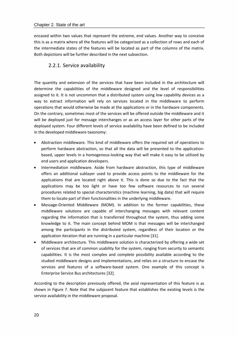
Chapter 2. State of the art
20
encased within two values that represent the extreme, end values. Another way to conceive
this is as a matrix where all the features will be categorized as a collection of rows and each of
the intermediate states of the features will be located as part of the columns of the matrix.
Both depictions will be further described in the next subsection.
2.2.1. Service availability
The quantity and extension of the services that have been included in the architecture will
determine the capabilities of the middleware designed and the level of responsibilities
assigned to it. It is not uncommon that a distributed system using low capability devices as a
way to extract information will rely on services located in the middleware to perform
operations that would otherwise be made at the applications or in the hardware components.
On the contrary, sometimes most of the services will be offered outside the middleware and it
will be deployed just for message interchanges or as an access layer for other parts of the
deployed system. Four different levels of service availability have been defined to be included
in the developed middleware taxonomy:
Abstraction middleware. This kind of middleware offers the required set of operations to
perform hardware abstraction, so that all the data will be presented to the application-
based, upper levels in a homogenous-looking way that will make it easy to be utilized by
end users and application developers.
Intermediation middleware. Aside from hardware abstraction, this type of middleware
offers an additional sublayer used to provide access points to the middleware for the
applications that are located right above it. This is done so due to the fact that the
applications may be too light or have too few software resources to run several
procedures related to special characteristics (machine learning, big data) that will require
them to locate part of their functionalities in the underlying middleware.
Message-Oriented Middleware (MOM). In addition to the former capabilities, these
middleware solutions are capable of interchanging messages with relevant content
regarding the information that is transferred throughout the system, thus adding some
knowledge to it. The main concept behind MOM is that messages will be interchanged
among the participants in the distributed system, regardless of their location or the
application iteration that are running in a particular machine [31].
Middleware architecture. This middleware solution is characterized by offering a wide set
of services that are of common usability for the system, ranging from security to semantic
capabilities. It is the most complex and complete possibility available according to the
studied middleware designs and implementations, and relies on a structure to encase the
services and features of a software-based system. One example of this concept is
Enterprise Service Bus architectures [32].
According to the description previously offered, the axial representation of this feature is as
shown in Figure 7. Note that the subjacent feature that establishes the existing levels is the
service availability in the middleware proposal.

Chapter 2. State of the art
21
Figure 7. Levels of service availability for middleware
2.2.2. Computational capabilities of deployment hardware
Even though hardware will be an underlying element that middleware will abstract in order to
withhold its complexity for end users and clients alike instead of part of the middleware itself,
it is something that must be taken into account when designing it, for it will determine the
kind of services that can be run in the system. When all is said and done, computational
capabilities must be born in mind when designing the complexity of the services to be used, as
the processing power provided by the hardware will determine if a service can be executed
locally, in a distributed manner, or cannot be offered to higher levels at all due to its excessive
workload demand. The levels that have been defined for computational capabilities are:
End user domain devices. These are pieces of hardware that are usually included in the
Smart Grid as equipment mounted in an end user´s dwell or facility. The most common
ones are Advanced Metering Infrastructure (AMI), which sometimes can be used and
deemed as if it was part of an Internet of Things development [33] or home batteries for
energy storage, which are becoming increasingly popular because of the energy they can
provide when buying it from the electricity markets at a particular moment is
disadvantageous [34]. The capability of these end user devices to have software
components installed in them is usually acceptable, but issues related to Intellectual
Property Rights (IPRs) or security may happen when proprietary solutions are used.
Aggregator domain devices. These are the devices that will be used by the
aggregator/retailer present in a deployment to, depending on how smart the power grid is,
either trade with electricity among different clusters of users (in case the aggregator has
the capabilities to do so) or just offer it to be sold to the end users. Commonly, these
devices will imply some hardware with a database in them to store information about end
user profiles or energy scheduling algorithms used to determine when energy should be
purchased [35].
TSO/DSO domain devices. These are devices that are used in a Smart Grid, but are not
accessed by end users or the aggregator, as they are usually owned by the DSO or the TSO;
if something, they will be accessed by the technicians and engineers participating in their
deployment. Two examples of this kind of equipment are Remote Terminal Units (RTUs),
used for functionalities such as executing demand response programs between the end
users and the DSO [36], and Phasor Measurement Units (PMUs) focused on synchronizing
the measurements on an electrical grid for monitoring and control purposes through the
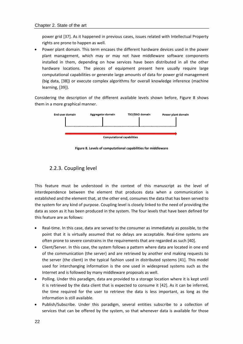
Chapter 2. State of the art
22
power grid [37]. As it happened in previous cases, issues related with Intellectual Property
rights are prone to happen as well.
Power plant domain. This term encases the different hardware devices used in the power
plant management, which may or may not have middleware software components
installed in them, depending on how services have been distributed in all the other
hardware locations. The pieces of equipment present here usually require large
computational capabilities or generate large amounts of data for power grid management
(big data, [38]) or execute complex algorithms for overall knowledge inference (machine
learning, [39]).
Considering the description of the different available levels shown before, Figure 8 shows
them in a more graphical manner.
Figure 8. Levels of computational capabilities for middleware
2.2.3. Coupling level
This feature must be understood in the context of this manuscript as the level of
interdependence between the element that produces data when a communication is
established and the element that, at the other end, consumes the data that has been served to
the system for any kind of purpose. Coupling level is closely linked to the need of providing the
data as soon as it has been produced in the system. The four levels that have been defined for
this feature are as follows:
Real-time. In this case, data are served to the consumer as immediately as possible, to the
point that it is virtually assumed that no delays are acceptable. Real-time systems are
often prone to severe constrains in the requirements that are regarded as such [40].
Client/Server. In this case, the system follows a pattern where data are located in one end
of the communication (the server) and are retrieved by another end making requests to
the server (the client) in the typical fashion used in distributed systems [41]. This model
used for interchanging information is the one used in widespread systems such as the
Internet and is followed by many middleware proposals as well.
Polling. Under this paradigm, data are provided to a storage location where it is kept until
it is retrieved by the data client that is expected to consume it [42]. As it can be inferred,
the time required for the user to retrieve the data is less important, as long as the
information is still available.
Publish/Subscribe. Under this paradigm, several entities subscribe to a collection of
services that can be offered by the system, so that whenever data is available for those

Chapter 2. State of the art
23
services they will be retrieved by the subscribed elements. The main difference between
polling and publish/subscribe is that when an entity subscribes to a service, it will receive
the data without any further action, whereas under a polling paradigm the entity that
needs the data will have to actively demand it to the entity that stores it.
As it happened with the other two criteria, there is a progression between the lowest message
coupling level and the highest one, as shown in Figure 9.
Figure 9. Levels of message coupling
2.2.4. Middleware distribution
This feature assesses the level of distribution that has been designed for each of the solutions.
Four different levels have been defined by bearing in mind how many devices will have
significant parts of the middleware installed:
Fully centralized. The middleware solution has been installed in a single device (which
implies that it will be powerful enough to run it). Although there might be other devices
connected to the one with the middleware installed, the solution is still installed in a single
one.
Mostly centralized. The middleware has been distributed among several devices, but there
is still a more prominent centre where most of the services or the system intelligence runs.
Mostly decentralized. Most of the logic and the prominent features are located on the
periphery of the system, despite the existence of a central node used to transfer
information from one part of the middleware solution to the other.
Peer-to-peer. No central elements are available in the solution; all the interchanged data is
done so in a fully distributed manner. This is the paradigm that, for example, has been
used the most for file sharing from a historical point of view [43].
Figure 10 shows the different levels that have been set for middleware distribution, ranging
from next to no distribution to a peer-to-peer paradigm.
Figure 10. Levels of middleware distribution

Chapter 2. State of the art
24
2.2.5. Taxonomy for middleware in distributed systems
The previous assessment of the criteria put to a use to classify and have a holistic perspective
of the middleware solutions can also be taken into account from different perspectives. A
direct one, where all the internal categories for each of the criterion become represented, has
been used in Figure 11. It effectively implies that a taxonomy has been introduced as a result
of the study on the state of the art of middleware architectures for the Smart Grid.
Figure 11. Taxonomy for middleware classification
In addition to that, there is another way that can be used to represent the taxonomy; rather
than having a separated branch for each of the features, they can be placed altogether in a

Chapter 2. State of the art
25
matrix where each of the rows will be occupied by the feature and each of the columns will be
made up by the intermediate levels of every characteristic of the ones that are represented.
This latter representation is more appealing from the mathematical point of view, as each of
the features can be located as one element matching a row and column position, as depicted
in Figure 12.
Figure 12. Matrix for Smart Grid middleware taxonomy
If the taxonomy is born in mind the way it has been depicted in the previous figure, the
accurate definition of the features of each of the middleware architectures could be regarded
a matter of choosing features that will match a collection of four positions in the given matrix,
one for each row (feature established as a way to define the kind of middleware), so that the
optimal middleware solution will be defined as the result of a mathematical equation. If, for
example, a solution where a) a middleware architecture for b) end user devices based on c) a
Publish/Subscribe paradigm that d) requires a peripheral information processing procedure
but still has a centre to perform certain functionalities, then the solution could be described as
follows:
Smart Grid Middleware = Service Availability (element no.3) + Computational Capabilities
(element no. 0) + Message Coupling (element no. 0) + Middleware Distribution (element no. 2).
Therefore, it can be represented as:
SGM = SA (3) + CC (0) + MC (0) + MD (2) (1)
In this way, a precise idea can be obtained of the most prominent aspects of a middleware
solution that has been conceived for the Smart Grid. In addition to that, once the
characteristics of a particular architecture have become clear, an assessment of its advantages
and disadvantages can also be done by considering how middleware functionalities are
performed in each of the presented proposals.

Chapter 2. State of the art
26
2.2.6. GridStat
The proposal elaborated by Harald Gjermundrød, et al. [44] focuses on several aspects
inherent to middleware and distributed systems: it has been conceived to be used by scattered
pieces of hardware involving Smart Grid deployments, Quality of Service (QoS) capabilities and
a collection of functionalities within its very architecture. It was firstly presented as a way to
distribute timestamped, time-synchronous data from Phasor Measurement Units [45] and
further developed into a way to support RPC (Remote Procedure Call) mechanisms to use its
own QoS semantic features [46]. The main purpose of this middleware proposal is creating a
framework where data can be interchanged in a distributed manner under a Publish/Subscribe
paradigm. In this way, messages will be transferred from one entity to another by mean of
intermediate hardware appliances and software components. The following information can
be inferred for each of the previously formulated criterion:
Service availability: while GridStat is regarded as a middleware framework by its authors and is
referred to as an architecture, its functionalities are aimed at transferring information among
different locations rather than providing any extra service, so it fits better a Message Oriented
Middleware type of service availability. The authors claim that it offers secure, robust and
flexible data communications that provides Quality of Service features, such as QoS-managed
multicast. One of the most notorious features of the architecture is that it is divided in two
different levels that are referred to as planes: the upper plane is the management plane; its
main purpose is establishing the forwarding rules of the information sent. The other plane is
called the data plane; it transfers data from the publishers to the subscribers, regardless of
their location. Management plane uses QoS brokers to determine where information is sent in
the data plane. QoS brokers in touch with the management plane (called leaf QoS brokers)
directly manage the data plane clouds (a set of routers with the same resource management
and cyber security policies) where the Status Routers are located; the latter have a flat
organization within the clouds and forward the incoming data to the suitable communication
link. Figure 13 depicts the appearance of the architecture.
Figure 13. Gridstat proposal, as described in [43]

Chapter 2. State of the art
27
Computational capabilities: The proposal is primarily aimed to provide substation automation
(which implies that the software components can be located in the TSO/DSO infrastructures,
as both entities have substations in the power grid). However, it is not explicitly mentioned
that it cannot be equipped elsewhere, as the software elements that are described, such as
QoS brokers or publishers and subscribers, are not necessarily located in one specific kind of
hardware. The implementation that was used to provide experimental results uses Java as
programming language (even though a C-written version, which should offer a higher
performance, were under development at the time the proposal was introduced to the
research community), whereas the hardware used implied Dell Power Edge 1750s servers for
data transmission, Fedora 2 Linux as the operating system and a Java 2 Platform standard
edition, so the requirements were more than acceptable to run the middleware architecture.
Message coupling: GridStat relies heavily on a Publish/Subscribe model in the data plane to
send and receive information among the different entities where it is installed. This is clear
from what has been shown of the data plane, which implies groups of routers receiving
information from publishers and forwarding it to subscribers that will be dependent on either
the same cloud or a different one (thus requiring forwarding commands from the management
plane). Along with Publish/Subscribe, some other paradigms have been used as well: it is
mentioned that Common Object Request Broker Architecture (CORBA), Client/Server
communications are used for command interactions interchanged among the entities of the
management plane.
Middleware distribution: The proposal offers a prominent degree of decentralization, but
rather than following a peer-to-peer model, it has a hierarchy that keeps high level
management decisions in an upper location. It is mentioned in the proposal that the
management plane must readapt the network to changing conditions, like power system
configurations or network failures, so a degree of control is given to some entities that others
do not have.
If the matrix for the middleware in the Smart Grid is considered, the proposal can be defined
as:
SGM = SA (2) + CC (2) + MC (0) + MD (2) (2)
Advantages of the proposal: GridStat offers a detailed framework not only from the theoretical
but also from the practical point of view, as there are implementation works to prove the
design that has been conceived by the authors and the performance results show the
feasibility of the proposal. The fact that it does not require many computational resources to
have it running and its significant distribution degree are also appealing, as it can be used in
different low capability devices the Smart Grid usually involves, such as smart meters.
Disadvantages of the proposal: The proposal does not have a collection of services that can be
used by applications; instead of that, GridStat seems to have been conceived for the mere
transmission of data one level above network capabilities. Even though security is mentioned
several times in the proposal, not enough detail is provided (such as how access is securitized
or whether cryptography is used). Lastly, important features used for middleware and

Chapter 2. State of the art
28
information enhancement (ontologies, information models) are not mentioned in the
proposal.
2.2.7. Service-Oriented Middleware for Smart Grid
L. Zhou and J. Rodrigues put forward a proposal that puts its stress on services for the Smart
Grid and how they get to be applied in a deployment [47]. The authors claim that they have
developed an efficient and integrated middleware solution for heterogeneous services of the
Smart Grid, aiming to obtain a high level of software sustainability and stability. The idea of
offering efficient services in the proposal is a major one for the authors, as they consider that
serving for power allocation and consumption is closely linked to the idea of service applied to
a middleware solution for the enhancement of the power grid. The proposal deals with one
usual problem of middleware solutions, that is to say, the difficulty to be reused from one
development to another, due to the different nature of the services that are requested in each
application domain. Consequently, the service-oriented middleware has been decoupled
according to several application-based functionalities. Its most prominent characteristics are:
Service availability: As it usually happens with middleware, this proposal is divided into several
layers that split the functionalities in different levels, so that they will be accessed and used in
different ways. As it has been displayed in Figure 14 there are three levels: a user part, a
control part and a transmission layer. The user part is responsible for providing both QoS and
Quality of Experience (QoE) for the end user (which usually determines bandwidth, delay,
reliability or jitter parameters); it also takes care of scheduling flexibility to offer the best
available QoS possible. Secondly, the control part connects the user part with the transmission
layer; its functionalities are the ones more typical of a middleware solution, as it is expected to
handle the different devices interoperating in the system and transferring information via
transmission layer while maintaining an acceptable level of QoS and QoE in the user part.
Lastly, the transmission layer is regarded as the foundation of the whole system and uses its
services in the Advanced Metering Infrastructure of any deployment where the proposal is
used. Data interchanges are carried out both among contiguous levels and between the user
part and the transmission layer. Due to the separation of the proposal in different layers, and
its differentiated services, it can be regarded as a middleware architecture.
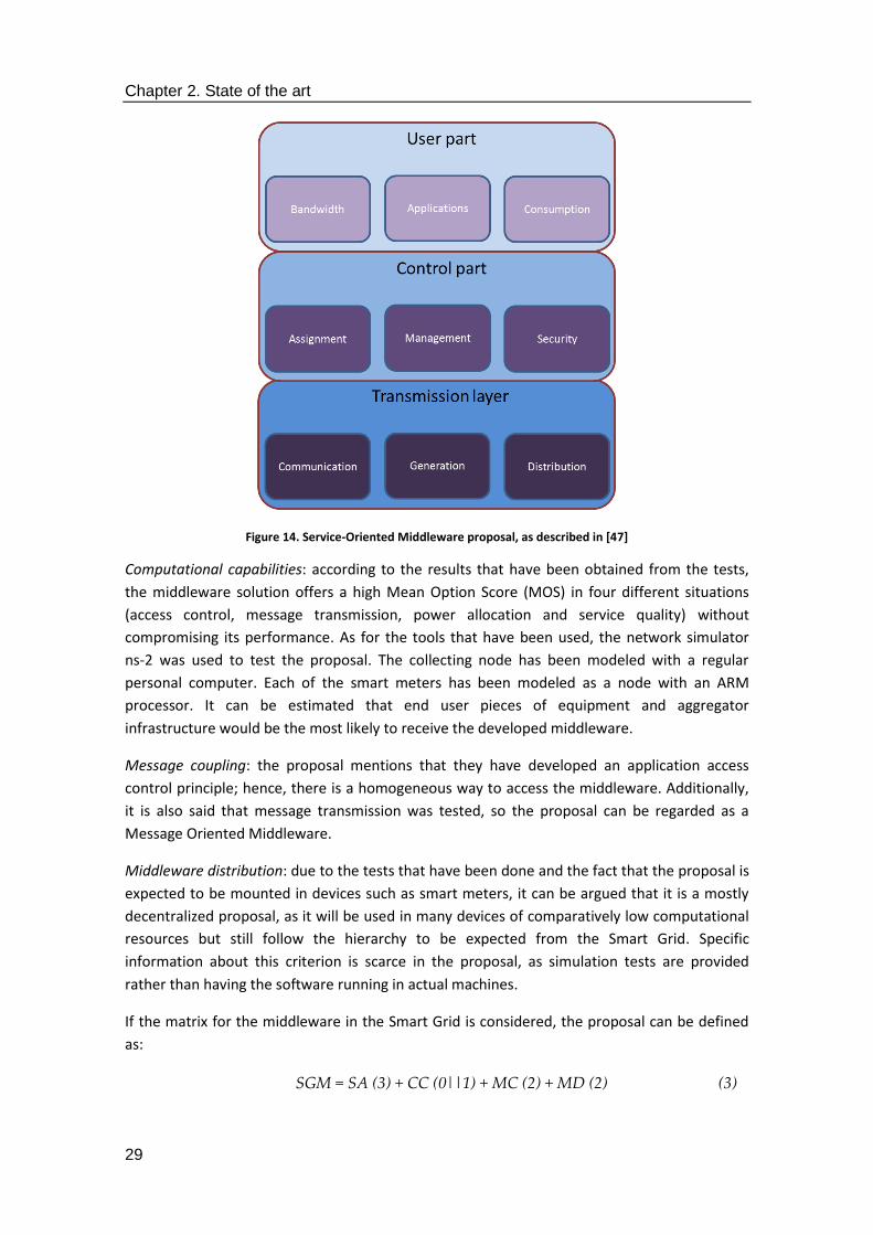
Chapter 2. State of the art
29
Figure 14. Service-Oriented Middleware proposal, as described in [47]
Computational capabilities: according to the results that have been obtained from the tests,
the middleware solution offers a high Mean Option Score (MOS) in four different situations
(access control, message transmission, power allocation and service quality) without
compromising its performance. As for the tools that have been used, the network simulator
ns-2 was used to test the proposal. The collecting node has been modeled with a regular
personal computer. Each of the smart meters has been modeled as a node with an ARM
processor. It can be estimated that end user pieces of equipment and aggregator
infrastructure would be the most likely to receive the developed middleware.
Message coupling: the proposal mentions that they have developed an application access
control principle; hence, there is a homogeneous way to access the middleware. Additionally,
it is also said that message transmission was tested, so the proposal can be regarded as a
Message Oriented Middleware.
Middleware distribution: due to the tests that have been done and the fact that the proposal is
expected to be mounted in devices such as smart meters, it can be argued that it is a mostly
decentralized proposal, as it will be used in many devices of comparatively low computational
resources but still follow the hierarchy to be expected from the Smart Grid. Specific
information about this criterion is scarce in the proposal, as simulation tests are provided
rather than having the software running in actual machines.
If the matrix for the middleware in the Smart Grid is considered, the proposal can be defined
as:
SGM = SA (3) + CC (0||1) + MC (2) + MD (2) (3)
Chapter 2. State of the art
30
Advantages of the proposal: there is a collection of services provided clearly stated by the
authors. Apart from that, performance tests have been made in order to offer actual data
about the behavior of the middleware solution. Even they have been done in the controlled
environment of a simulator, they offer an idea of the capabilities of the middleware solution.
Finally, it is also mentioned that symmetric algorithms have been considered for security
implementation.
Disadvantages of the proposal: overall, the services that are provided are not that prominent
or complex. In addition to that, it is not mentioned how distributed it can be or the devices
that would be able to have installed the software packages it is made of. In addition to that,
the monitoring system that is referred to in the proposal is mainly composed by elements that,
although are used for communication purposes, can also be regarded as part of levels usually
assigned to physical and network-based ones (such as Wi-Fi, satellite networks, the Internet,
etc.). Overall, few data are provided with regards of the nature of each of the services present
in the three layers of the proposal; information about the functionalities of each of them is
missing too.
2.2.8. Ubiquitous Sensor Network Middleware (USN)
Zaballos et al. offer their own interpretation about what a middleware architecture for the
Smart Grid should look like [48]. It is mainly focused on adapting the framework of the ITU
ubiquitous sensor architecture to the application domain of the Smart Grid, which is conceived
by the authors of the proposal as a network of Intelligent Electronic Devices, sensors,
distributed generators, dispersed loads and smart meters requiring a heterogeneous
communication paradigm. It is also mentioned how by using the framework referred to as the
Ubiquitous Sensor Network architecture at defining interoperability, along with a Next
Generation Network (NGN) as the backbone where the proposal is deployed, end-to-end
integration of devices can be achieved. The proposal relies heavily on Internet of Things-like
features, such as lightweight transmission protocols (such as IEEE 802.15.4, used for bit
transmission among constrained devices like nodes from a Wireless Sensor Network, even
when adding security capabilities to it [49]). In addition to that, it also makes use of
technologies like Power Line Communication (PLC) or Worldwide Interoperability for
Microwave Access (WiMAX).
Service availability: there are several kinds of services that have been conceived, as it can be
seen in Figure 15, so the proposal can be regarded as a middleware architecture. There are
three different levels closely related to the kind of level they are closest to. The higher level
has a directory containing information about the sensor network. Furthermore, it has an open
API that can be accessed by the application developers in order to access the middleware
architecture. The middle level is used to process either events related to the deployment or
the sensing data that can be mined. Finally, the lower level is devoted to interface and monitor
the sensor network that is present in the lower levels. Interestingly enough, there is a security
manager module that is used in every level of the architecture.
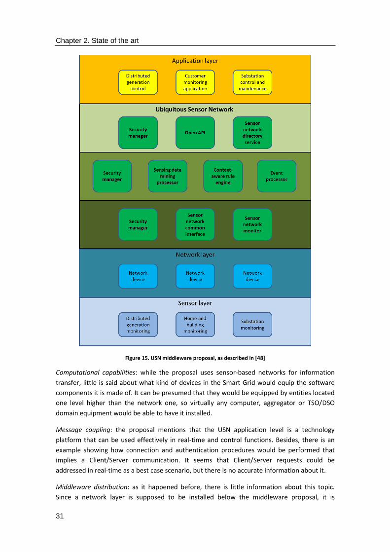
Chapter 2. State of the art
31
Figure 15. USN middleware proposal, as described in [48]
Computational capabilities: while the proposal uses sensor-based networks for information
transfer, little is said about what kind of devices in the Smart Grid would equip the software
components it is made of. It can be presumed that they would be equipped by entities located
one level higher than the network one, so virtually any computer, aggregator or TSO/DSO
domain equipment would be able to have it installed.
Message coupling: the proposal mentions that the USN application level is a technology
platform that can be used effectively in real-time and control functions. Besides, there is an
example showing how connection and authentication procedures would be performed that
implies a Client/Server communication. It seems that Client/Server requests could be
addressed in real-time as a best case scenario, but there is no accurate information about it.
Middleware distribution: as it happened before, there is little information about this topic.
Since a network layer is supposed to be installed below the middleware proposal, it is
Chapter 2. State of the art
32
supposed to be either mostly centralized or a mostly decentralized proposal that is able to run
in several devices simultaneously.
This proposal can be described as:
SGM = SA (3) + CC (0||1||2) + MC (3) + MD (1||2) (4)
Advantages of the proposal: the proposal makes use, or at least is compatible with, several
different proved technologies used in other levels of the system, such as IEEE 802.15.4 or
WiMAX. It aims at being reasonable decentralized.
Disadvantages of the proposal: the proposal tends to mix several different concepts that, due
to their inherent features and locations in a system architecture, are not part of middleware
(such as applications or Wireless Sensor Networks). What is more, there are no explicit
mentions on what kind of equipment would be used to encase the proposal in a Smart Grid or
a microgrid. Performance tests, either simulated or in actual appliances, are not shown to get a
grasp on how the proposal gets needs solved, such as consumption data or data transport.
Overall, the proposal feels more like an Internet of Things development that was ported to the
Smart Grid rather than something that was made from the scratch for the latter application
domain.
2.2.9. OSHNet (Object-Based Middleware for Smart Home Network)
Sang Oh Park et al. describe a proposal based on interoperability between home devices and
Smart Grid-related ones [50]. The proposal is structured in three different layers: the
Application layer (which offers the home users the proposal is aimed to five different
Application Programming Interfaces), the Library layer (responsible for providing the necessary
information about the present home devices) and the Network layer (which provides device
interoperability among devices using different kinds of protocols). Thus, it expands its borders
further than what is strictly located as the domain of a middleware architecture, which usually
relies on data received from the network to be provided to an application; taking into account
this idea, the library layer of OSHNet would be the one that is fitting an actual middleware
solution, even though it is the network layer the one that is more closely aimed to the usual
functionalities of middleware. Home devices characteristics are included in the Library layer as
four different kinds of objects: Control object (applied to controlling neighbouring home
appliances), Streaming object (focused on managing input and output data), Status object
(used to maintain current status of the home devices included in the deployment) and
Function object (utilized to execute functionalities in home appliances, like powering on or
switching TV channels).
Service availability: the proposal can be regarded as a middleware architecture, as it is
composed by several levels (referred to in the proposal as layers) with different services in
each of them. As it was mentioned before, the highest one has the suitable API used to access
the application level, whereas the library layer has the aforementioned four kinds of objects
(Control, Streaming, Function and Status) used to categorize each of the devices in the home

Chapter 2. State of the art
33
deployment, as well as three modules that are used to invoke services from the proposal: the
Object Management Module (in order to control the functionalities that are offered by the
devices where the solution is present), the Object Discovery Module (to gather information
about other home peer devices) and the Connection Management Module (used to establish,
maintain and terminate connections among devices). One lower level, but still within the
middleware architecture, the Network layer presents the Virtual Network Adapter (VNA),
which is the software entity interconnecting the different devices that are used outside the
middleware proposal. Figure 16 displays the most prominent software components of the
proposal.
Figure 16. OSHNet architecture, as described in [50]
Computational capabilities: the proposal often refers to home systems as the devices that will
equip the middleware solution. In addition to that, the proposal documentation offers
screenshots of mobile devices as smartphones, so it can be assumed that End User equipment
of the Smart Grid, such as Advanced Metering Infrastructure, would suffice to have the
software components installed. The tests that have been carried out involve a set of virtual
devices, such as a humidifier, a wind-powered generator, a smart meter, a smartphone, three
laptops or an external information center.
Message coupling: since there are user interfaces shown in the proposal, it can be assumed
that it is capable of handling Client/Server requests. Information is fed onto those interfaces,
so at least they should be able to support some kind of polling, even though the actual way to
interact with the simulated environment is not completely clear.
Chapter 2. State of the art
34
Middleware distribution: it is mentioned that the proposal is expected to be installed in
Distributed Energy Resources, as well as in other devices of somewhat lower computational
capabilities. In addition to that, there are other pieces of equipment as laptops that are
expected to have higher ruling capabilities over the system, so it can be said that the proposal
deals with a mostly distributed middleware solution. The devices that are included are
supposed to be simulated, though.
According to the matrix that was previously defined, this proposal can be described as:
SGM = SA (3) + CC (0) + MC (2) + MD (2) (5)
Advantages of the proposal: the middleware architecture that is put forward here contains a
collection of services where a group of them are specifically designed to tackle hardware
interoperability. In addition to that, simulated devices and user interfaces have been created
to have a realistic idea of what can be expected from the proposal.
Disadvantages of the proposal: The proposal also uses confusing names in the sense that there
are several levels referred to as “layers” still within the boundaries of the middleware
architecture, as the network layer or the application layer. In addition to that, while some
services are added to the architecture, those are meant for the internal performance of the
proposal, rather than offering a more compelling functionality for end users.
2.2.10. Meter Data Integration (MDI)
Zhao Li et al. offer in this proposal their own conception of what a middleware solution should
be [51]. While the proposal is referred to in the proposal as a Meter Data Integration (MDI)
solution, it is clear from the text that is supposed to integrate different kinds of AMI in a
common deployment, so it is actually performing middleware functionalities to the point that
is described as a middleware located between the Advanced Metering Infrastructure and the
Distributed Management System (DMS). Some other elements are defined as well: a Meter
Data Management System (MDMS) is used as a certain kind of data server and a Meter Data
Collector gathers all the information obtained from the deployed Smart Meters. This proposal
takes into account implementation details about the smart meters that are either used or
manufactured by several large companies, such as Pacific Gas & Electricity or Siemens, so a
more realistic approach can be taken when functionalities are designed.
Service availability: the proposal described here makes used of three different levels of
information to separate and determine the specific functionalities that will be carried out.
Consequently, and taking into account that each of the layers contains different services, it can
be regarded as a middleware architecture. The first level contains the services used to adapt
the information utilized by the DMSs to the possible transport interfaces used in the
deployment. The intermediate layer is the more complex one: there is a temporal database
used to verify and translate the collected smart meter data, the Loosely Couple Event (LCE)
infrastructure used for message publication and subscription and a MDI monitor used to track
the status of the functional components existing in the overall MDI layer. Lastly, the lower

Chapter 2. State of the art
35
level is used to contain all the adaptors used for connectivity with the AMI network. The
overall appearance of the services of this middleware architecture is shown in Figure 17.
Figure 17. Meter Data Integration Proposal, as described in [51]
Computational capabilities: according to the tests that have been performed on the proposal,
the devices used are two simulated smart meters (which use separated pieces of hardware
and Windows Server 2003 and 2008 as the operating systems) and another one used as a
server containing the MDI layer (it uses a Windows 2008 Server operating system). The
proposal is mainly focused on managing Advanced Metering Infrastructure, although taking
into account that the MDI components have been located in a different machine and the fact
that there are data obtained from the smart meters, arguably it can be expected to be
installed in aggregator-located equipment.
Message coupling: the proposal is explicitly described as using a Publish/Subscribe paradigm,
as it has been designed to work publishing and subscribing the messages that are transferred
by means of the LCE infrastructure. According to the information on this middleware
architecture, it is loosely coupled in the sense that message senders and receivers run in
different spaces and if for any reason one of them stops working, the other side of the
communications will still be operational.
Middleware distribution: the proposal has been installed in a single computer in the tests that
have been carried out. On the other hand, it is commanding several devices that have been
portrayed as part of an Advanced Metering Infrastructure. Due to these reasons, it has been
considered a mostly centralized middleware architecture.
This proposal can be described as:
SGM = SA (3) + CC (0||1) + MC (0) + MD (1) (6)
Chapter 2. State of the art
36
Advantages of the proposal: the middleware architecture aims to provide interoperability of
different devices that are used as real smart meters. In addition to that, it is clearly justified
why the proposal is conceived as one using a publisher/subscriber and the computational
resources that are suitable to run it with good enough performance.
Disadvantages of the proposal: as it happened with several previous proposals, there is very
little information about how the services can be implemented or any detail about their
performance on different programming languages. What is more, services provide not so many
functionalities beyond interoperability and interconnectivity; security or semantics, for
example, seem not to be supported by the proposal. In addition to that, the information about
the tests that have been carried out is referred to as a small group of devices that are
simulating actual ones; having more devices that were located in an application domain that
involved a microgrid or something alike would have been welcomed, especially when actual
smart meters have been studied for the proposal.
2.2.11. IEC 61850 and DPWS Integration
Stjepan Sucic et al. combine in their proposal the usage of DPWS (Device Profile for Web
Services, a standard put forward to promote interoperability among constrained
implementations of Web services, along with higher interoperability with more flexible client
implementations [52]) and an electric standard (IEC 61850, a communication model used for
functionalities like setting requirements for device models or the description of the language
for communication among substations [53]) typical of the power grid needs that the authors
present [54]. Their main idea is that, since the principles of IEC 61850 are defined under a non-
Platform Specific or software specific point of view, and in fact, they use a description known
as Abstract Communication Service Interface (ACSI) that is not linked to any specific
middleware solution, Web services can be used to complement one effective middleware
mapping enabling IEC 61850 communications. This mapping enabling is known as
Manufacturing Message Specification or MMS, and is also used for distributed transmission of
power control [55]. Rather than replacing this technology, the proposal seeks to improve some
of its weaknesses; the authors cite its complexity and involving a full OSI stack that makes
integration of any distributed solution more expensive.
Service availability: there are several levels that are defined in this middleware proposal as an
architecture. One important fact is that, despite their different features, they are all focused
on providing facilities to the Web services that are present in it. DPWS is used here, as it is
claimed by the authors that it is a technology aimed to provide interoperability for
heterogeneous and constrained devices that may have limited and low capability resources.
The three different levels that are present are located as it is usual in middleware solutions,
that is to say, between the application layer and the network one. The uppermost of them is
used for Web service discovery (which provides an addressing mechanism for Web services),
Web service Metadata Exchange (defines operations to retrieve device and service metadata,
along with datatypes) and Web service eventing (for management of the publish/subscribe
mechanism used in the proposal. These capabilities are linked to the intention of using the
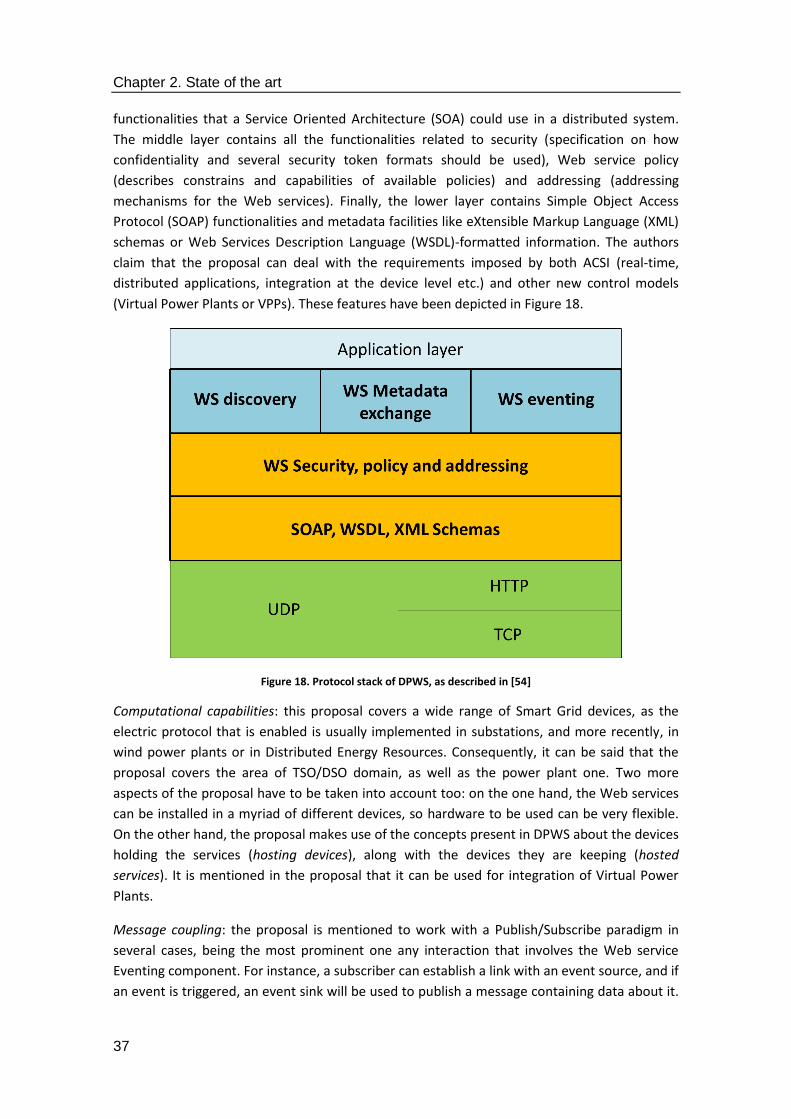
Chapter 2. State of the art
37
functionalities that a Service Oriented Architecture (SOA) could use in a distributed system.
The middle layer contains all the functionalities related to security (specification on how
confidentiality and several security token formats should be used), Web service policy
(describes constrains and capabilities of available policies) and addressing (addressing
mechanisms for the Web services). Finally, the lower layer contains Simple Object Access
Protocol (SOAP) functionalities and metadata facilities like eXtensible Markup Language (XML)
schemas or Web Services Description Language (WSDL)-formatted information. The authors
claim that the proposal can deal with the requirements imposed by both ACSI (real-time,
distributed applications, integration at the device level etc.) and other new control models
(Virtual Power Plants or VPPs). These features have been depicted in Figure 18.
Figure 18. Protocol stack of DPWS, as described in [54]
Computational capabilities: this proposal covers a wide range of Smart Grid devices, as the
electric protocol that is enabled is usually implemented in substations, and more recently, in
wind power plants or in Distributed Energy Resources. Consequently, it can be said that the
proposal covers the area of TSO/DSO domain, as well as the power plant one. Two more
aspects of the proposal have to be taken into account too: on the one hand, the Web services
can be installed in a myriad of different devices, so hardware to be used can be very flexible.
On the other hand, the proposal makes use of the concepts present in DPWS about the devices
holding the services (hosting devices), along with the devices they are keeping (hosted
services). It is mentioned in the proposal that it can be used for integration of Virtual Power
Plants.
Message coupling: the proposal is mentioned to work with a Publish/Subscribe paradigm in
several cases, being the most prominent one any interaction that involves the Web service
Eventing component. For instance, a subscriber can establish a link with an event source, and if
an event is triggered, an event sink will be used to publish a message containing data about it.
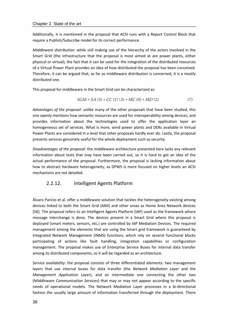
Chapter 2. State of the art
38
Additionally, it is mentioned in the proposal that ACSI runs with a Report Control Block that
require a Publish/Subscribe model for its correct performance.
Middleware distribution: while still making use of the hierarchy of the actors involved in the
Smart Grid (the infrastructure that the proposal is most aimed at are power plants, either
physical or virtual), the fact that it can be used for the integration of the distributed resources
of a Virtual Power Plant provides an idea of how distributed the proposal has been conceived.
Therefore, it can be argued that, as far as middleware distribution is concerned, it is a mostly
distributed one.
This proposal for middleware in the Smart Grid can be characterized as:
SGM = SA (3) + CC (2||3) + MC (0) + MD (2) (7)
Advantages of the proposal: unlike many of the other proposals that have been studied, this
one openly mentions how semantic resources are used for interoperability among devices, and
provides information about the technologies used to offer the application layer an
homogeneous set of services. What is more, wind power plants and DERs available in Virtual
Power Plants are considered in a level that other proposals hardly ever do. Lastly, the proposal
presents services genuinely useful for the whole deployment such as security.
Disadvantages of the proposal: the middleware architecture presented here lacks any relevant
information about tests that may have been carried out, so it is hard to get an idea of the
actual performance of the proposal. Furthermore, the proposal is lacking information about
how to abstract hardware heterogeneity, as DPWS is more focused on higher levels an ACSI
mechanisms are not detailed.
2.2.12. Intelligent Agents Platform
Álvaro Paricio et al. offer a middleware solution that tackles the heterogeneity existing among
devices linked to both the Smart Grid (AMI) and other areas as Home Area Network devices
[56]. The proposal refers to an Intelligent Agents Platform (IAP) used as the framework where
message interchange is done. The devices present in a Smart Grid where this proposal is
deployed (smart meters, sensors, etc.) are controlled by IAP Mediation Devices. The required
management among the elements that are using the Smart grid framework is guaranteed by
Integrated Network Management (INMS) functions, which rely on several functional blocks
participating of actions like fault handling, integration capabilities or configuration
management. The proposal makes use of Enterprise Service Buses for internal data transfer
among its distributed components, so it will be regarded as an architecture.
Service availability: the proposal consists of three differentiated elements: two management
layers that use internal buses for data transfer (the Network Mediation Layer and the
Management Application Layer), and an intermediate one connecting the other two
(Middleware Communication Services) that may or may not appear according to the specific
needs of operational models. The Network Mediation Layer processes in a bi-directional
fashion the usually large amount of information transferred through the deployment. There

Chapter 2. State of the art
39
are pieces of equipment called IAP Mediation Device (MD) that use this layer for control
purposes. Any management traffic type is controlled with these MDs, regardless of its nature
(status monitoring, security, configuration, operation flows, etc.). The Management
Applications Layer is responsible for using a collection of functional application blocks that are
closely tied to an end user functionality as a reporting engine, alarm handling or a task
scheduler. Lastly, the middleware communication services basically interconnect one layer
with the immediately other one in case data have to be transported from the applications
backend to the mediation system. All these features have been represented in Figure 19.
Figure 19. IAP-INMS appearance, as described in [56]
Computational capabilities: it is mentioned that the proposal has been tested repeatedly in
different application domains. Furthermore, Customer Premises Equipment has been used as a
way to employ a Smart Grid-like deployment where information could be transmitted via IP
network. Unfortunately, there are scarce data of the equipment that was used for the text, or
even if it was simulated or not (it is mentioned, for instance, that each Mediation Device will
control one hundred concentrators, so a total of ten thousand AMIs will be managed).
Message coupling: there are two different kinds of paradigms that are used in this proposal.
The first on is real-time for event collection, with no message decoupling whatsoever. On the
other hand, a Publish/Subscribe mechanism is also utilized for the Intelligent Agents Platform
used for the implementation and testing activities. There are even other kinds of paradigms,
such as agents using peer-to-peer communications, or polling done on the concentrators used
for testing activities.
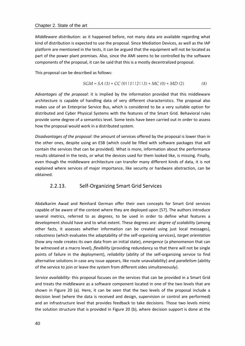
Chapter 2. State of the art
40
Middleware distribution: as it happened before, not many data are available regarding what
kind of distribution is expected to use the proposal. Since Mediation Devices, as well as the IAP
platform are mentioned in the tests, it can be argued that the equipment will not be located as
part of the power plant premises. Also, since the AMI seems to be controlled by the software
components of the proposal, it can be said that this is a mostly decentralized proposal.
This proposal can be described as follows:
SGM = SA (3) + CC (0||1||2||3) + MC (0) + MD (2) (8)
Advantages of the proposal: it is implied by the information provided that this middleware
architecture is capable of handling data of very different characteristics. The proposal also
makes use of an Enterprise Service Bus, which is considered to be a very suitable option for
distributed and Cyber Physical Systems with the features of the Smart Grid. Behavioral rules
provide some degree of a semantics level. Some tests have been carried out in order to assess
how the proposal would work in a distributed system.
Disadvantages of the proposal: the amount of services offered by the proposal is lower than in
the other ones, despite using an ESB (which could be filled with software packages that will
contain the services that can be provided). What is more, information about the performance
results obtained in the tests, or what the devices used for them looked like, is missing. Finally,
even though the middleware architecture can transfer many different kinds of data, it is not
explained where services of major importance, like security or hardware abstraction, can be
obtained.
2.2.13. Self-Organizing Smart Grid Services
Abdalkarim Awad and Reinhard German offer their own concepts for Smart Grid services
capable of be aware of the context where they are deployed upon [57]. The authors introduce
several metrics, referred to as degrees, to be used in order to define what features a
development should have and to what extent. These degrees are: degree of scalability (among
other facts, it assesses whether information can be created using just local messages),
robustness (which evaluates the adaptability of the self-organizing services), target orientation
(how any node creates its own data from an initial state), emergence (a phenomenon that can
be witnessed at a macro level), flexibility (providing redundancy so that there will not be single
points of failure in the deployment), reliability (ability of the self-organizing service to find
alternative solutions in case any issue appears, like route unavailability) and parallelism (ability
of the service to join or leave the system from different sides simultaneously).
Service availability: this proposal focuses on the services that can be provided in a Smart Grid
and treats the middleware as a software component located in one of the two levels that are
shown in Figure 20 (a). Here, it can be seen that the two levels of the proposal include a
decision level (where the data is received and design, supervision or control are performed)
and an infrastructure level that provides feedback to take decisions. Those two levels mimic
the solution structure that is provided in Figure 20 (b), where decision support is done at the
Chapter 2. State of the art
41
decision level and data communication combined with physical devices roughly matches the
infrastructure level. It is expected from middleware that it will cope with several processes:
data routing, aggregation, filtering and replication are mentioned by the authors. Middleware
as a software participant in the system is less relevant here than in other proposals, as it is
used in the infrastructure side of the communications that take place throughout the system.
Therefore, it can be regarded as an abstraction middleware.
Computational capabilities: the proposal makes no explicit mention about the devices that are
expected to be used to install the proposal. The physical level seems to correspond with
Advanced Metering Infrastructure, whereas the decision support centers could be located in
the aggregator side, as they are controlling the devices present on the very end of the
deployment and they are able to send commands.
Figure 20. Solution structure (a) and main levels of the proposal (b), as described in [57]
Message coupling: real-time communications are mentioned the most in the proposal as one
of the most critical ways to interchange data among the elements of the Smart Grid. Aside
from that, not many details are providing any other form of message coupling
(publish/subscribe, polling or Client/Server communications are not mentioned).
Middleware distribution: the proposal openly criticizes centralized middleware solutions, and it
is also mentioned that all nodes have the same importance here. However, while it can be
inferred from the proposal that there is some degree of distribution (which could mean that
the proposal is a mostly decentralized one), it is not clear where the solution is expected to be
installed. Peer-to-peer is mentioned in the proposal as the most preferred used for networks
in the proposal.
Considering all these facts, the proposal can be described as:
SGM = SA (0) + CC (0||1) + MC (3) + MD (3) (9)
Advantages of the proposal: the middleware architecture put forward here offers a distributed
way to interchange data among several software entities.
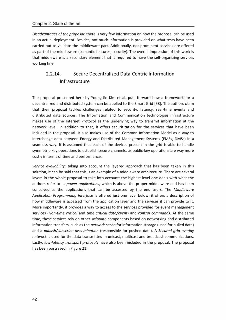
Chapter 2. State of the art
42
Disadvantages of the proposal: there is very few information on how the proposal can be used
in an actual deployment. Besides, not much information is provided on what tests have been
carried out to validate the middleware part. Additionally, not prominent services are offered
as part of the middleware (semantic features, security). The overall impression of this work is
that middleware is a secondary element that is required to have the self-organizing services
working fine.
2.2.14. Secure Decentralized Data-Centric Information
Infrastructure
The proposal presented here by Young-Jin Kim et al. puts forward how a framework for a
decentralized and distributed system can be applied to the Smart Grid [58]. The authors claim
that their proposal tackles challenges related to security, latency, real-time events and
distributed data sources. The Information and Communication technologies infrastructure
makes use of the Internet Protocol as the underlying way to transmit information at the
network level. In addition to that, it offers securitization for the services that have been
included in the proposal. It also makes use of the Common Information Model as a way to
interchange data between Energy and Distributed Management Systems (EMSs, DMSs) in a
seamless way. It is assumed that each of the devices present in the grid is able to handle
symmetric-key operations to establish secure channels, as public-key operations are way more
costly in terms of time and performance.
Service availability: taking into account the layered approach that has been taken in this
solution, it can be said that this is an example of a middleware architecture. There are several
layers in the whole proposal to take into account: the highest level one deals with what the
authors refer to as power applications, which is above the proper middleware and has been
conceived as the applications that can be accessed by the end users. The Middleware
Application Programming Interface is offered just one level below; it offers a description of
how middleware is accessed from the application layer and the services it can provide to it.
More importantly, it provides a way to access to the services provided for event management
services (Non-time critical and time critical data/event) and control commands. At the same
time, these services rely on other software components based on networking and distributed
information transfers, such as the network cache for information storage (used for pulled data)
and a publish/subscribe dissemination (responsible for pushed data). A Secured grid overlay
network is used for the data transmitted in unicast, multicast and broadcast communications.
Lastly, low-latency transport protocols have also been included in the proposal. The proposal
has been portrayed in Figure 21.
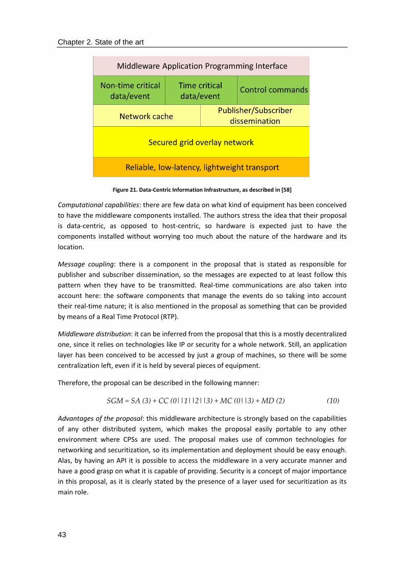
Chapter 2. State of the art
43
Figure 21. Data-Centric Information Infrastructure, as described in [58]
Computational capabilities: there are few data on what kind of equipment has been conceived
to have the middleware components installed. The authors stress the idea that their proposal
is data-centric, as opposed to host-centric, so hardware is expected just to have the
components installed without worrying too much about the nature of the hardware and its
location.
Message coupling: there is a component in the proposal that is stated as responsible for
publisher and subscriber dissemination, so the messages are expected to at least follow this
pattern when they have to be transmitted. Real-time communications are also taken into
account here: the software components that manage the events do so taking into account
their real-time nature; it is also mentioned in the proposal as something that can be provided
by means of a Real Time Protocol (RTP).
Middleware distribution: it can be inferred from the proposal that this is a mostly decentralized
one, since it relies on technologies like IP or security for a whole network. Still, an application
layer has been conceived to be accessed by just a group of machines, so there will be some
centralization left, even if it is held by several pieces of equipment.
Therefore, the proposal can be described in the following manner:
SGM = SA (3) + CC (0||1||2||3) + MC (0||3) + MD (2) (10)
Advantages of the proposal: this middleware architecture is strongly based on the capabilities
of any other distributed system, which makes the proposal easily portable to any other
environment where CPSs are used. The proposal makes use of common technologies for
networking and securitization, so its implementation and deployment should be easy enough.
Alas, by having an API it is possible to access the middleware in a very accurate manner and
have a good grasp on what it is capable of providing. Security is a concept of major importance
in this proposal, as it is clearly stated by the presence of a layer used for securitization as its
main role.

Chapter 2. State of the art
44
Disadvantages of the proposal: there are some major services as the ones used to provide
semantic capabilities that are missing in this middleware architecture. The proposal has also
included a level used for low-latency transport layer that, while a welcome addition, falls out
of the traditional scope of middleware and may represent an extra work to have it working
with the most usual transport layer protocols like UDP or TCP. Finally, the implementation
works that have been carried out are conceived as something extra done for the benefit of the
IP network, rather than to create a separate distributed software layer for hardware
interoperability.
2.2.15. A cloud optimization perspective
Xi Fang et al. put forward their own proposal for a Smart Grid middleware-like architecture
that uses cloud computing as a way to provide services in a distributed manner [59]. In this
context, it can be said that cloud computing is a large-scale computational paradigm where the
resources required to provide a service (storage, network utilities, etc.) are done in distributed
infrastructures and/or platforms that make use of tools as the Internet or web services [60].
Cloud computing platforms are used in a widespread manner; companies such as Amazon or
Microsoft offer their own solutions for commercial and research purposes, like Amazon Web
Services (AWS, [61]) or Microsoft Azure [62]. According to the authors, cloud computing is a
paradigm that should be used as a way to offer services in the application domain of the Smart
Grid due to four reasons: a) it fits the high information processing requirements of the Smart
grid, where changing prices during short periods of time demand high computation
capabilities, b) cloud computing can improve information integration by avoiding having what
they call “islands of information”, c) it can be used to outsource some of the tasks related to
information management, thus having a less complex system and d) it eases the duties of
Distributed Energy Generation parties willing to enter the electricity marketplace, who are
usually of smaller scale that traditional participants.
Service availability: the proposal relies on several domains that encircle the core functionalities
that have been conceived by the authors, namely, the Smart Grid domain (composed of seven
subdomains that tackle different functionalities related to the application domain of this
thesis: service providers, operations, markets, bulk generation, transmission, distribution and
the customers), the cloud domain (used to offer storage or computing services), the broker
domain (a mediation party between the cloud domain and the smart grid domain that collects
the needs of the main actors in the Smart grid and finding the best cloud services available to
satisfy them) and the network domain (which provides the network and the communications
infrastructure). According to the subdomains that are offered as part of the Smart Grid
domain, the proposal can be regarded as a middleware architecture, as it has a collection of
functionalities that are matching a collection of services offered in a distributed manner.
Figure 22 displays the location of the main components that have been included in the
proposal. Interestingly enough, middleware as such is not mentioned in the proposal, even
though it is clearly used to interconnect heterogeneous entities belonging to different domains
by means of a broker.

Chapter 2. State of the art
45
Figure 22. Main components of the cloud optimisation service, as shown in [59]
Computational capabilities: these are strongly linked to the paradigm of cloud computing.
Since the underlying idea of the proposal is that the cloud will separate the ICT-related
functionalities of the Smart Grid, any kind of device capable of running the algorithms and
tools required for optimization (CPLEX Studio from IBM is mentioned as one of them) will be
able to hold the middleware components. By “middleware components” it has to be assumed
that they will be the main software subsystems associated to the subdomains present in the
Smart Grid. The clouds that belong to the cloud domain might be regarded as part of the
middleware as well, but due to the fact that they do not show what software components
include, it can only be estimated what kind of facilities could be used. Overall, regular
equipment (servers, Personal Computer-like appliances) falling within the facilities of the
Aggregator or the TSO and DSO can be considered as the optimal choice to install the required
software.
Message coupling: it is not possible to know what the main way to interchange messages in
the proposal is. It can be assumed that a cloud computing-based infrastructure should be able
to, at least, interchange data both in real-time (as mentioned in the related works that are
described by the authors) or under a Publish/Subscribe paradigm (where data obtained from
the Smart Grid domain can be stored until a subscriber interested in those data is registered).
Middleware distribution: since a cloud computing infrastructure is strongly implied in the
proposal, it can be regarded as a mostly distributed one where even though most of the
elements are distributed, there are also some more centralized ones (such as a the broker
domain described by the authors) also included.
Therefore, the proposal can be described as:
SGM = SA (3) + CC (0||1||2||3) + MC (0||3) + MD (2) (11)

Chapter 2. State of the art
46
Advantages of the proposal: the proposal is crystal clear in describing how it is a distributed
one (by providing cloud computing services, any proposal becomes distributed almost by
default). In addition to that, the idea of distinguishing the Information and Communication
infrastructure from the power grid one is appealing in the sense that it makes easier to work in
parallel in both areas, provided that detailed interfaces are provided to cooperate among
them. Services with a major importance as security have also been included in the proposal, as
well as some tests to assess its likely performance.
Disadvantages of the proposal: it would have been welcomed if the authors had provided
some kind of API to reflect how interactions are done between the cloud, the network and the
Smart Grid domain. While it can be assumed that commercial solutions have been used
(Amazon Simple Storage Service, known for its ability to work with other cloud platforms [63],
is mentioned in the proposal, as well as its pricing options) there is no more specific
information. Finally, next to no information is given on how messages are interchanged among
the software elements present in the proposal.
2.2.16. KT Smart Grid Architecture and Open Platform
Jisun Lee et al. have also described the approach that has been taken by KT (former Korea
Telecom) to offer a commercial solution based on an energy management platform [64]. It is
claimed to be based on the functionalities offered by a SOA, along with intelligent agents and
business process management. The new functionalities that have to be dealt with in order to
integrate the new facilities that become part of the Smart Grid (Demand Response, Distributed
Energy Resources, Electric Vehicles, grid performance optimization or energy management for
end users) are taken into account. One remarkable fact of this proposal is that despite being
offered by a private company, it is regarded as an open service platform, so the scalability that
it can offer a far as service availability is concerned should be guaranteed.
Service availability: while middleware as such is mentioned in the proposal, there are three
different levels , as it usually is the case among middleware architectures. The first, uppermost
level is the Customer Energy Management Systems (CEMS), which integrates, among others,
the management capabilities required for home dwellers (Home Energy Management System,
HEMS). The second one consists of a database that contains information about customers,
energy usage or even metadata obtained from the system. The third level, referred to as KOC
Platform, is used for management of functionalities as demand response (Demand Response
Management System, DRMS), renewable energies (Renewable Energy Management System,
REMS), smart metering information (Metering Data Management System) and for business-
related operations (Business Supporting System, BSS). Apart from these levels, there is a low
level interface used to connect hardware devices typical of the Smart Grid (Supervisory Control
And Data Acquisition systems or SCADAs, AMI, power panels, etc.). The service platform that
has been depicted in Figure 23 also enables the participation of third party providers and
customers that will use the platform by means of service interfaces.

Chapter 2. State of the art
47
Figure 23. Main components of the Open Service Platform, as described in [64]
Computational capabilities: despite being clear that the proposal is accessing a plethora of
devices, it is harder to tell where it is expected to be installed. Arguably, since information is
going to be collected from AMIs or SCADAs, it could be located in a device that is outside
those, so it would belong to either the aggregator or other participants like the TSO or the
DSO. In that case, hardware as servers or mainframes should be powerful enough to have the
components installed.
Message coupling: it is explicitly mentioned in the proposal that the data is analyzed and
displayed in a real-time fashion. Apart from that, few data are provided on how the
information is transferred throughout the architecture.
Middleware distribution: it is implied in the proposal that the platform will be installed
throughout all the locations where its services are required. Yet there are several specific
devices (specifically, the ones installed in the end users dwells) that are expected to feed data
to the system, so it can be said that it will be a mostly decentralized proposal.
This middleware for the Smart Grid can be also described as:
SGM = SA (3) + CC (1||2||3) + MC (0) + MD (2) (12)
Advantages of the proposal: the proposal has also been tested in an actual scenario where
information about energy consumption or energy flow is offered to end users. Perhaps as a
consequence of having a realistic deployment done, concerns about electricity usage and

Chapter 2. State of the art
48
information about the users of the platform is widely available. The idea of having the platform
as an open development is positive in the sense that it allows the improvement of the
architecture according to the needs of the end users that may become participants of it.
Disadvantages of the proposal: there are some concepts and terms of the proposal are not
correctly explained, such as how data is sent from one side of the architecture to the opposite
one. Likewise, end users are regarded just as consumers, instead of taking into account that
they could also be in the position of injecting electricity into the power grid. Furthermore,
there are several aspects of the deployment, like securitization of services, that are not
mentioned and it is not known how they would be implemented, or even if they would be.
Finally, information about how to access the application layer or what kind of Application
Programming Interfaces are offered is not available.
2.2.17. Smart microgrid monitoring with DDS
The authors of this proposal [65] rely on an already developed middleware solution in the form
of Data Distributed Service (DDS) to offer interoperability among the devices present in a
microgrid. DDS is a standard defined by the Object Management Group (OMG) that defines a
middleware protocol and an Application Programming Interface for interconnectivity in a data-
centric fashion [66]. It describes how to interchange information at the data level (as opposed
to bits, frames, packages or frames) by means of a Publish/Subscribe system, among other
functionalities offered. The DDS specification has been conceived as a Data-Centric
Publish/Subscribe (DCPS) model that describes all the features required to understand the
procedures associated to DDS, to the point that a Platform Independent and a Platform
Specific Model (PIM and PSM) are thoroughly depicted [67]. The DCPS model also makes use of
a lower level, real-time oriented architecture referred to as Real Time Publish Subscriber
(RTPS) [68]. This architecture is used to interconnect different DCPS-based, upper level
developments. In order to understand how DDS works, there are several terms that have to be
known. A topic, for example, is a definition for an association of participants in a
communication specified and distinguished from others by several features (the topic name,
the topic type and the topic domain ID). A domain, on the other hand, is a data space that
comprehends a logical network of participations [69, 70] where several entities referred to as
domain participants publish data and become subscribed to other pieces of information.
Lastly, the Publish/Subscribe paradigm is pivotal in the development of a DDS solution, as it is
the most prominent communication paradigm used whenever data are going to be transferred
by means of this solution. In an environment like this, the publisher will implement a data
writer, whereas the subscriber will have a data reader to collect the data that was published by
the other entity of the communication. Figure 24 shows the main participants of a DDS
communication where data is published and transferred to the subscribers.
Since the OMG only provides a description of the standard, it is left to companies, universities
and research institutions the actual implementation of DDS solutions. There are solutions that
have been developed under the idea of providing an open source solution to a greater or a
lower extent (OpenDDS [71] or the OpenSpliceDDS developed by PrismTech [72]) whereas

Chapter 2. State of the art
49
other solutions utilize a more commercial approach (eProsima [73] or the CoreDX solution
developed by Twin Oaks [74]). Commonly, commercial solutions require licensing agreements
for their usage in any kind of middleware development; open source-based solutions hardly
ever require the same, even though the kind of license they are using must be taken into
account so as it will not backfire and creates issues when exploiting the developed software.
As for the proposal itself, the authors take advantage of the Quality of Service features
provided by DDS as a way to enhance the power grid. The RTI distribution of DDS is explicitly
mentioned as being capable of providing the required efficiency and reliability for data
communications. They stress the importance of having a data-centric model due to the fact
that they are able to avoid having to worry about other lower level tasks (network locations,
etc.). As far as the implementation of the proposal is concerned, it uses the Interface
Description Language (IDL) as a way to define the data that are going to be transferred (that is
to say), since IDL files are the ones used by DDS implementations to include the data that is
relevant for a deployment. IDL is oblivious to the programming language that is used, so it
enables the implementation of a DDS-based solution regardless of how it is programmed. A
microgrid monitoring system is also offered in the proposal, where a DDS-enabled data
acquisition system is used for data publishing.
Service availability: this proposal solely conceives middleware to transfer messages that will
collect information from microgrid devices while offering this information via DCPS (as it offers
an API that can be used by applications to access the data). Therefore, it can be regarded as a
Message-Oriented Middleware with no further services (such as security or semantics)
encased in it.
Computational capabilities: little is said about what kind of devices is expected to have the DDS
components installed. Since the middleware is collecting data from devices as wind turbines or
IP cameras, it can be inferred that it will be installed in other appliances that receive those
data. Therefore, the middleware proposal will be installed in pieces of equipment that would
correspond to the aggregator or the TDO/DSO infrastructure. They might even be installed in
power plants, since it can be used to track real-time events that force the electricity
production to change in one way or another.

Chapter 2. State of the art
50
Figure 24. Main features of a DDS deployment, as described in [65]
Message coupling: the proposal is clearly oriented to two ways to transfer data, namely,
Publish/Subscribe and real-time paradigms. On the one hand, DDS is heavily reliant on a
Publish/Subscribe model for communications. On the other hand, a database has been
conceived in the proposal where real-time data generated from the devices and the non-end
user equipment. These data end up stored in the historical database for data playback, in case
it is needed for information analysis or system performance.
Middleware distribution: DDS is consistent with the idea of having a distributed system sharing
data among different elements. Consequently, it is a mostly distributed architecture that still
has some elements more likely to have a higher level of computational capabilities (for
example, a DB server will usually be more powerful than a mobile device) and hence have
more functionalities installed.
The middleware solution that has been presented here should be regarded as:
SGM = SA (2) + CC (1||2||3) + MC (0||3) + MD (2) (13)
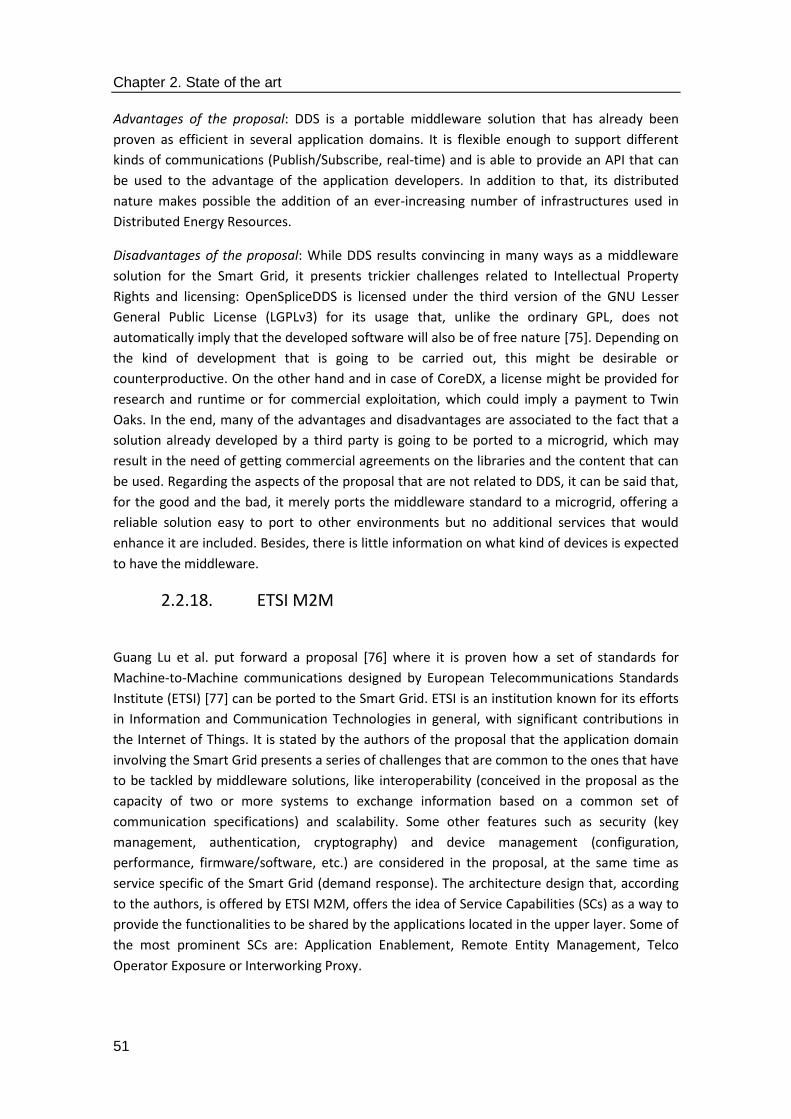
Chapter 2. State of the art
51
Advantages of the proposal: DDS is a portable middleware solution that has already been
proven as efficient in several application domains. It is flexible enough to support different
kinds of communications (Publish/Subscribe, real-time) and is able to provide an API that can
be used to the advantage of the application developers. In addition to that, its distributed
nature makes possible the addition of an ever-increasing number of infrastructures used in
Distributed Energy Resources.
Disadvantages of the proposal: While DDS results convincing in many ways as a middleware
solution for the Smart Grid, it presents trickier challenges related to Intellectual Property
Rights and licensing: OpenSpliceDDS is licensed under the third version of the GNU Lesser
General Public License (LGPLv3) for its usage that, unlike the ordinary GPL, does not
automatically imply that the developed software will also be of free nature [75]. Depending on
the kind of development that is going to be carried out, this might be desirable or
counterproductive. On the other hand and in case of CoreDX, a license might be provided for
research and runtime or for commercial exploitation, which could imply a payment to Twin
Oaks. In the end, many of the advantages and disadvantages are associated to the fact that a
solution already developed by a third party is going to be ported to a microgrid, which may
result in the need of getting commercial agreements on the libraries and the content that can
be used. Regarding the aspects of the proposal that are not related to DDS, it can be said that,
for the good and the bad, it merely ports the middleware standard to a microgrid, offering a
reliable solution easy to port to other environments but no additional services that would
enhance it are included. Besides, there is little information on what kind of devices is expected
to have the middleware.
2.2.18. ETSI M2M
Guang Lu et al. put forward a proposal [76] where it is proven how a set of standards for
Machine-to-Machine communications designed by European Telecommunications Standards
Institute (ETSI) [77] can be ported to the Smart Grid. ETSI is an institution known for its efforts
in Information and Communication Technologies in general, with significant contributions in
the Internet of Things. It is stated by the authors of the proposal that the application domain
involving the Smart Grid presents a series of challenges that are common to the ones that have
to be tackled by middleware solutions, like interoperability (conceived in the proposal as the
capacity of two or more systems to exchange information based on a common set of
communication specifications) and scalability. Some other features such as security (key
management, authentication, cryptography) and device management (configuration,
performance, firmware/software, etc.) are considered in the proposal, at the same time as
service specific of the Smart Grid (demand response). The architecture design that, according
to the authors, is offered by ETSI M2M, offers the idea of Service Capabilities (SCs) as a way to
provide the functionalities to be shared by the applications located in the upper layer. Some of
the most prominent SCs are: Application Enablement, Remote Entity Management, Telco
Operator Exposure or Interworking Proxy.

Chapter 2. State of the art
52
Service availability: the information provided by the authors of the proposal mentions how the
Service Capabilities in the ETSI M2M architecture can be installed in a quite distributed
manner. The proposal is also claimed not to require a specific underlying access technology.
Furthermore, an open API is mentioned as a way for the applications to obtain access to the
middleware. Taking into account that security and device management are also implemented
in the proposal, it can be mentioned that this is a middleware architecture. When applied to
the Smart Grid, there will be a collection of control centres that will gather as particular
domains of a M2M Core that communicates via network with a group of Smart Grid Systems
that include the components that deal with the main facilities of a deployment (generation,
transmission, distribution). Its overall appearance has been displayed in Figure 25.
Figure 25. Structure of the ETSI M2M proposal, as described in [76]
Computational capabilities: it is clearly stated in the proposal that Service Capabilities are
installed in devices as gateways and Machine-to-Machine communication cores, which can be
estimated as regular PC-like or server-like hardware components in a deployment. In addition
to that, since ETSI M2M is based on the Internet of Things, it has been conceived to be
installed in almost any location. Therefore, the proposal could be installed almost anywhere in
a deployment, such as the Advanced Metering Infrastructure of a home dweller, Aggregator,
TSO or DSO equipment or even monitoring the facilities of a power plant.
Message coupling: there is little data about how messages are expected to be transferred.
While it is mentioned once that a real-time automated response is to be expected, the most
predominant idea that has been considered is that there are appliances like servers for
information on power resources or how M2M servers have been included in the proposal, so it
can be said that a Client/Server architecture is the one that is coming closer to how messages
are interchanged. No information available about the existence of a broker is present either,
so it can be assumed that a publish/subscribe paradigm is unlikely to be used in this case.
Middleware distribution: as it usually is the case with IoT-like proposals, this is a mostly
decentralized architecture that is able to run in devices of very different nature, even those
that have limited computational resources. In addition to that, a peer-to-peer paradigm could
be implemented as well, as three are several machines that will communicate with each other

Chapter 2. State of the art
53
(which can be deduced from the preeminence of the concept of M2M in the proposal) without
requiring the intervention of any end user or application with a Graphical User Interface (GUI).
This proposal can be represented by:
SGM = SA (3) + CC (0||1||2||3) + MC (2) + MD (2) (14)
Advantages of the proposal: this middleware architecture covers most of the prominent issues
that have to be tackled in a middleware for the Smart Grid, such as service and API availability,
security or interoperability. Details about how prototyping is performed and the kind of tools
that have been used are profuse and focused on each of the characteristics that have been
deemed as important by the authors (interoperability and scalability, security, device
management, demand response). The fact that this proposal is ported from an IoT application
domain also points out the fact that CPSs share multiple challenges that can be addressed with
a similar kind of solution.
Disadvantages of the proposal: information offered about the challenges and the activities that
have to be carried out to port the set of ETSI M2M standards from the IoT to the Smart Grid is
somehow confusing. While it is mentioned a wide plethora or services that can be added,
sometimes it is not clear how they are implemented, if either a set of protocols cooperating
with each other or as software components that are executed in different pieces of hardware.
Finally, how data messages are transferred from one part of the deployment to the other is
described with too scarce information.
2.2.19. Smart Middleware Device for Smart Grid Integration
Oliveira et al. [78] show in their work regarding middleware how it can be included as another
software component in a single hardware device tailored for Smart Grid integration. One of
the main issues that according to them is yet to be fully dealt with is the integration between
devices and protocols such as Modbus (considered as an standard for the industry application
domain), which would require special gateways in a deployment. This proposal puts forward a
design and implementation for a gateway of this sort, which has been named Smart
Middleware Device (DMI in the Portuguese acronym used by the authors). The appliance is
capable of managing the software components to be used for protocol translations, along with
data flow characteristics. This device is expected to be used as a connector between the power
grid and the ICT domains, as it will be linked to other power stations present in the grid, as well
as to routers included in the network infrastructure.
Service availability: DMI has been conceived as a middleware architecture because it explicitly
mentions a plethora of services that have been developed. According to the authors, though,
the middleware solution will be included just as a part of the device that has been
implemented for that purpose, so it will be present only in one device. As for the services, they
are part of two different groups: the translators and the core components. Translators will be
used as a way to transfer information from the protocols deemed as standards to be
considered by the proposal (Modbus, IEC 61850 and Distributed Network Protocol, version 3; it
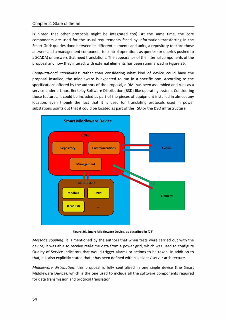
Chapter 2. State of the art
54
is hinted that other protocols might be integrated too). At the same time, the core
components are used for the usual requirements faced by information transferring in the
Smart Grid: queries done between its different elements and units, a repository to store those
answers and a management component to control operations as queries (or queries pushed to
a SCADA) or answers that need translations. The appearance of the internal components of the
proposal and how they interact with external elements has been summarized in Figure 26.
Computational capabilities: rather than considering what kind of device could have the
proposal installed, the middleware is expected to run in a specific one. According to the
specifications offered by the authors of the proposal, a DMI has been assembled and runs as a
service under a Linux, Berkeley Software Distribution (BSD)-like operating system. Considering
those features, it could be included as part of the pieces of equipment installed in almost any
location, even though the fact that it is used for translating protocols used in power
substations points out that it could be located as part of the TSO or the DSO infrastructure.
Figure 26. Smart Middleware Device, as described in [78]
Message coupling: it is mentioned by the authors that when tests were carried out with the
device, it was able to receive real-time data from a power grid, which was used to configure
Quality of Service indicators that would trigger alarms or actions to be taken. In addition to
that, it is also explicitly stated that it has been defined within a client / server architecture.
Middleware distribution: this proposal is fully centralized in one single device (the Smart
Middleware Device), which is the one used to include all the software components required
for data transmission and protocol translation.

Chapter 2. State of the art
55
According to the matrix that was defined before, this proposal can be defined as follows:
SGM = SA (3) + CC (2||3) + MC (3) + MD (0) (15)
Advantages of the proposal: the authors have included information about actual tests that
have been carried out by integrating the DMI with a Smart Meter, and a General Packet Radio
Service (GPRS)-enabled device used by the device of the proposal to send commands and
receive readings. Integration of different kinds of protocols by the same kind of entity is also
addressed by the proposal; translating data representations from one format to the other is
also to be expected considering how middleware is used.
Disadvantages of the proposal: one of the most important decisions taken by the authors of
the proposal is confining the middleware in a single device, which will require having that
device whenever middleware is required, so middleware is not actually providing hardware
abstraction in this case. Overall, there are not many data on how the put forward solutions are
going to be implemented for a distributed environment, and the fact that the middleware will
be located in one single device makes it more vulnerable for the deployment, as middleware
may completely fail in case there is a malfunction on the hardware that has it installed. What is
more, the idea of having a device embodying the concept of middleware can be disorienting,
as it looks as inconsistent with the intention of having middleware as a software layer installed
in several devices and appliances that will negate the differences between them to offer a
homogeneous set of facilities to an upper layer. Lastly, there are some major features like
security, semantics or an API for the application layer, which are not mentioned in the
proposal.
2.2.20. WAMPAC-based Smart Grid communications
Aditya Ashok et al. stress the importance of security in CPSs in their work [79]. Specifically,
they address a Wide-Area Monitoring, Protection and Control subsystem that is included in a
Smart Grid. It is claimed in the proposal that PMUs are the main components of the power grid
that take advantage of the existence of a WAMPAC subsystem, as it leverages the PMUs to
obtain real-time knowledge from the operations that are being carried out in the power grid
where it is installed. According to the authors, WAMPAC can be divided into several different
subdomains: Wide-Area Monitoring Systems (WAMS), Wide-Area Protection Systems (WAP)
and Wide-Area Control (WAC). As it happened with former proposals, the authors rely on a
SCADA system to collect information from outside the middleware. They also provide a
classification on cyber security attacks (timing attacks, data integrity attacks, replay attacks)
that can be performed onto a system. According to the proposal, deploying the different
WAMPAC subsystems can have several challenges: for example, WAMS must be able to
provide high availability, integrity and some degree of confidentiality in utility data.
Furthermore, WAPAC schemes, based to an extent on power-related protocols such as IEC
61850, must guarantee that messages that are transferred ensuring that they have been
authenticated to separate malicious information or commands. Finally, the idea of a real-time
WAC using information from a PMU is planned to be further researched. The proposal makes

Chapter 2. State of the art
56
use of a game theoretic framework in order to model features from both cyber and physical
points of view.
Service availability: the authors´ proposal is an architecture built on the three subdomains that
WAMPAC is made of. WAP, for example, relies on large amounts of information collected from
the whole deployed system, which will be used to enable decisions that will counter
disturbances across the system. Furthermore, WAMS is claimed to be responsible for
distributing information in a reliable way (which involves an infrastructure that must offer
integrity and high availability regarding the PMU data) and needing a high-speed networking
infrastructure. Lastly, WAC is mentioned as a potential way to offer applications as secondary
voltage control, static control or inter-area oscillation damping. The location of the WAMPAC
controller in a deployment is shown in Figure 27. Note that this WAMPAC component that has
been included is regarded as part of a wider Smart Grid deployment bent on solving security
issues, so it is not conceived to be a whole middleware solution.
Figure 27. WAMPAC controller location, as described in [79]
Computational capabilities: even though not very much information is provided about this
feature, it can be said that the WAMPC controller involves networking, security and data
management solutions, so it is supposed to be part of the facilities used for communications
and data interchange between the end users´ equipment and the infrastructure used to
generate electricity, that is to say, the TSO and DSO pieces of equipment.
Message coupling: as it happened with the former case, there are few data to get a grasp
about how messages are transferred, except for the idea that securitization must be provided.
Nevertheless, real-time communications are mentioned as the most usual ones that take place
in the proposal scenario. Furthermore, the approach taken by the North American Synchro-
Phasor Initiative (NASPI) regarding secure synchronized data measurement infrastructure
Chapter 2. State of the art
57
(NASPInet, [80]), where a Publisher/Subscribe component has been implemented, is
mentioned in the proposal as a known solution.
Middleware distribution: while the proposal makes use of a distributed domain for information
interchange, and it is included in a distributed system as the Smart Grid is, it is not made clear
how devices are expected to be deployed where the proposal can be installed. Considering the
kind of infrastructure mentioned in the proposal, it can be claimed that it will be a mostly
decentralized solution, as the WAMS component requires a network for data delivery.
This proposal can be further described as:
SGM = SA (3) + CC (2||3) + MC (0||3) + MD (2) (16)
Advantages of the proposal: security is strongly tackled in the proposal and it is made clear
how the Smart Grid can be securitized against the most damaging attacks. Also, the concept of
using a game theory framework as a tool for security in Cyber-Physical Systems is interesting
and offers a different point of view on how to address it. The authors of the proposal have also
provided a justification of how a testbed can be implemented to test security in a Smart Grid-
like deployment when game formulations are involved.
Disadvantages of the proposal: while the focus of the proposal on security is welcomed, as it is
a functionality of major importance in a distributed system, there is less information about all
the other services expected to be part of a middleware architecture (semantics, API, etc.).
Clearly, the main idea that the authors want to transmit is that they have created a system
capable to provide secure communications, rather than a middleware solution with several
services encased.
2.2.21. C-DAX
Michael Hoefling et al. [81] provide their own vision of what a secure middleware should be
according to what has been designed in the research project called Cyber-secure Data and
Control Cloud for power grids (C-DAX, [82]). As it was presented in other proposals, their
solution is focused on solving security issues found in data exchanges for the Smart Grid (the
authors refer to Active Distribution Networks or ADNs). Facilities that are likely to make use of
this proposal according to the criteria of the authors are: Phasor Measurement Units (PMUs),
the ones related to Real-Time State Estimation (RTSE) and Phasor Data Concentrators (PDCs).
RTSE applications are described as receiving aggregated information from the PDCs and
feeding it in a mathematical model used to estimate the current conditions of the grid. PDCs
are used for the reception of data that have been timestamped (refreshed at a frequency of 50
Hz), time-aligned and aggregated from different PMUs. Information is sent throughout a
deployment with this solution according to topics established to separate one kind of content
from the others. These topics are defined as representations of abstract nature used for
unidirectional information channels with a certain storage capacity. PMU measurement is
made by using NASPInet (North American Synchro-Phasor Initiative Network) as the protocol.

Chapter 2. State of the art
58
Service availability: the middleware that has been prepared for this project can be regarded as
a Message-Oriented Middleware, considering that the main efforts of the proposal are centred
in creating a secure procedure for the interchange of messages in the deployment, instead of
offering a collection of services that will be contained in the software infrastructure chosen for
the middleware. Two planes of information have been defined as a way to organize the data:
control plane and data plane; the latter is utilized in combination with Designated Nodes (DNs)
that grant access to the cloud used to implement the middleware proposal for the C-DAX
project. Data Brokers (DBs) are used as a way to either store or send forward information.
Finally, there is a Monitoring and Management System devoted to monitor and control the
deployed devices. The overall appearance of the proposal has been displayed in Figure 28.
Computational capabilities: the proposal is expected to use pieces of equipment that are to be
expected according to a regular Information and Communication Technologies deployment. It
is also mentioned in the proposal that in order to perform the tests, a 100 Mbit/s link has been
used. Therefore, and taking into account that the proposal deals mostly with data transmission
and securitization, it can be inferred that it is expected that TSO or DSO infrastructure will be
the main beneficiaries of the security measures that are described by the authors. In addition
to that, pieces of equipment present in power stations may also welcome having the proposal
installed, as it will add security to information of critical importance for their performance, as it
will depend on the feedback obtained from a Smart Grid.
Figure 28. C-DAX middleware appearance, as described in [81]
Message coupling: the proposal makes possible several different ways to establish
communications. The authors distinguish three of them: streaming communication mode
(where subscribers receive topic data after becoming part of one of them in a continuous, non-
interrupted way), query communication mode (subscribers send explicit data queries) and

Chapter 2. State of the art
59
point-to-point communications (without using Designated Nodes or Data Brokers). However, it
can be said that there are two different paradigms in the proposal that are heavily mentioned
and used. On the one hand, real-time data are required to be taken into account, as they
usually imply information obtained from the smart meters deployed in the Smart Grid
deployment in an almost instantaneous fashion. On the other hand, information is published
throughout the data plane (and by means of the designated nodes that are at both ends) using
a Publish/Subscribe paradigm, where application data is published in one end of the
communication and is consumed by the subscribed located at the other end. It is explicitly
stated by the authors that one of the objectives of the project is to adapt the
Publish/Subscribe paradigm to the needs of power grids. Finally, Client/Server communications
are discouraged by the authors of the proposal, claiming that they demand servers to be
configured properly and clients have to be re-configured when they have to establish
connections with backup servers.
Middleware distribution: the proposal is a mostly decentralized middleware solution due to
the fact that it is distributed in several different pieces of equipment that are part of the ICT
infrastructure of the Smart Grid (subscribers, publishers, databases) and a communication
infrastructure has been used in order to perform tests on the proposal. Since there are
elements that manage data reception and delivery (such as the Data Brokers) there will be still
some more prominence of several software elements over others, thus proving that the
solution is not entirely peer-to-peer, with similar features in each of the nodes where the
proposal has been installed.
This proposal can be described as:
SGM = SA (2) + CC (2||3) + MC (0) + MD (2) (17)
Advantages of the proposal: the authors offer a compelling proposal that has been tested in a
realistic scenario (a laboratory belonging to one of the project partners). There are several
scenarios that have been consider for testing activities, being failing DBs one of them.
Disadvantages of the proposal: The number of services included in the proposal is more
modest than in other ones, due to its condition of being a Message-Oriented Middleware. No
information is provided regarding an API to be offered to the higher levels as a specific way to
interact with the middleware shown here.
2.2.22. Building as a Service (BaaS)
The main concept that has been implemented in the proposal led by Susana Martin et al. is the
usefulness of the Smart Grid for energy efficiency in buildings [83]. According to the authors,
buildings can be used to obtain services from them (hence the term Building as a Service) by
developing a middleware solution used to link a collection of entities of a CPS that stresses the
importance of energy consumption. The Open Services Gateway initiative (OSGi, [84]), which is
claimed to offer openness, interoperability and transparency, offers interfaces in the
implementation works required for the solution. Several other ideas common to this kind of

Chapter 2. State of the art
60
application domain (Event-Driven Architecture, Service-Oriented Architecture) have also been
included in the proposal. Interoperability among several interlinked entities is provided by
integrating Building Information Models (BIMs), Data Warehouses (so as to store information
as a whole) and Building Management Systems (BMSs) and the legacy ICT facilities as a single
system. Furthermore, services based on optimal control, prediction and assessment have been
included too.
Service availability: The proposal is considered to be a middleware architecture due to the fact
that it has included several devices that are distributed in different layers. However, the only
software component regarded as middleware by the authors of the proposal is the
Communication Logic Layer or CLL. It is encased with two more levels as part of the
intermediation architecture defined for this proposal, that is to say, the Application Layer and
the Data Layer. The Data Layer has included information dealing with the services related to
the building used for the BaaS concept (for example, the ICT infrastructure for weather and
access control), the Data Warehouse infrastructure, the Building Information Modelling Server
and the external services responsible for collection information. The Communication Logic
Layer is composed by two sub levels: the Core Communication and the Data Access Object
sublayer. The first one consists of the Domain Controllers or DCs and the Data Acquisition
Control Manager or DACM. The second one adds the Data Access Objects for the DC and the
DACM. Figure 29 shows the overall appearance of the proposal.
Figure 29. High level architecture of the BaaS system part of the proposal, as described in [83]
Chapter 2. State of the art
61
Computational capabilities: the software components that the middleware architecture is
made of are implemented as OSGi-bundles that are usually on the kilobyte or the megabyte
scale, so it is easy to install the software in any kind of piece of hardware with normal and even
low capabilities. Considering that data is being obtained from sensors it can be argued that the
middleware solution can be installed in any intermediate piece of equipment belonging to the
Aggregator, the TSO or the DSO.
Message coupling: it is explicitly said in the proposal that this middleware has been conceived
for applications that follow a Client/Server architecture. Additionally, it is mentioned that the
proposal has been designed taking SOA and EDA concepts into account and a modular event-
driven design has been created. On the other hand, it is added that components can be
subscribed to events in an EDA architecture, so it is subtly implied that there could some kind
of Publish/Subscribe system. However, this point is never mentioned explicitly, so a
Client/Server approach should still be considered as the one that is used here.
Middleware distribution: the proposal is a mostly decentralized one due to the fact that while
it is distributed in different elements that are independent from each other (the buildings)
there are still some elements that have a higher degree of responsibility than others, such as
the Data Acquisition and Control Manager.
Considering all these features, this middleware proposal can be described like this:
SGM = SA (3) + CC (1||2) + MC (2) + MD (2) (18)
Advantages of the proposal: the proposal makes use of an API for data interchange that makes
it easier for application developers to access the middleware solution, and how levels are
interfaced with each other is made clear. Moreover, the usage of OSGi technologies is
consistent with the idea of having open source software technologies for the middleware,
which is a desirable feature for further scalability and improvement of the implementation
works done. Finally, the proposal makes use of a collection of standardized technologies that
ease the replication and implementation of software solutions. The proposal makes use of
software technologies of widespread usage that have proven to be useful, such as Java
Database Connectivity (JDBC) in the Data Warehouse component, JavaScript Object Notation
(JSON) for the Building Information Model or Simple Object Access Protocol (SOAP) in the
Building Management System.
Disadvantages of the proposal: Services of major importance to be encased by a middleware
solution that are related to security or the semantic enhanced of information are not present
in this related work. Furthermore, it is very centered on the idea of using it only for energy
consumption in buildings, which may make challenging to port the middleware architecture to
other applications related to the Smart Grid, or even other Cyber-Physical System.
2.2.23. Middleware-based management for the Smart Grid
Villa et al. put forward in their proposal [85] how a hardware platform can be used to manage,
control and integrate electrical installations that are large scale and heterogeneous.

Chapter 2. State of the art
62
Specifically, they refer to it as Embedded Metering Devices (EMDs), capable of controlling
pieces of equipment that require no parameters to be changed. Among the features that are
claimed to be enabled by the authors, adaptability (EMDs for devices that require no changes),
scalability, availability (segments of the network can continue working in an autonomous way
in case of failure) and hierarchical design are the most prominent ones. Other advantages
related to the hardware and its components are: its small size and cost, low energy
consumption, flexible access, access transparency and conventional tools. The proposal aims
to have a generic platform capable of develop power management services for any kind of
environment. It should be noted that the main interest of the authors is regarding the device
as Advanced Metering Infrastructure, rather than software components to be installed in one
piece of hardware in a microgrid.
Service availability: while there is very scarce information about the services that can be
provided, it can be said that the software used for device interconnectivity is solely employed
for that purpose. Consequently, it is a hardware abstraction kind of middleware where no
other services are offered as part of the deployed hardware. What is more, there are no
mentions on how the middleware is accessed by any other higher layer (in case it is a
possibility), so the existence of an API is unlikely. The main hardware elements that are to be
mounted on a node that is using the device (Bluetooth interfaces, the microcontroller or the
very Embedded Metering Device) are present in Figure 30.
Figure 30. Block diagram of the EMD structure, as described in [85]
Computational capabilities: the proposal aims very specifically to be a scalable piece of
Advanced Metering Infrastructure, so it has been aimed to be part of the AMI infrastructure
that an end consumer/prosumer would have in their dwell or store. No other location of a
Smart Grid deployment (TSO, DSO, Aggregator or power plant) is expected to be used to have
the software components related to the middleware installed.
Message coupling: it is stated by the authors that their prototypes were working under CORBA
[86] and the Internet Communications Engine (Ice, which provides a Remote Procedure Call

Chapter 2. State of the art
63
protocol using standards from the transport layer [87]), so it essentially works under a
Client/Server paradigm.
Middleware distribution: since the middleware solution is strongly linked to the hardware
where it has been installed, it has been considered as a mostly centralized proposal that is
running in a single kind of element (AMI) that is likely to be present in the facilities of many
end users.
Bearing all these features in mind, the proposal can be described as:
SGM = SA (0) + CC (0) + MC (2) + MD (1) (19)
Advantages of the proposal: the authors have made a great effort in creating a realistic way to
have a piece or AMI capable of establishing connections with other parts of any possible
deployed infrastructure of this sort by using middleware in it. Besides, they take into account
aspects like the cost or the size that are usually not considered for prototyping purposes in
other pieces of work.
Disadvantages of the proposal: the proposal is too focused on the hardware components that
have been mounted in order to have EMDs that can be considered as a scalable AMI, so the
limitations of the proposal come from that fact. Moreover, the EMD shown here basically
makes use of CORBA and Ice as the actual middleware implemented within it, so it is not
possible to use any other standard or a more novel solution that what is being provided here.
Therefore, in order to port the software elements to other part of a Smart Grid, a significant
recoding work is likely to be needed. In addition to that, software-related features such as
security, semantics for information enhancement, or offering a specific API to access the
services that may be provided by the device, are not stated in the proposal.
2.2.24. OpenNode Smart Grid architecture
Florent Leménager et al. offer their own novel concepts for a middleware solution focused on
the Smart Grid [88]. They show the implementation works that have been made as part of the
OpenNode project [89]. In the proposal, it is shown that there is a collection of key concepts
(modularity, extensibility, distribution of intelligence, an open common reference architecture,
usage of open standards and cost effectiveness) of major importance by the authors. The
efforts carried out in this proposal have been directed to creating an open development for
Secondary Substation Nodes (SSNs) located within secondary substations of the power grid,
and a middleware solution used to interconnected the SSN with the utility systems related to
the electrical facilities and infrastructures. It is mentioned by the authors that the middleware,
always regarded as something separated from the SSNs and running above them, is used to
deal with the stakeholder diversification and the flexibility needed to interoperate among the
power grid, the network and the management methods.
Service availability: judging from the information available in the proposal, the middleware is
solely focused on hardware abstraction, as there is no information about the kind of services
that could be encased in the middleware proposal or in any message format interchanged
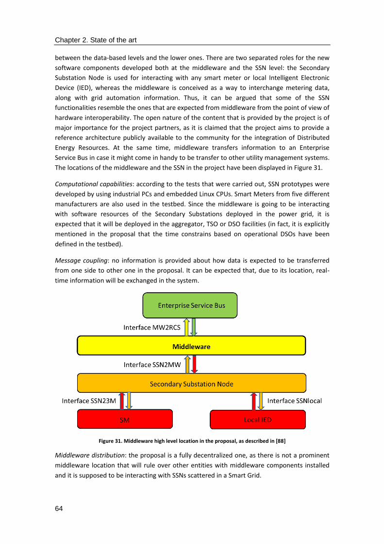
Chapter 2. State of the art
64
between the data-based levels and the lower ones. There are two separated roles for the new
software components developed both at the middleware and the SSN level: the Secondary
Substation Node is used for interacting with any smart meter or local Intelligent Electronic
Device (IED), whereas the middleware is conceived as a way to interchange metering data,
along with grid automation information. Thus, it can be argued that some of the SSN
functionalities resemble the ones that are expected from middleware from the point of view of
hardware interoperability. The open nature of the content that is provided by the project is of
major importance for the project partners, as it is claimed that the project aims to provide a
reference architecture publicly available to the community for the integration of Distributed
Energy Resources. At the same time, middleware transfers information to an Enterprise
Service Bus in case it might come in handy to be transfer to other utility management systems.
The locations of the middleware and the SSN in the project have been displayed in Figure 31.
Computational capabilities: according to the tests that were carried out, SSN prototypes were
developed by using industrial PCs and embedded Linux CPUs. Smart Meters from five different
manufacturers are also used in the testbed. Since the middleware is going to be interacting
with software resources of the Secondary Substations deployed in the power grid, it is
expected that it will be deployed in the aggregator, TSO or DSO facilities (in fact, it is explicitly
mentioned in the proposal that the time constrains based on operational DSOs have been
defined in the testbed).
Message coupling: no information is provided about how data is expected to be transferred
from one side to other one in the proposal. It can be expected that, due to its location, real-
time information will be exchanged in the system.
Figure 31. Middleware high level location in the proposal, as described in [88]
Middleware distribution: the proposal is a fully decentralized one, as there is not a prominent
middleware location that will rule over other entities with middleware components installed
and it is supposed to be interacting with SSNs scattered in a Smart Grid.

Chapter 2. State of the art
65
Consequently, this proposal can also be described like:
SGM = SA (0) + CC (1||2) + MC (3) + MD (3) (20)
Advantages of the proposal: the authors ensure that what has been developed will have a high
degree of applicability to the power grid in order to enhance its performance. Furthermore,
the proposal has been tested in several realistic scenarios where two physical and one virtual
tests were carried out.
Disadvantages of the proposal: the proposal relies in middleware only to transfer information
from the Secondary Substation Node to the Enterprise Service Bus that is used to interchange
information with other utility deployments. Besides, data about major characteristics of the
middleware are absent, such as how data messages are transferred from one area to the other
or how to enable semantic capabilities or security as components of the middleware solution.
2.2.25. DIRECTOR
James Wilcox and Mahesh Sooriyabandara present what they refer to as a distributed
communication transport manager for the Smart Grid [90]. It is expected from DIRECTOR that
it will be able to manage the requirements of application communications throughout a Smart
Grid. It has been placed by the authors between the application layer and the socket
Application Programming Interfaces located right below the DIRECTOR middleware layer. It is
claimed to instruct those sockets to generate an optimised interface that supports application
needs to its best possible. Messages in the middleware domain contain the work payload, a list
of destinations and the priority of the message.
Service availability: among what the proposal is capable of providing, hardware abstraction is
the most prominent and obvious service. However, message orientation is also strong, stating
that the socket configuration can be changed when sending them and different levels of
bandwidth efficiency are required, so it has been regarded as an intermediation middleware.
According to the authors, the DIRECTOR middleware is made up by several functionalities: an
application interface (conceived as an inter-process communication transport socket), network
health (offered by monitoring data exchanges over an Ethernet bridge), a custom transport
layer (generated after considering the inputs provided both by the application interface and
the network health information) and a software component used for custom socket (generated
with negotiated transport features). The location of the middleware layer has been displayed
in Figure 32.

Chapter 2. State of the art
66
Figure 32. Location of the DIRECTOR proposal in a Smart Grid deployment, as stated in [90]
Computational capabilities: the proposal can be installed in almost any piece of equipment
present in the Smart Grid, as tests were carried out in five Raspberry Pi platforms that,
according to the authors and the specifications of the Raspberry Pi model B [91] have a 700
MHz ARM processor and 512 MB of Random Access Memory (RAM). Therefore, and
considering that a smart meter can be implemented out of a Raspberry Pi, even hardware
located at the end user´s facilities could handle the computational requirements of the
middleware solution, let alone any other piece of equipment in the aggregator, TSO, DSO or
power plant.
Message coupling: the proposal mentions that it has been conceived for distributed and real-
time embedded systems, so it must be capable of transferring that kind of information.
Furthermore, a virtualized Demand Response Automation Server has been used to simulate an
actual Demand Response scenario.
Middleware distribution: it can be regarded as a fully decentralized middleware architecture
that works under a peer-to-peer level, due to the fact that there is not a single component that
adds an extra prominence when compared to all the others. However, this is due to the fact
that no Publish/Subscribe (and thus, centralizing elements such as brokers) or any other
message interchange paradigm is ever used.
Therefore, this architecture can be described as follows:
SGM = SA (1) + CC (0||1||2||3) + MC (3) + MD (3) (21)
Advantages of the proposal: DIRECTOR has been tested under a deployment using hardware
easy to find in a more realistic scenario (such as a microgrid, a power plant, etc.). The solution
makes use of a data model to exemplify how applications would work. Lastly, the location of
the proposal in a distributed system is made very clear, as it is aimed to be placed between the
application layer and the sockets that are used for transport layer communications.
Disadvantages of the proposal: there are no mentions about how security or semantic
capabilities can be added to the proposal, or any service that may go beyond interoperability

Chapter 2. State of the art
67
among different devices. Besides, the proposal seems to be just involved in the messages that
are sent through the transport layer but shows less information about how the information is
transferred to the application layer, or the kind of APIs that are available for that level. As far
as message coupling is concerned, it is not easy to figure out the kind of criteria that has been
used in the proposal to use one paradigm or another.
2.2.26. DDS interoperability for the Smart Grid
As it happened with a former one, the proposal of Tarek A. Youssef et al. makes use of Data
Distribution Service as a way to provide middleware to the Smart Grid [92]. DDS is utilized
combined with data structures and standard interfaces in order to have a scalable Smart Grid
infrastructure that can be used in the testbed utilized to assess the feasibility of the
hypotheses formulated. It is claimed that it makes possible integration with other
deployments, experimentation, data gathering and algorithm testing. At the same time, DDS
enables the system to establish a global Data Space where data structures are used to
generate information that can be interchanged under a Publish/Subscribe paradigm.
Interoperability is guaranteed by means of Real Time Publish Subscribe Protocol (RTPS), the
DDS lower level layer used for this purpose, whereas an API is provided for the higher levels to
access the middleware services.
Service availability: the proposal is bent on providing connectivity between the devices present
in the testbed and the applications that would be requested by the end users. The authors
focus on the idea of providing a gateway for each of the applications that are estimated to be
required in a Smart Grid deployment. These gateways will be used as a way to provide an
Application Programming Interface for the topmost level of the architecture to access the
middleware facilities. Therefore, it can be said that this is an example of Message-Oriented
Middleware rather than an architecture with several distinguished devices. The most
foreseeable services to be included have been depicted in Figure 33.
Figure 33. Testbed for the DDS infrastructure, as described in [92]
Computational capabilities: the proposal is expected to be installed in devices capable of
handling DDS, so a regular computer should be able to handle it. Regarding the pieces of
equipment expected to be included here, PC- or server-like appliances belonging to the
aggregator and the TSO/DSO are likely to encase the software components of the proposal.
Message coupling: DDS strongly relies on a Publish/Subscribe paradigm to deliver data;
consequently, it is used in this proposal as well, in order to deliver information related to the
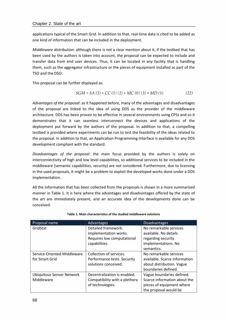
Chapter 2. State of the art
68
applications typical of the Smart Grid. In addition to that, real-time data is cited to be added as
one kind of information that can be included in the deployment.
Middleware distribution: although there is not a clear mention about it, if the testbed that has
been used by the authors is taken into account, the proposal can be expected to include and
transfer data from end user devices. Thus, it can be located in any facility that is handling
them, such as the aggregator infrastructure or the pieces of equipment installed as part of the
TSO and the DSO.
This proposal can be further displayed as:
SGM = SA (2) + CC (1||2) + MC (0||3) + MD (1) (22)
Advantages of the proposal: as it happened before, many of the advantages and disadvantages
of the proposal are linked to the idea of using DDS as the provider of the middleware
architecture. DDS has been proven to be effective in several environments using CPSs and so it
demonstrates that it can seamless interconnect the devices and applications of the
deployment put forward by the authors of the proposal. In addition to that, a compelling
testbed is provided where experiments can be run to test the feasibility of the ideas related to
the proposal. In addition to that, an Application Programming Interface is available for any DDS
development compliant with the standard.
Disadvantages of the proposal: the main focus provided by the authors is solely on
interconnectivity of high and low level capabilities, so additional services to be included in the
middleware (semantic capabilities, security) are not considered. Furthermore, due to licensing
in the used proposals, it might be a problem to exploit the developed works done under a DDS
implementation.
All the information that has been collected from the proposals is shown in a more summarized
manner in Table 1. It is here where the advantages and disadvantages offered by the state of
the art are immediately present, and an accurate idea of the developments done can be
conceived.
Table 1. Main characteristics of the studied middleware solutions
Proposal name Advantages Disadvantages
GridStat Detailed framework. Implementation works. Requires low computational capabilities.
No remarkable services available. No details regarding security implementations. No semantics.
Service-Oriented Middleware for Smart Grid
Collection of services. Performance tests. Security solutions conceived.
No remarkable services available. Scarce information about distribution. Vague boundaries defined.
Ubiquitous Sensor Network Middleware
Decentralization is enabled. Compatibility with a plethora of technologies.
Vague boundaries defined. Scarce information about the pieces of equipment where the proposal would be
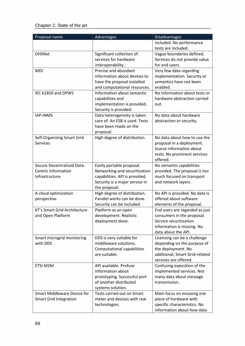
Chapter 2. State of the art
69
Proposal name Advantages Disadvantages
included. No performance tests are included.
OHSNet Significant collection of services for hardware interoperability.
Vague boundaries defined. Services do not provide value for end users.
MDI Precise and abundant information about devices to have the proposal installed and computational resources.
Very few data regarding implementation. Security or semantics have not been enabled.
IEC 61850 and DPWS Information about semantic capabilities and implementation is provided. Security is provided.
No information about tests or hardware abstraction carried out.
IAP-INMS Data heterogeneity is taken care of. An ESB is used. Tests have been made on the proposal.
No data about hardware abstraction or security.
Self-Organizing Smart Grid Services
High degree of distribution. No data about how to use the proposal in a deployment. Scarce information about tests. No prominent services offered.
Secure Decentralized Data-Centric Information Infrastructure
Easily portable proposal. Networking and securitization capabilities. API is provided. Security is a major service in the proposal.
No semantic capabilities provided. The proposal is too much focused on transport and network layers.
A cloud optimization perspective
High degree of distribution. Parallel works can be done. Security can be included.
No API is provided. No data is offered about software elements of the proposal.
KT’s Smart Grid Architecture and Open Platform
Platform as an open development. Realistic deployment done.
End users are regarded as just consumers in the proposal. Service securitization information is missing. No data about the API.
Smart microgrid monitoring with DDS
DDS is very suitable for middleware solutions. Computational capabilities are suitable.
Licensing can be a challenge depending on the purpose of the deployment. No additional, Smart Grid-related services are offered.
ETSI M2M API available. Profuse information about prototyping. Successful port of another distributed systems solution.
Confusing exposition of the implemented services. Not many data about message transmission.
Smart Middleware Device for Smart Grid Integration
Tests carried out on Smart meter and devices with real technologies.
Main focus on encasing one piece of hardware with specific characteristics. No information about how data
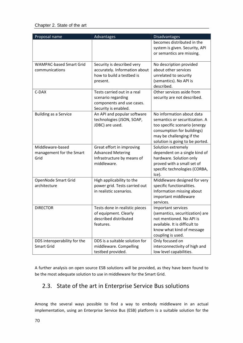
Chapter 2. State of the art
70
Proposal name Advantages Disadvantages
becomes distributed in the system is given. Security, API or semantics are missing.
WAMPAC-based Smart Grid communications
Security is described very accurately. Information about how to build a testbed is present.
No description provided about other services unrelated to security (semantics). No API is described.
C-DAX Tests carried out in a real scenario regarding components and use cases. Security is enabled.
Other services aside from security are not described.
Building as a Service An API and popular software technologies (JSON, SOAP, JDBC) are used.
No information about data semantics or securitization. A too specific scenario (energy consumption for buildings) may be challenging if the solution is going to be ported.
Middleware-based management for the Smart Grid
Great effort in improving Advanced Metering Infrastructure by means of middleware.
Solution extremely dependent on a single kind of hardware. Solution only proved with a small set of specific technologies (CORBA, Ice).
OpenNode Smart Grid architecture
High applicability to the power grid. Tests carried out in realistic scenarios.
Middleware designed for very specific functionalities. Information missing about important middleware services.
DIRECTOR Tests done in realistic pieces of equipment. Clearly described distributed features.
Important services (semantics, securitization) are not mentioned. No API is available. It is difficult to know what kind of message coupling is used.
DDS interoperability for the Smart Grid
DDS is a suitable solution for middleware. Compelling testbed provided.
Only focused on interconnectivity of high and low level capabilities.
A further analysis on open source ESB solutions will be provided, as they have been found to
be the most adequate solution to use in middleware for the Smart Grid.
2.3. State of the art in Enterprise Service Bus solutions
Among the several ways possible to find a way to embody middleware in an actual
implementation, using an Enterprise Service Bus (ESB) platform is a suitable solution for the

Chapter 2. State of the art
71
challenges that may be found in the Internet of Things. Typically, an ESB will contain several
features to guarantee that interoperability can be provided:
1. Rather than having a massive number of point-to-point mesh-based communications
between the integrated applications, which would be impractical and a source of
delays, a bus is used to connect them all and transfer the data. This enables the good
usage of the software entity used for data transfer.
2. An ESB hides away the heterogeneity and complexity of the services and applications
that is interconnecting, so it fits in accurately with the purpose of middleware.
3. An ESB allows the usage of software packages (bundles) that make possible their port
from one deployment to a different one, thus saving time and resources in
development works.
The position of an ESB (and of middleware when it is embedded in an ESB) in a CPS-based
deployment (with similar features that can be found in a Smart Grid from the software point of
view) has been depicted in Figure 34. Note that apart from the services that it is
interconnecting, the ESB is capable of containing some more if required (device registration,
securitization), so it effectively becomes a way to implement a middleware architecture.
Figure 34. ESB location and most usual services in a Cyber-Physical System
The study that has been done about the state of the art in Enterprise Service Bus solutions
focuses only on the ones that are offered under open source agreements. The motivation to
do it like this is because two reasons:
1. From a purely economic point of view, it is much more convenient to use an open
source solution, as they usually offer a number of services and interfaces enough for
the idea of providing a middleware architecture for the Smart Grid. While open source

Chapter 2. State of the art
72
solutions usually offer a weaker support than commercial ones, the development and
integration issues that may be found are usually likely to have taken place before, so
there is usually a way to solve them. However, having a strong community behind an
ESB solution is more important here than in other solutions were support is a paid
service.
2. As far as the research projects where implementation works were done are
concerned, a non-open source ESB was never considered as an eligible solution due to
the European Commission policies, which favour the usage of open source solutions,
and the utilization of inexpensive tools that will not challenge budget requests.
The most interesting options that have been found matching the previous requirements have
been listed in the following subsections.
2.3.1. OpenESB
According to their developers, OpenESB is an open-source ESB written in Java and expected to
be used as a platform with a dual purpose: enterprise application integration (the original
purpose that ESBs were designed for) and a service-oriented architecture (much closer to what
a middleware architecture represents), as mentioned in [93]. It is claimed by its creators that
“OpenESB is the unique open source ESB relying on standards that provides you with Simplicity,
Efficiency, Long term durability, save on your present and future investments with a very low
TCO (Total Cost of Ownership)” [94]. OpenESB makes use of Java Business Integration (JBI) as a
way to provide an architecture that will encase components for service production and
consumption [95]. It is maintained by the OpenESB community that was created after Sun
Microsystems was purchased by Oracle. This ESB has five different parts organized as follows:
1. Framework: it is an implementation of JBI claimed to be lightweight [96]. Even though
it works in close cooperation with the used container, the framework remains
container-agnostic, so one can be chosen among a plethora of them. The framework
is encased in a Java Virtual Machine (JVM) that makes use of binding components to
communicate with other frameworks. In addition to that, it is claimed to be fully
manageable by Java Management Extensions (JMX)-related tools. Lastly, the
framework is the part that contains the virtual bus (named Normalised Message
Router) to be utilized in this ESB.
2. Container: the container can be regarded as the application server used to store the
facilities that might be needed by the applications. OpenESB is claimed to be capable
of processing more than 10 million complete messages per day [10] that use this
container to be transferred. The current version of OpenESB has six different
containers available: GlassFish Version 2 [97] (the one that is included by default),
JBoss [98] Version 4, Version 5 and Version 7 and the vey used JVM.
3. Components: these are the software entities able to deliver the ESB the facilities used
to transfer information. There are two different kinds of them: one is the Services
Engine and the other one is the Binding Component. The former are used for receiving
and sending messages to the bus, without dealing with any messages that have to be

Chapter 2. State of the art
73
sent outside it, whereas the latter interacts with messages outside the defined bus,
but can generate either messages that will be sent inside the bus or messages
transferred within the bus that leave it afterwards.
4. Integrated Development Environment and development plugins: it refers to the facility
that is used for programming, debugging and testing the code that is produced. They
usually include any plugging that is required for code generation. XML Schema
Definition (XSD), WSDL, Business Process Execution Language (BPEL), Data Mapper and
Composite Application editors are available to build, deploy, un-deploy, run, test and
perform debugging tasks.
It is also noteworthy to mention that an OpenESB instance is able to work with both legacy
solutions, which are dealt with by Domains and Node Agents working together with a Glassfish
application server, and standalone stacks (that rely solely on an OpenESB instance making use
of a Java Virtual Machine) [99]. A comparison of what is required for each of the iterations can
be seen in Figure 35.
Figure 35. Legacy and standalone required software components, as described in [99]
As it can be inferred, OpenESB works in a way that implies that messages are sent from and to
the applications accessing the bus where the legacy and the standalone stack are used. These
messages will be sent via Binding Components and Services engines when they are required to
travel inside the bus. All these components will be included in a selected container provided by
a framework, and they will be worked upon by means of the Integrated Development
Environment and the development plugins added to the distribution. One key feature of
OpenESB is its openness; it is provided under a Common Development and Distribution License
(CDDL) that makes possible providing a world-wide, royalty-free, non-exclusive license that

Chapter 2. State of the art
74
enables the owner of the licensed software to use, reproduce, modify, display, perform,
sublicense and distribute the original software [100].
OpenESB provides a good framework for services and delivers messages to the applications
that require them. It has a foreseeable behaviour as it uses a bus to transport all the
information required to interconnect the applications that have been distributed. However,
the fact that is focused on one single programming language might be an issue for developers
that are not proficient with that programming language.
2.3.2. WSO2 ESB
As it happened with the previous proposal, this iteration of the Enterprise Service Bus is
claimed to be lightweight. In addition to that, it also has an open source development that
explicitly regards itself as middleware conceptually relying on a SOA approach. Among the
main features that are supported [101] the most important ones are:
1. WSO2 ESB makes use of WSO2 Carbon as the core of the platform, which provides a
componentized architecture able to adapt business activity automatically in response
to market events.
2. This proposal is expected to offer seamless adaptation among public, private and
hybrid clouds, along with on premise solutions.
3. The developers of this proposal say WSO2 is optimized for the Internet of Things. The
architecture offers a server-side and a cloud-based Reference Architecture so that the
developers working on the IoT can use it as a starting point.
4. Flexibility is also a stressed feature: all the products linked to the proposal are said to
be completely based on open source solutions and open standards. Legacy and
package apps are integrated in WSO2, and the developers are able to extend the
platform and customize it if required.
5. The possibility of having an Original Equipment Manufacturer (OEM) is also offered in
order to offer subsystems for an end product provided by a third party.
Figure 36 shows the most important services that the WSO2 architecture is capable of
providing; security for the deployed components, facilities for portals and stores (namely,
asset storage), device management focused on mobile devices and the IoT, app development
and management (working closely with what can be offered to portals and stores), API
management (interweaved with the integration functionalities and the facilitates offered to
portals and stores, as they require the services of an API to provide their own functionalities),
integration by means of connectors with legacy systems and other facilities (along with service
orchestration and composition) and analytics services. Note that several of them make use of
other functionalities in order to offer their own, whereas there are some other services
delivered in all the involved levels of the communication (such as security or analytics).
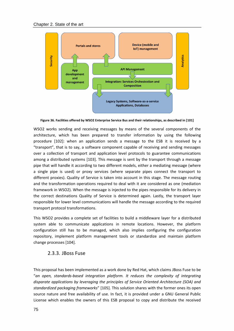
Chapter 2. State of the art
75
Figure 36. Facilities offered by WSO2 Enterprise Service Bus and their relationships, as described in [101]
WSO2 works sending and receiving messages by means of the several components of the
architecture, which has been prepared to transfer information by using the following
procedure [102]: when an application sends a message to the ESB it is received by a
“transport”, that is to say, a software component capable of receiving and sending messages
over a collection of transport and application level protocols to guarantee communications
among a distributed systems [103]. This message is sent by the transport through a message
pipe that will handle it according to two different models, either a mediating message (where
a single pipe is used) or proxy services (where separate pipes connect the transport to
different proxies). Quality of Service is taken into account in this stage. The message routing
and the transformation operations required to deal with it are considered as one (mediation
framework in WSO2). When the message is injected to the pipes responsible for its delivery in
the correct destinations Quality of Service is determined again. Lastly, the transport layer
responsible for lower level communications will handle the message according to the required
transport protocol transformations.
This WSO2 provides a complete set of facilities to build a middleware layer for a distributed
system able to communicate applications in remote locations. However, the platform
configuration still has to be managed, which also implies configuring the configuration
repository, implement platform management tools or standardize and maintain platform
change processes [104].
2.3.3. JBoss Fuse
This proposal has been implemented as a work done by Red Hat, which claims JBoss Fuse to be
“an open, standards-based integration platform. It reduces the complexity of integrating
disparate applications by leveraging the principles of Service Oriented Architecture (SOA) and
standardized packaging frameworks” [105]. This solution shares with the former ones its open
source nature and free availability of use. In fact, it is provided under a GNU General Public
License which enables the owners of this ESB proposal to copy and distribute the received
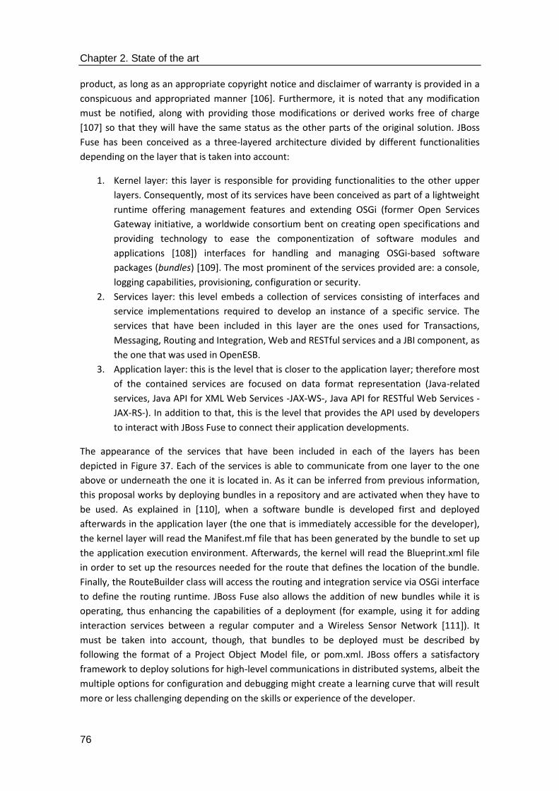
Chapter 2. State of the art
76
product, as long as an appropriate copyright notice and disclaimer of warranty is provided in a
conspicuous and appropriated manner [106]. Furthermore, it is noted that any modification
must be notified, along with providing those modifications or derived works free of charge
[107] so that they will have the same status as the other parts of the original solution. JBoss
Fuse has been conceived as a three-layered architecture divided by different functionalities
depending on the layer that is taken into account:
1. Kernel layer: this layer is responsible for providing functionalities to the other upper
layers. Consequently, most of its services have been conceived as part of a lightweight
runtime offering management features and extending OSGi (former Open Services
Gateway initiative, a worldwide consortium bent on creating open specifications and
providing technology to ease the componentization of software modules and
applications [108]) interfaces for handling and managing OSGi-based software
packages (bundles) [109]. The most prominent of the services provided are: a console,
logging capabilities, provisioning, configuration or security.
2. Services layer: this level embeds a collection of services consisting of interfaces and
service implementations required to develop an instance of a specific service. The
services that have been included in this layer are the ones used for Transactions,
Messaging, Routing and Integration, Web and RESTful services and a JBI component, as
the one that was used in OpenESB.
3. Application layer: this is the level that is closer to the application layer; therefore most
of the contained services are focused on data format representation (Java-related
services, Java API for XML Web Services -JAX-WS-, Java API for RESTful Web Services -
JAX-RS-). In addition to that, this is the level that provides the API used by developers
to interact with JBoss Fuse to connect their application developments.
The appearance of the services that have been included in each of the layers has been
depicted in Figure 37. Each of the services is able to communicate from one layer to the one
above or underneath the one it is located in. As it can be inferred from previous information,
this proposal works by deploying bundles in a repository and are activated when they have to
be used. As explained in [110], when a software bundle is developed first and deployed
afterwards in the application layer (the one that is immediately accessible for the developer),
the kernel layer will read the Manifest.mf file that has been generated by the bundle to set up
the application execution environment. Afterwards, the kernel will read the Blueprint.xml file
in order to set up the resources needed for the route that defines the location of the bundle.
Finally, the RouteBuilder class will access the routing and integration service via OSGi interface
to define the routing runtime. JBoss Fuse also allows the addition of new bundles while it is
operating, thus enhancing the capabilities of a deployment (for example, using it for adding
interaction services between a regular computer and a Wireless Sensor Network [111]). It
must be taken into account, though, that bundles to be deployed must be described by
following the format of a Project Object Model file, or pom.xml. JBoss offers a satisfactory
framework to deploy solutions for high-level communications in distributed systems, albeit the
multiple options for configuration and debugging might create a learning curve that will result
more or less challenging depending on the skills or experience of the developer.
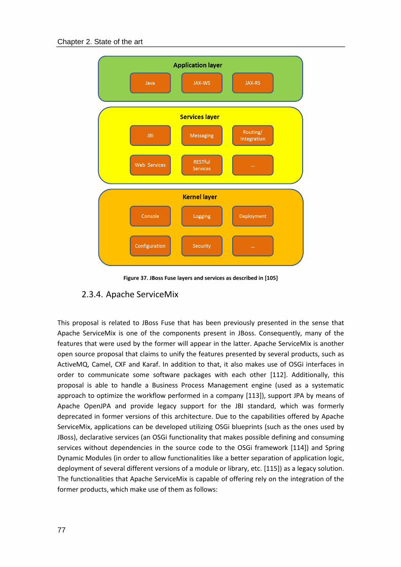
Chapter 2. State of the art
77
Figure 37. JBoss Fuse layers and services as described in [105]
2.3.4. Apache ServiceMix
This proposal is related to JBoss Fuse that has been previously presented in the sense that
Apache ServiceMix is one of the components present in JBoss. Consequently, many of the
features that were used by the former will appear in the latter. Apache ServiceMix is another
open source proposal that claims to unify the features presented by several products, such as
ActiveMQ, Camel, CXF and Karaf. In addition to that, it also makes use of OSGi interfaces in
order to communicate some software packages with each other [112]. Additionally, this
proposal is able to handle a Business Process Management engine (used as a systematic
approach to optimize the workflow performed in a company [113]), support JPA by means of
Apache OpenJPA and provide legacy support for the JBI standard, which was formerly
deprecated in former versions of this architecture. Due to the capabilities offered by Apache
ServiceMix, applications can be developed utilizing OSGi blueprints (such as the ones used by
JBoss), declarative services (an OSGi functionality that makes possible defining and consuming
services without dependencies in the source code to the OSGi framework [114]) and Spring
Dynamic Modules (in order to allow functionalities like a better separation of application logic,
deployment of several different versions of a module or library, etc. [115]) as a legacy solution.
The functionalities that Apache ServiceMix is capable of offering rely on the integration of the
former products, which make use of them as follows:

Chapter 2. State of the art
78
1. Apache ActiveMQ: it is used as the messaging system and integration patterns server
[116]. As the ESB proposal itself, it is also offered as an open source product. Among
the features that it offers it is able to support a collection of cross language clients and
protocols (Java, C, C++, C#, Python, etc.), as well as Java Message Service 1.1, J2EE 1.4
and Enterprise Integration Patterns. Furthermore, it also offers support to Spring to
embed ActiveMQ and fast persistence by means of Java Database Connectivity (JDBC,
a Java-based industry standard for database-agnostic connectivity between Java and a
set of SQL databases [117]).
2. Apache Camel: its main functionality is the definition of routing and mediation rules in
domain-specific languages (Java-based Fluent API, Spring or Blueprint XML
configuration files, as they were offered in JBoss Fuse). It makes use of Uniform
Resource Identifiers to work with transport or messaging underlying standards [118]. It
is claimed to provide seamless integration with the most popular frameworks, such as
Spring, Blueprint and Guice.
3. Apache CXF: it can be regarded as an open source services framework used to develop
services by using frontend programming APIs, such as the already mentioned JAX-WS
and JAX-RS. As it has been described for other proposals, SOAP, XML/HTTP or RESTful-
based facilities are understood by this framework [119]. It therefore supports a
collection of Web Services standards along with several frontend programming
models.
4. Apache Karaf: it is used as the way to have a runtime server. Apache Karaf is actually
capable of running itself as a container in a not dissimilar way than what would be
used by a regular ESB architecture [120], albeit it would not provide as many
components as an actual Enterprise Service Bus architecture would provide.
Apache ServiceMix works in a similar way to the one that was presented in JBoss, that is to say,
when a bundle is developed, it will be done so as a regular project, but when it has to be
deployed it will rely on two files, the blueprint for dependencies and another one for a
description of the bundle (in this case, it will be a Spring file rather than a Project Object Model
one). The deployed bundles will be stored in a deploy folder where they will be checked in
order to know their status (Active, Failure status in case there has been any problem in their
deployment, etc.) and, since it provides URIs, the services of the deployed bundles will be
accessible remotely, as it happened with JBoss. Apache ServiceMix offers all the services and
facilities that are expected from an ESB, but it lacks some features that the JBoss Fuse has,
such as the “Fuse Fabric” technology that allows a location managing the installation and
status of the ESB in a distributed system [121], so its advantages become reduced.
2.3.5. Petals ESB
This is another open source proposal for an Enterprise Service Bus primarily used for the
implementation of a SOA that comes with a collection of heterogeneous services in its last
distribution [122]. It has been developed by the OW2 consortium (an open source software
community that claims to be independent, global and promote the development of software
facilities as open-source middleware, generic business applications or cloud computing

Chapter 2. State of the art
79
platforms [123]). Petals ESB is has eight different kinds of features that can be described as
follows:
1. The Petals server: the latest distribution of Petals comes with a standalone Java server
composed by several modules that supports a distributed mode, which implies that a
group of instances can constitute a single virtual ESB.
2. JBI Components: they are used to bridge services included in Petals with external
systems or applications (binding components) and provide internal logic-like service
orchestration, routing or transformation (service engines).
3. Administration: it has two different components: the Petals ANT tasks (a collection of
ANT tasks used to execute administration programs) and the Petals Command Line
Interface (CLI, utilized to administrate a group of Petals servers).
4. Platform monitoring: a Java Management Extensions (JMX)-based server has been
included. It has a JMX API conceived to work Cacti (a monitoring tool with graphical
options used to display historical data gathered from monitoring probes [124]) and
Nagios (another monitoring tool for mission-critical infrastructure components such as
applications, network protocols or operating systems [125]).
5. Flow monitoring: in order to provide good enough monitoring capabilities, log services
must be provided. Therefore, a log level called MONIT is included in the ESB.
Furthermore, specific log handlers have also been added as an extra service.
6. Development: there are two software facilities that are offered by the Petals ESB: one
is petals studio (described by the developers of this ESB as a custom Eclipse
distribution) and the petals Maven plugin (a regular Maven plugin that offers
additional support for Petals ESB).
7. Packaging: there are two ways offered to install this ESB: either by means of a
compressed ZIP archive or by means of Devian packages offered for the Petals
Command Line Interface, server and their extensions.
8. Experimental features: there some other facilities included that have been regarded as
experimental by the creators of this ESB. One is the Petals web console (that is, a web
application used to administrate a set of Petals servers), a Simple Flow Viewer
(another web application used to visualize Petals flows) and a log handler to store
information in a Mongo DB.
As for the Petals ESB itself, the authors claim that it has been developed according to the
software component paradigm [126]. There are four different kinds of those that can be
found:
1. Configuration: the software components present here are used for configuration
duties: topology is utilized to acknowledge and update the topology information of the
Petals ESB network, configuration has data about properties of the local Petals ESB
container and the System State stores states and keeps consistency whenever a Java
Business Integration (JBI) artefact state gets an update.
2. Distribution: these are the software components related to the distributed nature of
the ESB: network provides information that is complementary to the one provided by

Chapter 2. State of the art
80
the topology, whereas repository handles JBI artefacts resources needed at runtime by
the ESB container.
3. Messaging is used for the external communications of Petals ESB. There are three
software components to be mentioned in this case: delivery channel behaves as an
interface with the JBI consumer/provider, router plays the role of choosing the
endpoint to send any JBI message and uses and the transporter mediates between the
router component and the communication channel.
4. Management is used to rule the capabilities of Petals ESB. This is the kind of software
with a highest number or components. Deployment manages the deployment of
service assemblies, whereas the installation service deals with installing the JBI
components and their shared libraries. The Java Management Extensions (JMX) service
is used to manage JMX connections to either a remote or a local petals ESB container.
Lastly, there are other software components used for LifeCycle management purposes.
Their overall appearance has been displayed in Figure 38. Note that in order to send messages
to the JBI consumer, the only kind of software components that is involved in this interchange
is the Messaging one.
Figure 38. Petals ESB software components, as described in [126]
Petals ESB has a large number of services available to be immediately installed wherever it is
required, such as a personal computer or a server. The main inconvenience that can be found
in Petals is that it is not as popular or a widely used as other open source solutions, so it might
be more challenging than wanted (fixing bugs, getting feedback from the community, etc.)
during implementation duties.

Chapter 2. State of the art
81
2.3.6. Mule ESB
According to its developers, this proposal for a source Enterprise Service Bus [127] is a
lightweight one. There are several features to be taken into account in this. A description of all
the services that are encased within Mule ESB can be found in [128]. This Enterprise Service
Bus is offered in two different implementations called Mule ESB Community and Mule ESB
Enterprise. The latter has a greater number of features, such as operational control facilities
(web-based console, deployment and performance management, etc.) and additional security
characteristics. Also, it is offered with additional support (for example, Service Level
Agreements are provided). However, some of these functionalities are provided either by
subscription or as separated products [129]. It is mentioned that the capabilities of Mule ESB
include message routing (used for aggregating, filtering, routing and re-sequencing messages
considering assigned rules and content), service mediation (negates differences among
message protocols and services, separates business logic from messaging and makes possible
location-independent service calls), service creation and hosting (hosts and exposes reusable
services using the ESB as the container) and data transformation (utilized for exchanging
information through several different formats and transport protocols). Figure 39 is displaying
them as they have been described.
Figure 39. Mule ESB main software components, as described in [128]
Chapter 2. State of the art
82
According to the performance metrics described in the MuleSoft white paper on MULE ESB
Enterprise Performance [130], a customer should be able to process almost a million
messages every day with less than 200 milliseconds latency and a peak rate of 600 messages
per second. Testing activities run in a machine with 24 cores showed that an average latency of
less than 1 second was measured for tests of increasing concurrency of up to 800 threads. A
stable throughput with up to 4000 threads could be offered.
Among the advantages that the developers of Mule ESB claim their solution has, the following
ones must be mentioned: a) the components that are encased by Mule ESB can be of very
different kinds (ranging from plain Java projects to software components from other
frameworks), b) this Enterprise Service Bus accepts many different formats for the messages
that are transferred in a deployment (for example, SOAP or binary image files), c) components
are conceived to be reusable without any need for specific code or a programmatic API, d) the
kind of event-driven architecture that has been conceived (Stage Event-Driven Architecture or
SEDA) by the developers allows a high degree of scalability and e) the core of the
functionalities can be deployed without the need of an ESB. Overall, this ESB offers a wide set
of interconnectivity capabilities for its users. However, some of the most advanced services
have to be obtained via subscription (therefore, partially undermining the open source nature
of the development).
2.3.7. Talend ESB
This Enterprise Service Bus is part of a larger software infrastructure based on what the
developers refer to as Talend Open Studio [131] which comprises free tools for Big Data, Data
Integration, Data Quality, the ESB and Master Data Management. The authors of this open
source ESB implementation mention that it has been built taking into account former open
source, Apache ESB-based technologies like Apache CXF, Apache camel and Apache ActiveMQ
[132]. In addition to that, this Enterprise Service Bus solution is claimed to be lightweight and
have a modular design that comes in handy for incremental deployment in distributed systems
projects. Standards as SOAP or REST are also taken into consideration for service development
and integration.
Talend ESB developers describe the proposal as made up by three autonomous architectural
functional blocks [133], which have been represented in Figure 39. The names of the three
functional blocks are: Client (which includes a Talend Studio used to enable data integration or
data service processes, services or mediation routes), Talend Execution Servers (which
describes one or more Talend Runtimes that make possible deploying and executing the
services, jobs and routes previously created in the Studio located in the client part) and the
Monitoring Databases (representing the Service Activity Monitoring database that monitors
service calls).
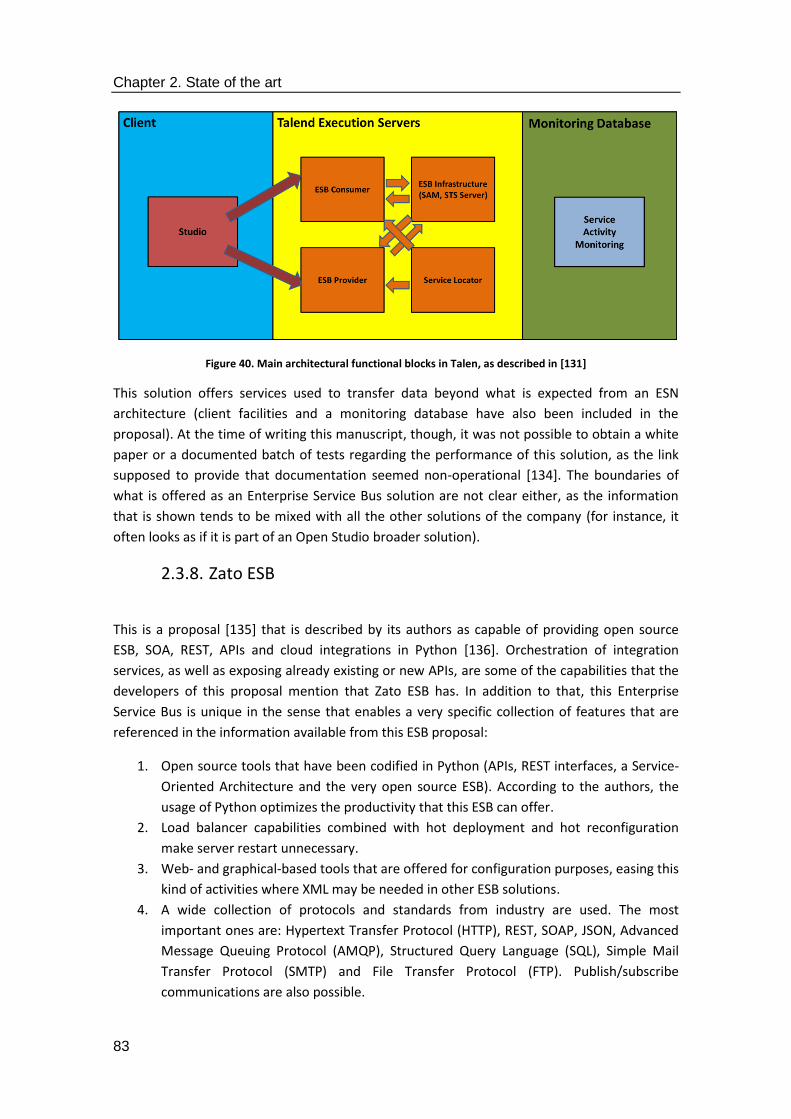
Chapter 2. State of the art
83
Figure 40. Main architectural functional blocks in Talen, as described in [131]
This solution offers services used to transfer data beyond what is expected from an ESN
architecture (client facilities and a monitoring database have also been included in the
proposal). At the time of writing this manuscript, though, it was not possible to obtain a white
paper or a documented batch of tests regarding the performance of this solution, as the link
supposed to provide that documentation seemed non-operational [134]. The boundaries of
what is offered as an Enterprise Service Bus solution are not clear either, as the information
that is shown tends to be mixed with all the other solutions of the company (for instance, it
often looks as if it is part of an Open Studio broader solution).
2.3.8. Zato ESB
This is a proposal [135] that is described by its authors as capable of providing open source
ESB, SOA, REST, APIs and cloud integrations in Python [136]. Orchestration of integration
services, as well as exposing already existing or new APIs, are some of the capabilities that the
developers of this proposal mention that Zato ESB has. In addition to that, this Enterprise
Service Bus is unique in the sense that enables a very specific collection of features that are
referenced in the information available from this ESB proposal:
1. Open source tools that have been codified in Python (APIs, REST interfaces, a Service-
Oriented Architecture and the very open source ESB). According to the authors, the
usage of Python optimizes the productivity that this ESB can offer.
2. Load balancer capabilities combined with hot deployment and hot reconfiguration
make server restart unnecessary.
3. Web- and graphical-based tools that are offered for configuration purposes, easing this
kind of activities where XML may be needed in other ESB solutions.
4. A wide collection of protocols and standards from industry are used. The most
important ones are: Hypertext Transfer Protocol (HTTP), REST, SOAP, JSON, Advanced
Message Queuing Protocol (AMQP), Structured Query Language (SQL), Simple Mail
Transfer Protocol (SMTP) and File Transfer Protocol (FTP). Publish/subscribe
communications are also possible.

Chapter 2. State of the art
84
5. The community around the project is said to be growing, and training or commercial
support are available.
The developers of this ESB describe how an ESB is suited to run different applications
transmitting information among them when compared to one-to-one communications among
a plethora of applications [137]. What is more, it offers a complete and clear set of documents
that can be used to get a quick grasp of how this ESB works. However, in order to have secure
APIs, and external tool called Vault must be installed separately [138]. Also, while the
collection of features provided by the creators of Zato ESB is appealing, some of them are not
that unique: for instance, hot deployment is also possible for JBoss Fuse, where software
bundles can be deployed right away without having to stop the ESB. This latter ESB solution
can also be managed by means of a web console where logs and deployed services are
displayed. Furthermore, despite Python is a very simple and efficient programming language, it
is not clear that is the optimal solution for productivity, due to the fact that it is a characteristic
extremely subjective and dependent on the abilities of human developers. Plus, other
programming languages like C++ may offer better performance results that Python. Finally, in
order to have Zato installed in machines with Windows or OS X as the operating systems, a
virtual machine running a Long Term Support Ubuntu operating system is used in each of the
cases [139].
All in all, the main features of the Enterprise Service Bus architectures presented here can be
summarized as shown in Table 2:
Table 2. Main characteristics of the studied open source ESB solutions
Proposal name Advantages Disadvantages
Open ESB Variety of services. Clear legacy system integration.
Only one programming language implementation (Java).
WSO2 ESB Service orchestration and composition are offered.
Multiple configuration operations have to be done.
JBoss Fuse Wide variety of services. Easily portable components. High scalability. Strong community.
Extra security resources required.
Apache ServiceMix Simplicity of use. Lack of available services.
Petals ESB Wide variety of services. Community not a strong as in other ESBs.
Mule ESB Strong community. Plethora of available solutions.
Some services are only available via subscription.
Talend ESB Capabilities out of the typical ESB boundaries.
Lack of performance information. It is not clear the scope of the ESB in the Open Studio solution.
Zato ESB User-friendliness (web and graphical tools). Clarity of documentation.
Security requires another tool. Features present in other ESB solutions. Dependent on Python.

Chapter 2. State of the art
85
2.4. Open issues and challenges
Taking into account the previous study done on both middleware solutions for the Smart Grid
and Enterprise Service Bus architectures, it can be inferred that the proposed solutions tend to
use a common approach to solve the challenges expected in terms of interoperability and
service availability. Typically, they will include a way to interconnect devices at the data level
(by means of message interchange, hardware abstraction layers or any other resource) and
offer interfaces to the application layer. In a network model, these interfaces could be
regarded as Service Access Points. In addition to that, the ESBs tend to encase a collection of
different services capable of carrying out tasks like message brokering or legacy system
integration. The disadvantage to this common way of solving issues is that there are also
several common challenges that essentially remain unsolved. Overall, taking into account what
has been researched in the presented solutions, the issues that have been found in
middleware solutions for the Smart Grid usually resemble the ones found for the ESB
architectures, as an ESB is used in this context as the embodiment of middleware. The ones
that that could be listed as most significant are:
1. Lack of consistency in service availability. The services that are encased in middleware
solutions vary greatly from one proposal to another; there is no list of criteria or fixed rules
to define what and what not should be included in a middleware solution. That presents
several problems that are difficult to solve. To begin with, the development of new
middleware or using a new iteration of an already existing solution is more troublesome
than for other kinds of software products, since it is harder to completely reuse the
already available code due to the heterogeneity of the services middleware is developed.
As a consequence, sometimes it looks more appealing starting from scratch when
implementing middleware rather than porting an already existing solution, resulting in a
significant loss of resources and an underuse of the already available code, which
jeopardizes the scalability of the development works.
2. No common solutions to access services. While there are several ways to offer interfaces
to the application layer, there is not a common API agreed to be used in terms of methods,
parameters or services to be accessed (as a matter of fact, many solutions do not even
have a defined API and solely rely on message interchange to connect remote hardware
devices at the data level). This compromises the adaptability of the system to different
application domains where a list of facilities to access middleware would have been
welcome. In addition to that, it makes likely the update of the middleware solution every
single time a new device has to be integrated, thus challenging middleware scalability and
making the establishment of Long Term Support versions harder, as it is common in other
software developments like operating systems.
3. Ambiguity regarding middleware design. Although a clear definition of middleware and
what is expected from it has been accepted for decades, the design of a solution that will
offer that kind of services is still unclear. Some solutions make use of services that are part
of an architecture deployed in a distributed way (this is the most typical approach of
system making use of an ESB, otherwise their service encasing capabilities would not be

Chapter 2. State of the art
86
utilized at all), whereas some other solutions use little more than message interchange and
prefer focusing on the higher or lower layers. The lack of a middleware design that is used
in a generalized manner further complicates interoperability of hardware devices or
among subsystems included as part of a larger system (for example, several microgrids
included in a large Smart Grid [140] that, depending on their operating conditions, may
work either connected to the macrogrid or operate in island mode, isolated from the
larger infrastructure).
4. Ambiguity regarding middleware solution. As a direct consequence of the previous open
issue, middleware implementation remains a convoluted process where local
developments may not guarantee remote interoperability when those implementations
have to be combined in something larger. If an open source Enterprise Service Bus is used,
though, development can be eased, as in the end the software packages will be mutually
understandable in different parts of the distributed systems, as long as the same kind of
ESB is used (sometimes, using a slightly different kind of ESB in different sides of the
system will still be possible if they have a common ground. For instance, it is shown in
[141] that an constrained Apache ServiceMix ESB can work in a seamless way with a JBoss-
like ESB).
5. No specific methodology for middleware development. Unlike other works that have very
accurate procedures for software implementation (for example, software design via UML
[142]) or have standards that define languages for software architecture description [143],
there is not a clearly defined approach or standardized manner to develop middleware
solutions. Again, this is a source of challenges, as a team that has to implement this kind of
software solution has to rely on their instincts or the experience of their senior members
(if any), thus making the whole procedure less predictable.
In a nutshell, lack of standardized, specific software solutions that clearly describe what is
required from middleware are a critical hinder for the development works that result in losing
time and money in codification of software components hard to accommodate to any further
development that might be carried out. These are the open issues that the proposal included
in this doctoral thesis deals with, based on the requirement analysis, design, implementation
and testing experience that has been gain through the participation in research projects where
middleware development is required.
2.5. Section summary
It has been said at the start of this section that middleware is a software development
desirable for the Smart Grid, as it makes possible several functionalities that can be regarded
as mandatory for the satisfactory performance of a system where hardware devices (AMI,
PMUs, RTUs, etc.) and software components have to be used. In addition to that, since this
kind of software development can be found in different kinds of systems and fulfilling their
functionalities in a diverse manner, its location in a matrix representing the different possible
features of middleware for the Smart Grid has also been included.
Chapter 2. State of the art
87
As the main objective of this thesis is the design and development of a complete middleware
architecture for the application domain of the Smart Grid, a study on the state of the art in this
topic has been carried out. In order to have a fixed of features to evaluate how each of the
proposals solves the challenges that have to be faced by middleware, four different
characteristics have been defined, with different degrees of depth that vary from one solution
to the next one. Due to the nature of the middleware, decentralization and software
architecture-like proposals are the most frequent ones, albeit they do not form a homogenous
majority and have in fact deep differences regarding the services that have been included, how
they are accessed or the way they tackled the underlying hardware present in a deployment.
Furthermore, a state of the art in open source Enterprise Service Bus solutions has been
included too. Since the middleware solutions tend to include a number of layers bent on
solving different kinds of issues, along with integrating services that have been previously
implemented as software packages, the usage of an ESB has been justified. In addition to that,
it is also stated why an open source solution is a more appealing option for the needs that
research projects have had, as they are usually costless and have a strong community behind
them willing to provide information in case any issue springs up. The most common problems
found in the developed Enterprise Service Buses mirror to an extent the ones found in
middleware solutions: either the services that they provide are scarce, the most important
ones are not available, or it is not clearly stated how they are accessed by both the application
and the hardware-based layers. The size of the community using them has been regarded as a
major characteristic to take into account, as a professional customer service or completely
reliable support cannot be guaranteed for an open source development most of the times and
bugs and unforeseen issues are prone to appear in distributed systems that imply
development activities made by several people.
Overall, the open issues and limitations that have been found are closely related to the lack of
a standard (or at least, strongly advisable) solution that defines with clarity a collection of key
features of a middleware development: the services that are going to be included, how they
are going to be accessed, the requirements that should be taken into account when designing
the solution, how to easily integrate local developments in a distributed system and the
necessary steps to successfully implement middleware in the Smart Grid.
What the next section presents is a way to deal with all these open issues so that they can be
either completely erased or mitigated to a great extent. The specific problems that are going
to be solved are described as objectives that will be fixed in the proposed middleware solution.
Considerations in the requirement analysis that is mandatory for almost any software
development have been included. From those requirements, a design of software components
will result. These software components will satisfy functionalities to be expected from a Smart
Grid that has a significant amount of data being transmitted from one side to the other of a
distributed system.

Chapter 2. State of the art
88
3. Proposal for a Common
Middleware Architecture

Chapter 3. Proposal for a Common Middleware Architecture
90
Chapter 3. Proposal for a Common Middleware Architecture
91
3.1. Introduction
This section of the thesis has been included in order to have an accurate perspective of the
proposal that is done for (as mentioned in the objectives at the introduction) the development
of a standardized middleware architecture to guarantee interoperability among the devices
present in a Smart Grid. Acknowledging this objective, the proposal has been named Common
Middleware Architecture (CMA), as it aims at contributing to a common way to design and
implement a semantic middleware solution for the Smart Grid that might be extensive to other
CPSs where similar standardization issues are taking place. When reading through this section,
it must be taken into account that several points of view have been considered with the
purpose of providing a perspective on the proposal as holistic and detailed as possible. UML
come here as a useful tool, since they make possible the representation of the software
components required for the middleware. More specifically, the majority of the description
that has been included in this section has been done so according the ideas put forward by the
principles of the Model Driven Architecture (MDA), an initiative commanded by the Object
Management Group, which aims to create software architectures that guarantee portability,
interoperability, platform independence, domain specificity and productivity [144]. MDA offers
a framework where there are two points of view with critical importance to understand the
perspectives that can be provided for the CMA:
1. Computational Independent Model. Although it can be defined as a vocabulary of a
problem domain useful to a variety of stakeholders [145], for other authors there are
actually two different kinds of CIMs: ontology-based (made up by a formalized conceptual
domain model) and UML-based ones [146]. As it can be inferred from its name, no rules
are defined for computer-related implementation activities. This model is the most likely
to be obtained when the requirement analysis is carried out (since it makes use of
functional requirements, non-functional requirements, among other features, as explained
in [147]), so it is the first one that is obtained when specifying a software system,
according to the criteria established by MDA. According to [147], the UML diagrams that
can be used to define software at this stage are sequence, activity and use case. In a way, a
UML-based Computational Independent Model resembles a Platform Independent Model.
The most important characteristic of this latter model is that it is obtained regardless of
the platform where the software system is expected to run. A Platform Independent
Model is of critical importance for the Model Driven Architecture, to the point that the
OMG claims that “The MDA is OMG's way of developing applications and writing
specifications, based on a platform-independent model (PIM) of the application or
specification's business functionality and behavior” or “A complete MDA application
consists of a definitive PIM, plus one or more PSMs and complete implementations, one on
each platform that the application developer decides to support” [148]. If defined with
UML, class, object, timing, interaction or communication diagrams are the most useful
ones.
2. Validation of the platform. It is the most specific of the three models, as it is tailored to the
pieces of equipment where it is going to be installed and must take into account

Chapter 3. Proposal for a Common Middleware Architecture
92
information about specific, already existing solutions, such as network protocols [67].
According to [147], component, package and deployment diagrams are the ones most
useful for its representation. Operational, system, support and user documentations are
the ones regarded as most useful at this stage.
In addition to MDA, an iteration of the ISO/IEC/IEEE 42010 standard [143] has also been
included as another way to describe CMS; it has been considered that viewpoints and
standards of different nature enrich the proposal by incorporating other features that would
be otherwise ignored. Unlike MDA, ISO/IEC/IEEE 42010 makes use of Architecture and/or
Viewpoint Descriptions to define the characteristics of a software development. In any case,
one vision is not incompatible with the other one, as there are ways to have an Architecture
Description as stated by the ISO/IEC/IEEE standard that will make heavy use of UML, as MDA
does.
Lastly, the structures used for the documentation in standards that have been settled under
OASIS have also influenced this part of the manuscript, such as the documents that described
MQTT [149] or AMQP [150]. They have been of great usefulness to state the different
subsections that should be used for the Protocol Data Units when interchanging information at
the low levels, as a detailed description is required for the different PDUs that are used in the
proposal for the middleware architecture.
3.2. Common Middleware Architecture: purpose and scope
If CMA is assessed according to the same criteria that have been presented before (hardware
abstraction for devices, high level interfaces for the application layer, UML description, etc.), it
will result in the following features:
1. CMA has been conceived as a middleware architecture. Since it was deemed as the
best possible solution because it is able to have the largest amount possible of
services, an architecture with the three different levels that are most common in the
studied proposals (one for hardware abstraction, another for the core services and a
third one for interaction with the highest, application-based level) has been defined.
2. CMA can be used under a wide range of computational capabilities. Since CMA aims to
provide a high level of decentralization, it has been conceived to being lightweight
enough to be installed in almost every device imaginable that is present in the Smart
Grid. It can be integrated as part of the software components of a smart meter or as
part of the pieces of equipment located in any of the most prominent actors that were
defined in the first chapter, regardless of the underlying software solution that is used
during the implementation stages (ESB or any other are fine as long as they include the
software components).
3. CMA has been designed as a Client/Server architecture capable of using other kinds of
message coupling. The main idea behind the proposal is that it will be able to satisfy
requests when they are started from the client side of the communication with the
knowledge of the specific device among a plethora that should receive it (the server).

Chapter 3. Proposal for a Common Middleware Architecture
93
However, as it will be described in chapter 4, there is no problem in using technologies
(AMQP) that are mostly involved in a Publish/Subscribe paradigm.
4. Common Middleware Architecture is a mostly decentralized solution. While there will
be a piece (or maybe even several pieces) of equipment that will have more software
components installed that some others, many of the most prominent functionalities
(data collection, device registration, etc.) will be done either in the periphery of the
system or with the cooperation of it. As mentioned before, even though the validation
of the proposal has been made with an ESB, there are no preconditions to have it
implemented and installed with other architectural styles.
As it has been depicted in Figure 41, the CMA is located as any other middleware solution
would be. As for the legacy systems that might be either too poor in computational resources
to have middleware components running (regardless of how unlikely that is) or proprietary
solutions that cannot be accessed because that would require unauthorized reprogramming of
its software, they can still be integrated via gateways that will interface those legacy systems
and adapt their information formats to the one used at the other parts of the deployment.

Chapter 3. Proposal for a Common Middleware Architecture
94
Figure 41. Location of Common Middleware Architecture
Therefore, it can be said that the purpose of this proposal of semantic middleware for the
Smart Grid is tackling to the greatest extent possible the open issues found before, so that it
will imply a major step forward the usability of the advantages that middleware can offer.
Another purpose of this thesis is using CMA as a way to establish a reliable way to implement a
middleware solution of the Smart Grid will also be able as a cornerstone for the
standardization of middleware in this application domain. As explained before, the
development of middleware implies several different services at different levels, so it is a
complex procedure that can become convoluted and complex, especially if many different
parties are involved in the development. By using CMA-based implementations, it becomes
easy to know which are the required steps and building blocks to develop middleware; they
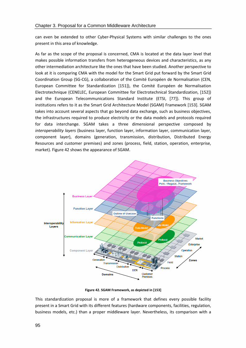
Chapter 3. Proposal for a Common Middleware Architecture
95
can even be extended to other Cyber-Physical Systems with similar challenges to the ones
present in this area of knowledge.
As far as the scope of the proposal is concerned, CMA is located at the data layer level that
makes possible information transfers from heterogeneous devices and characteristics, as any
other intermediation architecture like the ones that have been studied. Another perspective to
look at it is comparing CMA with the model for the Smart Grid put forward by the Smart Grid
Coordination Group (SG-CG), a collaboration of the Comité Européen de Normalisation (CEN,
European Committee for Standardization [151]), the Comité Européen de Normalisation
Electrotechnique (CENELEC, European Committee for Electrotechnical Standardization, [152])
and the European Telecommunications Standard Institute (ETSI, [77]). This group of
institutions refers to it as the Smart Grid Architecture Model (SGAM) Framework [153]. SGAM
takes into account several aspects that go beyond data exchange, such as business objectives,
the infrastructures required to produce electricity or the data models and protocols required
for data interchange. SGAM takes a three dimensional perspective composed by
interoperability layers (business layer, function layer, information layer, communication layer,
component layer), domains (generation, transmission, distribution, Distributed Energy
Resources and customer premises) and zones (process, field, station, operation, enterprise,
market). Figure 42 shows the appearance of SGAM.
Figure 42. SGAM Framework, as depicted in [153]
This standardization proposal is more of a framework that defines every possible facility
present in a Smart Grid with its different features (hardware components, facilities, regulation,
business models, etc.) than a proper middleware layer. Nevertheless, its comparison with a

Chapter 3. Proposal for a Common Middleware Architecture
96
middleware solution comes in handy due to the fact that some of the levels that are present in
SGAM are also within the scope of CMA, to a greater or lesser degree. Specifically, CMA is
almost entirely focused on the equivalent Information Layer of SGAM, due to the fact that the
functionalities that it uses are placed almost exclusively at the information layer (as
middleware operates at the data level). Figure 43 compares the two different scopes assumed
by each of the proposals: whereas SGAM offers a holistic view of all the hardware, networking
and software components involved in the Smart Grid, CMA takes information layer at a deeper
level while takes business or components as already for granted. While CMA is located at the
information layer and nowhere else, interfaces are offered to the communications layer
represented by SGAM, due to the fact that it is a distributed system where aspects like
networking have to be born in mind when designing the solution.
Figure 43. Comparison between the scope of SGAM and CMA.
3.3. Computational analysis
When compared to the traditional waterfall model for software development, this stage would
be similar as the requirement analysis done prior to the design of a software system.
Therefore, all the imaginable requirements of the system must be conceived at this point, so
that they will be captured as software components performing the required functionalities.
Table 3. Actions taken to tackle open issues
Open Issue/Challenge Requirement Action
Lack of consistency in service availability.
Information managed by the middleware architecture.
Design of a fixed collection of services to be included in the middleware architecture.
No common solutions to Elaboration of an Application Inclusion of Middleware

Chapter 3. Proposal for a Common Middleware Architecture
97
Open Issue/Challenge Requirement Action
access services. Programming Interface to access the semantic middleware solution.
Access Points to use its services.
Ambiguity regarding middleware design.
Standardization procedures for design in semantic middleware for the Smart Grid.
Creation of a list of functional and non-functional requirements to be included in middleware design.
Ambiguity regarding middleware solution.
Standardization procedures for implementation in semantic middleware for the Smart Grid.
Development of middleware as a collection of executable components.
No specific methodology for middleware development.
Development of a methodology for conception and development of semantic middleware.
Appendix describing the methodology of middleware development.
3.3.1. Functional requirements
CMA has been defined the way it is due to the set of requirements that were used in the
research projects related to the Smart Grid were middleware was required to be added as a
way to guarantee device interoperability, interconnectivity at the data level and access to
devices from applications. The functional requirements were described taking into account the
three scenarios that had been set for the demonstrators where middleware was expected to
be deployed: one of them was based on a residential scenario (where several home dwellings
were equipped with Raspberry Pi-based Advanced Metering Infrastructure), another one for a
factory used to manufacture olive oil (where all the processes were automated and the facility
relied on SCADA systems to gather information) and a third one for a tertiary environment
(which implied power infrastructure for a set of buildings). Consequently, the high level
appearance of the functional requirements for the middleware architecture was as follows:
1. Information managed by the middleware architecture: considering the kind of application
domain where the research projects took place, it was decided that middleware was to be
involved in the transfer of information regarding prices, weather forecasting, energy
consumption forecasting, energy generation forecasting, energy storage forecasting and
historical data. By the term “managing”, it was meant that data received by the
middleware about the previously formulated topics would have to be sent to the
corresponding higher level entities where it was supposed to be utilized in a significant
way, as the services themselves were part of the applications that could be used in the
demonstrator.
2. Support of Central and Local Controllers: as the implementation activities of the research
projects went by, it was decided that the most suitable way to deploy the hardware
components would be having a Central Controller than managed other smaller controllers
located in different facilities; these latter were called Local Controllers. Therefore, the

Chapter 3. Proposal for a Common Middleware Architecture
98
middleware components should be included in those hardware devices too, along with the
ones dealing with the data transferred at the data level among them.
3. Service Discovery: the availability of services should be made clear for the application layer
(as well as the devices present in the deployment as well. However, the middleware
architecture described here is way more service- than device-oriented), as well as a
registration mechanisms for them.
4. Information security: securitization of the interfaces that were used to access information
had to be offered so that the whole system would guarantee some security dealing with
access to the system.
As for the non-functional requirements that were established (as a way to strictly define what
the system should be), the participants of the projects where middleware for the Smart Grid
was to be developed decided that those requirements would be the following ones:
1. Usage of open source licenses. In order to maximize the usability and usefulness of the
provided budget, it was decided that open source tools were the most useful for the
development of the works done. As it will be explained in the next section, an open source
Enterprise Service Bus was chosen to embody the middleware works done in the research
projects that were carried out under the idea of having a common framework for
middleware in the Smart Grid, as represented by CMA.
2. Usage of an ESB. As explained in [154], it has been deemed that the most suitable option
for middleware in the Smart Grid is using an ESB, for it is able to interconnect any
distributed system with ease for the developers using it (as all the complexity of the
underlying software connection facilities are hidden from them) and is capable of encasing
services and facilities at a level that other architectures do not do, which would imply
reducing middleware to just a set of PDUs been transmitted among several devices.
3. Usage of semantic capabilities. A semantic middleware architecture designed to contain
features for information inference from the data transferred among the deployment was
expected to be implemented, as it was a common flaw found in the existing literature.
4. Middleware as a distributed system. There was no way that middleware could be
implemented as a centralized effort in a single device, as it would not fit the distributed
nature of the Smart Grid, where information is shared among many different elements
scattered in a wide location, so it was decided that middleware would be present in
different devices.
5. Middleware as a Service-Oriented Architecture. Instead of stressing the technical
characteristics of the devices present in a deployment, it was considered that middleware
should focus on the services that could be provided, as it was going to be embodied by a
collection of software components capable of providing functionalities.
All these requirements were common for all the three demonstrators that were conceived to
be undertaken during the testing and deployment of hardware and software activities. They
were further defined in a more specific way as the design activities went by. When
implementation works had to be done, all these requirements were given identifiers as a way
to have more specific information about them. Once they had them assigned, it became easier

Chapter 3. Proposal for a Common Middleware Architecture
99
to figure out which services should be implemented so that they could be included. The have
been included in Table 4.
Table 4. Functional and Non-functional requirements for middleware
Requirement identifier Name and description Functional/ Non-functional
EGO-MDW-FUN-0010 Middleware managed information. Prices, generation and storage forecast, weather forecast, energy generation and storage forecast, energy consumption forecast, historical data.
Functional
EGO-MDW-OPR-0020 Central Controller support. A piece of hardware in the deployment will have more middleware components.
Functional
EGO-MDW-OPR-0030 Local Controller support. The less significant pieces of hardware will still have some middleware components.
Functional
EGO-MDW-FUN-0040 Middleware service discovery. Middleware will be able to register devices and offer services to the higher layers.
Functional
EGO-MDW-SEC-0050 Middleware information security. Information will be access in a secure way.
Functional
EGO-MDW-NFR-0010 Open source licenses. Middleware is developed using open source licensed tools.
Non-functional
EGO-MDW-NFR-0020 Semantic capabilities. Middleware architecture makes use of semantics in one component used for device registration.
Non-functional
EGO-MDW-NFR-0030 Enterprise Service Bus. An ESB is used to guarantee message interchange and services encased.
Non-functional
EGO-MDW-NFR-0040 Distributed system. Middleware must be deployed as a distributed system.
Non-functional
EGO-MDW-NFR-0050 Service-Oriented Architecture. The middleware architecture must be focused on offering services to end users rather than on device technical features.
Non-functional
Considering these requirements, it was made clear that a) there were several services that had
to be designed to fulfil those requirements and b) they would end up modelled as software
components. These procedures have been carried out as it has been depicted in Table 5:
Table 5. Software components defined from the requirements
Functional requirement identifier
Software component designed Justification
EGO-MDW-FUN-0010 High Level services related to They are needed to either
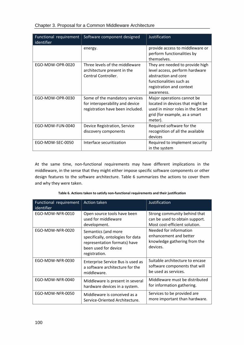
Chapter 3. Proposal for a Common Middleware Architecture
100
Functional requirement identifier
Software component designed Justification
energy. provide access to middleware or perform functionalities by themselves.
EGO-MDW-OPR-0020 Three levels of the middleware architecture present in the Central Controller.
They are needed to provide high level access, perform hardware abstraction and core functionalities such as registration and context awareness.
EGO-MDW-OPR-0030 Some of the mandatory services for interoperability and device registration have been included.
Major operations cannot be located in devices that might be used in minor roles in the Smart grid (for example, as a smart meter).
EGO-MDW-FUN-0040 Device Registration, Service discovery components
Required software for the recognition of all the available devices
EGO-MDW-SEC-0050 Interface securitization Required to implement security in the system
At the same time, non-functional requirements may have different implications in the
middleware, in the sense that they might either impose specific software components or other
design features to the software architecture. Table 6 summarizes the actions to cover them
and why they were taken.
Table 6. Actions taken to satisfy non-functional requirements and their justification
Functional requirement identifier
Action taken Justification
EGO-MDW-NFR-0010 Open source tools have been used for middleware development.
Strong community behind that can be used to obtain support. Most cost-efficient solution.
EGO-MDW-NFR-0020 Semantics (and more specifically, ontologies for data representation formats) have been used for device registration.
Needed for information enhancement and better knowledge gathering from the devices.
EGO-MDW-NFR-0030 Enterprise Service Bus is used as a software architecture for the middleware.
Suitable architecture to encase software components that will be used as services.
EGO-MDW-NFR-0040 Middleware is present in several hardware devices in a system.
Middleware must be distributed for information gathering.
EGO-MDW-NFR-0050 Middleware is conceived as a Service-Oriented Architecture.
Services to be provided are more important than hardware.
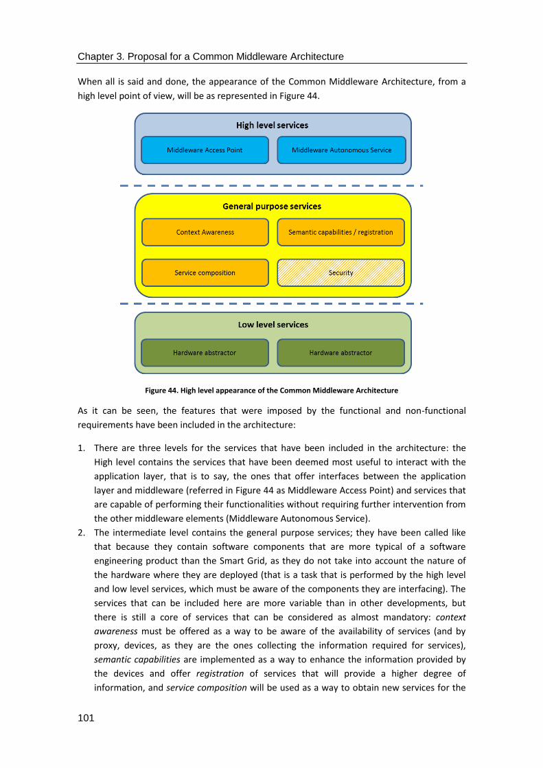
Chapter 3. Proposal for a Common Middleware Architecture
101
When all is said and done, the appearance of the Common Middleware Architecture, from a
high level point of view, will be as represented in Figure 44.
Figure 44. High level appearance of the Common Middleware Architecture
As it can be seen, the features that were imposed by the functional and non-functional
requirements have been included in the architecture:
1. There are three levels for the services that have been included in the architecture: the
High level contains the services that have been deemed most useful to interact with the
application layer, that is to say, the ones that offer interfaces between the application
layer and middleware (referred in Figure 44 as Middleware Access Point) and services that
are capable of performing their functionalities without requiring further intervention from
the other middleware elements (Middleware Autonomous Service).
2. The intermediate level contains the general purpose services; they have been called like
that because they contain software components that are more typical of a software
engineering product than the Smart Grid, as they do not take into account the nature of
the hardware where they are deployed (that is a task that is performed by the high level
and low level services, which must be aware of the components they are interfacing). The
services that can be included here are more variable than in other developments, but
there is still a core of services that can be considered as almost mandatory: context
awareness must be offered as a way to be aware of the availability of services (and by
proxy, devices, as they are the ones collecting the information required for services),
semantic capabilities are implemented as a way to enhance the information provided by
the devices and offer registration of services that will provide a higher degree of
information, and service composition will be used as a way to obtain new services for the

Chapter 3. Proposal for a Common Middleware Architecture
102
whole system based on simple services that are already present (for example, building a
fire risk alarm based on a) temperature and b) power readings in a cable). Note that,
among other components depending on the needs of the deployment, securitization can
also be offered at this level if there are explicit implementation works done regarding
information cyphering. While securitization was carried out in the research projects
associated to this thesis by means of several operations regarding certificates for web
browsers rather than actual implementation of a General purpose service component (as it
will be explained in Chapter 4), it can be provided to a software component via libraries
(for example, by means of Bouncy Castle ones [155]).
3. Low level services are responsible for the hardware abstraction of the underlying devices
in a deployment. Not only they are used to collect the information that is received from
the hardware, but also they rely on a specific information format to isolate the hardware
particularities. That format is based on a collection of Protocol Data Units that has been
included in section 3.6.
Note that despite the application domain where it has been implemented, this representation
of the architecture has no specific features related to the Smart Grid, so it can be ported with
ease to other environments that rely on CPSs to perform their functionalities. The previous
picture shows CMA from a purely software point of view. However, if the hardware devices
that are to contain middleware were to be considered, the overall appearance would be as
shown in Figure 45. Basically, CMA has been conceived to be installed in different machines
and appliances present in the Smart Grid, so that it will be a distributed enough development.
There will be two exceptions to the deployment of middleware in this kind of devices: a) when
the device will have too little power to have any extra software component installed (unlikely
but still possible for some kind of Advanced Metering Infrastructure) or b) it is proprietary
system that cannot be programmed by any third party (in that case, a specific interface with
the remaining parts of the system will have to be carried out).

Chapter 3. Proposal for a Common Middleware Architecture
103
Figure 45. Common Middleware Architecture location in Smart Grid devices
So far, CMA has been depicted just as a representation of software components and levels. A
more in-depth depiction based on UML will be done in the next subsections.
3.3.2. Subsystem diagram
The first UML diagram that has been included is referred to the highest level possible point of
view, which is displaying the three different levels that Common Middleware Architecture is
made of. Overall, each of the levels has been gathered in a subsystem that covers all those
components. In this way, the High Level Services use a subsystem and interact with the
applications and the General Purpose Services, whereas the latter ones form another
subsystem that has the low layer services below them. These Low Level Services are also
gathered in a subsystem that contains the software components that were defined previously,
and will interact with the network infrastructure that has been used to deploy the middleware
solution. All these subsystems have been represented in Figure 46.

Chapter 3. Proposal for a Common Middleware Architecture
104
Figure 46. CMA subsystem diagram with all the groups of services represented
Each of the subsystems that have been presented can be further divided into several
components that interact with each other in the middleware solution.
3.3.3. Component diagrams
In the case of High Level Services, there are two different kinds of components that differ with
each other in the way that has already been explained: there is a type of service merely used
to access the middleware and collect the request done from the application layer (Middleware
Access Point), whereas the other type (Middleware Autonomous Service) is used to satisfy the
request that was sent, as this kind of service is capable of performing the operations by itself.
This latter kind of service has to be implemented whenever it is required that a functionality
can be accessed in a distributed manner but does not require any other component from the
uses Low Level MW Services
uses Communication Layer
uses High Level services
APPLICATIONS (Not part of the Middleware)
HARDWARE DEVICES (Not part of the Middleware)
Communications (Not part of the Middleware)
uses General Purpose services
High Level Services
General Purpose Services
Low Level Services

Chapter 3. Proposal for a Common Middleware Architecture
105
architecture for its performance. For the former type of middleware service, communications
will be performed with the General Purpose Services. For Middleware Autonomous Services,
on the contrary, only interactions with the application layer will be required, as it has been
depicted in Figure 47.
Figure 47. Components diagram from the High Level MW services subsystem
The General Purpose Services combine all the software components that are required for the
normal performance of the middleware embedded in the devices that are part of the Smart
Grid. The components that are present in this subsystem have a one-to-one correspondence to
the software components described in the previous subsection of the thesis: a) a Context
Awareness component is used to check on the surroundings of the middleware, along with its
different elements, b) a Device Registration component is further used with the suitable
semantic capabilities and contains the ontology designed for the system (which will be further
used for the semantic enhancement of the information stored in the middleware architecture),
c) a Service Composition component is used to merge simple services in new ones and d) a
Security component (or at least, a procedure that will enable security capabilities) has been
added. These components are represented in Figure 48.
Figure 48. Components diagram from the General Purpose Services subsystem
Middleware Access Point AIMAPA
From Application Layer
To General Purpose Services
Middleware Access Point BIMAPB
From Application Layer
To General Purpose Services
Middleware Autonomous ServiceIMAS
From/to Application Layer
High Level Services
Context AwarenessICA
From/to High Level services
From Low Level services
Semantic Capabilities/RegistrationISC
SecurityService Composition
IDR
From/to High Level services
From/to Low Level services
From/to Semantic Capabilities
From/to Device Registration
IS
From/to Semantic Capabilities
From/to Device RegistrationFrom/to Low Level services
To Semantic Capabilities
General Purpose Services
From/to High Level services

Chapter 3. Proposal for a Common Middleware Architecture
106
Low level services are represented by the hardware adaptors included in the subsystem. If a
format based on a data level PDU is respected, one hardware adaptor will be enough, as its
main functionality will be receiving the information according to the foreseen format. If for any
other reason more components are needed, an additional hardware abstractor can be added
for each service or group of services that is required. This idea is further represented in Figure
49, where different hardware abstractors are encased in the Low Level Services subsystem.
Figure 49. Components diagram from the General Purpose Services subsystem
3.3.4. Use case diagram
Use case diagrams have been used to describe with further accuracy the functionalities
expected from a middleware architecture. There are two different levels that have been used
in order to have a more accurate representation: on the one hand, a top, more generic-looking
top level is used to address the most typical use cases that can be found in a development that
requires a middleware solution. On the other hand, each of the uses cases (represented in the
next diagram as ovals within the boundaries of the system represented by the Common
Middleware Architecture) has been further split into other use case diagrams that show the
relationships between the functionalities included in each of the use cases that were first
formulated. To begin with, Figure 50 displays the main use cases that have been conceived for
the middleware architecture. It has to be noted that the actors that have been included are
parts of the overall system that is used along with middleware deployment (and therefore is
surrounding the location where it is supposed to be) rather than human operators. Also, the
boundaries of the system are provided by the CMA itself.
Hardware Adaptor AIHAA
From/to General Purpose services
From communication layer
Hardware Adaptor BIHAB
From communication layer
From/to General Purpose services
Low Level Services
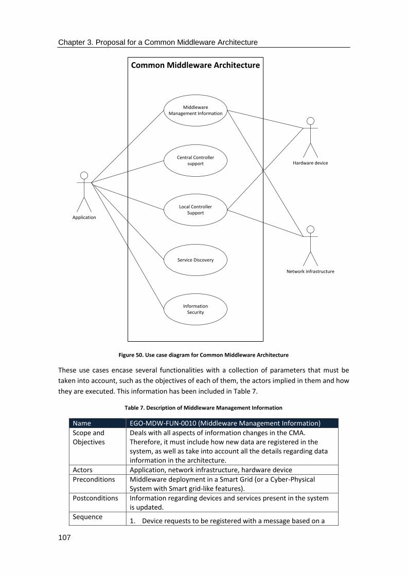
Chapter 3. Proposal for a Common Middleware Architecture
107
Figure 50. Use case diagram for Common Middleware Architecture
These use cases encase several functionalities with a collection of parameters that must be
taken into account, such as the objectives of each of them, the actors implied in them and how
they are executed. This information has been included in Table 7.
Table 7. Description of Middleware Management Information
Name EGO-MDW-FUN-0010 (Middleware Management Information)
Scope and Objectives
Deals with all aspects of information changes in the CMA. Therefore, it must include how new data are registered in the system, as well as take into account all the details regarding data information in the architecture.
Actors Application, network infrastructure, hardware device
Preconditions Middleware deployment in a Smart Grid (or a Cyber-Physical System with Smart grid-like features).
Postconditions Information regarding devices and services present in the system is updated.
Sequence 1. Device requests to be registered with a message based on a
Common Middleware Architecture
MiddlewareManagement Information
Application
Hardware device
InformationSecurity
Service Discovery
Local ControllerSupport
Central Controllersupport
Network infrastructure

Chapter 3. Proposal for a Common Middleware Architecture
108
description specific Protocol Data Unit that contains information regarding its capabilities and services.
2. Alternatively, a service within the middleware architecture sends its own information about the functionalities that is capable of providing.
3. The information is formatted according to the data format defined in the middleware. This will usually consist of an ontology tailored for Smart Grid purposes.
4. The information is included in a registry where devices and services are present. In order to store this kind of information a database will be required; a Triples Database (TDB) can be used as the most suitable database to store semantically enhanced information. TDB can be described as a Jena (describe as a Java-based software framework used to build Semantic Web developments, [156]) component used for information storage and queries based on Resource Description Framework (RDF, [157]). It can also be accessed via SPARQL Protocol and RDF Query Language (SPARQL, a language used to compose queries done to RDF-based developments, [158]) queries in order to list services or provide service discovery, which will come in handy for next use cases.
Exceptions No information is added from the applications. This is done so because it is expected from this higher level that it will adapt to the API provided, rather than having to tailor a solution for each of the applications that might be included.
The sequence can be further described with the aid of UML. In Figure 51, it can be appreciated
how the different procedures that give shape Middleware Management Information interact
with each other. All the functionalities related to registration, regardless of the nature of what
is registered, will be undertaken by including the Smart Grid ontology that has been defined
for the Common Middleware Architecture, as well as by any activity required to obtain the
data from either outside the middleware or any other software component present in the
middleware architecture. The data format used for information representation must also be
considered, as it will have to be adapted to the one that is used by the ontology developed for
the deployment where the solution is used. As it was mentioned before, the components of
this ontology and how it is developed is out of the scope of this thesis, but it will have to be
able to include information regarding the services present in the devices to be expected from a
Smart Grid. During the implementation works done in the research projects e-GOTHAM and
I3RES it was decided that it was more practical to perform the format conversion within the
middleware rather than providing it as the format to be used when data are transferred, as
this had the consequence of having to deal with verbose messages in the network.

Chapter 3. Proposal for a Common Middleware Architecture
109
Figure 51. Use case diagram for further Middleware Management Information representation
The procedure that was explained previously can also be further defined with sequence
diagrams. For example, registration can be carried out with three different actions, depending
on the origin of the registration request. These procedures can be triggered either by a human
operator, a device or a service within the middleware architecture. The first case has been
depicted in the sequence diagram that is shown in Figure 52. Firstly, the human operator will
request the registration of a specific device which will know previously. This request will be
usually done via an Application layer facility (an app, a Graphical User Interface or even a web
browser) that is capable of accessing the middleware solution via REST interface (1).
Middleware is accessed via a Middleware Access Point that is used for merely transferring
information to the other software components of the middleware architecture (as opposed to
Middleware Autonomous Services). This registration request is further transferred to the
software component responsible for device registration (2). According to the procedures
defined during the e-GOTHAM and I3RES projects, it was made mandatory to check with the
context awareness component whether that service or device was already registered in order
to avoid redundancies that would result in listing duplicated or non-existing services, so the
registration request message is sent to this Context Awareness component (3). Once an
answer is sent back to the registration component stating that the service or device has not
been registered yet (4), the registration request will involve the usage of semantic capabilities
to adapt the request to the format that has been defined by the ontology of the middleware
solution, so the message will be sent to the software component in charge for semantic
capabilities in case they are not included locally (5), and will be formatted in terms of textfields
and information according to the middleware ontology and sent back (6). It has to be noted
that registration and semantic capabilities have been placed separately because due to the
complexity of these procedures, they look clearer in a sequence diagram if they are defined as
different instances of a class, even if they are implemented in the same software component.
Middleware Management Information
Application
«include»
«include» «extend»
«extend»
Device Registration
ServiceRegistration
Network Infrastructure
Hardware Device
Smart Grid Ontology
External DataTransfer
Data Format
Web OntologyLanguage
«include»
Internal DataTransfer
«include»«extend»

Chapter 3. Proposal for a Common Middleware Architecture
110
At this point, the request will look like an XML message with semantically annotated
information about the features of the services, the location of the hardware device they
belong to, the outputs that are expected from them and, all in all, the features that make the
device unique. After this latter step, the device will be finally registered (7), and confirmation
messages will be sent back the middleware high level (8) and the application (9). During the
development works carried out in the e-GOTHAM project, an XML message was defined as the
output for Middleware Access Point as a way to confirm that the registration had taken place.
However, it could happen that the device that is about to be registered was already present.
During the testing activities carried out the previously mentioned projects, it was considered
as a situation unlikely but not impossible to happen, in case a device became unattached from
the deployment and was connected again during a period of time that was shorter than the
one that could be handled by the Context Awareness component. Consequently, a message
was defined where the fact that a device has already been registered has been created and
can be sent when required to the registration component (10), which will sent it back to the
Middleware Access point (11) and be published in the application that is interacted by a
human operator (12).
Figure 52. Sequence diagram for device registration started by a human operator
If the registration process is started by a device, the procedure is different in the first stages
but similar in the latest ones: the device will send a registration request message according to
a pre-established message format that involves the main data of the services and features that
device is capable of providing (1). This message will be transferred throughout all the network
elements present in the deployment (which are not part of the middleware, as this is
conceived as software components between the network and the application levels) until it is
reached by the registration component within the solution and send to the context awareness
one (2) in order to check whether there is an already registered device with the exact same
features that the one that is making the request. If the device has not been registered yet (3),
the message will be sent to the middleware component that contains the ontology that is
being used in the system (4) in order to format it according to its own rules (5). Once all these
procedures are completed, the device will be registered in the database that is connected to
the registration component (6). A confirmation will be sent to the device that is registered,
map:MiddlewareAccessPointapp:Application
highLevelDataRequest (2)
hab: HardwareAbstractor
Not part of the
Common Middleware
Architecture
hd: HardwareDeviceni: NetworkInfrastructure
Not part of the
Common Middleware
Architecture
lowLevelDataRequest (3)
hardwareDataRequest (4)
hardwareAnswer (5)
LowLevelDataAnswer (6)
highLevelAnswer (7)
middlewareDataAnswer (8)
Not part of the
Common Middleware
Architecture
applicationDataRequest (1)
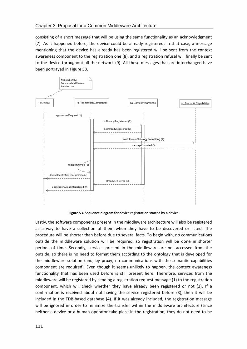
Chapter 3. Proposal for a Common Middleware Architecture
111
consisting of a short message that will be using the same functionality as an acknowledgment
(7). As it happened before, the device could be already registered; in that case, a message
mentioning that the device has already has been registered will be sent from the context
awareness component to the registration one (8), and a registration refusal will finally be sent
to the device throughout all the network (9). All these messages that are interchanged have
been portrayed in Figure 53.
Figure 53. Sequence diagram for device registration started by a device
Lastly, the software components present in the middleware architecture will also be registered
as a way to have a collection of them when they have to be discovered or listed. The
procedure will be shorter than before due to several facts. To begin with, no communications
outside the middleware solution will be required, so registration will be done in shorter
periods of time. Secondly, services present in the middleware are not accessed from the
outside, so there is no need to format them according to the ontology that is developed for
the middleware solution (and, by proxy, no communications with the semantic capabilities
component are required). Even though it seems unlikely to happen, the context awareness
functionality that has been used before is still present here. Therefore, services from the
middleware will be registered by sending a registration request message (1) to the registration
component, which will check whether they have already been registered or not (2). If a
confirmation is received about not having the service registered before (3), then it will be
included in the TDB-based database (4). If it was already included, the registration message
will be ignored in order to minimize the transfer within the middleware architecture (since
neither a device or a human operator take place in the registration, they do not need to be
registerDevice (6)
rc:RegistrationComponentd:Device
registrationRequest (1)
ca:ContextAwareness
isAlreadyRegistered (2)
Not part of the Common Middleware Architecture
deviceRegistrationConfirmation (7)
alreadyRegistered (8)
applicationAlreadyRegistered (9)
sc:SemanticCapabilities
middlewareOntologyFormatting (4)
messageFormated (5)
notAlreadyRegistered (3)

Chapter 3. Proposal for a Common Middleware Architecture
112
informed about the presence of the device). When all is said and done, this third possible
option to register a service will be done as shown in Figure 54.
Figure 54. Sequence diagram for device registration started by a middleware service
The next general use case studied is the Central Controller support. This one involves all the
activities required to request information to the central Controller where the most significant
software components are located. In order to deliver the required data, data transfers will be
required to at least interact with the hardware device that represents the Central Controller in
the deployment. Therefore, data representation capabilities (represented by the middleware
ontology composed by means of the Web Ontology Language) will be the ones to be used in
the information transfers. The main characteristics of this use case have been further
described in Table 8.
Table 8. Description of Central Controller support use case
Name EGO-MDW-OPR-0020 (Central Controller support)
Scope and Objectives
It is used to retrieve information that can be provided by interacting with the Central Controller that has been deployed in the system. The Central Controller is expected to be equipped with most of the software services defined for the Common Middleware Architecture.
Actors Application.
Preconditions Common Middleware Architecture has been installed in a hardware device (Central Controller).
Postconditions Information is retrieved from the services present in the Central Controller.
Sequence description
1. Data is requested to the Central Controller about any of the functionalities that can be provided by it (service listing or service discovery).
2. The request is sent to the Common Middleware Architecture. 3. The request is attended by the services located at the central
Controller and an answer is sent back.
registerService (4)
rc:RegistrationComponentms:MiddlewareService
registrationRequest (1)
ca:ContextAwareness
registerServiceRequest (2)
registrationConfirmation (3)
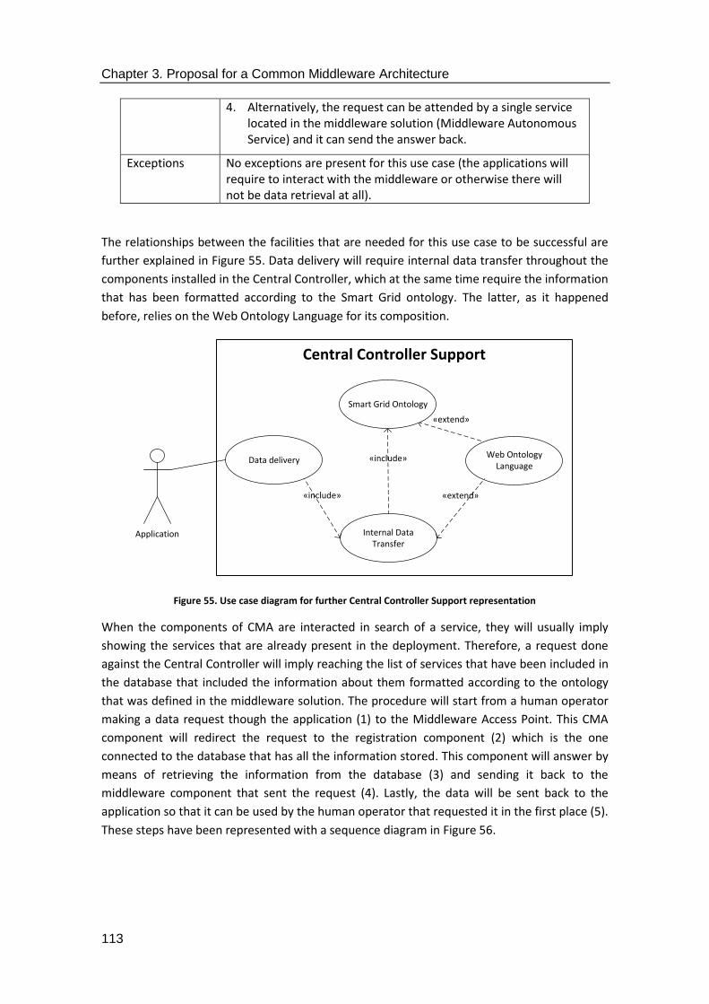
Chapter 3. Proposal for a Common Middleware Architecture
113
4. Alternatively, the request can be attended by a single service located in the middleware solution (Middleware Autonomous Service) and it can send the answer back.
Exceptions No exceptions are present for this use case (the applications will require to interact with the middleware or otherwise there will not be data retrieval at all).
The relationships between the facilities that are needed for this use case to be successful are
further explained in Figure 55. Data delivery will require internal data transfer throughout the
components installed in the Central Controller, which at the same time require the information
that has been formatted according to the Smart Grid ontology. The latter, as it happened
before, relies on the Web Ontology Language for its composition.
Figure 55. Use case diagram for further Central Controller Support representation
When the components of CMA are interacted in search of a service, they will usually imply
showing the services that are already present in the deployment. Therefore, a request done
against the Central Controller will imply reaching the list of services that have been included in
the database that included the information about them formatted according to the ontology
that was defined in the middleware solution. The procedure will start from a human operator
making a data request though the application (1) to the Middleware Access Point. This CMA
component will redirect the request to the registration component (2) which is the one
connected to the database that has all the information stored. This component will answer by
means of retrieving the information from the database (3) and sending it back to the
middleware component that sent the request (4). Lastly, the data will be sent back to the
application so that it can be used by the human operator that requested it in the first place (5).
These steps have been represented with a sequence diagram in Figure 56.
Central Controller Support
Application
«include»
«extend»
Data delivery
Smart Grid Ontology
Web OntologyLanguage
Internal DataTransfer
«include» «extend»
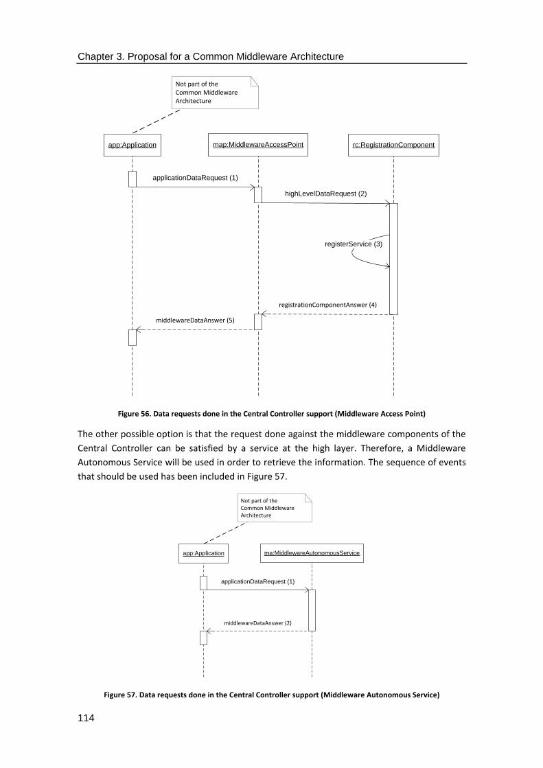
Chapter 3. Proposal for a Common Middleware Architecture
114
Figure 56. Data requests done in the Central Controller support (Middleware Access Point)
The other possible option is that the request done against the middleware components of the
Central Controller can be satisfied by a service at the high layer. Therefore, a Middleware
Autonomous Service will be used in order to retrieve the information. The sequence of events
that should be used has been included in Figure 57.
Figure 57. Data requests done in the Central Controller support (Middleware Autonomous Service)
map:MiddlewareAccessPointapp:Application rc:RegistrationComponent
highLevelDataRequest (2)
Not part of the Common Middleware Architecture
registrationComponentAnswer (4)
middlewareDataAnswer (5)
applicationDataRequest (1)
registerService (3)
ma:MiddlewareAutonomousServiceapp:Application
Not part of the Common Middleware Architecture
middlewareDataAnswer (2)
applicationDataRequest (1)

Chapter 3. Proposal for a Common Middleware Architecture
115
It can be seen how the procedure to obtain the data is simpler now than before, as it only
implies sending the message from the application (1) to the suitable middleware component,
which will send an answer back with the required data (2). The procedure used to distinguish
the Middleware Autonomous Services from the Middleware Access Points, as well as how to
justify their presence in the middleware solution have been described in Section 4.
Requests done to Local Controllers, on the other hand, require mode steps, as it has been
represented in Table 9. Additionally, the application request will have to leave the Central
Controller and be transferred through the network until the suitable Local Controller is
reached.
Table 9. Description of Local Controller support use case
Name EGO-MDW-OPR-0030 (Local Controller support)
Scope and Objectives
It is used to retrieve information that can be provided by one of the Local Controllers that have been deployed in the system. These Local Controllers will have some components from the Common Middleware Architecture in order to provide information through the distributed middleware, namely the ones required to interact with all the other parts of the middleware architecture.
Actors Application, Hardware device
Preconditions Common Middleware Architecture has been installed in the Local Controller for the most prominent functionalities to be expected from the devices present in the deployment (interaction with Central Controller, etc.).
Postconditions Information is retrieved from the hardware capabilities present in the Local Controller (sensors, for example, can provide information about electricity parameters, environment, etc.).
Sequence description
1. A request is done for information via the application layer. 2. The request is transferred throughout the middleware
components to the network that is located underneath. 3. The information request arrives to the device that has it and is
collected. 4. The information is sent back to the middleware in a
standardized message format. 5. The middleware sends the information to the application
layer, where it is displayed.
Exceptions No exceptions are present for this use case (the applications will require to interact with the middleware or otherwise there will not be data retrieval at all).
These functionalities have been further explained in the following use case diagram that deals
with the specific functionalities needed for Local Controller support. As it happened in the
previous use case, there will be some functionalities linked to the central Controller, since the
communications will have to be done through it. However, external data transfers will be
performed that will required a specific data format. Therefore, that functionality has also been
included in Figure 58.
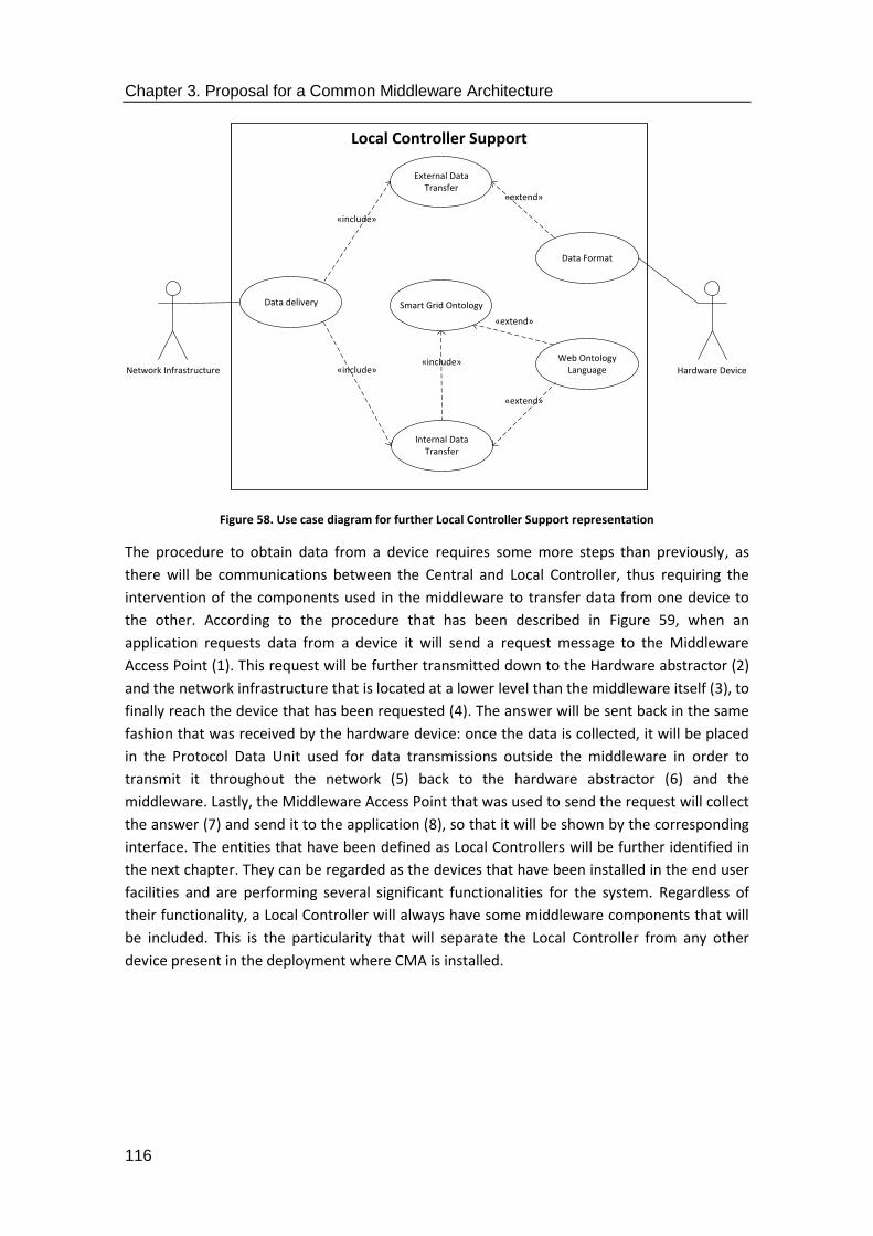
Chapter 3. Proposal for a Common Middleware Architecture
116
Figure 58. Use case diagram for further Local Controller Support representation
The procedure to obtain data from a device requires some more steps than previously, as
there will be communications between the Central and Local Controller, thus requiring the
intervention of the components used in the middleware to transfer data from one device to
the other. According to the procedure that has been described in Figure 59, when an
application requests data from a device it will send a request message to the Middleware
Access Point (1). This request will be further transmitted down to the Hardware abstractor (2)
and the network infrastructure that is located at a lower level than the middleware itself (3), to
finally reach the device that has been requested (4). The answer will be sent back in the same
fashion that was received by the hardware device: once the data is collected, it will be placed
in the Protocol Data Unit used for data transmissions outside the middleware in order to
transmit it throughout the network (5) back to the hardware abstractor (6) and the
middleware. Lastly, the Middleware Access Point that was used to send the request will collect
the answer (7) and send it to the application (8), so that it will be shown by the corresponding
interface. The entities that have been defined as Local Controllers will be further identified in
the next chapter. They can be regarded as the devices that have been installed in the end user
facilities and are performing several significant functionalities for the system. Regardless of
their functionality, a Local Controller will always have some middleware components that will
be included. This is the particularity that will separate the Local Controller from any other
device present in the deployment where CMA is installed.
Local Controller Support
Network Infrastructure«include»
«include»
«extend»
«extend»
Data delivery Smart Grid Ontology
External DataTransfer
Data Format
Web OntologyLanguage
Internal DataTransfer
«include»
«extend»
Hardware Device
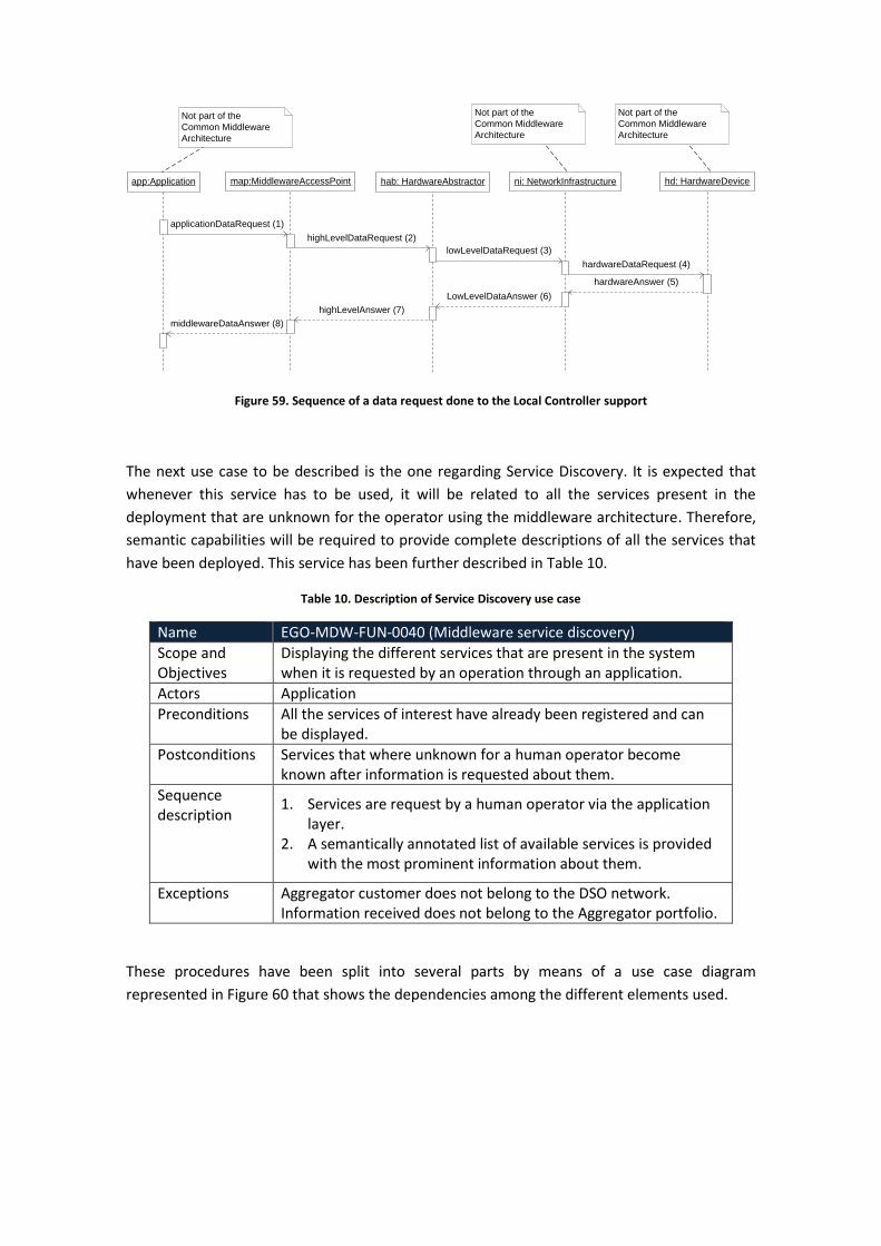
Figure 59. Sequence of a data request done to the Local Controller support
The next use case to be described is the one regarding Service Discovery. It is expected that
whenever this service has to be used, it will be related to all the services present in the
deployment that are unknown for the operator using the middleware architecture. Therefore,
semantic capabilities will be required to provide complete descriptions of all the services that
have been deployed. This service has been further described in Table 10.
Table 10. Description of Service Discovery use case
Name EGO-MDW-FUN-0040 (Middleware service discovery)
Scope and Objectives
Displaying the different services that are present in the system when it is requested by an operation through an application.
Actors Application
Preconditions All the services of interest have already been registered and can be displayed.
Postconditions Services that where unknown for a human operator become known after information is requested about them.
Sequence description
1. Services are request by a human operator via the application layer.
2. A semantically annotated list of available services is provided with the most prominent information about them.
Exceptions Aggregator customer does not belong to the DSO network. Information received does not belong to the Aggregator portfolio.
These procedures have been split into several parts by means of a use case diagram
represented in Figure 60 that shows the dependencies among the different elements used.
map:MiddlewareAccessPointapp:Application
highLevelDataRequest (2)
hab: HardwareAbstractor
Not part of the
Common Middleware
Architecture
hd: HardwareDeviceni: NetworkInfrastructure
Not part of the
Common Middleware
Architecture
lowLevelDataRequest (3)
hardwareDataRequest (4)
hardwareAnswer (5)
LowLevelDataAnswer (6)
highLevelAnswer (7)
middlewareDataAnswer (8)
Not part of the
Common Middleware
Architecture
applicationDataRequest (1)

Chapter 3. Proposal for a Common Middleware Architecture
118
Figure 60. Use case diagram for service discovery representation
In this diagram it can be seen how the data delivery performed in this case relies on the
context awareness facilities that have to be used in order to have an accurate idea of what
services are present. Aside from that, the information present in the deployment is based on
the format representation that has been chosen for the data. As it has been done before, the
data format will be based on the ontology that has been implemented in the middleware
solution. In addition to that, internal data transfer will also be required, as the semantic
capabilities present in the middleware solution must be requested. This latter process can be
further defined by means of a sequence diagram, such as the one portrayed in Figure 61. In
this case, when a human operator requests the service discovery functionality from an
application, it will be done so via Middleware Access Point (since a Middleware Autonomous
Service would only access). When the request is sent from the application (1) to the high level
middleware component, it will be resent to the registration one (2), as it is the one that has
the data regarding the services that have been registered in the deployment. However, rather
than getting a list of the services present in the middleware solution, the information will be
updated with the semantic information that is used in the annotation of the service
descriptions. Therefore, the request will be further sent to the component responsible for
those semantic capabilities (3). Once the data is obtained, it will be sent back to the
registration component (4) and the Middleware Access Point that collected the request in the
first place will receive it (5) and send it back to the application layer (6).
Service Discovery
Application«include»
«extend»
Data delivery Smart Grid OntologyWeb Ontology
Language
Internal DataTransfer
«include» «extend»
Context Awareness
«include»

Chapter 3. Proposal for a Common Middleware Architecture
119
Figure 61. Sequence of a data request done to the Local Controller support
Lastly, securitization of the transactions that are going to take place must also be dealt with.
There were two procedures that were deemed possible for this activity. The one dealing with
certifications for the web browser whenever a user was connecting was the one finally used. It
has been included in the section 4 of this thesis. As it has been done with the previous use
cases, Table 11 is presented with the most important features of this use case.
Table 11. Description of Information Security use case
Name EGO-MDW-FUN-0050 (Information security)
Scope and Objectives
Securitization of the transactions that are carried out among the parties involved in the communications. It will guarantee some security functionalities like confidentiality, integrity and authentication, as long as a web browser is used in the data transmissions.
Actors Application
Preconditions The security software infrastructure (certification, etc.) has been installed both in the remote application utilized by the end user and the Central Controller that is used as an intermediary between the user and the services that are requested.
Postconditions Communications are carried out in a regular way. The end user does not notice any change when security is used, but the exchanged information cannot be accessed by any unwanted party.
Sequence description
1. Security certification is established previously by the parties that are going to participate in the communication.
2. Data interchange is carried out as usual.
Exceptions No exceptions should be allowed in the system; not using security
map:MiddlewareAccessPointapp:Application rc:RegistrationComponent
highLevelServiceRequest (2)
sc:SemanticCapabilities
Not part of the Common Middleware Architecture
registrationComponentRequest (3)
semanticCapabilitiesAnswer (4)
registrationComponentAnswer (5)
middlewareAccessPoint (6)
applicationServiceRequest (1)

Chapter 3. Proposal for a Common Middleware Architecture
120
is discouraged in any distributed or Cyber-Physical System.
The operations that have been displayed in Table 11 can be further explained by means of the
use case diagram that has been depicted in Figure 62.
Figure 62. Use case diagram for service discovery representation
In the previous figure, it can be appreciated how the resources used for securitization are
almost the same as the ones defined for other use cases, such as Central or Local Controller
support and Service Discovery. The only significant difference, though, is that security must be
taken into account for this case, as it will rule the data exchange that takes place among the
parties that have been secured. Therefore, any data transfer and the very ontology that is used
for the transmission of information must be involved in the security procedures that are
developed.
Another way to explain these features is by means of a sequence diagram as the one that has
been depicted in Figure 63. The securitization operations that have been carried out in the
sequence diagram correspond to the ones that can be performed when requesting
information from a device, as it was depicted in the Local Controller support use case. In this
way, when a human operator requests information from an application, the latter will send a
request message (1) with the data that is required. The request will be sent to the Middleware
Access Point used to transmit that piece of information (2). Afterwards, the securitization
component will be used to cypher communications and transmit the data to the hardware
abstractor component (3). Once this procedure has been completed, all the other data
transmissions are undertaken as any other regular data request to a device: the information
Information Security
Application
«include»«include»
«extend»
«extend»
Data delivery Smart Grid Ontology
Securitization
Data Format
Web OntologyLanguage
Internal DataTransfer
«include»
«extend»
«include»

Chapter 3. Proposal for a Common Middleware Architecture
121
request will be transferred as packets at the network layer level (4) until it finally is delivered
to the hardware device responsible for providing the needed information (5). The request will
be deciphered in the hardware device so that it becomes clear the kind of data that is required
(6) and the answered will be cyphered again in order to guarantee its secure delivery (7). Once
an answer is obtained from the hardware (8), it will travel back to the middleware (9) until it
reaches the hardware abstractor and is sent back to the securitization component (10). The
latter will be responsible for deciphering the message received in the middleware solution and
sending it back to the high level of the software architecture (11) and delivering it to the
application that started the request (12).
It has to be highlighted that, according to what has been represented here, ciphering and
deciphering operations can be done via symmetric or asymmetric data encryption. The only
difference is that asymmetric encryption operations will take a longer time to be completed,
which depending on the hardware of the end user device might take seconds to complete.
Another different approach is the aforementioned usage of certifications to guarantee an
acceptable level of security in the system. This is the solution that was implemented in the e-
GOTHAM and I3RES research projects.

Figure 63. Sequence diagram with data collection and securitization
map:MiddlewareAccessPointapp:Application
highLevelDataRequest (2)
hab: HardwareAbstractor
Not part of the
Common Middleware
Architecture
hd: HardwareDeviceni: NetworkInfrastructure
Not part of the
Common Middleware
Architecture
networkDataRequest (4)
hardwareDataRequest (5)
hardwareAnswer (8)
networkAnswer (9)
highLevelAnswer (11)
middlewareDataAnswer (12)
Not part of the
Common Middleware
Architecture
applicationDataRequest (1)
sc:SecuritizationComponent
highLevelDataRequest (3)
hardwareAbstractorAnswer (10)
requestDecyphering (6)
answerCyphering (7)
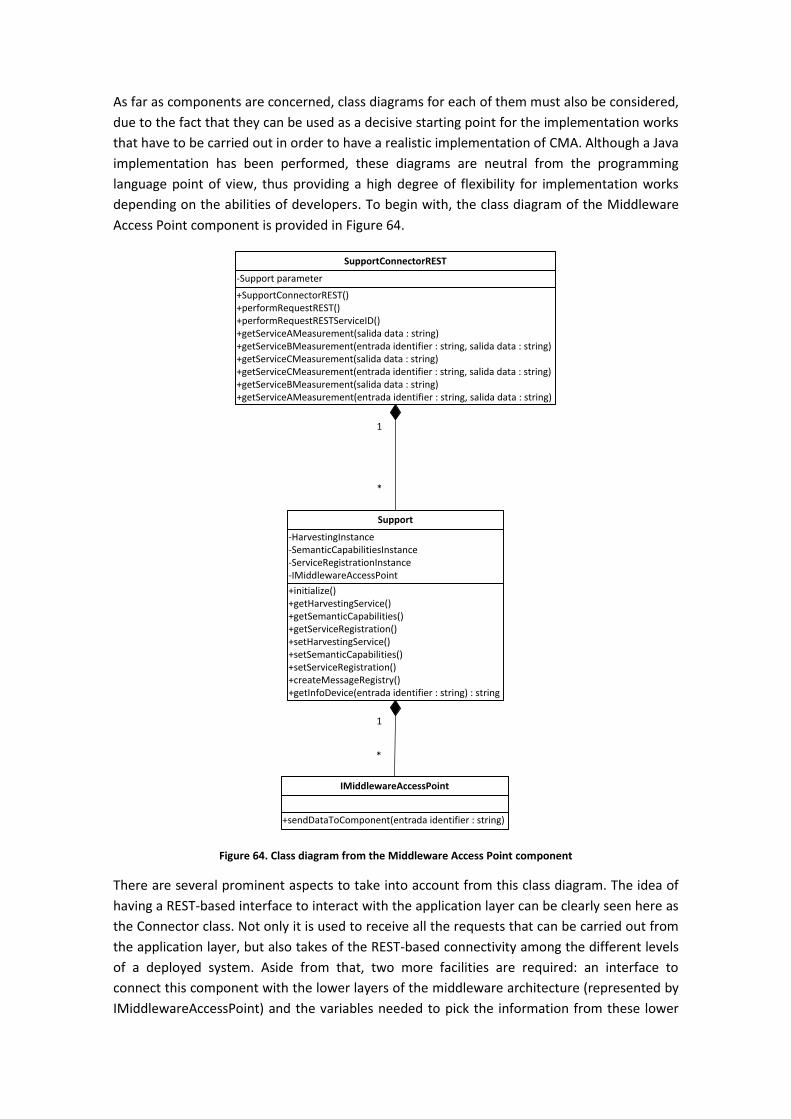
As far as components are concerned, class diagrams for each of them must also be considered,
due to the fact that they can be used as a decisive starting point for the implementation works
that have to be carried out in order to have a realistic implementation of CMA. Although a Java
implementation has been performed, these diagrams are neutral from the programming
language point of view, thus providing a high degree of flexibility for implementation works
depending on the abilities of developers. To begin with, the class diagram of the Middleware
Access Point component is provided in Figure 64.
Figure 64. Class diagram from the Middleware Access Point component
There are several prominent aspects to take into account from this class diagram. The idea of
having a REST-based interface to interact with the application layer can be clearly seen here as
the Connector class. Not only it is used to receive all the requests that can be carried out from
the application layer, but also takes of the REST-based connectivity among the different levels
of a deployed system. Aside from that, two more facilities are required: an interface to
connect this component with the lower layers of the middleware architecture (represented by
IMiddlewareAccessPoint) and the variables needed to pick the information from these lower
+SupportConnectorREST()+performRequestREST()+performRequestRESTServiceID()+getServiceAMeasurement(salida data : string)+getServiceBMeasurement(entrada identifier : string, salida data : string)+getServiceCMeasurement(salida data : string)+getServiceCMeasurement(entrada identifier : string, salida data : string)+getServiceBMeasurement(salida data : string)+getServiceAMeasurement(entrada identifier : string, salida data : string)
-Support parameter
SupportConnectorREST
1
*
+initialize()+getHarvestingService()+getSemanticCapabilities()+getServiceRegistration()+setHarvestingService()+setSemanticCapabilities()+setServiceRegistration()+createMessageRegistry()+getInfoDevice(entrada identifier : string) : string
-HarvestingInstance-SemanticCapabilitiesInstance-ServiceRegistrationInstance-IMiddlewareAccessPoint
Support
+sendDataToComponent(entrada identifier : string)
IMiddlewareAccessPoint
1
*
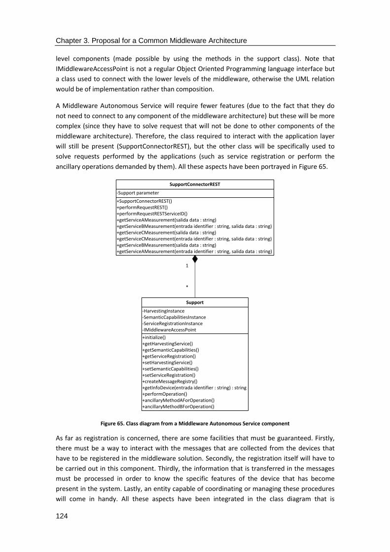
Chapter 3. Proposal for a Common Middleware Architecture
124
level components (made possible by using the methods in the support class). Note that
IMiddlewareAccessPoint is not a regular Object Oriented Programming language interface but
a class used to connect with the lower levels of the middleware, otherwise the UML relation
would be of implementation rather than composition.
A Middleware Autonomous Service will require fewer features (due to the fact that they do
not need to connect to any component of the middleware architecture) but these will be more
complex (since they have to solve request that will not be done to other components of the
middleware architecture). Therefore, the class required to interact with the application layer
will still be present (SupportConnectorREST), but the other class will be specifically used to
solve requests performed by the applications (such as service registration or perform the
ancillary operations demanded by them). All these aspects have been portrayed in Figure 65.
Figure 65. Class diagram from a Middleware Autonomous Service component
As far as registration is concerned, there are some facilities that must be guaranteed. Firstly,
there must be a way to interact with the messages that are collected from the devices that
have to be registered in the middleware solution. Secondly, the registration itself will have to
be carried out in this component. Thirdly, the information that is transferred in the messages
must be processed in order to know the specific features of the device that has become
present in the system. Lastly, an entity capable of coordinating or managing these procedures
will come in handy. All these aspects have been integrated in the class diagram that is
+SupportConnectorREST()+performRequestREST()+performRequestRESTServiceID()+getServiceAMeasurement(salida data : string)+getServiceBMeasurement(entrada identifier : string, salida data : string)+getServiceCMeasurement(salida data : string)+getServiceCMeasurement(entrada identifier : string, salida data : string)+getServiceBMeasurement(salida data : string)+getServiceAMeasurement(entrada identifier : string, salida data : string)
-Support parameter
SupportConnectorREST
1
*
+initialize()+getHarvestingService()+getSemanticCapabilities()+getServiceRegistration()+setHarvestingService()+setSemanticCapabilities()+setServiceRegistration()+createMessageRegistry()+getInfoDevice(entrada identifier : string) : string+performOperation()+ancillaryMethodAForOperation()+ancillaryMethodBForOperation()
-HarvestingInstance-SemanticCapabilitiesInstance-ServiceRegistrationInstance-IMiddlewareAccessPoint
Support

Chapter 3. Proposal for a Common Middleware Architecture
125
portrayed in Figure 66. Depending on the complexity of the developments, the ontology can
also be included in this component, but due to its potential complexity it is considered as
located in a different one.
The relationships among the most prominent classes have also been included. Basically, the
class responsible for providing the management facilities (MessageFormatManager) will
control how the services belonging to devices will be registered, which will be collected from
the interface that is offered to interact with the lower level components.
Figure 66. Class diagram of the Registration component
Additionally, the Context Awareness component will have several facilities that can be
expected to obtain information from the environment and trigger any action that might be
considered as necessary. One of the tasks to deal with it is processing the messages that will
be received from the registered devices that are present in the system, so a class used for that
purposed has been added (MessageManager). At the same time, an interface is required to
obtain those messages both from outside the middleware architecture and other software
components of the architecture, specifically the registration component that is used during
+SupportConnectorREST()+performRequestREST()+performRequestRESTServiceID()+getServiceAMeasurement(salida data : string)+getServiceBMeasurement(entrada identifier : string, salida data : string)+getServiceCMeasurement(salida data : string)+getServiceCMeasurement(entrada identifier : string, salida data : string)+getServiceBMeasurement(salida data : string)+getServiceAMeasurement(entrada identifier : string, salida data : string)
-Support parameter
MessageFormatManager
1
*
+initialize()+getHarvestingService()+getSemanticCapabilities()+getServiceRegistration()+setHarvestingService()+setSemanticCapabilities()+setServiceRegistration()+createMessageRegistry()+getInfoDevice(entrada identifier : string) : string
-HarvestingInstance-SemanticCapabilitiesInstance-ServiceRegistrationInstance
ServicesRegistration
+initialize()+getHarvestingService()+getSemanticCapabilities()+getServiceRegistration()+setHarvestingService()+setSemanticCapabilities()+setServiceRegistration()+createMessageRegistry()+getInfoDevice(entrada identifier : string) : string
-HarvestingInstance-SemanticCapabilitiesInstance-ServiceRegistrationInstance
InterfaceServicesRegistration
+initialize()+getHarvestingService()+getSemanticCapabilities()+getServiceRegistration()+setHarvestingService()+setSemanticCapabilities()+setServiceRegistration()+createMessageRegistry()+getInfoDevice(entrada identifier : string) : string
-HarvestingInstance-SemanticCapabilitiesInstance-ServiceRegistrationInstance
ServicesRegistrationMessage
1
*
1
*

Chapter 3. Proposal for a Common Middleware Architecture
126
service registration (hence the IContextAwarenessService interface and
ContextAwarenessService class). As it was done for the previous component, a manager class
will be used for management purposes when interchanging information with the ontology of
the system or the service registration. Finally, a timestamp will be generated whenever a new
message regarding the presence of devices is received by the component. These features have
been included in Figure 67.
Figure 67. Class diagram of the Context Awareness component
The ontology itself has also been defined at a high level, due to the fact that its functionalities
are of major importance for a system of these features. Apart from the managing class
(OntologyConnector) and its interface (IOntologyConnector), there are two main classes where
most of the functionalities of the ontology are located. The first one is used to contain all the
templates of the devices established as the ones to be included in the deployment. This class
has been represented as Templates, since it contains all those features to be expected from
hardware (kind of device, geographical location, model, manufacturer, serial number) and
software (service type, functionality or state). Note that even though hardware information
was included in the ontology, the most relevant data that will be requested by the users
communicating with the middleware will be related to the services. In addition to that, there is
another class called QueryLanguageFacilities that has been used in order to define all the
possible outcomes of the requests that are taken to be attended by the ontology (typically,
they will be about alternative services to provide to the Context Awareness component, types
+getService()+initialize()+getOntologyInterface(salida ontologyID : string)+getRegisteredService(salida ack : string)+getTimeStamp(salida timestamp : long)+setOntologyInterface(entrada ontologyID : string)+setRegisteredComponent(entrada componentID : string)+setTimeStamper(entrada TimeStamp : long)
-IServicesRegistry-IOntology-TimeStamper
ContextAwarenessController
1
*
+createDocumentFromString(entrada XMLString : string)+parseHeartbeatMessage(entrada HBMesage : string)
-DocumentBuilder-Document
MessageManager
+sendMessage(entrada message : string)+isDeviceDeployed(entrada deviceID : string)+registrationEnabled(entrada ena : bool)+setDeviceTransportID(entrada TransportID : string)+getdeviceTransportID(entrada transportID : string)
-ContextAwarenessController
ContextAwarenessService
+sendMessage(entrada message : string)+isDeviceDeployed(entrada deviceID : string)+registrationEnabled(entrada ena : bool)+setDeviceTransportID(entrada TransportID : string)+getdeviceTransportID(entrada transportID : string)
-ContextAwarenessController
IContextAwarenessService
1*

Chapter 3. Proposal for a Common Middleware Architecture
127
of devices, hardware compliant with certain features, input and output parameters or listing
devices and services). This has been designed like this due to the fact that it became evident
during the design and development stages that SPARQL was the most suitable language to
compose queries against the ontology that was defined for the system. The classes have been
represented in Figure 68.
Figure 68. Class diagram of the semantic capabilities component
The CMA component used to abstract the hardware heterogeneity has also been portrayed as
a set of classes in a diagram. The main particularity of this component is that it will have
certain capabilities that will ensure that it is ready to receive information from the PDUs
received from the network. Consequently, it implements a listener used to retrieve all the
information regarding messages sent by the hardware devices deployed
(HabServiceImplementation) that is implemented from an interface (IHabService).
Furthermore, a managing class (called HardwareAbstractorManager) has also been included
for sending and receiving messages, containing their most prominent data. This class makes
+initialize()+deleteDataBase()+registerEntry(entrada message : string)+createMessageRegistry(salida message : string)+registerService(entrada messageXML : string)
-model-namespace : string-location-dataset-query
OntologyConnector
+disableService(entrada dataset, entrada serviceID : string)+modifyState(entrada dataset, entrada serviceID : string, entrada state : string)+addAlternativeService(entrada dataset, entrada serviceID : string, entrada alternativeServices : string)+getLocation(salida location : string, entrada serviceID : string, entrada dataset)+getAlternativeServices(salida location : string, entrada serviceID : string, entrada dataset)+getCompliantDevices(salida compliantDevices : string, entrada type : string, entrada dataset)+getDevicesNameType(salida devices : string, entrada type : string, entrada dataset)+getActiveServices(salida activeServices : string, entrada dataset)+getDeviceType(salida type : string, entrada serviceID : string, entrada dataset)+getState(salida state : string, entrada serviceID : string, entrada dataset)+getOperations(salida operations : string, entrada serviceID : string, entrada dataset)+getInputParametersInfo(salida inputParametersInfo : string, entrada serviceID : string, entrada dataset)+getOutputParametersInfo(salida outputParametersInfo : string, entrada serviceID : string, entrada dataset)+getInfoDevice(salida deviceInfo : string, entrada serviceID : string, entrada dataset)+getInfoDB(salida dbInfo : string, entrada serviceID : string, entrada dataset)+listDevices(salida devices : string, entrada dataset)+listServices(salida services : string, entrada dataset)
-namespace
QueryLanguageFacilities
+fillIndividuals(entrada model)+setServiceFunctionality(entrada functionality : string)+setServiceType(entrada type : string)+setServiceState(entrada functionality : string)+setManufacturer(entrada manufacturer : string)+setModelID(entrada modelID : string)+setType(entrada type : string)+setLatitude(entrada latitude : long)+setLongitude(entrada longitude : long)+getServiceFunctionality(salida functionality : string)+getServiceType(salida type : string)+getServiceState(salida state : string)+getLatitude(salida latitude : long)+getManufacturer(salida manufacturer : string)+getSerialNumber(salida serialNumber : int)+getModelID(salida modelID : string)+getType(salida type : string)+getLongitude(salida longitude : long)
-serviceFunctionality-serviceType-sericeState-latitude-longitude-manufacturer-serialNumber-modelID-type
Templates
1
*
1
*
+initialize()+deleteDataBase()+registerEntry(entrada message : string)+createMessage(salida message : string)+registerService(entrada messageXML : string)
«interface»IOntologyConnector

Chapter 3. Proposal for a Common Middleware Architecture
128
use of a data listener that has been included in another one (DataListener) that is in
permanent waiting mode so that it will immediately transfer the messages that are collected
from the network. All these characteristics have been included in Figure 69. If the middleware
architecture is deactivated due to any reason (hardware migration, etc.), the listening
capabilities will remain disabled until they are either activated again or replaced with a
different component.
Figure 69. Class diagram of the Hardware Abstractor component
The component used for Service Composition can also be described in a similar manner. The
elements that can be expected here are related to one class used to collect all the information
from simple service requests and send it back to the high level middleware components. An
agent is used as the Object Oriented Programming language interface because there are
services that can be implemented and easily ported to other object instances. The class that
implements the service composition functionalities receives the data from the other
components, enables the composition and returns the result to its origins. The overall
appearance of the class diagram that has been designed is present in Figure 70.
+createListener(entrada transportID : string)+destroyListener(entrada transportID : string)+sendMessage(entrada serialNumber : string, entrada message : string)
-HighLevelInstance-SemanticCapabilitiesInstance-ServiceRegistrationInstance
HabServiceImplementation
+initialize()+createRegistrationMessage(entrada message : string)+processInputData(entrada input : string)+setUpListener()+sendMesage(entrada serviceID : string, entrada message : string)
-Session-Connection-MessageConsumer-IServiceRegistration-IContextAwareness
HardwareAbstractorManager
+DataListener()+onMessage(entrada message : string)
-HardwareAbstractorManager
DataListener
1
*
1
*
+createListener(entrada transportID : string)+sendMessage(entrada serialNumber : string, entrada message : string)+destroyListener(entrada transportID : string)
«interface»IHabService

Chapter 3. Proposal for a Common Middleware Architecture
129
Figure 70. Class diagram of the Service Composition component
Lastly, the securitization component includes the functions used to encrypt and decrypt
transferred information. They are very clearly separated between asymmetric
(AsymmetricCryptography) and symmetric encryption (SymmetricCryptography), as it has been
deemed useful that, should security be implemented by means of a software component, both
options are available. Furthermore, a class used for ancillary purposes
(AncillaryFunctionalities), such as choosing one kind of encryption over the other one, has
been added to the software component. Figure 71 contains a representation of all these
functionalities.
+ServiceCompositionAgent()+getAgentDescription() : String+getServiceAgentObject()+load(entrada Context : Context)+receptacle(entrada operationInvocation : ServiceContext)+run()+stop()+unload()+sendDataAnswer() : String+receiveDataRequest(entrada dataType : string)+composeAnswer(entrada dataType1 : string, entrada dataType2 : string)
-context : Context-servicesDescription : ServicesAgentObject -incomingData : string-outgoingData : string-TYPE_1 : string = 1-TYPE_2 : string = 2-TYPE_3 : string = 3
ServiceCompositionAgent
+getAgentDescrption() : String+getServiceAgentObject()+load(entrada Context : Agent)+receptacle(entrada operationInvocation)+run()+stop()+unload()
«interface»Agent

Chapter 3. Proposal for a Common Middleware Architecture
130
Figure 71. Class diagram of the Securitization component
3.3.5. State diagrams
There are two other ways that can be used to characterize from a Platform Independent
Model point of view. One of them is by means state diagrams that show the different statuses
where the system will work whenever it receives a specific input. Since they provide an
interesting point of view regarding how a system changes its behaviour depending on the
external stimuli it receives, they have been included in this thesis.
To begin with, the activity diagram for registration has been placed as Figure 72. From the
point of view of a state diagram, the system stays in a “Waiting for registration request” status
until it receives a device registration request, which will trigger a registration message that will
be sent from the application to the middleware for its semantic treatment (1). The presence of
the already registered device, along with all its associated services, will be checked by the
Context Awareness component, since it will receive the request to do so (2). If the data
corresponds to a non-registered device (3), the request will be further transferred (4) through
the middleware architecture. It is interesting noting that during the message transmission, the
system will move from one state to the next one without any other option. This is due to the
fact that, as tests result will show in the next section, any other event happening once the
request has started being transmitted through the middleware is extremely unlikely. As soon
as the registration process is finished after the last transfer (5), the system will revert to its
waiting status for further component registration (6).
+sendToSymmetricEncryption(entrada message : string)+sendToAsymmetricEncryption(entrada message : string)+setPublicKey(entrada publicKey : string)+setPrivateKey(entrada privateKey : string)+getPublicKey(salida publickKey : string)+getPrivateKey(salida privateKey : string)+storeObject(entrada key)
-message-publicKey-privateKey
AncillaryFunctionalities
1
*
+generateKeyPair(entrada keyLength : long)+asymmetricCyphering(entrada object)+asymmetricDecyphering(entrada object)
-RSAKeyPairGenerator-AsymmetricCipherKeyPair
AsymmetricCryptography
+symmetricCyphering(entrada object)+symmetricDecyphering(entrada object)+generateAESKey(entrada keyLength : int)
-CipherKeyGenerator
SymmetricCryptography
1
*

Chapter 3. Proposal for a Common Middleware Architecture
131
Figure 72. State diagram for service registration
Another situation that may happen, though, is that the device is already registered (7).
Consequently, the Context Awareness component will refuse its registration, as it would be
redundant. In any case, after this last change of status, the middleware architecture will go
back to its initial status (8) and wait for further devices to be registered.
In case a request is received to obtain some kind of information from a service the sequence of
states is as depicted in Figure 73. In this case, when the system is idle (it may be very well
doing something else, but it is considered idle from the requests point of view) and a service
request is sent to the middleware architecture (1) the service request will be checked by the
Context Awareness component, which will look for an already registered device in order to
satisfy it. If it is found, it will send back the confirmation of an existing device to the other part
of the middleware (4) and the message will be further transferred throughout the architecture
until it leaves the hardware device where it has been installed and the underlying network
capabilities transfer the data request to the device itself (6). After some processing is done in
the device (7), the information will be retrieved and send back to the hardware component
that contained the Middleware Access Point that collected it (8). Once it has been delivered in
the main part of the middleware architecture (9). The system will then change a status where
the answer has already been received (10) and delivered to the middleware component that
started it (11), to finally get back to its original idle state (12). As it happened before, other
possible situation is that a request has been sent to a device that is not available.
Consequently, the Context Awareness component will refuse its further processing (13) and
the middleware architecture will revert to its original idle state.
Waiting for registration request
Registration request
Middleware message transfer
Device registration message (1)
Semantic treatment of data transfer (4)
Device services registration
Semantic data transfer (5)
Revert to waiting status (6)
Context Awareness check
Context awareness data transfer (2)
Registration rejection
Revert to waiting status (8)
Existing device (7)
Non-existing device (3)
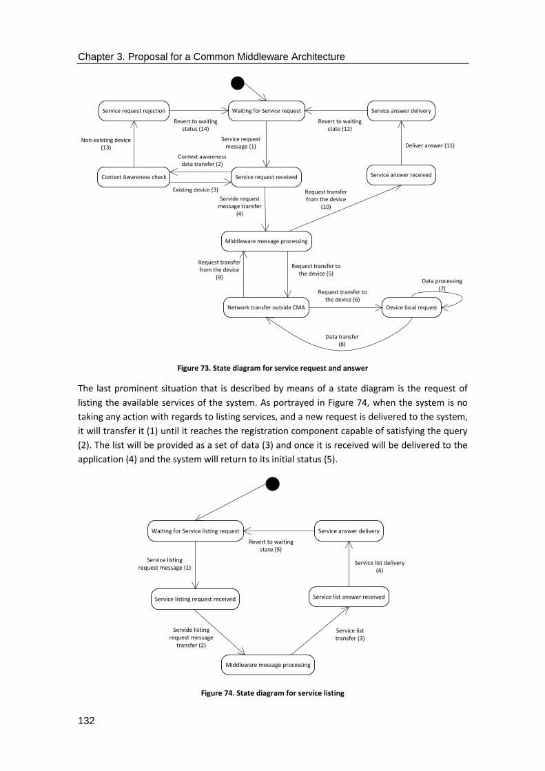
Chapter 3. Proposal for a Common Middleware Architecture
132
Figure 73. State diagram for service request and answer
The last prominent situation that is described by means of a state diagram is the request of
listing the available services of the system. As portrayed in Figure 74, when the system is no
taking any action with regards to listing services, and a new request is delivered to the system,
it will transfer it (1) until it reaches the registration component capable of satisfying the query
(2). The list will be provided as a set of data (3) and once it is received will be delivered to the
application (4) and the system will return to its initial status (5).
Figure 74. State diagram for service listing
Waiting for Service request
Service request received
Middleware message processing
Service request message (1)
Servide request message transfer
(4)
Network transfer outside CMA
Request transfer to the device (5)
Device local request
Request transfer to the device (6)
Data transfer (8)
Data processing (7)
Request transfer from the device
(9)
Request transfer from the device
(10)
Service answer received
Service answer delivery
Revert to waiting state (12)
Deliver answer (11)
Context Awareness check
Context awareness data transfer (2)
Existing device (3)
Service request rejection
Revert to waiting status (14)
Non-existing device (13)
Waiting for Service listing request
Service listing request received
Middleware message processing
Service listing request message (1)
Servide listing request message
transfer (2)
Service list transfer (3)
Service list answer received
Service answer delivery
Revert to waiting state (5)
Service list delivery (4)

Chapter 3. Proposal for a Common Middleware Architecture
133
3.3.6. Activity diagrams
Activity diagrams show the different actions that can be taken by the parties implied in
communications where the middleware solution is deployed. In the case of Common
Middleware Architecture, they can be used to define the actions that have to be taken in order
to complete a certain operation of interest for the system. They can be especially useful when
determining the differences regarding a specific choice or option in the system behaviour that
will result in a different set of actions. The same likely situations that were depicted in the
previous section have been included here as well: device registration, service request and
service list request.
When a device registration has to be done in the system, and according to the point of view
that is provided by an activity diagram, the first action following the start of all the procedure
will be sending forward the registration request until it reaches a point where either the device
will be already registered or not. Should it be registered, any further step will become
thwarted and the flow of actions will come to an end. In case it is not registered yet, it will
have to be considered whether the query was started either from the device or the application
layer. If the device has started the request, then it will imply that a network transfer has been
performed and therefore CMA functionalities have been used. If the request was started from
the application layer, the request will be attended by the suitable middleware component and
the registration process will be finished, as shown in Figure 75.
Figure 75. Activity diagram for device registration
Device Registration
From application layerFrom device
Registration rejection message
Device registration request
Device services registrationRegistered deviceNon-registered device
Device registration request
Network transfer request
CMA transfer request
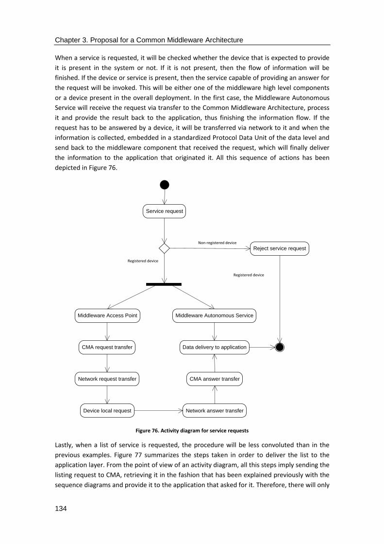
Chapter 3. Proposal for a Common Middleware Architecture
134
When a service is requested, it will be checked whether the device that is expected to provide
it is present in the system or not. If it is not present, then the flow of information will be
finished. If the device or service is present, then the service capable of providing an answer for
the request will be invoked. This will be either one of the middleware high level components
or a device present in the overall deployment. In the first case, the Middleware Autonomous
Service will receive the request via transfer to the Common Middleware Architecture, process
it and provide the result back to the application, thus finishing the information flow. If the
request has to be answered by a device, it will be transferred via network to it and when the
information is collected, embedded in a standardized Protocol Data Unit of the data level and
send back to the middleware component that received the request, which will finally deliver
the information to the application that originated it. All this sequence of actions has been
depicted in Figure 76.
Figure 76. Activity diagram for service requests
Lastly, when a list of service is requested, the procedure will be less convoluted than in the
previous examples. Figure 77 summarizes the steps taken in order to deliver the list to the
application layer. From the point of view of an activity diagram, all this steps imply sending the
listing request to CMA, retrieving it in the fashion that has been explained previously with the
sequence diagrams and provide it to the application that asked for it. Therefore, there will only
Reject service request
Service request
Non-registered device
Registered device
Registered device
Middleware Autonomous ServiceMiddleware Access Point
Data delivery to application
Network request transfer
Device local request
CMA request transfer
Network answer transfer
CMA answer transfer

Chapter 3. Proposal for a Common Middleware Architecture
135
be three different intermediate steps: the service list will be requested from the application
layer, it will be transferred to the Common Middleware Architecture components (which will
be, as shown before, the registration component and the semantic capabilities component)
and will be transferred back to the application that requested the information to the
middleware.
Figure 77. Activity diagram for service list request
3.3.7. Deployment diagram
The last UML diagram that is going to be used to represent the features and behaviour of the
Common Middleware Architecture is a deployment one. As it has been mentioned before, the
middleware architecture will be distributed among several different hardware devices present
in a system with different hardware components belonging to a Smart Grid-like system (which
has been referred to as “deployment”). Deployment diagrams show where the different parts
of the middleware solution have been installed. By “where”, it is meant the pieces of hardware
that contain the middleware solution. In addition to that, the interconnections among all of
them and the resources used to obtain them are also shown in this kind of diagram. All these
ideas have been tied together in Figure 78. There, the elements that are used in a
demonstrator or an actual working system can be better appreciated: the device referred to as
the Central Controller connects itself with the device that is using the TCP/IP stack. At the
same time, REST interfaces are used at the uppermost level of the stack (application) between
the Central Controller and the device that is expected to use the application. This one can be
based in a web browser or any other software technology, but in the end will have to count
with some sort of Graphical User Interface. As far as the other devices are concerned, they will
be connected with each other with the same kind of TCP/IP stack, as they have to be reached
Service list request
Data delivery to application
CMA request transfer

Chapter 3. Proposal for a Common Middleware Architecture
136
remotely, as it was done with the previous device that had the GUI installed in it. The number
of local controllers that has been installed in the system will differ depending on the services
that are demanded. In any case, they will be a collection that will at least focused on retrieving
information either from the environment (as if they were part of an Internet of Things system)
or from the power facilities installed in a certain area.
Figure 78. Deployment diagram of a system with the Common Middleware Architecture installed
3.4. Architecture Description for ISO/IEC/IEEE 42010
The description that has been placed in this section deals with the idea of describing CMA
according to the models and principles formulated according to the ISO/IEC/IEEE 42010
<<device>> Central Controller
<<device>> Local Controller 1
<<device>> Local Controller 3
<<device>> Hardware with GUI
<<device>> Local Controller 2
<<device>> Local Controller 4
REST
TCP/IP
TCP/IP
TCP/IP
TCP/IP
Chapter 3. Proposal for a Common Middleware Architecture
137
standard. The different subsections that have been included in this document have been done
so according to the template defined by the ISO member Rich Hilliard for the description of
software architectures [159], whom the author of this thesis established contact in order to
clarify and obtain the suitable resources for this description. Rather than constantly
referencing the standard, the next sections have been included as if having the architecture
described according to this standard had been previously agreed upon. There are some
aspects from this standard (as stated in [160]) that deal with the concept of model kinds and
their features. Model kind names are a concept very specific to the ISO/IEC/IEEE 42010
standard, in the sense that according to it, architecture viewpoints are constituted by means of
several architecture models which are ruled by a model kind that fixes conventions, notations
and rules for the models of that type. The same idea is located in Figure 2 of [160], where it is
represented that each Architecture Viewpoint is an aggregation of one or several model kinds
that, at the same time, govern models for the architecture. It is also mentioned that “Examples
of model kinds include data flow diagrams, class diagrams, Petri nets, balance sheets,
organization charts and state transition models”. Therefore, considering that these elements
have already been included, and considering the scope of the thesis, model kinds and their
features are not referenced in the description that has been included in this section. In order
to make crystal clear the terms and parameters that have been included in this subsection,
,the ones that play a major role in it have been surrounded by <> symbols.
3.4.1. Identifying information
The <Architecture Name> that is described here is the <Common Middleware Architecture> or
CMA. It aims to provide a significant contribution to a standard for the development of
middleware for the <System of Interest> represented by the <Smart Grid>, although it can be
extended with a minimal amount of modifications to other Cyber-Physical Systems, such as
underwater robotics of the Internet of Things.
3.4.2. Supplementary information
This architecture has been defined as a result of the experience acquired during the
collaboration of the author of this manuscript in several Smart Grid-themed projects, such as
e-GOTHAM [21]and I3RES [22]. The specific needs for those projects were slightly different, in
the sense that e-GOTHAM aimed to provide an ICT-based platform for the interoperability of
hardware devices and energy-related applications, whereas I3RES was focused on the
management of energy from a more electrical point of view, enabling new actors like
aggregators or prosumers, and management of electricity from the end user side by means of
services like Demand Response (DR) and Demand Side Management (DSM).
3.4.3. Other information
There are other important pieces of information that can be included from the architecture
that is described here. Specifically, features related to the Purpose of <Common Middleware

Chapter 3. Proposal for a Common Middleware Architecture
138
Architecture>, its scope and the context of this architecture have been described in the
following section.
3.4.4. Overview
CMA is a software middleware solution that has as its purpose guaranteeing interoperability of
hardware devices interconnected via networked systems and the applications that can be
accessed from the higher level endpoints that have been enabled in <Common Middleware
Architecture>. In the same way, it establishes a number of processes, Processing Data Units
and format details that target interconnectivity at the data level, so that data can be
seamlessly transmitted from one part of a distributed system to the other.
The scope of <Common Middleware Architecture> strictly covers the middleware layer, as its
main objectives are consistent with what is expected from this level (hardware abstraction,
interoperability, Application Programming Interfaces for applications). Due to the nature of
middleware, other levels such as applications networking, operating systems or hardware are
not covered due to the following reasons:
1. Applications are supposed to be connected via access points to lower levels rather
than perform the interconnection by themselves, due to the fact that applications are
commonly unaware of all the other devices present in a distributed system, and if they
had to be so, their complexity would grow exponentially and their scalability would be
very limited.
2. Network layer perform interconnectivity functionalities, but these are limited to the
PDUs typical of the network layer (packages) and its contents and format cannot be
usually understood in an immediate manner by an application (let alone its human
users).
3. Hardware devices are produced by different manufactures and vendors and, by
themselves, their components at this level are not supposed to be aware of other
devices. While middleware components can be added to hardware (as it will be shown
in the next chapter), they are still part of the middleware layer from a distributed, CPS
point of view. Alas, they are software-based, rather than actual hardware assembled in
a production line.
As far as the context is concerned, the features presented in <Common Middleware
Architecture> have been conceived for the <Smart Grid> and any other CPS that results similar
enough to it. Usually, any distributed system that presents hardware devices that receive and
transfer information regarding application domain –or even contextual- information and can
be acted upon via software will be likely to receive a port. In the end, by following the
definition of what a Cyber-Physical System is – “CPSs refer to the next generation of engineered
systems that require tight integration of computing, communication and control technologies
to achieve stability, performance, reliability, robustness, and efficiency in dealing with physical
systems of many application domains” [161] or the kind of deployment where computing
devices and physical components are integrated [162]-, it can be determined how <Common
Middleware Architecture> can be ported to those systems.

Chapter 3. Proposal for a Common Middleware Architecture
139
3.4.5. Architecture evaluations
Two different scenarios have been used to assess the feasibility and performance of the
semantic middleware proposals that have contributed to the creation of <Common
Middleware Architecture>. In addition to that, [141] also includes a description and testing
activities related to what was done in a laboratory-based environment using a Raspberry Pi as
a Local Controller. For the sake of the manuscript that contains this description, they have
been included in Chapter 4.
3.4.6. Rationale for key decisions
There are several decisions of major importance that have been taken in the context of the
design and development of the <Common Middleware Architecture>. They have been taken
considering some underlying aspects that are common of middleware architectures, such as
the following ones:
1. Encapsulation of services was mandatory. Since the services that were going to be
used by higher level entities (such as the application layer) have an immediate
connection with the middleware, they had to be included in this latter layer.
2. Accessibility to the services present in the middleware had to be granted. Due to the
same reason described before, several access points had to be created for the
applications to access middleware.
3. The system presented had to be distributed. It was required that the facilities that can
be offered by the middleware could be accessed from every device where it was
supposed that middleware should be installed (such as the end user pieces of
equipment like Advanced Metering Infrastructure)
4. Performance had to be acceptable. In the end, the system should work in a way that it
was able to provide the data retrieved from the services at a reasonable speed,
otherwise it would be useful for end users.
All in all, decisions match the criteria established for the non-functional requirements that
were formulated in the projects were the middleware architectures were carried out.
3.4.7. Stakeholders, concerns and concern–stakeholder traceability
The main group of stakeholders can be roughly described as the group of people with an
interest in information transmission in the <Smart Grid>. To put it more accurately, the
following stakeholders have to be considered, according to what is defined in the ISO/IEC/IEEE
42010 standard for Architecture Description:
1. Users: the users of the middleware solution that is described in this thesis are the
consumers at the very end of the <Smart Grid> that make use of the electricity that they
have purchased to turn it into other different kinds of energy, depending on their needs

Chapter 3. Proposal for a Common Middleware Architecture
140
(mechanical, chemical, etc.). It must be taken into account, though, that prosumers can
also be included in this group, and they will be able to provide power to the system, in a
bi-directional way that can be regarded as one of the most prominent contributions of the
application domain that is being studied.
2. Operators: these are the staff involve in the correct performance of the systems in the
<Smart Grid>. Typically, they will involve ICT- and power-related personnel, as these are
the two main implied areas of knowledge. Nevertheless, their functions will be rather
similar: supervising the hardware and software equipment that is used in the system and
controlling that the electricity is transferred according to their instructions.
3. Acquirers: the acquirers of the middleware solution that is being studied are the main
parties involved in the ICT part of the <Smart Grid>: Distributed System Operator,
Transmission System Operator and the aggregator all participate from the system that is
being developed as part of the work performed in this thesis. Depending on the kind of
devices used by the consumers/prosumers, middleware may also be extended to the local
devices used in their dwellings, as shown in [141].
4. Owners: they will be the same entities that the acquirers are, as no transfer is planned to
be done from one entity to another one out from the <Smart Grid>.
5. Suppliers: the entity expected to offer the middleware architecture will fall within the
same category as the ones providing ICT-related services. Software developers,
telecommunication companies or even start-ups related to the business of the power grid
can supply the required.
6. Developers: the developers of a middleware solution will usually be part of the staff that is
working on the ICT part of the <Smart Grid>. They might be either from the third party
software company responsible for the development and installation of the middleware
solution or from the power grid actors (DSO, TSO or the aggregator) in case they want to
extend their areas of interest to <Smart Grid> software.
7. Builders: since what is presented here is a middleware architecture, there is no hardware
to build except for the one that will have all the required software installed. Commonly,
the computational capabilities of this solution will not be very demanding, so the hardware
does not require being expensive.
8. Maintainers: there will be part of the staff implied in the middleware to check its correct
performance, even though maintenance is likely to be minimal, as most of the services
implied take care of the needs of the system. Replacement of devices or their upgrade
(with new sensors and services) may require minor updates in the deployed middleware
solution.
Concerns involving <Common Middleware Architecture> involve interoperability and
interconnectivity at the data level of hardware devices typical of a power grid. Specifically, and
as a way to answer the concerns addressed by the template of the ISO/IEC/IEEE 42010
standard for Architecture Description:
1. The purpose of the system-of-interest: allow the interoperability of the hardware devices
that are present in the distributed, Cyber-Physical System represented by the <Smart
Grid>. That is to say, the integration of different equipment regardless of their features
and complexity in a deployment where all of the will be working in a cooperative manner.

Chapter 3. Proposal for a Common Middleware Architecture
141
2. Suitability of the architecture: the suitability is very high, due to the fact that middleware is
being used since the 1980s to guarantee interoperability between legacy and new systems.
While the amount of services that is included here are way vaster than during that era, and
they are applied to an application domain that was not present back then, middleware is
proven to be a suitable solution for that kind of challenges.
3. Feasibility of the construction and deployment of the system-of-interest: Platform Specific
Models of the system that has been included have been installed and tested in two
different locations, so the system is capable of being successfully developed and deployed
in a realistic manner.
4. Potential risks and impacts: there are two different kinds of risks and impacts. The first one
involves technical complications, namely: issues related to the information transferred
among the parties (especially regarding data privacy), complexity of the required software
services (context awareness, device registration, etc.). The other one is more related to
legislative aspects. For example, legal regulations may prevent prosumers to enter
electricity markets by themselves, or a minimum level of security in data transactions must
be guaranteed not to compromise privacy and integrity of the information transferred in
the <Smart Grid>.
5. Maintenance and evolution of the system of interest. It will be done as in any other
software system that requires periodic updates: whenever there is a new device or service
that has to be included, it will be done so that it will become accessible for the applications
and their users.
Last but not least, the traceability of the solution that is put forward here has been defined by
means of Table 12, where the concerns that have to be faced by each of the stakeholders have
been depicted.
Table 12. Traceability for the concerns of the stakeholders
Concerns DSO TSO Aggregator User/Prosumer
Purpose Relevant (information transmission)
Relevant (information transmission)
Relevant (information, profitability)
Very relevant (new actor, profitability)
Suitability Relevant (integration)
Relevant (integration)
Relevant (integration)
Relevant (integration)
Feasibility Relevant (game changer)
Relevant (information transmission)
Relevant (information transmission)
Relevant (profitability)
Potential risks Relevant Relevant Relevant Irrelevant
Maintenance and evolution
Relevant (new facilities)
Relevant (new facilities)
Relevant (new users/prosumers)
Irrelevant
As it can be seen, the overwhelming majority of the provided concerns affect to all of the
entities participating in any deployment done implying <Smart Grid>-based hardware and
software. The only concerns that are irrelevant are the ones concerning the potential risk of
the installed software and the maintenance and evolution of the software for the end user or
Chapter 3. Proposal for a Common Middleware Architecture
142
prosumer, since these are challenges that are not in their hands to solve, but in the other
agents that are providing the software and hardware facilities.
3.4.8. Viewpoint names
Although the main objective of including the IEEE/IEC/ISO 42010 standard is describing
<Common Middleware Architecture> according to its principles, there are some other
characteristics of ancillary concepts that should be included as well, such as the idea of
architecture viewpoint. According to the standard, an Architecture Description may contain
several different views, which adhere to the features of what is referred to as architecture
viewpoint. An architecture viewpoint can be defined as a collection of conventions introduced
in views, which at the same time address specific concerns of interest for the stakeholders
[163]. In the previous reference, it is stated how decision detail, relationship, chronology and
stakeholder involvement viewpoints are provided for forces in architecture decisions.
According to the template that is expected to be used to describe an architecture viewpoint
[164], there are several features that define the latter that are also present in the description
of an architecture, such as an overview, concerns and stakeholders or model kinds. As far as
<Common Middleware Architecture> is concerned, there are two different viewpoints that
have been added, according to the two domains where the <Smart Grid> is more heavily
involved:
1. One has been named <Electricity>. This viewpoint includes all the features related to
the generation, usage and consumption of electricity in the power grid.
2. The second viewpoint is <ICT>. This one deals with all the features that are related to
Information and Communication Technologies.
The viewpoints that have been included provide a more detailed explanation of the
architecture description, as they allow expanding the knowledge of the two areas of
knowledge that have more features composing the <Smart Grid>.
3.4.9. Overview for viewpoints
The viewpoint <Electricity> considers the system of interest of the <Smart Grid> from the
perspective of electricity. Therefore, it is its main interest how the <Smart Grid> impacts in
every aspect of <Electricity>, such as the patterns of its consumption, where it can be
generated, how it impacts on the production and need of regular power plants, etc. Other
aspect relevant to this point of view is trading: if there are newly added small energy
producers, this energy can be traded in the markets so that revenues can be obtained by the
prosumers. However, legislation may have to be modified, or prosumers may have to conform
to it if they want to participate. It can be said the same about other actors that may have
prominent changes under the <Smart Grid>, like aggregators or DSOs.
On the other hand, <ICT> convers all the aspects related to Information and Communication
Technologies. These are related mostly to the aspects involving software for the <Smart Grid>

Chapter 3. Proposal for a Common Middleware Architecture
143
devices and appliances present in a deployment. Therefore, this viewpoint comprehends all
the facilities related to the services that can be provided for end users/prosumers, such as
device and service registration, security, context awareness, and any other service that will be
included in the middleware architecture. Data that is transferred from one device to another
will usually fall within the domain of this viewpoint.
3.4.10. Stakeholders, concerns and “anti-concerns” for
viewpoints
Each of these features reflects the description made before for the architecture. For example,
regarding the concerns and the stakeholders related to the <Electricity> and <ICT> viewpoints,
concerns will name areas of interest in a system [159]. The ones that can be mentioned are as
follows:
1. Concerns for <Electricity> involve mostly the reliability of the power grid when it has to
deliver the electricity required. In addition to that, the required changes of voltage
throughout the system must also be considered (from a very high voltage in the
facilities of the DSO to a high one in the TSO transmission, a medium one when it is
delivered to the aggregator or the aggregator-like company that is selling it to the end
users and low voltage for end users).
2. Concerns for <ICT> are wider due to the plethora of services expected to be included
in the middleware solution. The main concerns involve, as it happened with the
previous viewpoint, the reliability of the architecture in terms of data delivery and
service availability. Other areas of interest that may be cited are the ones dealing with
each of the services the architecture is expected to provide, such as a) device
registration, b) security of information transfers, c) semantic capabilities and d)
application access to the middleware via Middleware Access Points.
Stakeholders and “anti-concerns” have also to be taken into account. On the one hand, the
stakeholders that are relevant for each of the viewpoints are the same that the ones that were
mentioned in the architecture description. However, they are part of the area of influence of
each of the viewpoints that have been settled.
1. Stakeholders for the <Electricity> viewpoint involve many of the ones that were
mentioned in the architecture description: users (the parties that use <Electricity>,
either as a commodity –consumers- or as a good to make a profit with), operators
(parties involved in the transmission or distribution of <Electricity>, like the DSO or the
TSO), acquirers (parties that buy <Electricity>), owners (parties that own the facilities
required to produce <Electricity>), suppliers (agents whose main role is supplying
<Electricity>), builders (parties interested in building the infrastructures linked to
<Electricity>; the DSO and the TSO appear as the ones more evident) and maintainers
(parties involved in the maintenance of <Electricity>-related goods and services; DSO
and TSO appear again as the most interested in this kind of maters). No developers

Chapter 3. Proposal for a Common Middleware Architecture
144
have been considered for this viewpoint, as the development of software is regarded
as an activity more related to the <ICT> viewpoint.
2. Stakeholders from the <ICT> point of view are quite similar to the ones that have been
described before, since there is usually a party interested in the same kind of activities,
even though they are more focused on the software side in the system of interest
represented by the <Smart Grid>. Therefore, users (users of the software deployed in
the <Smart Grid>), operators (staff monitoring the software), owners (parties that
have purchased the software, which are likely to be either the DSO, TSO or the
aggregator, if present), suppliers (staff providing the services included in each of the
software components), developers (the staff that implemented the software that has
been included in the middleware architecture) and maintainers (staff responsible for
the stable performance of the software and its update, if necessary) are cited as the
stakeholders with a prominent role in this viewpoint. Builders are left outside this
viewpoint because the term feels more related to hardware than Information and
Communication Technologies. Staff that takes part in the <ICT> are usually part of the
companies that either generate, distribute or transmit the electricity in the <Smart
Grid>; end users will take a lesser participation in this case, unless they have been
turned into prosumers.
“Anti-concerns”, on the other hand, summarize the challenges not useful to be tackled by a
point of view. Regarding the two viewpoints that have been established for the system of
interest called the <Smart Grid>, and considering that they cover by themselves the
overwhelming majority of features and behaviour that can be found in the system of interest,
it can be said that the issues that they both deal with are mutually exclusive, so <Electricity>
will not result useful to understand the challenges associated to software services, device
registration or data retrieval, whereas <ICT> cannot be used for issues related to power flow or
electricity transmission and distribution.
3.4.11. Operations on views
If operations are defined as the methods to be applied to views and their models [159], there
are several actions that can be regarded as operations in the <Common Middleware
Architecture>. According to the previous reference, there are at least four different kinds of
operations to bear in mind: construction methods (used to construct views according to a
certain viewpoint; process guidance or work product guidance are cited as examples of
operations), interpretation methods (used to guide readers when interpreting and learning
about the architecture views and their models), analysis methods (utilized to perform several
actions, such as reasoning about any topic, transformations, predictions, evaluation of
architectural results or checking a feature) and implementation methods (means to design and
build systems using a specific view). These elements have already been included as part of the
UML diagrams that were described in the previous section, so that information has already
been provided. Nevertheless, a summarization of the criteria that has been followed to include
them is offered here as a summary of those actions:

Chapter 3. Proposal for a Common Middleware Architecture
145
1. Construction methods are roughly equivalent the constructor methods that are used in
each of the classes of the class diagrams of each of the components that have been
included previously for each of the software components described in the <Common
Middleware Architecture>, as they are used to create the instances of the objects
required to execute the software when required.
2. Interpretation methods as defined in this context can be referred to all the UML
diagrams that have been created for the description of the middleware architecture,
as they provide those diagrams as a way to know what the proposal of this thesis is
made of and how it behaves when running in a system.
3. Analysis methods can be referred to the requirement analysis that has been
performed before, so that the required components of the <Common Middleware
Architecture> could be determined. The evaluation of the results provided by the
usage of this model of architecture will be offered in the next section of the thesis.
4. Implementation methods have been heavily described both in section 4 and in the
Platform Specific Models, where information is offered regarding how the architecture
was developed. Lastly, the methods present in the class diagrams that have been
included are mostly about how operations made by each of the instances are done.
3.4.12. Views and views name
Another major feature of this standard is the existence of Views, that is to say, the conventions
that have been chosen from the different governing viewpoints. It is stated in the template
used to describe architecture views that an architecture view for each viewpoint must be
included, along with all its characteristics. Consequently, the following views and their names
have been included:
1. <Electricity Deployment> has been chosen as the view for the <Electricity> viewpoint,
as it best includes the stakeholders, concerns and “anti-concerns” that were
formulated previously. It deals with the deployment of the entire electric
infrastructure required for power generation, distribution, transmission and
commercialization. In the end, it represents all the elements present in a conventional
grid that makes no use of <Smart Grid>-like ICT elements.
2. <ICT architecture>, on the other hand, includes all the Information and
Communication Technology-based features of the <Smart Grid>. The term
“architecture” makes reference to the kind of middleware solution that <Common
Middleware Architecture> can be best described for. It also establishes a more specific
perspective for this view, as <ICT> as a viewpoint does not hint what kind of software
development is being done.
3.4.13. Models and model name
As it happened with the previous features, each of the models that have been included must
also be given a name. It is stated in the template used for the description of architecture

Chapter 3. Proposal for a Common Middleware Architecture
146
models that each of the architecture views must have at least one model, since the former is
composed by the latter. In addition to that, it is expected from each of the models that will
address each of the concerns that were highlighted by the viewpoints, as well as covering the
whole system from that particular viewpoint. Thus, the following aspects have been added to
the description of the model:
1. From the viewpoint of <Electricity> that is addressed by the <Electricity Deployment> view,
an architecture model has been created; it is called <Electricity Deployment Model>. This
model deals with all the previously described concerns by taking the following actions:
1. Reliability of the power grid is guaranteed by several actions that have been taken
since the power grid was firstly made possible: forecasting the energy that is going to
be demanded from the <Smart Grid> is one of the most useful ones (for example,
forecasting wind speed as a way to know how much electricity will be injected [165]),
as it prevents unforeseen overloads that may result in blackouts. Redundancy may also
be used as a way to have a power grid functional despite occasional failures [166].
2. Required changes of voltage are also guaranteed by well-known regular power
infrastructure: power converters can be used for conversion of frequencies in
electrical energy [167] or voltage [168]. They are a proven solution that successfully
solves these challenges.
2. As far as the <ICT Architecture> view is concerned, a model called <ICT Architecture
Model> has been created. The following actions are undertaken by it so as to tackle the
concerns of this viewpoint:
1. Data delivery: it is made sure that data will arrive to their destination due to the
interoperability that the middleware solution installed in the <Smart Grid> is capable
of offering. Services in the upper layer will collect the information about the queries
done by the users of the system and will be sent to the hardware connected to the
distributed software architecture via network and lower levels.
2. Service availability: this is ensured by the context awareness component that is
present in the middleware solution: if there is any service that is not available, context
awareness will look an equivalent one that can perform a similar functionality, or will
communicate its availability if no replacement can be done.
3. Each of the present services: a collection of services will be installed so that end user
will have a wide range of software facilities: device registration, security of information
transfers, semantic capabilities or applications used to access the middleware
architecture will be ready for the end users.
All these aspects have been summarized in Table 13:

Chapter 3. Proposal for a Common Middleware Architecture
147
Table 13. Viewpoints and their associated views and architecture models
Viewpoint Associated view Associated architecture model
Concerns Actions to deal with the concerns
<Electricity> <Electricity Deployment>
<Electricity Deployment Model>
Reliability of the power grid; voltage changes.
Forecasting and redundancy; power converters.
<ICT> <ICT Architecture>
<ICT Architecture Model>
Data delivery; service availability; present services.
Middleware interoperability capabilities; context awareness; middleware encased services.
3.4.14. Known issues with views
According to the documentation provided for the standard, any open issue with the views that
have been included must be described. The challenges that can be pointed out are closely
linked to the open issues that were mentioned at the end of section 2 (imprecision in service
availability, no common solutions, ambiguity in middleware design and solutions, no specific
methodology). All these issues are primarily focused on the <ICT Architecture> view rather
than the power grid, since the former is the main interest of this thesis. In any case, <Common
Middleware Architecture> attempts to partially solve them by means of the portrayed
solutions that have been described.
3.4.15. Consistency and correspondences
The consistency requirements that have been chosen for this architecture can be divided in
two different levels. On the one hand, they deal mostly with the ones expected with a
middleware architecture in the application domain of the <Smart Grid>. On the other hand,
they result from the idea of using <Common Middleware Architecture> as a standard, so it will
be required to observe the services and methodologies described here to have an
implementation compliant with the proposal.
1. The critical consistency requirement for any architecture that is described according to
the services, components and interfaces that have been described is that it will
abstract hardware heterogeneity for the upper applications, so that it will provide the
illusion of requesting locally any service middleware is expected to provide. As a way
of access those services, access via Middleware Access Points will have to be enabled
as well.
2. The major consistency requirement for any system implementing this solution is that
the a) services, b) protocols, c) API and d) procedures to implement the middleware

Chapter 3. Proposal for a Common Middleware Architecture
148
solution based on <Common Middleware Architecture>. Under occasional
circumstances, though, some services may not have to be implemented, provided that
there is a good reason for it (if, for example, middleware is going to be used in a
system that offers security via certifications, the security component may not be
necessary).
3.4.16. Known inconsistencies
By inconsistencies, it is meant the differences between the objectives put forward by the
architecture models and their actual views. So far, there are not significant inconsistencies to
be detected, due to the fact that the implementations that have been carried out according to
the ideas that have been put forward in this thesis have been done so with a) very tight
requirements obtained from the analysis, which makes it hard to have deviations from the
original expectations and b) the implementations that have been carried out are still not
widespread and the performance of the studied systems does not vary greatly from one
implementation to another.
3.4.17. Correspondences in the Architecture Description
The correspondences existing in the architecture description are closely linked to the
distributed nature of the two systems of interest within the application domain of the <Smart
Grid>: both the power grid and the ICT infrastructure are located in several devices scattered
in a certain environment and transfer a commodity –either electricity or data- from one device
to another in order to provide services to end users. However, there are still more prominent
differences than similarities between the two viewpoints represented by <Electricity> and
<ICT>: energy storage is way more complex (and more expensive) to perform than data
storage, and there are no losses to be taken into account if data is transferred or kept for a
prolonged amount of time. Additionally, trading activities that are done with energy are harder
to do with the data that has been transferred, and it may be even possible due to privacy
concerns.
3.4.18. Correspondence rules
Correspondence rules that have been fixed in the proposal are primarily focused on the
software tools and standards that are used to represent the information and the data
interchanges that are performed as part of the <ICT> viewpoint, since the scope of this thesis is
mainly related to providing a software architecture for the power grid. Therefore, the
following rules can be used for correspondence between this viewpoint and the ones that may
be present in other architectures:
1. Protocol Data Units must be used with the same fields and purposes that the ones shown
in section 3.5. While its actual implementation may vary from one architecture or another
depending on the needs of the deployment, using high-level data representation formats
Chapter 3. Proposal for a Common Middleware Architecture
149
(JSON) or metadata (XML) can be considered as the most useful options, due to the fact
that they are an already accepted way to depict data and can easily be formatted in almost
any imaginable solution. This flexibility and the usage of a set of parameters widely known
(sensor information, electricity data, network addresses for sources and data destinations,
etc.) make up for the verbosity of these solutions.
2. Enterprise Service Bus as a way to encase the services present in the middleware
architecture. There are three different kinds of services (device registration, context
awareness and securitization) that must always be present in middleware for the <Smart
Grid> in order to provide the bare minimum of required functionalities.
3. Application Programming Interfaces must be offered to the application layer in the way
that will be explained in the following section. This is done so to guarantee that the
applications (and the end users) will be able to access the middleware solution. Again,
even though technologies to be used may differ depending on the requirements of a
particular project (REST is used in the Platform Specific models that have been included in
this thesis), the API provided must implement the services offered in the Appendix B of
this manuscript.
3.4.19. Architecture decisions and rationale
Lastly, the rationale behind the decisions that have been made have been listed here in a
summarized way, as suggested in the template used for the middleware description. This
decisions mirror the key ones that were described previously:
1. The middleware architecture to be developed must provide interoperability, high-level
interfaces and encase services for registration, securitization and context awareness.
2. It must be a distributed solution in order to include all the devices available in one
deployment with heterogeneous hardware.
3. Adding the middleware solution to the deployment must not hinder the performance of
the system that is put to run in a particular location.
3.5. Protocol Data Units
The Common Middleware Architecture that is presented here includes in its description the
PDUs that have been used for data transmission in the implementation works of the Smart
Grid-related research projects where they were required. The PDUs were conceived to solve
the typical duties than can be expected from middleware solutions in the Smart Grid:
1. Device registration: if the hardware elements present in a deployment are to be
accessed to retrieve data from them, they must be registered in the system before so
that they will be acknowledged.
2. Service request: once the devices have been registered, they can be requested about
the information that they have obtained.
3. Service reply: the devices will encapsulate the significant information that is provided
in return for the request that was previously formulated.

Chapter 3. Proposal for a Common Middleware Architecture
150
4. Service listing of services: it is a useful functionality when tasks related to service
discovery are being carried out.
The PDUs to be shown here contain the information that is transferred both at the high and
the low levels of CMA, since communications will have different features at both levels of the
middleware architecture. Next sections describe the appearance of the PDUs that have been
used in each of the levels.
3.5.1. Generic PDU format
The PDUs have been defined will have the same format overall: a header will have the most
important elements required for the information exchange to take place (the type of request
that is being done, the identifier of the destination, etc.), whereas the payload will contain all
the information required in the data exchange (the name of the operation, its parameters, the
output obtained from that result, etc.). Consequently, the PDUs used for information requests
to the middleware have the format portrayed in Figure 79:
Figure 79. PDU format for a high level data request
The three elements present in the header and the payload can be further described as having
the following features:
1. The type defines what kind of PDU is being used. While all the PDUs that are launched
from the high level are service requests, the same field has been used for the low level
ones, so it was decided to leave it the same way for any kind of PDU type.
2. The identifier that has been located in the header is required to identify the service
that is going to be requested and differentiate it from the other, so that it can be
directed to the hardware device (or middleware component) that can receive it.
3. The payload is also present in all the PDUs. In this case, it will contain information
about the data requests that are transmitted from the application layer.
It is important noting that the PDUs that are described in this section are the ones used for
data requests, so the formats of how data are transferred from the lower levels are defined
according to the low level PDU formats. The REST interfaces will be used to transfer these
PDUs to the high levels of the middleware solution. In order to do so, they will be invoked via
URI, so each of the URIs used will correspond to a specific kind of data request (and therefore
will contain different information from that request in the payload).
Type (Data
request)Identifier Data request information
Header Payload
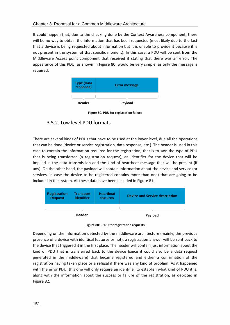
Chapter 3. Proposal for a Common Middleware Architecture
151
It could happen that, due to the checking done by the Context Awareness component, there
will be no way to obtain the information that has been requested (most likely due to the fact
that a device is being requested about information but it is unable to provide it because it is
not present in the system at that specific moment). In this case, a PDU will be sent from the
Middleware Access point component that received it stating that there was an error. The
appearance of this PDU, as shown in Figure 80, would be very simple, as only the message is
required.
Figure 80. PDU for registration failure
3.5.2. Low level PDU formats
There are several kinds of PDUs that have to be used at the lower level, due all the operations
that can be done (device or service registration, data response, etc.). The header is used in this
case to contain the information required for the registration, that is to say: the type of PDU
that is being transferred (a registration request), an identifier for the device that will be
implied in the data transmission and the kind of heartbeat message that will be present (if
any). On the other hand, the payload will contain information about the device and service (or
services, in case the device to be registered contains more than one) that are going to be
included in the system. All these data have been included in Figure 81.
Figure 801. PDU for registration requests
Depending on the information detected by the middleware architecture (mainly, the previous
presence of a device with identical features or not), a registration answer will be sent back to
the device that triggered it in the first place. The header will contain just information about the
kind of PDU that is transferred back to the device (since it could also be a data request
generated in the middleware) that became registered and either a confirmation of the
registration having taken place or a refusal if there was any kind of problem. As it happened
with the error PDU, this one will only require an identifier to establish what kind of PDU it is,
along with the information about the success or failure of the registration, as depicted in
Figure 82.
Type (Data
response)Error message
Header Payload
Registration
Request
Heartbeat
features
Transport
identifierDevice and Service description
Header Payload

Chapter 3. Proposal for a Common Middleware Architecture
152
Figure 812. PDU for registration answer
Last but not least, a PDU has to be designed for data response in order to format the
information that is going to be sent back to the application layer. While the complexity of the
information that is sent back could more significant than in other cases, the overall structure
of the PDU transferred will be rather simple, as the information identifying destination or kinds
of data will already be included in the payload. The data that have been added to this PDU will
be usually related to sensor information, so it has been chosen to place sensor reading
information as the information that is collected by the device. Furthermore, an identifier for
the service that was requested will also be included so as to let the middleware components
be aware of where the data should be sent back. Figure 83 represents all the concepts
described for this PDU.
Figure 823. PDU for data response
3.6. Business models and middleware exploitation
Another topic of major importance for this thesis is the usability of middleware as a part of the
necessary infrastructure to make the Smart Grid profitable, especially for the prosumers that
are willing to take part of it. As it has been previously mentioned, the integration of prosumers
is a critical objective for the Smart Grid, since they represent small scale energy producers (and
consumers) that can assist the overall power grid not only with their own supply of electricity,
but also with their changed patterns of behaviour when consuming energy. In this case,
middleware will be used as the entity giving access to the economic part of electricity
generation, trading and consumption, since it will make possible for the prosumers to trade
their produced energy at will. This is what is referred to in the thesis as middleware
exploitation: the creation of business models that will suppose an opportunity for prosumers
and regular end users of the Smart Grid to make a profit, with the mandatory cooperation of a
middleware solution that will integrate their facilities in the whole power grid infrastructure.
As represented in [34], there are several business models that can be used with end users and
the power grid, depending on the level of intelligence of both the power grid where the
models can be included and the infrastructure of the end user. Note that although middleware
Registration
answerDevice and Service description
Header Payload
Type (Data
response)Service ID + Sensor reading
Header Payload
Chapter 3. Proposal for a Common Middleware Architecture
153
is rare to be explicitly mentioned, it is the underlying software solution that is making possible
the business models that have been represented, along with their mathematical models. Also,
models that rely on fewer software elements might not be using the Smart Grid infrastructures
by default. In these cases, middleware will still be useful, but as a way to interchange
information between the elements present in the TSO and DSO. As described in [34], the
models that have been conceived as a way to provide middleware exploitation are as follows:
3.6.1. Offline model without the Smart Grid
This scenario has been designed for the use case where end users will not necessarily be
prosumers, and the Smart Grid will not necessarily be present (middleware is still able to exist,
though, as software components in the TSO and DSO parts of the power distribution). The end
user will employ three different elements to obtain a profit in this scenario: an energy storage
solution (typically, a home battery), a trading algorithm with access to energy markets and a
Home Load Controller (HLC) used to monitor the energy consumed in the facilities where it is
installed. Trading operations done with the algorithm use the differences between prices in
energy during peak and valley (or off-peak) hours to its advantage: since energy is more
expensive during peak hours and cheaper during the valley ones, it can be bought at a certain
buying price for a number of kilowatts per hour (Bpk) and sold to others member of the power
grid (such as the DSO) at a certain selling price for the kilowatt per hour (Spk), according to the
actual needs and availability of the end user, who may choose to use some of that energy for
their own personal consumption if they need it for themselves. These price variations will
result in a profit for the user, which has been called Upk in (23). In this scenario, this profit has
to be understood as the cost reduction that results after applying the installed infrastructure at
the end user´s facilities. As it will be explained in the next lines, this profit will be an actual one
when the Smart grid becomes fully enabled.
Upk = Spk – Bpk (23)
Another way to describe this profit is taking into account the energy storage solution is located
in the premises used by the end user. If the energy can be measured as charge cycles, then an
amount of energy Ec will be stored in the battery each time it is charged within its warranty
period. In this way, end user profit can be modeled as the profit for each of the battery
charges done to the battery, thus obtaining a user profit called Upc, represented by the profit
for each kilowatt per hour (Upk) and the kilowatts per hour that an energy storage solution
can hold (Ec). These ideas have been expressed in (24).
Upc = Upk ∙ Ec (24)
Bearing this in mind, it is possible to model the user profit as something that will be repeated
during a certain amount of time. This idea can referred to as user profit during a certain
amount of time (Upt) ranging from 0 to n for every i, as expressed in (25).
𝑈𝑝𝑡 = ∑ 𝑈𝑝𝑐𝑖𝑛𝑖=0 (25)

Chapter 3. Proposal for a Common Middleware Architecture
154
The consequence of all this will be that the end users adopting this model with their available
infrastructure (energy storage, trading algorithm, Home Load Controller) will be able to pay
less for the electricity they produce. As depicted in (26), the cost of the energy used during a
period of time (Int) will result from the regular expenditures (Ext) of the end user during the
same period time described in (26) and the subtraction of the user profit during that same
period (Upt). In the most drastic scenario, it might even be possible that the profit obtained is
larger than the costs of electricity used by them, so they will have a net profit from the
available pieces of equipment and software.
Int = Ext – Upt (26)
In the end, the end user will be able to fully pay the investment done in the energy storage
solution and the other elements that allow them to engage into trading activities. When this
happens, the Break Event Point or BEP will be reached and the costs of the investment (Inv) is
equal to the profit (or in this scenario, cost reduction) obtained by the end user during a
certain amount of time (Upt), as represented in (27). The amount of time that the investment
is fully returned, though, will depend on the extent of modernization of the power grid and
how the end user is involved in trading activities.
𝐵𝐸𝑃 → 𝑈𝑝𝑡 = 𝐼𝑛𝑣 (27)
Finally, the number of charge cycles required to obtain the user profit that was previously
mentioned will be defined depending on the Investment (Inv) done in order to purchase all the
required infrastructure and the user profit obtained from the battery charges (Upc). This
number of charges has been defined as Nc in (28), which represents the idea of calculating the
number of battery charges required by an end user to obtain a profit considering the amount
of capital that has been invested.
𝑁𝑐 =𝐼𝑛𝑣
𝑈𝑝𝑐 (28)
3.6.2. Offline model within the Smart Grid
As far as this model is concerned, not only it will make use of the equations of the
mathematical model previously introduced, but also some new are introduced regarding the
location of the Trading Algorithm used, which will be located in the facilities of an entity
(aggregator, DSO, TSO, etc.) that is not the end user. In addition to that, since the power grid
has been enhanced (or at least, enhanced enough) to be regarded as smart, the user profit
obtained from a Smart Grid-like environment (Upsg) can be modelled as the profit obtained
from the regular amount as the profit per kilowatt hour (Upk) and the amount of time they are
connected to the facilities of the Smart Grid (t). This profit will result as represented in (29):
Upsg = Upk ∙ t (29)

Chapter 3. Proposal for a Common Middleware Architecture
155
The usage of the infrastructure owned by the Smart Grid will guarantee than an additional
profit is obtained, due to the fact that it will be used to enable further services that were not
previously available. Equation (30) represents this fact by adding the profits obtained from the
usage of the Smart Grid infrastructures to the ones obtained from the battery charges (Upc).
This latter gained has been referred to as Upcsg.
Upcsg = Upc + Upsg (30)
3.6.3. Online model without the Smart Grid
The main addition that this model brings when compared to the previous ones is that it
includes online services for the end user. The idea that is put forward by this model is that
there will be a company selling the required hardware and software components (energy
reservoir, Trading Algorithm and the Home Load Controller). Consequently, benefits will be
shared between the end user and the entity that is providing the necessary infrastructure to
keep the former online. In addition to that, a different quantity of profits will be obtained from
the end user, which will be defined as the user profit during a specific amount of time (Upt).
The components will be sold to the end user at a lower cost than the one they would have to
afford if they were bought by themselves, but this end user will be charged with an additional
fee for using them. In this way, the selling price established for a specific period of time (Spt)
will be the one for the kilowatts per hour that was established in (23) multiplied by the number
of time units used to generate the electricity to be sold (t), as depicted in (31):
Spt = Spk ∙ t (31)
The same kind of procedure will be carried out for the buying price, which will result in
defining a new term called Buying price for a specific amount of time (Bpt) during an amount
of time t, as shown in (32):
Bpt = Bpk ∙ t (32)
The final user profit per amount of time in this use case, or Upt, will be obtained by taking into
account the buying price of electricity during a specific amount of time Bpt, its selling price or
Spt, and the cost assigned to the platform that is used for the online activities, which as has
been modelled as a percentage obtained from the profit made by enabling trading activities
(Pch). Overall, the benefits obtained for the end user, and represented by (33) are most
suitable for an end user that prefer not doing a first significant investment; since a percentage
from the benefits is charge by time unit, all the infrastructure ends up being effectively paid
during that amount of time.
𝑈𝑝𝑡 = (1 − 𝑃𝑐ℎ) ∙ (𝑆𝑝𝑡 − 𝐵𝑝𝑡) (33)
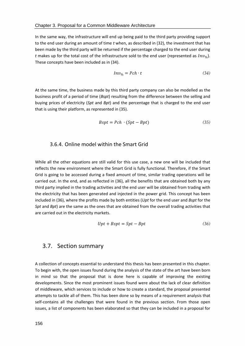
Chapter 3. Proposal for a Common Middleware Architecture
156
In the same way, the infrastructure will end up being paid to the third party providing support
to the end user during an amount of time t when, as described in (32), the investment that has
been made by the third party will be returned if the percentage charged to the end user during
t makes up for the total cost of the infrastructure sold to the end user (represented as 𝐼𝑛𝑣%).
These concepts have been included as in (34).
𝐼𝑛𝑣% = 𝑃𝑐ℎ ∙ 𝑡 (34)
At the same time, the business made by this third party company can also be modelled as the
business profit of a period of time (Bspt) resulting from the difference between the selling and
buying prices of electricity (Spt and Bpt) and the percentage that is charged to the end user
that is using their platform, as represented in (35).
𝐵𝑠𝑝𝑡 = 𝑃𝑐ℎ ∙ (𝑆𝑝𝑡 − 𝐵𝑝𝑡) (35)
3.6.4. Online model within the Smart Grid
While all the other equations are still valid for this use case, a new one will be included that
reflects the new environment where the Smart Grid is fully functional. Therefore, if the Smart
Grid is going to be accessed during a fixed amount of time, similar trading operations will be
carried out. In the end, and as reflected in (36), all the benefits that are obtained both by any
third party implied in the trading activities and the end user will be obtained from trading with
the electricity that has been generated and injected in the power grid. This concept has been
included in (36), where the profits made by both entities (Upt for the end user and Bspt for the
Spt and Bpt) are the same as the ones that are obtained from the overall trading activities that
are carried out in the electricity markets.
𝑈𝑝𝑡 + 𝐵𝑠𝑝𝑡 = 𝑆𝑝𝑡 − 𝐵𝑝𝑡 (36)
3.7. Section summary
A collection of concepts essential to understand this thesis has been presented in this chapter.
To begin with, the open issues found during the analysis of the state of the art have been born
in mind so that the proposal that is done here is capable of improving the existing
developments. Since the most prominent issues found were about the lack of clear definition
of middleware, which services to include or how to create a standard, the proposal presented
attempts to tackle all of them. This has been done so by means of a requirement analysis that
self-contains all the challenges that were found in the previous section. From those open
issues, a list of components has been elaborated so that they can be included in a proposal for

Chapter 3. Proposal for a Common Middleware Architecture
157
a Common Middleware Architecture. From an UML perspective, the typical problems that will
have to be tackled were modelled into use cases. These ones, in turn, have been further
analysed via sequence diagrams, resulting in a collection of classes that have been kept as part
of the components that were identified as necessary during the requirement analysis stage.
Furthermore, a deeper analysis of the proposal that shows its behaviour and different
transitioning states has also been provided with the usage of UML state and activity diagrams.
They have shown that the aforementioned challenges can be solved with the principles
described in this section. In section for it will be explained where those components were
located for the implementation works, as defined in Figure 84.
Figure 834. High-level view of component deployments
Data representation formats are also to be considered in the description of the proposal, as
they will change depending on the environment where they are used. Furthermore, how
middleware is located in the business models where new agents (aggregators and more
specifically, prosumers) are included in the system, and the business models that become
possible due to the inclusion of middleware in the Smart Grid, have also been represented.
They have been subdivided in different scenarios where they can be applied, taking into
account the level of development of the Smart Grid and the hardware devices available for the
end users. It has been explicitly described how the integration of the different RESs within a
distributed, Cyber-Physical System that is offered by semantic middleware offers economic
benefits to prosumers, who can choose to buy, sell or store power either among them or to
other parties participating in energy markets. While the legislative framework changes that
would be required to include prosumers in them is beyond the scope of this thesis, it is stated
that it is possible to do so from a purely technological point of view.
Besides, Common Middleware Architecture offers a framework where the design, structure
and location of the services are already provided. In addition to that, the standardization
perspective is tackled by describing the middleware architecture according to the information
details provided by the proposal ISO/IEC/IEEE 42010, where ideas as viewpoints or
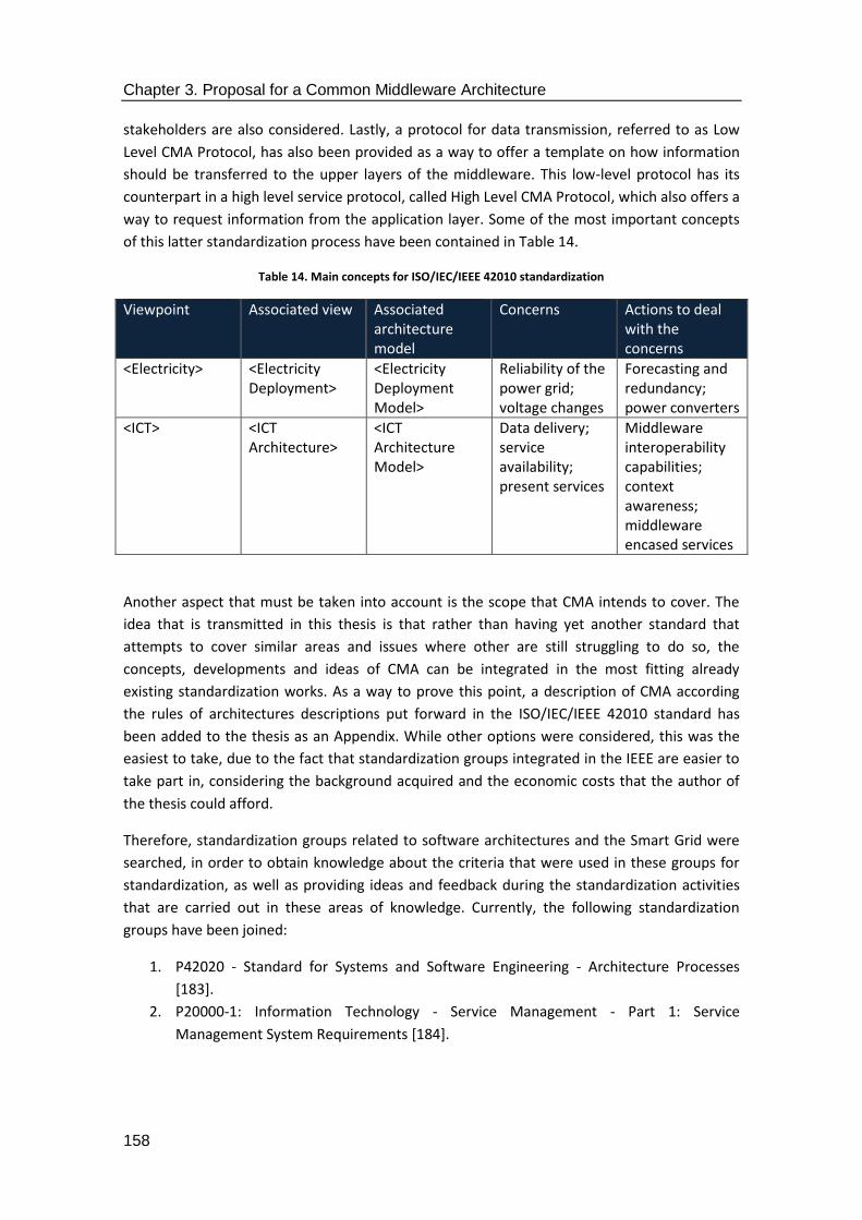
Chapter 3. Proposal for a Common Middleware Architecture
158
stakeholders are also considered. Lastly, a protocol for data transmission, referred to as Low
Level CMA Protocol, has also been provided as a way to offer a template on how information
should be transferred to the upper layers of the middleware. This low-level protocol has its
counterpart in a high level service protocol, called High Level CMA Protocol, which also offers a
way to request information from the application layer. Some of the most important concepts
of this latter standardization process have been contained in Table 14.
Table 14. Main concepts for ISO/IEC/IEEE 42010 standardization
Viewpoint Associated view Associated architecture model
Concerns Actions to deal with the concerns
<Electricity> <Electricity Deployment>
<Electricity Deployment Model>
Reliability of the power grid; voltage changes
Forecasting and redundancy; power converters
<ICT> <ICT Architecture>
<ICT Architecture Model>
Data delivery; service availability; present services
Middleware interoperability capabilities; context awareness; middleware encased services
Another aspect that must be taken into account is the scope that CMA intends to cover. The
idea that is transmitted in this thesis is that rather than having yet another standard that
attempts to cover similar areas and issues where other are still struggling to do so, the
concepts, developments and ideas of CMA can be integrated in the most fitting already
existing standardization works. As a way to prove this point, a description of CMA according
the rules of architectures descriptions put forward in the ISO/IEC/IEEE 42010 standard has
been added to the thesis as an Appendix. While other options were considered, this was the
easiest to take, due to the fact that standardization groups integrated in the IEEE are easier to
take part in, considering the background acquired and the economic costs that the author of
the thesis could afford.
Therefore, standardization groups related to software architectures and the Smart Grid were
searched, in order to obtain knowledge about the criteria that were used in these groups for
standardization, as well as providing ideas and feedback during the standardization activities
that are carried out in these areas of knowledge. Currently, the following standardization
groups have been joined:
1. P42020 - Standard for Systems and Software Engineering - Architecture Processes
[183].
2. P20000-1: Information Technology - Service Management - Part 1: Service
Management System Requirements [184].
4. Validation of the proposal
and results

Chapter 4. Validation of the proposal and results
160

Chapter 4. Validation of the proposal and results
161
This chapter is focused on the validation of the principles described previously in the thesis. In
order to do so, there are two main actions that have been taken in this section of the
document: the implementation works that were carried out during the e-GOTHAM and I3RES
projects have been described here, highlighting the most critical parts of them. Additionally,
the deployment that was done in two different demonstrators related to the projects has also
been described, so that the functionalities and innovations introduced by the middleware
solutions inspired by this Common Middleware Architecture proposal can be seen when
dealing with actual needs for services and communications at the data level. There are two
scenarios that have been chosen for validation purposes: the first one was the residential
scenario of the e-GOTHAM project, where middleware was deployed, among other
components, in the Finnish town of Ylivieska. In the second one, middleware was deployed for
the I3RES project in the Norwegian town of Steinkjer.
4.1. Introduction
The theoretical principles that have been described in the previous sections become part of an
actual implementation in this one. For example, each of the levels that has been previously
described (application, middleware, network, etc.) have been turned into actual software
elements that are part of components and solutions that have been tested and installed in
demonstrators. As it can be seen in Figure 85, each of the levels of the layered architecture has
become part of a specific implementation work.
Figure 845. Theoretical and actual implementations of the middleware and its adjacent layers
This chapter has been divided in several sections that show the importance of the
implementation works that were carried out in both the developments done during the e-
Application
Middleware
Communications
Hardware
Web browser
Jboss ESB + software components
Internet Protocol
Smart Meter (XML-like file data)
Theoretical model Implementation

Chapter 4. Validation of the proposal and results
162
GOTHAM and I3RES research projects, as well as when comparing the ideas that have been put
into practice in the other solutions aiming to create a middleware for the Smart Grid. Firstly,
the framework that has been used to contain all the services and components that have been
included is described. “Framework” in this context means the collection of tools, devices and
services that have been used for the implementation of the middleware iterations used in the
aforementioned research projects. This idea is of major importance, due to the fact that it
summarizes two of the four pillars Common Middleware Architecture is coming from. In
addition to that, the implementation works carried out during the period of time
comprehended in the research projects will be displayed in this chapter. When those
implementation works were carried out they were tested in two different kinds of
environments at three different locations (one set of tests took place in a laboratory, whereas
the other tests were carried out in the demonstrators used for components deployment). The
section summary that has been introduced in this chapter will highlight the main achievements
depicted.
Another characteristic of this section is featuring the methodology used for the development
of the middleware solution. Basically, a merge between incremental prototyping and the
waterfall model for software development has been used in the research projects where
middleware for the Smart Grid was featured. Under this methodology, analysis, design,
implementation and testing activities are made carried out every time a development iteration
is completed. Therefore, prototypes of increasing complexity can be deployed under the
assumption that the previous version has worked as expected. This methodology –which
combines the traditional waterfall model with feedback and incremental prototyping- ensures
that unforeseen events are kept at a minimal. While there might be a small delay regarding the
achievement of lesser, partial goals rather than pointing at the final ones, reliability of the
obtained results, which is sometimes jeopardized in complex, long-term projects, makes up for
it. Overall, this procedure has been depicted in Figure 86. Aside from some minor differences
in the activities that have to be made in each stage, such as the setting of the framework at the
very first stage, or the maintenance of the final software product created, the steps to be
taken are essentially the same in every iteration of the incremental prototype.

Chapter 4. Validation of the proposal and results
163
Figure 856. Waterfall model (enhanced with feedback and incremental prototyping) for middleware development
As far as this section is concerned, the main procedures that have been included deal with the
steps that have been used to develop the middleware solutions that have been used as a way
to infer the Common Middleware Architecture that was used before. Purely implementation
details have been included in Annex A, whereas part of the API that resulted is in Annex B.
4.2. Framework for the Common Middleware Architecture
When describing the elements that are used for describing the main features that have been
added to the framework of the implementation works, there are five of them that must be
highlighted:
1. The Enterprise Service Bus implementation that has been chosen. As it was described in
Chapter 2, an Enterprise Service Bus is used as the most suitable way to install services as
Chapter 4. Validation of the proposal and results
164
part of a middleware architecture that, according to the needs of the Smart Grid, will have
them contained.
2. The programming language used for the services. It has been considered that, due to the
experience gathered during the developments done and its sheer popularity, Java should
be used as the programming language for the services.
3. High level interfaces. Representational State Transfer (REST) facilities have been chosen as
the way to implement how communications are done when interfacing the application
layer with the highest layer of the CMA.
4. Low level interfaces. They are required to collect information from the devices. There have
been two different strategies that have been followed: on the one hand, the XML format
that was referred to before has been defined for data transfers. On the other hand,
middleware has used interfaces with AMQP in order to collect the information from the
lower layers. AMQP was chosen by a partner in the research project that was responsible
for the communication layer falling just below middleware. The purpose for using AMQP
was decoupling communications between middleware and lower layers, since it offered
Publish/Subscribe facilities (and the middleware could subscribe to the hardware devices
that would publish information, so that the data would be already available in the
middleware once it was requested from the application layer). Therefore, interfaces were
specifically tailored for the interconnectivity between the AMQP-based and all the other
components.
5. Interconnectivity among software components. The software elements that have been
defined as part of the middleware have to transfer information among them. Therefore,
they must have interfaces that are utilized for inner middleware information
transmissions.
Considering all these aspects, the next sections will provide a description of the framework
tools that have been included in this thesis.
4.2.1. Enterprise Service Bus
Among the possible ESBs that could be used, the final decision was to implement middleware
solutions with Fuse ESB, which has been recently transformed into JBoss Fuse [105]. In this
case, the software components that are developed have been included in the ESB as bundles,
that is to say, executable software packages that are run when the main ESB is launched. There
were several reasons to choose this ESB solution over other similar:
1. It was offered for free to be downloaded from the Internet [169]. Taking into account that
a proprietary or costly solution would have imposed strain on the budget, and the fact that
there were satisfactory solutions that were offered for free, JBoss Fuse could be used
without restrictions.
2. The community that is behind it is significant enough in case there is any issue that
requires being solved fast. JBoss Fuse is a red hat development, so there is a great
availability amount of documentation that can be checked. Also, researchers and
developers that have already been implied in the development of solutions with JBoss
Fuse can provide some feedback.
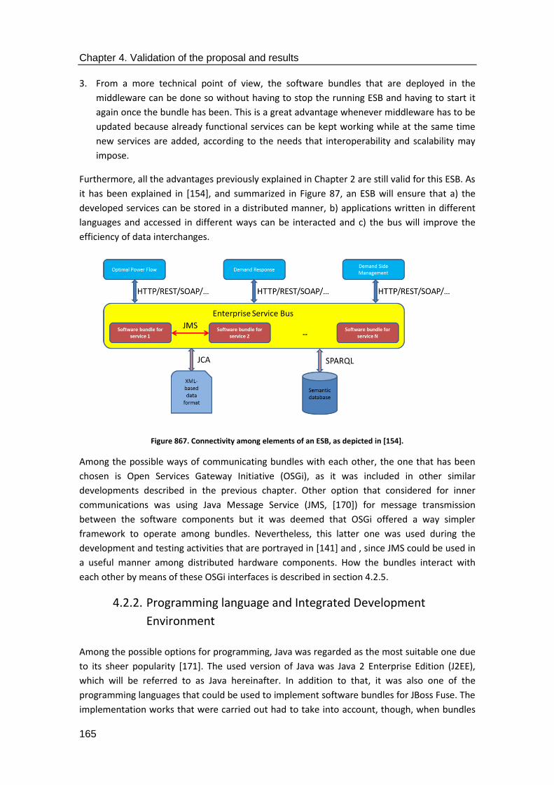
Chapter 4. Validation of the proposal and results
165
3. From a more technical point of view, the software bundles that are deployed in the
middleware can be done so without having to stop the running ESB and having to start it
again once the bundle has been. This is a great advantage whenever middleware has to be
updated because already functional services can be kept working while at the same time
new services are added, according to the needs that interoperability and scalability may
impose.
Furthermore, all the advantages previously explained in Chapter 2 are still valid for this ESB. As
it has been explained in [154], and summarized in Figure 87, an ESB will ensure that a) the
developed services can be stored in a distributed manner, b) applications written in different
languages and accessed in different ways can be interacted and c) the bus will improve the
efficiency of data interchanges.
Figure 867. Connectivity among elements of an ESB, as depicted in [154].
Among the possible ways of communicating bundles with each other, the one that has been
chosen is Open Services Gateway Initiative (OSGi), as it was included in other similar
developments described in the previous chapter. Other option that considered for inner
communications was using Java Message Service (JMS, [170]) for message transmission
between the software components but it was deemed that OSGi offered a way simpler
framework to operate among bundles. Nevertheless, this latter one was used during the
development and testing activities that are portrayed in [141] and , since JMS could be used in
a useful manner among distributed hardware components. How the bundles interact with
each other by means of these OSGi interfaces is described in section 4.2.5.
4.2.2. Programming language and Integrated Development
Environment
Among the possible options for programming, Java was regarded as the most suitable one due
to its sheer popularity [171]. The used version of Java was Java 2 Enterprise Edition (J2EE),
which will be referred to as Java hereinafter. In addition to that, it was also one of the
programming languages that could be used to implement software bundles for JBoss Fuse. The
implementation works that were carried out had to take into account, though, when bundles

Chapter 4. Validation of the proposal and results
166
had to be developed, since they are required to be compliant with the Apache Maven build
system. In order to do that there were several procedures that must be taken into account
when codifying these in an Integrated Development Environment (IDE). Apache Maven [172] is
used as a way to have runnable software bundles located in one repository that will execute
them when it is commanded to do so. In a way they are executable compressed files that will
be triggered as soon as the directory where they have been located is involved in a program
execution.
4.2.3. High level interfaces
When high level interfaces had to be implemented, there were three ideas that had to be born
in mind: a) how to enable a way for applications to interact with the high level services of the
middleware architecture, b) what kind of information should be sent from the applications and
c) how it should be formatted in order to make it understandable by the middleware solution
supposed to interact with them. These two issues were solved by using REST as they way to
establish interfaces with the application layer (which was represented firstly by a web browser
and afterwards as an Android GUI) and a specific XML message format for application data
exchange. REST interfaces were implemented by making three additions to the Java Maven
projects that had been created and codified previously. On the one hand, the Java libraries
that are supporting REST functionalities have to be imported. That was done by typing the
following lines of code in the classes that, as was shown in the previous section, include the
methods required to invoke the REST operations. Those imported libraries are:
import javax.ws.rs.GET;
import javax.ws.rs.Path;
import javax.ws.rs.PathParam;
import javax.ws.rs.Produces;
import javax.ws.rs.POST;
import javax.ws.rs.core.Response;
Another additional edition that has to be introduced is related to the nature of a Maven
project. Whenever it is created, there are several adjacent files that are made available. These
ancillary files reflect, among other features, the dependencies that the project has with the
maven software facilities. For example, the blueprint.xml file contains the most prominent
features that are part of the project. Another one of the files is the one referred to Project
Object Model (POM), which makes use of XML to describe a representation of a Maven
project. This file, though, must specify how the specifications of the Maven project are made
compatible with the usage of JBoss Fuse and the Web service-based that are being used.
Therefore, the following lines of code have to be included:
<dependency>
<groupId>org.apache.servicemix.specs</groupId>
<artifactId>org.apache.servicemix.specs.jsr311-api-
1.1.1</artifactId>
<version>1.9.0</version>
<scope>provided</scope>
</dependency>

Chapter 4. Validation of the proposal and results
167
If the overall POM.xml file is taken into account, they will be located within the dependencies
section of the file, as represented in Figure 88.
Figure 878. Web service dependencies location
The last edition that has to be carried out is all the sections of the URI that will be used in
order to invoke the services. This is done so by introducing parameters immediately before the
header of the methods that are used as the operations to be invoked in the code; they will be
codified by adding “@” before the kind of operation (“GET” will be the most frequent due to
the fact that information is retrieved from the application, rather than provided to it when a
request is done via URI), the part of the URI that is invoked (or the “path”, as it is added to the
code) and the “result” that is produced (xml document, plain text, etc.). An example of what
the code looks like has been included in the next lines.
@Path("/new")
public class NewMaven
{
//method init is required, regardless of its content, to get the
interfaces going
public NewMaven()
{
init();
}
@GET
@Path("/newserv1")
@Produces("text/plain")
public Response getNewMavenService1()
{

Chapter 4. Validation of the proposal and results
168
System.out.println("getNewMavenService1: this comment will
spring up at the terminal monitor");
return Response.ok("getNewMavenService1 invoked!").build();
}
@GET
@Path("/newserv2")
@Produces("text/plain")
public Response getNewMavenService2()
{
System.out.println("getNewMavenService2: this comment will
spring up at the terminal monitor");
return Response.ok("getNewMavenService2 invoked!").build();
}
final void init()
{
//left empty on purpose
}
}
With all these aspects taken into account, it was decided to incorporate URIs to all the
hardware devices that could be added to the middleware solution that was planned to be
installed, all according to their own capabilities. As far as the e-GOTHAM project was
concerned, there were ten possible devices to be accessed (as well as other URIs for data
storage and other services). Depending on the services that could be provided, the URIs
associated with each of them would be different. The structure that has been followed for the
Uniform Resource Identifiers could be described as follows:
http://[IP address]:8181/cxf/support/support/{service name}/{serviceID}/{input}
The first part of the URL remains fixed for all the URIs that can be invoked. The only parameter
that changes is the IP address of the machine that is running the most significant parts of the
middleware (that is, the Central Controller; for the sake of readability it is referred to as [IP
address] in the URIs that have been presented). There are two support tags in the URIs that
have been used because the initial tests for implementation activities were made in an e-
GOTHAM component (which was equivalent to what a Middleware Access Point is in Common
Middleware Architecture) used for support where all of the tasks were supposed to be support
related. The original idea was to move those interfaces to other components that would have
received a different name, but due to the fact that the functionality was already been offered
in that component, they were left as URIs accessible from the support component. The
finished middleware architecture conceived from e-GOTHAM has been summarized in [141].
After those tags, the variable part of the URI is added: the service name represents the service
that is requested, the service identifier is the unique number that the device it belongs to was
given during the registration process and the input is a parameter that may be required for the
service data delivery; this last parameter is optional, as it may not be needed by the hardware
device that will receive the request (for example, if real-time current is requested to a

Chapter 4. Validation of the proposal and results
169
particular device with an identifier there is no need to specify other parameters, but if a device
is requested to take an action, such as turning on or off a load, it might need so).
It has to be noted that a URI is not the same as a Uniform Resource Location (URL), due to the
fact that the former points to the name of the very resource that is accessed, whereas a URL
points at the location of the resource, instead of to the resource itself. With this in mind,
invoking services from one device or the middleware itself became a matter of using the
suitable URI containing the service invocation and the required parameters. As far as the e-
GOTHAM project was concerned, there were several devices to obtain services from:
1. Local Controller: this is a device that was tailored for the e-GOTHAM project which
contains several services aimed to control several features of a dwell, such as power
consumption or temperature.
2. Energy meter at the Ylivieska demonstrator: device used to measure energy
consumed. The demonstrator that was deployed in Ylivieska relied on these devices to
collect information about consumed energy.
3. Pressure meter at the Ylivieska demonstrator: device used to collect pressure
measurements from sensors monitoring a District Heating Network present in the
Ylivieska demonstrator.
4. Remote Terminal Unit: these are pieces of equipment to manage transmission and
distribution automation. They had several electricity-related services that could be
invoked by using the URIs that have been previously described.
5. Combined temperature and humidity measurement device: used to measure that kind
of parameters in the demonstrator of Ylivieska
6. Phasor Measurement Unit: PMUs are used for measuring and synchronizing electric
waves transmitted through the power grid. Starting and stopping a specific service
number that could be provided by them was listed as the only potential facility that
could be managed from the middleware architecture.
7. Pressure device at Herrfors facilities: it is used for the same purpose that the pressure
meter was used for, but it is installed in Herrfors, which is a local power company that
was involved in the e-GOTHAM project as one of the utilities that would use the results
of the project to their advantage [173].
8. Data device at Herrfors facilities: this URI was added in case a device used to obtain
generic information was added to the project. Even though no new devices were used,
it was kept as part of the development works done.
9. Enfo ESS Box: an appliance used to gather information about energy consumed in a
certain amount of time. Enfo is a Norwegian company heavily involved in facilities for
the Smart Grid, such as business models, Demand Side Management and energy
trading [174].
10. E-GOTHAM Box: device tailored for the e-GOTHAM project used for several actions:
turning off loads, obtaining information about power consumption, etc.
The features that were invoked by the URIs used by the services have been described
according to the URIs that the high level services of the middleware got programmed with:
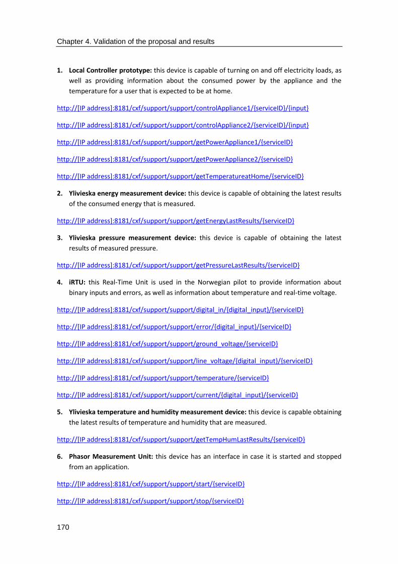
Chapter 4. Validation of the proposal and results
170
1. Local Controller prototype: this device is capable of turning on and off electricity loads, as
well as providing information about the consumed power by the appliance and the
temperature for a user that is expected to be at home.
http://[IP address]:8181/cxf/support/support/controlAppliance1/{serviceID}/{input}
http://[IP address]:8181/cxf/support/support/controlAppliance2/{serviceID}/{input}
http://[IP address]:8181/cxf/support/support/getPowerAppliance1/{serviceID}
http://[IP address]:8181/cxf/support/support/getPowerAppliance2/{serviceID}
http://[IP address]:8181/cxf/support/support/getTemperatureatHome/{serviceID}
2. Ylivieska energy measurement device: this device is capable of obtaining the latest results
of the consumed energy that is measured.
http://[IP address]:8181/cxf/support/support/getEnergyLastResults/{serviceID}
3. Ylivieska pressure measurement device: this device is capable of obtaining the latest
results of measured pressure.
http://[IP address]:8181/cxf/support/support/getPressureLastResults/{serviceID}
4. iRTU: this Real-Time Unit is used in the Norwegian pilot to provide information about
binary inputs and errors, as well as information about temperature and real-time voltage.
http://[IP address]:8181/cxf/support/support/digital_in/{digital_input}/{serviceID}
http://[IP address]:8181/cxf/support/support/error/{digital_input}/{serviceID}
http://[IP address]:8181/cxf/support/support/ground_voltage/{serviceID}
http://[IP address]:8181/cxf/support/support/line_voltage/{digital_input}/{serviceID}
http://[IP address]:8181/cxf/support/support/temperature/{serviceID}
http://[IP address]:8181/cxf/support/support/current/{digital_input}/{serviceID}
5. Ylivieska temperature and humidity measurement device: this device is capable obtaining
the latest results of temperature and humidity that are measured.
http://[IP address]:8181/cxf/support/support/getTempHumLastResults/{serviceID}
6. Phasor Measurement Unit: this device has an interface in case it is started and stopped
from an application.
http://[IP address]:8181/cxf/support/support/start/{serviceID}
http://[IP address]:8181/cxf/support/support/stop/{serviceID}

Chapter 4. Validation of the proposal and results
171
7. Herrfors pressure device: as in previous devices, this one is capable of obtaining the latest
results of the pressure that is measured.
http://[IP address]:8181/cxf/support/support/getHerrforsPressureLastResults/{serviceID}
8. Herrfors data device: this device is capable obtaining the latest results of the data that is
being gathered from the deployment.
http://[IP address]:8181/cxf/support/support/getHerrforsDataLastResults/{serviceID}
9. Enfo ESS Box: application interfaces have been developed for energy-centred operations:
energy measurements, accumulated energy or average energy values are taken into
account.
http://[IP address]:8181/cxf/support/support/energy/{serviceID}
http://[IP address]:8181/cxf/support/support/get_accumulated_energy/{serviceID}
http://[IP address]:8181/cxf/support/support/get_accumulated_energy_interval/{serviceID}
http://[IP address]:8181/cxf/support/support/get_average_power/{serviceID}
http://[IP address]:8181/cxf/support/support/get_average_power_interval/{serviceID}
http://[IP address]:8181/cxf/support/support/get_energy/{serviceID}
http://[IP address]:8181/cxf/support/support/get_energy_interval/{serviceID}
10. e-GOTHAM Box: this device is used in the Norwegian pilot to deal with energy data, such
as temperature, power consumption, turning off one energy load, etc.
http://[IP address]:8181/cxf/support/support/getFlexibleLoad/{serviceID}
http://[IP address]:8181/cxf/support/support/getTemperature/{serviceID}
http://[IP address]:8181/cxf/support/support/getTotalPowerConsuption/{serviceID}
http://[IP address]:8181/cxf/support/support/turnOffLoad/{power_off}/{serviceID}
In addition to the former URIs, there were some other that were used during testing activities
with the purpose of assessing how the software and interfaces that had been developed were
behaving. All those testing interfaces can be described as follows:
1. URIs used as an example of how to use applications that already have a request message
to be sent, rather than relying on the middleware for that task:
http://[IP address]:8181/cxf/support/support/performRequest.
http://[IP address]:8181/cxf/support/support/performRequest/{serviceID}
2. URIs used to test the early Logical Device that was developed by UPM, regarding how
current could be requested:

Chapter 4. Validation of the proposal and results
172
http://[IP address]:8181/cxf/support/support/getCurrent
http://[IP address]:8181/cxf/support/support/getCurrent/{serviceID}
3. URIs used as an example of how service list could be generated:
http://[IP address]:8181/cxf/support/support/ejemploList
http://[IP address]:8181/cxf/support/support/ejemploListNoCab
http://[IP address]:8181/cxf/support/support/ejemploListText
4. URIs used as an example of how Monitoring and testing and Discovery components could
be accessed.
http://[IP address]:8181/cxf/monitoringTesting/monitoringTesting/getMonitoringTesting
http://[IP address]:8181/cxf/discovery/discovery/getDiscovery
Finally, there are some other URIs used by the Discovery component with the purpose of
listing these services, the active services (according to how they are defined as active by the
Context Awareness component) and listing devices and the operations each of them is capable
of providing.
http://[IP address]:8181/cxf/discovery/discovery/listServices
http://[IP address]:8181/cxf/discovery/discovery/listActiveServices
http://[IP address]:8181/cxf/discovery/discovery/listDevices
http://[IP address]:8181/cxf/discovery/discovery/listServiceOperations/{serviceID}
An example of how URIs can be used to get a grasp on the available middleware components
at the highest level by just requesting the available ones is executing a URI request in the
controller that is supposed to contain all the services. This can be done by simply invoking the
first fixed part of the URIs that have been used as a way to request data, that is, introducing
http://[IP address]:8181/cxf/ in a web browser or any software that has the full TCP/IP or OSI
stack installed. An example of what will be obtained as a result has been portrayed in Figure
89. Note that despite using REST interfaces, the services that are listed have been regarded as
SOAP-based ones by the JBoss Fuse, thus hinting that the Simple Object Access Protocol is
used in a subtle way.

Chapter 4. Validation of the proposal and results
173
Figure 889. URIs for available middleware high level components
4.2.4. Low level interfaces
Rather than just being focused on how information is recovered from devices, low level
interfaces implement a specific low level format that was designed as a way to establish a
convention on how data was expected to be retrieved. That convention has already been
described in the second-to-last subsection of the previous chapter (the PDUs to be used for
data transfers and delivery), but the implementation details have been included here. Since
middleware works at a data level, it was decided that XML messages were the most suitable
way to represent the Processing Data Units that were included in the system. The specification
and the simple protocol that has been developed so as to undertake all these procedures are
referred to in [154] as Smart Grid Data Interchange Protocol (SGDIP). The procedures contain
all the required information to manage the facilities mentioned before: device registration and
deregistration, heartbeats or devices leaving the system where they have been deployed.
As far as registration is concerned, the procedure to have a service registered differs greatly
from the way used to register a device. In addition to that, differences between legacy and
tailored devices may have to be taken into account as well. Services that were registered in
the middleware by making use of XML messages should have the following appearance:
<message>
<type>REGISTRY REQUEST</type>
<payload>
<serviceTypeId>HIGH/CORE/LOW LEVEL</serviceTypeId>
<templateId>SERVICE NAME</templateId>
<context>
<location>
<latitude>ALTITUDE COORDINATES</latitude>
<longitude>LONGITUDE COORDINATES</longitude>
</location>
</context>
</payload>
</message>
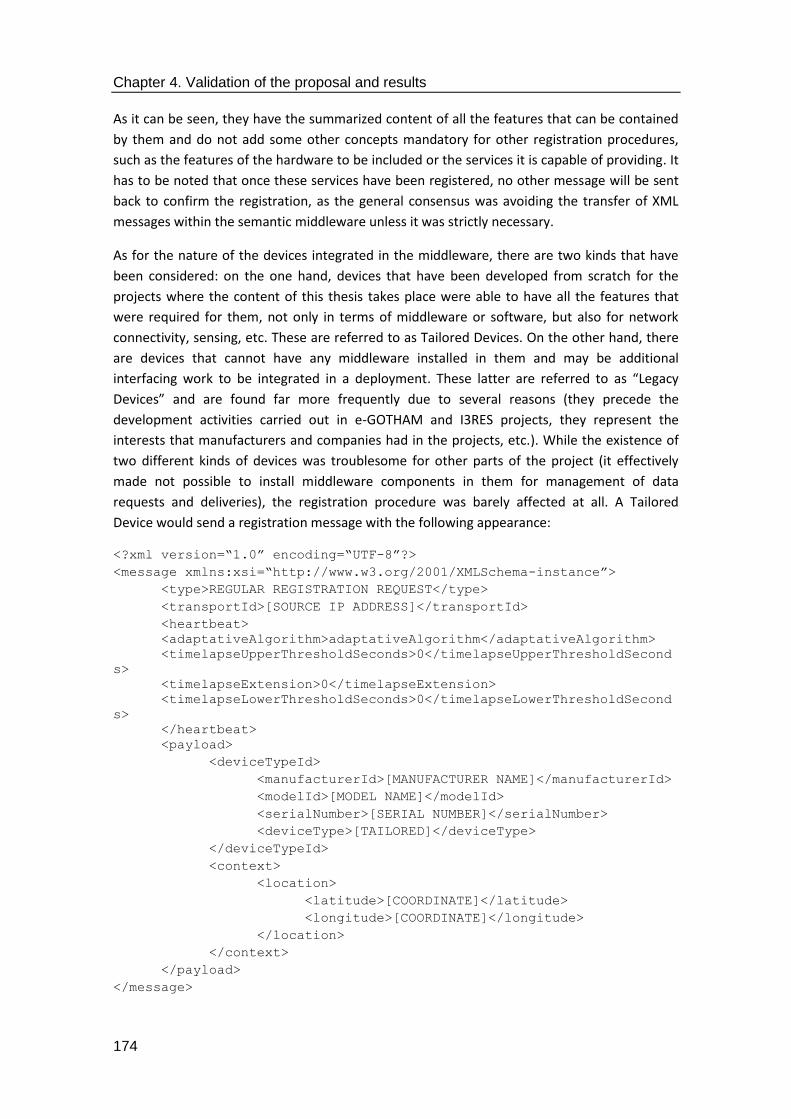
Chapter 4. Validation of the proposal and results
174
As it can be seen, they have the summarized content of all the features that can be contained
by them and do not add some other concepts mandatory for other registration procedures,
such as the features of the hardware to be included or the services it is capable of providing. It
has to be noted that once these services have been registered, no other message will be sent
back to confirm the registration, as the general consensus was avoiding the transfer of XML
messages within the semantic middleware unless it was strictly necessary.
As for the nature of the devices integrated in the middleware, there are two kinds that have
been considered: on the one hand, devices that have been developed from scratch for the
projects where the content of this thesis takes place were able to have all the features that
were required for them, not only in terms of middleware or software, but also for network
connectivity, sensing, etc. These are referred to as Tailored Devices. On the other hand, there
are devices that cannot have any middleware installed in them and may be additional
interfacing work to be integrated in a deployment. These latter are referred to as “Legacy
Devices” and are found far more frequently due to several reasons (they precede the
development activities carried out in e-GOTHAM and I3RES projects, they represent the
interests that manufacturers and companies had in the projects, etc.). While the existence of
two different kinds of devices was troublesome for other parts of the project (it effectively
made not possible to install middleware components in them for management of data
requests and deliveries), the registration procedure was barely affected at all. A Tailored
Device would send a registration message with the following appearance:
<?xml version=“1.0” encoding=“UTF-8”?>
<message xmlns:xsi=“http://www.w3.org/2001/XMLSchema-instance”>
<type>REGULAR REGISTRATION REQUEST</type>
<transportId>[SOURCE IP ADDRESS]</transportId>
<heartbeat>
<adaptativeAlgorithm>adaptativeAlgorithm</adaptativeAlgorithm>
<timelapseUpperThresholdSeconds>0</timelapseUpperThresholdSecond
s>
<timelapseExtension>0</timelapseExtension>
<timelapseLowerThresholdSeconds>0</timelapseLowerThresholdSecond
s>
</heartbeat>
<payload>
<deviceTypeId>
<manufacturerId>[MANUFACTURER NAME]</manufacturerId>
<modelId>[MODEL NAME]</modelId>
<serialNumber>[SERIAL NUMBER]</serialNumber>
<deviceType>[TAILORED]</deviceType>
</deviceTypeId>
<context>
<location>
<latitude>[COORDINATE]</latitude>
<longitude>[COORDINATE]</longitude>
</location>
</context>
</payload>
</message>
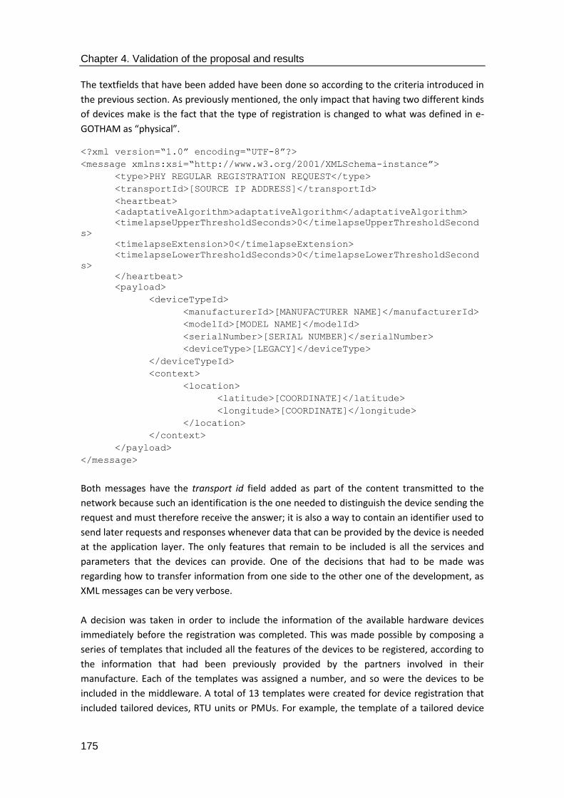
Chapter 4. Validation of the proposal and results
175
The textfields that have been added have been done so according to the criteria introduced in
the previous section. As previously mentioned, the only impact that having two different kinds
of devices make is the fact that the type of registration is changed to what was defined in e-
GOTHAM as “physical”.
<?xml version=“1.0” encoding=“UTF-8”?>
<message xmlns:xsi=“http://www.w3.org/2001/XMLSchema-instance”>
<type>PHY REGULAR REGISTRATION REQUEST</type>
<transportId>[SOURCE IP ADDRESS]</transportId>
<heartbeat>
<adaptativeAlgorithm>adaptativeAlgorithm</adaptativeAlgorithm>
<timelapseUpperThresholdSeconds>0</timelapseUpperThresholdSecond
s>
<timelapseExtension>0</timelapseExtension>
<timelapseLowerThresholdSeconds>0</timelapseLowerThresholdSecond
s>
</heartbeat>
<payload>
<deviceTypeId>
<manufacturerId>[MANUFACTURER NAME]</manufacturerId>
<modelId>[MODEL NAME]</modelId>
<serialNumber>[SERIAL NUMBER]</serialNumber>
<deviceType>[LEGACY]</deviceType>
</deviceTypeId>
<context>
<location>
<latitude>[COORDINATE]</latitude>
<longitude>[COORDINATE]</longitude>
</location>
</context>
</payload>
</message>
Both messages have the transport id field added as part of the content transmitted to the
network because such an identification is the one needed to distinguish the device sending the
request and must therefore receive the answer; it is also a way to contain an identifier used to
send later requests and responses whenever data that can be provided by the device is needed
at the application layer. The only features that remain to be included is all the services and
parameters that the devices can provide. One of the decisions that had to be made was
regarding how to transfer information from one side to the other one of the development, as
XML messages can be very verbose.
A decision was taken in order to include the information of the available hardware devices
immediately before the registration was completed. This was made possible by composing a
series of templates that included all the features of the devices to be registered, according to
the information that had been previously provided by the partners involved in their
manufacture. Each of the templates was assigned a number, and so were the devices to be
included in the middleware. A total of 13 templates were created for device registration that
included tailored devices, RTU units or PMUs. For example, the template of a tailored device

Chapter 4. Validation of the proposal and results
176
used as a way to check all the content included in the registration procedure has been included
in the database of the middleware solution.
<service>
<templateId>logical device</templateId>
<serviceType>Device service</serviceType>
<serviceFunctionality>Monitoring and Control of appliances in
home environment</serviceFunctionality>
<context>
<location>
<latitude></latitude>
<longitude></longitude>
</location>
<deviceTypeId>
<manufacturerId></manufacturerId>
<modelId></modelId>
<serialNumber></serialNumber>
<deviceType>4</deviceType>
</deviceTypeId>
</context>
<operations>
<operation>
<name>ControlAppliance1</name>
<type>power</type>
<description>Switch (ON/OFF) appliance
1</description>
<parameters>
<parameter>
<inputParameter>ON or
OFF</inputParameter>
<typeInput>String</typeInput>
</parameter>
<parameter>
<outputParameter>XML</outputParameter>
<typeOutput>String</typeOutput>
</parameter>
</parameters>
</operation>
<operation>
<name>PowerAppliance1</name>
<type>power</type>
<description>Read instant power (Watts) consumed by
appliance 1</description>
<parameters>
<parameter>
<outputParameter>XML</outputParameter>
<typeOutput>String</typeOutput>
</parameter>
</parameters>
</operation>
<operation>
<name>ControlAppliance2</name>
<type>power</type>
<description>Switch (ON/OFF) appliance
2</description>
<parameters>
<parameter>
<inputParameter>ON or
OFF</inputParameter>

Chapter 4. Validation of the proposal and results
177
<typeInput>String</typeInput>
</parameter>
<parameter>
<outputParameter>XML</outputParameter>
<typeOutput>String</typeOutput>
</parameter>
</parameters>
</operation>
<operation>
<name>PowerAppliance2</name>
<type>power</type>
<description>Read instant power (Watts) consumed by
appliance 2</description>
<parameters>
<parameter>
<outputParameter>XML</outputParameter>
<typeOutput>String</typeOutput>
</parameter>
</parameters>
</operation>
<operation>
<name>TemperatureatHome</name>
<type>temperature</type>
<description>Get temperature at home</description>
<parameters>
<parameter>
<outputParameter>XML</outputParameter>
<typeOutput>String</typeOutput>
</parameter>
</parameters>
</operation>
</operations>
<grounding>
<groundingProtocol>AMPQ</groundingProtocol>
<groundingProtocol>OSGi</groundingProtocol>
</grounding>
</service>
As it can be seen in the previous template, the amount of information regarding the services
that the device can provide is way larger than the one sent in the registration request
message. This was made possible because partners of the e-GOTHAM project were requested
about the information to be included in the demonstrators. The procedure to do so was filling
up a table with all the data regarding operations, features and input or output parameters
required for the services. This table looked like Table 15.
Table 15. Device information table filled by e-GOTHAM partners
Field name Content
Service functionality Describes the usefulness of the service [String]
Latitude location Indicates the latitude, in degrees, where the service is located [double]
Longitude location Indicates the longitude, in degrees, where the service is located [double]

Chapter 4. Validation of the proposal and results
178
Device manufacturer Describes the manufacturer of the physical device, for example of the smart meter [String]
Device model Model name of the device [String]
Serial number identifies the device uniquely [String]
Operation name 1
Name of the operation associated to that service [String]. The service can have one or more operations depending on its available functionalities
Operation description 1 Describes the functionality of the operation [String]
Input parameter operation 1
Input parameter employed for the execution of the operation. It follows the e-GOTHAM data model information, that is, CIM + SSN. None, one or more input parameters can appear
Input parameter operation N Input parameter for operation number N
Output parameter operation 1
It is the output parameter that is obtained such as result of the operation. It follows the e-GOTHAM data model information, that is, CIM + SSN. None, one or more output parameters can appear
Output parameter operation N Output parameter number N
Precondition parameter operation 1
If the operation needs some precondition before its execution, this field indicates it. It follows the e-GOTHAM data model information, that is, CIM + SSN. None, one or more input parameters can appear.
Precondition parameter operation N Precondition N
Operation name N Name of Operation N
Operation description N Description of Operation N
Once the device with its ancillary services became registered, the registration responses that
are sent from the middleware solution to the devices are simple messages that will reflect the
success or failure of the operation that they were trying in the first place. The appearance of
the XML message that will be sent has been included below this paragraph. As it was
mentioned in the previous chapter, this will largely depend on whether a device has already
been registered in the system or not. A service id and the acknowledgement of the registration
procedure (marked with a “Y” in the registered field) are included in the message.
<message>
<type>REGISTRY RESPONSE</type>
<payload>
<registered>Y</registered>
<serviceId>[serviceID]</serviceId>

Chapter 4. Validation of the proposal and results
179
</payload>
</message>
The message that is obtained from the middleware solution in case the registration did not
take place due to the reasons mentioned in the previous chapter is essentially the same as the
one shown before, with the exception that a capital “N” will be used instead of a “Y”. An error
code and description are also offered so as to provide more information about the potential
failure.
<message>
<type>REGISTRY RESPONSE</type>
<payload>
<registered>N</registered>
<errorCode>1</errorCode>
<errorDescription>Already registered</errorDescription>
</payload>
</message>
Another message that has also been conceived for the protocol to be used with the low level
interfaces includes the voluntary removal of a device from the deployment, due to any reason
(device replacement, testing, etc.). For this kind of situations, a “bye” message has been
conceived. Its appearance is as included in the XML message described right below this
paragraph.
<message>
<type>BYE</type>
<payload>
<serviceId>[serviceID]</serviceId>
<cause>[service description]</cause>
</payload>
</message>
Other message that comes in handy for discovery and context-related services is the heartbeat
messages that are supposed to be sent by devices that have already been registered and
included in the system. The structure of this message will follow the textfields introduced in
the PDUs of section 3. No extra content is required to be included, as it will be only required
for the message to contain the code of the service that has been registered. Additionally, the
amount of keep alive/heartbeat messages can be regulated depending on the information
contained in the fields related to heartbeats in the registration message.
<message>
<type>[CONTEXT DISCOVERY TYPE]</type>
<payload>
<serviceId>[SERVICE ID CODE]</serviceId>
</payload>
</message>

Chapter 4. Validation of the proposal and results
180
Lastly, deregistration can also be started from the middleware if it is required. The procedure
that has to be followed implies sending a message to the device that is going to become
unattached from the system.
<message>
<type>DEREGISTRATION</type>
<payload>
<cause>[Description of the reason]<cause>
</payload>
</message>
These are all the messages that can be sent from the lower interfaces to the higher level
middleware services. Plus, since there is an action needed between the data that were sent to
the middleware solution and how they were stored in it, an ontology-based component must
be included as a support for the registration functionalities. The data format that was sent to
the ontology connector component, where they are supposed to be reformatted according to
the elements defined by the semantic capabilities, will be used for registration. Figure 90
shows how data are transferred among the different elements of the middleware, in the way
they were designed for the e-GOTHAM project.
Figure 90. Device registration with the intervention of the ontology of the middleware, as developed in the e-GOTHAM project
As it can be seen, when the information reaches the software component used for device
registration (1). The request that is obtained is compared to an XMLSchema to verify that is
correctly built (2). It is in that software component where it has been decided that the
template used for service and device registration (3), which will be filled according to the
information regarding the kind of device that is planned to be registered in the system. Finally,
the XML template filled with the required information will be sent to the software component

Chapter 4. Validation of the proposal and results
181
called Ontology connector, which was used to encase the ontology used in the deployment.
The important concept to have clear is that the format used by the devices to be registered
will be as the one shown for registration of physical and logical devices previously, whereas the
data format that is used to store the information about the devices and the services is the one
shown in the template of the device type number 4.
4.2.5. Interconnectivity of software components
The software components that have been implemented are capable of performing operations
by themselves (especially when they become Middleware Autonomous Services), interact with
high or lower levels of the architecture by means of either REST interfaces and URIs (for
Middleware Access Points) or lower level identifiers and information transmission conventions.
(hardware abstraction capabilities). However, if data has to be sent from one component to
another one, other software technologies that do not require leaving the middleware will have
to be used. It was explained previously in this manuscript that OSGi interfaces can be used as a
way to interface software components. Considering that they can also be used as part of the
JBoss Fuse components, it was decided to incorporate them to the software components that
were being developed as part of the middleware in e-GOTHAM and I3RES projects. In order to
do so, though, there are several modifications that must be done to the implementation works
that are being carried out.
It has been explained that while creating the maven project there are several ancillary files
that become part of the project, such as the blueprint.xml or POM.xml. These latter two files
have to be modified to reflect the dependencies on OSGi and OSGi as a technology to offer
interfaces among software components. For example, if there were two JBoss Fuse bundles to
communicate with each other in a Client/Server, it should be reflected that a) OSGi interfaces
are being used and b) those interfaces connect the client bundle with the server bundle. It can
be appreciated in the next lines of code how the technology used is reflected: an OSGi
reference has been included mentioning both the identifier that has been given to the service
(helloWorldService) and the codified interface. These text lines were not present in the
blueprint.xml file that was firstly obtained from the generation of the Maven project. The
example that has been used here has as its only purpose to clarify how interconnectivity is
done among software bundles, as other communication paradigms can be used as well (for
example, a Publish/Subscribe paradigm is possible to be used in case it is needed to have data
sent and received following the same fashion).
<?xml version="1.0" encoding="UTF-8"?> <blueprint xmlns="http://www.osgi.org/xmlns/blueprint/v1.0.0" xmlns:xsi="http://www.w3.org/2001/XMLSchema-instance" xsi:schemaLocation=" http://www.osgi.org/xmlns/blueprint/v1.0.0 http://www.osgi.org/xmlns/blueprint/v1.0.0/blueprint.xsd">
<!-- OSGi reference --> <reference id="helloWorldService" interface="org.mycompany.server.osgi.IHelloWorldSvc" /> <bean id="clientBean" class="org.mycompany.client.osgi.Client">

Chapter 4. Validation of the proposal and results
182
<property name="helloWorldSvc" ref="helloWorldService"/> </bean> </blueprint>
In the same fashion, extra lines are added to the server part of the communications that
reflect both the interfaces that have been defined (OSGi Interface) and the implementation
main class used (OSGi implementation).
<?xml version="1.0" encoding="UTF-8"?> <blueprint xmlns="http://www.osgi.org/xmlns/blueprint/v1.0.0" xmlns:xsi="http://www.w3.org/2001/XMLSchema-instance" xsi:schemaLocation=" http://www.osgi.org/xmlns/blueprint/v1.0.0 http://www.osgi.org/xmlns/blueprint/v1.0.0/blueprint.xsd">
<!-- OSGi implementation --> <bean id="helloWorldService" class="org.mycompany.server.osgi.HelloWorldSvcImpl" init-method="init" >
</bean>
<!-- OSGi interface --> <service ref=" helloWorldService" interface="org.mycompany.server.osgi.IHelloWorldSvc">
</service > </service> </blueprint>
Lastly, the POM.xml files that are located in both ends of the communication must also be
edited. The editions that must be done involve two tags: dependencies and plugin. The
dependencies tag will have to incorporate the other bundles used to send and receive
information (for example, the bundle with the server part of the communications). In addition
to that, the plugin referred to the artefact id will have to be included, as depicted in the code
lines included below.
Overall, the procedures that have been described here are based on the experience and know-
how acquired by the author of the thesis while performing implementation works for the e-
GOTHAM and I3RES projects. They may differ depending on other variables that are much
closer to an implementation, lower level; for example, the creation of a Maven project might
be different if instead of using Eclipse in Ubuntu as the IDE and operating system, NetBeans
and Windows are used instead. In any case, the underlying ideas will be still valid, as it is made
clear how it is needed to have an IDE running in a machine to perform the codification of the
software services.
<project xmlns="http://maven.apache.org/POM/4.0.0" xmlns:xsi="http://www.w3.org/2001/XMLSchema-instance" xsi:schemaLocation="http://maven.apache.org/POM/4.0.0 http://maven.apache.org/xsd/maven-4.0.0.xsd"> <modelVersion>4.0.0</modelVersion> <groupId>org.mycompany</groupId> <artifactId>helloWorld-client</artifactId> <version>0.0.1-SNAPSHOT</version> <packaging>bundle</packaging> <dependencies>
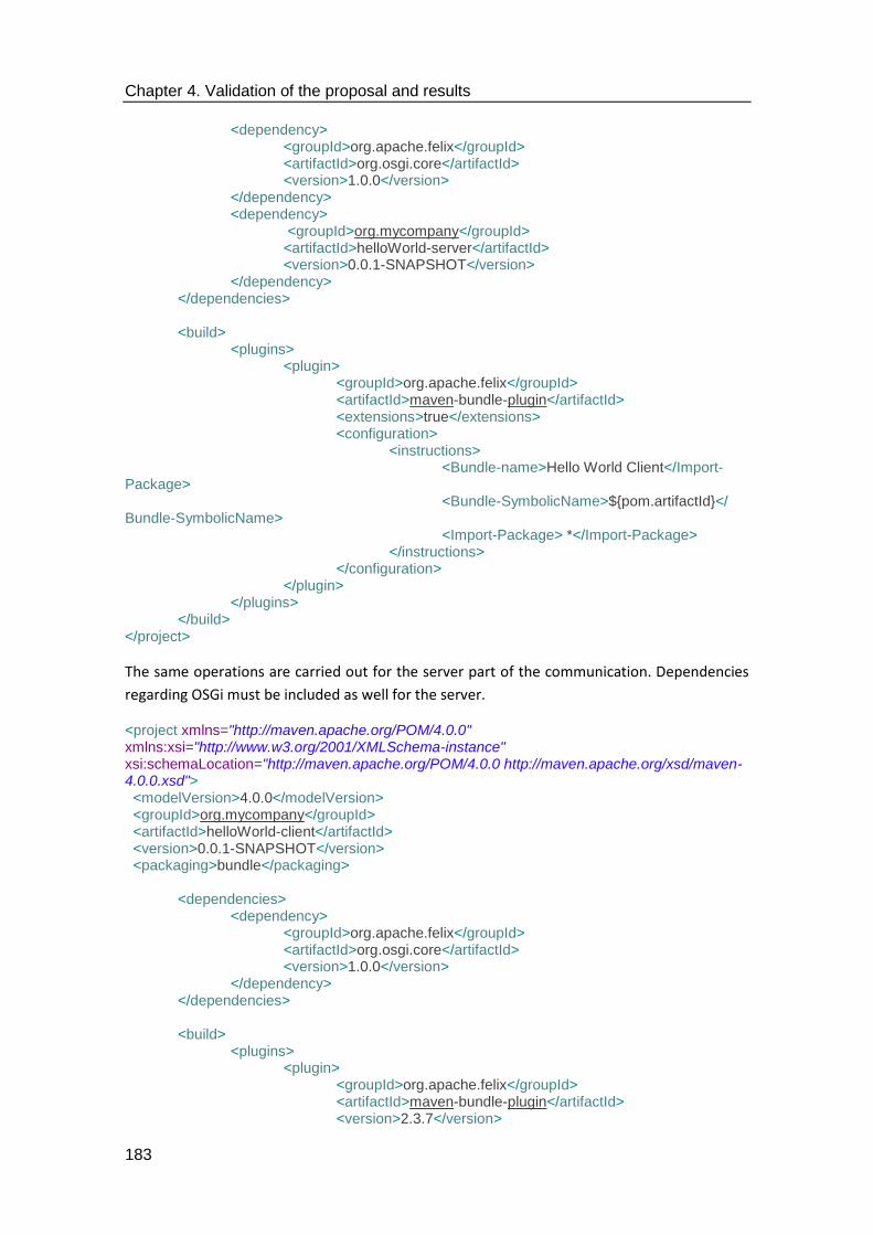
Chapter 4. Validation of the proposal and results
183
<dependency> <groupId>org.apache.felix</groupId> <artifactId>org.osgi.core</artifactId> <version>1.0.0</version> </dependency> <dependency> <groupId>org.mycompany</groupId> <artifactId>helloWorld-server</artifactId> <version>0.0.1-SNAPSHOT</version> </dependency> </dependencies> <build> <plugins> <plugin> <groupId>org.apache.felix</groupId> <artifactId>maven-bundle-plugin</artifactId> <extensions>true</extensions> <configuration> <instructions> <Bundle-name>Hello World Client</Import-Package> <Bundle-SymbolicName>${pom.artifactId}</ Bundle-SymbolicName>
<Import-Package> *</Import-Package> </instructions> </configuration> </plugin> </plugins> </build> </project>
The same operations are carried out for the server part of the communication. Dependencies
regarding OSGi must be included as well for the server.
<project xmlns="http://maven.apache.org/POM/4.0.0" xmlns:xsi="http://www.w3.org/2001/XMLSchema-instance" xsi:schemaLocation="http://maven.apache.org/POM/4.0.0 http://maven.apache.org/xsd/maven-4.0.0.xsd"> <modelVersion>4.0.0</modelVersion> <groupId>org.mycompany</groupId> <artifactId>helloWorld-client</artifactId> <version>0.0.1-SNAPSHOT</version> <packaging>bundle</packaging> <dependencies> <dependency> <groupId>org.apache.felix</groupId> <artifactId>org.osgi.core</artifactId> <version>1.0.0</version> </dependency> </dependencies> <build> <plugins> <plugin> <groupId>org.apache.felix</groupId> <artifactId>maven-bundle-plugin</artifactId> <version>2.3.7</version>
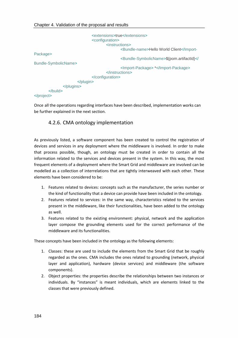
Chapter 4. Validation of the proposal and results
184
<extensions>true</extensions> <configuration> <instructions> <Bundle-name>Hello World Client</Import-Package> <Bundle-SymbolicName>${pom.artifactId}</ Bundle-SymbolicName>
<Import-Package> *</Import-Package> </instructions> </configuration> </plugin> </plugins> </build> </project>
Once all the operations regarding interfaces have been described, implementation works can
be further explained in the next section.
4.2.6. CMA ontology implementation
As previously listed, a software component has been created to control the registration of
devices and services in any deployment where the middleware is involved. In order to make
that process possible, though, an ontology must be created in order to contain all the
information related to the services and devices present in the system. In this way, the most
frequent elements of a deployment where the Smart Grid and middleware are involved can be
modelled as a collection of interrelations that are tightly interweaved with each other. These
elements have been considered to be:
1. Features related to devices: concepts such as the manufacturer, the series number or
the kind of functionality that a device can provide have been included in the ontology.
2. Features related to services: in the same way, characteristics related to the services
present in the middleware, like their functionalities, have been added to the ontology
as well.
3. Features related to the existing environment: physical, network and the application
layer compose the grounding elements used for the correct performance of the
middleware and its functionalities.
These concepts have been included in the ontology as the following elements:
1. Classes: these are used to include the elements from the Smart Grid that be roughly
regarded as the ones. CMA includes the ones related to grounding (network, physical
layer and application), hardware (device services) and middleware (the software
components).
2. Object properties: the properties describe the relationships between two instances or
individuals. By “instances” is meant individuals, which are elements linked to the
classes that were previously defined.

Chapter 4. Validation of the proposal and results
185
3. Data properties: the properties that have been included in the ontology relationships
are used to establish between instances and individuals and data values. In this case,
their value is a data literal, as described in [175].
4. Individuals: these are characteristics that have been included in the classes, which
express a feature about a specific feature of the device. They are instances of the
objects that are used at the most basic level.
The methodology that has been used to include the ontology as part of the Common
Middleware Architecture components is referred to as Methontology. It makes use of the
following steps in order to make sure that a realistic result can be obtained:
1. Building the glossary of terms: this stage consists of listing all the prominent elements
of the application domain where the ontology is located. In this case, characteristics
related to devices, middleware services and the required infrastructure for them to
work flawlessly were included.
2. Building taxonomy concepts: it consists of creating associations (or even a hierarchy)
between the listed elements depending on their position in the environment. For
example, a concept can be regarded as a subclass from another one,
3. Building diagrams of ad hoc binary relationships: they are based on the relationships
that elements from the ontology may have among them, usually focused on an entity
A having B and, at the same time, B being part of A.
4. Building the dictionary of concepts: in this step, the characteristics of each of the
concepts that have been included in the ontology are explained. Typically, concepts
will be linked to several attributes (this is especially evident for devices and the
services of the middleware architecture) that will establish a set of relationships
among them.
5. Describing the binary, ad hoc relationships: in this step, the name of each of the
relations ships that were created, as well as their domain (the class it is associated to),
cardinality (number of potential iterations of the relationship), range (the kind of
attribute related to the relationship) and inverse relationship (which is essentially the
relationship name from the opposite perspective).
6. Describing the attributes: in this stage the attributes are described according to the
concept they are linked to and are given a kind of value that will be used for their
implementation (it will usually match the primitive types provided by any high-level
programming language). Possible range of values and the cardinality between the
attribute name and the concept is usually given as well.
Once all these steps have been carried out, the ontology can be normalized, as it has been
described in [175]. The ontology that has been created to include such a functionality has been
displayed in Figure 91. As it can be seen, all the previous elements have been integrated in it,
along with the relationships that they keep with each other. The ontology that is portrayed in
this thesis can be regarded as a starting ground to describe how the different elements of a
semantic middleware for the Smart Grid can be included in a deployment of this nature. It can
be expanded in either future iterations of the CMA or can be included as a branch in other
standards where CMA makes its own contributions for their improvement.

Chapter 4. Validation of the proposal and results
186
Figure 91. Conceived CMA ontology

Chapter 4. Validation of the proposal and results
187
The ontology that is represented in is also represented as an OWL file that describes what
elements for a Smart Grid deployment with the middleware are and how they are related to
each other. Part of this OWL file has been included in the Appendix B regarding middleware
implementation activities.
4.3. Implementation works
Most of the implementation works have been carried out with the central objective of having
bundles (software components of the middleware) included in the JBoss Fuse (the middleware
framework) performing their expected functionalities. After the codification activities have
been carried out and the projects have been compiled with all their classes, they will have to
be installed and executed. The place to perform such actions in JBoss Fuse is the directory
called “deploy”, where all the developed components will be stored for their usage. When
JBoss Fuse is run, all the bundles (which in the end are executable jar files) that have been
deployed to the deploy directory start running, as it has been depicted in Figure 92.
During implementation works, the components will be deployed repeatedly and it is only
natural that the services will not work as planned the first time. Due to this fact, it would be
surprising that sometimes the status of those components is defined as “Failure” rather than
“Active”. Some other times interfaces may malfunction; in that case, bundles will be
characterized as “Installed”, but not active. Therefore, bugs must be fixed before the
component is deployed again, as any minor issue might make the bundle completely useless.
These aspects are part of the troubleshooting activities that were carried out during the
implementation works.
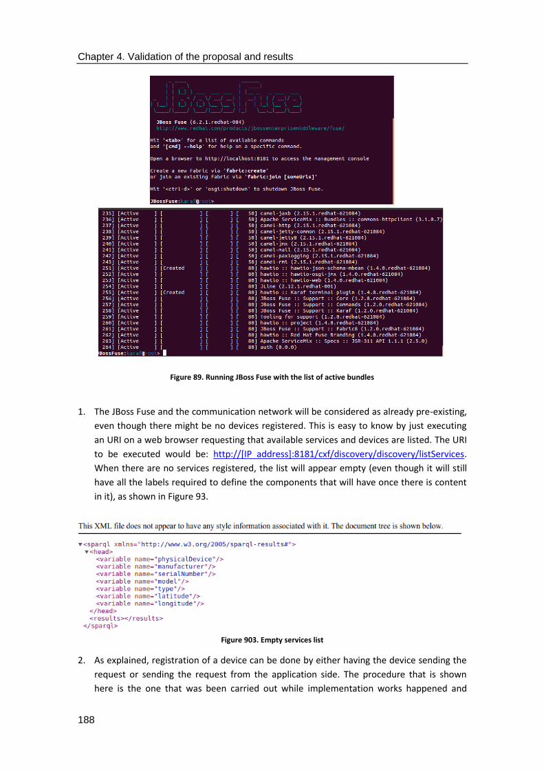
Chapter 4. Validation of the proposal and results
188
Figure 89. Running JBoss Fuse with the list of active bundles
1. The JBoss Fuse and the communication network will be considered as already pre-existing,
even though there might be no devices registered. This is easy to know by just executing
an URI on a web browser requesting that available services and devices are listed. The URI
to be executed would be: http://[IP address]:8181/cxf/discovery/discovery/listServices.
When there are no services registered, the list will appear empty (even though it will still
have all the labels required to define the components that will have once there is content
in it), as shown in Figure 93.
Figure 903. Empty services list
2. As explained, registration of a device can be done by either having the device sending the
request or sending the request from the application side. The procedure that is shown
here is the one that was been carried out while implementation works happened and
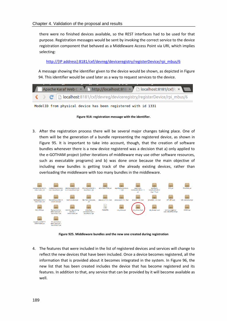
Chapter 4. Validation of the proposal and results
189
there were no finished devices available, so the REST interfaces had to be used for that
purpose. Registration messages would be sent by invoking the correct service to the device
registration component that behaved as a Middleware Access Point via URI, which implies
selecting:
http://[IP address]:8181/cxf/devreg/deviceregistry/registerDevice/rpi_mbus/6
A message showing the identifier given to the device would be shown, as depicted in Figure
94. This identifier would be used later as a way to request services to the device.
Figure 914: registration message with the identifier.
3. After the registration process there will be several major changes taking place. One of
them will be the generation of a bundle representing the registered device, as shown in
Figure 95. It is important to take into account, though, that the creation of software
bundles whenever there is a new device registered was a decision that a) only applied to
the e-GOTHAM project (other iterations of middleware may use other software resources,
such as executable programs) and b) was done once because the main objective of
including new bundles is getting track of the already existing devices, rather than
overloading the middleware with too many bundles in the middleware.
Figure 925. Middleware bundles and the new one created during registration
4. The features that were included in the list of registered devices and services will change to
reflect the new devices that have been included. Once a device becomes registered, all the
information that is provided about it becomes integrated in the system. In Figure 96, the
new list that has been created includes the device that has become registered and its
features. In addition to that, any service that can be provided by it will become available as
well.
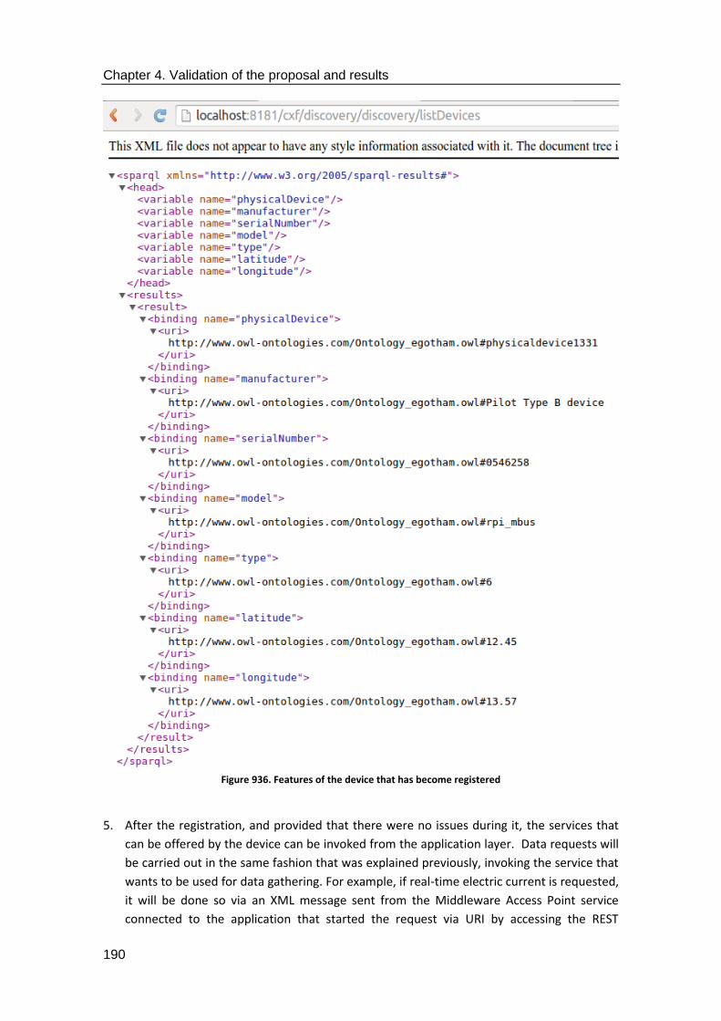
Chapter 4. Validation of the proposal and results
190
Figure 936. Features of the device that has become registered
5. After the registration, and provided that there were no issues during it, the services that
can be offered by the device can be invoked from the application layer. Data requests will
be carried out in the same fashion that was explained previously, invoking the service that
wants to be used for data gathering. For example, if real-time electric current is requested,
it will be done so via an XML message sent from the Middleware Access Point service
connected to the application that started the request via URI by accessing the REST

Chapter 4. Validation of the proposal and results
191
interface. The following XML is an example of how it would be used to send the request for
electric current at a specific time.
<message xmlns="http://www.example.org/logical_req"> <type>DATA REQUEST</type> <serviceID></serviceID> <payload> <operation> <name>getCurrent</name> <parameters> <parameter> <typeInput></typeInput> <sequenceInput></sequenceInput> <value></value> </parameter> </parameters> </operation> </payload> </message>
6. The request will be transferred through the distributed system until it reaches the device
that is expected to have the information needed to answer it. Once the information is
provided, it will be returned to the application that asked for it and the result will be
shown by means of any resource that the application has, such as a Graphical User
Interface or alike.
<message xmlns:xsi="http://www.w3.org/2001/XMLSchema-instance" xsi:noNamespaceSchemaLocation="GrysSensor.xsd"> <type>DATA RESPONSE</type> <serviceID></serviceID> <sensorReading> <timestamp>2014-06-17T12:37:16.171</timestamp> <property> <physicalQuality>electric current</physicalQuality> </property> <sensorOutput> <observationValue> <quantityValue>35</quantityValue> <prefix>mili</prefix> <unitOfMeasure>ampere</unitOfMeasure> </observationValue> </sensorOutput> </sensorReading> </message>
7. Lastly, this procedure has been carried out considering that the securitization of the
interfaces has already been completed. It has been considered that the detailed procedure
to make possible the securitization of the interfaces should rely in certifications rather

Chapter 4. Validation of the proposal and results
192
than software components. Therefore, the procedure that has been included in this thesis
reflects the one that was described in [154] and depicted in Figure 97:
1. In order to have secure transactions between elements using access from the layer
where applications are located, some security –related infrastructure must be added
to the system. An HTTP Apache server can be used to provide that infrastructure, as
long as there is a machine using it [171]. Once the Apache Server has been created, a
new SSL will be integrated in the system.
2. Whenever there is a communication, data will have to be re-directed through the
securitized site. To make this possible, a new directive in the non-secure VirtualHost
will have to be created at the default configuration file, so that the process will
become automated anytime. The default fine is stored at /apache2/sites-
available/000-default.conf in UNIX-based machines, and the sentence
that has to be added to the file will be Redirect permanent /[URL used
for securitized access]/. DocumentRoot resources will also need to be
disabled and swapped by the former order.
3. Certificates will be created for the user willing to participate in data interchanges.
Having the certificate as something provided by them as a self-signed Certificate
Authority (CA) might be required. Additionally, entities participating in the
communication require a user key and user certificate request; these latter must be
signed to enable the Certificate Authority to create the certificate.
4. Consequently, the Certificate Signing Request (CSR) will be sent for its verification at
the CA. If everything goes as planned and there are no issues found, the CSR will be
signed with the key owned by the CA.
5. Finally, the signed Server/Client certificate will be delivered at the Server/Client side of
the communications link (in case the CA is not involved in the communication about to
take place) and be used for information exchange.
Figure 947. Security sequence of steps, as shown in [154]
:CA
Generate public-private key pair
:Server/Client
Generate CSR with the keys
Verify CSR integrity
Sign CSR with the CA key
Signed Server/Client certificate
Send CSR
Send Signed Server/Client certificate
Chapter 4. Validation of the proposal and results
193
As far as security is concerned, while the option that was decided to be used was the one
described here, there is also the possibility of having the securitization features as another
separated software component in the middleware architecture. This is the option that has
been applied in [176], where bundles for a JBoss Fuse have been equipped with the security
capabilities provided by the library Bouncy Castle [155]. The component that used those
libraries was tested to figure out its performance when either symmetric or asymmetric
cyphering were used; it can be regarded as satisfactory (even though asymmetric ciphering
may take even some minutes when 4092 bits long public and private keys are used, it is still
acceptable because asymmetric cyphering takes always a longer time to be performed when
compared to its symmetric counterpart, especially with long keys), so it can be concluded that
the addition of components focused on providing security does not worsen the output of the
overall system that has been used.
4.4. Demonstrator tests
The developed middleware solutions where deployed in two different demonstrators where
the principles of what would become the Common Middleware Architecture would be used. It
has to be remembered that the conception of the middleware architectural model that has
been put forward in this document is a result of the development works made for the e-
GOTHAM and I3RES research projects, as well as the weaknesses found in the existing
middleware architectures for the Smart Grid and the challenges associated to its
standardization activities.
4.4.1. Preliminary tests
The main principles that guide semantic middleware for the Smart Grid were firstly introduced
when preliminary versions of the middleware implementation works that were carried out in
the LifeWear project. The middleware architecture that was present relied on software
components installed in the nodes of a Wireless Sensor Network. The main challenge that had
to be faced with this implementation was related to the capabilities of the motes of the WSN,
which had a computational capability lower than usual pieces of equipment, such as a PC, or
other pieces of equipment present in the Smart Grid, such as smart meters, PMUs or RTUs.
Testing activities were carried out to assess the performance of the system, as it has been
described in [177]. As it can be seen in Figure 98, several sets of simple service requests were
carried out in order to know how it would take for data to be transferred in the wireless
environment. The average time used to satisfy those requests after installing the middleware
components responsible for simple and composed service requests was slightly larger than 700
milliseconds; it was deemed as acceptable considering the computational capabilities of the
motes and the verbosity of the messages that was used.
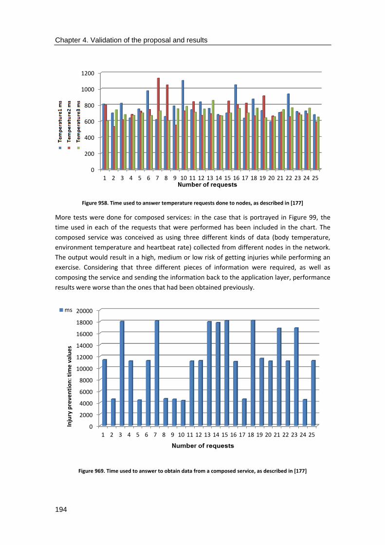
Chapter 4. Validation of the proposal and results
194
Figure 958. Time used to answer temperature requests done to nodes, as described in [177]
More tests were done for composed services: in the case that is portrayed in Figure 99, the
time used in each of the requests that were performed has been included in the chart. The
composed service was conceived as using three different kinds of data (body temperature,
environment temperature and heartbeat rate) collected from different nodes in the network.
The output would result in a high, medium or low risk of getting injuries while performing an
exercise. Considering that three different pieces of information were required, as well as
composing the service and sending the information back to the application layer, performance
results were worse than the ones that had been obtained previously.
Figure 969. Time used to answer to obtain data from a composed service, as described in [177]
0
200
400
600
800
1000
1200
1 2 3 4 5 6 7 8 9 10 11 12 13 14 15 16 17 18 19 20 21 22 23 24 25
0
2000
4000
6000
8000
10000
12000
14000
16000
18000
20000
1 2 3 4 5 6 7 8 9 10 11 12 13 14 15 16 17 18 19 20 21 22 23 24 25
Inju
ry p
reve
nti
on
: tim
e v
alu
es
ms

Chapter 4. Validation of the proposal and results
195
After this first iteration of the middleware, a more advanced one that was expected to be used
in the I3RES project was implemented in another WSN in order to check its future feasibility in
a future Smart Grid environment. Although motes from a WSN are devices that cannot be
easily compared to the ones present in the Smart Grid, the middleware that was developed
this time had many features in common with what would become the middleware
developments done for I3RES and e-GOTHAM. For example, as depicted in [178], simple and
composed service requests were still carried out, but there were other elements that took part
in the development works that had been carried out, such a semantic component or facilities
for device and service registration. Furthermore, a first UML design of the elements that a
middleware architecture for the Smart Grid should have were made as well. Some results
regarding performance have been included in Figure 100. In this case, compose services were
obtained in way lower time that before, but it was mostly due to the fact that only two simple
services where used for composition, and the WSN that was built for testing purposes did not
have as many nodes as the previous one.
Figure 100. Performance results for simple (high graph) and composed (low graph) service requests, as described in [178]
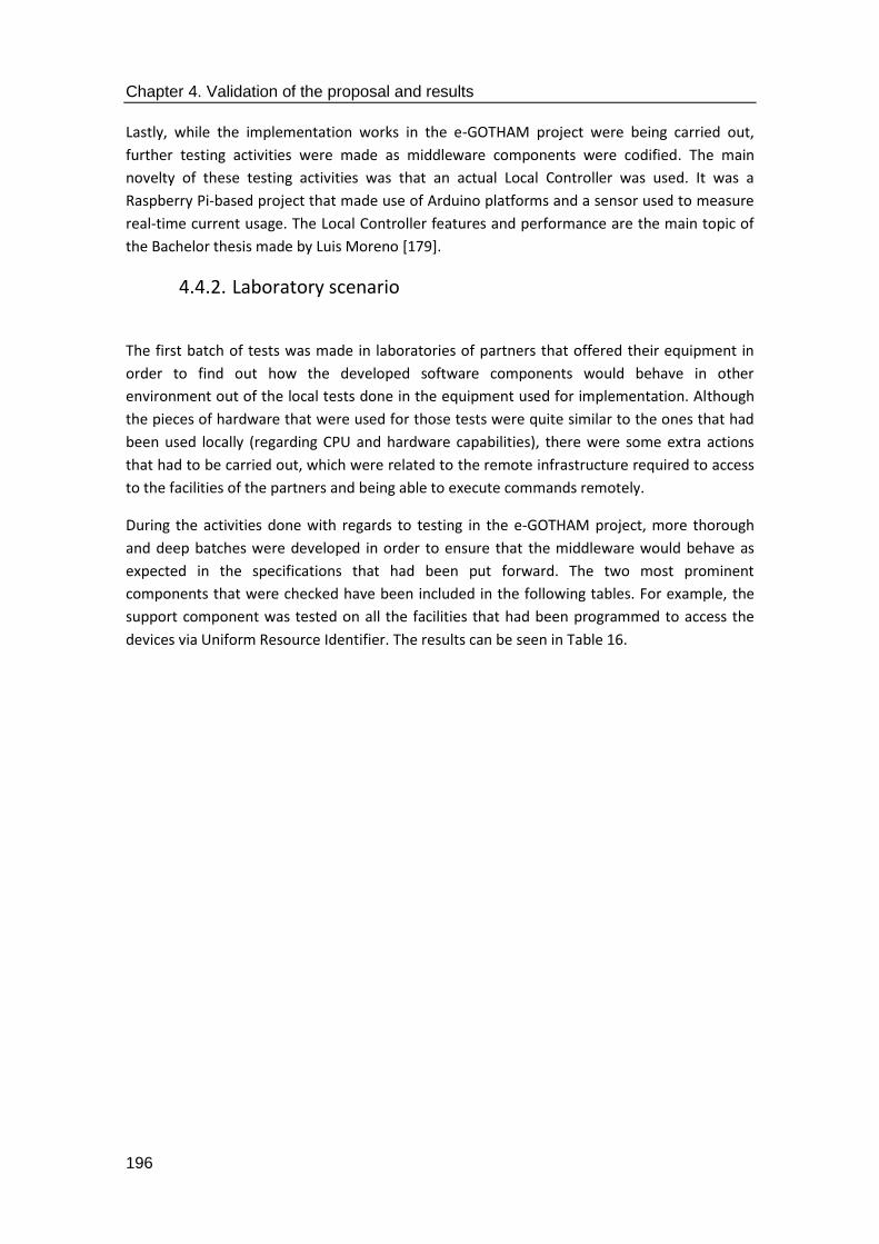
Chapter 4. Validation of the proposal and results
196
Lastly, while the implementation works in the e-GOTHAM project were being carried out,
further testing activities were made as middleware components were codified. The main
novelty of these testing activities was that an actual Local Controller was used. It was a
Raspberry Pi-based project that made use of Arduino platforms and a sensor used to measure
real-time current usage. The Local Controller features and performance are the main topic of
the Bachelor thesis made by Luis Moreno [179].
4.4.2. Laboratory scenario
The first batch of tests was made in laboratories of partners that offered their equipment in
order to find out how the developed software components would behave in other
environment out of the local tests done in the equipment used for implementation. Although
the pieces of hardware that were used for those tests were quite similar to the ones that had
been used locally (regarding CPU and hardware capabilities), there were some extra actions
that had to be carried out, which were related to the remote infrastructure required to access
to the facilities of the partners and being able to execute commands remotely.
During the activities done with regards to testing in the e-GOTHAM project, more thorough
and deep batches were developed in order to ensure that the middleware would behave as
expected in the specifications that had been put forward. The two most prominent
components that were checked have been included in the following tables. For example, the
support component was tested on all the facilities that had been programmed to access the
devices via Uniform Resource Identifier. The results can be seen in Table 16.

Chapter 4. Validation of the proposal and results
197
Table 16. Support middleware component testing
Test information for the Support component (e-GOTHAM)
Test Number Test Test Data Expected result Actual result Status Notes
1 /controlAppliance1/{serviceID}/{input}
serviceID= 4347
Input=on
ok ok Pass
Fail
serviceID= 4347
Input=test
Error – parameters error
Error – parameters error
Pass
Fail
serviceID= test
Input=on
Error – Parameters error
Error 500 Pass
Fail
serviceID= 3423
Input=on
Error – parameters error
Error – parameters error
Pass
Fail
3423 was a random number
2 /controlAppliance1/{serviceID}/{input}
serviceID= 4347
Input=on
ok ok Pass
Fail
serviceID= 4347
Input=test
Error – parameters error
Error – parameters error
Pass
Fail
serviceID= test
Input=on
Error – Parameters error
Error 500 Pass
Fail
serviceID= 3423
Input=on
Error – parameters error
Error – parameters error
Pass
Fail
3423 was a random number
3 /controlAppliance1/{serviceID}/{input}
Digital input= on
serviceID=4347
ok ok Pass
Fail
ID=4347 ok ok Pass
Fail
ID=3423 Error – parameters error
Error – parameters error
Pass
Fail
3423 was a random number
4 /controlAppliance1/{serviceID}/{input}
ID=test Error – parameters error
Error – parameters error
Pass
Fail
Digital input= on ok ok Pass

Chapter 4. Validation of the proposal and results
198
serviceID=4347 Fail
ID=4347 ok ok, but no content returned (204)
Pass
Fail
ID=3423 Error – parameters error
Error – parameters error
Pass
Fail
3423 was a random number
5 /controlAppliance1/{serviceID}/{input}
ID=test Error – parameters error
Error – parameters error
Pass
Fail
Get request with no parameters
ok Error 500 Pass
Fail
Id=4347 ok ok Pass
Fail
Id=3423 Error – parameters error
Error – parameters error
Pass
Fail
3423 was a random number
6 /controlAppliance1/{serviceID}/{input}
Id=test Error – parameters error
Error – parameters error
Pass
Fail
Id=4347 ok ok Pass
Fail
Id=3423 Error – parameters error
Error – parameters error
Pass
Fail
3423 was a random number
Id=test Error – parameters error
Error – parameters error
Pass
Fail
7 /controlAppliance1/{serviceID}/{input}
Id=4347 ok ok Pass
Fail
Id=3423 Error – parameters error
Error – parameters error
Pass
Fail
3423 was a random number
Id=test Error – parameters error
Error – parameters error
Pass
Fail
Id=4347 ok ok Pass

Chapter 4. Validation of the proposal and results
199
Fail
8 /controlAppliance1/{serviceID}/{input}
Id=3423 Error – parameters error
Error – parameters error
Pass
Fail
3423 was a random number
Id=test Error – parameters error
Error – parameters error
Pass
Fail
Id=4347 ok ok Pass
Fail
Id=3423 Error – parameters error
Error – parameters error
Pass
Fail
3423 was a random number
9 /controlAppliance1/{serviceID}/{input}
Id=test Error – parameters error
Error – parameters error
Pass
Fail
Id=4347 ok ok Pass
Fail
Id=3423 Response with empty results
Response with empty results
Pass
Fail
Id=test Response with empty results
Response with empty results
Pass
Fail
10 /controlAppliance1/{serviceID}/{input}
Id=4347 Response with empty results
Response with empty results
Pass
Fail
Id=3423 Response with empty results
Response with empty results
Pass
Fail
Id=test Response with empty results
Response with empty results
Pass
Fail
Id=4347 ok ok Pass
Fail
11 /controlAppliance1/{serviceID}/{input}
Id=test Error – parameters error
Error – parameters error
Pass
Fail
Id=4347 ok ok Pass

Chapter 4. Validation of the proposal and results
200
Fail
Id=3423 Error – parameters error
Error – parameters error
Pass
Fail
3423 was a random number
12 /controlAppliance1/{serviceID}/{input}
Id=test Error – parameters error
Error – parameters error
Pass
Fail
Id=4347 ok ok Pass
Fail
Id=3423 Error – parameters error
Error – parameters error
Pass
Fail
3423 was a random number
Id=test Error – parameters error
Error – parameters error
Pass
Fail
13 /controlAppliance1/{serviceID}/{input}
Id=4347 ok ok Pass
Fail
Id=3423 Error – parameters error
Error – parameters error
Pass
Fail
3423 was a random number
Id=test Error – parameters error
Error – parameters error
Pass
Fail
Id=4347 ok ok Pass
Fail
14 /controlAppliance1/{serviceID}/{input}
Id=3423 Error – parameters error
Error – parameters error
Pass
Fail
3423 was a random number
Id=test Error parameters Error 500 Pass
Fail
Id=4347 ok ok Pass
Fail
15 /controlAppliance1/{serviceID}/{input}
Id=test Error – parameters error
Error – parameters error
Pass
Fail
Id=4347 ok ok Pass

Chapter 4. Validation of the proposal and results
201
Fail
Id=3423 Error parameters Server does not respond.
Pass
Fail
3423 was a random number
Id=test Error – parameters error
Error – parameters error
Pass
Fail
16 /controlAppliance1/{serviceID}/{input}
Id=4347 ok ok Pass
Fail
Id=3423 Error – parameters error
Error – parameters error
Pass
Fail
3423 was a random number
Id=test Error – parameters error
Error – parameters error
Pass
Fail
Id=4347 ok ok Pass
Fail
17 /controlAppliance1/{serviceID}/{input}
Id=3423 Error – parameters error
Error – parameters error
Pass
Fail
3423 was a random number
Id=test Error – parameters error
Error – parameters error
Pass
Fail
Id=4347 ok ok Pass
Fail
Id=3423 Error – parameters error
Error – parameters error
Pass
Fail
3423 was a random number
18 /controlAppliance1/{serviceID}/{input}
Id=test Error – parameters error
Error – parameters error
Pass
Fail
Id=4347 ok ok Pass
Fail
Id=3423 Error – parameters error
Error – parameters error
Pass
Fail
3423 was a random number
Id=test Error – Error – Pass

Chapter 4. Validation of the proposal and results
202
parameters error parameters error Fail
19 /controlAppliance1/{serviceID}/{input}
Id=4347 ok ok Pass
Fail
Id=3423 Error – parameters error
Error – parameters error
Pass
Fail
3423 was a random number
Id=test Error – parameters error
Error – parameters error
Pass
Fail
Id=4347 ok ok Pass
Fail
20 /controlAppliance1/{serviceID}/{input}
Id=3423 Error – parameters error
Error – parameters error
Pass
Fail
3423 was a random number
Id=test Error – parameters error
Error – parameters error
Pass
Fail
Id=4347 ok ok Pass
Fail
Id=3423 Error – parameters error
Error – parameters error
Pass
Fail
3423 was a random number
21 /controlAppliance1/{serviceID}/{input}
Id=test Error – parameters error
Error – parameters error
Pass
Fail
Id=4347 ok ok Pass
Fail
Id=3423 Error – parameters error
Error – parameters error
Pass
Fail
3423 was a random number
Id=test Error – parameters error
Error – parameters error
Pass
Fail
22 /controlAppliance1/{serviceID}/{input}
Digital input= on
serviceID=4347
ok ok Pass
Fail
Id=4347 ok ok Pass
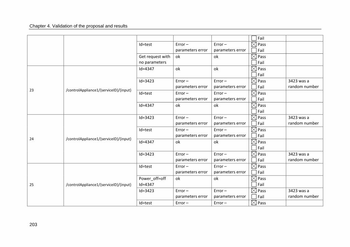
Chapter 4. Validation of the proposal and results
203
Fail
Id=test Error – parameters error
Error – parameters error
Pass
Fail
Get request with no parameters
ok ok Pass
Fail
23 /controlAppliance1/{serviceID}/{input}
Id=4347 ok ok Pass
Fail
Id=3423 Error – parameters error
Error – parameters error
Pass
Fail
3423 was a random number
Id=test Error – parameters error
Error – parameters error
Pass
Fail
Id=4347 ok ok Pass
Fail
24 /controlAppliance1/{serviceID}/{input}
Id=3423 Error – parameters error
Error – parameters error
Pass
Fail
3423 was a random number
Id=test Error – parameters error
Error – parameters error
Pass
Fail
Id=4347 ok ok Pass
Fail
Id=3423 Error – parameters error
Error – parameters error
Pass
Fail
3423 was a random number
25 /controlAppliance1/{serviceID}/{input}
Id=test Error – parameters error
Error – parameters error
Pass
Fail
Power_off=off
Id=4347
ok ok Pass
Fail
Id=3423 Error – parameters error
Error – parameters error
Pass
Fail
3423 was a random number
Id=test Error – Error – Pass

Chapter 4. Validation of the proposal and results
204
parameters error parameters error Fail
26 /controlAppliance1/{serviceID}/{input}
serviceID= 4347
Input=on
ok ok Pass
Fail
serviceID= 4347
Input=test
Error – parameters error
Error – parameters error
Pass
Fail
serviceID= test
Input=on
Error – Parameters error
Error 500 Pass
Fail
serviceID= 3423
Input=on
Error – parameters error
Error – parameters error
Pass
Fail
3423 was a random number
27 /controlAppliance1/{serviceID}/{input}
serviceID= 4347
Input=on
ok ok Pass
Fail
serviceID= 4347
Input=test
Error – parameters error
Error – parameters error
Pass
Fail
serviceID= 3423
Input=on
Error – parameters error
Error – parameters error
Pass
Fail
3423 was a random number
28 /controlAppliance1/{serviceID}/{input}
Digital input= on
serviceID=4347
ok Error 400 (not found)
Pass
Fail
Digital input= on
serviceID=4347
ok ok Pass
Fail
ID=4347 ok ok Pass
Fail
ID=3423 Error – parameters error
Error – parameters error
Pass
Fail
3423 was a random number
29 /controlAppliance1/{serviceID}/{input}
ID=test Error – parameters error
Error – parameters error
Pass
Fail
Digital input= on
serviceID=4347
ok ok Pass
Fail
ID=4347 ok ok Pass

Chapter 4. Validation of the proposal and results
205
Fail
ID=3423 Error – parameters error
Error – parameters error
Pass
Fail
3423 was a random number
30 /controlAppliance1/{serviceID}/{input}
ID=test Error – parameters error
Error – parameters error
Pass
Fail
Get request with no parameters
ok Error 500 Pass
Fail
Id=4347 ok ok Pass
Fail
Id=3423 Error – parameters error
Error – parameters error
Pass
Fail
3423 was a random number
31 /controlAppliance1/{serviceID}/{input}
Id=test Error – parameters error
Error – parameters error
Pass
Fail
Id=4347 ok ok Pass
Fail
Id=3423 Error – parameters error
Error – parameters error
Pass
Fail
3423 was a random number
Id=test Error – parameters error
Error – parameters error
Pass
Fail
32 /controlAppliance1/{serviceID}/{input}
Id=4347 ok ok Pass
Fail
Id=3423 Error – parameters error
Error – parameters error
Pass
Fail
3423 was a random number
Id=test Error – parameters error
Error – parameters error
Pass
Fail
Id=4347 ok ok Pass
Fail
33 /controlAppliance1/{serviceID}/{input} Id=3423 Error – Error – Pass 3423 was a

Chapter 4. Validation of the proposal and results
206
parameters error parameters error Fail random number
Id=test Error – parameters error
Error – parameters error
Pass
Fail
Id=4347 ok ok Pass
Fail
Id=3423 Error – parameters error
Error – parameters error
Pass
Fail
3423 was a random number
34 /controlAppliance1/{serviceID}/{input}
Id=test Error – parameters error
Error – parameters error
Pass
Fail
Id=4347 ok ok Pass
Fail
Id=3423 Response with empty results
Response with empty results
Pass
Fail
Id=test Response with empty results
Response with empty results
Pass
Fail
35 /controlAppliance1/{serviceID}/{input}
Id=4347 Response with empty results
Response with empty results
Pass
Fail
Id=3423 Response with empty results
Response with empty results
Pass
Fail
Id=test Response with empty results
Response with empty results
Pass
Fail
Id=4347 ok ok Pass
Fail
36 /controlAppliance1/{serviceID}/{input}
Id=test Error – parameters error
Error – parameters error
Pass
Fail
Id=4347 ok ok Pass
Fail
Id=3423 Error – Error – Pass 3423 was a
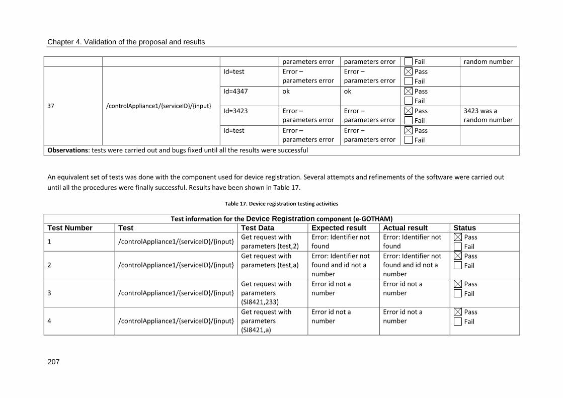
Chapter 4. Validation of the proposal and results
207
parameters error parameters error Fail random number
37 /controlAppliance1/{serviceID}/{input}
Id=test Error – parameters error
Error – parameters error
Pass
Fail
Id=4347 ok ok Pass
Fail
Id=3423 Error – parameters error
Error – parameters error
Pass
Fail
3423 was a random number
Id=test Error – parameters error
Error – parameters error
Pass
Fail
Observations: tests were carried out and bugs fixed until all the results were successful
An equivalent set of tests was done with the component used for device registration. Several attempts and refinements of the software were carried out
until all the procedures were finally successful. Results have been shown in Table 17.
Table 17. Device registration testing activities
Test information for the Device Registration component (e-GOTHAM) Test Number Test Test Data Expected result Actual result Status
1 /controlAppliance1/{serviceID}/{input} Get request with parameters (test,2)
Error: Identifier not found
Error: Identifier not found
Pass
Fail
2 /controlAppliance1/{serviceID}/{input} Get request with parameters (test,a)
Error: Identifier not found and id not a number
Error: Identifier not found and id not a number
Pass
Fail
3 /controlAppliance1/{serviceID}/{input} Get request with parameters (SI8421,233)
Error id not a number
Error id not a number
Pass
Fail
4 /controlAppliance1/{serviceID}/{input} Get request with parameters (SI8421,a)
Error id not a number
Error id not a number
Pass
Fail

Chapter 4. Validation of the proposal and results
208
5 /controlAppliance1/{serviceID}/{input} Get request with parameters (SI8421,2)
Success and response with registration id
Success and response with registration id
Pass
Fail
6 /controlAppliance1/{serviceID}/{input} Get request with parameters (SI8421,1)
Success and response with registration id
Success and response with registration id
Pass
Fail
7 /controlAppliance1/{serviceID}/{input} Get request with parameters (fire risk,2)
Success and response with registration id
Success and response with registration id
Pass
Fail
8 /controlAppliance1/{serviceID}/{input} Get request with parameters (eGLCARM7700/3)
Success and response with registration id
Success and response with registration id
Pass
Fail
9 /controlAppliance1/{serviceID}/{input} Get request with parameters (eGLCARM7700/4)
Success and response with registration id
Success and response with registration id
Pass
Fail
10 /controlAppliance1/{serviceID}/{input} Get request with parameters (rpi_mbus/5)
Success and response with registration id
Success and response with registration id
Pass
Fail
11 /controlAppliance1/{serviceID}/{input} Get request with parameters (rpi_mbus/6)
Success and response with registration id
Success and response with registration id
Pass
Fail
12 /controlAppliance1/{serviceID}/{input} Get request with parameters (ld7_iRTU/7)
Success and response with registration id
Success and response with registration id
Pass
Fail
13 /controlAppliance1/{serviceID}/{input} Get request with parameters (ld8_temphum/8)
Success and response with registration id
Success and response with registration id
Pass
Fail
14 /controlAppliance1/{serviceID}/{input} Get request with parameters (ld9_PMU/9)
Success and response with registration id
Success and response with registration id
Pass
Fail

Chapter 4. Validation of the proposal and results
209
15 /controlAppliance1/{serviceID}/{input}
Get request with parameters (Herrfors-pressure/10)
Success and response with registration id
Success and response with registration id
Pass
Fail
16 /controlAppliance1/{serviceID}/{input} Get request with parameters (Herrfors-data/11)
Success and response with registration id
Success and response with registration id
Pass
Fail
17 /controlAppliance1/{serviceID}/{input} Get request with parameters (ESS/12)
Success and response with registration id
Success and response with registration id
Pass
Fail

Chapter 4. Validation of the proposal and results
210
4.4.3. Ylivieska scenario
When the testing activities proved that the middleware components had reached a suitable
level of maturity, middleware was deployed in the two demonstrators that had been arranged
for its usage. The first one was used in the Finnish city of Ylivieska, where middleware was
used to contain several communication facilities and software components [180]. The
Enterprise Service Bus that was used during testing facilities was employed again when the
actual deployment took place. Additionally, the hardware capabilities of the unit running the
central Controller had no special requirements (as stated in [154], middleware was installed in
a Ubuntu-based virtual machine running the 14.04 Long Time Support version of the operating
system. The hardware had a 3 GHz CPU, 4 GB of RAM memory, 160 GB of Hard Disk and
Gigabit Ethernet communications). As portrayed in Figure 101, the deployment was done in
line to what had been conceived during the design and implementation stages for middleware:
a somewhat centralized element contained most of the elements in the middleware
architecture, which was chosen to have the most complex services to be installed. Some of
them had functionalities comparable to the ones defined as Middleware Access Points, where
software components were used to access other parts of the middleware. Others performed
functionalities typical of a Smart Grid (energy consumption forecasting, information,
management, etc.) and did not require any other middleware service (and therefore behaved
as Middleware Autonomous Services).
Figure 101. Deployment made in Ylivieska. Middleware is at the centre of the deployment
According to what was used in the Ylivieska scenario, the following pieces of equipment were
installed in different facilities of the town: Local Controllers were installed in the school of the

Chapter 4. Validation of the proposal and results
211
city, elderly home, sports centre, an industrial facility, an elementary school and a rowhouse.
Furthermore, two of them were installed in a power plant owned by a DSO called Herrfors, due
to the higher complexity of its installations. The Local Controllers that were communicating
with the middleware were based on raspberry Pi model B hardware, which had enough
computational power to receive and transfer information from their location to the one where
they were deployed [91]. Data was gathered by means of shields that were manufactured and
sold by Open Energy Monitor [181]. All in all, the deployment guaranteed that data could be
sent from the Local Controllers to the central one and have requests done throughout the
interfaces, both on top of the middleware (via HTTP) and below it (by means of AMQP).
4.4.4. Steinkjer scenario
This was the demonstrator that was chosen to be used in the I3RES project [182]. While the
middleware components that were deployed had several major differences from the ones that
had been created for the e-GOTHAM project (both in their implemented code and purpose),
the computer where they were deployed was still of regular characteristics, so the solution
could be deployed in a fashion that resembled the one carried out previously. The hardware
that was to be interacted reflected the higher stress in power transmission made by I3RES, in
the sense that were units such as weather stations or tertiary buildings expected to send their
information about their status and performance. The final appearance of the deployment,
along with its components, has been depicted in Figure 102.
Figure 102. Steinjker deployment with the middleware solution, as depicted in [34]
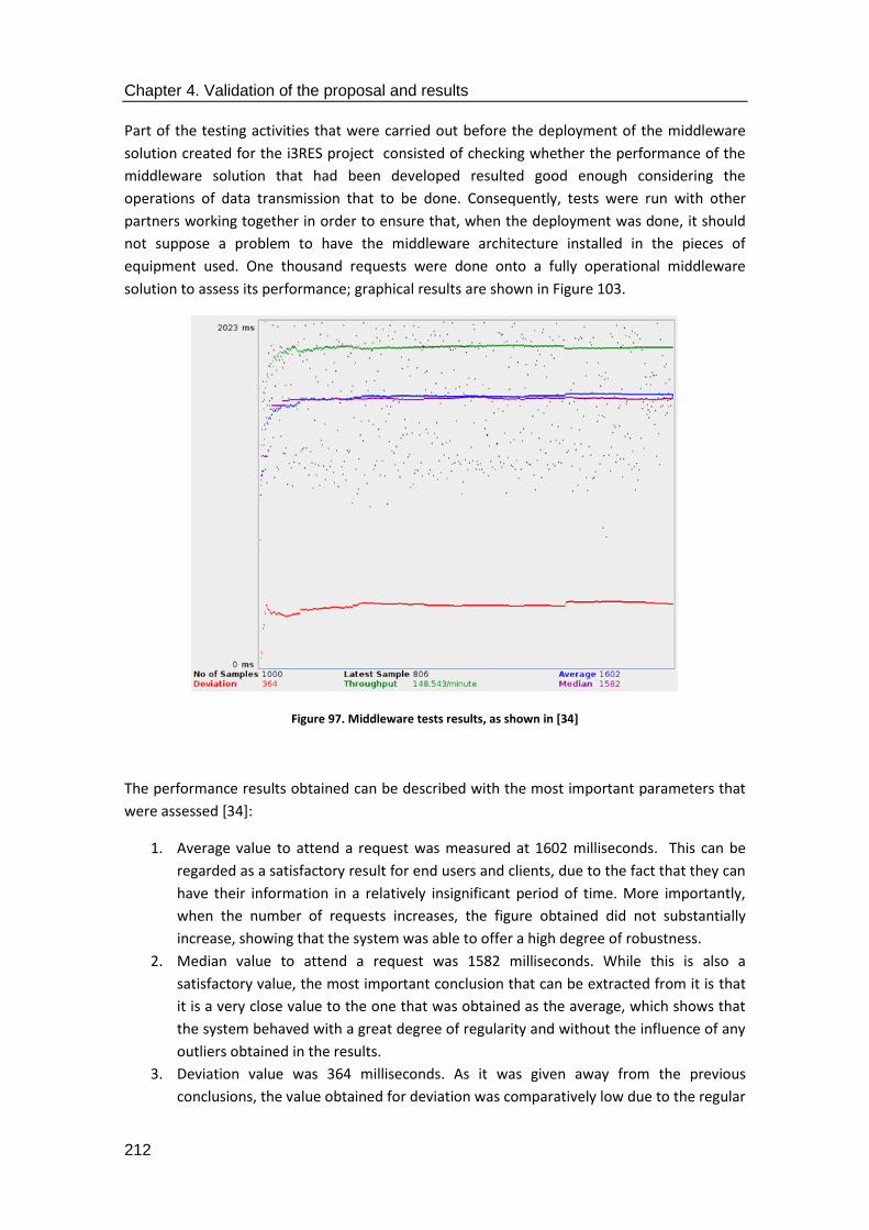
Chapter 4. Validation of the proposal and results
212
Part of the testing activities that were carried out before the deployment of the middleware
solution created for the i3RES project consisted of checking whether the performance of the
middleware solution that had been developed resulted good enough considering the
operations of data transmission that to be done. Consequently, tests were run with other
partners working together in order to ensure that, when the deployment was done, it should
not suppose a problem to have the middleware architecture installed in the pieces of
equipment used. One thousand requests were done onto a fully operational middleware
solution to assess its performance; graphical results are shown in Figure 103.
Figure 97. Middleware tests results, as shown in [34]
The performance results obtained can be described with the most important parameters that
were assessed [34]:
1. Average value to attend a request was measured at 1602 milliseconds. This can be
regarded as a satisfactory result for end users and clients, due to the fact that they can
have their information in a relatively insignificant period of time. More importantly,
when the number of requests increases, the figure obtained did not substantially
increase, showing that the system was able to offer a high degree of robustness.
2. Median value to attend a request was 1582 milliseconds. While this is also a
satisfactory value, the most important conclusion that can be extracted from it is that
it is a very close value to the one that was obtained as the average, which shows that
the system behaved with a great degree of regularity and without the influence of any
outliers obtained in the results.
3. Deviation value was 364 milliseconds. As it was given away from the previous
conclusions, the value obtained for deviation was comparatively low due to the regular

Chapter 4. Validation of the proposal and results
213
performance of the middleware solution. The dispersion level obtained from the 100
samples that were registered is also acceptable, as it does not suppose a significant
time value for an end user, a consumer or even a prosumer.
4. Throughput value was 148.543 queries/minute. Considering the scale of the system
that was implemented and were it was deployed, it can be considered as an
acceptable figure, as there was not a chance that there would be such a number of
requests per minute done to the middleware solution once it was deployed to the
demonstrator.
4.4.5. Smart Grid scenario test results
The results that have been presented in this section provide all the testing activities that were
carried out in order to assess the feasibility of the solution put forward in this thesis. Aside
from the testing activities that were carried out in a controlled environment (such as
laboratories and the facilities of Vitrociset), software services and implementation works that
have been depicted in this section, along with all the activities required to prove them until
they are reliable enough to be deployed in an actual scenario. The performance obtained in
the laboratory tests done for the I3RES project confirmed that its behaviour is good enough for
the purposes of the middleware. In addition to that, the middleware deployment done in the
cities of Ylivieska and Steinkjer proves that it can be used to receive and transfer information
at the data level. The software components that were included in those latter two scenarios
also show how middleware can be used to provide services for the Smart Grid.
When comparing the results that have been obtained with this middleware architecture
against the results that the first versions of the middleware implemented in the Wireless
Sensor Networks, it can be seen that the capacity and the improvement that have been carried
out are remarkable: not only there are more services that can be used (secure access to the
middleware architecture, semantic capabilities, device registration in a database, etc.) but also
the amount of requests that can be handled by the middleware is far greater than the one that
was used before. In addition to that, the performance of the semantic middleware
architecture is able to guarantee that service requests will be satisfied at an acceptable rate, so
it can be claimed that including a middleware architecture in a system related to the Smart
Grid does not impact negatively its performance, while at the same time there are more
services available for end users or prosumers.
4.5. Section summary
This section has offered a thorough description about how the proposal for a common
middleware architecture for the Smart Grid has been implemented in order to test its
performance and feasibility in a realistic scenario. The implementation activities that have
been offered describe the software tools that have been used for such an implementation
(Java as the programming language, JBoss Fuse as the Enterprise Service Bus), along with the
hardware devices that were used during the testing and deployment of the solutions in two

Chapter 4. Validation of the proposal and results
214
different demonstrators, as arranged in the e-GOTHAM and I3RES projects. The results that
have been provided show that services have been added in a way that had not been conceived
before, while at the same time keeping an acceptable performance for the overall system.
The inference process that resulted in conceiving the Common Middleware Architecture must
also be included in this part of the chapter. During the implementation works that were taking
place in e-GOTHAM and I3RES research projects, there were several aspects that were found
out to be common in both projects:
1. Existing solutions for middleware in the Smart Grid were not completely satisfactory.
There were several services like semantics, security or context awareness that were not
included in previous solutions, or they were so in a way that could not be used to the
overall system´s advantage (only partial solutions, laboratory testing in simulators as
opposed to real world deployments, etc.).
2. A way to encase services had to be figured out. Since what was deemed as most useful
was the design and implementation of a middleware architecture, a way to contain all the
software services that had to be included had to be thought. In order to do so, Enterprise
Service Bus solutions seemed like the best ones, as they were able to contain those
services, establish a way to have them communicating with each other and enabling its
capability to interact with other elements of a distributed or Cyber-Physical System.
3. Software technologies used for communications between elements alien to the
middleware architecture had to be included. The importance of interfacing other software
developments was stressed from the very first stages of the projects, where the
requirements were defined for each of the elements present in what would become the
deployed system.
4. The solutions had to be tested in actual deployments rather than only in controlled
environments or laboratories. The nature of the European research projects defined by
ARTEMIS or FP7 initiatives made almost mandatory having the development works tested
in environments where they could provide real usefulness to a system that contained the
other elements development by other partners in the consortiums that had cooperated in
the projects.
5. Similarities and differences among projects could be defined and given boundaries. While
the objectives in the projects that were participated were different from each other (the e-
GOTHAM project was mostly focused on device integration and interoperability whereas
I3RES was focused on Demand Response and Demand Side Management for the Smart
Grid), there were similarities in requirements (distributed system with software
components interacting with a plethora of devices) among them, so a common ground
could be found that complemented the works done in a) previous middleware instalments
and b) standards that, to a greater or a lesser extent, were involved, in hardware
interoperability for the Smart Grid (or at least, the power grid). Those are the four
different areas of knowledge that have been heavily considered for the analysis, design,
implementation and testing works that have resulted in the conception of CMA, which can
be located at the intersection of all of those initiatives, as depicted in Figure 104.

Chapter 4. Validation of the proposal and results
215
Figure 98. Different areas of knowledge and projects used for the conception of CMA
It can be inferred from the previous figure that the combination of different sources of
demands form research projects and weaknesses detected in previous pieces of work have
been the main motivation for the development of Common Middleware Architecture.
6. The inclusion of a middleware architecture (as part of the implementation works required
to integrate it with all the other parts of the system) does not pose a threat in terms of
performance. Even though the results obtained for middleware in the scenario where
WSNs were used as the hardware where the architecture was installed show that nodes
may struggle to get a near real-time result for composed services, this issue was basically
non-existent in the other deployments where more capable hardware was used to deliver
data readings and service-related information.
e-GOTHAM
CMA
I3RES
Smart Grid-related
standardsOpen issues
in SotA

Chapter 4. Validation of the proposal and results
216

5. Conclusions and future
works

Chapter 5. Conclusions and future works
218

Chapter 5. Conclusions and future works
219
This chapter of the thesis has been used to include the main conclusions that can be extracted
from the work that has led to its completion. It highlights all the lessons that have been
learned about the topics that were introduced (middleware for the Smart Grid, integration of
renewable energies, etc.) and pinpoints where future works can be aimed at.
5.1. Original contributions of the thesis
This thesis has described several significant original contributions that have been listed in this
section as a way to provide a starting ground for future research activities.
1. Viability of middleware solutions for the Smart Grid. The usefulness of having a
middleware solution for the Smart Grid has been proven in this thesis. Middleware can be
used for functionalities of major importance for the Smart Grid, such as hardware
abstraction, device integration and addition of software services, as long as it is configured
as a software architecture where new functionalities can be encased. Its inclusion in a
deployment improves the overall status of the Smart Grid, due to the fact that it enables
the use of advanced ICT functionalities (service registration, security, semantics, etc.) that
would be harder or impossible to count on without middleware.
2. Standardization for middleware architectures in the Smart Grid. Services that are
available with a middleware solution for the Smart Grid, as well as how to access them
with an Application Programming Interface, have been depicted in this thesis. These
activities had not been done before for a middleware architecture for the Smart Grid, so
they are most useful for any development that has to be done in this application domain,
since they are providing a starting ground that will ease developments and will further aid
its future refinement. In addition to that, it has been proved why a software architecture is
the most suitable option for middleware in a Smart Grid. Among the different ways to
include middleware, there are options such as using just hardware abstraction or Message-
Oriented Middleware. The study on the state of the art that has been carried out proves
that the most useful existing options, and the ones capable of providing a greater array of
services, are the ones based on software architectures that encase software components
within them.
3. Exploitation of middleware via business models for prosumers and small-scale facilities.
Semantic middleware has been proven to be a critical component to make possible the
integration, from a more economics-related point of view, of the prosumers that are
expected to play a significant role in the Smart Grid (due to the fact that they provide their
own electricity to buy and sell in a distributed, small-sized way). Business models have
been provided for prosumers that, by making use of an intermediation architecture, will be
able to trade the electricity they produce in the markets. While the legislative part
required to be modified is beyond the scope of this thesis, it is proven from the technical
point of view that it is possible to perform operations of this nature for their benefit, thus
making the grid more reliable and democratizing access to energy.
Chapter 5. Conclusions and future works
220
5.2. Conclusions
This thesis has been structured in a way that the contributions have been described in the
introduction, as a way to make a first mention of the objectives that were set for it. That is why
a study of the current State of the Art regarding middleware architectures for the Smart Grid
was made. This study resulted in the inference of several open issues and challenges that were
deemed as necessary to be tackled in any future solution that was going to be developed in
this application domain. In addition to that, since it was mentioned during the study that a
collection of services would have to interchange information between the application layer
and the hardware, another study of open source Enterprise Service Bus implementations was
added.
Several requirements were set so that the highlighted open issues and challenges could be
dealt with in the most efficient way possible. With this list of requirements, a collection of
components was established and implemented. The requirement analysis that was performed
for each of the research projects differ in results, due to the fact that they had different
orientations (e-GOTHAM was mostly focused on the integration of the ICT part of the Smart
Grid within the power grid, whereas I3RES was more oriented to the enhancement of energy
consumption behaviour by means of services such as Demand Side Management or Demand
Response). Nevertheless, the obtained complementary results, combined with the features
that the existing State of the Art offered, as well as the different aspects that were
contemplated in the existing standards within this area of knowledge resulted in the
conception of Common Middleware Architecture, a proposal for a semantic middleware
architecture in the context of the Smart Grid that supersedes many of the issues that were
found before. When all is said and done, the following conclusions can be inferred from the
presented work:
1. Challenges in existing solutions of middleware for the Smart Grid are profuse. When all the
studied solutions where researched, it was found that none of them would completely
address the issues found regarding interoperability, service availability, distribution or
usability. Therefore, there was a solution that had to be achieved based on the challenges
found in the ones preceding the development works done during the e-GOTHAM and
I3RES research projects, and the requirements of these projects.
2. The bulk of the issues that were found has been addressed. CMA provides a framework
were services can be included in an ordered fashion, with each of their functionalities and
boundaries clearly defined. In addition to that, the procedures that must be followed in
order to have an equivalent implementation have been described as well.
3. Feasibility of middleware for the Smart Grid. Rather than having just a theoretical work of
design, implementation activities were carried out so that developments could be used in
an actual scenario. It was due to those successful implementation activities that common
features could be inferred and combined with the weaknesses found in the existing
standards, thus making possible the conception of CMA. In addition to that, performance
results measured and deployments done in two different pilots prove that the
development of semantic middleware for the Smart Grid is feasible and desirable. Indeed,

Chapter 5. Conclusions and future works
221
the validation results obtained in the two previously described scenarios show that
middleware and its encased services can be implemented in a realistic manner, where
characteristics like context awareness or semantics can be offered without significant
impact in the rates they are offered at.
4. Benefits of standardization have been offered. Since one of the main goals of middleware
is guarantee interoperability among heterogeneous distributed devices, a standard that
defines the services to be used and how information is supposed to be mapped and
integrated becomes an appealing objective. The establishment of a standard for
interoperability software architectures used as something consensual in the Smart Grid
would greatly improve any development done in this application domain, as it will provide
a blueprint of the services to be included and how to interface them.
5. Implementation via open source resources. An important feature to consider here is that
the development works described have been done with open source tools (JBoss Fuse
being the most prominent of them all), which is of major importance to lower the overall
cost of the project and facilitate the implementation with examples and troubleshooting
procedures that can be found with next to no problem. Also, it is easier to improve the
state of the art in semantic middleware for the Smart Grid using this kind of software
resources, since any component detail or the overall appearance of the architecture can
be described.
6. A commercial point of view has also been provided in order to justify how the business
models that make use of middleware as part of the required technology to integrate
prosumers (or even regular end users) in the Smart Grid. By being able to guarantee
information interchanges between several distributed entities, middleware enhances the
capacities of the power grid and includes new actors that are likely to contribute to the
power flow of the overall grid, as well as demand and offer new services according to their
needs and capabilities.
5.3. Future works
The following future works have been programmed for future research:
1. Portability to other Cyber-Physical Systems is already been made. Many of the principles
of CMA have been included in the SWARMs project [20], even though the application
domain of maritime robotics has many major differences if it is compared to the Smart
Grid (despite sharing several underlying features) such as being a Cyber-Physical System
with distributed hardware heterogeneous elements in a constrained environment from
the computational and communications point of view.
2. Further integration with other similarly themed standards. As it has already been
mentioned, the objective of CMA is providing new ideas that other proposals and
standards may lack in order to provide the most holistic and complete point of view to the
standardization processes that are being carried out for now. The promotion of the
concepts of CMA (layered middleware architecture, core services, access services,
procedure for middleware implementation and testing, interfaces within and without

Chapter 5. Conclusions and future works
222
middleware) and their inclusion in other more developed proposals for standardization
preceding the ones made here for years will be emphasized during the next period of time.
3. Extension to other software tools and languages. It has already been proven how CMA can
be implemented by means of an open source JBoss Fuse as an ESB and Java as the
programming language. Other developers, though, may prefer other kinds of tools due to
their background or the requirements of their own projects. Offering consulting to other
possible implementations or Platform Specific Models will be done as soon as an interest is
spotted both within and without the research group where these implementation works
have been carried out.
4. Increase of the intelligence of the services included in the middleware. As described in this
document and supported by research papers, services make extensive use of semantic
capabilities. Its further enhancement of their performance by means of already familiar or
new tools (deep learning, machine learning, etc.) is a likely development to take place.
5.4. Publications and projects
The following section includes all the scientific publications that have been made that can be
considered as part of this thesis. They comprehend a timespan of more than four years from
the first one to the last one. Currently there are other publications that are under
consideration for some other journals, but they have yet to be accepted and published.
5.4.1. SCI-indexed journals
The following scientific papers have been published as a result of the research works done. At
the end of each of the references, a description has been added to clarify what they provide as
a contribution to the thesis, as well as a way to refer to them in Figure 106, which portrays in a
graphical manner a timeline with all the outputs aimed to satisfy the objectives of the thesis.
1. Rodríguez-Molina, Jesús; Martínez, José-Fernán; Castillejo, Pedro; López, Lourdes,
"Combining Wireless Sensor Networks and Semantic Middleware for an Internet of Things-
Based Sportsman/Woman Monitoring Application," Sensors, vol. 13, p. 1787, 2013.
This paper summarizes the work that has been done for the LifeWear project regarding the
extension of the previously existing middleware works, as well as other new services that
were added both to the project and the content of this thesis, such as interfaces to the
application layer (based on REST). This is the first paper co-authored by the author of this
manuscript where service composition was used: there were two services (injury
prevention, assessing the data obtained from body temperature, environmental
temperature and heartbeat rate, and temperature control, making use of environmental
and body temperature). This paper is referred to as Sensors 1 in Figure 106.
2. Rodríguez-Molina, Jesús; Martínez, José-Fernán; Castillejo, Pedro; de Diego, Rubén;
"SMArc: A Proposal for a Smart, Semantic Middleware Architecture Focused on Smart City

Chapter 5. Conclusions and future works
223
Energy Management," International Journal of Distributed Sensor Networks, vol. 2013, p.
17, 2013.
This was a first approach to what middleware should be for distributed and Cyber-Physical
Systems. Ideas like having a middleware layer with several components providing services,
as well as abstracting hardware heterogeneity, semantic capabilities and offering access
points to the applications. The design principles and some of the implementation works
were included as part of the I3RES project. It is referred to as IJDSN in Figure 106.
3. Rodríguez-Molina, Jesús; Martínez-Núñez, Margarita; Martínez, José-Fernán; Pérez-
Aguiar, Waldo. “Business Models in the Smart Grid: Challenges, Opportunities and
Proposals for Prosumer Profitability”. Energies, vol. 7, no. 9, p. 6142, 2014.
This is the first approach that was made with the idea of integrating prosumers into a
business model that makes use of middleware as the underlying software. A study of the
possibilities that were offered for prosumers was included, as well as how they could
impact the Smart Grid with their activities. This manuscript is referred to as Energies 3 in
Figure 106.
4. Rodríguez-Molina, Jesús; Martínez, José-Fernán; Castillejo, Pedro. “A Study on
Applicability of Distributed Energy Generation, Storage and Consumption within Small
Scale Facilities”. Energies, vol. 9, no. 9, p. 745, 2016.
This manuscript improves the ideas put forward in the former one by providing a
mathematical model used to prove how either payment reduction regarding electricity or
even profits can be obtained. This model is the foundation of the Section 2.4 present in
this thesis. Performance details of the middleware tested for the I3RES project have been
included in this manuscript. It is referred to as Energies 4 in Figure 106.
5. Rodríguez-Molina, Jesús; Martínez, José-Fernán; Castillejo, Pedro; Rubio, Gregorio.
“Development of middleware applied to microgrids by means of an open source Enterprise
Service Bus” [154]. Energies, vol. 10, no. 2, p. 172, 2017.
This research paper focuses on how an ESB is used to gather all the services present in a
middleware solution, as well as offering information about the data that is to be included
in the messages that are interchanged among the different parties where middleware has
been installed. It is referred to as Energies 5 in Figure 106.
6. Martínez, José-Fernán; Rodríguez-Molina, Jesús; Castillejo, Pedro; de Diego, Rubén.
“Middleware Architectures for the Smart Grid: Survey and Challenges in the Foreseeable
Future”. Energies, vol. 6, no. 9, p. 3593, 2013.
This paper offers a first study of the state of the art regarding middleware architectures for
the Smart Grid, in order to have an exact idea of what is used as such and their features,
strong points and weaknesses. While the studied proposals of the paper have been

Chapter 5. Conclusions and future works
224
included in this thesis, there are many others that have been included as well in order to
have an overall more complete study. This manuscript is referred to as Energies 1 in Figure
106.
7. Castillejo, Pedro; Martinez, José-Fernán; Rodriguez-Molina, Jesús; Cuerva, Alexandra.
"Integration of wearable devices in a wireless sensor network for an E-health application,"
in IEEE Wireless Communications, vol. 20, no. 4, p. 38, 2013 [28].
This paper describes how a middleware architecture can be used as part of a distributed
system where both wearable and non-wearable elements are combined together in the
same deployment due to its hardware abstraction properties. It is referred to as IEEE WC
in Figure 106.
8. de Diego, Rubén; Martínez, José-Fernán; Rodríguez-Molina, Jesús.; Cuerva, Alexandra. “A
Semantic Middleware Architecture Focused on Data and Heterogeneity Management
within the Smart Grid”. Energies vol. 7, no. 9, p. 5953, 2014.
This paper offers a first approach to how to build middleware for a Smart Grid in a realistic
manner that will integrate devices to be found in a deployment. It also includes
information about how semantics are built as part of the system and how components can
be interfaced among them and from outside the middleware. It is referred to as Energies 2
in Figure 106.
9. Li, Xin; Martínez, José-Fernán; Rodríguez-Molina, Jesús; Lucas Martínez, Néstor. “A Survey
on Intermediation Architectures for Underwater Robotics.” Sensors, vol. 16, no. 2, p. 190
[185].
This manuscript provides information about how middleware architectures can be used
and are present in other CPSs that, even though are different to the Smart Grid, contain a
significant number of similarities (hardware heterogeneity, need for interoperability,
devices scattered in an area sharing information collected from their environment, etc.). It
is referred to as Sensors 2 in Figure 106.
5.4.2. Conferences
The following contributions have been made to conferences regarding the scope of this thesis:
1. Rodríguez-Molina, Jesús; Martínez, José-Fernán; Rubio, Gregorio.; Hernández,
Vicente. “A Proposal for an Internet of Things-based Monitoring System Composed by
Low Capability, Open Source and Open Hardware Devices”. 3rd International
Conference on Sensor Networks (SENSORNETS), 2014 [186].
This conference was used to show how middleware can be used to unify under a same
system several devices reliant on the IoT to collect and transfer information. Aside

Chapter 5. Conclusions and future works
225
from middleware there were several levels that were studied to do such integration. In
this case, middleware was oriented to messages rather than offering a whole
architecture with services. It is referred to as SENSORN in Figure 106.
2. Rodríguez-Molina, Jesús; Martínez-Núñez, Margarita; Pérez-Aguiar, Waldo; de Diego,
Rubén. “A study on challenges and opportunities for energy business developments in
the Smart City”. 8th International Conference on Industrial Engineering and Industrial
Management (CIO-ICIEOM-IIIE), 2014 [187].
The piece of work that was shown in this conference dealt with the possibility of
having different business strategies for Smart Cities where the Smart Grid played a
prominent role. Prosumer activities were included as a way to describe that prosumers
could result in a new agent with a critical importance in this kind of environment. It is
referred to as CIO in Figure 106.
3. Martín-Wanton, T.; Muelas, E.; Santos de la Cámara, R.; Rodríguez-Molina, J., Li, X.,
Martinez-Ortega, J-F. ”Modelado de vehículos autónomos y la incertidumbre de su
entorno para la seguridad de operaciones marítimas”. IV Congreso Nacional de i+d en
Defensa y Seguridad (DESEi+d), 2016 [188].
The collaboration is this conference was focused on showing how the middleware
could be used in other systems resembling the Smart Grid, despite being included in
other different CPSs. It is referred to as DESEi+d in Figure 106.
5.4.3. Book chapters
This thesis has been involved in the following book chapters:
1. Rodríguez-Molina, J. “The Role of Middleware in Distributed Energy Systems
Integrated in the Smart Grid”. This is Chapter 5 of “Energy Management of Distributed
Generation Systems” [189].
This book chapter describes how the development of middleware can be eased with a
collection of steps and resources that are usually the same during its development.
Furthermore, it offers a perspective of how middleware can be standardized as a
collection of services in a middleware architecture and the services it could contain. It
is referred to as Chapter 2 in Figure 106.
2. Hernández, V.; Martínez, J-F.; Cuerva, A.; Rodríguez-Molina, J.; Rubio, G.; Jara, A.
“Semantic as an Interoperability Enabler in Internet of Things”. This is Chapter 9 of
"Internet of Things: Converging Technologies for Smart Environments and Integrated
Ecosystems" [190].

Chapter 5. Conclusions and future works
226
This book chapter had as its main idea how semantic middleware is a critical concept
in the IoT. It describes how middleware is used as a way to withhold hardware
differences in a distributed deployment and how homogeneity is provided with the aid
of semantics. Its content can also be easily ported to the Smart Grid, due to its
resemblance to some major features in IoT-based deployments. It is referred in Figure
106 as Chapter 1.
5.4.4. Research projects
This thesis has been done in the context of the following European research projects:
1. LifeWear: Mobilized Lifestyle with Wearables (ITEA2) [23] was focused on providing simple
and composed services for wearables and distributed systems. Among other aspects, a
Wireless Sensor Network was used to transfer data from a Body Area Network (BAN) to a
mobile phone application by means of middleware, an open source Enterprise Service Bus,
and REST-based interfaces. The foundations used to develop semantic middleware for the
Smart Grid were firstly introduced during this project, such as hardware abstraction or
URIs to access interfaces.
2. WoO: Web of Objects (ITEA2) . The goals of this project were described as “turn up the
Internet of Things promises by simplifying object and application deployment,
commissioning, maintenance, operation and service composition inside building
infrastructures” [24]. Middleware was also involved as a way to abstract hardware
heterogeneity from the different devices that could be present in the network.
3. e-GOTHAM: Sustainable-Smart Grid Open System for the Aggregated Control, Monitoring
and Management of Energy (ARTEMIS) [21]. As it has been mentioned before, this project
dealt with the Integration of Information and Communication Technologies at the
microgrid level by creating a new aggregated energy demand model, so that different
appliances related to the latter could be monitored and requested for services. The
requirement analysis, design procedures and implementation works done in this project
are of critical importance to the thesis.
4. I3RES: ICT-based intelligent integration of Renewable Energy Sources (FP7) aimed to
“integrate renewable energy sources in the distribution grid by incorporating intelligence at
three different levels: in the integration of Renewable Energy Sources (RES) and the
development of control and management mechanisms that reduce the impact of its
intermittency; in the facilitation of the participation of all actors in the electricity market;
and in the overall operation of the network” [53]. Even though activities in this project
were dealing mostly with the services that could be obtained from the demand side, the
requirement analysis carried out and the middleware solution that was specified for this
project were also pivotal for the conception of CMA as a general semantic middleware
architecture for the Smart Grid.
5. SWARMs: Smart and Networking UnderWAter Robots in Cooperation Meshes (ECSEL) [20].
This project has set as main objective spreading the usage of autonomous maritime
vehicles with the purpose of easing the creation, planning and performance of tasks and
Chapter 5. Conclusions and future works
227
missions in water-based environments. Although it is not explicitly related to the Smart
Grid, it is an example of how Cyber-Physical Systems with similar challenges
(heterogeneous hardware, set of services to be defined, interfaces with the application
layer of a distributed system, etc.) can use middleware solutions that resemble the basic
principles of other CPSs.
5.4.5. Other produced results
Aside from the scientific results that have been previously shown regarding publications and
projects where this thesis is embedded, there are some other achievements that must be
mentioned, as they are closely related to the activities that have been carried out in relation
with this manuscript.
The software components that were developed for e-GOTHAM have been registered as
original contributions made by the researches involved in the project. The documentation
required to be delivered to the Technology Transfer Office (OTT) of the Technical University of
Madrid clearly states that the author of the thesis has been an active co-operator in the
design, implementation and testing of the software solutions that have been created as the
middleware solutions in the e-GOTHAM research project. Among other features, procedures
showing how the semantic middleware components were conceived, designed, implemented
and tested have been included in the thesis.
The ideas that have been included in this thesis were also the cornerstone for a business
models. Exploitation of the results that have been obtained in the projects are a major area or
interest in the projects funded by the European Commission, so aside of including the
development activities carried out regarding middleware in several demonstrators (with the
most prominent ones shown in the previous section) an idea for a business based on
integration of Renewable Energy Sources based on semantic middleware was put forward for
the 13th competition for start-up ideas made during 2016 called Actúa UPM [191]. The startup
idea was applied under the name “Middlegrid”. Among the 506 business ideas that were
presented, the one co-authored by the author of thesis was considered among the top 10 ones
and received a cash prize of 1000 € [192] and a certificate that has been included as Figure
105.

Chapter 5. Conclusions and future works
228
Figure 99. Cash prize certificate for Middlegrid (Spanish)
The main achievements that have been produced as a result of the implementation works that
have been carried out for this thesis have been summarized in Figure 106 in a chronological
order. The notation that has been used is the same as the one that was referred to those
achievements in the previous pages. Note that the activities related to commercial aspects
where the middleware is involved have been referred to as business model (for the
preparation of the Middlegrid proposal) and E-G/I3 Reg. for the registration of the middleware
produced in e-GOTHAM and I3RES projects.
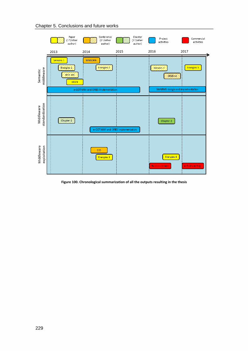
Chapter 5. Conclusions and future works
229
Figure 100. Chronological summarization of all the outputs resulting in the thesis

Chapter 5. Conclusions and future works
230

Appendix A: development
procedures

Appendix A: development procedures
232

Appendix A: development procedures
233
This Appendix is used to include some of the implementation works that, although do not
strictly fall within research activities (rather, implementation took place as an output of the
research activities done) are useful to have as some extra content, in case it can be useful as a
guide on semantic middleware architectures for the Smart Grid.
For starters, it must be remembered that there are two actions that must be carried out In
order to have them working as an Apache Maven piece of work:
1. The option to create an Apache Maven project must be available from the IDE: depending
on the version of the latter, it may be accessible right away or a plug-in will have to be
downloaded. For example, in Figure 107, it can be seen how it is accessed by following the
File New Maven Project options.
Figure 101. Maven project access in Eclipse IDE for Ubuntu
2. The group and artifact identifiers must be set so that bundles will be able to communicate
with each other via OSGi interfaces. This will be done by setting the name of the Group ID
as the one that will be used in order to univocally identify the project among the other
ones. The Artifact ID, on the other hand, will be used to identify the future .jar file to be
executed that contains the developed service. The configuration is included in Figure 108.
Figure 102. Creation of a maven project for Eclipse in Ubuntu

Appendix A: development procedures
234
There are several other software components that are part of JBoss Fuse and play different
roles in it, and even some others that can be installed in order to enhance the qualities of the
services that are provided. For example, in Figure 109 it can be seen where the software
components were supposed to be included, as well as the broker that was used in order to
establish a layer of AMQP communications right below the middleware architecture. There are
some features from the JBoss Fuse that can be seen, but they are common to other ESB
implementations and systems (dependencies, uninstalling executable program, etc.).
Figure 103. Location of the activemq broker and deploy directories
JBoss Fuse also makes available a web interface with several capabilities that can be accessed
for a better understanding of the software components that have been deployed. It is also a
very useful tool for debugging any failure that may have happened when deploying a bundle to
the JBoss Fuse, as it will show a brief message that tells any issue found. This feature has been
depicted in Figure 110.
Figure 104. Web interface of the JBoss Fuse
The last aspect to take into account when using the ESB is that there are several permissions
that must be enabled in order to have full access to the testing and deployment of the
presented solutions. These permissions are properties that must be addressed by editing the
user.properties file that usually stored in the /etc directory of JBoss Fuse (several minor

Appendix A: development procedures
235
changes may happen depending on the version of the ESB, though). As displayed in Figure 111,
commonly there will be two categories; one is referred to the end users and the other to the
administrator. Logins and passwords will be set to the end users in order to have them use the
system in a more extensive fashion or not, depending on the privileges that they have been
given.
Figure 105. User.properties file in JBoss Fuse
A final glimpse of the appearance of the Java bundles developed as the software components
of the middleware architecture is offered in Figure 112. This is the result stored in the /deploy
directory of JBoss Fuse. They can be divided in different kinds, depending on what they are
related to:
1. Middleware services related to different levels: these are the software bundles that
have been obtained regarding the features that have been described before (high
level, core and low level services).
2. Registered devices: these are the software bundles used to contain all the features and
services that are provided for a registered device. This decision was taken due to the
specific developments in the e-GOTHAM, so bundles containing descriptions of the
services may or may not be present in other research projects.
3. Ancillary software components. These latter ones are shown as a way to prove that
external works can also be included in the JBoss Fuse, as long as they are converted in
functional bundles.

Appendix A: development procedures
236
Figure 106. Software bundles from the middleware
One of the most important actions to be undertaken during the development works of the e-
GOTHAM project was connecting to those facilities by means of a Virtual Private Network
(VPN) which was offered to us as a way to perform remote testing, while at the same time
having a securitized environment that can offer confidentiality with data authentication. The
parameters required to access this VPN were as shown in Figure 113.
Figure 107. Virtual Private Network settings for remote connections to the Vitrociset laboratory
Once the parameters, login and password were correctly set, there was no problem in
accessing remotely to the hardware used for service testing. The software components of the
middleware would be loaded to the remote piece of equipment by means of a Secure File
Transfer Protocol (SFTP) called Filezilla, and the operation with them via Command Line
Interface would be done in the same way as if local equipment was being handled. The version
of JBoss Fuse that was installed in those facilities was Fuse ESB, a slightly older version of the
ESB that was commonly used locally (which switched from Fuse ESB to JBoss Fuse as it was
made available), as it had been agreed with other partners to use this one over making any
change that would consume time. The components had the appearance in the Command Line
Interface as portrayed in Figure 114.

Appendix A: development procedures
237
Figure 108. Example of ESB and components deployed in Vitrociset facilities
Lastly, while implementation works were carried out for the ontology used as the starting
ground of the different features represented by the CMA, an OWL file was obtained after
adding all the elements that were described in Section 4. Some of the content of this file has
been included in the next pages. Both the ontology and the OWL file were developed by using
Protegé as the tool for this implementation works.
?xml version="1.0"?>
<!DOCTYPE rdf:RDF [
<!ENTITY owl "http://www.w3.org/2002/07/owl#" >
<!ENTITY xsd "http://www.w3.org/2001/XMLSchema#" >
<!ENTITY rdfs "http://www.w3.org/2000/01/rdf-schema#" >
<!ENTITY rdf "http://www.w3.org/1999/02/22-rdf-syntax-ns#" >

Appendix A: development procedures
238
]>
<rdf:RDF xmlns="http://www.semanticweb.org/jesús/ontologies/2017/3/untitled-
ontology-12#"
xml:base="http://www.semanticweb.org/jesús/ontologies/2017/3/untitled-ontology-
12"
xmlns:rdfs="http://www.w3.org/2000/01/rdf-schema#"
xmlns:owl="http://www.w3.org/2002/07/owl#"
xmlns:xsd="http://www.w3.org/2001/XMLSchema#"
xmlns:rdf="http://www.w3.org/1999/02/22-rdf-syntax-ns#">
<owl:Ontology
rdf:about="http://www.semanticweb.org/jesús/ontologies/2017/3/untitled-ontology-12"/>
<!--
///////////////////////////////////////////////////////////////////////////////////////
//
// Object Properties
//
///////////////////////////////////////////////////////////////////////////////////////
-->
<!-- http://www.semanticweb.org/jesús/ontologies/2017/3/untitled-ontology-
12#hasAManufacturer -->
<owl:ObjectProperty
rdf:about="http://www.semanticweb.org/jesús/ontologies/2017/3/untitled-ontology-
12#hasAManufacturer">
<rdfs:domain
rdf:resource="http://www.semanticweb.org/jesús/ontologies/2017/3/untitled-ontology-
12#hardware"/>
</owl:ObjectProperty>
<!-- http://www.semanticweb.org/jesús/ontologies/2017/3/untitled-ontology-
12#hasAName -->
<owl:ObjectProperty
rdf:about="http://www.semanticweb.org/jesús/ontologies/2017/3/untitled-ontology-
12#hasAName">

Appendix A: development procedures
239
<rdfs:domain
rdf:resource="http://www.semanticweb.org/jesús/ontologies/2017/3/untitled-ontology-
12#hardware"/>
</owl:ObjectProperty>
<!-- http://www.semanticweb.org/jesús/ontologies/2017/3/untitled-ontology-
12#hasASimpleService -->
<owl:ObjectProperty
rdf:about="http://www.semanticweb.org/jesús/ontologies/2017/3/untitled-ontology-
12#hasASimpleService">
<rdfs:domain
rdf:resource="http://www.semanticweb.org/jesús/ontologies/2017/3/untitled-ontology-
12#device_services"/>
<rdfs:domain
rdf:resource="http://www.semanticweb.org/jesús/ontologies/2017/3/untitled-ontology-
12#hardware"/>
</owl:ObjectProperty>
<!-- http://www.semanticweb.org/jesús/ontologies/2017/3/untitled-ontology-
12#hasAStatus -->
<owl:ObjectProperty
rdf:about="http://www.semanticweb.org/jesús/ontologies/2017/3/untitled-ontology-
12#hasAStatus">
<rdfs:domain
rdf:resource="http://www.semanticweb.org/jesús/ontologies/2017/3/untitled-ontology-
12#hardware"/>
</owl:ObjectProperty>
<!-- http://www.semanticweb.org/jesús/ontologies/2017/3/untitled-ontology-
12#hasAnApplication -->
<owl:ObjectProperty
rdf:about="http://www.semanticweb.org/jesús/ontologies/2017/3/untitled-ontology-
12#hasAnApplication">
<rdfs:domain
rdf:resource="http://www.semanticweb.org/jesús/ontologies/2017/3/untitled-ontology-
12#grounding"/>
</owl:ObjectProperty>

Appendix A: development procedures
240
<!-- http://www.semanticweb.org/jesús/ontologies/2017/3/untitled-ontology-
12#hasAnInnerInterface -->
<owl:ObjectProperty
rdf:about="http://www.semanticweb.org/jesús/ontologies/2017/3/untitled-ontology-
12#hasAnInnerInterface">
<rdfs:domain
rdf:resource="http://www.semanticweb.org/jesús/ontologies/2017/3/untitled-ontology-
12#HAL_service"/>
<rdfs:domain
rdf:resource="http://www.semanticweb.org/jesús/ontologies/2017/3/untitled-ontology-
12#MAP_service"/>
<rdfs:domain
rdf:resource="http://www.semanticweb.org/jesús/ontologies/2017/3/untitled-ontology-
12#MAS_service"/>
<rdfs:domain
rdf:resource="http://www.semanticweb.org/jesús/ontologies/2017/3/untitled-ontology-
12#composition_service"/>
<rdfs:domain
rdf:resource="http://www.semanticweb.org/jesús/ontologies/2017/3/untitled-ontology-
12#context_service"/>
<rdfs:domain
rdf:resource="http://www.semanticweb.org/jesús/ontologies/2017/3/untitled-ontology-
12#middleware_services"/>
<rdfs:domain
rdf:resource="http://www.semanticweb.org/jesús/ontologies/2017/3/untitled-ontology-
12#registration_service"/>
<rdfs:domain
rdf:resource="http://www.semanticweb.org/jesús/ontologies/2017/3/untitled-ontology-
12#security_service"/>
</owl:ObjectProperty>
<!-- http://www.semanticweb.org/jesús/ontologies/2017/3/untitled-ontology-
12#hasAnOuterInterface -->
<owl:ObjectProperty
rdf:about="http://www.semanticweb.org/jesús/ontologies/2017/3/untitled-ontology-
12#hasAnOuterInterface">

Appendix A: development procedures
241
<rdfs:domain
rdf:resource="http://www.semanticweb.org/jesús/ontologies/2017/3/untitled-ontology-
12#MAP_service"/>
<rdfs:domain
rdf:resource="http://www.semanticweb.org/jesús/ontologies/2017/3/untitled-ontology-
12#MAS_service"/>
<rdfs:domain
rdf:resource="http://www.semanticweb.org/jesús/ontologies/2017/3/untitled-ontology-
12#network"/>
</owl:ObjectProperty>
<!-- http://www.semanticweb.org/jesús/ontologies/2017/3/untitled-ontology-
12#hasAsymmetricCyphering -->
<owl:ObjectProperty
rdf:about="http://www.semanticweb.org/jesús/ontologies/2017/3/untitled-ontology-
12#hasAsymmetricCyphering">
<rdfs:domain
rdf:resource="http://www.semanticweb.org/jesús/ontologies/2017/3/untitled-ontology-
12#security_service"/>
</owl:ObjectProperty>
<!-- http://www.semanticweb.org/jesús/ontologies/2017/3/untitled-ontology-
12#hasCompositionFunctionality -->
<owl:ObjectProperty
rdf:about="http://www.semanticweb.org/jesús/ontologies/2017/3/untitled-ontology-
12#hasCompositionFunctionality">
<rdfs:domain
rdf:resource="http://www.semanticweb.org/jesús/ontologies/2017/3/untitled-ontology-
12#composition_service"/>
</owl:ObjectProperty>
<!-- http://www.semanticweb.org/jesús/ontologies/2017/3/untitled-ontology-
12#hasContextAwarenessFunctionality -->
<owl:ObjectProperty
rdf:about="http://www.semanticweb.org/jesús/ontologies/2017/3/untitled-ontology-
12#hasContextAwarenessFunctionality">

Appendix A: development procedures
242
<rdfs:domain
rdf:resource="http://www.semanticweb.org/jesús/ontologies/2017/3/untitled-ontology-
12#context_service"/>
</owl:ObjectProperty>
<!-- http://www.semanticweb.org/jesús/ontologies/2017/3/untitled-ontology-
12#hasDeviceList -->
<owl:ObjectProperty
rdf:about="http://www.semanticweb.org/jesús/ontologies/2017/3/untitled-ontology-
12#hasDeviceList">
<rdfs:domain
rdf:resource="http://www.semanticweb.org/jesús/ontologies/2017/3/untitled-ontology-
12#registration_service"/>
</owl:ObjectProperty>
<!-- http://www.semanticweb.org/jesús/ontologies/2017/3/untitled-ontology-
12#hasFeatures -->
<owl:ObjectProperty
rdf:about="http://www.semanticweb.org/jesús/ontologies/2017/3/untitled-ontology-
12#hasFeatures">
<rdfs:domain
rdf:resource="http://www.semanticweb.org/jesús/ontologies/2017/3/untitled-ontology-
12#hardware"/>
</owl:ObjectProperty>
<!-- http://www.semanticweb.org/jesús/ontologies/2017/3/untitled-ontology-
12#hasGpsCoordinates -->
<owl:ObjectProperty
rdf:about="http://www.semanticweb.org/jesús/ontologies/2017/3/untitled-ontology-
12#hasGpsCoordinates">
<rdfs:domain
rdf:resource="http://www.semanticweb.org/jesús/ontologies/2017/3/untitled-ontology-
12#hardware"/>
</owl:ObjectProperty>
<!-- http://www.semanticweb.org/jesús/ontologies/2017/3/untitled-ontology-
12#hasHALFunctionality -->
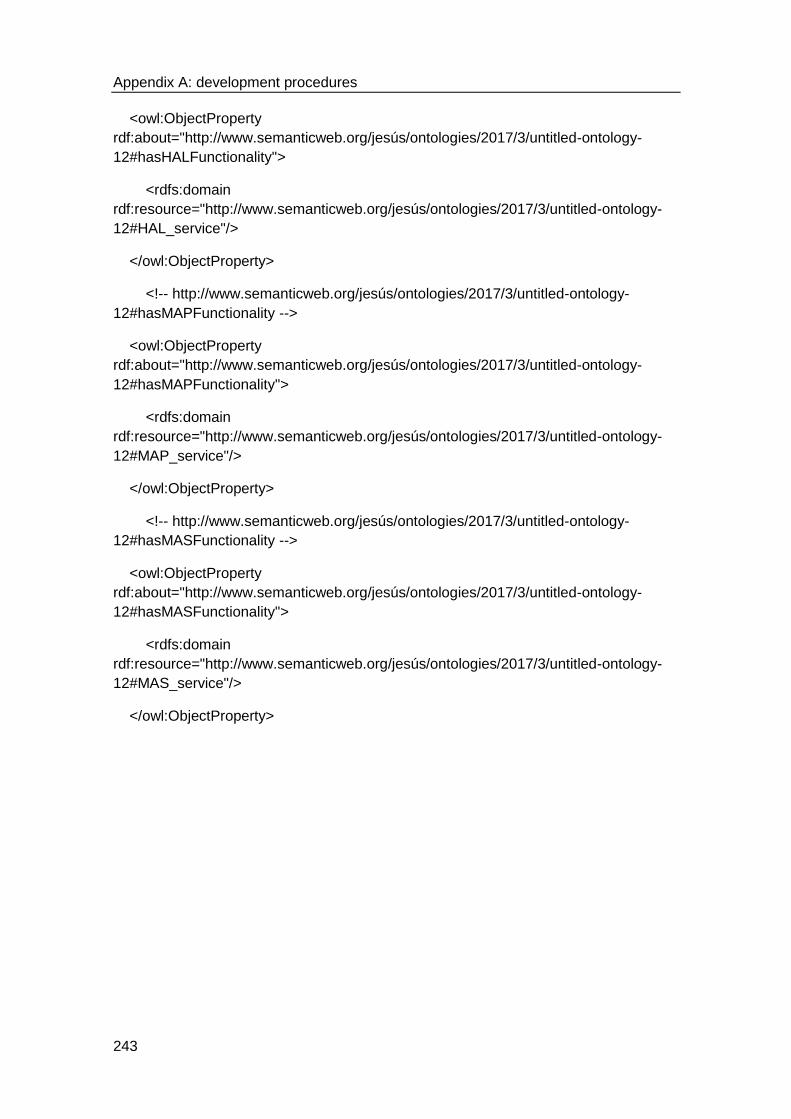
Appendix A: development procedures
243
<owl:ObjectProperty
rdf:about="http://www.semanticweb.org/jesús/ontologies/2017/3/untitled-ontology-
12#hasHALFunctionality">
<rdfs:domain
rdf:resource="http://www.semanticweb.org/jesús/ontologies/2017/3/untitled-ontology-
12#HAL_service"/>
</owl:ObjectProperty>
<!-- http://www.semanticweb.org/jesús/ontologies/2017/3/untitled-ontology-
12#hasMAPFunctionality -->
<owl:ObjectProperty
rdf:about="http://www.semanticweb.org/jesús/ontologies/2017/3/untitled-ontology-
12#hasMAPFunctionality">
<rdfs:domain
rdf:resource="http://www.semanticweb.org/jesús/ontologies/2017/3/untitled-ontology-
12#MAP_service"/>
</owl:ObjectProperty>
<!-- http://www.semanticweb.org/jesús/ontologies/2017/3/untitled-ontology-
12#hasMASFunctionality -->
<owl:ObjectProperty
rdf:about="http://www.semanticweb.org/jesús/ontologies/2017/3/untitled-ontology-
12#hasMASFunctionality">
<rdfs:domain
rdf:resource="http://www.semanticweb.org/jesús/ontologies/2017/3/untitled-ontology-
12#MAS_service"/>
</owl:ObjectProperty>

Appendix A: development procedures
244

Appendix B: Application
Programming Interface

Appendix B: Application Programming Interface
246

Appendix B: Application Programming Interface
247
Considering the work that was carried out during the implementation of the middleware
solution, as well as the information that is presented in other software standards of
widespread use in distributed systems (CoAP, AMQP, MQTT, energy interoperability solutions,
etc.), it has been considered as mandatory to provide and Application Programming Interface
that can be used as a way to provide a starting ground for middleware developments in the
Smart Grid. It has to be noted that the thesis is focused on providing an API for the middleware
rather than the implementation of specific services such as security or semantic capabilities.
Consequently, these latter two services can be further expanded with the usage of further
methods that will make possible the usage of more functionalities provided by the systems
where they are deployed.
The API that has been included in this section is the one that belongs to several classes that
were developed for the e-GOTHAM project. The reason for choosing just some of them is due
to the fact that they have a huge amount of methods, and in fact there are a total of 230
classes that were developed during the semantic middleware implementation works. Having
the API of all the classes and methods would result in a very long document, where the
majority of the content would be the API itself, which is unrelated to the main objectives of
this thesis.
To begin with, the API from the SupportConnectorREST class has been included. As it can be
inferred from the name, it is used to guarantee connectivity between the application layer and
all the other components from the middleware. Its appearance has been included in Figure
115.
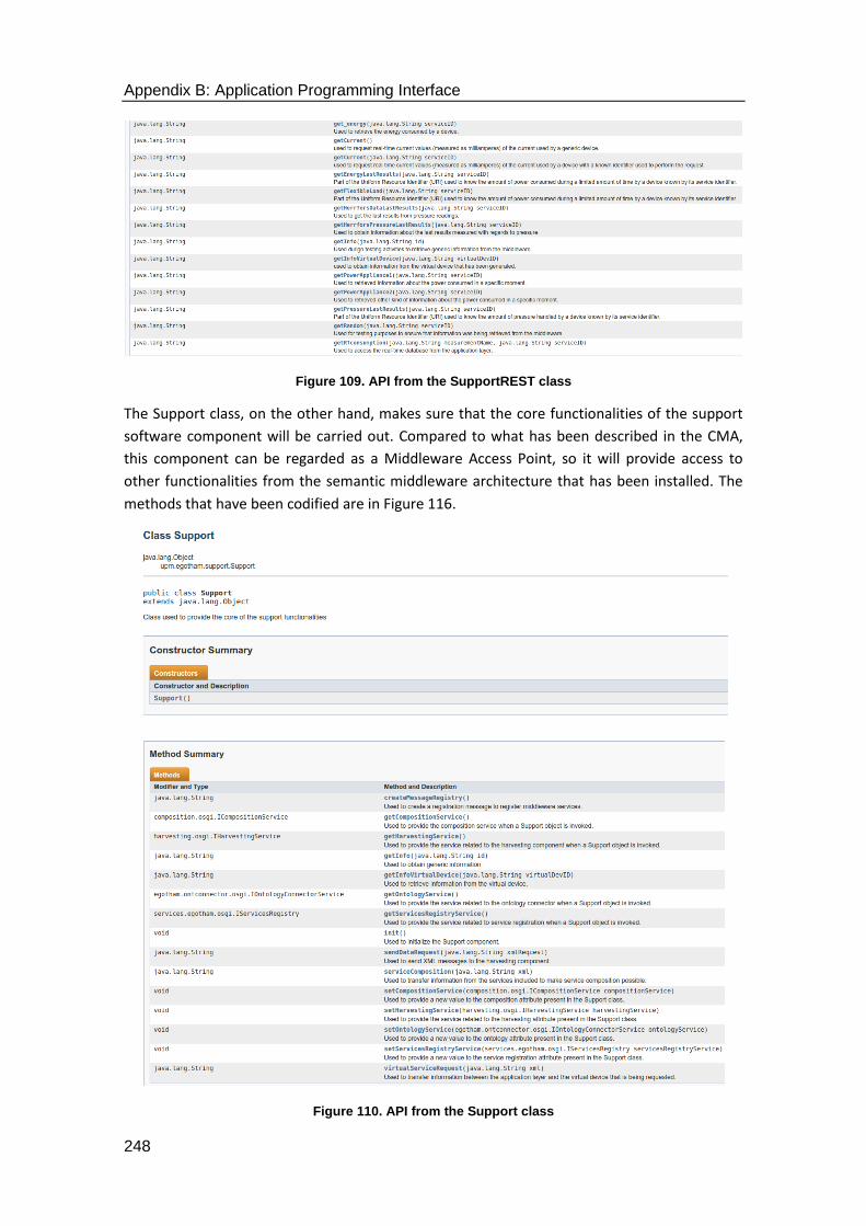
Appendix B: Application Programming Interface
248
Figure 109. API from the SupportREST class
The Support class, on the other hand, makes sure that the core functionalities of the support
software component will be carried out. Compared to what has been described in the CMA,
this component can be regarded as a Middleware Access Point, so it will provide access to
other functionalities from the semantic middleware architecture that has been installed. The
methods that have been codified are in Figure 116.
Figure 110. API from the Support class

Appendix B: Application Programming Interface
249
In the same way, the ContextAwarenessController class is used in order to manage the
functionalities used for context awareness functionalities. In case of this class, it becomes
important to include functionalities that will be capable of interacting with all the other
components required for the context awareness functionalities. Therefore, the ontology
connector and the methods related to device registration have been included as part of the
API. The methods that were implemented have been included in Figure 117.
Figure 111. API of the ContextAwarenessController class
The Composition Controller class is mostly used to manage the composition operations used to
merge different simple services into a single one capable of providing different functionalities
that are still related with the original simple services, as it has been previously described. As it
happens with other components, there are also methods used for the interaction of this
service with other ones present in the middleware (hence the set and get methods related to
the message registration or the ontology component). A screenshot of the API from this class
has been included in Figure 118.
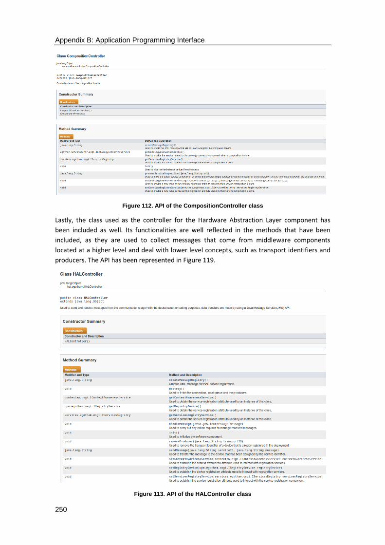
Appendix B: Application Programming Interface
250
Figure 112. API of the CompositionController class
Lastly, the class used as the controller for the Hardware Abstraction Layer component has
been included as well. Its functionalities are well reflected in the methods that have been
included, as they are used to collect messages that come from middleware components
located at a higher level and deal with lower level concepts, such as transport identifiers and
producers. The API has been represented in Figure 119.
Figure 113. API of the HALController class

6. Bibliography

Chapter 6. Bibliography
252

Chapter 6. Bibliography
253
6.1. References
The following format has been used for the references that have been included:
1. Scientific papers: first author surname, first character of first author´s name; second
author surname, first character of second author´s name, N author surname, first
character of N author´s name; name of the scientific paper [in italics]. Name of the journal,
date details, volume, number of issue, pages [if applicable].
2. Conference papers: first author surname, first character of first author´s name; second
author surname, first character of second author´s name, N author surname, first
character of N author´s name; name of the scientific paper [in italics]. Name of the
conference (abbreviation of the conference), year, volume, number of issue, pages [if
applicable].
3. Electronic books: name of the book. Available from: URL of the book. Date details. Last
time it was accessed.
4. Web sites: name of the website. Available from: URL of the website. Date details. Last time
it was accessed.
5. Other pieces of work (Bachelor theses, Master theses, etc.): name of the website. URL of
the website. Last time it was accessed.
[1] Atkeson, A.; Kehoe, P. The Transition to a New Economy After the Second Industrial Revolution. Proceedings, Federal Reserve Bank of San Francisco. November 2002.
[2] Liu, Z.; Yu, J.; Guo, X.; Sun, T.; Zhang, J. Survey of technologies of line commutated
converter based high voltage direct current transmission in China. CSEE Journal of Power and Energy Systems, 2015. vol. 1 no. 2. pp. 1-8.
[3] Brittain, J.E., Electrical Engineering Hall of Fame: Nikola Tesla. Proceedings of the IEEE,
2005. vol. 93, no.5. pp. 1057-1059. [4] Pourbeik, P.; Kundur, P.S.; Taylor, C.W. The anatomy of a power grid blackout - Root
causes and dynamics of recent major blackouts. IEEE Power and Energy Magazine, 2006. vol. 4, no. 5. pp. 22-29.
[5] Sardella, M. Stuck In the Sixties: Power Grid Modernization Remains Elusive. Available
from: http://static1.1.sqspcdn.com/static/f/205172/26761467/1451508058660/2015_12_30_Stuck+in+the+60%27s.pdf?token=qkFxflR3vL3p6%2FWMibvzA4e8gmo%3D.
2015. Last access 16th May 2017. [6] Tverberg, G. The U. S. electric grid: will it be our undoing? Available from:
http://www.theoildrum.com/node/3934. 2008. Last access 16th May 2017. [7] Bu, S.; Yu, F. R.; Liu, P. X.; Zhang, P. Distributed Scheduling in Smart Grid
Communications with Dynamic Power Demands and Intermittent Renewable Energy

Chapter 6. Bibliography
254
Resources. IEEE International Conference on Communications Workshops (ICC). 2011. pp. 1-5.
[8] Torres Sibille, A. del C.; Cloquell-Ballester Víctor-Andrés; Cloquell-Ballester Vicente-
Agustín; Darton, R. Development and validation of a multicriteria indicator for the assessment of objective aesthetic impact of wind farms. Renewable and Sustainable Energy Reviews. 2009. vol 13, no. 1. pp. 40-66.
[9] Rybach, L., Geothermal Power Growth 1995–2013—A Comparison with Other
Renewables. Energies. 2014. vol 7 no. 8. pp. 4802-4812. [10] Singhal, A.; Saxena, R.P. Software models for Smart Grid. International Workshop on
Software Engineering for the Smart Grid (SE4SG). 2012. [11] Rodríguez-Molina, J.; Martínez-Núñez, M.; Martínez, J.-F.; Pérez-Aguiar, W. Business
Models in the Smart Grid: Challenges, Opportunities and Proposals for Prosumer Profitability. Energies. 2014. vol. 7 no. 9. pp. 6142-6171.
[12] European Energy Exchange AG, E.E.E. Available from: https://www.eex.com/en/.
2017. Last access 16th May 2017. [13] Bauer, F.L.; Bolliet, L.; Helms H. J. Software Engineering: Report on a conference
sponsored by the NATO science committee, Peter Naur and Brian Randell, Editors. 1968. Last access 16th May 2017.
[14] Uribe, O.H.; Martin J.P.; García-Alegre, J.P.; Santos, M.; Guinea, D. Smart Building:
Decision Making Architecture for Thermal Energy Management. Sensors. 2015. vol 15 no. 11. pp. 27543-27568.
[15] Hussain, S.; Bang, J.H.; Han, M.; Ahmed, M.I.; Amin, M.B.; Lee, S.; Nugent, C.; McClean,
S.; Scotney, B.; Parr, G. Behavior Life Style Analysis for Mobile Sensory Data in Cloud Computing through MapReduce. Sensors. 2014. vol. 14 no. 11. pp. 22001-22020.
[16] Razzaque, M.A.; Milojevic-Jevric, M.; Palade, A. ; S. Clarke. Middleware for Internet of
Things: A Survey. IEEE Internet of Things Journal. 2016. vol 3, no. 1. pp. 70-95. [17] Yurur, O.; C.H. Liu; Moreno, W. A survey of context-aware middleware designs for
human activity recognition. IEEE Communications Magazine. 2014. vol 52 no 6. pp. 24-31.
[18] Aguilar, J.; Jerez, M.; Exposito, E.; Villemur, T.. CARMiCLOC: Context Awareness
Middleware in Cloud Computing. Latin American Computing Conference (CLEI). 2015. [19] Yang, J., L. Zhang, and X.A. Wang. On Cloud Computing Middleware Architecture. in
2015 10th International Conference on P2P, Parallel, Grid, Cloud and Internet Computing (3PGCIC). 2015.
[20] SWARMs consortium. SWARMs: Smart and Networking UnderWAter Robots in
Cooperation Meshes. Available from: http://www.swarms.eu/. 2017. Last access 17th May 2017.
Chapter 6. Bibliography
255
[21] e-GOTHAM consortium. e-GOTHAM: Sustainable-Smart Grid Open System for the Aggregated Control, Monitoring and Management of Energy. Available from: http://ses.jrc.ec.europa.eu/e-gotham. 2012. Last access 17th May 2017.
[22] CORDIS (Community Research and Development Information Service). ICT-based
Intelligent management of Integrated RES for the smart grid optimal operation. Available from: http://cordis.europa.eu/project/rcn/106338_es.html. 2016. Last access 17th May 2017.
[23] ITEA 3 Initiative. LifeWear: Mobilized Lifestyle With Wearables. Available from:
https://itea3.org/project/lifewear.html. 2013. Last access 17th May 2017. [24] ITEA 3 Initiative. WoO: Web of Objects. Available from: https://itea3.org/project/web-
of-objects.html. 2013. Last access 17th May 2017. [25] Che, L.; Shahidehpour, M.; Alabdulwahab, A.; Al-Turki, Y. Hierarchical Coordination of a
Community Microgrid With AC and DC Microgrids. IEEE Transactions on Smart Grid. 2015. vol. 6 no. 6. pp. 3042-3051.
[26] Ding, K.; Deng, B.; Zhang, X.; Ge, L. Optimization of service selection algorithm for
complex event processing in Enterprise Service Bus platform. 4th International Conference on Computer Science & Education. ICCSE '09. 2009. pp. 582-586.
[27] Jieming, W.; Xiaoli, T. Research of enterprise application integration based-on ESB. 2nd
International Conference on Advanced Computer Control (ICACC). 2010. vol. 5. pp. 90-93.
[28] Castillejo, P.; Martinez, J.-F.; Rodriguez-Molina, J.; Cuerva, A.. Integration of wearable
devices in a wireless sensor network for an E-health application. IEEE Wireless Communications. vol 20, no. 4. pp. 38-49.
[29] Alghamdi, A.; Nasir, M.; Ahmad, I.; Nafjan, K.A. An interoperability study of ESB for C4I
systems. International Symposium on Information Technology. 2010. [30] Eurich, M. and R. Boutellier. Middleware integration platforms: A new challenge to
business models of ICT companies: Unleashing the business potential of horizontalization. in e-Business (ICE-B), Proceedings of the 2010 International Conference on. 2010. vol 2. pp. 733-738.
[31] Chongnan, W.; Zongtao, W.; Hongwei, X. Design of message-oriented middleware with
publish/subscribe model on Telemetry and Command computer. 2nd International Conference on Systems and Informatics (ICSAI). 2014.
[32] Bahsoon, R., W. Emmerich, and J. Macke, Using real options to select stable
middleware-induced software architectures. IEE Proceedings - Software, 2005. vol 152. no 4. pp. 167-186.
[33] Ramakrishnan, R.; Gaur, L. Smart electricity distribution in residential areas: Internet of
Things (IoT) based advanced metering infrastructure and cloud analytics. International Conference on Internet of Things and Applications (IOTA). 2016. pp. 46-51.

Chapter 6. Bibliography
256
[34] Rodríguez-Molina, J.; Martínez, J.-F.; Castillejo, P. A Study on Applicability of Distributed Energy Generation, Storage and Consumption within Small Scale Facilities. Energies. 2016. vol 9. no. 9. pp. 745.
[35] Wu, D.; Aliprantis, D.C.; Ying, L. Load Scheduling and Dispatch for Aggregators of Plug-
In Electric Vehicles. IEEE Transactions on Smart Grid. 2012. vol 3. no 1. pp. 368-376. [36] Sattarpour, T.; Daryoosh, N.; Golshannavaz, S.; Siano, P. A multi-objective hybrid GA
and TOPSIS approach for sizing and siting of DG and RTU in smart distribution grids. Journal of Ambient Intelligence and Humanized Computing. 2016. pp. 1-18.
[37] Barella, R.; Nguyen, D.; Winter, R.; Lu, K.-T.; Wallace, S.; Zhao, X.; Cotilla-Sanchez, E. A
Sensitivity Based Approach for Efficient PMU Deployment on Smart Grid. Smart Cities, Green Technologies, and Intelligent Transport Systems: 4th International Conference (SMARTGREENS). 2015. 1st International Conference (VEHITS). 2015. Lisbon, Portugal. May 20-22, 2015. Revised Selected Papers. pp. 199-215.
[38] Wu, X.; Zhu, X.; Wu, G. Q.; Ding, W. Data mining with big data. IEEE Transactions on
Knowledge and Data Engineering, 2014. vol 26. no. 1. p. 97-107. [39] Capra, L. MaLM: Machine Learning Middleware to Tackle Ontology Heterogeneity.
Fifth Annual IEEE International Conference on Pervasive Computing and Communications Workshops (PerCom Workshops '07). 2007. pp. 449-454.
[40] Valls, M.G.; Lopez, I.R.; Villar, L.F. iLAND: An Enhanced Middleware for Real-Time
Reconfiguration of Service Oriented Distributed Real-Time Systems. IEEE Transactions on Industrial Informatics. 2013. vol 9. no 1. pp. 228-236.
[41] Nishida, H.; Nguyen, T. Optimal Client/Server Assignment for Internet Distributed
Systems. IEEE Transactions on Parallel and Distributed Systems. 2013. vol. 24. no. 3. pp. 565-575.
[42] Heard, N.; Rubin-Delanchy, P.; Lawson, D.J. Filtering Automated Polling Traffic in
Computer Network Flow Data. Intelligence and Security Informatics Conference (JISIC), IEEE Joint. 2014. pp. 268-271.
[43] Croucher, D.A.; Engelbrecht, H.A. A peer-to-peer middleware plugin for an existing
MMOG Client/Server architecture. 2012 IEEE International Workshop on Haptic Audio Visual Environments and Games (HAVE). 2012. pp. 140-141.
[44] Gjermundrod, H.; Bakken, D. E.; Hauser, C. H.; Bose, A. GridStat: A Flexible QoS-
Managed Data Dissemination Framework for the Power Grid. IEEE Transactions on Power Delivery. 2009. vol 24. no 1. pp. 136-143.
[45] Johnston, R. A.; Hauser, C. H.; Gjermundrod, K. H.; Bakken, D. E. Distributing Time-
Synchronous Phasor Measurement Data Using the GridStat Communication Infrastructure. Proceedings of the 39th Annual Hawaii International Conference on System Sciences (HICSS'06). 2006. vol. 10. pp 245.

Chapter 6. Bibliography
257
[46] Viddal, E. S.; Bakken, D. E.; Gjermundr, H.; Hauser, C. H. Wide-Area Actuator RPC over GridStat with Timeliness, Redundancy, and Safety. International Conference on Complex, Intelligent and Software Intensive Systems (CISIS). 2010. pp. 17-24.
[47] Zhou, L.; Rodrigues, J.J.P.C. Service-oriented middleware for smart grid: Principle,
infrastructure, and application. IEEE Communications Magazine. 2013. vol 51. no 1. pp. 84-89.
[48] Zaballos, A.; Vallejo, A.; Selga, J. M. Heterogeneous communication architecture for the
smart grid. IEEE Network. 2011. vol 25. no 5. pp. 30-37. [49] Sajjad, S.M.; Yousaf, M. Security analysis of IEEE 802.15.4 MAC in the context of
Internet of Things (IoT). Conference on Information Assurance and Cyber Security (CIACS). 2014. pp. 9-14.
[50] Park, S.O.; Kim, J. S.; Kim, S. J. An object-based middleware supporting efficient
interoperability on a smart home network. Multimedia Tools and Applications. 2013. vol. 63. no. 1. pp. 227-246.
[51] Li, Z.; Wang, Z.; Tournier, J. C.; Peterson, W.; Li, W.; Wang, Y. A Unified Solution for
Advanced Metering Infrastructure Integration with a Distribution Management System. First IEEE International Conference on Smart Grid Communications (SmartGridComm). 2010. pp. 566-571.
[52] OASIS. Devices Profile for Web Services Version 1.1. Available from: http://docs.oasis-
open.org/ws-dd/dpws/1.1/os/wsdd-dpws-1.1-spec-os.pdf. 2009. Last access 17th May 2017.
[53] Mark Adamiak , D.B.; Mackiewicz, R. IEC 61850 Communication Networks and Systems
In Substations: An Overview for Users. Available from: http://citeseerx.ist.psu.edu/viewdoc/download?doi=10.1.1.698.1497&rep=rep1&type=pdf. 2009. Last access 17th May 2017.
[54] Sucic, S.; Bony, B.; Guise, L. Standards-compliant event-driven SOA for semantic-
enabled smart grid automation: Evaluating IEC 61850 and DPWS integration. IEEE International Conference on Industrial Technology (ICIT). 2012. pp. 403-408.
[55] Dewen, W.; Yongli, Z.; Peipei, L.; Jiancai, H.; Wenqing, Z. Research on distributed
transmission of power telecontrol information based on ACSI/MMS. 3rd IEEE Conference on Industrial Electronics and Applications. 2008. pp. 670-674.
[56] Garc, A. P.; Oliver, J.; Gosch, D. An intelligent agent-based distributed architecture for
Smart-Grid integrated network management. IEEE 35th Conference on Local Computer Networks (LCN). 2010. pp. 1013-1018.
[57] Awad, A.; German, R. Self-Organizing Smart Grid Services. Sixth International
Conference on Next Generation Mobile Applications, Services and Technologies. 2012. pp. 205-210.
Chapter 6. Bibliography
258
[58] Kim, Y. J.; Thottan, M.; Kolesnikov, V.; Lee, W. A secure decentralized data-centric information infrastructure for smart grid. IEEE Communications Magazine. 2010. vol 48. no. 11. pp. 58-65.
[59] Fang, X.; Yang, D.; Xue, G. Evolving Smart Grid Information Management Cloudward: A
Cloud Optimization Perspective. IEEE Transactions on Smart Grid. 2013. vol 4. no. 1. pp. 111-119.
[60] Moghe, U.; Lakkadwala, P.; Mishra, D. K. Cloud computing: Survey of different
utilization techniques. CSI Sixth International Conference on Software Engineering (CONSEG). 2012. pp. 1-4.
[61] Liao, W.H.; Kuai, S. C. Leau, Y. R. Auto-scaling Strategy for Amazon Web Services in
Cloud Computing. IEEE International Conference on Smart City/SocialCom/SustainCom (SmartCity). 2015. pp. 1-6.
[62] Souidi, S.; Boccio, D.; Mierzwa, S.; Aguilar, J. The feasibility of using Microsoft Azure
infrastructure for a monitoring and evaluation system solution in sub-Saharan Africa. IEEE Global Humanitarian Technology Conference (GHTC). 2015. pp. 226-232.
[63] Subhashini, P.; Nalla, S. Data retrieval mechanism using Amazon simple storage service
and Windows Azure. 3rd International Conference on Computing for Sustainable Global Development (INDIACom). 2016. pp. 412-414.
[64] Lee, J.; Kim, Y.; Hahn, J.; Hoseok S. Customer energy management platform in the
Smart Grid. 14th Asia-Pacific Network Operations and Management Symposium (APNOMS). 2012. pp. 1-4.
[65] Shi, K.; Bi, Y.; Jiang, L. Middleware-based implementation of smart micro-grid
monitoring using data distribution service over IP networks. 49th International Universities Power Engineering Conference (UPEC). 2014. pp. 1-5.
[66] Object Management Group. What´s in the DDS Standard? Available from:
http://portals.omg.org/dds/omg-dds-standard/. 2016. Last access 17th May 2017. [67] Object Management group, I. Documents Associated With Data Distribution Service™,
V1.4. 2015 [cited 2016 4th November 2016]; Available from: http://www.omg.org/spec/DDS/1.4/.
[68] Object Management Group. Documents Associated With The Real-Time Publish-Subscribe Wire Protocol DDS Interoperability™ Wire Protocol Specification, V2.2. Available from: http://www.omg.org/spec/DDSI-RTPS/2.2/. 2014. 17th May 2017.
[69] RTI. Data Distribution Service (DDS) Community RTI Connext Users: Domain. Available
from: https://community.rti.com/glossary/domain. 2016. 17th May 2017. [70] RTI community. Fundamentals of DDS Domains and DomainParticipants. Available
from: https://community.rti.com/static/documentation/connext-dds/5.2.0/doc/manuals/connext_dds/html_files/RTI_ConnextDDS_CoreLibraries_UsersManual/Content/UsersManual/Fundamentals_of_DDS_Domains_and_DomainPa.htm. 2015. Last access 17th May 2017.
Chapter 6. Bibliography
259
[71] OpenDDS. OpenDDS. Available from: http://opendds.org/. 2016. Last access 17th May 2017.
[72] PrismTech. DDS community. Available from: http://www.prismtech.com/dds-
community. 2017. Last access 17th May 2017. [73] eProsima. Introduction to DDS. Available from: http://www.eprosima.com/index.php/resources-all/dds-all. 2015. Last access 17th May
2017. [74] Twin Oaks Computing, Inc. CoreDX DDS Data Distribution Service Middleware.
Available from: http://www.twinoakscomputing.com/coredx. 2017. Last access 17th May 2017.
[75] GNU Operating System initiative. GNU Lesser General Public License. Available from:
https://www.gnu.org/licenses/lgpl-3.0.en.html. 2007. Last access 17th May 2017. [76] Guang L.; Seed, D.; Starsinic, M.; Wang, C.; Russell, P. Enabling Smart Grid with ETSI
M2M standards. IEEE Wireless Communications and Networking Conference Workshops (WCNCW). 2012. pp. 148-153.
[77] European Telecommunications Standards Institute. Available from:
http://www.etsi.org/about. 2017. Last access 17th May 2017.
[78] Oliveira, J. P. C. M.; Rodrigues, A. W. d. O.; Sá, R. C.; Araújo, P.; Araújo, A. L. C. Smart Middleware Device for Smart Grid integration. IEEE 24th International Symposium on Industrial Electronics (ISIE). 2015. pp. 779-781.
[79] Ashok, A.; Hahn, A.; Govindarasu, M. Cyber-physical security of Wide-Area Monitoring,
Protection and Control in a smart grid environment. Journal of Advanced Research, 2014. vol 5. no. 4. p. 481-489.
[80] Hu, Y.; Donnelly, M.; Helmer, T.; Tram, H.; Martin, K.; Govindarasu, M.; Uluski, R.;
Cioni, M. NASPInet Specification - An Important Step toward Its Implementation. 43rd Hawaii International Conference on System Sciences (HICSS). 2010. pp. 1-9.
[81] Hoefling, M.; Heimgaertner, F.; Menth, M.; Katsaros, K. V.; Romano, P.; Zanni, L.;
Kamel, G. Enabling resilient smart grid communication over the information-centric C-DAX middleware. International Conference and Workshops on Networked Systems (NetSys). 2015. pp. 1-8.
[82] C-DAX Consortium. Cyber-secure Data and Control Cloud for power grids. Available
from: http://www.cdax.eu/. 2012. Last access 17th May 2017. [83] Martin, S.; Hernandez, J.; Valmaseda, C. A novel middleware for smart grid data
exchange towards the energy efficiency in buildings. International Conference and Workshops on Networked Systems (NetSys). 2015. pp. 1-8.
[84] OSGi Alliance Initiative. OSGi Alliance - About us.
Available from: https://www.osgi.org/about-us/. 2017. Last access 17th May 2017.

Chapter 6. Bibliography
260
[85] Villa, D.; Martín, C.; Villanueva, F. J.; Moya, F.; López J. C.. Middleware-based management for smart grids. IEEE International Conference on Consumer Electronics (ICCE). 2011. pp. 545-546.
[86] Object Management Group. CORBA - Home. Available from: http://www.corba.org/.
2017. Last access 17th May 2017. [87] Henning, M.; Spruiell, M. Distributed programming with Ice. Available from:
http://www.triodia.com/staff/michi/Ice-3.4.1.pdf. 2010. Last access 17th May 2017. [88] Lemenager, F.; Joannic, C.; Soriano, R.; Bachiller Prieto, R.; Alberto Monferrer, M.;
Espejo Portero, N.; Mosshammer, R. Assessment and outlook of the OpenNode Smart Grid architecture. 22nd International Conference and Exhibition on Electricity Distribution (CIRED). 2013. pp. 1-4.
[89] OpenNode consortium. Available from: http://opennode.atosresearch.eu/. 2012. Last
access 17th May 2017. [90] Wilcox, J.; Kaleshi, D.; Sooriyabandara, M. DIRECTOR: A distributed communication
transport manager for the Smart Grid. IEEE International Conference on Communications (ICC). 2014. pp. 4227-4232.
[91] RS Components. Raspberry Pi Model B. Available from:
http://docs-europe.electrocomponents.com/webdocs/127d/0900766b8127da4b.pdf. 2017. Last access 17th May 2017.
[92] Youssef, T.A.; Elsayed, A. T.; Mohammed, O. A. DDS based interoperability framework for Smart Grid Testbed infrastructure. IEEE 15th International Conference on Environment and Electrical Engineering (EEEIC). 2015. pp. 219-224.
[93] OpenESB community. OpenESB: the Open Enterprise Service Bus. Available from:
http://www.open-esb.net/. 2017. Last access 17th May 2017. [94] OpenESB V2.3 team. OpenESB V2.3 Data Sheet. Available from: http://www.open-
esb.net/files/OpenESB%20Documents/Community/v2.3%20datasheet/ProductSheet-OpenESB%20V2.3%20.pdf. 2017. Last access 17th May 2017.
[95] Oracle Corp. JSR 208: JavaTM Business Integration (JBI). Available from:
https://jcp.org/en/jsr/detail?id=208. 2010. Last access 17th May 2017. [96] OpenESB community. Available from: https://en.wikipedia.org/wiki/Open_ESB. 2017.
Last access 17th May 2017. [97] Oracle Corp. Oracle GlassFish Server 3.1 Quick Start Guide. Available from:
http://docs.oracle.com/cd/E18930_01/html/821-2432/index.html. 2011. Last access 17th May 2017.
[98] Red Hat Inc.. Red Hat JBoss Enterprise Application Platform. Available from:
http://www.jboss.org/products/eap/download/. 2016. Last access 17th May 2017.
Chapter 6. Bibliography
261
[99] Pymma Services. OpenESB SE Enterprise Edition V3.0 Installation guide. Available from: http://www.open-esb.net/files/OpenESB%20Documents/Pymma/rt@!&%60%60WERTO/770-001%20Startup%20with%20OpenESB%20SE.pdf. 2014. Last access 17th May 2017.
[100] Open Source Initiative. Common Development and Distribution License (CDDL-1.0). Available from: https://opensource.org/licenses/CDDL-1.0. 2017. Last access 17th May 2017.
[101] WSO2 consortium. WSO2: Comprehensive and open platform for your connected
business. Available from: http://wso2.com/products/. 2017. Last access 17th May 2017.
[102] WSO2 ESB consortium. WSO2 ESB architecture.
Available from: https://docs.wso2.com/display/ESB490/Architecture. 2016. Last access 17th May 2017.
[103] WSO2 ESB documentation. ESB Transports. Available from: https://docs.wso2.com/display/ESB490/ESB+Transports. 2016. Last access 17th May 2017.
[104] Pietrzak, M. Scalability of WSO2 integration bus. Available from: https://www.bluesoft.net.pl/2012/04/scalability-of-wso2-integration-bus/. 2015. Last
access 17th May 2017. [105] Red hat Inc. Introducing Red Hat JBoss Fuse. Available from: https://access.redhat.com/documentation/en-
US/Red_Hat_JBoss_Fuse/6.0/html/Product_Introduction/files/ESBProdIntroOverview.html. 2015. Last access 17th May 2017.
[106] Open Source Initiative. GNU General Public License, version 2 (GPL-2.0). Available from:
https://opensource.org/licenses/GPL-2.0. 2017. Last access 17th May 2017. [107] JBoss Community. Getting Started Guide: Your guide to starting out with the JBoss ESB.
Available from: http://docs.jboss.org/jbossesb/docs/4.12/manuals/html/Getting_Started_Guide/index.html#gpl. 2010. Last access 17th May 2017.
[108] OSGi Alliance. OSGi: Architecrture. Available from: https://www.osgi.org/developer/architecture/. 2017. Last access 17th May 2017.
[109] Red Hat Inc. Architectural Levels. Available from: https://access.redhat.com/documentation/en-
US/Red_Hat_JBoss_Fuse/6.0/html/Product_Introduction/files/ESBProdIntroAnatomy.html. 2017. Last access 17th May 2017.
[110] Red Hat Inc. How Red Hat JBoss Fuse Activates a Deployed Bundle. Available from:
https://access.redhat.com/documentation/en-

Chapter 6. Bibliography
262
US/Red_Hat_JBoss_Fuse/6.0/html/Product_Introduction/files/ESBexecution.html. 2017. Last access 17th May 2017.
[111] Rintanen, J.; Suhonen, J.; Hännikäinen, M.; Hämäläinen, T. D. International Workshop
on Embedded Computer Systems. 2008. pp. 248-257. [112] Apache Software Foundation. Service Mix. Available from: http://servicemix.apache.org/. 2011. Last access 17th May 2017. [113] Rouse, M. business process management (BPM). Available from:
http://searchcio.techtarget.com/definition/business-process-management. 2017. Last access 17th May 2017.
[114] Vogel, L. The OSGi declarative services functionality. Available from:
http://www.vogella.com/tutorials/OSGiServices/article.html#declarativeservices_overview. 2016. Last access 17th May 2017.
[115] Spring Framework consortium. Chapter 1. Why Spring Dynamic Modules? Available
from: http://docs.spring.io/osgi/docs/current/reference/html/why-Spring%20DM.html. 2017. Last access 17th May 2017.
[116] Apache Software Foundation. ActiveMQ. Available from: http://activemq.apache.org/. 2011. Last access 17th May 2017.
[117] Oracle Corp. Java SE Technologies - Database.
Available from: http://www.oracle.com/technetwork/java/javase/jdbc/index.html. 2017. Last access 17th May 2017.
[118] Apache Software Foundation. Apache Camel. Available from: http://camel.apache.org/. 2017. Last access 17th May 2017.
[119] Apache Software Foundation. Apache CXF: An Open-Source Services Framework.
Available from: http://cxf.apache.org/. 2017. Last access 17th May 2017. [120] Apache Software Foundation. Apache Karaf. Available from: http://karaf.apache.org/.
2016. Last access 17th May 2017. [121] Red Hat Inc. Scalable Deployment with Fuse Fabric. Available from:
https://access.redhat.com/documentation/en-US/Red_Hat_JBoss_Fuse/6.0/html/Getting_Started/files/Deploy-Scalable.html. 2017. Last access 17th May 2017.
[122] Petals ESB Consortium. Available from: https://doc.petalslink.com/display/petalsesb/Petals+ESB. 2014. Last access 17th May
2017. [123] OW2 consortium. Introducing the OW2 consortium. Available from: https://www.ow2.org/bin/view/About/OW2_Consortium. 2017. Last access 17th May
2017.
Chapter 6. Bibliography
263
[124] Petals ESB community. Monitoring Petals ESB with Cacti. Available from: https://doc.petalslink.com/display/petalsesbsnapshot/Monitoring+Petals+ESB+with+Cacti. 2017. Last access 17th May 2017.
[125] Nagios Enterprises. Nagios: The industry standard inIT infrastructure monitoring.
Available from: https://www.nagios.com/. 2017. Last access 17th May 2017. [126] Petals ESB community. Petals Technical Overview. Available from: https://doc.petalslink.com/display/petalsesb/Petals+Technical+Overview. 2017. Last
access 17th May 2017. [127] Mulesoft Inc. Mule User Guide. Available from: https://docs.mulesoft.com/mule-user-guide/v/3.6/. 2017. Last access 17th May 2017. [128] MuleSoft Inc. What is Mule ESB? Available from: https://www.mulesoft.com/resources/esb/what-mule-esb. 2009. Last access 17th May
2017. [129] MuleSoft Inc. Mule ESB Enterprise. Available from: https://www.mulesoft.com/platform/soa/mule-esb-enterprise. 2009. Last access 17th
May 2017. [130] MuleSoft Inc., Mule ESB Enterprise Performance. Available from:
https://www.mulesoft.com/lp/whitepaper/soa/esb-enterprise-performance 2014. (pp. 5). Last access 17th May 2017.
[131] Talend community. Talend Open Studio Documentation. Available from: https://help.talend.com/#/home. 2017. Last access 17th May 2017. [132] Talend Inc. Talend Open Source ESB. Available from: https://www.talend.com/resource/open-source-esb.html. 2017. Last access 17th May
2017. [133] Talend ESB community. Enterprise Service Bus. Available from: https://www.talend.com/resource/enterprise-service-bus/. 2017. Last access 17th
May 2017. [134] Talend ESB community. Technical Overview - Talend ESB. Available from:
https://info.talend.com/esbtechoverview.html?type=seo&_ga=1.131380428.2118450593.1479400308. 2017. Last access 17th May 2017.
[135] Zato community. Zato 2.0.7 documentation. Available from: https://zato.io/docs/index.html. 2017. Last access 17th May 2017. [136] Zato community. Open Source ESB, SOA, REST, APIs and Cloud Integrations in Python.
Available from: https://zato.io/blog/. 2017. Last access 17th May 2017. [137] Zato community. What ESB and SOA are anyway. Available from: https://zato.io/docs/intro/esb-soa.html. 2017. Last access 17th May 2017. [138] Zato community. Securing APIs with Zato and Vault, part 1. Available from:
Chapter 6. Bibliography
264
https://zato.io/blog/posts/securing-apis-zato-vault.html. 2016. Last access 17th May 2017.
[139] Zato. Zato downloads. Available from: https://zato.io/downloads.html. 2017. Last
access 17th May 2017. [140] Zachar, M.; Daoutidis, P. Microgrid/Macrogrid Energy Exchange: A Novel Market
Structure and Stochastic Scheduling. IEEE Transactions on Smart Grid. 2016. vol. 8. no 1. pp. 178-189.
[141] de Diego, R.; Martínez, J.-F.; Rodríguez-Molina, J.; Cuerva, A. A Semantic Middleware
Architecture Focused on Data and Heterogeneity Management within the Smart Grid. Energies. 2014. vol. 7 no. 9. pp. 5953-5994.
[142] Grady Booch, J.R.; Jacobson, I. The Unified Modeling Language User Guide, 2nd Edition,
ed. Addison-Wesley. 2005. [143] IEEE/IEC/ISO 42010 group,. ISO/IEC/IEEE 42010 Website. Available from:
http://www.iso-architecture.org/ieee-1471/. 2017. Last access 17th May 2017. [144] Object Management Group. The Architecture of Choice for a Changing World
(Executive Overview). Available from: http://www.omg.org/mda/executive_overview.htm. 2016. Last access 17th May 2017. [145] Ciancarini, P. Model transformations. Available from: http://www.slideshare.net/kronat/6-architetture-software-model-transformation.
2011. Last access 17th May 2017. [146] Garrido, J. L.; Noguera, M.; González, M.; Hurtado, M. V.; Rodríguez, M. L. Definition
and use of Computation Independent Models in an MDA-based groupware development process. Science of Computer Programming. 2007. vol 66. no 1. pp. 25-43.
[147] Yashwant S.; Sood, M. The Impact of the Computational Independent Model for
Enterprise Information System Development. Available from: http://citeseerx.ist.psu.edu/viewdoc/download?doi=10.1.1.206.5131&rep=rep1&type
=pdf. 2010. Last access 17th May 2017. [148] Object Management Group. Model Driven Architecture (MDA) FAQ. Available from:
http://www.omg.org/mda/faq_mda.htm. 2017. Last access 17th May 2017. [149] MQTT community. MQTT Version 3.1.1. Available from: http://docs.oasis-
open.org/mqtt/mqtt/v3.1.1/os/mqtt-v3.1.1-os.pdf. 2014. Last access 17th May 2017. [150] AMQP community. AMQP - Advanced Message Queuing Protocol. Available from:
https://www.amqp.org/. 2014. Last access 17th May 2017. [151] European Committee for Standardization. CEN, the European Committee for
Standardization: who we are. Available from: https://www.cen.eu/about/Pages/default.aspx. 2017. Last access 17th May 2017.

Chapter 6. Bibliography
265
[152] European Committee for Electrotechnical Standardization consortium (CENELEC). CENELEC: Who we are. Available from:
https://www.cenelec.eu/aboutcenelec/whoweare/. 2017. Last access 17th May 2017. [153] CEN-CENELEC-ETSI Smart Grid Coordination Group. Smart Grid Reference Architecture.
Available from: https://ec.europa.eu/energy/sites/ener/files/documents/xpert_group1_reference_architecture.pdf. 2012. Last access 17th May 2017.
[154] Rodríguez-Molina, J.; Martínez, J.-F.; Castillejo, P.; Rubio, G. Development of Middleware Applied to Microgrids by Means of an Open Source Enterprise Service Bus. Energies. 2017. vol. 10. no. 2. pp. 172-221.
[155] The Legion of the Bouncy Castle. Bouncy Castle Crypto APIs. Available from:
https://www.bouncycastle.org/. 2013. Last access 17th May 2017.
[156] Apache Software Foundation. Apache Jena: A free and open source Java framework for building Semantic Web and Linked Data applications. Available from:
http://jena.apache.org/index.html. 2017. Last access 17th May 2017. [157] World Wide Web Consortium. Resource Description Framework (RDF). Available from:
http://www.w3.org/RDF/. 2014. Last access 17th May 2017. [158] World Wide Web Consortium. SPARQL 1.1 Query Language. Available from:
https://www.w3.org/TR/sparql11-query/. 2013. Last access 17th May 2017. [159] Hilliard, R. Architecture description template for use with ISO/IEC/IEEE 42010:2011.
Available from: http://www.iso-architecture.org/42010/templates/42010-ad-template.pdf. 2011. Last access 17th May 2017.
[160] International Standard Organization, International Electrotechnical Commission,
Institute of Electrical and Electronics Engineers. Systems and software engineering — Architecture description (International Standard ISO/IEC/IEEE 42010). Available from: http://ieeexplore.ieee.org/stamp/stamp.jsp?arnumber=6129467&tag=1. 2011. Last access 17th May 2017.
[161] Kim, K.D.; Kumar, P. R. Cyber-Physical Systems: A Perspective at the Centennial.
Proceedings of the IEEE. 2012. vol 100 (Special Centennial Issue). pp. 1287-1308. [162] Sakurama, K. Control of Large-Scale Cyber-Physical Systems with Agents via a
Representative Model. IEEE 4th International Conference on Cyber-Physical Systems, Networks, and Applications (CPSNA). 2016. pp. 40-43.
[163] Heesch, U.v.; Avgeriou, P.; Hilliard, R. Forces on Architecture Decisions - A Viewpoint.
Joint Working IEEE/IFIP Conference on Software Architecture and European Conference on Software Architecture. 2012. pp. 101-110.
[164] IEEE/IEC/ISO, Architecture Viewpoint Template for ISO/IEC/IEEE 42010. Available from:
http://www.iso-architecture.org/ieee-1471/templates/42010-vp-template.pdf. 2011. 2011. Last access 17th May 2017.
Chapter 6. Bibliography
266
[165] Sharma, D.; Lie, T.T.; Nair, N. K. C., Vallès, B. Wind speed forecasting using ANN, ARMA and AIC hybrid to ensure power grid reliability. IEEE Innovative Smart Grid Technologies - Asia (ISGT ASIA). 2015. pp. 1-5.
[166] Al-Khannak, R.; Bitzer, B. Grid Computing as an innovative solution for power system's
reliability and redundancy. International Conference on Clean Electrical Power. 2009. pp. 790-797.
[167] Noshahr, J.B. Emission phenomenon of supra-harmonics caused by switching of full-
power frequency converter of wind turbines generator (PMSG) in smart grid. IEEE 16th International Conference on Environment and Electrical Engineering (EEEIC). 2016. pp. 1-6.
[168] Ivry, P. M.; Rawa, M. J.; Thomas, D. W. P.; Sumner, M. Power quality of a voltage
source converter in a smart grid. IEEE Grenoble Conference. 2013. pp. 1-6. [169] Red Hat Inc. Download JBoss Fuse for Development Use. Available from:
https://developers.redhat.com/products/fuse/download/. 2016. Last access 17th May 2017.
[170] Oracle Corp. The JMS API Programming Model. Available from: http://docs.oracle.com/javaee/6/tutorial/doc/bnceh.html. 2013. Last access 17th May
2017. [171] Redmonk Community,. The RedMonk Programming Language Rankings: January 2015.
Available from: http://redmonk.com/sogrady/2015/01/14/language-rankings-1-15/. 2015. Last access 17th May 2017.
[172] Apache Maven Project. Welcome to Apache Maven. Available from:
https://maven.apache.org/. 2015. Last access 17th May 2017. [173] Herrfors katerno Group. Herrfors Ltd., Your local power company (Finnish). Available
from: https://www.herrfors.fi/. 2017. Last access 17th May 2017. [174] Enfo Ltd. About Enfo. Available from: http://www.enfo.no/about-enfo/. 2017. Last
access 17th May 2017. [175] Cuerva, A. Modelo de información común de un middleware semántico para Internet
de la Energía (Spanish). Available from: http://oa.upm.es/43690/. 2016. Last access 17th May 2017.
[176] Martos, M.d.l.C.. Servicio de seguridad combinable mediante técnicas de orquestación
de servicios (Spanish). Available from: http://oa.upm.es/38799/. 2015. Last access 17th May 2017.
[177] Rodríguez-Molina, J.; Martínez, J.-F.; Castillejo, P.; López, L. Combining Wireless Sensor
Networks and Semantic Middleware for an Internet of Things-Based Sportsman/Woman Monitoring Application. Sensors. 2013. vol 13. no 2. p. 1787.

Chapter 6. Bibliography
267
[178] Rodríguez-Molina, J.; Martínez, J.-F.; Castillejo, P.; de Diego, R. SMArc: A Proposal for a Smart, Semantic Middleware Architecture Focused on Smart City Energy Management. International Journal of Distributed Sensor Networks. 2013. vol 9. no 12. pp. 560418.
[179] Rodríguez, L.M.M. Evaluación del dispositivo Raspberry Pi como elemento de
despliegue de servicios en el marco de las Smart Grids (Spanish). Available from: http://oa.upm.es/32612/. 2014. Last access 17th May 2017.
[180] e-GOTHAM consortium. e-GOTHAM in short. Available from:
http://ylivieska.centria.fi/egotham/eGenglish.html. 2015. Last access 22nd March 2017. [181] OpenEnergyMonitor Project. About OpenEnergyMonitor Project. Available from:
https://learn.openenergymonitor.org/sustainable-energy/energy/introduction. 2017. Last access 17th May 2017.
[182] NTE - Demo Steinkjer (Norwegian). Available from: http://smartgridnorway.no/?dt_portfolio=nte-demo-steinkjer. 2017. Last access 17th
May 2017. [183] International Standard Association. P42020 - Standard for Systems and Software
Engineering -- Architecture Processes. Available from: https://standards.ieee.org/develop/project/42020.html. 2017. Last access 17th May 2017.
[184] Society, I.S. P20000-1 - 20000-1, Information Technology -- Service Management -- Part
1: Service Management System Requirements. Available from: https://standards.ieee.org/develop/project/20000-1.html. 2017. Last access 17th May 2017.
[185] Li, X.; Martínez, J.-F.; Rodríguez-Molina, J.; Martínez, N.L. A Survey on Intermediation
Architectures for Underwater Robotics. Sensors. 2016. vol 16 no. 2. pp. 190. [186] Rodríguez-Molina, J.; Martínez, J.-F.; Rubio, G.; Hernández, V. A Proposal for an
Internet of Things-based Monitoring System Composed by Low Capability, Open Source and Open Hardware Devices. SENSORNETS 2014 - 3rd International Conference on Sensor Networks. 2014. vol. 3. pp. 87-94.
[187] Rodríguez-Molina, J.M.-N., M.; Pérez-Aguiar, W.; de Diego, R, A study on challenges
and opportunities for energy business developments in the Smart City. 8th International Conference on Industrial Engineering and Industrial Management. 2014. pp. 254-261.
[188] Martín-Wanton, T.; Muelas, E.; Santos de la Cámara, R.; Rodríguez-Molina, J.; Li, X.;
Martinez-Ortega, J-F. Modelado de vehículos autónomos y la incertidumbre de su entorno para la seguridad de operaciones marítimas (Spanish). IV Congreso Nacional de i+d en Defensa y Seguridad (DESEi+d 2016). 2016. pp. 599-606.
[189] Rodríguez‐Molina, J., The Role of Middleware in Distributed Energy Systems Integrated
in the Smart Grid. Energy Management of Distributed Generation Systems. Available from:

Chapter 6. Bibliography
268
https://www.intechopen.com/books/energy-management-of-distributed-generation-systems/the-role-of-middleware-in-distributed-energy-systems-integrated-in-the-smart-grid. 2016. pp. 133-154.
[190] Hernández, V.; Martínez J.-F.; Cuerva, A.; Rodríguez-Molina, J.; Rubio, G.; Jara, A.;
Semantic as an Interoperability Enabler in Internet of Things. Vol. 1. 2013. pp. 315-342. [191] Actúa UPM blogspot. ¡La XIII Competición actúaupm alcanza sus mejores cifras!
(Spanish). Available from: http://actuaupm.blogspot.com.es/2016/04/la-xiii-competicion-actuaupm-alcanza.html. 2016. Last access 17th May 2017.
[192] Universidad Politécnica de Madrid web manager. XIII Competición de creación de
empresas UPM. Premios de mil euros a las mejores ideas de negocio. (Spanish). Available from: http://www.upm.es/sfs/Rectorado/Gabinete%20del%20Rector/Notas%20de%20Prensa/2016/04/documentos/premiadoscompeticionactua.pdf. 2016. Last access 17th May 2017.

Chapter 6. Bibliography
269
6.2. List of acronyms
Acronym Extended name ACSI Abstract Communication Service Interface
ADN Active Distribution Networks
AMI Advanced Metering Infrastructure
AMQP Advanced Message Queuing Protocol
API Application Programming Interface
ARM Advanced RISC Machines
ARTEMIS Advanced Research and Technology for Embedded Intelligence and Systems
AUV Autonomous Underwater Vehicle
AWS Amazon Web Services
BAN Body Area Network
BIM Building Information Model
BMS Building Management System
BPEL Business Process Execution Language
BSD Berkeley Software Distribution
BSS Business Supporting System
CC Central Controller
C-DAX Cyber-secure Data and Control Cloud for power grids
CDDL Common Development and Distribution License
CEMS Customer Energy Management Systems
CLI Command Line Interface
CLL Communication Logic Layer
CMA Common Middleware Architecture
CORBA Common Object Request Broker Architecture
CPS Cyber-Physical System
DACM Data Acquisition and Control Manager
DC Domain Controller
DCPS Data-Centric Publish/Subscribe
DDS Data Distributed Service
DER Distributed Energy Resource
DMS Distributed Management System
DNP3 Distributed Network Protocol, version 3
DN Designated Node
DPWS Device Profile for Web Services
DR Demand Response
DRMS Demand Response Management System
DSM Demand Side Management
DSO Distribution System Operator
ECSEL Electronic Components and Systems for European Leadership
EDA Event Driven Architecture
Chapter 6. Bibliography
270
e-GOTHAM Sustainable-Smart Grid Open System for the Aggregated Control, Monitoring and Management of Energy
EMD Embedded Metering Devices
EMS Energy Management System
ESB Enterprise Service Bus
ETSI European Telecommunications Standards Institute
FP7 Framework Programme 7
GNU GNU's Not Unix!
GPRS General Packet Radio Service
GUI Graphical User Interface
HEMS Home Energy Management System
HTTP Hypertext Transfer Protocol
HVDC High Voltage Direct Current
I3RES ICT-based Intelligent management of Integrated RES for the smart grid optimal operation
IAP Intelligent Agents Platform
IBM International Business Machines
ICT Information and Communication Technology
IDL Interface Description Language
IED Intelligent Electronic Device
INMS Integrated Network Management
IoT Internet of Things
IP Internet Protocol
IPRs Intellectual Property Rights
ITEA Information Technology for European Advancement
JBI Java Business Integration
JCR Journal Citation Report
JDBC Java Database Connectivity
JSON JavaScript Object Notation
JVM Java Virtual Machine
LC Local Controller
LCE Loosely Couple Event
LGPLv3 GNU Lesser General Public License
M2M Machine-to-Machine
MD Mediation Device
MDI Meter Data Integration
MDMS Meter Data Management System
MMS Manufacturing Message Specification
MOM Message-Oriented Middleware
MOS Mean Option Score
NASPI North American Synchro-Phasor Initiative
NATO North Atlantic Treaty Organization
NGB Next Generation Network

Chapter 6. Bibliography
271
OEM Original Equipment Manufacturer
OMG Object Management Group
OPF Optimal Power Flow
OSGi Open Services Gateway initiative
OSHNet Object-Based Middleware for Smart Home Network
PC Personal Computer
PDC Phasor Data Concentrators
PIM Platform Independent Model
PLC Power Line Communication
PMU Phasor Measurement Unit
POM Project Object Model
PSM Platform Specific Model
QoE Quality of Experience
QoS Quality of Service
RAM Random Access Memory
REMS Renewable Energy Management System
RES Renewable Energy Source
REST Representational State Transfer
RPC Remote Procedure Call
RTP Real Time Protocol
RTPS Real Time Publish Subscriber
RTSE Real-Time State Estimation
RTU Remote Terminal Unit
SC Service Consumers
SCADA Supervisory Control And Data Acquisition system
SEDA Stage Event-Driven Architecture
SMTP Simple Mail Transfer Protocol
SOA Service Oriented Architecture
SOAP Simple Object Access Protocol
SP Service Providers
SQL Structured Query Language
SSN Secondary Substation Node
SWARMs Smart and Networking UnderWAter Robots in Cooperation Meshes
TCP Transmission Control Protocol
TSO Transmission System Operator
UDP User Datagram Protocol
USN Ubiquitous Sensor Network Middleware
VNA Virtual Network Adapter
VPN Virtual Private Network
VPP Virtual Power Plant
WAC Wide-Area Control
WAMPAC Wide Area Monitoring, Protection, and Control Systems

Chapter 6. Bibliography
272
WAMS Wide-Area Monitoring Systems
Wi-Fi Wireless Fidelity
WiMAX Worldwide Interoperability for Microwave Access
WSDL Web Services Description Language
WSN Wireless Sensor Network
XML eXtensible Markup Language
XSD XML Schema Definition