control and automation - elnu.se · control and signalling units electronic relays ... adjustable...
TRANSCRIPT

@
GE Consumer & IndustrialPower Protection
Control and AutomationFor industrial applications ED.03
Limit switches
Power Protection (formerly GE Power Controls), a division of GE Consumer & Industrial, is a first class European supplier of low-voltage products including wiring devices, residential and industrial electrical distribution components, automation products, enclosures and switchboards. Demand for the company’s products comes from, wholesalers, installers, panel-board builders, contractors, OEMsand utilities worldwide.
www.ge.com/ex/powerprotectionwww.ge.com/eu/powerprotection
GE INDUSTRIAL BELGIUMPOWER PROTECTIONNieuwevaart 51B-9000 Gent - BelgiumTel. +32/9 265 21 11Fax +32/9 265 28 00E-mail: [email protected]
GE POWER CONTROLS Ltd 129-135 Camp Road St Albans Herts AL1 5HL United Kingdom Customer Service Tel. 0800 587 1251 Fax 0800 587 1239 [email protected]
GE Consumer & IndustrialPower Protection
680804Ref. C/4551/E/EX 11.0 Ed. 09/07
© Copyright GE Consumer & Industrial 2007
3958
4
Control and Autom
ationG
E Consum
er & Industrial
GE imagination at workGE imagination at work
ED.02
Limit switches
APlug-in relays and Auxiliary contactors
Motor protection devices
Contactors and Thermal overload relays
Motorstarters
Control and signalling units
Electronic relays
Limit switches
Speed drive units
Main switches
Numerical index
G.1
B
C
D
E
F
G
H
I
X
Series IS and IM - Metal and thermoplastic EN 50041
Order codes
Technical data
Dimensions
Series IUG - Thermoplastic EN 50047
Order codes
Technical data
Dimensions
Series IZ - Thermoplastic, miniature design
Order codes
Technical data
Dimensions
Series 114FCT - Three pole limit switches
Order codes
Dimensions
Series 115 - Pressure switches
Order codes
Technical data
Dimensions
G.3
G.10
G.11
G.5
G.10
G.13
G.6
G.10
G.15
G.9
G.15
G.18
G.20
G.21

A
G.2
B
C
D
E
F
G
H
I
X
Lim
it sw
itch
esSeries IS and IM Series IS and IM
Metal and thermoplastic limit switches. Positive opening. Conforming to EN 50041
• Fixingcenterlinesandoperationpointsinaccordancewith EN 50041• NCcontactswithpositiveopeningtoIEC/EN60947-5-1• IP65protection• TerminalnumberingaccordingtoIEC/EN50013• CableentryM20x1.5• Safetyswitchesaccordingtocat.1ofIEC/EN60947-5-1 (depends on actuating system)• CSAandULcertified
Standards Specifications
Approvals
Degreeofprotection IP65Ambientconditions Storage temperature °C -40 to +80 Operating temperature °C -25 to +80 Resistance to shocks (10 ms) G 30 Resistancetovibrations (10-55 Hz) G 25Mechanical endurance ops. 10 x 106
Cableentry M20x1.5Fixing screws 4 x M5
Series IS...
Series IM...
Order codesTechnical data
Dimensions
pg. G.3pg. G.10pg. G.11
!!!
IEC/EN60947-5-1IEC/EN60204-1
Mounted versions
• Metalbodiesconstructedfrominjected aluminium.
• Coverfasteningbyscrews.
• Double-insulatedbodies,in thermoplastic material, according to UL-94 VO
• Clip-fixingand openingofterminalaccescover,noscrews.
Series IS and IM Series IS and IM
A
B
C
D
E
F
G
H
I
X
Order codes
G.3
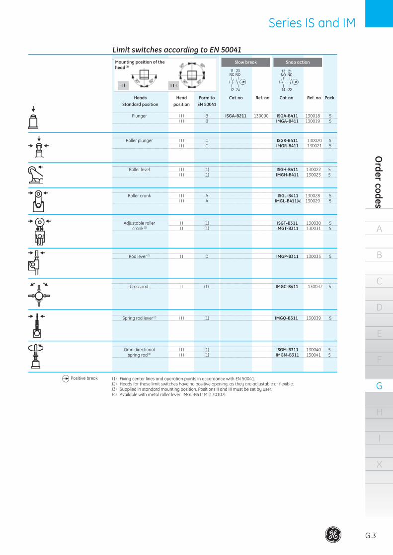
Limit switches according to EN 50041
Heads Head Form to Cat.no Ref. no. Cat.no Ref. no. Pack Standard position position EN 50041
Slow break Snap action
I I I I I
Omnidirectional I I I (1) ISGM-B311 130040 5 spring rod (2) I I I (1) IMGM-B311 130041 5
Roller plunger I I I C ISGR-B411 130020 5 I I I C IMGR-B411 130021 5
Roller level I I I (1) ISGH-B411 130022 5 I I I (1) IMGH-B411 130023 5
Roller crank I I I A ISGL-B411 130028 5 I I I A IMGL-B411(4) 130029 5
Adjustableroller II (1) ISGT-B311 130030 5 crank (2) I I (1) IMGT-B311 130031 5
Rod lever (2) I I D IMGP-B311 130035 5
Cross rod I I (1) IMGC-B411 130037 5
Spring rod lever (2) I I I (1) IMGQ-B311 130039 5
(1) Fixing center lines and operation points in accordance with EN 50041.(2) Headsfortheselimitswitcheshavenopositiveopening,astheyareadjustableorflexible.(3) Suppliedinstandardmountingposition.PositionsIIandIIImustbesetbyuser.(4) Availablewithmetalrollerlever:IMGL-B411M(130107).
Positivebreak
Mounting position of the head (3)
Plunger I I I B ISGA-B211 130000 ISGA-B411 130018 5 I I I B IMGA-B411 130019 5

A
G.4
B
C
D
E
F
G
H
I
X
Lim
it sw
itch
esSeriesIUG
Thermoplastic limit switches. Positive opening conforming to EN 50047
• Fixingcenterandoperationpoints(IUG...)inaccordancewithEN50047• NCcontactswithpositiveopeningaccordingtoIEC/EN60947-5-1• IP65protection• TerminalnumberingaccordingtoEN50013• ThermoplasticmaterialaccordingtoUL-94V0• OnebottomcableentryM20x1.5onSeriesIUG... TwosidecableentriesforM16x1.5onSeriesIUC.
• TwofixingpossibilitiesforseriesIUGA...• Clipfixingandopeningofterminalsaccesscover,noscrews.• CSAandULcertified
Standards Specifications
Approvals
Degreeofprotection IP65Ambientconditions Storage temperature °C -40 to +80 Operating temperature °C -25 to +80 Resistance to shocks (10 ms) G 30 Resistancetovibrations (10-55 Hz) G 25Mechanical endurance ops. 10 x 106
Cableentry IUG... 1x(M20x1.5)Fixingscrews 2ofM5
Series IUG...
Order codesTechnical data
Dimensions
pg. G.5pg. G.10pg. G.13
!!!
Switch functionContact type Switch function Switch contacts Voltage CurrentIUG Slowmake&break Changeover 1NC/1NO 250V 10A Snapaction Changeover 1NC/1NO 250V 10A
Mounted versions
IEC/EN60947-5-1IEC/EN60204-1

A
B
C
D
E
F
G
H
I
X
Order codes
G.5
SeriesIUG
Limit switches according to EN 50047
Heads Head Form to Cat. Ref. no. Cat. Ref. no. Pack Standard position position EN 50047 no. no.
Slow break Snap action
I I
Omnidirectional I I I (2) IUGM-B311 130104 5 spring rod (1)
Plunger I I I B IUGA-B211 130060 IUGA-B411 130082 5 I I I B IUGA-B211 S 209140 5
Low roller I I I (2) IUGU-B411 130084 5 plunger I I I (2) IUGU-B211 S 130057 5
Low roller plunger (1) I I I (2) IUGR-B411 130086 5
Roller lever I I I E IUGH-B211 130066 IUGH-B411 130088 5
Adjustablerollerlever III (2) IUGI-B411 130090 5
Retractablereturning III (2) IUGE-B211 130072 IUGE-B411 130094 5 roller lever
Roller crank I I I A IUGL-B211 130074 IUGL-B411 130096 5 (28mmbetweencentres)
Adjustablerollercrank(1) I I (2) IUGT-B111 130076 IUGT-B311 130098 5
Rod lever (1) I I (2) IUGP-B311 130100 5
Spring rod lever (1) I I I (2) IUGQ-B111 130080 IUGQ-B311 130102 5
(1) Headsfortheselimitswitcheshavenopositiveopening.(2) FixingcentrelinesandoperatingpointsaccordingtoEN50047.
Mounting position of the head
I I I
Positivebreak
A
G.6
B
C
D
E
F
G
H
I
X
Lim
it sw
itch
esSeries IZ Series IZ
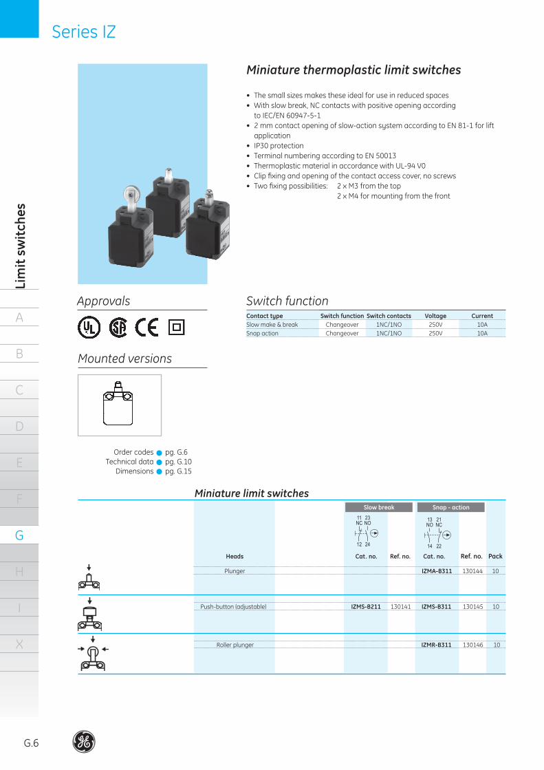
Miniature thermoplastic limit switches
• Thesmallsizesmakestheseidealforuseinreducedspaces• Withslowbreak,NCcontactswithpositiveopeningaccording toIEC/EN60947-5-1
• 2mmcontactopeningofslow-actionsystemaccordingtoEN81-1forliftapplication
• IP30protection• TerminalnumberingaccordingtoEN50013• ThermoplasticmaterialinaccordancewithUL-94V0• Clipfixingandopeningofthecontactaccesscover,noscrews• Twofixingpossibilities: 2xM3fromthetop 2xM4formountingfromthefront
Approvals
Mounted versions
Switch functionContact type Switch function Switch contacts Voltage CurrentSlowmake&break Changeover 1NC/1NO 250V 10ASnapaction Changeover 1NC/1NO 250V 10A
Miniature limit switches
Heads Cat. no. Ref. no. Cat. no. Ref. no. Pack
Slow break Snap - action
Plunger IZMA-B311 130144 10
Push-button(adjustable) IZMS-B211 130141 IZMS-B311 130145 10
Roller plunger IZMR-B311 130146 10
Order codesTechnical data
Dimensions
pg. G.6pg. G.10pg. G.15
!!!

Series IZ Series IZ
A
B
C
D
E
F
G
H
I
X
Order codes
G.7
Notes
. . . . . . . . . . . . . . . . . . . . . . . . . . . . . . . . . . . . . .
. . . . . . . . . . . . . . . . . . . . . . . . . . . . . . . . . . . . . .
. . . . . . . . . . . . . . . . . . . . . . . . . . . . . . . . . . . . . .
. . . . . . . . . . . . . . . . . . . . . . . . . . . . . . . . . . . . . .
. . . . . . . . . . . . . . . . . . . . . . . . . . . . . . . . . . . . . .
. . . . . . . . . . . . . . . . . . . . . . . . . . . . . . . . . . . . . .
. . . . . . . . . . . . . . . . . . . . . . . . . . . . . . . . . . . . . .
. . . . . . . . . . . . . . . . . . . . . . . . . . . . . . . . . . . . . .
. . . . . . . . . . . . . . . . . . . . . . . . . . . . . . . . . . . . . .
. . . . . . . . . . . . . . . . . . . . . . . . . . . . . . . . . . . . . .
. . . . . . . . . . . . . . . . . . . . . . . . . . . . . . . . . . . . . .
. . . . . . . . . . . . . . . . . . . . . . . . . . . . . . . . . . . . . .
. . . . . . . . . . . . . . . . . . . . . . . . . . . . . . . . . . . . . .
. . . . . . . . . . . . . . . . . . . . . . . . . . . . . . . . . . . . . .
. . . . . . . . . . . . . . . . . . . . . . . . . . . . . . . . . . . . . .
. . . . . . . . . . . . . . . . . . . . . . . . . . . . . . . . . . . . . .
. . . . . . . . . . . . . . . . . . . . . . . . . . . . . . . . . . . . . .
. . . . . . . . . . . . . . . . . . . . . . . . . . . . . . . . . . . . . .
. . . . . . . . . . . . . . . . . . . . . . . . . . . . . . . . . . . . . .
. . . . . . . . . . . . . . . . . . . . . . . . . . . . . . . . . . . . . .
. . . . . . . . . . . . . . . . . . . . . . . . . . . . . . . . . . . . . .
. . . . . . . . . . . . . . . . . . . . . . . . . . . . . . . . . . . . . .
. . . . . . . . . . . . . . . . . . . . . . . . . . . . . . . . . . . . . .
. . . . . . . . . . . . . . . . . . . . . . . . . . . . . . . . . . . . . .
. . . . . . . . . . . . . . . . . . . . . . . . . . . . . . . . . . . . . .
. . . . . . . . . . . . . . . . . . . . . . . . . . . . . . . . . . . . . .
. . . . . . . . . . . . . . . . . . . . . . . . . . . . . . . . . . . . . .
. . . . . . . . . . . . . . . . . . . . . . . . . . . . . . . . . . . . . .
. . . . . . . . . . . . . . . . . . . . . . . . . . . . . . . . . . . . . .
. . . . . . . . . . . . . . . . . . . . . . . . . . . . . . . . . . . . . .
. . . . . . . . . . . . . . . . . . . . . . . . . . . . . . . . . . . . . .
. . . . . . . . . . . . . . . . . . . . . . . . . . . . . . . . . . . . . .
. . . . . . . . . . . . . . . . . . . . . . . . . . . . . . . . . . . . . .
. . . . . . . . . . . . . . . . . . . . . . . . . . . . . . . . . . . . . .
. . . . . . . . . . . . . . . . . . . . . . . . . . . . . . . . . . . . . .
. . . . . . . . . . . . . . . . . . . . . . . . . . . . . . . . . . . . . .
. . . . . . . . . . . . . . . . . . . . . . . . . . . . . . . . . . . . . .
. . . . . . . . . . . . . . . . . . . . . . . . . . . . . . . . . . . . . .
. . . . . . . . . . . . . . . . . . . . . . . . . . . . . . . . . . . . . .
. . . . . . . . . . . . . . . . . . . . . . . . . . . . . . . . . . . . . .
. . . . . . . . . . . . . . . . . . . . . . . . . . . . . . . . . . . . . .
. . . . . . . . . . . . . . . . . . . . . . . . . . . . . . . . . . . . . .
. . . . . . . . . . . . . . . . . . . . . . . . . . . . . . . . . . . . . .
. . . . . . . . . . . . . . . . . . . . . . . . . . . . . . . . . . . . . .
. . . . . . . . . . . . . . . . . . . . . . . . . . . . . . . . . . . . . .
. . . . . . . . . . . . . . . . . . . . . . . . . . . . . . . . . . . . . .
. . . . . . . . . . . . . . . . . . . . . . . . . . . . . . . . . . . . . .
. . . . . . . . . . . . . . . . . . . . . . . . . . . . . . . . . . . . . .
A
G.8
B
C
D
E
F
G
H
I
X
Lim
it sw
itch
esSeries 114FCT Series 114FCT
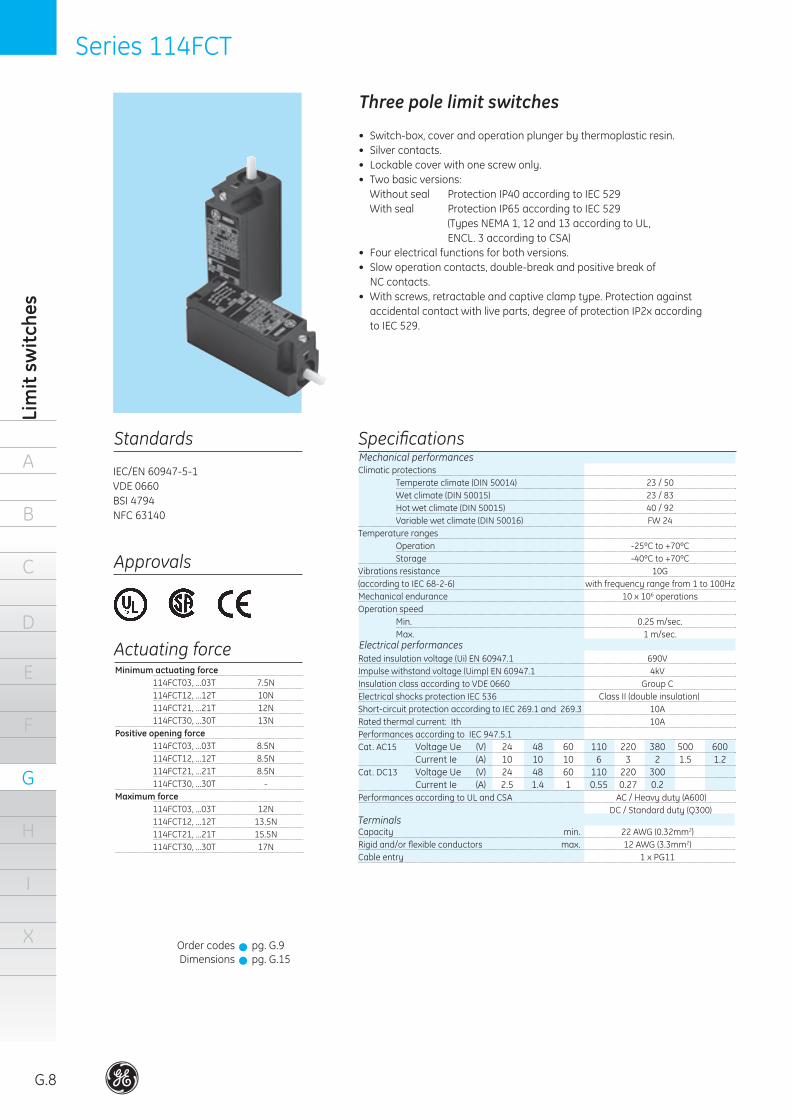
Climatic protections Temperateclimate(DIN50014) 23/50 Wetclimate(DIN50015) 23/83 Hotwetclimate(DIN50015) 40/92 Variablewetclimate(DIN50016) FW24Temperature ranges Operation -25ºCto+70ºC Storage -40ºCto+70ºCVibrationsresistance 10G(accordingtoIEC68-2-6) withfrequencyrangefrom1to100HzMechanical endurance 10 x 106 operationsOperation speed Min. 0.25m/sec. Max. 1m/sec.Electrical performances
Capacity min. 22AWG(0.32mm2)Rigidand/orflexibleconductors max. 12AWG(3.3mm2)Cableentry 1xPG11
Terminals
Mechanical performances
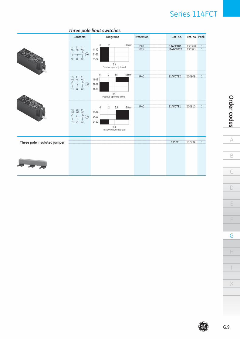
Three pole limit switches
• Switch-box,coverandoperationplungerbythermoplasticresin.• Silvercontacts.• Lockablecoverwithonescrewonly.• Twobasicversions: Withoutseal ProtectionIP40accordingtoIEC529 Withseal ProtectionIP65accordingtoIEC529 (TypesNEMA1,12and13accordingtoUL,
ENCL. 3 according to CSA)• Fourelectricalfunctionsforbothversions.• Slowoperationcontacts,double-breakandpositivebreakof
NC contacts.• Withscrews,retractableandcaptiveclamptype.Protectionagainst accidentalcontactwithliveparts,degreeofprotectionIP2xaccording
to IEC 529.
Standards Specifications
IEC/EN60947-5-1VDE0660BSI4794NFC 63140
Approvals
Minimum actuating force 114FCT03,...03T 7.5N 114FCT12,...12T 10N 114FCT21,...21T 12N 114FCT30,...30T 13NPositive opening force 114FCT03,...03T 8.5N 114FCT12,...12T 8.5N 114FCT21,...21T 8.5N 114FCT30,...30T -Maximum force 114FCT03,...03T 12N 114FCT12,...12T 13.5N 114FCT21,...21T 15.5N 114FCT30,...30T 17N
Actuating force
Order codesDimensions
pg. G.9pg. G.15
!!
Ratedinsulationvoltage(Ui)EN60947.1 690VImpulsewithstandvoltage(Uimp)EN60947.1 4kVInsulationclassaccordingtoVDE0660 GroupCElectricalshocksprotectionIEC536 ClassII(doubleinsulation)Short-circuit protection according to IEC 269.1 and 269.3 10ARatedthermalcurrent:Ith 10APerformancesaccordingtoIEC947.5.1Cat. AC15 VoltageUe (V) 24 48 60 110 220 380 500 600 Current Ie (A) 10 10 10 6 3 2 1.5 1.2Cat. DC13 VoltageUe (V) 24 48 60 110 220 300 CurrentIe (A) 2.5 1.4 1 0.55 0.27 0.2PerformancesaccordingtoULandCSA AC/Heavyduty(A600) DC/Standardduty(Q300)
Series 114FCT Series 114FCT
A
B
C
D
E
F
G
H
I
X
Order codes
G.9
Three pole limit switches Contacts Diagrams Protection Cat. no. Ref. no. Pack. IP40 114FCT03 130320 1 IP65 114FCT03T 130321 1
Positive opening travel
Positive opening travel
IP40 114FCT12 200909 1
Positive opening travel
Three pole insulated jumper
IP40 114FCT21 200910 1
105PT 132234 1

Series IS and IM
A
G.10
B
C
D
E
F
G
H
I
X
Lim
it sw
itch
esSeries IS, IM, IUG, IZ
Technical data
ISG..-B211 ISG..-B311 IUG..-B111 IUG..-B311 IZM..-B211 IZM..-B311 IMG..-B211 IMG..-B311 IUG..-B211 IUG..-B411 ISG..-B411 IMG..-411
Limit switches
Rated insulation voltage (Ui) V
Protection against electrical shocks Protection against electrical shocks (fuse) (A)Rated current (DIN EN60947-5-1) A300 AC-15 12/24V (A) 48/60V (A) (110V) 120V (A) 127V (A) (220V) 240V (A) 380V (A) Q300 DC-13 24V (A) 48V (A) (110V) 125V (A) (220V) 250V (A) 300V (A)Operating rate ops./hSwitching time (ms)Repetition assurance (mm)Clamping capacity (mm2)Terminal screwProtection
Type of break Slow break Snap action Slow break Snap action Slow break Snap actionNumber of contacts 2 2 2 2 2 2 Function 1NO-1NC 1NO-1NC 1NO-1NC 1NO-1NC 1NO-1NC 1NO-1NC Polarity Same Same Same Same Same Same Rated thermal current (Ithe) (A) 10 10 10 10 10 10
380
-
6
--6-3---
0.550.27
-6000
-± 0.11.5
M3.5IP30
250
-
6
--6-3---
0.550.27
-6000
10± 0.11.5
M3.5IP30
250
Class II
10
--6-3------
6000-
± 0.11.5
M3.5IP65
250
Class II
2
--6-3------
600010
± 0.11.5
M3.5IP65
400
Class II (ISG)CLASS I (IMG)
10
--6-3---
0.550.27
-6000
-± 0.1
0.5 - 1.5M3.5IP65
400
Class II (ISG)CLASS I (IMG)
2
--6-3---
0.550.27
-6000
10± 0.11.5
M3.5IP65
Auxiliary contacts
Series IS and IM
A
B
C
D
E
F
G
H
I
X
Dim
ensions
G.11
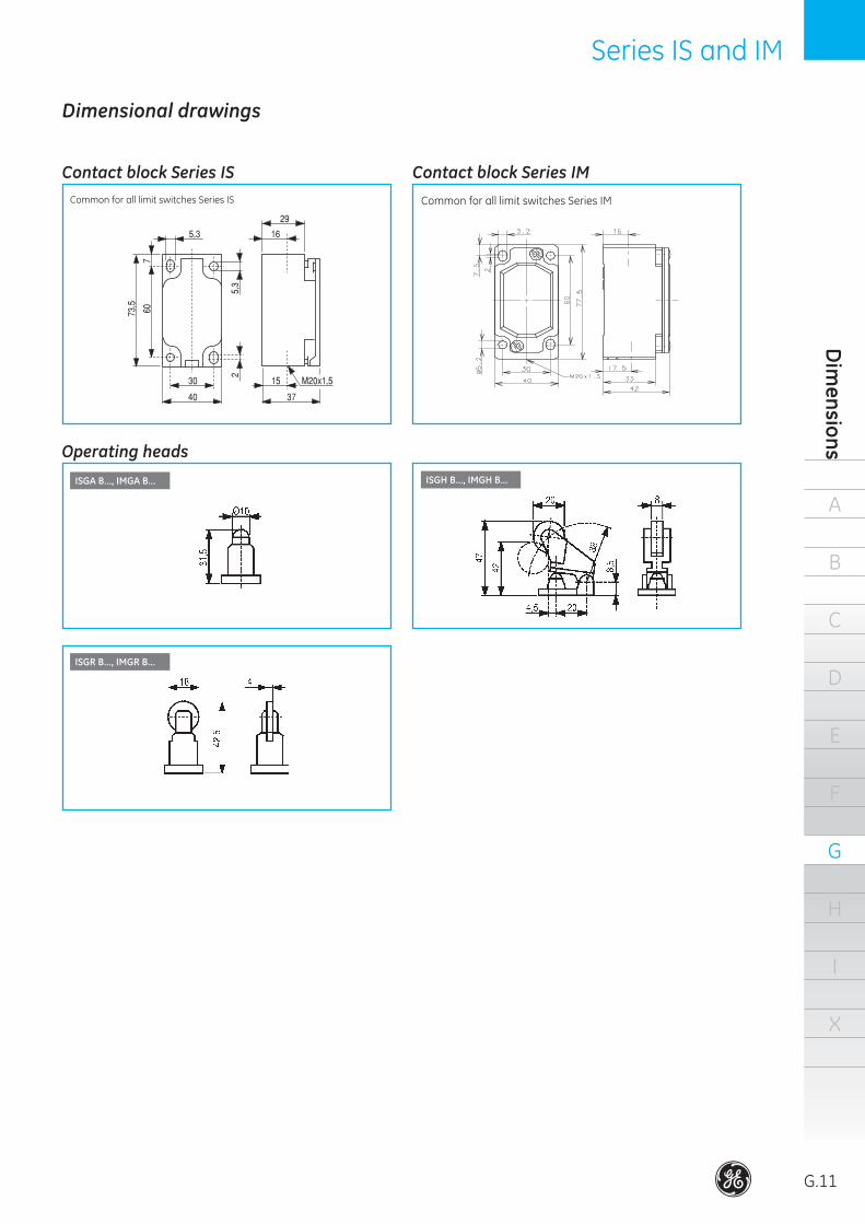
Dimensional drawings
Common for all limit switches Series IS Common for all limit switches Series IM
ISGA B..., IMGA B... ISGH B..., IMGH B...
ISGR B..., IMGR B...
Contact block Series IS
Operating heads
Contact block Series IM

A
G.12
B
C
D
E
F
G
H
I
X
Lim
it sw
itch
esSeries IS and IM
ISGT B..., IMGT B...
IMGP B... ISGM B..., IMGM B...
IMGC B...
IMGQ B...
ISGL B..., IMGL B...
Operating heads (continued)
Dimensional drawings
Series IS and IM
A
B
C
D
E
F
G
H
I
X
Dim
ensions
G.13
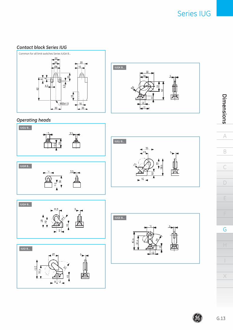
Series IUG
IUGE B...
IUGU B...
IUGR B...
IUGH B...
IUGI B...
IUGK B...
IUGJ B...
Common for all limit switches Series IUGA B...
Contact block Series IUG
Operating heads

A
G.14
B
C
D
E
F
G
H
I
X
Lim
it sw
itch
esSeries IZ and 114FCTSeries IUG
Dimensional drawings
IUGL B...
IUGT B... IUGM B...
IUGQ B...
IUGP B...
Operating heads (continued)
Series IZ and 114FCT
A
B
C
D
E
F
G
H
I
X
Dim
ensions
G.15
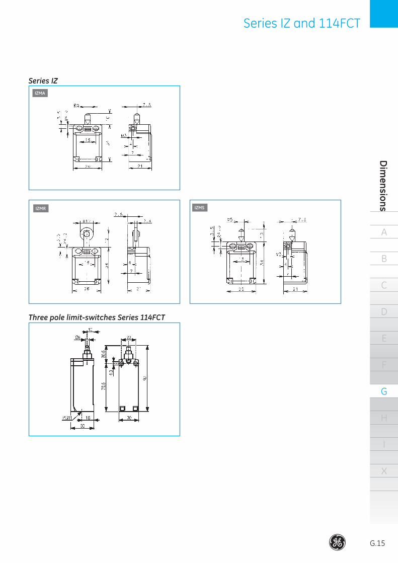
IZMA
IZMS
Series IZ
Three pole limit-switches Series 114FCT
IZMR
A
G.16
B
C
D
E
F
G
H
I
X
Lim
it sw
itch
esSeries 115 Series 115
Standards
IEC/EN 60947-5-1 BSICEI UTEVDE 0660
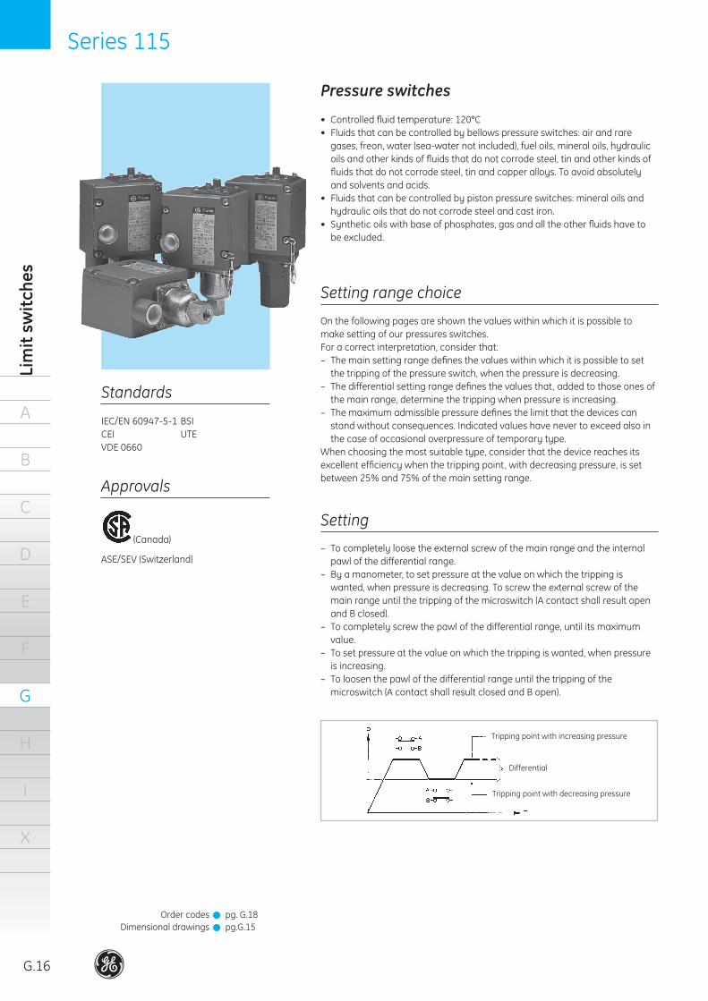
Pressure switches
• Controlledfluidtemperature:120°C• Fluidsthatcanbecontrolledbybellowspressureswitches:airandraregases,freon,water(sea-waternotincluded),fueloils,mineraloils,hydraulicoilsandotherkindsoffluidsthatdonotcorrodesteel,tinandotherkindsoffluidsthatdonotcorrodesteel,tinandcopperalloys.Toavoidabsolutelyandsolventsandacids.
• Fluidsthatcanbecontrolledbypistonpressureswitches:mineraloilsandhydraulicoilsthatdonotcorrodesteelandcastiron.
• Syntheticoilswithbaseofphosphates,gasandalltheotherfluidshavetobeexcluded.
Setting range choice
Onthefollowingpagesareshownthevalueswithinwhichitispossibletomakesettingofourpressuresswitches.Foracorrectinterpretation,considerthat:– Themainsettingrangedefinesthevalueswithinwhichitispossibletosetthetrippingofthepressureswitch,whenthepressureisdecreasing.
– Thedifferentialsettingrangedefinesthevaluesthat,addedtothoseonesofthemainrange,determinethetrippingwhenpressureisincreasing.
– Themaximumadmissiblepressuredefinesthelimitthatthedevicescanstandwithoutconsequences.Indicatedvalueshavenevertoexceedalsointhecaseofoccasionaloverpressureoftemporarytype.
Whenchoosingthemostsuitabletype,considerthatthedevicereachesitsexcellentefficiencywhenthetrippingpoint,withdecreasingpressure,issetbetween25%and75%ofthemainsettingrange.
Setting
– Tocompletelyloosetheexternalscrewofthemainrangeandtheinternalpawlofthedifferentialrange.
– Byamanometer,tosetpressureatthevalueonwhichthetrippingiswanted,whenpressureisdecreasing.Toscrewtheexternalscrewofthemainrangeuntilthetrippingofthemicroswitch(AcontactshallresultopenandBclosed).
– Tocompletelyscrewthepawlofthedifferentialrange,untilitsmaximumvalue.
– Tosetpressureatthevalueonwhichthetrippingiswanted,whenpressureisincreasing.
– Toloosenthepawlofthedifferentialrangeuntilthetrippingofthe microswitch(AcontactshallresultclosedandBopen).
Trippingpointwithdecreasingpressure
Differential
Trippingpointwithincreasingpressure
Approvals
(Canada)
ASE/SEV(Switzerland)
OrdercodesDimensionaldrawings
pg.G.18pg.G.15
!!
Series 115 Series 115
A
B
C
D
E
F
G
H
I
X
Pressure switches
G.17
Location
Generallythelocationofourpressureswitchescanbe effectedaswanted.Nevertheless,astothepistontypeswhitoutsealring,locationhavetobemadeinsuchawayastoallowthedischarge,throughthedrainagehole,oftheblow-byoilbetweencylinderandpiston(afewdropsperhour).Thegoing-outoilcanbecollectedbyaproperdrainagepipethatconveysit ,freefalling,intothetankofthe hydrauliccentral,asshowninthebelowfigure.
Caution
– Donotconnectthedrainageholetoareturnpipeoftheline...
– Thedrainagepipemustnotcoverawaydifferentfromthatoneindicated(e.g.towardsthetop).
– Donotplugthedrainageholes.
Iftheabovecautionsarenotmet,insidethesensitivegrouptherewillbeacounterpressurethatcoulddamagethesealingwasherbetweenactuatorandframeofthepressureswitch.
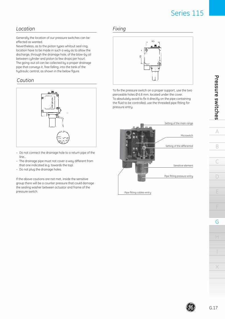
Fixing
Tofixthepressureswitchonapropersupport,usethetwopierceableholesØ6.8mm.locatedunderthecover.Toabsolutelyavoidtofixitdirectlyonthepipecontainingthefluidtobecontrolled,usethethreadedpipefittingforpressureentry.
Settingofthemainrange
Pipefittingcables-entry
Pipefittingpressureentry
Sensitiveelement
Settingofthedifferential
Microwitch
A
G.18
B
C
D
E
F
G
H
I
X
Lim
it sw
itch
esSeries 115 Series 115
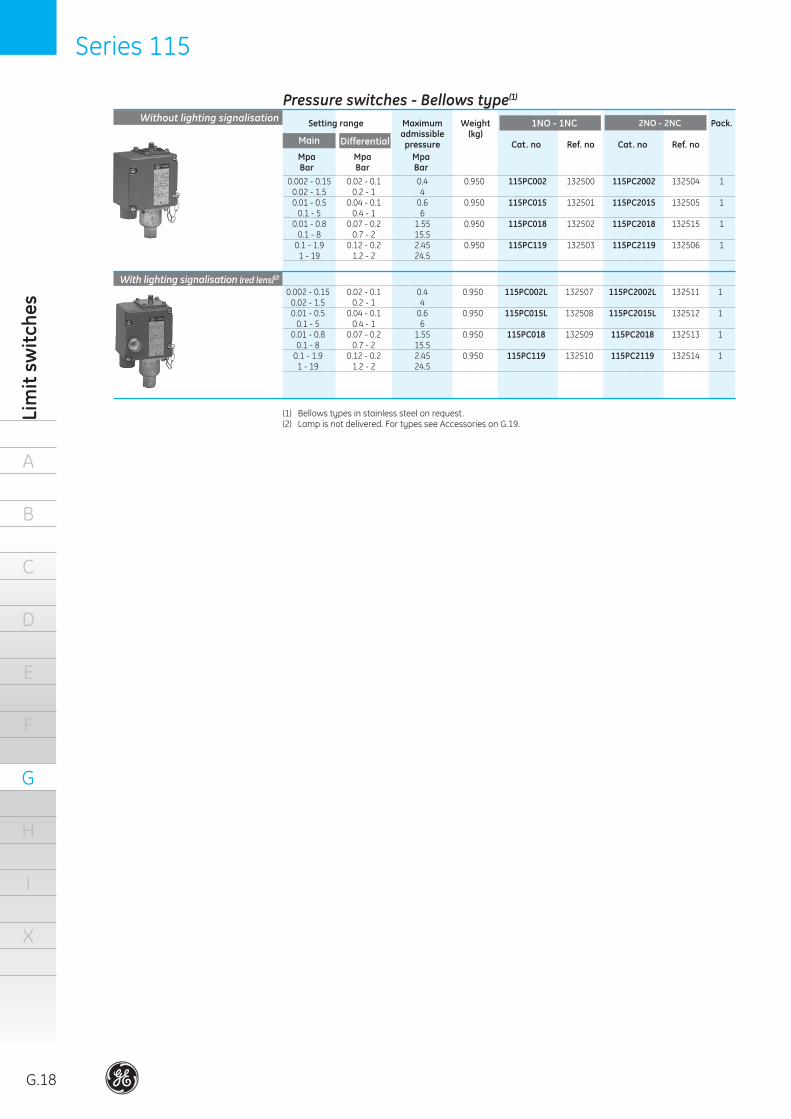
Pressure switches - Bellows type(1)
Without lighting signalisation
0.002-0.15 0.02-0.1 0.4 0.950 115PC002 132500 115PC2002 132504 1 0.02-1.5 0.2-1 4 0.01 - 0.5 0.04 - 0.1 0.6 0.950 115PC015 132501 115PC2015 132505 1 0.1 - 5 0.4 - 1 6 0.01-0.8 0.07-0.2 1.55 0.950 115PC018 132502 115PC2018 132515 1 0.1-8 0.7-2 15.5 0.1-1.9 0.12-0.2 2.45 0.950 115PC119 132503 115PC2119 132506 1 1-19 1.2-2 24.5
Setting range Maximum Weight Pack. admissible (kg) pressure Cat. no Ref. no Cat. no Ref. no Main Differential
2NO - 2NC
Mpa Mpa Mpa Bar Bar Bar
With lighting signalisation (red lens)(2) 0.002-0.15 0.02-0.1 0.4 0.950 115PC002L 132507 115PC2002L 132511 1 0.02-1.5 0.2-1 4 0.01 - 0.5 0.04 - 0.1 0.6 0.950 115PC015L 132508 115PC2015L 132512 1 0.1 - 5 0.4 - 1 6 0.01-0.8 0.07-0.2 1.55 0.950 115PC018 132509 115PC2018 132513 1 0.1-8 0.7-2 15.5 0.1-1.9 0.12-0.2 2.45 0.950 115PC119 132510 115PC2119 132514 1 1-19 1.2-2 24.5
(1) Bellowstypesinstainlesssteelonrequest.(2) Lampisnotdelivered.FortypesseeAccessoriesonG.19.
1NO - 1NC
Series 115 Series 115
A
B
C
D
E
F
G
H
I
X
Pressure switches
G.19
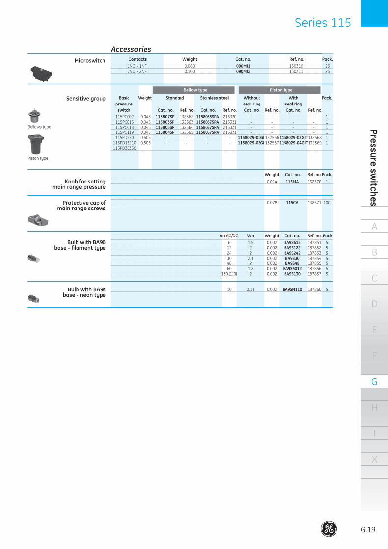
AccessoriesMicroswitch
1NO - 1NF 0.060 090MI1 130310 25 2NO-2NF 0.100 090MI2 130311 25
Sensitive group Piston type
115PC002 0.045 115807SP 132562 1158065SPA 215320 - - - - 1 115PC015 0.045 115803SP 132563 1158067SPA 215321 - - - - 1 115PC018 0.045 115805SP 132564 1158067SPA 215321 - - - - 1 115PC119 0.045 115804SP 132565 1158067SPA 215321 - - - - 1 115PD970 0.505 - - - - 1158029-01GI1325661158029-03GIT132568 1 115PD15210 0.505 - - - - 1158029-02GI1325671158029-04GIT132569 1 115PD38350
Basic Weight Standard Without With Pack. pressure seal ring seal ring switch Cat. no. Ref. no. Cat. no. Ref. no. Cat. no. Ref. no. Cat. no. Ref. no.
Knob for setting main range pressure
Bellowstype
Pistontype
Protective cap of main range screws
Bulb with BA96 base - filament type
Bulb with BA9s base - neon type
Contacts Weight Cat. no. Ref. no. Pack.
Weight Cat. no. Ref. no. Pack.
Bellow type
Stainless steel
0.014 115MA 132570 1
0.078 115CA 132571 100
Vn AC/DC Wn Weight Cat. no. Ref. no. Pack 6 1.5 0.002 BA9S615 187851 5 12 2 0.002 BA9S122 187852 5 24 2 0.002 BA9S242 187853 5 30 2.1 0.002 BA9S30 187854 5 48 2 0.002 BA9S48 187855 5 60 1.2 0.002 BA9S6012 187856 5 130(110) 2 0.002 BA9S130 187857 5
10 0.11 0.002 BA9SN110 187860 5

A
G.20
B
C
D
E
F
G
H
I
X
Lim
it sw
itch
esSeries 115 Series 115
ThepressureswitchesSeries115aredesignedfortrans-formingapressurevariationintoanelectricalsignalwhenapre-arrangedpressurevalueisreached.Pressureswitchesareutilizedinthefieldoftheindustrymachines,installationsandtransports.
Climatic protections
Insulation classIP65 IEC/EN60529ENCL.4,5 CSA
General
Temperatureclimate cat.23/50(DIN50014)Wetclimate cat.23/83(DIN50015)Hotwetclimate cat.40/92(DIN50015)Variablewetclimate cat.FW24(DIN50016)
Electrical performances
Technical data
Temperature rangesOperation –25°Cto+70°CStorage –40°Cto+70°C
Vibration resistance5gatasinusoidalfrequencyranging IEC68-2-6fromto100HzaccordingtoIEC68-2-6
090MI1(1NO+1NC)090MI2(2NO+2NC)Ratedthermalcurrent:Ith=10A
Performances according IEC 947.5.1
AC/HeavyDuty(A/600)DC/StandardDuty(Q300)Connectionsatsamepolarity
Connection terminalsScrewtypewithoutclampingscrew.Suitableforeye,forkandhookterminals.
Cable entryOnePG13.5threadedcableentry.
RangeThepressureswitchesseries115areavailableintwobasicversions:– Withbellowssensitiveelementforpressuresrangingbetween0.002Mpa(0.02bar)minimumand2.1Mpa (21bar)maximum.
– Withpistonsensitiveelementforpressuresrangingbetween0.95Mpa
(9.5bar)minimumand37.25Mpa(372.5bar)maximum.Bothversionscanbesupplied:•Withoutlightingsignaling•Withlightingsignaling
ConstructionSnap-action1NO-1NCor2NO+2NCmicroswitcheswithdouble-breakcontactswithoutpositive-breakofthe NCcontact.Bellowssensitiveelement,hermeticsealing,madeby Tombacco(orstainlesssteel)materialenclosedintoa die-castzamaccasecompletewitha1mm.damper.Pistonsensitiveelement,withorwithoutsealring,withsteelpistonenclosedintoacast-ironcylindercompletewith1mm.damper.Enclosureandcoveraremadeofdie-castaluminiumandpaintedwithanaphoresisprocessgreyRAL7012..
Rated insulation voltage
Mechanical endurance
Bellows type1millionoperations.Itcanbeconsiderablyreducedwhenthepressurejumpreachsthemaximumvalueforeseenforeverytypeofdeviceandtheoperationsnumberishigh.Thebellowsendurancecanbealsonegativelyinfluencedbythetemperatureandthekindofcontrolledfluid.
600V AC/DC
Insulation classGroupCaccordingtoVDE0110
Short-circuit protection10AgLfusesaccordingtoIEC947-5-1
CategoryAC15(A600)VoltageUe V 24 48 60 110 220 380 500 600CurrentIe A 10 10 10 6 3 2 1.5 1.2CategoryDC13(P600)Voltage Ue V 24 48 60 110 220 300Current Ie A 2.5 1.4 1 0.55 0.27 0.2
Performances according to CSA
Series 115 Series 115
A
B
C
D
E
F
G
H
I
X
Pressure switches
G.21
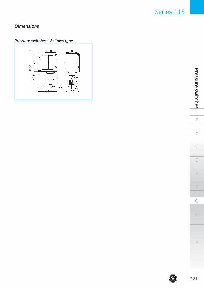
Dimensions
Pressure switches - Bellows type
@
Power Protection (formerly GE Power Controls), a division of GE Consumer & Industrial, is a first class European supplier of low-voltage products including wiring devices, residential and industrial electrical distribution components, automation products, enclosures and switchboards. Demand for the company’s products comes from, wholesalers, installers, panel-board builders, contractors, OEMsand utilities worldwide.
www.ge.com/ex/powerprotectionwww.ge.com/eu/powerprotection
GE Consumer & IndustrialPower Protection
680804Ref. C/4601/E/EX 2.5 Ed. 05/09
© Copyright GE Consumer & Industrial 2009
4896
2
GE imagination at work
GE imagination at work
GE imagination at work
GE imagination at work
GE imagination at work
GE imagination at work
GE imagination at work
GE imagination at work
GE imagination at work
GE POWER CONTROLS Ltd Houghton CentreSalthouse RoadNorthampton NN4 7EXUnited Kingdom
Customer Service Tel. 0800 587 1251 Fax 0800 587 1239 E-mail: [email protected]
GE CONSUMER & INDUSTRIAL HUNGARYVáci út 77 H-1340 Budapest Hungary
Customer Service Tel. +361 447 6046 Fax +361 447 5060 E-mail: mea.export [email protected]: www.gepowershop.com
GE CONSUMER & INDUSTRIALPOWER PROTECTIONNieuwevaart 51B-9000 GentBelgium
Tel. +32/9 265 21 11Fax +32/9 265 28 00E-mail: [email protected]