control and choke valves solutions ltd/vs... · choke valve manufacturer that was established in...
TRANSCRIPT
alve Solutions
Control and Choke Valves

l Valve Solutions tel: 01274 531992 fax: 01274 531995 email: [email protected] web: www.valvesolutions.co.uk

Service backed by Experience l
■ Valve Solutions Company Profile 1
■ Globe Control Valves 4
■ Series 110 Globe Control Valves 8
■ Series 110 Severe Service Trims 18
■ Series 130 3 Way Globe Control Valves 22
■ Series 170 Angle and Choke Valves 28
■ Series 600 Downstream Pressure Regulators 33
■ Series 700 Upstream Pressure Regulators 35
■ Series 117 Teflon Lined Globe Control Valves 37
■ Series 119 Low Flow Globe Control Valves 39
■ Series 400 Diaphragm Control Valves 40
■ Series 800 Desuperheaters 44
■ Series 200 Butterfly Valves 47
■ Series 310 V-Notch Ball Valves 53
■ Actuators 56 57Pneumatic Spring Opposed Diaphragm Actuators 59Pneumatic Spring Opposed and Double Acting Piston Actuators
■ Accessories 60 60 Valve Positioner 62 Volume Booster Model VSB-1 63 Volume Booster Model VSB-2 64 Air Lock VSAL-1
Contents

l Valve Solutions tel: 01274 531992 fax: 01274 531995 email: [email protected] web: www.valvesolutions.co.uk
Company Profile
Valve Solutions is a specialist Control and Choke Valve manufacturer that was established in 1997. It provides the Oil and Gas, Power Generation, Chemical, Petrochemical, Paper and Pulp and Process Industries with a UK manufacturer of significant expertise and experience in the field of Control and Choke Valves. The aim of the company is to provide Contral Valve Solutions at a competitive price within the required delivery schedule, to customers technical and quality requirements.
Scopel Design, manufacture, modification, and sales of industrial process control valves, choke valves, actuators and valve mounted instrumentation.l Manufacture of spare parts, refurbishment of control valves and supply of after sales service, training and consultancy.
l Quality systems in accordance with ISO9001:2008.
l Control valves and actuators manufactured to the requirements of European Directives 97/23/EC (PED) and 94/9/EC (ATEX).
The two directors are David B Martin andEdward G Williams.
Resume: David B MartinDavid is a chartered engineer, Fellow of the Institute of Mechanical Engineers and has been in the control valve industry for over 45 years.- He has worked in all aspects of control valves including technical, sales, design, manufacturing, service support, quality and senior management. A number of notable achievements include the following:
- Held senior positions in a number of major control valve manufacturers.
- Presented a number of technical papers on control valves, choke valves and associ-ated issues.
- Undertook significant research in to control valve noise during 70’s to generatenoise prediction techniques for incompressible and compressible fluids together with development of low noise trim designs.
- Former technical director of major UK control valve manufacturer.
- Specialist in design and application of control valves for standard and severe service duties.
- Currently involved on executive committee of the BVAA (British Valve and ActuatorAssociation).
1

Service backed by Experience l
Recent ClientsHuntsman Chemicals
Drax Power Station
BP Chemicals
Enron Power station
Alstom Power
Sulzer Pumps
Shell Expro
Amec Offshore
Aker Solutions
Wood Group Pressure Control
DSM (Roche Products)
Bapco Bahrain
ADGAS Abu Dhabi
BOC
Scottish Power
DuPont Chemicals
Invista Products
Siemens
Petrofac Offshore
Talisman Aberdeen
Petrofac Tunisia
Petronas Malaysia
Baric Systems
Maersk Oil and Gas
Merlon Petroleum
BP Exploration
Resume: Edward Glyn WilliamsGlyn is a qualified instrument and valve engineer who has been in the control valve industry for over 45 years.
- He has worked in all aspects of control valves including technical, sales, design, manufacturing, marketing and senior management.
A number of notable achievements include the following:
- Held senior positions in a number of major control valve manufacturers.
- Overall responsibility of the Middle East sales organisation for a major worldwidemanufacturer of control valves.
- Former sales director of major UK control valve manufacturer.
- Specialist in design and application of
control valves for standard and severe service duties.
- Currently involved on executive committee of the BVAA (British Valve and ActuatorAssociation).
2

l Valve Solutions tel: 01274 531992 fax: 01274 531995 email: [email protected] web: www.valvesolutions.co.uk
l In 2000 Valve Solutions formulated a joint working agreement and technical collaboration responsibility with Pneucon Valves for the manufacture of globe, angle and 3-way control valves for standard and medium service control valves up to 300mm NB and ANSI class 900.
l In 2000 Valve Solutions formulated a joint working agreement with Mitech SA to undertake manufacture of globe and angle control and choke valves for severe service control valves up to 400mm NB and ANSI class 4500.
l In February 2002 Valve Solutions was awarded ISO 9001:2000 by QMS.
l In 2002 Pneucon Valves (Pvte) (Valve Solutions manufacturing partner) were certified to issue PED certificate of conformity to module H.
l In 2003 Valve Solutions were awarded ISO 14001:1996 by QMS.
l In 2003 Valve Solutions supplied 16” ANSI 4500 angle valve with severe service trim design to Sulzer Pumps. This valve was capable of handling a pressure drop across the valve from 850 to 2 bar with a flow of 2000 m3/hr.
l In 2003 Valve Solutions extended the technical and manufacturing capability of Pneucon Valves (Pvte) Limited up to 600mm and ANSI class 2500.
l In 2003 Valve Solutions provided
Valve Solutions are approved by Lloyd’s Register Quality Assurance to the Quality Management System Standard: ISO 9001:2008.
This is applicable to: l Design l Modification l Manufacture and sales of industrial process control valves
l Manufacture of spare parts
l Choke valves
l Actuators and valve mounted instrumentation
l Refurbishment of control valves
l Supply of after sales service
l Training and consultancy
Company Profile
450mm severe service control valve to Centrica Storage for use as an anti-surge control valve to replace existing control valve design which had caused major operational issues.
l In 2004 Valve Solutions Limited supplied 400mm control valve to BP Petroleum for use on Schehallion offshore facility.
l In 2005 Valve Solutions were certified to issue ATEX certificate of conformities in accordance with European legislation.
l In 2006 Valve Solutions purchased a 3D modelling program to enhance its design capability.
l In 2007 Valve Solutions provided 2 off 600mm globe control valves fitted with severe service trim designs to Sulzer pumps
l In 2008 Sulzer Pumps awarded Valve Solutions the contract for the supply and support of Valves for all Sulzer Pump test facilities.
l In 2008 Valve Solutions were awarded the contract by Alstom Power to supply 17 Control Valves to Grain PS project which included 12 off 14” globe style control valves.
l In 2009 Valve Solutions designed, CFD modelled and manufactured a new severe service multi turn multi stage trim design.
l In 2009 Valve solutions was awarded ISO:9001:2008 by Lloyds Register.
3
Service backed by Experience l
Globe Control Valves
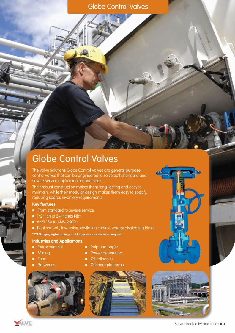
The Valve Solutions Globe Control Valves are general purpose control valves that can be engineered to solve both standard and severe service application requirements. Their robust construction makes them long-lasting and easy to maintain, while their modular design makes them easy to specify, reducing spares inventory requirements.
Key features■ From standard to severe service■ 1/2 inch to 24 inches NB*■ANSI 150 to ANSI 2500* ■Tight shut-off, low noise, cavitation control, energy dissipating trims*PN Flanges, higher ratings and larger sizes available on request
Industries and Applications■ Petrochemical■ Mining■ Food■ Breweries
■ Pulp and paper■ Power generation■ Oil refineries■ Offshore platforms
Globe Control Valves
4

l Valve Solutions tel: 01274 531992 fax: 01274 531995 email: [email protected] web: www.valvesolutions.co.uk
Globe Control Valves
Valve name
Series 110Standard Duty
Series 110Severe Service
Valve type
Two-way globe
Two-way angle
Three-way mixing
Three-way diverting to ANSI, DIN,BS10, JIS
Two-way globe
Two-way angle
Swept angleto ANSI, DIN, BS10, JIS
Body materials
Carbon steelStainless steelMonelDuplex SSHastelloyAL BronzeSpecial alloy NACE
Carbon steel
Stainless steel
Monel
Duplex SS
Hastelloy
AL Bronze
Special alloys
NACE
Valve sizes
DN15 to DN600
½” to 24”
Larger sizes on request
DN25 to DN600
1” to 24”
Flowcharacteristics
=%
Linear
Quick opening
Linear
Bi-linear
Tri-linear
Special trims
Low noise
Flashing duty
Anti-cavitation
Soft seat
Hard facing
Multi-cage
Multi-step
Multi-turn
Stem seals
PTFE Chevrons
Graphite
Low emission
Bellows bonnet
Live loading
PTFE Chevrons
Graphite
Low emission
Bellows bonnet
Live loading
Actuation
Pneumatic diaphragm
Pneumatic piston
Electric
Manual
Pneumatic diaphragm
Pneumatic piston
Electric
Manual
2-Way GlobeSenses 110 globe valve fitted with diaphragm actuator
2-Way GlobeSeries 110 globe valve fitted with piston actuator.
Severe Service Trims
Typical Control Valve examples
5

Service backed by Experience l
Globe Control Valves
Computational Fluid DynamicsValve bodies and trim designs are supported by extensive Computational Fluid Dynamics (CFD) analysis.
Valve name
Series 110 Standard Duty
Series 110 Severe Service
Severe Service - Trim designs
Key features
Precise control
Universal application
High Integrity body / bonnet and stem seal design
Long life valve internals
Low number of components
Quick and easy maintenance
Low cost of ownership
Severe Service
Robust construction
Modular design
Suitable for high pressure and extremetemperature conditions
Can be adapted for corrosive fluids
Various sizes and pressure ratings
Pneumatic, electro-pneumatic or smartpositioners
Local CFD design
Linear/Bi-Linear/Tri-Linear
Wide range of materials
Multi cage, Multi-step and Multi-turn
Compact design
Key benefits
Guaranteed control performance across a wide range ofapplications
Standardised control valve for your plant, whichminimises maintenance, training and spares inventory
Low emissions from the valve, which means a betterenvironment and no loss of valuable product or energy
Infrequent seal replacement, reducing operating costs
Fit and forget
Highly flexible supply
Minimises spares inventory
Limited plant downtime
Low lifetime costs
Solves basic and complex requirements
Long lasting
Reduces spares
Versatile and eliminates noise or cavitation problems
Flexible
Wide range
Meets modern plant control requirements
Can be engineered to suit a specific application
Suitable for large turndowns up to 200:1
Also available in Tungsten Carbide and Ceramics
Potential cost reduction on smaller sizes
Suitable for retrofitting
6
l Valve Solutions tel: 01274 531992 fax: 01274 531995 email: [email protected] web: www.valvesolutions.co.uk
Globe Control Valves
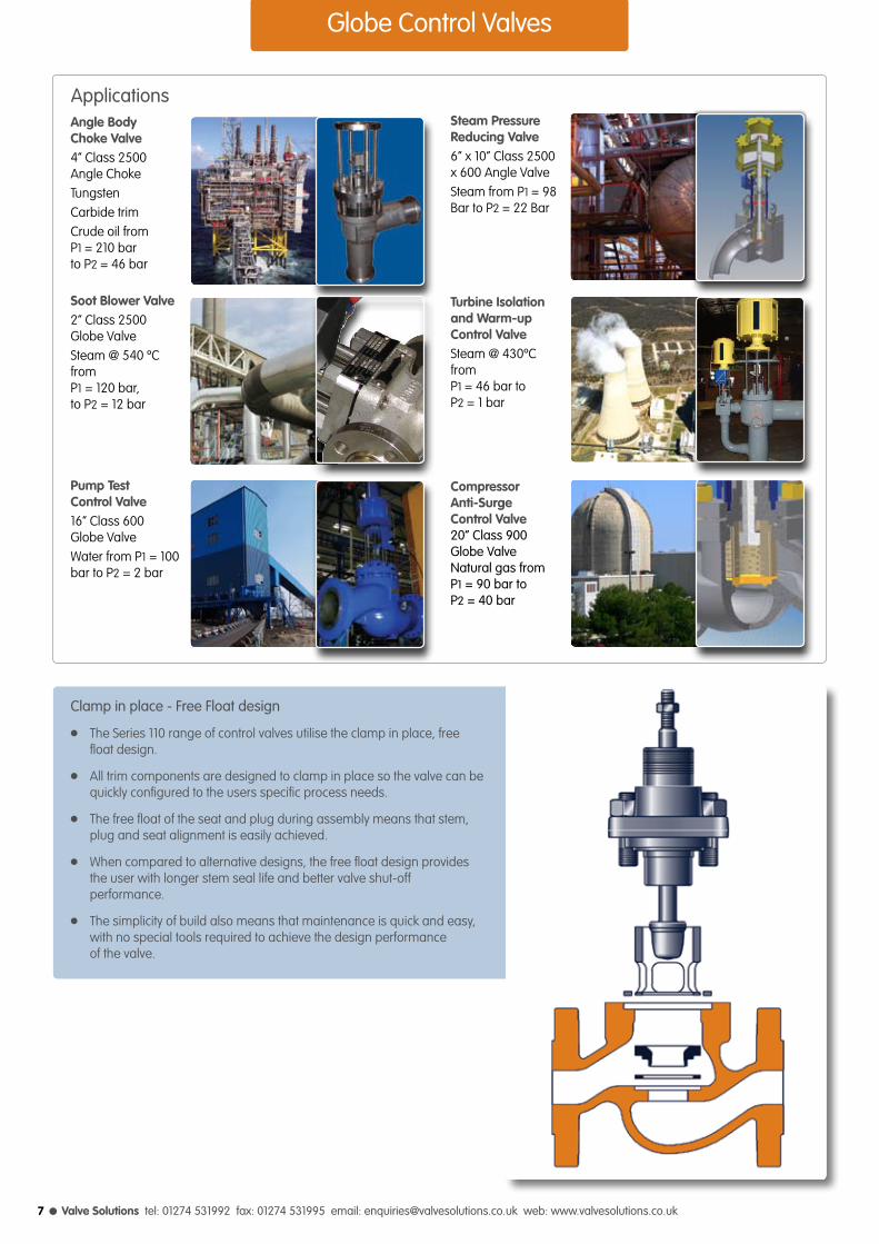
Clamp in place - Free Float design
l The Series 110 range of control valves utilise the clamp in place, free float design.
l All trim components are designed to clamp in place so the valve can be quickly configured to the users specific process needs.
l The free float of the seat and plug during assembly means that stem, plug and seat alignment is easily achieved.
l When compared to alternative designs, the free float design provides the user with longer stem seal life and better valve shut-off performance.
l The simplicity of build also means that maintenance is quick and easy, with no special tools required to achieve the design performance of the valve.
Steam Pressure Reducing Valve6” x 10” Class 2500 x 600 Angle ValveSteam from P1 = 98 Bar to P2 = 22 Bar
Turbine Isolationand Warm-up Control ValveSteam @ 430ºC from P1 = 46 bar toP2 = 1 bar
Compressor Anti-Surge Control Valve20” Class 900Globe ValveNatural gas fromP1 = 90 bar toP2 = 40 bar
ApplicationsAngle Body Choke Valve4” Class 2500 Angle ChokeTungsten Carbide trimCrude oil from P1 = 210 bar to P2 = 46 bar
Soot Blower Valve2” Class 2500 Globe ValveSteam @ 540 ºC from P1 = 120 bar, to P2 = 12 bar
Pump Test Control Valve16” Class 600 Globe ValveWater from P1 = 100 bar to P2 = 2 bar
7

Service backed by Experience l
Series 110 Control Valves
Series 110 Globe Control ValvesThis type of control valve with it’s globe body shape, uses the variable area generated within the control valve trim to control fluid flow. Designed in accordance with ASME B16-34, it is single seated with unbalanced or balanced trim configurations and can be supplied with a wide variety of trim design options. The valve can provide good positional accuracy, high rangeability and simplified maintenance. It satisfies the majority of control applications throughout the process and power industries.
8

l Valve Solutions tel: 01274 531992 fax: 01274 531995 email: [email protected] web: www.valvesolutions.co.uk
Design Code ASME B16-34
Valve Size 15 to 600 mm (1/2” to 24”)
Rating ANSI 150 to 2500 or equivalents to DIN, BS10, JIS etc
End Connection Flanged, Hubbed, Butt weld, Screwed
Body Material Carbon steel, Chrome-moly steel, Stainless steel, Monel, Alloy 20, Hastelloy B/C, Duplex stainless steel, Aluminium bronze
Bonnet Standard up to 400°C Normalising between 250°C to 500°C Extended cold service -20°C to -100°C, Cryogenic -100 ºC to -250 ºC Bellowseal
Gland Packing PTFE Chevrons, Graphite, Low emission
Trim Form Top guided contoured, Spline Micro Flow Ported cage (unbalanced / balanced) Low Noise (LR1, LR2, LR3, LR4)
Trim Material Stainless steel, Duplex stainless steel, 13% Chrome steel, Monel Hastelloy B/C, Stellite
Flow Characteristic Equal percentage, Linear , Quick Opening
Seat Leakage As per ANSI / FCI 70-2-2006 Class III, IV, V and VI
Actuator Form Diaphragm, Piston or Electric
Actuator Type Direct / Reverse Acting
Diaphragm Nitrile / Neoprene (nylon reinforced)
Accessories Valve Positioners - Pneumatic, Electro-Pneumatic, Smart
Instruments - Airset, Solenoid Valve, Volume Booster, Airlock, Limit Switches
Features - Top or Side Mounted handwheel, Limit Stops Removable Blind Head, Steam Jacketting etc.
Specification
Series 110 Control Valves
Series 110: Control valve with standard bonnet and direct acting actuator
Series 110: Control valve with standard bonnet and reverse acting actuator
l High flow capacity and rangeability.
l Large variety of trim designs.
l Top entry for ease of inspection and maintenance.
l Designed with clamped seat and trim configuration.
l Unbalanced or balanced plug design options to achieve specified leakage requirements.
l Bolts located outside of the piping stress area to eliminate gasket crush problems.
l Wide selection of actuators to meet most system requirements.
Design Features
l Produced with Quality Systems accredited to ISO 9001 : 2008 by Bureau Veritas and “CE” marked in accordance with Pressure Equipment Directive and Regulations 07/23/EC by Lloyd’s Register.
l Full material certification available for all major component parts.
l Rigorous proven on-site performance.
l Full guarantee on design and performance.
l All testing performed to the requirements of ASME B16.34.
Quality and Performance Guarantee
9

Service backed by Experience l
Series 110 Control Valves
Valve size
Valve body material
Carbon steel Alloy steel Aluminium bronze
ins mm m/s m/s m/s
1/2 to 2 15 to 50 12.5 14.0 8.0
3 to 8 80 to 200 10.5 11.0 6.5
1 to 12 25 to 300 13.1 15.8 8.0
12 to 18 350 to 450 10.7 13.1 6.5
Maximum recommended valve body velocity for liquid flows
Trim style
Contoured
Cage Guided
Maximum Maximum Maximum outlet mach No. for
Inlet velocity Outlet velocity predicted noise level
ins mm m/s m/s
1/2 to 2 15 to 50 105 253
>95dBA <95dBA <85dBA
3 and 4 80 and 100 90 253
0.65 0.5 0.3
6 and 8 150 to 200 85 253
0.65 0.5 0.3
1 to 18 25 to 450 68 253
0.65 0.5 0.3
0.65 0.5 0.3
Maximum recommended valve body velocity for gas/vapor flows
Valve sizeTrim style
Contoured
Cage Guided
Trim size
Standard rangeability
ins mm
1/2” and 3/4” 15 and 20 40 : 1 40 : 1 - -
1 to 3 25 to 80 55 : 1 50 : 1 50 : 1 40 : 1
4 to 12 100 to 300 - 50 : 1 60 : 1 50 : 1
14 to 24 350 to 600 - 70 : 1 70 : 1 50 : 1
Rangeability
Spline micro trim Contoured trim LR trim Multi stage trim
10 20 30 40 50 60 70 80 90 100
100
90
80
70
60
50
40
30
20
10
0
Flow
co-
effe
cien
t (Cv
)
Valve lift % of full lift
QO
LIN
Equal %
Characteristic Curves
The Inherent flow characteristic of a control valve is the relationship between the flow and the lift of the plug at a constant pressure drop.
The characteristics normally available, are shown.
Linear - Flow is directly proportional to valve lift.
Equal % - Flow change by a constant percentage of its instantaneous value for each unit of valve lift.
Quick opening - Flow increases rapidly with initial travel reaching near its maximum at a low lift.
10

l Valve Solutions tel: 01274 531992 fax: 01274 531995 email: [email protected] web: www.valvesolutions.co.uk
Series 110 Control Valves
Contoured trimMetal to Metal
Contoured trimSoft Seated
Ported trimMetal to Metal or Soft Seated
Spline MicroMetal to Metal or Soft Seated
l The contoured trim is the standard configuration for benign pressure drop service.
l A large diameter, precision machined plug and hardened guide bush provide the basic elements of a heavy top guided construction.
l Contoured trim available for modulating and on/off duty.
l The contoured trim configuration is available with metal to metal contact and soft seat options.
Contoured trim (Metal to Metal and Soft Seated)
l Ported cage trim is a heavy duty cage guided design with the option of pressure balanced configuration.
l Choice of elastomer seal materials provides fluid compatibility.
l This design of trim is a seat guided arrangement having a very high rangeability and designed for the accurate control of small flow applications.
Valve trims - Standard range
11

Service backed by Experience l
Series 110 Control Valves
LR 1Single Stage Low Pressure Recovery
LR 2Double Stage Low Pressure Recovery
LR 3Triple Stage Low Pressure Recovery
LR 4Four Stage Low Recovery
l All the advantages of ported cage trims.
l Multiple drilled orifices of a special size and spacing resulting in reduced noise levels compared to conventional valve trims.
l Added advantage on liquid duty valves by preventing cavitation damage.
l Low pressure recovery characteristic of LR1 suitable for flashing duty.
Low Recovery trim (Metal to Metal and Soft Seated)
Valve trims - Standard range
12

l Valve Solutions tel: 01274 531992 fax: 01274 531995 email: [email protected] web: www.valvesolutions.co.uk
1/2
3/4
1
15
20
25
Valve size Trim size Contoured Quick Low noise LR1
ins mm ins equal%/linear opening Equal Linear
Valve sizing coefficient / Cv rating (Valve sizes up to 1” (25mm))
-
-
-
-
2.0
3.2
-
-
-
-
2.0
3.2
5.0
-
-
-
-
2.0
3.2
5.0
8.0
1/16
1/8
3/16
1/4
3/8
1/2
1/16
1/8
3/16
1/4
3/8
1/2
3/4
1/16
1/8
3/16
1/4
3/8
1/2
3/4
1
-
-
-
-
-
5.00
-
-
-
-
-
5.00
8.00
-
-
-
-
-
5.00
8.00
13.00
-
-
-
-
2.0
3.2
-
-
-
-
2.0
3.2
5.0
-
-
-
-
2.0
3.2
5.0
8.0
0.40
0.63
1.20
2.00
3.20
5.00
0.40
0.63
1.20
2.00
3.20
5.00
8.00
0.40
0.63
1.20
2.00
3.20
5.00
8.00
13.00
Valve sizing coefficient / Cv rating (Spline Micro Trims)
1/2
3/4
1
15
20
25
No. A
No. B
No. C
No. D
No. E
No. F
No. G
No. H
No. I
No. J
No. K
No. L
No. M
No. N
No. O
0.75
0.45
0.30
0.20
0.13
0.075
0.045
0.030
0.020
0.013
0.0075
0.0045
0.0030
0.0020
0.0013
Valve size Trim size Modified
ins mm ins equal %
Series 110 Control Valves
Guide to Bonnet and Gland packing selection
Graphite
PTFE Chevron
Standard
Normalising
Extended
Temperature oC -200 -100 0 100 200 300 400 500
All services except strong oxidisers - lubrication is not required
Resistance to most known chemicals Lubrication not required
Common service condition
Cryogenic
Provides gland-packing Protection in high temperature conditions
13

Service backed by Experience l
Series 110 Control Valves
25
15
8
45
35
25
55
45
35
95
55
45
180
130
95
350
250
180
550
475
350
800
675
550
1150
1020
800
1650
1550
2100
2000
2900
2100
1.1/2
2
2.1/2
3
4
6
8
10
12
14
16
18
40
50
65
80
100
150
200
250
300
350
400
450
1.1/2
1.1/4
1
2
1.3/4
1.1/2
2.1/2
2
1.3/4
3
2.1/2
2
4
3.1/2
3
6
5
4
8
7
6
10
9
8
12
11
10
14
13
16
15
18
16
40
32
25
50
45
40
65
50
40
80
65
50
100
90
80
150
125
100
200
175
150
250
225
200
300
275
250
350
325
400
380
450
400
30
20
13
50
45
30
90
50
-
118
90
50
220
175
118
450
320
220
625
550
450
925
-
625
1350
-
925
1900
1400
2400
1850
3100
2400
35
20
13
55
45
35
95
55
-
125
95
55
225
180
125
470
335
225
700
590
470
930
-
550
1420
-
990
2250
1650
3000
2250
3700
3000
Valve size Trim size Contoured & Ported Cage Low noise LR1
ins mm ins mm Equal % & linear Quick opening Equal % & linear
Valve sizing coefficient /Cv rating (Valve sizes 1 1/2 to 18”(40 to 450mm))
Note: CV values are for valve ratings up to and including ANSI Class 600 - for higher ratings consult Valve Solutions
14
l Valve Solutions tel: 01274 531992 fax: 01274 531995 email: [email protected] web: www.valvesolutions.co.uk
2
3
4
6
8
10
12
50
80
100
150
200
250
300
Valve size Trim size Liquid duty flow over the plug Gas duty flow under the plug
ins mm ins Equal Linear Equal Linear
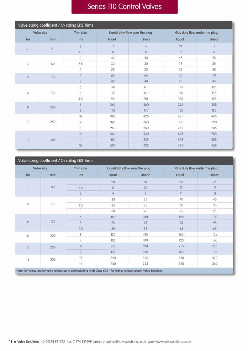
Valve sizing coefficient / Cv rating LR2 Trims
19
12
45
35
28
70
45
185
135
105
285
185
465
390
285
700
585
465
2
1.5
3
2.5
2
4
3
6
5
4.5
8
6
10
9
8
12
11
10
17
11
40
30
25
66
40
170
120
90
260
170
425
360
260
630
525
425
19
12
45
35
28
70
45
185
135
105
285
185
435
380
285
625
535
435
17
11
40
30
25
66
40
170
120
90
260
170
390
345
260
560
480
390
Valve size Trim size Liquid duty flow over the plug Gas duty flow under the plug
ins mm ins Equal Linear Equal Linear
Valve sizing coefficient / Cv rating LR3 Trims
3
4
6
8
10
12
80
100
150
200
250
300
25
17
11
40
30
25
120
95
65
165
120
255
165
420
360
3
2.5
2
4
3.5
3
6
5
4.5
8
7
10
9
12
11
20
13
9
35
25
20
100
75
55
135
100
210
135
340
295
25
17
11
40
30
25
120
95
65
165
120
255
165
390
340
20
13
9
35
25
20
100
75
55
135
100
210
135
320
280
Series 110 Control Valves
Note: CV values are for valve ratings up to and including ANSI Class 600 - for higher ratings consult Valve Solutions
15

Service backed by Experience l
UB - ΔP values for contoured / ported cage unbalanced trimB - ΔP values for low noise / ported cage balanced trim
Actuator Selection Guide
valve size
trimsize
act.size
ins
mm
ins
mm
loadBar
3/16
4.5
3/4, 1
20, 25
3/8,1/2
10,15
1/4
6
1
25
11/4
32
11/2
40
2
50
2
50
21/2
65
3
80
21/2
65
3
80
4
100
4
100
5
125
8
200
6
150
6
150
10
250
8
200
12
300
1
25
1/1/2, 2
40, 50
3
80
4
100
6, 8
150, 200
10, 12
250, 300
N/A
17
40
63
0.25
20
0.9
69
1.5
118
2.1
167
N/A
21
44
66
0.8
24
2
73
3.5
122
5
171
N/A
18
41
64
0.4
22
1.2
71
2
120
2.8
169
N/A
23
45
68
1.5
26.5
4.3
75
7
124
9.7
173
N/A
22
47
71
1
10
3.5
45
6.5
81
9
117
4
50
10
127
16
204
22
280
N/A
21
46
70
0.75
9
2.9
45
5
80
7
116
3
50
7.5
126
12
203
17
280
N/A
19
44
68
0.3
7
1.5
43
2.9
78
4
114
1.8
48
4.5
124
7
201
10
278
N/A
17
41
65
0.1
4
0.8
40
1.5
74
2.2
111
0.9
45
2.4
121
3.8
198
5.3
275
0.6
9
2.5
52
4.4
85
6.3
138
1.5
29
4.3
92
7
156
9.5
219
0.5
1.4
3.5
37
6.5
73
9
109
2.75
27
7.8
89
12.5
151
18
213
5
56
12.5
148
20
239
27.5
330
0.4
0.1
2.75
36
5
71
7
107
2
26
6
88
10
150
13.5
212
4
55
10
147
15
238
21
329
2
13
7
56
12
99
17
142
4
33
11
96
19
160
26
223
1.5
12
5.5
55
9
98
13
141
3
32
9
95
14.5
159
20
222
1.2
3.5
6
39
11
75
16
111
4.8
29
13
91
22
153
30
215
9
59
21
150
34
241
46
333
12
N/A
34
N/A
55
N/A
76
N/A
7.5
21
20
78
32
134
45
190
4.5
21
12
78
21
134
29
190
2.5
19
7.5
75
12
131
17
187
49
N/A
115
N/A
182
N/A
249
N/A
80
N/A
180
N/A
280
N/A
380
N/A
7.8
N/A
20
N/A
30
N/A
42
N/A
15
N/A
36
N/A
57
N/A
79
N/A
UB
B
UB
B
UB
B
UB
B
UB
B
UB
B
UB
B
UB
B
UB
B
UB
B
UB
B
UB
B
UB
B
UB
B
UB
B
UB
B
UB
B
UB
B
UB
B
UB
B
shut-off pressure in (bar)
1 1/8” / 28mmtravel
1 1/2” / 38mmtravel
2 1/2”/57mmtravel
3 1/2” / 90mmtravel
0.2
0.4
0.6
0.8
0.2
0.4
0.6
0.8
0.2
0.4
0.6
0.8
0.2
0.4
0.6
0.8
0.2
0.4
0.6
0.8
030
055
095
140
300
Series 110 Control Valves
16

l Valve Solutions tel: 01274 531992 fax: 01274 531995 email: [email protected] web: www.valvesolutions.co.uk
inch
1/2
3/4
1
1. 1/2
2
2. 1/2
3
4
6
8
10
12
14
16
18
mm
15
20
25
40
50
65
80
100
150
200
250
300
350
400
450
H
117
117
117
117
117
143
143
143
197
197
229
229
339
244
325
Z
53.97
53.97
53.97
53.97
53.97
71.44
71.44
71.44
90.42
90.42
90.42
90.42
90.42
90.42
146
140
140
140
159
168
203
203
206
276
292
390
390
490
622
700
222
222
222
292
284
327
327
357
391
435
632
673
822
927
1005
324
324
324
353
362
467
467
467
676
686
-
-
-
-
-
G
67
67
67
83
86
111
111
146
171
203
238
251
292
343
512
28
28
28
28
28
38
38
38
57
57
90
90
100
100
125
Valve size
184
184
184
223
254
276
299
352
451
543
673
737
890
1016
1153
190
194
197
235
267
292
318
368
473
568
708
775
927
1057
1194
203
206
210
251
286
311
337
394
508
610
752
819
972
1108
1251
ANSI 150PN 10, 16BS-10-D,E
ANSI 300PN 25, 40
BS-10-F, H, J
ANSI 600PN 64, 100BS-10-K, R
Bonnetmount
dia
Stem inup
position Standard Normalising Bellows
Stemtravel
Centreline to base
Lface to face (F)
Series 110 Control Valves
L
F
G
H
Z
Valve withStandard bonnet
Valve withBellow seal bonnet
Valve withNormalising bonnet
Height from centre line
Control Valve Standard Dimensions
L
G
F
H
H
L
G
F
17

Service backed by Experience l
Series 110 Severe Service Trims
Series 110 Severe Service TrimsThe Valve solutions range of severe service trim designs can be fitted within the Series 110 range to compliment the standard trim designs. These severe service trims can be manufactured from a wide range of materials including Ceramics and Tungsten Carbide.
The Severe service trims can also be engineered to fit in to existing control valves to provide solutions to current problems.Each control valve is specifically engineered to meet the process and operational requirements of the application.
18

l Valve Solutions tel: 01274 531992 fax: 01274 531995 email: [email protected] web: www.valvesolutions.co.uk
Series 110 Severe Service Trims
Trim Size 15 to 600 mm (1/2” to 24”)
Rating ANSI 150 to 2500 or equivalents to DIN, BS10, JIS etc
Trim Types Single cage, Multi-cage, Multi step, Multi-Stage, Special
Trim Material Stainless steel, Duplex stainless steel, 13% Chrome steel, Monel
Flow Characteristic Linear, Bi-linear, Tri-linear, Special
Hard Facings Stellited seating areas, stellited full contours, hard chrome plating
Hard Metal Tungsten Carbide, PSZ Ceramics, Advanced coatings
Specification
10 20 30 40 50 60 70 80 90 100
100
90
80
70
60
50
40
30
20
10
0
Flow
co-
effe
cien
t (Cv
)
Valve lift % of full lift
LIN
Characteristic Curves
The Inherent flow characteristic of a control valve is the relationship between the flow and the lift of the plug at a constant pressure drop.
The characteristics provided for severe service conrol valve designs are shown.
Linear - Flow is directly proportional to valve lift.
Bi-Linear - Flow is directly proportional to valve lift in two stages.
Tri-Linear - Flow is directly proportional to valve lift in three stages.
BI-LIN
TRI-LIN
Rangeability
Trim size
ins mm
All sizes All sizes Up to 150:1
<4 <100 50 : 1
4 to 12 100 to 300 70:1
>12 >300 85:1
All sizes All sizes 35:1
Standard rangeability
Severe ServiceTrim style
Multi Step
Single or Multi Cage
Multi Stage
l Designed for low noise gas / vapor applications.
l Designed to minimise energy dissipation to within acceptable levels.
l Hard metal options including tungsten carbide and ceramics for superior erosion resistance.
l Wide variety of trim design options based on extensive operational experience.
l Special trims designed to suit specific applications.
l Designed to eliminate cavitation and reduce associated noise and premature damage on liquid applications
Design Features
l Produced with Quality Systems accredited to ISO 9001:2008
l CE marked in accordance with European Pressure Equipment Directive 97/23/EC and ATEX compliant with European directive 94/9/EC.
l Full material certification available for all major component parts.
l Full guarantee on design and performance.
l All testing performed to the requirements of ANSI B16.34.
Quality and Performance Guarantee
19

Service backed by Experience l
Series 110 Severe Service Trims
Multi Step Trim Design
l Suitable for low capacity high pressure drop applications.
l Up to 5 stages of pressure let down.
l Uses a large number of changes of direction to achieve pressure reduction.
l Pressure staging designs available.
l Hard metal material options available.
l High rangeability capability.
Multi Step Trim Designs
Single and Multi Cage Trim Design
l Used for medium to high pressure drop applications.l Designs up to 4 cages available as standard.l Uses principle of splitting the total flow into a large number of small streams together with changes of direction to achieve pressure reduction.l Single stage cage trim design for ‘flashing applications’.
l Can be designed for new or retrofit valve applications.
l Provides anti cavitation characteristics for liquid applications.
l Provides low noise characteristics for gas and vapour fluids.
l Hard metal material options available.
l Balanced plug designs available.
20
Cage Trim Design
l Valve Solutions tel: 01274 531992 fax: 01274 531995 email: [email protected] web: www.valvesolutions.co.uk
Series 110 Severe Service Trims
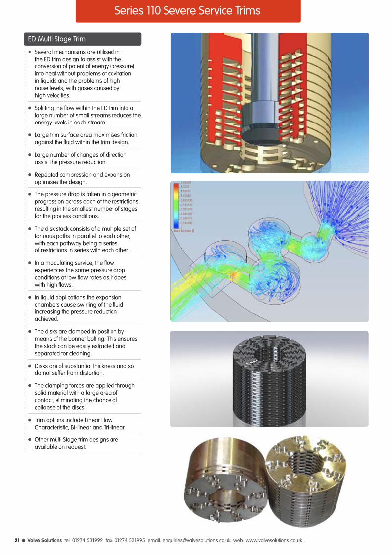
ED Multi Stage Trim
• Several mechanisms are utilised in the ED trim design to assist with the conversion of potential energy (pressure) into heat without problems of cavitation in liquids and the problems of high noise levels, with gases caused by high velocities.
l Splitting the flow within the ED trim into a large number of small streams reduces the energy levels in each stream.
l Large trim surface area maximises friction against the fluid within the trim design.
l Large number of changes of direction assist the pressure reduction.
l Repeated compression and expansion optimises the design.
l The pressure drop is taken in a geometric progression across each of the restrictions, resulting in the smallest number of stages for the process conditions.
l The disk stack consists of a multiple set of tortuous paths in parallel to each other, with each pathway being a series of restrictions in series with each other.
l In a modulating service, the flow experiences the same pressure drop conditions at low flow rates as it does with high flows.
l In liquid applications the expansion chambers cause swirling of the fluid increasing the pressure reduction achieved.
l The disks are clamped in position by means of the bonnet bolting. This ensures the stack can be easily extracted and separated for cleaning.
l Disks are of substantial thickness and so do not suffer from distortion.
l The clamping forces are applied through solid material with a large area of contact, eliminating the chance of collapse of the discs.
l Trim options include Linear Flow Characteristic, Bi-linear and Tri-linear.
l Other multi Stage trim designs are available on request.
21
Service backed by Experience l
Series 130 Control Valves
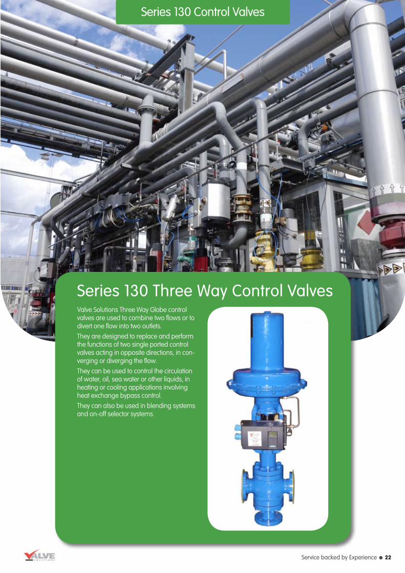
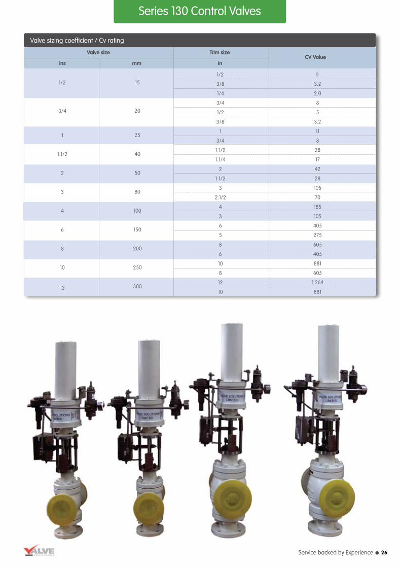
Series 130 Three Way Control ValvesValve Solutions Three Way Globe control valves are used to combine two flows or to divert one flow into two outlets. They are designed to replace and perform the functions of two single ported control valves acting in opposite directions, in con-verging or diverging the flow.They can be used to control the circulation of water, oil, sea water or other liquids, in heating or cooling applications involving heat exchange bypass control.They can also be used in blending systems and on-off selector systems.
22

l Valve Solutions tel: 01274 531992 fax: 01274 531995 email: [email protected] web: www.valvesolutions.co.uk
Series 130: Control valve with finned bonnet and direct actuator
Series 130: Control valve with standard bonnet and reverse actuator
Design Code ASME B16-34
Valve Size 15 to 300 mm (1/2” to 12”)
Rating ANSI 150 to 600 or equivalents to BS10, DIN, JIS etc
End Connection Flanged, Butt Weld
Body Material Carbon steel, Chrome moly steel, Stainless steel, Monel, Alloy 20, Hastelloy B/C, Duplex stainless steel, Aluminium bronze
Bonnet Standard up to 400°C, Normalising between 250°C to 500°C, Extended cold service -20°C to -100°C, Cryogenic -100°C to -250°C Bellowseal
Gland Packing PTFE Chevrons, Graphite, Low emission
Trim Forms Skirt Guided, Linear, Pressure balanced
Trim Material Stainless steel, Duplex stainless steel, 13% Chrome steel, Monel, Hastelloy B/C, Stellite
SpecificationFlow Characteristic Linear
Seat Leakage As per FCI 70 2 Class III, IV, V and VI
Actuator Form Diaphragm, Piston, Electric
Actuator Type Direct / Reverse Acting Direct acting air failure “Close” top port. Reverse acting air failure “Opens” top port
Diaphragm Nitrile / Neoprene (nylon reinforced)
Spring Range 3-15 PSIG (0.2 - 1.0 Bar) 6-30 PSIG (0.4 - 2.0 Bar)
Air Supply 20-60 PSIG (1.4 - 4.0 Bar)
Air Connection 1/4” or 1/2” NPT
Accessories Valve Positioners - Pneumatic, Electro-Pneumatic, Smart Instruments - Airset, Solenoid Valve, Volume Booster, Airlock, Limit Switches Features - Top or Side Mounted handwheel, Limit Stops Steam Jacketting etc
Series 130 Control Valves
l High flow capacity and rangeability.
l Heavy duty stems.
l Wide range of interchangeable trim sizes.
l Wide selection of actuators to meet most system requirements.
l Comprehensively designed and tested to ensure optimum performance.
Design Features
l Quality Systems accredited to ISO 9001 : 2008 by Bureau Veritas and “CE” marked in accordance with Pressure Equipment Directive 97/23/EC by Lloyds Register and Regulations.
l Full material certification available for all major component parts.
l Rigorous proven on-site performance.
l Full guarantee on design and performance.
l All testing performed to the requirements of ASME B16.34.
Quality and Performance Guarantee
23
Service backed by Experience l
Series 130 Control Valves
Maximum recommended valve body velocity for liquid flows
Valve size
Valve body material
Carbon steel Alloy steel Aluminium Bronze
ins mm m/s m/s m/s
1 to 2 25 to 50 10.5 12.0 7.0
3 to 8 80 to 200 9.0 10.0 6.5
10 to 12 250 to 300 6.0 8.0 5.5
Trim Style
Linear
inch
1/4 to 3/4
1 to 3
4 to 12
mm
6 to 20
25 to 80
100 to 300
Rangeability
35 : 1
50 : 1
60 : 1
Trim size
Rangeability
Maximum Maximum Maximum outlet mach No. for
Inlet velocity Outlet velocity predicted noise level
Maximum recommended valve body velocity for gas/vapor flows
Valve size
ins mm m/s m/s 95dBA 95dBA 85dBA
1/2 to 2 15 to 50 95 220 0.65 0.5 0.3
3 and 4 80 and 100 85 220 0.65 0.5 0.3
6 and 8 150 and 200 75 220 0.65 0.5 0.3
10 and 12 250 and 350 60 220 0.65 0.5 0.3
10 20 30 40 50 60 70 80 90 100
100
90
80
70
60
50
40
30
20
10
0
Flow
% o
f max
imum
Valve lift % of full lift
LIN
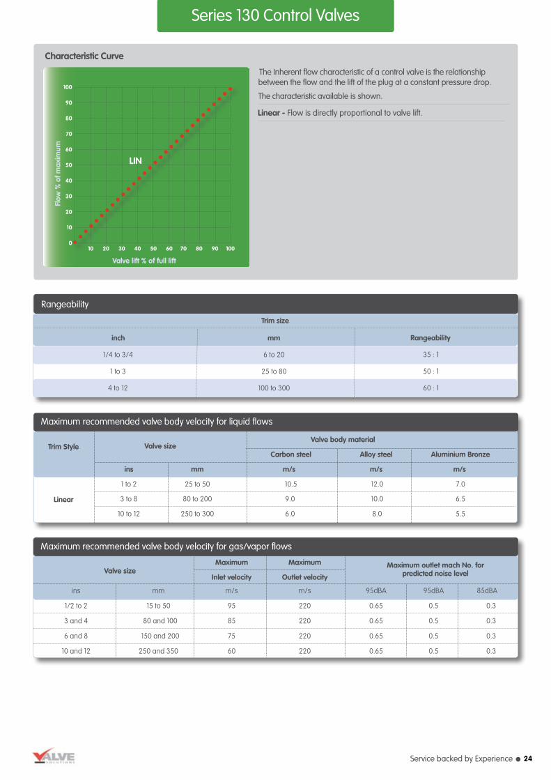
Characteristic Curve
The Inherent flow characteristic of a control valve is the relationship between the flow and the lift of the plug at a constant pressure drop.
The characteristic available is shown.
Linear - Flow is directly proportional to valve lift.
24
l Valve Solutions tel: 01274 531992 fax: 01274 531995 email: [email protected] web: www.valvesolutions.co.uk
Series 130 Control Valves
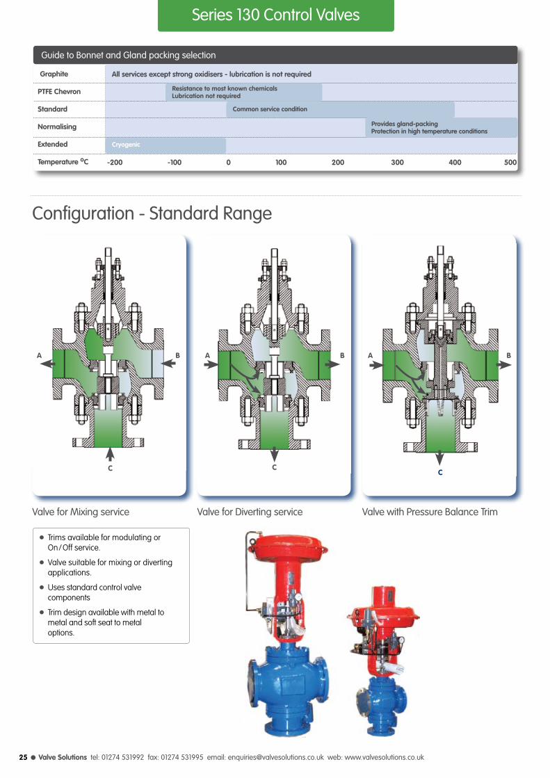
l Trims available for modulating or On/Off service.
l Valve suitable for mixing or diverting applications.
l Uses standard control valve components
l Trim design available with metal to metal and soft seat to metal options.
Guide to Bonnet and Gland packing selection
Graphite
PTFE Chevron
Standard
Normalising
Extended
Temperature oC -200 -100 0 100 200 300 400 500
All services except strong oxidisers - lubrication is not required
Resistance to most known chemicals Lubrication not required
Common service condition
Cryogenic
Provides gland-packing Protection in high temperature conditions
Configuration - Standard Range
Valve for Mixing service Valve for Diverting service Valve with Pressure Balance Trim
A
C
B A
C
BA
C
B
25
Service backed by Experience l
Series 130 Control Valves
Series 130 Control Valve
Valve size Trim size CV Value
ins mm in
Valve sizing coefficient / Cv rating
1/2
3/4
1
1.1/2
2
3
4
6
8
10
12
15
20
25
40
50
80
100
150
200
250
300
1/2
3/8
1/4
3/4
1/2
3/8
1
3/4
1.1/2
1.1/4
2
1.1/2
3
2.1/2
4
3
6
5
8
6
10
8
12
10
5
3.2
2.0
8
5
3.2
11
8
28
17
42
28
105
70
185
105
405
275
605
405
881
605
1,264
881
26

l Valve Solutions tel: 01274 531992 fax: 01274 531995 email: [email protected] web: www.valvesolutions.co.uk
Valve size
ANSI 150NP 10, 16BS-10-D,E
ANSI 300NP 25, 40
BS-10-F, H, J
ANSI 600NP 64, 100BS-10-K, R
Bonnetmount
DIA
Stem inup
position standard normalising bellow
Height from centre lineStemtravel
Centreline to base
L
Series 130 - 3 Way Valve Standard Dimensions
Z
G
L
H
F
H
L
F
G
L
G
H
F
inch
1/2
3/4
1
1 1/2
2
2 1/2
3
4
6
8
10
12
mm
15
20
25
40
50
65
80
100
150
200
250
300
H
117
117
117
117
117
143
143
143
197
197
229
229
Z
53.97
53.97
53.97
53.97
53.97
71.44
71.44
71.44
90.42
90.42
90.42
90.42
140
140
140
159
168
203
203
206
276
292
390
390
222
222
222
292
284
327
327
357
391
435
632
673
324
324
324
353
362
467
467
467
676
686
-
-
G
156
156
156
160
178
198
232
270
352
418
440
455
28
28
28
28
28
38
38
38
57
57
90
90
184
184
184
223
254
276
299
352
451
543
673
737
203
206
210
251
286
311
337
394
508
610
752
819
190
194
197
235
267
292
318
368
473
568
708
775
Series 130 Control Valves
face to face (F)
27
Valve withStandard Bonnet
Valve withBellow Seal Bonnet
Valve withNormalising Bonnet

Service backed by Experience l
Series 170 Angle Control and Choke Valves The Series 170 Control Valve product range emulates the Series 110 design except that the valve body is an angle type constitution instead of a globe style.This range of control valves can be fitted with the same trim design options as the Series 110 product. It is used where the pipework configuration necessitates an angle pattern design.The Series 170 can also be adapted to
the choke valve application and again fitted with a selection of trim designs to suit each application in conjunction with the angle body configuration.This range can be fitted with standard and severe service trim designs.In conjunction with this the trims could be supplied manufactured in hard metal for potentially erosiveapplications.
Series 170 Angle, Control and Choke Valves
28

l Valve Solutions tel: 01274 531992 fax: 01274 531995 email: [email protected] web: www.valvesolutions.co.uk
Design Code ASME B16-34
Valve Size 5 to 300 mm (1” to 12”)
Rating ANSI 150 to 2500 or equivalents to BS10, DIN, JIS etc
End Connection Flanged, Hubbed, Butt Weld, Socket Weld, Screwed
Body Material Carbon steel, Chrome moly steel, Stainless steel, Monel, Alloy 20, Hastelloy B/C, Duplex stainless steel, Aluminium bronze
Bonnet Standard up to 400°C, Normalising between 250°C to 500°C, Extended cold service -20°C to -100°C, Cryogenic -100°C to -250°C, Bellowseal
Gland Packing PTFE Chevrons, Graphite, Low emission
Trim Forms Top guided contoured, Spline Micro Flow Ported cage (balanced / unbalanced) Low Noise (LR1, LR2, LR3, LR4)
Trim Material Stainless steel, Duplex stainless steel, 13% Chrome steel, Monel, Hastelloy B/C, Stellite
SpecificationFlow Characteristic Equal percentage, Linear, Quick opening
Seat Leakage As per ANSI/ FCI 70.02-2006 Class III, IV, V and VI
Actuator Form Diaphragm, Cylinder, Electric
Actuator Type Direct / Reverse Acting Direct acting air failure “Close” top port. Reverse acting air failure “Opens” top port
Diaphragm Nitrile / Neoprene (nylon reinforced)
Spring Range 3-15 PSIG (0.2 - 1.0 Bar) 6-30 PSIG (0.4 - 2.0 Bar)
Air Supply 20-60 PSIG (1.4 - 4.0 Bar)
Air Connection 1/4” or 1/2” NPT
Accessories Valve Positioners - Pneumatic, Electro-Pneumatic, Smart
Instuments - Airset, Solenoid Valve, Volume Booster, Airlock, Limit Switches
Features - Top or Side Mounted handwheel, Limit Stops Steam Jacketting etc
l High flow capacity and rangeability.
l Large variety of trim designs.
l Top entry for ease of inspection and maintenance.
l Designed with clamped seat and trim configuration.
l Unbalanced or balanced plug design options to achieve specified leakage requirements.
l Bolts located outside of the piping stress area to eliminate gasket crush problems.
l Wide selection of actuators to meet most system requirements.
l Rigorous proven on-site performance.
Design Features
l Produced with Quality Systems accredited to ISO 9001 : 2008 by Bureau Veritas and “CE” marked in accordance with Pressure Equipment Directive and Regulations by Lloyd’s Register.
l Full material certification available for all major component parts.
l Full guarantee on design and performance.
l All testing performed to the requirements of ANSI B16.34.
Quality and Performance Guarantee
Series 170 Angle Control Valves
29

Service backed by Experience l
Series 170 Angle Control Valves
Rangeability
Trim size
Standard rangeability
Contoured Cage trim
ins mm
1/2” and 3/4” 15 and 20 40 : 1 35 : 1
1 to 3 25 to 80 55 : 1 50 : 1
4 to 18 100 to 450 70 : 1 70 : 1
Spline Micro All sizes Up to 400:1
10 20 30 40 50 60 70 80 90 100
100
90
80
70
60
50
40
30
20
10
0
Flow
co-
effe
cien
t (Cv
)
Valve lift % of full lift
QO
LIN
Equal %
Characteristic Curves
The Inherent flow characteristic of a control valve is the relationship between the flow and the lift of the plug at a constant pressure drop.
The characteristic normally available, are shown.
Linear - Flow is directly proportional to valve lift.
Equal % - Flow change by a constant percentage of its instantaneous value for each unit of valve lift.
Quick opening - Flow increases rapidly with initial travel reaching near its maximum at a low lift.
Valve size
Valve body material
Carbon steel Alloy steel Aluminium bronze
ins mm m/s m/s m/s
1/2 to 2 15 to 50 12.5 14.0 8.0
3 to 8 80 to 200 10.5 11.0 6.5
1 to 12 25 to 300 13.1 15.8 8.0
12 to 18 350 to 450 10.7 13.1 6.5
Maximum recommended valve body velocity for liquid flows
Trim style
Contoured
Cage Guided
Maximum Maximum Maximum outlet mach No. for
Inlet velocity Outlet velocity predicted noise level
ins mm m/s m/s
1/2 to 2 15 to 50 105 253
>95dBA <95dBA <85dBA
3 and 4 80 and 100 90 253
0.65 0.5 0.3
6 and 8 150 to 200 85 253
0.65 0.5 0.3
1 to 18 25 to 450 68 253
0.65 0.5 0.3
0.65 0.5 0.3
Maximum recommended valve body velocity for gas/vapor flows
Valve sizeTrim style
Contoured
Cage Guided
30

l Valve Solutions tel: 01274 531992 fax: 01274 531995 email: [email protected] web: www.valvesolutions.co.uk
Series 170 Choke Valves
Design Code ASME B16-34
Valve Size 5 to 300 mm (1” to 12”)
Rating ANSI 150 to 2500 API 3000 to 10000
End Connection Flanged, Hubbed
Body Material Carbon steel, Chrome moly steel, Stainless steel, Duplex stainless steel,
Bonnet Standard
Gland Packing PTFE Chevrons, Graphite, Low emission
Trim Forms Ported cage (balanced / unbalanced) Low Noise (LR1, LR2, LR3, LR4)
Trim Material Stainless steel, Duplex stainless steel, 13% Chrome steel, Stellite, Tungsten Carbide, Ceramics
Flow Characteristic Equal percentage, Linear,
Seat Leakage As per ANSI / FCI 70.02-2006 Class III, IV, V and VI
SpecificationActuator Form Diaphragm, Piston, Electric, Stepping
Actuator Type Direct / Reverse Acting Direct acting air failure “Close” top port. Reverse acting air failure “Opens” top port
Diaphragm Nitrile / Neoprene (nylon reinforced)
Spring Range 3-15 PSIG (0.2 - 1.0 Bar) 6-30 PSIG (0.4 - 2.0 Bar) Further range available for piston actuator
Air Supply 20-60 PSIG (1.4 - 4.0 Bar)
Air Connection 1/4” or 1/2” NPT
Accessories Valve Positioners - Pneumatic, Electro-Pneumatic, Smart
Instruments - Airset, Solenoid Valve, Volume Booster, Airlock, Limit Switches
Features - Top or Side Mounted handwheel, Limit Stops Steam Jacketting etc
l High flow capacity and rangeability.
l Large variety of trim designs.
l Top entry for ease of inspection and maintenance.
l Designed with clamped seat and trim confuguration.
l Hard metal trim materials available..
l Unbalanced or balanced plug design options to acheive specified leakage requirements.
l Bolts located outside of the piping stress area to eliminate gasket crush problems.
l Wide selection of actuators to meet most system requirements.
l Rigorous proven on-site performance.
Design Features
l Quality Systems accredited to ISO 9001 : 2008.
l Full material certification available for all major component parts.
l Full guarantee on design and performance.
l All testing performed to the requirements of ANSI B16.34.
Quality and Performance Guarantee
31

Service backed by Experience l
Series 170 Choke Valves
10 20 30 40 50 60 70 80 90 100
100
90
80
70
60
50
40
30
20
10
0
Flow
co-
effe
cien
t (Cv
)
Valve lift % of full lift
LIN
Equal %
Characteristic Curves
The Inherent flow characteristic of a control valve is the relationship between the flow and the lift of the plug at a constant pressure drop.
The characteristic normally available, are shown.
Linear - Flow is directly proportional to valve lift.
Equal % - Flow change by a constant percentage of its instantaneous value for each unit of valve lift.
Valve size
Valve body material
Carbon steel Alloy steel
ins mm m/s m/s
1 to 12 25 to 300 13.1 15.8
Maximum recommended valve body velocity for liquid flows
Trim style
Cage Guided
32
Rangeability
Trim size
Standard Rangeability
Cage Trim Multi Stage Trim
ins mm
1 to 3 25 to 80 50 : 1 40 : 1
4 to 12 100 to 300 60 : 1 50 : 1
Spline Micro All sizes Up to 400:1
Maximum Maximum Maximum outlet mach No. for
Inlet velocity Outlet velocity predicted noise level
mm m/s m/s
BA
1 to 12 25 to 300 68 253 0.65 0.5 0.3 0.65 0.5 0.3
Maximum recommended valve body velocity for gas/vapor flows
Valve sizeTrim style
Cage Guided
95dBA <95dBA <85dB

l Valve Solutions tel: 01274 531992 fax: 01274 531995 email: [email protected] web: www.valvesolutions.co.uk
Series 600
SpecificationDesign Code ASME B16-34
Valve Size 15 to 150 mm (1/2” to 6”)
Valve Type Direct or Pilot Operated
Rating ANSI 150 and 300, Higher on request
End Connection Flanged – 15mm to 150mm (1/2” to 6”) Screwed – 15mm to 50mm (1/2” to 2”)
Body Material Carbon steel, Chrome-moly steel, Stainless steel, Monel, Alloy 20, Hastelloy B/C, Duplex stainless steel, Aluminium bronze
Trim Material Stainless steel, Duplex stainless steel, 13% Chrome steel, Monel Hastelloy B/C, Stellite
Diaphragm Neoprene, Natural rubber, Nitrile, EDPM, Viton, Teflon.
Max. Temperature As per the diaphragm limitations.
Seat Leakage As per FCI-70-2 Class IV, V and VI
Downstream Pressure Regulating ValvesSeries 600Downstream Pressure regulating valves are self contained, Self Operated control devices, which use energy from the controlled system to operate and regulate pressures.Valve Solutions manufactures a variety of pressure reducing regulators to manage downstream system pressures in low, medium, high flow applications, model
features a diaphragm type, piston typeor combination of both to suit different applications. A pressure reducing regulator maintains a desired reduced outlet pressure while providing the required fluid flow to satisfy a variabledownstream demand. The valve at which the reduced pressure is maintained is the outlet pressure setting of the regulator.
l Reduces higher inlet pressure to a constant lower outlet pressure.
l Outlet pressure is accurate over a wide range of flows.
l Pilot-operated main valve is not subject to pressure fall off characteristic of direct-acting PRV’s.
l Outlet pressure is adjustable over complete range of control spring.
l Range of body and diaphragm material combinations to meet the majority of requirements.
l IBR certification in Form III C available.
l Designed ruggedly to withstand shocks.
l Simple and economic design.
l Operates automatically off line pressure.
l Heavy-duty, nylon reinforced diaphragm.
l Round-shaped, soft seat seal provides drip-tight class VI closure.
l Diaphragm assembly guided top and bottom.
l Throttling seat retainer for flow and pressure stability.
l Easily maintained without removal from the line.
l Pressure adjustment by single adjusting screw.
l Replaceable seat ring.
l Produced with Quality Systems accredited to ISO 9001 : 2000
l Full material certification available for all major component Parts.
Quality and Performance GuaranteeDesign Features
l Full guarantee on design and Performance.
l All testing performed to the requirements of ANSI B16.34.
33

Service backed by Experience l
Series 600
Regulator Types
All types of regulators generally fit in to one of the following two basic categories.1 Direct Operated2 Pilot Operated
The specific considerations particular to your control needs are to be carefully studied andunderstood to determine which method of control is the
better choice. Regulators when compared to control Valve / Instrument package have their advantages and limitations. The table below lists selected
characteristics of both.The operational principal of both types of regulators is explained as follows.
B Pilot OperatedA pilot operated system uses a two-path control. In two path control, the main valvediaphragm responds quickly to downstream pressure changes, causing an immediate correction in the main valve position. At the same time, the pilot diaphragm diverts some ofthe reduced inlet pressure to the other side of the valve diaphragm, control the final positioning
A Direct OperatedIn operation, a directoperated, pressure reducing regulator senses the downstream pressure through either internal pressure registration or an external control line. This downstream pressure opposes a spring which moves the diaphragm and valve plug to change the size of the flow path
through the regulator.Characteristically direct operator regulators are adequate for narrow-range control, and where the allowable change in output pressure can be 10 to 20% of the outlet pressure setting. This 10 to 20% is typical although finer control can be achieved depending on the specific application requirement.
of the main valve plug. Two-path control result in fast response.Pilot-operated regulators are preferred for broad-range control, or where the allowable change in outlet pressure is required to be less than 10 percent of the outlet pressure setting. They are also commonly used when remote set point adjustment is required for a regulatorapplication.
Diaphragm
Spring
Plug
Externalcontrol line
Pilot springPilot diaphragm
Pilot valveplug
Main valve springMain valve diaphragm
Main valve plug
Selected Regulator Characteristics
l Purchase price, installation and maintenance costs are normally lower.
l Requires no additional power sources for basic operation.
lLess complex, and often lighter and more compact.
lController, which provides fixed-band proportional control only, is built in.
Selected Control Valve / Instrument Characteristics
lWide variety of construction material and accessories available. Transmitting and controlling instruments are separate and may be remote mounted.
lSpecific construction has broad application flexibility.
lSeparate controller allows for adjustable-band proportional control with reset and/or rate optional for excellent control response.
Table: Regulator Vs. Control Valve / Instrument
34

l Valve Solutions tel: 01274 531992 fax: 01274 531995 email: [email protected] web: www.valvesolutions.co.uk
Series 700
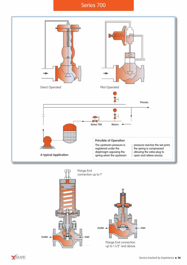
Upstream Pressure Regulating Valves - Series 700These are self operated upstream pressure regulating control valves, used in many applications for limiting pressure buildup (i.e. prevent overpressure) at its location in the pressure system. The valve opens in proportion to the inlet pressure preventing a rise of
internal pressure in excess of a specified value. These valves are used on a wide range of applications in the chemical process industry for up-stream pressure control,eg: Refineries, Fertiliser and Petrochemical Plants, Pharmaceutical and Food Processing Plants.
SpecificationDesign Code ASME B16-34
Valve Size 15 to 150 mm (1/2” to 6”)
Valve Type Direct or Pilot Operated
Rating ANSI 150 and 300, Higher on request
End Connection Flanged – 15mm to 150mm (1/2” to 6”) Screwed – 15mm to 50mm (1/2” to 2”)
Body Material Carbon steel, Chrome-moly steel, Stainless steel, Monel, Alloy 20, Hastelloy B/C, Duplex stainless steel, Aluminium bronze
Trim Material Stainless steel, Duplex stainless steel, 13% Chrome steel, Monel Hastelloy B/C, Stellite
Diaphragm Neoprene, Natural rubber, Nitrile, EDPM, Viton, Teflon.
Max. Temperature As per the diaphragm limitations.
Seat Leakage As per FCI-70-2 Class IV, V and VI
l Produced with Quality Systems accredited to ISO 9001 : 2000 (Certificate No. 208920) by Bureau Veritas.
l Full material certification available for all major component Parts.
l Glandless Construction: Where positive Zero gland packing is required, the design scores over conventional solutions such as bellow seals etc. as the gland itself is eliminated.
l Wide range of body sizes and trim sizes to satisfy varied flow requirements.
l Full guarantee on design and performance.
l All testing performed to the requirements of ANSI B16.34.
Selected Regulator Characteristics
lPurchase price, installation and maintenance costs are normally lower.
lRequires no additional power sources for basic operation
lLess complex, and often lighter and more compact.
lController, which provides fixed-band proportional control only, is built in.
Selected Control Valve / Instrument Characteristics
lWide variety of construction material and accessories available. Transmitting and controlling instruments are separate and may be remote mounted.
lSpecific construction has broad application flexibility.
lSeparate controller allows for adjustable-band proportional control with reset and/or rate optional for excellent control response.
Regulator Vs. Control Valve / Instrument
l Tight sensitively and stability of controlled pressure.
l Provides excellent tight shut off capability over long working life.
l Compact design with minimum number of moving parts.
l Simple resetting.
Design Features Quality and Performance Guarantee
35
Service backed by Experience l
Series 700
Direct Operated Pilot Operated
A typical Application
Series 700 Return
Process
Flange End connection up to 1”
Flange End connection up to 1.1/2” and above
Outlet Inlet
Outlet Inlet
The upstream pressure is registered under the diaphragm opposing the spring when the upstream
pressure reaches the set point, the spring is compressed allowing the valve plug to open and relieve excess.
Princible of Operation
36
l Valve Solutions tel: 01274 531992 fax: 01274 531995 email: [email protected] web: www.valvesolutions.co.uk
Series 117
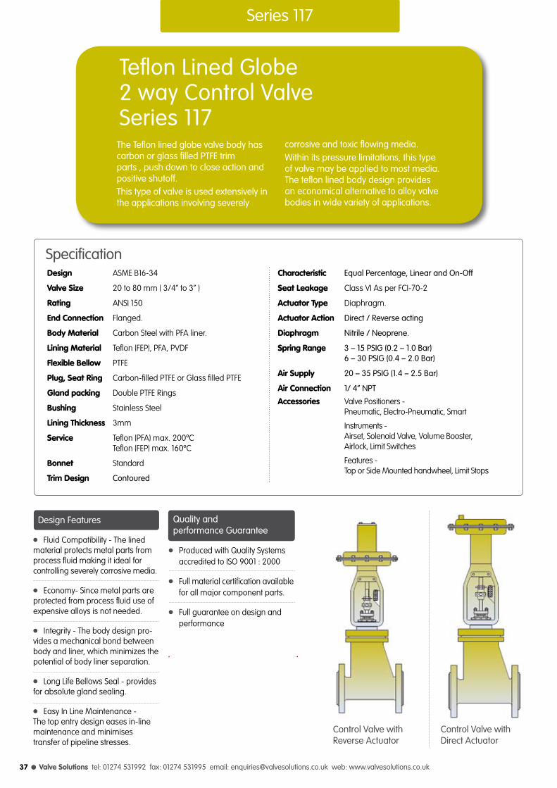
Teflon Lined Globe 2 way Control ValveSeries 117
The Teflon lined globe valve body has carbon or glass filled PTFE trimparts , push down to close action and positive shutoff.This type of valve is used extensively in the applications involving severely
corrosive and toxic flowing media. Within its pressure limitations, this type of valve may be applied to most media. The teflon lined body design provides an economical alternative to alloy valve bodies in wide variety of applications.
SpecificationDesign ASME B16-34
Valve Size 20 to 80 mm ( 3/4” to 3” )
Rating ANSI 150
End Connection Flanged.
Body Material Carbon Steel with PFA liner.
Lining Material Teflon (FEP), PFA, PVDF
Flexible Bellow PTFE
Plug, Seat Ring Carbon-filled PTFE or Glass filled PTFE
Gland packing Double PTFE Rings
Bushing Stainless Steel
Lining Thickness 3mm
Service Teflon (PFA) max. 200ºC Teflon (FEP) max. 160ºC
Bonnet Standard
Trim Design Contoured
Characteristic Equal Percentage, Linear and On-Off
Seat Leakage Class VI As per FCI-70-2
Actuator Type Diaphragm.
Actuator Action Direct / Reverse acting
Diaphragm Nitrile / Neoprene.
Spring Range 3 – 15 PSIG (0.2 – 1.0 Bar) 6 – 30 PSIG (0.4 – 2.0 Bar)
Air Supply 20 – 35 PSIG (1.4 – 2.5 Bar)
Air Connection 1/ 4” NPT
Accessories Valve Positioners - Pneumatic, Electro-Pneumatic, Smart
Instruments - Airset, Solenoid Valve, Volume Booster, Airlock, Limit Switches
Features - Top or Side Mounted handwheel, Limit Stops
l Produced with Quality Systems accredited to ISO 9001 : 2000
l Full material certification available for all major component parts.
l Full guarantee on design and performance
l Fluid Compatibility - The lined material protects metal parts from process fluid making it ideal for controlling severely corrosive media.
l Economy- Since metal parts are protected from process fluid use of expensive alloys is not needed.
l Integrity - The body design pro-vides a mechanical bond between body and liner, which minimizes the potential of body liner separation.
l Long Life Bellows Seal - provides for absolute gland sealing.
l Easy In Line Maintenance - The top entry design eases in-line maintenance and minimises transfer of pipeline stresses.
Control Valve withDirect Actuator
Control Valve withReverse Actuator
Design Features Quality and performance Guarantee
37

Service backed by Experience l
ins
3/4
1
1.1/2
2
3
mm
20
25
40
50
80
ins
1/23/4
1/23/4
1
1.1/41.1/2
1.1/22
2.1/23
mm
1520
152025
3240
4050
6580
equal % & linear
58
5810
25
2545
5595
Valve sizing co-efficient Cv rating
Valve Size Trim Size Cv Value
Series 117
Control Valve withDirect Actuator
Control Valve withReverse Actuator
H
A
H2 H2
H
A
F/F F/F
øD øD
Series 117 Standard Dimensions
Valve size F / F A
20 184 184
25 184 184
40 229 190
50 231 220
80 310 310
Actuator Effective Bonnet Travel øD H H1 H2 H3 Model inch2 Mount Dia.
PDC - 030 30 54 14.3 218 -- 375 -- 559
PDO - 030 30 54 14.3 218 400 -- 584 --
PDC - 030 30 54 14.3 218 -- 375 -- 559
PDO - 030 30 54 14.3 218 400 -- 584 --
PDC – 055 55 54 28 286 -- 510 -- 565
PDO - 055 55 54 28 286 510 -- 700 --
PDC - 055 55 54 28 286 -- 510 -- 730
PDO - 055 55 54 28 286 510 -- 730 --
PDC - 095 95 71.5 38 371 -- 600 -- 910
PDO - 095 95 71.5 38 371 600 -- 910 --
l PDC - Reverse Acting Actuator ( used on supply failure Valve – Closes l PDO - Direct Acting Actuator ( used on supply failure Valve – Opens )l All dimensions in mm.
38
l Valve Solutions tel: 01274 531992 fax: 01274 531995 email: [email protected] web: www.valvesolutions.co.uk
Series 119
Specification
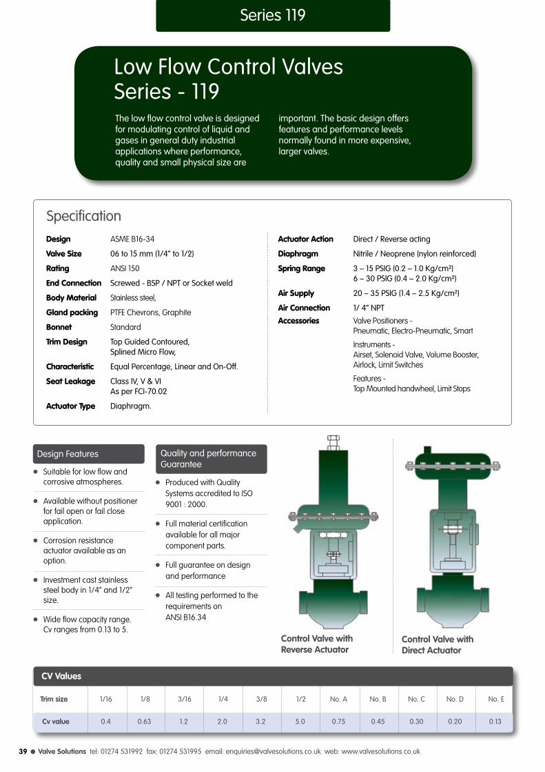
Low Flow Control ValvesSeries - 119
Design ASME B16-34
Valve Size 06 to 15 mm (1/4” to 1/2)
Rating ANSI 150
End Connection Screwed - BSP / NPT or Socket weld
Body Material Stainless steel,
Gland packing PTFE Chevrons, Graphite
Bonnet Standard
Trim Design Top Guided Contoured, Splined Micro Flow,
Characteristic Equal Percentage, Linear and On-Off.
Seat Leakage Class IV, V & VI As per FCI-70.02
Actuator Type Diaphragm.
The low flow control valve is designed for modulating control of liquid andgases in general duty industrial applications where performance, quality and small physical size are
important. The basic design offers features and performance levels normally found in more expensive, larger valves.
Actuator Action Direct / Reverse acting
Diaphragm Nitrile / Neoprene (nylon reinforced)
Spring Range 3 – 15 PSIG (0.2 – 1.0 Kg/cm²) 6 – 30 PSIG (0.4 – 2.0 Kg/cm²)
Air Supply 20 – 35 PSIG (1.4 – 2.5 Kg/cm²)
Air Connection 1/ 4” NPT
Accessories Valve Positioners - Pneumatic, Electro-Pneumatic, Smart
Instruments - Airset, Solenoid Valve, Volume Booster, Airlock, Limit Switches
Features - Top Mounted handwheel, Limit Stops
l Produced with Quality Systems accredited to ISO 9001 : 2000.
l Full material certification available for all major component parts.
l Full guarantee on design and performance
l All testing performed to the requirements on ANSI B16.34
l Suitable for low flow and corrosive atmospheres.
l Available without positioner for fail open or fail close application.
l Corrosion resistance actuator available as an option.
l Investment cast stainless steel body in 1/4” and 1/2” size.
l Wide flow capacity range. Cv ranges from 0.13 to 5.
CV Values
Trim size 1/16 1/8 3/16 1/4 3/8 1/2 No. A No. B No. C No. D No. E
Cv value 0.4 0.63 1.2 2.0 3.2 5.0 0.75 0.45 0.30 0.20 0.13
Control Valve withDirect Actuator
Control Valve withReverse Actuator
Design Features Quality and performance Guarantee
39

Service backed by Experience l 40
Series 400
Diaphragm Control ValvesSeries 400The Diaphragm Valve is essentially a simple pinch clamp, closed by pressing a flexible diaphragm against transverse weir, when fully closed, the diaphragm seats against the weir providing a leak tight closure.
The diaphragm valves are recommended for handling sticky and viscous fluids, slurries and highly corrosive and hazardous substances and other hard to handle mediums or where tight closure is
prime factor. It is the most ideal valve to handle fluids that require high purity and should remain free from contamination.
The Diaphragm Valve is a simple pinch type valve and of low pressure type because of large area of diaphragm and is extensively used for both On/Off and throttling services and finds its application in Waste and Water Treatment Plants, Filtration Plants, Chlorination Plants etc.
SpecificationDesign Confirm to BS 5156
Body Type Weir (Lined or Unlined)
Valve Size 15mm to 300mm (1/2” to 12”)
End Connection ANSI B 16.1 Class 150
Body Material Cast Iron (IS 210 grade FG 200) Cast Steel, Other alloys on request.
Lining Material Ebonite, PVDF, PFA, PP, EPDM, Glass etc.
Lining Hardness Ebonite-95 ± 5 Shore A Natural/Neo Rubber-55 ± 5 Shore A Teflon-Rockwell/Shore R100 D78 or D62 Glasslining and FRP-Parcol Parcol 40 Respectively.
Lining Thickness 15 to 65 mm Valve - 3.0 mm 80 to 100 mm Valve - 3.5 mm 125 to 150 mm Valve - 4.0 mm 200 to 300 mm Valve - 5.0 mm Teflon Coating Thickness – 800 micron, Glass Lining – 1.5mm.
Diaphragm Neoprene, Teflon Backed with Neoprene Butyl, Viton, Hyplon, Nitrile, EPDM
Leakage Rate As per ANSI B 16.104 Class VI (100% Leak tight)
Temperature - 30oC to 80oC
Flow characteristic On/Off, Throttling
Testing Standard BS 6755 Part - I
Actuator Form Diaphragm
Actuator Type Direct / Reverse Acting Normally Open (Air to Close) Normally Closed (Air to Open)
Spring Ranges 3 – 15 PSIG (0.2 – 1.0 bar) 6 – 30 PSIG (0.4 – 2.0 bar)
Air Supply 20 – 50 PSIG (1.4 – 3.5 bar)
Air Connection 1/ 4” or 1/ 2” NPT
Accessories Valve Positioners - Pneumatic, Electro-Pneumatic, Smart
Instruments - Airset, Solenoid Valve, Volume Booster, Airlock, Limit Switches
Features - Top or Side Mounted handwheel, Limit Stops
l Full bore, straight through, high flow design with minimum turbulence, while giving 100% shut-off.
l Integrity sealing and longer diaphragm life due to weir design.
l Valve is self cleaning with no pockets, recesses, corners,grooves or sharp edges in the direction of flow.
right: Diaphragm Valve with Direct Actuator
left: Diaphragm Valve with Reverse Actuator
Design and Performance Features

l Valve Solutions tel: 01274 531992 fax: 01274 531995 email: [email protected] web: www.valvesolutions.co.uk41
l The valve should be installed preferably in a straight run of the pipe, a few diameters away from the bends. The preferred position is with actuator vertically above or below the valve body. It may also be installed in a horizontal or angled position provided the diaphragm actuator is supported.
l Necessary clearance should be provided above the actuator to permit removal for servicing or for inspection of the valve internals. The supply pressure to the actuator be either 20 psig or 35 psig or as per rating indicated on the name plate.
l For control applications, positioner mounted are piped and adjusted at the factory.
Final checkl After the valve has been installed, check the operations for full stroke travel as indicated on the name plate.
l Check for air leaks in air line connection. Open and close the valve two or three times to ensure proper operation.
l Before commissioning the process flow, it would be advisable to use conical filter or other temporary devices to avoid damage to the rubber lining or body diaphragm as the fluid is likely to carry foreign solid material during testing or commissioning of the plant.
l This care is particularly important with neoprene or other soft elastomer lining. Special care has to be exercised with glass lining construction.
l It is generally not desirable to use excessive air pressure to the actuator than specified as it would reduce the life of the body diaphragm and also cause undue forces on the actuator diaphragm.
l Valves having manual hand wheels should be preferably operated with air pressure, particularly during the start of the plant when any foreign material is likely to damage the internals.
F/F
L
G
Series 400
Valve Sizing Co-efficient Cv Ratings
Travel (in) Rubber lined Unlined or glass lined
Valve size
Rubber Teflon Rubber Teflon Rubber Teflon
(in) dia. dia. dia. dia. dia. dia.
1/ 2” 1/ 4” 1/ 4” 6 4 6 4
3/ 4” 3/8” 3/8” 12 6 9 6
1” 9/16” 9/16” 15 12 12 10
1.1/2” 3/ 4” 3 / 4’’ 40 25 30 20
2” 15/16” 3 / 4’’ 55 35 50 30
2.1/2” 1.1/4” 15/16” 85 55 75 50
3” 1.1/2” 1.1/4” 120 75 95 70
4” 1.3/4” 1.1/2” 210 180 200 160
6” 2.3/4” -- 375 275 350 270
8” 3” -- 650 475 625 450
10” 3.1/2” -- 870 1045 845 1020
12” 4” -- 1328 1503 1303 1478
Installation
Size
Inch mm Lined Unlined G L in Kgs
½” 15 114 108 45 75 1.50
¾’’ 20 123 117 50 85 1.60
1’’ 25 133 127 55 90 2.50
1.1/4’’ 32 152 146 60 90 4.50
1.1/2’’ 40 165 159 65 125 5.60
2’’ 50 196 190 75 135 7.30
2.1/2’’ 65 222 216 90 155 12.40
3’’ 80 261 254 95 175 19.60
4’’ 100 312 305 115 200 35
5’’ 125 364 350 125 230 56
6’’ 150 414 406 140 360 82
8’’ 200 531 521 175 370 151
10’’ 250 645 635 204 559 220
12’’ 300 759 749 242 651 390
Body dimensions
F/F Approx. weightsDimensions
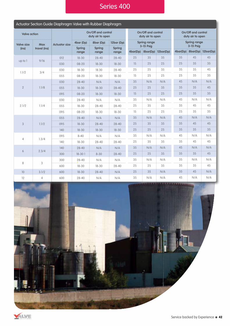
Service backed by Experience l
Series 400
On/Off and control duty air to open
On/Off and control duty air to open
Actuator Section Guide Diaphragm Valve with Rubber Diaphragm
Valve size Max (ins) travel (ins)
up to 1 9/16
1.1/2 3/4
2 1.1/8
2.1/2 1.1/4
3 1.1/2
4 1.3/4
6 2.3/4
8 3
10 3.1/2
12 4
Actuator size
4bar (Dp) 8bar (Dp) 12bar (Dp)
Spring Spring Spring range range range
012 18-30 28-40 28-40
030 08-20 18-30 18-30
030 18-30 18.30 28-40
055 08-20 18-30 18-30
030 28-40 N/A N/A
055 18-30 18-30 28-40
095 08-20 18-30 18-30
030 28-40 N/A N/A
055 18-30 28-40 28-40
095 08-20 18-30 18-30
055 28-40 N/A N/A
095 18-30 28-40 28-40
140 18-30 18-30 18-30
095 8-40 N/A N/A
140 18-30 28-40 28-40
140 28-40 N/A N/A
300 18-30 1 8-30 28-40
300 28-40 N/A N/A
600 18-30 18-30 28-40
600 18-30 28-40 N/A
600 28-40 N/A N/A
Valve action On/Off and control duty air to open
Spring range 3-15 Psig
4bar(Dp) 8bar(Dp) 12bar(Dp)
25 35 35
15 25 25
25 25 35
15 25 25
35 N/A N/A
25 25 35
15 25 25
35 N/A N/A
25 35 35
15 25 25
35 N/A N/A
25 35 35
25 25 25
35 N/A N/A
25 35 35
35 N/A N/A
25 25 35
35 N/A N/A
25 25 35
25 35 N/A
35 N/A N/A
Spring range 3-15 Psig
4bar(Dp) 8bar(Dp) 12bar(Dp)
35 45 45
25 35 35
35 35 45
25 35 35
45 N/A N/A
35 35 45
25 35 35
45 N/A N/A
35 45 45
25 35 35
45 N/A N/A
35 45 45
35 35 35
45 N/A N/A
35 45 45
45 N/A N/A
35 35 45
35 N/A N/A
35 35 45
35 45 N/A
45 N/A N/A
42
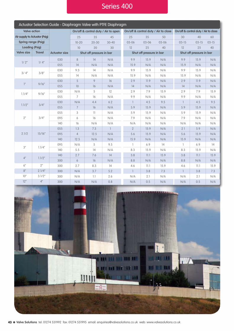
l Valve Solutions tel: 01274 531992 fax: 01274 531995 email: [email protected] web: www.valvesolutions.co.uk
Series 400
1/ 2” 1/ 4”
3/ 4” 3/8”
1” 9/16”
1.1/4” 9/16”
1.1/2” 3/4”
2” 3/4”
2.1/2 15/16”
3” 1.1/4”
4” 1.1/2”
6” 2”
8” 2.1/4”
10” 3.1/2”
12” 4”
030 8 14 N/A 9.9 15.9 N/A 9.9 15.9 N/A
055 14 N/A N/A 15.9 N/A N/A 15.9 N/A N/A
030 9.3 14 N/A 9.9 15.9 N/A 9.9 15.9 N/A
055 14 N/A N/A 15.9 N/A N/A 15.9 N/A N/A
030 5 9 16 2.9 11.9 N/A 2.9 11.9 N/A
055 10 16 N/A 14 N/A N/A 14 N/A N/A
030 N/A 5 12 2.9 7.9 15.9 2.9 7.9 15.9
055 7 16 N/A 9.9 N/A N/A 9.9 N/A N/A
030 N/A 4.4 6.2 1 4.5 9.5 1 4.5 9.5
055 7 16 N/A 5.9 15.9 N/A 5.9 15.9 N/A
055 3 11 N/A 5.9 15.9 N/A 5.9 15.9 N/A
095 6 16 N/A 7.9 N/A N/A 7.9 N/A N/A
140 16 N/A N/A N/A N/A N/A N/A N/A N/A
055 1.3 7.3 1 2 15.9 N/A 2 1 5.9 N/A
095 4 12.5 N/A 5.6 15.9 N/A 5.6 15.9 N/A
140 12.5 N/A N/A 15.9 N/A N/A 15.9 N/A N/A
095 N/A 5 9.5 1 6.9 14 1 6.9 14
140 5.5 14 N/A 8.3 15.9 N/A 8.3 15.9 N/A
140 2.7 7.6 14 3.8 11.1 15.9 3.8 11.1 15.9
300 6 16 N/A 8.8 N/A N/A 8.8 N/A N/A
300 2.7 8.3 14 4.6 11.1 15.9 4.6 11.1 15.9
300 N/A 3.7 5.2 1 3.8 7.3 1 3.8 7.3
300 N/A 1.1 2.6 N/A 2.1 N/A N/A 2.1 N/A
300 N/A N/A 0.8 N/A 0.5 N/A N/A 0.5 N/A
Valve action
Air supply to Actuator (Psig)
Spring range (Psig)
Loading (Psig)
Valve size Travel Actuator size
On/off & control duty / Air to close
25 35 50
03-06 03-06 03-06
12 25 40
Shut off pressure in bar
On/off & control duty / Air to close
30 40 60
03-15 03-15 03-15
12 25 40
Shut off pressure in bar
On/off & control duty / Air to open
25 35 45
10-20 20-30 30-40
10 20 30
Shut off pressure in bar
Actuator Selection Guide - Diaphragm Valve with PTFE Diaphragm
43

Service backed by Experience l
Series 800
DesuperheaterSeries - 800The evolutionary series 800 Desuperheater i.e. Varitrol variable spray nozzles unit can be used in many application to efficiently reduce the superheated steam or other vapors to temperature approaching saturation.The superheated vapor is passed through a section of pipe into which is
fitted a spray nozzle that produces dispersed droplets from a supply of pressurized condensate.These finely atomized particles promote almost immediate evaporation. The required heat being absorbed from the superheated vapor, thus reducing the temperature.
SpecificationDesign ASME B16-34
Valve Size 2” (50mm)
Rating 150 to 1500 ANSI.
Nozzle size Refer to Table 1
Rangeability Maximum 45 to 1.
Valve Travel 38mm.
Body Material ASME A216 Gr. WCB (<425º C) ASME A217 Gr. WC6/9 (<550º C)
Body Tube Stainless Steel.
Guide / Seat Stellite 6
Plug / Stem Stellite 6/316L
Sealing Ring Carbon
Atomiser 316 Stainless Steel (CF8M)
Packing Graphite
End Connection Refer Table No. 1
Actuator Diaphragm.
Diaphragm Direct / Reverse acting
Spring Range 3 – 15 PSIG (0.2 – 1.0 bar) 6 – 30 PSIG (0.4 – 2.0 bar)
Air Supply 20 – 35 PSIG (1.4 – 2.5 bar)
Air Connection 1/ 4” NPT
Accessories Valve Positioners - Pneumatic, Electro-Pneumatic, Smart
Instruments - Airset, Solenoid Valve, Volume Booster, Airlock, Limit Switches
Features - Top or Side Mounted handwheel, Limit Stops
Desuperheater with Actuator
Varitrol Spray Unit
l High efficient atomisation.
l Accurate and repeatable control fluid temperature.
l Tight shut off variable spray unit.
l High rangeability variable area spray unit.
l Erosion resistance materials of selection.
l Ease of installation.
l Low maintenance features.
l High integrity stem sealing arrangement.
l Thoroughly checked at factory to ensure that it meets the specified performance on site with high integrity.
l Produced with Quality Systems accredited to ISO 9001 : 2000
l Full material certification available for all major component Parts.
l Full guarantee on design and Performance.
l All testing performed to the requirements of ANSI B16.34.
l Quality assurance at every stage of manufacturing.
l Comprehensively designed and tested to ensure its optimum performance for the tough process parameters specified.
Quality and performance Guarantee
Design Features
44

l Valve Solutions tel: 01274 531992 fax: 01274 531995 email: [email protected] web: www.valvesolutions.co.uk
l For the most efficient use of heat energy from steam, it is necessary to reduce the temperature of superheated steam to near the saturation temperature.
l The high temperature of superheated steam provides the large amount of energy that is used for water vaporisation resulting in an increased flow of steam at a lower temperature.
l By having the amount of water added the temperature is controlled.
l The rate of cooling depending on spray water drop size, distribution and velocity.
Series 800
Standard Nozzle Cv Values
Nozzle number
Cv Value
0 0.25
1 0.5
2 1.0
3 2.0
4 4.0
5 6.5
6 9.0
Figure 1 Minimum Distances for Temperature Sensor Points
10 20 30 40 50
15
10
5
0Dis
tanc
e be
twee
n sp
ray
nozz
le a
nd te
mpe
ratu
re
sens
ors-
met
ers
Final temperature ˚C of steamabove saturation
Table 1 Desuperheater Mounting Dimensions
Travel
mm
38
38
Nozzlenumbers
0 - 6
0 - 6
A
mm
152
216
A
mm
197
276
B
mm
171
229
>150 <250
mm
305
305
>250
mm
457
457
F
mm
800
800
OE
mm
286
286
steamconnection
mm
80
100
condensateconnection
mm
40
50
Rating
ANSI
150-600
900-1500
Standard Actuator
150-600
900-1500
D based on pipe dia.
Temperaturecontroller
Spraywater
Desuperheater
Steamflow
TE
Steam pipeconnection
A C
D
B
45
Principle of Operation

Service backed by Experience l
Series 800
20 40 60 80 100
100
80
60
40
20
0Flow
rate
- %
Valve lift - %
Figure 3 Varitrol Spray Unit Inherent Characteristic
100 200 300 400 500 600
12
10
8
6
4
2
0Min
imum
ste
am v
eloc
ity-m
/s
Pipe nominal diameter - mm
Spraywater temperature = 50°C
Spraywater temperature = 100°C
Spraywater temperature = 150°C
Spraywater temperature = 200°C
Figure 2 Minimum Steam velocity for Pipe Desuperheating Units
Satisfactory desuperheating is dependant on the correct selection and installation of a unit for a particular application. The following guidelines detail the installation requirements to achieve maximum efficiency from a desuperheating unit.
1 The installation of aDesuperheater unit should be with the flange orientation aswith the drawing opposite.
2 Units may be located in suitable horizontal or vertical down pipe work.
3 Minimum length of straight pipe work following Desuperheating unit should be6 to 8 pipe diameters.
4 Steam pipe work to fall in direction of flow by minimum 20mm in 1000mm.
5 Condensate supply to be free
of debris and effectively filtered to less than 0.25mm.
6 Efficient drainage of Desuperheater pipe work is essential. Large condensatetraps for 10% maximum flow are required to facilitate start-up and shut down of plant.
7 Lagged pipe work assist successful Desuperheating.
8 Controlled temperature to be higher than 6°C (11°F ) above saturation point.
9 To achieve satisfactory evaporation the percentage ratio of water to steam should not exceed 15%. The exact value is dependant on each application and the factory should be consulted if this figure is to be exceeded.
10 Where the Variatrol unit is required to shut off for long
periods it is recommended that an upstream motorized isolating valve is incorporated intothe system.
11 The temperature pocket should extend into the pipe 1/3 to 1/2 pipe diameter for steam pipes up to ǿ 300mm and 1/4 to 1/3 on steam pipe diametersabove ǿ300mm.
12 The minimum distance of the temperature sensor point from the desuperheating unit shown in figure 1.
13 For maximum steam turndown applications, a high superior pressure ofcondensate is necessary.
14 Maximum recommended liner velocity 330 ft/s (100 m/s). The minimum liner velocity is taken from the graph shown in figure 2.
46
Installation Guide

l Valve Solutions tel: 01274 531992 fax: 01274 531995 email: [email protected] web: www.valvesolutions.co.uk
l Compact and simple design, low cost and maintenance free.
l Very high Cv to body size ratio.
l Reliable smooth operation and flow control.
l Replaceable elastomer liner.
l Full guarantee on design and Performance.
l All testing are performed to the requirements of ANSI B16.34.
l Assured product quality.
Series 200
Butterfly Valve - Series 200Butterfly Valve design is the most common type of rotary valve andprovides low weight to Cv Ratio combined with simplicity of design and comparatively low cost. It is a simple device to control or block the flow, a single vane or wafer disc pivots in the valve body. They can be found on a wide variety of applications for throttling or two position control in
the chemical, paper and pulp, sugar industries, cooling water circulation, water treatment plants, compressed air, gas plant, flue gas desulphurization plants etc.Butterfly Valves have been around theindustry for decades, performing well defined tasks and are Economic alternative to Gate valves, Ball valves, Plug valves etc
SpecificationDesign Wafer
Size 50 to 900 mm (2” to 36”)
Rating 50 to 900 mm (2” to 36”)
Flow Characteristic Throttling, On-Off
Body Material Cast Iron, Carbon Steel, Stainless Steel etc.
Vane Material Stainless Steel.
Body Sleeve Neoprene, Nitrile, Teflon, EPDM, Silicon, Butyl, Viton etc.
Soft Seat Teflon
Gland Packing PTFE V Rings up to 180C Grafoil up to 400C
Actuator Form Diaphragm, Piston, Electric
Actuator Type Rotary
Diaphragm Nitrile / Neoprene
Spring Range 3 – 15 Psig (0.2 – 1.0 Kg/cm²) 6 – 30 Psig (0.4 – 2.0 Kg/cm²)
Air supply 20 – 35 Psig (1.4 – 2.5 Kg/cm²)
Air Connection 1/ 4” or 1/ 2” NPT
Accessories Valve Positioners - Pneumatic, Electro-Pneumatic, Smart
Instruments - Airset, Solenoid Valve, Volume Booster, Airlock, Limit Switches
Features - Top or Side Mounted handwheel, Limit Stops Removable Blind Head, Steam Jacketting etc
Butterfly ValveSoft Seated, Model 230
Butterfly ValveMetal to Metal, Model 210 / 240
Butterfly ValveSleeved Design, Model 250
l Produced with Quality Systems accredited to ISO 9001 : 2000 ( Certificate No. 208920) by Bureau Veritas.
l Full material certification available for all major component Parts.
l Bubble tight shut off, leakage Class – VI.
l Rangeability of 33:1 in the control range.
l Flow characteristic throttling for modulating duty.
Design FeaturesQuality and Performance Guarantee
47
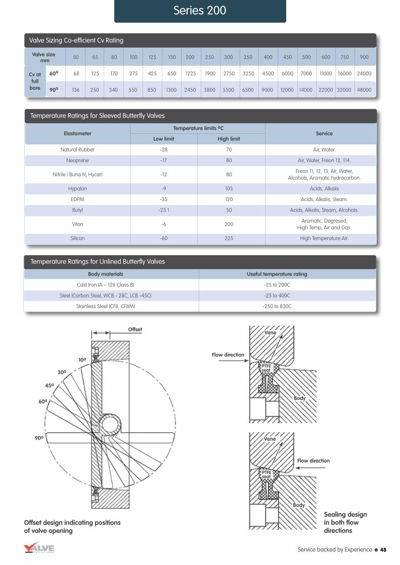
Service backed by Experience l
Series 200
Temperature Ratings for Unlined Butterfly Valves
Body materials Useful temperature rating
Cast Iron (A – 126 Class B) -25 to 200C
Steel (Carbon Steel, WCB - 28C, LCB -45C) -25 to 400C
Stainless Steel (CF8, CF8M) -250 to 830C
Temperature limits oC
Temperature Ratings for Sleeved Butterfly Valves
Elastometer Low limit High limit
Service
Natural Rubber -28 70 Air, Water.
Neoprene -17 80 Air, Water, Freon 12, 114.
Nitrile ( Buna N, Hycar)
-12
80
Freon 11, 12, 13, Air, Water, Alcohols, Aromatic hydrocarbon.
Hypalon -9 105 Acids, Alkalis
EDPM -35 120 Acids, Alkalis, Steam.
Butyl -23 1 50 Acids, Alkalis, Steam, Alcohols.
Viton -6
200
Aromatic, Degresed, High Temp, Air and Gas.
Silicon -60 225 High Temperature Air.
Offset design indicating positionsof valve opening
Sealing designin both flowdirections
Flow direction
Offset
Flow direction
Vane
Vane
Body
Body
10o
90o
60o
45o
30o
PTFEseat
PTFEseat
Valve Sizing Co-efficient Cv Rating
Valve size 50 65 80 100 125 150 200 250 300 350 400 450 500 600 750 900
60o 68 125 170 275 425 650 1225 1900 2750 3250 4500 6000 7000 11000 16000 24000
90o 136 250 340 550 850 1300 2450 3800 5500 6500 9000 12000 14000 22000 32000 48000
Cv atfull
bore
mm
48

l Valve Solutions tel: 01274 531992 fax: 01274 531995 email: [email protected] web: www.valvesolutions.co.uk
Sizing and actuator selection for Butterfly Valves
Cv in USGPMShaft Dia
A B
Maximumallowable
Torque for304/316 shaftValve size
Metal to metal Torque Required at ao
Tao = A x ∆Pαo + B
inch mm 60° 90° 0 60 90 IN-LB inch mm
2 50 65 130 0.2 1 2.75 36 225 1/2 14
2.1/2 65 120 240 0.3 1.86 5.26 36 225 1/2 14
3 80 160 320 0.44 4.14 9.04 36 225 1/2 14
4 100 280 560 1 7.4 21.4 50 430 5/8 16
5 125 430 860 1.56 14.06 41.36 50 430 5/8 16
6 150 640 1280 2.63 24.13 71.63 65 745 3/4 20
8 200 1200 2400 6.23 57.23 169.23 100 1764 1 25
10 250 1850 3700 9.81 109.81 329.81 100 1764 1 25
12 300 2700 5400 14.4 187.4 552.4 100 1764 1 25
14 350 3300 6600 27 272 790 184 3438 1.1/4 33
16 400 4400 8800 35.3 405.3 1195.3 184 3438 1.3/8 35
18 450 6250 12500 52.7 587.7 1762.7 232 5508 1.5/8 42
20 500 6900 13800 64.4 784.4 2374.4 235 5508 1.5/8 42
24 600 10000 20000 108 1368 4138 282 14130 2 50
30 750 16300 32600 212 2732 8262 396 26640 2.1/2 63
36 900 24200 48400 300 4580 14000 396 26640 2.1/2 63
Cv in USGPMShaft Dia
A B
Maximumallowable
Torque for304/316 shaftValve size
Soft seated Torque Required at ao
Tao = A x ∆Pαo + B
inch mm 60° 90° 0o 60o 90o 0o 10o-90o IN-LB inch mm
2 50 65 130 0.2 1 2.75 75 36 225 1/2 14
2.1/2 65 120 240 0.3 1.86 5.26 75 36 225 1/2 14
3 80 160 320 0.44 4.14 9.04 75 36 225 1/2 14
4 100 280 560 1 7.4 21.4 100 50 430 5/8 16
5 125 430 860 1.88 14.38 41.68 120 65 745 3/4 20
6 150 640 1280 3.5 25 72.5 180 100 1764 1 25
8 200 1200 2400 6.23 57.23 169.23 250 140 1764 1.3/32 28
10 250 1850 3700 9.81 109.81 329.81 320 184 3440 1.3/8 35
12 300 2700 5400 14.4 187.4 552.4 320 184 5500 1.1/2 40
14 350 3300 6600 27 272 790 480 282 9500 1.3/4 45
16 400 4400 8800 35.3 405.3 1195.3 480 282 14130 2 50
18 450 6250 12500 52.7 587.7 1762.7 700 396 19700 2.1/4 55
20 500 6900 13800 91.9 811.9 2401.9 700 396 19700 2.1/4 55
24 600 10000 20000 135 1392 4138 700 396 26700 2.1/4 63
30 750 16300 32600 212 2732 8262 1000 396 26700 2.1/2 63
36 900 24200 48400 360 4640 14060 1000 520 53900 3 80
Series 200
49

Service backed by Experience l
Series 200
Available Torque for 90o Actuator (Lbc-in)
Actuator Actuator Mode Spring Range (Kg/cm²) C/C Torque
55 PDS – 055-90o 0.2 to 1.0 33 183
95 PDS – 095-90o 0.2 to 1.0 33 316
140 PDS – 140-90o 0.2 to 1.0 49 691
140 PDS – 140G-90o 0.2 to 1.0 68.5 966
300 PDS – 140-90o 0.2 to 1.0 77.5 2343
Available Torque for 60o Actuator (Lbc-in)
Actuator Actuator Mode Spring Range (Kg/cm²) C/C Torque
55 PDS – 055-60o 0.2 to 1.0 45.5 252
95 PDS – 095-60o 0.2 to 1.0 45.5 436
140 PDS – 140-60o 0.2 to 1.0 68.5 966
140 PDS – 140G-60o 0.2 to 1.0 96.5 1361
300 PDS – 140-60o 0.2 to 1.0 105.5 3189
Note:- For spring range other than 0.2 – 1.0 kg/cm multiply the Torque values by following factors.
Spring Range ( Kg/cm² ) Multiple Factor
0.4 to 1.2 252 0.6 to 1.4 436 0.8 to 1.6 966
Valve Actuator F / F A
B
C
D
H
H1 H2 H3 size model STD TMH SMH
50 PDS-055-90º 50 55 70 270 286 125 500 750 775
65 PDS-055-90º 48 60 85 280 286 125 500 750 775
80 PDS-055-90º 48 65 100 290 286 125 500 750 775
100 PDS-055-90º 54 80 125 315 286 125 500 750 775
150 PDS-055-90º 62 110 160 360 286 125 500 750 775
200 PDS-095-90º 69 135 175 425 371 125 525 775 800
250 PDS-140-90º 80 165 230 470 443 150 725 1075 1000
300 PDS-140-90º 82 195 250 525 443 150 725 1075 1000
350 PDS-140G-90º 92 215 280 570 443 175 825 1225 1150
400 PDS-140G-90º 102 245 305 600 443 175 825 1225 1150
450 PDS-300-90º 126 270 335 645 616 225 925 N/A 1300
500 PDS-300-90º 127 295 380 660 616 225 925 N/A 1300
600 PDS-300-90º 134 390 450 725 616 225 925 N/A 1300
Dimensions of Soft Seated Butterfly Valves
H3
H1
A
C
A
B
H
CB
H
H1
H2
øD
øD
øD
H3
A
CB
H
50
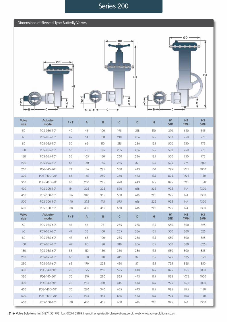
l Valve Solutions tel: 01274 531992 fax: 01274 531995 email: [email protected] web: www.valvesolutions.co.uk
Available Torque for 90o Actuator (Lbc-in)
Valve Actuator F / F A
B
C
D
H
H1 H2 H3 size model STD TMH SMH
50 PDS-030-90º 49 46 100 195 218 110 370 620 645
65 PDS-055-90º 49 54 100 210 286 125 500 750 775
80 PDS-055-90º 50 62 110 215 286 125 500 750 775
100 PDS-055-90º 56 76 125 235 286 125 500 750 775
150 PDS-055-90º 56 105 160 260 286 125 500 750 775
200 PDS-095-90º 63 130 185 285 371 125 525 775 800
250 PDS-140-90º 73 156 225 350 443 150 725 1075 1000
300 PDS-140G-90º 83 185 250 380 443 175 825 1225 1150
350 PDS-140G-90º 83 200 285 420 443 175 825 1225 1150
400 PDS-300-90º 114 305 325 520 616 225 925 NA 1300
450 PDS-300-90º 126 340 355 550 616 225 925 NA 1300
500 PDS-300-90º 140 375 415 575 616 225 925 NA 1300
600 PDS-300-90º 168 430 455 650 616 225 925 NA 1300
Valve Actuator F / F A B C D H H1 H2 H3
size model STD TMH SMH
50 PDS-055-60º 47 54 75 255 286 135 550 800 825
65 PDS-055-60º 47 56 100 285 286 135 550 800 825
80 PDS-055-60º 47 65 100 285 286 135 550 800 825
100 PDS-055-60º 47 80 120 310 286 135 550 800 825
150 PDS-055-60º 56 110 150 360 286 135 550 800 825
200 PDS-095-60º 60 150 170 415 371 135 525 825 850
250 PDS-095-60º 65 170 225 450 371 135 725 825 850
300 PDS-140-60º 70 195 250 525 443 175 825 1075 1000
350 PDS-140-60º 70 210 290 565 443 175 825 1075 1000
400 PDS-140-60º 70 235 310 615 443 175 925 1075 1000
450 PDS-140G-60º 70 270 340 655 443 175 925 1175 1150
500 PDS-140G-90º 70 295 445 675 443 175 925 1175 1150
600 PDS-300-90º 168 430 455 650 616 225 925 NA 1300
Dimensions of Sleeved Type Butterfly Valves
Series 200
C
A
B
H
H1
øD
C
A
B
H
H2
øD
C
A
B
H
H3
øD
51

Service backed by Experience l
Series 200
Dimensions of Metal to Metal Butterfly Valves
Valve Actuator F / F A
B
C
D
H
H1 H2 H3 size model STD TMH SMH
50 PDS-030-90º 47 54 75 250 218 110 370 620 645
65 PDS-030-90º 47 56 100 280 218 125 370 620 645
80 PDS-030-90º 47 65 100 280 218 110 370 620 645
100 PDS-030-90º 47 80 120 305 218 110 370 620 645
150 PDS-055-90º 56 110 150 360 286 110 500 750 775
200 PDS-055-90º 60 150 170 415 286 110 500 750 775
250 PDS-095-90º 65 170 225 450 371 125 525 775 800
300 PDS-095-90º 70 195 250 505 371 125 525 775 800
350 PDS-140-90º 70 210 290 560 443 150 725 1075 1000
400 PDS-140-90º 114 235 310 610 443 150 725 1075 1000
450 PDS-140-90º 70 270 340 650 443 150 725 1075 1000
500 PDS-140G-90º 70 295 445 675 443 175 825 1225 1150
Valve Actuator F / F A B C D H H1 H2 H3
size model STD TMH SMH
50 PDS-030-60º 47 54 75 255 286 135 550 800 825
65 PDS-055-60º 47 56 100 285 286 135 550 800 825
80 PDS-055-60º 47 65 100 285 286 135 550 800 825
100 PDS-055-60º 47 80 120 310 286 135 550 800 825
150 PDS-055-60º 56 110 150 360 286 135 550 800 825
200 PDS-095-60º 60 150 170 415 371 135 575 825 850
250 PDS-095-60º 65 170 225 450 371 135 575 825 850
300 PDS-140-60º 70 195 250 525 443 175 725 1075 1000
350 PDS-140-60º 70 210 290 565 443 175 725 1075 1000
400 PDS-140-60º 70 235 310 615 443 175 725 1075 1000
450 PDS-140-60º 70 270 340 655 443 175 775 1175 1150
500 PDS-140G-90º 70 295 445 675 443 175 775 1175 1150
C
A
B
H
H1
øD
C
A
B
H
H2
øD
C
A
B
H
H3
øD
52

l Valve Solutions tel: 01274 531992 fax: 01274 531995 email: [email protected] web: www.valvesolutions.co.uk
Series 310
V-Notch Ball Valve - Series 310The V–Notch Ball Valve gives non-clogging, high capacity, straight through flow control of fluids containing pulp and paper stock or slurries and fluids containing suspended solids or fibrous materials.
The V- Notch Ball Valves are offered squared and clamped driven shaft plus ball shaft with splined connection designed for zero lost motion for highly accurate positioning and precise control.
SpecificationDesign BS. 5351
Size 25 to 200 mm (1” to 8”)
Rating ANSI 150 and 300
End Connection Flanged End
F/F Dimensions ANSI B-16.10
Flow Characteristic Approx. Equal Percentage, Linear, On-Off
Flow Direction Forward (into convex face of V-ball)
Max. Ball Rotation 90º
Body Material Carbon Steel, Stainless Steel, and Alloy Steel etc
Ball Material 50 to 900 mm (2” to 36”)
Seat Ring PTFE, Carbon Filled Teflon
Ball Ring CF8M, Alloy steels
Gasket PTFE, Graphite Laminate
Gland Packing PTFE V Rings, Grafoil
Actuator Form Diaphragm, Piston, Electric
Actuator Type Rotary
Diaphragm Nitrile / Neoprene
Spring Range 3 – 15 Psig (0.2 – 1.0 Kg/cm²) 6 – 30 Psig (0.4 – 2.0 Kg/cm²)
Air supply 20 – 35 Psig (1.4 – 2.5 Kg/cm²)
Air Connection 1/ 4” or 1/ 2” NPT
Accessories Valve Positioners - Pneumatic, Electro-Pneumatic, Smart
Instruments - Airset, Solenoid Valve, Volume Booster, Airlock, Limit Switches
Features - Top or Side Mounted handwheel, Limit Stops Removable Blind Head, Steam Jacketting etc
V-Notch Ball Valve with Actuator
V-Notch Ball Valve
53

Service backed by Experience l
Series 310
Cv(max.) at 90o opening
Valve Sizing Co-efficient Cv Rating
Valve size
ins 1 1.1/2 2 2.1/2 3 4 6 8
mm 25 40 50 65 80 100 150 200
26 78 120 220 325 595 1050 1750
Pressure / Temperaturefor PTFE Ball Seals
Flui
d Te
mpe
ratu
re o F
Shut off Pressure PSI
0 50 100 150 200 250 300
450
400
350
300
250
200
150
100
50
0
-20
285
% Valve opening0 10 20 30 40 50 60 70 80 90 100
2000
1000800600100300200
1008060403020
1086432
100.80.60.40.30.2
0.1
Valv
e Cv
Valv
e Si
ze
1750
1050
595
325220
120
78
26
200
150
100
8065
50
40
25
Flow
Co-
effic
ient
(Cv)
US-
GPM
Flow Characteristic Curves90o of Opening
1) The valve should preferably be installed with actuator verti-cally above or below the valve body. It can be installed in a horizontal or angled position if actuator is suitably supported.
2) Necessary clearance should be provided above the actuator to permit servicing.
3) The flange bolts are to be tightened evenly to avoid
placing strain on the body.
4) The inlet of air pressure regulator (Air set) should be connected to the pneumatic supply line.
5) Supply pressure to the diaphragm actuator should be either 1.5 kg/cm² (20psig) or 2.5 kg/cm² (35 psig) as per indication on the nameplate.
6) For cylinder actuator, supply pressure specified.
7) For control applications, the air set and valve positioner are mounted, piped and adjusted at the factory.
Final Check1) After installation, check the valve operation for full stroke as indicated on the nameplate, check for leaks in air line connection.
2) Open and close the valve
two or three times to ensure proper operation.
3) Before commissioning the process flow, it is essential to flush clean the piping properly. Ball valves require minimum maintenance for its operation.4) Apply a few drops of oil on the exposed guides and bushings, Hand wheel, if present, must be greased periodically.
Installation
nearly equal percentage characteristic.
l Replaceable ball seal and back up ring for added rigidity.
l Ball machined to a super smooth finish, hard – chrome plated and polished to increase ball seal life.
l High Cv to body size ratio.
l A Shearing effect between the ball and seal ensures tight shut-off, even on fibrous slurries.
l The unrestricted, straight through flow design provides high capacity and wide rangeability.
l Precise contouring of the V-notch balls provides a
l Produced with Quality Systems accredited to ISO 9001 : 2000 (Certificate No. 208920.) by Bureau Veritas.
l Full material certification available for all major component Parts.
l Full guarantee on design and Performance.
l All testing are performed to the requirements of ANSI B16.34.
Design Features Quality and Performance Guarantee
54

l Valve Solutions tel: 01274 531992 fax: 01274 531995 email: [email protected] web: www.valvesolutions.co.uk
Valve Actuator ANSI 150 ANSI 300 C/C Ø D H
H1 H2 H3
size model STD TMH SMH
25 PDS-055-90º 127 165 250 286 125 500 750 775
40 PDS-055-90º 165 190 280 286 125 500 750 775
50 PDS-055-90º 178 216 280 286 125 500 750 775
65 PDS-095-90º 190 241 315 371 125 525 775 800
80 PDS-095-90º 203 283 315 371 125 525 775 800
80 PDS-140-90º 203 283 335 443 443 725 1075 1000
100 PDS-140-90º 229 305 360 443 443 725 1075 1000
150 PDS-140-90º 267 403 415 443 443 825 1225 1150
150 PDS-300-90º 267 403 425 616 616 925 925 1300
200 PDS-300-90º 292 419 510 616 616 975 925 1300
Face to face
Mounting Dimensions for V-Notch Ball Valve
Series 310
C/C
H2
Ø D
H
C/C
Ø D
H3
H
H1
Ø D
H
F/F C/C
55

Service backed by Experience l
Cv(max.) at 90o openingPneumatic, Spring Opposed Diaphragm, Spring Opposed Piston and Double Acting Piston Actuators The valve solutions family of pneumatic actuators offer the valve designer and user a choice from a wide range of actuating devices to satisfy the majority control valve applications.The versatility of the design enables a wide selection of ancillary’s to be selected included manual overides, limit stops and multiple instrumentation.The simplicity of the designs have made these ranges of actuators to be a popular choice, particularly in high risk environments.
Series P Actuators
56

l Valve Solutions tel: 01274 531992 fax: 01274 531995 email: [email protected] web: www.valvesolutions.co.uk
ActuatorType
Actuator Type Spring Opposed Diaphragm, Manual
Actuator Action Direct / Reverse Acting
Diaphragm Nitrile / Neoprene (nylon reinforced)
Spring Range See Table 1
Air Supply 20 - 60 PSIG (1.4 - 4.0 Bar)
Air Connection 1/4” or 1/2” NPT
Accessories Valve Positioners - Pneumatic, Electro-Pneumatic, Smart
Instruments - Airset, Solenoid Valve, Volume Booster, Airlock, Limit Switches
Features - Top or Side Mounted handwheel, Limit Stops Removable Blind Head, Steam Jacketting etc.
Specification
l High power
l Fast response.
l Low stress components.
l Large variety of sizes.
l Easily serviceable.
l Split coupling design for attachment to valve.
l Wide range of accessories available.
Design Features
l Produced with Quality Systems accredited to ISO 9001 : 2008 by Bureau Veritas and “CE” marked in accordance with Pressure Equipment Directive and Regulations 07/23/EC by Lloyd’s Register.
l Full guarantee on design and performance.
l Comprehensively tested to ensure performance on site.
Quality and Performance Guarantee
Series PD Actuators
57
*Other Spring Ranges available on request
**Nett thrust is that available after compressing spring,
Psi Bar Psi Bar Lbs kg Lbs Kg Lbs Kg
60 4
60 4
60 4
60 4
50 3.5
1530 694
1350 612
900 408
840 381
2805 1272
2475 1123
1650 748
1540 699
4845 2198
4275 1939
2805 1293
2660 1207
7140 3239
6300 2858
4200 1905
3920 1778
12300 5579
10500 4763
6000 2722
5400 2449
90 41
90 41
180 82
240 109
165 75
165 75
330 150
440 200
285 129
285 129
570 259
760 345
420 191
420 191
840 381
1120 508
900 408
900 408
180 816
2400 1089
1800 815
3300 1500
5700 2585
8400 3810
15000 6800
30
55
95
140
300
Spring Range* Thrust Gross Nett Thrust** Extended ThrustWorking Pressure
3-9 0.2-0.6
3-15 0.2-1.0
6-30 0.4-2.0
8-32 0.6-2.2
3-9 0.2-0.6
3-15 0.2-0.6
6-30 0.4-2.0
8-32 0.6-2.2
3-9 0.2-0.6
3-15 0.2-1.0
6-30 0.4-2.0
8-32 0.6-2.2
3-9 0.2-0.6
3-15 0.2-1.0
6-30 0.4-2.0
8-32 0.6-2.2
3-9 0.2-0.6
3-15 0.2-1.0
6-30 0.4-2.0
8-32 0.6-2.2
Spring Diaphragm
Actuator Size( in²)
Actuator Spring Table

Service backed by Experience l
Series PD Actuators
Diaphragm actuatorDirect - acting
Diaphragm actuatorReverse - acting
Diaphragm actuatorTop mounted handwheel Reverse - acting
Diaphragm actuatorTop mounted handwheel Direct - acting
Diaphragm actuatorSide mounted handwheel Reverse - acting
Diaphragm actuatorSide mounted handwheel Direct - acting
Actuator Dimensions
O DO DO DO D
O DO D
H H 1H 3H 2 H 5H 4
Actuatormodel
PDC - 030
PDO - 030
PDC - 055
PDO - 055
PDC - 055
PDO - 055
PDC - 095
PDO - 095
PDC - 095
PDO - 095
PDC - 140
PDO - 140
PDC - 140
PDO - 140
PDC - 300
PDO - 300
PDC - 300
PDO - 300
PDC - 300
PDO - 300
PDC - 300
PDO - 300
Effectiveinch2
30
30
55
55
55
55
95
95
95
95
140
140
140
140
300
300
300
300
300
300
300
300
Bonnetmount dia.
54
54
54
54
71.5
71.5
54
54
71.5
71.5
71.5
71.5
90.5
90.5
71.5
71.5
90.5
90.5
90.5
90.5
90.5
90.5
Travel
28
28
28
28
38
38
28
28
38
38
38
38
57
57
38
38
57
57
90
90
102
102
O D
218
218
286
286
286
286
371
371
371
371
443
443
443
443
616
616
616
616
616
616
616
616
H
-
400
-
510
-
560
-
550
-
600
-
650
-
780
-
850
-
900
-
1050
-
1200
H1
375
-
510
-
560
-
550
-
600
-
650
-
780
-
850
-
900
-
1050
-
1200
-
H2
-
575
-
750
-
800
-
800
-
850
-
950
-
1100
-
-
-
-
-
-
-
-
H3
505
-
600
-
650
-
650
-
700
-
750
-
900
-
-
-
-
-
-
-
-
-
-
H4
-
650
-
700
-
750
-
750
-
800
-
900
-
1030
-
1200
-
1250
-
1400
-
1550
H5
650
-
700
-
750
-
750
-
800
-
900
-
1030
-
1200
-
1250
-
1400
-
1550
-
l PDO - Direct Acting Actuator (used on supply failure Valve - Opens)
l PDC - Reverse Acting Actuator (used on supply failure Valve - Closes)
l All dimensions in mm
l The company’s policy is one of continuous product improvement and the right is reserved to modify the specifications contained herein without notice
Rotary Scotch Yoke Actuators - also available as part of the above range
l High power.
l Low hysterisis.
l Fast response.
l Long life alloy steel actuator springs.
l ‘Scotch yoke’ are designed to provideextremely reliable and accurate operation of Ball, Butterfly and Plug valves.
58
Psi Bar Psi Bar Lbs kg Lbs Kg Lbs Kg
60 4
60 4
60 4
60 4
50 3.5

l Valve Solutions tel: 01274 531992 fax: 01274 531995 email: [email protected] web: www.valvesolutions.co.uk
Series PP Actuators
Actuator Type Spring Opposed Piston, Double Acting Piston
Actuator Action Direct / Reverse Acting
Spring Range Wide range available to suit application
Air Supply 20 - 150 PSIG (1.4 - 10.0 Bar)
Air Connection 1/4” or 1/2” NPT
Materials Wide range of materials available to suit application
Accessories Valve Positioners - Pneumatic, Electro-Pneumatic, Smart
Instruments - Airset, Solenoid Valve, Volume Booster, Airlock, Limit Switches
Features - Top Mounted handwheel, Limit Stops
Specification
59
l The VSL range of pneumatic piston actuators has been designed to provide powerful high performance for automatic control valves.
l Corrosion resistance to aggressive environments has led to careful consideration of component selection, whilst keeping in mind the need for weight reduction.
l Safety is an important consideration and spring containment has been carefully addressed so that inadvertent energy release has been eliminated.
l The foregoing conditions have led to unit being designed to accept air pressure up to 10 Bar, to provide thrust and stiffness.
l The end caps, piston, stems and tie bars are all either carbon or stainless steel, with the cylinder being a strong light composite material called Black Amalgon.
Piston Actuator Sizes Available
Actuator size (in²) 25 50 100 150 200 250
Standard stroke mm 50 80 80 80 100 100
This careful material selection makes the actuator inherently strong, durable and corrosion resistant.
l The spring is contained in a cage and the spring cap is secured with HT Steel tie rods and the nuts welded in place.
l This cage cartridge design prevents accidental unbolting of a pre-compressed spring and possibility of a catastrophic energy release.
l A further feature is the spring being contained inside the cylinder in a protected clean environment inhibiting atmospheric degradation.
l The actuator is also available as a spring-less double acting unit for even greater bidirectionan thrust.
l The following sizes are available as spring opposed pistons, double acting pistons or springless double acting pistons.
Design Features
l High power
l Fast response.
l Low stress components.
l Large variety of sizes.
l Easily serviceable.
l Split coupling design for attachment to valve.
l Wide range of accessories available.
Quality and Performance Guarantee
l Produced with Quality Systems accredited to ISO 9001 : 2008 by Bureau Veritas and “CE” marked in accordance with Pressure Equipment Directive and Regulations 07/23/EC by Lloyd’s Register.
l Full guarantee on design and performance.
l Comprehensively tested to ensure performance on site.

Service backed by Experience l
Accessories - Valve Positioner
Valve PositionerThe PNEUCON PNEUMATIC VALVE POSITIONER is an instrument working on force balance principle to position the Control Valve stem in accordance to a pneumatic signal received from a controller or manual loading station,
regardless of packing box friction, actuator hysteresis or unbalanced forces on the valve plug. Thus, the positioner ensures a reliable and accurate operation of Control Valve.
SpecificationsModel PVP-1 Single Acting - Direct Action PVP-2 Single Acting - Reverse Action. PVP-3 Double Acting - Direct Action
Supply Connection 1 /4” NPT (F)
Supply Air Pressure 1.4 To 3.5 kg/cm² (Standard.) 5.0 kg/cm² (Maximum)
Input 0.2 – 1.0 kg/cm² (Standard)
Hysteresis Within ± 1% of FS
Linearity Within ± 1% of FS
Dead Band Within 0.1% of FS
Stroke Speed (max) 10mm/sec
Stroke 14 mm to 100mm
Air Consumption 7.0 NL / Min (Normal.)
Air Flow Capacity 200 NL / Min (Maximum.)
Material of Construction
Housing Die cast aluminum to LM – 6
Internals & Linkage AISI 304
Diaphragm Nitrile / Neoprene with nylon fabric reinforcement
control instrument, positioners will reduce lag, thereby speeding up valve operation.
Split range
Some processes require the dual or sequential operation of two to three control valves by a single controller with a 3-15 psi output signal range.
Improves all performance
When process lags necessitate the use of wide controller proportional band, the positioner provides an exact means of making the control valve responsive to infinitely small changes in controller output pressure.
Non-standard controller output
The positioner is used to operate a valve with3-15 psi spring range when controller signal is other than 3 –15 psi.
Non-standard actuator spring range
The positioner is used to operate valves having non standard actuator spring ranges by controllers having the standard 3-15 psi signal pressure.
Remote valve location
When air operated control valves are located far from
l High sensitivity and stability. Simple zero and span adjustments.
l Field reversibility.
l Large port pilot relay eliminates the air passage blockage.
l Internal components are of stainless steel.
Valve Positioner
Application
Design and Performance Features
60
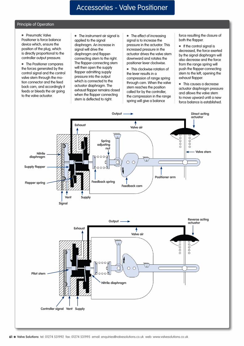
l Valve Solutions tel: 01274 531992 fax: 01274 531995 email: [email protected] web: www.valvesolutions.co.uk61
Accessories - Valve Positioner
l Pneumatic Valve Positioner is force balance device which, ensure the position of the plug, which is directly proportional to the controller output pressure.
l The Positioner compares the forces generated by the control signal and the control valve stem through the mo-tion connector and the feed back cam, and accordingly it feeds or bleeds the air going to the valve actuator.
l The instrument air signal is applied to the signal diaphragm. An increase in signal will drive the diaphragm and flapper-connecting stem to the right. The flapper-connecting stem will then open the supply flapper admitting supply pressure into the output which is connected to the actuator diaphragm. The exhaust flapper remains closed when the flapper connecting stem is deflected to right.
l The effect of increasing signal is to increase the pressure in the actuator. This increased pressure in the actuator drives the valve stem downward and rotates the positioner lever clockwise.
l This clockwise rotation of the lever results in a compression of range spring through cam. When the valve stem reaches the position called for by the controller, the compression in the range spring will give a balance
force resulting the closure of both the flapper.
l If the control signal is decreased, the force exerted by the signal diaphragm will also decrease and the force from the range spring will push the flapper-connecting stem to the left, opening the exhaust flapper.
l This causes a decrease actuator diaphragm pressure and allows the valve stem to move upward until a new force balance is established.
Principle of Operation
Valve stem
Valve air
Direct actingactuator
Springadjusting
nut
Feedback cam
Positioner arm
Exhaust
Feedback spring
Nitrile diaphragm
Supply flapper
Flapper spring
Signal
Vent Supply
Reverse actingactuatorOutput
Valve air
Exhaust
Controller signal Vent Supply
Pilot stem
Nitrile diaphragm
Output
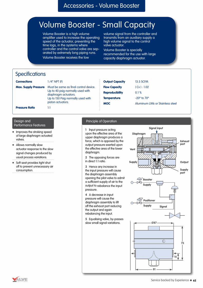
Service backed by Experience l
l Improves the stroking speed of large diaphragm actuated valves.
l Allows normally slow actuator response to the slow signal changes produced by usual process variations.
l Soft seat provides tight shut off to prevent unnecessary air consumption.
Accessories - Volume Booster
Volume Booster - Small CapacityVolume Booster is a high volume amplifier used to increase the operating speed of the actuator, preventing the time lags, in the systems where controller and the control valve are sep-arated by extremely long piping runs.Volume Booster receives the low
volume signal from the controller and transmits from an auxiliary supply a high volume signal to the control valve actuator.Volume Booster is specially recommended for the use with large capacity diaphragm actuator.
SpecificationsConnections 1 /4” NPT (F)
Max. Supply Pressure Must be same as final control device. Up to 40 psig normally used with diaphragm actuators. Up to 150 Psig normally used with piston actuators.
Pressure Ratio 1:1
Output Capacity 13.5 SCFM
Flow Capacity ( Cv ) : 1.02
Reproducibility 0.1 %
Temperature -20º to 70º
MOC Aluminum LM6 or Stainless steel
1 Input pressure acting upon the effective area of the upper diaphragm produces a force, which is opposed by the output pressure exerted upon the effective area of the lower diaphragm.
2 The opposing forces are in direct 1:1 ratio.
3 Hence any increase in the input pressure will cause the diaphragm assembly opening the pilot valve to admit a sufficient supply of air to the output to rebalance the input pressure.
4 A decrease in input pressure will cause the diaphragm assembly to lift off the exhaust port reducing the output and again rebalancing the input.
5 Equalising valve, by-passes slow small signal variations.
Booster
Supply
Signal
Positioner
Supply
81
O87
75
15
Signal input
Exhaustport
Output
Supplyport
Supply
Vent
Diaphragm
Principle of OperationDesign and Performance Features
62

l Valve Solutions tel: 01274 531992 fax: 01274 531995 email: [email protected] web: www.valvesolutions.co.uk63
Principle of Operation
Accessories - Volume Booster
Volume Booster - Large CapacityHigh Volume Booster with a fixed minimum deadband is designed to substantially increase stroking speeds of large actuators. Actuators retain their normal slow and stable responses as long as their signal
fluctuations remain within the deadband limits that can be set on the booster.Volume Booster is specially recommended for the use with large capacity diaphragm actuator.
SpecificationsConnections ½” or ¾” NPT ( F )
Supply Port ½” or ¾” NPT ( F )
Exhaust Port ½” or ¾” NPT ( F )
Max. Supply Pressure Must be same as final control device. Up to 40 psig normally used with diaphragm actuators. Up to 150 Psig normally used with piston actuators.
Pressure Ratio 1:1
Deadpan Width 1psi or 5% of output span, whichever is greater.
Flow Capacity 115 scfm ( 195.4m³ / hr )
Maximum Cv 3.0
Temperature - 20º to 70º C
MOC Aluminum LM6 or Stainless steel
Booster
Supply
Signal
Positioner
Supply
Signal input
Exhaustport
OutputSupply
Vent
Diaphragm
Supply port
Bypass valve
125
150
40
128
l During steady process conditions when Controller output variations are small, the controller or valve positioner signal to the booster input will be registered through the bypass valve directly to the actuator. l Both booster ports remain tightly shut; soft seats preventing unnecessary air consumption.
l Because of the bypass valve restriction, larger or faster signal changes will be registered sooner on the booster input than in the booster output chamber connected to the actuator.
l When the differential pressure exceeds the dead-band value of the booster, the diaphragm assembly will move so as to open one, or the other, booster port and allow rapidactuator pressure change. l When the controller or positioner senses that the corrective action is completed, the booster closes and lets the actuator return to normal operation.
Quick Response: Provides large volume for rapid stroking of the actuator when confronted with input signalsexceeding preset magnitude and rate capabilities.
l Stroking period can be reduced from one minute to less than three seconds using ¾” High Volume Booster on 300 sq. inch diaphragm actuator having 3 ½” stroke.
Greater Stability: Allows normally slow actuator response to the small or slow signal changes produced by usual process variations.
Low Air Consumption: Soft seats provide tight shutoff to prevent unnecessary air consumption.
Accuracy: Maintains correct actuator position at high stroking speeds.
Design and Performance Features

Service backed by Experience l 64
Accessories - Air Lock
Air LockAir Lock is used when it is required to automatically hold the air pressure in diaphragm chamber of the actuator, on the same level in an event of failure of air supply. When supply pressure drops
below a preset value, the Air Lock Relay locks the air pressure in the diaphragm chamber of the actuator thereby holding the inner valve in one position, till the air supply is resumed.
SpecificationsConnections 1 /4” NPT (F)
Max. Supply Pressure 7 Kg/cm²
Spring Setting (standard) 1.5 Kg/cm²
MOC Aluminum LM6 or Stainless steel
Principle of Operation
Air locksupply
SignalPositionersupply
AirsupplyOutlet
Inlet
O86
170
Cut off Setting
1 The cut off setting is adjustable and is generally set at a much higher value than required for the operation of the control valve. 2 If the actuator pressure range is 0.2-1.0 Kg/cm², the setting of this relay could be much higher than 1.0 Kg/cm² as desired for cut off.
3 Where many control loops are involved, the setting of this relay therefore needs impulse
connection for cut off from the air supply header.
4 Cut off setting has been factory adjusted to the desired cut off value. Should it be required to re-adjust the cut off setting, this could be achieved either while the unit is already installed and connected to the system or separately on the test bench.
5 Inlet supply air and the outlet output gauge should
be available to re-adjust the setting.
6 To adjust the cut off setting,remove cap and adjust spring adjusting screw until desired outlet cut off pressure is achieved. Please note that air lock pressure differential is approx. 0.17 Kg/cm² higher than the set cut off pressure.
7 Turning the adjusting screw clock-wise will increase the cut off setting and turning anti-
clockwise will reduce the cut off setting. In this relay, a built-in manual relief valve is provided if the control valve has manual hand wheel. This exhausts the air from the diaphragm chamber when the hand wheel is operated to avoid damage to the actuator diaphragm.
8 Replace cap securely after having re-adjusting the cut off setting.

l Valve Solutions tel: 01274 531992 fax: 01274 531995 email: [email protected] web: www.valvesolutions.co.uk
Valve Solutions LimitedUnit 3, Acorn Business Park, Baildon, ShipleyWest Yorkshire, BD17 7SWtel: 01274 531992 fax: 01274 531995email: [email protected]: www.valvesolutions.co.uk