control and data channels allocation for large-scale uwb
TRANSCRIPT

HAL Id: inria-00435514https://hal.inria.fr/inria-00435514
Submitted on 24 Nov 2009
HAL is a multi-disciplinary open accessarchive for the deposit and dissemination of sci-entific research documents, whether they are pub-lished or not. The documents may come fromteaching and research institutions in France orabroad, or from public or private research centers.
L’archive ouverte pluridisciplinaire HAL, estdestinée au dépôt et à la diffusion de documentsscientifiques de niveau recherche, publiés ou non,émanant des établissements d’enseignement et derecherche français ou étrangers, des laboratoirespublics ou privés.
Control and data channels allocation for Large-ScaleUWB-based WSNs
Jamila Ben Sliman, Ye-Qiong Song, Anis Koubâa
To cite this version:Jamila Ben Sliman, Ye-Qiong Song, Anis Koubâa. Control and data channels allocation for Large-Scale UWB-based WSNs. ComNet’09: The First International Conference on Communications, andNetworking, Nov 2009, Hammamet, Tunisia. pp.64. �inria-00435514�

Control and data channels allocation forLarge-Scale UWB-based WSNs
Jamila Ben Slimane∗‡, Ye-Qiong Song‡ and Anis Koubaa§¶∗Sup’Com-MEDIATRON, City of Communication Technologies, 2083 Ariana, Tunisia‡LORIA and INPL, Campus Scientifique, BP 239 54506 Vandoeuvre-les-Nancy, France
§IPP-HURRAY! Research Group, Polytechnic Institute of Porto,Rua Antnio Bernardino de Almeida, 431, 4200-072 Porto, Portugal
¶Al-Imam Muhammad ibn Saud University, Computer Science Dept., 11681 Riyadh, Saudi ArabiaEmail: [email protected], [email protected], [email protected]
Abstract—Resource allocation is a critical issue for WirelessSensor Networks (WSNs) especially for Ultra-Wide Band (UWB)based networks. In this paper, we present frequency allocationscheme for an efficient spectrum management that is able tostatically assign control channels and dynamically reuse datachannels for Personal Area Networks (PANs) inside a Large-Scale WSN based on UWB technology. The frequency allocationproblem is decomposed into two sub-problems: static controlchannel assignment and dynamic data channel allocation. Thegoal is two-folded: first, we aim to avoid congestion of controlchannel, second, to maximize simultaneous communications with-out suffering from interference in order to enhance throughput,decrease delay and minimize energy consumption.
I. INTRODUCTION
Wireless communication based on UWB signals has re-cently been quite attractive to the wireless community. In-deed, this emerging technology promises, high-rate, low powertransmission, immunity to multi-path propagation and high-precision ranging capability. In this context, the recently stan-dardized IEEE 802.15.4a protocol provides a new alternative tothe physical layers of the IEEE 802.15.4 protocol, particularydeveloped for low-rate low-power Wireless Personal AreaNetworks (WPAN), among which one is based on the UWBtechnology. Nowadays multi-channel Media Access Control(MAC) protocols represent a critical topic of research in WSNsallowing parallel transmissions which can improve networkperformance. Both IEEE 802.15.4 and its recent amendmentIEEE 802.15.4a standards allow dynamic channel allocationand use of multiple channels available at their physical layersbut its MAC protocols are designed only for single chan-nel to support different network architectures. Also, sensor’stransceivers such as CC2420 used by current WSN hardware(MICAZ, TelosB, and CMU FireFly), provide multiple chan-nels and as shown in [1] and [2] channel switch latency ofCC2420 transceiver is short (just about 200µs). However, inthe general case of dense Mesh WSNs, the exploitation of themulti-channel access is complex. This explains the imperativeneed to propose an adequate network architecture that cansimplify and reduce the complexity of the resource sharingtask in such networks and to design scalable and optimalmulti-frequency MAC protocols. Given the several advantagesoffered by the UWB technology, we propose to investigate the
UWB physical layer specified by IEEE 802.15.4a standardfor WSNs, by designing efficient schemes to ensure the bestmanagement of the UWB channels. Most currently deployedsensor networks use the same channel to communicate infor-mation towards nodes (control and data traffic) what leads to acomplex problem of resource sharing especially in dense andlarge scale networks. Although multi-channel access protocolsfor WSNs are not new issues and have been a topic ofresearch in such networks, proposed protocols are really veryfew. The principle of frequency allocation is firstly used incellular networks like Global System for Mobile commu-nications (GSM) [3]. In GSM networks, channel allocationis a function of network sizing (taking in account trafficdistribution and subscriber model) and cellular planning, sothe minimum distance of frequency reuse D =
√3K × R
where R represents the cell radius and K represents the scaleof cluster. However in WSNs, frequency reuse is a functionof sensor’s coverage, duty cycle of network’s members andnetwork’s topology. In the literature, a number of multi-channel MAC protocols have been proposed for WSNs [4]–[8].The first multi-channel protocol, called Multi-frequency Mediaaccess control for wireless Sensor Networks (MMSN) [4],represents four frequency assignment schemes for WSN: ex-clusive frequency assignment, even selection, eavesdroppingand implicit-consensus. The first scheme is used when thenumber of available frequencies is at least as large as thetwo-hop node number, it allocates channels in such a waythat nodes within two hops are assigned different frequencies.Due to several broadcasts, the communication overhead in thisscheme is relatively high. The second scheme ensures smalleroverhead but it requires more physical frequencies that is,it assumes that frequency resource are abundant. Given thatthe two other schemes do not guarantee the assignment ofdifferent frequencies to two-hop neighbors, potential conflictscan not be avoided. Moreover, we note that MMSN’s schemesallocate channels in static way which limits channel utilities asa node does not permanently use its assigned channel. In [5]and [6], the authors proposed a dynamic channel allocationbased on agreement established between each sender andreceiver nodes. Such approach may be suitable in light networkbut in dense network frequency negotiation messages can

involve a considerable unnecessary overhead (e.g negotiationmessage retransmissions following their reception failure). Theadvantage of those protocols is the use of several channelsfor control traffic which can avoid control channel congestionproblem. All previous multi-channel allocation schemes areproposed for classical WSNs operating on 2.4 Ghz bandwithout any support of quality-of-service (QoS) mechanisms,however the authors in [7] proposed the first Multi-ChannelMAC protocol (MCMAC) taking into account the notion ofpriority during channel allocation process inside a cluster.In [8], the authors proposed the first multi-channel schemedesigned for UWB based IEEE 802.15.3 networks.Our paper makes the following main contributions.• First, to reduce the complexity of channels sharing in
dense and large-scale full Mesh WSN, we focus onnetwork architecture proposed in [9]. Then, we takeadvantage from some notions of graph theory but in anew context which was not previously addressed. Thatmust obey, on the one hand, to the conditions of resourcesharing relative to WSNs (which are different to theresource allocation conditions of other wireless networkslike GSM) and, on the other hand, by completely exploit-ing advantages offered by the UWB technology.
• Second, To avoid the congestion of control channel, wepropose to statically assign the optimal number of controlchannels to ensure one control channel per PAN.
• Finally, to maximize the number of simultaneous commu-nications per active PAN, we try to dynamically assigndata channels according to the spatial channel reuse andthe duty cycle’s information of PANs.
The rest of the paper is organized as follows: In section 2,we present the system model. In section 3, we detail the staticchannel allocation scheme. Section 4 presents the dynamicdata channel allocation scheme. In section 5, we evaluate theproposed schemes by analyzing and commenting some results.
II. SYSTEM MODEL
A. Network Topology
In order to deploy a dense network supporting a consid-erable number of nodes, we proposed in [9] a three-tierednetwork to represent the global network, using UWB sensorsin the first and second network levels. We have chosen theUWB technology for the following raisons:• its extremely low transmitting power minimizing interfer-
ence,• high data rates allowing real time and high data rate
applications,• location capacity ensuring mobility management and
node identification.For the third tier, we propose Wifi network to benefit from itshigh data rate, large coverage and security aspects. We aimto design a WHSN (Wireless Hospital Sensor Network) foran application in hospital (medical monitoring of patients andmanagement of doctors) but the proposed system model aswell as channel allocation schemes to be proposed can apply
to more general WSNs contexts. Fig. 1 shows all networklayers composing the WHSN.
Fig. 1. WHSN architecture
The lowest level represents the Body Sensor Network(BSN). We can model an elementary BSN by a star networkcomposed of one coordinator and a set of biosensors thatensure physiological measurements and medical monitoring ofpatient. To improve patient’s network performance in a densehospital environment, we propose overlaying the network ofBSNs with a second upper level network or PAN. As shownin Fig. 1, the network is represented by a hexagonal cellof sensors organized in mesh topology including one PANcoordinator, several mobile BSNs coordinators (one coordi-nator per BSN) and several routers. For an efficient solutionfor channel allocation and mobility management in WHSNs,that cellular architecture, based on UWB/Wifi technologies,is chosen to the third level to have at the end a three-tierhierarchical cellular network. The detailed description of thenetwork architecture is out of scoop of this paper, so for moredetails, one can refer to [9]. Let us assume the general caseof a network composed by Nc PANs uniformly distributed.The ideal case of an hexagonal model is chosen to ensurethe totality coverage of the network. Although in practice thecoverage zone of a sensor device is neither an hexagon nora perfect circle, there are procedures and mechanisms [10]that ensure the adjustments of the model during networkdeployment by means of experimental test of measurements. Inthe following sections we are only interested in the problem ofUWB-channels sharing between PANs, seen that the problemof Wifi-channels sharing within a mesh network is alreadytreated in [11].
B. IEEE 802.15.4a IR-UWB Spectrum Resource
IEEE 802.15.4a IR UWB complaint devices can operatein three independent bands: (1) the sub-gigahertz band (250-750 MHz), (2) the low band (3.1-5 GHz) and (3) the highband (6-10.6 GHz) (See Fig. 2). As shown in the table 39dgiven in [12], we dispose of 16 physical frequency channelsassociated with 8 sequence codes to have in total 32 logicalchannels. According to table 39d given in [12] and Fig. 2,neither overlapping channels nor adjacent channels share same
sequence codes. Let us assume that Ntch represents the setof all available logical channels. Conforming to worldwideUWB regulation, Card(Ntch) is equal to 32, 18 and 22 forrespectively US, Europe and Japan region. Although band-widths of the UWB channels are different the IEEE 802.15.4aUWB physical layer operating with any channel can supportall proposed data rates (0.11 Mbps to 27.24 Mbps).
Fig. 2. IEEE 802.15.4a UWB plan bands
According to radio transceiver characteristics, channelswitch latency does not exceed 200µs. Although we canassume that during one duty cycle the additional delay intro-duced by radio channel switch is not significant, an efficientchannel-switch protocol must be proposed to avoid unneces-sary channel switches. To switch from a channel to anotherwe need just to firstly program the set of available channelfrequencies at a specific register (eg FSCTRL.FREQ forCC2420 transceiver) then to select a given channel. Thisregister must be set to the adequate value.
III. STATIC CHANNEL ALLOCATION
A. Allocation of Control Channels
According to network organization and by means of an op-timal coloring algorithm, we try to ensure an efficient controlchannel allocation. For this, we propose a static allocation ofan optimal number of control channels. To avoid the conges-tion of control channel [6], we propose to statically assign onecontrol channel to each PAN. The emission power density ofthe UWB signals is less than -41.3 dBm/MHz [12]. Given that,overlapping channels (4, 7, 11 and 15) are characterized byhigh bandwidth [12], they can allow higher transmit power,permitting an extended range, compared to non-overlappingchannels. To persistently cover each cell with control traffic,we find that the overlapping channels are more suitable toensure the zone coverage of such traffic. Taking the simpleexample of a network of Nc cells with a same radius R equalsto the PAN coordinator coverage zone that we assume becircular. All PAN members transmit with the same transmitterpower P0. The choice of P0 is done by taking into accountEq.1.
P cRx = P0 + PlR (1)
P cRx − Linkcmargin = Rxsensitivity (2)
Where:• P c
Rx represents received power that must obey to Eq.2,• P0 represents transmitter output power (for control traf-
fic),• PlR represents path loss at a distance R (cell radius), the
expression of path loss is given in [12],
• Linkcmargin represents the link margin (for control traf-fic),
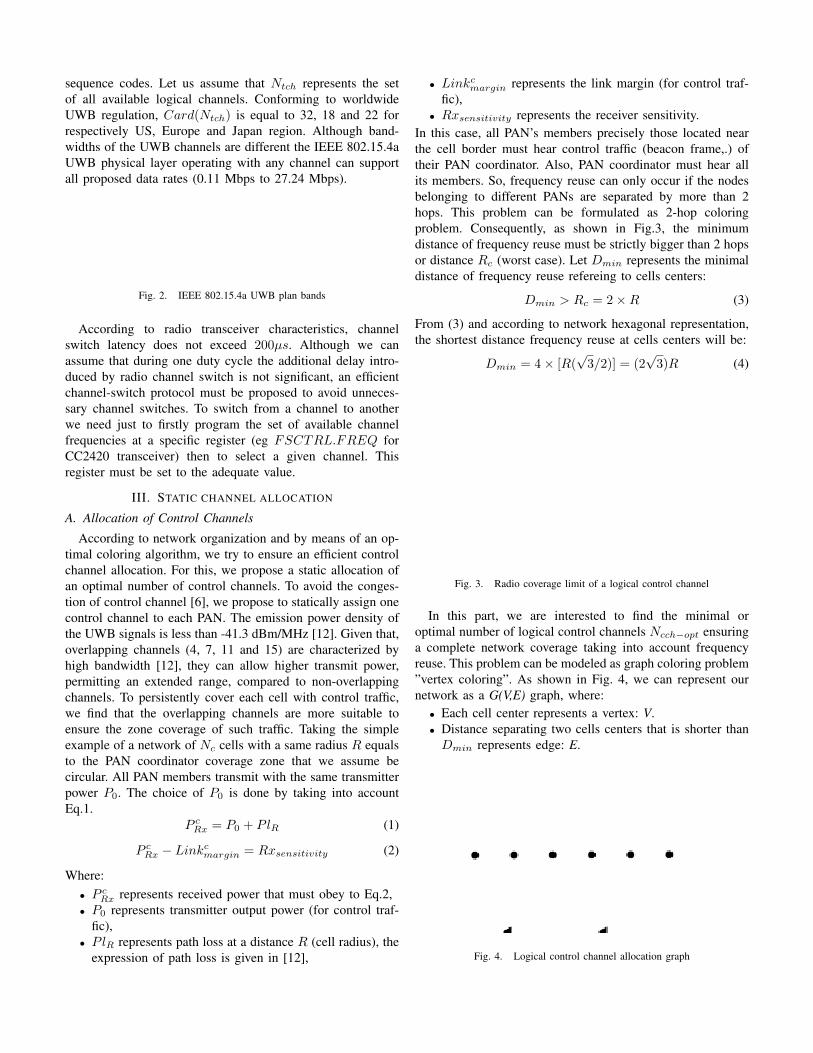
• Rxsensitivity represents the receiver sensitivity.In this case, all PAN’s members precisely those located nearthe cell border must hear control traffic (beacon frame,.) oftheir PAN coordinator. Also, PAN coordinator must hear allits members. So, frequency reuse can only occur if the nodesbelonging to different PANs are separated by more than 2hops. This problem can be formulated as 2-hop coloringproblem. Consequently, as shown in Fig.3, the minimumdistance of frequency reuse must be strictly bigger than 2 hopsor distance Rc (worst case). Let Dmin represents the minimaldistance of frequency reuse refereing to cells centers:
Dmin > Rc = 2×R (3)
From (3) and according to network hexagonal representation,the shortest distance frequency reuse at cells centers will be:
Dmin = 4× [R(√3/2)] = (2
√3)R (4)
Fig. 3. Radio coverage limit of a logical control channel
In this part, we are interested to find the minimal oroptimal number of logical control channels Ncch−opt ensuringa complete network coverage taking into account frequencyreuse. This problem can be modeled as graph coloring problem”vertex coloring”. As shown in Fig. 4, we can represent ournetwork as a G(V,E) graph, where:• Each cell center represents a vertex: V.• Distance separating two cells centers that is shorter thanDmin represents edge: E.
Fig. 4. Logical control channel allocation graph

According to Fig. 4 no two cells near than Dmin share thesame control channel. For that we can call for one of optimalcoloring algorithms such as Zykov’s algorithm, branch andbound method, etc. The application of Zykov’s algorithmto previous graph produces nine sub graphs, due to spacerestrictions; we represent only the final step which is given byFig. 4.b. In step 9, we are left with a complete graph (”A com-plete graph with n vertices obviously requires n colors” [13])with 4 vertices. To cover the entire network by control trafficwithout suffering from co-channel interference, we just need 4different channel frequencies. In [14], we propose an analyticalproof to generalize this result for networks of more than fouradjacent cells.
B. Allocation of Data Channels
Similar to our approach proposed for control channelallocation, we propose the use of the set of residual channelsfor data communication but in the context of full meshnetwork. We assume that all PAN members transmit with thesame transmitter power P1, in order to have a coverage ofradius r.
r < R/2 (5)
Given a PAN’s mesh topology, we propose a multi-hop routinginside each cell where the hop must be equal to (or shorterthan) r in order to:• decrease transmit power to save sensor battery, maximize
network life time and avoid interference,• balance energy consumption and load over all network
cells.The choice of P1 is done by taking into account Eq.6.
P dRx = P1 + Plr (6)
P dRx − Linkdmargin = Rxsensitivity (7)
Where:• P d
Rx represents received power that must obey to Eq.7,• P1 represents transmitter output power (for data traffic),• Plr represents path loss at a distance r,• Linkdmargin represents the link margin (for data traffic).
As shown in Fig.5, taking the example of the 4th cell, we notethat sensors located at or near the cell border can interfere withsensors of adjacent PANs, located at or near their cell border.Consequently, as shown in Fig. 5, the minimum distance offrequency reuse must be strictly bigger than Rc (worst case).Let D′min represents the minimal distance of frequency reuserefereing to cells centers:
D′min > Rc (8)
Rc = R+ r (9)
From (8), (9) and according to network hexagonal representa-tion, the shortest distance frequency reuse at cells centers willbe :
D′min = 3×R (10)
In this part, we are interested to find the minimal num-ber of data communication channels Ndch−opt to cover theglobal network taking into account frequency reuse. Similarto the case of control channel allocation, this problem can betranslated into graph coloring problem applied to the graphG′(V,E) shown by Fig. 6, such that no two adjacent verticesshare the same color. The application of Zykov’s algorithmto graph G′(V,E) produces ten sub graphs. In the 10th stepgiven by Fig. 6.b, we are left with a complete graph. Theoptimal solution is given by the complete graph with threevertices (ie Ndch−opt = 3). To cover the entire networkfrom communication traffic without suffering from co-channelinterference, we just need 3 different channel frequencies.In [14], we propose an analytical proof to generalize this resultfor networks of more than three adjacent cells.
Fig. 5. Radio coverage limit of a logical data communication channel
Fig. 6. Logical data communication channel allocation graph
IV. DYNAMIC DATA CHANNEL ALLOCATION
To ensure dynamic data channel allocation, our approachconsists in taking advantage of data channel allocation method,previously detailed, but with the exploitation of the dutycycle’s information of PANs. According to available datachannel frequencies Ndch and PANs duty cycle, each PANcan benefit simultaneously from several data channels.We define K as :
K = ceil[Card(Ndch)DivNdch−opt] (11)
K represents the number of simultaneous data channel fre-quencies that can benefit each PAN. From a spectrum reg-ulation to another, K isn’t the same, for US: K = 8,Europe: K = 4 and Japan: K = 6. But in reality each
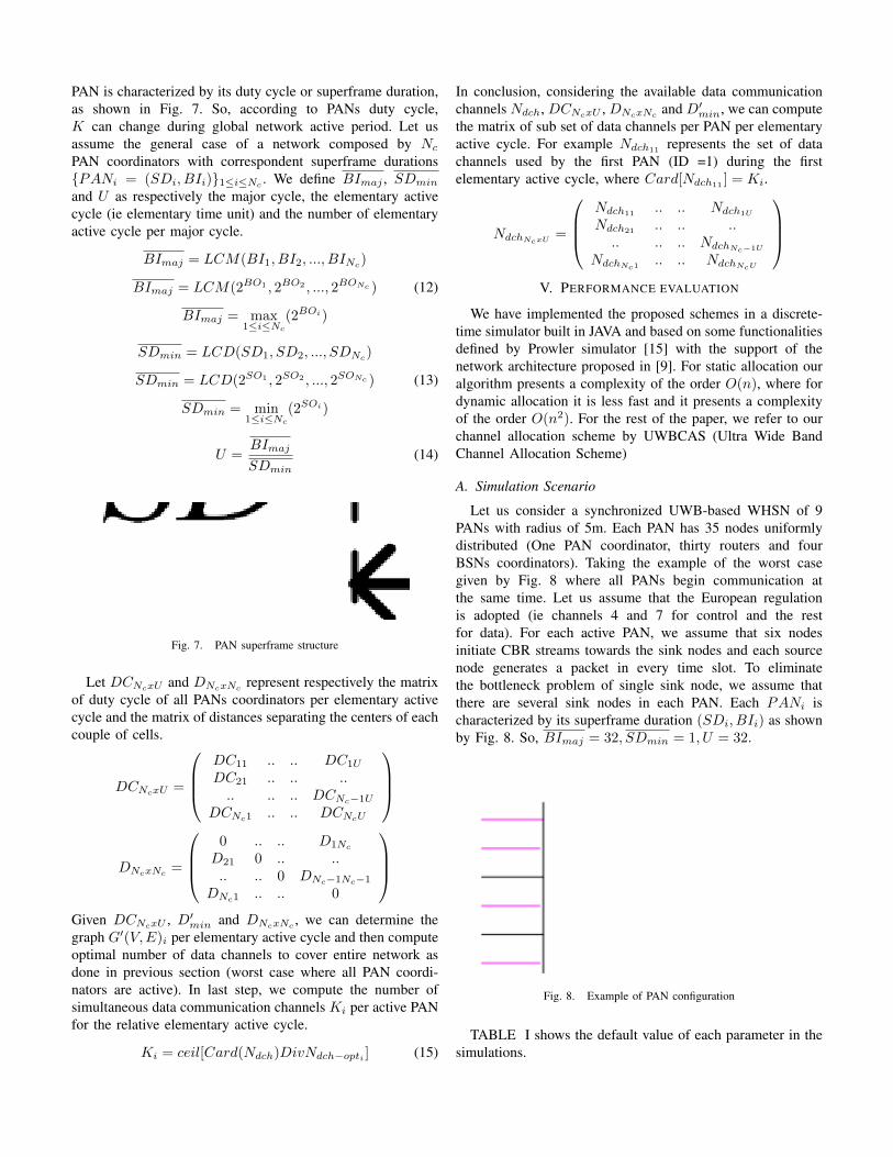
PAN is characterized by its duty cycle or superframe duration,as shown in Fig. 7. So, according to PANs duty cycle,K can change during global network active period. Let usassume the general case of a network composed by Nc
PAN coordinators with correspondent superframe durations{PANi = (SDi, BIi)}1≤i≤Nc
. We define BImaj , SDmin
and U as respectively the major cycle, the elementary activecycle (ie elementary time unit) and the number of elementaryactive cycle per major cycle.
BImaj = LCM(BI1, BI2, ..., BINc)
BImaj = LCM(2BO1 , 2BO2 , ..., 2BONc ) (12)
BImaj = max1≤i≤Nc
(2BOi)
SDmin = LCD(SD1, SD2, ..., SDNc)
SDmin = LCD(2SO1 , 2SO2 , ..., 2SONc ) (13)
SDmin = min1≤i≤Nc
(2SOi)
U =BImaj
SDmin
(14)
Fig. 7. PAN superframe structure
Let DCNcxU and DNcxNc represent respectively the matrixof duty cycle of all PANs coordinators per elementary activecycle and the matrix of distances separating the centers of eachcouple of cells.
DCNcxU =
DC11 .. .. DC1U
DC21 .. .. .... .. .. DCNc−1U
DCNc1 .. .. DCNcU
DNcxNc =
0 .. .. D1Nc
D21 0 .. .... .. 0 DNc−1Nc−1
DNc1 .. .. 0
Given DCNcxU , D′min and DNcxNc , we can determine thegraph G′(V,E)i per elementary active cycle and then computeoptimal number of data channels to cover entire network asdone in previous section (worst case where all PAN coordi-nators are active). In last step, we compute the number ofsimultaneous data communication channels Ki per active PANfor the relative elementary active cycle.
Ki = ceil[Card(Ndch)DivNdch−opti ] (15)
In conclusion, considering the available data communicationchannels Ndch, DCNcxU , DNcxNc
and D′min, we can computethe matrix of sub set of data channels per PAN per elementaryactive cycle. For example Ndch11 represents the set of datachannels used by the first PAN (ID =1) during the firstelementary active cycle, where Card[Ndch11
] = Ki.
NdchNcxU=
Ndch11
.. .. Ndch1U
Ndch21.. .. ..
.. .. .. NdchNc−1U
NdchNc1.. .. NdchNcU
V. PERFORMANCE EVALUATION
We have implemented the proposed schemes in a discrete-time simulator built in JAVA and based on some functionalitiesdefined by Prowler simulator [15] with the support of thenetwork architecture proposed in [9]. For static allocation ouralgorithm presents a complexity of the order O(n), where fordynamic allocation it is less fast and it presents a complexityof the order O(n2). For the rest of the paper, we refer to ourchannel allocation scheme by UWBCAS (Ultra Wide BandChannel Allocation Scheme)
A. Simulation Scenario
Let us consider a synchronized UWB-based WHSN of 9PANs with radius of 5m. Each PAN has 35 nodes uniformlydistributed (One PAN coordinator, thirty routers and fourBSNs coordinators). Taking the example of the worst casegiven by Fig. 8 where all PANs begin communication atthe same time. Let us assume that the European regulationis adopted (ie channels 4 and 7 for control and the restfor data). For each active PAN, we assume that six nodesinitiate CBR streams towards the sink nodes and each sourcenode generates a packet in every time slot. To eliminatethe bottleneck problem of single sink node, we assume thatthere are several sink nodes in each PAN. Each PANi ischaracterized by its superframe duration (SDi, BIi) as shownby Fig. 8. So, BImaj = 32, SDmin = 1, U = 32.
Fig. 8. Example of PAN configuration
TABLE I shows the default value of each parameter in thesimulations.

TABLE ISIMULATION PARAMETER
Parameter Default valueNumber of PANs 9
PAN’s radius 5mNumber of Nodes 35 : (1 PAN coordinator,
per PAN 4 BSNs, 30 Routers)Node placement Uniform
Communication rate 850KbpsRadio range 5m for control, 2m for data
Data Packet length 127BytesSystem Load 6 packet/PAN/Time slot
Time slot duration 0.985msSOmin 4 , (PAN ’s superframe Order
will be normalized by SOmin)Network Duty Cycle See Fig. 8
We conduct simulation with the configuration given inTABLE I. We obtain a data channel distribution as illustratedin Fig. 9, where:• During the 1st, 2nd and 17th elementary cycles, each
active PAN benefits simultaneously from 4 channels.• During the 3rd, 4th, 9th, 18th and 25th elementary cycles
each active PAN benefits from 7 channels (completegraph is composed by two vertices).
• During the 5th, 6th, 7th, 8th, 19th and 20th elementarycycles, only one PAN (1st or 9th ) is active which benefitssimultaneously from all available channels.
• During the 10th and 26th elementary cycles only twoPANs (4th and 8th) are active, each one benefits simulta-neously from all available channels because the distanceseparating those two PANs is greater than D′min.
1 2 3 4 5 6 7 8 9 10 17 18 19 20 25 260
2
4
6
8
10
12
14
16
Elementary active cycle
Nb
of A
lloca
ted
Cha
nnel
s
Static Allocation
PAN1PAN2,6
PAN3,5
PAN4
PAN7PAN8
PAN9
Fig. 9. Data channel allocation during active elementary cycles
Fig. 10 illustrates the results obtained with static and dynamicdata channel allocation. The simulation is conducted withdifferent spectrum regulations as well. We note that with staticdata channel allocation, the maximum number of allocatedchannels per PAN is 8, 6 and 4, respectively for US, Japaneseand European regulation. Where with dynamic data channelallocation, during given elementary cycles, active PANs canbenefit from supplementary channels which are initially beenallocated to some other PANs.During the 5th, 6th, 7th, 8th, 10th, 19th, 20th and 26th,
active PANs benefit up to 28, 18 and 14 in respectively US,Japanese and European regulation.
1 2 3 4 5 6 7 8 9 10 17 18 19 20 25 260
5
10
15
20
25
30
Active Cycle
Nb
of A
lloca
ted
Cha
nnel
per
Act
ive
PA
N
US−Dyn Japan−Dyn Europe−Dyn US−Sta Japan−Sta Europe−Sta
Fig. 10. Static vs Dynamic channel allocation
B. Comparative Performance Evaluation
In this part, we conduct simulations to compare UWBCAS,on the one hand, with MCMAC [7], characterized by acomplexity of the order O(n), in terms of channel utility,throughput and delay and, on the other hand, with MMSN [4],characterized by a complexity of the order O(n2), in terms ofrequired number of channels to enable the network operation.
1) Channel Utility: We define the Channel Utilityj asthe ratio of the sum of channel frequencies used by eachactive PAN per available data channel frequencies (of the jth
elementary cycle).
Channel Utilityj =
Nactivej∑i=0
Ndchij
Ndch(16)
where Nactivej represents the number of active PAN duringthe jth elementary cycle, with Nactivej ≤ Nc.In this part, we compare the behavior of each scheme in termsof channel utility for the same amount of load. As shownin Fig. 11, the MCMAC presents a constant channel utilitypercentage given that it allows only one PAN to be active.With UWBCAS, from an active cycle to another, results varyaccording to the variation of the number of both active PANsand allocated channels per active PAN. It is observed thatUWBCAS always exhibits better performance than MCMACbecause it allows several PANs to communicate simultane-ously. This can ensure the full use of available resource.

0 1 2 3 4 5 6 7 8 9 10 17 18 19 20 25 26
25
50
75
100
125
150
175
200
225
240
Elementary Cycle
ChannelUtility(%)
Our Scheme
MCMAC
UWBCAS
Fig. 11. Channel Utility vs Time
Fig. 12 highlights the behavior of UWBCAS in terms ofchannel utility through the whole network by varying thesystem load. We note that the channel utility increases withthe increase of the system load and it can increase more whenthe number of active PANs increases. Almost in every case,we discover that the channel utility performance of UWBCASis better than that of MCMAC. Fig. 12 shows that, with allsystem loads, our protocol becomes more spectrum efficientwhen the number of active PAN are important which isconsistent with the result presented in the previous experiment.
10 15 20 25
25
50
75
100
125
150
175
200
225
Number of CBR stream
ChannelUtility(%)
Our Scheme: 1st Cycle
Our Scheme: 2nd Cycle
Our Scheme: 3rd, 4th, 9th Cycles
Our Scheme: 5th, 6th, 7th, 8th, 19th, 20thCycles
Our Scheme: 10th,17th, 26thCycles
Our Scheme: 18thCycle
MCMAC
UWBCAS
UWBCAS
UWBCAS
UWBCAS
UWBCAS
UWBCAS
Fig. 12. Channel Utility vs System Loads Variety
2) Throughput: We take the global throughput as a met-ric to measure schemes performance. Fig. 13 shows that,MCMAC presents almost a static behavior where UWBCASoffers better results. Once again, UWBCAS makes its proofto guarantee the enhancement of the throughput of the globalnetwork. This guarantee comes from the exploitation of thedynamic data channel allocation policy based on PANs dutycycle’s information that avoids the underutilization of spec-trum resource and maximizes the number of used channelsper active PAN.
0.1 0.2 0.3 0.4 0.5 0.60
0.5
1
1.5
2
2.5
3
3.5
4
x 106
Time (sec)
Thr
ough
put (
Byt
e pe
r se
c)
MCMAC
UWBCAS
Fig. 13. Throughput vs Time
Although globally our model offers the best result but if weanalyze the behavior of a single PAN per time slot we findthat MCMAC presents a slightly enhanced result as shown inFig. 14. With MCMAC, given that there are only one activePAN per cycle all available channels will be allocated to it.This can locally enhance PAN’s performance during giventime slots but not globally for the entire network.
10 20 30 40 50 60 70 80 90 100 0
1
2
3
4
5
6
7
x 105
Time (msec)
Thr
ough
put (
Byt
e pe
r se
c)
MCMAC UWBCAS (PAN1)
Fig. 14. Throughput vs Time of the first PAN
3) Delay: We define the average end-to-end delay perpacket as the ratio of the sum of delay (δi) experienced byeach packet making up the flow per number of packets (N).
AVG(End2End Delay per packet) =
N∑i=0
δi
N(17)
We propose to evaluate the behavior of both schemes in termsof the average end-to-end delay per packet. Fig. 15 shows thatUWBCAS always exhibits better performance than MCMAC.With UWBCAS, the decrease of the end to end delay ismainly due, on the one hand, to the increase of the number ofsimultaneous communications and, on the other hand, to theavoidance of the phenomena of congestion (data and controltraffic).

0.02 0.04 0.06 0.08 0.1 0.12 0.14 0.16 0.18 0.20
0,001
0,002
0,003
0,004
0,005
0,006
0,007
0,008
0,009
0,01
Time (sec)
AV
G E
nd to
End
Del
ay p
er p
acke
t (m
sec)
MCMAC UWBCAS
Fig. 15. Delay vs Time
4) UWBCAS vs MMSN: Taking the case of the first schemeproposed by MMSN (exclusive frequency assignment scheme)and UWBCAS, we propose to give an idea about the numberof required channels, to enable the operation of the network,for different node densities. The node density is increasedfrom 6 to 21 by configuring different radio ranges (from 1.5to 3.5 m). Fig. 16 mentions that the behavior of exclusivefrequency assignment scheme is considerably sensitive to thenode density factor. The number of required channels increaseswhen the node density increases. Contrarily to MMSN, withUWBCAS the operation of the network doesn’t depend onthe node density factor. We need at most seven differentchannel frequencies to launch the network then to improve itsperformance the use of more channel frequencies is encour-aged. Compared to UWBCAS, exclusive frequency assignmentscheme can not ensure an efficient use of spectrum resourcegiven that it allocates channels in static way that limits channelutility as a node does not permanently use its assigned channel.
6 10 13 17 210
5
10
15
20
25
30
35
40
45
Node density
Num
ber
of r
equi
red
chan
nels
MMSN
UWBCAS (Nb of adjacent cells>3)UWBCAS (Nb of adjacent cells=3)
UWBCAS (Nb of adjacent cells=2)
Fig. 16. Required channels in UWBCAS and MMSN in function of nodedensity
VI. CONCLUSION
In this paper, we presented frequency allocation schemesfor an efficient spectrum management, in large-scale and denseWSNs. We have decomposed the frequency allocation probleminto two sub-problems: static control channel allocation toensure a permanent control channel frequency per PAN avoid-ing the problem of control channel congestion and dynamic
data channel allocation based on PANs duty cycle’s informa-tion and spatial frequency reuse to avoid the underutilizationof spectrum resource. We implemented our schemes on ina discrete-time simulator built in JAVA. Evaluation resultsdemonstrate that our schemes come to reach our goals interms of spectrum efficiency which under an adequate multi-channel MAC protocol can significantly improve networkperformances. In this way, we can ensure, on the one hand,an efficient and fair data channel allocation between PANspermitting an enhancement of QoS of the entire network and,on the other hand, a maximization of the channel utility. Ascontinuation of this work, we propose in future a prioritizedmulti-channel multi-time slot MAC protocol for Large-ScaleWSNs.
REFERENCES
[1] X. Wang and T. Berger, ”Spatial channel reuse in wireless sensornetworks”, Wireless Networks Journal, vol 14, pp. 133-146, March 2008.
[2] CC2420 datasheet, 2004 chipcon,inst.eecs.berkeley.edu/ cs150/Documents/CC2420.pdf
[3] X. Lagrange, P. Godlewski and S. Tabbane, ”Reseaux GSM-DCS ”,Herms Sciences Publications, 1999.
[4] G. Zhou, C. Huang, T. Yan, T. He and J. Stankovic, A. Abdelza-her, ”MMSN: multi-frequency media access control for wireless sensornetworks”, INFOCOM 2006. 25th IEEE International Conference onComputer Communications Proceedings, April 2006, pp. 1 - 13.
[5] R.E. Cagley, S.A. McNally and M.R. Wiatt, ”Dynamic channel allocationfor dynamic spectrum use in wireless sensor networks” Military Commu-nications Conference, October 2006, pp. 1-5.
[6] H. So, W. Walrand and J. Jeonghoon, ”McMAC: a parallel rendezvousmulti-channel MAC protocol”, IEEE Wireless Communications and Net-working Conference, March 2007, pp. 334-339.
[7] X. Chen, P. Han, Q. He, S. Tu and Z. Chen,”A multi-channel MACprotocol for wireless sensor networks”, The 16th IEEE InternationalConference on Computer and Information, 2006, pp.224-229.
[8] A. Rangnekar, K.M. Sivalingam, ”Multiple Channel Scheduling in UWBbased IEEE 802.15.3 Networks”, Proceedings of the First InternationalConference on Broadband Networks, October 2004, pp.406-415.
[9] J. Ben Slimane, Y.Q .Song, A. Koubaa, M. Frikha, ”A Three-TieredArchitecture for Large-Scale Wireless Hospital Sensor Networks”, theInternational Workshop on Mobilizing Health Information to SupportHealthcare-Related Knowledge Work - MobiHealthInf 2009, pp 20-31.
[10] J. Jemai, R.Piesiewicz, T.Kurner, ”Calibration of an indoor radio propa-gation prediction model at 2.4 GHz by measurements of the IEEE 802.11bpreamble” IEEE 61st Vehicular Technology Conference, Spring. 2005,Vol1, pp.111-115.
[11] B. Raman, ”Channel Allocation in 802.11-Based Mesh Networks”, 25thIEEE International Conference on Computer Communications, INFO-COM 2006, pp. 1-10.
[12] IEEE 802.15.4a Standard Part 15.4: IEEE Standard for InformationTechnology, Amendment to IEEE Std 802.15.4-2006, 2007.
[13] A. Kathryn, ”Classical Techniques”, Springer US Book, chapter 2, 2005,pp.19-68.
[14] J. Ben Slimane, Y.Q .Song, A. Koubaa, M. Frikha, ”Allocation of controland data channels for Large-Scale Wireless Sensor Networks”, Technicalreport, 2008, http://hal.inria.fr/inria-00322584/fr/.
[15] http://www.isis.vanderbilt.edu/projects/nest/prowler/.