control architecture for segmented trajectory following...
TRANSCRIPT

Control Architecture for Segmented Trajectory
Following of a Wind-Propelled Autonomous
Catamaran
Gabriel H. Elkaim∗ and Robert J. Kelbley†
University of California, Santa Cruz, Santa Cruz, CA, 95064, USA
An autonomous surface vehicle, based on a Prindle-19 catamaran and substituting aself-trimming vertical wing for the sail, was developed to demonstrate precision guidanceand control. This vehicle, the Atlantis, was demonstrated to track straight line segmentsto better than 0.3 meters (one σ) when already trimmed for sail along the segment. Inorder to make the Atlantis useful as an autonomous vehicle, however, more complicatedpaths are required than simple straight line segments. A segmented trajectory is developedbased on waypoints, segments, and arcs as the path primitives. A control architecture isalso developed which can traverse a segmented trajectory made of linked path primitives,given reachability constraints due to wind direction. For segments where the destination isunreachable due to the wind direction a lane width is established and an on-the-fly tackingmode is used to traverse the segment while remaining within the lane width. A nonlinearmodel of the catamaran was simulated using Simulink, including realistic wind and currentmodels. The control architecture was applied to the simulated catamaran using MonteCarlo simulations which demonstrated very robust segment traversal while maintaining acrosstrack error of less than one meter throughout the path.
I. Introduction
Autonomous marine navigation using wind-powered propulsion has been demonstrated by the Atlantisto an accuracy better than 0.3 meters (one σ) for line following applications. This achievement hints at thepossibilities of autonomous ocean vehicles which can traverse great distances restricted only by the availabilityof wind and electronic positioning systems. Wind-propelled Autonomous Surface Vehicles (ASV’s) canprovide unmanned coastal cruising capabilities with energy efficiency for a myriad of sensing and scientificmeasurement missions.
The addition of a more advanced guidance system using waypoint navigation to the Atlantis will allowit to perform as a fully functional ASV. The control architecture for this guidance system uses a fixed seriesof latitude and longitude coordinates to mark points along the way to its final destination. The details ofthe control architecture for this segmented trajectory following model will be outlined, including details ofthe simulation models used throughout testing.
The key components of the Atlantis are discussed in Section II, including previous results of precise linefollowing control. The different simulation models used for guidance system testing are shown in Section IIIincluding the nonlinear model of the ocean vehicle, water current and wave disturbances, and the wingsailpropulsion system. An analysis of the closed loop controller used is highlighted in Section IV. The generationof segmented trajectories consisting of arcs and lines to connect waypoints is then outlined in Section V,including a real-time tacking procedure to traverse line segments that are unreachable due to wind directionlimitations. The nonlinear 3 DOF (Degrees of Freedom) simulation results are presented in Section VI andfinally a conclusion is provided in Section VII.
∗Assistant Professor, Department of Computer Engineering, UCSC, 1156 High St., Santa Cruz, CA, 95064, USA.†Graduate Student, Department of Computer Engineering, UCSC, 1156 High St., Santa Cruz, CA, 95064, USA.
1 of 14
American Institute of Aeronautics and Astronautics

Figure 1. Atlantis with wingsail, January 2001.
II. The Atlantis
A. System Overview
The Atlantis, pictured in figure 1, is an unmanned, autonomous, GPS-guided, wingsailed sailboat. TheAtlantis has demonstrated an advance in control precision of a wind-propelled marine vehicle to an accuracyof better than one meter. This quantitative improvement enables new applications, including unmannedstation-keeping for navigation or communication purposes, autonomous “dock-to-dock” transportation ca-pabilities, emergency “return unmanned” functions, precision marine science monitoring,1 and many othersstill to be developed. The prototype is based on a modified Prindle-19 light catamaran.
The wind-propulsion system is a rigid wingsail mounted vertically on bearings to allow free rotation inazimuth about a stub-mast. Aerodynamic torque about the stub-mast is trimmed using a flying tail mountedon booms joined to the wing. This arrangement allows the wingsail to automatically attain the optimumangle to the wind, and weather vane into gusts without inducing large heeling moments. Modern airfoildesign allows for an increased lift to drag ratio (L/D) over a conventional sail, thus providing thrust whilereducing the overturning moment.
The system architecture is based on distributed sensing and actuation, with a high-speed digital serial busconnecting the various modules together. Sensors are sampled at 100Hz., and a central guidance navigationand control (GNC) computer performs the estimation and control tasks at 5Hz. This bandwidth has beendemonstrated to be capable of precise control of the catamaran.
The sensor system uses differential GPS (DGPS) for position and velocity measurements, augmentedby a low-cost attitude system based on accelerometer- and magnetometer-triads. Accurate attitude anddetermination is required to create a synthetic position sensor that is located at the center-of-gravity (CG)of the boat, rather than at the GPS antenna location.
Previous experimental trials recorded sensor and actuator data intended to excite all system modes. Asystem model was assembled using Observer/Kalman System Identification (OKID) techniques.2 An LQGcontroller was designed using the OKID model, using an estimator based on the observed noise statistics.Experimental tests were run to sail on a precise track through the water, in the presence of currents, wind,
2 of 14
American Institute of Aeronautics and Astronautics

and waves.
B. Previous Line Following Control Results
In order to validate the performance of the controllers and all up system, closed loop control experimentswere performed in Redwood City Harbor, California, on January 27, 2001. These tests were intended toverify that the closed loop controllers were capable of precise line following with the increased disturbancesdue to the wingsail propulsion. No modifications were made to the LQR controller design, and the testswere run on a day with approximately 12 knots (or 6 m/s) of wind, with gusts up to the 20 knot (or 10 m/s)range.
Upon analyzing the data, it was demonstrated that the Atlantis was capable of sailing to within 25degrees of the true wind direction. Figure 2 presents a close-up of the first path of regulated control, andlooks at the crosstrack error, azimuth error, and velocities while tracking a line. Note that the dark line inthe top of the boat speed graph is the wind speed, and can be seen to vary well over 50% of nominal.
Figure 2. Sailing path errors.
The mean of the crosstrack error is less than 3 cm., and the standard deviation is less than 30 cm.,note that this is the Sailboat Technical Error (STE, the sailing analog of Flight Technical Error) definedas the difference between the position estimated by the GNC computer and the desired sailboat position.Previous characterization of the coast-guard differential GPS receiver indicated that the Navigation SensorError (NSE) is approximately 36 cm., thus the Total System Error (TSE) is less than 1 meter.
III. System Models
A. Vehicle Model
In order to simulate control of the Atlantis a nonlinear 3 DOF system model was needed. While severalgood modeling techniques exist to model a powered boat through the water,4 they remain complicated anddifficult to calculate. To formulate the equations of motion, the Atlantis is assumed to be travelling upon astraight line, conveniently assumed to be coincident with the X-axis, through the water at a constant speed,Vx. The distance along that line is referred to as X, the along-track distance. The perpendicular distanceto the line is referred to as Y , the crosstrack error, and the angle that the centerline of the Atlantis makeswith respect to the desired path is defined as Ψ, the angular error. This frame is referred to as the controlframe. Figure 3 illustrates the mathematical model of the assumed path of the Atlantis, where Y , Ψ, and δare defined as the crosstrack error, azimuth error, and rudder angle, and L is the length from the center of
3 of 14
American Institute of Aeronautics and Astronautics

gravity (CG) of the boat to the center of pressure of the rudders.
Figure 3. Control frame definitions.
These simplified equations of motion are insufficient to model the boat to great precision, but are anexcellent basis for simulating controlled trajectory following for the catamaran.
This model is a simple kinematic model that assumes that the rudders cannot move sideways throughthe water; that is this model places a kinematic constraint upon the motion of the entire boat. In order tosimplify the equations of motion, these equations are written in the body frame, which is rigidly attached tothe vehicle having the x-axis pointing directly from the bow of the boat and y-axis pointing out the starboardside. In these coordinates, the equations of motion are:
x = Vx (1)y = 0 (2)
Ψ =Vx
Lsin (δ) (3)
Based on prior data, though simplified, a kinematic model yields good experimental results. Using steadystate turn data, we computed an effective length for the centerboard to rudder distance, L, which was foundto be 2.95 m. Figure 4 shows the experimental constant turning radius data used for centerboard to rudderdistance calculations.
The North-East-Down (NED) coordinate system attached to the Earth is used as the navigation frame.The relative orientation of the body frame to the navigation frame is described using the [3-2-1] Euler angles:yaw (ψ), pitch (θ), and roll (φ). In this work, the full vehicle 6 DOF model is reduced to 3 DOF by assumingthe vehicle will remain level on the water surface (and hence that the pitch and roll angles are very small).
The desired heading of the Atlantis in the navigation frame is the trajectory generated from the controlarchitecture discussed in Section V and will be defined as Ψref . Therefore, knowing the heading error fromthe control frame (Ψ) and the control frame’s orientation to the navigation frame (Ψref ), the body frameparameters can be transformed to the navigation frame where Ψboat is the orientation of the body frame inthe navigation frame (the heading of the boat in reference to North):
4 of 14
American Institute of Aeronautics and Astronautics

Figure 4. Trajectory of Atlantis as viewed from above when generating turning radius data at constant rudderangles.
Ψboat = Ψref + Ψ (4)
N = Vx cos (Ψboat) (5)
E = Vx sin (Ψboat) (6)
B. Water Current and Wave Disturbance Model
A combination of two Gauss-Markov processes were used to model water currents and wave disturbances onthe surface craft. That is, the disturbances are modelled as:
Vcurrent =−1
τcurrentVcurrent + νcurrent (7)
Vwave =−1τwave
Vwave + νwave (8)
Vdist = Vcurrent + Vwave (9)
Where τ is a time constant, and ν is white noise. These are tuned to match experimental data by changingthe correlation time constant and the standard deviation of the white noise. The first Gauss-Markov processis assumed to be water currents that change gradually over time. The second process models waves thatproduce higher frequency disturbances on the boat’s hull. An exact analog formula is used for the directionof the waves (and also the wind).
These disturbances are assumed to alter the velocity of the boat in the navigation frame (Eq. 5-6)directly:
Ψboat = Ψref + Ψ (10)
N = Vx cos (Ψboat) + Vdist cos (Ψdist) (11)
E = Vx sin (Ψboat) + Vdist sin (Ψdist) (12)
Figure 5 shows a water speed and direction model generated from the combination of these stochasticprocesses.
5 of 14
American Institute of Aeronautics and Astronautics
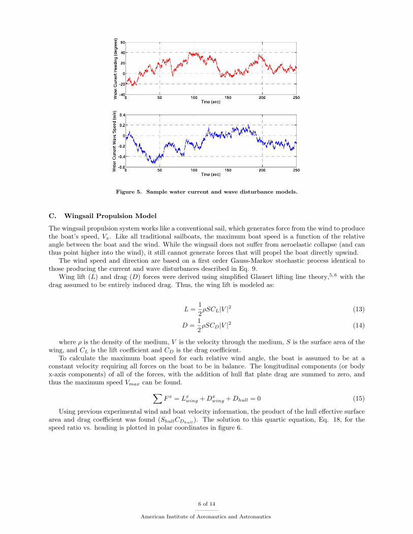
Figure 5. Sample water current and wave disturbance models.
C. Wingsail Propulsion Model
The wingsail propulsion system works like a conventional sail, which generates force from the wind to producethe boat’s speed, Vx. Like all traditional sailboats, the maximum boat speed is a function of the relativeangle between the boat and the wind. While the wingsail does not suffer from aeroelastic collapse (and canthus point higher into the wind), it still cannot generate forces that will propel the boat directly upwind.
The wind speed and direction are based on a first order Gauss-Markov stochastic process identical tothose producing the current and wave disturbances described in Eq. 9.
Wing lift (L) and drag (D) forces were derived using simplified Glauert lifting line theory,5,6 with thedrag assumed to be entirely induced drag. Thus, the wing lift is modeled as:
L =12ρSCL|V |2 (13)
D =12ρSCD|V |2 (14)
where ρ is the density of the medium, V is the velocity through the medium, S is the surface area of thewing, and CL is the lift coefficient and CD is the drag coefficient.
To calculate the maximum boat speed for each relative wind angle, the boat is assumed to be at aconstant velocity requiring all forces on the boat to be in balance. The longitudinal components (or bodyx-axis components) of all of the forces, with the addition of hull flat plate drag are summed to zero, andthus the maximum speed Vmax can be found.∑
F x = Lxwing +Dx
wing +Dhull = 0 (15)
Using previous experimental wind and boat velocity information, the product of the hull effective surfacearea and drag coefficient was found (ShullCDhull
). The solution to this quartic equation, Eq. 18, for thespeed ratio vs. heading is plotted in polar coordinates in figure 6.
6 of 14
American Institute of Aeronautics and Astronautics

K =(ρH20ShullCDhull
ρairSwingCLwing
)2
(16)
σ =sin (Ψ) − (D/L) cos (Ψ) (17)((D/L)2 −K
)V 4
max + 2Vwind(D/L) ((D/L) cos(Ψ) − σ)V 3max
+ V 2wind
((D/L)2 + σ2 − 4(D/L)σ cos(Ψ)
)V 2
max
+ 2V 3windσ (σ cos(Ψ) − (D/L))Vmax + V 4
windσ2 = 0 (18)
where in Eq. 18 Ψ = Ψboat − Ψwind.
Figure 6. Wind Angle vs|Vmax|
|Vwind−Vmax|.
When running downwind the propulsion is based mainly on drag, as opposed to lift. In this case thesimplified analysis fails to take into consideration the additional drag from a stalled wing. To account forthis added propulsion a spline has been inserted into the speed ratio plot to more accurately represent boatspeed when the Atlantis is running before the wind.
Lastly, in order to simulate the momentum of the Atlantis through the water, the speed is low-pass filtered,with a time constant of approximately 5 seconds. This provides a response comparable to experimental resultswithout needing to estimate either the exact mass nor the complicated hull water interactions.
Vx(s) =0.2
s+ 0.2Vmax(s) (19)
IV. Controller Analysis
A simple proportional plus integral (PI) feedback controller is used to stabilize the nonlinear boat modelwhen following trajectories in the presence of wave disturbances. The controller takes as input the boat’sheading error (Ψerror) and crosstrack error (Yerror). Proportional and integral gains are then applied tothese inputs to generate a reference rudder angle (δref ) to direct the boat back on its proper trajectory.
7 of 14
American Institute of Aeronautics and Astronautics

It was previously shown7 that our boat model will loose stability as the boat speed reaches a certain pointbeyond the controller’s design point V design
x . To address this problem, the controller can compensate for theboat’s speed using a gain-scheduled controller or by applying input pre-scaling to obtain a velocity invariantcontroller. In our simplified model, we will instead show that our controller is stable up to a specific boatspeed point, which can never be exceeded in any of our simulations.
The boat speed design point V designx = 2.0 m/s was used to find controller gain values that minimized
steady state errors in the presence wave disturbances and provided a quick transient response. The Eqs. 3-6were then linearized around a small variance in boat heading providing the linearized equations:
Ψ =Vx
Lδ (20)
N = Vx (21)
E = VxΨboat (22)
A block diagram of the linearized equations combined with the closed loop PI controller gains is shownin figure 7. Assuming the reference heading for the boat is due North (Ψref = 0◦), the transfer function forthe closed loop system is then formulated as:
Yerror(s) =(V 2
x
L
)s
s3 + KΨVx
L s2 + KY V 2x
L s+ KYiV 2
x
L
(23)
where for our controller design KY = 3.0, KYi= 0.25, and KΨ = 2.0.
Figure 7. Block diagram of linearized boat equations combined with PI controller gains.
A mapping of the closed loop system poles from Eq. 23 is shown in figure 8 as a function of Vx. Theclosed loop system poles will remain stable as the boat’s speed is increased for this linearization of ourkinematic equations. The natural frequency of the linearized closed loop system for V design
x = 2.0 m/s is 2.0rad/s. Testing of the nonlinear model was then performed by simulating a step input for the crosstrack andheading errors and observing the resulting steady state system response. A stable response was observed forboat velocities up to 7 m/s, well beyond the maximum operating point for the wing-sail propulsion system.
V. Segmented Trajectory Generation
A. Arcs and Lines
The waypoint navigation system uses a series of user defined waypoints as reference points for navigation.The Atlantis could simply use these waypoints as heading references, however large crosstrack errors wouldbe produced during waypoint transitions and certain references may be unreachable because of the winddirection. A segmented trajectory of lines connected by arcs of a constant radius is used to provide a pathof achievable trajectories.
Arc segments are added between line segments such that the line segments are tangent to the arc wherethey meet. Figure 9 demonstrates how waypoint inputs are transformed to line and arc segments. In practice,segments will be created in real-time as waypoints are achieved allowing for tacking scenarios to be appliedwhen necessary.
8 of 14
American Institute of Aeronautics and Astronautics

Figure 8. Mapping of closed loop system pole locations as a function of increasing boat speed.
Figure 9. User defined waypoints (left) transformed into arc and line segments (right).
B. Tacking Algorithm
In sailing, a tack is performed when the boat turns such that the bow passes through the wind. Tacking(as a sailing procedure) then refers to the process of making alternate tacks as close as possible to the wind,allowing a sailboat to effectively sail upwind. As shown in figure 6, if the Atlantis attempts to sail directlyupwind it will eventually be “in irons” meaning it will lose all speed and stall out. A lane width for thedesired line segment is defined and used to tack back and forth through the desired heading until the nextwaypoint is reached. The Atlantis must be prepared to tack at any point should the wind change andthe waypoint become unreachable. As such, a real-time tacking algorithm was developed for the guidancesystem that provides navigation within the defined lane width allowing waypoints to be achieved whileavoiding unreachable points of sail.
Figure 10 depicts an ocean vehicle traversing a line segment with a varying wind direction (left side).
9 of 14
American Institute of Aeronautics and Astronautics

As the wind shifts inside a defined wind heading allowance, the water craft adjusts its heading to navigatewithin the desired lane width.
Figure 10. Surface vehicle adjusting to tacking routine in reaction to changing wind headings (left side).
C. Initial Segment Acquisition
Unless the vehicle starts in the exact same position as the first line segment, a technique to provide a referenceheading that progressively locks on to the first segment must be used. A reasonable heading for the vehiclewould be to command the boat to a 90◦ angle towards the line until it gets closer, and then angle towardsthe line in the direction of the desired navigation.
An easy method to achieve this curved trajectory is to create a reference heading to the line that is afunction of the vehicle’s crosstrack in the control frame. By definition, as the surface craft moves closer tothe desired line segment, its crosstrack will approach zero. Therefore, a desired heading to the line can bederived as:
Ψcontrolref = arctan
(Y
τ
)(24)
where Y is the crosstrack value and τ is a constant that determines how steep a trajectory the boat willtake to acquire the line. Figure 11 shows the Atlantis using this technique for line acquisition using τ = 5and then switching to the PI controller for line following when Y < 0.5 m.
VI. Simulation Results
Using the boat, wind, and wave models outlined in Section III, the PI controller discussed in Section IVwas used to follow the set of trajectories generated from predefined waypoints as described in Section V.The controller monitors both the heading error Ψ and crosstrack Y to adjust the rudder position δ. First,a surface vehicle propelled by a constant speed source such as an outboard motor is simulated. Figure 12shows the resulting path and figure 13 displays the heading error and crosstrack error for such a boat. Monte
10 of 14
American Institute of Aeronautics and Astronautics

Figure 11. Acquisition of first segment from distant initial vehicle position.
Carlo simulations providing different random values for wind and wave disturbances show the boat to havean average heading error of 2.2o and an average crosstrack error of 2 cm. as shown in Table 1.
Motorboat SailboatLines Arcs Total Lines Arcs Total
Ψavg(o) 0.69 10.9 2.20 1.20 11.7 3.25Ψσ(o) 4.85 18.6 9.42 8.99 17.8 12.6Ψmax(o) 18.3 34.8 34.8 53.9 40.1 63.0Yavg(m) 0.01 0.15 0.02 0.01 0.27 0.06Yσ(m) 0.08 0.30 0.16 0.10 0.45 0.28Ymax(m) 0.42 0.82 0.82 0.47 1.22 1.23
Table 1. Simulation results.
Using the same PI controller, the varying wingsail speed model was used with the tacking algorithm tofollow the same set of waypoints with identical disturbances. The vehicle path and average wind directionis displayed in figure 14 and resulting heading error and crosstrack error information is shown in figure 15.As with the motorboat, Monte Carlo simulations were completed showing the Atlantis to have a simulatedaverage heading error of 3.25o and an average crosstrack error of 6 cm. Sailboat results are also shown inTable 1.
VII. Conclusions
A control architecture for an autonomous sailboat using a waypoint navigation system and simulatedwith a PI controller is capable of providing robust and reliable guidance under realistic wind and waterdisturbance models. This architecture was applied to a simplified model of the Atlantis, a wingsail propelledcatamaran previously shown capable of line following accuracy better than 0.3 meters. Simulations modelingsimilar experimental conditions previously encountered show that precision control is possible for waypointnavigation requiring segmented trajectory following of arcs and lines and real-time waypoint managementto prevent unreachable points of sail. Simulations show the sailboat can be controlled to better than onemeter accuracy.
This control architecture is not limited to PI controllers, and more advanced controllers will presumablyallow for better system accuracy. The simulation environment discussed will also serve as a developmentplatform for controller comparisons and Hardware-in-the-Loop testing of the ship’s sensors, actuators, andcomplete GNC system.
Future work will include a waypoint generation methodology that will avoid stationary obstacles and also
11 of 14
American Institute of Aeronautics and Astronautics

Figure 12. Control architecture applied to surface vehicle simulated with constant speed propulsion with watercurrent and wave disturbances.
Figure 13. Heading and crosstrack error for constant speed surface vehicle simulation
optimally determine trajectories given only a destination point and weather data forecasts to predict futurewind activity. This added guidance system combined with advancements in Atlantis sensors and actuatorswill create a wind-propelled ASV capable of robust navigation that can be used for a variety of future marineapplications.
References
1Pascoal, A., Olivera, P., and Silvestre, C., “Robotic Ocean Vehicles for Marine Science Applications: The EuropeanASIMOV Project,” OCEANS 2000 MTS/IEEE Conference and Exhibition, Vol. 1, 2000, pp. 409–415.
12 of 14
American Institute of Aeronautics and Astronautics

Figure 14. Control architecture applied to wingsailed vehicle simulated with water current and wave distur-bances.
Figure 15. Heading and crosstrack error for wingsailed surface vehicle simulation.
2Juang, J.-N., Applied System Identification, Prentice Hall, NJ, 1994.3Fossen, T., Guidance and Control of Ocean Vehicles, Wiley and Sons, New York, NY, 1994.4Fossen, T., “A Nonlinear Unified State-Space Model for Ship Maneuvering and Control in a Seaway,” Intl Journal of
Bifurcation and Chaos, Vol. 15, 2005, pp. 2717–2746.5McCormick, B., Aerodynamics, Aeronautics, and Flight Mechanics, John Wiley and Sons, New York, NY, 1979.6R.S.Shevell, Fundamentals of Flight , Prentice-Hall, Inc., Englewood Cliffs, NJ, 1983.7Elkaim, G., System Identification for Precision Control of a Wingsailed GPS-Guided Catamarn, Ph.D. thesis, Stanford
University, 2001.8Encarnacao, P., Pascoal, A., and Arcak, M., “Path Following for Autonomous Marine Craft,” 5th IFAC Conference on
Maneuvering and Control of Marine Craft , 2000, pp. 117–22.9VanZwieten, T., Dynamic Simulation and Control of an Autonomous Surface Vehicle, Ph.D. thesis, Florida Atlantic
University, 2003.
13 of 14
American Institute of Aeronautics and Astronautics
10Skjetne, R. and Fossen, T., “Nonlinear Maneuvering and Control of Ships,” MTS/IEEE OCEANS 2001 , Vol. 3, 2001,pp. 1808–15.
11Lefeber, E., Pettersen, K., and Nijmeijer, H., “Tracking Control of an Underactuated Ship,” IEEE Transactions onControl Systems Technology, Vol. 3, 2003, pp. 52–61.
14 of 14
American Institute of Aeronautics and Astronautics