control features hazardous area connectors - … area connectors. ... 15 15: 15 15: 15 15: h...
TRANSCRIPT

60www.ehawke.com
Connection Solutions
UPD 051515
Hazardous Area ConnectorsCertified ATEX / IECEx / EAC / INMETRO / NEC505
Bulkhead-BR
Connector Plug-CP
Connector Receptacle - CR
Tamb: -40°C to +60°C II2 GD Exdb IIC Gb, Extb IIIC Db T95 IP66, 67 & DTS01 deluge protected Certificate No's Baseefa12ATEX0014X & IECEx BAS 12.0006X.
Control Features

61Connection Solutions
www.ehawke.comUPD 050515
Hazardous Area ConnectorsCertified ATEX / IECEx / EAC / INMETRO / NEC505
Easy FieldwireablePin and socket inserts are numbered front and back to assist wiring and avoid termination errors. Crimp and solder inserts available.
Running CouplerAllows the connector to be installed onto a pre-assembled cable gland. Connector is rear loading and includes locking engaging nut.
Acme Thread at Mating InterfaceUnique ACME thread offers a smooth and quick fully mating action.
Fully Inspectable Flameproof BarrierProvides direct inspection of the flameproof seal and offers users the peace of mind that the connector is safe for installation.
Keying PositionThe unique visual 5 position insert keying system (3 on Ex16) along with the integral machined keyways prevent contact damage and ensures safe use by eliminating the possibility of misconnection of adjacent circuits.
Anti-Rotation DeviceConnector plugs and receptacles come complete with anti-rotation ring, which when fitted between the connector and gland, helps to eliminate the possibility of the gland loosening, locking this in position.
Locking PinOptional locking pin provides the facility for mated connectors to be permanently locked, via the use of a padlock, ensuring they cannot be separated under load. (Padlock not supplied)
Internal Keyway SpacerEases accessibility for termination as tube fitted after termination complete, along with allowing easy installation into the required keyed position (See )
Control Features

62www.ehawke.com
Connection Solutions
UPD 051515
Hazardous Area ConnectorsCertified ATEX / IECEx / EAC / INMETRO / NEC505
Ex16 - 3 x 1.5 Ex16 - 4 x 1.5 Ex25 - 4 x 1.5 Ex25 - 9 x 1.5 Ex25 - 12 x 1.5 Ex25 - 4 x 2.5 Ex25 - 7 x 2.5 Ex25 - 4 x 6Soldered Only
Ex32 - 12 x 1.5 Ex32 - 19 x 1.5 Ex32 - 10 x 2.5 Ex32 - 12 x 2.5 Ex32 - 4 x 6
Ex32 - 6 x 6 Ex32 - 3 x 10 Ex32 - 4 x 10 Ex32 - 3 x 16 Ex32 - 4 x 16
Ex40 - 24 x 1.5 Ex40 - 8 x 6 Ex40 - 5 x 10
Ex40 - 5 x 16
Ex40 - 30 x 1.5 Ex40 - 19 x 2.5
Ex40 - 4 x 25 Ex40 - 4 x 35
Ex50 - 37 x 1.5 Ex50 - 13 x 6Ex50 - 27 x 2.5 Ex63 - 49 x 1.5 Ex63 - 60 x 1.5Ex63 - 37 x 2.5
Hawke Control connectors have a maximum working voltage of 660V DC (660V AC) as standard. 3rd & 4th generation Control connectors can be connected together within certification.
Other voltages available on special request.
INSERT SELECTION TABLE
Configuration
Shell size 16 Shell Size 25 Shell Size 32 Shell Size 40 Shell Size 50 Shell Size 63
3 x 1.5mm² + Earth 4 x 1.5mm² + Earth 12 x 1.5mm² + Earth 24 x 1.5mm² + Earth 37 x 1.5mm² + Earth 49 x 1.5mm² + Earth
4 x 1.5mm² + Earth 9 x 1.5mm² + Earth 19 x 1.5mm² + Earth 30 x 1.5mm² + Earth 27 x 2.5mm² + Earth 60 x 1.5mm² + Earth
- 12 x 1.5mm² + Earth 10 x 2.5mm² + Earth 19 x 2.5mm² + Earth 13 x 6mm² + Earth 37 x 2.5mm² + Earth
- 4 x 2.5mm² + Earth 12 x 2.5mm² + Earth 4 x 25mm² + Earth - -
- 7 x 2.5mm² + Earth 4 x 6mm² + Earth 4 x 35mm² + Earth - -
- 4 x 6mm² + Earth 6 x 6mm² + Earth - - -
- - 3 x 10mm² + Earth - - -
- - 4 x 10mm² + Earth - - -
- - 3 x 16mm² + Earth - - -
- - 4 x 16mm² + Earth - - -Note: Inserts for use in bulkhead receptacles are solder termination only for contact sizes of 6mm² and above.
TABLE
Insert Size
Internal Diameter of cup (mm) Nominal
Soldered Crimped
1.5mm2 2 2
2.5mm2 3 3
6mm2 3.5 3.2
10mm2 7 4
16mm2 7 5
25mm2 8 6.5
35mm2 8 8.3
Control Inserts
63Connection Solutions
www.ehawke.comUPD 050515
Hazardous Area ConnectorsCertified ATEX / IECEx / EAC / INMETRO / NEC505
SELECT CODE DESCRIPTION EXAMPLE
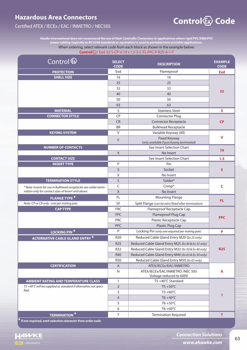
CODEPROTECTION Exd Flameproof Exd
SHELL SIZE 16 16
32
25 2532 3240 4050 5063 63
MATERIAL S Stainless Steel SCONNECTOR STYLE CP Connector Plug
CPCR Connector ReceptacleBR Bulkhead Receptacle
KEYING SYSTEM V Variable Keyway (All)V
F Fixed Keyway (only available if purchasing terminated)
NUMBER OF CONTACTS See Insert Selection Chart19
X No InsertCONTACT SIZE See Insert Selection Chart 1.5INSERT TYPE P Pin
SS SocketX No Insert
TERMINATION STYLE S Solder*
C* Note: Inserts for use in Bulkhead receptacles are solder termi-nation only for contact sizes of 6mm2 and above.
C Crimp*X No Insert
FLANGE TYPE FL Mounting FlangeFL
Note: CP or CR only - one per mating pair. SF Split Flange (can be retro fitted after termination)
CAP TYPE FRC Flameproof Receptacle Cap
FPCFPC Flameproof Plug CapPRC Plastic Receptacle CapPPC Plastic Plug Cap
LOCKING PIN P Locking Pin (only one required per mating pair) P
ALTERNATIVE CABLE GLAND ENTRY R20 Reduced Cable Gland Entry M20 (Ex 25 only)
R25R25 Reduced Cable Gland Entry M25 (Ex 40 & Ex 32 only)
R32 Reduced Cable Gland Entry M32 (Ex 50 & Ex 40 only)
R40 Reduced Cable Gland Entry M40 (Ex 63 & Ex 50 only)
R50 Reduced Cable Gland Entry M50 (Ex 63 only)
CERTIFICATION A ATEX/IECEx/EAC/INMETROAN ATEX/IECEx/EAC/INMETRO /NEC 505
Voltage reduced to 600VAMBIENT RATING AND TEMPERATURE CLASS 1 T5 +40°C Standard
1
T5 +40°C will be supplied as standard if alternative not speci-fied.
2 T5 +50°C3 T5 +60°C4 T6 +40°C5 T6 +50°C6 T6 +60°C
TERMINATION T Termination Required T If not required, omit selection character from order code.
Control
When ordering, select relevant code from each block as shown in the example below: Control / Exd-32-S-CP-V-19 x 1.5-S-C-FL-FPC-P-R25-A-1-T
Hawke International does not recommend the use of their ControlEx Connectors in applications where rigid PVC/SWA/PVC power cabling (typically to BS 6346 standards or equivalnts) is used in portable/semi-portable applications.
Control Code

64www.ehawke.com
Connection Solutions
UPD 051515
Hazardous Area ConnectorsCertified ATEX / IECEx / EAC / INMETRO / NEC505
HAWKE Ex SERIES DIMENSIONS (MM)
Dimension Ex16 Ex25 Ex32 Ex40 Ex50 Ex63A 127 152 152 152 152 148B 105 128 129 129 129 126
Ø C 36 46 53 60 66 83Ø D 37 49 57 65 76 90
E 128 152 152 152 152 152Ø F 32 45 51 59 70 83G 15 15 15 15 15 15
H (nominal) 20 20 20 20 20 20J (Aperture Clearance Hole) 55 65 75 85 95 115
*Thread L (1.5mm Pitch) M25 M32 M40 M50 M63 M75M 54 54 56 56 56 56
N A/F 36 46 55 65 80 95R 15 15 15 16 16 17S 38 38 38 39 39 40
Ø T 28 34 42 51 60 73U 40 40 40 40 40 40
Thread V (1.5mm Pitch) M20 M25 M32 M40 M50 M63X (nominal) 54 70 70 70 70 67
Ø Y 66 76 83 91 102 117 49 59 66 74 85 100
Ø Z 87 99 105 117 129 147 70 82 88 100 112 130
*Bulkhead entry thread L can be adapted to other sizes. This may affect the overall length of unit.
The flameproof cap must be fitted to the connector before the power is restored to the disconnected circuit. The receptacle cap and plug cap are available in acetal and provide an IP rating of IP66/67. They may only be used when the socket or plug is not re-energised following disconnection.
For connector plugs and connector receptacles cable glands are required to terminate incoming cables. Hawke recommend the ICG 653/UNIV cable gland is used.
Connector Plug Connector Receptacle
Split Flange Standard Flange
External Earth AB12X
OptionalMounting Flange
OptionalMounting Flange.Interlocking Plate Interlocking Plate
Gland Entry Thread V
Mating Face
Ø Y
or Z
Ø C
Ø D
Ø J
External earth
Gland Entry Thread V
Ø C
Ø Y
or Z
Ø F
Ø J
12 X
E
M G H
N A
/F
Thre
ad L
Bulkhead Receptacle
FlameproofPlug CapØ
F
Ø T
U
FlameproofReceptacle Cap Ø
D
S
RMating Face
Ø F
Ø J
Ø Z
Ø Y
Ø 8.5Ø 8.5
PCD PCD
90°90°
Control Dimensions
ATEX

65Connection Solutions
www.ehawke.comUPD 050515
Hazardous Area ConnectorsCertified ATEX / IECEx / EAC / INMETRO / NEC505
To select the shell size of the connector, it is essential that you calculate the dissipated wattage of the arrangement. This ensures that the arrangement does not exceed the maximum permitted temperature classification with regard to the upper ambient temperature for the area of installation. (please refer to table 1 for the maximum allowable dissipated wattage per connector size).
TABLE 1
Connector Size
Upper ambient Temperature of
+40°C
Upper ambient Temperature of
+50°C
Upper ambient Temperature of
+60°CTemperature
ClassTemperature
ClassTemperature
Class
T6 T5 T6 T5 T6 T5
Ex16 5W 7W 4W 6W 2.6W 4.6W
Ex25 8W 11W 6W 10W 4W 7W
Ex32 10.5W 14.5W 8W 12W 5.4W 9W
Ex40 12W 17W 9W 14W 5.5W 10.5W
Ex50 13W 20W 10W 17W 6.5W 12.5W
Ex6317W 29W 13W 24W 8.5W 17W
Maximum allowable dissipated wattage
Other ambient temperature options can be extrapolated from Table 1 above, or contact Hawke International for more information.
TABLE 2
Contact Size
Combined Cable and Contact Resistance (Ohms)
Contact Current RatingSoldered Crimped
1.5mm² 0.0166 0.0173 10 amps
2.5mm² 0.0102 0.0109 17 amps
6mm² 0.0047 0.0054 30 amps
10mm² 0.0027 0.0033 78 amps
16mm² 0.0018 0.0024 78 amps
25mm² 0.0012 0.0018 125 amps
35mm² 0.0009 0.0015 125 amps
Dissipated wattage calculationEquation DefinitionsW = Dissipated wattage factor of the connector
N = The number of conductors to be terminated/number of contacts required. (Note: A contact comprises of a pin and socket).
I = The current requirement per contact. (Note: This must be equal to or less than the maximum current rating of the contact, as shown in table 2).
R = The combined cable and contact resistance (see table 2)
Values pertinent to these definitions must then be input into the following equation to calculate the dissipated wattage (w) of your chosen arrangement:
W = N x I² x R(Note: The results must be lower than the maximum figure shown in table 1 for the appropriate temperature class and ambient temperature).
e.g. T6 40°C ambient application with 9 x 1.5mm² conductors, running at 7 amps.
N = 9 contacts I = 7 amps R = 0.0166Ω (1.5mm² soldered combined cable and contact resistance)
Therefore W = 9 x 49 x 0.0166Ω = 7.32 watts.Therefore, an Ex25 Connector should be specified for this application as the shell size can accommodate the required 9 x 1.5mm² pin/socket inserts (SEE PAGE 56 - Insert Selection Table) and the resultant dissipated wattage (7.32 watts) is below the maximum permitted 8 watts (See Table 1).
This equation can also be transposed to facilitate the calculation of the maximum number of conductors permitted in your selected connector and the maximum allowable current within the upper ambient temperature of our location .
(Note: The result of equation must not exceed the maximum current rating of contacts (see table 2).Note: Unless otherwise requested, connectors will be marked as T5 with an upper ambient temperature of +40°C.
Control Calculations
WR x I²
N = I = WN x R