control iii - programming in c (small plc) -...
TRANSCRIPT
Control III Programming in C (small PLC)
Description of the commands
Revision date: 2013-02-21

Subject to modifications without notice.Generally, this manual refers to products without mentioning existing patents, utility models, or trademarks.The absence of any such references doesnot indicate that a product is patent-free.
Control III Programming in C (small PLC)Table of Contents
Issu
e da
te: 2
1.02
.13
Table of Contents
Control III Programming in C (small PLC)
1 Symbol Catalog ....................................................................................7
2 General ..................................................................................................82.1 Product information ........................................................................................ 8
2.2 Introduction ..................................................................................................... 8
3 Safety.....................................................................................................93.1 Intended use .................................................................................................... 9
3.2 General safety information ............................................................................ 9
3.3 Disposal ........................................................................................................... 9
4 Programming Control III ....................................................................104.1 Overview ........................................................................................................ 104.1.1 ASi Data Exchange ...................................................................................................... 124.1.2 AS-i Read IDI ................................................................................................................. 144.1.3 AS-i Write ODI ............................................................................................................... 144.1.4 AS-i Read ODI ............................................................................................................... 144.1.5 AS-i Write Permanent Parameter ................................................................................ 154.1.6 AS-i Read Permanent Parameter ................................................................................ 154.1.7 AS-i Send Parameter .................................................................................................... 154.1.8 AS-i Read PI .................................................................................................................. 164.1.9 AS-i Store PI ................................................................................................................. 164.1.10 AS-i Read Duplicate Address List .............................................................................. 164.1.11 AS-i Read Fault Detector ............................................................................................. 174.1.12 AS-i Write PCD ............................................................................................................. 174.1.13 AS-i Read PCD .............................................................................................................. 174.1.14 AS-i Store CDI ............................................................................................................... 184.1.15 AS-i Read CDI ............................................................................................................... 184.1.16 AS-i Write Extended ID1 .............................................................................................. 184.1.17 AS-i Write LPS .............................................................................................................. 194.1.18 AS-i Read LPS .............................................................................................................. 204.1.19 AS-i Read LAS .............................................................................................................. 204.1.20 AS-i Read LDS .............................................................................................................. 214.1.21 AS-i Read LCS .............................................................................................................. 214.1.22 AS-i Write LOS .............................................................................................................. 214.1.23 AS-i Read LOS .............................................................................................................. 224.1.24 AS-i Read LPF .............................................................................................................. 224.1.25 AS-i Read Ec Flags ...................................................................................................... 224.1.26 AS-i set Config Mode ................................................................................................... 234.1.27 AS-i Write Hi Flags ....................................................................................................... 234.1.27.1 AS-i Read Hi-Flags ..................................................................................................... 234.1.28 AS-i Address Slave ...................................................................................................... 244.1.29 AS-i Execute Command ............................................................................................... 24
3
Issu
e da
te: 2
1.02
.13
Control III Programming in C (small PLC)Table of Contents
4.1.30 AS-i Read All Config .....................................................................................................244.1.31 AS-i Write All Config ....................................................................................................254.1.32 AS-i read Error Counter ...............................................................................................254.1.33 AS-i Mail Box .................................................................................................................254.1.34 AS-i Write 16-bit ODI ....................................................................................................264.1.35 AS-i Read 16Bit ODI .....................................................................................................264.1.36 AS-i Read 16Bit IDI .......................................................................................................274.1.37 AS-i Read Ctrl Acc ODI ................................................................................................274.1.38 AS-i Write Ctrl Acc ODI ................................................................................................284.1.39 AS-i Read Ctrl Acc AODI ..............................................................................................284.1.40 AS-i Write Ctrl Acc AODI ..............................................................................................294.1.41 Ctrl Init Timer ................................................................................................................294.1.42 Ctrl Delay .......................................................................................................................294.1.43 Ctrl Init wgd ...................................................................................................................294.1.44 Ctrl Trigger wdg ............................................................................................................304.1.45 Ctrl Eval Cycle time ......................................................................................................304.1.46 Ctrl Read Parameter .....................................................................................................304.1.47 Ctrl Write Parameter .....................................................................................................304.1.48 Ctrl Read Flags .............................................................................................................314.1.49 Ctrl Write Flags .............................................................................................................314.1.50 Crtl Read Key ................................................................................................................314.1.51 Ctrl printf .......................................................................................................................314.1.52 Ctrl Breakpoint ..............................................................................................................314.1.53 Ctrl Display ....................................................................................................................32
5 Getting Started ................................................................................... 335.1 Installing Eclipse Control III .........................................................................33
5.2 Enabling Control III .......................................................................................33
6 Using Eclipse...................................................................................... 346.1 Starting ...........................................................................................................34
6.2 Eclipse overview ...........................................................................................346.2.1 The Project Explorer ....................................................................................................346.2.2 Toolbar ..........................................................................................................................356.2.2.1 Compiler ......................................................................................................................356.2.2.2 Debugging ...................................................................................................................356.2.2.3 Configuration tools .......................................................................................................356.2.3 Editor .............................................................................................................................366.2.4 Console .........................................................................................................................36
6.3 File information .............................................................................................37
6.4 Setting the port ..............................................................................................38
6.5 Creating a new project ..................................................................................38
6.6 A sample project ...........................................................................................396.6.1 The C-code ....................................................................................................................396.6.2 Compiling ......................................................................................................................426.6.3 Downloading .................................................................................................................426.6.4 Starting Control III ........................................................................................................42
6.7 The Debugger ................................................................................................426.7.1 Initializing ......................................................................................................................42
4
Control III Programming in C (small PLC)Table of Contents
Issu
e da
te: 2
1.02
.13
6.7.2 Debugger overview ...................................................................................................... 436.7.2.1 The Control Panel ....................................................................................................... 446.7.2.2 Tasks ........................................................................................................................... 446.7.2.3 Debugger Overview .................................................................................................... 446.7.2.4 Code overview ............................................................................................................ 456.7.2.5 Disassembly ................................................................................................................ 456.7.2.6 Console ....................................................................................................................... 456.7.3 Start the Debugger ....................................................................................................... 456.7.4 Example ........................................................................................................................ 466.7.4.1 Starting the Debugger ................................................................................................. 506.7.4.2 Using the Debugger .................................................................................................... 51
7 Technical Data ....................................................................................537.1 Overview ........................................................................................................ 53
7.2 Flags ............................................................................................................... 53
7.3 Non-volatile parameters ............................................................................... 53
7.4 Access rights to the output data area ......................................................... 54
8 Error Messages...................................................................................558.1 error: control not activated! ......................................................................... 55
8.2 error: wrong control version ........................................................................ 55
8.3 Launching problem ....................................................................................... 55
8.4 No or an incorrect cycle time is displayed. ................................................ 56
8.5 The gateway doesn’t stop at a breakpoint. ................................................ 56
8.6 The program always goes to the same breakpoint. .................................. 56
8.7 The Control III can’t affect any outputs. ..................................................... 56
5
Issu
e da
te: 2
1.02
.13
6
Control III Programming in C (small PLC)List of Figures
List of Figures
Fig. 1. Eclipse Control III start window .................................................................................................34 Fig. 2. Eclipse settings.mak ..................................................................................................................38 Fig. 3. New Control III project ...............................................................................................................39 Fig. 4. Debug Configuration... ..............................................................................................................46 Fig. 5. Marking a breakpoint in the program code ................................................................................50 Fig. 6. First breakpoint in Debug-mode ................................................................................................51 Fig. 7. Second breakpoint in Debug-mode ...........................................................................................51 Fig. 8. Flag area ...................................................................................................................................53 Fig. 9. Non-volatile parameters ............................................................................................................54 Fig. 10. Access rights for the output data area .....................................................................................54 Fig. 11. error: control not activated .......................................................................................................55 Fig. 12. error: wrong control version! ....................................................................................................55 Fig. 13. Launching problem ..................................................................................................................56

7
Issu
e da
te: 2
1.02
.201
3
Control III Programming in C (small PLC)Symbol Catalog
1. Symbol Catalog
Information!This symbol indicates important information.

Issu
e da
te: 2
1.02
.201
3
8
Control III Programming in C (small PLC)General
2. General
2.1 Product informationControl III performs all the tasks of a powerful small PLC and allows you to pre-process all sensor and actuator information.
2.2 IntroductionControl III, the AS-i Master PLC functionality integrated into the AS-i Masterworks together with standard AS-i I/O modules to form a small PLC with up to 248in- and outputs per AS-i circuit, or up to 496 I/Os in a dual master. Standard C isused for all programming tasks of the small PLC.Use of Control III in the gateways makes it possible to preprocess the sensor/ac-tuator information. Typical applications include preprocessing of data as well asrapid execution of time-critical operations directly in the gateway.The program for Control III is created on a standard PC and then uploaded to theAS-i master. A specially created Eclipse version (IDE) is provided as the pro-gramming tool. This includes all the tools needed for creating and testing theControl III program.Control III is written in the widely used and very powerful “C” programming lan-guage. Various library functions serve to assist you and make programming ea-sier.The Control III program is loaded through one of the ports on the gateway andstored non-volatile in flash memory.

9
Issu
e da
te: 2
1.02
.201
3
Control III Programming in C (small PLC)Safety
3 Safety
3.1 Intended use
3.2 General safety information
3.3 Disposal
Warning!This symbol warns of a possible danger. The protection of operating personnel and thesystem against possible danger is not guaranteed if the control interface unit is notoperated in accordance to its intended use.
Warning!Safety and correct functioning of the device cannot be guaranteed if any operationother than described in this operation manual is performed. Connecting the equipmentand conducting any maintenance work under power must exclusively be performed byappropriately qualified personnel. In case a failure cannot be eliminated, the devicemust be taken out of operation and inadvertently operation must be prevented. Repairwork must be performed by the manufacturer only. Additions or modifications to theequipment are not permitted and will void the warranty.
Information!The operator is responsible for the observation of local safety standards.
Information!Electronic waste is hazardous waste. Please comply with all local ordinances whendisposing this product!The device does not contain batteries that need to be removed before disposing it.

Issu
e da
te: 2
1.02
.201
3
Control III Programming in C (small PLC)Programming Control III
4 Programming Control IIIProgramming of Control III is based on the widely-used and highly modular pro-gramming language ‘C’. To create a Control III program, all the tasks that thegateway must assume must be written in ‘C’ and loaded into the gateway.To program with Control III, the header file ‘control.h’ contains a series of libraryfunctions which can be used for running certain master functions. These func-tions are listed and explained in the following.
4.1 Overview
AASiDataExchange AS-i Data Exchange is used for exchanging AS-i data and reads the ‘execution control’ flags.
AASiReadIDI Reads the slave input data and the ‘execution cont-rol’ flags.
AASiWriteODI Writes the slave output data.AASiReadODI Reads the output data from the AS-i master.AASiWritePP Writes the permanent parameters of a slave in the
master.
AASiReadPP Reads the permanent parameters of a slave in the master.
AASiSendParameter Sends the parameters to a slave.AASiReadPI Reads the current parameters of a slaveAASiStorePI Stores the current slave parameters as permanent
parameters.
AASiReadDuplicateAdrList Reads the list of all duplicate addresses.AASiReadFaultDetector Reads overvoltage, noise, EFLT and duplicate
addresses.
AASiWritePCD Writes the projected configuration of a slave.AASiReadPCD Reads the projected configuration of a slave.AASiStoreCDI Stores the current configuration as a permanent
configuration.
AASiReadCDI Reads the current configuration of a slave.AASiWriteExtID1 Writes the extended ID code 1 of Slave 0.AASiWriteLPS Writes the projected slave.AASiReadLPS Reads the projected slaves.AASiReadLAS Reads the activated slavesAASiReadLDS Reads the detected slaves.AASiReadLCS Reads all defective slaves.AASiWriteLOS List of the slaves which should go offline when there
is a configuration error.
AASiReadLOS Reads the list of the slaves which should go offline when there is a configuration error.
AASiReadLPF Reads the list of slaves having a peripheral error.
10

Control III Programming in C (small PLC)Programming Control III
Issu
e da
te: 2
1.02
.201
3
AASiReadEcFlags Reads the ’execution control’ flagsAASiSetConfigMode Sets the AS-i master to Configuration mode or to
protected operating mode.
AASiWriteHiFlags Writes the Host-Interface-Flags of the AS-i Master.AASiReadHiFlags Reads the Host-Interface-Flags of the AS-i Master.AASiAddressSlave Changes the address of a slave.AASiExecuteCommand AS-Interface command to be sent directly.AASiReadAllConfig Reads all configuration data (e.g. LPS, PP[ ] and
PCD [ ]) for all connected slaves.
AASiWriteAllConfig Writes all configuration data (e.g. LPS, PP[ ] and PCD [ ]) for all connected slaves.
AASiReadErrorCounters Reads the Slave-Error-CounterAASiMailbox Generic Mailbox function.AASiWrite16BitODI Writes four channels of 16-bit ODI to an AS-i-Slave
having e.g. Analog-Slave profile 7.3 or 7.4.
AASiRead16BitODI Reads four channels of 16-bit ODI to an AS-i-Slave having e.g. Analog-Slave profile 7.3 or 7.4.
AASiRead16BitIDI Reads four 16-bit IDI channels of an AS-i slave having e.g. Analog-Slave profile 7.3 or 7.4.
AASiReadCtrlAccODI Reads the Control III authorization in order to change output data.
AASiWriteCtrlAccODI Writes the Control III authorizations of the slave in order to change output data.
AASiReadCtrlAccAODI Reads the Control III authorization in order to change analog output data.
AASiWriteCtrlAccAODI Writes the Control III authorizations of the slave in order to change analog output data.
CCtrlInitTimer Initialization of a timer functionCCtrlDelay Delay in msCCtrlInitWdg Initialization of the Control III watchdogCCtrlTriggerWdg Trigger Control III Watchdog.CCtrlEvalCycletime Evaluates the Control lII cycle time.CCtrlReadParameter Reads Control NV-Parameter.CCtrlWriteParameter Writes Control NV-Parameter.CCtrlReadFlags Reads Control-Flags.CCtrlWriteFlags Writes Control-Flags.CCtrlReadkey Reads user-defined unique control key.
CCtrlPrintf Printf functionCCtrlBreakpoint Initializes the DebuggerCCtrlDisplay Control III display function
11

Issu
e da
te: 2
1.02
.201
3
Control III Programming in C (small PLC)Programming Control III
4.1.1 ASi Data ExchangeAS-i Data Exchange is used for exchanging AS-i data between the master andthe application and reads the ‘execution control’ flags.
int (*AASiDataExchange) (unsigned char Circuit, AASiProcessDataODI, AASiProcessData IDI, AASiEcFlags *EcFlags);
Parameter:Circuit: AS-i Master circuit
ODI: 32 bytes output dataReturn:
IDI: 32 bytes input dataEcFlags: Execution control flags (2 Bytes) of the AS-i Master.
AS-i circuit 1 / 2 : Input data image IDIBit 7 6 5 4 3 2 1 0 Bit 7 6 5 4 3 2 1 0Byte D3 D2 D1 D0 D3 D2 D1 D0 Byte D3 D2 D1 D0 D3 D2 D1 D00 Slave 1/1A Slave 0/0A 1 Slave 3/3A Slave 2/2A2 Slave 5/5A Slave 4/4A 3 Slave 7/7A Slave 6/6A4 Slave 9/9A Slave 8/8A 5 Slave 11/11A Slave 10/10A6 Slave 13/13A Slave 12/12A 7 Slave 15/15A Slave 14/14A8 Slave 17/17A Slave 16/16A 9 Slave 19/19A Slave 18/18A10 Slave 21/21A Slave 20/20A 11 Slave 23/23A Slave 22/22A12 Slave 25/25A Slave 24/24A 13 Slave 27/27A Slave 26/26A14 Slave 29/29A Slave 28/28A 15 Slave 31/31A Slave 30/30A16 Slave 1/1B Slave 0/0B 17 Slave 3/3B Slave 2/2B18 Slave 5/5B Slave 4/4B 19 Slave 7/7B Slave 6/6B20 Slave 9/9B Slave 8/8B 21 Slave 11/11B Slave 10/10B22 Slave 13/13B Slave 12/12B 23 Slave 15/15B Slave 14/14B24 Slave 17/17B Slave 16/16B 25 Slave 19/19B Slave 18/18B26 Slave 21/21B Slave 20/20B 27 Slave 23/23B Slave 22/22B28 Slave 25/25B Slave 24/24B 29 Slave 27/27B Slave 26/26B30 Slave 29/29B Slave 28/28B 31 Slave 31/31B Slave 30/30B
Tab. 4-1. Input data image IDI
12

Control III Programming in C (small PLC)Programming Control III
Issu
e da
te: 2
1.02
.201
3
AS-i circuit 1 / 2 : Output data image ODIBit 7 6 5 4 3 2 1 0 Bit 7 6 5 4 3 2 1 0Byte D3 D2 D1 D0 D3 D2 D1 D0 Byte D3 D2 D1 D0 D3 D2 D1 D00 Slave 1/1A Slave 0/0A 1 Slave 3/3A Slave 2/2A2 Slave 5/5A Slave 4/4A 3 Slave 7/7A Slave 6/6A4 Slave 9/9A Slave 8/8A 5 Slave 11/11A Slave 10/10A6 Slave 13/13A Slave 12/12A 7 Slave 15/15A Slave 14/14A8 Slave 17/17A Slave 16/16A 9 Slave 19/19A Slave 18/18A10 Slave 21/21A Slave 20/20A 11 Slave 23/23A Slave 22/22A12 Slave 25/25A Slave 24/24A 13 Slave 27/27A Slave 26/26A14 Slave 29/29A Slave 28/28A 15 Slave 31/31A Slave 30/30A16 Slave 1/1B Slave 0/0B 17 Slave 3/3B Slave 2/2B18 Slave 5/5B Slave 4/4B 19 Slave 7/7B Slave 6/6B20 Slave 9/9B Slave 8/8B 21 Slave 11/11B Slave 10/10B22 Slave 13/13B Slave 12/12B 23 Slave 15/15B Slave 14/14B24 Slave 17/17B Slave 16/16B 25 Slave 19/19B Slave 18/18B26 Slave 21/21B Slave 20/20B 27 Slave 23/23B Slave 22/22B28 Slave 25/25B Slave 24/24B 29 Slave 27/27B Slave 26/26B30 Slave 29/29B Slave 28/28B 31 Slave 31/31B Slave 30/30B
Tab. 4-2. Output data image ODI
13

Issu
e da
te: 2
1.02
.201
3
Control III Programming in C (small PLC)Programming Control III
4.1.2 AS-i Read IDIAS-i Read IDI reads the input data from slaves and the execution control flags.
int (*AASiReadIDI) (unsigned char Circuit, AASiProcessData IDI,AASiSlaveAddr First, unsigned char Amount, AASiEcFlags*EcFlags);
4.1.3 AS-i Write ODIAS-i Write ODI writes the output data from slaves.
int (*AASiWriteODI) (unsigned char Circuit, AASiProcessData ODI,AASiSlaveAddr First, unsigned char Amount);
Each slave uses 4 bits (nibble) of a byte. Unused bytes are set to null.
Return: —
4.1.4 AS-i Read ODIAS-i Read ODI reads the output data from the AS-i Master.
int (*AASiReadODI) (unsigned char Circuit, AASiProcessData ODI);
Parameter:Circuit: AS-i Master circuitFirst: Index of the first slavesAmount: Number of slaves to read
Return:IDI: 32 bytes input data
Each slave uses 4 bits (nibble) of a byte. Unused bytes are set to null
EcFlags: Execution control flags (2 Bytes) of the AS-i master
Parameter:Circuit: AS-i Master circuit
ODI: 32 bytes output dataFirst: Index of the first slaveAmount: Number of slaves to be written
Parameter:Circuit AS-i Master circuit
Return:ODI: 32 bytes output data
Each slave uses 4 bits (nibble) of a byte. Unused bytes are set to null.
14

Control III Programming in C (small PLC)Programming Control III
Issu
e da
te: 2
1.02
.201
3
4.1.5 AS-i Write Permanent ParameterAS-i Write Permanent Parameter writes the permanent parameters of a slave inthe Master.
int (*AASiWritePP) (unsigned char Circuit, AASiSlaveAddrAddress, AASiSlaveData PP);
4.1.6 AS-i Read Permanent ParameterAS-i Read Permanent Parameter reads the permanent parameters of a slave inthe Master.
int (*AASiReadPP) (unsigned char Circuit, AASiSlaveAddr Address,AASiSlaveData *PP);
4.1.7 AS-i Send ParameterAS-i Send Parameter sends the parameters to a slave.
int (*AASiSendParameter) (unsigned char Circuit, AASiSlaveAddrAddress, AASiSlaveData PI, AASiSlaveData *Return);
Parameter:Circuit: AS-i Master circuitAddress: Slave address
PP: Permanent Parameters (low Nibble)
Return: —
ParameterCircuit: AS-i Master circuitAddress: Slave address
Return: PP: Permanent parameters (low nibble)
Parameter:Circuit: AS-i Master circuitAddress: Slave address
PI: Parameters to be sent (low Nibble)
Return: Return: In case of error PI is returned inverted. .
15

Issu
e da
te: 2
1.02
.201
3
Control III Programming in C (small PLC)Programming Control III
4.1.8 AS-i Read PIAS-i Read PI reads the current parameters of a slave.
int (*AASiReadPI) (unsigned char Circuit, AASiSlaveAddr Address,AASiSlaveData *PI);
4.1.9 AS-i Store PIAS-i Store PI stores the current slave parameters as permanent parameters.
int (*AASiStorePI) (unsigned char Circuit);
4.1.10 AS-i Read Duplicate Address ListAS-i Read Duplicate Address List reads the list of all duplicate addresses.
int (*AASiReadDuplicateAdrList) (unsigned char Circuit, AASiSlaveList, *DpAdrList);
Parameter:Circuit: AS-i Master circuitAddress: Slave address
Return: PI: Parameters to be sent (low Nibble)
Parameter:Circuit: AS-i Master circuitAddress: Slave address
Return: —
Parameter:Circuit: AS-i Master circuit
Return: DpAdrList: List of duplicate addresses
16

Control III Programming in C (small PLC)Programming Control III
Issu
e da
te: 2
1.02
.201
3
4.1.11 AS-i Read Fault DetectorAS-i Read Fault Detector reads overvoltage, noise, EFLT and duplicate addres-ses.
int (*AASiReadFaultDetector) (unsigned char Circuit,
unsigned char *pucFaultDetectorActiv,
unsigned char *pucFaultDetectorHistoric);
4.1.12 AS-i Write PCDAS-i Write PCD writes the projected configuration of a slave.
int (*AASiWritePCD) (unsigned char Circuit, AASiSlaveAddrAddress, AASiConfigData PCD);
4.1.13 AS-i Read PCDAS-i Read PCD reads the projected configuration of a slave.
int (*AASiReadPCD) (unsigned char Circuit, AASiSlaveAddrAddress, AASiConfigData *PCD);
Parameter:Circuit: AS-i Master circuit
Return: PucFaultDetectorActiv: Active fault detector
PucFaultDetectorHistoric: Historic fault detector
Parameter:Circuit: AS-i Master circuitAddress: Slave address
Return: PCD: Projected slave configuration to be written
Bit 7 6 5 4 3 2 1 0Byte D3 D2 D1 D0 D3 D2 D1 D00 Slave ID I/O Configuration1 Extended ID2 Extended ID1
Tab. 4-3. PCD configuration
Parameter:Circuit: AS-i Master circuitAddress: Slave address
Return: PCD: Projected Slave configuration (see Tab. <PCD configuration>).
17

Issu
e da
te: 2
1.02
.201
3
Control III Programming in C (small PLC)Programming Control III
4.1.14 AS-i Store CDIAS-i Store CDI stores the current configuration as a permanent configuration.
int (*AASiStoreCDI) (unsigned char Circuit);
4.1.15 AS-i Read CDIAS-i Read CDI reads the current configuration of a slave.
int (*AASiReadCDI) (unsigned char Circuit, AASiSlaveAddrAddress, AASiConfigData *CDI);
4.1.16 AS-i Write Extended ID1AS-i Write Extended ID1 writes the extended ID-Code 1 von Slave 0.
int (*AASiWriteExtID1) (unsigned char Circuit, AASiSlaveDataID1);
Parameter:Circuit: AS-i Master circuit
Parameter:Circuit: AS-i Master circuitAddress: Slave address
Return: CDI: Slave configuration
Bit 7 6 5 4 3 2 1 0Byte D3 D2 D1 D0 D3 D2 D1 D00 Slave ID I/O Configuration1 Extended ID2 Extended ID1
Tab. 4-4. CDI configuration
Parameter:Circuit: AS-i Master circuitAddress: Slave address
ID1: Extended ID-Code 1
Return: Special error codes which describe the reason for the faulty transmis-sion.
18

Control III Programming in C (small PLC)Programming Control III
Issu
e da
te: 2
1.02
.201
3
4.1.17 AS-i Write LPSAS-i Write LPS writes the projected slaves.
int (*AASiWriteLPS) (unsigned char Circuit, AASiSlaveList LPS);
Each bit in the LPS corresponds to a slave as follows:
The slave is projected if the bit is set.
Parameter:Circuit: AS-i Master circuit
LPS: 8-byte Slave list
Bit Slave Bit Slave Bit Slave Bit Slave0 Slave 0/0A
cannot be set!16 Slave 16/16A 32 Slave 0/0B
cannot be set!48 Slave 16/16B
1 Slave 1/1A 17 Slave 17/17A 33 Slave 1/1B 49 Slave 17/17B2 Slave 2/2A 18 Slave 18/18A 34 Slave 2/2B 50 Slave 18/18B3 Slave 3/3A 19 Slave 19/19A 35 Slave 3/3B 51 Slave 19/19B4 Slave 4/4A 20 Slave 20/20A 36 Slave 4/4B 52 Slave 20/20B5 Slave 5/5A 21 Slave 21/21A 37 Slave 5/5B 53 Slave 21/21B6 Slave 6/6A 22 Slave 22/22A 38 Slave 6/6B 54 Slave 22/22B7 Slave 7/7A 23 Slave 23/23A 39 Slave 7/7B 55 Slave 23/23B8 Slave 8/8A 24 Slave 24/24A 40 Slave 8/8B 56 Slave 24/24B9 Slave 9/9A 25 Slave 25/25A 41 Slave 9/9B 57 Slave 25/25B10 Slave 10/10A 26 Slave 26/26A 42 Slave 10/10B 58 Slave 26/26B11 Slave 11/11A 27 Slave 27/27A 43 Slave 11/11B 59 Slave 27/27B12 Slave 12/12A 28 Slave 28/28A 44 Slave 12/12B 60 Slave 28/28B13 Slave 13/13A 29 Slave 29/29A 45 Slave 13/13B 61 Slave 29/29B14 Slave 14/14A 30 Slave 30/30A 46 Slave 14/14B 62 Slave 30/30B15 Slave 15/15A 31 Slave 31/31A 47 Slave 15/15B 63 Slave 31/31B
Tab. 4-5. LPS
19

Issu
e da
te: 2
1.02
.201
3
Control III Programming in C (small PLC)Programming Control III
4.1.18 AS-i Read LPSAS-i Read LPS reads the projected slaves.
int (*AASiReadLPS) (unsigned char Circuit, AASiSlaveList *LPS);
The slave is projected if the bit is set.
4.1.19 AS-i Read LASAS-i Read LAS reads the activated slaves.
int (*AASiReadLAS) (unsigned char Circuit, AASiSlaveList *LAS);
Each bit in the LAS corresponds to a slave.
The slave is activated if the bit is set.
Parameter:Circuit: AS-i Master circuit
Return:LPS: 8-byte slave list (see Tab. <LPS>)
Parameter:Circuit: AS-i Master circuit
LAS: 8-byte slave list
Bit Slave Bit Slave Bit Slave Bit Slave0 Slave 0/0A 16 Slave 16/16A 32 Slave 0/0B 48 Slave 16/16B1 Slave 1/1A 17 Slave 17/17A 33 Slave 1/1B 49 Slave 17/17B2 Slave 2/2A 18 Slave 18/18A 34 Slave 2/2B 50 Slave 18/18B3 Slave 3/3A 19 Slave 19/19A 35 Slave 3/3B 51 Slave 19/19B4 Slave 4/4A 20 Slave 20/20A 36 Slave 4/4B 52 Slave 20/20B5 Slave 5/5A 21 Slave 21/21A 37 Slave 5/5B 53 Slave 21/21B6 Slave 6/6A 22 Slave 22/22A 38 Slave 6/6B 54 Slave 22/22B7 Slave 7/7A 23 Slave 23/23A 39 Slave 7/7B 55 Slave 23/23B8 Slave 8/8A 24 Slave 24/24A 40 Slave 8/8B 56 Slave 24/24B9 Slave 9/9A 25 Slave 25/25A 41 Slave 9/9B 57 Slave 25/25B10 Slave 10/10A 26 Slave 26/26A 42 Slave 10/10B 58 Slave 26/26B11 Slave 11/11A 27 Slave 27/27A 43 Slave 11/11B 59 Slave 27/27B12 Slave 12/12A 28 Slave 28/28A 44 Slave 12/12B 60 Slave 28/28B13 Slave 13/13A 29 Slave 29/29A 45 Slave 13/13B 61 Slave 29/29B14 Slave 14/14A 30 Slave 30/30A 46 Slave 14/14B 62 Slave 30/30B15 Slave 15/15A 31 Slave 31/31A 47 Slave 15/15B 63 Slave 31/31B
Tab. 4-6. LAS, LDS, LOS and LPF
20

Control III Programming in C (small PLC)Programming Control III
Issu
e da
te: 2
1.02
.201
3
4.1.20 AS-i Read LDSAS-i Read LDS reads the detected slaves laves.
int (*AASiReadLDS) (unsigned char Circuit, AASiSlaveList *LDS);
Each bit in the LDS corresponds to a slave (see Tab. <LAS, LDS, LOS andLPF>).
4.1.21 AS-i Read LCSAS-i Read LCS reads all faulty slaves.
int (*AASiReadLCS) (unsigned char Circuit, AASiSlaveList *LCS);
Each bit in the LCS corresponds to a slave (see Tab. <LAS, LDS, LOS andLPF>).
4.1.22 AS-i Write LOSAS-i Write LOS writes the list of those slaves which should go offline when thereis a configuration error.
int (*AASiWriteLOS) (unsigned char Circuit, AASiSlaveList LOS);
Each bit in the LOS corresponds to a slave (see Tab. <LAS, LDS, LOS andLPF>).
Parameter:Circuit: AS-i Master circuit
Return:LDS: 8-byte slave list
Parameter:Circuit: AS-i Master circuit
Return:LCS: 8-byte slave list
Information!The list is reset after reading!
Parameter:Circuit: AS-i Master circuit
Return:LOS: 8-byte slave address list
21

Issu
e da
te: 2
1.02
.201
3
Control III Programming in C (small PLC)Programming Control III
4.1.23 AS-i Read LOSAS-i Write LOS reads the list of those slaves which should go offline when thereis a configuration error.
int (*AASiReadLOS) (unsigned char Circuit, AASiSlaveList *LOS);
Each bit in the LOS corresponds to a slave (see Tab. <LAS, LDS, LOS andLPF>).
4.1.24 AS-i Read LPFAS-i Read LPF reads the list of slaves with a peripheral error.
int (*AASiReadLPF) (unsigned char Circuit, AASiSlaveList *LPF);
Each bit in the LPS corresponds to a slave (see Tab. <LAS, LDS, LOS andLPF>).
4.1.25 AS-i Read Ec FlagsAS-i Read Ec Flags reads the execution control flags.
int (*AASiReadEcFlags) (unsigned char Circuit, AASiEcFlags*EcFlags);
Parameter:Circuit: AS-i Master circuit
Return:LOS: 8-byte slave address list
Parameter:Circuit: AS-i Master circuit
Return:LPF: 8-byte slave address list
Parameter:Circuit: AS-i Master circuit
Return:EcFlags: Two-byte EcFlags.
22

Control III Programming in C (small PLC)Programming Control III
Issu
e da
te: 2
1.02
.201
3
4.1.26 AS-i set Config ModeAS-i set Config Mode sets the AS-i Master to Configuration mode or to protectedoperating mode.
int (*AASiSetConfigMode) (unsigned char Circuit, unsigned charMode);
4.1.27 AS-i Write Hi FlagsAS-i Write Hi Flags writes Host-Interface-Flags of the AS-i master.
int (*AASiWriteHiFlags) (unsigned char Circuit, AASiHiFlagsHiFlags);
4.1.27.1 AS-i Read Hi-Flags
AS-i Read Hi-Flags reads the Host-Interface-Flags of the AS-i master.
int (*AASiReadHiFlags) (unsigned char Circuit, AASiHiFlags*HiFlags);
Parameter:Circuit: AS-i Master circuit
Mode: 1 = Configuration mode0 = Protected operating mode
Return: —
Parameter:Circuit: AS-i Master circuitHiFlags: Host-Interface-Flags (one byte)
Return: —
Parameter:Circuit: AS-i Master circuit
Return:HiFlags: Host-Interface-Flags (one byte)
23
Issu
e da
te: 2
1.02
.201
3
Control III Programming in C (small PLC)Programming Control III
4.1.28 AS-i Address SlaveAS-i Address Slave changes the address of a slave.
int (*AASiAddressSlave) (unsigned char Circuit, AASiSlaveAddrOldAddress, AASiSlaveAddr NewAddress);
4.1.29 AS-i Execute CommandAS-i Execute Command is an AS-i command to be sent directly.
int (*AASiExecuteCommand) (unsigned char Circuit, AASiSlaveAddrAddress, AASiSlaveData Request, AASiSlaveData *Response);
4.1.30 AS-i Read All ConfigAS-i Read All Config reads all configuration data (e.g. LPS, PP[ ] and PCD [ ]) forall connected slaves.
int (*AASiReadAllConfig) (unsigned char Circuit, AASiConfig*Configurations );
Parameter:Circuit: AS-i Master circuit
OldAddress: Old slave addressNewAddress: New slave address
Return:Special error codes which describe the reason for the defective transmission.
Parameter:Circuit: AS-i Master circuitAddress: Slave addressRequest: AS-i Request command
Return:Response: AS-i Request
Parameter:Circuit: AS-i Master circuit
Configurations: Array for recording the configuration data
Return:The configuration data in Configurations [ ]
24

Control III Programming in C (small PLC)Programming Control III
Issu
e da
te: 2
1.02
.201
3
4.1.31 AS-i Write All ConfigAS-i Write All Config writes all configuration data (e.g. LPS, PP[ ] and PCD [ ]) forall connected slaves.
int (*AASiWriteAllConfig) (unsigned char Circuit, AASiConfigConfigurations);
4.1.32 AS-i read Error CounterAS-i read Error Counter reads the Slave-Error-Counter.
int (*AASiReadErrorCounters) (unsigned char Circuit,AASiErrorCounters Counters);
4.1.33 AS-i Mail BoxGeneric Mailbox function
int (*AASiMailbox) (unsigned char Circuit, AASiMbRequestTypeRequest, int ExpResLen, AASiMbResponseType *Response);
Parameter:Circuit: AS-i Master circuit
Configurations: Array for recording the configuration data
Return: —
Parameter:Circuit: AS-i Master circuit
Return:Counters: 64 bytes (one byte per slave)
Information!The list is reset after reading!
Parameter:Circuit: AS-i Master circuitRequest: Structure for Mailbox query
ExpResLen: Expected length of the response (-1 = unknown)
Return:Response: Structure for Mailbox response
25
Issu
e da
te: 2
1.02
.201
3
Control III Programming in C (small PLC)Programming Control III
4.1.34 AS-i Write 16-bit ODIAS-i Write 16Bit ODI writes four 16-bit ODI channels of an AS-i slave having e.g.Analog-Slave-Profile 7.3 or 7.4.
int (*AASiWrite16BitODI) (unsigned char Circuit, AASiSlaveAddrAddress, AASi16BitData Out);
4.1.35 AS-i Read 16Bit ODIAS-i Read 16Bit ODI reads four 16-bit ODI channels of an AS-i slave having e.g.Analog-Slave-Profile 7.3 or 7.4.
int (*AASiRead16BitODI) (unsigned char Circuit, AASiSlaveAddrAddress, AASi16BitData In);
Parameter:Circuit: AS-i Master circuitAddress: Slave address
ExpResLen: Expected length of the response (-1 = unknown)Out: 4 channels with 16-bit values
Word 0 : Channel 1Word 1 : Channel 2Word 2 : Channel 3Word 3 : Channel 4
Return:—
Parameter:Circuit: AS-i Master circuitAddress: Slave address
In: 4 channels with 16-bit valuesWord 0 : Channel 1Word 1 : Channel 2Word 2 : Channel 3Word 3 : Channel 4
26
Control III Programming in C (small PLC)Programming Control III
Issu
e da
te: 2
1.02
.201
3
4.1.36 AS-i Read 16Bit IDIAS-i Read 16Bit IDI reads four 16-bit ODI channels of an AS-i slave having e.g.Analog-Slave-Profile 7.3 or 7.4.
int (*AASiRead16BitIDI) (unsigned char Circuit, unsigned charAddress, AASi16BitData In);
4.1.37 AS-i Read Ctrl Acc ODIAS-i Read Ctrl Acc ODI reads the Control III authorizations for writing slave out-put data.
int (*AASiReadCtrlAccODI) (unsigned char Circuit,AASiCtrlAccODI ODI );
Parameter:Circuit: AS-i Master circuitAddress: Slave address
In: 4 channels with 16-bit valuesWord 0 : Channel 1Word 1 : Channel 2Word 2 : Channel 3Word 3 : Channel 4
Parameter:Circuit: AS-i Master circuit
Return:ODI: 32 bytes Ctrl access data
27

Issu
e da
te: 2
1.02
.201
3
Control III Programming in C (small PLC)Programming Control III
4.1.38 AS-i Write Ctrl Acc ODIAS-i Write Ctrl Acc ODI writes the Control III slave authorizations for changingoutput data.
int (*AASiWriteCtrlAccODI) (unsigned char Circuit,AASiCtrlAccODI ODI, AASiSlaveAddr First, unsigned char Amount);
4.1.39 AS-i Read Ctrl Acc AODIAS-i Read Ctrl Acc AODI reads the Control III authorizations for writing analogslave output data.
int (*AASiReadCtrlAccAODI) (unsigned char Circuit,AASiCtrlAccAODI AODI);
Parameter:Circuit: AS-i Master circuit
ODI: 32 bytes Ctrl access dataFirst: Index of the first slaveAmount: Number of slaves following the first
Return:—
Parameter:Circuit: AS-i Master circuit
Return:AODI: 16 bytes output data Ctrl access
Bit 7 6 5 4 3 2 1 0 Bit 7 6 5 4 3 2 1 0Channel 3 2 1 0 3 2 1 0 Channel 3 2 1 0 3 2 1 0Byte D3 D2 D1 D0 D3 D2 D1 D0 Byte D3 D2 D1 D0 D3 D2 D1 D00 Slave 1/1A Slave 0/0A 1 Slave 3/3A Slave 2/2A2 Slave 5/5A Slave 4/4A 3 Slave 7/7A Slave 6/6A4 Slave 9/9A Slave 8/8A 5 Slave 11/11A Slave 10/10A6 Slave 13/13A Slave 12/12A 7 Slave 15/15A Slave 14/14A8 Slave 17/17A Slave 16/16A 9 Slave 19/19A Slave 18/18A10 Slave 21/21A Slave 20/20A 11 Slave 23/23A Slave 22/22A12 Slave 25/25A Slave 24/24A 13 Slave 27/27A Slave 26/26A14 Slave 29/29A Slave 28/28A 15 Slave 31/31A Slave 30/30A16 Slave 1/1B Slave 0/0B 17 Slave 3/3B Slave 2/2B18 Slave 5/5B Slave 4/4B 19 Slave 7/7B Slave 6/6B20 Slave 9/9B Slave 8/8B 21 Slave 11/11B Slave 10/10B22 Slave 13/13B Slave 12/12B 23 Slave 15/15B Slave 14/14B24 Slave 17/17B Slave 16/16B 25 Slave 19/19B Slave 18/18B26 Slave 21/21B Slave 20/20B 27 Slave 23/23B Slave 22/22B28 Slave 25/25B Slave 24/24B 29 Slave 27/27B Slave 26/26B30 Slave 29/29B Slave 28/28B 31 Slave 31/31B Slave 30/30B
Tab. 4-7. Output data image AODI
28

Control III Programming in C (small PLC)Programming Control III
Issu
e da
te: 2
1.02
.201
3
4.1.40 AS-i Write Ctrl Acc AODIAS-i Write Ctrl Acc AODI writes the Control III slave authorizations for changinganalog output data.
int (*AASiWriteCtrlAccAODI)( unsigned char Circuit,AASiCtrlAccAODI AODI, AASiSlaveAddr First, unsigned char Amount;
4.1.41 Ctrl Init TimerInitialization of a Timer Interrupt
int (*CCtrlInitTimer) (unsigned long ticks_ms, void(*timer_func)( void ) );
4.1.42 Ctrl DelayDelay function
int (*CCtrlDelay) ( unsigned long ticks_ms );
4.1.43 Ctrl Init wgdInitialization of a watchdog for Control III
int (*CctrlInitWdg) ( unsigned long ticks );
Parameter:Circuit: AS-i Master circuit
AODI: 16 bytes Ctrl access data (see Tab. <Output data image AODI>)
First: Index of the first slaveAmount: Number of slaves following the first
Return:—
Parameter:Circuit: AS-i Master circuitticks_ms: Interrupt Time in ms
timer_func: Callback function of the timer interrupt
Return:—
Parameter:Circuit: AS-i Master circuitticks_ms: Delay in ms
Return:—
Parameter:Circuit: AS-i Master circuitticks: Watchdog time in ms
Return:—
29

Issu
e da
te: 2
1.02
.201
3
Control III Programming in C (small PLC)Programming Control III
4.1.44 Ctrl Trigger wdgTriggers the Control III Watchdogs
int (*CctrlTriggerWdg) ( void );
4.1.45 Ctrl Eval Cycle timeThe function determines the cycle time of the Control III program.
int (*CctrlEvalCycletime) ( void );
4.1.46 Ctrl Read ParameterCtrl Read Parameter reads non-volatile data from the flash memory.
int (*CctrlReadParameter) (unsigned char *buffer, unsignedshort len, unsigned short adr);
4.1.47 Ctrl Write ParameterCtrl Write Parameter writes non-volatile data to the flash memory.
int (*CctrlWriteParameter) ( unsigned char *buffer, unsignedshort len, unsigned short adr );
Parameter: —
Return:—
Parameter: —
Return:—
Parameter:len: Length of the memory to be readadr: Address of the first byte in the data to be read
Return:buffer: Read-buffer
Parameter:buffer: Write-buffer
len: Length of the bufferadr: Address of the first byte to which the data should be written
Return:—
30

Control III Programming in C (small PLC)Programming Control III
Issu
e da
te: 2
1.02
.201
3
4.1.48 Ctrl Read FlagsCtrl Read Flags reads the AS-i-Control-Flags.
int (*CctrlReadFlags) ( unsigned char *flags );
4.1.49 Ctrl Write FlagsCtrl Write Flags writes the AS-i-Control-Flags.
int (*CctrlWriteFlags) ( unsigned char flags );
4.1.50 Crtl Read KeyCrtl Read Key reads user-defined, unique Control III keys.
int (*CctrlReadKey) ( unsigned int *key );
4.1.51 Ctrl printfPrintf function
int (*CCtrlPrintf) ( const char *format, ... );
4.1.52 Ctrl BreakpointDebugger initialization; “First” Breakpoint.
void (*CCtrlBreakpoint) (void);
Parameter: —
Return:flags AS-i-Control-Flags
Parameter:flags: AS-i-Control-Flags
Return:—
Parameter: —
Return:key: User-defined Control III key
Parameter: —
Return:—
Parameter: —
Return:—
31

Issu
e da
te: 2
1.02
.201
3
Control III Programming in C (small PLC)Programming Control III
4.1.53 Ctrl DisplaySelf-defined display on the gateway display
int (*CCtrlDisplay)( unsigned char mode, cctrl_disp_tdisp_buffer );
Parameter: mode CCTRL_DISP_MODE_TRADITIONAL
CCTRL_DISP_MODE_SPONTANEOUSdisp_buffer.show: 0 = Clear
1 = Showdisp_buffer.type: CCTRL_DISP_TYP_4LINES
= 4 lines of textCCTRL_DISP_TYP_BIGNUM = Large number + 1 line of text
disp_buffer.time: Time for showing on the Display (min 2 sec.)
disp_buffer.big: Buffer for large numberdisp_buffer.lines: Buffer for 4 lines of text
Return: 0 = OK!0 = not OK
32
33
Issu
e da
te: 2
1.02
.201
3
Control III Programming in C (small PLC)Getting Started
5 Getting StartedEclipse is a widely used and open-source programming tool for developing va-rious kinds of software. Eclipse has been adapted for using Control III so that itassists the user in implementing his software program.
5.1 Installing Eclipse Control IIIRun the ‘setup.exe’, select a destination directory and click on the ‘Install’ button.Installation may take several minutes.
5.2 Enabling Control IIIIf your gateway is not yet enabled for using Control III, you can request enabling.If you already have an enabling code for your gateway, you will find an unlockcontrol tool under the Eclipse configuration tools (see Sec. <Unlock Control:>).Select your gateway and enter the corresponding enable code. The Control IIIfunction is enabled by clicking on ‘Unlock/Lock’. After successful activation youare prompted to start the gateway. Additional information can be found in the do-cument “Control_enabling.pdf”.
Information!No entries are made in the Windows Start menu. The files are simply extracted andsaved to the corresponding directory.
Issu
e da
te: 2
1.02
.201
3
Control III Programming in C (small PLC)Using Eclipse
6. Using EclipseAfter successful installation you may proceed directly creating your ownControl III program.
6.1 StartingFollow the installation path (default C:/Programs) to the "eclipse_control" folderand from there run "eclipse.exe".
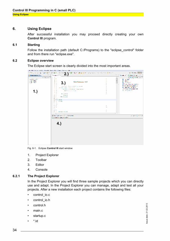
6.2 Eclipse overviewThe Eclipse start screen is clearly divided into the most important areas.
Fig. 6-1. Eclipse Control III start window
1. Project Explorer2. Toolbar3. Editor4. Console
6.2.1 The Project ExplorerIn the Project Explorer you will find three sample projects which you can directlyuse and adapt. In the Project Explorer you can manage, adapt and test all yourprojects. After a new installation each project contains the following files:• control_io.c• control_io.h• control.h• main.c• startup.c• *.ld
1.)
3.)
4.)
2.)
34

Control III Programming in C (small PLC)Using Eclipse
Issu
e da
te: 2
1.02
.201
3
• *.mak• settings.mak
6.2.2 ToolbarThe Toolbar includes all the tools needed for working with Control III.
6.2.2.1 Compiler
• clean: Used to clean the project folder. Clean deletes all the files and folders created by compiling.
• debug: Compiles the currently selected project without optimization. The resulting control.bin is used for debugging. (See Sec. <The Debugger>).
• release: Compiles the currently selected project. The resulting control.bin is optimized for time in order to achieve the fastest possible cycle times for your program code.
6.2.2.2 Debugging
This button is used among other things for starting the debugger. To debug youmust set the corresponding port. More information can be found in Sec. <Start theDebugger>.
6.2.2.3 Configuration tools
The Configuration tools button is used for communicating with the gateway andhas the following functions:
Unlock Control:Tool for unlocking Control III in the gateway (See Sec. <Enabling Control III>).
Download Control:The file "control.bin" is written to the gateway.
Start Control: The Control III program in the gateway is started.
Information!If the Control III program is at a ‘breakpoint’, the entire operating system freezes andthe fieldbus interface is no longer processed
Information!To start a new program, after downloading the running program must first be stopped.
35

Issu
e da
te: 2
1.02
.201
3
Control III Programming in C (small PLC)Using Eclipse
Download + Start Control:The Control III program is first stopped, then the new program is loaded into thegateway and then started.
Stop Control: The Control III program is stopped
Set Auto Start: The Auto Start flag is set. The Control III program starts up automatically aftereach power-on.
Clear Auto Start: The Auto Start flag is cleared.
Read Flags: The Control III flags are read and displayed in the console.
Read Flags Cyclically: The Control III flags are read and the display in the console refreshed cyclically.This allows for example variables to be monitored during run time.
Cycle time: The current cycle times are displayed.
Reset Cycle Time: The cycle time of the Control III is reset and recalculated.
6.2.3 EditorIn this window the entire C-code is written and adapted. The Editor also supportserrors in the ‘C’ syntax.
6.2.4 ConsoleThe console serves as an information window. It outputs for example error mes-sages or status messages and displays how much memory is being used by theControl III program after compiling.
36

Control III Programming in C (small PLC)Using Eclipse
Issu
e da
te: 2
1.02
.201
3
6.3 File informationAs already described in <The Project Explorer>, each project folder contains va-rious files. In this section the individual files are described in greater detail.
control_io.cThis file is used for example to break down a C program into multiple sub-modu-les so that it is clearer and easier to read.Both functions 'read_bit' and 'write_bit' read and write a corresponding output orinput bit.
control_io.hHeader for control_io.c. This file contains the function definitions for 'read_bit' and'write_bit'.
control.hThe header file ’control.h’ contains all data types and library functions. In additionit explains the way the function and are used (See Sec. <Programming ControlIII>).
main.cThe ’main’ function is the “starting point” of the actual program code. It also con-tains the main loop of the program (for ; ; ).
startup.cThis file is used for initializing various memory ranges. The file has no meaningfor the user.
*.ldThis is the linker file and specifies the corresponding memory ranges in the gate-way. The file has no meaning for the user.
*.makThis file specifies all the information needed by the compiler. The file has no mea-ning for the user.
int read_bit (AASiProcessData idi, int slave_addr, int bit)idi = Slave input data
slave_addr = Address of the corresponding slavebit = Slave input bit (0-3)
void write_bit (AASiProcessData odi, int slave_addr, int bit, int value)odi = Slave output data
slave_addr = Address of the corresponding slavebit = Slave output bit (0-3)
value = Output bit value (0 or 1)
37

Issu
e da
te: 2
1.02
.201
3
Control III Programming in C (small PLC)Using Eclipse
settings.makIn this file the communication port for the gateway is specified. More detailed in-formation can be found in Sec. <Setting the port>.
6.4 Setting the portEach project folder contains a file called settings.mak PORT=COM3. In this file youcan set the port for communicating with the gateway. To do this, select the corres-ponding file and enter the connection to the gateway. If for example you are usingCOM Port 3 on your PC, then enter PORT=COM3 in line 30 of the settings.mak. Ifyou are using an Ethernet port, then enter for examplePORT=UDP:192.168.42.149.
Fig. 6-2. Eclipse settings.mak
6.5 Creating a new projectAfter a new installation the Project Explorer contains sample projects for eachgateway having Control III. This makes it possible to start programming directlyafter installing Eclipse Control III. If you still want to create a new project, proceed as follows:
Select a new ‘C Project’ under 'File' -> 'New'. Assign a new project name and select an empty ‘Makefile Project’.Confirm the prompt with 'Finish'.
38

Control III Programming in C (small PLC)Using Eclipse
Issu
e da
te: 2
1.02
.201
3
Fig. 6-3. New Control III project
Now you will find a new empty project folder in the Project Explorer. Right-clickingon the new project and ‘Import…’ allows you to add all the necessary project filesfor your gateway.
Select 'File System' and then click on 'Next'. Now select 'Browse...' and navigate to your Eclipse installation .../eclipse_control/Templates/ Now select the gateway you are using.
EthernetIPProfibusProfiNET
Select 'Select All' and Finish. To apply all settings, select 'Yes to All' in the following prompt.
6.6 A sample projectIn the following section the complete procedure for writing the code up to startingin the gateway is explained.
6.6.1 The C-codeIn the sample program the outputs on a 4I/4O slave having Address 1 are set andcleared one after the other every second. To do this change the main.c as follows:
39

Issu
e da
te: 2
1.02
.201
3
Control III Programming in C (small PLC)Using Eclipse
/*-------------------------------------------------------------------* * include files * *-------------------------------------------------------------------*/#include "control.h"#include "string.h"#include "control_io.h"
/*-------------------------------------------------------------------* * local definitions * *-------------------------------------------------------------------*/
/*-------------------------------------------------------------------* * external declarations * *-------------------------------------------------------------------*/
/*-------------------------------------------------------------------* * public data * *-------------------------------------------------------------------*/
/*-------------------------------------------------------------------* * private data * *-------------------------------------------------------------------*/
static unsigned short system_ticks;static unsigned short end_timer;
/*-------------------------------------------------------------------* * private functions * *-------------------------------------------------------------------*/
static void timer_function ( void ){
/* timer interrupt every 10 ms */system_ticks++;
}
/*-------------------------------------------------------------------* * public functions * *-------------------------------------------------------------------*/int main ( void ){//initialization of the Debugger//cctrl_func.CCtrlBreakpoint();unsigned charctrl_flags;int i = 0;int x = 1;
AASiProcessData odi[2];AASiProcessData idi[2];AASiCtrlAccODI acc_odi;AASiEcFlags ecflags;
40
Control III Programming in C (small PLC)Using Eclipse
Issu
e da
te: 2
1.02
.201
3
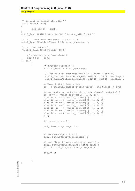
/* We want to access all odis */for (i=0;i<32;i++){
acc_odi[i] = 0xFF;}cctrl_func.AASiWriteCtrlAccODI ( 0, acc_odi, 0, 64 );
/* init timer function with 10ms ticks */cctrl_func.CCtrlInitTimer ( 10, timer_function );
/* init watchdog *///cctrl_func.CCtrlInitWdg( 10 );
// clear outputs from slave 1 odi[0][0] = 0x00;for(;;)
{/* trigger watchdog *///cctrl_func.CCtrlTriggerWdg();
/* Define data exchange for AS-i Circuit 1 and 2*/ cctrl_func.AASiDataExchange(0, odi[0], idi[0], &ecflags); cctrl_func.AASiDataExchange(1, odi[1], idi[1], &ecflags);
//Timer 1 100 * 10ms = 1sec.if ( ((unsigned short)(system_ticks - end_timer)) > 100){// set and clear outputs circuit=1, slave=1, output=0-3if (x == 1) write_bit(odi[0], 1, 0, 1);else if (x == 2) write_bit(odi[0], 1, 1, 1);else if (x == 3) write_bit(odi[0], 1, 2, 1);else if (x == 4) write_bit(odi[0], 1, 3, 1);else if (x == 5) write_bit(odi[0], 1, 0, 0);else if (x == 6) write_bit(odi[0], 1, 1, 0);else if (x == 7) write_bit(odi[0], 1, 2, 0);else if (x == 8) write_bit(odi[0], 1, 3, 0);x++;
if (x == 9) x = 1;
end_timer = system_ticks;}
/* to check Cycletime */cctrl_func.CCtrlEvalCycletime();
/*read flags if we should stop control*/cctrl_func.CCtrlReadFlags( &ctrl_flags );if ( !( ctrl_flags & CCTRL_FLAG_RUN ) ){return 1;}
}}
41

Issu
e da
te: 2
1.02
.201
3
Control III Programming in C (small PLC)Using Eclipse
6.6.2 CompilingThe C-code you have created must now be translated for the processor. To dothis, select “release” under the option “Compiler” in the toolbar. A “release” folderis created and your project folder now contains the corresponding binary file ‘con-trol.bin”.
6.6.3 Downloading To load the newly created program into the gateway, go to your project folder andselect the file settings.mak and enter the corresponding port for your gateway.For additional information see Sec. <Setting the port>.Next go to the toolbar and under the configuration tools select: Download Control.If the download was successful the following message appears in the Eclipseconsole:
6.6.4 Starting Control IIITo start and test the program, go to Toolbar / Configuration tools and select theStart Control button. The following message is displayed:
6.7 The DebuggerA Debugger is a programming tools used for diagnostics and identifying program-ming errors. If the debugger function is used, the entire operating system is sus-pended during diagnostics.
6.7.1 InitializingTo be able to use the Debugger, it must be initialized in C-code. This is doneusing the following code line:
----------------------- ++++ CONTROL III ++++ -----------------------
communication port set to UDP:192.168.42.157.
writing C-Control control.bin to Master ... ....................................... o.k.
closing control.bin ...
have a nice day.
83Control 3 reset
Information!The debug function serves only to test how your program runs. The Debugger cannotbe used for diagnosing your hardware configuration.
//initialization of the Debuggercctrl_func.CCtrlBreakpoint();
42

Control III Programming in C (small PLC)Using Eclipse
Issu
e da
te: 2
1.02
.201
3
Using this line stops the operating system and allows Eclipse to communicatewith the processor. At this point the Debugger is given the program data and itjumps to the next user-defined breakpoint of the Control III program.
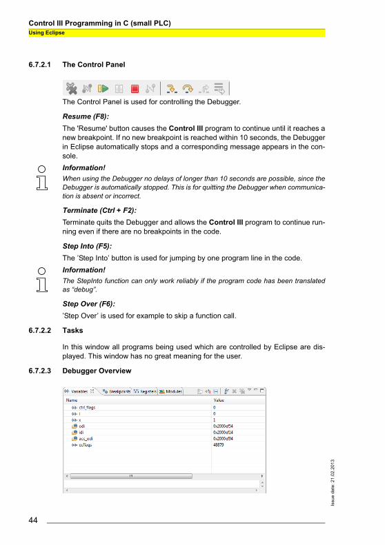
6.7.2 Debugger overview
1. Control Panel2. Tasks3. Debugger Overview4. Code Overview5. Disassembly6. Console
Information!The Debugger should not be initialized in the main loop of the program code ( for(;;) ), since this breakpoint is not controlled by Eclipse and therefore cannot be stop-ped.
1.)
2.)3.)
4.) 5.)
6.)
43
Issu
e da
te: 2
1.02
.201
3
Control III Programming in C (small PLC)Using Eclipse
6.7.2.1 The Control Panel
The Control Panel is used for controlling the Debugger.
Resume (F8):The 'Resume' button causes the Control III program to continue until it reaches anew breakpoint. If no new breakpoint is reached within 10 seconds, the Debuggerin Eclipse automatically stops and a corresponding message appears in the con-sole.
Terminate (Ctrl + F2):Terminate quits the Debugger and allows the Control III program to continue run-ning even if there are no breakpoints in the code.
Step Into (F5):The ’Step Into’ button is used for jumping by one program line in the code.
Step Over (F6):’Step Over’ is used for example to skip a function call.
6.7.2.2 Tasks
In this window all programs being used which are controlled by Eclipse are dis-played. This window has no great meaning for the user.
6.7.2.3 Debugger Overview
Information!When using the Debugger no delays of longer than 10 seconds are possible, since theDebugger is automatically stopped. This is for quitting the Debugger when communica-tion is absent or incorrect.
Information!The StepInto function can only work reliably if the program code has been translatedas “debug”.
44

Control III Programming in C (small PLC)Using Eclipse
Issu
e da
te: 2
1.02
.201
3
Variables:In the Variables tab of the “Debugger overview” all the existing variables and theirvalues can be displayed. Right-clicking in the window allows you to use ‘Add Glo-bal Variables’ to add additional variables to the view. The value of the variables isalways displayed in hex format. The view can be changed to binary or decimal byright-clicking on ‘Format’.
Breakpoints:The Breakpoints tab contains an overview of all breakpoints controlled by andused in Eclipse including the program line. Individual breakpoints can be deletedby right-clicking.
6.7.2.4 Code overview
This window allows you to always see at which point in the program code the De-bugger is currently located. Double-clicking n ext to the corresponding code lineallows you to set or delete a breakpoint.
6.7.2.5 Disassembly
Like the Code overview window, the Disassembly window shows exactly wherethe Debugger is currently. Here both the memory address and the associated as-sembler code are displayed.
6.7.2.6 Console
The console serves as an output window and tells you about the Debugger sta-tus.
6.7.3 Start the DebuggerThe Debugger is started from the Control Panel.
Before you can establish a connection with the target, you must define the port forthe gateway under ‘Debug-Configuration’. To do this, click on the ‘Commands’ taband under target remote enter the port. (e.g. target remoteUDP:192.168.42.33 or COM3).
Information!As soon as the Debugger is started you first see an empty window with the text“Source not found.” At this point the Debugger is in the operating system and does notknow the associated C-code.
45

Issu
e da
te: 2
1.02
.201
3
Control III Programming in C (small PLC)Using Eclipse
Fig. 6-4. Debug Configuration...
6.7.4 ExampleTo illustrate the Debugger, here is a sample program which sets an output bit (0-3) of the slave having Address 1 in every main loop pass. Following is the corres-ponding program code.
46

Control III Programming in C (small PLC)Using Eclipse
Issu
e da
te: 2
1.02
.201
3
*-------------------------------------------------------------------* * include files * *-------------------------------------------------------------------*/#include "control.h"#include "string.h"#include "control_io.h"
/*-------------------------------------------------------------------* * local definitions * *-------------------------------------------------------------------*/
/*-------------------------------------------------------------------* * external declarations * *-------------------------------------------------------------------*/
/*-------------------------------------------------------------------* * public data * *-------------------------------------------------------------------*/
/*-------------------------------------------------------------------* * private data * *-------------------------------------------------------------------*/
static unsigned short system_ticks;static unsigned short end_timer;
/*-------------------------------------------------------------------* * private functions * *-------------------------------------------------------------------*/
static void timer_function ( void ){
/* timer interrupt every 10 ms */system_ticks++;
}
/*-------------------------------------------------------------------* * public functions * *-------------------------------------------------------------------*/
47

Issu
e da
te: 2
1.02
.201
3
Control III Programming in C (small PLC)Using Eclipse
int main ( void ){
//initialization of the Debuggercctrl_func.CCtrlBreakpoint();
unsigned charctrl_flags;int i = 0;int x = 1;
AASiProcessData odi[2];AASiProcessData idi[2];AASiCtrlAccODI acc_odi;AASiEcFlags ecflags;
/* We want to access all odis */for (i=0;i<32;i++){
acc_odi[i] = 0xFF;}cctrl_func.AASiWriteCtrlAccODI ( 0, acc_odi, 0, 64 );
/* init timer function with 10ms ticks */ cctrl_func.CCtrlInitTimer ( 10, timer_function );
/* init watchdog *///cctrl_func.CCtrlInitWdg( 10 );
// clear outputs from slave 1 odi[0][0] = 0x00;
48

Control III Programming in C (small PLC)Using Eclipse
Issu
e da
te: 2
1.02
.201
3
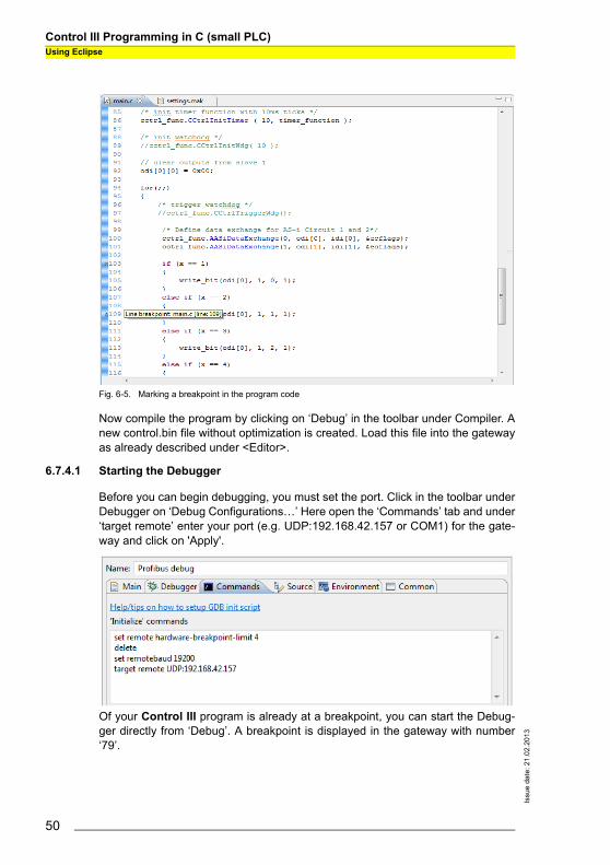
Now create two breakpoints by double-clicking in the margin of the program codeon the corresponding code line. In our example we use both lines 103 and 109.The line in which a breakpoint was added is indicated by a period. These linesare shown later in the Debugger overview under Breakpoint and this informationconveyed to the processor during initialization.
for(;;){
/* trigger watchdog *///cctrl_func.CCtrlTriggerWdg();
/* Define data exchange for AS-i Circuit 1 and 2*/ cctrl_func.AASiDataExchange(0, odi[0], idi[0], &ecflags); cctrl_func.AASiDataExchange(1, odi[1], idi[1], &ecflags);
if (x == 1) { write_bit(odi[0], 1, 0, 1); } else if (x == 2) { write_bit(odi[0], 1, 1, 1); } else if (x == 3) { write_bit(odi[0], 1, 2, 1); } else if (x == 4) { write_bit(odi[0], 1, 3, 1); x = 1; } x++;
/* check Cycletime */cctrl_func.CCtrlEvalCycletime();
/*read flags if we should stop control*/cctrl_func.CCtrlReadFlags( &ctrl_flags );if ( !( ctrl_flags & CCTRL_FLAG_RUN ) ){return 1;}
}}/*-------------------------------------------------------------------* * eof * *-------------------------------------------------------------------*/
49
Issu
e da
te: 2
1.02
.201
3
Control III Programming in C (small PLC)Using Eclipse
Fig. 6-5. Marking a breakpoint in the program code
Now compile the program by clicking on ‘Debug’ in the toolbar under Compiler. Anew control.bin file without optimization is created. Load this file into the gatewayas already described under <Editor>.
6.7.4.1 Starting the Debugger
Before you can begin debugging, you must set the port. Click in the toolbar underDebugger on ‘Debug Configurations…’ Here open the ‘Commands’ tab and under‘target remote’ enter your port (e.g. UDP:192.168.42.157 or COM1) for the gate-way and click on 'Apply'.
Of your Control III program is already at a breakpoint, you can start the Debug-ger directly from ‘Debug’. A breakpoint is displayed in the gateway with number‘79’.
50

Control III Programming in C (small PLC)Using Eclipse
Issu
e da
te: 2
1.02
.201
3
If this is not the case, quit entry with ‘Close’ and start your program. You can nowdirectly start the Debugger by clicking for example on ‘Profibus debug’ in the tool-bar.
6.7.4.2 Using the Debugger
After you have started the Debugger, it is configured for the application. The De-bugging window is automatically opened by Eclipse. Under Breakpoints you nowsee the first breakpoint which is run by the program code. This is the Debuggerinitialization. In this case you are shown an empty window. Click on ‘Resume’.The program code is run up to the corresponding line with the first breakpoint andstopped.
Fig. 6-6. First breakpoint in Debug-mode
You can also click on ‘Variables’ in the Debugger overview to display all the vari-ables which are used (see Sec. <Debugger overview>). Click on ‘Resume’. TheDebugger again stops at this point and not at the second breakpoint. This is be-cause the second breakpoint is not reached until the variable ‘x’ in our sampleprogram has a value of 2. You can display the value of the variable by moving themouse cursor over the corresponding variable. The variable x now has a value of2. Click again on ‘Resume’ to jump to the breakpoint in line 109.
Fig. 6-7. Second breakpoint in Debug-mode
For this code line you can choose from between ‘Step over’ and ‘Step into’. ‘Stepover’ causes the program to skip to line 120, in other words skips the function call‘write_bit(…)’ and continues from the next valid line in the code. ‘Step into’ opens
79breakpoint
51

Issu
e da
te: 2
1.02
.201
3
Control III Programming in C (small PLC)Using Eclipse
the corresponding file (control_io.c) and continues ‘Debug-mode’ from the corres-ponding location. If you want to jump to the next breakpoint, click again on the‘Resume’ button. Quit the Debugger by clicking on ‘Terminate’.
52

Control III Programming in C (small PLC)Technical Data
Issu
e da
te: 2
1.02
.201
3
7. Technical DataThe following section provides an overview of all the key technical data for Cont-rol III.
7.1 Overview• 28 kB program memory (can be split between ROM and RAM)• 1kB non-volatile parameters• 256 bytes of flag memory• Control program and parameters also on chip card• A configurable timer interrupt which can be used to create any number of
timers
• Programmable timer times from 1 to 232 ms• Up to 248 I/O and 248 analog values using AS-i slaves• Unique 32-bit ID in the device• Simple determination of the cycle time• Eclipse with GCC and GDB as a complete development environment
7.2 FlagsThe flag area is transparent and administered by the user.
Fig. 7-8. Flag area
7.3 Non-volatile parametersThe non-volatile parameters are transparent and administered by the user.
���������� ��������������
������
��� ������������
53

Issu
e da
te: 2
1.02
.201
3
Control III Programming in C (small PLC)Technical Data
Fig. 7-9. Non-volatile parameters
7.4 Access rights to the output data areaFieldbus and the Control III program can both set outputs at the same time. Ac-cess rights can be assigned by the bit or by channel.
Fig. 7-10. Access rights for the output data area
���������� ���!�� ��������������
������
��� ������������
�"� �����
)�
)�
)�
)*
��
��
��
�*
+�
+�
+�
+*
,
�
,
�
)�
��
)�
�*
����������
��� �����������"�
�������� �� ��!
��� ������������"�!����
�������� "������"��������� �� ��!
54
Control III Programming in C (small PLC)Error Messages
Issu
e da
te: 2
1.02
.201
3
8. Error MessagesThis section is intended to help you to troubleshoot and resolve any problemswhich may arise.
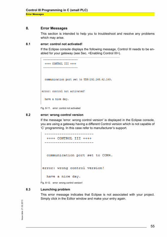
8.1 error: control not activated!If the Eclipse console displays the following message, Control III needs to be en-abled for your gateway (see Sec. <Enabling Control III>).
Fig. 8-11. error: control not activated
8.2 error: wrong control versionIf the message 'error: wrong control version' is displayed in the Eclipse console,you are using a gateway having a different Control version which is not capable of‘C’ programming. In this case refer to manufacturer’s support.
Fig. 8-12. error: wrong control version!
8.3 Launching problemThis error message indicates that Eclipse is not associated with your project.Simply click in the Editor window and make your entry again.
55

Issu
e da
te: 2
1.02
.201
3
Control III Programming in C (small PLC)Error Messages
Fig. 8-13. Launching problem
8.4 No or an incorrect cycle time is displayed.If you read the cycle time on Eclipse and a value of 0 keeps appearing, the follo-wing line is missing in the program code:
8.5 The gateway doesn’t stop at a breakpoint.If the gateway doesn’t stop at a breakpoint, it is possible that the auto-start flag isset or the following line for initializing the Debugger is missing in the program co-de:
8.6 The program always goes to the same breakpoint.If this happens and there is no Debugger initialization in the code, the error is inthe program code. The most frequent cause is an un-initialized pointer. Pleasecheck your program code. If you have also set the Autostart flag, you can performa reset when starting the gateway. To do this, press both the ‘Mode’ and ‘Set’keys while turning on the gateway. The existing program code is deleted and thegateway starts back up.
8.7 The Control III can’t affect any outputs.Check whether the slaves are correctly projected and the gateway indicates noconfiguration error. If needed, project the slaves again. If the error persists, youmay not have access rights. These are assigned by the following function:
Additional information can be found in Sec. <AS-i Read Ctrl Acc AODI>.
/* check Cycletime */cctrl_func.CCtrlEvalCycletime();
//initialization of the Debuggercctrl_func.CCtrlBreakpoint();
cctrl_func.AASiWriteCtrlAccODI ( … );
56