control of embedded system via internet - uni-obuda.hu
TRANSCRIPT

Magyar Kutatók 9. Nemzetközi Szimpóziuma 9th International Symposium of Hungarian Researchers on Computational Intelligence and Informatics
171
Control of Embedded System via Internet
Péter Szekeres, Béla Takarics, Gábor Sziebig, Péter Korondi Department of Automation and Applied Informatics Budapest University of Technology and Economics Goldmann György tér 3, H-1111 Budapest, Hungary [email protected]
Abstract: The paper presents a complete multimedia educational program of DC servo drive for distant learning. The program contains three parts: animation, simulation and internet-based measurement. The animation program gives the operation of DC motors as well as its time- and frequency-domain equations, transfer functions and the theoretical background necessary to design a controller for DC servo motors. The simulation model of the DC servo motor and the controller can be designed by the students based on the animation program. The students can also test their controllers by the internet based measurement, which is the most important part from engineering point of view. The exercises the students can do are programming the D/A and A/D cards of the embedded system and to design different types of controllers. First, a simple PI controller can be designed, but advanced students can also design more sophisticated controllers such as the sliding mode controller. After the measurement is executed, the students can download the measured data and compare them to the simulation results.
Keywords: Electrical engineering learning, distant laboratory, PI control
1 Introduction
To meet the competitiveness and environmental challenges in the manufacturing industry, automation and robotization is one of the most important trends i.e. turning the manual work power from tiring repetitive tasks into complex tasks where knowledge and human skills are required. This is both due to the increasing complexity level of products and the focus on improved working environment within EU. However, advanced robotic systems require advanced knowledge within many classical fields of engineering and surely in the small and medium size enterprises (SME), where all of these areas expertises by the knowledge of the employees. Turning now to the problems of the advanced courses offered by universities, one of them is the different backgrounds of the attendees. In case of an advanced motion control course, one solution can be that the professor can refer to the internet for the necessary background. In this special course new
P. Szekeres et al. Control of Embedded System via Internet
172
technology and new learning methods are combined. The interactive multimedia applications (animations, simulations, remote tasks) combined with the Web-based laboratory tests result a Personal Learning Environment, available all day around and all year around.
The DC motors have a special historical role in the field of industrial electronics since all industrial servo drives used DC motors in the past and the first microprocessor controlled drive [1] also applied DC motor. Even if they have several drawbacks they are used in recent applications [2], [3]. The main advantage of a DC servo motor drive is that it is simple from the point of view of control. Before the advent of micro controllers they were the only solutions for servo drive systems. It is easy to adopt various control methods for a DC servo system. It explains why some of the newly proposed control methods are frequently applied first for a DC servo system. On the other hand, there is a trend to control all kind of servo drives (field oriented induction motor drives [4] and brushless drives [5]) like a DC servo drive. PID controller is still the most common controller method in the industrial applications, this is the reason why the web based laboratory concentrates on exercises with PID control.
The organisation of the paper is as follows: the second chapter describes the animation program for DC servo drives; Section 3 introduces simulation models of the DC servo drive with controllers. Section 4 describes the web based laboratory and Section 5 gives the results of the remote laboratory exercises with comparison of the simulation results. Finally, the conclusions are given.
2 Animation of a DC Servo Motor
The web-based laboratory has user manuls for the DC motor control exercises, but also has a multimedia animation. Explaining the sophisticated processes of servo systems and their control methods is a real challenge by the traditional methods. The static figures shown by books or the computer projector with power point are not well suited for individual distant learning. On the other hand the possibilities by the modern multimedia methods can optimally be adapted in this area. Utilizing the opportunities of the technique, the sequence of topologies and transient processes of the system can well be shown by animated figures and understood easier. The basics of the method in most cases are the application of simulation techniques to obtain the results representing the complex processes. The advantages of animated representation are obvious in the study of both simple and complex units. Within the framework of the Leonardo da Vinci program of the European Union (EU), a project called INETELE incorporating eight Universities from eight member countries is aimed at developing multimedia software for teaching the subject of Electrical Engineering (EE) [6], [7].
Magyar Kutatók 9. Nemzetközi Szimpóziuma 9th International Symposium of Hungarian Researchers on Computational Intelligence and Informatics
173
2.1 Content of the Animation
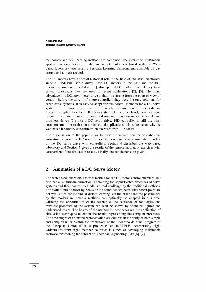
1) Physical model of the DC motor: This chapter describes the construct of a DC motor. Based on the physical model, the equivalent circuit of the DC motor will be given in the next chapter of the animation.
The construction of the DC-servo motor:
• Stator: Stator is the stationary part of the machine.
• Armature: Armature is the rotating part of the machine.
• Excitation winding: Excitation winding is placed around the poles in the stator.
• Armature winding: Armature winding is in the slots of the armature.
• Commutator: The commutator periodically reverses the current. It consists of rotating segmented copper contacts and stationary carbon brushes.
Figure 1
Physical model of DC Motor
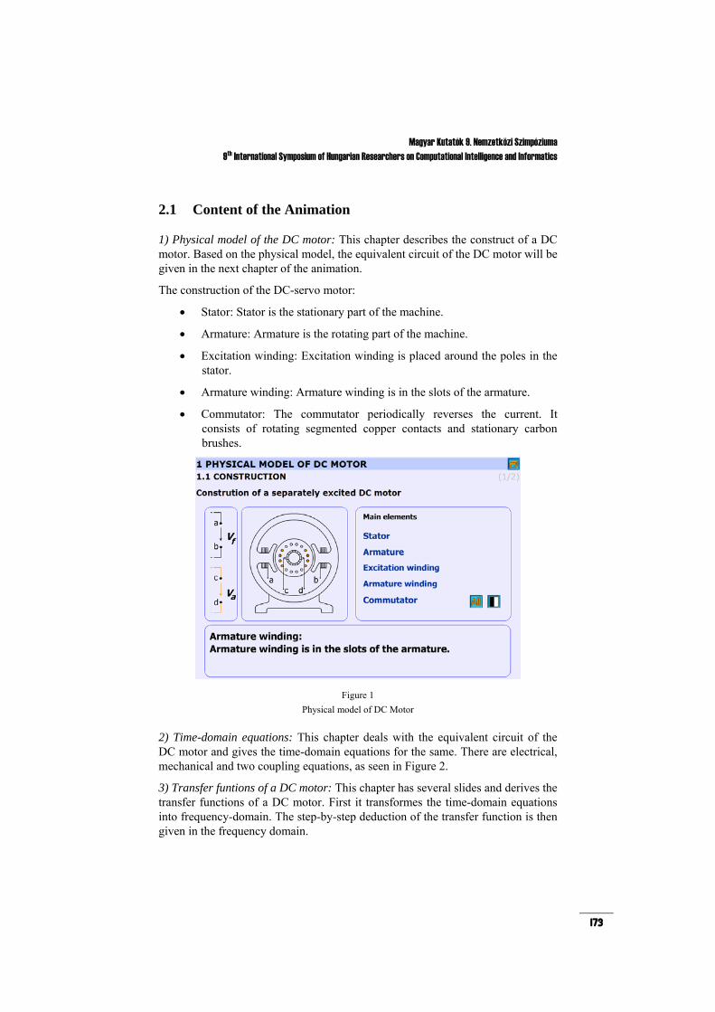
2) Time-domain equations: This chapter deals with the equivalent circuit of the DC motor and gives the time-domain equations for the same. There are electrical, mechanical and two coupling equations, as seen in Figure 2.
3) Transfer funtions of a DC motor: This chapter has several slides and derives the transfer functions of a DC motor. First it transformes the time-domain equations into frequency-domain. The step-by-step deduction of the transfer function is then given in the frequency domain.
P. Szekeres et al. Control of Embedded System via Internet
174
Figure 2
Time-domain equations of the DC motor
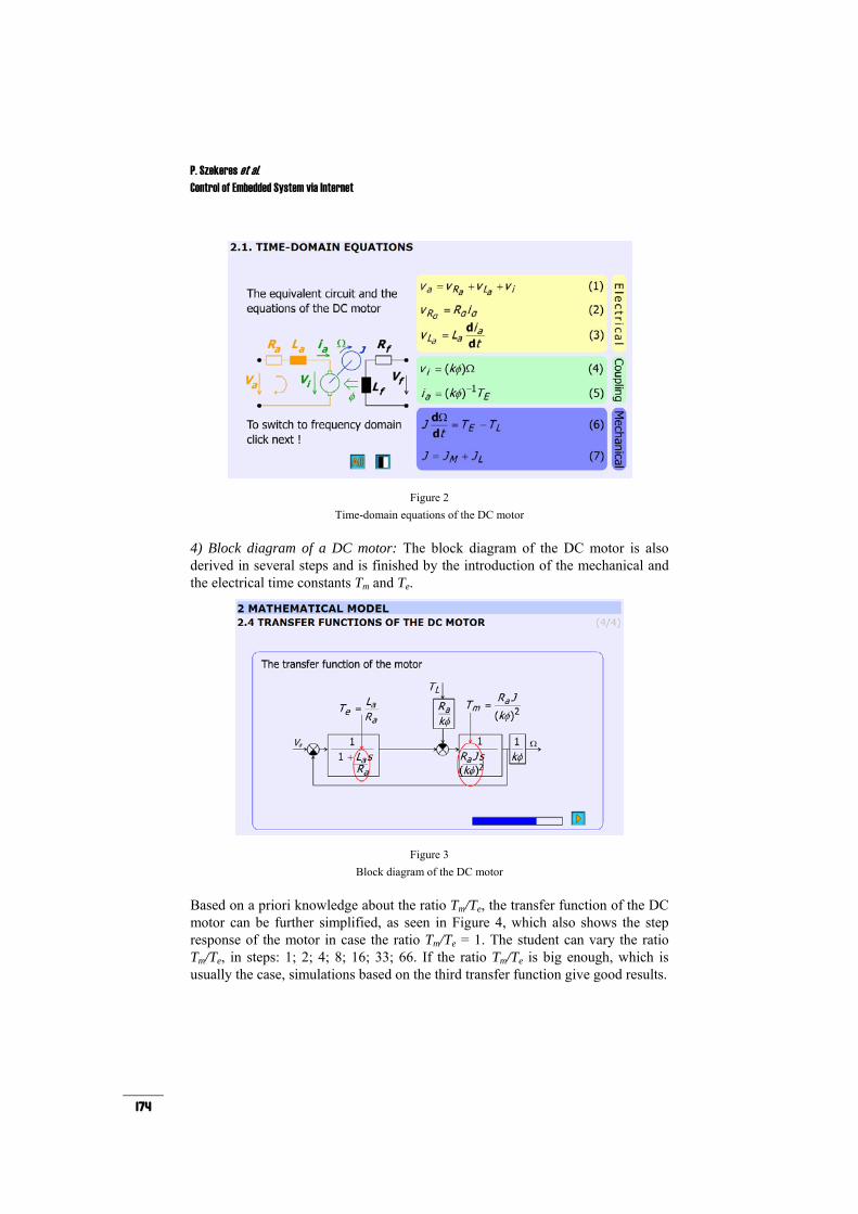
4) Block diagram of a DC motor: The block diagram of the DC motor is also derived in several steps and is finished by the introduction of the mechanical and the electrical time constants Tm and Te.
Figure 3
Block diagram of the DC motor
Based on a priori knowledge about the ratio Tm/Te, the transfer function of the DC motor can be further simplified, as seen in Figure 4, which also shows the step response of the motor in case the ratio Tm/Te = 1. The student can vary the ratio Tm/Te, in steps: 1; 2; 4; 8; 16; 33; 66. If the ratio Tm/Te is big enough, which is usually the case, simulations based on the third transfer function give good results.

Magyar Kutatók 9. Nemzetközi Szimpóziuma 9th International Symposium of Hungarian Researchers on Computational Intelligence and Informatics
175
Figure 4
Transfer function approximations of the DC motor
5) PID controller: The animation also gives an introduction to PID controller design. The steps of control design are explained in a detailed form. Figure 5 explains the meaning of phase margin. The aim of the animation is to explain how to design the phase margin in a reversed non-analytical way where the Bode plots let to see the phase margin. Student can vary Ap between 0.5 and 3.5 and can check the effect of different amplification. The animation uses the preliminary simulated results and graphs. Ap can be varied from 0.5 to 3.5 in 7 steps (0.5; 1.0; 1.5; 2.0; 2.5; 3.0; 3.5) so the flash file is small enough but the number of the frames are enough to see the difference.
Figure 5
Calculation of the phase margin by the Bode-diagram
The animation also gives introduction to sliding mode design, but since this control is not part of basic control design experiments, it will be not treated here.

P. Szekeres et al. Control of Embedded System via Internet
176
3 Simulation
The first step from theory to application is simulation. The students use Matlab-Simulink software. Identification is an important part of the design process. In optimal case with the help of an appropriate simulation model the behaviour of the real system can be pre-estimated.
Based on the block diagram amd the transfer functions of the DC motor found in the animation, the following Simulink model of the DC servo motor can be constructed
Figure 6
Simulink model of a DC drive
After the model of the DC motor is constructed, the students can add a contorller to the system. It should not be forgotten that the embedded system has already a current controller implemented, which should be added to the model as seen in Figure 7.
Figure 7
Simulink model of a DC drive with PID control and inner PID current control
The students can check the torque-speed characteristics by simulation and they can study the performance (overshot, settle down time, oscillation, robustness) of the cascade speed controller with different parameters and phase margins.

Magyar Kutatók 9. Nemzetközi Szimpóziuma 9th International Symposium of Hungarian Researchers on Computational Intelligence and Informatics
177
4 Overview of the Web-based Laboratory
Web based experiments play an important role in next generation of laboratories. The experiments can be operated around the clock. Access is provided whenever needed.
In order to control the DC motor connected to PC, the following system components performing basic functions are needed:
1. A card generating analogue output signals (e.g. D/A card)
2. A card measuring input signals (e.g. A/D card or counter card) 3. A real-time clock that can schedule signal sampling or task execution
Figure 8
System setup
The key system components applied here are the following:
• Industrial Siemens PC with Pentium 4, 2.8 GHz processor • Advantec PCI-1720 D/A output card performing function 1 • Advantec PCI-1784 A/D counter input card performing function 2 • Servo drive including:
1. Servoamplifier 2. Maxon A-max 26(110961) DC motor 3. Maxon Digital Encoder HP HEDL 5540
• Maxon Planetary Gearhead GP 26(110395) • WebCam for visualising the laboratory setup on the monitor • MATLAB program
P. Szekeres et al. Control of Embedded System via Internet
178
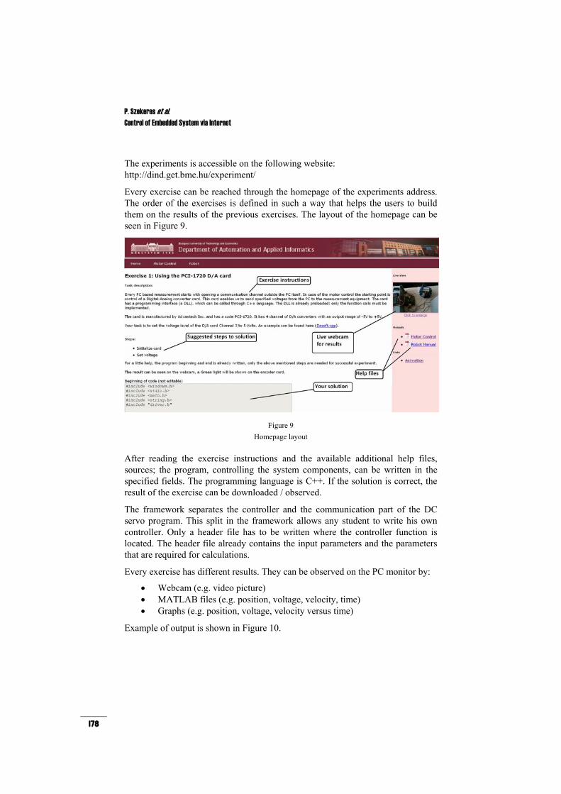
The experiments is accessible on the following website: http://dind.get.bme.hu/experiment/
Every exercise can be reached through the homepage of the experiments address. The order of the exercises is defined in such a way that helps the users to build them on the results of the previous exercises. The layout of the homepage can be seen in Figure 9.
Figure 9
Homepage layout
After reading the exercise instructions and the available additional help files, sources; the program, controlling the system components, can be written in the specified fields. The programming language is C++. If the solution is correct, the result of the exercise can be downloaded / observed.
The framework separates the controller and the communication part of the DC servo program. This split in the framework allows any student to write his own controller. Only a header file has to be written where the controller function is located. The header file already contains the input parameters and the parameters that are required for calculations.
Every exercise has different results. They can be observed on the PC monitor by:
• Webcam (e.g. video picture) • MATLAB files (e.g. position, voltage, velocity, time) • Graphs (e.g. position, voltage, velocity versus time)
Example of output is shown in Figure 10.

Magyar Kutatók 9. Nemzetközi Szimpóziuma 9th International Symposium of Hungarian Researchers on Computational Intelligence and Informatics
179
Figure 10 Exercise results
5 Testing the Control of Embedded System via Internet
There are five different tests that should be carried out by the students. The first three of them is connected to the control of the D/A card, the real-time clock and the counter card. The second two are the open-loop and PID control of the DC servo drive.
All of the measurements start with opening a communication channel outside the PC itself. In case of the motor control the starting point is control of a Digital-Analog converter card. This card enables us to send specified voltages from the PC to the measurement equipment. The card has a programming interface (a DLL), which can be called through C++ language. The DLL is already preloaded; only the function calls must be implemented. In the first exercise, the students have to choose a communication channel, and set a constant output voltage on that channel.
The second important thing in a PC based measurement is sampling. For this reason we need two things. A card that can read input (counter) from the experimental equipment and a real-time clock that can read the counter in a specified moment and in a given frequency.
In the second exercise, the students have to define the relationship of the sampling time and a sinus wave. The sampling time start from 0 and can be reached through the variable given in the program. The time variable can be reached through the variable time_array[tickCount] and the value is given in 100 nanosecond units. The result of the output can be seen in Figure 10.

P. Szekeres et al. Control of Embedded System via Internet
180
As mentioned before for retrieving data from experimental equipment a counter is also needed. The counter is used to read the encoder’s signals and convert it to a numeric representation. The counter value is read by function, which is executed in every tick of the real-time clock.
The student’s task in the third experiment is to read the counter value of channel 3 on the PCI-1784 card.
5.1 Open-Loop, P and PI Control of the DC Servo Drive
As mentioned before, for the open-loop and P, PI tests, the D/A card, the real-time clock and the counter card do not have to be reprogrammed, at this stage, the students can contentrate on the controller itself.
The task is to design a controller for shaft speed control of the motor. The open-loop controller is the simplest one, it can be designed knowing the motor parameters. The P and PI controllers need values for AP and TI. Determining these parameters is the tuning process. Several tuning methods exist, one of the most wide-spread is the Ziegler-Nichols method [8]. The students can tune their controllers based on this, thus they can execute the control exercieses. Results for open-loop, P and PI controllers can be seen in Figure 11.
(a) (b)
(c)
Figure 11 DC motor control results with 3 rad/s desired shaft speed; (a) open-loop control; (b) P control; (c) PI
control
Magyar Kutatók 9. Nemzetközi Szimpóziuma 9th International Symposium of Hungarian Researchers on Computational Intelligence and Informatics
181
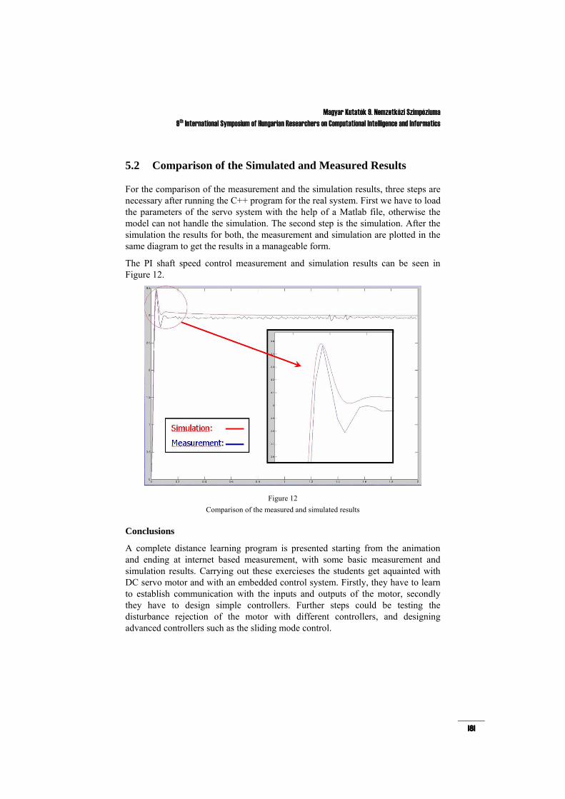
5.2 Comparison of the Simulated and Measured Results
For the comparison of the measurement and the simulation results, three steps are necessary after running the C++ program for the real system. First we have to load the parameters of the servo system with the help of a Matlab file, otherwise the model can not handle the simulation. The second step is the simulation. After the simulation the results for both, the measurement and simulation are plotted in the same diagram to get the results in a manageable form.
The PI shaft speed control measurement and simulation results can be seen in Figure 12.
Figure 12 Comparison of the measured and simulated results
Conclusions
A complete distance learning program is presented starting from the animation and ending at internet based measurement, with some basic measurement and simulation results. Carrying out these exercieses the students get aquainted with DC servo motor and with an embedded control system. Firstly, they have to learn to establish communication with the inputs and outputs of the motor, secondly they have to design simple controllers. Further steps could be testing the disturbance rejection of the motor with different controllers, and designing advanced controllers such as the sliding mode control.
P. Szekeres et al. Control of Embedded System via Internet
182
Acknowledgement
This work was supported by the European Community program Leonardo da Vinci no 2002-CZ/02/B/F/PP-134009, the Hungarian Research Fund (OTKA TO46240 and K62836), Control Research Group and Janos Bolyai Research Scholarship of Hungarian Academy of Science. The authors thank for their financial support.
References
[1] K. Saito, K. Kamiyama, T. Ohmae, and T. Matsuda: A Microprocessor-controlled Speed Regulator with Instantaneous Speed Estimation for Motor Drives, IEEE Trans. Ind. Electron., Vol. 35, No. 1, pp. 95-99, Feb. 1988
[2] C. Chan, S. Hua, and Z. Hong-Yue: Application of Fully Decoupled Parity Equation in Fault Detection and Identification of DCmotors, IEEE Trans. Ind. Electron., Vol. 53, No. 4, pp. 1277-1284, June 2006
[3] F. Betin, A. Sivert, A. Yazidi, and G.-A. Capolino: Determination of Scaling Factors for Fuzzy Logic Control Using the Sliding-Mode Approach: Application to Control of a DC Machine Drive, IEEE Trans. Ind. Electron., Vol. 54, No. 1, pp. 296-309, Feb. 2007
[4] M. Boussak and K. Jarray: A High-Performance Sensorless Indirect Stator Flux Orientation Control of Induction Motor Drive, IEEE Trans. Ind. Electron., Vol. 53, No. 1, pp. 41-49, Feb. 2006
[5] J. Moreno, M. Ortuzar, and J. Dixon: Energy-Management System for a Hybrid Electric Vehicle, Using Ultracapacitors and Neural Networks, IEEE Trans. Ind. Electron., Vol. 53, No. 2, pp. 614-623, Apr. 2006
[6] P. Bartal, J. Hamar, R. K. Járdán, P. Korondi, I. Nagy, Z. Sepa, Z. Sütő, K. Zabán, H. Funato, E. Masada, and S. Ogasawara: Learning Multimedia Software for Teaching Nonlinear Dynamics, in Proc. Control in Power Electronics and Motion Control (IPEC’05), Niigata, Japan, Apr. 2005
[7] P. Bauer and V. Fedak: Educational Visualization of Different Aspects for Power Circuits and Electrical Drives, in Proc. 11th International Power Electronics and Motion Control Conference (EPE- PEMC’04), Riga, Latvia, Sept. 2004
[8] Van, Doren, Vance J.: Loop Tuning Fundamentals, Control Engineering. Red Business Information, July 2003