control of inverted pendulum system nurulnaim...
TRANSCRIPT

CONTROL OF INVERTED PENDULUM SYSTEM
NURULNAIM MOHD ALUWI
This is submitted in partial fulfilment of the requirements for the award of Bachelor of
Electronics Engineering (Computer Engineering) with Honours.
Faculty of Electronics and Computer Engineering
Universiti Teknikal Malaysia Melaka
April 2010

UNIVERSTI TEKNIKAL MALAYSIA MELAKA FAKULTI KEJURUTERAAN ELEKTRONIK DAN KEJURUTERAAN KOMPUTER
BORANG PENGESAHAN STATUS LAPORAN
PROJEK SARJANA MUDA II
Tajuk Projek : ……………………………………………………………………………… Sesi Pengajian : ………………………………………………………………………………
Saya ………………………………………………………………………………………………….. (HURUF BESAR) mengaku membenarkan Laporan Projek Sarjana Muda ini disimpan di Perpustakaan dengan syarat-syarat kegunaan seperti berikut:
1. Laporan adalah hakmilik Universiti Teknikal Malaysia Melaka.
2. Perpustakaan dibenarkan membuat salinan untuk tujuan pengajian sahaja.
3. Perpustakaan dibenarkan membuat salinan laporan ini sebagai bahan pertukaran antara institusi
pengajian tinggi.
4. Sila tandakan ( √ ) :
SULIT* (Mengandungi maklumat yang berdarjah keselamatan atau kepentingan Malaysia seperti yang termaktub di dalam AKTA RAHSIA RASMI 1972)
TERHAD* (Mengandungi maklumat terhad yang telah ditentukan oleh organisasi/badan di mana penyelidikan dijalankan)
TIDAK TERHAD
Disahkan oleh:
__________________________ ___________________________________ (TANDATANGAN PENULIS) (COP DAN TANDATANGAN PENYELIA)
Alamat Tetap: ……………………………......
……………………………......
Tarikh: ……………………….. Tarikh: ………………………..

iii
“I hereby declare that this report is the result of my own work except for quotes as cited
in the references.”
Signature : …………………………
Author : Nurulnaim Mohd Aluwi
Date : …………………………

iv
“I hereby declare that I have read this report and in my opinion this report is sufficient in
terms of and quality for the award of Bachelor of Electronics Engineering (Computer
Engineering) with Honours.”
Signature : …………………………
Supervisor : En. Amat Amir Basari
Date : …………………………

v
To education, professionalism and all things that matter.

vi
ACKNOWLEDGEMENT
Finishing this report is a true blessing in disguise. There would be an endless list
from where I need to convey my gratitude. Without these people, I would not be able to
finish my research. This past year had been a journey embarked in the most appropriate
time. Had it been earlier or later, it would not be the same.
A special thanks to my supervisor, En. Amat Amir Basari whose constant
support, patience and unbounded enthusiasm were of invaluable help. His helping hands
in assisting me throughout this whole experience are something that could not be
replaced.
A significant gratitude is also offered to the colleagues who travelled a long way
to make sure I succeeded in carrying out my tasks. Thank you, Syazana Sapie, Nor
Hanim Md Razali, Faten Nadia Mansor and Zatul Iffah Ahmad for granting me a chance
in time of need. Without all of your support and ideas, I would have not come this far.
I would also like to appreciate all the people that have stood by me in the past
four years. Thank you for baring all my incompetence and lack of knowledge. Also to
family who have supported me along the way with all the encouragement and love they
could give.
This has been a tremendously insightful journey.

vii
ABSTRACT
An inverted pendulum is a device which has its mass freely oscillating above its pivot
point. The implementation often involves a horizontal moving cart with the pivot point
mounted on it. This innovation may also be called a cart and pole. Whereas a normal
pendulum is stable when hanging downwards, an inverted pendulum is inherently
unstable, and must be actively balanced in order to remain upright. This is done either by
applying a torque at the pivot point or by moving the pivot point horizontally as part of a
feedback system. Due to its structure simplicities, inverted pendulum is also frequently
used as a standard to validate the performance and effectiveness of control methods.
Therefore, this project aims to control the stability of this mass and its pole by supplying
control input to the cart with appropriate control strategy. A mathematical model of this
mechanism is to be developed in order to have a deeper understanding on the
characteristics. Among the controller that will be experimented with this pendulum are
Fuzzy Logic Controller and Sliding Mode Controller. The efficiency of these controllers
will be simulated using the MATLAB Software and afterwards differentiated.

viii
ABSTRAK
Bandul terbalik ialah sebuah alat yang mempunyai sebuah jisim berayun bebas di atas
titik paksinya. Alat ini melibatkan sebuah kereta bergerak secara melintang bersama titik
paksi tersebut dipasang di atasnya. Inivasi ini juga bleh digelar sebuah kereta dan
tiangnya. Berbeza dengan bandul normal yang stabil digantung kebawah, sebuah bandul
terbalik sememangnya tidak stabil dan harus aktif diimbangi supaya sentiasa ke atas. Ini
dapat dilkukan samada dengan memberi kilas pada titik paksi atau menggerakkan titik
paksi tersebut didalam suatu sistem suap balik. Disebabkan strukturnya yang mudah,
bandul terbalik juga sering digunakan sebagai standard untuk mengesahkan prestasi dan
keberkesanan kaedah kawalan. Oleh itu, matlamat projek ini ialah untuk mengawal
kestabilan jisim dan tiangnya dengan memberikan input strategi kawalan yang sesuai
kepada kereta bandul. Sebuah model matematik berkenaan mekanisma ini akan
dibangunkan untuk mendapat pemahaman yang lebih baik ke atas cirri-cirinya. Antara
pengawal yang akan dikaji adalah Pengawal Logik Kabur dan Pengawal Mod Meluncur.
Kecekapan pengawal-pengawal ini akan disimulasikan di dalam perisian Matlab dan
kemudiannya dibandingkan.

ix
TABLE OF CONTENTS
CHAPTER CONTENTS PAGE
TITLE i
REPORT STATUS AUTHENTICARION FORM i
CONFESSION iii
AUTHENTICATION FROM SUPERVISOR iv
DEDICATION v
ACKNOWLEDGEMENT vi
ABSTRACT vii
LIST OF TABLES xii
LIST OF FIGURES xiii
LIST OF APENDICES xv
I INTRODUCTION 1
1.1 Overview 1
1.2 Objectives 3
1.3 Problem Statement 3
1.4 Work Scope 4
1.5 Project Methodology 5

x
II LITERATURE REVIEW 7
2.1 Introduction 7
2.2 Background 7
2.3 Present Applications 8
2.4 Inverted Pendulum Configurations 8
2.5 Control Methodology 9
2.6 Fuzzy Logic Controller 10
2.7 Sliding Mode Controller 11
III Project Methodology 13
3.1 Literature Review 15
3.2 Mathematical Modelling 17 3.2.1 Inverted pendulum mathematical modelling 17
3.2.2Linear Model in state space form 21 3.2.3Controllability 22
3.3 Simulation and Analysis 23
3.4 Thesis Writing 23
3.5 Conclusion 23
IV SLIDING MODE CONTROLLER 24
4.1 Introduction 24
4.2 Switching Surface and Controller Design 25
4.3 Implementation in Simulink 28
V FUZZY LOGIC CONTROLLER 29
5.1 Introduction 29

xi
5.2 Designing Fuzzy Control 30
5.2.1 Set of fuzzy controller 31
5.3 Rule Base 33
5.4 Implementation in Simulink 34
VI RESULTS AND DISCUSSIONS 35
6.1 Simulations 35
6.2 Closed Loop System 36
6.2.1 Sliding Mode Controller 36
6.2.2 Fuzzy Logic Controller 38
6.2.3 Comparison of Fuzzy Logic and Sliding Mode Controller outputs 40
VII CONCLUSION AND RECOMMENDATION 45
7.1 Conclusion 45
7.2 Recommendation 46
REFFERENCES 47
APPENDICES 47

xii
LIST OF TABLES NO TITLE PAGE
3.1 Time management Gantt Chart 16
3.2 Plant Parameters 21
5. 1 Standard labels of quantization 32

xiii
LIST OF FIGURES NO TITLE PAGE
1.1 An Inverted Pendulum model in non-functional state 1
1.2 The movement of an inverted pendulum 2
1.3 An inverted pendulum on its centre 4
2.1 An Inverted Pendulum model offered in the market. 8
3.1 Methodology Flowchart 14
3.2 K. Ogata model of Inverted Pendulum on cart 17
4. 1 Implementation of Sliding Mode Controller in Simulink 28
5. 1 Rearranged block diagram of the system with Fuzzy Logic Controller 29
5. 2 Membership functions for each of the fuzzy subsets of the controller 32
5. 3 Fuzzy rule matrix for Fuzzy Logic Controller of the system 33
5. 4 Schematic diagram of the Nonlinear Inverted Pendulum system 34
6. 1 Controllability simulated in Simulink 22
6. 2 Graph of Pendulum Oscillation versus Time 36
6. 3 Graph of Cart Displacement versus Time 37
6. 4 Graph of Pendulum Oscillation versus Time using Fuzzy Logic 38
6. 5 Graph of Cart Displacement versus Time using FLC 39

xiv
6. 6 Comparison of Pendulum Oscillation versus Time Graph 40
6. 7 Comparison of Cart Displacement versus Time Graph 40
6. 8 Comparison of Pendulum Oscillation between Controllers versus Time Graph 41
6. 9 Comparison of Cart Displacement between Controllers versus Time Graph 42
6. 10 Comparison of Angular Velocity between Controllers versus Time Graph 42
6. 11 Comparison of Cart Velocity between Controllers versus Time Graph 43

xv
LIST OF APENDICES
NO TITLE PAGE
A.1 Sliding Mode System 48
A.2 Sliding Mode System 48
B Controllability of System 48
CHAPTER I
INTRODUCTION
1.1 Overview
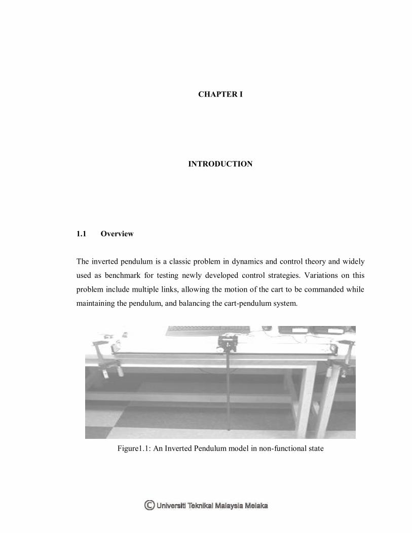
The inverted pendulum is a classic problem in dynamics and control theory and widely
used as benchmark for testing newly developed control strategies. Variations on this
problem include multiple links, allowing the motion of the cart to be commanded while
maintaining the pendulum, and balancing the cart-pendulum system.
Figure1.1: An Inverted Pendulum model in non-functional state

2
The inverted pendulum is an intriguing subject from the control point of view
due to their intrinsic non-linearity. The main concern is to balance a pole on a mobile
platform that can move in only two directions; left or right. The inverted pendulum is
related to rocket or missile guidance, where thrust is actuated at the bottom of a tall
vehicle. The largest implemented use is on huge lifting cranes on shipyards. When
moving the shipping containers back and forth, the cranes move the box accordingly so
that it never swings or sways. It always stays perfectly positioned under the operator
even when moving or stopping quickly.
Another way that an inverted pendulum may be stabilized, without any feedback
or control mechanism, is by oscillating the support rapidly up and down. If the
oscillation is sufficiently strong (in terms of its acceleration and amplitude) then the
inverted pendulum can recover from perturbations in a strikingly counterintuitive
manner.
Figure 1.2: The movement of an inverted pendulum
Inverted pendulum system is a nonlinear unstable system, an ideal experiment
platform for teaching control theories and conducting various control experiments. Many
abstract control concepts, such as the stability and the controllability of a control system,
can all be shown visually through the inverted pendulum system. In addition to
educational purposes, an inverted pendulum is also a research area for many researchers
of modern control theories.

3
1.2 Objectives
The objectives of this project are:
i) To synthesis the mathematical model of an Inverted Pendulum based on
the K. Ogata, 1978 modelling.
ii) To develop the fuzzy logic control strategy to restrain the system‟s cart
displacement and rod angle.
iii) To develop the mathematical model of sliding mode controller to restrain
the system‟s cart displacement and rod angle.
iv) To run a simulation for both developed control strategies in Matlab
Software.
v) To compare the both control strategies in terms of the cart displacement
and rod angle pattern as well as other differences.
1.3 Problem Statement
It is virtually impossible to balance out an inverted pendulum without applying external
force into the system. The balancing of an inverted pendulum by moving a cart along a
horizontal track is a classic problem in the area of control. They are often useful to
demonstrate concepts in linear control such as the stabilization of unstable systems.
The problem involves a cart – moving forward and backward – and a pendulum
– hinged to the cart at the bottom of its length so that it moves in the same plane as the
cart. The pendulum mounted on the cart is free to fall and oscillate along the cart‟s
motion axis. A control system is needed to keep the pendulum upright and balanced.

4
Figure 1.3: An inverted pendulum on its centre
This problem comprises a simple coupled system. If the pendulum starts off-
centre, it is prone to fall immediately. Even if it starts centre, once the cart moves, it
would triggered to be off-centre and cause the pendulum to fall. In stabilizing this
circumstance, such to keep the pendulum in upright position, a control strategy must be
applied.
1.4 Work Scope
During the project, a mathematical representation of inverted pendulum will be
synthesized based on the K. Ogata, 1978 modelling. An analysis on the difference of
linear and nonlinear equations will also be done in order to have a deeper understanding
on the characteristics of the system.
Then, control strategies for both fuzzy logic and sliding mode will be developed
to restrain the system‟s cart displacement and rod angle.
A simulation using the MATLAB Software will be done later on the project to validate
the effectiveness of the control strategies. Finally, a comparison of both control
strategies in terms of the cart displacement and rod angle pattern as well as other
differences will be done to determine the better control strategy.

5
1.5 Project Methodology
To ensure a successful outcome in the project, the project objectives shall be achieved
first. The flow chart below shows the method that will be done step by step until the goal
of the project is achieved. There are four phases involved during this project‟s
execution:
i) First Phase : Literature Review
ii) Second Phase : Mathematical Modelling and control strategy
development
iii) Third Phase : Simulation and Analysis
iv) Fourth Phase : Thesis Writing
i) First Phase : Literature Review
Gather the information about the project via internet, journals,
magazines, published work and reference books.
Study of the software implementation (Matlab).
Do research to know more details about fuzzy logic controller and
sliding mode controller.
ii) Second Phase: Mathematical Modelling and control strategy development
Synthesize the mathematical model of an Inverted Pendulum
based on the K. Ogata, 1978 modelling.
Simulate the passive system for linear and non-linear validity
Develop the fuzzy logic control strategy.
Develop the mathematical model of sliding mode controller.
iii) Third Phase : Simulation and Analysis
Simulate the inverted pendulum system with controllers separately.
Analyze the control of cart displacement and rod angle on the
inverted pendulum system.

6
iv) Fourth Phase: Thesis writing
State all the ideas concentrated regarding to this project.
Show flow of ideas during the implementation of this project.
State the project conditions (from the beginning until the end of
the project).
CHAPTER II
LITERATURE REVIEW
2.1 Introduction
The literature review undertaken focus on understanding the background and application
of inverted pendulum system, mathematical modelling, control and other projects of
similar nature.
2.2 Background
The inverted pendulum is a classic example of a non-linear control topic which is
studied frequently with reference to design, implementation and development of control.
It appears in undergraduate control textbooks such as K. Ogata (1978) where it is used
as an example of how to mathematically describe physical systems.

8
2.3 Present Applications
Inverted pendulum is currently used as teaching aids and research experiments. Quanser
(2004), a supplier of educational and research based equipment produce modular
systems which can be configured as single or double inverted pendulum. The range
offers both rotary and linear version. Many other researchers have also built their own
inverted pendulum systems such as Åström and Furuta in 1996 to suit their
investigations.
Figure 2.1: An Inverted Pendulum model offered in the market.
2.4 Inverted Pendulum Configurations
The simplest controllable inverted pendulum would consist of a pendulum link directly
coupled to a motor shaft (Dorf and Bishop, 1998). This configuration could be
controlled open-loop with the use of a stepper motor. However, it is deemed too simple
for further consideration. Therefore, the simplest controllable inverted pendulum system
that shall be considered must have at least two degrees of freedom, one for the position
of the pendulum base and the other for the pendulum angle. For two degrees of freedom,

9
the pendulum base is restricted to only one dimensional movement. The angle has to
also vary in only one dimension. For higher degrees of freedom, either more single
degree of freedom links are added, or the existing links are allowed to move in multiple
dimensions.
In the linear case, a motor is used to move a cart along a straight track. The
pendulum is attached to the cart by a pin joint. The axis of rotation of the pendulum link
about the pin joint is horizontal and perpendicular to the cart‟s direction of travel. The
input to the system is the force applied to the cart, via the motor. Full derivation of the
systems‟ dynamics for a linear inverted pendulum can be found in Dorf and Bishop
(1998) and Franklin (2002).
2.5 Control Methodology
In general, a Control System is a collection of electronic devices and equipment which
are in place to ensure the stability, accuracy and smooth transition of a process or a
manufacturing activity. It takes any form and varies in scale of implementation, from a
power plant to a semi-conductor machine. As a result of rapid advancement of
technology, complicated control tasks accomplished with a highly automated control
system.
Besides signal interfacing to the field devices (such as operator panel, motors,
sensors, switches, solenoid valves and etc.), capabilities in network communication
enable a big scale implementation and process co-ordination besides providing greater
flexibility in realizing distributed control system. Every single component in a control
system plays an important role regardless of size.