control of mechanical systems in data storage. collaborations in data storage stmicroelectronics –...
TRANSCRIPT
Control of mechanical systems in data storage

Collaborations in Data Storage
STMicroelectronics – Agrate – MI
Computer Mechanics Lab - UC Berkeley
Prof. Masayoshi Tomizuka – prof. Roberto Horowitz
Center for Magnetic Recording Research (CMRR) -UC San Diego
Prof. Frank Talke
Data Storage Center – Carnegie-Mellon University
Prof. William Messner
HITACHI-IBM Almaden Research Center
Data stored on concentric circular tracks
Operating modes
• Track Following when performing R/W operations
• Track Seek when changing track
Actuators:
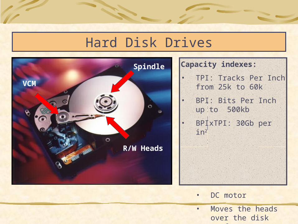
• Spindle motor at a constant speed, between 3600 and 18000 rpm
• Brushless
• Provides the rotation of the disk stack assembly
• Voice Coil Motor (VCM)
• DC motor
• Moves the heads over the disk surface
Hard Disk Drives
Capacity indexes:
• TPI: Tracks Per Inch from 25k to 60k
• BPI: Bits Per Inch up to 500kb
• BPIxTPI: 30Gb per in2
Spindle
VCM
R/W Heads

ChannelChannel
•Microelectronics (analog and digital)
•Code theory
•Digital filters
BER < 10BER < 10-9-9SpindleSpindle •Electric Drives
•Mechanics
ElasticityElasticity
EccentricityEccentricity
Torque rippleTorque ripple
BearingsBearings
Disk modesDisk modes
Technologies, problems and objectives
Subsystem Technologies Problems and objectives
SuspensionSuspension •Mechanics
•Materials
•Aerodynamics
Resonant Resonant modesmodes
Fly height: Fly height: 15 nm15 nm
Speed: 120 Speed: 120 km/hkm/h
HeadsHeads
•Electric Drives
•Digital control
Seek Time: Seek Time: 5512ms12ms
PES: 5PES: 57% Tr.7% Tr.
(i.e. 50 nm (i.e. 50 nm precision in precision in servo-servo-positioning)positioning)
ServopositioningServopositioning

Head Servo-positioning
Servo sectorSector
Servo sector
• synchronization signals
• Track number
• Head postion w.r.t. track center (PES)
Servo sector
• synchronization signals
• Track number
• Head postion w.r.t. track center (PES)
Sampling
F = N x rpm / 60 ; N = #Servo sectors
F = 8 30 kHz
Sampling
F = N x rpm / 60 ; N = #Servo sectors
F = 8 30 kHz

The head servopositioning system
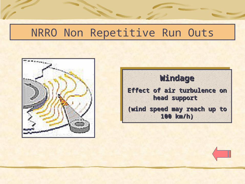
NRRO Non Repetitive Run Outs
WindageWindage
Effect of air turbulence on head Effect of air turbulence on head support support
(wind speed may reach up to 100 km/h)(wind speed may reach up to 100 km/h)
WindageWindage
Effect of air turbulence on head Effect of air turbulence on head support support
(wind speed may reach up to 100 km/h)(wind speed may reach up to 100 km/h)
-4 -3 -2 -1 0 1 2 3 4
-3
-2
-1
0
1
2
3
-4 -3 -2 -1 0 1 2 3 4
-3
-2
-1
0
1
2
3
-4 -3 -2 -1 0 1 2 3 4
-3
-2
-1
0
1
2
3
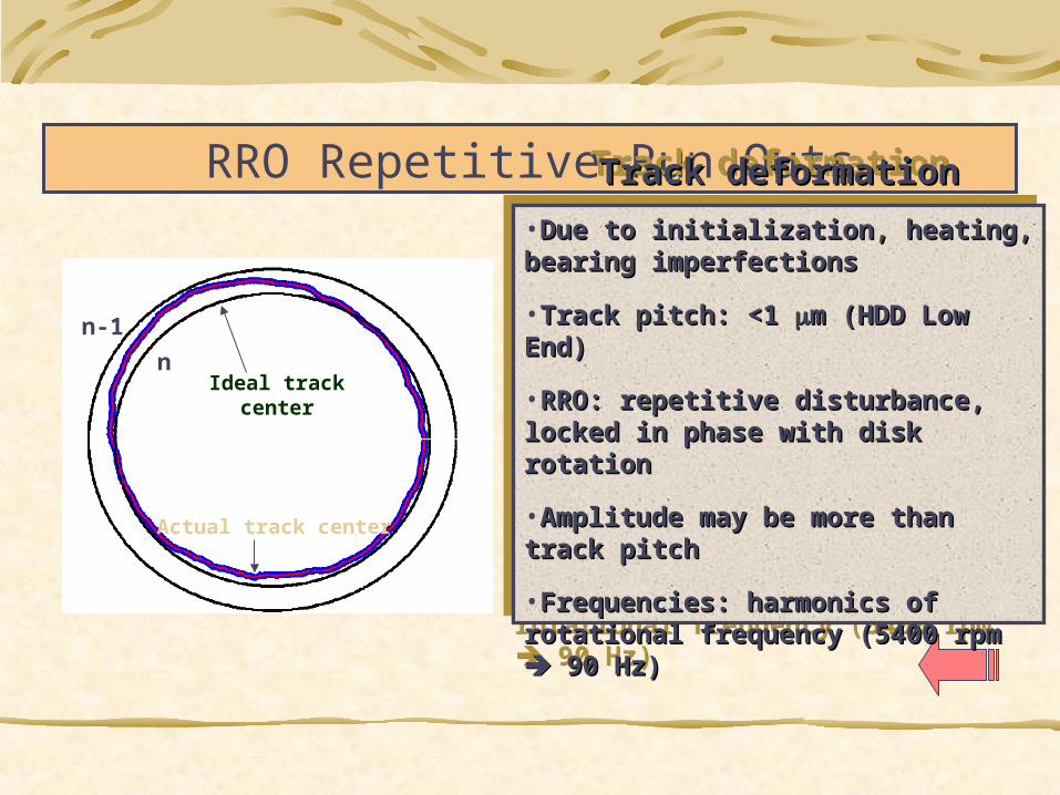
Ideal track center
Actual track center
n
n-1
RRO Repetitive Run OutsTrack deformationTrack deformation
•Due to initialization, heating, bearing Due to initialization, heating, bearing imperfectionsimperfections
•Track pitch: <1 Track pitch: <1 m (HDD Low End)m (HDD Low End)
•RRO: repetitive disturbance, locked in RRO: repetitive disturbance, locked in phase with disk rotation phase with disk rotation
•Amplitude may be more than track pitch Amplitude may be more than track pitch
•Frequencies: harmonics of rotational Frequencies: harmonics of rotational frequency (5400 rpm frequency (5400 rpm 90 Hz) 90 Hz)
Track deformationTrack deformation
•Due to initialization, heating, bearing Due to initialization, heating, bearing imperfectionsimperfections
•Track pitch: <1 Track pitch: <1 m (HDD Low End)m (HDD Low End)
•RRO: repetitive disturbance, locked in RRO: repetitive disturbance, locked in phase with disk rotation phase with disk rotation
•Amplitude may be more than track pitch Amplitude may be more than track pitch
•Frequencies: harmonics of rotational Frequencies: harmonics of rotational frequency (5400 rpm frequency (5400 rpm 90 Hz) 90 Hz)
Hard Disk
Interesting, multi-disciplinary case of study:
Modeling of complex mechanical systemsIdentification and control Power electronics and electric drivesVibration suppressionData coding, magnetic materials, aerodynamics, signal processing …
Research Activities in HDD Servo
Modeling and Simulation
Digital control algorithms design and test
Active vibration suppression
VCM voltage command

Modeling and SimulationExperimentally tuned simulator:
[rad ]
Arm Resonances
Arm Resonances
1/s1/s 1/s1/s1/J1/J
..
[Nm] [rad/s2] [rad/s]
τ Φ Φ Φ.
[rad]
Non L inearFrictionModel
Non L inearFrictionModel
TPRTPR
RRORRO NRRONRRO
PES
[Tr ] [Tr]
WindageWindageBias &
Flat CableBias &
Flat Cable
[rad]
Arm Resonances
Arm Resonances
1/s1/s 1/s1/s1/J1/J
..
[Nm] [rad/s2] [rad/s]
τ Φ Φ Φ.
[rad]
Non L inearFrictionModel
Non L inearFrictionModel
TPRTPR
RRORRO NRRONRRO
PES
[Tr ] [Tr]
WindageWindageBias &
Flat CableBias &
Flat Cable
0 10 20 30 40 50 60 70 80 90-0.06
-0.04
-0.02
0
0.02
0.04
0.06
0.08
[Samples]
[Tracks]
PESrro
Average data1 data2 data3 data4 data5 data6 data7 data8 data9 data10 data11 data12 data13 data14 data15 data16

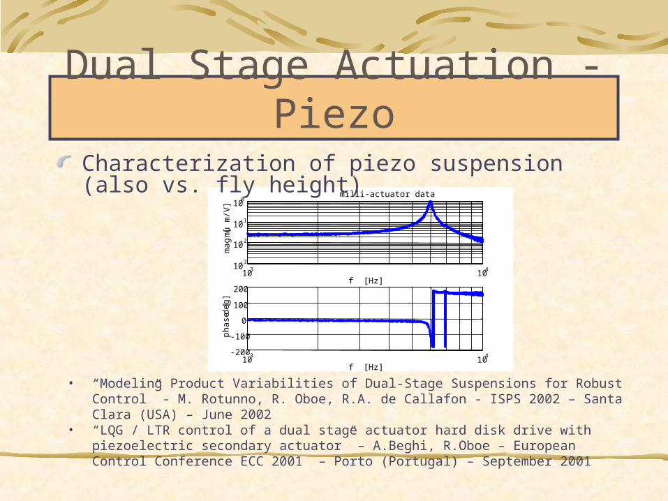
Dual Stage Actuation - Piezo
LDVsuspension
spindle
gold-coatedslider
Dual stage actuator can be simulatedPiezo (experimentally tuned)Mems (multi-body mechanical system)
Dual Stage Actuation - Piezo
103
10410
-3
10-2
10-1
100
milli-actuator data
f [Hz]
ma
g [ m
u m
/V]
103
104-200
-100
0
100
200
f [Hz]
ph
ase
[de
g]
Characterization of piezo suspension (also vs. fly height)
• “Modeling Product Variabilities of Dual-Stage Suspensions for Robust Control” - M. Rotunno, R. Oboe, R.A. de Callafon - ISPS 2002 – Santa Clara (USA) – June 2002
• “LQG / LTR control of a dual stage actuator hard disk drive with piezoelectric secondary actuator” – A.Beghi, R.Oboe – European Control Conference ECC 2001 – Porto (Portugal) – September 2001
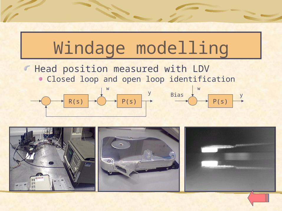
Windage modellingHead position measured with LDV
Closed loop and open loop identification
R(s) P(s) P(s)
w wy yBias

Digital servo control design and test
VCMVCM
PreampChannel
Controller
DACPowerDrive
External BoardExternal Board
Controller
DAC

Estimated state feedback controller with disturbance observer
HDDPLANT
ESTIMATOR
K2 K3 K4
xs2 xs3 xs4
uTarget Track
+−
+ + +
− − −
External Controller
Head Position
K 1
xs1
HDDPLANT
ESTIMATOR
K 2 K 3 K 4
xs2 xs3 xs4
uTarget Track
+−
+ + +
− − −
External Controller
Head Position
K 1
xs1
Xs1: estim. position
Xs2: estim. velocity
Xs3: estim. disturbance
Xs4: u(k-1)
Xs1: estim. position
Xs2: estim. velocity
Xs3: estim. disturbance
Xs4: u(k-1)
• “Loop shaping issues in hard disk drive servo system design” - A.Beghi, R.Oboe, P.Capretta, F.Chrappan Soldavini - Advanced Intelligent Mechatronics AIM 2001 – Como (Italy) – July 2001
• “Optimal Estimation for Disk Drive Head Positioning System” - D.Ciscato, R.Oboe, G.Picci, E.Colecchia, G.P.Maccone, G.Traversa - The 2nd Annual Magnetic Recording Conference on Recording Systems - Hidden Valley, Pittsburgh PA (USA), June 12-15 1991
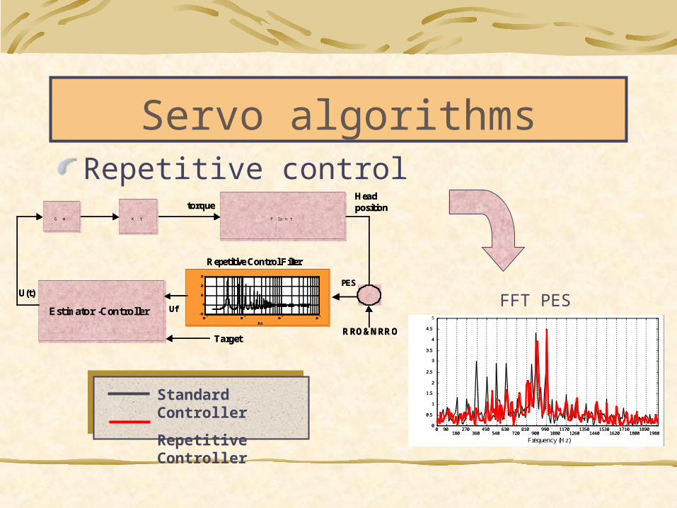
Servo algorithmsRepetitive control
Gm Kt Planttorque
Head position
RRO&NRROTarget
U(t)PES
Repetitive Control Filter
UfEstimator -Controller 10
110
210
310
4-10
0
10
20
30
[Hz]
Magnitude
[dB
]
101
102
103
104
-10
0
10
20
30
[Hz]
Magnitude
[dB
]
G m K t P l a n t
torqueHead position
RRO&NRROTarget
U(t)PES
Repetitive Control Filter
UfEstimator -Controller 10
110
210
310
4-10
0
10
20
30
[Hz]
Magnitude
[dB
]
101
102
103
104
-10
0
10
20
30
[Hz]
Magnitude
[dB
]
0 90180
270360
450540
630720
810900
9901080
11701260
13501440
15301620
17101800
18901980
0
0.5
1
1.5
2
2.5
3
3.5
4
4.5
5
Frequency (Hz)
0 90180
270360
450540
630720
810900
9901080
11701260
13501440
15301620
17101800
18901980
0
0.5
1
1.5
2
2.5
3
3.5
4
4.5
0 90180
270360
450540
630720
810900
9901080
11701260
13501440
15301620
17101800
18901980
0
0.5
1
1.5
2
2.5
3
3.5
4
4.5
5
Frequency (Hz)
FFT PES
Standard Controller
Repetitive Controller

0 500 1000 1500 2000 2500 3000 35000
0.5
1
1.5
2
2.5
3
FFT PES
Frequency [Hz]
Tra
cks/
Hz
102
103
-50
-40
-30
-20
-10
0
10
Frequency (Hz)
Mag
nitu
de (
dB)
Larger Estimator BandwidthLarger Estimator Bandwidth
Estimator Bandwidth : 500 to 900 HzEstimator Bandwidth : 500 to 900 Hz
Controller Bandwidth : 500 Hz Controller Bandwidth : 500 Hz
102
103
-50
-40
-30
-20
-10
0
10
Frequency (Hz)
Mag
nitu
de (
dB)
Larger Estimator BandwidthLarger Estimator Bandwidth
Estimator Bandwidth : 500 to 900 HzEstimator Bandwidth : 500 to 900 Hz
Controller Bandwidth : 500 Hz Controller Bandwidth : 500 Hz
Sensitivity Function
Ts=m_Tc
Tc
u (k,0)
u (k,1)
u (k,i)
u (k,m-1)
x (k,0)
x (k,1)
x (k,i)x (k,m-1)
k_Ts (k+1) _Tsi_Tc (i+1)Tc
Ts=m_Tc
Tc
u (k,0)
u (k,1)
u (k,i)
u (k,m-1)
x (k,0)
x (k,1)
x (k,i)x (k,m-1)
k_Ts (k+1) _Tsi_Tc (i+1)Tc
Ts=m_Tc
Tc
u (k,0)
u (k,1)
u (k,i)
u (k,m-1)
x (k,0)
x (k,1)
x (k,i)x (k,m-1)
k_Ts (k+1) _Tsi_Tc (i+1)Tc
Ts=m_Tc
Tc
u (k,0)
u (k,1)
u (k,i)
u (k,m-1)
x (k,0)
x (k,1)
x (k,i)x (k,m-1)
k_Ts (k+1) _Tsi_Tc (i+1)Tc
Pubblications:“Disturbance rejection in hard disk drives with multi-rate estimated state feedback”R. Oboe, F. Marcassa - To appear in Mechatronics 2002 – Berkeley (USA) – December 2002
Pubblications:“Disturbance rejection in hard disk drives with multi-rate estimated state feedback”R. Oboe, F. Marcassa - To appear in Mechatronics 2002 – Berkeley (USA) – December 2002
Servo algorithmsMultirate control
Objectives (from literature):Objectives (from literature):
Reduce command discontinuitiesReduce command discontinuities
Reduce phase delayReduce phase delay
Enlarge control BWEnlarge control BW
Reduce TMRReduce TMR
Objectives (from literature):Objectives (from literature):
Reduce command discontinuitiesReduce command discontinuities
Reduce phase delayReduce phase delay
Enlarge control BWEnlarge control BW
Reduce TMRReduce TMR
Results:Results:
•Short Seek improvementShort Seek improvement
•Analytical evaluation of closed-loop Analytical evaluation of closed-loop sensitivity functionsensitivity function
•Worsening in sensitivity observed Worsening in sensitivity observed (analytically and experimentally)(analytically and experimentally)
K Zoh plant
Estimator
HTc
RRO&NRRO
u(k,i)
x(k,i))
Plant H
Ts
PES
PositionTarget
Ts = mTcTs = mTc
2 3 4 5 6 7 8
x 10-3
1.2288
1.2288
1.2288
1.2288
1.2289
1.2289
1.2289
1.2289
1.2289
1.229x 10
4 short seek (1 track): sr vs mr
time [sec]
head position [tracks]
multi-rate
single-rate
2 3 4 5 6 7 8
x 10-3
1.2287
1.2288
1.2289
1.229
1.2291
1.2292
1.2293
1.2294x 10
4 short seek (5 tracks)
time [t]
head position [tracks] single-rate
multi-rate
“DISTURBANCE REJECTION IN HARD DISK DRIVES WITH MULTI-RATE ESTIMATED STATE FEEDBACK”Federico Marcassa and Roberto Oboe
Control Engineering Practice 2003 – In press
IVCΔΔxxSSIVCΔΔxxSS
Mode Switching ControlMode Switching ControlMode Switching ControlMode Switching Control
yR
xS1
u
Disturbance
PROCESS
ESTIMATOR
-
a
y
yn
TRACK FOLL.
CONTROLLER
SEEK &
SETTLINGCONTROLLER
ut
us
+-
y a
>YD
xSn
xSi
yR
xS1
u
Disturbance
PROCESS
ESTIMATOR
-
a
y
yn
TRACK FOLL.
CONTROLLER
SEEK &
SETTLINGCONTROLLER
ut
us
+-
y
>YD
x
x
yR
xS1
u
Disturbance
PLANT
ESTIMATOR
-
y
yn
TRACK FOLL.
CONTROLLER
SEEK &
SETTLINGCONTROLLER
ut
us
SWITCH+
-
y
>YD
x
εThreshold
yR
xS1
u
Disturbance
PROCESS
ESTIMATOR
-
a
y
yn
TRACK FOLL.
CONTROLLER
SEEK &
SETTLINGCONTROLLER
ut
us
+-
ya
>Y D
xSn
xSi
yR
xS1
u
Disturbance
PROCESS
ESTIMATOR
-
a
y
yn
TRACK FOLL.
CONTROLLER
SEEK &
SETTLINGCONTROLLER
ut
us
+-
ya
>Y D
xSn
xSi
yR
xS1
u
Disturbance
PROCESS
ESTIMATOR
-
a
y
yn
TRACK FOLL.
CONTROLLER
SEEK &
SETTLINGCONTROLLER
ut
us
+-
y
>Y D
x
x
yR
xS1
u
Disturbance
PLANT
ESTIMATOR
-
y
yn
TRACK FOLL .
CONTROLLER
SEEK &
SETTL INGCONTROLLER
ut
us
SWITCH+
-
y
>Y D
x
εThreshold
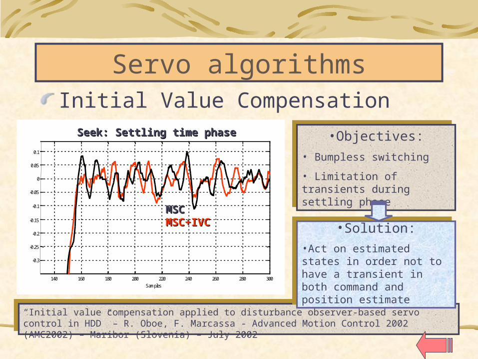
140 160 180 200 220 240 260 280 300
-0.3
-0.25
-0.2
-0.15
-0.1
-0.05
0
0.05
0.1
Samples
Tracks
MSC+IVCMSC
140 160 180 200 220 240 260 280 300
-0.3
-0.25
-0.2
-0.15
-0.1
-0.05
0
0.05
0.1
Samples
Tracks
140 160 180 200 220 240 260 280 300
-0.3
-0.25
-0.2
-0.15
-0.1
-0.05
0
0.05
0.1
Samples
Tracks
MSC+IVCMSC
140 160 180 200 220 240 260 280 300
-0.3
-0.25
-0.2
-0.15
-0.1
-0.05
0
0.05
0.1
Samples
Tracks MSCMSCMSC+IVCMSC+IVC
Seek: Settling time phaseSeek: Settling time phase
Servo algorithmsInitial Value Compensation
“Initial value compensation applied to disturbance observer-based servo control in HDD” – R. Oboe, F. Marcassa - Advanced Motion Control 2002 (AMC2002) – Maribor (Slovenia) – July 2002
“Initial value compensation applied to disturbance observer-based servo control in HDD” – R. Oboe, F. Marcassa - Advanced Motion Control 2002 (AMC2002) – Maribor (Slovenia) – July 2002
•Objectives:• Bumpless switching
• Limitation of transients during settling phase
•Objectives:• Bumpless switching
• Limitation of transients during settling phase
•Solution:•Act on estimated states in order not to have a transient in both command and position estimate
•Solution:•Act on estimated states in order not to have a transient in both command and position estimate
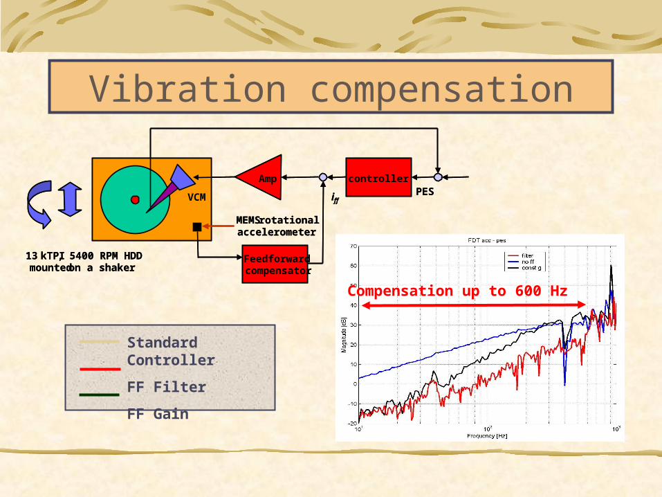
Vibration compensation
MEMS rotational accelerometer
Feedforwardcompensator
controllerPES
13 kTPI, 5400 RPM HDDmounted on a shaker
VCM
Amp
iff
MEMS rotational accelerometer
Feedforwardcompensator
controllerPES
13 kTPI, 5400 RPM HDDmounted on a shaker
VCM
Amp
iff
Standard Controller
FF Filter
FF Gain
Compensation up to 600 Hz

Active vibration damping
Active suspension with two piezo strips:ActuationSensing
Active damping of resonant modes

ProsPros
Bandwidth 50kHz I=GURobustness against variations in RT LVCM
ProsPros
Bandwidth 50kHz I=GURobustness against variations in RT LVCM
ConsCons
Dissipation: R shunt – Linear AmplifierSilicon area: Linear AmplifierDigital current loop expensive A/D
ConsCons
Dissipation: R shunt – Linear AmplifierSilicon area: Linear AmplifierDigital current loop expensive A/D
1RT+sLVcm
[V] [A]
J*s
Kt
KtBemf
-
+ I(s)U(s)
R
Linear Power Amplifier& Phase Shaping[V]
Command
VCM control: Current Mode

Controllo VCM: Voltage Mode
ProsProsGood performance without current meas.Cost reductionMigration toward SOC
ProsProsGood performance without current meas.Cost reductionMigration toward SOC
1RT+sLVcm
[V] [A]
J*s
Kt
KtBemf
-
+ I(s)U(s)
PowerPSM[V]
Command DigitalPrefilter
Multi-rate
1RT+sLVcm
[V] [A]
J*s
Kt
KtBemf
-
+ I(s)U(s)
PowerPSM[V]
Command DigitalPrefilter
Multi-rate
ConsConsPre-filter cancels out the electrical dynamic
of VCMR varies ±30%On-line estimation of R required
ConsConsPre-filter cancels out the electrical dynamic
of VCMR varies ±30%On-line estimation of R required
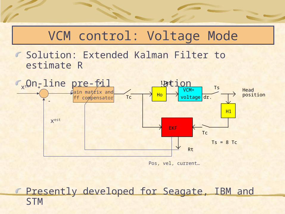
Solution: Extended Kalman Filter to estimate R
On-line pre-filter adaptation
Presently developed for Seagate, IBM and STM
VCM control: Voltage Mode
From servo controller
H1
HoVCM+
voltage dr.
EKF
Rt
Tc
Tc
Ts Head position
Ts = 8 Tc
Gain matrix and ff compensator
Pos, vel, current…
xref
xest
+
-